Embed Size (px)
Citation preview

Available online at www.sciencedirect.com
www.elsevier.com/locate/micromeso
Microporous and Mesoporous Materials 108 (2008) 123–135
Morphological classification of mesoporous silicas synthesizedin a binary water–ether solvent system
Qiang Cai a,*, Yi Geng a, Xiang Zhao a, Kai Cui a, Qianyao Sun b, Xihua Chen a,Qingling Feng a, Hengde Li a, Engel G. Vrieling c
a Department of Materials Science and Engineering, Tsinghua University, Beijing 100084, PR Chinab State Key laboratory of Heavy Oil Processing, China University of Petroleum, Beijing 102249, PR China
c Groningen Biomolecular Sciences and Biotechnology Institute, University of Groningen, P.O. Box 14, 9750 AA Haren, The Netherlands
Received 13 September 2006; received in revised form 23 March 2007; accepted 27 March 2007Available online 1 May 2007
Abstract
Using diethyl ether as a co-solvent, a non-stable interface of biphasic oil–water system (the so-called oil–water two-phase (OWTP)system) was employed in the preparation of mesostructured silicas with diversified particle morphologies. By adjusting the molar ratiosof H2O:C2H5OC2H5:NH3 Æ H2O and the alkalinity of the OWTP system, several product morphologies could be obtained under differentreaction conditions. On the other hand, different product morphologies with distinct structural properties could be obtained at a specificreaction condition, indicating that product morphology varied upon intrinsic characteristics of non-equilibrium processes in the systemas well. There are six kinds of product morphologies in our results. In the biphasic region the morphotypes such as vesicles, slices, andspheres were widely distributed. Multi-lamellar fragments were formed under relatively strong alkaline conditions and at a high propor-tion of diethyl ether (>41%). bi-continuously phased fragments were observed in the weak alkaline conditions and medium proportionbetween diethyl ether and water. In the single-phase region, hexagonally ordered MCM-41, plain sheets of MCM-48, as well as smoothand plain slices with worm-like pore structures were formed with bi-modal pore-size distribution structure. Based on HRTEM analysis,these structural features were rationalized being derived from fragments that originated from the oil/water interface. Apparently, theproduct morphosynthesis resulted from a combination of fluid rheological distortions and reconstructive reaction fields. With a system-atic approach we have established the reaction phase diagram of the system, which enabled us to define the structural properties and toclassify the morphology of the products for nomenclatural purposes in studying OWTP systems.� 2007 Elsevier Inc. All rights reserved.
Keywords: Hierarchical pore structure; Mesostructured silica; Morphosynthesis; Oil–water two-phase system (OWTP); Reconstructive reaction fields;Rheology
1. Introduction
In recent years, synthesis of novel and improved meso-structured materials has attracted increasing attentiondue to the potential industrial and nanotechnologicalapplication of these materials as sorbents [1], catalyst sup-ports [2], and controlled drug delivery agents [3], and theirimportance in understanding the physico-chemical pro-
1387-1811/$ - see front matter � 2007 Elsevier Inc. All rights reserved.
doi:10.1016/j.micromeso.2007.03.051
* Corresponding author. Tel.: +86 10 6277 5005.E-mail address: [email protected] (Q. Cai).
cesses in silica biomineralization [4]. By transcripting sur-factant aggregates, fluids–solids and confined reactionconditions, various well-defined silica structures can beobtained. Excellent examples are templating approachesinvolving lyotropic liquid crystals [5], block copolymermesophases [6], bi-continuous (micro-)emulsions [7,8],emulsion foams, pollen grains [9] and even bacteria [10].
In contrast to chemical templating approaches, the mor-phology of mesostructured materials can also be controlledby physical effects such as those induced by fluid rheology[11], acoustic cavitation [12], and electron irradiation [13].
124 Q. Cai et al. / Microporous and Mesoporous Materials 108 (2008) 123–135
Indeed, diverse material morphologies can be produceddue to physical control in systems by using various solvents[14]. Organic co-solvents, which are usually used as auxil-iary reagents in aqueous chemical reactions, do affect thephase behavior and thus rheological properties effectively[15]. Furthermore, biphasic systems (e.g. oil–water) canalso be used as a template in material syntheses. By dissolv-ing the surfactant in a biphasic oil–water (OWTP) system,not only the surfactant molecule aggregates, but unstablemesostructured surfactant fragments also exist at the oil–water interface [16]. These instantaneous formed fragmentsand the oil–water interface, however, are easily affected byrheological interactions of the solvents and thermodynamicfluctuations, making the system extremely complex tounderstand structure-direction and morphological controlof the products.
Nevertheless, by using biphasic templating approachesthat involved physical control mechanisms, various mor-phologically well-defined materials have been synthe-sized; these are: (i) macrocellular mesoporous silica foamsusing a metastable surfactant foam system [16], (ii) hollowsilica spheres with multi-lamellar shells via block copoly-mer-based emulsions [17], (iii) spongiform and hollowmicrospheres in an emulsion-based system [18], and (iv)mesostructured ultrastable silica vesicles prepared througha supramolecular assembly pathway that relies on hydro-gen bonding between electrically neutral gemini surfactants[19].
Structural conformation and product morphology aretwo important characteristics in the design and synthesisof mesostructured materials. Previous studies have indi-cated that, in comparison with structure-direction andstructural conformation, the morphological control of theproduct is a much more complex process. In fact, the finalmorphology depends on all the physical and templatingprocesses in material syntheses [20]. It is obvious from allaforementioned templating approaches that the productmorphology becomes defined once the initial template-structure is set. Physical effects on their own have littleinfluence on template-based structure-direction, but playan important part in controlling the morphology of theend product. This has been confirmed by studying thepacking parameters theory, where the preferred structureof surfactant aggregates correlated to the geometricalparameters of surfactants [21]. In other studies, the influ-ence of physico-chemical parameters on structural proper-ties was investigated using phase diagrams; althoughfactors such as surfactant concentration, temperature andpH do affect the structural conformation, only the appliedreaction conditions determined the final structures perexperiment [22].
The correlation between material morphology andexperimental approach has not yet been assessed systemat-ically. Instead, irregularity or mixed product morphologiesare usually considered as poorly-defined or unimportant,being easily neglected [23]. In common, product morphol-ogy has been defined for one or a few specific synthesis con-
ditions. So far, it has not been investigated whetherproduct morphology is uniform between versatile and sim-ple reaction systems such as for the OWTP system. In orderto define any regularity in morphological control by theOWTP system, a general classification of product morphol-ogy is a prerequisite. At present, morphological assessmentusually focus on individually synthesized products ratherthan analyzing them when mixed together. Our recentresearch on the OWTP system indicated that, in contrastto the structural conformation, the product morphologycannot be assessed by just one templating approach [24].Instead, structure-direction by templates and physical pro-cesses cooperatively controlled the final morphology of theproducts formed.
We now emphasized on extensive electron microscopicaland structural analysis to define cryptic information that isuseful for further classification of various kinds of materialmorphologies. For this, we investigated the OWTP systemin which diethyl ether was used as a co-solvent, and forwhich the co-solvent volume ratio and the alkalinity wererationally tuned in order to study their influence on themorphological and structural properties of final products.In keeping the amounts of surfactant and silica source con-stant we not only limited the variables of the system, butalso focused on the phase behavior of diethyl ether, aque-ous ammonia and water; the latter can be easily describedin a ternary phase diagram.
2. Experimental section
2.1. Synthesis of mesostructured silicas
Samples were prepared by using hexadecyltrimethylammonium bromide (CTAB) as surfactant, and tetraethylorthosilicate (TEOS) as the silicate source. In the synthe-ses, the volume proportions of water, diethyl ether andaqueous ammonia were varied. For all conditions 2 g ofCTAB and 10 ml of TEOS were used; the total volumeof the mixed solution was kept constant at 480 ml. The ini-tial conditions are further outlined in the ternary phasediagram (Fig. 1). In order to increase homogeneity andto produce a distorted oil–water interface, all mixtureswere vigorously stirred throughout the synthesis. The usedprocedure in general was as follows: (1) aqueous ammonia(28%, AR) was mixed with distilled water, (2) CTAB (99%,AR) was dissolved in this solution by heating to 323 K, (3)after the solution became homogeneous and was cooled toroom temperature (RT), diethyl ether was added to themixture, (4) subsequently TEOS was added, and (5) thereaction mixture was stirred for 24 h (at RT). Uponaddition of silica precursor to the system and intermediatesampling, the diversity in hierarchically ordered structuresand product morphologies could be assessed as the so-called ‘‘chemical snapshots’’. The resulting sampledproducts were filtered, washed with distilled water, driedat ambient temperature, and calcined in air for 5 h at823 K.
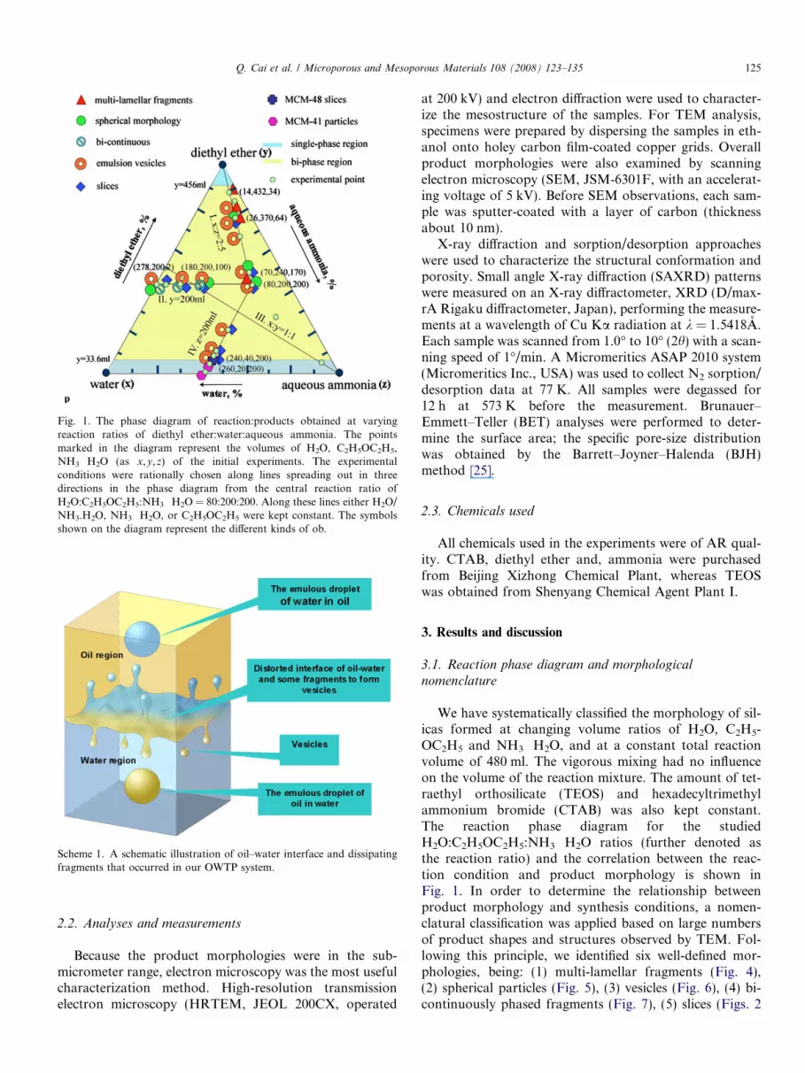
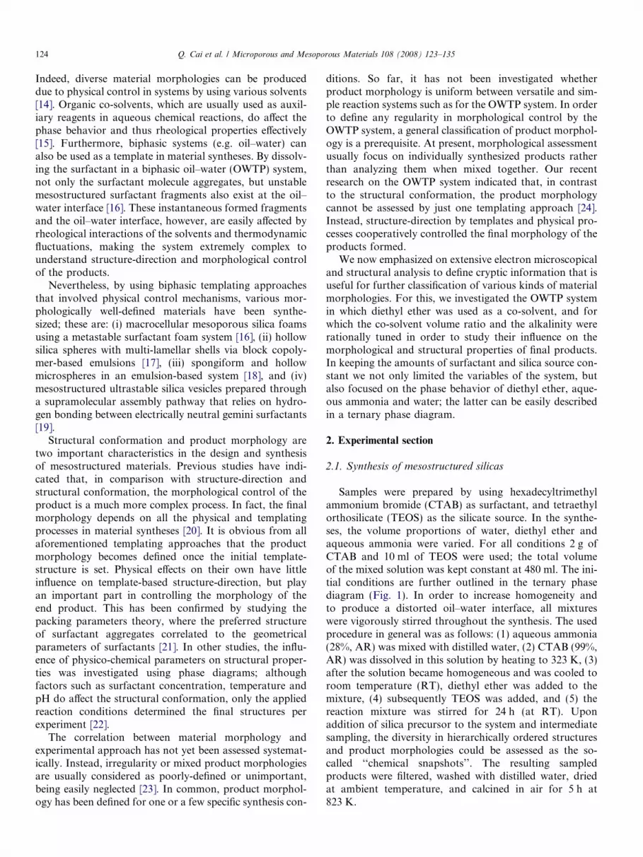
Fig. 1. The phase diagram of reaction:products obtained at varyingreaction ratios of diethyl ether:water:aqueous ammonia. The pointsmarked in the diagram represent the volumes of H2O, C2H5OC2H5,NH3 Æ H2O (as x,y,z) of the initial experiments. The experimentalconditions were rationally chosen along lines spreading out in threedirections in the phase diagram from the central reaction ratio ofH2O:C2H5OC2H5:NH3 Æ H2O = 80:200:200. Along these lines either H2O/NH3.H2O, NH3 Æ H2O, or C2H5OC2H5 were kept constant. The symbolsshown on the diagram represent the different kinds of ob.
Scheme 1. A schematic illustration of oil–water interface and dissipatingfragments that occurred in our OWTP system.
Q. Cai et al. / Microporous and Mesoporous Materials 108 (2008) 123–135 125
2.2. Analyses and measurements
Because the product morphologies were in the sub-micrometer range, electron microscopy was the most usefulcharacterization method. High-resolution transmissionelectron microscopy (HRTEM, JEOL 200CX, operated
at 200 kV) and electron diffraction were used to character-ize the mesostructure of the samples. For TEM analysis,specimens were prepared by dispersing the samples in eth-anol onto holey carbon film-coated copper grids. Overallproduct morphologies were also examined by scanningelectron microscopy (SEM, JSM-6301F, with an accelerat-ing voltage of 5 kV). Before SEM observations, each sam-ple was sputter-coated with a layer of carbon (thicknessabout 10 nm).
X-ray diffraction and sorption/desorption approacheswere used to characterize the structural conformation andporosity. Small angle X-ray diffraction (SAXRD) patternswere measured on an X-ray diffractometer, XRD (D/max-rA Rigaku diffractometer, Japan), performing the measure-ments at a wavelength of Cu Ka radiation at k = 1.5418A.Each sample was scanned from 1.0� to 10� (2h) with a scan-ning speed of 1�/min. A Micromeritics ASAP 2010 system(Micromeritics Inc., USA) was used to collect N2 sorption/desorption data at 77 K. All samples were degassed for12 h at 573 K before the measurement. Brunauer–Emmett–Teller (BET) analyses were performed to deter-mine the surface area; the specific pore-size distributionwas obtained by the Barrett–Joyner–Halenda (BJH)method [25].
2.3. Chemicals used
All chemicals used in the experiments were of AR qual-ity. CTAB, diethyl ether and, ammonia were purchasedfrom Beijing Xizhong Chemical Plant, whereas TEOSwas obtained from Shenyang Chemical Agent Plant I.
3. Results and discussion
3.1. Reaction phase diagram and morphological
nomenclature
We have systematically classified the morphology of sil-icas formed at changing volume ratios of H2O, C2H5-OC2H5 and NH3 Æ H2O, and at a constant total reactionvolume of 480 ml. The vigorous mixing had no influenceon the volume of the reaction mixture. The amount of tet-raethyl orthosilicate (TEOS) and hexadecyltrimethylammonium bromide (CTAB) was also kept constant.The reaction phase diagram for the studiedH2O:C2H5OC2H5:NH3 Æ H2O ratios (further denoted asthe reaction ratio) and the correlation between the reac-tion condition and product morphology is shown inFig. 1. In order to determine the relationship betweenproduct morphology and synthesis conditions, a nomen-clatural classification was applied based on large numbersof product shapes and structures observed by TEM. Fol-lowing this principle, we identified six well-defined mor-phologies, being: (1) multi-lamellar fragments (Fig. 4),(2) spherical particles (Fig. 5), (3) vesicles (Fig. 6), (4) bi-continuously phased fragments (Fig. 7), (5) slices (Figs. 2

Fig. 2. Typical particle shapes of mesostructured silicas observed by SEM, which were synthesized under different alkalinity levels and reaction ratios(shown in the brackets) of the OWTP system.
126 Q. Cai et al. / Microporous and Mesoporous Materials 108 (2008) 123–135
and 8g, and (6) ‘crystalline’ particles (Figs. 2h and 9). Wefurther noticed that at a specific reaction condition multi-ple product morphologies could be obtained, whereas viceversa under different synthesis conditions similar morphol-ogy types could be produced. For example, four morpho-types such as multi-lamellar fragments, spheres, vesiclesand slices, were synthesized at the center point with thereaction ratio 80:200:200 (Fig. 1). By changing the reac-tion condition, however, comparable morphology typeswere obtained, notably several kinds of spherical morphol-ogies were produced at the reaction ratios of: (a)278:200:2, (b) 27:386:67, and (c) 80:200:200.
In the biphasic region (the molar ratio of H2O/C2H5OC2H5 between 78 and 0.3) the morphotypes suchas vesicles, slices, and spheres were widely distributed.Multi-lamellar fragments were formed under relativelystrong alkaline conditions and at a high proportion ofdiethyl ether (>41%). In, or near, the single-phase regionand under alkaline conditions, hexagonally ordered
MCM-41 (reaction ratio of 260:20:200) (Fig. 9a and b),plain sheets of MCM-48 (reaction ratio of 240:40:200)(Fig. 8a, e and f), as well as smooth and plain slices withworm-like pore structures (reaction ratio of 230:200:50)(Fig. 8c and d) were formed. The evolution from hexago-nal to cubic or lamellar mesophases at increasing co-sol-vent concentration, as we noticed for our MCM-typesilicas, has also been described by Anderson [26]. Bicon-tinuously emulsified silicas with amorphous mesostruc-tures, were formed under relatively weak alkalinereaction conditions (reaction ratio of 278:200:2) (Fig. 7aand b). There was a clear relationship between the appliedreaction condition and the obtained silica mesostructure,whereas such a relationship did not exist between the reac-tion condition and product morphology. Hence, productmorphology could be nomenclaturally classified, but notvia the synthesis route. Moreover, the biphasic behaviorof the OWTP enhanced the diversity of productmorphologies.

Fig. 3. An overview of mixed particle shapes, including spheres, vesicles and slices, formed at the reaction ratio of H2O:C2H5OC2H5:NH3 Æ H2O = 27:386:67 and 230, 200, 50.
Fig. 4. Typical structural features of multi-lamellar silica fragments examined by (HR)TEM. The left column (TEM) and right column (HRTEM)represent particles formed at identical experimental conditions for (a, b) collapsed vesicles, (c, d) the star-shaped vesicles, and (e, f) the snail shell-shapedvesicles. The insets (b, d, f) show the lamellar organization of the particle shell at higher resolution. The applied reaction ratios are shown between thebrackets.
Q. Cai et al. / Microporous and Mesoporous Materials 108 (2008) 123–135 127

128 Q. Cai et al. / Microporous and Mesoporous Materials 108 (2008) 123–135
3.2. Scanning electron microscopy
The variation in overall morphologies of silica samplesprepared under different alkalinity levels and reaction ratioswas demonstrated by SEM (Fig. 2). Two types of sphereswere found; one with a spongiform external surface
Fig. 5. Representative structural features of spherical particles observed by (brackets. The nanotubes (d) corresponded to the intra-particle fibres that are
Fig. 6. Typical morphologies of vesicle-like silicas observed by TEM (a) sphenanotubes. The applied reaction ratios are shown between the brackets.
obtained at the H2O:C2H5OC2H5:NH3 Æ H2O ratio278:200:2 (Fig. 2a), whereas the other spheres (reactionratio of 80:200:200) were very smooth (Fig. 2b). At lowerresolution it became clear that monodisperse smoothspheres were also found at the reaction ratio of 278:200:2(Fig. 2d), while combinations of spheres, slices and other
HR)TEM, formed at the indicated reaction ratios as shown between thevisible inside the particles formed at the reaction ratio 80:200:200.
rical vesicles; (b) elongated spherical vesicles; (c) distorted vesicles and (d)

Q. Cai et al. / Microporous and Mesoporous Materials 108 (2008) 123–135 129
shaped fragments occurred at the reaction ratio of80:200:200 (Fig. 2e). At a high concentration of diethylether (�90% v/v at the reaction ratio of 14:432:34) a spon-giform mesoporous silica was produced (Fig. 2c), whichshowed a quite similar surface pattern of the porous spheresthat were prepared at the reaction ratio of 278:200:2(Fig. 2a). However, at lower resolution the difference in par-ticle shape in comparison with the spherical morphologybecame much more clear (Fig. 2f). Homogeneous phasesconsisting of thin slices (Fig. 2g), irregularly shaped parti-cles (Fig. 2h) were observed at the reaction ratios of240:40:200 and 260:20:200, respectively. In addition, irregu-lar amorphous structures were produced at various reactionratios such as, 180:200:100, 230:200:50, 27:386:67 and80:200:200, which showed less morphological details asfound in well-defined structures obtained at other appliedreaction ratios (Fig. 2i–l). Typically, at the reaction ratioof 27:386:67. A mixture of different morphologies wasobtained with thin regular slices, wrinkled slices, vesicle-likestructures, and spheres (Fig. 3). This observation showedthat our OWTP system did not lead to one single well-defined structure at every chosen reaction condition, indi-cating a multiformity in the synthesis system.
Fig. 7. Typical structures of bi-continuously emulsified silicas as observed by Tare shown between the brackets.
3.3. (High-resolution) Transmission electron microscopy
Because SEM did not reveal much structural detail, wefurther investigated the prepared silicas at a higher resolu-tion by (HR)TEM. This provided much more valuableinformation on the structural organization instead of solelyparticle morphology. The silicas synthesized at a relativelyhigh alkaline conditions – with a reaction ratio in which thevolume ratio of H2O/NH3 Æ H2O was �2:5 (Fig. 1) and thevolume of C2H5OC2H5 decreased from 432 ml to 200 ml –showed that the product shape changed from collapsedhollow vesicles (Fig. 4a and b), via multi-lamellar star-likevesicles (Fig. 4c and d), to snail shell-like vesicles with acontinuous multi-lamellar wall (Fig. 4e and f). The multi-lamellar ordering of the silica shells of the particles is fur-ther demonstrated by HRTEM (in the insets in Fig. 4b, dand f), revealing that the lamellar spacing is about 2.5–4.0 nm. The dimension of the hollow interior space variedfrom about 60 to 500 nm, whereas the shell thickness ran-ged between 30 and 100 nm.
By examining the three spherical morphologies in moredetail, these particles displayed different internal structures(Fig. 5). The first type of spheres (see also Fig. 2a) is
EM (a, c, e) and HRTEM (b, d, f), respectively. The applied reaction ratios

130 Q. Cai et al. / Microporous and Mesoporous Materials 108 (2008) 123–135
porous, consisting of radially ordering of silica structuresthat was formed under weak alkaline conditions (reactionratio of 278:200:2); the diameter of these spheres was about1 lm. The second type of spheres exhibits a ‘‘radiolarian-like’’ structure [8] with a smooth dense outer shell andapparently well-ordered porous internal organization(Fig. 5b). These spheres were synthesized at a relativelyhigh alkalinity level and higher concentrations of diethylether (reaction ratio of 27:386:67). The third type ofspheres was obtained at high alkaline conditions (reactionratio of 80:200:200) and appeared to be hollow with asmooth silica shell (Fig. 5c); the shells of these particleswere less dense (thus less thick) when compared to thatof the spheres produced at high diethyl ether levels(Fig. 5b). Remarkably, these shells were entangled by silicananotubes with a diameter of about 6 nm (Fig. 5d).
At various relatively low alkaline conditions the so-called bi-continuously shaped silica structures were formed(Fig. 6); here the amount of C2H5OC2H5 was kept con-stant, whereas the ratio of H2O:NH3 Æ H2O was altered.At the reaction ratio of 278:200:2, an ordered porous silicanetwork with pore diameters between 30 and 110 nm wasobtained (Fig. 7a). The silica backbone between the poreshad an average thickness of 50 nm (Fig. 7b). A similar mor-phology, albeit with smaller pores, was observed for silica
Fig. 8. Representative structural feature of highly ordered silica slices (MCM-the brackets.
synthesized at the reaction ratio of 230:200:50 (Fig. 7cand d). A quite disordered porous network was obtainedat the reaction ratio 180:200:100 (Fig. 7e and f). The diam-eters of the irregular and non-uniform distributed macrop-ores range from 50 to 167 nm; the silica backbone betweenthe pores had a thickness of �17 nm.
Another typical particle morphology is that of the thinstraight or wrinkled slices (Figs. 2g and 3). We observedthat the slices became less plain by decreasing the propor-tion of water (Fig. 8a and b). Remarkably, the thin silicaslices consisted of a highly ordered mesostructure with atetragonal (Fig. 8f) and a hexagonal (Fig. 8e) orientation.Such structural organizations of pores resemble that ofhexagonally ordered MCM-41 (as shown in Fig. 7g andh) that was produced when the amount of water was<7%. (Note that the solubility of diethyl ether at 293 Kin water is about 6.9% [27].) Due to the hexagonal organi-zation of mesopores in MCM-41, Bragg reflectionsappeared in electron diffraction analysis confirmed thestructural ordering of this silica (inset Fig. 8g). Further-more, both tetragonal (Fig. 8f) and hexagonal (Fig. 8e)symmetries were observed in the HRTEM images, whichrevealed its MCM-48 structure [26].
Wrinkled slices and irregular vesicle structures, synthe-sized at the reaction ratio 27:386:67 (Fig. 10b–d), appeared
48) observed by HRTEM. The applied reaction ratios are shown between

Fig. 9. Representative structural feature of regular particle-like (MCM-41) silicas observed by HRTEM. MCM-41 crystals (b) and theirhexagonally ordered pores (a) were readily visible; the typical diffractionpattern of the MCM-41 structure is shown in the inset (a). The reactionratio is indicated between brackets.
Q. Cai et al. / Microporous and Mesoporous Materials 108 (2008) 123–135 131
to co-occur as various types (Fig. 10a). Typical structureswere: (i) helical-structured wrinkles with as by-productsmall vesicles (Fig. 10b), (ii) larger sheet-like aggregatesof collided wrinkled vesicles (Fig. 10c), (iii) semi-continu-ously phased silicas with aggregated small wrinkled vesicles(Fig. 10d), and (iv) randomly aggregated wrinkled vesicles(Fig. 10e). The difference between these structures, how-ever, was assigned arbitrarily, because their difference wasnot always clear-cut. We inferred that wrinkled slices wereobtained by being drawn out from the originally plainwater–oil interface during exhaustive stirring; i.e. the rheo-logical effect of fluids [28]. In addition, the transformationof extruded wrinkled vesicles into smooth vesicles (Fig10e), suggesting the evolution of vesicle and spherical struc-ture in our OWTP system proceeded from slices, via wrin-kled slice structures towards vesicles. We could notexclude, however, that this process proceeded in sequentialsteps or that it was the net result of continuous physicalprocesses that steered the reaction equilibriums. Thisuncertainty appears to be intrinsic to the non-equilibriumsystems [29].
3.4. Powder X-ray diffraction
The nanostructure of the mesostructured materials wasfurther determined by a small angle X-ray diffraction(SAXRD) analysis. The SAXRD on the MCM-41 type sil-ica particles revealed three distinct peaks (100, 110, and200) at 2.2�, 3.7�, and 4.4� (Fig. 11a), which was consistentwith our TEM observations (Fig. 9a and b). The SAXRDdata showed (211) peaks at 2.4� and a band centered atabout 4.8�, which contained weak indistinctive diffractionpeaks. As aforementioned, the multi-lamellar structurewas confirmed by X-ray analysis. For example, in sampleswith multi-lamellar silica fragments, a second peak at 2.8�corresponded to a (00 1) reflection with a d-spacing ofabout 3.32 nm (Fig. 11d); this agreed well with the spacingdetermined by TEM (inset Fig. 4d). For the majority ofobtained silica vesicles and slices with disordered worm-like pores (Fig. 7d), the presence of only a weak and broaddiffraction peak (e.g. Fig. 11c) demonstrated that these sil-icas have a ‘‘non-crystalline’’ mesostructure in contrast tothe clear crystalline ordering of MCM-41. In most occa-sions, SAXRD patterns represented structural informationof silicas containing disordered worm-like pores. The factthat the general profile exhibited two broad diffractionpeaks, confirmed its consistence with mesoporous struc-tures, lacking long-range periodicity in the arrangementof the mesopores.
3.5. Nitrogen physisorption
Because the products of OWTP system could be a mix-ture of silica morphotypes, not only morphological andstructural properties could be determined but also thepore-size distribution, being an additional method toassign differences between silicas formed in the applied
OWTP system. The majority of the nitrogen sorption–desorption isotherms and the corresponding BJH pore-sizedistribution plots were similar; representative plots areshown in Fig. 10. The isotherms were recognized as typeIV [30] with a distinct H4 hysteresis loop observed in therange of 0.45–1.0 p/p0 (Table 1). Such isotherms also coin-cided with those of multi-lamellar and hollow spherical sil-ica materials [31,32]. The calcined samples overall exhibiteda higher specific BET surface area than 387.6 m2/g; theaverage area was estimated at 803 m2/g (Table 1). TheBJH calculation for pore-size distributions from thedesorption branches of the isotherms in general revealeda different pore-size distribution (inset Fig. 12a). Thismulti-modal structure was assigned to the mesoporousstructure, being the result of surfactant-directed formationof mesophases and corresponding to the hollow interiorand macropores as observed by TEM (Fig. 5a).
3.6. Deduced reaction mechanism
On the basis of our experimental results, we consideredit reasonable that the packing parameter theory [21] couldbe applied to describe the evolution of mesoporous struc-tures in our OWTP system. As a non-polar solvent witha low dielectric constant, diethyl ether tended to solubilizethe hydrophobic tail region of the CTAB micelles [26].

Fig. 10. Overview of the so-called ‘‘chemical snapshots’’, revealing the diversity in slices and vesicles (a) and also their intermediate morphologies shown in(b–e), respectively. The applied reaction ratios are shown between the brackets.
132 Q. Cai et al. / Microporous and Mesoporous Materials 108 (2008) 123–135
The evolution of the mesoporous structure at increasingproportions of diethyl ether confirmed that the packingparameter g [33,34] varied with diethyl ether concentration.Additionally, our data suggested that the multi-lamellarfragments formed under relatively strong alkaline condi-tions originated from the vesicles with thin shells. The min-imum of the total energy E (where E is the sum of Eedge andEbend) is expected to be reached by an energy compromise[35]. Thus, the snail shell-like and star-shaped particles, aswell as the collapsed hollow spheres displayed a graduallyincreasing surface tension in the multi-lamellar shells,resulting from both the increased vesicle curvature and
the shifted energy equilibrium at decreasing water contents.When the reaction mixture varied from alkaline to approx-imately neutral conditions, the disordered silica networkswere transformed to continuous porous networks (the so-called high-genus vesicles [36]), which were confirmed byHRTEM (Fig. 6b,e,f).
The morphological classification of the silicas formed inour OWTP system could be rationalized in view of thestructured template aggregates and fragments that werepresent near the oil–water interface (Scheme 1). On themicron scale, the biphasic interface should become unsta-ble and irregularly shaped as a result of the interactions

Table 1Material properties of silica synthesized under several typical reaction conditions
Sampleno.
Reaction ratio(H2O:C2H5OC2H5:NH3 Æ H2O)
2h (�) of distinctpeaks in SAXRDpatterns
BET isothermtype
Specific surfacearea (m2/g)
Specific pore volume(cm3/g)
BJH-estimatedaverage porediameter (nm)
1 (70, 240, 170) 2.1 – – IV 803 0.71 2.0 4.0 342 (14, 432, 34) 1.9 – – IV 683 0.63 3.1 3.8 353 (80, 200, 200) 1.9 – – IV 388 0.65 2.5 3.8 –4 (260, 20, 200) 2.2 3.7 4.4 IV 1020 0.93 2.9 – –
The ‘‘–’’ entries in the table presented no perceptible data in the result of the tests.
Fig. 11. Small angle X-ray diffraction (SAXRD) spectra of silica samplessynthesized under the following reaction ratios: (a) 260:20:200, (b)240:40:200, (c) 70:240:170, and (d) 23:400:57. The SAXRD spectrumshown for the reaction ratio 70:240:170 (c) coincided with those of themajority of the samples synthesized at the experimental conditionsmentioned in the phase diagram (Fig. 1) and Table 1.
Q. Cai et al. / Microporous and Mesoporous Materials 108 (2008) 123–135 133
between thermodynamics processes and the rheologicalbehavior [28]. The resulting fluctuations would enable dis-persion of part of each liquid phase into the other and largefluctuations would result in emulsified droplets and smallvesicles. The addition of surfactant stabilized the vesiclesand at a certain oil-to-water ratio and surfactant concen-tration the interface became reduced into a bi-continuouslyphased emulsion. The six assigned morphological classesrepresented the shapes and structures of silicas templatedby dissipated phase fragments near the oil–water interface.Similar to other oil-in-water emulsions, the multi-lamellarsilicas and hollow spheres were produced at conditionswith small emulsified vesicles [8,17–19,37]. Due to strongrheological distortions droplets were produced that trav-eled from the interface far into the opposite phase, becom-
ing a template with a spherical shape. The relatively stableinterface, plain or curly, which existed across the wholebiphasic reaction system, could also be transcripted to thinslices through assembly of both silicate and surfactant onit. At weak alkalinity bi-continuous shaped silica morpho-types were formed through the slow assembly of silicateand surfactant in the bi-continuous emulsion system. Inthe solely aqueous phase region, i.e. when neither an oil–water interface nor an oil phase existed in the system,hexagonally ordered MCM-41 could be formed from theself-assembly in the homogeneously diluted solution [20].Additionally, lowering of the boiling point enhanced insta-bilities in the solvent/assemblage interface, which in turnenhanced the variability in the resulting silica morpholo-gies. One should consider that this interface was affectedby many factors such as temperature, local exothermalreactions, and microscopic flow behavior of fluids. Conse-quently, this non-equilibrium interface could easily be dis-torted and the resulting instabilities became furtheramplified according to the principle of non-equilibriumthermodynamics [29]. Thus, the originally small interfaceregions should have been enlarged, suggesting that theobserved diversity in silica morphologies agreed with theirtemporally- and spatially-dependent formation and thestructure-directing processes along the reaction coordinatesof our phase diagram; this coincided with a previous study[12].
4. Conclusions
Particle shape and mesostructure, as apparent structuralcharacteristics of silicas produced in our OWTP system,defined the overall physical properties of the materials thatwere produced. Unlike the traditional equilibrium-depen-dent shaping of particles governed by Gibbs–ThompsonTheorem [38], the morphological structuring of self-assem-bled mesoporous materials in oil–water biphasic systemfollowed the self-assembly thermodynamics of interfacialtemplating. Such a process has been known as a soft chem-ical process in a non-equilibrium system [14]. Thus,morphological structuring to some extent exhibited apoor-definable behavior as a consequence of these softchemical processes. Here, we have shown that theseunpredictable processes occurred in the synthesis of thediverse morphologies of mesostructured silicas using theunstable OWTP interface. There are six kinds of product

Fig. 12. Representative nitrogen sorption–desorption isotherms collectedfor the silicas synthesized in the OWTP system are shown for the reactionratios of (a) 70:240:170, (b) 14:432:34, and (c) 80:200:200. The narrow typeIV hysteresis loops and BJH pore-size distributions (insets) coincided withthat of typical mesoporous silicas [25,26]. The broader peaks at the right(a, b) suggested a wider pore-size distribution in this region.
134 Q. Cai et al. / Microporous and Mesoporous Materials 108 (2008) 123–135
morphologies in our results. In the biphasic region, themorphotypes such as vesicles, slices, and spheres werewidely distributed. Multi-lamellar fragments were formedunder relatively strong alkaline conditions and at a highproportion of diethyl ether (>41%) bi-continuously phasedfragments were observed in the weak alkaline conditions
and medium proportion between diethyl ether and water.In the single-phase region, MCM-41 and MCM-48 wereformed with bi-modal pore-size distribution mesoporousstructure. We concluded that the morphological structur-ing was controlled by the combination of fluid rheologicaldistortions and reconstructive reaction fields, resulting in aclassifiable set of the so-called product morphotypes with apredictable well-defined mesostructure, but a rather unpre-dictable overall particle shape. Therewith, the particleshapes could be rationally sorted analogous to the shapeof the fragments that originate from the distortions at theinterface between the two liquid phases.
Acknowledgments
This work was supported by the National Natural Sci-ence Foundation of China (Grant number 50572046). Prof.Andy Godfrey is acknowledged for helpful discussions.
References
[1] A. Walcarius, C. Delacote, Chem. Mater. 15 (2003) 4181–4192.[2] R. Hoppe, A. Ortlam, J. Rathousky, G. Schulz, E.A. Zukel,
Microporous Mater. 8 (1997) 267–273.[3] B. Munoz, A. Ramila, J. Perez-Pariente, I. Diaz, M. Vallet-Regi,
Chem. Mater. 15 (2003) 500–503.[4] S.A. Davis, M. Breulmann, K.H. Rhodes, B. Zhang, S. Mann, Chem.
Mater. 13 (2001) 3218–3226.[5] (a) C.T. Kresge, M.E. Leonowicz, W.J. Roth, J.C. Vartuli, J.S. Beck,
Nature 359 (1992) 710–712;(b) G.S. Attard, J.C. Glyde, C.G. Goltner, Nature 378 (1995) 366–368;(c) C.G. Goltner, S. Henke, M.C. Weisenherger, M. Antonietti,Angew. Chem. Int. Ed. 37 (1998) 613–616;(d) S.A. Bagshaw, E. Prouzet, J. Thomas, Science 269 (1995) 1242–1244.
[6] (a) C.E. Fowler, D. Khushalani, S. Mann, Chem. Commun. (2001)2028–2029;(b) D.Y. Zhao, J. Feng, Q. Huo, N. Melosh, G.H. Fredrickson, B.E.Chmelka, G.D. Stucky, Science 279 (1998) 548–552.
[7] D. Walsh, J.D. Hopwood, S. Mann, Science 264 (1994) 1576–1578.[8] D. Volkmer, S. Tugulu, M. Fricke, T. Nielsen, Angew. Chem. Int. Ed.
42 (2003) 58–61.[9] S.R. Hall, H. Bolger, S. Mann, Chem. Commun. (2003) 2784–2785.
[10] S.A. Davis, S.L. Burkett, N.H. Mendelson, S. Mann, Nature 385(1997) 420–423.
[11] H. Yang, N. Coombs, G.A. Ozin, Nature 386 (1997) 692–695.[12] R.K. Rana, Y. Mastai, A. Gedanken, Adv. Mater. 14 (2002) 1414–
1418.[13] Z.Y. Yuan, J.Q. Liu, L.M. Peng, B.L. Su, Langmuir 18 (2002) 2450–
2452.[14] H.P. Lin, Y. Cheng, C.Y. Mou, Chem. Mater. 10 (1998) 3772–
3776.[15] B. Jonsson, B. Lindman, K. Holmberg, B. Kronberg, Surfactants and
Polymers in Aqueous Solution, John Wiley & Sons, New York, 1998(Chapter 3).
[16] S.A. Bagshaw, Chem. Commun. (1999) 767–768.[17] Q.Y. Sun, P.J. Kooyman, J.G. Grossmann, P.H.H. Bomans, P.M.
Frederik, P.C.M.M. Magusin, T.P.M. Beelen, R.A. Van Santen,N.A.M. Sommerdijk, Adv. Mater. 15 (2003) 1097–1100.
[18] E. Muthusamy, D. Walsh, S. Mann, Adv. Mater. 14 (2002) 969–972.
[19] S.S. Kim, W.Z. Zhang, T.J. Pinnavaia, Science 282 (1998) 1302–1305.

Q. Cai et al. / Microporous and Mesoporous Materials 108 (2008) 123–135 135
[20] Q. Cai, Z. Luo, W. Pang, Y. Fan, X. Chen, F. Cui, Chem. Mater. 13(2001) 258–263.
[21] S.H. Tolbert, C.C. Landry, G.D. Stucky, B.F. Chmelka, P. Norby,J.C. Hanson, A. Monnier, Chem. Mater. 13 (7) (2001) 2247–2256.
[22] (a) R.K. Iler, The Chemistry of Silica, John Wiley & Sons, NewYork, 1979;(b) C.J. Brinker, G.W. Scherer, Sol–Gel Science, Academic Press, SanDiego, 1990.
[23] G.A. Ozin, Acc. Chem. Res. 30 (1997) 17–27.[24] K. Cui, Q. Cai, X.H. Chen, Q.L. Feng, H.D. Li, Microporous
Mesoporous Mater. 68 (2004) 61–64.[25] S.J. Greg, K.S.W. Sing, Adsorption, Surface Area and Porosity,
second ed., Academic Press, London, 1995.[26] M.T. Anderson, J.E. Martin, J.G. Odinek, P.P. Newcomer, Chem.
Mater. 10 (1998) 311–321.[27] H. Stephen, T. Stephen, Solubilities of Inorganic and Organic
Compounds, first ed., Pergamon Press, Oxford, 1963.[28] H.S. Jeon, A.I. Nakatani, E.K. Hobbie, C.C. Han, Langmuir 17 (10)
(2001) 3087–3095.[29] I. Prigogine, Non-Equilibrium Statistical Mechanics, Interscience
Publishers, New York, 1962.
[30] K.S.W. Sing, D.H. Everett, R.A.W. Haul, L. Moscou, R.A. Pierrotti,J. Rouquerol, T. Siemieniewska, Pure Appl. Chem. 57 (1985) 603–619.
[31] P.T. Tanev, Y. Liang, T.J.J. Pinnavaia, Am. Chem. Soc. 119 (1997)8616–8624.
[32] D.H.W. Hubert, M. Jung, P.M. Frederik, P.H.H. Bmans, J.Meuldijk, A.L. German, Adv. Mater. 12 (2000) 1286–1290.
[33] (a) Q. Huo, J. Feng, F. Schuth, G.D. Stucky, Chem. Mater. 9 (1997)14–17;(b) Q. Huo, R. Leon, P.M. Petroff, G.D. Stucky, Science 268 (1995)1324–1327.
[34] (a) J.N. Israelachvili, D.J. Mitchell, B.W. Ninham, J. Chem. Soc.Faraday Trans. II 72 (1976) 1525–1568;(b) J.N. Israelachvili, D.J. Mitchell, B.W. Ninham, Biochem. Bio-phys. Acta 470 (1977) 185.
[35] A. Shioi, T.A. Hatton, Langmuir 18 (2002) 7341–7348.[36] M. Antonietti, S. Forster, Adv. Mater. 15 (2003) 1323–1333.[37] Q. Sun, P.C.M.M. Magusin, B. Mezari, P. Panine, R.A. van Santen,
N.A.J.M. Sommerdijk, J. Mater. Chem. 15 (2) (2005) 256–259.[38] J.P. Holman, Thermodynamics, second ed., McGraw-Hill, New
York, 1974.