Embed Size (px)
Citation preview
ARTICLE IN PRESS
0960-1481/$ - se
doi:10.1016/j.re
�CorrespondE-mail addr
Renewable Energy 33 (2008) 1759–1767
www.elsevier.com/locate/renene
Monitoring and operational results of a hybridsolar-biomass heating system
D. Chasapisa, V. Drosoub,�, I. Papamechaelb, A. Aidonisb, R. Blanchardc
aLackonias 26, Chalandri, 152 34 Attiki, GreecebCentre for Renewable Energy Sources, 19th km Marathonos Avenue, 190 09 Pikermi, Greece
cDepartment of Electronic and Electrical Engineering, Centre for Renewable Energy Systems Technology, Loughborough University, Leicestershire, UK
Received 2 July 2007; accepted 3 November 2007
Available online 10 January 2008
Abstract
Solar thermal systems, that provide auxiliary energy for space heating, represent a growing opportunity in European countries like
Austria and Germany. However, such systems are as yet not widely known in the rest of Europe, unlike thermosyphon water heating
systems. In addition, the need for energy conservation and reduction of CO2 emissions, to combat climate change, demands the use and
advance of renewable energy sources in new sectors than for common domestic water heating.
The purpose of this research work is to present a full cycle of operational results of a hybrid solar thermal-biomass space heating
system in Greece.
The hybrid heating system was installed at the Centre for Renewable Energy Sources (CRES), Pikermi, central Greece in September
2005 with the intension to provide all the heat requirements for a specific office block of 60m2 area. The system was analyzed and
optimized over a period of 6 months. The solar contribution during the actual measurement period (60% of the operating period)
covered 52.9% of the total heating demand.
The operational results of this unit from November 2005 till April of 2006 are presented and analyzed. The main parameters presented
here include the operation of the system, the results, the coverage fraction (f%) of the solar and the biomass subsystems, the actions
taken to increase its efficiency and the technical problems faced along with possible solutions to overcome them.
r 2007 Elsevier Ltd. All rights reserved.
Keywords: Combi; Solar thermal; Pellet; Biomass; Space heating
1. Introduction
In the framework of the European project SOLLET—European network strategy for combined solar and wood
pellet heating systems for decentralized applications—ahybrid solar thermal-biomass heating demonstration planthas been installed in Centre for Renewable Energy Sources(CRES) in order to heat the offices of one of its buildings.The system was designed to meet, 100%, all the heatingrequirements of the offices with biomass and solar energy.The solar thermal collectors have the priority as a heatingsource, backed up by the biomass boiler when the heating
e front matter r 2007 Elsevier Ltd. All rights reserved.
nene.2007.11.003
ing author. Tel.: +30210 6603381; fax: +30 210 6603301.
ess: [email protected] (V. Drosou).
produced by the solar collectors is not sufficient either dueto low irradiation or due to low ambient temperatures.The purpose of the SOLLET project is to improve and
standardize the combined solar thermal-biomass (woodpellet) heating systems and to advance the research in thetechnical interaction between the biomass boiler, thestorage system and the solar thermal collector.Under this framework, 10 demonstration plants with
different sizes and different solar/pellet combinations havebeen installed, and are being monitored, in different loca-tions in Europe (Austria, Germany, Sweden, Luxemburgand Greece). At the end of the project, the data from all theplants will be analyzed and a European Technical Guidefor solar thermal-biomass systems will be implemented inorder to standardize them with the maximum possibleefficiency, both energetically and economically.
ARTICLE IN PRESS
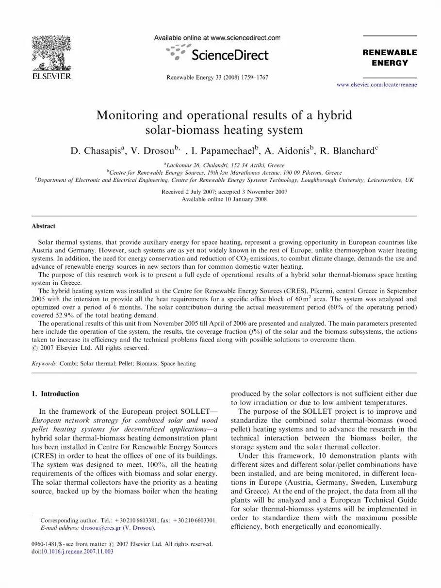
Fig. 2. Hybrid solar thermal-biomass space heating system at CRES.
(Schematic diagram from the data Logging program at 21/11/05 at
13:42:05h. All the circuits and the biomass burner are in operation.)
D. Chasapis et al. / Renewable Energy 33 (2008) 1759–17671760
2. Combi systems—the status in Europe and Greece
Although solar thermal systems for combined domestichot water preparation and space heating (called ‘‘solarcombisystems’’ or simply ‘‘combi’’) are not widely known inGreece, they are rapidly developing in other Europeancountries like Austria and Germany. Specifically, in 2001 thetotal installed area of solar thermal collectors for combisystems in eight European countries (Germany, Austria,France, Holland, Switzerland, Sweden, Denmark andNorway) [1] was equal to 340,000m2. If an average collectorarea of 15m2 per system is assumed, that equals to about22,600 installed combi systems in the mentioned countries.
According to Aidonis et al. [2], the simulations forGreece showed that the combi systems can be combinedwith the conventional heating systems, giving highenergetic results and solar coverage of the total heatingload that can reach 40–50%. Similar results have beenpresented from Argiriou et al. [3] in a simulation of threesystems in Northern Greece.
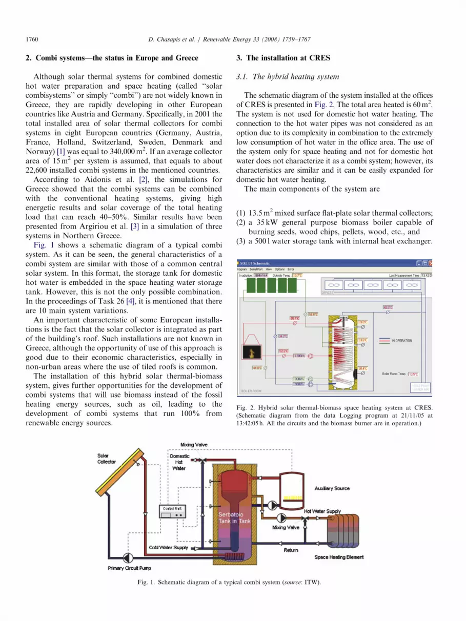
Fig. 1 shows a schematic diagram of a typical combisystem. As it can be seen, the general characteristics of acombi system are similar with those of a common centralsolar system. In this format, the storage tank for domestichot water is embedded in the space heating water storagetank. However, this is not the only possible combination.In the proceedings of Task 26 [4], it is mentioned that thereare 10 main system variations.
An important characteristic of some European installa-tions is the fact that the solar collector is integrated as partof the building’s roof. Such installations are not known inGreece, although the opportunity of use of this approach isgood due to their economic characteristics, especially innon-urban areas where the use of tiled roofs is common.
The installation of this hybrid solar thermal-biomasssystem, gives further opportunities for the development ofcombi systems that will use biomass instead of the fossilheating energy sources, such as oil, leading to thedevelopment of combi systems that run 100% fromrenewable energy sources.
Fig. 1. Schematic diagram of a typi
3. The installation at CRES
3.1. The hybrid heating system
The schematic diagram of the system installed at the officesof CRES is presented in Fig. 2. The total area heated is 60m2.The system is not used for domestic hot water heating. Theconnection to the hot water pipes was not considered as anoption due to its complexity in combination to the extremelylow consumption of hot water in the office area. The use ofthe system only for space heating and not for domestic hotwater does not characterize it as a combi system; however, itscharacteristics are similar and it can be easily expanded fordomestic hot water heating.The main components of the system are
(1)
cal c
13.5m2 mixed surface flat-plate solar thermal collectors;
(2) a 35 kW general purpose biomass boiler capable ofburning seeds, wood chips, pellets, wood, etc., and
(3) a 500 l water storage tank with internal heat exchanger.ombi system (source: ITW).
ARTICLE IN PRESSD. Chasapis et al. / Renewable Energy 33 (2008) 1759–1767 1761
All the components are made by Greek manufacturingcompanies. One important requirement, according to the
1The pyranometer used for the measurement of the incident irradiation
is made by NES, model SOZ-03 (http://www.nes-datalogger.de/produkte_
soz03.htm). Its main characteristics are 50� 50mm2 mono-crystalline
silicon cell Class 1 pyranometer; measuring range, 50–1500W/m2;
accuracy, 710% at 1000W/m2; long-term drift, o1%/year.
SOLLET project’s specifications, is that all the componentsused must be available in the local market (in the case ofCRES in the Greek market).
3.1.1. Solar collectors
Five flat-plate collectors, with selective absorber and a2.7m2 gross surface area each, were used for the collectionof solar energy. The collectors have been installed facingsouth and inclined at an angle of 601 from the horizon formaximum gain during winter collection.
According to the study of Aidonis et al. [2] for a well-insulated house in Athens and for a 15% collector area/heating area, the solar contribution for space heating canreach 37% of the total requirements. Similar results havebeen presented from Argiriou et al. [3]. The dimensioningof the solar collector was initially based on theseestimations, with an expected solar coverage of at least40%. The heat from the collectors is transferred to waterthrough a heat exchanger located inside the storage tank.
Special attention has been given to the dimensioning ofthe expansion tank in order to be able to cope withstagnation during the summer period when, although thedemand is zero, the gain is maximum.
3.1.2. Biomass heating
During days that solar energy is not adequate, thesystem is backed up by the biomass boiler. The burnerrequires manual ignition and ash removal. The biomassboiler directly heats the water of the space heating circuit.
3.1.3. Water storage tank
A 500 l storage tank with two internal heat exchangers isused for the storage of the hot water. The heat exchangersare located one on the top and one on the bottom of thetank and they are both connected to the solar collectors’circuit.
3.1.4. Space heating circuit
The output of the hot water has been connected to thepreviously existing heating system of five fan coils suppliedby a heat pump. The supply of the hot water is achievedthrough a triode-mixing valve, so that the supplied watertemperature is kept constant at 55 1C.
3.1.5. Control system
As it has already been mentioned, the primary energysource is solar. The control of the solar circuit is carried outby a common differential thermostat (set at 71 temperaturedifference) used in the control of solar thermal systems.There is the possibility for the user to manually select thehot water entrance by the solar collectors at the wholelength or the bottom of the heat exchanger.
The control of the biomass circuit is achieved by anelectronic thermostat, with adjustable hysteresis, posi-tioned at 3/4 of the storage tank’s height. During days
with low solar radiation, when the temperature of the waterin the storage tank drops below a defined limit of 45 1C, thepump of the biomass circuit is activated to assist theheating until the water reaches a temperature of 68 1C. Alocal thermostat at the biomass boiler keeps the boiler’sheat exchange system at 70 1C.
3.2. The monitoring system
The installed data logging unit monitors
�
the flow, � the supply and return temperatures of each circuit, � the water temperature at three points of the storagetank,
� the external temperature, and � the temperature at the boiler’s room.In addition, the incident solar irradiation1 and thebiomass boilers burning time are recorded. Measurementsare recorded at every minute during 24 h.The data logging unit has been supplied by the control
office in Germany where the measurements arerecorded daily for post-processing. A main requirementby CRES was to have a real-time monitoring systemfor demonstration purposes. The data logger had to bemodified therefore, and a second interface was constructedthat sends the measurements in real time to a PCrunning Windows XP at the boiler room. A respectivemonitoring software was developed (in Visual Basic)which takes the measurements, processes them anddisplays them on a schematic diagram. At the same time,several graphs are plotted in real time that shows theoperation and performance of the system. These plots areas follows:
�
a general temperature variation plot that gives arough indication of the system’s operation. Thesetemperatures are the solar collectors to storagetemperature, the fan coils return temperature, thebiomass boiler to storage temperature, the temperatureat the top of the storage tank and the outside airtemperature; � a plot of the solar energy produced (Q solar) and totalenergy consumed (Q consumed);
� a solar circuit temperature variation plot that includesthe supply and return temperatures as well as theincident solar irradiation;
� a biomass circuit temperature variation plot thatincludes the supply and return temperatures, thebiomass circuits pump operation and the biomassburner’s operation;
ARTICLE IN PRESSD. Chasapis et al. / Renewable Energy 33 (2008) 1759–17671762
�
a fan coil circuit temperature variation plot that includesthe supply and return temperatures as well as theexternal air temperature; and � a storage tank temperature variation plot that includesthe water’s temperature at the bottom, the middle andthe top of the storage tank, as well as the boilers roomair temperature.
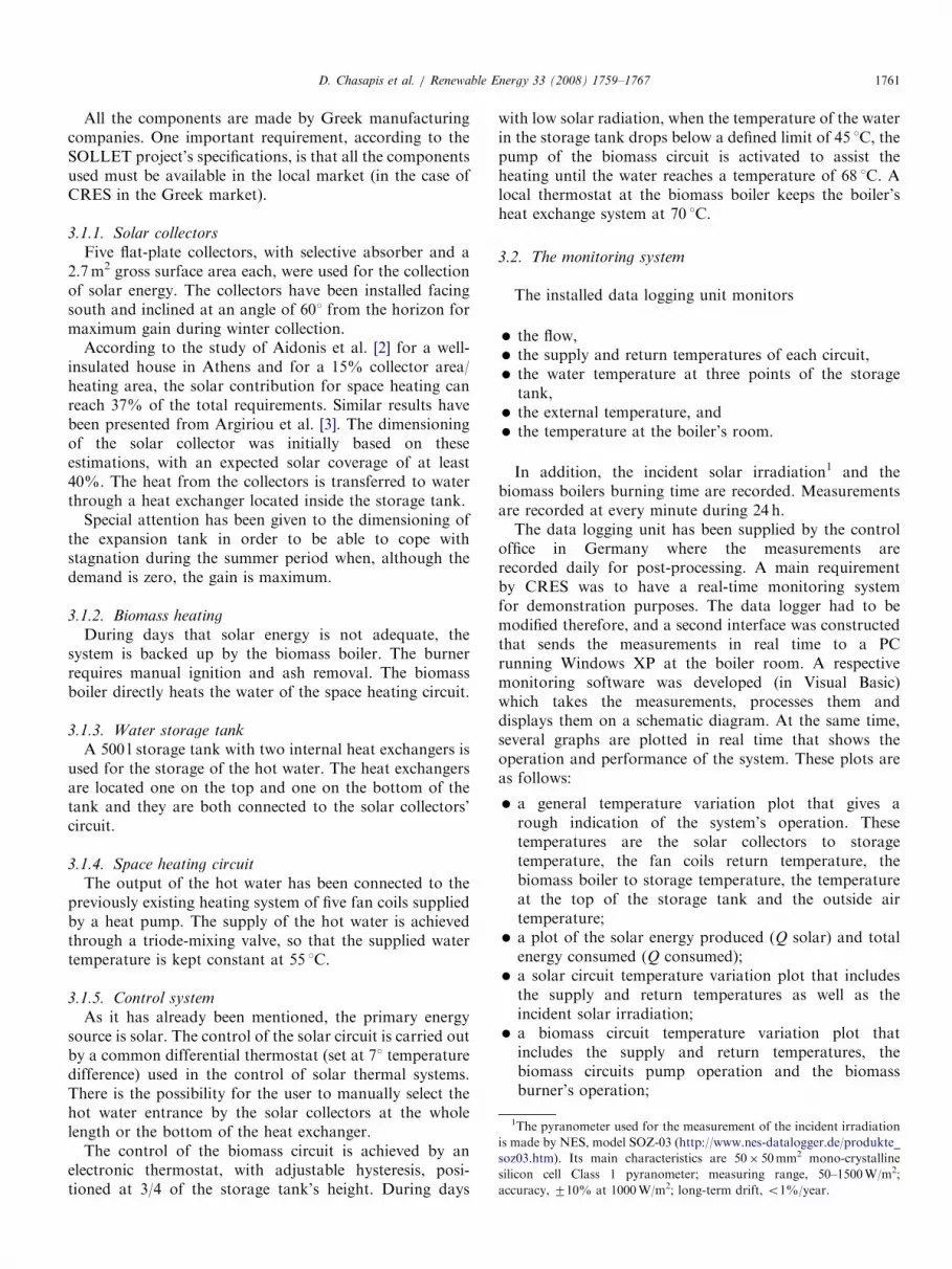
Fig. 3. Daily temperature variation, solar energy gain (Q
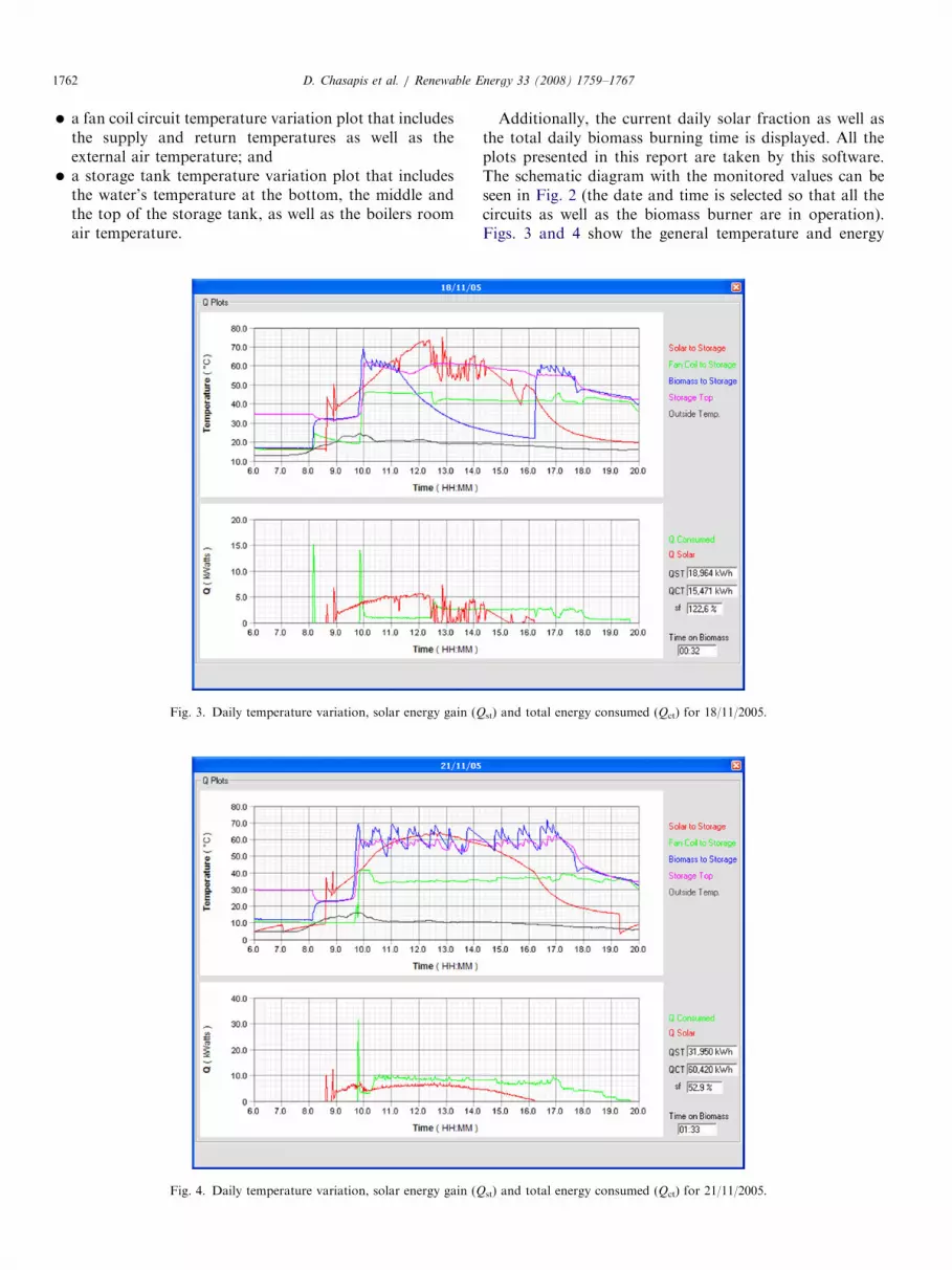
Fig. 4. Daily temperature variation, solar energy gain (Q
Additionally, the current daily solar fraction as well asthe total daily biomass burning time is displayed. All the
plots presented in this report are taken by this software.The schematic diagram with the monitored values can beseen in Fig. 2 (the date and time is selected so that all thecircuits as well as the biomass burner are in operation).Figs. 3 and 4 show the general temperature and energyst) and total energy consumed (Qct) for 18/11/2005.
st) and total energy consumed (Qct) for 21/11/2005.

ARTICLE IN PRESS
Fig. 5. Temperature variations before the biomass circuit’s thermostat
replacement. (Biomass burning can be seen on the second plot with blue
color.)
D. Chasapis et al. / Renewable Energy 33 (2008) 1759–1767 1763
variation plots, and Figs. 5 and 6 show the individualcircuit’s variation plots.
4. System’s operation and optimization
4.1. System’s operation
The system’s operation demand is 5 days per week from9:30 h in the morning till about 20:00 h in the evening.When there is no heating need from the biomass backupcircuit, a timer installed in the biomass control circuitoperates the burner periodically, for 15min at every 3.5 h,to preserve the required glowing embers for automaticignition.
Figs. 3 and 4 show the system’s operation for twotypical days (18/11/2005 and 21/11/2005). On 18/11/2005,the profile is characterized by high solar radiation(4.38 kWhm�2) and mid-external temperature (19.5 1C),while on 21/11/2005 the profile is characterized by highsolar radiation (5.97 kWhm�2) and low external tempera-ture (10.7 1C). The combination of these characteristics(days with high solar radiation and low external tempera-ture) compose the ideal operating conditions for thesystem.
The solar energy produced those days was 18.96 and31.95 kWh, respectively. Despite the fact that the solarenergy was lower at 18/11/2005 due to the higher externaltemperature the system was able to supply all the required
heating energy (15.47 kWh). At 21/11/05 that the externaltemperature was low the solar system was able to supply52.9% of the required heating energy (60.42 kWh).Due to the use of the system in offices, there is the need
for heating early in the morning, so biomass backup isrequired even on days with high irradiation to recovernightly heat losses. At 18/11/2005 despite the fact that thesolar energy gain was enough to cover the total heatingenergy requirements, the biomass burner had to operate for32min. At 21/11/2005 that the energy requirements wherehigh, the biomass burning was kept at 1 h and 33min.
4.2. System’s optimization
At the initial stage of operation, the control of thebiomass circuit was implemented using a common mechan-ical thermostat set at 60 1C.This setting caused multiple short biomass ignitions, in
totally cloudy days, since the water temperature at the topof the storage tank had to be kept at 6072 1C. Thisoperation reduces the biomass burner’s efficiency andincreases the emissions.Additionally, during partial cloudy days (with cloud of
more than 5min and associated reduction in solarradiation), when the temperature of the water in thestorage tank dropped below 58 1C the low hysteresis of themechanical thermostat initiated the pump’s operation, as itcan be seen in Fig. 5. Most of the times, the biomasscontribution was not required since the duration of thecloud existence was not enough to lower the temperature ofthe water in the storage tank below the required 40 1C forthe fan coils operation. This led to a reduced energycontribution from the solar collectors. (According to thecalculated temperature drop rate, the storage can supplythe fan coils on average from 45min to 1 h and 20min,depending on the daily heating requirements, with aninitial water temperature in the storage tank of 65 1C.)The solution to this problem was provided by replacing
the mechanical thermostat that controlled the biomasscircuit with an electronic one with programmable hyster-esis. With the new control, the biomass circuit operateswhen the temperature of the water in the storage tankdrops below 45 1C and until the water is heated up to 60 1C.As a result, the burner does not operate during short
cloudy periods and the multiple short ignitions have beenlimited to less frequent and longer lasting burnings that aremore efficient and less polluting. In addition, higherefficiency from the solar collectors has been achieved dueto the lower temperatures and the better stratification as itcan be seen in Fig. 6.During January, due to the extreme low ambient
temperatures, there was need for faster heating in the earlymorning hours. The temperature of the water that suppliedthe fan coils had, therefore, to be raised to 55 1C. In orderto be able to cope with this high temperature, the uppersetting for the biomass circuit control has been increasedfrom 60 to 68 1C.

ARTICLE IN PRESS
Fig. 6. Temperature variations after the biomass circuit’s thermostat replacement. (Biomass burnings can be seen on the second plot with blue color.)
D. Chasapis et al. / Renewable Energy 33 (2008) 1759–17671764
4.3. Automatic ignition roundabout
During the initial operation of the system, due to thelack of automatic ignition, the biomass boiler was shutdown at 17:30 h in the afternoon when the last personinvolved with the system left the boiler’s room and a pieceof wood was placed in the fireplace to create burning coalto ignite the biomass the next morning. For safety reasons(complete coal burning, failed ignition, etc.), the ignition ofthe boiler was carried out when an operator was present.Unfortunately, on days with high irradiation where thebiomass burner’s backup was not necessary until late in theafternoon, the coal had been fully burned resulting infailure of biomass ignition.
In order to resolve this problem as well as to fullyautomize the operation of the system, a timer was installedin the biomass burner’s control circuit that forces a 5minburning every 3 h (in a 24 h base). As a result, automaticignition is achieved with a negligible increase in consump-tion. Furthermore, the biomass burner’s operation wasextended until 20:00 h that the space heating was turned
off. After this modification, the system operated auto-matically without the user’s interference.
4.4. Thermodynamics analysis
4.4.1. Heat transfer calculations
For the calculation of the heat transferred (Q)from the solar, the biomass and the fan coils circuits, theflow (q) and the supply and return temperatures (ts and tr)for each circuit have been measured. From these measure-ments, the heat transfer was calculated using the generalformula:
Q ¼ q� cp � p� ðtr � tsÞ � 1:163� 10�3, (1)
where Q is the heat transferred (kW); q the flow in (l h�1);cp the specific heat capacity of the medium used(kcal kg�1 1C�1); p the density of the medium (kg l�1); trthe return temperature in (1C) and ts is the supplytemperature (1C).The solar thermal collector circuit is filled up with a
mixture of water and propylene–glycol (35–40%) to

ARTICLE IN PRESSD. Chasapis et al. / Renewable Energy 33 (2008) 1759–1767 1765
prevent the water from freezing during the winter period.The biomass boiler circuit and the fan coils circuit usewater as heat transfer medium. In order to simplify the heattransfer calculations, both the density and the specific heatcapacity of the water and the water/propylene–glycerolmixture have been assumed to be constant throughout thewhole temperature range.
The specific heat capacity of the water/propylene–glycerol mixture has been taken to be equal to 4kJkg�1K�1,or 0.9554 kcal kg�1 1C�1, while its density equal to1.01 kg l�1. Respectively, the specific heat capacity of thewater has been taken to be equal to 1 kcal kg�1 1C�1 and itsdensity equal to 1 kg l�1.
4.4.2. Energy calculation
The daily energy transfer has been calculated byintegrating the heat transferred using the Trapezoidalintegration method every 1min.
Fig. 8. Solar coverage fraction (f%), solar irradiation (Gav) and average extern
20:00 h.)
Fig. 7. Solar energy produced (SEP) an
4.4.3. Solar coverage fraction calculation
The solar coverage fraction has been calculated as thepercentage of the solar energy gain to the consumedenergy. The formula used for this calculation is
f ð%Þ ¼Qst
Qct
� �� 100, (2)
where f is the solar fraction (%); Qst is the solar energyproduced (kW) and Qct is the energy consumed (kW).
4.5. Operational results
The system’s operation started in October 2005 whilethe systematic monitoring and data analysis started inNovember. The operational results till the end of April areshown in Figs. 7 and 8. A problem with the flow-metersensors prevented the measurement of credible values fromthe 10th of December till the 8th of February, so the resultsfor this period as well as the weekends that the system did
al temperature (Tav). (The mean values have been calculated from 6:00 till
d total energy consumption (TEP).

ARTICLE IN PRESS
Table 1
Monthly operational results
Month Measuring
period (%)
Solar
fraction
(f%)
Solar energy
produced
(kWh)
Total energy
consumed
(kWh)
November 97 37.0 265.3 717.5
December 23 48.0 64.6 134.8
January 0 – – –
February 57 46.4 180.8 389.9
March 90 53.6 349.6 652.6
April 93 113.5 265.8 234.2
Total 60 52.9 1126.21 2129.10
D. Chasapis et al. / Renewable Energy 33 (2008) 1759–17671766
not operate, are not presented. The average solar coveragefraction for the measurement period was 52.9% with anaverage external temperature of 17.4 1C. Analytically, theactual measurement period for each month (as a percen-tage of the total month’s operational time), the solarcoverage fraction, the solar heating energy produced andthe total energy consumed for each month can be seen inTable 1.
A significant factor which affects the whole system’soperation is the biomass burner used that has a relativelylow efficiency when burning pellets (�72%). This isbecause it is designed to use all the available biomass fuelsgiving the opportunity to take advantage of the low cost ofseasonal biomass (the boiler was chosen due to its Greekmarket availability according to the SOLLET project’srequirements). Furthermore, its heat capacity is muchhigher than the energy requirements of the offices since thiswas the smallest available unit at the time of purchase (thenormal required burner capacity is 17 kW).
It should be noted that there is no local pelletsproduction in Greece. The supply of the biomass for theoperation of the system was imported from Italy with anexpected high purchase cost. The cost for the 15 kg pelletsbag was 340 h tonne�1. Theoretically, if there was a localproduction of pellets in Greece, this cost would have beenreduced by 29% (the mean European price for the 15 kgbag is 240 h tonne�1).2
If a smaller capacity pellet optimized burner was used(with average efficiency of 90%), as well as bulk pellets—and not bags—with an average mean value of165 h tonne�1 the daily cost would be notably reduced.
5. Conclusions
For the evaluation of the conclusions, it is important tomention that the results regard just space heating.Additionally, the use of the system is limited in officehours and days. Those exclude weekends and night.Unfortunately, the data for half of December and all ofJanuary are missing at a time that would be expected to
2The prices for the biomass are taken from the European Pellet Centre
http://www.pelletcentre.info.
reduce the overall solar coverage fraction. If the system wasused for domestic hot water as well, its efficiency wouldhave been noticeably increased as has been reported inprevious studies [2].The main advantage of a hybrid solar thermal-biomass
heating system is that it can be combined with conventionalheating means (like radiators, fan coils, floor heating, etc.);therefore, it can be easily integrated in any existing heatingsystem replacing the conventional heating source (e.g., oil).The combination of such systems with the burn of
biomass, constitute form an energetic perspective a veryattractive and feasible option for a 100% renewabledomestic hot water and space heating system. The pelletfuel is convenient to use, with similarities to that of fossilsources (transportation, storage, etc.). Additionally, thepromotion of local pellet supply production could intro-duce a price reduction, to the benefit of the local economy.The results are promising with respect to the technology
and energy requirements: the daily coverage of the heatingfrom the solar collectors often exceeded 40%. The CO2
emissions avoided by the use of this system up until the endof April 2006 have been calculated as 1.016 tonnes.3
Due to the technical problems with the data loggingsystem, an economic evaluation of the system’s operationwas not feasible. By the end of the next heating periodwhen the technical problems will be overcome, aneconomic evaluation of the system operation is expectedto be feasible.Synoptically, we can conclude the following:
�
3
10.
The capacity and the type of the biomass burner are veryimportant for the economic operation of this system.Due to the non-existence of an alternative burner in theGreek market (at the time of the equipment purchase),the burner used is both super-sized and has a lowefficiency for pellet burning, as it was designed to use allthe available biomass fuels. Recently, specialized pelletburners have been introduced to the Greek market withmuch higher efficiencies and in a wider capacity range.
� Special care should be given to the dimensioning of theexpansion tank for the confrontation of the stagnationduring the summer period where the maximum solargain, coexist with zero demand.
� For higher system efficiency, the control of the biomassbackup circuit should be implemented with an electronicthermostat that allows for a wide hysteresis adjustment.
Finally, we must stress that for the successful spread ofsuch systems, it is important that they enter the marketafter the completion of all the testing and optimizationprocedures and standards as well as technical installationguides are published. This will minimize the risk oftechnical absurdities that, although easily overcome, canharm the reliability of this technology.
For the calculation of CO2 reduction, it is assumed that 1 toe produce
062kWhth and 1 toe 3.2 tonnes CO2 [5].

ARTICLE IN PRESSD. Chasapis et al. / Renewable Energy 33 (2008) 1759–1767 1767
References
[1] Weiss W. Solar heating systems—status and recent technology
developments. Goeteborg, Sweden: ISES Solar World Congress;
2003.
[2] Aidonis A, Drosou V, Karagiorgas M. Combi solar thermal systems
for combined space and domestic water heating. In: Proceedings of the
3rd national conference for the application of renewable energy
sources, NTU, RENES, Athens, 23–25 February.
[3] Argiriou N, et al. Active solar space heating of residential buildings in
northern Hellas—a case study. Energy Build 1996:215–21.
[4] Task 26, International Energy Agency—IEA. Solar combisystems,
solar heating & cooling programme, /http://www.iea-shc.orgS.
[5] Hellenic Republic—Ministry of Development, /http://www.ypan.grS.