Embed Size (px)
Citation preview

Accepted Manuscript
Model-Based Platform-Specific Co-Design Methodology for Dynamically Par‐
tially Reconfigurable Systems with Hardware Virtualization and Preemption
Chun-Hsian Huang, Pao-Ann Hsiung, Jih-Sheng Shen
PII: S1383-7621(10)00082-2
DOI: 10.1016/j.sysarc.2010.07.007
Reference: SYSARC 949
To appear in: Journal of Systems Architecture
Received Date: 15 October 2009
Revised Date: 16 April 2010
Accepted Date: 26 July 2010
Please cite this article as: C-H. Huang, P-A. Hsiung, J-S. Shen, Model-Based Platform-Specific Co-Design
Methodology for Dynamically Partially Reconfigurable Systems with Hardware Virtualization and Preemption,
Journal of Systems Architecture (2010), doi: 10.1016/j.sysarc.2010.07.007
This is a PDF file of an unedited manuscript that has been accepted for publication. As a service to our customers
we are providing this early version of the manuscript. The manuscript will undergo copyediting, typesetting, and
review of the resulting proof before it is published in its final form. Please note that during the production process
errors may be discovered which could affect the content, and all legal disclaimers that apply to the journal pertain.
Model-Based Platform-Specific Co-Design Methodology
for Dynamically Partially Reconfigurable Systems with
Hardware Virtualization and Preemption
Chun-Hsian Huang, Pao-Ann Hsiung∗, Jih-Sheng Shen
Department of Computer Science and Information EngineeringNational Chung Cheng University, Chiayi, Taiwan−621, ROC
Abstract
To facilitate the development of the dynamically partially reconfigurablesystem (DPRS), we propose a model-based platform-specific co-design (MPC)methodology for DPRS with hardware virtualization and preemption. ForDPRS analysis and validation, a model-based verification and estimationframework is proposed to make model-driven architecture (MDA) more re-alistic and applicable to the DPRS design. Considering inherent character-istics of DPRS and real-time system requirements, a semi-automatic modeltranslator converts the UML models of DPRS into timed automata modelswith transition urgency semantics for model checking. Furthermore, a UML-based hardware/software co-design platform (UCoP) can support the directinteraction between the UML models and the real hardware architecture.Compared to the existing estimation methods, UCoP can provide accurateand efficient platform-specific verification and estimation. We also proposea hierarchical design that consists of a hardware virtualization mechanismfor dynamically linking the device nodes, kernel modules, and on-demandreconfigurable hardware functions and a hardware preemption mechanismfor further increasing the utilization of hardware resources per unit time.Further, we realize a dynamically partially reconfigurable network securitysystem (DPRNSS) to show the applicability and practicability of the MPCmethodology. The DPRNSS can not only dynamically adapt some of its hard-ware functions at run-time to meet different system requirements, but also
∗Corresponding author: Tel.: +886-5-272-0411 ext. 33119; Fax: +886-5-272-0859;E-mail address: [email protected] (Pao-Ann Hsiung)
Preprint submitted to Journal of Systems Architecture August 13, 2010
determine which mechanism will be used. Our experiments also demonstratethat the hardware virtualization mechanism can save the overall system exe-cution time up to 12.8% and the hardware preemption mechanism can reduceup to 41.3% of the time required by reconfiguration-based methods.
Keywords: UML, dynamically partially reconfigurable system,hardware/software co-design
1. Introduction
FPGA devices, such as Xilinx Virtex II/II Pro, Virtex 4, and Virtex 5, canbe partially reconfigured at run-time, which means that one part of the de-vice can be reconfigured while other parts remain operational without beingaffected by reconfiguration. Through dynamic partial reconfiguration, moreand more applications can be accelerated in hardware at run-time, thus ef-fectively reducing the overall system execution time [34]. Furthermore, muchmore computing intensive applications can be executed as hardware functionsrunning on an FPGA, even though the total logic resource requirements ofall hardware functions are more than those of the used FPGA devices. Ahardware/software embedded system realized with such an FPGA device iscalled a Dynamically Partially Reconfigurable System (DPRS) that can dy-namically adapt some of its hardware functions at run-time to meet differentsystem requirements.
Through the partial reconfiguration technology, the hardware functionscan be also executed as hardware tasks in an embedded operating system,similar to software tasks that can be dynamically created and removed atrun-time. Such an embedded operating system that supports the DPRS ar-chitecture is called an Operating System for Reconfigurable Systems (OS4RS),using which user applications can be executed as software tasks, hardwaretasks, or both according to system performance requirements. As a result,such an OS4RS design with the DPRS platform is a self-adaptable systemdesign, in which its functionalities can dynamically change without humanintervention [17].
Many existing hardware/software co-design methodologies [4, 5, 6, 12,23, 29, 31] have proposed different effective and innovative approaches forthe DPRS development; however, they only focus on parts of the DPRSdevelopment without supporting the full design and verification flow. As aresult, there still exist many gaps in the DPRS development, even though
2

they have many remarkable research results. Three main problems in mostexisting hardware/software co-design DPRS methodologies are described asfollows.
1. Model-platform information gap: Most UML-based design methodolo-gies use time estimates for simulating the functional interactions be-tween applications and a system. Furthermore, the simulation-basedmethods cannot guarantee that all system behaviors are tested andcorrected. As a result, significantly more iterations are required forrectifying the system design, and the physical design correctness canbe verified and estimated only after the UML models are synthesizedinto concrete system designs.
2. Low system scalability: Reconfigurable hardware functions are usuallyindividually implemented at design-time without supporting a unifiedcommunication interface. Therefore, to incorporate hardware functionshaving different data interfaces with a DPRS at run-time becomes verydifficult, which does not only reduce system scalability but also in-creases development efforts.
3. Limitation in infrastructure support for DPRS: Reconfigurable hard-ware functions are usually managed as conventional hardware devicesin most DPRS design methodologies. Therefore, the enhancement ofsystem performance using partial reconfiguration technology is still lim-ited, and thus makes the utilization of reconfigurable hardware func-tions inefficient.
Besides enhancing parts of the DPRS development, if there is a morecomplete hardware/software co-design methodology covering effective sys-tem analysis, complete functionality verification, accurate performance es-timation, and scalable system implementation, system development effortscan be further reduced. This is the motivation and also the goal of thiswork, in which we propose a Model-based Platform-specific Co-design (MPC)methodology for dynamically partially reconfigurable systems with hardwarevirtualization and preemption. The contributions of this work are illustratedas follows.
• The UML models proposed in MPC are designed as reusable models,using which different user applications can be effectively developed,thus significantly saving design and analysis time. The detailed DPRS
3
behaviors specified by the UML models can be further used for model-level system verification and estimation, thus bridging the gap betweenhigh-level models and system implementation.
• To further enhance system scalability, the concept of the layered ap-proach is introduced in our OS4RS design. Within the hierarchicalOS4RS design, we also propose a unified communication mechanism tostandardize the hardware/software communication interface such thatnew hardware functions can be easily integrated with an OS4RS.
• Instead of the one-to-one relation between a device node, a kernel mod-ule, and a hardware function in an embedded operating system, wepropose a hardware virtualization mechanism to effectively manage thekernel resources of an operating system and the hardware logics. Thus,it is now a many-to-one or one-to-many mapping between the hardwarefunctions configured on the FPGA and the software applications in theOS4RS user space. Using the hardware virtualization mechanism, ahardware function configured on the FPGA is virtualized such that itcan be accessed by more than one application at the same time. Fur-ther, the processing results of a reconfigurable hardware function canbe directly transferred to another in the kernel space, without a largetime overhead in repeatedly transferring data between the user spaceand the kernel space.
• We propose generic wrapper designs that can be used by hardwarefunctions for supporting dynamic swapping. As a result, high-priorityhardware tasks can interrupt low-priority hardware tasks in real-timeonline system environments, which can further increase the utilizationof hardware logics.
The rest of the article is organized as follows. Section 2 discusses therelated DPRS design methodologies. The introduction of a DPRS design isgiven in Section 3. Sections 4 introduces the proposed MPC methodology,where Sections 4.1, 4.2, and 4.3 give the details of design and modeling,verification and estimation, and system implementation phases, respectively.The related experimental results and analysis are described in Section 5.Finally, conclusions are described in Section 6.
4

2. Related Work
Similar to the development of a conventional embedded system, that ofa DPRS covers three main phases, including design and modeling, verifica-tion and estimation, and system implementation phases. In the design andmodeling phase, Steinbach et al. [4] proposed a complete UML-based designmethodology for reconfigurable architectures to efficiently analyze the inter-actions between all DPRS components. Furthermore, the UML-based designmethodology included a model compiler that can help designers to translatethe system-level specifications of reconfigurable architectures into executableapplications. Schattkowsky et al. [31] also proposed a model-based approachfor executable UML to close the gap between the system specification and itsmodel-based execution on reconfigurable hardware. The UML specificationscan be compiled to binary representations that were directly executed ontheir proposed abstract machine platform.
In the verification and estimation phase, besides the functional verifica-tion of a hardware design using RTL simulation, the interactions among allDPRS components are usually simulated and then verified using the SystemClanguage. The DPRS design methodology proposed by ITIV [5] included aSystemC-based approach [7] for modeling and simulating the DPRS. Basedon the Register Transfer Level (RTL) SystemC, they implemented the spe-cific operations for dynamic partial reconfiguration in the SystemC kernel.The DPRS design methodology proposed by DRESD [29] also included aSystemC-based design exploration framework [3], where the system function-alities were described using the Transaction Level Modeling (TLM) techniqueand mapped to a real system architecture. Instead of system verification us-ing only simulation, an integrated design and verification methodology calledSymbad [6] first described a reconfigurable system using SystemC for func-tional simulation. To exhaustively validate system correctness, the systemdescriptions using SystemC were then abstracted for formal verification. Asa result, a DPRS could be more effectively and completely validated throughboth simulation and formal verification. The above verification approaches[3, 6, 7] only simulated the functional interactions between applications anda system, thus the physical design correctness of the system could be veri-fied only after the high-level system models were synthesized into concretesystem designs. The DPRS design methodology proposed by ITIV furtherincluded a model-level debugger [11] that integrated the Matlab Stateflowmodels with its target system. By using the JTAG cable, users can debug
5
their configured system at the graphical model-level.In the system implementation phase, besides the standalone DPRS ar-
chitecture, the OS4RS design was integrated into the DPRS design method-ologies [12, 26]. Thus, reconfigurable hardware functions are executed assoftware applications that can be dynamically created and removed. Fur-ther, the INDRA design methodology [12] proposed a hierarchical dynami-cally reconfigurable system that facilitates the design of a suitable on-chipcommunication infrastructure for partially reconfigurable systems. Dynamicswitching or relocation of hardware designs in reconfigurable logic has alsobeen proposed in the INDRA design methodology to enable the preemptionof low-priority hardware tasks by high-priority hardware tasks in real-timeonline system environments.
Similar to the UML-based DPRS design methodologies [4, 31], the MPCmethodology adopts the MDA-based UML approach to make the DPRS de-sign more realistic and applicable in an industrial setting. However, differentfrom the UML-based DPRS design methodologies [4, 31] that focused on thefunctional code generation with poor support for design-space exploration,the MPC methodology includes a complete and effective verification and es-timation for a DPRS design.
Instead of only being able to simulate partial system behaviors, suchas the SystemC-based methods [3, 7], the MPC methodology uses formalverification for exhaustively verifying the functional interactions between userapplications and a DPRS. Furthermore, though the SymbC methodology [6]used model checking for exhaustive verification, translating the SystemCdescriptions of a DPRS for model checking was not intuitive enough becausethey are based on different design points of view. In contrast, the verificationand estimation phase in the MPC methodology is completely model-based,and thus the UML-based system specifications can be more intuitively andeasily translated into timed automata for model checking. For the physical-aware verification and estimation, the model-level debugger [11] needed tosuspend its model execution while reading the system state for debugging.However, the MPC methodology proposes a UML-based hardware/softwareCo-design Platform (UCoP) that not only enables the user-specified UMLmodels to directly interact with the real system hardware architecture, butalso supports for real-time tracing of the functional interactions betweenapplications and a system.
For system implementation, the reconfiguration-based hardware preemp-tion of INDRA [22] that required readback support from the reconfigurable
6

Microprocessor
Operating System
Microprocessor
p g y
HW/SW Communication Interface
PRR1FPGA ConfigurationPRR1 Controller
HW Communication Architecture
PRR2
HW Communication Architecture
OtherPRR2 Peripherals
(a) SoB-based DPRS Design
MiFPGA
Operating
Microprocessor
ConfigurationSystem
gController
HW/SW Communication Interface
OtherPRR1 PRR2
OtherPeripherals
(b) SoC-based DPRS Design
Figure 1: SoB-based and SoC-based DPRS Designs
logic and deep knowledge of the reconfiguration process for tasks, such asstate extraction from the readback stream and manipulation of the bitstreamsfor context restoring. Another drawback is the poor data efficiency becauseonly a maximum of about 8% of the readback data actually contains stateinformation but all data must be readback to extract the state [22]. Differentfrom the reconfiguration-based method [22], the MPC methodology adoptsthe design-based method that is self-sufficient because all context switchingtasks are taken care of by the hardware design itself through a switching cir-cuitry and registers can be read out or preloaded by the switching circuitry.The MPC methodology proposes two basic wrapper designs with differentstandard interfaces such that any digital hardware design following the stan-dard can be transformed into dynamically switchable by interfacing with thewrappers. Further, reconfigurable hardware functions were managed as con-ventional hardware devices in most of the OS4RS design [12, 26], and thusthe utilization of reconfigurable hardware functions is still limited. To fur-ther enhance the utilization of reconfigurable hardware functions, the MPCmethodology proposes a hardware virtualization mechanism that enables thevirtualization of a reconfigurable hardware function to support more thantwo software applications. The details of the MPC methodology will beintroduced in Section 4.
7

3. Dynamically Partially Reconfigurable System
Before introducing the proposed MPC methodology, we first introduce thedesign of a dynamically partially reconfigurable system (DPRS). A DPRS is ahardware/software embedded system capable of reconfiguring new hardwarefunctions into the system at run-time, and mainly consists of a microproces-sor, an FPGA, and a hardware/software communication interface. Two typesof the DPRS architecture designs, namely System-on-Board (SoB)-based de-sign and System-on-Chip (SoC)-based design as illustrated in Figure 1(a) andFigure 1(b), respectively, can be developed. The main difference between theSoB-based design and the SoC-based design depends on whether the micro-processor is a separate chip device or is a core embedded within the FPGAdevice.
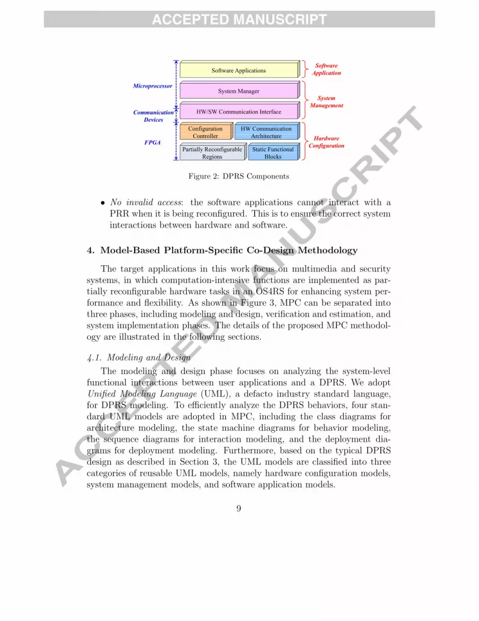
According to the DPRS architecture design, we can classify the DPRScomponents into three main categories, including hardware configuration,system management, and software application as shown in Figure 2. Thehardware configuration category contains all the static and reconfigurablehardware components. The reconfigurable components in an FPGA consistsof several slots called Partially Reconfigurable Regions (PRRs), which can bereconfigured into different hardware functions at run-time. The static compo-nents that cannot be reconfigured at run-time in an FPGA includes the staticfunctional blocks (other peripherals in Figure 1(a) and Figure 1(b)), a hard-ware communication architecture that connects all hardware components inan FPGA, and a configuration controller, such as Internal ConfigurationAccess Port (ICAP) or SelectMap embedded in the FPGA for configuringthe partial bitstreams into PRRs. The system management components areresponsible for managing the control and data transfers between hardwareand software in a DPRS. It mainly includes a system manager and a hard-ware/software communication interface which includes the device drivers forhardware and system communication devices, such as Peripheral ComponentInterconnect (PCI) in the SoB-based DPRS design, or a system bus in theSoC-based DPRS design. The software application category includes all user-specified application functions. When we design a DPRS, there are mainlytwo physical constraints imposed by the partial reconfiguration technologyas described in the following.
• Mutual exclusion: only one hardware function can be configured at atime into a PRR; only one PRR can be reconfigured at a time. This isthe constraint imposed by the current FPGA devices.
8
Software ApplicationsSoftware
Application
System ManagerSystem
Microprocessor
HW/SW Communication Interface
SystemManagement
Communication
ConfigurationC ll
HW Communication A hi
Devices
Controller Architecture
Partially Reconfigurable Static Functional
HardwareConfigurationFPGA
y gRegions Blocks
Figure 2: DPRS Components
• No invalid access: the software applications cannot interact with aPRR when it is being reconfigured. This is to ensure the correct systeminteractions between hardware and software.
4. Model-Based Platform-Specific Co-Design Methodology
The target applications in this work focus on multimedia and securitysystems, in which computation-intensive functions are implemented as par-tially reconfigurable hardware tasks in an OS4RS for enhancing system per-formance and flexibility. As shown in Figure 3, MPC can be separated intothree phases, including modeling and design, verification and estimation, andsystem implementation phases. The details of the proposed MPC methodol-ogy are illustrated in the following sections.
4.1. Modeling and Design
The modeling and design phase focuses on analyzing the system-levelfunctional interactions between user applications and a DPRS. We adoptUnified Modeling Language (UML), a defacto industry standard language,for DPRS modeling. To efficiently analyze the DPRS behaviors, four stan-dard UML models are adopted in MPC, including the class diagrams forarchitecture modeling, the state machine diagrams for behavior modeling,the sequence diagrams for interaction modeling, and the deployment dia-grams for deployment modeling. Furthermore, based on the typical DPRSdesign as described in Section 3, the UML models are classified into threecategories of reusable UML models, namely hardware configuration models,system management models, and software application models.
9

ApplicationSystem
Specification ModelChecking
M t
Function
Application
UML UC P
Interface
Management
Modeling UCoP
Configuration
Communication
M d li d Verification and SModeling andDesign
Verification andEstimation
SystemImplementation
Figure 3: Model-Based Platform-Specific Co-Design Methodology
Based on the three categories of UML models, MPC provides basic UMLdiagram patterns for designers to model their DPRS architecture and appli-cations. As illustrated by the class diagram of MPC in Figure 4, the hardwareconfiguration models include the ReconfigHW and StaticHW classes which areresponsible for configuring the hardware functions into the PRRs and the sta-tic area, respectively, in an FPGA. The system management models includethe SystemManager and ConfigManager classes which are responsible formanaging all control and data transfers in a DPRS and all FPGA configura-tion, respectively. The software application models include the Interactor
and UserDefined classes which are responsible for providing the interac-tive interface between software applications and hardware functions, and theuser-defined application, respectively. Besides modeling the functional rela-tionships in a DPRS using the class diagram, MPC also provides state ma-chine design patterns for the classes SystemManager, ConfigManager, andInteractor to model a new application-specific component. On applyingthe design patterns, the user-customized UML models are used to describethe functional behaviors of a DPRS, without any platform-related informa-tion, such as hardware configuration and execution time. Henceforth, we callthem functional UML models.
4.2. Verification and Estimation
The verification and estimation phase focuses on supporting an efficientverification and accurate estimation mechanism, where the UML modelsspecified at the modeling and design phase are adopted as input modelsof this phase. Thus, designers can use their UML models to directly verifyand estimate their DPRS design, instead of performing the simulation for a
10

Hardware Configuration Software Application
System Management
Figure 4: Class Diagram of MPC
DPRS independent from their specified UML models.First, a formal verification method, model checking [9], is used to vali-
date the correctness of the DPRS functional behaviors. Using model check-ing, all system behaviors are first described as timed automata, which arethen merged into a global state graph by applying parallel composition toexhaustively validate the global system behaviors. However, the UML statemachine diagrams cannot be accepted as system model input by most modelcheckers, which can accept only flat automata model. Thus, we apply aflattening scheme [24] to transform the state concurrency and hierarchy inthe UML state machine diagrams into semantically equivalent constructs intimed automata. Further, to exhaustively validate the interactions betweenall DPRS components, partial reconfiguration requests in a user-given modelneed to be abstracted such that all combinations of reconfigurable hardwarefunctions are model checked. As a result, the transitions triggered by partialreconfiguration requests need to be distinguished from all the transitions inthe UML state machine diagram. We classify the transitions in the UMLstate machine diagrams into two types, namely reconfiguration and general.Reconfiguration transitions are triggered due to the partial reconfigurationrequirements, and general transitions are the other remaining transitions.A transition in the extended UML state machine diagram of MPC has thefollowing syntax:
Transition := Event [Guard] / Action 〈Type〉Event:= Event name
Guard:= Boolean Expression
Action:= Operation name (Arguments) [Duration, Deadline]
11

Type:= <Reconfiguration>, <General>An Event represents the occurrence of a stimulus to trigger a state tran-
sition, a Guard is a Boolean expression representing transition trigger, andan Action is an executable atomic operation having duration and deadlinethat results in a change in state.
The combination of simultaneously executing hardware functions in aDPRS changes with time and environment conditions. To model real-timesystem behaviors, the previously proposed urgency semantics [16] are appliedto TA, and thus transitions in such Extended Timed Automata (ETA) areassociated with urgency types, including lazy and eager. Lazy transitionsneed not be taken even if their triggers are satisfied, while eager transitionsare triggered as soon as possible. A transition in ETA of MPC has thefollowing syntax:
Transition := Condition / Assignment <Urgency>Condition:= Boolean Expression, Clock Constraint
Assignment:= Operation name, Clock Resetting
Urgency:= <Lazy>, <Eager>A Condition is a Boolean expression and/or a clock constraint that repre-
sents the transition trigger. An Assignment sets discrete variables to specificinteger values and/or resets clock variables.
The transitions in ETA are semi-automatically adapted to fit the DPRSfeatures and real-time system requirements using the model extensions. Theprocess of transition adaptation in ETA is in the following.
• If the type of a transition in the UML state machine diagram is recon-figuration, the triggering condition of the corresponding transition inETA is defined as True for direct triggering; otherwise, the triggeringevent and the guard of a transition in the UML state machine diagramare mapped to the triggering condition of the corresponding transitionin ETA. By making the reconfiguration transitions non-deterministic,all possible functional combinations of a DPRS are verified.
• If the type of a transition in the UML state machine diagram is re-configuration, the corresponding transition in ETA is associated withthe eager urgency type, so that real-time reconfiguration is correctlymodeled.
After translating user-given UML state machine diagram into ETA, themodel checker can perform a verification procedure for exhaustively searching
12

the state space of the design, and thus show if the system satisfies a user-specified property or violates it by giving a counterexample. The propertiesare specified using Computation Tree Logic (CTL) [13]. CTL properties, suchas EF , AF , AG, AU , can all be defined [13], and they are briefly introducedas follows, where p and q are atomic observations.
• Path qualifier: A, for all paths; E, for some paths.
• Temporal operators: Xp, p holds next time; Fp, p eventually holds inthe future; Gp, p always holds in the future; pUq, p holds until q holds.
Second, a UML-based hardware/software co-design platform (UCoP) [8,21] as shown in Figure 5 is used for physical-aware system verification and es-timation. To realize UCoP, we integrated the FPGA platform-specific libraryinto a UML modeling tool. The platform library consists of APIs for dataaccess by hardware designs and for the FPGA configuration control. Userscan invoke these platform APIs directly in the functional UML models cus-tomized in MPC, and thus the models can configure new hardware functionsinto the system and interact with them by sending/receiving data. The UMLmodels that consist of the functional UML models, platform APIs, softwareexecutables, and hardware bitstreams are thus called interactive UML mod-els in the PSV phase. As a result, UCoP allows accurate time measurementsof the total operation time, including the pure execution time of a processingiteration for a hardware design and the time overheads of data transfers overthe PCI bus, and the hardware configuration time, and real-time debugging,instead of only simulating the functional interactions between applicationsand a DPRS, which thus solves the problem of model-platform informationgap.
To ease the integration of user-designed hardware functions into theUCoP, a partially reconfigurable hardware task template (PR template) isproposed, which connects the user functions with the hardware communi-cation architecture. To use a newly developed hardware function in UCoP,a designer has to simply integrate the new hardware function with the PRtemplate because it provides a common communication interface between thehardware function and the rest of the system. The PR template implementsonly 32-bit wide signals for all kinds of data transfers. It consists of eight32-bit input data signals, one 32-bit input control signal, four 32-bit outputdata signals, and one 32-bit output control signal. The PR template also
13

HW/SW Communication Interface
Microprocessor
HardwareFunction
PR templatePRR1
HardwareFunction
PR templatePRR2
FPGA
Interactive UML ModelsOS
SoftwareApplication
SystemManagement
HardwareConfiguration
SoftwareExecutables
PlatformAPIs
HardwareBitstreams
Figure 5: UML-Based HW/SW Co-Design Platform
contains an optional data transformation component for unpacking incom-ing data and packing outgoing data based on the I/O registers sizes in thehardware functions.
To implement the DPRS architecture, the Early Access Partial Recon-figuration (EA PR) flow [34] from Xilinx that provides the most completesupport for partial reconfiguration technology in all industrial FPGA designsis used in UCoP. A DPRS hardware architecture consists of a static area andseveral PRRs. The static area design can be reused across different appli-cations, and is thus integrated into UCoP such that users can reuse it asrequired in different applications. Furthermore, the necessary commands forgenerating partial bitstreams are integrated by UCoP into a script file. Usersonly need to integrate their new hardware design with the PR template, syn-thesize it, and run the script, without explicitly and manually going throughthe last two phases of the PR implementation flow step-by-step. Using UCoP,users inexperienced in the partial reconfiguration technique can still easilyenhance their IP designs with the capability for partial reconfiguration andintegrate them into a DPRS. Therefore, UCoP supports not only the indus-trially standard UML modeling for system analysis but also the generation ofthe partial bitstream following the EA PR standard. Through the capabilityfor the direct interactions between the system models and real reconfigurablehardware designs, the PSV efforts can be thus significantly reduced.
Compared to the Matlab approach [11], UCoP supports real-time tracing
14

MicroprocessorOS
SW SW SW SW ApplicationApplication
OS
HW Control LibraryFunctionFunction
HW Task Management
dev/comm0 dev/comm2dev/comm1
ManagementManagement
dev/comm0 dev/comm2dev/comm1
module.o module.omodule.oInterfaceInterface
FPGAComm-Component0 Comm-Component1CommunicationCommunication
PRR0 PRR1PR Template PR TemplateConfigurationConfiguration
HW-IP Core HW-IP Coregg
Figure 6: Hierarchical OS4RS Design
without suspending model execution. Thus, developing a DPRS in UCoPis more efficient and accurate because not only the time-consuming hard-ware/software co-simulation, such as using the SystemC language, can beavoided, but also real-time tracing is provided for users to verify their DPRS.
4.3. System Implementation
The system implementation phase focuses on realizing the verified de-sign of a DPRS and further enhancing system scalability and performance.Similar to the OSI model used for computer network protocols, a layeredapproach is introduced in our OS4RS design that enhances the transparencyof system design through a hierarchical design. As a result, the design ofeach layer can be separately implemented and enhanced, which benefits thedevelopment of an OS4RS. As shown in Figure 6, our hierarchical OS4RSdesign consists of six layers, namely configuration, communication, interface,management, function, and application layers. The configuration and com-munication layers are implemented on the FPGA, while the other four layersare realized in the OS4RS running on a microprocessor. The details of eachlayer are described in the following sections.
15

4.3.1. Configuration layer
The configuration layer focuses on integrating new reconfigurable hard-ware functions in the FPGA. To standardize user-designed hardware func-tions having different data interfaces, the PR template [8] used in PSV isadopted to connect user-designed functions to the communication compo-nent designed in the communication layer. To further raise the utilization oflogic resources, different sizes of PRRs, which can be evaluated by the exitingmethod, such as the reconfiguration-aware floorplacer proposed by Montoneet al. [25], are implemented on the FPGA. As a result, each reconfigurablehardware function can be (re)configured into a best-fit PRR at run-time.
Another alternative is to use the proposed hardware preemption wrap-pers [18, 19] for enhancing hardware functions with the capability of dynamicswapping. Thus, high priority hardware tasks can interrupt low-priority tasksin real-time embedded systems to increase the utilization of hardware spaceper unit time. Further, the limitation in infrastructure support for DPRScan be improved. Two basic wrapper architectures, namely Last Interrupt-ible State Swap (LISS) wrapper and Next Interruptible State Swap (NISS)wrapper, are proposed for controlling the swapping of a hardware circuitinto and out from a reconfigurable logic, such that all swap circuitry is im-plemented within the wrappers with minimal changes to the hardware designitself. As shown in Figure 7, the wrapper architectures consist of a contextbuffer to store context data, a data path for data transfer, a swap controllerto manage the swap-out and swap-in activities, and some optional DTCs for(un)packing data types. The difference between the two wrappers lies in theswap-out mechanism and the hardware state in which the hardware designis swapped out. The LISS wrapper stores the hardware context at each in-terruptible state, thus the hardware design can be swapped out from thelast interruptible state whenever there is a swap request. The NISS wrapperrequires the hardware design execute until the next interruptible state, storethe context, and then swap out. The different swap-out processes and thesame swap-in process are described as follows.
• LISS wrapper swap-out: At every interruptible state, the context ofhardware IP is stored in a Context Buffer using the Wout State andWout cdata signals. When there is a Swap out request from the OS4RSfor some hardware task, the wrapper sends an Interrupt signal to themicroprocessor to notify the OS4RS that (1) the context data storedin the context buffer can be read and saved into the communication
16

Wrapper
Figure 7: Wrapper Design
memory, and (2) the resources (columns) can be deallocated and reused(reconfigured). The swap-out process is thus completed. This wrappercan be used for hardware circuits whose context data size is less thanthat of the context buffer, as a result of which all context data can bestored in the context buffer using a single data transfer.
• NISS wrapper swap-out: When there is a Swap out request from theOS4RS for some hardware task, the swap controller in the wrappersends a swap signal (asserted high), to the hardware design, which startsthe whole swap out process. However, the hardware design might bein an unswappable state, thus execution is allowed to continue untilthe next swappable state is reached. At a swappable state, the contextof hardware design, including current state information and selectedregister data, is stored in a context buffer in the wrapper using theWout State and Wout cdata signals. The hardware design then sendsan acknowledgment W interrupt to the wrapper that the swap-outprocess can continue. The wrapper sends an Interrupt signal to themicroprocessor to notify the OS4RS that the context data stored inthe context buffer can be read and saved into an off-chip memory. Thiswrapper can be used when the context data size is larger than thatof the context buffer by repeating the process of storing into buffer,interrupting microprocessor, and reading into memory. Finally when
17
all context data have been stored into the off-chip memory, the wrappersends a Swap fin signal to the task interface, thus notifying the OS4RSthat the resources occupied by the IP can be deallocated and reused.The swap-out process is thus completed.
• Swap-in: When a hardware task is scheduled to execute, the OS4RSconfigures the corresponding hardware design with wrapper and task in-terface into the reconfigurable logic using the configuration controllers,reloads the context data from the communication memory to the con-text buffer in the wrapper, and sends a Swap in request to the swap con-troller, which then starts to copy the context data from the buffer to thecorresponding registers in the design using Win State and Win cdata.After all context data are restored, the swap controller sends a swap
signal to the hardware design, which then continues from the state inwhich it was swapped out. It must be noted here that context datamight be of different sizes for different hardware designs, so data pack-ing and unpacking are performed using the DTC within the wrapper.
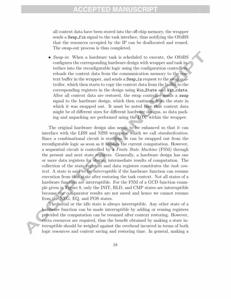
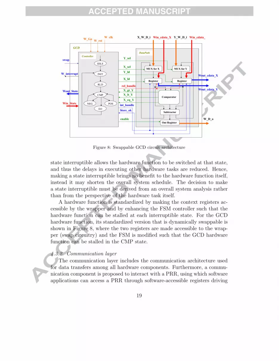
The original hardware design also needs to be enhanced so that it caninterface with the LISS and NISS wrappers, which we call standardization.Since a combinational circuit is stateless, it can be swapped out from thereconfigurable logic as soon as it finishes the current computation. However,a sequential circuit is controlled by a Finite State Machine (FSM) throughthe present and next state registers. Generally, a hardware design has oneor more data registers for storing intermediate results of computation. Thecollection of the state registers and data registers constitutes the task con-text. A state is said to be interruptible if the hardware function can resumeexecution from that state after restoring the task context. Not all states of ahardware function are interruptible. For the FSM of a GCD function exam-ple given in Figure 8, only the INIT, RLD, and CMP states are interruptiblebecause the comparator results are not saved and hence we cannot resumefrom the NEG, EQ, and POS states.
The initial or the idle state is always interruptible. Any other state of ahardware function can be made interruptible by adding or reusing registersprovided the computation can be resumed after context restoring. However,extra resources are required, thus the benefit obtained by making a state in-terruptible should be weighed against the overhead incurred in terms of bothlogic resources and context saving and restoring time. In general, making a
18
Y_ld
X_eq_Y
X_lt_YX_gt_Y
INIT
MUX for X MUX for Y
Register Register
Comparator
Subtractor
Out Register
Controller DataPath
Y_sel
X_sel
GCD
RLD
EQ
NEG
CMP
POS
IDLE
enable
W clk X_W_D_i Y_W_D_iWin_cdata_X Win_cdata_W_Go
Wout_cdata_X
Wout_cdata_Y
Win_State
Wout_State
int_handle
Store_ok
rel_handle
X_ld
swap
W rst
W_interrupt
W_D_o
Figure 8: Swappable GCD circuit architecture
state interruptible allows the hardware function to be switched at that state,and thus the delays in executing other hardware tasks are reduced. Hence,making a state interruptible brings no benefit to the hardware function itself,instead it may shorten the overall system schedule. The decision to makea state interruptible must be derived from an overall system analysis ratherthan from the perspective of the hardware task itself.
A hardware function is standardized by making the context registers ac-cessible by the wrapper and by enhancing the FSM controller such that thehardware function can be stalled at each interruptible state. For the GCDhardware function, its standardized version that is dynamically swappable isshown in Figure 8, where the two registers are made accessible to the wrap-per (swap circuitry) and the FSM is modified such that the GCD hardwarefunction can be stalled in the CMP state.
4.3.2. Communication layer
The communication layer includes the communication architecture usedfor data transfers among all hardware components. Furthermore, a commu-nication component is proposed to interact with a PRR, using which softwareapplications can access a PRR through software-accessible registers driving
19

(a) Logic Virtualization (b) HW Device Virtualization
Figure 9: Logic Virtualization and Hardware Device Virtualization
the signals in the PR template. The communication component is realizedusing the OPB Intellectual Property Interface (IPIF) design, and thus theprocessing results can be buffered in the communication component untilthe OS4RS reads them.
4.3.3. Interface layer
Besides proposing a hardware preemption mechanism on the FPGA toimprove the limitation in infrastructure support for DPRS, we further pro-pose a hardware virtualization mechanism [20] realized in the kernel spaceof an OS4RS and the FPGA to enhance the utilization of reconfigurablehardware function. Similar to the interactions between software applicationsand hardware devices in a conventional embedded OS, software applicationsin our OS4RS design also interact with reconfigurable hardware functionsthrough the device nodes, which does not sacrifice the generality in accessingthe hardware device design. The hardware virtualization mechanism consistsof the logic virtualization and the hardware device virtualization, and theirdetails are described as follows.
• Logic virtualization: Using the logic virtualization as shown in Fig-ure 9(a), another device node (comm3) can be dynamically linked tothe required hardware function (HW1) such that it can be accessed byApplication2. Thus, Application2 can access HW1, while Application1is accessing HW2. Through the many-to-one logic virtualization, a re-quired hardware function can be virtualized such that it can be ac-cessed by different software applications through different device nodes.The processing results of the required hardware function are separatelytransferred to the kernel modules corresponding to different software
20

applications, and then read back by the software applications in theuser space. This many-to-one mapping thus increases the utilization ofa hardware function.
• Hardware device virtualization: Using the hardware device virtualiza-tion as shown in Figure 9(b), the kernel module corresponding to arequired hardware function (HW1) can be also dynamically linked to an-other required hardware function HW2. Thus, the processing results ofHW1 can be directly transferred to HW2 through the kernel module, andthe final processing results of HW2 are sent back to the user space. Thisis because, through the many-to-one logic virtualization, HW2 is sharedby different device nodes. As a result, the time overhead in repeatedlytransferring data between the user space and the kernel space can besignificantly reduced. This one-to-many mapping is thus a seamlessreconfiguration of the underlying hardware, without any change to thesoftware.
4.3.4. Management layer
The management layer contains a hardware task manager to not onlymanage all data transfers between the kernel modules and the reconfigurablehardware functions, but also to determine which mechanism will be usedwhen a request for a hardware function arrives. As shown in Figure 10,the hardware task management employs all the three proposed techniques,including hardware device virtualization, logic virtualization, and hardwarepreemption.
When a request for a hardware function arrives, the hardware task man-ager first checks if the required hardware function has been configured in aPRR. If not, the hardware task manager checks if the priority of the requiredhardware function is higher than that of any configured hardware function. Ifnot, the required hardware function will be configured in the FPGA only afterone of the configured hardware function finishes its execution and there is noother higher priority hardware function waiting to be configured. Otherwise,the hardware preemption mechanism is invoked to send a Swap out requestto a configured hardware function with lower priority. When the hardwaretask manager receives a Swap fin notification, it requests the ICAP deviceto configure the required hardware function into the FPGA.
When the required hardware function is already configured, the hard-ware task manager checks if the request is received from the same software
21

Request a HW function
Does a PRR with the required HW function
NO Is the required HW function with higher
NO
exist?
YES
priority?
YES
Is the request from Send the “Swap_out”
request to a HW function Select another NOthe same SW application
with lower priority
W it f th “S fi ”
Se ec a o eunused device node
Wait for the “Swap_fin”notification
Link the unused Link the previously used
YES
device node to the corresponding PRR
kernel module to the PRR with the required HW function
Reconfigure the required HW function
Logic Virtualization HW Device Virtualization HW Preemption
Figure 10: Hardware Task Management
application. If not, the logic virtualization is invoked to dynamically linkanother unused device node to the corresponding PRR. Otherwise, the hard-ware device virtualization is invoked to dynamically link the previously usedkernel module to the PRR with the required hardware function, and thus theprocessing results of the previous hardware function can be directly trans-ferred to the requested hardware function. Further, using the hardware de-vice virtualization, when a pair of device node and kernel module is linked toonly one hardware function, the final processing results are thus transferredback to the user space. For example, as shown in Figure 9(b), the main dif-ference between the pairs comm1 and comm2 of device node and kernel moduleis that the pair comm2 of device node and kernel module is connected to onlyHW2, and thus the final processing results are transferred back to the userspace via the device node comm2. In contrast, the pair comm1 of device nodeand kernel module is connected to both HW1 and HW2, and thus the processingresults of HW1 are transferred to HW2 via the kernel module, instead of beingtransferred back to the user space via the device node comm1.
In our current implementation, the hardware task manager adopts a sim-
22
ple First-In-First-Out (FIFO) method for scheduling hardware tasks. Toefficiently use the hardware virtualization and preemption mechanisms toadapt changing environment conditions and runtime user requirements, inthe future, the previously proposed Relocatable Hardware-Software Schedul-ing (RHSS) method [15] will be further extended and integrated in the hard-ware task manager.
4.3.5. Function layer
The unified kernel module is used in the interface layer to interact withdifferent reconfigurable hardware functions, where fourteen ioctl systemcalls are adopted to only interact with the signals of the PR template, and arenot designed for a specific hardware function. Different hardware functionshave different interaction methods, and thus a hardware control library isused to implement the interaction methods of all reconfigurable hardwarefunctions. As a result, a user-designed hardware function needs to be onlyintegrated with the PR template, and then to update the hardware controllibrary with its interaction method. Software applications can easily interactwith the new hardware function by invoking the APIs in the hardware controllibrary, thus further enhancing the system scalability.
4.3.6. Application layer
The topmost layer of the hierarchical OS4RS design is the applicationlayer. An application is defined as a set of functions, which could includesoftware and hardware tasks. Through the hardware control library, a soft-ware task can interact with a hardware task using the ioctl system calls.
5. Experiments
To illustrate how MPC can be applied to a real system, we use a Dynam-ically Partially Reconfigurable Network Security System (DPRNSS) as ourexample. DPRNSS is mainly used to support the service of Secure SocketLayer (SSL), for example, a Secure Shell (SSH) can request the DPRNSS toconfigure different cryptographic or hash hardware functions for data authen-tication and encryption/decryption, respectively. DPRNSS consists of fivesystem devices, including a microprocessor, an FPGA, a network interface,a hardware/software communication interface, and an off-chip memory. Forthe dynamically partial reconfiguration of cryptographic and hash hardware
23

functions, some PRRs are implemented on the FPGA. All partial bitstreamsfor cryptographic and hash hardware designs are saved in an off-chip memory.
For the DPRNSS design, the basic controllers as shown in Figure 4 arecustomized, including a configuration manager, a system manager, and aninteractor. Further, a negotiator is used in DPRNSS to allow a sender and areceiver to use the same cryptographic and hash algorithms for data trans-fer. The software application is a network multimedia application, whichreceives in real-time 128 × 64 pixel images from a camera. The receivedimages are transferred to the cryptographic and hash hardware functionsfor data processing, and then sent to a receiver on the network. To vali-date DPRNSS, the negotiator and the network multimedia application aremodeled as a new Negotiator class customized from the UserDefined classand in the Interactor classes, respectively, and then integrated with thesoftware application model customized from MPC. We adopt the Rhapsodymodeling tool [2] that has the powerful capability for code generation in C,C++, Java, and Ada, as the UML modeler. Furthermore, we use the XMItoolkit in Rhapsody to export the functional UML models in the XMI format.
For the new Negotiator class, its corresponding state machine diagrammodeled by using Rhapsody is illustrated in Figure 11. The evStart tran-sition is first triggered from the Initial state, and then the Negotiate()
function is used to receive the requests from a receiver on the network fordata transfer. If the cryptographic and hash functions that are currentlyconfigured in the FPGA are different from those requested by the receiver,the action getItsSystemManager() → GEN(evAdapt()) on the evHWAdapt
transition generates an evAdapt event in the SystemManager state machineto reconfigure the required hardware functions on the FPGA. Otherwise,the action getItsSystemManager() → GEN(evStable()) on the evNoAdapt
transition generates an evStable event in the SystemManager state machineto start data transfer. Thus, the DPRNSS can dynamically self-adapt thecryptographic and hash functions to meet the requests from different receiverson the network, without human intervention. Further, in the system imple-mentation phase, the hierarchical OS4RS design, as described in Section 4.3,would be realized in the DPRNSS design. The hardware task manager, asdescribed in Section 4.3.4, enables the DPRNSS itself to use the hardwarevirtualization and preemption mechanisms to adapt to changing environmentconditions and runtime user requirements, without human intervention.
In the following sections, we show how the proposed MPC methodologycan solve the three main problems of the DPRS development described in
24

Initial
HWAdapt
evEndAdapt
Negotiation
evNoAdapt/getItsSystemManager()->GEN(evStable());
evHWAdapt/getItsSystemManager()->GEN(evAdapt());
evStart/Negotiate();
Figure 11: State Machine Diagram for Negotiator Class
Section 1 through the verification and estimation phase, the hardware vir-tualization mechanism, and the hardware preemption mechanism. For thesystem implementation phase, the XtremeDSP Development Kit-II [27] fromNallatech and Xilinx ML310 platform [36] are adopted as our reference boardsfor showing that the proposed MPC methodology can be applied to both theSoB-based and SoC-based DPRS designs, respectively.
5.1. PIV using Model Checking
After successfully modeling DPRNSS by the functional UML models, themodel translator is used to transform the UML state machine diagrams intoETA models. Here, we use SGM, which runs on an Intel Pentium 4 CPU3.00GHz with 8 GB RAM, to validate the functional interactions among allsystem components. We have verified nine versions of DPRNSS designs whichdiffer in the number of PRRs from 1 to 9. More PRRs in a DPRNSS meansgreater flexibility and complexity. The CTL properties verified in MPC areas follows, where we have shown only the properties for PRR1, while thetotal number of PRRs in the system is nine.
• Mutual exclusion: AG(mode(SystemManager) = PRR1Config → evPR2= 0 & evPR3 = 0 & evPR4 = 0 & evPR5 = 0 & evPR6 = 0 & evPR7= 0 & evPR8 = 0 & evPR9 = 0)
• No invalid access: mode(SystemManager) = PRR1Config → A(PRR1-Access = 0)U(EndPRR1Partial = 1))
• Starvation free : evPR1 = 1 → AF(mode(SystemManager) = PRR1-Config))
25

In the CTL properties, “mode(SystemManager) = PRR1Config” meansthat the SystemManager automaton stays in the PRR1Config state, which in-dicates that PRR1 is being reconfigured. The variables evPRR1, evPRR1Access,and evEndPRR1Partial with values equal to 1 show that the system managerstarts to reconfigure PRR1, the interactor is interacting with the hardwarefunction on PRR1, and PRR1 has been reconfigured, respectively.
Similar to the above CTL properties, the functional interactions witheach PRR in a DPRNSS are verified using the corresponding CTL proper-ties, and thus the total number of the verified CTL properties are changedwith the number of PRRs. Table 1 shows the related information for CasesA to I, including the number of PRRs, the numbers of the total ETA modesand transitions before merging all ETA, and the number of verified CTLproperties. Our first experiment is mainly to verify the purely functionalinteractions between DPRNSS components, that is, there is no clock vari-able in ETA. However, because the requirements for partial reconfigurationchange over time and due to the environment conditions, the temporal fea-ture is considered in our second experiment. The microprocessor and theFPGA have different frequencies in DPRNSS, and thus we assign two differ-ent clock variables to the software applications and the hardware functions.Further, in a DPRS, the configuration controller usually has an independentfrequency different from the microprocessor and the FPGA to configure thebitstreams. Thus, a third clock variable is assigned to the operations forpartial reconfiguration in our third experiment. As a result, each case in Ta-ble 1 can be further separated into three situations, including ETA withoutclock variables, ETA with two different clock variables, and ETA with threedifferent clock variables.
Figure 12 shows the numbers of ETA modes and transitions of the mergedETA for all different situations and the memory usage and verification timeby SGM. Because the inherent characteristics of reconfigurable systems, whosecomplexity is dependent on the number of PRRs, instead of functions, we
Table 1: The Related Information for Each Verified Case before Merging All ETACase A B C D E F G H I#PRR 1 2 3 4 5 6 7 8 9#Mode 17 18 19 20 21 22 23 24 25#Transition 22 24 26 28 30 32 34 36 38#Property 2 6 9 12 15 18 21 24 27
26
050
100150200250300
1 2 3 4 5 6 7 8 9
#Mod
e
#PRR
Without Clock Variables 2 Clock Variables3 Clock Variables
050
100150200250300350400
1 2 3 4 5 6 7 8 9
#Tra
nsiti
on
#PRR
Without Clock Variables 2 Clock Variables3 Clock Variables
(a) Number of ETA Modes for DPRNSS (b) Number of ETA Transitions for DPRNSS
120130140150160170180
1 2 3 4 5 6 7 8 9M
emor
y U
sage
(MB
)#PRR
Without Clock Variables 2 Clock Variables3 Clock Variables
00.10.20.30.40.50.6
1 2 3 4 5 6 7 8 9
Ver
ifica
tion
Tim
e(se
c)
#PRR
Without Clock Variables 2 Clock Variables3 Clock Variables
(c) Verification Time by SGM for DPRNSS (d) Memory Usage by SGM for DPRNSS
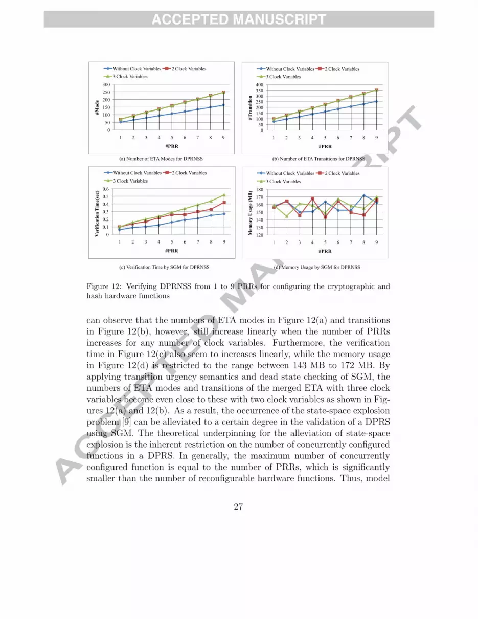
Figure 12: Verifying DPRNSS from 1 to 9 PRRs for configuring the cryptographic andhash hardware functions
can observe that the numbers of ETA modes in Figure 12(a) and transitionsin Figure 12(b), however, still increase linearly when the number of PRRsincreases for any number of clock variables. Furthermore, the verificationtime in Figure 12(c) also seem to increases linearly, while the memory usagein Figure 12(d) is restricted to the range between 143 MB to 172 MB. Byapplying transition urgency semantics and dead state checking of SGM, thenumbers of ETA modes and transitions of the merged ETA with three clockvariables become even close to these with two clock variables as shown in Fig-ures 12(a) and 12(b). As a result, the occurrence of the state-space explosionproblem [9] can be alleviated to a certain degree in the validation of a DPRSusing SGM. The theoretical underpinning for the alleviation of state-spaceexplosion is the inherent restriction on the number of concurrently configuredfunctions in a DPRS. In generally, the maximum number of concurrentlyconfigured function is equal to the number of PRRs, which is significantlysmaller than the number of reconfigurable hardware functions. Thus, model
27
checking in MPC verifies each different combination of concurrently config-ured functions. However, to validate such timing requirements, simulationneeds much more exhaustive testbench or test vectors. This usually causesmuch more iterations for rectifying and validating a DPRS design, especiallyafter the system has been implemented. Therefore, MPC integrates SGM inPIV for providing efficient and exhaustive functional verification, instead ofsimulation-based methods, and our experiments have demonstrated that thestate-space explosion problem does not occur.
5.2. PSV using UCoP
UCoP was implemented on a reference board, that is, the XtremeDSPDevelopment Kit-II [27] from Nallatech. The software applications run on amicroprocessor. The Field Upgradeable Systems Environment (FUSE) APIsand the PCI driver are provided by the XtremeDSP Development Kit-II tofacilitate the FPGA reconfiguration and communication over the PCI bus.Instead of doing this per application, UCoP integrates them directly intothe software code generator of the Rhapsody modeling tool. As a result,through the animation mode of Rhapsody, the functional interactions amongthe interactive UML models and the real DPRS hardware architecture canbe dynamically traced, step by step, in the sequence diagrams and the statemachine diagrams.
In order to analyze the execution process for each cryptographic function,the execution time for each cryptographic hardware design in UCoP needs tobe first defined. Given input data of Din-bits, output data of Dout-bits, datasize of Dpci-bits for each data transfer iteration over the PCI bus, data writeand data read transfer time of δwr and δrd microseconds, respectively, for eachiteration over the PCI bus, initialization time of Tpci microseconds for startingdata transfer over the PCI bus, pure execution time of Te microseconds fora hardware design in UCoP, the total operation time is Ttotal. As shown inEquation (1), the measured total operation time includes not only the pureexecution time (Te) of a processing iteration for a hardware design, but alsothe time overheads of data transfers over the PCI bus.
Ttotal = Tpci + (⌈
Din
Dpci
⌉× δwr) + Te + (
⌈Dout
Dpci
⌉× δrd) (1)
A common lower-bound estimation method [32] to evaluate the hardwareexecution time is used to compare with UCoP for demonstrating the impor-tance of accurate time estimation, where the time necessary to transfer se-
28

304050607080
essin
g Ti
me
(sec
)
Lower-bound UCoP
01020304050607080
Encrypt Decrypt Encrypt Decrypt Encrypt Decrypt
DES 3DES AES
Proc
essin
g Ti
me
(sec
)
Lower-bound UCoP
Figure 13: Estimation using Lower-bound Method and Measurement using UCoP
quences of 32-bit values was measured for obtaining the lower bound on datatransfers and then used to estimate system performance. In this experiment,three cryptographic hardware functions, including Data Encryption Standard(DES), 3DES, and Advanced Encryption Standard (AES), are adopted for theimage encryption/decryption in the DPRNSS. Figure 13 shows the process-ing time in seconds for fifty 128×64 pixel image encryption/dcryption usingthe lower-bound estimation method [32] and UCoP.
In a network multimedia application using the 3DES encryption witha Quality of Service (QoS) for 50 image frames per 65 seconds, the timefor processing 50 image frames using the lower-bound estimation methodand using UCoP are around 61 and 72 seconds, respectively. This showsthat the lower-bound estimation method guarantee that the QoS can beachieved, however in reality it is not, which could cause a very serious problemespecially when hard real-time constraints are violated. In this experiment,the time underestimation using the lower-bound estimation method is from1.1 seconds (DES encryption) to 11.9 seconds (3DES decryption). In contrastto the inaccurate lower-bound estimation method, UCoP provides the exactmeasured timing results. As a result, UCoP can effectively close the model-platform information gap.
5.3. OS4RS Design using Hardware Virtualization Mechanism
In this experiment, we realized the DPRNSS design on the Xilinx ML310platform with a Virtex II Pro XC2VP30 FPGA chip that has 13,696 slices.
29
The proposed hardware virtualization mechanism was realized in the PetaL-inux embedded OS [28], which ran on a Xilinx MicroBlaze soft-core processor[35] at 100 MHz. The network security reconfigurable system supported fourcryptographic hardware functions, including three variants of RSA havingdifferent key and input data sizes in bits (RSA32, RSA64, and RSA128) andRC6, and three hash hardware functions, including three variants of CRChaving different input data sizes in bits (CRC32, CRC64, and CRC128), byimplementing only two different sized PRRs, namely a small PRR1 and a largePRR2. The reconfigurable hardware functions can be dynamically configuredin either PRR1 or PRR2, except for RSA128 which can only be configured inPRR1. A current limitation in the proposed virtualization mechanism requiresthe hardware functions to have the same I/O bandwidth. For example, RC6and CRC32 both have 32-bit I/O interfaces, and thus can be configured forhardware virtualization.
5.3.1. System Resource Analysis
Table 2 shows the system resource usage, including the logic usage, thenumber of device nodes, and the number of kernel modules, using a con-ventional embedded system, existing reconfigurable systems [12, 26], and areconfigurable system with hardware virtualization mechanism, respectively.To support the transfer of encrypted real-time images on a network, all sevenhardware functions must be configured at design-time in a conventional em-bedded system. Existing reconfigurable systems [12, 26] and the proposedreconfigurable system with hardware virtualization mechanism both requirelogic resources for the PRRs only as the PRRs can be reconfigured into differ-ent hardware functions at run-time for fitting different system requirements.However, reconfigurable hardware functions are still managed as conventionalhardware devices in the existing reconfigurable systems [12, 26], and the fullset of seven device nodes and seven kernel modules are required for the net-work security reconfigurable systems. Through the hardware virtualizationmechanism, our OS4RS allows the system to work for all seven reconfigurablehardware functions using only two device nodes and two kernel modules, in-stead of seven as in the existing nodes. Thus, the number of device nodesand kernel modules required in our OS4RS can be minimized to the numberof PRRs, instead of growing with the number of hardware functions. Sincethe number of PRRs is usually much smaller than that of the hardware func-tions, the hardware virtualization mechanism has basically placed a lowerbound on the number of device nodes and kernel modules.
30

Table 2: System Resource ComparisonConventional Related [10, 33] Our
Logic 5,010 slices 2,975 slices 2,975 slicesUsage (7 HWs) (2 PRRs) (2 PRRs)
#Device #HW #HW #PRR ∼ #HWNode (7) (7) (2 ∼ 7)
#Kernel #HW #HW #PRR ∼ #HWModule (7) (7) (2 ∼ 7)
#HW: the number of hardware functions; #PRR: the number of partially reconfigurable regions.
5.3.2. Time Analysis
We compared the time required by a multimedia application for process-ing 5 to 50 images in two cases: (a) conventional hardware reuse, and (b)the proposed hardware virtualization mechanism. Figure 14 shows the re-duced time using the logic virtualization and hardware device virtualization,respectively, compared to that using the conventional hardware reuse, fordifferent cryptographic and hash function pairs.
In our first experiment, two multimedia applications simultaneously inter-act with the same cryptographic hardware function, where each multimediaapplication first captures real-time images from the camera, and then sequen-tially transfers the captured images to the cryptographic and hash hardwarefunctions for data processing. Figure 14(a) shows the reduced time usingthe logic virtualization, compared to that using the conventional hardwarereuse, for processing from five to fifty 128×64 pixel images. Here, one of theRSA32, RSA64, RSA128, and RC6 hardware functions is shared between twodifferent multimedia applications for image encryption. We can observe thatthe time reduced by using the logic virtualization becomes more and morecompared to that using the conventional hardware reuse, when the numberof captured images increases. The reduced time is up to 13% for RSA32, 6%for RSA64, 4% for RSA128, and 10% for RC6 of the time required by usingthe conventional hardware reuse. This is because with logic virtualizationthe required cryptographic hardware function can be continuously accessedby two different multimedia applications through different device nodes turnby turn, without being blocked by one of the two multimedia applications,and thus the time overhead for repeatedly closing and opening the devicenode is alleviated.
In our second experiment, a multimedia application sequentially interacts
31
(a) Reduced Time using Logic Virtualization (b) Reduced Time using Hardware Device Virtualization
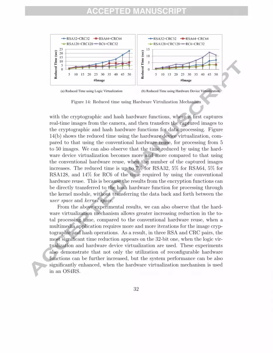
Figure 14: Reduced time using Hardware Virtulization Mechanism
with the cryptographic and hash hardware functions, where it first capturesreal-time images from the camera, and then transfers the captured images tothe cryptographic and hash hardware functions for data processing. Figure14(b) shows the reduced time using the hardware device virtualization, com-pared to that using the conventional hardware reuse, for processing from 5to 50 images. We can also observe that the time reduced by using the hard-ware device virtualization becomes more and more compared to that usingthe conventional hardware reuse, when the number of the captured imagesincreases. The reduced time is up to 7% for RSA32, 5% for RSA64, 5% forRSA128, and 14% for RC6 of the time required by using the conventionalhardware reuse. This is because the results from the encryption functions canbe directly transferred to the hash hardware function for processing throughthe kernel module, without transferring the data back and forth between theuser space and kernel space.
From the above experimental results, we can also observe that the hard-ware virtualization mechanism allows greater increasing reduction in the to-tal processing time, compared to the conventional hardware reuse, when amultimedia application requires more and more iterations for the image cryp-tographic and hash operations. As a result, in three RSA and CRC pairs, themost significant time reduction appears on the 32-bit one, when the logic vir-tualization and hardware device virtualization are used. These experimentsalso demonstrate that not only the utilization of reconfigurable hardwarefunctions can be further increased, but the system performance can be alsosignificantly enhanced, when the hardware virtualization mechanism is usedin an OS4RS.
32

Table 3: Time overheads for swap-out and swap-inV TE TR Swap-Out Swap-In Task Relocate
TW TSO TW TSI Our RBM(µs) (µs) (µs) (µs) (µs) (µs)
N 387.9 11 388.0 5 388.0 776.0GCD L 13,566.8 401.5 9 401.7 3 401.6 803.3 1,038.1
N 649.7 84 650.7 55 650.6 1,301.3DES L 7,577.1 649.7 58 650.7 29 650.6 1,301.3 2,183.8
N 1,267.4 100 1,269.0 66 1,268.7 2,537.8DCT L 577,209.9 1,254.2 68 1,255.5 34 1,255.2 2,510.7 4,278.2
V: Version; N: NISS wrapper, L: LISS wrapper, RBM: Reconfiguration-based method,
TE : execution time, TW : time overhead incurred by wrapper (in IP clock cycles).
5.4. DPRS Architecture using Hardware Preemption Mechanism
This experiment focuses on comparing the reconfiguration-based method[22] with our proposed hardware preemption mechanism, where the Great-est Common Divisor (GCD), DES, and Discrete Cosine Transform (DCT)hardware functions are integrated with the LISS or NISS wrappers to beswappable. Given context data of DC-bits, context buffer of DB-bits, datatransformation rate of RT bits/cycle, buffer data load rate of RB bits/cycle,peripheral bus data transfer rate of RP bits/cycle, peripheral bus access timeof TA cycles, transition time of TI cycles to go to an interruptible state , andreconfiguration time of TR cycles, the swap-out and swap-in processes requiretime TSO and TSI , respectively, as shown in Equation (2).
TSO = TI +⌈
DC
DB
⌉×
(DB
RT+ DB
RB+ TA + DB
RP
)+ TR
TSI = TR +⌈
DC
DB
⌉×
(DB
RT+ DB
RB+ TA + DB
RP
) (2)
In our current implementation, the software processing time is much morethan the hardware processing time. To clearly show our contributions to thehardware preemption mechanism, we directly compared our design-basedmethod with another reconfiguration-based method (RBM) [22]. Table 3shows the time overheads in swapping out and swapping in for all the ex-amples. Comparing the time required for a task relocation, that is, oneswap-out and one swap-in, our proposed design-based method performs bet-ter than RBM. From the experimental results, our proposed hardware pre-emption mechanism can reduce 40.4% and 40.6% for the NISS wrapper, and
33

LV HDV
PRR2PRR1RC6 HP
CRC32DCT
HP: Hardware Preemption; LV: Logic Virtualization; HDV H d D i Vi li iHDV: Hardware Device Virtualization;Priority: CRC32 > RC6 > DCT
Figure 15: DPRNSS using both HW Preemption and Virtualization Mechanisms
40.4% and 41.3% for the LISS wrapper, respectively, of the time requiredby reconfiguration-based methods, respectively, for the larger DES and DCTexamples. We are thus saving much time, which is important for hard real-time systems. Even though additional reconfiguration time is required, theswappable design would enable more hardware tasks to fit their deadline con-straints, which makes the hardware-software scheduling in an OS4RS moreflexible for achieving higher system performance.
5.5. DPRNSSS using both HW Preemption and Virtualization Mechanisms
To show how system performance can be significantly improved usingboth the hardware virtualization and preemption mechanisms, we use theDPRNSS that contains only two PRRs, namely PRR1 and PRR2 as shown inFigure 15, as an example. The DPRNSS receives an application APP2 requestfor processing fifty images using the RC6 and CRC32 hardware functions witha QoS requirement of total 90 seconds. While scheduling the execution of theRC6 hardware function, because the DCT and CRC32 hardware functionshave been configured in PRR1 and PRR2, respectively, the PRR1 with a low-priority DCT function, which has already executed for 100,000 μs, is selectedto configure the required RC6 function. Without the hardware preemptionmechanism, the RC6 hardware function will be configured in PRR1 only afterthe DCT function finishes. According to our experimental results, it needs477,209.9 (577, 209.9 − 100, 000) μs to finish the current DCT execution asshown in Table 3 and 177,000 μs to configure the RC6 function. Note that
34
here we assume that the currently executing application APP1 (with require-ment for the DCT hardware function) can also be preempted after one DCTexecution. If this is not the case, a much more delay will be encounteredwithout the hardware and software preemption. However, using the hard-ware preemption mechanism, it needs only 1,268.7 μs for the NISS wrapper or1,255.2 μs for the LISS wrapper to swap out the DCT function, and 177,000μs to configure the RC6 function. The latency in starting to serve the im-age processing application APP2 without and with the hardware preemptionmechanism is around 0.654 seconds and 0.178 seconds, respectively.
After hardware and software preemption, the required RC6 hardwarefunction is configured into PRR1. Using the conventional hardware reusemethod, the new image processing application APP2 must now wait until thecurrently executing application APP1 closes the device node comm1 that islinked to PRR1, and then the image processing application APP2 opens thesame device node comm1 to access PRR1 with the RC6 hardware function.However, using the proposed logic virtualization design, the hardware taskmanager can simultaneously use another pair comm2 of device node and kernelmodule to connect to PRR1 and the new application APP2 starts accessingPRR1 with the RC6 hardware function more quickly. The time saved bynot waiting for another application APP1 to close and open the device nodecomm1, namely logic virtualization, is around 0.301 seconds according to ourexperimental results.
Finally, using the hardware device virtualization, the processing results ofthe RC6 hardware function in PRR1 can be directly transferred to the CRC32hardware function in PRR2 through the kernel module in the pair comm2 ofdevice node and kernel module without going back and forth between theOS kernel and the user levels, as introduced in Section 4.3.3. The totalamounts of time required for performing the image processing applicationAPP2 without and with the proposed hardware virtualization mechanism are96.397 seconds and 85.336 seconds, respectively. As a result, without usingboth the hardware preemption and virtualization mechanisms for DPRNSS,the image processing application APP2 needs 97.051 (0.654+96.397) seconds,that is, the QoS requirement cannot be achieved. However, using both thehardware preemption and virtualization mechanisms for DPRNSS, the im-age processing application APP2 needs only 85.514 (0.178 + 85.336) seconds,that is, the QoS requirement can be achieved. The experimental resultsdemonstrate that system performance can be significantly enhanced, whenboth the hardware preemption and virtualization mechanisms are used. This
35

performance improvement is very important, especially for a hard real-timesystem.
6. Conclusions
In this work, we discovered an important characteristic of DPRS. Unliketraditional systems, the verification complexity of DPRS is limited by theamount of functionalities that can be concurrently executed in the system.This observation allowed us to successfully apply model checking to DPRS,which not only alleviates the occurrence of the state-space explosion problemto a certain degree but also increases the verification coverage at the sametime. To bridge the model-platform information gap, UCoP was proposed forplatform-specific verification. UCoP supported direct interactions betweenthe UML models and a real DPRS architecture, which was a novel approachto efficient system validation such that designers can have accurate executionand configuration time measurements that aided in efficiently and correctlyverifying a DPRS.
To overcome the the limitation in infrastructure support for DPRS, weproposed a hardware virtualization mechanism to dynamically link the devicenodes, kernel modules, and on-demand reconfigurable hardware functionsto fit different system requirements. Furthermore, through the proposedhardware preemption mechanism, user-designed hardware functions can bedynamically swapped out and then swapped in, thus further increasing theutilization of hardware resources per unit time. We also proposed a hierarchi-cal OS4RS design with the unified communication mechanism, using whichsystem scalability can be further enhanced without losing the generality inaccessing hardware designs.
In the future, to maintain a DPRS infrastructure to support the designof self-adaptable systems [30], our previously proposed relocatable hardware-software scheduling (RHSS) method [15] will be further extended and inte-grated in the hardware task manager. Thus, system performance can be self-optimized to adapt to changing environment conditions and runtime user re-quirements. Further, the UML profile for Modeling and Analysis of Real TimeEmbedded systems (MARTE) [1] will be integrated into MPC to support morecomplete and efficient system analysis. To provide a more robust validationmechanism for the DPRS development, MPC will next integrate a SystemCplatform called Perfecto [14] to rapidly explore the hardware/software parti-tioning and scheduling alternatives at the modeling and design. As a result,
36

more detailed analysis at a highly abstract model-level and rapid and ef-fective design explorations can be further supported in MPC, thus reducingdesign and verification efforts more significantly.
References
[1] Object Management Group (OMG). http://www.omg.org.
[2] Rhapsody User Guide. Telelogic Inc, 2004. http://www.telelogic.com.
[3] C. Amicucci, F. Ferrandi, M. D. Santambrogio, and D. Sciuto. SyCERS: a SystemCdesign exploration framework for SoC reconfigurable architecture. In Proc. of theInternational Conference on Engineering of Reconfigurable Systems and Algorithm(ERSA’06), pages 63–69, June 2006.
[4] B. Steinbach, C. Dorotska and D. Frohlich . Automated Hardware-Synthesis of UML-Models. In Proc. of the 2rd International DAC Workshop, UML for SoC Design(UML-SOC’2006), June 2005.
[5] J. Becker, M. Hubner, G. Hettich, R. Constapel, J. Eisenmann, and J. Luka. Dynamicand Partial FPGA Exploitation. In Proc. of the IEEE Special Issue on AdvancedAutomobile Technologies, volume 95, pages 438–452, 2007.
[6] M. Borgatti, A. Capello, U. Rossi, J. L. Lambert, I. Moussa, F. Fummi, andG. Pravadelli. An Integrated Design and Verification Methodology for Reconfig-urable Multimedia Systems. In Proc. of the Design, Automation and Test in EuropeConference and Exhibition (DATE’05), volume 3, pages 266–271. IEEE CS Press,March 2005.
[7] A. Brito, M. Kuhnle, M. Hubner, J. Becker, and E. U. K. Melcher. Modelling andSimulation of Dynamic and Partially Reconfigurable Systems using SystemC. In Proc.of the IEEE Computer Society Annual Symposium on VLSI (ISVLSI’07), pages 35–40, March 2007.
[8] C.-H. Huang and P.-A. Hsiung. UML-Based Hardware/Software Co-Design Platformfor Dynamically Partially Reconfigurable Network Security Systems. In Proc. ofthe 13th IEEE Asia-Pacific Computer Systems Architecture Conference (ACSAC),August 2008. (doi:10.1109/APCSAC.2008.4625436).
[9] E. M. Clarke, O. Grumberg, and D. A. Peled. Model checking. MIT Press, 1999.
[10] A. Donato, F. Ferrandi, M. D. Santambrogio, and D. Sciuto. Operating systemsupport for dynamically reconfigurable SoC architecture. In Proc. of the IEEE In-ternational SOC Conference, pages 233–238, September 2005.
37
[11] P. Graf, M. Hubner, K. D. Muller-Glaser, and J. Becker. A Graphical Model-LevelDebugger for Heterogenous Reconfigurable Architectures. In Proc. of the 17th IEEEInternational Conference on Field Programmable Logic and Applications (FPL’07),pages 722–725. IEEE CS Press, August 2007.
[12] J. Hagemeyer, B. Keltelhoit, M. Koester, and M. Pomnann. A design methodologyfor communication infrastructures on partially reconfigurable FPGAs. In Proc. of the17th IEEE International Conference on Field Programmable Logic and Applications(FPL’07), pages 331–338. IEEE CS Press, August 2007.
[13] T. A. Henzinger, X. Nicollin, J. Sifakis, and S. Yovine. Symbolic Model Checking forReal-Time Systems. In Proc. of IEEE International Conference Logics in ComputerScience, pages 394–406, 1992.
[14] P.-A. Hsiung, C.-H. Huang, and C.-F. Liao. Perfecto: A SystemC-based performanceevaluation framework for dynamically partially reconfigurable systems. In Proc. of the16th IEEE International Conference on Field Programmable Logic and Applications(FPL’06), pages 190–198. IEEE CS Press, August 2006.
[15] P.-A. Hsiung, C.-H. Huang, J.-S. Shen, and C.-C. Chiang. Scheduling and Placementof Hardware/Software Real-Time Relocatable Tasks in Dynamically Partially Recon-figurable Systems. ACM Transactions on Reconfigurable Technology and Systems(TRETS), 2010. (to appear).
[16] P.-A. Hsiung, S.-W. Lin, Y.-R. Chen, C.-H. Huang, and W. Chu. Modeling and verifi-cation of real-time embedded systems with urgency. Journal of Systems and Software,82(10):1627–1641, October 2009. (DOI: http://dx.doi.org/10.1016/j.jss.2009.03.013).
[17] P.-A. Hsiung, M. D. Santambrogio, and C.-H. Huang. Reconfigurable System Designand Verification. CRC Press, USA, ISBN: 978-1420062663, 2009.
[18] C.-H. Huang, S.-S. Chang, and P.-A. Hsiung. Generic wrapper design for dynamicswappable hardware IP in partially reconfigurable systems. International Journal ofElectrical Engineering (IJEE), 14(3):229–238, June 2007.
[19] C.-H. Huang and P.-A. Hsiung. Software-controlled dynamically swappable hardwaredesign in partially reconfigurable systems. EURASIP Journal on Embedded System,2008. Article ID 231940, 11 pages, doi:10.1155/2008/231940.
[20] C.-H. Huang and P.-A. Hsiung. Hardware resource virtualization for dynamicallypartially reconfigurable systems. IEEE Embedded Systems Letters, 1(1):19–23, May2009. (DOI: 10.1109/LES.2009.2028039).
[21] C.-H. Huang and P.-A. Hsiung. On the Use of a UML-Based HW/SW Co-DesignPlatform for Reconfigurable Cryptographic Systems. In Proc. of the IEEE Interna-tional Symposium on Circuits and Systems (ISCAS), pages 2221–2224. IEEE Press,May 2009.
38
[22] H. Kalte and M. Porrmann. Context saving and restoring for multitasking in recon-figurable systems. In Proc. of the International Conference on Field ProgrammableLogic and Applications (FPL’05), pages 223–228. IEEE CS Press, August 2005.
[23] B. Kettelhoit and M. Porrmann. A layer model for systematically designing dynam-ically reconfigurable systems. In Proc. of the 16th IEEE International Conferenceon Field Programmable Logic and Applications (FPL’06), pages 1–6. IEEE CS Press,August 2006.
[24] L. Lavazza. A Methodology for Formalizing Concepts Underlying the DESS Notation.EUREKA-ITEA project, 2001.
[25] A. Montone, F. Redaelli, M. D. Santambrogio, and S. O. Memik. A Reconfiguration-Aware Floorplacer for FPGAs. In Proc. of the 2008 International Conference onReconfigurable Computing and FPGAs (RECONFIG08), pages 109–114. IEEE Com-puter Society, 2008.
[26] M. Morandi, M. Novati, M. D. Santambrogio, and D. Sciuto. Core allocation andrelocation management for a self dynamically reconfigurable architecture. In ”Proc.of 2008 IEEE Computer Society Annual Symposium on VLSI, pages 286–291, 2008.
[27] Nallatech. XtremeDSP Development Kit-II User Guide, Issue 4, 2004.
[28] PetaLogix. PetaLinux. http://www.petalogix.com/.
[29] M. Santambrogio and D. Sciuto. Design methodology for partial dynamic reconfig-uration: a new degree of freedom in the HW/SW codesign. In Proc. of the IEEEInternational Symposium on Parallel and Distributed Processing (IPDPS’08), pages1–8, April 2008.
[30] M. D. Santambrogio. From reconfigurable architectures to self-adaptive autonomicsystems. In Proc. of the 2009 International Conference on Computational Scienceand Engineering (CSE09), pages 926–931. IEEE Computer Society, 2009.
[31] T. Schattkowsky, W. Mueller, and A. Rettberg. A Model-Based Approach for Ex-ecutable Specifications on Reconfigurable Hardware. In Proc. of the Conference onDesign, Automation and Test in Europe (DATE’05), pages 692–697. IEEE ComputerSociety, March 2005.
[32] M. L. Silva and J. C. Ferreira. Support for Partial Run-Time Reconfiguration ofPlatform FPGAs. Journal of Systems Architecture, 52(12):709–726, December 2006.
[33] J. A. Williams and N. W. Bergmann. Embedded Linux as a platform for dynamicallyself-reconfiguring systems-on-chip. In Proc. of International Conference on Engineer-ing of Reconfigurable Systems and Algorithms, June 2004.
[34] Xilinx. Early Access Partial Reconfiguration User Guide, UG208, 2006.
39
[35] Xilinx. MicroBlaze Processor Reference Guide, Embedded Development Kit, EDK8.2i - UG081 (v6.3), August 2006.
[36] Xilinx. ML310 User Guide, Virtex-II Pro Embedded Development Platform, UG068(v1.1.5), 2007. http://www.xilinx.com.
40
Chun-Hsian Huang received his B.S. degree in Information and Computer Education
from National TaiTung University, TaiTung, Taiwan, ROC, in 2004. He is currently
working toward his Ph.D. in the Department of Computer Science and Information
Engineering at National Chung Cheng University, Chiayi, Taiwan, ROC. He is a teaching
and research assistant in the Department of Computer Science and Information
Engineering at National Chung Cheng University. His research interests include
dynamically partially reconfigurable systems, UML-based hardware/software co-design
methodology, hardware/software co-verification, and formal verification.
Pao-Ann Hsiung, Ph.D., received his B.S. in Mathematics and his Ph.D. in Electrical
Engineering from the National Taiwan University, Taipei, Taiwan, ROC, in 1991 and
1996, respectively. From 1996 to 2000, he was a post-doctoral researcher at the Institute
of Information Science, Academia Sinica, Taipei, Taiwan, ROC. From February 2001 to
July 2002, he was an assistant professor and from August 2002 to July 2007 he was an
associate professor in the Department of Computer Science and Information Engineering,
National Chung Cheng University, Chiayi, Taiwan, ROC. Since August 2007, he has
been a full professor. Dr. Hsiung was the recipient of the 2001 ACM Taipei Chapter
Kuo-Ting Li Young Researcher for his significant contributions to design automation of
electronic systems. Dr. Hsiung was also a recipient of the 2004 Young Scholar Research
Award given by National Chung Cheng University to five young faculty members per
year. Dr. Hsiung is a senior member of the IEEE, a senior member of the ACM, and a life
member of the IICM. He has been included in several professional listings such as
Marquis' Who's Who in the World, Marquis' Who's Who in Asia, Outstanding People of
the 20th Century by International Biographical Centre, Cambridge, England, Rifacimento
International's Admirable Asian Achievers (2006), Afro/Asian Who's Who, and
Asia/Pacific Who's Who. Dr. Hsiung is an editorial board member of the International
Journal of Embedded Systems (IJES), Inderscience Publishers, USA; the International
Journal of Multimedia and Ubiquitous Engineering (IJMUE), Science and Engineering
Research Center (SERSC), USA; an associate editor of the Journal of Software
Engineering (JSE), Academic Journals, Inc., USA; an editorial board member of the
Open Software Engineering Journal (OSE), Bentham Science Publishers, Ltd., USA; an
international editorial board member of the International Journal of Patterns (IJOP). Dr.
Hsiung has been on the program committee of more than 50 international conferences.
He served as session organizer and chair for PDPTA'99, and as workshop organizer and
chair for RTC'99, DSVV'2000, and PDES'2005. He has published more than 150 papers
in international journals and conferences. He has taken an active part in paper refereeing
for international journals and conferences. His main research interests include
reconfigurable computing and system design, multi-core programming, cognitive radio
architecture, System-on-Chip (SoC) design and verification, embedded software
synthesis and verification, real-time system design and verification, hardware-software
codesign and coverification, and component-based object-oriented application
frameworks for real-time embedded systems.
Jih-Sheng Shen received his B.S. and his M.S. in Computer Science and Information
Engineering from the I-Shou University and the National Chung Cheng University,
Taiwan, ROC, in 2003 and 2004, respectively. His M.S. thesis was on the design and
implementation of on-chip crossroad communication architectures for low power
embedded systems. He is currently pursuing his Ph.D. in the Department of Computer
Science and Information Engineering at the National Chung Cheng University, Taiwan,
ROC. His research interests include the theories and the architectures of reconfigurable
systems, machine learning strategies, Network-on-Chip (NoC) designs, encoding
methods for minimizing crosstalk interferences and dynamic power consumption.
1. Chun-Hsian Huang’s Photo

2. Pao-Ann Hsiung’s Photo

3. Jih-Sheng Shen’s Photo


