Embed Size (px)
Citation preview
Model-Based Hand Tracking UsingA Hierar chical Bayesian Filter
BjornDietmarRafaelStenger
St. John’sCollege
March2004
Dissertationsubmittedto theUniversityof Cambridge
for thedegreeof Doctorof Philosophy

Model-BasedHandTracking UsingA Hierarchical
Bayesian Filter
BjornStenger
Abstract
This thesisfocuseson theautomatic recoveryof three-dimensionalhandmotionfrom
oneor moreviews. A 3D geometrichandmodel is constructedfrom truncatedcones,
cylindersandellipsoids andis usedto generatecontours,which canbe comparedwith
edgecontoursandskin colour in images. The handtrackingproblemis formulatedas
stateestimation, where the model parametersdefinethe internal state,which is to be
estimatedfrom imageobservations.
In the first approach,an unscentedKalmanfilter is employed to updatethe model’s
posebasedon local intensityor skin colouredges.Thealgorithmis ableto tracksmooth
handmotion in front of backgroundsthat areeitheruniform or containno skin colour.
However, manualinitializationis requiredin thefirst frame,andno recovery strategy is
availablewhentrackis lost.
Thesecondapproach,tree-basedfiltering, combinesideasfromdetectionandBayesian
filtering: Detectionis usedto solve the initialization problem,wherea single imageis
given with no prior informationof the handpose. A hierarchicalBayesianfilter is de-
veloped,which allows integration of temporalinformation. This is moreefficient than
applyingdetectionat eachframe,becausedynamicinformation canbeincorporatedinto
the search,which helpsto resolve ambiguities in difficult cases.This thesisdevelops a
likelihoodfunction,whichis basedonintensity edges,aswell aspixel colourvalues.This
functionis obtainedfrom asimilarity measure,whichis comparedwith anumberof other
costfunctions. Theposteriordistribution is computedin a hierarchicalfashion,theaim
beingto concentratecomputationpower on regionsin statespacewith larger posterior
values. The algorithmis testedon a numberof imagesequences,which includehand
motionwith self-occlusionin front of aclutteredbackground.

Ackno wledg ements
First andforemost,I wish to thankmy supervisorsRobertoCipolla andPhilip Torr who
havebothcontinuously sharedtheirsupportandenthusiasm. Workingwith themhasbeen
agreatpleasure.
OverthepastyearsI havealsoenjoyedworkingwith anumberof fellow PhDstudents,
in particularPauloMendonca andArasanathanThayananthan,with whomthesharingof
authorship in severalpapersreflectstheclosenessof ourcooperation.Presentandformer
colleaguesin the vision grouphave madethe lab an excellentplaceto work, including
Tom Drummond, Paul Smith,Adrian Broadhurst,KennethWong,Anthony Dick, Dun-
canRobertson,YongduekSeo,Bjorn Johansson,Martin Weber, Oliver Williams, Jason
McEwen,George Vogiatzis,JamieShotton,RamananNavaratnam,andOgnjenArand-
jelovic.
Thefinancialsupportof theEngineeringandPhysicalSciencesResearchCouncil,the
Gottlieb-DaimlerandKarl-BenzFoundation, theCambridgeEuropeanTrust,andToshiba
Researchhave mademy stay in Cambridgepossible. I also thankSt. John’s College
andthe Departmentof Engineeringfor supporting my participationin conferencesand
seminarsandfor providing afine work environment.
A very big ‘thank you’ goesto SofyaPogerfor helpwith thedataglove, to Nanthan,
Ram,Ollie, Martin, Oggie,Phil, Bill GibsonandSimonRedheadfor thetime andeffort
put into proof-reading,to Rei for theOmamoricharm,andto Dani for thebinding.
Finally, heartfeltthanksgo to my family andfriendsfor their immensesupportalong
theway.
BjornStenger
Contents
1 Intr oduction 2
1.1 Motivation . . . . . . . . . . . . . . . . . . . . . . . . . . . . . . . . . . 2
1.1.1 Limitationsof existingsystems . . . . . . . . . . . . . . . . . . 3
1.1.2 Approach . . . . . . . . . . . . . . . . . . . . . . . . . . . . . . 5
1.1.3 Limiti ng thescope . . . . . . . . . . . . . . . . . . . . . . . . . 5
1.2 Thesisoverview . . . . . . . . . . . . . . . . . . . . . . . . . . . . . . . 6
1.2.1 Contributions of this thesis . . . . . . . . . . . . . . . . . . . . . 6
1.2.2 Thesisoutline . . . . . . . . . . . . . . . . . . . . . . . . . . . . 7
2 Related Work 8
2.1 Handtracking . . . . . . . . . . . . . . . . . . . . . . . . . . . . . . . . 8
2.1.1 2D handtracking . . . . . . . . . . . . . . . . . . . . . . . . . . 9
2.1.2 Model-basedhandtracking. . . . . . . . . . . . . . . . . . . . . 10
2.1.3 View-basedgesturerecognition . . . . . . . . . . . . . . . . . . 14
2.1.4 Single-view poseestimation . . . . . . . . . . . . . . . . . . . . 16
2.2 Full humanbodytracking. . . . . . . . . . . . . . . . . . . . . . . . . . 18
2.3 Objectdetection. . . . . . . . . . . . . . . . . . . . . . . . . . . . . . . 21
2.3.1 Matchingshapetemplates . . . . . . . . . . . . . . . . . . . . . 22
2.3.2 Hierarchicalclassification . . . . . . . . . . . . . . . . . . . . . 24
2.4 Summary . . . . . . . . . . . . . . . . . . . . . . . . . . . . . . . . . . 26
3 A 3D Hand Model Built From Quadrics 27
3.1 Projectivegeometryof quadricsandconics . . . . . . . . . . . . . . . . 27
3.2 Constructingahandmodel . . . . . . . . . . . . . . . . . . . . . . . . . 33
3.3 Drawing thecontours . . . . . . . . . . . . . . . . . . . . . . . . . . . . 35
3.4 Handlingself-occlusion. . . . . . . . . . . . . . . . . . . . . . . . . . . 38
3.5 Summary . . . . . . . . . . . . . . . . . . . . . . . . . . . . . . . . . . 39
iii
4 Model-Based Tracking Using an Unscented Kalman Filter 40
4.1 Trackingasprobabilistic inference . . . . . . . . . . . . . . . . . . . . . 40
4.2 TheunscentedKalmanfilter . . . . . . . . . . . . . . . . . . . . . . . . 43
4.3 ObjecttrackingusingtheUKF algorithm . . . . . . . . . . . . . . . . . 45
4.4 Experimentalresults . . . . . . . . . . . . . . . . . . . . . . . . . . . . 48
4.5 Limitationsof theUKF tracker . . . . . . . . . . . . . . . . . . . . . . . 51
4.6 Summary . . . . . . . . . . . . . . . . . . . . . . . . . . . . . . . . . . 52
5 Similarity Measures for Template-Base d Shape Matching 55
5.1 Shapematchingusingdistancetransforms. . . . . . . . . . . . . . . . . 56
5.1.1 TheHausdorff distance. . . . . . . . . . . . . . . . . . . . . . . 60
5.2 Shapematchingaslinearclassification. . . . . . . . . . . . . . . . . . . 61
5.2.1 Comparisonof classifiers. . . . . . . . . . . . . . . . . . . . . . 62
5.2.2 Experimentalresults . . . . . . . . . . . . . . . . . . . . . . . . 64
5.2.3 Discussion . . . . . . . . . . . . . . . . . . . . . . . . . . . . . 67
5.3 Modelling skincolour . . . . . . . . . . . . . . . . . . . . . . . . . . . . 68
5.3.1 Comparisonof classifiers. . . . . . . . . . . . . . . . . . . . . . 71
5.3.2 Experimentalresults . . . . . . . . . . . . . . . . . . . . . . . . 72
5.4 Combiningedgeandcolourinformation . . . . . . . . . . . . . . . . . . 75
5.4.1 Experimentalresults . . . . . . . . . . . . . . . . . . . . . . . . 76
5.5 Summary . . . . . . . . . . . . . . . . . . . . . . . . . . . . . . . . . . 78
6 Hand Tracking Using A Hierar chical Filter 82
6.1 Tree-baseddetection . . . . . . . . . . . . . . . . . . . . . . . . . . . . 82
6.2 Tree-basedfiltering . . . . . . . . . . . . . . . . . . . . . . . . . . . . . 83
6.2.1 Therelationto particlefiltering . . . . . . . . . . . . . . . . . . 87
6.3 Edgeandcolourlikelihoods . . . . . . . . . . . . . . . . . . . . . . . . 89
6.4 Modelling handdynamics. . . . . . . . . . . . . . . . . . . . . . . . . . 90
6.5 Trackingrigid bodymotion . . . . . . . . . . . . . . . . . . . . . . . . . 91
6.5.1 Initialization . . . . . . . . . . . . . . . . . . . . . . . . . . . . 92
6.6 Dimensionality reductionfor articulatedmotion . . . . . . . . . . . . . . 94
6.6.1 Constructinga treefor articulatedmotion . . . . . . . . . . . . . 96
6.7 Summary . . . . . . . . . . . . . . . . . . . . . . . . . . . . . . . . . . 99
7 Conc lusion 103
7.1 Summary . . . . . . . . . . . . . . . . . . . . . . . . . . . . . . . . . . 103
iv

0 Contents 1
7.2 Limitations . . . . . . . . . . . . . . . . . . . . . . . . . . . . . . . . . 104
7.3 Futurework . . . . . . . . . . . . . . . . . . . . . . . . . . . . . . . . . 104
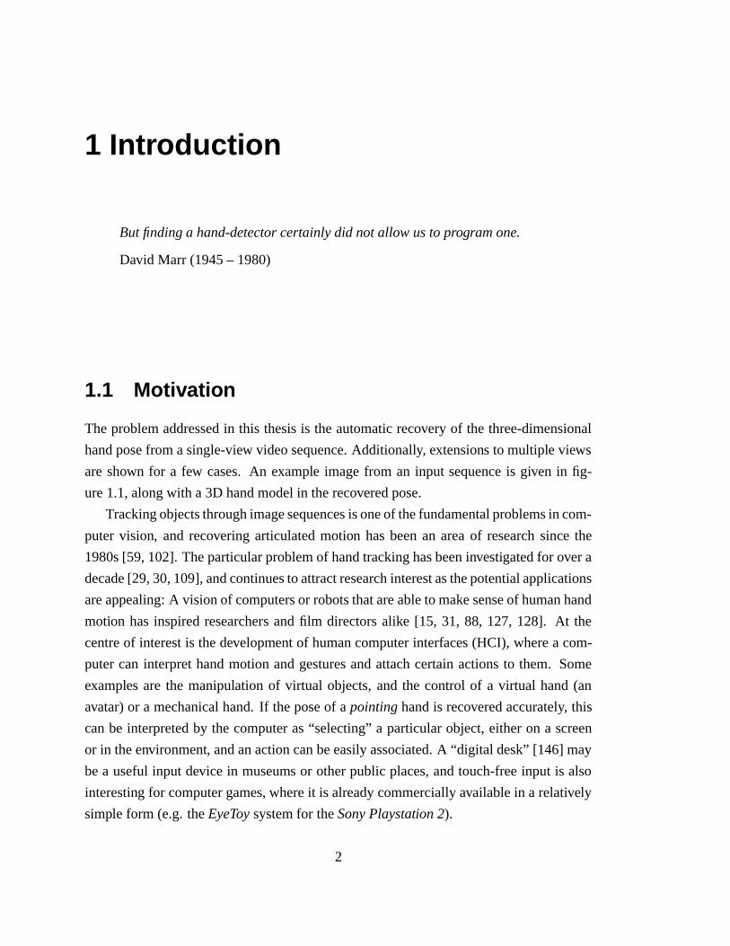
1 Intr oduction
But findinga hand-detectorcertainlydid notallow usto programone.
David Marr (1945– 1980)
1.1 Motiv atio n
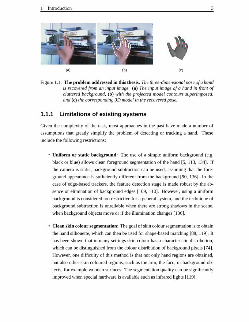
Theproblemaddressedin this thesisis theautomaticrecovery of the three-dimensional
handposefrom asingle-view videosequence.Additionally, extensions to multipleviews
areshown for a few cases.An example imagefrom an input sequenceis given in fig-
ure1.1,alongwith a3D handmodelin therecoveredpose.
Trackingobjectsthroughimagesequencesisoneof thefundamentalproblemsin com-
puter vision, and recovering articulatedmotion hasbeenan areaof researchsincethe
1980s[59, 102]. Theparticularproblemof handtrackinghasbeeninvestigatedfor overa
decade[29,30,109],andcontinuesto attractresearchinterestasthepotentialapplications
areappealing:A visionof computersor robotsthatareableto makesenseof humanhand
motion hasinspiredresearchers andfilm directorsalike [15, 31, 88, 127, 128]. At the
centreof interestis thedevelopmentof humancomputerinterfaces(HCI), wherea com-
putercan interprethandmotion andgesturesandattachcertainactionsto them. Some
examplesare the manipulation of virtual objects,andthe control of a virtual hand(an
avatar)or a mechanicalhand.If theposeof a pointinghandis recoveredaccurately, this
canbe interpretedby the computeras“selecting”a particularobject,eitheron a screen
or in theenvironment, andanactioncanbeeasilyassociated.A “digital desk”[146] may
bea usefulinput device in museums or otherpublic places,andtouch-freeinput is also
interesting for computergames,whereit is alreadycommerciallyavailablein a relatively
simple form (e.g.theEyeToy systemfor theSonyPlaystation 2).
2
1 Introduction 3
(a) (b) (c)
Figure1.1: The problemaddressedin this thesis.Thethree-dimensional poseof a handis recovered froman input image. (a) Theinput image of a handin front ofcluttered background, (b) with the projectedmodelcontours superimposed,and(c) thecorresponding3D modelin therecoveredpose.
1.1.1 Limitations of exi sting sys tems
Given the complexity of the task,mostapproachesin the pasthave madea numberof
assumptions that greatly simplify the problemof detectingor trackinga hand. These
includethefollowing restrictions:
• Uniform or static background: The useof a simpleuniform background(e.g.
blackor blue)allows cleanforegroundsegmentationof thehand[5, 113, 134]. If
the camerais static,backgroundsubtractioncanbe used,assumingthat the fore-
groundappearanceis sufficiently differentfrom the background[90, 136]. In the
caseof edge-basedtrackers,the featuredetectionstageis maderobustby the ab-
senceor eliminationof backgroundedges[109, 110]. However, usinga uniform
backgroundis consideredtoo restrictive for a generalsystem,andthetechniqueof
backgroundsubtractionis unreliablewhentherearestrongshadows in the scene,
whenbackgroundobjectsmoveor if theilluminationchanges[136].
• Cleanskin colour segmentation:Thegoalof skincoloursegmentation is to obtain
thehandsilhouette,whichcanthenbeusedfor shape-basedmatching[88, 119]. It
hasbeenshown that in many settingsskin colourhasa characteristicdistribution,
whichcanbedistinguishedfrom thecolourdistributionof backgroundpixels[74].
However, onedifficulty of this methodis thatnot only handregionsareobtained,
but alsootherskin colouredregions,suchasthearm,the face,or backgroundob-
jects,for examplewoodensurfaces.Thesegmentation quality canbesignificantly
improvedwhenspecialhardwareis available suchasinfraredlights [119].

4�
1 Introduction
• Delimitation of the wrist: Often it is assumedthat the handin the imagecan
be easilysegmentedfrom thearm. If a personis wearinglong non-skincoloured
sleeves,the extractionof the handsilhouetteis muchsimplified [113, 119, 134].
Lockton andFitzgibbon[88] make this assumption explicit by requiringthe user
to weara wristband. If suchan “anchorfeature” is supplied,the handshapecan
beprojectedinto a canonicalframe,thusobtainingtheorientation, translationand
scaleparameters.
• Manual initialization: If a three-dimensionalmodelis usedfor poseestimation,
it is oftenassumedthatthemodelis correctlyalignedin thefirst frame[109, 110].
The problemcan thenbe posedas an optimization problem,whereinthe model
parametersareadaptedin eachframein orderto minimize an error function. For
userinterfaces,however, it is desirableto maketheinitialization processautomatic.
• Slow hand motion: Giventhat thehandis moving slowly, a sequentialoptimiza-
tion approachcanbe taken in which the parametersof a handmodelareadapted
in eachframe. Thesolutionfrom theprevious frameis usedto initialize theopti-
mizationprocessin thecurrentframe[109, 110]. However, dueto thenumberof
localminimathisapproachdoesnotwork whenhandmotionis fastor whenfeature
associationis difficult dueto self-occlusion.
• Unoccludedfingertips: If thefingertipscanbelocatedin theimage,thehandpose
canbe reconstructedby solving an inversekinematicsproblem[149]. However,
extracting the fingertip positionsis not an easytask, and in many posesnot all
fingersarevisible.
Eventhoughtheseassumptionshold in certaincases,they areconsideredtoo restric-
tive in thegeneralcase.For example,whena singleinput imageis given, no knowledge
of thebackgroundscenecanbeassumed.Similarly, it is notguaranteedthatnootherskin
colouredobjectsarein thescene.Usuallypeopleareableto estimatetheposeof a hand,
evenwhenviewedwith oneeye. This fact is proof of the existenceof a solutionto the
problem.However, theunderlying mechanismsof biological visualinformation process-
ing, particularlyathigherlevelsof abstraction,arecurrentlynot fully understood[81]. In
1972Grosset al. [53] discoveredneuronsin theinferotemporalcortex of macaquemon-
keys that showed the strongestresponsewhena handshapewaspresentin their visual
field. However, the fact thatsuchcellsshouldexist doesnot tell usanything abouthow
they do it. This is thecontext of David Marr’s quoteat thebeginningof thischapter.
1 Introduction 5
1.1.2 Appr oach
In this thesisa model-basedapproachis taken. By “model” we a meangeometricthree-
dimensionalhandmodel,whichhastheadvantagesof compactrepresentation,correspon-
dencewith semantics,andtheability to work in continuousspace.In themoregeneral
sense,our “model” encodesinformation aboutthe shape,motion andcolour that is ex-
pectedin an imagecontaininga hand. Statevariablesareassociatedwith thegeometric
model,which areestimatedby a filter allowing integration of temporalinformation and
imageobservations. In the caseof hands,edgecontoursandskin colour featureshave
beenusedasobservations in thepast[5, 90, 110,119] andbothof thesefeaturesareused
in thiswork.
Two solutionsaresuggestedfor theestimationproblem.Thefirst solution is basedon
recursiveBayesianfiltering usinganextension of theKalmanfilter, theunscentedKalman
filter [78]. This approachmakesuseof a dynamicmodelto predictthe handmotion in
eachframeandcombinesthepredictionwith anobservationto obtaina poseestimate.It
is shown thatthisapproachworksundercertainassumptions,but it is toorestrictivein the
generalsetting.
Thesecondapproachcombinesideasfrom detectiontechniquesandBayesianfilter-
ing. A detectionapproachis usedto solvetheinitializationproblem,whereasingle image
is givenwith noprior informationof thehandpose.This is a hardtaskandraisesa num-
berof issues,suchashow to find thelocationof a handandhow to discriminatebetween
differentposes.Perhapsthemoreimportant question is whetherthesetwo tasksshould
beseparatedatall. In thiswork, templatematchingis usedto solve thisproblem:A large
numberof templatesaregeneratedby the 3D modelanda similarity function basedon
edgeandcolourfeaturesscoresthequalityof amatch.This is shown to work for asingle
frame,but usingdetectionin every frameis not efficient. Furthermore,in certainhand
poses,e.g.if a flat handis viewedfrom theside,thereis little imageinformation thatcan
be usedfor reliabledetection.Thus,the ideais to usetemporalinformation in orderto
increasetheefficiency, aswell asto resolveambiguitiesin difficult cases.This leadsto a
hierarchicalBayesianfilter. Theproposedalgorithmis shown to successfullyrecover the
handposein challenginginputsequences,whichincludehandmotionwith self-occlusion
in front of aclutteredbackground,andassuchrepresentsthecurrentstate-of-the-art.
1.1.3 Limiting the scope
Two importantapplicationsareexplicitly not consideredwithin this thesis. The first is
marker-basedmotion capture,widely usedfor animationpurposesin the film or games
6� 1 Introduction
industry, or for biomechanicalanalysis.Commercialmotion capturesystemsusemarkers
on theobjectin orderto obtainexactpoint locations.They alsowork with multiple cam-
erasto resolveambiguities,whichoccurin asingleview. Theuseof markerssolvesoneof
themostdifficult tasks,whichis thefeaturecorrespondenceproblem.Thenumberof pos-
siblecorrespondencesis reduceddrastically, andoncethesearefound,3D poserecovery
becomesrelatively easy. In this thesisonly thecaseof markerlesstrackingis considered.
Thesecondapplication,which we do not attemptto solve, is thatof automaticsign lan-
guageinterpretation.Eventhoughrecovering3D posereliablycouldbeusedto interpret
fingerspelling,sucha level of detailmaynot berequiredfor theseapplications.For ex-
ample,theAmericanSignLanguagerecognition systemby Starneret al. [128], relieson
temporalinformation andonly recoversthehandpositionandorientation. Also thefinger
spelling systemof LocktonandFitzgibbon[88], which canrecognize46 differenthand
poses,doesnotattemptto recover3D information.
1.2 Thesis overview
This sectionstatesthe main contributionsof this thesis,andgivesa brief outline of the
following chapters.
1.2.1 Contrib utions of this thesis
Themaincontributionsof this thesisare:
• a hierarchicalfiltering algorithm, which combinesrobust detectionwith temporal
filtering;
• the formulation of a likelihoodfunction that fusesshapeandcolour information,
significantlyimproving therobustnessof thetracker.
Minor contributionsinclude:
• the constructionof a three-dimensionalhandmodel using truncatedquadricsas
building blocks,andtheefficientgenerationof its projectedcontours;
• the applicationof theunscentedKalmanfilter to three-dimensional handtracking
in singleanddualviews.
1 Introduction 7
1.2.2 Thesis outline
Chapter 2. This chapterpresentsa literaturereview of handtracking,wherethemain
ideasof model-basedtracking,view-basedrecognitionandsingleview poseestimation
are discussed.The similarities and differencesto full humanbody tracking are made
explicit. Finally, it givesabrief introductionto objectdetectionmethods,whicharebased
onhierarchicalapproaches.
Chapter 3. A methodto constructa three-dimensionalhandmodel from truncated
cones,cylindersandellipsoids is presentedin this chapter. It startswith an introduction
to thegeometryof quadricsurfacesandexplainshow suchsurfacesareprojectedinto the
imageplane. The handmodel,which approximatesthe anatomyof a real humanhand,
is thenconstructedusingtruncatedquadricsasbuilding blocks. It is alsoexplainedhow
self-occlusionscanbehandledwhenprojectingthemodelcontours.
Chapter 4. This chapterfirst formulatesthe taskof trackingasa Bayesianinference
problem.TheunscentedKalmanfilter is introducedwithin thecontext of Bayesianfilter-
ing andis appliedto 3D handtracking.Experimentsusingsingleanddualviews demon-
stratetheperformanceof thismethod,but alsorevealits limitations.
Chapter 5. In this chaptersimilarity measuresare examined,which canbe usedin
orderto find a handin imageswith clutteredbackgrounds.Thesuggestedcostfunction
integratesbothshapeandcolour information. Thechamferdistancefunction [9] is used
to measureshapesimilarity betweenahandtemplateandanimage.Thecolourcostterm
is basedonastatisticalcolourmodelandcorrespondsto thelikelihood of thecolourdata
in animageregion.
Chapter 6. This chapterdescribesoneof themaincontributions of this work, which
is thedevelopmentof analgorithm, which combinesrobustdetectionwith Bayesianfil-
tering. This allows for automatic initialization and recovery of the tracker, as well as
theincorporationof a dynamic model. It is shown how thedimensionality of articulated
handmotion canbereducedby analyzingjoint angledatacapturedwith adataglove,and
examplesof 3D poseestimationfrom asingleview arepresented.
2 Related Work
Studythepastif youwoulddefinethefuture.
Confucius(551BC–479BC)
Thischaptergivesanoverview of thedevelopmentsandthecurrentstate-of-the-artin
handtracking. Earlier reviews have beenpublishedby Pavlovic et al. [105] andWu and
Huang[150, 152]. The next sectionintroducesthe ideasbehindmodel-basedtracking,
view-basedrecognition,andsingle-view poseestimation,highlighting themerits,aswell
asthe limits of eachapproachfor handtracking. In section2.2 the commongroundas
well asthedifferencesto full humanbody trackingarepointedout. Finally, section2.3
givesa brief introduction to generalobjectdetectionmethods, which have yieldedgood
resultsfor locatingdeformableobjectsin images.
2.1 Hand trac kin g
For a long time thework onhandtrackingcouldbedividedinto two streamsof research,
model-basedandview-basedapproaches[105]. Model-basedapproachesusean articu-
latedthree-dimensional (3D) handmodelfor tracking. The model is projectedinto the
imageandanerrorfunctionis computed,scoringthequalityof thematch.Themodelpa-
rametersarethenadaptedsuchthatthis costis minimized. Usuallyit is assumedthatthe
modelconfigurationat theprevious frameis known, andonly a smallparameterupdate
is necessary. Therefore,modelinitializationhasbeena big obstacle.In mostcasesthe
modelis alignedmanuallyin thefirst frame. Section2.1.2reviews methodsfor model-
basedhandtracking.
In the view-basedapproach,the problemis formulatedasa classificationproblem.
A setof handfeaturesis labelledwith a particularhandpose,anda classifieris learnt
8
2 RelatedWork 9
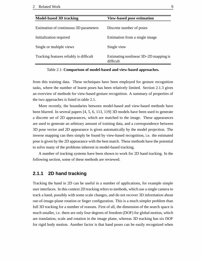
Model-based3D tracking View-basedposeestimation
Estimation of continuous3D parameters Discretenumberof poses
Initialization required Estimationfrom asingleimage
Singleor multipleviews Singleview
Trackingfeaturesreliably is difficult Estimatingnonlinear3D–2Dmappingisdifficult
Table2.1:Comparisonof model-basedand view-basedapproaches.
from this training data. Thesetechniqueshave beenemployed for gesturerecognition
tasks,wherethe numberof learntposeshasbeenrelatively limited. Section2.1.3gives
anoverview of methods for view-basedgesturerecognition.A summaryof propertiesof
thetwo approachesis listedin table2.1.
More recently, the boundariesbetweenmodel-basedandview-basedmethodshave
beenblurred.In severalpapers[4, 5, 6, 113, 119] 3D modelshave beenusedto generate
a discretesetof 2D appearances,which arematchedto the image. Theseappearances
areusedto generateanarbitraryamountof trainingdata,anda correspondencebetween
3D posevectorand2D appearanceis givenautomaticallyby themodelprojection.The
inversemappingcanthensimply befoundby view-basedrecognition,i.e. theestimated
poseis givenby the2D appearancewith thebestmatch.Thesemethodshavethepotential
to solvemany of theproblemsinherentin model-basedtracking.
A numberof trackingsystemshavebeenshown to work for 2D handtracking.In the
following section,someof thesemethodsarereviewed.
2.1.1 2D hand trac king
Trackingthehandin 2D canbeuseful in a numberof applications, for example simple
userinterfaces.In thiscontext 2D trackingrefersto methods,whichuseasinglecamerato
trackahand,possibly with somescalechanges,anddonot recover3D informationabout
out-of-image-planerotationor fingerconfiguration.This is amuchsimpler problemthan
full 3D trackingfor anumberof reasons.Firstof all, thedimension of thesearchspaceis
muchsmaller, i.e. thereareonly four degreesof freedom(DOF) for globalmotion,which
aretranslation,scaleandrotationin the imageplane,whereas3D trackinghassix DOF
for rigid bodymotion. Anotherfactoris thathandposescanbeeasilyrecognizedwhen
10 2 RelatedWork
thehandis fronto-parallelto thecamera,becausethevisible areais relatively large and
self-occlusionbetweendifferentfingersis small.
Oneexampleof a humancomputerinterface(HCI) applicationis the vision-based
drawing systempresentedby MacCormickandIsard[90]. Thehandshapewasmodelled
usinga B-spline, anda particlefilter wasusedto trackthehandcontour. Thestatespace
waspartitionedfor efficiency, decouplingthemotionsof index fingerandthumb. Back-
groundestimationwasusedto constrainthesearchregion,andsevenDOF weretracked
in real-time. The tracker was initializedby searchingregionswhich wereclassifiedas
skin colour [67]. A limitation of this methodis the fact that the contouraloneis not a
reliablefeatureduringfasthandmovements.
Laptev andLindeberg [84] andBretzneretal. [20] presentedasystemthatcouldtrack
anopenhandanddistinguishbetweenfivedifferenthandstates.Scale-spaceanalysiswas
usedto find intensityor colour blob featuresat differentscales,correspondingto palm
andfingers.Likelihoodmapsweregeneratedfor thesefeaturesandwereusedto evaluate
fivehypothesizedhandstatesthatcorrespondedto certainfingersbeingbentor extended.
Trackingwaseffectedusinga particlefilter, and the systemoperatedat 10 framesper
second.It wasusedwithin avision-basedtelevision remotecontrolapplication.
Von Hardenberg andBerard [143] showedtheuseof anefficient but simplefingertip
detectorin someHCI applications.Thesystemadaptively estimatedthebackgroundand
searchedtheforegroundregion for finger-like shapesat a singlescale.This methodonly
worksfor applicationswith asteadycameraandreliesoncleanforegroundsegmentation,
whichis difficult to obtainin ageneralsetting[136]. However, it requiresnoinitialization
andallows for fasthandmotion.
To summarize,a numberof 2D trackingsystems have beenshown to work in HCI
applicationsin realtime. However, they aredifficult to extendto 3D trackingwithout the
useof a geometrichandmodel.Thefollowingsectiondealswith 3D tracking,whichhas
many morepotentialapplications,but at thesametime is averychallengingtask.
2.1.2 Model-base d hand trac king
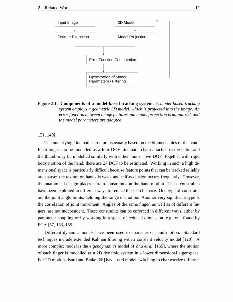
A model-basedtrackingsystemgenerallyconsistsof anumberof components,asdepicted
in figure 2.1. The geometrichandmodel is usuallycreatedmanually, but canalsobe
obtainedby reconstructionmethods.Modelsthathavebeenusedfor trackingarebasedon
planarpatches[153, 155],deformablepolygonmeshes[57] or generalizedcylinders[36,
108, 109,110,118,120,121]. In someworks thehandshapeparametersareestimated
togetherwith themotionparameters,thusadaptingthehandmodelto eachuser[118,120,
2 RelatedWork 11
Input Image
Feature Extraction Model Projection
Error Function Computation
Optimization of ModelParameters / Filtering
3D Model
Figure2.1: Componentsof a model-basedtracking system. A model-basedtrackingsystememploysa geometric3D model,which is projectedinto theimage. Anerror functionbetweenimagefeaturesandmodelprojectionis minimized,andthemodelparametersareadapted.
121, 149].
Theunderlying kinematicstructureis usuallybasedon thebiomechanicsof thehand.
Eachfinger canbe modelled asa four DOF kinematic chainattachedto the palm, and
the thumbmay be modelledsimilarly with eitherfour or five DOF. Togetherwith rigid
bodymotion of thehand,thereare27 DOF to beestimated.Working in sucha high di-
mensional spaceis particularlydifficult becausefeaturepointsthatcanbetrackedreliably
aresparse:thetextureon handsis weakandself-occlusionoccursfrequently. However,
the anatomicaldesignplacescertainconstraintson the handmotion. Theseconstraints
have beenexploited in differentwaysto reducethesearchspace.Onetypeof constraint
arethe joint anglelimits, definingthe rangeof motion. Anothervery significanttype is
thecorrelationof joint movement.Anglesof thesamefinger, aswell asof differentfin-
gers,arenot independent.Theseconstraintscanbeenforcedin differentways,eitherby
parametercouplingor by working in a spaceof reduceddimension, e.g. onefound by
PCA [57, 153,155].
Different dynamic modelshave beenusedto characterizehandmotion. Standard
techniquesincludeextendedKalmanfiltering with a constantvelocity model [120]. A
morecomplex modelis theeigendynamicsmodelof Zhu et al. [155], wherethemotion
of eachfinger is modelledasa 2D dynamicsystemin a lower dimensional eigenspace.
For 2D motionsIsardandBlake [68] haveusedmodelswitching to characterizedifferent
12 2 RelatedWork
typesof motion. However, global handmotion canbe fast in termsof imagemotion.
Eventhoughit is usuallysmooth,it maybeabruptanddifficult to predictfrom frameto
frame.Furthermore,Tomasietal. [134] pointedoutthatfingerflexion or extensioncanbe
asshortas0.1seconds,correspondingto only threeframesin animagesequence.These
considerations increasethedifficulty of modellinghanddynamicsin ageneralsetting. An
approachsuggestedin [134] is to identify anumberof key posesandinterpolatethehand
motionbetweenthem.
Arguablythe most important componentis the observation model, in particularthe
selectionof featuresthat areusedto updatethe model. Possible featuresare intensity
edges[57, 109, 110], colour edges[90] or silhouettesderived from colour segmenta-
tion [87, 153]. Identificationof certainkey pointshasbeenattempted[118, 120,121],
e.g. looking for fingertipsby searchingfor protrusionsin thesilhouetteshape.In some
cases,featureshave beenusedthat requiremorecomputational effort, suchasa stereo
depthmap[36] or opticalflow [89]. Severalsystems combine multiple cuesinto a single
costfunction[87, 89, 153, 155].
Oneof thefirst systemsfor markerlesshandtrackingwasthatof CipollaandHolling-
hurst[29, 30], who usedB-splinesnakesto tracka pointing handfrom two uncalibrated
views. In eachview the affine transformationof the snake was estimated,andwith a
groundplaneconstraintthe indicatedtarget position wasfound. The systemrequireda
simple background,but it couldoperatein real-time.
Three-dimensionalarticulatedhandtrackingwaspioneeredbyRehgandKanade[109,
110] with their DigitEyestrackingsystem. The systemuseda 3D handmodel,which
wasconstructedfrom truncatedcylindersandhadan underlyingkinematic modelwith
27 degreesof freedom. Trackingwasperformedby minimizing a costfunction,which
measuredhow well the model is alignedwith the image. Two possible cost functions
weresuggested,the first is basedon edgefeatures[109], the secondon templateregis-
tration[110]. In thefirst method,themodelcylinder axeswereprojectedinto theimage
andlocaledgeswerefound.Similarly, fingertippositionswerefound.Theerrortermwas
thesumof squareddifferencesbetweenprojectedpointsandimagefeaturepoints, andit
wasminimizedusingtheGauss-Newton algorithm.Thesecondmethodof templatereg-
istration wasusedin orderto dealwith self-occlusion.An edgetemplatewasassociated
with eachfinger segment, togetherwith a window functionmaskingthecontribution of
occludedsegments.Using two camerasanddedicatedhardware,the systemachieved a
rateof tenframespersecondwhenusinglocaledgefeatures.Off-line resultswereshown
for the caseof self-occlusion. A neutralbackgroundwas requiredfor reliable feature
2 RelatedWork 13
extraction.
HeapandHogg[57] useda 3D point distribution model[32], which wasconstructed
from a 3D magneticresonanceimagedataset. The possible handshapeswere a lin-
earcombination of thefive mostsignificanteigenvectorsaddedto themeanshape.This
reductionin the numberof parametersallowed for trackingfrom a singleview. How-
ever, naturalhandmotionwasnotmodelledaccuratelybecausethe3D shapechangesare
nonlinear. Themodelwasfirst deformed,thenrotated,scaledandtranslated,sothat the
contoursmatchedtheedgesin theimage.Thesystemtracked12DOF in a limited range
at 10 framespersecond.
DelamarreandFaugeras[36] pursueda stereoapproachto handtracking. A stereo-
correlationalgorithmwasusedto estimateadensedepthmap.In eachframea3D model
was fitted to this depthmap using the iterative closestpoints (ICP) algorithm. Using
stereoinformationhelpedsegmentthehandfrom a clutteredbackground.However, the
disparitymapsobtainedwith thecorrelationalgorithmwerenotveryaccurateasthereare
notmany strongfeaturesonahand.
Shimadaet al. [118, 120, 121] useda silhouette-basedapproachto tracking from
singlecamerainput. Thepositionsof finger-like shapeswereextractedfrom thesilhou-
ette and matchedwith the projectionof a 3D model. A set of possibleposevectors
wasmaintainedandeachone was updatedusingan extendedKalmanfilter. An opti-
mal pathwasthenfoundfor thewhole imagesequence.Thedifficulty in this methodis
to identify finger-like shapesduringunconstrainedhandmotion, particularlyin casesof
self-occlusion.
Wu andHuang[149] useddifferent techniquesto reducethe dimensionality of the
searchspace.Firstly, constraintson the finger motion wereimposed,suchaslinear de-
pendenceof finger joint angles.Furthermore,thestatespacewaspartitionedinto global
poseparametersandfingermotion parameters.Thesesetsof parameterswereestimated
in a two-stepiterative algorithm. Thelimitation of this methodis thatthefingertipshave
to bevisible in eachframe.
In anotherapproach,Wu, Lin andHuang[87, 153] learntthecorrelationsof joint an-
glesfrom datausingadataglove. It wasfoundthathandarticulationis highly constrained
andthata few principalcomponentscapturemostof themotion. For thetrainingdatathe
statespacecouldbereducedfrom 20 to sevendimensions with lossof only five percent
of the information, andfinger motion wasdescribedby a unionof line segments in this
lower dimensional space.This structurewasusedfor generatinga proposaldistribution
in aparticlefilter framework.
14 2 RelatedWork
ZhouandHuang[155] analyzedhandmotionin moredetail,andintroducedaneigen-
dynamicsmodel.As previously, thedimensionality of joint angledatawasreducedusing
PCA.Eigendynamicsaredefinedasthemotionof asinglefinger, modelledby a2D linear
dynamic systemin thislowerdimensional eigenspace,reducingthenumberof parameters
from 20 to 10. As in previouswork [149], theglobalposeandfingermotion parameters
wereestimatedseparatelyin aniterativescheme.By usingacostfunctionbasedoninten-
sity edgesaswell ascolour, therobustnesstowardsclutteredbackgroundswasincreased.
Lu et al. [89] suggestedthattheintegrationof multiple cuescanassisttrackingof ar-
ticulatedmotion. In theirapproach,intensityedgesandopticalflow wereusedto generate
forces,which acton a kinematic handmodel. Onelimitationof themethod,however, is
theassumption thatilluminationdoesnotchangeover time.
To summarize,3D handtrackinghasbeenshown to work in principle, but only for
relatively slow handmotionandusuallyin constrainedenvironments,suchasplainback-
groundsor controlledlighting. Theproblemis ill-posedin asingleview, becausein some
configurationsthemotionis verydifficult to observe[15,100]. In orderto dealwith these
ambiguities,mostsystemsusemultiple cameras.
A further issueis the initializationof the3D model. Whenstartingto trackor when
trackis lost,aninitializationor recoverymechanismis required,aspresentedby Willi ams
et al. for region-basedtracking[147]. This problemhasbeensolved eitherby manual
initializationor by findingthehandin afixedpose.Generally, thistaskcanbeformulated
asahanddetectionproblem,whichhasbeenaddressedby view-basedmethods.Thenext
sectiongives ashortreview of thisapproach.
2.1.3 View-base d gesture recognition
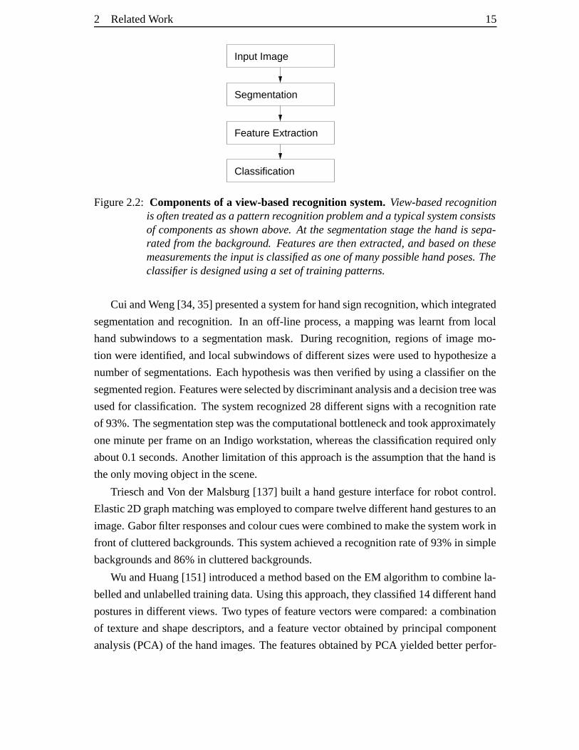
View-basedmethodshave traditionallybeenusedfor gesturerecognition.This is often
posedasa patternrecognitionproblem,which maybepartitionedinto componentssuch
asshown in figure2.2. Thesemethodsareoftendescribedas“bottom-up” methods, be-
causelow-level featuresareusedto infer higherlevel information. Themainproblems,
whichneedto besolved in thesesystemsarehow to segmentahandfrom ageneralback-
groundsceneandwhich featuresto extractfrom thesegmentedregion. Theclassification
itself is mostlydoneusinga nearestneighbourclassifieror otherstandardclassification
methods [42]. Generally, the classifieris learntfrom a setof training examplesandas-
signstheinput imageto oneof thepossible categories.In thefollowing paragraphsonly
a few selectedpapersin gesturerecognitionaredescribed.More thoroughreviewscanbe
foundin [105,152].
2 RelatedWork 15
Classification
Segmentation
Feature Extraction
Input Image
Figure2.2: Componentsof a view-basedrecognitionsystem.View-basedrecognitionis oftentreatedasa patternrecognitionproblemanda typicalsystemconsistsof componentsasshownabove. At thesegmentation stage thehandis sepa-ratedfromthebackground. Featuresare thenextracted,andbasedon thesemeasurementstheinput is classifiedasoneof manypossiblehandposes.Theclassifieris designedusinga setof training patterns.
Cui andWeng[34,35] presentedasystemfor handsignrecognition,whichintegrated
segmentation andrecognition. In an off-line process,a mappingwas learnt from local
handsubwindows to a segmentation mask. During recognition, regionsof imagemo-
tion wereidentified,andlocal subwindows of differentsizeswereusedto hypothesizea
numberof segmentations.Eachhypothesiswasthenverifiedby usinga classifieron the
segmentedregion. Featureswereselectedbydiscriminantanalysisandadecisiontreewas
usedfor classification.Thesystemrecognized28 differentsignswith a recognitionrate
of 93%.Thesegmentationstepwasthecomputational bottleneckandtookapproximately
oneminute per frameon anIndigo workstation,whereastheclassificationrequiredonly
about0.1seconds.Anotherlimitationof this approachis theassumption thatthehandis
theonly moving objectin thescene.
TrieschandVon derMalsburg [137] built a handgestureinterfacefor robotcontrol.
Elastic2D graphmatchingwasemployedto comparetwelvedifferenthandgesturesto an
image.Gaborfilter responsesandcolourcueswerecombinedto makethesystemwork in
front of clutteredbackgrounds.Thissystemachieveda recognitionrateof 93%in simple
backgroundsand86%in clutteredbackgrounds.
Wu andHuang[151] introduceda methodbasedon theEM algorithmto combinela-
belledandunlabelledtrainingdata.Usingthisapproach,they classified14differenthand
posturesin differentviews. Two typesof featurevectorswerecompared:a combination
of texture andshapedescriptors,anda featurevectorobtainedby principal component
analysis(PCA) of thehandimages.Thefeaturesobtainedby PCA yieldedbetterperfor-
16 2 RelatedWork
mance,andacorrectclassificationrateof 92%wasreported.
LocktonandFitzgibbon[88] built a real-timegesturerecognitionsystemfor 46 dif-
ferenthandposes,including letterspellingsof AmericanSignLanguage.Their method
is basedon skin colour segmentationandusesa boosting algorithm[46] for fastclassi-
fication. Theuserwasrequiredto weara wristbandsothat thehandshapecanbeeasily
mappedto acanonicalframe.They reporteda recognition rateof 99.87%;this is thebest
recognitionresultachievedso far, however, a limitation of the systemis that controlled
lighting conditionsareneeded.
Tomasiet al. [134] useda classificationapproachtogetherwith parameterinterpola-
tion to track handmotion. Imageintensity datawasusedto train a hierarchicalnearest
neighbour classifier(24 posesin 15 views), classifyingeachframeasoneof 360views.
A 3D handmodelwasthenusedfor visualizing the motion. The parametersfor the 24
poseswereroughlyfixedby handandthemodelparameterswereinterpolatedfor transi-
tionsbetweentwo poses.Thesystemcouldhandlefasthandmotion, but it reliedonclean
skin colour segmentationandcontrolledlighting conditions,in a mannersimilar to that
of LocktonandFitzgibbon.
It mayalsobenotedthatmany otherpapersin gesturerecognition,suchasthesign
languagerecognitionsystemby Starneret al. [128], make heavy useof temporalinfor-
mation. AmericanSign Languagehasa vocabulary of approximately 6,000 temporal
gestures,eachrepresentingoneword. This is differentfrom fingerspelling, whichis used
for dictatingunknown wordsor propernouns.Thehandtrackingstagein [128] doesnot
attemptto recover detail; it recoversonly a coarsedescriptionof thehandshape,aswell
asits positionandorientation.Methodsfrom automatedspeechrecognition,suchashid-
denMarkov models,canbeusedfor thesetasks.Starneretal. reportedarecognitionrate
of 98%usingavocabularyof 40words.
To summarize,view-basedmethodshavebeenshown to beeffectiveatdiscriminating
betweenacertainnumberof handposes,whichissatisfactoryfor anumberof applications
in gesturerecognition. Oneof themainproblemsin view-basedmethods is thesegmen-
tationstage.This is oftendoneby skin coloursegmentation, which requirestheuserto
wearlongsleevesor awristband.Anotheroptionis to testseveralpossible segmentations,
which increasetherecognitiontime.
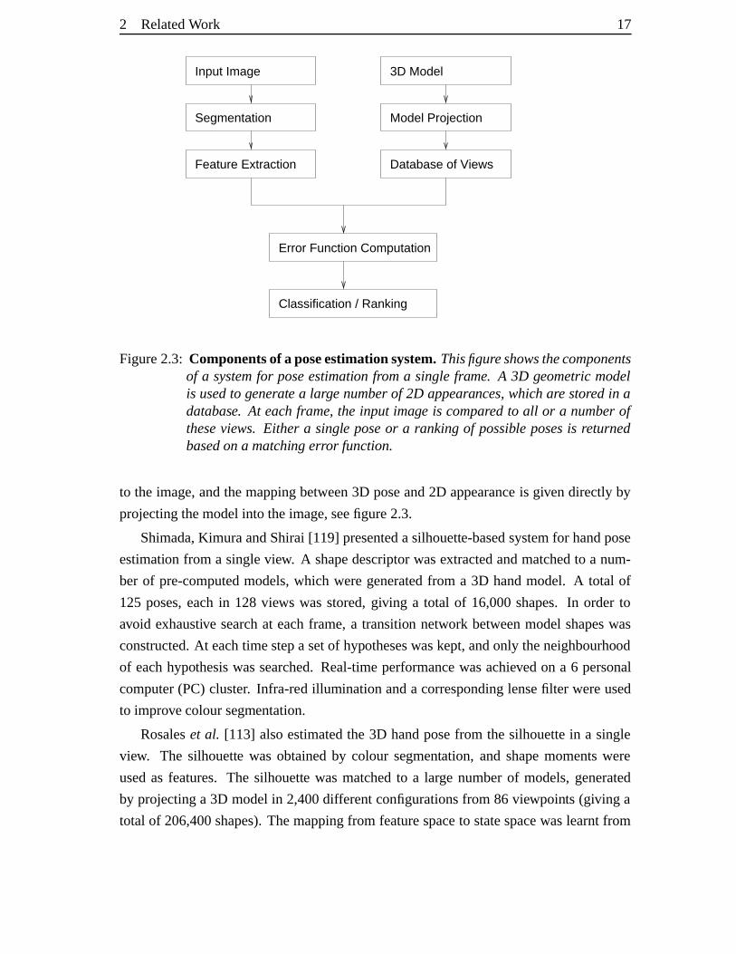
2.1.4 Single-view pose estim ation
More recently, a numberof methodshave beensuggestedfor handposeestimation from
a singleview. A 3D handmodelis usedto generate2D appearances,which arematched
2 RelatedWork 17
Input Image 3D Model
Segmentation
Feature Extraction Database of Views
Model Projection
Error Function Computation
Classification / Ranking
Figure2.3: Componentsof aposeestimationsystem.Thisfigureshowsthecomponentsof a systemfor poseestimation froma singleframe. A 3D geometricmodelis usedto generate a large numberof 2D appearances,which are storedin adatabase. At each frame, the input image is compared to all or a numberoftheseviews. Either a single poseor a rankingof possible posesis returnedbasedona matchingerror function.
to the image,andthemappingbetween3D poseand2D appearanceis givendirectly by
projectingthemodelinto theimage,seefigure2.3.
Shimada,KimuraandShirai[119] presentedasilhouette-basedsystemfor handpose
estimation from a singleview. A shapedescriptorwasextractedandmatchedto a num-
ber of pre-computedmodels,which weregeneratedfrom a 3D handmodel. A total of
125 poses,eachin 128 views wasstored,giving a total of 16,000shapes.In order to
avoid exhaustive searchat eachframe,a transition network betweenmodelshapeswas
constructed.At eachtimestepa setof hypotheseswaskept,andonly theneighbourhood
of eachhypothesiswassearched.Real-timeperformancewasachievedon a 6 personal
computer(PC)cluster. Infra-red illuminationanda correspondinglensefilter wereused
to improvecoloursegmentation.
Rosaleset al. [113] alsoestimatedthe 3D handposefrom the silhouettein a single
view. The silhouette was obtainedby colour segmentation, and shapemomentswere
usedas features. The silhouette wasmatchedto a large numberof models,generated
by projectinga 3D modelin 2,400differentconfigurationsfrom 86 viewpoints (giving a
total of 206,400shapes).Themappingfrom featurespaceto statespacewaslearntfrom
18 2 RelatedWork
example silhouettesgeneratedby a 3D model.A limitationof thetwo previousmethods
is that thesilhouette shapeis not a very rich feature,andmany differenthandposescan
give riseto thesamesilhouetteshapein casesof self-occlusion.
Athitsos andSclaroff [4, 5] followed a databaseretrieval approach.A databaseof
107,328imageswas constructedusinga 3D model (26 posesin 4128views). Differ-
entsimilarity measureswereevaluated,includingchamferdistance,edgeorientationhis-
tograms,shapemomentsanddetectedfingerpositions.A weightedsumof thesewasused
asaglobalmatchingcost.Retrieval timesof 3-4secondsperframeona1.2GHzPCwere
reportedin thecaseof aneutralbackground.In [6] theapproachwasextendedto cluttered
backgroundsby including a line matchingcosttermin thesimilarity measure.Processing
time increasedto 15 secondsperframe.Retrieval efficiency wasaddressedin [3], where
thesymmetricchamferdistancewasusedasasimilarity measure.Fastapproximationsto
thenearestneighbourclassifierwereexploredto reducethesearchtime. This wasdone
by learninganembeddingfrom theinput datainto Euclideanspace,wheredistancescan
berapidlycomputed,while trying to preserve therelativeproximity structureof thedata.
Poseestimation techniquesfrom asingleview areattractive,becausethey potentially
solve the initializationproblemin model-basedtrackers. In fact, if they wereefficient
enough,they couldbeusedfor poseestimationin eachinput frameindependently. The
observation modelis a key componentwhenadoptinga database-retrieval method.Ide-
ally, the similarity function shouldhave a global minimum at the correctpose,and it
should also be smooth aroundthis minimum to toleratesomediscretizationerror. As
in view-basedrecognition,segmentation is a difficult problem. The methodspresented
above requireeithera cleanbackground[4, 5, 113, 119] or a roughsegmentation [6] of
thehand.
The following sectiongives a brief review of the relatedfield of full humanbody
tracking.
2.2 Full human body trac king
Bothhandtrackingandfull humanbodytrackingcanbeviewedasspecialcasesof track-
ing non-rigid articulatedobjects. Many of the techniquesfor humanbody trackingde-
scribedin the literaturecanbe appliedto handtrackingaswell. Thereforethis section
givesa brief review of methodsusedfor trackingpeople,which is still a very active re-
searcharea.For moreextensive reviews thereaderis referredto thepapersby Aggarwal
andCai [1] andMoeslundandGranum[98].
Despitetheobvioussimilaritiesbetweenthetwo domains,therearea number of key
2 RelatedWork 19
differences.First of all, the observation model is usuallydifferent for handand body
tracking.Dueto clothing,full bodytrackershaveto handlealargervariability, but texture
or colourof clothingprovidemorereliablefeatures,whichcanbeusedfor tracking[107].
Anotheroption is to find peoplein imagesby usinga facedetector. In handtracking,
it is difficult to find featuresthat canbe tracked reliably due to weak texture andself-
occlusion.On theotherhand,skin colouris a discriminative feature,which is oftenused
to segmentthehandfrom thebackground.
Anotherdifferenceis thesystemdynamicsin bothcases.In humanbodymotion, the
relative imagemotion of the limbs is usuallymuchslower thanfor hands.Globalhand
motioncanbeveryfastandalsofingermotion mayonly takeafractionof asecond[134].
Thesefactorsmake thedynamicsof thehandmuchharderto modelthanregularmotion
patternssuchaswalkingor running.However, handtrackingisusuallydonein thecontext
of HCI, andfeedbackfrom higherlevelscanbeusedto interpretthemotion, for example
in signlanguagerecognitionsystems.
As pointedout by Moeslund andGranum[98], mostbody motion capturesystems
makevariousassumptionsrelatedto motionandappearance.Typicalassumptionsarethat
thesubjectremainsinsidethecameraview, that therangeof motion is constrained,that
lighting conditionsareconstant,or thatthesubjectiswearingtight-fitting clothes.Mostof
theseconditions canbemadeto hold in controlledenvironments,e.g. for motion capture
applications. For robustnessin lessrestrictiveenvironments,suchasHCI or surveillance
applications, aninitializationandrecoverymechanismneedsto beavailable.
Trackersbasedon 3D modelshave a relatively long tradition in humanbody track-
ing. The first model-basedtrackerswerepresentedby O’Rourke andBadler [102] and
Hogg[59]. Thesystemof Hoggalreadycontainedall theelementsof figure2.1,namely
a 3D geometricalmodelwith body kinematics,an observation model,anda methodto
searchfor the 3D parameters,which optimally align the modelwith the image. These
issuesneedto beaddressedin everymodel-basedtracker.
Thefirst geometricalmodel,suggestedby Marr andNishihara[92], is a hierarchical
structurewhereineachpart is representedby a cylinder. This model is usedin Hogg’s
trackingsystem[59]. Otherprimitiveshave beenusedsuchasboxesor quadrics,which
includecylinders,conesandellipsoids [19, 48, 95], deformablemodels[79] or implicit
surfaces[106]. Theunderlyingkinematical modelis arrangedin a hierarchicalfashion,
the torsobeingthe root frameof reference,relative to which the coordinatesystemsof
thebodylimbsaredefined.
A numberof differentobservation modelshave beensuggestedto matchthe model
20� 2 RelatedWork
projectionto the image. Examplesof observations usedare: edgecontours[41, 48,
59, 125], foregroundsilhouettes [37, 106], optical flow [19, 125], densestereodepth
maps[54, 106], or multi-view voxel data[95]. Severalworkscombineanumberof these
featuresinto onecostterm.
In somecases,a modelwith weakor no dynamicsis used,andthemodelparameters
areoptimized at eachframe,suchthat they minimize a costfunctionbasedon observa-
tions[37,59,106,125]. Whenadynamicmodelis used,themotion in consecutiveframes
canbepredictedandintegratedwith theobservationwithin a filtering framework. Possi-
ble choicesareextendedKalmanfiltering [79, 95], or versionsof particlefiltering [38].
Thehumanbodydynamicshave beenmodelledwith constantvelocity or constantaccel-
erationmodels[48, 79], switchedlinear dynamicmodels[104] or example-basedmod-
els[122].
Themajority of model-based3D bodytrackersrequiremultiple views in orderto re-
duceambiguity. Thehighdimensionalityof thestatespace,togetherwith self-occlusions
anddepthambiguity make trackingin asingleview anill-posedproblem[100]. Thecost
functionin themonocularestimationproblemis highly multi-modalandthereexist many
possible inversekinematic solutions for oneobservation. Choosingthewrongminimum
leadsto lossof track,thereforereliabletrackingrequiresthemaintenanceof multiple hy-
potheses.SminchisescuandTriggs[125] addressthis problemby usinga costfunction,
which includesmultiple cues,suchas edgeintensityand optical flow, and adopting a
sophisticatedsampling andsearchstrategy in the 30 dimensional statespace.Another,
complementarystrategy to resolvethisambiguity is to learndynamicpriorsfrom training
dataof motions[18, 60,122].
For simple HCI applicationsblob trackersmaybeadequate,for example thePfinder
system[148]. Typically a personis modelledby a numberof ellipsoids, which are
matchedfrom frameto frameusinganappearancedescriptor, suchasacolourhistogram.
IsardandMacCormick[69] combinedblobtrackingwith particlefiltering in theirBraMBLe
system. The body shapewasmodelled asa single generalizedcylinder, andthe system
could track the position of multiple peoplein a surveillanceapplication,wherea static
camerawasassumed.
Therehave beenonly few paperson 3D body poseestimationfrom a single image.
Oneexampleis the methodof Mori andMalik [99] who useda shapecontext descrip-
tor [11] to matchtheinput imageto anumberof exemplar2D views. Theexemplarswere
labelledwith key points, andafter registeringthe input shape,thesepointswereusedto
reconstructa likely 3D pose.This estimation algorithmwasappliedto eachframein a
2 RelatedWork 21
videosequenceindependently.
Anothermethodwaspresentedby Shakhnarovich et al. [117] who generateda large
numberof exampleimagesusing3D animationsoftware. The techniqueof parameter
sensitive hashingwasintroducedto learna hashfunction in orderto efficiently retrieve
approximatenearestneighbourswith respectto bothfeatureandparametervalues.This
approachis verysimilar to themethodof AthitsosandSclaroff [4] for handposeestima-
tion, wheretheproblemwassolved by a fastnearestneighboursearchin theappearance
domain.
In a parts-basedapproachto peopledetection,suchastheoneby Felzenszwalb and
Huttenlocher [44], “bottom-up” and “top-down” methodsare combined. The body is
representedby a collectionof bodyparts,e.g. torso,headandlimbs, andeachof these
is matchedindividually. The body poseis found by optimizing a cost function which
takes the global configurationinto account. Thesemethodsare promising as they re-
ducethesearchcomplexity significantlyandthey have recentlybeenextendedto three-
dimensionalbodytrackingfrom multipleviews [123].
2.3 Objec t detect ion
Oneof themainchallengesin trackingis initializationandrecovery. This is necessaryin
HCI applications, wherethe usercanmove in andout of the cameraview, andmanual
re-initialization is nota desirableoption.Handor full bodytrackingsystemsthatrely on
incrementalestimationanddonothavearecoverymechanismhavebeendemonstratedto
trackaccurately, but notoververy long imagesequences.
Usinga filter thatsupports multiple hypothesesis necessaryto overcomeambiguous
framesso that the tracker is ableto recover. Anotherway to overcomethe problemof
losinglock is to treattrackingasobjectdetectionat eachframe.Thusif thetargetis lost
at one frame,subsequentframesarenot affected. For example, currentfacedetection
systemswork reliably andfast[141] without relying on dynamicmodels.However, de-
tectorstendto give multiple positive responsesin theneighbourhoodof a correctmatch,
andtemporalinformation is usefulto rendersuchcasesunambiguous.
The following subsectionsreview templatematchingtechniques,which have been
introducedin the context of objectdetection. Someof thesemethodshave becomeso
efficient that they canbe implementedin real time systems, e.g. automatedpedestrian
detectionin vehicles[47].
22� 2 RelatedWork
2.3.1 Matching shape templa tes
Template-basedmethodshave yieldedgoodresultsfor locatingdeformableobjectsin a
scenewith no prior knowledge,e.g. for handsor pedestrians[6, 47]. Thesemethodsare
maderobustandefficient by theuseof distancetransformssuchasthechamferor Haus-
dorff distancebetweentemplateandimage[9, 16,62, 64], andwereoriginally developed
for matchingasingletemplate.
Chamfermatchingfor asingleshapewasintroducedby Barrow etal. [9]. It is a tech-
niquefor finding thebestmatchof two setsof edgepoints by minimizing a generalized
distancebetweenthem. A commonapplicationis template-to-imagematching,where
the aim is to locatea previously definedobject in the image. In mostpracticalappli-
cations,theshapetemplateis allowed to undergo a certaintransformation,which needs
to be dealtwith efficiently. No explicit point correspondencesaredeterminedin cham-
fer matching,which meansthat the whole parameterspaceneedsto be searchedfor an
optimum match. In orderto do this efficiently, the smoothnesspropertyof thechamfer
distancecanbe exploited. If the changein the transformationparametersis small, the
chamferdistancechangeis alsosmall. This motivatedthe multi-resolution approaches
of Borgeforsfor chamfermatching[16] andHuttenlocherandRucklidgefor Hausdorff
matching[65]. Borgeforsintroducedthehierarchicalchamfermatchingalgorithm[16],
wherea multi-resolutionpyramid of edgeimagesis built and matchingproceedsin a
coarse-to-finemanner. At thecoarsestlevel, thetransformation parametersareoptimized,
startingfrom points, which arelocatedon a regulargrid in parameterspace.Fromthese
optima thematchesat thenext level of resolutionarecomputed,andlocationswherethe
costincreasesbeyondathresholdarerejectedandnotfurtherexplored.Shapematchingis
demonstratedfor Euclideanandaffine transformations.However, acarefuladjustmentof
steplengthsfor optimizationandrejectionthresholdsis requiredandthealgorithmonly
guaranteesa locally optimal match.
HuttenlocherandRucklidge[65] useda similar approachto searchthe 4D transfor-
mation spaceof translationandindependentscalingof the � – and � –axis. Theparame-
ter spaceis tesselatedat multiple resolutionsandthe centreof eachregion is evaluated.
Boundsonthemaximumchangein costarederivedfor thetransformation parametersand
regionsin parameterspaceareeliminatedin acoarse-to-finesearch.Within thisparticular
4D transformation spacethemethodis guaranteednot to missany match,however, it is
notstraightforwardto extendto othertransformations,suchasrotations.
Bothmethodsweredevelopedfor matchingasingleshapetemplate.Three-dimensional
objectscanberecognizedby representingeachobjectby a setof 2D views. This multi-
2 RelatedWork 23
view basedrepresentationhasbeenusedfrequentlyin object recognition[83]. These
views, togetherwith a similarity transformationcanthenbeusedto approximatethefull
6D transformationspace.In thecasewhentheseshapesareobtainedfrom trainingexam-
ples,they areoftenreferred to asexemplars.
Breuel[21, 22] proposedanalternative shapematchingalgorithmby subdividing the
transformationspace.Thequality of a matchassignedto a transformationis thenumber
of templatepointsthatarebroughtwithin anerrorboundof someimagepoint. For each
sub-regionof parameterspaceanupperboundon this qualityof matchis computed,and
theglobaloptimumis foundby recursivesubdivisionof theseregions.
A key suggestionwasthatmultiple templatescouldbedealtwith efficiently by using
a treestructure[47, 101]. OlsonandHuttenlocher[101] usedagglomerative clustering
of shapetemplates.In eachiterationthetwo closestmodelsin termsof chamferdistance
aregroupedtogether. Eachnodeonly containsthosepoints, which the templatesin the
subtreehave in common. Duringevaluation thetreeis searchedfrom therootandateach
nodemodelpoints, which aretoo far away from an imageedgearecounted.This count
is propagatedto the childrennodesandthe searchis stopped oncea thresholdvalueis
reached.The thresholdvaluecorrespondsto an upperboundon the partial Hausdorff
distancebetweentemplates.This allows for earlyrejectionof models,however, thegain
in speedis only significant if themodelshave a largenumberof pointsin common. For
this to belikely, a largenumber of modelviews is necessaryandit is notclearwhichand
how many viewsto use.
Gavrila [47, 49] suggestedforming thetemplatehierarchyby optimizing a clustering
cost function. His idea is to groupsimilar templatesandrepresentthemwith a single
prototypetemplatetogetherwith anestimateof thevarianceof theerrorwithin thecluster,
whichis usedto defineamatchingthreshold.Theprototypeis first comparedto theimage
andonly if theerror is below thethresholdarethetemplateswithin theclustercompared
to the image.This clusteringis doneat variouslevels, resultingin a hierarchy, in which
the templatesat the leaf level cover the spaceof all possible templates.The methodis
usedin the context of pedestriandetectionfrom a moving vehicle. A three-level tree
is built from approximately4,500templates,which includesa searchover five scales
for eachtemplate.Detectionratesof 60–90%arereportedby usingthechamferdistance
alone.An extensionof thesystemincludesafurtherverificationstepbasedonanonlinear
classifier[47].
An approachto embedexemplar-basedmatchingin a probabilistic tracking frame-
work wasproposedby ToyamaandBlake [135]. In this method,templatesareclustered
24� 2 RelatedWork
usinga � -medioidclusteringalgorithm.A likelihoodfunctionis estimatedasa Gaussian
mixturemodel,whereeachclusterprototypedefinesthecentreof amode.Thedynamics
areencodedastransitionprobabilitiesbetweenprototypetemplates,anda first orderdy-
namicmodelis usedfor thecontinuoustransformation parameters.Theobservation and
dynamic modelsareintegratedin a Bayesianframework andtheposteriordistribution is
estimatedwith a particlefilter. A problemwith templatesetsis that their sizecangrow
exponentially with objectcomplexity.
2.3.2 Hierar chica l class ification
Thissectionpresentsanotherline of work in theareaof objectdetection,whichhasbeen
shown to besuccesfulfor facedetection.Thegeneralideais to slidewindowsof different
sizesover the imageand classifyeachwindow as faceor non-face. Alternatively, by
scalingthe image,a window of the samesize, typically of size ������� pixels, canbe
used.
Thetaskthusis formulatedasa patternrecognitionproblem,andthemethodsdiffer
by which featuresandwhich type of classifierthey use. Most of the papersdealwith
thecaseof singleview detection.Multiple views canbe handledby separatelytraining
detectorsfor imagestaken from otherviews. Variationin lighting andcontrastis either
handledby a normalizationstepduringpre-processing,or by explicitly includinga large
number of trainingexamplesin differentlightingconditions.
Rowley, BalujaandKanade[114] useda neuralnetwork-basedclassifier. After pre-
processing,the sub-window were fed into a multi-layer neuralnetwork, which returns
a real value between �� , correspondingto a face,and ��� , correspondingto no face.
The outputsof different filters were then combinedin order to eliminateoverlapping
detections.
SchneidermanandKanade[115] learnttheappearanceof facesandof non-facepatches
in frontal andside-view by representingthemashistogramsof waveletcoefficients.The
detectiondecisionfor eachwindow wasbasedon themaximumlikelihoodratio.
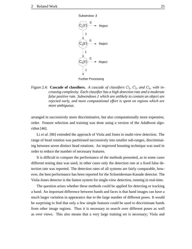
Romdhaniet al. [112] introduceda cascadeof classifierswhereregionswhich are
unlikely to befaceswerediscardedearly, andmorecomputationalresourceswasspentin
theremainingregions(seefigure2.4).Thiswasdoneby sequentialevaluation of support
vectorsin anSVM classifier.
Viola andJones[141] introducedrectanglefeatures,which aredifferencesof sums
of intensitiesover rectangularregionsin the imagepatch. Thesecanbe computedvery
efficiently by usingintegral images[33, 141]. A cascadeof classifierswasconstructed,
2 RelatedWork 25
C ( )3 I
C ( )2 I
C ( )1
I
Subwindow
Reject
Reject
Reject0
1
0
0
1
1
I
Further Processing
Figure2.4: Cascadeof classifiers. A cascadeof classifiers ��� , ��� , and ��� , with in-creasingcomplexity. Each classifierhasa highdetectionrateanda moderatefalsepositiverate. Subwindows� which are unlikely to containan objectarerejectedearly, and more computational effort is spenton regionswhich aremoreambiguous.
arrangedin successively morediscriminative, but alsocomputationally moreexpensive,
order. Featureselectionand training wasdoneusinga versionof the AdaBoostalgo-
rithm [46].
Li et al. [86] extendedtheapproachof Viola andJonesto multi-view detection.The
rangeof headrotationwaspartitionedsuccessively into smallersub-ranges,discriminat-
ing betweensevendistinct headrotations.An improvedboosting techniquewasusedin
orderto reducethenumberof necessaryfeatures.
It is difficult to comparetheperformanceof themethodspresented,asin somecases
differenttestingdatawasused,in othercasesonly thedetectionrateat a fixed falsede-
tectionratewasreported.Thedetectionratesof all systemsarefairly comparable,how-
ever, thebestperformancehasbeenreportedfor theSchneiderman-Kanadedetector. The
Viola-Jonesdetectoris thefastestsystemfor single-view detection,runningin real-time.
Thequestionariseswhetherthesemethodscouldbeappliedfor detectingor tracking
a hand.An importantdifferencebetweenhandsandfacesis thathandimagescanhave a
muchlargervariationin appearancedueto thelargenumberof differentposes.It would
besurprising to find thatonly a few simple featurescouldbeusedto discriminate hands
from other imageregions. Thus it is necessaryto searchover differentposesas well
as over views. This also meansthat a very large training set is necessary;Viola and
26� 2 RelatedWork
Jonesusednearly 5,000 faceimagesfor single-view detection[141]. There is also a
large variationin handshape,andin mostposes,a searchwindow containingthe hand
will include a larger numberof backgroundpixels. It may be necessaryto usemore
discriminative featuresthanrectanglefilters basedon intensity differences.For example,
Viola et al. [142] includedsimple motion featuresto applytheir framework to pedestrian
detection.If shapeis to beusedasa feature,thenthis framework becomesverysimilar to
thehierarchicalshapematchingmethodsdescribedin section2.3.1.
2.4 Summar y
This chapterhasintroduceda numberof differentapproachesto detecting,trackingand
interpretinghandmotionfrom images.Accurate3D trackingof handor full bodyrequires
ageometricmodel,aswell asaschemeto updatethemodelgiven theimagedata.A range
of handtrackingalgorithmshave beensurveyed, usingsingleor multiple views. The
problemis ill-posed whenusinga singlecamera,anda numberof methodshave been
suggestedto reducethenumberof parametersthatneedto beestimated.A shortcoming
of thesemethodsis the lack of an initialization andrecovery mechanism.View-based
methods couldbeusedto solve this problem. However, view-basedgesturerecognition
systems generallyassumethat the segmentation problemhasalreadybeensolved, and
most of them discriminatebetweena few gesturesonly. Single-view poseestimation
attempts to recover thefull 3D handposefrom a singleimage.This is doneby matching
the imageto a large databaseof model-generatedhandshapes.However, the mapping
from asingle2D view to 3D poseis inherentlyambiguous,andmethodsthatarebasedon
detectionaloneignoretemporalinformation, whichcouldresolveambiguous situations.
In orderto beableto accuratelyrecover3D informationaboutthehandposea3D ge-
ometrichandmodelis essential,andthefollowing chapterpresentsamethodto construct
suchamodelusingtruncatedquadricsasbuildingblocks.
3 A 3D Hand Model Built FromQuadrics
Treatnaturebymeansof thecylinder, thesphere, thecone, everythingbrought
into properperspective.
PaulCezanne(1839–1906)
In thiswork amodel-basedapproachis pursuedto recoverthethree-dimensionalhand
pose.The modelis usedto encodeprior knowledgeaboutthehandgeometryandvalid
handmotion. It alsoallows theposerecovery problemto be formulatedasa parameter
estimation taskandis thereforecentralto this work. In chapter4 the model is usedto
generatecontoursfor trackingwith anunscentedKalmanfilter, andin chapters5 and6 it
is usedto generatetemplates,whichareusedfor shape-basedmatching.
This chapterexplainshow to constructa three-dimensionalhandmodelusingtrun-
catedquadricsasbuildingblocks,approximatingtheanatomyof arealhumanhand.This
approachusesresultsfrom projective geometryin orderto generatethemodelprojection
asa setof conics,while handlingcasesof self-occlusion.As a theoreticalbackground,a
brief introductionto theprojectivegeometryof quadricsis givenin thenext section.For
textbookson this topic, thereaderis referredto [28, 56,116].
3.1 Projec tive geometr y of quadric s and conics
A quadric � is a seconddegreeimplicit surfacein 3D space. It canbe representedin
homogeneous coordinatesasa symmetric���� matrix � . The surfaceis definedby the
points � , whichsatisfytheequation� �!�"� # �%$ (3.1)
27
28� 3 A 3D HandModelBuilt FromQuadrics
x
y
z
d
h
w
(a)
x
y
z
h
dw
(b)
x
y
z
dw
(c)
y0
y1
π0
π 1
x
y
z
(d)
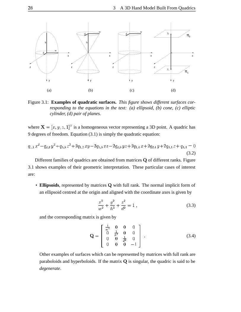
Figure3.1: Examplesof quadratic surfaces. Thisfigure showsdifferentsurfacescor-respondingto the equationsin the text: (a) ellipsoid, (b) cone, (c) ellipticcylinder, (d) pair of planes.
where �&#(' �*)+�,)+-.)/�10 � is a homogeneousvectorrepresentinga 3D point. A quadrichas
9 degreesof freedom.Equation(3.1) is simply thequadraticequation:2 �435�6� � 2 �73 �8� � 2 �73 �,- � 9� 2 �43 �:�8�! 9� 2 �43 �;�<-8 9� 2 �73 �<�=-8 >� 2 �43 ?;�@ >� 2 �73 ?8�! 9� 2 �73 ?A-8 2 ?+3 ?B#C�(3.2)
Differentfamiliesof quadricsareobtainedfrom matrices� of differentranks.Figure
3.1 shows examplesof their geometricinterpretation.Theseparticularcasesof interest
are:
• Ellipsoids, representedby matrices� with full rank. Thenormalimplicit form of
anellipsoidcentredat theorigin andalignedwith thecoordinateaxesis given by� �DE� � �F � - �G � #H��) (3.3)
andthecorrespondingmatrix is givenby
�I# JKKL �M;N � � �� �O N � �� � �P N �� � � ���QSRRT $ (3.4)
Otherexamplesof surfaceswhichcanberepresentedby matriceswith full rankare
paraboloidsandhyperboloids. If thematrix � is singular, thequadricis saidto be
degenerate.
3 A 3D HandModelBuilt FromQuadrics 29
• Conesand cylinders, representedby matrices� with U+V�W:X,YZ�>[�#C\ .Theequationof a conealignedwith the � -axisis givenby� �DE� � � �F � - �G � #]�^) (3.5)
andthecorrespondingmatrix is givenby
�I# JKKL �M:N � � �� � �O N � �� � �P N �� � � �QSRRT $ (3.6)
An elliptic cylinder, alignedwith the � -axis, is describedby� �D � - �G � #H��) (3.7)
andthecorrespondingmatrix is givenby
�I# JKKL �M;N � � �� � � �� � �P N �� � � �_�QSRRT $ (3.8)
• Pairs of planes `ba and `c� , representedas �I#C`dae` � � f`��g` �a with U7V�W:X,Y4�9[h#C� .For example, a pair of planes,which areparallelto the �<- -planecanbedescribed
by theequation: Yi���j��ak[dYl�m�n�o�p[q#]�^) (3.9)
in whichcasesrt#"'u�.)1�v)e�.)/�b��aw0 � and `bxB#y'u�=)/�v)e�.)1�E�o�Z0 � .Thecorrespondingmatrix is given by
�y# JKKL � � � �� � � �{z}|g~g�.|+�l��� � � �� ��z�|g~g�.|+�l�� � ��a8�6�QSRRT $ (3.10)
Coor dinate transf ormations Undera Euclideantransformation� the shapeof a
quadricis preserved,but thematrix representationchanges.Givena point � on quadric� , the equationof quadric �� , on which the transformedpoint �� # ��� lies can be
30� 3 A 3D HandModelBuilt FromQuadrics
derivedasfollows: � � �^� #]� (3.11)� � � Y�� � �%� � [<�]Y��^� � ��[.� #]� (3.12)� Yl�_�{[ � Yl�%� � �9�^� � [�Y����[q#]� (3.13)� �� � �� �� #]�^$ (3.14)
Thusthe matrix � is mappedto a matrix ���#�� � �!�>� � � . The matrix � representsa
Euclideantransformation, and � and � � � canbewritten in homogeneouscoordinatesas�H#��{� �� � ��� and � � � #�� � � � � � �� � � � $ (3.15)
Equivalently, this implies that any quadricmatrix �� , representingan ellipsoid, coneor
cylindercanbefactoredinto components representingits shape,givenin normalimplicit
form asin section3.1,andmotion in form of aEuclideantransformation.
Truncated quadrics By truncatingquadrics,they canbeusedasbuilding blocksfor
modelling morecomplex shapes[109, 130]. For any quadric � thetruncatedquadric �{�canbeobtainedby findingpoints � satisfying:� �!�^��#]� (3.16)
and � �8� �����%) (3.17)
where� is amatrixrepresentingapairof clippingplanes,seefigure3.2. It canbeensured
that ��� � � ��� for pointsbetweentheclipping planes,by evaluatingthisequationfor
a point at infinity in thedirectionof oneof theplanenormalvectors,andif it is positive,
thesignof � is changed.
Projecting a quadric In orderto determinethe projectedoutline of a quadricfor a
normalizedprojectivecamera�� #"'w�m� � 0 , thequadricmatrix � is writtenas�I# ��� �� � � � $ (3.18)
Thecameracentre�
andapoint in imagecoordinatesdefinearay �¡Y�¢6[q#£'5 �)e¢v0 � in 3D
space.Theinversedepthof apointontheray is determinedby thefreeparameter¢ , such
that thepoint �fY��¤[ is at infinity and �¡Y�¥¦[ is at thecameracentre(seefigure3.3). The
pointof intersectionof theray with thequadric � canbefoundby solvingtheequation�fYl¢6[ � ���fY�¢6[§#]�^) (3.19)
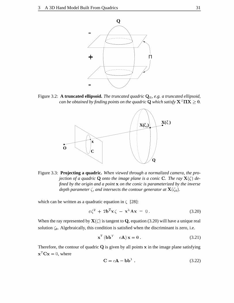
3 A 3D HandModelBuilt FromQuadrics 31
Π
-
-
+
Q
Figure3.2: A truncated ellipsoid. Thetruncatedquadric �>¨ , e.g. a truncatedellipsoid,canbeobtainedbyfindingpointsonthequadric � which satisfy � � � �&��� .
O
x
C
Q
0
X( ) ζ ζX( )
Figure3.3: Projecting a quadric. Whenviewedthrough a normalizedcamera, thepro-jectionof a quadric � ontothe image planeis a conic © . Theray �¡Yl¢=[ de-finedby theorigin anda point on theconicis parameterizedby theinversedepthparameter¢ , andintersectsthecontourgenerator at �fY�¢�ak[ .
whichcanbewrittenasaquadraticequationin ¢ [28]:� ¢ � ª� � � �¢� � !� � &# �^$ (3.20)
Whentherayrepresentedby �fY�¢6[ is tangentto � , equation(3.20)will haveauniquereal
solution ¢/a . Algebraically, thisconditionis satisfiedwhenthediscriminantis zero,i.e. !��Y �«� � � � � [= ¬#]�^$ (3.21)
Therefore,thecontourof quadric � is given by all points in theimageplanesatisfying � ©� #®� , where ©£# � � � �@� � $ (3.22)
32� 3 A 3D HandModelBuilt FromQuadrics
The \§b\ matrix © representsaconic,whichis animplicit curvein 2D space.For points on theconic © , theuniquesolutionof equation(3.20)is¢¯as#H� � � � ) (3.23)
which is theinversedepthof thepointon thecontourgeneratorof quadric � .
The normal vector to a conic Thenormalvector ° to aconic © atapoint canbe
computedin astraightforwardmanner. In homogeneouscoordinatesa line is represented
by a \ –vector ± , andis definedasthesetof points satisfying±8�8 ²#C�%$ (3.24)
By writing ±³#�'u°�)/� G 0 � , the line is definedin termsof its normalvector ° , andG, the
distanceto theorigin.
Theline ´ which is tangentialto theconicat thepoint ¶µ·© is given by´A#¸©� ·) (3.25)
for a proof see[56]. For ´E#¹'»ºi�k)eº¼�/)+º¼�+0 � its normalin Cartesiancoordinatesis given as°#y'»ºl�½)eº¼�p0 � andis normalizedto lengthone.
Projection into multipl e cameras A world point � is mappedto animagepoint by the \%¬� homogeneouscameraprojectionmatrix
�: ²# � ��#®¾�'w�m� � 0;��) (3.26)
where ¾ is the cameracalibrationmatrix andthe camerais locatedat the origin of the
world coordinatesystem,pointing in the direction of the positive - -axis. If thereare
multiple cameras,the first cameracanbe usedto definea referencecoordinateframe.
All othercamerapositions andorientationsarethengivenrelative to this view, andcan
be transformedinto the normalizedcameraview by a Euclideantransformation¿ . For
example,assumethat� �À#Á¾�'w�%� � 0 is thenormalizedprojectivecamera,anda second
camerais definedas� ��# � �p¿ . Thenprojectingtheworld point � with camera
� � is
thesameasprojectingthepoint ¿Â� in thenormalizedview: &# � �e� # � �p¿]�&$ (3.27)
As seenpreviously, coordinatetransformationsfor quadricscanbehandledeasily. It may
bethecasethata point is not visible in all views, thusocclusionhandlingmustbedone
for eachview separately.
3 A 3D HandModelBuilt FromQuadrics 33
(a) (b)
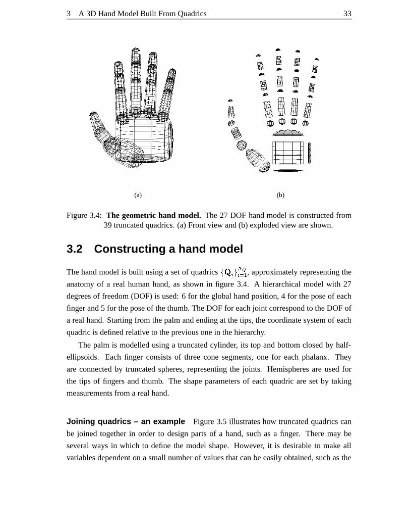
Figure3.4: The geometric hand model. The27 DOF handmodelis constructedfrom39 truncatedquadrics.(a) Frontview and(b) explodedview areshown.
3.2 Cons tructing a hand model
Thehandmodelis built usinga setof quadricsÃv��ÄÆÅÈÇ8ÉÄSÊ � , approximately representingthe
anatomyof a real humanhand,asshown in figure 3.4. A hierarchicalmodelwith 27
degreesof freedom(DOF) is used:6 for theglobalhandposition, 4 for theposeof each
fingerand5 for theposeof thethumb. TheDOF for eachjoint correspondto theDOF of
a realhand.Startingfrom thepalmandendingat thetips, thecoordinatesystemof each
quadricis definedrelative to thepreviousonein thehierarchy.
The palm is modelledusinga truncatedcylinder, its top andbottomclosedby half-
ellipsoids. Eachfinger consistsof threeconesegments,one for eachphalanx. They
areconnectedby truncatedspheres,representingthe joints. Hemispheresare usedfor
the tips of fingersandthumb. The shapeparametersof eachquadricaresetby taking
measurementsfrom arealhand.
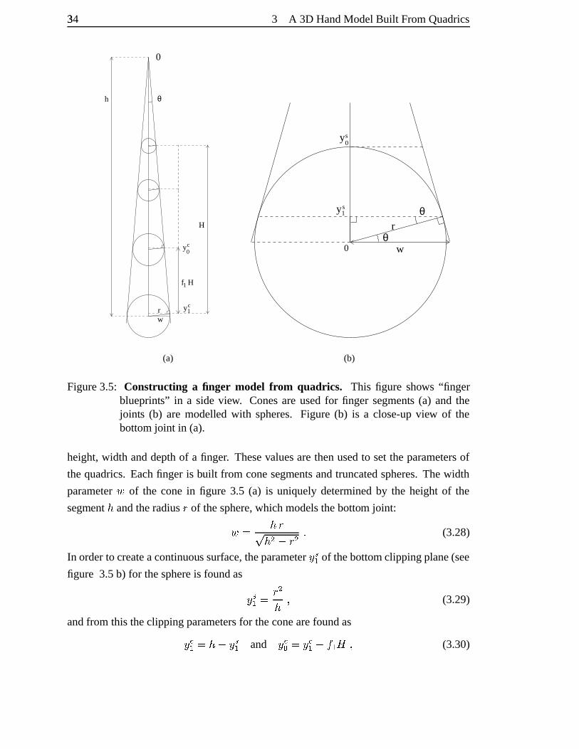
Joining quadrics – an example Figure3.5 illustrateshow truncatedquadricscan
be joined togetherin order to designpartsof a hand,suchasa finger. Theremay be
several ways in which to definethe modelshape.However, it is desirableto make all
variablesdependenton a smallnumberof valuesthatcanbeeasilyobtained,suchasthe
34� 3 A 3D HandModelBuilt FromQuadrics
θ
H
h
w
1f H
rcy1
yc0
0
(a)
wθ
θr
0
y1
y0s
s
(b)
Figure3.5: Constructing a finger model fr om quadrics. This figure shows “fingerblueprints” in a sideview. Conesare usedfor finger segments (a) and thejoints (b) are modelled with spheres.Figure (b) is a close-upview of thebottomjoint in (a).
height,width anddepthof a finger. Thesevaluesarethenusedto settheparametersof
thequadrics.Eachfinger is built from conesegmentsandtruncatedspheres.Thewidth
parameterD of the conein figure 3.5 (a) is uniquelydeterminedby the heightof the
segmentF
andtheradiusË of thesphere,whichmodelsthebottom joint:D # F ËÌ F � �nË � $ (3.28)
In orderto createacontinuoussurface,theparameter�.� of thebottomclippingplane(see
figure 3.5b) for thesphereis foundas � Í� # Ë �F ) (3.29)
andfrom this theclippingparametersfor theconearefoundas�6Î� # F �n� Í� and �=Îa #®�6Î� �³Ïv�wй) (3.30)
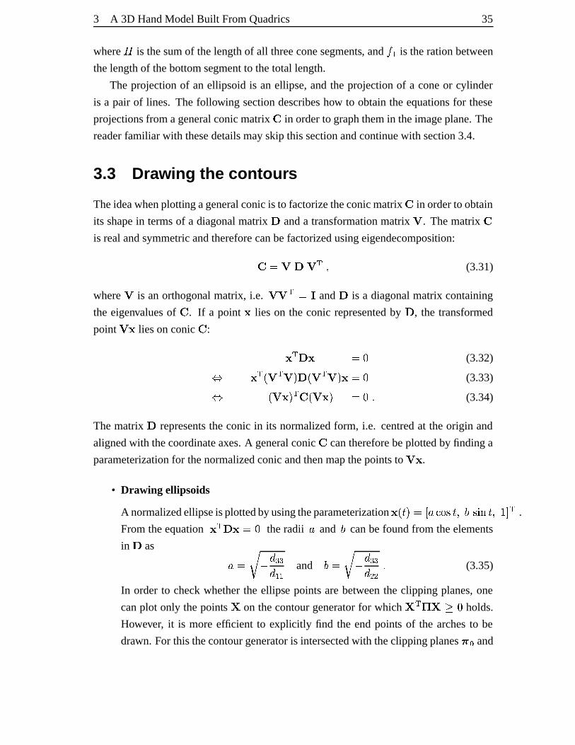
3 A 3D HandModelBuilt FromQuadrics 35
whereÐ is thesumof thelengthof all threeconesegments, and Ï.� is therationbetween
thelengthof thebottomsegmentto thetotal length.
The projectionof an ellipsoid is an ellipse,andthe projectionof a coneor cylinder
is a pair of lines. The following sectiondescribeshow to obtaintheequationsfor these
projectionsfrom ageneralconicmatrix © in orderto graphthemin theimageplane.The
readerfamiliarwith thesedetailsmayskip thissectionandcontinuewith section3.4.
3.3 Drawing the contour s
Theideawhenplottingageneralconicis to factorizetheconicmatrix © in orderto obtain
its shapein termsof a diagonalmatrix Ñ anda transformationmatrix Ò . Thematrix ©is realandsymmetricandthereforecanbefactorizedusingeigendecomposition:©H#®Ò�Ñ(Ò{�²) (3.31)
where Ò is anorthogonal matrix, i.e. Ò{Ò¬�n#I� and Ñ is a diagonalmatrix containing
the eigenvaluesof © . If a point lies on the conic representedby Ñ , the transformed
point Ò{ liesonconic © : � Ñ #C� (3.32)� !�ÓYÔÒ � Ò¬[wѶYÔÒ � Ò[4 ²#C� (3.33)� YiÒ{ «[ � © YiÒ{ «[ #C�%$ (3.34)
Thematrix Ñ representstheconic in its normalizedform, i.e. centredat theorigin and
alignedwith thecoordinateaxes.A generalconic © canthereforebeplottedby findinga
parameterizationfor thenormalizedconicandthenmapthepointsto Ò{ .
• Drawing ellipsoids
A normalizedellipseisplottedbyusingtheparameterization hYiÕp[�#y'»ÖÀׯØvÙ:Õk)hÚtÙ7ÛÜW�Õk)E�10 � .
Fromtheequation � Ñ f#H� theradii Ö and Ú canbefoundfrom theelements
in Ñ as Ö^#ÞÝ � G �4�G �4� and Úd#yÝ � G �4�G �4� $ (3.35)
In order to checkwhetherthe ellipse pointsarebetweenthe clipping planes,one
canplot only thepoints � on thecontourgeneratorfor which �²� � ���£� holds.
However, it is moreefficient to explicitly find the endpoints of the archesto be
drawn. For this thecontourgeneratoris intersectedwith theclippingplanes�a and
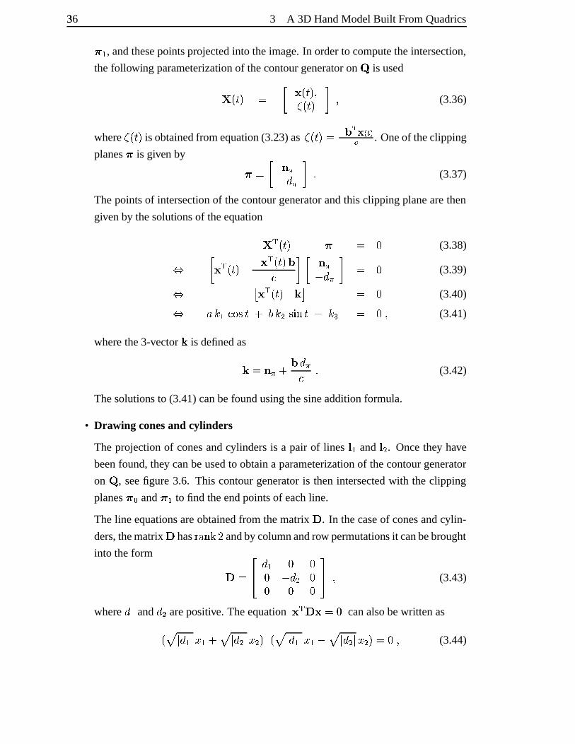
36� 3 A 3D HandModelBuilt FromQuadrics`�� , andthesepointsprojectedinto theimage.In orderto computetheintersection,
thefollowingparameterizationof thecontourgeneratoron � is used�fYiÕp[ # � �YiÕp[½)¢<YiÕp[ß� ) (3.36)
where¢,YÔÕp[ is obtainedfrom equation(3.23)as ¢<YiÕp[q# � �Óà z�áâ�Î . Oneof theclipping
planes is given by `®# � °«ã� G ã¬� $ (3.37)
Thepointsof intersectionof thecontourgeneratorandthis clippingplanearethen
givenby thesolutionsof theequation� �ÓYÔÕp[ ` # � (3.38)� �Ô � YÔÕp[ �d � YiÕp[ �� � � °*ã� G ã¬� # � (3.39)� ä !�ÓYiÕp[ åAæ # � (3.40)� Ö��=�s×1ØvÙ:Õ ªÚA�¤�EÙ7ÛÜW�Õ �v� # �^) (3.41)
wherethe3-vector å is definedasåÂ#]°�ãb � G ã� $ (3.42)
Thesolutions to (3.41)canbefoundusingthesineadditionformula.
• Drawing conesand cylinders
The projectionof conesandcylindersis a pair of lines ´p� and ´i� . Oncethey have
beenfound,they canbeusedto obtaina parameterizationof thecontourgenerator
on � , seefigure 3.6. This contourgeneratoris thenintersectedwith the clipping
planesEa and `t� to find theendpointsof eachline.
Theline equationsareobtainedfrom thematrix Ñ . In thecaseof conesandcylin-
ders,thematrix Ñ hasU+V�W:XB� andbycolumnandrow permutationsit canbebrought
into theform �# JL G � � �� � G ���� � �QT ) (3.43)
whereG � and
G � arepositive. Theequation � Ñ #®� canalsobewrittenasY+ç � G �/�4�!�� Áç � G ���Z�8�½[èY+ç � G �é�Z�!�@�]ç � G �È�4�8�k[�#]�^) (3.44)
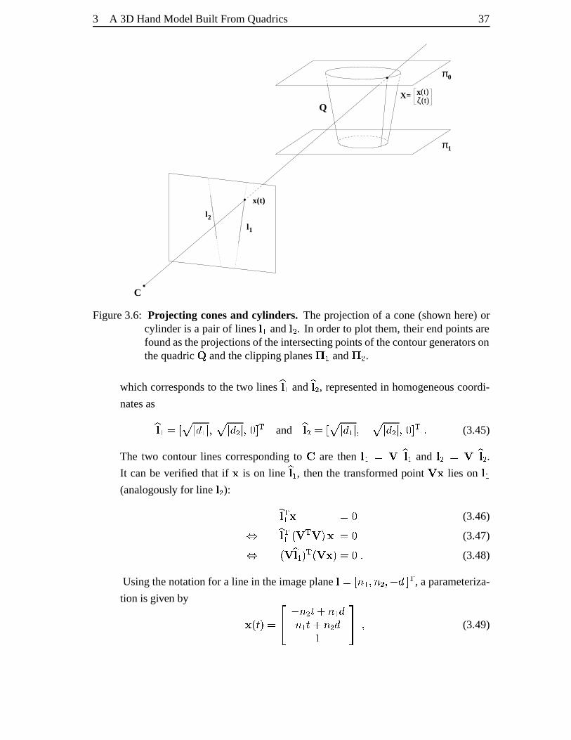
3 A 3D HandModelBuilt FromQuadrics 37
x(t)
π0
π1
Q
l1
l2
C
X= (t)x (t)ζ
Figure3.6: Projecting conesand cylinders. The projectionof a cone(shown here)orcylinder is a pair of lines ´g� and ´i� . In orderto plot them,their endpointsarefoundastheprojectionsof theintersectingpointsof thecontourgeneratorsonthequadric � andtheclippingplanes� � and � � .
which correspondsto thetwo lines � ´4� and� ´i� , representedin homogeneous coordi-
natesas� ´4�§#"'¼ç � G �é��)@ç � G ����)8��0 � and � ´i��#£'êç � G �/��)*�^ç � G ���}),�È0 � $ (3.45)
The two contourlines correspondingto © are then ´7�{#�Ò � ´Z� and ´l�¡#�Ò � ´i� .It canbe verified that if is on line � ´Æ� , thenthe transformedpoint Ò{ lies on ´w�(analogously for line ´l� ): � ´ � � #C� (3.46)� � ´ � � YiÒ{�;Ò¬[= &#C� (3.47)� YÔÒ � ´4�p[ � YiÒ{ «[�#C�%$ (3.48)
Usingthenotationfor a line in theimageplane ´�#y'5ë��½)+ëA�1)/� G 0 � , aparameteriza-
tion is given by hYiÕp[q# JL �Eë,�+Õ� ìë«� Gë«�ZÕ* ³ë,� G�QT ) (3.49)
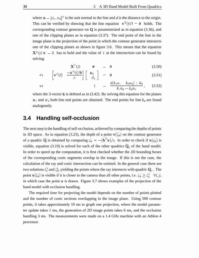
38� 3 A 3D HandModelBuilt FromQuadrics
where°¡#£'»ë*�½)+ë,�70 � is theunit normalto theline andG
is thedistanceto theorigin.
This canbe verified by showing that the line equation � YiÕp[:´�#�� holds. The
correspondingcontourgeneratoron � is parameterizedasin equation(3.36),and
oneof the clipping planesasin equation(3.37). The endpoint of the line in the
imageplaneis theprojectionof thepoint in which thecontourgeneratorintersects
oneof the clipping planesasshown in figure 3.6. This meansthat the equation� � YÔÕp[.`�#�� hasto hold andthe valueof Õ at the intersectioncanbe found by
solving � � YiÕp[ ` # � (3.50)� �Ô � YiÕp[ �b � YÔÕp[ �� � � °�ã� G ã¬� # � (3.51)� Õ # G YÆ�=�gë«�� í�v�+ë,�½[� í�v��=�gë,�À�³�v�+ë*� ) (3.52)
wherethe3-vector å is definedasin (3.42).By solving thisequationfor theplanes`�� and `b� both line endpointsareobtained.Theendpointsfor line ´w� arefound
analogously.
3.4 Handlin g self-oc clusion
Thenext stepis thehandlingof self-occlusion,achievedbycomparingthedepthsof points
in 3D space.As in equation(3.23), thedepthof a point hY�¢Èae[ on thecontourgenerator
of a quadric � is obtainedby computing ¢îam#&��Y � � «[pï � . In orderto checkif hYl¢¯ak[ is
visible, equation(3.19) is solved for eachof the otherquadrics � Ä of the handmodel.
In orderto speedup thecomputation, it is first checkedwhetherthe2D boundingboxes
of the correspondingconic segmentsoverlap in the image. If this is not the case,the
calculationof theray andconicintersectioncanbeomitted.In thegeneralcasethereare
two solutions ¢ Ä� and ¢ Ä� , yieldingthepointswheretheray intersectswith quadric ��Ä . The
point hYl¢1ak[ is visible if it is closerto thecamerathanall otherpoints, i.e. ¢�aE�®¢ Äð ñ,ò )4ó ,in which casethepoint is drawn. Figure3.7 shows examplesof theprojectionof the
handmodelwith occlusionhandling.
The requiredtime for projectingthemodeldependson thenumberof pointsplotted
and the numberof conic sectionsoverlapping in the imageplane. Using 500 contour
points, it takesapproximately10 ms to graphoneprojection,wherethemodelparame-
ter updatetakes1 ms, the generationof 2D imagepoints takes6 ms,andthe occlusion
handling 3 ms. Themeasurementsweremadeon a 1.4 GHz machinewith an Athlon 4
processor.
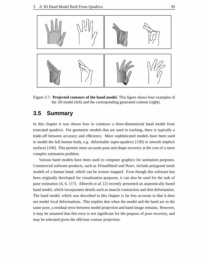
3 A 3D HandModelBuilt FromQuadrics 39
Figure3.7: Projectedcontoursof the hand model. Thisfigureshowsfour examplesofthe3D model(left) andthecorrespondinggeneratedcontour(right).
3.5 Summ ary
In this chapterit was shown how to constructa three-dimensional handmodel from
truncatedquadrics.For geometricmodelsthat areusedin tracking,thereis typically a
trade-off betweenaccuracy andefficiency. More sophisticatedmodelshave beenused
to modelthe full humanbody, e.g. deformablesuper-quadrics[130] or smoothimplicit
surfaces[106]. Thispermitsmoreaccurateposeandshaperecoveryat thecostof amore
complex estimationproblem.
Varioushandmodelshave beenusedin computergraphicsfor animation purposes.
Commercialsoftwareproducts,suchasVirtualHandandPoser, includepolygonalmesh
modelsof a humanhand,which canbe texturemapped.Even though this softwarehas
beenoriginally developedfor visualizationpurposes,it canalsobe usedfor the taskof
poseestimation[4, 6, 117]. Albrechtet al. [2] recentlypresentedananatomicallybased
handmodel,which incorporatesdetailssuchasmusclecontractionandskindeformation.
The handmodel,which wasdescribedin this chapteris far lessaccuratein that it does
not modellocal deformations.This impliesthatwhenthemodelandthehandarein the
samepose,a residualerrorbetweenmodelprojectionandhandimageremains.However,
it maybeassumedthat this error is not significantfor thepurposeof poserecovery, and
maybetoleratedgiven theefficient contourprojection.
4 Model-Based Tracking Using anUnscented Kalman Filter
We love to expect,andwhenexpectationis eitherdisappointedor gratified,
wewantto beagainexpecting.
SamuelJohnson(1709–1784)
This chapterpresentsa methodfor 3D model-basedhandtrackingbasedon the un-
scentedKalmanfilter (UKF). TheunscentedKalmanfilter is anextension of theKalman
filter to nonlinearsystems.In thehandtrackingapplicationnonlinearityis introducedby
theobservationmodel,which involvesprojectingthe3D modelinto theimage.
Thenext sectiongivesa brief review of Bayesianstateestimationandmotivatesthe
Kalmanfilter for linearsystemsfrom aprobabilistic pointof view. TheunscentedKalman
filter is thenintroducedandappliedto 3D handtracking. Experimentsfrom singleand
dualcameraviewsdemonstratetheperformanceof thismethod.
4.1 Trackin g as probabil istic inf erence
Thissectiongivesabrief introduction to recursiveBayesianestimation, which is thethe-
oreticalplatformfor therestof this thesis.For a morethoroughtreatmentof probability
andestimationtheorythereaderis referredto anumberof textbooks[71, 94,103].
The internalstateof theobjectat time Õ is representedasa setof modelparameters,
which aremodelledby therandomvariable ô á . Themeasurementobtainedat time Õ are
valuesof the randomvariable õ á . Trackingcanbe formulatedasan inferenceproblem:
Givenknowledgeabouttheobservations up to andincluding time Õ , ö*�4÷ á #øÃîö Ä Å áÄSÊ � , the
40
4 Model-BasedTrackingUsinganUnscentedKalmanFilter 41
aim is to find thedistributionof thestateô á :ù YÆô á � ö6�4÷ á [s$ (4.1)
wherethe notationù Ylö á [ is usedasa shorthandfor ù Y�õ á #øö á [ . Two independenceas-
sumptionsaretypically made,whichyield significantsimplifications.
• The first order Markov assumption statesthat the stateat time Õ only dependson
thestateat theprevioustime instantÕ§�è� :ù YÆô á �5ô á � �e)/$/$/$¯)kôE�p[j# ù YÆô á �5ô á � �7[B$ (4.2)
• Thesecondassumption statesthatthemeasurementat time Õ is conditionally inde-
pendentof all pastmeasurementsgiven ô á :ù Y�õ á �5ô á )7ö=�4÷ á � �7[·# ù Ylõ á �5ô á [B$ (4.3)
Stateestimationis typically expressedas a time-orderedpair of recursive equations,
namelya predictionstepanda updatestep. For initialization it is assumedthat ù YÆô%�w[is given, which is the statedistribution in the absenceof any measurement.Whenthe
observation ö;� is obtained,thedistribution is updatedusingBayesrule:ù Y�ôc�«�wõt�p[·# ù Ylö6�î�»ôE�p[ ù YÆôE�p[ú ù Ylö=�î�5ôc�w[ ù YÆôE�p[ G ôc� $ (4.4)
In the predictionstepat time Õ , it is assumedthat the estimate of ù YÆô á � �î� ö6�4÷ á � �7[ from
theprevious time stepis given. The statedistribution givenall previousmeasurements,ù YÆô á � ö.�4÷ á � �7[ , is thencomputedasù YÆô á � ö=�4÷ á � �7[·# û ù YÆô á �5ô á � �7[ ù Y�ô á � �é� ö.�4÷ á � �7[ G ô á � ��$ (4.5)
This relationis alsoreferredto astheChapman-Kolmogorov equation[71]. After obtain-
ing theobservationat time Õ , thedistribution is updatedasfollowsù YÆô á � ö=�4÷ á [¶# � � �á ù Ylö á �»ô á [ ù YÆô á � ö=�4÷ á � �7[�) (4.6)
wherethepartitionfunctionis givenby� á # û ù Yiö á �»ô á [ ù Y�ô á � ö=�4÷ á � �7[ G ô á $ (4.7)
Equation4.6canbeinterpretedasweightinga prior distribution ù Y�ô á � ö=�4÷ á � �7[ , computed
in thepredictionstep,with the likelihood ù Ylö á �»ô á [ . Theposteriordistribution ù YÆô á � ö.�4÷ á [is obtainedby normalizationandis usedin thenext predictionstep.
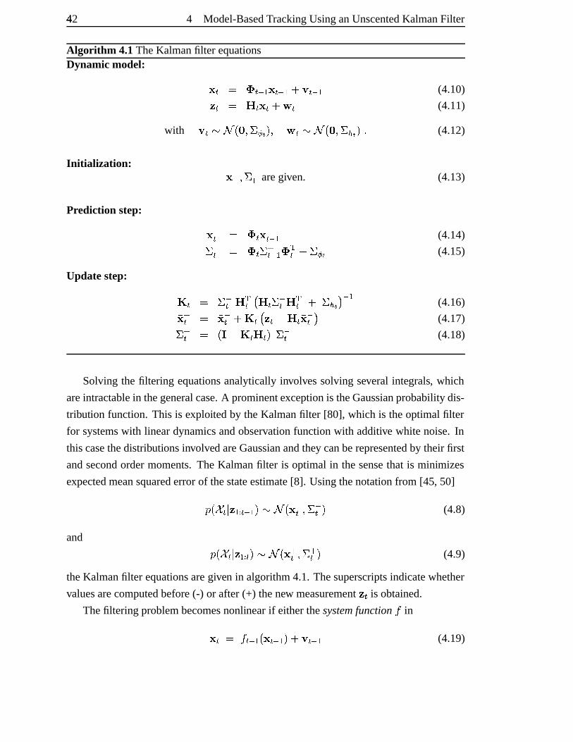
42�
4 Model-BasedTrackingUsinganUnscentedKalmanFilter
Algorithm 4.1TheKalmanfilter equationsDynamic model: á # ü á � �g á � �* ný á � � (4.10)ö á # ¿ á á ìþ á (4.11)
with ý á!ÿ�� Y � )������Æ[½) þ á!ÿ�� Y � )�� O ��[�$ (4.12)
Initiali zation: �� )�� �� aregiven. (4.13)
Prediction step: �á # ü á �á � � (4.14)� �á # ü á � �á � � ü �á ����� (4.15)
Updatestep: ¾ á # � �á ¿{�á ¿ á � �á ¿{�á � O ��� � � (4.16) �á # @�á �¾ á ö á �ì¿ á @�á � (4.17)� �á # Yi���ì¾ á ¿ á [�� �á (4.18)
Solving the filtering equationsanalyticallyinvolvessolving several integrals, which
areintractablein thegeneralcase.A prominentexceptionis theGaussianprobabilitydis-
tribution function. This is exploitedby theKalmanfilter [80], which is theoptimalfilter
for systemswith lineardynamicsandobservationfunctionwith additive white noise. In
thiscasethedistributionsinvolved areGaussianandthey canberepresentedby their first
andsecondordermoments.TheKalmanfilter is optimal in thesensethat is minimizes
expectedmeansquarederrorof thestateestimate[8]. Usingthenotationfrom [45, 50]ù Y�ô á � ö=�4÷ á � �7[ ÿ� Y @�á )�� �á [ (4.8)
and ù Y�ô á � ö=�4÷ á [ ÿ� Y �á )�� �á [ (4.9)
theKalmanfilter equationsaregiven in algorithm4.1. Thesuperscriptsindicatewhether
valuesarecomputedbefore(-) or after(+) thenew measurementö á is obtained.
Thefiltering problembecomesnonlinearif eitherthesystemfunction Ï in á # Ï á � �1Yi á � �7[� ný á � � (4.19)
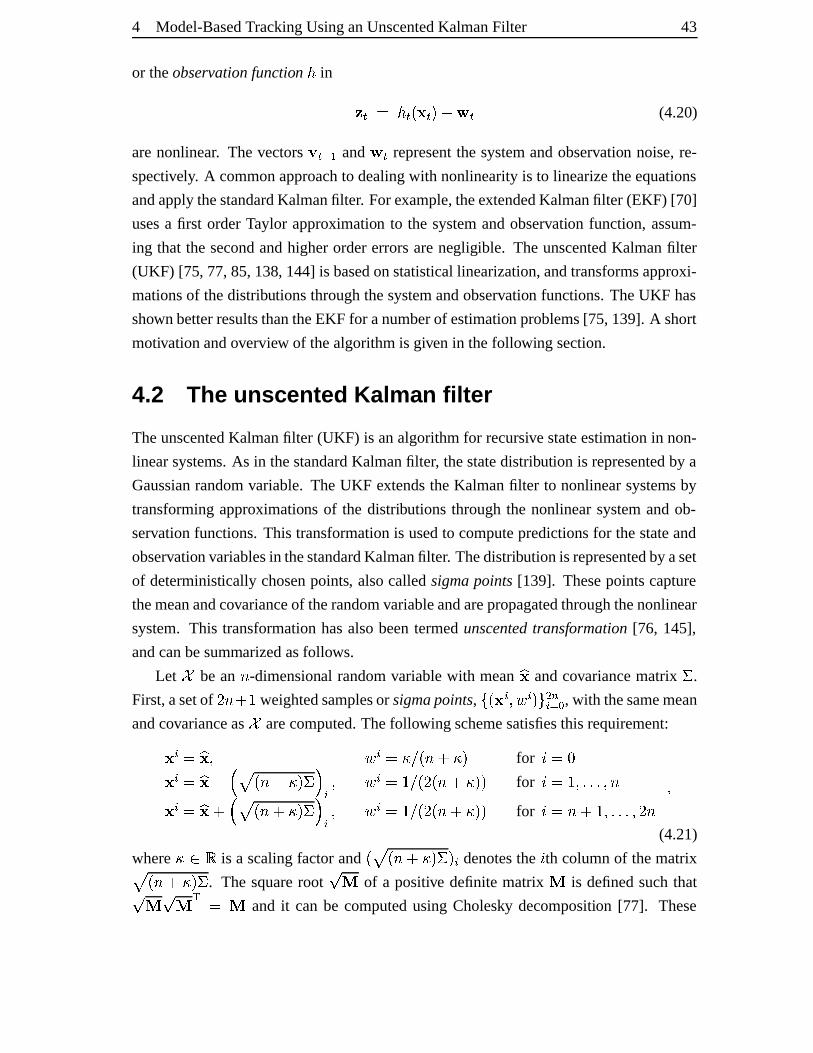
4 Model-BasedTrackingUsinganUnscentedKalmanFilter 43
or theobservationfunctionF
in ö á # F á Yi á [� nþ á (4.20)
arenonlinear. The vectorsý á � � and þ á representthe systemandobservation noise,re-
spectively. A commonapproachto dealingwith nonlinearityis to linearizetheequations
andapplythestandardKalmanfilter. For example,theextendedKalmanfilter (EKF) [70]
usesa first orderTaylor approximation to the systemandobservation function, assum-
ing that the secondandhigherordererrorsarenegligible. The unscentedKalmanfilter
(UKF) [75, 77,85,138, 144] is basedonstatisticallinearization,andtransformsapproxi-
mationsof thedistributionsthroughthesystemandobservation functions.TheUKF has
shown betterresultsthantheEKF for anumberof estimation problems[75, 139]. A short
motivationandoverview of thealgorithmis givenin thefollowingsection.
4.2 The unsc ented Kalma n filter
TheunscentedKalmanfilter (UKF) is analgorithmfor recursivestateestimation in non-
linearsystems. As in thestandardKalmanfilter, thestatedistribution is representedby a
Gaussianrandomvariable. TheUKF extendstheKalmanfilter to nonlinearsystems by
transformingapproximations of the distributionsthroughthe nonlinearsystemandob-
servationfunctions.This transformationis usedto computepredictionsfor thestateand
observation variablesin thestandardKalmanfilter. Thedistributionis representedby aset
of deterministically chosenpoints, alsocalledsigmapoints[139]. Thesepointscapture
themeanandcovarianceof therandomvariableandarepropagatedthroughthenonlinear
system. This transformationhasalsobeentermedunscentedtransformation [76, 145],
andcanbesummarizedasfollows.
Let ô be an ë -dimensional randomvariablewith mean � andcovariancematrix � .
First,asetof ��ës ¬� weightedsamplesor sigmapoints, Ã=Yi Ä ) D Ä [eÅ ���Ä Ê a , with thesamemean
andcovarianceas ô arecomputed.Thefollowing schemesatisfiesthis requirement: Ä # � q) D Ä #��8ï:Yië9 �8[ for ò #®� Ä # � Â��� ç Ylë9 �8[���� Ä ) D Ä #£�îï.YÆ�:Yië% �8[7[ for ò #¸�v)/$/$/$¯)+ë Ä # � � ç Ylë> ��<[�� � Ä ) D Ä #£�îï.YÆ�:Yië% �8[7[ for ò #�ë9 ®�v)/$1$/$1)k�Èë )(4.21)
where �¶µ�� is a scalingfactorand Y ç Yië9 �8[��d[ Ä denotesthe ò th columnof thematrixç Ylë> �8[�� . The squarerootÌ �
of a positive definitematrix�
is definedsuchthatÌ � Ì � � # �and it can be computedusingCholesky decomposition [77]. These
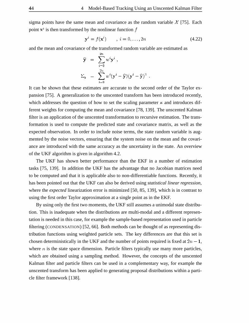
44�
4 Model-BasedTrackingUsinganUnscentedKalmanFilter
sigma pointshave the samemeanandcovarianceasthe randomvariable ô [75]. Each
point Ä is thentransformedby thenonlinearfunction Ï� Ä #]ϧYi Ä [ ) ò #]�.)1$/$/$½)k��ë (4.22)
andthemeanandcovarianceof thetransformedrandomvariableareestimatedas�� # ���� Ä Ê a D Ä � Ä )� | # ���� Ä Ê a D Ä Y � Ä � �� [1Y � Ä � �� [4�²$It canbe shown that theseestimatesareaccurateto the secondorderof the Taylor ex-
pansion[75]. A generalizationto theunscentedtransformhasbeenintroducedrecently,
which addressesthe question of how to set the scalingparameter� andintroducesdif-
ferentweightsfor computing themeanandcovariance[78, 139]. TheunscentedKalman
filter is anapplicationof theunscentedtransformation to recursiveestimation. Thetrans-
formationis usedto computethe predictedstateandcovariancematrix, aswell as the
expectedobservation. In orderto includenoiseterms,thestaterandomvariableis aug-
mentedby thenoisevectors,ensuringthat thesystemnoiseon themeanandthecovari-
anceareintroducedwith thesameaccuracy astheuncertaintyin thestate.An overview
of theUKF algorithmis givenin algorithm4.2.
The UKF hasshown betterperformancethan the EKF in a numberof estimation
tasks[75, 139]. In addition the UKF hasthe advantagethat no Jacobianmatricesneed
to becomputedandthat it is applicablealsoto non-differentiable functions. Recently, it
hasbeenpointedout thattheUKF canalsobederivedusingstatistical linear regression,
wheretheexpectedlinearizationerror is minimized[50, 85,139], which is in contrastto
usingthefirst orderTaylorapproximationata singlepointasin theEKF.
By usingonly thefirst two moments, theUKF still assumesaunimodal statedistribu-
tion. This is inadequatewhenthedistributionsaremulti-modalanda differentrepresen-
tationis neededin thiscase,for examplethesample-basedrepresentationusedin particle
filtering (CONDENSATION) [52, 66]. Bothmethodscanbethoughtof asrepresentingdis-
tribution functionsusingweightedparticlesets. The key differencesare that this set is
chosendeterministically in theUKF andthenumberof pointsrequiredis fixedat ��ë^ í� ,where ë is thestatespacedimension. Particle filters typically usemany moreparticles,
which areobtainedusinga samplingmethod. However, the conceptsof the unscented
Kalmanfilter andparticlefilters canbe usedin a complementaryway, for example the
unscentedtransformhasbeenappliedto generatingproposaldistributionswithin a parti-
clefilter framework [138].
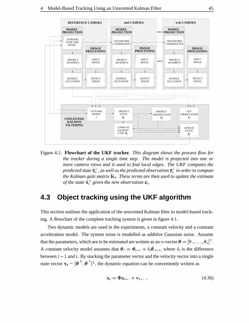
4 Model-BasedTrackingUsinganUnscentedKalmanFilter 45
...
...
COORDINATESTRANSFORM
QUADRICSPROJECT
OCCLUSIONHANDLE DETECT
EDGES
QUADRICSPROJECT
OCCLUSIONHANDLE DETECT
EDGES
COORDINATESTRANSFORM
QUADRICSPROJECT
OCCLUSIONHANDLE DETECT
EDGES
3D MODEL
SHAPEPOSE AND
PROJECTIONMODEL
PROCESSINGIMAGE
PROJECTIONMODEL
PROJECTIONMODEL
PROCESSINGIMAGE
PROCESSINGIMAGE
INPUTIMAGE
INPUTIMAGE
INPUTIMAGE
DYNAMICMODEL
UPDATESTATE
STATEPREDICT
COMPUTEKALMANGAIN
OBSERVATIONPREDICT
REFERENCE CAMERA 2nd CAMERA
GETOBSERVATION
n th CAMERA
KALMANFILTERING
f
t
_x +
t
__x tz
K t
t
__zUNSCENTED
Figure4.1: Flowchart of the UKF tracker. This diagram showsthe processflow forthe tracker during a single time step. The model is projectedinto one ormore camera views and is usedto find local edges. TheUKF computesthepredictedstate !#"$ , aswell asthepredictedobservation %&"$ in ordertocomputetheKalmangainmatrix ' $ . Thesetermsare thenusedto updatetheestimateof thestate !)($ giventhenew observation% $ .
4.3 Objec t trac king using the UKF algorith m
Thissectionoutlinestheapplicationof theunscentedKalmanfilter to model-basedtrack-
ing. A flowchartof thecompletetrackingsystemis givenin figure4.1.
Two dynamic modelsareusedin theexperiments,a constantvelocity anda constant
accelerationmodel. The systemnoiseis modelledasadditive Gaussiannoise. Assume
thattheparameters,whicharetobeestimatedarewrittenasan * -vector +-,/.1032�4656565�4�087:9<; .
A constantvelocity modelassumesthat + $ ,=+ $ " 2?>A@ $)B+ $ " 2 , where @ $ is the difference
betweenCEDGF and C . By stackingtheparametervectorandthevelocityvectorinto asingle
statevector ! $ ,/.H+ ; 4 B+ ; 9 ; , thedynamicequationcanbeconveniently writtenas! $ ,JI ! $ " 2)>LK $ " 2�4 (4.36)
46M
4 Model-BasedTrackingUsinganUnscentedKalmanFilter
where IN,PORQ @ $ QS QUT 5 (4.37)
Similarly the constantaccelerationmodel can be written as a linear systemby aug-
menting the statevector by the accelerationvector suchthat the statevector is given
as ! ,V.1+ ; 4 B+ ; 4)W+ ; 9 ; . In thiscasethesystemmatrix is givenbyIJ, XY Q @ $ Q SS Q @ $ QS S QZ[
(4.38)
All of theabovedynamicmodelsaredescribedby lineartransformations. Nonlinearityis
introducedby theobservation function.Theobservationvector% isobtainedby projecting
themodelinto eachcameraview andfinding local featuresalongvectorsnormalto the
contour. Two differenttypesof featuresareused:
• The input sequencesin the first set of experimentsconsistof greyscaleimages.
In theseexperiments the featuresareedgesin theneighbourhoodof theprojected
contour. Let \:]6^_a` 76bc_ed 2 bea setof contourpointsin theimageof cameraf . For each
point ] ^_ thenormalvector g ^_ is obtainedasexplainedin section3.1andalongeach
normalvectorthestrongestlocaledgeis detected[15, 27, 55]. For thistheintensity
valuesalongthenormalvectorareconvolvedwith aGaussiankernelandthelargest
absolutevalueis labelledasedgelocation hjik] ^_8l .• In asecondsetof experiments,coloursequencesareusedandtheextractedfeatures
arelocal skin colouredges[90]. A colourhistogramin RGB spaceis usedto clas-
sify pixelsinto skinandnon-skinpixels.For thissetof experimentsmeasurements
areonly takenfrom pointsonthesilhouette,andthepointof transition from skinto
non-skincolouris usedastheobservation hji�] ^_ l .Theobservationvector % is constructedby stackingtheinnerproductshmi�] ^_ l ; g ^_ n ,JF34656565�4o* ^ p 4 fR,NF34656565�4o* ^ (4.39)
into a singlevector. The sigmapointscorrespondto pointsin the statespace,symmet-
rically distributed aroundthe currentstateestimate.After transformingthemusingthe
dynamic model, the momentsof the predictedstate, qr"$ and s "$ are computed. Each
sigma point correspondsto a parametervector, which is usedto projectthe modelin a
particularposein order to obtain t% _ . The predictedobservation vector %&"$ at time C in
theUKF algorithmis obtainedby projectingthe handmodelcorrespondingto the state
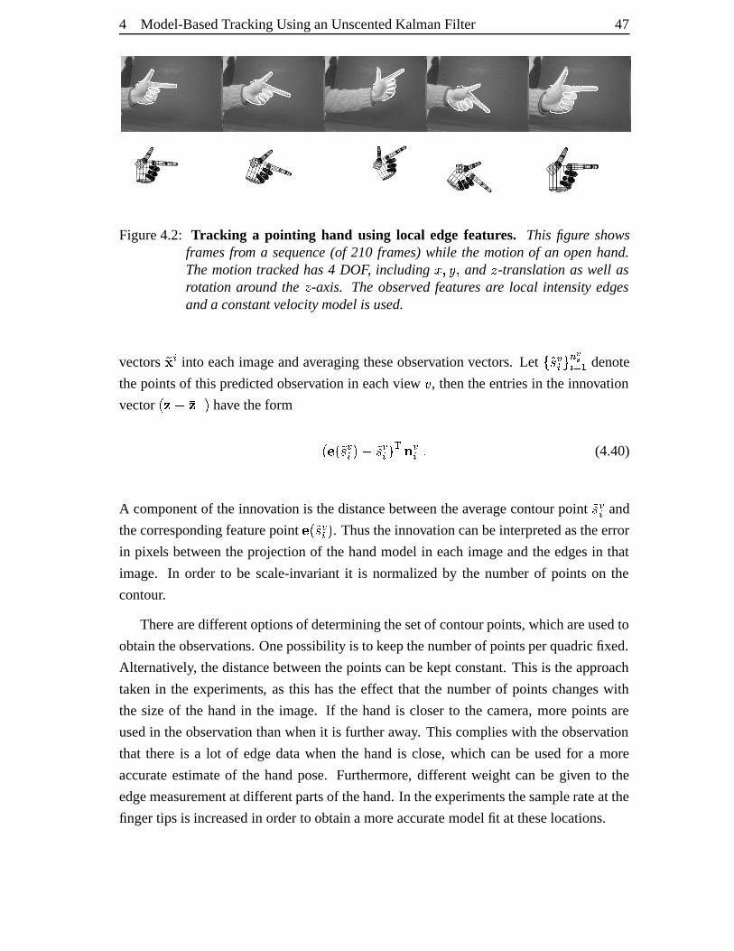
4 Model-BasedTrackingUsinganUnscentedKalmanFilter 47
Figure4.2: Tracking a pointing hand using local edgefeatures. This figure showsframesfrom a sequence(of 210 frames)while the motionof an openhand.Themotiontracked has4 DOF, including q 4ouv4 and w -translation as well asrotation aroundthe w -axis. Theobservedfeaturesare local intensity edgesanda constantvelocitymodelis used.
vectors t! _ into eachimageandaveragingtheseobservationvectors.Let \ t] ^_a` 76bc_ed 2 denote
thepointsof this predictedobservationin eachview f , thentheentriesin theinnovation
vector i % Dx % " l have theform iyhmi t] ^_ lrD t] ^_ l ; g ^_ 5 (4.40)
A componentof the innovationis thedistancebetweentheaveragecontourpoint t] ^_ and
thecorrespondingfeaturepoint hzi t] ^_ l . Thustheinnovationcanbeinterpretedastheerror
in pixels betweenthe projectionof the handmodelin eachimageandthe edgesin that
image. In order to be scale-invariant it is normalizedby the numberof pointson the
contour.
Therearedifferentoptionsof determiningthesetof contourpoints,whichareusedto
obtaintheobservations. Onepossibility is to keepthenumberof pointsperquadricfixed.
Alternatively, thedistancebetweenthepointscanbekeptconstant.This is theapproach
taken in the experiments, as this hasthe effect that the numberof pointschangeswith
the sizeof the handin the image. If the handis closerto the camera,morepointsare
usedin theobservation thanwhenit is furtheraway. This complieswith theobservation
that thereis a lot of edgedatawhen the handis close,which canbe usedfor a more
accurateestimateof the handpose. Furthermore,differentweight canbe given to the
edgemeasurementatdifferentpartsof thehand.In theexperimentsthesamplerateat the
fingertips is increasedin orderto obtainamoreaccuratemodelfit at theselocations.
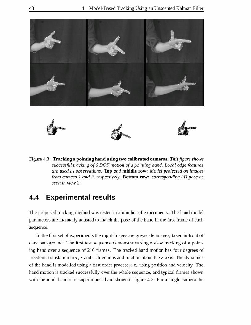
48M
4 Model-BasedTrackingUsinganUnscentedKalmanFilter
Figure4.3: Tracking a pointing hand usingtwo calibrated cameras.Thisfigureshowssuccessfultrackingof 6 DOF motionof a pointing hand.Local edge featuresare usedasobservations. Top andmiddle row: Modelprojectedon imagesfrom camera 1 and2, respectively. Bottom row: corresponding 3D poseasseenin view 2.
4.4 Experime ntal results
Theproposedtrackingmethodwastestedin a numberof experiments. Thehandmodel
parametersaremanuallyadustedto matchtheposeof thehandin thefirst frameof each
sequence.
In thefirst setof experimentstheinput imagesaregreyscaleimages,takenin front of
dark background.The first testsequencedemonstratessingle view trackingof a point-
ing handover a sequenceof 210 frames. The tracked handmotion hasfour degreesof
freedom:translationin q , u and w -directionsandrotationaboutthe w -axis. Thedynamics
of thehandis modelledusinga first orderprocess,i.e. usingposition andvelocity. The
handmotionis trackedsuccessfullyover thewholesequence,andtypical framesshown
with themodelcontourssuperimposedareshown in figure4.2. For a singlecamerathe
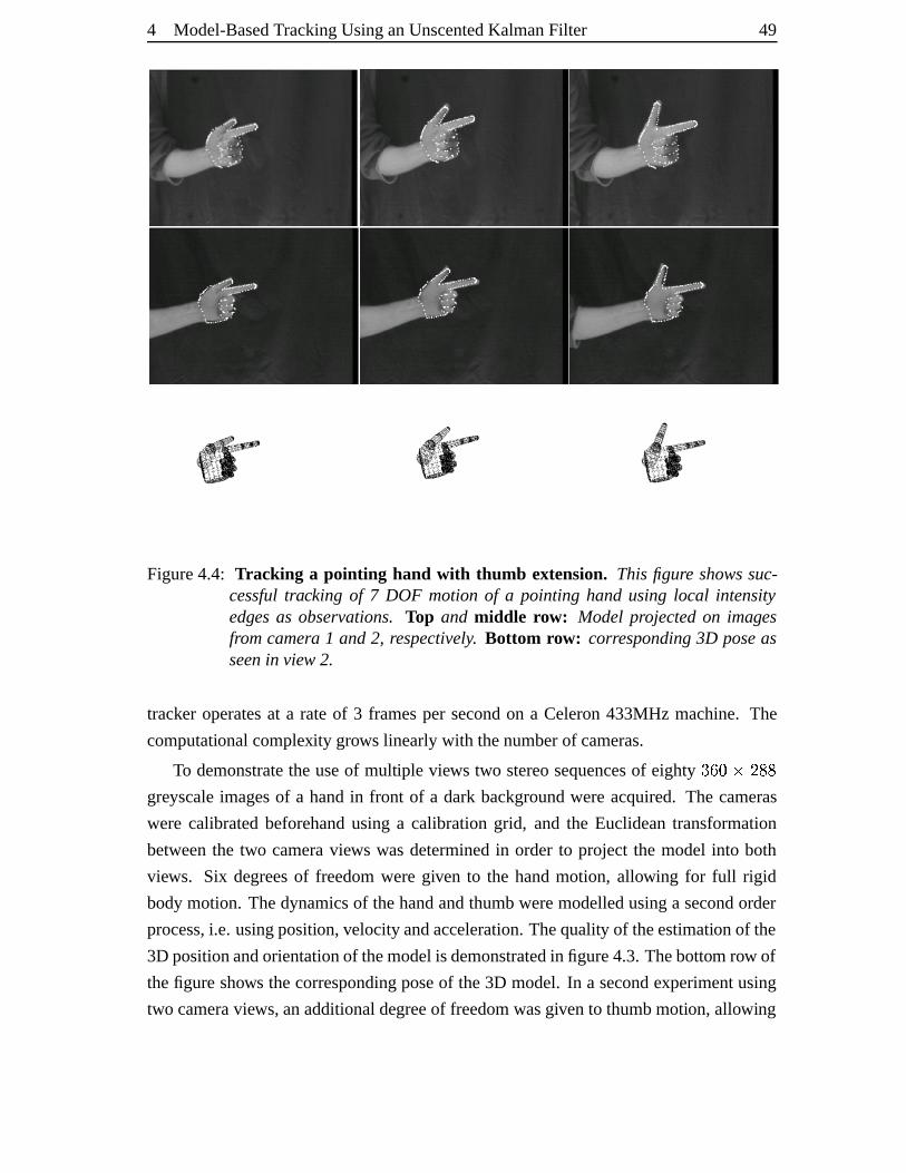
4 Model-BasedTrackingUsinganUnscentedKalmanFilter 49
Figure4.4: Tracking a pointing hand with thumb extension. This figure showssuc-cessfultracking of 7 DOF motion of a pointing hand using local intensityedges as observations.Top and middle row: Model projectedon imagesfromcamera 1 and2, respectively. Bottom row: corresponding3D poseasseenin view 2.
tracker operatesat a rateof 3 framesper secondon a Celeron433MHz machine. The
computationalcomplexity grows linearlywith thenumberof cameras.
To demonstratetheuseof multiple views two stereosequencesof eighty {3|3}�~L�:�3�greyscaleimagesof a handin front of a dark backgroundwereacquired.The cameras
were calibratedbeforehandusing a calibrationgrid, and the Euclideantransformation
betweenthe two cameraviews wasdeterminedin order to project the model into both
views. Six degreesof freedomweregiven to the handmotion, allowing for full rigid
bodymotion. Thedynamicsof thehandandthumbweremodelledusinga secondorder
process,i.e. usingposition,velocityandacceleration.Thequality of theestimationof the
3D positionandorientationof themodelis demonstratedin figure4.3.Thebottom row of
thefigureshows thecorrespondingposeof the3D model. In a secondexperimentusing
two cameraviews,anadditionaldegreeof freedomwasgivento thumbmotion,allowing
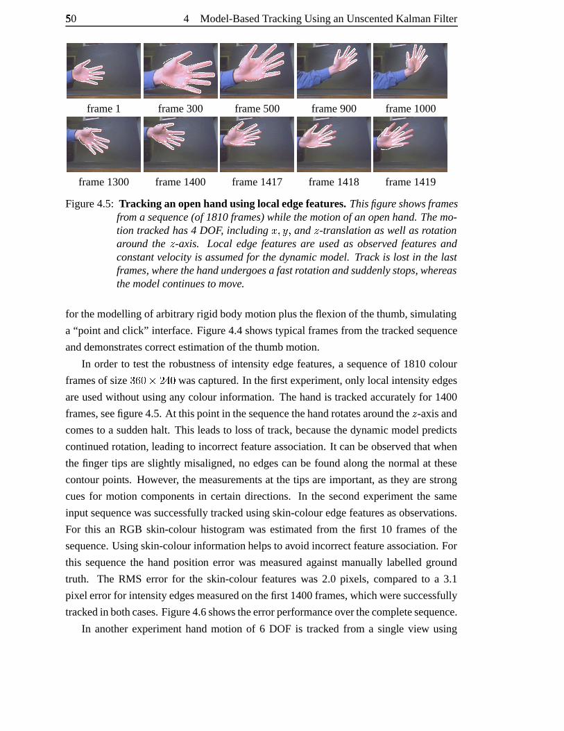
50� 4 Model-BasedTrackingUsinganUnscentedKalmanFilter
frame1 frame300 frame500 frame900 frame1000
frame1300 frame1400 frame1417 frame1418 frame1419
Figure4.5: Tracking an openhand usinglocal edgefeatures.Thisfigureshowsframesfrom a sequence(of 1810frames)while themotionof anopenhand.Themo-tion trackedhas4 DOF, including q 4ouj4 and w -translation aswell asrotationaround the w -axis. Local edge features are usedas observedfeatures andconstantvelocityis assumedfor thedynamicmodel. Track is lost in the lastframes,where thehandundergoesa fastrotationandsuddenlystops,whereasthemodelcontinuesto move.
for themodelling of arbitraryrigid bodymotionplustheflexion of thethumb,simulating
a “point andclick” interface.Figure4.4shows typical framesfrom thetrackedsequence
anddemonstratescorrectestimationof thethumbmotion.
In orderto testthe robustnessof intensity edgefeatures,a sequenceof 1810colour
framesof size {3|�}�~��:��} wascaptured.In thefirst experiment,only local intensity edges
areusedwithout usingany colour information. Thehandis trackedaccuratelyfor 1400
frames,seefigure4.5.At thispoint in thesequencethehandrotatesaroundthe w -axisand
comesto a suddenhalt. This leadsto lossof track,becausethedynamicmodelpredicts
continuedrotation,leadingto incorrectfeatureassociation.It canbeobservedthatwhen
thefinger tips areslightly misaligned,no edgescanbe foundalongthe normalat these
contourpoints. However, themeasurementsat the tips areimportant, asthey arestrong
cuesfor motion componentsin certaindirections. In the secondexperimentthe same
inputsequencewassuccessfullytrackedusingskin-colouredgefeaturesasobservations.
For this an RGB skin-colour histogramwas estimatedfrom the first 10 framesof the
sequence.Usingskin-colour informationhelpsto avoid incorrectfeatureassociation.For
this sequencethe handposition error was measuredagainstmanuallylabelledground
truth. The RMS error for the skin-colourfeatureswas 2.0 pixels, comparedto a 3.1
pixel errorfor intensityedgesmeasuredonthefirst 1400frames,whichweresuccessfully
trackedin bothcases.Figure4.6showstheerrorperformanceoverthecompletesequence.
In anotherexperimenthandmotion of 6 DOF is tracked from a single view using
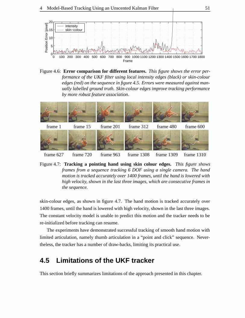
4 Model-BasedTrackingUsinganUnscentedKalmanFilter 51
0 100 200 300 400 500 600 700 800 900 1000 1100 1200 1300 1400 1500 1600 1700 18000
5
10
15
20
Frame
Pos
ition
Err
or [p
ixel
]
intensity skin−colour
Figure4.6: Err or comparison for differ ent features. Thisfigure showstheerror per-formanceof theUKF filter usinglocal intensity edges(black) or skin-colouredges(red)onthesequencein figure4.5.Errorsweremeasuredagainst man-ually labelledground truth. Skin-colouredgesimprovetrackingperformancebymore robust featureassociation.
frame1 frame15 frame201 frame312 frame480 frame600
frame627 frame720 frame963 frame1308 frame1309 frame1310
Figure4.7: Tracking a pointing hand using skin colour edges. This figure showsframesfrom a sequencetracking 6 DOF usinga singlecamera. Thehandmotionis trackedaccuratelyover1400frames,until thehandis loweredwithhighvelocity, shownin thelast threeimages,which areconsecutiveframesinthesequence.
skin-colour edges,asshown in figure 4.7. The handmotion is tracked accuratelyover
1400frames,until thehandis loweredwith highvelocity, shown in thelastthreeimages.
Theconstantvelocity modelis unableto predictthis motion andthe tracker needsto be
re-initializedbeforetrackingcanresume.
Theexperimentshave demonstratedsuccessfultrackingof smooth handmotion with
limited articulation, namelythumbarticulationin a “point andclick” sequence.Never-
theless,thetracker hasanumberof draw-backs,limiti ng its practicaluse.
4.5 Limit ations of the UKF trac ker
Thissectionbriefly summarizeslimitationsof theapproachpresentedin thischapter.
52� 4 Model-BasedTrackingUsinganUnscentedKalmanFilter
Initiali zation and reco very The tracker usesincrementalestimation andtherefore
requiresmanualinitializationof theposeparametersin thefirst frame.In theexperiments
this is solved by roughlyaligning themodelandstartingthetracker from this initial pose.
However, in an interactive application,possiblywith fasthandmotionor with thehand
leaving thecameraview, it is notdesirableto hold thehandin aparticularposeeachtime
trackhasbeenlost.
Ambig uous poses Whenusinga single view, thereareseveralposeswherea subset
of stateparametersbecomeunobservable,e.g. dueto self-occlusion[15, 39]. In such
casesthe underlying distributionsbecomemultimodalanda tracker, which canhandle
multi-modality hasto beused.SincetheUKF assumesunimodaldistributions,it cannot
handlesuchcases.Theuseof multiple camerascanhelpto resolvesomeof theambigui-
ties.
Feature robustness For thegreyscalesequenceslocal edgesareused,which could
only bereliablydetectedin front of neutralbackground.As soonasbackgroundclutteris
introduced,trackingbecomesunstable. Skincolouredgeshaveshown to bemorereliable.
However, only pointson the silhouettecanbe usedto obtain thesemeasurements,and
thereforeinformation from the internalregion of thehandis not included.Furthermore,
skincolourclassificationis noisyin general,andthefeaturesdisappearcompletelywhen
askin-colouredbackgroundis introduced.
4.6 Summar y
In this chaptera model-basedhandtrackingsystembasedon theunscentedKalmanfil-
ter waspresented.Theobservedfeaturesareintensity edgesor skin-colouredges,found
by local searchalongthecontournormals.Skin-colouredgeshave beenshown to make
trackingmorerobust by improving featurecorrespondence,however, they rely on suc-
cessfulskin-coloursegmentation.Chapter5 examineshow bothedgeandcolourfeatures
canbeintegratedto yield abetterobservationmodel.Thedynamicmodelsusedarecon-
stantvelocity andconstantaccelerationmodels.Thesearereasonablemodelswhenthe
trackedmotion is smooth, but they fail to capturevery fastor abrupthandmotion. The
systemscalesfrom singleto multiple viewsandexperimentsusingsingleanddualcamera
views wereshown. Themain limitationsof theapproacharethat it requiresmanualini-
tialization anddoesnothavea recoverystrategy whentrackis lost. Also, theassumption

4 Model-BasedTrackingUsinganUnscentedKalmanFilter 53
of theUKF of unimodality doesnotholdin severalcases,astherecanbeambiguity when
trackingahandin asingleview.
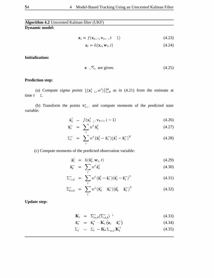
54� 4 Model-BasedTrackingUsinganUnscentedKalmanFilter
Algorithm 4.2UnscentedKalmanfilter (UKF)Dynamic model: ! $ ,���i ! $ " 2�4�K $ " 2�4�CrD�F�l (4.23)% $ ,��)i ! $ 4�� $ 4�C�l (4.24)
Initiali zation: !r"2 4�s "2 aregiven. (4.25)
Prediction step:
(a) Compute sigma points \�i ! _$ " 2 4o� _ l�`�� 7_ed�� as in (4.21) from the estimateattime C#D�F .
(b) Transform the points ! _$ " 2 and compute moments of the predicted statevariable: t! _$ , ��i ! _$ " 2 4�K $ " 2�4�CrDF�l (4.26) ! "$ , � _ � _ t! _$ (4.27)s "$ , � _ � _ i�t! _$ D� ! "$ l8i�t! _$ D� ! "$ l ; (4.28)
(c) Computemomentsof thepredictedobservation variable:t% _$ , �)i�t! _$ 4�� $ 4�C�l (4.29) % "$ , � _ � _ t% _$ (4.30)s "���o� $ , � _ � _ i�t% _$ Dx % "$ l8i�t% _$ Dx % "$ l ; (4.31)s "����� $ , � _ � _ i�t! _$ D� !r"$ l�i�t% _$ Dx %&"$ l ; (4.32)
Updatestep: ' $ , s "���o� $ i�s "����� $ l " 2 (4.33) !�($ , !#"$ >�' $z� % $ Dx %&"$)� (4.34)s ($ , s "$ D�' $ s "���o� $ ' ;$ (4.35)
5 Similarity Measures forTemplate-Based Shape Matching
I foundI couldsaythingswith colourandshapesthatI couldn’t sayanyother
way– thingsI hadnowordsfor.
GeorgiaO’Keeffe (1887–1986)
The task of robust tracking demandsa robust observation model. In the previous
chapterintensityandcolour edgeshave beenused. Either of thesefeaturetypesis not
reliableenoughin the generalcaseof a clutteredbackground,which may alsocontain
skin-colour. It is thereforenecessaryto examinein moredetail how a handshapecan
be detectedin an arbitrary image. In this chapterthe detectiontask is formulatedasa
templatematchingproblemandit is examinedhow shapeandcolour information canbe
usedto solve it. In termsof imageregions, edgeandskin colourfeaturescanbeseenas
complementary, asthey describetheboundaryandthe internalareaof thehand.A hand
in front of acomplex, but non-skincolouredbackgroundmayberecognizedby its colour,
whereasahandin agreyscaleimagemaystill berecognizedby its shape.Thetwo feature
typesaretreatedseparatelyin thefollowing sections,andarethencombinedinto asingle
costfunctionin section5.4.
Shapecarriessignificant visual informationaboutanobject. In theabsenceof other
cues,peoplecanusuallystill recognizeobjectsby their shape,for example in line draw-
ings. A commonway to extract shapeinformation from an imageis by edgedetec-
tion [25]. Thefirst sectionthereforeexaminesmethodsfor robustshapematchingbased
on distancetransformsandcomparesthemto a numberof methodswhich couldbeem-
ployed.
55
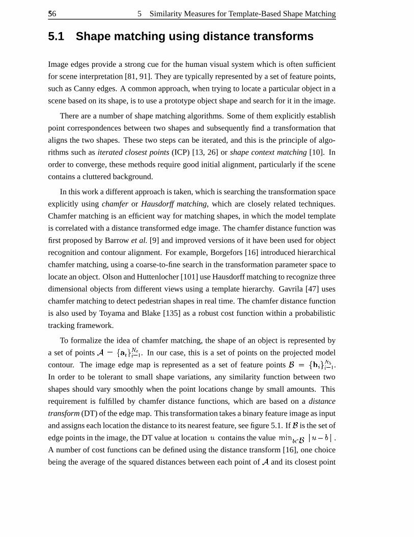
56� 5 Similarity Measuresfor Template-BasedShapeMatching
5.1 Shape matc hing using distance transf orms
Imageedgesprovide a strongcuefor thehumanvisualsystemwhich is often sufficient
for sceneinterpretation[81, 91]. They aretypically representedby asetof featurepoints,
suchasCanny edges.A commonapproach,whentrying to locatea particularobjectin a
scenebasedon its shape,is to useaprototypeobjectshapeandsearchfor it in theimage.
Therearea numberof shapematchingalgorithms. Someof themexplicitly establish
point correspondencesbetweentwo shapesandsubsequently find a transformationthat
alignsthe two shapes.Thesetwo stepscanbe iterated,andthis is theprincipleof algo-
rithms suchas iteratedclosestpoints(ICP) [13, 26] or shapecontext matching [10]. In
orderto converge,thesemethodsrequiregoodinitial alignment,particularlyif thescene
containsaclutteredbackground.
In thiswork adifferentapproachis taken,whichis searchingthetransformationspace
explicitly usingchamferor Hausdorff matching, which are closely relatedtechniques.
Chamfermatchingis anefficient way for matchingshapes,in which themodeltemplate
is correlatedwith adistancetransformededgeimage.Thechamferdistancefunctionwas
first proposedby Barrow et al. [9] andimprovedversionsof it have beenusedfor object
recognitionandcontouralignment. For example, Borgefors[16] introducedhierarchical
chamfermatching,usingacoarse-to-finesearchin thetransformationparameterspaceto
locateanobject.OlsonandHuttenlocher[101] useHausdorff matchingto recognizethree
dimensional objectsfrom differentviews usinga templatehierarchy. Gavrila [47] uses
chamfermatchingto detectpedestrianshapesin realtime. Thechamferdistancefunction
is alsousedby ToyamaandBlake [135] asa robustcostfunctionwithin a probabilistic
trackingframework.
To formalizethe ideaof chamfermatching,the shapeof anobjectis representedby
a setof points � ,U\�¡ _ `£¢�¤_ed 2 . In our case,this is a setof pointson the projectedmodel
contour. The imageedgemap is representedas a set of featurepoints ¥ , \�¦ _ ` ¢¨§_ed 2 .In order to be tolerantto small shapevariations, any similarity function betweentwo
shapesshouldvary smoothly whenthe point locationschangeby small amounts.This
requirementis fulfilled by chamferdistancefunctions, which are basedon a distance
transform(DT) of theedgemap.Thistransformationtakesabinaryfeatureimageasinput
andassignseachlocationthedistanceto its nearestfeature,seefigure5.1. If ¥ is thesetof
edgepointsin theimage,theDT valueat location © containsthevalue ª�«¬m®k¯ ¥°±° ©²D´³ °±° .A numberof costfunctionscanbedefinedusingthedistancetransform[16], onechoice
beingtheaverageof thesquareddistancesbetweeneachpoint of � andits closestpoint
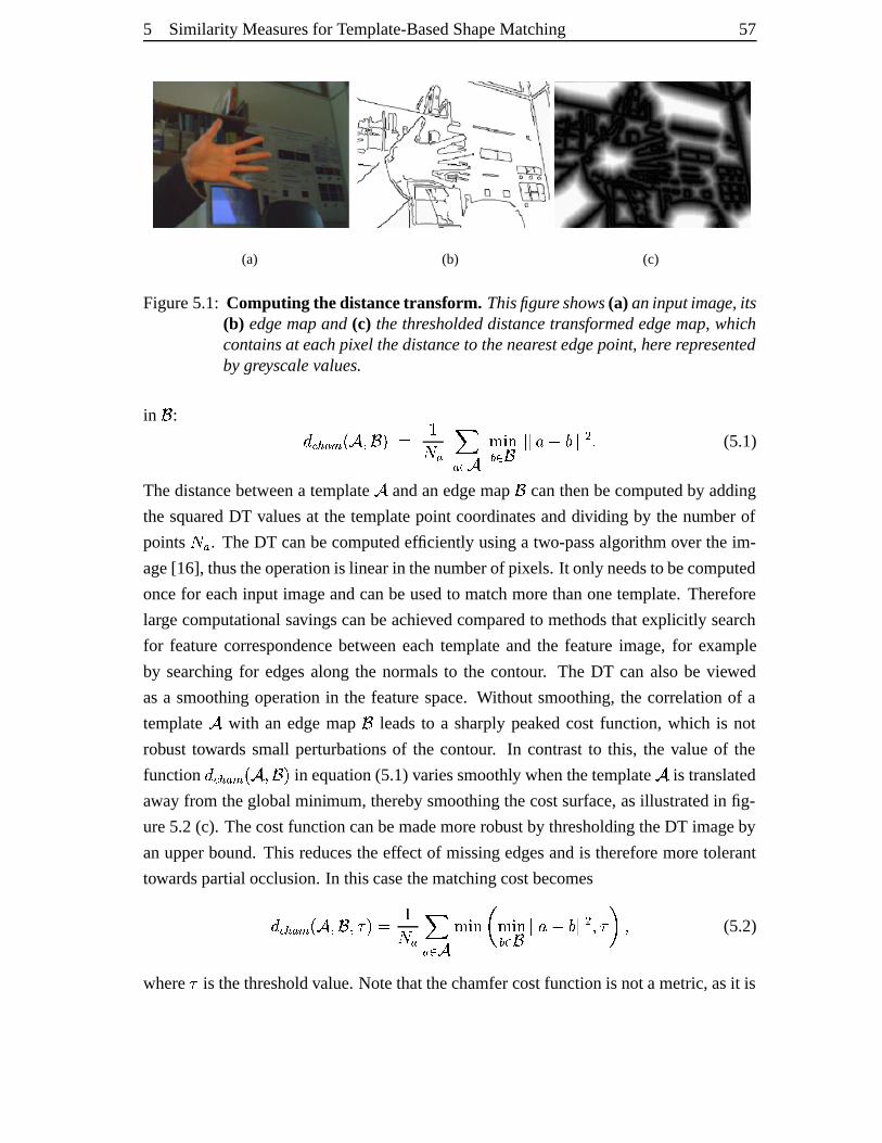
5 Similarity Measuresfor Template-BasedShapeMatching 57
(a) (b) (c)
Figure5.1: Computing the distancetransform. Thisfigureshows(a) aninputimage, its(b) edge mapand (c) thethresholdeddistancetransformededge map,whichcontainsat each pixel thedistanceto thenearestedgepoint, here representedbygreyscalevalues.
in ¥ : µ·¶y¸�¹�º iy��4o¥�l», F¼ ¹ �¹ ¯ � ª½«±¬®k¯ ¥ °±°�¾ D�³ °° � 5 (5.1)
Thedistancebetweena template� andanedgemap ¥ canthenbecomputedby adding
the squaredDT valuesat the templatepoint coordinatesanddividing by the numberof
points¼ ¹
. TheDT canbecomputedefficiently usinga two-passalgorithmover the im-
age[16], thustheoperationis linearin thenumberof pixels. It only needsto becomputed
oncefor eachinput imageandcanbeusedto matchmorethanonetemplate.Therefore
largecomputational savingscanbeachievedcomparedto methodsthatexplicitly search
for featurecorrespondencebetweeneachtemplateand the featureimage,for example
by searchingfor edgesalong the normalsto the contour. The DT can alsobe viewed
asa smoothing operationin the featurespace.Without smoothing, the correlationof a
template� with an edgemap ¥ leadsto a sharplypeaked cost function, which is not
robust towardssmall perturbationsof the contour. In contrastto this, the valueof the
function
µE¶y¸�¹�º iy��4o¥¿l in equation(5.1)variessmoothly whenthetemplate� is translated
away from theglobalminimum,therebysmoothing thecostsurface,asillustratedin fig-
ure5.2(c). Thecostfunctioncanbemademorerobustby thresholding theDT imageby
anupperbound.This reducestheeffect of missingedgesandis thereforemoretolerant
towardspartialocclusion.In thiscasethematchingcostbecomesµ�¶y¸�¹�º iÀ�Á4o¥²4�¨lÃ, F¼ ¹ �¹ ¯ � ª½«±¬-Ĩª½«±¬®k¯ ¥ °°Å¾ D�³ °° � 4�Â�Æ»4 (5.2)
where is thethresholdvalue.Notethatthechamfercostfunctionis notametric,asit is
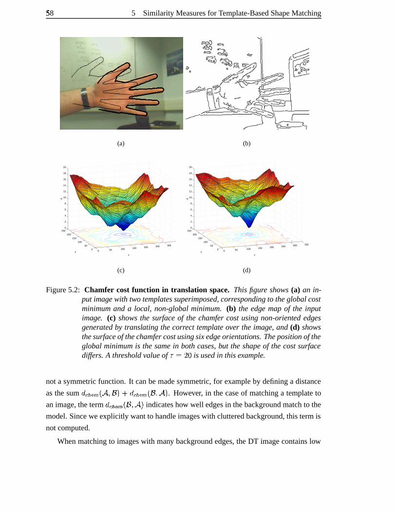
58� 5 Similarity Measuresfor Template-BasedShapeMatching
(a) (b)
0 50 100 150 200 250 300 350
0
50
100
150
200
2500
2
4
6
8
10
12
14
16
18
20
xy
d
(c)
0 50 100 150 200 250 300 350
0
50
100
150
200
2500
2
4
6
8
10
12
14
16
18
20
xy
d
(d)
Figure5.2: Chamfer cost function in translation space. This figure shows(a) an in-put imagewith two templatessuperimposed,correspondingto theglobalcostminimumand a local, non-globalminimum. (b) the edge mapof the inputimage. (c) showsthe surfaceof the chamfercostusingnon-oriented edgesgeneratedby translating thecorrect templateover the image, and (d) showsthesurfaceof thechamfercostusingsixedgeorientations.Thepositionof theglobal minimumis the samein bothcases,but the shapeof the costsurfacediffers. A thresholdvalueof ÂÁ,���} is usedin thisexample.
not a symmetricfunction. It canbemadesymmetric, for exampleby defininga distance
asthesum
µE¶y¸�¹�º iÀ�Á4o¥¿l�> µ�¶y¸�¹�º iÀ¥Ç4o�Èl . However, in thecaseof matchinga templateto
animage,theterm
µE¶y¸�¹�º iy¥²4o�½l indicateshow well edgesin thebackgroundmatchto the
model.Sinceweexplicitly wantto handleimageswith clutteredbackground,this termis
notcomputed.
Whenmatchingto imageswith many backgroundedges,theDT imagecontainslow
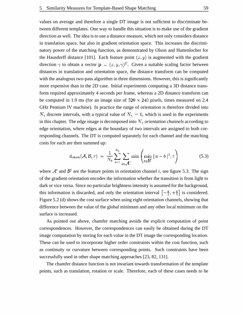
5 Similarity Measuresfor Template-BasedShapeMatching 59
valueson averageandthereforea singleDT imageis not sufficient to discriminate be-
tweendifferenttemplates.Oneway to handlethissituationis to makeuseof thegradient
directionaswell. Theideais to useadistancemeasure,whichnotonly considersdistance
in translationspace,but alsoin gradientorientationspace.This increasesthe discrimi-
natorypower of the matchingfunction,asdemonstratedby OlsonandHuttenlocherfor
the Hausdorff distance[101]. Eachfeaturepoint i q 4�u�l is augmentedwith the gradient
direction É to obtaina vector Ê�, i q 4�uj4�Ézl�Ë . Given a suitablescalingfactorbetween
distancesin translationandorientation space,the distancetransformcanbe computed
with theanalogoustwo-passalgorithmin threedimensions.However, this is significantly
moreexpensive thanin the2D case.Initial experimentscomputinga 3D distancetrans-
form requiredapproximately4 secondsper frame,whereasa 2D distancetransformcan
be computedin 1.9 ms (for an imagesizeof {3��}Ì~��£��} pixels, timesmeasuredon 2.4
GHz PentiumIV machine).In practicetherangeof orientation is thereforedividedinto¼ÎÍdiscreteintervals,with a typical valueof
¼ÏÍ ,Ð| , which is usedin the experiments
in thischapter. Theedgeimageis decomposedinto¼RÍ
orientationchannelsaccordingto
edgeorientation,whereedgesat theboundaryof two intervalsareassignedto bothcor-
respondingchannels.TheDT is computedseparatelyfor eachchannelandthematching
costsfor eacharethensummedup:µ�¶y¸�¹�º iÀ�Ñ4�¥²4�¨l�, F¼ ¹ ¢¨Ò� _Ód 2 �¹ ¯ �RÔ ª½«±¬ÖÕ#ª½«±¬®k¯ ¥�Ô °±°Å¾ DL³ °±° � 4�Â�× (5.3)
where � _ and ¥ _ arethe featurepointsin orientationchanneln , seefigure5.3. Thesign
of thegradientorientationencodestheinformationwhetherthetransitionis from light to
darkor viceversa.Sincenoparticularbrightnessintensity is assumedfor thebackground,
this informationis discarded,andonly the orientationinterval ØÙDÈÚ � 4�>ÁÚ �£Û is considered.
Figure5.2(d) showsthecostsurfacewhenusingeightorientationchannels,showing that
differencebetweenthevalueof theglobalminimumandany otherlocalminimumonthe
surfaceis increased.
As pointed out above, chamfermatchingavoids the explicit computationof point
correspondences.However, the correspondencescaneasilybe obtainedduring the DT
imagecomputationby storingfor eachvaluein theDT imagethecorrespondinglocation.
Thesecanbeusedto incorporatehigherorderconstraintswithin thecostfunction,such
as continuity or curvaturebetweencorrespondingpoints. Suchconstraintshave been
successfullyusedin othershapematchingapproaches[23, 82,131].
Thechamferdistancefunctionis not invarianttowardstransformationof thetemplate
points, suchastranslation,rotationor scale.Therefore,eachof thesecasesneedsto be
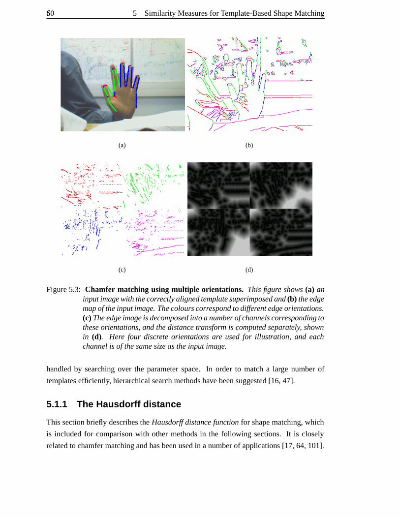
60Ü 5 Similarity Measuresfor Template-BasedShapeMatching
(a) (b)
(c) (d)
Figure5.3: Chamfer matching using multiple orientations. Thisfigure shows(a) aninputimagewith thecorrectlyalignedtemplatesuperimposedand(b) theedgemapof theinputimage. Thecolourscorrespondto differentedgeorientations.(c) Theedgeimageisdecomposedintoa numberof channelscorrespondingtotheseorientations,andthedistancetransform is computedseparately, shownin (d). Here four discrete orientations are usedfor illustration, and eachchannelis of thesamesizeastheinput image.
handledby searchingover the parameterspace. In order to matcha large numberof
templatesefficiently, hierarchicalsearchmethodshavebeensuggested[16, 47].
5.1.1 The Hausdorff distance
This sectionbriefly describestheHausdorff distancefunctionfor shapematching,which
is includedfor comparisonwith othermethodsin the following sections. It is closely
relatedto chamfermatchingandhasbeenusedin anumberof applications [17, 64,101].
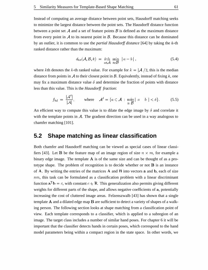
5 Similarity Measuresfor Template-BasedShapeMatching 61
Insteadof computing anaveragedistancebetweenpoint sets,Hausdorff matchingseeks
to minimize thelargestdistancebetweenthepoint sets.TheHausdorff distancefunction
betweena point set � anda setof featurepoints ¥ is definedasthemaximum distance
from every point in � to its nearestpoint in ¥ . Becausethis distancecanbedominated
by anoutlier, it is commonto usethepartial Hausdorff distance[64] by takingthe Ý -thrankeddistanceratherthanthemaximum:µ·¸�Þ iy��4o¥²4�Ý�l�, ÝEß�๠¯ � ª½«±¬®k¯ ¥ °±°�¾ D�³ °° 4 (5.4)
where Ý th denotesthe Ý -th rankedvalue. For examplefor ÝÌ, ° � °Åá � , this is themedian
distancefrom pointsin � to theirclosestpoint in ¥ . Equivalently, insteadof fixing Ý , one
mayfix a maximumdistancevalue @ anddeterminethe fractionof pointswith distance
lessthanthisvalue.This is theHausdorff fraction:� ¸�Þ , ° �Râ °° � ° 4 where � â ,J\ ¾�ã � äϪ½«±¬®k¯ ¥ °°�¾ D�³ °±°·å @·`·5 (5.5)
An efficient way to computethis valueis to dilate the edgeimageby @ andcorrelateit
with thetemplatepointsin � . Thegradientdirectioncanbeusedin a way analogousto
chamfermatching[101].
5.2 Shape matc hing as linear classifica tion
Both chamferandHausdorff matchingcanbe viewed asspecialcasesof linear classi-
fiers [43]. Let æ be the featuremapof an imageregion of size *�~Lç , for examplea
binaryedgeimage. The template è is of thesamesizeandcanbe thoughtof asa pro-
totypeshape.The problemof recognitionis to decidewhetheror not æ is an instance
of è . By writing theentriesof thematricesè and æ into vectors¡ and ¦ , eachof size*zç , this taskcanbe formulatedasa classificationproblemwith a linear discriminant
function ¡ ; ¦»,�é , with constanté ã�ê . This generalizationalsopermitsgiving different
weightsfor differentpartsof theshape,andallows negative coefficientsof ¡ , potentially
increasingthe costof clutteredimageareas.Felzenszwalb [43] hasshown thata single
templateè andadilatededgemap æ aresufficientto detectavarietyof shapesof awalk-
ing person.Thefollowing sectionlooksat shapematchingfrom a classificationpoint of
view. Eachtemplatecorrespondsto a classifier, which is appliedto a subregion of an
image.Thetargetclassincludesa numberof similar handposes.For chapter6 it will be
important thattheclassifierdetectshandsin certainposes,which correspondto thehand
modelparametersbeingwithin a compactregion in thestatespace.In otherwords,we
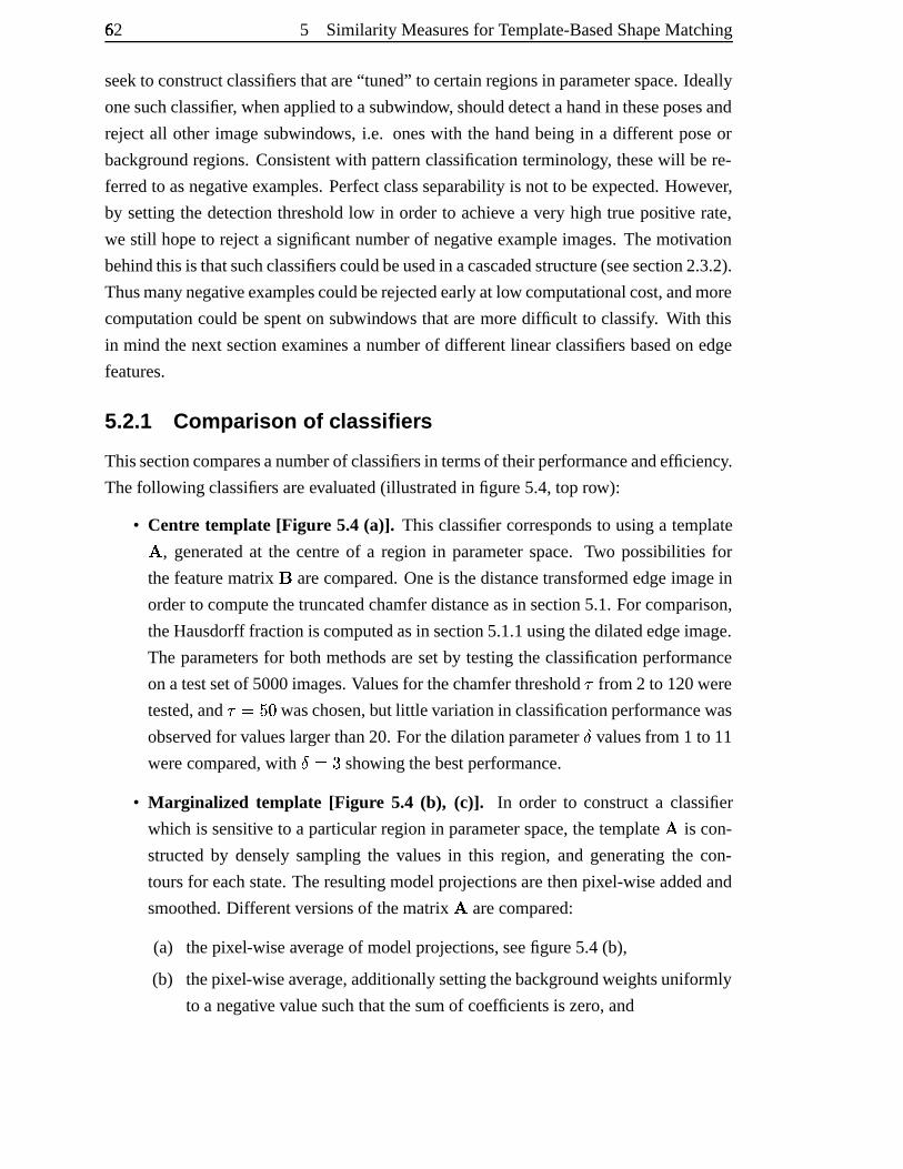
62Ü 5 Similarity Measuresfor Template-BasedShapeMatching
seekto constructclassifiersthatare“tuned” to certainregionsin parameterspace.Ideally
onesuchclassifier, whenappliedto asubwindow, shoulddetectahandin theseposesand
rejectall other imagesubwindows, i.e. oneswith the handbeingin a differentposeor
backgroundregions.Consistentwith patternclassificationterminology, thesewill bere-
ferredto asnegative examples.Perfectclassseparabilityis not to beexpected.However,
by setting the detectionthresholdlow in orderto achieve a very high true positive rate,
we still hopeto rejecta significantnumberof negative exampleimages.Themotivation
behindthisis thatsuchclassifierscouldbeusedin acascadedstructure(seesection2.3.2).
Thusmany negativeexamplescouldberejectedearlyat low computationalcost,andmore
computationcouldbespenton subwindows thataremoredifficult to classify. With this
in mind thenext sectionexaminesa numberof differentlinearclassifiersbasedon edge
features.
5.2.1 Comparison of classi fier s
Thissectioncomparesanumberof classifiersin termsof theirperformanceandefficiency.
Thefollowing classifiersareevaluated(illustratedin figure5.4,top row):
• Centre template [Figur e 5.4 (a)]. This classifiercorrespondsto usinga templateè , generatedat the centreof a region in parameterspace. Two possibilities for
thefeaturematrix æ arecompared.Oneis thedistancetransformededgeimagein
orderto computethetruncatedchamferdistanceasin section5.1.For comparison,
theHausdorff fractionis computedasin section5.1.1usingthedilatededgeimage.
The parametersfor bothmethodsaresetby testingtheclassificationperformance
onatestsetof 5000images.Valuesfor thechamferthreshold from 2 to 120were
tested,and ÂÁ,�ë�} waschosen,but little variationin classificationperformancewas
observedfor valueslargerthan20. For thedilationparameter@ valuesfrom 1 to 11
werecompared,with @ì,�{ showing thebestperformance.
• Mar ginalized template [Figur e 5.4 (b), (c)]. In order to constructa classifier
which is sensitive to a particularregion in parameterspace,thetemplateè is con-
structedby denselysamplingthe valuesin this region, and generatingthe con-
toursfor eachstate.Theresultingmodelprojectionsarethenpixel-wise addedand
smoothed.Differentversionsof thematrix è arecompared:
(a) thepixel-wiseaverageof modelprojections,seefigure5.4(b),
(b) thepixel-wiseaverage,additionally settingthebackgroundweightsuniformly
to a negativevaluesuchthatthesumof coefficientsis zero,and
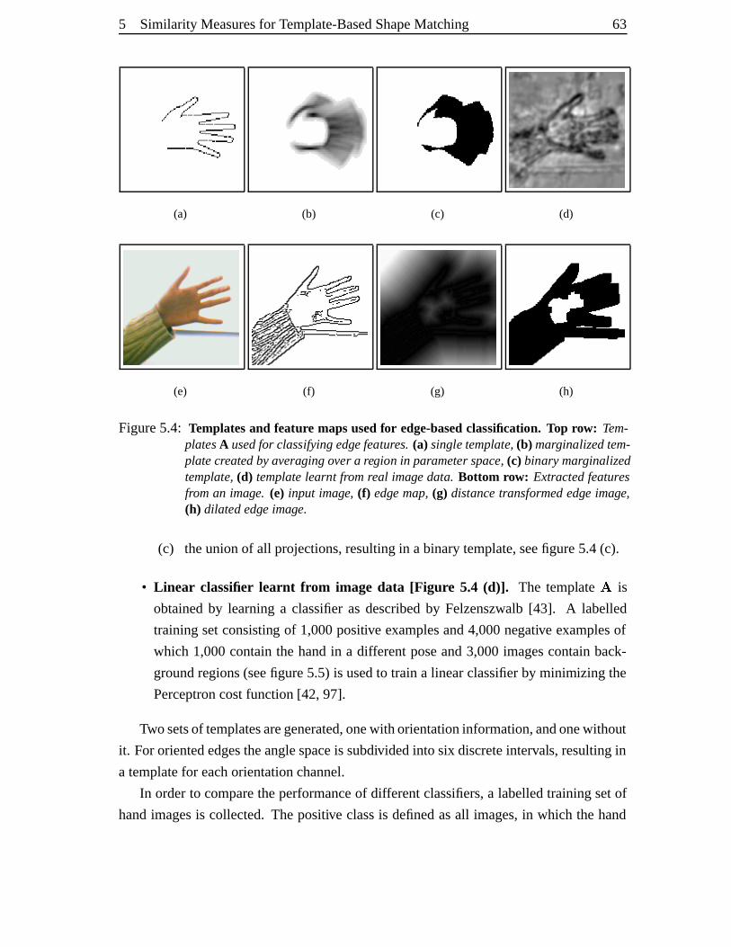
5 Similarity Measuresfor Template-BasedShapeMatching 63
(a) (b) (c) (d)
(e) (f) (g) (h)
Figure5.4: Templatesand feature mapsusedfor edge-basedclassification. Top row: Tem-platesA usedfor classifying edgefeatures.(a) singletemplate, (b) marginalizedtem-platecreatedbyaveragingover a region in parameter space, (c) binary marginalizedtemplate, (d) templatelearnt fromreal image data. Bottom row: Extractedfeaturesfroman image. (e) input image, (f) edge map,(g) distancetransformededge image,(h) dilated edge image.
(c) theunionof all projections,resultingin abinarytemplate,seefigure5.4(c).
• Linear classifier learnt fr om image data [Figur e 5.4 (d)]. The template è is
obtainedby learninga classifieras describedby Felzenszwalb [43]. A labelled
trainingsetconsisting of 1,000positive examplesand4,000negative examplesof
which 1,000containthe handin a differentposeand3,000imagescontainback-
groundregions(seefigure5.5) is usedto train a linearclassifierby minimizing the
Perceptroncostfunction[42, 97].
Twosetsof templatesaregenerated,onewith orientationinformation,andonewithout
it. For orientededgestheanglespaceis subdividedinto six discreteintervals,resultingin
a templatefor eachorientationchannel.
In orderto comparetheperformanceof differentclassifiers,a labelledtrainingsetof
handimagesis collected.Thepositive classis definedasall images,in which thehand
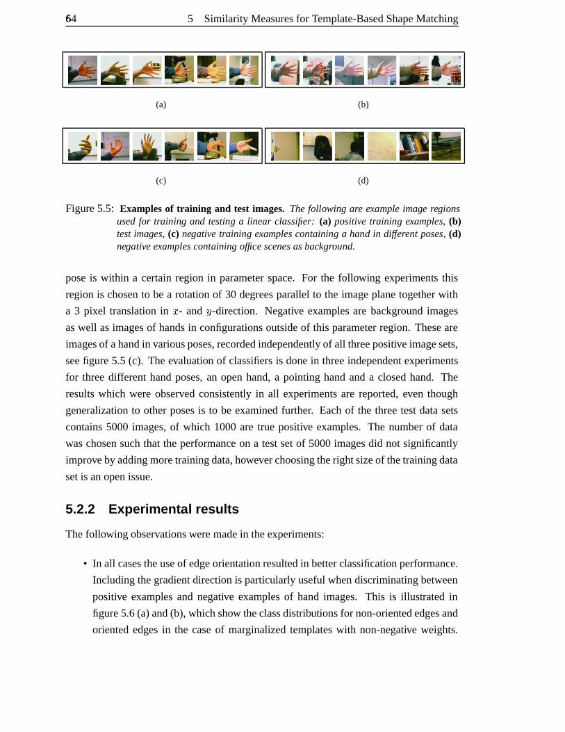
64Ü 5 Similarity Measuresfor Template-BasedShapeMatching
(a) (b)
(c) (d)
Figure5.5: Examplesof training and test images. Thefollowing are exampleimage regionsusedfor training and testing a linear classifier: (a) positive training examples, (b)testimages, (c) negative training examples containing a hand in different poses, (d)negative examplescontaining office scenes asbackground.
poseis within a certainregion in parameterspace.For the following experiments this
region is chosento bea rotationof 30 degreesparallelto the imageplanetogetherwith
a 3 pixel translationin q - and u -direction. Negative examplesare backgroundimages
aswell asimagesof handsin configurationsoutsideof this parameterregion. Theseare
imagesof ahandin variousposes,recordedindependentlyof all threepositiveimagesets,
seefigure5.5 (c). Theevaluation of classifiersis donein threeindependentexperiments
for threedifferenthandposes,an openhand,a pointing handanda closedhand. The
resultswhich were observed consistently in all experimentsare reported,even though
generalizationto otherposesis to be examinedfurther. Eachof the threetestdatasets
contains5000 images,of which 1000are true positive examples. The numberof data
waschosensuchthat theperformanceon a testsetof 5000imagesdid not significantly
improveby addingmoretrainingdata,howeverchoosingtheright sizeof thetrainingdata
setis anopenissue.
5.2.2 Experimenta l results
Thefollowing observationsweremadein theexperiments:
• In all casestheuseof edgeorientationresultedin betterclassificationperformance.
Includingthegradientdirectionis particularlyusefulwhendiscriminatingbetween
positive examples and negative examplesof handimages. This is illustrated in
figure5.6(a)and(b), whichshow theclassdistributionsfor non-orientededgesand
orientededgesin the caseof marginalizedtemplateswith non-negative weights.
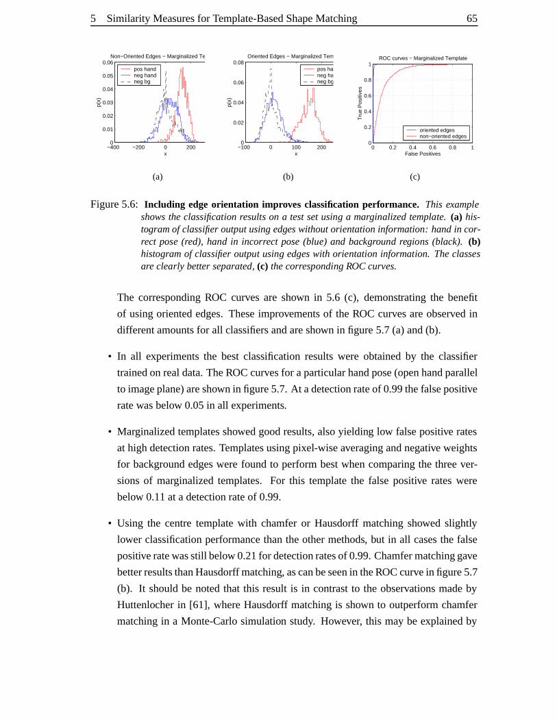
5 Similarity Measuresfor Template-BasedShapeMatching 65
−400 −200 0 200 4000
0.01
0.02
0.03
0.04
0.05
0.06
x
p(x)
Non−Oriented Edges − Marginalized Template
pos handneg handneg bg
(a)
−100 0 100 200 3000
0.02
0.04
0.06
0.08
x
p(x)
Oriented Edges − Marginalized Template
pos handneg handneg bg
(b)
0 0.2 0.4 0.6 0.8 10
0.2
0.4
0.6
0.8
1
False Positives
Tru
e P
ositi
ves
ROC curves − Marginalized Template
oriented edges non−oriented edges
(c)
Figure5.6: Including edgeorientation impr oves classification performance. This exampleshowsthe classification results on a testsetusing a marginalizedtemplate. (a) his-togramof classifier output usingedgeswithoutorientation information: handin cor-rect pose (red), hand in incorrect pose(blue) and background regions (black). (b)histogramof classifier output using edgeswith orientation information. Theclassesare clearly betterseparated, (c) thecorresponding ROCcurves.
The correspondingROC curves are shown in 5.6 (c), demonstrating the benefit
of usingorientededges.Theseimprovementsof the ROC curvesareobserved in
differentamountsfor all classifiersandareshown in figure5.7(a) and(b).
• In all experimentsthe bestclassificationresultswere obtainedby the classifier
trainedonrealdata.TheROCcurvesfor aparticularhandpose(openhandparallel
to imageplane)areshown in figure5.7.At adetectionrateof 0.99thefalsepositive
ratewasbelow 0.05in all experiments.
• Marginalizedtemplatesshowedgoodresults,alsoyielding low falsepositive rates
at highdetectionrates.Templatesusingpixel-wiseaveragingandnegativeweights
for backgroundedgeswerefound to performbestwhencomparingthe threever-
sionsof marginalizedtemplates. For this templatethe falsepositive rateswere
below 0.11at adetectionrateof 0.99.
• Using the centretemplatewith chamferor Hausdorff matchingshowed slightly
lower classificationperformancethantheothermethods, but in all casesthe false
positiveratewasstill below 0.21for detectionratesof 0.99.Chamfermatchinggave
betterresultsthanHausdorff matching, ascanbeseenin theROCcurvein figure5.7
(b). It shouldbe notedthat this result is in contrastto the observationsmadeby
Huttenlocher in [61], whereHausdorff matchingis shown to outperformchamfer
matchingin a Monte-Carlosimulation study. However, this maybe explainedby
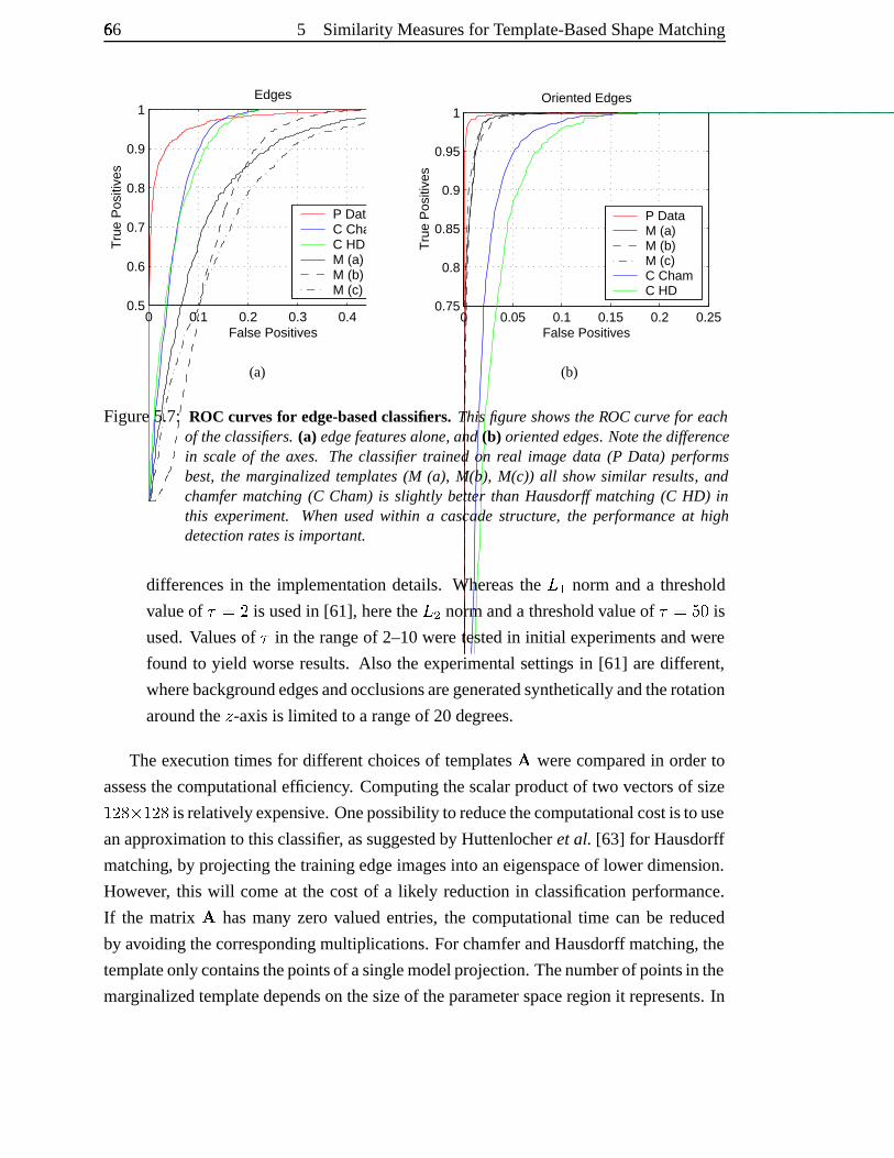
66Ü 5 Similarity Measuresfor Template-BasedShapeMatching
0 0.1 0.2 0.3 0.4 0.50.5
0.6
0.7
0.8
0.9
1
False Positives
Tru
e P
ositi
ves
Edges
P DataC ChamC HD M (a) M (b) M (c)
(a)
0 0.05 0.1 0.15 0.2 0.250.75
0.8
0.85
0.9
0.95
1
False Positives
Tru
e P
ositi
ves
Oriented Edges
P DataM (a) M (b) M (c) C ChamC HD
(b)
Figure5.7: ROC curvesfor edge-based classifiers. Thisfigure showstheROC curvefor eachof theclassifiers. (a) edge featuresalone, and(b) orientededges. Notethedifferencein scaleof the axes. The classifier trained on real image data (P Data) performsbest,the marginalized templates (M (a), M(b), M(c)) all show similar results, andchamfermatching (C Cham)is slightly better than Hausdorff matching (C HD) inthis experiment. Whenusedwithin a cascade structure, the performanceat highdetection ratesis important.
differencesin the implementation details. Whereasthe íî2 norm anda threshold
valueof ÂÑ,ï� is usedin [61], herethe í � normanda thresholdvalueof ´,�ë�} is
used.Valuesof  in therangeof 2–10weretestedin initial experimentsandwere
found to yield worseresults. Also the experimentalsettings in [61] aredifferent,
wherebackgroundedgesandocclusionsaregeneratedsynthetically andtherotation
aroundthe w -axisis limited to a rangeof 20degrees.
Theexecutiontimesfor differentchoicesof templatesè werecomparedin orderto
assessthecomputationalefficiency. Computingthescalarproductof two vectorsof sizeF�����~îF���� is relativelyexpensive. Onepossibility to reducethecomputational costis touse
anapproximation to thisclassifier, assuggestedby Huttenlocheret al. [63] for Hausdorff
matching, by projectingthetrainingedgeimagesinto aneigenspaceof lowerdimension.
However, this will comeat the costof a likely reductionin classificationperformance.
If the matrix è hasmany zero valuedentries,the computationaltime can be reduced
by avoiding thecorrespondingmultiplications.For chamferandHausdorff matching,the
templateonlycontainsthepointsof asinglemodelprojection.Thenumberof pointsin the
marginalizedtemplatedependson thesizeof theparameterspaceregion it represents.In
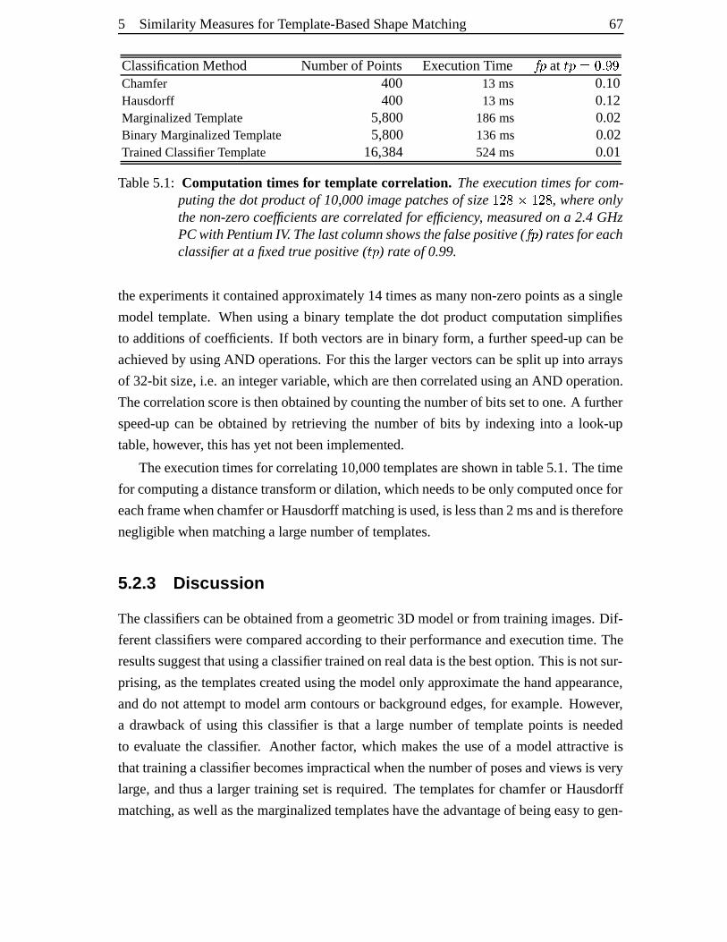
5 Similarity Measuresfor Template-BasedShapeMatching 67
ClassificationMethod Numberof Points ExecutionTime ��ð at CñðÑ,A}&5óò�òChamfer 400 13 ms 0.10Hausdorff 400 13 ms 0.12Marginalized Template 5,800 186ms 0.02Binary MarginalizedTemplate 5,800 136ms 0.02TrainedClassifier Template 16,384 524ms 0.01
Table5.1: Computation times for template correlation. Theexecutiontimesfor com-putingthedot productof 10,000image patchesof size F�����~�Fa��� , where onlythenon-zero coefficientsare correlatedfor efficiency, measuredon a 2.4 GHzPCwith PentiumIV. Thelastcolumnshowsthefalsepositive( ôõð ) ratesfor eachclassifier at a fixedtruepositive( öñð ) rateof 0.99.
theexperimentsit containedapproximately14 timesasmany non-zeropoints asa single
modeltemplate. Whenusinga binary templatethe dot productcomputation simplifies
to additions of coefficients. If bothvectorsarein binaryform, a furtherspeed-upcanbe
achievedby usingAND operations.For this thelargervectorscanbesplit up into arrays
of 32-bitsize,i.e. anintegervariable,whicharethencorrelatedusinganAND operation.
Thecorrelationscoreis thenobtainedby countingthenumberof bitssetto one.A further
speed-upcan be obtainedby retrieving the numberof bits by indexing into a look-up
table,however, thishasyet notbeenimplemented.
Theexecutiontimesfor correlating10,000templatesareshown in table5.1.Thetime
for computingadistancetransformor dilation, whichneedsto beonly computedoncefor
eachframewhenchamferor Hausdorff matchingis used,is lessthan2 msandis therefore
negligible whenmatchinga largenumberof templates.
5.2.3 Disc ussion
Theclassifierscanbeobtainedfrom a geometric3D modelor from trainingimages.Dif-
ferentclassifierswerecomparedaccordingto their performanceandexecution time. The
resultssuggestthatusingaclassifiertrainedonrealdatais thebestoption. This is notsur-
prising,asthetemplatescreatedusingthemodelonly approximatethehandappearance,
anddo not attemptto modelarmcontoursor backgroundedges,for example.However,
a drawbackof using this classifieris that a large numberof template points is needed
to evaluatethe classifier. Another factor, which makesthe useof a modelattractive is
thattrainingaclassifierbecomesimpracticalwhenthenumberof posesandviews is very
large,andthusa larger trainingsetis required.Thetemplatesfor chamferor Hausdorff
matching,aswell asthemarginalizedtemplateshave theadvantageof beingeasyto gen-
68÷ 5 Similarity Measuresfor Template-BasedShapeMatching
erateandbeinglabelledwith 3D poseparameters.
Thereclearly seemsto be a trade-off betweencomputation time and classification
performancefor theclassifiers,asshown in table5.1.Whenusedin acascadedstructure,
thedetectionrateof aclassifierneedsto beveryhigh,soasnot to missany truepositives.
Thefalsepositive ratefor eachclassifierat a fixeddetectionrateof 0.99,is given in the
last columnof table5.1. ChamferandHausdorff matching,while having a larger false
positive rate,areabout10-14 timesfasterto evaluatethanmarginalizedtemplatesand
about40 timesfasterthanthetrainedclassifier.
Oneissuethathasbeenleft asidefor themomentarelargescalechangesof thetem-
plate;Thechamfercostof a small templatewith relatively few edgeson a randomedge
imagewill be lower thanthat of a large template[96]. This effect becomessignificant
whensearchingovera largerrangeof scales,andit is treatedin moredetailin chapter6.
In the next sectionthe attentionis shifted from contourto colour information. In
particularit is examinedhow thefact that thehandinterior is skin-colouredcanbeused
in templatematching.
5.3 Modellin g skin colou r
Skin colour in imageshasa characteristicdistribution and this hasbeenexploited by
systems for trackingor detectinghandsor faces[14, 67, 88, 119]. However, the way
in that colour information hasbeenuseddiffers widely, in particularwith regardto the
choiceof a colourspaceandtherepresentationof thedistribution.
JonesandRehg[74] carriedout a thoroughstudyof skin colourmodels.A dataset
of 13,640imageswasusedto obtaindistributionsof skincolourandnon-skincolourval-
ues.A Bayesianclassifier, treatingeachpixel independently, wasdefinedusingdifferent
representationsof the distribution. It wasshown that a RGB-histogramrepresentation,
quantizedto ø�ù�ú bins leadsto bettergeneralizationperformancethana histogramwithû�ü ú or ù3ý û ú binsandit alsooutperformsaclassifierbasedonaGaussianmixturemodel.
Many authorschooseto work in colourspaceswherethebrightnessvalueis separated
from the hue,suchasthe HSV andYUV colour spaces[14, 137]. The intensityvalue
is theneitherweightedlessrelative to the hueor discardedcompletely. Anotheroption
is to work in the intensity normalized þÀÿ�� ��� -space,where ÿ�� ���þ���� ���� � and� �� ���þ���� ���� � . Several studieshave indicatedthat skin tonesdiffer mainly in
theirbrightnessvaluesbut thattheirchrominanceis relativelyconstrainedamongdifferent
people[14,93,154]. Yangetal. [154] suggestmodellingthedistribution asaGaussianinþÀÿ�� ��� -space,anadvantageof thisparametricrepresentationbeingthatit is easyto update
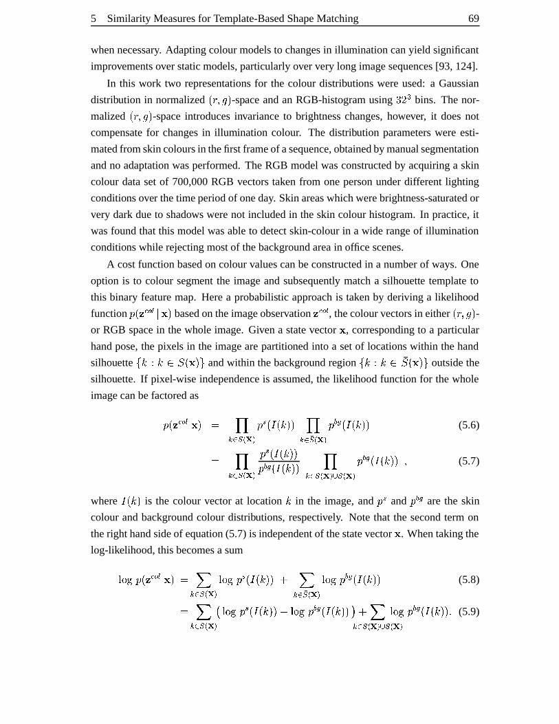
5 Similarity Measuresfor Template-BasedShapeMatching 69
whennecessary. Adaptingcolourmodelsto changesin illuminationcanyield significant
improvementsoverstaticmodels,particularlyoververy long imagesequences[93, 124].
In this work two representationsfor the colour distributionswereused:a Gaussian
distribution in normalized þÀÿ�� ��� -spaceandan RGB-histogramusing ø3ù ú bins. The nor-
malized þÀÿ�� ��� -spaceintroducesinvarianceto brightnesschanges,however, it doesnot
compensatefor changesin illumination colour. The distribution parameterswere esti-
matedfromskincoloursin thefirst frameof asequence,obtainedbymanualsegmentation
andno adaptationwasperformed.TheRGB modelwasconstructedby acquiringa skin
colour datasetof 700,000RGB vectorstaken from onepersonunderdifferent lighting
conditionsover thetimeperiodof oneday. Skinareaswhichwerebrightness-saturatedor
very darkdueto shadows werenot includedin theskin colourhistogram.In practice,it
wasfoundthat this modelwasableto detectskin-colourin a wide rangeof illumination
conditionswhile rejectingmostof thebackgroundareain office scenes.
A costfunctionbasedon colourvaluescanbeconstructedin a numberof ways.One
option is to colour segment the imageandsubsequently matcha silhouette templateto
this binary featuremap. Herea probabilistic approachis takenby deriving a likelihood
function � þ����������! � basedontheimageobservation �"���#� , thecolourvectorsin either þÀÿ�� ��� -or RGB spacein thewhole image.Givena statevector , correspondingto a particular
handpose,thepixels in the imagearepartitionedinto a setof locationswithin thehand
silhouette $&%(')%(*,+�þ� �.- andwithin thebackgroundregion $&%/'0%1*32+¿þ� �.- outsidethe
silhouette. If pixel-wise independenceis assumed,the likelihoodfunctionfor thewhole
imagecanbefactoredas�)þ�� ����� � � � 457698;: =< �0>�þ�?jþ#% �@� 4576BA8C: D< �)EGF:þ�?zþ% �@� (5.6)
� 457698;: =< � > þ�?jþ#% �H�� EGF þ�?zþ% �@� 4576I8�: =<KJ A8;: D< �)EGF:þ�?jþ% �@� � (5.7)
where ?jþ#% � is the colour vectorat location % in the image,and � > and � EGF are the skin
colour andbackgroundcolour distributions,respectively. Note that the secondterm on
theright handsideof equation(5.7) is independentof thestatevector . Whentakingthe
log-likelihood,thisbecomesasumLNMCO � þ�� ����� � � � P576I8;: Q< LNM;O �0>�þ�?jþ#% �@� � P576 A8C: R< LNM;O �)EGF:þ�?jþ% �@� (5.8)
� P576I8;: Q< S LNMCO �0>�þ�?jþ% �@�UT LVM;O �WEGF:þ�?jþ#% �H�WX � P57698;: =<VJ A8;: =<LNMCO �)EGF:þ�?jþ#% �H�ZY (5.9)
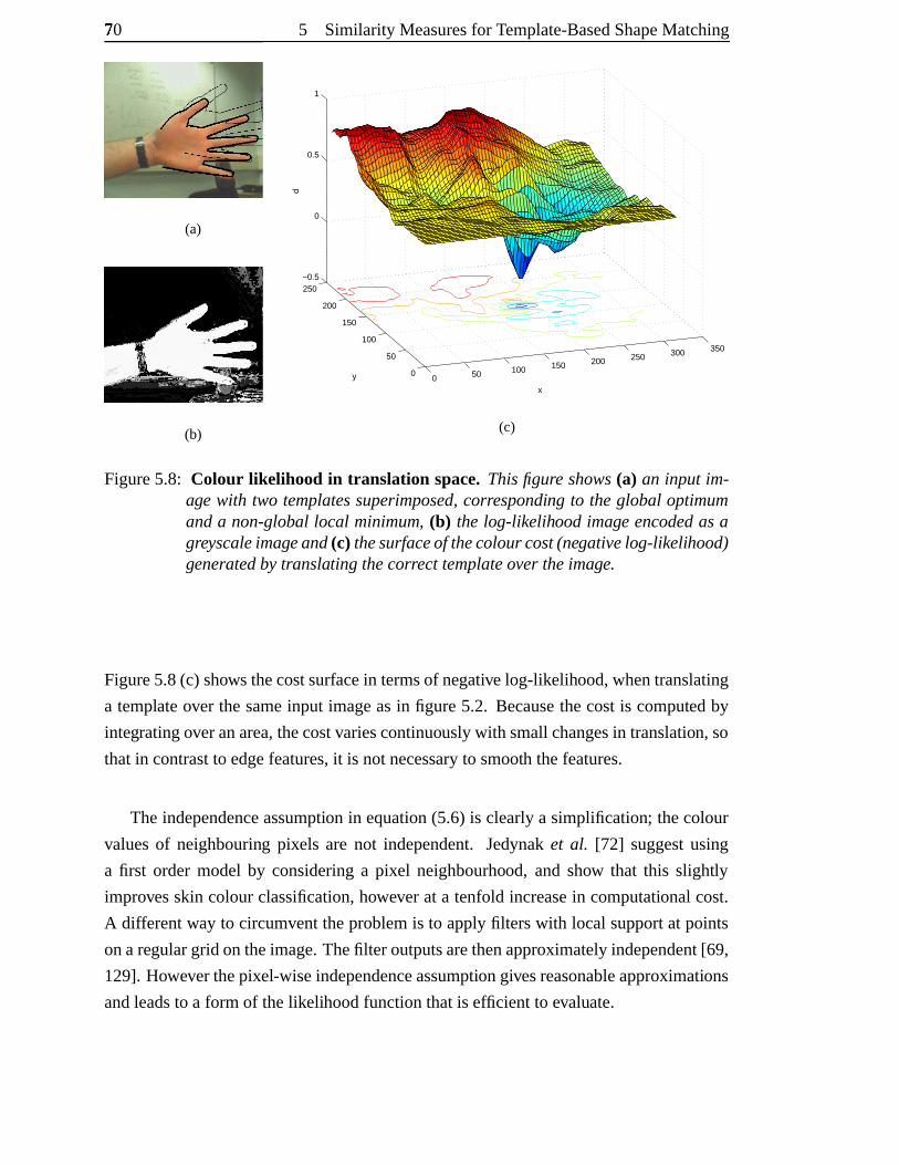
70[ 5 Similarity Measuresfor Template-BasedShapeMatching
(a)
(b)
0 50 100 150 200 250 300 350
0
50
100
150
200
250−0.5
0
0.5
1
x
y
d
(c)
Figure5.8: Colour lik elihood in translation space.Thisfigure shows(a) an input im-age with two templatessuperimposed,corresponding to the global optimumanda non-globallocal minimum, (b) the log-likelihood image encodedasagreyscaleimageand(c) thesurfaceof thecolourcost(negativelog-likelihood)generatedby translating thecorrecttemplateover theimage.
Figure5.8(c) showsthecostsurfacein termsof negative log-likelihood,whentranslating
a templateover thesameinput imageasin figure5.2. Becausethecostis computedby
integratingoveranarea,thecostvariescontinuouslywith smallchangesin translation, so
thatin contrastto edgefeatures,it is notnecessaryto smooth thefeatures.
Theindependenceassumption in equation(5.6) is clearlya simplification; thecolour
valuesof neighbouring pixels are not independent.Jedynaket al. [72] suggestusing
a first order model by consideringa pixel neighbourhood, and show that this slightly
improvesskin colourclassification,however at a tenfold increasein computationalcost.
A differentway to circumventtheproblemis to applyfilters with local supportat points
onaregulargrid ontheimage.Thefilter outputsarethenapproximatelyindependent[69,
129]. Howeverthepixel-wiseindependenceassumptiongivesreasonableapproximations
andleadsto a form of thelikelihoodfunctionthatis efficient to evaluate.
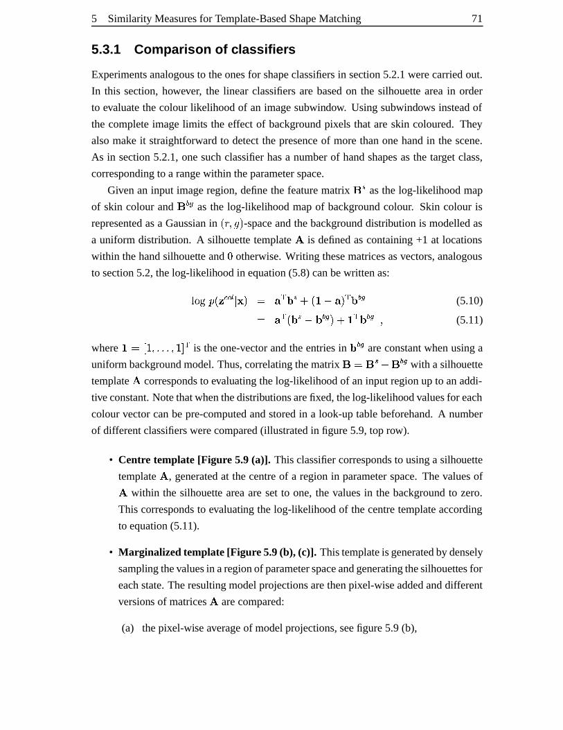
5 Similarity Measuresfor Template-BasedShapeMatching 71
5.3.1 Comparis on of class ifier s
Experimentsanalogousto theonesfor shapeclassifiersin section5.2.1werecarriedout.
In this section,however, the linear classifiersarebasedon the silhouette areain order
to evaluatethecolour likelihoodof an imagesubwindow. Usingsubwindows insteadof
the completeimagelimits the effect of backgroundpixels that areskin coloured. They
alsomake it straightforward to detectthe presenceof morethanonehandin the scene.
As in section5.2.1,onesuchclassifierhasa numberof handshapesasthe target class,
correspondingto a rangewithin theparameterspace.
Givenan input imageregion, definethe featurematrix \ > asthe log-likelihoodmap
of skin colour and \ EGF asthe log-likelihoodmapof backgroundcolour. Skin colour is
representedasa Gaussianin þÀÿ�� ��� -spaceandthebackgrounddistribution is modelledas
a uniform distribution. A silhouette template ] is definedascontaining +1 at locations
within thehandsilhouette and ^ otherwise.Writing thesematricesasvectors,analogous
to section5.2,thelog-likelihoodin equation(5.8)canbewrittenas:LNM;O � þ�� ����� � � � _W`0a > ��þcb T _ � `0a EGF (5.10)� _W`#þ�a > T a EGF � �db;`0a EGF � (5.11)
where be�gfih;� YIYjY �Ihjk ` is theone-vectorandtheentriesin a EGF areconstantwhenusinga
uniformbackgroundmodel.Thus,correlatingthematrix \l�d\ > T \ EGF with asilhouette
template] correspondsto evaluatingthelog-likelihoodof aninput regionup to anaddi-
tiveconstant.Notethatwhenthedistributionsarefixed,thelog-likelihoodvaluesfor each
colourvectorcanbepre-computedandstoredin a look-uptablebeforehand.A number
of differentclassifierswerecompared(illustratedin figure5.9,top row).
• Centre template [Figur e 5.9(a)]. Thisclassifiercorrespondsto usinga silhouette
template] , generatedat thecentreof a region in parameterspace.Thevaluesof] within the silhouette areaaresetto one,the valuesin the backgroundto zero.
This correspondsto evaluating the log-likelihood of thecentretemplateaccording
to equation(5.11).
• Mar ginalizedtemplate[Figur e5.9(b), (c)]. Thistemplateisgeneratedby densely
samplingthevaluesin aregionof parameterspaceandgeneratingthesilhouettesfor
eachstate.Theresultingmodelprojectionsarethenpixel-wiseaddedanddifferent
versions of matrices] arecompared:
(a) thepixel-wiseaverageof modelprojections,seefigure5.9(b),
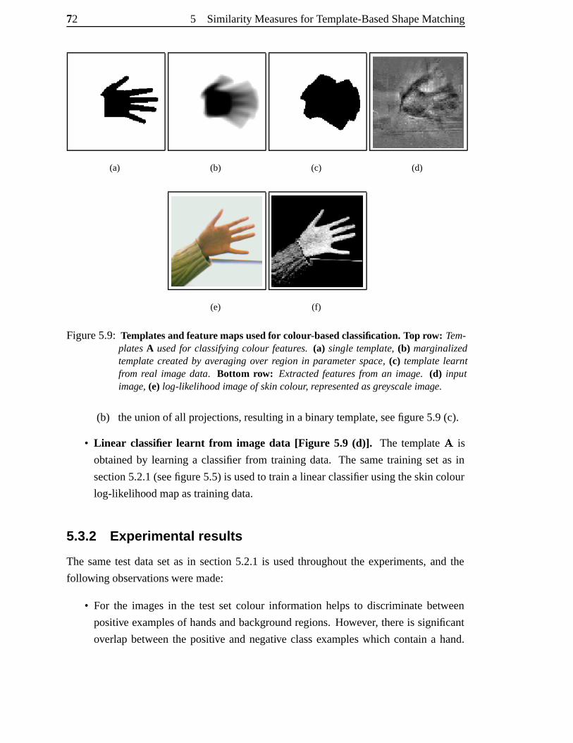
72[ 5 Similarity Measuresfor Template-BasedShapeMatching
(a) (b) (c) (d)
(e) (f)
Figure5.9: Templatesand featuremapsusedfor colour-basedclassification. Top row: Tem-plates A usedfor classifying colour features. (a) single template, (b) marginalizedtemplatecreated by averaging over region in parameter space, (c) template learntfrom real image data. Bottom row: Extracted features from an image. (d) inputimage, (e) log-likelihoodimage of skincolour, representedasgreyscaleimage.
(b) theunionof all projections,resulting in abinarytemplate,seefigure5.9(c).
• Linear classifier learnt fr om image data [Figur e 5.9 (d)]. The template ] is
obtainedby learninga classifierfrom training data. The sametraining setas in
section5.2.1(seefigure5.5) is usedto traina linearclassifierusingtheskincolour
log-likelihoodmapastrainingdata.
5.3.2 Experimenta l results
The sametestdatasetas in section5.2.1 is usedthroughoutthe experiments,and the
following observationsweremade:
• For the imagesin the test set colour information helpsto discriminate between
positive examplesof handsandbackgroundregions. However, thereis significant
overlapbetweenthe positive andnegative classexampleswhich containa hand.
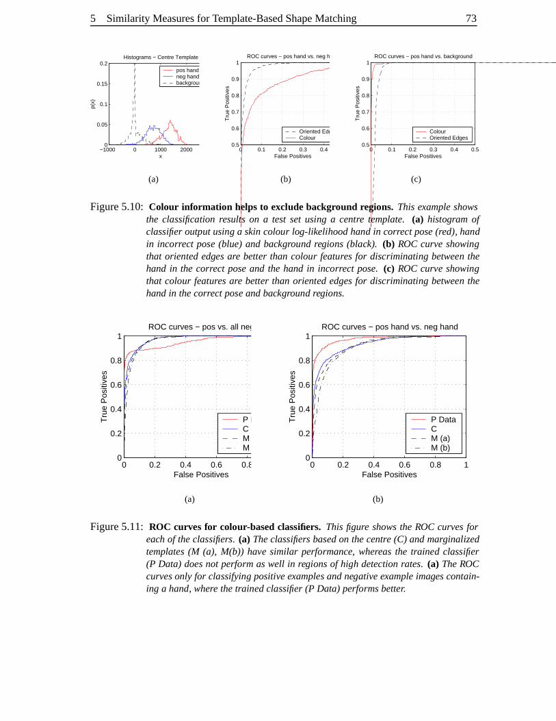
5 Similarity Measuresfor Template-BasedShapeMatching 73
−1000 0 1000 2000 30000
0.05
0.1
0.15
0.2
x
p(x)
Histograms − Centre Template
pos hand neg hand background
(a)
0 0.1 0.2 0.3 0.4 0.50.5
0.6
0.7
0.8
0.9
1
False Positives
Tru
e P
ositi
ves
ROC curves − pos hand vs. neg hand
Oriented EdgesColour
(b)
0 0.1 0.2 0.3 0.4 0.50.5
0.6
0.7
0.8
0.9
1
False Positives
Tru
e P
ositi
ves
ROC curves − pos hand vs. background
Colour Oriented Edges
(c)
Figure5.10: Colour information helps to exclude background regions. Thisexampleshowsthe classification results on a test set using a centre template. (a) histogram ofclassifier output using a skincolour log-likelihoodhand in correct pose(red), handin incorrect pose (blue) and background regions (black). (b) ROC curveshowingthat oriented edges are better than colour featuresfor discriminating between thehand in the correct poseand the handin incorrect pose. (c) ROC curve showingthat colour featuresare better than oriented edgesfor discriminating between thehandin thecorrectpose andbackground regions.
0 0.2 0.4 0.6 0.8 10
0.2
0.4
0.6
0.8
1
False Positives
Tru
e P
ositi
ves
ROC curves − pos vs. all neg
P DataC M (a) M (b)
(a)
0 0.2 0.4 0.6 0.8 10
0.2
0.4
0.6
0.8
1
False Positives
Tru
e P
ositi
ves
ROC curves − pos hand vs. neg hand
P DataC M (a) M (b)
(b)
Figure5.11: ROC curves for colour-basedclassifiers. This figure showsthe ROC curvesforeach of theclassifiers. (a) Theclassifiers basedon thecentre (C) andmarginalizedtemplates (M (a), M(b)) have similar performance, whereasthe trained classifier(P Data) does not perform aswell in regionsof high detection rates. (a) TheROCcurvesonly for classifying positiveexamplesandnegativeexampleimagescontain-ing a hand, where thetrainedclassifier(P Data) performsbetter.
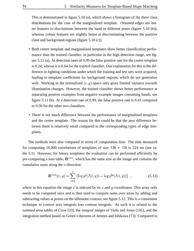
74[ 5 Similarity Measuresfor Template-BasedShapeMatching
This is demonstratedin figure5.10(a),which shows a histogramof thethreeclass
distributions for the caseof the marginalizedtemplate. Orientededgesare bet-
ter featuresto discriminatebetweenthe handin differentposes(figure 5.10 (b)),
whereascolour featuresareslightly betterat discriminating betweenthe positive
classandbackgroundregions(figure5.10(c)).
• Both centretemplateandmarginalizedtemplatesshow betterclassificationperfor-
mancethanthe trainedclassifier, in particularin thehigh detectionrange,seefig-
ure5.11(a). At detectionratesof 0.99thefalsepositiveratefor thecentretemplate
is 0.24,wherasit is 0.64for thetrainedclassifier. Oneexplanationfor thisis thedif-
ferencein lighting conditionsunderwhich thetrainingandtestsetswereacquired,
leadingto templatecoefficients for backgroundregions, which do not generalize
well. Working in the normalizedþÀÿ�� ��� -spaceonly giveslimited variancetowards
illuminationchanges.However, the trainedclassifiershows betterperformanceat
separatingpositive examplesfrom negative example imagescontaininghands,see
figure5.11(b). At a detectionrateof 0.99,thefalsepositive rateis 0.41compared
to 0.56for theothertwo classifiers.
• Thereis not muchdifferencebetweenthe performanceof marginalizedtemplates
andthe centretemplate.The reasonfor this could be that the areadifferencebe-
tweenthemis relatively small comparedto the correspondingtypesof edgetem-
plates.
Themethodswerealsocomparedin termsof computation time. Thetime measured
for computing 10,000correlationsof templatesof size haùCmon�haùCm is 524 ms (seeta-
ble 5.1). However, for binary templatesthe evaluation canbe performedefficiently by
pre-computing a sumtable, \ >�prq , whichhasthesamesizeastheimageandcontainsthe
cumulativesumsalongthe s -direction:
\ >�pZq þts=�vu � � wx y z|{ S LVM;O �0>�þ�?jþ�}H�vu �@�~T LVM;O �)EGF:þ�?jþ�}@�vu �@� X � (5.12)
wherein this equationtheimage? is indexedby its s and u -coordinates.This arrayonly
needsto becomputedonceandis thenusedto computesumsover areasby addingand
subtracting valuesatpointsonthesilhouettecontour, seefigure5.12.This is aconvenient
techniqueto convert areaintegrals into contour integrals. As suchit is relatedto the
summedareatablesof Crow [33], the integral imagesof Viola andJones[141], andthe
integrationmethodbasedonGreen’s theoremof JermynandIshikawa[73]. Comparedto
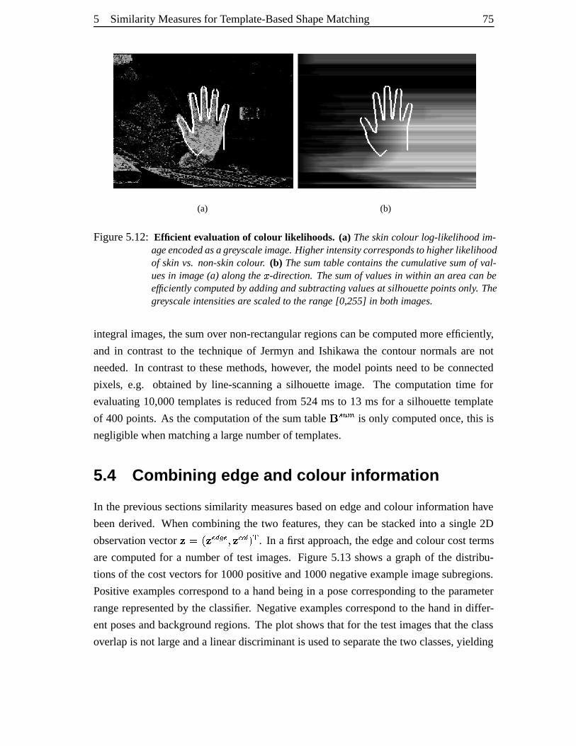
5 Similarity Measuresfor Template-BasedShapeMatching 75
(a) (b)
Figure5.12: Efficient evaluation of colour lik elihoods. (a) Theskincolour log-likelihood im-ageencodedasa greyscaleimage. Higherintensitycorrespondsto higher likelihoodof skin vs. non-skin colour. (b) Thesumtable contains the cumulativesumof val-uesin image (a) along the � -direction. Thesumof valuesin within an areacanbeefficiently computed by adding andsubtracting valuesat silhouettepointsonly. Thegreyscaleintensitiesare scaled to therange [0,255] in bothimages.
integral images,thesumover non-rectangularregionscanbecomputedmoreefficiently,
and in contrastto the techniqueof Jermynand Ishikawa the contournormalsare not
needed.In contrastto thesemethods, however, the modelpointsneedto be connected
pixels, e.g. obtainedby line-scanninga silhouette image. The computation time for
evaluating 10,000templatesis reducedfrom 524 ms to 13 ms for a silhouette template
of 400points. As thecomputation of thesumtable \ >�pZq is only computedonce,this is
negligible whenmatchinga largenumberof templates.
5.4 Combining edge and colou r inf orma tion
In theprevioussectionssimilarity measuresbasedon edgeandcolour informationhave
beenderived. Whencombiningthe two features,they canbe stacked into a single2D
observation vector ���Ðþ����#� F �7�v� ����� � ` . In a first approach,theedgeandcolourcostterms
arecomputedfor a numberof test images. Figure5.13shows a graphof the distribu-
tionsof thecostvectorsfor 1000positive and1000negative exampleimagesubregions.
Positive examplescorrespondto a handbeingin a posecorrespondingto the parameter
rangerepresentedby theclassifier. Negative examplescorrespondto thehandin differ-
entposesandbackgroundregions. Theplot shows that for thetestimagesthat theclass
overlapis not largeanda lineardiscriminantis usedto separatethetwo classes,yielding
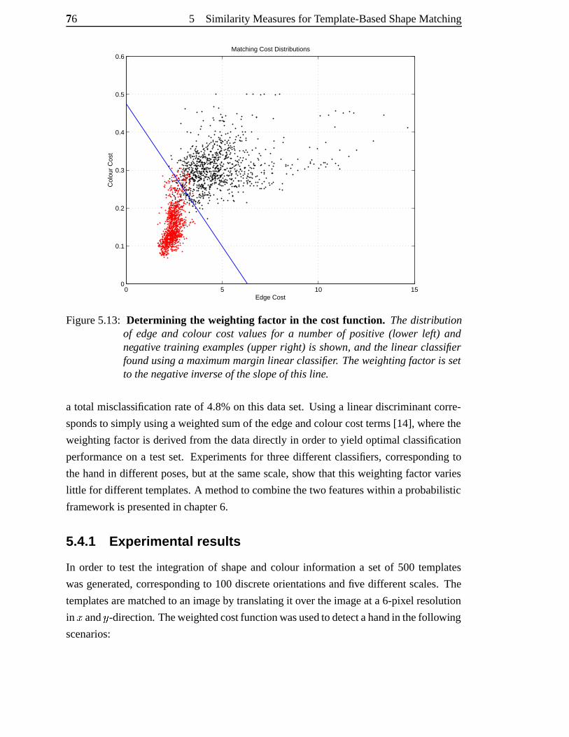
76[ 5 Similarity Measuresfor Template-BasedShapeMatching
0 5 10 150
0.1
0.2
0.3
0.4
0.5
0.6
Edge Cost
Col
our
Cos
t
Matching Cost Distributions
Figure5.13: Determining the weighting factor in the cost function. Thedistributionof edge and colour cost valuesfor a numberof positive(lower left) andnegativetraining examples(upperright) is shown,andthe linear classifierfoundusinga maximummargin linear classifier. Theweightingfactor is setto thenegativeinverseof theslopeof this line.
a total misclassification rateof 4.8%on this dataset. Usinga lineardiscriminantcorre-
spondsto simplyusingaweightedsumof theedgeandcolourcostterms[14], wherethe
weighting factoris derivedfrom thedatadirectly in orderto yield optimalclassification
performanceon a testset. Experimentsfor threedifferentclassifiers,correspondingto
thehandin differentposes,but at thesamescale,show that this weightingfactorvaries
litt le for differenttemplates.A methodto combinethetwo featureswithin aprobabilistic
framework is presentedin chapter6.
5.4.1 Experimenta l results
In order to test the integration of shapeandcolour informationa setof 500 templates
wasgenerated,correspondingto 100discreteorientationsandfive differentscales.The
templatesarematchedto animageby translatingit over theimageat a6-pixel resolution
in s andu -direction. Theweightedcostfunctionwasusedtodetectahandin thefollowing
scenarios:
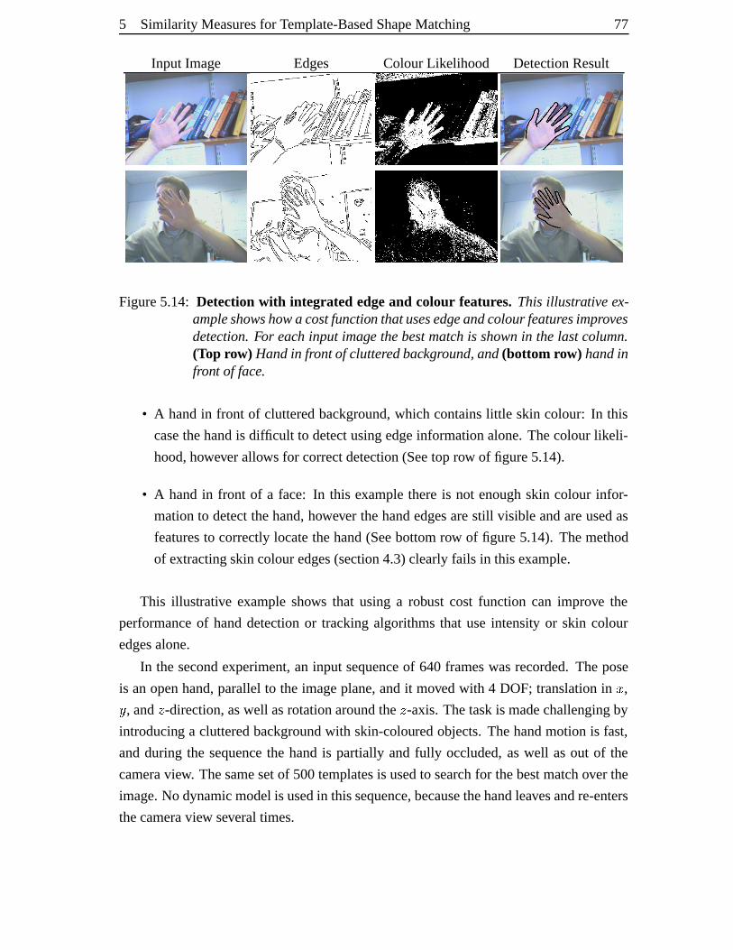
5 Similarity Measuresfor Template-BasedShapeMatching 77
Input Image Edges ColourLikelihood DetectionResult
Figure5.14: Detectionwith integrated edgeand colour features. This illustrative ex-ampleshowshowa costfunction thatusesedgeandcolourfeaturesimprovesdetection.For each input image thebestmatch is shownin thelast column.(Top row) Handin frontof clutteredbackground,and(bottom row) handinfront of face.
• A handin front of clutteredbackground,which containslittle skin colour: In this
casethehandis difficult to detectusingedgeinformationalone.Thecolourlikeli-
hood,howeverallows for correctdetection(Seetop row of figure5.14).
• A handin front of a face: In this examplethereis not enoughskin colour infor-
mationto detectthehand,however thehandedgesarestill visible andareusedas
featuresto correctlylocatethehand(Seebottomrow of figure5.14). Themethod
of extractingskincolouredges(section4.3)clearlyfails in thisexample.
This illustrative exampleshows that using a robust cost function can improve the
performanceof handdetectionor trackingalgorithmsthat useintensity or skin colour
edgesalone.
In thesecondexperiment,an input sequenceof 640 frameswasrecorded.Thepose
is anopenhand,parallelto the imageplane,andit movedwith 4 DOF; translationin s ,u , and � -direction,aswell asrotationaroundthe � -axis.Thetaskis madechallengingby
introducing a clutteredbackgroundwith skin-colouredobjects.Thehandmotionis fast,
andduring the sequencethe handis partially andfully occluded,aswell asout of the
cameraview. Thesamesetof 500templatesis usedto searchfor thebestmatchover the
image.No dynamicmodelis usedin thissequence,becausethehandleavesandre-enters
thecameraview severaltimes.
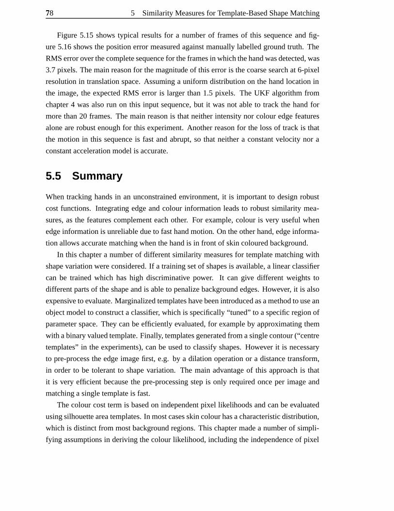
78[ 5 Similarity Measuresfor Template-BasedShapeMatching
Figure5.15 shows typical resultsfor a numberof framesof this sequenceandfig-
ure5.16shows thepositionerrormeasuredagainstmanuallylabelledgroundtruth. The
RMSerroroverthecompletesequencefor theframesin whichthehandwasdetected,was
3.7pixels. Themainreasonfor themagnitudeof this erroris thecoarsesearchat 6-pixel
resolution in translationspace.Assuming a uniform distribution on thehandlocationin
the image,the expectedRMS error is larger than1.5 pixels. The UKF algorithmfrom
chapter4 wasalsorun on this input sequence,but it wasnot ableto track the handfor
morethan20 frames.Themain reasonis thatneitherintensitynor colouredgefeatures
alonearerobustenoughfor this experiment.Anotherreasonfor the lossof track is that
the motion in this sequenceis fastandabrupt,so that neithera constantvelocity nor a
constantaccelerationmodelis accurate.
5.5 Summar y
Whentrackinghandsin an unconstrainedenvironment, it is importantto designrobust
costfunctions. Integrating edgeandcolour informationleadsto robust similarity mea-
sures,asthe featurescomplementeachother. For example,colour is very usefulwhen
edgeinformationis unreliabledueto fasthandmotion. On theotherhand,edgeinforma-
tion allowsaccuratematchingwhenthehandis in front of skincolouredbackground.
In this chaptera numberof differentsimilarity measuresfor templatematchingwith
shapevariationwereconsidered.If a trainingsetof shapesis available,a linearclassifier
can be trainedwhich hashigh discriminative power. It can give different weightsto
differentpartsof theshapeandis ableto penalizebackgroundedges.However, it is also
expensiveto evaluate.Marginalizedtemplateshavebeenintroducedasamethodto usean
objectmodelto constructaclassifier, which is specifically“tuned” to aspecificregionof
parameterspace.They canbeefficiently evaluated,for exampleby approximating them
with abinaryvaluedtemplate.Finally, templatesgeneratedfrom asinglecontour(“centre
templates”in theexperiments),canbe usedto classifyshapes.However it is necessary
to pre-processtheedgeimagefirst, e.g. by a dilation operationor a distancetransform,
in order to be tolerantto shapevariation. The main advantageof this approachis that
it is very efficient becausethe pre-processingstepis only requiredonceper imageand
matchingasingletemplateis fast.
Thecolourcosttermis basedon independentpixel likelihoodsandcanbeevaluated
usingsilhouetteareatemplates.In mostcasesskincolourhasacharacteristicdistribution,
which is distinctfrom mostbackgroundregions.This chaptermadea numberof simpli-
fying assumptionsin deriving thecolour likelihood,including the independenceof pixel

5 Similarity Measuresfor Template-BasedShapeMatching 79
likelihoods,auniformbackgroundcolourmodel,aswell aslimitedilluminationchanges.
It was found that a representationusing a quantizedRGB histogram obtainedfrom a
imagestakenundera varietyof illuminationconditionswasstill ableto discriminatebe-
tweenskin-colourandmostof thebackgroundregions. Finally, by usingpre-computed
sumtablestheevaluation costof thecolour likelihoodtermis proportionalto the length
of thesilhouettecontourinsteadof its area.
Thedetectionresultsin thischapterweredemonstratedfor asinglehandposeonlyand
it remainsto beshown that themethodworksfor arbitraryhandposes.In thefollowing
chaptermany ideasthathave beendevelopedup to herewill becomingtogetherto build
a handtrackingsystem. The main idea is to usethe robust cost function developed in
thischapter, whereit wasusedfor detectionateachframeandapplyit within anefficient
temporalfiltering framework.
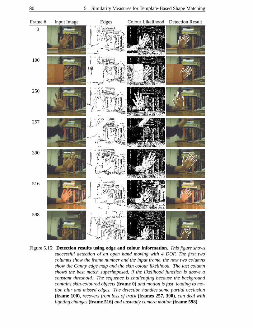
80� 5 Similarity Measuresfor Template-BasedShapeMatching
Frame# Input Image Edges ColourLikelihood DetectionResult
0
100
250
257
390
516
598
Figure5.15: Detection resultsusing edgeand colour information. Thisfigure showssuccessfuldetectionof an open hand moving with 4 DOF. The first twocolumnsshowtheframenumberandthe input frame, thenext two columnsshowtheCannyedge mapand the skincolour likelihood. Thelast columnshowsthe bestmatch superimposed, if the likelihood function is above aconstant threshold. The sequenceis challengingbecausethe backgroundcontains skin-colouredobjects(frame 0) andmotionis fast,leadingto mo-tion blur and missededges. Thedetectionhandlessomepartial occlusion(frame 100), recovers from lossof track (frames 257,390), can deal withlighting changes(frame 516)andunsteadycamera motion(frame 598).
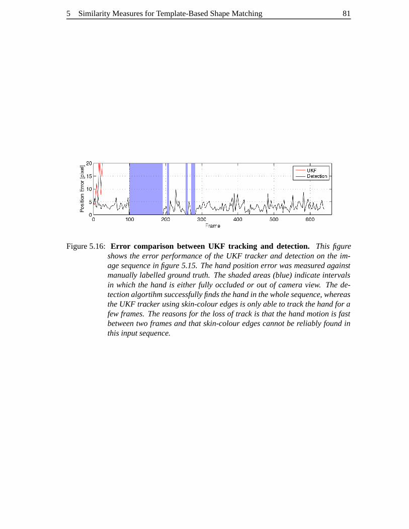
5 Similarity Measuresfor Template-BasedShapeMatching 81
Figure5.16: Err or comparison betweenUKF tracking and detection. This figureshowsthe error performanceof the UKF tracker and detectionon the im-age sequencein figure 5.15. Thehandposition error wasmeasuredagainstmanually labelledgroundtruth. Theshadedareas(blue) indicateintervalsin which the handis either fully occludedor out of camera view. Thede-tectionalgortihmsuccessfullyfindsthehandin thewholesequence, whereastheUKF tracker usingskin-colouredgesis onlyableto track thehandfor afew frames.Thereasonsfor the lossof track is that thehandmotionis fastbetweentwo framesand that skin-colouredgescannotbe reliably foundinthis inputsequence.
6 Hand Tracking Using AHierar chical Filter
Hewhoplantsa treeplantsa hope.
Lucy Larcom(1824–1893)
The taskof robust trackingdemandsa strategy for detectingthe object in the first
frame,aswell asfinding theobjectwhentrack is lost. This is particularlyimportant for
HCI applications, wherehandmotioncanbe fastandit is difficult to accuratelypredict
themotion.
A secondchallengeis thattherecanbea lot of ambiguity dueto self-occlusionwhen
usinga single input image. Several differenthandposescangive rise to the sameap-
pearance,for examplewhensomefingersareoccludedby otherfingers. In suchcases
dynamic informationcanhelpto resolve theambiguity.
This chapteraddressesboth issuesandproposesanalgorithmfor Bayesiantracking,
which is basedon a multi-resolutionpartitioning of the statespace. It is motivatedby
methods introducedin thecontext of hierarchicaldetection,which arebriefly outlinedin
thenext section.
6.1 Tree-based detectio n
Methodsfor detectingobjectsarebecomingincreasinglyefficient. Examplesarereal-time
facedetectionor pedestriandetection[47, 86, 141]. However, applyingthesetechniques
to handdetectionfrom a singleimageis difficult becauseof the largevariationin shape
andappearanceof a handin differentposes.In this casedetectionandposeestimation
are tightly coupled. Oneapproachto solving this problemis to usea large numberof
82
6 HandTrackingUsingA HierarchicalFilter 83
shapetemplatesandfind thebestmatchin the image.In exemplar-basedmethods, such
templatesareobtaineddirectlyfrom thetrainingsets.Thishastheadvantagethatnopara-
metricmodelneedsto be constructed[18, 47, 135]. For example,Gavrila usesapprox-
imately4,500shapetemplatesto detectpedestriansin images[47]. To avoid exhaustive
search,a templatehierarchyis formedby bottom-upclusteringbasedon thechamferdis-
tance(seesection5.1). A numberof similar shapetemplatesarerepresentedby a cluster
prototype. This prototype is first comparedto the input image,andonly if the error is
below a thresholdvalue,thetemplateswithin theclusterarecomparedto theimage.The
useof a templatehierarchyis reportedto resultin aspeed-upof threeordersof magnitude
comparedto exhaustivematching[47].
If a parametricobjectmodelis available, anotheroptionto build sucha treeof tem-
platesis by partitioning thestatespace.Let this treehave � levels,eachlevel � definesa
partition � � of thestatespaceinto � � distinctsets�D�lh;� YjYIY �v� , suchthat � � ��$9� y � -��0�y z|{ .The leavesof the treedefinethefinestpartitionof thestatespace���o��$9� y � - �0�y z|{ . The
useof a parametricmodelalsoallows to combine a templatehierarchycreatedoff-line
with anon-lineoptimizationprocess.Oncethe leaf level is reached,thetemplatematch
canberefinedby continuousoptimizationof themodelparameters.In [131] weusedthis
methodto adapttheshapeof agenerichandmodelto anindividualuserin thefirst frame.
A draw-backof asingle-framedetector, suchastheonepresentedin [47], is thediffi-
culty to incorporatetemporalconstraints.ToyamaandBlake[135] proposedaprobabilis-
tic framework for exemplar-basedmatching,which allows the integration of a dynamic
model. Temporalinformationis useful,firstly to resolve ambiguoussituations, andsec-
ondly, to smooththe motion. However, in [135] no templatehierarchyis formed. The
following sectionintroducesanalgorithmwhich combinestheefficiency of hierarchical
methodswith Bayesianfiltering.
6.2 Tree-based filtering
Trackinghasbeenformulatedasa Bayesianinferenceproblemin section4.1, leadingto
recursivepredictionandupdateequations:
� þ#���.� � {!� �G� { � � �l� þ#���.�����G� { � � þ���G� { � � {!� �G� { ��� ���G� { (6.1)� þ#���.� � {!� � � � � � {� � þ��C�.����� � � þ���.� � {!� �G� { � (6.2)�r��� � � þ��;�v����� � � þ#���.� � {!� �G� { ��� ��� Y (6.3)
84� 6 HandTrackingUsingA HierarchicalFilter
In thegeneralcaseit is not possibleto obtainanalyticsolutionsfor theseequations,but
thereexist a numberof approximationmethodswhich canbeusedto obtaina numerical
solution [12, 40,66, 126].
An important issuein eachapproachis how to representtheprior andposteriordis-
tributionsin thefiltering equations.Onesuggestion,introducedby Bucy andSenne[24],
is to usea point-massrepresentationon a uniform grid. The grid is definedby a dis-
cretesetof pointsin statespace,andis usedto approximatethe integralsin thefiltering
equationsby replacingcontinuous integralswith Riemannsumsover finite regions. The
distributionsare approximatedaspiecewise constantover theseregions. The underly-
ing assumption of this methodis that the posteriordistribution is band-limited, so that
thereareno singularitiesor large oscillationsbetweenthepointson the grid. Typically
grid-basedfiltershavebeenappliedusinganevenlyspacedgrid andtheevaluation is thus
exponentially expensive asthedimension of thestatespaceincreases[12, 24]. Bucy and
Sennesuggestmodellingeachmodeof thedistribution by a separateadaptinggrid, and
they devisea schemefor creatinganddeletinglocal gridson-line. A differentapproach
is takenby Bergman[12], who usesa fixedgrid, but avoidstheevaluation at grid points
wheretheprobability massis below a thresholdvalue. Thegrid resolutionis adaptedin
orderto keepthenumberof computationswithin pre-definedbounds.
The aim in this chapteris to designan algorithm that can take advantageof the
efficiency of tree-basedsearchto efficiently computean approximation to the optimal
Bayesiansolution usinga grid-basedfilter.
In the following, assumethat the valuesof the statevectors arewithin a compact
region � of thestatespace.In thecaseof handtracking,thiscorrespondsto thefactthat
theparametervaluesarebounded,theboundaryvaluesbeingdefinedby thevalid range
of motion. Definea multi-resolutionpartitionof theregion � asdescribedin section6.1
by dividing the region � at eachtree-level � into � � distinct sets $9� y � -��0�y z|{ , which are
non-overlappingandmutually exclusive, thatis�)� y z|{ �y � �¡� for �R��hC� YIYIY �.� Y (6.4)
A graphicaldepictionis shown in figure6.1. Theposteriordistribution is representedas
piecewise constantover thesesets,the distribution at the leaf level beingthe represen-
tation at the highestresolution. Even thoughthe complexity of this methodwill grow
exponentially in thestatespacedimension,the ideais to usetheprocessof hierarchical
detectionto rapidly identify regionsin statespacewith low probability mass.
To formalizethediscretefiltering problem,define ¢ y �� astheparametervaluesin state
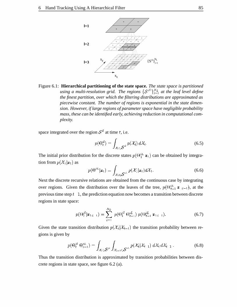
6 HandTrackingUsingA HierarchicalFilter 85
l=1
l=2
l=3
1
2i=1
{S }iL NLx
x
Figure6.1: Hierar chical partitioning of the statespace.Thestate spaceis partitionedusinga multi-resolutiongrid. Theregions $9� y � - � �y z|{ at the leaf level definethefinestpartition, over which thefiltering distributionsare approximatedaspiecewiseconstant. Thenumberof regionsis exponentialin thestatedimen-sion.However, if largeregionsof parameterspacehavenegligible probabilitymass,thesecanbeidentifiedearly, achievingreductionin computational com-plexity.
spaceintegratedover theregion � y � at time £ , i.e.� þ¢ y �� � �d�)¤;¥ 6 ��¦ � � þ#��� �W� ��� Y (6.5)
Theinitial prior distribution for thediscretestates�)þ#¢ y �{ � � { � canbeobtainedby integra-
tion from � þ#� { � � { � as � þ¢ y �{ � � { � � � ¤"§ 6 � ¦ � �)þ#� { � � { �H� � { Y (6.6)
Next thediscreterecursive relationsareobtainedfrom thecontinuouscaseby integrating
over regions. Given the distribution over the leaves of the tree, � þ¢ y ��G� { � � {!� �G� { � , at the
previoustimestep£ T h , thepredictionequationnow becomesatransitionbetweendiscrete
regionsin statespace:
�)þ#¢©¨ �� � � {!� �G� { � � �0�x y z|{ � þ¢©¨ �� ��¢ y ��G� { � � þ¢ y ��G� { � � {!� �G� { �rY (6.7)
Given the statetransition distribution � þ�ª�.�����G� { � the transition probability betweenre-
gionsis given by� þ#¢ ¨ �� ��¢ y ��G� { � � � ¤ ¥ 6 �¬« � � ¤ ¥V § 6 � ¦ � � þ#���.�����G� { ��� ��� � ���G� { Y (6.8)
Thusthe transitiondistribution is approximatedby transition probabilities betweendis-
creteregionsin statespace,seefigure6.2(a).
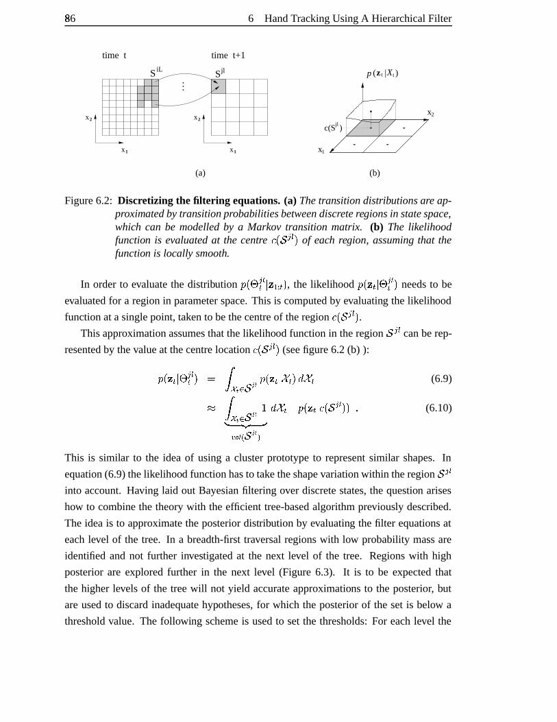
86� 6 HandTrackingUsingA HierarchicalFilter
2
1
2
1
time t time t+1
S
jlSiL
x
x
x
x
(a)
c(S )jl
1
2
x
x
p ( | )Xt tz
(b)
Figure6.2: Discretizing the filtering equations.(a) Thetransitiondistributionsareap-proximatedbytransitionprobabilities betweendiscreteregionsin statespace,which can be modelledby a Markov transition matrix. (b) The likelihoodfunction is evaluatedat the centre �:þ�� ¨ � � of each region, assumingthat thefunction is locally smooth.
In orderto evaluatethe distribution � þ#¢®¨ �� � � {!� � � , the likelihood � þ����.��¢©¨ �� � needsto be
evaluatedfor a region in parameterspace.This is computedby evaluating thelikelihood
functionatasinglepoint, takento bethecentreof theregion �:þ�� ¨ � � .Thisapproximationassumesthatthelikelihood functionin theregion � ¨ � canberep-
resentedby thevalueat thecentrelocation �:þ�� ¨ � � (seefigure6.2(b) ):� þ��;�.��¢ ¨ �� � � � ¤;¥ 6 ��« � � þ��C�.����� �W� ��� (6.9)¯ � ¤ ¥ 6 ��« � h° ±j² ³´ ��� : ��« � <� ���µ� þ��;�.� ��þt� ¨ � �@�oY (6.10)
This is similar to the ideaof usinga clusterprototypeto representsimilar shapes.In
equation(6.9)thelikelihood functionhasto taketheshapevariationwithin theregion � ¨ �into account.Having laid out Bayesianfiltering over discretestates,the question arises
how to combinethe theorywith theefficient tree-basedalgorithmpreviously described.
Theideais to approximatetheposteriordistribution by evaluating thefilter equationsat
eachlevel of the tree. In a breadth-firsttraversalregionswith low probabilitymassare
identified andnot further investigatedat the next level of the tree. Regionswith high
posteriorare explored further in the next level (Figure 6.3). It is to be expectedthat
the higherlevels of the treewill not yield accurateapproximations to the posterior, but
areusedto discardinadequatehypotheses,for which the posteriorof the setis below a
thresholdvalue. The following schemeis usedto setthe thresholds:For eachlevel the
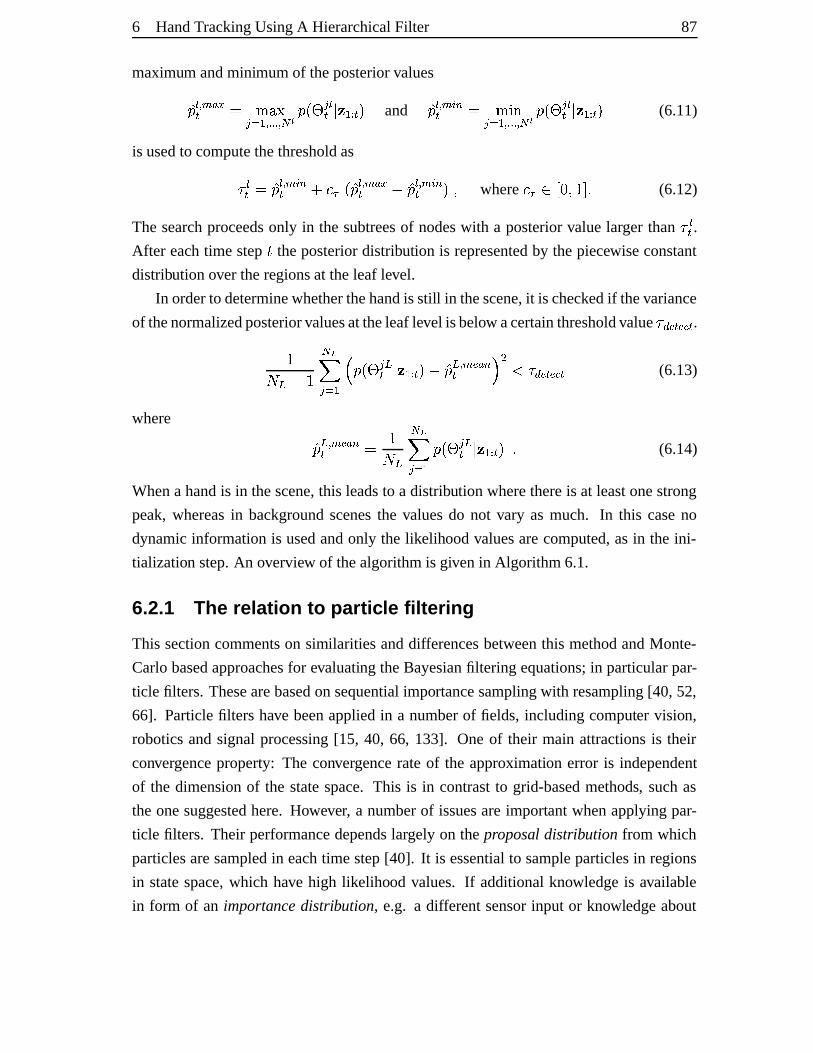
6 HandTrackingUsingA HierarchicalFilter 87
maximum andminimumof theposteriorvalues¶� �i· qU¸ w� � ¹»º�¼¨ z|{ ·�½�½�½ · � � � þ#¢©¨ �� � � {!� � � and¶� �i· q y¿¾� � ¹»ÀVÁ¨ z|{ ·�½�½�½ · � � � þ¢©¨ �� � � {!� � � (6.11)
is usedto computethethresholdas �� � ¶� �i· q yþ� �Ä�.Å�þ ¶� �i· qU¸ w� T ¶� �i· q yþ� � � where �.ÅÆ*Çf�^��Ihjk Y (6.12)
The searchproceedsonly in the subtreesof nodeswith a posteriorvaluelarger than  �� .After eachtime step £ theposteriordistribution is representedby thepiecewiseconstant
distributionover theregionsat theleaf level.
In orderto determinewhetherthehandis still in thescene,it is checkedif thevariance
of thenormalizedposteriorvaluesattheleaflevel isbelow acertainthresholdvalue �c� � � � � .h��� T h �0�x ¨ z|{®È � þ¢ ¨ �� � � {!� � �UT ¶� � · q � ¸ ¾� ÉËÊÍÌ Â �c� � � � � (6.13)
where ¶� � · q � ¸ ¾� � h��� �0�x ¨ z|{ � þ¢©¨ �� � � {!� � �oY (6.14)
Whena handis in thescene,this leadsto a distribution wherethereis at leastonestrong
peak,whereasin backgroundscenesthe valuesdo not vary as much. In this caseno
dynamicinformationis usedandonly the likelihoodvaluesarecomputed,asin the ini-
tialization step.An overview of thealgorithmis givenin Algorithm 6.1.
6.2.1 The relation to par tic le filtering
This sectioncommentson similarities anddifferencesbetweenthis methodandMonte-
Carlobasedapproachesfor evaluating theBayesianfiltering equations;in particularpar-
ticle filters. Thesearebasedonsequentialimportancesamplingwith resampling[40, 52,
66]. Particlefilters have beenappliedin a numberof fields, includingcomputer vision,
roboticsandsignalprocessing[15, 40, 66, 133]. Oneof their main attractionsis their
convergenceproperty: The convergencerateof the approximation error is independent
of the dimensionof the statespace.This is in contrastto grid-basedmethods, suchas
theonesuggestedhere. However, a numberof issuesareimportantwhenapplyingpar-
ticle filters. Their performancedependslargely on theproposal distribution from which
particlesaresampledin eachtime step[40]. It is essentialto sampleparticlesin regions
in statespace,which have high likelihood values. If additionalknowledgeis available
in form of an importancedistribution, e.g. a differentsensorinput or knowledgeabout
88� 6 HandTrackingUsingA HierarchicalFilter
l
l
l
=1
=2
=3
(a)
x
p(x|z)
x
x
p(x|z)
p(x|z)
(b)
Figure6.3: Tree-basedestimation of the posterior density. (a) Associatedwith thenodesat each level is a non-overlapping setin thestatespace, defininga par-tition of the state space. Theposteriorfor each nodeis evaluatedusingthecenterof each set,depictedby a handrotatedby a specificangle. Sub-treesof nodeswith low posterior arenot furtherevaluated.(b) Correspondingpos-terior density(continuous) and the piecewiseconstantapproximation usingtree-basedestimation. Themodesof the distribution are approximated withhigherprecisionat each level.
the valid posteriordistribution, this canbe usedin orderto obtaina significantlybetter
estimateof theposteriorwith thesamenumberof samples[67, 111,153].
In contrastto particlefilters, the tree-basedfilter is a deterministic filter, which was
motivatedby anumberof problem-specificreasons.Firstof all, thefactsthathandmotion
canbefastandthatthehandcanenterandleavethecameraview in HCI applicationscall
for a methodthat provides automatic initialization. It is difficult to definea dynamic
model that can accuratelypredict the handmotion at the given temporalresolution of
30 framesper second,andthusit is important to maintain large supportregionsof the
distributions. The secondimportantconsiderationis the fact that the time requiredfor
projectingthe modelis approximatelythreeordersof magnitudehigherthanevaluating
thelikelihood function. Thusthesampling stepin a particlefilter is relatively expensive
andthismakestheoff-line generationof templatesattractive.
Theideasof tree-basedfiltering andparticlefiltering canalsobecombinedby using
the posteriordistribution estimatedwith the tree-basedfilter asan importancedistribu-
tion for a particlefilter. Finally, it canbe notedthat hierarchicalapproacheshave also
successfullyappliedin particlefilters directly [38, 140].
6 HandTrackingUsingA HierarchicalFilter 89
6.3 Edge and colou r likeliho ods
This sectionintroducesthe likelihood functionwhich is usedwithin thealgorithm. The
likelihood �)þ��Q� � relatesobservations � in the imageto the unknown state . The ob-
servationsare basedon the edgemap � �#� F � of the image,as well as pixel colour val-
ues ������� . Thesefeatureshave provedusefulfor detectingandtrackinghandsin previous
work [88, 90, 155] and the previous chapterhasexamineda numberof cost functions
basedon them. In the following sectionsthe joint likelihood of �Î� þ�� �#� F � �@�����#� � ` is
approximatedas �)þ��Q� � � � þ�� �� F � �v� ����� �! � (6.23)� � þ�� �� F � �! � � þ�� ����� �! � � (6.24)
thustreatingtheobservationsindependently. We aim to derive likelihoodtermsfor each
of theobservations, � �#� F � and �;���#� , in thefollowingparagraphs.
• Edge lik elihood: In chapter5 a numberof similarity measureshave beencom-
pared,all of which canbe usedto definethe observation model. Herewe choose
chamfermatching,introducedin section5.1, which hasbeendemonstratedto be
computationally mostefficient whenmatchinga largenumberof templates.How-
ever, deriving a likelihood basedon the chamferdistancefunction is a non-trivial
problem.ToyamaandBlake [135] suggesta likelihood model,whereanexemplar
shapetemplateis thecentreof amixturedistribution, eachcomponentbeingamet-
ric exponentialdistribution [135]. Given the shapetemplate � andthe observed
edgeimage� �#� F � , thelikelihood hastheform� þ�� �#� F � � � � � hÏ �ÑÐ ¼"Ò S T®Ó � � ��Ô ¸cq þt�Õ�v� �#� F � � X � (6.25)
whereÏ � is thepartition function. Basedon theassumption that theshape� can
berepresentedasa linearcombination of � independentcurve basisfunctions,the
chamferdistanceis shown to have a Ö Êv×=Ê� distribution, where Ö is a distancecon-
stant[135]. Theseparametersalsodefine Ó � h��3ù&Ö Ê and the partition functionÏÙØ ÖË� for eachtemplate(the subscript� hasbeenomitted). The likelihoodis
approximately GaussianandtheparametersÖ and � arelearntfrom avalidationset
of edgeimagesfor eachexemplarclusterseparately. In our casethe templates �aregeneratedby themodel,andarethereforedependenton thevaluesof thestate
vector . Analogousto ToyamaandBlake, thetemplateat eachnodeis treatedas
90Ú 6 HandTrackingUsingA HierarchicalFilter
thecentreof anexponentialdistribution of theform in equation(6.25),andthepa-
rametersÓ and Ö arelearntby computingthemomentswithin aclusterof templates
assuggestedin [135].
A draw-backof this methodof constructingtheliklihood is thatthedistribution of
thechamfercoston randombackgroundedgesis not takeninto account.Different
subsetsof edgepointsareusedto compute thechamferdistancefor differenttem-
plates.This directly influencesthe distribution of the featurevalues,for example
to computethechamferdistanceof a templatewith very few points,only a small
numberof edgepointsis used,andthis templatewill havea low chamfercostnear
any edge,alsoon backgroundedges.A differentmethodto definelikelihoodsis
basedon thePDF projectiontheorem[7, 96], which stateshow thedistribution on
featurescanbe convertedto a distribution on the images. However, the applica-
tion of thePDFprojectiontheoremto deriving likelihood functionsis left to future
work.
• Colour lik elihood: Thecolourcosttermhasalreadybeendefinedasa likelihood
function � þ������#��� � in chapter5. It assumespixelwise independenceof the colour
values,sothatit canbefactoredinto aproductof skin-colourlikelihoods for pixels
within thesilhouette$&%Õ'Û%e*o+�þt �r- andbackgroundcolour likelihoodsfor pixels
outsideof thesilhouette $&%e'�%e*Ü2+�þ� �.- :� þ�� ���#� � � � 4576I8;: =< �0>�þ�?jþ% �@� 4576BA8;: =< �WEGF?þ�?zþ% �@� (6.26)
where ?jþ#% � is thecolourvectorat location % in the image. � > and � EGF aretheskin
colourandbackgroundcolourdistributions,respectively. Skin colour is modelled
with a Gaussiandistribution in þÀÿ�� ��� -space,for backgroundpixelsa uniform dis-
tribution is assumed.This is anapproximationonly, andif a distribution of back-
groundcolourcanbeobtainedfrom astaticscene,thisshouldbeusedinstead.
6.4 Modellin g hand dynamic s
The dynamicsof global handmotion and finger articulationare modelled in different
ways.A simple first orderprocessis usedto modeltheglobaldynamics� þ� Q�.� Ë�G� { �ÞÝ ß þ� Q�G� { �rà �(Y (6.27)
This modelmakesonly weakassumptionsby not takingvelocity into accountandthere
aremany otherpossiblechoicesfor thedynamicmodel,suchastheconstantvelocity or
6 HandTrackingUsingA HierarchicalFilter 91
constantaccelerationmodelusedin chapter4, or secondordermodels,which have been
usedfor handtracking[15, 90].
Thedynamicsfor articulatedmotionarealsomodelledasa first orderprocess,how-
ever, they arelearntfrom trainingdataobtainedwith adataglove(seesection6.6). Since
discreteregionsin statespaceareconsidered,theprocesscanbedescribedby a Markov
transition matrix á �C� *Çf�^��Ihjk �0�Ûâ;�B� , whichcontainsthetransitionprobabilitiesbetween
theregions $&+ ¨ � -��B�¨ z|{ at theleaf-level. In orderto evaluatethetransitionsat differenttree
levels,a transitionmatrix á � � *ãfä^��jhjk �0�Ûâ;�)� for eachlevel � of thetreeis required,where
eachmatrixcontainsthevalues:á � �y ¨ �Ç� þ#¢ ¨ �� ��¢ y ��G� { � for }~��h;� YjYIY �v��� and åæ��h;� YIYIY �.� � Y (6.28)
In practice,thesematricesaresparseandthenon-zerovaluesarestoredin alook-uptable.
6.5 Tracking rigid bod y motion
In the following experimentsthe hierarchicalfilter is usedto track rigid handmotion
in clutteredscenesusinga singlecamera.The resultsreveal the ability to tolerateself-
occlusionduring out-of-image-planerotations. The 3D rotationsarelimited to a hemi-
sphereandfor eachsequenceathree-level treeisbuilt, whichhasthefollowing resolutions
at theleaf level: 15degreesin two 3D rotations,10degreesin imagerotationand5 differ-
entscales,resultingin a totalof haø�nÞhaø�nçh9èénGý��h û �.^�ý3ý templates.Theresolutionof
thetranslationparametersis 20pixelsat thefirst level, 5 pixelson thesecondlevel, and2
pixelsat the leaf level. Notethat for eachof thesequencea differenttreeis constructed,
usingthecorrespondinghandconfiguration.
Figures6.4showsthetrackingresultsonaninputsequenceof apointinghandduring
translationandrotation. During the rotation thereis self-occlusionas the index finger
movesin front of the palm. For eachframethe maximuma-posteriori(MAP) solution
is shown. An errorplot for this sequenceis shown in figure6.5 andin this sequencethe
erroris measuredasthelocalizationerrorof theindex fingertip. TheRMS errorover the
wholesequenceis 8.0pixels.
Figure6.6shows framesfrom thesequenceof anopenhandperformingoutof image
planerotation.Thissequencecontains160framesandshowsahandfirst rotatingapprox-
imately 180 degreesandreturningto its initial pose(figure 6.6, two top rows). This is
followedby a90degreerotation(figure 6.6,two bottomrows),andreturningto its initial
position. This motion is difficult to trackasthereis little informationavailablewhenthe
palmsurfaceis normalto theimageplane.
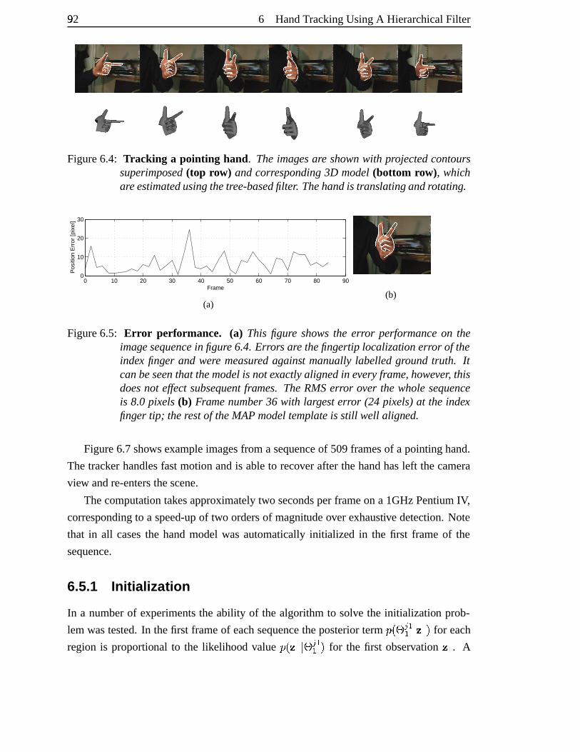
92Ú 6 HandTrackingUsingA HierarchicalFilter
Figure6.4: Tracking a pointing hand. Theimagesare shownwith projectedcontourssuperimposed(top row) andcorresponding3D model(bottom row), whichareestimatedusingthetree-basedfilter. Thehandis translating androtating.
0 10 20 30 40 50 60 70 80 900
10
20
30
Frame
Pos
ition
Err
or [p
ixel
]
(a)(b)
Figure6.5: Err or performance. (a) This figure showsthe error performanceon theimagesequencein figure6.4.Errorsare thefingertip localization error of theindex finger and were measured against manuallylabelledgroundtruth. Itcanbeseenthat themodelis notexactlyalignedin everyframe, however, thisdoesnot effect subsequentframes. TheRMSerror over the wholesequenceis 8.0 pixels(b) Framenumber36 with largesterror (24 pixels)at the indexfinger tip; therestof theMAPmodeltemplateis still well aligned.
Figure6.7shows exampleimagesfrom a sequenceof 509framesof a pointinghand.
Thetracker handlesfastmotionandis ableto recover after thehandhasleft thecamera
view andre-entersthescene.
Thecomputation takesapproximatelytwo secondsperframeon a 1GHzPentiumIV,
correspondingto a speed-upof two ordersof magnitudeover exhaustive detection.Note
that in all casesthe handmodelwas automaticallyinitialized in the first frame of the
sequence.
6.5.1 Initializa tion
In a numberof experimentsthe ability of the algorithmto solve the initialization prob-
lem wastested.In thefirst frameof eachsequencetheposteriorterm � þ¢ê¨ {{ � � { � for each
region is proportional to the likelihood value �)þ�� { ��¢©¨ {{ � for the first observation � { . A
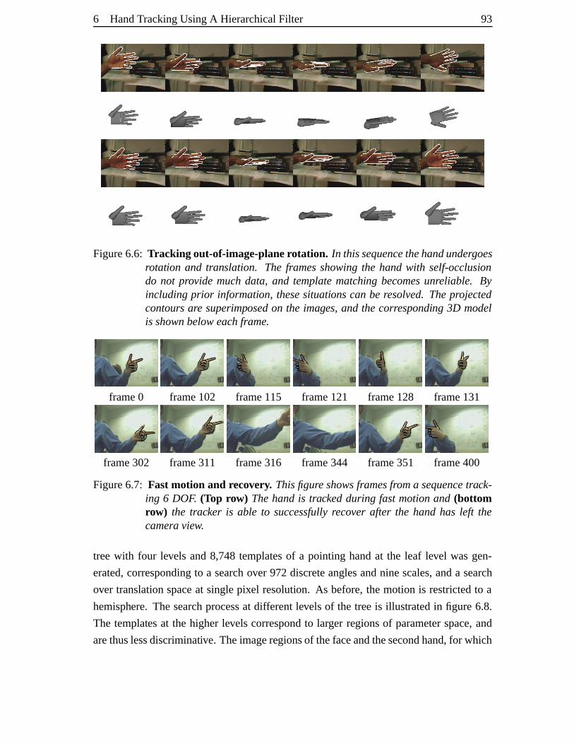
6 HandTrackingUsingA HierarchicalFilter 93
Figure6.6: Tracking out-of-image-planerotation. In thissequencethehandundergoesrotation and translation. The framesshowingthe handwith self-occlusiondo not provide much data, and templatematching becomesunreliable. Byincludingprior information, thesesituationscan beresolved.Theprojectedcontours are superimposedon the images,and the corresponding 3D modelis shownbeloweach frame.
frame0 frame102 frame115 frame121 frame128 frame131
frame302 frame311 frame316 frame344 frame351 frame400
Figure6.7: Fast motion and recovery. Thisfigureshowsframesfroma sequencetrack-ing 6 DOF. (Top row) Thehandis tracked during fast motionand (bottomrow) the tracker is able to successfullyrecover after the hand has left thecamera view.
treewith four levels and8,748templatesof a pointing handat the leaf level wasgen-
erated,correspondingto a searchover 972discreteanglesandninescales,anda search
over translationspaceat singlepixel resolution. As before,themotion is restrictedto a
hemisphere. Thesearchprocessat differentlevelsof the treeis illustratedin figure 6.8.
The templatesat the higherlevelscorrespondto larger regionsof parameterspace,and
arethuslessdiscriminative. Theimageregionsof thefaceandthesecondhand,for which
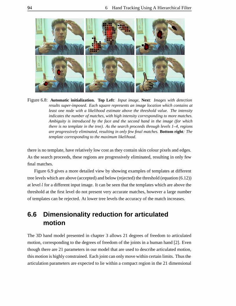
94Ú 6 HandTrackingUsingA HierarchicalFilter
Figure6.8: Automatic initial ization. Top Left : Input image, Next: Images with detectionresultssuper-imposed. Each square representsan image location which contains atleast onenodewith a likelihood estimateabove the threshold value. The intensityindicatesthenumberof matches,with high intensitycorresponding to more matches.Ambiguity is introducedby the face and the second hand in the image (for whichthere is no templatein the tree). As thesearch proceedsthrough levels1–4, regionsare progressively eliminated,resulting in only few final matches.Bottom right : Thetemplatecorresponding to themaximumlikelihood.
thereis notemplate,haverelatively low costasthey containskincolourpixelsandedges.
As thesearchproceeds,theseregionsareprogressively eliminated,resultingin only few
final matches.
Figure6.9givesa moredetailedview by showing examplesof templatesat different
treelevelswhichareabove(accepted)andbelow (rejected)thethreshold(equation(6.12))
at level � for adifferentinput image.It canbeseenthatthetemplateswhichareabovethe
thresholdat thefirst level do not presentvery accuratematches,however a largenumber
of templatescanberejected.At lower treelevelstheaccuracy of thematchincreases.
6.6 Dimensi onality reduc tion for articulat edmotion
The 3D handmodelpresentedin chapter3 allows 21 degreesof freedomto articulated
motion,correspondingto thedegreesof freedomof thejoints in ahumanhand[2]. Even
though thereare21parametersin ourmodelthatareusedto describearticulatedmotion,
thismotionishighlyconstrained.Eachjoint canonlymovewithin certainlimits. Thusthe
articulationparametersareexpectedto lie within acompactregion in the21dimensional
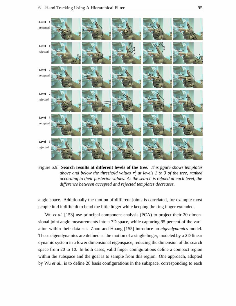
6 HandTrackingUsingA HierarchicalFilter 95
Level 1
accepted
Level 1
rejected
Level 2
accepted
Level 2
rejected
Level 3
accepted
Level 3
rejected
Figure6.9: Search resultsat differ ent levels of the tr ee. This figure showstemplatesabove and belowthe thresholdvalues  �� at levels1 to 3 of the tree, rankedaccording to their posteriorvalues.Asthesearch is refinedat each level, thedifferencebetweenacceptedandrejectedtemplatesdecreases.
anglespace.Additionally the motion of differentjoints is correlated,for examplemost
peoplefind it difficult to bendthelittle fingerwhile keepingthering fingerextended.
Wu et al. [153] useprincipal componentanalysis(PCA) to project their 20 dimen-
sionaljoint anglemeasurementsinto a 7D space,while capturing95 percentof thevari-
ation within their dataset. Zhou andHuang[155] introducean eigendynamicsmodel.
Theseeigendynamicsaredefinedasthemotionof asinglefinger, modeledby a2D linear
dynamicsystemin a lowerdimensionaleigenspace,reducingthedimensionof thesearch
spacefrom 20 to 10. In bothcases,valid finger configurationsdefinea compactregion
within the subspaceandthe goal is to samplefrom this region. Oneapproach,adopted
by Wu et al., is to define28 basisconfigurationsin thesubspace,correspondingto each
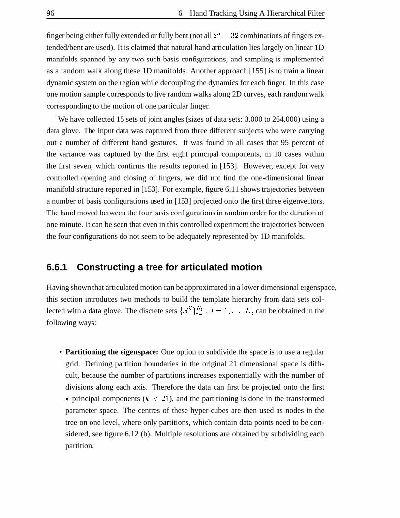
96ë 6 HandTrackingUsingA HierarchicalFilter
fingerbeingeitherfully extendedor fully bent(notall ì�í�îÎï�ì combinationsof fingersex-
tended/bentareused).It is claimedthatnaturalhandarticulationlies largelyon linear1D
manifolds spannedby any two suchbasisconfigurations,andsampling is implemented
asa randomwalk alongthese1D manifolds.Anotherapproach[155] is to train a linear
dynamic systemontheregionwhile decouplingthedynamicsfor eachfinger. In thiscase
onemotionsamplecorrespondsto fiverandomwalksalong2D curves,eachrandomwalk
correspondingto themotionof oneparticularfinger.
Wehavecollected15setsof joint angles(sizesof datasets:3,000to 264,000)usinga
dataglove. Theinputdatawascapturedfrom threedifferentsubjectswho werecarrying
out a numberof different handgestures. It was found in all casesthat 95 percentof
the variancewas capturedby the first eight principal components, in 10 caseswithin
the first seven, which confirmsthe resultsreportedin [153]. However, except for very
controlled openingand closing of fingers,we did not find the one-dimensional linear
manifold structurereportedin [153]. For example,figure6.11showstrajectoriesbetween
anumberof basisconfigurationsusedin [153] projectedontothefirst threeeigenvectors.
Thehandmoved betweenthefour basisconfigurationsin randomorderfor thedurationof
oneminute.It canbeseenthatevenin thiscontrolledexperimentthetrajectoriesbetween
thefour configurationsdonotseemto beadequatelyrepresentedby 1D manifolds.
6.6.1 Constructing a tree for articul ated motion
Havingshownthatarticulatedmotioncanbeapproximatedin alowerdimensionaleigenspace,
this sectionintroducestwo methodsto build the templatehierarchyfrom datasetscol-
lectedwith a dataglove. Thediscretesetsð9ñ©òiótô�õ)öòø÷|ùrúüû î�ý úIþjþIþjú.ÿ ú canbeobtainedin the
following ways:
• Partitioning the eigenspace:Oneoption to subdivide thespaceis to usea regular
grid. Defining partition boundariesin the original 21 dimensional spaceis diffi-
cult, becausethenumberof partitions increasesexponentiallywith thenumberof
divisionsalongeachaxis. Thereforethe datacanfirst be projectedonto the first�principal components (
��� ì"ý ), andthepartitioningis donein the transformed
parameterspace.The centresof thesehyper-cubesare thenusedasnodesin the
treeon onelevel, whereonly partitions,which containdatapointsneedto becon-
sidered,seefigure6.12(b). Multiple resolutionsareobtainedby subdividing each
partition.
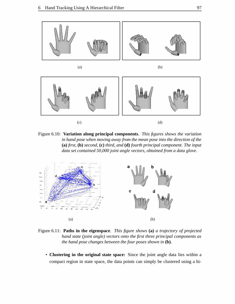
6 HandTrackingUsingA HierarchicalFilter 97
(a) (b)
(c) (d)
Figure6.10: Variation along principal components. This figuresshowsthe variationin handposewhenmovingawayfromthemeanposeinto thedirectionof the(a) first,(b) second,(c) third, and(d) fourth principal component.Theinputdatasetcontained50,000joint anglevectors,obtainedfroma dataglove.
(a) (b)
Figure6.11: Paths in the eigenspace. This figure shows(a) a trajectoryof projectedhandstate(joint angle)vectors ontothefirst threeprincipal componentsasthehandposechangesbetweenthefour posesshownin (b).
• Clustering in the original state space: Sincethe joint angledatalies within a
compactregion in statespace,the datapoints cansimply be clusteredusinga hi-
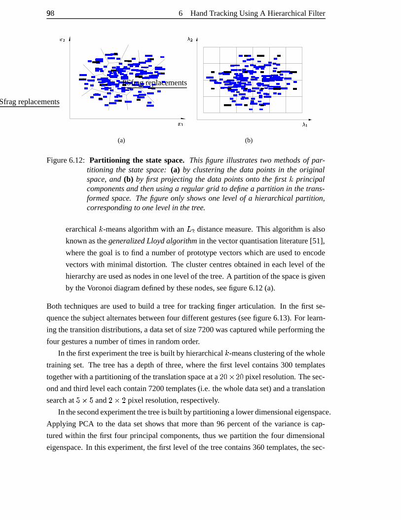
98ë 6 HandTrackingUsingA HierarchicalFilter
��������
�
�� � ��� ��
����
�� ��
���� ����
�
!" #$ %�%%�%&&'())** +�+,-. /0
12345678 9: ;< =�=>�> ?@A�AB�B CDEFGHI�IJ
KL M�MNOOPP
QRST
U�UV�V WX Y�YY�YZ�ZZ�Z[�[\]�]^_` ab c�cd efg�ghi�ij�jkkllm�mn�nop qr st uv
w�wxy�yz�z{�{|}�}~�~ ���� ����������������
�� ����
����������������
����� �
¡¢ £¤¥¦§�§¨�¨
©�©ª�ª«�«¬�¬® ¯�¯° ±²
³�³´ µ¶·�·¸�¸¹�¹º»¼½�½¾�¾
¿�¿À ÁÂÃ�ÃÄ�ÄÅ�ÅÆ�ÆÇ�ÇÈ�ÈÉÊË�ËÌ
ÍÎÏ�ÏÐ�ÐÑ�ÑÒ�ÒÓ�ÓÔÕ�ÕÖ�Ö ×ØÙÚÛÜ ÝÞß
ßààáâãäå�åæçè é�éê�ê
ë�ëì�ìí�íî�îïðñò óô õ�õö÷�÷ø�ø ù�ùú ûü ýþ
ÿ� ������ ���� �� ��� �
��������
���� �� ����������������
����
���� ! "�"#�#
$�$% &'() *�*+�+
,-
./01
PSfragreplacements
243
265
(a)
7879
:;
<= >? @ABCDE
FGH8HI
JK
LLMM
N8NOPQ
R8RS8ST8TU8UVWX8XY Z8Z[
\\]]
^8^_8_`abbccd8de
f8fg
hij8jk
lm nop8pqrstu
v8vwx8xy8yz{
|8|}~��8���8��8� �8��8�
�8��8��8���8��8� ��
���� ��������
�8��8� �8��8����8��8��� ¡
¢8¢£ ¤8¤¥ ¦§
¨©ª«
¬8¬¬8¬ ®8®¯8¯°8°±8±²³ ´µ ¶8¶·8·
¸¹º» ¼8¼½
¾¿À8ÀÁ
ÂÃ
Ä8ÄÅ8Å
ÆÇ
È8ÈÉ8ÉÊË
ÌÍÎÏ
ÐÑÒÓÔÕÖ8Ö×8×
ØÙÚÛ
ÜÝ
Þ8Þß8ß
à8àáâã
ä8äåæçèé
ê8êë8ëìí îï ðñ
òóôõ
ö8ö÷ø8øùúû
ü8üýþþÿÿ���� ����
������ ����� ������������������������ ����� !�!"#$
%&'�'()*+,-./�/01�11�12�22�23456 78 9�9:�:
;�;<=>?@
A�AB�BCD
EFGH I�IJ�J KL
M�MN�NOPQRSTU�UVWX
YZ[\]^
_�_`ab c�cd�dPSfragreplacements
e 3
e 5
(b)
Figure6.12: Partitioning the state space. This figure illustratestwo methodsof par-titioning the statespace: (a) by clusteringthe data points in the originalspace, and (b) by first projecting the data pointsonto the first
�principal
componentsandthenusinga regular grid to definea partition in thetrans-formedspace. Thefigure only showsonelevel of a hierarchical partition,corresponding to onelevel in thetree.
erarchical�-meansalgorithmwith an ÿ f distancemeasure.This algorithmis also
known asthegeneralizedLloydalgorithm in thevectorquantisation literature[51],
wherethegoal is to find a numberof prototype vectorswhich areusedto encode
vectorswith minimal distortion. The clustercentresobtainedin eachlevel of the
hierarchyareusedasnodesin onelevel of thetree.A partitionof thespaceis given
by theVoronoidiagramdefinedby thesenodes,seefigure6.12(a).
Both techniquesareusedto build a treefor trackingfinger articulation. In the first se-
quencethesubjectalternatesbetweenfour differentgestures(seefigure6.13).For learn-
ing thetransitiondistributions,a datasetof size7200wascapturedwhile performingthe
four gesturesanumberof timesin randomorder.
In thefirst experimentthetreeis built by hierarchical�-meansclusteringof thewhole
training set. The treehasa depthof three,wherethe first level contains300 templates
togetherwith apartitioning of thetranslationspaceata ì gih ì g pixel resolution. Thesec-
ondandthird level eachcontain7200templates(i.e. thewholedataset)anda translation
searchat j h j and ì h ì pixel resolution, respectively.
In thesecondexperimentthetreeisbuilt bypartitioningalowerdimensionaleigenspace.
Applying PCA to the datasetshows that more than96 percentof the varianceis cap-
turedwithin the first four principal components, thuswe partition the four dimensional
eigenspace.In this experiment,thefirst level of thetreecontains360templates,thesec-
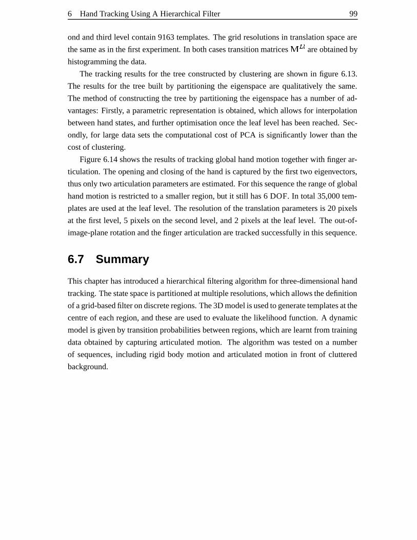
6 HandTrackingUsingA HierarchicalFilter 99
ondandthird level contain9163templates.Thegrid resolutionsin translationspaceare
thesameasin thefirst experiment. In bothcasestransitionmatricesk l ó areobtainedby
histogrammingthedata.
The trackingresultsfor the treeconstructedby clusteringareshown in figure 6.13.
The resultsfor the tree built by partitioning the eigenspacearequalitatively the same.
Themethodof constructingthe treeby partitioning the eigenspacehasa numberof ad-
vantages:Firstly, a parametricrepresentationis obtained,which allows for interpolation
betweenhandstates,andfurtheroptimisationoncetheleaf level hasbeenreached.Sec-
ondly, for large datasetsthe computationalcostof PCA is significantly lower thanthe
costof clustering.
Figure6.14shows theresultsof trackingglobalhandmotion togetherwith fingerar-
ticulation. Theopeningandclosingof thehandis capturedby thefirst two eigenvectors,
thusonly two articulationparametersareestimated.For thissequencetherangeof global
handmotion is restrictedto a smallerregion,but it still has6 DOF. In total 35,000tem-
platesareusedat the leaf level. Theresolutionof thetranslationparametersis 20 pixels
at thefirst level, 5 pixelson thesecondlevel, and2 pixelsat the leaf level. Theout-of-
image-planerotationandthefingerarticulationaretrackedsuccessfullyin thissequence.
6.7 Summ ary
This chapterhasintroduceda hierarchicalfiltering algorithmfor three-dimensionalhand
tracking.Thestatespaceis partitionedatmultipleresolutions,whichallowsthedefinition
of agrid-basedfilter ondiscreteregions.The3Dmodelisusedtogeneratetemplatesatthe
centreof eachregion, andtheseareusedto evaluatethe likelihoodfunction. A dynamic
modelis givenby transitionprobabilitiesbetweenregions,whicharelearntfrom training
dataobtainedby capturingarticulatedmotion. The algorithmwas testedon a number
of sequences,including rigid body motion andarticulatedmotion in front of cluttered
background.
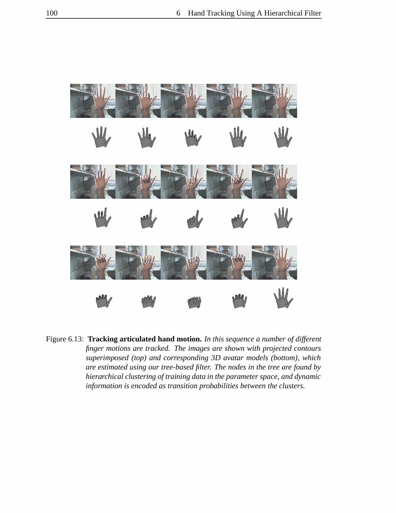
100 6 HandTrackingUsingA HierarchicalFilter
Figure6.13: Tracking articulated hand motion. In this sequencea numberof differentfinger motionsare tracked. Theimagesare shownwith projectedcontourssuperimposed(top) and corresponding3D avatar models(bottom),whichare estimatedusingour tree-basedfilter. Thenodesin thetreeare foundbyhierarchical clusteringof trainingdatain theparameterspace, anddynamicinformationis encodedastransitionprobabilitiesbetweentheclusters.
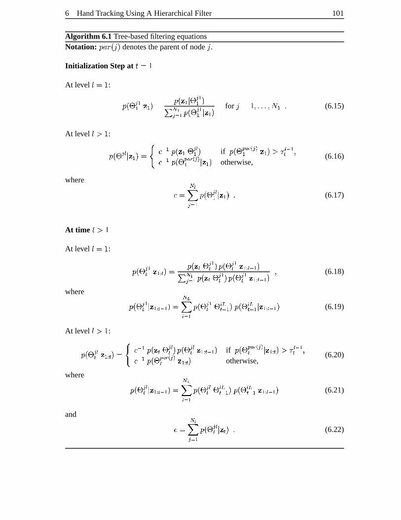
6 HandTrackingUsingA HierarchicalFilter 101
Algorithm 6.1Tree-basedfiltering equationsNotation: monqpsrutwv denotestheparentof nodet .Initializatio n Stepat x�î�ýAt level û î�ý :
myr{z}| ùù ~ � ù v�î myr � ù ~ z | ùù v� õ 3| ÷|ù myr{z | ùù ~ � ù v for tæî�ý újþIþIþjú � ù þ (6.15)
At level û�� ý :myr{z | óù ~ � ù v¬î ����� ù myr � ù ~ z | óù v if myr�z}������� |��ù ~ � ù v ��� ó � ù� ú��� ù myr�z ������� |��ù ~ � ù v otherwise,
(6.16)
where � î õ ö�| ÷|ù myr�z}| óù ~ � ù v þ (6.17)
At time x � ýAt level û î�ý :
myr{z | ù� ~ � ù�� � v�î myr � � ~ z | ù� v�myr�z | ù� ~ � ù�� � � ù v� õ 3| ÷|ù myr � � ~ z | ù� v�m�r{z | ù� ~ � ù�� � � ù v ú (6.18)
where
myr{z | ù� ~ � ù�� � � ù v¬î õo�� òi÷|ù myr�z | ù� ~ z ò l� � ù v�myr{z ò l� � ù ~ � ù�� � � ù v (6.19)
At level û�� ý :myr{z | ó� ~ � ù�� � v�î ����� ù myr � � ~ z | ó� v�myr{z | ó� ~ � ù�� � � ù v if myr�z ������� |��� ~ � ù�� � v ��� ó � ù� ú��� ù myr�z ������� |��� ~ � ù�� � v otherwise,
(6.20)
where
myr{z}| ó� ~ � ù�� � � ù v¬î õo�� òi÷|ù myr�z}| ó� ~ z ò l� � ù v�myr�z ò l� � ù ~ � ù�� � � ù v (6.21)
and � î õ ö�| ÷|ù myr�z}| ó� ~ � � v þ (6.22)
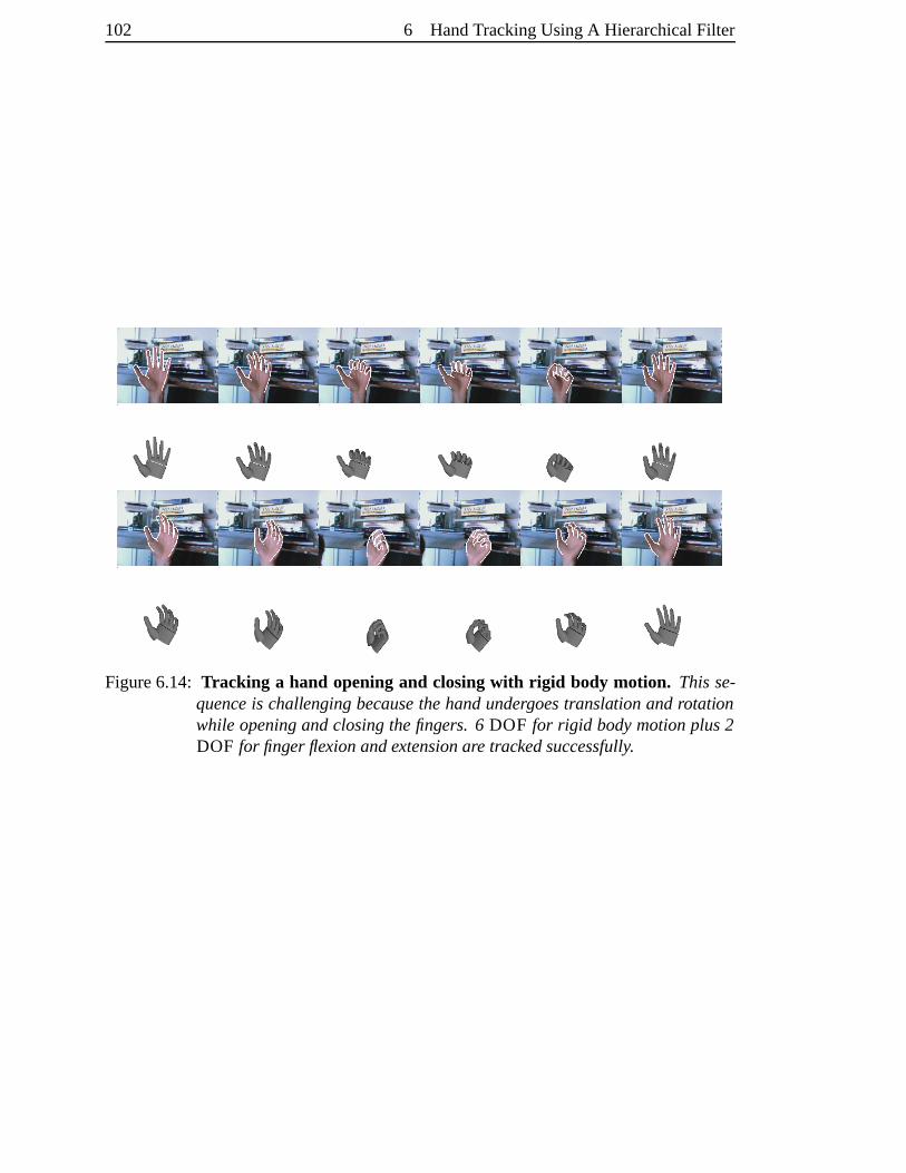
102 6 HandTrackingUsingA HierarchicalFilter
Figure6.14: Tracking a hand opening and closingwith rigid body motion. Thisse-quenceis challengingbecausethehandundergoestranslation androtationwhile openingandclosingthefingers. 6 DOF for rigid bodymotionplus2DOF for finger flexionandextensionare trackedsuccessfully.
7 Conc lusion
Whatgoodarecomputers?They canonlygiveyouanswers.
PabloPicasso(1881-1973)
7.1 Summ ary
Themaincontribution of this thesisis theformulationof a framework for recoveringthe
3D handposefrom imagesequences.It draws from two strandsof research:hierarchical
detectionandBayesianfiltering. Reliabledetectionhelpsin dealingwith difficult prob-
lemssuchasloosing trackdueto self-occlusion.By usingdynamicinformation, detec-
tion is mademoreefficient by eliminating a significantnumberof hypotheses.Bayesian
methodsare attractive as they provide a principledway of encodinguncertaintyabout
parameterestimates.This is particularlynecessaryfor the problemof trackingin clut-
ter as thereis muchambiguity, resultingin multi-modal distributions. Oneof the key
issuesin Bayesianfiltering is how to representthesedistributions. Previously grid-based
methods, involving partitioning the statespace,have proven very successfulfor propa-
gatingdistributionsin tracking.However, they suffer from themajordrawbackthat they
arecomputationally infeasiblein high dimensional spaces.Whenthe stateparameters
areconfinedto a compactregion, it is suggestedto partitionthis region in a hierarchical
fashionandusetheresultingtreeto representthedistributions.
It hasbeenshown in this work how to constructa 3D handmodelfrom simple geo-
metricprimitives.Thereareseveralbenefitsto usinga3D modeloverparametriccontour
modelsor exemplar models.In contrastto parametriccontourmodels,topologicalshape
changesof the contourcausedby self-occlusionarehandlednaturallyby a 3D model,
without the needof resortingto nonlinearshapespaces[58]. In contrastto exemplar-
basedmodels,theuseof a 3D parametricmodelallows to generatefurthertemplateson-
line, onceanapproximatematchhasbeenfound.Continuousoptimizationcanbeusedto
refinethematchor adaptthemodelto thehandof adifferentuser[132]. A 3D modelalso
hastheadvantageof semanticcorrespondence,whichallowsthedefinitionof ameaning-
103
104 7 Conclusion
ful dynamicmodel,andcanbe importantfor HCI applications.Furthermore,methods
basedon 3D modelscanbeextendedfrom singleto multiple views with relatively little
effort, becauseit simply requiresprojectingthemodelinto eachview.
7.2 Limitatio ns
The rangeof allowed motion is currently limited by the numberof templates. In the
currentsystemtemplatesfor differentscaleandorientationparametersaregeneratedoff-
line, leadingto a largenumberof templates.Thesetemplatescouldalsobegeneratedon-
line by 2D transformations,andtheincreasein timerequiredfor likelihoodcomputations
couldbetolerablein thelight of memorysavings.
On our currenthardware (2.4 GHz PentiumIV) the algorithmdoesnot run in real
time. Typical run timesaretwo framespersecondfor a few hundredtemplatesto three
secondsper framefor about35,000templates.Even thoughsomeeffort wasspenton
optimizing themethods,thereis still scopefor improvement.
Emphasishasbeenplacedonthedesignof robustsimilarity measures,whicharethen
usedto constructa likelihood function within the filter. For edgedetection,the Canny
edgedetectorhasbeenused,which is a standardtool in computer vision [25]. However,
it doesnotalwaysyield consistentedgeresponsesin videosequencesdueto imagenoise.
Theresultis alsohighly dependentonthekernelandthresholdparametersin thedetector.
In practicemissing edgessometimesleadto missed detections,andspuriousedgescan
lead to falsepositive detections.Similarly, the static skin colour featurescan become
unreliableif illuminationchangessignificantly.
7.3 Future work
This sectionidentifiesa numberof directionsof futurework. An advantageof theprob-
abilistic approach,which wastaken in this work, is that it is modularin the sensethat
application-specificdynamicmodelsor observationmodelscanbeincludedseamlessly.
• Observation model: Thedesignof bettersimilarity measureswill directlyincrease
therobustnessof thetracker. It will beinteresting to investigateusingdifferentfilter
outputsasfeatures,asin [69, 129, 137]. Also theintegrationof othercuessuchas
texture,motionandshadingcouldleadto bettercostfunctions.If two camerasare
available,densestereoalgorithms,can be useful for segmenting the handin the
image.
7 Conclusion 105
• Hand model: Thetracker will alsodirectly benefitfrom a moreaccurategeomet-
ric handmodelandefficient renderingtechniques.The modelusedin this work
is comparableto the simple cylindermodelsof Marr andNishihara[92] or Rehg
andKanade[109]. Eventhoughsuchmodelsarea goodapproximation to thetrue
geometry, advancesin computergraphicshave led to morecomplex but accurate
models, suchas the handmodelof Albrecht et al. [2]. As computing power in-
creases,it is possible to usethesemodelsin computervisionapplications.
• Tree construction: The tree hasbeenconstructedmanuallyin the examplesby
dividing the parameterspaceat certainresolutions. Futurework should consider
methodsto make this processautomatic,for exampleby consideringthe appear-
ancevariationwithin eachpartition or by clusteringthe templatesbasedon their
appearancesimilarity.
• Combining tr ee-basedfiltering with continuousmethods:Theresultof thetree-
basedfilter containsa discretizationerrordueto thepartitioning of thestatespace.
However, becausetheoutputis a probability distribution, it canbeintegratedwith
acontinuousfilter, suchasa particlefilter.
• Extension to multiple views: Thefiltering framework presentedin chapter6 can
beextendedto estimationfrom multiple calibratedcameras.Thesamestatespace
partitioning canbe usedasfor the singleview case,andthe modelat the canbe
projectedinto eachview.
• Experimental comparison with other approaches: The stepfrom the research
laboratoryto commercialapplicationstypically leadsvia anevaluation of compet-
ing methodson benchmarkdata. Possiblydue to the ambiguity of the task, the
difficulty to obtaingroundtruthdata,aswell asdifferentapplicationgoals,thereis
nopublicallyavailabledatasetfor three-dimensionalhandtracking.
Bib liog raph y
[1] J. K. Aggarwal andQ. Cai. Humanmotionanalysis:A review. ComputerVision
andImageUnderstanding, 73(3):428–440,1999.
[2] I. Albrecht,J.Haber, andH.-P. Seidel.Constructionandanimationof anatomically
basedhumanhandmodels.In Proc.Eurographics/SIGGRAPHSymp.onComputer
Animation, 98–109,SanDiego,CA, July2003.
[3] V. Athitsos,J.Alon, S.Sclaroff, andG. Kollios. Boostmap:A methodfor efficient
approximatesimilarity rankings. In BostonUniversity ComputerScienceTech.
ReportNo.2003-023, November2003.
[4] V. AthitsosandS.Sclaroff. 3D handposeestimationby findingappearance-based
matchesin a largedatabaseof trainingviews. In IEEEWorkshoponCuesin Com-
munication, 100–106,December2001.
[5] V. Athitsos andS. Sclaroff. An appearance-basedframework for 3D handshape
classificationandcameraviewpoint estimation. In IEEE Conferenceon Faceand
GestureRecognition, 45–50,WashingtonDC, May 2002.
[6] V. AthitsosandS. Sclaroff. Estimating 3D handposefrom a clutteredimage. In
Proc.Conf. ComputerVisionandPatternRecognition, volumeII, 432–439, Madi-
son,WI, June2003.
[7] P. M. Baggenstoss.The pdf projectiontheoremand the class-specificmethod.
IEEETransactionsonSignalProcessing, (51):672–685,2003.
[8] Y. Bar-ShalomandT. E. Fortmann.Tracking andData Association. Number179
in Mathematicsin scienceandengineering.AcademicPress,Boston,1988.
[9] H. G. Barrow, J. M. Tenenbaum,R. C. Bolles, andH. C. Wolf. Parametriccor-
respondenceandchamfermatching:Two new techniquesfor imagematching. In
Proc.5th Int. Joint Conf. Artificial Intelligence, 659–663,1977.
106
7 Bibliography 107
[10] S.Belongie,J.Malik, andJ.Puzicha.Matchingshapes.In Proc.InternationalCon-
ferenceonComputerVision, volume I, 454–455, Vancouver, Canada,July2001.
[11] S.Belongie,J.Malik, andJ.Puzicha.Shapematchingandobjectrecognitionusing
shapecontexts. IEEETrans.PatternAnalysisandMachineIntell., 24(4):509–522,
April 2002.
[12] N. Bergman. RecursiveBayesianEstimation: NavigationandTracking Applica-
tions. PhDthesis,Linkoping University, Linkoping,Sweden,1999.
[13] P. J. BeslandN. McKay. A methodfor registrationof 3-D shapes.IEEE Trans.
PatternAnalysisandMachineIntell., 14(2):239–256, March1992.
[14] S. Birchfield. Elliptical headtracking using intensity gradientsand color his-
tograms.In Proc.Conf. ComputerVisionandPatternRecognition, 232–237,Santa
Barbara, CA, June1998.
[15] A. Blake and M. Isard. Active Contours : The Application of Techniquesfrom
Graphics,Vision, Control Theoryand Statistics to Visual Tracking of Shapesin
Motion. Springer-Verlag,London,1998.
[16] G. Borgefors. Hierarchicalchamfermatching: A parametricedgematchingalgo-
rithm. IEEE Trans.PatternAnalysis andMachineIntell., 10(6):849–865,Novem-
ber1988.
[17] Y. Boykov andD. P. Huttenlocher. A new Bayesianframework for objectrecogni-
tion. In Proc. Conf. ComputerVision andPatternRecognition, volume II, 2517–
2523,Fort Collins,CO,June1999.
[18] M. Brand.Shadow puppetry. In Proc.7thInt. Conf. onComputerVision, volumeII,
1237–1244,Corfu,Greece,September1999.
[19] C. Bregler andJ. Malik. Trackingpeoplewith twists andexponentialmaps. In
Proc. Conf. ComputerVision andPatternRecognition, 8–15,SantaBarbara,CA,
June1998.
[20] L. Bretzner, I. Laptev, andT. Lindeberg. Handgesturerecognitionusingmulti-
scalecolourfeatures,hierarchicalmodelsandparticlefiltering. In Proc.Faceand
Gesture, 423–428,WashingtonDC, 2002.
108 7 Bibliography
[21] T. M. Breuel.Fastrecognitionusingadaptivesubdivisionsof transformationspace.
In Proc. Conf. ComputerVisionandPatternRecognition, 445–451, UrbanaCham-
paign,IL, June1992.
[22] T. M. Breuel. GeometricAspectsof Visual ObjectRecognition. PhDthesis,Mas-
sachusettsInstituteof Technology, Cambridge,MA, April 1992.
[23] T. M. Breuel.Higher-orderstatisticsin objectrecognition.In Proc.Conf. Computer
VisionandPatternRecognition, 707–8,New York, 1993.
[24] R. S. Bucy andK. D. Senne. Digital synthesisof nonlinearfilters. Automatica,
(7):287–298,1971.
[25] J. F. Canny. A computational approachto edgedetection. IEEE Trans. Pattern
AnalysisandMachineIntell., 8(6):679–698, November 1986.
[26] Y. ChenandG.Medioni. Objectmodelingby registrationof multiple rangeimages.
ImageandVisionComputing, 10(3):145–155, April 1992.
[27] R. CipollaandA. Blake. Thedynamicanalysisof apparentcontours.In Proc.3rd
Int. Conf. onComputerVision, 616–623, Osaka,Japan,December1990.
[28] R. Cipolla andP. J. Giblin. Visual Motion of Curvesand Surfaces. Cambridge
University Press,Cambridge,UK, 1999.
[29] R. Cipolla,P. A. Hadfield,andN. J.Hollinghurst. Uncalibratedstereovision with
pointing for aman-machineinterface.In Proc.IAPRWorkshoponMachineVision
Applications, 163–166, Kawasaki,Japan,1994.
[30] R. CipollaandN. J.Hollinghurst. Human-robotinterfaceby pointing with uncali-
bratedstereovision. ImageandVisionComputing, 14(3):171–178, April 1996.
[31] R. Cipolla,Y. Okamoto,andY. Kuno. Qualitativevisualinterpretationof 3D hand
gesturesusingmotionparallax.In Proc.IAPRWorkshoponMachineVision Appli-
cations, 477–482, Tokyo, Japan,1992.
[32] T. F. Cootes,C.J.Taylor, D. H. Cooper, andJ.Graham.Activeshapemodels– their
trainingandapplication.ComputerVision andImageUnderstanding, 61(1):38–59,
January1995.
[33] F. C. Crow. Summed-areatablesfor texturemapping. In Proc. SIGGRAPH, vol-
ume18,207–212,July1984.
7 Bibliography 109
[34] Y. Cui andJ. J. Weng. Handsegmentation using learning-basedpredictionand
verificationfor handsignrecognition.In Proc.Conf. ComputerVision andPattern
Recognition, 88–93,SanFrancisco,CA, June1996.
[35] Y. Cui and J. J. Weng. Appearance-basedhandsign recognitionfrom intensity
imagesequences.ComputerVision and Image Understanding, 78(2):157–176,
2000.
[36] Q. DelamarreandO. D. Faugeras.Findingposeof handin videoimages:astereo-
basedapproach.In Proc.3rd Int. Con.onAutomatic FaceandGestureRecogntion,
585–590,Nara,Japan,April 1998.
[37] Q. Delamarreand O. D. Faugeras. Articulatedmodelsandmulti-view tracking
with silhouettes.In Proc.7th Int. Conf. on ComputerVision, volumeII, 716–721,
Corfu,Greece,September1999.
[38] J.Deutscher, A. Blake, andI. Reid. Articulatedbodymotion captureby annealed
particlefiltering. In Proc. Conf. ComputerVision and Pattern Recognition, vol-
umeII, 126–133,Hilton Head,SC,June2000.
[39] J.Deutscher, B. North,B. Bascle,andA. Blake. Trackingthroughsingularitiesand
discontinuities by randomsampling. In Proc. 7th Int. Conf. on ComputerVision,
volumeII, 1144–1149,Corfu,Greece,September1999.
[40] A. Doucet,N. G. de Freitas,andN. J. Gordon,editors. SequentialMonteCarlo
Methodsin Practice. Springer-Verlag,2001.
[41] T. W. DrummondandR.Cipolla.Real-timetrackingof highly articulatedstructures
in thepresenceof noisymeasurements.In Proc.8thInt. Conf. onComputerVision,
volumeII, 315–320,Vancouver, Canada,July2001.
[42] R. O. Duda,P. E. Hart, andD. G. Stork. Pattern Classification. JohnWiley &
Sons,New York, secondedition, 2001.
[43] P. F. Felzenszwalb. Learningmodelsfor objectrecognition.In Proc. Conf. Com-
puterVisionandPatternRecognition, volumeI, 56–62,Kauai,HI, December2001.
[44] P. F. Felzenszwalb andD. P. Huttenlocher. Efficient matchingof pictorial struc-
tures. In Proc.Conf. ComputerVision andPatternRecognition, volume 2, 66–73,
2000.
110 7 Bibliography
[45] D. A. ForsythandJ.Ponce.ComputerVision – A ModernApproach. PrenticeHall,
UpperSaddleRiver, NJ,first edition, 2003.
[46] Y. FreundandR. Schapire.A decisiontheoreticgeneralizationof on-linelearning
andan applicationto boosting. J. of Computerand SystemSciences, 55(1):119–
139,1997.
[47] D. M. Gavrila. Pedestriandetectionfrom amoving vehicle.In Proc.6thEuropean
Conf. onComputerVision, volumeII, 37–49,Dublin, Ireland,June/July 2000.
[48] D. M. Gavrila andL. S. Davis. 3-D model-basedtrackingof humansin action:
a multi-view approach.In Proc. Conf. ComputerVision andPatternRecognition,
73–80,SanFrancisco,June1996.
[49] D. M. Gavrila andV. Philomin. Real-timeobjectdetectionfor smartvehicles. In
Proc.7th Int. Conf. onComputerVision, volumeI, 87–93,Corfu,Greece,Septem-
ber1999.
[50] A. Gelb. AppliedOptimalEstimation. TheMIT Press,Cambridge,MA, 1974.
[51] A. GershoandR. M. Gray. VectorQuantization andSignalCompression. Kluwer
Academic,1992.
[52] N. J.Gordon,D. J.Salmond,andA. F. M. Smith.Novel approachto non-linearand
non-GaussianBayesianstateestimation. IEE Proceedings-F, 140:107–113,1993.
[53] C. G. Gross,C. E. Rocha-Miranda,andD. B. Bender. Visualpropertiesof neurons
in inferotemporalcortex of themacaque.J. Neurophysiol., 35:96–111, 1972.
[54] I. Haritaoglu,D. Harwood,andL. S.Davis. W4: Real-timesurveillanceof people
andtheir activities. IEEE Trans.PatternAnalysisandMachineIntell., 22(8):809–
830,2000.
[55] C. G. HarrisandC. Stennett.Rapid– a video-rateobjecttracker. In Proc.British
MachineVisionConference, 73–78,Oxford,UK, September1990.
[56] R. I. Hartley and A. Zisserman. Multiple View Geometryin ComputerVision.
CambridgeUniversity Press,Cambridge,UK, 2000.
[57] A. J.HeapandD. C. Hogg.Towards3-D handtrackingusingadeformablemodel.
In 2ndInternational FaceandGestureRecognitionConference, 140–145,Killing-
ton,VT, October1996.
7 Bibliography 111
[58] A. J.HeapandD. C. Hogg. Wormholesin shapespace:Trackingthroughdiscon-
tinuouschangesin shape. In Proc. 6th Int. Conf. on ComputerVision, 344–349,
Bombay, India,January1998.
[59] D. Hogg. Model-basedvision: a programto seea walking person. Image and
VisionComputing, 1(1):5–20,February1983.
[60] N. R. Howe, M. E. Leventon, andW. T. Freeman.Bayesianreconstructionof 3D
humanmotion from single-cameravideo. In Adv. Neural Information Processing
Systems, 820–826, Denver, CO,November1999.
[61] D. P. Huttenlocher. MonteCarlocomparisonof distancetransformbasedmatching
measure.In ARPA ImageUnderstandingWorkshop, 1179–1183,New Orleans,LA,
May 1997.
[62] D. P. Huttenlocher, G. A. Klanderman,andW. J. Rucklidge. Comparingimages
usingthe Hausdorff distance.IEEE Trans.PatternAnalysisand Machine Intell.,
15(9):850–863,1993.
[63] D. P. Huttenlocher, R. H. Lilien, andC. F. Olson.View-basedrecognitionusingan
eigenspaceapproximation to theHausdorff measure.IEEETrans.PatternAnalysis
andMachineIntell., 21(9):951–955,September1999.
[64] D. P. Huttenlocher, J. J. Noh, andW. J. Rucklidge. Trackingnon-rigidobjectsin
complex scenes.In Proc.4th Int. Conf. on ComputerVision, 93–101,Berlin, May
1993.
[65] D. P. HuttenlocherandW. J. Rucklidge. A multi-resolutiontechniquefor com-
paringimagesusingtheHausdorff distance.In Proc. Conf. ComputerVision and
PatternRecognition, 705–706,New York, June1993.
[66] M. IsardandA. Blake. CONDENSATION — conditional densitypropagation
for visualtracking. Int. Journalof ComputerVision, 29(1):5–28,August1998.
[67] M. IsardandA. Blake. ICondensation:Unifying low-level andhigh-level track-
ing in a stochastic framework. In Proc. 5th EuropeanConf. on ComputerVision,
volumeI, 893–908,Freiburg, Germany, June1998.Springer-Verlag.
[68] M. IsardandA. Blake. A mixed-statecondensationtrackerwith automaticmodel-
switching. In Proc. 6th Int. Conf. on ComputerVision, 107–112, Bombay, India,
January1998.
112 7 Bibliography
[69] M. IsardandJ. MacCormick. BraMBLe: A Bayesianmultiple-blobtracker. In
Proc. 8th Int. Conf. on ComputerVision, volume 2, 34–41,Vancouver, Canada,
July2001.
[70] O. L. R. Jacobs.Introduction to Control Theory. Oxford University Press,second
edition,1993.
[71] A. H. Jazwinski. StochasticProcessesandFil teringTheory. AcademicPress,New
York, 1970.
[72] B. Jedynak,H. Zheng,andM. Daoudi. Statisticalmodelsfor skin detection. In
IEEE Workshopon Statistical Analysisin ComputerVision, 180–193,Madison,
WI, June2003.
[73] I. H. JermynandH. Ishikawa. Globally optimal regionsandboundaries.In Proc.
7th Int. Conf. on ComputerVision, volumeI, 20–27,Corfu, Greece,September
1999.
[74] M. J.JonesandJ.M. Rehg.Statisticalcolormodelswith applicationto skindetec-
tion. Int. Journalof ComputerVision, 46(1):81–96, January2002.
[75] S.J.Julier. ProcessModelsfor theNavigationof High-SpeedLandVehicles. PhD
thesis,Departmentof EngineeringScience,Universityof Oxford,1997.
[76] S. J. JulierandJ.K. Uhlmann.A new extensionof theKalmanfilter to nonlinear
systems.In SPIEProceedings, volume3068,182–193,April 1997.
[77] S.J.Julier, J.K. Uhlmann,andH. F. Durrant-Whyte.A new approachfor filtering
nonlinearsystems. In Proc. AmericanControl Conference, 1628–1632, Seattle,
USA, June1995.
[78] S. J. Julier, J. K. Uhlmann,andH. F. Durrant-Whyte.A new methodfor thenon-
linear transformation of meansandcovariances.IEEE Trans.Automatic Control,
45(3):477–482, March2000.
[79] I. A. KakadiarisandD. N. Metaxas.Model-basedestimation of 3-D humanmotion
with occlusionbasedonactivemulti-viewpointselection.In Proc.Conf. Computer
VisionandPatternRecognition, 81–87,SanFrancisco,June1996.
[80] R. E. Kalman. A new approachto linearfiltering andpredictionproblems.Trans-
actionsof theASME,Journalof BasicEngineering, 82:35–45,March1960.
7 Bibliography 113
[81] E. R. Kandel, J. H. Schwartz, and T. M. Jessell,editors. Principles of Neural
Science. McGraw-Hill, New York, fourthedition,2000.
[82] M. Kass,A. Witkin, andD. Terzopoulos.Snakes:Activecontourmodels.In Proc.
1stInt. Conf. onComputerVision, 259–268,London,June1987.
[83] M. R. Korn andC. R. Dyer. 3D multiview objectrepresentationsfor model-based
objectrecognition.PatternRecognition, 20(1):91–103,1987.
[84] I. Laptev andT. Lindeberg. Trackingof multi-statehandmodelsusingparticle
filtering andahierarchyof multi-scaleimagefeatures.In IEEEWorkshoponScale-
SpaceandMorphology, 63–74,Vancouver, Canada,July2001.
[85] T. Lefebvre, H. Bruyninckx,andJ.De Schutter. Commenton ’A new methodfor
the nonlineartransformationof meansandcovariancesin filters andestimators’.
IEEETrans.AutomaticControl, 47(8):1406–1408,August2002.
[86] S. Li, L. Zhu, Z. Zhang,A. Blake, H. Zhang,andH. Shum. Statistical learning
of multi-view facedetection. In Proc. 7th EuropeanConf. on ComputerVision,
volumeIV, 67–81,Copenhagen,Denmark,May 2002.
[87] J.Lin, Y. Wu,andT. S.Huang.Capturinghumanhandmotionin imagesequences.
In Proc. of IEEE Workshopon Motion and Video Computing, 99–104, Orlando,
FL, December2002.
[88] R. LocktonandA. W. Fitzgibbon. Real-timegesturerecognitionusingdetermin-
istic boosting. In Proc. British Machine Vision Conference, volume II, 817–826,
Cardiff, UK, September2002.
[89] S.Lu, D. Metaxas,D. Samaras,andJ.Oliensis.Usingmultiple cuesfor handtrack-
ing andmodelrefinement.In Proc. Conf. ComputerVision andPatternRecogni-
tion, volumeII, 443–450,Madison, WI, June2003.
[90] J. MacCormick and M. Isard. Partitioned sampling, articulatedobjects, and
interface-qualityhandtracking. In Proc.6thEuropeanConf. on ComputerVision,
volume2, 3–19,Dublin, Ireland,June2000.
[91] D. Marr. Vision. Freeman,SanFrancisco,1982.
114 7 Bibliography
[92] D. Marr andH. K. Nishihara.Representationandrecognitionof thespatialorgani-
zationof threedimensional structure.Proc.RoyalSociety, London, 200:269–294,
1978.
[93] B. Martinkauppi. FaceColour underVarying Illumination – AnalysisandAppli-
cations. PhDthesis,Universityof Oulu,Oulu,Finland,2002.
[94] P. S.Maybeck.Stochastic Models,Estimation, andControl, volume1. Academic
Press,New York, 1979.
[95] I. Miki c, E. Hunter, M. Trivedi, andP. Cosman.Articulatedbodyposture estima-
tion from multi-cameravoxel data. In Proc. Conf. ComputerVision and Pattern
Recognition, volumeI, 455–460,Kauai,HI, December2001.
[96] T. Minka. Exemplar-basedlikelihoodsusingthepdf projectiontheorem.Technical
report,MicrosoftResearchLtd., Cambridge,UK, March2004.
[97] M. L. Minsky andS. A. Papert. Perceptrons: An Introduction to Computational
Geometry. MIT Press,Cambridge,MA, 1969.
[98] T. B. MoeslundandE. Granum.A survey of computervision-basedhumanmotion
capture.ComputerVisionandImageUnderstanding, 81(3):231–268,2001.
[99] G. Mori andJ.Malik. Estimating humanbodyconfigurationsusingshapecontext
matching.In Proc.7thEuropeanConf. onComputerVision, volume III, 666–680,
Copenhagen,Denmark,May 2002.
[100] D. D. Morris andJ. M. Rehg. Singularityanalysisfor articulatedobjecttracking.
In Proc.Conf. ComputerVisionandPatternRecognition, 289–296,SantaBarbara,
CA, June1998.
[101] C. F. Olson and D. P. Huttenlocher. Automatic target recognitionby matching
orientededgepixels. Transactionson Image Processing, 6(1):103–113, January
1997.
[102] J. O’Rourke and N. Badler. Model-basedimageanalysisof humanmotion us-
ing constraintpropagation. IEEE Trans. Pattern Analysisand Machine Intell.,
2(6):522–536, November 1980.
7 Bibliography 115
[103] A. Papoulis.Probability, RandomVariables,andStochastic Processes. McGraw-
Hill Seriesin Electrical Engineering: Communications and Signal Processing.
McGraw-Hill, New York, third edition,1991.
[104] V. Pavlovic, J. M. Rehg,T.-J. Cham,and K. P. Murphy. A dynamic Bayesian
network approachto trackingusinglearnedlearneddynamicmodels.In Proc.7th
Int. Conf. onComputerVision, 94–101,Corfu,Greece,September1999.
[105] V. Pavlovic, R. Sharma,andT. Huang. Visual interpretationof handgesturesfor
human-computerinteraction:A review. IEEETrans.PatternAnalysisandMachine
Intell., 19(7):677–695,July1997.
[106] R. PlankersandP. Fua. Articulatedsoft objectsfor multi-view shapeandmotion
capture.IEEETrans.PatternAnalysisandMachineIntell., 25:1182–1187,2003.
[107] D. Ramananand D. A. Forsyth. Finding and tracking peoplefrom the bottom
up. In Proc.Conf. ComputerVisionandPatternRecognition, volumeII, 467–474,
Madison,WI, June2003.
[108] J.M. Rehg.Visual Analysisof High DOF ArticulatedObjectswith Application to
Hand Tracking. PhD thesis,Carnegie Mellon University, Dept.of Electricaland
ComputerEngineering,1995.
[109] J.M. RehgandT. Kanade.Visualtrackingof high DOF articulatedstructures:an
applicationto humanhandtracking. In Proc. 3rd EuropeanConf. on Computer
Vision, volumeII, 35–46,May 1994.
[110] J. M. Rehgand T. Kanade. Model-basedtracking of self-occludingarticulated
objects. In Proc. 5th Int. Conf. on ComputerVision, 612–617,Cambridge,MA,
June1995.
[111] B. D. Ripley. Stochastic Simulation. Wiley, New York, 1987.
[112] S.Romdhani,P. H. S.Torr, B. Scholkopf, andA. Blake. Computationallyefficient
facedetection. In Proc. 8th Int. Conf. on ComputerVision, volumeII, 695–700,
Vancouver, Canada,July2001.
[113] R. Rosales,V. Athitsos, L. Sigal, andS. Scarloff. 3D handposereconstruction
usingspecializedmappings. In Proc.8th Int. Conf. onComputerVision, volume I,
378–385,Vancouver, Canada,July2001.
116 7 Bibliography
[114] H. Rowley, S.Baluja,andT. Kanade.Neuralnetwork-basedfacedetection.IEEE
Trans.PatternAnalysisandMachineIntell., 20(1):22–38,1998.
[115] H. Schneidermanand T. Kanade. A statistical methodfor 3D object detection
appliedto facesandcars.In Proc.Conf. ComputerVisionandPatternRecognition,
volumeI, 746–751,Hilton Head,SC,June2000.
[116] J.G. SempleandG. T. Kneebone.Algebraic ProjectiveGeometry. OxfordClassic
Texts in the PhysicalSciences.ClarendonPress,Oxford, UK, 1998. Originally
publishedin 1952.
[117] G. Shakhnarovich, P. Viola, andT. Darrell. Fastposeestimationwith parameter-
sensitivehashing.In Proc.9th Int. Conf. onComputerVision, volumeII, 750–757,
Nice,France,October2003.
[118] N. Shimada,K. Kimura, and Y. Shirai. Hand gesturerecognitionusing com-
putervision basedon model-matchingmethod. In 6th International Conference
onHuman-ComputerInteraction, Yokohama,Japan,July1995.
[119] N. Shimada,K. Kimura, andY. Shirai. Real-time3-D handpostureestimation
basedon2-D appearanceretrieval usingmonocularcamera.In Proc.Int. Workshop
onRecognition, AnalysisandTrackingofFacesandGesturesin Real-timeSystems,
23–30,Vancouver, Canada,July2001.
[120] N. ShimadaandY. Shirai. 3-D handposeestimation andshapemodelrefinement
from a monocularimagesequence.In Proc. of Int. Conf. on Virtual Systemsand
Multimedia, 423–428,Gifu, Japan,September1996.
[121] N. Shimada,Y. Shirai,Y. Kuno, andJ.Miura. Handgestureestimation andmodel
refinementusingmonocularcamera.In Proc.3rd Int. Conf. onAutomatic Faceand
GestureRecognition, 268– 273,Nara,Japan,April 1998.
[122] H. Sidenbladh,M. J. Black, andL. Sigal. Implicit probabilistic modelsof human
motionfor synthesis andtracking. In Proc. 7th EuropeanConf. on ComputerVi-
sion, volume1, 784–800,Copenhagen,Denmark,May 2002.
[123] L. Sigal, M. Isard,B. H. Sigelman,andM. J. Black. Attractive people:Assem-
bling loose-limbedmodelsusingnon-parametricbeliefpropagation.In Adv. Neural
Information Processing Systems, 2004.to appear.
7 Bibliography 117
[124] L. Sigal,S. Sclaroff, andV. Athitsos. Estimation andpredictionof evolving color
distributionsfor skinsegmentationundervaryingillumination.In Proc.Conf. Com-
puter Vision and Pattern Recognition, volume 2, 2152–2159,Hilton Head,SC,
June2000.
[125] C. SminchisescuandB. Triggs. Estimatingarticulatedhumanmotionwith covari-
ancescaledsampling. Int. Journalof RoboticsResearch, 22(6):371–393,2003.
[126] H. W. Sorenson.BayesianAnalysisof TimeSeriesandDynamicModels, chapter
Recursive Estimation for nonlineardynamicsystems,127–165. Marcel Dekker
inc., 1988.
[127] S. Spielberg (director). Minority Report,20thCenturyFox andDreamworksPic-
tures,2002.
[128] T. Starner, J.Weaver, andA. Pentland.Real-timeAmericanSignLanguagerecog-
nition usingdeskandwearablecomputer-basedvideo. IEEE Trans.PatternAnal-
ysisandMachineIntell., 20(12):1371–1375,December1998.
[129] J. Sullivan,A. Blake, andJ.Rittscher. Statisticalforegroundmodelling for object
localisation.In Proc.6thEuropeanConf. onComputerVision, volumeII, 307–323,
Dublin, Ireland,June/July 2000.
[130] D. TerzopoulosandD. Metaxas.Dynamic3D modelswith localandglobaldefor-
mations:Deformablesuperquadrics.IEEE Trans.Pattern Analysisand Machine
Intell., 13(7):703–714,1991.
[131] A. Thayananthan,B. Stenger, P. H. S. Torr, andR. Cipolla. Learninga kinematic
prior for tree-basedfiltering. In Proc. British Machine Vision Conference, vol-
ume2, 589–598,Norwich,UK, September2003.
[132] A. Thayananthan,B. Stenger, P. H. S. Torr, andR. Cipolla. Shapecontext and
chamfermatchingin clutteredscenes.In Proc.Conf. ComputerVisionandPattern
Recognition, volume I, 127–133,Madison,WI, June2003.
[133] S. Thrun,D. Fox, W. Burgard,andF. Dellaert. Robust MonteCarlo localization
for mobilerobots.Artificial Intelligence, 128(1-2):99–141, 2000.
[134] C. Tomasi,S.Petrov, andA. K. Sastry. 3D tracking= classification+ interpolation.
In Proc. 9th Int. Conf. on ComputerVision, volumeII, 1441–1448, Nice, France,
October2003.
118 7 Bibliography
[135] K. ToyamaandA. Blake. Probabilistic trackingwith exemplarsin a metricspace.
Int. Journal of ComputerVision, 48(1):9–19,June2002.
[136] K. Toyama,J. Krumm, B. Brumitt, andB. Meyers. Wallflower: Principlesand
practiceof backgroundmaintenance.In Proc. 7th Int. Conf. on ComputerVision,
255–261,Corfu,Greece,September1999.
[137] J. TrieschandC. Von derMalsburg. A systemfor person-independenthandpos-
turerecognitionagainstcomplex backgrounds.IEEE Trans. PatternAnalysisand
MachineIntell., 23(12):1449–1453,2001.
[138] R. vanderMerwe,N. deFreitas,A. Doucet,andE. A. Wan. Theunscentedpar-
ticle filter. In Adv. Neural InformationProcessing Systems, 584–590,Denver, CO,
November2000.
[139] R. vanderMerweandE. Wan. Sigma-pointKalmanfilters for probabilistic infer-
encein dynamicstate-spacemodels.In Proc.Workshopon Advancesin Machine
Learning, Montreal,Canada,June2003.
[140] V. Verma,S. Thrun,andR. Simmons.Variableresolution particlefilter. In Proc.
Int. Joint. Conf. onArt. Intell., August2003.
[141] P. Viola andM. J.Jones.Rapidobjectdetectionusingaboostedcascadeof simple
features.In Proc.Conf. ComputerVisionandPatternRecognition, volumeI, 511–
518,Kauai,HI, December2001.
[142] P. Viola, M. J.Jones,andD. Snow. Detectingpedestriansusingpatternsof motion
andappearance.In Proc.9th Int. Conf. on ComputerVision, volumeII, 734–741,
Nice,France,October2003.
[143] C.VonHardenberg andF. Berard. Bare-handhuman-computerinteraction.In Proc.
ACM WorkshoponPerceptiveUserInterfaces, Orlando,FL, November2001.
[144] E.A. WanandR.vanderMerve.TheunscentedKalmanfilter for nonlinearestima-
tion. In Proc.of IEEESymposium2000onAdaptiveSystemsfor SignalProcessing,
CommunicationsandControl, 153–158,LakeLouise,Canada,October2000.
[145] E. A. Wan,R. vanderMerve,andA. T. Nelson.Dualestimationandtheunscented
transformation.In Adv. Neural Information ProcessingSystems, 666–672, Denver,
CO,November 1999.
7 Bibliography 119
[146] P. Wellner. Thedigitaldeskcalculator:tangiblemanipulation onadesktopdisplay.
In Proc. UIST ’91 ACM Symposiumon User InterfaceSoftware and Technology,
27–33,New York, November 1991.
[147] O.Willi ams,A. Blake,andR.Cipolla.A sparseprobabilisticlearningalgorithmfor
real-timetracking.In Proc.9th Int. Conf. onComputerVision, volumeI, 353–360,
Nice,France,October2003.
[148] C. R. Wren,A. Azarbayejani,T. Darrell, andA. P. Pentland.Pfinder: Real-time
trackingof the humanbody. IEEE Trans. Pattern Analysisand Machine Intell.,
19(7):780–785,1997.
[149] Y. Wu andT. S.Huang.Capturingarticulatedhumanhandmotion: A divide-and-
conquerapproach.In Proc.7th Int. Conf. onComputerVision, volumeI, 606–611,
Corfu,Greece,September1999.
[150] Y. Wu andT. S. Huang. Vision-basedgesturerecognition:A review. In A. Braf-
fort et al., editor, Gesture-BasedCommunicationin Human-ComputerInteraction,
103–116,1999.
[151] Y. Wu andT. S.Huang.View-independentrecognitionof handpostures. In Proc.
Conf. ComputerVision and PatternRecognition, volume II, 88–94,Hilton Head,
SC,June2000.
[152] Y. Wu andT. S. Huang. Humanhandmodeling,analysisand animation in the
context of humancomputerinteraction.IEEESignalProcessingMagazine, Special
issueon ImmersiveInteractiveTechnology, 18(3):51–60, May 2001.
[153] Y. Wu, J. Y. Lin, andT. S. Huang. Capturingnaturalhandarticulation. In Proc.
8th Int. Conf. on ComputerVision, volumeII, 426–432, Vancouver, Canada,July
2001.
[154] J.Yang,W. Lu, andA. Waibel. Skin-colormodelingandadaptation.In Proc.3rd
AsianConf. onComputerVision, 687–694,HongKong,China,January1998.
[155] H. ZhouandT. S. Huang.Trackingarticulatedhandmotionwith eigen-dynamics
analysis.In Proc.9th Int. Conf. onComputerVision, volume II, 1102–1109, Nice,
France,October2003.


