Embed Size (px)
Citation preview

PLEASE SCROLL DOWN FOR ARTICLE
This article was downloaded by: [University of Bath Library]On: 27 May 2009Access details: Access Details: [subscription number 909050074]Publisher Taylor & FrancisInforma Ltd Registered in England and Wales Registered Number: 1072954 Registered office: Mortimer House,37-41 Mortimer Street, London W1T 3JH, UK
International Journal of Production ResearchPublication details, including instructions for authors and subscription information:http://www.informaworld.com/smpp/title~content=t713696255
Mobile Spatial coordinate Measuring System (MScMS) - introduction to thesystemFiorenzo Franceschini a; Maurizio Galetto a; Domenico Maisano a; Luca Mastrogiacomo a
a Politecnico di Torino, Dipartimento di Sistemi di Produzione ed Economia dell'Azienda, 10129 - Torino, Italy
First Published:January2009
To cite this Article Franceschini, Fiorenzo, Galetto, Maurizio, Maisano, Domenico and Mastrogiacomo, Luca(2009)'Mobile Spatialcoordinate Measuring System (MScMS) - introduction to the system',International Journal of Production Research,47:14,3867 —3889To link to this Article: DOI: 10.1080/00207540701881852URL: http://dx.doi.org/10.1080/00207540701881852
Full terms and conditions of use: http://www.informaworld.com/terms-and-conditions-of-access.pdf
This article may be used for research, teaching and private study purposes. Any substantial orsystematic reproduction, re-distribution, re-selling, loan or sub-licensing, systematic supply ordistribution in any form to anyone is expressly forbidden.
The publisher does not give any warranty express or implied or make any representation that the contentswill be complete or accurate or up to date. The accuracy of any instructions, formulae and drug dosesshould be independently verified with primary sources. The publisher shall not be liable for any loss,actions, claims, proceedings, demand or costs or damages whatsoever or howsoever caused arising directlyor indirectly in connection with or arising out of the use of this material.
International Journal of Production ResearchVol. 47, No. 14, 15 July 2009, 3867–3889
Mobile Spatial coordinate Measuring System (MScMS) – introductionto the system
Fiorenzo Franceschini*, Maurizio Galetto, Domenico Maisano andLuca Mastrogiacomo
Politecnico di Torino, Dipartimento di Sistemi di Produzione ed Economia dell’Azienda,Corso Duca degli Abruzzi 24, 10129 – Torino, Italy
(Received 29 January 2007; final version received 7 December 2007)
In many industrial fields (for example, automotive and aerospace) dimensionalmeasurements of large size objects should be easily and rapidly taken. Nowadays,the problem can be handled using many metrological systems, based on differenttechnologies (optical, mechanical, electromagnetic, etc.). Each of these systems ismore or less adequate, depending on measuring conditions, a user’s experienceand skill, or other factors like time, cost, dimensions, accurateness, portability,etc. In general for measuring medium-large size objects, portable systems can bepreferred to fixed systems. Transferring the measuring system to themeasured object place is often more practical than vice-versa. The purposeof this paper is to introduce a new system called Mobile Spatial coordinateMeasuring System (MScMS). The system has been designed to performdimensional measurements of medium-large size objects. MScMS is made upof three basic parts: a ‘constellation’ of wireless devices, liberallydistributed around the working area; a mobile probe to register the coordinatepoints of the measured object; and a PC to store data sent by the mobile probe –via Bluetooth – and to process them by means of ad hoc application software.MScMS is easily adaptable to different measuring environments and does notrequire complex procedures for installation, start-up or calibration. Thisdocument presents the system hardware/software/firmware architecture andfunctionalities and describes the peculiarities and metrological performancesof MScMS first prototype, which has been developed at the industrial metrologyand quality laboratory of DISPEA – Politecnico di Torino. Finally, the mostcritical aspects of MScMS are illustrated and the research perspectives for futureimprovements are given.
Keywords: mobile measuring system; wireless sensor networks; dimensionalmeasurements; coordinate measuring machine (CMM)
1. Introduction
This paper introduces a new measuring system called Mobile Spatial coordinateMeasuring System (MScMS). MScMS is designed to perform simple and rapiddimensional measurements of large size objects. An essential requirement for the systemis portability – that is its aptitude to be easily transferred and installed.
*Corresponding author. Email: [email protected]
ISSN 0020–7543 print/ISSN 1366–588X online
� 2009 Taylor & Francis
DOI: 10.1080/00207540701881852
http://www.informaworld.com
Downloaded By: [University of Bath Library] At: 13:30 27 May 2009
Many types of metrological equipment, utilising different kinds of technologies
(optical, mechanical, electromagnetic, etc.), give physical representations of measured
objects in a three-dimensional Cartesian coordinate system. Coordinate measuring
machines (CMM), theodolites/tacheometers, photogrammetry equipments, GPS (global
positioning systems), laser-trackers are typical instruments to do it. Each of these
systems is more or less adequate, depending on measuring conditions, a user’s experience
and skill, and other factors like time, cost, size, accuracy, portability, etc. Classical
CMMs that make performing of repeated and accurate measurements on objects which
are even complexly shaped possible are widespread. On the other hand, CMMs are
generally bulky and not always suitable for measuring large size objects (for example,
longerons of railway vehicles, airplane wings, fuselages, etc.), because the working
volume is limited (ISO 10360, Part 2 2001). In general, for measuring medium-large size
objects, portable systems can be preferred to fixed systems. Transferring the measuring
system to the measured object place is often more practical than vice-versa (Bosch 1995).
Systems such as theodolites/tacheometers, photogrammetry equipment, laser-trackers, or
GPS – rather than CMMs – can be easily installed and moved (Pozzi 2002). However,
they can have some other drawbacks as mentioned in the next section.MScMS has been designed to be portable, easy to install and start-up, low priced
and adequate for measuring medium-large size objects. Innovative measuring systems,
which have been recently industrialised, only partially fulfil previous desiderata.
In particular, we mention 3rd Tech Hi-Ball, Leica T-Probe and Metris Laser Radar
(Welch et al. 2001, Rooks 2004). These systems – all based on optical technologies – are
lightweight and very accurate, but they are relatively high priced and generally require a
large time for installation and start-up.Before introducing MScMS, in the next section we provide a structured description
of requirements and functionalities that a generic system should meet. At the same time,
we present a taxonomy of the most common techniques and metrological equipment for
dimensional measuring. Major advantages and drawbacks will be highlighted. The
attention will be subsequently focused on MScMS. The following aspects will be
analysed in detail: hardware and software configuration; MScMS description and
description of the first prototype; trial runs and preliminary experimental results; and
critical aspects and possible improvements. The final section of the document illustrates
the possible improvements and research perspectives for MScMS enhancement.
2. System requirements and comparison with other measuring techniques
MScMS has been designed to perform dimensional measurements of medium-large size
objects – dimensions up to 30–60metres. It should be easy to move and install, low-priced
and able to work indoors (inside warehouses, workshops, laboratories). Table 1 identifies
MScMS basic requirements.Considering previous requirements, we briefly analyse the most common measuring
tools and techniques. Table 2 shows the result of a qualitative comparison among five
measuring instruments: theodolite/tacheometer, CMM, laser-tracker, photogrammetry
system, and GPS. The last row of the table takes into account MScMS target
performances.Different considerations arise from Table 2. CMMs – in spite of being very
accurate measuring instruments – are expensive, bulky and not easily movable. On the
3868 F. Franceschini et al.
Downloaded By: [University of Bath Library] At: 13:30 27 May 2009

other hand, theodolites or GPS are smaller and lightweight but not very flexible, interms of different types of measurements offered. Furthermore, GPS systems are lessaccurate, and cannot operate indoors. Interferometrical laser trackers and digitalphotogrammetry equipment are extremely accurate, but complex and expensive at thesame time (Sandwith and Predmore 2001). Points to be measured need to be identifiedby the use of reflective markers or projected light spots. Theodolites/tacheometers aretypically used in topography, but are not suitable to measure complex shaped objects.
In conclusion, none of the examined measuring systems fulfil all previous require-ments. MScMS is a system based on the wireless sensor network technology, able to makea trade-off among these requirements.
Table 2. Measuring systems comparison: qualitative performance evaluation.
Table 1. Definition and description of MScMS basic requirements.
Requirement Description
Portability Easy to move, easy to assemble/disassemble, lightweight andsmall sized.
Fast installation and start-up Before being ready to work, system installation, start-up orcalibration should be fast and not too complicated.
Low price Low costs of production, installation and maintenance.Metrological performances Appropriate metrological performances, in terms of stability,
repeatability, reproducibility and accuracy [ISO 5725 1986].Working volume Area covered by the instrument, should be wide enough to
perform measurements of large size objects (dimensions upto 30–60metres).
Easy use System should be user-friendly. An intuitive software interfaceshould guide the user through measurements.
Work indoor System should be able to work indoor (inside warehouses,workshops, or laboratories).
Flexibility System should be able to perform different measurementtypologies (i.e. determination of point coordinates,distances, curves, surfaces etc.).
International Journal of Production Research 3869
Downloaded By: [University of Bath Library] At: 13:30 27 May 2009
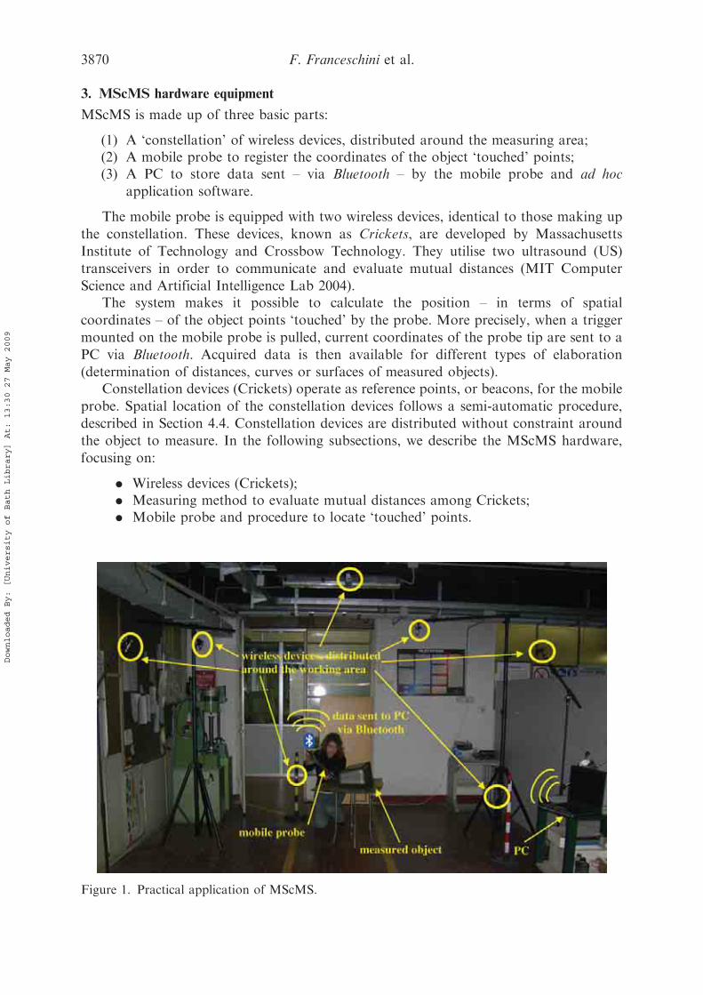
3. MScMS hardware equipment
MScMS is made up of three basic parts:
(1) A ‘constellation’ of wireless devices, distributed around the measuring area;(2) A mobile probe to register the coordinates of the object ‘touched’ points;(3) A PC to store data sent – via Bluetooth – by the mobile probe and ad hoc
application software.
The mobile probe is equipped with two wireless devices, identical to those making up
the constellation. These devices, known as Crickets, are developed by Massachusetts
Institute of Technology and Crossbow Technology. They utilise two ultrasound (US)
transceivers in order to communicate and evaluate mutual distances (MIT Computer
Science and Artificial Intelligence Lab 2004).The system makes it possible to calculate the position – in terms of spatial
coordinates – of the object points ‘touched’ by the probe. More precisely, when a trigger
mounted on the mobile probe is pulled, current coordinates of the probe tip are sent to a
PC via Bluetooth. Acquired data is then available for different types of elaboration
(determination of distances, curves or surfaces of measured objects).Constellation devices (Crickets) operate as reference points, or beacons, for the mobile
probe. Spatial location of the constellation devices follows a semi-automatic procedure,
described in Section 4.4. Constellation devices are distributed without constraint around
the object to measure. In the following subsections, we describe the MScMS hardware,
focusing on:
. Wireless devices (Crickets);
. Measuring method to evaluate mutual distances among Crickets;
. Mobile probe and procedure to locate ‘touched’ points.
Figure 1. Practical application of MScMS.
3870 F. Franceschini et al.
Downloaded By: [University of Bath Library] At: 13:30 27 May 2009
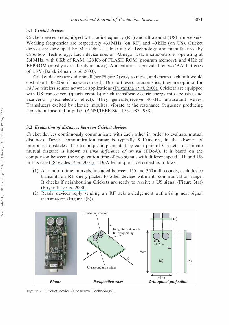
3.1 Cricket devices
Cricket devices are equipped with radiofrequency (RF) and ultrasound (US) transceivers.
Working frequencies are respectively 433MHz (on RF) and 40 kHz (on US). Cricket
devices are developed by Massachusetts Institute of Technology and manufactured by
Crossbow Technology. Each device uses an Atmega 128L microcontroller operating at
7.4MHz, with 8Kb of RAM, 128Kb of FLASH ROM (program memory), and 4Kb of
EEPROM (mostly as read-only memory). Alimentation is provided by two ‘AA’ batteries
of 1.5V (Balakrishnan et al. 2003).Cricket devices are quite small (see Figure 2) easy to move, and cheap (each unit would
cost about 10–20E, if mass-produced). Due to these characteristics, they are optimal for
ad hoc wireless sensor network applications (Priyantha et al. 2000). Crickets are equipped
with US transceivers (quartz crystals) which transform electric energy into acoustic, and
vice-versa (piezo-electric effect). They generate/receive 40 kHz ultrasound waves.
Transducers excited by electric impulses, vibrate at the resonance frequency producing
acoustic ultrasound impulses (ANSI/IEEE Std. 176-1987 1988).
3.2 Evaluation of distances between Cricket devices
Cricket devices continuously communicate with each other in order to evaluate mutual
distances. Device communication range is typically 8–10metres, in the absence of
interposed obstacles. The technique implemented by each pair of Crickets to estimate
mutual distance is known as time difference of arrival (TDoA). It is based on the
comparison between the propagation time of two signals with different speed (RF and US
in this case) (Savvides et al. 2001). TDoA technique is described as follows:
(1) At random time intervals, included between 150 and 350milliseconds, each device
transmits an RF query-packet to other devices within its communication range.
It checks if neighbouring Crickets are ready to receive a US signal (Figure 3(a))
(Priyantha et al. 2000).(2) Ready devices reply sending an RF acknowledgement authorising next signal
transmission (Figure 3(b)).
a
bc
(b)
(c)
Integrated antenna forRF transceiving
Perspective view Orthogonal projection
≈9 cm
≈4 cm
(a)
Ultrasound transmitter
Photo
≈1.2 cm
Ultrasound receiver
Figure 2. Cricket device (Crossbow Technology).
International Journal of Production Research 3871
Downloaded By: [University of Bath Library] At: 13:30 27 May 2009
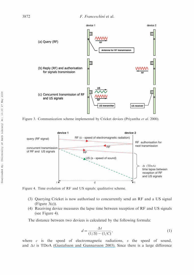
(3) Querying Cricket is now authorised to concurrently send an RF and a US signal
(Figure 3(c)).(4) Receiving device measures the lapse time between reception of RF and US signals
(see Figure 4).
The distance between two devices is calculated by the following formula:
d ¼ �t
ð1=SÞ � ð1=CÞ , ð1Þ
where c is the speed of electromagnetic radiations, s the speed of sound,
and �t is TDoA (Gustafsson and Gunnarsson 2003). Since there is a large difference
RF (c - speed of electromagnetic radiation)
US (s - speed of sound)
RF
RF
query (RF signal)
t
RF authorisation fornext transmission
concurrent transmissionof RF and US signals
t
Δt (TDoA)time lapse betweenreception of RFand US signals
device 1 device 2
d
Figure 4. Time evolution of RF and US signals: qualitative scheme.
Figure 3. Communication scheme implemented by Cricket devices (Priyantha et al. 2000).
3872 F. Franceschini et al.
Downloaded By: [University of Bath Library] At: 13:30 27 May 2009

between c (about 300,000 km/s) and s (about 340m/s in air with temperature T¼ 20�C and
relative humidity RH¼ 50%) then:
d � s ��t ð2Þ
3.3 Cricket communication
Cricket devices build a wireless network of cooperating sensor nodes. To preserve network
scalability, that is to make sure that the amount of information stored by each node is
independent from network dimension (in terms of nodes), each node memorises the
distances from its direct neighbours contained in the communication range (see Figure 5).
3.4 The mobile probe
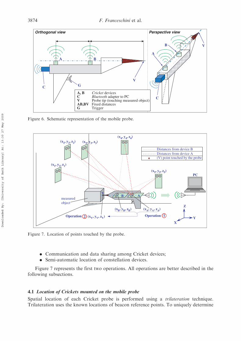
The mobile probe is equipped with two Cricket devices aligned with the tip (see Figure 6).
The system has been designed to be deployed over small or wide areas, depending on the
dimension of measured objects. The measuring area can be ‘covered’ varying the number
of constellation nodes.
4. MScMS software architecture
This section describes software/firmware features of MScMS to implement the following
operations:
. Location of Crickets mounted on the mobile probe;
. Location of points touched by the probe;
B1
B7
B4
B5
B8
D B3, B8B3
B2
B6
B9
D B3, B4
D B4, B8
D B7, B8
D B3, B7
D B1, B3
D B2, B7
D B1, B7
D B2, B4
D B5, B8
D B8, B9
D B4, B5
D B4, B9
D B5, B9
D B5, B6
D B6, B9
D B1, B2
Distances received by device B8Distances discardedby B8 Distances stored by B8 (and sent to its neighbours)
+
D B2, B3
B8 communication range
Figure 5. Distance information handled by a single device (B8). The shadow highlights the B8communication range.
International Journal of Production Research 3873
Downloaded By: [University of Bath Library] At: 13:30 27 May 2009
. Communication and data sharing among Cricket devices;
. Semi-automatic location of constellation devices.
Figure 7 represents the first two operations. All operations are better described in thefollowing subsections.
4.1 Location of Crickets mounted on the mobile probe
Spatial location of each Cricket probe is performed using a trilateration technique.Trilateration uses the known locations of beacon reference points. To uniquely determine
(x5, y5, z5)
(x4, y4, z4)(x3, y3, z3)(x2, y2, z2)
(x1, y1, z1)
(xB, yB, zB) (xA, yA, zA)
(xV, yV, zV)
X Y
Z
Distances from device B Distances from device A (V) point touched by the probe
Operation 1Operation 2
B A
PC
measuredobject
V
Figure 7. Location of points touched by the probe.
Perspective view
A
B V
B A
V G
A, B Cricket devices C Bluetooth adapter to PCV Probe tip (touching measured object)AB,BV Fixed distancesG Trigger
C
C
Orthogonal view
Figure 6. Schematic representation of the mobile probe.
3874 F. Franceschini et al.
Downloaded By: [University of Bath Library] At: 13:30 27 May 2009
the relative location of a point on a 3D space, at least four reference points are generally
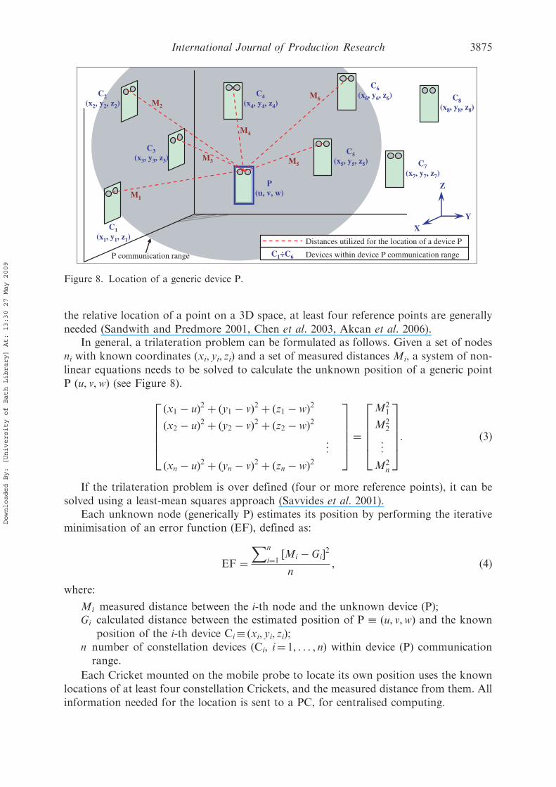
needed (Sandwith and Predmore 2001, Chen et al. 2003, Akcan et al. 2006).In general, a trilateration problem can be formulated as follows. Given a set of nodes
ni with known coordinates (xi, yi, zi) and a set of measured distances Mi, a system of non-
linear equations needs to be solved to calculate the unknown position of a generic point
P (u, v,w) (see Figure 8).
ðx1 � uÞ2 þ ðy1 � vÞ2 þ ðz1 � wÞ2ðx2 � uÞ2 þ ðy2 � vÞ2 þ ðz2 � wÞ2
..
.
ðxn � uÞ2 þ ðyn � vÞ2 þ ðzn � wÞ2
266664
377775 ¼
M21
M22
..
.
M2n
266664
377775: ð3Þ
If the trilateration problem is over defined (four or more reference points), it can be
solved using a least-mean squares approach (Savvides et al. 2001).Each unknown node (generically P) estimates its position by performing the iterative
minimisation of an error function (EF), defined as:
EF ¼Xn
i¼1½Mi � Gi�2n
, ð4Þ
where:
Mi measured distance between the i-th node and the unknown device (P);Gi calculated distance between the estimated position of P � (u, v,w) and the known
position of the i-th device Ci� (xi, yi, zi);n number of constellation devices (Ci, i¼ 1, . . . , n) within device (P) communication
range.
Each Cricket mounted on the mobile probe to locate its own position uses the known
locations of at least four constellation Crickets, and the measured distance from them. All
information needed for the location is sent to a PC, for centralised computing.
X
Y
Z
C1(x1, y1, z1)
C2(x2, y2, z2)
C3(x3, y3, z3)
C4(x4, y4, z4)
C5(x5, y5, z5)
C6(x6, y6, z6)
P (u, v, w)
M3
M2
M1
M4
M5
M6 C8(x8, y8, z8)
C7(x7, y7, z7)
Distances utilized for the location of a device P
C1÷C6 Devices within device P communication range P communication range
Figure 8. Location of a generic device P.
International Journal of Production Research 3875
Downloaded By: [University of Bath Library] At: 13:30 27 May 2009

4.2 Location of points touched by the probe tip
The probe tip (V) lies on the same line of devices A and B (see Figure 6). This line can be
univocally determined knowing coordinates of points A � (xA, yA, zA) and B� (xB, yB, zB),
and the distance d(A�V). The parametric equation of this line is:
x ¼ xA þ ðxB � xAÞ � ty ¼ yA þ ðyB � yAÞ � tz ¼ zA þ ðzB � zAÞ � t
8>><>>: : ð5Þ
The distance d(A�V) can be expressed as:
dðA� VÞ ¼ffiffiffiffiffiffiffiffiffiffiffiffiffiffiffiffiffiffiffiffiffiffiffiffiffiffiffiffiffiffiffiffiffiffiffiffiffiffiffiffiffiffiffiffiffiffiffiffiffiffiffiffiffiffiffiffiffiffiffiffiffiffiffiffiffiffiffiffiffiffiffiffiffiffiffiffiðxA � xVÞ2 þ ðyA � yVÞ2 þ ðzA � zVÞ2
q: ð6Þ
Coordinates of point V� (xv, yv, zv) are univocally determined solving a system of four
equations in four unknown values (xv, yv, zv, and tv):
xV ¼ xA þ ðxB � xAÞ � tVyV ¼ yA þ ðyB � yAÞ � tVzV ¼ zA þ ðzB � zAÞ � tVdðA� VÞ ¼
ffiffiffiffiffiffiffiffiffiffiffiffiffiffiffiffiffiffiffiffiffiffiffiffiffiffiffiffiffiffiffiffiffiffiffiffiffiffiffiffiffiffiffiffiffiffiffiffiffiffiffiffiffiffiffiffiffiffiffiffiffiffiffiffiffiffiffiffiffiffiffiffiffiffiffiffiðxA � xVÞ2 þ ðyA � yVÞ2 þ ðzA � zVÞ2
q
8>>>><>>>>:
: ð7Þ
Replacing terms xv, yv and zv in the fourth equation:
dðA� VÞ ¼
ffiffiffiffiffiffiffiffiffiffiffiffiffiffiffiffiffiffiffiffiffiffiffiffiffiffiffiffiffiffiffiffiffiffiffiffiffiffiffiffiffiffiffiffiffiffiffiffiffiffiffiffiffiffiffiffiffiffiffiffiffiffixA � ðxA þ ðxB � xAÞ � tVÞ½ �2þ yA � ðyA þ ðyB � yAÞ � tVÞ½ �2þ zA � ðzA þ ðzB � zAÞ � tVÞ½ �2
vuuuut : ð8Þ
then:
tV ¼ dðA� VÞffiffiffiffiffiffiffiffiffiffiffiffiffiffiffiffiffiffiffiffiffiffiffiffiffiffiffiffiffiffiffiffiffiffiffiffiffiffiffiffiffiffiffiffiffiffiffiffiffiffiffiffiffiffiffiffiffiffiffiffiffiffiffiffiffiffiffiffiffiffiffiffiffiffiffiðxA � xBÞ2 þ ðyA � yBÞ2 þ ðzA � zBÞ2
q ¼ dðA� VÞdðA� BÞ : ð9Þ
The denominator of Equation (9) is the distance d(A�B) between the two Cricket devices
installed on the mobile probe.In conclusion, coordinates of the point V can be calculated as:
xV ¼ xA þ ðxB � xAÞ � dðA� VÞdðA� BÞ
yV ¼ yA þ ðyB � yAÞ � dðA� VÞdðA� BÞ
zV ¼ zA þ ðzB � zAÞ � dðA� VÞdðA� BÞ
8>>>>>>><>>>>>>>:
: ð10Þ
Formulas (10) univocally locate point V using spatial coordinates of Crickets A and B.
Distances d(A�B) and d(A�V) are a priori known as they depend on probe geometry.The previous model is based on the assumption that US sensor (A and B) and probe tip
(V) are punctiform geometric elements. In practice, the model is inevitably approximated
3876 F. Franceschini et al.
Downloaded By: [University of Bath Library] At: 13:30 27 May 2009
because sensors A and B have non punctual dimensions (see Figure 2). To minimise point
P position uncertainty, the following condition should be approached:
d(B�V)� d(A�V) (Zakrzewski 2003).
4.3 Cricket firmware
Firmware is essential to organise RF and US communication among Cricket devices.
Firmware is written in NesC language, and works under the operating system TinyOS.
NesC is derived from C, and it is currently utilised to program MICA Mote
devices (produced by Crossbow Technologies), which Crickets are derived from. NesC
is object-oriented and event-based. Programs are organised in independent modules.
They interrelate themselves by means of reciprocal queries/replies (MIT Computer Science
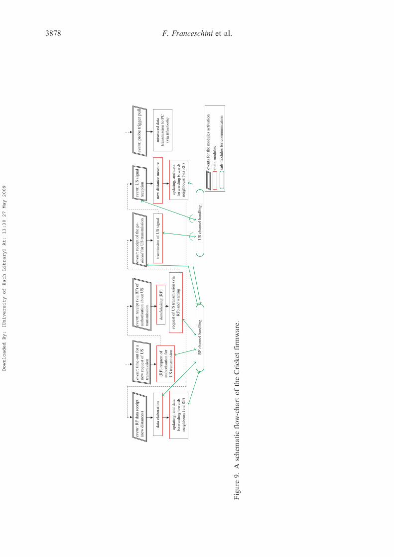
and Artificial Intelligence Lab 2004, Moore et al. 2004). Figure 9 shows a schematic
flow-chart of Cricket firmware.Each Cricket device performs two types of operation:
(1) Time of flight measurement of US signals transmitted/received from other devices.
At random time intervals, included between 150 and 350milliseconds, each device
tries to synchronise itself with neighbours, in order to exchange US signals.
Synchronisation information is transmitted through RF packets.(2) When a Cricket receives a new distance – from a neighbour, or directly measured –
stores and sends it to its neighbours by an RF packet containing a new list of
inter-node distances.
Firmware coordinates the communication among Cricket devices, making them able to
cooperate and share information about inter-node distances. When the user pulls the
mobile probe trigger, all information is sent (via Bluetooth) to a PC for elaboration.
4.4 Semi-automatic location of the constellation
Location of Cricket devices should be fast and automated as much as possible.
This operation – if manually performed – is tedious and conflicting with system
adaptability to different working places. As a consequence – in order to minimise
human moderation – a method for a semi-automatic localisation has been implemented.
It is important to remark that accuracy in the localisation of constellation nodes is
fundamental for accuracy in the next mobile probe location (Patwari et al. 2005, Sottile
and Spirito 2006). Two techniques for the location of constellation devices have been
designed.
4.4.1 First approach
First technique consists of touching (using the mobile probe) different reference points
within the measuring area. It is good to select points that are easily reachable and easy to
be manually located in a reference coordinate system. For example, points lying on objects
with a simple and known geometry (like parallelepiped vertexes). Spatial coordinates
(xi, yi, zi) of the distributed constellation devices are the unknown parameters of the
problem. Location of each device is performed using a trilateration. To identify a new
International Journal of Production Research 3877
Downloaded By: [University of Bath Library] At: 13:30 27 May 2009
data
ela
bora
tion
upda
ting,
and
dat
a fo
rwar
ding
tow
ards
ne
ighb
ours
(vi
a R
F)
(RF)
req
uest
of
auth
oris
atio
n fo
r U
S tr
ansm
issi
on
even
t: R
F da
ta r
ecei
pt
(new
dis
tanc
es)
ev
ent:
tim
e-ou
t for
a
new
req
uest
of
US
tran
smis
sion
hand
shak
ing
(RF)
even
t: re
ceip
t (vi
a R
F) o
f au
thor
isat
ion
abou
t US
tran
smis
sion
requ
est o
f U
S tr
ansm
issi
on (
via
RF)
and
wai
ting
RF
chan
nel h
andl
ing
US
chan
nel h
andl
ing
even
t: pr
obe
trig
ger
pull
even
t: U
S si
gnal
re
cept
ion
mea
sure
d da
ta
tran
smis
sion
to P
C
(via
Blu
etoo
th)
new
dis
tanc
e m
easu
re
tras
mis
sion
of
US
sign
al
even
t: re
ceip
t of
the
go-
ahea
d fo
r U
S tr
ansm
issi
on
upda
ting,
and
dat
a fo
rwar
ding
tow
ards
ne
ighb
ours
(vi
a R
F)
even
ts f
or th
e m
odul
es a
ctiv
atio
n
mai
n m
odul
es
sub-
mod
ules
for
com
mun
icat
ion
Figure
9.A
schem
aticflow-chart
oftheCricket
firm
ware.
3878 F. Franceschini et al.
Downloaded By: [University of Bath Library] At: 13:30 27 May 2009
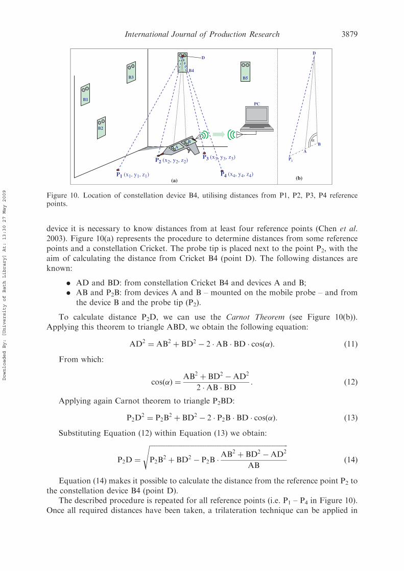
device it is necessary to know distances from at least four reference points (Chen et al.
2003). Figure 10(a) represents the procedure to determine distances from some reference
points and a constellation Cricket. The probe tip is placed next to the point P2, with the
aim of calculating the distance from Cricket B4 (point D). The following distances are
known:
. AD and BD: from constellation Cricket B4 and devices A and B;
. AB and P2B: from devices A and B – mounted on the mobile probe – and from
the device B and the probe tip (P2).
To calculate distance P2D, we can use the Carnot Theorem (see Figure 10(b)).
Applying this theorem to triangle ABD, we obtain the following equation:
AD2 ¼ AB2 þ BD2 � 2 �AB � BD � cosð�Þ: ð11ÞFrom which:
cosð�Þ ¼ AB2 þ BD2 �AD2
2 �AB � BD : ð12Þ
Applying again Carnot theorem to triangle P2BD:
P2D2 ¼ P2B
2 þ BD2 � 2 � P2B � BD � cosð�Þ: ð13ÞSubstituting Equation (12) within Equation (13) we obtain:
P2D ¼ffiffiffiffiffiffiffiffiffiffiffiffiffiffiffiffiffiffiffiffiffiffiffiffiffiffiffiffiffiffiffiffiffiffiffiffiffiffiffiffiffiffiffiffiffiffiffiffiffiffiffiffiffiffiffiffiffiffiffiffiffiffiffiffiffiffiffiffiffiffiffiffiffiffiffiffiffiffiffiffiffiffiP2B
2 þ BD2 � P2B �AB2 þ BD2 �AD2
AB
sð14Þ
Equation (14) makes it possible to calculate the distance from the reference point P2 to
the constellation device B4 (point D).The described procedure is repeated for all reference points (i.e. P1 – P4 in Figure 10).
Once all required distances have been taken, a trilateration technique can be applied in
B1
B2
D
B5 B3
PC
P2 (x2, y2, z2)
A B
P2
A
B
D
α
P1 (x1, y1, z1) P4 (x4, y4, z4)
P3 (x3, y3, z3)
(a)
B4
(b)
Figure 10. Location of constellation device B4, utilising distances from P1, P2, P3, P4 referencepoints.
International Journal of Production Research 3879
Downloaded By: [University of Bath Library] At: 13:30 27 May 2009

order to localise each constellation Cricket. The acquisition procedure is driven by anad hoc software routine. Calculations are automatically performed by the central PC.
4.4.2 Second approach
The second approach is an extension of the first. The previous localisation approach is notadequate for constellations with a large number of Crickets, since each device needs toknow distances from at least four reference points. For that reason, we have implementeda semi-automatic localisation technique, which also uses the information on the mutualdistances among constellation Crickets. This technique is based on two steps:
(1) As described for the first approach, the mobile probe is used to touch fourreference points in order to locate five constellation Crickets.
(2) Subsequently, the mobile probe is used as an ‘ear’, to receive the mutual distancesof all the constellation Crickets (including the five which have been located).Signals gathered are sent to the PC (see Figure 11). This information – combinedwith the information on the five located Crickets – is used to locate the wholeconstellation, by means of an ‘incremental’ algorithm (Moore et al. 2004). Thisalgorithm starts with a set of five nodes with known coordinates. Other nodes inthe network determine their own coordinates using distances from them. As anunknown node obtains an acceptable position estimate, it may serve as a newreference point. This process can be incrementally applied until all nodes in thenetwork obtain their specific coordinates.
The procedure is driven by an ad hoc software routine. Time required forself-localisation is about 1–2minutes. Calculations are automatically performed by thecentral PC.
B1
B2
B4
B5
D B1, B2
D B1, B3
D B1, B4
D B2, B3
D B2, B4
D B3, B4
D B3, B5
D B4, B5
B3D B1, B2
D B1, B4
D B2, B3
D B1, B3
D B2, B4 D B3, B4
D B4, B5
D B3, B5
Distances utilised in thesemi-automatic location ofthe constellation
PC
A
B1÷B5 constellation Crickets
A, B probe Crickets
B
Figure 11. Constellation location using the mobile probe as an ‘ear’.
3880 F. Franceschini et al.
Downloaded By: [University of Bath Library] At: 13:30 27 May 2009

Again, accuracy in constellation location influences accuracy in future measurements.The more Cricket positions are affected by uncertainty, the less accurate measurementswill be (Taylor et al. 2005, Franceschini et al. 2007).
5. MScMS prototype
A first prototype of MScMS has been developed at the industrial metrology and qualitylaboratory of DISPEA – Politecnico di Torino. It is made by the following elements:
(1) Cricket constellation. Twenty-two Cricket devices have been freely distributedaround a measuring area, covering a volume of about 60m3. To make theirpositioning easy, we used different supports, such as booms, articulated arms andtripods (see Figure 1).
(2) Mobile probe. It is made by a metal structure containing the following elements:
(a) Two Cricket devices.(b) A tip to ‘touch’ the points of measured objects. Tip (V) and Cricket devices
(A and B) are aligned and spaced as indicated: d(A�B)¼ 450mm andd(A�V)¼ 540mm (see Figure 12).
(c) A bluetooth transceiver connected with one of the two Cricket devices, by anRS232 serial port.
(3) Personal computer. Ad hoc application sofware runs on a standard PC. In order toreceive data sent by the probe, the PC is equipped with a bluetooth transceiver.
(4) Application software. The purpose of this software is to drive the user throughmeasurements, and to make results display efficient. Functions provided aresimilar to those typically implemented by CMM software packages. MScMS,likewise CMMs, make it possible to determine the shape/geometry of objects(circumferences, cylinders, planes, cones, spheres, etc.), on the basis of a set ofmeasured surface points gathered from the mobile probe, using classicaloptimisation algorithms (Overmars 1997).
In more detail, the software is organised into three application modules to assist theuser in the following operations:
. Initialisation. This is a guided procedure to switch on wireless devices (Cricketsand bluetooth adapter), and open the PC connection for data reception from themobile probe.
Figure 12. Mobile probe prototype.
International Journal of Production Research 3881
Downloaded By: [University of Bath Library] At: 13:30 27 May 2009

. Self-localisation of the constellation. This procedure is described in Section 4.4(Figure 13(a)).
. Measurements. Execution of different kinds of measurements: single pointsmeasurements, distance measurements, curves and surfaces evaluation (seeFigures 13(b), 14 and 15).
Measurements are taken by the probe tip. When the probe trigger is pulled, theapplication software calculates Cartesian coordinates of the touched point. If measure-ment is correctly taken, an acoustic signal is emitted. Measured results are displayed usingnumeric and graphical representations. Figure 13 shows some screenshots of the softwaremain menu and sub-menus. Figures 14 and 15 show some displays of the MScMSsoftware.
6. MScMS actual performances, critical aspects and possible improvements
A preliminary prototype of MScMS has been set-up and tested, with the purpose ofverifying system feasibility and to evaluate the performances. The prototype actualperformance has been estimated carrying out two practical tests:
(1) Repeatability test: a single point within the working volume is measured repeating
the measurement about 50 times, leaving the mobile probe in a fixed position (seeFigure 16(a)). The test is repeated measuring at least 20 different points in differentareas of the working volume. For each point, we have calculated the standarddeviations (�x, �y, �z) related to the registered Cartesian coordinates (x, y, z).
(2) Reproducibility test: this test is similar to the previous one, with the only differencethat the mobile probe orientation is changed before each measurement, with theaim of approaching each (single) point from a different direction (see Figure 16(b)).
Figure 13. MScMS software menu.
3882 F. Franceschini et al.
Downloaded By: [University of Bath Library] At: 13:30 27 May 2009

Figure 15. Display for the measurement of a circle.
Figure 14. Display for the measurement of single points.
International Journal of Production Research 3883
Downloaded By: [University of Bath Library] At: 13:30 27 May 2009
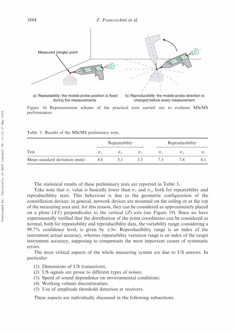
The statistical results of these preliminary tests are reported in Table 3.Take note that �z value is basically lower than �x and �y, both for repeatability and
reproducibility tests. This behaviour is due to the geometric configuration of theconstellation devices: in general, network devices are mounted on the ceiling or at the topof the measuring area and, for this reason, they can be considered as approximately placedon a plane (XY) perpendicular to the vertical (Z) axis (see Figure 19). Since we haveexperimentally verified that the distribution of the point coordinates can be considered asnormal, both for repeatability and reproducibility data, the variability range, considering a99.7% confidence level, is given by 3�. Reproducibility range is an index of theinstrument actual accuracy, whereas repeatability variation range is an index of the targetinstrument accuracy, supposing to compensate the most important causes of systematicerrors.
The most critical aspects of the whole measuring system are due to US sensors. Inparticular:
(1) Dimensions of US transceivers;(2) US signals are prone to different types of noises;(3) Speed of sound dependence on environmental conditions;(4) Working volume discontinuities;(5) Use of amplitude threshold detection at receivers.
These aspects are individually discussed in the following subsections.
Table 3. Results of the MScMS preliminary tests.
Repeatability Reproducibility
Test �x �y �z �x �y �z
Mean standard deviation (mm) 4.8 5.1 3.5 7.3 7.8 4.1
a) Repeatability: the mobile-probe position is fixedduring the measurements
b) Reproducibility: the mobile-probe direction ischanged before every measurement
Measured (single) point
Figure 16. Representation scheme of the practical tests carried out to evaluate MScMSperformances.
3884 F. Franceschini et al.
Downloaded By: [University of Bath Library] At: 13:30 27 May 2009

6.1 Dimensions of US transceivers
A source of uncertainty in US time-of-flight measurements is due to non punctiform US
sensors. The volume of each piezo-electric crystal is about 1 cm3. As shown in Figure 17,
it is difficult to determine the exact point of departure/arrival of a US signal exchanged
between a pair of Crickets. These points are placed on the US sensors surfaces, and may
vary depending on their relative position (see Figure 17).Regarding the future, Cricket devices will be modified in order to minimise this
problem, for example reducing the size of US sensors.
6.2 US signal are prone to different types of noises
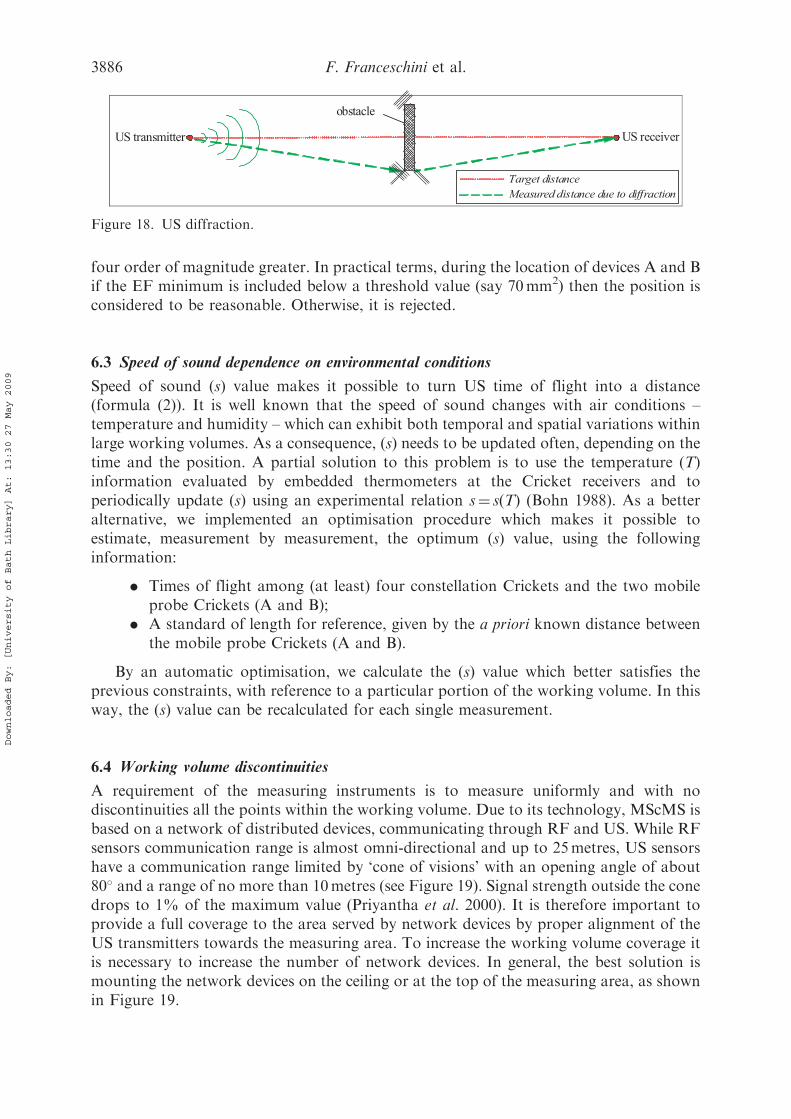
During measurement, the user should not obstruct US signal propagation. Two possible
drawbacks may occur:
(1) Transmitted US signal does not reach the receiver because it is completely shielded
by an obstacle;(2) Transmitted US signal diffracts and goes round interposed obstacle, reaching the
receiver. In this case, the path covered by US is longer than the real distance
between transmitter and receiver (see Figure 18).
Case 2 is more complicated to handle than case 1. In general, it is not easy to notice
possible path deflections. Probe can be prone to other types of noise, like external sources
of US. For example, US produced by metal objects jingling. However, wrong distance
measurements, like the ones described, can be indirectly detected and rejected. To that
purpose, an effective diagnostic tool is the error function (EF, see Equation (4))
(Franceschini et al. 2002). This function, evaluated for both the mobile probe devices
(A and B) during localisation, is an index of the bias between measured distances
(evaluated by means of US transceivers) and calculated distances (on the basis of the
localised position). We have experimentally verified that the minimum value of the EF is
generally of the order of one tenth of mm2. When one or more measured distances are
wrong – due to systematic effects – the EF minimum value ‘explodes’ becoming three or
(a)
(b)
≈ 1.2 cm
ultrasound points of departure/arrival
Figure 17. Points of departure/arrival of US exchanged between two Crickets.
International Journal of Production Research 3885
Downloaded By: [University of Bath Library] At: 13:30 27 May 2009
four order of magnitude greater. In practical terms, during the location of devices A and Bif the EF minimum is included below a threshold value (say 70mm2) then the position isconsidered to be reasonable. Otherwise, it is rejected.
6.3 Speed of sound dependence on environmental conditions
Speed of sound (s) value makes it possible to turn US time of flight into a distance(formula (2)). It is well known that the speed of sound changes with air conditions –temperature and humidity – which can exhibit both temporal and spatial variations withinlarge working volumes. As a consequence, (s) needs to be updated often, depending on thetime and the position. A partial solution to this problem is to use the temperature (T)information evaluated by embedded thermometers at the Cricket receivers and toperiodically update (s) using an experimental relation s¼ s(T) (Bohn 1988). As a betteralternative, we implemented an optimisation procedure which makes it possible toestimate, measurement by measurement, the optimum (s) value, using the followinginformation:
. Times of flight among (at least) four constellation Crickets and the two mobileprobe Crickets (A and B);
. A standard of length for reference, given by the a priori known distance betweenthe mobile probe Crickets (A and B).
By an automatic optimisation, we calculate the (s) value which better satisfies theprevious constraints, with reference to a particular portion of the working volume. In thisway, the (s) value can be recalculated for each single measurement.
6.4 Working volume discontinuities
A requirement of the measuring instruments is to measure uniformly and with nodiscontinuities all the points within the working volume. Due to its technology, MScMS isbased on a network of distributed devices, communicating through RF and US. While RFsensors communication range is almost omni-directional and up to 25metres, US sensorshave a communication range limited by ‘cone of visions’ with an opening angle of about80� and a range of no more than 10metres (see Figure 19). Signal strength outside the conedrops to 1% of the maximum value (Priyantha et al. 2000). It is therefore important toprovide a full coverage to the area served by network devices by proper alignment of theUS transmitters towards the measuring area. To increase the working volume coverage itis necessary to increase the number of network devices. In general, the best solution ismounting the network devices on the ceiling or at the top of the measuring area, as shownin Figure 19.
obstacle
US transmitter US receiver
Measured distance due to diffraction
Target distance
Figure 18. US diffraction.
3886 F. Franceschini et al.
Downloaded By: [University of Bath Library] At: 13:30 27 May 2009

Since, for locating the mobile probe by trilateration, the mobile probe should
communicate with at least four network devices, on the basis of practical tests, we
determined that the coverage of an indoor working volume about four metres high can be
achieved using about one network device per square metre (considering a plant layout).
6.5 Use of amplitude threshold detection at receivers
To evaluate time difference of arrival (TDoA), receivers can detect signals with amplitude
equal or greater than a threshold value. Since US transceivers operate at 40 kHz frequency,
the time period of a complete wave cycle is 1/40000 s¼ 25 ms. US waves are saw-tooth
shaped, with a linear rise (see Figure 20).Considering fresh US signals at the transmitter, their amplitude may decrease
depending on two basic factors:
(1) Attenuation: signal amplitude decreases depending on the distance covered.(2) Transmitter orientation: since US transmitters are not omni-directional, signal
amplitude changes depending on their orientation. In particular, the maximum
signal strength is related to the direction perpendicular to the transducer surface
(at the centre of the ‘cone of vision’), while signal amplitude drops to 1% of the
maximum value at 40� away from it (Priyantha et al. 2000).
Figure 19. Representation scheme of the US sensors ‘cone of vision’.
International Journal of Production Research 3887
Downloaded By: [University of Bath Library] At: 13:30 27 May 2009
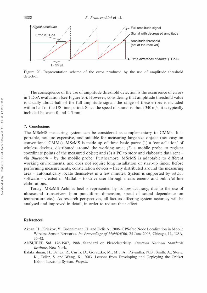
The consequence of the use of amplitude threshold detection is the occurrence of errors
in TDoA evaluation (see Figure 20). However, considering that amplitude threshold value
is usually about half of the full amplitude signal, the range of these errors is included
within half of the US time period. Since the speed of sound is about 340m/s, it is typically
included between 0 and 4.5mm.
7. Conclusions
The MScMS measuring system can be considered as complementary to CMMs. It is
portable, not too expensive, and suitable for measuring large-size objects (not easy on
conventional CMMs). MScMS is made up of three basic parts: (1) a ‘constellation’ of
wireless devices, distributed around the working area; (2) a mobile probe to register
coordinate points of the measured object; and (3) a PC to store and elaborate data sent –
via Bluetooth – by the mobile probe. Furthermore, MScMS is adaptable to different
working environments, and does not require long installation or start-up times. Before
performing measurements, constellation devices – freely distributed around the measuring
area – automatically locate themselves in a few minutes. System is supported by ad hoc
software – created in Matlab – to drive user through measurements and online/offline
elaborations.Today, MScMS Achilles heel is represented by its low accuracy, due to the use of
ultrasound transceivers (non punctiform dimension, speed of sound dependence on
temperature etc.). As research perspectives, all factors affecting system accuracy will be
analysed and improved in detail, in order to reduce their effect.
References
Akcan, H., Kriakov, V., Bronnimann, H. and Delis A., 2006. GPS-free Node Localization in Mobile
Wireless Sensor Networks. In: Proceedings of MobiDE’06, 25 June 2006, Chicago, IL, USA,
35–42.ANSI/IEEE Std. 176-1987, 1988. Standard on Piezoelectricity. American National Standards
Institute, New York.Balakrishnan, H., Baliga, R., Curtis, D., Goraczko, M., Miu, A., Priyantha, N.B., Smith, A., Steele,
K., Teller, S. and Wang, K., 2003. Lessons from Developing and Deploying the Cricket
Indoor Location System. Preprint.
Full amplitude signal
Signal with decreased amplitude
Time difference of arrival (TDoA)
T= 25 μs
Signal amplitude
Amplitude threshold(set at the receiver)
Error in TDoA
Figure 20. Representation scheme of the error produced by the use of amplitude thresholddetection.
3888 F. Franceschini et al.
Downloaded By: [University of Bath Library] At: 13:30 27 May 2009
Bohn, D.A., 1988. Environmental effects on the speed of sound. Journal of the Audio EngineeringSociety, 36 (4), 223–231.
Bosch, J.A., 1995. Coordinate Measuring Machines and Systems. New York: Marcel Dekker.Chen, M., Cheng, F., and Gudavalli, R., 2003. Precision and Accuracy in an Indoor Localization
System. Technical Report CS294-1/2, University of California, Berkeley, USA.Franceschini, F., Galetto, M., and Settineri, L., 2002. On-Line diagnostic tools for cmm
performance. The International Journal of Advanced Manufacturing Technology, 19 (2),
125–130.Franceschini, F., Galetto, M., Maisano, D., and Mastrogiacomo L., 2007. A review of localization
algorithms for distributed wireless sensor networks in manufacturing (Forthcoming)
International Journal of Computer Integrated Manufacturing.Gustafsson, F. and Gunnarsson, F., 2003. Positioning using Time Difference of Arrival
measurements. In: Proceedings of the IEEE international conference on acoustics, speech, and
signal processing (ICASSP 2003), 6–10 April, Hong Kong, Vol. 6, 553–556.ISO 5725, 1986. Precision of test methods – determination of repeatability and reproducibility for a
standard test method by inter-laboratory tests.ISO 10360, Part 2, 2001. Geometrical Product Specifications (GPS) – acceptance and reverification
tests for coordinate measuring machines (CMM).MIT Computer Science and Artificial Intelligence Lab., 2004. Cricket v2 User Manual. Available
from: http://cricket.csail.mit.edu/v2man.html [Accessed 22 January 2007].
Moore, D., Leonard, J., Rus, D., and Teller, S.S., 2004. Robust distributed network localizationwith noisy range measurements. In: Proceedings of SenSys 2004, November, Baltimore, MD,50–61.
Overmars, M.H., 1997. Designing the Computational Geometry Algorithms Library CGAL, Appliedcomputational geometry towards geometric engineering. Berlin: Springer-Verlag, 53.
Patwari, N., Ash, J., Kyperountas, S., Hero, A., Moses, R., and Correal, N., 2005. Locating thenodes – cooperative localization in wireless sensor networks. IEEE Signal processing
Magazine, 22 (4), 54–69.Pozzi, F., 2002. Comparison of 3D Measurement Techniques in Cultural Heritage Application: User
Point of View. In: Proceedings of the 1st international symposium on 3D data processing
visualization and transmission - IEEE computer society, 19–21 June, Padova, Italy, 762–765.Priyantha, N.B., Chakraborty, A., and Balakrishnan, H., 2000. The Cricket Location-Support
System. In: Proceedings of the 6th ACM MOBICOM, August, Boston, MA, 32–43.
Rooks, B., 2004. A vision of the future at TEAM. Sensor Review, 24 (2), 137–143.Sandwith, S. and Predmore, R., 2001. Real-time 5-Micron Uncertainty with Laser Tracking
Interferometer Systems using Weighted Trilateration. In: Proceedings of 2001 boeing large
scale metrology seminar, St. Louis, MO.Savvides, A., Han, C., and Strivastava, M.B., 2001. Dynamic fine-grained localization in ad hoc
networks of sensors. In: Proceedings of ACM/IEEE 7th annual international conference onmobile computing and networking (MobiCom’01), 16–21 July, Rome, Italy, 166–179.
Sottile, F. and Spirito, M., 2006. Enhanced Quadrilateral-based Localization for Wireless Ad hocNetworks. In: Proceedings of IFIP fifth annual mediterranean ad hoc networking workshop(Med-Hoc-Net 2006), 14–17 June, Lipari, Italy, 224–231.
Taylor, C., Rahimi, A., Bachrach, J., and Shrobe, H., 2005. Simultaneous Localization, Calibration,and Tracking in an ad hoc Sensor Network. Tech. Rep., Computer Science and ArtificialIntelligence Laboratory of MIT. Available from: https://dspace.mit.edu/handle/1721.1/30541
[Accessed 22 January 2007].Welch, G., Bishop, G., Vicci, L., Brumback, S., and Keller, K., 2001. High-performance wide-area
optical tracking the Hi-Ball tracking system. Presence: Teleoperators And VirtualEnvironments, 10 (1), 1–21.
Zakrzewski, J., 2003. Error and uncertainty reduction – challenge for a measuring systems designer.Measurement Science Review, 3, 31–34.
International Journal of Production Research 3889
Downloaded By: [University of Bath Library] At: 13:30 27 May 2009


