Embed Size (px)
Citation preview
MOBILE COMPUTING
Seventh Sem.
B.E.(I.T.)
K. D. K. College of Engineering Nagpur
Introduction to Mobile Computing
The rapidly expanding technology of cellular communication, wireless LANs, and
satellite services will make information accessible anywhere an
size, most mobile computers will be equipped with a wireless connection to the fixed part of
the network, and, perhaps, to other mobile computers. The resulting computing
environment, which is often referred to as
requires users to maintain a fixed and universally known position in the network and
enables almost unrestricted mobility. Mobility and portability will create an entire new class
of applications and, possibly, new massive markets
consumer electronics.
Mobile Computing is an umbrella term used to describe technologies that
people to access network services anyplace, anytime, and
A communication device can exhibit any one of the
� Fixed and wired: This configuration describes the typical desktop
Neither weight nor power consumption of the devices allow for mobile usage. The
devices use fixed networks for performance
� Mobile and wired: Many of today’s laptops fall into this category; users
from one hotel to the next, reconnecting to the company’s network via the telephone
network and a modem.
� Fixed and wireless: This mode is used for installing networks, e.g
to avoid damage by installing
� Mobile and wireless: This is the most interesting case. No cable restricts the user, who
can roam between different wireless networks. Most tec
deal with this type of device and the networks supporting them. Today’s most successful
example for this category is GSM with more than 800 million
APPLICATIONS OF MOBILE COMPUTING
In many fields of work, the abilit
efficiently. The importance of Mobile Computers has been highlighted in many fields of
which a few are described below:
Unit-1
Introduction to Mobile Computing
The rapidly expanding technology of cellular communication, wireless LANs, and
satellite services will make information accessible anywhere and at any time. Regardless of
size, most mobile computers will be equipped with a wireless connection to the fixed part of
the network, and, perhaps, to other mobile computers. The resulting computing
environment, which is often referred to as mobile or nomadic computing
requires users to maintain a fixed and universally known position in the network and
enables almost unrestricted mobility. Mobility and portability will create an entire new class
of applications and, possibly, new massive markets combining personal computing and
is an umbrella term used to describe technologies that
people to access network services anyplace, anytime, and anywhere.
A communication device can exhibit any one of the following characteristics:
: This configuration describes the typical desktop computer
Neither weight nor power consumption of the devices allow for mobile usage. The
devices use fixed networks for performance reasons.
: Many of today’s laptops fall into this category; users carry
from one hotel to the next, reconnecting to the company’s network via the telephone
: This mode is used for installing networks, e.g., in historical buildings
installing wires, or at trade shows to ensure fast network
: This is the most interesting case. No cable restricts the user, who
can roam between different wireless networks. Most technologies discussed in this book
deal with this type of device and the networks supporting them. Today’s most successful
example for this category is GSM with more than 800 million users.
APPLICATIONS OF MOBILE COMPUTING
In many fields of work, the ability to keep on the move is vital in order to utilise time
efficiently. The importance of Mobile Computers has been highlighted in many fields of
which a few are described below:
The rapidly expanding technology of cellular communication, wireless LANs, and
d at any time. Regardless of
size, most mobile computers will be equipped with a wireless connection to the fixed part of
the network, and, perhaps, to other mobile computers. The resulting computing
adic computing, no longer
requires users to maintain a fixed and universally known position in the network and
enables almost unrestricted mobility. Mobility and portability will create an entire new class
combining personal computing and
is an umbrella term used to describe technologies that enable
computer in an office.
Neither weight nor power consumption of the devices allow for mobile usage. The
carry the laptop
from one hotel to the next, reconnecting to the company’s network via the telephone
historical buildings
network setup.
: This is the most interesting case. No cable restricts the user, who
hnologies discussed in this book
deal with this type of device and the networks supporting them. Today’s most successful
y to keep on the move is vital in order to utilise time
efficiently. The importance of Mobile Computers has been highlighted in many fields of
a. Vehicles: Music, news, road conditions, weather reports, and other broadcast information
are received via digital audio broadcasting (DAB) with 1.5 Mbit/s. For personal
communication, a universal mobile telecommunications system (UMTS) phone might be
available offering voice and data connectivity with 384 kbit/s. The current position of the
car is determined via the global positioning system (GPS). Cars driving in the same area
build a local ad-hoc network for the fast exchange of information in emergency situations
or to help each other keep a safe distance. In case of an accident, not only will the airbag
be triggered, but the police and ambulance service will be informed via an emergency call
to a service provider. Buses, trucks, and trains are already transmitting maintenance and
logistic information to their home base, which helps to improve organization (fleet
management), and saves time and money.
b. Emergencies: An ambulance with a high-quality wireless connection to a hospital can
carry vital information about injured persons to the hospital from the scene of the
accident. All the necessary steps for this particular type of accident can be prepared and
specialists can be consulted for an early diagnosis. Wireless networks are the only means
of communication in the case of natural disasters such as hurricanes or earthquakes. In
the worst cases, only decentralized, wireless ad-hoc networks survive.
c. Business: Managers can use mobile computers say, critical presentations to major
customers. They can access the latest market share information. At a small recess, they
can revise the presentation to take advantage of this information. They can communicate
with the office about possible new offers and call meetings for discussing responds to the
new proposals. Therefore, mobile computers can leverage competitive advantages. A
travelling salesman today needs instant access to the company’s database: to ensure
that files on his or her laptop reflect the current situation, to enable the company to keep
track of all activities of their travelling employees, to keep databases consistent etc.
With wireless access, the laptop can be turned into a true mobile office, but efficient
and powerful synchronization mechanisms are needed to ensure data consistency.
d. Credit Card Verification: At Point of Sale (POS) terminals in shops and supermarkets,
when customers use credit cards for transactions, the intercommunication required
between the bank central computer and the POS terminal, in order to effect verification of
the card usage, can take place quickly and securely over cellular channels using a mobile
computer unit. This can speed up the transaction process and relieve congestion at the
POS terminals.
e. Replacement of Wired Networks: wireless networks can also be used to replace wired
networks, e.g., remote sensors, for tradeshows, or in historic buildings. Due to
economic reasons, it is often impossible to wire remote sensors for weather forecasts,
earthquake detection, or to provide environmental information. Wireless connections,
e.g., via satellite, can help in this situation. Other examples for wireless networks are
computers, sensors, or information displays in historical buildings, where excess cabling
may destroy valuable walls or floors.
f. Infotainment: wireless networks can provide up-to-date information at any appropriate
location. The travel guide might tell you something about the history of a building
(knowing via GPS, contact to a local base station, or triangulation where you are)
downloading information about a concert in the building at the same evening via a local
wireless network. Another growing field of wireless network applications lies in
entertainment and games to enable, e.g., ad-hoc gaming networks as soon as people
meet to play together.
Limitations of Mobile Computing
� Resource constraints: Battery
� Interference: Radio transmission cannot be protected against interference using
shielding and result in higher loss rates for transmitted data or higher bit error rates
respectively
� Bandwidth: Although they are continuously increasing, transmission rates are still
very low for wireless devices compared to desktop systems. Researchers look for
more efficient communication protocols with low overhead.
� Dynamic changes in communication environment: variations in signal power within a
region, thus link delays and connection losses
� Network Issues: discovery of the connection-service to destination and connection
stability
� Interoperability issues: the varying protocol standards
� Security constraints: Not only can portable devices be stolen more easily, but the
radio interface is also prone to the dangers of eavesdropping. Wireless access must
always include encryption, authentication, and other security mechanisms that must
be efficient and simple to use.
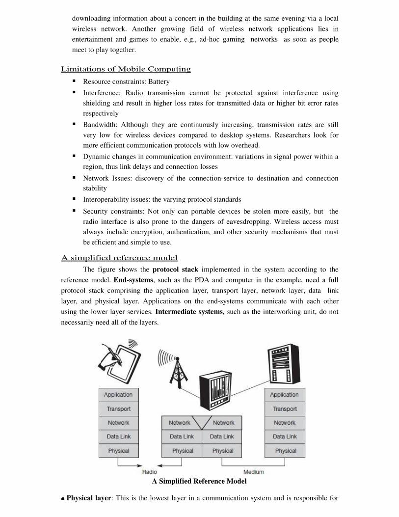
A simplified reference model
The figure shows the protocol stack implemented in the system according to the
reference model. End-systems, such as the PDA and computer in the example, need a full
protocol stack comprising the application layer, transport layer, network layer, data link
layer, and physical layer. Applications on the end-systems communicate with each other
using the lower layer services. Intermediate systems, such as the interworking unit, do not
necessarily need all of the layers.
A Simplified Reference Model
● Physical layer: This is the lowest layer in a communication system and is responsible for
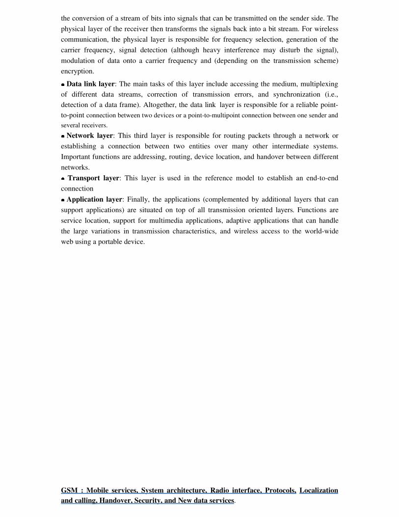
the conversion of a stream of bits into signals that can be transmitted on the sender side. The
physical layer of the receiver then transforms the signals back into a bit stream. For wireless
communication, the physical layer is responsible for frequency selection, generation of the
carrier frequency, signal detection (although heavy interference may disturb the signal),
modulation of data onto a carrier frequency and (depending on the transmission scheme)
encryption.
● Data link layer: The main tasks of this layer include accessing the medium, multiplexing
of different data streams, correction of transmission errors, and synchronization (i.e.,
detection of a data frame). Altogether, the data link layer is responsible for a reliable point-
to-point connection between two devices or a point-to-multipoint connection between one sender and
several receivers.
● Network layer: This third layer is responsible for routing packets through a network or
establishing a connection between two entities over many other intermediate systems.
Important functions are addressing, routing, device location, and handover between different
networks.
● Transport layer: This layer is used in the reference model to establish an end-to-end
connection
● Application layer: Finally, the applications (complemented by additional layers that can
support applications) are situated on top of all transmission oriented layers. Functions are
service location, support for multimedia applications, adaptive applications that can handle
the large variations in transmission characteristics, and wireless access to the world-wide
web using a portable device.
GSM : Mobile services, System architecture, Radio interface, Protocols, Localization
and calling, Handover, Security, and New data services.
GSM Services
GSM is the most successful digital mobile telecommunication system in the world today. It is
used by over 800 million people in more than 190 countries. GSM permits the integration of
different voice and data services and the interworking with existing networks. Services make
a network interesting for customers. GSM has defined three different categories of services:
bearer, tele and supplementary services.
Bearer services: GSM specifies different mechanisms for data transmission, the original
GSM allowing for data rates of up to 9600 bit/s for non-voice services. Bearer services
permit transparent and non-transparent, synchronous or asynchronous data transmission.
Transparent bearer services only use the functions of the physical layer (layer 1) to
transmit data. Datatransmissionhas aconstant delayandthroughput ifnotransmissionerrors
occur. Transmission quality can be improved with the use of forward error correction
(FEC), which codes redundancy into the data stream and helps to reconstruct the original
data in case of transmission errors. Transparent bearer services do not try to recover lost
data in case of, for example, shadowing or interruptions due to handover. Non-transparent
bearer services use protocols of layers two and three to implement error correction and
flow control. These services use the transparent bearer services, adding a radio link
protocol (RLP). This protocol comprises mechanisms of high-level data link control
(HDLC), and special selective-reject mechanisms to trigger retransmission of erroneous
data.Using transparent and non-transparent services, GSM specifies several bearer services
for interworking with PSTN, ISDN, and packet switched public data networks (PSPDN) like
X.25, which is available worldwide. Data transmission can be full-duplex, synchronous with
data rates of 1.2, 2.4, 4.8, and 9.6 kbit/s or full-duplex, asynchronous from 300 to 9,600 bit/s.
Tele services: GSM mainly focuses on voice-oriented tele services. These comprise
encrypted voice transmission, message services, and basic data communication with
terminals as known from the PSTN or ISDN (e.g., fax). The primary goal of GSM was the
provision of high-quality digital voice transmission. Special codecs (coder/decoder) are used
for voice transmission, while other codecs are used for the transmission of analog data for
communication with traditional computer modems used in, e.g., fax machines. Another
service offered by GSM is the emergency number (eg 911, 999). This service is
mandatory for all providers and free of charge. This connection also has the highest
priority, possibly pre-empting other connections, and will automatically be set up with the
closest emergency center. A useful service for very simple message transfer is the short
message service (SMS), which offers transmission of messages of up to 160 characters.
Sending and receiving of SMS is possible during data or voice transmission. It can be used
for “serious” applications such as displaying road conditions, e-mail headers or stock
quotes, but it can also transfer logos, ring tones, horoscopes and love letters.
The successor of SMS, the enhanced message service (EMS), offers a larger
message size, formatted text, and the transmission of animated pictures, small images and
ring tones in a standardized way. But with MMS, EMS was hardly used. MMS offers
the transmission of larger pictures (GIF, JPG, WBMP), short video clips etc. and comes
with mobile phones that integrate small cameras. Another non-voice tele service is group 3
fax, which is available worldwide. In this service, fax data is transmitted as digital data over
the analog telephone network according to the ITU-T standards T.4 and T.30 using modems.
Supplementary services: In addition to tele and bearer services, GSM providers can offer
supplementary services. these services offer various enhancements for the standard
telephony service, and may vary from provider to provider. Typical services are user
identification, call redirection, or forwarding of ongoing calls, barring of
incoming/outgoing calls, Advice of Charge (AoC) etc. Standard ISDN features such as
closed user groups and multiparty communication may be available.
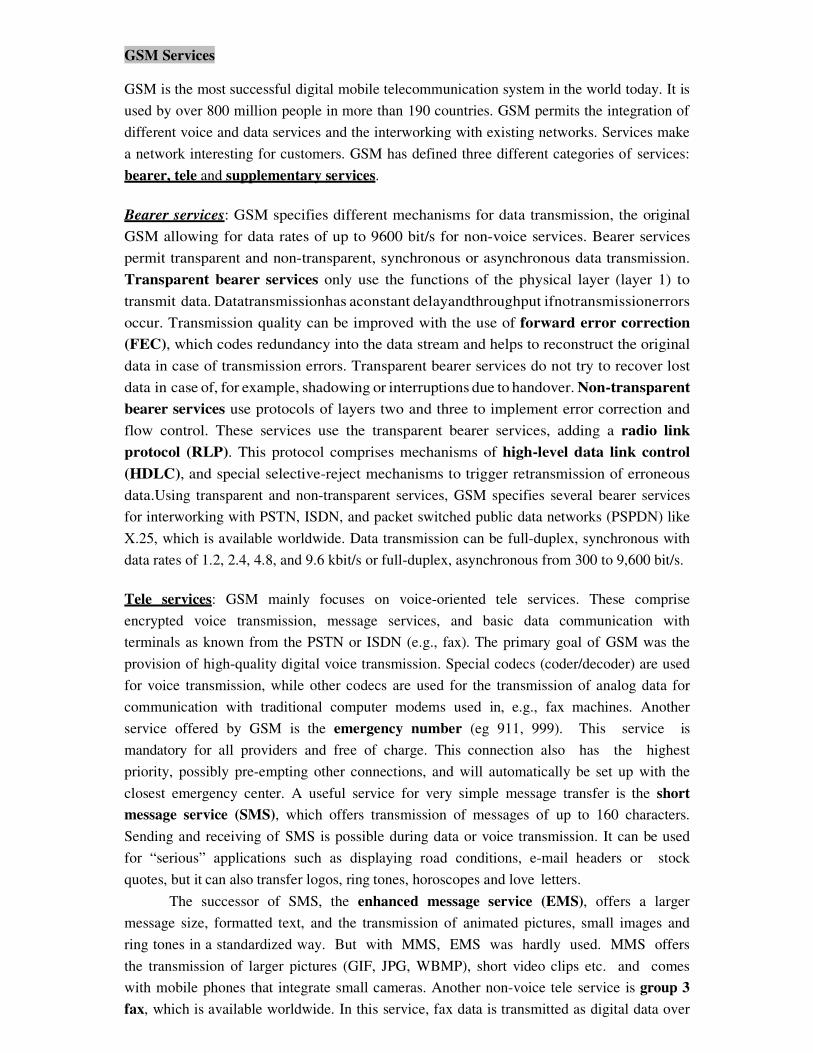
GSM Architecture
A GSM system consists of three subsystems, the radio sub system (RSS), the network
and switching subsystem (NSS), and the operation subsystem (OSS).
Functional Architecture of a GSM System
Network Switching Subsystem: The NSS is responsible for performing callprocessing
and subscriber related functions. The switching system includes the following functional
units:
� Home location register (HLR): It is a database used for storage and management of
subscriptions. HLR stores permanent data about subscribers, including a subscribers
service profile, location information and activity status. When an individual buys a
subscription from the PCS provider, he or she is registered in the HLR of that operator.
� Visitor location register (VLR): It is a database that contains temporary information about
subscribers that is needed by the MSC in order to service visiting subscribers. VLR is
always integrated with the MSC. When a MS roams into a new MSC area, the VLR
connected to that MSC will request data about the mobile station from the HLR. Later if
the mobile station needs to make a call, VLR will be having all the information needed
for call setup.
� Authentication center (AUC): A unit called the AUC provides authentication and
encryption parameters that verify the users identity and ensure the confidentiality of
each call.
� Equipment identity register (EIR): It is a database that contains information about the
identity of mobile equipment that prevents calls from stolen, unauthorized or defective
mobile stations.
� Mobile switching center (MSC): The MSC performs the telephony switching functions of
the system. It controls calls to and from other telephone and data systems.
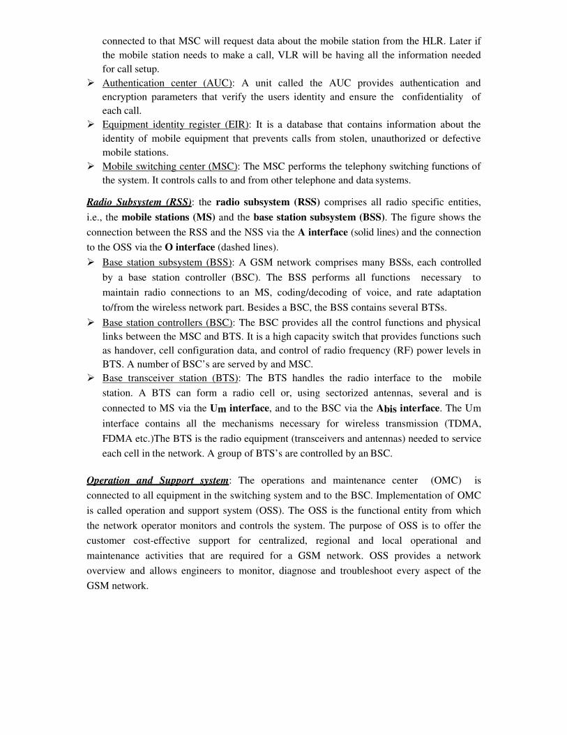
Radio Subsystem (RSS): the radio subsystem (RSS) comprises all radio specific entities,
i.e., the mobile stations (MS) and the base station subsystem (BSS). The figure shows the
connection between the RSS and the NSS via the A interface (solid lines) and the connection
to the OSS via the O interface (dashed lines).
� Base station subsystem (BSS): A GSM network comprises many BSSs, each controlled
by a base station controller (BSC). The BSS performs all functions necessary to
maintain radio connections to an MS, coding/decoding of voice, and rate adaptation
to/from the wireless network part. Besides a BSC, the BSS contains several BTSs.
� Base station controllers (BSC): The BSC provides all the control functions and physical
links between the MSC and BTS. It is a high capacity switch that provides functions such
as handover, cell configuration data, and control of radio frequency (RF) power levels in
BTS. A number of BSC’s are served by and MSC.
� Base transceiver station (BTS): The BTS handles the radio interface to the mobile
station. A BTS can form a radio cell or, using sectorized antennas, several and is
connected to MS via the Um interface, and to the BSC via the Abis interface. The Um
interface contains all the mechanisms necessary for wireless transmission (TDMA,
FDMA etc.)The BTS is the radio equipment (transceivers and antennas) needed to service
each cell in the network. A group of BTS’s are controlled by an BSC.
Operation and Support system: The operations and maintenance center (OMC) is
connected to all equipment in the switching system and to the BSC. Implementation of OMC
is called operation and support system (OSS). The OSS is the functional entity from which
the network operator monitors and controls the system. The purpose of OSS is to offer the
customer cost-effective support for centralized, regional and local operational and
maintenance activities that are required for a GSM network. OSS provides a network
overview and allows engineers to monitor, diagnose and troubleshoot every aspect of the
GSM network.
The mobile station (MS) consists of the mobile equipment (the terminal) and a smart
card called the Subscriber Identity Module (SIM). The SIM provides personal mobility, so
that the user can have access to subscribed services irrespective of a specific terminal. By
inserting the SIM card into another GSM terminal, the user is able to receive calls at that
terminal, make calls from that terminal, and receive other subscribed services.
The mobile equipment is uniquely identified by the International Mobile Equipment
Identity (IMEI). The SIM card contains the International Mobile Subscriber Identity
(IMSI) used to identify the subscriber to the system, a secret key for authentication, and
other information. The IMEI and the IMSI are independent, thereby allowing personal
mobility. The SIM card may be protected against unauthorized use by a password or
personal identity number.
Radio Interface
The most interesting interface in a GSM system is Um, the radio interface, as it comprises
various multiplexing and media access mechanisms. GSM implements SDMA using cells
with BTS and assigns an MS to a BTS.
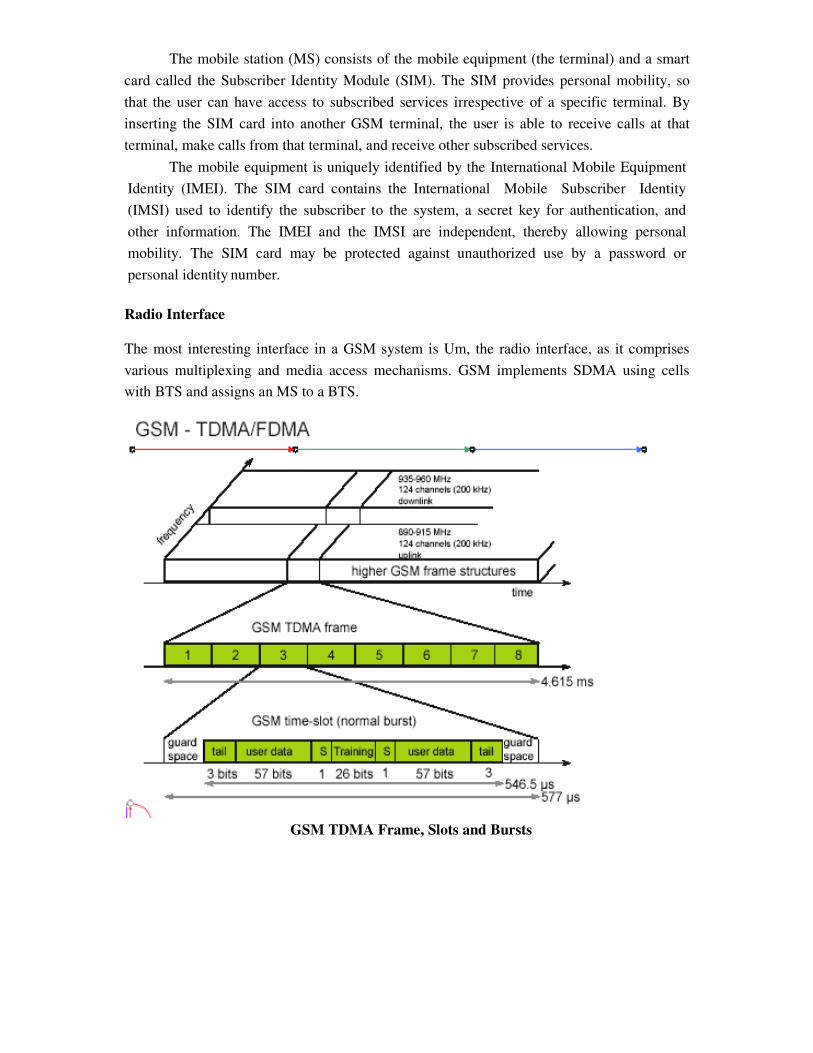
GSM TDMA Frame, Slots and Bursts
Each of the 248 channels
i.e., each 200 kHz carrier is subdivided into frames that are repeated continuously. The
duration of a frame is 4.615 ms.
each slot represents a physical TDM channel and lasts for 577
occupies the 200 kHz carrier for 577
portions, called bursts. The following figure shows a so c
transmission inside a time slot.
bits. The remaining 30.5 µs are used as
due to different path delays and to
The first and last three bits of a normal burst (
enhance the receiver performance. The
adapt the parameters of the receiver to the current path propagation characteristics and to
select the strongest signal in case of multi
data field contains user or network control data.
Apart from the normal burst, ETSI (1993a) defin
transmission: a frequency correction
avoid interference with neighbouring channels, a
training sequence synchronizes the MS with the
initial connection setup between MS and BTS, and finally a
is available for a slot.
Logical channels and frame hierarchy
Two types of channels, namely physical channels and logical
Physical channel: channel defined by specifying both, a carrier frequency and a TDMA
timeslot number. Logic channel:
Each logic channel performs a specific task. Consequent
transmitted in the corresponding timeslots of the physical channel. During this process,
logical channels can occupy a part
Each of the frequency carriers
577 s (15/26 s) duration with 156.25 bits per timeslot. The duration
is 4.615ms (577 s x 8 = 4.615 ms). The bits per timeslot and frame duration
bit rate of about 271kbps per TDMA
TDMA frames are grouped into two types of multiframes:
• 26-frame multiframe (4.615ms x 26 = 120
This multiframe is used to
the 248 channels is additionally separated in time via a GSM TDMA frame
subdivided into frames that are repeated continuously. The
ms. A frame is again subdivided into 8 GSM time slots
each slot represents a physical TDM channel and lasts for 577 µs. Each TDM channel
occupies the 200 kHz carrier for 577 µs every 4.615 ms. Data is transmitted
. The following figure shows a so called normal burst as used for data
transmission inside a time slot. As shown, the burst is only 546.5 µs long and contains 148
s are used as guard space to avoid overlapping with other bursts
to give the transmitter time to turn on and off.
The first and last three bits of a normal burst (tail) are all set to 0 and can be used to
enhance the receiver performance. The training sequence in the middle of a slot is used to
receiver to the current path propagation characteristics and to
select the strongest signal in case of multi-path propagation. A flag S indicates whether the
field contains user or network control data.
Apart from the normal burst, ETSI (1993a) defines four more bursts for data
frequency correction burst allows the MS to correct the local oscillator to
avoid interference with neighbouring channels, a synchronization burst with an extended
training sequence synchronizes the MS with the BTS in time, an access burst is
initial connection setup between MS and BTS, and finally a dummy burst is used if
Logical channels and frame hierarchy
channels, namely physical channels and logical channels are present.
channel defined by specifying both, a carrier frequency and a TDMA
Logic channel: logical channels are multiplexed into the physical channels.
Each logic channel performs a specific task. Consequently the data of a logical channel
the corresponding timeslots of the physical channel. During this process,
a part of the physical channel or even the entire channel.
Each of the frequency carriers is divided into frames of 8 timeslots of approximately
577 s (15/26 s) duration with 156.25 bits per timeslot. The duration of a TDMA frame
4.615ms (577 s x 8 = 4.615 ms). The bits per timeslot and frame duration
bps per TDMA frame.
TDMA frames are grouped into two types of multiframes:
frame multiframe (4.615ms x 26 = 120 ms) comprising of 26 TDMA frames.
to carry traffic channels and their associated control
TDMA frame,
subdivided into frames that are repeated continuously. The
GSM time slots, where
s. Each TDM channel
transmitted in small
as used for data
s long and contains 148
to avoid overlapping with other bursts
) are all set to 0 and can be used to
sequence in the middle of a slot is used to
receiver to the current path propagation characteristics and to
indicates whether the
es four more bursts for data
burst allows the MS to correct the local oscillator to
with an extended
is used for the
used if no data
channels are present.
channel defined by specifying both, a carrier frequency and a TDMA
logical channels are multiplexed into the physical channels.
ly the data of a logical channel is
the corresponding timeslots of the physical channel. During this process,
channel.
approximately
a TDMA frame
4.615ms (577 s x 8 = 4.615 ms). The bits per timeslot and frame duration yield a gross
comprising of 26 TDMA frames.
control channels.
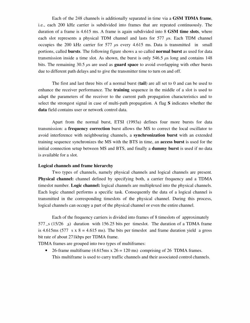
• 51-frame multiframe (4.615ms x 51 235.4 ms) comprising 51 TDMA frames.
This multiframe is exclusively used for control channels.
The multiframe structure is further multiplexed into a single superframe of duration of
6.12sec. This means a superframe consists of
• 51 multiframes of 26 frames.
• 26 multiframes of 51 frames.
The last multiplexing level of the frame hierarchy, consisting of 2048 superframes (2715648
TDMA frames), is a hyperframe. This long time period is needed to support the GSM data
encryption mechanisms. The frame hierarchy is shown below:
GSM Frame Hierarchy
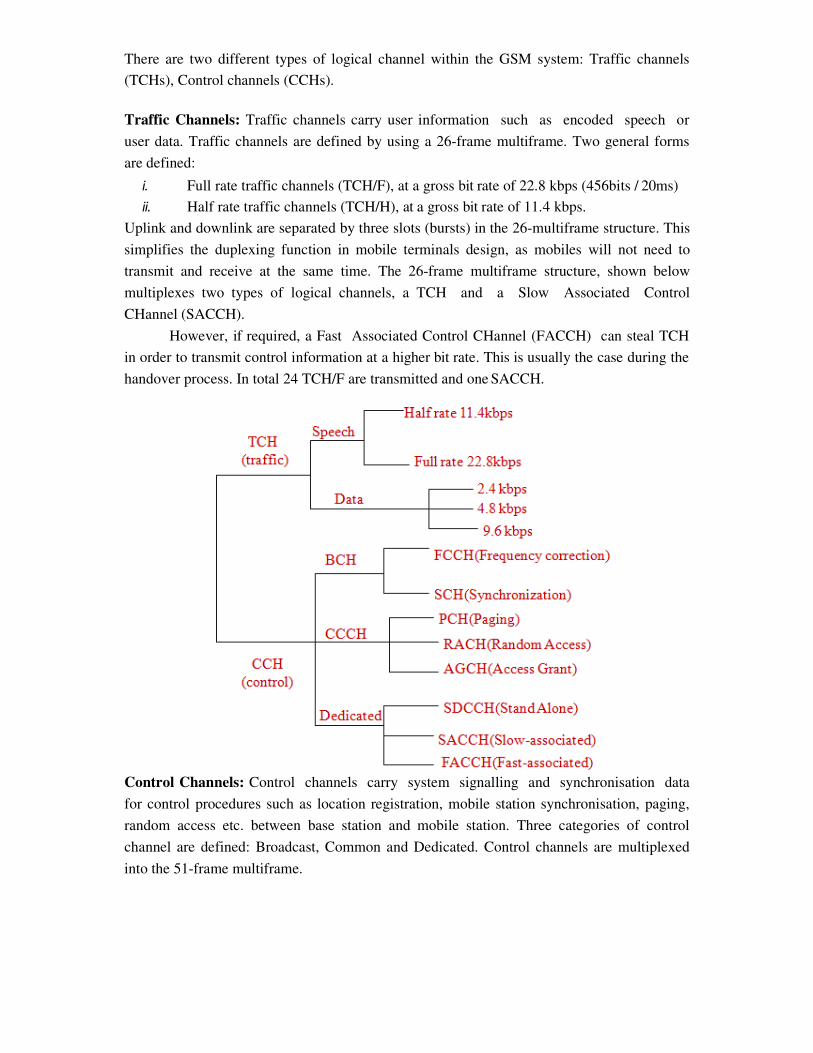
There are two different types of logical channel within the GSM system: Traffic channels
(TCHs), Control channels (CCHs).
Traffic Channels: Traffic channels carry user information such as encoded speech or
user data. Traffic channels are defined by using a 26-frame multiframe. Two general forms
are defined:
i. Full rate traffic channels (TCH/F), at a gross bit rate of 22.8 kbps (456bits / 20ms)
ii. Half rate traffic channels (TCH/H), at a gross bit rate of 11.4 kbps.
Uplink and downlink are separated by three slots (bursts) in the 26-multiframe structure. This
simplifies the duplexing function in mobile terminals design, as mobiles will not need to
transmit and receive at the same time. The 26-frame multiframe structure, shown below
multiplexes two types of logical channels, a TCH and a Slow Associated Control
CHannel (SACCH).
However, if required, a Fast Associated Control CHannel (FACCH) can steal TCH
in order to transmit control information at a higher bit rate. This is usually the case during the
handover process. In total 24 TCH/F are transmitted and one SACCH.
Control Channels: Control channels carry system signalling and synchronisation data
for control procedures such as location registration, mobile station synchronisation, paging,
random access etc. between base station and mobile station. Three categories of control
channel are defined: Broadcast, Common and Dedicated. Control channels are multiplexed
into the 51-frame multiframe.
� Broadcast control channel (BCCH): A BTS uses this channel to signal information
to all MSs within a cell. Information transmitted in this channel is, e.g., the cell
identifier, options available within this cell (frequency hopping), and frequencies
available inside the cell and in neighboring cells. The BTS sends information for
frequency correction via the frequency correction channel (FCCH) and information
about time synchronization via the synchronization channel (SCH), where both
channels are subchannels of the BCCH.
� Common control channel (CCCH): All information regarding connection setup
between MS and BS is exchanged via the CCCH. For calls toward an MS, the BTS
uses the paging channel (PCH) for paging the appropriate MS. If an MS wants to set
up a call, it uses the random access channel (RACH) to send data to the BTS.
The RACH implements multiple access (all MSs within a cell may access this
channel) using slotted Aloha. This is where a collision may occur with other MSs
in a GSM system. The BTS uses the access grant channel (AGCH) to signal an MS
that it can use a TCH or SDCCH for further connection setup.
� Dedicated control channel (DCCH): While the previous channels have all been
unidirectional, the following channels are bidirectional. As long as an MS has not
established a TCH with the BTS, it uses the stand-alone dedicated control
channel (SDCCH) with a low data rate (782 bit/s) for signaling. This can comprise
authentication, registration or other data needed for setting up a TCH. Each TCH and
SDCCH has a slow associated dedicated control channel (SACCH) associated with
it, which is used to exchange system information, such as the channel quality and
signal power level. Finally, if more signaling information needs to be transmitted and
a TCH already exists, GSM uses a fast associated dedicated control channel
(FACCH). The FACCH uses the time slots which are otherwise used by the TCH.
This is necessary in the case of handovers where BTS and MS have to exchange
larger amounts of data in less time.
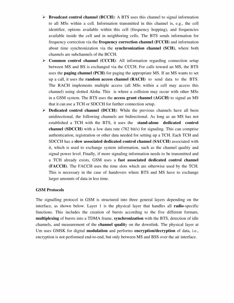
GSM Protocols
The signalling protocol in GSM is structured into three general layers depending on the
interface, as shown below. Layer 1 is the physical layer that handles all radio-specific
functions. This includes the creation of bursts according to the five different formats,
multiplexing of bursts into a TDMA frame, synchronization with the BTS, detection of idle
channels, and measurement of the channel quality on the downlink. The physical layer at
Um uses GMSK for digital modulation and performs encryption/decryption of data, i.e.,
encryption is not performed end-to-end, but only between MS and BSS over the air interface.
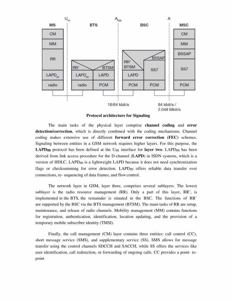
Protocol architecture for Signaling
The main tasks of the physical layer comprise channel coding and error
detection/correction, which is directly combined with the coding mechanisms. Channel
coding makes extensive use of different forward error correction (FEC) schemes.
Signaling between entities in a GSM network requires higher layers. For this purpose, the
LAPDm protocol has been defined at the Um interface for layer two. LAPDm has been
derived from link access procedure for the D-channel (LAPD) in ISDN systems, which is a
version of HDLC. LAPDm is a lightweight LAPD because it does not need synchronization
flags or checksumming for error detection. LAPDm offers reliable data transfer over
connections, re- sequencing of data frames, and flow control.
The network layer in GSM, layer three, comprises several sublayers. The lowest
sublayer is the radio resource management (RR). Only a part of this layer, RR’, is
implemented in the BTS, the remainder is situated in the BSC. The functions of RR’
are supported by the BSC via the BTS management (BTSM). The main tasks of RR are setup,
maintenance, and release of radio channels. Mobility management (MM) contains functions
for registration, authentication, identification, location updating, and the provision of a
temporary mobile subscriber identity (TMSI).
Finally, the call management (CM) layer contains three entities: call control (CC),
short message service (SMS), and supplementary service (SS). SMS allows for message
transfer using the control channels SDCCH and SACCH, while SS offers the services like
user identification, call redirection, or forwarding of ongoing calls. CC provides a point- to-
point
connection between two terminals and is used by higher layers for call establishment, call
clearing and change of call parameters. This layer also provides functions to send in-band
tones, called dual tone multiple frequency (DTMF), over the GSM network. These tones are
used, e.g., for the remote control of answering machines or the entry of PINs in electronic
banking and are, also used for dialing in traditional analog telephone systems.
Additional protocols are used at the Abis and A interfaces. Data transmission at the
physical layer typically uses pulse code modulation (PCM) systems. LAPD is used for layer
two at Abis, BTSM for BTS management. Signaling system No. 7 (SS7) is used for
signaling between an MSC and a BSC. This protocol also transfers all management
information between MSCs, HLR, VLRs, AuC, EIR, and OMC. An MSC can also control
a BSS via a BSS application part (BSSAP).
Localization and Calling
The fundamental feature of the GSM system is the automatic, worldwide localization of users
for which, the system performs periodic location updates. The HLR always contains
information about the current location and the VLR currently responsible for the MS informs
the HLR about the location changes. Changing VLRs with uninterrupted availability is called
roaming. Roaming can take place within a network of one provider, between two providers
in a country and also between different providers in different countries.
To locate and address an MS, several numbers are needed:
� Mobile station international ISDN number (MSISDN):- The only important
number for a user of GSM is the phone number. This number consists of the
country code (CC), the national destination code (NDC) and the subscriber number
(SN).
� International mobile subscriber identity (IMSI): GSM uses the IMSI for internal
unique identification of a subscriber. IMSI consists of a mobile country code (MCC),
the mobile network code (MNC), and finally the mobile subscriber identification
number (MSIN).
� Temporary mobile subscriber identity (TMSI): To hide the IMSI, which would
give away the exact identity of the user signalling over the air interface, GSM uses
the 4 byte TMSI for local subscriber identification.
� Mobile station roaming number (MSRN): Another temporary address that hides the
identity and location of a subscriber is MSRN. The VLR generates this address on
request from the MSC, and the address is also stored in the HLR. MSRN contains the
current visitor country code (VCC), the visitor national destination code (VNDC),
the identification of the current MSC together with the subscriber number. The MSRN
helps the HLR to find a subscriber for an incoming call.
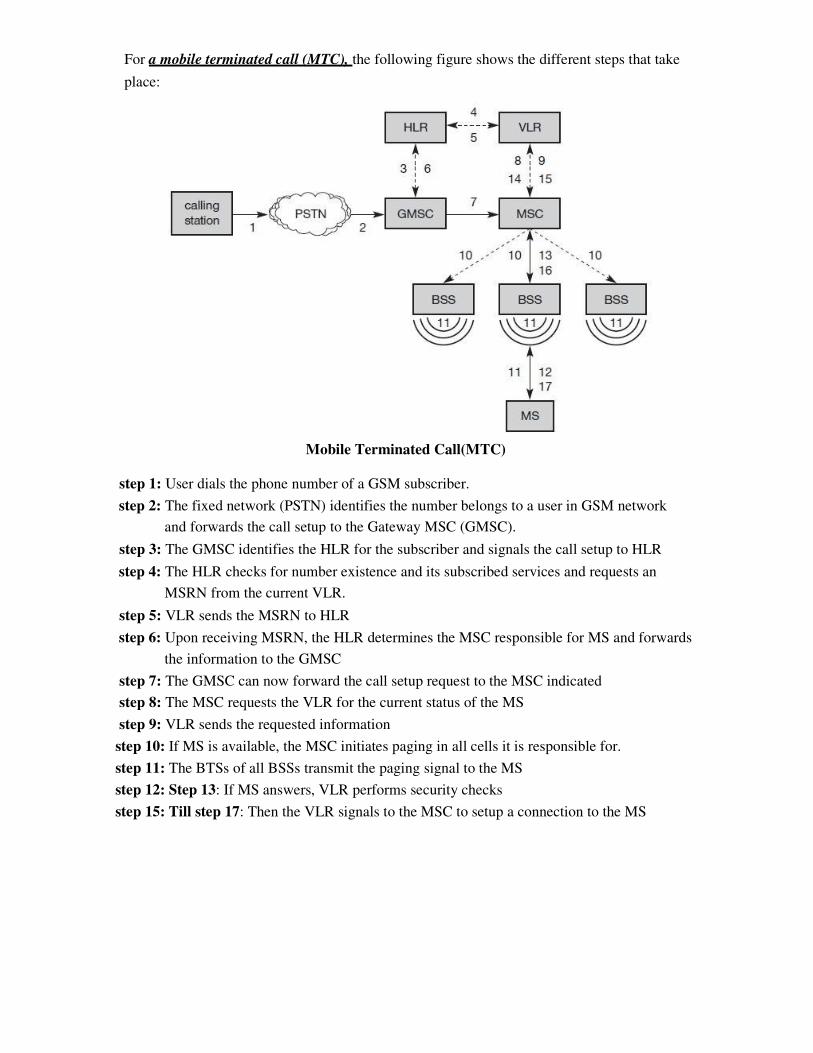
For a mobile terminated call (MTC), the following figure shows the different steps that take
place:
Mobile Terminated Call(MTC)
step 1: User dials the phone number of a GSM subscriber.
step 2: The fixed network (PSTN) identifies the number belongs to a user in GSM network
and forwards the call setup to the Gateway MSC (GMSC).
step 3: The GMSC identifies the HLR for the subscriber and signals the call setup to HLR
step 4: The HLR checks for number existence and its subscribed services and requests an
MSRN from the current VLR.
step 5: VLR sends the MSRN to HLR
step 6: Upon receiving MSRN, the HLR determines the MSC responsible for MS and forwards
the information to the GMSC
step 7: The GMSC can now forward the call setup request to the MSC indicated
step 8: The MSC requests the VLR for the current status of the MS
step 9: VLR sends the requested information
step 10: If MS is available, the MSC initiates paging in all cells it is responsible for.
step 11: The BTSs of all BSSs transmit the paging signal to the MS
step 12: Step 13: If MS answers, VLR performs security checks
step 15: Till step 17: Then the VLR signals to the MSC to setup a connection to the MS
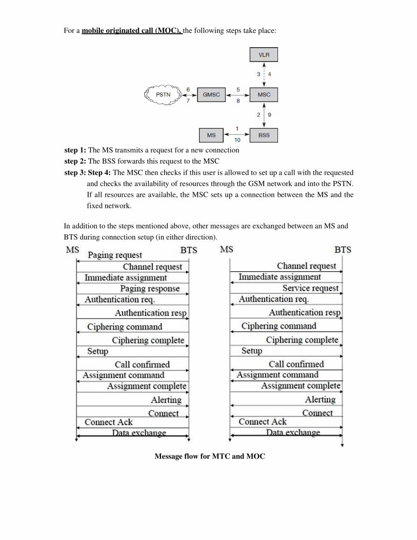
For a mobile originated call (MOC), the following steps take place:
step 1: The MS transmits a request for a new connection
step 2: The BSS forwards this request to the MSC
step 3: Step 4: The MSC then checks if this user is allowed to set up a call with the requested
and checks the availability of resources through the GSM network and into the PSTN.
If all resources are available, the MSC sets up a connection between the MS and the
fixed network.
In addition to the steps mentioned above, other messages are exchanged between an MS and
BTS during connection setup (in either direction).
Message flow for MTC and MOC
Handover
Cellular systems require handover procedures, as single cells do not cover the whole service
area. However, a handover should not cause a cut-off, also called call drop. GSM aims at
maximum handover duration of 60 ms. There are two basic reasons for a handover:
1. The mobile station moves out of the range of a BTS, decreasing the received signal
level increasing the error rate thereby diminishing the quality of the radio link.
2. Handover may be due to load balancing, when an MSC/BSC decides the traffic is too
high in one cell and shifts some MS to other cells with a lower load.
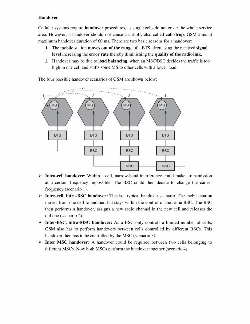
The four possible handover scenarios of GSM are shown below:
� Intra-cell handover: Within a cell, narrow-band interference could make transmission
at a certain frequency impossible. The BSC could then decide to change the carrier
frequency (scenario 1).
� Inter-cell, intra-BSC handover: This is a typical handover scenario. The mobile station
moves from one cell to another, but stays within the control of the same BSC. The BSC
then performs a handover, assigns a new radio channel in the new cell and releases the
old one (scenario 2).
� Inter-BSC, intra-MSC handover: As a BSC only controls a limited number of cells;
GSM also has to perform handovers between cells controlled by different BSCs. This
handover then has to be controlled by the MSC (scenario 3).
� Inter MSC handover: A handover could be required between two cells belonging to
different MSCs. Now both MSCs perform the handover together (scenario 4).
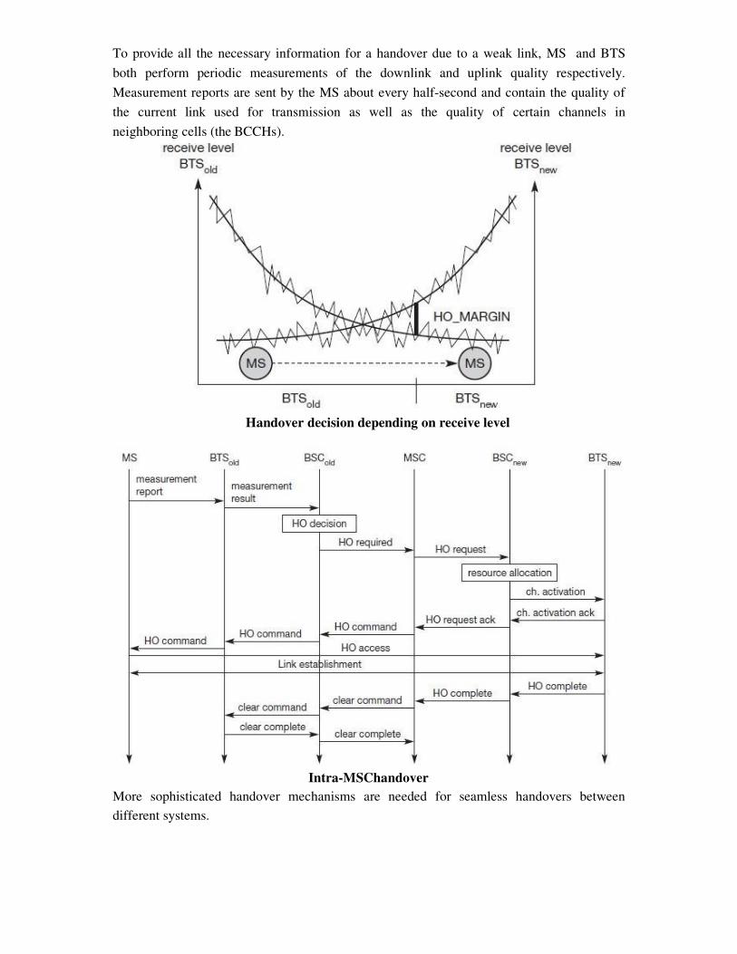
To provide all the necessary information for a handover due to a weak link, MS and BTS
both perform periodic measurements of the downlink and uplink quality respectively.
Measurement reports are sent by the MS about every half-second and contain the quality of
the current link used for transmission as well as the quality of certain channels in
neighboring cells (the BCCHs).
Handover decision depending on receive level
Intra-MSChandover
More sophisticated handover mechanisms are needed for seamless handovers between
different systems.
Security
GSM offers several security services using confidential information stored in the AuC and in
the individual SIM. The SIM stores personal, secret data and is protected with a PIN against
unauthorized use. Three algorithms have been specified to provide security services in GSM.
Algorithm A3 is used for authentication, A5 for encryption, and A8 for the generation of
a cipher key. The various security services offered by GSM are:
Access control and authentication: The first step includes the authentication of a valid user
for the SIM. The user needs a secret PIN to access the SIM. The next step is the
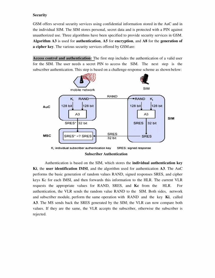
subscriber authentication. This step is based on a challenge-response scheme as shown below:
Subscriber Authentication
Authentication is based on the SIM, which stores the individual authentication key
Ki, the user identification IMSI, and the algorithm used for authentication A3. The AuC
performs the basic generation of random values RAND, signed responses SRES, and cipher
keys Kc for each IMSI, and then forwards this information to the HLR. The current VLR
requests the appropriate values for RAND, SRES, and Kc from the HLR. For
authentication, the VLR sends the random value RAND to the SIM. Both sides, network
and subscriber module, perform the same operation with RAND and the key Ki, called
A3. The MS sends back the SRES generated by the SIM; the VLR can now compare both
values. If they are the same, the VLR accepts the subscriber, otherwise the subscriber is
rejected.
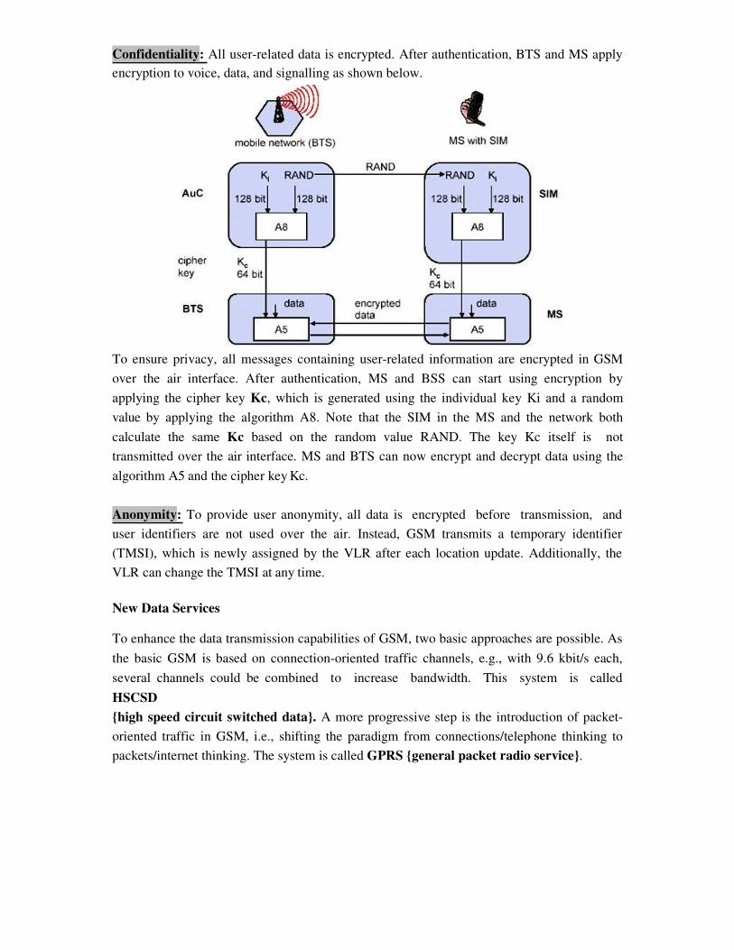
Confidentiality: All user-related data is encrypted. After authentication, BTS and MS apply
encryption to voice, data, and signalling as shown below.
To ensure privacy, all messages containing user-related information are encrypted in GSM
over the air interface. After authentication, MS and BSS can start using encryption by
applying the cipher key Kc, which is generated using the individual key Ki and a random
value by applying the algorithm A8. Note that the SIM in the MS and the network both
calculate the same Kc based on the random value RAND. The key Kc itself is not
transmitted over the air interface. MS and BTS can now encrypt and decrypt data using the
algorithm A5 and the cipher key Kc.
Anonymity: To provide user anonymity, all data is encrypted before transmission, and
user identifiers are not used over the air. Instead, GSM transmits a temporary identifier
(TMSI), which is newly assigned by the VLR after each location update. Additionally, the
VLR can change the TMSI at any time.
New Data Services
To enhance the data transmission capabilities of GSM, two basic approaches are possible. As
the basic GSM is based on connection-oriented traffic channels, e.g., with 9.6 kbit/s each,
several channels could be combined to increase bandwidth. This system is called
HSCSD
{high speed circuit switched data}. A more progressive step is the introduction of packet-
oriented traffic in GSM, i.e., shifting the paradigm from connections/telephone thinking to
packets/internet thinking. The system is called GPRS {general packet radio service}.
HSCD: A straightforward improvement of GSM’s data transmission capabilities is high
speed circuit switched data (HSCSD) in which higher data rates are achieved by bundling
several TCHs. An MS requests one or more TCHs from the GSM network, i.e., it allocates
several TDMA slots within a TDMA frame. This allocation can be asymmetrical, i.e. more
slots can be allocated on the downlink than on the uplink, which fits the typical user
behaviour of downloading more data compared to uploading. A major disadvantage of
HSCD is that it still uses the connection-oriented mechanisms of GSM, which is not efficient
for computer data traffic.
GPRS: The next step toward more flexible and powerful data transmission avoids the
problems of HSCSD by being fully packet-oriented. The general packet radio service
(GPRS) provides packet mode transfer for applications that exhibit traffic patterns such as
frequent transmission of small volumes (e.g., typical web requests) or infrequent
transmissions of small or medium volumes (e.g., typical web responses) according to the
requirement specification. For the new GPRS radio channels, the GSM system can allocate
between one and eight time slots within a TDMA frame. Time slots are not allocated in a
fixed, pre-determined manner but on demand. All time slots can be shared by the active
users; up- and downlink are allocated separately. Allocation of the slots is based on current
load and operator preferences. The GPRS concept is independent of channel characteristics
and of the type of channel (traditional GSM traffic or control channel), and does not limit
the maximum data rate (only the GSM transport system limits the rate). All GPRS services
can be used in parallel to conventional services. GPRS includes several security services
such as authentication, access control, user identity confidentiality, and user information
confidentiality.
The GPRS architecture introduces two new network elements, which are called GPRS
support nodes (GSN) and are in fact routers. All GSNs are integrated into the standard GSM
architecture, and many new interfaces have been defined. The gateway GPRS support node
(GGSN) is the interworking unit between the GPRS network and external packet data
networks (PDN). This node contains routing information for GPRS users, performs address
conversion, and tunnels data to a user via encapsulation. The GGSN is connected to external
networks (e.g., IP or X.25) via the Gi interface and transfers packets to the SGSN via an
IP- based GPRS backbone network (Gn interface). The other new element is the serving
GPRS support node (SGSN) which supports the MS via the Gb interface. The SGSN, for
example, requests user addresses from the GPRS register (GR), keeps track of the
individual MSs’ location, is responsible for collecting billing information (e.g., counting
bytes), and performs several security functions such as access control. The SGSN is
connected to a BSC via frame
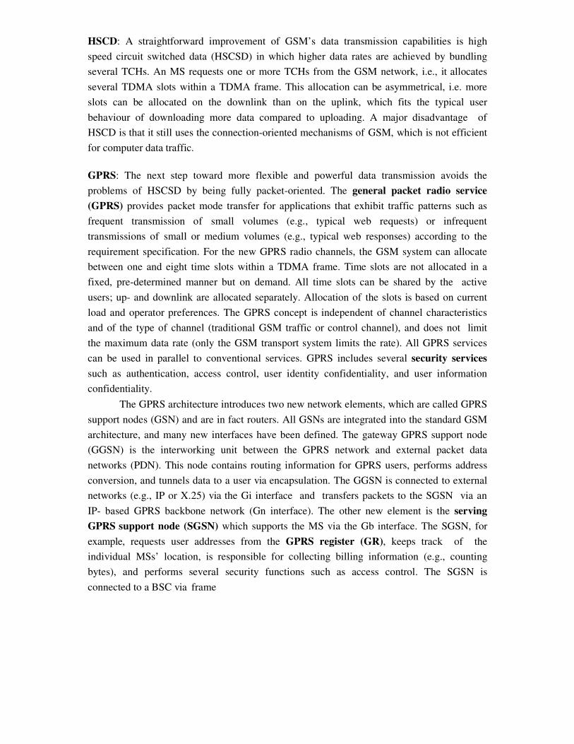
relay and is basically on the same hierarchy level as an MSC. The GR, which is typically a
part of the HLR, stores all GPRS-relevant data.
GPRS Architecture Reference Model
As shown above, packet data is transmitted from a PDN, via the GGSN and SGSN
directly to the BSS and finally to the MS. The MSC, which is responsible for data transport
in the traditional circuit-switched GSM, is only used for signalling in the GPRS scenario.
Before sending any data over the GPRS network, an MS must attach to it, following the
procedures of the mobility management. The attachment procedure includes assigning a
temporal identifier, called a temporary logical link identity (TLLI), and a ciphering key
sequence number (CKSN) for data encryption. For each MS, a GPRS context is set up and
stored in the MS and in the corresponding SGSN. Besides attaching and detaching,
mobility management also comprises functions for authentication, location management, and
ciphering.
The following figure shows the protocol architecture of the transmission plane for
GPRS. All data within the GPRS backbone, i.e., between the GSNs, is transferred using
the GPRS tunnelling protocol (GTP). GTP can use two different transport protocols, either
the reliable TCP (needed for reliable transfer of X.25 packets) or the non-reliable UDP
(used for IP packets). The network protocol for the GPRS backbone is IP (using any lower
layers). To adapt to the different characteristics of the underlying networks, the subnetwork
dependent convergence protocol (SNDCP) is used between an SGSN and the MS. On top
of SNDCP and GTP, user packet data is tunneled from the MS to the GGSN and vice versa.
To achieve a high reliability of packet transfer between SGSN and MS, a special LLC is
used, which comprises ARQ and FEC mechanisms for PTP (and later PTM) services.
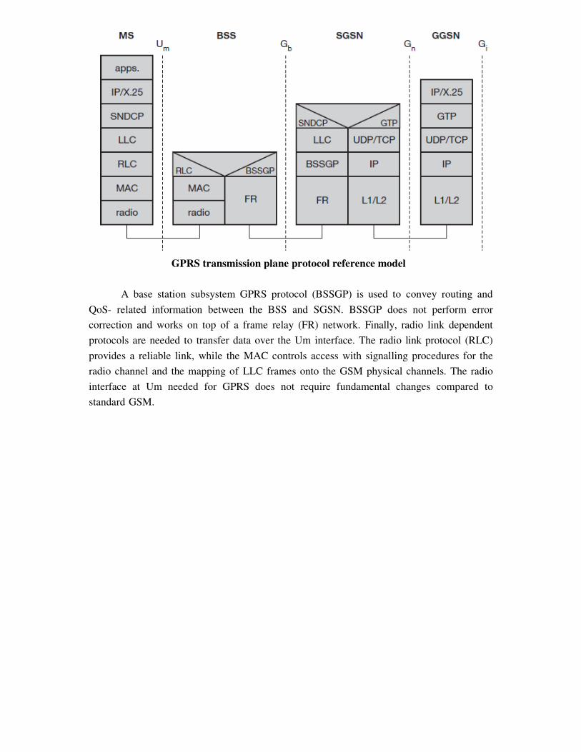
GPRS transmission plane protocol reference model
A base station subsystem GPRS protocol (BSSGP) is used to convey routing and
QoS- related information between the BSS and SGSN. BSSGP does not perform error
correction and works on top of a frame relay (FR) network. Finally, radio link dependent
protocols are needed to transfer data over the Um interface. The radio link protocol (RLC)
provides a reliable link, while the MAC controls access with signalling procedures for the
radio channel and the mapping of LLC frames onto the GSM physical channels. The radio
interface at Um needed for GPRS does not require fundamental changes compared to
standard GSM.
![Leerapan B, Nimmanit A, Jaturapatporn D. Situation analysis of health services system and its quality control according to the Statute on the National Health System B.E. 2552 [in Thai]](https://img.dokumen.tips/doc/110x75/6314ed0185333559270ceb12/leerapan-b-nimmanit-a-jaturapatporn-d-situation-analysis-of-health-services-system.jpg)


