Embed Size (px)
Citation preview

INSTALLATION ANDSERVICE INSTRUCTIONS
INCINOMITE MODELSJ81A-3 and J121A-3
Incinerator Gas Burners
In the United States, installation must conform with local codesor, in the absence of local codes, with National Fuel Gas CodeANSI Z223.1-1992, or latest edition available from AmericanNational Standard Institute. Further reference should bemade to the recommendation of your fuel supplier.
NOTE: Any additions, changes, or conversions required in orderfor the gas utilization equipment to satisfactorily meet theapplication needs must be made by a MIDCO distributor (orother qualified agency) using factory specified and approvedparts.
In Canada, installation must conform with local codes or, in the absence of local codes, with Installation Codes for GasBurning Appliances and Equipment, CGA StandardCAN/CGA 1-B-149.1 or 2. Further reference should be madeto the recommendation of your fuel supplier.
INSTALLER: Inform and demonstrate tothe user the correct operation andmaintenance of this gas utilizationequipment. Inform the user of thehazards of storing flammable liquids andvapors in the vicinity of this gasutilization equipment and remove suchhazards. Affix this manual adjacent tothe incinerator burner. CODECOMPLIANCE IS THE SOLE RESPONSIBILITY OF THE INSTALLER.
Do not store or use gasoline or otherflammable vapors and liquids in thevicinity of this or any other appliance.
WHAT TO DO IF YOU SMELL GAS
• Do not try to light any appliance.
• Do not touch any electrical switch;
do not use any phone in your
building.
• Immediately call your gas supplier
from a neighbor's phone. Follow the
gas supplier's instructions.
• If you cannot reach your gas supplier,
call the fire department.
Installation and service must be performed by a qualified installer, serviceagency or the gas supplier.
WARNING: If the information inthese instructions is not followedexactly, a fire or explosion may resultcausing pro p e rty damage, personalinjury or death.
SAFETY INFORMATION TERMS: The following terms are used to identify hazards, safety precautions or special notations andhave standard meanings throughout this manual. When you see the safety alert symbol and one of the safety information terms, asshown below, be aware of the hazard potential.
DANGER: Identifies the most serious hazards which will result in severe personal injury or death.WARNING: Signifies a hazard that could result in personal injury or death.CAUTION: Identifies unsafe practices which would result in minor personal injury or product and property damage.
PRINTED IN U.S.A.797
8470-70
The INCINOMITE Models J81A-3 and J121A-3 incinerator gas burners feature continuously monitored electronic flame safety andspark ignited intermittent proven ignitor (pilot). They are adaptable to either primary or secondary chamber installation.
USER: Retain this manual for future reference. If other than routine service ormaintenance as described in this manual is required, contact a qualified service agency.DO NOT ATTEMPT REPAIRS. An inadvertent service error could result in a dangerouscondition.
MIDCO International Inc. 4140 WEST VICTORIA STREET • CHICAGO, ILLINOIS 60646 • (773) 604-8700 FAX: (773) 604-4070 • http://www.midco-intl.com

SPECIFICATIONS1
BURNER AIR DELIVERY(Approximate Air Delivery at Zero Draft)
J81A-3………………………………………....90 SCFM2
J121A-3………………………………………..180 SCFM
MINIMUM GAS PRESSURE LISTED FOR PURPOSE OFINPUT ADJUSTMENT ( Take Pressure at Inlet Tap of Main Automatic Va l v e )
N ATURAL………………………………………………..5.5" W. C .P R O PANE……………………………………………….8.0" W. C .
BURNER FIRING RATE (NAT U R A LOR PROPA N E )3All Ratings Based on 1000 BTU/cu. ft. NATURAL, 2500 BTU/cu. ft. PROPANE at Sea Level
M I N I M U MJ81A-3 or J121A-3…………………………………100 MBH4
MAXIMUM (With Combustion Air From Burner Only)J81A-3
20% Excess Air……………………………450 MBH0% Excess Air (stoichiometric)…………..540 MBH
J121A-320% Excess Air……………………………900 MBH0% Excess Air……………………………1080 MBH
MAXIMUM (With Combustion Air From Burner Blower and Additional Air Available in Combustion Chamber.)
NATURAL Gas 5.5" W.C. or PROPANE Gas at 11.0" W.C. Gas Pressure at Main Automatic Valve
J81A-3…………………………………………800 MBHJ121A-3……………………………………..1,200 MBH
ELECTRICAL SUPPLYJ81A-3………………………………...120/1/60; 3 a m p sJ121A-3………………………………..120/1/60; 4.5 amps
BURNER ON-OFF CONTROL……………Toggle Switch.Optional 0 to 6 Hr. Manual Timer5
FLAME SAFETY…………………...Electronic Flame Safetywith spark ignited ignitor (pilot) and 100% shut-off.
OPTIONAL WEATHERHOOD5
ADJUSTABLE FIRING ANGLE…………...Mounting Flangeadjustable for horizontal or 10° down firing.
NOTE: Burner components are ULrecognized, CGA listed, CSAcertified and/or AGA design certified, mounted and wired. The complete burner is fire tested.
1. Standard burners are shipped as NATURAL gas models. A kit is available for field conversion to PROPANE gas.
2. SCFM = Standard Cubic Feet/Minute.3. NOTE: Firing rate with combustion air from burner blower only is
based on using standard air at sea level with zero draft over-fire. Derate burner for altitudes over 2,000 feet by 4% for each 1000 feet above sea level.
4. 100 MBH = 100,000 BTU/Hr.5. Kit is available for field installation.
PART 1 INSTALLATION
I PRIMARY CHAMBER FUEL INPUT■ No. 1 Waste: Primarily dry material such as paper, ragsand wood. Burner normally required only for light-off.■ No. 2 Waste:Consisting of approximately equal portions,by weight of No. 1 and No. 3 waste; 70 lbs. per 100 MBH.■ No. 3 Waste: Wet material such as garbage; 25lbs. per100 MBH.■ No. 4 Waste: Organic materials such as small carcassesand waste from hospital operating rooms or pathologicallaboratories; 13 lbs. per 100 MBH.NOTE: The burner input required for the secondarychamber must be determined from the heat required tomaintain the discharge temperature of the flue products asspecified by the EPA for the type of waste involved and thelocation of the incinerator.
II INDOOR VENTILATIONMake sure that the incinerator room has suff i c i e n tventilation to provide the necessary combustion air for theburner fuel, the waste material and any other appliance thatwould draw its air from the same enclosed area.
WARNING: Under no condition should the access tooutside air be so restricted that the maximum possibleuse of combustion air is inhibited. Pay particularattention to exhaust fans that could draw air from thearea and create a negative pressure in the room.
III INSTALLATIONInstall the INCINOMITE burner(s) in location(s) specified bythe incinerator manufacturer. It should be positionedapproximately level with the top of the highest normal loadand fire with or across the draft flow.
FIGURE 1 Typical Installation-2-

■ If the incinerator is designed only for No. 4 waste, thelevel can be lowered to bring the flame to play directly onthe smaller loads characteristic of this type of operation.The opening through which the burner fires should be of adiameter only large enough to accommodate the Blast Tube(41⁄4" diameter x 3" minimum long.) Do not allow the BlastTube to protrude into the incineration chamber. Ifnecessary, build an extension outside of the incinerator wallto increase wall depth.■ To change the Mounting Flange to its alternate position,horizontal or 10° down firing, remove the four (4) screwsthat attach it to the burner, rotate the flange 180° andreinstall the screws.■ Before mounting the burner, check that the Blast Tubeand Blower Housing are clear of foreign material and thatthe Main Gas Port and Nozzle Support is clean andundamaged.■ If the incinerator is located outdoors, the burner and all ofits components, except the Main Manual Shut-Off Valve,must be protected from weather. The MIDCO AccessoryWeatherhood will provide such protection.
CAUTION: If the incinerator is of the down draftdesign, make sure that a direct draft vent opening ofapproximately 10 square inches has been put throughthe top of the drop section(s) to provide for the ventingof any gas leakage. See Figure 1.
IV CHIMNEY, VENT CONNECTOR AND DRAFT CONTROL
The size and type of material used for the vent connectorand chimney must conform to the recommendations of theincinerator manufacturer, as well as local and nationalcodes. This is especially true where high flue gastemperatures are encountered.■ When natural draft is used and the chimney height is over25 feet, a barometric damper of the same size as the ventconnector should be installed. If the chimney is highenough to make it difficult for the barometric to maintain amaximum incineration chamber over-fire draft, (0 to minus0.5” W.C. for Model J81A-3, 0 to minus 1.0” W.C. for ModelJ121A-3), a fixed damper should be installed in the ventconnector between the barometric and chimney to restrictthe chimney draft to a point within the controlling capacityof the barometric. After final setting, the damper should bepermanently fastened into position per ANSI Z223.1-1992"National Fuel Gas Code", or latest edition available fromAmerican National Standards Institute to preventtampering.
V PIPINGThe supply piping to the burner should branch off from themain line as close to the source as possible (NATURALgas meter or PROPANE tank regulator). When branchingoff from an existing gas line, do not tap off the bottom of ahorizontal section. Use new black pipe and malleablefittings free from cutting and threading burrs or defects.■ Use pipe joint compound resistant to liquid petroleumgases when using either NATURAL or PROPANE gas.Piping must comply with the local and national codes. If theburner piping must be rearranged because of spacelimitations, be sure to carry out the general configurationshown in Figure 3.
■ A suitable Main Gas Pressure Regulator should beinstalled as shown in Figures 1 or 3. Choose a regulator(s)to adjust the available gas pressure to the pressure shownin SPECIFICATIONS, page 2.
CAUTION: The regulated gas pressures must notexceed 14:" W.C. or Main Automatic Gas Valve andIgnitor Regulator will be damaged. If excessive gaspressure is prevalent, the regulator must be a tightshut-off type to prevent high pressures fromdeveloping during stand-by. The regulator must have aminimum flow regulating capacity for the ignitor gasrate (see Table 4). It is strongly recommended that aseparate smaller regulator be used for ignitor gas,connecting to the gas line ahead of the Main GasPressure Regulator and downstream of anyintermediate Regulator.■ For full input, refer to SPECIFICATIONS, page 2, forminimum gas pressure required. For reduced capacities,refer to Firing Rate Curves, Table 2 or 3.
CAUTION: If gas supply pressure is below itsspecified range during adjustment, an over-firecondition could result when pressure returns tonormal, particularly if the regulator adjustment screw isbottomed out. A LWAYS confirm that at least theminimum rated pressure is being supplied duringregulator adjustments, and NEVER B O T TOM OUTregulator screw.■ When selecting the burner supply piping size per Table 1,the permissible pressure drop must be based on thepressure available at the inlet to the supply pipe branch linewhen all other gas equipment fed by the same source(NATURAL gas meter or PROPANE tank regulator) is firingat full rate. Also take into account any other INCINOMITEburners to be attached to the same branch line.
Capacities shown are for total pressure drop of 0.3"W.C. Forhigher permissible pressure drops consult your fuel supplier.
Source: Gas Engineers Handbook-1974Industrial Press Inc. NY, NY
TABLE 1 Schedule 40 Pipe Capacities in MBH
■ When pressure testing the supply piping, the burnervalve train must be protected. If the test pressure is 0.5PSIG or less, closing the Main Manual Shut-Off Valve willsuffice.
NPTPIPESIZE
3⁄4"
1"
1-1⁄4"
1-1⁄2"
2
TYPEOF GAS
NATURALPROPANENATURALPROPANE
NATURALPROPANE
NATURALPROPANE
NATURALPROPANE
10
275450520820
105012001200
20
200300350550
730115011001200
1200
40
130200245385
500790760
1200
1200
60
100165195300
400630610960
11501200
100
125150235
300480460725
8701200
APPROXIMATE CAPACITY-MBHLENGTH OF PIPE/FEET
-3-

CAUTION: If the test pressure is over 0.5 PSIG, thetest must be made without any burner componentsconnected, including Main and Ignitor Manual Shut-OffValves.
WARNING: Explosion hazard.Do not use oxygen for pressure testing. An explosion could occur during initial start-up.
VI ELECTRICALInstallation wiring to the burner must conform to localcodes, or, in their absence in the United States the NationalElectric Code ANSI/NFPA No. 70-1990, or latest edition; inCanada, to CSA standard C22.1, "Canadian ElectricalCode Part 1."■ Use copper wires and provide disconnect and fuseprotection for each INCINOMITE installation. Refer toSPECIFICATIONS, page 2, for ampacity. Confirm that thepolarity is correct—hot wire to strip terminal L1, neutral L2and that the neutral line is not subject to induced lowvoltage (check L2 to ground) from other equipment as thatcan affect the flame safeguard, causing it to malfunction.See Flame Safeguard Section X.
CAUTION: In order for the automatic cooling system tofunction, power must be maintained to burner strip terminalL1. Do not install any safety or on-off controls in the circuitbetween the fused disconnect switch and strip terminal L1.Optional remote control devices should be connected inplace of, or in addition to, the switch or timer as indicted inFigure 2 Wiring Diagram.NOTE: Optional 0-6 hour Timer may be substituted for theburner On-Off Switch. Kit is available with full conversioninstructions.
VII INITIAL START UP/ADJUSTMENTBurners are suitable for use with NATURAL or PROPANEgas only.■ If a standard NATURAL gas model is to be used withP R O PANE gas, a conversion kit is available, whichcontains a PROPANE Main Gas Port, a PROPANE IgnitorTee Orifice Fitting and a PROPANE label and conversioninstructions.■ As shipped, the Air Shutter is in the full open position andthe Main Gas Input Adjuster 5 to 6 turns from full closed.Ignitor regulator is factory set for recommended outletpressure of 3.5" W.C. suitable for most applications.
CAUTION: Ignition is automatic. Therefore, make ignitoror spark observations into incineration chamber only withMain Manual Shut-Off Valve closed.1. Check the burner piping and valves for gas leaks by
applying a weak liquid soap solution to unions andjoints with the gas supply on. Leakage will be indicatedby the appearance of soap bubbles. Locate and correctall gas leaks before proceeding.
WARNING: DO NOT USE OPEN FLAME.2. Confirm that the main gas Input Adjuster is 5 to 6 turns
from full closed and that the Blower Air Shutter is fully open.
3. Close the Main Manual Shut-Off Valve and ManualIgnitor GAs Valve.
4. Purging the air from the gas supply line at this step willexpedite the first light-off.
CAUTION: Purge outside the building. Do not purge into the incineration chamber.
5. Turn on the Fused Disconnect, Burner Switch or Timer and press relay reset button. Let motor run longenough to accomplish four air changes. Note thatmotor will continue to run after Flame Safeguardlockout occurs.
6. Open the incinerator charging door. making sure anyDoor Open interlock is temporarily bypassed.
7. Turn on Manual Ignitor Gas Valve only, and press relayreset button. Trial for Ignitor Ignition: Flame Safeguardand motor are powered. There will be a delay untilblower reaches operating speed and trips blowerproving switch. When the blower proving switch ismade, the Ignitor Solenoid Valve and Spark Generatorare energized. Ignitor flame should light.
8. If ignitor fails to light during the trial prescribed forignition and goes into Flame Safeguard lockout, it isprobably due to air in ignitor gas line. Wait one minuteand press relay reset button for several relight attempts.If the ignitor fails to light, turn off Manual Ignitor Gas
Valve and repeat from step 5 above. Then, if necessary,refer to the Trouble Chart to isolate the problem. (Referto Section X for trial timings.)
WARNING: Repeated unsuccessful attempts tolight will result in accumulated gases in incin-eration chamber and chimney. To prevent thesegases from reaching an explosive level,periodicallypurge the incineration chamber as described inStep 5.
9. Observe the ignitor flame. If it is weak, screw in theIgnitor regulator adjustment to increase the pressure. Ifit is excessively rich and large or floating from the igni-tor tip, back off the regulator adjustment to reduce thepressure. Set the ignitor to a stable blue flame whichburns firmly within the ignitor tip. Check flame signalwith a DC voltmeter and adjust Ignitor Regulator slowly for highest steady 2 or more volts DC.
CAUTION: When adjusting the regulator, take noteof the supply pressure. If gas supply pressure isbelow its specified range during adjustment, anover-fire condition could result when pressurereturns to normal, particularly if the regulatoradjustment screw is BOTTOMED OUT. ALWAYS confirmthat at least the minimum rated pressure is beingsupplied to the ignitor during regulator adjustments,and NEVER BOTTOM OUT regulator screw. Operateair shutter throughout range to confirm Ignitorstability. Try several relights. Refer to Table 4.
10. Remove the Input Adjuster Cap (see Figure 3) and turnthe Main Gas Input Adjusting Screw until the desiredinput rating is reached (refer to Tables 2 or 3). Turningof adjustment screw counterclockwise increases gasflow; clockwise reduces gas flow. If Main Flame gaspressure requires adjustment, refer to Section V Piping.
11. Reset the Blower Air Shutter to match the intendedinput, i.e.; full open for maximum, closed for minimum or partially open for midrange. The Blower Air Shutter isfactory set wide open. Adjust as necessary when, withcombustion air available in the incineration chamber, itis desirable to increase the flame length, or to restrict the amount of excess air discharged into the incinera-tion chamber when the burner input is below 450 MBH.
-4-
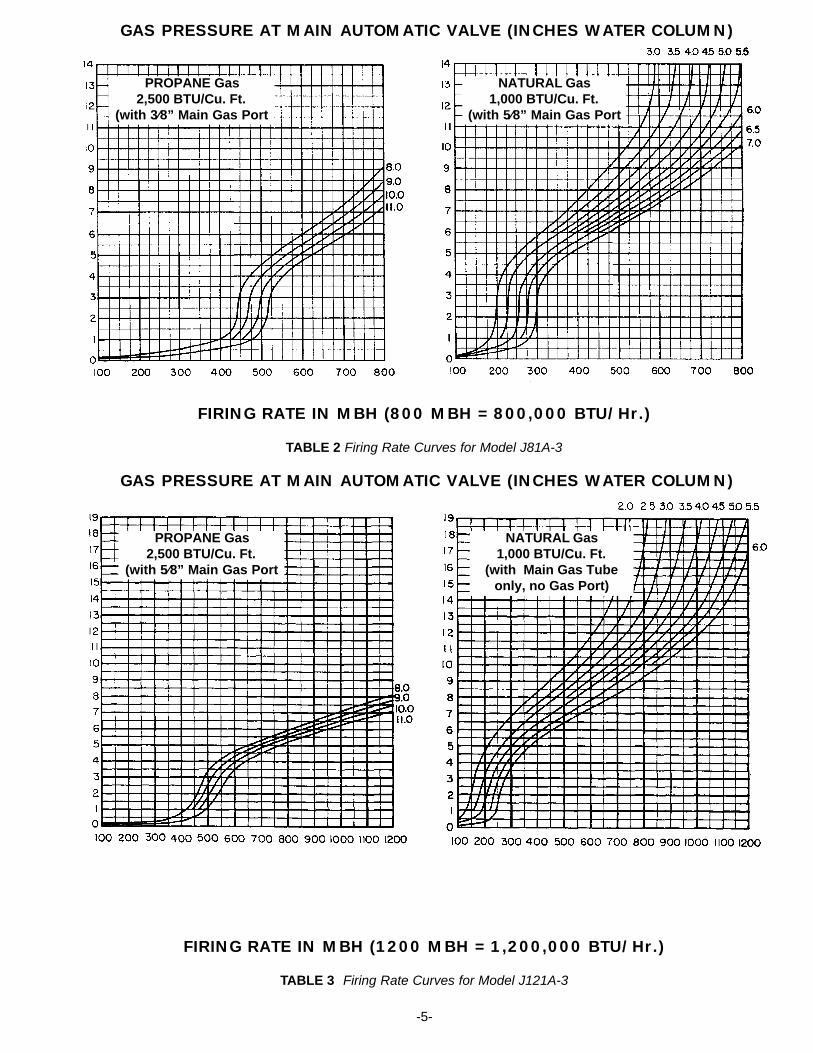
GAS PRESSURE AT MAIN AUTOMATIC VALVE (INCHES WATER COLUMN)
FIRING RATE IN MBH (800 MBH = 800,000 BTU/Hr.)
TABLE 2 Firing Rate Curves for Model J81A-3
GAS PRESSURE AT MAIN AUTOMATIC VALVE (INCHES WATER COLUMN)
FIRING RATE IN MBH (1200 MBH = 1,200,000 BTU/Hr.)
TABLE 3 Firing Rate Curves for Model J121A-3
-5-
PROPANE Gas2,500 BTU/Cu. Ft.
(with 3⁄8” Main Gas Port
PROPANE Gas2,500 BTU/Cu. Ft.
(with 5⁄8” Main Gas Port
NATURAL Gas1,000 BTU/Cu. Ft.
(with 5⁄8” Main Gas Port
NATURAL Gas1,000 BTU/Cu. Ft.
(with Main Gas Tubeonly, no Gas Port)

12. The actual NATURAL gas firing rate in BTU per hourcan be determined by timing the gas meter. Accuratelytime the meter test dial for one revolution, convert tohourly cubic feet and multiply by the BTU per cubic footvalue of your gas per formula:
Then divide by 1,000 for MBH value.
13. Start and stop the burner several times to check its operation with the charging door open, and then withit closed. Remove any temporary Door Open bypassesinstalled in Step 6.
14. Test operation of any auxiliary operating and/or limitcontrols.
15. Load incinerator and make trial run. Confirm that theincineration chamber pressure stays within the range of0 to minus 0.5"W.C. for Model J81A-3 and 0 to minus 1.0” W.C. for Model J121A-3.
16. WARNING: When the incinerator is locatedinside a building and a draft control is used, checkthat there is no spillage of flue products from the draftcontrol.17. To shut off: Turn Burner Switch or Timer off and close
Main Manual Shut -Off Valve
PART 1 SERVICEWARNING: BE SURE THAT THE MANUAL VALVE AND
BURNER DISCONNECT SWITCH ARE TURNED OFF BEFORE
ANY PARTS ARE REMOVED FOR SERVICE.
VIII IGNITOR AND REGULATOR ASSEMBLYThe Ignitor and Regulator Assembly is removed as a unit.Disconnect the ignitor gas line and electrode wires, removethe two mounting screws and pull out the assembly.
■ When the ignitor gas pressure is in the proper range (seeTable 4) and the electrodes are adjusted to the dimensionsshown in Figure 5, any ignition problems are usuallycaused by lint, dust, corrosion, cracked electrodeinsulators, foreign matter in the blast tube or deterioration ofignitor ports in Retention Plate.■ Ignitor trouble will be evidenced by failure of main burnerignition. It may also be indicated by poor or erratic relayresponse which cannot be remedied by ignitor gasadjustment, or it may cause frequent Flame Safeguardlockout. Check for dirt in the ignitor air and mixturepassageways and check for obstructions in the ignitorports. Also check electrode adjustments (see Figure 5).Replace any severely burned parts.■ Proper operation of the flame sensor rod can be checkedby measuring the flame signal. With the Flame Safeguardenergized and only the ignitor burning, a good readingshould run steady 2 or more volts DC.■ When servicing, clean the Ignitor Retention Plate portsand blow out the internal air and gas passages. Clean theElectrode Insulators and check them for hairline cracks.Also check the electrode ends and the Ground Barrier forserious corrosion or loss of metal. Replace any defectiveparts. ■ Make sure that there is no debris in the Blast Tube thatcould short out the Spark or Flame Electrode.■ Clean the Ignitor Gas Orifice in Tee Orifice Fitting (seeFigure 5) and check that the orifice size is correct per Table4.
TABLE 4 Ignitor Firing Rate
Q7800 BASE FOR RM7890 FLAME SAFEGUARD
G
5
20
21
6
7
8
F
3
4
9
10
19
18
17
16
22
15
14
13L2
12
L
2
3
4
5
6
7
8
9
10
11
NEUTRAL
120/1/60
HOT4 5
61
2
3
MAIN GAS VALVE
OPTIONAL REDUNDANT VALVE
OPTIONAL VENT VALVE
BLOWER MOTOR
NO
NC
C
SAFETY & OPERATINGCONTROLS
FLAME ROD
SPARK ROD
3 2 1
THERMAL SWITCH
THERMAL SWITCH
OPTIONAL HI-LO GAS PRESSURESWITCH. IF USED, REMOVEJUMPER 3-4
L2
L1
BK
310 Y3 4
R/W
12
3
8
10
9
F
6
7
8
W(BK)IGNITOR GAS VALVE
BRBL BL
BL/W BK(W)
O9
Y/BK BK
W
L2
6
HOT
120/1/60
NEUTRAL
SCHEMATIC
FUSED DISCONNECT
TERMINAL STRIP
SAFETY & OPERATINGCONTROLS
COMPONENT LAYOUT
Y/W
SWITCH OR TIMER
(LINE VOLTAGE)
(LINE VOLTAGE)
J81A-3 MOTOR END SWITCHJ121A-3 BLOWER AIR SWITCH
5
R
BL/W
Y/W
SPARK GENERATOR
R/BK
L2L1
L
R/BK
IF NOT USED JUMPER 10 TO 3
FIGURE 2 Wiring DiagramCAUTION: If a remote switch or timer is installed, remove or turn off the burner switch when using the remote control
TYPEOF
GAS
NATURALPROPANENATURALPROPANE
IGNITORGAS RATE
6 MBH7 MBH
13 MBH15 MBH
IGNITOR ORIFICE
DIAMETER
.052 (#55 Dr.)
.042 (#58 Dr.).070 (# 50 Dr.).063 (#52 Dr.)
RECOMMENDED IGNITOR GAS
PRESSURE
3.5 "W.C.
-6-
3600 x Test Dial Size x BTU ValueNo. of Seconds for One Rev. Test Dial = BTU/Hr.
Example: 3600 x 1 x 1000*20
*Approximate BTU value.
=180,000 BTU/ Hr. = 180 MBH
MODEL
J81A-3
J121A-3

FIGURE 3 Control Components -7-
■ Check that the electrode ends are positioned and that thegap between the end of each electrode and the groundbarrier is spaced per Figure 5. ■ Check that the Ignitor Air Deflector is at the correct angle(45°). See Figure 4.■ Inspect the electrode wire insulation for cracks or wornareas, or any contact with the burner frame. Dampness willfacilitate electrical leakage to ground, which will causeignition or flame signal failure.SPARK TEST—Main Manual Shut-Off Valve must be off.Place the Ignitor Assembly on top of the burner with theelectrode ends visible and good metal to metal contactbetween the Ignitor Mounting Plate and the burner chassis.■ Connect the high voltage wire to the spark electrode.Spark should be visible during trial for ignition period andarc from the electrode end to the Ground Barrier. It shouldbe audible and visible, though it is rather thin and difficult tosee in bright light.■ If the spark is not audible or visible it is leaking directly toground. Before removing electrodes, check to make surevoltage is available by positioning the spark wire 1/8" fromthe end of the electrode. If necessary, press relay resetbutton to recycle ignition sequence.■ Disconnect Flame Electrode wire and switch the highvoltage wire to the flame electrode and repeat test forinsulator leakage.
CAUTION: Do not indiscriminately change theignitor gas orifice size as ignition troubles are rarelycured in this manner. The ignitor utilizes a premixedgas/air mixture and, as the air input is relatively fixed,any adjustment to the gas/air ratio that might berequired for a specific application should be made bycareful adjustment of the ignitor regulator to vary itsoutlet gas pressure. Pressure adjustments must bemade when the gas is flowing. If cleaning and electrodeadjustment does not eliminate an ignition problem,further checks are required. Refer to Trouble Chart.
IX IGNITOR GAS/AIR ADJUSTMENT (J121A-3 ONLY)
The ignitor assembly as shipped is pre-set during factoryfire-testing and normally needs no adjustment except ininstallations where the air shutter is full open. The ignitorshould not be adjusted until it is confirmed that good light-offs are not possible with ignitor gas pressure adjustmentsonly as described in Section VIII.■The Air adjustment screw is located under a plug buttonin the Ignitor Block about 1⁄2 inch behind the Ignitor Orifice(refer to Figure 4). A 5⁄64 (.078) inch hexagon wrench isrequired for adjustment. Pry up the plug button to exposeair adjustment screw. Adjust the screw up or down to findthe best Flame Signal or until repeatable and stable light-offs are achieved. Ignitor airflow is decreased as the screwis turned clockwise, and increased as it is turned counter-clockwise. Generally 3 to 5 turns up from full closed (screwbottomed out) works best.■When adjustments are completed, replace plug button toprotect adjustment screw
X FLAME SAFEGUARDWARNING: Explosion hazard. Do not use this device
if it gets wet. It can malfunction and cause seriousinjury or death. Replace any device that has been wet.Standard Incinomite J Series burners are equipped with aHoneywell RM7890 microprocessor based burner controlemploying a flame rectification system of flame detection.Burner construction for special codes and/or insurancerequirements such as Factory Mutual or Industrial RiskInsurers (IRI) may require alternate controls. (Refer toSection XI SPECIAL EQUIPMENT). A safe start and runcontrol sequence is provided with instantaneous responseto presence or loss of flame signal. Flame failure responsetime is .8 seconds. Pilot Flame Establishing Period (PFEP)is field selectable from 4 or 10 seconds. The RM7890features a plug in amplifier. Five LED’s (light emittingdiodes) are provided to display sequence information.Refer to the Honeywell RM7890 literature for detailedoperating information, configuration requirements, testing,and service.

INITIATE (“POWER” LED is lit).■ The RM7890 enters the INITIATE sequence when it ispowered. The INITIATE sequence lasts for ten secondsunless the voltage or frequency tolerances are not met(refer to Honeywell RM7890 literature for criteria). Whentolerances are met, the INITIATE sequence will restart. Ifthe condition is not corrected and the hold condition existsfor four minutes, the RM7890 will lock-out. causes for holdconditions in the INITIATE sequence are in the HoneywellRM7890 literature.
STANDBY (“POWER” LED is lit).■ The RM7890 is idle in this state of sequencing. When theburner switch, limits, operating limit controls, and allmicroprocessor monitored circuits are in the correct statefor RM7890 to continue, sequencing will advance toIGNITION TRIAL.
IGNITION TRIAL1. PILOT FLAME ESTABLISHING PERIOD (PFEP)
A. The pilot valve (“PILOT” LED will be lit) and sparkgenerator are energized.
B. Flame must be proven by end of the 4 or 10-second PFEP to allow the sequence to continue. Ifflame is not proven by the end of PFEP, a safetyshutdown occurs.
2. MAIN FLAME ESTABLISHING■ After the ignition trials, and with the presence of flame,the main valve is energized. (“MAIN” LED will be lit.) If aflame-out occurs, the RM7890 will lock-out or recycle within.8 seconds. Refer to Honeywell literature for properconfiguration.
RUN■ The RM7890 is now in RUN mode and will remain in runmode until the controller input opens, indicating that the callfor heat has been satisfied or a limit has opened. Once thisoccurs the RM7890 will sequence back to the STANDBYmode.
Notes: 1. During STANDBY and during RM7890 sequencing the “POWER” LED will blink everyfour seconds. This is normal.
2. The “ALARM” LED will be lit in the event ofany flame failure.
3. To maintain proper operation of this device itMUST be electrically grounded. Refer toHoneywell RM7890 literature for criteria.
XI SPECIAL EQUIPMENT (OEM VERSIONS)Special equipment, either factory or field installed, cancause variations in the procedures and descriptions givenin this manual. Generally, any burner ordered with specialfactory installed equipment will be supplied with theappropriate wiring diagram and related instruction manualsfrom the special equipment manufacturer. Consult thesemanual to identify any differences in construction,operation, and testing. Field installed special equipment isthe responsibility of the installing contractor. For example,when a high/low gas pressure switch is used, the high gaspressure setting must be higher than the maximummanifold pressure during initial start-up and the lowpressure setting must be set below the normal minimuminlet pressure to prevent nuisance shutdowns during thestart-up procedure.■After the burner in started, the low pressure setting shouldbe raised until the burner shuts off. Reduce the setting andset the low pressure switch to restart the burner. Reducethe high pressure setting until the burner shuts off. Thenraise the setting slightly and reset the high pressure switchto restart the burner. Do not make the adjustments tooclose to trip points or nuisance shut downs may occur. Anytime the burner gas supply is shut off with the main manualvalve, the low pressure switch will require resetting.■IIf any doubt exists concerning burner operation whenspecial equipment is involved, contact the installingcontractor or MIDCO INTERNATIONAL INC. (front cover).
FIGURE 4 General Burner Head Assembly
-8-

■ The switch mechanism is a bi-metallic disc that snapsover when it is heated to the set temperature. The switch ismounted so that the disc bears against the side plate of theblower housing.■ Testing the switch to prove that it is functional can bedone by removing the ignitor assembly and blowing hot airthrough the opening toward the blower inlet. If hot air is notavailable, remove the switch and check for continuity. Withthe switch cool, there should be continuity betweenterminals 1 (black wire) and 3 (red/white). To simulate the“hot” condition, place the switch on a firm surface and applyfinger pressure to the switch disc. When the disc “snaps”,there should be continuity between terminals 1 and 2(yellow/black wire).
FIGURE 5 Type “3” Ignitor and Regulator Assembly
XII MAIN AUTOMATIC AND IGNITOR GASVALVESBoth valves are single function on-off type with automaticclosing on current failure. Replace entire valve if valvefails to open when power is applied or if leakage isdetected on standby.
XIII BLOWER ASSEMBLYModel J81A-3 uses a 1550 RPM shaded pole motor withauto-reset overload protection. It contains a centrifugalInterlock Switch which is connected in the control circuit toprevent burner operation if the motor fails. Model J121A-3is equipped with 1⁄6 HP split phase 3450 RPM motor. It maycontain either a manual or auto-reset overload protector. Ithas no interlock, this function being performed by an AirPressure Switch on the burner.Both motors feature permanently lubricated ball bearingsthat require no routine oiling maintenance.■ Cleaning of the blower wheel is usually the only servicerequired. Need for cleaning is required if the inlet screen orblower wheel shows an accumulation of dust and lint. Themotor air cooling vents should also be cleaned at this time.■ If the motor must be replaced, disconnect the motor wiresfrom the burner terminal strip and thermal switch. Removethe blower inlet screen and blower wheel and remove themotor case bolt nuts and lockwashers.■ When remounting the blower wheel, the distance fromthe wheel and the outside of the blower housing air inletside plate should be 5⁄16".
XIV THERMAL SWITCHThe Thermal Switch is a heat sensitive single pole doublethrow snap switch that energizes the blower motor toprovide cooling air if, because of a heat back up through theburner when the motor is off, the temperature of the blowerhousing reaches 160° F. The thermal switch is not wiredinto the gas valve circuit and does not turn valve off whenactivated by heat back up.
FLAMESENSOR
ELECTRODE
-9-

TROUBLE CHARTMake sure the switch or timer is calling for heat. Defective wiring or loose connections can simulate the component
defects outlined below. Check associated wiring before replacing a component.ELECTRICAL AND FLAME CHECKS MUST BE MADE IN THE ORDER LISTED.
I. MOTOR WILL NOT RUN.A . Confirm 120 volts between strip terminals.
1. L2 and L1: No voltage, Fused Disconnect off or Fuse open.
2. L2 and 3: No voltage, Safety Controls open.3. L2 and 10: No voltage, Burner Switch or
Timer open and/or Remote Switch or Timer open.
4. L2 and 4: No voltage, optional high or low gas pressure switch is tripped.
5. L2 and Thermal Switch Terminal 1 (black wire):a.No voltage, Thermal Switch is defective.b.Voltage present, defective Motor.
II. MOTOR RUNS CONTINUOUSLY, BUT NO FLAME AND BURNER HOUSING COOL.
A. Make certain Flame Safeguard lockout switch is not tripped.
CAUTION: Tests are valid only during the 4 or 10 second trial for ignition. Main Manual Shut-Off Valve must be closed and Manual Ignitor Valve open. 1. Confirm 120 volts on strip terminals L2 and 5.
a.Voltage present: Continue to Step 2.b.No voltage:
J81A - Motor Interlock Switch defective.J121A - Blower Air Switch defective.
2. Confirm 120 volts between strip terminal L2 and terminal 6.
a.Voltage present, continue to Step 3.b.No voltage, Flame Safeguard defective.
3. Confirm 120 volts on strip terminal L2 and 7.a.Voltage present, continue to Step 4.b.No voltage, Flame Safeguard defective.
4. Check for ignition spark (spark length approximately 1/8").
a.Between spark generator hi-voltage terminal and ground: No spark, defective SparkGenerator.
b.Between spark electrode wire and chassis ground: No spark, Spark Generator defective.
c.For checking spark gap between Spark Electrode and Ground Barrier, refer to PART2 SERVICE VIII IGNITOR AND REGULATOR ASSEMBLY, SPARK TEST.
5. Connect manometer to ignitor gas pressure test tap, and check pressure during trial for ignition period.
a.No pressure, confirm that pressure of at least 5.5" W.C. is available at the inlet of the Ignitor Gas Valve, and repeat Step 5. If still no ignitor gas pressure, ignitor gas valve defective.
b.Ignitor gas pressure 3.0" to 4.0" W.C., continue with Step 6.
c.Adjust the ignitor regulator to 3.5" W.C. while gas is flowing.
6. Open the charging door, make sure any door open interlock is temporarily by-passed and repeat trial for ignition.
a.Open Main Manual Shut-Off Valve. With main flamepresent, close charging door, remove temporary dooropen interlock and check incineration chamber pressure. Burner peep hole can be used for accessto obtain approximate reading (See Figure 3). Makesure sensing tube extends into the incinerationchamber at least 6". Pressure should be between 0" to minus 0.5" W.C. for J81A, 0" to minus 1.0" W.C.for J121A. If pressure is on the high negative side ofthe range, increase the ignitor flame gas pressure to4.0" to 5.0" W.C.
b.No flame present, clean and reset electrode assembly per Figure 5 and repeat Step 6a.
III. IGNITOR FLAME ON ONLY DURING THE 4 or 10 SECOND TRIAL FOR IGNITION.
A. With motor running, confirm 120 volts as follows:1. Between strip terminals L1 and L2: 120 volts
present, voltage OK.2. Between strip terminals L1 and Ground: 120
volts present, ground OK.3. Between strip terminals L2 and Ground: No
voltage, neutral OK.B. Follow test procedure as specified in Step II.A.
1. Disconnect Flame Electrode Wire and check for continuity.
2. Connect DC voltmeter in test jack in amplifier.With ignitor flame on, reading should be at 2 or more volts DC and steady. Adjust ignitor gas pressure to obtain acceptable signal and note gas pressure and signal strength for future reference.
C. If all checks listed above were satisfactory and the ignitor will not stay lit, Flame Safeguard defective.
IV. IGNITOR LIGHTS BUT NO MAIN FLAME.A. Confirm 120 volts between strip terminal L2 and 8.
1.120 volts present, continue with Step B.2.No voltage, Flame Safeguard defective.
B. Connect manometer to Main Automatic Valve downstream pressure tap.
1. No gas pressure when valve is energized.a.Confirm that pressure of at least 5.5" W.C.
NATURAL, 8.0" W.C. PROPANE, is available at the inlet of the Main Automatic Valve.
b.Pressure at inlet side OK, Main Automatic Valve defective.
V. SHORT MAIN FLAME.A. Low gas pressure.B. Air shutter open too far.C. Input adjuster not set properly.
VI. LONG HAZY MAIN FLAME.A. High gas pressure.B. Air shutter closed too far.C. Insufficient free air in incineration chamber.D. Dirty blower wheel.E. Input adjustor open too far for air shutter setting.
VII. GAS FAILS TO SHUT OFF.A. Main Automatic and/or Ignitor Gas Valve defective.B. High gas pressure.-10-