Embed Size (px)
Citation preview
1 23
Materials and Structures ISSN 1359-5997 Mater StructDOI 10.1617/s11527-013-0035-3
Microstructure and fracture morphology ofcarbon nano-fiber modified asphalt and hotmix asphalt mixtures
Mohammad J. Khattak, Ahmed Khattab,Pengfei Zhang, Hashim R. Rizvi &Thomas Pesacreta

1 23
Your article is protected by copyright and all
rights are held exclusively by RILEM. This e-
offprint is for personal use only and shall not
be self-archived in electronic repositories.
If you wish to self-archive your work, please
use the accepted author’s version for posting
to your own website or your institution’s
repository. You may further deposit the
accepted author’s version on a funder’s
repository at a funder’s request, provided it is
not made publicly available until 12 months
after publication.
ORIGINAL ARTICLE
Microstructure and fracture morphology of carbon nano-fiber modified asphalt and hot mix asphalt mixtures
Mohammad J. Khattak • Ahmed Khattab •
Pengfei Zhang • Hashim R. Rizvi •
Thomas Pesacreta
Received: 29 August 2012 / Accepted: 19 February 2013
� RILEM 2013
Abstract This paper focuses on the microstructure
and fracture surface morphology of neat and carbon
nanofibers (CNF) modified asphalts and hot mix
asphalt (HMA) mixtures using scanning electron
microscopy (SEM). Asphalt binder was modified with
1.5 % of CNF by weight of binder. The modified
asphalt was used to construct HMA mixtures at
various CNF dosages, mixed with aggregate, using
the Superpave Gyratory compactor. Small rectangular
specimens extracted from the center of large HMA
samples were tested under direct tension and the
fracture surface was examined under SEM. The SEM
analysis developed a fundamental understanding of
the role that the CNF modification plays in the
performance enhancement of asphalt and HMA mix-
tures. It was found that CNF not only possess good
adhesion characteristics but also exhibits high con-
nectivity and were evenly distribution throughout the
binder. The fracture surface morphology also revealed
that CNF exhibited crack bridging at micro/nano scale
which may enhance the resistance to cracking due to
repeated traffic loads.
Keywords Asphalt � Carbon-nanofibers � SEM �Micrographs � Fracture surface
1 Introduction and background
Asphalt is a historical material used in different
civilizations of the world and has been successfully
utilized by the modern pavement industry for the last
M. J. Khattak (&) � H. R. Rizvi
Department of Civil Engineering, University of Louisiana
at Lafayette, Lafayette, LA, USA
e-mail: [email protected]
H. R. Rizvi
e-mail: [email protected]
A. Khattab
Department of Industrial Technology, University
of Louisiana at Lafayette, Lafayette, LA, USA
e-mail: [email protected]
P. Zhang
Department of Mechanical Engineering, University
of Louisiana at Lafayette, Lafayette, LA, USA
e-mail: [email protected]
T. Pesacreta
Department of Biology, University of Louisiana
at Lafayette, Lafayette, LA, USA
e-mail: [email protected]
T. Pesacreta
Diretor Microscopy Center, University of Louisiana
at Lafayette, Lafayette, LA, USA
Materials and Structures
DOI 10.1617/s11527-013-0035-3
Author's personal copy
100 years [1]. Asphalt is a complex mixture of organic
molecules including n-heptane soluble resins (also
known as maltenes) and toluene soluble asphaltenes
(mw approx. 750–30,00 Da). In crude oil, the resins,
which are in some ways small molecular weight
versions of asphaltenes, stabilize the asphaltenes. If
resins are removed by processing, the asphaltenes can
form an extended nanocolloidal matrix or polyaro-
matic sheets, thus affecting mechanical properties
within mixtures. Not unexpectedly, asphaltenes can
impart high viscosity to crude oils during processing,
negatively impacting production. The same logic
applies to the production of asphalt during which
processing conditions can remove or alter resins.
Many studies have been conducted to modify and
improve asphalt binder’s strength and adhesion. Gen-
erally, different types of polymers and fibers have been
used to enhance asphalt binder rheological character-
istics. Such polymers and fibers are used in asphalt to
increase its visco-elastic, strength and stiffness prop-
erties, consequently improving the hot mix asphalt
mixtures (HMA) performance. Scanning electron
microscopy (SEM) analysis of asphalt is very difficult
as it is a liquid which flows as soon as heat is provided
to it. Electron microscopy is basically a bombardment
of electron to the sample and capturing the reflected
electrons or radiated electrons out of the sample. This
process raises the temperature of the sample, which
becomes worse in case of asphalt as it starts to flow.
Therefore, capturing asphalt images is very difficult.
SEM analysis played very important role in under-
standing the mixture behavior and examining the
microchemistry of asphalt binder and its mixtures [2–
7]. Electron microscopy analysis of asphaltenes has
indicated that, at the molecular level, they consist of
stacked aromatic rings that are laterally attached to
alkyl chains that can sometimes disrupt the stacking
[8]. Other structural studies have shown that, depend-
ing upon the molecules that surround the asphaltenes,
they can form agglomerate particles, porous structures
and smooth surfaces [9]. SEM-energy dispersive
spectroscopy (SEM-EDS) has shown that several
types of heteroatoms including the elements S, V,
and Si are associated with asphaltenes [10].
Understanding the microstructure of fibers and the
role that they play in the asphalt can be accomplished
using SEM imaging and analysis. The fiber diameters
and their specific surface area play a key role in
absorption and adhesion with asphalt binder [11, 12]
has shown that fibers provide bridging between
conductive clusters within the asphalt binder to
complete and enhance conductivity of the material.
SEM analysis of the mixture also proves that organic
fibers are torn into pieces due to mixing and they are
able to increase their surface area almost ten times
than the polymer and mineral fibers [13]. It was
observed that fibers make 3 dimensional networks
within the asphalt binder and perform better at high
temperature mixing [13, 14]. Kim et al. [14] used SEM
images to understand the healing process of asphalt
binder. They found that in sand-asphalt mixtures the
fracture healing occurs during the rest period of
loading, which is a basic difference between the
laboratory and field experimentation. The healing rate
was dependent upon healing time and binder viscosity,
which was confirmed by the SEM images. SEM
analysis has also made it possible to study the
differences between the phase distributions of mal-
eated polypropylene and isotactic polypropylene [15].
Smart materials are receiving significant popularity
in recent years due to their excellent mechanical,
thermal, and electrical properties as well as their
sensing capabilities. These materials not only can
sense excessive loading but also detect degradation,
and damage due to environmental effects. Similar
concept is finding its way in highway and pavement
design. Developing a smart HMA mixture that can
sense the load response and deliver the information
will enhance the efficiency of maintaining the high-
way and pavement network. A smart HMA mixture
can be developed using conductive carbon nanofibers
(CNF) as a modifier that can allow the conventional
HMA mixtures to exhibit a piezoresistive effect. CNF
modified asphalts and HMA mixtures are also believed
to exhibit better mechanical performance due to
increased stiffness and enhanced fracture resistance
attributed to high fiber aspect ratio and micro crack
bridging mechanism [16].
2 Objective of the study
The main objective of the study is to conduct
comprehensive analysis of SEM micrograph of asphalt
binders and HMA mixtures. The microstructure and
morphology of asphalt binders with and without CNF
was analyzed. Furthermore the fracture surface of
HMA mixture tested under direct tension mode was
Materials and Structures
Author's personal copy
investigated. Such analysis yielded a fundamental
understanding of the role that CNF play in enhancing
the electrical and mechanical characteristics of HMA
mixtures.
3 Test materials and methods
3.1 Materials
The viscosity graded asphalt cement AC5 (PG52-22),
was obtained from a vendor in Atlanta, GA. Crushed
limestone was supplied by a local HMA contractor
located in Lafayette, LA. 19 mm nominal maximum
size aggregates were used to construct HMA samples.
Vapor-grown CNF (Polygraf III) produced by Applied
Sciences was used for asphalt and HMA modification.
This functionalized CNF has a diameter of
60–150 nm, length of 30–100 lm, tensile modulus
of 600 GPa and tensile strength of 7 GPa. The fiber
has a high performance per cost ratio and a good
interfacial bonding with materials. The CNF are also
known to have high electric conductivity. Commer-
cially available kerosene and acetone were used as
solvents to disperse the CNF, ultimately mixing it with
asphalt and/or aggregate for constructing HMA
mixtures.
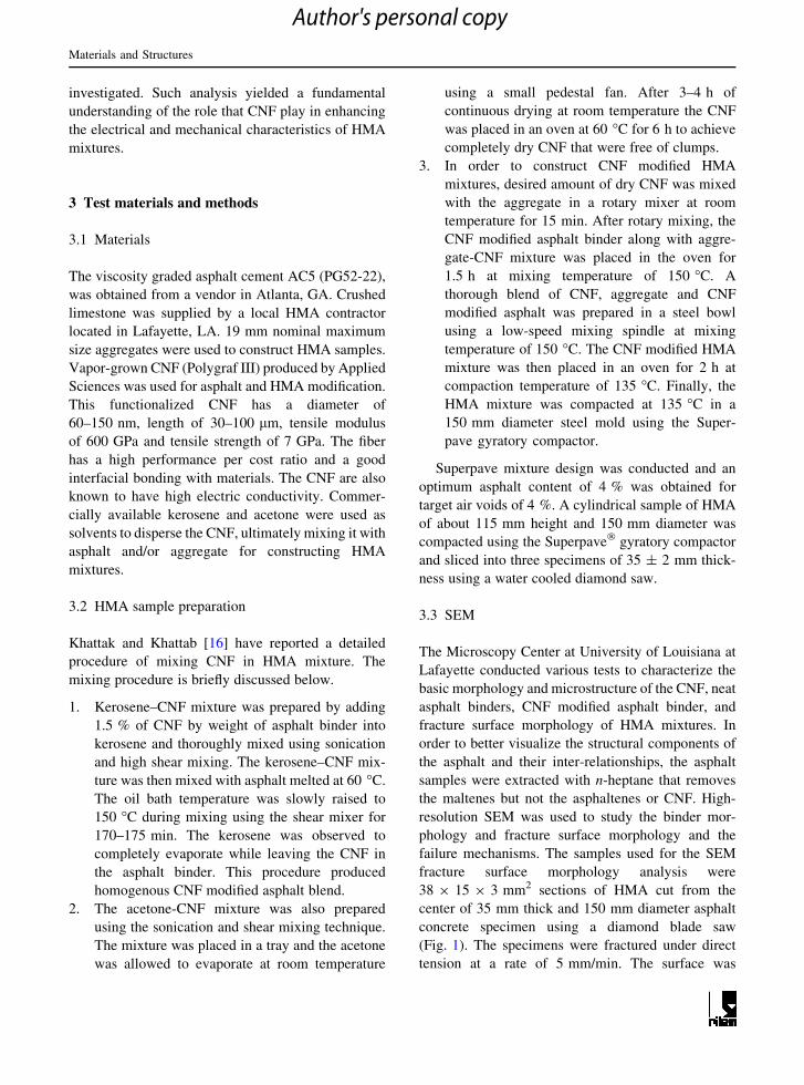
3.2 HMA sample preparation
Khattak and Khattab [16] have reported a detailed
procedure of mixing CNF in HMA mixture. The
mixing procedure is briefly discussed below.
1. Kerosene–CNF mixture was prepared by adding
1.5 % of CNF by weight of asphalt binder into
kerosene and thoroughly mixed using sonication
and high shear mixing. The kerosene–CNF mix-
ture was then mixed with asphalt melted at 60 �C.
The oil bath temperature was slowly raised to
150 �C during mixing using the shear mixer for
170–175 min. The kerosene was observed to
completely evaporate while leaving the CNF in
the asphalt binder. This procedure produced
homogenous CNF modified asphalt blend.
2. The acetone-CNF mixture was also prepared
using the sonication and shear mixing technique.
The mixture was placed in a tray and the acetone
was allowed to evaporate at room temperature
using a small pedestal fan. After 3–4 h of
continuous drying at room temperature the CNF
was placed in an oven at 60 �C for 6 h to achieve
completely dry CNF that were free of clumps.
3. In order to construct CNF modified HMA
mixtures, desired amount of dry CNF was mixed
with the aggregate in a rotary mixer at room
temperature for 15 min. After rotary mixing, the
CNF modified asphalt binder along with aggre-
gate-CNF mixture was placed in the oven for
1.5 h at mixing temperature of 150 �C. A
thorough blend of CNF, aggregate and CNF
modified asphalt was prepared in a steel bowl
using a low-speed mixing spindle at mixing
temperature of 150 �C. The CNF modified HMA
mixture was then placed in an oven for 2 h at
compaction temperature of 135 �C. Finally, the
HMA mixture was compacted at 135 �C in a
150 mm diameter steel mold using the Super-
pave gyratory compactor.
Superpave mixture design was conducted and an
optimum asphalt content of 4 % was obtained for
target air voids of 4 %. A cylindrical sample of HMA
of about 115 mm height and 150 mm diameter was
compacted using the Superpave� gyratory compactor
and sliced into three specimens of 35 ± 2 mm thick-
ness using a water cooled diamond saw.
3.3 SEM
The Microscopy Center at University of Louisiana at
Lafayette conducted various tests to characterize the
basic morphology and microstructure of the CNF, neat
asphalt binders, CNF modified asphalt binder, and
fracture surface morphology of HMA mixtures. In
order to better visualize the structural components of
the asphalt and their inter-relationships, the asphalt
samples were extracted with n-heptane that removes
the maltenes but not the asphaltenes or CNF. High-
resolution SEM was used to study the binder mor-
phology and fracture surface morphology and the
failure mechanisms. The samples used for the SEM
fracture surface morphology analysis were
38 9 15 9 3 mm2 sections of HMA cut from the
center of 35 mm thick and 150 mm diameter asphalt
concrete specimen using a diamond blade saw
(Fig. 1). The specimens were fractured under direct
tension at a rate of 5 mm/min. The surface was
Materials and Structures
Author's personal copy
examine under 15 kV of energy at various magnifica-
tion factors such as 2000, 6000, 14000, 18000 and
22,000, to understand the morphology and micro-
structure of CNF modified HMA mixtures. Specimens
were tested with and without gold coating. After
specimens were placed on a small aluminum stub, a
gold sputter thin coating of 0.6 nm was applied at
room temperature using the electron microscopy
sciences system. The gold coating reduces the SEM
beam damages, reduces specimen charging, and
improve secondary electron emission along with edge
resolution.
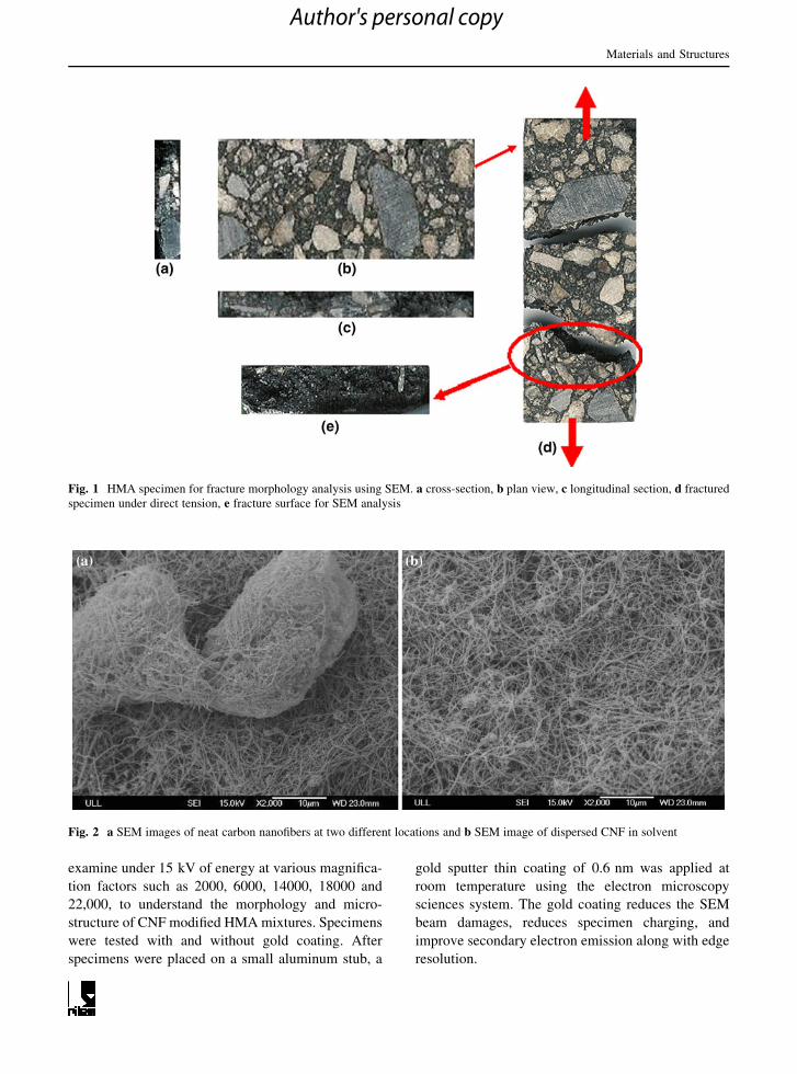
Fig. 1 HMA specimen for fracture morphology analysis using SEM. a cross-section, b plan view, c longitudinal section, d fractured
specimen under direct tension, e fracture surface for SEM analysis
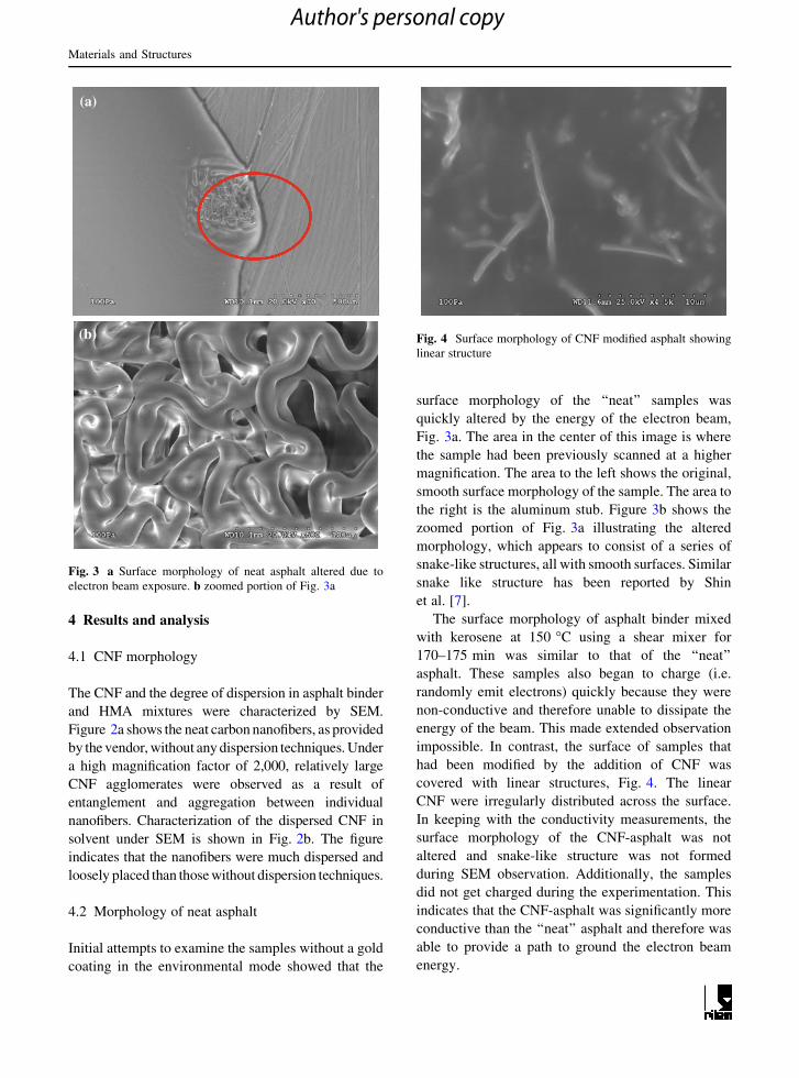
Fig. 2 a SEM images of neat carbon nanofibers at two different locations and b SEM image of dispersed CNF in solvent
Materials and Structures
Author's personal copy
4 Results and analysis
4.1 CNF morphology
The CNF and the degree of dispersion in asphalt binder
and HMA mixtures were characterized by SEM.
Figure 2a shows the neat carbon nanofibers, as provided
by the vendor, without any dispersion techniques. Under
a high magnification factor of 2,000, relatively large
CNF agglomerates were observed as a result of
entanglement and aggregation between individual
nanofibers. Characterization of the dispersed CNF in
solvent under SEM is shown in Fig. 2b. The figure
indicates that the nanofibers were much dispersed and
loosely placed than those without dispersion techniques.
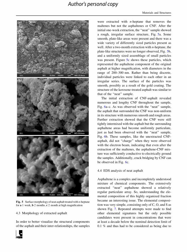
4.2 Morphology of neat asphalt
Initial attempts to examine the samples without a gold
coating in the environmental mode showed that the
surface morphology of the ‘‘neat’’ samples was
quickly altered by the energy of the electron beam,
Fig. 3a. The area in the center of this image is where
the sample had been previously scanned at a higher
magnification. The area to the left shows the original,
smooth surface morphology of the sample. The area to
the right is the aluminum stub. Figure 3b shows the
zoomed portion of Fig. 3a illustrating the altered
morphology, which appears to consist of a series of
snake-like structures, all with smooth surfaces. Similar
snake like structure has been reported by Shin
et al. [7].
The surface morphology of asphalt binder mixed
with kerosene at 150 �C using a shear mixer for
170–175 min was similar to that of the ‘‘neat’’
asphalt. These samples also began to charge (i.e.
randomly emit electrons) quickly because they were
non-conductive and therefore unable to dissipate the
energy of the beam. This made extended observation
impossible. In contrast, the surface of samples that
had been modified by the addition of CNF was
covered with linear structures, Fig. 4. The linear
CNF were irregularly distributed across the surface.
In keeping with the conductivity measurements, the
surface morphology of the CNF-asphalt was not
altered and snake-like structure was not formed
during SEM observation. Additionally, the samples
did not get charged during the experimentation. This
indicates that the CNF-asphalt was significantly more
conductive than the ‘‘neat’’ asphalt and therefore was
able to provide a path to ground the electron beam
energy.
(a)
(b)
Fig. 3 a Surface morphology of neat asphalt altered due to
electron beam exposure. b zoomed portion of Fig. 3a
Fig. 4 Surface morphology of CNF modified asphalt showing
linear structure
Materials and Structures
Author's personal copy
4.3 Morphology of extracted asphalt
In order to better visualize the structural components
of the asphalt and their inter-relationships, the samples
were extracted with n-heptane that removes the
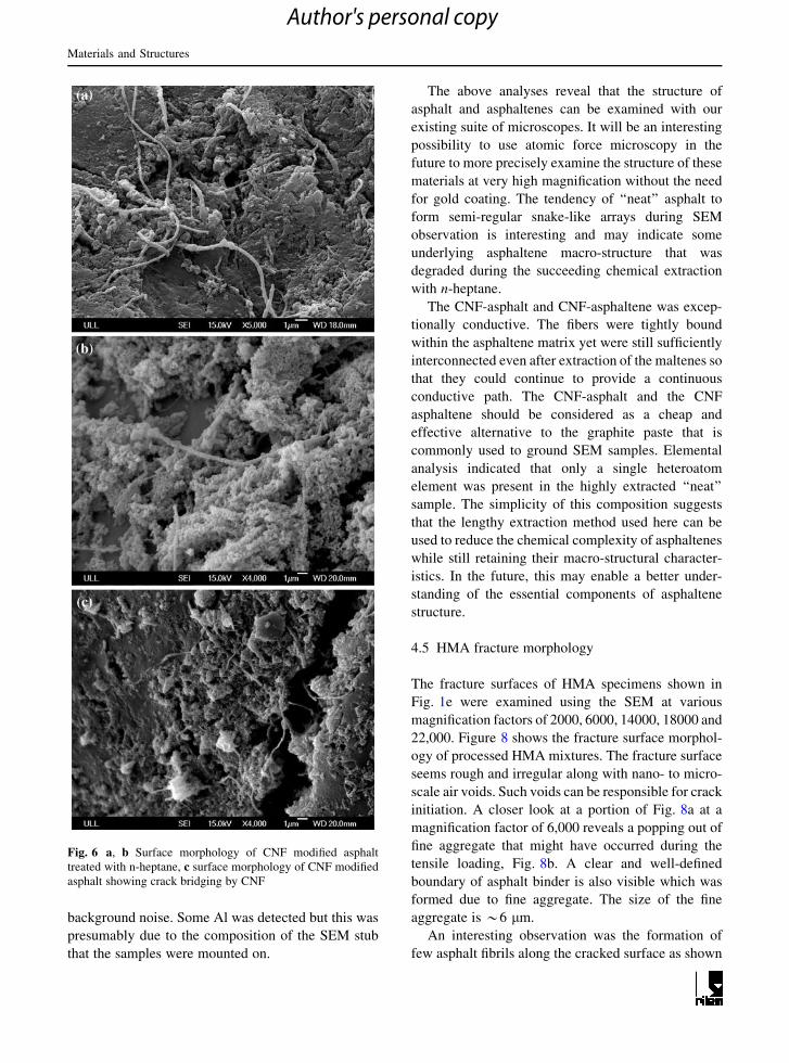
maltenes but not the asphaltenes or CNF. After the
initial one-week extraction, the ‘‘neat’’ sample showed
a rough, irregular surface structure, Fig. 5a. Some
smooth, plate-like areas were present and there was a
wide variety of differently sized particles present as
well. After a two-month extraction with n-heptane, the
plate-like structures were no longer observed, Fig. 5b,
and a uniformly sized assemblage of small particles
was present. Figure 5c shows these particles, which
represented the asphaltene component of the original
asphalt at higher magnification, with diameters in the
range of 200–300 nm. Rather than being discrete,
individual particles were linked to each other in an
irregular series. The surface of the particles was
smooth, possibly as a result of the gold coating. The
structure of the kerosene-treated asphalt was similar to
that of the ‘‘neat’’ sample.
The initial extraction of CNF-asphalt revealed
numerous and lengthy CNF throughout the sample,
Fig. 6a–c. As was observed with the ‘‘neat’’ sample,
the asphalt that surrounded the CNF was non-uniform
in its structure with numerous smooth and rough areas.
Further extraction showed that the CNF were still
tightly intermixed with the asphalt but the surrounding
asphaltene areas had become uniformly particulate,
just as had been observed with the ‘‘neat’’ sample,
Fig. 6b. These samples, like the unextracted CNF-
asphalt, did not ‘‘charge’’ when they were observed
with the electron beam, indicating that even after the
extraction of the maltenes, the asphaltene-CNF mix-
ture was sufficiently conductive to electrically ground
the samples. Additionally, crack bridging by CNF can
be observed in Fig. 6c.
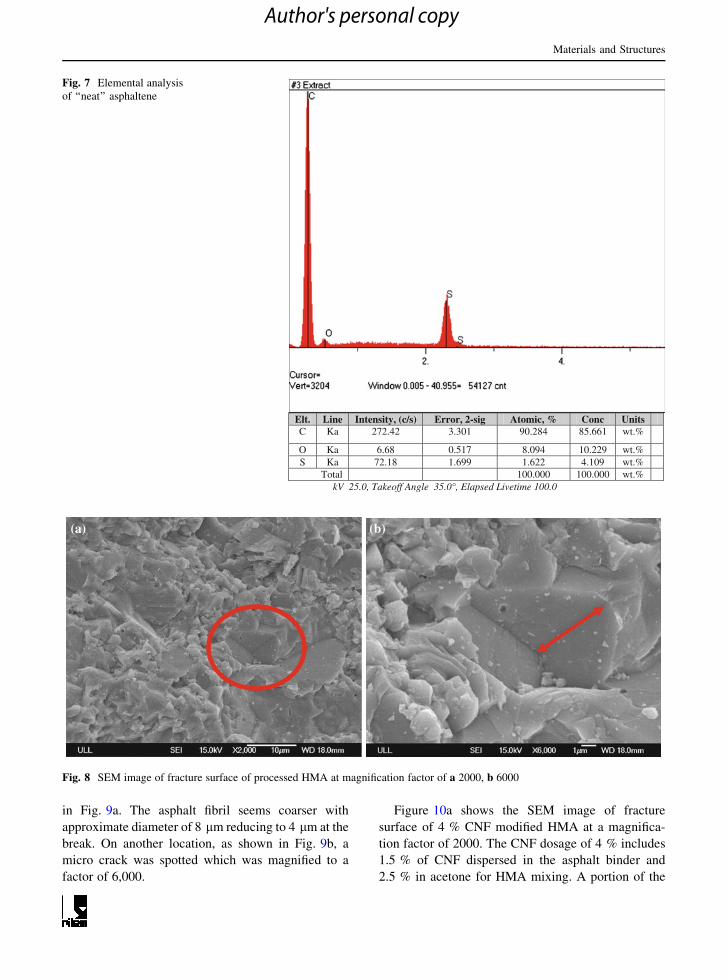
4.4 EDS analysis of neat asphalt
Asphaltene is a complex and incompletely understood
mixture of chemical components. The extensively
extracted ‘‘neat’’ asphaltene showed a relatively
regular particulate array. So, understanding the ele-
mental composition of this highly organized fraction
became an interesting issue. The elemental composi-
tion was very simple, consisting only of C, O, and S as
shown Fig. 7. Repeated attempts were made to find
other elemental signatures but the only possible
candidates were present in concentrations that were
at least a decade below the nominal detection limit of
0.1 % and thus had to be considered as being due to
Fig. 5 Surface morphology of neat asphalt treated with n-heptane
for a 1 week, b 2 months, c 2 month at high magnification
Materials and Structures
Author's personal copy
background noise. Some Al was detected but this was
presumably due to the composition of the SEM stub
that the samples were mounted on.
The above analyses reveal that the structure of
asphalt and asphaltenes can be examined with our
existing suite of microscopes. It will be an interesting
possibility to use atomic force microscopy in the
future to more precisely examine the structure of these
materials at very high magnification without the need
for gold coating. The tendency of ‘‘neat’’ asphalt to
form semi-regular snake-like arrays during SEM
observation is interesting and may indicate some
underlying asphaltene macro-structure that was
degraded during the succeeding chemical extraction
with n-heptane.
The CNF-asphalt and CNF-asphaltene was excep-
tionally conductive. The fibers were tightly bound
within the asphaltene matrix yet were still sufficiently
interconnected even after extraction of the maltenes so
that they could continue to provide a continuous
conductive path. The CNF-asphalt and the CNF
asphaltene should be considered as a cheap and
effective alternative to the graphite paste that is
commonly used to ground SEM samples. Elemental
analysis indicated that only a single heteroatom
element was present in the highly extracted ‘‘neat’’
sample. The simplicity of this composition suggests
that the lengthy extraction method used here can be
used to reduce the chemical complexity of asphaltenes
while still retaining their macro-structural character-
istics. In the future, this may enable a better under-
standing of the essential components of asphaltene
structure.
4.5 HMA fracture morphology
The fracture surfaces of HMA specimens shown in
Fig. 1e were examined using the SEM at various
magnification factors of 2000, 6000, 14000, 18000 and
22,000. Figure 8 shows the fracture surface morphol-
ogy of processed HMA mixtures. The fracture surface
seems rough and irregular along with nano- to micro-
scale air voids. Such voids can be responsible for crack
initiation. A closer look at a portion of Fig. 8a at a
magnification factor of 6,000 reveals a popping out of
fine aggregate that might have occurred during the
tensile loading, Fig. 8b. A clear and well-defined
boundary of asphalt binder is also visible which was
formed due to fine aggregate. The size of the fine
aggregate is *6 lm.
An interesting observation was the formation of
few asphalt fibrils along the cracked surface as shown
Fig. 6 a, b Surface morphology of CNF modified asphalt
treated with n-heptane, c surface morphology of CNF modified
asphalt showing crack bridging by CNF
Materials and Structures
Author's personal copy
in Fig. 9a. The asphalt fibril seems coarser with
approximate diameter of 8 lm reducing to 4 lm at the
break. On another location, as shown in Fig. 9b, a
micro crack was spotted which was magnified to a
factor of 6,000.
Figure 10a shows the SEM image of fracture
surface of 4 % CNF modified HMA at a magnifica-
tion factor of 2000. The CNF dosage of 4 % includes
1.5 % of CNF dispersed in the asphalt binder and
2.5 % in acetone for HMA mixing. A portion of the
Elt. Line Intensity, (c/s) Error, 2-sig Atomic, % Conc UnitsC Ka 272.42 3.301 90.284 85.661 wt.%
O Ka 6.68 0.517 8.094 10.229 wt.%S Ka 72.18 1.699 1.622 4.109 wt.%
Total 100.000 100.000 wt.%kV 25.0, Takeoff Angle 35.0°, Elapsed Livetime 100.0
Fig. 7 Elemental analysis
of ‘‘neat’’ asphaltene
(a) (b)
Fig. 8 SEM image of fracture surface of processed HMA at magnification factor of a 2000, b 6000
Materials and Structures
Author's personal copy
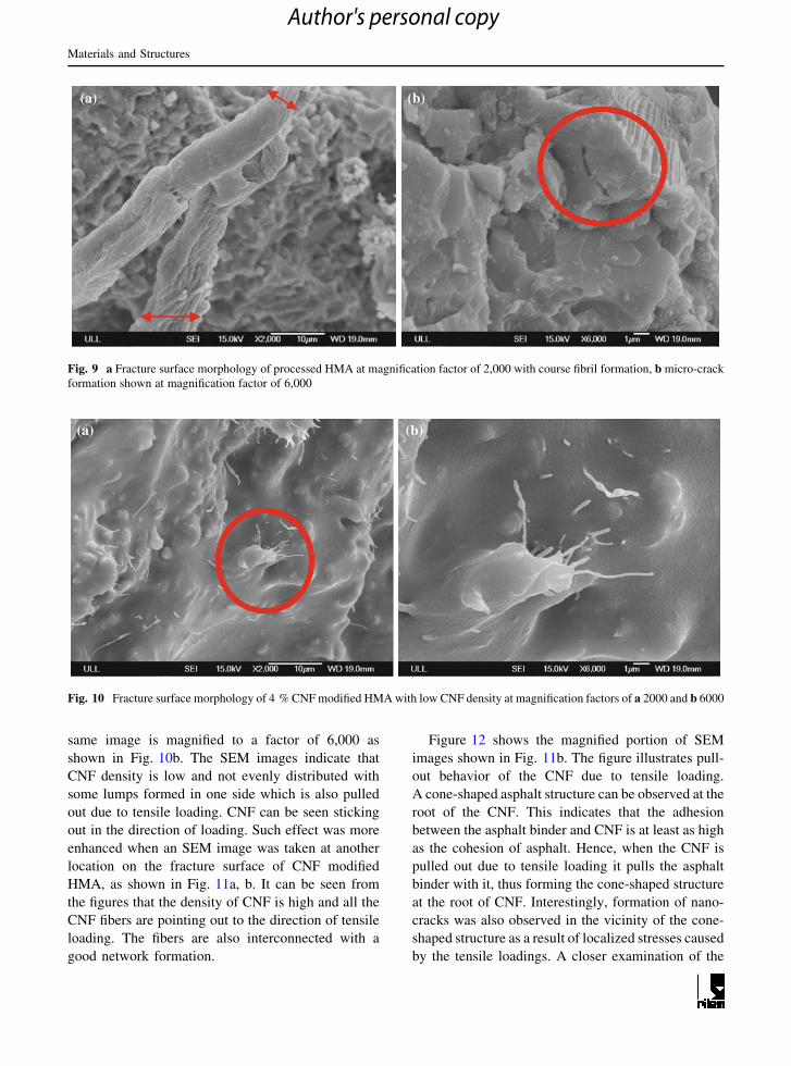
same image is magnified to a factor of 6,000 as
shown in Fig. 10b. The SEM images indicate that
CNF density is low and not evenly distributed with
some lumps formed in one side which is also pulled
out due to tensile loading. CNF can be seen sticking
out in the direction of loading. Such effect was more
enhanced when an SEM image was taken at another
location on the fracture surface of CNF modified
HMA, as shown in Fig. 11a, b. It can be seen from
the figures that the density of CNF is high and all the
CNF fibers are pointing out to the direction of tensile
loading. The fibers are also interconnected with a
good network formation.
Figure 12 shows the magnified portion of SEM
images shown in Fig. 11b. The figure illustrates pull-
out behavior of the CNF due to tensile loading.
A cone-shaped asphalt structure can be observed at the
root of the CNF. This indicates that the adhesion
between the asphalt binder and CNF is at least as high
as the cohesion of asphalt. Hence, when the CNF is
pulled out due to tensile loading it pulls the asphalt
binder with it, thus forming the cone-shaped structure
at the root of CNF. Interestingly, formation of nano-
cracks was also observed in the vicinity of the cone-
shaped structure as a result of localized stresses caused
by the tensile loadings. A closer examination of the
(a) (b)
Fig. 9 a Fracture surface morphology of processed HMA at magnification factor of 2,000 with course fibril formation, b micro-crack
formation shown at magnification factor of 6,000
(a) (b)
Fig. 10 Fracture surface morphology of 4 % CNF modified HMA with low CNF density at magnification factors of a 2000 and b 6000
Materials and Structures
Author's personal copy
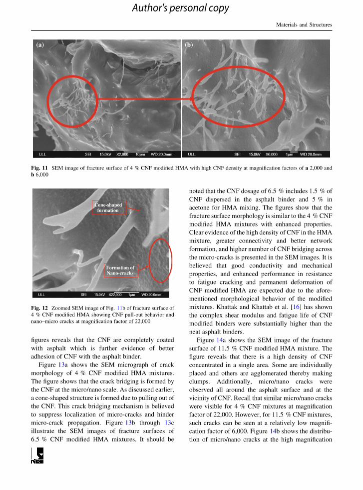
figures reveals that the CNF are completely coated
with asphalt which is further evidence of better
adhesion of CNF with the asphalt binder.
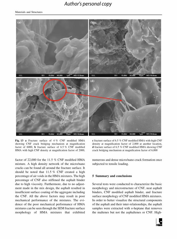
Figure 13a shows the SEM micrograph of crack
morphology of 4 % CNF modified HMA mixtures.
The figure shows that the crack bridging is formed by
the CNF at the micro/nano scale. As discussed earlier,
a cone-shaped structure is formed due to pulling out of
the CNF. This crack bridging mechanism is believed
to suppress localization of micro-cracks and hinder
micro-crack propagation. Figure 13b through 13c
illustrate the SEM images of fracture surfaces of
6.5 % CNF modified HMA mixtures. It should be
noted that the CNF dosage of 6.5 % includes 1.5 % of
CNF dispersed in the asphalt binder and 5 % in
acetone for HMA mixing. The figures show that the
fracture surface morphology is similar to the 4 % CNF
modified HMA mixtures with enhanced properties.
Clear evidence of the high density of CNF in the HMA
mixture, greater connectivity and better network
formation, and higher number of CNF bridging across
the micro-cracks is presented in the SEM images. It is
believed that good conductivity and mechanical
properties, and enhanced performance in resistance
to fatigue cracking and permanent deformation of
CNF modified HMA are expected due to the afore-
mentioned morphological behavior of the modified
mixtures. Khattak and Khattab et al. [16] has shown
the complex shear modulus and fatigue life of CNF
modified binders were substantially higher than the
neat asphalt binders.
Figure 14a shows the SEM image of the fracture
surface of 11.5 % CNF modified HMA mixture. The
figure reveals that there is a high density of CNF
concentrated in a single area. Some are individually
placed and others are agglomerated thereby making
clumps. Additionally, micro/nano cracks were
observed all around the asphalt surface and at the
vicinity of CNF. Recall that similar micro/nano cracks
were visible for 4 % CNF mixtures at magnification
factor of 22,000. However, for 11.5 % CNF mixtures,
such cracks can be seen at a relatively low magnifi-
cation factor of 6,000. Figure 14b shows the distribu-
tion of micro/nano cracks at the high magnification
(a) (b)
Fig. 11 SEM image of fracture surface of 4 % CNF modified HMA with high CNF density at magnification factors of a 2,000 and
b 6,000
Formation of Nano-cracks
Cone-shaped formation
Fig. 12 Zoomed SEM image of Fig. 11b of fracture surface of
4 % CNF modified HMA showing CNF pull-out behavior and
nano–micro cracks at magnification factor of 22,000
Materials and Structures
Author's personal copy
factor of 22,000 for the 11.5 % CNF modified HMA
mixture. A high density network of the micro/nano
cracks can be found all around the fracture surface. It
should be noted that 11.5 % CNF created a high
percentage of air voids in the HMA mixtures. The high
percentage of CNF also stiffened the asphalt binder
due to high viscosity. Furthermore, due to no adjust-
ment made in the mix design, the asphalt resulted in
insufficient surface coating of the aggregate including
the CNF. All the above factors may result in poor
mechanical performance of the mixtures. The evi-
dence of the poor mechanical performance of HMA
mixtures can be seen through the SEM fracture surface
morphology of HMA mixtures that exhibited
numerous and dense micro/nano crack formation once
subjected to tensile loading.
5 Summary and conclusions
Several tests were conducted to characterize the basic
morphology and microstructure of CNF, neat asphalt
binders, CNF modified asphalt binder, and fracture
surface morphology of CNF modified HMA mixtures.
In order to better visualize the structural components
of the asphalt and their inter-relationships, the asphalt
samples were extracted with n-heptane that removes
the maltenes but not the asphaltenes or CNF. High-
(a) (b)
(c) (d)
Fig. 13 a Fracture surface of 4 % CNF modified HMA
showing CNF crack bridging mechanism at magnification
factor of 6000, b fracture surface of 6.5 % CNF modified
HMA with high CNF density at magnification factor of 2000,
c fracture surface of 6.5 % CNF modified HMA with high CNF
density at magnification factor of 2,000 at another location,
d fracture surface of 6.5 % CNF modified HMA showing CNF
crack bridging mechanism at magnification factor of 6,000
Materials and Structures
Author's personal copy

resolution SEM was used to study the binder mor-
phology and fracture surface morphology and the
failure mechanisms. It was observed that binder
morphology of CNF modified asphalt binders indi-
cated a well distributed and interconnected CNF
network. The fibers were bridging across the cracks
and uniformly coated with asphalt, exhibiting better
adhesion between the CNF and asphalt binder. The
CNF-asphalt and CNF-asphaltene was exceptionally
conductive under the SEM electron beam. The fibers
were tightly bound within the asphaltene matrix yet
were still sufficiently interconnected even after
extraction of the maltenes so that they could continue
to provide a continuous conductive path.
The examination of the fracture morphology of
HMA mixtures revealed that CNF density increased
with the increase in CNF dosage. The CNF fibers
established a good network and showed high connec-
tivity. Fiber pull-out behavior under tensile loading as
observed in the SEM demonstrated a cone-shaped
asphalt structure formation at the root of the CNF. This
indicates that the adhesion between the asphalt binder
and CNF is at least as high as the cohesion strength of
the asphalt. Furthermore, the CNF is completely
coated with asphalt which was an evidence of better
adhesion of CNF with asphalt binder. SEM images of
crack morphology also showed that CNF were pulled
out in the direction of tensile loading and exhibited
crack bridging at micro/nano scale. This crack bridg-
ing mechanism is believed to suppress the localization
of micro-cracks and hinder micro-crack propagation.
In addition, formation of nano/micro cracks was
observed in the vicinity of cone-shaped structures as
a result of localized stresses caused by the tensile
loadings. The density of such cracks was significantly
high for the 11.5 % CNF dosage.
Acknowledgments The authors wish to express their sincere
thanks to the University of Louisiana at Lafayette and the
Louisiana Transportation Research Center-Transportation
Innovation for Research Exploration (TIRE) program for their
financial support.
References
1. Roberts FL, Kandhal PS, Brown ER, Lee DY, Kennedy TW
(1996) Hot mix asphalt materials, mixture design, and
construction. NAPA Education Foundation, Lanham
2. Xue Y, Wu S, Hou H, Jin Z (2006) Experimental investi-
gation of basic oxygen furnace slag used as aggregate in
asphalt mixture. J Hazard Mater 138(2):261–268
3. Liu H, Huang J (2005) Reactive thermal soray if TiC–Fe
composite coating by using asphalt as carbonaceous pre-
cursor. J Mater Sci 40:4149–4151
4. Shen DH, Wu CM, Du JC (2009) Laboratory investigation
of basic oxygen furnace slag for substitution of aggregate in
porous asphalt mixture. Constr Build Mater 23(1):453–461
5. Castro M, Sanchez JA (2006) Fatigue and healing of asphalt
mixtures: discriminate analysis of fatigue curves. J Transp
Eng 132(2):114–121
6. Khattak MJ, Baladi GY (2004) Binder rheology, morphol-
ogy and adhesion effects on asphlat mixture. In: Proceed-
ings of the geo-institute conference on geotechnical
engineering for transportation projects, Geo-Trans, Los
Angeles
7. Shin EE, Bhurke A, Scott E, Rozveld S, Drzal L (1996)
Microstructure, morphology, and failure modes of polymer-
Formation of nano/micro-
cracks
(a)
(b)
Fig. 14 a SEM image of fracture surface of 11.5 % CNF
modified HMA showing CNF density and nano- and micro
cracks in asphalt binder at magnification factor of 6000, b SEM
image of fracture surface of 11.5 % CNF modified HMA
showing nano- and micro cracks around the CNF/asphalt
interface at magnification factor of 22,000
Materials and Structures
Author's personal copy
modified asphalts. Transportation Research Board, TRR
No. 1535, Washington DC
8. Sharma A, Kyotani T, Tomita A (2000) Comparison of
structural parameters of PF carbon from XRD and HRTEM
techniques. Carbon 38(14):1977–1984
9. Trejo F, Ancheyta J, Rana MS (2009) Structural charac-
terization of asphaltenes obtained from hydroprocessed
crude oils by SEM and TEM. Energy Fuels 23(1):429–439
10. Camacho-Bragado GA, Santiago P, Marin-Alamazo M,
Espinoza M, Romero ET, Murgich J, Rodriguez-Lugo V,
Jose-Yacaman M (2002) Fullerenic structures derived from
oil asphaltenes. Carbon 40:2761–2766
11. Chen H, Xu Q (2009) Experimental study of fibers in sta-
bilizing and reinforcing asphalt binder. Fuel 2009:1615–
1622
12. Wu S, Mo L, Shui Z, Chen Z (2005) Investigation of the
conductivity of asphalt concrete containing conductive
fillers. Carbon 43(7):1358–1363
13. Chen JS, Lin KY (2005) Mechanism and behavior of bitumen
strength reinforcement using fibers. J Mater Sci 40(1):87–95
14. Kim YR, Little DN, Burghardt RC (1991) SEM analysis on
fracture and healing of sand asphalt mixtures. J Mater Civ
Eng 3(2):14–153
15. Yeh PH, Nien YH, Chen JH, Chen WC, Chen JS (2005)
Thermal and rheological properties of maleated polypro-
pylene modified asphalt. Polym Eng Sci 45(8):1152
16. Khattak MJ, Khattab A, Rizvi HR, Zhang P (2012) The
impact of carbon nano-fiber modification on asphalt binder
rheology. Int J Constr Build Mater 30:257–264
Materials and Structures
Author's personal copy


