Embed Size (px)
Citation preview
1
Course Title: Microprocessor Based Process Control
Course Code: EE413
Answer The following Questions Stating the DI , AI , DO , sensors & actuator types
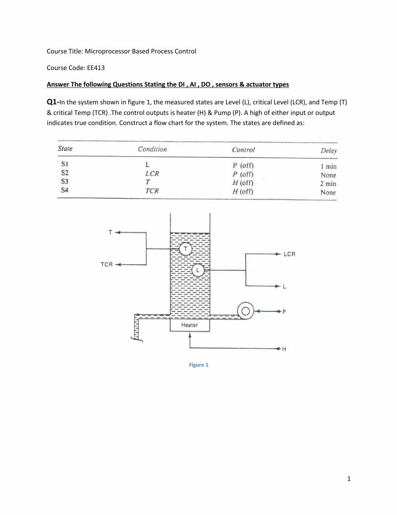
Q1-In the system shown in figure 1, the measured states are Level (L), critical Level (LCR), and Temp (T)
& critical Temp (TCR) .The control outputs is heater (H) & Pump (P). A high of either input or output
indicates true condition. Construct a flow chart for the system. The states are defined as:
Figure 1
2
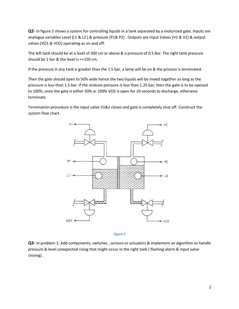
Q2- In figure 2 shows a system for controlling liquids in a tank separated by a motorized gate. Inputs are
analogue variables Level (L1 & L2 ) & pressure (P1& P2) . Outputs are Input Valves (V1 & V2) & output
valves (VO1 & VO2) operating as on and off.
The left tank should be at a level of 300 cm or above & a pressure of 0.5 Bar. The right tank pressure
should be 1 bar & the level is <=150 cm.
If the pressure in any tank is greater than the 1.5 bar, a lamp will be on & the process is terminated.
Then the gate should open to 50% wide hence the two liquids will be mixed together as long as the
pressure is less than 1.5 bar. If the mixture pressure is less than 1.25 bar, then the gate is to be opened
to 100%, once the gate is either 50% or 100% VO2 is open for 10 seconds to discharge, otherwise
terminate.
Termination procedure is the input valve V1&2 closes and gate is completely shut off. Construct the
system flow chart.
Figure 2
Q3- In problem 2, Add components, switches , sensors or actuators & implement an algorithm to handle
pressure & level unexpected rising that might occur in the right tank ( flashing alarm & input valve
closing) .
3
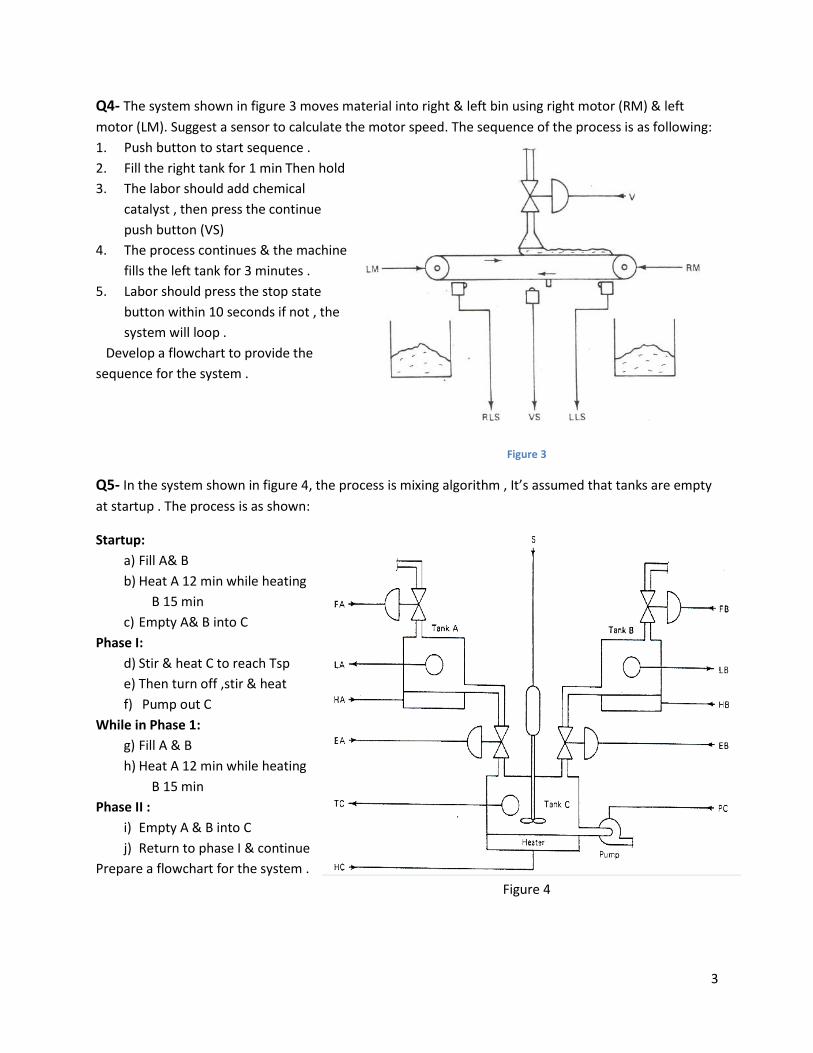
Q4- The system shown in figure 3 moves material into right & left bin using right motor (RM) & left
motor (LM). Suggest a sensor to calculate the motor speed. The sequence of the process is as following:
1. Push button to start sequence .
2. Fill the right tank for 1 min Then hold
3. The labor should add chemical
catalyst , then press the continue
push button (VS)
4. The process continues & the machine
fills the left tank for 3 minutes .
5. Labor should press the stop state
button within 10 seconds if not , the
system will loop .
Develop a flowchart to provide the
sequence for the system .
Figure 3
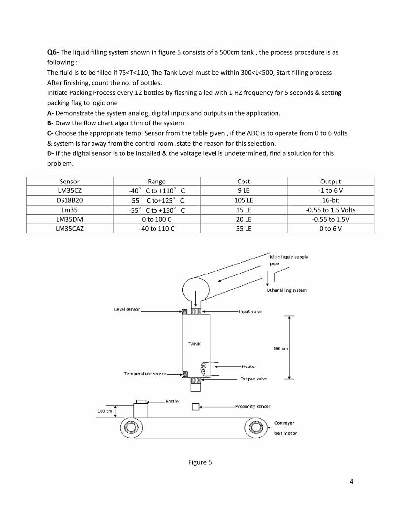
Q5- In the system shown in figure 4, the process is mixing algorithm , It’s assumed that tanks are empty
at startup . The process is as shown:
Startup:
a) Fill A& B
b) Heat A 12 min while heating
B 15 min
c) Empty A& B into C
Phase I:
d) Stir & heat C to reach Tsp
e) Then turn off ,stir & heat
f) Pump out C
While in Phase 1:
g) Fill A & B
h) Heat A 12 min while heating
B 15 min
Phase II :
i) Empty A & B into C
j) Return to phase I & continue
Prepare a flowchart for the system .
Figure 4
4
Q6- The liquid filling system shown in figure 5 consists of a 500cm tank , the process procedure is as
following :
The fluid is to be filled if 75<T<110, The Tank Level must be within 300<L<500, Start filling process
After finishing, count the no. of bottles.
Initiate Packing Process every 12 bottles by flashing a led with 1 HZ frequency for 5 seconds & setting
packing flag to logic one
A- Demonstrate the system analog, digital inputs and outputs in the application.
B- Draw the flow chart algorithm of the system.
C- Choose the appropriate temp. Sensor from the table given , if the ADC is to operate from 0 to 6 Volts
& system is far away from the control room .state the reason for this selection.
D- If the digital sensor is to be installed & the voltage level is undetermined, find a solution for this
problem.
Figure 5
Sensor Range Cost Output
LM35CZ -40°C to +110°C 9 LE -1 to 6 V
DS18B20 -55°C to+125°C 105 LE 16-bit
Lm35 -55°C to +150°C 15 LE -0.55 to 1.5 Volts
LM35DM 0 to 100 C 20 LE -0.55 to 1.5V
LM35CAZ -40 to 110 C 55 LE 0 to 6 V
5
Q7- A motor has the following inputs :
R1 = High , if RPM exceeds a low limit
R2 = High , if RPM exceeds a high limit
L = if the load is high
Outputs to control the motor are :
A1 =High , for armature drive 1
A2 = High , for armature drive 2
C= high to operate clutch & connect load
B= to apply friction brake
The following conditions are to be met for control
A1 : If the speed is below R1 or if the speed is above R1 & the load is low
A2 : If the speed is above R2 or if the speed is below R2& above R1 & the load is low
C : If the speed is above R2 or the speed is above R1 & the load is low
B : If the speed is above R2 & the load is low
Construct the logical equations & the flow chart for the system.
Course Title: Microprocessor Based Process Control
Course Code: EE413
Signal Conditioning & Analogue Control Applications
1- Develop an op-amp circuit that can provide an output voltage which is related to the input
voltage by: ���� = 3.4� + 5
2- Design a non-inverting amplifier with a voltage gain of 42.
3- A sensor outputs a range of 20 to 250mV. Design signal conditioning such that it becomes
0 to 5 V. The circuit must have very high impedance.
4- A sensor output a range of 0 to 1 V. It is required to transmit this signal as current ranging from
0 to 10mA, develop the required signal conditioning.
5- Use an integrator to produce a linear ramp voltage rising at 10V per millisecond. Determine the
required values R & C.
6- A sensor outputs a voltage from -2.4 to -1.1 V. For interface to an A/D, this needs to be 0 to
2.5volts. Develop the required signal conditioning.
7- Develop signal conditioning so an output voltage varies from 0 to 5 volts as the resistance varies
from 4 to 12kΩ.
8- Temperature is to be measured in the range of 250oC to 450
oC. The sensor is a resistance that
varies linearly from 280Ω to 1060Ω for this temperature range. Power dissipated in the sensor
must be kept below 5mW. Develop an analog signal conditioning circuit that provides a voltage
carrying linearly from -5 to +5 volts for this temperature range.
9- A process control system specifies that temperature should never exceed 160oC if the pressure
also exceeds 10Pa. Design an alarm to detect this condition, using temperature and pressure
transducers with transfer functions of 2.2mV/oC and 0.2V/Pa, respectively.
10- A sensor converts the liquid level in a tank to voltage according to the transfer function
(20mV/cm). A comparator is supposed to go high (5V) whenever the level becomes 50cm.
Splashing causes the level to fluctuate by ±3cm. Develop a hysteresis comparator to protect
against the effects of splashing.
11- A process involves moving speed, load weight, and rate of loading in a conveyor system. The
variables are provided as high (1) and low (0) levels for digital control. An alarm should be
initiated whenever any of the following occur:
a. Speed is low; both weight and loading rate are high
b. Speed is high; loading rate is low.
Find a Boolean equation describing the required alarm output. Let the variables be S for speed,
W for weight and R for loading rate.
12- Implement problem (11) with
a. AND/OR logic
b. NAND/NOR logic
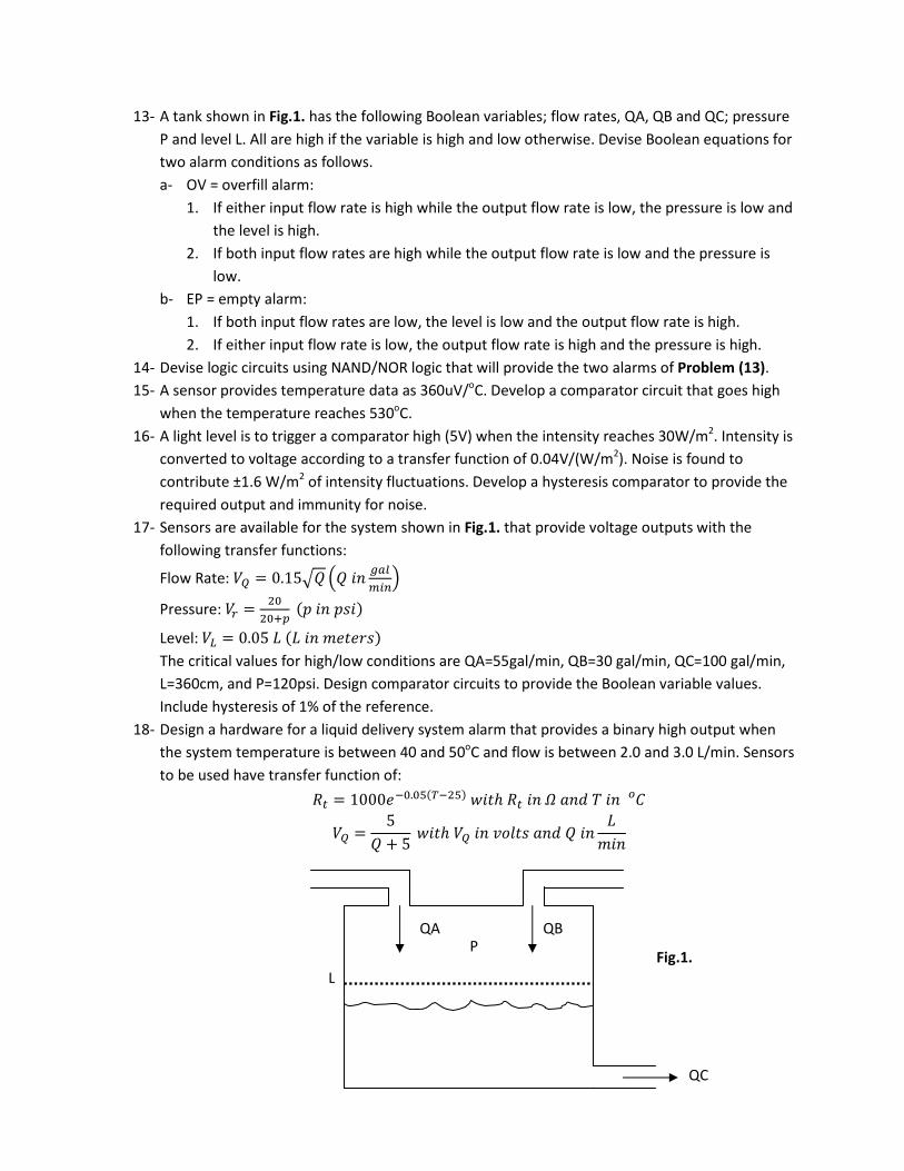
13- A tank shown in Fig.1. has the following Boolean variables; flow rates, QA, QB and QC; pressure
P and level L. All are high if the variable is high and low otherwise. Devise Boolean equations for
two alarm conditions as follows.
a- OV = overfill alarm:
1. If either input flow rate is high while the output flow rate is low, the pressure is low and
the level is high.
2. If both input flow rates are high while the output flow rate is low and the pressure is
low.
b- EP = empty alarm:
1. If both input flow rates are low, the level is low and the output flow rate is high.
2. If either input flow rate is low, the output flow rate is high and the pressure is high.
14- Devise logic circuits using NAND/NOR logic that will provide the two alarms of Problem (13).
15- A sensor provides temperature data as 360uV/oC. Develop a comparator circuit that goes high
when the temperature reaches 530oC.
16- A light level is to trigger a comparator high (5V) when the intensity reaches 30W/m2. Intensity is
converted to voltage according to a transfer function of 0.04V/(W/m2). Noise is found to
contribute ±1.6 W/m2 of intensity fluctuations. Develop a hysteresis comparator to provide the
required output and immunity for noise.
17- Sensors are available for the system shown in Fig.1. that provide voltage outputs with the
following transfer functions:
Flow Rate: � = 0.15�� �� �� �����
Pressure: �� = ������ ! �� !"�#
Level: �$ = 0.05 % % �� &'(')"#
The critical values for high/low conditions are QA=55gal/min, QB=30 gal/min, QC=100 gal/min,
L=360cm, and P=120psi. Design comparator circuits to provide the Boolean variable values.
Include hysteresis of 1% of the reference.
18- Design a hardware for a liquid delivery system alarm that provides a binary high output when
the system temperature is between 40 and 50oC and flow is between 2.0 and 3.0 L/min. Sensors
to be used have transfer function of:
*� = 1000'+�.�, -+�,# .�(ℎ *� �� 0 1�2 3 �� 4�
� = 5� + 5 .�(ℎ � �� 567(" 1�2 � �� %
&��
QA QB P
L
QC
Fig.1.
Course Title: Microprocessor Based Process ControlCourse Code: EE413
Digital Input/OutputWrite a program for the following applications:
1- Three LEDs operated by three switches.
2- Three LEDs operated by three on push buttons and three off push buttons.
3- Create a delay of 10us without using any header files.
4- Traffic lights going red for 5 secs, red & yellow for 1 sec, green for 5secs and yellow for 1sec.
5- Traffic lights going red for 5 secs, red & yellow for 1 sec. The traffic light will stay greenuntil a button is pressed. When the button is pressed the green light stays on for 5seconds more and then yellow for 1 sec.
6- Create a digital signal of 50Hz frequency.
7- If a button is pressed three times a LED is switched on, if the LED is on and the button ispressed twice then the LED is switched off.
Course Code: EE 413Course Title: Microprocessor Based Process Control
Digital Input / Output Applications
Select an application and write a program to operate the process on a microcontroller.
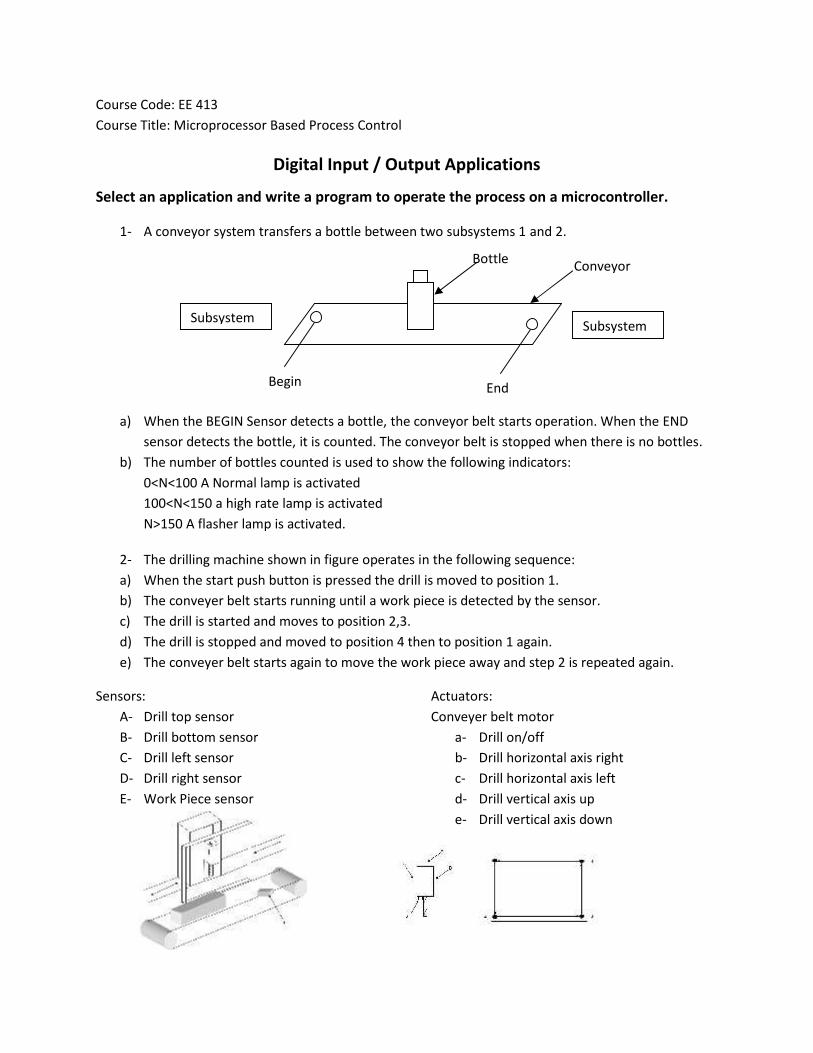
1- A conveyor system transfers a bottle between two subsystems 1 and 2.
a) When the BEGIN Sensor detects a bottle, the conveyor belt starts operation. When the ENDsensor detects the bottle, it is counted. The conveyor belt is stopped when there is no bottles.
b) The number of bottles counted is used to show the following indicators:0<N<100 A Normal lamp is activated100<N<150 a high rate lamp is activatedN>150 A flasher lamp is activated.
2- The drilling machine shown in figure operates in the following sequence:a) When the start push button is pressed the drill is moved to position 1.b) The conveyer belt starts running until a work piece is detected by the sensor.c) The drill is started and moves to position 2,3.d) The drill is stopped and moved to position 4 then to position 1 again.e) The conveyer belt starts again to move the work piece away and step 2 is repeated again.
Sensors:A- Drill top sensorB- Drill bottom sensorC- Drill left sensorD- Drill right sensorE- Work Piece sensor
Actuators:Conveyer belt motor
a- Drill on/offb- Drill horizontal axis rightc- Drill horizontal axis leftd- Drill vertical axis upe- Drill vertical axis down
Subsystem1
Subsystem2
Begin End
Bottle Conveyor
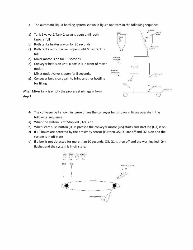
3- The automatic liquid bottling system shown in figure operates in the following sequence:
a) Tank 1 valve & Tank 2 valve is open until bothtanks is full
b) Both tanks heater are on for 20 secondsc) Both tanks output valve is open until Mixer tank is
fulld) Mixer motor is on for 15 seconds.e) Conveyer belt is on until a bottle is in front of mixer
outlet.f) Mixer outlet valve is open for 5 seconds.g) Conveyer belt is on again to bring another bottling
for filling.
When Mixer tank is empty the process starts again fromstep 1.
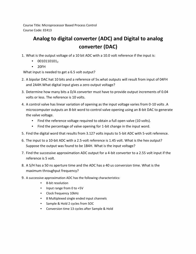
4- The conveyer belt shown in figure drives the conveyer belt shown in figure operate in thefollowing sequence:
a) When the system is off Stop led (Q2) is on.b) When start push button (I1) is pressed the conveyer motor (Q5) starts and start led (Q1) is on.c) If 10 boxes are detected by the proximity sensor (I3) then Q5, Q1 are off and Q2 is on and the
system is in off stated) If a box is not detected for more than 10 seconds, Q5, Q1 is then off and the warning led (Q4)
flashes and the system is in off state.
Course Title: Microprocessor Based Process ControlCourse Code: EE413
Analog to digital converter (ADC) and Digital to analogconverter (DAC)
1. What is the output voltage of a 10 bit ADC with a 10.0 volt reference if the input is: 00101101012
20FHWhat input is needed to get a 6.5 volt output?
2. A bipolar DAC hat 10 bits and a reference of 5v.what outputs will result from input of 04FHand 2A4H.What digital input gives a zero output voltage?
3. Determine how many bits a D/A converter must have to provide output increments of 0.04volts or less. The reference is 10 volts.
4. A control valve has linear variation of opening as the input voltage varies from 0-10 volts .Amicrocomputer outputs an 8-bit word to control valve opening using an 8-bit DAC to generatethe valve voltage.
Find the reference voltage required to obtain a full open valve (10 volts). Find the percentage of valve opening for 1-bit change in the input word.
5. Find the digital word that results from 3.127 volts inputs to 5-bit ADC with 5-volt reference.
6. The input to a 10-bit ADC with a 2.5-volt reference is 1.45 volt. What is the hex output?Suppose the output was found to be 1B4H. What is the input voltage?
7. Find the successive approximation ADC output for a 4-bit converter to a 2.55 volt input if thereference is 5 volt.
8. A S/H has a 50 ns aperture time and the ADC has a 40 us conversion time. What is themaximum throughput frequency?
9. A successive approximation ADC has the following characteristics: 8-bit resolution Input range from 0 to +5V Clock frequency 10kHz 8 Multiplexed single ended input channels Sample & Hold 2 cycles from SOC Conversion time 13 cycles after Sample & Hold
Determine:a) Total conversion time.b) Analog and digital range.c) Analog Resolution.d) The digital output for an input analog signal of 3Ve) If the converter is used to measure a sinusoidal voltage signal, determine the maximum
frequency for the sinusoidal signal.
10. A DAC has the following characteristics: 8-bit input -5 V reference
Determine:a) Analog resolutionb) Full scale outputc) Analog output for a digital input of 10101010d) The values of resistances in the DAC.
11. Natural gas is stored in a tank. Its temperature is monitored using a temperature sensor withsensitivity 10 mV/⁰C. The gas is stored at a temperature of 25⁰C, and due to pressure changes, the gastemperature may reach 100⁰C. The sensor is to be connected to a A/D converter with the followingcharacteristics:
Four channel multiplexer. Conversion time=20 μsec. Range of analog signal -5 to 5V.
(i) Design a signal conditioning circuit to adjust the sensor output voltage to be connectedto the A/D converter on the 3rd mux input.
(ii) Draw a flowchart for the A/D conversion and the following operating conditions:i. Normal Operation 5⁰C < T ≤ 70⁰C
ii. Warning 70⁰C < T ≤ 90⁰Ciii. Shut Down T > 90⁰C
Course Title: Microprocessor Based Process ControlCourse Code: EE413
Analogue input applications sheet1- If the microcontroller program is written in C programming language, explain how it can be
translated to machine code for the microcontroller.
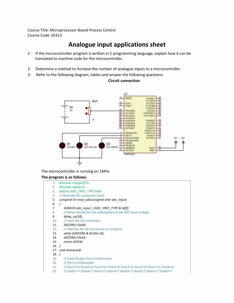
2- Determine a method to increase the number of analogue inputs to a microcontroller.3- Refer to the following diagram, tables and answer the following questions:
Circuit connection
The microcontroller is running on 1MHzThe program is as follows:
1. #include <mega32.h>2. #include <delay.h>3. #define ADC_VREF_TYPE 0x004. // Read the AD conversion result5. unsigned int read_adc(unsigned char adc_input)6. {7. ADMUX=adc_input | (ADC_VREF_TYPE & 0xff);8. // Delay needed for the stabilization of the ADC input voltage9. delay_us(10);10. // Start the AD conversion11. ADCSRA|=0x40;12. // Wait for the AD conversion to complete13. while ((ADCSRA & 0x10)==0);14. ADCSRA|=0x10;15. return ADCW;16. }17. void main(void)18. {19. // Input/Output Ports initialization20. // Port A initialization21. // Func7=In Func6=In Func5=In Func4=In Func3=In Func2=In Func1=In Func0=In22. // State7=T State6=T State5=T State4=T State3=T State2=T State1=T State0=T
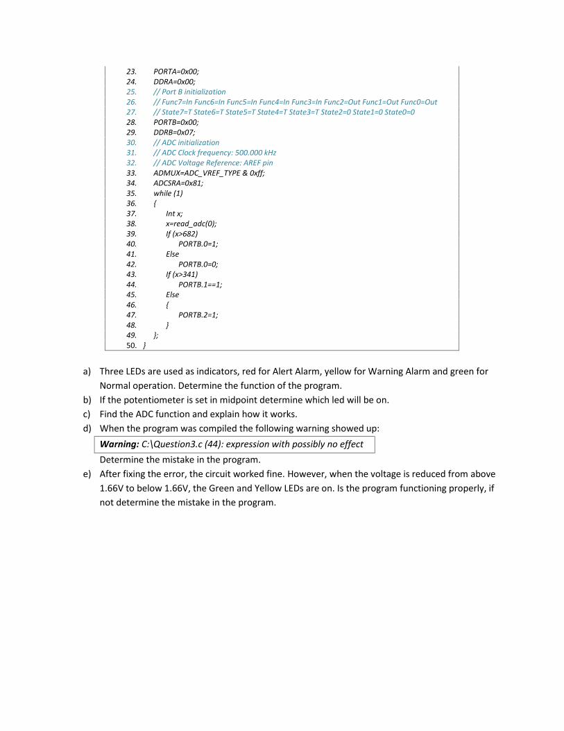
23. PORTA=0x00;24. DDRA=0x00;25. // Port B initialization26. // Func7=In Func6=In Func5=In Func4=In Func3=In Func2=Out Func1=Out Func0=Out27. // State7=T State6=T State5=T State4=T State3=T State2=0 State1=0 State0=028. PORTB=0x00;29. DDRB=0x07;30. // ADC initialization31. // ADC Clock frequency: 500.000 kHz32. // ADC Voltage Reference: AREF pin33. ADMUX=ADC_VREF_TYPE & 0xff;34. ADCSRA=0x81;35. while (1)36. {37. Int x;38. x=read_adc(0);39. If (x>682)40. PORTB.0=1;41. Else42. PORTB.0=0;43. If (x>341)44. PORTB.1==1;45. Else46. {47. PORTB.2=1;48. }49. };50. }
a) Three LEDs are used as indicators, red for Alert Alarm, yellow for Warning Alarm and green forNormal operation. Determine the function of the program.
b) If the potentiometer is set in midpoint determine which led will be on.c) Find the ADC function and explain how it works.d) When the program was compiled the following warning showed up:Warning: C:\Question3.c (44): expression with possibly no effectDetermine the mistake in the program.
e) After fixing the error, the circuit worked fine. However, when the voltage is reduced from above1.66V to below 1.66V, the Green and Yellow LEDs are on. Is the program functioning properly, ifnot determine the mistake in the program.
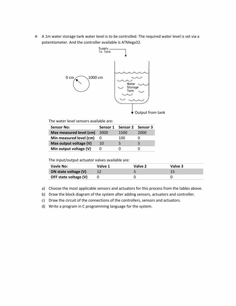
4- A 1m water storage tank water level is to be controlled. The required water level is set via apotentiometer. And the controller available is ATMega32.
The water level sensors available are:Sensor No: Sensor 1 Sensor 2 Sensor 3Max measured level (cm) 3000 1500 2000Min measured level (cm) 0 100 0Max output voltage (V) 10 5 5Min output voltage (V) 0 0 0
The input/output actuator valves available are:Vavle No: Valve 1 Valve 2 Valve 3ON state voltage (V) 12 5 15OFF state voltage (V) 0 0 0
a) Choose the most applicable sensors and actuators for this process from the tables above.b) Draw the block diagram of the system after adding sensors, actuators and controller.c) Draw the circuit of the connections of the controllers, sensors and actuators.d) Write a program in C programming language for the system.
0 cm 1000 cm
Output from tank
Course Title: Microprocessor Based Process ControlCourse Code: EE413
Analog Input1- A temperature sensor used in a process control system gives 5mV/oC. There are three indication
lamps used for operation indication:LED 1 ON: When temperature is greater than 50oCLED 2 ON: When temperature is greater than 100oCLED 3 ON: When temperature is greater than 250oC
2- Two pressure sensors are used to detect leakage in a pipeline system. Each sensor is placed ateach end of the pipeline. Two leds indicate which side is leaking. If the difference between thetwo pressures is more than 1kpa. The led equivalent to the leaking side is ON. The sensor usedoperates with 2.5V/kpa.
3- A level sensor is used to measure water level in a reservoir. The reservoir can hold up to 5m ofwater. When the water level falls below 4.5m an inlet valve is ON to let water in to the reservoiruntil it reaches 5m again. The level sensor used provides 0.8V/m with fluctuation of ±0.1m.
4- Convert an analog input to the microcontroller to a 8 bit binary output.
5- If an external ADC converter is used with the microcontroller determine the maximum numberchannels that can be used.
Q 1 ) Y=mx+b
Y=0 x=0
B= 0;
Y=m*1.25
Y= 1023 x=5 V
Y ? if x=1.25 V
Y= (1.25/5)*1023 = 255.7 ==256
M= 256/1.25 = 205;
Y(D) = 205* X (V)
Z © = Y* 1.0240
Z= 205*1.024 X
1.25 V = 250 C = 256 D
0 V 0 C 0 D
B = 0 ;
Y c = m x d
250 = m 256
M 0.9766
Y(C ) = 0.9766 * X (D)
Course Title: Microprocessor based process controlCourse Code: EE413
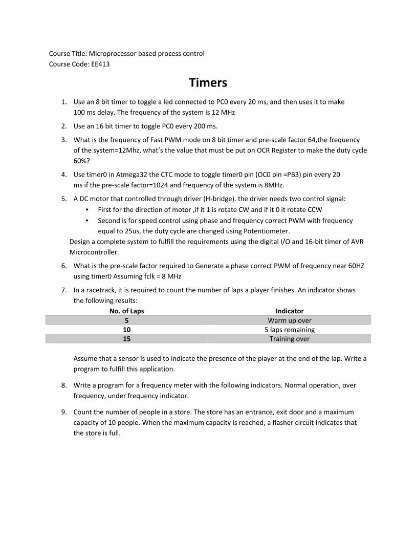
Timers1. Use an 8 bit timer to toggle a led connected to PC0 every 20 ms, and then uses it to make
100 ms delay. The frequency of the system is 12 MHz
2. Use an 16 bit timer to toggle PC0 every 200 ms.
3. What is the frequency of Fast PWM mode on 8 bit timer and pre-scale factor 64,the frequencyof the system=12Mhz, what’s the value that must be put on OCR Register to make the duty cycle60%?
4. Use timer0 in Atmega32 the CTC mode to toggle timer0 pin (OC0 pin =PB3) pin every 20ms if the pre-scale factor=1024 and frequency of the system is 8MHz.
5. A DC motor that controlled through driver (H-bridge). the driver needs two control signal: First for the direction of motor ,if it 1 is rotate CW and if it 0 it rotate CCW Second is for speed control using phase and frequency correct PWM with frequency
equal to 25us, the duty cycle are changed using Potentiometer.Design a complete system to fulfill the requirements using the digital I/O and 16-bit timer of AVRMicrocontroller.
6. What is the pre-scale factor required to Generate a phase correct PWM of frequency near 60HZusing timer0 Assuming fclk = 8 MHz
7. In a racetrack, it is required to count the number of laps a player finishes. An indicator showsthe following results:
No. of Laps Indicator5 Warm up over
10 5 laps remaining15 Training over
Assume that a sensor is used to indicate the presence of the player at the end of the lap. Write aprogram to fulfill this application.
8. Write a program for a frequency meter with the following indicators. Normal operation, overfrequency, under frequency indicator.
9. Count the number of people in a store. The store has an entrance, exit door and a maximumcapacity of 10 people. When the maximum capacity is reached, a flasher circuit indicates thatthe store is full.
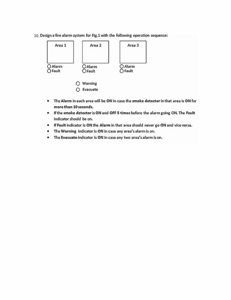
10.