Embed Size (px)
Citation preview

MicroChannel Heat Exchanger Installa�on Guidelines
Replacement Coil for Carrier 30RB & 30XA Chillers

Table of Contents
Introduction…………………………………… 3 Recommended Parts & Tools……………… 7 Safety & Microchannel Coil Handling……. 8Installation Guidelines………… …………... 9Fin/Tube Replacements……………………. 16Single Coil Replacement…………………… 16Maintenance & Care…………………………. 17Warranty……………………………………….. 18
2

3
Introduction
USA Coil & Air replacement condenser coils are an alternative for Carrier brand chillers, specifically for the Carrier 30RB and the Carrier 30XA. These replacement coils are designed as near perfect drop-in, with higher quality, longer life construction and Epoxy coated for improved corrosion protection.
Since the Carrier 30RB and 30XA chillers are equipped with either Fin/Tube or Microchannel Coils, USA Coil & Air's replacement coil can be used in either type of chiller coil replacement.
The USA Coil & Air WM2-83-41-378-EC model is designed as an alternative replacement coil for:• Microchannel coils manufactured by Delphi and others for Carrier• Fin/Tube coils manufactured by Carrier
What is different?There are several important USA Coil & Air microchannel coil features, based on field experience that make the design more robust and easier to install. These features allow the contractor and end user to replace damaged or failed condenser coils with an alternative solution, upgraded for longer life and to restore the Carrier chiller to operating condition.
1. Non-Automotive, industrial design with 25-30% Thicker tube walls2. Epoxy Coating for superior corrosion protection3. Lower Refrigerant Pressure drop for improved operation and oil return4. Built-in Mini-receiver (in lower header) to make it easier to charge5. Side Flange for drop in/slide in installation6. Equivalent Design & Performance
Notice to Installer & User:USA Coil & Air is a major U.S. manufacturer of Microchannel coils for the HVAC/R industry and provides coils to the replacement market and to OEM’s other than Carrier. USA Coil & Air's alternative replacement coils have not been endorsed by Carrier as a factory authorized part. All coil replacements should be performed by a trained and qualified HVAC/R Service Technician. Proper installation, procedures, handing of refrigerants, startup and operation of the equipment is the responsibility of the installing contractor and end user.Note: Carrier is a registered Trademark of Carrier Corporation, a subsidiary of United Technologies.
4
Introduction
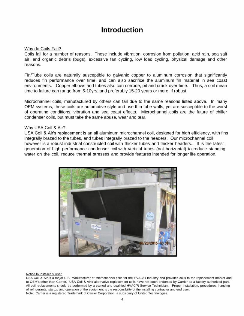
Why do Coils Fail?Coils fail for a number of reasons. These include vibration, corrosion from pollution, acid rain, sea salt air, and organic debris (bugs), excessive fan cycling, low load cycling, physical damage and other reasons.
Fin/Tube coils are naturally susceptible to galvanic copper to aluminum corrosion that significantly reduces fin performance over time, and can also sacrifice the aluminum fin material in sea coast environments. Copper elbows and tubes also can corrode, pit and crack over time. Thus, a coil mean time to failure can range from 5-10yrs, and preferably 15-20 years or more, if robust.
Microchannel coils, manufactured by others can fail due to the same reasons listed above. In many OEM systems, these coils are automotive style and use thin tube walls, yet are susceptible to the worst of operating conditions, vibration and sea coast effects. Microchannel coils are the future of chiller condenser coils, but must take the same abuse, wear and tear.
Why USA Coil & Air?USA Coil & Air's replacement is an all aluminum microchannel coil, designed for high efficiency, with fins integrally brazed to the tubes, and tubes integrally brazed to the headers. Our microchannel coil however is a robust industrial constructed coil with thicker tubes and thicker headers.. It is the latest generation of high performance condenser coil with vertical tubes (not horizontal) to reduce standing water on the coil, reduce thermal stresses and provide features intended for longer life operation.
Notice to Installer & User:USA Coil & Air is a major U.S. manufacturer of Microchannel coils for the HVAC/R industry and provides coils to the replacement market and to OEM’s other than Carrier. USA Coil & Air's alternative replacement coils have not been endorsed by Carrier as a factory authorized part. All coil replacements should be performed by a trained and qualified HVAC/R Service Technician. Proper installation, procedures, handing of refrigerants, startup and operation of the equipment is the responsibility of the installing contractor and end user.Note: Carrier is a registered Trademark of Carrier Corporation, a subsidiary of United Technologies.

5
Mounting Flange
1-1/8” RefrigerantInlet
7/8” Refrigerant Outlet
Coil Face with Vertical Tubes
Upper Header(with casing)
USA Coil & Air's Microchannel Replacement
Condenser Coils
Lower HeaderAnd Mini-Receiver
Center Face Plate
Design Working Pressure: 650psigMaximum Design Temperature: 250FRefrigerants: R410a, R134a & R407CApprovals: U.L. Listed

Product DrawingCARRIER Replacement Coils
Model: WM2-83-41-378-EC (E-Coated)
Overall Dimensions: 79.4”L x 4.0”W x 43.94”HConnections: 1-1/8”IDS Copper Inlet, 7/8”IDS Copper OutletMounting: Bolt-on Aluminum Mounting FlangeWeight: 80lbsNitrogen Charge: Rubber Plugs w/ 5-15psi N2 chargeEpoxy Coated (Required for Carrier Replacement Coils)
• Required in Industrial applications or within 50 miles of Sea Coast Environments.• Required in Urban or Rural areas with high pollution and acid rain• Required for replacement coils where the previously failed coil shows signs of
refrigerant oil spots or leaks on the coil, due to corrosion or thermal cycling.
• Epoxy Electrocoat, PPG Powercron Series; 0.001 Inch Nominal Coating Thickness• Black, Semi-gloss appearance
All dimensions in inches
6

7
Parts List & Recommended Tools (not provided by USA Coil & Air)
Parts List Per Coil:
Discharge lines: 2 feet of 1-1/8” ACR CopperTubing(1) 1-1/8” straight copper couplings(1) 1-1/8” copper 90 degree elbow
Liquid Lines:(1) ¾” Copper 90 degree elbows(1) 7/8” Copper 90 degree elbows(1) Copper 90 degree elbows street(1) 7/8” to ¾” copper reducers1 foot 7/8” ACR Copper Tubing 1 foot ¾” ACR Copper Tubing
(18) 5/16 Stainless Steel Self Tapping Screws (per coil)
Note: Copper piping & fittings may vary per Carrier model and for 30XA Models
Recommended Tools:
• Impact drill with hex drivers• Vacuum Pump & Refrigerant Recovery Equipment• 3/8” ratchet set• Refrigerant Gages• R410A Refrigerant & Scale• Oxy Acetylene Torch• Brazing Flux• Brazing rod for Copper Connections• Rags• Grease or Lubricant
USA Coil & Air's Replacement Coilsare individually packaged and shipped in a protective corrugated box. Multiple boxed coils arrive stacked on a pallet. (or crated for ocean export)

8
Safety & Microchannel Coil Handling
Upper Header
Lower Header
Inlet Copper Connection
Outlet Copper Connection
Mounting Flange
Coil Face
1. Only trained professionals and service mechanics shouldinstall, start up, and service this equipment.
2. Always wear proper PPE (Personal Protective Equipment), andfollow safe industry guidelines.
3. Always lift the coil using the upper and lower headers, or themounting flanges.
4. Always use two people to lift the coil. Each Coil Weighs 80lbs
5. Never lift the coil using the copper connections.
6. Contact with sharp objects on the coil face can cause apermanent leak. Use caution to protect the coil face fromdamage when handling and installing.

1. Turn off the chiller and turn off all electrical disconnects to the chiller
2. Recover the chiller’s refrigerant from the system in accordance withindustry procedures and regulations.
3. Using a socket wrench, remove the 6 nuts fastening the twodischarge line flanges and one liquid line flange from eachcondenser.
4. Once removed, cap off all three lines to mitigate moisture fromentering the system.
Installation Guidelines
Discharge Lines
Liquid Lines
9

10
4. Remove (9) 10MM Screws from each side of the coil, freeing the(black) coil casing from the chiller V frame.
Screw Locations: Top – 1, Bottom – 3, Side rail – 5
Top
Bottom
Side Rail
Installation Guidelines
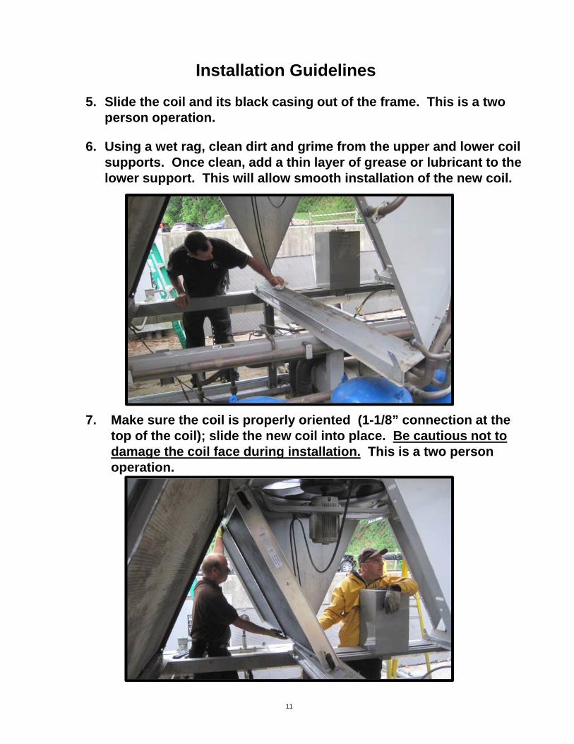
5. Slide the coil and its black casing out of the frame. This is a twoperson operation.
6. Using a wet rag, clean dirt and grime from the upper and lower coilsupports. Once clean, add a thin layer of grease or lubricant to thelower support. This will allow smooth installation of the new coil.
7. Make sure the coil is properly oriented (1-1/8” connection at thetop of the coil); slide the new coil into place. Be cautious not todamage the coil face during installation. This is a two personoperation.
11
Installation Guidelines

8. Using the existing holes in “V Panel” flanges, use new stainlesssteel 5/16” self tapping screws to secure the coil thru the newcoil’s flanges.
12
Installation Guides
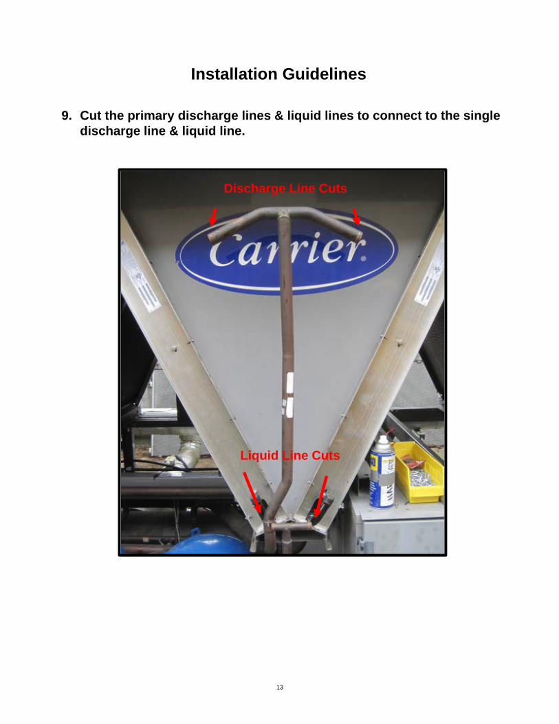
9. Cut the primary discharge lines & liquid lines to connect to the singledischarge line & liquid line.
Discharge Line Cuts
Liquid Line Cuts
13
Installation Guidelines

14
10.Using the refrigerant piping parts from the parts list, solder (braze)copper connections using Silver solder or Phos-Copper method.
Use wet rag on the Aluminum side of connections to protect the Al/Cu joint from overheating and damage to the Al/Cu joint.
Installation Guidelines
Use Wet Rag here

15
11.Leak check all connections and braze joints.
12.Re-charge the system using the original OEM’s recommendedrefrigerant charge quantity. With the chiller operating, adjust therefrigerant charge using site glass (minimal bubbles) andsubcooling at 5F to 10F.
Installation Guidelines

16
It is recommended to replace all coils in a refrigerant circuit at the same time.
If you do not replace every coil in a single refrigerant circuit, and our microchannel replacement coil(s) are installed in the same refrigerant circuit with the original OEM coils, a valve MUST be installed on the outlet of each replacement coil(s) to provide a method to balance the coil pressure drops. Without proper adjustment of this valve, liquid refrigerant may back up into the original OEM coil (higher pressure drop), versus the USA Coil & Air replacement coil (lower pressure drop).
If both USA Coil & Air replacement and OEM coils are mixed within a single circuit:
1. Purchase a manual inline type refrigeration valve with 3/4” connections.2. Install valve in the liquid line exiting the USA Coil & Air replacement coil.3. Leak check connections and charge system per step 11.4. With the system running, close valve ¼ turn and check site glass for bubbles.5. Repeat step 4 until the USA Coil & Air replacement coil shows 5F to 10F
subcooling and minimal bubbles in the site glass.6. Check condenser head pressure for normal operation.
Single Circuit Replacement
Manual Ball Type Refrigeration Valve – 3/4” Connections
Fin/Tube Coil Replacement(s)
If the Carrier 30RB or 30XA has Fin/Tube condensers, the Fin/Tube coil replacement using USA Coil & Air replacement coils should follow the same procedures listed in this installation guideline.
There is one primary difference: The chiller Electronic Expansion Valve (EV) control must be adjusted on the control board to increase the reaction time of the EV. This difference is normal for Fin/Tube versus Microchannel coils for these chillers, due to the lower charge and lower thermal mass of the microchannel coil. (This EV adjustment allows the chiller to operate properly and to not trip out on low evaporator or high head conditions during startup.)

17
Maintenance & Care
Routine inspection and general cleaning of the Microchannel coil(s) can prolongthe life of the coils and maintain the energy efficiency of the chiller.
1. Inspection and general cleaning is recommended annually, or morefrequently depending upon operating conditions, debris and scale buildup, both visible and microscopic.
2. Coil Cleaning.Routine cleaning of particulates from the coil can be performed with highpressure air.
Routine cleaning of particulates, dirt, grime, organic matter (bugs), andsalt buildup is highly recommended with a general garden hose or highpressure water, including using mild detergents.
Water pressure must be controlled to prevent damage to the fins and epoxycoating.
Avoid chemical cleaning.
3. Coil Protective Screen/ClothA coil filter or protective mesh cloth can also be used on the equipmentdesign, if cotton wood trees, large bugs or other debris is known orpresent.
4. Chiller Operation.Routinely inspect the chiller operation during peak loads and during lowambient loads for proper operation.
5. Repairs.If the coil face becomes moderately damaged, the coil fins can bemanually adjusted with a dental pick. If a tube is cut or breached, causinga leak, in most cases, the tube can be repaired using “REDEPOXY” brand repair kit, available from most local refrigerationwholesalers. DO NOT attempt a coil repair using tin, zinc or othersolders, since these will not work or bond with the coil materials.

18
Applies to USA Coil & Air Microchannel Coils
MANUFACTURER'S EXPRESS WARRANTY
USA Coil & Air warrants the unit identified above against failure caused by defects in materials and workmanship for five (5) years from the date of shipment by USA Coil & Air. This warranty includes all structural components, tubes, fins, headers and c onnections. Labor costs associated with !!!l'. repai r work performed under the terms of the warranty are NOT includ ed within the warranty. Damage caused by misuse of the product, including without limitation failure to properly install or maintain the product, is NOT covered by the warranty.
In addition to the unit warranty above, USA Coil & Air warrants the thermal performance of the unit as shown on the certified drawings delivered to the customer for a period of one-year from the date installation is completed in accordance with good engineering practices, but in no event shall such warranty period exceed eighteen (18) months from the date the unit is shipped by U SA Coil & Air. If after installation and start-up there is any question regarding thermal performance of the equipment, at the owner's request USA Coil & Air will send its engineers to the jobsite to conduct a performance test. This test may be observed by the owner and the consulting engineer or by their authorized r epresentatives. If the results of the evaluation show the equipment to be deficient, USA Coil & Air will make the necessary repairs or alterations to correct the deficiency subject to the limitations set forth below. If the e quipment is found to be performing in ac cordance wi th its certified cap acity, the own er wil l reimburse USA Coil & Air for all direct expenses incurred in connection with such performance test.
EXCLUSIONS
The above warranty shall not apply to any product that has been modified or repaired contrary to USA Coil & Air recommendations or generally accepted practices or procedures in the industry, or operated under conditions which may cause product failure. USA Coil & Air shall not be responsible for any costs associated with the product damage, loss or replacement due to freeze-up, improper water treatment, improper cleaning, fluid chemistry exceeding USA Coil & Air's recommendations, clogging and debris, fouling, corrosion, galvanic induced corrosion, vibration, thermal cycling, hydraulic shock, over-pressurization, compressor failure, system contamination, loss of protective coating (where applied) and any other operating or system condition which may cause product failure.
LIMITATION OF LIABILITY
THE SOLE REMEDY FOR BREACH OF THE EXPRESS WARRANTIES DESCRIBED HEREIN SHALL BE REPAIR OR REPLACEMENT OF THE EQUIPMENT BY USA COIL & AIR, OR REFUNDING THE PURCHASE PRICE SET FORTH ON THE PURCHASE ORDER. IT SHALL BE IN USA COIL & AIR'S SOLE DISCRETION AS TO WHETHER REP AIR, REPLACEMENT OR REFUND IS THE OFFERED REMEDY. IF USA COIL & AIR DECIDES TO MAKE REP AIRS, USA COIL & AIR HAS THE OPTION OF COMPLETING ALL NECESSARY REPAIRS ITSELF, OR AUTHORIZING A THIRD PARTY TO PERFORM SUCH REPAIRS AT USA COIL & AIR'S EXPENSE. USA COIL & AIR IS NOT RESPONSIBLE FOR ANY REPAIR WORK PERFORMED BY A TIDRD PARTY THAT EV APCO DID NOT PRE-APPROVE IN WRITING. USA COIL & AIR IS ONLY RESPONSIBLE FOR COSTS THAT PERTAIN TO REP AIR OR REPLACEMENT OF EQUIPMENT SUPPLIED BY COIL COMPANY (i.e., USA COIL & AIR IS NOT RESPONSIBLE FOR REPLACEMENT OR MODIFICATION OF PIPING OR "IN AND OUT" COSTS SUCH AS TIDRD PARTY LABOR, CRANE OR OTHER EQUIPMENT FEES).
NOTWITHSTANDING ANYTIDNG ELSE IN Tms DOCUMENT, USA COIL & AIR'S LIABILITY OF ANY KIND WHATSOEVER SHALL NOT EXCEED THE PURCHASE PRICE SET FORTH ON THE PURCHASE ORDER. UNDER NO CIRCUMSTANCES SHALL USA COIL & AIR BE LIABLE FOR LOST PROFITS, LOST SAVINGS, PERSONAL INJURIES, INCIDENTAL DAMAGES, ECONOMIC LOSS, REFRIGERANT LOSS, PRODUCT LOSS, PROPERTY DAMAGE, OR ANY OTHER CONSEQUENTIAL, INDIRECT, INCIDENTAL, OR PUNITIVE DAMAGES, EVEN IF USA COIL & AIR HAS BEEN ADVISED OF THE POSSIBILITY OF SUCH DAMAGES. In addition, USA Coil & Air shall not be responsible for any injuries or damages of any kind whatsoever under any theory of tort to the extent the injuries or damage are caused by misuse of the product by buyer or any third party.
DISCLAIMER OF IMPLIED WARRANTIES
OTHER THAN THE EXPRESS MANUFACTURER'S WARRANTY DESCRIBED HEREIN, THE UNIT IS SOLD "AS IS" AND THERE ARE NO OTHER WARRANTIES. USA COIL & AIR HEREBY DISCLAIMS AND EXCLUDES ALL IMPLIED WARRANTIES OF ANY KIND WHATSOEVER, INCLUDING WITHOUT LIMITATION WARRANTIES OF MERCHANTABILITY, THAT THE UNIT IS FIT FOR A PARTICULAR USE OR PURPOSE, THAT THE UNIT IS FIT FOR A PARTICULAR APPLICATION OR ENVIRONMENT, AND ANY WARRANTIES THAT MIGHT OTHERWISE ARISE OUT OF A COURSE OF DEALING BETWEEN THE PARTIES OR USAGE OF TRADE.


