Embed Size (px)
Citation preview

Dall·Kirkham Cassegrain
-300
INSTRUCTION MANUAL
TAKAHASHI

Thank you for purchasing Mewlon·300 Dall-Kirkham Cassegrain telescope.
The Mewlon·300 has been designed to be used lor high magnification tunar and planetary observation and deep sky Imaging In order to use the Mewlon-300 to the limit of Its capabililles, please read this instruction manual carefully alld understand ittholoughly before
using the instrument. Improper usage may cause malfunctions 01 dam· age to the instrument. Every Mewton-300 has been inspected thoroughly before shipl)ing: how·
ever, if you have noticed any defects with the Instrument, please contact your loc81 distributor a. soon 81 possible.
" I .&. WARNING ""
NEVER ATTEMPT TO OBSERVE THE SUN THROUGH
THIS TELESCOPE WITHOUT A FUll APERTURE SO
lAR FilTER DESIGNED FOR THIS PURPOSE. FAil_
URE TO DO SO COULD CAUSE INSTANT BLINDNESS.
COVER THE FINDER WITH AN OPAQUE COVER TO
PREVENT ANY LIGHT FROM COMING THROUGH. AN
UNCOVERED FINDER CAN ALSO CAUSE SERIOUS
DAMAGE TO THE EYE. KEEP CHILDREN AWAY FADM
THE TELESCOPE DURING DAYTIME.
, , I
IS
6 CAUTION • When placing the Mewlon·300 in the saddle, be carefull to balance the
tube in the saddle. This will prevent injury to fingerS and will prevent it
Irom falling to the ground. When placing the telescope in the saddle, always hold the tube with one hand to keep it from falling off the saddle on to the ground.
• Always lay the tube assembly on a completely flal surface that totally supports it to protect it from damage.
• Keep the lUbe assembly out of the Sun. Otherwise, the tube assembly could heat up, causing lens damage.
• Great care should be taken during focusing.
- 2

CONTENTS
Warning & Caution 2 Contents 3
Specifications 4 Mewlon Features 5
Tube Assembly Layout 6
Attaching The Finder And Tube Assembly ·...... 7 Focusing 9
Tube Currems And The Ventilated Mirror Cell 12 Finder Alignment 14
Collimation ,................. 16 Observations ,.......................................... 21
Accessories lor Photo!Visual Application 24
Care & Maintenance 28
Photo ImagingNisual Chart 30 Trouble Shooting 31
- 3

S c f ca 0 S
OpticaI Sys em Co figuration Dall-kirkham Cassegrain
Effective Ape ure 300mm
Effective Focal Leng h········ 3572mm
Effective Focal Ratio 1:'1.9
Secondary Mirror if> 88mm
Resovi. D ..9 rower 0.4"
Limiting Mag itude 14.2
Ugh Gathering Power 1837X
.. Measu emen s Diameter 0 Main Tube 324mm
Total Length of Ma n Tube 1094mm
Weight of Main Tube Assembly··· ·· A prox. 24.91<g [54.78Ibs]
Accessories In er Scope 11 x 70 mm 4.2'
Tube Counter-Weight 1kg X 2 Tools Allen Wrenches (2.5mm,mm.5mm,6mm)
Spa nerl19mm)
Warranty Card & In5tr'· ction Manu I
ote: Specification is subject to change without notice.
-4

Electric ~ Deuser
The Mewlon-300 u as a'n electric focusing
system th t moves the secondary. The ad
vantage of this type of system is tha he
focusing of the· sttument is done without
the, ube ever being touched to eliminate any vibration and image shift.
High magnification focusi 9 is made simp e
and 'the lac of mage shift insun~s precise
focus. Refer to the' page 10.
Mirror Venti lation Sys,em
Before the Mewlon-300 c p,erform 0 the
Ii it 0 its capabilities, the optics m st eq al~
'ze 0 the ambie t tempera ure of the outside air. Instruments of this size nor ally
a e a good deal of time to e _alize. The
ewlon-300 uses a special y designed ven
tilation system' he employs a lattice primary
cell with a removable rear cover that allows
air 0 flow over the ear of the prim ry mir
ror and side vents above' he surface of the
mirror that aIlows air to flow over he sur
ace of the pr'mary. This combination al ows
the Mewl'on-300 'to cool more rapidly.
Imag"ng
The Mewlon will support digital, CeD and
p 0 agraphic rmaging, of lu ,ar, p aneary
and deep sky objects.
-5

Tube Assembly Layout IIII~=========!
'.,
I~ ..."
/
,
--
_ FOQIM'C s-,.....

Attaching The Finder And Tube Assembly
The Mewlon·JOO is shipped with the finder • Anaching The Finder Scope detached to plIlVenl damage during ship Piece the finder bracket OVBr the holes in ping. Use the following instructions 10 the focuser assembly and attach it with the assemble end align the finder. two Allen bolts provided. Make tert,in that
the sides 01 thlt bracket I'" parallel to Ihe sides 01 the tube assembly. Failure to do so
will make find« alignment more difficult. A
cap screw covers the illuminator hole. Refor 10 fig.2,3.
A1i.......,.nt S<nw
Lock Nlit
Reticl. n....."..tor
- 7

,Attaching The Mewlon-300 To An Equa orial Mount
The Mewlon-300 can be used with the Takahashi EM-500 higbes capacity, EM-4QO slightly lower capacity and the JP. A ach the L-plate [accessory plate illustrated] to the top of the Dec. assembly of he mount as shown. Then place the tube assembly into he tube rings which have been positioned parallel 0 he ground. Then holding the tu e, place the op parts of e tube rings over the top of the tube and secu re them wi h the bolts provided, but do not tighten
em comp etely. Leave them loose e ough to allow t e tube to be moved 0' balance it After the tube has been placed into t e tube rings a d secured, he front cover should be removed and then all accessories should be attached to al:low for proper bala cing by moving he tube nd tube weigh to the
Tube Hold ..
Attach he acceSSQry Side Pia e plate on the mO\lf1 after
e ube hold rs ar set on it R -5
~ Warning When placing th Mewlo -300 [rno he ube rings it best to have another person to assrst with the recess. Remember to keep the tub weight tightened. FaTlure to do so could allow the weig t to fall off
eight rack and injure your leg or foot.
Allen Bolt
/Set the ru e ss'y with the counterweight rail facrn~
downward.
best balance position. It is co venient 0 leave the tube rings attached a the moun.
Rail
Lock Sarew Counter-weight
Fig.7
Tuhe Ass'y
Counter-Wei Lock Screw Fig.8
Attach the tube weight to the weight rail as illustrated in the diagram. However, if the' ewlon wIll be used or imaging, loosen the weight and move it towards the front of the tube and then find he balance point and tigh en he set screw
on he weight. Ma e certain that all tube weight[s] and as many accessories tha are saller have been a ached to he scope as well as removing he front cover before placing he telescope into he tube holder.
-6

• Focusing The optical configuration 01 the Mewlon·JOO
emplovs I moving secondary 10 .chleve
locus and 81. result the sPlIcing between
the primary and secondal'( are chllnged lind
Ihe fOQlllength will vary lithe Mewlon is
focused 101 diffellnl 'cc::enories. Best fo
CUI i. aChieved bV moving the locul lube
to the mark inscribed for Ihe accessory be
ing used to achieve .ough focus llnd Ihlln
moving the Hcondrll'( with the electric 10
euser to 'chieve critical focus. ThIs method
01 focusing minimiles Ihe rT\O\Iernenl of the
M<:ondery Inti Ihe th,ng8 In 1<>aIllength,
.How to use the scale on the draw tube The large focu.ing draw lube is inscribed
with the difterlMlt points III which cenilln vi
_lllCCe$SOrie, come 10 focus. First, loosen
Ihe II,ge chrome lock ring. The names of Ihe accessories and their local points .re
Inscribed on the bat.el of the draw tube and
thev 11111 marked 1 through 9. Depending
upon the accessory used, the draw tube
should be pulled out 10 the corruet mark and
then looking through the accessory the
coarse focus should be pertormed and thlIn
the chrome fing shoold be locked. Rnattv.
using the electric focus control, the critical
focus ihoold be made.
Viouallhc~ _
~.lElOJ 1-.I-,
--j'-h. . C., I-,
,• ..,::-!!::--" I-.
" I-I: ~-," I-,
-.

How 0 use he elec ic focuser Focusing can be made by moving the sec
ondary mirror electrically by the motor,
which is controlled by a hand held co - 0]
bo .
The advantage of using an electric focuser
that moves the secondary is moved and im
age shift is ze 0 as well as not having to
ouch the tube assembly which does away
wi h any ube vibration that caul hinder
critical focus. This total lac of vibration al·
lows focusi g at very high magnification,
A ' er placing the tube into the tube hoi er
,and balancing, I sert he connector a the foe s con rol j to t 18 receptacle loca ed at
the rear of t e ube on the nderside.
Insert the connector ilI~ Corm c;loranowed to the do
Fig,10
When the focus button [IN](red) 's pressed,
the secondary ml ror moves inw rd nd the
foea point comes outward. When the bu
ton [QUT](white)is pressed, the seeo dary
mirror moves outward and t e ocal po'n
goes inward. If you wan 0 move the foea
plane a elatively great distance, keep either
button pressed. Then, focusing speeds up
to max in a five seconds. When the bu on
is released, focusing stops. When the but
ton is pressed again, focusing will sta
again.
ondary will vary thereby changing the ef
fee ive focal length. In practice, the focal
length will change will be small. If you would like to calculate the magnifica
tion, use 3000mm as he ocallength of the
instrument. In the event you would Ii e to
calculate the exact effective foc I length,
hen refer to the section named "How to
C Iculate the Effective Foea Length."<1F';.";.:=..... ,,,... ,
.plllld
LiL_O- , reJeP: d
5~ri,
I .11
Replacing he battery 4 x UM3 ba eries a used for the power
source. Refer 0 the iIIust anon below.
/ Loe ere
Battery oase
/
Cover
RBmGVe the loc;k screw and lakeW en the Mewlon is ocused el c 'cally, he out the c:OV by P4.111I"1 hook..
distance between the primary and the sec- FigJ2
-to

• How to Use the 50.8 [2"] Draw Tube
Focuser
The inside diameter of tha draw lUbe is 5O.8mmIZ"]. Loosening Ihe locking screws at the end of the focus draw tube will allow the 50.8mm(Z'] insert to be removed.
Removing this tube opens the end up to 50.8mm(Z"] lor USB with 50.8mm[Z') diagonals and oculars.
The visual parts ere shown in Ihe diagram. The 0.0. of the sleeve is 5O.8mm[Z"] lind the diameter 01 the hole in the 5O.8mmIZ'] adapter is 43mm. This thread wiU 8CC1lpt the
adaptef ring lor the LArge Prism DiegoneL Twin Vue and the coupling'S'. 5O.8mm[2""1 &CCessories and diagonals can be used with eaSB.
Loosening the lock ring allO'Ml the diagonal or camera used to be faUlted 360' lor ease 01 viewing Of framing an image.
Additionally, the 5O.8mm[Z'ladaptel can be rotated bv loosening Ihe locking screws very slightlV. ... Caution: If the screws afel00sened 100
much the sleeve could filII out.
Photo.,.._""'", ~•• W1th tN "',.". f,",,~,
Fi.. 15
As shown to the right, 50.8mmtz'] accessoriell can be chllnged out with ease. When locus be certlin to use the draw lube at all bmes to Ichieve COIIrselocus end then lhe ellH:lfic focull for critical focus. It should be remembered il is beat to keep the secondary movement to an absolute miOimum. The MewkJon..300WlIl glVesuperb
imagelllD long as the secondery ill moved only fOf critical locus. If the secondary Is
moved too fer, the imege will deteriorete.
The Mewlon·300 is en oUlSl8nding astronomical instrumenl end is never to be
used fOf lend viewing.
-11

Mirror Ventilation Cell And Tube
Currents
Tube Currents
Tube cu rents are present in ewton[an al. d
Cassegrain elescopes. These tube currents
distort the stellar images causing them to
scintillate, blur or distort. Now, you mus
wait until the tube currents go away. How
do tube currents develop?
In winter, the tube is kep i th inside, there
fore when the tube is take 0 side the tem
perature differentiall between he outside
and inside air will cause severe tube cur
rents because the primary mirror will be
substantially w rmer than th outside air
and it will radia e i sea upwards. These
tube cu rents will persist until the mirror and
the outside air ar the same te perature.
Th"s is cailled temperature equaiza ion
which is ecessary for stab e high q ality
images.
Air Current in the tube of Cass grain eJescope
Fig. I6
Air Current In The Cassegrain Telescope
Additionally, when the tube is taken out, the
tube i self is war and urther radia· es nd
when taken in addition to the mirror c rrents
cau es ,a severe degradation of the stellar
images. Therefore, i is a good idea to take
the M-300 outside abou an ho r before an
observing session will begin, remove the
prima' y rear cover, and the two vents
located must above the prima mirror cell.
[This will be discussed presen Iy].
i'r rr
When compared to a Newtonian telescope.
the Cassegrain instrumen of a similar size
will have a sho er ube and when the baffle
tube which is a~so wa,rm is ta en in 0 ac
count, he ascending c rrents will cause a
swirl around he baffle tube. Until tempera
ure equalization has been achieved, the
stellar images will display these affects.
The airy pillars of lha intra and extra focal images will show the opposite image of each other as shown above.
Fi .18
- 12

• Primary Mirror Ventilation System
The Mewlon-300 has been designed 10 in
clude a mirror ventilation IYstem to enable
more rapid temperature equalization of the
optic•. This design include. II primary
mirror cover and two 'ide vents. These
fealUres allow the warm air to exit through
the front and sides of the Instrument as well
liS the rear of the mirror.
• Primary Mirror Rear Cover Remove the IlIrge retaining f,om the rellr
primary minor covet and remove it. Be
careful not 10 drop the primary cover when
removing iL
• Side Ventilation Pillte
ThlSe Iwo venls can be removed by
unclamping the latches. These ventilators
should not be removed in humid weather
because condenl.lJtion elln form on the
surface of the primary.
When the optics have equalized replace the
primary rear cover and the ventilator
cover•.
• ...19

- Finder A ignment Finder
Before placing the 11x70 inder into the
finder bracket, place a double layer of clear
plastic tape around the finder where he sets
of screws will contact t e finder 10 prevent
the p im from be·ng scratched.
A finder is a useful too. It permits the pre
cise centering of an object in the field of
view. The 4.2· field of view a'ilowshe ,easy
cen ering of an 0 jeet to be viewed 0 p 0
ographed.
The Takahashi finder uses an interrupted
crosshair which is designed 0 allow
easy cen ering of an objec 0 be photo
graphed or observed. The wide fiel'd of the
finder makes the mding of an object easier,
there ore, i is importanttha the finder and
the telescoep be in alignment. The follow
ing procedure can be sed to align he
finder.
Alignment Procedure
,. P ace a low power eyepiece in the tele
scope and cen ef b igh star in a con
venient pa of the sky. Do not forget to
engage he motor drive 0 eep the star
centered. If this procedure is done in day
light, use an object that is at least 0 e
mile away. Loosen he lock nuts on the
tinder bracket nd slight1y move the star
to he ce ter of he field using the ad
justing alignment screws.
-
2. Then use a higtler magnification eyepiece
and repea e procedure by centering
he object i the leld of view of the tele
scope and then he finder. Continue this
process until the ighes possib e ag
nifica jon has been used.
Adjusting Screw Procedure
1. Turn all the lock nuts until they reach the
head of e alignment screws.
Fig.20
Alignment Screw
Loc Nu
Fig.21
View Field of Finder
View Fiel
14

2.ln order t,o move the crosshafr in the di
reetion 'of the arrow, fi rst loosen screw (a)
and tighte (push) he finder with screw ~c). This procedure will move the crossha'r
in the desire direc 'on. The top of he finder will ov,e in the opposite direction
a d the object will move in the direc ion
of the smaller 81I!TOW. Refer to Ag..21.
3.lln a simUar fas ion he di Bctio 0 e
movement of the finder is made by tlld
justingthe three screws,
Lean'll he rela ionship between the move
men of' he three adjusting screws. If the
finder c nnot be mlove 'n the des'ired
direcfon, loosen the locki 9 nuts.
Reticle Illuminator Optional]
The 1 x70 fin de has a provision or an
optional reticle illuminator,
If an ·lIuminator will be instal ed, remove the
cap screw a the end of the nder and in
stall the eticle illuminator. The illuminator
makes the cen ering 0 dim objects easier.
n order to tum the illumine or on, t rn the
knob clockwise. T e knob will click when
t e iIIumi:n or turns on. As the knob is
turned, he re icl:e will brighte . Adjust the
knob 0 the desired brightness. Turn e
knob cQunter~clockwisepast the click to rum
the ilIum'natof 0 . Refer to F·g. 3.
Replacing he Battery
Before changing the bane ies in the iIIumi
natOf, please be ,certa'n to tum it off. Un
screw he battery holder as show 'n Fig.14.
Remove I he old batteries and ·nsel1 new one
after they have bee wiped with a dean dry
clot. Check he po arity of the b erras be
fore i serting them into the holder. Use
silver [V76~PK] or equivalent batteries.
Hold the knurled cap and urn e battery case as arrow d
Fig.23
Fig.22
- US
0

Co ima ion The Mewlon-300 is precisely collimated
before being shipped. I is possible ha the
Mewlon~300 could be decollimated during
shipment. In the event of this unlikely situa
tion, the following is an explanation of he
collimation procedure. Before proceeding,
c II your local di ributor.
Primary MirTo Colimation The Mew on 300 uses th Be push/pull
screws to collimate the primary mirror.
The mirror can be adjusted using an open
end wrench and an A len wrenc
Procedure
1. The nut closest to the mirror cell controls
the push screw. See the diagram. Remember the soc et screw holdS the mir
ror. The mirror can be moved by bac ing
off the socke (pull screw) and then plac
ing the open end wrench over the nut
closest to the mirror cell and turning it.
Make certain that the Mewlon-300 is ver
tical so that gravity will push against the
mirror cell to rna €I it move.
2, By urning he pUSh-screw, the p, imiuy
mir or can be moved back and for .
While ooki 9 at the in-au. er images,
tighte the pull screw to old the adjust
ment just made to the primary mirror. By
repeating this p ocedu s, the primary can
be colJimated.
3. Afte collimating the primary, tighten the
loc nuts (those closest to the end of the
ub ) to jam againstthe head of the push
screw.
-16
Double Action Screw (Small)
Fi .24
Primary ,8 S8 Pia £I
O""bl. Actin. So," (Small)
I
Primary Cell
I
Lo Nu
Double Ac ion Scr (Lar e)
ock nu w' h a spanner
Fig,25

Secondary Mirror COil 11 mation
The secondary mirror can be adjusted by
urning the three sets of ,push ~md pull
screws located on 'rh,e secondary older.
The illustratqons below indicate the d ec
tion in w ich the imag,e 'will move n heP
collimating telescope.
"Push" means tig tening ,h,e push screw
AFTER loosening the pull screw.
II Pull l m en as ig hte rI ing tl e fJu II screw
AFTER loosening the push 5cr,ew.
/ P"'hh"".
~_~ Pus Screw
Loosen these push screws a lit e. Frg.26
*Caution:
Do not loosen I he pull screws too much,
since th·s could cause the 's,aconda y to OOS,en and move, which wo Id totally
decolli te the M-300. Make the' smallest
possible adlustments. Keep in mind he very
ong ocal length for the IM-JOD wHii make
e secondary mo,ve w'th the smallest ,of
adju meso It is best to pertor is pro
cedure at night on a s ar with the he,lp of a
frie d to make he . ovement5 under your
direction.
Li:lo.sen this screw a little. Fig.28
Push here.
Loosen thjs ScreW a little. Rg.27 Fig.29
-0

e 5
$,",~
• Collimation with the Coflimating and the MCOtIdaty mirror CIIltllt ovettap,Telescope Then, thtI secondary nWrClf is completely
The procedllfl fot...wag ....~ ..... cc6'n1ted.
IICOfM I, discussed below. The colim09ting
t.l.scope CIIn be used on nrirlCtorl.1 well
.. c.negflinl.
• Collim.ling the Secondary Mirror
Using the Collimating Scope
1. The secondf,ry mirror ..... eenter dot 10
• Id In coIim.tion. Slide thllube 01' the
collill'llllnog scope until thI r.f1ectlOn 01'
ttHl spldef on !he pumllY mirror is vil
ibIlt. [F"Ig.J 11 Tho __"'... • ._. ___ .-.lIN _ ~ <II
2. From !his focusing point" If you __ the tM doo,_
foa. tube lightty outward, focvs will bI
on !he IOIC:Of'ld.y mirror. eenter dot. [Rg.32)
•
_2'<:::L~
3. If the mirror••ra coIlill'llllld the second•
try mirror" clnllr dOland the center of T1'HI cent.' of lI>e eolli lhe collimating scope will overlap and crl __ ""'OlIO' lookI fuu.,
ete concenu\c circles. However. if lhe sec·
ondery is nOI collimatad lIS shown in
Fig.33, then the secondary mirrOf must be adjusted
4. In • case shown In Fig.32.1o'l , enthe push
1Cf_ tAl IOd to in Fig.J3.oo lighten the
push Iet8WS to center !he centet m.tk.
By "lding the focus tube of the eoIIimat
jog.cope, whill!l checking the spider and
centet dol's foeus end edjulting each
lerew. find a place whete the center dot
~t8-

• Collimating the Primary Using the Collimating Scope
Poinl the tube at a while background.
1. Focus Ihe collimating scope on me $pi
do<.
2. Slide Ihe locus tube outward until the
circle 0I1he mirror ill a circle IUrroundecl
buy a larger black circle. (Fig.34I.
NOle: If the image is slightly off center as ,hown in the figure to the right, then the primary is deoollimated.
3. II the outside edge 01 Ihe primary mirror
10fm, an even circle again" the black
background of the side of the tube as in
Fig.J6, Ihen it is properly colhmaled. However, if !he position 01 me outer edge
of the primary looks like F"rg.34, the the
prl~ry " out 01 collimalion
4. If the prim.ry is decollim.ted, use the
pu~11 screws Iac:.ted lithe fur of
the minor cell 10 move the primary until the reflection looks like Fig.36.
5. Alter the primary is adjusled to produce
a concentric circle when the edge of the mirror celiagainsl the while ring of the
outer lube, then the primary i,coItimllloo.
liE Moving the collimating screw, appreciably will ~nge the local length of the in
'trument. Try 10 keep these adjustments
to • minimum. FOr1ul\lllely, ,hart 01
dropping the tube assemblv on the grOl.nd, this procedl.-e wi! hokl the c0l
limation for an indefinite period of lime.
,
Th. ~ir~l. 100'" in wh,l. and u.in(th<I o..U. ri'" of m. ll"""I"V ........or)
\
/ Tn. ~_ of u.. ~oIIorul.ln&
""_ tN ~.nt mart. of tN>•• odw ..........
- 19
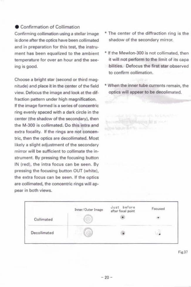
• Confirmation of Collimation
Confirming oollimatioo using II steller Image
'5 done lifter the optics have been collimated
and in preparation for this test, the InSIlU
ment has been equalized to the ambient temperature for oyer an hour and the see
ing is good.
Choose a bright star jMcond or third mag·
Mude)and place it in the center of the field
Ylew, Defocus the image and look /It the dif
fraction I)Inern under high magnification.
If the image fOfmed is a seri" d concentric
ring evenly spaced with a dark circle in the
center lIhe shadow of the secondary), then
the M-300 il collimated. Do this intra and extra focallty. If the rings lire not concen·
tric, then the optaare decollimatltd. Most likely a sllghtldjullment of the secondary
mirror will be sufficient to collimate the In.
IIrument. By pressing the foowsing bunon
IN (red), the Intra focul can be seen. By prellBing the focusing bunon OllT (white),
the elltra focus can be seen. If the optics
are collimated, the concentric rlnga will ap· pear in both views..
* The center 01 the diffraction ring la the
shadow 0/ the aecondary mirror.
• II the Mewlon·JOO ia not collimated, then
it will not perform to the limit of its capa
bilities. Defocus the first star observed
to confirm collimation.
• When the inner tube currents remain, the
optics will appear to be decolimated,
n-/OVWI.....
• •
• •
- 20

ObservationII II • Visual Observations The Mewlon-300 is cepable of producing
olltstllnding images of the Moon, planets and deep sky objects. The instrument musl
be temperature equalized befols serious
observing can take place.
• Magnification The megnification c.IIn be calculated by us' ing the following formula.
(focallenglh of. telescope) (focal length alan ocular)
Therefore, the shorter the focal length of lhe
oculars used, the higher the rrntgnificauon,
and vise wlln. However. generally the maximum magnification is SOli per inch of
IIperlure lind 1.4)( II the minimum. The
former is called Ihe effective maximum
magnification and Ih.lalle. the effeetive
minimum magnification.
Because the Mewlon-300'. focal length is
3.572mm, the magnification produced by
using the LE·30 ocula. is 119.7,.. Therefore.
It is lIppro"imalely 119)(.
• Lunar Observing The Moon is an ideal object to observe tor the beginner and well as the advanced
observer. When observing the lunar disc a
magnification 01 about 50ll will place the
lunar disc:: in the field of view. The Tskahuhi
LE-50 oc:ular is recommended lor this use.
Furthermore; when the Moon is full or close
to full, Ihe view mav be too bright, $0 it is
advisable to use such fille,. n: ND-96, 58
Green or a 3N5. All of these fitters will re
duce Ihe bfightne.. end inereese the con
-
uast.
The lunar lurtace -.hOWl e wealth of detail ,uch e" creters, mountains, rilles, valleys.
rey sUueture and crater leI,. When observ
ing with the Mewlon·300, it is best to ob
serve along the terminator to increase the conttllst between the dark end lighlfeaNrltS.
The filters mentioned previously will also en
hance the contruland detail observed.
The Mewlon-300 Is limiled bV Ihe seeing conditions. In those moments of good see·
ing the Mewlon·JOO will produce difffaetion
limited images.
• Planetary Observing
Planetary observations are besl when the
elmosphere is steedv. When Ihe Slllrs el Ihe lenith twinkle very little o. even filter not al
all, the best planetary observalions can be
made. The best observing t"hfllque 10 use Is 10 sit in e comforteble chair in order to observe
Ihe pleneu for en eXlended period of lime,
Ihis will enable Ihe observer to relax and take edvantlge of those rite moments when
the image pops in 10 sharp locus because
there is a steady column Of air eelland the
image popllnto sherp locus.
These are Ihe times when high magnifica
tion can be used. AI other times, use lower
magnification. Low magnification is used
when the imege of the planet is no longer
sharp. Then magnification should be
reduced until the image becomes sharp
once more.
21

Imaging
Deep Sky Observing
When observing galaxies and clusters.
primarily use lower magnification. When
observing small glo ula star clusters or
galaxies with small apparent diameters, use
a higt magnifica ion. Especially where Iig
pollution is a problem, use higher magnffi
cation to diffuse the light in the background
and darken it fol' better seeing.
The Mewlon-300 coupled with the option I
reducer/flattener to f/9.1 for deep space
imaging. The large image scale will make
the imaging of small galaxies and glo ular
clusters possible. 11 is a absolute neces
sity that a highly accurate stable equa orial
the mount is used such as: the Takahashi
NJP and EM-500. In bo h cases the mounts
have a low period"c error and an auto gu der
inpu tha will allow an au 0 guider to be
used to the mount during long exposu as.
Prime Focus Imaging
1. Prime Focus: P ime focus imaging is
possible. The long focal length and high
f-ra '0 ma es the use of an auto guider
necessary 0 make images. The au 0
g ider enabJes the imager to ma e long
exposures of small objects with a CGD or digital SLR. On the other hand, mak
ing prime focus images of the Moon is
relatively simple.
he 3500 ' m focal Ie gth is equ'valent
a 66x view of the Moon hrough and
oClJla . Since the Moon is so bright, brack
e ing exposures will produce excellent
images of the Moon.
2. Reducer/FI ena: he Mewlon-300 isI
designed 0 be used wit e optional fl 9.1 reducerlflattener. Use of the re ucerl flattener will reduce exposure times by
2/3rds when compared with prime oeus
and i will produce flat field images of
deep space objec s
is is an ideal imaging platform for a
digital SLR or CCD camera.
-22

3. Pror,ection Photography: The Mewlon·
300 ea be used 0 make high magnifica-
i(I n ima ges. of the Moo and planets
when used with the optional TCA-4 p 0
jection imaging unft Au ique feature of
t ,is uni allows the magnification to be
varied with e'8e ocular used. The mag
nifi catio fa ng e will de pend pan the
foea ~engtn of the ocular used.
4. Imaging: e Mewlon-300 ca be sed
w"th a CGD camera, dIgital SLR 0 35, m
film camera.
Wide mount -adapters are available' or
mos brands 0 digi al a d 35mm SLR's.
Please state the brand when erda i g this
produc.
Opt ona.1 Photographic Accessories
TCA-4 Eye ieee Projection Device]
T e TCA·4 is designed to produce high
magnifica io,n images of the Moon Bind
planets .sing eyepiec-e projection. The unit
is easily and ra pidly a11ached to the tele
scope. The draw tube allows the Imager to vary the magnification wi h each eyepiece
used to achieve the desired Image scale or
the lunar surface or plane imaged.
Flattenereducer
-his redllcerlflanel1er is specia11y desig ed
for heMewlon to correct for the coma and
field curvatlilre 0 p oduce a flat field image.
Th's eorrecto can be used to i age small
galaxies and clusters, as wei as smaH plan
etary nebulae.
Opfcal Specifications
focal length w/reducer
foca1 atio w/redueer
Image circle
Photograp Ie 'eld
2739m
1;9.1
¢ 36mm
0.8'
W en the foeal~ reducer 's used w"th the
Mewlo -300, nloc: the ring clamp and pull
QU' the focus ube 16mm, as shown and
focus can be done by a slight move ant of
t e secondary minor.
- 23

Accessories for Photo!Visual Application
• 31.7mm[1.25") Compression
Ring Diagonal
The Takahsh' compression ring 31.7mm [1.25'1 diagonal is 8 high quality diagonal
equipped with a compression ring ocular
adapter thaI insures Ihat the opticalaKes of
Ihe ocular end instrument are coincidental
for maximum performance Ihal produces an extremely sharp, high contrasl image.
Reier 10 Rg.J8. 31.1 Pri.... Di........
• 50.8mm[2"] Takahshi 1110th Wave Mirror Diagonal
The SO.6mm[2"]1I1Oth wave Takahashi mir·
ror diagonal is a very high quality SO.8mm
[1') end 31.7mm[1.2S"] diagonal that can be
used with the wide field Takahashi LE·50
ocular. II provides sharp, high conlrast
lliews. Reier to Fig.39.
- 24

• Twin Viewer Binocular
The Twin Vue is a 45' binocular viewer. The ocular adapters U$II the Takahshi com·
pression ring to insure coincidence of the
opticalllJles of the oculars and Mewlon-300.
Refer to Fog.411.
50.8 ~..v•
• 5-Turret Ocular Holder
This turret ocular holder was designed to
be 8 convenient way for an obselVef to use five diffefent ocular that will produce that
many diffe.ent megnifications fo. env ob
.elVing. Each ocular holder is a compres
,ion ring 31.7mmll.2S'] holder. Refer to
FogAl.
.......
- 2S

• T-Mount & Wide T-Mount
The T.Mount is used to connect to the TCA· 4 eyepiece projection IIdllpter for high
, TCA-( magnification photos lind CCo imllges of . Pnme Focus Rinathe Moon and planets. Refer to Fig. 42.
T_ OiFUlSlR
The Wide T·Mount can be used for prime FiI-(2
focus, reducer, 35-flattener photography.
Refer to Fig. 43.
F,.. 43
• TCA-4
This varioble eyepiece device allaches
eosily to the Mewlon-300 to produce high
quality lunar and planetary images. It cen
be used with 0 CCO camero, digital SlR as
shown below.
TCA-4 IJ -300 V,ouaI Baclo.
-,FR(~lRedo.Je¥l Dilital SlR
50.8 SIH\o.
=
- 26 ~

TSC Camera Adapter 42fl='O.75 hreadiri
An adap e ring for a digital SLR photogra
phy with the Mewlon-300. Please refer to
he section on Photography. This used a standard T-ring to attach to the TSC prime
focus camera adaputer. Refer to Fig. 45. Telescope Parts.
43 P=O.75 rp 43mm, Pitch O.75mm screw fig. 5
Mewlon Reduce I lattene
The Mewlon-300 reducer/flattener reduces
the Mewlon-300 to ff9.1, corrects for co a
and produces a latfield. leas,e refer 0 the
section on Imaging'. An optional wide mount
T-adapter will ttach directly to the reducer/
flattener. Refer 0 Fig. 46.
Attaching to the Mewlo 300 50.8 dap
FR(FlattenerIReducer)
e::::: '-
l- Wide T-mount Digital SLR I.J. -300 VIsual Back
Rg,46
CoUim 'ng Scope
This scope is used to col ;mate the Mewlon~
300 or a ef actor. The bUilt in magnifier
enlarges the cen er dot on the secondary
for easier collimation.
- I =h u
Coupl[ng Head Fig,47M36.4 =1.0 Threading
- 21

It is possible lhat after mllny YllalS 01 use
the primary mirrOi 01 the Mewton-3Oll may
need cleaning. Before llttempling thl, pro
cess. contact your local dealer.
1. Remove all of the visuailldapters; reo
move the cell clllmp ring alld the primary
mirror cell cover. Next remove !he side
ventilation plate 8S shown.
2. Place a clean piece of peper on II hard
lind flat surface. Pullhe lube with the
rear cell down on to the paper on the
flat surface. [In this caca, flat means re
ally flat with no tilt whatsoever to it. This
will prevent the lube from falting over on
10 the ground or on to youll. With 8 wrench, loosen the sil( Bmm cap bolt,
which connects the lube and the pl'imary
mirror cell.
lib!=====c=a-:re:::-&-::..:a:ln:~:::,na=n=c=e=====11 \ e.t cap L.oelo. RiI&
3. C!refully lift the lube off of the mounting
ring while being careful not 10 hillO the primery mirror baffle. At thi, time. make
lure thlll the tube hal been lifted com·
pletEtly aballEt and Iway from the baffle
tube.
SvNd _ or _".11_. _ to ..... tho __ bod< dirty.
- 28

When you are p eparing to disassemble
the Mewlo ·300 in order 0 clean the pri
mary mirror, please contact your local dis
ributo before attempting to do 50.
Replace the front cover and rear ocul r
plug after use to help prevent dust from
en ering the into the optical system.
When the Mewlon-300 is broug in 0 a warm environment from a cold one. dew
could form on the primary mirror. If this
occurs, do not replace the end covers.
Use a hair dryer on the low I eat setting to
remove the dew from he primary.
This same hair dryer can used during
a session under t e sky to emove any
dew that may form on the primary. The
long length of the Mewton-300 tube helps
keep dew away on most nights. Using a
hair dryer here will help preve. t spots
from forming on the mirror surface be
cause the dew has d ·ed.
Under no circumsances should the
Mewlon-300 be closed p while there is
dew on the surface of he primary or sec
ondary mirrors.
The outside of the tube may be cleaned
with auto wax.
It is highly unlike but possible that dew
co ld arm on he surface of the second
ary, but i does not hurt to check 0 be
ce in.
Main ube
Remove the m [1'1 tube slowly not to touch the baffle.
Blowout e dusts and parlJcles by a blower.
p
Fig.50
- 29

II System Chart
13.50.812"111_ [KPOO113] 14. Coupling -S"IKPOQ103)
18. ~Ion Reduce,/flMteflll'
26. Quintuple turret oculi. holder
•
•
~,,[}.-¥-
tKA705811
IKAOO4{)ll
30 TSC camera adapter [KAOO2061
32. T.Mount [KAOO221J - 002261 33. Wide T·Mount
iKA00230 - 002J6] 34. DigiUlVlilm SLR
36. TCA.. lKAOO210]
46. 31.1[1.251 oeuler ada.pter [KAOO1011
47. 31.711.25"J O<::ul.l. IAA00520 - 00'5211
48. SO.812"1 O<;Ulllf (LE50:KA00530] 49 31.1[1.25"Jprism diegonal
IKA005411 74, SO.812") O~90 ...1Mirror
"
_R~
L-1i---------'·~ "lIT!
-----';·m,------"Rfir -iIf IKA00543]
75. AdaptertDMl\31.7[1.25"]) [KAOO111] L-----"·,m
90. Twin Vew Bi~ [KA004710j
-30

Symptom Check Remedy
I' In. Ironi ~p remov&d1 Rema"" the Ironl tip.
Is lhe ocu,-, 1111 in place? You Clnnnol lee .n'(tlling without ,n ocular. ~I ~ in pIKe.
Nothing ean be seen. Dew on 1M mirror Or on the
ocular?
Dry the dew before vieWing.
Do no! uy ill """"" yo..o~ in I high humidity ~ce.
Th.e finder Illgrwldl Align the fioollr.
Imag" focused? FocUi image.
No foeus
Ale the baneries in lhe hend
conlrollef out of power?
Replace new batte,iu.
II the wirll of the hind
conloroller disconn&CIed7
Connect the wire !Iem..".
lmll{lll is fuzzy.
Dewan Ihe mirror or on the
ocula,] Gel rid of .:lew by blowing Ii'
Are the vilull parts Con· nected CDuletly1
Conn&Cllhem correctto,'.
Did you edept the mirrOrS
er.ough to the outside "i,?
Adapt thII mi,roe well enouo;lh 10 the
outside elf.
Im"llll is delo'med. "" you. '''1nc:09'' coIIimetedl Chack col1imltion Ind collimate W I\lIcesS<lry.
Is _.ng "el'dyl -
Poor seeill1l will deg,ede image
Il!..i~~~~T=rO=U=b=le=S=h=OO=I=in~g~~~=11
- 31