Embed Size (px)
Citation preview
Refer to the QuickLIT website for the most up-to-date version of this document.
Metasys® System UL 864 9th Edition UUKL/ORD-C100-13 UUKLC Smoke Control SystemTechnical Bulletin Code No. LIT-12011252
Software Release 5.2Issued August 1, 2012; Updated May 10, 2017
Supersedes June 25, 2014
Document Introduction . . . . . . . . . . . . . . . . . . . . . . . . . . . . . . . . . . . . . . . . . . . . . . . . 11
Related Documentation. . . . . . . . . . . . . . . . . . . . . . . . . . . . . . . . . . . . . . . . . . . . . . . . 12
Smoke Control Definitions . . . . . . . . . . . . . . . . . . . . . . . . . . . . . . . . . . . . . . . . . . . . . . . . 12
SCT, LCT, and CCT Standard Applications Library . . . . . . . . . . . . . . . . . . . . . . . . . . . . 13
References . . . . . . . . . . . . . . . . . . . . . . . . . . . . . . . . . . . . . . . . . . . . . . . . . . . . . . . . . . . . . 13
Smoke Control Product Labeling. . . . . . . . . . . . . . . . . . . . . . . . . . . . . . . . . . . . . . . . 14
Factory and Production Date Codes . . . . . . . . . . . . . . . . . . . . . . . . . . . . . . . . . . . . . . . . 14
Factory Location List . . . . . . . . . . . . . . . . . . . . . . . . . . . . . . . . . . . . . . . . . . . . . . . . . . . . . . 14
Hardware Revision. . . . . . . . . . . . . . . . . . . . . . . . . . . . . . . . . . . . . . . . . . . . . . . . . . . . . . . 14
Software and Firmware Version Numbering . . . . . . . . . . . . . . . . . . . . . . . . . . . . . . . . . . 15
Software Upgrades . . . . . . . . . . . . . . . . . . . . . . . . . . . . . . . . . . . . . . . . . . . . . . . . . . . . . . 15
Software Patches. . . . . . . . . . . . . . . . . . . . . . . . . . . . . . . . . . . . . . . . . . . . . . . . . . . . . . . . . 15
Installation Instructions Revision Level . . . . . . . . . . . . . . . . . . . . . . . . . . . . . . . . . . . . . 15
Smoke Control Requirements . . . . . . . . . . . . . . . . . . . . . . . . . . . . . . . . . . . . . . . . . . 16
Eighth Edition and Ninth Edition Coexistence . . . . . . . . . . . . . . . . . . . . . . . . . . . . . . . . 16
Firefighters Smoke Control Station (FSCS) . . . . . . . . . . . . . . . . . . . . . . . . . . . . . . . . . . 18
FSCS Guidelines . . . . . . . . . . . . . . . . . . . . . . . . . . . . . . . . . . . . . . . . . . . . . . . . . . . . . . . . . 18
FSCS Requirements . . . . . . . . . . . . . . . . . . . . . . . . . . . . . . . . . . . . . . . . . . . . . . . . . . . . . . 19
NxE Requirements. . . . . . . . . . . . . . . . . . . . . . . . . . . . . . . . . . . . . . . . . . . . . . . . . . . . . . . . 20
Metasys System Smoke Control System Overview . . . . . . . . . . . . . . . . . . . . . . . . . 20
Smoke Control Application Examples . . . . . . . . . . . . . . . . . . . . . . . . . . . . . . . . . . . . . . . 20
Overview of HVAC Smoke Control System Types . . . . . . . . . . . . . . . . . . . . . . . . . . . . . 23
Central Systems. . . . . . . . . . . . . . . . . . . . . . . . . . . . . . . . . . . . . . . . . . . . . . . . . . . . . . . . . . 23
Dedicated Smoke Control Systems . . . . . . . . . . . . . . . . . . . . . . . . . . . . . . . . . . . . . . . . . . . 23
Non-Dedicated Smoke Control Systems . . . . . . . . . . . . . . . . . . . . . . . . . . . . . . . . . . . . . . . 23
1Metasys® System UL 864 9th Edition UUKL/ORD-C100-13 UUKLC Smoke ControlSystem Technical Bulletin
Individual Floor Fan Units . . . . . . . . . . . . . . . . . . . . . . . . . . . . . . . . . . . . . . . . . . . . . . . . . . 23
Fan Coil Units/Water Source Heat Pumps. . . . . . . . . . . . . . . . . . . . . . . . . . . . . . . . . . . . . . 23
Induction Units . . . . . . . . . . . . . . . . . . . . . . . . . . . . . . . . . . . . . . . . . . . . . . . . . . . . . . . . . . . 23
Variable Air Volume (VAV) Systems . . . . . . . . . . . . . . . . . . . . . . . . . . . . . . . . . . . . . . . . . . 24
Smoke Dampers . . . . . . . . . . . . . . . . . . . . . . . . . . . . . . . . . . . . . . . . . . . . . . . . . . . . . . . . . 24
Design Considerations . . . . . . . . . . . . . . . . . . . . . . . . . . . . . . . . . . . . . . . . . . . . . . . . . . . 24
Smoke Movement . . . . . . . . . . . . . . . . . . . . . . . . . . . . . . . . . . . . . . . . . . . . . . . . . . . . . . . . 24
Smoke Control Strategies . . . . . . . . . . . . . . . . . . . . . . . . . . . . . . . . . . . . . . . . . . . . . . . . . 24
Initiating Devices . . . . . . . . . . . . . . . . . . . . . . . . . . . . . . . . . . . . . . . . . . . . . . . . . . . . . . . . 25
Manual Initiation. . . . . . . . . . . . . . . . . . . . . . . . . . . . . . . . . . . . . . . . . . . . . . . . . . . . . . . . . . 25
Automatic Initiation. . . . . . . . . . . . . . . . . . . . . . . . . . . . . . . . . . . . . . . . . . . . . . . . . . . . . . . . 25
End-to-End Verification . . . . . . . . . . . . . . . . . . . . . . . . . . . . . . . . . . . . . . . . . . . . . . . . . . . 26
Fan Relay Supervision . . . . . . . . . . . . . . . . . . . . . . . . . . . . . . . . . . . . . . . . . . . . . . . . . . . 26
Response Times . . . . . . . . . . . . . . . . . . . . . . . . . . . . . . . . . . . . . . . . . . . . . . . . . . . . . . . . 27
Communication Timing . . . . . . . . . . . . . . . . . . . . . . . . . . . . . . . . . . . . . . . . . . . . . . . . . . . . 27
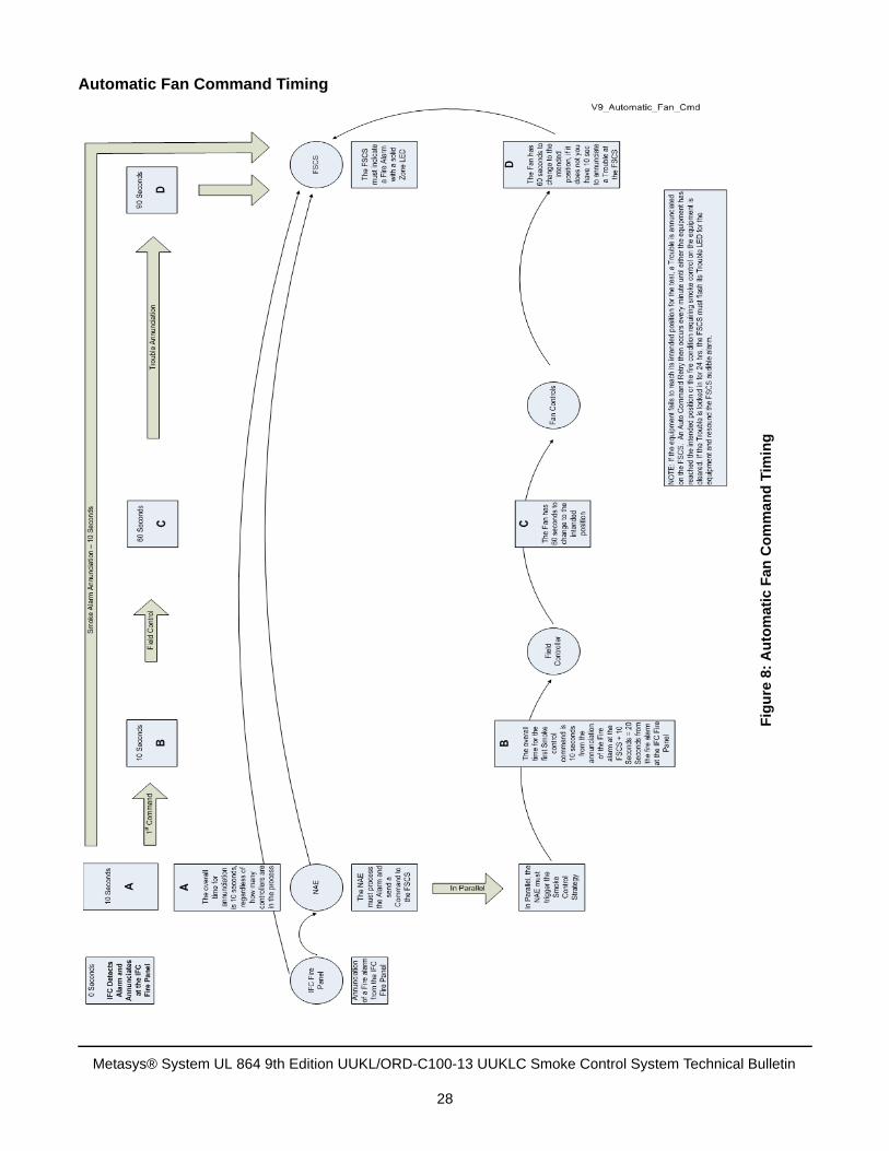
Automatic Fan Command Timing . . . . . . . . . . . . . . . . . . . . . . . . . . . . . . . . . . . . . . . . . . . . 28
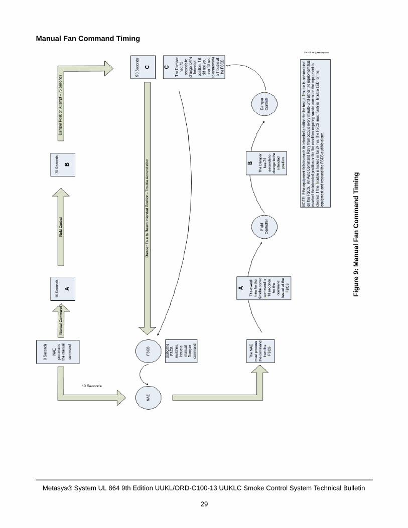
Manual Fan Command Timing. . . . . . . . . . . . . . . . . . . . . . . . . . . . . . . . . . . . . . . . . . . . . . . 29
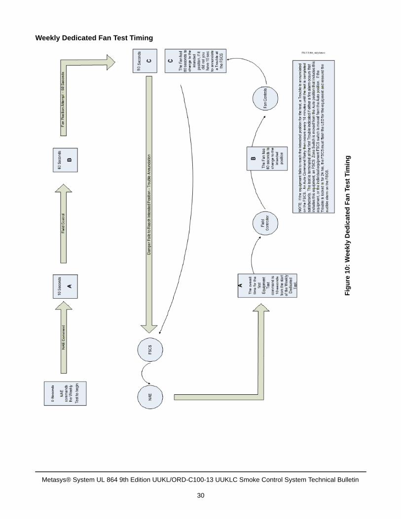
Weekly Dedicated Fan Test Timing . . . . . . . . . . . . . . . . . . . . . . . . . . . . . . . . . . . . . . . . . . . 30
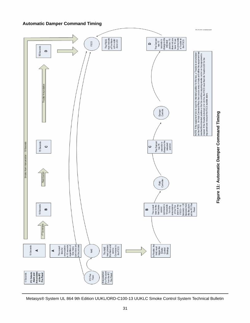
Automatic Damper Command Timing . . . . . . . . . . . . . . . . . . . . . . . . . . . . . . . . . . . . . . . . . 31
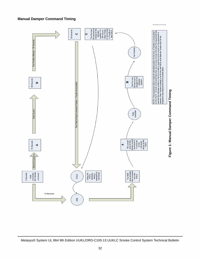
Manual Damper Command Timing . . . . . . . . . . . . . . . . . . . . . . . . . . . . . . . . . . . . . . . . . . . 32
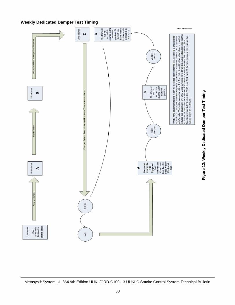
Weekly Dedicated Damper Test Timing . . . . . . . . . . . . . . . . . . . . . . . . . . . . . . . . . . . . . . . 33
Fire Alarm Annunciation Panels . . . . . . . . . . . . . . . . . . . . . . . . . . . . . . . . . . . . . . . . 34
IFC2-640 . . . . . . . . . . . . . . . . . . . . . . . . . . . . . . . . . . . . . . . . . . . . . . . . . . . . . . . . . . . . . . . 34
IFC2-3030 . . . . . . . . . . . . . . . . . . . . . . . . . . . . . . . . . . . . . . . . . . . . . . . . . . . . . . . . . . . . . . 35
IFC-320 . . . . . . . . . . . . . . . . . . . . . . . . . . . . . . . . . . . . . . . . . . . . . . . . . . . . . . . . . . . . . . . . 35
Surge Protection Devices. . . . . . . . . . . . . . . . . . . . . . . . . . . . . . . . . . . . . . . . . . . . . . 36
Ethernet Transient Protection . . . . . . . . . . . . . . . . . . . . . . . . . . . . . . . . . . . . . . . . . . . . . 36
American Power Conversion® (APC) PNET1GB Ethernet Transient Protector . . . . . . . . . 36
Specifications. . . . . . . . . . . . . . . . . . . . . . . . . . . . . . . . . . . . . . . . . . . . . . . . . . . . . . . . . . . . 38
UL/ULC Label Placement . . . . . . . . . . . . . . . . . . . . . . . . . . . . . . . . . . . . . . . . . . . . . . . . . . 38
Metasys® System UL 864 9th Edition UUKL/ORD-C100-13 UUKLC Smoke Control System Technical Bulletin
2
Power Surge Protection . . . . . . . . . . . . . . . . . . . . . . . . . . . . . . . . . . . . . . . . . . . . . . . . . . 39
Tripp Lite 8 Ultra Surge Suppressor . . . . . . . . . . . . . . . . . . . . . . . . . . . . . . . . . . . . . . . . . . 39
Specifications. . . . . . . . . . . . . . . . . . . . . . . . . . . . . . . . . . . . . . . . . . . . . . . . . . . . . . . . . . . . 40
UL/ULC Label Placement . . . . . . . . . . . . . . . . . . . . . . . . . . . . . . . . . . . . . . . . . . . . . . . . . . 40
Tripp Lite ISOBAR 12 Ultra Surge Suppressor . . . . . . . . . . . . . . . . . . . . . . . . . . . . . . . . . . 41
Specifications. . . . . . . . . . . . . . . . . . . . . . . . . . . . . . . . . . . . . . . . . . . . . . . . . . . . . . . . . . . . 42
UL/ULC Label Placement . . . . . . . . . . . . . . . . . . . . . . . . . . . . . . . . . . . . . . . . . . . . . . . . . . 42
MS/TP Field Communication Bus and Field Controller I/O Transient Protection . . . . 43
SMK-MOVKIT-MSTP Transient Protection Kit. . . . . . . . . . . . . . . . . . . . . . . . . . . . . . . . . . . 43
Installation Requirements . . . . . . . . . . . . . . . . . . . . . . . . . . . . . . . . . . . . . . . . . . . . . . . . . . 43
Specifications. . . . . . . . . . . . . . . . . . . . . . . . . . . . . . . . . . . . . . . . . . . . . . . . . . . . . . . . . . . . 44
SMK-MOVKIT-MSTP Wiring for MS/TP MS/TP (FC) Bus Communication Terminations . . 46
SMK-MOVKIT-MSTP Wiring for SA Bus Communication Terminations . . . . . . . . . . . . . . . 48
SMK-MOVKIT-BRD Replacement Transient Protection Kit . . . . . . . . . . . . . . . . . . . . . . . . . 50
Installation Requirements . . . . . . . . . . . . . . . . . . . . . . . . . . . . . . . . . . . . . . . . . . . . . . . . . . 50
Specifications. . . . . . . . . . . . . . . . . . . . . . . . . . . . . . . . . . . . . . . . . . . . . . . . . . . . . . . . . . . . 51
SMK-MOVKIT-BRD Wiring for MS/TP MS/TP (FC) Bus Communication Terminations . . . 51
SMK-MOVKIT-BRD Wiring for SA Bus Communication Terminations . . . . . . . . . . . . . . . . 53
MS/TP Field Communication Bus Repeater SMOKE-TRNKIT-1U transorbs . . . . . . . . 55
Installation Requirements . . . . . . . . . . . . . . . . . . . . . . . . . . . . . . . . . . . . . . . . . . . . . . . . . . 55
Specifications . . . . . . . . . . . . . . . . . . . . . . . . . . . . . . . . . . . . . . . . . . . . . . . . . . . . . . . . . . . 56
MS/TP Field Controller I/O Transient Protection. . . . . . . . . . . . . . . . . . . . . . . . . . . . . . . 56
Installation Requirements . . . . . . . . . . . . . . . . . . . . . . . . . . . . . . . . . . . . . . . . . . . . . . . . . . 58
Specifications. . . . . . . . . . . . . . . . . . . . . . . . . . . . . . . . . . . . . . . . . . . . . . . . . . . . . . . . . . . . 60
MOV Placement. . . . . . . . . . . . . . . . . . . . . . . . . . . . . . . . . . . . . . . . . . . . . . . . . . . . . . . . . . 60
Network Communications. . . . . . . . . . . . . . . . . . . . . . . . . . . . . . . . . . . . . . . . . . . . . . 70
Copper Cable Connections. . . . . . . . . . . . . . . . . . . . . . . . . . . . . . . . . . . . . . . . . . . . . . . . 72
Fiber-Optic Cable Connections . . . . . . . . . . . . . . . . . . . . . . . . . . . . . . . . . . . . . . . . . . . . 73
ST Style Connectors . . . . . . . . . . . . . . . . . . . . . . . . . . . . . . . . . . . . . . . . . . . . . . . . . . . . . . 74
24-Port Ethernet Switches . . . . . . . . . . . . . . . . . . . . . . . . . . . . . . . . . . . . . . . . . . . . . . . . 75
Metasys® System UL 864 9th Edition UUKL/ORD-C100-13 UUKLC Smoke Control System TechnicalBulletin
3
Specifications . . . . . . . . . . . . . . . . . . . . . . . . . . . . . . . . . . . . . . . . . . . . . . . . . . . . . . . . . . . 76
UL/ULC Label Placement . . . . . . . . . . . . . . . . . . . . . . . . . . . . . . . . . . . . . . . . . . . . . . . . . . 77
5-Port Ethernet Copper Switch with RJ45 Connectors . . . . . . . . . . . . . . . . . . . . . . . . . 77
Wiring. . . . . . . . . . . . . . . . . . . . . . . . . . . . . . . . . . . . . . . . . . . . . . . . . . . . . . . . . . . . . . . . . . 78
Specifications. . . . . . . . . . . . . . . . . . . . . . . . . . . . . . . . . . . . . . . . . . . . . . . . . . . . . . . . . . . . 79
UL/ULC Label Placement . . . . . . . . . . . . . . . . . . . . . . . . . . . . . . . . . . . . . . . . . . . . . . . . . . 80
8-Port Ethernet Copper Switch with RJ45 Connectors . . . . . . . . . . . . . . . . . . . . . . . . . 81
Flow Control Jumper Options . . . . . . . . . . . . . . . . . . . . . . . . . . . . . . . . . . . . . . . . . . . . . . . 82
Internal LEDs . . . . . . . . . . . . . . . . . . . . . . . . . . . . . . . . . . . . . . . . . . . . . . . . . . . . . . . . . . . . 83
Wiring. . . . . . . . . . . . . . . . . . . . . . . . . . . . . . . . . . . . . . . . . . . . . . . . . . . . . . . . . . . . . . . . . . 83
Specifications . . . . . . . . . . . . . . . . . . . . . . . . . . . . . . . . . . . . . . . . . . . . . . . . . . . . . . . . . . . 84
UL/ULC Label Placement . . . . . . . . . . . . . . . . . . . . . . . . . . . . . . . . . . . . . . . . . . . . . . . . . . 85
4-Port Ethernet Fiber/Copper Switch with RJ45 Connectors . . . . . . . . . . . . . . . . . . . . 86
Flow Jumper Options . . . . . . . . . . . . . . . . . . . . . . . . . . . . . . . . . . . . . . . . . . . . . . . . . . . . . . 87
Duplex Jumper Options - Fiber . . . . . . . . . . . . . . . . . . . . . . . . . . . . . . . . . . . . . . . . . . . . . . 87
Internal LEDs . . . . . . . . . . . . . . . . . . . . . . . . . . . . . . . . . . . . . . . . . . . . . . . . . . . . . . . . . . . . 88
Wiring. . . . . . . . . . . . . . . . . . . . . . . . . . . . . . . . . . . . . . . . . . . . . . . . . . . . . . . . . . . . . . . . . . 89
Specifications . . . . . . . . . . . . . . . . . . . . . . . . . . . . . . . . . . . . . . . . . . . . . . . . . . . . . . . . . . . 89
UL/ULC Label Placement . . . . . . . . . . . . . . . . . . . . . . . . . . . . . . . . . . . . . . . . . . . . . . . . . . 90
Media Converters. . . . . . . . . . . . . . . . . . . . . . . . . . . . . . . . . . . . . . . . . . . . . . . . . . . . . . . . 90
Contemporary Controls® EIMK-100T/FT Media Converter . . . . . . . . . . . . . . . . . . . . . . . . . 91
Specifications. . . . . . . . . . . . . . . . . . . . . . . . . . . . . . . . . . . . . . . . . . . . . . . . . . . . . . . . . . . . 92
UL/ULC Label Placement . . . . . . . . . . . . . . . . . . . . . . . . . . . . . . . . . . . . . . . . . . . . . . . . . . 92
Smoke Control Network Automation Engines and Network Control Engines . . . 95
Standard NxE Features and Connections . . . . . . . . . . . . . . . . . . . . . . . . . . . . . . . . . . . . 95
Power Supply. . . . . . . . . . . . . . . . . . . . . . . . . . . . . . . . . . . . . . . . . . . . . . . . . . . . . . . . . . . . 95
Wiring. . . . . . . . . . . . . . . . . . . . . . . . . . . . . . . . . . . . . . . . . . . . . . . . . . . . . . . . . . . . . . . . . . 95
Smoke Control NAEs MS-NAE5510-1U and MS-NAE5510-2U . . . . . . . . . . . . . . . . . . . . 96
Device Layout . . . . . . . . . . . . . . . . . . . . . . . . . . . . . . . . . . . . . . . . . . . . . . . . . . . . . . . . . . . 98
Powering On the NAE . . . . . . . . . . . . . . . . . . . . . . . . . . . . . . . . . . . . . . . . . . . . . . . . . . . . . 99
Metasys® System UL 864 9th Edition UUKL/ORD-C100-13 UUKLC Smoke Control System Technical Bulletin
4
Disconnecting Power from the NAE. . . . . . . . . . . . . . . . . . . . . . . . . . . . . . . . . . . . . . . . . . . 99
Troubleshooting . . . . . . . . . . . . . . . . . . . . . . . . . . . . . . . . . . . . . . . . . . . . . . . . . . . . . . . . . . 99
Specifications. . . . . . . . . . . . . . . . . . . . . . . . . . . . . . . . . . . . . . . . . . . . . . . . . . . . . . . . . . . 101
UL/ULC Label Placement . . . . . . . . . . . . . . . . . . . . . . . . . . . . . . . . . . . . . . . . . . . . . . . . . 103
Smoke Control NAE MS-NAE4510-2U . . . . . . . . . . . . . . . . . . . . . . . . . . . . . . . . . . . . . . 104
Device Layout . . . . . . . . . . . . . . . . . . . . . . . . . . . . . . . . . . . . . . . . . . . . . . . . . . . . . . . . . . 104
Specifications. . . . . . . . . . . . . . . . . . . . . . . . . . . . . . . . . . . . . . . . . . . . . . . . . . . . . . . . . . . 105
UL/ULC Label Placement . . . . . . . . . . . . . . . . . . . . . . . . . . . . . . . . . . . . . . . . . . . . . . . . . 107
Smoke Control NAE MS-NAE3510-2U . . . . . . . . . . . . . . . . . . . . . . . . . . . . . . . . . . . . . . 108
Device Layout . . . . . . . . . . . . . . . . . . . . . . . . . . . . . . . . . . . . . . . . . . . . . . . . . . . . . . . . . . 109
Performance Guidelines and Limitations for Network Engines . . . . . . . . . . . . . . . . . . . . . 109
Wiring Considerations and Guidelines for Network Integrations . . . . . . . . . . . . . . . . . . . . 110
Troubleshooting . . . . . . . . . . . . . . . . . . . . . . . . . . . . . . . . . . . . . . . . . . . . . . . . . . . . . . . . . 111
Specifications. . . . . . . . . . . . . . . . . . . . . . . . . . . . . . . . . . . . . . . . . . . . . . . . . . . . . . . . . . . 112
UL/ULC Label Placement . . . . . . . . . . . . . . . . . . . . . . . . . . . . . . . . . . . . . . . . . . . . . . . . . 114
Smoke Control NCE MS-NCE2560-0U . . . . . . . . . . . . . . . . . . . . . . . . . . . . . . . . . . . . . . 115
Device Layout . . . . . . . . . . . . . . . . . . . . . . . . . . . . . . . . . . . . . . . . . . . . . . . . . . . . . . . . . . 116
Specifications. . . . . . . . . . . . . . . . . . . . . . . . . . . . . . . . . . . . . . . . . . . . . . . . . . . . . . . . . . . 121
UL/ULC Label Placement . . . . . . . . . . . . . . . . . . . . . . . . . . . . . . . . . . . . . . . . . . . . . . . . . 123
MS/TP Field Bus. . . . . . . . . . . . . . . . . . . . . . . . . . . . . . . . . . . . . . . . . . . . . . . . . . . . . 124
Introduction . . . . . . . . . . . . . . . . . . . . . . . . . . . . . . . . . . . . . . . . . . . . . . . . . . . . . . . . . . . 124
MS/TP (FC) Bus Overview . . . . . . . . . . . . . . . . . . . . . . . . . . . . . . . . . . . . . . . . . . . . . . . . 124
MS/TP (FC) Bus Overview . . . . . . . . . . . . . . . . . . . . . . . . . . . . . . . . . . . . . . . . . . . . . . . . 124
SA Bus Overview . . . . . . . . . . . . . . . . . . . . . . . . . . . . . . . . . . . . . . . . . . . . . . . . . . . . . . . 125
Baud Rates on the MS/TP (FC) Bus . . . . . . . . . . . . . . . . . . . . . . . . . . . . . . . . . . . . . . . . 126
Device Addresses on the MS/TP (FC) Bus . . . . . . . . . . . . . . . . . . . . . . . . . . . . . . . . . . 127
Setting a Device Address. . . . . . . . . . . . . . . . . . . . . . . . . . . . . . . . . . . . . . . . . . . . . . . . . . 128
End-of-Line Termination on the MS/TP (FC) Bus . . . . . . . . . . . . . . . . . . . . . . . . . . . . . 128
End-of-Line Termination Switch Locations . . . . . . . . . . . . . . . . . . . . . . . . . . . . . . . . . . . . 129
FC and SA Bus Device EOL Switch Details . . . . . . . . . . . . . . . . . . . . . . . . . . . . . . . . . . . 129
Metasys® System UL 864 9th Edition UUKL/ORD-C100-13 UUKLC Smoke Control System TechnicalBulletin
5
EOL Termination on the MS/TP (FC) Bus . . . . . . . . . . . . . . . . . . . . . . . . . . . . . . . . . . . . . 130
EOL Termination on the SA Bus . . . . . . . . . . . . . . . . . . . . . . . . . . . . . . . . . . . . . . . . . . . . 131
SA Buses with Multiple Network Sensors . . . . . . . . . . . . . . . . . . . . . . . . . . . . . . . . . . . . . 132
Terminating FC Devices That Do Not Have Integral EOL Termination Capability. . . . . . . 132
MS/TP (FC) Bus Rules When Using TEC26xx Series Thermostat Controllers andThird-Party MS/TP Devices . . . . . . . . . . . . . . . . . . . . . . . . . . . . . . . . . . . . . . . . . . . . . . . . 137
MS/TP Required Transient Protection . . . . . . . . . . . . . . . . . . . . . . . . . . . . . . . . . . . . . . 137
FC Communication Bus . . . . . . . . . . . . . . . . . . . . . . . . . . . . . . . . . . . . . . . . . . . . . . . . . . . 137
SA Communication Bus . . . . . . . . . . . . . . . . . . . . . . . . . . . . . . . . . . . . . . . . . . . . . . . . . . . 137
Field Controller I/O Terminals . . . . . . . . . . . . . . . . . . . . . . . . . . . . . . . . . . . . . . . . . . . . . . 137
MS/TP (FC) Bus Rules and Specifications . . . . . . . . . . . . . . . . . . . . . . . . . . . . . . . . . . 138
Sensor Actuator (SA) Bus Rules and Specifications . . . . . . . . . . . . . . . . . . . . . . . . . . 140
NU-RPT101-1U RS-485-to-RS-485 MS/TP Repeater . . . . . . . . . . . . . . . . . . . . . . . . . . . 141
Setting EOL for the Repeater. . . . . . . . . . . . . . . . . . . . . . . . . . . . . . . . . . . . . . . . . . . . . . . 142
Wiring. . . . . . . . . . . . . . . . . . . . . . . . . . . . . . . . . . . . . . . . . . . . . . . . . . . . . . . . . . . . . . . . . 142
Specifications. . . . . . . . . . . . . . . . . . . . . . . . . . . . . . . . . . . . . . . . . . . . . . . . . . . . . . . . . . . 143
UL/ULC Label Placement . . . . . . . . . . . . . . . . . . . . . . . . . . . . . . . . . . . . . . . . . . . . . . . . . 144
MS/TP (FC) Bus Cable Recommendations . . . . . . . . . . . . . . . . . . . . . . . . . . . . . . . . . . 145
Wiring the MS/TP (FC) Bus . . . . . . . . . . . . . . . . . . . . . . . . . . . . . . . . . . . . . . . . . 147
General MS/TP (FC) Bus Wiring Guidelines . . . . . . . . . . . . . . . . . . . . . . . . . . . . . . . . . . . 147
MS/TP (FC) Bus Wiring Guidelines . . . . . . . . . . . . . . . . . . . . . . . . . . . . . . . . . . . . . . . . . . 148
MS/TP (FC) Bus and SA Bus Screw Terminations . . . . . . . . . . . . . . . . . . . . . . . . . . . . . . 148
Grounding the Cable Shield on MS/TP (FC) Bus Segments . . . . . . . . . . . . . . . . . . . . . . . 148
SA Bus Wiring Guidelines. . . . . . . . . . . . . . . . . . . . . . . . . . . . . . . . . . . . . . . . . . . . . . . . 149
SA Bus 6-Pin RJ-Style Modular Jack and Cables . . . . . . . . . . . . . . . . . . . . . . . . . . . . . . . 150
Commissioning Devices on the MS/TP (FC) Bus . . . . . . . . . . . . . . . . . . . . . . . . . . . . . 150
MS/TP Controllers . . . . . . . . . . . . . . . . . . . . . . . . . . . . . . . . . . . . . . . . . . . . . . . . . . . 151
FEU1610, FEC1611, FEU2610, and FEC2611 Field Equipment Controllers . . . . . . . . 151
Mounting . . . . . . . . . . . . . . . . . . . . . . . . . . . . . . . . . . . . . . . . . . . . . . . . . . . . . . . . . . . . . . 151
Common FEC Configuration Details . . . . . . . . . . . . . . . . . . . . . . . . . . . . . . . . . . . . . . . . . 152
Wiring . . . . . . . . . . . . . . . . . . . . . . . . . . . . . . . . . . . . . . . . . . . . . . . . . . . . . . . . . . . . . . . . 153
Metasys® System UL 864 9th Edition UUKL/ORD-C100-13 UUKLC Smoke Control System Technical Bulletin
6
Setup and Adjustments . . . . . . . . . . . . . . . . . . . . . . . . . . . . . . . . . . . . . . . . . . . . . . . . . . . 162
Commissioning . . . . . . . . . . . . . . . . . . . . . . . . . . . . . . . . . . . . . . . . . . . . . . . . . . . . . . . . . 163
Troubleshooting . . . . . . . . . . . . . . . . . . . . . . . . . . . . . . . . . . . . . . . . . . . . . . . . . . . . . . . . . 163
Specifications. . . . . . . . . . . . . . . . . . . . . . . . . . . . . . . . . . . . . . . . . . . . . . . . . . . . . . . . . . . 164
UL/ULC Label Placement . . . . . . . . . . . . . . . . . . . . . . . . . . . . . . . . . . . . . . . . . . . . . . . . . 166
IOMx710 Field Equipment Controllers . . . . . . . . . . . . . . . . . . . . . . . . . . . . . . . . . . . . . . 169
Mounting . . . . . . . . . . . . . . . . . . . . . . . . . . . . . . . . . . . . . . . . . . . . . . . . . . . . . . . . . . . . . . 169
Common IOM Configuration Details . . . . . . . . . . . . . . . . . . . . . . . . . . . . . . . . . . . . . . . . . 170
Wiring. . . . . . . . . . . . . . . . . . . . . . . . . . . . . . . . . . . . . . . . . . . . . . . . . . . . . . . . . . . . . . . . . 171
Wiring the IOM1710 and IOM1711 . . . . . . . . . . . . . . . . . . . . . . . . . . . . . . . . . . . . . . . . . . 171
Troubleshooting . . . . . . . . . . . . . . . . . . . . . . . . . . . . . . . . . . . . . . . . . . . . . . . . . . . . . . . . . 174
Wiring the IOM2710, IOM2711, IOM3710, and IOM3711 . . . . . . . . . . . . . . . . . . . . . . . . . 174
Troubleshooting . . . . . . . . . . . . . . . . . . . . . . . . . . . . . . . . . . . . . . . . . . . . . . . . . . . . . . . . . 182
Wiring the IOU4710 and IOM4711 IOM Controllers . . . . . . . . . . . . . . . . . . . . . . . . . . . . . 183
Troubleshooting . . . . . . . . . . . . . . . . . . . . . . . . . . . . . . . . . . . . . . . . . . . . . . . . . . . . . . . . . 187
IOMx710-0U Specifications . . . . . . . . . . . . . . . . . . . . . . . . . . . . . . . . . . . . . . . . . . . . . . . . 188
UL/ULC Label Placement . . . . . . . . . . . . . . . . . . . . . . . . . . . . . . . . . . . . . . . . . . . . . . . . . 190
VMA16 Series Controllers . . . . . . . . . . . . . . . . . . . . . . . . . . . . . . . . . . . . . . . . . . . . . . . . 196
Mounting . . . . . . . . . . . . . . . . . . . . . . . . . . . . . . . . . . . . . . . . . . . . . . . . . . . . . . . . . . . . . . 196
VMA16 Programming and Configuration Details . . . . . . . . . . . . . . . . . . . . . . . . . . . . . . . . 197
Wiring . . . . . . . . . . . . . . . . . . . . . . . . . . . . . . . . . . . . . . . . . . . . . . . . . . . . . . . . . . . . . . . 198
Troubleshooting . . . . . . . . . . . . . . . . . . . . . . . . . . . . . . . . . . . . . . . . . . . . . . . . . . . . . . . . . 203
Specifications . . . . . . . . . . . . . . . . . . . . . . . . . . . . . . . . . . . . . . . . . . . . . . . . . . . . . . . . . . 203
UL/ULC Label Placement . . . . . . . . . . . . . . . . . . . . . . . . . . . . . . . . . . . . . . . . . . . . . . . . . 205
MS/TP NS Series Network Sensors . . . . . . . . . . . . . . . . . . . . . . . . . . . . . . . . . . . . . . . . 207
Specifications. . . . . . . . . . . . . . . . . . . . . . . . . . . . . . . . . . . . . . . . . . . . . . . . . . . . . . . . . . . 208
Smoke Control System Software . . . . . . . . . . . . . . . . . . . . . . . . . . . . . . . . . . . . . . . 212
SCT . . . . . . . . . . . . . . . . . . . . . . . . . . . . . . . . . . . . . . . . . . . . . . . . . . . . . . . . . . . . . . . . . . 212
System Programming Guidelines for Smoke Control . . . . . . . . . . . . . . . . . . . . . . . . . 212
Enclosures and Accessories . . . . . . . . . . . . . . . . . . . . . . . . . . . . . . . . . . . . . . . . . . 212
Metasys® System UL 864 9th Edition UUKL/ORD-C100-13 UUKLC Smoke Control System TechnicalBulletin
7
PAN-PWRSP-U Power Supply . . . . . . . . . . . . . . . . . . . . . . . . . . . . . . . . . . . . . . . . . . . . 213
Wiring the PAN-PWRSP-U Power Supply . . . . . . . . . . . . . . . . . . . . . . . . . . . . . . . . . . . 214
PAN-PWRSP-U Power Supply Connections . . . . . . . . . . . . . . . . . . . . . . . . . . . . . . . . . . . 214
Specifications . . . . . . . . . . . . . . . . . . . . . . . . . . . . . . . . . . . . . . . . . . . . . . . . . . . . . . . . . . 215
UL/ULC Label Placement . . . . . . . . . . . . . . . . . . . . . . . . . . . . . . . . . . . . . . . . . . . . . . . . . 216
PAN-96VAXFR-U Power Supply . . . . . . . . . . . . . . . . . . . . . . . . . . . . . . . . . . . . . . . . . . . 217
Specifications . . . . . . . . . . . . . . . . . . . . . . . . . . . . . . . . . . . . . . . . . . . . . . . . . . . . . . . . . . 217
UL/ULC Label Placement . . . . . . . . . . . . . . . . . . . . . . . . . . . . . . . . . . . . . . . . . . . . . . . . . 219
Power Distribution Panel and Enclosure (PA0P00010FC0-U) . . . . . . . . . . . . . . . . . . . 219
Specifications. . . . . . . . . . . . . . . . . . . . . . . . . . . . . . . . . . . . . . . . . . . . . . . . . . . . . . . . . . . 221
UL/ULC Label Placement . . . . . . . . . . . . . . . . . . . . . . . . . . . . . . . . . . . . . . . . . . . . . . . . . 221
Smoke Control Listed Accessories in a Smoke Control Panel . . . . . . . . . . . . . . . . . . 222
Non-Smoke Control Listed Accessories in a Smoke Control Panel . . . . . . . . . . . . . . 222
Ordering Smoke Control Enclosures. . . . . . . . . . . . . . . . . . . . . . . . . . . . . . . . . . . . . . . 223
Custom Enclosures . . . . . . . . . . . . . . . . . . . . . . . . . . . . . . . . . . . . . . . . . . . . . . . . . . . . . . 223
Standard Enclosures . . . . . . . . . . . . . . . . . . . . . . . . . . . . . . . . . . . . . . . . . . . . . . . . . . . . . 223
VAV Box Enclosures . . . . . . . . . . . . . . . . . . . . . . . . . . . . . . . . . . . . . . . . . . . . . . . . . . . . . 223
Enclosures Requiring a Union Label . . . . . . . . . . . . . . . . . . . . . . . . . . . . . . . . . . . . . . . . . 224
Enclosures Requiring External Plastic Identification Tags. . . . . . . . . . . . . . . . . . . . . . . . . 225
Upgrading to Release 5.2 . . . . . . . . . . . . . . . . . . . . . . . . . . . . . . . . . . . . . . . . . . . . . 225
Software Revision Labels . . . . . . . . . . . . . . . . . . . . . . . . . . . . . . . . . . . . . . . . . . . . . . . . 225
Ordering and Revision Information. . . . . . . . . . . . . . . . . . . . . . . . . . . . . . . . . . . . . 226
General Smoke Control Ordering Requirements . . . . . . . . . . . . . . . . . . . . . . . . . . . . . 226
. . . . . . . . . . . . . . . . . . . . . . . . . . . . . . . . . . . . . . . . . . . . . . . . . . . . . . . . . . . . . . . . . . . . . 227
Repair Parts Ordering Information . . . . . . . . . . . . . . . . . . . . . . . . . . . . . . . . . . . . . . . . . . . 232
NS Series Network Sensors Selection Charts . . . . . . . . . . . . . . . . . . . . . . . . . . . . . . . . . . 233
Typical Panel Layouts for UL/ULC Smoke Control Listing . . . . . . . . . . . . . . . . . . 238
Compliance Checklist for UL/ULC Smoke Control Listing . . . . . . . . . . . . . . . . . . 239
Overview. . . . . . . . . . . . . . . . . . . . . . . . . . . . . . . . . . . . . . . . . . . . . . . . . . . . . . . . . . . . . . 239
Compliance Survey for UL/ULC Smoke Control Listing . . . . . . . . . . . . . . . . . . . . 240
Metasys® System UL 864 9th Edition UUKL/ORD-C100-13 UUKLC Smoke Control System Technical Bulletin
8
General Requirements for UL/ULC Smoke Control Listing . . . . . . . . . . . . . . . . . . . . . . . . 241
FSCS Requirements for UL/ULC Smoke Control Listing. . . . . . . . . . . . . . . . . . . . . . . . . . 242
Wiring Requirements for UL/ULC Smoke Control Listing . . . . . . . . . . . . . . . . . . . . . . . . . 243
Application Programming Requirements for UL/ULC Smoke Control Listing . . . . . . . . . . 243
Metasys® System UL 864 9th Edition UUKL/ORD-C100-13 UUKLC Smoke Control System TechnicalBulletin
9

Metasys® System UL 864 9th Edition UUKL/ORD-C100-13 UUKLC Smoke Control System Technical Bulletin
10
Metasys® System UL 864 9th Edition UUKL/ORD-C100-13 UUKLC Smoke Control SystemTechnical Bulletin
Document IntroductionThis document provides sales representatives, project engineers, application engineers, system representatives, and system installers with the information necessary to sell, engineer, and install a Metasys® system smoke control system that complies with the Underwriters Laboratories Inc.® (UL) requirements for the UL 864 9th Edition UUKL/ORD-C100-13 UUKLC Smoke Control Listing. This listing applies to an indoor, dry environment only, where each Air Handling Unit (AHU) is located in an indoor, enclosed space. This listing does not support applications where equipment is mounted in Rooftop Units (RTUs), or where equipment is exposed to a damp or wet environment. To comply with the listing, you must follow the requirements and restrictions placed on the Metasys system components as detailed in this and other Metasys system documentation applying to the UL 864 9th Edition UUKL/ORD-C100-13 UUKLC Listing. The restrictions apply to both used and assembled Metasys system components. If you are unsure if your particular application complies with the Ninth Edition smoke control listing, contact your nearest Johnson Controls® representative.
Notes:
• The Intelligent Fire Controller (IFC) fire system or third-party fire system is the primary fire annunciation station. (Refer to the Metasys System Extended Architecture Fire System Integration Using the IFC BACnet Gateway Application Note [LIT-1201993] for more information.) The Johnson Controls® Metasys system smoke control system is used as a secondary fire annunciation station.
• This document specifically addresses the Johnson Controls® Metasys system smoke control system. This document provides information on the Ethernet-based systems, communication equipment, and Master-Slave/Token-Passing (MS/TP) Bus controllers necessary to create a Metasys system smoke control application. Do not confuse the system in this document with the Metasys System Smoke Control UL 864 UUKL Eighth Edition system.
IMPORTANT: Smoke control applications require extra care during installation, commissioning, and servicing. Make sure to read smoke control documentation and follow all procedures carefully to ensure compliance with the UL 864 9th Edition UUKL/ORD-C100-13 UUKLC Standard for Smoke Control.
IMPORTANT: Smoke control equipment carries strict ordering guidelines. For example, all panels for smoke control must be ordered through Johnson Controls. See Ordering Smoke Control Enclosures.
Metasys® System UL 864 9th Edition UUKL/ORD-C100-13 UUKLC Smoke Control System Technical Bulletin
11
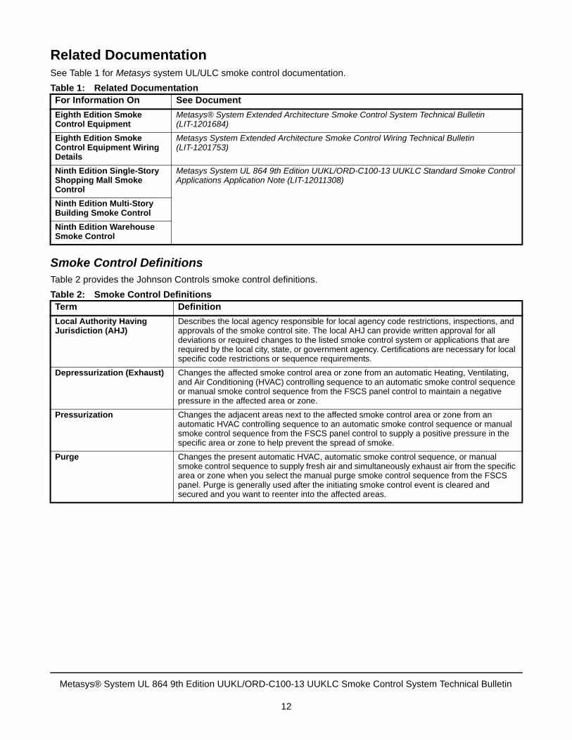
Related DocumentationSee Table 1 for Metasys system UL/ULC smoke control documentation.
Smoke Control DefinitionsTable 2 provides the Johnson Controls smoke control definitions.
Table 1: Related DocumentationFor Information On See Document
Eighth Edition Smoke Control Equipment
Metasys® System Extended Architecture Smoke Control System Technical Bulletin (LIT-1201684)
Eighth Edition Smoke Control Equipment Wiring Details
Metasys System Extended Architecture Smoke Control Wiring Technical Bulletin (LIT-1201753)
Ninth Edition Single-Story Shopping Mall Smoke Control
Metasys System UL 864 9th Edition UUKL/ORD-C100-13 UUKLC Standard Smoke Control Applications Application Note (LIT-12011308)
Ninth Edition Multi-Story Building Smoke Control
Ninth Edition Warehouse Smoke Control
Table 2: Smoke Control DefinitionsTerm Definition
Local Authority Having Jurisdiction (AHJ)
Describes the local agency responsible for local agency code restrictions, inspections, and approvals of the smoke control site. The local AHJ can provide written approval for all deviations or required changes to the listed smoke control system or applications that are required by the local city, state, or government agency. Certifications are necessary for local specific code restrictions or sequence requirements.
Depressurization (Exhaust) Changes the affected smoke control area or zone from an automatic Heating, Ventilating, and Air Conditioning (HVAC) controlling sequence to an automatic smoke control sequence or manual smoke control sequence from the FSCS panel control to maintain a negative pressure in the affected area or zone.
Pressurization Changes the adjacent areas next to the affected smoke control area or zone from an automatic HVAC controlling sequence to an automatic smoke control sequence or manual smoke control sequence from the FSCS panel control to supply a positive pressure in the specific area or zone to help prevent the spread of smoke.
Purge Changes the present automatic HVAC, automatic smoke control sequence, or manual smoke control sequence to supply fresh air and simultaneously exhaust air from the specific area or zone when you select the manual purge smoke control sequence from the FSCS panel. Purge is generally used after the initiating smoke control event is cleared and secured and you want to reenter into the affected areas.
Metasys® System UL 864 9th Edition UUKL/ORD-C100-13 UUKLC Smoke Control System Technical Bulletin
12

SCT, LCT, and CCT Standard Applications Library The System Configuration Tool (SCT) is used in all phases of engineering, installing, and commissioning of Network Engines (NxEs) and Field Controller (FC) bus devices that make up the Metasys smoke control system. The SCT is used offline to create archive databases that are downloaded to a smoke control NxE. The Logic Connector Tool (LCT), contained in the SCT, is used to create the standard smoke control applications logic and control. The Controller Configuration Tool (CCT) is used offline to create applications that configure the hardware input/output (I/O) in a Field Controller.
The standard smoke control applications can be installed and executed on any smoke control NxE. Use the standard smoke control applications as written; any sequence modification to the LCT program must be pre-approved by the AHJ. The SCT must not be accessible to anyone other than designated qualified technicians who are responsible for installing, commissioning, and maintaining the smoke control site configuration. Password restriction in conjunction with SCT accessibility prevents unauthorized editing of the smoke control sequences.
ReferencesWhen designing your smoke control system, read and become familiar with the following documents, codes, and standards, as applicable:
• National Fire Protection Association (NFPA) 92A Recommended Practice for Smoke Control Systems
• NFPA 92B Guide for Smoke Management Systems in Malls, Atria, and Large Areas
• NFPA 70 National Electrical Code
• NFPA 72 National Fire Alarm Code
• NFPA 101 Life Safety Code
• NFPA 90A Standard for the Installation of Air-Conditioning and Ventilating Systems
• International Code Council (ICC), which includes:
- Building Officials and Code Administrators International (BOCA) model code
- International Conference of Building Officials (ICBO) model code
- Southern Building Code Congress International (SBCCI) regulations
• UL 864 Control Units and Accessories for Fire Alarm Systems, 9th Edition, January 12, 2011
• ORD-C100-13 Smoke Control System Equipment
Metasys® System UL 864 9th Edition UUKL/ORD-C100-13 UUKLC Smoke Control System Technical Bulletin
13
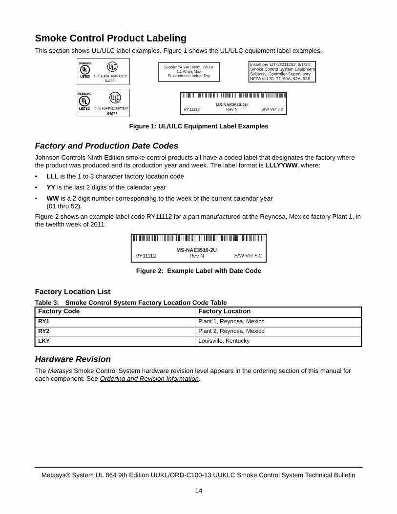
Smoke Control Product LabelingThis section shows UL/ULC label examples. Figure 1 shows the UL/ULC equipment label examples.
Factory and Production Date CodesJohnson Controls Ninth Edition smoke control products all have a coded label that designates the factory where the product was produced and its production year and week. The label format is LLLYYWW, where:
• LLL is the 1 to 3 character factory location code
• YY is the last 2 digits of the calendar year
• WW is a 2 digit number corresponding to the week of the current calendar year (01 thru 52).
Figure 2 shows an example label code RY11112 for a part manufactured at the Reynosa, Mexico factory Plant 1, in the twelfth week of 2011.
Factory Location List
Hardware RevisionThe Metasys Smoke Control System hardware revision level appears in the ordering section of this manual for each component. See Ordering and Revision Information.
Table 3: Smoke Control System Factory Location Code TableFactory Code Factory Location
RY1 Plant 1, Reynosa, Mexico
RY2 Plant 2, Reynosa, Mexico
LKY Louisville, Kentucky
Figure 1: UL/ULC Equipment Label Examples
MS-NAE3510-2URev N S/W Ver 5.2RY11112
Supply: 24 VAC Nom., 60 Hz1.1 Amps Max
Environment: Indoor Dry
Install per LIT-12011252, 8/1/12.Smoke Control System EquipmentSubassy, Controller-SupervisoryNFPA std 70, 72, 90A, 92A, 92B
Figure 2: Example Label with Date Code
MS-NAE3510-2URev N S/W Ver 5.2RY11112
Metasys® System UL 864 9th Edition UUKL/ORD-C100-13 UUKLC Smoke Control System Technical Bulletin
14
Software and Firmware Version NumberingMetasys smoke control system software uses an X.x.y numbering scheme, where:
• X is the major revision
• x is the minor revision
• y is a patch
Example: 5.2.10
Note: The current revision level is 5.2 for all Metasys components configured with System Configuration Tool (SCT) and 5.1 for all components configured with Controller Configuration Tool (CCT). All of the component revision levels appear in the Ordering and Revision Information section. For the UL/ULC components, all the revision levels appear on the UL/ULC label.
Software UpgradesWhen upgrading your Ninth Edition smoke control system to a major revision, such as from Release 4.1 to Release 5.2, be sure to respect the published object count for each engine in the smoke control system. If an engine exceeds its object count limit, you must add another engine to ensure the smoke control system functions properly. The engine must be ordered in a UL 864 9th Edition UUKL/ORD-C100-13 UUKLC custom or standard panel. You cannot mount an extra engine-U or -xU in the field to a new panel or to an existing panel. See Performance Guidelines and Limitations for Network Engines.
Software Patches
Be sure to install any Metasys system smoke control software patches that were released after your smoke control system was installed or upgraded.
To install Metasys system software patches for smoke control, contact your local Johnson Controls office, or:
Browse to one of the following locations:
Field Support Center (FSC) Product Quick Patch page at :https://my.jci.com/sites/BE/NAFieldSupport/quick-patches
For North American Authorized Building Controls Specialists (ABCS) Partners, go to the ABCS Exchange site under Metasys > Technical Support > Software Patches.
1. Search for patches that apply to the Metasys System Release 5.2 UL 864 9th Edition UUKL/ORD-C100-13 UUKLC Smoke Control System.
2. Follow patch installation instructions to install the patch.
Installation Instructions Revision LevelMetasys smoke control system installation instructions depict the current revision level of the document in the format MM/DD/YY, where:
• MM is the month
• DD is the day
• YY is the year
Although the revision level for all the drawings within this document show 08/01/12, the current revision level appears as the date on this manual. The smoke control listed product UL/ULC labels depict the current revision level of this technical bulletin.
Metasys® System UL 864 9th Edition UUKL/ORD-C100-13 UUKLC Smoke Control System Technical Bulletin
15
Smoke Control Requirements
Eighth Edition and Ninth Edition CoexistenceThe intended combined smoke control system must be approved in writing by the local AHJ prior to the installation of any Ninth Edition equipment.
To maintain the UL/ULC smoke control listing, the following rules for a smoke control system where Eighth Edition and Ninth Edition smoke control equipment coexist must be followed:
• The isolation of the Eighth and Ninth Edition smoke control equipment must occur at the Ethernet switch.
• The Eighth Edition smoke control system must be installed and operating as detailed in the Johnson Controls Metasys System Smoke Control UL 864 UUKL Eighth Edition literature.
• The Ninth Edition smoke control system must be installed and operate as detailed in the Johnson Controls Ninth Edition smoke control literature.
• Do not replace an Eighth Edition supervisory controller with a Ninth Edition supervisory controller to expand the Eighth Edition smoke control system. Eighth Edition smoke control systems must remain N2 field bus only and Ninth Edition smoke control systems must be MS/TP.
• If an Eighth Edition supervisory controller requires replacement, it must only be replaced with an Eighth Edition smoke control replacement part (Ninth Edition supervisory controllers are not allowed as Eight Edition replacement parts). The Johnson Controls Repair Center in Louisville, Kentucky provides smoke control replacements.
• The operation of the smoke control applications must have continuity between the two systems - floor above/floor below and so forth. Smoke control applications must be programmed to allow smoke control between all floors as if a single system were controlling the building.
• All Ninth Edition hardware must be loaded with the latest version of Metasys software approved for use with UL 864 9th Edition UUKL/ORD-C100-13 UUKLC smoke control. You may have non-smoke control hardware at a different release level than the smoke control hardware, but all smoke control hardware must be at the same release. For example, you can have two NxEs not approved for smoke control at Release 4.1 and 5.2, but if you have two NxEs approved for smoke control, they must both be at Release 4.1 or Release 5.2. In addition, if you are using an Application and Data Server (ADS) or Advanced Application and Data Server (ADX) to view the system (the ADS/ADX is not listed for smoke control), this device must be at the most recent Metasys release.
Note: The ADS/ADX may be at a higher release of Metasys software than the smoke control components because the ADS/ADX does not perform smoke control functions.
• All Field Controllers in a smoke control system (with the exception of the MS-FEU1610-0U in the FSCS panel) must be at the same software revision. For example, an FEU at CCT 4.1 must not coexist with an FEU at CCT 5.1 on an NAE-xU at Release 5.2.
Note: The MS-FEU1610-0U in the FSCS panel must be at Metasys CCT Release 4.1
Metasys® System UL 864 9th Edition UUKL/ORD-C100-13 UUKLC Smoke Control System Technical Bulletin
16
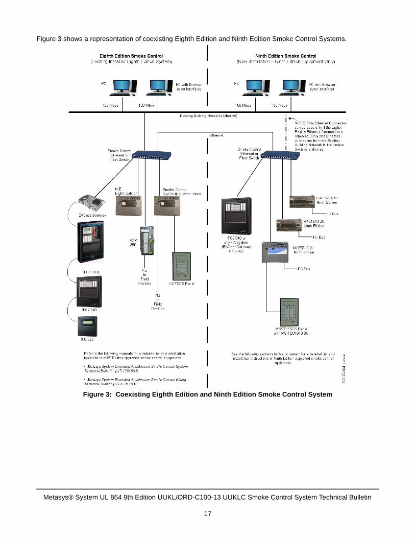
Figure 3 shows a representation of coexisting Eighth Edition and Ninth Edition Smoke Control Systems.
Figure 3: Coexisting Eighth Edition and Ninth Edition Smoke Control System
Metasys® System UL 864 9th Edition UUKL/ORD-C100-13 UUKLC Smoke Control System Technical Bulletin
17
Firefighters Smoke Control Station (FSCS)
FSCS Guidelines
Follow these guidelines:
• Use a UL 864 9th Edition UUKL/ORD-C100-13 UUKLC Listed FSCS to provide manual control of smoke control systems. You must use the FSCS panel from Automation Displays, Inc. (ADI), which has its own listing with the Johnson Controls MS-FEU1610-0U controller and PAN-PWRSP-U transformer. The local Johnson Controls office orders the MS-FEU1610-0U controller and PAN-PWRSP-U transformer from the Johnson Controls factory, and ship the two items to ADI to install in the FSCS panel. ADI programs the MS-FEU1610-0U controller with CCT 4.1 using a special tool. See the FSCS Requirements for ADI contact information.
• You cannot upgrade a MS-FEU1610-0U controller in the field. The MS-FEU1610-0U controller, which is enclosed in the FSCS panel, must be sent to ADI for a software revision. Upgrading the controller in the field voids the UL 864 9th Edition UUKL/ORD-C100-13 UUKLC listing. See the FSCS Requirements for ADI contact information.
• Provide a graphical representation of the building’s smoke control system to the AHJ or fire marshal and obtain approval before ordering an ADI panel.
• Provide positive indication of operation on the FSCS for all smoke control equipment; for example, the damper reaches its intended position.
• Configure each Binary Output (BO) object used for pressurization and exhaust control outputs with positive feedback. Positive feedback monitors the associated controlled equipment status. Typically, smoke control dampers provide a pair of feedback binary inputs for the two damper end switches, full open and full closed. For smoke control fans, provide positive indication of airflow with either a flow switch or pressure differential sensor to determine the intended operating status of the fan.
• Display the status of all smoke control systems on the FSCS.
• Indicate, both visibly and audibly, on the FSCS any trouble conditions, when smoke control equipment does not respond to automatic or manual commands. The FSCS controls the Sonalert® logic for all smoke control systems; no other application is necessary.
• Prevent the duct smoke detectors from stopping any smoke control fans once the smoke control system has been activated, if the smoke control strategy is such that the return duct exhausts the smoke from the building during the smoke control system operation. Duct smoke detectors are often located in the return duct of an HVAC fan and connected to stop the fan when smoke is detected, which is in compliance with NFPA 90A.
• Allow the overriding of the Weekly Dedicated Test sequence for higher priority requests. Refer to the Metasys System UL 864 9th Edition UUKL/ORD-C100-13 UUKLC Standard Smoke Control Applications Application Note (LIT-12011308) for more information. All dedicated smoke control systems require the Weekly Dedicated Test to verify the continuous proper operation of Smoke Control Dampers and Fans.
• Automatic activation of any smoke control sequence of operation must have priority over any Weekly Dedicated Test, automatic environmental control strategy, and over any non-smoke control manual commands. When an automatic smoke control sequence is initiated, the system design must bypass the following operational overrides:
- High and Low Temperature Protection Devices (specifically, A-11 and A-25 Series Temperature Protection Devices)
- Return and Exhaust Air Duct Smoke Detectors
• Make the indication of a trouble condition from any air duct smoke detector available to FSCS operators so that they are able to make informed decisions concerning their override actions if smoke is detected elsewhere, especially in the supply air. This indication can be in the form of annunciation on the fire alarm system control panel or a remote annunciator controlled by the fire alarm system.
Metasys® System UL 864 9th Edition UUKL/ORD-C100-13 UUKLC Smoke Control System Technical Bulletin
18

• Give the highest priority to the FSCS to manually activate or deactivate any predefined smoke control strategy. Give automatic smoke control a higher priority than any manual or automatic HVAC application. Give the Weekly Dedicated test higher priority than any manual or automatic HVAC application.
• After a smoke alarm is received and acted upon automatically by the smoke control system, additional smoke alarms must not cause the smoke control system to take automatic secondary actions. However, the system must execute any manual commands from the FSCS.
• Ensure that all communication links between buildings are fiber-optic cable.
• Ensure that all communication links between rooms are copper cable buried in a conduit that is separate from power wiring.
• Ensure that response time for individual smoke control components to reach their intended position from the point of command does not exceed the following time periods: 60 seconds for fan operation at the desired state plus 90 seconds to annunciate and 75 seconds for completion of damper travel plus 90 seconds to annunciate. In the case of fan start after damper close, add these times. If the damper must be closed before the fan starts, the total response time could be up to 135 seconds for operation, 75 seconds for damper to close plus 60 seconds for fan to start. Time to annunciate is added to this time. (Control system response is the time from automatic detection of a smoke condition to the issuing of the first smoke control command to the equipment.)
• Use the UL/ULC Listed Smoke Control NAE to interface all input and output smoke control points.
• Observe the status of the Programming LED. When illuminated, the Programming LED indicates that an operator is currently making changes to the smoke control system logic. When off, the Programming LED indicates that no logic changes are being made.
FSCS Requirements
Requirements of an FSCS include the following. The FSCS must have:
• full monitoring and manual control capability over all smoke control systems and equipment
• the capability to override (partially or fully) any operation in progress, including programmed actions, non-smoke control manual overrides, and non-smoke control bypasses
• the highest priority over all smoke control systems and equipment
• a building diagram clearly indicating the type and location of all smoke control equipment. The graphic depicting the building diagram must be approved by the local fire marshal or AHJ.
• indication of the actual status (not the command status) of systems and equipment used for smoke control. This includes both the full open status and the full closed status of each damper, the status of each fan used for smoke control, and the airflow status of every fan.
• the ability to activate an audible signal if the operation proof sensor (feedback point) failed to provide positive feedback that its command was executed within the allowed response time
• hardware supervision alarms, such as binary feedback trouble on fans and dampers, as well as the system trouble points, that turn on the FSCS alarm horn
• sole control (use only one FSCS on a Metasys system network used for smoke control applications, unless multiple FSCSs are approved by the AHJ).
Note: You must use an approved UL/ULC Listed display panel as your FSCS. Contact ADI for an approved FSCS panel. ADI ships approved panels to both the United States and Canada.
Automation Displays, Inc. (ADI)3533 N. White AvenueEau Claire, WI 54703(715) 834-9595http://www.adipanel.com
Metasys® System UL 864 9th Edition UUKL/ORD-C100-13 UUKLC Smoke Control System Technical Bulletin
19
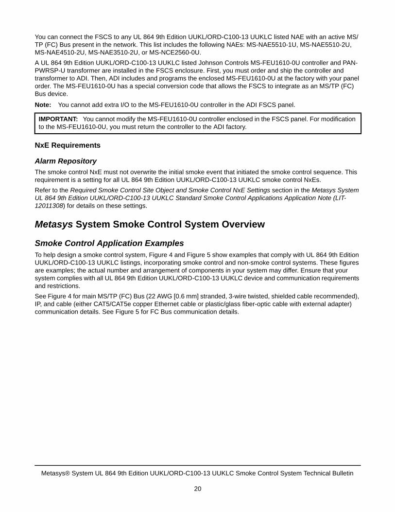
You can connect the FSCS to any UL 864 9th Edition UUKL/ORD-C100-13 UUKLC listed NAE with an active MS/TP (FC) Bus present in the network. This list includes the following NAEs: MS-NAE5510-1U, MS-NAE5510-2U, MS-NAE4510-2U, MS-NAE3510-2U, or MS-NCE2560-0U.
A UL 864 9th Edition UUKL/ORD-C100-13 UUKLC listed Johnson Controls MS-FEU1610-0U controller and PAN-PWRSP-U transformer are installed in the FSCS enclosure. First, you must order and ship the controller and transformer to ADI. Then, ADI includes and programs the enclosed MS-FEU1610-0U at the factory with your panel order. The MS-FEU1610-0U has a special conversion code that allows the FSCS to integrate as an MS/TP (FC) Bus device.
Note: You cannot add extra I/O to the MS-FEU1610-0U controller in the ADI FSCS panel.
NxE Requirements
Alarm Repository
The smoke control NxE must not overwrite the initial smoke event that initiated the smoke control sequence. This requirement is a setting for all UL 864 9th Edition UUKL/ORD-C100-13 UUKLC smoke control NxEs.
Refer to the Required Smoke Control Site Object and Smoke Control NxE Settings section in the Metasys System UL 864 9th Edition UUKL/ORD-C100-13 UUKLC Standard Smoke Control Applications Application Note (LIT-12011308) for details on these settings.
Metasys System Smoke Control System Overview
Smoke Control Application ExamplesTo help design a smoke control system, Figure 4 and Figure 5 show examples that comply with UL 864 9th Edition UUKL/ORD-C100-13 UUKLC listings, incorporating smoke control and non-smoke control systems. These figures are examples; the actual number and arrangement of components in your system may differ. Ensure that your system complies with all UL 864 9th Edition UUKL/ORD-C100-13 UUKLC device and communication requirements and restrictions.
See Figure 4 for main MS/TP (FC) Bus (22 AWG [0.6 mm] stranded, 3-wire twisted, shielded cable recommended), IP, and cable (either CAT5/CAT5e copper Ethernet cable or plastic/glass fiber-optic cable with external adapter) communication details. See Figure 5 for FC Bus communication details.
IMPORTANT: You cannot modify the MS-FEU1610-0U controller enclosed in the FSCS panel. For modification to the MS-FEU1610-0U, you must return the controller to the ADI factory.
Metasys® System UL 864 9th Edition UUKL/ORD-C100-13 UUKLC Smoke Control System Technical Bulletin
20
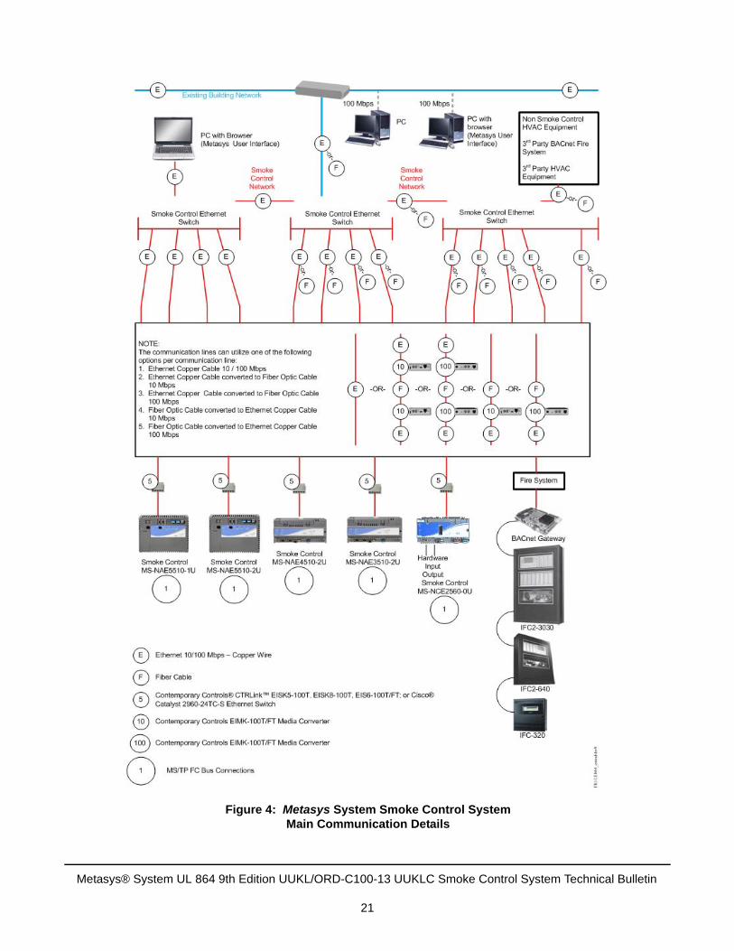
Figure 4: Metasys System Smoke Control SystemMain Communication Details
Metasys® System UL 864 9th Edition UUKL/ORD-C100-13 UUKLC Smoke Control System Technical Bulletin
21
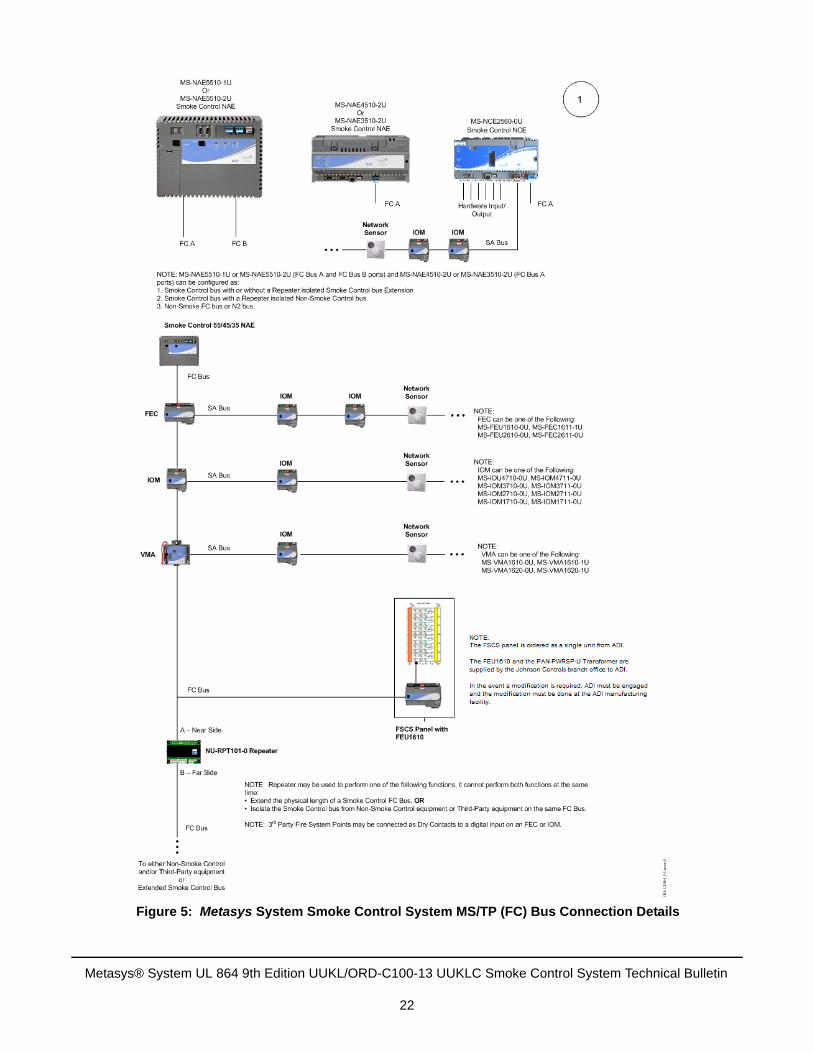
Figure 5: Metasys System Smoke Control System MS/TP (FC) Bus Connection Details
Metasys® System UL 864 9th Edition UUKL/ORD-C100-13 UUKLC Smoke Control System Technical Bulletin
22
Overview of HVAC Smoke Control System Types
Central Systems
Central HVAC systems are frequently employed in smoke control designs. The designer should ensure that the system’s capacity is sufficient to supply the quantity of outdoor air necessary to pressurize the areas adjacent to any fire area. The designer should also make sure that the fan systems can handle situations where a fire may expand to other areas, requiring more areas to be positively pressurized. In addition, the installer must install smoke dampers at the duct risers of each floor’s supply and return takeoffs as required by NFPA 92A. Pressure controls should also be employed to avoid rupturing or collapsing the ductwork.
Dedicated Smoke Control Systems
Dedicated smoke control systems are fan, damper, and duct systems designed for the sole purpose of controlling smoke within a building. An example of a dedicated system is a stairwell or elevator shaft pressurization system that is operational only during a smoke control event. The dedicated smoke control systems form a system of air movement that is separate and distinct from the building’s HVAC system, and they only operate to control the flow of smoke. With their function being dedicated to the performance of smoke control, dedicated smoke control systems are more immune to faults in the building’s HVAC system.
Note: To assure full performance and maintain UL/ULC compliance, apply automatic weekly testing to all dedicated systems, including dedicated elevator shaft fans and dampers used exclusively for smoke control. Refer to the Metasys System UL 864 9th Edition UUKL/ORD-C100-13 UUKLC Standard Smoke Control Applications Application Note (LIT-12011308) for details on how to perform the necessary tests. Any failure to properly respond in the allotted time must send a trouble signal to the FSCS.
Non-Dedicated Smoke Control Systems
Non-dedicated smoke control systems share components with other air moving equipment normally used for building environmental control. When the smoke control mode is activated, the operating mode of the building’s HVAC equipment changes in order to accomplish the objectives of the smoke control design. Non-dedicated systems tend to be less costly and occupy less space. However, from an operational standpoint, the control strategy becomes more elaborate. This strategy may expand the number of control and monitoring points connected to a Building Automation System (BAS) and increase the complexity of the sequence of operation of the air moving equipment.
Individual Floor Fan Units
If sufficient outdoor air is available and the system has the capability to exhaust an area, individual, or floor-by-floor fan units can be used in smoke control applications.
Fan Coil Units/Water Source Heat Pumps
These types of units are generally located on the perimeters of buildings and draw only enough outdoor air to fulfill the fresh air requirements of the spaces they serve. The units are used in conjunction with central systems, which deliver fresh air and exhaust recirculated air in larger quantities. When the fan coil unit is not located in the smoke zone, it is acceptable to exclude it from the smoke control sequence. When the unit serves the smoke zone in a design that calls for the area to be negatively pressurized, its outdoor air damper should be closed, and the unit should be de-energized.
Induction Units
During a smoke control mode, induction units that serve the smoke zone should be shut down, or their primary air source should be closed off.
Metasys® System UL 864 9th Edition UUKL/ORD-C100-13 UUKLC Smoke Control System Technical Bulletin
23
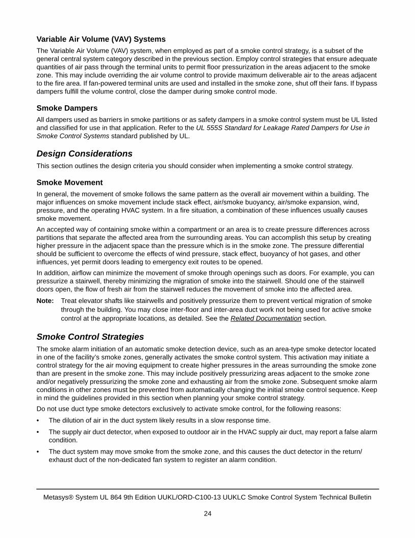
Variable Air Volume (VAV) Systems
The Variable Air Volume (VAV) system, when employed as part of a smoke control strategy, is a subset of the general central system category described in the previous section. Employ control strategies that ensure adequate quantities of air pass through the terminal units to permit floor pressurization in the areas adjacent to the smoke zone. This may include overriding the air volume control to provide maximum deliverable air to the areas adjacent to the fire area. If fan-powered terminal units are used and installed in the smoke zone, shut off their fans. If bypass dampers fulfill the volume control, close the damper during smoke control mode.
Smoke Dampers
All dampers used as barriers in smoke partitions or as safety dampers in a smoke control system must be UL listed and classified for use in that application. Refer to the UL 555S Standard for Leakage Rated Dampers for Use in Smoke Control Systems standard published by UL.
Design ConsiderationsThis section outlines the design criteria you should consider when implementing a smoke control strategy.
Smoke Movement
In general, the movement of smoke follows the same pattern as the overall air movement within a building. The major influences on smoke movement include stack effect, air/smoke buoyancy, air/smoke expansion, wind, pressure, and the operating HVAC system. In a fire situation, a combination of these influences usually causes smoke movement.
An accepted way of containing smoke within a compartment or an area is to create pressure differences across partitions that separate the affected area from the surrounding areas. You can accomplish this setup by creating higher pressure in the adjacent space than the pressure which is in the smoke zone. The pressure differential should be sufficient to overcome the effects of wind pressure, stack effect, buoyancy of hot gases, and other influences, yet permit doors leading to emergency exit routes to be opened.
In addition, airflow can minimize the movement of smoke through openings such as doors. For example, you can pressurize a stairwell, thereby minimizing the migration of smoke into the stairwell. Should one of the stairwell doors open, the flow of fresh air from the stairwell reduces the movement of smoke into the affected area.
Note: Treat elevator shafts like stairwells and positively pressurize them to prevent vertical migration of smoke through the building. You may close inter-floor and inter-area duct work not being used for active smoke control at the appropriate locations, as detailed. See the Related Documentation section.
Smoke Control StrategiesThe smoke alarm initiation of an automatic smoke detection device, such as an area-type smoke detector located in one of the facility’s smoke zones, generally activates the smoke control system. This activation may initiate a control strategy for the air moving equipment to create higher pressures in the areas surrounding the smoke zone than are present in the smoke zone. This may include positively pressurizing areas adjacent to the smoke zone and/or negatively pressurizing the smoke zone and exhausting air from the smoke zone. Subsequent smoke alarm conditions in other zones must be prevented from automatically changing the initial smoke control sequence. Keep in mind the guidelines provided in this section when planning your smoke control strategy.
Do not use duct type smoke detectors exclusively to activate smoke control, for the following reasons:
• The dilution of air in the duct system likely results in a slow response time.
• The supply air duct detector, when exposed to outdoor air in the HVAC supply air duct, may report a false alarm condition.
• The duct system may move smoke from the smoke zone, and this causes the duct detector in the return/exhaust duct of the non-dedicated fan system to register an alarm condition.
Metasys® System UL 864 9th Edition UUKL/ORD-C100-13 UUKLC Smoke Control System Technical Bulletin
24
Note: It may be acceptable to use a duct smoke detector if it is not exposed to outdoor air, the duct detector’s coverage area is equal to the area covered by a spot type area smoke detector (typically 900 square feet or less), the AHJ has approved the application, or both.
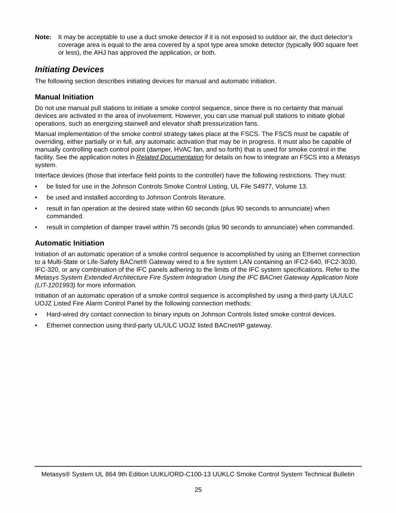
Initiating DevicesThe following section describes initiating devices for manual and automatic initiation.
Manual Initiation
Do not use manual pull stations to initiate a smoke control sequence, since there is no certainty that manual devices are activated in the area of involvement. However, you can use manual pull stations to initiate global operations, such as energizing stairwell and elevator shaft pressurization fans.
Manual implementation of the smoke control strategy takes place at the FSCS. The FSCS must be capable of overriding, either partially or in full, any automatic activation that may be in progress. It must also be capable of manually controlling each control point (damper, HVAC fan, and so forth) that is used for smoke control in the facility. See the application notes in Related Documentation for details on how to integrate an FSCS into a Metasys system.
Interface devices (those that interface field points to the controller) have the following restrictions. They must:
• be listed for use in the Johnson Controls Smoke Control Listing, UL File S4977, Volume 13.
• be used and installed according to Johnson Controls literature.
• result in fan operation at the desired state within 60 seconds (plus 90 seconds to annunciate) when commanded.
• result in completion of damper travel within 75 seconds (plus 90 seconds to annunciate) when commanded.
Automatic Initiation
Initiation of an automatic operation of a smoke control sequence is accomplished by using an Ethernet connection to a Multi-State or Life-Safety BACnet® Gateway wired to a fire system LAN containing an IFC2-640, IFC2-3030, IFC-320, or any combination of the IFC panels adhering to the limits of the IFC system specifications. Refer to the Metasys System Extended Architecture Fire System Integration Using the IFC BACnet Gateway Application Note (LIT-1201993) for more information.
Initiation of an automatic operation of a smoke control sequence is accomplished by using a third-party UL/ULC UOJZ Listed Fire Alarm Control Panel by the following connection methods:
• Hard-wired dry contact connection to binary inputs on Johnson Controls listed smoke control devices.
• Ethernet connection using third-party UL/ULC UOJZ listed BACnet/IP gateway.
Metasys® System UL 864 9th Edition UUKL/ORD-C100-13 UUKLC Smoke Control System Technical Bulletin
25
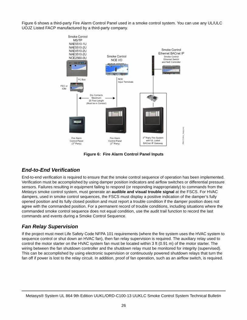
Figure 6 shows a third-party Fire Alarm Control Panel used in a smoke control system. You can use any UL/ULC UOJZ Listed FACP manufactured by a third-party company.
End-to-End VerificationEnd-to-end verification is required to ensure that the smoke control sequence of operation has been implemented. Verification must be accomplished by using damper position indicators and airflow switches or differential pressure sensors. Failures resulting in equipment failing to respond (or responding inappropriately) to commands from the Metasys smoke control system, must generate an audible and visual trouble signal at the FSCS. For HVAC dampers, used in smoke control sequences, the FSCS must display a positive indication of the damper’s fully opened position and its fully closed position and must report a trouble condition if the damper position does not agree with the commanded position. For a permanent record of trouble conditions, including situations where the commanded smoke control sequence does not equal condition, use the audit trail function to record the last commands and events during a Smoke Control Sequence.
Fan Relay SupervisionIf the project must meet Life Safety Code NFPA 101 requirements (where the fire system uses the HVAC system to sequence control or shut down an HVAC fan), then fan relay supervision is required. The auxiliary relay used to control the motor starter on the HVAC system fan must be located within 3 ft (0.91 m) of the motor starter. The wiring between the fan shutdown controller and the shutdown relay must be monitored for integrity (supervised). This can be accomplished by using electronic supervision or continuously powered shutdown relays that turn the fan off if power is lost to the relay circuit. In addition, proof of fan operation, such as an airflow switch, is required.
Figure 6: Fire Alarm Control Panel Inputs
Metasys® System UL 864 9th Edition UUKL/ORD-C100-13 UUKLC Smoke Control System Technical Bulletin
26
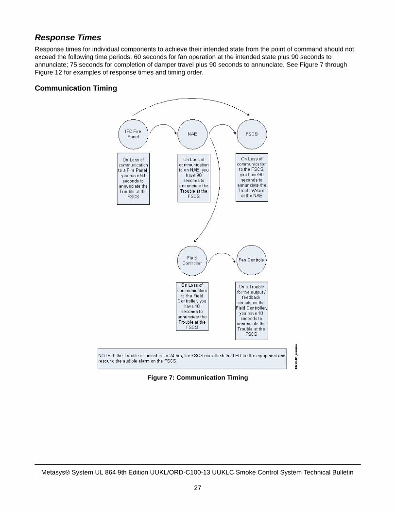
Response TimesResponse times for individual components to achieve their intended state from the point of command should not exceed the following time periods: 60 seconds for fan operation at the intended state plus 90 seconds to annunciate; 75 seconds for completion of damper travel plus 90 seconds to annunciate. See Figure 7 through Figure 12 for examples of response times and timing order.
Communication Timing
Figure 7: Communication Timing
Metasys® System UL 864 9th Edition UUKL/ORD-C100-13 UUKLC Smoke Control System Technical Bulletin
27
Automatic Fan Command Timing
Fig
ure
8:
Au
tom
atic
Fan
Co
mm
and
Tim
ing
Metasys® System UL 864 9th Edition UUKL/ORD-C100-13 UUKLC Smoke Control System Technical Bulletin
28
Manual Fan Command Timing
Fig
ure
9:
Ma
nu
al F
an C
om
man
d T
imin
g
Metasys® System UL 864 9th Edition UUKL/ORD-C100-13 UUKLC Smoke Control System Technical Bulletin
29
Weekly Dedicated Fan Test Timing
Fig
ure
10
: W
eek
ly D
ed
icat
ed F
an
Te
st
Tim
ing
Metasys® System UL 864 9th Edition UUKL/ORD-C100-13 UUKLC Smoke Control System Technical Bulletin
30
Automatic Damper Command Timing
Fig
ure
11
: A
uto
mat
ic D
amp
er C
om
man
d T
imin
g
Metasys® System UL 864 9th Edition UUKL/ORD-C100-13 UUKLC Smoke Control System Technical Bulletin
31
Manual Damper Command Timing
Fig
ure
1:
Man
ual
Da
mp
er C
om
man
d T
imin
g
Metasys® System UL 864 9th Edition UUKL/ORD-C100-13 UUKLC Smoke Control System Technical Bulletin
32
Weekly Dedicated Damper Test Timing
Fig
ure
12:
We
ekly
Ded
icat
ed
Da
mp
er
Tes
t T
imin
g
Metasys® System UL 864 9th Edition UUKL/ORD-C100-13 UUKLC Smoke Control System Technical Bulletin
33
Fire Alarm Annunciation PanelsJohnson Controls fire alarm annunciation panels are available in many different configurations. Your panel may not match the photos shown of the panels in this section. Depending on the manufacturer of the fire alarm system that the Johnson Controls UL 864 9th Edition UUKL/ORD-C100-13 UUKLC smoke control system interfaces with, you may need to order a separate electronics card for a BACnet gateway. The BACnet gateway offering varies with different fire alarm systems. Refer to the Metasys System Extended Architecture Fire System Integration Using the IFC BACnet Gateway Application Note (LIT-1201993) for more information.
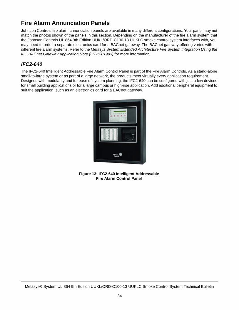
IFC2-640The IFC2-640 Intelligent Addressable Fire Alarm Control Panel is part of the Fire Alarm Controls. As a stand-alone small-to-large system or as part of a large network, the products meet virtually every application requirement. Designed with modularity and for ease of system planning, the IFC2-640 can be configured with just a few devices for small building applications or for a large campus or high-rise application. Add additional peripheral equipment to suit the application, such as an electronics card for a BACnet gateway.
Figure 13: IFC2-640 Intelligent AddressableFire Alarm Control Panel
Metasys® System UL 864 9th Edition UUKL/ORD-C100-13 UUKLC Smoke Control System Technical Bulletin
34
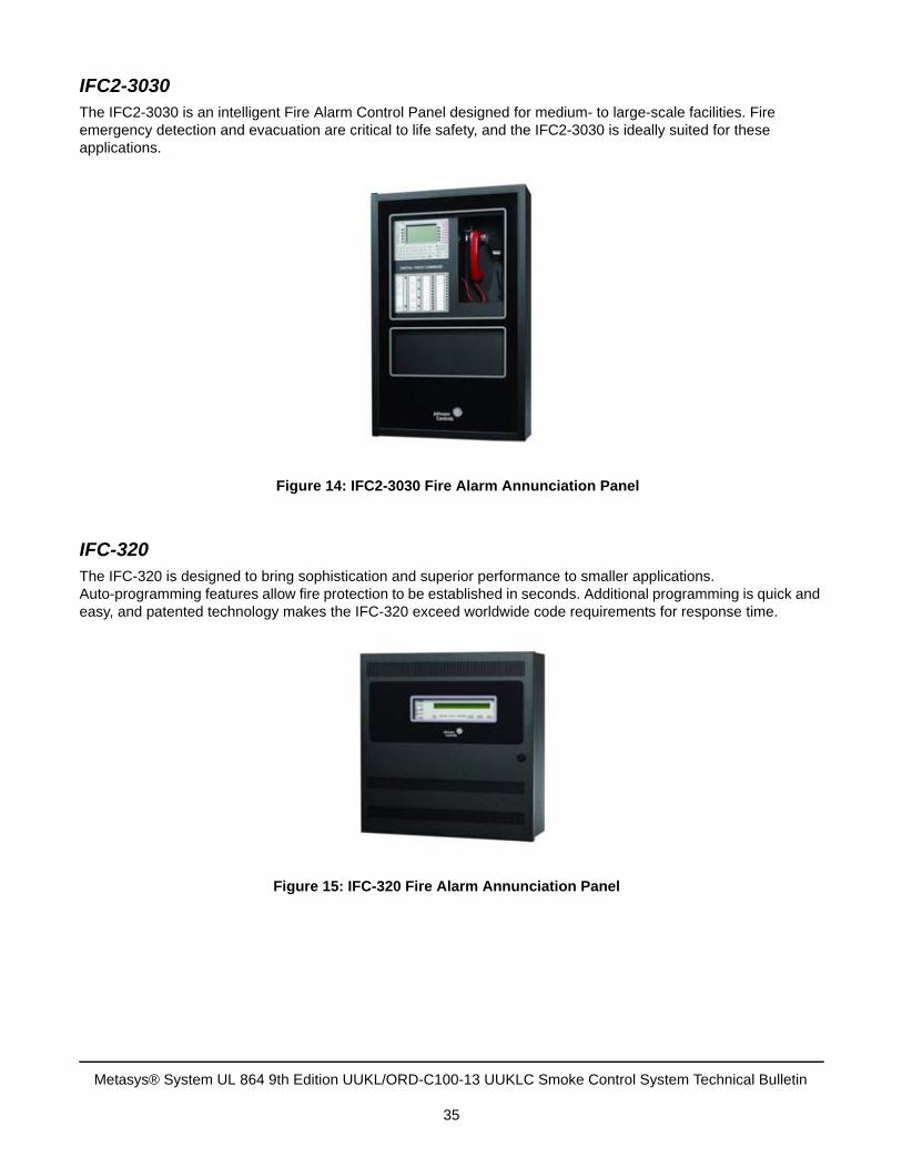
IFC2-3030The IFC2-3030 is an intelligent Fire Alarm Control Panel designed for medium- to large-scale facilities. Fire emergency detection and evacuation are critical to life safety, and the IFC2-3030 is ideally suited for these applications.
IFC-320The IFC-320 is designed to bring sophistication and superior performance to smaller applications. Auto-programming features allow fire protection to be established in seconds. Additional programming is quick and easy, and patented technology makes the IFC-320 exceed worldwide code requirements for response time.
Figure 14: IFC2-3030 Fire Alarm Annunciation Panel
Figure 15: IFC-320 Fire Alarm Annunciation Panel
Metasys® System UL 864 9th Edition UUKL/ORD-C100-13 UUKLC Smoke Control System Technical Bulletin
35
Surge Protection Devices
Ethernet Transient Protection
American Power Conversion® (APC) PNET1GB Ethernet Transient Protector
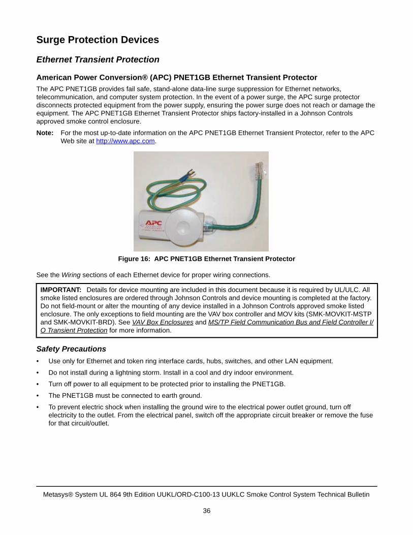
The APC PNET1GB provides fail safe, stand-alone data-line surge suppression for Ethernet networks, telecommunication, and computer system protection. In the event of a power surge, the APC surge protector disconnects protected equipment from the power supply, ensuring the power surge does not reach or damage the equipment. The APC PNET1GB Ethernet Transient Protector ships factory-installed in a Johnson Controls approved smoke control enclosure.
Note: For the most up-to-date information on the APC PNET1GB Ethernet Transient Protector, refer to the APC Web site at http://www.apc.com.
See the Wiring sections of each Ethernet device for proper wiring connections.
Safety Precautions
• Use only for Ethernet and token ring interface cards, hubs, switches, and other LAN equipment.
• Do not install during a lightning storm. Install in a cool and dry indoor environment.
• Turn off power to all equipment to be protected prior to installing the PNET1GB.
• The PNET1GB must be connected to earth ground.
• To prevent electric shock when installing the ground wire to the electrical power outlet ground, turn off electricity to the outlet. From the electrical panel, switch off the appropriate circuit breaker or remove the fuse for that circuit/outlet.
IMPORTANT: Details for device mounting are included in this document because it is required by UL/ULC. All smoke listed enclosures are ordered through Johnson Controls and device mounting is completed at the factory. Do not field-mount or alter the mounting of any device installed in a Johnson Controls approved smoke listed enclosure. The only exceptions to field mounting are the VAV box controller and MOV kits (SMK-MOVKIT-MSTP and SMK-MOVKIT-BRD). See VAV Box Enclosures and MS/TP Field Communication Bus and Field Controller I/O Transient Protection for more information.
Figure 16: APC PNET1GB Ethernet Transient Protector
Metasys® System UL 864 9th Edition UUKL/ORD-C100-13 UUKLC Smoke Control System Technical Bulletin
36
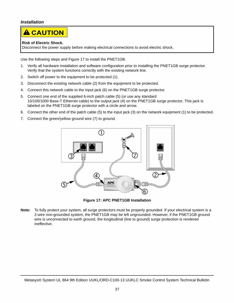
Installation
Use the following steps and Figure 17 to install the PNET1GB.
1. Verify all hardware installation and software configuration prior to installing the PNET1GB surge protector. Verify that the system functions correctly with the existing network line.
2. Switch off power to the equipment to be protected (1).
3. Disconnect the existing network cable (2) from the equipment to be protected.
4. Connect this network cable to the input jack (6) on the PNET1GB surge protector.
5. Connect one end of the supplied 6-inch patch cable (5) (or use any standard 10/100/1000 Base-T Ethernet cable) to the output jack (4) on the PNET1GB surge protector. This jack is labeled on the PNET1GB surge protector with a circle and arrow.
6. Connect the other end of the patch cable (5) to the input jack (3) on the network equipment (1) to be protected.
7. Connect the green/yellow ground wire (7) to ground.
Note: To fully protect your system, all surge protectors must be properly grounded. If your electrical system is a 2-wire non-grounded system, the PNET1GB may be left ungrounded. However, if the PNET1GB ground wire is unconnected to earth ground, the longitudinal (line to ground) surge protection is rendered ineffective.
Risk of Electric Shock.Disconnect the power supply before making electrical connections to avoid electric shock.
Figure 17: APC PNET1GB Installation
Metasys® System UL 864 9th Edition UUKL/ORD-C100-13 UUKLC Smoke Control System Technical Bulletin
37
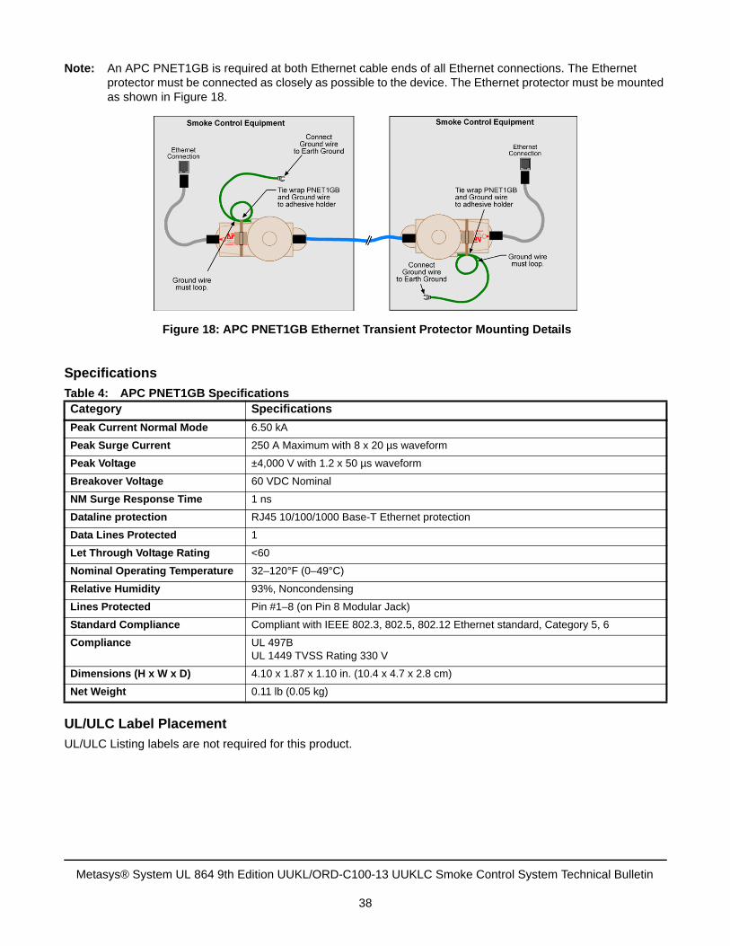
Note: An APC PNET1GB is required at both Ethernet cable ends of all Ethernet connections. The Ethernet protector must be connected as closely as possible to the device. The Ethernet protector must be mounted as shown in Figure 18.
Specifications
UL/ULC Label Placement
UL/ULC Listing labels are not required for this product.
Table 4: APC PNET1GB SpecificationsCategory Specifications
Peak Current Normal Mode 6.50 kA
Peak Surge Current 250 A Maximum with 8 x 20 µs waveform
Peak Voltage ±4,000 V with 1.2 x 50 µs waveform
Breakover Voltage 60 VDC Nominal
NM Surge Response Time 1 ns
Dataline protection RJ45 10/100/1000 Base-T Ethernet protection
Data Lines Protected 1
Let Through Voltage Rating <60
Nominal Operating Temperature 32–120°F (0–49°C)
Relative Humidity 93%, Noncondensing
Lines Protected Pin #1–8 (on Pin 8 Modular Jack)
Standard Compliance Compliant with IEEE 802.3, 802.5, 802.12 Ethernet standard, Category 5, 6
Compliance UL 497BUL 1449 TVSS Rating 330 V
Dimensions (H x W x D) 4.10 x 1.87 x 1.10 in. (10.4 x 4.7 x 2.8 cm)
Net Weight 0.11 lb (0.05 kg)
Figure 18: APC PNET1GB Ethernet Transient Protector Mounting Details
Metasys® System UL 864 9th Edition UUKL/ORD-C100-13 UUKLC Smoke Control System Technical Bulletin
38
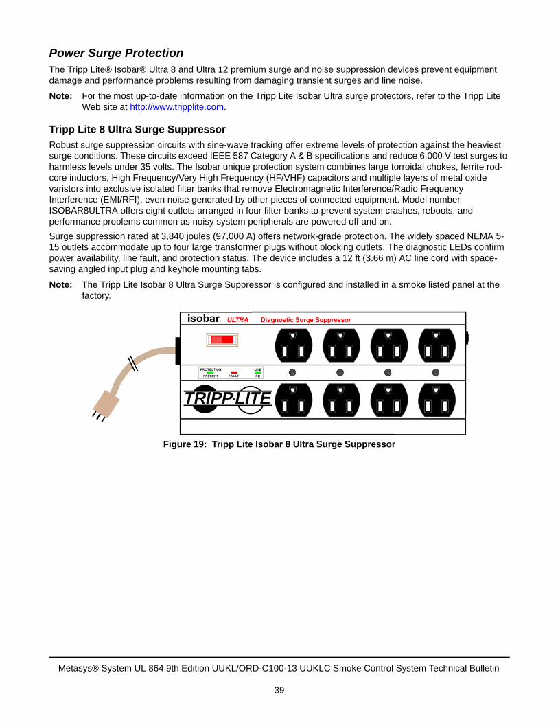
Power Surge ProtectionThe Tripp Lite® Isobar® Ultra 8 and Ultra 12 premium surge and noise suppression devices prevent equipment damage and performance problems resulting from damaging transient surges and line noise.
Note: For the most up-to-date information on the Tripp Lite Isobar Ultra surge protectors, refer to the Tripp Lite Web site at http://www.tripplite.com.
Tripp Lite 8 Ultra Surge Suppressor
Robust surge suppression circuits with sine-wave tracking offer extreme levels of protection against the heaviest surge conditions. These circuits exceed IEEE 587 Category A & B specifications and reduce 6,000 V test surges to harmless levels under 35 volts. The Isobar unique protection system combines large torroidal chokes, ferrite rod-core inductors, High Frequency/Very High Frequency (HF/VHF) capacitors and multiple layers of metal oxide varistors into exclusive isolated filter banks that remove Electromagnetic Interference/Radio Frequency Interference (EMI/RFI), even noise generated by other pieces of connected equipment. Model number ISOBAR8ULTRA offers eight outlets arranged in four filter banks to prevent system crashes, reboots, and performance problems common as noisy system peripherals are powered off and on.
Surge suppression rated at 3,840 joules (97,000 A) offers network-grade protection. The widely spaced NEMA 5-15 outlets accommodate up to four large transformer plugs without blocking outlets. The diagnostic LEDs confirm power availability, line fault, and protection status. The device includes a 12 ft (3.66 m) AC line cord with space-saving angled input plug and keyhole mounting tabs.
Note: The Tripp Lite Isobar 8 Ultra Surge Suppressor is configured and installed in a smoke listed panel at the factory.
Figure 19: Tripp Lite Isobar 8 Ultra Surge Suppressor
Metasys® System UL 864 9th Edition UUKL/ORD-C100-13 UUKLC Smoke Control System Technical Bulletin
39
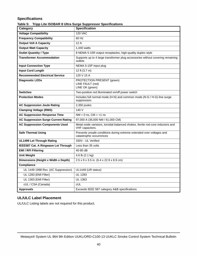
Specifications
UL/ULC Label Placement
UL/ULC Listing labels are not required for this product.
Table 5: Tripp Lite ISOBAR 8 Ultra Surge Suppressor SpecificationsCategory Specification
Voltage Compatibility 120 VAC
Frequency Compatibility 60 Hz
Output Volt A Capacity 12 A
Output Watt Capacity 1,440 watts
Outlet Quantity / Type 8 NEMA 5-15R output receptacles, high-quality duplex style
Transformer Accommodation Supports up to 4 large transformer plug accessories without covering remaining outlets
Input Connection Type NEMA 5-15P input plug
Input Cord Length 12 ft (3.7 m)
Recommended Electrical Service 120 V 15 A
Diagnostic LEDs PROTECTION PRESENT (green)LINE FAULT (red)LINE OK (green)
Switches Two-position red illuminated on/off power switch
Protection Modes Includes full normal mode (H-N) and common mode (N-G / H-G) line surge suppression
AC Suppression Joule Rating 2,350 joules
Clamping Voltage (RMS) 140 V
AC Suppression Response Time NM = 0 ns, CM = <1 ns
AC Suppression Surge Current Rating 97,000 A (36,000 NM / 61,000 CM)
AC Suppression Components Used Metal oxide varistors, toroidal balanced chokes, ferrite rod-core inductors and VHF capacitors.
Safe Thermal Using Prevents unsafe conditions during extreme extended over voltages and catastrophic occurrences
UL1499 Let Through Rating 330V - UL Verified
IEEE587 Cat. A Ringwave Let Through Less than 35 volts
EMI / RFI Filtering 40-80 dB
Unit Weight 4.6 lb (2.1 kg)
Dimensions (Height x Width x Depth) 2.5 x 9 x 3.5 in. (6.4 x 22.9 x 8.9 cm)
Compliance
UL 1449 1998 Rev. (AC Suppression) UL1449 (UR status)
UL 1283 (EMI Filter) UL 1283
UL 1363 (EMI Filter) UL 1363
cUL / CSA (Canada) cUL
Approvals Exceeds IEEE 587 category A&B specifications
Metasys® System UL 864 9th Edition UUKL/ORD-C100-13 UUKLC Smoke Control System Technical Bulletin
40
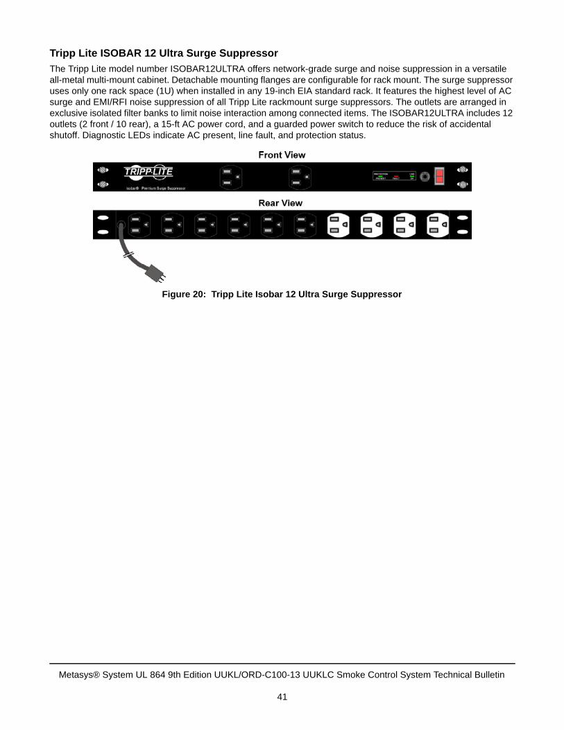
Tripp Lite ISOBAR 12 Ultra Surge Suppressor
The Tripp Lite model number ISOBAR12ULTRA offers network-grade surge and noise suppression in a versatile all-metal multi-mount cabinet. Detachable mounting flanges are configurable for rack mount. The surge suppressor uses only one rack space (1U) when installed in any 19-inch EIA standard rack. It features the highest level of AC surge and EMI/RFI noise suppression of all Tripp Lite rackmount surge suppressors. The outlets are arranged in exclusive isolated filter banks to limit noise interaction among connected items. The ISOBAR12ULTRA includes 12 outlets (2 front / 10 rear), a 15-ft AC power cord, and a guarded power switch to reduce the risk of accidental shutoff. Diagnostic LEDs indicate AC present, line fault, and protection status.
Figure 20: Tripp Lite Isobar 12 Ultra Surge Suppressor
Metasys® System UL 864 9th Edition UUKL/ORD-C100-13 UUKLC Smoke Control System Technical Bulletin
41
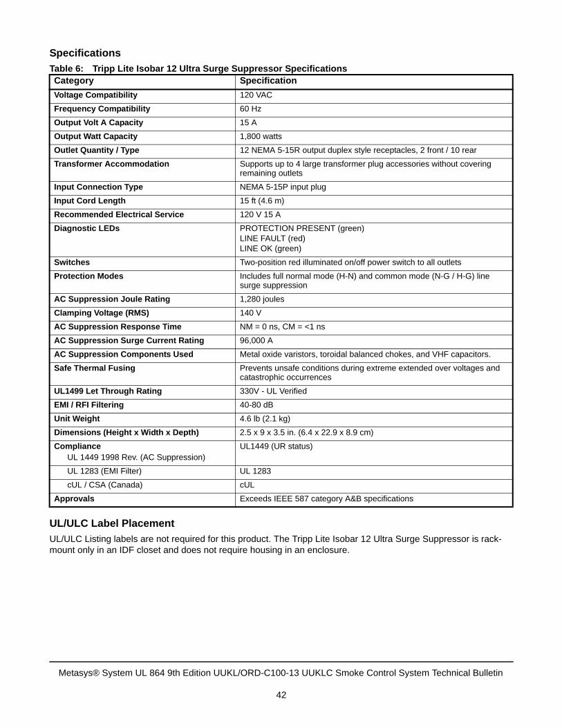
Specifications
UL/ULC Label Placement
UL/ULC Listing labels are not required for this product. The Tripp Lite Isobar 12 Ultra Surge Suppressor is rack-mount only in an IDF closet and does not require housing in an enclosure.
Table 6: Tripp Lite Isobar 12 Ultra Surge Suppressor SpecificationsCategory Specification
Voltage Compatibility 120 VAC
Frequency Compatibility 60 Hz
Output Volt A Capacity 15 A
Output Watt Capacity 1,800 watts
Outlet Quantity / Type 12 NEMA 5-15R output duplex style receptacles, 2 front / 10 rear
Transformer Accommodation Supports up to 4 large transformer plug accessories without covering remaining outlets
Input Connection Type NEMA 5-15P input plug
Input Cord Length 15 ft (4.6 m)
Recommended Electrical Service 120 V 15 A
Diagnostic LEDs PROTECTION PRESENT (green)LINE FAULT (red)LINE OK (green)
Switches Two-position red illuminated on/off power switch to all outlets
Protection Modes Includes full normal mode (H-N) and common mode (N-G / H-G) line surge suppression
AC Suppression Joule Rating 1,280 joules
Clamping Voltage (RMS) 140 V
AC Suppression Response Time NM = 0 ns, CM = <1 ns
AC Suppression Surge Current Rating 96,000 A
AC Suppression Components Used Metal oxide varistors, toroidal balanced chokes, and VHF capacitors.
Safe Thermal Fusing Prevents unsafe conditions during extreme extended over voltages and catastrophic occurrences
UL1499 Let Through Rating 330V - UL Verified
EMI / RFI Filtering 40-80 dB
Unit Weight 4.6 lb (2.1 kg)
Dimensions (Height x Width x Depth) 2.5 x 9 x 3.5 in. (6.4 x 22.9 x 8.9 cm)
ComplianceUL 1449 1998 Rev. (AC Suppression)
UL1449 (UR status)
UL 1283 (EMI Filter) UL 1283
cUL / CSA (Canada) cUL
Approvals Exceeds IEEE 587 category A&B specifications
Metasys® System UL 864 9th Edition UUKL/ORD-C100-13 UUKLC Smoke Control System Technical Bulletin
42
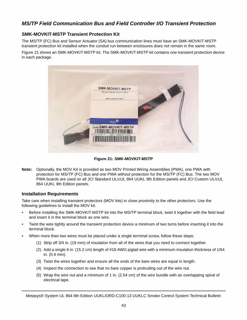
MS/TP Field Communication Bus and Field Controller I/O Transient Protection
SMK-MOVKIT-MSTP Transient Protection Kit
The MS/TP (FC) Bus and Sensor Actuator (SA) bus communication lines must have an SMK-MOVKIT-MSTP transient protection kit installed when the conduit run between enclosures does not remain in the same room.
Figure 21 shows an SMK-MOVKIT-MSTP kit. The SMK-MOVKIT-MSTP kit contains one transient protection device in each package.
Note: Optionally, the MOV Kit is provided as two MOV Printed Wiring Assemblies (PWA), one PWA with protection for MS/TP (FC) Bus and one PWA without protection for the MS/TP (FC) Bus. The two MOV PWA boards are used on all JCI Standard UL/cUL 864 UUKL 9th Edition panels and JCI Custom UL/cUL 864 UUKL 9th Edition panels.
Installation Requirements
Take care when installing transient protectors (MOV kits) in close proximity to the other protectors. Use the following guidelines to install the MOV kit.
• Before installing the SMK-MOVKIT-MSTP kit into the MS/TP terminal block, twist it together with the field lead and insert it in the terminal block as one wire.
• Twist the wire tightly around the transient protection device a minimum of two turns before inserting it into the terminal block.
• When more than two wires must be placed under a single terminal screw, follow these steps:
(1) Strip off 3/4 in. (19 mm) of insulation from all of the wires that you need to connect together.
(2) Add a single 6 in. (15.2 cm) length of #18 AWG pigtail wire with a minimum insulation thickness of 1/64 in. (0.4 mm).
(3) Twist the wires together and ensure all the ends of the bare wires are equal in length.
(4) Inspect the connection to see that no bare copper is protruding out of the wire nut.
(5) Wrap the wire nut and a minimum of 1 in. (2.54 cm) of the wire bundle with an overlapping spiral of electrical tape.
Figure 21: SMK-MOVKIT-MSTP
Metasys® System UL 864 9th Edition UUKL/ORD-C100-13 UUKLC Smoke Control System Technical Bulletin
43
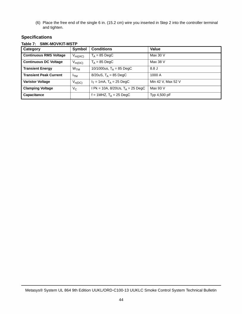
(6) Place the free end of the single 6 in. (15.2 cm) wire you inserted in Step 2 into the controller terminal and tighten.
Specifications
Table 7: SMK-MOVKIT-MSTPCategory Symbol Conditions Value
Continuous RMS Voltage Vm((AC) TA = 85 DegC Max 30 V
Continuous DC Voltage Vm(DC) TA = 85 DegC Max 38 V
Transient Energy WTM 10/1000us, TA = 85 DegC 8.8 J
Transient Peak Current ITM 8/20uS, TA = 85 DegC 1000 A
Varistor Voltage Vn(DC) IT = 1mA, TA = 25 DegC Min 42 V, Max 52 V
Clamping Voltage VC I Pk = 10A, 8/20Us, TA = 25 DegC Max 93 V
Capacitance f = 1MHZ, TA = 25 DegC Typ 4,500 pF
Metasys® System UL 864 9th Edition UUKL/ORD-C100-13 UUKLC Smoke Control System Technical Bulletin
44
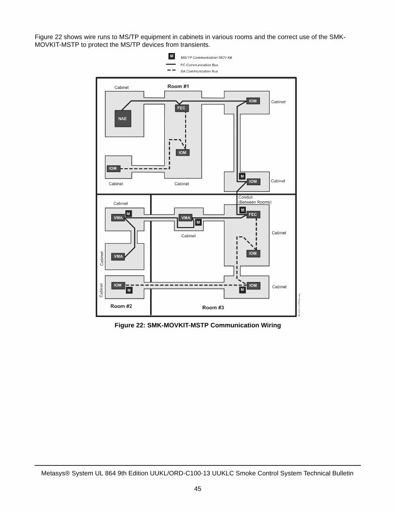
Figure 22 shows wire runs to MS/TP equipment in cabinets in various rooms and the correct use of the SMK-MOVKIT-MSTP to protect the MS/TP devices from transients.
Figure 22: SMK-MOVKIT-MSTP Communication Wiring
Metasys® System UL 864 9th Edition UUKL/ORD-C100-13 UUKLC Smoke Control System Technical Bulletin
45
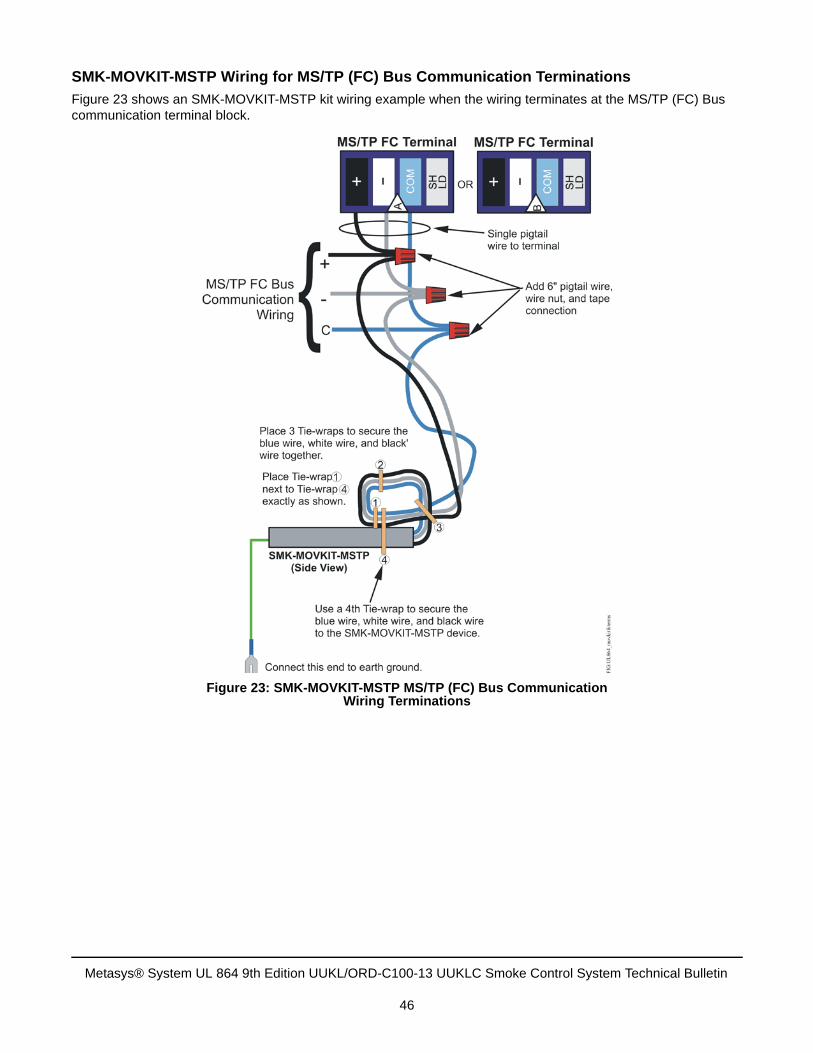
SMK-MOVKIT-MSTP Wiring for MS/TP (FC) Bus Communication Terminations
Figure 23 shows an SMK-MOVKIT-MSTP kit wiring example when the wiring terminates at the MS/TP (FC) Bus communication terminal block.
Figure 23: SMK-MOVKIT-MSTP MS/TP (FC) Bus Communication Wiring Terminations
Metasys® System UL 864 9th Edition UUKL/ORD-C100-13 UUKLC Smoke Control System Technical Bulletin
46
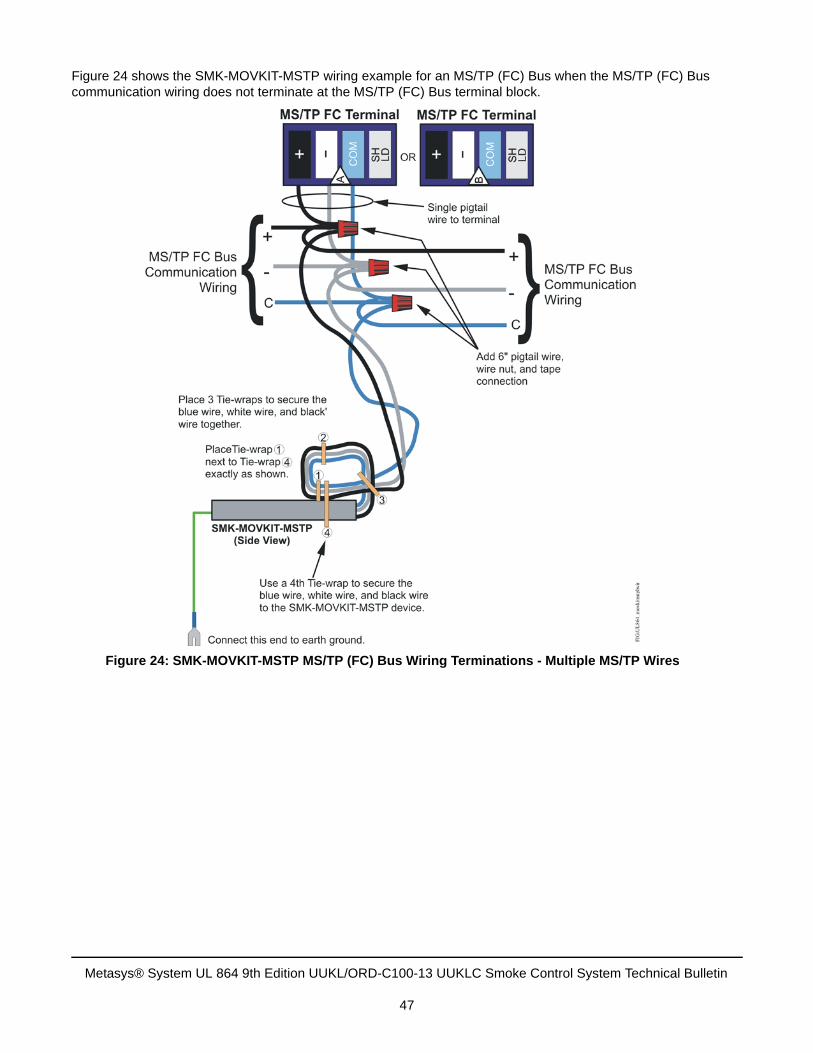
Figure 24 shows the SMK-MOVKIT-MSTP wiring example for an MS/TP (FC) Bus when the MS/TP (FC) Bus communication wiring does not terminate at the MS/TP (FC) Bus terminal block.
Figure 24: SMK-MOVKIT-MSTP MS/TP (FC) Bus Wiring Terminations - Multiple MS/TP Wires
Metasys® System UL 864 9th Edition UUKL/ORD-C100-13 UUKLC Smoke Control System Technical Bulletin
47
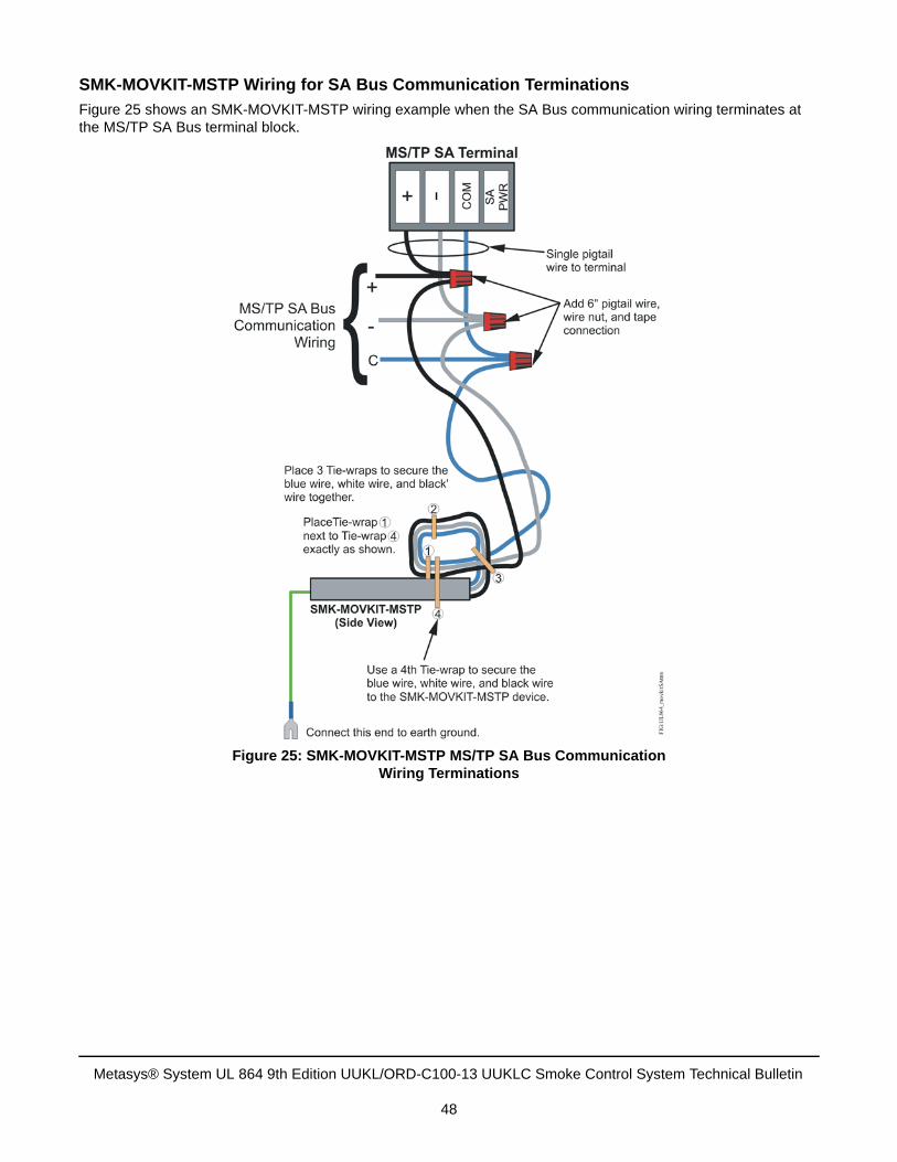
SMK-MOVKIT-MSTP Wiring for SA Bus Communication Terminations
Figure 25 shows an SMK-MOVKIT-MSTP wiring example when the SA Bus communication wiring terminates at the MS/TP SA Bus terminal block.
Figure 25: SMK-MOVKIT-MSTP MS/TP SA Bus CommunicationWiring Terminations
Metasys® System UL 864 9th Edition UUKL/ORD-C100-13 UUKLC Smoke Control System Technical Bulletin
48
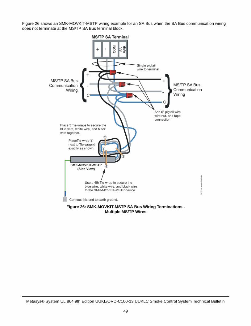
Figure 26 shows an SMK-MOVKIT-MSTP wiring example for an SA Bus when the SA Bus communication wiring does not terminate at the MS/TP SA Bus terminal block.
Figure 26: SMK-MOVKIT-MSTP SA Bus Wiring Terminations - Multiple MS/TP Wires
Metasys® System UL 864 9th Edition UUKL/ORD-C100-13 UUKLC Smoke Control System Technical Bulletin
49
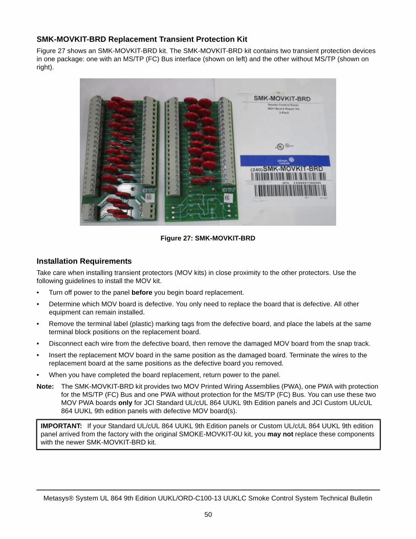
SMK-MOVKIT-BRD Replacement Transient Protection Kit
Figure 27 shows an SMK-MOVKIT-BRD kit. The SMK-MOVKIT-BRD kit contains two transient protection devices in one package: one with an MS/TP (FC) Bus interface (shown on left) and the other without MS/TP (shown on right).
Installation Requirements
Take care when installing transient protectors (MOV kits) in close proximity to the other protectors. Use the following guidelines to install the MOV kit.
• Turn off power to the panel before you begin board replacement.
• Determine which MOV board is defective. You only need to replace the board that is defective. All other equipment can remain installed.
• Remove the terminal label (plastic) marking tags from the defective board, and place the labels at the same terminal block positions on the replacement board.
• Disconnect each wire from the defective board, then remove the damaged MOV board from the snap track.
• Insert the replacement MOV board in the same position as the damaged board. Terminate the wires to the replacement board at the same positions as the defective board you removed.
• When you have completed the board replacement, return power to the panel.
Note: The SMK-MOVKIT-BRD kit provides two MOV Printed Wiring Assemblies (PWA), one PWA with protection for the MS/TP (FC) Bus and one PWA without protection for the MS/TP (FC) Bus. You can use these two MOV PWA boards only for JCI Standard UL/cUL 864 UUKL 9th Edition panels and JCI Custom UL/cUL 864 UUKL 9th edition panels with defective MOV board(s).
IMPORTANT: If your Standard UL/cUL 864 UUKL 9th Edition panels or Custom UL/cUL 864 UUKL 9th edition panel arrived from the factory with the original SMOKE-MOVKIT-0U kit, you may not replace these components with the newer SMK-MOVKIT-BRD kit.
Figure 27: SMK-MOVKIT-BRD
Metasys® System UL 864 9th Edition UUKL/ORD-C100-13 UUKLC Smoke Control System Technical Bulletin
50
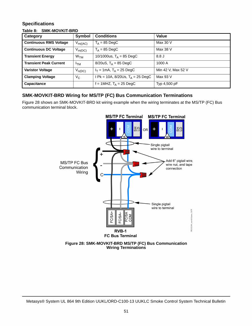
Specifications
SMK-MOVKIT-BRD Wiring for MS/TP (FC) Bus Communication Terminations
Figure 28 shows an SMK-MOVKIT-BRD kit wiring example when the wiring terminates at the MS/TP (FC) Bus communication terminal block.
Table 8: SMK-MOVKIT-BRDCategory Symbol Conditions Value
Continuous RMS Voltage Vm((AC) TA = 85 DegC Max 30 V
Continuous DC Voltage Vm(DC) TA = 85 DegC Max 38 V
Transient Energy WTM 10/1000us, TA = 85 DegC 8.8 J
Transient Peak Current ITM 8/20uS, TA = 85 DegC 1000 A
Varistor Voltage Vn(DC) IT = 1mA, TA = 25 DegC Min 42 V, Max 52 V
Clamping Voltage VC I Pk = 10A, 8/20Us, TA = 25 DegC Max 93 V
Capacitance f = 1MHZ, TA = 25 DegC Typ 4,500 pF
Figure 28: SMK-MOVKIT-BRD MS/TP (FC) Bus Communication Wiring Terminations
Metasys® System UL 864 9th Edition UUKL/ORD-C100-13 UUKLC Smoke Control System Technical Bulletin
51
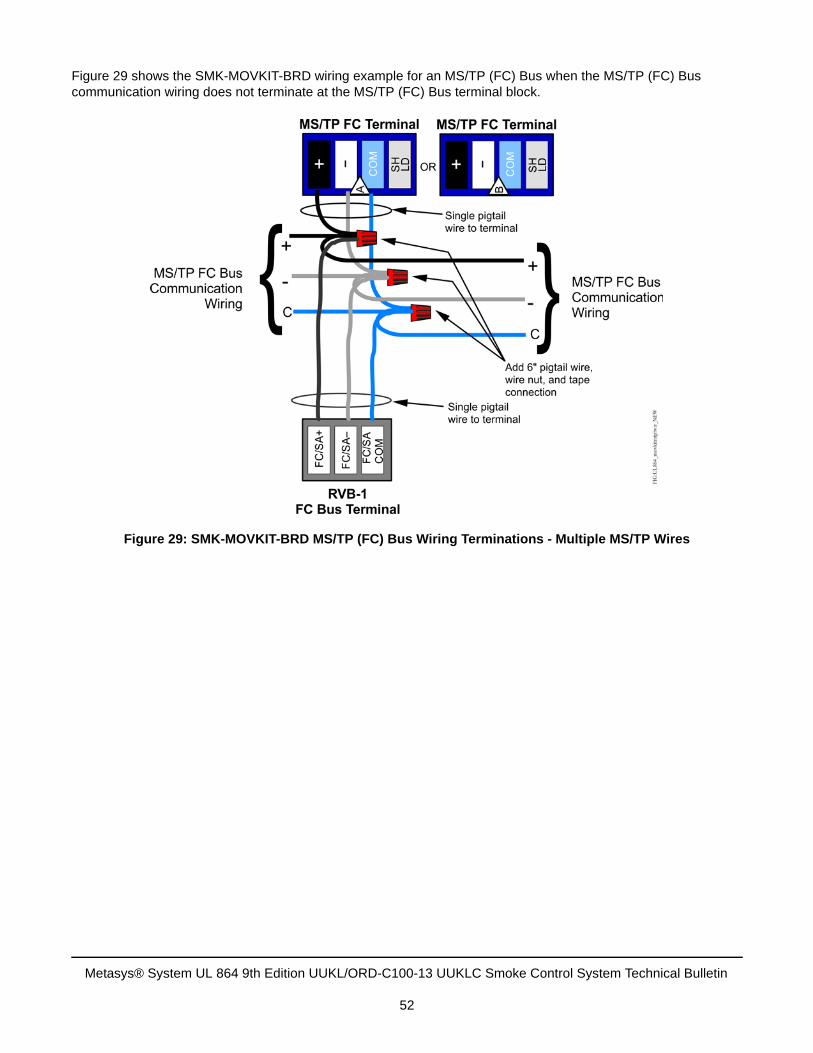
Figure 29 shows the SMK-MOVKIT-BRD wiring example for an MS/TP (FC) Bus when the MS/TP (FC) Bus communication wiring does not terminate at the MS/TP (FC) Bus terminal block.
Figure 29: SMK-MOVKIT-BRD MS/TP (FC) Bus Wiring Terminations - Multiple MS/TP Wires
Metasys® System UL 864 9th Edition UUKL/ORD-C100-13 UUKLC Smoke Control System Technical Bulletin
52
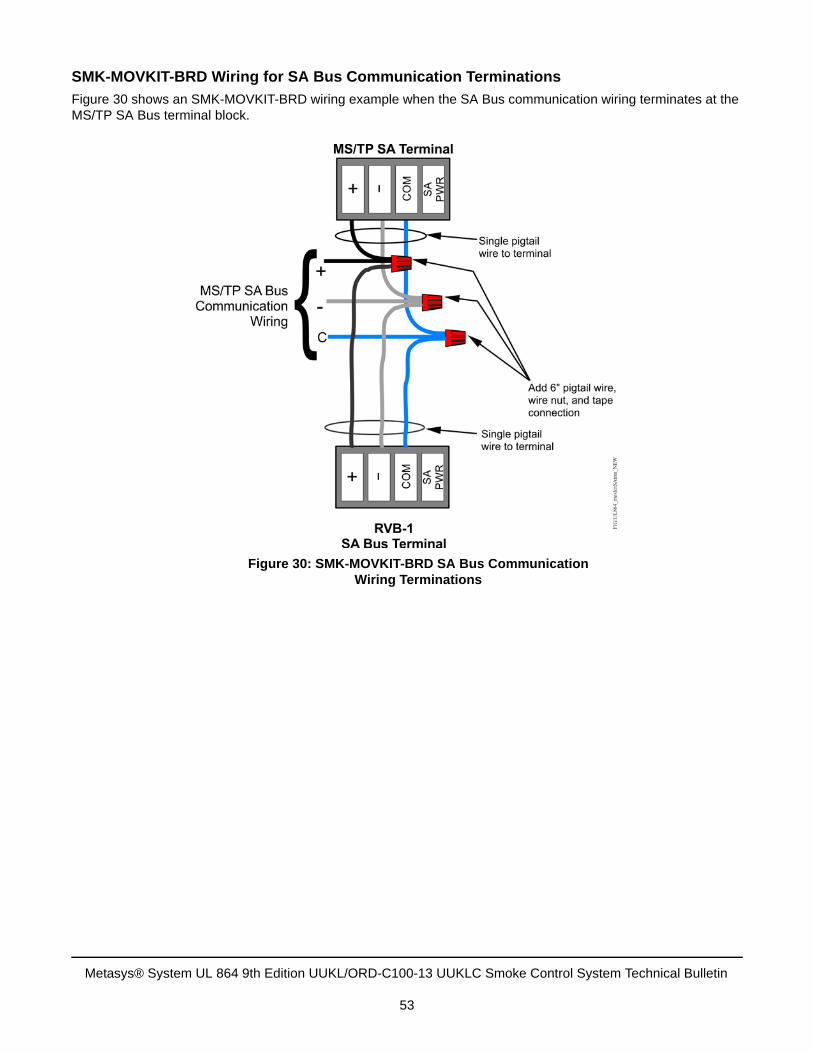
SMK-MOVKIT-BRD Wiring for SA Bus Communication Terminations
Figure 30 shows an SMK-MOVKIT-BRD wiring example when the SA Bus communication wiring terminates at the MS/TP SA Bus terminal block.
Figure 30: SMK-MOVKIT-BRD SA Bus CommunicationWiring Terminations
Metasys® System UL 864 9th Edition UUKL/ORD-C100-13 UUKLC Smoke Control System Technical Bulletin
53
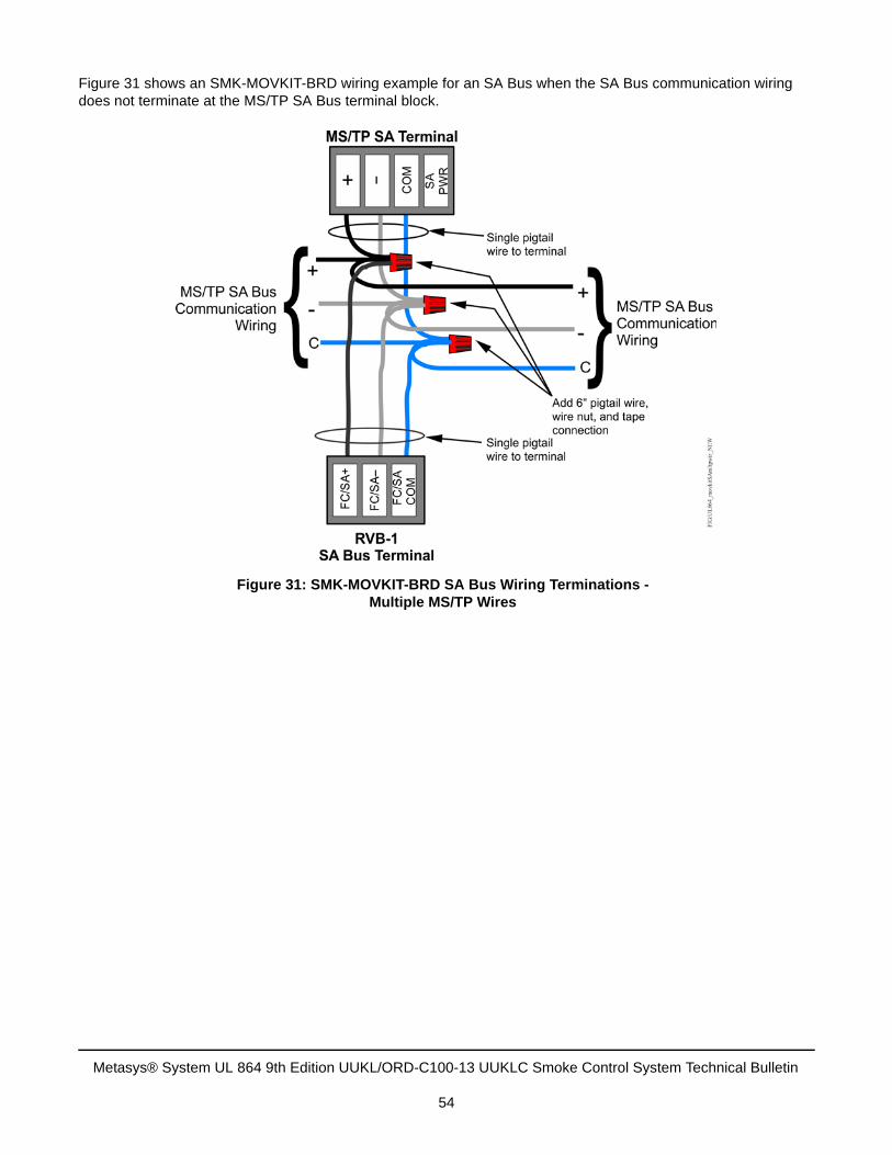
Figure 31 shows an SMK-MOVKIT-BRD wiring example for an SA Bus when the SA Bus communication wiring does not terminate at the MS/TP SA Bus terminal block.
Figure 31: SMK-MOVKIT-BRD SA Bus Wiring Terminations - Multiple MS/TP Wires
Metasys® System UL 864 9th Edition UUKL/ORD-C100-13 UUKLC Smoke Control System Technical Bulletin
54
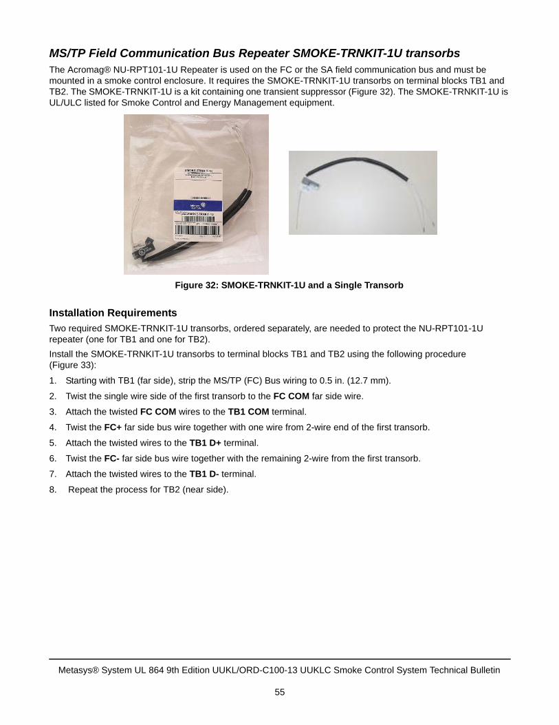
MS/TP Field Communication Bus Repeater SMOKE-TRNKIT-1U transorbs The Acromag® NU-RPT101-1U Repeater is used on the FC or the SA field communication bus and must be mounted in a smoke control enclosure. It requires the SMOKE-TRNKIT-1U transorbs on terminal blocks TB1 and TB2. The SMOKE-TRNKIT-1U is a kit containing one transient suppressor (Figure 32). The SMOKE-TRNKIT-1U is UL/ULC listed for Smoke Control and Energy Management equipment.
Installation Requirements
Two required SMOKE-TRNKIT-1U transorbs, ordered separately, are needed to protect the NU-RPT101-1U repeater (one for TB1 and one for TB2).
Install the SMOKE-TRNKIT-1U transorbs to terminal blocks TB1 and TB2 using the following procedure (Figure 33):
1. Starting with TB1 (far side), strip the MS/TP (FC) Bus wiring to 0.5 in. (12.7 mm).
2. Twist the single wire side of the first transorb to the FC COM far side wire.
3. Attach the twisted FC COM wires to the TB1 COM terminal.
4. Twist the FC+ far side bus wire together with one wire from 2-wire end of the first transorb.
5. Attach the twisted wires to the TB1 D+ terminal.
6. Twist the FC- far side bus wire together with the remaining 2-wire from the first transorb.
7. Attach the twisted wires to the TB1 D- terminal.
8. Repeat the process for TB2 (near side).
Figure 32: SMOKE-TRNKIT-1U and a Single Transorb
Metasys® System UL 864 9th Edition UUKL/ORD-C100-13 UUKLC Smoke Control System Technical Bulletin
55
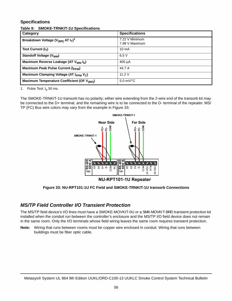
Specifications
The SMOKE-TRNKIT-1U transorb has no polarity; either wire extending from the 2-wire end of the transorb kit may be connected to the D+ terminal, and the remaining wire is to be connected to the D- terminal of the repeater. MS/TP (FC) Bus wire colors may vary from the example in Figure 33.
MS/TP Field Controller I/O Transient Protection The MS/TP field device’s I/O lines must have a SMOKE-MOVKIT-0U or a SMK-MOVKIT-BRD transient protection kit installed when the conduit run between the controller’s enclosure and the MS/TP I/O field device does not remain in the same room. Only the I/O terminals whose field wiring leaves the same room requires transient protection.
Note: Wiring that runs between rooms must be copper wire enclosed in conduit. Wiring that runs between buildings must be fiber optic cable.
Table 9: SMOKE-TRNKIT-1U SpecificationsCategory Specifications
Breakdown Voltage (V(BR) AT IT)1
1. Pulse Test: tp 50 ms.
7.22 V Minimum7.98 V Maximum
Test Current (IT) 10 mA
Standoff Voltage (VWM) 6.5 V
Maximum Reverse Leakage (AT VWM ID) 400 µA
Maximum Peak Pulse Current (IPPM) 44.7 A
Maximum Clamping Voltage (AT IPPM VC) 11.2 V
Maximum Temperature Coefficient (OF V(BR)) 5.0 mV/°C
Figure 33: NU-RPT101-1U FC Field and SMOKE-TRNKIT-1U transorb Connections
Metasys® System UL 864 9th Edition UUKL/ORD-C100-13 UUKLC Smoke Control System Technical Bulletin
56
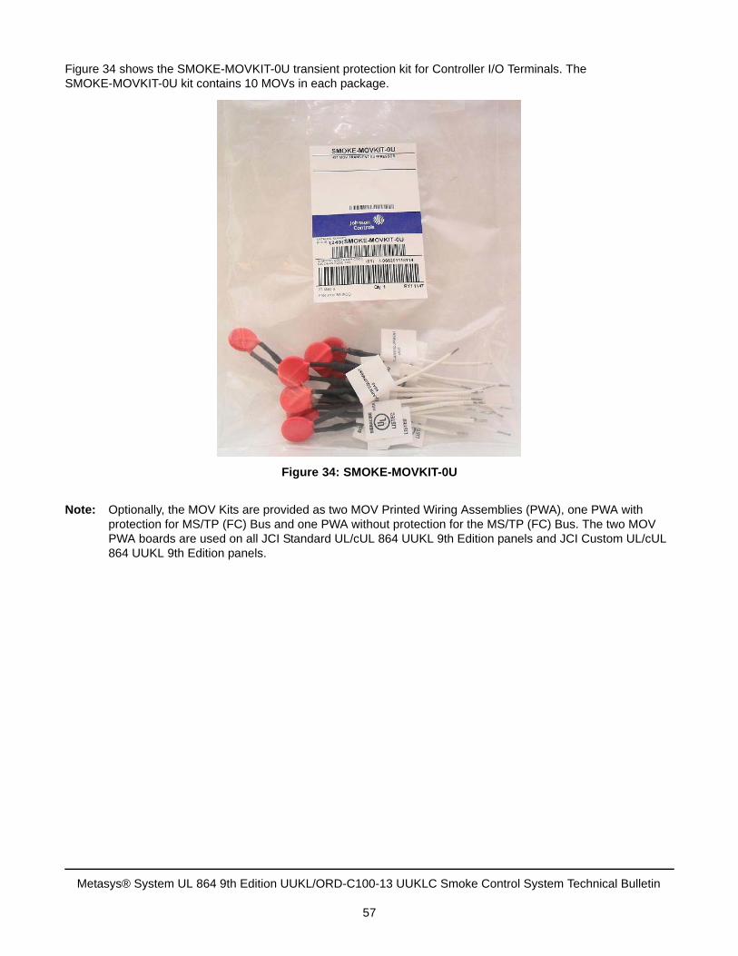
Figure 34 shows the SMOKE-MOVKIT-0U transient protection kit for Controller I/O Terminals. The SMOKE-MOVKIT-0U kit contains 10 MOVs in each package.
Note: Optionally, the MOV Kits are provided as two MOV Printed Wiring Assemblies (PWA), one PWA with protection for MS/TP (FC) Bus and one PWA without protection for the MS/TP (FC) Bus. The two MOV PWA boards are used on all JCI Standard UL/cUL 864 UUKL 9th Edition panels and JCI Custom UL/cUL 864 UUKL 9th Edition panels.
Figure 34: SMOKE-MOVKIT-0U
Metasys® System UL 864 9th Edition UUKL/ORD-C100-13 UUKLC Smoke Control System Technical Bulletin
57
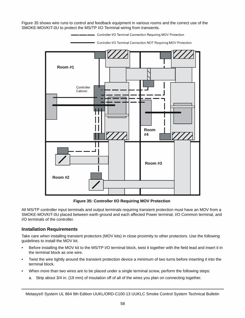
Figure 35 shows wire runs to control and feedback equipment in various rooms and the correct use of the SMOKE-MOVKIT-0U to protect the MS/TP I/O Terminal wiring from transients.
All MS/TP controller input terminals and output terminals requiring transient protection must have an MOV from a SMOKE-MOVKIT-0U placed between earth ground and each affected Power terminal, I/O Common terminal, and I/O terminals of the controller.
Installation Requirements
Take care when installing transient protectors (MOV kits) in close proximity to other protectors. Use the following guidelines to install the MOV kit.
• Before installing the MOV kit to the MS/TP I/O terminal block, twist it together with the field lead and insert it inthe terminal block as one wire.
• Twist the wire tightly around the transient protection device a minimum of two turns before inserting it into theterminal block.
• When more than two wires are to be placed under a single terminal screw, perform the following steps:
a. Strip about 3/4 in. (19 mm) of insulation off of all of the wires you plan on connecting together.
Figure 35: Controller I/O Requiring MOV Protection
Room #1
Room #2
Room #3
Room #4
Metasys® System UL 864 9th Edition UUKL/ORD-C100-13 UUKLC Smoke Control System Technical Bulletin
58
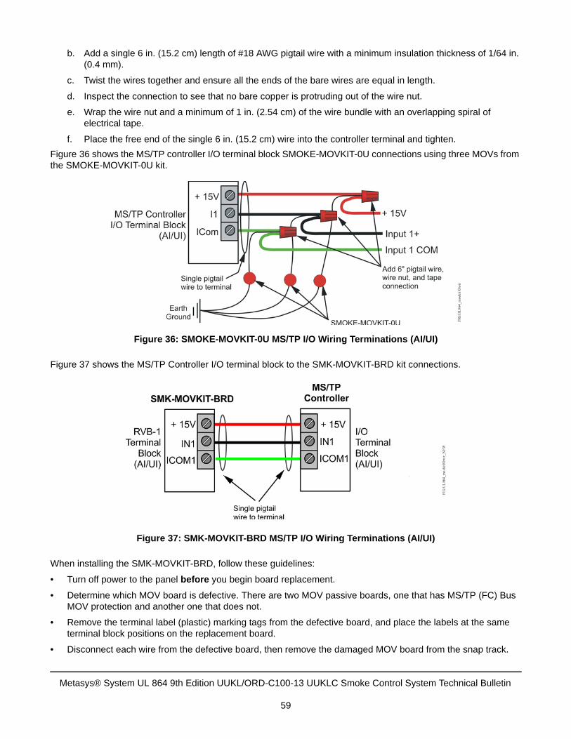
b. Add a single 6 in. (15.2 cm) length of #18 AWG pigtail wire with a minimum insulation thickness of 1/64 in.(0.4 mm).
c. Twist the wires together and ensure all the ends of the bare wires are equal in length.
d. Inspect the connection to see that no bare copper is protruding out of the wire nut.
e. Wrap the wire nut and a minimum of 1 in. (2.54 cm) of the wire bundle with an overlapping spiral ofelectrical tape.
f. Place the free end of the single 6 in. (15.2 cm) wire into the controller terminal and tighten.
Figure 36 shows the MS/TP controller I/O terminal block SMOKE-MOVKIT-0U connections using three MOVs from the SMOKE-MOVKIT-0U kit.
Figure 37 shows the MS/TP Controller I/O terminal block to the SMK-MOVKIT-BRD kit connections.
When installing the SMK-MOVKIT-BRD, follow these guidelines:
• Turn off power to the panel before you begin board replacement.
• Determine which MOV board is defective. There are two MOV passive boards, one that has MS/TP (FC) BusMOV protection and another one that does not.
• Remove the terminal label (plastic) marking tags from the defective board, and place the labels at the sameterminal block positions on the replacement board.
• Disconnect each wire from the defective board, then remove the damaged MOV board from the snap track.
Figure 36: SMOKE-MOVKIT-0U MS/TP I/O Wiring Terminations (AI/UI)
Figure 37: SMK-MOVKIT-BRD MS/TP I/O Wiring Terminations (AI/UI)
Metasys® System UL 864 9th Edition UUKL/ORD-C100-13 UUKLC Smoke Control System Technical Bulletin
59
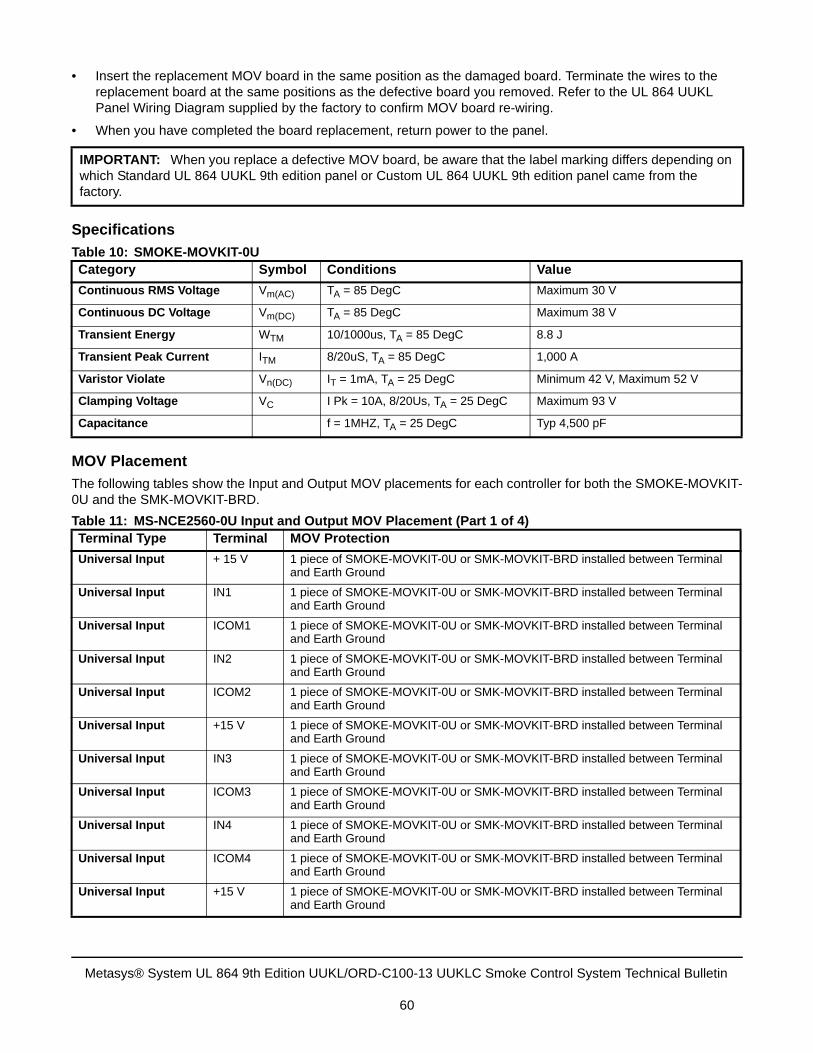
• Insert the replacement MOV board in the same position as the damaged board. Terminate the wires to thereplacement board at the same positions as the defective board you removed. Refer to the UL 864 UUKLPanel Wiring Diagram supplied by the factory to confirm MOV board re-wiring.
• When you have completed the board replacement, return power to the panel.
Specifications
MOV Placement
The following tables show the Input and Output MOV placements for each controller for both the SMOKE-MOVKIT-0U and the SMK-MOVKIT-BRD.
IMPORTANT: When you replace a defective MOV board, be aware that the label marking differs depending on which Standard UL 864 UUKL 9th edition panel or Custom UL 864 UUKL 9th edition panel came from the factory.
Table 10: SMOKE-MOVKIT-0UCategory Symbol Conditions Value
Continuous RMS Voltage Vm(AC) TA = 85 DegC Maximum 30 V
Continuous DC Voltage Vm(DC) TA = 85 DegC Maximum 38 V
Transient Energy WTM 10/1000us, TA = 85 DegC 8.8 J
Transient Peak Current ITM 8/20uS, TA = 85 DegC 1,000 A
Varistor Violate Vn(DC) IT = 1mA, TA = 25 DegC Minimum 42 V, Maximum 52 V
Clamping Voltage VC I Pk = 10A, 8/20Us, TA = 25 DegC Maximum 93 V
Capacitance f = 1MHZ, TA = 25 DegC Typ 4,500 pF
Table 11: MS-NCE2560-0U Input and Output MOV Placement (Part 1 of 4)Terminal Type Terminal MOV Protection
Universal Input + 15 V 1 piece of SMOKE-MOVKIT-0U or SMK-MOVKIT-BRD installed between Terminal and Earth Ground
Universal Input IN1 1 piece of SMOKE-MOVKIT-0U or SMK-MOVKIT-BRD installed between Terminal and Earth Ground
Universal Input ICOM1 1 piece of SMOKE-MOVKIT-0U or SMK-MOVKIT-BRD installed between Terminal and Earth Ground
Universal Input IN2 1 piece of SMOKE-MOVKIT-0U or SMK-MOVKIT-BRD installed between Terminal and Earth Ground
Universal Input ICOM2 1 piece of SMOKE-MOVKIT-0U or SMK-MOVKIT-BRD installed between Terminal and Earth Ground
Universal Input +15 V 1 piece of SMOKE-MOVKIT-0U or SMK-MOVKIT-BRD installed between Terminal and Earth Ground
Universal Input IN3 1 piece of SMOKE-MOVKIT-0U or SMK-MOVKIT-BRD installed between Terminal and Earth Ground
Universal Input ICOM3 1 piece of SMOKE-MOVKIT-0U or SMK-MOVKIT-BRD installed between Terminal and Earth Ground
Universal Input IN4 1 piece of SMOKE-MOVKIT-0U or SMK-MOVKIT-BRD installed between Terminal and Earth Ground
Universal Input ICOM4 1 piece of SMOKE-MOVKIT-0U or SMK-MOVKIT-BRD installed between Terminal and Earth Ground
Universal Input +15 V 1 piece of SMOKE-MOVKIT-0U or SMK-MOVKIT-BRD installed between Terminal and Earth Ground
Metasys® System UL 864 9th Edition UUKL/ORD-C100-13 UUKLC Smoke Control System Technical Bulletin
60
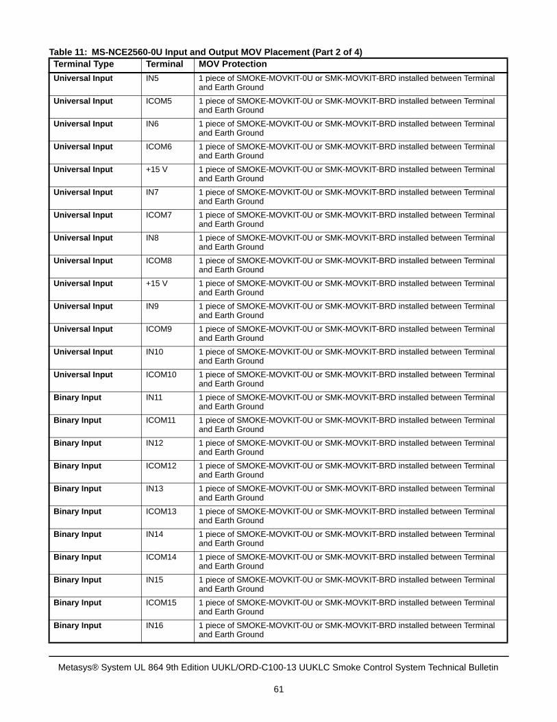
Universal Input IN5 1 piece of SMOKE-MOVKIT-0U or SMK-MOVKIT-BRD installed between Terminal and Earth Ground
Universal Input ICOM5 1 piece of SMOKE-MOVKIT-0U or SMK-MOVKIT-BRD installed between Terminal and Earth Ground
Universal Input IN6 1 piece of SMOKE-MOVKIT-0U or SMK-MOVKIT-BRD installed between Terminal and Earth Ground
Universal Input ICOM6 1 piece of SMOKE-MOVKIT-0U or SMK-MOVKIT-BRD installed between Terminal and Earth Ground
Universal Input +15 V 1 piece of SMOKE-MOVKIT-0U or SMK-MOVKIT-BRD installed between Terminal and Earth Ground
Universal Input IN7 1 piece of SMOKE-MOVKIT-0U or SMK-MOVKIT-BRD installed between Terminal and Earth Ground
Universal Input ICOM7 1 piece of SMOKE-MOVKIT-0U or SMK-MOVKIT-BRD installed between Terminal and Earth Ground
Universal Input IN8 1 piece of SMOKE-MOVKIT-0U or SMK-MOVKIT-BRD installed between Terminal and Earth Ground
Universal Input ICOM8 1 piece of SMOKE-MOVKIT-0U or SMK-MOVKIT-BRD installed between Terminal and Earth Ground
Universal Input +15 V 1 piece of SMOKE-MOVKIT-0U or SMK-MOVKIT-BRD installed between Terminal and Earth Ground
Universal Input IN9 1 piece of SMOKE-MOVKIT-0U or SMK-MOVKIT-BRD installed between Terminal and Earth Ground
Universal Input ICOM9 1 piece of SMOKE-MOVKIT-0U or SMK-MOVKIT-BRD installed between Terminal and Earth Ground
Universal Input IN10 1 piece of SMOKE-MOVKIT-0U or SMK-MOVKIT-BRD installed between Terminal and Earth Ground
Universal Input ICOM10 1 piece of SMOKE-MOVKIT-0U or SMK-MOVKIT-BRD installed between Terminal and Earth Ground
Binary Input IN11 1 piece of SMOKE-MOVKIT-0U or SMK-MOVKIT-BRD installed between Terminal and Earth Ground
Binary Input ICOM11 1 piece of SMOKE-MOVKIT-0U or SMK-MOVKIT-BRD installed between Terminal and Earth Ground
Binary Input IN12 1 piece of SMOKE-MOVKIT-0U or SMK-MOVKIT-BRD installed between Terminal and Earth Ground
Binary Input ICOM12 1 piece of SMOKE-MOVKIT-0U or SMK-MOVKIT-BRD installed between Terminal and Earth Ground
Binary Input IN13 1 piece of SMOKE-MOVKIT-0U or SMK-MOVKIT-BRD installed between Terminal and Earth Ground
Binary Input ICOM13 1 piece of SMOKE-MOVKIT-0U or SMK-MOVKIT-BRD installed between Terminal and Earth Ground
Binary Input IN14 1 piece of SMOKE-MOVKIT-0U or SMK-MOVKIT-BRD installed between Terminal and Earth Ground
Binary Input ICOM14 1 piece of SMOKE-MOVKIT-0U or SMK-MOVKIT-BRD installed between Terminal and Earth Ground
Binary Input IN15 1 piece of SMOKE-MOVKIT-0U or SMK-MOVKIT-BRD installed between Terminal and Earth Ground
Binary Input ICOM15 1 piece of SMOKE-MOVKIT-0U or SMK-MOVKIT-BRD installed between Terminal and Earth Ground
Binary Input IN16 1 piece of SMOKE-MOVKIT-0U or SMK-MOVKIT-BRD installed between Terminal and Earth Ground
Table 11: MS-NCE2560-0U Input and Output MOV Placement (Part 2 of 4)Terminal Type Terminal MOV Protection
Metasys® System UL 864 9th Edition UUKL/ORD-C100-13 UUKLC Smoke Control System Technical Bulletin
61
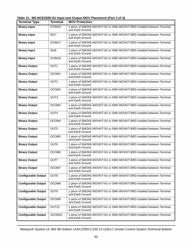
Binary Input ICOM16 1 piece of SMOKE-MOVKIT-0U or SMK-MOVKIT-BRD installed between Terminal and Earth Ground
Binary Input IN17 1 piece of SMOKE-MOVKIT-0U or SMK-MOVKIT-BRD installed between Terminal and Earth Ground
Binary Input ICOM17 1 piece of SMOKE-MOVKIT-0U or SMK-MOVKIT-BRD installed between Terminal and Earth Ground
Binary Input IN18 1 piece of SMOKE-MOVKIT-0U or SMK-MOVKIT-BRD installed between Terminal and Earth Ground
Binary Input ICOM18 1 piece of SMOKE-MOVKIT-0U or SMK-MOVKIT-BRD installed between Terminal and Earth Ground
Binary Output OUT1 1 piece of SMOKE-MOVKIT-0U or SMK-MOVKIT-BRD installed between Terminal and Earth Ground
Binary Output OCOM1 1 piece of SMOKE-MOVKIT-0U or SMK-MOVKIT-BRD installed between Terminal and Earth Ground
Binary Output OUT2 1 piece of SMOKE-MOVKIT-0U or SMK-MOVKIT-BRD installed between Terminal and Earth Ground
Binary Output OCOM2 1 piece of SMOKE-MOVKIT-0U or SMK-MOVKIT-BRD installed between Terminal and Earth Ground
Binary Output OUT3 1 piece of SMOKE-MOVKIT-0U or SMK-MOVKIT-BRD installed between Terminal and Earth Ground
Binary Output OCOM3 1 piece of SMOKE-MOVKIT-0U or SMK-MOVKIT-BRD installed between Terminal and Earth Ground
Binary Output OUT4 1 piece of SMOKE-MOVKIT-0U or SMK-MOVKIT-BRD installed between Terminal and Earth Ground
Binary Output OCOM4 1 piece of SMOKE-MOVKIT-0U or SMK-MOVKIT-BRD installed between Terminal and Earth Ground
Binary Output OUT5 1 piece of SMOKE-MOVKIT-0U or SMK-MOVKIT-BRD installed between Terminal and Earth Ground
Binary Output OCOM5 1 piece of SMOKE-MOVKIT-0U or SMK-MOVKIT-BRD installed between Terminal and Earth Ground
Binary Output OUT6 1 piece of SMOKE-MOVKIT-0U or SMK-MOVKIT-BRD installed between Terminal and Earth Ground
Binary Output OCOM6 1 piece of SMOKE-MOVKIT-0U or SMK-MOVKIT-BRD installed between Terminal and Earth Ground
Binary Output OUT7 1 piece of SMOKE-MOVKIT-0U or SMK-MOVKIT-BRD installed between Terminal and Earth Ground
Binary Output OCOM7 1 piece of SMOKE-MOVKIT-0U or SMK-MOVKIT-BRD installed between Terminal and Earth Ground
Configurable Output OUT8 1 piece of SMOKE-MOVKIT-0U or SMK-MOVKIT-BRD installed between Terminal and Earth Ground
Configurable Output OCOM8 1 piece of SMOKE-MOVKIT-0U or SMK-MOVKIT-BRD installed between Terminal and Earth Ground
Configurable Output OUT9 1 piece of SMOKE-MOVKIT-0U or SMK-MOVKIT-BRD installed between Terminal and Earth Ground
Configurable Output OCOM9 1 piece of SMOKE-MOVKIT-0U or SMK-MOVKIT-BRD installed between Terminal and Earth Ground
Configurable Output OUT10 1 piece of SMOKE-MOVKIT-0U or SMK-MOVKIT-BRD installed between Terminal and Earth Ground
Configurable Output OCOM10 1 piece of SMOKE-MOVKIT-0U or SMK-MOVKIT-BRD installed between Terminal and Earth Ground
Table 11: MS-NCE2560-0U Input and Output MOV Placement (Part 3 of 4)Terminal Type Terminal MOV Protection
Metasys® System UL 864 9th Edition UUKL/ORD-C100-13 UUKLC Smoke Control System Technical Bulletin
62
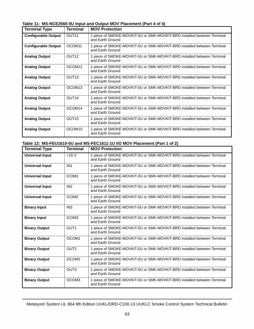
Configurable Output OUT11 1 piece of SMOKE-MOVKIT-0U or SMK-MOVKIT-BRD installed between Terminal and Earth Ground
Configurable Output OCOM11 1 piece of SMOKE-MOVKIT-0U or SMK-MOVKIT-BRD installed between Terminal and Earth Ground
Analog Output OUT12 1 piece of SMOKE-MOVKIT-0U or SMK-MOVKIT-BRD installed between Terminal and Earth Ground
Analog Output OCOM12 1 piece of SMOKE-MOVKIT-0U or SMK-MOVKIT-BRD installed between Terminal and Earth Ground
Analog Output OUT13 1 piece of SMOKE-MOVKIT-0U or SMK-MOVKIT-BRD installed between Terminal and Earth Ground
Analog Output OCOM13 1 piece of SMOKE-MOVKIT-0U or SMK-MOVKIT-BRD installed between Terminal and Earth Ground
Analog Output OUT14 1 piece of SMOKE-MOVKIT-0U or SMK-MOVKIT-BRD installed between Terminal and Earth Ground
Analog Output OCOM14 1 piece of SMOKE-MOVKIT-0U or SMK-MOVKIT-BRD installed between Terminal and Earth Ground
Analog Output OUT15 1 piece of SMOKE-MOVKIT-0U or SMK-MOVKIT-BRD installed between Terminal and Earth Ground
Analog Output OCOM15 1 piece of SMOKE-MOVKIT-0U or SMK-MOVKIT-BRD installed between Terminal and Earth Ground
Table 12: MS-FEU1610-0U and MS-FEC1611-1U I/O MOV Placement (Part 1 of 2)Terminal Type Terminal MOV Protection
Universal Input +15 V 1 piece of SMOKE-MOVKIT-0U or SMK-MOVKIT-BRD installed between Terminal and Earth Ground
Universal Input IN1 1 piece of SMOKE-MOVKIT-0U or SMK-MOVKIT-BRD installed between Terminal and Earth Ground
Universal Input ICOM1 1 piece of SMOKE-MOVKIT-0U or SMK-MOVKIT-BRD installed between Terminal and Earth Ground
Universal Input IN2 1 piece of SMOKE-MOVKIT-0U or SMK-MOVKIT-BRD installed between Terminal and Earth Ground
Universal Input ICOM2 1 piece of SMOKE-MOVKIT-0U or SMK-MOVKIT-BRD installed between Terminal and Earth Ground
Binary Input IN3 1 piece of SMOKE-MOVKIT-0U or SMK-MOVKIT-BRD installed between Terminal and Earth Ground
Binary Input ICOM3 1 piece of SMOKE-MOVKIT-0U or SMK-MOVKIT-BRD installed between Terminal and Earth Ground
Binary Output OUT1 1 piece of SMOKE-MOVKIT-0U or SMK-MOVKIT-BRD installed between Terminal and Earth Ground
Binary Output OCOM1 1 piece of SMOKE-MOVKIT-0U or SMK-MOVKIT-BRD installed between Terminal and Earth Ground
Binary Output OUT2 1 piece of SMOKE-MOVKIT-0U or SMK-MOVKIT-BRD installed between Terminal and Earth Ground
Binary Output OCOM2 1 piece of SMOKE-MOVKIT-0U or SMK-MOVKIT-BRD installed between Terminal and Earth Ground
Binary Output OUT3 1 piece of SMOKE-MOVKIT-0U or SMK-MOVKIT-BRD installed between Terminal and Earth Ground
Binary Output OCOM3 1 piece of SMOKE-MOVKIT-0U or SMK-MOVKIT-BRD installed between Terminal and Earth Ground
Table 11: MS-NCE2560-0U Input and Output MOV Placement (Part 4 of 4)Terminal Type Terminal MOV Protection
Metasys® System UL 864 9th Edition UUKL/ORD-C100-13 UUKLC Smoke Control System Technical Bulletin
63
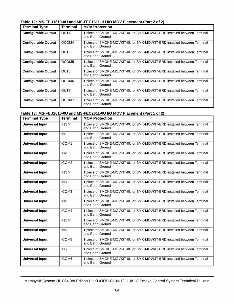
Configurable Output OUT4 1 piece of SMOKE-MOVKIT-0U or SMK-MOVKIT-BRD installed between Terminal and Earth Ground
Configurable Output OCOM4 1 piece of SMOKE-MOVKIT-0U or SMK-MOVKIT-BRD installed between Terminal and Earth Ground
Configurable Output OUT5 1 piece of SMOKE-MOVKIT-0U or SMK-MOVKIT-BRD installed between Terminal and Earth Ground
Configurable Output OCOM5 1 piece of SMOKE-MOVKIT-0U or SMK-MOVKIT-BRD installed between Terminal and Earth Ground
Configurable Output OUT6 1 piece of SMOKE-MOVKIT-0U or SMK-MOVKIT-BRD installed between Terminal and Earth Ground
Configurable Output OCOM6 1 piece of SMOKE-MOVKIT-0U or SMK-MOVKIT-BRD installed between Terminal and Earth Ground
Configurable Output OUT7 1 piece of SMOKE-MOVKIT-0U or SMK-MOVKIT-BRD installed between Terminal and Earth Ground
Configurable Output OCOM7 1 piece of SMOKE-MOVKIT-0U or SMK-MOVKIT-BRD installed between Terminal and Earth Ground
Table 13: MS-FEU2610-0U and MS-FEC2611-0U I/O MOV Placement (Part 1 of 2)Terminal Type Terminal MOV Protection
Universal Input +15 V 1 piece of SMOKE-MOVKIT-0U or SMK-MOVKIT-BRD installed between Terminal and Earth Ground
Universal Input IN1 1 piece of SMOKE-MOVKIT-0U or SMK-MOVKIT-BRD installed between Terminal and Earth Ground
Universal Input ICOM1 1 piece of SMOKE-MOVKIT-0U or SMK-MOVKIT-BRD installed between Terminal and Earth Ground
Universal Input IN2 1 piece of SMOKE-MOVKIT-0U or SMK-MOVKIT-BRD installed between Terminal and Earth Ground
Universal Input ICOM2 1 piece of SMOKE-MOVKIT-0U or SMK-MOVKIT-BRD installed between Terminal and Earth Ground
Universal Input +15 V 1 piece of SMOKE-MOVKIT-0U or SMK-MOVKIT-BRD installed between Terminal and Earth Ground
Universal Input IN3 1 piece of SMOKE-MOVKIT-0U or SMK-MOVKIT-BRD installed between Terminal and Earth Ground
Universal Input ICOM3 1 piece of SMOKE-MOVKIT-0U or SMK-MOVKIT-BRD installed between Terminal and Earth Ground
Universal Input IN4 1 piece of SMOKE-MOVKIT-0U or SMK-MOVKIT-BRD installed between Terminal and Earth Ground
Universal Input ICOM4 1 piece of SMOKE-MOVKIT-0U or SMK-MOVKIT-BRD installed between Terminal and Earth Ground
Universal Input +15 V 1 piece of SMOKE-MOVKIT-0U or SMK-MOVKIT-BRD installed between Terminal and Earth Ground
Universal Input IN5 1 piece of SMOKE-MOVKIT-0U or SMK-MOVKIT-BRD installed between Terminal and Earth Ground
Universal Input ICOM5 1 piece of SMOKE-MOVKIT-0U or SMK-MOVKIT-BRD installed between Terminal and Earth Ground
Universal Input IN6 1 piece of SMOKE-MOVKIT-0U or SMK-MOVKIT-BRD installed between Terminal and Earth Ground
Universal Input ICOM6 1 piece of SMOKE-MOVKIT-0U or SMK-MOVKIT-BRD installed between Terminal and Earth Ground
Table 12: MS-FEU1610-0U and MS-FEC1611-1U I/O MOV Placement (Part 2 of 2)Terminal Type Terminal MOV Protection
Metasys® System UL 864 9th Edition UUKL/ORD-C100-13 UUKLC Smoke Control System Technical Bulletin
64
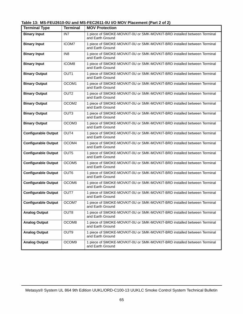
Binary Input IN7 1 piece of SMOKE-MOVKIT-0U or SMK-MOVKIT-BRD installed between Terminal and Earth Ground
Binary Input ICOM7 1 piece of SMOKE-MOVKIT-0U or SMK-MOVKIT-BRD installed between Terminal and Earth Ground
Binary Input IN8 1 piece of SMOKE-MOVKIT-0U or SMK-MOVKIT-BRD installed between Terminal and Earth Ground
Binary Input ICOM8 1 piece of SMOKE-MOVKIT-0U or SMK-MOVKIT-BRD installed between Terminal and Earth Ground
Binary Output OUT1 1 piece of SMOKE-MOVKIT-0U or SMK-MOVKIT-BRD installed between Terminal and Earth Ground
Binary Output OCOM1 1 piece of SMOKE-MOVKIT-0U or SMK-MOVKIT-BRD installed between Terminal and Earth Ground
Binary Output OUT2 1 piece of SMOKE-MOVKIT-0U or SMK-MOVKIT-BRD installed between Terminal and Earth Ground
Binary Output OCOM2 1 piece of SMOKE-MOVKIT-0U or SMK-MOVKIT-BRD installed between Terminal and Earth Ground
Binary Output OUT3 1 piece of SMOKE-MOVKIT-0U or SMK-MOVKIT-BRD installed between Terminal and Earth Ground
Binary Output OCOM3 1 piece of SMOKE-MOVKIT-0U or SMK-MOVKIT-BRD installed between Terminal and Earth Ground
Configurable Output OUT4 1 piece of SMOKE-MOVKIT-0U or SMK-MOVKIT-BRD installed between Terminal and Earth Ground
Configurable Output OCOM4 1 piece of SMOKE-MOVKIT-0U or SMK-MOVKIT-BRD installed between Terminal and Earth Ground
Configurable Output OUT5 1 piece of SMOKE-MOVKIT-0U or SMK-MOVKIT-BRD installed between Terminal and Earth Ground
Configurable Output OCOM5 1 piece of SMOKE-MOVKIT-0U or SMK-MOVKIT-BRD installed between Terminal and Earth Ground
Configurable Output OUT6 1 piece of SMOKE-MOVKIT-0U or SMK-MOVKIT-BRD installed between Terminal and Earth Ground
Configurable Output OCOM6 1 piece of SMOKE-MOVKIT-0U or SMK-MOVKIT-BRD installed between Terminal and Earth Ground
Configurable Output OUT7 1 piece of SMOKE-MOVKIT-0U or SMK-MOVKIT-BRD installed between Terminal and Earth Ground
Configurable Output OCOM7 1 piece of SMOKE-MOVKIT-0U or SMK-MOVKIT-BRD installed between Terminal and Earth Ground
Analog Output OUT8 1 piece of SMOKE-MOVKIT-0U or SMK-MOVKIT-BRD installed between Terminal and Earth Ground
Analog Output OCOM8 1 piece of SMOKE-MOVKIT-0U or SMK-MOVKIT-BRD installed between Terminal and Earth Ground
Analog Output OUT9 1 piece of SMOKE-MOVKIT-0U or SMK-MOVKIT-BRD installed between Terminal and Earth Ground
Analog Output OCOM9 1 piece of SMOKE-MOVKIT-0U or SMK-MOVKIT-BRD installed between Terminal and Earth Ground
Table 13: MS-FEU2610-0U and MS-FEC2611-0U I/O MOV Placement (Part 2 of 2)Terminal Type Terminal MOV Protection
Metasys® System UL 864 9th Edition UUKL/ORD-C100-13 UUKLC Smoke Control System Technical Bulletin
65
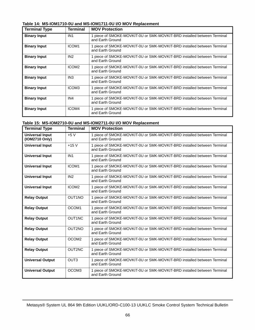
Table 14: MS-IOM1710-0U and MS-IOM1711-0U I/O MOV ReplacementTerminal Type Terminal MOV Protection
Binary Input IN1 1 piece of SMOKE-MOVKIT-0U or SMK-MOVKIT-BRD installed between Terminal and Earth Ground
Binary Input ICOM1 1 piece of SMOKE-MOVKIT-0U or SMK-MOVKIT-BRD installed between Terminal and Earth Ground
Binary Input IN2 1 piece of SMOKE-MOVKIT-0U or SMK-MOVKIT-BRD installed between Terminal and Earth Ground
Binary Input ICOM2 1 piece of SMOKE-MOVKIT-0U or SMK-MOVKIT-BRD installed between Terminal and Earth Ground
Binary Input IN3 1 piece of SMOKE-MOVKIT-0U or SMK-MOVKIT-BRD installed between Terminal and Earth Ground
Binary Input ICOM3 1 piece of SMOKE-MOVKIT-0U or SMK-MOVKIT-BRD installed between Terminal and Earth Ground
Binary Input IN4 1 piece of SMOKE-MOVKIT-0U or SMK-MOVKIT-BRD installed between Terminal and Earth Ground
Binary Input ICOM4 1 piece of SMOKE-MOVKIT-0U or SMK-MOVKIT-BRD installed between Terminal and Earth Ground
Table 15: MS-IOM2710-0U and MS-IOM2711-0U I/O MOV ReplacementTerminal Type Terminal MOV Protection
Universal Input(IOM2710 Only)
+5 V 1 piece of SMOKE-MOVKIT-0U or SMK-MOVKIT-BRD installed between Terminal and Earth Ground
Universal Input +15 V 1 piece of SMOKE-MOVKIT-0U or SMK-MOVKIT-BRD installed between Terminal and Earth Ground
Universal Input IN1 1 piece of SMOKE-MOVKIT-0U or SMK-MOVKIT-BRD installed between Terminal and Earth Ground
Universal Input ICOM1 1 piece of SMOKE-MOVKIT-0U or SMK-MOVKIT-BRD installed between Terminal and Earth Ground
Universal Input IN2 1 piece of SMOKE-MOVKIT-0U or SMK-MOVKIT-BRD installed between Terminal and Earth Ground
Universal Input ICOM2 1 piece of SMOKE-MOVKIT-0U or SMK-MOVKIT-BRD installed between Terminal and Earth Ground
Relay Output OUT1NO 1 piece of SMOKE-MOVKIT-0U or SMK-MOVKIT-BRD installed between Terminal and Earth Ground
Relay Output OCOM1 1 piece of SMOKE-MOVKIT-0U or SMK-MOVKIT-BRD installed between Terminal and Earth Ground
Relay Output OUT1NC 1 piece of SMOKE-MOVKIT-0U or SMK-MOVKIT-BRD installed between Terminal and Earth Ground
Relay Output OUT2NO 1 piece of SMOKE-MOVKIT-0U or SMK-MOVKIT-BRD installed between Terminal and Earth Ground
Relay Output OCOM2 1 piece of SMOKE-MOVKIT-0U or SMK-MOVKIT-BRD installed between Terminal and Earth Ground
Relay Output OUT2NC 1 piece of SMOKE-MOVKIT-0U or SMK-MOVKIT-BRD installed between Terminal and Earth Ground
Universal Output OUT3 1 piece of SMOKE-MOVKIT-0U or SMK-MOVKIT-BRD installed between Terminal and Earth Ground
Universal Output OCOM3 1 piece of SMOKE-MOVKIT-0U or SMK-MOVKIT-BRD installed between Terminal and Earth Ground
Metasys® System UL 864 9th Edition UUKL/ORD-C100-13 UUKLC Smoke Control System Technical Bulletin
66
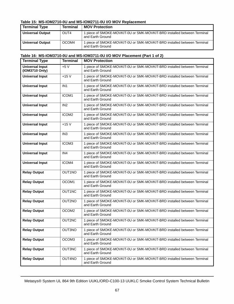
Universal Output OUT4 1 piece of SMOKE-MOVKIT-0U or SMK-MOVKIT-BRD installed between Terminal and Earth Ground
Universal Output OCOM4 1 piece of SMOKE-MOVKIT-0U or SMK-MOVKIT-BRD installed between Terminal and Earth Ground
Table 16: MS-IOM3710-0U and MS-IOM3711-0U I/O MOV Placement (Part 1 of 2)Terminal Type Terminal MOV Protection
Universal Input(IOM3710 Only)
+5 V 1 piece of SMOKE-MOVKIT-0U or SMK-MOVKIT-BRD installed between Terminal and Earth Ground
Universal Input +15 V 1 piece of SMOKE-MOVKIT-0U or SMK-MOVKIT-BRD installed between Terminal and Earth Ground
Universal Input IN1 1 piece of SMOKE-MOVKIT-0U or SMK-MOVKIT-BRD installed between Terminal and Earth Ground
Universal Input ICOM1 1 piece of SMOKE-MOVKIT-0U or SMK-MOVKIT-BRD installed between Terminal and Earth Ground
Universal Input IN2 1 piece of SMOKE-MOVKIT-0U or SMK-MOVKIT-BRD installed between Terminal and Earth Ground
Universal Input ICOM2 1 piece of SMOKE-MOVKIT-0U or SMK-MOVKIT-BRD installed between Terminal and Earth Ground
Universal Input +15 V 1 piece of SMOKE-MOVKIT-0U or SMK-MOVKIT-BRD installed between Terminal and Earth Ground
Universal Input IN3 1 piece of SMOKE-MOVKIT-0U or SMK-MOVKIT-BRD installed between Terminal and Earth Ground
Universal Input ICOM3 1 piece of SMOKE-MOVKIT-0U or SMK-MOVKIT-BRD installed between Terminal and Earth Ground
Universal Input IN4 1 piece of SMOKE-MOVKIT-0U or SMK-MOVKIT-BRD installed between Terminal and Earth Ground
Universal Input ICOM4 1 piece of SMOKE-MOVKIT-0U or SMK-MOVKIT-BRD installed between Terminal and Earth Ground
Relay Output OUT1NO 1 piece of SMOKE-MOVKIT-0U or SMK-MOVKIT-BRD installed between Terminal and Earth Ground
Relay Output OCOM1 1 piece of SMOKE-MOVKIT-0U or SMK-MOVKIT-BRD installed between Terminal and Earth Ground
Relay Output OUT1NC 1 piece of SMOKE-MOVKIT-0U or SMK-MOVKIT-BRD installed between Terminal and Earth Ground
Relay Output OUT2NO 1 piece of SMOKE-MOVKIT-0U or SMK-MOVKIT-BRD installed between Terminal and Earth Ground
Relay Output OCOM2 1 piece of SMOKE-MOVKIT-0U or SMK-MOVKIT-BRD installed between Terminal and Earth Ground
Relay Output OUT2NC 1 piece of SMOKE-MOVKIT-0U or SMK-MOVKIT-BRD installed between Terminal and Earth Ground
Relay Output OUT3NO 1 piece of SMOKE-MOVKIT-0U or SMK-MOVKIT-BRD installed between Terminal and Earth Ground
Relay Output OCOM3 1 piece of SMOKE-MOVKIT-0U or SMK-MOVKIT-BRD installed between Terminal and Earth Ground
Relay Output OUT3NC 1 piece of SMOKE-MOVKIT-0U or SMK-MOVKIT-BRD installed between Terminal and Earth Ground
Relay Output OUT4NO 1 piece of SMOKE-MOVKIT-0U or SMK-MOVKIT-BRD installed between Terminal and Earth Ground
Table 15: MS-IOM2710-0U and MS-IOM2711-0U I/O MOV ReplacementTerminal Type Terminal MOV Protection
Metasys® System UL 864 9th Edition UUKL/ORD-C100-13 UUKLC Smoke Control System Technical Bulletin
67
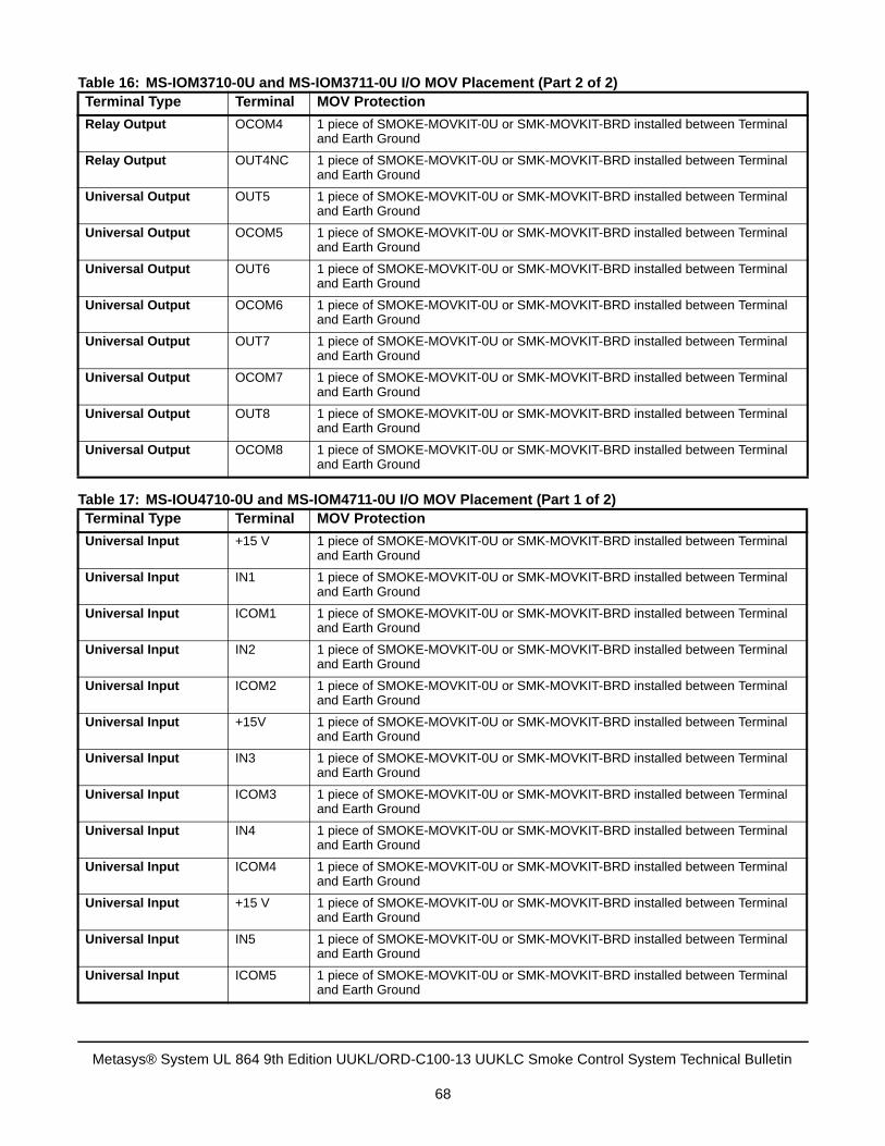
Relay Output OCOM4 1 piece of SMOKE-MOVKIT-0U or SMK-MOVKIT-BRD installed between Terminal and Earth Ground
Relay Output OUT4NC 1 piece of SMOKE-MOVKIT-0U or SMK-MOVKIT-BRD installed between Terminal and Earth Ground
Universal Output OUT5 1 piece of SMOKE-MOVKIT-0U or SMK-MOVKIT-BRD installed between Terminal and Earth Ground
Universal Output OCOM5 1 piece of SMOKE-MOVKIT-0U or SMK-MOVKIT-BRD installed between Terminal and Earth Ground
Universal Output OUT6 1 piece of SMOKE-MOVKIT-0U or SMK-MOVKIT-BRD installed between Terminal and Earth Ground
Universal Output OCOM6 1 piece of SMOKE-MOVKIT-0U or SMK-MOVKIT-BRD installed between Terminal and Earth Ground
Universal Output OUT7 1 piece of SMOKE-MOVKIT-0U or SMK-MOVKIT-BRD installed between Terminal and Earth Ground
Universal Output OCOM7 1 piece of SMOKE-MOVKIT-0U or SMK-MOVKIT-BRD installed between Terminal and Earth Ground
Universal Output OUT8 1 piece of SMOKE-MOVKIT-0U or SMK-MOVKIT-BRD installed between Terminal and Earth Ground
Universal Output OCOM8 1 piece of SMOKE-MOVKIT-0U or SMK-MOVKIT-BRD installed between Terminal and Earth Ground
Table 17: MS-IOU4710-0U and MS-IOM4711-0U I/O MOV Placement (Part 1 of 2)Terminal Type Terminal MOV Protection
Universal Input +15 V 1 piece of SMOKE-MOVKIT-0U or SMK-MOVKIT-BRD installed between Terminal and Earth Ground
Universal Input IN1 1 piece of SMOKE-MOVKIT-0U or SMK-MOVKIT-BRD installed between Terminal and Earth Ground
Universal Input ICOM1 1 piece of SMOKE-MOVKIT-0U or SMK-MOVKIT-BRD installed between Terminal and Earth Ground
Universal Input IN2 1 piece of SMOKE-MOVKIT-0U or SMK-MOVKIT-BRD installed between Terminal and Earth Ground
Universal Input ICOM2 1 piece of SMOKE-MOVKIT-0U or SMK-MOVKIT-BRD installed between Terminal and Earth Ground
Universal Input +15V 1 piece of SMOKE-MOVKIT-0U or SMK-MOVKIT-BRD installed between Terminal and Earth Ground
Universal Input IN3 1 piece of SMOKE-MOVKIT-0U or SMK-MOVKIT-BRD installed between Terminal and Earth Ground
Universal Input ICOM3 1 piece of SMOKE-MOVKIT-0U or SMK-MOVKIT-BRD installed between Terminal and Earth Ground
Universal Input IN4 1 piece of SMOKE-MOVKIT-0U or SMK-MOVKIT-BRD installed between Terminal and Earth Ground
Universal Input ICOM4 1 piece of SMOKE-MOVKIT-0U or SMK-MOVKIT-BRD installed between Terminal and Earth Ground
Universal Input +15 V 1 piece of SMOKE-MOVKIT-0U or SMK-MOVKIT-BRD installed between Terminal and Earth Ground
Universal Input IN5 1 piece of SMOKE-MOVKIT-0U or SMK-MOVKIT-BRD installed between Terminal and Earth Ground
Universal Input ICOM5 1 piece of SMOKE-MOVKIT-0U or SMK-MOVKIT-BRD installed between Terminal and Earth Ground
Table 16: MS-IOM3710-0U and MS-IOM3711-0U I/O MOV Placement (Part 2 of 2)Terminal Type Terminal MOV Protection
Metasys® System UL 864 9th Edition UUKL/ORD-C100-13 UUKLC Smoke Control System Technical Bulletin
68
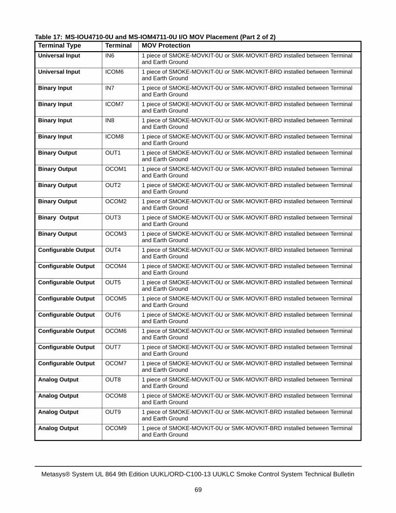
Universal Input IN6 1 piece of SMOKE-MOVKIT-0U or SMK-MOVKIT-BRD installed between Terminal and Earth Ground
Universal Input ICOM6 1 piece of SMOKE-MOVKIT-0U or SMK-MOVKIT-BRD installed between Terminal and Earth Ground
Binary Input IN7 1 piece of SMOKE-MOVKIT-0U or SMK-MOVKIT-BRD installed between Terminal and Earth Ground
Binary Input ICOM7 1 piece of SMOKE-MOVKIT-0U or SMK-MOVKIT-BRD installed between Terminal and Earth Ground
Binary Input IN8 1 piece of SMOKE-MOVKIT-0U or SMK-MOVKIT-BRD installed between Terminal and Earth Ground
Binary Input ICOM8 1 piece of SMOKE-MOVKIT-0U or SMK-MOVKIT-BRD installed between Terminal and Earth Ground
Binary Output OUT1 1 piece of SMOKE-MOVKIT-0U or SMK-MOVKIT-BRD installed between Terminal and Earth Ground
Binary Output OCOM1 1 piece of SMOKE-MOVKIT-0U or SMK-MOVKIT-BRD installed between Terminal and Earth Ground
Binary Output OUT2 1 piece of SMOKE-MOVKIT-0U or SMK-MOVKIT-BRD installed between Terminal and Earth Ground
Binary Output OCOM2 1 piece of SMOKE-MOVKIT-0U or SMK-MOVKIT-BRD installed between Terminal and Earth Ground
Binary Output OUT3 1 piece of SMOKE-MOVKIT-0U or SMK-MOVKIT-BRD installed between Terminal and Earth Ground
Binary Output OCOM3 1 piece of SMOKE-MOVKIT-0U or SMK-MOVKIT-BRD installed between Terminal and Earth Ground
Configurable Output OUT4 1 piece of SMOKE-MOVKIT-0U or SMK-MOVKIT-BRD installed between Terminal and Earth Ground
Configurable Output OCOM4 1 piece of SMOKE-MOVKIT-0U or SMK-MOVKIT-BRD installed between Terminal and Earth Ground
Configurable Output OUT5 1 piece of SMOKE-MOVKIT-0U or SMK-MOVKIT-BRD installed between Terminal and Earth Ground
Configurable Output OCOM5 1 piece of SMOKE-MOVKIT-0U or SMK-MOVKIT-BRD installed between Terminal and Earth Ground
Configurable Output OUT6 1 piece of SMOKE-MOVKIT-0U or SMK-MOVKIT-BRD installed between Terminal and Earth Ground
Configurable Output OCOM6 1 piece of SMOKE-MOVKIT-0U or SMK-MOVKIT-BRD installed between Terminal and Earth Ground
Configurable Output OUT7 1 piece of SMOKE-MOVKIT-0U or SMK-MOVKIT-BRD installed between Terminal and Earth Ground
Configurable Output OCOM7 1 piece of SMOKE-MOVKIT-0U or SMK-MOVKIT-BRD installed between Terminal and Earth Ground
Analog Output OUT8 1 piece of SMOKE-MOVKIT-0U or SMK-MOVKIT-BRD installed between Terminal and Earth Ground
Analog Output OCOM8 1 piece of SMOKE-MOVKIT-0U or SMK-MOVKIT-BRD installed between Terminal and Earth Ground
Analog Output OUT9 1 piece of SMOKE-MOVKIT-0U or SMK-MOVKIT-BRD installed between Terminal and Earth Ground
Analog Output OCOM9 1 piece of SMOKE-MOVKIT-0U or SMK-MOVKIT-BRD installed between Terminal and Earth Ground
Table 17: MS-IOU4710-0U and MS-IOM4711-0U I/O MOV Placement (Part 2 of 2)Terminal Type Terminal MOV Protection
Metasys® System UL 864 9th Edition UUKL/ORD-C100-13 UUKLC Smoke Control System Technical Bulletin
69
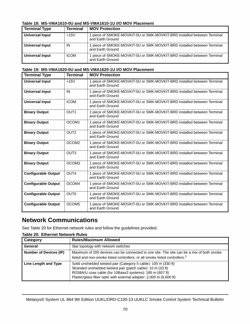
Network CommunicationsSee Table 20 for Ethernet network rules and follow the guidelines provided.
Table 18: MS-VMA1610-0U and MS-VMA1610-1U I/O MOV PlacementTerminal Type Terminal MOV Protection
Universal Input +15V 1 piece of SMOKE-MOVKIT-0U or SMK-MOVKIT-BRD installed between Terminal and Earth Ground
Universal Input IN 1 piece of SMOKE-MOVKIT-0U or SMK-MOVKIT-BRD installed between Terminal and Earth Ground
Universal Input ICOM 1 piece of SMOKE-MOVKIT-0U or SMK-MOVKIT-BRD installed between Terminal and Earth Ground
Table 19: MS-VMA1620-0U and MS-VMA1620-1U I/O MOV PlacementTerminal Type Terminal MOV Protection
Universal Input +15V 1 piece of SMOKE-MOVKIT-0U or SMK-MOVKIT-BRD installed between Terminal and Earth Ground
Universal Input IN 1 piece of SMOKE-MOVKIT-0U or SMK-MOVKIT-BRD installed between Terminal and Earth Ground
Universal Input ICOM 1 piece of SMOKE-MOVKIT-0U or SMK-MOVKIT-BRD installed between Terminal and Earth Ground
Binary Output OUT1 1 piece of SMOKE-MOVKIT-0U or SMK-MOVKIT-BRD installed between Terminal and Earth Ground
Binary Output OCOM1 1 piece of SMOKE-MOVKIT-0U or SMK-MOVKIT-BRD installed between Terminal and Earth Ground
Binary Output OUT2 1 piece of SMOKE-MOVKIT-0U or SMK-MOVKIT-BRD installed between Terminal and Earth Ground
Binary Output OCOM2 1 piece of SMOKE-MOVKIT-0U or SMK-MOVKIT-BRD installed between Terminal and Earth Ground
Binary Output OUT3 1 piece of SMOKE-MOVKIT-0U or SMK-MOVKIT-BRD installed between Terminal and Earth Ground
Binary Output OCOM3 1 piece of SMOKE-MOVKIT-0U or SMK-MOVKIT-BRD installed between Terminal and Earth Ground
Configurable Output OUT4 1 piece of SMOKE-MOVKIT-0U or SMK-MOVKIT-BRD installed between Terminal and Earth Ground
Configurable Output OCOM4 1 piece of SMOKE-MOVKIT-0U or SMK-MOVKIT-BRD installed between Terminal and Earth Ground
Configurable Output OUT5 1 piece of SMOKE-MOVKIT-0U or SMK-MOVKIT-BRD installed between Terminal and Earth Ground
Configurable Output OCOM5 1 piece of SMOKE-MOVKIT-0U or SMK-MOVKIT-BRD installed between Terminal and Earth Ground
Table 20: Ethernet Network RulesCategory Rules/Maximum Allowed
General Star topology with network switches
Number of Devices (IP) Maximum of 200 devices can be connected to one site. The site can be a mix of both smoke listed and non-smoke listed controllers, or all smoke listed controllers.1
Line Length and Type Solid unshielded twisted pair (Category 5 cable): 100 m (330 ft)Stranded unshielded twisted pair (patch cable): 10 m (33 ft)RG58A/U coax cable (for 10Base2 systems): 185 m (607 ft)Plastic/glass fiber optic with external adapter: 2,000 m (6,600 ft)
Metasys® System UL 864 9th Edition UUKL/ORD-C100-13 UUKLC Smoke Control System Technical Bulletin
70
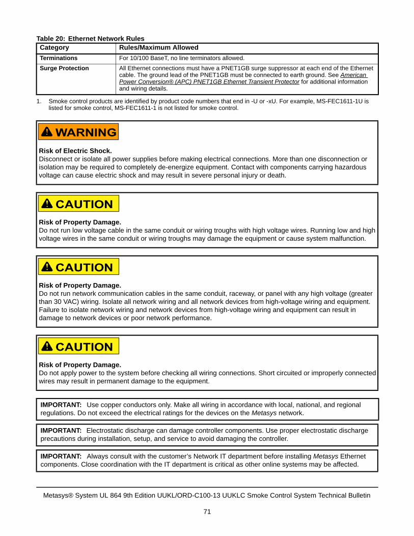
Terminations For 10/100 BaseT, no line terminators allowed.
Surge Protection All Ethernet connections must have a PNET1GB surge suppressor at each end of the Ethernet cable. The ground lead of the PNET1GB must be connected to earth ground. See American Power Conversion® (APC) PNET1GB Ethernet Transient Protector for additional information and wiring details.
1. Smoke control products are identified by product code numbers that end in -U or -xU. For example, MS-FEC1611-1U islisted for smoke control, MS-FEC1611-1 is not listed for smoke control.
Risk of Electric Shock.Disconnect or isolate all power supplies before making electrical connections. More than one disconnection or isolation may be required to completely de-energize equipment. Contact with components carrying hazardous voltage can cause electric shock and may result in severe personal injury or death.
Risk of Property Damage.Do not run low voltage cable in the same conduit or wiring troughs with high voltage wires. Running low and high voltage wires in the same conduit or wiring troughs may damage the equipment or cause system malfunction.
Risk of Property Damage.Do not run network communication cables in the same conduit, raceway, or panel with any high voltage (greater than 30 VAC) wiring. Isolate all network wiring and all network devices from high-voltage wiring and equipment. Failure to isolate network wiring and network devices from high-voltage wiring and equipment can result in damage to network devices or poor network performance.
Risk of Property Damage.Do not apply power to the system before checking all wiring connections. Short circuited or improperly connected wires may result in permanent damage to the equipment.
IMPORTANT: Use copper conductors only. Make all wiring in accordance with local, national, and regional regulations. Do not exceed the electrical ratings for the devices on the Metasys network.
IMPORTANT: Electrostatic discharge can damage controller components. Use proper electrostatic discharge precautions during installation, setup, and service to avoid damaging the controller.
IMPORTANT: Always consult with the customer’s Network IT department before installing Metasys Ethernet components. Close coordination with the IT department is critical as other online systems may be affected.
Table 20: Ethernet Network RulesCategory Rules/Maximum Allowed
Metasys® System UL 864 9th Edition UUKL/ORD-C100-13 UUKLC Smoke Control System Technical Bulletin
71
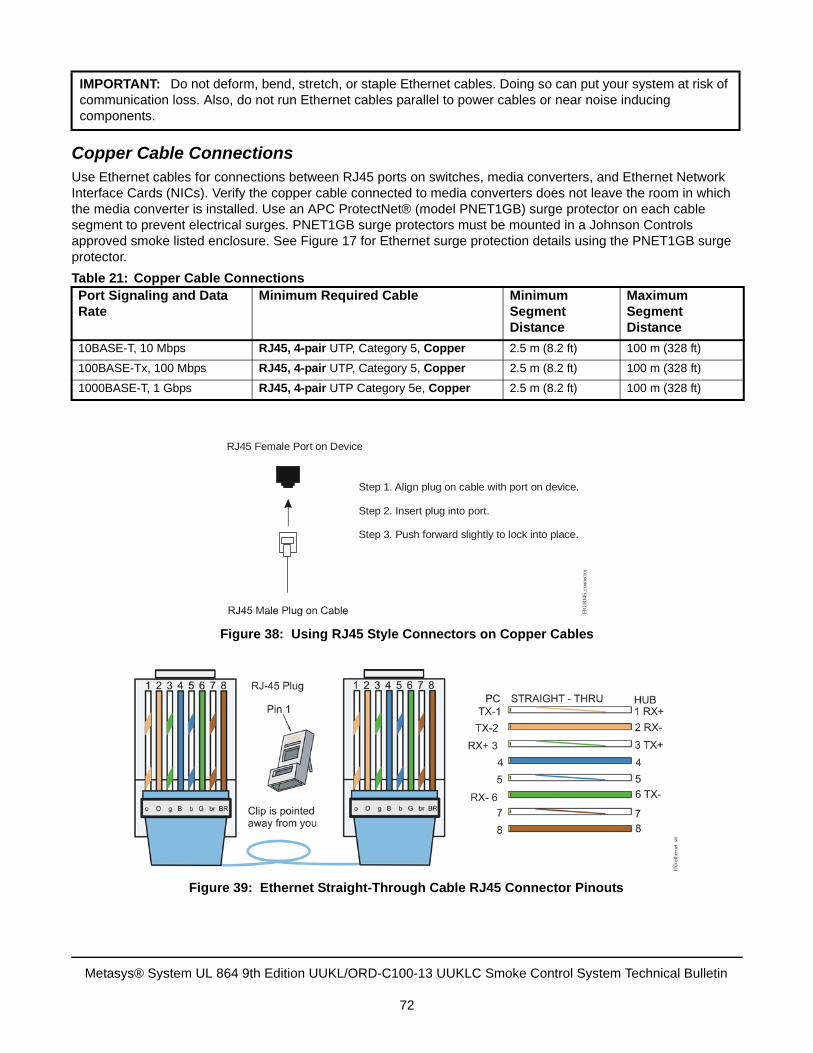
Copper Cable ConnectionsUse Ethernet cables for connections between RJ45 ports on switches, media converters, and Ethernet Network Interface Cards (NICs). Verify the copper cable connected to media converters does not leave the room in which the media converter is installed. Use an APC ProtectNet® (model PNET1GB) surge protector on each cable segment to prevent electrical surges. PNET1GB surge protectors must be mounted in a Johnson Controls approved smoke listed enclosure. See Figure 17 for Ethernet surge protection details using the PNET1GB surge protector.
IMPORTANT: Do not deform, bend, stretch, or staple Ethernet cables. Doing so can put your system at risk of communication loss. Also, do not run Ethernet cables parallel to power cables or near noise inducing components.
Table 21: Copper Cable ConnectionsPort Signaling and Data Rate
Minimum Required Cable Minimum Segment Distance
Maximum Segment Distance
10BASE-T, 10 Mbps RJ45, 4-pair UTP, Category 5, Copper 2.5 m (8.2 ft) 100 m (328 ft)
100BASE-Tx, 100 Mbps RJ45, 4-pair UTP, Category 5, Copper 2.5 m (8.2 ft) 100 m (328 ft)
1000BASE-T, 1 Gbps RJ45, 4-pair UTP Category 5e, Copper 2.5 m (8.2 ft) 100 m (328 ft)
Step 1. Align plug on cable with port on device.
Step 2. Insert plug into port.
Step 3. Push forward slightly to lock into place.
R 45 Female Port on DeviceJ
FIG
:RJ4
5_co
nnec
tor
Figure 38: Using RJ45 Style Connectors on Copper Cables
Figure 39: Ethernet Straight-Through Cable RJ45 Connector Pinouts
Metasys® System UL 864 9th Edition UUKL/ORD-C100-13 UUKLC Smoke Control System Technical Bulletin
72
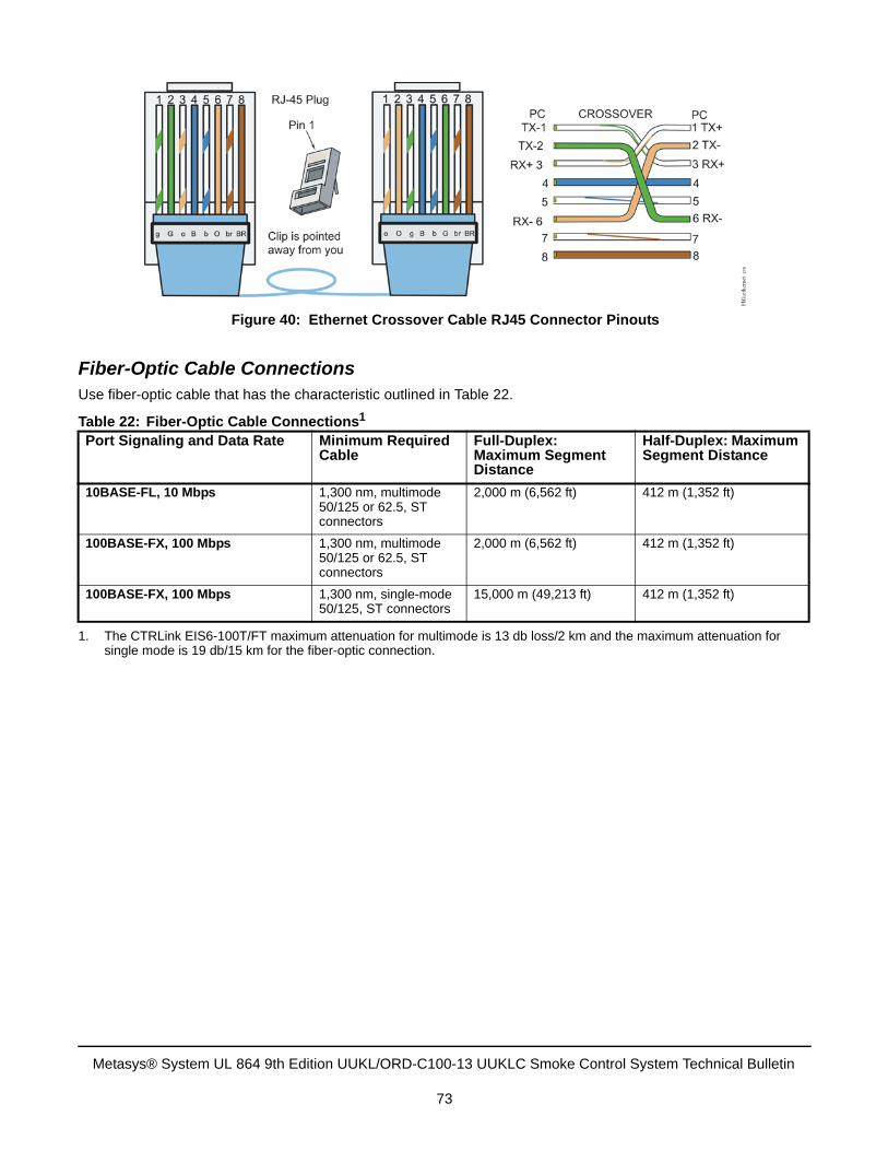
Fiber-Optic Cable ConnectionsUse fiber-optic cable that has the characteristic outlined in Table 22.
Table 22: Fiber-Optic Cable Connections1
1. The CTRLink EIS6-100T/FT maximum attenuation for multimode is 13 db loss/2 km and the maximum attenuation forsingle mode is 19 db/15 km for the fiber-optic connection.
Port Signaling and Data Rate Minimum Required Cable
Full-Duplex: Maximum Segment Distance
Half-Duplex: Maximum Segment Distance
10BASE-FL, 10 Mbps 1,300 nm, multimode 50/125 or 62.5, ST connectors
2,000 m (6,562 ft) 412 m (1,352 ft)
100BASE-FX, 100 Mbps 1,300 nm, multimode 50/125 or 62.5, ST connectors
2,000 m (6,562 ft) 412 m (1,352 ft)
100BASE-FX, 100 Mbps 1,300 nm, single-mode 50/125, ST connectors
15,000 m (49,213 ft) 412 m (1,352 ft)
Figure 40: Ethernet Crossover Cable RJ45 Connector Pinouts
Metasys® System UL 864 9th Edition UUKL/ORD-C100-13 UUKLC Smoke Control System Technical Bulletin
73
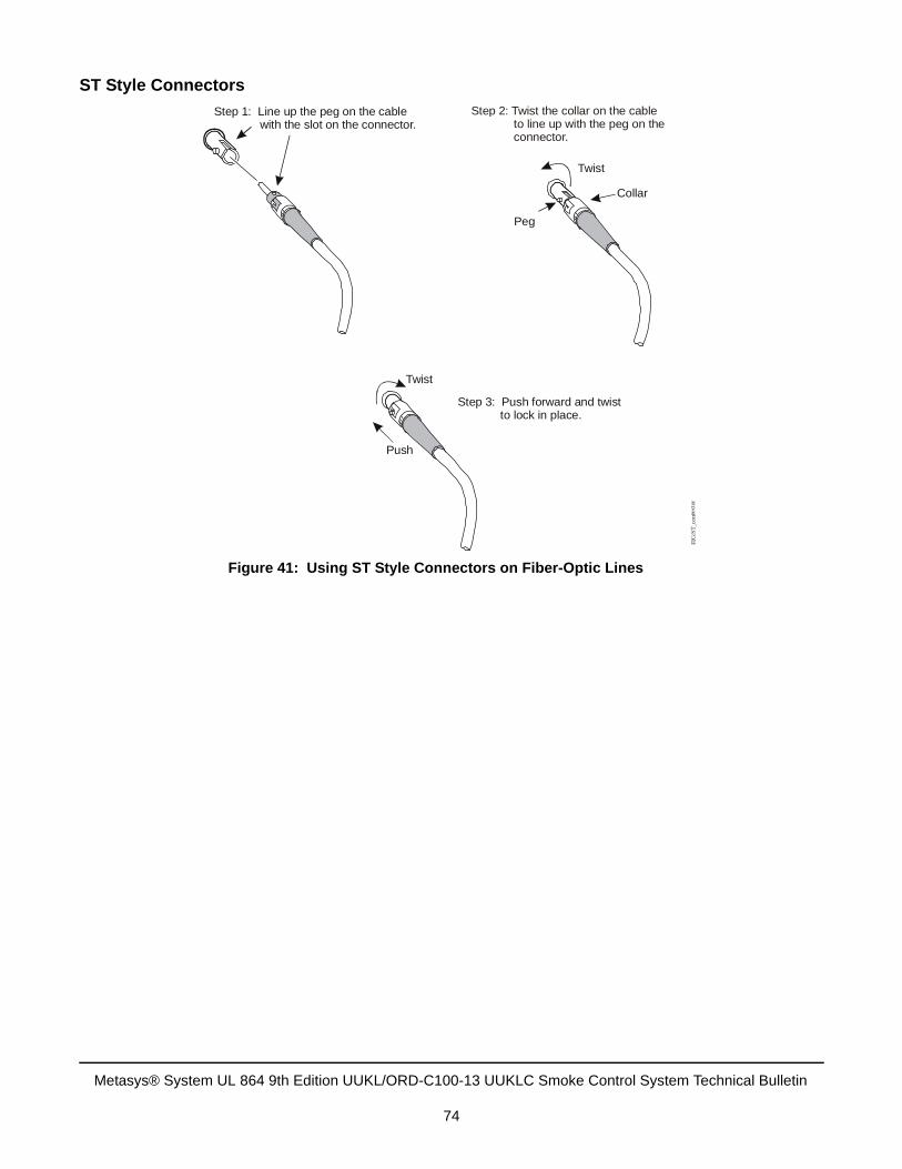
ST Style Connectors
Figure 41: Using ST Style Connectors on Fiber-Optic Lines
Step 1: Line up the peg on the cable with the slot on the connector.
Step 3: Push forward and twist to lock in place.
Push
Twist
Collar
Peg
Twist
Step 2: Twist the collar on the cable to line up with the peg on the connector.
FIG
:ST
_con
nect
or
Metasys® System UL 864 9th Edition UUKL/ORD-C100-13 UUKLC Smoke Control System Technical Bulletin
74
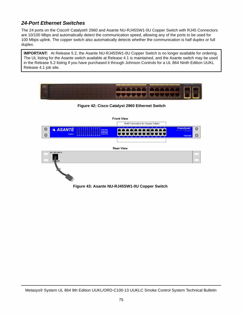
24-Port Ethernet SwitchesThe 24 ports on the Cisco® Catalyst® 2960 and Asante NU-RJ45SW1-0U Copper Switch with RJ45 Connectors are 10/100 Mbps and automatically detect the communication speed, allowing any of the ports to be used for 100 Mbps uplink. The copper switch also automatically detects whether the communication is half duplex or full duplex.
IMPORTANT: At Release 5.2, the Asante NU-RJ45SW1-0U Copper Switch is no longer available for ordering. The UL listing for the Asante switch available at Release 4.1 is maintained, and the Asante switch may be used in the Release 5.2 listing if you have purchased it through Johnson Controls for a UL 864 Ninth Edition UUKL Release 4.1 job site.
Figure 42: Cisco Catalyst 2960 Ethernet Switch
Figure 43: Asante NU-RJ45SW1-0U Copper Switch
Metasys® System UL 864 9th Edition UUKL/ORD-C100-13 UUKLC Smoke Control System Technical Bulletin
75
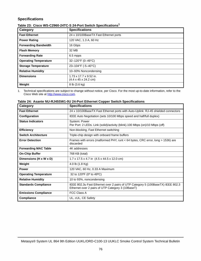
Specifications
Table 23: Cisco WS-C2960-24TC-S 24-Port Switch Specifications1
1. Technical specifications are subject to change without notice, per Cisco. For the most up-to-date information, refer to theCisco Web site at http://www.cisco.com.
Category Specifications
Fast Ethernet 24 x 10/100BaseTX Fast Ethernet ports
Power Rating 120 VAC, 1.3 A, 60 Hz
Forwarding Bandwidth 16 Gbps
Flash Memory 32 MB
Forwarding Rate 6.5 mpps
Operating Temperature 32–120°F (0–49°C)
Storage Temperature 23–104°F (-5–40°C)
Relative Humidity 10–93% Noncondensing
Dimensions 1.73 x 17.7 x 9.52 in.(4.4 x 45 x 24.2 cm)
Weight 8 lb (3.6 kg)
Table 24: Asante NU-RJ45SW1-0U 24-Port Ethernet Copper Switch SpecificationsCategory Specifications
Fast Ethernet 24 x 10/100BaseTX Fast Ethernet ports with Auto-Uplink: RJ-45 shielded connectors
Configuration IEEE Auto Negotiation (sets 10/100 Mbps speed and half/full duplex)
Status Indicators System: PowerPer Port: 2 LEDs. Link (solid)/activity (blink).100 Mbps (on)/10 Mbps (off)
Efficiency Non-blocking, Fast Ethernet switching
Switch Architecture Triple-chip design with onboard frame buffers
Error Detection Frames with errors (malformed PHY, runt < 64 bytes, CRC error, long > 1536) are discarded
Forwarding MAC Table 4K addresses
On-Chip Buffer 768 KB (total)
Dimensions (H x W x D) 1.7 x 17.5 x 4.7 in (4.5 x 44.5 x 12.0 cm)
Weight 4.0 lb (1.8 Kg)
Power 120 VAC, 60 Hz, 0.33 A Maximum
Operating Temperature 32 to 120ºF (0º to 49ºC)
Relative Humidity 10 to 93%, noncondensing
Standards Compliance IEEE 802.3u Fast Ethernet over 2 pairs of UTP Category 5 (100BaseTX) IEEE 802.3 Ethernet over 2 pairs of UTP Category 3 (10BaseT)
Emissions Compliance FCC Class A
Compliance UL, cUL, CE Safety
Metasys® System UL 864 9th Edition UUKL/ORD-C100-13 UUKLC Smoke Control System Technical Bulletin
76
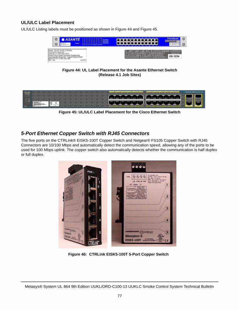
UL/ULC Label Placement
UL/ULC Listing labels must be positioned as shown in Figure 44 and Figure 45.
5-Port Ethernet Copper Switch with RJ45 ConnectorsThe five ports on the CTRLink® EISK5-100T Copper Switch and Netgear® FS105 Copper Switch with RJ45 Connectors are 10/100 Mbps and automatically detect the communication speed, allowing any of the ports to be used for 100 Mbps uplink. The copper switch also automatically detects whether the communication is half duplex or full duplex.
Figure 44: UL Label Placement for the Asante Ethernet Switch(Release 4.1 Job Sites)
Figure 45: UL/ULC Label Placement for the Cisco Ethernet Switch
Figure 46: CTRLink EISK5-100T 5-Port Copper Switch
Metasys® System UL 864 9th Edition UUKL/ORD-C100-13 UUKLC Smoke Control System Technical Bulletin
77
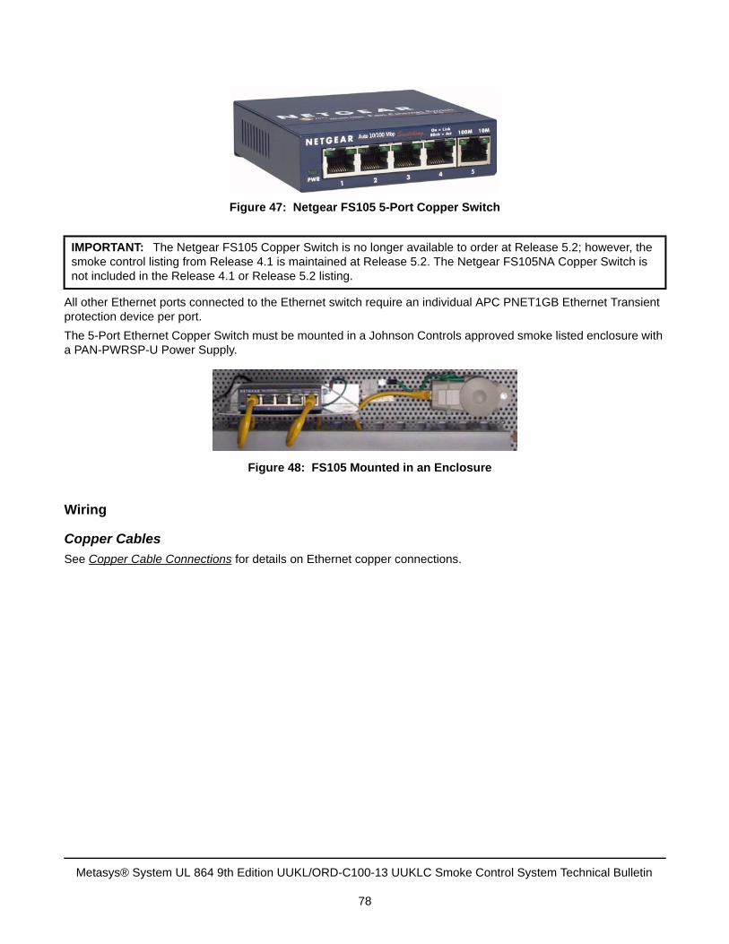
All other Ethernet ports connected to the Ethernet switch require an individual APC PNET1GB Ethernet Transient protection device per port.
The 5-Port Ethernet Copper Switch must be mounted in a Johnson Controls approved smoke listed enclosure with a PAN-PWRSP-U Power Supply.
Wiring
Copper Cables
See Copper Cable Connections for details on Ethernet copper connections.
IMPORTANT: The Netgear FS105 Copper Switch is no longer available to order at Release 5.2; however, the smoke control listing from Release 4.1 is maintained at Release 5.2. The Netgear FS105NA Copper Switch is not included in the Release 4.1 or Release 5.2 listing.
Figure 47: Netgear FS105 5-Port Copper Switch
Figure 48: FS105 Mounted in an Enclosure
Metasys® System UL 864 9th Edition UUKL/ORD-C100-13 UUKLC Smoke Control System Technical Bulletin
78
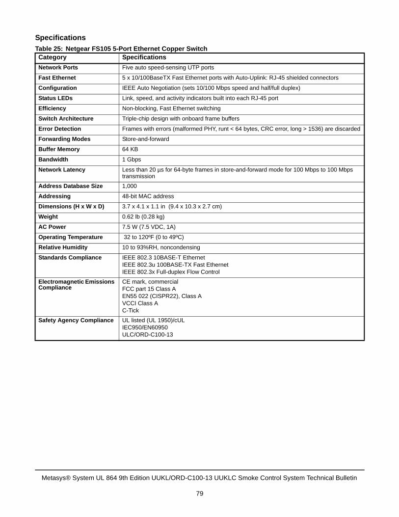
Specifications
Table 25: Netgear FS105 5-Port Ethernet Copper SwitchCategory Specifications
Network Ports Five auto speed-sensing UTP ports
Fast Ethernet 5 x 10/100BaseTX Fast Ethernet ports with Auto-Uplink: RJ-45 shielded connectors
Configuration IEEE Auto Negotiation (sets 10/100 Mbps speed and half/full duplex)
Status LEDs Link, speed, and activity indicators built into each RJ-45 port
Efficiency Non-blocking, Fast Ethernet switching
Switch Architecture Triple-chip design with onboard frame buffers
Error Detection Frames with errors (malformed PHY, runt < 64 bytes, CRC error, long > 1536) are discarded
Forwarding Modes Store-and-forward
Buffer Memory 64 KB
Bandwidth 1 Gbps
Network Latency Less than 20 µs for 64-byte frames in store-and-forward mode for 100 Mbps to 100 Mbps transmission
Address Database Size 1,000
Addressing 48-bit MAC address
Dimensions (H x W x D) 3.7 x 4.1 x 1.1 in (9.4 x 10.3 x 2.7 cm)
Weight 0.62 lb (0.28 kg)
AC Power 7.5 W (7.5 VDC, 1A)
Operating Temperature 32 to 120ºF (0 to 49ºC)
Relative Humidity 10 to 93%RH, noncondensing
Standards Compliance IEEE 802.3 10BASE-T EthernetIEEE 802.3u 100BASE-TX Fast EthernetIEEE 802.3x Full-duplex Flow Control
Electromagnetic Emissions Compliance
CE mark, commercialFCC part 15 Class AEN55 022 (CISPR22), Class AVCCI Class AC-Tick
Safety Agency Compliance UL listed (UL 1950)/cULIEC950/EN60950ULC/ORD-C100-13
Metasys® System UL 864 9th Edition UUKL/ORD-C100-13 UUKLC Smoke Control System Technical Bulletin
79
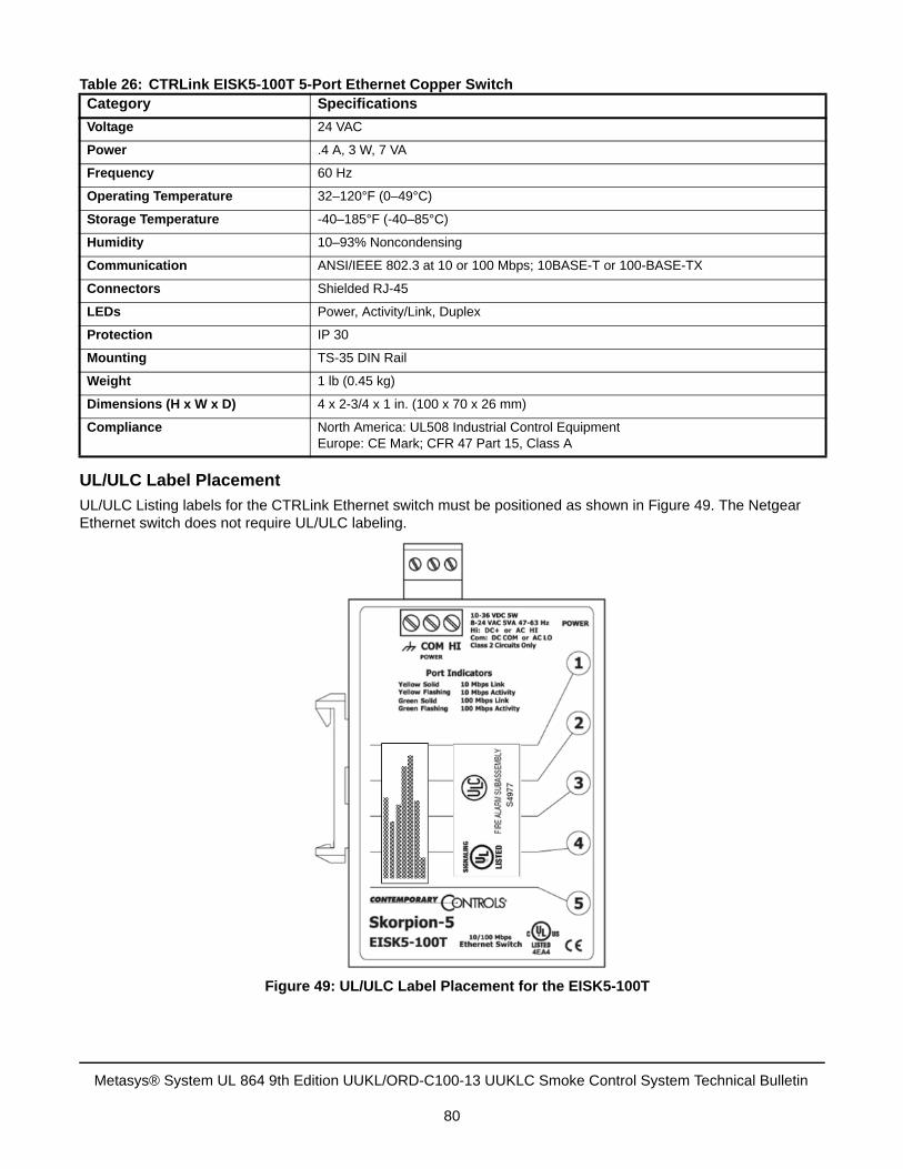
UL/ULC Label Placement
UL/ULC Listing labels for the CTRLink Ethernet switch must be positioned as shown in Figure 49. The Netgear Ethernet switch does not require UL/ULC labeling.
Table 26: CTRLink EISK5-100T 5-Port Ethernet Copper SwitchCategory Specifications
Voltage 24 VAC
Power .4 A, 3 W, 7 VA
Frequency 60 Hz
Operating Temperature 32–120°F (0–49°C)
Storage Temperature -40–185°F (-40–85°C)
Humidity 10–93% Noncondensing
Communication ANSI/IEEE 802.3 at 10 or 100 Mbps; 10BASE-T or 100-BASE-TX
Connectors Shielded RJ-45
LEDs Power, Activity/Link, Duplex
Protection IP 30
Mounting TS-35 DIN Rail
Weight 1 lb (0.45 kg)
Dimensions (H x W x D) 4 x 2-3/4 x 1 in. (100 x 70 x 26 mm)
Compliance North America: UL508 Industrial Control EquipmentEurope: CE Mark; CFR 47 Part 15, Class A
Figure 49: UL/ULC Label Placement for the EISK5-100T
Metasys® System UL 864 9th Edition UUKL/ORD-C100-13 UUKLC Smoke Control System Technical Bulletin
80
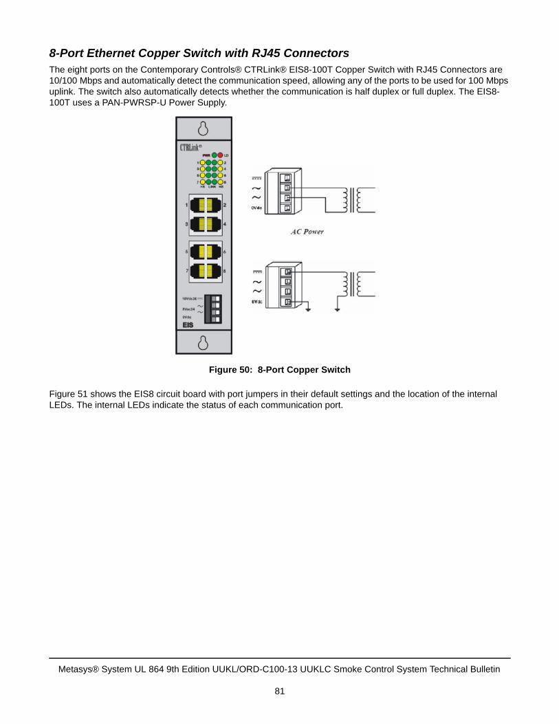
8-Port Ethernet Copper Switch with RJ45 ConnectorsThe eight ports on the Contemporary Controls® CTRLink® EIS8-100T Copper Switch with RJ45 Connectors are 10/100 Mbps and automatically detect the communication speed, allowing any of the ports to be used for 100 Mbps uplink. The switch also automatically detects whether the communication is half duplex or full duplex. The EIS8-100T uses a PAN-PWRSP-U Power Supply.
Figure 51 shows the EIS8 circuit board with port jumpers in their default settings and the location of the internal LEDs. The internal LEDs indicate the status of each communication port.
Figure 50: 8-Port Copper Switch
Metasys® System UL 864 9th Edition UUKL/ORD-C100-13 UUKLC Smoke Control System Technical Bulletin
81
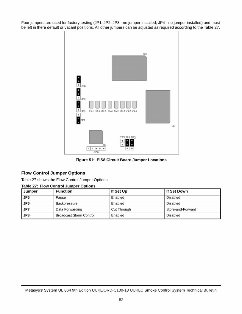
Four jumpers are used for factory testing (JP1, JP2, JP3 - no jumper installed, JP4 - no jumper installed) and must be left in there default or vacant positions. All other jumpers can be adjusted as required according to the Table 27.
Flow Control Jumper Options
Table 27 shows the Flow Control Jumper Options.
Table 27: Flow Control Jumper OptionsJumper Function If Set Up If Set Down
JP5 Pause Enabled Disabled
JP6 Backpressure Enabled Disabled
JP7 Data Forwarding Cut Through Store-and-Forward
JP8 Broadcast Storm Control Enabled Disabled
Figure 51: EIS8 Circuit Board Jumper Locations
Metasys® System UL 864 9th Edition UUKL/ORD-C100-13 UUKLC Smoke Control System Technical Bulletin
82
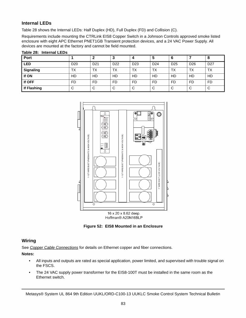
Internal LEDs
Table 28 shows the Internal LEDs: Half Duplex (HD), Full Duplex (FD) and Collision (C).
Requirements include mounting the CTRLink EIS8 Copper Switch in a Johnson Controls approved smoke listed enclosure with eight APC Ethernet PNET1GB Transient protection devices, and a 24 VAC Power Supply. All devices are mounted at the factory and cannot be field mounted.
Wiring
See Copper Cable Connections for details on Ethernet copper and fiber connections.
Notes:
• All inputs and outputs are rated as special application, power limited, and supervised with trouble signal onthe FSCS.
• The 24 VAC supply power transformer for the EIS8-100T must be installed in the same room as theEthernet switch.
Table 28: Internal LEDsPort 1 2 3 4 5 6 7 8
LED D20 D21 D22 D23 D24 D25 D26 D27
Signaling TX TX TX TX TX TX TX TX
If ON HD HD HD HD HD HD HD HD
If OFF FD FD FD FD FD FD FD FD
If Flashing C C C C C C C C
Figure 52: EIS8 Mounted in an Enclosure
Metasys® System UL 864 9th Edition UUKL/ORD-C100-13 UUKLC Smoke Control System Technical Bulletin
83
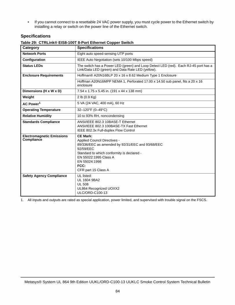
• If you cannot connect to a resettable 24 VAC power supply, you must cycle power to the Ethernet switch byinstalling a relay or switch on the power line of the Ethernet switch.
Specifications
Table 29: CTRLink® EIS8-100T 8-Port Ethernet Copper SwitchCategory Specifications
Network Ports Eight auto speed-sensing UTP ports
Configuration IEEE Auto Negotiation (sets 10/100 Mbps speed)
Status LEDs The switch has a Power LED (green) and Loop Detect LED (red). Each RJ-45 port has a Link/Data LED (green) and Data Rate LED (yellow).
Enclosure Requirements Hoffman® A20N16BLP 20 x 16 x 8.62 Medium Type 1 Enclosure
Hoffman A20N16MPP NEMA 1, Perforated 17.00 x 14.50 sub panel, fits a 20 x 16 enclosure
Dimensions (H x W x D) 7.54 x 1.75 x 5.45 in. (191 x 44 x 138 mm)
Weight 2 lb (0.9 Kg)
AC Power1
1. All inputs and outputs are rated as special application, power limited, and supervised with trouble signal on the FSCS.
5 VA (24 VAC, 400 mA), 60 Hz
Operating Temperature 32–120°F (0–49°C)
Relative Humidity 10 to 93% RH, noncondensing
Standards Compliance ANSI/IEEE 802.3 10BASE-T EthernetANSI/IEEE 802.3 100BASE-TX Fast EthernetIEEE 802.3x Full-duplex Flow Control
Electromagnetic Emissions Compliance
CE Mark:Applied Council Directives - 89/336/EEC as amended by 92/31/EEC and 93/68/EEC92/59/EECStandard to which conformity is declared - EN 55022:1995 Class AEN 55024:1998FCC:CFR part 15 Class A
Safety Agency Compliance UL listed:UL 1604 9BA2UL 508UL864 Recognized UOXX2ULC/ORD-C100-13
Metasys® System UL 864 9th Edition UUKL/ORD-C100-13 UUKLC Smoke Control System Technical Bulletin
84
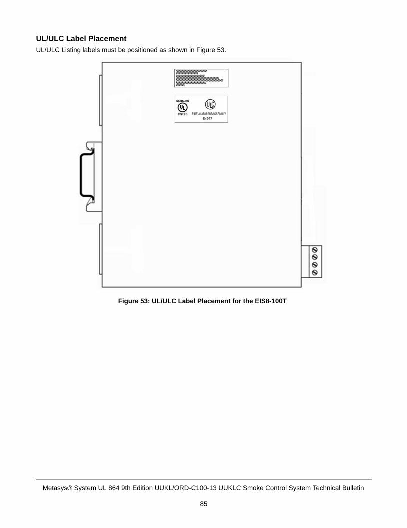
UL/ULC Label Placement
UL/ULC Listing labels must be positioned as shown in Figure 53.
Figure 53: UL/ULC Label Placement for the EIS8-100T
Metasys® System UL 864 9th Edition UUKL/ORD-C100-13 UUKLC Smoke Control System Technical Bulletin
85
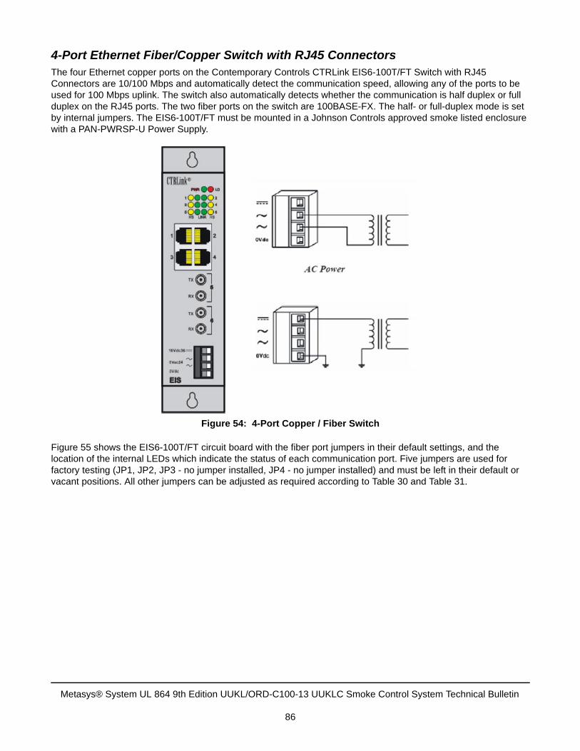
4-Port Ethernet Fiber/Copper Switch with RJ45 ConnectorsThe four Ethernet copper ports on the Contemporary Controls CTRLink EIS6-100T/FT Switch with RJ45 Connectors are 10/100 Mbps and automatically detect the communication speed, allowing any of the ports to be used for 100 Mbps uplink. The switch also automatically detects whether the communication is half duplex or full duplex on the RJ45 ports. The two fiber ports on the switch are 100BASE-FX. The half- or full-duplex mode is set by internal jumpers. The EIS6-100T/FT must be mounted in a Johnson Controls approved smoke listed enclosure with a PAN-PWRSP-U Power Supply.
Figure 55 shows the EIS6-100T/FT circuit board with the fiber port jumpers in their default settings, and the location of the internal LEDs which indicate the status of each communication port. Five jumpers are used for factory testing (JP1, JP2, JP3 - no jumper installed, JP4 - no jumper installed) and must be left in their default or vacant positions. All other jumpers can be adjusted as required according to Table 30 and Table 31.
Figure 54: 4-Port Copper / Fiber Switch
Metasys® System UL 864 9th Edition UUKL/ORD-C100-13 UUKLC Smoke Control System Technical Bulletin
86
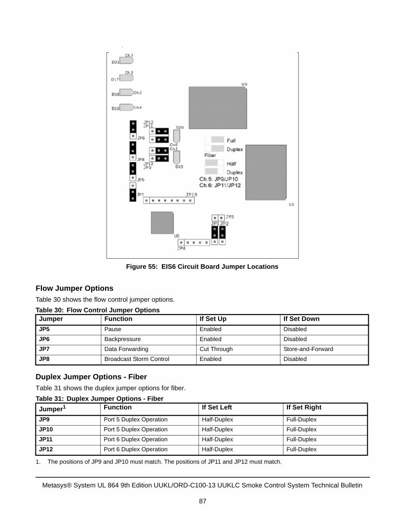
Flow Jumper Options
Table 30 shows the flow control jumper options.
Duplex Jumper Options - Fiber
Table 31 shows the duplex jumper options for fiber.
Table 30: Flow Control Jumper OptionsJumper Function If Set Up If Set Down
JP5 Pause Enabled Disabled
JP6 Backpressure Enabled Disabled
JP7 Data Forwarding Cut Through Store-and-Forward
JP8 Broadcast Storm Control Enabled Disabled
Table 31: Duplex Jumper Options - Fiber
Jumper1
1. The positions of JP9 and JP10 must match. The positions of JP11 and JP12 must match.
Function If Set Left If Set Right
JP9 Port 5 Duplex Operation Half-Duplex Full-Duplex
JP10 Port 5 Duplex Operation Half-Duplex Full-Duplex
JP11 Port 6 Duplex Operation Half-Duplex Full-Duplex
JP12 Port 6 Duplex Operation Half-Duplex Full-Duplex
Figure 55: EIS6 Circuit Board Jumper Locations
Metasys® System UL 864 9th Edition UUKL/ORD-C100-13 UUKLC Smoke Control System Technical Bulletin
87
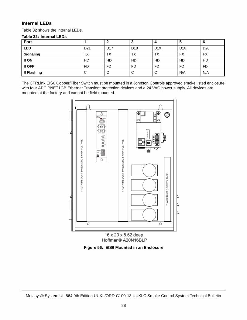
Internal LEDs
Table 32 shows the internal LEDs.
The CTRLink EIS6 Copper/Fiber Switch must be mounted in a Johnson Controls approved smoke listed enclosure with four APC PNET1GB Ethernet Transient protection devices and a 24 VAC power supply. All devices are mounted at the factory and cannot be field mounted.
Table 32: Internal LEDsPort 1 2 3 4 5 6
LED D21 D17 D18 D19 D16 D20
Signaling TX TX TX TX FX FX
If ON HD HD HD HD HD HD
If OFF FD FD FD FD FD FD
If Flashing C C C C N/A N/A
Figure 56: EIS6 Mounted in an Enclosure
Metasys® System UL 864 9th Edition UUKL/ORD-C100-13 UUKLC Smoke Control System Technical Bulletin
88
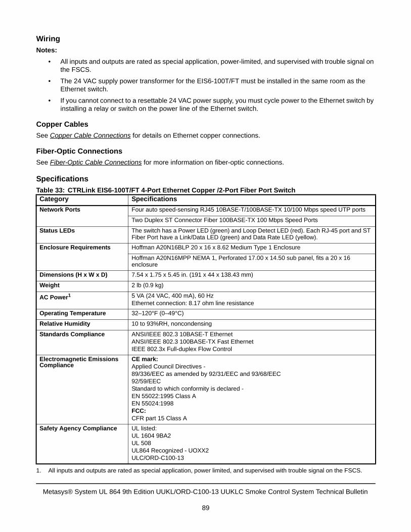
Wiring
Notes:
• All inputs and outputs are rated as special application, power-limited, and supervised with trouble signal onthe FSCS.
• The 24 VAC supply power transformer for the EIS6-100T/FT must be installed in the same room as theEthernet switch.
• If you cannot connect to a resettable 24 VAC power supply, you must cycle power to the Ethernet switch byinstalling a relay or switch on the power line of the Ethernet switch.
Copper Cables
See Copper Cable Connections for details on Ethernet copper connections.
Fiber-Optic Connections
See Fiber-Optic Cable Connections for more information on fiber-optic connections.
Specifications
Table 33: CTRLink EIS6-100T/FT 4-Port Ethernet Copper /2-Port Fiber Port SwitchCategory Specifications
Network Ports Four auto speed-sensing RJ45 10BASE-T/100BASE-TX 10/100 Mbps speed UTP ports
Two Duplex ST Connector Fiber 100BASE-TX 100 Mbps Speed Ports
Status LEDs The switch has a Power LED (green) and Loop Detect LED (red). Each RJ-45 port and ST Fiber Port have a Link/Data LED (green) and Data Rate LED (yellow).
Enclosure Requirements Hoffman A20N16BLP 20 x 16 x 8.62 Medium Type 1 Enclosure
Hoffman A20N16MPP NEMA 1, Perforated 17.00 x 14.50 sub panel, fits a 20 x 16 enclosure
Dimensions (H x W x D) 7.54 x 1.75 x 5.45 in. (191 x 44 x 138.43 mm)
Weight 2 lb (0.9 kg)
AC Power1
1. All inputs and outputs are rated as special application, power limited, and supervised with trouble signal on the FSCS.
5 VA (24 VAC, 400 mA), 60 HzEthernet connection: 8.17 ohm line resistance
Operating Temperature 32–120°F (0–49°C)
Relative Humidity 10 to 93%RH, noncondensing
Standards Compliance ANSI/IEEE 802.3 10BASE-T EthernetANSI/IEEE 802.3 100BASE-TX Fast EthernetIEEE 802.3x Full-duplex Flow Control
Electromagnetic Emissions Compliance
CE mark:Applied Council Directives - 89/336/EEC as amended by 92/31/EEC and 93/68/EEC92/59/EECStandard to which conformity is declared - EN 55022:1995 Class AEN 55024:1998FCC:CFR part 15 Class A
Safety Agency Compliance UL listed:UL 1604 9BA2UL 508UL864 Recognized - UOXX2ULC/ORD-C100-13
Metasys® System UL 864 9th Edition UUKL/ORD-C100-13 UUKLC Smoke Control System Technical Bulletin
89
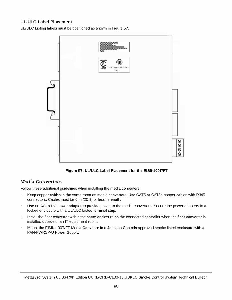
UL/ULC Label Placement
UL/ULC Listing labels must be positioned as shown in Figure 57.
Media ConvertersFollow these additional guidelines when installing the media converters:
• Keep copper cables in the same room as media converters. Use CAT5 or CAT5e copper cables with RJ45connectors. Cables must be 6 m (20 ft) or less in length.
• Use an AC to DC power adapter to provide power to the media converters. Secure the power adapters in alocked enclosure with a UL/ULC Listed terminal strip.
• Install the fiber converter within the same enclosure as the connected controller when the fiber converter isinstalled outside of an IT equipment room.
• Mount the EIMK-100T/FT Media Convertor in a Johnson Controls approved smoke listed enclosure with aPAN-PWRSP-U Power Supply.
Figure 57: UL/ULC Label Placement for the EIS6-100T/FT
Metasys® System UL 864 9th Edition UUKL/ORD-C100-13 UUKLC Smoke Control System Technical Bulletin
90
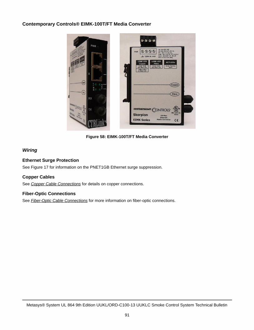
Contemporary Controls® EIMK-100T/FT Media Converter
Wiring
Ethernet Surge Protection
See Figure 17 for information on the PNET1GB Ethernet surge suppression.
Copper Cables
See Copper Cable Connections for details on copper connections.
Fiber-Optic Connections
See Fiber-Optic Cable Connections for more information on fiber-optic connections.
Figure 58: EIMK-100T/FT Media Converter
Metasys® System UL 864 9th Edition UUKL/ORD-C100-13 UUKLC Smoke Control System Technical Bulletin
91
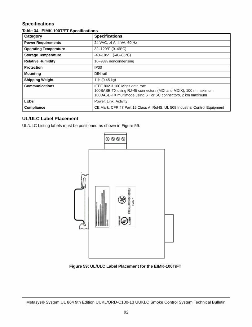
Specifications
UL/ULC Label Placement
UL/ULC Listing labels must be positioned as shown in Figure 59.
Table 34: EIMK-100T/FT SpecificationsCategory Specifications
Power Requirements 24 VAC, .4 A, 4 VA, 60 Hz
Operating Temperature 32–120°F (0–49°C)
Storage Temperature -40–185°F (-40–85°C)
Relative Humidity 10–93% noncondensing
Protection IP30
Mounting DIN rail
Shipping Weight 1 lb (0.45 kg)
Communications IEEE 802.3 100 Mbps data rate100BASE-TX using RJ-45 connectors (MDI and MDIX), 100 m maximum100BASE-FX multimode using ST or SC connectors, 2 km maximum
LEDs Power, Link, Activity
Compliance CE Mark, CFR 47 Part 15 Class A; RoHS, UL 508 Industrial Control Equipment
Figure 59: UL/ULC Label Placement for the EIMK-100T/FT
Metasys® System UL 864 9th Edition UUKL/ORD-C100-13 UUKLC Smoke Control System Technical Bulletin
92

See the manufacturer’s information packaged with each device for more device specifications.
Communication Wiring Example
Figure 60 shows a application using fiber-optic cable and media converters. The following guidelines apply in this system:
• Install all fiber-optic lines and copper cables in conduit.
• Verify that all fiber-optic lines with ST connectors have a maximum length of 6,560 feet (2,000 meters).
• Verify that connections between a media converter and a Smoke Control supervisory controller have amaximum length of 6 meters (20 feet) and that all cables are in the same room as the media converters.
• Verify that all copper cables with RJ45 connectors are CAT5 or CAT5e twisted pair.
• Do not field mount any devices; all smoke control devices are mounted at the factory to ensure compliancewith the UL 864 9th Edition UUKL/ORD-C100-13 UUKLC listing.
Table 35: Media Converter Fiber Optic Connector SpecificationsConnector Type
Fiber Type
Wave Length
Typical Distance
Min TX PWR
Max TX PWR
Sensitivity
(dBm)
Max In PWR
Link Budget
ST Multimode 850 nm LED
2 km -16.0 dBm -10.0 dBm -29.5 dBm -7.2 dBm 13.5 dB
Table 36: Electrical Specifications for Ethernet-to-Fiber Media ConvertorsProduct Code Number
Product Electrical Specifications
EIMK-100T/FT 100 Mbps Media Converter Power supplied from external adapterPower Draw: 4 W
Metasys® System UL 864 9th Edition UUKL/ORD-C100-13 UUKLC Smoke Control System Technical Bulletin
93
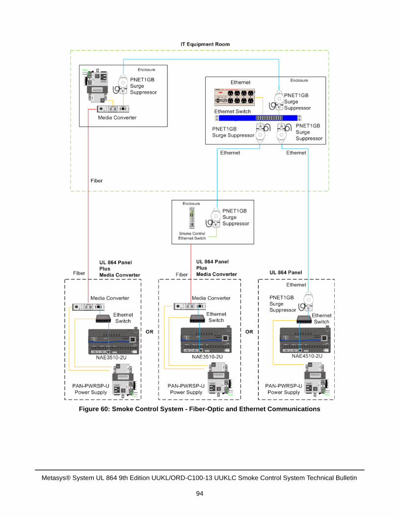
Figure 60: Smoke Control System - Fiber-Optic and Ethernet Communications
Metasys® System UL 864 9th Edition UUKL/ORD-C100-13 UUKLC Smoke Control System Technical Bulletin
94
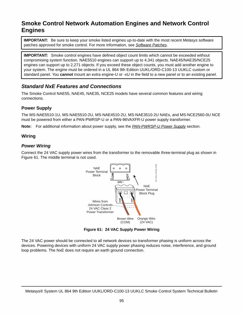
Smoke Control Network Automation Engines and Network Control Engines
Standard NxE Features and ConnectionsThe Smoke Control NAE55, NAE45, NAE35, NCE25 models have several common features and wiring connections.
Power Supply
The MS-NAE5510-1U, MS-NAE5510-2U, MS-NAE4510-2U, MS-NAE3510-2U NAEs, and MS-NCE2560-0U NCE must be powered from either a PAN-PWRSP-U or a PAN-96VAXFR-U power supply transformer.
Note: For additional information about power supply, see the PAN-PWRSP-U Power Supply section.
Wiring
Power Wiring
Connect the 24 VAC supply power wires from the transformer to the removable three-terminal plug as shown in Figure 61. The middle terminal is not used.
The 24 VAC power should be connected to all network devices so transformer phasing is uniform across the devices. Powering devices with uniform 24 VAC supply power phasing reduces noise, interference, and ground loop problems. The NxE does not require an earth ground connection.
IMPORTANT: Be sure to keep your smoke listed engines up-to-date with the most recent Metasys software patches approved for smoke control. For more information, see Software Patches.
IMPORTANT: Smoke control engines have defined object count limits which cannot be exceeded without compromising system function. NAE5510 engines can support up to 4,341 objects. NAE45/NAE35/NCE25 engines can support up to 2,271 objects. If you exceed these object counts, you must add another engine to your system. The engine must be ordered in a UL 864 9th Edition UUKL/ORD-C100-13 UUKLC custom or standard panel. You cannot mount an extra engine-U or -xU in the field to a new panel or to an existing panel.
Figure 61: 24 VAC Supply Power Wiring
NAEPower Terminal
Block
NAE Power Terminal
Block Plug
Wires from Johnson Controls24 VAC Class 2
Power Transformer
Brown Wire(COM)
Orange Wire(24 VAC)
FIG
: NA
E_P
OW
ER
_PO
RT
24V~
CO
M
HO
T
Metasys® System UL 864 9th Edition UUKL/ORD-C100-13 UUKLC Smoke Control System Technical Bulletin
95
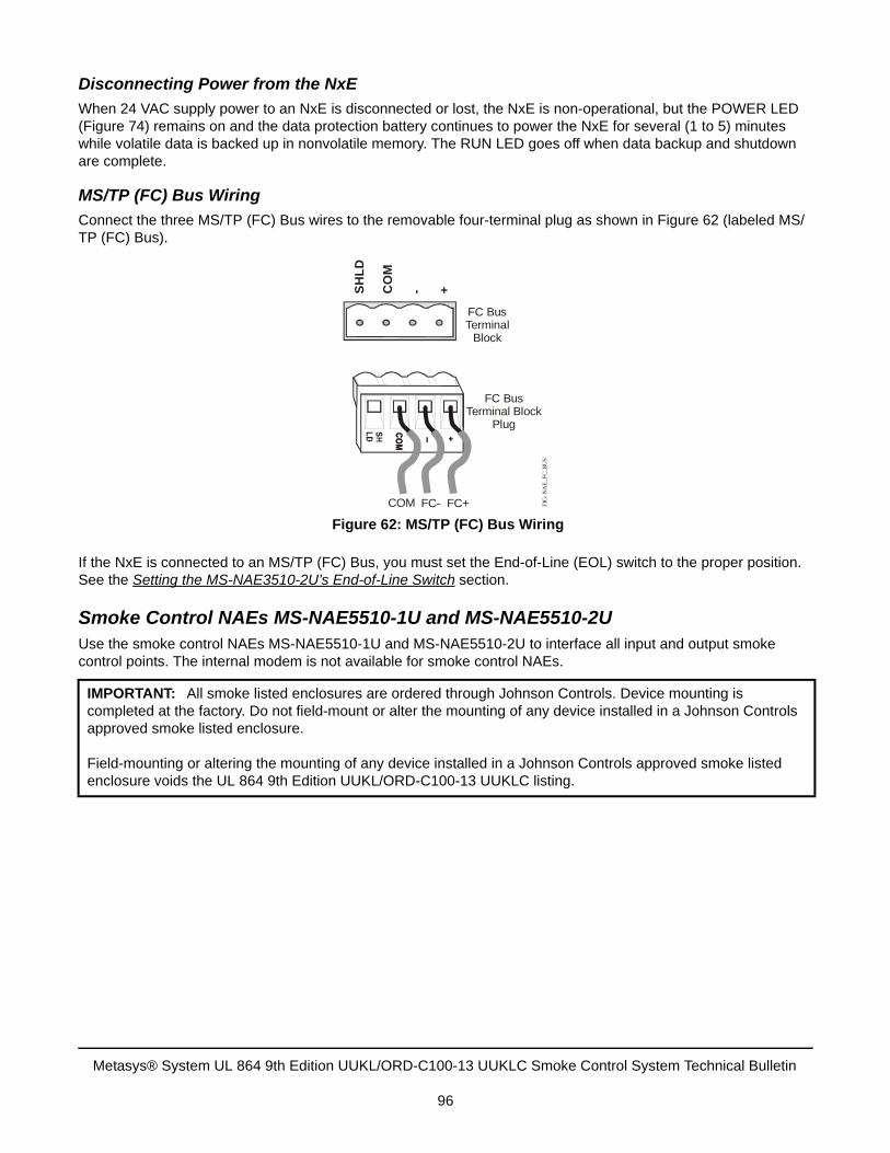
Disconnecting Power from the NxE
When 24 VAC supply power to an NxE is disconnected or lost, the NxE is non-operational, but the POWER LED (Figure 74) remains on and the data protection battery continues to power the NxE for several (1 to 5) minutes while volatile data is backed up in nonvolatile memory. The RUN LED goes off when data backup and shutdown are complete.
MS/TP (FC) Bus Wiring
Connect the three MS/TP (FC) Bus wires to the removable four-terminal plug as shown in Figure 62 (labeled MS/TP (FC) Bus).
If the NxE is connected to an MS/TP (FC) Bus, you must set the End-of-Line (EOL) switch to the proper position. See the Setting the MS-NAE3510-2U’s End-of-Line Switch section.
Smoke Control NAEs MS-NAE5510-1U and MS-NAE5510-2UUse the smoke control NAEs MS-NAE5510-1U and MS-NAE5510-2U to interface all input and output smoke control points. The internal modem is not available for smoke control NAEs.
IMPORTANT: All smoke listed enclosures are ordered through Johnson Controls. Device mounting is completed at the factory. Do not field-mount or alter the mounting of any device installed in a Johnson Controls approved smoke listed enclosure.
Field-mounting or altering the mounting of any device installed in a Johnson Controls approved smoke listed enclosure voids the UL 864 9th Edition UUKL/ORD-C100-13 UUKLC listing.
Figure 62: MS/TP (FC) Bus Wiring
FC BusTerminal
Block
FC BusTerminal Block
Plug
FIG
: NA
E_F
C_B
US
SH
LD
CO
M
- +
FC+FC-COM
Metasys® System UL 864 9th Edition UUKL/ORD-C100-13 UUKLC Smoke Control System Technical Bulletin
96
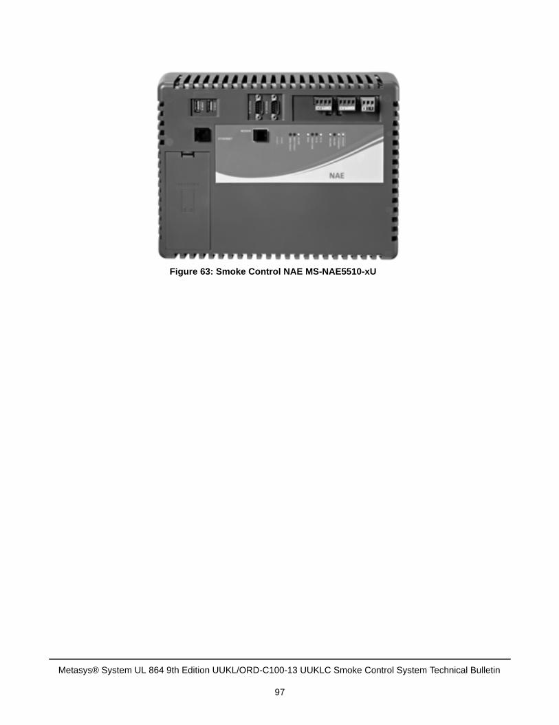
Figure 63: Smoke Control NAE MS-NAE5510-xU
Metasys® System UL 864 9th Edition UUKL/ORD-C100-13 UUKLC Smoke Control System Technical Bulletin
97
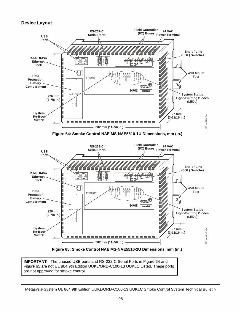
Device Layout
IMPORTANT: The unused USB ports and RS-232-C Serial Ports in Figure 64 and Figure 65 are not UL 864 9th Edition UUKL/ORD-C100-13 UUKLC Listed. These ports are not approved for smoke control.
Figure 64: Smoke Control NAE MS-NAE5510-1U Dimensions, mm (in.)
24 VACPower Terminal
RS-232-CSerial PortsUSB
Ports
RJ-45 8-PinEthernet
Jack
DataProtection
BatteryCompartment
SystemRe-BootSwitch
Wall MountFeet
System StatusLight-Emitting Diodes
(LEDs)
End-of-Line(EOL) Switches
97 mm(3-13/16 in.)
226 mm(8-7/8 in.)
FIG
:nae
5510
_dim
Field Controller(FC) Buses
Figure 65: Smoke Control NAE MS-NAE5510-2U Dimensions, mm (in.)
24 VACPower Terminal
RS-232-CSerial PortsUSB
Ports
RJ-45 8-PinEthernet
Jack
DataProtection
BatteryCompartment
SystemRe-BootSwitch
Wall MountFeet
System StatusLight-Emitting Diodes
(LEDs)
End-of-Line(EOL) Switches
97 mm(3-13/16 in.)
226 mm(8-7/8 in.)
FIG
:nae
5510
-2_d
im
Field Controller(FC) Buses
Metasys® System UL 864 9th Edition UUKL/ORD-C100-13 UUKLC Smoke Control System Technical Bulletin
98
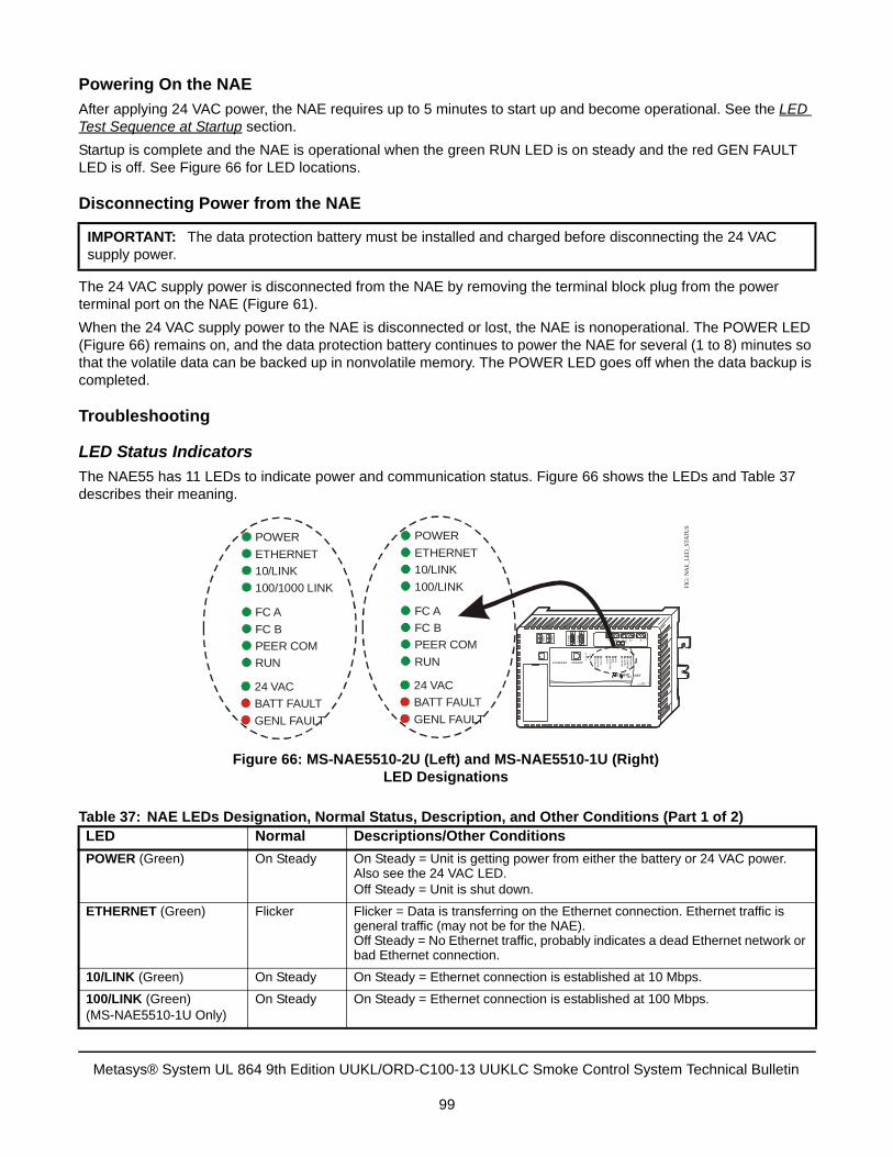
Powering On the NAE
After applying 24 VAC power, the NAE requires up to 5 minutes to start up and become operational. See the LED Test Sequence at Startup section.
Startup is complete and the NAE is operational when the green RUN LED is on steady and the red GEN FAULT LED is off. See Figure 66 for LED locations.
Disconnecting Power from the NAE
The 24 VAC supply power is disconnected from the NAE by removing the terminal block plug from the power terminal port on the NAE (Figure 61).
When the 24 VAC supply power to the NAE is disconnected or lost, the NAE is nonoperational. The POWER LED (Figure 66) remains on, and the data protection battery continues to power the NAE for several (1 to 8) minutes so that the volatile data can be backed up in nonvolatile memory. The POWER LED goes off when the data backup is completed.
Troubleshooting
LED Status Indicators
The NAE55 has 11 LEDs to indicate power and communication status. Figure 66 shows the LEDs and Table 37 describes their meaning.
IMPORTANT: The data protection battery must be installed and charged before disconnecting the 24 VAC supply power.
Table 37: NAE LEDs Designation, Normal Status, Description, and Other Conditions (Part 1 of 2)LED Normal Descriptions/Other Conditions
POWER (Green) On Steady On Steady = Unit is getting power from either the battery or 24 VAC power. Also see the 24 VAC LED. Off Steady = Unit is shut down.
ETHERNET (Green) Flicker Flicker = Data is transferring on the Ethernet connection. Ethernet traffic is general traffic (may not be for the NAE).Off Steady = No Ethernet traffic, probably indicates a dead Ethernet network or bad Ethernet connection.
10/LINK (Green) On Steady On Steady = Ethernet connection is established at 10 Mbps.
100/LINK (Green)(MS-NAE5510-1U Only)
On Steady On Steady = Ethernet connection is established at 100 Mbps.
Figure 66: MS-NAE5510-2U (Left) and MS-NAE5510-1U (Right)LED Designations
POWER
ETHERNET
10/LINK
100/LINK
FC A
FC B
PEER COM
RUN
24 VAC
BATT FAULT
GENL FAULT
N2-B
N2-A
POW
ER+-R
EF
S N2
+-REF
S N2
+NC
-
PO
WE
R
ET
HER
NET
10/LIN
K1
00/LIN
K
N2
AN
2B
PE
ER
CO
M
RU
N
24 V
AC
BA
TT FAU
LTG
EN
L FAU
LT
SER
IAL B
SER
IAL A
US
B A
US
B B
ETHERNET MODEM
SY
ST
EM
RE
-BO
OT
NAERET SY
FIG
: NA
E_L
ED
_STA
TU
S
POWER
ETHERNET
10/LINK
100/1000 LINK
FC A
FC B
PEER COM
RUN
24 VAC
BATT FAULT
GENL FAULT
Metasys® System UL 864 9th Edition UUKL/ORD-C100-13 UUKLC Smoke Control System Technical Bulletin
99
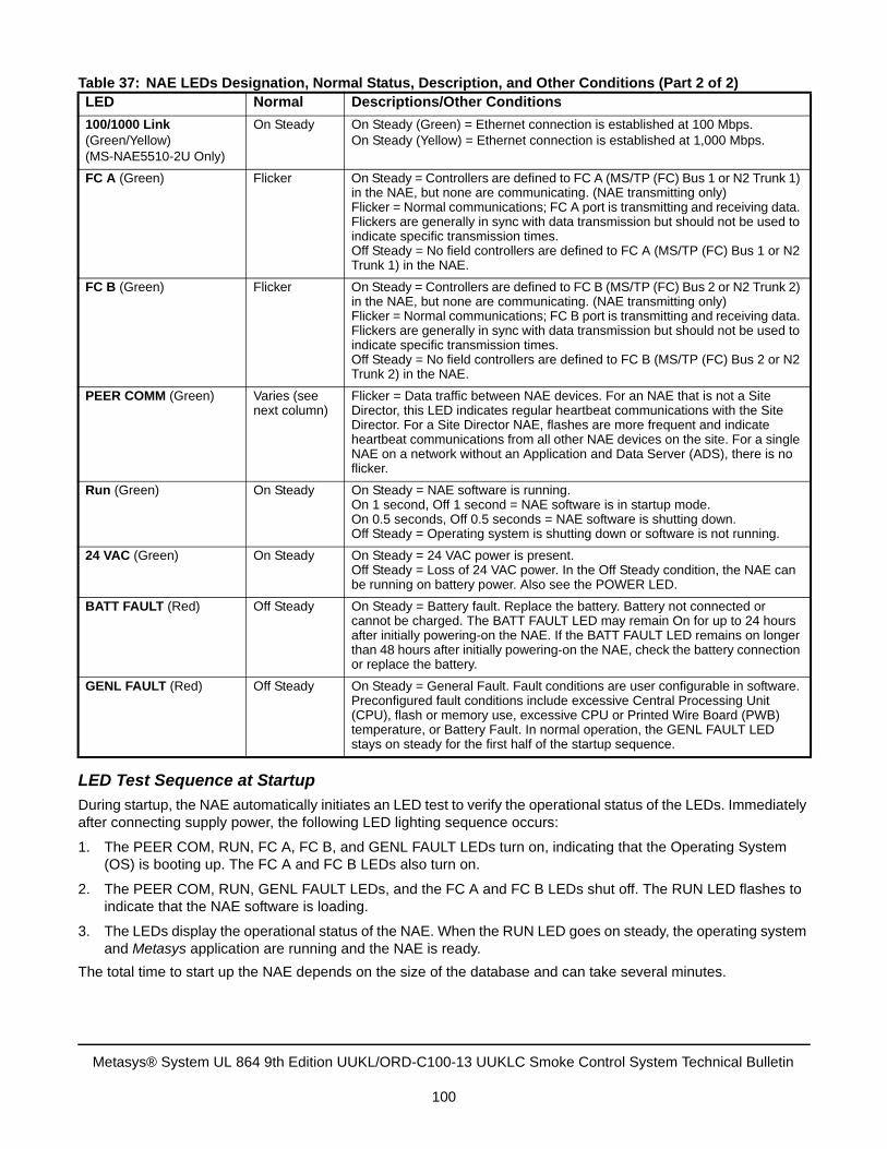
LED Test Sequence at Startup
During startup, the NAE automatically initiates an LED test to verify the operational status of the LEDs. Immediately after connecting supply power, the following LED lighting sequence occurs:
1. The PEER COM, RUN, FC A, FC B, and GENL FAULT LEDs turn on, indicating that the Operating System(OS) is booting up. The FC A and FC B LEDs also turn on.
2. The PEER COM, RUN, GENL FAULT LEDs, and the FC A and FC B LEDs shut off. The RUN LED flashes toindicate that the NAE software is loading.
3. The LEDs display the operational status of the NAE. When the RUN LED goes on steady, the operating systemand Metasys application are running and the NAE is ready.
The total time to start up the NAE depends on the size of the database and can take several minutes.
100/1000 Link (Green/Yellow)(MS-NAE5510-2U Only)
On Steady On Steady (Green) = Ethernet connection is established at 100 Mbps.On Steady (Yellow) = Ethernet connection is established at 1,000 Mbps.
FC A (Green) Flicker On Steady = Controllers are defined to FC A (MS/TP (FC) Bus 1 or N2 Trunk 1) in the NAE, but none are communicating. (NAE transmitting only)Flicker = Normal communications; FC A port is transmitting and receiving data. Flickers are generally in sync with data transmission but should not be used to indicate specific transmission times.Off Steady = No field controllers are defined to FC A (MS/TP (FC) Bus 1 or N2 Trunk 1) in the NAE.
FC B (Green) Flicker On Steady = Controllers are defined to FC B (MS/TP (FC) Bus 2 or N2 Trunk 2) in the NAE, but none are communicating. (NAE transmitting only)Flicker = Normal communications; FC B port is transmitting and receiving data. Flickers are generally in sync with data transmission but should not be used to indicate specific transmission times.Off Steady = No field controllers are defined to FC B (MS/TP (FC) Bus 2 or N2 Trunk 2) in the NAE.
PEER COMM (Green) Varies (see next column)
Flicker = Data traffic between NAE devices. For an NAE that is not a Site Director, this LED indicates regular heartbeat communications with the Site Director. For a Site Director NAE, flashes are more frequent and indicate heartbeat communications from all other NAE devices on the site. For a single NAE on a network without an Application and Data Server (ADS), there is no flicker.
Run (Green) On Steady On Steady = NAE software is running.On 1 second, Off 1 second = NAE software is in startup mode.On 0.5 seconds, Off 0.5 seconds = NAE software is shutting down.Off Steady = Operating system is shutting down or software is not running.
24 VAC (Green) On Steady On Steady = 24 VAC power is present.Off Steady = Loss of 24 VAC power. In the Off Steady condition, the NAE can be running on battery power. Also see the POWER LED.
BATT FAULT (Red) Off Steady On Steady = Battery fault. Replace the battery. Battery not connected or cannot be charged. The BATT FAULT LED may remain On for up to 24 hours after initially powering-on the NAE. If the BATT FAULT LED remains on longer than 48 hours after initially powering-on the NAE, check the battery connection or replace the battery.
GENL FAULT (Red) Off Steady On Steady = General Fault. Fault conditions are user configurable in software. Preconfigured fault conditions include excessive Central Processing Unit (CPU), flash or memory use, excessive CPU or Printed Wire Board (PWB) temperature, or Battery Fault. In normal operation, the GENL FAULT LED stays on steady for the first half of the startup sequence.
Table 37: NAE LEDs Designation, Normal Status, Description, and Other Conditions (Part 2 of 2)LED Normal Descriptions/Other Conditions
Metasys® System UL 864 9th Edition UUKL/ORD-C100-13 UUKLC Smoke Control System Technical Bulletin
100
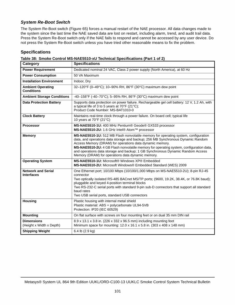
System Re-Boot Switch
The System Re-Boot switch (Figure 65) forces a manual restart of the NAE processor. All data changes made to the system since the last time the NAE saved data are lost on restart, including alarm, trend, and audit trail data. Press the System Re-Boot switch only if the NAE fails to respond and cannot be accessed by any user device. Do not press the System Re-Boot switch unless you have tried other reasonable means to fix the problem.
Specifications
Table 38: Smoke Control MS-NAE5510-xU Technical Specifications (Part 1 of 2) Category Specifications
Power Requirement Dedicated nominal 24 VAC, Class 2 power supply (North America), at 60 Hz
Power Consumption 50 VA Maximum
Installation Environment Indoor, Dry
Ambient Operating Conditions
32–120°F (0–49°C); 10–90% RH, 86°F (30°C) maximum dew point
Ambient Storage Conditions -40–158°F (-40–70°C); 5–95% RH, 86°F (30°C) maximum dew point
Data Protection Battery Supports data protection on power failure. Rechargeable gel cell battery: 12 V, 1.2 Ah, with a typical life of 3 to 5 years at 70°F (21°C); Product Code Number: MS-BAT1010-0
Clock Battery Maintains real-time clock through a power failure. On board cell; typical life 10 years at 70°F (21°C)
Processor MS-NAE5510-1U: 400 MHz Pentium® Geode® GX533 processorMS-NAE5510-2U: 1.6 GHz Intel® Atom™ processor
Memory MS-NAE5510-1U: 512 MB Flash nonvolatile memory for operating system, configuration data, and operations data storage and backup; 256 MB Synchronous Dynamic Random Access Memory (DRAM) for operations data dynamic memory.MS-NAE5510-2U: 4 GB Flash nonvolatile memory for operating system, configuration data, and operations data storage and backup; 1 GB Synchronous Dynamic Random Access Memory (DRAM) for operations data dynamic memory.
Operating System MS-NAE5510-1U: Microsoft® Windows XP® EmbeddedMS-NAE5510-2U: Microsoft Windows® Embedded Standard (WES) 2009
Network and Serial Interfaces
One Ethernet port; 10/100 Mbps (10/100/1,000 Mbps on MS-NAE5510-2U); 8-pin RJ-45 connectorTwo optically isolated RS-485 BACnet MS/TP ports; (9600, 19.2K, 38.4K, or 76.8K baud); pluggable and keyed 4-position terminal blocksTwo RS-232-C serial ports with standard 9-pin sub-D connectors that support all standard baud ratesTwo USB serial ports, standard USB connectors
Housing Plastic housing with internal metal shieldPlastic material: ABS + polycarbonate UL94-5VBProtection: IP20 (IEC 60529)
Mounting On flat surface with screws on four mounting feet or on dual 35 mm DIN rail
Dimensions(Height x Width x Depth)
8.9 x 13.1 x 3.8 in. (226 x 332 x 96.5 mm) including mounting feetMinimum space for mounting: 12.0 x 16.1 x 5.8 in. (303 x 408 x 148 mm)
Shipping Weight 6.4 lb (2.9 kg)
Metasys® System UL 864 9th Edition UUKL/ORD-C100-13 UUKLC Smoke Control System Technical Bulletin
101
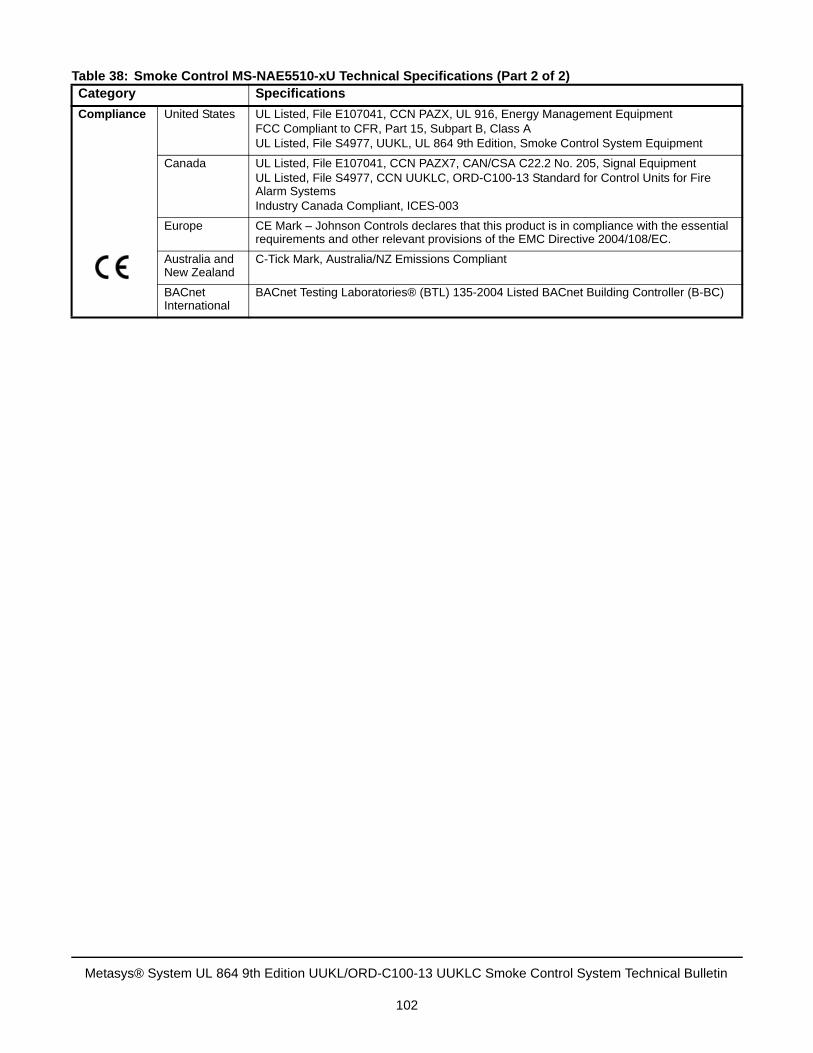
Compliance United States UL Listed, File E107041, CCN PAZX, UL 916, Energy Management EquipmentFCC Compliant to CFR, Part 15, Subpart B, Class AUL Listed, File S4977, UUKL, UL 864 9th Edition, Smoke Control System Equipment
Canada UL Listed, File E107041, CCN PAZX7, CAN/CSA C22.2 No. 205, Signal EquipmentUL Listed, File S4977, CCN UUKLC, ORD-C100-13 Standard for Control Units for Fire Alarm SystemsIndustry Canada Compliant, ICES-003
Europe CE Mark – Johnson Controls declares that this product is in compliance with the essential requirements and other relevant provisions of the EMC Directive 2004/108/EC.
Australia and New Zealand
C-Tick Mark, Australia/NZ Emissions Compliant
BACnet International
BACnet Testing Laboratories® (BTL) 135-2004 Listed BACnet Building Controller (B-BC)
Table 38: Smoke Control MS-NAE5510-xU Technical Specifications (Part 2 of 2) Category Specifications
Metasys® System UL 864 9th Edition UUKL/ORD-C100-13 UUKLC Smoke Control System Technical Bulletin
102
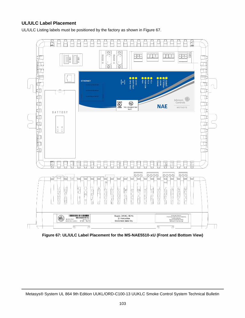
UL/ULC Label Placement
UL/ULC Listing labels must be positioned by the factory as shown in Figure 67.
Figure 67: UL/ULC Label Placement for the MS-NAE5510-xU (Front and Bottom View)
Metasys® System UL 864 9th Edition UUKL/ORD-C100-13 UUKLC Smoke Control System Technical Bulletin
103
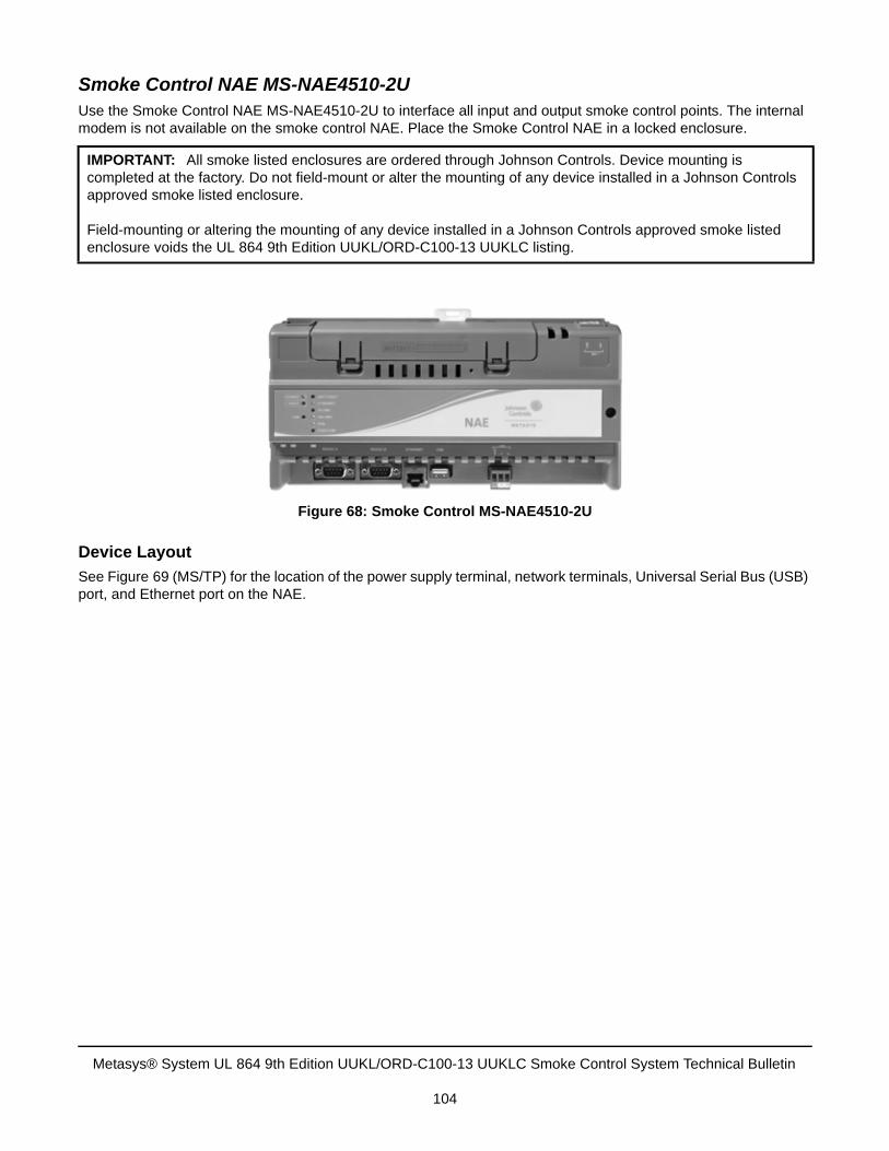
Smoke Control NAE MS-NAE4510-2UUse the Smoke Control NAE MS-NAE4510-2U to interface all input and output smoke control points. The internal modem is not available on the smoke control NAE. Place the Smoke Control NAE in a locked enclosure.
Device Layout
See Figure 69 (MS/TP) for the location of the power supply terminal, network terminals, Universal Serial Bus (USB) port, and Ethernet port on the NAE.
IMPORTANT: All smoke listed enclosures are ordered through Johnson Controls. Device mounting is completed at the factory. Do not field-mount or alter the mounting of any device installed in a Johnson Controls approved smoke listed enclosure.
Field-mounting or altering the mounting of any device installed in a Johnson Controls approved smoke listed enclosure voids the UL 864 9th Edition UUKL/ORD-C100-13 UUKLC listing.
Figure 68: Smoke Control MS-NAE4510-2U
Metasys® System UL 864 9th Edition UUKL/ORD-C100-13 UUKLC Smoke Control System Technical Bulletin
104
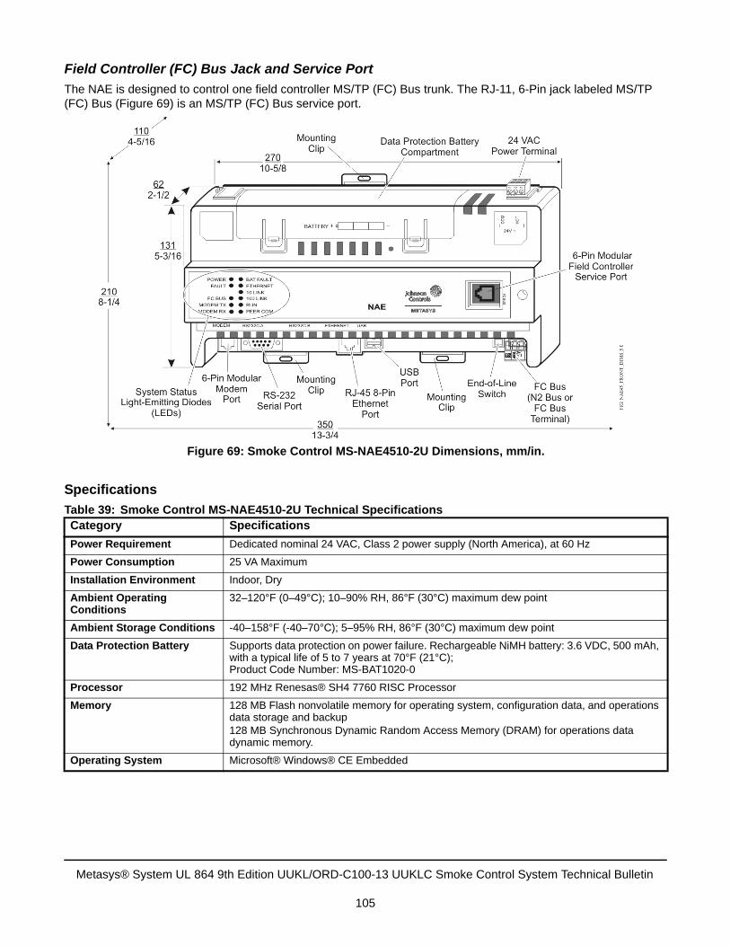
Field Controller (FC) Bus Jack and Service Port
The NAE is designed to control one field controller MS/TP (FC) Bus trunk. The RJ-11, 6-Pin jack labeled MS/TP (FC) Bus (Figure 69) is an MS/TP (FC) Bus service port.
Specifications
Table 39: Smoke Control MS-NAE4510-2U Technical SpecificationsCategory Specifications
Power Requirement Dedicated nominal 24 VAC, Class 2 power supply (North America), at 60 Hz
Power Consumption 25 VA Maximum
Installation Environment Indoor, Dry
Ambient Operating Conditions
32–120°F (0–49°C); 10–90% RH, 86°F (30°C) maximum dew point
Ambient Storage Conditions -40–158°F (-40–70°C); 5–95% RH, 86°F (30°C) maximum dew point
Data Protection Battery Supports data protection on power failure. Rechargeable NiMH battery: 3.6 VDC, 500 mAh, with a typical life of 5 to 7 years at 70°F (21°C); Product Code Number: MS-BAT1020-0
Processor 192 MHz Renesas® SH4 7760 RISC Processor
Memory 128 MB Flash nonvolatile memory for operating system, configuration data, and operations data storage and backup128 MB Synchronous Dynamic Random Access Memory (DRAM) for operations data dynamic memory.
Operating System Microsoft® Windows® CE Embedded
Figure 69: Smoke Control MS-NAE4510-2U Dimensions, mm/in.
Metasys® System UL 864 9th Edition UUKL/ORD-C100-13 UUKLC Smoke Control System Technical Bulletin
105
Network and Serial Interfaces
One Ethernet port; 10/100 Mbps; 8-pin RJ-45 connectorOne optically isolated RS-485 BACnet MS/TP port; (9,600, 19.2K, 38.4K, or 76.8K baud); pluggable and keyed 4-position terminal blocksOne RS-232-C serial port with standard 9-pin sub-D connector that supports all standard baud ratesOne USB serial port, standard USB connector
Housing Plastic housing material: ABS + polycarbonate UL94-5VBProtection: IP20 (IEC 60529)
Mounting On flat surface with screws on three mounting clips or on a single 35 mm DIN rail
Dimensions(Height x Width x Depth)
5.2 x 10.6 x 2.5 in. (131 x 270 x 62 mm)Minimum space for mounting: 8.3 x 13.8 x 4.3 in. (210 x 350 x 110 mm)
Shipping Weight 2.7 lb (1.2 kg)
Compliance United States UL Listed, File E107041, CCN PAZX, UL 916, Energy Management EquipmentFCC Compliant to CFR, Part 15, Subpart B, Class AUL Listed, File S4977, UUKL, UL 864 Ninth Edition, Smoke Control System Equipment
Canada UL Listed, File E107041, CCN PAZX7, CAN/CSA C22.2 No. 205, Signal EquipmentUL Listed, File S4977, CCN UUKLC, ORD-C100-13 Standard for Control Units for Fire Alarm SystemsIndustry Canada Compliant, ICES-003
Europe CE Mark – Johnson Controls declares that this product is in compliance with the essential requirements and other relevant provisions of the EMC Directive 2004/108/EC.
Australia and New Zealand
C-Tick Mark, Australia/NZ Emissions Compliant
BACnet International
BACnet Testing Laboratories® (BTL) 135-2004 Listed BACnet Building Controller (B-BC)
Table 39: Smoke Control MS-NAE4510-2U Technical Specifications (Continued) Category Specifications
Metasys® System UL 864 9th Edition UUKL/ORD-C100-13 UUKLC Smoke Control System Technical Bulletin
106
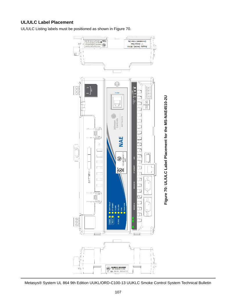
UL/ULC Label Placement
UL/ULC Listing labels must be positioned as shown in Figure 70.
Fig
ure
70:
UL
/UL
C L
ab
el
Pla
cem
en
t fo
r th
e M
S-N
AE
451
0-2U
Metasys® System UL 864 9th Edition UUKL/ORD-C100-13 UUKLC Smoke Control System Technical Bulletin
107
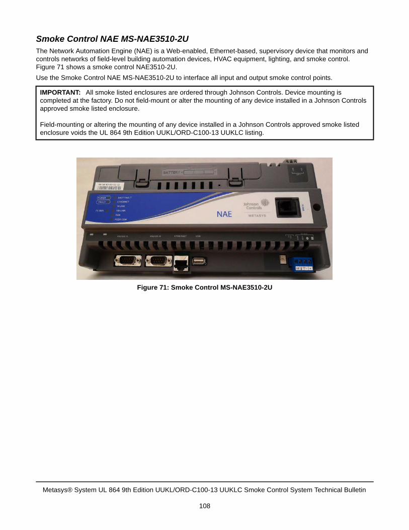
Smoke Control NAE MS-NAE3510-2UThe Network Automation Engine (NAE) is a Web-enabled, Ethernet-based, supervisory device that monitors and controls networks of field-level building automation devices, HVAC equipment, lighting, and smoke control. Figure 71 shows a smoke control NAE3510-2U.
Use the Smoke Control NAE MS-NAE3510-2U to interface all input and output smoke control points.
IMPORTANT: All smoke listed enclosures are ordered through Johnson Controls. Device mounting is completed at the factory. Do not field-mount or alter the mounting of any device installed in a Johnson Controls approved smoke listed enclosure.
Field-mounting or altering the mounting of any device installed in a Johnson Controls approved smoke listed enclosure voids the UL 864 9th Edition UUKL/ORD-C100-13 UUKLC listing.
Figure 71: Smoke Control MS-NAE3510-2U
Metasys® System UL 864 9th Edition UUKL/ORD-C100-13 UUKLC Smoke Control System Technical Bulletin
108
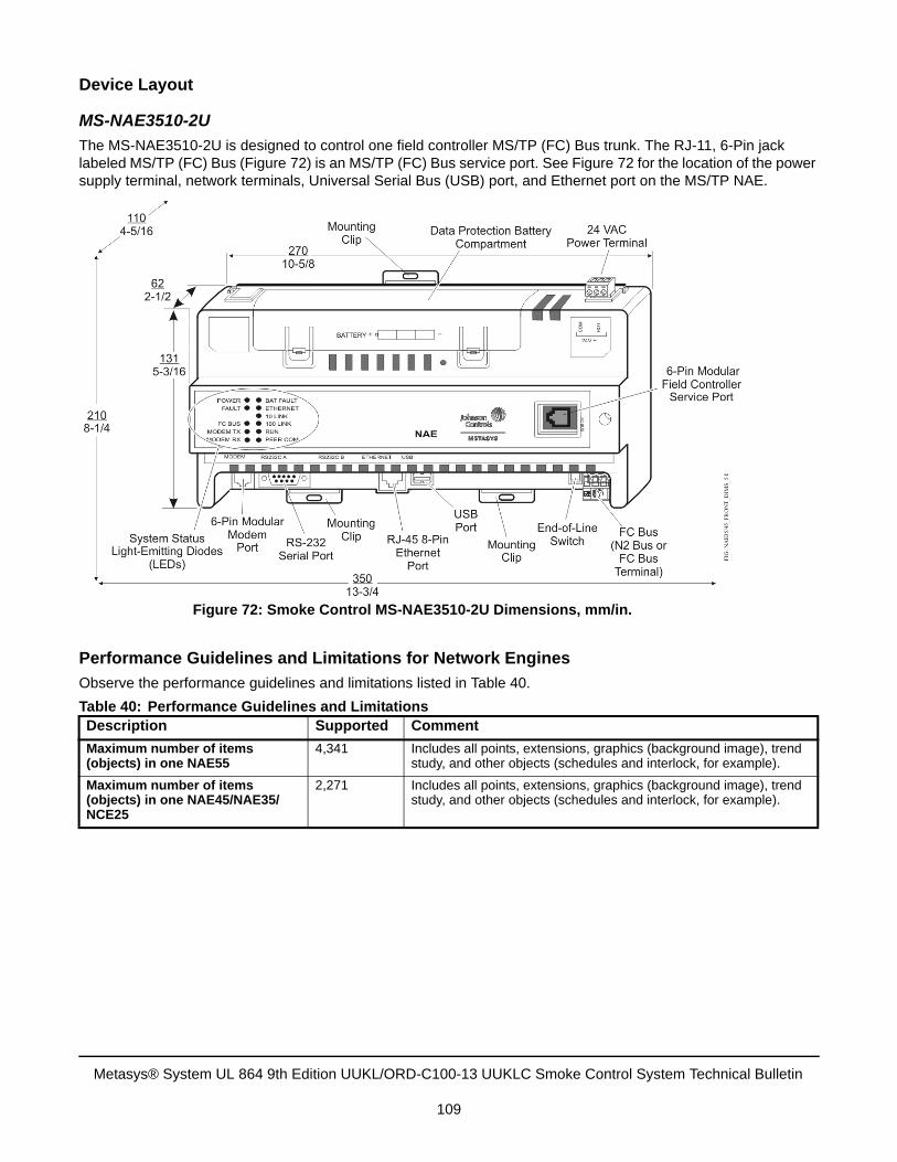
Device Layout
MS-NAE3510-2U
The MS-NAE3510-2U is designed to control one field controller MS/TP (FC) Bus trunk. The RJ-11, 6-Pin jack labeled MS/TP (FC) Bus (Figure 72) is an MS/TP (FC) Bus service port. See Figure 72 for the location of the power supply terminal, network terminals, Universal Serial Bus (USB) port, and Ethernet port on the MS/TP NAE.
Performance Guidelines and Limitations for Network Engines
Observe the performance guidelines and limitations listed in Table 40.
Table 40: Performance Guidelines and LimitationsDescription Supported Comment
Maximum number of items (objects) in one NAE55
4,341 Includes all points, extensions, graphics (background image), trend study, and other objects (schedules and interlock, for example).
Maximum number of items (objects) in one NAE45/NAE35/NCE25
2,271 Includes all points, extensions, graphics (background image), trend study, and other objects (schedules and interlock, for example).
Figure 72: Smoke Control MS-NAE3510-2U Dimensions, mm/in.
Metasys® System UL 864 9th Edition UUKL/ORD-C100-13 UUKLC Smoke Control System Technical Bulletin
109
Wiring Considerations and Guidelines for Network Integrations
Powering On the NAE35/45
After applying 24 VAC power, the NAE35/45 requires up to 2 minutes to start up and become operational. See the LED Test Sequence at Startup section.
Startup is complete and the NAE35/45 is operational when the (green) RUN LED is on steady and the (red) FAULT LED is off (Figure 74).
Table 41: Guidelines for MS/TP (MS/TP (FC) Bus) Network TopologyCategory Rules/Maximums Allowed
General One MS/TP (FC) Bus per NAE35 and NAE45
Only daisy-chained devices
Number of FC Devices Supported NAE45 models support up to 1001 devices on the MS/TP (FC) Bus trunk with no more than two repeaters between an NAE and any device and a maximum of 50 devices between repeaters.
1. If TEC Thermostat Controllers or third-party devices are used on the MS/TP (FC) Bus, the maximum total number of devices is 32 and the maximum length is 4,000 ft (1,219 m).
NAE35 models support up to 501 devices on the MS/TP (FC) Bus trunk with no more than two repeaters between an NAE and any device and a maximum of 50 devices between repeaters.
Cable Length and Type 5,000 ft (1,500 m) twisted pair cable without a repeater
15,000 ft (4,500 m) twisted pair cable from an NAE and the farthest FC device (three segments of 5,000 ft [1,500 m] each, separated by repeaters)
6,600 ft (2,000 m) between two fiber media converters
Cable Wire Type and Size Solid or stranded 22 AWG recommended (24 AWG twisted pair or larger is acceptable)
Terminations Two MS/TP (FC) Bus devices with EOL switches in the ON position, one at each end of each MS/TP (FC) Bus segment
Table 42: NAE Ethernet Network Rules Category Rules/Maximums Allowed1
1. See Surge Protection Devices and Network Communications for more information.
General Point-to-point star topology with network hubs/switches
Number of Devices Maximum of 200 supervisory devices may be connected to one site in the Metasys system extended architecture.
Line Length and Type 6,600 ft (2,000 m) ( for plastic/glass fiber optic with external adapter
10/100 BaseT: 330 ft (100 m) CAT5 cable
1000 BaseT:2 330 ft (100 m) CAT5E cable
2. MS-NAE5510-2U only.
Terminations For 10/100/1000 BaseT, no line terminators allowed
Transient Protection A PNET1GB transient protector is required at each end of every Ethernet connection
Metasys® System UL 864 9th Edition UUKL/ORD-C100-13 UUKLC Smoke Control System Technical Bulletin
110
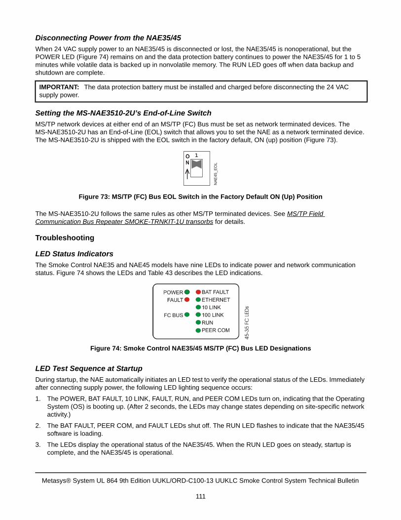
Disconnecting Power from the NAE35/45
When 24 VAC supply power to an NAE35/45 is disconnected or lost, the NAE35/45 is nonoperational, but the POWER LED (Figure 74) remains on and the data protection battery continues to power the NAE35/45 for 1 to 5 minutes while volatile data is backed up in nonvolatile memory. The RUN LED goes off when data backup and shutdown are complete.
Setting the MS-NAE3510-2U’s End-of-Line Switch
MS/TP network devices at either end of an MS/TP (FC) Bus must be set as network terminated devices. The MS-NAE3510-2U has an End-of-Line (EOL) switch that allows you to set the NAE as a network terminated device. The MS-NAE3510-2U is shipped with the EOL switch in the factory default, ON (up) position (Figure 73).
The MS-NAE3510-2U follows the same rules as other MS/TP terminated devices. See MS/TP Field Communication Bus Repeater SMOKE-TRNKIT-1U transorbs for details.
Troubleshooting
LED Status Indicators
The Smoke Control NAE35 and NAE45 models have nine LEDs to indicate power and network communication status. Figure 74 shows the LEDs and Table 43 describes the LED indications.
LED Test Sequence at Startup
During startup, the NAE automatically initiates an LED test to verify the operational status of the LEDs. Immediately after connecting supply power, the following LED lighting sequence occurs:
1. The POWER, BAT FAULT, 10 LINK, FAULT, RUN, and PEER COM LEDs turn on, indicating that the OperatingSystem (OS) is booting up. (After 2 seconds, the LEDs may change states depending on site-specific networkactivity.)
2. The BAT FAULT, PEER COM, and FAULT LEDs shut off. The RUN LED flashes to indicate that the NAE35/45software is loading.
3. The LEDs display the operational status of the NAE35/45. When the RUN LED goes on steady, startup iscomplete, and the NAE35/45 is operational.
IMPORTANT: The data protection battery must be installed and charged before disconnecting the 24 VAC supply power.
Figure 73: MS/TP (FC) Bus EOL Switch in the Factory Default ON (Up) Position
NA
E4
5_
EO
L
1
Figure 74: Smoke Control NAE35/45 MS/TP (FC) Bus LED Designations
Metasys® System UL 864 9th Edition UUKL/ORD-C100-13 UUKLC Smoke Control System Technical Bulletin
111
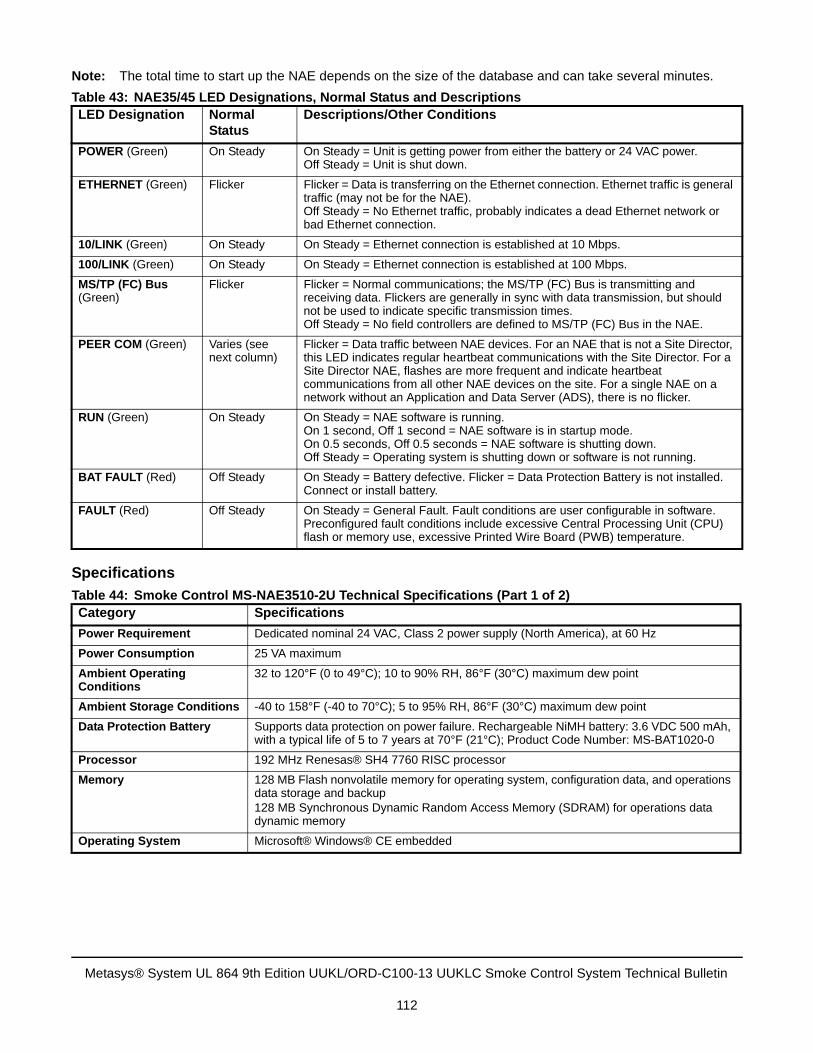
Note: The total time to start up the NAE depends on the size of the database and can take several minutes.
Specifications
Table 43: NAE35/45 LED Designations, Normal Status and DescriptionsLED Designation Normal
StatusDescriptions/Other Conditions
POWER (Green) On Steady On Steady = Unit is getting power from either the battery or 24 VAC power. Off Steady = Unit is shut down.
ETHERNET (Green) Flicker Flicker = Data is transferring on the Ethernet connection. Ethernet traffic is general traffic (may not be for the NAE).Off Steady = No Ethernet traffic, probably indicates a dead Ethernet network or bad Ethernet connection.
10/LINK (Green) On Steady On Steady = Ethernet connection is established at 10 Mbps.
100/LINK (Green) On Steady On Steady = Ethernet connection is established at 100 Mbps.
MS/TP (FC) Bus (Green)
Flicker Flicker = Normal communications; the MS/TP (FC) Bus is transmitting and receiving data. Flickers are generally in sync with data transmission, but should not be used to indicate specific transmission times.Off Steady = No field controllers are defined to MS/TP (FC) Bus in the NAE.
PEER COM (Green) Varies (see next column)
Flicker = Data traffic between NAE devices. For an NAE that is not a Site Director, this LED indicates regular heartbeat communications with the Site Director. For a Site Director NAE, flashes are more frequent and indicate heartbeat communications from all other NAE devices on the site. For a single NAE on a network without an Application and Data Server (ADS), there is no flicker.
RUN (Green) On Steady On Steady = NAE software is running.On 1 second, Off 1 second = NAE software is in startup mode.On 0.5 seconds, Off 0.5 seconds = NAE software is shutting down.Off Steady = Operating system is shutting down or software is not running.
BAT FAULT (Red) Off Steady On Steady = Battery defective. Flicker = Data Protection Battery is not installed. Connect or install battery.
FAULT (Red) Off Steady On Steady = General Fault. Fault conditions are user configurable in software. Preconfigured fault conditions include excessive Central Processing Unit (CPU) flash or memory use, excessive Printed Wire Board (PWB) temperature.
Table 44: Smoke Control MS-NAE3510-2U Technical Specifications (Part 1 of 2)Category Specifications
Power Requirement Dedicated nominal 24 VAC, Class 2 power supply (North America), at 60 Hz
Power Consumption 25 VA maximum
Ambient Operating Conditions
32 to 120°F (0 to 49°C); 10 to 90% RH, 86°F (30°C) maximum dew point
Ambient Storage Conditions -40 to 158°F (-40 to 70°C); 5 to 95% RH, 86°F (30°C) maximum dew point
Data Protection Battery Supports data protection on power failure. Rechargeable NiMH battery: 3.6 VDC 500 mAh, with a typical life of 5 to 7 years at 70°F (21°C); Product Code Number: MS-BAT1020-0
Processor 192 MHz Renesas® SH4 7760 RISC processor
Memory 128 MB Flash nonvolatile memory for operating system, configuration data, and operations data storage and backup128 MB Synchronous Dynamic Random Access Memory (SDRAM) for operations data dynamic memory
Operating System Microsoft® Windows® CE embedded
Metasys® System UL 864 9th Edition UUKL/ORD-C100-13 UUKLC Smoke Control System Technical Bulletin
112
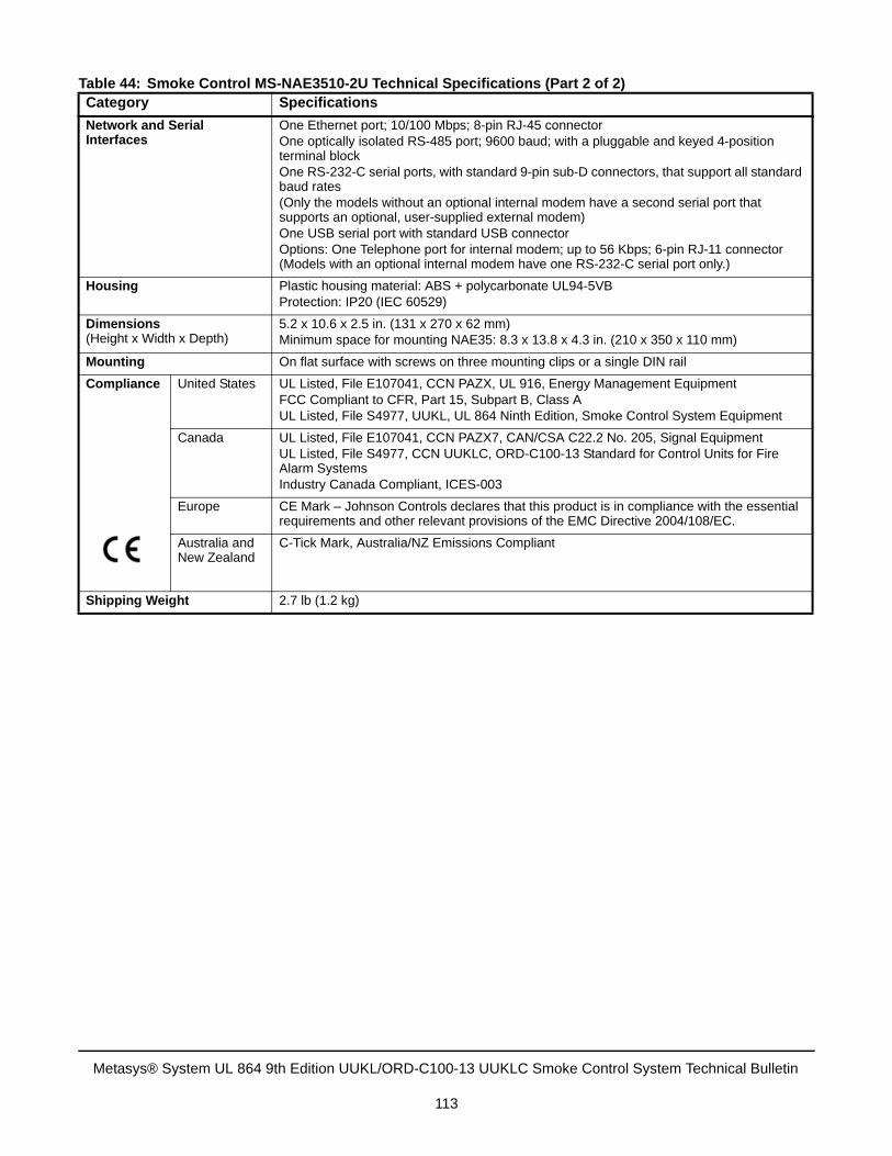
Network and Serial Interfaces
One Ethernet port; 10/100 Mbps; 8-pin RJ-45 connectorOne optically isolated RS-485 port; 9600 baud; with a pluggable and keyed 4-position terminal blockOne RS-232-C serial ports, with standard 9-pin sub-D connectors, that support all standard baud rates(Only the models without an optional internal modem have a second serial port that supports an optional, user-supplied external modem)One USB serial port with standard USB connectorOptions: One Telephone port for internal modem; up to 56 Kbps; 6-pin RJ-11 connector (Models with an optional internal modem have one RS-232-C serial port only.)
Housing Plastic housing material: ABS + polycarbonate UL94-5VBProtection: IP20 (IEC 60529)
Dimensions (Height x Width x Depth)
5.2 x 10.6 x 2.5 in. (131 x 270 x 62 mm)Minimum space for mounting NAE35: 8.3 x 13.8 x 4.3 in. (210 x 350 x 110 mm)
Mounting On flat surface with screws on three mounting clips or a single DIN rail
Compliance United States UL Listed, File E107041, CCN PAZX, UL 916, Energy Management EquipmentFCC Compliant to CFR, Part 15, Subpart B, Class AUL Listed, File S4977, UUKL, UL 864 Ninth Edition, Smoke Control System Equipment
Canada UL Listed, File E107041, CCN PAZX7, CAN/CSA C22.2 No. 205, Signal EquipmentUL Listed, File S4977, CCN UUKLC, ORD-C100-13 Standard for Control Units for Fire Alarm SystemsIndustry Canada Compliant, ICES-003
Europe CE Mark – Johnson Controls declares that this product is in compliance with the essential requirements and other relevant provisions of the EMC Directive 2004/108/EC.
Australia and New Zealand
C-Tick Mark, Australia/NZ Emissions Compliant
Shipping Weight 2.7 lb (1.2 kg)
Table 44: Smoke Control MS-NAE3510-2U Technical Specifications (Part 2 of 2)Category Specifications
Metasys® System UL 864 9th Edition UUKL/ORD-C100-13 UUKLC Smoke Control System Technical Bulletin
113
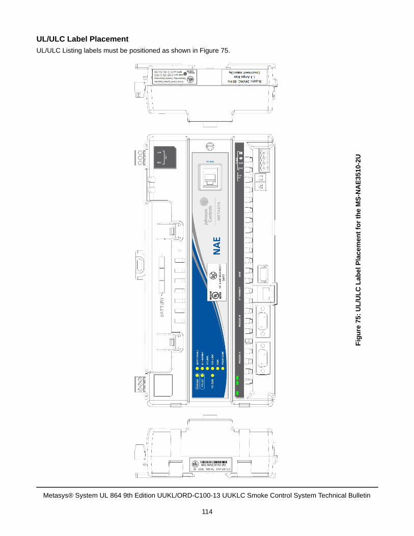
UL/ULC Label Placement
UL/ULC Listing labels must be positioned as shown in Figure 75.
Fig
ure
75
: U
L/U
LC
Lab
el
Pla
ce
men
t fo
r th
e M
S-N
AE
35
10-2
U
Metasys® System UL 864 9th Edition UUKL/ORD-C100-13 UUKLC Smoke Control System Technical Bulletin
114
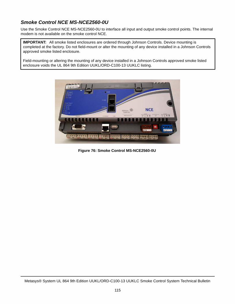
Smoke Control NCE MS-NCE2560-0UUse the Smoke Control NCE MS-NCE2560-0U to interface all input and output smoke control points. The internal modem is not available on the smoke control NCE.
IMPORTANT: All smoke listed enclosures are ordered through Johnson Controls. Device mounting is completed at the factory. Do not field-mount or alter the mounting of any device installed in a Johnson Controls approved smoke listed enclosure.
Field-mounting or altering the mounting of any device installed in a Johnson Controls approved smoke listed enclosure voids the UL 864 9th Edition UUKL/ORD-C100-13 UUKLC listing.
Figure 76: Smoke Control MS-NCE2560-0U
Metasys® System UL 864 9th Edition UUKL/ORD-C100-13 UUKLC Smoke Control System Technical Bulletin
115
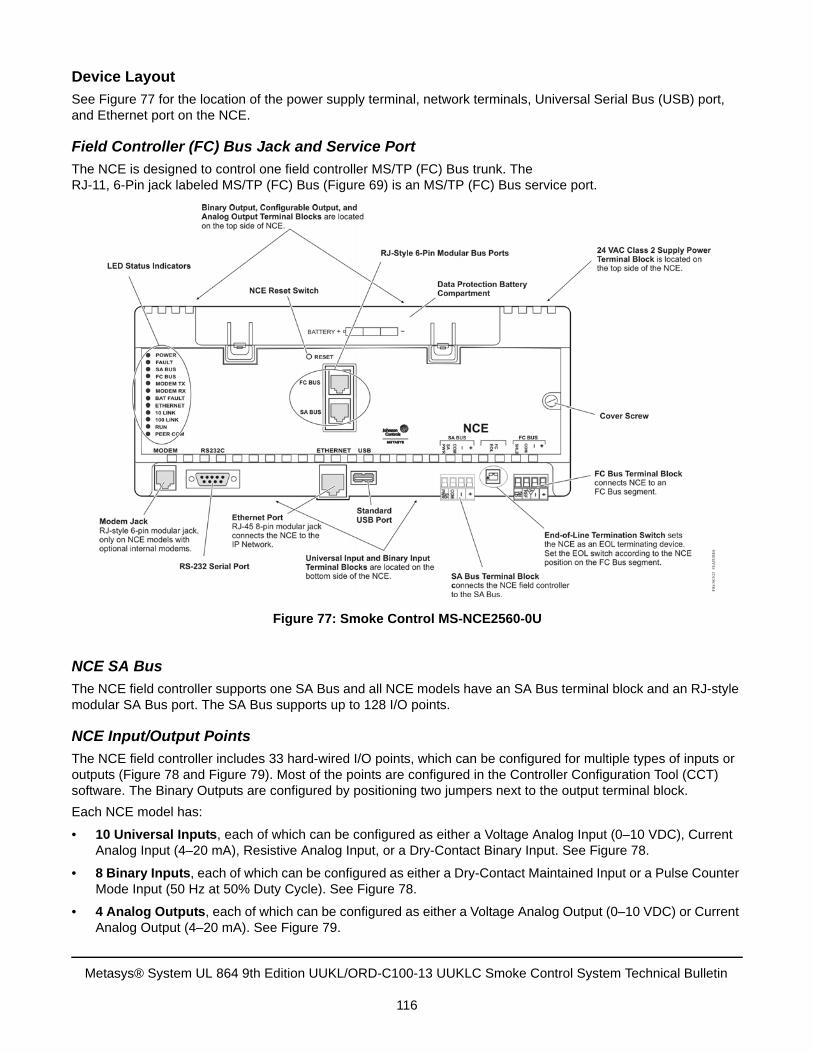
Device Layout
See Figure 77 for the location of the power supply terminal, network terminals, Universal Serial Bus (USB) port, and Ethernet port on the NCE.
Field Controller (FC) Bus Jack and Service Port
The NCE is designed to control one field controller MS/TP (FC) Bus trunk. The RJ-11, 6-Pin jack labeled MS/TP (FC) Bus (Figure 69) is an MS/TP (FC) Bus service port.
NCE SA Bus
The NCE field controller supports one SA Bus and all NCE models have an SA Bus terminal block and an RJ-style modular SA Bus port. The SA Bus supports up to 128 I/O points.
NCE Input/Output Points
The NCE field controller includes 33 hard-wired I/O points, which can be configured for multiple types of inputs or outputs (Figure 78 and Figure 79). Most of the points are configured in the Controller Configuration Tool (CCT) software. The Binary Outputs are configured by positioning two jumpers next to the output terminal block.
Each NCE model has:
• 10 Universal Inputs, each of which can be configured as either a Voltage Analog Input (0–10 VDC), CurrentAnalog Input (4–20 mA), Resistive Analog Input, or a Dry-Contact Binary Input. See Figure 78.
• 8 Binary Inputs, each of which can be configured as either a Dry-Contact Maintained Input or a Pulse CounterMode Input (50 Hz at 50% Duty Cycle). See Figure 78.
• 4 Analog Outputs, each of which can be configured as either a Voltage Analog Output (0–10 VDC) or CurrentAnalog Output (4–20 mA). See Figure 79.
Figure 77: Smoke Control MS-NCE2560-0U
Metasys® System UL 864 9th Edition UUKL/ORD-C100-13 UUKLC Smoke Control System Technical Bulletin
116
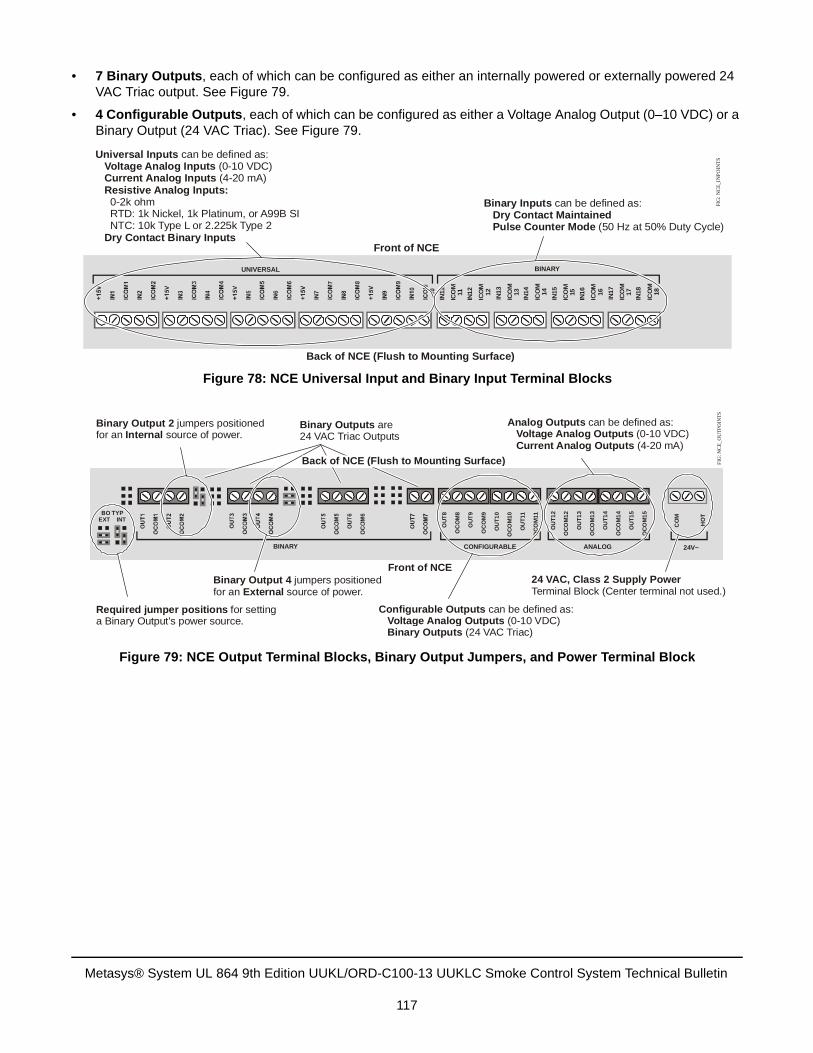
• 7 Binary Outputs, each of which can be configured as either an internally powered or externally powered 24 VAC Triac output. See Figure 79.
• 4 Configurable Outputs, each of which can be configured as either a Voltage Analog Output (0–10 VDC) or a Binary Output (24 VAC Triac). See Figure 79.
Figure 78: NCE Universal Input and Binary Input Terminal Blocks
IN11
ICO
M11
IN12
ICO
M12
IN13
ICO
M13
IN14
ICO
M14
IN15
ICO
M15
IN16
ICO
M16
IN17
ICO
M17
IN18
ICO
M18
BINARY
Back of NCE (Flush to Mounting Surface)
Front of NCE
UNIVERSAL
Universal InputsVoltage Analog InputsCurrent Analog InputsResistive Analog Inputs:
Dry Contact Binary Inputs
can be defined as: (0-10 VDC) (4-20 mA) 0-2k ohm RTD: 1k Nickel, 1k Platinum, or A99B SI NTC: 10k Type L or 2.225k Type 2
Binary InputsDry Contact MaintainedPulse Counter Mode
can be defined as: (50 Hz at 50% Duty Cycle)
FIG
: NC
E_I
NPO
INT
S
Figure 79: NCE Output Terminal Blocks, Binary Output Jumpers, and Power Terminal Block
Required jumper positions for setting a Binary Output's power source.
Binary Output 2Internal
jumpers positionedfor an source of power.
Binary Output 4External
jumpers positionedfor an source of power.
OU
T8
OC
OM
8
OU
T9
OC
OM
9
OU
T1
0
OC
OM
10
OU
T11
OC
OM
11
OU
T1
2
OC
OM
12
OU
T1
3
OC
OM
13
OU
T1
4
OC
OM
14
OU
T1
5
OC
OM
15
CO
M
HO
TBO TYPEXT INT
BINARY CONFIGURABLE ANALOG 24V~
Front of NCE24 VAC, Class 2 Supply PowerTerminal Block (Center terminal not used.)
Configurable Outputs Voltage Analog Outputs Binary Outputs
can be defined as: (0-10 VDC)
(24 VAC Triac)
Analog Outputs can be defined as: Voltage Analog Outputs
Current Analog Outputs (0-10 VDC)
(4-20 mA)
Binary Outputs are 24 VAC Triac Outputs
Back of NCE (Flush to Mounting Surface) FIG
: NC
E_O
UT
POIN
TS
Metasys® System UL 864 9th Edition UUKL/ORD-C100-13 UUKLC Smoke Control System Technical Bulletin
117
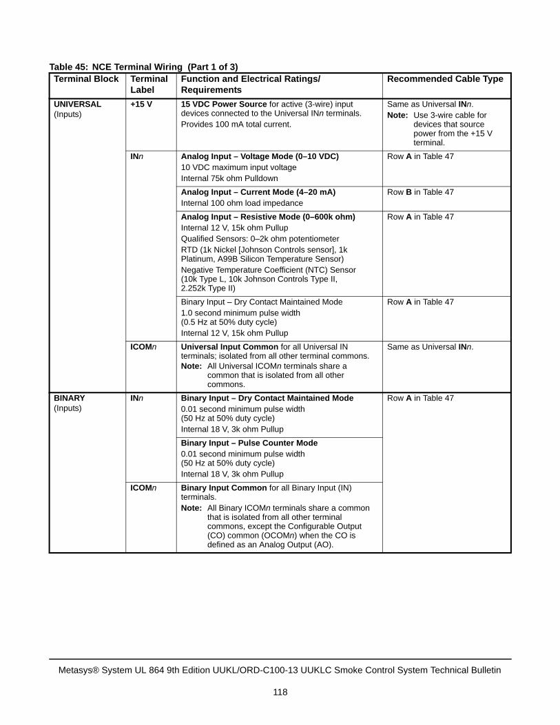
Table 45: NCE Terminal Wiring (Part 1 of 3)Terminal Block Terminal
LabelFunction and Electrical Ratings/Requirements
Recommended Cable Type
UNIVERSAL(Inputs)
+15 V 15 VDC Power Source for active (3-wire) input devices connected to the Universal INn terminals.Provides 100 mA total current.
Same as Universal INn. Note: Use 3-wire cable for
devices that source power from the +15 V terminal.
INn Analog Input – Voltage Mode (0–10 VDC)10 VDC maximum input voltageInternal 75k ohm Pulldown
Row A in Table 47
Analog Input – Current Mode (4–20 mA)Internal 100 ohm load impedance
Row B in Table 47
Analog Input – Resistive Mode (0–600k ohm)Internal 12 V, 15k ohm PullupQualified Sensors: 0–2k ohm potentiometerRTD (1k Nickel [Johnson Controls sensor], 1k Platinum, A99B Silicon Temperature Sensor)Negative Temperature Coefficient (NTC) Sensor (10k Type L, 10k Johnson Controls Type II, 2.252k Type II)
Row A in Table 47
Binary Input – Dry Contact Maintained Mode1.0 second minimum pulse width(0.5 Hz at 50% duty cycle)Internal 12 V, 15k ohm Pullup
Row A in Table 47
ICOMn Universal Input Common for all Universal IN terminals; isolated from all other terminal commons.Note: All Universal ICOMn terminals share a
common that is isolated from all other commons.
Same as Universal INn.
BINARY(Inputs)
INn Binary Input – Dry Contact Maintained Mode0.01 second minimum pulse width(50 Hz at 50% duty cycle)Internal 18 V, 3k ohm Pullup
Row A in Table 47
Binary Input – Pulse Counter Mode0.01 second minimum pulse width(50 Hz at 50% duty cycle)Internal 18 V, 3k ohm Pullup
ICOMn Binary Input Common for all Binary Input (IN) terminals.Note: All Binary ICOMn terminals share a common
that is isolated from all other terminal commons, except the Configurable Output (CO) common (OCOMn) when the CO is defined as an Analog Output (AO).
Metasys® System UL 864 9th Edition UUKL/ORD-C100-13 UUKLC Smoke Control System Technical Bulletin
118
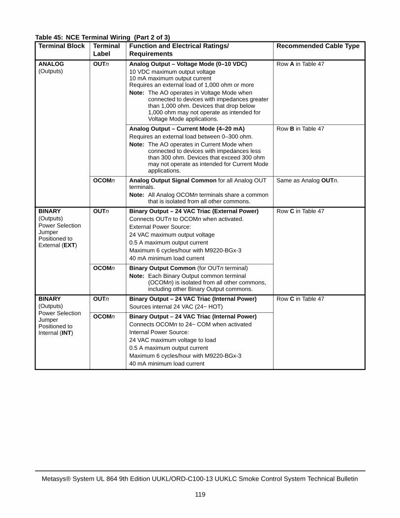
ANALOG(Outputs)
OUTn Analog Output – Voltage Mode (0–10 VDC)10 VDC maximum output voltage10 mA maximum output currentRequires an external load of 1,000 ohm or moreNote: The AO operates in Voltage Mode when
connected to devices with impedances greater than 1,000 ohm. Devices that drop below 1,000 ohm may not operate as intended for Voltage Mode applications.
Row A in Table 47
Analog Output – Current Mode (4–20 mA)Requires an external load between 0–300 ohm.Note: The AO operates in Current Mode when
connected to devices with impedances less than 300 ohm. Devices that exceed 300 ohm may not operate as intended for Current Mode applications.
Row B in Table 47
OCOMn Analog Output Signal Common for all Analog OUT terminals.Note: All Analog OCOMn terminals share a common
that is isolated from all other commons.
Same as Analog OUTn.
BINARY(Outputs)Power Selection Jumper Positioned to External (EXT)
OUTn Binary Output – 24 VAC Triac (External Power)Connects OUTn to OCOMn when activated.External Power Source:24 VAC maximum output voltage0.5 A maximum output currentMaximum 6 cycles/hour with M9220-BGx-340 mA minimum load current
Row C in Table 47
OCOMn Binary Output Common (for OUTn terminal) Note: Each Binary Output common terminal
(OCOMn) is isolated from all other commons, including other Binary Output commons.
BINARY(Outputs)Power Selection Jumper Positioned to Internal (INT)
OUTn Binary Output – 24 VAC Triac (Internal Power)Sources internal 24 VAC (24~ HOT)
Row C in Table 47
OCOMn Binary Output – 24 VAC Triac (Internal Power)Connects OCOMn to 24~ COM when activatedInternal Power Source:24 VAC maximum voltage to load0.5 A maximum output currentMaximum 6 cycles/hour with M9220-BGx-340 mA minimum load current
Table 45: NCE Terminal Wiring (Part 2 of 3)Terminal Block Terminal
LabelFunction and Electrical Ratings/Requirements
Recommended Cable Type
Metasys® System UL 864 9th Edition UUKL/ORD-C100-13 UUKLC Smoke Control System Technical Bulletin
119
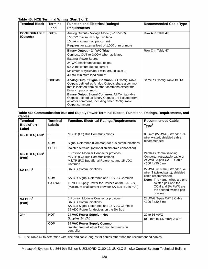
CONFIGURABLE (Outputs)
OUTn Analog Output – Voltage Mode (0–10 VDC)10 VDC maximum output voltage10 mA maximum output currentRequires an external load of 1,000 ohm or more
Row A in Table 47
Binary Output – 24 VAC TriacConnects OUT to OCOM when activated.External Power Source:24 VAC maximum voltage to load0.5 A maximum output currentMaximum 6 cycles/hour with M9220-BGx-340 mA minimum load current
Row C in Table 47
OCOMn Analog Output Signal Common: All Configurable Outputs defined as Analog Outputs share a common that is isolated from all other commons except the Binary Input common.Binary Output Signal Common: All Configurable Outputs defined as Binary Outputs are isolated from all other commons, including other Configurable Output commons.
Same as Configurable OUTn.
Table 46: Communication Bus and Supply Power Terminal Blocks, Functions, Ratings, Requirements, and Cables Terminal Block/Port Label
Terminal Labels
Function, Electrical Ratings/Requirements Recommended Cable
Type1
MS/TP (FC) Bus2 +-
MS/TP (FC) Bus Communications 0.6 mm (22 AWG) stranded, 3-wire twisted, shielded cable recommended
COM Signal Reference (Common) for bus communications
SHLD Isolated terminal (optional shield drain connection)
MS/TP (FC) Bus2
(Port)
6-Position Modular Connector provides:MS/TP (FC) Bus CommunicationsMS/TP (FC) Bus Signal Reference and 15 VDC Common
Wireless Commissioning Converter retractable cable or 24 AWG 3-pair CAT 3 Cable <100 ft (30.5 m)
SA BUS2 +-
SA Bus Communications 22 AWG (0.6 mm) stranded, 4-wire (2 twisted pairs), shielded cable recommended.Note: The + and- wires are one
twisted pair and the COM and SA PWR are the second twisted pair of wires.
COM SA Bus Signal Reference and 15 VDC Common
SA PWR 15 VDC Supply Power for Devices on the SA Bus (Maximum total current draw for SA Bus is 240 mA.)
SA BUS2
(Port)
6-Position Modular Connector provides:SA Bus CommunicationsSA Bus Signal Reference and 15 VDC Common15 VDC Power for devices on the SA Bus
24 AWG 3-pair CAT 3 Cable <100 ft (30.5 m)
24~ HOT 24 VAC Power Supply – HotSupplies 24 VAC
20 to 16 AWG(0.8 mm to 1.5 mm2) 2-wire
COM 24 VAC Power Supply Common Isolated from all other Common terminals on controller
1. See Table 47 to determine wire size and cable lengths for cables other than the recommended cables.
Table 45: NCE Terminal Wiring (Part 3 of 3)Terminal Block Terminal
LabelFunction and Electrical Ratings/Requirements
Recommended Cable Type
Metasys® System UL 864 9th Edition UUKL/ORD-C100-13 UUKLC Smoke Control System Technical Bulletin
120
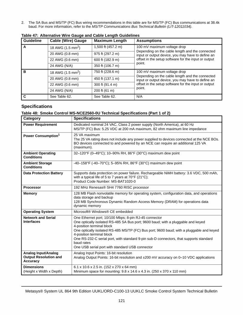
Specifications
2. The SA Bus and MS/TP (FC) Bus wiring recommendations in this table are for MS/TP (FC) Bus communications at 38.4kbaud. For more information, refer to the MS/TP Communications Bus Technical Bulletin (LIT-12011034).
Table 47: Alternative Wire Gauge and Cable Length GuidelinesGuideline Cable (Wire) Gauge Maximum Length Assumptions
A 18 AWG (1.5 mm2) 1,500 ft (457.2 m) 100 mV maximum voltage dropDepending on the cable length and the connected input or output device, you may have to define an offset in the setup software for the input or output point.
20 AWG (0.8 mm) 975 ft (297.2 m)
22 AWG (0.6 mm) 600 ft (182.9 m)
24 AWG (N/A) 350 ft (106.7 m)
B 18 AWG (1.5 mm2) 750 ft (228.6 m) 100 mV maximum voltage dropDepending on the cable length and the connected input or output device, you may have to define an offset in the setup software for the input or output point.
20 AWG (0.8 mm) 450 ft (137.1 m)
22 AWG (0.6 mm) 300 ft (91.4 m)
24 AWG (N/A) 200 ft (61 m)
C See Table 62. See Table 62. N/A
Table 48: Smoke Control MS-NCE2560-0U Technical Specifications (Part 1 of 2)Category Specifications
Power Requirement Dedicated nominal 24 VAC, Class 2 power supply (North America), at 60 HzMS/TP (FC) Bus: 5.25 VDC at 200 mA maximum, 82 ohm maximum line impedance
Power Consumption1 25 VA maximumThe 25 VA rating does not include any power supplied to devices connected at the NCE BOs. BO devices connected to and powered by an NCE can require an additional 125 VA (maximum).
Ambient Operating Conditions
32–120°F (0–49°C); 10–90% RH, 86°F (30°C) maximum dew point
Ambient Storage Conditions
-40–158°F (-40–70°C); 5–95% RH, 86°F (30°C) maximum dew point
Data Protection Battery Supports data protection on power failure. Rechargeable NiMH battery: 3.6 VDC, 500 mAh, with a typical life of 5 to 7 years at 70°F (21°C); Product Code Number: MS-BAT1020-0
Processor 192 MHz Renesas® SH4 7760 RISC processor
Memory 128 MB Flash nonvolatile memory for operating system, configuration data, and operations data storage and backup128 MB Synchronous Dynamic Random Access Memory (DRAM) for operations data dynamic memory
Operating System Microsoft® Windows® CE embedded
Network and Serial Interfaces
One Ethernet port; 10/100 Mbps; 8-pin RJ-45 connectorOne optically isolated RS-485 SA Bus port; 9600 baud; with a pluggable and keyed 4-position terminal blockOne optically isolated RS-485 MS/TP (FC) Bus port; 9600 baud; with a pluggable and keyed 4-position terminal blockOne RS-232-C serial port, with standard 9-pin sub-D connectors, that supports standard baud ratesOne USB serial port with standard USB connector
Analog Input/Analog Output Resolution and Accuracy
Analog Input Points: 16-bit resolutionAnalog Output Points: 16-bit resolution and ±200 mV accuracy on 0–10 VDC applications
Dimensions(Height x Width x Depth)
6.1 x 10.6 x 2.5 in. (152 x 270 x 64 mm)Minimum space for mounting: 9.8 x 14.6 x 4.3 in. (250 x 370 x 110 mm)
Metasys® System UL 864 9th Edition UUKL/ORD-C100-13 UUKLC Smoke Control System Technical Bulletin
121
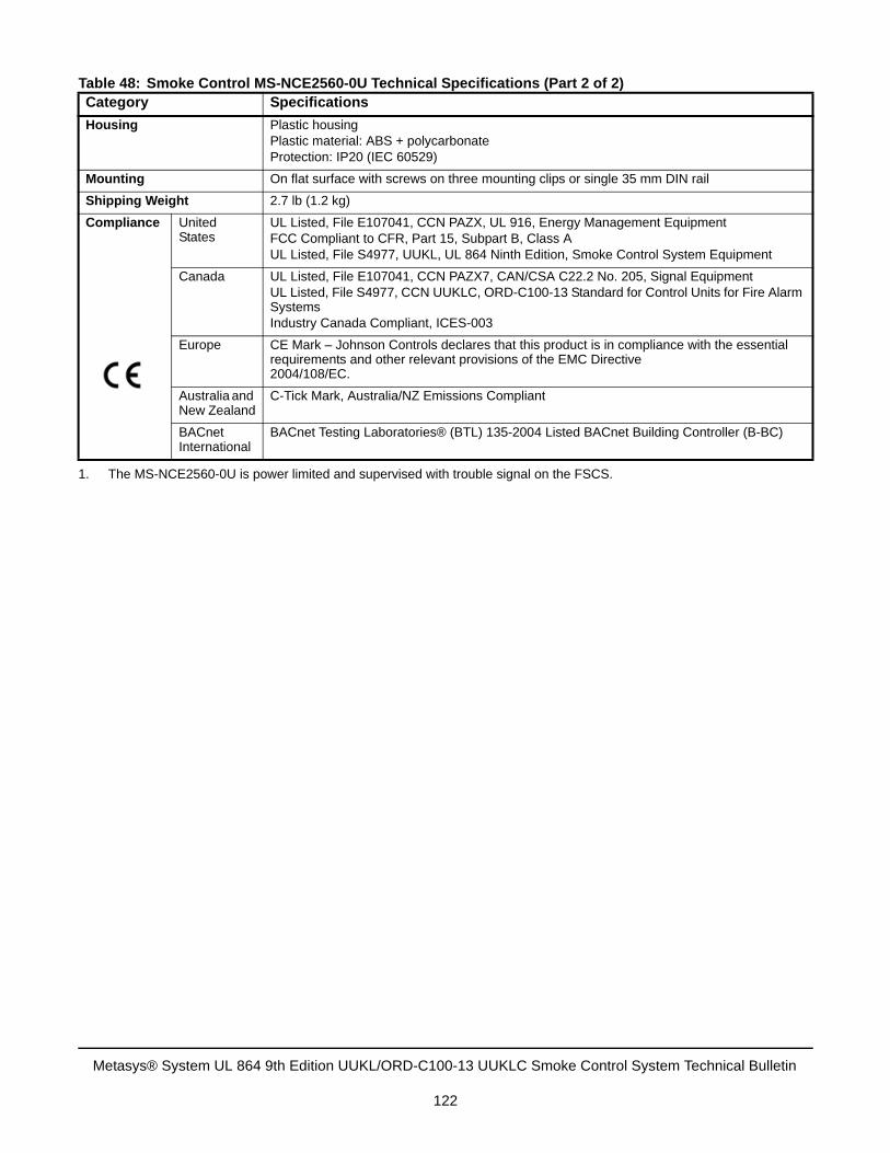
Housing Plastic housingPlastic material: ABS + polycarbonateProtection: IP20 (IEC 60529)
Mounting On flat surface with screws on three mounting clips or single 35 mm DIN rail
Shipping Weight 2.7 lb (1.2 kg)
Compliance United States
UL Listed, File E107041, CCN PAZX, UL 916, Energy Management EquipmentFCC Compliant to CFR, Part 15, Subpart B, Class AUL Listed, File S4977, UUKL, UL 864 Ninth Edition, Smoke Control System Equipment
Canada UL Listed, File E107041, CCN PAZX7, CAN/CSA C22.2 No. 205, Signal EquipmentUL Listed, File S4977, CCN UUKLC, ORD-C100-13 Standard for Control Units for Fire Alarm SystemsIndustry Canada Compliant, ICES-003
Europe CE Mark – Johnson Controls declares that this product is in compliance with the essential requirements and other relevant provisions of the EMC Directive 2004/108/EC.
Australia and New Zealand
C-Tick Mark, Australia/NZ Emissions Compliant
BACnet International
BACnet Testing Laboratories® (BTL) 135-2004 Listed BACnet Building Controller (B-BC)
1. The MS-NCE2560-0U is power limited and supervised with trouble signal on the FSCS.
Table 48: Smoke Control MS-NCE2560-0U Technical Specifications (Part 2 of 2)Category Specifications
Metasys® System UL 864 9th Edition UUKL/ORD-C100-13 UUKLC Smoke Control System Technical Bulletin
122
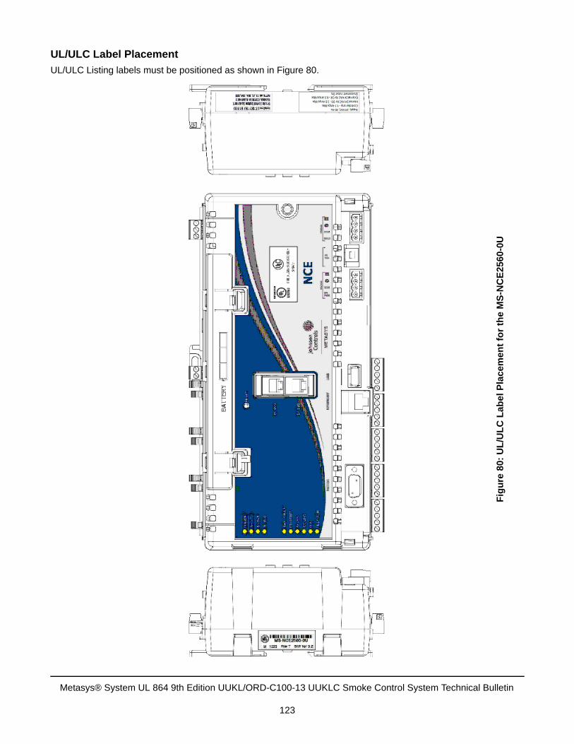
UL/ULC Label Placement
UL/ULC Listing labels must be positioned as shown in Figure 80.
Fig
ure
80:
UL
/UL
C L
abe
l Pla
ce
men
t fo
r th
e M
S-N
CE
2560
-0U
Metasys® System UL 864 9th Edition UUKL/ORD-C100-13 UUKLC Smoke Control System Technical Bulletin
123
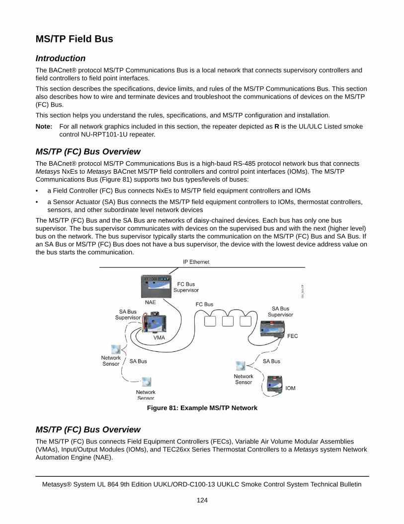
MS/TP Field Bus
IntroductionThe BACnet® protocol MS/TP Communications Bus is a local network that connects supervisory controllers and field controllers to field point interfaces.
This section describes the specifications, device limits, and rules of the MS/TP Communications Bus. This section also describes how to wire and terminate devices and troubleshoot the communications of devices on the MS/TP (FC) Bus.
This section helps you understand the rules, specifications, and MS/TP configuration and installation.
Note: For all network graphics included in this section, the repeater depicted as R is the UL/ULC Listed smoke control NU-RPT101-1U repeater.
MS/TP (FC) Bus OverviewThe BACnet® protocol MS/TP Communications Bus is a high-baud RS-485 protocol network bus that connects Metasys NxEs to Metasys BACnet MS/TP field controllers and control point interfaces (IOMs). The MS/TP Communications Bus (Figure 81) supports two bus types/levels of buses:
• a Field Controller (FC) Bus connects NxEs to MS/TP field equipment controllers and IOMs
• a Sensor Actuator (SA) Bus connects the MS/TP field equipment controllers to IOMs, thermostat controllers, sensors, and other subordinate level network devices
The MS/TP (FC) Bus and the SA Bus are networks of daisy-chained devices. Each bus has only one bus supervisor. The bus supervisor communicates with devices on the supervised bus and with the next (higher level) bus on the network. The bus supervisor typically starts the communication on the MS/TP (FC) Bus and SA Bus. If an SA Bus or MS/TP (FC) Bus does not have a bus supervisor, the device with the lowest device address value on the bus starts the communication.
MS/TP (FC) Bus OverviewThe MS/TP (FC) Bus connects Field Equipment Controllers (FECs), Variable Air Volume Modular Assemblies (VMAs), Input/Output Modules (IOMs), and TEC26xx Series Thermostat Controllers to a Metasys system Network Automation Engine (NAE).
Figure 81: Example MS/TP Network
Metasys® System UL 864 9th Edition UUKL/ORD-C100-13 UUKLC Smoke Control System Technical Bulletin
124
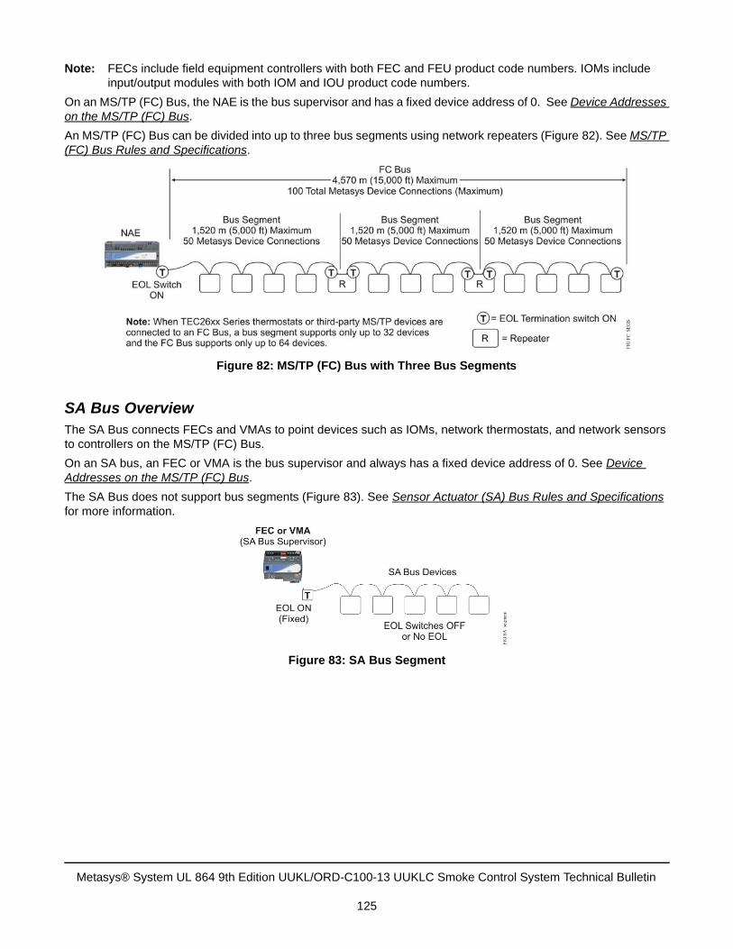
Note: FECs include field equipment controllers with both FEC and FEU product code numbers. IOMs include input/output modules with both IOM and IOU product code numbers.
On an MS/TP (FC) Bus, the NAE is the bus supervisor and has a fixed device address of 0. See Device Addresses on the MS/TP (FC) Bus.
An MS/TP (FC) Bus can be divided into up to three bus segments using network repeaters (Figure 82). See MS/TP (FC) Bus Rules and Specifications.
SA Bus OverviewThe SA Bus connects FECs and VMAs to point devices such as IOMs, network thermostats, and network sensors to controllers on the MS/TP (FC) Bus.
On an SA bus, an FEC or VMA is the bus supervisor and always has a fixed device address of 0. See Device Addresses on the MS/TP (FC) Bus.
The SA Bus does not support bus segments (Figure 83). See Sensor Actuator (SA) Bus Rules and Specifications for more information.
Figure 82: MS/TP (FC) Bus with Three Bus Segments
Figure 83: SA Bus Segment
Metasys® System UL 864 9th Edition UUKL/ORD-C100-13 UUKLC Smoke Control System Technical Bulletin
125

Baud Rates on the MS/TP (FC) BusAn MS/TP (FC) Bus can be configured to communicate at one of four different baud rates. All devices on the MS/TP (FC) Bus must communicate at the same baud rate. The baud rate setting determines the rate at which devices communicate data over the bus. The baud rate settings available on Metasys MS/TP devices are 9600, 19,200, 38,400, 76,800, and Auto. We recommend setting all MS/TP (FC) Bus supervisors to 38,400 baud.
In the Auto setting, the Metasys devices listen for the bus supervisor to communicate first; the devices then automatically set their baud rate to the bus supervisor’s baud rate. We recommend setting all field controllers on the MS/TP (FC) Bus (FECs, VMAs, and IOMs) to Auto.
TEC26xx Series thermostats automatically set their baud rate to the bus supervisor’s baud rate. The baud rate setting on bus repeaters and third-party MS/TP devices typically is configured manually at the device and the baud rate setting must match the setting of the bus supervisor. Refer to the manufacturer’s product documentation for information on setting the device’s baud rate.
The two device attributes related to the baud rate are Baud Rate Selection and Active Baud Rate. The Baud Rate Selection attribute allows you to use the SCT (for NAEs) or the CCT (for FECs, VMAs, and IOMs) to set the baud rate for the device. The Active Baud Rate attribute allows you to view the baud rate at which the device is communicating on the active bus when Auto baud is selected. For more information on Metasys system attributes, refer to the Metasys system Help (LIT-1201793).
Higher baud rates require a limited range of wire gauge. There is a direct relationship among the baud rate, wire gauge, and wire length that determines the number of devices allowed on the bus. Higher baud rates support more devices, but require small gauge wire (which provides lower capacitance). A lower baud rate may be required in order to use existing, larger gauge wire (which has higher capacitance), but may support fewer devices. We recommend 38,400 baud using 22 AWG stranded wire. This provides the best balance between performance and installation sensitivity.
For more details on baud rate, wire gauge, wire length, and the number of devices see MS/TP (FC) Bus Cable Recommendations.
Metasys® System UL 864 9th Edition UUKL/ORD-C100-13 UUKLC Smoke Control System Technical Bulletin
126
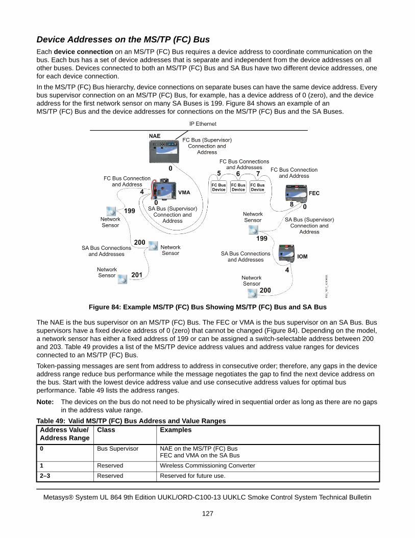
Device Addresses on the MS/TP (FC) BusEach device connection on an MS/TP (FC) Bus requires a device address to coordinate communication on the bus. Each bus has a set of device addresses that is separate and independent from the device addresses on all other buses. Devices connected to both an MS/TP (FC) Bus and SA Bus have two different device addresses, one for each device connection.
In the MS/TP (FC) Bus hierarchy, device connections on separate buses can have the same device address. Every bus supervisor connection on an MS/TP (FC) Bus, for example, has a device address of 0 (zero), and the device address for the first network sensor on many SA Buses is 199. Figure 84 shows an example of an MS/TP (FC) Bus and the device addresses for connections on the MS/TP (FC) Bus and the SA Buses.
The NAE is the bus supervisor on an MS/TP (FC) Bus. The FEC or VMA is the bus supervisor on an SA Bus. Bus supervisors have a fixed device address of 0 (zero) that cannot be changed (Figure 84). Depending on the model, a network sensor has either a fixed address of 199 or can be assigned a switch-selectable address between 200 and 203. Table 49 provides a list of the MS/TP device address values and address value ranges for devices connected to an MS/TP (FC) Bus.
Token-passing messages are sent from address to address in consecutive order; therefore, any gaps in the device address range reduce bus performance while the message negotiates the gap to find the next device address on the bus. Start with the lowest device address value and use consecutive address values for optimal bus performance. Table 49 lists the address ranges.
Note: The devices on the bus do not need to be physically wired in sequential order as long as there are no gaps in the address value range.
Table 49: Valid MS/TP (FC) Bus Address and Value RangesAddress Value/Address Range
Class Examples
0 Bus Supervisor NAE on the MS/TP (FC) BusFEC and VMA on the SA Bus
1 Reserved Wireless Commissioning Converter
2–3 Reserved Reserved for future use.
Figure 84: Example MS/TP (FC) Bus Showing MS/TP (FC) Bus and SA Bus
Metasys® System UL 864 9th Edition UUKL/ORD-C100-13 UUKLC Smoke Control System Technical Bulletin
127
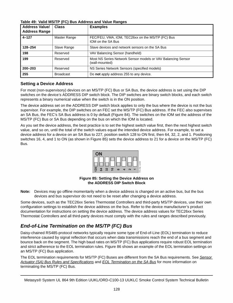
Setting a Device Address
For most (non-supervisory) devices on an MS/TP (FC) Bus or SA Bus, the device address is set using the DIP switches on the device’s ADDRESS DIP switch block. The DIP switches are binary switch blocks, and each switch represents a binary numerical value when the switch is in the ON position.
The device address set on the ADDRESS DIP switch block applies to only the bus where the device is not the bus supervisor. For example, the DIP switches on an FEC set the MS/TP (FC) Bus address. If the FEC also supervises an SA Bus, the FEC’s SA Bus address is 0 by default (Figure 84). The switches on the IOM set the address of the MS/TP (FC) Bus or SA Bus depending on the bus on which the IOM is located.
As you set the device address, the best practice is to set the highest switch value first, then the next highest switch value, and so on, until the total of the switch values equal the intended device address. For example, to set a device address for a device on an SA Bus to 227, position switch 128 to ON first, then 64, 32, 2, and 1. Positioning switches 16, 4, and 1 to ON (as shown in Figure 85) sets the device address to 21 for a device on the MS/TP (FC) Bus.
Note: Devices may go offline momentarily when a device address is changed on an active bus, but the bus devices and bus supervisor do not need to be reset after changing a device address.
Some devices, such as the TEC26xx Series Thermostat Controllers and third-party MS/TP devices, use their own configuration settings to establish the device address on the bus. Refer to the device manufacturer’s product documentation for instructions on setting the device address. The device address values for TEC26xx Series Thermostat Controllers and all third-party devices must comply with the rules and ranges described previously.
End-of-Line Termination on the MS/TP (FC) BusDaisy-chained RS485-protocol networks typically require some type of End-of-Line (EOL) termination to reduce interference caused by signal reflection that occurs when data transmissions reach the end of a bus segment and bounce back on the segment. The high baud rates on MS/TP (FC) Bus applications require robust EOL termination and strict adherence to the EOL termination rules. Figure 86 shows an example of the EOL termination settings on an MS/TP (FC) Bus application.
The EOL termination requirements for MS/TP (FC) Buses are different from the SA Bus requirements. See Sensor Actuator (SA) Bus Rules and Specifications and EOL Termination on the SA Bus for more information on terminating the MS/TP (FC) Bus.
4–127 Master Range FEC/FEU, VMA, IOM, TEC26xx on the MS/TP (FC) BusIOM on the SA Bus
128–254 Slave Range Slave devices and network sensors on the SA Bus
198 Reserved VAV Balancing Sensor (handheld)
199 Reserved Most NS Series Network Sensor models or VAV Balancing Sensor (wall-mounted)
200–203 Reserved NS Series Network Sensors (specified models)
255 Broadcast Do not apply address 255 to any device.
Table 49: Valid MS/TP (FC) Bus Address and Value RangesAddress Value/Address Range
Class Examples
Figure 85: Setting the Device Address on the ADDRESS DIP Switch Block
Metasys® System UL 864 9th Edition UUKL/ORD-C100-13 UUKLC Smoke Control System Technical Bulletin
128
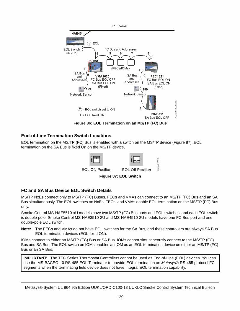
End-of-Line Termination Switch Locations
EOL termination on the MS/TP (FC) Bus is enabled with a switch on the MS/TP device (Figure 87). EOL termination on the SA Bus is fixed On on the MS/TP device.
FC and SA Bus Device EOL Switch Details
MS/TP NxEs connect only to MS/TP (FC) Buses. FECs and VMAs can connect to an MS/TP (FC) Bus and an SA Bus simultaneously. The EOL switches on NxEs, FECs, and VMAs enable EOL termination on the MS/TP (FC) Bus only.
Smoke Control MS-NAE5510-xU models have two MS/TP (FC) Bus ports and EOL switches, and each EOL switch is double-pole. Smoke Control MS-NAE3510-2U and MS-NAE4510-2U models have one FC Bus port and one double-pole EOL switch.
Note: The FECs and VMAs do not have EOL switches for the SA Bus, and these controllers are always SA Bus EOL termination devices (EOL fixed ON).
IOMs connect to either an MS/TP (FC) Bus or SA Bus. IOMs cannot simultaneously connect to the MS/TP (FC) Bus and SA Bus. The EOL switch on IOMs enables an IOM as an EOL termination device on either an MS/TP (FC) Bus or an SA Bus.
IMPORTANT: The TEC Series Thermostat Controllers cannot be used as End-of-Line (EOL) devices. You can use the MS-BACEOL-0 RS-485 EOL Terminator to provide EOL termination on Metasys® RS-485 protocol FC segments when the terminating field device does not have integral EOL termination capability.
Figure 86: EOL Termination on an MS/TP (FC) Bus
Figure 87: EOL Switch
Metasys® System UL 864 9th Edition UUKL/ORD-C100-13 UUKLC Smoke Control System Technical Bulletin
129
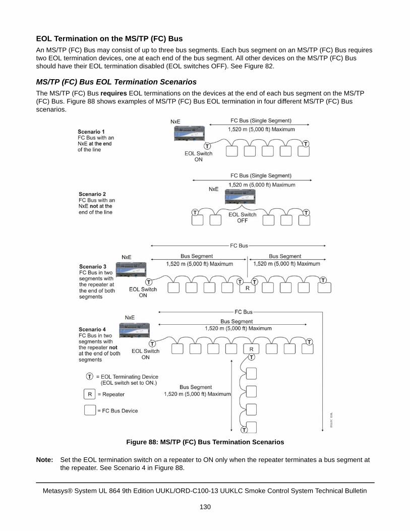
EOL Termination on the MS/TP (FC) Bus
An MS/TP (FC) Bus may consist of up to three bus segments. Each bus segment on an MS/TP (FC) Bus requires two EOL termination devices, one at each end of the bus segment. All other devices on the MS/TP (FC) Bus should have their EOL termination disabled (EOL switches OFF). See Figure 82.
MS/TP (FC) Bus EOL Termination Scenarios
The MS/TP (FC) Bus requires EOL terminations on the devices at the end of each bus segment on the MS/TP (FC) Bus. Figure 88 shows examples of MS/TP (FC) Bus EOL termination in four different MS/TP (FC) Bus scenarios.
Note: Set the EOL termination switch on a repeater to ON only when the repeater terminates a bus segment at the repeater. See Scenario 4 in Figure 88.
Figure 88: MS/TP (FC) Bus Termination Scenarios
Metasys® System UL 864 9th Edition UUKL/ORD-C100-13 UUKLC Smoke Control System Technical Bulletin
130
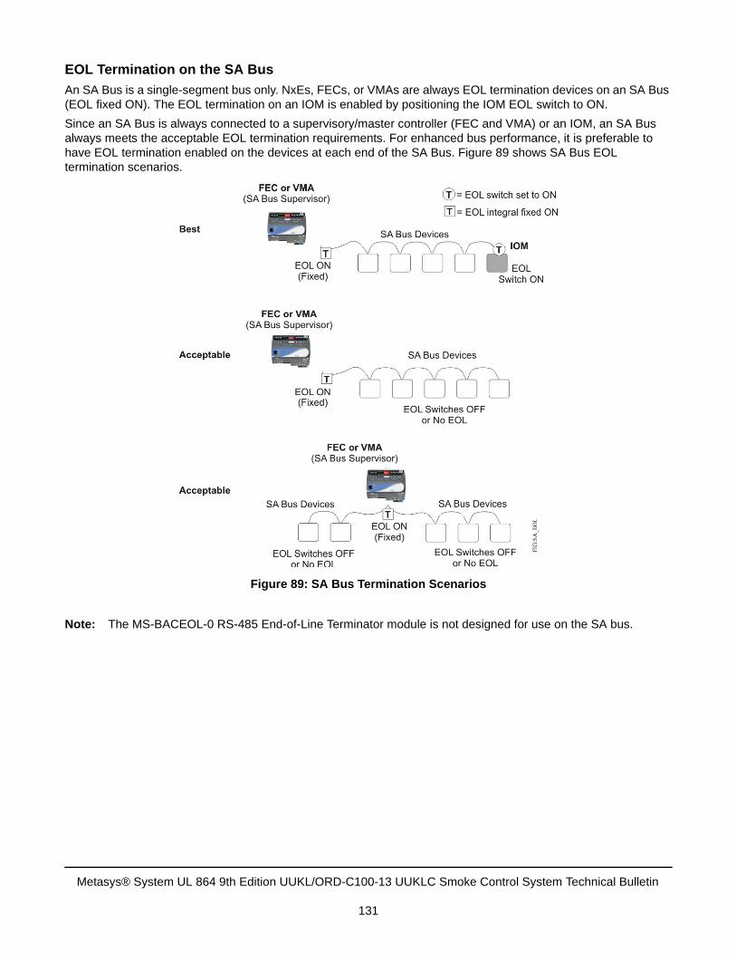
EOL Termination on the SA Bus
An SA Bus is a single-segment bus only. NxEs, FECs, or VMAs are always EOL termination devices on an SA Bus (EOL fixed ON). The EOL termination on an IOM is enabled by positioning the IOM EOL switch to ON.
Since an SA Bus is always connected to a supervisory/master controller (FEC and VMA) or an IOM, an SA Bus always meets the acceptable EOL termination requirements. For enhanced bus performance, it is preferable to have EOL termination enabled on the devices at each end of the SA Bus. Figure 89 shows SA Bus EOL termination scenarios.
Note: The MS-BACEOL-0 RS-485 End-of-Line Terminator module is not designed for use on the SA bus.
Figure 89: SA Bus Termination Scenarios
Metasys® System UL 864 9th Edition UUKL/ORD-C100-13 UUKLC Smoke Control System Technical Bulletin
131
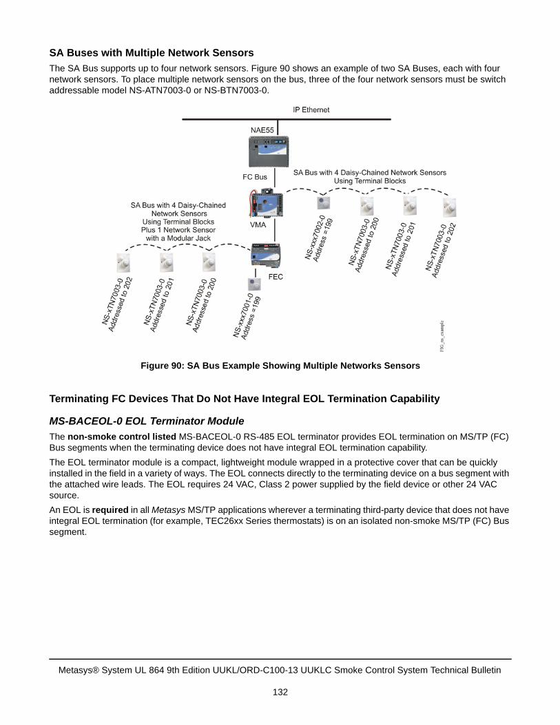
SA Buses with Multiple Network Sensors
The SA Bus supports up to four network sensors. Figure 90 shows an example of two SA Buses, each with four network sensors. To place multiple network sensors on the bus, three of the four network sensors must be switch addressable model NS-ATN7003-0 or NS-BTN7003-0.
Terminating FC Devices That Do Not Have Integral EOL Termination Capability
MS-BACEOL-0 EOL Terminator Module
The non-smoke control listed MS-BACEOL-0 RS-485 EOL terminator provides EOL termination on MS/TP (FC) Bus segments when the terminating device does not have integral EOL termination capability.
The EOL terminator module is a compact, lightweight module wrapped in a protective cover that can be quickly installed in the field in a variety of ways. The EOL connects directly to the terminating device on a bus segment with the attached wire leads. The EOL requires 24 VAC, Class 2 power supplied by the field device or other 24 VAC source.
An EOL is required in all Metasys MS/TP applications wherever a terminating third-party device that does not have integral EOL termination (for example, TEC26xx Series thermostats) is on an isolated non-smoke MS/TP (FC) Bus segment.
Figure 90: SA Bus Example Showing Multiple Networks Sensors
Metasys® System UL 864 9th Edition UUKL/ORD-C100-13 UUKLC Smoke Control System Technical Bulletin
132
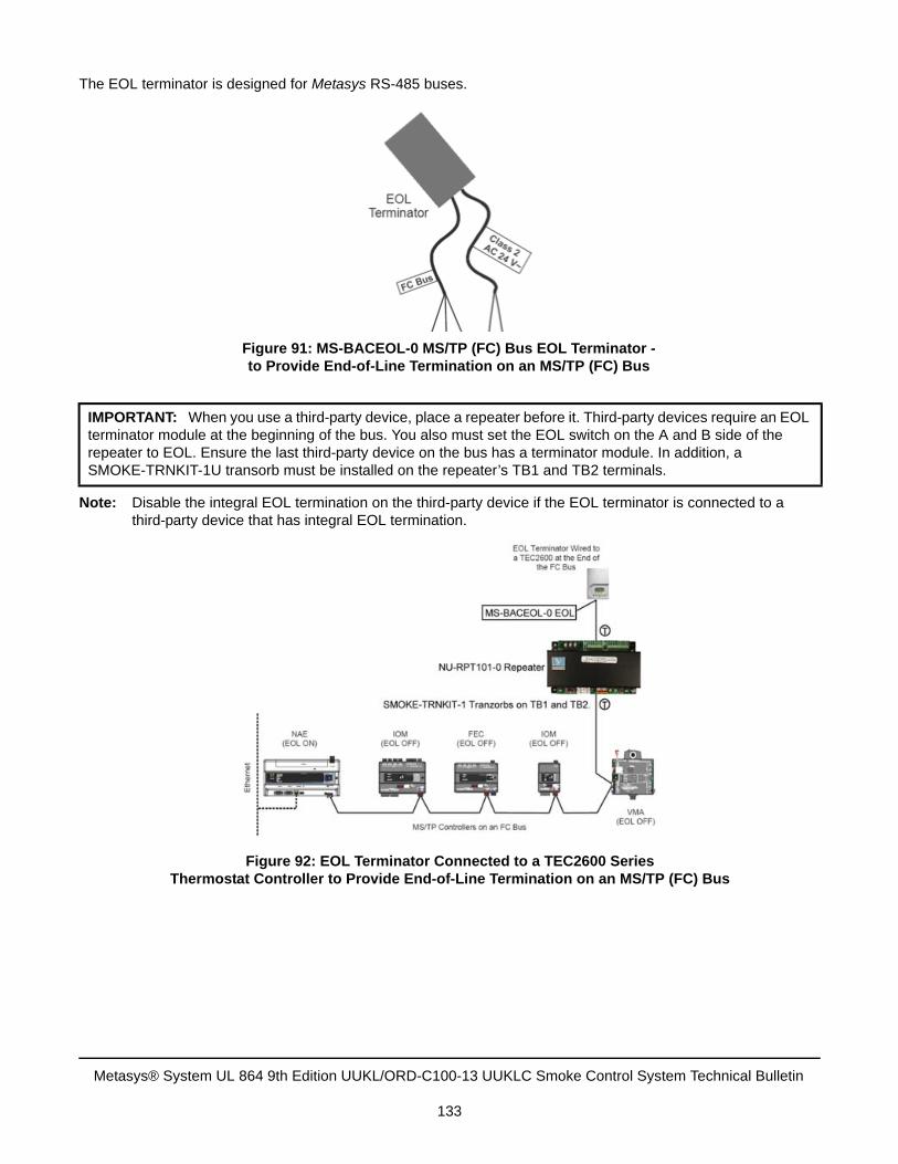
The EOL terminator is designed for Metasys RS-485 buses.
Note: Disable the integral EOL termination on the third-party device if the EOL terminator is connected to a third-party device that has integral EOL termination.
IMPORTANT: When you use a third-party device, place a repeater before it. Third-party devices require an EOL terminator module at the beginning of the bus. You also must set the EOL switch on the A and B side of the repeater to EOL. Ensure the last third-party device on the bus has a terminator module. In addition, a SMOKE-TRNKIT-1U transorb must be installed on the repeater’s TB1 and TB2 terminals.
Figure 91: MS-BACEOL-0 MS/TP (FC) Bus EOL Terminator - to Provide End-of-Line Termination on an MS/TP (FC) Bus
Figure 92: EOL Terminator Connected to a TEC2600 SeriesThermostat Controller to Provide End-of-Line Termination on an MS/TP (FC) Bus
Metasys® System UL 864 9th Edition UUKL/ORD-C100-13 UUKLC Smoke Control System Technical Bulletin
133
Wiring the MS-BACEOL-0 EOL Terminator Module
Observe the following guidelines when wiring the EOL terminator:
• The EOL terminator is designed for MS/TP trunks on Metasys RS-485 Buses. Connect the EOL terminator toonly MS/TP trunks on Metasys RS-485 MS/TP (FC) Buses.
• Connect the EOL terminator to MS/TP devices that terminate Metasys bus segments and do not have integralEOL termination capability.
• When a third-party device terminates a Metasys MS/TP (FC) Bus segment, it is recommended that any EOLtermination on the third-party be disabled and an EOL terminator be installed to provide EOL termination on thebus segment.
• When the third-party (terminating) device has only the + and - terminals (no REF or COM), isolate and insulatethe blue REF lead on the EOL (Figure 93).
Connect the EOL MS/TP (FC) Bus leads to the appropriate MS/TP (FC) Bus terminals on the bus terminating device (Figure 93).
Connect the EOL 24 VAC power supply leads to a dedicated or surged protected 24 VAC, Class 2 power supply (Figure 93).
Risk of Electric Shock.Disconnect the power supply before making electrical connections to avoid electric shock.
IMPORTANT: Do not connect 24 VAC supply power to the EOL Terminator before wiring is complete.
IMPORTANT: Use copper conductors only. Ensure all wiring is in accordance with local, national, and regional regulations.
IMPORTANT: The EOL Terminator is a low-voltage (<30 VAC) device. Do not exceed the EOL Terminator electrical ratings.
IMPORTANT: Electrostatic discharge can damage controller components. Use proper electrostatic discharge precautions during installation, setup, and service to avoid damaging the controller.
Metasys® System UL 864 9th Edition UUKL/ORD-C100-13 UUKLC Smoke Control System Technical Bulletin
134
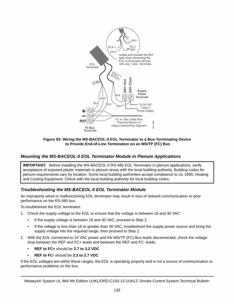
Mounting the MS-BACEOL-0 EOL Terminator Module in Plenum Applications
Troubleshooting the MS-BACEOL-0 EOL Terminator Module
An improperly wired or malfunctioning EOL terminator may result in loss of network communication or poor performance on the RS-485 bus.
To troubleshoot the EOL terminator:
1. Check the supply voltage to the EOL to ensure that the voltage is between 18 and 30 VAC:
• If the supply voltage is between 18 and 30 VAC, proceed to Step 2.
• If the voltage is less than 18 or greater than 30 VAC, troubleshoot the supply power source and bring thesupply voltage into the required range, then proceed to Step 2.
2. With the EOL connected to 24 VAC power and the MS/TP (FC) Bus leads disconnected, check the voltagedrop between the REF and FC+ leads and between the REF and FC- leads:
• REF to FC+ should be 2.7 to 3.2 VDC
• REF to FC- should be 2.3 to 2.7 VDC
If the EOL voltages are within these ranges, the EOL is operating properly and is not a source of communication or performance problems on the bus.
IMPORTANT: Before installing the MS-BACEOL-0 RS-485 EOL Terminator in plenum applications, verify acceptance of exposed plastic materials in plenum areas with the local building authority. Building codes for plenum requirements vary by location. Some local building authorities accept compliance to UL 1995, Heating and Cooling Equipment. Check with the local building authority for local building codes.
Figure 93: Wiring the MS-BACEOL-0 EOL Terminator to a Bus-Terminating Device to Provide End-of-Line Termination on an MS/TP (FC) Bus
Metasys® System UL 864 9th Edition UUKL/ORD-C100-13 UUKLC Smoke Control System Technical Bulletin
135
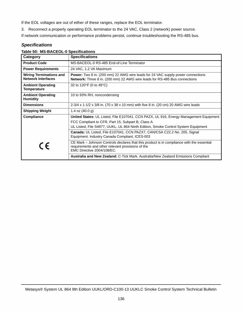
If the EOL voltages are out of either of these ranges, replace the EOL terminator.
3. Reconnect a properly operating EOL terminator to the 24 VAC, Class 2 (network) power source.
If network communication or performance problems persist, continue troubleshooting the RS-485 bus.
Specifications
Table 50: MS-BACEOL-0 SpecificationsCategory Specifications
Product Code MS-BACEOL-0 RS-485 End-of-Line Terminator
Power Requirements 24 VAC, 1.2 VA Maximum
Wiring Terminations and Network Interfaces
Power: Two 8 in. (200 mm) 22 AWG wire leads for 24 VAC supply power connectionsNetwork: Three 8 in. (200 mm) 22 AWG wire leads for RS-485 Bus connections
Ambient Operating Temperature
32 to 120°F (0 to 49°C)
Ambient Operating Humidity
10 to 93% RH, noncondensing
Dimensions 2-3/4 x 1-1/2 x 3/8 in. (70 x 38 x 10 mm) with five 8 in. (20 cm) 20 AWG wire leads
Shipping Weight 1.4 oz (40.0 g)
Compliance United States: UL Listed, File E107041, CCN PAZX, UL 916, Energy Management Equipment
FCC Compliant to CFR, Part 15, Subpart B, Class AUL Listed, File S4977, UUKL, UL 864 Ninth Edition, Smoke Control System Equipment
Canada: UL Listed, File E107041, CCN PAZX7, CAN/CSA C22.2 No. 205, SignalEquipment. Industry Canada Compliant, ICES-003
CE Mark – Johnson Controls declares that this product is in compliance with the essential requirements and other relevant provisions of the EMC Directive 2004/108/EC.
Australia and New Zealand: C-Tick Mark, Australia/New Zealand Emissions Compliant
Metasys® System UL 864 9th Edition UUKL/ORD-C100-13 UUKLC Smoke Control System Technical Bulletin
136
MS/TP (FC) Bus Rules When Using TEC26xx Series Thermostat Controllers andThird-Party MS/TP Devices
If TEC26xx Series Thermostat Controllers and/or third-party BACnet MS/TP devices are connected on an FC Bus, then they must be isolated from the MS/TP (FC) Bus using an NU-RPT101-1U repeater.
When a TEC26xx Series Thermostat Controller terminates an isolated MS/TP (FC) Bus segment, an EOL Terminator module (MS-BACEOL-0) must be wired to the MS/TP (FC) Bus terminals on the TEC26xx Series Thermostat Controller. See Terminating FC Devices That Do Not Have Integral EOL Termination Capability for more information.
If one or more TEC26xx Series Thermostat Controllers and/or third-party BACnet MS/TP devices are connected on an isolated MS/TP (FC) Bus, the supported maximum device counts, bus segments, and bus length are:
• 64 devices total per MS/TP (FC) Bus (maximum)
• 3 bus segments per MS/TP (FC) Bus (maximum)
• 32 devices per bus segment (maximum, not to exceed 64 devices total on MS/TP (FC) Bus)
• 4,000 ft (1,220 m) maximum per bus segment (using 22 AWG stranded, 3-wire twisted, shielded cable)
• 12,000 ft (3,660 m) maximum per MS/TP (FC) Bus (using 22 AWG stranded, 3-wire twisted, shielded cable)
• MS/TP Required Transient Protection
MS/TP Required Transient Protection
FC Communication Bus
See MS/TP Field Communication Bus and Field Controller I/O Transient Protection.
SA Communication Bus
See MS/TP Field Communication Bus and Field Controller I/O Transient Protection.
Field Controller I/O Terminals
See MS/TP Field Controller I/O Transient Protection.
Metasys® System UL 864 9th Edition UUKL/ORD-C100-13 UUKLC Smoke Control System Technical Bulletin
137
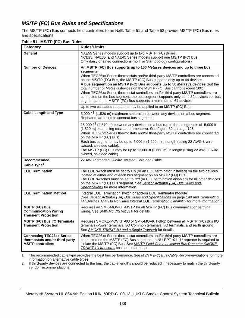
MS/TP (FC) Bus Rules and SpecificationsThe MS/TP (FC) Bus connects field controllers to an NxE. Table 51 and Table 52 provide MS/TP (FC) Bus rules and specifications.
Table 51: MS/TP (FC) Bus RulesCategory Rules/Limits
General NAE55 Series models support up to two MS/TP (FC) Buses. NCE25, NAE35, and NAE45 Series models support one MS/TP (FC) Bus.Only daisy-chained connections (no T or Star topology configurations)
Number of Devices An MS/TP (FC) Bus supports up to 100 Metasys devices and up to three bus segments. When TEC26xx Series thermostats and/or third-party MS/TP controllers are connected on the MS/TP (FC) Bus, the MS/TP (FC) Bus supports only up to 64 devices.A bus segment on an MS/TP (FC) Bus supports up to 50 Metasys devices (but the total number of Metasys devices on the MS/TP (FC) Bus cannot exceed 100).When TEC26xx Series thermostat controllers and/or third-party MS/TP controllers are connected on the bus segment, the bus segment supports only up to 32 devices per bus segment and the MS/TP (FC) Bus supports a maximum of 64 devices.
Up to two cascaded repeaters may be applied to an MS/TP (FC) Bus.
Cable Length and Type 5,000 ft2 (1,520 m) maximum separation between any devices on a bus segment. Repeaters are used to connect bus segments.
15,000 ft2 (4,570 m) between any devices on a bus (up to three segments of 5,000 ft [1,520 m] each using cascaded repeaters). See Figure 82 on page 125.When TEC26xx Series thermostats and/or third-party MS/TP controllers are connected on the MS/TP (FC) Bus:Each bus segment may be up to 4,000 ft (1,220 m) in length (using 22 AWG 3-wire twisted, shielded cable).The MS/TP (FC) Bus may be up to 12,000 ft (3,660 m) in length (using 22 AWG 3-wire twisted, shielded cable).
RecommendedCable Type1
1. The recommended cable type provides the best bus performance. See MS/TP (FC) Bus Cable Recommendations for moreinformation on alternative cable types.
2. If third-party devices are connected to the bus, the cable lengths should be reduced if necessary to match the third-partyvendor recommendations.
22 AWG Stranded, 3-Wire Twisted, Shielded Cable
EOL Termination The EOL switch must be set to On (or an EOL terminator installed) on the two devices located at either end of each bus segment on an MS/TP (FC) Bus.The EOL switches must be set to Off (or EOL termination disabled) for all other devices on the MS/TP (FC) Bus segment. See Sensor Actuator (SA) Bus Rules and Specifications for more information.
EOL Termination Method Integral EOL Termination switch or add-on EOL Terminator module (See Sensor Actuator (SA) Bus Rules and Specifications on page 140 and Terminating FC Devices That Do Not Have Integral EOL Termination Capability for more information.)
MS/TP (FC) Bus Communication Wiring Transient Protection
Requires an SMK-MOVKIT-MSTP for all MS/TP (FC) Bus communication terminal wiring. See SMK-MOVKIT-MSTP for details.
MS/TP (FC) Bus I/O Terminals Transient Protection
Requires SMOKE-MOVKIT-0U or SMK-MOVKIT-BRD between all MS/TP (FC) Bus I/O terminals (Power terminals, I/O Common terminals, I/O terminals, and earth ground).See SMOKE-TRNKIT-1U and a Single Transorb for details.
Connecting TEC26xx Series thermostats and/or third-party MS/TP controllers
When TEC26xx Series thermostat controllers and/or third-party MS/TP controllers are connected on the MS/TP (FC) Bus segment, an NU-RPT101-1U repeater is required to isolate the MS/TP (FC) Bus. See MS/TP Field Communication Bus Repeater SMOKE-TRNKIT-1U transorbs for more information.
Metasys® System UL 864 9th Edition UUKL/ORD-C100-13 UUKLC Smoke Control System Technical Bulletin
138
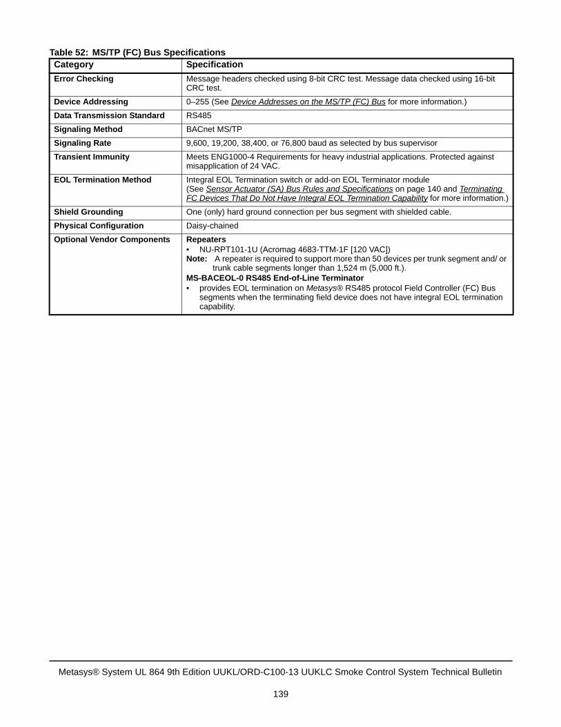
Table 52: MS/TP (FC) Bus SpecificationsCategory Specification
Error Checking Message headers checked using 8-bit CRC test. Message data checked using 16-bit CRC test.
Device Addressing 0–255 (See Device Addresses on the MS/TP (FC) Bus for more information.)
Data Transmission Standard RS485
Signaling Method BACnet MS/TP
Signaling Rate 9,600, 19,200, 38,400, or 76,800 baud as selected by bus supervisor
Transient Immunity Meets ENG1000-4 Requirements for heavy industrial applications. Protected against misapplication of 24 VAC.
EOL Termination Method Integral EOL Termination switch or add-on EOL Terminator module (See Sensor Actuator (SA) Bus Rules and Specifications on page 140 and Terminating FC Devices That Do Not Have Integral EOL Termination Capability for more information.)
Shield Grounding One (only) hard ground connection per bus segment with shielded cable.
Physical Configuration Daisy-chained
Optional Vendor Components Repeaters• NU-RPT101-1U (Acromag 4683-TTM-1F [120 VAC]) Note: A repeater is required to support more than 50 devices per trunk segment and/ or
trunk cable segments longer than 1,524 m (5,000 ft.).MS-BACEOL-0 RS485 End-of-Line Terminator • provides EOL termination on Metasys® RS485 protocol Field Controller (FC) Bus
segments when the terminating field device does not have integral EOL termination capability.
Metasys® System UL 864 9th Edition UUKL/ORD-C100-13 UUKLC Smoke Control System Technical Bulletin
139
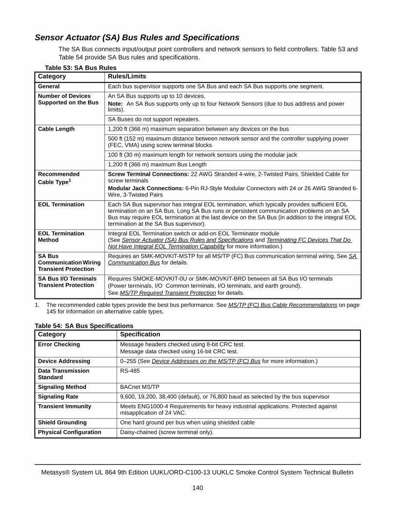
Sensor Actuator (SA) Bus Rules and SpecificationsThe SA Bus connects input/output point controllers and network sensors to field controllers. Table 53 and Table 54 provide SA Bus rules and specifications.
Table 53: SA Bus RulesCategory Rules/Limits
General Each bus supervisor supports one SA Bus and each SA Bus supports one segment.
Number of Devices Supported on the Bus
An SA Bus supports up to 10 devices.Note: An SA Bus supports only up to four Network Sensors (due to bus address and power limits).
SA Buses do not support repeaters.
Cable Length 1,200 ft (366 m) maximum separation between any devices on the bus
500 ft (152 m) maximum distance between network sensor and the controller supplying power (FEC, VMA) using screw terminal blocks
100 ft (30 m) maximum length for network sensors using the modular jack
1,200 ft (366 m) maximum Bus Length
Recommended Cable Type1
1. The recommended cable types provide the best bus performance. See MS/TP (FC) Bus Cable Recommendations on page145 for information on alternative cable types.
Screw Terminal Connections: 22 AWG Stranded 4-wire, 2-Twisted Pairs, Shielded Cable for screw terminalsModular Jack Connections: 6-Pin RJ-Style Modular Connectors with 24 or 26 AWG Stranded 6-Wire, 3-Twisted Pairs
EOL Termination Each SA Bus supervisor has integral EOL termination, which typically provides sufficient EOL termination on an SA Bus. Long SA Bus runs or persistent communication problems on an SA Bus may require EOL termination at the last device on the SA Bus (in addition to the integral EOL termination at the SA Bus supervisor).
EOL Termination Method
Integral EOL Termination switch or add-on EOL Terminator module (See Sensor Actuator (SA) Bus Rules and Specifications and Terminating FC Devices That Do Not Have Integral EOL Termination Capability for more information.)
SA Bus Communication Wiring Transient Protection
Requires an SMK-MOVKIT-MSTP for all MS/TP (FC) Bus communication terminal wiring. See SA Communication Bus for details.
SA Bus I/O Terminals Transient Protection
Requires SMOKE-MOVKIT-0U or SMK-MOVKIT-BRD between all SA Bus I/O terminals(Power terminals, I/O Common terminals, I/O terminals, and earth ground).See MS/TP Required Transient Protection for details.
Table 54: SA Bus SpecificationsCategory Specification
Error Checking Message headers checked using 8-bit CRC test.Message data checked using 16-bit CRC test.
Device Addressing 0–255 (See Device Addresses on the MS/TP (FC) Bus for more information.)
Data Transmission Standard
RS-485
Signaling Method BACnet MS/TP
Signaling Rate 9,600, 19,200, 38,400 (default), or 76,800 baud as selected by the bus supervisor
Transient Immunity Meets ENG1000-4 Requirements for heavy industrial applications. Protected against misapplication of 24 VAC.
Shield Grounding One hard ground per bus when using shielded cable
Physical Configuration Daisy-chained (screw terminal only).
Metasys® System UL 864 9th Edition UUKL/ORD-C100-13 UUKLC Smoke Control System Technical Bulletin
140
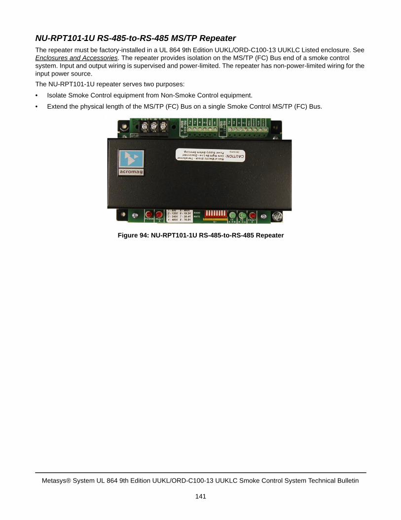
NU-RPT101-1U RS-485-to-RS-485 MS/TP RepeaterThe repeater must be factory-installed in a UL 864 9th Edition UUKL/ORD-C100-13 UUKLC Listed enclosure. See Enclosures and Accessories. The repeater provides isolation on the MS/TP (FC) Bus end of a smoke control system. Input and output wiring is supervised and power-limited. The repeater has non-power-limited wiring for the input power source.
The NU-RPT101-1U repeater serves two purposes:
• Isolate Smoke Control equipment from Non-Smoke Control equipment.
• Extend the physical length of the MS/TP (FC) Bus on a single Smoke Control MS/TP (FC) Bus.
Figure 94: NU-RPT101-1U RS-485-to-RS-485 Repeater
Metasys® System UL 864 9th Edition UUKL/ORD-C100-13 UUKLC Smoke Control System Technical Bulletin
141
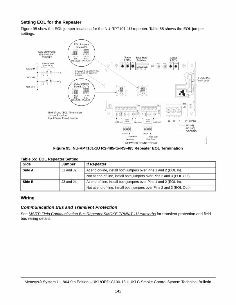
Setting EOL for the Repeater
Figure 95 show the EOL jumper locations for the NU-RPT101-1U repeater. Table 55 shows the EOL jumper settings.
Wiring
Communication Bus and Transient Protection
See MS/TP Field Communication Bus Repeater SMOKE-TRNKIT-1U transorbs for transient protection and field bus wiring details.
Table 55: EOL Repeater SettingSide Jumper If Repeater
Side A J1 and J2 At end-of-line, install both jumpers over Pins 1 and 2 (EOL In).
Not at end-of-line, install both jumpers over Pins 2 and 3 (EOL Out).
Side B J3 and J4 At end-of-line, install both jumpers over Pins 1 and 2 (EOL In).
Not at end-of-line, install both jumpers over Pins 2 and 3 (EOL Out).
Figure 95: NU-RPT101-1U RS-485-to-RS-485 Repeater EOL Termination
Metasys® System UL 864 9th Edition UUKL/ORD-C100-13 UUKLC Smoke Control System Technical Bulletin
142
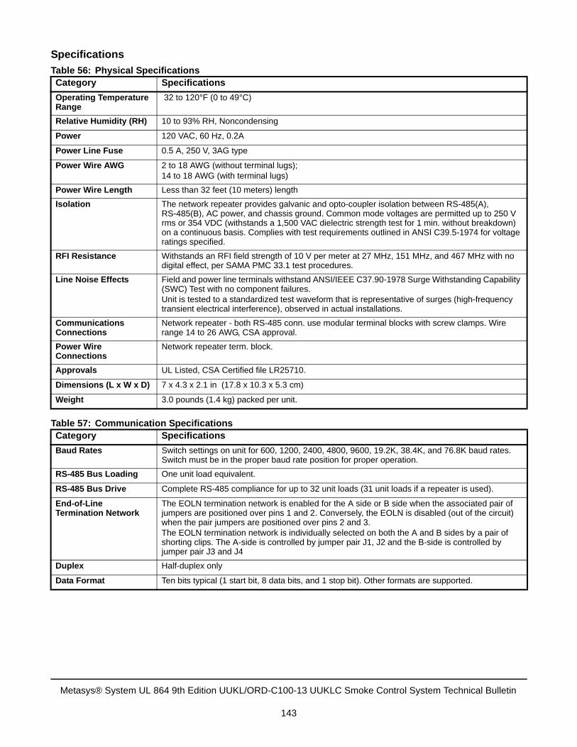
Specifications
Table 56: Physical SpecificationsCategory Specifications
Operating Temperature Range
32 to 120°F (0 to 49°C)
Relative Humidity (RH) 10 to 93% RH, Noncondensing
Power 120 VAC, 60 Hz, 0.2A
Power Line Fuse 0.5 A, 250 V, 3AG type
Power Wire AWG 2 to 18 AWG (without terminal lugs); 14 to 18 AWG (with terminal lugs)
Power Wire Length Less than 32 feet (10 meters) length
Isolation The network repeater provides galvanic and opto-coupler isolation between RS-485(A), RS-485(B), AC power, and chassis ground. Common mode voltages are permitted up to 250 V rms or 354 VDC (withstands a 1,500 VAC dielectric strength test for 1 min. without breakdown) on a continuous basis. Complies with test requirements outlined in ANSI C39.5-1974 for voltage ratings specified.
RFI Resistance Withstands an RFI field strength of 10 V per meter at 27 MHz, 151 MHz, and 467 MHz with no digital effect, per SAMA PMC 33.1 test procedures.
Line Noise Effects Field and power line terminals withstand ANSI/IEEE C37.90-1978 Surge Withstanding Capability (SWC) Test with no component failures.Unit is tested to a standardized test waveform that is representative of surges (high-frequency transient electrical interference), observed in actual installations.
Communications Connections
Network repeater - both RS-485 conn. use modular terminal blocks with screw clamps. Wire range 14 to 26 AWG, CSA approval.
Power Wire Connections
Network repeater term. block.
Approvals UL Listed, CSA Certified file LR25710.
Dimensions (L x W x D) 7 x 4.3 x 2.1 in (17.8 x 10.3 x 5.3 cm)
Weight 3.0 pounds (1.4 kg) packed per unit.
Table 57: Communication SpecificationsCategory Specifications
Baud Rates Switch settings on unit for 600, 1200, 2400, 4800, 9600, 19.2K, 38.4K, and 76.8K baud rates. Switch must be in the proper baud rate position for proper operation.
RS-485 Bus Loading One unit load equivalent.
RS-485 Bus Drive Complete RS-485 compliance for up to 32 unit loads (31 unit loads if a repeater is used).
End-of-Line Termination Network
The EOLN termination network is enabled for the A side or B side when the associated pair of jumpers are positioned over pins 1 and 2. Conversely, the EOLN is disabled (out of the circuit) when the pair jumpers are positioned over pins 2 and 3.The EOLN termination network is individually selected on both the A and B sides by a pair of shorting clips. The A-side is controlled by jumper pair J1, J2 and the B-side is controlled by jumper pair J3 and J4
Duplex Half-duplex only
Data Format Ten bits typical (1 start bit, 8 data bits, and 1 stop bit). Other formats are supported.
Metasys® System UL 864 9th Edition UUKL/ORD-C100-13 UUKLC Smoke Control System Technical Bulletin
143
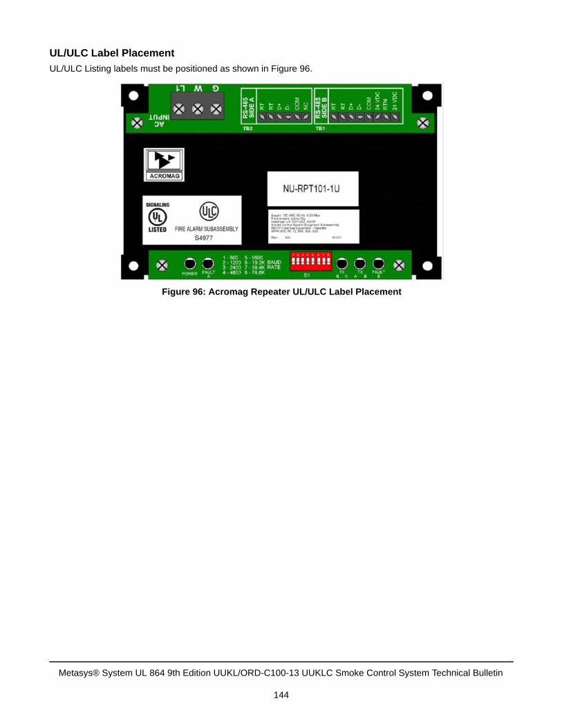
UL/ULC Label Placement
UL/ULC Listing labels must be positioned as shown in Figure 96.
Figure 96: Acromag Repeater UL/ULC Label Placement
Metasys® System UL 864 9th Edition UUKL/ORD-C100-13 UUKLC Smoke Control System Technical Bulletin
144
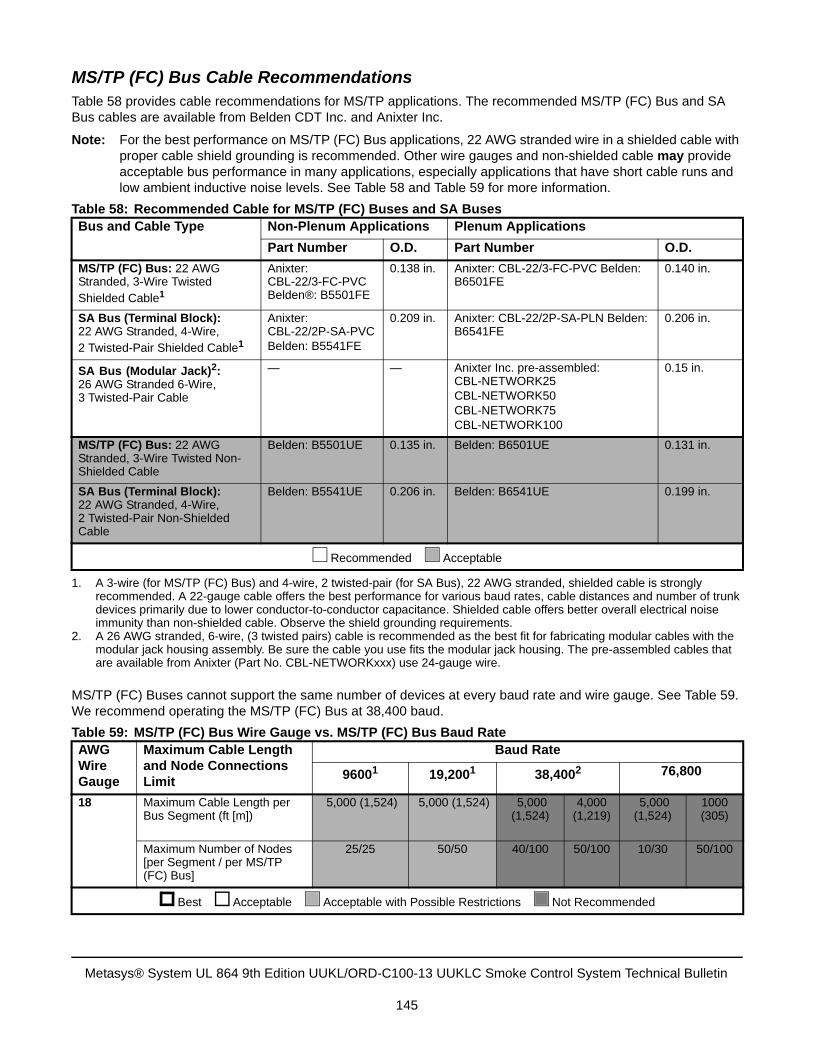
MS/TP (FC) Bus Cable RecommendationsTable 58 provides cable recommendations for MS/TP applications. The recommended MS/TP (FC) Bus and SA Bus cables are available from Belden CDT Inc. and Anixter Inc.
Note: For the best performance on MS/TP (FC) Bus applications, 22 AWG stranded wire in a shielded cable with proper cable shield grounding is recommended. Other wire gauges and non-shielded cable may provide acceptable bus performance in many applications, especially applications that have short cable runs and low ambient inductive noise levels. See Table 58 and Table 59 for more information.
MS/TP (FC) Buses cannot support the same number of devices at every baud rate and wire gauge. See Table 59. We recommend operating the MS/TP (FC) Bus at 38,400 baud.
Table 58: Recommended Cable for MS/TP (FC) Buses and SA BusesBus and Cable Type Non-Plenum Applications Plenum Applications
Part Number O.D. Part Number O.D.
MS/TP (FC) Bus: 22 AWG Stranded, 3-Wire Twisted Shielded Cable1
1. A 3-wire (for MS/TP (FC) Bus) and 4-wire, 2 twisted-pair (for SA Bus), 22 AWG stranded, shielded cable is stronglyrecommended. A 22-gauge cable offers the best performance for various baud rates, cable distances and number of trunkdevices primarily due to lower conductor-to-conductor capacitance. Shielded cable offers better overall electrical noiseimmunity than non-shielded cable. Observe the shield grounding requirements.
Anixter: CBL-22/3-FC-PVC Belden®: B5501FE
0.138 in. Anixter: CBL-22/3-FC-PVC Belden: B6501FE
0.140 in.
SA Bus (Terminal Block):22 AWG Stranded, 4-Wire, 2 Twisted-Pair Shielded Cable1
Anixter: CBL-22/2P-SA-PVCBelden: B5541FE
0.209 in. Anixter: CBL-22/2P-SA-PLN Belden: B6541FE
0.206 in.
SA Bus (Modular Jack)2:26 AWG Stranded 6-Wire, 3 Twisted-Pair Cable
2. A 26 AWG stranded, 6-wire, (3 twisted pairs) cable is recommended as the best fit for fabricating modular cables with themodular jack housing assembly. Be sure the cable you use fits the modular jack housing. The pre-assembled cables thatare available from Anixter (Part No. CBL-NETWORKxxx) use 24-gauge wire.
— — Anixter Inc. pre-assembled: CBL-NETWORK25CBL-NETWORK50CBL-NETWORK75CBL-NETWORK100
0.15 in.
MS/TP (FC) Bus: 22 AWG Stranded, 3-Wire Twisted Non-Shielded Cable
Belden: B5501UE 0.135 in. Belden: B6501UE 0.131 in.
SA Bus (Terminal Block):22 AWG Stranded, 4-Wire, 2 Twisted-Pair Non-Shielded Cable
Belden: B5541UE 0.206 in. Belden: B6541UE 0.199 in.
Recommended Acceptable
Table 59: MS/TP (FC) Bus Wire Gauge vs. MS/TP (FC) Bus Baud RateAWG Wire Gauge
Maximum Cable Length and Node Connections Limit
Baud Rate
96001 19,2001 38,4002 76,800
18 Maximum Cable Length per Bus Segment (ft [m])
5,000 (1,524) 5,000 (1,524) 5,000 (1,524)
4,000 (1,219)
5,000 (1,524)
1000 (305)
Maximum Number of Nodes [per Segment / per MS/TP (FC) Bus]
25/25 50/50 40/100 50/100 10/30 50/100
Best Acceptable Acceptable with Possible Restrictions Not Recommended
Metasys® System UL 864 9th Edition UUKL/ORD-C100-13 UUKLC Smoke Control System Technical Bulletin
145
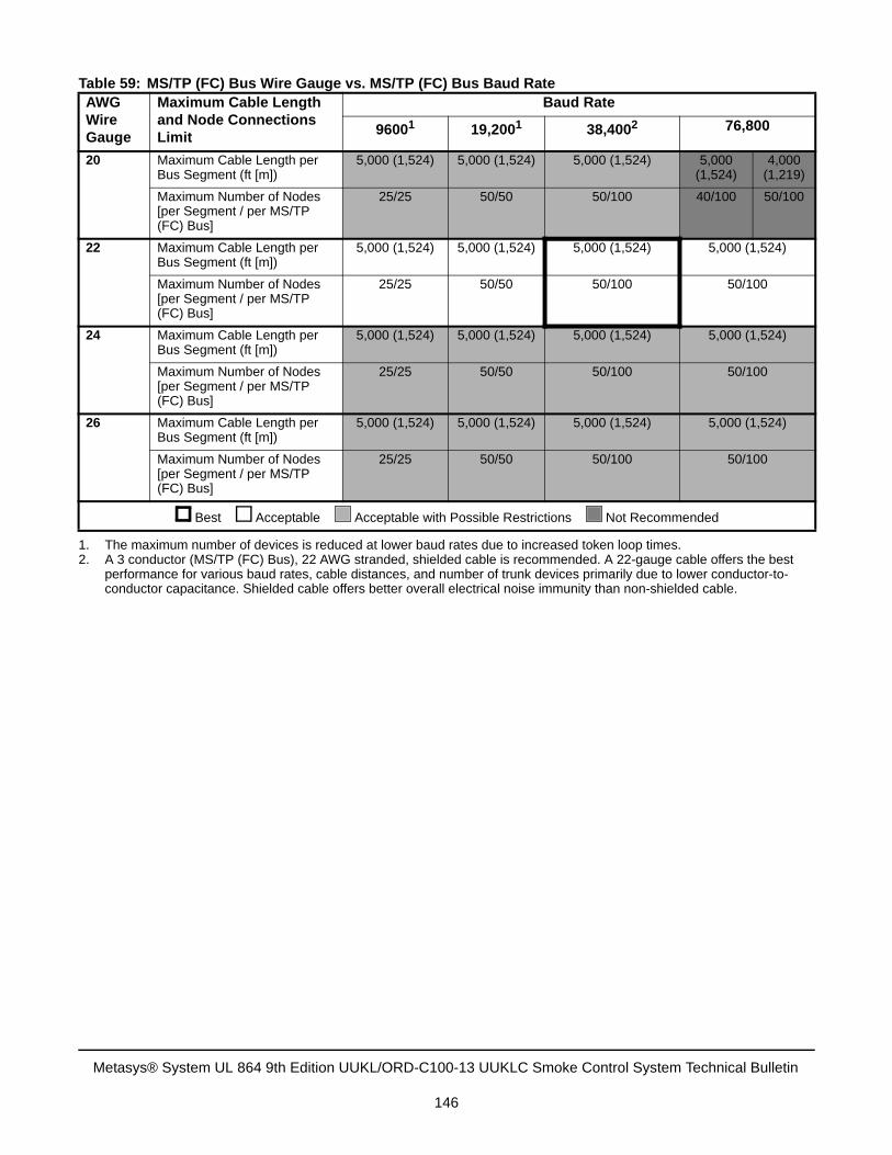
20 Maximum Cable Length per Bus Segment (ft [m])
5,000 (1,524) 5,000 (1,524) 5,000 (1,524) 5,000 (1,524)
4,000 (1,219)
Maximum Number of Nodes [per Segment / per MS/TP (FC) Bus]
25/25 50/50 50/100 40/100 50/100
22 Maximum Cable Length per Bus Segment (ft [m])
5,000 (1,524) 5,000 (1,524) 5,000 (1,524) 5,000 (1,524)
Maximum Number of Nodes [per Segment / per MS/TP (FC) Bus]
25/25 50/50 50/100 50/100
24 Maximum Cable Length per Bus Segment (ft [m])
5,000 (1,524) 5,000 (1,524) 5,000 (1,524) 5,000 (1,524)
Maximum Number of Nodes [per Segment / per MS/TP (FC) Bus]
25/25 50/50 50/100 50/100
26 Maximum Cable Length per Bus Segment (ft [m])
5,000 (1,524) 5,000 (1,524) 5,000 (1,524) 5,000 (1,524)
Maximum Number of Nodes [per Segment / per MS/TP (FC) Bus]
25/25 50/50 50/100 50/100
1. The maximum number of devices is reduced at lower baud rates due to increased token loop times.2. A 3 conductor (MS/TP (FC) Bus), 22 AWG stranded, shielded cable is recommended. A 22-gauge cable offers the best
performance for various baud rates, cable distances, and number of trunk devices primarily due to lower conductor-to-conductor capacitance. Shielded cable offers better overall electrical noise immunity than non-shielded cable.
Table 59: MS/TP (FC) Bus Wire Gauge vs. MS/TP (FC) Bus Baud RateAWG Wire Gauge
Maximum Cable Length and Node Connections Limit
Baud Rate
96001 19,2001 38,4002 76,800
Best Acceptable Acceptable with Possible Restrictions Not Recommended
Metasys® System UL 864 9th Edition UUKL/ORD-C100-13 UUKLC Smoke Control System Technical Bulletin
146
Wiring the MS/TP (FC) Bus
General MS/TP (FC) Bus Wiring Guidelines
Observe the following when installing and wiring the MS/TP Communications Bus:
• Do not run cables near moving parts. Avoid sharp bends, abrasion, and the potential for severing or crushingthe cable.
• Route cables neatly to promote good ventilation, visibility, testing, and ease of service.
• Provide some slack in the wires and cables to allow for access and servicing.
• Protect, coil, and secure any excess cable.
• Ensure proper grounding for bus cable shielding.
• Ensure proper EOL termination on buses and bus segments.
• Use dedicated transformers (either PAN-PWRSP-U or PAN-96VAXFR-U) for 24 VAC supply power to thenetwork devices.
Risk of Property Damage.Do not run low voltage cable in the same conduit or wiring troughs with high voltage wires. Running low and high voltage wires in the same conduit or wiring troughs may damage the equipment or cause system malfunction.
Risk of Property Damage.Do not apply power to the system before checking all wiring connections. Short circuited or improperly connected wires may result in permanent damage to the equipment.
IMPORTANT: Use copper conductors only. Make all wiring in accordance with local, national, and regional regulations. Do not exceed the electrical ratings for the devices on the Metasys network.
IMPORTANT: Properly install, terminate, and ground the cable shield on the MS/TP (FC) Bus to minimize inductive noise, which can result in unreliable communication on the bus.
IMPORTANT: Electrostatic discharge can damage controller components. Use proper electrostatic discharge precautions during installation, setup, and service to avoid damaging the controller.
Metasys® System UL 864 9th Edition UUKL/ORD-C100-13 UUKLC Smoke Control System Technical Bulletin
147
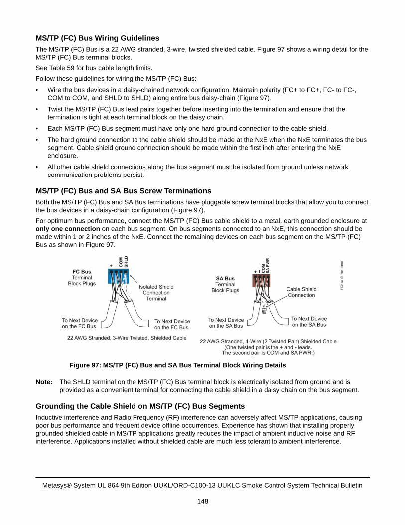
MS/TP (FC) Bus Wiring Guidelines
The MS/TP (FC) Bus is a 22 AWG stranded, 3-wire, twisted shielded cable. Figure 97 shows a wiring detail for the MS/TP (FC) Bus terminal blocks.
See Table 59 for bus cable length limits.
Follow these guidelines for wiring the MS/TP (FC) Bus:
• Wire the bus devices in a daisy-chained network configuration. Maintain polarity (FC+ to FC+, FC- to FC-, COM to COM, and SHLD to SHLD) along entire bus daisy-chain (Figure 97).
• Twist the MS/TP (FC) Bus lead pairs together before inserting into the termination and ensure that the termination is tight at each terminal block on the daisy chain.
• Each MS/TP (FC) Bus segment must have only one hard ground connection to the cable shield.
• The hard ground connection to the cable shield should be made at the NxE when the NxE terminates the bus segment. Cable shield ground connection should be made within the first inch after entering the NxE enclosure.
• All other cable shield connections along the bus segment must be isolated from ground unless network communication problems persist.
MS/TP (FC) Bus and SA Bus Screw Terminations
Both the MS/TP (FC) Bus and SA Bus terminations have pluggable screw terminal blocks that allow you to connect the bus devices in a daisy-chain configuration (Figure 97).
For optimum bus performance, connect the MS/TP (FC) Bus cable shield to a metal, earth grounded enclosure at only one connection on each bus segment. On bus segments connected to an NxE, this connection should be made within 1 or 2 inches of the NxE. Connect the remaining devices on each bus segment on the MS/TP (FC) Bus as shown in Figure 97.
Note: The SHLD terminal on the MS/TP (FC) Bus terminal block is electrically isolated from ground and is provided as a convenient terminal for connecting the cable shield in a daisy chain on the bus segment.
Grounding the Cable Shield on MS/TP (FC) Bus Segments
Inductive interference and Radio Frequency (RF) interference can adversely affect MS/TP applications, causing poor bus performance and frequent device offline occurrences. Experience has shown that installing properly grounded shielded cable in MS/TP applications greatly reduces the impact of ambient inductive noise and RF interference. Applications installed without shielded cable are much less tolerant to ambient interference.
Figure 97: MS/TP (FC) Bus and SA Bus Terminal Block Wiring Details
Metasys® System UL 864 9th Edition UUKL/ORD-C100-13 UUKLC Smoke Control System Technical Bulletin
148
We recommended installing MS/TP (FC) Bus applications using shielded cable. In applications using shielded cable, it is very important to ensure you ground the cable shield properly. Improper shield grounding can also result in poor bus performance and frequent device offline occurrences.
To properly ground the cable shield on an MS/TP application, the cable shields on each bus segment must be connected in a daisy chain as shown in Figure 97. Each daisy-chained segment must be connected at only one point to a hard ground connection. We recommend making the hard ground connection within the first 2 inches of the cable terminations at the bus supervisor (the NAE on an MS/TP (FC) Bus, and the FEC or VMA on the SA Bus).
SA Bus Wiring GuidelinesThe SA Bus can be connected using either a 4-wire (2-twisted pair) cable to the SA Bus (screw) terminal block or 6-wire cables with RJ-style modular jacks.
SA Bus Screw Terminations
The SA bus is a (2 twisted pair) shielded cable. The + and - leads make up one twisted pair and the SA PWR and COM leads makeup the second twisted pair.
• Wire the SA Bus devices in a daisy-chain network configuration. Maintain polarity (SA+ to SA+, SA- to SA-,COM to COM, and SA PWR to SA PWR) along entire bus daisy chain.
• Twist the SA bus leads together before inserting into the termination and ensure that the termination is tight ateach terminal block on the daisy chain.
• Each SA Bus must have only one hard ground connection to the cable shield.
• The single hard ground connection should be made at the bus supervisor where the SA Bus originates andshould be made within one inch of entering an enclosure.
• All shield connections on the SA Bus must be isolated from ground and connected in continuous segmentalong the SA Bus.
Note: The SA Bus terminal blocks do not provide an isolated terminal for making cable shield connections. Use a small wire nut or other suitable connector to daisy-chain and isolate the cable shield on the SA Bus (Figure 98).
IMPORTANT: Ensure that the cable shield is connected to hard ground at only one point on the bus segment and is completely isolated from hard ground at all other points on the bus segment. Multiple hard ground connections on a bus segment can create transient currents in the cable shield, which can result in poor bus performance and frequent device offline occurrences.
Metasys® System UL 864 9th Edition UUKL/ORD-C100-13 UUKLC Smoke Control System Technical Bulletin
149
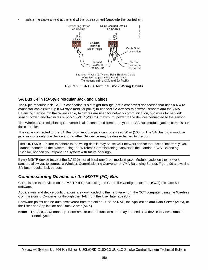
• Isolate the cable shield at the end of the bus segment (opposite the controller).
SA Bus 6-Pin RJ-Style Modular Jack and Cables
The 6-pin modular jack SA Bus connection is a straight-through (not a crossover) connection that uses a 6-wire connector cable (with 6-pin RJ-style modular jacks) to connect SA devices to network sensors and the VMA Balancing Sensor. On the 6-wire cable, two wires are used for network communication, two wires for network sensor power, and two wires supply 15 VDC (200 mA maximum) power to the devices connected to the sensor.
The Wireless Commissioning Converter is also connected (temporarily) to the SA Bus modular jack to commission the controller.
The cable connected to the SA Bus 6-pin modular jack cannot exceed 30 m (100 ft). The SA Bus 6-pin modular jack supports only one device and no other SA device may be daisy-chained to the port.
Every MS/TP device (except the NAE55) has at least one 6-pin modular jack. Modular jacks on the network sensors allow you to connect a Wireless Commissioning Converter or VMA Balancing Sensor. Figure 99 shows the SA Bus modular jack pinouts.
Commissioning Devices on the MS/TP (FC) BusCommission the devices on the MS/TP (FC) Bus using the Controller Configuration Tool (CCT) Release 5.1 software.
Applications and device configurations are downloaded to the hardware from the CCT computer using the Wireless Commissioning Converter or through the NAE from the User Interface (UI).
Hardware points can be auto discovered from the online UI of the NAE, the Application and Data Server (ADS), or the Extended Application and Data Server (ADX).
Note: The ADS/ADX cannot perform smoke control functions, but may be used as a device to view a smoke control system.
IMPORTANT: Failure to adhere to the wiring details may cause your network sensor to function incorrectly. You cannot connect to the system using the Wireless Commissioning Converter, the Handheld VAV Balancing Sensor, nor can you expand the system with future offerings.
Figure 98: SA Bus Terminal Block Wiring Details
Metasys® System UL 864 9th Edition UUKL/ORD-C100-13 UUKLC Smoke Control System Technical Bulletin
150
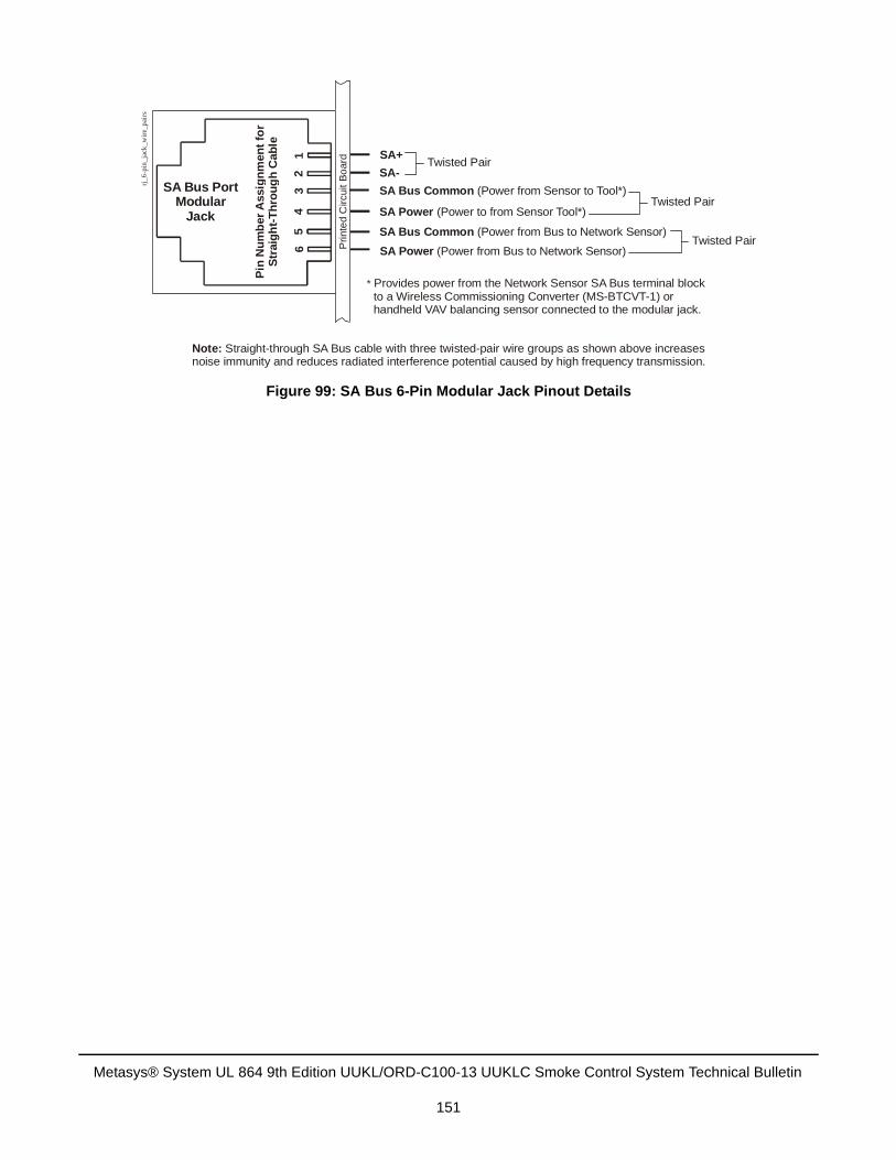
Figure 99: SA Bus 6-Pin Modular Jack Pinout Details
Pin
Nu
mb
er A
ssig
nm
ent
for
Str
aig
ht-
Th
rou
gh
Cab
le
Prin
ted
Circ
uit
Bo
ard
SA Power (Power from Bus to Network Sensor)
23
45
61 SA+
SA-
SA Bus Common (Power from Sensor to Tool*)
SA Power (Power to from Sensor Tool*)
* Provides power from the Network Sensor SA Bus terminal blockto a Wireless Commissioning Converter (MS-BTCVT-1) orhandheld VAV balancing sensor connected to the modular jack.
SA Bus PortModular
JackSA Bus Common (Power from Bus to Network Sensor)
Twisted Pair
Twisted Pair
Twisted Pair
Note: Straight-through SA Bus cable with three twisted-pair wire groups as shown above increases noise immunity and reduces radiated interference potential caused by high frequency transmission.
rj_6
-pin
_jac
k_w
ire_
pair
s
Metasys® System UL 864 9th Edition UUKL/ORD-C100-13 UUKLC Smoke Control System Technical Bulletin
151
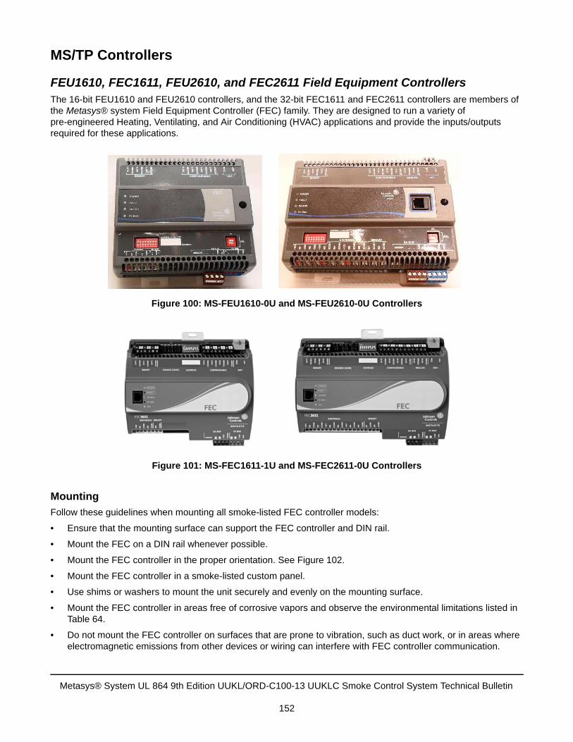
MS/TP Controllers
FEU1610, FEC1611, FEU2610, and FEC2611 Field Equipment ControllersThe 16-bit FEU1610 and FEU2610 controllers, and the 32-bit FEC1611 and FEC2611 controllers are members of the Metasys® system Field Equipment Controller (FEC) family. They are designed to run a variety of pre-engineered Heating, Ventilating, and Air Conditioning (HVAC) applications and provide the inputs/outputs required for these applications.
Mounting
Follow these guidelines when mounting all smoke-listed FEC controller models:
• Ensure that the mounting surface can support the FEC controller and DIN rail.
• Mount the FEC on a DIN rail whenever possible.
• Mount the FEC controller in the proper orientation. See Figure 102.
• Mount the FEC controller in a smoke-listed custom panel.
• Use shims or washers to mount the unit securely and evenly on the mounting surface.
• Mount the FEC controller in areas free of corrosive vapors and observe the environmental limitations listed inTable 64.
• Do not mount the FEC controller on surfaces that are prone to vibration, such as duct work, or in areas whereelectromagnetic emissions from other devices or wiring can interfere with FEC controller communication.
Figure 100: MS-FEU1610-0U and MS-FEU2610-0U Controllers
Figure 101: MS-FEC1611-1U and MS-FEC2611-0U Controllers
Metasys® System UL 864 9th Edition UUKL/ORD-C100-13 UUKLC Smoke Control System Technical Bulletin
152
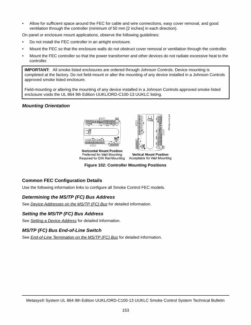
• Allow for sufficient space around the FEC for cable and wire connections, easy cover removal, and goodventilation through the controller (minimum of 50 mm [2 inches] in each direction).
On panel or enclosure mount applications, observe the following guidelines:
• Do not install the FEC controller in an airtight enclosure.
• Mount the FEC so that the enclosure walls do not obstruct cover removal or ventilation through the controller.
• Mount the FEC controller so that the power transformer and other devices do not radiate excessive heat to thecontroller.
Mounting Orientation
Common FEC Configuration Details
Use the following information links to configure all Smoke Control FEC models.
Determining the MS/TP (FC) Bus Address
See Device Addresses on the MS/TP (FC) Bus for detailed information.
Setting the MS/TP (FC) Bus Address
See Setting a Device Address for detailed information.
MS/TP (FC) Bus End-of-Line Switch
See End-of-Line Termination on the MS/TP (FC) Bus for detailed information.
IMPORTANT: All smoke listed enclosures are ordered through Johnson Controls. Device mounting is completed at the factory. Do not field-mount or alter the mounting of any device installed in a Johnson Controls approved smoke listed enclosure.
Field-mounting or altering the mounting of any device installed in a Johnson Controls approved smoke listed enclosure voids the UL 864 9th Edition UUKL/ORD-C100-13 UUKLC listing.
Figure 102: Controller Mounting Positions
Metasys® System UL 864 9th Edition UUKL/ORD-C100-13 UUKLC Smoke Control System Technical Bulletin
153
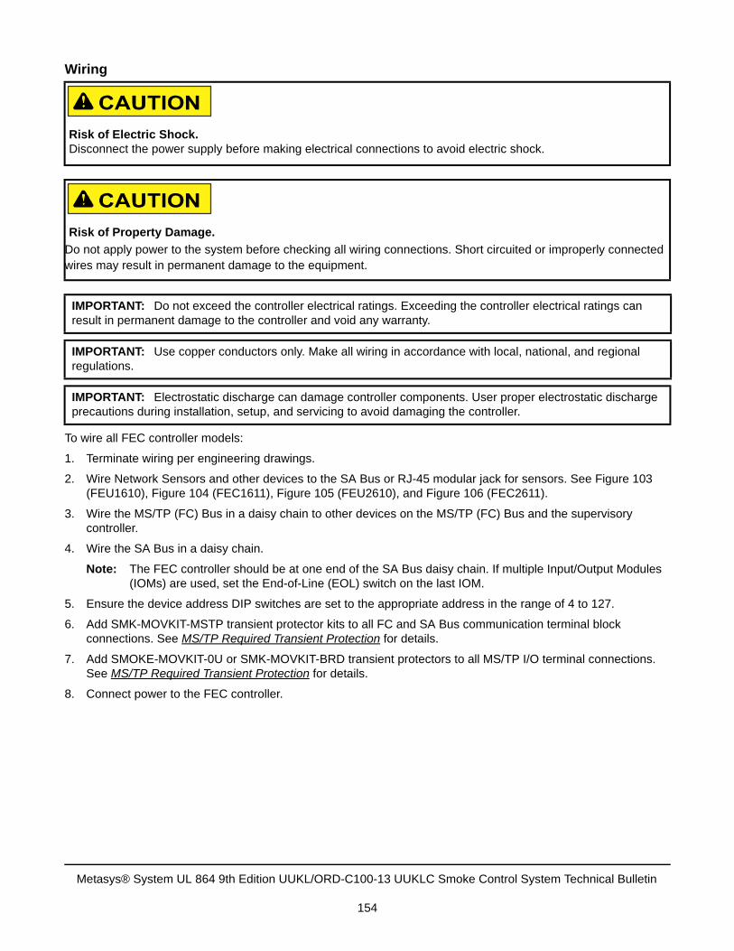
Wiring
To wire all FEC controller models:
1. Terminate wiring per engineering drawings.
2. Wire Network Sensors and other devices to the SA Bus or RJ-45 modular jack for sensors. See Figure 103(FEU1610), Figure 104 (FEC1611), Figure 105 (FEU2610), and Figure 106 (FEC2611).
3. Wire the MS/TP (FC) Bus in a daisy chain to other devices on the MS/TP (FC) Bus and the supervisorycontroller.
4. Wire the SA Bus in a daisy chain.
Note: The FEC controller should be at one end of the SA Bus daisy chain. If multiple Input/Output Modules(IOMs) are used, set the End-of-Line (EOL) switch on the last IOM.
5. Ensure the device address DIP switches are set to the appropriate address in the range of 4 to 127.
6. Add SMK-MOVKIT-MSTP transient protector kits to all FC and SA Bus communication terminal blockconnections. See MS/TP Required Transient Protection for details.
7. Add SMOKE-MOVKIT-0U or SMK-MOVKIT-BRD transient protectors to all MS/TP I/O terminal connections.See MS/TP Required Transient Protection for details.
8. Connect power to the FEC controller.
Risk of Electric Shock.Disconnect the power supply before making electrical connections to avoid electric shock.
Risk of Property Damage.
Do not apply power to the system before checking all wiring connections. Short circuited or improperly connected wires may result in permanent damage to the equipment.
IMPORTANT: Do not exceed the controller electrical ratings. Exceeding the controller electrical ratings can result in permanent damage to the controller and void any warranty.
IMPORTANT: Use copper conductors only. Make all wiring in accordance with local, national, and regional regulations.
IMPORTANT: Electrostatic discharge can damage controller components. User proper electrostatic discharge precautions during installation, setup, and servicing to avoid damaging the controller.
Metasys® System UL 864 9th Edition UUKL/ORD-C100-13 UUKLC Smoke Control System Technical Bulletin
154
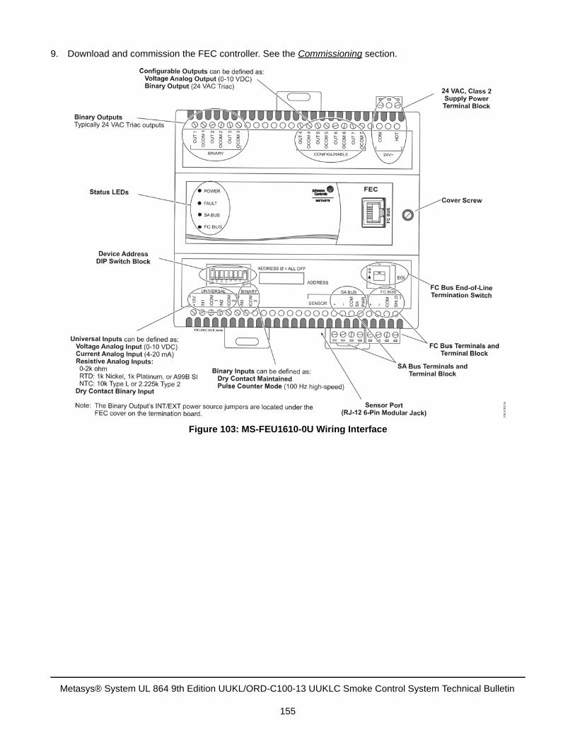
9. Download and commission the FEC controller. See the Commissioning section.
Figure 103: MS-FEU1610-0U Wiring Interface
Metasys® System UL 864 9th Edition UUKL/ORD-C100-13 UUKLC Smoke Control System Technical Bulletin
155
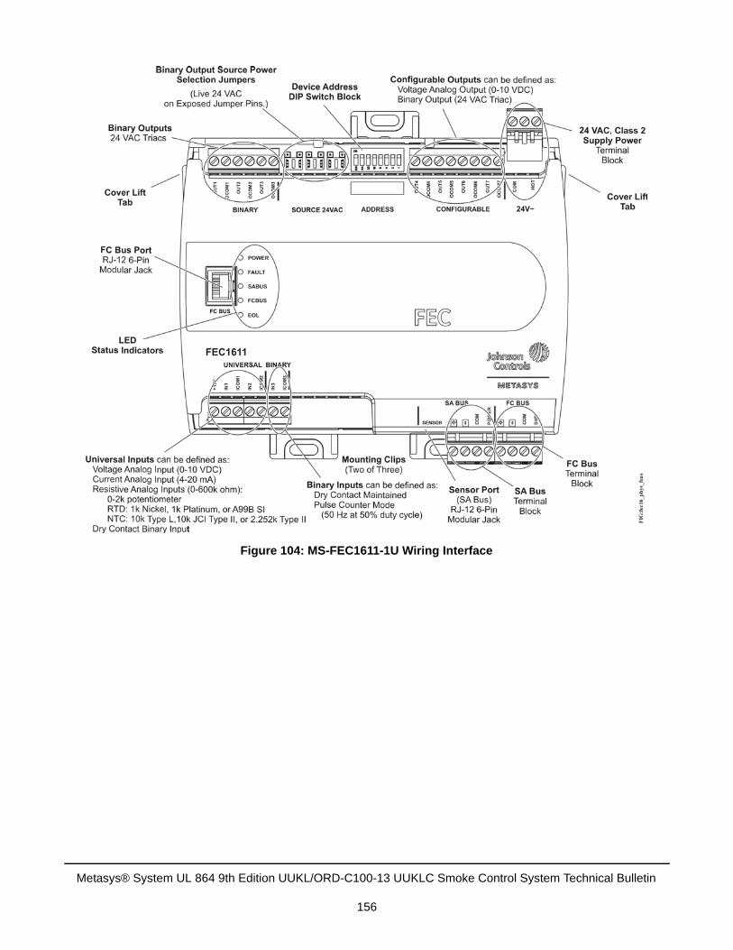
Figure 104: MS-FEC1611-1U Wiring Interface
Metasys® System UL 864 9th Edition UUKL/ORD-C100-13 UUKLC Smoke Control System Technical Bulletin
156
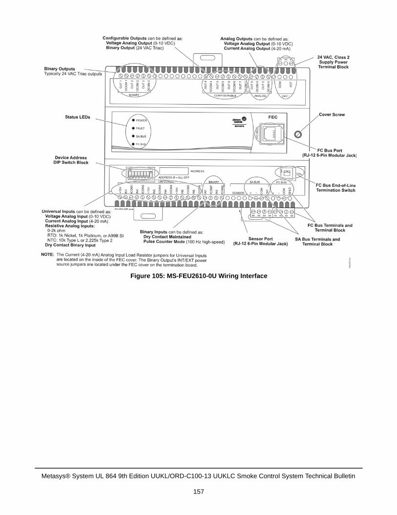
Figure 105: MS-FEU2610-0U Wiring Interface
Metasys® System UL 864 9th Edition UUKL/ORD-C100-13 UUKLC Smoke Control System Technical Bulletin
157
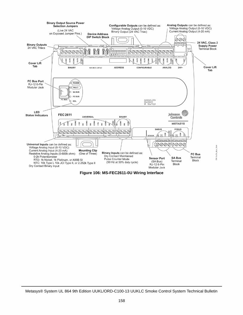
Figure 106: MS-FEC2611-0U Wiring Interface
Metasys® System UL 864 9th Edition UUKL/ORD-C100-13 UUKLC Smoke Control System Technical Bulletin
158
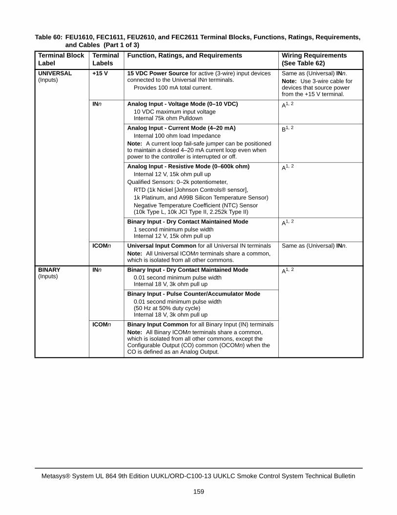
Table 60: FEU1610, FEC1611, FEU2610, and FEC2611 Terminal Blocks, Functions, Ratings, Requirements, and Cables (Part 1 of 3)
Terminal Block Label
Terminal Labels
Function, Ratings, and Requirements Wiring Requirements (See Table 62)
UNIVERSAL(Inputs)
+15 V 15 VDC Power Source for active (3-wire) input devices connected to the Universal INn terminals. Provides 100 mA total current.
Same as (Universal) INn.Note: Use 3-wire cable for devices that source power from the +15 V terminal.
INn Analog Input - Voltage Mode (0–10 VDC) 10 VDC maximum input voltage
Internal 75k ohm Pulldown
A1, 2
Analog Input - Current Mode (4–20 mA) Internal 100 ohm load Impedance Note: A current loop fail-safe jumper can be positioned to maintain a closed 4–20 mA current loop even when power to the controller is interrupted or off.
B1, 2
Analog Input - Resistive Mode (0–600k ohm) Internal 12 V, 15k ohm pull upQualified Sensors: 0–2k potentiometer, RTD (1k Nickel [Johnson Controls® sensor], 1k Platinum, and A99B Silicon Temperature Sensor) Negative Temperature Coefficient (NTC) Sensor (10k Type L, 10k JCI Type II, 2.252k Type II)
A1, 2
Binary Input - Dry Contact Maintained Mode 1 second minimum pulse width
Internal 12 V, 15k ohm pull up
A1, 2
ICOMn Universal Input Common for all Universal IN terminals Note: All Universal ICOMn terminals share a common, which is isolated from all other commons.
Same as (Universal) INn.
BINARY(Inputs)
INn Binary Input - Dry Contact Maintained Mode 0.01 second minimum pulse width Internal 18 V, 3k ohm pull up
A1, 2
Binary Input - Pulse Counter/Accumulator Mode 0.01 second minimum pulse width (50 Hz at 50% duty cycle) Internal 18 V, 3k ohm pull up
ICOMn Binary Input Common for all Binary Input (IN) terminals Note: All Binary ICOMn terminals share a common, which is isolated from all other commons, except the Configurable Output (CO) common (OCOMn) when the CO is defined as an Analog Output.
Metasys® System UL 864 9th Edition UUKL/ORD-C100-13 UUKLC Smoke Control System Technical Bulletin
159
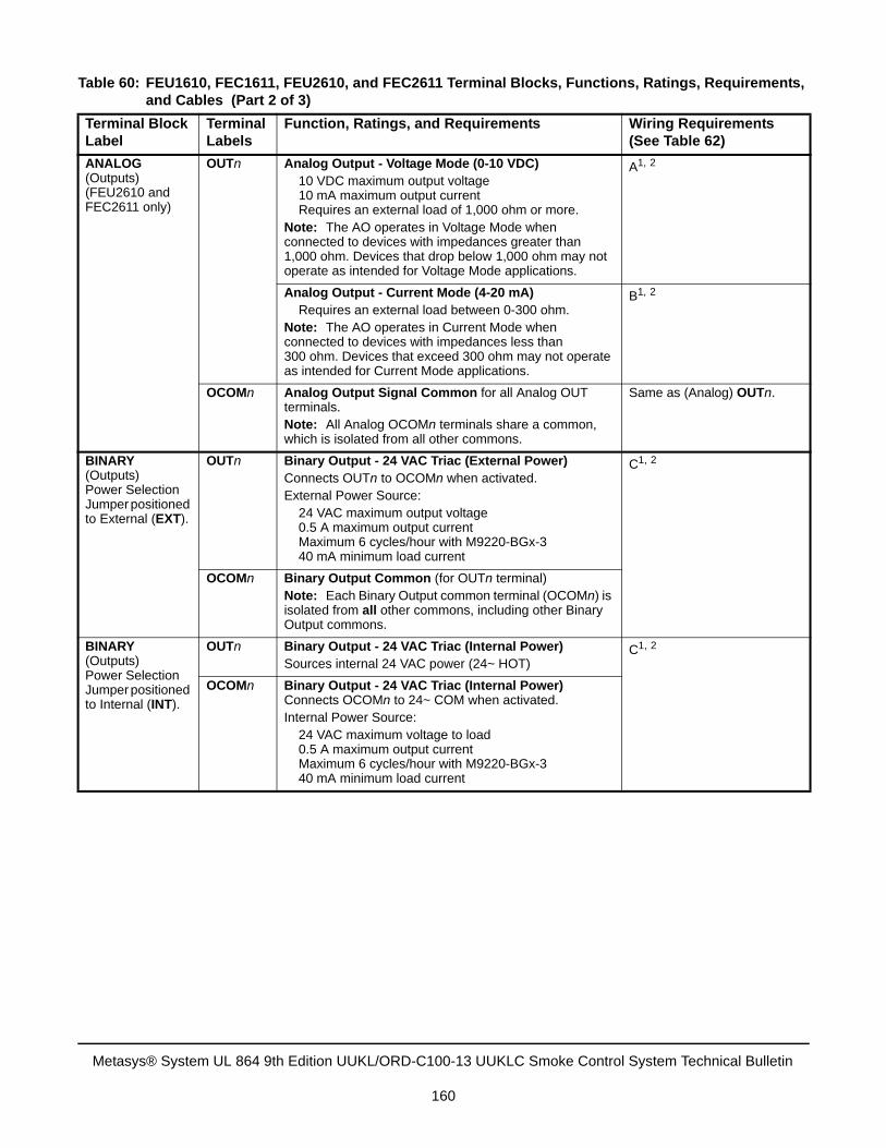
ANALOG(Outputs)(FEU2610 and FEC2611 only)
OUTn Analog Output - Voltage Mode (0-10 VDC) 10 VDC maximum output voltage
10 mA maximum output current Requires an external load of 1,000 ohm or more.Note: The AO operates in Voltage Mode when connected to devices with impedances greater than 1,000 ohm. Devices that drop below 1,000 ohm may not operate as intended for Voltage Mode applications.
A1, 2
Analog Output - Current Mode (4-20 mA) Requires an external load between 0-300 ohm.Note: The AO operates in Current Mode when connected to devices with impedances less than 300 ohm. Devices that exceed 300 ohm may not operate as intended for Current Mode applications.
B1, 2
OCOMn Analog Output Signal Common for all Analog OUT terminals.Note: All Analog OCOMn terminals share a common, which is isolated from all other commons.
Same as (Analog) OUTn.
BINARY(Outputs) Power Selection Jumper positioned to External (EXT).
OUTn Binary Output - 24 VAC Triac (External Power)Connects OUTn to OCOMn when activated.External Power Source: 24 VAC maximum output voltage 0.5 A maximum output current Maximum 6 cycles/hour with M9220-BGx-3 40 mA minimum load current
C1, 2
OCOMn Binary Output Common (for OUTn terminal) Note: Each Binary Output common terminal (OCOMn) is isolated from all other commons, including other Binary Output commons.
BINARY(Outputs) Power Selection Jumper positioned to Internal (INT).
OUTn Binary Output - 24 VAC Triac (Internal Power)Sources internal 24 VAC power (24~ HOT)
C1, 2
OCOMn Binary Output - 24 VAC Triac (Internal Power) Connects OCOMn to 24~ COM when activated.Internal Power Source: 24 VAC maximum voltage to load 0.5 A maximum output current Maximum 6 cycles/hour with M9220-BGx-3 40 mA minimum load current
Table 60: FEU1610, FEC1611, FEU2610, and FEC2611 Terminal Blocks, Functions, Ratings, Requirements, and Cables (Part 2 of 3)
Terminal Block Label
Terminal Labels
Function, Ratings, and Requirements Wiring Requirements (See Table 62)
Metasys® System UL 864 9th Edition UUKL/ORD-C100-13 UUKLC Smoke Control System Technical Bulletin
160

CONFIGURABLE (Outputs)
OUTn Analog Output - Voltage Mode (0-10 VDC) 10 VDC maximum output voltage
10 mA maximum output current Requires an external load of 1000 ohm or more
A1, 2
Binary Output 24 VAC TriacConnects OUT to OCOM when activated.External Power Source: 24 VAC maximum voltage to load 0.5 A maximum output current Maximum 6 cycles/hour with M9220-BGx-3 40 mA minimum load current
C1, 2
OCOMn Analog Output Signal Common: All Configurable Outputs defined as Analog Outputs share a common, which is isolated from all other commons except the Binary Input common.Binary Output Signal Common: All Configurable Outputs defined as Binary Outputs are isolated from all other commons, including other Configurable Output commons.
Same as (Configurable) OUTn.
1. See MS/TP (FC) Bus Cable Recommendations for wire length specifications.2. Requires original SMOKE-MOVKIT-0U or new SMOKE-MOVKIT-BRD transient protectors for all MS/TP I/O terminal
connections. See MS/TP Field Controller I/O Transient Protection for wiring details.
Table 61: Communication Bus and Supply Power Terminal Blocks, Functions, Ratings, Requirements, and Cables
Terminal Block/Port Label
Terminal Labels
Function, Electrical Ratings/Requirements Recommended Cable Type1
MS/TP (FC) Bus2
+-
MS/TP (FC) Bus Communications 22 AWG (0.6 mm) stranded, 3-wire twisted, shielded cable recommended
COM Signal Reference (Common) for bus communications
SHLD Isolated terminal (optional shield drain connection)
MS/TP (FC) Bus2
(Port)
RJ-12 6-Position Modular Connector provides: MS/TP (FC) Bus Communications MS/TP (FC) Bus Signal Reference and 15 VDC Common
24 AWG 3-pair CAT 3 Cable <100 ft (30.5 m)
SA BUS2 +-
SA Bus Communications 0.6 mm (22 AWG) stranded, 4-wire (2 twisted-pairs), shielded cable recommendedNote: The + and - wires are one twisted pair and the COM and SA PWR are the second twisted pair of wires.
COM SA Bus Signal Reference and 15 VDC Common
SA PWR 15 VDC Supply Power for Devices on the SA Bus(Maximum total current draw for SA Bus is 240 mA.)
SENSOR2, 3 SENSOR RJ-12 6-Position Modular Connector provides: SA Bus Communications SA Bus Signal Reference and 15 VDC Common
24 AWG 3-pair CAT 3 Cable <100 ft (30.5 m)
24~ HOT 24 VAC Power Supply - Hot Supplies 24 VAC
20 to 16 AWG (0.8 mm to 1.5 mm2) 2-wire
COM 24 VAC Power Supply Common (Isolated from all other Common terminals on controller)
Table 60: FEU1610, FEC1611, FEU2610, and FEC2611 Terminal Blocks, Functions, Ratings, Requirements, and Cables (Part 3 of 3)
Terminal Block Label
Terminal Labels
Function, Ratings, and Requirements Wiring Requirements (See Table 62)
Metasys® System UL 864 9th Edition UUKL/ORD-C100-13 UUKLC Smoke Control System Technical Bulletin
161
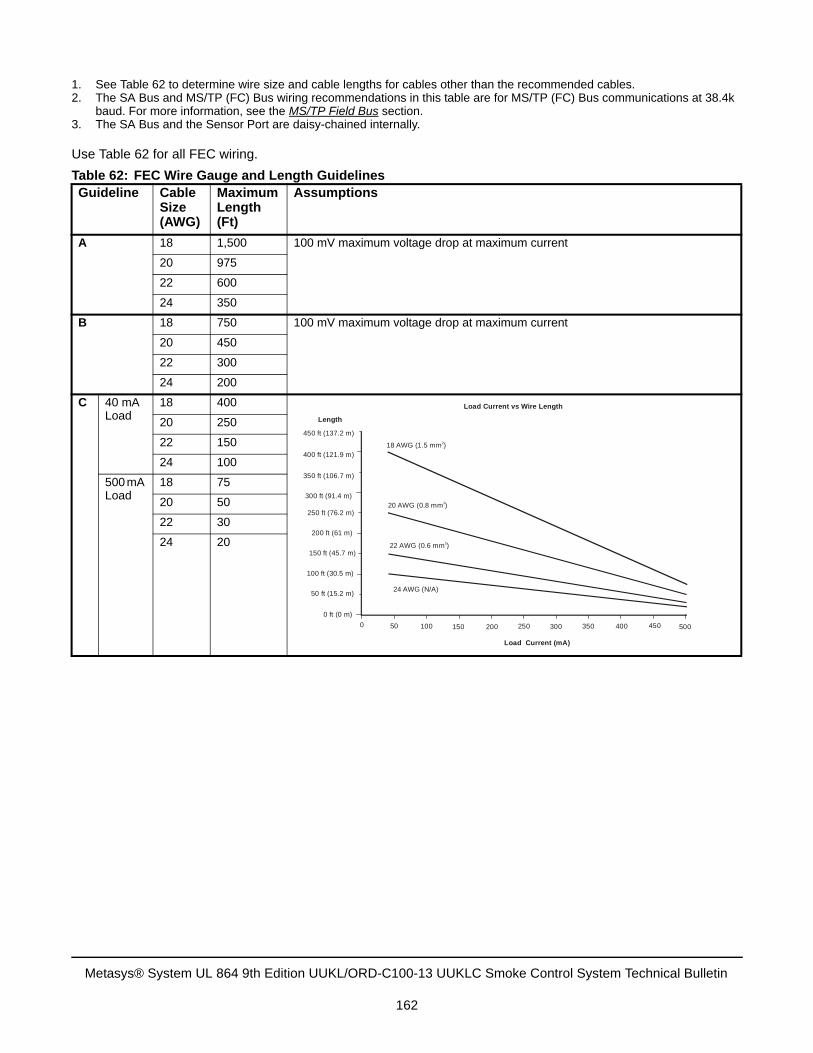
Use Table 62 for all FEC wiring.
1. See Table 62 to determine wire size and cable lengths for cables other than the recommended cables.2. The SA Bus and MS/TP (FC) Bus wiring recommendations in this table are for MS/TP (FC) Bus communications at 38.4k
baud. For more information, see the MS/TP Field Bus section.3. The SA Bus and the Sensor Port are daisy-chained internally.
Table 62: FEC Wire Gauge and Length GuidelinesGuideline Cable
Size (AWG)
Maximum Length (Ft)
Assumptions
A 18 1,500 100 mV maximum voltage drop at maximum current
20 975
22 600
24 350
B 18 750 100 mV maximum voltage drop at maximum current
20 450
22 300
24 200
C 40 mA Load
18 400
20 250
22 150
24 100
500 mA Load
18 75
20 50
22 30
24 20
18 AWG (1.5 mm )2
20 AWG (0.8 mm )2
22 AWG (0.6 mm )2
24 AWG (N/A)
450 500400350300250200150100500
Load Current (mA)
0 ft (0 m)
50 ft (15.2 m)
100 ft (30.5 m)
150 ft (45.7 m)
200 ft (61 m)
250 ft (76.2 m)
300 ft (91.4 m)
350 ft (106.7 m)
400 ft (121.9 m)
450 ft (137.2 m)
Length
Load Current vs Wire Length
Metasys® System UL 864 9th Edition UUKL/ORD-C100-13 UUKLC Smoke Control System Technical Bulletin
162
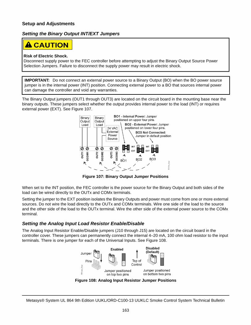
Setup and Adjustments
Setting the Binary Output INT/EXT Jumpers
The Binary Output jumpers (OUT1 through OUT3) are located on the circuit board in the mounting base near the binary outputs. These jumpers select whether the output provides internal power to the load (INT) or requires external power (EXT). See Figure 107.
When set to the INT position, the FEC controller is the power source for the Binary Output and both sides of the load can be wired directly to the OUTx and COMx terminals.
Setting the jumper to the EXT position isolates the Binary Outputs and power must come from one or more external sources. Do not wire the load directly to the OUTx and COMx terminals. Wire one side of the load to the source and the other side of the load to the OUTx terminal. Wire the other side of the external power source to the COMx terminal.
Setting the Analog Input Load Resistor Enable/Disable
The Analog Input Resistor Enable/Disable jumpers (J10 through J15) are located on the circuit board in the controller cover. These jumpers can permanently connect the internal 4–20 mA, 100 ohm load resistor to the input terminals. There is one jumper for each of the Universal Inputs. See Figure 108.
Risk of Electric Shock.Disconnect supply power to the FEC controller before attempting to adjust the Binary Output Source Power Selection Jumpers. Failure to disconnect the supply power may result in electric shock.
IMPORTANT: Do not connect an external power source to a Binary Output (BO) when the BO power source jumper is in the internal power (INT) position. Connecting external power to a BO that sources internal power can damage the controller and void any warranties.
Figure 107: Binary Output Jumper Positions
Figure 108: Analog Input Resistor Jumper Positions
Metasys® System UL 864 9th Edition UUKL/ORD-C100-13 UUKLC Smoke Control System Technical Bulletin
163
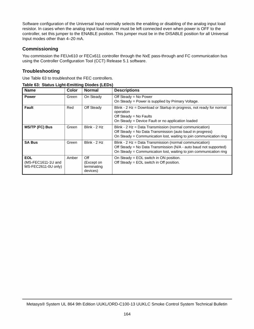
Software configuration of the Universal Input normally selects the enabling or disabling of the analog input load resistor. In cases when the analog input load resistor must be left connected even when power is OFF to the controller, set this jumper to the ENABLE position. This jumper must be in the DISABLE position for all Universal Input modes other than 4–20 mA.
Commissioning
You commission the FEUx610 or FECx611 controller through the NxE pass-through and FC communication bus using the Controller Configuration Tool (CCT) Release 5.1 software.
Troubleshooting
Use Table 63 to troubleshoot the FEC controllers.
Table 63: Status Light-Emitting Diodes (LEDs)Name Color Normal Descriptions
Power Green On Steady Off Steady = No PowerOn Steady = Power is supplied by Primary Voltage.
Fault Red Off Steady Blink - 2 Hz = Download or Startup in progress, not ready for normal operationOff Steady = No FaultsOn Steady = Device Fault or no application loaded
MS/TP (FC) Bus Green Blink - 2 Hz Blink - 2 Hz = Data Transmission (normal communication)Off Steady = No Data Transmission (auto baud in progress)On Steady = Communication lost, waiting to join communication ring
SA Bus Green Blink - 2 Hz Blink - 2 Hz = Data Transmission (normal communication)Off Steady = No Data Transmission (N/A - auto baud not supported)On Steady = Communication lost, waiting to join communication ring
EOL(MS-FEC1611-1U and MS-FEC2611-0U only)
Amber Off(Except on terminating devices)
On Steady = EOL switch in ON position.Off Steady = EOL switch in Off position.
Metasys® System UL 864 9th Edition UUKL/ORD-C100-13 UUKLC Smoke Control System Technical Bulletin
164
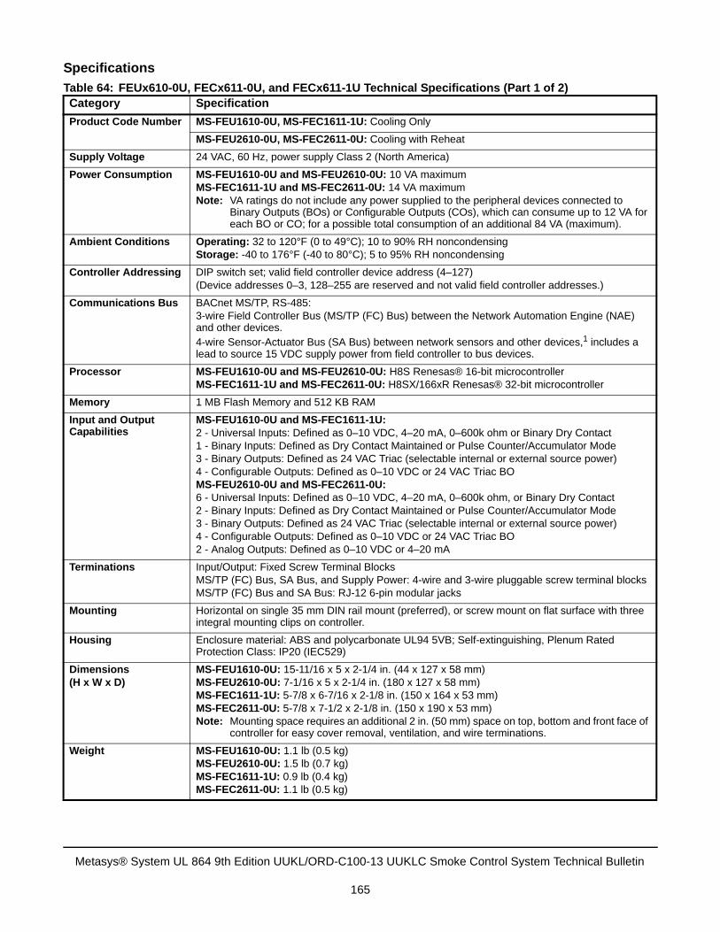
Specifications
Table 64: FEUx610-0U, FECx611-0U, and FECx611-1U Technical Specifications (Part 1 of 2)Category Specification
Product Code Number MS-FEU1610-0U, MS-FEC1611-1U: Cooling Only
MS-FEU2610-0U, MS-FEC2611-0U: Cooling with Reheat
Supply Voltage 24 VAC, 60 Hz, power supply Class 2 (North America)
Power Consumption MS-FEU1610-0U and MS-FEU2610-0U: 10 VA maximum MS-FEC1611-1U and MS-FEC2611-0U: 14 VA maximumNote: VA ratings do not include any power supplied to the peripheral devices connected to
Binary Outputs (BOs) or Configurable Outputs (COs), which can consume up to 12 VA for each BO or CO; for a possible total consumption of an additional 84 VA (maximum).
Ambient Conditions Operating: 32 to 120°F (0 to 49°C); 10 to 90% RH noncondensingStorage: -40 to 176°F (-40 to 80°C); 5 to 95% RH noncondensing
Controller Addressing DIP switch set; valid field controller device address (4–127)(Device addresses 0–3, 128–255 are reserved and not valid field controller addresses.)
Communications Bus BACnet MS/TP, RS-485:3-wire Field Controller Bus (MS/TP (FC) Bus) between the Network Automation Engine (NAE) and other devices. 4-wire Sensor-Actuator Bus (SA Bus) between network sensors and other devices,1 includes a lead to source 15 VDC supply power from field controller to bus devices.
Processor MS-FEU1610-0U and MS-FEU2610-0U: H8S Renesas® 16-bit microcontrollerMS-FEC1611-1U and MS-FEC2611-0U: H8SX/166xR Renesas® 32-bit microcontroller
Memory 1 MB Flash Memory and 512 KB RAM
Input and Output Capabilities
MS-FEU1610-0U and MS-FEC1611-1U:2 - Universal Inputs: Defined as 0–10 VDC, 4–20 mA, 0–600k ohm or Binary Dry Contact1 - Binary Inputs: Defined as Dry Contact Maintained or Pulse Counter/Accumulator Mode3 - Binary Outputs: Defined as 24 VAC Triac (selectable internal or external source power)4 - Configurable Outputs: Defined as 0–10 VDC or 24 VAC Triac BOMS-FEU2610-0U and MS-FEC2611-0U: 6 - Universal Inputs: Defined as 0–10 VDC, 4–20 mA, 0–600k ohm, or Binary Dry Contact2 - Binary Inputs: Defined as Dry Contact Maintained or Pulse Counter/Accumulator Mode3 - Binary Outputs: Defined as 24 VAC Triac (selectable internal or external source power)4 - Configurable Outputs: Defined as 0–10 VDC or 24 VAC Triac BO2 - Analog Outputs: Defined as 0–10 VDC or 4–20 mA
Terminations Input/Output: Fixed Screw Terminal BlocksMS/TP (FC) Bus, SA Bus, and Supply Power: 4-wire and 3-wire pluggable screw terminal blocksMS/TP (FC) Bus and SA Bus: RJ-12 6-pin modular jacks
Mounting Horizontal on single 35 mm DIN rail mount (preferred), or screw mount on flat surface with three integral mounting clips on controller.
Housing Enclosure material: ABS and polycarbonate UL94 5VB; Self-extinguishing, Plenum Rated Protection Class: IP20 (IEC529)
Dimensions(H x W x D)
MS-FEU1610-0U: 15-11/16 x 5 x 2-1/4 in. (44 x 127 x 58 mm)MS-FEU2610-0U: 7-1/16 x 5 x 2-1/4 in. (180 x 127 x 58 mm)MS-FEC1611-1U: 5-7/8 x 6-7/16 x 2-1/8 in. (150 x 164 x 53 mm)MS-FEC2611-0U: 5-7/8 x 7-1/2 x 2-1/8 in. (150 x 190 x 53 mm)Note: Mounting space requires an additional 2 in. (50 mm) space on top, bottom and front face of
controller for easy cover removal, ventilation, and wire terminations.
Weight MS-FEU1610-0U: 1.1 lb (0.5 kg)MS-FEU2610-0U: 1.5 lb (0.7 kg)MS-FEC1611-1U: 0.9 lb (0.4 kg)MS-FEC2611-0U: 1.1 lb (0.5 kg)
Metasys® System UL 864 9th Edition UUKL/ORD-C100-13 UUKLC Smoke Control System Technical Bulletin
165
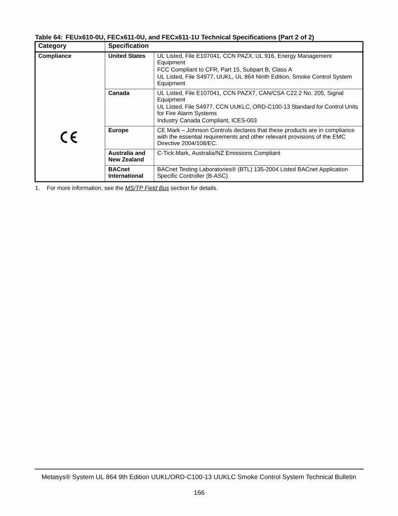
Compliance United States UL Listed, File E107041, CCN PAZX, UL 916, Energy Management EquipmentFCC Compliant to CFR, Part 15, Subpart B, Class AUL Listed, File S4977, UUKL, UL 864 Ninth Edition, Smoke Control System Equipment
Canada UL Listed, File E107041, CCN PAZX7, CAN/CSA C22.2 No. 205, Signal EquipmentUL Listed, File S4977, CCN UUKLC, ORD-C100-13 Standard for Control Units for Fire Alarm SystemsIndustry Canada Compliant, ICES-003
Europe CE Mark – Johnson Controls declares that these products are in compliance with the essential requirements and other relevant provisions of the EMC Directive 2004/108/EC.
Australia and New Zealand
C-Tick Mark, Australia/NZ Emissions Compliant
BACnet International
BACnet Testing Laboratories® (BTL) 135-2004 Listed BACnet Application Specific Controller (B-ASC)
1. For more information, see the MS/TP Field Bus section for details.
Table 64: FEUx610-0U, FECx611-0U, and FECx611-1U Technical Specifications (Part 2 of 2)Category Specification
Metasys® System UL 864 9th Edition UUKL/ORD-C100-13 UUKLC Smoke Control System Technical Bulletin
166
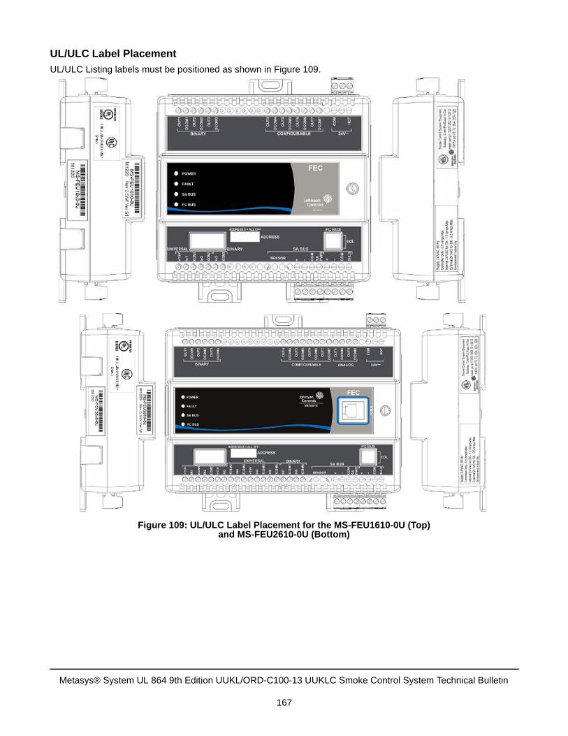
UL/ULC Label Placement
UL/ULC Listing labels must be positioned as shown in Figure 109.
Figure 109: UL/ULC Label Placement for the MS-FEU1610-0U (Top)and MS-FEU2610-0U (Bottom)
Metasys® System UL 864 9th Edition UUKL/ORD-C100-13 UUKLC Smoke Control System Technical Bulletin
167
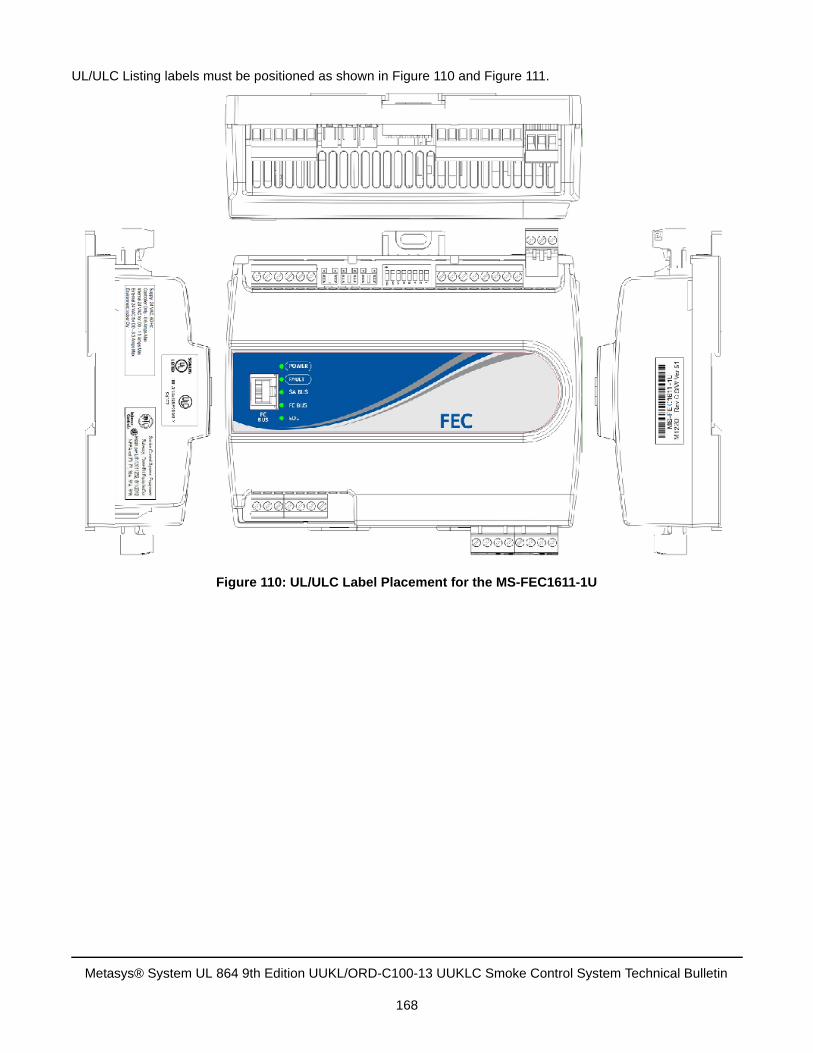
UL/ULC Listing labels must be positioned as shown in Figure 110 and Figure 111.
Figure 110: UL/ULC Label Placement for the MS-FEC1611-1U
Metasys® System UL 864 9th Edition UUKL/ORD-C100-13 UUKLC Smoke Control System Technical Bulletin
168
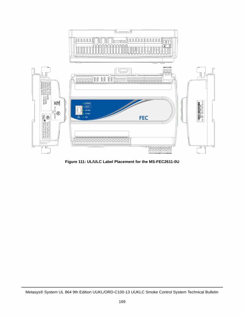
Figure 111: UL/ULC Label Placement for the MS-FEC2611-0U
Metasys® System UL 864 9th Edition UUKL/ORD-C100-13 UUKLC Smoke Control System Technical Bulletin
169
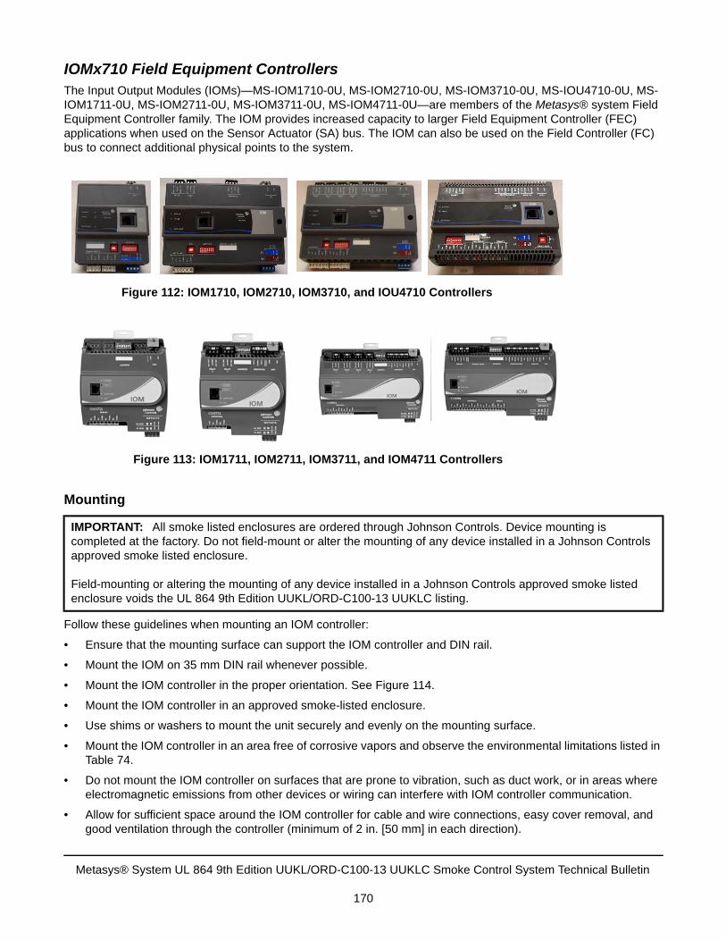
IOMx710 Field Equipment ControllersThe Input Output Modules (IOMs)—MS-IOM1710-0U, MS-IOM2710-0U, MS-IOM3710-0U, MS-IOU4710-0U, MS-IOM1711-0U, MS-IOM2711-0U, MS-IOM3711-0U, MS-IOM4711-0U—are members of the Metasys® system Field Equipment Controller family. The IOM provides increased capacity to larger Field Equipment Controller (FEC) applications when used on the Sensor Actuator (SA) bus. The IOM can also be used on the Field Controller (FC) bus to connect additional physical points to the system.
Mounting
Follow these guidelines when mounting an IOM controller:
• Ensure that the mounting surface can support the IOM controller and DIN rail.
• Mount the IOM on 35 mm DIN rail whenever possible.
• Mount the IOM controller in the proper orientation. See Figure 114.
• Mount the IOM controller in an approved smoke-listed enclosure.
• Use shims or washers to mount the unit securely and evenly on the mounting surface.
• Mount the IOM controller in an area free of corrosive vapors and observe the environmental limitations listed inTable 74.
• Do not mount the IOM controller on surfaces that are prone to vibration, such as duct work, or in areas whereelectromagnetic emissions from other devices or wiring can interfere with IOM controller communication.
• Allow for sufficient space around the IOM controller for cable and wire connections, easy cover removal, andgood ventilation through the controller (minimum of 2 in. [50 mm] in each direction).
IMPORTANT: All smoke listed enclosures are ordered through Johnson Controls. Device mounting is completed at the factory. Do not field-mount or alter the mounting of any device installed in a Johnson Controls approved smoke listed enclosure.
Field-mounting or altering the mounting of any device installed in a Johnson Controls approved smoke listed enclosure voids the UL 864 9th Edition UUKL/ORD-C100-13 UUKLC listing.
Figure 112: IOM1710, IOM2710, IOM3710, and IOU4710 Controllers
Figure 113: IOM1711, IOM2711, IOM3711, and IOM4711 Controllers
Metasys® System UL 864 9th Edition UUKL/ORD-C100-13 UUKLC Smoke Control System Technical Bulletin
170
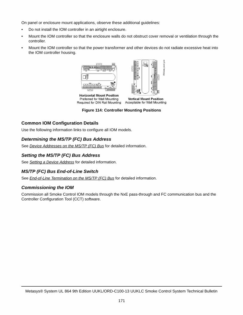
On panel or enclosure mount applications, observe these additional guidelines:
• Do not install the IOM controller in an airtight enclosure.
• Mount the IOM controller so that the enclosure walls do not obstruct cover removal or ventilation through thecontroller.
• Mount the IOM controller so that the power transformer and other devices do not radiate excessive heat intothe IOM controller housing.
Common IOM Configuration Details
Use the following information links to configure all IOM models.
Determining the MS/TP (FC) Bus Address
See Device Addresses on the MS/TP (FC) Bus for detailed information.
Setting the MS/TP (FC) Bus Address
See Setting a Device Address for detailed information.
MS/TP (FC) Bus End-of-Line Switch
See End-of-Line Termination on the MS/TP (FC) Bus for detailed information.
Commissioning the IOM
Commission all Smoke Control IOM models through the NxE pass-through and FC communication bus and the Controller Configuration Tool (CCT) software.
Figure 114: Controller Mounting Positions
Metasys® System UL 864 9th Edition UUKL/ORD-C100-13 UUKLC Smoke Control System Technical Bulletin
171
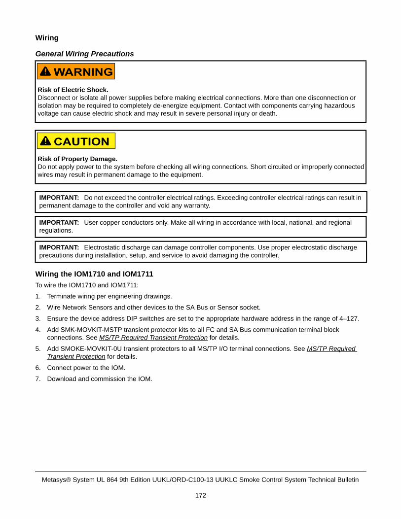
Wiring
General Wiring Precautions
Wiring the IOM1710 and IOM1711
To wire the IOM1710 and IOM1711:
1. Terminate wiring per engineering drawings.
2. Wire Network Sensors and other devices to the SA Bus or Sensor socket.
3. Ensure the device address DIP switches are set to the appropriate hardware address in the range of 4–127.
4. Add SMK-MOVKIT-MSTP transient protector kits to all FC and SA Bus communication terminal blockconnections. See MS/TP Required Transient Protection for details.
5. Add SMOKE-MOVKIT-0U transient protectors to all MS/TP I/O terminal connections. See MS/TP RequiredTransient Protection for details.
6. Connect power to the IOM.
7. Download and commission the IOM.
Risk of Electric Shock.Disconnect or isolate all power supplies before making electrical connections. More than one disconnection or isolation may be required to completely de-energize equipment. Contact with components carrying hazardous voltage can cause electric shock and may result in severe personal injury or death.
Risk of Property Damage.Do not apply power to the system before checking all wiring connections. Short circuited or improperly connected wires may result in permanent damage to the equipment.
IMPORTANT: Do not exceed the controller electrical ratings. Exceeding controller electrical ratings can result in permanent damage to the controller and void any warranty.
IMPORTANT: User copper conductors only. Make all wiring in accordance with local, national, and regional regulations.
IMPORTANT: Electrostatic discharge can damage controller components. Use proper electrostatic discharge precautions during installation, setup, and service to avoid damaging the controller.
Metasys® System UL 864 9th Edition UUKL/ORD-C100-13 UUKLC Smoke Control System Technical Bulletin
172
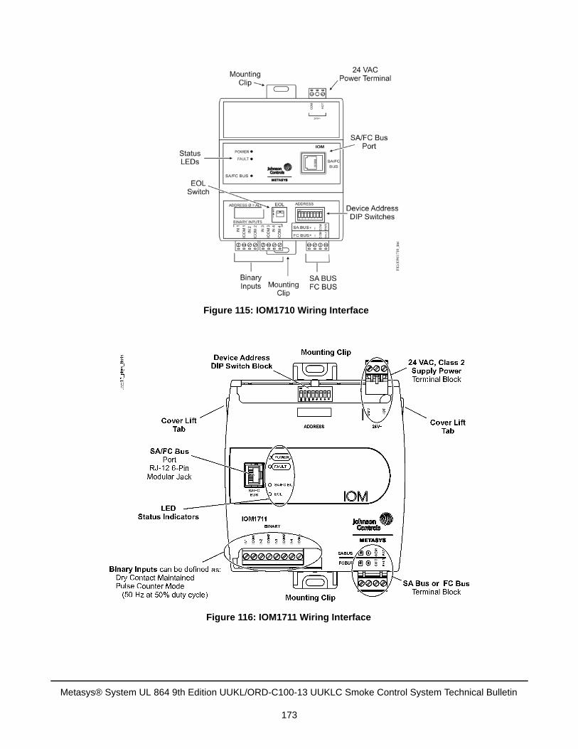
Figure 115: IOM1710 Wiring Interface
Figure 116: IOM1711 Wiring Interface
Metasys® System UL 864 9th Edition UUKL/ORD-C100-13 UUKLC Smoke Control System Technical Bulletin
173
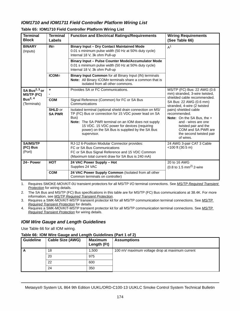
IOM1710 and IOM1711 Field Controller Platform Wiring List
IOM Wire Gauge and Length Guidelines
Use Table 66 for all IOM wiring.
Table 65: IOM1710 Field Controller Platform Wiring List
Terminal Block
Terminal Labels
Function and Electrical Ratings/Requirements Wiring Requirements(See Table 66)
BINARY(Inputs)
INn Binary Input – Dry Contact Maintained Mode0.01 s minimum pulse width (50 Hz at 50% duty cycle)Internal 18 V, 3k ohm Pull-up
A1
1. Requires SMOKE-MOVKIT-0U transient protectors for all MS/TP I/O terminal connections. See MS/TP Required TransientProtection for wiring details.
Binary Input – Pulse Counter Mode/Accumulator Mode0.01 s minimum pulse width (50 Hz at 50% duty cycle)Internal 18 V, 3k ohm Pull-up
ICOMn Binary Input Common for all Binary Input (IN) terminalsNote: All Binary ICOMn terminals share a common that is
isolated from all other commons.
SA Bus2, 3 or MS/TP (FC) Bus2, 4
(Terminals)
2. The SA Bus and MS/TP (FC) Bus specifications in this table are for MS/TP (FC) Bus communications at 38.4K. For moreinformation, see MS/TP Required Transient Protection.
3. Requires a SMK-MOVKIT-MSTP transient protector kit for all MS/TP communication terminal connections. See MS/TPRequired Transient Protection for details.
4. Requires a SMK-MOVKIT-MSTP transient protector kit for all MS/TP communication terminal connections. See MS/TPRequired Transient Protection for wiring details.
+-
Provides SA or FC Communications. MS/TP (FC) Bus: 22 AWG (0.6 mm) stranded, 3-wire twisted, shielded cable recommended.SA Bus: 22 AWG (0.6 mm) stranded, 4-wire (2 twisted pairs) shielded cable recommended.Note: On the SA Bus, the +
and - wires are one twisted pair and the COM and SA PWR are the second twisted pair of wires.
COM Signal Reference (Common) for FC or SA Bus Communications
SHLD orSA PWR
Isolated terminal (optional shield drain connection on MS/TP (FC) Bus or connection for 15 VDC power lead on SA Bus)Note: The SA PWR terminal on an IOM does not supply
15 VDC. 15 VDC power for devices (requiring power) on the SA Bus is supplied by the SA Bus supervisor.
SA/MS/TP (FC) Bus (Port)
RJ-12 6-Position Modular Connector provides:FC or SA Bus CommunicationsFC or SA Bus Signal Reference and 15 VDC Common(Maximum total current draw for SA Bus is 240 mA)
24 AWG 3-pair CAT 3 Cable <100 ft (30.5 m)
24~ Power HOT 24 VAC Power Supply – HotSupplies 24 VAC
20 to 16 AWG(0.8 to 1.5 mm2) 2-wire
COM 24 VAC Power Supply Common (Isolated from all other Common terminals on controller)
Table 66: IOM Wire Gauge and Length Guidelines (Part 1 of 2)Guideline Cable Size (AWG) Maximum
Length (Ft)Assumptions
A 18 1,500 100 mV maximum voltage drop at maximum current
20 975
22 600
24 350
Metasys® System UL 864 9th Edition UUKL/ORD-C100-13 UUKLC Smoke Control System Technical Bulletin
174
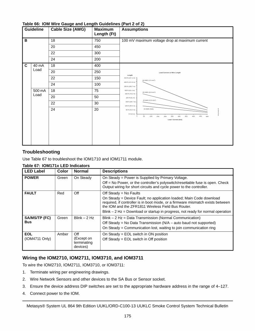
Troubleshooting
Use Table 67 to troubleshoot the IOM1710 and IOM1711 module.
Wiring the IOM2710, IOM2711, IOM3710, and IOM3711
To wire the IOM2710, IOM2711, IOM3710, or IOM3711:
1. Terminate wiring per engineering drawings.
2. Wire Network Sensors and other devices to the SA Bus or Sensor socket.
3. Ensure the device address DIP switches are set to the appropriate hardware address in the range of 4–127.
4. Connect power to the IOM.
B 18 750 100 mV maximum voltage drop at maximum current
20 450
22 300
24 200
C 40 mA Load
18 400
20 250
22 150
24 100
500 mA Load
18 75
20 50
22 30
24 20
Table 67: IOM171x LED IndicatorsLED Label Color Normal Descriptions
POWER Green On Steady On Steady = Power is Supplied by Primary Voltage.Off = No Power, or the controller’s polyswitch/resettable fuse is open. Check Output wiring for short circuits and cycle power to the controller.
FAULT Red Off Off Steady = No FaultsOn Steady = Device Fault; no application loaded; Main Code download required, if controller is in boot mode, or a firmware mismatch exists between the IOM and the ZFR1811 Wireless Field Bus Router.Blink – 2 Hz = Download or startup in progress, not ready for normal operation
SA/MS/TP (FC) Bus
Green Blink – 2 Hz Blink – 2 Hz = Data Transmission (Normal Communication)Off Steady = No Data Transmission (N/A – auto baud not supported)On Steady = Communication lost, waiting to join communication ring
EOL(IOM4711 Only)
Amber Off(Except on terminating devices)
On Steady = EOL switch in ON positionOff Steady = EOL switch in Off position
Table 66: IOM Wire Gauge and Length Guidelines (Part 2 of 2)Guideline Cable Size (AWG) Maximum
Length (Ft)Assumptions
18 AWG (1.5 mm )2
20 AWG (0.8 mm )2
22 AWG (0.6 mm )2
24 AWG (N/A)
450 500400350300250200150100500
Load Current (mA)
0 ft (0 m)
50 ft (15.2 m)
100 ft (30.5 m)
150 ft (45.7 m)
200 ft (61 m)
250 ft (76.2 m)
300 ft (91.4 m)
350 ft (106.7 m)
400 ft (121.9 m)
450 ft (137.2 m)
Length
Wirin
g le
ngth
.cdr
Load Current vs Wire Length
Metasys® System UL 864 9th Edition UUKL/ORD-C100-13 UUKLC Smoke Control System Technical Bulletin
175
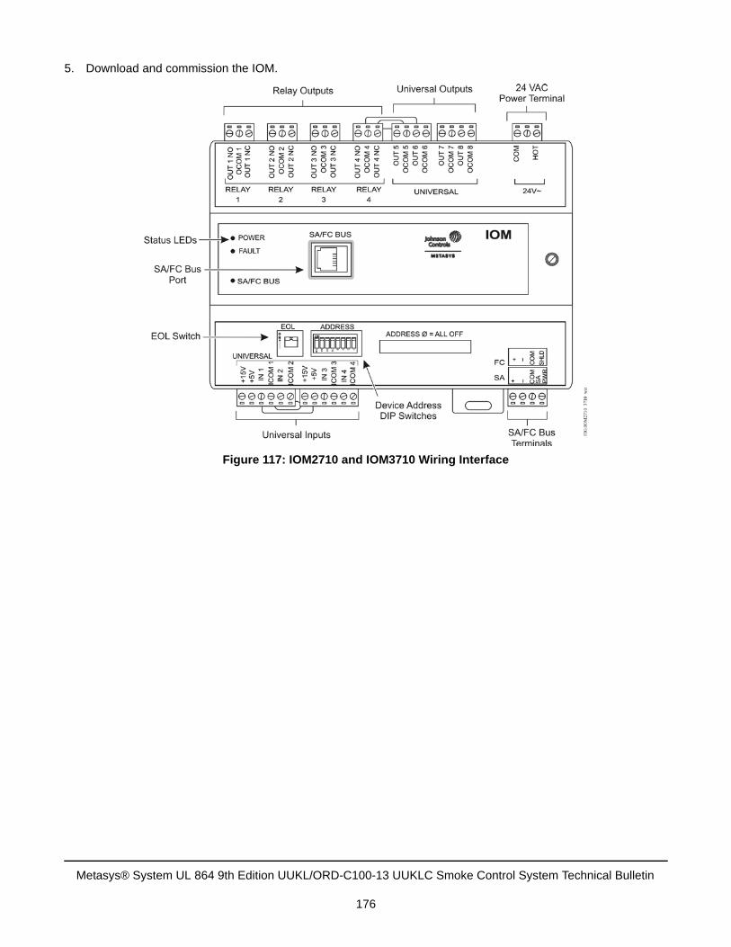
5. Download and commission the IOM.
Figure 117: IOM2710 and IOM3710 Wiring Interface
Metasys® System UL 864 9th Edition UUKL/ORD-C100-13 UUKLC Smoke Control System Technical Bulletin
176
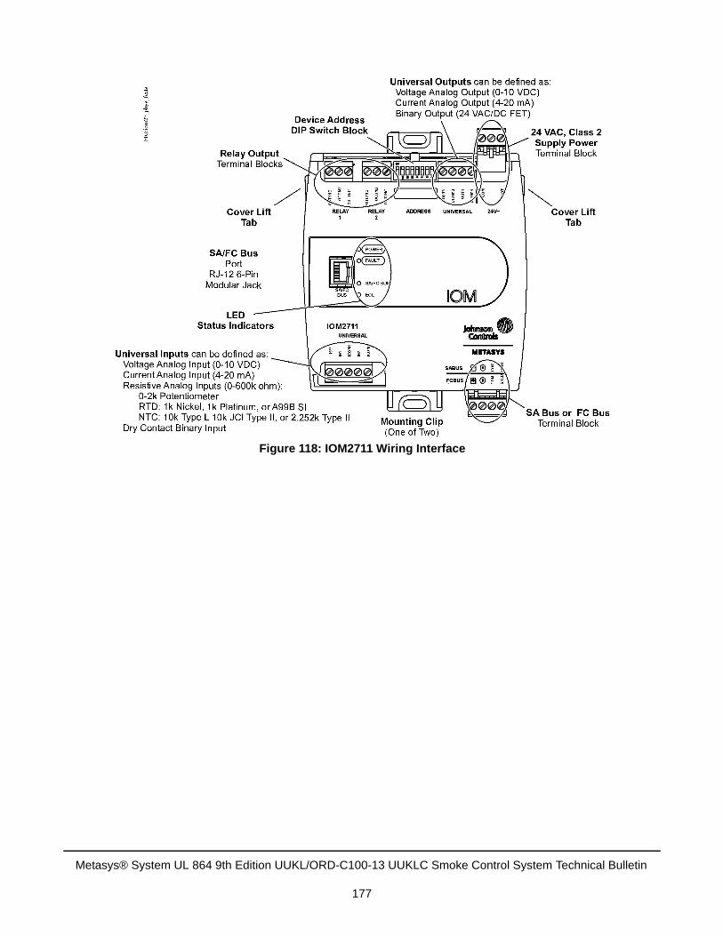
Figure 118: IOM2711 Wiring Interface
Metasys® System UL 864 9th Edition UUKL/ORD-C100-13 UUKLC Smoke Control System Technical Bulletin
177
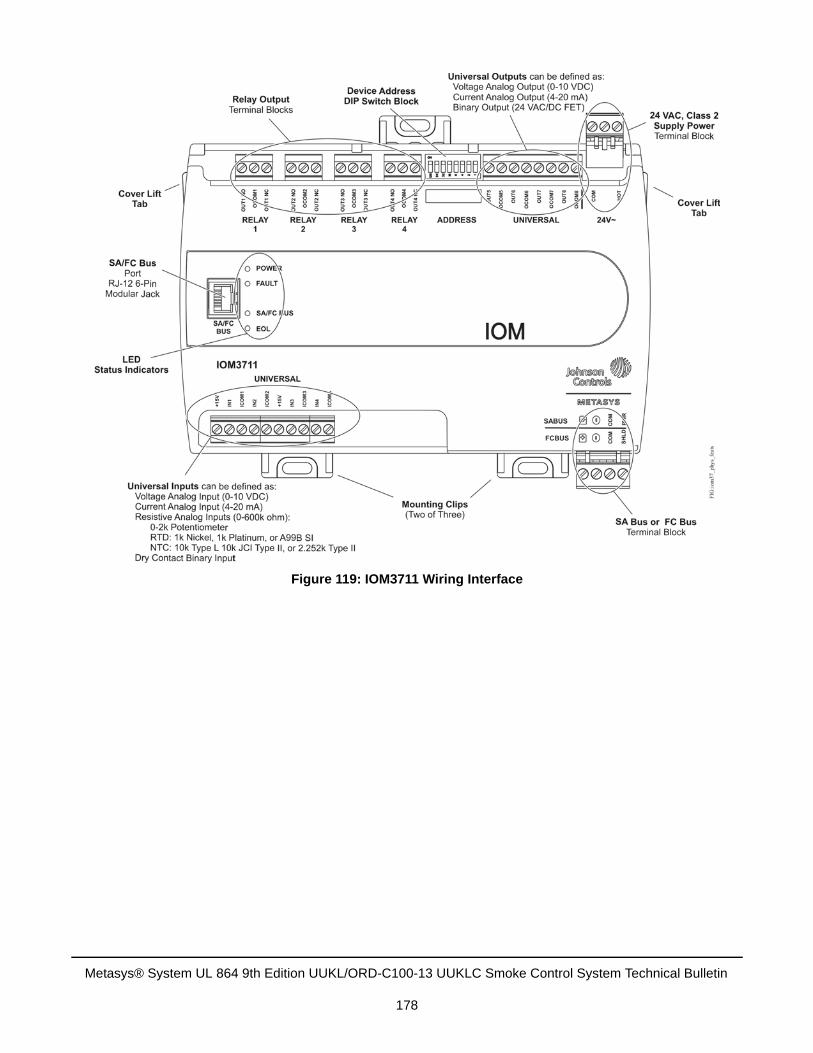
Figure 119: IOM3711 Wiring Interface
Metasys® System UL 864 9th Edition UUKL/ORD-C100-13 UUKLC Smoke Control System Technical Bulletin
178
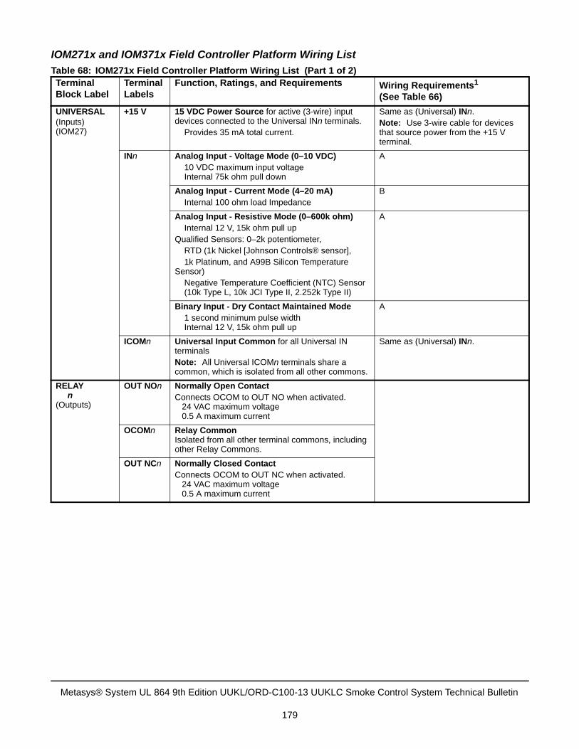
IOM271x and IOM371x Field Controller Platform Wiring List
Table 68: IOM271x Field Controller Platform Wiring List (Part 1 of 2)Terminal Block Label
Terminal Labels
Function, Ratings, and Requirements Wiring Requirements1
(See Table 66)
UNIVERSAL(Inputs)(IOM27)
+15 V 15 VDC Power Source for active (3-wire) input devices connected to the Universal INn terminals. Provides 35 mA total current.
Same as (Universal) INn.Note: Use 3-wire cable for devices that source power from the +15 V terminal.
INn Analog Input - Voltage Mode (0–10 VDC) 10 VDC maximum input voltage Internal 75k ohm pull down
A
Analog Input - Current Mode (4–20 mA) Internal 100 ohm load Impedance
B
Analog Input - Resistive Mode (0–600k ohm) Internal 12 V, 15k ohm pull upQualified Sensors: 0–2k potentiometer, RTD (1k Nickel [Johnson Controls® sensor],
1k Platinum, and A99B Silicon Temperature Sensor) Negative Temperature Coefficient (NTC) Sensor (10k Type L, 10k JCI Type II, 2.252k Type II)
A
Binary Input - Dry Contact Maintained Mode 1 second minimum pulse width Internal 12 V, 15k ohm pull up
A
ICOMn Universal Input Common for all Universal IN terminals Note: All Universal ICOMn terminals share a common, which is isolated from all other commons.
Same as (Universal) INn.
RELAY n
(Outputs)
OUT NOn Normally Open ContactConnects OCOM to OUT NO when activated. 24 VAC maximum voltage 0.5 A maximum current
OCOMn Relay Common Isolated from all other terminal commons, including other Relay Commons.
OUT NCn Normally Closed ContactConnects OCOM to OUT NC when activated. 24 VAC maximum voltage 0.5 A maximum current
Metasys® System UL 864 9th Edition UUKL/ORD-C100-13 UUKLC Smoke Control System Technical Bulletin
179
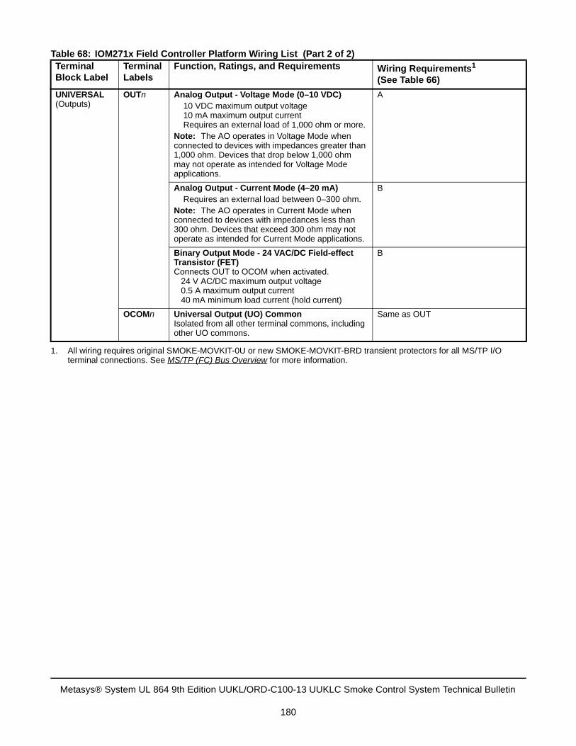
UNIVERSAL(Outputs)
OUTn Analog Output - Voltage Mode (0–10 VDC) 10 VDC maximum output voltage 10 mA maximum output current Requires an external load of 1,000 ohm or more.
Note: The AO operates in Voltage Mode when connected to devices with impedances greater than 1,000 ohm. Devices that drop below 1,000 ohm may not operate as intended for Voltage Mode applications.
A
Analog Output - Current Mode (4–20 mA) Requires an external load between 0–300 ohm.
Note: The AO operates in Current Mode when connected to devices with impedances less than 300 ohm. Devices that exceed 300 ohm may not operate as intended for Current Mode applications.
B
Binary Output Mode - 24 VAC/DC Field-effect Transistor (FET)Connects OUT to OCOM when activated. 24 V AC/DC maximum output voltage 0.5 A maximum output current 40 mA minimum load current (hold current)
B
OCOMn Universal Output (UO) Common Isolated from all other terminal commons, including other UO commons.
Same as OUT
1. All wiring requires original SMOKE-MOVKIT-0U or new SMOKE-MOVKIT-BRD transient protectors for all MS/TP I/Oterminal connections. See MS/TP (FC) Bus Overview for more information.
Table 68: IOM271x Field Controller Platform Wiring List (Part 2 of 2)Terminal Block Label
Terminal Labels
Function, Ratings, and Requirements Wiring Requirements1
(See Table 66)
Metasys® System UL 864 9th Edition UUKL/ORD-C100-13 UUKLC Smoke Control System Technical Bulletin
180
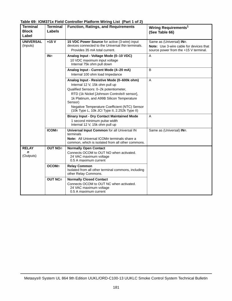
Table 69: IOM371x Field Controller Platform Wiring List (Part 1 of 2)Terminal Block Label
Terminal Labels
Function, Ratings, and Requirements Wiring Requirements1
(See Table 66)
UNIVERSAL(Inputs)
+15 V 15 VDC Power Source for active (3-wire) input devices connected to the Universal INn terminals.
Provides 35 mA total current.
Same as (Universal) INn.Note: Use 3-wire cable for devices that source power from the +15 V terminal.
INn Analog Input - Voltage Mode (0–10 VDC) 10 VDC maximum input voltage Internal 75k ohm pull down
A
Analog Input - Current Mode (4–20 mA) Internal 100 ohm load Impedance
B
Analog Input - Resistive Mode (0–600k ohm) Internal 12 V, 15k ohm pull upQualified Sensors: 0–2k potentiometer,
RTD (1k Nickel [Johnson Controls® sensor], 1k Platinum, and A99B Silicon Temperature Sensor)
Negative Temperature Coefficient (NTC) Sensor (10k Type L, 10k JCI Type II, 2.252k Type II)
A
Binary Input - Dry Contact Maintained Mode 1 second minimum pulse width Internal 12 V, 15k ohm pull up
A
ICOMn Universal Input Common for all Universal IN terminals Note: All Universal ICOMn terminals share a common, which is isolated from all other commons.
Same as (Universal) INn.
RELAY n
(Outputs)
OUT NOn Normally Open ContactConnects OCOM to OUT NO when activated. 24 VAC maximum voltage 0.5 A maximum current
OCOMn Relay Common Isolated from all other terminal commons, including other Relay Commons.
OUT NCn Normally Closed ContactConnects OCOM to OUT NC when activated. 24 VAC maximum voltage 0.5 A maximum current
Metasys® System UL 864 9th Edition UUKL/ORD-C100-13 UUKLC Smoke Control System Technical Bulletin
181

UNIVERSAL(Outputs)
OUTn Analog Output - Voltage Mode (0-10 VDC) 10 VDC maximum output voltage 10 mA maximum output current Requires an external load of 1,000 ohm or more.
Note: The AO operates in Voltage Mode when connected to devices with impedances greater than 1,000 ohm. Devices that drop below 1,000 ohm may not operate as intended for Voltage Mode applications.
A
Analog Output - Current Mode (4–20 mA) Requires an external load between 0-300 ohm.
Note: The AO operates in Current Mode when connected to devices with impedances less than 300 ohm. Devices that exceed 300 ohm may not operate as intended for Current Mode applications.
B
Binary Output Mode - 24 VAC/DC Field-Effect Transistor (FET)Connects OUT to OCOM when activated. 24 V AC/DC maximum output voltage 0.5 A maximum output current 40 mA minimum load current (hold current)
B
OCOMn Universal Output (UO) Common Isolated from all other terminal commons, including other UO commons.
Same as OUT
1. All wiring requires original SMOKE-MOVKIT-0U or new SMOKE-MOVKIT-BRD transient protectors for all MS/TP I/Oterminal connections. See MS/TP (FC) Bus Overview for more information.
Table 69: IOM371x Field Controller Platform Wiring List (Part 2 of 2)Terminal Block Label
Terminal Labels
Function, Ratings, and Requirements Wiring Requirements1
(See Table 66)
Metasys® System UL 864 9th Edition UUKL/ORD-C100-13 UUKLC Smoke Control System Technical Bulletin
182
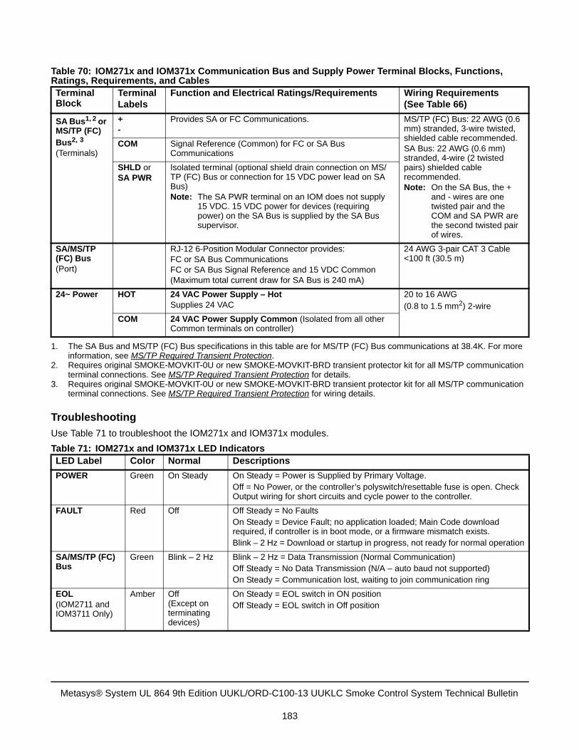
Troubleshooting
Use Table 71 to troubleshoot the IOM271x and IOM371x modules.
Table 70: IOM271x and IOM371x Communication Bus and Supply Power Terminal Blocks, Functions, Ratings, Requirements, and CablesTerminal Block
Terminal Labels
Function and Electrical Ratings/Requirements Wiring Requirements(See Table 66)
SA Bus1, 2 or MS/TP (FC) Bus2, 3
(Terminals)
1. The SA Bus and MS/TP (FC) Bus specifications in this table are for MS/TP (FC) Bus communications at 38.4K. For moreinformation, see MS/TP Required Transient Protection.
2. Requires original SMOKE-MOVKIT-0U or new SMOKE-MOVKIT-BRD transient protector kit for all MS/TP communicationterminal connections. See MS/TP Required Transient Protection for details.
3. Requires original SMOKE-MOVKIT-0U or new SMOKE-MOVKIT-BRD transient protector kit for all MS/TP communicationterminal connections. See MS/TP Required Transient Protection for wiring details.
+-
Provides SA or FC Communications. MS/TP (FC) Bus: 22 AWG (0.6 mm) stranded, 3-wire twisted, shielded cable recommended.SA Bus: 22 AWG (0.6 mm) stranded, 4-wire (2 twisted pairs) shielded cable recommended.Note: On the SA Bus, the +
and - wires are one twisted pair and the COM and SA PWR are the second twisted pair of wires.
COM Signal Reference (Common) for FC or SA Bus Communications
SHLD orSA PWR
Isolated terminal (optional shield drain connection on MS/TP (FC) Bus or connection for 15 VDC power lead on SA Bus)Note: The SA PWR terminal on an IOM does not supply
15 VDC. 15 VDC power for devices (requiring power) on the SA Bus is supplied by the SA Bus supervisor.
SA/MS/TP (FC) Bus (Port)
RJ-12 6-Position Modular Connector provides:FC or SA Bus CommunicationsFC or SA Bus Signal Reference and 15 VDC Common(Maximum total current draw for SA Bus is 240 mA)
24 AWG 3-pair CAT 3 Cable <100 ft (30.5 m)
24~ Power HOT 24 VAC Power Supply – HotSupplies 24 VAC
20 to 16 AWG(0.8 to 1.5 mm2) 2-wire
COM 24 VAC Power Supply Common (Isolated from all other Common terminals on controller)
Table 71: IOM271x and IOM371x LED IndicatorsLED Label Color Normal Descriptions
POWER Green On Steady On Steady = Power is Supplied by Primary Voltage.Off = No Power, or the controller’s polyswitch/resettable fuse is open. Check Output wiring for short circuits and cycle power to the controller.
FAULT Red Off Off Steady = No FaultsOn Steady = Device Fault; no application loaded; Main Code download required, if controller is in boot mode, or a firmware mismatch exists.Blink – 2 Hz = Download or startup in progress, not ready for normal operation
SA/MS/TP (FC) Bus
Green Blink – 2 Hz Blink – 2 Hz = Data Transmission (Normal Communication)Off Steady = No Data Transmission (N/A – auto baud not supported)On Steady = Communication lost, waiting to join communication ring
EOL(IOM2711 and IOM3711 Only)
Amber Off(Except on terminating devices)
On Steady = EOL switch in ON positionOff Steady = EOL switch in Off position
Metasys® System UL 864 9th Edition UUKL/ORD-C100-13 UUKLC Smoke Control System Technical Bulletin
183
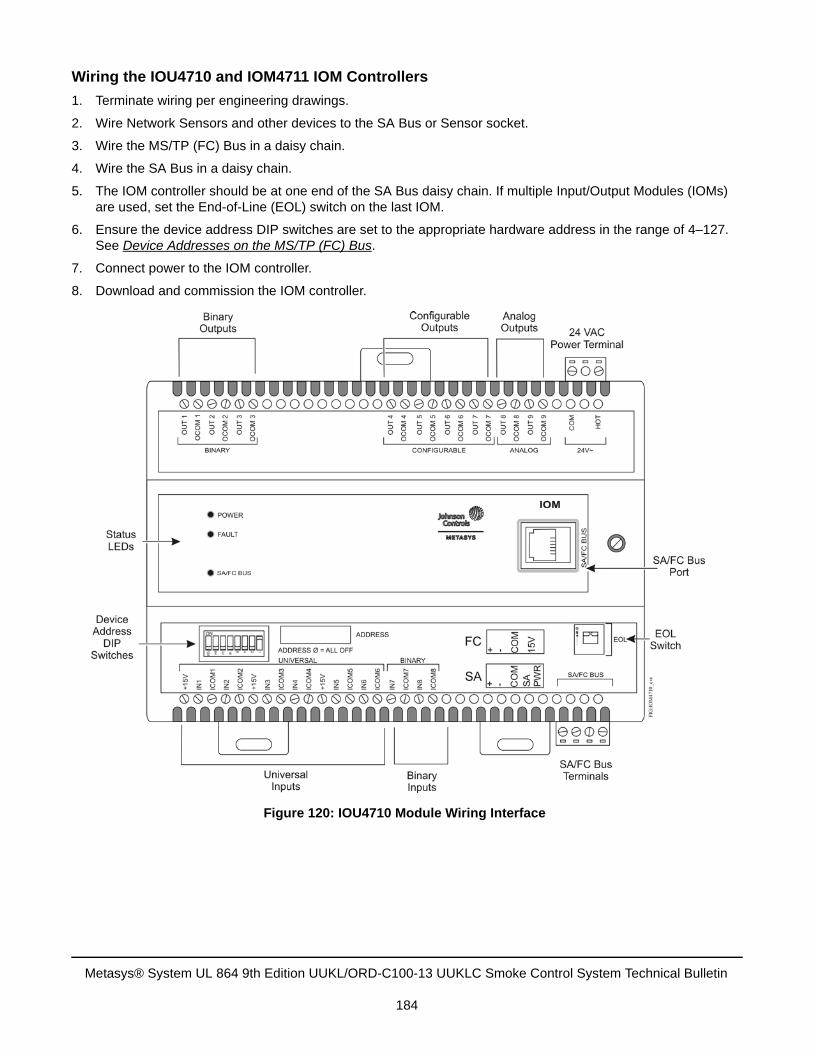
Wiring the IOU4710 and IOM4711 IOM Controllers
1. Terminate wiring per engineering drawings.
2. Wire Network Sensors and other devices to the SA Bus or Sensor socket.
3. Wire the MS/TP (FC) Bus in a daisy chain.
4. Wire the SA Bus in a daisy chain.
5. The IOM controller should be at one end of the SA Bus daisy chain. If multiple Input/Output Modules (IOMs)are used, set the End-of-Line (EOL) switch on the last IOM.
6. Ensure the device address DIP switches are set to the appropriate hardware address in the range of 4–127.See Device Addresses on the MS/TP (FC) Bus.
7. Connect power to the IOM controller.
8. Download and commission the IOM controller.
Figure 120: IOU4710 Module Wiring Interface
Metasys® System UL 864 9th Edition UUKL/ORD-C100-13 UUKLC Smoke Control System Technical Bulletin
184
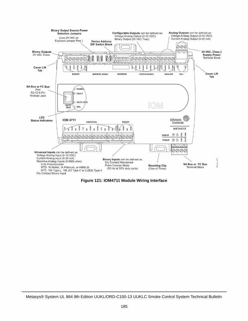
Figure 121: IOM4711 Module Wiring Interface
Metasys® System UL 864 9th Edition UUKL/ORD-C100-13 UUKLC Smoke Control System Technical Bulletin
185
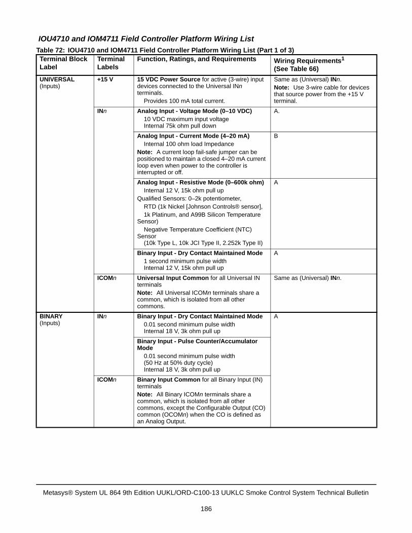
IOU4710 and IOM4711 Field Controller Platform Wiring List
Table 72: IOU4710 and IOM4711 Field Controller Platform Wiring List (Part 1 of 3)Terminal Block Label
Terminal Labels
Function, Ratings, and Requirements Wiring Requirements1
(See Table 66)
UNIVERSAL(Inputs)
+15 V 15 VDC Power Source for active (3-wire) input devices connected to the Universal INn terminals. Provides 100 mA total current.
Same as (Universal) INn.Note: Use 3-wire cable for devices that source power from the +15 V terminal.
INn Analog Input - Voltage Mode (0–10 VDC) 10 VDC maximum input voltage Internal 75k ohm pull down
A.
Analog Input - Current Mode (4–20 mA) Internal 100 ohm load Impedance
Note: A current loop fail-safe jumper can be positioned to maintain a closed 4–20 mA current loop even when power to the controller is interrupted or off.
B
Analog Input - Resistive Mode (0–600k ohm) Internal 12 V, 15k ohm pull up
Qualified Sensors: 0–2k potentiometer, RTD (1k Nickel [Johnson Controls® sensor],
1k Platinum, and A99B Silicon Temperature Sensor) Negative Temperature Coefficient (NTC) Sensor (10k Type L, 10k JCI Type II, 2.252k Type II)
A
Binary Input - Dry Contact Maintained Mode 1 second minimum pulse width Internal 12 V, 15k ohm pull up
A
ICOMn Universal Input Common for all Universal IN terminals Note: All Universal ICOMn terminals share a common, which is isolated from all other commons.
Same as (Universal) INn.
BINARY(Inputs)
INn Binary Input - Dry Contact Maintained Mode 0.01 second minimum pulse width Internal 18 V, 3k ohm pull up
A
Binary Input - Pulse Counter/Accumulator Mode
0.01 second minimum pulse width (50 Hz at 50% duty cycle) Internal 18 V, 3k ohm pull up
ICOMn Binary Input Common for all Binary Input (IN) terminals Note: All Binary ICOMn terminals share a common, which is isolated from all other commons, except the Configurable Output (CO) common (OCOMn) when the CO is defined as an Analog Output.
Metasys® System UL 864 9th Edition UUKL/ORD-C100-13 UUKLC Smoke Control System Technical Bulletin
186
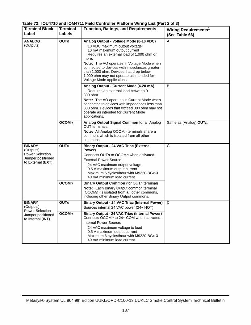
ANALOG(Outputs)
OUTn Analog Output - Voltage Mode (0-10 VDC) 10 VDC maximum output voltage 10 mA maximum output current Requires an external load of 1,000 ohm or
more.Note: The AO operates in Voltage Mode when connected to devices with impedances greater than 1,000 ohm. Devices that drop below 1,000 ohm may not operate as intended for Voltage Mode applications.
A
Analog Output - Current Mode (4-20 mA) Requires an external load between 0-300 ohm.Note: The AO operates in Current Mode when connected to devices with impedances less than 300 ohm. Devices that exceed 300 ohm may not operate as intended for Current Mode applications.
B
OCOMn Analog Output Signal Common for all Analog OUT terminals.Note: All Analog OCOMn terminals share a common, which is isolated from all other commons.
Same as (Analog) OUTn.
BINARY(Outputs) Power Selection Jumper positioned to External (EXT).
OUTn Binary Output - 24 VAC Triac (External Power)Connects OUTn to OCOMn when activated.External Power Source: 24 VAC maximum output voltage 0.5 A maximum output current Maximum 6 cycles/hour with M9220-BGx-3
40 mA minimum load current
C
OCOMn Binary Output Common (for OUTn terminal) Note: Each Binary Output common terminal (OCOMn) is isolated from all other commons, including other Binary Output commons.
BINARY(Outputs) Power Selection Jumper positioned to Internal (INT).
OUTn Binary Output - 24 VAC Triac (Internal Power)Sources internal 24 VAC power (24~ HOT)
C
OCOMn Binary Output - 24 VAC Triac (Internal Power) Connects OCOMn to 24~ COM when activated.Internal Power Source: 24 VAC maximum voltage to load 0.5 A maximum output current Maximum 6 cycles/hour with M9220-BGx-3
40 mA minimum load current
Table 72: IOU4710 and IOM4711 Field Controller Platform Wiring List (Part 2 of 3)Terminal Block Label
Terminal Labels
Function, Ratings, and Requirements Wiring Requirements1
(See Table 66)
Metasys® System UL 864 9th Edition UUKL/ORD-C100-13 UUKLC Smoke Control System Technical Bulletin
187
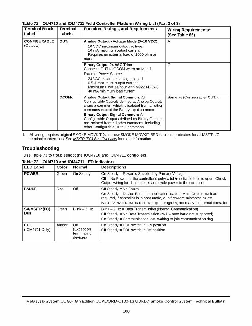
Troubleshooting
Use Table 73 to troubleshoot the IOU4710 and IOM4711 controllers.
CONFIGURABLE (Outputs)
OUTn Analog Output - Voltage Mode (0–10 VDC) 10 VDC maximum output voltage 10 mA maximum output current Requires an external load of 1000 ohm or
more
A
Binary Output 24 VAC TriacConnects OUT to OCOM when activated.External Power Source: 24 VAC maximum voltage to load 0.5 A maximum output current Maximum 6 cycles/hour with M9220-BGx-3
40 mA minimum load current
C
OCOMn Analog Output Signal Common: All Configurable Outputs defined as Analog Outputs share a common, which is isolated from all other commons except the Binary Input common.Binary Output Signal Common: All Configurable Outputs defined as Binary Outputs are isolated from all other commons, including other Configurable Output commons.
Same as (Configurable) OUTn.
1. All wiring requires original SMOKE-MOVKIT-0U or new SMOKE-MOVKIT-BRD transient protectors for all MS/TP I/Oterminal connections. See MS/TP (FC) Bus Overview for more information.
Table 73: IOU4710 and IOM4711 LED IndicatorsLED Label Color Normal Descriptions
POWER Green On Steady On Steady = Power is Supplied by Primary Voltage.Off = No Power, or the controller’s polyswitch/resettable fuse is open. Check Output wiring for short circuits and cycle power to the controller.
FAULT Red Off Off Steady = No FaultsOn Steady = Device Fault; no application loaded; Main Code download required, if controller is in boot mode, or a firmware mismatch exists.Blink – 2 Hz = Download or startup in progress, not ready for normal operation
SA/MS/TP (FC) Bus
Green Blink – 2 Hz Blink – 2 Hz = Data Transmission (Normal Communication)Off Steady = No Data Transmission (N/A – auto baud not supported)On Steady = Communication lost, waiting to join communication ring
EOL(IOM4711 Only)
Amber Off(Except on terminating devices)
On Steady = EOL switch in ON positionOff Steady = EOL switch in Off position
Table 72: IOU4710 and IOM4711 Field Controller Platform Wiring List (Part 3 of 3)Terminal Block Label
Terminal Labels
Function, Ratings, and Requirements Wiring Requirements1
(See Table 66)
Metasys® System UL 864 9th Edition UUKL/ORD-C100-13 UUKLC Smoke Control System Technical Bulletin
188
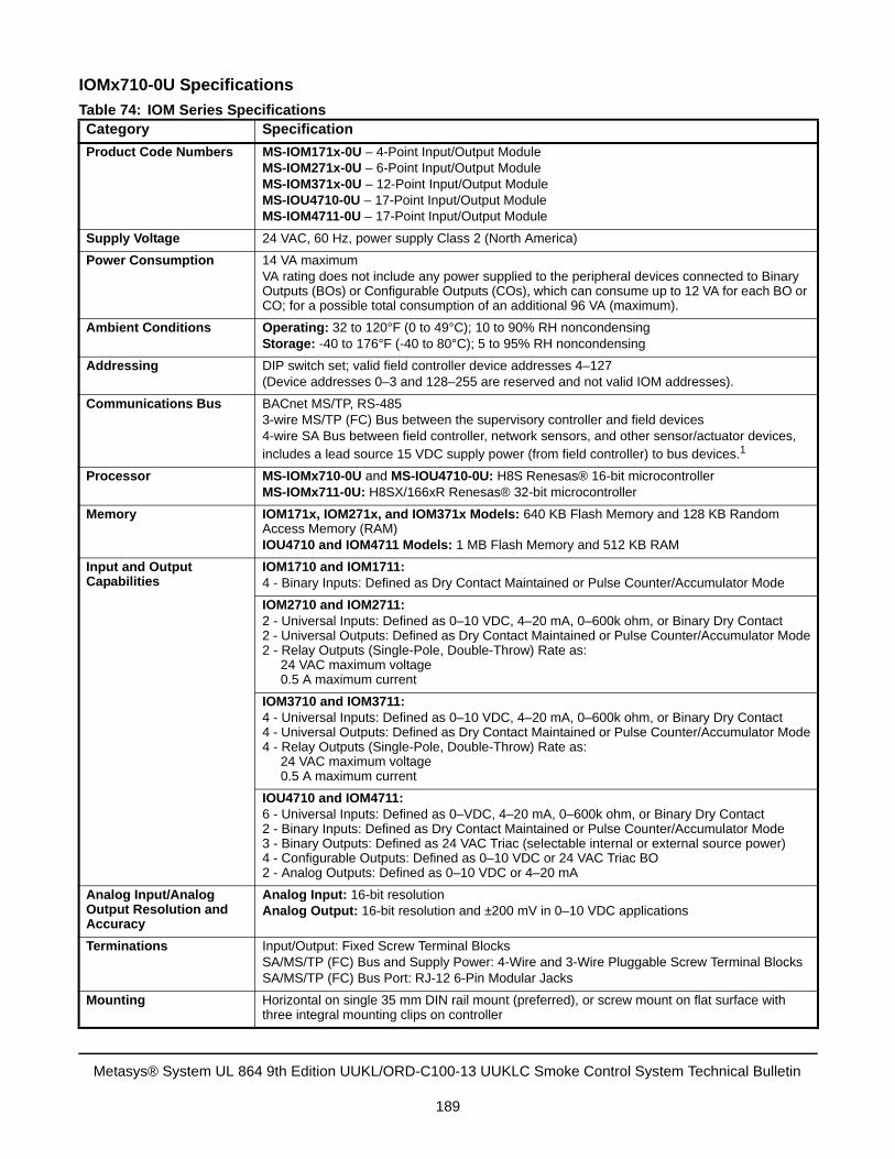
IOMx710-0U Specifications
Table 74: IOM Series SpecificationsCategory Specification
Product Code Numbers MS-IOM171x-0U – 4-Point Input/Output ModuleMS-IOM271x-0U – 6-Point Input/Output ModuleMS-IOM371x-0U – 12-Point Input/Output ModuleMS-IOU4710-0U – 17-Point Input/Output ModuleMS-IOM4711-0U – 17-Point Input/Output Module
Supply Voltage 24 VAC, 60 Hz, power supply Class 2 (North America)
Power Consumption 14 VA maximumVA rating does not include any power supplied to the peripheral devices connected to Binary Outputs (BOs) or Configurable Outputs (COs), which can consume up to 12 VA for each BO or CO; for a possible total consumption of an additional 96 VA (maximum).
Ambient Conditions Operating: 32 to 120°F (0 to 49°C); 10 to 90% RH noncondensingStorage: -40 to 176°F (-40 to 80°C); 5 to 95% RH noncondensing
Addressing DIP switch set; valid field controller device addresses 4–127(Device addresses 0–3 and 128–255 are reserved and not valid IOM addresses).
Communications Bus BACnet MS/TP, RS-4853-wire MS/TP (FC) Bus between the supervisory controller and field devices4-wire SA Bus between field controller, network sensors, and other sensor/actuator devices, includes a lead source 15 VDC supply power (from field controller) to bus devices.1
Processor MS-IOMx710-0U and MS-IOU4710-0U: H8S Renesas® 16-bit microcontrollerMS-IOMx711-0U: H8SX/166xR Renesas® 32-bit microcontroller
Memory IOM171x, IOM271x, and IOM371x Models: 640 KB Flash Memory and 128 KB Random Access Memory (RAM)IOU4710 and IOM4711 Models: 1 MB Flash Memory and 512 KB RAM
Input and Output Capabilities
IOM1710 and IOM1711:4 - Binary Inputs: Defined as Dry Contact Maintained or Pulse Counter/Accumulator Mode
IOM2710 and IOM2711:2 - Universal Inputs: Defined as 0–10 VDC, 4–20 mA, 0–600k ohm, or Binary Dry Contact2 - Universal Outputs: Defined as Dry Contact Maintained or Pulse Counter/Accumulator Mode2 - Relay Outputs (Single-Pole, Double-Throw) Rate as:
24 VAC maximum voltage 0.5 A maximum current
IOM3710 and IOM3711:4 - Universal Inputs: Defined as 0–10 VDC, 4–20 mA, 0–600k ohm, or Binary Dry Contact4 - Universal Outputs: Defined as Dry Contact Maintained or Pulse Counter/Accumulator Mode4 - Relay Outputs (Single-Pole, Double-Throw) Rate as:
24 VAC maximum voltage 0.5 A maximum current
IOU4710 and IOM4711:6 - Universal Inputs: Defined as 0–VDC, 4–20 mA, 0–600k ohm, or Binary Dry Contact2 - Binary Inputs: Defined as Dry Contact Maintained or Pulse Counter/Accumulator Mode3 - Binary Outputs: Defined as 24 VAC Triac (selectable internal or external source power)4 - Configurable Outputs: Defined as 0–10 VDC or 24 VAC Triac BO2 - Analog Outputs: Defined as 0–10 VDC or 4–20 mA
Analog Input/Analog Output Resolution and Accuracy
Analog Input: 16-bit resolutionAnalog Output: 16-bit resolution and ±200 mV in 0–10 VDC applications
Terminations Input/Output: Fixed Screw Terminal BlocksSA/MS/TP (FC) Bus and Supply Power: 4-Wire and 3-Wire Pluggable Screw Terminal BlocksSA/MS/TP (FC) Bus Port: RJ-12 6-Pin Modular Jacks
Mounting Horizontal on single 35 mm DIN rail mount (preferred), or screw mount on flat surface with three integral mounting clips on controller
Metasys® System UL 864 9th Edition UUKL/ORD-C100-13 UUKLC Smoke Control System Technical Bulletin
189
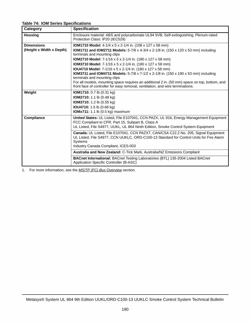
Housing Enclosure material: ABS and polycarbonate UL94 5VB; Self-extinguishing, Plenum-rated Protection Class: IP20 (IEC529)
Dimensions(Height x Width x Depth)
IOM1710 Model: 4-1/4 x 5 x 2-1/4 in. (108 x 127 x 58 mm)IOM1711 and IOM2711 Models: 5-7/8 x 4-3/4 x 2-1/8 in. (150 x 120 x 53 mm) including terminals and mounting clipsIOM2710 Model: 7-1/16 x 5 x 2-1/4 in. (180 x 127 x 58 mm)IOM3710 Model: 7-1/16 x 5 x 2-1/4 in. (180 x 127 x 58 mm)IOU4710 Model: 7-1/16 x 5 x 2-1/4 in. (180 x 127 x 58 mm)IOM3711 and IOM4711 Models: 5-7/8 x 7-1/2 x 2-1/8 in. (150 x 190 x 53 mm) including terminals and mounting clipsFor all models, mounting space requires an additional 2 in. (50 mm) space on top, bottom, and front face of controller for easy removal, ventilation, and wire terminations.
Weight IOM1710: 0.7 lb (0.31 kg)IOM2710: 1.1 lb (0.48 kg)IOM3710: 1.2 lb (0.55 kg)IOU4710: 1.5 lb (0.68 kg)IOMx711: 1.1 lb (0.5 kg) maximum
Compliance United States: UL Listed, File E107041, CCN PAZX, UL 916, Energy Management EquipmentFCC Compliant to CFR, Part 15, Subpart B, Class AUL Listed, File S4977, UUKL, UL 864 Ninth Edition, Smoke Control System Equipment
Canada: UL Listed, File E107041, CCN PAZX7, CAN/CSA C22.2 No. 205, Signal EquipmentUL Listed, File S4977, CCN UUKLC, ORD-C100-13 Standard for Control Units for Fire Alarm SystemsIndustry Canada Compliant, ICES-003
Australia and New Zealand: C-Tick Mark, Australia/NZ Emissions Compliant
BACnet International: BACnet Testing Laboratories (BTL) 135-2004 Listed BACnet Application Specific Controller (B-ASC)
1. For more information, see the MS/TP (FC) Bus Overview section.
Table 74: IOM Series SpecificationsCategory Specification
Metasys® System UL 864 9th Edition UUKL/ORD-C100-13 UUKLC Smoke Control System Technical Bulletin
190
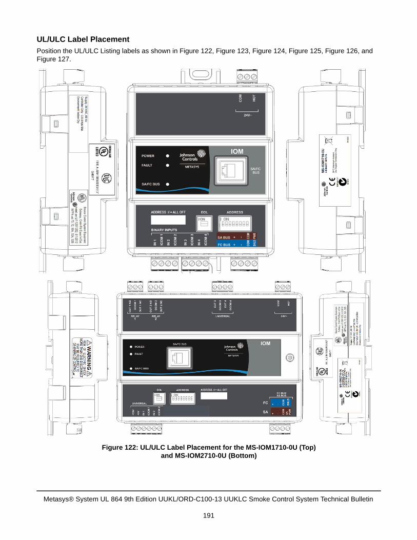
UL/ULC Label Placement
Position the UL/ULC Listing labels as shown in Figure 122, Figure 123, Figure 124, Figure 125, Figure 126, and Figure 127.
Figure 122: UL/ULC Label Placement for the MS-IOM1710-0U (Top)and MS-IOM2710-0U (Bottom)
Metasys® System UL 864 9th Edition UUKL/ORD-C100-13 UUKLC Smoke Control System Technical Bulletin
191
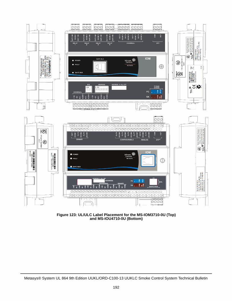
Figure 123: UL/ULC Label Placement for the MS-IOM3710-0U (Top)and MS-IOU4710-0U (Bottom)
Metasys® System UL 864 9th Edition UUKL/ORD-C100-13 UUKLC Smoke Control System Technical Bulletin
192
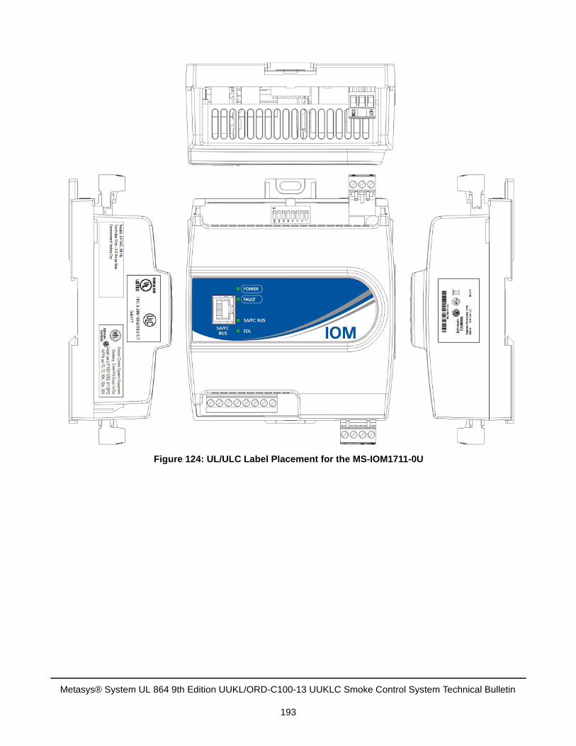
Figure 124: UL/ULC Label Placement for the MS-IOM1711-0U
Metasys® System UL 864 9th Edition UUKL/ORD-C100-13 UUKLC Smoke Control System Technical Bulletin
193
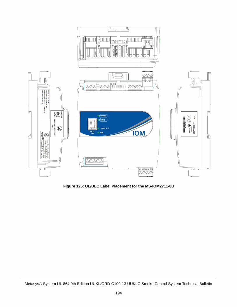
Figure 125: UL/ULC Label Placement for the MS-IOM2711-0U
Metasys® System UL 864 9th Edition UUKL/ORD-C100-13 UUKLC Smoke Control System Technical Bulletin
194
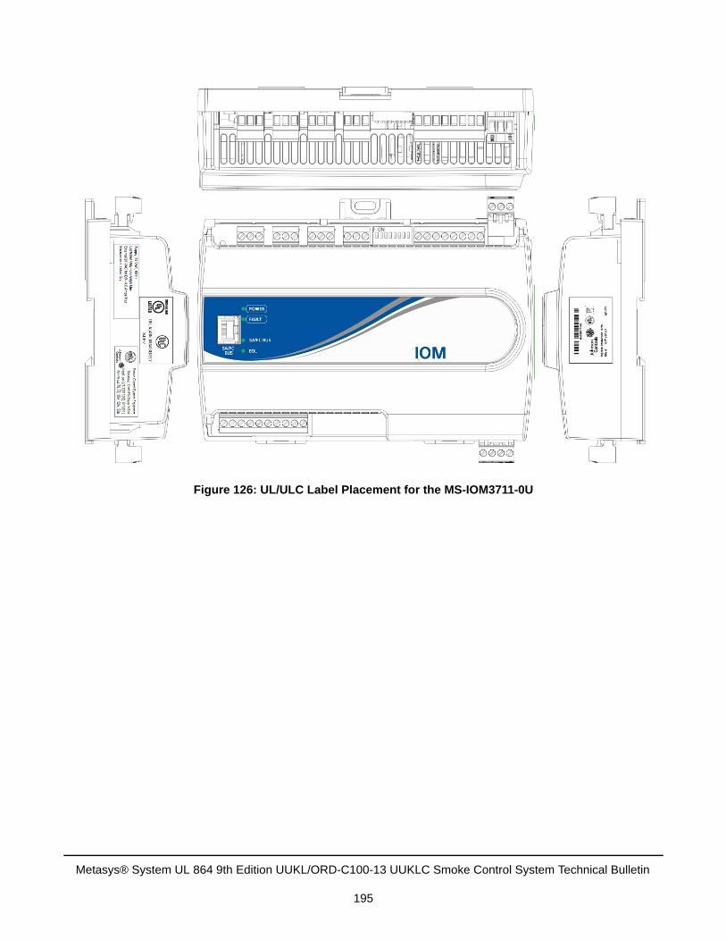
Figure 126: UL/ULC Label Placement for the MS-IOM3711-0U
Metasys® System UL 864 9th Edition UUKL/ORD-C100-13 UUKLC Smoke Control System Technical Bulletin
195
VMA16 Series ControllersThe Variable Air Volume (VAV) Modular Assembly (VMA) 16 Series controllers are programmable digital controllers that communicate over a BACnet® MS/TP field bus. Included in the VMA16 Series, the VMA1610 and VMA1620 controllers have integral air-pressure sensors and a damper actuator in a pre-wired unit. VMA16 Series controllers connect easily to the NS Series Network Sensors for zone and discharge air temperature sensing and control.
Figure 127: UL/ULC Label Placement for the MS-IOM4711-0U
Figure 128: VMA16 Series Controller
Metasys® System UL 864 9th Edition UUKL/ORD-C100-13 UUKLC Smoke Control System Technical Bulletin
196
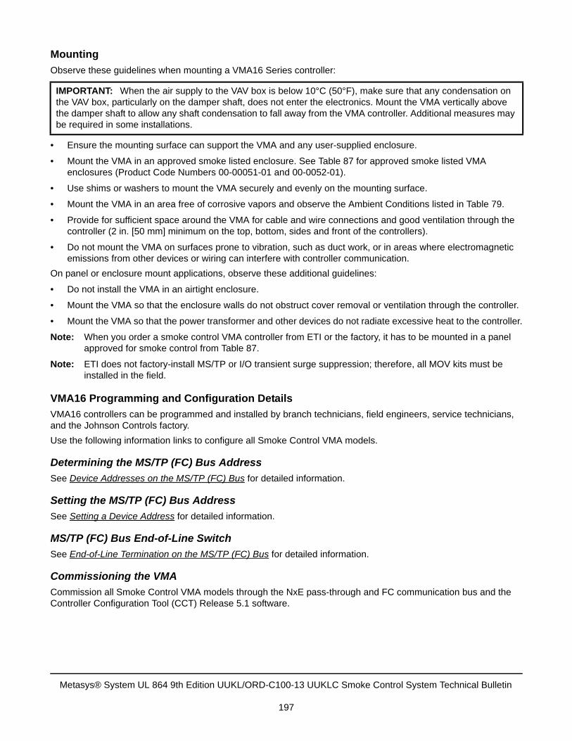
Mounting
Observe these guidelines when mounting a VMA16 Series controller:
• Ensure the mounting surface can support the VMA and any user-supplied enclosure.
• Mount the VMA in an approved smoke listed enclosure. See Table 87 for approved smoke listed VMAenclosures (Product Code Numbers 00-00051-01 and 00-0052-01).
• Use shims or washers to mount the VMA securely and evenly on the mounting surface.
• Mount the VMA in an area free of corrosive vapors and observe the Ambient Conditions listed in Table 79.
• Provide for sufficient space around the VMA for cable and wire connections and good ventilation through thecontroller (2 in. [50 mm] minimum on the top, bottom, sides and front of the controllers).
• Do not mount the VMA on surfaces prone to vibration, such as duct work, or in areas where electromagneticemissions from other devices or wiring can interfere with controller communication.
On panel or enclosure mount applications, observe these additional guidelines:
• Do not install the VMA in an airtight enclosure.
• Mount the VMA so that the enclosure walls do not obstruct cover removal or ventilation through the controller.
• Mount the VMA so that the power transformer and other devices do not radiate excessive heat to the controller.
Note: When you order a smoke control VMA controller from ETI or the factory, it has to be mounted in a panel approved for smoke control from Table 87.
Note: ETI does not factory-install MS/TP or I/O transient surge suppression; therefore, all MOV kits must be installed in the field.
VMA16 Programming and Configuration Details
VMA16 controllers can be programmed and installed by branch technicians, field engineers, service technicians, and the Johnson Controls factory.
Use the following information links to configure all Smoke Control VMA models.
Determining the MS/TP (FC) Bus Address
See Device Addresses on the MS/TP (FC) Bus for detailed information.
Setting the MS/TP (FC) Bus Address
See Setting a Device Address for detailed information.
MS/TP (FC) Bus End-of-Line Switch
See End-of-Line Termination on the MS/TP (FC) Bus for detailed information.
Commissioning the VMA
Commission all Smoke Control VMA models through the NxE pass-through and FC communication bus and the Controller Configuration Tool (CCT) Release 5.1 software.
IMPORTANT: When the air supply to the VAV box is below 10°C (50°F), make sure that any condensation on the VAV box, particularly on the damper shaft, does not enter the electronics. Mount the VMA vertically above the damper shaft to allow any shaft condensation to fall away from the VMA controller. Additional measures may be required in some installations.
Metasys® System UL 864 9th Edition UUKL/ORD-C100-13 UUKLC Smoke Control System Technical Bulletin
197
Wiring
For more information on the rules of the MS/TP Communications Bus, see the MS/TP Field Bus section in this document.
To wire the VMA:
1. Terminate wiring per engineering drawings.
2. Wire network sensors and other devices to the SA Bus or Sensor socket.
3. Wire the MS/TP (FC) Bus in a daisy chain.
4. Ensure the device address DIP switches are set to the appropriate hardware address, between 4–127.
5. Add SMK-MOVKIT-MSTP transient protector kits to all FC and SA Bus communication terminal blockconnections. See MS/TP Required Transient Protection for details.
6. Add SMOKE-MOVKIT-0U transient protectors to all MS/TP I/O terminal connections. See MS/TP RequiredTransient Protection for details
Risk of Electric Shock.Disconnect the power supply before making electrical connections to avoid electric shock.
Risk of Property Damage.Do not run network communication cables in the same conduit, raceway, or panel with any high voltage (greater than 30 VAC) wiring. Isolate all network wiring and all network devices from high-voltage wiring and equipment. Failure to isolate network wiring and network devices from high-voltage wiring and equipment can result in damage to network devices or poor network performance.
Risk of Property Damage.Do not apply power to the system before checking all wiring connections. Short circuited or improperly connected wires may result in permanent damage to the equipment.
IMPORTANT: Do not exceed the controller electrical ratings. Exceeding controller electrical ratings can result in permanent damage to the controller and void any warranty.
IMPORTANT: Use copper conductors only. Make all wiring in accordance with local, national, and regional regulations.
IMPORTANT: Electrostatic discharge can damage controller components. Use proper electrostatic discharge precautions during installation, setup, and service to avoid damaging the controller.
Metasys® System UL 864 9th Edition UUKL/ORD-C100-13 UUKLC Smoke Control System Technical Bulletin
198
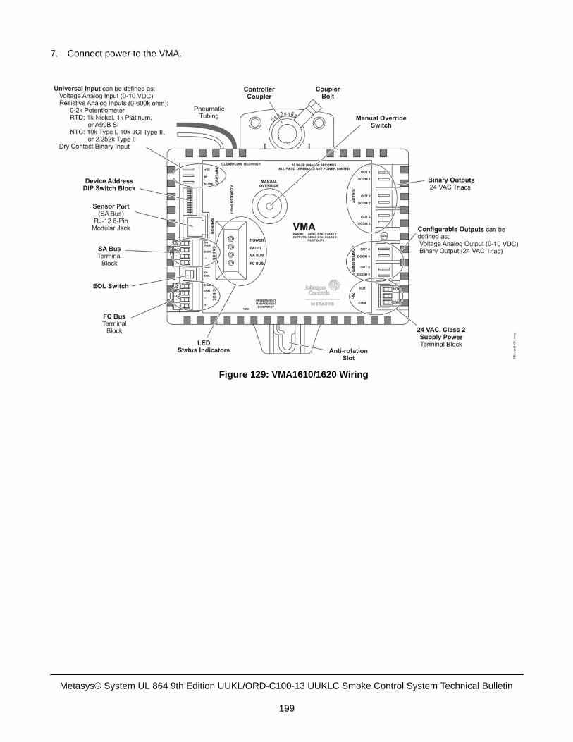
7. Connect power to the VMA.
Figure 129: VMA1610/1620 Wiring
Metasys® System UL 864 9th Edition UUKL/ORD-C100-13 UUKLC Smoke Control System Technical Bulletin
199
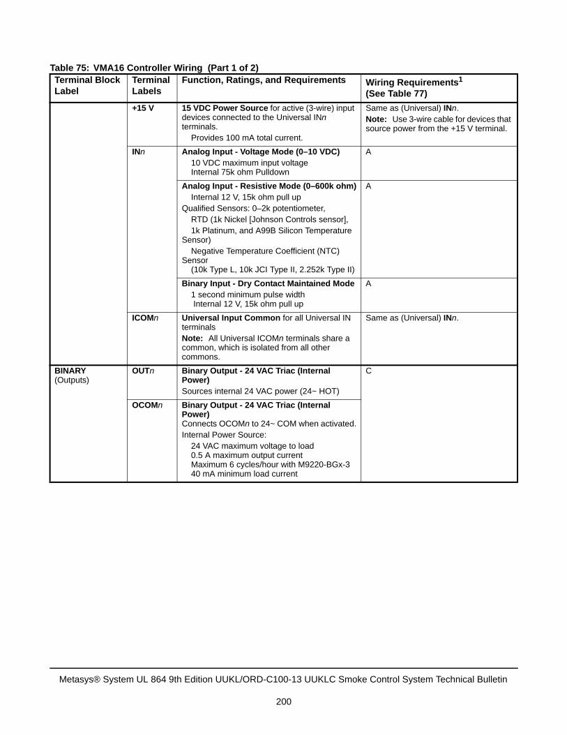
Table 75: VMA16 Controller Wiring (Part 1 of 2)Terminal Block Label
Terminal Labels
Function, Ratings, and Requirements Wiring Requirements1
(See Table 77)
+15 V 15 VDC Power Source for active (3-wire) input devices connected to the Universal INn terminals. Provides 100 mA total current.
Same as (Universal) INn.Note: Use 3-wire cable for devices that source power from the +15 V terminal.
INn Analog Input - Voltage Mode (0–10 VDC) 10 VDC maximum input voltage
Internal 75k ohm Pulldown
A
Analog Input - Resistive Mode (0–600k ohm) Internal 12 V, 15k ohm pull up
Qualified Sensors: 0–2k potentiometer, RTD (1k Nickel [Johnson Controls sensor], 1k Platinum, and A99B Silicon Temperature Sensor) Negative Temperature Coefficient (NTC) Sensor (10k Type L, 10k JCI Type II, 2.252k Type II)
A
Binary Input - Dry Contact Maintained Mode 1 second minimum pulse width Internal 12 V, 15k ohm pull up
A
ICOMn Universal Input Common for all Universal IN terminals Note: All Universal ICOMn terminals share a common, which is isolated from all other commons.
Same as (Universal) INn.
BINARY(Outputs)
OUTn Binary Output - 24 VAC Triac (Internal Power)Sources internal 24 VAC power (24~ HOT)
C
OCOMn Binary Output - 24 VAC Triac (Internal Power) Connects OCOMn to 24~ COM when activated.Internal Power Source: 24 VAC maximum voltage to load 0.5 A maximum output current Maximum 6 cycles/hour with M9220-BGx-3 40 mA minimum load current
Metasys® System UL 864 9th Edition UUKL/ORD-C100-13 UUKLC Smoke Control System Technical Bulletin
200
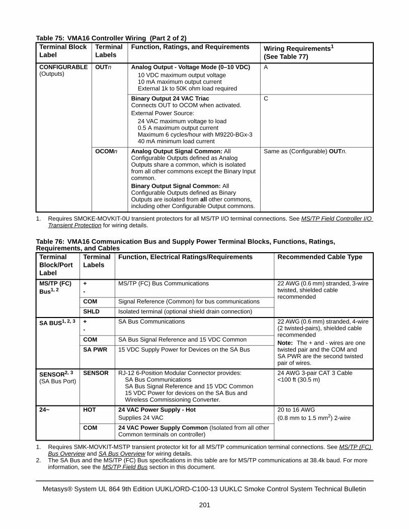
CONFIGURABLE (Outputs)
OUTn Analog Output - Voltage Mode (0–10 VDC) 10 VDC maximum output voltage
10 mA maximum output current External 1k to 50K ohm load required
A
Binary Output 24 VAC TriacConnects OUT to OCOM when activated.External Power Source: 24 VAC maximum voltage to load 0.5 A maximum output current Maximum 6 cycles/hour with M9220-BGx-3 40 mA minimum load current
C
OCOMn Analog Output Signal Common: All Configurable Outputs defined as Analog Outputs share a common, which is isolated from all other commons except the Binary Input common.Binary Output Signal Common: All Configurable Outputs defined as Binary Outputs are isolated from all other commons, including other Configurable Output commons.
Same as (Configurable) OUTn.
1. Requires SMOKE-MOVKIT-0U transient protectors for all MS/TP I/O terminal connections. See MS/TP Field Controller I/OTransient Protection for wiring details.
Table 76: VMA16 Communication Bus and Supply Power Terminal Blocks, Functions, Ratings, Requirements, and Cables Terminal Block/Port Label
Terminal Labels
Function, Electrical Ratings/Requirements Recommended Cable Type
MS/TP (FC) Bus1, 2
+-
MS/TP (FC) Bus Communications 22 AWG (0.6 mm) stranded, 3-wire twisted, shielded cable recommended
COM Signal Reference (Common) for bus communications
SHLD Isolated terminal (optional shield drain connection)
SA BUS1, 2, 3 +-
SA Bus Communications 22 AWG (0.6 mm) stranded, 4-wire (2 twisted-pairs), shielded cable recommendedNote: The + and - wires are one twisted pair and the COM and SA PWR are the second twisted pair of wires.
COM SA Bus Signal Reference and 15 VDC Common
SA PWR 15 VDC Supply Power for Devices on the SA Bus
SENSOR2, 3
(SA Bus Port)SENSOR RJ-12 6-Position Modular Connector provides:
SA Bus Communications SA Bus Signal Reference and 15 VDC Common
15 VDC Power for devices on the SA Bus and Wireless Commissioning Converter.
24 AWG 3-pair CAT 3 Cable <100 ft (30.5 m)
24~ HOT 24 VAC Power Supply - Hot Supplies 24 VAC
20 to 16 AWG(0.8 mm to 1.5 mm2) 2-wire
COM 24 VAC Power Supply Common (Isolated from all other Common terminals on controller)
1. Requires SMK-MOVKIT-MSTP transient protector kit for all MS/TP communication terminal connections. See MS/TP (FC)Bus Overview and SA Bus Overview for wiring details.
2. The SA Bus and the MS/TP (FC) Bus specifications in this table are for MS/TP communications at 38.4k baud. For moreinformation, see the MS/TP Field Bus section in this document.
Table 75: VMA16 Controller Wiring (Part 2 of 2)Terminal Block Label
Terminal Labels
Function, Ratings, and Requirements Wiring Requirements1
(See Table 77)
Metasys® System UL 864 9th Edition UUKL/ORD-C100-13 UUKLC Smoke Control System Technical Bulletin
201
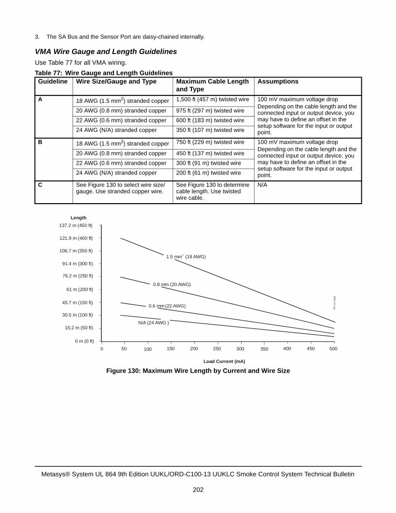
VMA Wire Gauge and Length Guidelines
Use Table 77 for all VMA wiring.
3. The SA Bus and the Sensor Port are daisy-chained internally.
Table 77: Wire Gauge and Length GuidelinesGuideline Wire Size/Gauge and Type Maximum Cable Length
and TypeAssumptions
A 18 AWG (1.5 mm2) stranded copper 1,500 ft (457 m) twisted wire 100 mV maximum voltage dropDepending on the cable length and the connected input or output device, you may have to define an offset in the setup software for the input or output point.
20 AWG (0.8 mm) stranded copper 975 ft (297 m) twisted wire
22 AWG (0.6 mm) stranded copper 600 ft (183 m) twisted wire
24 AWG (N/A) stranded copper 350 ft (107 m) twisted wire
B 18 AWG (1.5 mm2) stranded copper 750 ft (229 m) twisted wire 100 mV maximum voltage dropDepending on the cable length and the connected input or output device, you may have to define an offset in the setup software for the input or output point.
20 AWG (0.8 mm) stranded copper 450 ft (137 m) twisted wire
22 AWG (0.6 mm) stranded copper 300 ft (91 m) twisted wire
24 AWG (N/A) stranded copper 200 ft (61 m) twisted wire
C See Figure 130 to select wire size/gauge. Use stranded copper wire.
See Figure 130 to determine cable length. Use twisted wire cable.
N/A
Figure 130: Maximum Wire Length by Current and Wire Size
450 500400350300250200150100500
0 m 0 ft( )
15.2 m 50 ft( )
30.5 m 100 ft( )
45.7 m (150 ft)
61 m 200 ft( )
76.2 m 250 ft( )
91.4 m 300 ft( )
106.7 m 350 ft( )
121.9 m 400 ft( )
137.2 m 450 ft( )
Load Current (mA)
Length
FIG
:wir
_lng
th
1.5 mm (18 AWG)2
0.8 mm (20 AWG)
0.6 mm (22 AWG)
N/A (24 AWG )
Metasys® System UL 864 9th Edition UUKL/ORD-C100-13 UUKLC Smoke Control System Technical Bulletin
202
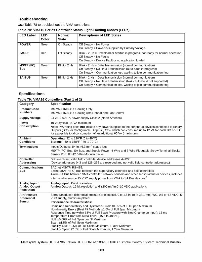
Troubleshooting
Use Table 78 to troubleshoot the VMA controllers.
Specifications
Table 78: VMA16 Series Controller Status Light-Emitting Diodes (LEDs)
LED Label LED Color
Normal State
Descriptions of LED States
POWER Green On Steady Off Steady = No PowerOn Steady = Power is supplied by Primary Voltage.
FAULT Red Off Steady Blink - 2 Hz = Download or Startup in progress, not ready for normal operationOff Steady = No FaultsOn Steady = Device Fault or no application loaded
MS/TP (FC) Bus
Green Blink - 2 Hz Blink - 2 Hz = Data Transmission (normal communication)Off Steady = No Data Transmission (auto baud in progress)On Steady = Communication lost, waiting to join communication ring
SA BUS Green Blink - 2 Hz Blink - 2 Hz = Data Transmission (normal communication)Off Steady = No Data Transmission (N/A - auto baud not supported)On Steady = Communication lost, waiting to join communication ring
Table 79: VMA16 Controllers (Part 1 of 2)Category Specification
Product Code Numbers
MS-VMA1610-xU: Cooling OnlyMS-VMA1620-xU: Cooling with Reheat and Fan Control
Supply Voltage 24 VAC, 60 Hz, power supply Class 2 (North America)
Power Consumption
10 VA typical, 14 VA maximum Note: VA rating does not include any power supplied to the peripheral devices connected to Binary Outputs (BOs) or Configurable Outputs (COs), which can consume up to 12 VA for each BO or CO; for a possible total consumption of an additional 60 VA (maximum).
Ambient Conditions
Operating: 32 to 120°F (0 to 49°C)Storage: -40 to 158°F (-40 to 70°C)
Terminations Inputs/Outputs: 1/4 in. (6.3 mm) spade lugs MS/TP (FC) Bus, SA Bus, and Supply Power: 4-Wire and 3-Wire Pluggable Screw Terminal BlocksSensor Port: RJ-12 6-Pin Modular Jacks
Controller Addressing
DIP switch set; valid field controller device addresses 4–127 (Device addresses 0–3 and 128–255 are reserved and not valid field controller addresses.)
Communications Bus
BACnet MS/TP, RS-485:3-wire MS/TP (FC) Bus between the supervisory controller and field controllers4-wire SA Bus between VMA controller, network sensors and other sensor/actuator devices, includes a terminal to source 15 VDC supply power from VMA to SA Bus devices.1
Analog Input/Analog Output Resolution
Analog Input: 15-bit resolutionAnalog Output: 16-bit resolution and ±200 mV in 0–10 VDC applications
Air Pressure DifferentialSensor
Setra transducer, differential pressure to electrical, 0 to 1.5 in. (0 to 38.1 mm) WC, 0.5 to 4.5 VDC, 5 VDC supply, aluminum plated.Performance Characteristics:Combined Repeatability and Hysteresis Error: ±0.05% of Full Span MaximumNon-linearity Errors (Best Fit Method): ±1.0% of Full Span MaximumResponse Time (to within 63% of Full Scale Pressure with Step Change on Input): 15 msTemperature Error from 60 to 120°F (15.6 to 48.9°C)Null: ±0.06% of Full Span per °F MaximumSpan: ±1.5% of Full Span MaximumStability, Null: ±0.5% of Full Scale Maximum, 1 Year MinimumStability, Span: ±2.0% of Full Scale Maximum, 1 Year Minimum
Metasys® System UL 864 9th Edition UUKL/ORD-C100-13 UUKLC Smoke Control System Technical Bulletin
203
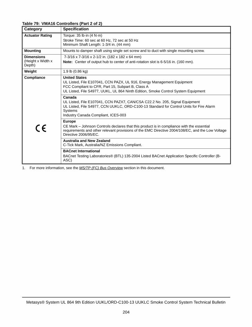
Actuator Rating Torque: 35 lb·in (4 N·m)Stroke Time: 60 sec at 60 Hz, 72 sec at 50 HzMinimum Shaft Length: 1-3/4 in. (44 mm)
Mounting Mounts to damper shaft using single set screw and to duct with single mounting screw.
Dimensions(Height x Width x Depth)
7-3/16 x 7-3/16 x 2-1/2 in. (182 x 182 x 64 mm)Note: Center of output hub to center of anti-rotation slot is 6-5/16 in. (160 mm).
Weight 1.9 lb (0.86 kg)
Compliance United StatesUL Listed, File E107041, CCN PAZX, UL 916, Energy Management EquipmentFCC Compliant to CFR, Part 15, Subpart B, Class AUL Listed, File S4977, UUKL, UL 864 Ninth Edition, Smoke Control System Equipment
CanadaUL Listed, File E107041, CCN PAZX7, CAN/CSA C22.2 No. 205, Signal EquipmentUL Listed, File S4977, CCN UUKLC, ORD-C100-13 Standard for Control Units for Fire Alarm SystemsIndustry Canada Compliant, ICES-003
EuropeCE Mark – Johnson Controls declares that this product is in compliance with the essential requirements and other relevant provisions of the EMC Directive 2004/108/EC, and the Low Voltage Directive 2006/95/EC.
Australia and New ZealandC-Tick Mark, Australia/NZ Emissions Compliant.
BACnet InternationalBACnet Testing Laboratories® (BTL) 135-2004 Listed BACnet Application Specific Controller (B-ASC)
1. For more information, see the MS/TP (FC) Bus Overview section in this document.
Table 79: VMA16 Controllers (Part 2 of 2)Category Specification
Metasys® System UL 864 9th Edition UUKL/ORD-C100-13 UUKLC Smoke Control System Technical Bulletin
204
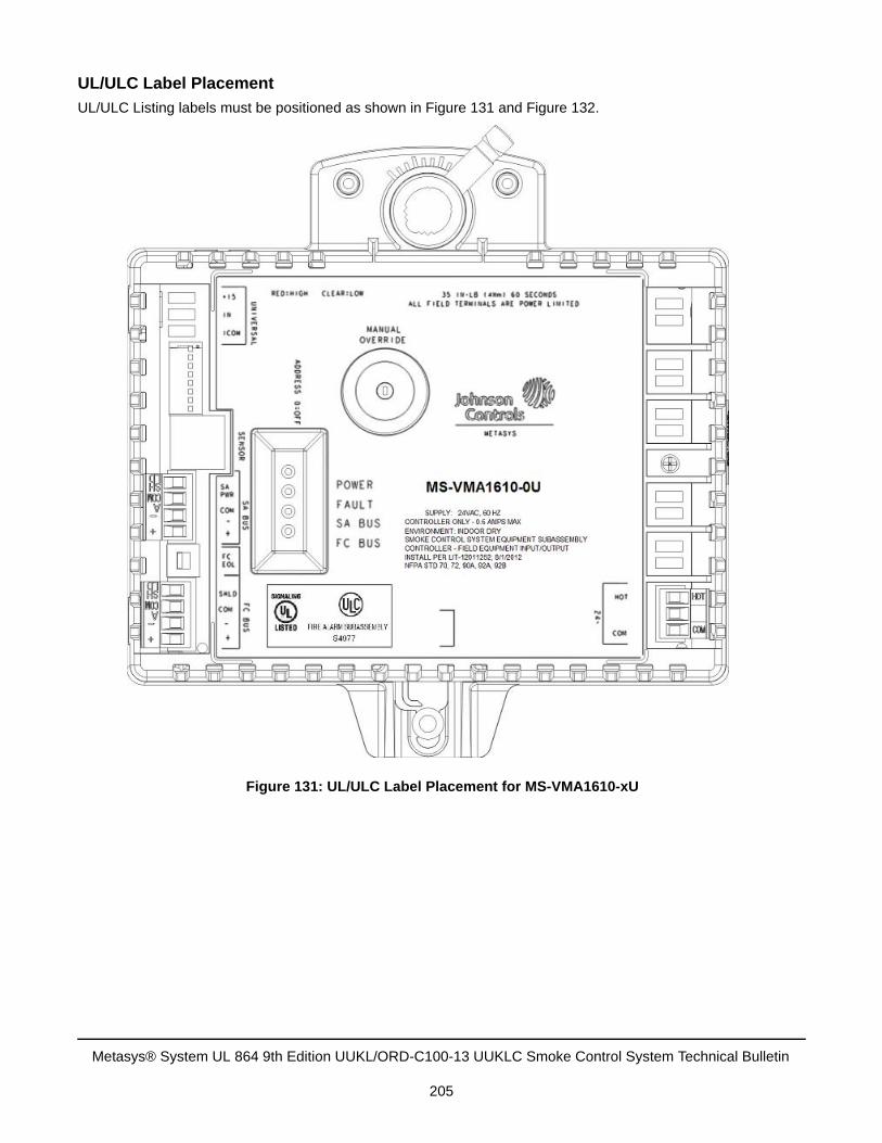
UL/ULC Label Placement
UL/ULC Listing labels must be positioned as shown in Figure 131 and Figure 132.
Figure 131: UL/ULC Label Placement for MS-VMA1610-xU
Metasys® System UL 864 9th Edition UUKL/ORD-C100-13 UUKLC Smoke Control System Technical Bulletin
205
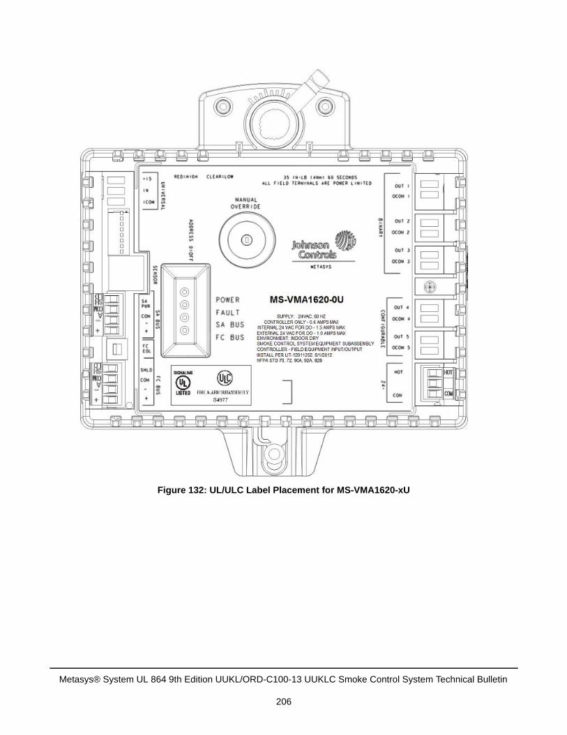
Figure 132: UL/ULC Label Placement for MS-VMA1620-xU
Metasys® System UL 864 9th Edition UUKL/ORD-C100-13 UUKLC Smoke Control System Technical Bulletin
206
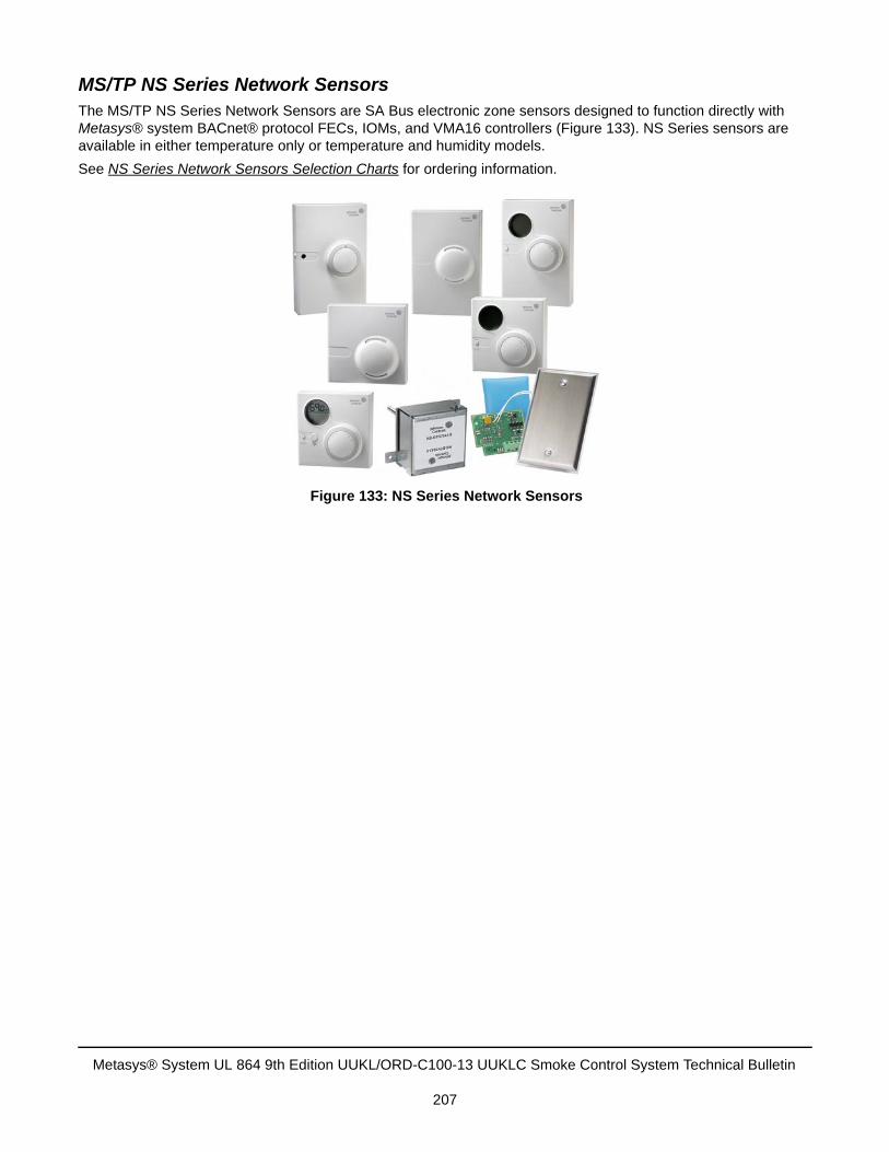
MS/TP NS Series Network SensorsThe MS/TP NS Series Network Sensors are SA Bus electronic zone sensors designed to function directly with Metasys® system BACnet® protocol FECs, IOMs, and VMA16 controllers (Figure 133). NS Series sensors are available in either temperature only or temperature and humidity models.
See NS Series Network Sensors Selection Charts for ordering information.
Figure 133: NS Series Network Sensors
Metasys® System UL 864 9th Edition UUKL/ORD-C100-13 UUKLC Smoke Control System Technical Bulletin
207
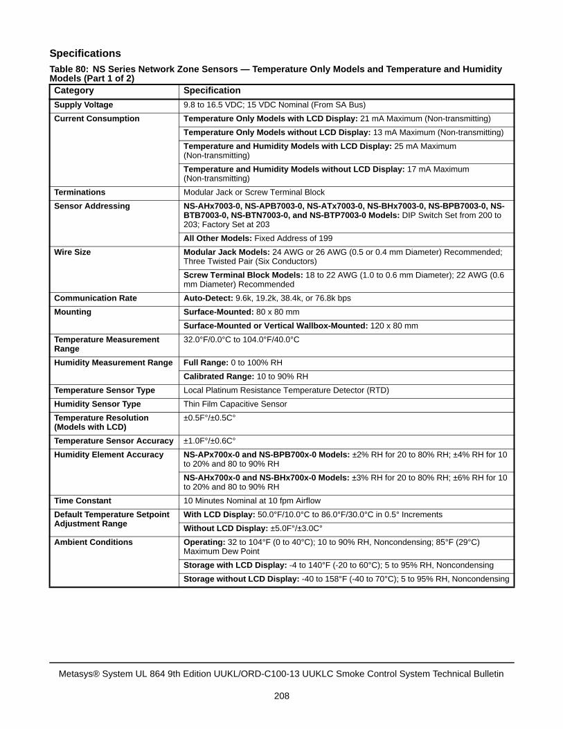
Specifications
Table 80: NS Series Network Zone Sensors — Temperature Only Models and Temperature and Humidity Models (Part 1 of 2)Category Specification
Supply Voltage 9.8 to 16.5 VDC; 15 VDC Nominal (From SA Bus)
Current Consumption Temperature Only Models with LCD Display: 21 mA Maximum (Non-transmitting)
Temperature Only Models without LCD Display: 13 mA Maximum (Non-transmitting)
Temperature and Humidity Models with LCD Display: 25 mA Maximum (Non-transmitting)
Temperature and Humidity Models without LCD Display: 17 mA Maximum (Non-transmitting)
Terminations Modular Jack or Screw Terminal Block
Sensor Addressing NS-AHx7003-0, NS-APB7003-0, NS-ATx7003-0, NS-BHx7003-0, NS-BPB7003-0, NS-BTB7003-0, NS-BTN7003-0, and NS-BTP7003-0 Models: DIP Switch Set from 200 to 203; Factory Set at 203
All Other Models: Fixed Address of 199
Wire Size Modular Jack Models: 24 AWG or 26 AWG (0.5 or 0.4 mm Diameter) Recommended; Three Twisted Pair (Six Conductors)
Screw Terminal Block Models: 18 to 22 AWG (1.0 to 0.6 mm Diameter); 22 AWG (0.6 mm Diameter) Recommended
Communication Rate Auto-Detect: 9.6k, 19.2k, 38.4k, or 76.8k bps
Mounting Surface-Mounted: 80 x 80 mm
Surface-Mounted or Vertical Wallbox-Mounted: 120 x 80 mm
Temperature Measurement Range
32.0°F/0.0°C to 104.0°F/40.0°C
Humidity Measurement Range Full Range: 0 to 100% RH
Calibrated Range: 10 to 90% RH
Temperature Sensor Type Local Platinum Resistance Temperature Detector (RTD)
Humidity Sensor Type Thin Film Capacitive Sensor
Temperature Resolution (Models with LCD)
±0.5F°/±0.5C°
Temperature Sensor Accuracy ±1.0F°/±0.6C°
Humidity Element Accuracy NS-APx700x-0 and NS-BPB700x-0 Models: ±2% RH for 20 to 80% RH; ±4% RH for 10 to 20% and 80 to 90% RH
NS-AHx700x-0 and NS-BHx700x-0 Models: ±3% RH for 20 to 80% RH; ±6% RH for 10 to 20% and 80 to 90% RH
Time Constant 10 Minutes Nominal at 10 fpm Airflow
Default Temperature Setpoint Adjustment Range
With LCD Display: 50.0°F/10.0°C to 86.0°F/30.0°C in 0.5° Increments
Without LCD Display: ±5.0F°/±3.0C°
Ambient Conditions Operating: 32 to 104°F (0 to 40°C); 10 to 90% RH, Noncondensing; 85°F (29°C) Maximum Dew Point
Storage with LCD Display: -4 to 140°F (-20 to 60°C); 5 to 95% RH, Noncondensing
Storage without LCD Display: -40 to 158°F (-40 to 70°C); 5 to 95% RH, Noncondensing
Metasys® System UL 864 9th Edition UUKL/ORD-C100-13 UUKLC Smoke Control System Technical Bulletin
208
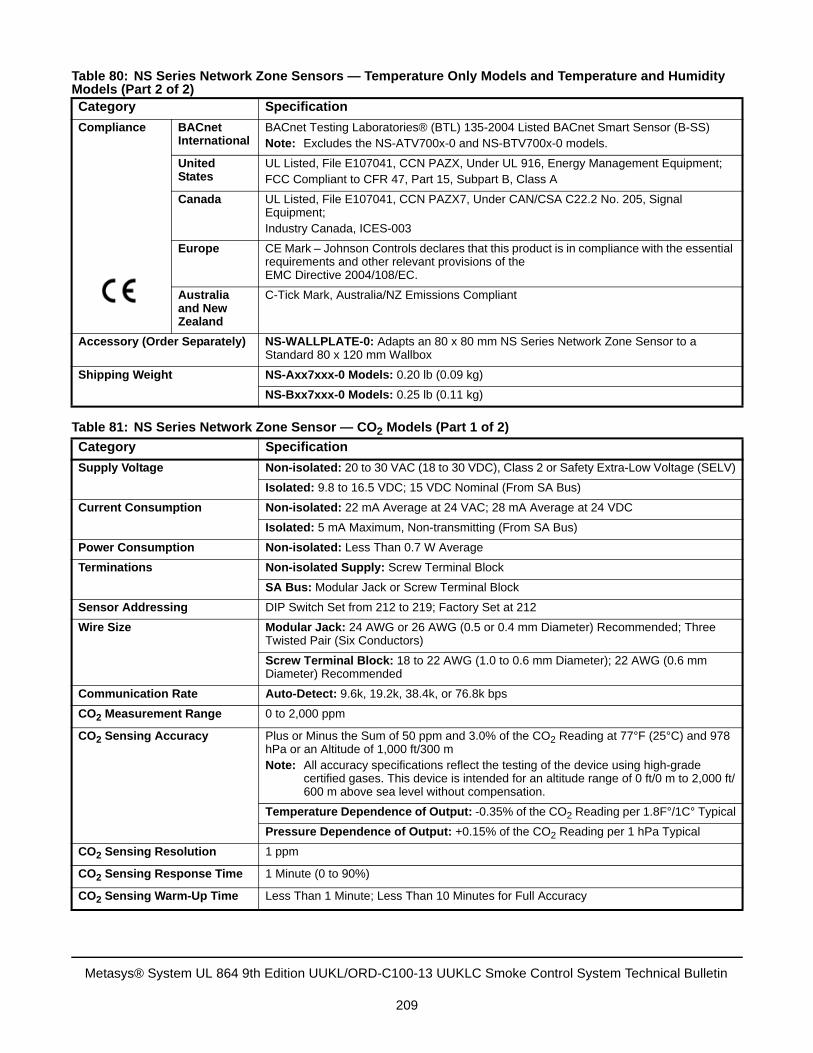
Compliance BACnet International
BACnet Testing Laboratories® (BTL) 135-2004 Listed BACnet Smart Sensor (B-SS)Note: Excludes the NS-ATV700x-0 and NS-BTV700x-0 models.
United States
UL Listed, File E107041, CCN PAZX, Under UL 916, Energy Management Equipment;FCC Compliant to CFR 47, Part 15, Subpart B, Class A
Canada UL Listed, File E107041, CCN PAZX7, Under CAN/CSA C22.2 No. 205, Signal Equipment;Industry Canada, ICES-003
Europe CE Mark – Johnson Controls declares that this product is in compliance with the essential requirements and other relevant provisions of theEMC Directive 2004/108/EC.
Australia and New Zealand
C-Tick Mark, Australia/NZ Emissions Compliant
Accessory (Order Separately) NS-WALLPLATE-0: Adapts an 80 x 80 mm NS Series Network Zone Sensor to a Standard 80 x 120 mm Wallbox
Shipping Weight NS-Axx7xxx-0 Models: 0.20 lb (0.09 kg)
NS-Bxx7xxx-0 Models: 0.25 lb (0.11 kg)
Table 81: NS Series Network Zone Sensor — CO2 Models (Part 1 of 2)
Category Specification
Supply Voltage Non-isolated: 20 to 30 VAC (18 to 30 VDC), Class 2 or Safety Extra-Low Voltage (SELV)
Isolated: 9.8 to 16.5 VDC; 15 VDC Nominal (From SA Bus)
Current Consumption Non-isolated: 22 mA Average at 24 VAC; 28 mA Average at 24 VDC
Isolated: 5 mA Maximum, Non-transmitting (From SA Bus)
Power Consumption Non-isolated: Less Than 0.7 W Average
Terminations Non-isolated Supply: Screw Terminal Block
SA Bus: Modular Jack or Screw Terminal Block
Sensor Addressing DIP Switch Set from 212 to 219; Factory Set at 212
Wire Size Modular Jack: 24 AWG or 26 AWG (0.5 or 0.4 mm Diameter) Recommended; Three Twisted Pair (Six Conductors)
Screw Terminal Block: 18 to 22 AWG (1.0 to 0.6 mm Diameter); 22 AWG (0.6 mm Diameter) Recommended
Communication Rate Auto-Detect: 9.6k, 19.2k, 38.4k, or 76.8k bps
CO2 Measurement Range 0 to 2,000 ppm
CO2 Sensing Accuracy Plus or Minus the Sum of 50 ppm and 3.0% of the CO2 Reading at 77°F (25°C) and 978 hPa or an Altitude of 1,000 ft/300 mNote: All accuracy specifications reflect the testing of the device using high-grade
certified gases. This device is intended for an altitude range of 0 ft/0 m to 2,000 ft/600 m above sea level without compensation.
Temperature Dependence of Output: -0.35% of the CO2 Reading per 1.8F°/1C° Typical
Pressure Dependence of Output: +0.15% of the CO2 Reading per 1 hPa Typical
CO2 Sensing Resolution 1 ppm
CO2 Sensing Response Time 1 Minute (0 to 90%)
CO2 Sensing Warm-Up Time Less Than 1 Minute; Less Than 10 Minutes for Full Accuracy
Table 80: NS Series Network Zone Sensors — Temperature Only Models and Temperature and Humidity Models (Part 2 of 2)Category Specification
Metasys® System UL 864 9th Edition UUKL/ORD-C100-13 UUKLC Smoke Control System Technical Bulletin
209
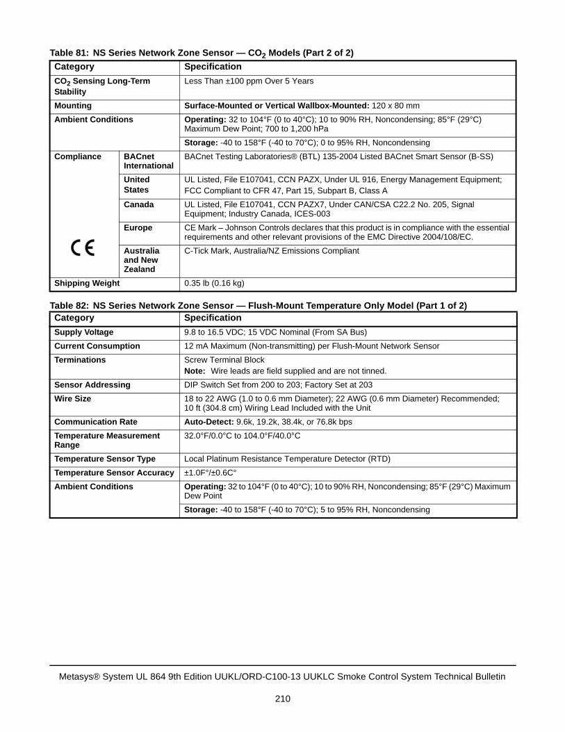
CO2 Sensing Long-Term Stability
Less Than ±100 ppm Over 5 Years
Mounting Surface-Mounted or Vertical Wallbox-Mounted: 120 x 80 mm
Ambient Conditions Operating: 32 to 104°F (0 to 40°C); 10 to 90% RH, Noncondensing; 85°F (29°C) Maximum Dew Point; 700 to 1,200 hPa
Storage: -40 to 158°F (-40 to 70°C); 0 to 95% RH, Noncondensing
Compliance BACnet International
BACnet Testing Laboratories® (BTL) 135-2004 Listed BACnet Smart Sensor (B-SS)
United States
UL Listed, File E107041, CCN PAZX, Under UL 916, Energy Management Equipment;FCC Compliant to CFR 47, Part 15, Subpart B, Class A
Canada UL Listed, File E107041, CCN PAZX7, Under CAN/CSA C22.2 No. 205, Signal Equipment; Industry Canada, ICES-003
Europe CE Mark – Johnson Controls declares that this product is in compliance with the essential requirements and other relevant provisions of the EMC Directive 2004/108/EC.
Australia and New Zealand
C-Tick Mark, Australia/NZ Emissions Compliant
Shipping Weight 0.35 lb (0.16 kg)
Table 82: NS Series Network Zone Sensor — Flush-Mount Temperature Only Model (Part 1 of 2)Category Specification
Supply Voltage 9.8 to 16.5 VDC; 15 VDC Nominal (From SA Bus)
Current Consumption 12 mA Maximum (Non-transmitting) per Flush-Mount Network Sensor
Terminations Screw Terminal BlockNote: Wire leads are field supplied and are not tinned.
Sensor Addressing DIP Switch Set from 200 to 203; Factory Set at 203
Wire Size 18 to 22 AWG (1.0 to 0.6 mm Diameter); 22 AWG (0.6 mm Diameter) Recommended;10 ft (304.8 cm) Wiring Lead Included with the Unit
Communication Rate Auto-Detect: 9.6k, 19.2k, 38.4k, or 76.8k bps
Temperature Measurement Range
32.0°F/0.0°C to 104.0°F/40.0°C
Temperature Sensor Type Local Platinum Resistance Temperature Detector (RTD)
Temperature Sensor Accuracy ±1.0F°/±0.6C°
Ambient Conditions Operating: 32 to 104°F (0 to 40°C); 10 to 90% RH, Noncondensing; 85°F (29°C) Maximum Dew Point
Storage: -40 to 158°F (-40 to 70°C); 5 to 95% RH, Noncondensing
Table 81: NS Series Network Zone Sensor — CO2 Models (Part 2 of 2)
Category Specification
Metasys® System UL 864 9th Edition UUKL/ORD-C100-13 UUKLC Smoke Control System Technical Bulletin
210
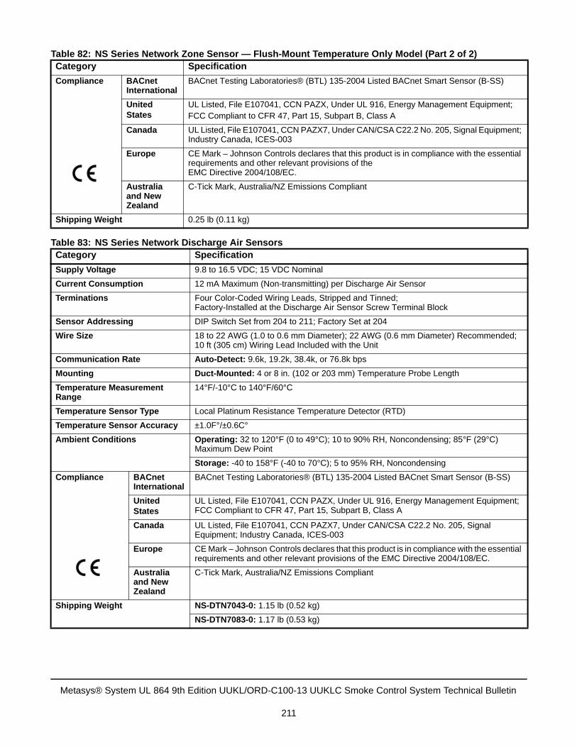
Compliance BACnet International
BACnet Testing Laboratories® (BTL) 135-2004 Listed BACnet Smart Sensor (B-SS)
United States
UL Listed, File E107041, CCN PAZX, Under UL 916, Energy Management Equipment;FCC Compliant to CFR 47, Part 15, Subpart B, Class A
Canada UL Listed, File E107041, CCN PAZX7, Under CAN/CSA C22.2 No. 205, Signal Equipment; Industry Canada, ICES-003
Europe CE Mark – Johnson Controls declares that this product is in compliance with the essential requirements and other relevant provisions of theEMC Directive 2004/108/EC.
Australia and New Zealand
C-Tick Mark, Australia/NZ Emissions Compliant
Shipping Weight 0.25 lb (0.11 kg)
Table 83: NS Series Network Discharge Air SensorsCategory Specification
Supply Voltage 9.8 to 16.5 VDC; 15 VDC Nominal
Current Consumption 12 mA Maximum (Non-transmitting) per Discharge Air Sensor
Terminations Four Color-Coded Wiring Leads, Stripped and Tinned; Factory-Installed at the Discharge Air Sensor Screw Terminal Block
Sensor Addressing DIP Switch Set from 204 to 211; Factory Set at 204
Wire Size 18 to 22 AWG (1.0 to 0.6 mm Diameter); 22 AWG (0.6 mm Diameter) Recommended;10 ft (305 cm) Wiring Lead Included with the Unit
Communication Rate Auto-Detect: 9.6k, 19.2k, 38.4k, or 76.8k bps
Mounting Duct-Mounted: 4 or 8 in. (102 or 203 mm) Temperature Probe Length
Temperature Measurement Range
14°F/-10°C to 140°F/60°C
Temperature Sensor Type Local Platinum Resistance Temperature Detector (RTD)
Temperature Sensor Accuracy ±1.0F°/±0.6C°
Ambient Conditions Operating: 32 to 120°F (0 to 49°C); 10 to 90% RH, Noncondensing; 85°F (29°C) Maximum Dew Point
Storage: -40 to 158°F (-40 to 70°C); 5 to 95% RH, Noncondensing
Compliance BACnet International
BACnet Testing Laboratories® (BTL) 135-2004 Listed BACnet Smart Sensor (B-SS)
United States
UL Listed, File E107041, CCN PAZX, Under UL 916, Energy Management Equipment;FCC Compliant to CFR 47, Part 15, Subpart B, Class A
Canada UL Listed, File E107041, CCN PAZX7, Under CAN/CSA C22.2 No. 205, Signal Equipment; Industry Canada, ICES-003
Europe CE Mark – Johnson Controls declares that this product is in compliance with the essential requirements and other relevant provisions of the EMC Directive 2004/108/EC.
Australia and New Zealand
C-Tick Mark, Australia/NZ Emissions Compliant
Shipping Weight NS-DTN7043-0: 1.15 lb (0.52 kg)
NS-DTN7083-0: 1.17 lb (0.53 kg)
Table 82: NS Series Network Zone Sensor — Flush-Mount Temperature Only Model (Part 2 of 2)Category Specification
Metasys® System UL 864 9th Edition UUKL/ORD-C100-13 UUKLC Smoke Control System Technical Bulletin
211
Smoke Control System Software
SCTThe Release 5.2 System Configuration Tool (SCT) is used in all phases of engineering, installation, and commissioning of NxEs and MS/TP (FC) Bus devices that make up the Metasys smoke control system. The SCT is used offline to create archive databases that are downloaded to a smoke control NxE. The Logic Connector Tool (LCT), contained in the SCT, was used to create the standard smoke control applications included on the Branch Purchase Package (BPP) product disc. This product disc is preloaded with the following smoke control application examples: multi-story building, warehouse, and single-story shopping mall.
The standard smoke control applications can be installed and executed on any smoke control NxE. Use the standard smoke control applications as written; any sequence modification to the LCT program must be pre-approved by the AHJ. The SCT must not be accessible to anyone other than designated qualified technicians who are responsible for installing, commissioning, and maintaining the smoke control site configuration. Password restriction in conjunction with SCT accessibility prevents unauthorized editing of the smoke control sequences.
Note: The UL 864 9th Edition UUKL/ORD-C100-13 UUKLC Smoke Control System uses the Metasys Release 5.2 version of SCT and the Release 5.1 version of CCT.
System Programming Guidelines for Smoke ControlWhen programming the system for smoke control applications, the system must conform to the following guidelines.
Follow these guidelines when defining systems and objects:
• Name all systems used for smoke control in a manner that makes identification obvious. For example, the airhandling unit serving the west wing on the third floor might be called AHU3_W and the stairwell pressurizationsystem might be called STR_PRES.
• Name all objects within a system used for smoke control in a manner that makes identification obvious. Forexample, the outdoor air damper might be called OSA_DMPR and the mixed air damper might be calledMXA_DMPR.
• Use engineering units that are appropriate to easily determine the current status of a device.
• Use the 24-character expanded ID attribute in an object definition window to provide information that ispertinent to an object’s type and location and is easily understood in an emergency situation.
Enclosures and AccessoriesEvery enclosure must be of correct metal thickness for its size, mounted, and wired in accordance with the UL/ULC Control Units and Accessories for Fire Alarm Systems specification. UL 864 9th Edition UUKL/ORD-C100-13 UUKLC Smoke Listed enclosures are built by the Johnson Controls custom panel supplier.
The Johnson Controls factory mounts NxE controllers, switches, and all other equipment in the smoke control network in a UL/ULC Listed enclosure. Refer to the installation information packaged with each product. See Table 87 for enclosure and accessory part numbers and specifications. See the Typical Panel Layouts for UL/ULC Smoke Control Listing section for additional enclosure information.
IMPORTANT: All smoke listed enclosures are ordered through Johnson Controls. Device mounting is completed at the factory. Do not field-mount or alter the mounting of any device installed in a Johnson Controls approved smoke listed enclosure.
Field-mounting or altering the mounting of any device installed in a Johnson Controls approved smoke listed enclosure voids the UL 864 9th Edition UUKL/ORD-C100-13 UUKLC listing.
Metasys® System UL 864 9th Edition UUKL/ORD-C100-13 UUKLC Smoke Control System Technical Bulletin
212
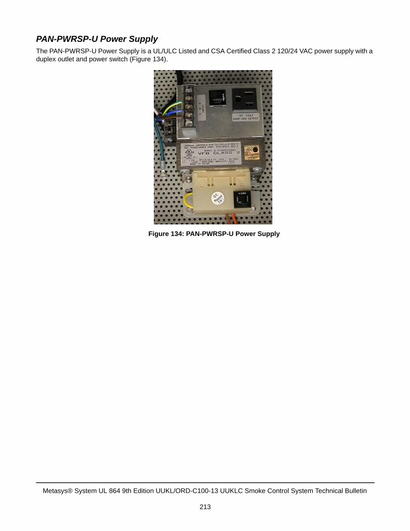
PAN-PWRSP-U Power Supply The PAN-PWRSP-U Power Supply is a UL/ULC Listed and CSA Certified Class 2 120/24 VAC power supply with a duplex outlet and power switch (Figure 134).
Figure 134: PAN-PWRSP-U Power Supply
Metasys® System UL 864 9th Edition UUKL/ORD-C100-13 UUKLC Smoke Control System Technical Bulletin
213
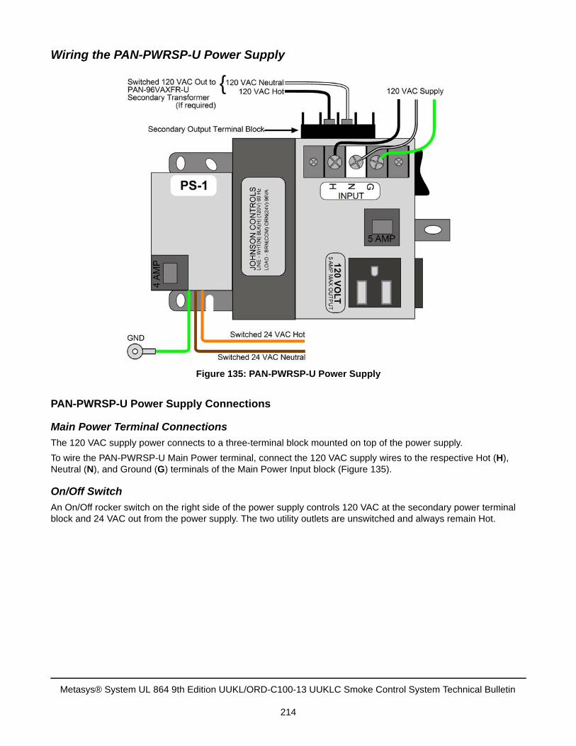
Wiring the PAN-PWRSP-U Power Supply
PAN-PWRSP-U Power Supply Connections
Main Power Terminal Connections
The 120 VAC supply power connects to a three-terminal block mounted on top of the power supply.
To wire the PAN-PWRSP-U Main Power terminal, connect the 120 VAC supply wires to the respective Hot (H), Neutral (N), and Ground (G) terminals of the Main Power Input block (Figure 135).
On/Off Switch
An On/Off rocker switch on the right side of the power supply controls 120 VAC at the secondary power terminal block and 24 VAC out from the power supply. The two utility outlets are unswitched and always remain Hot.
Figure 135: PAN-PWRSP-U Power Supply
Metasys® System UL 864 9th Edition UUKL/ORD-C100-13 UUKLC Smoke Control System Technical Bulletin
214
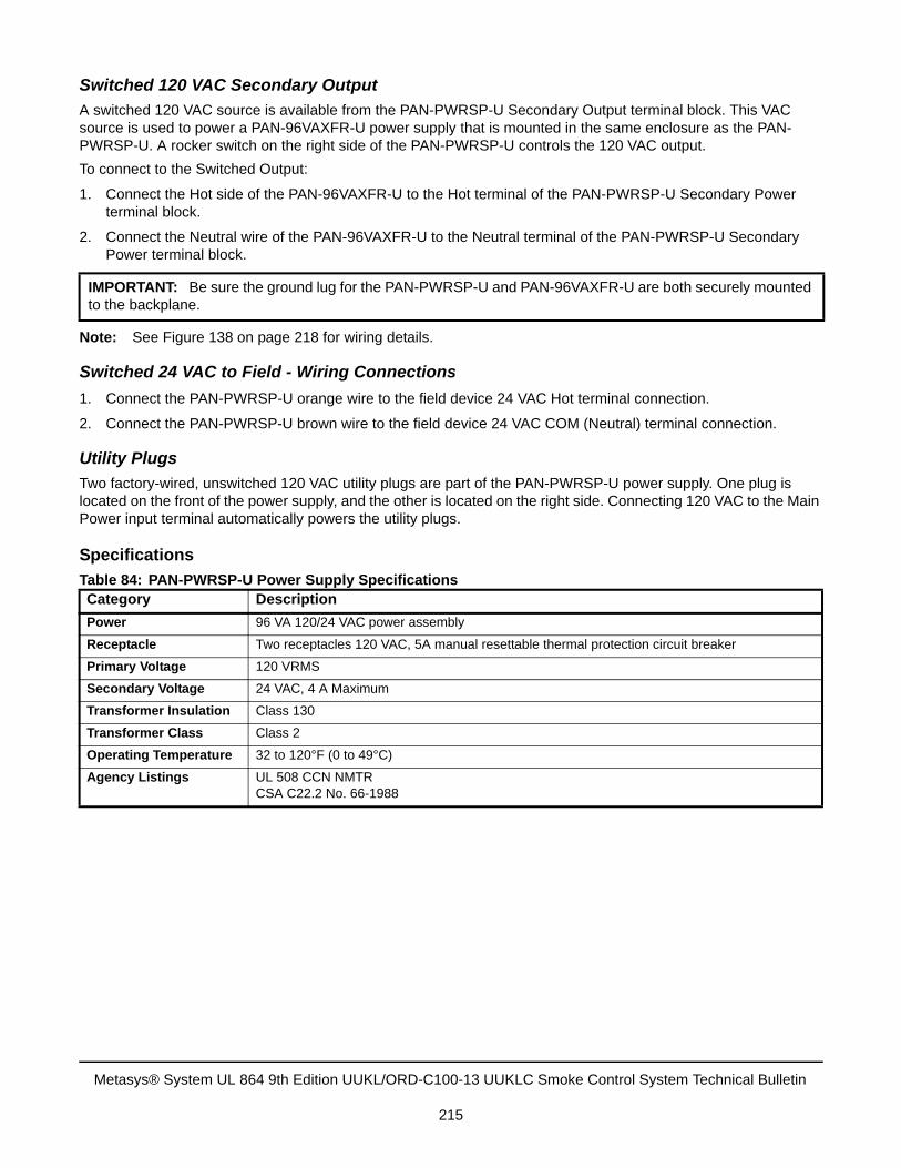
Switched 120 VAC Secondary Output
A switched 120 VAC source is available from the PAN-PWRSP-U Secondary Output terminal block. This VAC source is used to power a PAN-96VAXFR-U power supply that is mounted in the same enclosure as the PAN-PWRSP-U. A rocker switch on the right side of the PAN-PWRSP-U controls the 120 VAC output.
To connect to the Switched Output:
1. Connect the Hot side of the PAN-96VAXFR-U to the Hot terminal of the PAN-PWRSP-U Secondary Powerterminal block.
2. Connect the Neutral wire of the PAN-96VAXFR-U to the Neutral terminal of the PAN-PWRSP-U SecondaryPower terminal block.
Note: See Figure 138 on page 218 for wiring details.
Switched 24 VAC to Field - Wiring Connections
1. Connect the PAN-PWRSP-U orange wire to the field device 24 VAC Hot terminal connection.
2. Connect the PAN-PWRSP-U brown wire to the field device 24 VAC COM (Neutral) terminal connection.
Utility Plugs
Two factory-wired, unswitched 120 VAC utility plugs are part of the PAN-PWRSP-U power supply. One plug is located on the front of the power supply, and the other is located on the right side. Connecting 120 VAC to the Main Power input terminal automatically powers the utility plugs.
Specifications
IMPORTANT: Be sure the ground lug for the PAN-PWRSP-U and PAN-96VAXFR-U are both securely mounted to the backplane.
Table 84: PAN-PWRSP-U Power Supply SpecificationsCategory Description
Power 96 VA 120/24 VAC power assembly
Receptacle Two receptacles 120 VAC, 5A manual resettable thermal protection circuit breaker
Primary Voltage 120 VRMS
Secondary Voltage 24 VAC, 4 A Maximum
Transformer Insulation Class 130
Transformer Class Class 2
Operating Temperature 32 to 120°F (0 to 49°C)
Agency Listings UL 508 CCN NMTRCSA C22.2 No. 66-1988
Metasys® System UL 864 9th Edition UUKL/ORD-C100-13 UUKLC Smoke Control System Technical Bulletin
215
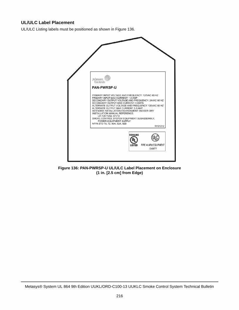
UL/ULC Label Placement
UL/ULC Listing labels must be positioned as shown in Figure 136.
Figure 136: PAN-PWRSP-U UL/ULC Label Placement on Enclosure(1 in. [2.5 cm] from Edge)
Metasys® System UL 864 9th Edition UUKL/ORD-C100-13 UUKLC Smoke Control System Technical Bulletin
216
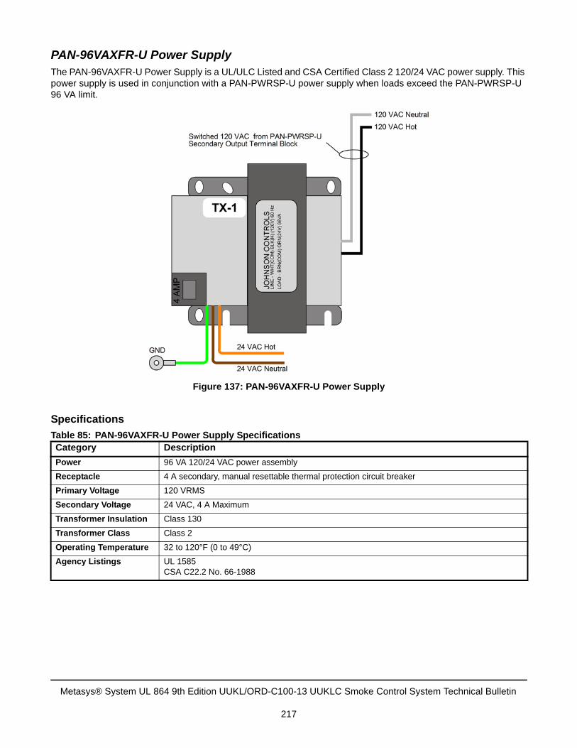
PAN-96VAXFR-U Power Supply The PAN-96VAXFR-U Power Supply is a UL/ULC Listed and CSA Certified Class 2 120/24 VAC power supply. This power supply is used in conjunction with a PAN-PWRSP-U power supply when loads exceed the PAN-PWRSP-U 96 VA limit.
Specifications
Table 85: PAN-96VAXFR-U Power Supply SpecificationsCategory Description
Power 96 VA 120/24 VAC power assembly
Receptacle 4 A secondary, manual resettable thermal protection circuit breaker
Primary Voltage 120 VRMS
Secondary Voltage 24 VAC, 4 A Maximum
Transformer Insulation Class 130
Transformer Class Class 2
Operating Temperature 32 to 120°F (0 to 49°C)
Agency Listings UL 1585CSA C22.2 No. 66-1988
Figure 137: PAN-96VAXFR-U Power Supply
Metasys® System UL 864 9th Edition UUKL/ORD-C100-13 UUKLC Smoke Control System Technical Bulletin
217
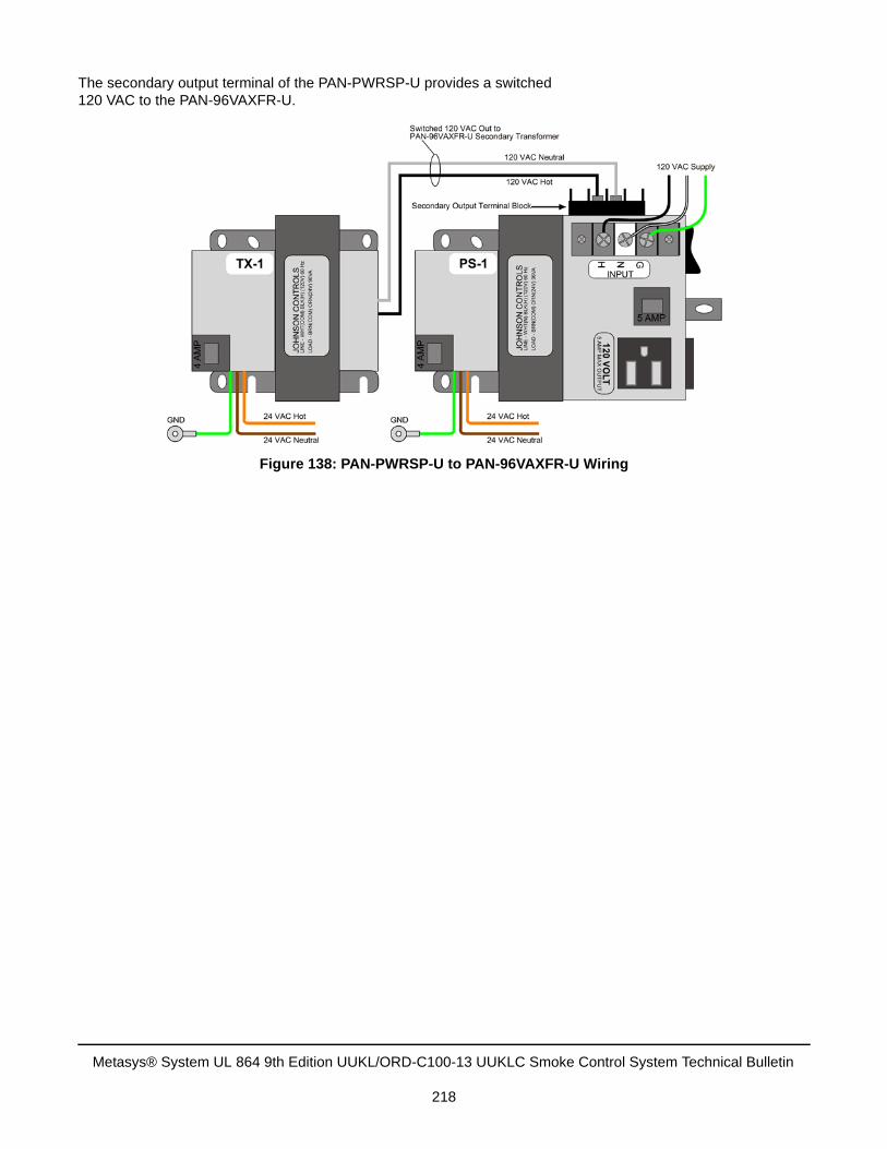
The secondary output terminal of the PAN-PWRSP-U provides a switched 120 VAC to the PAN-96VAXFR-U.
Figure 138: PAN-PWRSP-U to PAN-96VAXFR-U Wiring
Metasys® System UL 864 9th Edition UUKL/ORD-C100-13 UUKLC Smoke Control System Technical Bulletin
218
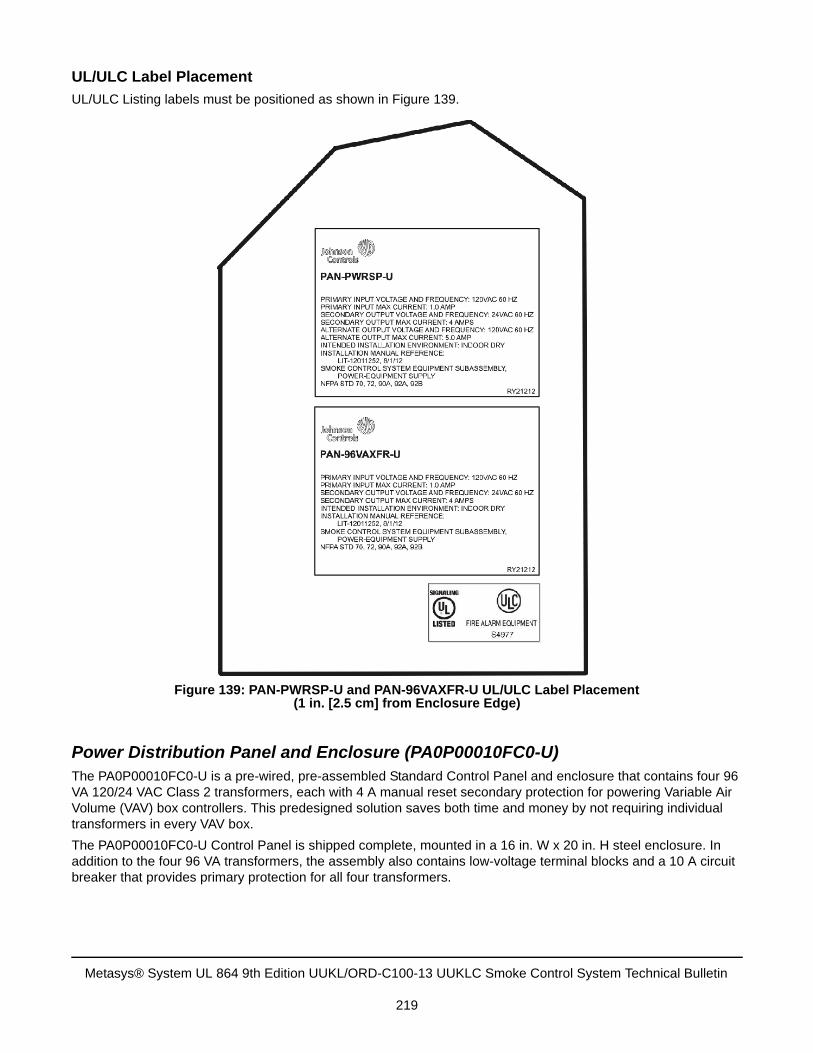
UL/ULC Label Placement
UL/ULC Listing labels must be positioned as shown in Figure 139.
Power Distribution Panel and Enclosure (PA0P00010FC0-U)The PA0P00010FC0-U is a pre-wired, pre-assembled Standard Control Panel and enclosure that contains four 96 VA 120/24 VAC Class 2 transformers, each with 4 A manual reset secondary protection for powering Variable Air Volume (VAV) box controllers. This predesigned solution saves both time and money by not requiring individual transformers in every VAV box.
The PA0P00010FC0-U Control Panel is shipped complete, mounted in a 16 in. W x 20 in. H steel enclosure. In addition to the four 96 VA transformers, the assembly also contains low-voltage terminal blocks and a 10 A circuit breaker that provides primary protection for all four transformers.
Figure 139: PAN-PWRSP-U and PAN-96VAXFR-U UL/ULC Label Placement(1 in. [2.5 cm] from Enclosure Edge)
Metasys® System UL 864 9th Edition UUKL/ORD-C100-13 UUKLC Smoke Control System Technical Bulletin
219
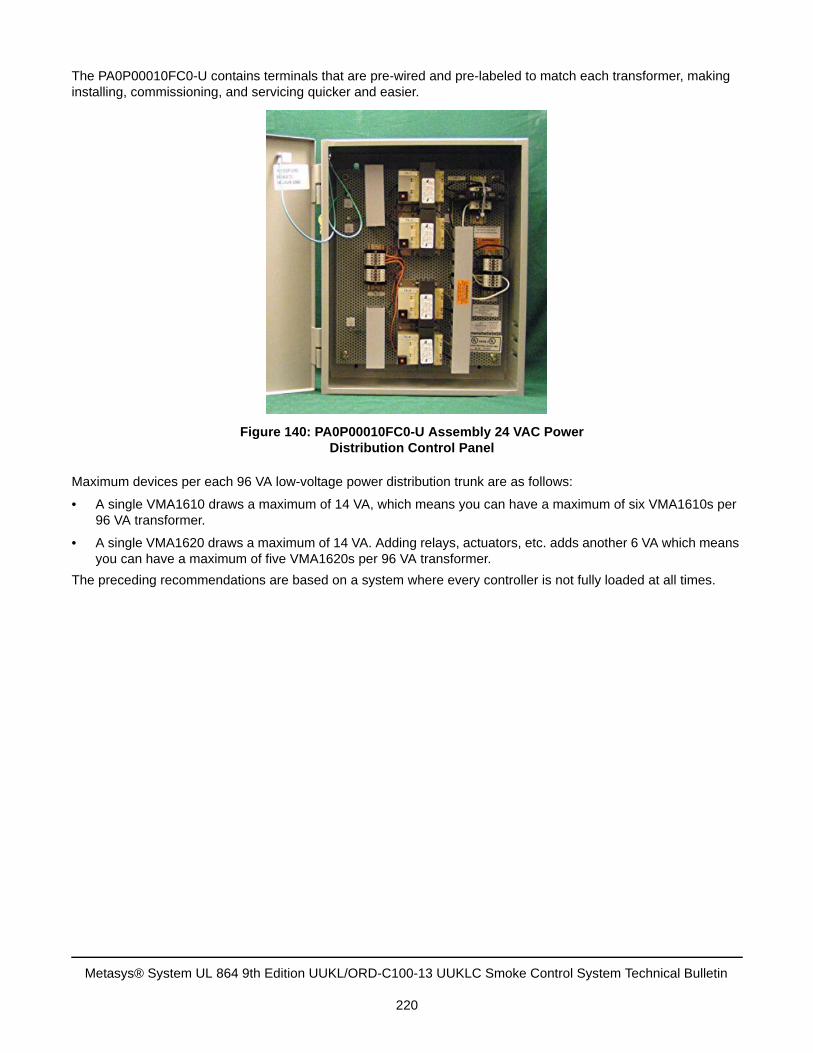
The PA0P00010FC0-U contains terminals that are pre-wired and pre-labeled to match each transformer, making installing, commissioning, and servicing quicker and easier.
Maximum devices per each 96 VA low-voltage power distribution trunk are as follows:
• A single VMA1610 draws a maximum of 14 VA, which means you can have a maximum of six VMA1610s per96 VA transformer.
• A single VMA1620 draws a maximum of 14 VA. Adding relays, actuators, etc. adds another 6 VA which meansyou can have a maximum of five VMA1620s per 96 VA transformer.
The preceding recommendations are based on a system where every controller is not fully loaded at all times.
Figure 140: PA0P00010FC0-U Assembly 24 VAC Power Distribution Control Panel
Metasys® System UL 864 9th Edition UUKL/ORD-C100-13 UUKLC Smoke Control System Technical Bulletin
220
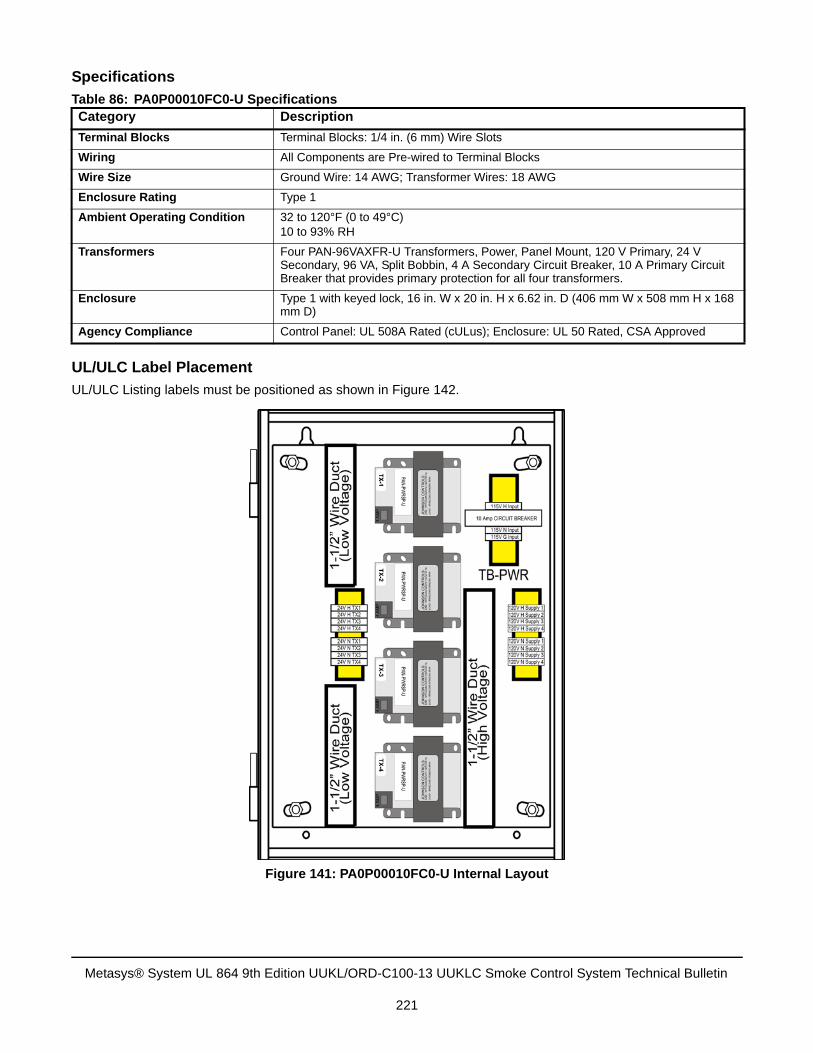
Specifications
UL/ULC Label Placement
UL/ULC Listing labels must be positioned as shown in Figure 142.
Table 86: PA0P00010FC0-U SpecificationsCategory Description
Terminal Blocks Terminal Blocks: 1/4 in. (6 mm) Wire Slots
Wiring All Components are Pre-wired to Terminal Blocks
Wire Size Ground Wire: 14 AWG; Transformer Wires: 18 AWG
Enclosure Rating Type 1
Ambient Operating Condition 32 to 120°F (0 to 49°C)10 to 93% RH
Transformers Four PAN-96VAXFR-U Transformers, Power, Panel Mount, 120 V Primary, 24 V Secondary, 96 VA, Split Bobbin, 4 A Secondary Circuit Breaker, 10 A Primary Circuit Breaker that provides primary protection for all four transformers.
Enclosure Type 1 with keyed lock, 16 in. W x 20 in. H x 6.62 in. D (406 mm W x 508 mm H x 168 mm D)
Agency Compliance Control Panel: UL 508A Rated (cULus); Enclosure: UL 50 Rated, CSA Approved
Figure 141: PA0P00010FC0-U Internal Layout
Metasys® System UL 864 9th Edition UUKL/ORD-C100-13 UUKLC Smoke Control System Technical Bulletin
221
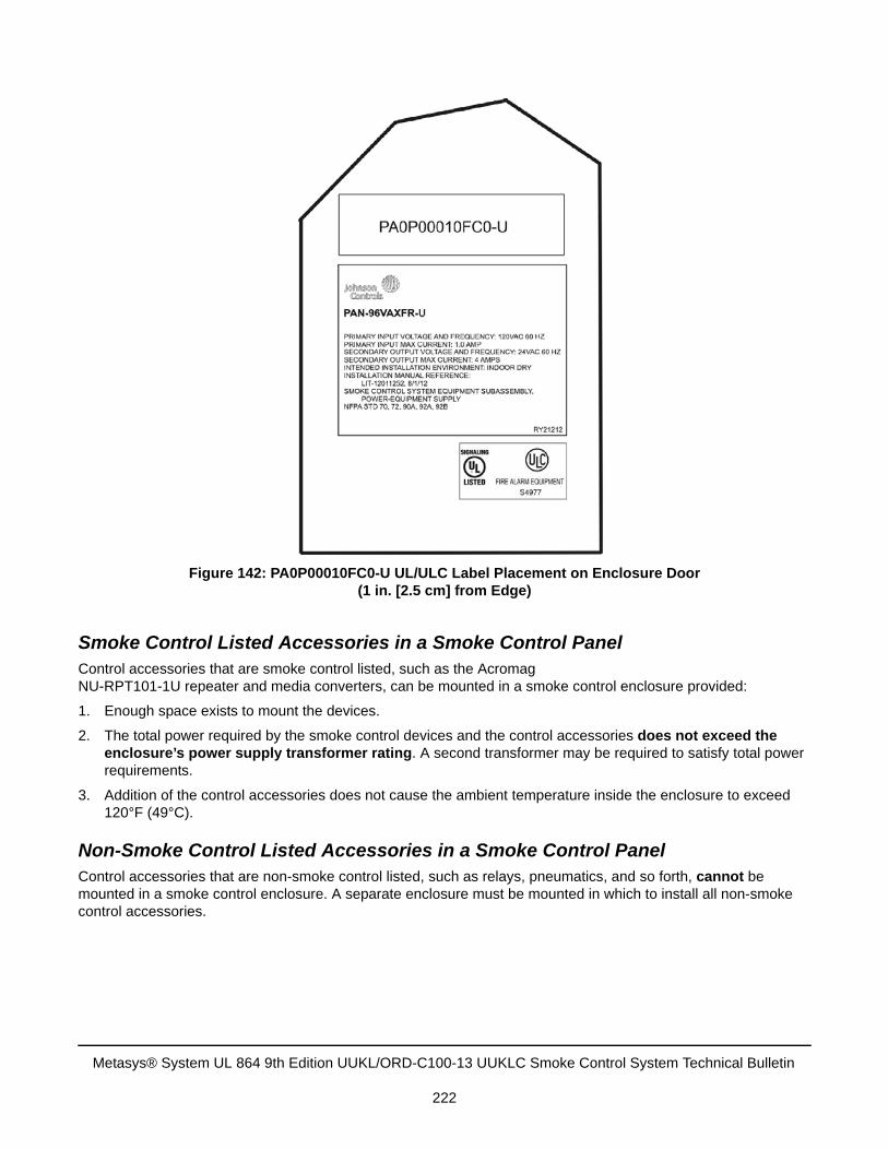
Smoke Control Listed Accessories in a Smoke Control PanelControl accessories that are smoke control listed, such as the Acromag NU-RPT101-1U repeater and media converters, can be mounted in a smoke control enclosure provided:
1. Enough space exists to mount the devices.
2. The total power required by the smoke control devices and the control accessories does not exceed theenclosure’s power supply transformer rating. A second transformer may be required to satisfy total powerrequirements.
3. Addition of the control accessories does not cause the ambient temperature inside the enclosure to exceed120°F (49°C).
Non-Smoke Control Listed Accessories in a Smoke Control PanelControl accessories that are non-smoke control listed, such as relays, pneumatics, and so forth, cannot be mounted in a smoke control enclosure. A separate enclosure must be mounted in which to install all non-smoke control accessories.
Figure 142: PA0P00010FC0-U UL/ULC Label Placement on Enclosure Door(1 in. [2.5 cm] from Edge)
Metasys® System UL 864 9th Edition UUKL/ORD-C100-13 UUKLC Smoke Control System Technical Bulletin
222
Ordering Smoke Control EnclosuresUL 864 9th Edition UUKL/ORD-C100-13 UUKLC smoke control enclosures are available as custom or standard enclosures.
For more information on UL 864 9th Edition UUKL/ORD-C100-13 UUKLC Smoke Control Panels, refer to the Metasys System UL 864 9th Edition UUKL/ORD-C100-13 UUKLC Smoke Control System Catalog Page (LIT-1900612).
Custom Enclosures
Custom enclosures using UL 864 9th Edition UUKL/ORD-C100-13 UUKLC listed MS-NAE5510-xU, MS-NAE4510-2U, MS-NAE3510-2U, MS-NCE2560-0U, MS-FEUx610-0U, MS-FECx611-0U, MS-IOU4710-0U, and IOMx71x-0U controllers are ordered through the Johnson Controls Control Panels Web site in the Custom Panels section. Use order form 1634-a to place a custom panel order.
• Be sure to select the Smoke Control check box in the Special Conditions section of this form.
• If the local authority requires that a Union label be affixed to the panel, then select the Union Label Requiredcheck box.
Standard Enclosures
Standard enclosures are preconfigured panels built by Johnson Controls using UL 864 9th Edition UUKL/ORD-C100-13 UUKLC listed MS-NAE5510-xU, MS-NAE4510-2U, MS-NAE3510-2U, MS-NCE2560-0U, MS-FEC2611-0U, and MS-IOM4711-0U controllers and other devices. The panels are configured with MS/TP, I/O, or Ethernet transient surge suppression where applicable. Each panel comes with the appropriate software version and a factory-applied UL/ULC label. See Table 87 for a list of standard enclosure product code numbers.
VAV Box Enclosures
Custom VAV box controller enclosures using the UL 864 9th Edition UUKL/ORD-C100-13 UUKLC listed MS-VMA16x0-xU controllers are ordered from Environmental Technology, Inc. using the ETI Selection Program. To order an enclosure, contact your Johnson Controls Sales Representative. The local branch office is allowed to mount a MS-VMA16x0-xU controller in an enclosure specified in Table 87 along with MOV kits for MS/TP and I/O transient surge suppression. See Figure 143 for ETI enclosure details.
• Be sure to select the Smoke Control Electronics Enclosure check box when ordering a new VAV box unit fromETI.
• For systems that have a VAV box unit that was not manufactured by ETI, order only the Smoke ControlElectronics Enclosure from ETI. Install the enclosure on the non ETI manufactured VAV box unit to house thecontroller.
• ETI does not factory-install MS/TP or I/O transient surge suppression; therefore, all MOV kits must be installedin the field. For installation guidelines, see MS/TP Field Communication Bus and Field Controller I/O TransientProtection.
IMPORTANT: All smoke listed enclosures are ordered through Johnson Controls. Device mounting is completed at the factory. Do not field-mount or alter the mounting of any device installed in a Johnson Controls approved smoke listed enclosure.
Field-mounting or altering the mounting of any device installed in a Johnson Controls approved smoke listed enclosure voids the UL 864 9th Edition UUKL/ORD-C100-13 UUKLC listing.
IMPORTANT: Operating MS/TP (FC) Bus or I/O in the field without MOV kits installed voids the UL 864 9th Edition UUKL/ORD-C100-13 UUKLC listing.
Metasys® System UL 864 9th Edition UUKL/ORD-C100-13 UUKLC Smoke Control System Technical Bulletin
223
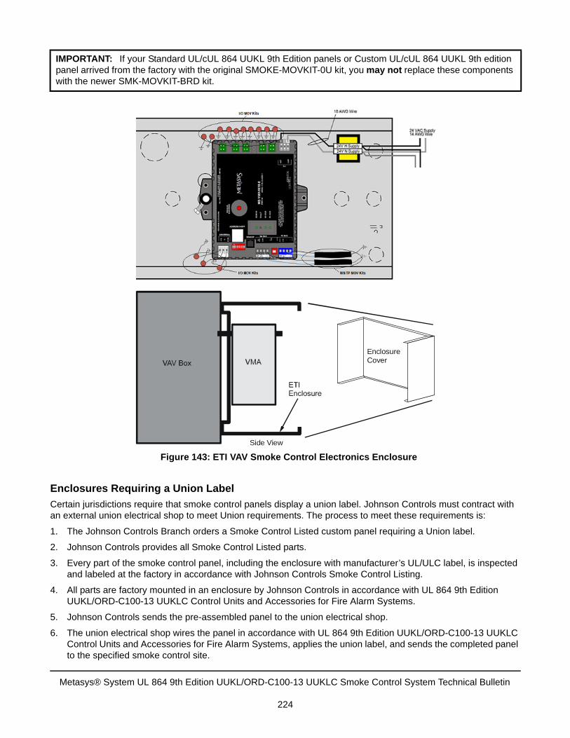
Enclosures Requiring a Union Label
Certain jurisdictions require that smoke control panels display a union label. Johnson Controls must contract with an external union electrical shop to meet Union requirements. The process to meet these requirements is:
1. The Johnson Controls Branch orders a Smoke Control Listed custom panel requiring a Union label.
2. Johnson Controls provides all Smoke Control Listed parts.
3. Every part of the smoke control panel, including the enclosure with manufacturer’s UL/ULC label, is inspectedand labeled at the factory in accordance with Johnson Controls Smoke Control Listing.
4. All parts are factory mounted in an enclosure by Johnson Controls in accordance with UL 864 9th EditionUUKL/ORD-C100-13 UUKLC Control Units and Accessories for Fire Alarm Systems.
5. Johnson Controls sends the pre-assembled panel to the union electrical shop.
6. The union electrical shop wires the panel in accordance with UL 864 9th Edition UUKL/ORD-C100-13 UUKLCControl Units and Accessories for Fire Alarm Systems, applies the union label, and sends the completed panelto the specified smoke control site.
IMPORTANT: If your Standard UL/cUL 864 UUKL 9th Edition panels or Custom UL/cUL 864 UUKL 9th edition panel arrived from the factory with the original SMOKE-MOVKIT-0U kit, you may not replace these components with the newer SMK-MOVKIT-BRD kit.
Figure 143: ETI VAV Smoke Control Electronics Enclosure
EnclosureCover
Side View
Metasys® System UL 864 9th Edition UUKL/ORD-C100-13 UUKLC Smoke Control System Technical Bulletin
224
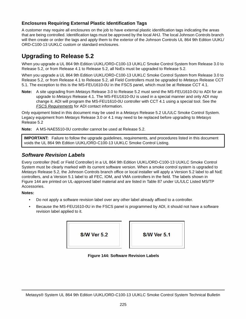
Enclosures Requiring External Plastic Identification Tags
A customer may require all enclosures on the job to have external plastic identification tags indicating the areas that are being controlled. Identification tags must be approved by the local AHJ. The local Johnson Controls branch will then create or order the tags and apply them to the exterior of the Johnson Controls UL 864 9th Edition UUKL/ORD-C100-13 UUKLC custom or standard enclosures.
Upgrading to Release 5.2When you upgrade a UL 864 9th Edition UUKL/ORD-C100-13 UUKLC Smoke Control System from Release 3.0 to Release 5.2, or from Release 4.1 to Release 5.2, all NxEs must be upgraded to Release 5.2.
When you upgrade a UL 864 9th Edition UUKL/ORD-C100-13 UUKLC Smoke Control System from Release 3.0 to Release 5.2, or from Release 4.1 to Release 5.2, all Field Controllers must be upgraded to Metasys Release CCT 5.1. The exception to this is the MS-FEU1610-0U in the FSCS panel, which must be at Release CCT 4.1.
Note: A site upgrading from Metasys Release 3.0 to Release 5.2 must send the MS-FEU1610-0U to ADI for an upgrade to Metasys Release 4.1. The MS-FEU1610-0U is used in a special manner and only ADI may change it. ADI will program the MS-FEU1610-0U controller with CCT 4.1 using a special tool. See the FSCS Requirements for ADI contact information.
Only equipment listed in this document may be used in a Metasys Release 5.2 UL/ULC Smoke Control System. Legacy equipment from Metasys Release 3.0 or 4.1 may need to be replaced before upgrading to Metasys Release 5.2
Note: A MS-NAE5510-0U controller cannot be used at Release 5.2.
Software Revision LabelsEvery controller (NxE or Field Controller) in a UL 864 9th Edition UUKL/ORD-C100-13 UUKLC Smoke Control System must be clearly marked with its current software version. When a smoke control system is upgraded to Metasys Release 5.2, the Johnson Controls branch office or local installer will apply a Version 5.2 label to all NxE controllers, and a Version 5.1 label to all FEC, IOM, and VMA controllers in the field. The labels shown in Figure 144 are printed on UL-approved label material and are listed in Table 87 under UL/ULC Listed MS/TP Accessories.
Notes:
• Do not apply a software revision label over any other label already affixed to a controller.
• Because the MS-FEU1610-0U in the FSCS panel is programmed by ADI, it should not have a softwarerevision label applied to it.
IMPORTANT: Failure to follow the upgrade guidelines, requirements, and procedures listed in this document voids the UL 864 9th Edition UUKL/ORD-C100-13 UUKLC Smoke Control Listing.
Figure 144: Software Revision Labels
Metasys® System UL 864 9th Edition UUKL/ORD-C100-13 UUKLC Smoke Control System Technical Bulletin
225
Ordering and Revision InformationTable 87 shows ordering information and revision numbers (when applicable) for all orderable UL 864 9th Edition UUKL/ORD-C100-13 UUKLC Smoke Control Parts.
General Smoke Control Ordering Requirements All Smoke Control sites must abide by the following requirements:
1. You cannot purchase a similar third-party device and install it in a UL/ULC Listed smoke control system. Doingso voids the UL/ULC Smoke Control Listing. Third-party devices must be provided and labeled by the factoryas described in the UL/ULC Smoke Control Listing.
2. A minimum of one UL 864 9th Edition UUKL/ORD-C100-13 UUKLC approved Ethernet switch is required foreach smoke control site. See Table 87 for a list of UL/ULC Listed Ethernet switches approved for use withMetasys Release 5.2.
3. A PNET1GB Ethernet transient protector is required at each end of all Ethernet communication cables. ThePNET1GB transient protector must have the strain-relief tie-wrap installed. You can use CAT5 or CAT5eEthernet cable between two PNET1GB devices.
4. All devices mounted in enclosures that have a 120 VAC power converter must have the power converterconnected to a TrippLite Isobar 8 Ultra surge suppressor mounted in the same enclosure.
5. Acromag® NU-RPT101-1U repeaters must be mounted in an enclosure and must have the 120 VAC powerconnected to a TrippLite Isobar 8 Ultra surge suppressor mounted in the same enclosure.
6. All technical guidelines for Release 5.2, including products, must be followed when upgrading from Release3.0 or 4.1.
7. When a smoke control system is upgraded to Metasys Release 5.2, a Version 5.2 revision label must beapplied to every upgraded smoke control NxE, and a Version 5.1 revision label must be applied to everyupgraded smoke control FEC, IOM, and VMA. Do not place a revision label over any other label on thecontroller.
All parts following are UL 864 9th Edition UUKL/ORD-C100-13 UUKLC listed smoke control applications.
IMPORTANT: The Johnson Controls products listed in Table 87 have been tested and listed by UL for use in a Metasys System UL 864 9th Edition UUKL/ORD-C100-13 UUKLC Smoke Control System. Installation of a product that is not UL/ULC Listed and labeled for this application prevents the entire system from being UL/ULC Listed for smoke control.
All panels must be purchased through the Johnson Controls panel factory and labeled for UL 864 9th Edition UUKL/ORD-C100-13 UUKLC.
Metasys® System UL 864 9th Edition UUKL/ORD-C100-13 UUKLC Smoke Control System Technical Bulletin
226
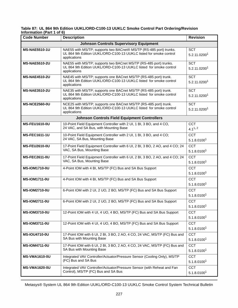
Table 87: UL 864 9th Edition UUKL/ORD-C100-13 UUKLC Smoke Control Part Ordering/Revision Information (Part 1 of 6)Code Number Description Revision
Johnson Controls Supervisory Equipment
MS-NAE5510-1U NAE55 with MS/TP; supports two BACnet® MS/TP (RS-485 port) trunks.UL 864 9th Edition UUKL/ORD-C100-13 UUKLC listed for smoke control applications
SCT
5.2.11.02001
MS-NAE5510-2U NAE55 with MS/TP; supports two BACnet MS/TP (RS-485 port) trunks.UL 864 9th Edition UUKL/ORD-C100-13 UUKLC listed for smoke control applications
SCT
5.2.11.02001
MS-NAE4510-2U NAE45 with MS/TP; supports one BACnet MS/TP (RS-485 port) trunk.UL 864 9th Edition UUKL/ORD-C100-13 UUKLC listed for smoke control applications
SCT
5.2.11.02001
MS-NAE3510-2U NAE35 with MS/TP; supports one BACnet MS/TP (RS-485 port) trunk.UL 864 9th Edition UUKL/ORD-C100-13 UUKLC listed for smoke control applications
SCT
5.2.11.02001
MS-NCE2560-0U NCE25 with MS/TP; supports one BACnet MS/TP (RS-485 port) trunk.UL 864 9th Edition UUKL/ORD-C100-13 UUKLC listed for smoke control applications
SCT
5.2.11.02001
Johnson Controls Field Equipment Controllers
MS-FEU1610-0U 10-Point Field Equipment Controller with 2 UI, 1 BI, 3 BO, and 4 CO, 24 VAC, and SA Bus, with Mounting Base
CCT
4.11, 2
MS-FEC1611-1U 10-Point Field Equipment Controller with 2 UI, 1 BI, 3 BO, and 4 CO;24 VAC, SA Bus, Mounting Base
CCT
5.1.8.01001
MS-FEU2610-0U 17-Point Field Equipment Controller with 6 UI, 2 BI, 3 BO, 2 AO, and 4 CO; 24 VAC, SA Bus, Mounting Base
CCT
5.1.8.01001
MS-FEC2611-0U 17-Point Field Equipment Controller with 6 UI, 2 BI, 3 BO, 2 AO, and 4 CO; 24 VAC, SA Bus, Mounting Base
CCT
5.1.8.01001
MS-IOM1710-0U 4-Point IOM with 4 BI, MS/TP (FC) Bus and SA Bus Support CCT
5.1.8.01001
MS-IOM1711-0U 4-Point IOM with 4 BI, MS/TP (FC) Bus and SA Bus Support CCT
5.1.8.01001
MS-IOM2710-0U 6-Point IOM with 2 UI, 2 UO, 2 BO, MS/TP (FC) Bus and SA Bus Support CCT
5.1.8.01001
MS-IOM2711-0U 6-Point IOM with 2 UI, 2 UO, 2 BO, MS/TP (FC) Bus and SA Bus Support CCT
5.1.8.01001
MS-IOM3710-0U 12-Point IOM with 4 UI, 4 UO, 4 BO, MS/TP (FC) Bus and SA Bus Support CCT
5.1.8.01001
MS-IOM3711-0U 12-Point IOM with 4 UI, 4 UO, 4 BO, MS/TP (FC) Bus and SA Bus Support CCT
5.1.8.01001
MS-IOU4710-0U 17-Point IOM with 6 UI, 2 BI, 3 BO, 2 AO, 4 CO, 24 VAC, MS/TP (FC) Bus and SA Bus with Mounting Base
CCT
5.1.8.01001
MS-IOM4711-0U 17-Point IOM with 6 UI, 2 BI, 3 BO, 2 AO, 4 CO, 24 VAC, MS/TP (FC) Bus and SA Bus with Mounting Base
CCT
5.1.8.01001
MS-VMA1610-0U Integrated VAV Controller/Actuator/Pressure Sensor (Cooling Only), MS/TP (FC) Bus and SA Bus
CCT
5.1.8.01001
MS-VMA1620-0U Integrated VAV Controller/Actuator/Pressure Sensor (with Reheat and Fan Control), MS/TP (FC) Bus and SA Bus
CCT
5.1.8.01001
Metasys® System UL 864 9th Edition UUKL/ORD-C100-13 UUKLC Smoke Control System Technical Bulletin
227
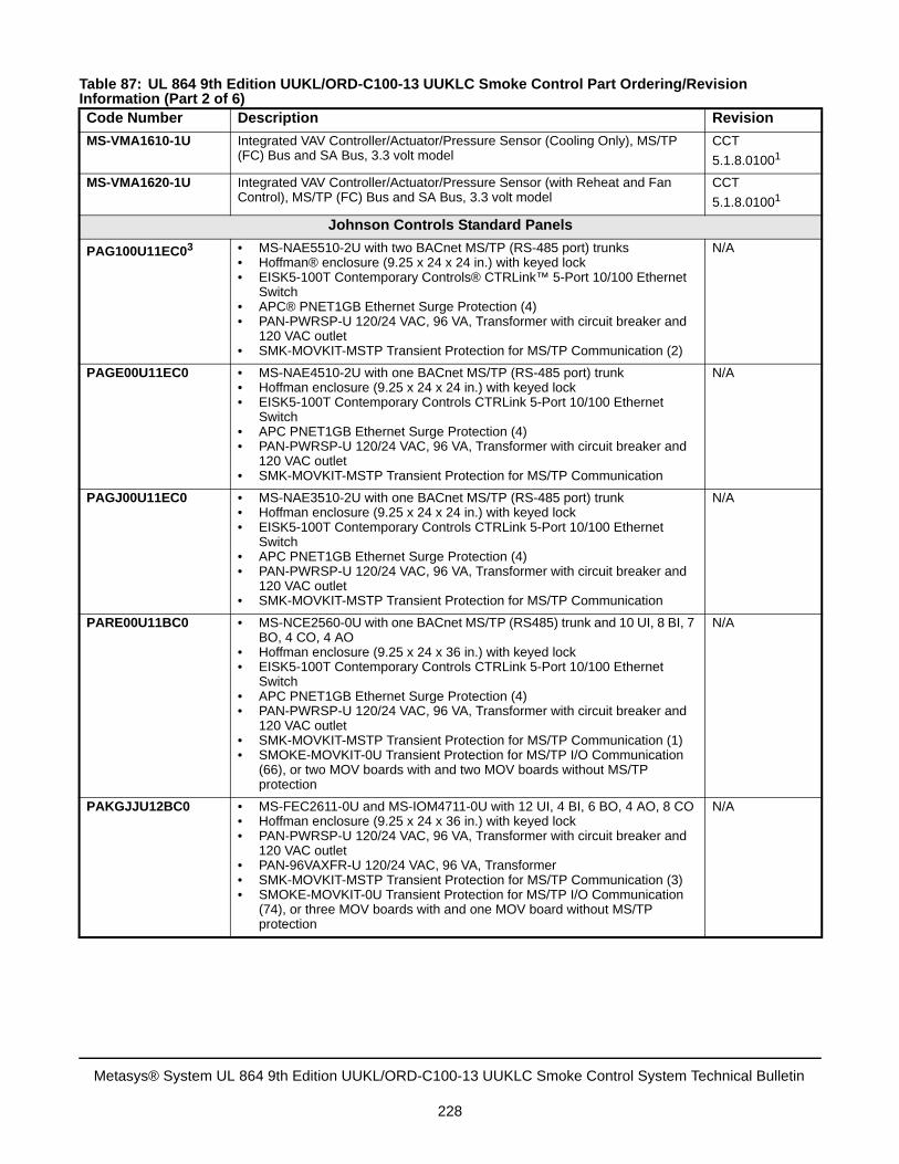
MS-VMA1610-1U Integrated VAV Controller/Actuator/Pressure Sensor (Cooling Only), MS/TP (FC) Bus and SA Bus, 3.3 volt model
CCT
5.1.8.01001
MS-VMA1620-1U Integrated VAV Controller/Actuator/Pressure Sensor (with Reheat and Fan Control), MS/TP (FC) Bus and SA Bus, 3.3 volt model
CCT
5.1.8.01001
Johnson Controls Standard Panels
PAG100U11EC03 • MS-NAE5510-2U with two BACnet MS/TP (RS-485 port) trunks• Hoffman® enclosure (9.25 x 24 x 24 in.) with keyed lock• EISK5-100T Contemporary Controls® CTRLink™ 5-Port 10/100 Ethernet
Switch• APC® PNET1GB Ethernet Surge Protection (4)• PAN-PWRSP-U 120/24 VAC, 96 VA, Transformer with circuit breaker and
120 VAC outlet• SMK-MOVKIT-MSTP Transient Protection for MS/TP Communication (2)
N/A
PAGE00U11EC0 • MS-NAE4510-2U with one BACnet MS/TP (RS-485 port) trunk• Hoffman enclosure (9.25 x 24 x 24 in.) with keyed lock• EISK5-100T Contemporary Controls CTRLink 5-Port 10/100 Ethernet
Switch• APC PNET1GB Ethernet Surge Protection (4)• PAN-PWRSP-U 120/24 VAC, 96 VA, Transformer with circuit breaker and
120 VAC outlet• SMK-MOVKIT-MSTP Transient Protection for MS/TP Communication
N/A
PAGJ00U11EC0 • MS-NAE3510-2U with one BACnet MS/TP (RS-485 port) trunk• Hoffman enclosure (9.25 x 24 x 24 in.) with keyed lock• EISK5-100T Contemporary Controls CTRLink 5-Port 10/100 Ethernet
Switch• APC PNET1GB Ethernet Surge Protection (4)• PAN-PWRSP-U 120/24 VAC, 96 VA, Transformer with circuit breaker and
120 VAC outlet• SMK-MOVKIT-MSTP Transient Protection for MS/TP Communication
N/A
PARE00U11BC0 • MS-NCE2560-0U with one BACnet MS/TP (RS485) trunk and 10 UI, 8 BI, 7BO, 4 CO, 4 AO
• Hoffman enclosure (9.25 x 24 x 36 in.) with keyed lock• EISK5-100T Contemporary Controls CTRLink 5-Port 10/100 Ethernet
Switch• APC PNET1GB Ethernet Surge Protection (4)• PAN-PWRSP-U 120/24 VAC, 96 VA, Transformer with circuit breaker and
120 VAC outlet• SMK-MOVKIT-MSTP Transient Protection for MS/TP Communication (1)• SMOKE-MOVKIT-0U Transient Protection for MS/TP I/O Communication
(66), or two MOV boards with and two MOV boards without MS/TPprotection
N/A
PAKGJJU12BC0 • MS-FEC2611-0U and MS-IOM4711-0U with 12 UI, 4 BI, 6 BO, 4 AO, 8 CO• Hoffman enclosure (9.25 x 24 x 36 in.) with keyed lock• PAN-PWRSP-U 120/24 VAC, 96 VA, Transformer with circuit breaker and
120 VAC outlet• PAN-96VAXFR-U 120/24 VAC, 96 VA, Transformer• SMK-MOVKIT-MSTP Transient Protection for MS/TP Communication (3)• SMOKE-MOVKIT-0U Transient Protection for MS/TP I/O Communication
(74), or three MOV boards with and one MOV board without MS/TPprotection
N/A
Table 87: UL 864 9th Edition UUKL/ORD-C100-13 UUKLC Smoke Control Part Ordering/Revision Information (Part 2 of 6)Code Number Description Revision
Metasys® System UL 864 9th Edition UUKL/ORD-C100-13 UUKLC Smoke Control System Technical Bulletin
228
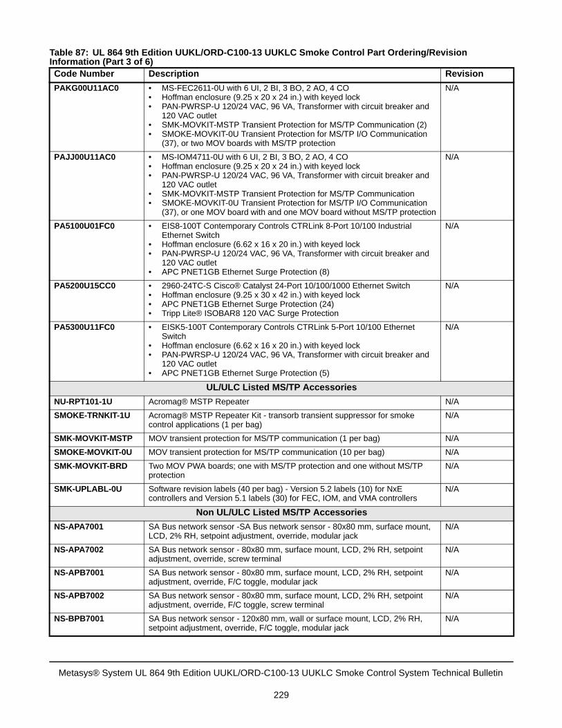
PAKG00U11AC0 • MS-FEC2611-0U with 6 UI, 2 BI, 3 BO, 2 AO, 4 CO• Hoffman enclosure (9.25 x 20 x 24 in.) with keyed lock• PAN-PWRSP-U 120/24 VAC, 96 VA, Transformer with circuit breaker and
120 VAC outlet• SMK-MOVKIT-MSTP Transient Protection for MS/TP Communication (2)• SMOKE-MOVKIT-0U Transient Protection for MS/TP I/O Communication
(37), or two MOV boards with MS/TP protection
N/A
PAJJ00U11AC0 • MS-IOM4711-0U with 6 UI, 2 BI, 3 BO, 2 AO, 4 CO• Hoffman enclosure (9.25 x 20 x 24 in.) with keyed lock• PAN-PWRSP-U 120/24 VAC, 96 VA, Transformer with circuit breaker and
120 VAC outlet• SMK-MOVKIT-MSTP Transient Protection for MS/TP Communication• SMOKE-MOVKIT-0U Transient Protection for MS/TP I/O Communication
(37), or one MOV board with and one MOV board without MS/TP protection
N/A
PA5100U01FC0 • EIS8-100T Contemporary Controls CTRLink 8-Port 10/100 IndustrialEthernet Switch
• Hoffman enclosure (6.62 x 16 x 20 in.) with keyed lock• PAN-PWRSP-U 120/24 VAC, 96 VA, Transformer with circuit breaker and
120 VAC outlet• APC PNET1GB Ethernet Surge Protection (8)
N/A
PA5200U15CC0 • 2960-24TC-S Cisco® Catalyst 24-Port 10/100/1000 Ethernet Switch• Hoffman enclosure (9.25 x 30 x 42 in.) with keyed lock• APC PNET1GB Ethernet Surge Protection (24)• Tripp Lite® ISOBAR8 120 VAC Surge Protection
N/A
PA5300U11FC0 • EISK5-100T Contemporary Controls CTRLink 5-Port 10/100 EthernetSwitch
• Hoffman enclosure (6.62 x 16 x 20 in.) with keyed lock• PAN-PWRSP-U 120/24 VAC, 96 VA, Transformer with circuit breaker and
120 VAC outlet• APC PNET1GB Ethernet Surge Protection (5)
N/A
UL/ULC Listed MS/TP Accessories
NU-RPT101-1U Acromag® MSTP Repeater N/A
SMOKE-TRNKIT-1U Acromag® MSTP Repeater Kit - transorb transient suppressor for smoke control applications (1 per bag)
N/A
SMK-MOVKIT-MSTP MOV transient protection for MS/TP communication (1 per bag) N/A
SMOKE-MOVKIT-0U MOV transient protection for MS/TP communication (10 per bag) N/A
SMK-MOVKIT-BRD Two MOV PWA boards; one with MS/TP protection and one without MS/TP protection
N/A
SMK-UPLABL-0U Software revision labels (40 per bag) - Version 5.2 labels (10) for NxE controllers and Version 5.1 labels (30) for FEC, IOM, and VMA controllers
N/A
Non UL/ULC Listed MS/TP Accessories
NS-APA7001 SA Bus network sensor -SA Bus network sensor - 80x80 mm, surface mount, LCD, 2% RH, setpoint adjustment, override, modular jack
N/A
NS-APA7002 SA Bus network sensor - 80x80 mm, surface mount, LCD, 2% RH, setpoint adjustment, override, screw terminal
N/A
NS-APB7001 SA Bus network sensor - 80x80 mm, surface mount, LCD, 2% RH, setpoint adjustment, override, F/C toggle, modular jack
N/A
NS-APB7002 SA Bus network sensor - 80x80 mm, surface mount, LCD, 2% RH, setpoint adjustment, override, F/C toggle, screw terminal
N/A
NS-BPB7001 SA Bus network sensor - 120x80 mm, wall or surface mount, LCD, 2% RH, setpoint adjustment, override, F/C toggle, modular jack
N/A
Table 87: UL 864 9th Edition UUKL/ORD-C100-13 UUKLC Smoke Control Part Ordering/Revision Information (Part 3 of 6)Code Number Description Revision
Metasys® System UL 864 9th Edition UUKL/ORD-C100-13 UUKLC Smoke Control System Technical Bulletin
229
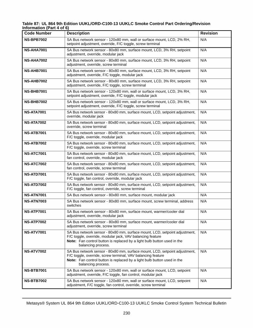
NS-BPB7002 SA Bus network sensor - 120x80 mm, wall or surface mount, LCD, 2% RH, setpoint adjustment, override, F/C toggle, screw terminal
N/A
NS-AHA7001 SA Bus network sensor - 80x80 mm, surface mount, LCD, 3% RH, setpoint adjustment, override, modular jack
N/A
NS-AHA7002 SA Bus network sensor - 80x80 mm, surface mount, LCD, 3% RH, setpoint adjustment, override, screw terminal
N/A
NS-AHB7001 SA Bus network sensor - 80x80 mm, surface mount, LCD, 3% RH, setpoint adjustment, override, F/C toggle, modular jack
N/A
NS-AHB7002 SA Bus network sensor - 80x80 mm, surface mount, LCD, 3% RH, setpoint adjustment, override, F/C toggle, screw terminal
N/A
NS-BHB7001 SA Bus network sensor - 120x80 mm, wall or surface mount, LCD, 3% RH, setpoint adjustment, override, F/C toggle, modular jack
N/A
NS-BHB7002 SA Bus network sensor - 120x80 mm, wall or surface mount, LCD, 3% RH, setpoint adjustment, override, F/C toggle, screw terminal
N/A
NS-ATA7001 SA Bus network sensor - 80x80 mm, surface mount, LCD, setpoint adjustment, override, modular jack
N/A
NS-ATA7002 SA Bus network sensor - 80x80 mm, surface mount, LCD, setpoint adjustment, override, screw terminal
N/A
NS-ATB7001 SA Bus network sensor - 80x80 mm, surface mount, LCD, setpoint adjustment, F/C toggle, override, modular jack
N/A
NS-ATB7002 SA Bus network sensor - 80x80 mm, surface mount, LCD, setpoint adjustment, F/C toggle, override, screw terminal
N/A
NS-ATC7001 SA Bus network sensor - 80x80 mm, surface mount, LCD, setpoint adjustment, fan control, override, modular jack
N/A
NS-ATC7002 SA Bus network sensor - 80x80 mm, surface mount, LCD, setpoint adjustment, fan control, override, screw terminal
N/A
NS-ATD7001 SA Bus network sensor - 80x80 mm, surface mount, LCD, setpoint adjustment, F/C toggle, fan control, override, modular jack
N/A
NS-ATD7002 SA Bus network sensor - 80x80 mm, surface mount, LCD, setpoint adjustment, F/C toggle, fan control, override, screw terminal
N/A
NS-ATN7001 SA Bus network sensor - 80x80 mm, surface mount, modular jack N/A
NS-ATN7003 SA Bus network sensor - 80x80 mm, surface mount, screw terminal, address switches
N/A
NS-ATP7001 SA Bus network sensor - 80x80 mm, surface mount, warmer/cooler dial adjustment, override, modular jack
N/A
NS-ATP7002 SA Bus network sensor - 80x80 mm, surface mount, warmer/cooler dial adjustment, override, screw terminal
N/A
NS-ATV7001 SA Bus network sensor - 80x80 mm, surface mount, LCD, setpoint adjustment, F/C toggle, override, modular jack, VAV balancing featureNote: Fan control button is replaced by a light bulb button used in the
balancing process.
N/A
NS-ATV7002 SA Bus network sensor - 80x80 mm, surface mount, LCD, setpoint adjustment, F/C toggle, override, screw terminal, VAV balancing featureNote: Fan control button is replaced by a light bulb button used in the
balancing process.
N/A
NS-BTB7001 SA Bus network sensor - 120x80 mm, wall or surface mount, LCD, setpoint adjustment, override, F/C toggle, fan control, modular jack
N/A
NS-BTB7002 SA Bus network sensor - 120x80 mm, wall or surface mount, LCD, setpoint adjustment, F/C toggle, fan control, override, screw terminal
N/A
Table 87: UL 864 9th Edition UUKL/ORD-C100-13 UUKLC Smoke Control Part Ordering/Revision Information (Part 4 of 6)Code Number Description Revision
Metasys® System UL 864 9th Edition UUKL/ORD-C100-13 UUKLC Smoke Control System Technical Bulletin
230
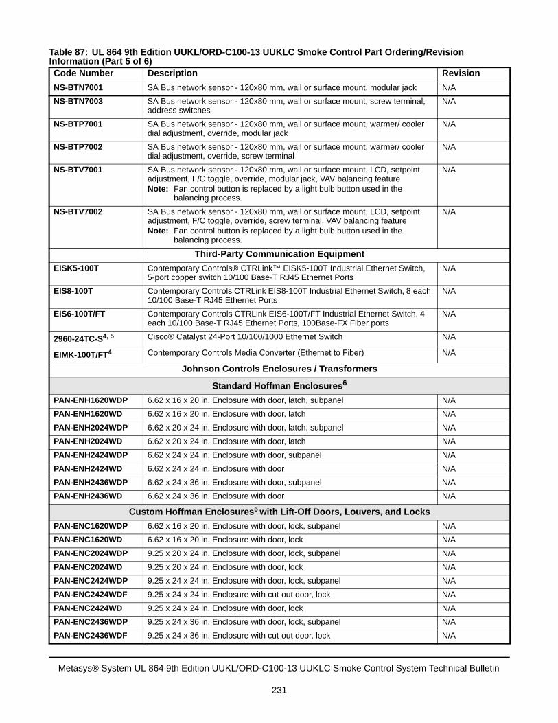
NS-BTN7001 SA Bus network sensor - 120x80 mm, wall or surface mount, modular jack N/A
NS-BTN7003 SA Bus network sensor - 120x80 mm, wall or surface mount, screw terminal, address switches
N/A
NS-BTP7001 SA Bus network sensor - 120x80 mm, wall or surface mount, warmer/ cooler dial adjustment, override, modular jack
N/A
NS-BTP7002 SA Bus network sensor - 120x80 mm, wall or surface mount, warmer/ cooler dial adjustment, override, screw terminal
N/A
NS-BTV7001 SA Bus network sensor - 120x80 mm, wall or surface mount, LCD, setpoint adjustment, F/C toggle, override, modular jack, VAV balancing featureNote: Fan control button is replaced by a light bulb button used in the
balancing process.
N/A
NS-BTV7002 SA Bus network sensor - 120x80 mm, wall or surface mount, LCD, setpoint adjustment, F/C toggle, override, screw terminal, VAV balancing featureNote: Fan control button is replaced by a light bulb button used in the
balancing process.
N/A
Third-Party Communication Equipment
EISK5-100T Contemporary Controls® CTRLink™ EISK5-100T Industrial Ethernet Switch, 5-port copper switch 10/100 Base-T RJ45 Ethernet Ports
N/A
EIS8-100T Contemporary Controls CTRLink EIS8-100T Industrial Ethernet Switch, 8 each 10/100 Base-T RJ45 Ethernet Ports
N/A
EIS6-100T/FT Contemporary Controls CTRLink EIS6-100T/FT Industrial Ethernet Switch, 4 each 10/100 Base-T RJ45 Ethernet Ports, 100Base-FX Fiber ports
N/A
2960-24TC-S4, 5 Cisco® Catalyst 24-Port 10/100/1000 Ethernet Switch N/A
EIMK-100T/FT4 Contemporary Controls Media Converter (Ethernet to Fiber) N/A
Johnson Controls Enclosures / Transformers
Standard Hoffman Enclosures6
PAN-ENH1620WDP 6.62 x 16 x 20 in. Enclosure with door, latch, subpanel N/A
PAN-ENH1620WD 6.62 x 16 x 20 in. Enclosure with door, latch N/A
PAN-ENH2024WDP 6.62 x 20 x 24 in. Enclosure with door, latch, subpanel N/A
PAN-ENH2024WD 6.62 x 20 x 24 in. Enclosure with door, latch N/A
PAN-ENH2424WDP 6.62 x 24 x 24 in. Enclosure with door, subpanel N/A
PAN-ENH2424WD 6.62 x 24 x 24 in. Enclosure with door N/A
PAN-ENH2436WDP 6.62 x 24 x 36 in. Enclosure with door, subpanel N/A
PAN-ENH2436WD 6.62 x 24 x 36 in. Enclosure with door N/A
Custom Hoffman Enclosures6 with Lift-Off Doors, Louvers, and Locks
PAN-ENC1620WDP 6.62 x 16 x 20 in. Enclosure with door, lock, subpanel N/A
PAN-ENC1620WD 6.62 x 16 x 20 in. Enclosure with door, lock N/A
PAN-ENC2024WDP 9.25 x 20 x 24 in. Enclosure with door, lock, subpanel N/A
PAN-ENC2024WD 9.25 x 20 x 24 in. Enclosure with door, lock N/A
PAN-ENC2424WDP 9.25 x 24 x 24 in. Enclosure with door, lock, subpanel N/A
PAN-ENC2424WDF 9.25 x 24 x 24 in. Enclosure with cut-out door, lock N/A
PAN-ENC2424WD 9.25 x 24 x 24 in. Enclosure with door, lock N/A
PAN-ENC2436WDP 9.25 x 24 x 36 in. Enclosure with door, lock, subpanel N/A
PAN-ENC2436WDF 9.25 x 24 x 36 in. Enclosure with cut-out door, lock N/A
Table 87: UL 864 9th Edition UUKL/ORD-C100-13 UUKLC Smoke Control Part Ordering/Revision Information (Part 5 of 6)Code Number Description Revision
Metasys® System UL 864 9th Edition UUKL/ORD-C100-13 UUKLC Smoke Control System Technical Bulletin
231
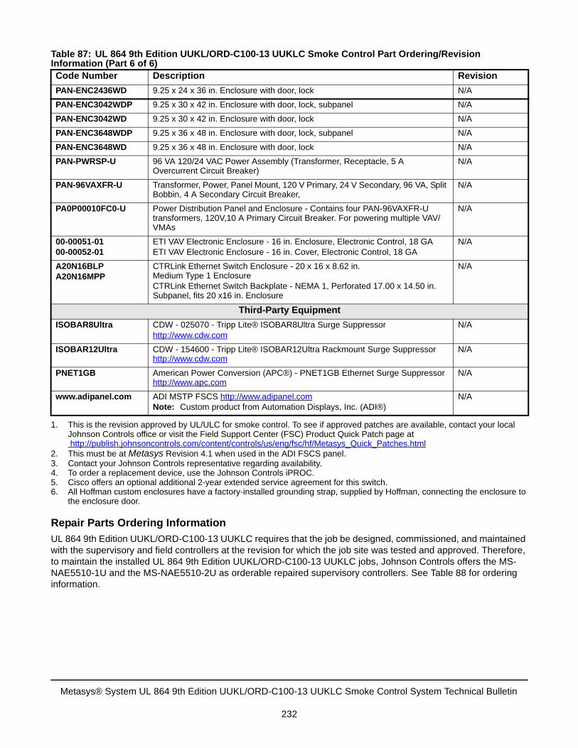
Repair Parts Ordering Information
UL 864 9th Edition UUKL/ORD-C100-13 UUKLC requires that the job be designed, commissioned, and maintained with the supervisory and field controllers at the revision for which the job site was tested and approved. Therefore, to maintain the installed UL 864 9th Edition UUKL/ORD-C100-13 UUKLC jobs, Johnson Controls offers the MS-NAE5510-1U and the MS-NAE5510-2U as orderable repaired supervisory controllers. See Table 88 for ordering information.
PAN-ENC2436WD 9.25 x 24 x 36 in. Enclosure with door, lock N/A
PAN-ENC3042WDP 9.25 x 30 x 42 in. Enclosure with door, lock, subpanel N/A
PAN-ENC3042WD 9.25 x 30 x 42 in. Enclosure with door, lock N/A
PAN-ENC3648WDP 9.25 x 36 x 48 in. Enclosure with door, lock, subpanel N/A
PAN-ENC3648WD 9.25 x 36 x 48 in. Enclosure with door, lock N/A
PAN-PWRSP-U 96 VA 120/24 VAC Power Assembly (Transformer, Receptacle, 5 A Overcurrent Circuit Breaker)
N/A
PAN-96VAXFR-U Transformer, Power, Panel Mount, 120 V Primary, 24 V Secondary, 96 VA, Split Bobbin, 4 A Secondary Circuit Breaker,
N/A
PA0P00010FC0-U Power Distribution Panel and Enclosure - Contains four PAN-96VAXFR-U transformers, 120V,10 A Primary Circuit Breaker. For powering multiple VAV/VMAs
N/A
00-00051-0100-00052-01
ETI VAV Electronic Enclosure - 16 in. Enclosure, Electronic Control, 18 GAETI VAV Electronic Enclosure - 16 in. Cover, Electronic Control, 18 GA
N/A
A20N16BLPA20N16MPP
CTRLink Ethernet Switch Enclosure - 20 x 16 x 8.62 in. Medium Type 1 EnclosureCTRLink Ethernet Switch Backplate - NEMA 1, Perforated 17.00 x 14.50 in. Subpanel, fits 20 x16 in. Enclosure
N/A
Third-Party Equipment
ISOBAR8Ultra CDW - 025070 - Tripp Lite® ISOBAR8Ultra Surge Suppressorhttp://www.cdw.com
N/A
ISOBAR12Ultra CDW - 154600 - Tripp Lite® ISOBAR12Ultra Rackmount Surge Suppressor http://www.cdw.com
N/A
PNET1GB American Power Conversion (APC®) - PNET1GB Ethernet Surge Suppressor http://www.apc.com
N/A
www.adipanel.com ADI MSTP FSCS http://www.adipanel.comNote: Custom product from Automation Displays, Inc. (ADI®)
N/A
1. This is the revision approved by UL/ULC for smoke control. To see if approved patches are available, contact your localJohnson Controls office or visit the Field Support Center (FSC) Product Quick Patch page athttp://publish.johnsoncontrols.com/content/controls/us/eng/fsc/hf/Metasys_Quick_Patches.html
2. This must be at Metasys Revision 4.1 when used in the ADI FSCS panel.3. Contact your Johnson Controls representative regarding availability.4. To order a replacement device, use the Johnson Controls iPROC.5. Cisco offers an optional additional 2-year extended service agreement for this switch.6. All Hoffman custom enclosures have a factory-installed grounding strap, supplied by Hoffman, connecting the enclosure to
the enclosure door.
Table 87: UL 864 9th Edition UUKL/ORD-C100-13 UUKLC Smoke Control Part Ordering/Revision Information (Part 6 of 6)Code Number Description Revision
Metasys® System UL 864 9th Edition UUKL/ORD-C100-13 UUKLC Smoke Control System Technical Bulletin
232
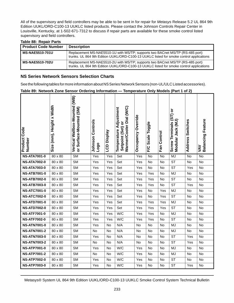
All of the supervisory and field controllers may be able to be sent in for repair for Metasys Release 5.2 UL 864 9th Edition UUKL/ORD-C100-13 UUKLC listed products. Please contact the Johnson Controls Repair Center in Louisville, Kentucky, at 1-502-671-7312 to discuss if repair parts are available for these smoke control listed supervisory and field controllers.
NS Series Network Sensors Selection Charts
See the following tables for more information about NS Series Network Sensors (non-UL/ULC Listed accessories).
Table 88: Repair PartsProduct Code Number Description
MS-NAE5510-701U Replacement MS-NAE5510-1U with MS/TP; supports two BACnet MS/TP (RS-485 port) trunks. UL 864 9th Edition UUKL/ORD-C100-13 UUKLC listed for smoke control applications
MS-NAE5510-702U Replacement MS-NAE5510-2U with MS/TP; supports two BACnet MS/TP (RS-485 port) trunks. UL 864 9th Edition UUKL/ORD-C100-13 UUKLC listed for smoke control applications
Table 89: Network Zone Sensor Ordering Information — Temperature Only Models (Part 1 of 2)
Pro
du
ct
Co
de
N
um
be
r
Siz
e (m
m),
Hei
gh
t x
Wid
th
Ve
rtic
al W
all
bo
x-M
ou
nte
d (
WB
)o
r S
urf
ace
-Mo
un
ted
(S
M)
Jo
hn
so
n C
on
tro
lsL
og
o
LC
D D
isp
lay
Tem
pe
ratu
re A
dju
stm
en
t S
etp
oin
t (S
et)
or
Wa
rmer
/Co
ole
r D
ial (
W/C
)
Occ
up
anc
y O
ve
rrid
e
F/C
Sca
le T
og
gle
Fan
Co
ntr
ol
Scr
ew T
erm
inal
s (S
T)
or
Mo
du
lar
Jac
k (
MJ
)
Ad
dre
ss
Sw
itc
hes
VA
V
Ba
lan
cin
g F
eat
ure
NS-ATA7001-0 80 x 80 SM Yes Yes Set Yes No No MJ No No
NS-ATA7002-0 80 x 80 SM Yes Yes Set Yes No No ST No No
NS-ATA7003-0 80 x 80 SM Yes Yes Set Yes No No ST Yes No
NS-ATB7001-0 80 x 80 SM Yes Yes Set Yes Yes No MJ No No
NS-ATB7002-0 80 x 80 SM Yes Yes Set Yes Yes No ST No No
NS-ATB7003-0 80 x 80 SM Yes Yes Set Yes Yes No ST Yes No
NS-ATC7001-0 80 x 80 SM Yes Yes Set Yes No Yes MJ No No
NS-ATC7002-0 80 x 80 SM Yes Yes Set Yes No Yes ST No No
NS-ATD7001-0 80 x 80 SM Yes Yes Set Yes Yes Yes MJ No No
NS-ATD7002-0 80 x 80 SM Yes Yes Set Yes Yes Yes ST No No
NS-ATF7001-0 80 x 80 SM Yes Yes W/C Yes Yes No MJ No No
NS-ATF7002-0 80 x 80 SM Yes Yes W/C Yes Yes No ST No No
NS-ATN7001-0 80 x 80 SM Yes No N/A No No No MJ No No
NS-ATN7001-2 80 x 80 SM No No N/A No No No MJ No No
NS-ATN7003-0 80 x 80 SM Yes No N/A No No No ST Yes No
NS-ATN7003-2 80 x 80 SM No No N/A No No No ST Yes No
NS-ATP7001-0 80 x 80 SM Yes No W/C Yes No No MJ No No
NS-ATP7001-2 80 x 80 SM No No W/C Yes No No MJ No No
NS-ATP7002-0 80 x 80 SM Yes No W/C Yes No No ST No No
NS-ATP7003-0 80 x 80 SM Yes No W/C Yes No No ST Yes No
Metasys® System UL 864 9th Edition UUKL/ORD-C100-13 UUKLC Smoke Control System Technical Bulletin
233
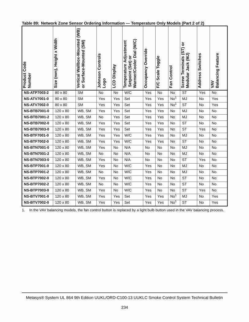
NS-ATP7003-2 80 x 80 SM No No W/C Yes No No ST Yes No
NS-ATV7001-0 80 x 80 SM Yes Yes Set Yes Yes No1 MJ No Yes
NS-ATV7002-0 80 x 80 SM Yes Yes Set Yes Yes No1 ST No Yes
NS-BTB7001-0 120 x 80 WB, SM Yes Yes Set Yes Yes No MJ No No
NS-BTB7001-2 120 x 80 WB, SM No Yes Set Yes Yes No MJ No No
NS-BTB7002-0 120 x 80 WB, SM Yes Yes Set Yes Yes No ST No No
NS-BTB7003-0 120 x 80 WB, SM Yes Yes Set Yes Yes No ST Yes No
NS-BTF7001-0 120 x 80 WB, SM Yes Yes W/C Yes Yes No MJ No No
NS-BTF7002-0 120 x 80 WB, SM Yes Yes W/C Yes Yes No ST No No
NS-BTN7001-0 120 x 80 WB, SM Yes No N/A No No No MJ No No
NS-BTN7001-2 120 x 80 WB, SM No No N/A No No No MJ No No
NS-BTN7003-0 120 x 80 WB, SM Yes No N/A No No No ST Yes No
NS-BTP7001-0 120 x 80 WB, SM Yes No W/C Yes No No MJ No No
NS-BTP7001-2 120 x 80 WB, SM No No W/C Yes No No MJ No No
NS-BTP7002-0 120 x 80 WB, SM Yes No W/C Yes No No ST No No
NS-BTP7002-2 120 x 80 WB, SM No No W/C Yes No No ST No No
NS-BTP7003-0 120 x 80 WB, SM Yes No W/C Yes No No ST Yes No
NS-BTV7001-0 120 x 80 WB, SM Yes Yes Set Yes Yes No1 MJ No Yes
NS-BTV7002-0 120 x 80 WB, SM Yes Yes Set Yes Yes No1 ST No Yes
1. In the VAV balancing models, the fan control button is replaced by a light bulb button used in the VAV balancing process.
Table 89: Network Zone Sensor Ordering Information — Temperature Only Models (Part 2 of 2)P
rod
uct
Co
de
N
um
be
r
Siz
e (
mm
), H
eig
ht
x W
idth
Ve
rtic
al
Wal
lbo
x-M
ou
nte
d (
WB
)o
r S
urf
ace-
Mo
un
ted
(S
M)
Jo
hn
so
n C
on
tro
lsL
og
o
LC
D D
isp
lay
Tem
pe
ratu
re A
dju
stm
ent
Set
po
int
(Se
t) o
rW
arm
er/
Co
ole
r D
ial (
W/C
)
Oc
cup
an
cy O
verr
ide
F/C
Sc
ale
Tog
gle
Fa
n C
on
tro
l
Scr
ew
Te
rmin
als
(ST
) o
rM
od
ula
r Ja
ck (
MJ)
Ad
dre
ss S
wit
che
s
VA
V
Bal
anc
ing
Fea
ture
Metasys® System UL 864 9th Edition UUKL/ORD-C100-13 UUKLC Smoke Control System Technical Bulletin
234
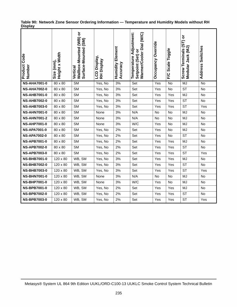
Table 90: Network Zone Sensor Ordering Information — Temperature and Humidity Models without RH Display
Pro
du
ct
Co
de
Nu
mb
er
Siz
e (m
m),
He
igh
t x
Wid
th
Ve
rtic
al
Wa
llb
ox
-Mo
un
ted
(W
B)
or
Su
rfa
ce-
Mo
un
ted
(S
M)
LC
D D
isp
lay,
RH
Dis
pla
y
Hu
mid
ity
Ele
me
nt
Ac
cu
racy
Tem
pe
ratu
re A
dju
stm
en
t:
Se
tpo
int
(Se
t) o
rW
arm
er/C
oo
ler
Dia
l (W
/C)
Occ
up
anc
y O
ve
rrid
e
F/C
Sc
ale
To
gg
le
Sc
rew
Ter
min
als
(S
T)
or
Mo
du
lar
Ja
ck (
MJ
)
Ad
dre
ss
Sw
itc
hes
NS-AHA7001-0 80 x 80 SM Yes, No 3% Set Yes No MJ No
NS-AHA7002-0 80 x 80 SM Yes, No 3% Set Yes No ST No
NS-AHB7001-0 80 x 80 SM Yes, No 3% Set Yes Yes MJ No
NS-AHB7002-0 80 x 80 SM Yes, No 3% Set Yes Yes ST No
NS-AHB7003-0 80 x 80 SM Yes, No 3% Set Yes Yes ST Yes
NS-AHN7001-0 80 x 80 SM None 3% N/A No No MJ No
NS-AHN7001-2 80 x 80 SM None 3% N/A No No MJ No
NS-AHP7001-0 80 x 80 SM None 3% W/C Yes No MJ No
NS-APA7001-0 80 x 80 SM Yes, No 2% Set Yes No MJ No
NS-APA7002-0 80 x 80 SM Yes, No 2% Set Yes No ST No
NS-APB7001-0 80 x 80 SM Yes, No 2% Set Yes Yes MJ No
NS-APB7002-0 80 x 80 SM Yes, No 2% Set Yes Yes ST No
NS-APB7003-0 80 x 80 SM Yes, No 2% Set Yes Yes ST Yes
NS-BHB7001-0 120 x 80 WB, SM Yes, No 3% Set Yes Yes MJ No
NS-BHB7002-0 120 x 80 WB, SM Yes, No 3% Set Yes Yes ST No
NS-BHB7003-0 120 x 80 WB, SM Yes, No 3% Set Yes Yes ST Yes
NS-BHN7001-0 120 x 80 WB, SM None 3% N/A No No MJ No
NS-BHP7001-0 120 x 80 WB, SM None 3% W/C Yes No MJ No
NS-BPB7001-0 120 x 80 WB, SM Yes, No 2% Set Yes Yes MJ No
NS-BPB7002-0 120 x 80 WB, SM Yes, No 2% Set Yes Yes ST No
NS-BPB7003-0 120 x 80 WB, SM Yes, No 2% Set Yes Yes ST Yes
Metasys® System UL 864 9th Edition UUKL/ORD-C100-13 UUKLC Smoke Control System Technical Bulletin
235
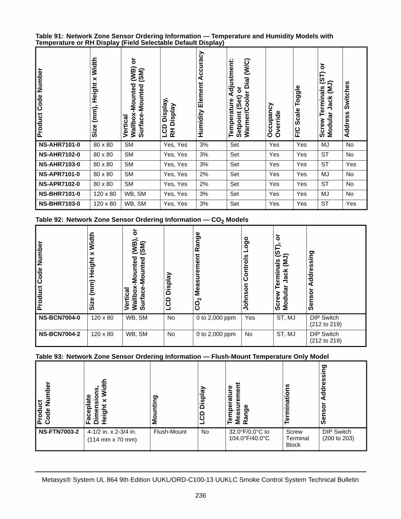
Table 91: Network Zone Sensor Ordering Information — Temperature and Humidity Models with Temperature or RH Display (Field Selectable Default Display)
Pro
du
ct
Co
de
Nu
mb
er
Siz
e (m
m),
Hei
gh
t x
Wid
th
Ve
rtic
al
Wa
llb
ox
-Mo
un
ted
(W
B)
or
Su
rfa
ce-
Mo
un
ted
(S
M)
LC
D D
isp
lay,
RH
Dis
pla
y
Hu
mid
ity
Ele
me
nt
Acc
ura
cy
Tem
pe
ratu
re A
dju
stm
en
t:
Se
tpo
int
(Se
t) o
rW
arm
er/C
oo
ler
Dia
l (W
/C)
Occ
up
anc
yO
ve
rrid
e
F/C
Sca
le T
og
gle
Sc
rew
Ter
min
als
(S
T)
or
Mo
du
lar
Ja
ck (
MJ
)
Ad
dre
ss
Sw
itc
hes
NS-AHR7101-0 80 x 80 SM Yes, Yes 3% Set Yes Yes MJ No
NS-AHR7102-0 80 x 80 SM Yes, Yes 3% Set Yes Yes ST No
NS-AHR7103-0 80 x 80 SM Yes, Yes 3% Set Yes Yes ST Yes
NS-APR7101-0 80 x 80 SM Yes, Yes 2% Set Yes Yes MJ No
NS-APR7102-0 80 x 80 SM Yes, Yes 2% Set Yes Yes ST No
NS-BHR7101-0 120 x 80 WB, SM Yes, Yes 3% Set Yes Yes MJ No
NS-BHR7103-0 120 x 80 WB, SM Yes, Yes 3% Set Yes Yes ST Yes
Table 92: Network Zone Sensor Ordering Information — CO2 Models
Pro
du
ct
Co
de
Nu
mb
er
Siz
e (m
m)
Hei
gh
t x
Wid
th
Ver
tica
lW
allb
ox-
Mo
un
ted
(W
B),
or
Su
rfa
ce-M
ou
nte
d (
SM
)
LC
D D
isp
lay
CO
2 M
ea
su
rem
en
t R
an
ge
Joh
nso
n C
on
tro
ls L
og
o
Scr
ew
Te
rmin
als
(ST
), o
rM
od
ula
r Ja
ck
(MJ
)
Sen
so
r A
dd
res
sin
gNS-BCN7004-0 120 x 80 WB, SM No 0 to 2,000 ppm Yes ST, MJ DIP Switch
(212 to 219)
NS-BCN7004-2 120 x 80 WB, SM No 0 to 2,000 ppm No ST, MJ DIP Switch (212 to 219)
Table 93: Network Zone Sensor Ordering Information — Flush-Mount Temperature Only Model
Pro
du
ct
Co
de
Nu
mb
er
Fa
cep
late
Dim
en
sio
ns
,H
eig
ht
x W
idth
Mo
un
tin
g
LC
D D
isp
lay
Tem
per
atu
reM
ea
sure
men
tR
ang
e
Term
inat
ion
s
Sen
so
r A
dd
res
sin
g
NS-FTN7003-2 4-1/2 in. x 2-3/4 in.(114 mm x 70 mm)
Flush-Mount No 32.0°F/0.0°C to 104.0°F/40.0°C
Screw Terminal Block
DIP Switch (200 to 203)
Metasys® System UL 864 9th Edition UUKL/ORD-C100-13 UUKLC Smoke Control System Technical Bulletin
236
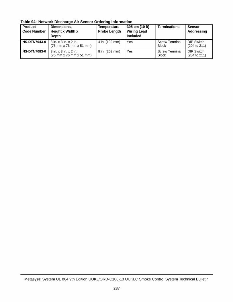
Table 94: Network Discharge Air Sensor Ordering InformationProduct Code Number
Dimensions, Height x Width xDepth
Temperature Probe Length
305 cm (10 ft) Wiring LeadIncluded
Terminations Sensor Addressing
NS-DTN7043-0 3 in. x 3 in. x 2 in.(76 mm x 76 mm x 51 mm)
4 in. (102 mm) Yes Screw Terminal Block
DIP Switch (204 to 211)
NS-DTN7083-0 3 in. x 3 in. x 2 in.(76 mm x 76 mm x 51 mm)
8 in. (203 mm) Yes Screw Terminal Block
DIP Switch (204 to 211)
Metasys® System UL 864 9th Edition UUKL/ORD-C100-13 UUKLC Smoke Control System Technical Bulletin
237
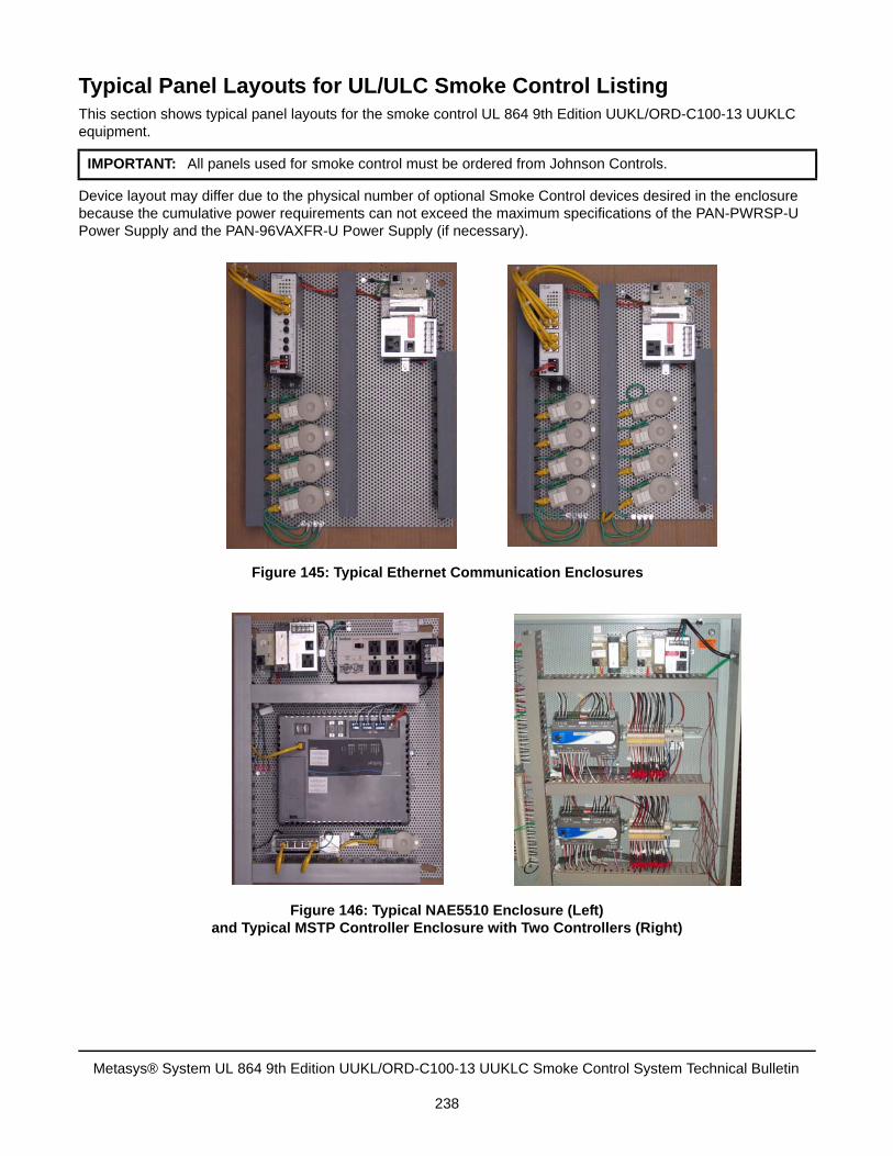
Typical Panel Layouts for UL/ULC Smoke Control ListingThis section shows typical panel layouts for the smoke control UL 864 9th Edition UUKL/ORD-C100-13 UUKLC equipment.
Device layout may differ due to the physical number of optional Smoke Control devices desired in the enclosure because the cumulative power requirements can not exceed the maximum specifications of the PAN-PWRSP-U Power Supply and the PAN-96VAXFR-U Power Supply (if necessary).
IMPORTANT: All panels used for smoke control must be ordered from Johnson Controls.
Figure 145: Typical Ethernet Communication Enclosures
Figure 146: Typical NAE5510 Enclosure (Left) and Typical MSTP Controller Enclosure with Two Controllers (Right)
Metasys® System UL 864 9th Edition UUKL/ORD-C100-13 UUKLC Smoke Control System Technical Bulletin
238
Compliance Checklist for UL/ULC Smoke Control Listing
OverviewThis section summarizes the most common requirements to configure the Metasys system to comply with the UL 864 9th Edition UUKL/ORD-C100-13 UUKLC Smoke Control Listing. A Compliance Survey for UL/ULC Smoke Control Listing form is followed by tables listing the requirements for UL 864 9th Edition UUKL/ORD-C100-13 UUKLC Listing compliance.
The purpose of the Compliance Survey for UL/ULC Smoke Control Listing is to provide a record of those elements of National Fire Protection Association (NFPA) 92A and UL/ULC that Johnson Controls does or does not provide.
UL/ULC is an identifier created by UL to identify those products listed under UL 864 9th Edition UUKL/ORD-C100-13 UUKLC for smoke control. Products covered by this listing are intended to be installed in conjunction with Heating, Ventilating, and Air Conditioning (HVAC) equipment to form a system for controlling the flow of smoke in a building during a fire condition in accordance with NFPA Recommended Practice 92A.
It is important that we document the system elements that are being provided. The Compliance Survey for UL/ULC Smoke Control Listing can be used to provide that documentation.
In the case where a project specification dictates compliance with the UL/ULC Listing, but contains elements of the system design that conflict with the Listing or are omitted, the completed Compliance Survey for UL/ULC Smoke Control Listing can be given to the designer or the AHJ to obtain recognition and agreement on the extent of Listing compliance. This should occur prior to bid or proposal.
Once an agreement is reached with the AHJ, designer, and customer, the signed or initialed Smoke Control Compliance Checklist must become a permanent part of the project file.
If you are bidding, engineering, installing, or commissioning a Metasys system requiring UL 864 9th Edition UUKL/ORD-C100-13 UUKLC Smoke Control Listing compliance, follow the guidelines, requirements, and procedures listed in this document and in the Related Documentation section.
Metasys® System UL 864 9th Edition UUKL/ORD-C100-13 UUKLC Smoke Control System Technical Bulletin
239
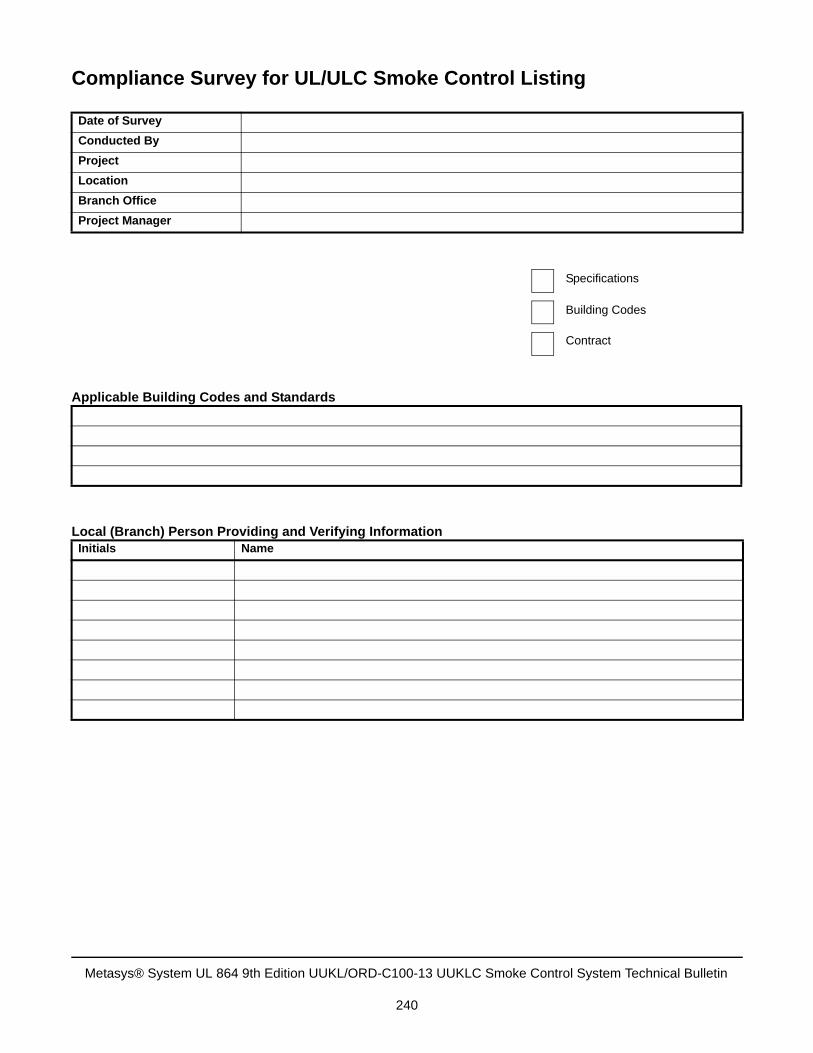
Compliance Survey for UL/ULC Smoke Control Listing
Date of Survey
Conducted By
Project
Location
Branch Office
Project Manager
Applicable Building Codes and Standards
Local (Branch) Person Providing and Verifying InformationInitials Name
Specifications
Building Codes
Contract
Metasys® System UL 864 9th Edition UUKL/ORD-C100-13 UUKLC Smoke Control System Technical Bulletin
240
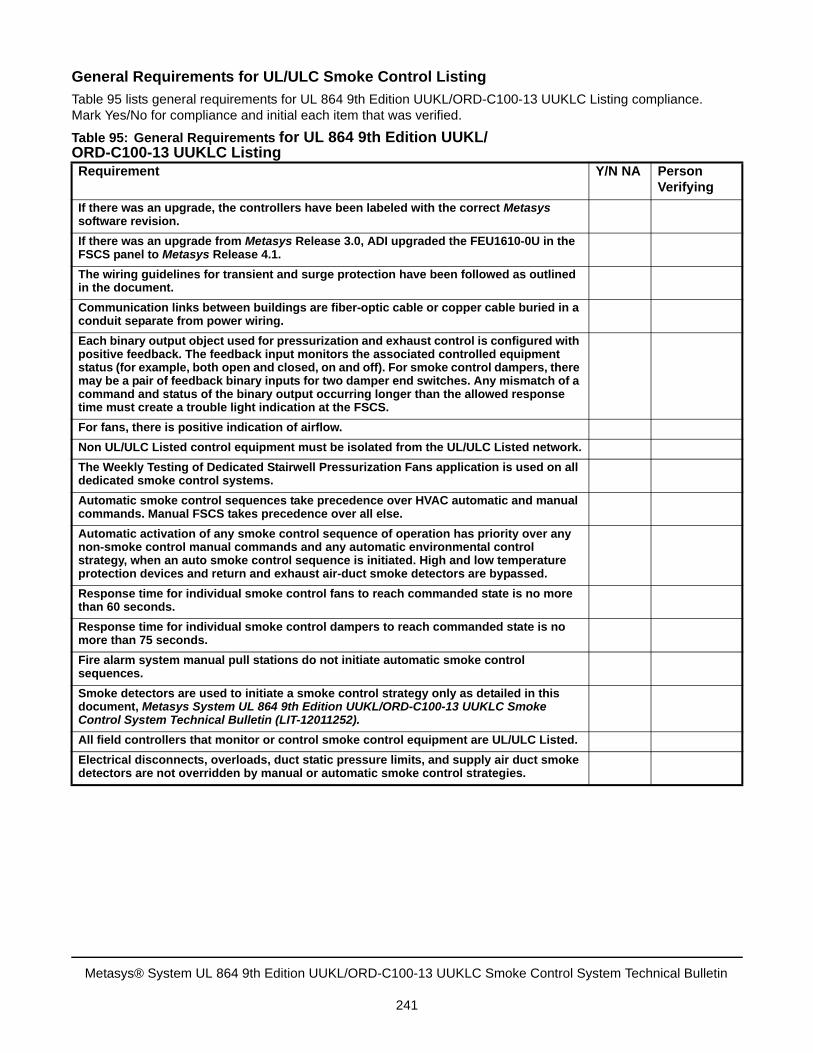
General Requirements for UL/ULC Smoke Control Listing
Table 95 lists general requirements for UL 864 9th Edition UUKL/ORD-C100-13 UUKLC Listing compliance. Mark Yes/No for compliance and initial each item that was verified.
Table 95: General Requirements for UL 864 9th Edition UUKL/ORD-C100-13 UUKLC ListingRequirement Y/N NA Person
Verifying
If there was an upgrade, the controllers have been labeled with the correct Metasys software revision.
If there was an upgrade from Metasys Release 3.0, ADI upgraded the FEU1610-0U in the FSCS panel to Metasys Release 4.1.
The wiring guidelines for transient and surge protection have been followed as outlined in the document.
Communication links between buildings are fiber-optic cable or copper cable buried in a conduit separate from power wiring.
Each binary output object used for pressurization and exhaust control is configured with positive feedback. The feedback input monitors the associated controlled equipment status (for example, both open and closed, on and off). For smoke control dampers, there may be a pair of feedback binary inputs for two damper end switches. Any mismatch of a command and status of the binary output occurring longer than the allowed response time must create a trouble light indication at the FSCS.
For fans, there is positive indication of airflow.
Non UL/ULC Listed control equipment must be isolated from the UL/ULC Listed network.
The Weekly Testing of Dedicated Stairwell Pressurization Fans application is used on all dedicated smoke control systems.
Automatic smoke control sequences take precedence over HVAC automatic and manual commands. Manual FSCS takes precedence over all else.
Automatic activation of any smoke control sequence of operation has priority over any non-smoke control manual commands and any automatic environmental control strategy, when an auto smoke control sequence is initiated. High and low temperature protection devices and return and exhaust air-duct smoke detectors are bypassed.
Response time for individual smoke control fans to reach commanded state is no more than 60 seconds.
Response time for individual smoke control dampers to reach commanded state is no more than 75 seconds.
Fire alarm system manual pull stations do not initiate automatic smoke control sequences.
Smoke detectors are used to initiate a smoke control strategy only as detailed in this document, Metasys System UL 864 9th Edition UUKL/ORD-C100-13 UUKLC Smoke Control System Technical Bulletin (LIT-12011252).
All field controllers that monitor or control smoke control equipment are UL/ULC Listed.
Electrical disconnects, overloads, duct static pressure limits, and supply air duct smoke detectors are not overridden by manual or automatic smoke control strategies.
Metasys® System UL 864 9th Edition UUKL/ORD-C100-13 UUKLC Smoke Control System Technical Bulletin
241
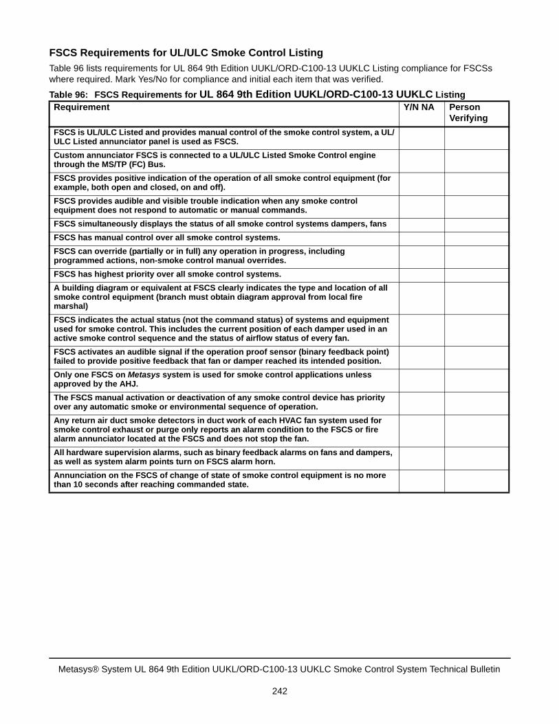
FSCS Requirements for UL/ULC Smoke Control Listing
Table 96 lists requirements for UL 864 9th Edition UUKL/ORD-C100-13 UUKLC Listing compliance for FSCSs where required. Mark Yes/No for compliance and initial each item that was verified.
Table 96: FSCS Requirements for UL 864 9th Edition UUKL/ORD-C100-13 UUKLC ListingRequirement Y/N NA Person
Verifying
FSCS is UL/ULC Listed and provides manual control of the smoke control system, a UL/ULC Listed annunciator panel is used as FSCS.
Custom annunciator FSCS is connected to a UL/ULC Listed Smoke Control engine through the MS/TP (FC) Bus.
FSCS provides positive indication of the operation of all smoke control equipment (for example, both open and closed, on and off).
FSCS provides audible and visible trouble indication when any smoke control equipment does not respond to automatic or manual commands.
FSCS simultaneously displays the status of all smoke control systems dampers, fans
FSCS has manual control over all smoke control systems.
FSCS can override (partially or in full) any operation in progress, including programmed actions, non-smoke control manual overrides.
FSCS has highest priority over all smoke control systems.
A building diagram or equivalent at FSCS clearly indicates the type and location of all smoke control equipment (branch must obtain diagram approval from local fire marshal)
FSCS indicates the actual status (not the command status) of systems and equipment used for smoke control. This includes the current position of each damper used in an active smoke control sequence and the status of airflow status of every fan.
FSCS activates an audible signal if the operation proof sensor (binary feedback point) failed to provide positive feedback that fan or damper reached its intended position.
Only one FSCS on Metasys system is used for smoke control applications unless approved by the AHJ.
The FSCS manual activation or deactivation of any smoke control device has priority over any automatic smoke or environmental sequence of operation.
Any return air duct smoke detectors in duct work of each HVAC fan system used for smoke control exhaust or purge only reports an alarm condition to the FSCS or fire alarm annunciator located at the FSCS and does not stop the fan.
All hardware supervision alarms, such as binary feedback alarms on fans and dampers, as well as system alarm points turn on FSCS alarm horn.
Annunciation on the FSCS of change of state of smoke control equipment is no more than 10 seconds after reaching commanded state.
Metasys® System UL 864 9th Edition UUKL/ORD-C100-13 UUKLC Smoke Control System Technical Bulletin
242
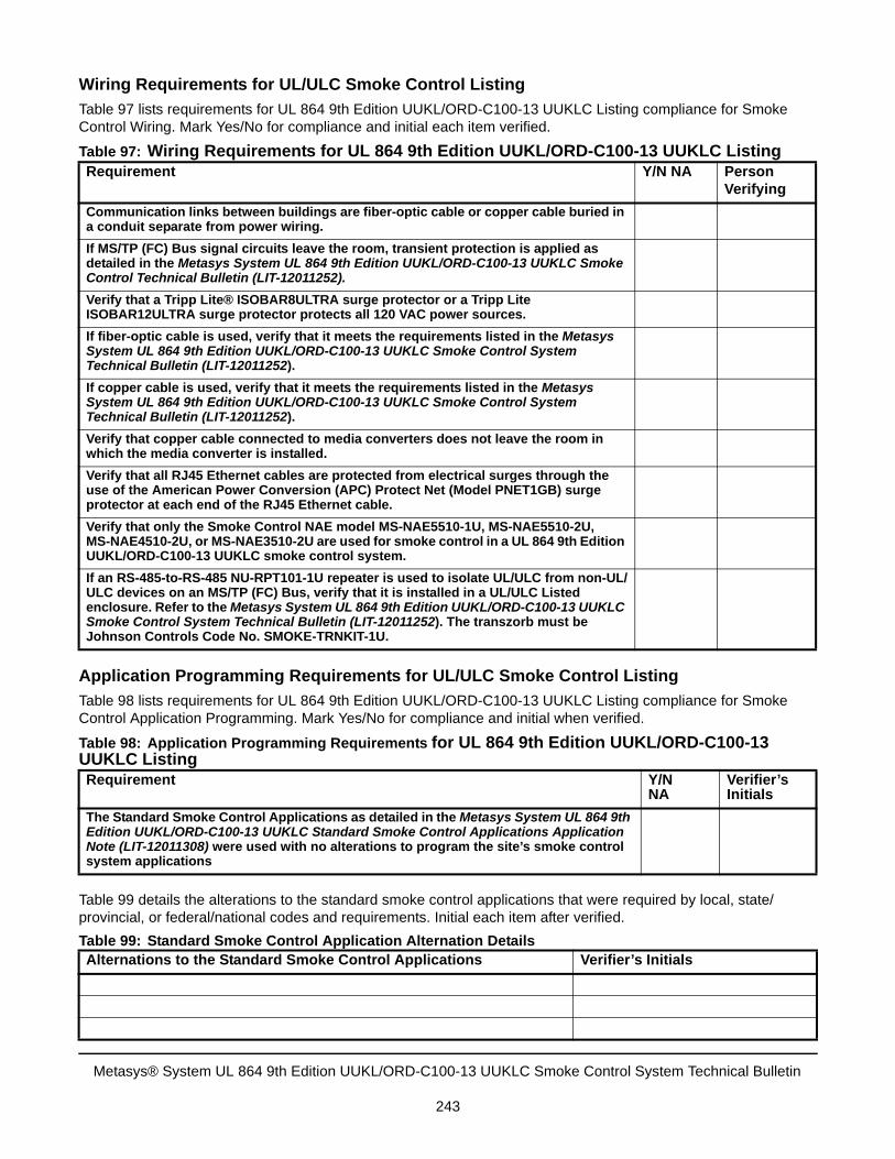
Wiring Requirements for UL/ULC Smoke Control Listing
Table 97 lists requirements for UL 864 9th Edition UUKL/ORD-C100-13 UUKLC Listing compliance for Smoke Control Wiring. Mark Yes/No for compliance and initial each item verified.
Application Programming Requirements for UL/ULC Smoke Control Listing
Table 98 lists requirements for UL 864 9th Edition UUKL/ORD-C100-13 UUKLC Listing compliance for Smoke Control Application Programming. Mark Yes/No for compliance and initial when verified.
Table 99 details the alterations to the standard smoke control applications that were required by local, state/provincial, or federal/national codes and requirements. Initial each item after verified.
Table 97: Wiring Requirements for UL 864 9th Edition UUKL/ORD-C100-13 UUKLC ListingRequirement Y/N NA Person
Verifying
Communication links between buildings are fiber-optic cable or copper cable buried in a conduit separate from power wiring.
If MS/TP (FC) Bus signal circuits leave the room, transient protection is applied as detailed in the Metasys System UL 864 9th Edition UUKL/ORD-C100-13 UUKLC Smoke Control Technical Bulletin (LIT-12011252).
Verify that a Tripp Lite® ISOBAR8ULTRA surge protector or a Tripp Lite ISOBAR12ULTRA surge protector protects all 120 VAC power sources.
If fiber-optic cable is used, verify that it meets the requirements listed in the Metasys System UL 864 9th Edition UUKL/ORD-C100-13 UUKLC Smoke Control System Technical Bulletin (LIT-12011252).
If copper cable is used, verify that it meets the requirements listed in the Metasys System UL 864 9th Edition UUKL/ORD-C100-13 UUKLC Smoke Control System Technical Bulletin (LIT-12011252).
Verify that copper cable connected to media converters does not leave the room in which the media converter is installed.
Verify that all RJ45 Ethernet cables are protected from electrical surges through the use of the American Power Conversion (APC) Protect Net (Model PNET1GB) surge protector at each end of the RJ45 Ethernet cable.
Verify that only the Smoke Control NAE model MS-NAE5510-1U, MS-NAE5510-2U, MS-NAE4510-2U, or MS-NAE3510-2U are used for smoke control in a UL 864 9th Edition UUKL/ORD-C100-13 UUKLC smoke control system.
If an RS-485-to-RS-485 NU-RPT101-1U repeater is used to isolate UL/ULC from non-UL/ULC devices on an MS/TP (FC) Bus, verify that it is installed in a UL/ULC Listed enclosure. Refer to the Metasys System UL 864 9th Edition UUKL/ORD-C100-13 UUKLC Smoke Control System Technical Bulletin (LIT-12011252). The transzorb must be Johnson Controls Code No. SMOKE-TRNKIT-1U.
Table 98: Application Programming Requirements for UL 864 9th Edition UUKL/ORD-C100-13 UUKLC ListingRequirement Y/N
NAVerifier’s Initials
The Standard Smoke Control Applications as detailed in the Metasys System UL 864 9th Edition UUKL/ORD-C100-13 UUKLC Standard Smoke Control Applications Application Note (LIT-12011308) were used with no alterations to program the site’s smoke control system applications
Table 99: Standard Smoke Control Application Alternation DetailsAlternations to the Standard Smoke Control Applications Verifier’s Initials
Metasys® System UL 864 9th Edition UUKL/ORD-C100-13 UUKLC Smoke Control System Technical Bulletin
243

The information contained within this compliance checklist is verified and accepted to be true as indicated by the signatures in Table 100.
Table 100: Smoke Control Site Acceptance InformationDate of Acceptance
Project
Location
Branch Office
Title
Project Manager (signature)
Branch Manager (signature)
Building Engineer (signature)
Building Manger/Owner (signature)
Authority Having Jurisdiction
Table 99: Standard Smoke Control Application Alternation DetailsAlternations to the Standard Smoke Control Applications Verifier’s Initials
Published in U.S.A. www.johnsoncontrols.com
Metasys® System UL 864 9th Edition UUKL/ORD-C100-13 UUKLC Smoke Control System Technical Bulletin
244
Metasys® and Johnson Controls® are registered trademarks of Johnson ControlsAll other marks herein are the marks of their respective owners. © 2017 Johnson Controls
Building Technologies & Solutions507 E. Michigan Street, Milwaukee, WI 53202