Embed Size (px)
Citation preview
MEGARIS: A NEW CONCEPT OF HYBRID SOLAR-BIOMASS-STIRLING CHP SYSTEM
G. Angrisania, K. Bizona, R. Chironeb, G. Continilloa, F. Floro Floresc, G. Fuscoc, S. Lombardia, E. Mancusia, F. S. Marrab, F. Micciob, C. Rosellia, M. Sassoa,
F. Tarielloa, R. Solimeneb, M. Urciuolob a Università del Sannio, Facoltà di Ingegneria, P. Roma 21, 82100, Benevento, Italy
b Istituto di Ricerche sulla Combustione CNR, V. Diocleziano 328, 80124, Napoli, Italy c Aerosoft Spa, Centro Direzionale Is. E7, 80143, Napoli, Italy
*corresponding author: [email protected]
ABSTRACT
A new concept of a system for Combined Heat and Power generation is presented. The concept is based on hybrid use of two renewable energy sources, direct solar (thermodynamic solar) and biomass (indirect solar energy). Biomass combustion is conducted using a fluidized bed combustor. A second source of energy, given by the direct irradiation of the bed with a concentrated solar radiation, is integrated in the same system, using the fluidized bed as solar receiver. A Stirling engine converts heat into mechanical power. A Scheffler type mirror is adopted to allow irradiation of the system in a fixed focal point. Advantages of the proposed solution are illustrated and some preliminary results on the performance of the system, obtained with a simple model, are presented. The principal improvements with respect to existing systems of similar size and primary energy source are illustrated. The most important are the enhanced heat transfer processes that are realized with the help of the fluidized bed, and the possibility of continuous cogeneration during the day. Different working conditions are considered to estimate the contribution given by the burning of fuel, in presence as well as in absence of sun irradiation (as during the night). The distribution of energy shares among the different flux contributes is reported versus the amount of biomass burned per unit time. The results clearly demonstrate the advantage of coupling, in the same system, two sources for heat generation, thus maintaining the option of producing electricity without the supply of biomass fuel.
Keywords: CSP, CHP, FBC, Renewable Energy, Biomass.
INTRODUCTION
This paper presents the first developments of a new cogeneration system driven by two renewable energy sources: direct solar
(thermodynamic solar) and biomass (indirect solar energy).
Solar energy is, either directly or indirectly, the common source for all renewable sources, apart from geothermal and tidal. Important renewable sources that indirectly derive from the Sun (such as wind and waves) cannot be stored. Biomass is instead different: photosynthesis, carried out by the living matter, uses solar radiation to build organic compounds from carbon dioxide and water. These molecules constitute an energy reservoir that can be used at a later time, balancing the variability of other renewable energy sources, especially direct solar. Nevertheless, biomass availability is limited and expected to become costly, as a consequence of demand increase. Moreover, biomass combustion, while being neutral to CO2 cycle, produces several other types of pollutants that must be controlled especially in urban areas.
The international scientific community have identified small scale on-site cogenerators and polygenerators, able to meet different energy demands of the end-users, high potential for reducing energy consumptions and emissions [1-4]. Benefits include reduction of energy transport and distribution losses, and of inefficiencies due to partial load operation of large size systems. The best application of biomass energy is related to small size distributed cogeneration or trigeneration systems [5]. This is especially true if a Fluidized Bed (FB) combustor is used, capable of burning different types of biomass, including “difficult” materials (lignite, municipal solid wastes and sludge), even with a very high humidity grade. Further benefits of distributed microcogeneration systems fuelled by biomass are:
biomass can be derived from the surrounding
area, exploiting local resources and reducing
costs and emissions related to fuel transport;
full exploitation of biomass energy through
cogenerative use. By locating the plants near
thermal loads, it is possible to exploit existing
small district heating networks.
Among the technologies available for cogeneration, the Stirling engine (SE), if activated by a renewable source, appears the most suitable and promising for small size systems. Microcogenerators (MCHP, Micro Combined Heat and Power, electric power lower than 15 kW) based on Stirling engine, nowadays commercially available (electric efficiencies in the range 10–25%), have been widely analyzed, to identify feasible applications and evaluate technical and economic feasibility as well as primary energy and emissions savings with respect to conventional energy conversion devices in residential and tertiary buildings. The coupling of a biomass system with a Stirling engine is therefore quite natural.
The original idea, successfully adopted in the past in several systems already on the market, is to place the hot head of the SE in direct contact with the flame, identified as the region of highest temperature, to maximize thermal exchange between the hot combustion gases and the working fluid of the engine. While this is an effective solution for gas combustors, it is not suitable for biomass. Therefore, in usual designs of biomass-fuelled SE, heat is recovered from exhaust gases, while combustion of biomass takes place in fixed-bed systems, such as gratings typically used to burn logs and wood chips, or braziers used for combustion of pellets [6]. A major drawback of this concept is that, even in the cleaner burners that can be imagined, it is difficult to prevent formation of solid particles that deposit on heat exchange surfaces, progressively reducing efficiency [7].
The prototype developed in [8] belongs to this type of plants. A similar system was successfully developed in Denmark [9]. Probably the most significant example is the SOLO 161 Stirling engine, adopted in several projects aimed at producing electricity by burning biomass [10], or natural gas [11] as primary energy source, achieving efficiencies as high as 36% [12]. All these plants are characterized by primary power input in the range of 100-150 kW and, correspondingly, by electrical power generated around 35 kW. Thus far, the only real market application is PowerUnit of Stirling Biopower (USA), equipped with a 4-cylinder Stirling engine delivering up to 38 kW of electric power (at 50 Hz) with an efficiency of 27-28%, plus heat recovery that leads to a global efficiency up to 80% for such fuel-flexible system.
A CHP (Combined Heat and Power) device sized for household energy demands was developed in the USA by External Power LLC [13]. It consists in coupling a burner for biomass
in the form of pellets, with a Stirling generator, and it is potentially able to meet the energy requirements of a single-family housing unit. A German manufacturer produces a CHP unit with 3 kW electric and 10.5 kW thermal power based on Stirling engine powered by biogas, wood pellet and solar source [14].
Processes where biomass is converted into gas fuel prior to being burned have failed so far, due to the low efficiency of biomass gasification [15]. Moreover, all gasification processes produce tar, i.e. compounds of long-chain hydrocarbons, which make acid fumes and have a tendency to condense on the exchange surface. This causes serious problems of clogging and corrosion, reducing heat transfer efficiency from the combustion products to the working fluid of the SE. It is essential that the temperature is as high as possible, and the heat exchanger must be designed to minimize fouling [6].
Currently, the use of Stirling engines activated by solar energy, except than few studies analyzing systems with flat plate collectors, [16,17], is realized by Parabolic Dish Reflectors (PDR); they are concentrating solar collectors, consisting of a reflective paraboloid, equipped with a biaxial tracking system, which focuses the solar radiation on the receiver, placed in the focus of the paraboloid. Solar energy is absorbed by the receiver and converted into thermal energy; then it is transferred to a carrier fluid. Thermal energy can be directly used in the receiver, to generate electricity by means of an electric generator typically activated by a Stirling engine, directly located in the receiver of the system. Alternatively, thermal energy can be transferred to a centralized system, also in this case for electric energy “production” by means of a Stirling engine. Usually, PDR systems do not have a thermal storage capacity, but they can be hybridized to operate with fossil or renewable fuels when solar radiation lacks. To the authors’ knowledge, no projects have been developed so far to investigate the feasibility of this coupling. This is the aim of this paper. Specifically, we are attempting to introduce the fluidized bed technology as a mean to increase the transfer rate of both the concentrated solar heat and the heat produced by biomass combustion to the Stirling engine.
The main motivations supporting integration of Concentrated Solar Power (CSP) are: the large and unconditioned availability of solar energy, especially in tropical and subtropical regions; the possibility to greatly reduce the consumption of biomass, limited to the supply of the primary energy required during night and/or reduced solar radiation; the possibility to shorten the economic payback time. Furthermore, the possibility to store heat in the inert material of
the bed compensates to some extent the variability intrinsic to the atmospheric conditions. This allows to obtain, besides fuel flexibility and low emissions, typical of fluidized bed systems, also optimal operating conditions for the Stirling unit, as it becomes independent from the aleatory solar source.
SYSTEM DESCRIPTION
The system here reported is sized to satisfy the needs of a single family residential unit.
The first innovation here proposed is the use of a FB combustion process that offers, at least in principle, several advantages:
FB combustion is conducted at a
temperature of about 850 °C and then it is
perfectly compatible with those required for
optimal operation of the SE [18];
at this temperature, emissions of nitrogen
oxides are low, making it a favourable mode
of combustion for the environmental impact;
coefficients of heat exchange between the
fluidized bed and the surfaces of the heat
exchangers immersed in it are, typically, at
least 10 times greater than those achieved
with a gas. Depending on the design targets,
this may reduce the size of heat exchange
surfaces, and thus the footprint of the
equipment, or ensure the required heat flux
at lower combustion temperatures, thus
reducing heat losses in the flue gases;
FB operation principle exerts a cleaning
action on the surfaces of the heat exchanger,
thus maintaining the exchange coefficients
stable over time at the design values,
minimizing the need for maintenance [19].
A second innovation proposed is to integrate, in the same equipment, a different source of renewable energy, given by the direct irradiation of the bed with a concentrated solar radiation. The FB offers several opportunities to be exploited in conjunction with CSP. Firstly, by considering the FB as a particle laden flow, the receiver can be conceived on the basis of a radiative transfer from the solar radiation to the small solid particles, in principle much more efficient than any convective or conductive heat exchange [20]. Secondly, the heat capacity of the mass of the solid particles forming the bed can act as a damper of the energy supply oscillations due to the nature of the solar source. On the other hand, CSP integration implies higher design complexity and cost, and increases the footprint of the whole equipment.
Due to the size, weight and operating tempera-ture of the FB-SE system, a proper choice of the solar concentrator is required. Most conven-tional concentrated collector types, such as
parabolic trough, linear Fresnel, parabolic dish and heliostat field collectors, are clearly unsuitable. Parabolic trough, as well as Linear Fresnel collectors, use a carrier fluid, upon which depends the temperature of the source, varying between 350 °C (diathermic oil) and 550 °C (molten salts) too low to be used with a fluidized bed combustor.
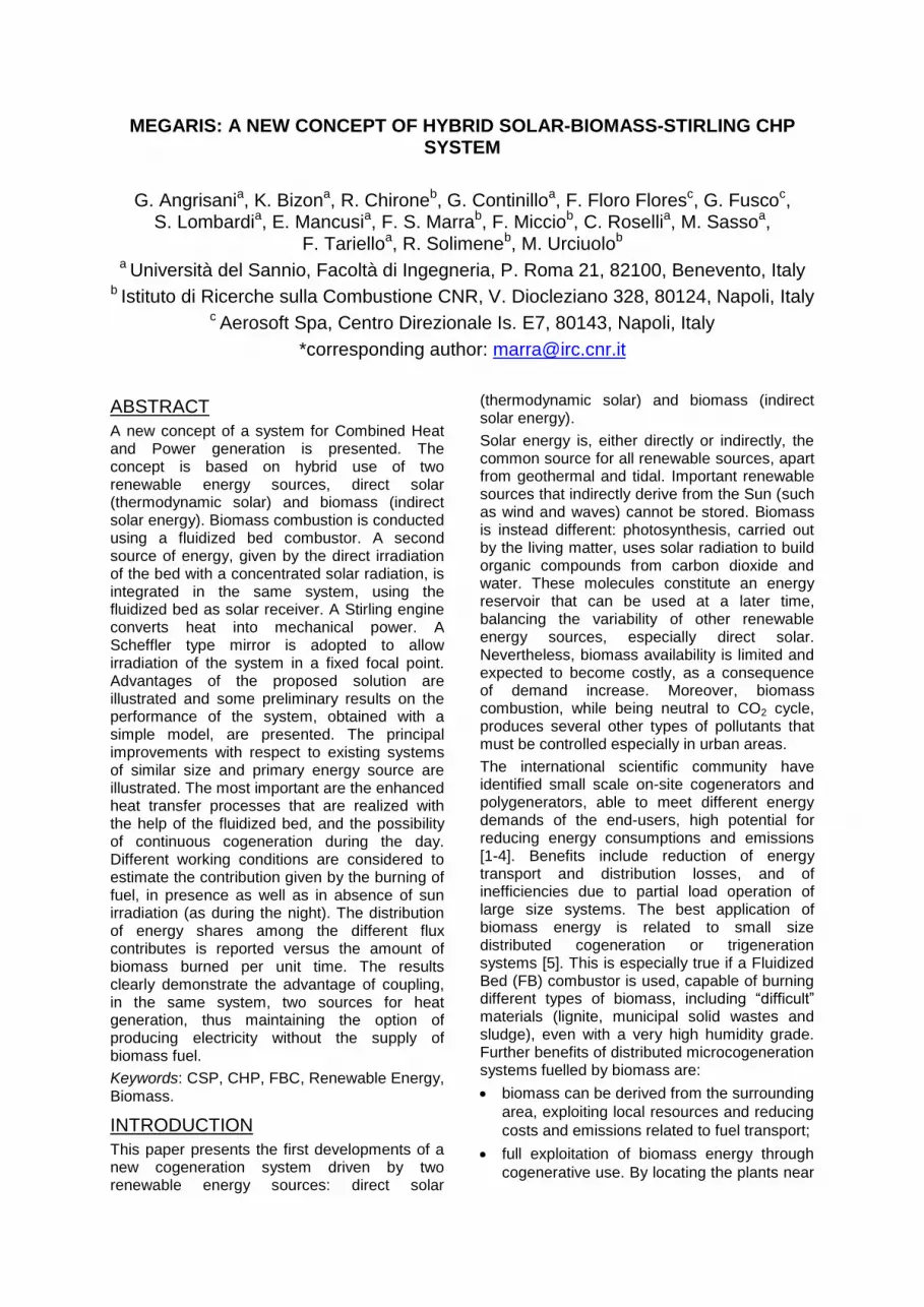
Figure 1. Schematic of the assembly.
Parabolic dish collectors, due to their high geometrical concentration factor, reach much higher temperatures in their focus, even above 1000 °C. The coupling of a dish reflector and a Stirling engine has been extensively analyzed and some systems are currently commercialized in Europe and USA. In a conventional parabolic dish, a two-axes tracking motion of the reflector is required, whereas the receiver must sit in the focal point, which moves along with the reflector, thus becoming an integral part of the reflector itself. Fixing the combustor in the focus of the concentrator, so that in the tracking process solar beams are focused at the same point, is an unlikely hypothesis due to the size (large parts of the dish would be shaded), the weight, and the need to feed the device with biomass and hold it in vertical position. The solution to the last issue could be a tilting anchoring system, that is a Cardan-type system as found in some solar cookers [21], but this still does not make the solution technically feasible.
A solar system with a central receiver tower would be compatible for the operating temperatures and the vertical positioning of the combustor, but this is a complex system; each heliostat requires its own tracking system and small size applications are rare.
All these limitations can be overcome by the Scheffler concentrator [22], that is suitable for a static target/focus. The most numerous applications of this type of concentrator fall
Scheffler Mirror
Stirling Engine
Fluidized Bed
Combustor Biomass supply system
within the scope of the solar cookers [23], but the exergetic analysis proposed in [24] shows that Scheffler collectors are more appropriate for industrial application than for cooking. Sardeshpande et al. [25] compared the economic benefits of a Scheffler and a dish concentrator with Fresnel arrangement for medium temperature applications in India, deriving that the former have a greater feasibility and a shorter pay-back period. Ruelas et al. [26] developed a simulation model of a Scheffler reflector directly coupled to a Stirling engine. Their model, based on geometrical and optical considerations relatively to the concentrator, incorporates a thermal model of the receiver. They validate the model and numerically demonstrate that thermal efficiency can increase of 7% with respect to a parabolic dish collector. A very interesting configuration is found in [27], where a 8 m
2 Scheffler collector is used with a
distillation system employed for the treatment of medicinal and aromatic plants.
A fixed-focus solar concentrator, such as the Scheffler, requires a three-degrees of freedom tracking. A stepper motor provides the daily motion around the equatorial axis, inclined at an angle equal to the local latitude. The seasonal correction is achieved by changing both the declination angle (+/- 23.5°) and the shape of the mirror, to refit the focus on the target area.
A pictorial representation of the system is shown in Fig. 1. It essentially includes: the solar collector; the FB, that plays the multiple role of CSP receiver, heat exchanger, and biomass combustor; and a Stirling Engine. In this seemingly complex system, all parts can be manufactured to be robust, reliable, and low-maintenance, the most complex being the SE.
In this paper, some technical aspects of relevance to the design of the proposed system are analysed in detail, and its potential advantages are highlighted.
MODEL DEVELOPMENT
A simple model has been developed to assess the potentiality of the proposed system. It analyzes the energy fluxes distribution among the several system components (Figure 2).
Fluidized Bed Reactor
As anticipated in the Introduction, the fluidized bed reactor plays three roles: concentrated solar energy receiver, heat exchanger with the head of the SE and biomass combustor. Fluidization is obtained, as usual, by air flow blowing from the bottom of a vessel where a certain amount of granular material, like sand, is loaded over an air distributor. This allows all particles to float and move, carrying and efficiently exchanging heat with the other particles, the confining walls
and the gas phase. Therefore, heat is almost immediately spread to both the gas and solid phase, and temperature can be assumed uniform in space. The high heat capacity of the bed helps to avoid oscillations in time of the bed temperature, enhancing the performance of the combustion process.
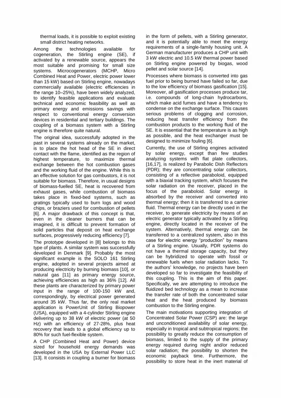
Figure 2. Definition of the Control Volumes with
the accounted energy fluxes.
Several models are proposed in the literature to estimate fundamental design parameters for a FBC (Fluidized Bed Combustor). Many of these models are based on a 0-dimensional (lumped) approach, with mass and energy balance. This approach, described, for instance, in [28], is adopted here to determine the main size of the components. The control volume used to formulate the energy balance, is delimited by the surfaces that surround the volume of the fluidized bed. An overall mass balance is written, leading to algebraic identity between entering and leaving mass. The contributions to the energy balance are identified and shown schematically in Fig. 2. The energy balance is written assuming the FB working as a pseudo-homogeneous, perfectly stirred reactor including both solid- and gas-phase. Constant values of specific heats are also assumed. The main energy fluxes are, per unit time: the inlet thermal power carried by the fluidization air, QC,in=ṁairhair, and fuel, QF,in=ṁFhF; the solar radiation power coming from the collector, QCSP; the thermal power delivered to the SE, QSE; the outlet power
carried by the hot gases (fluidization air and combustion gases) leaving the FB, QCout,FBC=ṁexhhexh=(ṁair+ṁF)hexh, where the mass of the solid phase in the FBC is assumed constant, that is ashes accumulation is neglected. In this analysis, heat losses are neglected. A generation term appears in the balance equation that represents the thermal power due to biomass combustion, Qcomb=ṁFLHVF. Under typical conditions of
operation of a FB, the gas velocity is everywhere very low, in the order of few meters
per second. Also, the pressure drop needed to fluidize the bed is relatively small and can be neglected, assuming that density variations are due primarily to changes in temperature (low-Mach number flow). In this case ρgT=const. Accumulation of heat in the volume can be assumed to occur only in the solid phase. Thus, the total energy balance in the FB is:
airbed
s s a F
air F exh
ir F CSP SE
F F
dTm c h h Qm m
m m h m
Qdt
LHV
(1)
Fluxes depending upon FB properties are computed adopting theoretical and semi-empirical relations, [28]. Particularly, the heat transfer coefficient between the fluidized bed and an immersed surface can be calculated by considering both conductive and radiative terms, [28]. Since biomass fuels are very reactive, a large fraction of combustion enthalpy is released in the bed. The remainder is released in the freeboard, contributing to its overheating [29].
Stirling Engine
The simplified SE model proposed in [30] is adopted here to compute the efficiency of the SE, hence the useful power for electricity production, as a function of all main variables describing the engine and its operation. The power produced by the thermodynamic cycle of the SE when the working fluid temperatures are, respectively, T1 inside the expansion chamber and T2 inside the compression chamber, is given
by PSE=(1-χ)φ(T1), where2 1/ /L HT T T T ,
TH≡Tbed is the temperature of the hot source and TL is the temperature of the cold sink. The φ(T1),
function includes the most important dependencies upon the SE parameters:
1
1 1
1
1
1
1 11
( )
11
H H
L
H
L L
A
T T TU
T
S
U
A
SF
T
(2)
In this expression UH is the heat exchange coefficient between the FB and the working fluid in the expansion chamber; in the present work, this coefficient is assumed as being limited only by the resistance between the solid granular phase and the external surface of the SE hot-side heat exchanger, or absorber. SH is the total
extension of the external surface of the absorber; TH is the temperature of the hot heat
source, assumed equal to the temperature in the FB, TH=Tbed; UL is the heat exchange coefficient
between the working fluid of the SE inside the compression chamber and the cooling fluid; SL is
the total extension of the external surface of the
cooler; TL is the temperature of the cooling fluid; A1=(1-εR)/[(γ-1)lnλ] where εR is the effectiveness of the regenerator, γ is the specific heat ratio of the working fluid, and λ=V1/V2 the compression
ratio of the SE; 1 1 21 1 lnF M M nR ,
where n is the number of moles of the working
fluid, R the corresponding gas constant, M1 and M2 and the regenerator time constants of compression and expansion, respectively.
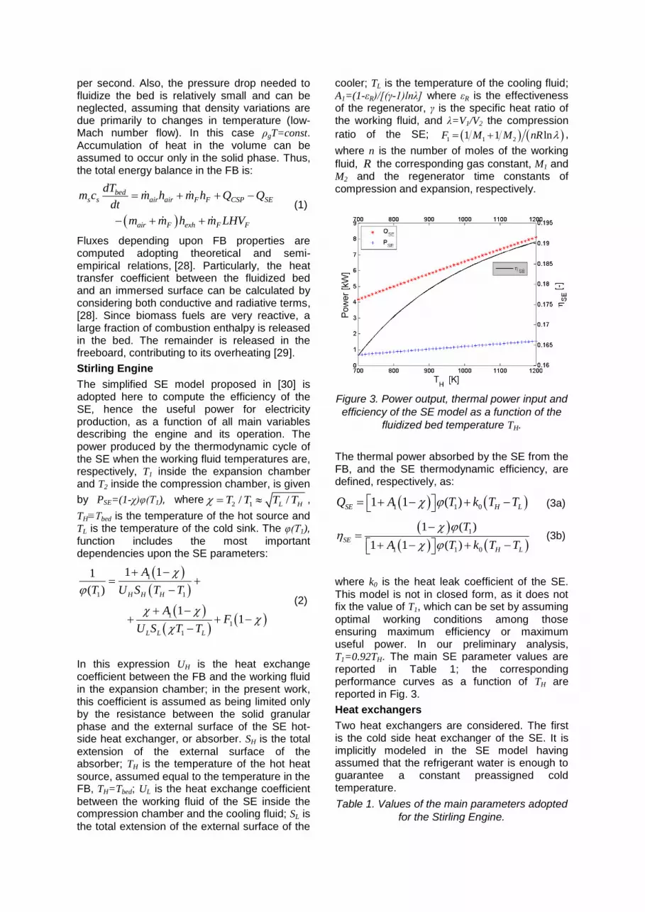
Figure 3. Power output, thermal power input and
efficiency of the SE model as a function of the
fluidized bed temperature TH.
The thermal power absorbed by the SE from the FB, and the SE thermodynamic efficiency, are defined, respectively, as:
1 1 01 1 ( )SE H Lk T TQ A T (3a)
1
1 1 0
1 ( )
1 1 ( )SE
H L
T
A T k T T
(3b)
where k0 is the heat leak coefficient of the SE.
This model is not in closed form, as it does not fix the value of T1, which can be set by assuming
optimal working conditions among those ensuring maximum efficiency or maximum useful power. In our preliminary analysis, T1=0.92TH. The main SE parameter values are reported in Table 1; the corresponding performance curves as a function of TH are reported in Fig. 3.
Heat exchangers
Two heat exchangers are considered. The first is the cold side heat exchanger of the SE. It is implicitly modeled in the SE model having assumed that the refrigerant water is enough to guarantee a constant preassigned cold temperature.
Table 1. Values of the main parameters adopted
for the Stirling Engine.
Temperature of refrigerant 293 K
moles of working fluid multiplied
by the gas constant, n R 1 J/K
Specific heat ratio of the working fluid (Air), γ
1.4
working pressure 10E+5 Pa
Regenerator effectiveness, εR 0.85 [-]
number of absorber elements 50
combined reciprocal regenerative time constant [30]
2.0E-5 s/K
heat leak coefficient [30], k0 4.0 s/K
Compression ratio, λ 1.5
radius of absorber elements 0.004 m
length of absorber elements 0.2 m
heat transfer coefficient 200 W/(m2 K)
It is then assumed that all the heat wasted by the SE is recovered in the water flow stream. To complete the unsteady energy balance, it is necessary to know the volume of water in the heat exchanger. Modeling the heat exchanger as a continuos stirred tank, the energy balance for water is written as:
,1, 1
,0 ,1 (1 )
w
w w w w SE SE
ww hx
w w
dTm
m c m c Q
cdt
T T
(4)
where, with reference to Fig. 2, 0,www0wTcmQ
and 1,www1wTcmQ and having neglected heat
losses to the ambient air.
Table 2. Values of the main parameters of the
heat exchangers.
Mass of water in the SE Heat Exc. 0.5 kg
Mass of water in the exhaust gases/water heat exchanger
0.2 kg
Water mass flow rate 0.05 kg/s
Water temperature at inlet ,0wT 293 K
The second heat exchanger is actually a regenerator for the heat contained in the gases leaving the Fluidized Bed Combustor (FBC). It is placed in series with the heat exchanger of the SE and it is expected to be effective if the water flux is high enough to guarantee a small water temperature rise, well below the boiling temperature. Assuming that a condensing heat exchanger is used, so that the exhaust gases leave at a temperature of 80 °C, the heat recovered in this unit can be computed as
, ( (273 80))hx exh P exh bedQ m c T . At steady
state, having neglected the mass of ashes,
exh F airm m m . Then, the energy balance
equation can be written as:
,2, 2
,1 ,2
ww hx
w xw
w
w w w w hm c
dTm c
dt
T Tm c Q
(5)
where, with reference to Fig. 2, 2,www2wTcmQ .
The parameters appearing in Eqs. (4) and (5) are reported in Table 2.
MODEL RESULTS
Two different working conditions are analysed. The first corresponding to functioning with the only contribute of concentrated solar power with a mirror having a surface of 12 m
2, the second,
corresponding to night or absence of sun irradiation, with power coming from the burning of biomass fuel. Apart from the heat source, the main difference between this two working conditions comes from the very different air flow rate, determined by the minimum fluidization velocity in the first case and the required air excess to ensure clean combustion of the biomass in the second.
All the other parameters of the configuration adopted are reported in Table 3.
Table 3. Values of the main parameters of the
Fluidized Bed reactor.
Reactor diameter 0.300 m
Solid particles mean diameter 300 m
Solid particles specific heat 800 J/(kg K)
Total mass of particles in bed 8 kg
Heat transfer coefficient of the Stirling Engine heater
200 W/(m2 K)
Global CSP efficiency 0.75 [-]
Lower Heating Value of Biomass (pellet)
18.24E+06 J/kg
Air excess for pellet combustion 30 %
The distribution of energy shares among the different flux contributes has been evaluated (not shown in this work). The simplifying assumptions of the model make the energy outputs too optimistic: in fact, when temperature increases, several heat losses, not accounted for in the model, become significant.
In Fig. 4, Tbed and Tw,2 as a function of time for
different solar irradiance are shown.
The bed temperature needs to be limited below 1100 °C for technological reasons, and therefore the results shown in Fig. 4 indicate that a smaller mirror could be considered.

Figure 4. Bed and water temperatures versus
time for solar irradiance from 200 to 1000 W/m2
with step of 80 W/m2.
In Fig. 5, the index of utilization of the solar energy that enters the FBC:
,2 ,0SE w w w w
CSP
P m c T TFUE
Q
(6)
is reported. In this working condition, most of the heat recovered comes from the heat wasted by the SE, since a very low amount of energy is transferred to the fluidization air required. Even excluding unpractical values, the possibility of obtaining a significant power output, as well as a useful cogenerated heat, exists.
Figure 5. CSP power utilization coefficient
versus solar irradiance.
When biomass combustion is the primary source, the situation significantly changes (Fig. 6). When no CSP can be collected, about 2 to 4 kg/h of biomass are needed to establish the same PSE and heat power output. Actually, in this
case, temperatures lower than about 800 °C cannot be considered in order to allow a self sustained biomass combustion. The distribution of energy shares in this case indicate that, when adopting biomass combustion, the present
layout of the system suffers of a rapid increase of energy dissipated by convection. Indeed, to ensure the proper amount of oxygen for complete combustion, the air mass flow rate must be well above the value required for the minimum fluidization velocity.
Figure 6. Bed and water temperatures versus
time for ṁF from 1 to 4 kg/h with steps of 0.3
kg/h, water mass flow rate of 0.05 kg/s.
Furthermore, when increasing PSE, available thermal also rapidly increase, and an higher water flux is needed to absorb such thermal energy output, to avoid boiling. By doubling the water flux, it is possible to avoid boiling, as reported in Figure 7. The plot of the FUE, defined for this configuration as:
,2 ,0SE w w w w
F F
P m c T TFUE
m LHV
(7)
reported in Fig. 8, clearly indicates the limits of this configuration with respect to the efficiency attainable with CSP.
Figure 7. Bed and water temperatures versus
time for ṁF from 1 to 4 kg/h with steps of 0.3
kg/h, water mass flow rate of 0.1 kg/s.
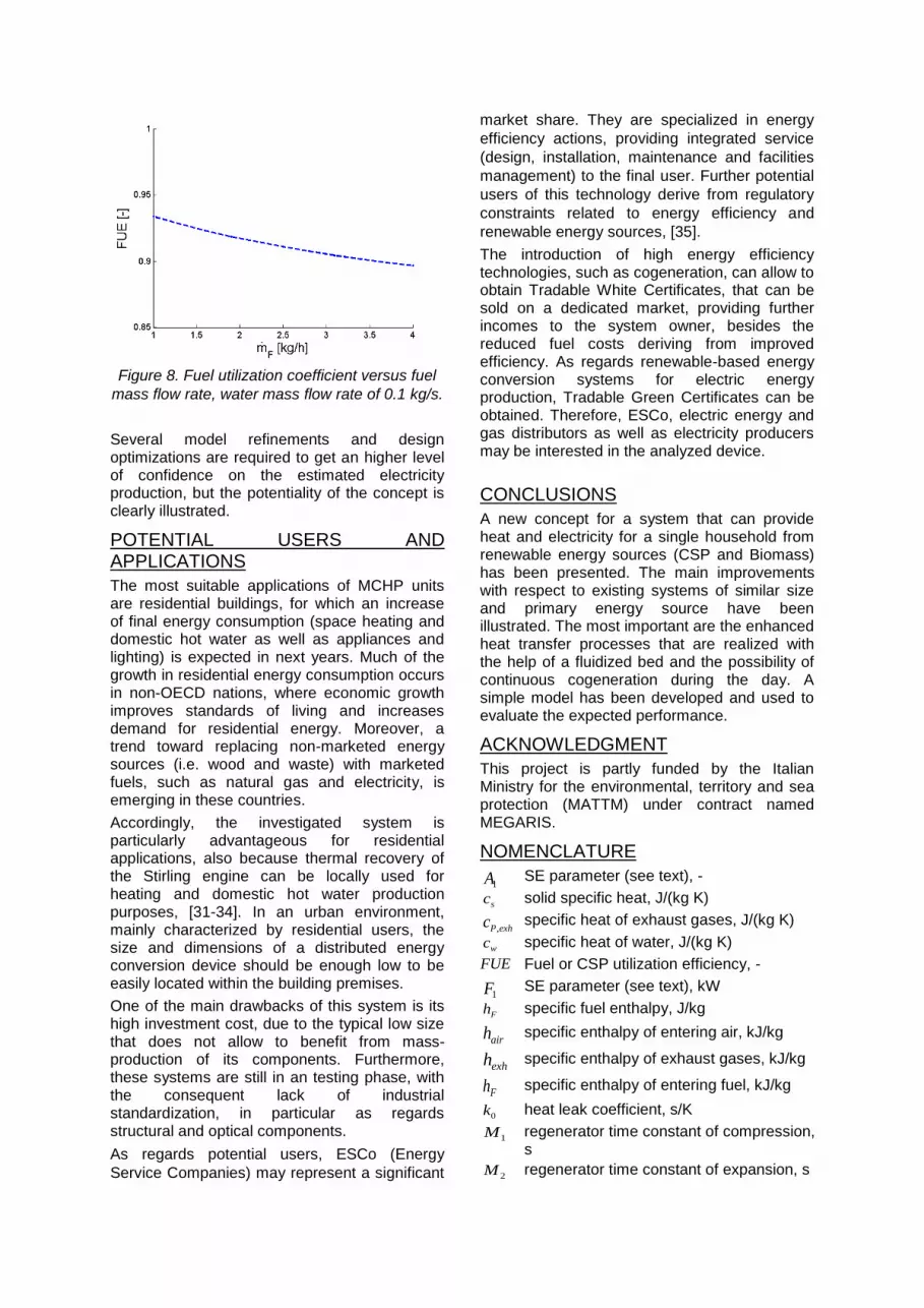
Figure 8. Fuel utilization coefficient versus fuel
mass flow rate, water mass flow rate of 0.1 kg/s.
Several model refinements and design optimizations are required to get an higher level of confidence on the estimated electricity production, but the potentiality of the concept is clearly illustrated.
POTENTIAL USERS AND APPLICATIONS
The most suitable applications of MCHP units are residential buildings, for which an increase of final energy consumption (space heating and domestic hot water as well as appliances and lighting) is expected in next years. Much of the growth in residential energy consumption occurs in non-OECD nations, where economic growth improves standards of living and increases demand for residential energy. Moreover, a trend toward replacing non-marketed energy sources (i.e. wood and waste) with marketed fuels, such as natural gas and electricity, is emerging in these countries.
Accordingly, the investigated system is particularly advantageous for residential applications, also because thermal recovery of the Stirling engine can be locally used for heating and domestic hot water production purposes, [31-34]. In an urban environment, mainly characterized by residential users, the size and dimensions of a distributed energy conversion device should be enough low to be easily located within the building premises.
One of the main drawbacks of this system is its high investment cost, due to the typical low size that does not allow to benefit from mass-production of its components. Furthermore, these systems are still in an testing phase, with the consequent lack of industrial standardization, in particular as regards structural and optical components.
As regards potential users, ESCo (Energy
Service Companies) may represent a significant
market share. They are specialized in energy
efficiency actions, providing integrated service
(design, installation, maintenance and facilities
management) to the final user. Further potential
users of this technology derive from regulatory
constraints related to energy efficiency and
renewable energy sources, [35].
The introduction of high energy efficiency technologies, such as cogeneration, can allow to obtain Tradable White Certificates, that can be sold on a dedicated market, providing further incomes to the system owner, besides the reduced fuel costs deriving from improved efficiency. As regards renewable-based energy conversion systems for electric energy production, Tradable Green Certificates can be obtained. Therefore, ESCo, electric energy and gas distributors as well as electricity producers may be interested in the analyzed device.
CONCLUSIONS
A new concept for a system that can provide heat and electricity for a single household from renewable energy sources (CSP and Biomass) has been presented. The main improvements with respect to existing systems of similar size and primary energy source have been illustrated. The most important are the enhanced heat transfer processes that are realized with the help of a fluidized bed and the possibility of continuous cogeneration during the day. A simple model has been developed and used to evaluate the expected performance.
ACKNOWLEDGMENT
This project is partly funded by the Italian Ministry for the environmental, territory and sea protection (MATTM) under contract named MEGARIS.
NOMENCLATURE
1A SE parameter (see text), -
sc solid specific heat, J/(kg K)
,P exhc specific heat of exhaust gases, J/(kg K)
wc specific heat of water, J/(kg K)
FUE Fuel or CSP utilization efficiency, -
1F SE parameter (see text), kW
Fh specific fuel enthalpy, J/kg
airh specific enthalpy of entering air, kJ/kg
exhh
specific enthalpy of exhaust gases, kJ/kg
Fh specific enthalpy of entering fuel, kJ/kg
0k heat leak coefficient, s/K
1M regenerator time constant of compression, s
2M regenerator time constant of expansion, s
airm air mass flow rate, kg/s
exhm exhaust gases mass flow rate, kg/s
Fm fuel mass flow rate, kg/s
sm total mass of solid particles, kg
, 1w hxm mass of water in SE heat exchanger, kg
, 2w hxm
mass of water in the exhaust gas heat exchanger, kg
wm mass flow rate of water, kg/s
n number of moles of the working fluid, -
FLHV
Lower Heating value of the fuel, kJ/kg
SEP SE power, kW
CinQ Heat entering the system with air, kW
,Cout FBCQ Heat flux leaving by convection the FBC, kW
,RecCoutQ Heat flux leaving by convection the exhaust gases/water h. e., kW
combQ
Heat released by biomass combustion, kW
,F inQ Heat entering the system with fuel, kW
CSPQ Heat collected by solar concentrator, kW
SEQ Heat transferred to the Stirling engine, kW
hxQ Heat recovered from exhaust gases, kW
0wQ Heat entering the SE/water heat exchanger, kW
1wQ Heat leaving the SE/water heat exchanger, kW
2wQ Heat leaving the exhaust gases/water heat exchanger, kW
R gas constant of the working fluid, J/(kg K)
HS total extension of the external surface of the absorber, m
2
LS total surface area of the cooler, m2
bedT temperature of fluidized bed, K
1T temperature in the expansion chamber, K
2T temperature in the compression chamber, K
HT temperature of the hot source, K
LT temperature of the cold sink, K
wT temperature of water, K
HU heat exchange coefficient between the FB and the working fluid, W/(m
2 K)
LU heat exchange coefficient between the working fluid and the coolant, W/(m
2 K)
1V volume of the expansion chamber, m3
2V volume of the compression chamber, m3
Greek letters
R SE regenerator efficiency, -
specific heat ratio of the working fluid, -
compression ratio, -
SE Stirling engine efficiency, -
ρg gas density, kg/m3
see eq. (2)
temperature ratio, -
Acronyms
CHP Combined Heat and Power
CSP Concentrated Solar Power
ESCo Energy Service Companies
FB Fluidized Bed
FBC Fluidized Bed Combustor
MCHP Micro Combined Heat and Power
PDR Parabolic Dish Reflector
SE Stirling Engine
REFERENCES
[1] C. Roselli, M. Sasso, S. Sibilio, P.
Tzscheutschler, Experimental analysis of
microcogenerators based on different prime
movers, Energy and Buildings 43 (2011)
796–804.
[2] G. Angrisani, F. Minichiello, C. Roselli, M.
Sasso, Experimental investigation to
optimise a desiccant HVAC system coupled
to a small size cogenerator, Applied
Thermal Engineering 31 (2011) 506–512.
[3] D.W. Wu, R.Z. Wang. Combined cooling,
heating and power: a review, Progress in
energy and combustion science 32 (2006)
459–495.
[4] G. Chicco, P. Mancarella, Distributed multi-
generation: A comprehensive view,
Renewable and Sustainable Energy
Reviews 13 (2009) 535–551.
[5] G. Angrisani, C. Roselli, M. Sasso,
Distributed microtrigeneration systems,
Progress in Energy and Combustion
Science 38 (2012) 502–521.
[6] R.L. Bain, R.P. Overend, Biomass for heat
and power, Forest Products Journal 52
(2002) 12–19.
[7] J. Vos, Biomass energy for heating and hot
water supply in Belarus, Contract Report
(BYE/03/G31), BTG 2006.
[8] E. Podesser, Electricity production in rural
villages with a biomass Stirling engine,
Renewable Energy 16 (1999) 1049–1052.
[9] N. Jensen, J. Werling, H. Carlsen, U.B.
Henriksen, CHP from updraft gasifier and
stirling engine, European Biomass
Conference 12 (2002) 726–729.
[10] HighBio Project. Biomass Gasification to
Heat, Electricity and Biofuels. Ed. Ulla Lassi
and Bodil Wikman. HighBio Project
Publication, 2011.
[11] T. Keck, W. Schiel, Envirodish and
Eurodish-System and Status, Proceedings
of ISES Solar World Congress, June 14-19,
Göteborg, Sweden, 2003.
[12] E.D. Rogdakis, G.D. Antonakos, I.P
Koronaki, Thermodynamic analysis and
experimental investigation of a Solo V161
Stirling cogeneration unit, Energy 45 (2012)
503 – 511.
[13] Y. Koyama Tilt, Micro-Cogeneration for
Single-Family Dwellings, 2001.
[14] S. Thiers, B. Aoun, B. Peuportier,
Experimental characterization, modeling and
simulation of a wood pellet micro-combined
heat and power unit used as a heat source
for a residential building, Energy and
Buildings 42 (2010) 896–903.
[15] J.H. Leu, Biomass Power Generation
through Direct Integration of Updraft Gasifier
and Stirling Engine Combustion System,
Advances in Mechanical Engineering, 2010.
[16] A.R. Tavakolpour, A. Zomorodian, A.A.
Golneshan, Simulation, construction and
testing of a two-cylinder solar Stirling engine
powered by a flat-plate solar collector
without regenerator, Renewable Energy 33
(2008) 77–87.
[17] B. Kongtragool, S. Wongwises, A review of
solar-powered Stirling engines and low
temperature differential Stirling engines,
Renewable and Sustainable Energy
Reviews 7 (2003) 131–154.
[18] S.Y. Kim, J. Huth, J.G. Wood, Performance
Characterization of Sunpower Free-Piston
Stirling Engines, Proceedings of AIAA
IECEC2005 conference (2005).
[19] F. Miccio, On the integration between
fluidized bed and stirling engine for micro-
generation, Applied Thermal Engineering 52
(2013) 46-53.
[20] K. Kim, N. Siegel, G. Kolb, V. Rangaswamy,
S.F. Moujaes, A study of solid particle flow
characterization in solar particle receiver,
Solar Energy 83 (2009) 1784–1793.
[21] J. Franco, C. Cadena, L. Saravia, Multiple
use communal solar cookers, Solar Energy
77 (2004) 217–223.
[22] A. Munir, O. Hensel, W. Scheffler, Design
principle and calculations of Scheffler fixed
focus concentrator for medium temperature
applications, Solar Energy 84 (2010) 1490–
1502.
[23] P. Kariuki Nyahoro, R.R. Johnson, J.
Edwards, Simulated performance of thermal
storage in solar cookers, Solar Energy 59
(1997) 11–17.
[24] N. Kumar, G. Vishwanath, A. Gupta, An
exergy based unified test protocol for solar
cookers of different geometries, Renewable
Energy 44 (2012) 457–462.
[25] V. Sardeshpande, I.R. Pillai, Effect of micro-
level and macro-level factors on adoption
potential of solar concentrators for medium
temperature thermal applications, Energy for
Sustainable Development 16 (2012) 216–
223.
[26] J. Ruelas, N. Velázquez, J. Cerezo, A
mathematical model to develop a Scheffler-
type solar concentrator coupled with a
Stirling engine, Applied Energy 101 (2013)
253–260.
[27] A. Munir, O. Hensel, On-farm processing of
medicinal and aromatic plants by solar
distillation system, Biosystems Engineering
106 (2010) 268–277.
[28] D. Kunii, O. Levenspiel, Fluidization
engineering, Butterworth-Heinemann
Boston, 1991.
[29] R. Chirone, F. Miccio, F. Scala, On the
relevance of axial and transversal fuel
segregation during the FB combustion of a
biomass, Energy and Fuels 18 (2004) 1108–
1117.
[30] L. Yaqi, H. Yaling, W. Weiwei, Optimization
of solar-powered Stirling heat engine with
finite-time thermodynamics, Renewable
Energy 36 (2011) 421–427.
[31] F. Caresana, C. Brandoni, P. Feliciotti, C.M.
Bartolini, Energy and economic analysis of
an ICE-based variable speed-operated
micro-cogenerator, Applied Energy 88
(2011) 659–671.
[32] F. Cardona, A. Piacentino, V. Alterio,
Analysis and optimization of fuel cell
cogeneration systems for application in
single-family houses, Proc. of ECOS 2010,
June 14 – 17, Lausanne, Switzerland, 2010.
[33] G. Orr, T. Dennish, I. Summerfield, F.
Purcell, Commercial micro-CHP Field Trial
Report, Report of Sustainable Energy
Authority if Ireland (SEAI), 2011.
[34] Carbon Trust, Micro-CHP Accelerator,
Interim report, 2007.
[35] A.D. Hawkes, M.A. Leach, On policy
instruments for support of micro combined
heat and power, Energy Policy 36 (2008)
2973–2982.


