Embed Size (px)
Citation preview

ORIGINAL PAPER
Mathematical modeling of the operation of SOFCNickel-cermet anodes
D. Presvytes & C. G. Vayenas
Received: 8 December 2006 /Accepted: 8 December 2006 / Published online: 7 March 2007# Springer-Verlag 2007
Abstract A surface diffusion–reaction model is developedand solved to describe the steady-state operation of Nickel-cermet anodes in solid oxide fuel cells. The model accountsfor the migration (backspillover) and diffusion of oxygenions from the solid electrolyte onto the nickel surface andthe concomitant reaction with the fuel over a finite reactionzone extending from the three-phase boundaries onto theNi–gas interface. The model is developed for various nickelparticle geometries and is compared with existing anodemodel predictions for flat geometries. The performance ofthe anode, expressed by an anodic effectiveness factor, isfound to depend on two dimensionless numbers, whichcontain all the operational and structural information of theanode. The model is validated with literature experimentaldata regarding the dependence of the anode performance onthe fuel partial pressure and predicts correctly the observeddeviation from linearity of the dependence of cell currenton fuel partial pressure.
Keywords SOFC anode modeling . Ni/YSZ cermet .
Ni particle geometry . Overpotential . Anode effectivenessfactor . Thiele modulus . Ion spillover
Introduction
Solid oxide fuel cells (SOFC) are attracting increasingattention during the last few years as highly efficient andenvironmentally acceptable sources of electrical energy [1–
4]. Mathematical modelling of SOFCs, which startedalready in the 1980s [5, 6], particularly after the experi-mental demonstration of the first flat plate cross-flow SOFCunits [7], has intensified in recent years [8–16].
There is a strong interest in modelling the performance ofNi–YSZ cermet SOFC anodes [17–23], where the impor-tance of gas diffusional limitations [17, 19] and of O2− andO− spillover [19] is receiving increasing attention. The latteris because, in recent years, it has been shown by severalelectrochemical and surface science techniques [24–28] thatthe oxidation process is not strictly limited to the three-phaseboundaries (tpb) of the anode, as believed earlier, but thereaction zone extends on the Ni catalyst surface over severalhundreds of Angstroms [25–28]. The nature of the migratingoxygen anionic species on the metal electrode has beeninvestigated using a variety of electrochemical and surfacescience techniques [25–29], as well as with theoreticalstudies [30, 31]. In most previous anode models, thedeviation from linearity of the current–voltage curve of thecell and concomitant anodic overpotential has been linked tothe diffusional limitations imposed by the adsorption ofreactants on this extended reaction area [22–25].
In the present study, we model the performance of Ni–YSZ cermet anodes by accounting explicitly for thespillover of O2− from YSZ to the Ni–gas interface and thereaction of O2− at this interface with the fuel. The resultingsurface diffusion–reaction model is solved analytically forvarious sphere-based Ni particle geometries. The assumedgeometries are in good qualitative agreement with scanningelectron microscopy (SEM) images obtained in numerousexperimental SOFC studies [32–38]. The obtained analyticsolution is in good agreement with recent SOFC anodeperformance studies [39] (Fig. 1a), which show significantdeviations from linearity in the current–fuel concentrationdependence (Fig. 1b).
Ionics (2007) 13:9–18DOI 10.1007/s11581-007-0070-6
D. Presvytes :C. G. Vayenas (*)Department of Chemical Engineering, Laboratory of Chemicaland Electrochemical Processes, University of Patras,Caratheodory 1, St.,26504 Patras, Greecee-mail: [email protected]

Model development
Considering the anodic oxidation of hydrogen or CH4 [39,40] at a Ni/YSZ cermet:
H2 þ O2� ! H2Oþ 2e� ð1Þ
CH4 þ O2� ! COþ 2H2 ð2Þ
CH4 þ 3O2� ! CO2 þ H2O ð3Þand assuming an Eley–Rideal type reaction mechanism[41–43] between the gaseous fuel reactant and O2− on areaction zone that extends from the three-phase boundaries(tpb) over, potentially, the entire Ni–gas interface, one canexpress the rate of O2− consumption by the fuel as:
r ¼ kypACmax
Z L
0θO2�dz ¼ I=2F ð4Þ
where k is a rate constant (s−1), yp is the mole fraction of thefuel (e.g. hydrogen or CH4) that is assumed to be weaklyadsorbed on the Ni electrocatalyst surface (i.e. Ni–gasinterface), A (m2) is the surface area of that interface, Cmax
is the maximum (full coverage) surface concentration ofspillover O2− species at that interface, qO2� is the coverage(C/Cmax) of the O2− ions at that interface, C is the surfaceconcentration (mol/m2), Cmax is the maximum surfaceconcentration corresponding to full coverage, z is the distancefrom the tpb, L is thickness of the spillover zone on the Nisurface, I is the current and F is Faraday’s constant.
The oxygen coverage, qO2� , is in general not uniform onthe Ni surface but decreases with distance from the tpbzone due to its fast consumption by the fuel.
Similarly to the treatment of similar reaction–diffusionproblems in chemical and electrochemical reaction engi-neering [42, 43], one defines an anodic effectiveness factor,ηeff, from:
ηeff ¼ r=rmax ð5Þwhere rmax (=kypACmax) is the maximum, kineticallycontrolled reaction rate corresponding to qO2� ¼ 1, i.e. tothe limit of infinitely fast oxygen spillover and diffusion.The model does not consider gas phase diffusionallimitations, which become important only at the limit ofvery high current densities leading to the onset ofsignificant gas–diffusional overpotentials [5, 8, 26].
From Eqs. 4 and 5 it follows that
heff ¼Z L
0qO2�dz ð6Þ
where L is a characteristic diffusional length equal to thethickness of the diffusional zone on the Ni particle insidethe Ni/YSZ cermet anode.
The function qO2� zð Þ, or C(z), is the solution of thefollowing differential mass balance equation, whichdescribes the diffusion of oxygen ions on the Ni surfacetogether with their reaction with the fuel:
d2C
dz2� k=Dsð ÞC ¼ 0 ð7Þ
Fig. 1 a Experimental current density–potential curves obtained at 1,000 °C for various anodic yCH4values [39]. b Effect of yCH4 on the rate offuel consumption computed from a
10 Ionics (2007) 13:9–18
where Ds is the surface diffusivity of the spillover oxygenions on the Ni electrode surface. The problem described byEqs. 6 and 7 bears several similarities with that of thereaction and diffusion of backspillover O2− ions in porousmetal films interfaced with a slab of YSZ and used forelectrochemical promotion studies [30, 31, 44].
One also has the following boundary conditions:
z ¼ 0;dC
dz¼ � I
2FDs‘tpb1� C=Cmaxð Þ ð8Þ
z ¼ L; dC=dz ¼ 0 ð9Þwhere ‘tpb mð Þ is the three-phase-boundary length.
Recalling that θ=C/Cmax and defining ξ=z/L, where L isthe thickness of the catalyst film, one can write Eqs. 7,8 and 9 in the following dimensionless form:
d2q
dx2� Φ2q ¼ 0 ð10Þ
x ¼ 0;dqdx
¼ �JΦ2 1� qð Þ ð11Þ
ξ ¼ 1; dθ=dξ ¼ 0 ð12Þwhere the Thiele modulus Φ is defined from:
Φ ¼ Lffiffiffiffiffiffiffiffiffiffik=Ds
pð13Þ
and the dimensionless current J is defined from:
J ¼ I�
2FkCmaxL‘tpb� � ¼ I=2FkCmaxAc; ð14Þ
where in the last equality, we have expressed the total gasexposed Ni-electrode surface area, A, as L‘tpb.
Solution of Eq. 10 with boundary conditions Eqs. 11 and12 gives [30, 44]:
θ ξð Þ ¼ cos h Φ 1� ξð Þ½ �sin hΦ= ΦJð Þ þ cos hΦ
: ð15Þ
Note that for small Φ and large J values θ(ξ) approachesunity for all J values.
The promotional effectiveness factor, ηeff, is defined as
heff ¼Z1
0
q xð Þdx ð16Þ
and expresses the fraction of the total catalyst surfacecovered by the promotional backspillover species. Substi-tuting Eq. 15 into Eq. 16 and integrating, one obtains:
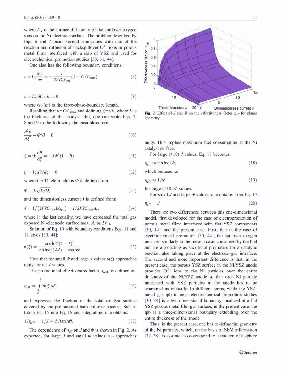
1=ηeff ¼ 1=J þ Φ=tan hΦ: ð17ÞThe dependence of ηeff on J and Φ is shown in Fig. 2. As
expected, for large J and small Φ values ηeff approaches
unity. This implies maximum fuel consumption at the Nicatalyst surface.
For large (>10) J values, Eq. 17 becomes:
ηeff � tan hΦ=Φ; ð18Þwhich reduces to:
ηeff � 1=Φ ð19Þfor large (>10) Φ values.
For small J and large Φ values, one obtains from Eq. 17:
heff ¼ J ð20ÞThere are two differences between this one-dimensional
model, first developed for the case of electropromotion ofporous metal films interfaced with flat YSZ components[30, 44], and the present case. First, that in the case ofelectrochemical promotion [30, 44], the spillover oxygenions are, similarly to the present case, consumed by the fuelbut are also acting as sacrificial promoters for a catalyticreaction also taking place at the electrode–gas interface.The second and more important difference is that, in thepresent case, the porous YSZ surface in the Ni/YSZ anodeprovides O2− ions to the Ni particles over the entirethickness of the Ni/YSZ anode so that each Ni particleinterfaced with YSZ particles in the anode has to beexamined individually. In different terms, while the YSZ-metal–gas tpb in most electrochemical promotion studies[30, 44] is a two-dimensional boundary localized at a flatYSZ-porous metal film-gas surface, in the present case, thetpb is a three-dimensional boundary extending over theentire thickness of the anode.
Thus, in the present case, one has to define the geometryof the Ni particles, which, on the basis of SEM information[32–38], is assumed to correspond to a fraction of a sphere
Fig. 2 Effect of J and Φ on the effectiveness factor ηeff for planargeometry
Ionics (2007) 13:9–18 11
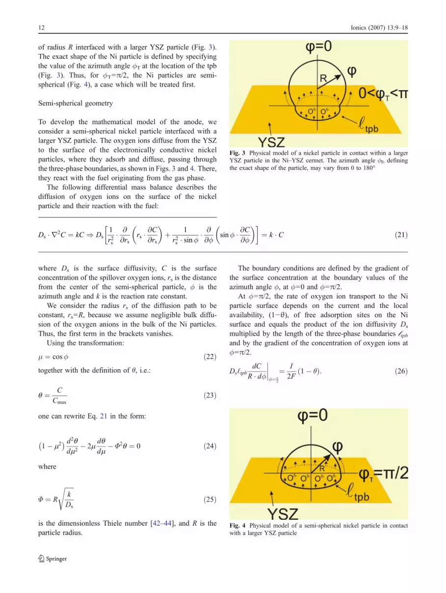
of radius R interfaced with a larger YSZ particle (Fig. 3).The exact shape of the Ni particle is defined by specifyingthe value of the azimuth angle φT at the location of the tpb(Fig. 3). Thus, for φφT=π/2, the Ni particles are semi-spherical (Fig. 4), a case which will be treated first.
Semi-spherical geometry
To develop the mathematical model of the anode, weconsider a semi-spherical nickel particle interfaced with alarger YSZ particle. The oxygen ions diffuse from the YSZto the surface of the electronically conductive nickelparticles, where they adsorb and diffuse, passing throughthe three-phase boundaries, as shown in Figs. 3 and 4. There,they react with the fuel originating from the gas phase.
The following differential mass balance describes thediffusion of oxygen ions on the surface of the nickelparticle and their reaction with the fuel:
Ds � r2C ¼ kC ) Ds1
r2s� @
@rsrs � @C
@rs
� �þ 1
r2s � sinφ� @
@φsinφ � @C
@φ
� �� ¼ k � C ð21Þ
where Ds is the surface diffusivity, C is the surfaceconcentration of the spillover oxygen ions, rs is the distancefrom the center of the semi-spherical particle, φϕis theazimuth angle and k is the reaction rate constant.
We consider the radius rs of the diffusion path to beconstant, rs=R, because we assume negligible bulk diffu-sion of the oxygen anions in the bulk of the Ni particles.Thus, the first term in the brackets vanishes.
Using the transformation:
μ ¼ cosφ ð22Þtogether with the definition of θ, i.e.:
q ¼ C
Cmaxð23Þ
one can rewrite Eq. 21 in the form:
1� m2� � d2q
dm2� 2m
dqdm
� Φ2q ¼ 0 ð24Þ
where
Φ ¼ R
ffiffiffiffiffiffik
Ds
sð25Þ
is the dimensionless Thiele number [42–44], and R is theparticle radius.
The boundary conditions are defined by the gradient ofthe surface concentration at the boundary values of theazimuth angle φϕ, at φϕ=0 and φϕ=π/2.
At φϕ=π/2, the rate of oxygen ion transport to the Niparticle surface depends on the current and the localavailability, (1−θ), of free adsorption sites on the Nisurface and equals the product of the ion diffusivity Ds
multiplied by the length of the three-phase boundaries ℓtpband by the gradient of the concentration of oxygen ions atφϕ=π/2.
Ds‘tpbdC
R � dφφ¼π
2
¼ I
2F1� θð Þ: ð26Þ
Fig. 3 Physical model of a nickel particle in contact within a largerYSZ particle in the Ni–YSZ cermet. The azimuth angle φϕT, definingthe exact shape of the particle, may vary from 0 to 180°
Fig. 4 Physical model of a semi-spherical nickel particle in contactwith a larger YSZ particle
12 Ionics (2007) 13:9–18

Taking into account Eqs. 22, 23 and 24, one can rewriteEq. 26 as:
dqdm
¼ � I
2F‘tpbCmaxRk
kR2
Ds1� qð Þ ð27Þ
where J is the dimensionless current of the anode definedfrom:
J ¼ I=2F‘tpbCmaxRk: ð28ÞThe above can also be expressed as:
dθdμ
μ¼0
¼ �JΦ2 1� θ φ ¼ π=2ð Þð Þ ð29Þ
At φϕ=0, one uses the symmetry boundary condition:
dθdφ
φ¼0
¼ 0 ;dθdμ
μ¼1
¼ 0: ð30Þ
We have integrated numerically the differential Eq. 24with the boundary conditions Eqs. 29 and 30 using ashooting Euler method. One, thus, determines the depen-dence of the coverage θ on the azimuth angle φ. Twoexamples of that dependence are shown in Fig. 5a and b forlow and high values, respectively, of the dimensionlesscurrent J. One observes that increasing Φ causes apronounced decrease in the thickness of the reaction zoneand that the value of θ at the three-phase boundaries (φ=φT)is very close to unity for all pairs of high values of J and Φ.
Effectiveness factor
The anodic effectiveness factor ηeff was defined in Eq. 5 as:
ηeff ¼ r=rmax
where r is the actual reaction rate and rmax is the reactionrate when the surface coverage equals unity for every valueof the angle φϕ(rmax corresponds to infinite ion diffusivity Ds
and thus to maximum reaction rate). As 0<θ<1, it followsthat the anodic effectiveness factor ηeff obviously takes valuesbetween 0 and 1.
The value of ηeff can be computed either from:
ηeff ¼Z π=2
0θ φð Þdφ ð31Þ
or from:
ηeff ¼C dθ
Rdφ
φ¼π
2
Ds2πR
2πR2kCmaxð32Þ
where the denominator expresses the rate on the semi-spherical surface when θ=1. Using Eq. 29, one thusobtains:
ηeff ¼ J 1� θ φ ¼ π=2ð Þ½ � ð33Þ
One can thus calculate the anodic effectiveness factor,ηeff, from the dimensionless current density J and from thevalue of the surface coverage at φϕ=π/2. The latter isdetermined by the Thiele number Φ.
Fig. 5 a Angular dependence of the spillover oxygen coverage for J=1 and various values of Φ. b Angular dependence of the spillover oxygencoverage for J=5 and various values of Φ; semi-spherical Ni particle
Ionics (2007) 13:9–18 13
At the limit Φ=0, the coverage θ becomes spatiallyuniform over the entire Ni particle surface, thus:
ηeff ¼RθdφRdφ
) ηeff ¼ θ: ð34Þ
This, in conjunction with Eq. 33, gives:
heff ¼J
J þ 1: ð35Þ
The dependence of ηeff on J and Φ practically coincideswith that shown in Fig. 2 for planar geometry. The anodiceffectiveness factor is an increasing function of thedimensionless current density J and a decreasing functionof the Thiele number Φ. In fact, for large values of J (>1)and Φ (>5), the effectiveness factor is approximated well bythe limiting expression:
ηeff � 1=Φ: ð36ÞAs already noted, for a planar anode geometry, the
dependence of ηeff on Φ is [30, 44]:
1=ηeff ¼ 1=J þ Φ=tan hΦ:
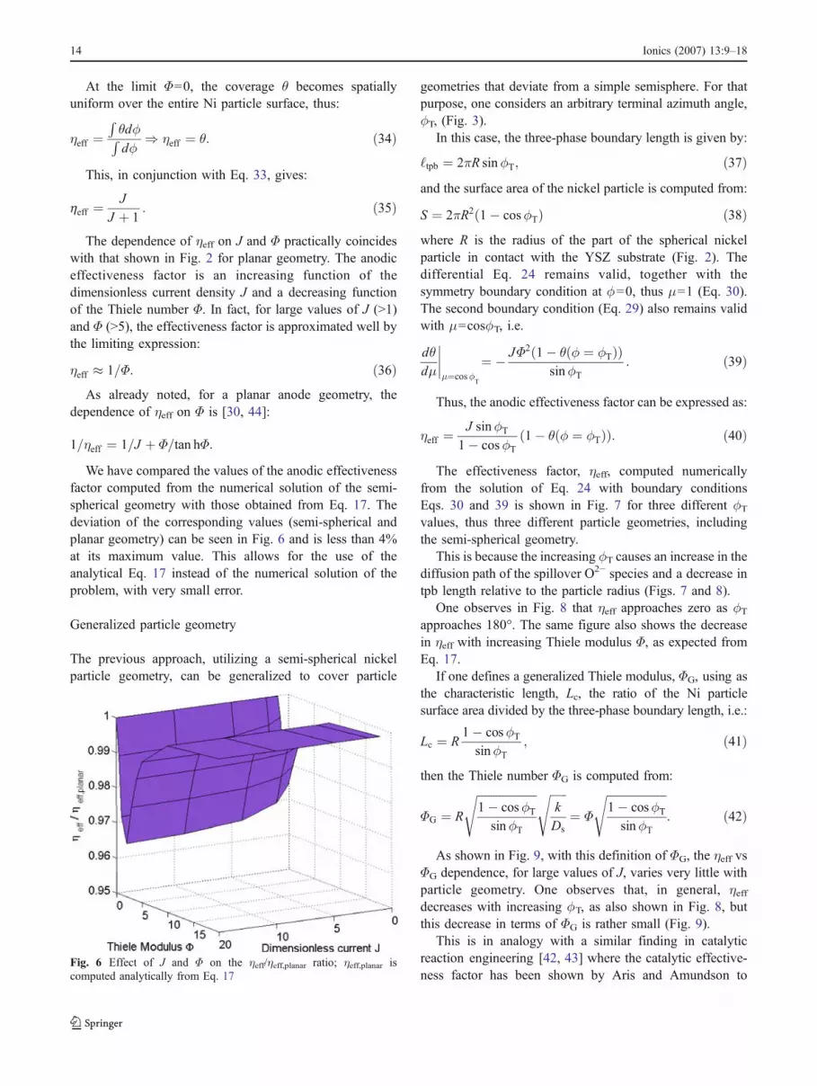
We have compared the values of the anodic effectivenessfactor computed from the numerical solution of the semi-spherical geometry with those obtained from Eq. 17. Thedeviation of the corresponding values (semi-spherical andplanar geometry) can be seen in Fig. 6 and is less than 4%at its maximum value. This allows for the use of theanalytical Eq. 17 instead of the numerical solution of theproblem, with very small error.
Generalized particle geometry
The previous approach, utilizing a semi-spherical nickelparticle geometry, can be generalized to cover particle
geometries that deviate from a simple semisphere. For thatpurpose, one considers an arbitrary terminal azimuth angle,φT, (Fig. 3).
In this case, the three-phase boundary length is given by:
‘tpb ¼ 2πR sinφT; ð37Þand the surface area of the nickel particle is computed from:
S ¼ 2πR2 1� cosφTð Þ ð38Þwhere R is the radius of the part of the spherical nickelparticle in contact with the YSZ substrate (Fig. 2). Thedifferential Eq. 24 remains valid, together with thesymmetry boundary condition at φφ=0, thus μ=1 (Eq. 30).The second boundary condition (Eq. 29) also remains validwith μ=cosφφT, i.e.
dθdμ
μ¼cosφ
T
¼ � JΦ2 1� θ φ ¼ φTð Þð ÞsinφT
: ð39Þ
Thus, the anodic effectiveness factor can be expressed as:
ηeff ¼J sinφT
1� cosφT1� θ φ ¼ φTð Þð Þ: ð40Þ
The effectiveness factor, ηeff, computed numericallyfrom the solution of Eq. 24 with boundary conditionsEqs. 30 and 39 is shown in Fig. 7 for three different φTvalues, thus three different particle geometries, includingthe semi-spherical geometry.
This is because the increasing φT causes an increase in thediffusion path of the spillover O2− species and a decrease intpb length relative to the particle radius (Figs. 7 and 8).
One observes in Fig. 8 that ηeff approaches zero as φTapproaches 180°. The same figure also shows the decreasein ηeff with increasing Thiele modulus Φ, as expected fromEq. 17.
If one defines a generalized Thiele modulus, ΦG, using asthe characteristic length, Lc, the ratio of the Ni particlesurface area divided by the three-phase boundary length, i.e.:
Lc ¼ R1� cosφT
sinφT; ð41Þ
then the Thiele number ΦG is computed from:
ΦG ¼ R
ffiffiffiffiffiffiffiffiffiffiffiffiffiffiffiffiffiffiffiffiffi1� cosφT
sinφT
s ffiffiffiffiffiffik
Ds
s¼ Φ
ffiffiffiffiffiffiffiffiffiffiffiffiffiffiffiffiffiffiffiffiffi1� cosφT
sinφT
s: ð42Þ
As shown in Fig. 9, with this definition of ΦG, the ηeff vsΦG dependence, for large values of J, varies very little withparticle geometry. One observes that, in general, ηeffdecreases with increasing φφT, as also shown in Fig. 8, butthis decrease in terms of ΦG is rather small (Fig. 9).
This is in analogy with a similar finding in catalyticreaction engineering [42, 43] where the catalytic effective-ness factor has been shown by Aris and Amundson to
Fig. 6 Effect of J and Φ on the ηeff/ηeff,planar ratio; ηeff,planar iscomputed analytically from Eq. 17
14 Ionics (2007) 13:9–18

vary little with particle geometry when the propercharacteristic length L is used in the definition of theThiele number [42, 43].
Model validation
To validate our model, we have used recent experimentaldata obtained with state-of-the art SOFCs operating on1,000 °C. Eguchi et al. [39] have studied the effect of CH4
fuel concentration on the current–voltage curves (Fig. 1a).Using these curves and the equation r=I/2F, we haveobtained Fig. 1b, which shows that for high fuel concen-tration, there are deviations from linearity.
Using Fig. 1b and the tangents of the r vs yCH4 curves atthe axis origin (0,0 point; Fig. 10), one can compute theintrinsic rate corresponding to negligible diffusionallimitations (ηeff=1, θ=1), i.e. the product kyCH4ACmax
(Eq. 41).
Fig. 7 Effect of J and Φ on ηefffor various Ni particlegeometries
Ionics (2007) 13:9–18 15
From the definition of ηeff (Eq. 5), it follows that ηeff cannow be computed for every r vs pCH4 point and for anyoverpotential h ¼ U � Uo
WR
� �by the simple geometrical
procedure shown in Fig. 10. Thus, one can compute theeffectiveness factor, ηeff, from:
heff ¼r
rmax¼ r
kyCH4Að43Þ
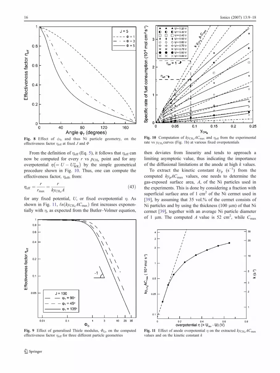
for any fixed potential, U, or fixed overpotential η. Asshown in Fig. 11, ‘n kyCH4ACmaxð Þ first increases exponen-tially with η, as expected from the Butler–Volmer equation,
then deviates from linearity and tends to approach alimiting asymptotic value, thus indicating the importanceof the diffusional limitations at the anode at high k values.
To extract the kinetic constant kyp (s−1) from thecomputed kypACmax values, one needs to determine thegas-exposed surface area, A, of the Ni particles used inthe experiments. This is done by considering a fraction withsuperficial surface area of 1 cm2 of the Ni cermet used in[39], by assuming that 35 vol.% of the cermet consists ofNi particles and by using the thickness (100 μm) of that Nicermet [39], together with an average Ni particle diameterof 1 μm. The computed A value is 52 cm2, while Cmax
Fig. 8 Effect of φφT, and thus Ni particle geometry, on theeffectiveness factor ηeff at fixed J and Φ
Fig. 9 Effect of generalised Thiele modulus, ΦG, on the computedeffectiveness factor ηeff for three different particle geometries
Fig. 10 Computation of kyCH4ACmax and ηeff from the experimentalrate vs yCH4curves (Fig. 1b) at various fixed overpotentials
Fig. 11 Effect of anode overpotential η on the extracted kyCH4ACmax
values and on the kinetic constant k
16 Ionics (2007) 13:9–18
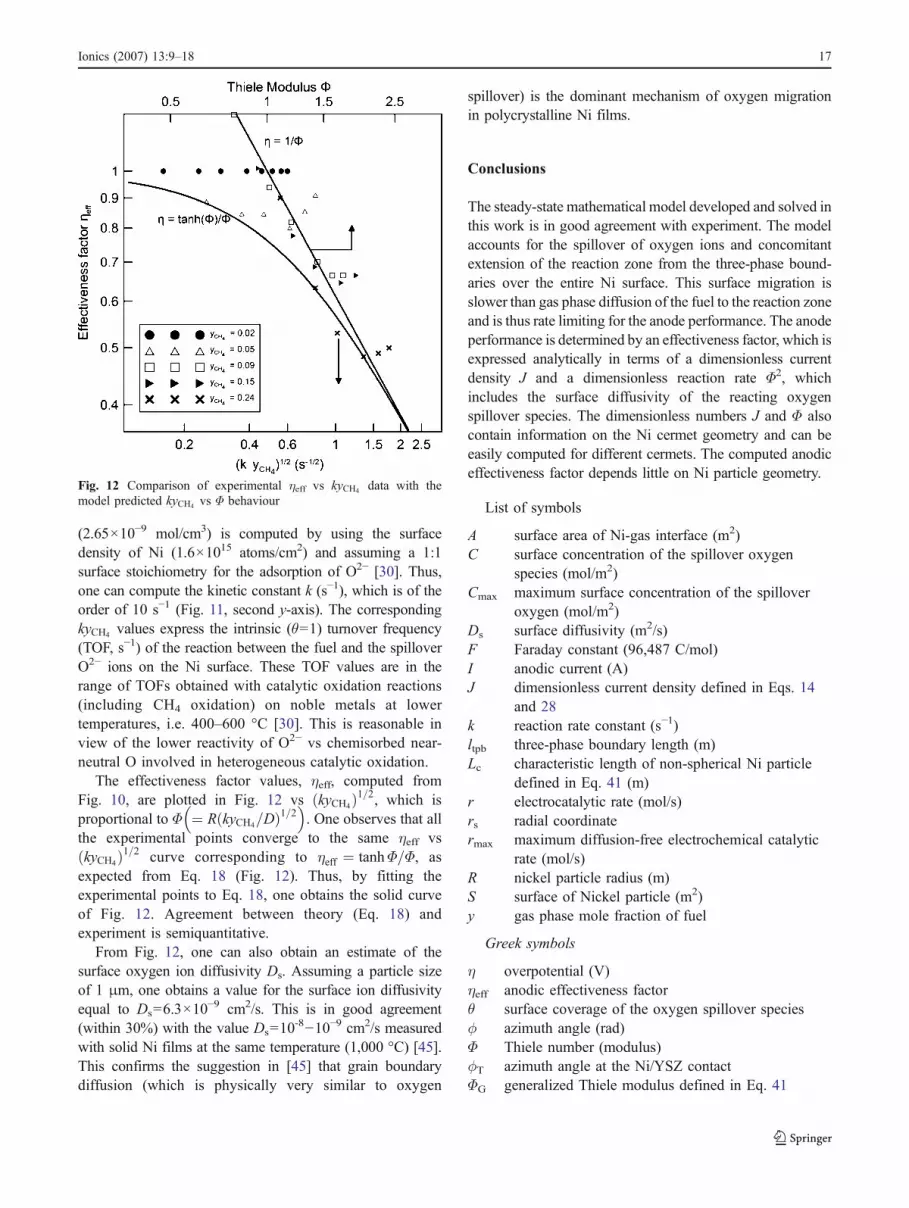
(2.65×10⁻⁹ mol/cm3) is computed by using the surfacedensity of Ni (1.6×10¹⁵ atoms/cm2) and assuming a 1:1surface stoichiometry for the adsorption of O2− [30]. Thus,one can compute the kinetic constant k (s−1), which is of theorder of 10 s−1 (Fig. 11, second y-axis). The correspondingkyCH4 values express the intrinsic (θ=1) turnover frequency(TOF, s−1) of the reaction between the fuel and the spilloverO2− ions on the Ni surface. These TOF values are in therange of TOFs obtained with catalytic oxidation reactions(including CH4 oxidation) on noble metals at lowertemperatures, i.e. 400–600 °C [30]. This is reasonable inview of the lower reactivity of O2− vs chemisorbed near-neutral O involved in heterogeneous catalytic oxidation.
The effectiveness factor values, ηeff, computed fromFig. 10, are plotted in Fig. 12 vs kyCH4ð Þ1=2, which isproportional to Φ ¼ R kyCH4=Dð Þ1=2
� �. One observes that all
the experimental points converge to the same ηeff vskyCH4ð Þ1=2 curve corresponding to ηeff ¼ tanhΦ=Φ, asexpected from Eq. 18 (Fig. 12). Thus, by fitting theexperimental points to Eq. 18, one obtains the solid curveof Fig. 12. Agreement between theory (Eq. 18) andexperiment is semiquantitative.
From Fig. 12, one can also obtain an estimate of thesurface oxygen ion diffusivity Ds. Assuming a particle sizeof 1 μm, one obtains a value for the surface ion diffusivityequal to Ds=6.3×10
−9 cm2/s. This is in good agreement(within 30%) with the value Ds=10
-8−10−9 cm2/s measuredwith solid Ni films at the same temperature (1,000 °C) [45].This confirms the suggestion in [45] that grain boundarydiffusion (which is physically very similar to oxygen
spillover) is the dominant mechanism of oxygen migrationin polycrystalline Ni films.
Conclusions
The steady-state mathematical model developed and solved inthis work is in good agreement with experiment. The modelaccounts for the spillover of oxygen ions and concomitantextension of the reaction zone from the three-phase bound-aries over the entire Ni surface. This surface migration isslower than gas phase diffusion of the fuel to the reaction zoneand is thus rate limiting for the anode performance. The anodeperformance is determined by an effectiveness factor, which isexpressed analytically in terms of a dimensionless currentdensity J and a dimensionless reaction rate Φ2, whichincludes the surface diffusivity of the reacting oxygenspillover species. The dimensionless numbers J and Φ alsocontain information on the Ni cermet geometry and can beeasily computed for different cermets. The computed anodiceffectiveness factor depends little on Ni particle geometry.
List of symbols
A surface area of Ni-gas interface (m2)C surface concentration of the spillover oxygen
species (mol/m2)Cmax maximum surface concentration of the spillover
oxygen (mol/m2)Ds surface diffusivity (m2/s)F Faraday constant (96,487 C/mol)I anodic current (A)J dimensionless current density defined in Eqs. 14
and 28k reaction rate constant (s−1)ltpb three-phase boundary length (m)Lc characteristic length of non-spherical Ni particle
defined in Eq. 41 (m)r electrocatalytic rate (mol/s)rs radial coordinatermax maximum diffusion-free electrochemical catalytic
rate (mol/s)R nickel particle radius (m)S surface of Nickel particle (m2)y gas phase mole fraction of fuel
Greek symbols
η overpotential (V)ηeff anodic effectiveness factorθ surface coverage of the oxygen spillover speciesφ azimuth angle (rad)Φ Thiele number (modulus)φT azimuth angle at the Ni/YSZ contactΦG generalized Thiele modulus defined in Eq. 41
Fig. 12 Comparison of experimental ηeff vs kyCH4 data with themodel predicted kyCH4 vs Φ behaviour
Ionics (2007) 13:9–18 17

Acknowledgement We are thankful to Dr. Anke Hagen for helpfuldiscussions and to the European IP Project REAL SOFC: SES 6CT2003 for financial support.
References
1. Singhal SC (2000) Solid State Ion 135:3052. Zhu WZ, Deevi SC (2003) Mater Sci Eng A362:2283. Kikuchi R, Eguchi K (2004) J Jpn Pet Inst 47(4):2254. Steele BCH (1996) Solid State Ion 86–88:12235. Debenedetti PG, Vayenas CG (1983) Chem Eng Sci 38(11):1817–
18296. Vayenas CG, Debenedetti PG, Yentekakis Y, Hegedus LL (1985)
Ind Eng Chem Fundam 24:316–3247. Michaels JN, Vayenas CG, Hegedus LL (1986) J Electrochem Soc
133(3):522–5258. Costamagna P, Selimovic A, Del Borghi M, Agnew G (2004)
Chem Eng J 102:61–699. Bieberle A, Gauckler LJ (2002) Solid State Ion 146:23–41
10. Chan SH, Low CF, Ding OL (2002) J Power Sources 103:188–20011. Ackmann T, de Haart GJ, Lehnert W, Stolten D (2003) J
Electrochem Soc 150(6):A783–A78912. Li P-W, Suzuki K (2004) J Electrochem Soc 151(4):A548–A55713. Mandin P, Bernay C, Tran-Dac S, Broto A, Abes D, Cassir M
(2006) Fuel Cells 06 1:71–7814. Bessler WG (2005) Solid State Ion 176:997–101115. Schneider LCR, Martin CL, Bultel Y, Bouvard D, Siebert E
(2006) Electrochim Acta 52:314–32416. Hussain MM, Li X, Dincer I (2006) J Power Sources 161:1012–102217. Williford RE, Chick LA, Maupin GD, Simner SP (2003) J
Electrochem Soc 150(8):A1067–A107218. Zhdanov VP (2003) Phys Rev E 67:042601–04260419. Williford RE, Chick LA (2003) Surf Sci 547:421–43720. Repetto L, Agnew G, Del Borghi A, Di Benedetto F, Costamagna
P (2007) J Fuel Cell Sci Technol (in press)21. Yakabe H, Hishinuma M, Uratani M, Matsuzaki Y, Yasuda I
(2000) J Power Sources 86:423–43122. Mizusaki J, Tagawa H, Isobe K, Tajika M, Koshiro I, Maruyama
H, Hirano K (1994) J Electrochem Soc 141(8):167423. Zhdanov VP (2003) Phys Rev E 67:042601
24. Williford RE, Chick LA, Maupin GD, Simner SP, Stevenson JW(2003) J Electrochem Soc 150(8):A1067
25. Williford RE, Chick LA (2003) Surf Sci 547:42126. Vayenas CG, Jaksic MM, Bebelis S, Neophytides SG (1996) In:
Bockris JOM, Conway BE, White RE (eds) Modern aspects ofelectrochemistry, vol. 29. Kluwer, New York, p 57
27. Vayenas CG, Bebelis S, Ladas S (1990) Nature 343:62528. Wieckowski A, Savinova E, Vayenas CG (2003) In: Catalysis and
electrocatalysis at nanoparticles. Marcel Dekker, New York29. Janek J, Luerßen B, Mutoro E, Fischer H, Günther S (2006)
Top Catal (in press)30. Vayenas CG, Bebelis S, Pliangos C, Brosda S, Tsiplakides D
(2001) Electrochemical activation of catalysis: promotion, elec-trochemical promotion and metal-support interactions. Kluwer,New York
31. Riess I, Vayenas CG (2003) Solid State Ion 159(3–4):313–32932. Abe H, Murata K, Fukui T, Moon W-J, Kaneko K, Naito M (2006)
Thin Solid Films 496:49–5233. Visco SS, De Jonghe LC (1997) J Electrochem Soc 144(3):L35–
L3734. Fukui T, Murata K, Ohara S, Abe H, Naito M, Nogi K (2004) J
Power Sources 125:17–2135. Kawada T, Sakai N, Yokokawa H, Dokiya M, Mori M, Iwata T
(1990) J Electrochem Soc 137(10):3042–304736. Carrillo AS, Tagawa T, Goto S (2001) Mater Res Bull 36:1017–
102737. Tietz F, Buchkremer H-P, Stöver D (2002) Solid State Ion 152–
153:373–38138. Marinšek M, Zupan K, Maèek J (2002) J Power Sources 106:178–
18839. Eguchi K, Kojo H, Takeguchi T, Kikuchi R, Sasaki K (2002)
Solid State Ion 152–153:41140. Yentekakis IV, Jiang Y, Neophytides S, Bebelis S, Vayenas CG
(1995) Ionics 1:49141. Bowden FB, Rideal E (1928) Proc Roy Soc A 120:5942. Smith JM (1981) Chemical engineering kinetics, 3rd edn.
McGraw-Hill, New York43. Froment GF, Bischoff KB (1979) Chemical reactor analysis and
design. Wiley, New York44. Vayenas CG, Pitselis GE (2001) Ind Eng Chem Res 40:420945. Perusin S, Monceau D, Andrieu E (2005) J Electrochem Soc 152
(12):E390
18 Ionics (2007) 13:9–18


