Embed Size (px)
Citation preview
Catalogue2009
Masterpact NT and NW NAVYLV power circuit breakersand switch-disconnectors
Low voltage electrical distribution
222E0000.indd 1 07/07/2009 14:13:37

1
PB
1016
46A
60_S
E
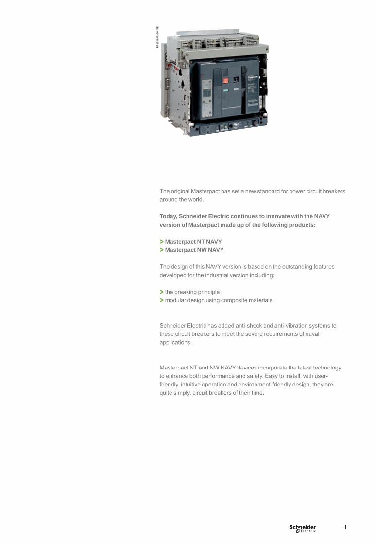
The original Masterpact has set a new standard for power circuit breakers around the world.
Today, Schneider Electric continues to innovate with the NAVY version of Masterpact made up of the following products:
> Masterpact NT NAVY> Masterpact NW NAVY
The design of this NAVY version is based on the outstanding features developed for the industrial version including:
> the breaking principle> modular design using composite materials.
Schneider Electric has added anti-shock and anti-vibration systems to these circuit breakers to meet the severe requirements of naval applications.
Masterpact NT and NW NAVY devices incorporate the latest technology to enhance both performance and safety. Easy to install, with user-friendly, intuitive operation and environment-friendly design, they are, quite simply, circuit breakers of their time.
BTP222E.indb 1 30/06/2009 09:30:10
2
Masterpact NAVY,levels of performance
DB
1066
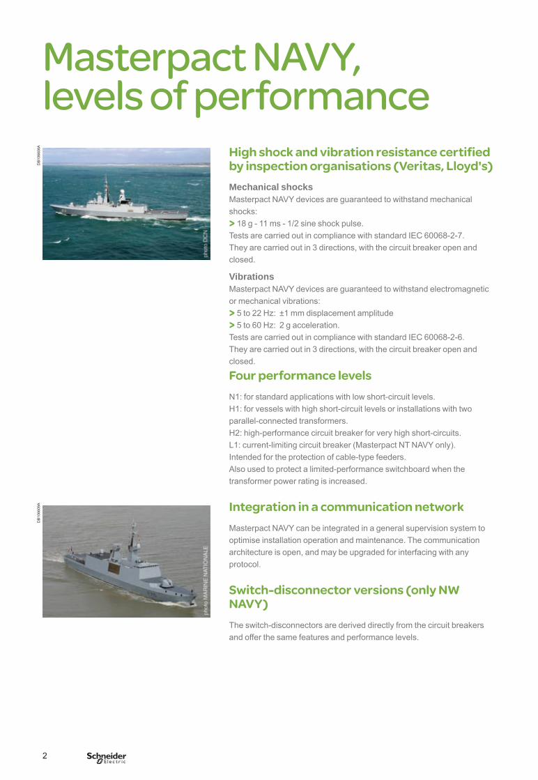
08A High shock and vibration resistance certified
by inspection organisations (Veritas, Lloyd's)Mechanical shocksMasterpact NAVY devices are guaranteed to withstand mechanical shocks:> 18 g - 11 ms - 1/2 sine shock pulse.Tests are carried out in compliance with standard IEC 60068-2-7.They are carried out in 3 directions, with the circuit breaker open and closed.
VibrationsMasterpact NAVY devices are guaranteed to withstand electromagnetic or mechanical vibrations:> 5 to 22 Hz: ±1 mm displacement amplitude > 5 to 60 Hz: 2 g acceleration.Tests are carried out in compliance with standard IEC 60068-2-6.They are carried out in 3 directions, with the circuit breaker open and closed.
Four performance levelsN1: for standard applications with low short-circuit levels.H1: for vessels with high short-circuit levels or installations with two parallel-connected transformers.H2: high-performance circuit breaker for very high short-circuits.L1: current-limiting circuit breaker (Masterpact NT NAVY only).Intended for the protection of cable-type feeders.Also used to protect a limited-performance switchboard when the transformer power rating is increased.
Integration in a communication networkMasterpact NAVY can be integrated in a general supervision system to optimise installation operation and maintenance. The communication architecture is open, and may be upgraded for interfacing with any protocol.
Switch-disconnector versions (only NW NAVY)The switch-disconnectors are derived directly from the circuit breakersand offer the same features and performance levels.
DB
1066
09A
BTP222E.indb 2 30/06/2009 09:30:12
3
2 frame sizes, 2 families
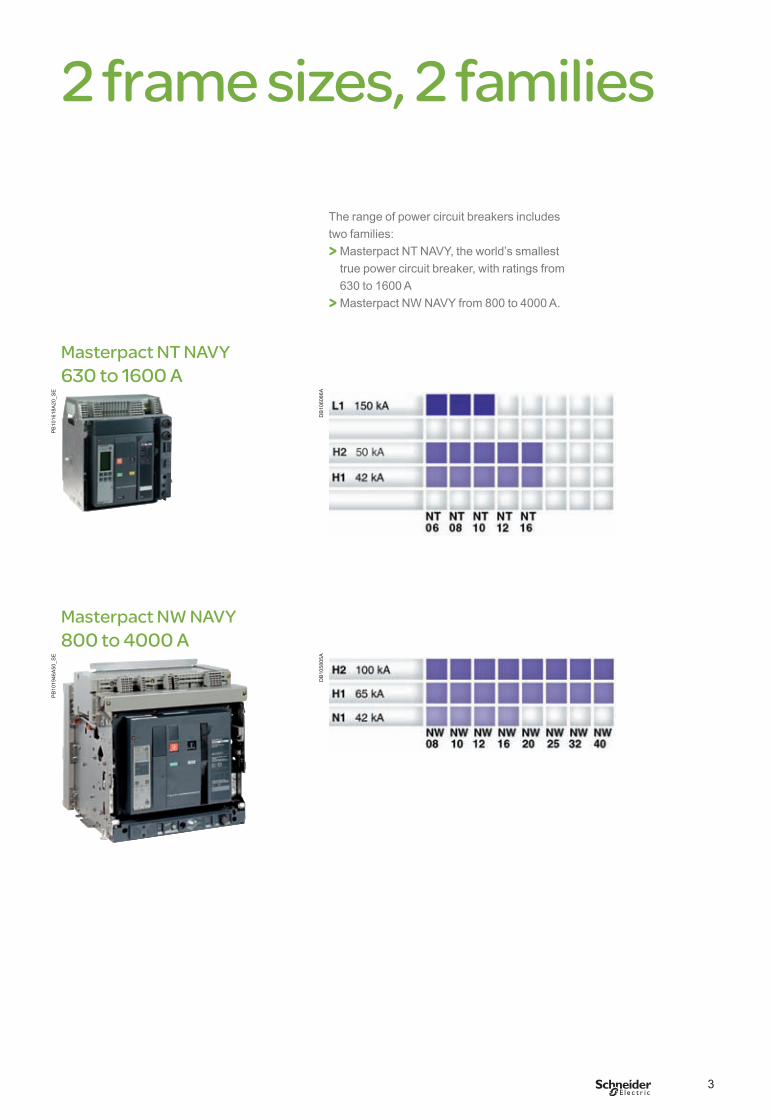
The range of power circuit breakers includes two families:> Masterpact NT NAVY, the world’s smallest
true power circuit breaker, with ratings from 630 to 1600 A
> Masterpact NW NAVY from 800 to 4000 A.
Masterpact NT NAVY630 to 1600 A
PB
1016
18A
20_S
E
DB
1060
86A
Masterpact NW NAVY800 to 4000 A
PB
1019
46A
50_S
E
DB
1058
05A
BTP222E.indb 3 30/06/2009 09:30:14
4
Optimised volumesP
B10
1618
A20
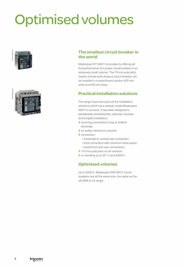
_SE The smallest circuit breaker in
the worldMasterpact NT NAVY innovates by offering all the performance of a power circuit breaker in an extremely small volume. The 70 mm pole pitch means a three-pole drawout circuit breaker can be installed in a switchboard section 400 mm wide and 400 mm deep.
Practical installation solutions
The range improves upon all the installation solutions which have already made Masterpact NAVY a success. It has been designed to standardise switchboards, optimise volumes and simplify installation:> incoming connection to top or bottom
terminals> no safety clearance required> connection: • horizontal or vertical rear connection • front connection with minimum extra space • mixed front and rear connections> 115 mm pole pitch on all versions> no derating up to 55 °C and 4000 A.
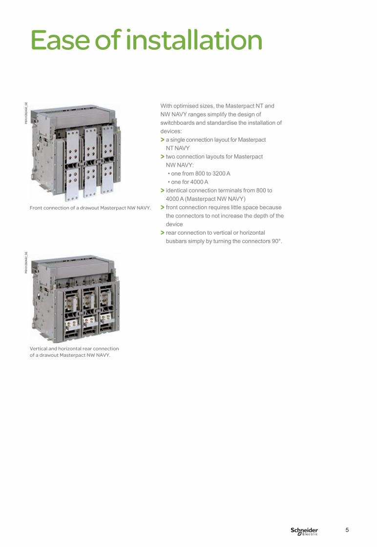
Optimised volumes
Up to 4000 A, Masterpact NW NAVY circuit breakers are all the same size, the same as the old M08 to 32 range.
PB
1019
46A
30_S
E
BTP222E.indb 4 30/06/2009 09:30:14
5
Ease of installationP
B10
1282
A50
_SE
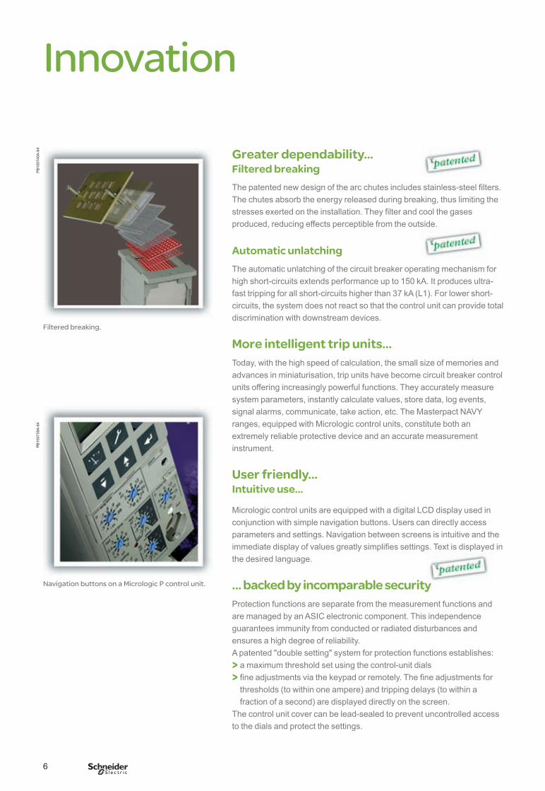
With optimised sizes, the Masterpact NT and NW NAVY ranges simplify the design of switchboards and standardise the installation of devices:> a single connection layout for Masterpact
NT NAVY> two connection layouts for Masterpact
NW NAVY: • one from 800 to 3200 A • one for 4000 A> identical connection terminals from 800 to
4000 A (Masterpact NW NAVY)> front connection requires little space because
the connectors to not increase the depth of the device
> rear connection to vertical or horizontal busbars simply by turning the connectors 90°.
Front connection of a drawout Masterpact NW NAVY.
PB
1012
80A
50_S
E
Vertical and horizontal rear connection of a drawout Masterpact NW NAVY.
BTP222E.indb 5 30/06/2009 09:30:16
6
InnovationP
B10
0740
A-6
4
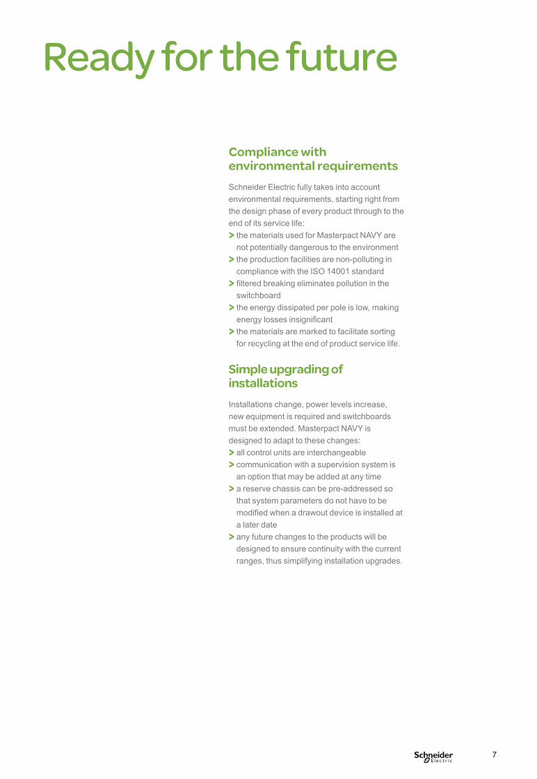
Filtered breaking.
Greater dependability…Filtered breakingThe patented new design of the arc chutes includes stainless-steel filters.The chutes absorb the energy released during breaking, thus limiting the stresses exerted on the installation. They filter and cool the gases produced, reducing effects perceptible from the outside.
Automatic unlatchingThe automatic unlatching of the circuit breaker operating mechanism for high short-circuits extends performance up to 150 kA. It produces ultra-fast tripping for all short-circuits higher than 37 kA (L1). For lower short-circuits, the system does not react so that the control unit can provide total discrimination with downstream devices.
More intelligent trip units…Today, with the high speed of calculation, the small size of memories and advances in miniaturisation, trip units have become circuit breaker control units offering increasingly powerful functions. They accurately measure system parameters, instantly calculate values, store data, log events, signal alarms, communicate, take action, etc. The Masterpact NAVY ranges, equipped with Micrologic control units, constitute both an extremely reliable protective device and an accurate measurement instrument.
User friendly…Intuitive use…
Micrologic control units are equipped with a digital LCD display used in conjunction with simple navigation buttons. Users can directly access parameters and settings. Navigation between screens is intuitive and the immediate display of values greatly simplifies settings. Text is displayed in the desired language.
… backed by incomparable securityProtection functions are separate from the measurement functions and are managed by an ASIC electronic component. This independence guarantees immunity from conducted or radiated disturbances and ensures a high degree of reliability.A patented "double setting" system for protection functions establishes:> a maximum threshold set using the control-unit dials> fine adjustments via the keypad or remotely. The fine adjustments for
thresholds (to within one ampere) and tripping delays (to within a fraction of a second) are displayed directly on the screen.
The control unit cover can be lead-sealed to prevent uncontrolled access to the dials and protect the settings.
PB
1007
39A
-64
Navigation buttons on a Micrologic P control unit.
BTP222E.indb 6 30/06/2009 09:30:17
7
Ready for the future
Compliance with environmental requirementsSchneider Electric fully takes into account environmental requirements, starting right from the design phase of every product through to the end of its service life:> the materials used for Masterpact NAVY are
not potentially dangerous to the environment> the production facilities are non-polluting in
compliance with the ISO 14001 standard> filtered breaking eliminates pollution in the
switchboard> the energy dissipated per pole is low, making
energy losses insignificant> the materials are marked to facilitate sorting
for recycling at the end of product service life.
Simple upgrading of installationsInstallations change, power levels increase, new equipment is required and switchboards must be extended. Masterpact NAVY is designed to adapt to these changes:> all control units are interchangeable> communication with a supervision system is
an option that may be added at any time> a reserve chassis can be pre-addressed so
that system parameters do not have to be modified when a drawout device is installed at a later date
> any future changes to the products will be designed to ensure continuity with the current ranges, thus simplifying installation upgrades.
BTP222E.indb 7 30/06/2009 09:30:17

8
BTP222E.indb 8 30/06/2009 09:30:17
9
Presentation 1
Functions and characteristics A-1
Installation recommendations B-1
Dimensions and connection C-1
Electrical diagrams D-1
Additional characteristics E-1
Catalogue numbers and order form F-1
ContentsMasterpact NT and NW NAVY
BTP222E.indb 9 30/06/2009 09:30:18

This international site allows you to access all the Schneider Electric products in just 2 clicksvia comprehensive range data-sheets, with direct links to:
complete library: technical documents, catalogs, FAQs, brochures…
selection guides from the e-catalog.
product discovery sites andtheir Flash animations.You will also fi nd illustrated overviews, news to which you can subscribe, the list of country contacts…
p
p
p
These technical guides help you comply with installation standards and rules i.e.: the electrical installation guide, the protection guide, the switchboard implementation guide,the technical bookletsand the co-ordination tables all form genuine reference tools for the design of high performance electrical installations.For example, the LV protectionco-ordination guide - discrimination and cascading - optimises choiceof protection and connection devices while also increasing markedly continuity of supplyin the installations.
schneider-electric.com The technical guide
TOOLS
BTP222E.indb 2 30/06/2009 09:30:20
A-1
Functions and characteristicsMasterpact NT and NW NAVY
Presentation 1
General overview A-2Detailed contents A-2
Circuit breakers and switch-disconnectors A-5NT06 to NT16 NAVY and NW08 to NW40 NAVY A-5NT06 to NT16 NAVY A-6NW08 to NW40 NAVY A-8
Micrologic control units A-10Overview of functions A-10Micrologic A “ammeter” A-12Micrologic P “power” A-14Micrologic H “harmonics” A-18Accessories and test equipment A-20
Portable data acquisition A-22Masterpact and GetnSet A-22
Communication A-24COM option in Masterpact A-24Overview of functions A-25Masterpact in a communication network A-26
Connections A-28Overview of solutions A-28Accessories A-29
Locking A-31On the device A-31On the chassis A-32
Indication contacts A-33
Remote operation A-35Remote ON / OFF A-35Remote tripping A-38
Accessories A-39
Installationrecommendations B-1Dimensionsandconnections C-1Electricaldiagrams D-1Additionalcharacteristics E-1Cataloguenumbersandorderform F-1
BTP222E.indb 1 30/06/2009 09:30:21
A-2
Functions and characteristics
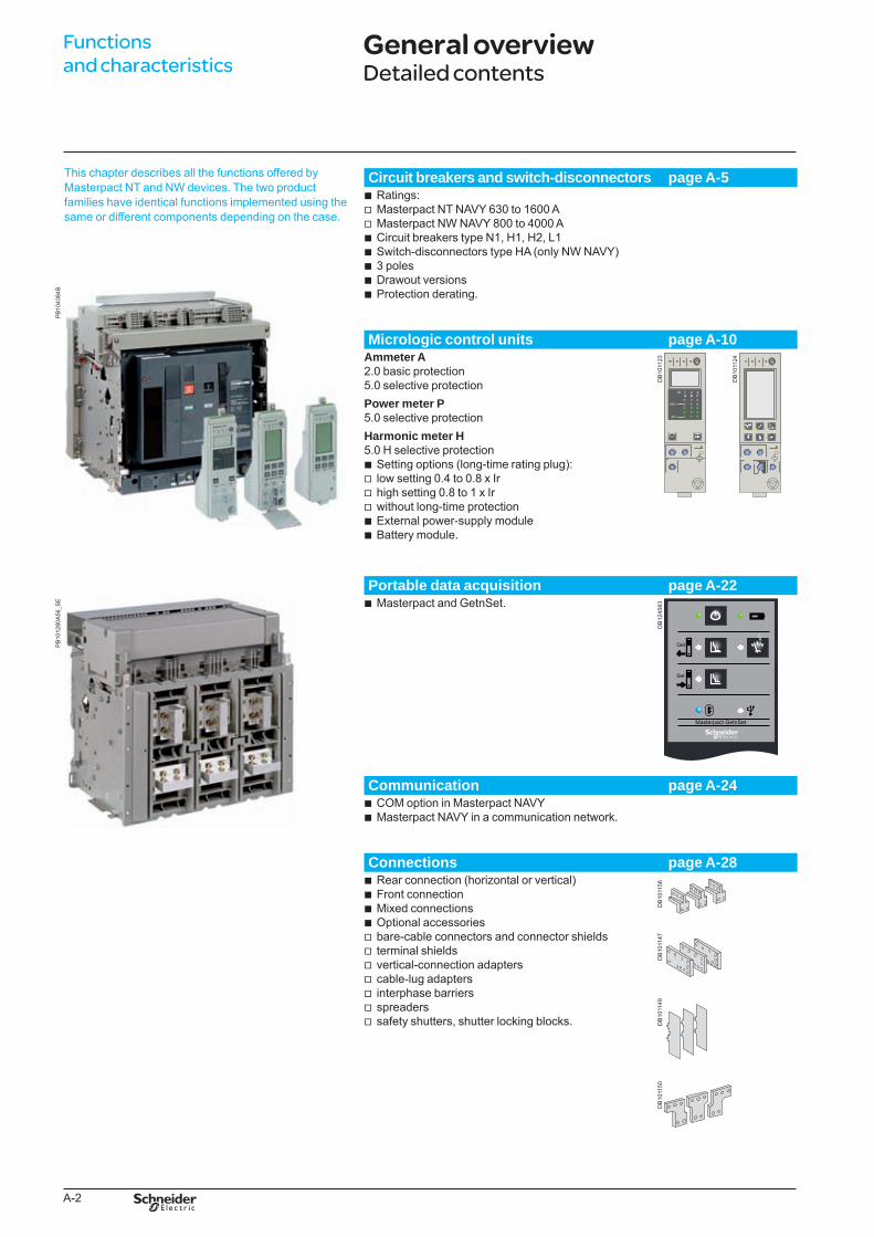
This chapter describes all the functions offered by Masterpact NT and NW devices. The two product families have identical functions implemented using the same or different components depending on the case.
Circuit breakers and switch-disconnectors page A-5
PB
1043
84B
Ratings:Masterpact NT NAVY 630 to 1600 AMasterpact NW NAVY 800 to 4000 ACircuit breakers type N1, H1, H2, L1Switch-disconnectors type HA (only NW NAVY)3 polesDrawout versionsProtection derating.
bvvbbbbb
Micrologic control units page A-10Ammeter A2.0 basic protection5.0 selective protectionPower meter P5.0 selective protectionHarmonic meter H5.0 H selective protection
Setting options (long-time rating plug):low setting 0.4 to 0.8 x Irhigh setting 0.8 to 1 x Irwithout long-time protectionExternal power-supply moduleBattery module.
bvvvbb
DB
1011
23
DB
1011
24
Portable data acquisition page A-22
PB
1012
80A
56_S
E Masterpact and GetnSet.b
DB
1245
83
Communication page A-24COM option in Masterpact NAVYMasterpact NAVY in a communication network.
bb
Connections page A-28Rear connection (horizontal or vertical)Front connectionMixed connectionsOptional accessoriesbare-cable connectors and connector shieldsterminal shieldsvertical-connection adapterscable-lug adaptersinterphase barriersspreaderssafety shutters, shutter locking blocks.
bbbbvvvvvvv
DB
1011
56D
B10
1147
DB
1011
49D
B10
1150
General overviewDetailed contents
BTP222E.indb 2 30/06/2009 09:30:24
A-3
PB
1019
41A
55_S
E
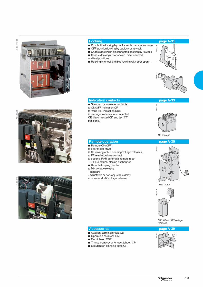
Locking page A-31Pushbutton locking by padlockable transparent coverOFF-position locking by padlock or keylockChassis locking in disconnected position by keylockChassis locking in connected, disconnected
and test positionsRacking interlock (inhibits racking with door open).
bbbb
b
DB
1011
10
DB
1011
09
Indication contacts page A-33
PB
1043
53A
55
Standard or low-level contacts:ON/OFF indication OF“fault trip” indication SDEcarriage switches for connected
CE disconnected CD and test CT positions.
bvvv
DB
1011
12
OFcontact.
Remote operation page A-35
PB
1043
49A
55
Remote ON/OFF:gear motor MCHXF closing or MX opening voltage releasesPF ready-to-close contactoptions: RAR automatic remote reset
- BPFE electrical closing pushbutton Remote tripping function:MN voltage release
- standard- adjustable or non-adjustable delay
or second MX voltage release.
bvvvv
bv
v
D
B10
1114
D
B10
1113
Gearmotor.
MX,XFandMNvoltagereleases.
Accessories page A-39Auxiliary terminal shield CBOperation counter CDMEscutcheon CDPTransparent cover for escutcheon CPEscutcheon blanking plate OP.
bbbbb
DB
1011
15
BTP222E.indb 3 30/06/2009 09:30:26

A-4
BTP222E.indb 4 30/06/2009 09:30:26
A-5
Functions and characteristics
Circuit breakers and switch-disconnectorsNT06 to NT16 NAVY and NW08 to NW40 NAVY
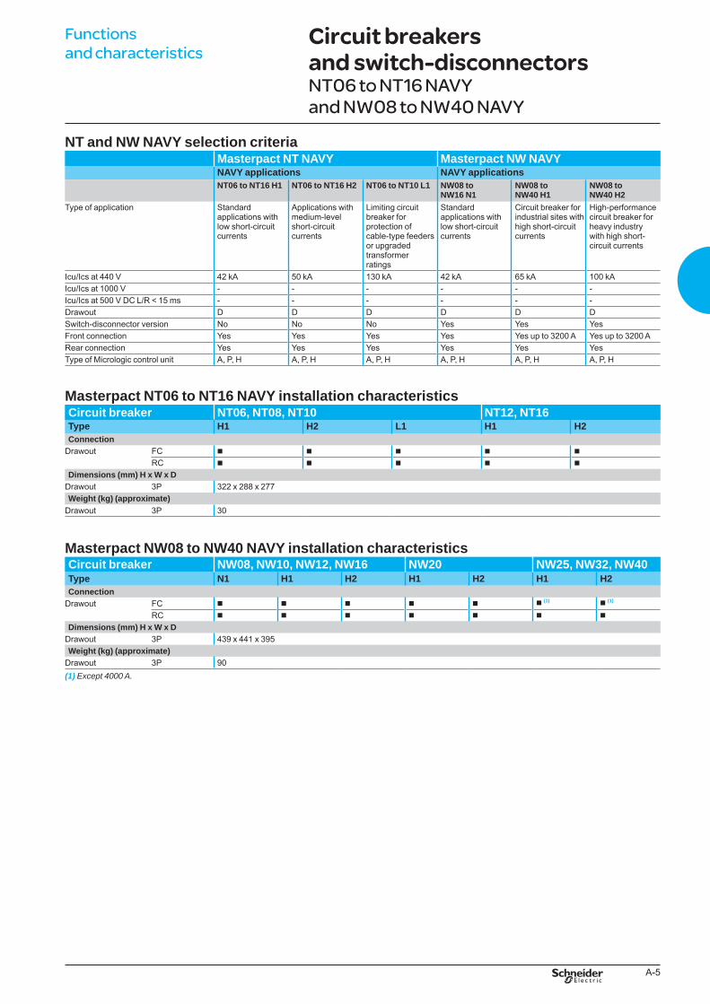
NT and NW NAVY selection criteria Masterpact NT NAVY Masterpact NW NAVYNAVY applications NAVY applicationsNT06 to NT16 H1 NT06 to NT16 H2 NT06 to NT10 L1 NW08 to
NW16 N1NW08 to NW40 H1
NW08 to NW40 H2
Type of application Standard applications with low short-circuit currents
Applications with medium-level short-circuit currents
Limiting circuit breaker for protection of cable-type feeders or upgraded transformer ratings
Standard applications with low short-circuit currents
Circuit breaker for industrial sites with high short-circuit currents
High-performance circuit breaker for heavy industry with high short-circuit currents
Icu/Ics at 440 V 42 kA 50 kA 130 kA 42 kA 65 kA 100 kAIcu/Ics at 1000 V - - - - - -Icu/Ics at 500 V DC L/R < 15 ms - - - - - -Drawout D D D D D DSwitch-disconnector version No No No Yes Yes YesFront connection Yes Yes Yes Yes Yes up to 3200 A Yes up to 3200 ARear connection Yes Yes Yes Yes Yes YesType of Micrologic control unit A, P, H A, P, H A, P, H A, P, H A, P, H A, P, H
Masterpact NT06 to NT16 NAVY installation characteristicsCircuit breaker NT06, NT08, NT10 NT12, NT16Type H1 H2 L1 H1 H2Connection
Drawout FC b b b b b
RC b b b b b
Dimensions (mm) H x W x DDrawout 3P 322 x 288 x 277Weight (kg) (approximate)
Drawout 3P 30
Masterpact NW08 to NW40 NAVY installation characteristicsCircuit breaker NW08, NW10, NW12, NW16 NW20 NW25, NW32, NW40Type N1 H1 H2 H1 H2 H1 H2Connection
Drawout FC b b b b b b (1) b (1)
RC b b b b b b b
Dimensions (mm) H x W x DDrawout 3P 439 x 441 x 395Weight (kg) (approximate)
Drawout 3P 90(1) Except4000A.
BTP222E.indb 5 30/06/2009 09:30:27
A-6
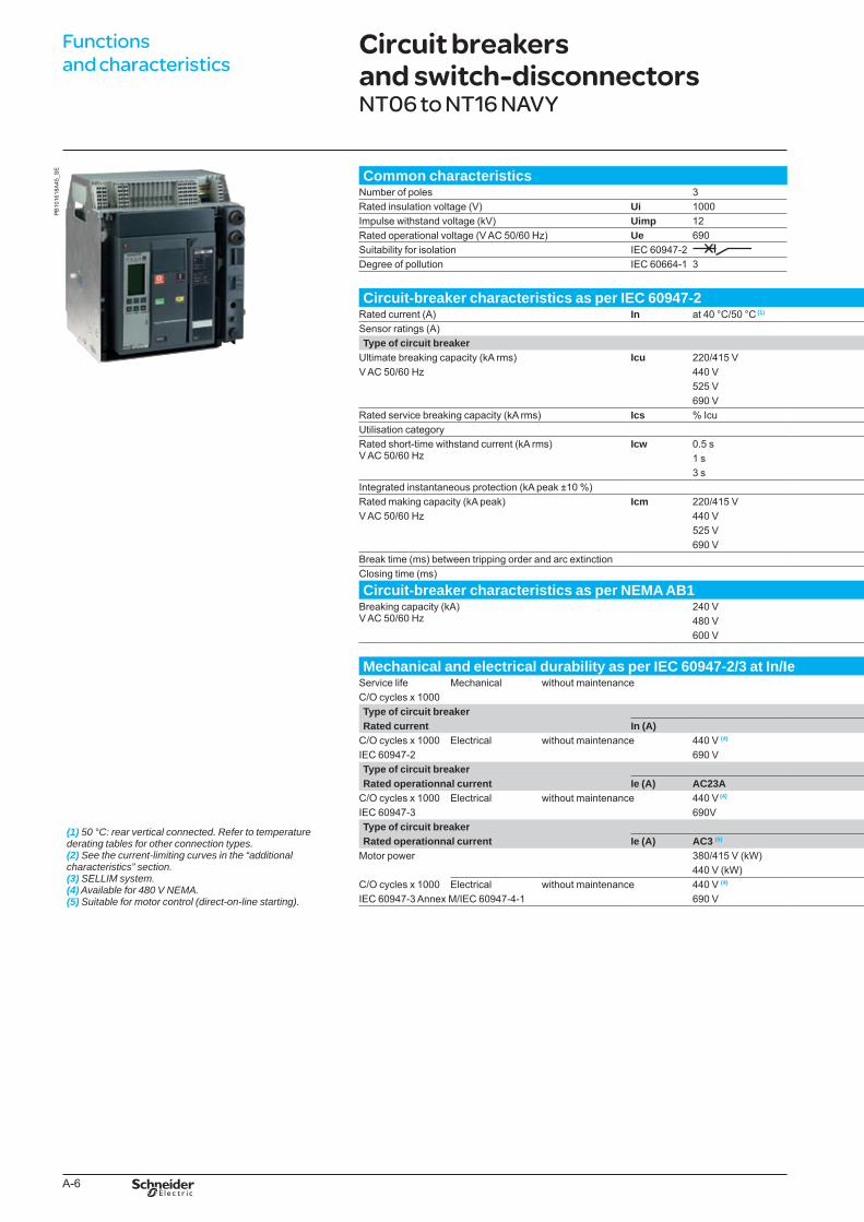
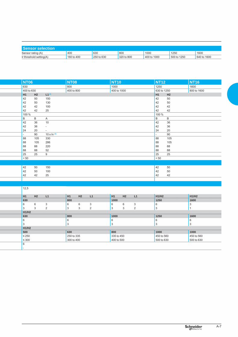
Common characteristics Sensor selectionNumber of poles 3 Sensor rating (A) 400 630 800 1000 1250 1600Rated insulation voltage (V) Ui 1000 Ir threshold setting(A) 160 to 400 250 to 630 320 to 800 400 to 1000 500 to 1250 640 to 1600Impulse withstand voltage (kV) Uimp 12Rated operational voltage (V AC 50/60 Hz) Ue 690Suitability for isolation IEC 60947-2 Degree of pollution IEC 60664-1 3
Functions and characteristics
Circuit breakers and switch-disconnectorsNT06 to NT16 NAVY
Circuit-breaker characteristics as per IEC 60947-2 NT06 NT08 NT10 NT12 NT16Rated current (A) In at 40 °C/50 °C (1) 630 800 1000 1250 1600Sensor ratings (A) 400 to 630 400 to 800 400 to 1000 630 to 1250 800 to 1600Type of circuit breaker H1 H2 L1 (2) H1 H2
Ultimate breaking capacity (kA rms) Icu 220/415 V 42 50 150 42 50V AC 50/60 Hz 440 V 42 50 130 42 50
525 V 42 42 100 42 42690 V 42 42 25 42 42
Rated service breaking capacity (kA rms) Ics % Icu 100 % 100 %Utilisation category B B A B BRated short-time withstand current (kA rms)V AC 50/60 Hz
Icw 0.5 s 42 36 10 42 361 s 42 36 - 42 363 s 24 20 - 24 20
Integrated instantaneous protection (kA peak ±10 %) - 90 10 x In (3) - 90Rated making capacity (kA peak) Icm 220/415 V 88 105 330 88 105V AC 50/60 Hz 440 V 88 105 286 88 105
525 V 88 88 220 88 88690 V 88 88 52 88 88
Break time (ms) between tripping order and arc extinction 25 25 9 25 25Closing time (ms) < 50 < 50
Circuit-breaker characteristics as per NEMA AB1Breaking capacity (kA)V AC 50/60 Hz
240 V 42 50 150 42 50480 V 42 50 100 42 50600 V 42 42 25 42 42
(1)50°C:rearverticalconnected.Refertotemperaturederatingtablesforotherconnectiontypes.(2)Seethecurrent-limitingcurvesinthe“additionalcharacteristics”section.(3)SELLIMsystem.(4)Availablefor480VNEMA.(5) Suitableformotorcontrol(direct-on-linestarting).
Mechanical and electrical durability as per IEC 60947-2/3 at In/IeService life Mechanical without maintenance 12,5C/O cycles x 1000Type of circuit breaker H1 H2 L1 H1 H2 L1 H1 H2 L1 H1/H2 H1/H2Rated current In (A) 630 800 1000 1250 1600
C/O cycles x 1000 Electrical without maintenance 440 V (4) 6 6 3 6 6 3 6 6 3 6 3IEC 60947-2 690 V 3 3 2 3 3 2 3 3 2 3 1Type of circuit breaker H1/H2Rated operationnal current Ie (A) AC23A 630 800 1000 1250 1600
C/O cycles x 1000 Electrical without maintenance 440 V (4) 6 6 6 6 6IEC 60947-3 690V 3 3 3 3 3Type of circuit breaker H1/H2Rated operationnal current Ie (A) AC3 (5) 500 630 800 1000 1000
Motor power 380/415 V (kW) y 250 250 to 335 335 to 450 450 to 560 450 to 560440 V (kW) y 300 300 to 400 400 to 500 500 to 630 500 to 630
C/O cycles x 1000 Electrical without maintenance 440 V (4) 6IEC 60947-3 Annex M/IEC 60947-4-1 690 V -
PB
1016
18A
45_S
E
BTP222E.indb 6 30/06/2009 09:30:29
A-7
Common characteristics Sensor selectionNumber of poles 3 Sensor rating (A) 400 630 800 1000 1250 1600Rated insulation voltage (V) Ui 1000 Ir threshold setting(A) 160 to 400 250 to 630 320 to 800 400 to 1000 500 to 1250 640 to 1600Impulse withstand voltage (kV) Uimp 12Rated operational voltage (V AC 50/60 Hz) Ue 690Suitability for isolation IEC 60947-2 Degree of pollution IEC 60664-1 3
Circuit-breaker characteristics as per IEC 60947-2 NT06 NT08 NT10 NT12 NT16Rated current (A) In at 40 °C/50 °C (1) 630 800 1000 1250 1600Sensor ratings (A) 400 to 630 400 to 800 400 to 1000 630 to 1250 800 to 1600Type of circuit breaker H1 H2 L1 (2) H1 H2
Ultimate breaking capacity (kA rms) Icu 220/415 V 42 50 150 42 50V AC 50/60 Hz 440 V 42 50 130 42 50
525 V 42 42 100 42 42690 V 42 42 25 42 42
Rated service breaking capacity (kA rms) Ics % Icu 100 % 100 %Utilisation category B B A B BRated short-time withstand current (kA rms)V AC 50/60 Hz
Icw 0.5 s 42 36 10 42 361 s 42 36 - 42 363 s 24 20 - 24 20
Integrated instantaneous protection (kA peak ±10 %) - 90 10 x In (3) - 90Rated making capacity (kA peak) Icm 220/415 V 88 105 330 88 105V AC 50/60 Hz 440 V 88 105 286 88 105
525 V 88 88 220 88 88690 V 88 88 52 88 88
Break time (ms) between tripping order and arc extinction 25 25 9 25 25Closing time (ms) < 50 < 50
Circuit-breaker characteristics as per NEMA AB1Breaking capacity (kA)V AC 50/60 Hz
240 V 42 50 150 42 50480 V 42 50 100 42 50600 V 42 42 25 42 42
(1)50°C:rearverticalconnected.Refertotemperaturederatingtablesforotherconnectiontypes.(2)Seethecurrent-limitingcurvesinthe“additionalcharacteristics”section.(3)SELLIMsystem.(4)Availablefor480VNEMA.(5) Suitableformotorcontrol(direct-on-linestarting).
Mechanical and electrical durability as per IEC 60947-2/3 at In/IeService life Mechanical without maintenance 12,5C/O cycles x 1000Type of circuit breaker H1 H2 L1 H1 H2 L1 H1 H2 L1 H1/H2 H1/H2Rated current In (A) 630 800 1000 1250 1600
C/O cycles x 1000 Electrical without maintenance 440 V (4) 6 6 3 6 6 3 6 6 3 6 3IEC 60947-2 690 V 3 3 2 3 3 2 3 3 2 3 1Type of circuit breaker H1/H2Rated operationnal current Ie (A) AC23A 630 800 1000 1250 1600
C/O cycles x 1000 Electrical without maintenance 440 V (4) 6 6 6 6 6IEC 60947-3 690V 3 3 3 3 3Type of circuit breaker H1/H2Rated operationnal current Ie (A) AC3 (5) 500 630 800 1000 1000
Motor power 380/415 V (kW) y 250 250 to 335 335 to 450 450 to 560 450 to 560440 V (kW) y 300 300 to 400 400 to 500 500 to 630 500 to 630
C/O cycles x 1000 Electrical without maintenance 440 V (4) 6IEC 60947-3 Annex M/IEC 60947-4-1 690 V -
BTP222E.indb 7 30/06/2009 09:30:29
A-8
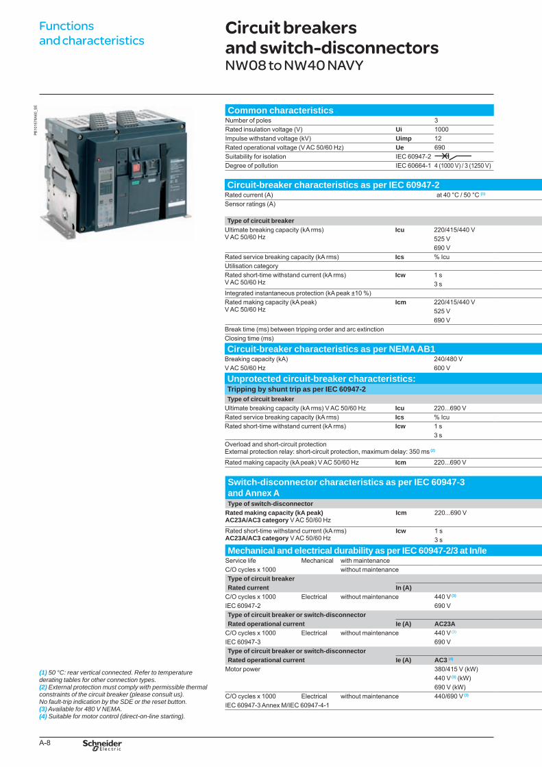
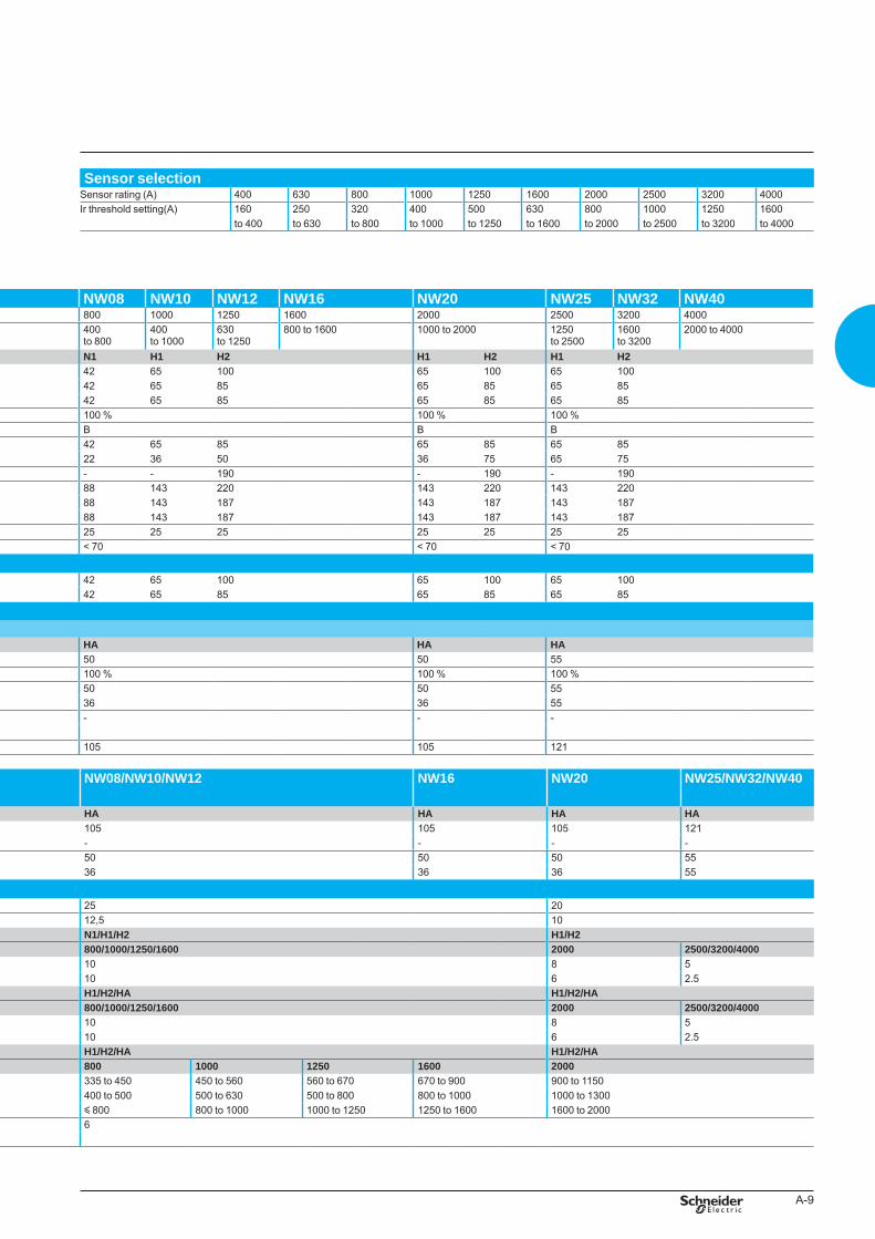
Common characteristics Sensor selectionNumber of poles 3 Sensor rating (A) 400 630 800 1000 1250 1600 2000 2500 3200 4000Rated insulation voltage (V) Ui 1000 Ir threshold setting(A) 160 250 320 400 500 630 800 1000 1250 1600Impulse withstand voltage (kV) Uimp 12 to 400 to 630 to 800 to 1000 to 1250 to 1600 to 2000 to 2500 to 3200 to 4000Rated operational voltage (V AC 50/60 Hz) Ue 690Suitability for isolation IEC 60947-2 Degree of pollution IEC 60664-1 4 (1000 V) / 3 (1250 V)
Circuit-breaker characteristics as per IEC 60947-2 NW08 NW10 NW12 NW16 NW20 NW25 NW32 NW40Rated current (A) at 40 °C / 50 °C (1) 800 1000 1250 1600 2000 2500 3200 4000Sensor ratings (A) 400
to 800400to 1000
630to 1250
800 to 1600 1000 to 2000 1250to 2500
1600to 3200
2000 to 4000
Type of circuit breaker N1 H1 H2 H1 H2 H1 H2Ultimate breaking capacity (kA rms)V AC 50/60 Hz
Icu 220/415/440 V 42 65 100 65 100 65 100525 V 42 65 85 65 85 65 85690 V 42 65 85 65 85 65 85
Rated service breaking capacity (kA rms) Ics % Icu 100 % 100 % 100 %Utilisation category B B BRated short-time withstand current (kA rms)V AC 50/60 Hz
Icw 1 s 42 65 85 65 85 65 853 s 22 36 50 36 75 65 75
Integrated instantaneous protection (kA peak ±10 %) - - 190 - 190 - 190Rated making capacity (kA peak)V AC 50/60 Hz
Icm 220/415/440 V 88 143 220 143 220 143 220525 V 88 143 187 143 187 143 187690 V 88 143 187 143 187 143 187
Break time (ms) between tripping order and arc extinction 25 25 25 25 25 25 25Closing time (ms) < 70 < 70 < 70
Circuit-breaker characteristics as per NEMA AB1Breaking capacity (kA) 240/480 V 42 65 100 65 100 65 100V AC 50/60 Hz 600 V 42 65 85 65 85 65 85
Unprotected circuit-breaker characteristics:Tripping by shunt trip as per IEC 60947-2Type of circuit breaker HA HA HA
Ultimate breaking capacity (kA rms) V AC 50/60 Hz Icu 220...690 V 50 50 55Rated service breaking capacity (kA rms) Ics % Icu 100 % 100 % 100 %Rated short-time withstand current (kA rms) Icw 1 s 50 50 55
3 s 36 36 55Overload and short-circuit protection External protection relay: short-circuit protection, maximum delay: 350 ms (2)
- - -
Rated making capacity (kA peak) V AC 50/60 Hz Icm 220...690 V 105 105 121
Switch-disconnector characteristics as per IEC 60947-3 and Annex A
NW08/NW10/NW12 NW16 NW20 NW25/NW32/NW40
Type of switch-disconnector HA HA HA HARated making capacity (kA peak)AC23A/AC3 category V AC 50/60 Hz
Icm 220...690 V 105 105 105 121- - - -
Rated short-time withstand current (kA rms)AC23A/AC3 category V AC 50/60 Hz
Icw 1 s 50 50 50 553 s 36 36 36 55
Mechanical and electrical durability as per IEC 60947-2/3 at In/IeService life Mechanical with maintenance 25 20C/O cycles x 1000 without maintenance 12,5 10Type of circuit breaker N1/H1/H2 H1/H2Rated current In (A) 800/1000/1250/1600 2000 2500/3200/4000
C/O cycles x 1000 Electrical without maintenance 440 V (3) 10 8 5IEC 60947-2 690 V 10 6 2.5Type of circuit breaker or switch-disconnector H1/H2/HA H1/H2/HARated operational current Ie (A) AC23A 800/1000/1250/1600 2000 2500/3200/4000
C/O cycles x 1000 Electrical without maintenance 440 V (3) 10 8 5IEC 60947-3 690 V 10 6 2.5Type of circuit breaker or switch-disconnector H1/H2/HA H1/H2/HARated operational current Ie (A) AC3 (4) 800 1000 1250 1600 2000
Motor power 380/415 V (kW) 335 to 450 450 to 560 560 to 670 670 to 900 900 to 1150440 V (3) (kW) 400 to 500 500 to 630 500 to 800 800 to 1000 1000 to 1300690 V (kW) y 800 800 to 1000 1000 to 1250 1250 to 1600 1600 to 2000
C/O cycles x 1000 Electrical without maintenance 440/690 V (3) 6IEC 60947-3 Annex M/IEC 60947-4-1
Functions and characteristics
Circuit breakers and switch-disconnectorsNW08 to NW40 NAVY
(1)50°C:rearverticalconnected.Refertotemperaturederatingtablesforotherconnectiontypes.(2)Externalprotectionmustcomplywithpermissiblethermalconstraintsofthecircuitbreaker(pleaseconsultus).Nofault-tripindicationbytheSDEortheresetbutton.(3)Availablefor480VNEMA.(4) Suitableformotorcontrol(direct-on-linestarting).
PB
1015
78A
60_S
E
BTP222E.indb 8 30/06/2009 09:30:30
A-9
Common characteristics Sensor selectionNumber of poles 3 Sensor rating (A) 400 630 800 1000 1250 1600 2000 2500 3200 4000Rated insulation voltage (V) Ui 1000 Ir threshold setting(A) 160 250 320 400 500 630 800 1000 1250 1600Impulse withstand voltage (kV) Uimp 12 to 400 to 630 to 800 to 1000 to 1250 to 1600 to 2000 to 2500 to 3200 to 4000Rated operational voltage (V AC 50/60 Hz) Ue 690Suitability for isolation IEC 60947-2 Degree of pollution IEC 60664-1 4 (1000 V) / 3 (1250 V)
Circuit-breaker characteristics as per IEC 60947-2 NW08 NW10 NW12 NW16 NW20 NW25 NW32 NW40Rated current (A) at 40 °C / 50 °C (1) 800 1000 1250 1600 2000 2500 3200 4000Sensor ratings (A) 400
to 800400to 1000
630to 1250
800 to 1600 1000 to 2000 1250to 2500
1600to 3200
2000 to 4000
Type of circuit breaker N1 H1 H2 H1 H2 H1 H2Ultimate breaking capacity (kA rms)V AC 50/60 Hz
Icu 220/415/440 V 42 65 100 65 100 65 100525 V 42 65 85 65 85 65 85690 V 42 65 85 65 85 65 85
Rated service breaking capacity (kA rms) Ics % Icu 100 % 100 % 100 %Utilisation category B B BRated short-time withstand current (kA rms)V AC 50/60 Hz
Icw 1 s 42 65 85 65 85 65 853 s 22 36 50 36 75 65 75
Integrated instantaneous protection (kA peak ±10 %) - - 190 - 190 - 190Rated making capacity (kA peak)V AC 50/60 Hz
Icm 220/415/440 V 88 143 220 143 220 143 220525 V 88 143 187 143 187 143 187690 V 88 143 187 143 187 143 187
Break time (ms) between tripping order and arc extinction 25 25 25 25 25 25 25Closing time (ms) < 70 < 70 < 70
Circuit-breaker characteristics as per NEMA AB1Breaking capacity (kA) 240/480 V 42 65 100 65 100 65 100V AC 50/60 Hz 600 V 42 65 85 65 85 65 85
Unprotected circuit-breaker characteristics:Tripping by shunt trip as per IEC 60947-2Type of circuit breaker HA HA HA
Ultimate breaking capacity (kA rms) V AC 50/60 Hz Icu 220...690 V 50 50 55Rated service breaking capacity (kA rms) Ics % Icu 100 % 100 % 100 %Rated short-time withstand current (kA rms) Icw 1 s 50 50 55
3 s 36 36 55Overload and short-circuit protection External protection relay: short-circuit protection, maximum delay: 350 ms (2)
- - -
Rated making capacity (kA peak) V AC 50/60 Hz Icm 220...690 V 105 105 121
Switch-disconnector characteristics as per IEC 60947-3 and Annex A
NW08/NW10/NW12 NW16 NW20 NW25/NW32/NW40
Type of switch-disconnector HA HA HA HARated making capacity (kA peak)AC23A/AC3 category V AC 50/60 Hz
Icm 220...690 V 105 105 105 121- - - -
Rated short-time withstand current (kA rms)AC23A/AC3 category V AC 50/60 Hz
Icw 1 s 50 50 50 553 s 36 36 36 55
Mechanical and electrical durability as per IEC 60947-2/3 at In/IeService life Mechanical with maintenance 25 20C/O cycles x 1000 without maintenance 12,5 10Type of circuit breaker N1/H1/H2 H1/H2Rated current In (A) 800/1000/1250/1600 2000 2500/3200/4000
C/O cycles x 1000 Electrical without maintenance 440 V (3) 10 8 5IEC 60947-2 690 V 10 6 2.5Type of circuit breaker or switch-disconnector H1/H2/HA H1/H2/HARated operational current Ie (A) AC23A 800/1000/1250/1600 2000 2500/3200/4000
C/O cycles x 1000 Electrical without maintenance 440 V (3) 10 8 5IEC 60947-3 690 V 10 6 2.5Type of circuit breaker or switch-disconnector H1/H2/HA H1/H2/HARated operational current Ie (A) AC3 (4) 800 1000 1250 1600 2000
Motor power 380/415 V (kW) 335 to 450 450 to 560 560 to 670 670 to 900 900 to 1150440 V (3) (kW) 400 to 500 500 to 630 500 to 800 800 to 1000 1000 to 1300690 V (kW) y 800 800 to 1000 1000 to 1250 1250 to 1600 1600 to 2000
C/O cycles x 1000 Electrical without maintenance 440/690 V (3) 6IEC 60947-3 Annex M/IEC 60947-4-1
BTP222E.indb 9 30/06/2009 09:30:31
A-10
Functions and characteristics
2.0 AX Y Z
Micrologic control units Overview of functions
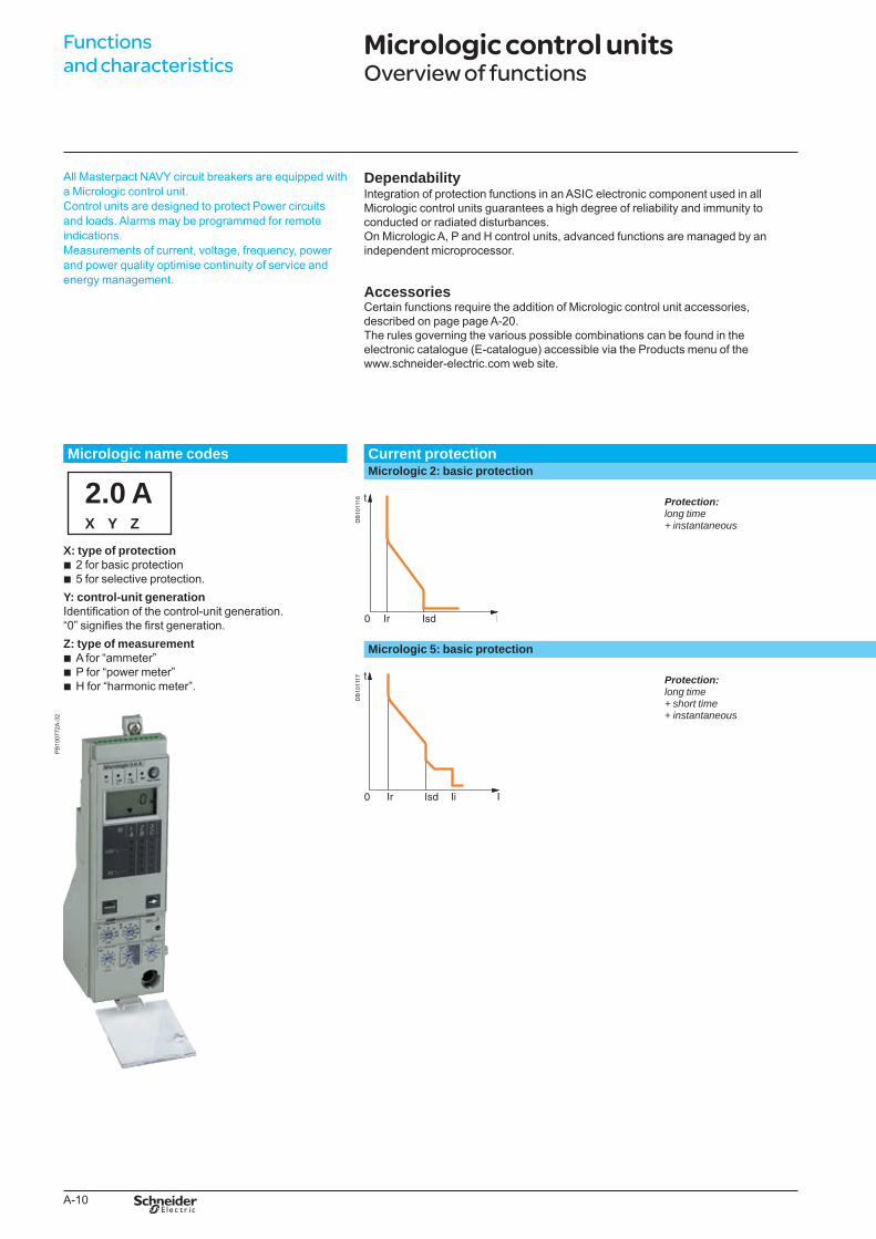
All Masterpact NAVY circuit breakers are equipped with a Micrologic control unit.Control units are designed to protect Power circuits and loads. Alarms may be programmed for remote indications.Measurements of current, voltage, frequency, power and power quality optimise continuity of service and energy management.
DependabilityIntegration of protection functions in an ASIC electronic component used in all Micrologic control units guarantees a high degree of reliability and immunity to conducted or radiated disturbances.On Micrologic A, P and H control units, advanced functions are managed by an independent microprocessor.
AccessoriesCertain functions require the addition of Micrologic control unit accessories,described on page page A-20.The rules governing the various possible combinations can be found in theelectronic catalogue (E-catalogue) accessible via the Products menu of thewww.schneider-electric.com web site.
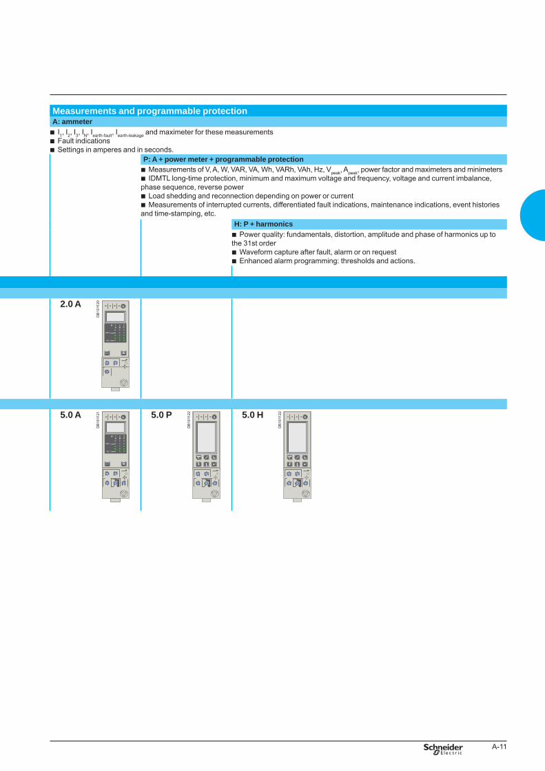
Measurements and programmable protectionA: ammeter
I1, I2, I3, IN, Iearth-fault, Iearth-leakage and maximeter for these measurementsFault indicationsSettings in amperes and in seconds.
bbb
P: A + power meter + programmable protectionMeasurements of V, A, W, VAR, VA, Wh, VARh, VAh, Hz, Vpeak, Apeak, power factor and maximeters and minimetersIDMTL long-time protection, minimum and maximum voltage and frequency, voltage and current imbalance,
phase sequence, reverse powerLoad shedding and reconnection depending on power or currentMeasurements of interrupted currents, differentiated fault indications, maintenance indications, event histories
and time-stamping, etc.
bb
bb
H: P + harmonicsPower quality: fundamentals, distortion, amplitude and phase of harmonics up to
the 31st orderWaveform capture after fault, alarm or on requestEnhanced alarm programming: thresholds and actions.
b
bb
Micrologic name codes Current protection
X: type of protection2 for basic protection5 for selective protection.
Y: control-unit generationIdentification of the control-unit generation.“0” signifies the first generation.Z: type of measurement
A for “ammeter”P for “power meter”H for “harmonic meter”.
bb
bbb
Micrologic 2: basic protection
DB
1011
16
2.0 A
DB
1011
20
Protection:longtime+instantaneous
Micrologic 5: basic protection
DB
1011
17
5.0 A
DB
1011
21 5.0 P
DB
1011
22 5.0 H
DB
1011
22
PB
1007
72A
-32
Protection:longtime+shorttime+instantaneous
BTP222E.indb 10 30/06/2009 09:30:32
A-11
All Masterpact NAVY circuit breakers are equipped with a Micrologic control unit.Control units are designed to protect Power circuits and loads. Alarms may be programmed for remote indications.Measurements of current, voltage, frequency, power and power quality optimise continuity of service and energy management.
DependabilityIntegration of protection functions in an ASIC electronic component used in all Micrologic control units guarantees a high degree of reliability and immunity to conducted or radiated disturbances.On Micrologic A, P and H control units, advanced functions are managed by an independent microprocessor.
AccessoriesCertain functions require the addition of Micrologic control unit accessories,described on page page A-20.The rules governing the various possible combinations can be found in theelectronic catalogue (E-catalogue) accessible via the Products menu of thewww.schneider-electric.com web site.
Measurements and programmable protectionA: ammeter
I1, I2, I3, IN, Iearth-fault, Iearth-leakage and maximeter for these measurementsFault indicationsSettings in amperes and in seconds.
bbb
P: A + power meter + programmable protectionMeasurements of V, A, W, VAR, VA, Wh, VARh, VAh, Hz, Vpeak, Apeak, power factor and maximeters and minimetersIDMTL long-time protection, minimum and maximum voltage and frequency, voltage and current imbalance,
phase sequence, reverse powerLoad shedding and reconnection depending on power or currentMeasurements of interrupted currents, differentiated fault indications, maintenance indications, event histories
and time-stamping, etc.
bb
bb
H: P + harmonicsPower quality: fundamentals, distortion, amplitude and phase of harmonics up to
the 31st orderWaveform capture after fault, alarm or on requestEnhanced alarm programming: thresholds and actions.
b
bb
Micrologic name codes Current protection
X: type of protection2 for basic protection5 for selective protection.
Y: control-unit generationIdentification of the control-unit generation.“0” signifies the first generation.Z: type of measurement
A for “ammeter”P for “power meter”H for “harmonic meter”.
bb
bbb
Micrologic 2: basic protection
DB
1011
16
2.0 A
DB
1011
20
Protection:longtime+instantaneous
Micrologic 5: basic protection
DB
1011
17
5.0 A
DB
1011
21 5.0 P
DB
1011
22 5.0 H
DB
1011
22
PB
1007
72A
-32
Protection:longtime+shorttime+instantaneous
BTP222E.indb 11 30/06/2009 09:30:33
A-12
DB
1057
54
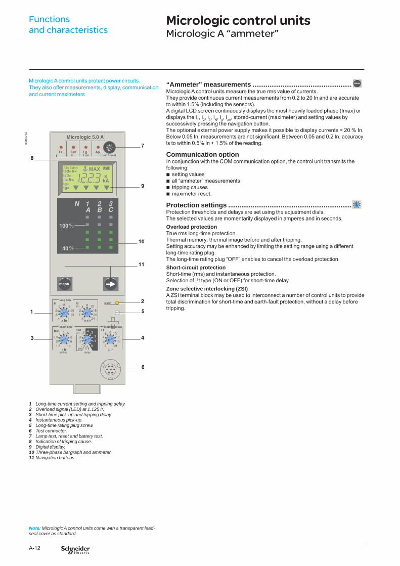
Micrologic A control units protect power circuits.They also offer measurements, display, communication and current maximeters
Long-time current setting and tripping delay.Overload signal (LED) at 1.125 Ir.Short-time pick-up and tripping delay.Instantaneous pick-up.Long-time rating plug screw.Test connector.Lamp test, reset and battery test.Indication of tripping cause.Digital display.Three-phase bargraph and ammeter.Navigation buttons.
1 2 3 4 5 6 7 8 9 10 11
“Ammeter” measurements .....................................................Micrologic A control units measure the true rms value of currents.They provide continuous current measurements from 0.2 to 20 In and are accurate to within 1.5% (including the sensors).A digital LCD screen continuously displays the most heavily loaded phase (Imax) or displays the I1, I2, I3, IN, Ig, IDn, stored-current (maximeter) and setting values by successively pressing the navigation button.The optional external power supply makes it possible to display currents < 20 % In.Below 0.05 In, measurements are not significant. Between 0.05 and 0.2 In, accuracy is to within 0.5% In + 1.5% of the reading.
Communication optionIn conjunction with the COM communication option, the control unit transmits the following:
setting valuesall “ammeter” measurementstripping causesmaximeter reset.
Protection settings ..................................................................Protection thresholds and delays are set using the adjustment dials.The selected values are momentarily displayed in amperes and in seconds.Overload protectionTrue rms long-time protection.Thermal memory: thermal image before and after tripping.Setting accuracy may be enhanced by limiting the setting range using a different long-time rating plug.The long-time rating plug “OFF” enables to cancel the overload protection.Short-circuit protectionShort-time (rms) and instantaneous protection.Selection of I2t type (ON or OFF) for short-time delay.Zone selective interlocking (ZSI)A ZSI terminal block may be used to interconnect a number of control units to provide total discrimination for short-time and earth-fault protection, without a delay before tripping.
bbbb
Note: Micrologic A control units come with a transparent lead-seal cover as standard.
Functions and characteristics
Micrologic control units Micrologic A “ammeter”
222E2200.indd 12 07/07/2009 09:44:07
A-13
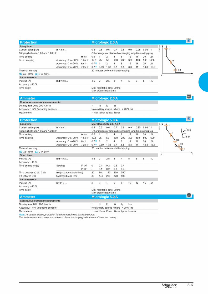
Protection Micrologic 2.0 ALong time
DB
1011
26
Current setting (A) Ir = In x … 0.4 0.5 0.6 0.7 0.8 0.9 0.95 0.98 1Tripping between 1.05 and 1.20 x Ir Other ranges or disable by changing long-time rating plug Time setting tr (s) 0.5 1 2 4 8 12 16 20 24Time delay (s) Accuracy: 0 to -30 % 1.5 x Ir 12.5 25 50 100 200 300 400 500 600
Accuracy: 0 to -20 % 6 x Ir 0.7(1) 1 2 4 8 12 16 20 24Accuracy: 0 to -20 % 7.2 x Ir 0.7(2) 0.69 1.38 2.7 5.5 8.3 11 13.8 16.6
Thermal memory 20 minutes before and after tripping(1) 0to-40%-(2)0to-60%Instantaneous
Pick-up (A) Isd = Ir x … 1.5 2 2.5 3 4 5 6 8 10Accuracy: ±10 %Time delay Max resettable time: 20 ms
Max break time: 80 ms
Ammeter Micrologic 2.0 AContinuous current measurements
Display from 20 to 200 % of In I1 I2 I3 INAccuracy: 1.5 % (including sensors) No auxiliary source (where I > 20 % In)Maximeters I1 max I2 max I3 max IN max
Protection Micrologic 5.0 ALong time Micrologic 5.0 / 6.0 / 7.0 A
DB
1011
27
Current setting (A) Ir = In x … 0.4 0.5 0.6 0.7 0.8 0.9 0.95 0.98 1Tripping between 1.05 and 1.20 x Ir Other ranges or disable by changing long-time rating plug Time setting tr (s) 0.5 1 2 4 8 12 16 20 24Time delay (s) Accuracy: 0 to -30 % 1.5 x Ir 12.5 25 50 100 200 300 400 500 600
Accuracy: 0 to -20 % 6 x Ir 0.7(1) 1 2 4 8 12 16 20 24Accuracy: 0 to -20 % 7.2 x Ir 0.7(2) 0.69 1.38 2.7 5.5 8.3 11 13.8 16.6
Thermal memory 20 minutes before and after tripping(1)0to-40%-(2)0to-60%Short time
Pick-up (A) Isd = Ir x … 1.5 2 2.5 3 4 5 6 8 10Accuracy: ±10 %Time setting tsd (s) Settings I2t Off 0 0.1 0.2 0.3 0.4
I2t On - 0.1 0.2 0.3 0.4Time delay (ms) at 10 x Ir tsd (max resettable time) 20 80 140 230 350(I2t Off or I2t On) tsd (max break time) 80 140 200 320 500Instantaneous
Pick-up (A) Ii = In x … 2 3 4 6 8 10 12 15 offAccuracy: ±10 %Time delay Max resettable time: 20 ms
Max break time: 50 ms
Ammeter Micrologic 5.0 AContinuous current measurements
Display from 20 to 200 % of In I1 I2 I3 IN Ig I∆nAccuracy: 1.5 % (including sensors) No auxiliary source (where I > 20 % In)Maximeters I1 max I2 max I3 max IN max Ig max I∆n maxNote:Allcurrent-basedprotectionfunctionsrequirenoauxiliarysource.Thetest/resetbuttonresetsmaximeters,clearsthetrippingindicationandteststhebattery.
BTP222E.indb 13 30/06/2009 09:30:34
A-14
DB
1208
96
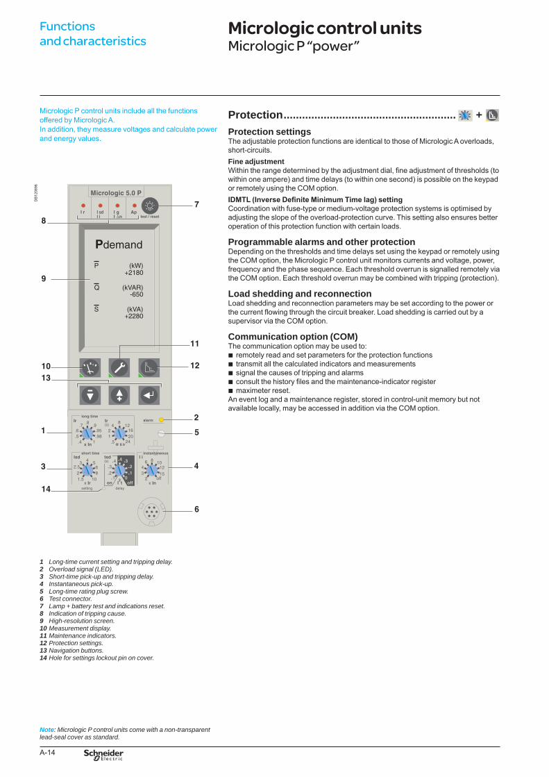
Micrologic P control units include all the functions offered by Micrologic A.In addition, they measure voltages and calculate power and energy values.
Long-timecurrentsettingandtrippingdelay.Overloadsignal(LED).Short-timepick-upandtrippingdelay.Instantaneouspick-up.Long-timeratingplugscrew.Testconnector.Lamp+batterytestandindicationsreset.Indicationoftrippingcause.High-resolutionscreen.Measurementdisplay.Maintenanceindicators.Protectionsettings.Navigationbuttons.Holeforsettingslockoutpinoncover.
1 2 3 4 5 6 7 8 9 10 11 12 13 14
Protection ........................................................ + Protection settings The adjustable protection functions are identical to those of Micrologic A overloads, short-circuits.Fine adjustmentWithin the range determined by the adjustment dial, fine adjustment of thresholds (to within one ampere) and time delays (to within one second) is possible on the keypad or remotely using the COM option.IDMTL (Inverse Definite Minimum Time lag) settingCoordination with fuse-type or medium-voltage protection systems is optimised by adjusting the slope of the overload-protection curve. This setting also ensures better operation of this protection function with certain loads.
Programmable alarms and other protectionDepending on the thresholds and time delays set using the keypad or remotely using the COM option, the Micrologic P control unit monitors currents and voltage, power, frequency and the phase sequence. Each threshold overrun is signalled remotely via the COM option. Each threshold overrun may be combined with tripping (protection).
Load shedding and reconnectionLoad shedding and reconnection parameters may be set according to the power or the current flowing through the circuit breaker. Load shedding is carried out by a supervisor via the COM option.
Communication option (COM)The communication option may be used to:
remotely read and set parameters for the protection functionstransmit all the calculated indicators and measurementssignal the causes of tripping and alarmsconsult the history files and the maintenance-indicator register maximeter reset.
An event log and a maintenance register, stored in control-unit memory but not available locally, may be accessed in addition via the COM option.
bbbbb
Note: MicrologicPcontrolunitscomewithanon-transparentlead-sealcoverasstandard.
Functions and characteristics
Micrologic control units Micrologic P “power”
BTP222E.indb 14 30/06/2009 09:30:35
A-15
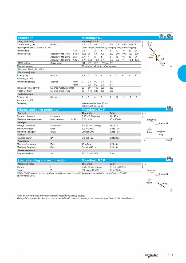
Protection Micrologic 5.0 +Long time (rms) Micrologic 5.0 P
DB
1011
30
Current setting (A) Ir = In x … 0.4 0.5 0.6 0.7 0.8 0.9 0.95 0.98 1Tripping between 1.05 and 1.20 x Ir Other ranges or disable by changing long-time rating plug Time setting tr (s) 0.5 1 2 4 8 12 16 20 24Time delay (s) Accuracy: 0 to -30 % 1.5 x Ir 12.5 25 50 100 200 300 400 500 600
Accuracy: 0 to -20 % 6 x Ir 0.7(1) 1 2 4 8 12 16 20 24Accuracy: 0 to -20 % 7.2 x Ir 0.7(2) 0.69 1.38 2.7 5.5 8.3 11 13.8 16.6
IDMTL setting Curve slope SIT VIT EIT HVFuse DTThermal memory 20 minutes before and after tripping(1)0to-40%-(2)0to-60%Short time (rms)
Pick-up (A) Isd = Ir x … 1.5 2 2.5 3 4 5 6 8 10Accuracy: ±10 %Time setting tsd (s) Settings I2t Off 0 0.1 0.2 0.3 0.4
I2t On - 0.1 0.2 0.3 0.4Time delay (ms) at 10 Ir tsd (max resettable time) 20 80 140 230 350(I2t Off or I2t On) tsd (max break time) 80 140 200 320 500Instantaneous
Pick-up (A) Ii = In x … 2 3 4 6 8 10 12 15 offAccuracy: ±10 %Time delay Max resettable time: 20 ms
Max break time: 50 ms
Alarms and other protection Micrologic 5.0 PCurrent Threshold Delay
DB
1011
42
Current unbalance Iunbalance 0.05 to 0.6 Iaverage 1 to 40 sMaximum average current Imax demand : I1, I2, I3, IN, 0.2 In to In 15 to 1500 sVoltage
Voltage unbalance Uunbalance 2 to 30 % x Uaverage 1 to 40 sMinimum voltage Umin 100 to Umax 1.2 to 10 sMaximum voltage (3) Umax Umin to 1200 1.2 to 10 sPower
Reverse power rP 5 to 500 kW 0.2 to 20 sFrequency
Minimum frequency Fmin 45 to Fmax 1.2 to 5 sMaximum frequency Fmax Fmin to 440 Hz 1.2 to 5 sPhase sequence
Sequense (alarm) DØ Ø1/2/3 or Ø1/3/2 0.3 s
Load shedding and reconnection Micrologic 5.0 P Measured value Threshold Delay
DB
1011
43
Current I 0.5 to 1 Ir per phases 20 % tr to 80 % trPower P 200 kW to 10 MW 10 to 3600 s(3)For690Vapplications,astep-downtransformermustbeusedifthevoltageexceedsthenominalvalueof690Vbymorethan10%.
Note: allcurrent-basedprotectionfunctionsrequirenoauxiliarysource.Voltage-basedprotectionfunctionsareconnectedtoACpowerviaavoltagemeasurementinputbuiltintothecircuitbreaker.
BTP222E.indb 15 30/06/2009 09:30:36
A-16
DB
1011
33
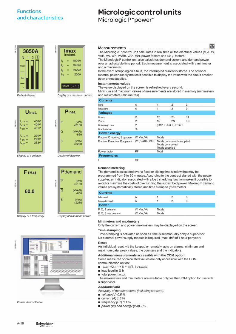
Defaultdisplay.
Displayofavoltage.
Displayofafrequency.
PowerViewsoftware.
DB
1057
56
Displayofamaximumcurrent.
Displayofapower.
Displayofademandpower.
Measurements ..........................................................................The Micrologic P control unit calculates in real time all the electrical values (V, A, W, VAR, VA, Wh, VARh, VAh, Hz), power factors and cos j factors.The Micrologic P control unit also calculates demand current and demand power over an adjustable time period. Each measurement is associated with a minimeter and a maximeter.In the event of tripping on a fault, the interrupted current is stored. The optional external power supply makes it possible to display the value with the circuit breaker open or not supplied.Instantaneous valuesThe value displayed on the screen is refreshed every second. Minimum and maximum values of measurements are stored in memory (minimeters and maximeters).minimètres).Currents
I rms A 1 2 3I max rms A 1 2 3
DB
1011
35
DB
1011
36
VoltagesU rms V 12 23 31V rms V 1N 2N 3NU average rms V (U12 + U23 + U31) / 3U unbalance %Power, energy
P active, Q reactive, S apparent W, Var, VA TotalsE active, E reactive, E apparent Wh, VARh, VAh Totals consumed - supplied
Totals consumedTotals supplied
Power factor PF TotalFrequencies
F Hz
DB
1011
37
DB
1011
38
Demand meteringThe demand is calculated over a fixed or sliding time window that may be programmed from 5 to 60 minutes. According to the contract signed with the power supplier, an indicator associated with a load shedding function makes it possible to avoid or minimise the costs of overrunning the subscribed power. Maximum demand values are systematically stored and time stamped (maximeter).
CurrentsI demand A 1 2 3I max demand A 1 2 3Power
P, Q, S demand W, Var, VA TotalsP, Q, S max demand W, Var, VA Totals
DB
1245
81A
Minimeters and maximetersOnly the current and power maximeters may be displayed on the screen.Time-stampingTime-stamping is activated as soon as time is set manually or by a supervisor.No external power supply module is required (max. drift of 1 hour per year).ResetAn individual reset, via the keypad or remotely, acts on alarms, minimum and maximum data, peak values, the counters and the indicators.Additional measurements accessible with the COM optionSome measured or calculated values are only accessible with the COM communication option:
I peak / 2, (I1 + I2 + I3)/3, I unbalanceload level in % Irtotal power factor.
The maximeters and minimeters are available only via the COM option for use with a supervisor.Additional infoAccuracyofmeasurements(includingsensors):
voltage(V)0.5%current(A)1.5%frequency(Hz)0.1%power(W)andenergy(Wh)2%.
bbb
bbbb
Functions and characteristics
Micrologic control units Micrologic P “power”
BTP222E.indb 16 30/06/2009 09:30:39
A-17
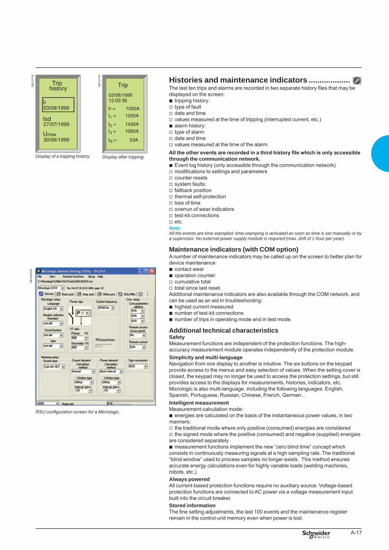
Histories and maintenance indicators ...................The last ten trips and alarms are recorded in two separate history files that may be displayed on the screen:
tripping history:type of faultdate and timevalues measured at the time of tripping (interrupted current, etc.)alarm history:type of alarmdate and timevalues measured at the time of the alarm.
All the other events are recorded in a third history file which is only accessible through the communication network.
Event log history (only accessible through the communication network)modifications to settings and parameterscounter resetssystem faults:fallback positionthermal self-protectionloss of timeoverrun of wear indicatorstest-kit connectionsetc.
Note: Alltheeventsaretimestampled:time-stampingisactivatedassoonastimeissetmanuallyorbyasupervisor.Noexternalpowersupplymoduleisrequired(max.driftof1hourperyear).
Maintenance indicators (with COM option)A number of maintenance indicators may be called up on the screen to better plan for device maintenance:
contact wearoperation counter:cumulative totaltotal since last reset.
Additional maintenance indicators are also available through the COM network, and can be used as an aid in troubleshooting:
highest current measurednumber of test-kit connectionsnumber of trips in operating mode and in test mode.
Additional technical characteristicsSafetyMeasurement functions are independent of the protection functions. The high-accuracy measurement module operates independently of the protection module.Simplicity and multi-languageNavigation from one display to another is intuitive. The six buttons on the keypad provide access to the menus and easy selection of values. When the setting cover is closed, the keypad may no longer be used to access the protection settings, but still provides access to the displays for measurements, histories, indicators, etc.Micrologic is also multi-language, including the following languages: English, Spanish, Portuguese, Russian, Chinese, French, German...Intelligent measurementMeasurement-calculation mode:
energies are calculated on the basis of the instantaneous power values, in two manners:
the traditional mode where only positive (consumed) energies are consideredthe signed mode where the positive (consumed) and negative (supplied) energies
are considered separatelymeasurement functions implement the new “zero blind time” concept which
consists in continuously measuring signals at a high sampling rate. The traditional “blind window” used to process samples no longer exists. This method ensures accurate energy calculations even for highly variable loads (welding machines, robots, etc.).Always poweredAll current-based protection functions require no auxiliary source. Voltage-based protection functions are connected to AC power via a voltage measurement input built into the circuit breaker.Stored informationThe fine setting adjustments, the last 100 events and the maintenance register remain in the control-unit memory even when power is lost.
bvvvbvvv
bvvvvvvvvv
bbvv
bbb
b
vv
b
DB
1011
39
Displayofatrippinghistory.
DB
1011
40
Displayaftertripping.
DB
1209
70A
RSU configuration screen for a Micrologic.
BTP222E.indb 17 30/06/2009 09:30:40
A-18
DB
1057
57
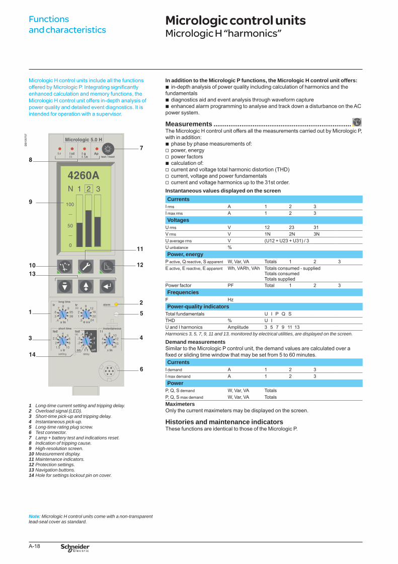
Micrologic H control units include all the functions offered by Micrologic P. Integrating significantly enhanced calculation and memory functions, the Micrologic H control unit offers in-depth analysis of power quality and detailed event diagnostics. It is intended for operation with a supervisor.
Long-timecurrentsettingandtrippingdelay.Overloadsignal(LED).Short-timepick-upandtrippingdelay.Instantaneouspick-up.Long-timeratingplugscrew.Testconnector.Lamp+batterytestandindicationsreset.Indicationoftrippingcause.High-resolutionscreen.Measurementdisplay.Maintenanceindicators.Protectionsettings.Navigationbuttons.Holeforsettingslockoutpinoncover.
1 2 3 4 5 6 7 8 9 10 11 12 13 14
In addition to the Micrologic P functions, the Micrologic H control unit offers:in-depth analysis of power quality including calculation of harmonics and the
fundamentalsdiagnostics aid and event analysis through waveform captureenhanced alarm programming to analyse and track down a disturbance on the AC
power system.
Measurements ..........................................................................The Micrologic H control unit offers all the measurements carried out by Micrologic P, with in addition:
phase by phase measurements of:power, energypower factorscalculation of:current and voltage total harmonic distortion (THD)current, voltage and power fundamentalscurrent and voltage harmonics up to the 31st order.
Instantaneous values displayed on the screen
b
bb
bvvbvvv
CurrentsI rms A 1 2 3I max rms A 1 2 3Voltages
U rms V 12 23 31V rms V 1N 2N 3NU average rms V (U12 + U23 + U31) / 3U unbalance %Power, energy
P active, Q reactive, S apparent W, Var, VA Totals 1 2 3E active, E reactive, E apparent Wh, VARh, VAh Totals consumed - supplied
Totals consumedTotals supplied
Power factor PF Total 1 2 3Frequencies
F HzPower-quality indicators
Total fundamentals U I P Q STHD % U I U and I harmonics Amplitude 3 5 7 9 11 13Harmonics3,5,7,9,11and13,monitoredbyelectricalutilities,aredisplayedonthescreen.
Demand measurementsSimilar to the Micrologic P control unit, the demand values are calculated over a fixed or sliding time window that may be set from 5 to 60 minutes. Currents
I demand A 1 2 3I max demand A 1 2 3Power
P, Q, S demand W, Var, VA TotalsP, Q, S max demand W, Var, VA TotalsMaximetersOnly the current maximeters may be displayed on the screen.
Histories and maintenance indicatorsThese functions are identical to those of the Micrologic P.
Note: MicrologicHcontrolunitscomewithanon-transparentlead-sealcoverasstandard.
Functions and characteristics
Micrologic control units Micrologic H “harmonics”
BTP222E.indb 18 30/06/2009 09:30:40
A-19
DB
1015
21
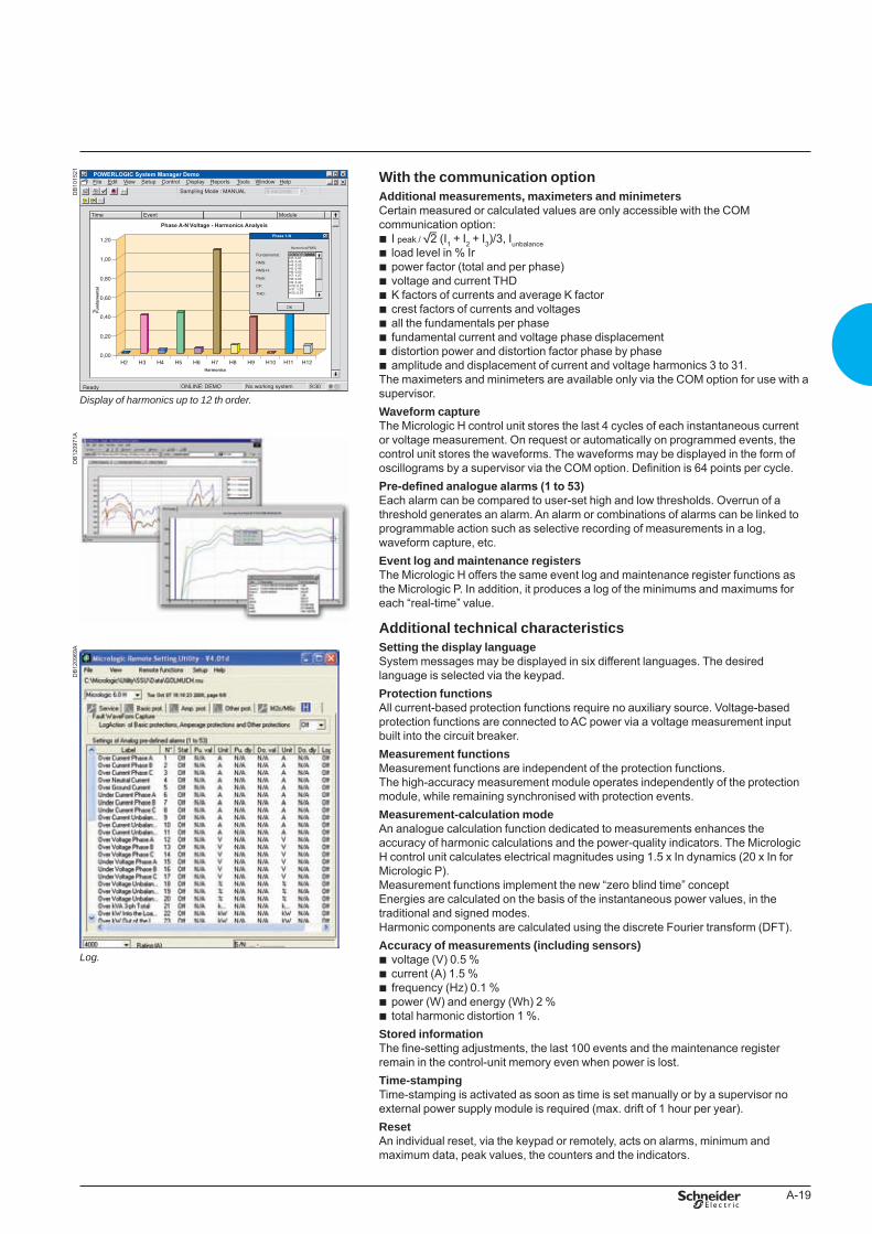
Displayofharmonicsupto12thorder.
With the communication optionAdditional measurements, maximeters and minimetersCertain measured or calculated values are only accessible with the COM communication option:
I peak / 2 (I1 + I2 + I3)/3, Iunbalanceload level in % Irpower factor (total and per phase)voltage and current THDK factors of currents and average K factorcrest factors of currents and voltagesall the fundamentals per phasefundamental current and voltage phase displacementdistortion power and distortion factor phase by phaseamplitude and displacement of current and voltage harmonics 3 to 31.
The maximeters and minimeters are available only via the COM option for use with a supervisor.Waveform captureThe Micrologic H control unit stores the last 4 cycles of each instantaneous current or voltage measurement. On request or automatically on programmed events, the control unit stores the waveforms. The waveforms may be displayed in the form of oscillograms by a supervisor via the COM option. Definition is 64 points per cycle.Pre-defined analogue alarms (1 to 53)Each alarm can be compared to user-set high and low thresholds. Overrun of a threshold generates an alarm. An alarm or combinations of alarms can be linked to programmable action such as selective recording of measurements in a log, waveform capture, etc.Event log and maintenance registersThe Micrologic H offers the same event log and maintenance register functions as the Micrologic P. In addition, it produces a log of the minimums and maximums for each “real-time” value.
Additional technical characteristicsSetting the display languageSystem messages may be displayed in six different languages. The desired language is selected via the keypad.Protection functionsAll current-based protection functions require no auxiliary source. Voltage-based protection functions are connected to AC power via a voltage measurement input built into the circuit breaker.Measurement functionsMeasurement functions are independent of the protection functions.The high-accuracy measurement module operates independently of the protection module, while remaining synchronised with protection events.Measurement-calculation modeAn analogue calculation function dedicated to measurements enhances the accuracy of harmonic calculations and the power-quality indicators. The Micrologic H control unit calculates electrical magnitudes using 1.5 x In dynamics (20 x In for Micrologic P).Measurement functions implement the new “zero blind time” conceptEnergies are calculated on the basis of the instantaneous power values, in the traditional and signed modes.Harmonic components are calculated using the discrete Fourier transform (DFT).Accuracy of measurements (including sensors)
voltage (V) 0.5 %current (A) 1.5 %frequency (Hz) 0.1 %power (W) and energy (Wh) 2 %total harmonic distortion 1 %.
Stored informationThe fine-setting adjustments, the last 100 events and the maintenance register remain in the control-unit memory even when power is lost.Time-stampingTime-stamping is activated as soon as time is set manually or by a supervisor no external power supply module is required (max. drift of 1 hour per year).ResetAn individual reset, via the keypad or remotely, acts on alarms, minimum and maximum data, peak values, the counters and the indicators.
bbbbbbbbbb
bbbbb
DB
1209
71A
DB
1209
69A
Log.
BTP222E.indb 19 30/06/2009 09:30:42
A-20
External sensorsVoltage measurement inputsVoltage measurement inputs are required for power measurements (Micrologic P or H).As standard, the control unit is supplied by internal voltage measurement inputs placed downstream of the pole for voltages between 220 and 690 V AC. On request, it is possible to replace the internal voltage measurement inputs by an external voltage input (PTE option) which enables the control unit to draw power directly from the distribution system upstream of the circuit breaker. An 3 m cable with ferrite comes with this PTE option.
PB
1007
73A
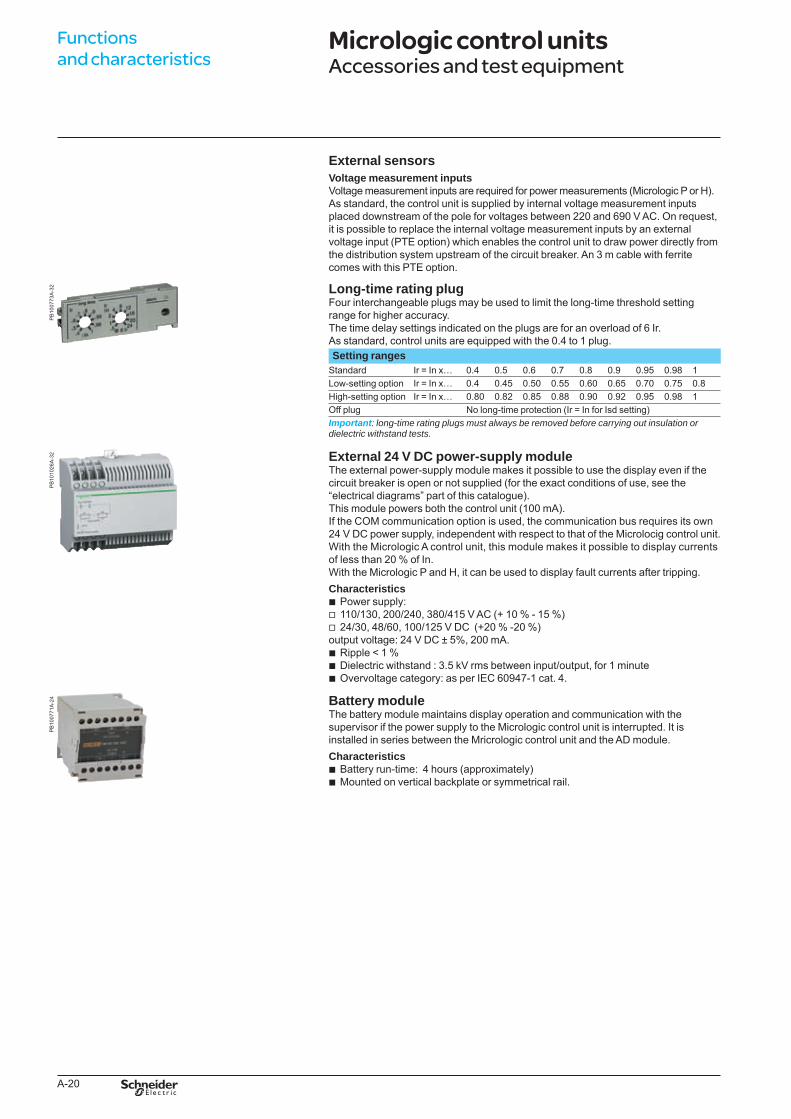
-32 Long-time rating plug
Four interchangeable plugs may be used to limit the long-time threshold setting range for higher accuracy. The time delay settings indicated on the plugs are for an overload of 6 Ir.As standard, control units are equipped with the 0.4 to 1 plug.Setting ranges
Standard Ir = In x… 0.4 0.5 0.6 0.7 0.8 0.9 0.95 0.98 1Low-setting option Ir = In x… 0.4 0.45 0.50 0.55 0.60 0.65 0.70 0.75 0.8High-setting option Ir = In x… 0.80 0.82 0.85 0.88 0.90 0.92 0.95 0.98 1Off plug No long-time protection (Ir = In for Isd setting)Important: long-timeratingplugsmustalwaysberemovedbeforecarryingoutinsulationordielectricwithstandtests.
PB
1010
26A
-32 External 24 V DC power-supply module
The external power-supply module makes it possible to use the display even if the circuit breaker is open or not supplied (for the exact conditions of use, see the “electrical diagrams” part of this catalogue).This module powers both the control unit (100 mA).If the COM communication option is used, the communication bus requires its own24 V DC power supply, independent with respect to that of the Microlocig control unit.With the Micrologic A control unit, this module makes it possible to display currents of less than 20 % of In.With the Micrologic P and H, it can be used to display fault currents after tripping. Characteristics
Power supply:110/130, 200/240, 380/415 V AC (+ 10 % - 15 %)24/30, 48/60, 100/125 V DC (+20 % -20 %)
output voltage: 24 V DC ± 5%, 200 mA.Ripple < 1 %Dielectric withstand : 3.5 kV rms between input/output, for 1 minuteOvervoltage category: as per IEC 60947-1 cat. 4.
bvv
bbb
PB
1007
71A
-24 Battery module
The battery module maintains display operation and communication with the supervisor if the power supply to the Micrologic control unit is interrupted. It isinstalled in series between the Mricrologic control unit and the AD module.Characteristics
Battery run-time: 4 hours (approximately)Mounted on vertical backplate or symmetrical rail.
bb
Functions and characteristics
Micrologic control units Accessories and test equipment
BTP222E.indb 20 30/06/2009 09:30:43
A-21
PB
1007
75A
-32
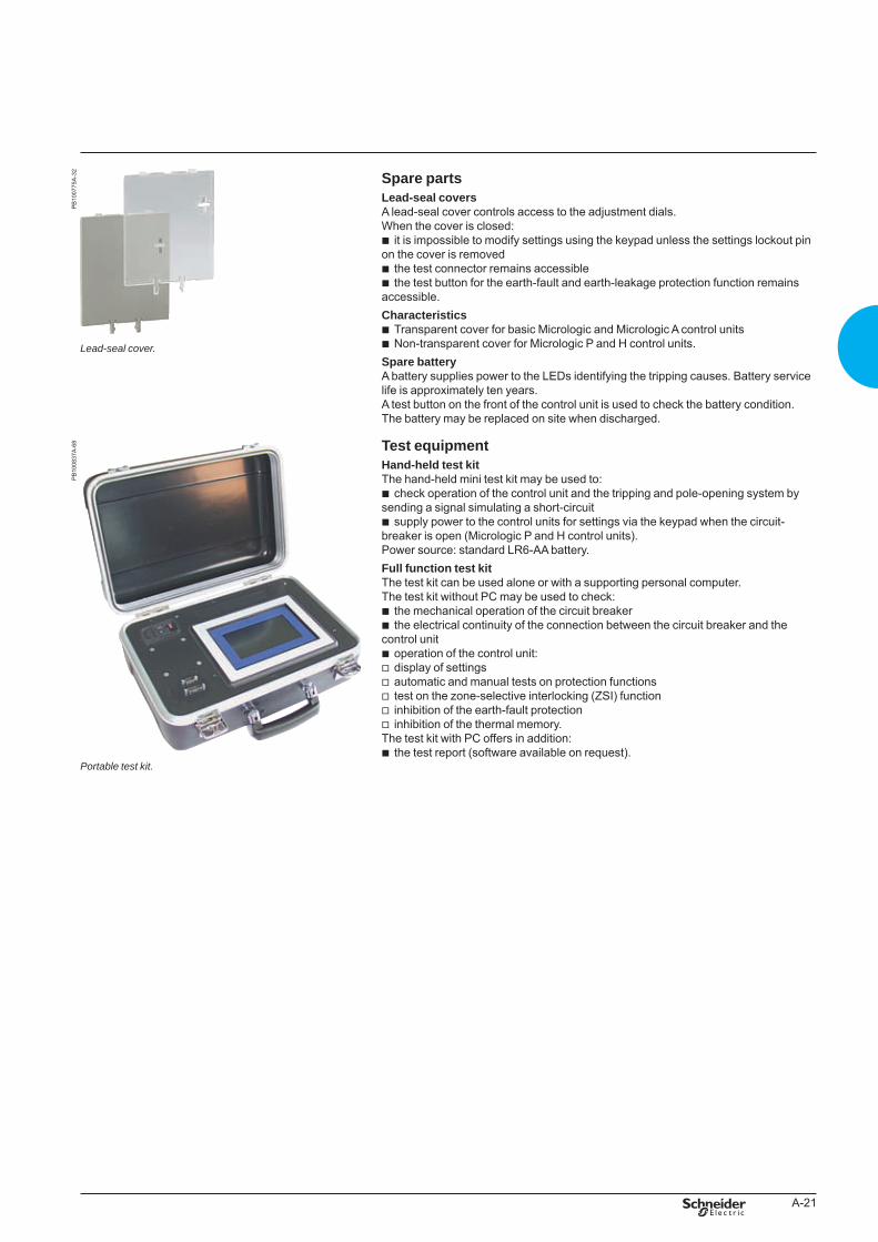
Lead-sealcover.
Spare partsLead-seal coversA lead-seal cover controls access to the adjustment dials.When the cover is closed:
it is impossible to modify settings using the keypad unless the settings lockout pin on the cover is removed
the test connector remains accessiblethe test button for the earth-fault and earth-leakage protection function remains
accessible.Characteristics
Transparent cover for basic Micrologic and Micrologic A control unitsNon-transparent cover for Micrologic P and H control units.
Spare batteryA battery supplies power to the LEDs identifying the tripping causes. Battery service life is approximately ten years.A test button on the front of the control unit is used to check the battery condition. The battery may be replaced on site when discharged.
b
bb
bb
PB
1008
37A
-68
Portabletestkit.
Test equipmentHand-held test kitThe hand-held mini test kit may be used to:
check operation of the control unit and the tripping and pole-opening system by sending a signal simulating a short-circuit
supply power to the control units for settings via the keypad when the circuit-breaker is open (Micrologic P and H control units).Power source: standard LR6-AA battery.Full function test kitThe test kit can be used alone or with a supporting personal computer.The test kit without PC may be used to check:
the mechanical operation of the circuit breakerthe electrical continuity of the connection between the circuit breaker and the
control unitoperation of the control unit:display of settingsautomatic and manual tests on protection functionstest on the zone-selective interlocking (ZSI) functioninhibition of the earth-fault protectioninhibition of the thermal memory.
The test kit with PC offers in addition:the test report (software available on request).
b
b
bb
bvvvvv
b
BTP222E.indb 21 30/06/2009 09:30:44
A-22
GetnSet is a portable data acquisition and storage accessory that connects directly to the Micrologic control units of Masterpact circuit breakers to read important electrical installation operating data and Masterpact protection settings.This information is stored in the GetnSet internal memory and can be transferred to a PC via USB or Bluetooth for monitoring and analysis.
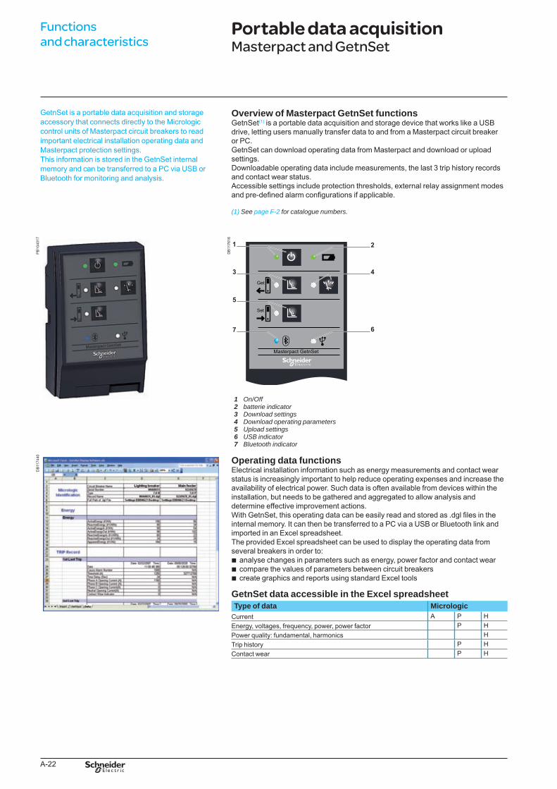
Overview of Masterpact GetnSet functionsGetnSet(1) is a portable data acquisition and storage device that works like a USB drive, letting users manually transfer data to and from a Masterpact circuit breaker or PC.GetnSet can download operating data from Masterpact and download or upload settings.Downloadable operating data include measurements, the last 3 trip history records and contact wear status.Accessible settings include protection thresholds, external relay assignment modes and pre-defined alarm configurations if applicable.
(1)SeepageF-2forcataloguenumbers.
PB
1040
17
DB
1176
16
On/OffbatterieindicatorDownloadsettingsDownloadoperatingparametersUploadsettingsUSBindicatorBluetoothindicator
1 2 3 4 5 6 7
DB
1174
40 Operating data functionsElectrical installation information such as energy measurements and contact wear status is increasingly important to help reduce operating expenses and increase the availability of electrical power. Such data is often available from devices within the installation, but needs to be gathered and aggregated to allow analysis and determine effective improvement actions.With GetnSet, this operating data can be easily read and stored as .dgl files in the internal memory. It can then be transferred to a PC via a USB or Bluetooth link and imported in an Excel spreadsheet. The provided Excel spreadsheet can be used to display the operating data from several breakers in order to:
analyse changes in parameters such as energy, power factor and contact wearcompare the values of parameters between circuit breakerscreate graphics and reports using standard Excel tools
GetnSet data accessible in the Excel spreadsheetType of data Micrologic
Current A P HEnergy, voltages, frequency, power, power factor P HPower quality: fundamental, harmonics HTrip history P HContact wear P H
bbb
Functions and characteristics
Portable data acquisitionMasterpact and GetnSet
BTP222E.indb 22 30/06/2009 09:30:46
A-23
DB
1174
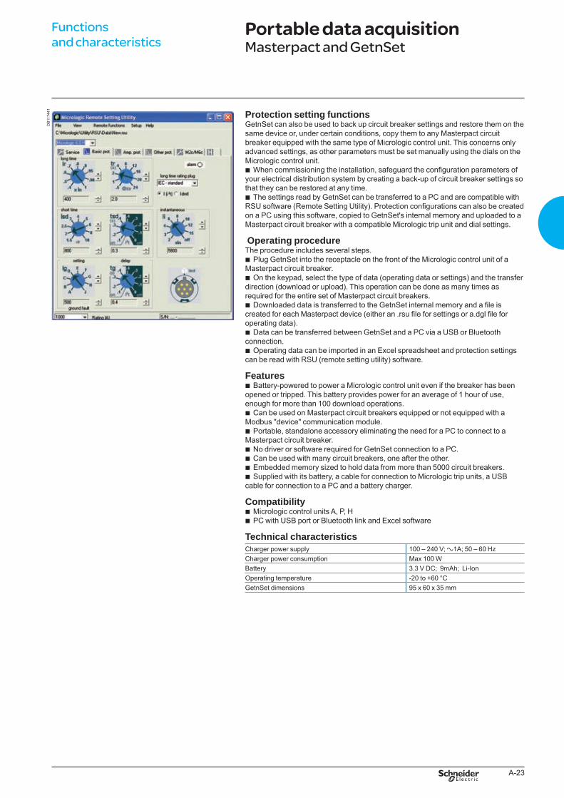
41 Protection setting functionsGetnSet can also be used to back up circuit breaker settings and restore them on the same device or, under certain conditions, copy them to any Masterpact circuit breaker equipped with the same type of Micrologic control unit. This concerns only advanced settings, as other parameters must be set manually using the dials on the Micrologic control unit.
When commissioning the installation, safeguard the configuration parameters of your electrical distribution system by creating a back-up of circuit breaker settings so that they can be restored at any time.
The settings read by GetnSet can be transferred to a PC and are compatible with RSU software (Remote Setting Utility). Protection configurations can also be created on a PC using this software, copied to GetnSet's internal memory and uploaded to a Masterpact circuit breaker with a compatible Micrologic trip unit and dial settings.
Operating procedureThe procedure includes several steps.
Plug GetnSet into the receptacle on the front of the Micrologic control unit of a Masterpact circuit breaker.
On the keypad, select the type of data (operating data or settings) and the transfer direction (download or upload). This operation can be done as many times as required for the entire set of Masterpact circuit breakers.
Downloaded data is transferred to the GetnSet internal memory and a file is created for each Masterpact device (either an .rsu file for settings or a.dgl file for operating data).
Data can be transferred between GetnSet and a PC via a USB or Bluetooth connection.
Operating data can be imported in an Excel spreadsheet and protection settings can be read with RSU (remote setting utility) software.
FeaturesBattery-powered to power a Micrologic control unit even if the breaker has been
opened or tripped. This battery provides power for an average of 1 hour of use, enough for more than 100 download operations.
Can be used on Masterpact circuit breakers equipped or not equipped with a Modbus "device" communication module.
Portable, standalone accessory eliminating the need for a PC to connect to a Masterpact circuit breaker.
No driver or software required for GetnSet connection to a PC.Can be used with many circuit breakers, one after the other.Embedded memory sized to hold data from more than 5000 circuit breakers.Supplied with its battery, a cable for connection to Micrologic trip units, a USB
cable for connection to a PC and a battery charger.
CompatibilityMicrologic control units A, P, HPC with USB port or Bluetooth link and Excel software
Technical characteristicsCharger power supply 100 – 240 V; a1A; 50 – 60 HzCharger power consumption Max 100 WBattery 3.3 V DC; 9mAh; Li-IonOperating temperature -20 to +60 °CGetnSet dimensions 95 x 60 x 35 mm
b
b
b
b
b
b
b
b
b
b
bbbb
bb
Portable data acquisitionMasterpact and GetnSet
Functions and characteristics
BTP222E.indb 23 30/06/2009 09:30:46
A-24
The COM option is required for integration of the circuit breaker or switch-disconnector in a supervision system.Masterpact NAVY uses the Modbus communications protocol for full compatibility with the supervision systems. An external gateway is available for communication on other networks:
Ion Enterprise (power management system)Ethernet gateway (MPS100/EGX)EthernetProfibus
Eco COM is limited to the transmission of metering data and does not allow the control of the circuit breaker.
bbbb
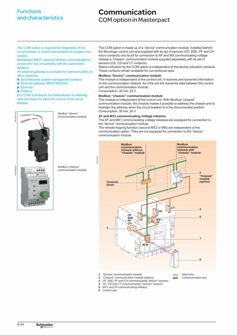
The COM option is made up of a “device” communication module, installed behind the Micrologic control unit and supplied with its set of sensors (OF, SDE, PF and CH micro-contacts) and its kit for connection to XF and MX communicating voltage release a “chassis” communication module supplied separately with its set of sensors (CE, CD and CT contacts).Status indication by the COM option is independent of the device indication contacts. These contacts remain available for conventional uses.Modbus “Device” communication moduleThis module is independent of the control unit. It receives and transmits information on the communication network. An infra-red link transmits data between the control unit and the communication module.Consumption: 30 mA, 24 V.Modbus “chassis” communication moduleThis module is independent of the control unit. With Modbus “chassis” communication module, this module makes it possible to address the chassis and to maintain the address when the circuit breaker is in the disconnected position.Consumption: 30 mA, 24 V.XF and MX1 communicating voltage releasesThe XF and MX1 communicating voltage releases are equipped for connection to the “device” communication module.The remote-tripping function (second MX2 or MN) are independent of the communication option. They are not equipped for connection to the “device” communication module.
“Device”communicationmodule. :Hardwire.“Chassis”communicationmodule(option). :Communicationbus.OF,SDE,PFandCHcommunicating“device”sensors.CE,CDandCTcommunicating“chassis”sensors.MX1andXFcommunicatingrelease.Controlunit.
1 2 3 4 5 6
DB
1021
89
PB
1007
82A
-26
Modbus“device”communicationmodule.
PB
1008
02B
-27
Modbus“chassis”communicationmodule.
Functions and characteristics
Communication COM option in Masterpact
OFSDEPFCH
BTP222E.indb 24 30/06/2009 09:30:49
A-25
0564
84N
-60
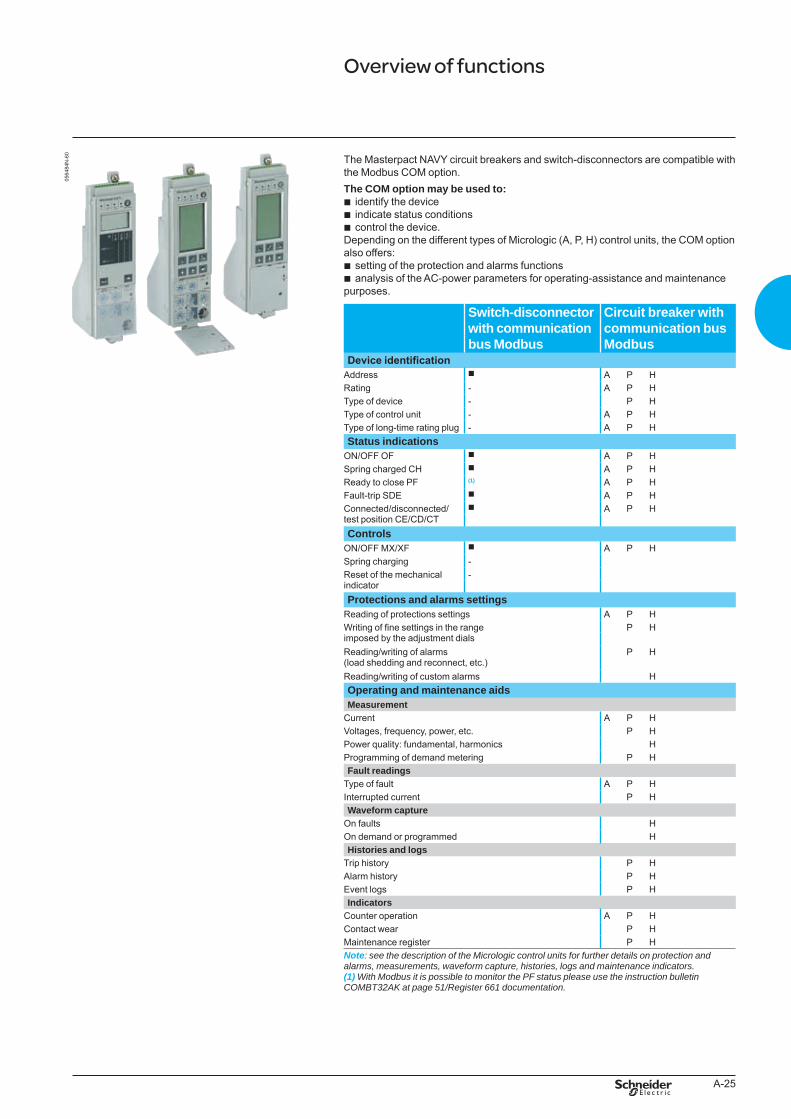
The Masterpact NAVY circuit breakers and switch-disconnectors are compatible with the Modbus COM option.The COM option may be used to:
identify the deviceindicate status conditionscontrol the device.
Depending on the different types of Micrologic (A, P, H) control units, the COM option also offers:
setting of the protection and alarms functionsanalysis of the AC-power parameters for operating-assistance and maintenance
purposes.
bbb
bb
Switch-disconnector with communication bus Modbus
Circuit breaker with communication busModbus
Device identificationAddress b A P HRating - A P HType of device - P HType of control unit - A P HType of long-time rating plug - A P HStatus indications
ON/OFF OF b A P HSpring charged CH b A P HReady to close PF (1) A P HFault-trip SDE b A P HConnected/disconnected/test position CE/CD/CT
b A P H
ControlsON/OFF MX/XF b A P HSpring charging -Reset of the mechanical indicator
-
Protections and alarms settingsReading of protections settings A P HWriting of fine settings in the range imposed by the adjustment dials
P H
Reading/writing of alarms (load shedding and reconnect, etc.)
P H
Reading/writing of custom alarms HOperating and maintenance aidsMeasurement
Current A P HVoltages, frequency, power, etc. P HPower quality: fundamental, harmonics HProgramming of demand metering P HFault readings
Type of fault A P HInterrupted current P HWaveform capture
On faults HOn demand or programmed HHistories and logs
Trip history P HAlarm history P HEvent logs P HIndicators
Counter operation A P HContact wear P HMaintenance register P HNote: seethedescriptionoftheMicrologiccontrolunitsforfurtherdetailsonprotectionandalarms,measurements,waveformcapture,histories,logsandmaintenanceindicators.(1)WithModbusitispossibletomonitorthePFstatuspleaseusetheinstructionbulletinCOMBT32AKatpage51/Register661documentation.
Overview of functions
BTP222E.indb 25 30/06/2009 09:30:50
A-26
Functions and characteristics
CommunicationMasterpact in a communication network
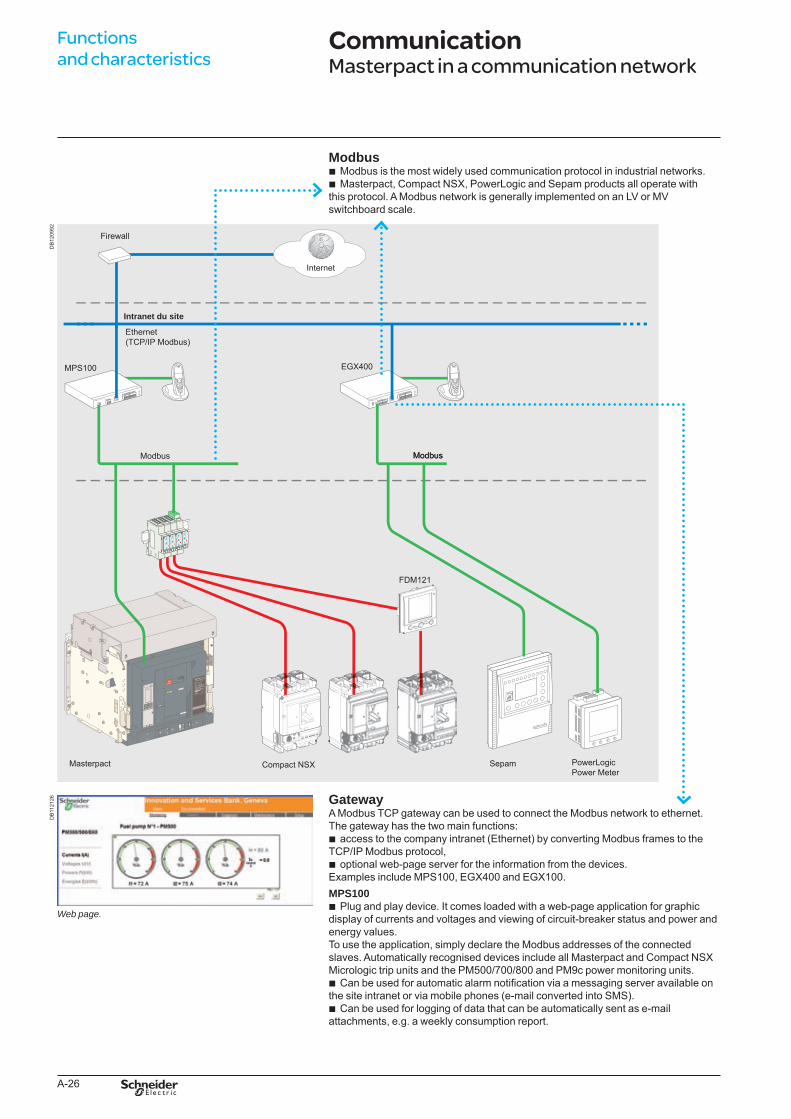
ModbusModbus is the most widely used communication protocol in industrial networks. Masterpact, Compact NSX, PowerLogic and Sepam products all operate with
this protocol. A Modbus network is generally implemented on an LV or MV switchboard scale.
bb
Firewall
Internet
Intranet du site
MPS100
Modbus Modbus
EGX400
Ethernet (TCP/IP Modbus)
FDM121
Masterpact Compact NSX
Modbus
PowerLogic Power Meter
Sepam
GatewayA Modbus TCP gateway can be used to connect the Modbus network to ethernet.The gateway has the two main functions:
access to the company intranet (Ethernet) by converting Modbus frames to the TCP/IP Modbus protocol,
optional web-page server for the information from the devices.Examples include MPS100, EGX400 and EGX100.MPS100
Plug and play device. It comes loaded with a web-page application for graphic display of currents and voltages and viewing of circuit-breaker status and power and energy values. To use the application, simply declare the Modbus addresses of the connected slaves. Automatically recognised devices include all Masterpact and Compact NSX Micrologic trip units and the PM500/700/800 and PM9c power monitoring units.
Can be used for automatic alarm notification via a messaging server available on the site intranet or via mobile phones (e-mail converted into SMS).
Can be used for logging of data that can be automatically sent as e-mail attachments, e.g. a weekly consumption report.
b
b
b
b
b
DB
1209
92D
B11
2126
Webpage.
BTP222E.indb 26 30/06/2009 09:30:55
A-27
Modbus busThe Modbus (RS 485) system is an open bus on which communicating Modbus devices (Masterpact NAVY with Modbus COM, Sepam, Vigilohm...) are installed. All types of PLCs and microcomputers may be connected to the bus.AddressesThe Modbus parameters (address, baud rate, parity) are entered using the keypad on the Micrologic A, P or H. For a switch-disconnector, it is necessary to use the RSU (Remote Setting Utility) Micrologic utility.The software layer of the Modbus protocol can manage up to 255 addresses (1 to 255).The “device” communication module comprises three addresses linked to:
circuit-breaker managermeasurement managerprotection manager
The “chassis” communication module comprises one address linked to the chassis manager.The division of the system into four managers secures data exchange with the supervision system and the circuit-breaker actuators.The manager addresses are automatically derived from the circuit-breaker address @ xx entered via the Micrologic control unit (the default address is 47).
bbb
Logic addresses@ xx Circuit-breaker manager (1 to 47)@ xx + 50 Chassis manager (51 to 97)@ xx + 200 Measurement managers (201 to 247)@ xx + 100 Protection manager (101 to 147)
Number of devicesThe maximum number of devices that may be connected to the Modbus bus depends on the type of device (Masterpact NAVY with Modbus COM, PM500, Sepam, Vigilohm, etc.), the baud rate (19200 is recommended), the volume of data exchanged and the desired response time. The RS485 physical layer offers up to 32 connection points on the bus (1 master, 31 slaves).A fixed device requires only one connection point (communication module on the device).A drawout device uses two connection points (communication modules on the device and on the chassis).The number must never exceed 15 drawout devices.Length of busThe maximum recommended length for the Modbus bus is 1200 meters.Bus power sourceA 24 V DC power supply is required (less than 20 % ripple, insulation class II).
Communication interfaceThe Modbus bus may be connected to the central processing device in any of three manners:
direct link to a PLC. The communication interface is not required if the PLC is equipped with a Modbus port
direct link to a computer. The Modbus (RS485) / Serial port (RS232) communication interface is required
connection to a TCP/IP (Ethernet) network. The Modbus (RS485) / TCP/IP (Ethernet) communication interface is required.
b
b
b
SoftwareTo make use of the information provided by the communicating devices, software with a Modbus driver must be used.
Micrologic utilitiesThis is a set of software that may be used with a PC to:
display the variables (I, U, P, E, etc.) with the RDU (Remote Display Utility)read/write the settings with the RSU (Remote Setting Utility)remotely control (ON / OFF) the device with the RCU (Remote Control Utility).
Micrologic utilities are available upon request
SMS (System Manager Software)SMS is a software to monitor LV and/or MV electrical energy.The SMS family includes a software range depending on the application and function, from single product monitoring to the management of a multiple building:
Power Meter and Circuit Monitor units LV devices Sepam units.
bbb
bbb
BTP222E.indb 27 30/06/2009 09:30:55
A-28
Functions and characteristics
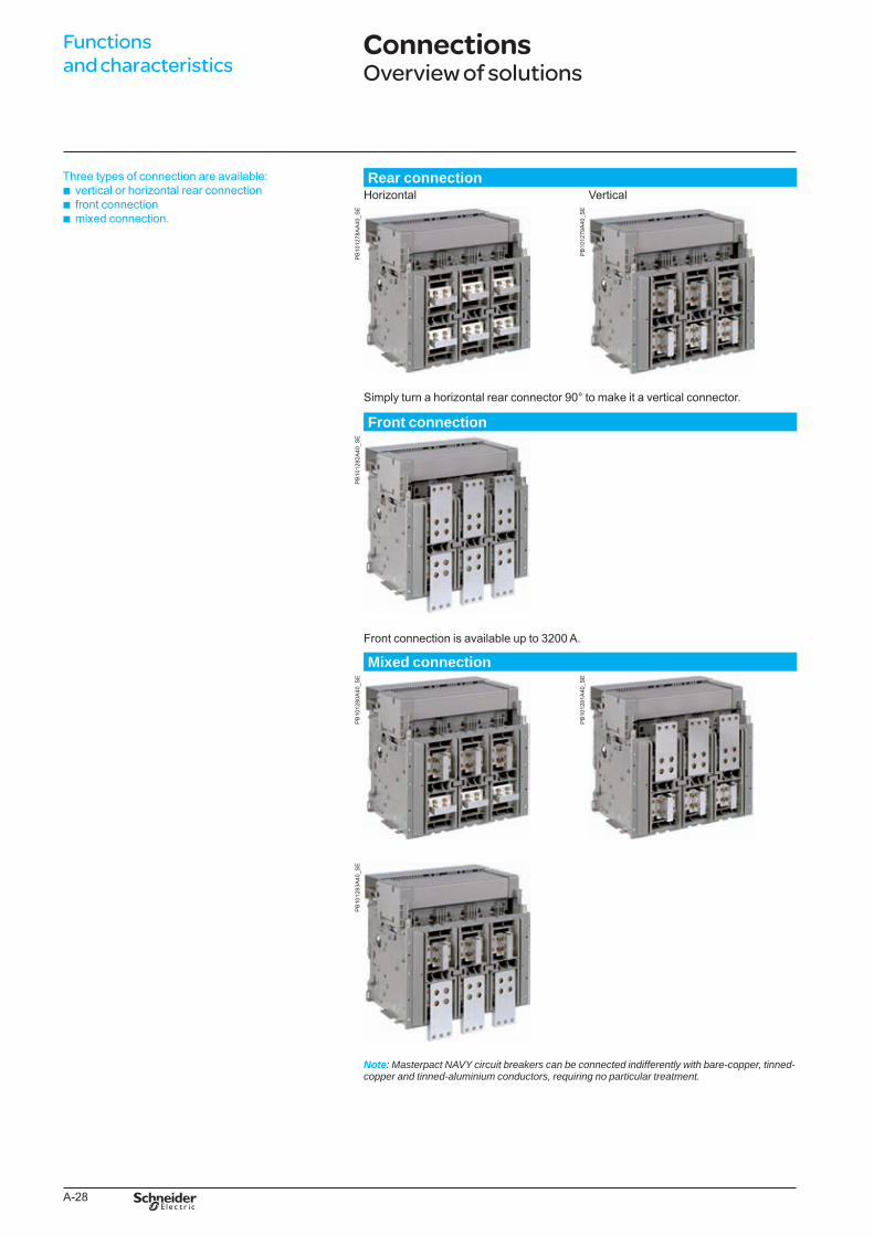
Three types of connection are available:vertical or horizontal rear connection front connection mixed connection.
bbb
Rear connectionHorizontal Vertical
PB
1012
78A
A40
_SE
PB
1012
79A
40_S
E
Simply turn a horizontal rear connector 90° to make it a vertical connector.
Front connection
PB
1012
82A
40_S
E
Front connection is available up to 3200 A.
Mixed connection
PB
1012
80A
40_S
E
PB
1012
81A
40_S
E
PB
1012
83A
40_S
E
Note: MasterpactNAVYcircuitbreakerscanbeconnectedindifferentlywithbare-copper,tinned-copperandtinned-aluminiumconductors,requiringnoparticulartreatment.
ConnectionsOverview of solutions
BTP222E.indb 28 30/06/2009 09:30:57
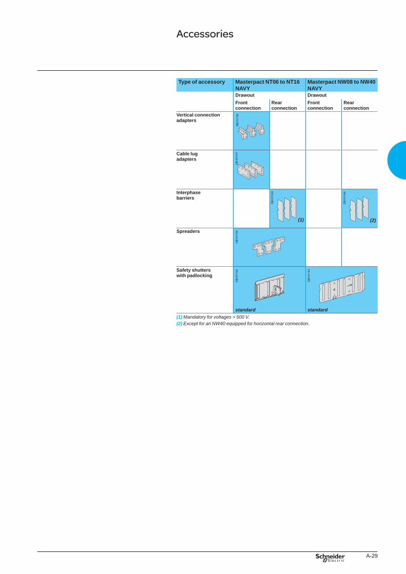
A-29
DB
1011
49
Type of accessory Masterpact NT06 to NT16 NAVY
Masterpact NW08 to NW40 NAVY
Drawout DrawoutFront connection
Rear connection
Front connection
Rear connection
Vertical connection adapters
Cable lug adapters
Interphase barriers
(1) (2)
Spreaders
Safety shutters with padlocking
standard standard(1)Mandatoryforvoltages>500V.(2) ExceptforanNW40equippedforhorizontalrearconnection.
Accessories
DB
1011
56D
B10
1147
DB
1011
49
DB
1011
49
DB
1011
50D
B10
1152
DB
1011
53
BTP222E.indb 29 30/06/2009 09:30:58
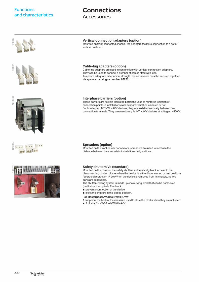
A-30
Functions and characteristics
DB
1058
06A
Vertical-connection adapters (option)Mounted on front-connected chassis, the adapters facilitate connection to a set of vertical busbars.
DB
1058
07A
Cable-lug adapters (option)Cable-lug adapters are used in conjunction with vertical-connection adapters.They can be used to connect a number of cables fitted with lugs.To ensure adequate mechanical strength, the connectors must be secured together via spacers (catalogue number 07251).
PB
1043
50A
33 Interphase barriers (option)These barriers are flexible insulated partitions used to reinforce isolation of connection points in installations with busbars, whether insulated or not. For Masterpact NT/NW NAVY devices, they are installed vertically between rear connection terminals. They are mandatory for NT NAVY devices at voltages > 500 V.
DB
1058
08A
Spreaders (option)Mounted on the front or rear connectors, spreaders are used to increase the distance between bars in certain installation configurations.
PB
1043
64A
48 Safety shutters Vo (standard)Mounted on the chassis, the safety shutters automatically block access to the disconnecting contact cluster when the device is in the disconnected or test positions (degree of protection IP 20) When the device is removed from its chassis, no live parts are accessible.The shutter-locking system is made up of a moving block that can be padlocked (padlock not supplied). The block:
prevents connection of the devicelocks the shutters in the closed position.
For Masterpact NW08 to NW40 NAVYA support at the back of the chassis is used to store the blocks when they are not used:
2 blocks for NW08 to NW40 NAVY.
bb
b
ConnectionsAccessories
BTP222E.indb 30 30/06/2009 09:31:00
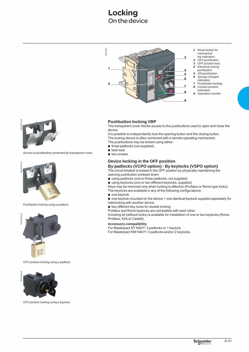
A-31
DB
1060
87 Resetbuttonformechanicaltripindication.OFFpushbutton.OFFpositionlock.Electricalclosingpushbutton.ONpushbutton.Springschargedindication.Pushbuttonlocking.Contactpositionindication.Operationcounter.
1
2 3 4
5 6
7 8
9
PB
1008
11A
-32
Pushbutton locking VBPThe transparent cover blocks access to the pushbuttons used to open and close the device.It is possible to independently lock the opening button and the closing button. The locking device is often combined with a remote operating mechanism.The pushbuttons may be locked using either:
three padlocks (not supplied)lead sealtwo screws.
Device locking in the OFF position By padlocks (VCPO option) - By keylocks (VSPO option)The circuit breaker is locked in the OFF position by physically maintaining the opening pushbutton pressed down:
using padlocks (one to three padlocks, not supplied)using keylocks (one or two different keylocks, supplied).
Keys may be removed only when locking is effective (Profalux or Ronis type locks). The keylocks are available in any of the following configurations:
one keylockone keylock mounted on the device + one identical keylock supplied separately for
interlocking with another devicetwo different key locks for double locking.
Profalux and Ronis keylocks are compatible with each other.A locking kit (without locks) is available for installation of one or two keylocks (Ronis, Profalux, Kirk or Castell).Accessory-compatibility For Masterpact NT NAVY: 3 padlocks or 1 keylock.For Masterpact NW NAVY: 3 padlocks and/or 2 keylocks.
bbb
bb
bb
b
Accesstopushbuttonsprotectedbytransparentcover.
PB
1008
10A
-32
Pushbuttonlockingusingapadlock.
PB
1008
12A
-32
OFFpositionlockingusingapadlock.
PB
1043
65A
30
OFFpositionlockingusingakeylock.
LockingOn the device
BTP222E.indb 31 30/06/2009 09:31:02
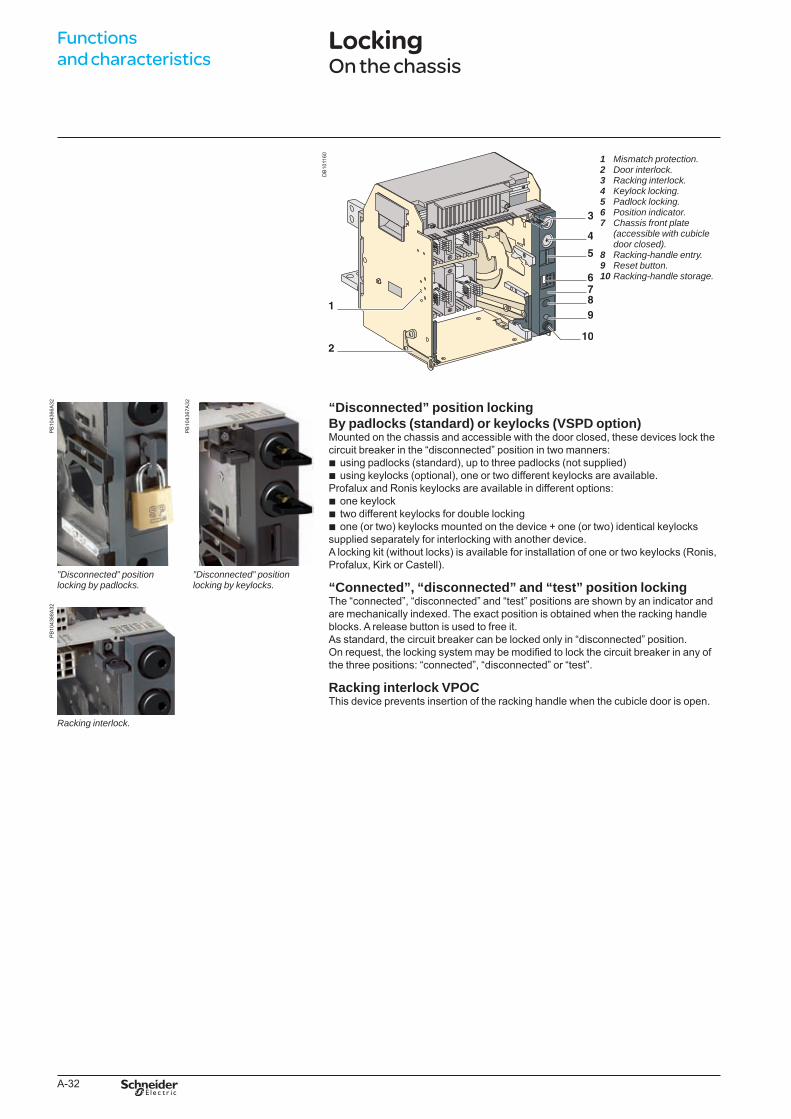
A-32
Functions and characteristics
DB
1011
60 Mismatchprotection.Doorinterlock.Rackinginterlock.Keylocklocking.Padlocklocking.Positionindicator.Chassisfrontplate(accessiblewithcubicledoorclosed).Racking-handleentry.Resetbutton.Racking-handlestorage.
1 2 3 4 5 6 7
8 9 10
PB
1043
66A
32
PB
1043
67A
32 “Disconnected” position locking By padlocks (standard) or keylocks (VSPD option)Mounted on the chassis and accessible with the door closed, these devices lock the circuit breaker in the “disconnected” position in two manners:
using padlocks (standard), up to three padlocks (not supplied)using keylocks (optional), one or two different keylocks are available.
Profalux and Ronis keylocks are available in different options:one keylocktwo different keylocks for double lockingone (or two) keylocks mounted on the device + one (or two) identical keylocks
supplied separately for interlocking with another device.A locking kit (without locks) is available for installation of one or two keylocks (Ronis, Profalux, Kirk or Castell).
“Connected”, “disconnected” and “test” position lockingThe “connected”, “disconnected” and “test” positions are shown by an indicator and are mechanically indexed. The exact position is obtained when the racking handle blocks. A release button is used to free it.As standard, the circuit breaker can be locked only in “disconnected” position.On request, the locking system may be modified to lock the circuit breaker in any of the three positions: “connected”, “disconnected” or “test”.
Racking interlock VPOCThis device prevents insertion of the racking handle when the cubicle door is open.
bb
bbb
”Disconnected”positionlockingbypadlocks.
”Disconnected”positionlockingbykeylocks.
PB
1043
68A
32
Rackinginterlock.
LockingOn the chassis
BTP222E.indb 32 30/06/2009 09:31:03
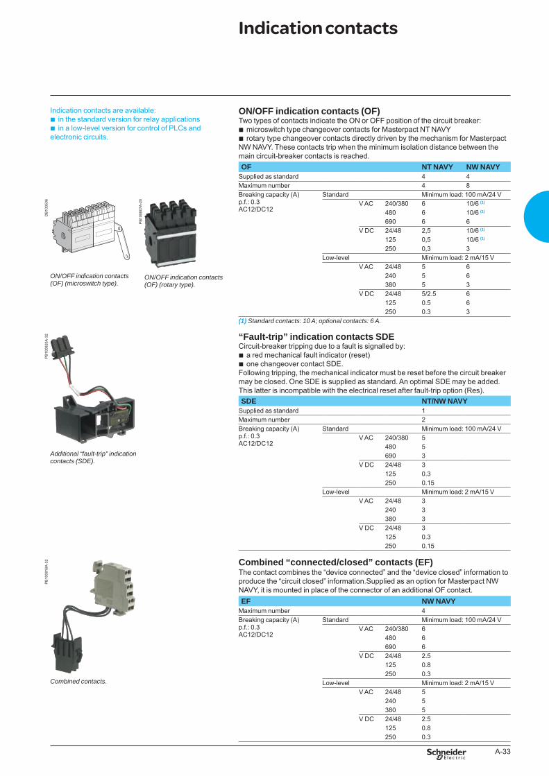
A-33
Indication contacts are available:in the standard version for relay applications in a low-level version for control of PLCs and
electronic circuits.
bb
ON/OFF indication contacts (OF)Two types of contacts indicate the ON or OFF position of the circuit breaker:
microswitch type changeover contacts for Masterpact NT NAVYrotary type changeover contacts directly driven by the mechanism for Masterpact
NW NAVY. These contacts trip when the minimum isolation distance between the main circuit-breaker contacts is reached.
bb
OF NT NAVY NW NAVYSupplied as standard 4 4Maximum number 4 8Breaking capacity (A)p.f.: 0.3AC12/DC12
Standard Minimum load: 100 mA/24 V
DB
1035
36
ON/OFFindicationcontacts(OF)(microswitchtype).
PB
1008
07A
-20
ON/OFFindicationcontacts(OF)(rotarytype).
V AC 240/380 6 10/6 (1)
480 6 10/6 (1)
690 6 6V DC 24/48 2,5 10/6 (1)
125 0,5 10/6 (1)
250 0,3 3Low-level Minimum load: 2 mA/15 V
V AC 24/48 5 6240 5 6380 5 3
V DC 24/48 5/2.5 6125 0.5 6250 0.3 3
(1)Standardcontacts:10A;optionalcontacts:6A.
PB
1008
20A
-32
Additional“fault-trip”indicationcontacts(SDE).
“Fault-trip” indication contacts SDECircuit-breaker tripping due to a fault is signalled by:
a red mechanical fault indicator (reset)one changeover contact SDE.
Following tripping, the mechanical indicator must be reset before the circuit breaker may be closed. One SDE is supplied as standard. An optimal SDE may be added. This latter is incompatible with the electrical reset after fault-trip option (Res).
bb
SDE NT/NW NAVYSupplied as standard 1Maximum number 2Breaking capacity (A)p.f.: 0.3AC12/DC12
Standard Minimum load: 100 mA/24 VV AC 240/380 5
480 5690 3
V DC 24/48 3125 0.3250 0.15
Low-level Minimum load: 2 mA/15 V V AC 24/48 3
240 3380 3
V DC 24/48 3125 0.3250 0.15
PB
1008
16A
-32 Combined “connected/closed” contacts (EF)
The contact combines the “device connected” and the “device closed” information to produce the “circuit closed” information.Supplied as an option for Masterpact NW NAVY, it is mounted in place of the connector of an additional OF contact.EF NW NAVY
Maximum number 4Breaking capacity (A)p.f.: 0.3AC12/DC12
Standard Minimum load: 100 mA/24 VV AC 240/380 6
480 6690 6
V DC 24/48 2.5125 0.8
Combinedcontacts.250 0.3
Low-level Minimum load: 2 mA/15 V V AC 24/48 5
240 5380 5
V DC 24/48 2.5125 0.8250 0.3
Indication contacts
BTP222E.indb 33 30/06/2009 09:31:08
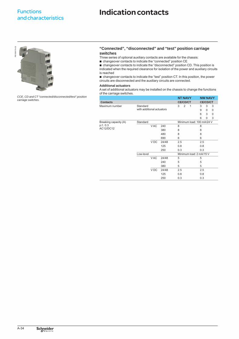
A-34
Functions and characteristics
PB
1008
17A
-32
CCE,CDandCT“connected/disconnected/test”positioncarriageswitches.
“Connected”, “disconnected” and “test” position carriage switchesThree series of optional auxiliary contacts are available for the chassis:
changeover contacts to indicate the “connected” position CEchangeover contacts to indicate the “disconnected” position CD. This position is
indicated when the required clearance for isolation of the power and auxiliary circuits is reached
changeover contacts to indicate the “test” position CT. In this position, the power circuits are disconnected and the auxiliary circuits are connected.Additional actuatorsA set of additional actuators may be installed on the chassis to change the functions of the carriage switches.
bb
b
NT NAVY NW NAVYContacts CE/CD/CT CE/CD/CT
Maximum number Standard with additional actuators
3 2 1 3 3 39 0 06 3 06 0 3
Breaking capacity (A)p.f.: 0.3AC12/DC12
Standard Minimum load: 100 mA/24 VV AC 240 8 8
380 8 8480 8 8690 6 6
V DC 24/48 2.5 2.5125 0.8 0.8250 0.3 0.3
Low-level Minimum load: 2 mA/15 V V AC 24/48 5 5
240 5 5380 5 5
V DC 24/48 2.5 2.5125 0.8 0.8250 0.3 0.3
Indication contacts
BTP222E.indb 34 30/06/2009 09:31:09
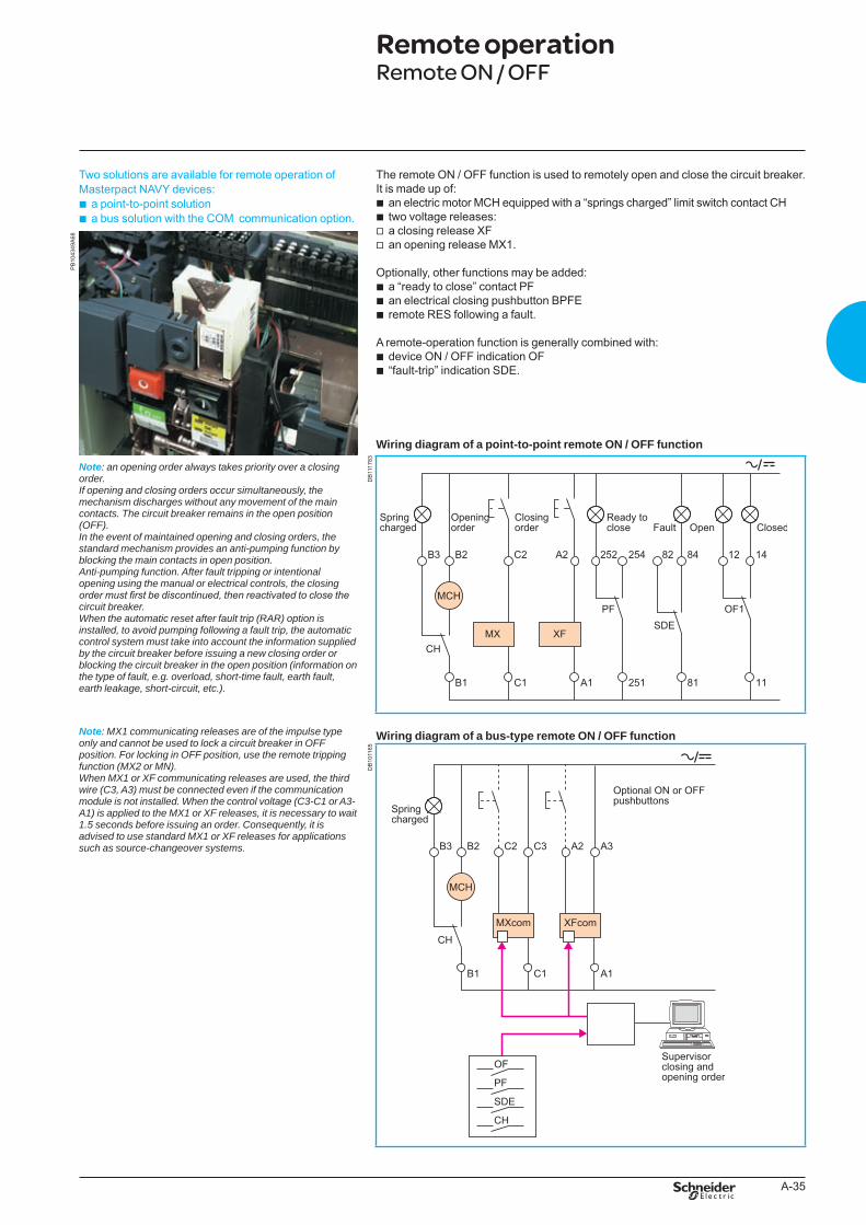
A-35
PB
1043
49A
68
Two solutions are available for remote operation of Masterpact NAVY devices:
a point-to-point solution a bus solution with the COM communication option.
bb
The remote ON / OFF function is used to remotely open and close the circuit breaker. It is made up of:
an electric motor MCH equipped with a “springs charged” limit switch contact CHtwo voltage releases:a closing release XFan opening release MX1.
Optionally, other functions may be added:a “ready to close” contact PFan electrical closing pushbutton BPFEremote RES following a fault.
A remote-operation function is generally combined with:device ON / OFF indication OF“fault-trip” indication SDE.
Wiring diagram of a point-to-point remote ON / OFF function
bbvv
bbb
bb
Note: anopeningorderalwaystakespriorityoveraclosingorder.Ifopeningandclosingordersoccursimultaneously,themechanismdischargeswithoutanymovementofthemaincontacts.Thecircuitbreakerremainsintheopenposition(OFF).Intheeventofmaintainedopeningandclosingorders,thestandardmechanismprovidesananti-pumpingfunctionbyblockingthemaincontactsinopenposition.Anti-pumpingfunction.Afterfaulttrippingorintentionalopeningusingthemanualorelectricalcontrols,theclosingorder must first be discontinued, then reactivated to close the circuitbreaker.Whentheautomaticresetafterfaulttrip(RAR)optionisinstalled,toavoidpumpingfollowingafaulttrip,theautomaticcontrolsystemmusttakeintoaccounttheinformationsuppliedbythecircuitbreakerbeforeissuinganewclosingorderorblockingthecircuitbreakerintheopenposition(informationonthetypeoffault,e.g.overload,short-timefault,earthfault,earthleakage,short-circuit,etc.).
Note: MX1communicatingreleasesareoftheimpulsetypeonlyandcannotbeusedtolockacircuitbreakerinOFFposition.ForlockinginOFFposition,usetheremotetrippingfunction(MX2orMN).WhenMX1orXFcommunicatingreleasesareused,thethirdwire(C3,A3)mustbeconnectedevenifthecommunicationmoduleisnotinstalled.Whenthecontrolvoltage(C3-C1orA3-A1)isappliedtotheMX1orXFreleases,itisnecessarytowait1.5secondsbeforeissuinganorder.Consequently,itisadvisedtousestandardMX1orXFreleasesforapplicationssuchassource-changeoversystems.
DB
1117
83
Wiring diagram of a bus-type remote ON / OFF function
DB
1011
65
Remote operationRemote ON / OFF
BTP222E.indb 35 30/06/2009 09:31:10
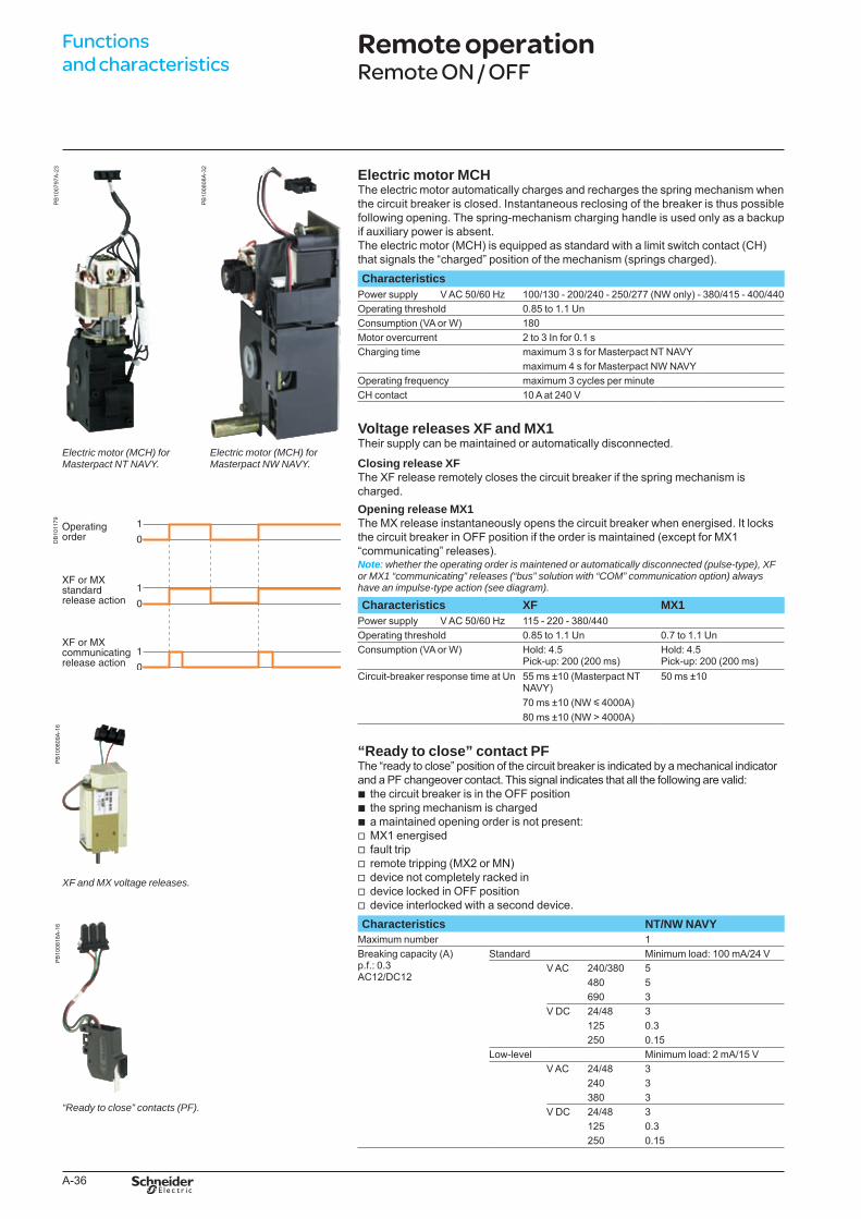
A-36
Functions and characteristics
PB
1007
97A
-23
PB
1008
08A
-32
Electric motor MCHThe electric motor automatically charges and recharges the spring mechanism when the circuit breaker is closed. Instantaneous reclosing of the breaker is thus possible following opening. The spring-mechanism charging handle is used only as a backup if auxiliary power is absent.The electric motor (MCH) is equipped as standard with a limit switch contact (CH) that signals the “charged” position of the mechanism (springs charged).Characteristics
Power supply V AC 50/60 Hz 100/130 - 200/240 - 250/277 (NW only) - 380/415 - 400/440Operating threshold 0.85 to 1.1 UnConsumption (VA or W) 180Motor overcurrent 2 to 3 In for 0.1 sCharging time maximum 3 s for Masterpact NT NAVY
maximum 4 s for Masterpact NW NAVYOperating frequency maximum 3 cycles per minuteCH contact 10 A at 240 V
Voltage releases XF and MX1Their supply can be maintained or automatically disconnected.
DB
1011
79
Closing release XFThe XF release remotely closes the circuit breaker if the spring mechanism is charged.Opening release MX1The MX release instantaneously opens the circuit breaker when energised. It locks the circuit breaker in OFF position if the order is maintained (except for MX1 “communicating” releases).Note:whethertheoperatingorderismaintenedorautomaticallydisconnected(pulse-type),XForMX1“communicating”releases(“bus”solutionwith“COM”communicationoption)alwayshaveanimpulse-typeaction(seediagram).
Characteristics XF MX1 Power supply V AC 50/60 Hz 115 - 220 - 380/440Operating threshold 0.85 to 1.1 Un 0.7 to 1.1 UnConsumption (VA or W) Hold: 4.5
Pick-up: 200 (200 ms)Hold: 4.5Pick-up: 200 (200 ms)
Circuit-breaker response time at Un 55 ms ±10 (Masterpact NT NAVY)
50 ms ±10
70 ms ±10 (NW y 4000A)80 ms ±10 (NW > 4000A)
PB
1008
09A
-16
XFandMXvoltagereleases.
“Readytoclose”contacts(PF).
“Ready to close” contact PFThe “ready to close” position of the circuit breaker is indicated by a mechanical indicator and a PF changeover contact. This signal indicates that all the following are valid:
the circuit breaker is in the OFF positionthe spring mechanism is chargeda maintained opening order is not present:MX1 energisedfault tripremote tripping (MX2 or MN)device not completely racked indevice locked in OFF positiondevice interlocked with a second device.
bbbvvvvvv
PB
1008
18A
-16 Characteristics NT/NW NAVY
Maximum number 1Breaking capacity (A)p.f.: 0.3AC12/DC12
Standard Minimum load: 100 mA/24 VV AC 240/380 5
480 5690 3
V DC 24/48 3125 0.3250 0.15
Low-level Minimum load: 2 mA/15 V V AC 24/48 3
240 3380 3
V DC 24/48 3125 0.3250 0.15
Remote operationRemote ON / OFF
Electricmotor(MCH)forMasterpactNTNAVY.
Electricmotor(MCH)forMasterpactNWNAVY.
BTP222E.indb 36 30/06/2009 09:31:15
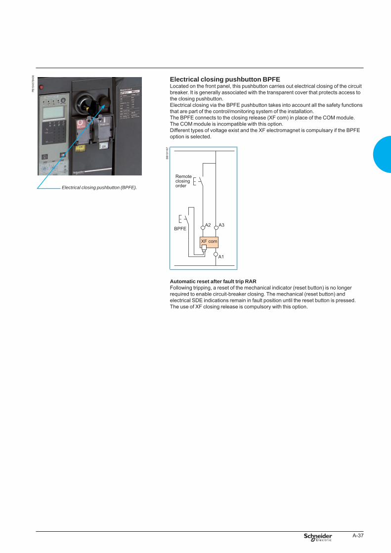
A-37
PB
1043
78A
56 Electrical closing pushbutton BPFELocated on the front panel, this pushbutton carries out electrical closing of the circuit breaker. It is generally associated with the transparent cover that protects access to the closing pushbutton.Electrical closing via the BPFE pushbutton takes into account all the safety functions that are part of the control/monitoring system of the installation.The BPFE connects to the closing release (XF com) in place of the COM module.The COM module is incompatible with this option.Different types of voltage exist and the XF electromagnet is compulsary if the BPFE option is selected.
DB
1011
67
Automatic reset after fault trip RARFollowing tripping, a reset of the mechanical indicator (reset button) is no longer required to enable circuit-breaker closing. The mechanical (reset button) and electrical SDE indications remain in fault position until the reset button is pressed.The use of XF closing release is compulsory with this option.
Electricalclosingpushbutton(BPFE).
BTP222E.indb 37 30/06/2009 09:31:16
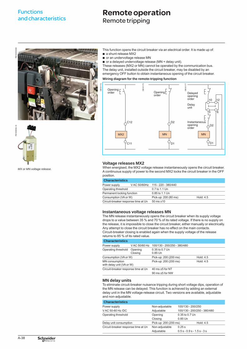
A-38
Functions and characteristics
PB
1043
53A
68 This function opens the circuit breaker via an electrical order. It is made up of:a shunt release MX2or an undervoltage release MNor a delayed undervoltage release (MN + delay unit).
These releases (MX2 or MN) cannot be operated by the communication bus.The delay unit, installed outside the circuit breaker, may be disabled by an emergency OFF button to obtain instantaneous opening of the circuit breaker.Wiring diagram for the remote-tripping function
bbb
DB
1011
72
DB
1011
75
DB
1011
77
PB
1008
09A
-16
MXorMNvoltagerelease.
Voltage releases MX2When energised, the MX2 voltage release instantaneously opens the circuit breaker. A continuous supply of power to the second MX2 locks the circuit breaker in the OFF position.Characteristics
Power supply V AC 50/60Hz 115 - 220 - 380/440Operating threshold 0.7 to 1.1 UnPermanent locking function 0.85 to 1.1 UnConsumption (VA or W) Pick-up: 200 (80 ms) Hold: 4.5Circuit-breaker response time at Un 50 ms ±10
Instantaneous voltage releases MNThe MN release instantaneously opens the circuit breaker when its supply voltage drops to a value between 35 % and 70 % of its rated voltage. If there is no supply on the release, it is impossible to close the circuit breaker, either manually or electrically. Any attempt to close the circuit breaker has no effect on the main contacts. Circuit-breaker closing is enabled again when the supply voltage of the release returns to 85 % of its rated value.Characteristics
Power supply V AC 50/60 Hz 100/130 - 200/250 - 380/480Operating threshold Opening
Closing0.35 to 0.7 Un0.85 Un
Consumption (VA or W) Pick-up: 200 (200 ms) Hold: 4.5MN consumption with delay unit (VA or W)
Pick-up: 200 (200 ms) Hold: 4.5
Circuit-breaker response time at Un 40 ms ±5 for NT90 ms ±5 for NW
MN delay unitsTo eliminate circuit-breaker nuisance tripping during short voltage dips, operation of the MN release can be delayed. This function is achieved by adding an external delay unit in the MN voltage-release circuit. Two versions are available, adjustable and non-adjustable.Characteristics
Power supply Non-adjustable 100/130 - 200/250V AC 50-60 Hz /DC Adjustable 100/130 - 200/250 - 380/480Operating threshold Opening 0.35 to 0.7 Un
Closing 0.85 UnDelay unit consumption Pick-up: 200 (200 ms) Hold: 4.5Circuit-breaker response time at Un Non-adjustable 0.25 s
Adjustable 0.5 s - 0.9 s - 1.5 s - 3 s
Remote operationRemote tripping
BTP222E.indb 38 30/06/2009 09:31:17
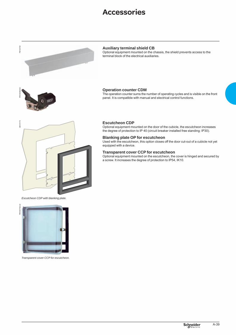
A-39
PB
1047
40 Auxiliary terminal shield CBOptional equipment mounted on the chassis, the shield prevents access to the terminal block of the electrical auxiliaries.
PB
1043
82A
32 Operation counter CDMThe operation counter sums the number of operating cycles and is visible on the front panel. It is compatible with manual and electrical control functions.
DB
1011
73
EscutcheonCDPwithblankingplate.
Escutcheon CDPOptional equipment mounted on the door of the cubicle, the escutcheon increases the degree of protection to IP 40 (circuit breaker installed free standing: IP30).
Blanking plate OP for escutcheonUsed with the escutcheon, this option closes off the door cut-out of a cubicle not yet equipped with a device.
Transparent cover CCP for escutcheonOptional equipment mounted on the escutcheon, the cover is hinged and secured by a screw. It increases the degree of protection to IP54, IK10.
PB
1007
76A
-42
.
TransparentcoverCCPforescutcheon.
Accessories
BTP222E.indb 39 30/06/2009 09:31:19
schneider-electric.com CAD software and tools
This international site allows you to access all the Schneider Electric products in just 2 clicksvia comprehensive range data-sheets, with direct links to:
complete library: technical documents, catalogs, FAQs, brochures…
selection guides from the e-catalog.
product discovery sites andtheir Flash animations.You will also fi nd illustrated overviews, news to which you can subscribe, the list of country contacts…
p
p
p
The CAD software and tools enhance productivity and safety. They help you create your installations by simplifying product choice through easy browsing in the Schneider Electric offers.Last but not least, they optimise use of our products while also complying with standards and proper procedures.
TOOLS
BTP222E.indb 2 30/06/2009 09:31:21
B-1
Installation recommendationsMasterpact NT and NW NAVY
Presentation 1Functionsandcharacteristics A-1
Operating conditions B-2
Installation in switchboard B-3
Control wiring B-5
Power connection B-6
Recommended busbars drilling B-8Masterpact NT06 to NT16 NAVY B-8Masterpact NW08 to NW40 NAVY B-9
Busbar sizing B-10
Temperature derating Power dissipation and input / output resistance B-12
Derating in switchboards B-13
Dimensionsandconnections C-1Electricaldiagrams D-1Additionalcharacteristics E-1Cataloguenumbersandorderform F-1
BTP222E.indb 1 30/06/2009 09:31:21
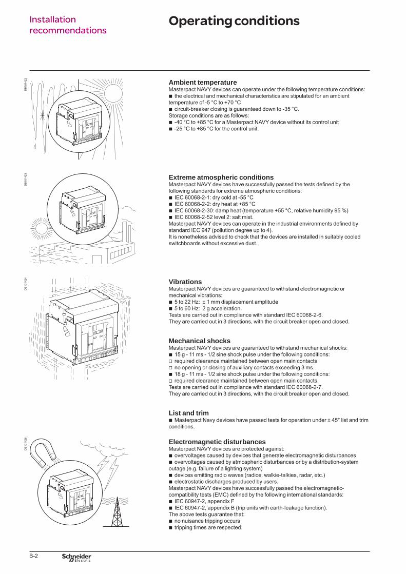
B-2
Installation recommendations
DB
1014
22 Ambient temperatureMasterpact NAVY devices can operate under the following temperature conditions:
the electrical and mechanical characteristics are stipulated for an ambient temperature of -5 °C to +70 °C
circuit-breaker closing is guaranteed down to -35 °C.Storage conditions are as follows:
-40 °C to +85 °C for a Masterpact NAVY device without its control unit-25 °C to +85 °C for the control unit.
b
b
bb
DB
1014
23 Extreme atmospheric conditionsMasterpact NAVY devices have successfully passed the tests defined by the following standards for extreme atmospheric conditions:
IEC 60068-2-1: dry cold at -55 °CIEC 60068-2-2: dry heat at +85 °CIEC 60068-2-30: damp heat (temperature +55 °C, relative humidity 95 %)IEC 60068-2-52 level 2: salt mist.
Masterpact NAVY devices can operate in the industrial environments defined by standard IEC 947 (pollution degree up to 4).It is nonetheless advised to check that the devices are installed in suitably cooled switchboards without excessive dust.
bbbb
DB
1014
24 VibrationsMasterpact NAVY devices are guaranteed to withstand electromagnetic or mechanical vibrations:
5 to 22 Hz: ± 1 mm displacement amplitude 5 to 60 Hz: 2 g acceleration.
Tests are carried out in compliance with standard IEC 60068-2-6.They are carried out in 3 directions, with the circuit breaker open and closed.
bb
Mechanical shocksMasterpact NAVY devices are guaranteed to withstand mechanical shocks:
15 g - 11 ms - 1/2 sine shock pulse under the following conditions:required clearance maintained between open main contactsno opening or closing of auxiliary contacts exceeding 3 ms.18 g - 11 ms - 1/2 sine shock pulse under the following conditions:required clearance maintained between open main contacts.
Tests are carried out in compliance with standard IEC 60068-2-7.They are carried out in 3 directions, with the circuit breaker open and closed.
bvvbv
List and trimMasterpact Navy devices have passed tests for operation under ± 45° list and trim
conditions.b
DB
1014
26 Electromagnetic disturbancesMasterpact NAVY devices are protected against:
overvoltages caused by devices that generate electromagnetic disturbancesovervoltages caused by atmospheric disturbances or by a distribution-system
outage (e.g. failure of a lighting system)devices emitting radio waves (radios, walkie-talkies, radar, etc.)electrostatic discharges produced by users.
Masterpact NAVY devices have successfully passed the electromagnetic-compatibility tests (EMC) defined by the following international standards:
IEC 60947-2, appendix FIEC 60947-2, appendix B (trip units with earth-leakage function).
The above tests guarantee that:no nuisance tripping occurstripping times are respected.
bb
bb
bb
bb
Operating conditions
BTP222E.indb 2 30/06/2009 09:31:23
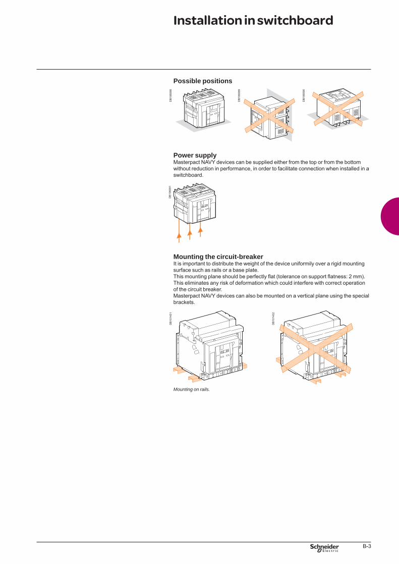
B-3
Possible positions
DB
1060
88
DB
1060
89
DB
1060
90
Power supplyMasterpact NAVY devices can be supplied either from the top or from the bottom without reduction in performance, in order to facilitate connection when installed in a switchboard.
DB
1060
91
Mounting the circuit-breakerIt is important to distribute the weight of the device uniformily over a rigid mounting surface such as rails or a base plate.This mounting plane should be perfectly flat (tolerance on support flatness: 2 mm). This eliminates any risk of deformation which could interfere with correct operation of the circuit breaker.Masterpact NAVY devices can also be mounted on a vertical plane using the special brackets.
DB
1014
31
Mountingonrails.
DB
1014
32
Installation in switchboard
BTP222E.indb 3 30/06/2009 09:31:24
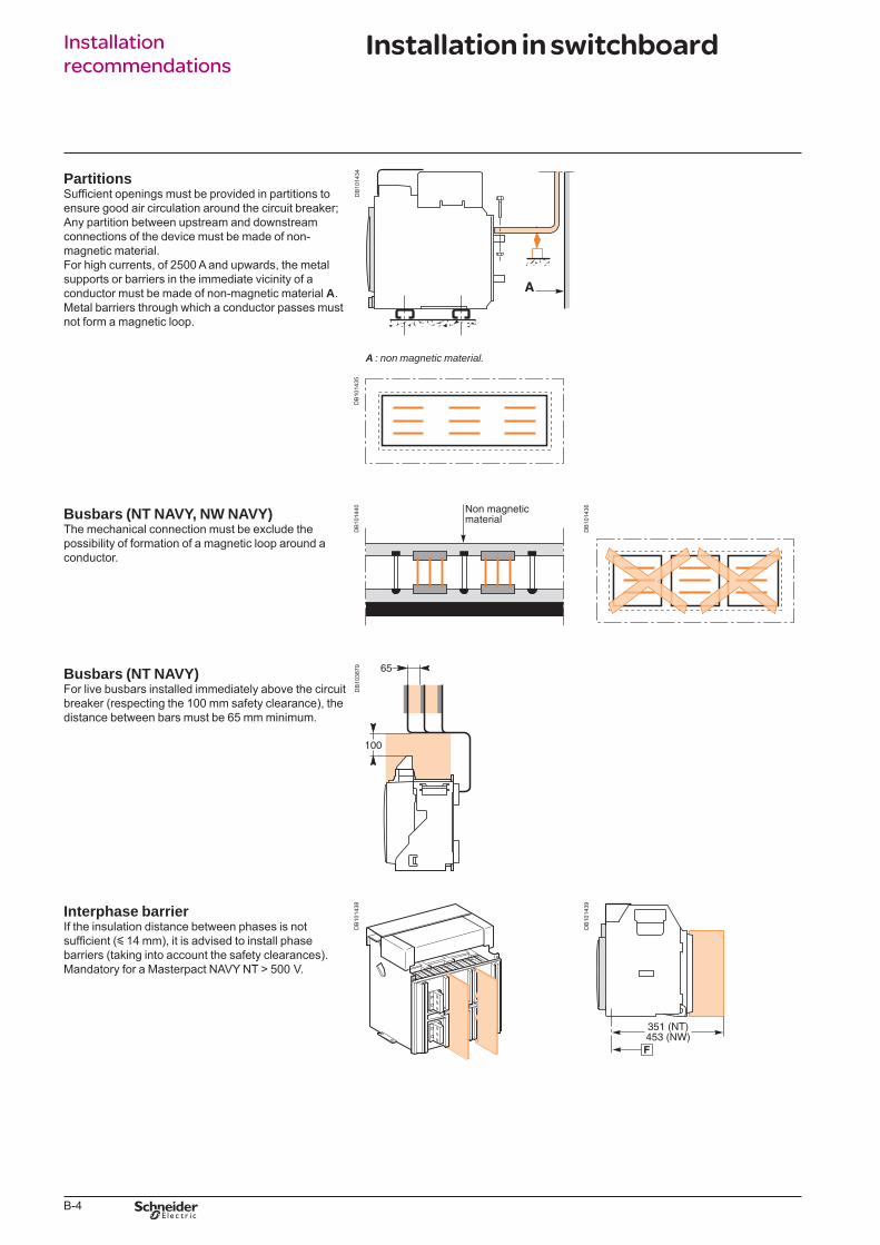
B-4
Installation recommendations
PartitionsSufficient openings must be provided in partitions to ensure good air circulation around the circuit breaker; Any partition between upstream and downstream connections of the device must be made of non-magnetic material.For high currents, of 2500 A and upwards, the metal supports or barriers in the immediate vicinity of a conductor must be made of non-magnetic material A.Metal barriers through which a conductor passes must not form a magnetic loop.
DB
1014
34A :nonmagneticmaterial.
DB
1014
35
Busbars (NT NAVY, NW NAVY)The mechanical connection must be exclude the possibility of formation of a magnetic loop around a conductor.
DB
1014
40
DB
1014
36
Busbars (NT NAVY)For live busbars installed immediately above the circuit breaker (respecting the 100 mm safety clearance), the distance between bars must be 65 mm minimum.
DB
1038
79
Interphase barrierIf the insulation distance between phases is not sufficient (y 14 mm), it is advised to install phase barriers (taking into account the safety clearances).Mandatory for a Masterpact NAVY NT > 500 V.
DB
1014
38
DB
1014
39
Installation in switchboard
BTP222E.indb 4 30/06/2009 09:31:25
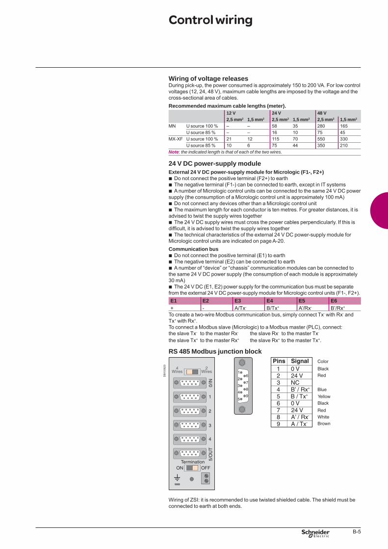
B-5
Wiring of voltage releasesDuring pick-up, the power consumed is approximately 150 to 200 VA. For low control voltages (12, 24, 48 V), maximum cable lengths are imposed by the voltage and the cross-sectional area of cables.Recommended maximum cable lengths (meter).
12 V 24 V 48 V2,5 mm2 1,5 mm2 2,5 mm2 1,5 mm2 2,5 mm2 1,5 mm2
MN U source 100 % – – 58 35 280 165U source 85 % – – 16 10 75 45
MX-XF U source 100 % 21 12 115 70 550 330U source 85 % 10 6 75 44 350 210
Note: theindicatedlengthisthatofeachofthetwowires.
24 V DC power-supply moduleExternal 24 V DC power-supply module for Micrologic (F1-, F2+)
Do not connect the positive terminal (F2+) to earthThe negative terminal (F1-) can be connected to earth, except in IT systemsA number of Micrologic control units can be connected to the same 24 V DC power
supply (the consumption of a Micrologic control unit is approximately 100 mA)Do not connect any devices other than a Micrologic control unitThe maximum length for each conductor is ten metres. For greater distances, it is
advised to twist the supply wires togetherThe 24 V DC supply wires must cross the power cables perpendicularly. If this is
difficult, it is advised to twist the supply wires togetherThe technical characteristics of the external 24 V DC power-supply module for
Micrologic control units are indicated on page A-20.Communication bus
Do not connect the positive terminal (E1) to earthThe negative terminal (E2) can be connected to earthA number of “device” or “chassis” communication modules can be connected to
the same 24 V DC power supply (the consumption of each module is approximately 30 mA)
The 24 V DC (E1, E2) power supply for the communication bus must be separate from the external 24 V DC power-supply module for Micrologic control units (F1-, F2+).
bbb
bb
b
b
bbb
b
E1 E2 E3 E4 E5 E6+ - A/Tx- B/Tx+ A’/Rx- B’/Rx+
To create a two-wire Modbus communication bus, simply connect Tx- with Rx- and Tx+ with Rx+.To connect a Modbus slave (Micrologic) to a Modbus master (PLC), connect:the slave Tx- to the master Rx- the slave Rx- to the master Tx-
the slave Tx+ to the master Rx+ the slave Rx+ to the master Tx+.
RS 485 Modbus junction block
DB
1038
20
Wiring of ZSI: it is recommended to use twisted shielded cable. The shield must be connected to earth at both ends.
Control wiring
Black
4Wires
2Wires
TerminationON OFF
5/O
UT
4
3
2
1
0/IN
1
26
3
4
5
7
8
9
Color
Black
Red
Blue
Yellow
Red
White
Brown
Pins Signal1 0 V2 24 V3 NC4 B’ / Rx+
5 B / Tx+
6 0 V7 24 V8 A’ / Rx-
9 A / Tx-
BTP222E.indb 5 30/06/2009 09:31:26
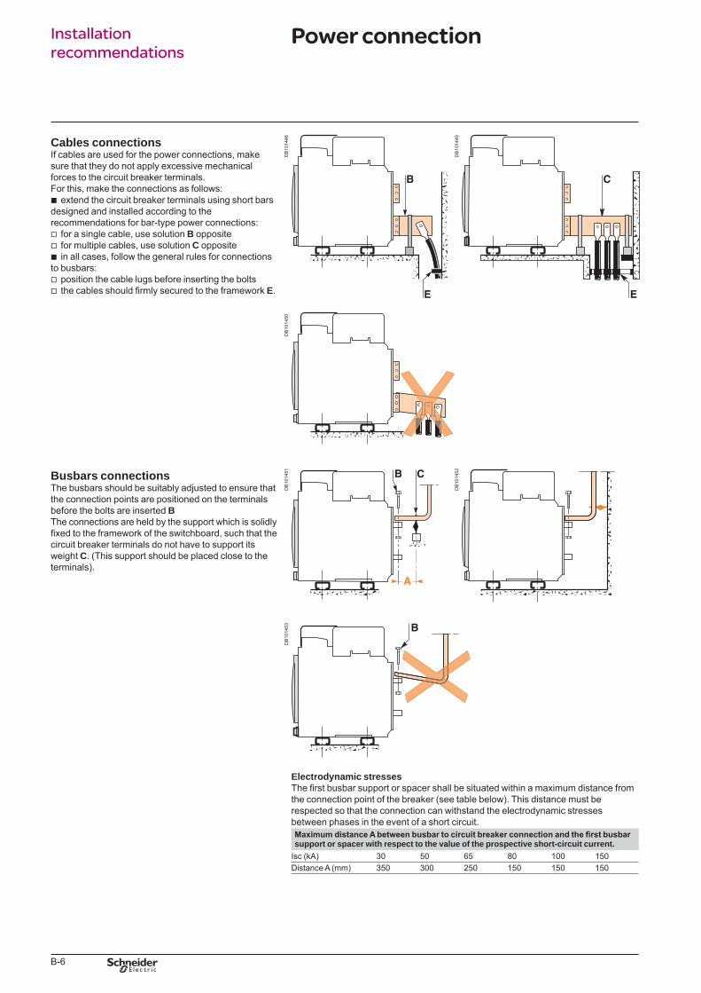
B-6
Installation recommendations
Cables connectionsIf cables are used for the power connections, make sure that they do not apply excessive mechanical forces to the circuit breaker terminals.For this, make the connections as follows:
extend the circuit breaker terminals using short bars designed and installed according to the recommendations for bar-type power connections:
for a single cable, use solution B oppositefor multiple cables, use solution C oppositein all cases, follow the general rules for connections
to busbars:position the cable lugs before inserting the boltsthe cables should firmly secured to the framework E.
b
vvb
vv
DB
1014
48
DB
1014
49
DB
1014
50
Busbars connectionsThe busbars should be suitably adjusted to ensure that the connection points are positioned on the terminals before the bolts are inserted BThe connections are held by the support which is solidly fixed to the framework of the switchboard, such that the circuit breaker terminals do not have to support its weight C. (This support should be placed close to the terminals).
DB
1014
51
DB
1014
52
DB
1014
53
Electrodynamic stressesThe first busbar support or spacer shall be situated within a maximum distance from the connection point of the breaker (see table below). This distance must be respected so that the connection can withstand the electrodynamic stresses between phases in the event of a short circuit.Maximum distance A between busbar to circuit breaker connection and the first busbarsupport or spacer with respect to the value of the prospective short-circuit current.
Isc (kA) 30 50 65 80 100 150Distance A (mm) 350 300 250 150 150 150
Power connection
BTP222E.indb 6 30/06/2009 09:31:28
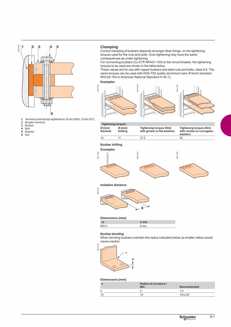
B-7
DB
1014
54
Terminalscrewfactory-tightenedto16Nm(NW),13Nm(NT).Breakerterminal.Busbar.Bolt.Washer.Nut.
1 2 3 4 5 6
ClampingCorrect clamping of busbars depends amongst other things, on the tightening torques used for the nuts and bolts. Over-tightening may have the same consequences as under-tightening.For connecting busbars (Cu ETP-NFA51-100) to the circuit breaker, the tightening torques to be used are shown in the table below.These values are for use with copper busbars and steel nuts and bolts, class 8.8. The same torques can be used with AGS-T52 quality aluminium bars (French standard NFA 02-104 or American National Standard H-35-1).Examples
DB
1014
55
DB
1014
56
DB
1014
57
Tightening torquesØ (mm) Ø (mm)Nominal Drilling
Tightening torques (Nm)with grower or flat washers
Tightening torques (Nm)with contact or corrugatec washers
10 11 37.5 50
Busbar drillingExamples
DB
1014
58
DB
1014
59
DB
1014
60
Isolation distance
DB
1014
61
Dimensions (mm)Ui X min
600 V 8 mm
Busbar bendingWhen bending busbars maintain the radius indicated below (a smaller radius would cause cracks).
DB
1014
62
Dimensions (mm)e Radius of curvature r
Min Recommended5 5 7.510 15 18 to 20
BTP222E.indb 7 30/06/2009 09:31:29
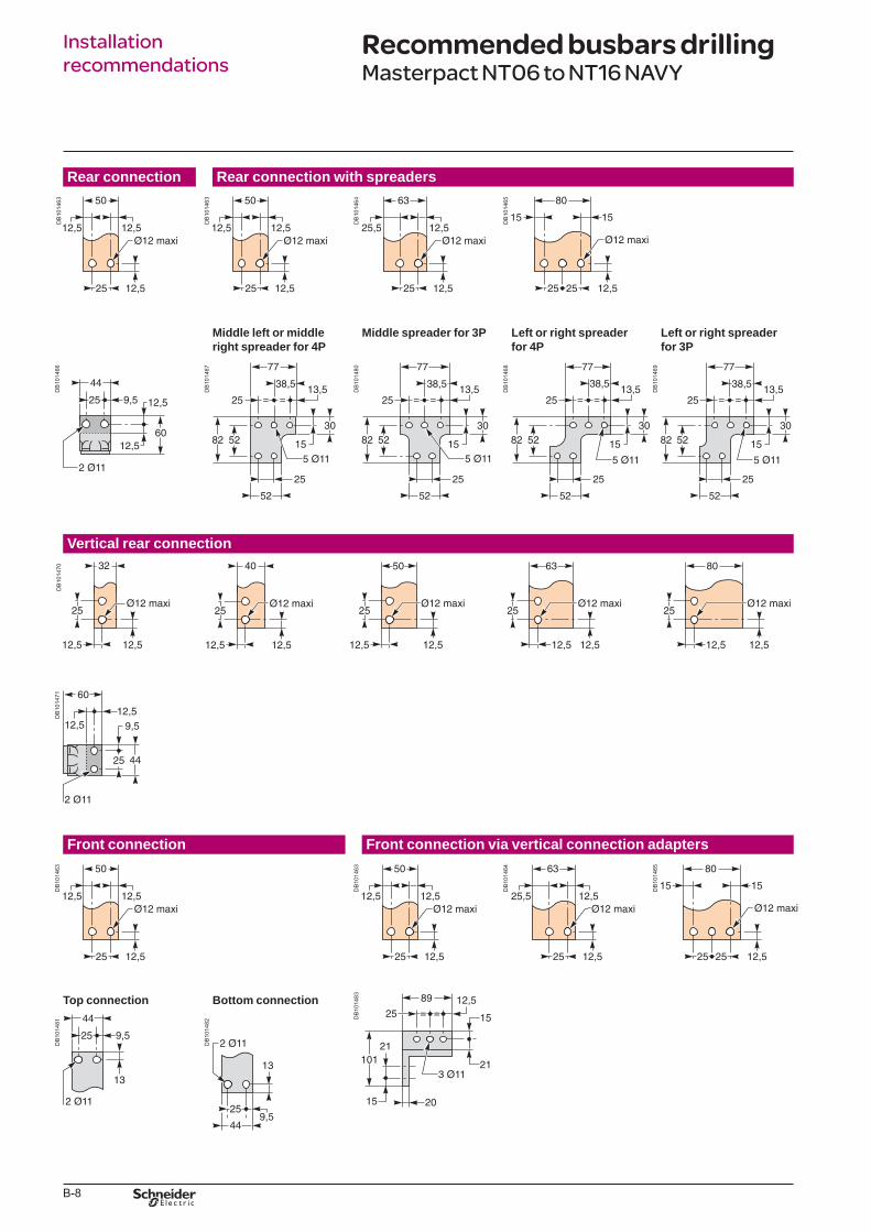
B-8
Installation recommendations
Rear connection Rear connection with spreaders
DB
1014
63
DB
1014
63
DB
1014
64
DB
1014
65
Middle left or middle right spreader for 4P
Middle spreader for 3P Left or right spreader for 4P
Left or right spreader for 3P
DB
1014
66
DB
1014
67
DB
1014
80
DB
1014
68
DB
1014
69
Vertical rear connection
DB
1014
70D
B10
1471
Front connection Front connection via vertical connection adapters
DB
1014
63
DB
1014
63
DB
1014
64
DB
1014
65
Top connection Bottom connection
DB
1014
83
DB
1014
81
DB
1014
82
Recommended busbars drillingMasterpact NT06 to NT16 NAVY
BTP222E.indb 8 30/06/2009 09:31:31
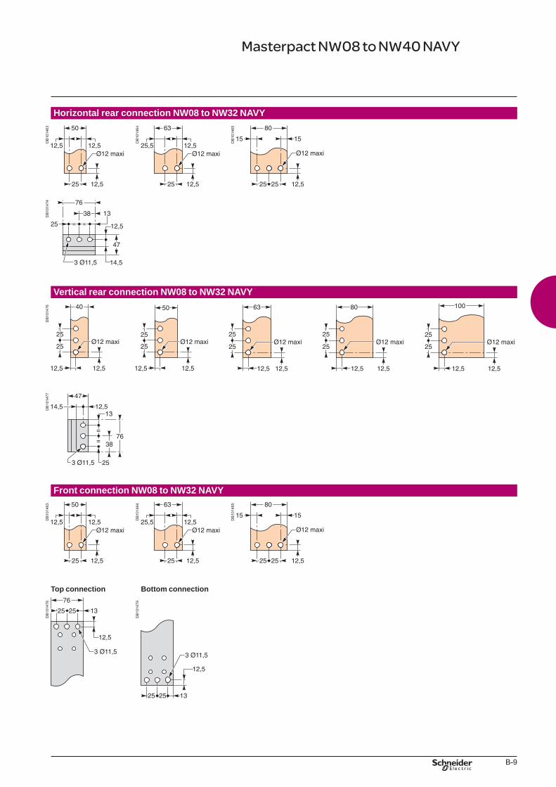
B-9
Horizontal rear connection NW08 to NW32 NAVY
DB
1014
63
DB
1014
64
DB
1014
65
DB
1014
74
Vertical rear connection NW08 to NW32 NAVY
DB
1014
76D
B10
1477
Front connection NW08 to NW32 NAVY
DB
1014
63
DB
1014
64
DB
1014
65
Top connection Bottom connection
DB
1014
78
DB
1014
79
Masterpact NW08 to NW40 NAVY
BTP222E.indb 9 30/06/2009 09:31:33
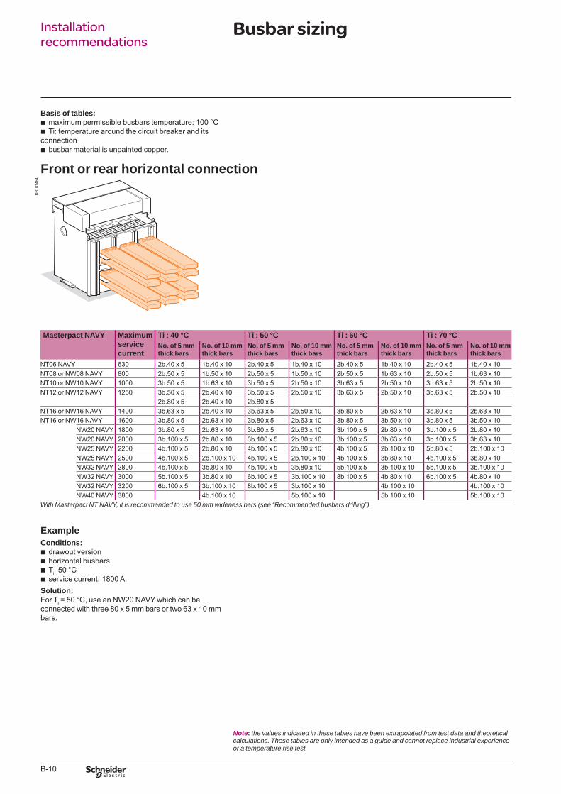
B-10
Installation recommendations
Basis of tables:maximum permissible busbars temperature: 100 °CTi: temperature around the circuit breaker and its
connectionbusbar material is unpainted copper.
bb
b
Front or rear horizontal connection
DB
1014
84
Masterpact NAVY Maximum service current
Ti : 40 °C Ti : 50 °C Ti : 60 °C Ti : 70 °CNo. of 5 mm thick bars
No. of 10 mm thick bars
No. of 5 mm thick bars
No. of 10 mm thick bars
No. of 5 mm thick bars
No. of 10 mm thick bars
No. of 5 mm thick bars
No. of 10 mm thick bars
NT06 NAVY 630 2b.40 x 5 1b.40 x 10 2b.40 x 5 1b.40 x 10 2b.40 x 5 1b.40 x 10 2b.40 x 5 1b.40 x 10NT08 or NW08 NAVY 800 2b.50 x 5 1b.50 x 10 2b.50 x 5 1b.50 x 10 2b.50 x 5 1b.63 x 10 2b.50 x 5 1b.63 x 10NT10 or NW10 NAVY 1000 3b.50 x 5 1b.63 x 10 3b.50 x 5 2b.50 x 10 3b.63 x 5 2b.50 x 10 3b.63 x 5 2b.50 x 10NT12 or NW12 NAVY 1250 3b.50 x 5 2b.40 x 10 3b.50 x 5 2b.50 x 10 3b.63 x 5 2b.50 x 10 3b.63 x 5 2b.50 x 10
2b.80 x 5 2b.40 x 10 2b.80 x 5NT16 or NW16 NAVY 1400 3b.63 x 5 2b.40 x 10 3b.63 x 5 2b.50 x 10 3b.80 x 5 2b.63 x 10 3b.80 x 5 2b.63 x 10NT16 or NW16 NAVY 1600 3b.80 x 5 2b.63 x 10 3b.80 x 5 2b.63 x 10 3b.80 x 5 3b.50 x 10 3b.80 x 5 3b.50 x 10
NW20 NAVY 1800 3b.80 x 5 2b.63 x 10 3b.80 x 5 2b.63 x 10 3b.100 x 5 2b.80 x 10 3b.100 x 5 2b.80 x 10NW20 NAVY 2000 3b.100 x 5 2b.80 x 10 3b.100 x 5 2b.80 x 10 3b.100 x 5 3b.63 x 10 3b.100 x 5 3b.63 x 10NW25 NAVY 2200 4b.100 x 5 2b.80 x 10 4b.100 x 5 2b.80 x 10 4b.100 x 5 2b.100 x 10 5b.80 x 5 2b.100 x 10NW25 NAVY 2500 4b.100 x 5 2b.100 x 10 4b.100 x 5 2b.100 x 10 4b.100 x 5 3b.80 x 10 4b.100 x 5 3b.80 x 10NW32 NAVY 2800 4b.100 x 5 3b.80 x 10 4b.100 x 5 3b.80 x 10 5b.100 x 5 3b.100 x 10 5b.100 x 5 3b.100 x 10NW32 NAVY 3000 5b.100 x 5 3b.80 x 10 6b.100 x 5 3b.100 x 10 8b.100 x 5 4b.80 x 10 6b.100 x 5 4b.80 x 10NW32 NAVY 3200 6b.100 x 5 3b.100 x 10 8b.100 x 5 3b.100 x 10 4b.100 x 10 4b.100 x 10NW40 NAVY 3800 4b.100 x 10 5b.100 x 10 5b.100 x 10 5b.100 x 10
WithMasterpactNTNAVY,itisrecommandedtouse50mmwidenessbars(see“Recommendedbusbarsdrilling”).
ExampleConditions:
drawout versionhorizontal busbarsTi: 50 °C service current: 1800 A.
Solution:For Ti = 50 °C, use an NW20 NAVY which can be connected with three 80 x 5 mm bars or two 63 x 10 mm bars.
bbbb
Note: thevaluesindicatedinthesetableshavebeenextrapolatedfromtestdataandtheoreticalcalculations.Thesetablesareonlyintendedasaguideandcannotreplaceindustrialexperienceoratemperaturerisetest.
Busbar sizing
BTP222E.indb 10 30/06/2009 09:31:33
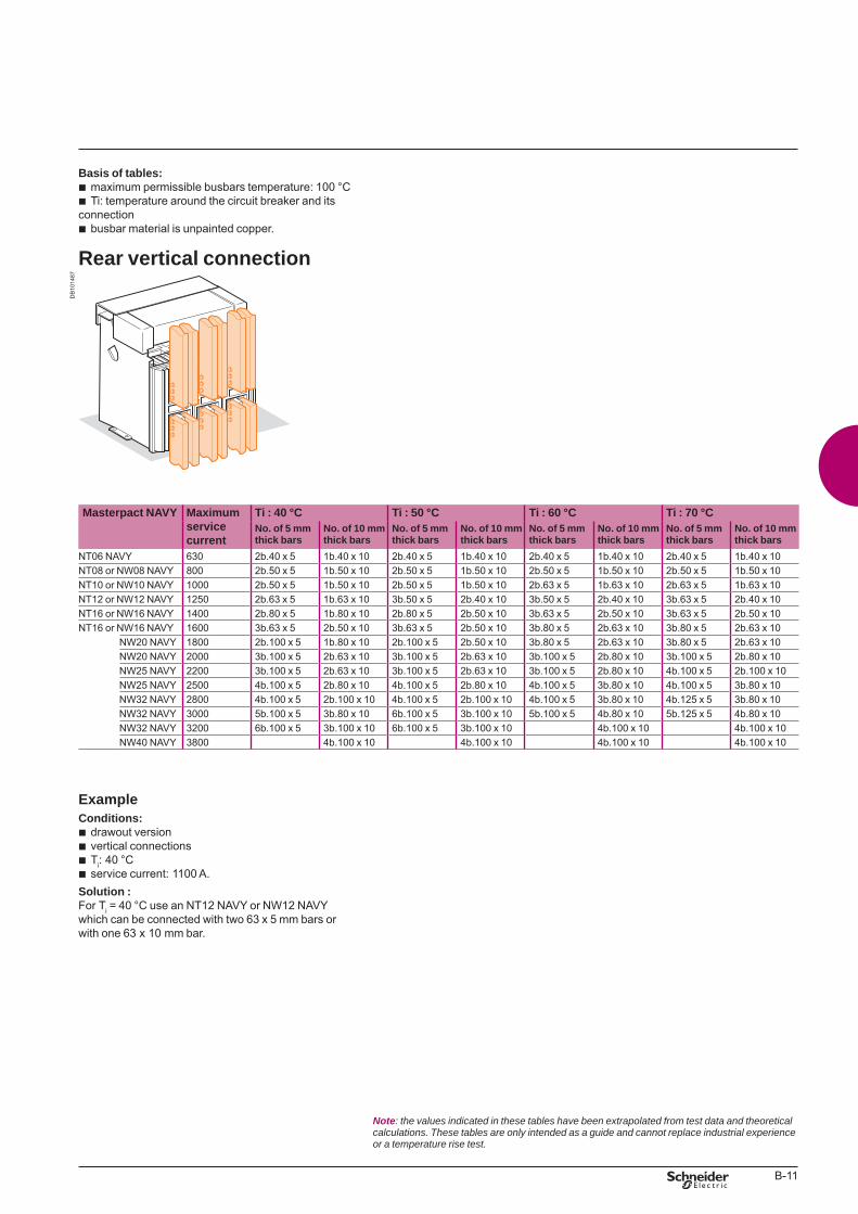
B-11
Basis of tables:maximum permissible busbars temperature: 100 °CTi: temperature around the circuit breaker and its
connectionbusbar material is unpainted copper.
bb
b
Rear vertical connection
DB
1014
87
Masterpact NAVY Maximum service current
Ti : 40 °C Ti : 50 °C Ti : 60 °C Ti : 70 °CNo. of 5 mm thick bars
No. of 10 mmthick bars
No. of 5 mmthick bars
No. of 10 mmthick bars
No. of 5 mmthick bars
No. of 10 mmthick bars
No. of 5 mmthick bars
No. of 10 mmthick bars
NT06 NAVY 630 2b.40 x 5 1b.40 x 10 2b.40 x 5 1b.40 x 10 2b.40 x 5 1b.40 x 10 2b.40 x 5 1b.40 x 10NT08 or NW08 NAVY 800 2b.50 x 5 1b.50 x 10 2b.50 x 5 1b.50 x 10 2b.50 x 5 1b.50 x 10 2b.50 x 5 1b.50 x 10NT10 or NW10 NAVY 1000 2b.50 x 5 1b.50 x 10 2b.50 x 5 1b.50 x 10 2b.63 x 5 1b.63 x 10 2b.63 x 5 1b.63 x 10NT12 or NW12 NAVY 1250 2b.63 x 5 1b.63 x 10 3b.50 x 5 2b.40 x 10 3b.50 x 5 2b.40 x 10 3b.63 x 5 2b.40 x 10NT16 or NW16 NAVY 1400 2b.80 x 5 1b.80 x 10 2b.80 x 5 2b.50 x 10 3b.63 x 5 2b.50 x 10 3b.63 x 5 2b.50 x 10NT16 or NW16 NAVY 1600 3b.63 x 5 2b.50 x 10 3b.63 x 5 2b.50 x 10 3b.80 x 5 2b.63 x 10 3b.80 x 5 2b.63 x 10
NW20 NAVY 1800 2b.100 x 5 1b.80 x 10 2b.100 x 5 2b.50 x 10 3b.80 x 5 2b.63 x 10 3b.80 x 5 2b.63 x 10NW20 NAVY 2000 3b.100 x 5 2b.63 x 10 3b.100 x 5 2b.63 x 10 3b.100 x 5 2b.80 x 10 3b.100 x 5 2b.80 x 10NW25 NAVY 2200 3b.100 x 5 2b.63 x 10 3b.100 x 5 2b.63 x 10 3b.100 x 5 2b.80 x 10 4b.100 x 5 2b.100 x 10NW25 NAVY 2500 4b.100 x 5 2b.80 x 10 4b.100 x 5 2b.80 x 10 4b.100 x 5 3b.80 x 10 4b.100 x 5 3b.80 x 10NW32 NAVY 2800 4b.100 x 5 2b.100 x 10 4b.100 x 5 2b.100 x 10 4b.100 x 5 3b.80 x 10 4b.125 x 5 3b.80 x 10NW32 NAVY 3000 5b.100 x 5 3b.80 x 10 6b.100 x 5 3b.100 x 10 5b.100 x 5 4b.80 x 10 5b.125 x 5 4b.80 x 10NW32 NAVY 3200 6b.100 x 5 3b.100 x 10 6b.100 x 5 3b.100 x 10 4b.100 x 10 4b.100 x 10NW40 NAVY 3800 4b.100 x 10 4b.100 x 10 4b.100 x 10 4b.100 x 10
ExampleConditions:
drawout versionvertical connectionsTi: 40 °C service current: 1100 A.
Solution :For Ti = 40 °C use an NT12 NAVY or NW12 NAVY which can be connected with two 63 x 5 mm bars or with one 63 x 10 mm bar.
bbbb
Note: thevaluesindicatedinthesetableshavebeenextrapolatedfromtestdataandtheoreticalcalculations.Thesetablesareonlyintendedasaguideandcannotreplaceindustrialexperienceoratemperaturerisetest.
BTP222E.indb 11 30/06/2009 09:31:34
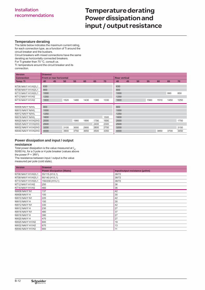
B-12
Installation recommendations
Temperature deratingThe table below indicates the maximum current rating, for each connection type, as a function of Ti around the circuit breaker and the busbars.Circuit breakers with mixed connections have the same derating as horizontally connected breakers.For Ti greater than 70 °C, consult us.Ti: temperature around the circuit breaker and its connection.
Version DrawoutConnection Front or rear horizontal Rear verticalTemp. Ti 40 45 50 55 60 65 70 40 45 50 55 60 65 70
NT06 NAVY H1/H2/L1 630 630NT08 NAVY H1/H2/L1 800 800NT10 NAVY H1/H2/L1 1000 1000 990 850NT12 NAVY H1/H2 1250 1250NT16 NAVY H1/H2 1600 1520 1480 1430 1380 1330 1600 1560 1510 1450 1250
NW08 NAVY N/H/L 800 800NW10 NAVY N/H/L 1000 1000NW12 NAVY N/H/L 1250 1250NW16 NAVY N/H/L 1600 1500 1600NW20 NAVY H1/H2/H3 2000 1980 1890 1790 1690 2000 1750NW25 NAVY H1/H2/H3 2500 2400 2300 2500NW32 NAVY H1/H2/H3 3200 3100 3000 2900 2800 2700 3200 3150NW40 NAVY H1/H2/H3 4000 3900 3750 3650 3500 3350 4000 3850 3700 3450
Power dissipation and input / output resistanceTotal power dissipation is the value measured at IN, 50/60 Hz, for a 3 pole or 4 pole breaker (values above the power P = 3RI2).The resistance between input / output is the value measured per pole (cold state).
Version DrawoutPower dissipation (Watts) Input/output resistance (µohm)
NT06 NAVY H1/H2/L1 55/115 (H1/L1) 38/72NT08 NAVY H1/H2/L1 90/140 (H1/L1) 38/72NT10 NAVY H1/H2/L1 150/230 (H1/L1) 38/72NT12 NAVY H1/H2 250 36NT16 NAVY H1/H2 460 36NW08 NAVY N1 137 42NW08 NAVY H 100 30NW10 NAVY N1 220 42NW10 NAVY H 150 30NW12 NAVY N1 330 42NW12 NAVY H 230 27NW16 NAVY N1 480 37NW16 NAVY H 390 27NW20 NAVY H 470 27NW25 NAVY H1/H2 600 19NW32 NAVY H1/H2 670 13NW40 NAVY H1/H2 900 11
Temperature derating Power dissipation and input / output resistance
BTP222E.indb 12 30/06/2009 09:31:35
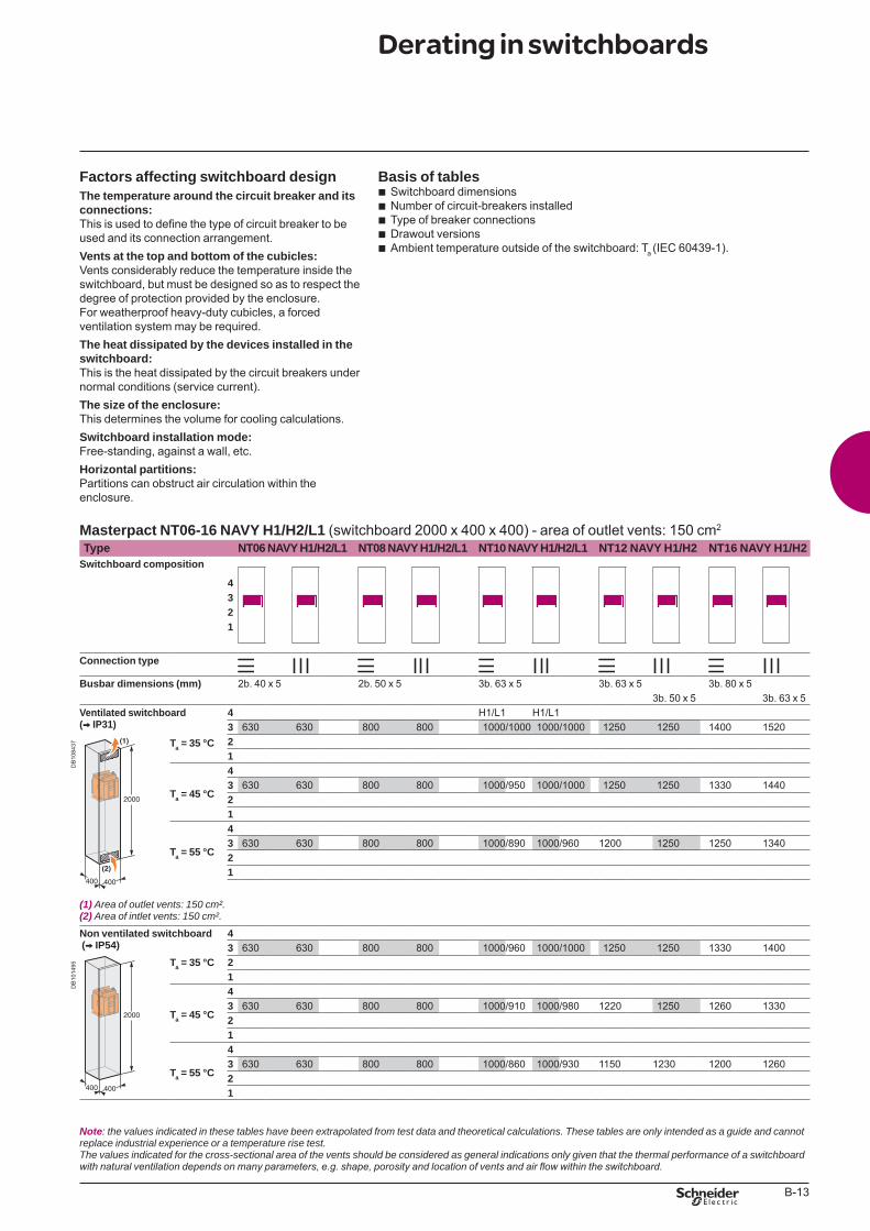
B-13
Factors affecting switchboard designThe temperature around the circuit breaker and its connections:This is used to define the type of circuit breaker to be used and its connection arrangement.Vents at the top and bottom of the cubicles:Vents considerably reduce the temperature inside the switchboard, but must be designed so as to respect the degree of protection provided by the enclosure. For weatherproof heavy-duty cubicles, a forced ventilation system may be required.The heat dissipated by the devices installed in the switchboard:This is the heat dissipated by the circuit breakers under normal conditions (service current).The size of the enclosure:This determines the volume for cooling calculations.Switchboard installation mode:Free-standing, against a wall, etc.Horizontal partitions:Partitions can obstruct air circulation within the enclosure.
Basis of tablesSwitchboard dimensionsNumber of circuit-breakers installedType of breaker connectionsDrawout versionsAmbient temperature outside of the switchboard: Ta (IEC 60439-1).
bbbbb
Masterpact NT06-16 NAVY H1/H2/L1 (switchboard 2000 x 400 x 400) - area of outlet vents: 150 cm2
Type NT06 NAVY H1/H2/L1 NT08 NAVY H1/H2/L1 NT10 NAVY H1/H2/L1 NT12 NAVY H1/H2 NT16 NAVY H1/H2Switchboard composition
4321
Connection type
Busbar dimensions (mm) 2b. 40 x 5 2b. 50 x 5 3b. 63 x 5 3b. 63 x 5 3b. 80 x 53b. 50 x 5 3b. 63 x 5
Ventilated switchboard (V IP31)
4 H1/L1 H1/L1
DB
1084
37
3 630 630 800 800 1000/1000 1000/1000 1250 1250 1400 1520Ta = 35 °C 2
1
Ta = 45 °C
43 630 630 800 800 1000/950 1000/1000 1250 1250 1330 144021
Ta = 55 °C
43 630 630 800 800 1000/890 1000/960 1200 1250 1250 134021
(1) Areaofoutletvents:150cm².(2) Areaofintletvents:150cm².
Non ventilated switchboard (V IP54)
4
DB
1014
95
3 630 630 800 800 1000/960 1000/1000 1250 1250 1330 1400Ta = 35 °C 2
1
Ta = 45 °C
43 630 630 800 800 1000/910 1000/980 1220 1250 1260 133021
Ta = 55 °C
43 630 630 800 800 1000/860 1000/930 1150 1230 1200 126021
Note: thevaluesindicatedinthesetableshavebeenextrapolatedfromtestdataandtheoreticalcalculations.Thesetablesareonlyintendedasaguideandcannotreplaceindustrialexperienceoratemperaturerisetest.Thevaluesindicatedforthecross-sectionalareaoftheventsshouldbeconsideredasgeneralindicationsonlygiventhatthethermalperformanceofaswitchboardwith natural ventilation depends on many parameters, e.g. shape, porosity and location of vents and air flow within the switchboard.
Derating in switchboards
BTP222E.indb 13 30/06/2009 09:31:36
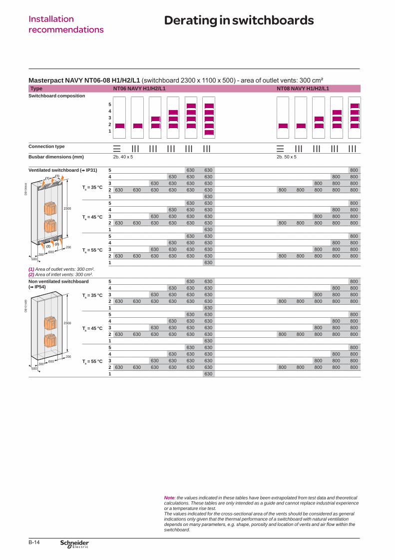
B-14
Installation recommendations
Masterpact NAVY NT06-08 H1/H2/L1 (switchboard 2300 x 1100 x 500) - area of outlet vents: 300 cm²Type NT06 NAVY H1/H2/L1 NT08 NAVY H1/H2/L1
Switchboard composition
54321
Connection type
Busbar dimensions (mm) 2b. 40 x 5 2b. 50 x 5
Ventilated switchboard (V IP31) 5 630 630 800
DB
1084
44
Ta = 35 °C
4 630 630 630 800 8003 630 630 630 630 800 800 8002 630 630 630 630 630 630 800 800 800 800 8001 630
Ta = 45 °C
5 630 630 8004 630 630 630 800 8003 630 630 630 630 800 800 8002 630 630 630 630 630 630 800 800 800 800 8001 630
Ta = 55 °C
5 630 630 8004 630 630 630 800 8003 630 630 630 630 800 800 8002 630 630 630 630 630 630 800 800 800 800 8001 630
(1) Areaofoutletvents:300cm².(2) Areaofintletvents:300cm².Non ventilated switchboard (V IP54)
5 630 630 800
DB
1014
89
4 630 630 630 800 800Ta = 35 °C 3 630 630 630 630 800 800 800
2 630 630 630 630 630 630 800 800 800 800 8001 630
Ta = 45 °C
5 630 630 8004 630 630 630 800 8003 630 630 630 630 800 800 8002 630 630 630 630 630 630 800 800 800 800 8001 630
Ta = 55 °C
5 630 630 8004 630 630 630 800 8003 630 630 630 630 800 800 8002 630 630 630 630 630 630 800 800 800 800 8001 630
Note: thevaluesindicatedinthesetableshavebeenextrapolatedfromtestdataandtheoreticalcalculations.Thesetablesareonlyintendedasaguideandcannotreplaceindustrialexperienceoratemperaturerisetest.Thevaluesindicatedforthecross-sectionalareaoftheventsshouldbeconsideredasgeneralindicationsonlygiventhatthethermalperformanceofaswitchboardwithnaturalventilationdepends on many parameters, e.g. shape, porosity and location of vents and air flow within the switchboard.
Derating in switchboards
BTP222E.indb 14 30/06/2009 09:31:39
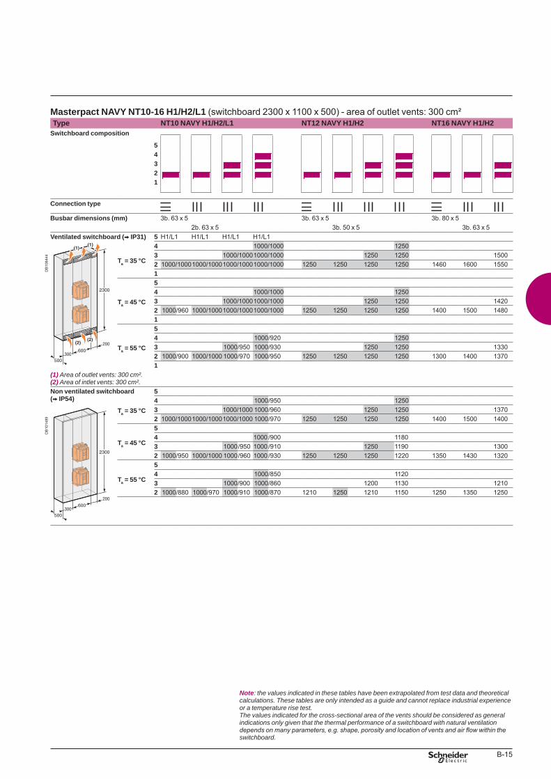
B-15
Masterpact NAVY NT10-16 H1/H2/L1 (switchboard 2300 x 1100 x 500) - area of outlet vents: 300 cm²Type NT10 NAVY H1/H2/L1 NT12 NAVY H1/H2 NT16 NAVY H1/H2
Switchboard composition
54321
Connection type
Busbar dimensions (mm) 3b. 63 x 5 3b. 63 x 5 3b. 80 x 52b. 63 x 5 3b. 50 x 5 3b. 63 x 5
Ventilated switchboard (V IP31) 5 H1/L1 H1/L1 H1/L1 H1/L1
DB
1084
44
Ta = 35 °C
4 1000/1000 12503 1000/10001000/1000 1250 1250 15002 1000/10001000/10001000/10001000/1000 1250 1250 1250 1250 1460 1600 15501
Ta = 45 °C
54 1000/1000 12503 1000/10001000/1000 1250 1250 14202 1000/960 1000/10001000/10001000/1000 1250 1250 1250 1250 1400 1500 14801
Ta = 55 °C
54 1000/920 12503 1000/950 1000/930 1250 1250 13302 1000/900 1000/1000 1000/970 1000/950 1250 1250 1250 1250 1300 1400 13701
(1) Areaofoutletvents:300cm².(2) Areaofintletvents:300cm².Non ventilated switchboard (V IP54)
5
DB
1014
89
4 1000/950 1250Ta = 35 °C 3 1000/1000 1000/960 1250 1250 1370
2 1000/10001000/10001000/1000 1000/970 1250 1250 1250 1250 1400 1500 1400
Ta = 45 °C
54 1000 /900 11803 1000/950 1000 /910 1250 1190 13002 1000/950 1000/1000 1000/960 1000 /930 1250 1250 1250 1220 1350 1430 1320
Ta = 55 °C
54 1000/850 11203 1000/900 1000/860 1200 1130 12102 1000/880 1000/970 1000/910 1000/870 1210 1250 1210 1150 1250 1350 1250
Note: thevaluesindicatedinthesetableshavebeenextrapolatedfromtestdataandtheoreticalcalculations.Thesetablesareonlyintendedasaguideandcannotreplaceindustrialexperienceoratemperaturerisetest.Thevaluesindicatedforthecross-sectionalareaoftheventsshouldbeconsideredasgeneralindicationsonlygiventhatthethermalperformanceofaswitchboardwithnaturalventilationdepends on many parameters, e.g. shape, porosity and location of vents and air flow within the switchboard.
BTP222E.indb 15 30/06/2009 09:31:41
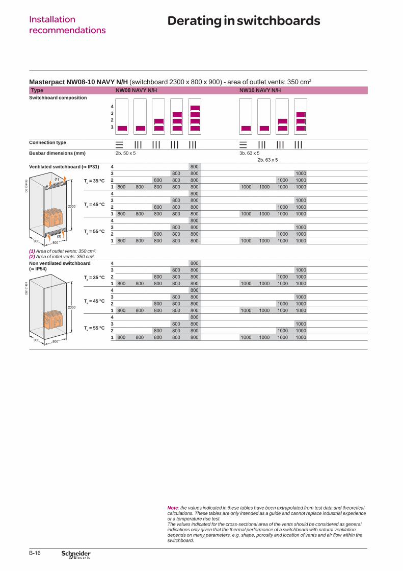
B-16
Installation recommendations
Masterpact NW08-10 NAVY N/H (switchboard 2300 x 800 x 900) - area of outlet vents: 350 cm²Type NW08 NAVY N/H NW10 NAVY N/H
Switchboard composition
4321
Connection type
Busbar dimensions (mm) 2b. 50 x 5 3b. 63 x 52b. 63 x 5
Ventilated switchboard (V IP31) 4 800
DB
1084
38
Ta = 35 °C
3 800 800 10002 800 800 800 1000 10001 800 800 800 800 800 1000 1000 1000 1000
Ta = 45 °C
4 8003 800 800 10002 800 800 800 1000 10001 800 800 800 800 800 1000 1000 1000 1000
Ta = 55 °C
4 8003 800 800 10002 800 800 800 1000 10001 800 800 800 800 800 1000 1000 1000 1000
(1) Areaofoutletvents:350cm².(2) Areaofintletvents:350cm².Non ventilated switchboard (V IP54)
4 800
DB
1014
91
3 800 800 1000Ta = 35 °C 2 800 800 800 1000 1000
1 800 800 800 800 800 1000 1000 1000 1000
Ta = 45 °C
4 8003 800 800 10002 800 800 800 1000 10001 800 800 800 800 800 1000 1000 1000 1000
Ta = 55 °C
4 8003 800 800 10002 800 800 800 1000 10001 800 800 800 800 800 1000 1000 1000 1000
Note: thevaluesindicatedinthesetableshavebeenextrapolatedfromtestdataandtheoreticalcalculations.Thesetablesareonlyintendedasaguideandcannotreplaceindustrialexperienceoratemperaturerisetest.Thevaluesindicatedforthecross-sectionalareaoftheventsshouldbeconsideredasgeneralindicationsonlygiventhatthethermalperformanceofaswitchboardwithnaturalventilationdepends on many parameters, e.g. shape, porosity and location of vents and air flow within the switchboard.
Derating in switchboards
BTP222E.indb 16 30/06/2009 09:31:43
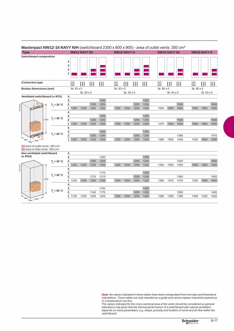
B-17
Masterpact NW12-16 NAVY N/H (switchboard 2300 x 800 x 900) - area of outlet vents: 350 cm²Type NW12 NAVY N1 NW12 NAVY H NW16 NAVY N1 NW16 NAVY H
Switchboard composition
4321
Connection type
Busbar dimensions (mm) 3b. 63 x 5 3b. 63 x 5 3b. 80 x 5 3b. 80 x 53b. 50 x 5 3b. 50 x 5 3b. 63 x 5 3b. 63 x 5
Ventilated switchboard (V IP31) 4
DB
1084
38
Ta = 35 °C
3 1250 12502 1250 1250 1250 1250 1600 16001 1250 1250 1250 1250 1250 1250 1250 1250 1550 1600 1600 1600 1600 1600
Ta = 45 °C
43 1250 12502 1250 1250 1250 1250 1500 16001 1250 1250 1250 1250 1250 1250 1250 1250 1470 1600 1600 1600 1600 1600
Ta = 55 °C
43 1250 12502 1250 1250 1250 1250 1380 14701 1250 1250 1250 1250 1250 1250 1250 1250 1380 1500 1500 1520 1600 1600
(1) Areaofoutletvents:350cm².(2) Areaofintletvents:350cm².Non ventilated switchboard (V IP54)
4
DB
1014
91
3 1240 1250Ta = 35 °C 2 1250 1250 1250 1250 1425 1600
1 1250 1250 1250 1250 1250 1250 1250 1250 1440 1550 1550 1600 1600 1600
Ta = 45 °C
43 1170 12502 1210 1210 1250 1250 1360 15001 1200 1250 1250 1250 1250 1250 1250 1250 1360 1470 1470 1500 1600 1600
Ta = 55 °C
43 1100 12502 1140 1170 1250 1250 1280 14001 1130 1200 1200 1200 1250 1250 1250 1250 1280 1380 1380 1400 1520 1520
Note: thevaluesindicatedinthesetableshavebeenextrapolatedfromtestdataandtheoreticalcalculations.Thesetablesareonlyintendedasaguideandcannotreplaceindustrialexperienceoratemperaturerisetest.Thevaluesindicatedforthecross-sectionalareaoftheventsshouldbeconsideredasgeneralindicationsonlygiventhatthethermalperformanceofaswitchboardwithnaturalventilationdepends on many parameters, e.g. shape, porosity and location of vents and air flow within the switchboard.
BTP222E.indb 17 30/06/2009 09:31:47
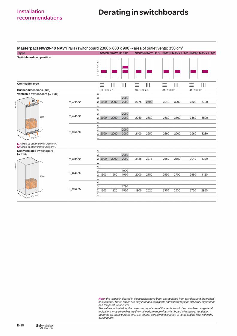
B-18
Installation recommendations
Masterpact NW20-40 NAVY N/H (switchboard 2300 x 800 x 900) - area of outlet vents: 350 cm²Type NW20 NAVY H1/H2 NW25 NAVY H1/2 NW32 NAVY H1/2 NW40 NAVY H1/2
Switchboard composition
4321
Connection type
Busbar dimensions (mm) 3b. 100 x 5 4b. 100 x 5 3b. 100 x 10 4b. 100 x 10Ventilated switchboard (V IP31) 4
DB
1084
38
Ta = 35 °C
3 20002 2000 2000 2000 2375 2500 3040 3200 3320 37001
Ta = 45 °C
43 20002 2000 2000 2000 2250 2380 2880 3100 3160 35001
Ta = 55 °C
43 20002 2000 2000 2000 2100 2250 2690 2900 2960 32801
(1) Areaofoutletvents:350cm².(2) Areaofintletvents:350cm².Non ventilated switchboard (V IP54)
4
DB
1014
91
3 2000Ta = 35 °C 2 2000 2000 2000 2125 2275 2650 2850 3040 3320
1
Ta = 45 °C
43 19002 1900 1960 1960 2000 2150 2550 2700 2880 31201
Ta = 55 °C
43 17802 1800 1920 1920 1900 2020 2370 2530 2720 29601
Note: thevaluesindicatedinthesetableshavebeenextrapolatedfromtestdataandtheoreticalcalculations.Thesetablesareonlyintendedasaguideandcannotreplaceindustrialexperienceoratemperaturerisetest.Thevaluesindicatedforthecross-sectionalareaoftheventsshouldbeconsideredasgeneralindicationsonlygiventhatthethermalperformanceofaswitchboardwithnaturalventilationdepends on many parameters, e.g. shape, porosity and location of vents and air flow within the switchboard.
Derating in switchboards
BTP222E.indb 18 30/06/2009 09:31:48

B-19
BTP222E.indb 19 30/06/2009 09:31:48

schneider-electric.com Training
This international site allows you to access all the Schneider Electric products in just 2 clicksvia comprehensive range data-sheets, with direct links to:
complete library: technical documents, catalogs, FAQs, brochures…
selection guides from the e-catalog.
product discovery sites andtheir Flash animations.You will also fi nd illustrated overviews, news to which you can subscribe, the list of country contacts…
p
p
p
Training allows you to acquire the Schneider Electric expertise (installation design, work with power on, etc.) for increased effi ciencyand a guarantee of improved customer service.The training catalogue includes beginner’s courses in electrical distribution, knowledgeof MV and LV switchgear, operation and maintenance of installations, design of LV installations to give but a few examples.
TOOLS
BTP222E.indb 2 30/06/2009 09:31:50
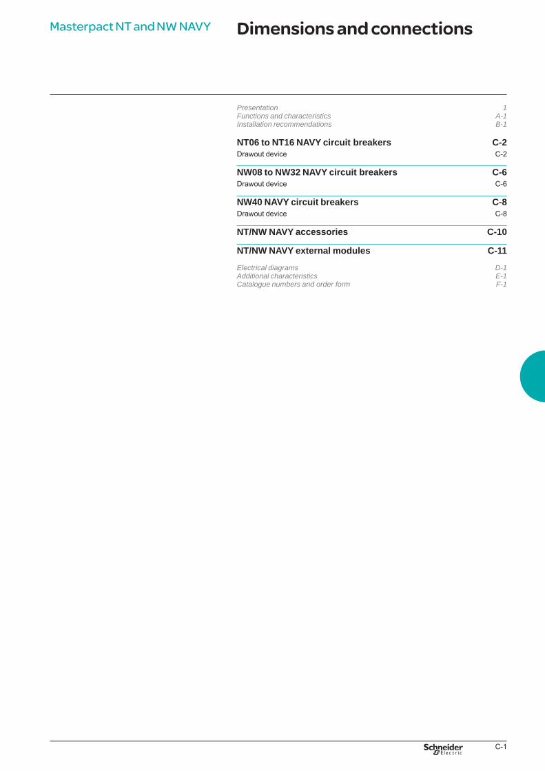
C-1
Dimensions and connectionsMasterpact NT and NW NAVY
Presentation 1Functionsandcharacteristics A-1Installationrecommendations B-1
NT06 to NT16 NAVY circuit breakers C-2Drawout device C-2
NW08 to NW32 NAVY circuit breakers C-6Drawout device C-6
NW40 NAVY circuit breakers C-8Drawout device C-8
NT/NW NAVY accessories C-10
NT/NW NAVY external modules C-11
Electricaldiagrams D-1Additionalcharacteristics E-1Cataloguenumbersandorderform F-1
BTP222E.indb 1 30/06/2009 09:31:50
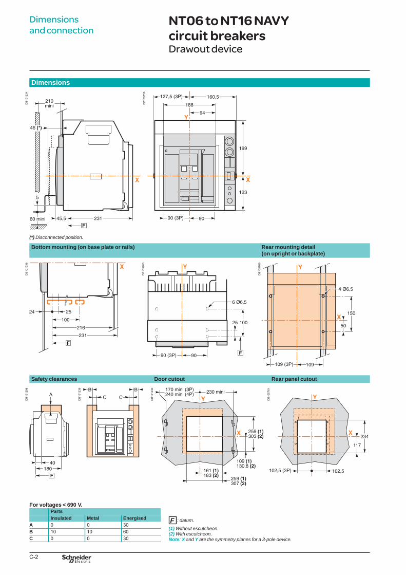
C-2
Dimensions
DB
1012
34
(*)Disconnectedposition.
DB
1057
59
Bottom mounting (on base plate or rails) Rear mounting detail (on upright or backplate)
DB
1012
36
DB
1057
60
DB
1057
66
Safety clearances Door cutout Rear panel cutout
DB
1012
56
DB
1012
39
DB
1012
40
DB
1057
61
For voltages < 690 V.Parts
:datum.
(1)Withoutescutcheon.(2) Withescutcheon.Note: XandYarethesymmetryplanesfora3-poledevice.
Insulated Metal EnergisedA 0 0 30B 10 10 60C 0 0 30
Dimensions and connection
NT06 to NT16 NAVY circuit breakersDrawout device
F
BTP222E.indb 2 30/06/2009 09:31:52
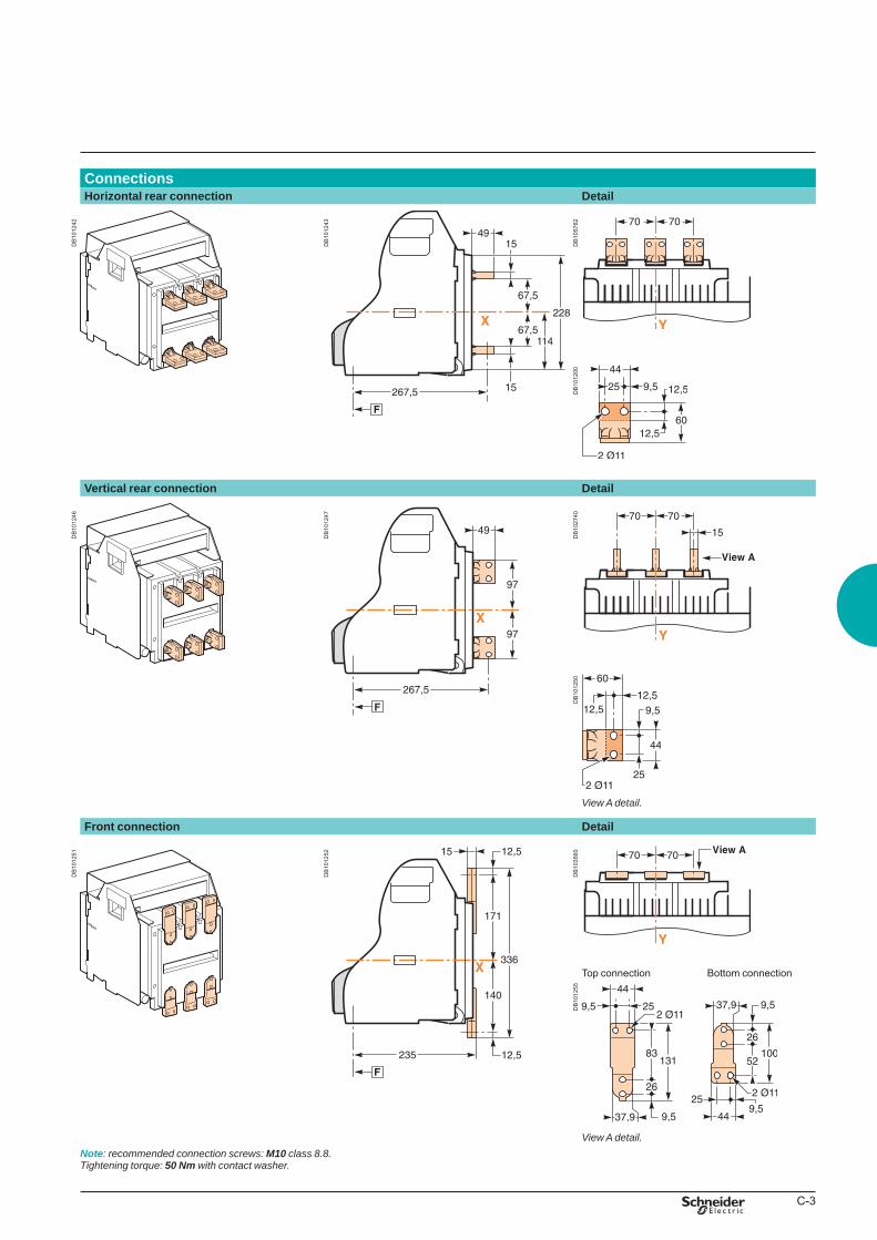
C-3
ConnectionsHorizontal rear connection Detail
DB
1012
42
DB
1012
43
DB
1057
62D
B10
1200
Vertical rear connection Detail
DB
1012
46
DB
1012
47
DB
1027
40D
B10
1250
ViewAdetail.
Front connection Detail
DB
1012
51
DB
1012
52
DB
1035
60
Top connection Bottom connection
DB
1012
55
ViewAdetail.Note: recommendedconnectionscrews:M10 class8.8.Tighteningtorque:50 Nm withcontactwasher.
BTP222E.indb 3 30/06/2009 09:31:55
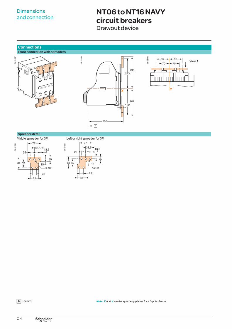
C-4
ConnectionsFront connection with spreaders
DB
1012
57
DB
1012
58
DB
1057
98
Spreader detailMiddle spreader for 3P. Left or right spreader for 3P.
DB
1012
19
DB
1012
21
:datum. Note: XandYarethesymmetryplanesfora3-poledevice.
Dimensions and connection
NT06 to NT16 NAVY circuit breakersDrawout device
F
BTP222E.indb 4 30/06/2009 09:31:56
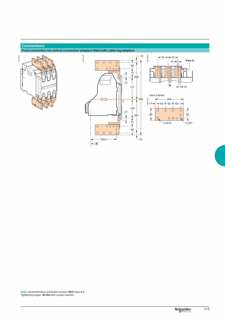
C-5
ConnectionsFront connection via vertical connection adapters fitted with cable-lug adapters
DB
1012
61
DB
1012
62
DB
1058
33D
B10
1229
ViewAdetail.
Note:recommendedconnectionscrews:M10 class8.8.Tighteningtorque:50 Nm withcontactwasher.
BTP222E.indb 5 30/06/2009 09:31:57
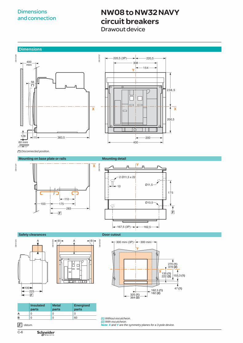
C-6
Dimensions
DB
1012
89
(*)Disconnectedposition.
DB
1057
67
Mounting on base plate or rails Mounting detail
DB
1012
91
DB
1057
68
Safety clearances Door cutout
DB
1012
93
DB
1012
94
DB
1057
69
Insulated parts
Metal parts
Energised parts
(1)Withoutescutcheon.(2) Withescutcheon.Note: XandYarethesymmetryplanesfora3-poledevice.
A 0 0 0B 0 0 60
:datum.
Dimensions and connection
NW08 to NW32 NAVY circuit breakersDrawout device
F
BTP222E.indb 6 30/06/2009 09:31:59
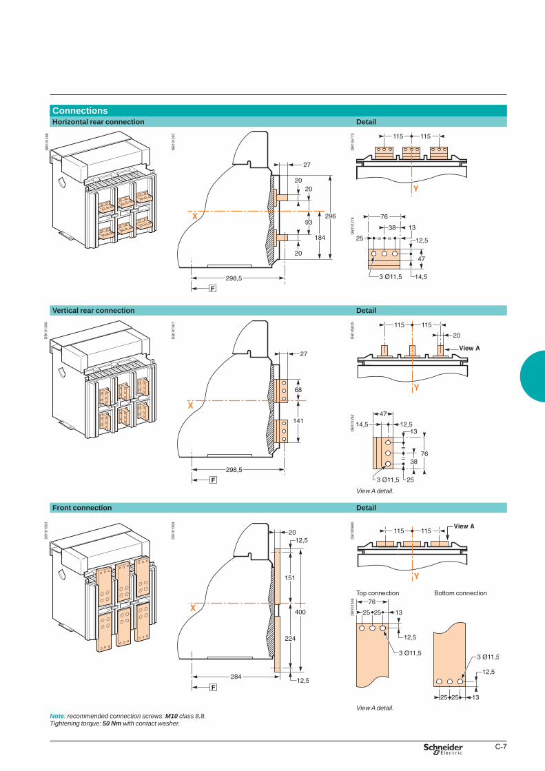
C-7
ConnectionsHorizontal rear connection Detail
DB
1012
96
DB
1012
97
DB
1057
70D
B10
1278
Vertical rear connection Detail
DB
1013
00
DB
1013
01
DB
1058
35D
B10
1282
ViewAdetail.
Front connection Detail
DB
1013
03
DB
1013
04
DB
1059
95
Top connection Bottom connection
DB
1013
06
ViewAdetail.Note: recommendedconnectionscrews:M10 class8.8.Tighteningtorque:50 Nm withcontactwasher.
BTP222E.indb 7 30/06/2009 09:32:01
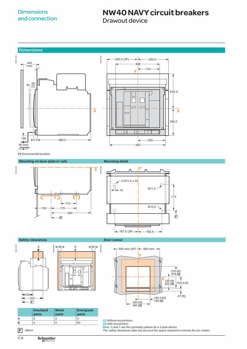
C-8
Dimensions
DB
1012
89
(*)Disconnectedposition.
DB
1057
67
Mounting on base plate or rails Mounting detail
DB
1012
91
DB
1057
68
Safety clearances Door cutout
DB
1012
93
DB
1012
94
DB
1057
69
Insulated parts
Metal parts
Energised parts
(1)Withoutescutcheon.(2) Withescutcheon.Note: XandYarethesymmetryplanesfora3-poledevice.Thesafetyclearancestakeintoaccountthespacerequiredtoremovethearcchutes.
A 0 0 0B 0 0 60:datum.
Dimensions and connection
NW40 NAVY circuit breakersDrawout device
F
BTP222E.indb 8 30/06/2009 09:32:01
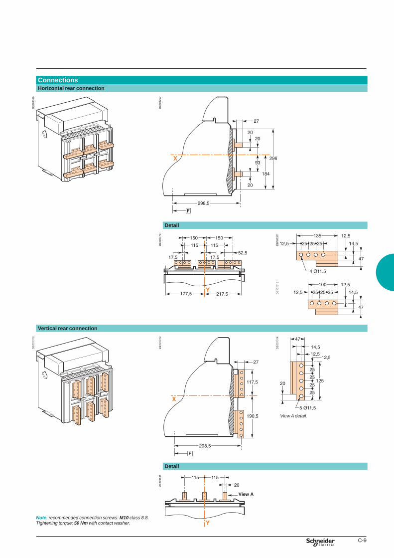
C-9
ConnectionsHorizontal rear connection
DB
1013
16
DB
1012
97
Detail
DB
1057
73
DB
1013
11D
B10
1315
Vertical rear connection
DB
1013
18
DB
1013
19
DB
1013
14
ViewAdetail.
Detail
Note: recommendedconnectionscrews:M10 class8.8.Tighteningtorque:50 Nm withcontactwasher.
DB
1058
35
BTP222E.indb 9 30/06/2009 09:32:03
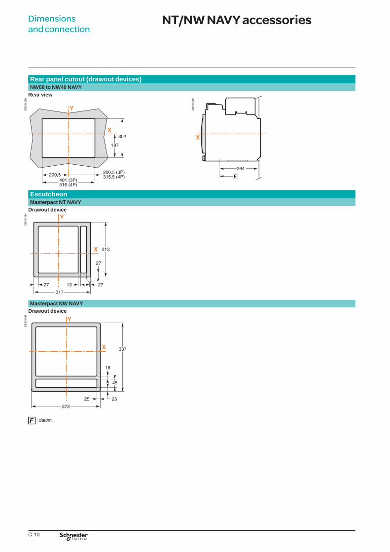
C-10
Rear panel cutout (drawout devices)NW08 to NW40 NAVY
Rear view
DB
1013
59
DB
1013
60EscutcheonMasterpact NT NAVY
Drawout device
DB
1013
64
Masterpact NW NAVYDrawout device
DB
1013
66
:datum.
Dimensions and connection
NT/NW NAVY accessories
F
BTP222E.indb 10 30/06/2009 09:32:04
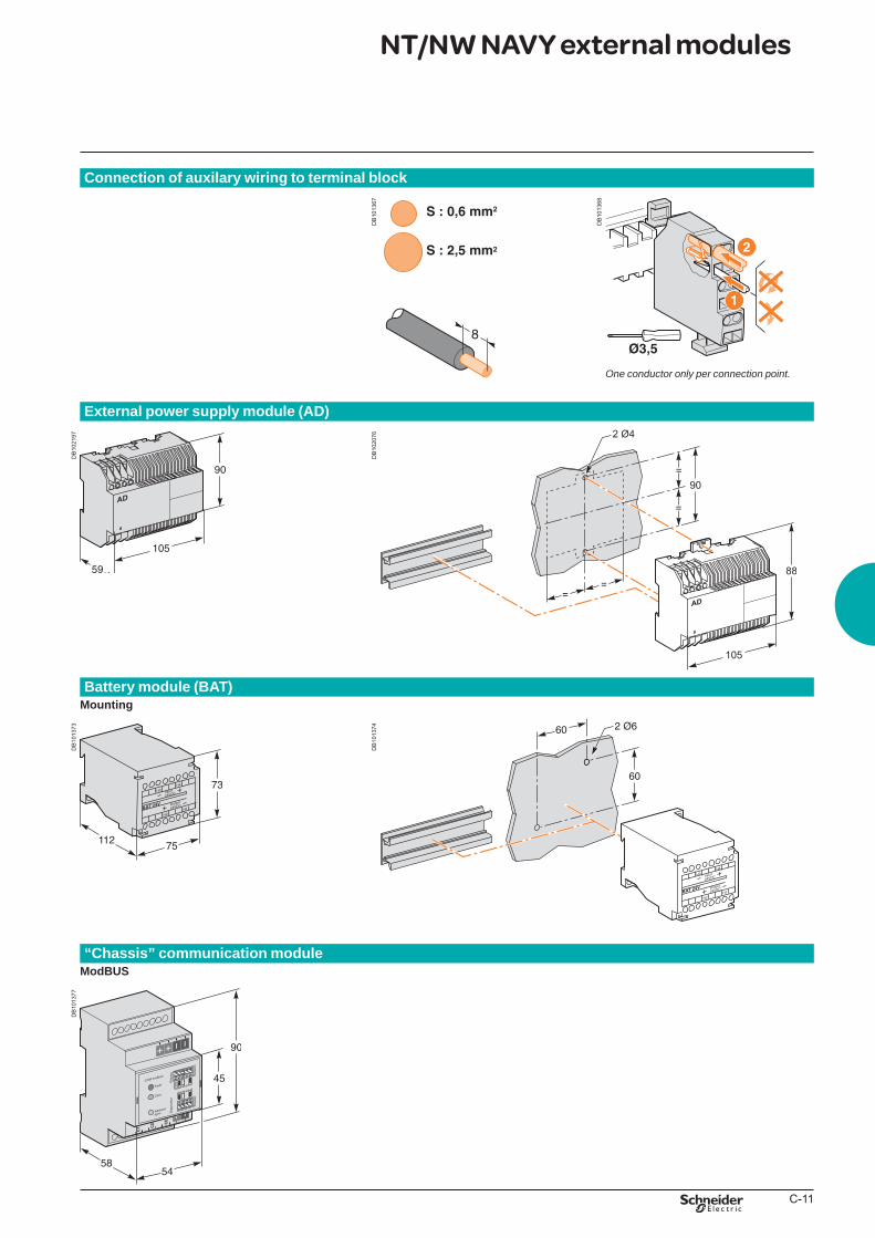
C-11
Connection of auxilary wiring to terminal block
DB
1013
67
DB
1013
68
Oneconductoronlyperconnectionpoint.
External power supply module (AD)
DB
1021
97
DB
1020
76
Battery module (BAT)Mounting
DB
1013
73
DB
1013
74
“Chassis” communication moduleModBUS
DB
1013
77
NT/NW NAVY external modules
BTP222E.indb 11 30/06/2009 09:32:05
schneider-electric.com The electrical installation guide
This international site allows you to access all the Schneider Electric products in just 2 clicksvia comprehensive range data-sheets, with direct links to:
complete library: technical documents, catalogs, FAQs, brochures…
selection guides from the e-catalog.
product discovery sites andtheir Flash animations.You will also fi nd illustrated overviews, news to which you can subscribe, the list of country contacts…
p
p
p
According to IEC 60364This guide, part of the Schneider Electric offer, is the essential tool to "guide" you any time in your business:
design offi ce, consultantcontractor, panelbuilderteacher, trainer.
Comprehensiveand concrete information on:
all the new technical solutionsall the componentsof an installation from a global
point of viewall the IEC standards modifi cationsall the fundamental
electrotechnical knowledgeall the design stages, from medium
to low voltage.
ppp
ppp
pp
p
TOOLS
BTP222E.indb 2 30/06/2009 09:32:33
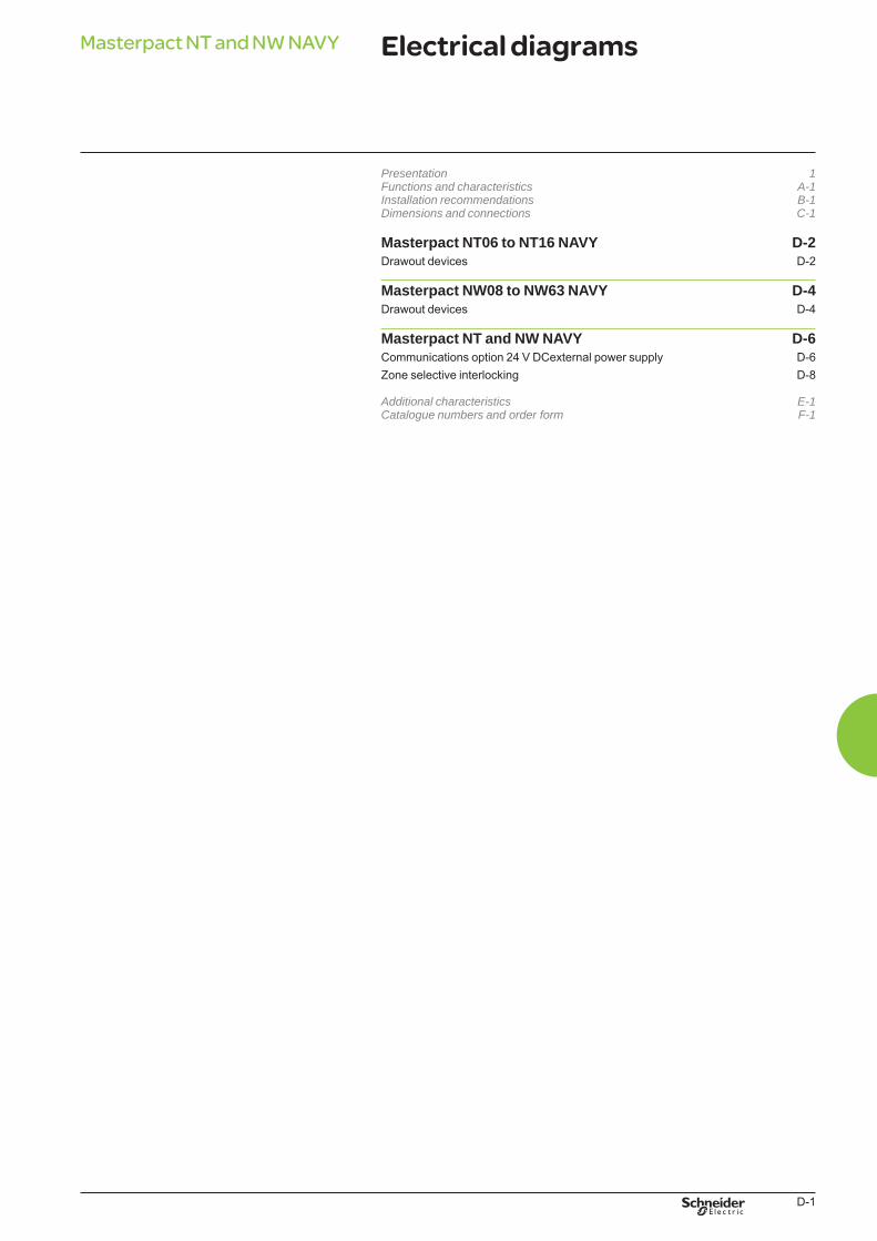
D-1
Electrical diagramsMasterpact NT and NW NAVY
Presentation 1Functionsandcharacteristics A-1Installationrecommendations B-1Dimensionsandconnections C-1
Masterpact NT06 to NT16 NAVY D-2Drawout devices D-2
Masterpact NW08 to NW63 NAVY D-4Drawout devices D-4
Masterpact NT and NW NAVY D-6Communications option 24 V DCexternal power supply D-6Zone selective interlocking D-8
Additionalcharacteristics E-1Cataloguenumbersandorderform F-1
BTP222E.indb 1 30/06/2009 09:32:37
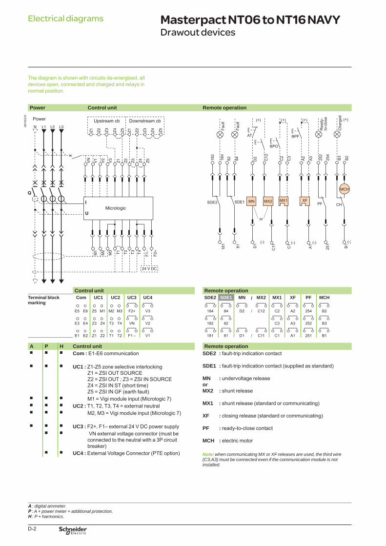
D-2
The diagram is shown with circuits de-energised, all devices open, connected and charged and relays in normal position.
Power Control unit Remote operation
DB
1063
35
Control unit Remote operationTerminal block marking
Com UC1 UC2 UC3 UC4 SDE2 SDE1 MN / MX2 MX1 XF PF MCH
E5 E6 Z5 M1 M2 M3 F2+ V3 184 84 D2 / C12 C2 A2 254 B2
E3 E4 Z3 Z4 T3 T4 VN V2 182 82 C3 A3 252 B3
E1 E2 Z1 Z2 T1 T2 F1 – V1 181 81 D1 / C11 C1 A1 251 B1
A P H Control unit Remote operationb b b Com : E1-E6 communication SDE2 : fault-trip indication contact
SDE1 : fault-trip indication contact (supplied as standard)
MN : undervoltage releaseorMX2 : shunt release
MX1 : shunt release (standard or communicating)
XF : closing release (standard or communicating)
PF : ready-to-close contact
MCH : electric motor
Note: whencommunicatingMXorXFreleasesareused,thethirdwire(C3,A3)mustbeconnectedevenifthecommunicationmoduleisnotinstalled.
b b b UC1 : Z1-Z5 zone selective interlockingZ1 = ZSI OUT SOURCEZ2 = ZSI OUT ; Z3 = ZSI IN SOURCEZ4 = ZSI IN ST (short time)Z5 = ZSI IN GF (earth fault)
b b b M1 = Vigi module input (Micrologic 7)b b b UC2 : T1, T2, T3, T4 = external neutralb b b M2, M3 = Vigi module input (Micrologic 7)
b b b UC3 : F2+, F1– external 24 V DC power supplyb b VN external voltage connector (must be
connected to the neutral with a 3P circuit breaker)
b b UC4 : External Voltage Connector (PTE option)
A :digitalammeter.P :A+powermeter+additionalprotection.H :P+harmonics.
Electrical diagrams Masterpact NT06 to NT16 NAVYDrawout devices
BTP222E.indb 2 30/06/2009 09:32:39
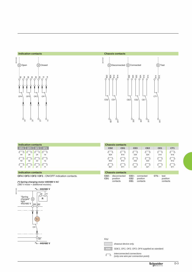
D-3
Indication contacts Chassis contacts
DB
1014
06
DB
1014
07
Indication contacts Chassis contactsOF4 OF3 OF2 OF1 CD2 CD1 CE3 CE2 CE1 CT1
44 34 24 14 824 814 334 324 314 914
42 32 22 12 822 812 332 322 312 912
41 31 21 11 821 811 331 321 311 911
Indication contacts Chassis contactsOF4 / OF3 / OF2 / OF1 : ON/OFF indication contacts.
(*) Spring charging motor 440/480 V AC(380Vmotor+additionalresistor).
CD2 :CD1
disconnectedposition contacts
CE3 : CE2CE1
connectedposition contacts
CT1 : testposition contacts
DB
1014
08
Key:
drawoutdeviceonly.
XXX SDE1,OF1,OF2,OF3,OF4suppliedasstandard.
interconnectedconnections (onlyonewireperconnectionpoint).
BTP222E.indb 3 30/06/2009 09:32:41
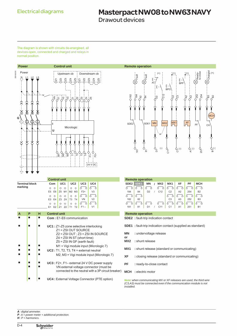
D-4
The diagram is shown with circuits de-energised, all devices open, connected and charged and relays in normal position.
Power Control unit Remote operation
DB
1063
35
Control unit Remote operationTerminal block marking
Com UC1 UC2 UC3 UC4 SDE2 SDE1 MN / MX2 MX1 XF PF MCH
E5 E6 Z5 M1 M2 M3 F2+ V3 184 84 D2 / C12 C2 A2 254 B2
E3 E4 Z3 Z4 T3 T4 VN V2 182 82 C3 A3 252 B3
E1 E2 Z1 Z2 T1 T2 F1 – V1 181 81 D1 / C11 C1 A1 251 B1
A P H Control unit Remote operationb b b Com : E1-E6 communication SDE2 : fault-trip indication contact
SDE1 : fault-trip indication contact (supplied as standard)
MN : undervoltage releaseorMX2 : shunt release
MX1 : shunt release (standard or communicating)
XF : closing release (standard or communicating)
PF : ready-to-close contact
MCH : electric motor
Note: whencommunicatingMXorXFreleasesareused,thethirdwire(C3,A3)mustbeconnectedevenifthecommunicationmoduleisnotinstalled.
b b b UC1 : Z1-Z5 zone selective interlockingZ1 = ZSI OUT SOURCEZ2 = ZSI OUT ; Z3 = ZSI IN SOURCEZ4 = ZSI IN ST (short time)Z5 = ZSI IN GF (earth fault)
b b b M1 = Vigi module input (Micrologic 7)b b b UC2 : T1, T2, T3, T4 = external neutralb b b M2, M3 = Vigi module input (Micrologic 7)
b b b UC3 : F2+, F1– external 24 V DC power supplyb b VN external voltage connector (must be
connected to the neutral with a 3P circuit breaker)
b b UC4 : External Voltage Connector (PTE option)
A :digitalammeter.P :A+powermeter+additionalprotection.H :P+harmonics.
Electrical diagrams Masterpact NW08 to NW63 NAVY Drawout devices
BTP222E.indb 4 30/06/2009 09:32:42
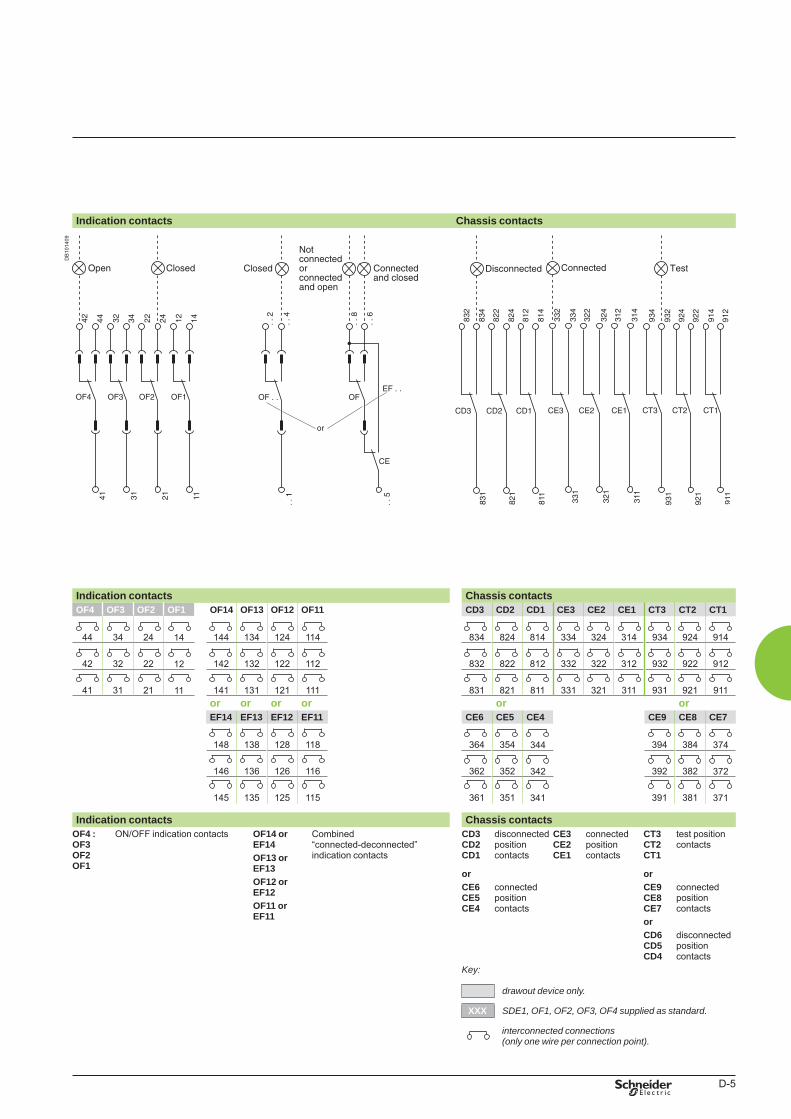
D-5
Indication contacts Chassis contacts
DB
1014
09
Indication contacts Chassis contactsOF4 OF3 OF2 OF1 OF14 OF13 OF12 OF11 CD3 CD2 CD1 CE3 CE2 CE1 CT3 CT2 CT1
44 34 24 14 144 134 124 114 834 824 814 334 324 314 934 924 914
42 32 22 12 142 132 122 112 832 822 812 332 322 312 932 922 912
41 31 21 11 141 131 121 111 831 821 811 331 321 311 931 921 911or or or or or orEF14 EF13 EF12 EF11 CE6 CE5 CE4 CE9 CE8 CE7
148 138 128 118 364 354 344 394 384 374
146 136 126 116 362 352 342 392 382 372
145 135 125 115 361 351 341 391 381 371
Indication contacts Chassis contactsOF4 :OF3OF2OF1
ON/OFF indication contacts OF14 or EF14OF13 or EF13OF12 or EF12OF11 orEF11
Combined “connected-deconnected” indication contacts
CD3 CD2CD1
disconnected position contacts
CE3CE2CE1
connected position contacts
CT3CT2CT1
test position contacts
or orCE6 CE5CE4
connected position contacts
CE9CE8CE7
connected position contacts
orCD6CD5CD4
disconnected position contacts
Key:
drawoutdeviceonly.
XXX SDE1,OF1,OF2,OF3,OF4suppliedasstandard.
interconnectedconnections (onlyonewireperconnectionpoint).
BTP222E.indb 5 30/06/2009 09:32:43
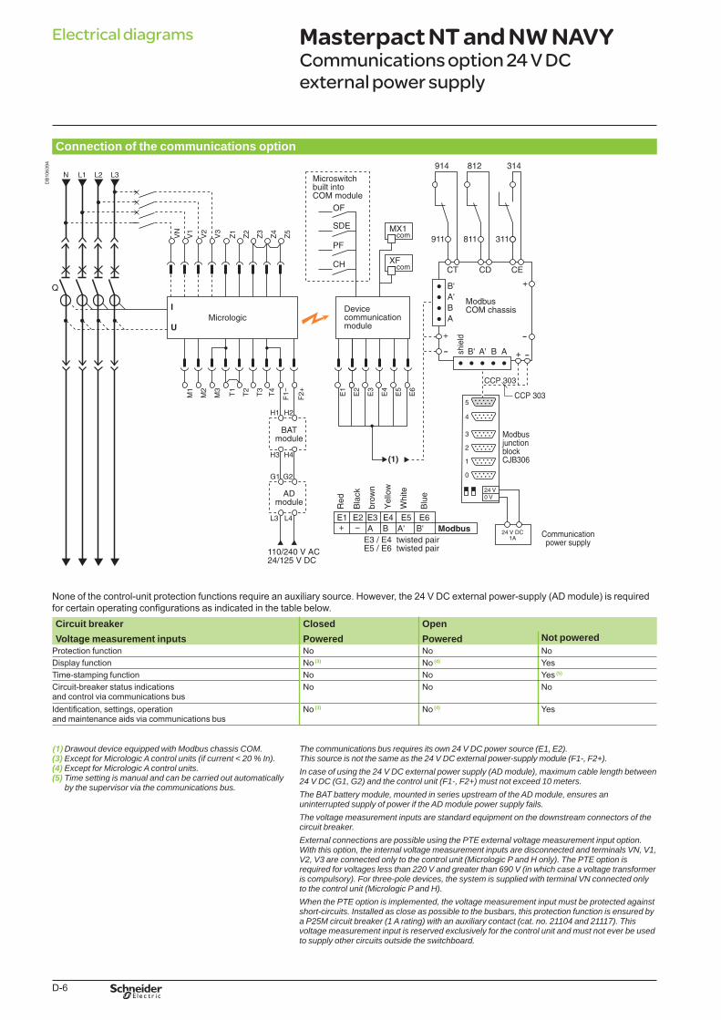
D-6
Connection of the communications option
DB
1063
94
None of the control-unit protection functions require an auxiliary source. However, the 24 V DC external power-supply (AD module) is required for certain operating configurations as indicated in the table below.Circuit breakerVoltage measurement inputs
ClosedPowered
OpenPowered Not powered
Protection function No No NoDisplay function No (3) No (4) YesTime-stamping function No No Yes (5)
Circuit-breaker status indications and control via communications bus
No No No
Identification, settings, operation and maintenance aids via communications bus
No (3) No (4) Yes
(1)DrawoutdeviceequippedwithModbuschassisCOM.(3)ExceptforMicrologicAcontrolunits(ifcurrent<20%In).(4)ExceptforMicrologicAcontrolunits.(5)Timesettingismanualandcanbecarriedoutautomatically bythesupervisorviathecommunicationsbus.
Thecommunicationsbusrequiresitsown24VDCpowersource(E1,E2).Thissourceisnotthesameasthe24VDCexternalpower-supplymodule(F1-,F2+).Incaseofusingthe24VDCexternalpowersupply(ADmodule),maximumcablelengthbetween24VDC(G1,G2)andthecontrolunit(F1-,F2+)mustnotexceed10meters.TheBATbatterymodule,mountedinseriesupstreamoftheADmodule,ensuresanuninterruptedsupplyofpoweriftheADmodulepowersupplyfails.Thevoltagemeasurementinputsarestandardequipmentonthedownstreamconnectorsofthecircuitbreaker.ExternalconnectionsarepossibleusingthePTEexternalvoltagemeasurementinputoption.Withthisoption,theinternalvoltagemeasurementinputsaredisconnectedandterminalsVN,V1,V2,V3areconnectedonlytothecontrolunit(MicrologicPandHonly).ThePTEoptionisrequiredforvoltageslessthan220Vandgreaterthan690V(inwhichcaseavoltagetransformeriscompulsory).Forthree-poledevices,thesystemissuppliedwithterminalVNconnectedonlytothecontrolunit(MicrologicPandH).WhenthePTEoptionisimplemented,thevoltagemeasurementinputmustbeprotectedagainstshort-circuits.Installedascloseaspossibletothebusbars,thisprotectionfunctionisensuredbyaP25Mcircuitbreaker(1Arating)withanauxiliarycontact(cat.no.21104and21117).Thisvoltagemeasurementinputisreservedexclusivelyforthecontrolunitandmustnoteverbeusedtosupplyothercircuitsoutsidetheswitchboard.
Electrical diagrams Masterpact NT and NW NAVYCommunications option 24 V DC external power supply
BTP222E.indb 6 30/06/2009 09:32:44
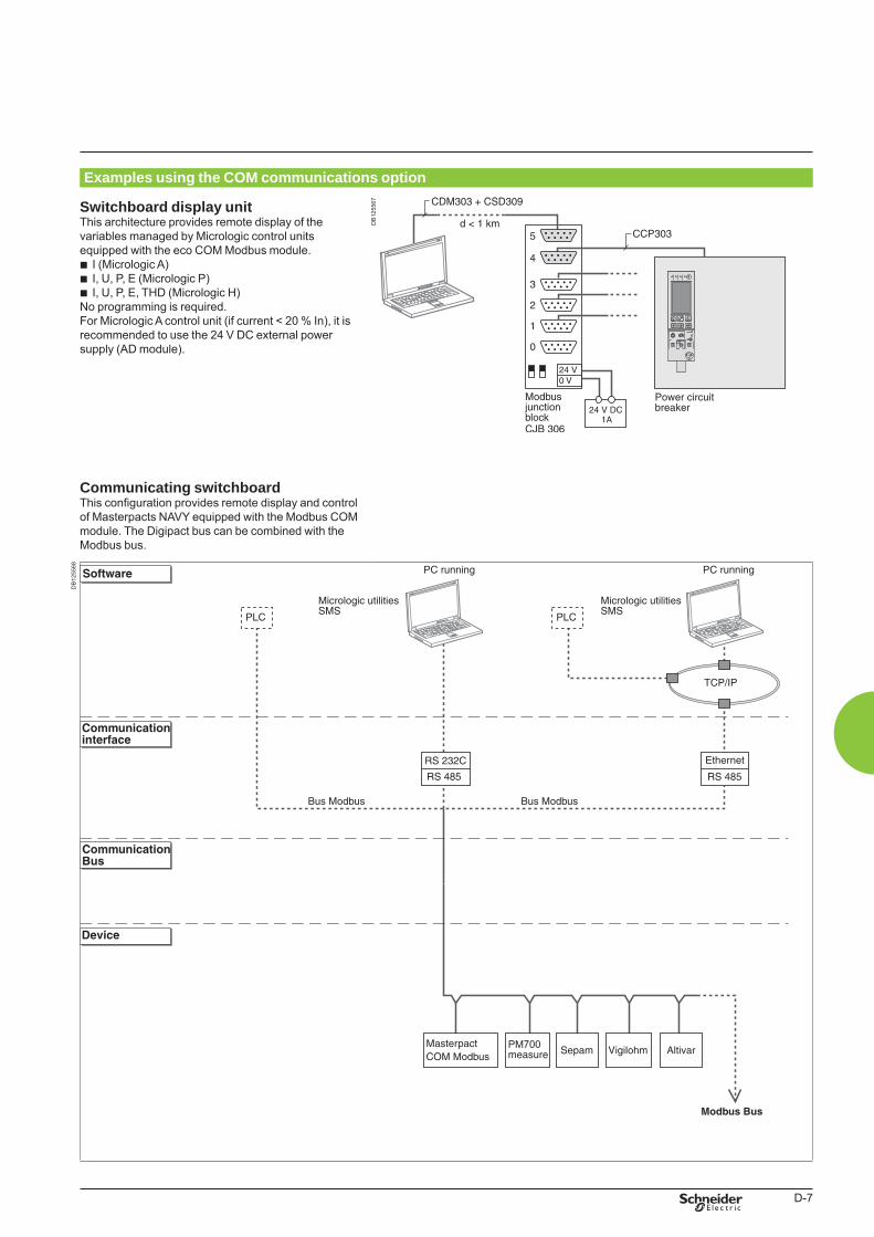
D-7
Examples using the COM communications option
Switchboard display unitThis architecture provides remote display of the variables managed by Micrologic control units equipped with the eco COM Modbus module.
I (Micrologic A)I, U, P, E (Micrologic P)I, U, P, E, THD (Micrologic H)
No programming is required.For Micrologic A control unit (if current < 20 % In), it is recommended to use the 24 V DC external power supply (AD module).
bbb
DB
1255
67
Communicating switchboardThis configuration provides remote display and control of Masterpacts NAVY equipped with the Modbus COM module. The Digipact bus can be combined with the Modbus bus.
DB
1255
68
BTP222E.indb 7 30/06/2009 09:32:45
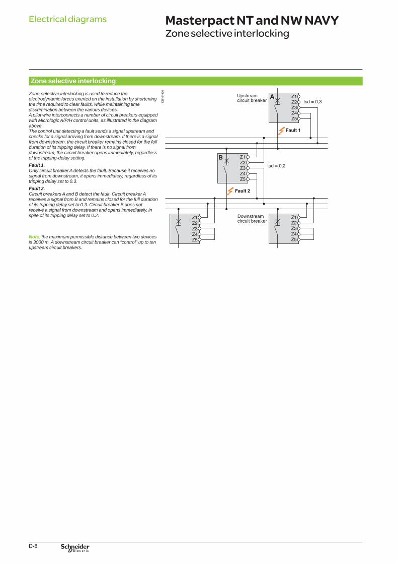
D-8
Electrical diagrams
Zone selective interlocking
Zone-selectiveinterlockingisusedtoreducetheelectrodynamicforcesexertedontheinstallationbyshorteningthetimerequiredtoclearfaults,whilemaintainingtimediscriminationbetweenthevariousdevices.ApilotwireinterconnectsanumberofcircuitbreakersequippedwithMicrologicA/P/Hcontrolunits,asillustratedinthediagramabove.Thecontrolunitdetectingafaultsendsasignalupstreamandchecksforasignalarrivingfromdownstream.Ifthereisasignalfromdownstream,thecircuitbreakerremainsclosedforthefulldurationofitstrippingdelay.Ifthereisnosignalfromdownstream,thecircuitbreakeropensimmediately,regardlessofthetripping-delaysetting.Fault 1.OnlycircuitbreakerAdetectsthefault.Becauseitreceivesnosignalfromdownstream,itopensimmediately,regardlessofitstrippingdelaysetto0.3.Fault 2.CircuitbreakersAandBdetectthefault.CircuitbreakerAreceivesasignalfromBandremainsclosedforthefulldurationofitstrippingdelaysetto0.3.CircuitbreakerBdoesnotreceiveasignalfromdownstreamandopensimmediately,inspiteofitstrippingdelaysetto0.2.
Note: themaximumpermissibledistancebetweentwodevicesis3000m.Adownstreamcircuitbreakercan“control”uptotenupstreamcircuitbreakers.
DB
1014
20
Masterpact NT and NW NAVYZone selective interlocking
BTP222E.indb 8 30/06/2009 09:32:45

D-9
BTP222E.indb 9 30/06/2009 09:32:46

This international site allows you to access all the Schneider Electric products in just 2 clicksvia comprehensive range data-sheets, with direct links to:
complete library: technical documents, catalogs, FAQs, brochures…
selection guides from the e-catalog.
product discovery sites andtheir Flash animations.You will also fi nd illustrated overviews, news to which you can subscribe, the list of country contacts…
p
p
p
These technical guides help you comply with installation standards and rules i.e.: the electrical installation guide, the protection guide, the switchboard implementation guide,the technical bookletsand the co-ordination tables all form genuine reference tools for the design of high performance electrical installations.For example, the LV protectionco-ordination guide - discrimination and cascading - optimises choiceof protection and connection devices while also increasing markedly continuity of supplyin the installations.
schneider-electric.com The technical guide
TOOLS
BTP222E.indb 2 30/06/2009 09:32:48
E-1
Additional characteristicsMasterpact NT and NW NAVY
Presentation 1Functionsandcharacteristics A-1Installationrecommendations B-1Dimensionsandconnections C-1Electricaldiagrams D-1
Tripping curves E-2
Limitation curves E-4Current limiting E-4Energy limiting E-5
Protection discrimination E-6
Cataloguenumbersandorderform F-1
BTP222E.indb 1 30/06/2009 09:32:48
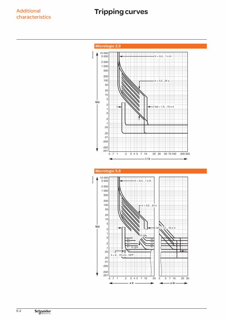
E-2
Micrologic 2.0
DB
1203
28
Micrologic 5.0
DB
1203
29
Additional characteristics
Tripping curves
BTP222E.indb 2 30/06/2009 09:32:50
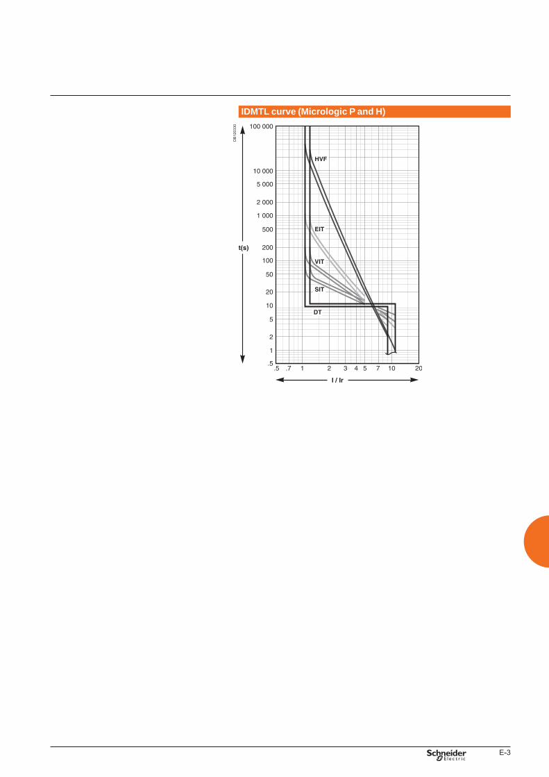
E-3
IDMTL curve (Micrologic P and H)
DB
1203
30
BTP222E.indb 3 30/06/2009 09:32:50
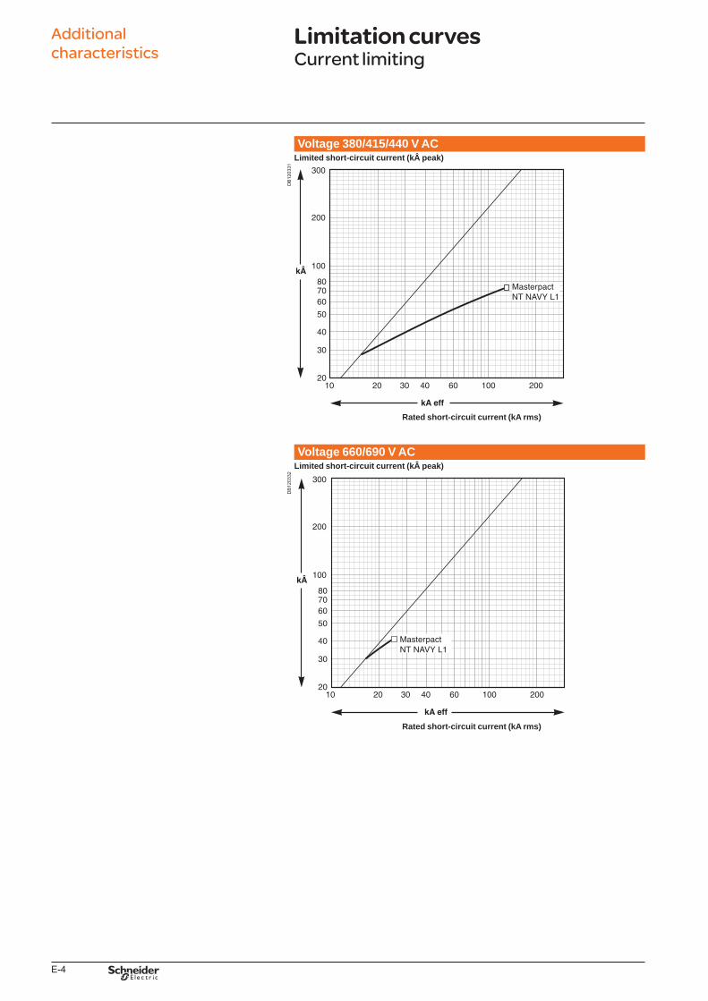
E-4
Voltage 380/415/440 V ACLimited short-circuit current (k peak)
DB
1203
31
Rated short-circuit current (kA rms)
Voltage 660/690 V ACLimited short-circuit current (k peak)
DB
1203
32
Rated short-circuit current (kA rms)
Additional characteristics
Limitation curvesCurrent limiting
BTP222E.indb 4 30/06/2009 09:32:51
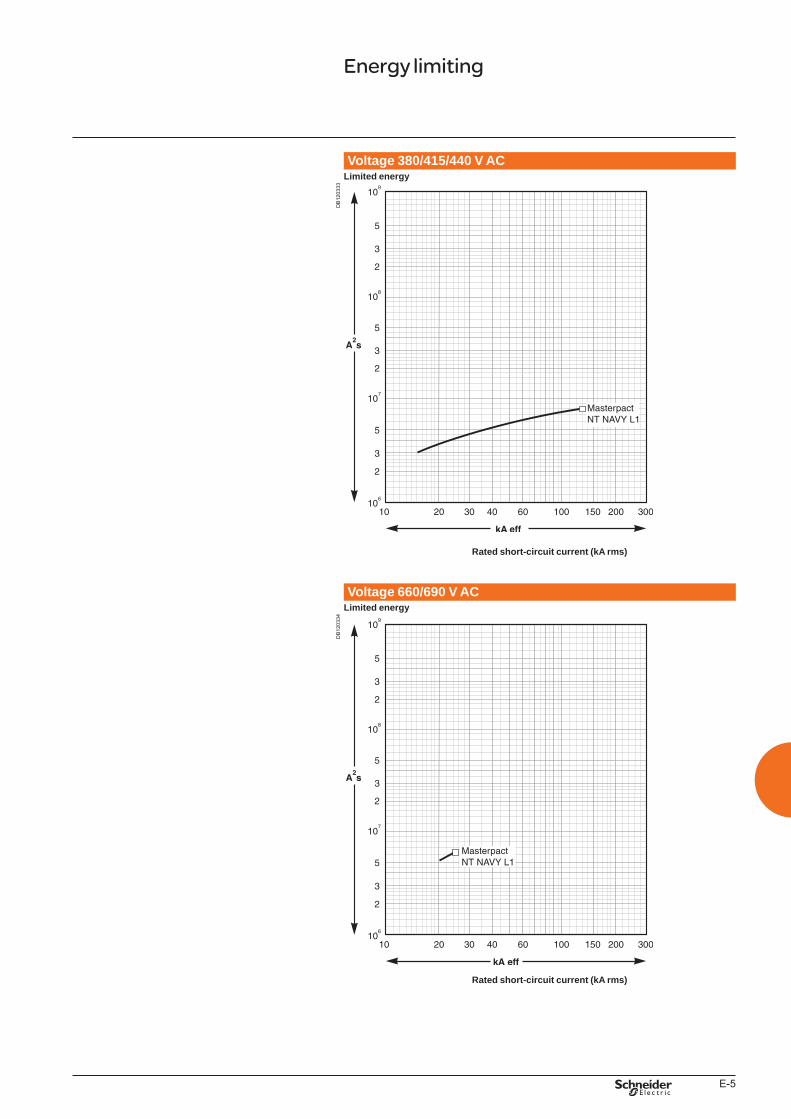
E-5
Voltage 380/415/440 V ACLimited energy
DB
1203
33
Rated short-circuit current (kA rms)
Voltage 660/690 V ACLimited energy
DB
1203
34
Rated short-circuit current (kA rms)
Energy limiting
BTP222E.indb 5 30/06/2009 09:32:51
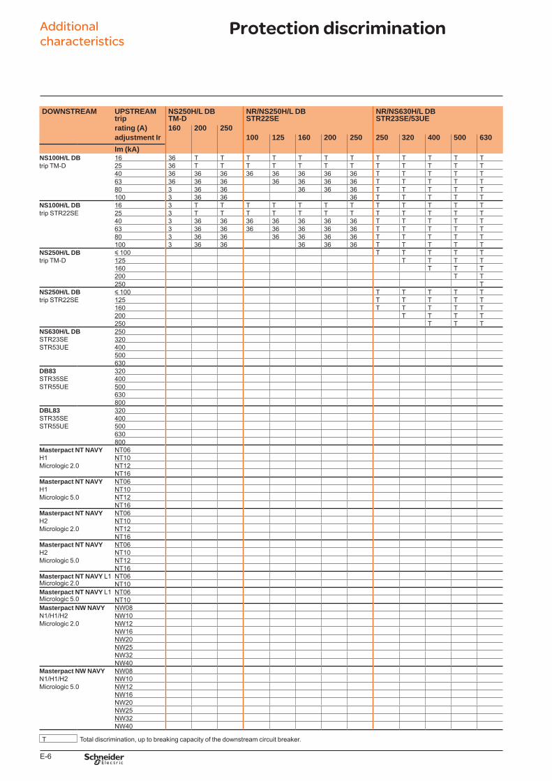
E-6
Additional characteristics
DOWNSTREAM UPSTREAM NS250H/L DB NR/NS250H/L DB NR/NS630H/L DBtrip TM-D STR22SE STR23SE/53UErating (A) 160 200 250adjustment Ir 100 125 160 200 250 250 320 400 500 630Im (kA)
NS100H/L DB 16 36 T T T T T T T T T T T Ttrip TM-D 25 36 T T T T T T T T T T T T
40 36 36 36 36 36 36 36 36 T T T T T63 36 36 36 36 36 36 36 T T T T T80 3 36 36 36 36 36 T T T T T100 3 36 36 36 T T T T T
NS100H/L DB 16 3 T T T T T T T T T T T Ttrip STR22SE 25 3 T T T T T T T T T T T T
40 3 36 36 36 36 36 36 36 T T T T T63 3 36 36 36 36 36 36 36 T T T T T80 3 36 36 36 36 36 36 T T T T T100 3 36 36 36 36 36 T T T T T
NS250H/L DB y 100 T T T T Ttrip TM-D 125 T T T T
160 T T T200 T T250 T
NS250H/L DB y 100 T T T T Ttrip STR22SE 125 T T T T T
160 T T T T T200 T T T T250 T T T
NS630H/L DB 250STR23SE 320STR53UE 400
500630
DB83 320STR35SE 400STR55UE 500
630800
DBL83 320STR35SE 400STR55UE 500
630800
Masterpact NT NAVY NT06H1 NT10Micrologic 2.0 NT12
NT16Masterpact NT NAVY NT06H1 NT10Micrologic 5.0 NT12
NT16Masterpact NT NAVY NT06H2 NT10Micrologic 2.0 NT12
NT16Masterpact NT NAVY NT06H2 NT10Micrologic 5.0 NT12
NT16Masterpact NT NAVY L1 NT06Micrologic 2.0 NT10Masterpact NT NAVY L1 NT06Micrologic 5.0 NT10Masterpact NW NAVY NW08N1/H1/H2 NW10Micrologic 2.0 NW12
NW16NW20NW25NW32NW40
Masterpact NW NAVY NW08N1/H1/H2 NW10Micrologic 5.0 NW12
NW16NW20NW25NW32NW40
T Total discrimination, up to breaking capacity of the downstream circuit breaker.
Protection discrimination
222E4200.indd 6 07/07/2009 08:33:55
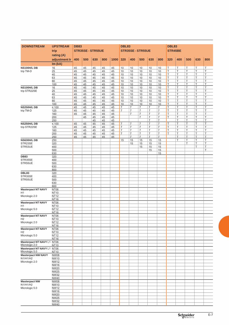
E-7
DOWNSTREAM UPSTREAM DB83 DBL83 DBL83trip STR35SE - STR55UE STR35SE - STR55UE STR45BErating (A)adjustment Ir 400 500 630 800 1000 320 400 500 630 800 320 400 500 630 800Im (kA)
NS100H/L DB 16 45 45 45 45 45 10 10 10 10 10 T T T T Ttrip TM-D 25 45 45 45 45 45 10 10 10 10 10 T T T T T
40 45 45 45 45 45 10 10 10 10 10 T T T T T63 45 45 45 45 45 10 10 10 10 10 T T T T T80 45 45 45 45 45 10 10 10 10 10 T T T T T100 45 45 45 45 45 10 10 10 10 10 T T T T T
NS100H/L DB 16 45 45 45 45 45 10 10 10 10 10 T T T T Ttrip STR22SE 25 45 45 45 45 45 10 10 10 10 10 T T T T T
40 45 45 45 45 45 10 10 10 10 10 T T T T T63 45 45 45 45 45 10 10 10 10 10 T T T T T80 45 45 45 45 45 10 10 10 10 10 T T T T T100 45 45 45 45 45 10 10 10 10 10 T T T T T
NS250H/L DB y 100 45 45 45 45 45 7 7 7 7 7 T T T T Ttrip TM-D 125 45 45 45 45 45 7 7 7 7 7 T T T T T
160 45 45 45 45 45 7 7 7 7 T T T T T200 45 45 45 45 7 7 7 T T T T T250 45 45 45 7 7 T T T T
NS250H/L DB y 100 45 45 45 45 45 7 7 7 7 7 T T T T Ttrip STR22SE 125 45 45 45 45 45 7 7 7 7 7 T T T T T
160 45 45 45 45 45 7 7 7 7 7 T T T T T200 45 45 45 45 45 7 7 7 7 7 T T T T T250 45 45 45 45 45 7 7 7 7 T T T T
NS630H/L DB 250 15 15 15 15 15 T T T TSTR23SE 320 15 15 15 15 T T TSTR53UE 400 15 15 15 T T
500 15 15 T630 15
DB83 320STR35SE 400STR55UE 500
630800
DBL83 320STR35SE 400STR55UE 500
630800
Masterpact NT NAVY NT06H1 NT10Micrologic 2.0 NT12
NT16Masterpact NT NAVY NT06H1 NT10Micrologic 5.0 NT12
NT16Masterpact NT NAVY NT06H2 NT10Micrologic 2.0 NT12
NT16Masterpact NT NAVY NT06H2 NT10Micrologic 5.0 NT12
NT16Masterpact NT NAVY L1 NT06Micrologic 2.0 NT10Masterpact NT NAVY L1 NT06Micrologic 5.0 NT10Masterpact NW NAVY NW08N1/H1/H2 NW10Micrologic 2.0 NW12
NW16NW20NW25NW32NW40
Masterpact NW NW08N1/H1/H2 NW10Micrologic 5.0 NW12
NW16NW20NW25NW32NW40
BTP222E.indb 7 30/06/2009 09:32:56
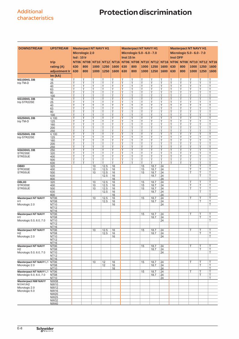
E-8
Additional characteristics
DOWNSTREAM UPSTREAM Masterpact NT NAVY H1 Masterpact NT NAVY H1 Masterpact NT NAVY H1Micrologic 2.0 Micrologic 5.0 - 6.0 - 7.0 Micrologic 5.0 - 6.0 - 7.0Isd : 10 Ir Inst 15 In Inst OFF
trip NT06 NT08 NT10 NT12 NT16 NT06 NT08 NT10 NT12 NT16 NT06 NT08 NT10 NT12 NT16rating (A) 630 800 1000 1250 1600 630 800 1000 1250 1600 630 800 1000 1250 1600adjustment Ir 630 800 1000 1250 1600 630 800 1000 1250 1600 630 800 1000 1250 1600Im (kA)
NS100H/L DB 16 T T T T T T T T T T T T T T Ttrip TM-D 25 T T T T T T T T T T T T T T T
40 T T T T T T T T T T T T T T T63 T T T T T T T T T T T T T T T80 T T T T T T T T T T T T T T T100 T T T T T T T T T T T T T T T
NS100H/L DB 16 T T T T T T T T T T T T T T Ttrip STR22SE 25 T T T T T T T T T T T T T T T
40 T T T T T T T T T T T T T T T63 T T T T T T T T T T T T T T T80 T T T T T T T T T T T T T T T100 T T T T T T T T T T T T T T T
NS250H/L DB y 100 T T T T T T T T T T T T T T Ttrip TM-D 125 T T T T T T T T T T T T T T T
160 T T T T T T T T T T T T T T T200 T T T T T T T T T T T T T T T250 T T T T T T T T T T T T T T T
NS250H/L DB y 100 T T T T T T T T T T T T T T Ttrip STR22SE 125 T T T T T T T T T T T T T T T
160 T T T T T T T T T T T T T T T200 T T T T T T T T T T T T T T T250 T T T T T T T T T T T T T T T
NS630H/L DB 250 T T T T T T T T T T T T T T TSTR23SE 320 T T T T T T T T T T T T T T TSTR53UE 400 T T T T T T T T T T T T T T T
500 T T T T T T T T T T T T T T T630 T T T T T T T T T T T T T T T
DB83 320 10 12.5 16 15 18.7 24 T T TSTR35SE 400 10 12.5 16 15 18.7 24 T T TSTR55UE 500 10 12.5 16 15 18.7 24 T T T
630 12.5 16 18.7 24 T T800 16 24 T
DBL83 320 10 12.5 16 15 18.7 24 T T TSTR35SE 400 10 12.5 16 15 18.7 24 T T TSTR55UE 500 10 12.5 16 15 18.7 24 T T T
630 12.5 16 18.7 24 T T800 16 24 T
Masterpact NT NAVY NT06 10 12.5 16 15 18.7 24 T T TH1Micrologic 2.0
NT08 12.5 16 18.7 24 T TNT10 16 24 TNT12NT16
Masterpact NT NAVY NT06 15 18.7 24 T T TH1Micrologic 5.0, 6.0, 7.0
NT08 18.7 24 T TNT10 24 TNT12NT16
Masterpact NT NAVY NT06 10 12.5 16 15 18.7 24 T T TH2Micrologic 2.0
NT08 12.5 16 18.7 24 T TNT10 16 24 TNT12NT16
Masterpact NT NAVY NT06 15 18.7 24 T T TH2Micrologic 5.0, 6.0, 7.0
NT08 18.7 24 T TNT10 24 TNT12NT16
Masterpact NT NAVY L1 NT06 10 12 16 15 18.7 24 T T TMicrologic 2.0 NT08 12 16 18.7 24 T T
NT10 16 24 TMasterpact NT NAVY L1 NT06 15 18.7 24 T T TMicrologic 5.0, 6.0, 7.0 NT08 18.7 24 T T
NT10 24 TMasterpact NW NAVY NW08N1/H1/H2Micrologic 2.0Micrologic 5.0
NW10NW12NW16NW20NW25NW32NW40
Protection discrimination
BTP222E.indb 8 30/06/2009 09:32:57
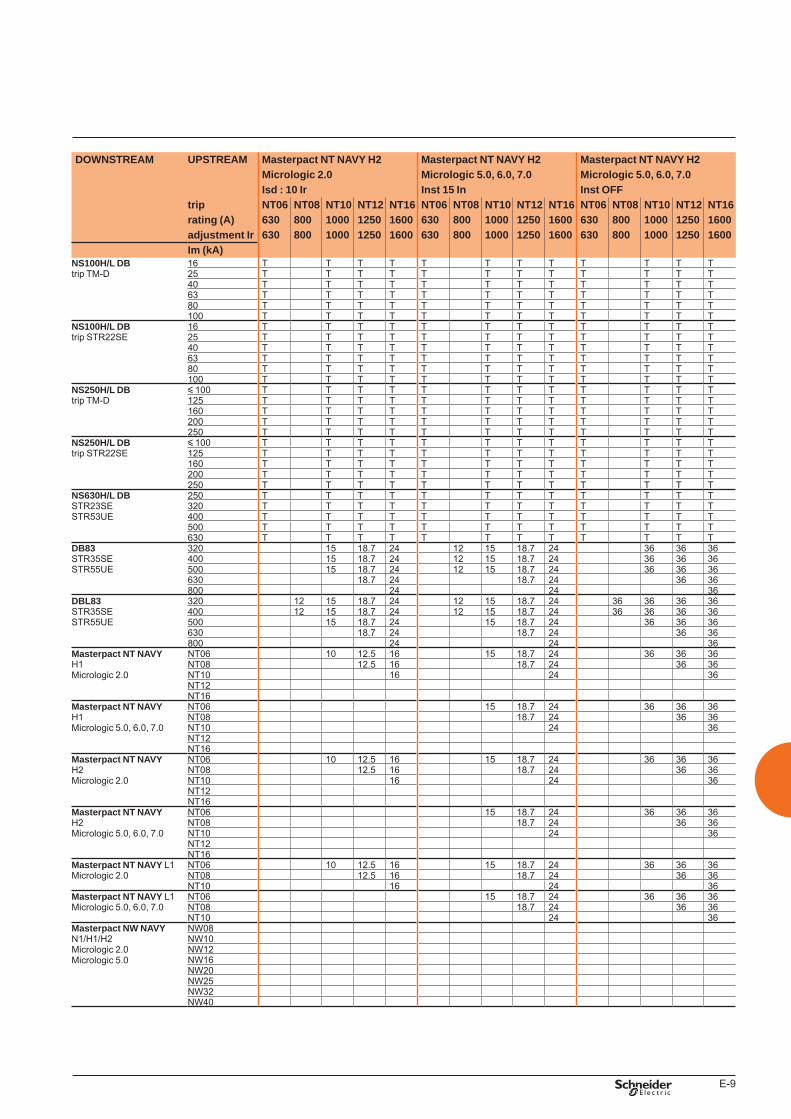
E-9
DOWNSTREAM UPSTREAM Masterpact NT NAVY H2 Masterpact NT NAVY H2 Masterpact NT NAVY H2Micrologic 2.0 Micrologic 5.0, 6.0, 7.0 Micrologic 5.0, 6.0, 7.0Isd : 10 Ir Inst 15 In Inst OFF
trip NT06 NT08 NT10 NT12 NT16 NT06 NT08 NT10 NT12 NT16 NT06 NT08 NT10 NT12 NT16rating (A) 630 800 1000 1250 1600 630 800 1000 1250 1600 630 800 1000 1250 1600adjustment Ir 630 800 1000 1250 1600 630 800 1000 1250 1600 630 800 1000 1250 1600Im (kA)
NS100H/L DB 16 T T T T T T T T T T T Ttrip TM-D 25 T T T T T T T T T T T T
40 T T T T T T T T T T T T63 T T T T T T T T T T T T80 T T T T T T T T T T T T100 T T T T T T T T T T T T
NS100H/L DB 16 T T T T T T T T T T T Ttrip STR22SE 25 T T T T T T T T T T T T
40 T T T T T T T T T T T T63 T T T T T T T T T T T T80 T T T T T T T T T T T T100 T T T T T T T T T T T T
NS250H/L DB y 100 T T T T T T T T T T T Ttrip TM-D 125 T T T T T T T T T T T T
160 T T T T T T T T T T T T200 T T T T T T T T T T T T250 T T T T T T T T T T T T
NS250H/L DB y 100 T T T T T T T T T T T Ttrip STR22SE 125 T T T T T T T T T T T T
160 T T T T T T T T T T T T200 T T T T T T T T T T T T250 T T T T T T T T T T T T
NS630H/L DB 250 T T T T T T T T T T T TSTR23SE 320 T T T T T T T T T T T TSTR53UE 400 T T T T T T T T T T T T
500 T T T T T T T T T T T T630 T T T T T T T T T T T T
DB83 320 15 18.7 24 12 15 18.7 24 36 36 36STR35SE 400 15 18.7 24 12 15 18.7 24 36 36 36STR55UE 500 15 18.7 24 12 15 18.7 24 36 36 36
630 18.7 24 18.7 24 36 36800 24 24 36
DBL83 320 12 15 18.7 24 12 15 18.7 24 36 36 36 36STR35SE 400 12 15 18.7 24 12 15 18.7 24 36 36 36 36STR55UE 500 15 18.7 24 15 18.7 24 36 36 36
630 18.7 24 18.7 24 36 36800 24 24 36
Masterpact NT NAVY NT06 10 12.5 16 15 18.7 24 36 36 36H1Micrologic 2.0
NT08 12.5 16 18.7 24 36 36NT10 16 24 36NT12NT16
Masterpact NT NAVY NT06 15 18.7 24 36 36 36H1Micrologic 5.0, 6.0, 7.0
NT08 18.7 24 36 36NT10 24 36NT12NT16
Masterpact NT NAVY NT06 10 12.5 16 15 18.7 24 36 36 36H2Micrologic 2.0
NT08 12.5 16 18.7 24 36 36NT10 16 24 36NT12NT16
Masterpact NT NAVY NT06 15 18.7 24 36 36 36H2Micrologic 5.0, 6.0, 7.0
NT08 18.7 24 36 36NT10 24 36NT12NT16
Masterpact NT NAVY L1 NT06 10 12.5 16 15 18.7 24 36 36 36Micrologic 2.0 NT08 12.5 16 18.7 24 36 36
NT10 16 24 36Masterpact NT NAVY L1 NT06 15 18.7 24 36 36 36Micrologic 5.0, 6.0, 7.0 NT08 18.7 24 36 36
NT10 24 36Masterpact NW NAVY NW08N1/H1/H2Micrologic 2.0Micrologic 5.0
NW10NW12NW16NW20NW25NW32NW40
BTP222E.indb 9 30/06/2009 09:32:59
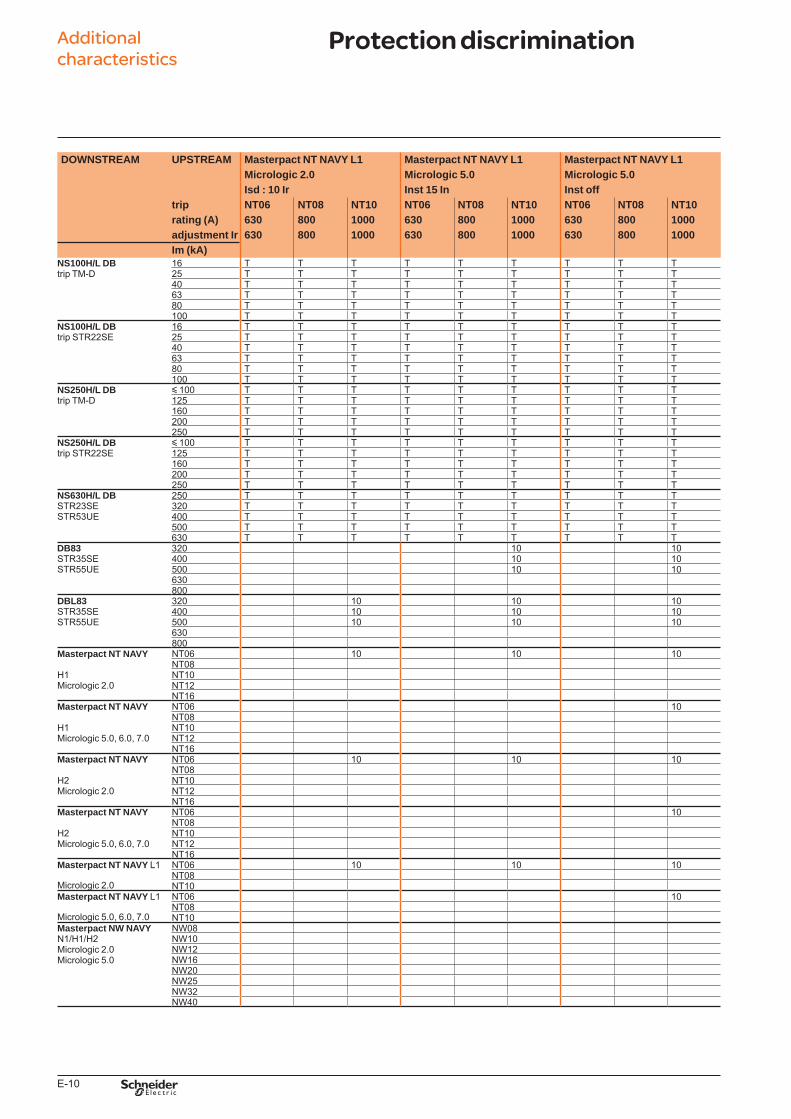
E-10
Additional characteristics
DOWNSTREAM UPSTREAM Masterpact NT NAVY L1 Masterpact NT NAVY L1 Masterpact NT NAVY L1Micrologic 2.0 Micrologic 5.0 Micrologic 5.0Isd : 10 Ir Inst 15 In Inst off
trip NT06 NT08 NT10 NT06 NT08 NT10 NT06 NT08 NT10rating (A) 630 800 1000 630 800 1000 630 800 1000adjustment Ir 630 800 1000 630 800 1000 630 800 1000Im (kA)
NS100H/L DB 16 T T T T T T T T Ttrip TM-D 25 T T T T T T T T T
40 T T T T T T T T T63 T T T T T T T T T80 T T T T T T T T T100 T T T T T T T T T
NS100H/L DB 16 T T T T T T T T Ttrip STR22SE 25 T T T T T T T T T
40 T T T T T T T T T63 T T T T T T T T T80 T T T T T T T T T100 T T T T T T T T T
NS250H/L DB y 100 T T T T T T T T Ttrip TM-D 125 T T T T T T T T T
160 T T T T T T T T T200 T T T T T T T T T250 T T T T T T T T T
NS250H/L DB y 100 T T T T T T T T Ttrip STR22SE 125 T T T T T T T T T
160 T T T T T T T T T200 T T T T T T T T T250 T T T T T T T T T
NS630H/L DB 250 T T T T T T T T TSTR23SE 320 T T T T T T T T TSTR53UE 400 T T T T T T T T T
500 T T T T T T T T T630 T T T T T T T T T
DB83 320 10 10STR35SE 400 10 10STR55UE 500 10 10
630800
DBL83 320 10 10 10STR35SE 400 10 10 10STR55UE 500 10 10 10
630800
Masterpact NT NAVY NT06 10 10 10NT08
H1 NT10Micrologic 2.0 NT12
NT16Masterpact NT NAVY NT06 10
NT08H1 NT10Micrologic 5.0, 6.0, 7.0 NT12
NT16Masterpact NT NAVY NT06 10 10 10
NT08H2 NT10Micrologic 2.0 NT12
NT16Masterpact NT NAVY NT06 10
NT08H2 NT10Micrologic 5.0, 6.0, 7.0 NT12
NT16Masterpact NT NAVY L1 NT06 10 10 10
NT08Micrologic 2.0 NT10Masterpact NT NAVY L1 NT06 10
NT08Micrologic 5.0, 6.0, 7.0 NT10Masterpact NW NAVY NW08N1/H1/H2Micrologic 2.0Micrologic 5.0
NW10NW12NW16NW20NW25NW32NW40
Protection discrimination
BTP222E.indb 10 30/06/2009 09:33:00
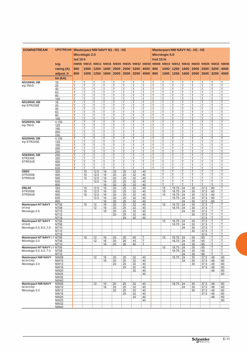
E-11
DOWNSTREAM UPSTREAM Masterpact NW NAVY N1 - H1 - H2 Masterpact NW NAVY N1 - H1 - H2Micrologic 2.0 Micrologic 5.0Isd 10 Ir Inst 15 In
trip NW08 NW10 NW12 NW16 NW20 NW25 NW32 NW40 NW08 NW10 NW12 NW16 NW20 NW25 NW32 NW40rating (A) 800 1000 1250 1600 2000 2500 3200 4000 800 1000 1250 1600 2000 2500 3200 4000adjust. Ir 800 1000 1250 1600 2000 2500 3200 4000 800 1000 1250 1600 2000 2500 3200 4000Im (kA)
NS100H/L DB 16 T T T T T T T T T T T T T T T Ttrip TM-D 25 T T T T T T T T T T T T T T T T
40 T T T T T T T T T T T T T T T T63 T T T T T T T T T T T T T T T T80 T T T T T T T T T T T T T T T T100 T T T T T T T T T T T T T T T T
NS100H/L DB 16 T T T T T T T T T T T T T T T Ttrip STR22SE 25 T T T T T T T T T T T T T T T T
40 T T T T T T T T T T T T T T T T63 T T T T T T T T T T T T T T T T80 T T T T T T T T T T T T T T T T100 T T T T T T T T T T T T T T T T
NS250H/L DB y 100 T T T T T T T T T T T T T T T Ttrip TM-D 125 T T T T T T T T T T T T T T T T
160 T T T T T T T T T T T T T T T T200 T T T T T T T T T T T T T T T T250 T T T T T T T T T T T T T T T T
NS250H/L DB y 100 T T T T T T T T T T T T T T T Ttrip STR22SE 125 T T T T T T T T T T T T T T T T
160 T T T T T T T T T T T T T T T T200 T T T T T T T T T T T T T T T T250 T T T T T T T T T T T T T T T T
NS630H/L DB 250 T T T T T T T T T T T T T T T TSTR23SE 320 T T T T T T T T T T T T T T T TSTR53UE 400 T T T T T T T T T T T T T T T T
500 T T T T T T T T T T T T T T T T630 T T T T T T T T T T T T T T T T
DB83 320 10 12.5 16 20 25 32 40 T T T T T T TSTR35SE 400 10 12.5 16 20 25 32 40 T T T T T T TSTR55UE 500 10 12.5 16 20 25 32 40 T T T T T T T
630 12.5 16 20 25 32 40 T T T T T T T800 16 20 25 32 40 T T T T T T T
DBL83 320 10 12.5 16 20 25 32 40 15 18.75 24 30 37.5 60 TSTR35SE 400 10 12.5 16 20 25 32 40 15 18.75 24 30 37.5 60 TSTR55UE 500 10 12.5 16 20 25 32 40 15 18.75 24 30 37.5 60 T
630 12.5 16 20 25 32 40 18.75 24 30 37.5 60 T800 16 20 25 32 40 24 30 37.5 60 T
Masterpact NT NAVY NT06 10 12 16 20 25 32 40 15 18.75 24 30 37.5 T TH1/H2Micrologic 2.0
NT08 12 16 20 25 32 40 18.75 24 30 37.5 T TNT10 16 20 25 32 40 24 30 37.5 T TNT12 20 25 32 40 30 37.5 T TNT16 25 32 40 37.5 T T
Masterpact NT NAVY NT06 15 18.75 24 30 37.5 T TH1/H2Micrologic 5.0, 6.0, 7.0
NT08 18.75 24 30 37.5 T TNT10 24 30 37.5 T TNT12 30 37.5 T TNT16 37.5 T T
Masterpact NT NAVY L1 NT06 10 12 16 20 26 45 T 15 18.75 24 35 65 T TMicrologic 2.0 NT08 12 16 20 26 45 T 18.75 24 35 65 T T
NT10 16 20 26 45 T 24 35 65 T TMasterpact NT NAVY L1 NT06 15 18.75 24 35 65 T TMicrologic 5.0, 6.0, 7.0 NT08 18.75 24 35 65 T T
NT10 24 35 65 T TMasterpact NW NAVY NW08 12 16 20 25 32 40 18.75 24 30 37.5 48 60N1/H1/H2 NW10 16 20 25 32 40 24 30 37.5 48 60Micrologic 2.0 NW12 20 25 32 40 30 37.5 48 60
NW16 25 32 40 37.5 48 60NW20 32 40 48 60NW25 40 60NW32NW40
Masterpact NW NAVY NW08 12 16 20 25 32 40 18.75 24 30 37.5 48 60N1/H1/H2 NW10 16 20 25 32 40 24 30 37.5 48 60Micrologic 5.0 NW12 20 25 32 40 30 37.5 48 60
NW16 25 32 40 37.5 48 60NW20 32 40 48 60NW25 40 60NW32NW40
BTP222E.indb 11 30/06/2009 09:33:02
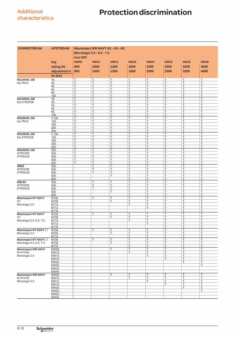
E-12
Additional characteristics
DOWNSTREAM UPSTREAM Masterpact NW NAVY N1 - H1 - H2Micrologic 5.0 - 6.0 - 7.0Inst OFF
trip NW08 NW10 NW12 NW16 NW20 NW25 NW32 NW40rating (A) 800 1000 1250 1600 2000 2500 3200 4000adjustment Ir 800 1000 1250 1600 2000 2500 3200 4000Im (kA)
NS100H/L DB 16 T T T T T T T Ttrip TM-D 25 T T T T T T T T
40 T T T T T T T T63 T T T T T T T T80 T T T T T T T T100 T T T T T T T T
NS100H/L DB 16 T T T T T T T Ttrip STR22SE 25 T T T T T T T T
40 T T T T T T T T63 T T T T T T T T80 T T T T T T T T100 T T T T T T T T
NS250H/L DB y 100 T T T T T T T Ttrip TM-D 125 T T T T T T T T
160 T T T T T T T T200 T T T T T T T T250 T T T T T T T T
NS250H/L DB y 100 T T T T T T T Ttrip STR22SE 125 T T T T T T T T
160 T T T T T T T T200 T T T T T T T T250 T T T T T T T T
NS630H/L DB 250 T T T T T T T TSTR23SE 320 T T T T T T T TSTR53UE 400 T T T T T T T T
500 T T T T T T T T630 T T T T T T T T
DB83 320 T T T T T T TSTR35SE 400 T T T T T T TSTR55UE 500 T T T T T T T
630 T T T T T T800 T T T T T
DBL83 320 T T T T T T TSTR35SE 400 T T T T T T TSTR55UE 500 T T T T T T T
630 T T T T T T800 T T T T T
Masterpact NT NAVY NT06 T T T T T T TH1Micrologic 2.0
NT08 T T T T T TNT10 T T T T TNT12 T T T TNT16 T T T
Masterpact NT NAVY NT06 T T T T T T TH1Micrologic 5.0, 6.0, 7.0
NT08 T T T T T TNT10 T T T T TNT12 T T T TNT16 T T T
Masterpact NT NAVY L1 NT06 T T T T T T TMicrologic 2.0 NT08 T T T T T T
NT10 T T T T TMasterpact NT NAVY L1 NT06 T T T T T T TMicrologic 5.0, 6.0, 7.0 NT08 T T T T T T
NT10 T T T T TMasterpact NW NAVY NW08 T T T T T TN1/H1/H2 NW10 T T T T TMicrologic 2.0 NW12 T T T T
NW16 T T TNW20 T TNW25 TNW32NW40
Masterpact NW NAVY NW08 T T T T T TN1/H1/H2 NW10 T T T T TMicrologic 5.0 NW12 T T T T
NW16 T T TNW20 T TNW25 TNW32NW40
Protection discrimination
BTP222E.indb 12 30/06/2009 09:33:03

E-13
BTP222E.indb 13 30/06/2009 09:33:03

schneider-electric.com CAD software and tools
This international site allows you to access all the Schneider Electric products in just 2 clicksvia comprehensive range data-sheets, with direct links to:
complete library: technical documents, catalogs, FAQs, brochures…
selection guides from the e-catalog.
product discovery sites andtheir Flash animations.You will also fi nd illustrated overviews, news to which you can subscribe, the list of country contacts…
p
p
p
The CAD software and tools enhance productivity and safety. They help you create your installations by simplifying product choice through easy browsing in the Schneider Electric offers.Last but not least, they optimise use of our products while also complying with standards and proper procedures.
TOOLS
BTP222E.indb 2 30/06/2009 09:33:05
F-1
Catalogue numbers and order form
Masterpact NT and NW NAVY
Presentation 1Functionsandcharacteristics A-1Installationrecommendations B-1Dimensionsandconnections C-1Electricaldiagrams D-1Additionalcharacteristics E-1
NT06 to NT16 Navy drawout circuit breakers F-3Circuit breakers F-3Connections F-4Chassis locking and accessories F-5Indication contacts F-6Remote operation F-7
Accessories for NT06 to NT16 Navy drawout circuit breakers F-8
NW08 to NW40 Navy drawout circuit breakers F-10Circuit breakers F-10Chassis and connections F-11Chassis locking and accessories F-12Chassis accessories F-13Indication contacts F-14Remote operation F-15
Accessories for NW08 to NW40 Navy drawout circuit breakers F-16
NW08 to NW40 Navy drawout circuit breakers F-18Switch-disconnectors F-18Connections F-19
Masterpact NT NAVY F-20Connection F-20Micrologic control unit, communication option, portable data acquisition F-21Remote operation F-22Chassis locking and accessories F-23Clusters F-24Circuit breaker locking and accessories F-25Indication contacts F-26
Masterpact NW NAVY F-27Connection F-27Micrologic control unit, communication option F-28Remote operation F-29Chassis locking and accessories F-30Clusters F-31Circuit breaker locking and accessories F-32Indication contacts F-33
Masterpact NT or NW NAVY F-34Circuit breakers and switch-disconnectors F-34
BTP222E.indb 1 30/06/2009 09:33:06

F-2
BTP222E.indb 2 30/06/2009 09:33:06
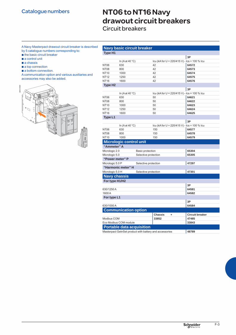
F-3
Navy basic circuit breakerType H1
3PIn (A at 40 °C) Icu (kA for U = 220/415 V) - Ics = 100 % Icu
NT06 630 42 64572NT08 800 42 64573NT10 1000 42 64574NT12 1250 42 64575NT16 1600 42 64576Type H2
3PIn (A at 40 °C) Icu (kA for U = 220/415 V) - Ics = 100 % Icu
NT06 630 50 64621NT08 800 50 64622NT10 1000 50 64623NT12 1250 50 64624NT16 1600 50 64625Type L1
3PIn (A at 40 °C) Icu (kA for U = 220/415 V) - Ics = 100 % Icu
NT06 630 150 64577NT08 800 150 64578NT10 1000 150 64579Micrologic control unit“Ammeter” A
Micrologic 2.0 Basic protection 65304Micrologic 5.0 Selective protection 65305“Power meter” P
Micrologic 5.0 P Selective protection 47297“Harmonic meter” H
Micrologic 5.0 H Selective protection 47301Navy chassisFor type H1/H2
3P630/1250 A 645811600 A 64582For type L1
3P630/1000 A 64584Communication option
Chassis + Circuit breakerModbus COM 33852 47485Eco Modbus COM module 33843Portable data acquisition
Masterpact GetnSet product with battery and accessories 48789
NT06 to NT16 Navy drawout circuit breakersCircuit breakers
A Navy Masterpact drawout circuit breaker is described by 5 catalogue numbers corresponding to: b the basic circuit breaker b a control unit b a chassis b a top connection b a bottom connection. A communication option and various auxiliaries and accessories may also be added.
DB
1019
09
Catalogue numbers
BTP222E.indb 3 30/06/2009 09:33:08
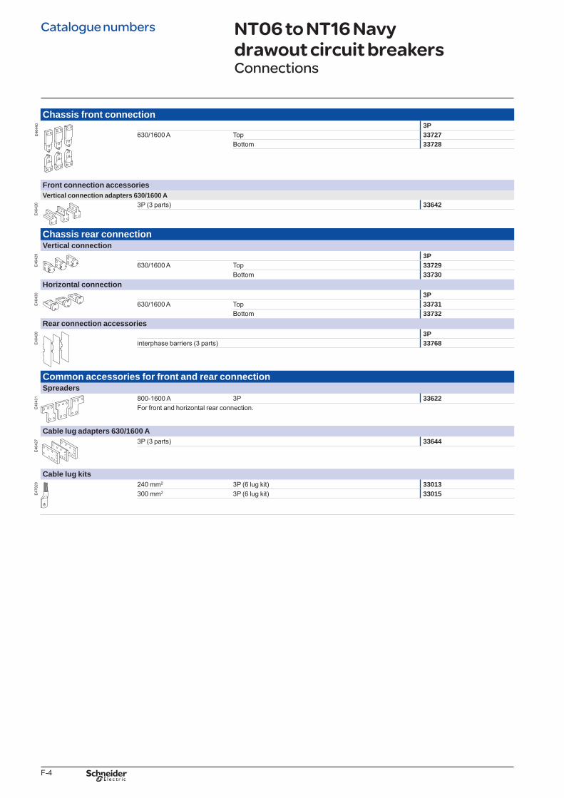
F-4
Chassis front connection
E46
440 3P
630/1600 A Top 33727Bottom 33728
Front connection accessoriesVertical connection adapters 630/1600 A
E46
426 3P (3 parts) 33642
Chassis rear connectionVertical connection
E46
429 3P
630/1600 A Top 33729Bottom 33730
Horizontal connection
E46
430 3P
630/1600 A Top 33731Bottom 33732
Rear connection accessories
E46
428 3P
interphase barriers (3 parts) 33768
Common accessories for front and rear connectionSpreaders
E46
431 800-1600 A 3P 33622
For front and horizontal rear connection.
Cable lug adapters 630/1600 A
E46
427 3P (3 parts) 33644
Cable lug kits
E47
820 240 mm2 3P (6 lug kit) 33013
300 mm2 3P (6 lug kit) 33015
NT06 to NT16 Navy drawout circuit breakers Connections
Catalogue numbers
BTP222E.indb 4 30/06/2009 09:33:09
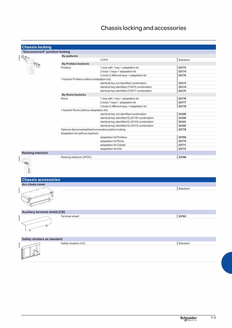
F-5
Chassis locking“Disconnected” position locking
E46
685 By padlocks
VCPO StandardBy Profalux keylocks
Profalux 1 lock with 1 key + adaptation kit 337732 locks 1 keys + adaptation kit 337742 locks 2 different keys + adaptation kit 33775
1 keylock Profalux (without adaptation kit):identical key not identified combination 33173identical key identified 215470 combination 33174identical key identified 215471 combination 33175
By Ronis keylocksRonis 1 lock with 1 key + adaptation kit 33776
2 locks 1 keys + adaptation kit 337772 locks 2 different keys + adaptation kit 33778
1 keylock Ronis (without adaptation kit):identical key not identified combination 33189identical key identified EL24135 combination 33190identical key identified EL24153 combination 33191identical key identified EL24315 combination 33192
Optional disconnected/test/connected position locking 33779Adaptation kit (without keylock):
adaptation kit Profalux 33769adaptation kit Ronis 33770adaptation kit Castell 33771adaptation kit Kirk 33772
Racking interlock
E46
465 Racking interlock (VPOC) 33788
Chassis accessoriesArc chute cover
E46
700 Standard
Auxiliary terminal shield (CB)
E46
698 Terminal shield 33763
Safety shutters as standard
E46
699 Safety shutters (VO) Standard
Chassis locking and accessories
BTP222E.indb 5 30/06/2009 09:33:11
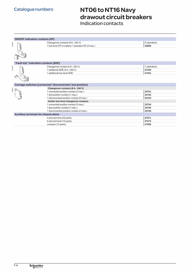
F-6
ON/OFF indication contacts (OF)
E46
467 Changeover contacts (6 A - 240 V) 4 (standard)
1 low-level OF to replace 1 standard OF (4 max.) 33806
“Fault trip” indication contacts (SDE)
E47
759 Changeover contact (5 A - 240 V) 1 (standard)
1 additional SDE (5 A - 240 V) 474301 additional low-level SDE 47431
Carriage switches (connected / disconnected / test position)
E46
661 Changeover contacts (6 A - 240 V)
1 connected position contact (3 max.) 337511 test position contact (1 max.) 337521 disconnected position contact (2 max.) 33753And/or low-level changeover contacts
1 connected position contact (3 max.) 337541 test position contact (1 max.) 337551 disconnected position contact (2 max.) 33756
Auxiliary terminals for chassis alone3 wire terminal (30 parts) 470716 wire terminal (10 parts) 47072Jumpers (10 parts) 47900
NT06 to NT16 Navy drawout circuit breakers Indication contacts
Catalogue numbers
BTP222E.indb 6 30/06/2009 09:33:11
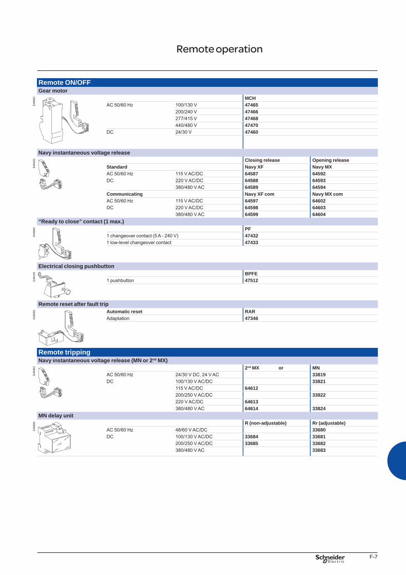
F-7
Remote ON/OFFGear motor
E46
662 MCH
AC 50/60 Hz 100/130 V 47465200/240 V 47466277/415 V 47468440/480 V 47470
DC 24/30 V 47460
Navy instantaneous voltage release
E46
463 Closing release Opening release
Standard Navy XF Navy MXAC 50/60 Hz 115 V AC/DC 64587 64592DC 220 V AC/DC 64588 64593
380/480 V AC 64589 64594Communicating Navy XF com Navy MX comAC 50/60 Hz 115 V AC/DC 64597 64602DC 220 V AC/DC 64598 64603
380/480 V AC 64599 64604“Ready to close” contact (1 max.)
E46
664 PF
1 changeover contact (5 A - 240 V) 474321 low-level changeover contact 47433
Electrical closing pushbutton
E46
439 BPFE
1 pushbutton 47512
Remote reset after fault trip
E46
660 Automatic reset RAR
Adaptation 47346
Remote trippingNavy instantaneous voltage release (MN or 2nd MX)
E46
463 2nd MX or MN
AC 50/60 Hz 24/30 V DC, 24 V AC 33819DC 100/130 V AC/DC 33821
115 V AC/DC 64612200/250 V AC/DC 33822220 V AC/DC 64613380/480 V AC 64614 33824
MN delay unit
E46
694 R (non-adjustable) Rr (adjustable)
AC 50/60 Hz 48/60 V AC/DC 33680DC 100/130 V AC/DC 33684 33681
200/250 V AC/DC 33685 33682380/480 V AC 33683
Remote operation
BTP222E.indb 7 30/06/2009 09:33:13
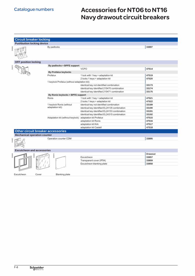
F-8
Circuit breaker lockingPushbutton locking device
E46
666 By padlocks 33897
OFF position locking
E46
701 By padlocks + BPFE support
VCPO 47514By Profalux keylocks
Profalux 1 lock with 1 key + adaptation kit 475192 locks 1 keys + adaptation kit 47520
1 keylock Profalux (without adaptation kit):identical key not identified combination 33173identical key identified 215470 combination 33174identical key identified 215471 combination 33175
By Ronis keylocks + BPFE supportRonis 1 lock with 1 key + adaptation kit 47521
2 locks 1 keys + adaptation kit 475221 keylock Ronis (without adaptation kit):
identical key not identified combination 33189identical key identified EL24135 combination 33190identical key identified EL24153 combination 33191identical key identified EL24315 combination 33192
Adaptation kit (without keylock): adaptation kit Profalux 47515adaptation kit Ronis 47516adaptation kit Kirk 47517adaptation kit Castell 47518
Other circuit breaker accessoriesMechanical operation counter
E46
667 Operation counter CDM 33895
Escutcheon and accessories
E46
668 Drawout
Escutcheon 33857Transparent cover (IP54) 33859Escutcheon blanking plate 33858
Escutcheon Cover Blanking plate
Accessories for NT06 to NT16 Navy drawout circuit breakers
E46
670
E46
669
Catalogue numbers
BTP222E.indb 8 30/06/2009 09:33:14
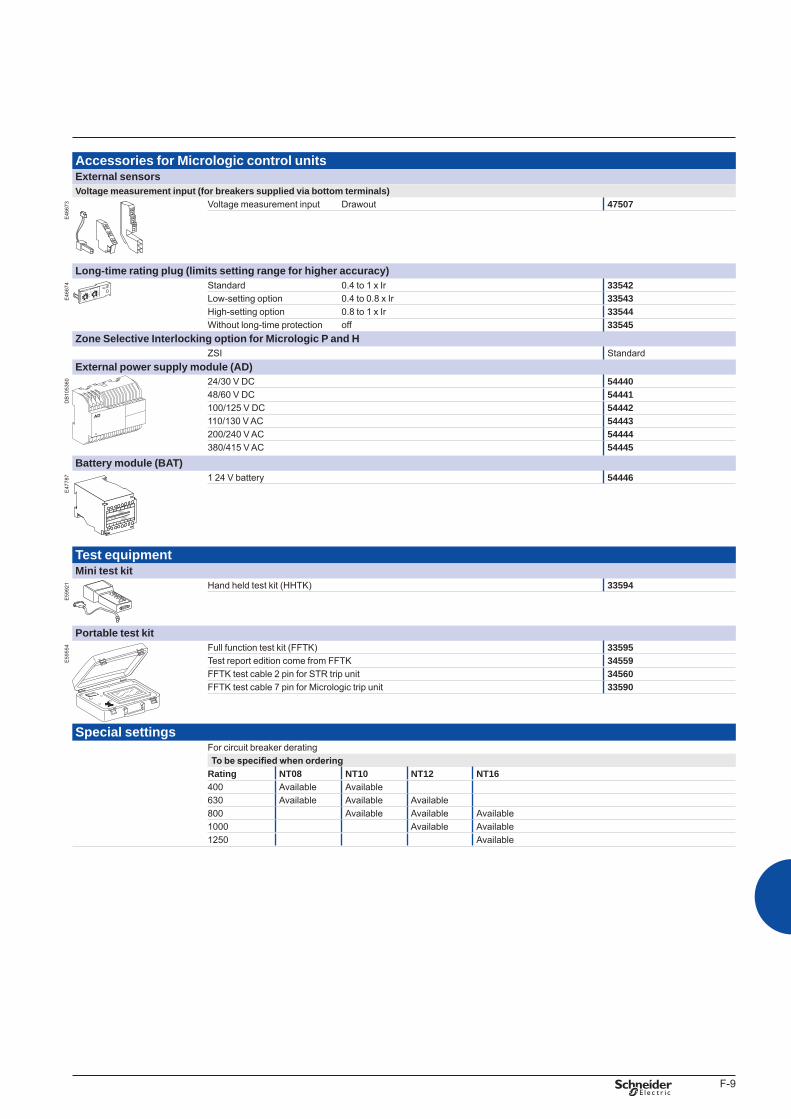
F-9
Accessories for Micrologic control unitsExternal sensorsVoltage measurement input (for breakers supplied via bottom terminals)
E46
673 Voltage measurement input Drawout 47507
Long-time rating plug (limits setting range for higher accuracy)
E46
674 Standard 0.4 to 1 x Ir 33542
Low-setting option 0.4 to 0.8 x Ir 33543High-setting option 0.8 to 1 x Ir 33544Without long-time protection off 33545
Zone Selective Interlocking option for Micrologic P and HZSI Standard
External power supply module (AD)
DB
1053
60 24/30 V DC 5444048/60 V DC 54441100/125 V DC 54442110/130 V AC 54443200/240 V AC 54444380/415 V AC 54445
Battery module (BAT)
E47
787 1 24 V battery 54446
Test equipmentMini test kit
E59
921 Hand held test kit (HHTK) 33594
Portable test kit
E59
554 Full function test kit (FFTK) 33595
Test report edition come from FFTK 34559FFTK test cable 2 pin for STR trip unit 34560FFTK test cable 7 pin for Micrologic trip unit 33590
Special settingsFor circuit breaker deratingTo be specified when ordering
Rating NT08 NT10 NT12 NT16400 Available Available630 Available Available Available800 Available Available Available1000 Available Available1250 Available
L3
G1
AD 220A
L4
G2
Input
24VDC
Output
24VDC
BTP222E.indb 9 30/06/2009 09:33:16
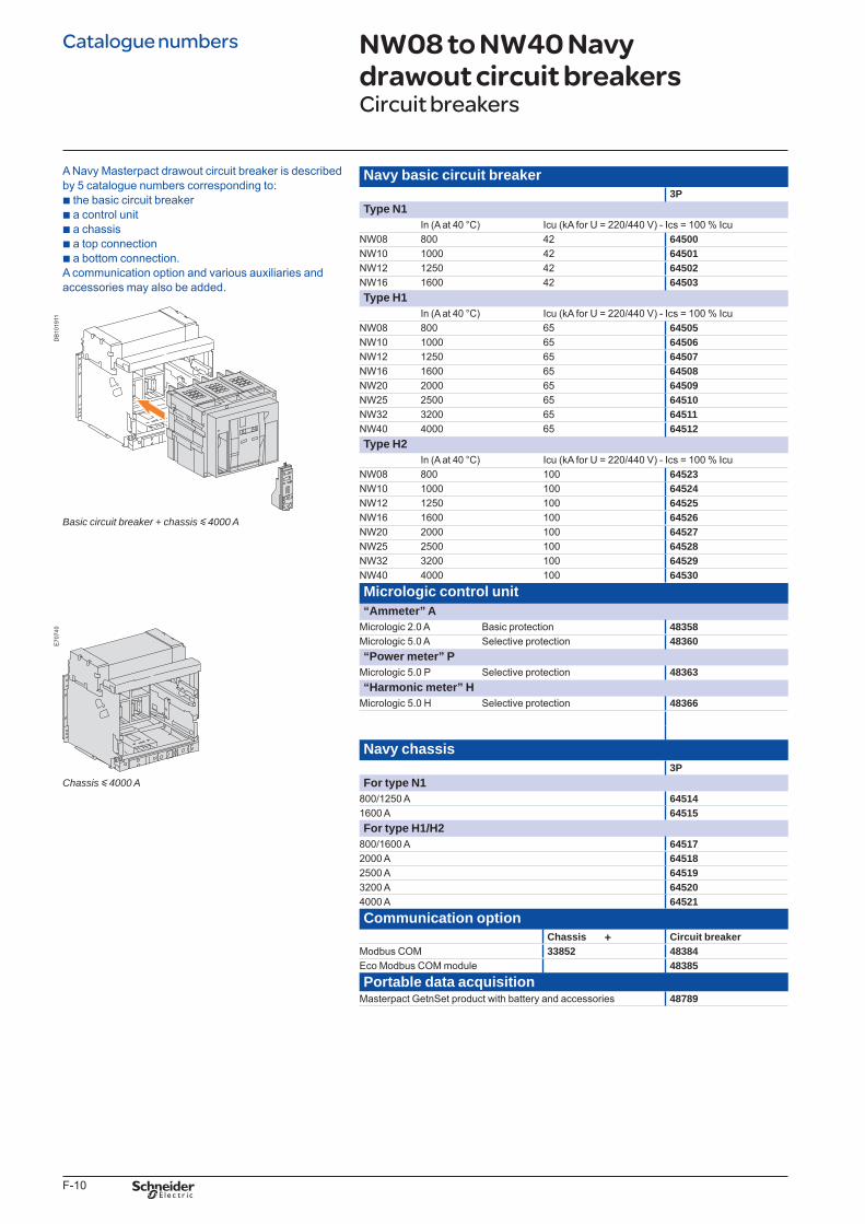
F-10
Navy basic circuit breaker3P
Type N1In (A at 40 °C) Icu (kA for U = 220/440 V) - Ics = 100 % Icu
NW08 800 42 64500NW10 1000 42 64501NW12 1250 42 64502NW16 1600 42 64503Type H1
In (A at 40 °C) Icu (kA for U = 220/440 V) - Ics = 100 % IcuNW08 800 65 64505NW10 1000 65 64506NW12 1250 65 64507NW16 1600 65 64508NW20 2000 65 64509NW25 2500 65 64510NW32 3200 65 64511NW40 4000 65 64512Type H2
In (A at 40 °C) Icu (kA for U = 220/440 V) - Ics = 100 % IcuNW08 800 100 64523NW10 1000 100 64524NW12 1250 100 64525NW16 1600 100 64526NW20 2000 100 64527NW25 2500 100 64528NW32 3200 100 64529NW40 4000 100 64530Micrologic control unit“Ammeter” A
Micrologic 2.0 A Basic protection 48358Micrologic 5.0 A Selective protection 48360“Power meter” P
Micrologic 5.0 P Selective protection 48363“Harmonic meter” H
Micrologic 5.0 H Selective protection 48366
Navy chassis3P
For type N1800/1250 A 645141600 A 64515For type H1/H2
800/1600 A 645172000 A 645182500 A 645193200 A 645204000 A 64521Communication option
Chassis + Circuit breakerModbus COM 33852 48384Eco Modbus COM module 48385Portable data acquisition
Masterpact GetnSet product with battery and accessories 48789
NW08 to NW40 Navy drawout circuit breakersCircuit breakers
A Navy Masterpact drawout circuit breaker is described by 5 catalogue numbers corresponding to: b the basic circuit breaker b a control unit b a chassis b a top connection b a bottom connection. A communication option and various auxiliaries and accessories may also be added.
DB
1019
11
Basiccircuitbreaker+chassisy4000A
E70
740
Chassisy4000A
Catalogue numbers
BTP222E.indb 10 30/06/2009 09:33:16
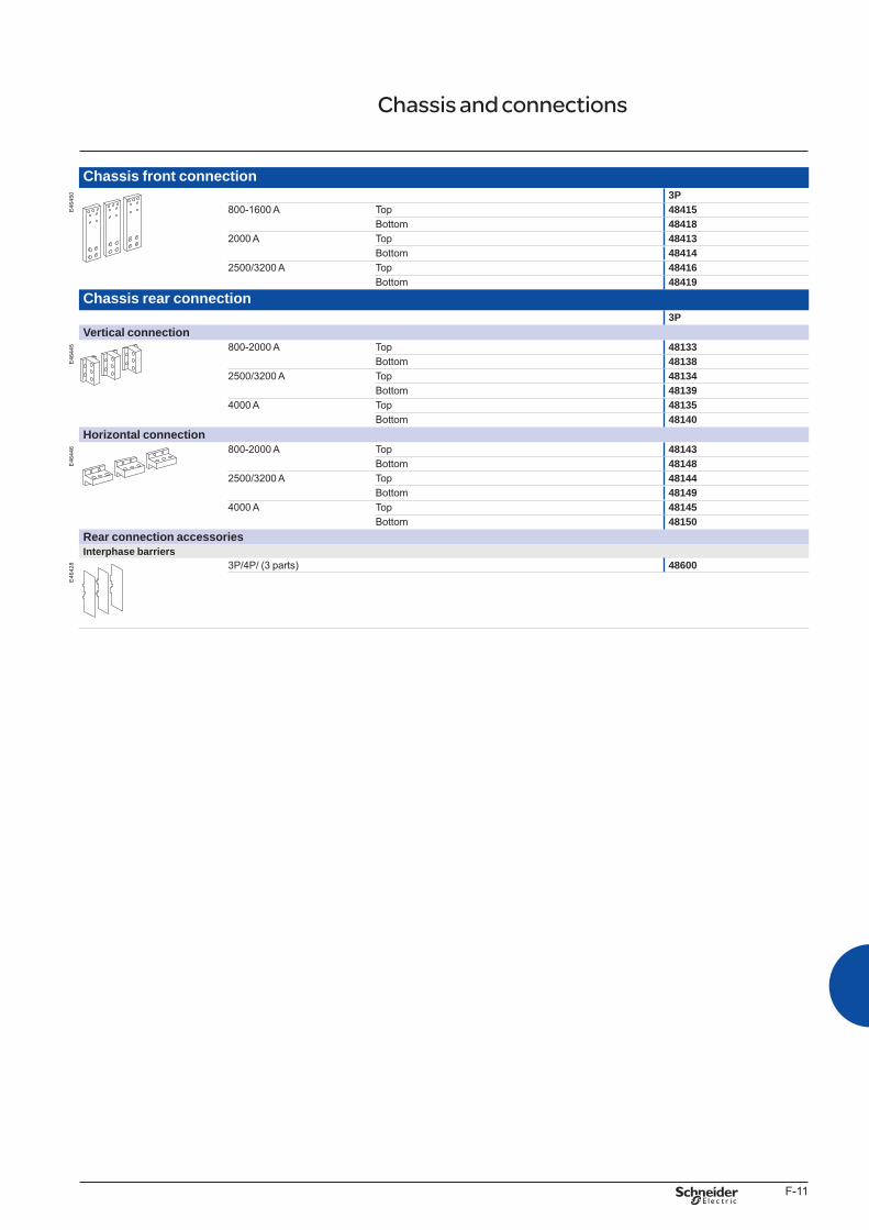
F-11
Chassis front connection
E46
450 3P
800-1600 A Top 48415Bottom 48418
2000 A Top 48413Bottom 48414
2500/3200 A Top 48416Bottom 48419
Chassis rear connection3P
Vertical connection
E46
445 800-2000 A Top 48133
Bottom 481382500/3200 A Top 48134
Bottom 481394000 A Top 48135
Bottom 48140Horizontal connection
E46
446 800-2000 A Top 48143
Bottom 481482500/3200 A Top 48144
Bottom 481494000 A Top 48145
Bottom 48150Rear connection accessoriesInterphase barriers
E46
428 3P/4P/ (3 parts) 48600
Chassis and connections
BTP222E.indb 11 30/06/2009 09:33:17
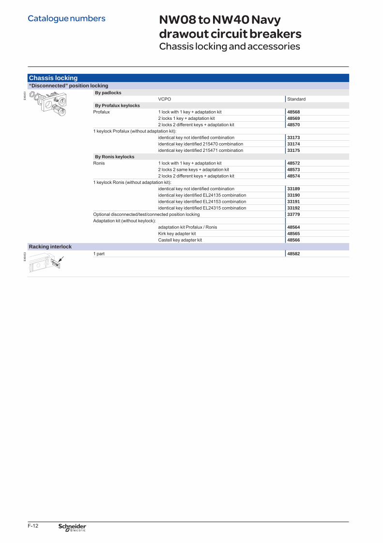
F-12
Chassis locking“Disconnected” position locking
E46
451 By padlocks
VCPO StandardBy Profalux keylocks
Profalux 1 lock with 1 key + adaptation kit 485682 locks 1 key + adaptation kit 485692 locks 2 different keys + adaptation kit 48570
1 keylock Profalux (without adaptation kit):identical key not identified combination 33173identical key identified 215470 combination 33174identical key identified 215471 combination 33175
By Ronis keylocksRonis 1 lock with 1 key + adaptation kit 48572
2 locks 2 same keys + adaptation kit 485732 locks 2 different keys + adaptation kit 48574
1 keylock Ronis (without adaptation kit):identical key not identified combination 33189identical key identified EL24135 combination 33190identical key identified EL24153 combination 33191identical key identified EL24315 combination 33192
Optional disconnected/test/connected position locking 33779Adaptation kit (without keylock):
adaptation kit Profalux / Ronis 48564Kirk key adapter kit 48565Castell key adapter kit 48566
Racking interlock
E46
453 1 part 48582
NW08 to NW40 Navy drawout circuit breakersChassis locking and accessories
Catalogue numbers
BTP222E.indb 12 30/06/2009 09:33:18
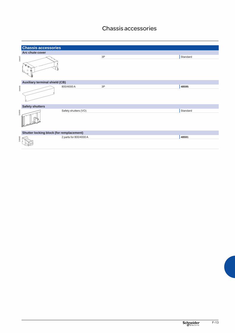
F-13
Chassis accessoriesArc chute cover
E46
457 3P Standard
Auxiliary terminal shield (CB)
E46
458 800/4000 A 3P 48595
Safety shutters
E46
699 Safety shutters (VO) Standard
Shutter locking block (for remplacement)
E46
460 2 parts for 800/4000 A 48591
Chassis accessories
BTP222E.indb 13 30/06/2009 09:33:18

F-14
ON/OFF indication contacts (OF)
E46
689 Navy block of 4 changeover contacts (6 A - 240 V) 1 block (standard)
1 additional Navy block of 4 contacts (1 max.) 64556
Combined closed / connected contacts for use with 1 auxiliary contact
E46
690 1 contact (5 A - 240 V) (8 max.) 48477
or 1 low-level contact (8 max.) 48478
“Fault trip” indication contacts (SDE)
E46
691 Changeover contact (5 A - 240 V) 1 (standard)
1 additional SDE (5 A - 240 V) 48475or 1 additional low-level SDE 48476
Carriage switches (connected / disconnected / test position)
E46
661 Changeover contacts (6 A - 240 V)
1 connected position contact (3 max.) 337511 test position contact (3 max.) 337521 disconnected position contact (3 max.) 33753and/or low-level changeover contacts
1 connected position contact (3 max.) 337541 test position contact (3 max.) 337551 disconnected position contact (3 max.) 33756Actuator for additional carriage switches 48560
Auxiliary terminals for chassis alone3 wire terminal (30 parts) 478986 wire terminal (10 parts) 47899Jumpers (10 parts) 47900
NW08 to NW40 Navy drawout circuit breakers Indication contacts
Catalogue numbers
BTP222E.indb 14 30/06/2009 09:33:19
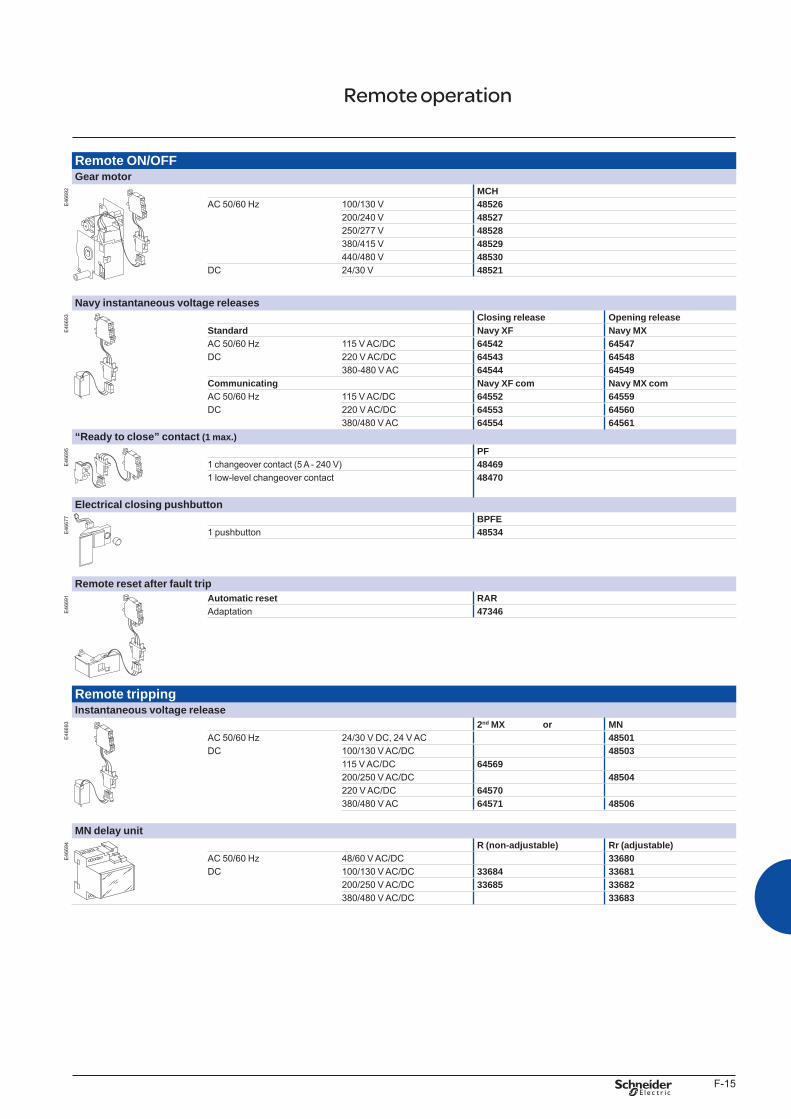
F-15
Remote ON/OFFGear motor
E46
692 MCH
AC 50/60 Hz 100/130 V 48526200/240 V 48527250/277 V 48528380/415 V 48529440/480 V 48530
DC 24/30 V 48521
Navy instantaneous voltage releases
E46
693 Closing release Opening release
Standard Navy XF Navy MXAC 50/60 Hz 115 V AC/DC 64542 64547DC 220 V AC/DC 64543 64548
380-480 V AC 64544 64549Communicating Navy XF com Navy MX comAC 50/60 Hz 115 V AC/DC 64552 64559DC 220 V AC/DC 64553 64560
380/480 V AC 64554 64561“Ready to close” contact (1 max.)
E46
695 PF
1 changeover contact (5 A - 240 V) 484691 low-level changeover contact 48470
Electrical closing pushbutton
E46
677 BPFE
1 pushbutton 48534
Remote reset after fault trip
E46
691 Automatic reset RAR
Adaptation 47346
Remote trippingInstantaneous voltage release
E46
693 2nd MX or MN
AC 50/60 Hz 24/30 V DC, 24 V AC 48501DC 100/130 V AC/DC 48503
115 V AC/DC 64569200/250 V AC/DC 48504220 V AC/DC 64570380/480 V AC 64571 48506
MN delay unit
E46
694 R (non-adjustable) Rr (adjustable)
AC 50/60 Hz 48/60 V AC/DC 33680DC 100/130 V AC/DC 33684 33681
200/250 V AC/DC 33685 33682380/480 V AC/DC 33683
Remote operation
BTP222E.indb 15 30/06/2009 09:33:20
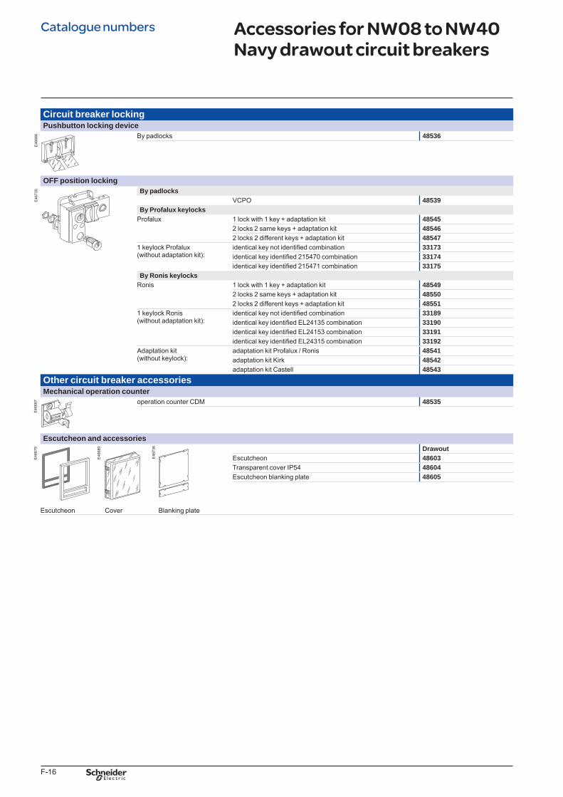
F-16
Circuit breaker locking Pushbutton locking device
E46
666 By padlocks 48536
OFF position locking
E46
735 By padlocks
VCPO 48539By Profalux keylocks
Profalux 1 lock with 1 key + adaptation kit 485452 locks 2 same keys + adaptation kit 485462 locks 2 different keys + adaptation kit 48547
1 keylock Profalux (without adaptation kit):
identical key not identified combination 33173identical key identified 215470 combination 33174identical key identified 215471 combination 33175
By Ronis keylocksRonis 1 lock with 1 key + adaptation kit 48549
2 locks 2 same keys + adaptation kit 485502 locks 2 different keys + adaptation kit 48551
1 keylock Ronis (without adaptation kit):
identical key not identified combination 33189identical key identified EL24135 combination 33190identical key identified EL24153 combination 33191identical key identified EL24315 combination 33192
Adaptation kit (without keylock):
adaptation kit Profalux / Ronis 48541adaptation kit Kirk 48542adaptation kit Castell 48543
Other circuit breaker accessoriesMechanical operation counter
E46
667 operation counter CDM 48535
Escutcheon and accessories
E46
679 Drawout
Escutcheon 48603Transparent cover IP54 48604Escutcheon blanking plate 48605
Escutcheon Cover Blanking plate
Accessories for NW08 to NW40 Navy drawout circuit breakers
E46
680
E46
736
Catalogue numbers
BTP222E.indb 16 30/06/2009 09:33:21
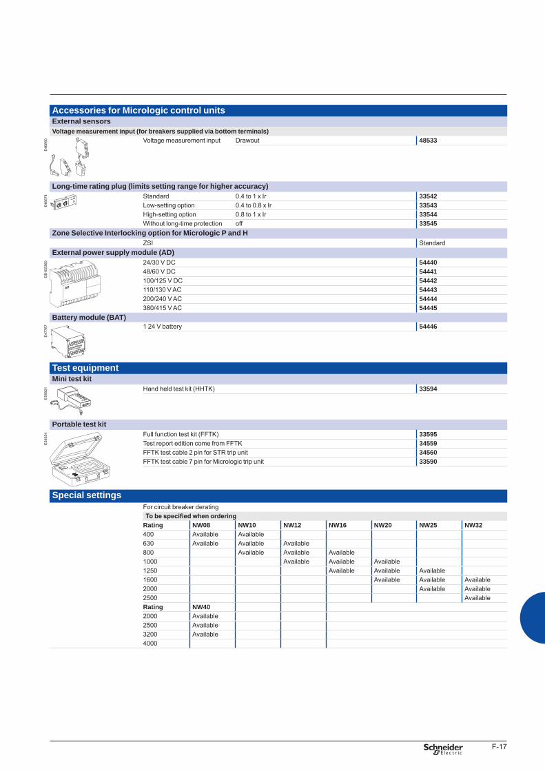
F-17
Accessories for Micrologic control unitsExternal sensorsVoltage measurement input (for breakers supplied via bottom terminals)
E46
890 Voltage measurement input Drawout 48533
Long-time rating plug (limits setting range for higher accuracy)
E46
674 Standard 0.4 to 1 x Ir 33542
Low-setting option 0.4 to 0.8 x Ir 33543High-setting option 0.8 to 1 x Ir 33544Without long-time protection off 33545
Zone Selective Interlocking option for Micrologic P and HZSI Standard
External power supply module (AD)
DB
1053
60 24/30 V DC 5444048/60 V DC 54441100/125 V DC 54442110/130 V AC 54443200/240 V AC 54444380/415 V AC 54445
Battery module (BAT)
E47
787 1 24 V battery 54446
Test equipmentMini test kit
E59
921 Hand held test kit (HHTK) 33594
Portable test kit
E59
554 Full function test kit (FFTK) 33595
Test report edition come from FFTK 34559FFTK test cable 2 pin for STR trip unit 34560FFTK test cable 7 pin for Micrologic trip unit 33590
Special settingsFor circuit breaker deratingTo be specified when ordering
Rating NW08 NW10 NW12 NW16 NW20 NW25 NW32400 Available Available630 Available Available Available800 Available Available Available1000 Available Available Available1250 Available Available Available1600 Available Available Available2000 Available Available2500 AvailableRating NW402000 Available2500 Available3200 Available4000
L3
G1
AD 220A
L4
G2
Input
24VDC
Output
24VDC
BTP222E.indb 17 30/06/2009 09:33:22
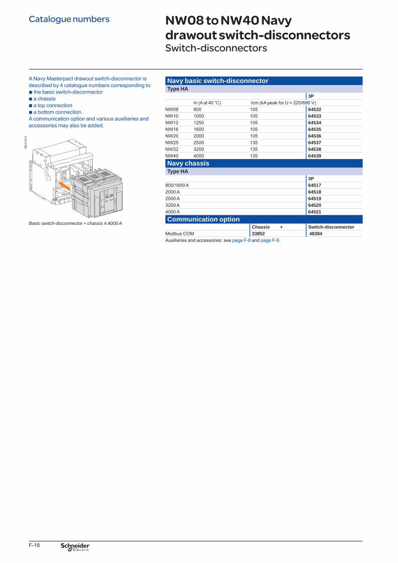
F-18
Navy basic switch-disconnectorType HA
3PIn (A at 40 °C) Icm (kA peak for U = 220/690 V)
NW08 800 105 64532NW10 1000 105 64533NW12 1250 105 64534NW16 1600 105 64535NW20 2000 105 64536NW25 2500 135 64537NW32 3200 135 64538NW40 4000 135 64539Navy chassisType HA
3P800/1600 A 645172000 A 645182500 A 645193200 A 645204000 A 64521Communication option
Chassis + Switch-disconnectorModbus COM 33852 48384Auxiliaries and accessories: see page F-8 and page F-9.
NW08 to NW40 Navy drawout switch-disconnectorsSwitch-disconnectors
A Navy Masterpact drawout switch-disconnector is described by 4 catalogue numbers corresponding to: b the basic switch-disconnector b a chassis b a top connection b a bottom connection. A communication option and various auxiliaries and accessories may also be added.
DB
1019
13
Basicswitch-disconnector+chassisy4000A
Catalogue numbers
BTP222E.indb 18 30/06/2009 09:33:22
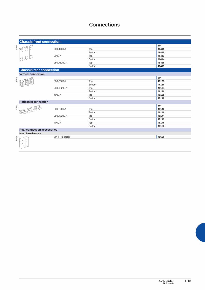
F-19
Chassis front connection
E46
450 3P
800-1600 A Top 48415Bottom 48418
2000 A Top 48413Bottom 48414
2500/3200 A Top 48416Bottom 48419
Chassis rear connectionVertical connection
E46
445 3P
800-2000 A Top 48133Bottom 48138
2500/3200 A Top 48134Bottom 48139
4000 A Top 48135Bottom 48140
Horizontal connection
E46
446 3P
800-2000 A Top 48143Bottom 48148
2500/3200 A Top 48144Bottom 48149
4000 A Top 48145Bottom 48150
Rear connection accessoriesInterphase barriers
E46
428 3P/4P (3 parts) 48600
Connections
BTP222E.indb 19 30/06/2009 09:33:22
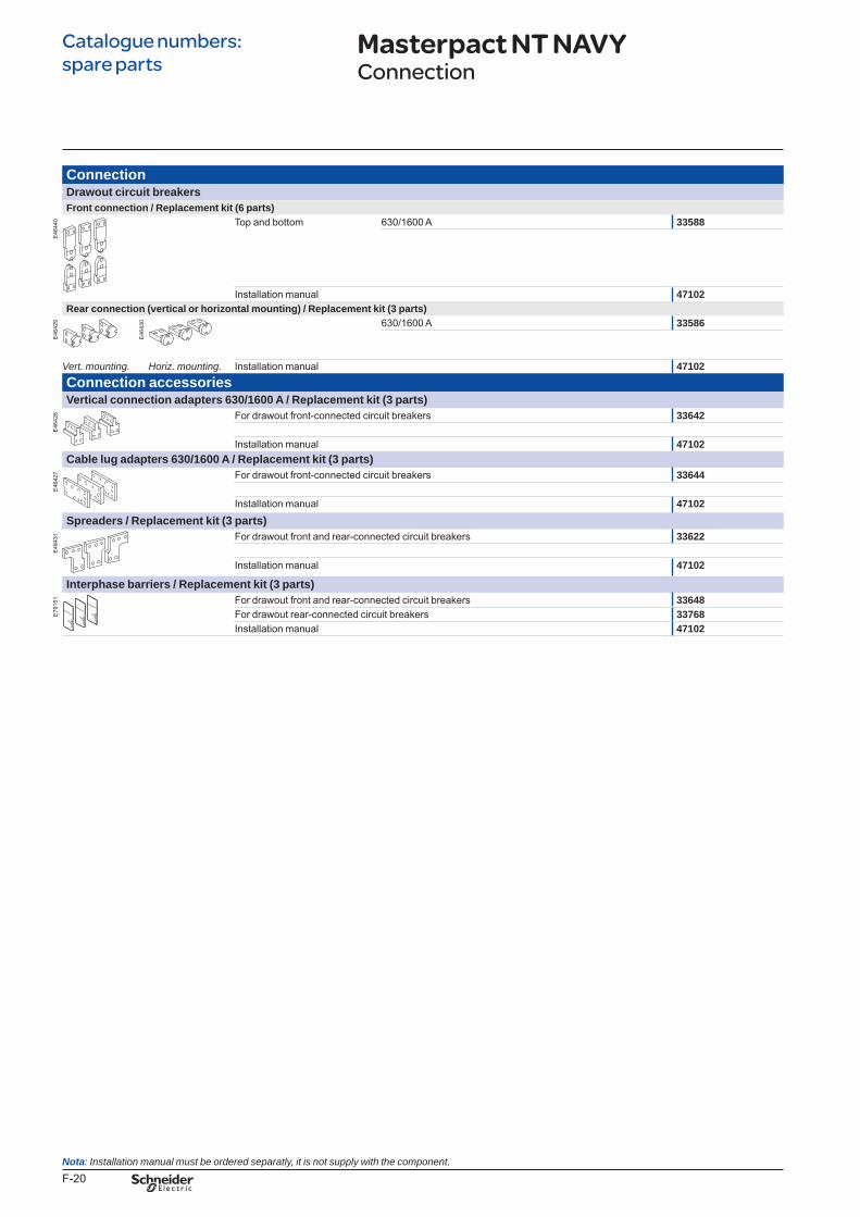
F-20
Catalogue numbers: spare parts
ConnectionDrawout circuit breakersFront connection / Replacement kit (6 parts)
E46
440 Top and bottom 630/1600 A 33588
Installation manual 47102Rear connection (vertical or horizontal mounting) / Replacement kit (3 parts)
E46
429
E46
430 630/1600 A 33586
Vert.mounting. Horiz.mounting. Installation manual 47102Connection accessoriesVertical connection adapters 630/1600 A / Replacement kit (3 parts)
E46
426 For drawout front-connected circuit breakers 33642
Installation manual 47102Cable lug adapters 630/1600 A / Replacement kit (3 parts)
E46
427 For drawout front-connected circuit breakers 33644
Installation manual 47102Spreaders / Replacement kit (3 parts)
E46
431 For drawout front and rear-connected circuit breakers 33622
Installation manual 47102
Interphase barriers / Replacement kit (3 parts)
E79
151 For drawout front and rear-connected circuit breakers 33648
For drawout rear-connected circuit breakers 33768Installation manual 47102
Masterpact NT NAVYConnection
Nota:Installationmanualmustbeorderedseparatly,itisnotsupplywiththecomponent.
BTP222E.indb 20 30/06/2009 09:33:24
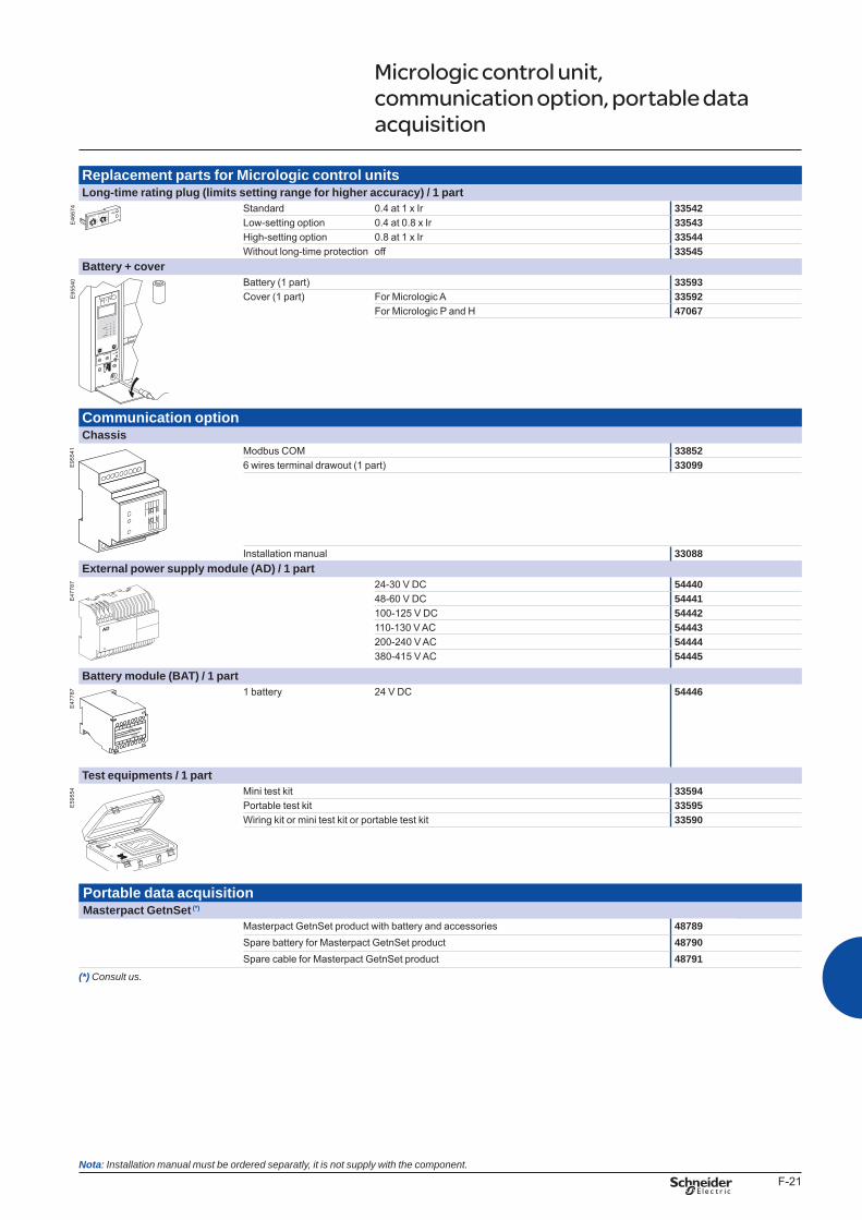
F-21
Replacement parts for Micrologic control unitsLong-time rating plug (limits setting range for higher accuracy) / 1 part
E46
674 Standard 0.4 at 1 x Ir 33542
Low-setting option 0.4 at 0.8 x Ir 33543High-setting option 0.8 at 1 x Ir 33544Without long-time protection off 33545
Battery + cover
E95
540 Battery (1 part) 33593
Cover (1 part) For Micrologic A 33592For Micrologic P and H 47067
Communication optionChassis
E95
541 Modbus COM 33852
6 wires terminal drawout (1 part) 33099
Installation manual 33088External power supply module (AD) / 1 part
E47
787 24-30 V DC 54440
48-60 V DC 54441100-125 V DC 54442110-130 V AC 54443200-240 V AC 54444380-415 V AC 54445
Battery module (BAT) / 1 part
E47
787
L3
G1
AD 220A
L4
G2
Input
24VDC
Output
24VDC
1 battery 24 V DC 54446
Test equipments / 1 part
E59
554 Mini test kit 33594
Portable test kit 33595Wiring kit or mini test kit or portable test kit 33590
Portable data acquisitionMasterpact GetnSet (*)
Masterpact GetnSet product with battery and accessories 48789Spare battery for Masterpact GetnSet product 48790Spare cable for Masterpact GetnSet product 48791
(*) Consultus.
Micrologic control unit, communication option, portable data acquisition
menu
Nota:Installationmanualmustbeorderedseparatly,itisnotsupplywiththecomponent.
BTP222E.indb 21 30/06/2009 09:33:25
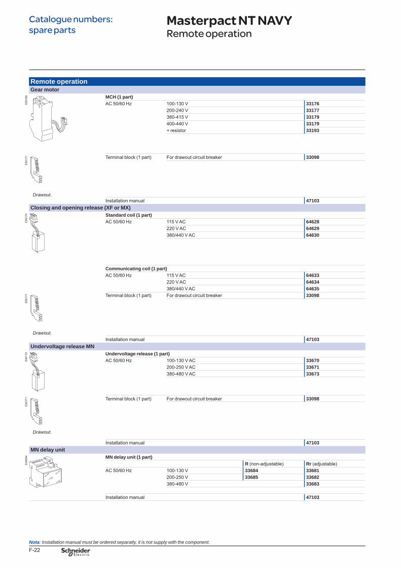
F-22
Catalogue numbers: spare parts
Remote operationGear motor
E95
168 MCH (1 part)
AC 50/60 Hz 100-130 V 33176200-240 V 33177380-415 V 33179400-440 V 33179+ resistor 33193
E95
171 Terminal block (1 part) For drawout circuit breaker 33098
Drawout.Installation manual 47103
Closing and opening release (XF or MX)
E95
170 Standard coil (1 part)
AC 50/60 Hz 115 V AC 64628220 V AC 64629380/440 V AC 64630
Communicating coil (1 part)AC 50/60 Hz 115 V AC 64633
220 V AC 64634380/440 V AC 64635
E95
171 Terminal block (1 part) For drawout circuit breaker 33098
Drawout.Installation manual 47103
Undervoltage release MN
E95
170 Undervoltage release (1 part)
Drawout.
AC 50/60 Hz 100-130 V AC 33670200-250 V AC 33671380-480 V AC 33673
E95
171 Terminal block (1 part) For drawout circuit breaker 33098
Installation manual 47103MN delay unit
E46
694 MN delay unit (1 part)
R (non-adjustable) Rr (adjustable)AC 50/60 Hz 100-130 V 33684 33681
200-250 V 33685 33682380-480 V 33683
Installation manual 47103
Masterpact NT NAVYRemote operation
Nota:Installationmanualmustbeorderedseparatly,itisnotsupplywiththecomponent.
BTP222E.indb 22 30/06/2009 09:33:26
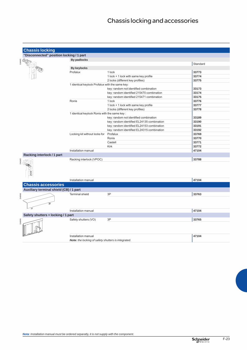
F-23
Chassis locking“Disconnected” position locking / 1 part
E46
685 By padlocks
StandardBy keylocks
Profalux 1 lock 337731 lock + 1 lock with same key profile 337742 locks (different key profiles) 33775
1 identical keylock Profalux with the same key:key: random not identified combination 33173key: random identified 215470 combination 33174key: random identified 215471 combination 33175
Ronis 1 lock 337761 lock + 1 lock with same key profile 337772 locks (different key profiles) 33778
1 identical keylock Ronis with the same key :key: random not identified combination 33189key: random identified EL24135 combination 33190key: random identified EL24153 combination 33191key: random identified EL24315 combination 33192
Locking kit without locks for Profalux 33769Ronis 33770Castell 33771Kirk 33772
Installation manual 47104Racking interlock / 1 part
E46
465 Racking interlock (VPOC) 33788
Installation manual 47104Chassis accessoriesAuxiliary terminal shield (CB) / 1 part
E46
698 Terminal shield 3P 33763
Installation manual 47104Safety shutters + locking / 1 part
E46
699 Safety shutters (VO) 3P 33765
Installation manual 47104Note: thelockingofsafetyshuttersisintegrated.
Chassis locking and accessories
Nota:Installationmanualmustbeorderedseparatly,itisnotsupplywiththecomponent.
BTP222E.indb 23 30/06/2009 09:33:27
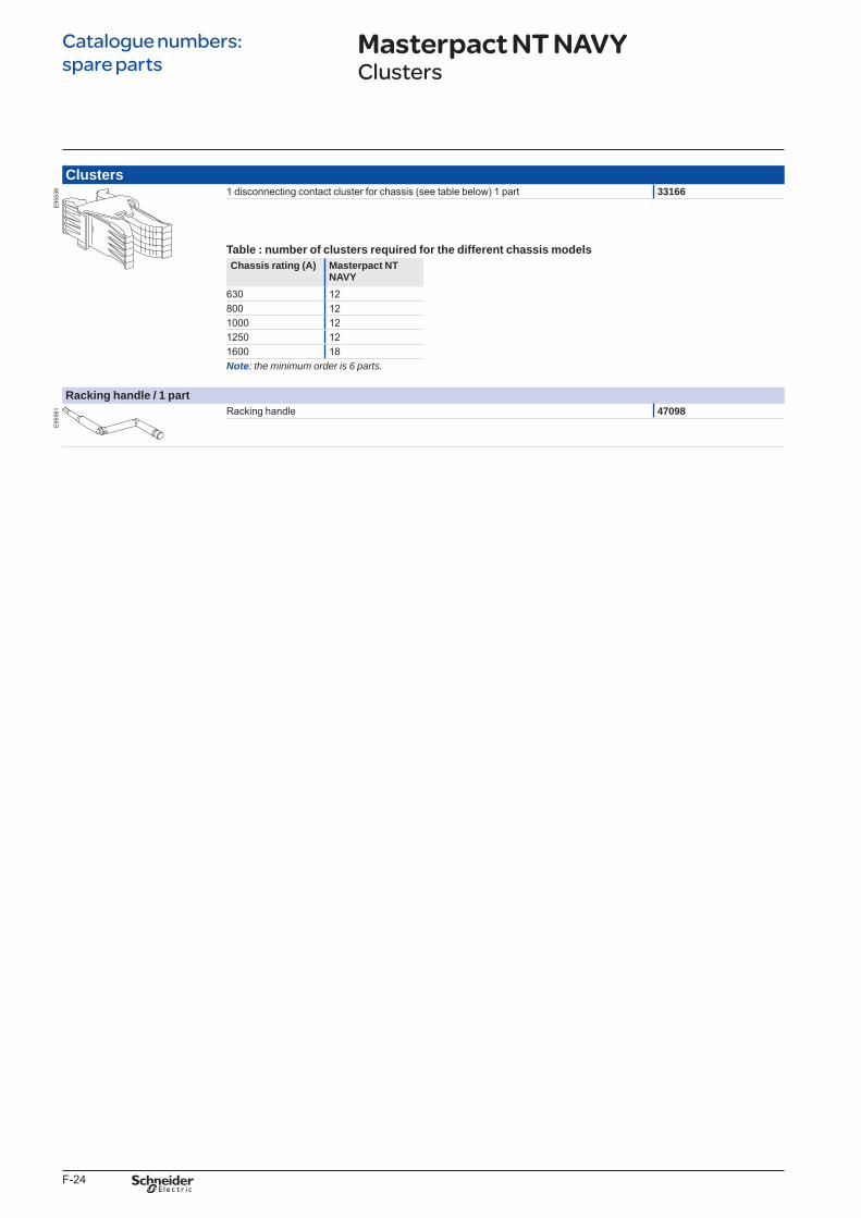
F-24
Catalogue numbers: spare parts
Clusters
E95
538 1 disconnecting contact cluster for chassis (see table below) 1 part 33166
Table : number of clusters required for the different chassis modelsChassis rating (A) Masterpact NT
NAVY630 12800 121000 121250 121600 18Note: theminimumorderis6parts.
Racking handle / 1 part
E95
561 Racking handle 47098
Masterpact NT NAVYClusters
BTP222E.indb 24 30/06/2009 09:33:28
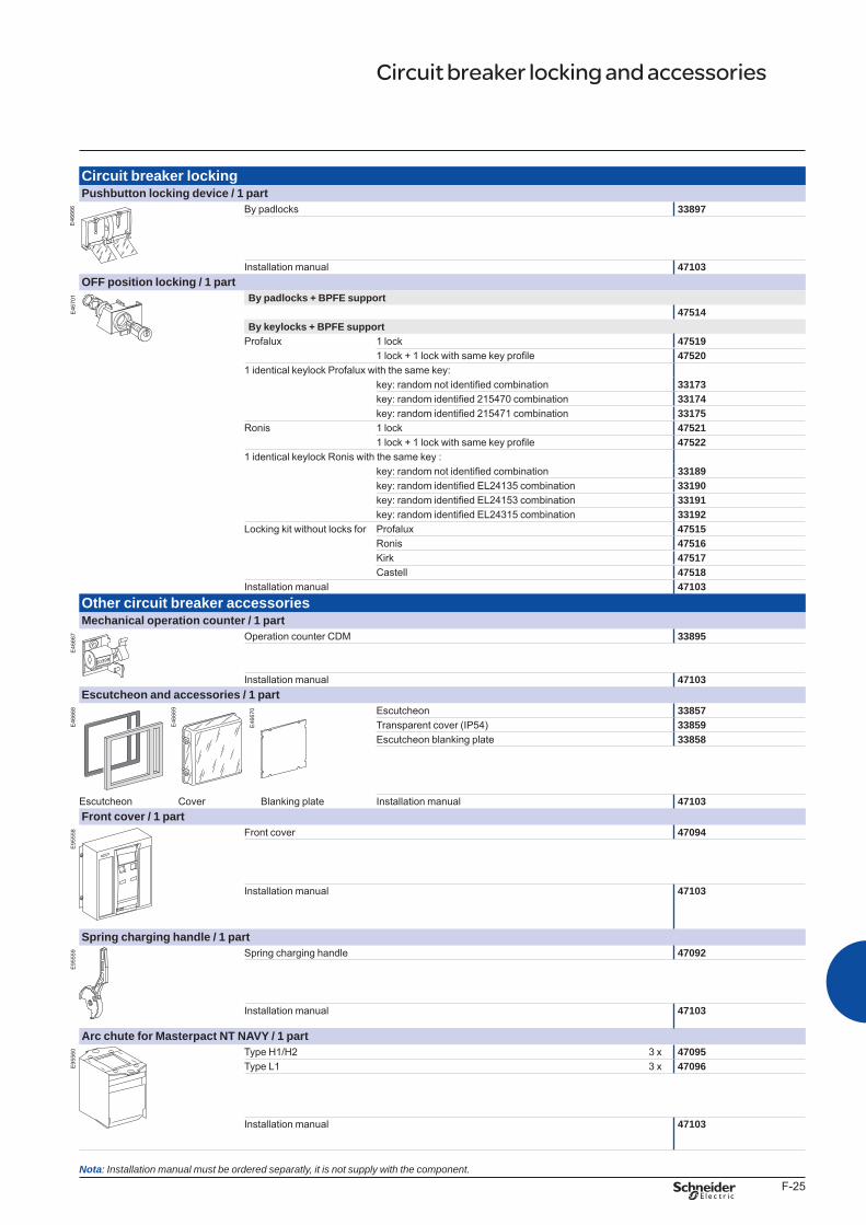
F-25
Circuit breaker lockingPushbutton locking device / 1 part
E46
666 By padlocks 33897
Installation manual 47103OFF position locking / 1 part
E46
701 By padlocks + BPFE support
47514By keylocks + BPFE support
Profalux 1 lock 475191 lock + 1 lock with same key profile 47520
1 identical keylock Profalux with the same key:key: random not identified combination 33173key: random identified 215470 combination 33174key: random identified 215471 combination 33175
Ronis 1 lock 475211 lock + 1 lock with same key profile 47522
1 identical keylock Ronis with the same key :key: random not identified combination 33189key: random identified EL24135 combination 33190key: random identified EL24153 combination 33191key: random identified EL24315 combination 33192
Locking kit without locks for Profalux 47515Ronis 47516Kirk 47517Castell 47518
Installation manual 47103Other circuit breaker accessoriesMechanical operation counter / 1 part
E46
667 Operation counter CDM 33895
Installation manual 47103Escutcheon and accessories / 1 part
E46
668 Escutcheon 33857
Transparent cover (IP54) 33859Escutcheon blanking plate 33858
Escutcheon Cover Blanking plate Installation manual 47103Front cover / 1 part
E95
558 Front cover 47094
Installation manual 47103
Spring charging handle / 1 part
E95
559 Spring charging handle 47092
Installation manual 47103
Arc chute for Masterpact NT NAVY / 1 part
E95
560 Type H1/H2 3 x 47095
Type L1 3 x 47096
Installation manual 47103
Circuit breaker locking and accessories
E46
669
E46
670
Nota:Installationmanualmustbeorderedseparatly,itisnotsupplywiththecomponent.
BTP222E.indb 25 30/06/2009 09:33:29
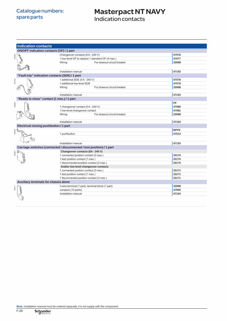
F-26
Catalogue numbers: spare parts
Indication contactsON/OFF indication contacts (OF) / 1 part
E46
463 Changeover contacts (6 A - 240 V) 47076
1 low-level OF to replace 1 standard OF (4 max.) 47077Wiring For drawout circuit breaker 33098
Installation manual 47103“Fault trip” indication contacts (SDE) / 1 part
E47
758 1 additional SDE (5 A - 240 V) 47078
1 additional low-level SDE 47079Wiring For drawout circuit breaker 33098
Installation manual 47103“Ready to close” contact (1 max.) / 1 part
E46
664 PF
1 changeover contact (5 A - 240 V) 470801 low-level changeover contact 47081Wiring For drawout circuit breaker 33098
Installation manual 47103Electrical closing pushbutton / 1 part
E46
439 BPFE
1 pushbutton 47512
Installation manual 47103Carriage switches (connected / disconnected / test position) / 1 part
E46
661 Changeover contacts (6A - 240 V)
1 connected position contact (3 max.) 331701 test position contact (1 max.) 331701 disconnected position contact (2 max.) 33170And/or low-level changeover contacts
1 connected position contact (3 max.) 331711 test position contact (1 max.) 331711 disconnected position contact (2 max.) 33171
Auxiliary terminals for chassis alone
E95
171 3 wire terminal (1 part), terminal block (1 part) 33098
Jumpers (10 parts) 47900Installation manual 47104
Masterpact NT NAVYIndication contacts
Nota:Installationmanualmustbeorderedseparatly,itisnotsupplywiththecomponent.
BTP222E.indb 26 30/06/2009 09:33:30
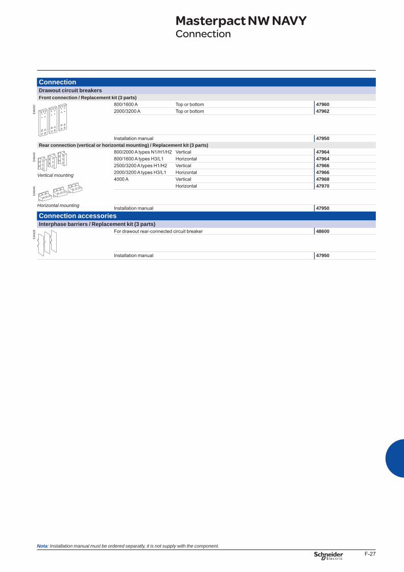
F-27
ConnectionDrawout circuit breakersFront connection / Replacement kit (3 parts)
E46
450 800/1600 A Top or bottom 47960
2000/3200 A Top or bottom 47962
Installation manual 47950Rear connection (vertical or horizontal mounting) / Replacement kit (3 parts)
E46
445 800/2000 A types N1/H1/H2 Vertical 47964
800/1600 A types H3/L1 Horizontal 479642500/3200 A types H1/H2 Vertical 479662000/3200 A types H3/L1 Horizontal 479664000 A Vertical 47968
E46
446 Horizontal 47970
Installation manual 47950
Connection accessoriesInterphase barriers / Replacement kit (3 parts)
E46
428 For drawout rear-connected circuit breaker 48600
Installation manual 47950
Masterpact NW NAVYConnection
Verticalmounting
Horizontalmounting
Nota:Installationmanualmustbeorderedseparatly,itisnotsupplywiththecomponent.
BTP222E.indb 27 30/06/2009 09:33:31
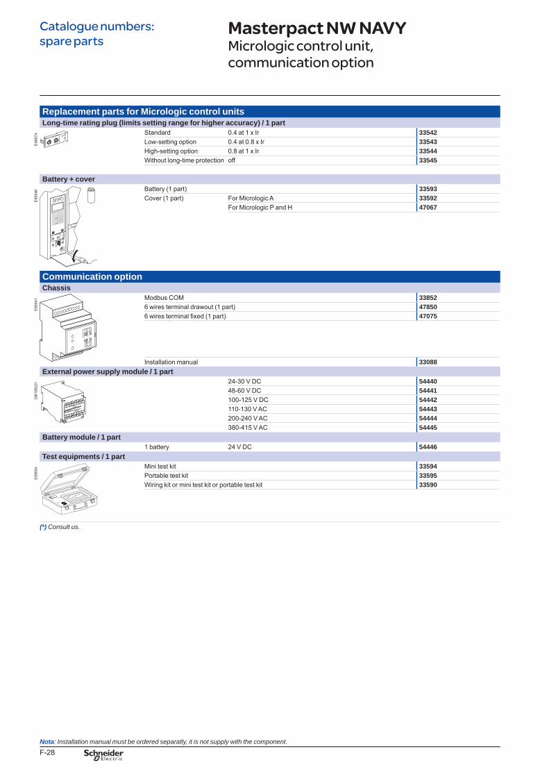
F-28
Catalogue numbers: spare parts
Replacement parts for Micrologic control unitsLong-time rating plug (limits setting range for higher accuracy) / 1 part
E46
674 Standard 0.4 at 1 x Ir 33542
Low-setting option 0.4 at 0.8 x Ir 33543High-setting option 0.8 at 1 x Ir 33544Without long-time protection off 33545
Battery + cover
E95
540 Battery (1 part) 33593
Cover (1 part) For Micrologic A 33592For Micrologic P and H 47067
Communication optionChassis
E95
541 Modbus COM 33852
6 wires terminal drawout (1 part) 478506 wires terminal fixed (1 part) 47075
Installation manual 33088External power supply module / 1 part
DB
1092
21 24-30 V DC 5444048-60 V DC 54441100-125 V DC 54442110-130 V AC 54443200-240 V AC 54444380-415 V AC 54445
Battery module / 1 part1 battery 24 V DC 54446
Test equipments / 1 part
E59
554 Mini test kit 33594
Portable test kit 33595Wiring kit or mini test kit or portable test kit 33590
(*)Consultus.
Masterpact NW NAVYMicrologic control unit, communication option
menu
Nota:Installationmanualmustbeorderedseparatly,itisnotsupplywiththecomponent.
BTP222E.indb 28 30/06/2009 09:33:32
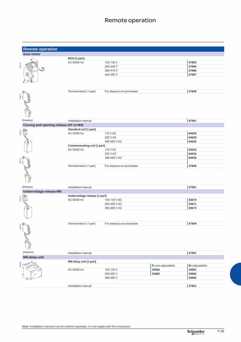
F-29
Remote operationGear motor
MCH (1 part)
E95
172 AC 50/60 Hz 100-130 V 47893
200-240 V 47894380-415 V 47896440-480 V 47897
Drawout.
Terminal block (1 part) For drawout circuit breaker 47849
E95
171
Installation manual 47951Closing and opening release (XF or MX)
E95
170 Standard coil (1 part)
AC 50/60 Hz 115 V AC 64628220 V AC 64629380-480 V AC 64630
Communicating coil (1 part)AC 50/60 Hz 115 V AC 64633
220 V AC 64634
E95
173 380-480 V AC 64635
Drawout.
Terminal block (1 part) For drawout circuit breaker 47849
Installation manual 47951Undervoltage release MN
E95
170 Undervoltage release (1 part)
Drawout.
AC 50/60 Hz 100-130 V AC 33670200-250 V AC 33671380-480 V AC 33673
E95
169
Terminal block (1 part) For drawout circuit breaker 47849
Installation manual 47951MN delay unit
E46
694 MN delay unit (1 part)
R (non-adjustable) Rr (adjustable)AC 50/60 Hz 100-130 V 33684 33681
200-250 V 33685 33682380-480 V 33683
Installation manual 47951
Remote operation
Nota:Installationmanualmustbeorderedseparatly,itisnotsupplywiththecomponent.
BTP222E.indb 29 30/06/2009 09:33:33
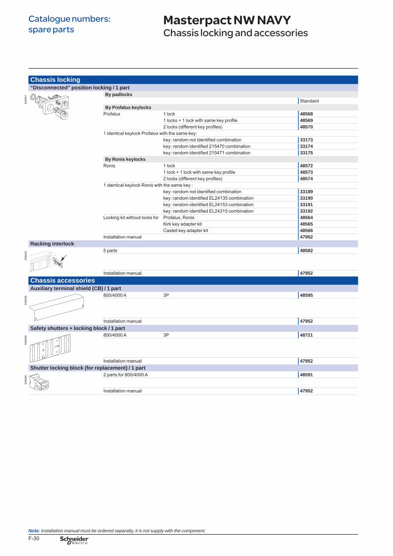
F-30
Chassis locking“Disconnected” position locking / 1 part
E46
451 By padlocks
StandardBy Profalux keylocks
Profalux 1 lock 485681 locks + 1 lock with same key profile 485692 locks (different key profiles) 48570
1 identical keylock Profalux with the same key:key: random not identified combination 33173key: random identified 215470 combination 33174key: random identified 215471 combination 33175
By Ronis keylocksRonis 1 lock 48572
1 lock + 1 lock with same key profile 485732 locks (different key profiles) 48574
1 identical keylock Ronis with the same key :key: random not identified combination 33189key: random identified EL24135 combination 33190key: random identified EL24153 combination 33191key: random identified EL24315 combination 33192
Locking kit without locks for Profalux, Ronis 48564Kirk key adapter kit 48565Castell key adapter kit 48566
Installation manual 47952Racking interlock
E46
453 5 parts 48582
Installation manual 47952Chassis accessoriesAuxiliary terminal shield (CB) / 1 part
E46
458 800/4000 A 3P 48595
Installation manual 47952Safety shutters + locking block / 1 part
E46
459 800/4000 A 3P 48721
Installation manual 47952Shutter locking block (for replacement) / 1 part
E46
460 2 parts for 800/4000 A 48591
Installation manual 47952
Masterpact NW NAVYChassis locking and accessories
Catalogue numbers: spare parts
Nota:Installationmanualmustbeorderedseparatly,itisnotsupplywiththecomponent.
BTP222E.indb 30 30/06/2009 09:33:34
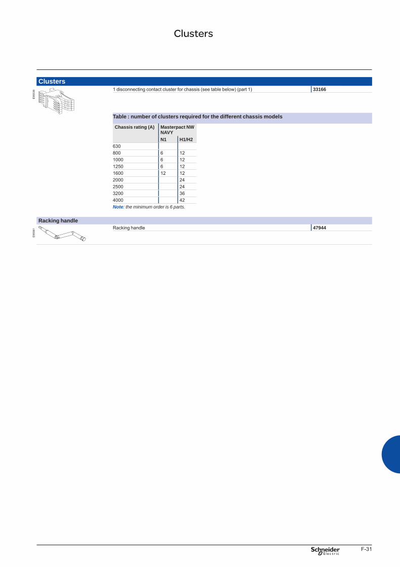
F-31
Clusters
E95
538 1 disconnecting contact cluster for chassis (see table below) (part 1) 33166
Table : number of clusters required for the different chassis models
Chassis rating (A) Masterpact NW NAVYN1 H1/H2
630800 6 121000 6 121250 6 121600 12 122000 242500 243200 364000 42Note:theminimumorderis6parts.
Racking handle
E95
561 Racking handle 47944
Clusters
BTP222E.indb 31 30/06/2009 09:33:35
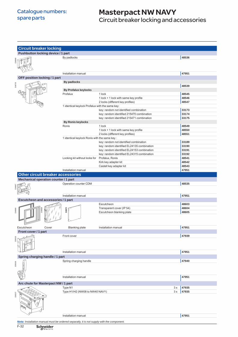
F-32
Circuit breaker lockingPushbutton locking device / 1 part
E46
666 By padlocks 48536
Installation manual 47951OFF position locking / 1 part
E46
735 By padlocks
48539By Profalux keylocks
Profalux 1 lock 485451 lock + 1 lock with same key profile 485462 locks (different key profiles) 48547
1 identical keylock Profalux with the same key:key: random not identified combination 33173key: random identified 215470 combination 33174key: random identified 215471 combination 33175
By Ronis keylocksRonis 1 lock 48549
1 lock + 1 lock with same key profile 485502 locks (different key profiles) 48551
1 identical keylock Ronis with the same key :key: random not identified combination 33189key: random identified EL24135 combination 33190key: random identified EL24153 combination 33191key: random identified EL24315 combination 33192
Locking kit without locks for Profalux, Ronis 48541Kirk key adapter kit 48542Castell key adapter kit 48543
Installation manual 47951Other circuit breaker accessoriesMechanical operation counter / 1 part
E46
667 Operation counter CDM 48535
Installation manual 47951Escutcheon and accessories / 1 part
E46
668
Escutcheon 48603Transparent cover (IP 54) 48604Escutcheon blanking plate 48605
Escutcheon Cover Blanking plate Installation manual 47951Front cover / 1 part
E95
535 Front cover 47939
Installation manual 47951
Spring charging handle / 1 part
E95
536 Spring charging handle 47940
Installation manual 47951
Arc chute for Masterpact NW / 1 partType N1 3 x 47935
E95
537 Type H1/H2 (NW08 to NW40 NAVY) 3 x 47935
Installation manual 47951
E46
669
E46
670
E46
669
E46
670
Masterpact NW NAVYCircuit breaker locking and accessories
Catalogue numbers: spare parts
Nota:Installationmanualmustbeorderedseparatly,itisnotsupplywiththecomponent.
BTP222E.indb 32 30/06/2009 09:33:37
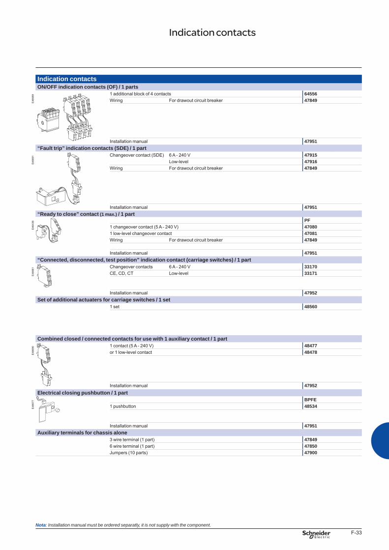
F-33
Indication contactsON/OFF indication contacts (OF) / 1 parts
E46
689 1 additional block of 4 contacts 64556
Wiring For drawout circuit breaker 47849
Installation manual 47951“Fault trip” indication contacts (SDE) / 1 part
E46
691 Changeover contact (SDE) 6 A - 240 V 47915
Low-level 47916Wiring For drawout circuit breaker 47849
Installation manual 47951“Ready to close” contact (1 max.) / 1 part
E46
438 PF
1 changeover contact (5 A - 240 V) 470801 low-level changeover contact 47081Wiring For drawout circuit breaker 47849
Installation manual 47951“Connected, disconnected, test position” indication contact (carriage switches) / 1 part
E46
661 Changeover contacts 6 A - 240 V 33170
CE, CD, CT Low-level 33171
Installation manual 47952Set of additional actuaters for carriage switches / 1 set
1 set 48560
Combined closed / connected contacts for use with 1 auxiliary contact / 1 part
E46
690 1 contact (5 A - 240 V) 48477
or 1 low-level contact 48478
Installation manual 47952Electrical closing pushbutton / 1 part
E46
677 BPFE
1 pushbutton 48534
Installation manual 47951Auxiliary terminals for chassis alone
3 wire terminal (1 part) 478496 wire terminal (1 part) 47850Jumpers (10 parts) 47900
Indication contacts
Nota:Installationmanualmustbeorderedseparatly,itisnotsupplywiththecomponent.
BTP222E.indb 33 30/06/2009 09:33:38
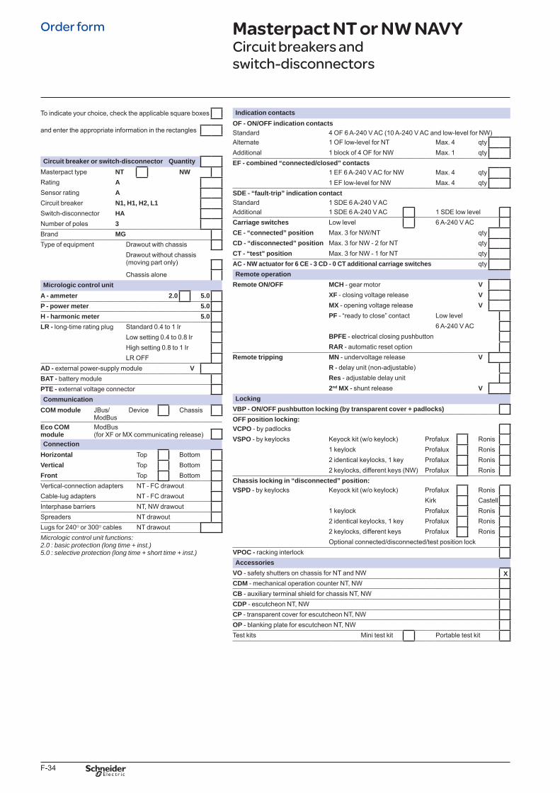
F-34
Indication contactsOF - ON/OFF indication contacts Standard 4 OF 6 A-240 V AC (10 A-240 V AC and low-level for NW)Alternate 1 OF low-level for NT Max. 4 qtyAdditional 1 block of 4 OF for NW Max. 1 qtyEF - combined “connected/closed” contacts
1 EF 6 A-240 V AC for NW Max. 4 qty1 EF low-level for NW Max. 4 qty
SDE - “fault-trip” indication contactStandard 1 SDE 6 A-240 V ACAdditional 1 SDE 6 A-240 V AC 1 SDE low levelCarriage switches Low level 6 A-240 V ACCE - “connected” position Max. 3 for NW/NT qtyCD - “disconnected” position Max. 3 for NW - 2 for NT qtyCT - “test” position Max. 3 for NW - 1 for NT qtyAC - NW actuator for 6 CE - 3 CD - 0 CT additional carriage switches qtyRemote operation
Remote ON/OFF MCH - gear motor VXF - closing voltage release VMX - opening voltage release VPF - “ready to close” contact Low level
6 A-240 V ACBPFE - electrical closing pushbuttonRAR - automatic reset option
Remote tripping MN - undervoltage release VR - delay unit (non-adjustable)Res - adjustable delay unit2nd MX - shunt release V
LockingVBP - ON/OFF pushbutton locking (by transparent cover + padlocks)OFF position locking:VCPO - by padlocks VSPO - by keylocks Keyock kit (w/o keylock) Profalux Ronis
1 keylock Profalux Ronis2 identical keylocks, 1 key Profalux Ronis2 keylocks, different keys (NW) Profalux Ronis
Chassis locking in “disconnected” position:VSPD - by keylocks Keyock kit (w/o keylock) Profalux Ronis
Kirk Castell1 keylock Profalux Ronis2 identical keylocks, 1 key Profalux Ronis2 keylocks, different keys Profalux RonisOptional connected/disconnected/test position lock
VPOC - racking interlockAccessories
VO - safety shutters on chassis for NT and NW XCDM - mechanical operation counter NT, NWCB - auxiliary terminal shield for chassis NT, NWCDP - escutcheon NT, NWCP - transparent cover for escutcheon NT, NWOP - blanking plate for escutcheon NT, NWTest kits Mini test kit Portable test kit
To indicate your choice, check the applicable square boxes
and enter the appropriate information in the rectangles
Circuit breaker or switch-disconnector QuantityMasterpact type NT NWRating ASensor rating ACircuit breaker N1, H1, H2, L1Switch-disconnector HANumber of poles 3Brand MGType of equipment Drawout with chassis
Drawout without chassis(moving part only)
Chassis aloneMicrologic control unit
A - ammeter 2.0 5.0P - power meter 5.0H - harmonic meter 5.0LR - long-time rating plug Standard 0.4 to 1 Ir
Low setting 0.4 to 0.8 IrHigh setting 0.8 to 1 IrLR OFF
AD - external power-supply module VBAT - battery modulePTE - external voltage connectorCommunication
COM module JBus/ModBus
Device Chassis
Eco COM module
ModBus(for XF or MX communicating release)
ConnectionHorizontal Top BottomVertical Top BottomFront Top BottomVertical-connection adapters NT - FC drawoutCable-lug adapters NT - FC drawoutInterphase barriers NT, NW drawoutSpreaders NT drawoutLugs for 240v or 300v cables NT drawoutMicrologiccontrolunitfunctions:2.0:basicprotection(longtime+inst.)5.0:selectiveprotection(longtime+shorttime+inst.)
Masterpact NT or NW NAVY Circuit breakers and switch-disconnectors
Order form
BTP222E.indb 34 30/06/2009 09:33:39


AR
T960
390
© 2
009
- Sch
neid
er E
lect
ric -
All
right
s re
serv
ed.
06-2009LVPED208017EN
As standards, specifications and designs change from time to time, please ask for confirmation of the information given in this publication.
This document has been printed on ecological paper
Design: Schneider ElectricPhotos: Schneider ElectricPrinted: Centre Impression - made in France
Schneider Electric Industries SAS35, rue Joseph MonierCS 30323F- 92506 Rueil Malmaison Cedex
RCS Nanterre 954 503 439Capital social 896 313 776 €www.schneider-electric.com
222E0000.indd 2 07/07/2009 14:13:37


