Embed Size (px)
Citation preview
Manufacturing sound-absorbing structures by 3d-printing
Pavel Pisarev, Alexander Anoshkin, and Natalya Merzliakova
Perm national research polytechnic university, 614990, Komsomolskii ave., 29, Russia, Perm
Abstract. In this research we developed the methods and technologies for manufacturing sound-
absorbing structures (SAS) samples using Dimension SST 1200 and Envisiontec Perfactory XEDE
units. While testing the technique, the shortcomings of both units were identified. To eliminate the
identified shortcomings, we formulated some recommendations and adjusted the main stages of
manufacturing SAS with the application of these methods. Experimental acoustic studies of the
produced reference samples of the SAS on an interferometer with normal incidence of waves were
carried out. Acoustic tests of samples of SAS manufactured with consideration of the developed
technological solutions showed good sustainability of the obtained results, we revealed strong
correlation with the samples from polymer composite materials manufactured using standard plant
technologies.
1 Introduction
In the 21st century there is a rapid development of civil
aviation and the air transportation market, which is a
catalyst for economic growth. At the same time, the
negative impact of aviation on the environment is increasing, especially in the near-airodrome areas. The
ecology of aviation transport has become the most urgent
problem, allocated by the International Civil Aviation
Organization (ICAO), second to safety only [1]. One of
the dominant components of the harmful impact of
aviation on the environment is the noise created by
aircraft. ICAO constantly tightens international standards
for aircraft noise, standardizing its level in the takeoff
and landing modes, forcing aircraft manufacturers to
develop new technologies to reduce the noise [2]. One of
the main components of aircraft noise is the noise
generated by propulsion systems - turbojet two-loop engines (TTLE) [3].
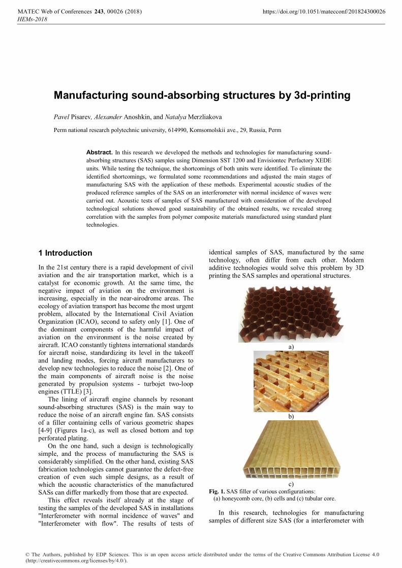
The lining of aircraft engine channels by resonant
sound-absorbing structures (SAS) is the main way to
reduce the noise of an aircraft engine fan. SAS consists
of a filler containing cells of various geometric shapes
[4-9] (Figures 1a-c), as well as closed bottom and top
perforated plating.
On the one hand, such a design is technologically
simple, and the process of manufacturing the SAS is
considerably simplified. On the other hand, existing SAS
fabrication technologies cannot guarantee the defect-free creation of even such simple designs, as a result of
which the acoustic characteristics of the manufactured
SASs can differ markedly from those that are expected.
This effect reveals itself already at the stage of
testing the samples of the developed SAS in installations
"Interferometer with normal incidence of waves" and
"Interferometer with flow". The results of tests of
identical samples of SAS, manufactured by the same
technology, often differ from each other. Modern
additive technologies would solve this problem by 3D
printing the SAS samples and operational structures.
a)
b)
c)
Fig. 1. SAS filler of various configurations: (a) honeycomb core, (b) cells and (c) tubular core.
In this research, technologies for manufacturing
samples of different size SAS (for a interferometer with
, 0 (2018)MATEC Web of Conferences https://doi.org/10.1051/matecconf/201824300026243 00HEMs-2018
26
© The Authors, published by EDP Sciences. This is an open access article distributed under the terms of the Creative Commons Attribution License 4.0 (http://creativecommons.org/licenses/by/4.0/).

normal incidence of waves and an interferometer with a
flow) were developed with different filling
configurations using the Dimension SST 1200 and
Envisiontec Perfactory XEDE installations (Figure 2).
а
b
Fig. 2. 3D printer: (a) Dimension SST 1200 (b) layer-by-layer
synthesis EnvisiontecPerfactory XEDE.
Acoustic tests of printed SAS samples on an
interferometer with normal incidence of waves were
carried out.
2 Making reference samples for an interferometer with a normal sound wave drop
For the production of SAS reference samples for the
interferometer with a normal fall of sound waves, FDM
prototyping technology was used. In Fig. 2 the general
view of the Dimension SST 1200 installation used to
make samples for the interferometer is shown. The
production cycle, in this case, is reduced to designing the
sample shape in the SiemensNX 3D simulation program, converting it into an .stl format, compatible with a 3D
printer, and printing the finished sample on the printer.
However, features of 3D prototyping on this unit had
both positive and negative sides. The technology of
manufacturing on this equipment consists of layer-by-
layer extensions of the detail by extrusion of a thread
from ABS plastic [10]. The printer uses two materials:
the main material, which is ABS-plus thermoplastic, and
the support material that creates layers that support the
base material where necessary. In the absence of support
material, significantly more than 5% deformation of the
structure is observed. From open areas, support material
is removed mechanically, for example, with a
screwdriver or a stationery knife. From the hard-to-reach
places, support material is removed by dissolving with a
special chemical composition. Examples of models
designed in Siemens NX are shown in Figure 3.
a)
b)
Fig. 3. Geometric models of the SAS developed in Siemens
NX (a) with cubic filler, (b) honeycomb filler.
After building, using the software package supplied
with the 3D printer, the model is divided into layers, the orientation of the detail in spaceis selected, as well as the
thickness of the layer, the method of filling the solid
sections (Solid, Hidensity, Lowdensity) is assigned. By
optimally selecting the position of the detail, it is
possible to reduce or completely eliminate the presence
of a supporting material.
The SAS samples produced during this work are a
closed cavity with a hole diameter of 2 mm. The
production of a SAS sample, which has "closed"
cavities, is accompanied by a number of technological
problems, for example, filling the cavity of the resonator with support material.
The presence of a stagnant, "blank" area filled with
support material, makes it impossible to remove support
material using a dissolving liquid. To solve this problem,
the lower non-perforated faces were removed in the
developed geometric models. Later, during acoustic
tests, we propose to use a special reinforced material that
will ensure the acoustic closure of the tested samples.
The use of this technology for manufacturing SAS
samples by means of 3D printing from ABS plastic made
it possible to use a minimum amount of supporting
material. The process of manufacturing the samples of cellular SAS, using FDM prototyping technology, is
presented in Figure 4.
, 0 (2018)MATEC Web of Conferences https://doi.org/10.1051/matecconf/201824300026243 00HEMs-2018
26
2
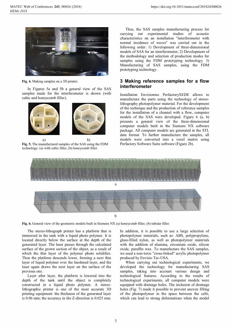
Fig. 4. Making samples on a 3D printer.
In Figures 5a and 5b a general view of the SAS
samples made for the interferometer is shown (with
cubic and honeycomb filler).
a) b) Fig. 5. The manufactured samples of the SAS using the FDM technology: (a) with cubic filler, (b) honeycomb filler.
Thus, the SAS samples manufacturing process for
carrying out experimental studies of acoustic
characteristics on an installation "interferometer with
normal incidence of waves" was carried out in the
following order: 1) Development of three-dimensional
models of SAS for an interferometer; 2) Development of
the methodology and selection of production modes for
samples using the FDM prototyping technology; 3)
Manufacturing of SAS samples, using the FDM
prototyping technology.
3 Making reference samples for a flow interferometer
Installation Envisiontec PerfactoryXEDE allows to
manufacture the parts using the technology of stereo-
lithography photopolymer material. For the development
of the technique and the production of reference samples for the installation of a channel with a flow, computer
models of the SAS were developed. Figure 6 (a, b)
presents a general view of the three-dimensional
computer models built in the Siemens NX software
package. All computer models are generated in the STL
data format. To further manufacture the samples, all
models were converted into a voxel matrix using
Perfactory Software Suite software (Figure 2b).
a
b
Fig. 6. General view of the geometric models built in Siemens NX (a) honeycomb filler, (b) tubular filler.
The stereo-lithograph printer has a platform that is
immersed in the tank with a liquid photo polymer. It is
located directly below the surface at the depth of the
generated layer. The laser passes through the calculated
surface of the grown section of the object, as a result of which the thin layer of the polymer photo solidifies.
Then the platform descends lower, forming a next thin
layer of liquid polymer over the hardened layer, and the
laser again draws the next layer on the surface of the
previous one.
Layer after layer, the platform is lowered into the
depth of the tank until the object is completely
constructed in a liquid photo polymer. A stereo-
lithographic printer is one of the most accurate 3D
printing equipment: the thickness of the generated layer
is 0.06 mm; the accuracy in the Z-direction is 0.025 mm.
In addition, it is possible to use a large selection of
photopolymer materials, such as: ABS, polypropylene,
glass-filled nylon, as well as photopolymer materials
with the addition of alumina, zirconium oxide, silicon
oxide, paraffin wax. To manufacture the SAS samples, we used a non-toxic "cross-linked" acrylic photopolymer
produced by Envisio Tec-USA.
When carrying out technological experiments, we
developed the technology for manufacturing SAS
samples, taking into account various design and
technological features. According to the results of
technological experiments, all computer models were
equipped with drainage holes. The inclusion of drainage
holes (Fig. 7) made it possible to prevent uneven filling
of the photopolymer in the space between the cells,
which can lead to strong deformations when the model
, 0 (2018)MATEC Web of Conferences https://doi.org/10.1051/matecconf/201824300026243 00HEMs-2018
26
3

cures. At the same time, the presence of drainage holes
allows to accelerate the process of complete drying and
solidification of the model. The curing time without
drainage holes is 4-6 weeks, with drainage holes - 2-3
weeks.
Fig.7. General view of the model on the rigging.
The technology for the production of samples of
reference SAS for the «channel with a flow» installation
includes the following steps: 1) development and
construction of specialized, inclined rigging (inclined
support devices) for constructing a model on the
installation platform (Figure 7); 2) Processing the
rigging with a release coating; 3) The model is cut into
2D layers, the required number of layers is not less than
3000, the layer thickness is 100 μm; 4) Assignment of
construction modes: laser treatment of each layer of the
model within 10,000 ms; 5) Setting the platform level to
zero; 6) Extracting the model from the working area of
the installation; 7) Washing the model in an alcohol bath
from residues of the photopolymer material SI500; 8)
Convective drying of the model produced at room
temperature; 9) Model machining - removal of supports; Curing the photopolymer 1 day under an ultraviolet
lamp, 14 days under normal daylight, fastening in the
rigging to avoid deformations.
As a result, samples of SAS with high parameters of
geometric dimensions of the aggregate and the location
of the perforation were obtained. The general view is
shown in Fig. 8.
Thus, according to the developed three-dimensional
models, samples were produced using the technology of
stereolithography of the photopolymer material and the
prototyping installation EnvisiontecPerfactory XEDE.
a
b
Fig. 8. General view of samples printed on a 3D printer (a) cellular (b)
4 Experimental determination of acoustic characteristics of the reference SAS samples
Experimental acoustic studies of the SAS samples
were carried out on the interferometer of the laboratory
of noise generating mechanisms and modal analysis of the PNRPU (Figure 9). The experimental setup consists
of a tube of circular cross-section, at one end of which
there is a sample of a SAS, on the other - a speaker that
irradiates the sample with acoustic waves. At some
distance from the sample, there are microphones that
record the acoustic pressure of the falling and reflected
waves in time. Further, the recorded pressure is
processed according to a special procedure, as a result of
which the impedance of the SAS sample is calculated.
Usually two microphones are used for measurements,
since the "transfer function method" used to determine
the impedance is the simplest for calculations [10]. In the
laboratory acoustic tests we studied the characteristics of
reference samples, as well as samples manufactured using standard plant technologies from polymer
composite materials.
, 0 (2018)MATEC Web of Conferences https://doi.org/10.1051/matecconf/201824300026243 00HEMs-2018
26
4
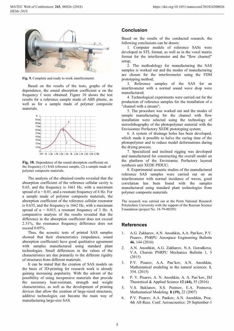
Fig. 9. Complete and ready to work interferometer.
Based on the results of the tests, graphs of the
dependence, the sound absorption coefficient α on the frequency f were obtained. Figure 10 shows the test
results for a reference sample made of ABS plastic, as
well as for a sample made of polymer composite
materials.
Fig. 10. Dependence of the sound absorption coefficient on
the frequency (1) SAS reference sample, (2) a sample made of polymer composite materials.
The analysis of the obtained results revealed that the absorption coefficient of the reference cellular cavity is
0.65, and the frequency is 1661 Hz, with a maximum
spread of α = 0.01, and a resonant frequency of 4 Hz. For
a sample made of polymer composite materials, the
absorption coefficient of the reference cellular resonator
is 0.635, and the frequency is 1662 Hz, with a maximum
spread of α = 0.015, a resonant frequency of 3 Hz. A
comparative analysis of the results revealed that the
difference in the absorption coefficient does not exceed
2.31%, the resonance frequency difference does not
exceed 0.05%. Thus, the acoustic tests of printed SAS samples
showed that their characteristics (impedance, sound
absorption coefficient) have good qualitative agreement
with samples manufactured using standard plant
technologies. Small differences in the values of the
characteristics are due primarily to the different rigidity
of structures from different materials.
It can be stated that the creation of SAS models on
the basis of 3D-printing for research work is already
gaining increasing popularity. With the advent of the
possibility of using inexpensive materials that provide the necessary heat-resistant, strength and weight
characteristics, as well as the development of printing
devices that allow the creation of large-sized structures,
additive technologies can become the main way of
manufacturing large-size SAS.
Conclusion
Based on the results of the conducted research, the
following conclusions can be drawn:
1. Computer models of reference SASs were
developed in STL format, as well as in the voxel matrix
format for the interferometer and the "flow channel"
setup;
2. The methodology for manufacturing the SAS
samples is worked out and the modes of manufacturing
are chosen for the interferometer using the FDM
prototyping method; 3. Reference samples of the SAS for an
interferometer with a normal sound wave drop were
manufactured;
4. Technological experiments were carried out for the
production of reference samples for the installation of a
"channel with a stream";
5. The procedure was worked out and the modes of
sample manufacturing for the channel with flow
installation were selected using the technology of
stereolithography of the photopolymer material with the
Envisiontec Perfactory XEDE prototyping system; 6. A system of drainage holes has been developed,
which made it possible to halve the curing time of the
photopolymer and to reduce model deformations during
the drying process;
7. Specialized and inclined rigging was developed
and manufactured for constructing the overall model on
the platform of the Envisiontec Perfactory layered
synthesis unit XEDE PIDUU;
8. Experimental acoustic studies of the manufactured
reference SAS samples were carried out on an
interferometer with normal incidence of waves, good
correlation has been found with the samples manufactured using standard plant technologies from
polymer composite materials.
The research was carried out at the Perm National Research Polytechnic University with the support of the Russian Science Foundation (project No. 18-79-00295)
References
1. A.G. Zakharov, A.N. Anoshkin, A.A. Pan'kov, P.V.
Pisarev, PNRPU Aerospace Engineering Bulletin
46, 144 (2016)
2. A.N. Anoshkin, A.G. Zakharov, N.A. Gorodkova,
V.A. Chursin PNRPU Mechanics Bulletin 1, 5 (2015)
3. P.V. Pisarev, A.A. Pan’kov, A.N. Anoshkin,
Mathematical modeling in the natural sciences. 1,
354. (2015)
4. P. V. Pisarev, A. N. Anoshkin, A. A. Pan’kov, ISJ Theoretical & Applied Science 12 (44), 55 (2016)
5. V.S. Baklanov, S.S. Postnov, E.A. Postnova, Mathematical Modeling. 8 (19), 22 (2007)
6. P.V. Pisarev, A.A. Pankov, A.N. Anoshkin, Proc.
4th All-Russ. Conf. Aeroacoustics: 29 September-1
, 0 (2018)MATEC Web of Conferences https://doi.org/10.1051/matecconf/201824300026243 00HEMs-2018
26
5

October, 2015 (Moscow: Publication. TsAGI,
2015) pp. 81-82
7. P.V. Pisarev, A.N. Anoshkin, A.A. Pan’kov, AIP
Conference Proceedings 1770, 030119 (2016), doi:
10.1063/1.4964061
8. A.P. Duben, T.K. Kozubskaya, S.I. Korolev, V.P.
Maslov, A.K. Mironov, D.A. Mironova, V.M.
Shakhparonov, Acoustical Phys. 58(1), 80 (2012)
9. A.I. Komkin, M.A. Mironov, S.I. Yudin, Acoustic J. 2 (60), 145 (2014)
10. O.Y. Kustov, V.V. Palchikovsky, Aerospace
Technology, High Technologies and Innovations,
1, 157 (2015)
, 0 (2018)MATEC Web of Conferences https://doi.org/10.1051/matecconf/201824300026243 00HEMs-2018
26
6


