Embed Size (px)
Citation preview

Meggitt SA, Route de Moncor 4, Case postale, 1701 Fribourg, Switzerland Tel: +41 26 407 1111Fax: +41 26 407 1660
[email protected]/energy
www.meggitt.com
INSTALLATION MANUALTitle page
Proximity measurement systems usingTQ4xx proximity sensors
with IQS45x signal conditioners
This document contains importantinformation about products thatare intended for use in potentiallyexplosive atmospheres.Ex
Document reference MAPROX400/EEdition 19 – January 2022

Document reference MAPROX400/E INSTALLATION MANUALEdition 19 - January 2022 Proximity measurement systems using TQ4xx proximity sensors
ii
REVISION RECORD SHEET
Edition Dateof issue
Written by / modified by Description Signature
1 26 Jun. 1995 R. Meyer Original edition RM
2 09 Apr. 1997 R. Meyer Page 5-21: Cabling diagram modified (−24 V on GSI123) RM
3 15 Jul. 1997 R. Meyer / ew Section 2.2 and Appendix A: All data sheets revised RM
4 03 Aug. 1999 R. Meyer / jlbCable layout diagrams modified to better show grounding technique (Figs 5-17, 5-18, 5-19).Removed references to TQ407 and TQ417.
RM
5 02 Jul. 2004 R. Meyer General revision. Updated “Ex” information according to directive 94/9/CE. RM
6 09 Mar. 2007 D. Evans Major revision. Substantial restructuring and updating throughout the document. DE
7 10 May 2007 D. Evans PZ drawings updated. Incorrect in Edition 6. Disclaimer updated. DE
8 16 April 2008 D. Evans Certification updated, electrical drawings updated DE
9 05 Feb. 2009 S. Trono Transducer mounting torques added.Certifications and electrical drawings updated. ST
10 25 Jan. 2011 P. Ward
Electrical drawings updated. Ex certificate updated for the IQS4xx/TQ4xx.Updated in accordance with the latest Meggitt brand guidelines.
PW
11 11.05.2012 P. Ward
Updated to reflect proximity measuring system improvements, including Ex certificate updates and the IP172 interconnection protection.Initial gap information moved to separate section. Reintroduced a separate maintenance section.
PW
12 19.03.2013 P. Ward
Updated wiring diagrams (Figure 7-1 and Figure 7-2) to correct a wiring error between the GSV14x and its external power supply. Ex certificate updated for the GSV14x.
PW
13 24.07.2013 P. Ward
Added the GSI127 galvanic separation unit (5 Installing galvanic separation units) and updated the mechanical diagrams (1 Introduction to TQ4xx-based proximity measurement chains) and the electrical diagrams (7 Electrical connections). Updated the Ex certificates.
PW
14 06.03.2014 P. Ward
Clarified the permitted installation areas for the GSI123, GSI124 and GSI127.Updated 7 Electrical connections: updated the electrical diagrams in Figure 7-1, Figure 7-2 and Figure 7-3.Also updated Appendix B: ATEX certifications: updated PTB 01 ATEX 1061 U, removed TÜV 03 ATEX 2153 X, and added PTB 98 ATEX 3101 U.
PW
Document reference MAPROX400/E INSTALLATION MANUALEdition 19 - January 2022 Proximity measurement systems using TQ4xx proximity sensors
iii
15 12.09.2014 P. Ward
Added a note to 5.3 Replacing a GSI124 galvanic separation unit with a GSI127, clarifying that cable lengths might have to be adjusted.Clarified the assembly of self-locking miniature coaxial connectors in 3.3 Installing an integral or extension cable.Updated Appendix B: ATEX certifications: updated PTB 01 ATEX 1061 U, LCIE 11 ATEX 1010 X, LCIE 11 ATEX 3091 X and LCIE 05 ATEX 6033 X.Updated Appendix C: cCSAus certifications: added 70001999 and updated 1699234.Updated Appendix D: IECEx certifications: updated IECEx LCI 11.0061X and IECEx LCI 11.0063X.
PW
16 01.06.2015 P. Ward
Clarified how to correctly hand-tighten the self-locking miniature coaxial connectors (3.3 Installing an integral or extension cable and 3.4.1.4 Joining the two parts of the IP172 interconnection protection).Updated Appendix B: ATEX certifications: updated PTB 98 ATEX 3101 U, added Presafe 14 ATEX 5378 U, LCIE 03 ATEX 0033 U, PTB 02 ATEX 1126 X, PTB 11 ATEX 1007 X, SIRA 10 ATEX 1224 X and SIRA 10 ATEX 1225 X.Updated Appendix D: IECEx certifications: added IECEx PTB 08.0003U, IECEx PTB 08.0005U, IECEx PRE 14.0042U, IECEx PTB 11.0019X, IECEx SEV 12.0001, IECEx SEV 12.0002, IECEx SIR 07.0009X and IECEx SIR 07.0010X.Added additional safety information toEquipment installed in potentially explosive atmospheres on page xii.
PW
17 29.10.2018 Peter Ward
Changed all Vibro-Meter® product names to not use spaces in order to be consistent with the latest product naming convention.Added a statement that Meggitt SA product certifications and warranties are valid only for products purchased directly from Meggitt SA or an authorised distributor (see IMPORTANT NOTICES).Added important safety-related information (see Replacement parts and accessories).Removed most ABA15x industrial housing information (as no longer available – replaced by ABA17x industrial housings).Removed most GSI124 galvanic separation unit and GSV14x power supply and safety barrier unit information (as no longer available – replaced by the GSI127 galvanic separation unit).Further clarified how to correctly hand-tighten the self-locking miniature coaxial connectors (3.3 Installing an integral or extension cable and 3.4.1.4 Joining the two parts of the IP172 interconnection protection).Updated 5 Installing galvanic separation units to clarify that a GS127 should be installed vertically but can be installed right-side-up or upside-down (inverted) (see 5.2.1 Mounting procedure).Updated 7 Electrical connections: updated the electrical diagrams in Figure 7-1, Figure 7-2 and Figure 7-3.Added information on cleaning a TQ4xx-based vibration measurement chain (see 8.3 Cleaning).…
PW
Edition Dateof issue
Written by / modified by Description Signature
INSTALLATION MANUAL Document reference MAPROX400/EProximity measurement systems using TQ4xx proximity sensors Edition 19 - January 2022iv
17(cont.) 29.10.2018 Peter Ward
…Added end-of-life product disposal information (see 9 End-of-life product disposal).Updated the Energy product return procedure and form to be consistent with the Meggitt Vibro-Meter website (see 10 Service and support).Updated Appendix B: ATEX certifications:Added BVS 15 ATEX E 112 U (ABA17x).Removed LCIE 05 ATEX 6033 X (GSI124).Updated LCIE 13 ATEX 3037 X (GSI127).Removed TÜV-A 03 ATEX 0018 X (GSV14x).Removed PTB 02 ATEX 1125 and PTB 02 ATEX 1126 X (cable stuffing glands).Added LCIE 02 ATEX 0038 U, PTB 98 ATEX 3130, SEV 15 ATEX 0151 and SEV 15 ATEX 0152 X (cable stuffing glands).Updated Appendix C: cCSAus certifications:Removed cCSAus 1699234 (GSI124).Updated cCSAus 70001999 (GSI127).Updated Appendix D: IECEx certifications:Added IECEx BVS 16.0026U (ABA17x).Updated IECEx LCI 11.0061X (EA4xx, IQS4xx and TQ4xx).Removed IECEx LCI 06.0010X (GSI124).Updated IECEx LCIE 13.0026X (GSI127).Updated IECEx PTB 11.0019X and IECEx SIR 07.0009X (cable stuffing glands).Removed IECEx SEV 12.0001 and IECEx SEV 12.0002 (cable stuffing glands).Added IECEx LCI 10.0009U, IECEx PTB 03.0000, IECEx SEV 15.0018 and IECEx SEV 15.0019 X (cable stuffing glands).Removed old Appendix D: NEPSI certifications:Removed NEPSI GYJ12.1451X (GSI124).Added new Appendix E: KGS certifications:Added KGS 15-GA4BO-0664X (EA4xx, IQS4xx and TQ4xx).Added KGS 17-GA4BO-0325X (GSI127).Added Appendix G: EAЭC RU certifications:Added TC RU C-CH.MШ06.B.00134 (ABA160, EA4xx, GSI12x, IQS4xx, JB11x, PA150, PA151 and TQ4xx).…
PW
18 25.11.2019 Peter Ward Updated to use the latest Meggitt brand identity. PW
Edition Dateof issue
Written by / modified by Description Signature
Document reference MAPROX400/E INSTALLATION MANUALEdition 19 - January 2022 Proximity measurement systems using TQ4xx proximity sensors
v
19 04.02.2022 Peter Ward
In 3.3 Installing an integral or extension cable, added Figure 3-3 to show a correctly tightened connection between the coaxial cable from the sensor / measurement chain to the input of the IQS900 signal conditioner (using self-locking miniature coaxial connectors).Changed 2.1.2.1 Influence of the target material to refer to Figure 6-3 (rather than the product data sheets).Updated the Energy product return procedure and form to be consistent with the Meggitt vibro-meter® Energy website (see 10 Service and support).Added Appendix A: Tightening torque values for cable fittings to clarify the torque values required for the proper assembly of cable fittings / stuffing glands.Updated Appendix B: ATEX certifications:Added ITS 16 ATEX 101335 X and ITS 16 ATEX 101336 X (cable fittings / stuffing glands).Updated SEV 15 ATEX 0151 and SEV 15 ATEX 0152 X (cable fittings / stuffing glands).Removed SIRA 10 ATEX 1224 X and SIRA 10 ATEX 1225 X (cable fittings / stuffing glands).Updated Appendix D: IECEx certifications:Added IECEx ITS 16.0011X and IECEx ITS 16.0012X (cable fittings / stuffing glands).Updated IECEx BVS 16.0026U (ABA17x), and IECEx PTB 11.0019X, IECEx SEV 15.0018 and IECEx SEV 15.0019X (cable fittings / stuffing glands).Removed IECEx SIR 07.0009X and IECEx SIR 07.0010X (cable fittings / stuffing glands).Added Appendix F: UK certifications:Added CML 21 UKEX 4542 X (GSI127).Updated Appendix G: EAЭC RU certifications:Added EAЭC RU C-CH.AД07.B.02998/21 (ABA17x), EAЭC RU C-CH.AД07.B.03008/21 (GSI127), EAЭC RU C-CH.AД07.B.03003/21 (EA4xx, IQS4xx and TQ4xx) and EAЭC RU C-CH.AД07.B.03022/21 (PA151).Removed TC RU C-CH.MLLI06.B.00134 (ABA160, EA4xx, GSI12x, IQS4xx, JB11x, PA150, PA151 and TQ4xx).Added new Appendix H: PESO certifications:Added PESO A/P/HQ/WB/104/5575 (P447944) for EA4xx, IQS4xx and TQ4xx.
Updated to use the latest Meggitt vibro-meter® brand identity and for consistency with other manuals.
PW
Edition Dateof issue
Written by / modified by Description Signature
INSTALLATION MANUAL Document reference MAPROX400/EProximity measurement systems using TQ4xx proximity sensors Edition 19 - January 2022vi
Department Name Date Signature
Technical contentapproved by
ATEX Manager Pascal Kornatko 28.01.2022 PK
Engineering (Electronics) Hans-Peter Aeby 04.02.2022 HPA
Product Line Management Frédéric Micco 04.02.2022 FM
Document released by Technical Publications Peter Ward 04.02.2022 PW
The duly signed master copy of this page is stored by the Technical publications department of Meggitt SAand can be obtained by writing to Technical publications.

Document reference MAPROX400/E INSTALLATION MANUALEdition 19 - January 2022 Proximity measurement systems using TQ4xx proximity sensors
vii
Important notices
IMPORTANT NOTICES
All statements, technical information, and recommendations in this document which relate to the products supplied by Meggitt vibro-meter® (Meggitt SA) are based on information believed to be reliable, but unless otherwise
expressly agreed in writing with Meggitt SA the accuracy or completeness of such data is not guaranteed. Before using this product, you must evaluate it and determine if it is suitable for your intended application. You should also
check our website at www.meggittsensing.com/energy for any updates to data sheets, Ex certificates, product drawings, user manuals, service bulletins and/or other instructions affecting the product.
Unless otherwise expressly agreed in writing with Meggitt SA, you assume all risks and liability associated with use of the product. Meggitt SA takes no responsibility for any statements related to the product which are not contained
in a current English language Meggitt SA publication, nor for any statements contained in extracts, summaries, translations or any other documents not authored and produced by Meggitt SA.
The certifications and warranties applicable to the products supplied by Meggitt SA are valid only for new products purchased directly from Meggitt SA or from an authorised distributor of Meggitt SA.Meggitt SA reserves the right to alter any part of this publication without prior notice.
EXPORT CONTROL
The information contained in this document may be subject to export control regulations of the European Community, USA or other countries. Each recipient of this document is responsible for ensuring that the transfer or use of any information contained in this document complies with all relevant export control regulations. ECN N/A.
COPYRIGHT
Copyright© 2009-2022 Meggitt SA
All rights reserved.
Published and printed by Meggitt SA in Fribourg, Switzerland.
The names of actual companies and products mentioned herein may be the trademarks of their respective owners.
The information contained in this document is subject to change without notice. This information shall not be used, duplicated or disclosed, in whole or in part, without the express written permission of Meggitt SA (Meggitt vibro-meter®).
INSTALLATION MANUAL Document reference MAPROX400/EProximity measurement systems using TQ4xx proximity sensors Edition 19 - January 2022viii
THIS PAGE INTENTIONALLY LEFT BLANK

Document reference MAPROX400/E INSTALLATION MANUALEdition 19 - January 2022 Proximity measurement systems using TQ4xx proximity sensors
ix
About this manualPREFACE
PREFACE
About this manualThis manual describes how to install proximity measurement systems using TQ4xx proximitysensors (transducers) with IQS45x signal conditioners, from Meggitt’s vibro-meter® productline.This manual also describes the general use of these systems.
About Meggitt and vibro-meter®
Meggitt PLC is a global engineering group, headquartered in the UK, specialising in thedesign and manufacture of high-performance components and systems for aerospace andenergy markets.The Meggitt facility in Fribourg, Switzerland, operates as the legal entity Meggitt SA (formerlyVibro-Meter SA). vibro-meter® is a product line of Meggitt that applies our core sensing andmonitoring technologies to power generation, oil & gas and other industrial markets.Meggitt SA produces a wide range of vibration, dynamic pressure, proximity, air-gap andother sensors capable of operation in extreme environments, electronic monitoring andprotection systems, and innovative software for aerospace and land-based turbomachinery.
vibro-meter® products and solutions have been at the forefront of sensing and monitoring formore than 65 years and help keep machinery and equipment working safely, reliably andefficiently. This includes the TQ4xx-based proximity measurement systems produced for theMeggitt vibro-meter® product line.
To learn more about Meggitt Switzerland, our proud tradition of innovation and excellence,and our solutions for energy markets and applications, visit thewww.meggittsensing.com/energy website.
Who should use this manual?The manual is intended for use by qualified personnel, such as mechanical and electricalfitters, and operators of monitoring/control systems.
NOTE: Personnel involved in the installation, operation and maintenance ofMeggitt vibro-meter® equipment are assumed to have the necessary technicaltraining in electronics and/or mechanical engineering (professionalcertificate/diploma, or equivalent) to enable them to install, operate and/or maintainthe equipment correctly and safely.

INSTALLATION MANUAL Document reference MAPROX400/EProximity measurement systems using TQ4xx proximity sensors Edition 19 - January 2022x
Adhere to the instructions!PREFACE
Adhere to the instructions!The procedures described in this manual should be strictly adhered to in order to ensure thatTQ4xx proximity sensors (transducers) and their associated equipment are properly installed.This ensures that measurement signals are reliable and systems function as intended.The user should adhere to general safety procedures as well as general and specific machineconstructor guidelines and instructions.
Limitations of this documentNot all installation and connection possibilities are described in this manual. Nevertheless,several specific configurations are described in detail. These can often be adapted to specificapplications (contact your local Meggitt representative or Meggitt SA for further information).
Related documentationFurther information on products can be found in their corresponding data sheets, which areavailable from our website at www.meggittsensing.com/energy or can be obtained from yourlocal Meggitt representative.
NOTE: To ensure that the latest version of documentation is being used, visit the Meggittvibro-meter® Energy website at www.meggittsensing.com/energy and check forany updates. Alternatively, contact your local Meggitt representative.
Document reference MAPROX400/E INSTALLATION MANUALEdition 19 - January 2022 Proximity measurement systems using TQ4xx proximity sensors
xi
Symbols and styles used in this manualSAFETY
SAFETY
Symbols and styles used in this manualThe following symbols are used in this manual where appropriate:
NOTE: This is an example of the NOTE paragraph style. This draws the operator’sattention to complementary information or advice relating to the subject beingtreated.
Important remarks on safety
Every effort has been made to include specific safety-related procedures in this manual usingthe symbols described above. However, operating personnel are expected to follow allgenerally accepted safety procedures.
The WARNING safety symbolTHIS INTRODUCES DIRECTIVES, PROCEDURES OR PRECAUTIONARY MEASURES WHICHMUST BE EXECUTED OR FOLLOWED. FAILURE TO OBEY A WARNING MIGHT RESULT ININJURY TO THE OPERATOR AND/OR THIRD PARTIES, AND/OR RESULT IN DAMAGE TOEQUIPMENT.
The CAUTION safety symbolThis draws the operator's attention to information, directives or procedureswhich must be executed or followed. Failure to obey a caution can result indamage to equipment.
The ELECTROSTATIC SENSITIVE DEVICE symbolThis indicates that the device or system being handled can be damaged byelectrostatic discharges. See Handling precautions for electrostatic sensitive devices on page xiii forfurther information.
FAILURE TO FOLLOW THE INSTRUCTIONS AND IMPLEMENT THE RECOMMENDATIONS INTHIS MANUAL MIGHT RESULT IN INJURY TO THE OPERATOR AND/OR THIRD PARTIES,AND/OR RESULT IN DAMAGE TO EQUIPMENT AND WILL INVALIDATE ANY WARRANTY.
Read this manual carefully and observe the safety instructions beforeinstalling and using the equipment described.By doing this, you will be aware of the potential hazards and be able to worksafely, ensuring your own protection and also that of the equipment.
INSTALLATION MANUAL Document reference MAPROX400/EProximity measurement systems using TQ4xx proximity sensors Edition 19 - January 2022xii
Equipment installed in potentially explosive atmospheresSAFETY
All personnel who are liable to install, operate and/or maintain the equipment described in thismanual should be trained in the correct safety procedures.Meggitt does not accept any liability for injury or material damage caused by failure to obeyany safety-related instructions or due to any modification, transformation or repair carried outon the equipment without written permission from Meggitt SA. Any modification,transformation or repair carried out on the equipment without written permission fromMeggitt SA will invalidate any warranty.
Equipment installed in potentially explosive atmospheres THIS MANUAL COVERS EQUIPMENT THAT CAN BE USED IN POTENTIALLY EXPLOSIVEATMOSPHERES (HAZARDOUS AREAS), AS WELL AS EQUIPMENT THAT IS SUITABLE FORORDINARY APPLICATIONS (NON-EXPLOSIVE ATMOSPHERES) ONLY.TO ENSURE THAT THE EQUIPMENT CAN BE USED SAFELY IN POTENTIALLY EXPLOSIVEATMOSPHERES (EX ZONES), IT IS ESSENTIAL TO:• VERIFY THAT IT HAS THE SPECIAL MARKING DESCRIBED IN THE EX CERTIFICATES
FOR THE PRODUCT.• ADHERE TO THE CRITERIA DEFINED IN THE SAME EX CERTIFICATES.AN “X” OR A “U” PLACED AFTER AN EX CERTIFICATE NUMBER INDICATES THAT THEEQUIPMENT IS SUBJECT TO SPECIAL CONDITIONS FOR SAFE USE. THESE CONDITIONSARE DEFINED IN THE APPROPRIATE SECTIONS OF THE CORRESPONDINGEX CERTIFICATES.FOR FURTHER INFORMATION, SEE THE EX CERTIFICATES IN THE APPENDICES OF THISMANUAL. (THE EX CERTIFICATES ARE ALSO AVAILABLE FROM OUR WEBSITE ATWWW.MEGGITTSENSING.COM/ENERGY)IF A TQ4XX PROXIMITY TRANSDUCER WITH PROTECTION MODE “EX NA” IS LOCATED INAN EX ZONE 2 (HAZARDOUS AREA), THE ELECTRICAL INSTALLATION MUST PROVIDEPROTECTION AGAINST TRANSIENT DISTURBANCES GREATER THAN 119 V.AN IQS45X SIGNAL CONDITIONER WITH PROTECTION MODE “EX NA” OR A GSI127WITH PROTECTION MODE “EX NA” LOCATED IN AN EX ZONE 2 (HAZARDOUS AREA)MUST BE INSTALLED INSIDE AN ENCLOSURE WITH A PROTECTION RATING OF AT LEASTIP54 (OR EQUIVALENT), WITH DUE CONSIDERATION FOR THE MAXIMUM THERMALDISSIPATION STATED IN THE CORRESPONDING EX CERTIFICATES.SEE ALSO 8 MAINTENANCE.
Document reference MAPROX400/E INSTALLATION MANUALEdition 19 - January 2022 Proximity measurement systems using TQ4xx proximity sensors
xiii
General handling precautionsSAFETY
General handling precautions
Meggitt’s vibro-meter® proximity transducers are rugged devices which can withstand acertain amount of careless handling. Nevertheless, certain precautions should be taken.
• Do not drop the sensor onto a hard surface or subject it to violent shocks.• Protect the body/head of the sensor with plastic protective netting when it is being
handled, stored or transported. Remove this protection only when installing the sensoror when inspecting or testing it.
• Check for dents when inspecting the sensor as this is a sign that it could have suffereda physical shock by impact. This could have caused damage to components within thesensor.
• Do not excessively bend the sensor cable or associated cables. Adhere to the minimumbend radius quoted in the appropriate data sheet.
• When storing and using the equipment, adhere to the environmental specifications(temperature, humidity) quoted in the appropriate data sheet.
• See also the Handling precautions for electrostatic sensitive devices on page xiii.
Handling precautions for electrostatic sensitive devicesCertain devices used in electronic equipment can be damaged by electrostatic dischargesresulting from built-up static electricity. Because of this, special precautions must be taken tominimize or eliminate the possibility of these electrostatic discharges occurring.
• Before handling electronic circuits, discharge the static electricity from your body bytouching and momentarily holding a grounded metal object (such as a pipe or cabinet).
• Avoid the build-up of static electricity on your body by not wearing synthetic clothingmaterial, as these tend to generate and store static electric charges. Cotton or cottonblend materials are preferred because they do not store static electric charges.
• Do not handle electronic circuits unless it is absolutely necessary. Only hold modules bytheir front panel handles.
• Do not touch printed circuit boards, their connectors or their components with conductivedevices or with your hands.
• Put the electronic circuit, printed circuit board or module containing electroniccomponents into an antistatic protective bag immediately after removing it from thesystem rack.
Read the following recommendations carefully before handling TQ4xxproximity transducers.
Read the following recommendations carefully before handling electroniccircuits, printed circuit boards or modules containing electroniccomponents.
INSTALLATION MANUAL Document reference MAPROX400/EProximity measurement systems using TQ4xx proximity sensors Edition 19 - January 2022xiv
Replacement parts and accessoriesSAFETY
Replacement parts and accessories
For information on replacement parts and accessories:
• Visit the Meggitt vibro-meter® Energy website at www.meggittsensing.com/energy• Contact your local Meggitt representative.
Use only approved replacement parts and accessories.Do not connect with incompatible products or accessories.Only use replacement parts and accessories intended for use withTQ4xx-based proximity measurement systems that have been approved byMeggitt SA.Using incompatible replacement parts and accessories could bedangerous and may damage the equipment or result in injury.
Document reference MAPROX400/E INSTALLATION MANUALEdition 19 - January 2022 Proximity measurement systems using TQ4xx proximity sensors
xv
TABLE OF CONTENTS
TITLE PAGE . . . . . . . . . . . . . . . . . . . . . . . . . . . . . . . . . . . . . . . . . . . . . . . . . . . . . . . . . . . . . . . i
REVISION RECORD SHEET . . . . . . . . . . . . . . . . . . . . . . . . . . . . . . . . . . . . . . . . . . . . . . . . . . ii
IMPORTANT NOTICES. . . . . . . . . . . . . . . . . . . . . . . . . . . . . . . . . . . . . . . . . . . . . . . . . . . . . . vii
PREFACE . . . . . . . . . . . . . . . . . . . . . . . . . . . . . . . . . . . . . . . . . . . . . . . . . . . . . . . . . . . . . . . . ix
SAFETY. . . . . . . . . . . . . . . . . . . . . . . . . . . . . . . . . . . . . . . . . . . . . . . . . . . . . . . . . . . . . . . . . . xi
TABLE OF CONTENTS . . . . . . . . . . . . . . . . . . . . . . . . . . . . . . . . . . . . . . . . . . . . . . . . . . . . . xv
1 INTRODUCTION TO TQ4XX-BASED PROXIMITY MEASUREMENT CHAINS. . . . . . . 1-1
1.1 System description . . . . . . . . . . . . . . . . . . . . . . . . . . . . . . . . . . . . . . . . . . . . . . . . . 1-11.2 Component descriptions . . . . . . . . . . . . . . . . . . . . . . . . . . . . . . . . . . . . . . . . . . . . . 1-3
1.2.1 TQ4xx proximity transducers . . . . . . . . . . . . . . . . . . . . . . . . . . . . . . . . . . . 1-31.2.1.1 Integral cable . . . . . . . . . . . . . . . . . . . . . . . . . . . . . . . . . . . . . . . 1-3
1.2.2 PA15x probe mounting adaptors . . . . . . . . . . . . . . . . . . . . . . . . . . . . . . . . 1-31.2.3 SG1xx cable feedthroughs . . . . . . . . . . . . . . . . . . . . . . . . . . . . . . . . . . . . . 1-41.2.4 EA40x extension cables . . . . . . . . . . . . . . . . . . . . . . . . . . . . . . . . . . . . . . . 1-41.2.5 IP172 interconnection protection . . . . . . . . . . . . . . . . . . . . . . . . . . . . . . . . 1-51.2.6 JB118 junction box . . . . . . . . . . . . . . . . . . . . . . . . . . . . . . . . . . . . . . . . . . . 1-51.2.7 IQS45x signal conditioner. . . . . . . . . . . . . . . . . . . . . . . . . . . . . . . . . . . . . . 1-51.2.8 ABA17x industrial housings . . . . . . . . . . . . . . . . . . . . . . . . . . . . . . . . . . . . 1-51.2.9 K209 and K210 cables . . . . . . . . . . . . . . . . . . . . . . . . . . . . . . . . . . . . . . . . 1-61.2.10 K309 and K310 cables . . . . . . . . . . . . . . . . . . . . . . . . . . . . . . . . . . . . . . . . 1-61.2.11 GSI127 galvanic separation unit. . . . . . . . . . . . . . . . . . . . . . . . . . . . . . . . . 1-61.2.12 APF19x power supplies . . . . . . . . . . . . . . . . . . . . . . . . . . . . . . . . . . . . . . . 1-71.2.13 ASPS auxiliary sensor power supply . . . . . . . . . . . . . . . . . . . . . . . . . . . . . 1-7
1.3 Mechanical diagrams . . . . . . . . . . . . . . . . . . . . . . . . . . . . . . . . . . . . . . . . . . . . . . . 1-7
INSTALLATION MANUAL Document reference MAPROX400/EProximity measurement systems using TQ4xx proximity sensors Edition 19 - January 2022xvi
2 INSTALLING PROXIMITY TRANSDUCERS . . . . . . . . . . . . . . . . . . . . . . . . . . . . . . . . . . 2-1
2.1 General considerations . . . . . . . . . . . . . . . . . . . . . . . . . . . . . . . . . . . . . . . . . . . . . . 2-12.1.1 Requirements for equipment used in potentially explosive atmospheres . 2-12.1.2 Factors influencing measurements . . . . . . . . . . . . . . . . . . . . . . . . . . . . . . . 2-1
2.1.2.1 Influence of the target material . . . . . . . . . . . . . . . . . . . . . . . . . . 2-22.1.2.2 Operating temperature range . . . . . . . . . . . . . . . . . . . . . . . . . . . 2-22.1.2.3 Runout effects . . . . . . . . . . . . . . . . . . . . . . . . . . . . . . . . . . . . . . 2-2
2.2 Mounting constraints . . . . . . . . . . . . . . . . . . . . . . . . . . . . . . . . . . . . . . . . . . . . . . . . 2-32.2.1 Free space around the head of the proximity transducer . . . . . . . . . . . . . . 2-32.2.2 Distance between head of the proximity transducer and
mounting support . . . . . . . . . . . . . . . . . . . . . . . . . . . . . . . . . . . . . . . . . . . . 2-42.2.3 Distance between two proximity transducers . . . . . . . . . . . . . . . . . . . . . . . 2-52.2.4 Distance between proximity transducer and shoulder
(radial measurement) . . . . . . . . . . . . . . . . . . . . . . . . . . . . . . . . . . . . . . . . . 2-62.2.5 Distance between proximity transducer and shoulder
(axial measurement) . . . . . . . . . . . . . . . . . . . . . . . . . . . . . . . . . . . . . . . . . . 2-72.2.6 Distance between proximity transducer and shaft end . . . . . . . . . . . . . . . . 2-82.2.7 Shaft diameter for a single proximity transducer. . . . . . . . . . . . . . . . . . . . . 2-92.2.8 Shaft diameter for two proximity transducers mounted at 90° . . . . . . . . . 2-10
2.3 Mounting a proximity transducer . . . . . . . . . . . . . . . . . . . . . . . . . . . . . . . . . . . . . . 2-112.3.1 Mounting supports used inside the machine housing . . . . . . . . . . . . . . . . 2-112.3.2 Tightening torque . . . . . . . . . . . . . . . . . . . . . . . . . . . . . . . . . . . . . . . . . . . 2-122.3.3 Probe adaptors . . . . . . . . . . . . . . . . . . . . . . . . . . . . . . . . . . . . . . . . . . . . . 2-14
2.3.3.1 Mounting a PA150 probe adaptor. . . . . . . . . . . . . . . . . . . . . . . 2-142.3.3.2 Mounting PA151 and PA152 probe adaptors . . . . . . . . . . . . . . 2-162.3.3.3 Mounting a PA153 probe adaptor. . . . . . . . . . . . . . . . . . . . . . . 2-18
3 INSTALLING CABLES. . . . . . . . . . . . . . . . . . . . . . . . . . . . . . . . . . . . . . . . . . . . . . . . . . . 3-1
3.1 General precautions . . . . . . . . . . . . . . . . . . . . . . . . . . . . . . . . . . . . . . . . . . . . . . . . 3-13.1.1 Cables in potentially explosive atmospheres . . . . . . . . . . . . . . . . . . . . . . . 3-13.1.2 Minimum bend radius . . . . . . . . . . . . . . . . . . . . . . . . . . . . . . . . . . . . . . . . . 3-13.1.3 Total system length . . . . . . . . . . . . . . . . . . . . . . . . . . . . . . . . . . . . . . . . . . . 3-23.1.4 Operating temperature range . . . . . . . . . . . . . . . . . . . . . . . . . . . . . . . . . . . 3-23.1.5 Minimizing sources of electromagnetic interference . . . . . . . . . . . . . . . . . . 3-23.1.6 Cable conduits . . . . . . . . . . . . . . . . . . . . . . . . . . . . . . . . . . . . . . . . . . . . . . 3-23.1.7 Interconnection protection. . . . . . . . . . . . . . . . . . . . . . . . . . . . . . . . . . . . . . 3-3
Document reference MAPROX400/E INSTALLATION MANUALEdition 19 - January 2022 Proximity measurement systems using TQ4xx proximity sensors
xvii
3.2 Cable feedthroughs. . . . . . . . . . . . . . . . . . . . . . . . . . . . . . . . . . . . . . . . . . . . . . . . . 3-33.2.1 Mounting a cable feedthrough . . . . . . . . . . . . . . . . . . . . . . . . . . . . . . . . . . 3-33.2.2 Connecting cables to a cable feedthrough . . . . . . . . . . . . . . . . . . . . . . . . . 3-3
3.3 Installing an integral or extension cable . . . . . . . . . . . . . . . . . . . . . . . . . . . . . . . . . 3-43.4 Protecting the connection between integral and extension cables. . . . . . . . . . . . . 3-5
3.4.1 Installing IP172 interconnection protection. . . . . . . . . . . . . . . . . . . . . . . . . 3-63.4.1.1 Equipment required . . . . . . . . . . . . . . . . . . . . . . . . . . . . . . . . . . 3-63.4.1.2 Assembling the male IP172 interconnection protector on
a TQ4xx transducer’s integral cable . . . . . . . . . . . . . . . . . . . . . 3-73.4.1.3 Assembling the female IP172 interconnection protector on
an EA40x extension cable . . . . . . . . . . . . . . . . . . . . . . . . . . . . . 3-93.4.1.4 Joining the two parts of the IP172 interconnection protection . 3-10
3.5 Installing transmission cables and connecting cables . . . . . . . . . . . . . . . . . . . . . 3-12
4 INSTALLING JUNCTION BOXES AND INDUSTRIAL HOUSINGS CONTAINING SIGNAL CONDITIONERS . . . . . . . . . . . . . . . . . . . . . . . . . . . . . . . . . . . . . . . . . . . . . . . . 4-1
4.1 General precautions . . . . . . . . . . . . . . . . . . . . . . . . . . . . . . . . . . . . . . . . . . . . . . . . 4-14.1.1 Junctions boxes in potentially explosive atmospheres . . . . . . . . . . . . . . . . 4-14.1.2 Industrial housings and signal conditioners in potentially
explosive atmospheres . . . . . . . . . . . . . . . . . . . . . . . . . . . . . . . . . . . . . . . 4-14.1.3 Operating temperature range . . . . . . . . . . . . . . . . . . . . . . . . . . . . . . . . . . . 4-2
4.2 Installing a junction box. . . . . . . . . . . . . . . . . . . . . . . . . . . . . . . . . . . . . . . . . . . . . . 4-24.2.1 Mounting a JB118 junction box . . . . . . . . . . . . . . . . . . . . . . . . . . . . . . . . . 4-2
4.3 Installing an ABA15x industrial housing with an IQS45x signal conditioner . . . . . . 4-34.3.1 Mounting an ABA15x industrial housing. . . . . . . . . . . . . . . . . . . . . . . . . . . 4-3
5 INSTALLING GALVANIC SEPARATION UNITS . . . . . . . . . . . . . . . . . . . . . . . . . . . . . . 5-1
5.1 General precautions . . . . . . . . . . . . . . . . . . . . . . . . . . . . . . . . . . . . . . . . . . . . . . . . 5-15.1.1 Galvanic separation units in potentially explosive atmospheres . . . . . . . . 5-15.1.2 Operating temperature range . . . . . . . . . . . . . . . . . . . . . . . . . . . . . . . . . . . 5-1
5.2 Installing a GSI127 galvanic separation unit. . . . . . . . . . . . . . . . . . . . . . . . . . . . . . 5-25.2.1 Mounting procedure . . . . . . . . . . . . . . . . . . . . . . . . . . . . . . . . . . . . . . . . . . 5-25.2.2 Removing and inserting the screw terminals . . . . . . . . . . . . . . . . . . . . . . . 5-35.2.3 Connecting cables . . . . . . . . . . . . . . . . . . . . . . . . . . . . . . . . . . . . . . . . . . . 5-4
5.3 Replacing a GSI124 galvanic separation unit with a GSI127 . . . . . . . . . . . . . . . . . 5-55.3.1 Uninstalling the GSI124 . . . . . . . . . . . . . . . . . . . . . . . . . . . . . . . . . . . . . . . 5-55.3.2 Installing and connecting the GSI127. . . . . . . . . . . . . . . . . . . . . . . . . . . . . 5-7
INSTALLATION MANUAL Document reference MAPROX400/EProximity measurement systems using TQ4xx proximity sensors Edition 19 - January 2022xviii
5.4 Replacing a GSI123 galvanic separation unit with a GSI127 . . . . . . . . . . . . . . . . . 5-75.4.1 Uninstalling the GSI123 . . . . . . . . . . . . . . . . . . . . . . . . . . . . . . . . . . . . . . . 5-75.4.2 Installing and connecting the GSI127 . . . . . . . . . . . . . . . . . . . . . . . . . . . . . 5-9
5.5 Replacing a GSV14x power supply and safety barrier unit with a GSI127 . . . . . . 5-105.5.1 Uninstalling the GSV14x . . . . . . . . . . . . . . . . . . . . . . . . . . . . . . . . . . . . . 5-105.5.2 Installing and connecting the GSI127 . . . . . . . . . . . . . . . . . . . . . . . . . . . . 5-12
6 MEASURING AND ADJUSTING THE INITIAL GAP . . . . . . . . . . . . . . . . . . . . . . . . . . . . 6-1
6.1 Measurement and mechanical adjustment of the initial gap . . . . . . . . . . . . . . . . . . 6-16.2 Electrical adjustment of the initial gap . . . . . . . . . . . . . . . . . . . . . . . . . . . . . . . . . . . 6-3
6.2.1 Adjusting 2-wire current transmission systems. . . . . . . . . . . . . . . . . . . . . . 6-56.2.2 Adjusting 3-wire voltage transmission systems. . . . . . . . . . . . . . . . . . . . . . 6-6
7 ELECTRICAL CONNECTIONS . . . . . . . . . . . . . . . . . . . . . . . . . . . . . . . . . . . . . . . . . . . . 7-1
7.1 General precautions . . . . . . . . . . . . . . . . . . . . . . . . . . . . . . . . . . . . . . . . . . . . . . . . 7-17.2 General wiring diagrams . . . . . . . . . . . . . . . . . . . . . . . . . . . . . . . . . . . . . . . . . . . . . 7-1
8 MAINTENANCE . . . . . . . . . . . . . . . . . . . . . . . . . . . . . . . . . . . . . . . . . . . . . . . . . . . . . . . . 8-1
8.1 General . . . . . . . . . . . . . . . . . . . . . . . . . . . . . . . . . . . . . . . . . . . . . . . . . . . . . . . . . . 8-18.2 Requirements for equipment used in potentially explosive atmospheres . . . . . . . . 8-18.3 Cleaning . . . . . . . . . . . . . . . . . . . . . . . . . . . . . . . . . . . . . . . . . . . . . . . . . . . . . . . . . 8-1
9 END-OF-LIFE PRODUCT DISPOSAL . . . . . . . . . . . . . . . . . . . . . . . . . . . . . . . . . . . . . . . 9-1
10 SERVICE AND SUPPORT . . . . . . . . . . . . . . . . . . . . . . . . . . . . . . . . . . . . . . . . . . . . . . . 10-1
10.1 Contacting us . . . . . . . . . . . . . . . . . . . . . . . . . . . . . . . . . . . . . . . . . . . . . . . . . . . . 10-110.2 Technical support . . . . . . . . . . . . . . . . . . . . . . . . . . . . . . . . . . . . . . . . . . . . . . . . . 10-110.3 Sales and repairs support . . . . . . . . . . . . . . . . . . . . . . . . . . . . . . . . . . . . . . . . . . . 10-110.4 Customer feedback . . . . . . . . . . . . . . . . . . . . . . . . . . . . . . . . . . . . . . . . . . . . . . . . 10-2
Energy product return form. . . . . . . . . . . . . . . . . . . . . . . . . . . . . . . . . . . . . . . . . . . . . . . . . . 10-4Energy customer feedback form. . . . . . . . . . . . . . . . . . . . . . . . . . . . . . . . . . . . . . . . . . . . . . 10-7
Document reference MAPROX400/E INSTALLATION MANUALEdition 19 - January 2022 Proximity measurement systems using TQ4xx proximity sensors
xix
A APPENDIX A: TIGHTENING TORQUE VALUES FOR CABLE FITTINGS . . . . . . . . . . A-1
B APPENDIX B: ATEX CERTIFICATIONS. . . . . . . . . . . . . . . . . . . . . . . . . . . . . . . . . . . . . B-1
C APPENDIX C: CCSAUS CERTIFICATIONS. . . . . . . . . . . . . . . . . . . . . . . . . . . . . . . . . . . C-1
D APPENDIX D: IECEx CERTIFICATIONS . . . . . . . . . . . . . . . . . . . . . . . . . . . . . . . . . . . . D-1
E APPENDIX E: KGS CERTIFICATIONS. . . . . . . . . . . . . . . . . . . . . . . . . . . . . . . . . . . . . . E-1
F APPENDIX F: UK CERTIFICATIONS . . . . . . . . . . . . . . . . . . . . . . . . . . . . . . . . . . . . . . . F-1
G APPENDIX G: EAЭC RU CERTIFICATIONS . . . . . . . . . . . . . . . . . . . . . . . . . . . . . . . . . G-1
H APPENDIX H: PESO CERTIFICATIONS . . . . . . . . . . . . . . . . . . . . . . . . . . . . . . . . . . . . H-1

INSTALLATION MANUAL Document reference MAPROX400/EProximity measurement systems using TQ4xx proximity sensors Edition 19 - January 2022xx
THIS PAGE INTENTIONALLY LEFT BLANK
Document reference MAPROX400/E INSTALLATION MANUALEdition 19 - January 2022 Proximity measurement systems using TQ4xx proximity sensors
1 - 1
System descriptionINTRODUCTION TO TQ4XX-BASED PROXIMITY MEASUREMENT CHAINS
1 INTRODUCTION TO TQ4XX-BASED PROXIMITY MEASUREMENT CHAINS
1.1 System descriptionThis chapter provides an overview of proximity measurement chains using TQ4xx proximitytransducers, from Meggitt’s vibro-meter® product line.These proximity measurement systems use a non-contact measurement technique based onthe eddy current effect to measure the distance between a moving (vibrating) object and aproximity transducer. In order to achieve this, proximity transducers are generally mountedon non-vibrating surfaces. The proximity measurement system provides a signal that isdirectly proportional to the relative movement between the proximity transducer and thesurface of the target.The non-contact technique is particularly suitable for monitoring various types of rotatingmachinery, including:• The axial displacement of a machine shaft or rotor. This can be used to measure the
relative shaft expansion or the condition (degree of wear) of thrust bearings.This corresponds to a static measurement.
• The relative vibration of a machine shaft in a radial direction. These radial vibrations arecaused by shaft eccentricity, due to the presence of imbalance in the rotor or resonance.This corresponds to a dynamic measurement.
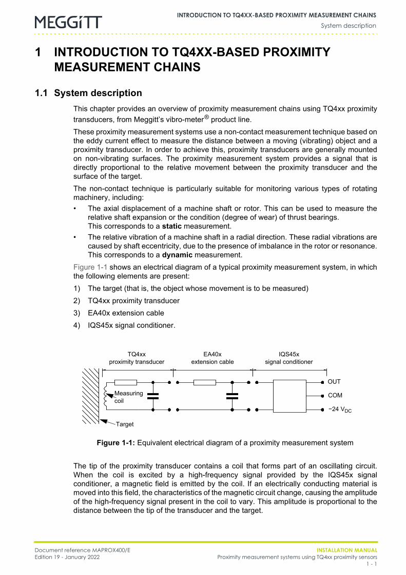
Figure 1-1 shows an electrical diagram of a typical proximity measurement system, in whichthe following elements are present:1) The target (that is, the object whose movement is to be measured)2) TQ4xx proximity transducer3) EA40x extension cable4) IQS45x signal conditioner.
The tip of the proximity transducer contains a coil that forms part of an oscillating circuit.When the coil is excited by a high-frequency signal provided by the IQS45x signalconditioner, a magnetic field is emitted by the coil. If an electrically conducting material ismoved into this field, the characteristics of the magnetic circuit change, causing the amplitudeof the high-frequency signal present in the coil to vary. This amplitude is proportional to thedistance between the tip of the transducer and the target.
Figure 1-1: Equivalent electrical diagram of a proximity measurement system
Target
TQ4xx proximity transducer
IQS45x signal conditioner
EA40x extension cable
Measuringcoil
OUT
COM
−24 VDC
INSTALLATION MANUAL Document reference MAPROX400/EProximity measurement systems using TQ4xx proximity sensors Edition 19 - January 20221 - 2
System descriptionINTRODUCTION TO TQ4XX-BASED PROXIMITY MEASUREMENT CHAINS
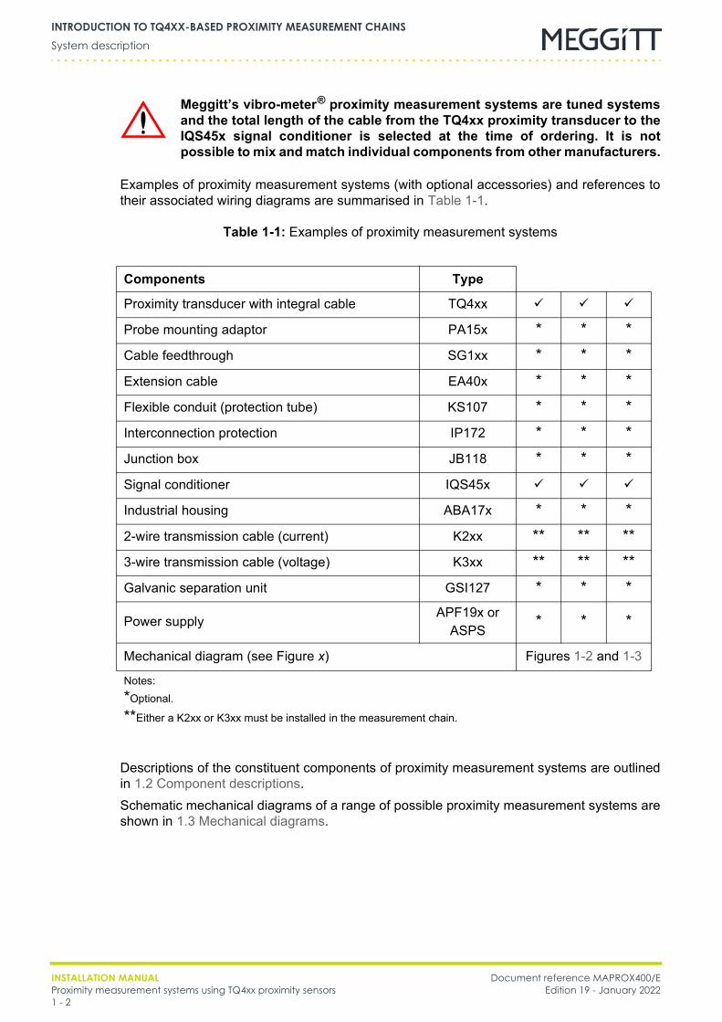
Examples of proximity measurement systems (with optional accessories) and references totheir associated wiring diagrams are summarised in Table 1-1.
Table 1-1: Examples of proximity measurement systems
Descriptions of the constituent components of proximity measurement systems are outlinedin 1.2 Component descriptions.Schematic mechanical diagrams of a range of possible proximity measurement systems areshown in 1.3 Mechanical diagrams.
Meggitt’s vibro-meter® proximity measurement systems are tuned systemsand the total length of the cable from the TQ4xx proximity transducer to theIQS45x signal conditioner is selected at the time of ordering. It is notpossible to mix and match individual components from other manufacturers.
Components Type
Proximity transducer with integral cable TQ4xx
Probe mounting adaptor PA15x * * *Cable feedthrough SG1xx * * *Extension cable EA40x * * *Flexible conduit (protection tube) KS107 * * *Interconnection protection IP172 * * *Junction box JB118 * * *Signal conditioner IQS45x
Industrial housing ABA17x * * *2-wire transmission cable (current) K2xx ** ** **3-wire transmission cable (voltage) K3xx ** ** **Galvanic separation unit GSI127 * * *
Power supply APF19x orASPS * * *
Mechanical diagram (see Figure x) Figures 1-2 and 1-3
Notes:*Optional.
**Either a K2xx or K3xx must be installed in the measurement chain.
Document reference MAPROX400/E INSTALLATION MANUALEdition 19 - January 2022 Proximity measurement systems using TQ4xx proximity sensors
1 - 3
Component descriptionsINTRODUCTION TO TQ4XX-BASED PROXIMITY MEASUREMENT CHAINS
1.2 Component descriptions
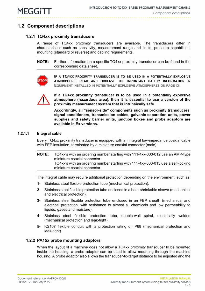
1.2.1 TQ4xx proximity transducersA range of TQ4xx proximity transducers are available. The transducers differ incharacteristics such as sensitivity, measurement range and limits, pressure capabilities,mounting (standard or reverse) and cabling requirements.
NOTE: Further information on a specific TQ4xx proximity transducer can be found in thecorresponding data sheet.
1.2.1.1 Integral cable
Every TQ4xx proximity transducer is equipped with an integral low-impedance coaxial cablewith FEP insulation, terminated by a miniature coaxial connector (male).
NOTE: TQ4xx’s with an ordering number starting with 111-4xx-000-012 use an AMP-typeminiature coaxial connector.TQ4xx’s with an ordering number starting with 111-4xx-000-013 use a self-lockingminiature coaxial connector.
The integral cable may require additional protection depending on the environment, such as:1- Stainless steel flexible protection tube (mechanical protection).2- Stainless steel flexible protection tube enclosed in a heat-shrinkable sleeve (mechanical
and electrical protection).3- Stainless steel flexible protection tube enclosed in an FEP sheath (mechanical and
electrical protection, with resistance to almost all chemicals and low permeability toliquids, gases and moisture).
4- Stainless steel flexible protection tube, double-wall spiral, electrically welded(mechanical protection and leak-tight).
5- KS107 flexible conduit with a protection rating of IP68 (mechanical protection andleak-tight).
1.2.2 PA15x probe mounting adaptorsWhen the layout of a machine does not allow a TQ4xx proximity transducer to be mountedinside the housing, a probe adaptor can be used to allow mounting through the machinehousing. A probe adaptor also allows the transducer-to-target distance to be adjusted and the
IF A TQ4XX PROXIMITY TRANSDUCER IS TO BE USED IN A POTENTIALLY EXPLOSIVEATMOSPHERE, READ AND OBSERVE THE IMPORTANT SAFETY INFORMATION INEQUIPMENT INSTALLED IN POTENTIALLY EXPLOSIVE ATMOSPHERES ON PAGE XII.
If a TQ4xx proximity transducer is to be used in a potentially explosiveatmosphere (hazardous area), then it is essential to use a version of theproximity measurement system that is intrinsically safe.Accordingly, all “sensor-side” components such as proximity transducers,signal conditioners, transmission cables, galvanic separation units, powersupplies and safety barrier units, junction boxes and probe adaptors areavailable in Ex versions.
INSTALLATION MANUAL Document reference MAPROX400/EProximity measurement systems using TQ4xx proximity sensors Edition 19 - January 20221 - 4
Component descriptionsINTRODUCTION TO TQ4XX-BASED PROXIMITY MEASUREMENT CHAINS
proximity transducer to be replaced from outside the machine housing. In this way, themachine does not have to be stopped or disassembled during adjustment.
NOTE: Refer to a specific data sheet for the specifications of a probe mounting adaptor.
1.2.3 SG1xx cable feedthroughsWhen a TQ4xx proximity transducer is mounted inside the machine housing, the integralcable can be passed through the wall of the machine housing using a leak-tight SG1xx cablefeedthrough. To ensure a splash-proof feedthrough, SG10x cable feedthroughs use a doublecable stuffing gland to secure both a coaxial cable and a stainless-steel flexible protectivesheath, while SG164 cable feedthroughs use a Viton® seal. All SG1xx cable feedthroughshave a protection rating of IP68.
NOTE: Refer to a specific data sheet for the specifications of a cable feedthrough.
1.2.4 EA40x extension cablesAn EA40x extension cable is a low-impedance coaxial cable with FEP insulation. For someapplications, a TQ4xx proximity transducer can be delivered with an integral cable length of5 m or 10 m. In which case, no EA40x extension cable is necessary.
NOTE: Refer to a specific proximity measurement system data sheet for furtherinformation on the possible lengths of integral and extension cables.
Mechanical protection of the EA40x extension cable may be necessary, depending on theapplication. The protection available is similar to that for an integral cable(see 1.2.1.1 Integral cable), however, not all options may be available.EA40x extension cables have miniature coaxial connectors (female and male) in order toconnect between the integral cable of a transducer and an IQS45x signal conditioner.
NOTE: EA40x’s with an ordering number starting with 913-40x-000-012 use AMP-typeminiature coaxial connectors.EA40x’s with an ordering number starting with 913-40x-000-013 use self-lockingminiature coaxial connectors.
The connection between a TQ4xx proximity transducer’s integral cable and a EA40xextension cable can be mechanically protected and electrically isolated using:• The protective housing used by the PA151 and PA152 probe adaptors (if included in the
proximity measurement system)• IP172 interconnection protection• A JB118 junction box.The PA15x and JB118 housings have a protection rating of IP65 and are available inintrinsically safe (Ex) versions.
NOTE: It is essential that the connection between the integral cable and the extensioncable is electrically isolated.

Document reference MAPROX400/E INSTALLATION MANUALEdition 19 - January 2022 Proximity measurement systems using TQ4xx proximity sensors
1 - 5
Component descriptionsINTRODUCTION TO TQ4XX-BASED PROXIMITY MEASUREMENT CHAINS
1.2.5 IP172 interconnection protectionAn IP172 interconnection protector is a fluorosilicone rubber boot that provides mechanicaland electrical protection to the connection between an integral cable and an extension cable.These interconnection protectors are resistant to chemicals, fuels and solvents and can beretrofitted to any TQ4xx proximity measurement system.
1.2.6 JB118 junction boxA JB118 junction box provides a protection rating of IP65 to the connection between anintegral cable and an extension cable in measurement systems. These junction boxes aremade of polyester and are available with a range of cable stuffing glands for operation withcables of different diameters.
1.2.7 IQS45x signal conditioner
A TQ4xx proximity transducer operates in conjunction with an IQS45x signal conditioner. Thesignal conditioner transforms the signal from a proximity transducer into a current-modulatedor voltage-modulated signal.
NOTE: The choice of signal type (current-modulated or voltage-modulated) must be madeat the time of ordering.
NOTE: The installation of an IQS45x signal conditioner set for a current-modulated outputsignal, a current (2-wire) transmission cable and a GSI127 galvanic separationunit, allows transmission over longer distances than any other solution.
An IQS45x signal conditioner has a miniature coaxial connector (female) in order to connectto a TQ4xx proximity transducer’s integral cable or an EA40x extension cable.
NOTE: IQS45x’s with an ordering number starting with 204-450-000-001 use an AMP-typeminiature coaxial connector.IQS45x’s with an ordering number starting with 204-450-000-002 use a self-lockingminiature coaxial connector.
1.2.8 ABA17x industrial housingsAn ABA17x industrial housing can be used to enclose and protect IQS45x signalconditioners. The ABA17x industrial housings are available in different sizes to contain andprotect different numbers of signal conditioners. All ABA17x housings offer a protection ratingof IP66 and versions for use in a hazardous area (potentially explosive atmosphere) areavailable.An ABA17x contains one or more DIN rails and an IQS45x is mounted using an MA130mounting adaptor. The mounting adaptor is made from electrically insulating material to helpensure that earth loops are avoided.
IF AN IQS45X SIGNAL CONDITIONER IS TO BE USED IN A POTENTIALLY EXPLOSIVEATMOSPHERE, READ AND OBSERVE THE IMPORTANT SAFETY INFORMATION INEQUIPMENT INSTALLED IN POTENTIALLY EXPLOSIVE ATMOSPHERES ON PAGE XII.

INSTALLATION MANUAL Document reference MAPROX400/EProximity measurement systems using TQ4xx proximity sensors Edition 19 - January 20221 - 6
Component descriptionsINTRODUCTION TO TQ4XX-BASED PROXIMITY MEASUREMENT CHAINS
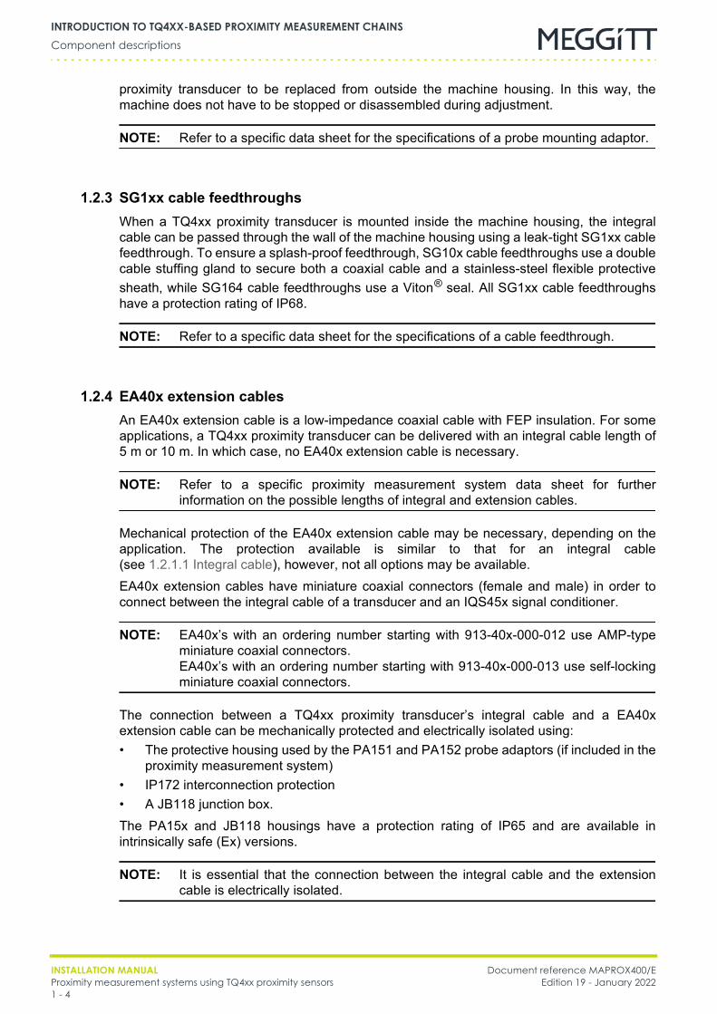
1.2.9 K209 and K210 cablesA K209 or K210 cable is used as a current transmission cable to connect an IQS45x signalconditioner to the electronic monitoring system, either directly or via a GSI127 galvanicseparation unit when current transmission is required. The K209 and K210 are shielded2-wire cables designed for use in harsh industrial environments. An optional protection tube(for example, a KS107) can be used to provide additional mechanical protection to the cableif required.
A K209 or K210 cable can also be used to connect a GSI127 galvanic separation unit (orother safety barrier) to the electronic monitoring system.
1.2.10 K309 and K310 cablesA K309 or K310 cable is used as a voltage transmission cable to connect an IQS45x signalconditioner to the electronic monitoring system, either directly or via a GSI127 galvanicseparation unit acting as a safety barrier, when voltage transmission is required (sufficient).The K309 and K310 are shielded 3-wire cables designed for use in harsh industrialenvironments. An optional protection tube (for example, a KS107) can be used to provideadditional mechanical protection to the cable if required.
1.2.11 GSI127 galvanic separation unitA GSI127 galvanic separation unit is used by TQ4xx measurement chains to supply powerto the sensor/signal conditioning circuitry, including those located in potentially explosiveatmospheres, while providing galvanic isolation between the sensor-side circuitry and thepower supply and between the sensor-side circuitry and the ground of the monitor-sidecircuitry. It also converts the measured current (2-wire transmission system) or voltage(3-wire transmission system) signal from the signal conditioner into a proportionalvoltage-based (floating) output signal, for subsequent use by monitor-side circuitry such asan electronic monitoring system.For use in potentially explosive atmospheres, the GSI127 has a certification that allowsinstallation in an Ex Zone 2, that is, it is an “Ex nA [ia]” safety barrier. As such, the GSI127 isan associated apparatus which can be connected to intrinsically safe apparatus that islocated in potentially explosive atmospheres.
K209 cables can only be used in ordinary applications (that is, innon-explosive atmospheres).
K210 cables can be used in potentially explosive atmospheres, for example,when a GSI127 is installed in the measurement chain.
K309 cables can only be used in ordinary applications (that is, innon-explosive atmospheres).
K310 cables can be used in potentially explosive atmospheres, for example,when a GSI127 (or other safety barrier – not available from Meggitt) isinstalled in the measurement chain.
The GSI127 is permitted to be installed in an Ex Zone 2 (hazardous area).For further information, see 7.2 General wiring diagrams.

Document reference MAPROX400/E INSTALLATION MANUALEdition 19 - January 2022 Proximity measurement systems using TQ4xx proximity sensors
1 - 7
Mechanical diagramsINTRODUCTION TO TQ4XX-BASED PROXIMITY MEASUREMENT CHAINS
In ordinary applications (non-explosive atmospheres), the GSI127 can be used wheregalvanic isolation is not required but transmission distance or noise reduction is a concern,as it rejects the frame voltage that appears between the sensor ground and the electronicmonitoring system ground (thereby helping to reduce noise in the measurement chain).For voltage (3-wire) signal transmission systems in potentially explosive atmospheres, theGSI127 can replace the GSV14x power supply and safety barrier unit, eliminating the needfor additional external Zener barriers.A GSI127 is usually installed on a DIN rail outside the rack, generally in a cubicle housing.The GSI127 galvanic separation unit requires an external power source such as an APF19xpower supply (see 1.2.12 APF19x power supplies) or ASPS auxiliary sensor power supply(see 1.2.13 ASPS auxiliary sensor power supply).
NOTE: The GSI127 galvanic separation unit has replaced the GSI124.
1.2.12 APF19x power suppliesAn APF19x power supply could be required to power external hardware requiring a 24 VDCpower supply, such as a GSI127 galvanic separation unit (see 1.2.11 GSI127 galvanicseparation unit). The APF19x requires a mains AC (or high-voltage DC) input and is usuallyinstalled on a DIN rail outside the rack, generally in a cubicle housing.
1.2.13 ASPS auxiliary sensor power supplyAn ASPS auxiliary sensor power supply is used to power external hardware requiring a24 VDC power supply, such as a GSI127 galvanic separation unit (see 1.2.11 GSI127galvanic separation unit).When a VM600 rack is used as the electronic monitoring system, an ASPS can be installedin the VM600 rack if an AC input version of the RPS6U rack power supply unit is used. It canreplace an APF19x power supply mounted externally, thereby reducing wiring and simplifyingthe installation.
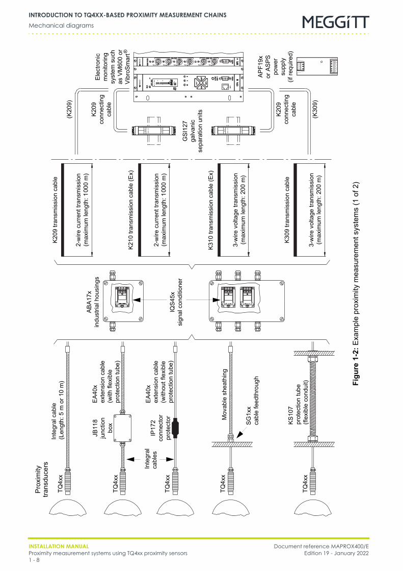
1.3 Mechanical diagramsFigure 1-2 and Figure 1-3 show some examples of the proximity measurement systemsavailable.
INSTALLATION MANUAL Document reference MAPROX400/EProximity measurement systems using TQ4xx proximity sensors Edition 19 - January 20221 - 8
Mechanical diagramsINTRODUCTION TO TQ4XX-BASED PROXIMITY MEASUREMENT CHAINS
VM60
0VM
600
GSI
127
SEN
SOR
MO
NIT
OR
GSI
127
SEN
SOR
MO
NIT
OR
Figu
re1-
2:Ex
ampl
e pr
oxim
ity m
easu
rem
ent s
yste
ms
(1 o
f 2)
Prox
imity
tra
nsdu
cers
TQ4x
x
TQ4x
x
TQ4x
x
TQ4x
x
Inte
gral
cab
le(L
engt
h: 5
m o
r 10
m)
Inte
gral
ca
bles
JB11
8 ju
nctio
n bo
x
Mov
able
she
athi
ng
SG1x
xca
ble
feed
thro
ugh
KS10
7pr
otec
tion
tube
(flex
ible
con
duit)
ABA1
7xin
dust
rial h
ousi
ngs
IQS4
5xsi
gnal
con
ditio
ner
K209
tran
smis
sion
cab
le
K210
tran
smis
sion
cab
le (E
x)
2-w
ire c
urre
nt tr
ansm
issi
on(m
axim
um le
ngth
: 100
0m
)
2-w
ire c
urre
nt tr
ansm
issi
on(m
axim
um le
ngth
: 100
0m
)
3-w
ire v
olta
ge tr
ansm
issi
on(m
axim
um le
ngth
: 200
m)
K310
tran
smis
sion
cab
le (E
x)
K309
tran
smis
sion
cab
le
3-w
ire v
olta
ge tr
ansm
issi
on(m
axim
um le
ngth
: 200
m)
TQ4x
x
IP17
2 co
nnec
tor
prot
ecto
r
EA40
xex
tens
ion
cabl
e(w
ith fl
exib
le
prot
ectio
n tu
be)
EA40
xex
tens
ion
cabl
e(w
ithou
t fle
xibl
e pr
otec
tion
tube
)
GSI
127
galv
anic
se
para
tion
units
APF1
9x
orAS
PS
pow
er
supp
ly
(ifre
quire
d)
K209
conn
ectin
g ca
ble
K209
conn
ectin
g ca
ble
(K30
9)
(K20
9)
Elec
troni
c m
onito
ring
syst
em s
uch
as V
M60
0 or
Vi
broS
mar
t®
Document reference MAPROX400/E INSTALLATION MANUALEdition 19 - January 2022 Proximity measurement systems using TQ4xx proximity sensors
1 - 9
Mechanical diagramsINTRODUCTION TO TQ4XX-BASED PROXIMITY MEASUREMENT CHAINS
VM60
0VM
600
GSI
127
SEN
SOR
MO
NIT
OR
GSI
127
SEN
SOR
MO
NIT
OR
Figu
re1-
3:Ex
ampl
e pr
oxim
ity m
easu
rem
ent s
yste
ms
(2 o
f 2)
TQ41
2
TQ41
2
PA15
1 or
PA1
52
PA15
3
Tran
smis
sion
cab
le
K209
tran
smis
sion
cab
le
K210
tran
smis
sion
cab
le (E
x)
2-w
ire c
urre
nt tr
ansm
issi
on(m
axim
um le
ngth
: 100
0m
)
2-w
ire c
urre
nt tr
ansm
issi
on(m
axim
um le
ngth
: 100
0m
)
3-w
ire v
olta
ge tr
ansm
issi
on(m
axim
um le
ngth
: 200
m)
TQ41
2
PA15
0
EA40
xex
tens
ion
cabl
eK3
10 tr
ansm
issi
on c
able
(Ex)
K309
tran
smis
sion
cab
le
3-w
ire v
olta
ge tr
ansm
issi
on(m
axim
um le
ngth
: 200
m)
EA40
xex
tens
ion
cabl
e
IQS4
5xsi
gnal
con
ditio
ner
GSI
127
galv
anic
se
para
tion
units
APF1
9x
orAS
PS
pow
er
supp
ly
(ifre
quire
d)
K209
conn
ectin
g ca
ble
(K20
9)
K209
conn
ectin
g ca
ble
(K30
9)
Elec
troni
c m
onito
ring
syst
em s
uch
as V
M60
0 or
Vi
broS
mar
t®
INSTALLATION MANUAL Document reference MAPROX400/EProximity measurement systems using TQ4xx proximity sensors Edition 19 - January 20221 - 10
Mechanical diagramsINTRODUCTION TO TQ4XX-BASED PROXIMITY MEASUREMENT CHAINS
THIS PAGE INTENTIONALLY LEFT BLANK
Document reference MAPROX400/E INSTALLATION MANUALEdition 19 - January 2022 Proximity measurement systems using TQ4xx proximity sensors
2 - 1
General considerationsINSTALLING PROXIMITY TRANSDUCERS
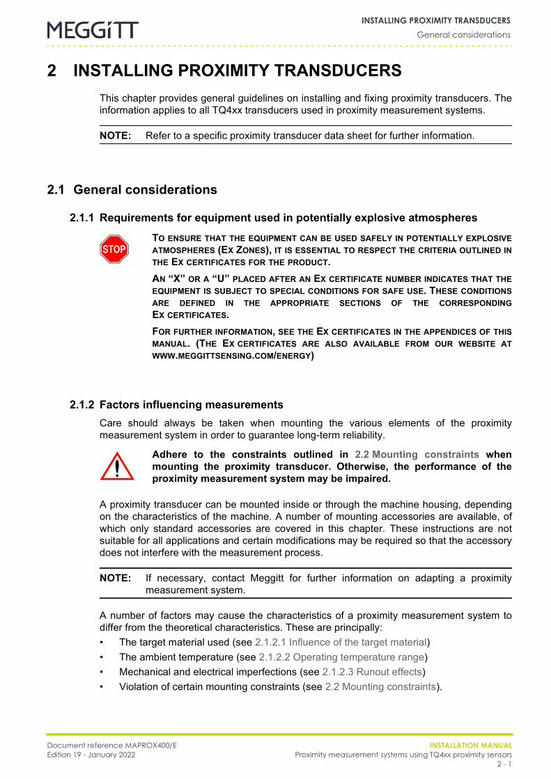
2 INSTALLING PROXIMITY TRANSDUCERSThis chapter provides general guidelines on installing and fixing proximity transducers. Theinformation applies to all TQ4xx transducers used in proximity measurement systems.
NOTE: Refer to a specific proximity transducer data sheet for further information.
2.1 General considerations
2.1.1 Requirements for equipment used in potentially explosive atmospheres
2.1.2 Factors influencing measurementsCare should always be taken when mounting the various elements of the proximitymeasurement system in order to guarantee long-term reliability.
A proximity transducer can be mounted inside or through the machine housing, dependingon the characteristics of the machine. A number of mounting accessories are available, ofwhich only standard accessories are covered in this chapter. These instructions are notsuitable for all applications and certain modifications may be required so that the accessorydoes not interfere with the measurement process.
NOTE: If necessary, contact Meggitt for further information on adapting a proximitymeasurement system.
A number of factors may cause the characteristics of a proximity measurement system todiffer from the theoretical characteristics. These are principally:• The target material used (see 2.1.2.1 Influence of the target material)• The ambient temperature (see 2.1.2.2 Operating temperature range)• Mechanical and electrical imperfections (see 2.1.2.3 Runout effects)• Violation of certain mounting constraints (see 2.2 Mounting constraints).
TO ENSURE THAT THE EQUIPMENT CAN BE USED SAFELY IN POTENTIALLY EXPLOSIVEATMOSPHERES (EX ZONES), IT IS ESSENTIAL TO RESPECT THE CRITERIA OUTLINED INTHE EX CERTIFICATES FOR THE PRODUCT.AN “X” OR A “U” PLACED AFTER AN EX CERTIFICATE NUMBER INDICATES THAT THEEQUIPMENT IS SUBJECT TO SPECIAL CONDITIONS FOR SAFE USE. THESE CONDITIONSARE DEFINED IN THE APPROPRIATE SECTIONS OF THE CORRESPONDINGEX CERTIFICATES.FOR FURTHER INFORMATION, SEE THE EX CERTIFICATES IN THE APPENDICES OF THISMANUAL. (THE EX CERTIFICATES ARE ALSO AVAILABLE FROM OUR WEBSITE ATWWW.MEGGITTSENSING.COM/ENERGY)
Adhere to the constraints outlined in 2.2 Mounting constraints whenmounting the proximity transducer. Otherwise, the performance of theproximity measurement system may be impaired.
INSTALLATION MANUAL Document reference MAPROX400/EProximity measurement systems using TQ4xx proximity sensors Edition 19 - January 20222 - 2
General considerationsINSTALLING PROXIMITY TRANSDUCERS
2.1.2.1 Influence of the target material
A proximity transducer requires an electrically conducting target material. The target materialcan be steel, copper, aluminium, or standard VCL 140 (equivalent to AISI 4140) and so on.The system sensitivity and the linear part of the measurement range are heavily dependenton the target material.For information on the effect of the target material on sensitivity, see Figure 6-3 which showsthe voltage-distance characteristics for targets made of VCL 140 steel (equivalent toAISI 4140) and other metals.
2.1.2.2 Operating temperature range
The electrical conductivity and permeability of the target material, as well as the cablecapacitance and other factors, are dependent on the ambient temperature. Therefore, theoperating temperature can affect the precision of results.
NOTE: Refer to a specific proximity transducer data sheet for further information on themaximum temperature drift.
2.1.2.3 Runout effects
The runout is the sum of two effects that are characteristic of a non-ideal target:1) Mechanical runout is caused by physical imperfections in the target. In the case of a
rotating shaft, this could be due to a lack of perfect coaxiality or circularity. It is also afunction of the surface state, as imperfections in the shaft’s surface (such as scratches)will cause mechanical runout.
2) Electrical runout is mainly caused by an unequal distribution of the electrical conductivityon the shaft’s surface (such as the presence of “magnetic spots”).
During measurements with a proximity transducer, runout effects lead to an apparent signalthat does not exist. These error sources can be eliminated digitally by the electronicmonitoring system.
Document reference MAPROX400/E INSTALLATION MANUALEdition 19 - January 2022 Proximity measurement systems using TQ4xx proximity sensors
2 - 3
Mounting constraintsINSTALLING PROXIMITY TRANSDUCERS
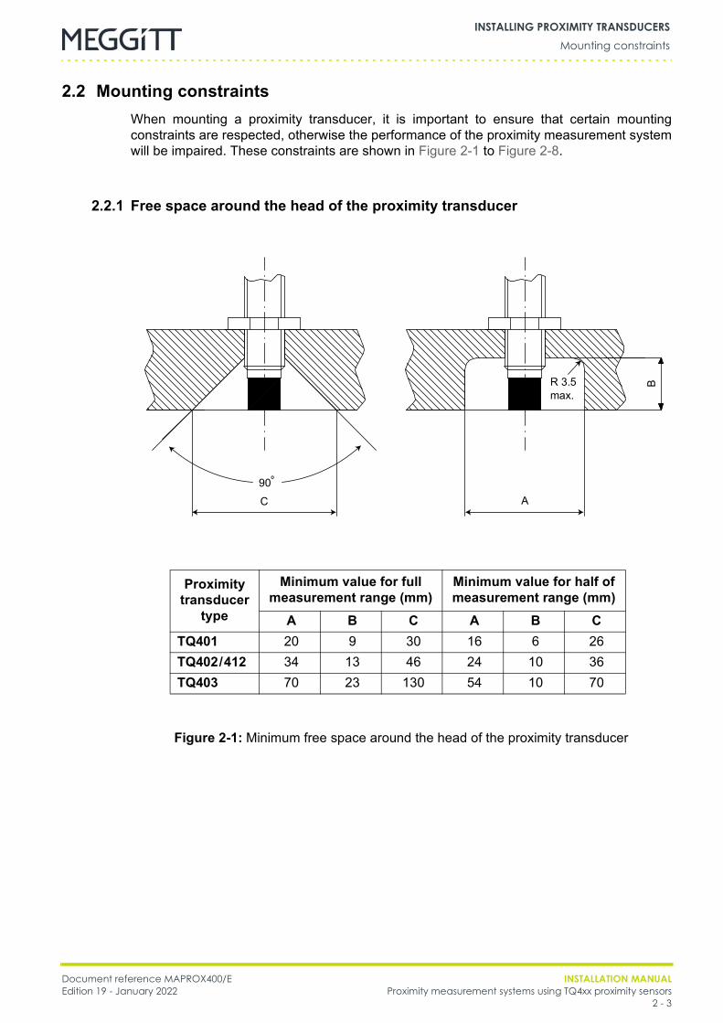
2.2 Mounting constraintsWhen mounting a proximity transducer, it is important to ensure that certain mountingconstraints are respected, otherwise the performance of the proximity measurement systemwill be impaired. These constraints are shown in Figure 2-1 to Figure 2-8.
2.2.1 Free space around the head of the proximity transducer
Proximity transducer
type
Minimum value for full measurement range (mm)
Minimum value for half of measurement range (mm)
A B C A B CTQ401 20 9 30 16 6 26TQ402/412 34 13 46 24 10 36TQ403 70 23 130 54 10 70
Figure 2-1: Minimum free space around the head of the proximity transducer
C A
BR 3.5max.
90º
INSTALLATION MANUAL Document reference MAPROX400/EProximity measurement systems using TQ4xx proximity sensors Edition 19 - January 20222 - 4
Mounting constraintsINSTALLING PROXIMITY TRANSDUCERS
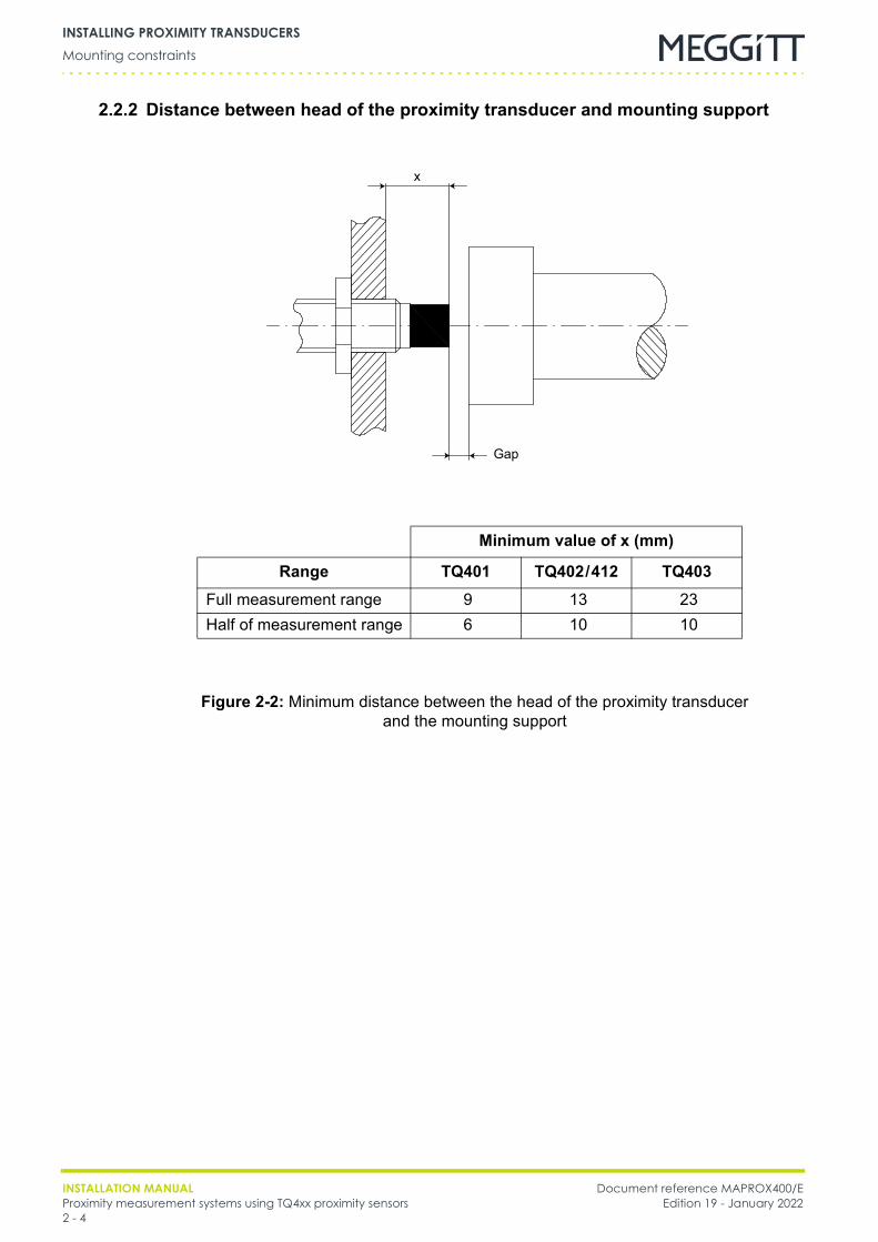
2.2.2 Distance between head of the proximity transducer and mounting support
Minimum value of x (mm)
Range TQ401 TQ402/412 TQ403Full measurement range 9 13 23Half of measurement range 6 10 10
Figure 2-2: Minimum distance between the head of the proximity transducer and the mounting support
Gap
x
Document reference MAPROX400/E INSTALLATION MANUALEdition 19 - January 2022 Proximity measurement systems using TQ4xx proximity sensors
2 - 5
Mounting constraintsINSTALLING PROXIMITY TRANSDUCERS
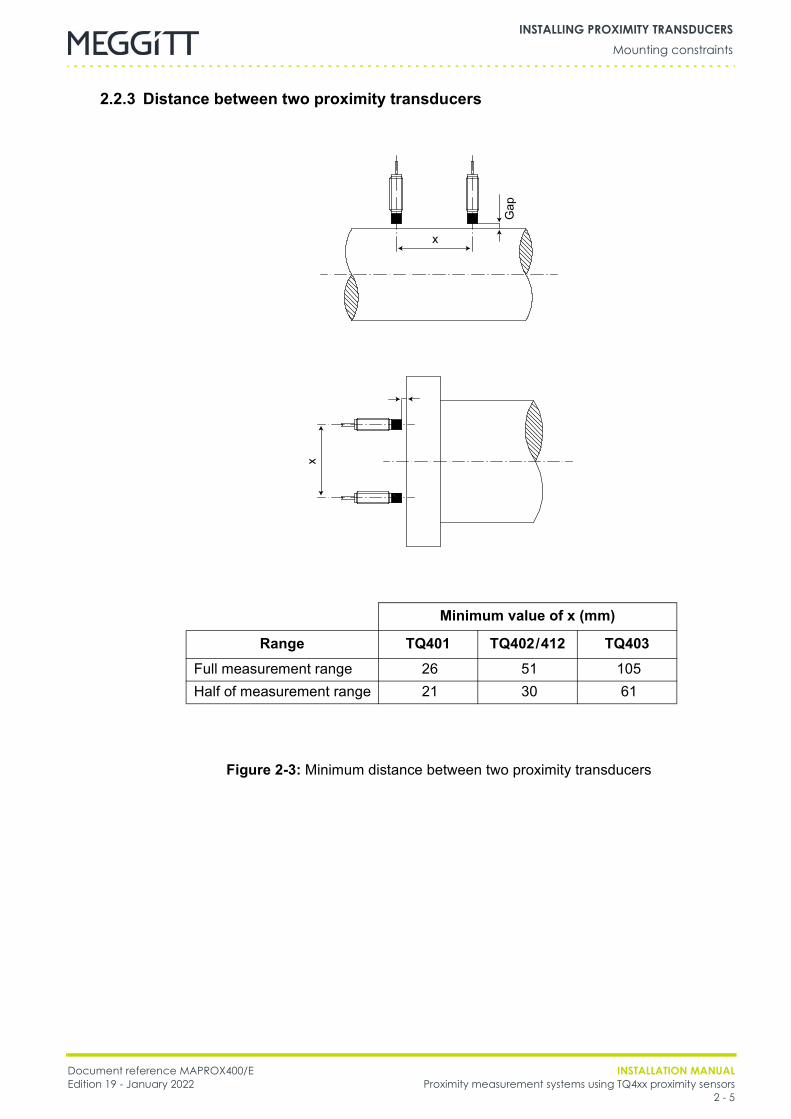
2.2.3 Distance between two proximity transducers
Minimum value of x (mm)
Range TQ401 TQ402/412 TQ403Full measurement range 26 51 105Half of measurement range 21 30 61
Figure 2-3: Minimum distance between two proximity transducers
Gap
x
x
INSTALLATION MANUAL Document reference MAPROX400/EProximity measurement systems using TQ4xx proximity sensors Edition 19 - January 20222 - 6
Mounting constraintsINSTALLING PROXIMITY TRANSDUCERS
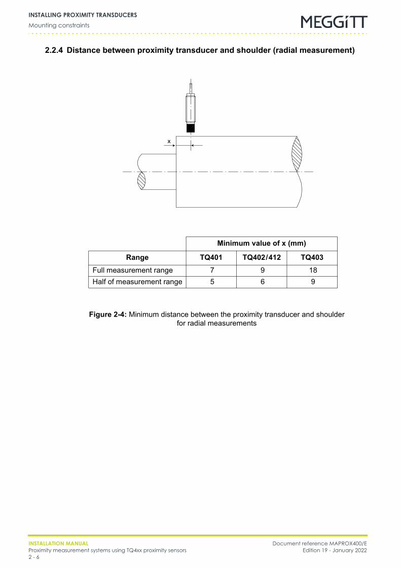
2.2.4 Distance between proximity transducer and shoulder (radial measurement)
Minimum value of x (mm)
Range TQ401 TQ402/412 TQ403Full measurement range 7 9 18Half of measurement range 5 6 9
Figure 2-4: Minimum distance between the proximity transducer and shoulderfor radial measurements
x
Document reference MAPROX400/E INSTALLATION MANUALEdition 19 - January 2022 Proximity measurement systems using TQ4xx proximity sensors
2 - 7
Mounting constraintsINSTALLING PROXIMITY TRANSDUCERS
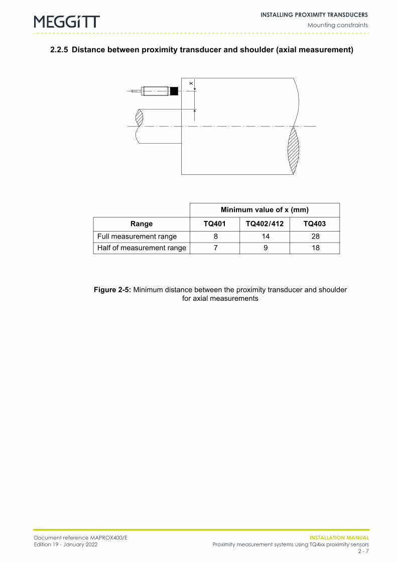
2.2.5 Distance between proximity transducer and shoulder (axial measurement)
Minimum value of x (mm)
Range TQ401 TQ402/412 TQ403Full measurement range 8 14 28Half of measurement range 7 9 18
Figure 2-5: Minimum distance between the proximity transducer and shoulderfor axial measurements
x
INSTALLATION MANUAL Document reference MAPROX400/EProximity measurement systems using TQ4xx proximity sensors Edition 19 - January 20222 - 8
Mounting constraintsINSTALLING PROXIMITY TRANSDUCERS
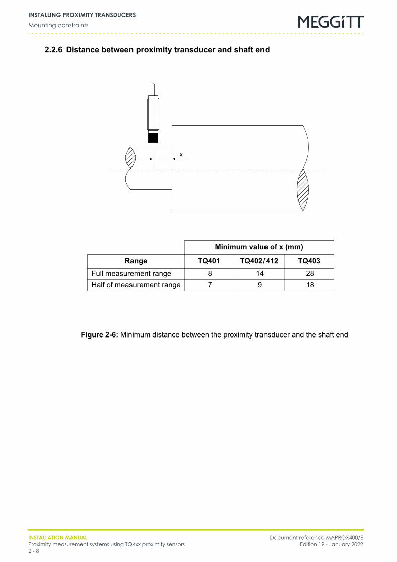
2.2.6 Distance between proximity transducer and shaft end
Minimum value of x (mm)
Range TQ401 TQ402/412 TQ403Full measurement range 8 14 28Half of measurement range 7 9 18
Figure 2-6: Minimum distance between the proximity transducer and the shaft end
x
Document reference MAPROX400/E INSTALLATION MANUALEdition 19 - January 2022 Proximity measurement systems using TQ4xx proximity sensors
2 - 9
Mounting constraintsINSTALLING PROXIMITY TRANSDUCERS
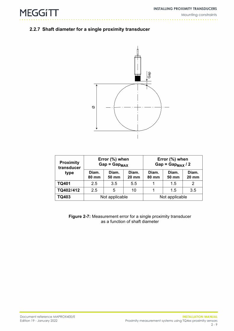
2.2.7 Shaft diameter for a single proximity transducer
Proximity transducer
type
Error (%) when Gap = GapMAX
Error (%) when Gap = GapMAX / 2
Diam. 80 mm
Diam. 50 mm
Diam. 20 mm
Diam. 80 mm
Diam. 50 mm
Diam. 20 mm
TQ401 2.5 3.5 5.5 1 1.5 2TQ402/412 2.5 5 10 1 1.5 3.5TQ403 Not applicable Not applicable
Figure 2-7: Measurement error for a single proximity transducer as a function of shaft diameter
Gap
Ø
INSTALLATION MANUAL Document reference MAPROX400/EProximity measurement systems using TQ4xx proximity sensors Edition 19 - January 20222 - 10
Mounting constraintsINSTALLING PROXIMITY TRANSDUCERS
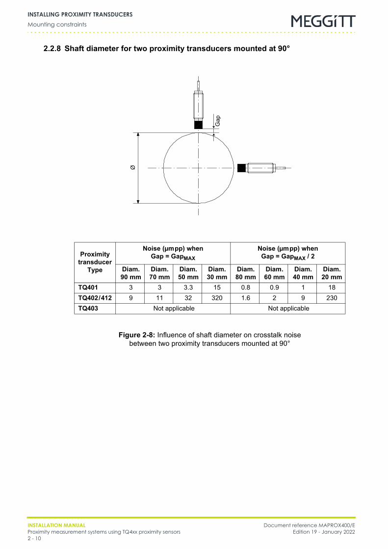
2.2.8 Shaft diameter for two proximity transducers mounted at 90°
Proximity transducer
Type
Noise (µmpp) when Gap = GapMAX
Noise (µmpp) when Gap = GapMAX / 2
Diam. 90 mm
Diam. 70 mm
Diam. 50 mm
Diam. 30 mm
Diam. 80 mm
Diam. 60 mm
Diam. 40 mm
Diam. 20 mm
TQ401 3 3 3.3 15 0.8 0.9 1 18TQ402/412 9 11 32 320 1.6 2 9 230TQ403 Not applicable Not applicable
Figure 2-8: Influence of shaft diameter on crosstalk noise between two proximity transducers mounted at 90°
Gap
Ø
Document reference MAPROX400/E INSTALLATION MANUALEdition 19 - January 2022 Proximity measurement systems using TQ4xx proximity sensors
2 - 11
Mounting a proximity transducerINSTALLING PROXIMITY TRANSDUCERS
2.3 Mounting a proximity transducer
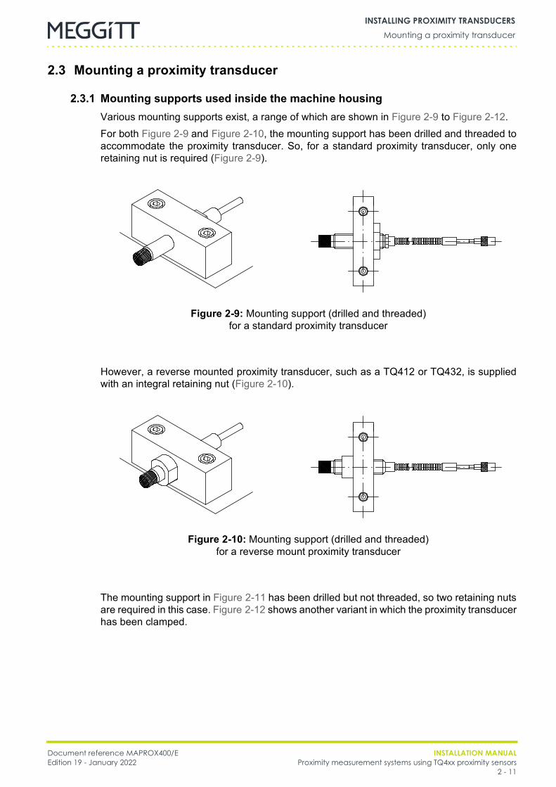
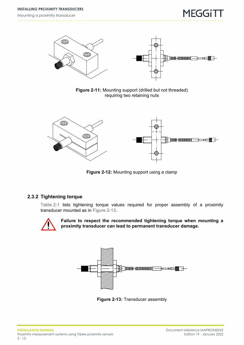
2.3.1 Mounting supports used inside the machine housingVarious mounting supports exist, a range of which are shown in Figure 2-9 to Figure 2-12.For both Figure 2-9 and Figure 2-10, the mounting support has been drilled and threaded toaccommodate the proximity transducer. So, for a standard proximity transducer, only oneretaining nut is required (Figure 2-9).
However, a reverse mounted proximity transducer, such as a TQ412 or TQ432, is suppliedwith an integral retaining nut (Figure 2-10).
The mounting support in Figure 2-11 has been drilled but not threaded, so two retaining nutsare required in this case. Figure 2-12 shows another variant in which the proximity transducerhas been clamped.
Figure 2-9: Mounting support (drilled and threaded) for a standard proximity transducer
Figure 2-10: Mounting support (drilled and threaded) for a reverse mount proximity transducer
INSTALLATION MANUAL Document reference MAPROX400/EProximity measurement systems using TQ4xx proximity sensors Edition 19 - January 20222 - 12
Mounting a proximity transducerINSTALLING PROXIMITY TRANSDUCERS
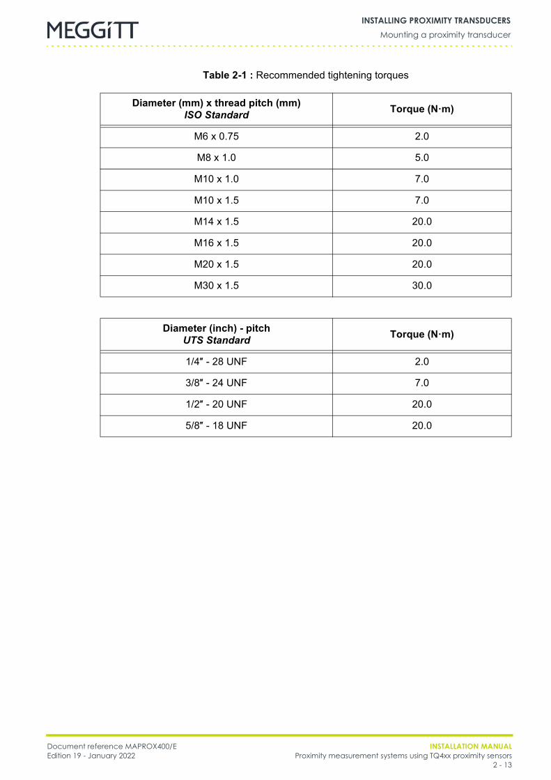
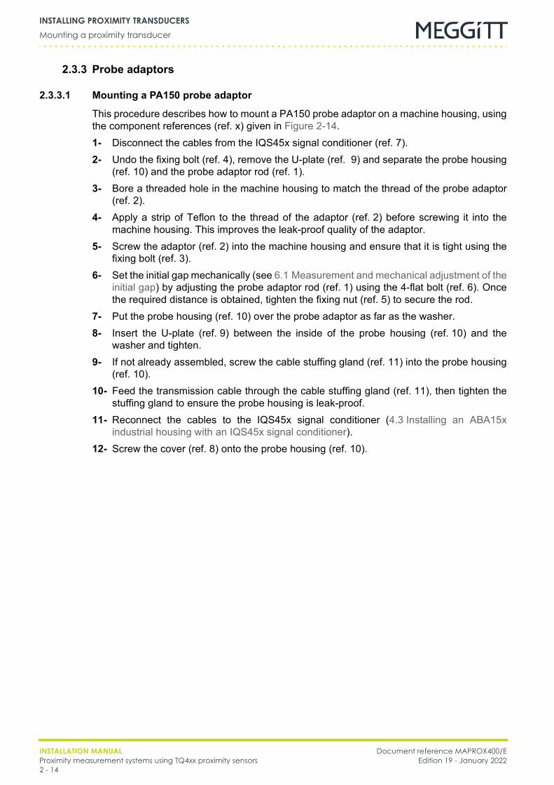
2.3.2 Tightening torqueTable 2-1 lists tightening torque values required for proper assembly of a proximitytransducer mounted as in Figure 2-13.
Figure 2-11: Mounting support (drilled but not threaded) requiring two retaining nuts
Figure 2-12: Mounting support using a clamp
Failure to respect the recommended tightening torque when mounting aproximity transducer can lead to permanent transducer damage.
Figure 2-13: Transducer assembly
Document reference MAPROX400/E INSTALLATION MANUALEdition 19 - January 2022 Proximity measurement systems using TQ4xx proximity sensors
2 - 13
Mounting a proximity transducerINSTALLING PROXIMITY TRANSDUCERS
Table 2-1 : Recommended tightening torques
Diameter (mm) x thread pitch (mm)ISO Standard Torque (N·m)
M6 x 0.75 2.0
M8 x 1.0 5.0
M10 x 1.0 7.0
M10 x 1.5 7.0
M14 x 1.5 20.0
M16 x 1.5 20.0
M20 x 1.5 20.0
M30 x 1.5 30.0
Diameter (inch) - pitch UTS Standard Torque (N·m)
1/4″ - 28 UNF 2.0
3/8″ - 24 UNF 7.0
1/2″ - 20 UNF 20.0
5/8″ - 18 UNF 20.0
INSTALLATION MANUAL Document reference MAPROX400/EProximity measurement systems using TQ4xx proximity sensors Edition 19 - January 20222 - 14
Mounting a proximity transducerINSTALLING PROXIMITY TRANSDUCERS
2.3.3 Probe adaptors
2.3.3.1 Mounting a PA150 probe adaptor
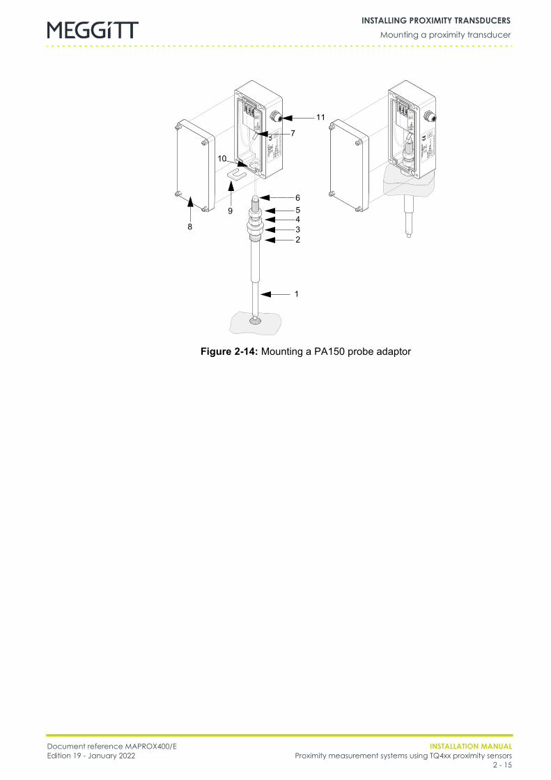
This procedure describes how to mount a PA150 probe adaptor on a machine housing, usingthe component references (ref. x) given in Figure 2-14.1- Disconnect the cables from the IQS45x signal conditioner (ref. 7).2- Undo the fixing bolt (ref. 4), remove the U-plate (ref. 9) and separate the probe housing
(ref. 10) and the probe adaptor rod (ref. 1).3- Bore a threaded hole in the machine housing to match the thread of the probe adaptor
(ref. 2).4- Apply a strip of Teflon to the thread of the adaptor (ref. 2) before screwing it into the
machine housing. This improves the leak-proof quality of the adaptor.5- Screw the adaptor (ref. 2) into the machine housing and ensure that it is tight using the
fixing bolt (ref. 3).6- Set the initial gap mechanically (see 6.1 Measurement and mechanical adjustment of the
initial gap) by adjusting the probe adaptor rod (ref. 1) using the 4-flat bolt (ref. 6). Oncethe required distance is obtained, tighten the fixing nut (ref. 5) to secure the rod.
7- Put the probe housing (ref. 10) over the probe adaptor as far as the washer.8- Insert the U-plate (ref. 9) between the inside of the probe housing (ref. 10) and the
washer and tighten.9- If not already assembled, screw the cable stuffing gland (ref. 11) into the probe housing
(ref. 10).10- Feed the transmission cable through the cable stuffing gland (ref. 11), then tighten the
stuffing gland to ensure the probe housing is leak-proof.11- Reconnect the cables to the IQS45x signal conditioner (4.3 Installing an ABA15x
industrial housing with an IQS45x signal conditioner).12- Screw the cover (ref. 8) onto the probe housing (ref. 10).
Document reference MAPROX400/E INSTALLATION MANUALEdition 19 - January 2022 Proximity measurement systems using TQ4xx proximity sensors
2 - 15
Mounting a proximity transducerINSTALLING PROXIMITY TRANSDUCERS
Figure 2-14: Mounting a PA150 probe adaptor
1
2345
8
9
10
11
7
6
INSTALLATION MANUAL Document reference MAPROX400/EProximity measurement systems using TQ4xx proximity sensors Edition 19 - January 20222 - 16
Mounting a proximity transducerINSTALLING PROXIMITY TRANSDUCERS
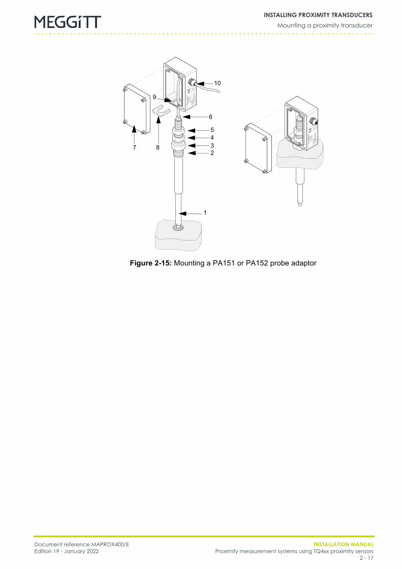
2.3.3.2 Mounting PA151 and PA152 probe adaptors
This procedure describes how to mount a PA151 or PA152 probe adaptor on a machinehousing, using the component references (ref. x) given in Figure 2-15.1- Undo the fixing bolt (ref. 4), remove the U-plate (ref. 8) and separate the probe housing
(ref. 9) from the probe adaptor rod (ref. 1).2- Bore a threaded hole in the machine housing to match the thread of the probe adaptor
(ref. 2).3- Apply a strip of Teflon to the thread of the adaptor (ref. 2) before screwing it into the
machine housing. This improves the leak-proof quality of the adaptor.4- Screw the adaptor (ref. 2) into the machine housing and ensure that it is tight using the
fixing bolt (ref. 3).5- Set the initial gap mechanically (see 6.1 Measurement and mechanical adjustment of the
initial gap) by adjusting the probe adaptor rod (ref. 1) using the 4-flat bolt (ref. 6). Oncethe required distance is obtained, tighten the fixing nut (ref. 5) to secure the rod.
6- Put the probe housing (ref. 9) over the probe adaptor as far as the housing fixing bolt(ref. 3).
7- Insert the U-plate (ref. 8) between the inside of the probe housing (ref. 9) and the fixingbolt (ref. 4) and tighten.
8- If not already assembled, screw the cable stuffing gland (ref. 10) into the probe housing(ref. 9).
9- Feed the integral cable or EA40x extension cable through the cable stuffing gland(ref. 10), then tighten the stuffing gland to ensure the probe housing is leak-proof.
10- If there is an EA40x extension cable, connect the EA40x extension cable to the integralcable, as described in 3.3 Installing an integral or extension cable.
11- Screw the cover (ref. 7) onto the probe housing (ref. 9).
Document reference MAPROX400/E INSTALLATION MANUALEdition 19 - January 2022 Proximity measurement systems using TQ4xx proximity sensors
2 - 17
Mounting a proximity transducerINSTALLING PROXIMITY TRANSDUCERS
Figure 2-15: Mounting a PA151 or PA152 probe adaptor
1
2345
7 8
9
10
6
INSTALLATION MANUAL Document reference MAPROX400/EProximity measurement systems using TQ4xx proximity sensors Edition 19 - January 20222 - 18
Mounting a proximity transducerINSTALLING PROXIMITY TRANSDUCERS
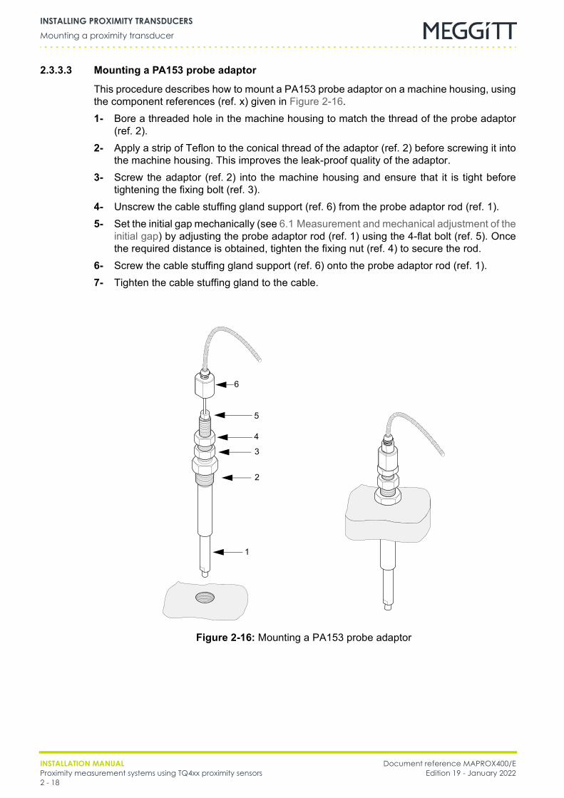
2.3.3.3 Mounting a PA153 probe adaptor
This procedure describes how to mount a PA153 probe adaptor on a machine housing, usingthe component references (ref. x) given in Figure 2-16.1- Bore a threaded hole in the machine housing to match the thread of the probe adaptor
(ref. 2).2- Apply a strip of Teflon to the conical thread of the adaptor (ref. 2) before screwing it into
the machine housing. This improves the leak-proof quality of the adaptor.3- Screw the adaptor (ref. 2) into the machine housing and ensure that it is tight before
tightening the fixing bolt (ref. 3).4- Unscrew the cable stuffing gland support (ref. 6) from the probe adaptor rod (ref. 1).5- Set the initial gap mechanically (see 6.1 Measurement and mechanical adjustment of the
initial gap) by adjusting the probe adaptor rod (ref. 1) using the 4-flat bolt (ref. 5). Oncethe required distance is obtained, tighten the fixing nut (ref. 4) to secure the rod.
6- Screw the cable stuffing gland support (ref. 6) onto the probe adaptor rod (ref. 1).7- Tighten the cable stuffing gland to the cable.
1
2
3
4
Figure 2-16: Mounting a PA153 probe adaptor
5
6

Document reference MAPROX400/E INSTALLATION MANUALEdition 19 - January 2022 Proximity measurement systems using TQ4xx proximity sensors
3 - 1
General precautionsINSTALLING CABLES
3 INSTALLING CABLESThis chapter provides general guidelines on installing cables, cable feedthroughs and cableprotectors in proximity measurement systems.
NOTE: Further information on a specific cable can be found in the corresponding datasheet.
The information contained in this chapter applies to installing the following:• Cable feedthroughs• Integral cables• EA40x extension cables• IP172 cable protectors• K2xx or K3xx transmission cables• K2xx connecting cables.Further information on connecting transmission and connecting cables is described in5 Installing galvanic separation units.
3.1 General precautions
3.1.1 Cables in potentially explosive atmospheres
3.1.2 Minimum bend radiusIt is essential that the minimum bend radius is respected when connecting and fixing anintegral cable, extension cable, transmission cable or connecting cable.
NOTE: Further information on the minimum bend radius of a specific cable can be foundin the corresponding data sheet.
ONLY CABLES APPROPRIATE FOR USE IN POTENTIALLY EXPLOSIVE ATMOSPHERES(EX ZONES) SHOULD BE INSTALLED IN SUCH ENVIRONMENTS.THE LENGTHS OF ALL CABLES (INTEGRAL CABLES AND/OR CABLE ASSEMBLIES)INSTALLED IN POTENTIALLY EXPLOSIVE ATMOSPHERES MUST BE DETERMINED ASPER THE CRITERIA DEFINED IN THE APPROPRIATE SECTIONS OF THE CORRESPONDINGEX CERTIFICATES.FOR FURTHER INFORMATION, SEE THE EX CERTIFICATES IN THE APPENDICES OF THISMANUAL. (THE EX CERTIFICATES ARE ALSO AVAILABLE FROM OUR WEBSITE ATWWW.MEGGITTSENSING.COM/ENERGY)
Failure to respect the minimum bend radius of a cable can lead to permanentcable damage.
INSTALLATION MANUAL Document reference MAPROX400/EProximity measurement systems using TQ4xx proximity sensors Edition 19 - January 20223 - 2
General precautionsINSTALLING CABLES
3.1.3 Total system lengthThe combined length of the integral cable and the EA40x extension cable is known as thetotal system length and must be one of the appropriate possible lengths defined by Meggitt.
NOTE: Further information on the total system lengths available for a specific proximitymeasurement system can be found in the corresponding data sheet.
3.1.4 Operating temperature range
NOTE: For further information on the temperature range of a specific cable, refer to thecorresponding data sheet.
3.1.5 Minimizing sources of electromagnetic interferenceSignals in the proximity measurement system, like all electrical signals, are sensitive toelectromagnetic interference (EMI). This is particularly true near the proximity transducer,where signal levels are low. Interference can come from a variety of sources including powercables, strong magnetic fields, motors, switching gear, portable phones and walkie-talkies.The following precautions must be taken to reduce the effects of EMI:1- Use appropriate grounding techniques. Always conform to the electrical wiring diagrams
(see 7 Electrical connections).2- If possible, place cables in a grounded steel protection tube to provide additional
electrical and mechanical protection.3- Do not run signal cables through conduits used for other purposes such as power cables
or communications lines.
3.1.6 Cable conduitsCable conduits provide mechanical and electrical protection. All signal wiring should be runthrough conduits that are reserved for only one type of cable. Do not mix signal wiring withpower cables or communications lines.The conduit must be well grounded according to industry standards in order to provideprotection against EMI. The conduit should be reasonably waterproof to prevent water or other liquids entering it. Ifthere is a risk of this happening, or of condensation forming in the conduit, then adequatedrainage should be provided.
Because Meggitt’s vibro-meter® proximity measurement systems are tunedsystems, never shorten or lengthen an integral cable or extension cable. Theoriginal total system length must be conserved. Otherwise, calibration of theproximity measurement system will be inaccurate.
The temperature were a cable is installed must remain permanently within itsoperating temperature range.
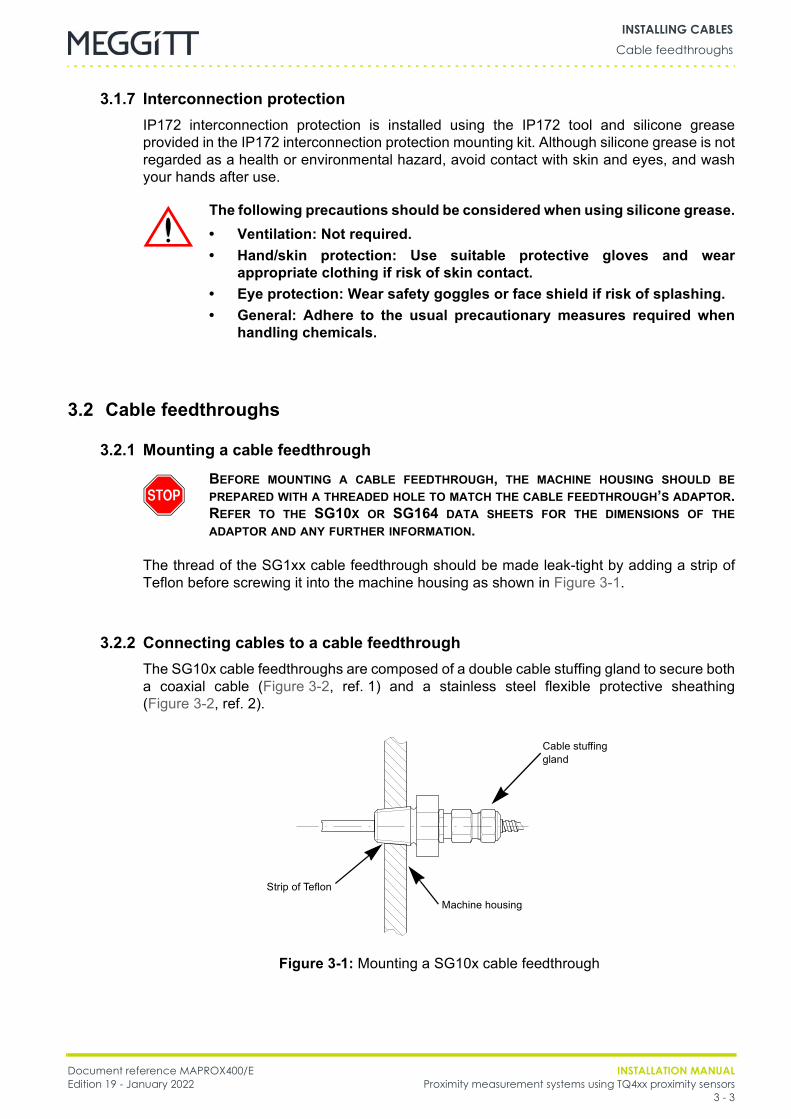
Document reference MAPROX400/E INSTALLATION MANUALEdition 19 - January 2022 Proximity measurement systems using TQ4xx proximity sensors
3 - 3
Cable feedthroughsINSTALLING CABLES
3.1.7 Interconnection protectionIP172 interconnection protection is installed using the IP172 tool and silicone greaseprovided in the IP172 interconnection protection mounting kit. Although silicone grease is notregarded as a health or environmental hazard, avoid contact with skin and eyes, and washyour hands after use.
3.2 Cable feedthroughs
3.2.1 Mounting a cable feedthrough
The thread of the SG1xx cable feedthrough should be made leak-tight by adding a strip ofTeflon before screwing it into the machine housing as shown in Figure 3-1.
3.2.2 Connecting cables to a cable feedthroughThe SG10x cable feedthroughs are composed of a double cable stuffing gland to secure botha coaxial cable (Figure 3-2, ref. 1) and a stainless steel flexible protective sheathing(Figure 3-2, ref. 2).
The following precautions should be considered when using silicone grease.• Ventilation: Not required.• Hand/skin protection: Use suitable protective gloves and wear
appropriate clothing if risk of skin contact.• Eye protection: Wear safety goggles or face shield if risk of splashing.• General: Adhere to the usual precautionary measures required when
handling chemicals.
BEFORE MOUNTING A CABLE FEEDTHROUGH, THE MACHINE HOUSING SHOULD BEPREPARED WITH A THREADED HOLE TO MATCH THE CABLE FEEDTHROUGH’S ADAPTOR.REFER TO THE SG10X OR SG164 DATA SHEETS FOR THE DIMENSIONS OF THEADAPTOR AND ANY FURTHER INFORMATION.
Figure 3-1: Mounting a SG10x cable feedthrough
Cable stuffing gland
Machine housing
Strip of Teflon
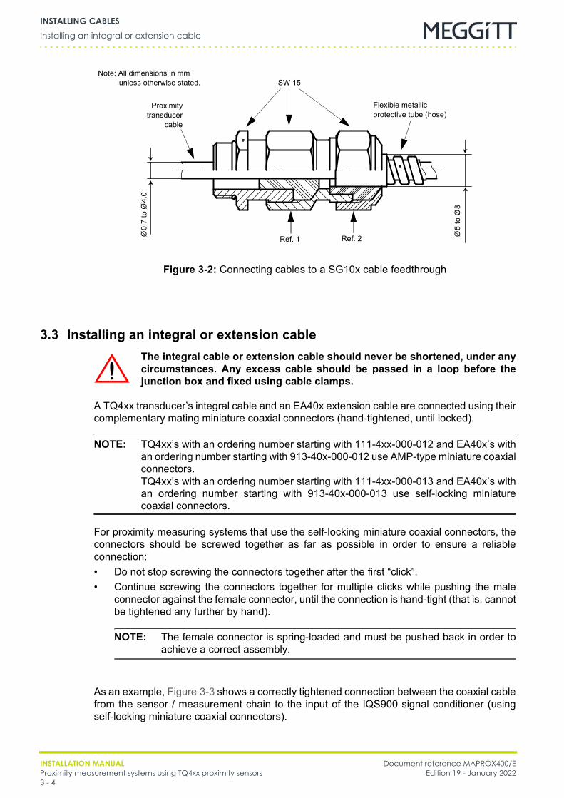
INSTALLATION MANUAL Document reference MAPROX400/EProximity measurement systems using TQ4xx proximity sensors Edition 19 - January 20223 - 4
Installing an integral or extension cableINSTALLING CABLES
3.3 Installing an integral or extension cable
A TQ4xx transducer’s integral cable and an EA40x extension cable are connected using theircomplementary mating miniature coaxial connectors (hand-tightened, until locked).
NOTE: TQ4xx’s with an ordering number starting with 111-4xx-000-012 and EA40x’s withan ordering number starting with 913-40x-000-012 use AMP-type miniature coaxialconnectors.TQ4xx’s with an ordering number starting with 111-4xx-000-013 and EA40x’s withan ordering number starting with 913-40x-000-013 use self-locking miniaturecoaxial connectors.
For proximity measuring systems that use the self-locking miniature coaxial connectors, theconnectors should be screwed together as far as possible in order to ensure a reliableconnection:• Do not stop screwing the connectors together after the first “click”.• Continue screwing the connectors together for multiple clicks while pushing the male
connector against the female connector, until the connection is hand-tight (that is, cannotbe tightened any further by hand).
NOTE: The female connector is spring-loaded and must be pushed back in order toachieve a correct assembly.
As an example, Figure 3-3 shows a correctly tightened connection between the coaxial cablefrom the sensor / measurement chain to the input of the IQS900 signal conditioner (usingself-locking miniature coaxial connectors).
SW 15
Proximitytransducer
cable
Ø0.
7 to
Ø4.
0
Ø5
to Ø
8
Note: All dimensions in mmunless otherwise stated.
Figure 3-2: Connecting cables to a SG10x cable feedthrough
Flexible metallic protective tube (hose)
Ref. 2Ref. 1
The integral cable or extension cable should never be shortened, under anycircumstances. Any excess cable should be passed in a loop before thejunction box and fixed using cable clamps.
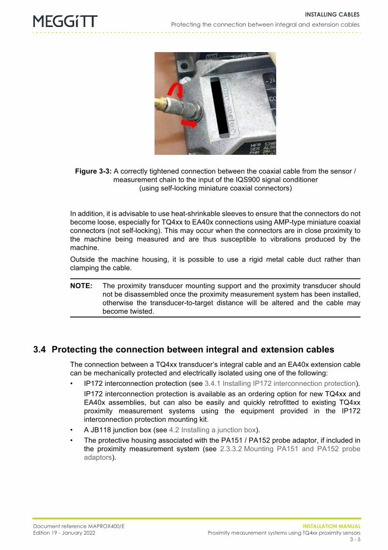
Document reference MAPROX400/E INSTALLATION MANUALEdition 19 - January 2022 Proximity measurement systems using TQ4xx proximity sensors
3 - 5
Protecting the connection between integral and extension cablesINSTALLING CABLES
In addition, it is advisable to use heat-shrinkable sleeves to ensure that the connectors do notbecome loose, especially for TQ4xx to EA40x connections using AMP-type miniature coaxialconnectors (not self-locking). This may occur when the connectors are in close proximity tothe machine being measured and are thus susceptible to vibrations produced by themachine.Outside the machine housing, it is possible to use a rigid metal cable duct rather thanclamping the cable.
NOTE: The proximity transducer mounting support and the proximity transducer shouldnot be disassembled once the proximity measurement system has been installed,otherwise the transducer-to-target distance will be altered and the cable maybecome twisted.
3.4 Protecting the connection between integral and extension cablesThe connection between a TQ4xx transducer’s integral cable and an EA40x extension cablecan be mechanically protected and electrically isolated using one of the following:• IP172 interconnection protection (see 3.4.1 Installing IP172 interconnection protection).
IP172 interconnection protection is available as an ordering option for new TQ4xx andEA40x assemblies, but can also be easily and quickly retrofitted to existing TQ4xxproximity measurement systems using the equipment provided in the IP172interconnection protection mounting kit.
• A JB118 junction box (see 4.2 Installing a junction box).• The protective housing associated with the PA151 / PA152 probe adaptor, if included in
the proximity measurement system (see 2.3.3.2 Mounting PA151 and PA152 probeadaptors).
Figure 3-3: A correctly tightened connection between the coaxial cable from the sensor / measurement chain to the input of the IQS900 signal conditioner
(using self-locking miniature coaxial connectors)
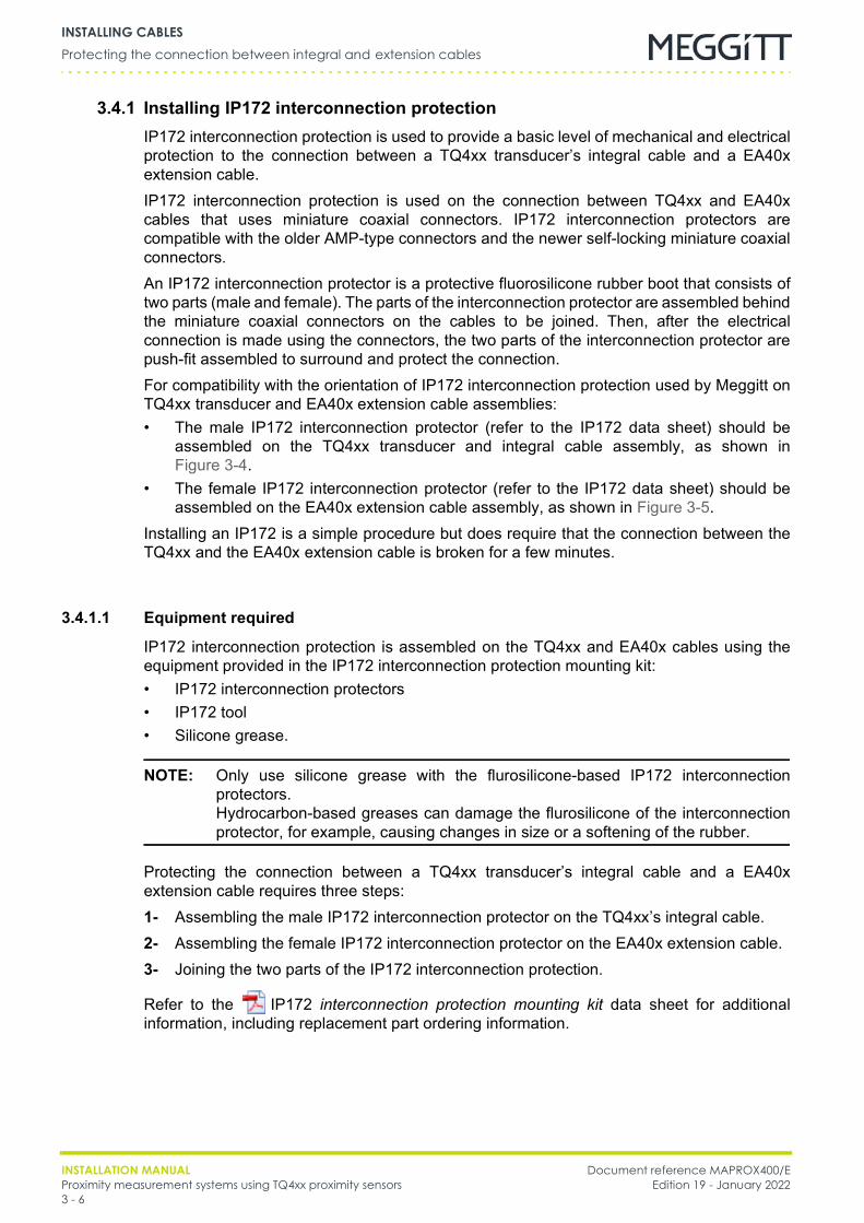
INSTALLATION MANUAL Document reference MAPROX400/EProximity measurement systems using TQ4xx proximity sensors Edition 19 - January 20223 - 6
Protecting the connection between integral and extension cablesINSTALLING CABLES
3.4.1 Installing IP172 interconnection protectionIP172 interconnection protection is used to provide a basic level of mechanical and electricalprotection to the connection between a TQ4xx transducer’s integral cable and a EA40xextension cable.IP172 interconnection protection is used on the connection between TQ4xx and EA40xcables that uses miniature coaxial connectors. IP172 interconnection protectors arecompatible with the older AMP-type connectors and the newer self-locking miniature coaxialconnectors.An IP172 interconnection protector is a protective fluorosilicone rubber boot that consists oftwo parts (male and female). The parts of the interconnection protector are assembled behindthe miniature coaxial connectors on the cables to be joined. Then, after the electricalconnection is made using the connectors, the two parts of the interconnection protector arepush-fit assembled to surround and protect the connection.For compatibility with the orientation of IP172 interconnection protection used by Meggitt onTQ4xx transducer and EA40x extension cable assemblies:• The male IP172 interconnection protector (refer to the IP172 data sheet) should be
assembled on the TQ4xx transducer and integral cable assembly, as shown inFigure 3-4.
• The female IP172 interconnection protector (refer to the IP172 data sheet) should beassembled on the EA40x extension cable assembly, as shown in Figure 3-5.
Installing an IP172 is a simple procedure but does require that the connection between theTQ4xx and the EA40x extension cable is broken for a few minutes.
3.4.1.1 Equipment required
IP172 interconnection protection is assembled on the TQ4xx and EA40x cables using theequipment provided in the IP172 interconnection protection mounting kit:• IP172 interconnection protectors• IP172 tool• Silicone grease.
NOTE: Only use silicone grease with the flurosilicone-based IP172 interconnectionprotectors.Hydrocarbon-based greases can damage the flurosilicone of the interconnectionprotector, for example, causing changes in size or a softening of the rubber.
Protecting the connection between a TQ4xx transducer’s integral cable and a EA40xextension cable requires three steps:1- Assembling the male IP172 interconnection protector on the TQ4xx’s integral cable.2- Assembling the female IP172 interconnection protector on the EA40x extension cable.3- Joining the two parts of the IP172 interconnection protection.
Refer to the IP172 interconnection protection mounting kit data sheet for additionalinformation, including replacement part ordering information.

Document reference MAPROX400/E INSTALLATION MANUALEdition 19 - January 2022 Proximity measurement systems using TQ4xx proximity sensors
3 - 7
Protecting the connection between integral and extension cablesINSTALLING CABLES
3.4.1.2 Assembling the male IP172 interconnection protector on a TQ4xx transducer’s integral cable
3.4.1.2.1 Prerequisites• TQ4xx with integral cable• IP172 interconnection protector: male part (refer to the IP172 data sheet)• IP172 tool: male part (refer to the IP172 data sheet)• Silicone grease.Before starting, separate the TQ4xx transducer’s integral cable and the EA40x extensioncable by unscrewing the miniature coaxial connectors, if required.
3.4.1.2.2 ProcedureTo assemble the male IP172 interconnection protector on the TQ4xx transducer’s integralcable, see Figure 3-4 and:
1- Screw the miniature coaxial connector of the TQ4xx’s integral cable onto the male partof the IP172 tool (hand-tightened).
2- Orientate the small diameter opening of the male IP172 interconnection protector withthe tool. Lubricate the small diameter opening of the interconnection protector (or the tool
itself) with a pea-sized amount of silicone grease, as indicated by the symbol inFigure 3-4).The silicone grease is used as a lubricant, to protect the interconnection protector fromdamage as it moves over the miniature coaxial connector. It is not a sealant, so don’t usetoo much.
NOTE: Silicone grease should be kept away from the electrically conductive contactsof the connector because it could interfere with the electrical signals passingthrough the connector.
3- Slide the interconnection protector along the length of the tool until it passes theminiature coaxial connector and is completely on the TQ4xx’s integral cable.If necessary, a bar (such as a screwdriver) can be inserted through the opening in theend of the tool for an improved grip.
NOTE: To avoid damaging the TQ4xx’s integral cable, do not use the cable forleverage when assembling the interconnection protector on the cable.Instead, hold the tool firmly in one hand and move the interconnectionprotector along the tool using the other hand. If an adequate quantity ofsilicone grease is used, the interconnection protector will slide over theminiature coaxial connector.
4- Unscrew the miniature coaxial connector of the TQ4xx’s integral cable from the IP172tool.
5- Clean any excess silicone grease from the TQ4xx’s integral cable (and the tool) using aclean paper towel or cloth, being careful to keep the miniature coaxial connector free ofthe silicone grease.
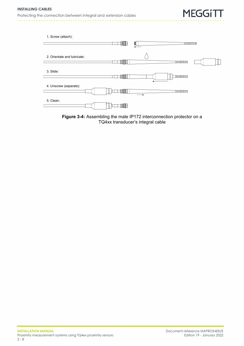
INSTALLATION MANUAL Document reference MAPROX400/EProximity measurement systems using TQ4xx proximity sensors Edition 19 - January 20223 - 8
Protecting the connection between integral and extension cablesINSTALLING CABLES
Figure 3-4: Assembling the male IP172 interconnection protector on aTQ4xx transducer’s integral cable
1. Screw (attach):
2. Orientate and lubricate:
3. Slide:
4. Unscrew (separate):
5. Clean:
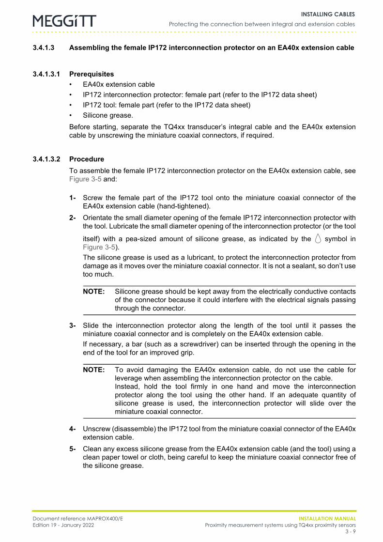
Document reference MAPROX400/E INSTALLATION MANUALEdition 19 - January 2022 Proximity measurement systems using TQ4xx proximity sensors
3 - 9
Protecting the connection between integral and extension cablesINSTALLING CABLES
3.4.1.3 Assembling the female IP172 interconnection protector on an EA40x extension cable
3.4.1.3.1 Prerequisites• EA40x extension cable• IP172 interconnection protector: female part (refer to the IP172 data sheet)• IP172 tool: female part (refer to the IP172 data sheet)• Silicone grease.Before starting, separate the TQ4xx transducer’s integral cable and the EA40x extensioncable by unscrewing the miniature coaxial connectors, if required.
3.4.1.3.2 ProcedureTo assemble the female IP172 interconnection protector on the EA40x extension cable, seeFigure 3-5 and:
1- Screw the female part of the IP172 tool onto the miniature coaxial connector of theEA40x extension cable (hand-tightened).
2- Orientate the small diameter opening of the female IP172 interconnection protector withthe tool. Lubricate the small diameter opening of the interconnection protector (or the tool
itself) with a pea-sized amount of silicone grease, as indicated by the symbol inFigure 3-5).The silicone grease is used as a lubricant, to protect the interconnection protector fromdamage as it moves over the miniature coaxial connector. It is not a sealant, so don’t usetoo much.
NOTE: Silicone grease should be kept away from the electrically conductive contactsof the connector because it could interfere with the electrical signals passingthrough the connector.
3- Slide the interconnection protector along the length of the tool until it passes theminiature coaxial connector and is completely on the EA40x extension cable.If necessary, a bar (such as a screwdriver) can be inserted through the opening in theend of the tool for an improved grip.
NOTE: To avoid damaging the EA40x extension cable, do not use the cable forleverage when assembling the interconnection protector on the cable.Instead, hold the tool firmly in one hand and move the interconnectionprotector along the tool using the other hand. If an adequate quantity ofsilicone grease is used, the interconnection protector will slide over theminiature coaxial connector.
4- Unscrew (disassemble) the IP172 tool from the miniature coaxial connector of the EA40xextension cable.
5- Clean any excess silicone grease from the EA40x extension cable (and the tool) using aclean paper towel or cloth, being careful to keep the miniature coaxial connector free ofthe silicone grease.
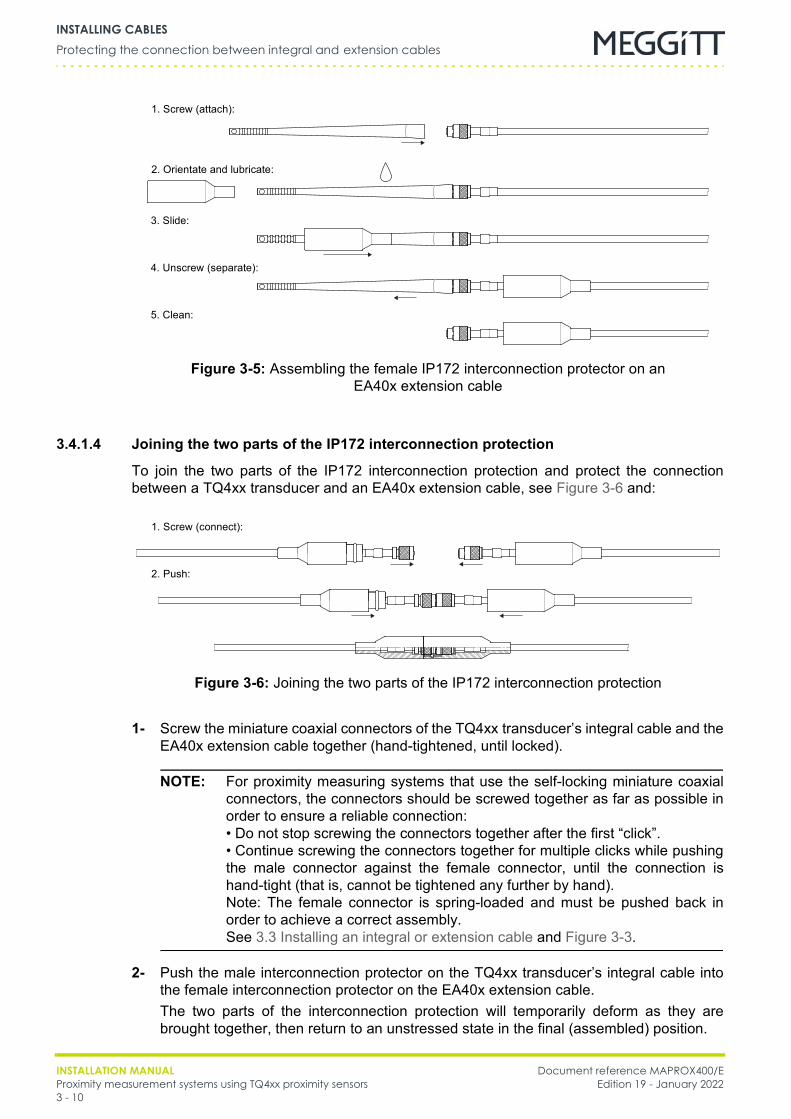
INSTALLATION MANUAL Document reference MAPROX400/EProximity measurement systems using TQ4xx proximity sensors Edition 19 - January 20223 - 10
Protecting the connection between integral and extension cablesINSTALLING CABLES
3.4.1.4 Joining the two parts of the IP172 interconnection protection
To join the two parts of the IP172 interconnection protection and protect the connectionbetween a TQ4xx transducer and an EA40x extension cable, see Figure 3-6 and:
1- Screw the miniature coaxial connectors of the TQ4xx transducer’s integral cable and theEA40x extension cable together (hand-tightened, until locked).
NOTE: For proximity measuring systems that use the self-locking miniature coaxialconnectors, the connectors should be screwed together as far as possible inorder to ensure a reliable connection:• Do not stop screwing the connectors together after the first “click”.• Continue screwing the connectors together for multiple clicks while pushingthe male connector against the female connector, until the connection ishand-tight (that is, cannot be tightened any further by hand).Note: The female connector is spring-loaded and must be pushed back inorder to achieve a correct assembly.See 3.3 Installing an integral or extension cable and Figure 3-3.
2- Push the male interconnection protector on the TQ4xx transducer’s integral cable intothe female interconnection protector on the EA40x extension cable.The two parts of the interconnection protection will temporarily deform as they arebrought together, then return to an unstressed state in the final (assembled) position.
Figure 3-5: Assembling the female IP172 interconnection protector on anEA40x extension cable
1. Screw (attach):
3. Slide:
4. Unscrew (separate):
5. Clean:
2. Orientate and lubricate:
Figure 3-6: Joining the two parts of the IP172 interconnection protection
1. Screw (connect):
2. Push:

Document reference MAPROX400/E INSTALLATION MANUALEdition 19 - January 2022 Proximity measurement systems using TQ4xx proximity sensors
3 - 11
Protecting the connection between integral and extension cablesINSTALLING CABLES
3- The IP172 interconnection protection is completely assembled when the raised ring ofmale interconnection protector fits into the annular groove of the female interconnectionprotector and all surfaces are flush (aligned).The friction of the fluorosilicone and the geometry of the annular ring/groove provide aretaining (release) force that must be overcome in order to separate the IP172interconnection protection.
As IP172 interconnection protection is push-fit assembled, it can be disassembled at any timeby pulling the two parts of the interconnection protector apart (for example, to inspect theconnection). IP172 interconnection protection is reusable by pushing the parts of theinterconnection protector together again.To permanently remove IP172 interconnection protection, the interconnection protectors canbe carefully cut away from the cables.After installing IP172 interconnection protection, ensure that the cables are appropriatelyfixed (see 3.3 Installing an integral or extension cable).
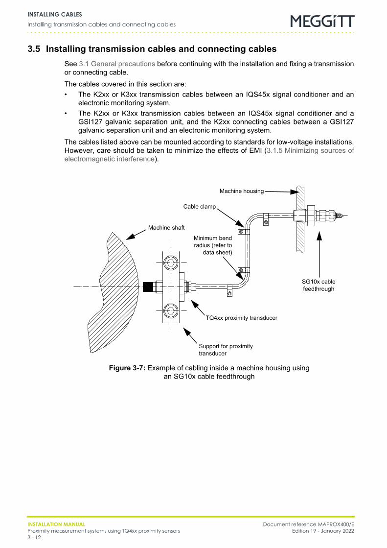
INSTALLATION MANUAL Document reference MAPROX400/EProximity measurement systems using TQ4xx proximity sensors Edition 19 - January 20223 - 12
Installing transmission cables and connecting cablesINSTALLING CABLES
3.5 Installing transmission cables and connecting cablesSee 3.1 General precautions before continuing with the installation and fixing a transmissionor connecting cable.The cables covered in this section are:• The K2xx or K3xx transmission cables between an IQS45x signal conditioner and an
electronic monitoring system.• The K2xx or K3xx transmission cables between an IQS45x signal conditioner and a
GSI127 galvanic separation unit, and the K2xx connecting cables between a GSI127galvanic separation unit and an electronic monitoring system.
The cables listed above can be mounted according to standards for low-voltage installations.However, care should be taken to minimize the effects of EMI (3.1.5 Minimizing sources ofelectromagnetic interference).
Figure 3-7: Example of cabling inside a machine housing usingan SG10x cable feedthrough
Machine shaft
TQ4xx proximity transducer
Support for proximity transducer
SG10x cable feedthrough
Cable clamp
Machine housing
Minimum bendradius (refer to
data sheet)
Document reference MAPROX400/E INSTALLATION MANUALEdition 19 - January 2022 Proximity measurement systems using TQ4xx proximity sensors
4 - 1
General precautionsINSTALLING JUNCTION BOXES AND INDUSTRIAL HOUSINGS CONTAINING
4 INSTALLING JUNCTION BOXES AND INDUSTRIAL HOUSINGS CONTAINING SIGNAL CONDITIONERS
This chapter provides general guidelines on installing a JB118 junction box and an ABA15xindustrial housing containing a signal conditioner in a proximity measurement system.
NOTE: Further information on a junction box or industrial housing can be found in thecorresponding data sheet.
The information applies to the following products in the measurement system:• A JB118 junction box used to connect an integral cable to an EA40x extension cable (see
4.2 Installing a junction box).• An ABA15x Industrial housing containing an IQS45x signal conditioner
(see 4.3 Installing an ABA15x industrial housing with an IQS45x signal conditioner).
4.1 General precautions
4.1.1 Junctions boxes in potentially explosive atmospheres
4.1.2 Industrial housings and signal conditioners in potentially explosive atmospheres
NOTE: Refer to the corresponding data sheet to determine whether an industrial housingcan be installed in potentially explosive atmospheres.
JB118 JUNCTION BOXES CAN BE INSTALLED IN POTENTIALLY EXPLOSIVEATMOSPHERES.FOR FURTHER INFORMATION, SEE THE EX CERTIFICATES IN THE APPENDICES OF THISMANUAL. (THE EX CERTIFICATES ARE ALSO AVAILABLE FROM OUR WEBSITE ATWWW.MEGGITTSENSING.COM/ENERGY)ALL OTHER JUNCTION BOXES THAT ARE NOT EX CERTIFIED MUST NOT BEINSTALLED IN EXPLOSIVE ATMOSPHERES.
ABA17X INDUSTRIAL HOUSINGS CAN BE INSTALLED IN POTENTIALLY EXPLOSIVEATMOSPHERES.FOR FURTHER INFORMATION, SEE THE EX CERTIFICATES IN THE APPENDICES OF THISMANUAL. (THE EX CERTIFICATES ARE ALSO AVAILABLE FROM OUR WEBSITE ATWWW.MEGGITTSENSING.COM/ENERGY)ALL OTHER INDUSTRIAL HOUSINGS THAT ARE NOT EX CERTIFIED MUST NOT BEINSTALLED IN POTENTIALLY EXPLOSIVE ATMOSPHERES.AN IQS45X WITH PROTECTION MODE “EX NA” LOCATED IN AN EX ZONE 2(HAZARDOUS AREA) MUST BE INSTALLED INSIDE AN ENCLOSURE WITH A PROTECTIONRATING OF AT LEAST IP54 (OR EQUIVALENT), WITH DUE CONSIDERATION FOR THEMAXIMUM THERMAL DISSIPATION STATED IN THE CORRESPONDING EX CERTIFICATES.
INSTALLATION MANUAL Document reference MAPROX400/EProximity measurement systems using TQ4xx proximity sensors Edition 19 - January 20224 - 2
Installing a junction boxINSTALLING JUNCTION BOXES AND INDUSTRIAL HOUSINGS CONTAINING
4.1.3 Operating temperature range
NOTE: Further information on the operating temperature range of a junction box or anindustrial housing can be found in the corresponding data sheet.
NOTE: Further information on the operating temperature range of a cable or a signalconditioner can be found in the corresponding data sheet.
4.2 Installing a junction box
4.2.1 Mounting a JB118 junction boxThis procedure describes how to mount a JB118 junction box, using the part references givenin Figure 4-1.1- Choose a vibration-free place to mount the junction box.2- Check the distance between the holes on the junction box, then drill and tap appropriate
holes in the machine surface.
NOTE: For the dimensions of a different junction box refer to the corresponding datasheet.
3- Remove the cover of the junction box.4- Mount the junction box on the mounting surface using the screws provided.5- Fix the IQS45x signal conditioner to the housing's base plate using the screws provided.6- Before putting the cover back on the junction box, make the electrical connections
(see 3.3 Installing an integral or extension cable).7- Fix the cover back on the junction box.
The temperature were a junction box or an industrial housing is installedmust remain permanently within the operating temperature range of the boxor housing.
Only install a junction box at a location where the temperature remainspermanently within the temperature range of the cables connected within it.
Only install an industrial housing at a location where the temperatureremains permanently within the temperature range of the signal conditionerhoused within it.
SEE 4.1 GENERAL PRECAUTIONS BEFORE INSTALLING A JUNCTION BOX.
When connecting cables in a metallic junction box, care should be taken toensure their connectors do not touch the box. Insulating the connectors witha heat-shrinkable sleeve will prevent this. In the case of the JB118 and PA150this is not necessary as these boxes are made of polyester.

Document reference MAPROX400/E INSTALLATION MANUALEdition 19 - January 2022 Proximity measurement systems using TQ4xx proximity sensors
4 - 3
Installing an ABA15x industrial housing with an IQS45x signal conditionerINSTALLING JUNCTION BOXES AND INDUSTRIAL HOUSINGS CONTAINING
4.3 Installing an ABA15x industrial housing with an IQS45x signal conditioner
NOTE: The metal housing of the IQS45x is connected to the “COM” terminal. Therefore,the IQS45x must be mounted on or in a device that insulates it from GND (ground).
4.3.1 Mounting an ABA15x industrial housingThis procedure describes how to mount an ABA15x industrial housing, using the partreferences given in Figure 4-2. 1- Choose a vibration-free place to mount the industrial housing.2- Check the distance between the holes on the industrial housing, then drill and tap
appropriate holes.
NOTE: For the dimensions of a different industrial housing refer to the correspondingdata sheet.
3- Remove the cover of the industrial housing.4- Mount the industrial housing on the mounting surface using the screws provided.5- Fix the IQS45x signal conditioner to the housing's base plate using the screws provided.
Cable stuffinggland
Cover of the junction boxCylindrical head screwsfor fixing the cover
Cable stuffing gland
2 M4 washers
2 M4 x 16 mounting screws
Figure 4-1: Mounting a JB118 junction box
Junction box
SEE 4.1 GENERAL PRECAUTIONS BEFORE INSTALLING AN INDUSTRIAL HOUSING.
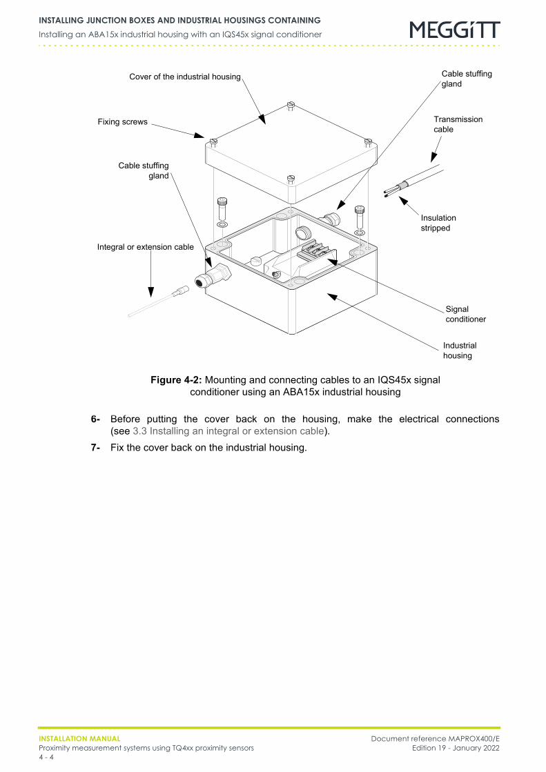
INSTALLATION MANUAL Document reference MAPROX400/EProximity measurement systems using TQ4xx proximity sensors Edition 19 - January 20224 - 4
Installing an ABA15x industrial housing with an IQS45x signal conditionerINSTALLING JUNCTION BOXES AND INDUSTRIAL HOUSINGS CONTAINING
6- Before putting the cover back on the housing, make the electrical connections(see 3.3 Installing an integral or extension cable).
7- Fix the cover back on the industrial housing.
Figure 4-2: Mounting and connecting cables to an IQS45x signal conditioner using an ABA15x industrial housing
Cover of the industrial housing
Integral or extension cable
Transmissioncable
Signalconditioner
Industrial housing
Fixing screws
Insulation stripped
Cable stuffinggland
Cable stuffing gland
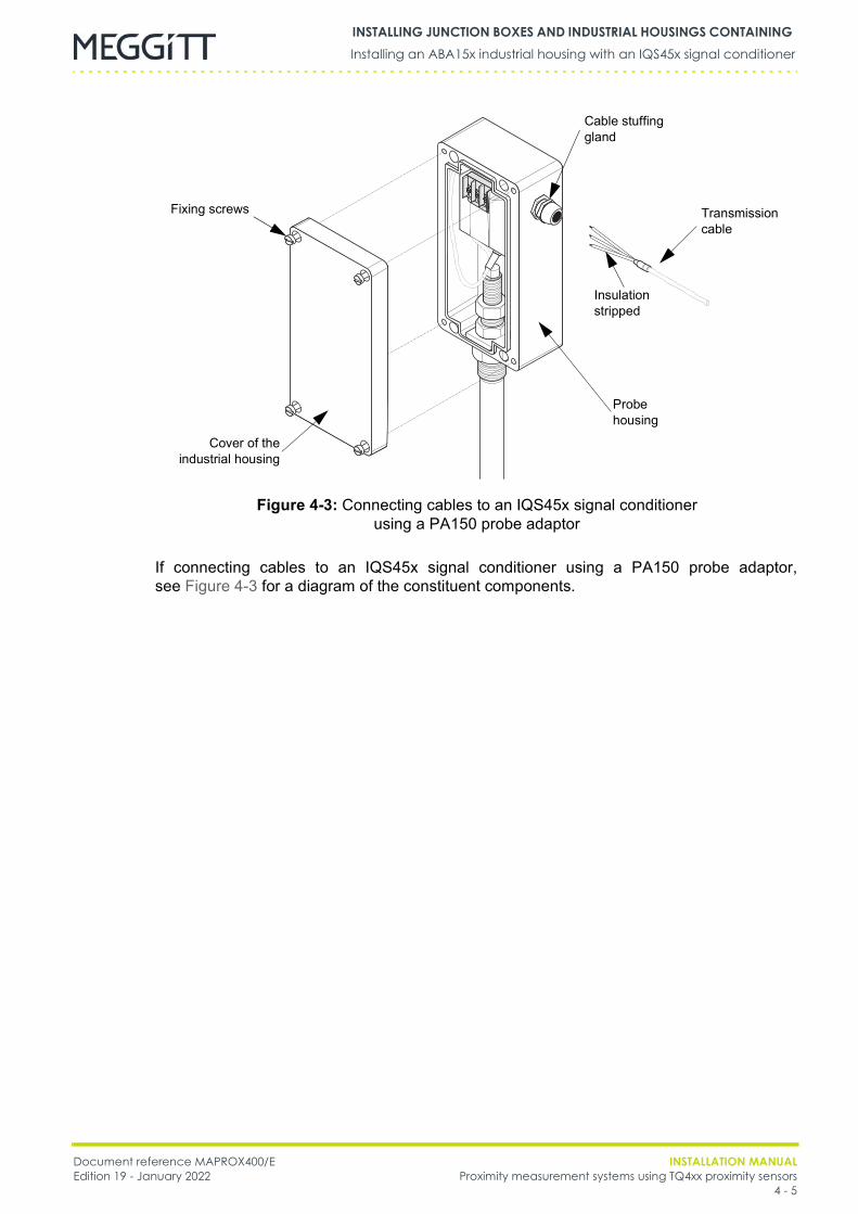
Document reference MAPROX400/E INSTALLATION MANUALEdition 19 - January 2022 Proximity measurement systems using TQ4xx proximity sensors
4 - 5
Installing an ABA15x industrial housing with an IQS45x signal conditionerINSTALLING JUNCTION BOXES AND INDUSTRIAL HOUSINGS CONTAINING
If connecting cables to an IQS45x signal conditioner using a PA150 probe adaptor,see Figure 4-3 for a diagram of the constituent components.
Figure 4-3: Connecting cables to an IQS45x signal conditionerusing a PA150 probe adaptor
Probe housing
Insulation stripped
Transmissioncable
Cable stuffing gland
Cover of theindustrial housing
Fixing screws
INSTALLATION MANUAL Document reference MAPROX400/EProximity measurement systems using TQ4xx proximity sensors Edition 19 - January 20224 - 6
Installing an ABA15x industrial housing with an IQS45x signal conditionerINSTALLING JUNCTION BOXES AND INDUSTRIAL HOUSINGS CONTAINING
THIS PAGE INTENTIONALLY LEFT BLANK
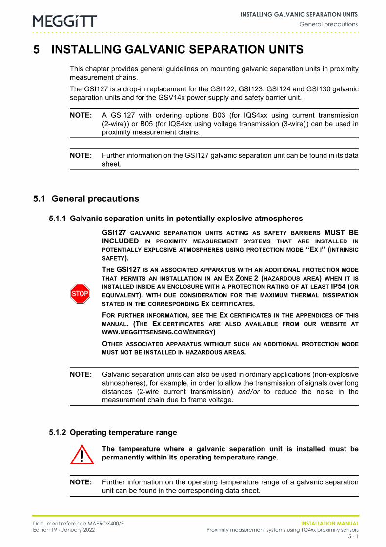
Document reference MAPROX400/E INSTALLATION MANUALEdition 19 - January 2022 Proximity measurement systems using TQ4xx proximity sensors
5 - 1
General precautionsINSTALLING GALVANIC SEPARATION UNITS
5 INSTALLING GALVANIC SEPARATION UNITSThis chapter provides general guidelines on mounting galvanic separation units in proximitymeasurement chains.The GSI127 is a drop-in replacement for the GSI122, GSI123, GSI124 and GSI130 galvanicseparation units and for the GSV14x power supply and safety barrier unit.
NOTE: A GSI127 with ordering options B03 (for IQS4xx using current transmission(2-wire)) or B05 (for IQS4xx using voltage transmission (3-wire)) can be used inproximity measurement chains.
NOTE: Further information on the GSI127 galvanic separation unit can be found in its datasheet.
5.1 General precautions
5.1.1 Galvanic separation units in potentially explosive atmospheres
NOTE: Galvanic separation units can also be used in ordinary applications (non-explosiveatmospheres), for example, in order to allow the transmission of signals over longdistances (2-wire current transmission) and/or to reduce the noise in themeasurement chain due to frame voltage.
5.1.2 Operating temperature range
NOTE: Further information on the operating temperature range of a galvanic separationunit can be found in the corresponding data sheet.
GSI127 GALVANIC SEPARATION UNITS ACTING AS SAFETY BARRIERS MUST BEINCLUDED IN PROXIMITY MEASUREMENT SYSTEMS THAT ARE INSTALLED INPOTENTIALLY EXPLOSIVE ATMOSPHERES USING PROTECTION MODE “EX I” (INTRINSICSAFETY).THE GSI127 IS AN ASSOCIATED APPARATUS WITH AN ADDITIONAL PROTECTION MODETHAT PERMITS AN INSTALLATION IN AN EX ZONE 2 (HAZARDOUS AREA) WHEN IT ISINSTALLED INSIDE AN ENCLOSURE WITH A PROTECTION RATING OF AT LEAST IP54 (OREQUIVALENT), WITH DUE CONSIDERATION FOR THE MAXIMUM THERMAL DISSIPATIONSTATED IN THE CORRESPONDING EX CERTIFICATES.FOR FURTHER INFORMATION, SEE THE EX CERTIFICATES IN THE APPENDICES OF THISMANUAL. (THE EX CERTIFICATES ARE ALSO AVAILABLE FROM OUR WEBSITE ATWWW.MEGGITTSENSING.COM/ENERGY)OTHER ASSOCIATED APPARATUS WITHOUT SUCH AN ADDITIONAL PROTECTION MODEMUST NOT BE INSTALLED IN HAZARDOUS AREAS.
The temperature where a galvanic separation unit is installed must bepermanently within its operating temperature range.
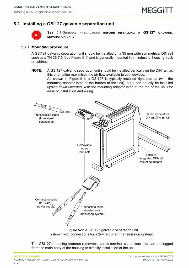
INSTALLATION MANUAL Document reference MAPROX400/EProximity measurement systems using TQ4xx proximity sensors Edition 19 - January 20225 - 2
Installing a GSI127 galvanic separation unitINSTALLING GALVANIC SEPARATION UNITS
5.2 Installing a GSI127 galvanic separation unit
5.2.1 Mounting procedureA GSI127 galvanic separation unit should be installed on a 35 mm wide symmetrical DIN railsuch as a TH 35-7.5 (see Figure 5-1) and is generally mounted in an industrial housing, rackor cabinet.
NOTE: A GSI127 galvanic separation unit should be installed vertically on the DIN rail, asthis orientation maximises the air flow available to cool devices.As shown in Figure 5-1, a GSI127 is typically installed right-side-up (with themounting adaptor latch at the bottom of the unit), but it can equally be installedupside-down (inverted, with the mounting adaptor latch at the top of the unit) forease of installation and wiring.
The GSI127’s housing features removable screw-terminal connectors that can unpluggedfrom the main body of the housing to simplify installation of the unit.
SEE 5.1 GENERAL PRECAUTIONS BEFORE INSTALLING A GSI127 GALVANICSEPARATION UNIT.
Transmission cable(from signal conditioner)
Connecting cable(to +24VDC
power supply)
Figure 5-1: A GSI127 galvanic separation unit(shown with connections for a 2-wire current transmission system)
35 mm symmetrical DIN rail (TH 35-7.5)
Latch ofintegrated DIN-rail mounting adaptor
Removable screw
terminals
Connecting cable(to electronic
monitoring system)
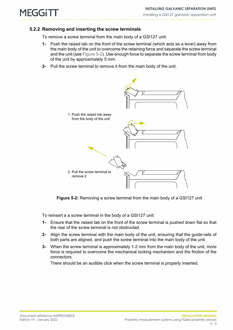
Document reference MAPROX400/E INSTALLATION MANUALEdition 19 - January 2022 Proximity measurement systems using TQ4xx proximity sensors
5 - 3
Installing a GSI127 galvanic separation unitINSTALLING GALVANIC SEPARATION UNITS
5.2.2 Removing and inserting the screw terminalsTo remove a screw terminal from the main body of a GSI127 unit:1- Push the raised tab on the front of the screw terminal (which acts as a lever) away from
the main body of the unit to overcome the retaining force and separate the screw terminaland the unit (see Figure 5-2). Use enough force to separate the screw terminal from bodyof the unit by approximately 5 mm.
2- Pull the screw terminal to remove it from the main body of the unit.
To reinsert a a screw terminal in the body of a GSI127 unit:1- Ensure that the raised tab on the front of the screw terminal is pushed down flat so that
the rear of the screw terminal is not obstructed.2- Align the screw terminal with the main body of the unit, ensuring that the guide-rails of
both parts are aligned, and push the screw terminal into the main body of the unit.3- When the screw terminal is approximately 1-2 mm from the main body of the unit, more
force is required to overcome the mechanical locking mechanism and the friction of theconnectors.There should be an audible click when the screw terminal is properly inserted.
1. Push the raised tab away from the body of the unit
Figure 5-2: Removing a screw terminal from the main body of a GSI127 unit
2. Pull the screw terminal to remove it
INSTALLATION MANUAL Document reference MAPROX400/EProximity measurement systems using TQ4xx proximity sensors Edition 19 - January 20225 - 4
Installing a GSI127 galvanic separation unitINSTALLING GALVANIC SEPARATION UNITS
5.2.3 Connecting cablesThe transmission cable from the proximity measurement system sensor-side circuitry(IQS45x signal conditioner) and the connecting cable to the monitor-side circuitry areconnected to the GSI127 galvanic separation unit using removable screw terminals(see Figure 5-1 and Figure 5-2).
NOTE: The screw terminals on the top of the GSI127, labelled “SENSOR”, are forconnection to the transmission cable that connects to the sensor-side circuitry, thatis, to front-end circuitry such as transducers and/or signal conditioners.
NOTE: The screw terminals on the bottom of the GSI127, labelled “MONITOR”, are forconnection to the connecting cable that connects to the monitor-side circuitry, suchas a VM600 rack-based electronic monitoring system.
There is a block of four screw terminals on the top front of the GSI127, labelled “SENSOR”,out of which, up to three of which are used for connection to the transmission cable thatconnects to the sensor-side circuitry:• For operation with current signals from the IQS45x signal conditioner (2-wire
transmission system), a GSI127 with ordering option B03 should be used. This optionuses two of the SENSOR screw terminals, labelled “+” and “−”. The other two SENSORscrew terminals, labelled “NC”, are not connected.
• For operation with voltage signals from the IQS45x signal conditioner (3-wiretransmission system), a GSI127 with ordering option B05 should be used. This optionuses three of the SENSOR screw terminals, labelled “COM”, “−” and “I/P”. The otherSENSOR screw terminal, labelled “NC”, is not connected.
There is a block of four screw terminals on the bottom front of the GSI127, labelled“MONITOR”, all of which are used for connection to the connecting cable that connects to themonitor-side circuitry:• The connection of the voltage output signal is the same for all GSI127s (ordering options
B01 to B05) and uses all of the MONITOR screw terminals, labelled “24 VDC +”,“24 VDC −”, “SIGNAL 0V” and “SIGNAL O/P”.
See 7 Electrical connections for detailed wiring diagrams of TQ4xx proximity measurementsystems using the GSI127.
NOTE: The shield of the transmission cable from the sensor-side circuitry should not beconnected to the GSI127 galvanic separation unit (“open screening”).Instead, the transmission cable from the sensor-side circuitry must be connectedto the mandatory grounding bracket at the entrance to the cubicle that containsthe GSI127.
NOTE: The GSI127 galvanic separation unit does not require a ground connection andshould not be grounded to its DIN rail.
If required, see 5.3 Replacing a GSI124 galvanic separation unit with a GSI127,5.4 Replacing a GSI123 galvanic separation unit with a GSI127 or5.5 Replacing a GSV14x power supply and safety barrier unit with a GSI127.
Document reference MAPROX400/E INSTALLATION MANUALEdition 19 - January 2022 Proximity measurement systems using TQ4xx proximity sensors
5 - 5
Replacing a GSI124 galvanic separation unit with a GSI127INSTALLING GALVANIC SEPARATION UNITS
5.3 Replacing a GSI124 galvanic separation unit with a GSI127For a GSI124 galvanic separation unit:• The connections at the top of the housing are for the connecting cable to the electronic
monitoring system.• The connections at the bottom of the housing are for the transmission cable from the
front-end circuitry such as transducers and/or signal conditioners.For a GSI127 galvanic separation unit:• The connections at the top of the housing are for the transmission cable from the
front-end circuitry such as transducers and/or signal conditioners.• The connections at the bottom of the housing are the connecting cable to the electronic
monitoring system.
NOTE: When replacing a GSI124 galvanic separation unit with a GSI127, the length of thecables to the unit might have to be adjusted in order to allow for this change ofposition.
5.3.1 Uninstalling the GSI124
A GSI124 galvanic separation unit is generally mounted in an industrial housing, rack orcabinet. The transmission cable from the sensor-side circuitry and the connecting cable tothe monitor-side circuitry are connected to the GSI124 using screw terminals(see Figure 5-3).To uninstall a GSI124:1- Turn off the power supply to the equipment.2- Identify each wire for both the transmission cable from the sensor-side and the
connecting cable to the monitor-side that are connected to the GSI124. See Figure 5-3and use Table 5-1 to record the number and/or colour for each wire.
3- On the GSI124, unscrew the screw terminals on the upper half of the unit in order todisconnect the connecting cable to the monitor-side circuitry (electronic monitoringsystem).
4- On the GSI124, unscrew the screw terminals on the lower half of the unit in order todisconnect the transmission cable from the sensor-side circuitry (signal conditioner).
5- Disconnect the grounding. That is, disconnect the black flying lead terminated with acrimp from the underside of the GSI124 and then remove this lead from the DIN rail, asit is not required by the GSI127 (see Figure 5-3).
6- Remove the GSI124 from the DIN rail.
SEE 5.1 GENERAL PRECAUTIONS BEFORE REPLACING A GSI124 GALVANICSEPARATION UNIT WITH A GSI127.
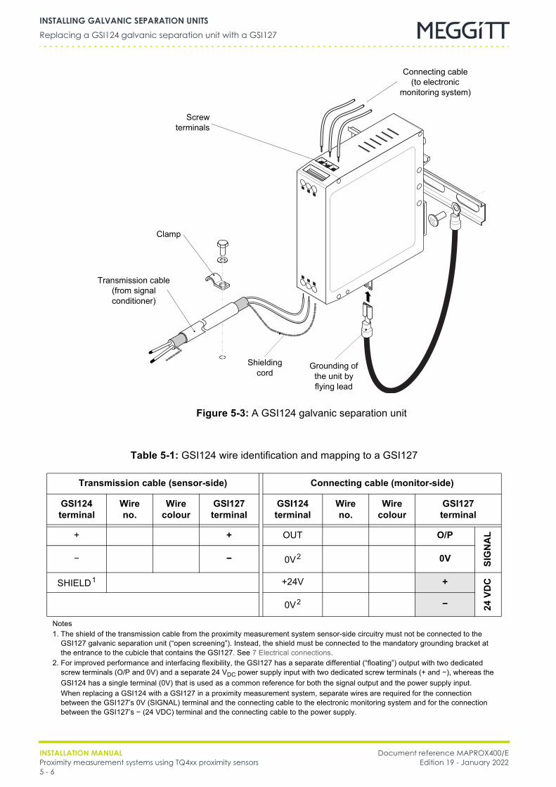
INSTALLATION MANUAL Document reference MAPROX400/EProximity measurement systems using TQ4xx proximity sensors Edition 19 - January 20225 - 6
Replacing a GSI124 galvanic separation unit with a GSI127INSTALLING GALVANIC SEPARATION UNITS
Figure 5-3: A GSI124 galvanic separation unit
Transmission cable(from signal conditioner)
Screwterminals
Grounding of the unit by flying lead
Clamp
Connecting cable(to electronic
monitoring system)
Shielding cord
Table 5-1: GSI124 wire identification and mapping to a GSI127
Transmission cable (sensor-side) Connecting cable (monitor-side)
GSI124 terminal
Wireno.
Wirecolour
GSI127 terminal
GSI124 terminal
Wireno.
Wirecolour
GSI127terminal
+ + OUT O/P
SIG
NA
L
− − 0V2 0V
SHIELD1 +24V +
24VD
C
0V2 −
Notes1. The shield of the transmission cable from the proximity measurement system sensor-side circuitry must not be connected to the
GSI127 galvanic separation unit (“open screening”). Instead, the shield must be connected to the mandatory grounding bracket at the entrance to the cubicle that contains the GSI127. See 7 Electrical connections.
2. For improved performance and interfacing flexibility, the GSI127 has a separate differential (“floating”) output with two dedicated screw terminals (O/P and 0V) and a separate 24 VDC power supply input with two dedicated screw terminals (+ and −), whereas the GSI124 has a single terminal (0V) that is used as a common reference for both the signal output and the power supply input.When replacing a GSI124 with a GSI127 in a proximity measurement system, separate wires are required for the connection between the GSI127’s 0V (SIGNAL) terminal and the connecting cable to the electronic monitoring system and for the connection between the GSI127’s − (24 VDC) terminal and the connecting cable to the power supply.
Document reference MAPROX400/E INSTALLATION MANUALEdition 19 - January 2022 Proximity measurement systems using TQ4xx proximity sensors
5 - 7
Replacing a GSI123 galvanic separation unit with a GSI127INSTALLING GALVANIC SEPARATION UNITS
5.3.2 Installing and connecting the GSI127To replace a GSI124 with a GSI127:1- Ensure that the procedure outlined in 5.3.1 Uninstalling the GSI124 has been followed
and that the power supply to the equipment is turned off.2- Either reuse the existing DIN rail or install a new one.3- Clip the GSI127 to the DIN rail.4- If necessary:
• Adapt the length of the transmission cable and connecting cable.• Strip the transmission cable from the sensor-side circuitry in order to get a sufficient
length of shielding cord for connection to the mandatory grounding bracket at theentrance to the cubicle that contains the GSI127 (see 7 Electrical connections).
5- Strip the end of each wire to expose approximately 5 mm of conductor.6- For each wire to be connected:
• Determine which terminal each wire has to be connected to using the informationrecorded in Table 5-1.
• Connect each wire by inserting the conductor into the corresponding screw terminaland tightening the fixing screw until tight.
NOTE: The GSI127’s housing features removable screw terminals that can unpluggedfrom the main body of the housing to simplify installation of the unit.
5.4 Replacing a GSI123 galvanic separation unit with a GSI127
5.4.1 Uninstalling the GSI123
A GSI123 galvanic separation unit is generally mounted in an industrial housing, rack orcabinet. This unit is normally installed on a dedicated mounting plate using a locating pin anda fixing screw (see Figure 5-5). The transmission cable from the sensor-side circuitry and theconnecting cable to the monitor-side circuitry are connected to the GSI123 using AMPFaston 6.3 lugs (see Figure 5-4) that are crimped to the wires.To uninstall a GSI123:1- Turn off the power supply to the equipment.2- Identify each wire for both the transmission cable from the sensor-side and the
connecting cable to the monitor-side that are connected to the GSI123. See Figure 5-4and use Table 5-2 to record the number and/or colour for each wire.
3- On the GSI123, pull the three AMP Faston 6.3 lugs free from the upper half of the unit inorder to disconnect the connecting cable to the monitor-side circuitry (electronicmonitoring system).
4- On the GSI123, pull the two AMP Faston 6.3 lugs free from the lower half of the unit inorder to disconnect the transmission cable from the sensor-side circuitry (signalconditioner).
5- Undo the M4 fixing screw until the GSI123 has been uninstalled and disassemble themounting plate from the DIN rail (see Figure 5-5).
SEE 5.1 GENERAL PRECAUTIONS BEFORE REPLACING A GSI123 GALVANICSEPARATION UNIT WITH A GSI127.

INSTALLATION MANUAL Document reference MAPROX400/EProximity measurement systems using TQ4xx proximity sensors Edition 19 - January 20225 - 8
Replacing a GSI123 galvanic separation unit with a GSI127INSTALLING GALVANIC SEPARATION UNITS
M4 fixingscrew
Figure 5-4: A GSI123 galvanic separation unit
AMP Faston 6.3 lugs crimped to leads
AMP Faston 6.3terminals
AMP Faston 6.3 lugscrimped to leads
AMP Faston 6.3 terminals
Connecting cable(to electronic
monitoring system)
Transmission cable(from signal conditioner)
Figure 5-5: The mounting plate used by GSI123 galvanic separation units
Mounting plate
M4 fixing screw
Locating pin (behind)
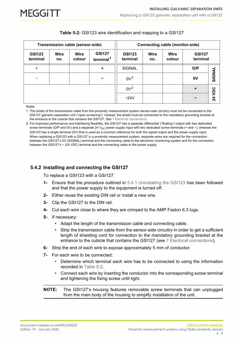
Document reference MAPROX400/E INSTALLATION MANUALEdition 19 - January 2022 Proximity measurement systems using TQ4xx proximity sensors
5 - 9
Replacing a GSI123 galvanic separation unit with a GSI127INSTALLING GALVANIC SEPARATION UNITS
5.4.2 Installing and connecting the GSI127To replace a GSI123 with a GSI127:1- Ensure that the procedure outlined in 5.4.1 Uninstalling the GSI123 has been followed
and that the power supply to the equipment is turned off.2- Either reuse the existing DIN rail or install a new one.3- Clip the GSI127 to the DIN rail.4- Cut each wire close to where they are crimped to the AMP Faston 6.3 lugs.5- If necessary:
• Adapt the length of the transmission cable and connecting cable.• Strip the transmission cable from the sensor-side circuitry in order to get a sufficient
length of shielding cord for connection to the mandatory grounding bracket at theentrance to the cubicle that contains the GSI127 (see 7 Electrical connections).
6- Strip the end of each wire to expose approximately 5 mm of conductor.7- For each wire to be connected:
• Determine which terminal each wire has to be connected to using the informationrecorded in Table 5-2.
• Connect each wire by inserting the conductor into the corresponding screw terminaland tightening the fixing screw until tight.
NOTE: The GSI127’s housing features removable screw terminals that can unpluggedfrom the main body of the housing to simplify installation of the unit.
Table 5-2: GSI123 wire identification and mapping to a GSI127
Transmission cable (sensor-side) Connecting cable (monitor-side)
GSI123 terminal
Wireno.
Wirecolour
GSI127 terminal1
GSI123 terminal
Wireno.
Wirecolour
GSI127terminal
+ + SIGNAL O/P
SIG
NA
L
− − 0V2 0V
0V2 +
24VD
C
−24V −
Notes1. The shield of the transmission cable from the proximity measurement system sensor-side circuitry must not be connected to the
GSI127 galvanic separation unit (“open screening”). Instead, the shield must be connected to the mandatory grounding bracket at the entrance to the cubicle that contains the GSI127. See 7 Electrical connections.
2. For improved performance and interfacing flexibility, the GSI127 has a separate differential (“floating”) output with two dedicated screw terminals (O/P and 0V) and a separate 24 VDC power supply input with two dedicated screw terminals (+ and −), whereas the GSI123 has a single terminal (0V) that is used as a common reference for both the signal output and the power supply input.When replacing a GSI123 with a GSI127 in a proximity measurement system, separate wires are required for the connection between the GSI127’s 0V (SIGNAL) terminal and the connecting cable to the electronic monitoring system and for the connection between the GSI127’s − (24 VDC) terminal and the connecting cable to the power supply.
INSTALLATION MANUAL Document reference MAPROX400/EProximity measurement systems using TQ4xx proximity sensors Edition 19 - January 20225 - 10
Replacing a GSV14x power supply and safety barrier unit with a GSI127INSTALLING GALVANIC SEPARATION UNITS
5.5 Replacing a GSV14x power supply and safety barrier unit with a GSI127
5.5.1 Uninstalling the GSV14x
A GSV14x power supply and safety barrier unit is generally mounted in an industrial housing,rack or cabinet. These units are normally installed using a single M4 screw but can bemounted using a mounting kit (DIN rail, nut assembly and bracket).
NOTE: Further information on mounting accessories for a GSV14x power supply andsafety barrier unit can be found in the GSI/GSV mounting accessories data sheet.
The transmission cable from the sensor-side circuitry and the connecting cable to themonitor-side circuitry are connected to the GSV14x using lugs (see Figure 5-6) that arecrimped to the wires.To uninstall a GSV14x:1- Turn off the power supply to the equipment.2- Identify each wire for both the transmission cable from the sensor-side and the
connecting cable to the monitor-side that are connected to the GSV14x. See Figure 5-6and use Table 5-3 to record the number and/or colour for each wire.
3- On the GSV14x, pull the four lugs free from the upper half of the unit in order todisconnect the connecting cable to the monitor-side circuitry (electronic monitoringsystem and power supply).
4- On the GSV14x, pull the four lugs free from the lower half of the unit in order todisconnect the transmission cable from the sensor-side circuitry (signal conditioner).
5- Undo the M4 fixing screw until the GSV14x has been uninstalled and disassemble themounting kit from the DIN rail (see Figure 5-6).
SEE 5.1 GENERAL PRECAUTIONS BEFORE REPLACING A GSV14X POWER SUPPLY ANDSAFETY BARRIER UNIT WITH A GSI127.
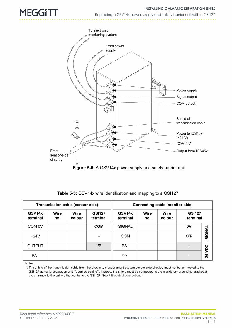
Document reference MAPROX400/E INSTALLATION MANUALEdition 19 - January 2022 Proximity measurement systems using TQ4xx proximity sensors
5 - 11
Replacing a GSV14x power supply and safety barrier unit with a GSI127INSTALLING GALVANIC SEPARATION UNITS
Power supply
Signal output
COM output
Shield oftransmission cable
COM 0 V
Output from IQS45x
Power to IQS45x (−24 V)
Figure 5-6: A GSV14x power supply and safety barrier unit
From power supply
To electronic monitoring system
From sensor-side circuitry
Table 5-3: GSV14x wire identification and mapping to a GSI127
Transmission cable (sensor-side) Connecting cable (monitor-side)
GSV14x terminal
Wireno.
Wirecolour
GSI127 terminal
GSV14x terminal
Wireno.
Wirecolour
GSI127terminal
COM 0V COM SIGNAL 0V
SIG
NA
L
−24V − COM O/P
OUTPUT I/P PS+ +
24VD
C
PA1 PS− −
Notes1. The shield of the transmission cable from the proximity measurement system sensor-side circuitry must not be connected to the
GSI127 galvanic separation unit (“open screening”). Instead, the shield must be connected to the mandatory grounding bracket at the entrance to the cubicle that contains the GSI127. See 7 Electrical connections.
INSTALLATION MANUAL Document reference MAPROX400/EProximity measurement systems using TQ4xx proximity sensors Edition 19 - January 20225 - 12
Replacing a GSV14x power supply and safety barrier unit with a GSI127INSTALLING GALVANIC SEPARATION UNITS
5.5.2 Installing and connecting the GSI127To replace a GSV14x with a GSI127:1- Ensure that the procedure outlined in 5.5.1 Uninstalling the GSV14x has been followed
and that the power supply to the equipment is turned off.2- Either reuse the existing DIN rail or install a new one.3- Clip the GSI127 to the DIN rail.4- Cut each wire close to where they are crimped to the lugs.5- If necessary:
• Adapt the length of the transmission cable and connecting cable.• Strip the transmission cable from the sensor-side circuitry in order to get a sufficient
length of shielding cord for connection to the mandatory grounding bracket at theentrance to the cubicle that contains the GSI127 (see 7 Electrical connections).
6- Strip the end of each wire to expose approximately 5 mm of conductor.7- For each wire to be connected:
• Determine which terminal each wire has to be connected to using the informationrecorded in Table 5-3.
• Connect each wire by inserting the conductor into the corresponding screw terminaland tightening the fixing screw until tight.
NOTE: The GSI127’s housing features removable screw terminals that can unpluggedfrom the main body of the housing to simplify installation of the unit.

Document reference MAPROX400/E INSTALLATION MANUALEdition 19 - January 2022 Proximity measurement systems using TQ4xx proximity sensors
6 - 1
Measurement and mechanical adjustment of the initial gapMEASURING AND ADJUSTING THE INITIAL GAP
6 MEASURING AND ADJUSTING THE INITIAL GAPThis chapter provides general guidelines on measuring and adjusting the initial gap of aninstalled TQ4xx proximity measurement system. The adjustment of the initial gap can bemechanical and/or electrical.Mechanical adjustment of the initial gap must be performed when a new proximitymeasurement system is installed, that is, before the measurement system is used.Electrical adjustment of the initial gap should be performed after the mechanical adjustmentof the initial gap and before the measurement system is used. This is a calibration of theelectronic measurement system used with the proximity measurement system and can bechecked periodically if required (see 8 Maintenance).The information contained in this chapter applies to installed proximity measurementsystems.
6.1 Measurement and mechanical adjustment of the initial gapMechanical adjustment of the initial gap should be performed when installing a TQ4xxproximity transducer by adjusting the distance between the tip of the proximity transducer andthe target ‒ with the power to the machine turned off.
NOTE: Mechanical adjustment of the initial gap should be performed with the power to themachine turned off.
The initial gap can be measured mechanically by inserting a feeler gauge of the requiredthickness between the tip of the proximity transducer and the target. The physical position ofthe proximity transducer can then be adjusted to create the required initial gap.The transducer-to-target distance must always be within the measurement range of theproximity transducer in order to ensure the correct operation of the measurement system.Therefore, knowledge of the approximate magnitude of the relative movement between thetarget and the proximity transducer is necessary. Knowledge of the expected direction ofmovement is also required.If the direction of movement alternates, for example, a relative vibration measurement, thenthe initial gap should be set in the middle of the proximity transducer’s measurement range.See the example in Figure 6-1 (a) for a TQ402 proximity transducer.If the direction of movement tends to be in one direction only, for example, an axial positionmeasurement, then the initial gap should be set at one end of the proximity transducer’smeasurement range according to the expected direction of movement. See the example inFigure 6-1 (b) for a TQ402 proximity transducer.
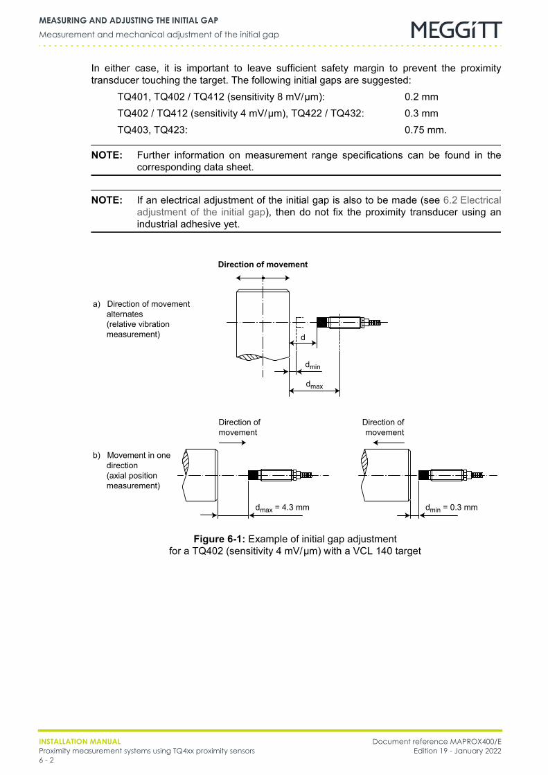
INSTALLATION MANUAL Document reference MAPROX400/EProximity measurement systems using TQ4xx proximity sensors Edition 19 - January 20226 - 2
Measurement and mechanical adjustment of the initial gapMEASURING AND ADJUSTING THE INITIAL GAP
In either case, it is important to leave sufficient safety margin to prevent the proximitytransducer touching the target. The following initial gaps are suggested:
TQ401, TQ402 / TQ412 (sensitivity 8 mV/µm): 0.2 mmTQ402 / TQ412 (sensitivity 4 mV/µm), TQ422 / TQ432: 0.3 mmTQ403, TQ423: 0.75 mm.
NOTE: Further information on measurement range specifications can be found in thecorresponding data sheet.
NOTE: If an electrical adjustment of the initial gap is also to be made (see 6.2 Electricaladjustment of the initial gap), then do not fix the proximity transducer using anindustrial adhesive yet.
Figure 6-1: Example of initial gap adjustmentfor a TQ402 (sensitivity 4 mV/µm) with a VCL 140 target
Direction of movement
a) Direction of movement alternates(relative vibration measurement)
b) Movement in onedirection(axial position measurement)
Direction of movement
Direction ofmovement
dmax = 4.3 mm dmin = 0.3 mm
dmin
dmax
d
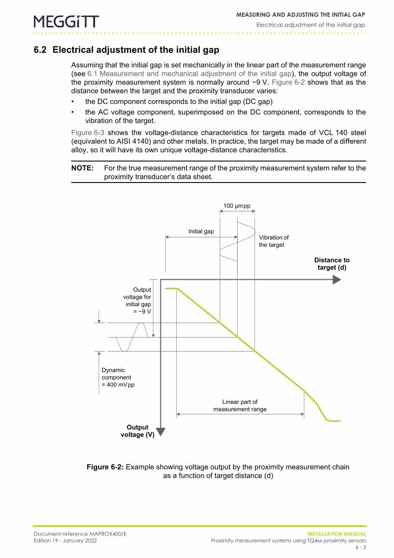
Document reference MAPROX400/E INSTALLATION MANUALEdition 19 - January 2022 Proximity measurement systems using TQ4xx proximity sensors
6 - 3
Electrical adjustment of the initial gapMEASURING AND ADJUSTING THE INITIAL GAP
6.2 Electrical adjustment of the initial gapAssuming that the initial gap is set mechanically in the linear part of the measurement range(see 6.1 Measurement and mechanical adjustment of the initial gap), the output voltage ofthe proximity measurement system is normally around −9 V. Figure 6-2 shows that as thedistance between the target and the proximity transducer varies:• the DC component corresponds to the initial gap (DC gap)• the AC voltage component, superimposed on the DC component, corresponds to the
vibration of the target.Figure 6-3 shows the voltage-distance characteristics for targets made of VCL 140 steel(equivalent to AISI 4140) and other metals. In practice, the target may be made of a differentalloy, so it will have its own unique voltage-distance characteristics.
NOTE: For the true measurement range of the proximity measurement system refer to theproximity transducer’s data sheet.
Figure 6-2: Example showing voltage output by the proximity measurement chainas a function of target distance (d)
Linear part of measurement range
Output voltage (V)
Distance to target (d)
Initial gap
100 µmpp
Vibration of the target
Dynamic component= 400 mVpp
Outputvoltage forinitial gap
= −9 V
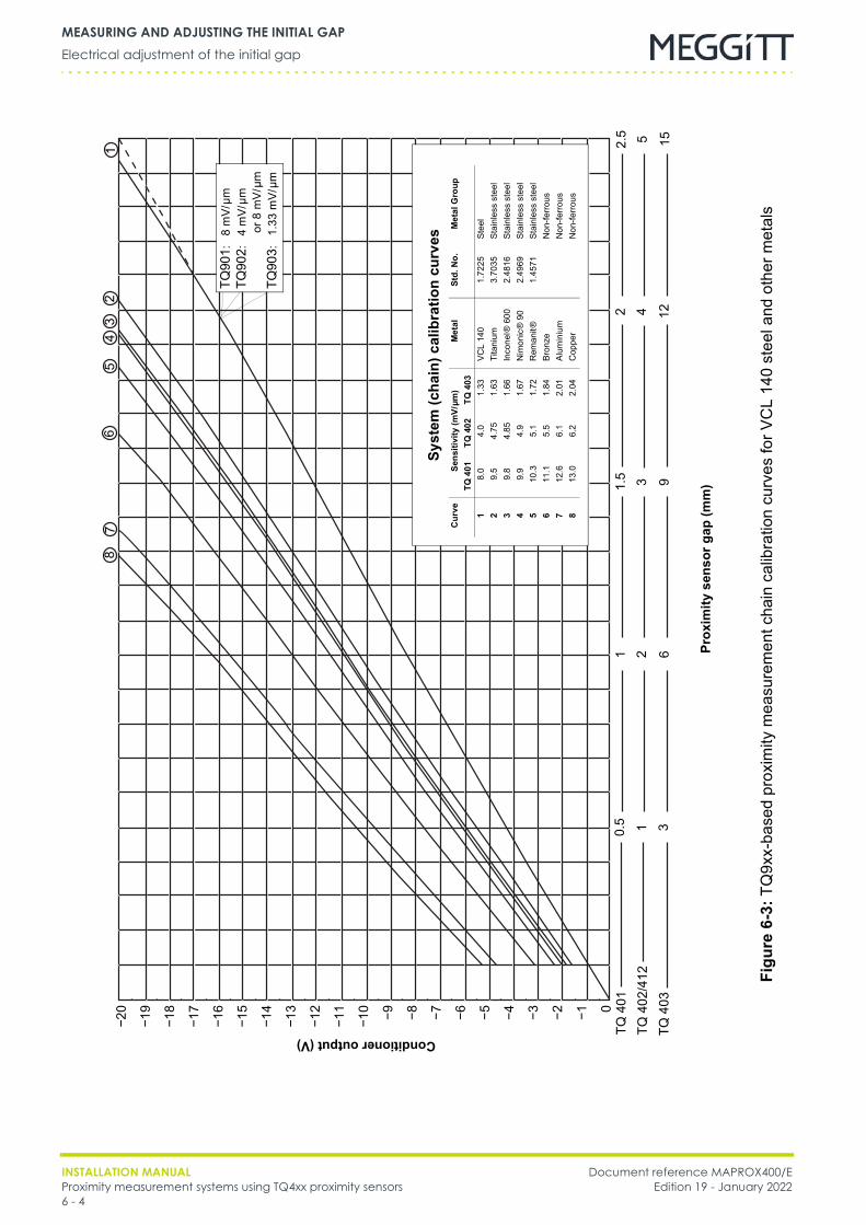
INSTALLATION MANUAL Document reference MAPROX400/EProximity measurement systems using TQ4xx proximity sensors Edition 19 - January 20226 - 4
Electrical adjustment of the initial gapMEASURING AND ADJUSTING THE INITIAL GAP
TQ90
1:8
mV/
µmTQ
902:
4m
V/µm
or 8
mV/
µmTQ
903:
1.33
mV/
µm
Figu
re6-
3:TQ
9xx-
base
d pr
oxim
ity m
easu
rem
ent c
hain
cal
ibra
tion
curv
es fo
r VC
L14
0 st
eel a
nd o
ther
met
als
−20
−19
−18
−17
−16
−15
−14
−13
−12
−11
−10 −9 −8 −7 −6 −5 −4 −3 −2 −1 0
Conditioner output (V)
Prox
imity
sen
sor g
ap (m
m)
Syst
em (c
hain
) cal
ibra
tion
curv
es
Cur
ve
Sens
itivi
ty (m
V/µm
)M
etal
Std.
No.
Met
al G
roup
TQ40
1TQ
402
TQ40
31
8.0
4.0
1.33
VCL
140
1.72
25St
eel
29.
54.
751.
63Ti
tani
um3.
7035
Stai
nles
s st
eel
39.
84.
851.
66In
cone
l® 6
002.
4816
Stai
nles
s st
eel
49.
94.
91.
67N
imon
ic®
90
2.49
69St
ainl
ess
stee
l5
10.3
5.1
1.72
Rem
anit®
1.45
71St
ainl
ess
stee
l6
11.1
5.5
1.84
Bron
zeN
on-fe
rrous
712
.66.
12.
01Al
umin
ium
Non
-ferro
us8
13.0
6.2
2.04
Cop
per
Non
-ferro
us
12
34
56
78
TQ 4
01
TQ 4
03TQ
402
/412
0.5 31
2 613 91.5
4 1225 152.5
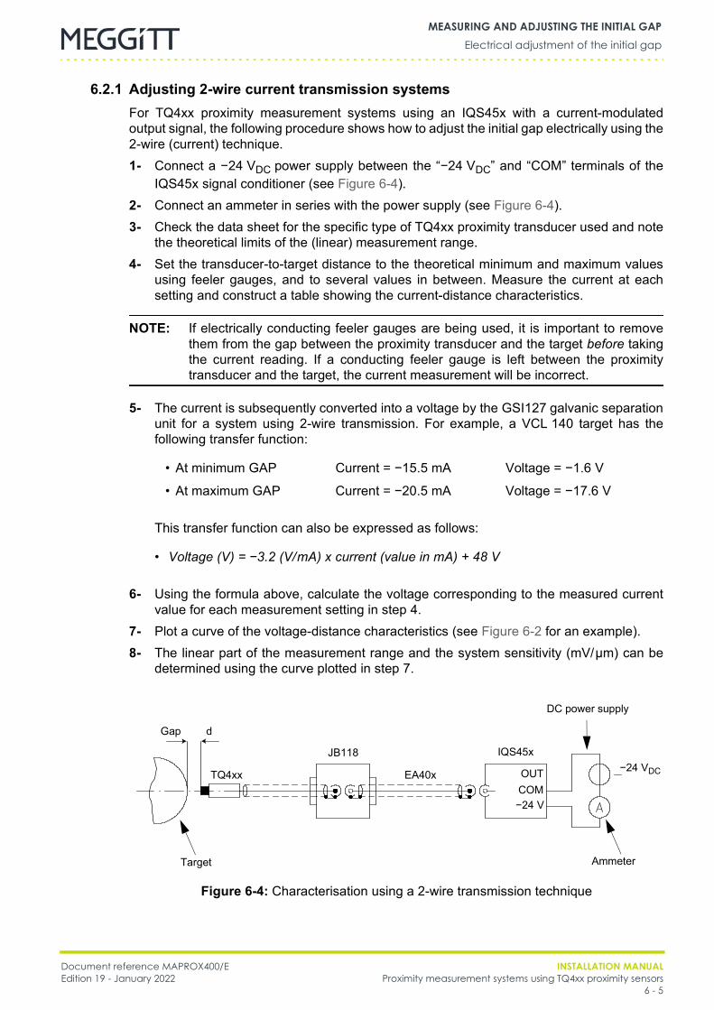
Document reference MAPROX400/E INSTALLATION MANUALEdition 19 - January 2022 Proximity measurement systems using TQ4xx proximity sensors
6 - 5
Electrical adjustment of the initial gapMEASURING AND ADJUSTING THE INITIAL GAP
6.2.1 Adjusting 2-wire current transmission systemsFor TQ4xx proximity measurement systems using an IQS45x with a current-modulatedoutput signal, the following procedure shows how to adjust the initial gap electrically using the2-wire (current) technique.1- Connect a −24 VDC power supply between the “−24 VDC” and “COM” terminals of the
IQS45x signal conditioner (see Figure 6-4).2- Connect an ammeter in series with the power supply (see Figure 6-4).3- Check the data sheet for the specific type of TQ4xx proximity transducer used and note
the theoretical limits of the (linear) measurement range.4- Set the transducer-to-target distance to the theoretical minimum and maximum values
using feeler gauges, and to several values in between. Measure the current at eachsetting and construct a table showing the current-distance characteristics.
NOTE: If electrically conducting feeler gauges are being used, it is important to removethem from the gap between the proximity transducer and the target before takingthe current reading. If a conducting feeler gauge is left between the proximitytransducer and the target, the current measurement will be incorrect.
5- The current is subsequently converted into a voltage by the GSI127 galvanic separationunit for a system using 2-wire transmission. For example, a VCL 140 target has thefollowing transfer function:
This transfer function can also be expressed as follows:
6- Using the formula above, calculate the voltage corresponding to the measured currentvalue for each measurement setting in step 4.
7- Plot a curve of the voltage-distance characteristics (see Figure 6-2 for an example).8- The linear part of the measurement range and the system sensitivity (mV/µm) can be
determined using the curve plotted in step 7.
• At minimum GAP Current = −15.5 mA Voltage = −1.6 V
• At maximum GAP Current = −20.5 mA Voltage = −17.6 V
• Voltage (V) = −3.2 (V/mA) x current (value in mA) + 48 V
Gap
Ammeter
DC power supply
Figure 6-4: Characterisation using a 2-wire transmission technique
d
JB118
EA40x
IQS45x
OUTCOM−24 V
TQ4xx −24 VDC
Target
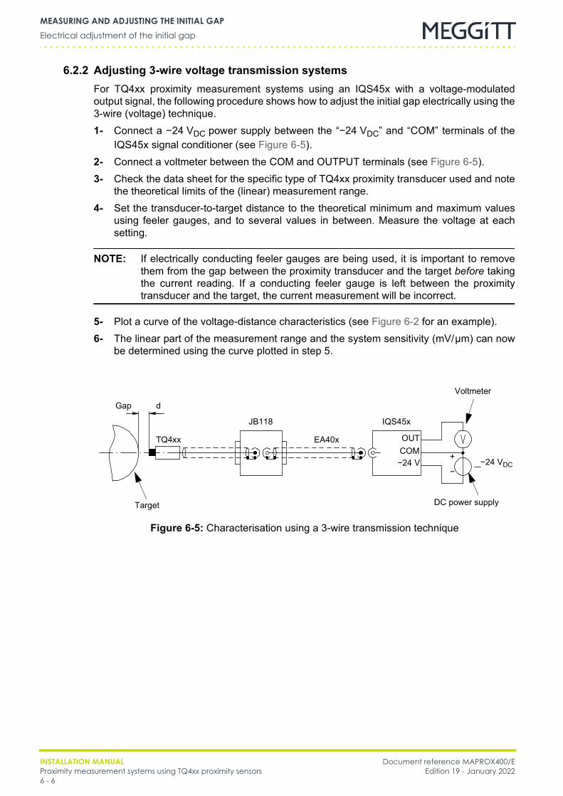
INSTALLATION MANUAL Document reference MAPROX400/EProximity measurement systems using TQ4xx proximity sensors Edition 19 - January 20226 - 6
Electrical adjustment of the initial gapMEASURING AND ADJUSTING THE INITIAL GAP
6.2.2 Adjusting 3-wire voltage transmission systemsFor TQ4xx proximity measurement systems using an IQS45x with a voltage-modulatedoutput signal, the following procedure shows how to adjust the initial gap electrically using the3-wire (voltage) technique.1- Connect a −24 VDC power supply between the “−24 VDC” and “COM” terminals of the
IQS45x signal conditioner (see Figure 6-5).2- Connect a voltmeter between the COM and OUTPUT terminals (see Figure 6-5).3- Check the data sheet for the specific type of TQ4xx proximity transducer used and note
the theoretical limits of the (linear) measurement range.4- Set the transducer-to-target distance to the theoretical minimum and maximum values
using feeler gauges, and to several values in between. Measure the voltage at eachsetting.
NOTE: If electrically conducting feeler gauges are being used, it is important to removethem from the gap between the proximity transducer and the target before takingthe current reading. If a conducting feeler gauge is left between the proximitytransducer and the target, the current measurement will be incorrect.
5- Plot a curve of the voltage-distance characteristics (see Figure 6-2 for an example).6- The linear part of the measurement range and the system sensitivity (mV/µm) can now
be determined using the curve plotted in step 5.
Gap
Voltmeter
DC power supply
Figure 6-5: Characterisation using a 3-wire transmission technique
d
JB118
EA40x
IQS45x
OUTCOM−24 V
TQ4xx
−24 VDC
Target
+
−
Document reference MAPROX400/E INSTALLATION MANUALEdition 19 - January 2022 Proximity measurement systems using TQ4xx proximity sensors
7 - 1
General precautionsELECTRICAL CONNECTIONS
7 ELECTRICAL CONNECTIONS
7.1 General precautions
7.2 General wiring diagrams
NOTE: Information on connecting equipment to the electronic monitoring system can befound in the project-specific wiring diagram delivered with a system.
For use in potentially explosive atmospheres, the GSI127 has a certification that allowsinstallation in an Ex Zone 2 (hazardous area), that is, it is an “Ex nA [ia]” safety barrier.Additional information is given in the wiring diagrams listed in Table 7-1.
IN ORDINARY APPLICATIONS (NON-EXPLOSIVE ATMOSPHERES), NO CERTIFICATIONS AREREQUIRED FOR THE USE OF THESE MEASUREMENT CHAINS.HOWEVER, IN POTENTIALLY EXPLOSIVE ATMOSPHERES, CERTIFICATIONS ARE REQUIREDFOR THE USE OF THESE MEASUREMENT CHAINS. THE ACTUAL CERTIFICATION REQUIREDFOR EACH PRODUCT IN THE MEASUREMENT CHAIN DEPENDS ON THE ATEX/IECEXZONE IN WHICH THE PRODUCT IS INSTALLED.THE “REQUESTED CERTIFICATIONS FOR EXPLOSIVE ZONES (ATEX/IECEX)” TABLEINCLUDED IN EACH WIRING DIAGRAM (FIGURE 7-1 AND FIGURE 7-2) OUTLINES THECERTIFICATIONS REQUIRED FOR EACH PRODUCT IN THE MEASUREMENT CHAINACCORDING TO THE ATEX/IECEX ZONE IN WHICH IT IS INSTALLED. THAT IS, THETABLES SPECIFY THE CERTIFICATION REQUIRED FOR A PRODUCT FROM AN AREA OF THEWIRING DIAGRAM (AREA A, AREA B OR AREA C) WHEN THAT AREA OF THE WIRINGDIAGRAM CORRESPONDS TO THE DIFFERENT ATEX/IECEX ZONES IN WHICH THEPRODUCT CAN BE INSTALLED.THE LENGTHS OF CABLES (INTEGRAL CABLES AND CABLE ASSEMBLIES) INSTALLED INPOTENTIALLY EXPLOSIVE ATMOSPHERES MUST BE DETERMINED AS PER THECRITERIA OUTLINED THE EC TYPE EXAMINATION CERTIFICATE FOR THE PRODUCT,WHICH ARE SUMMARISED IN FIGURE 7-3.FOR FURTHER INFORMATION, SEE THE EX CERTIFICATES IN THE APPENDICES OF THISMANUAL. (THE EX CERTIFICATES ARE ALSO AVAILABLE FROM OUR WEBSITE ATWWW.MEGGITTSENSING.COM/ENERGY)
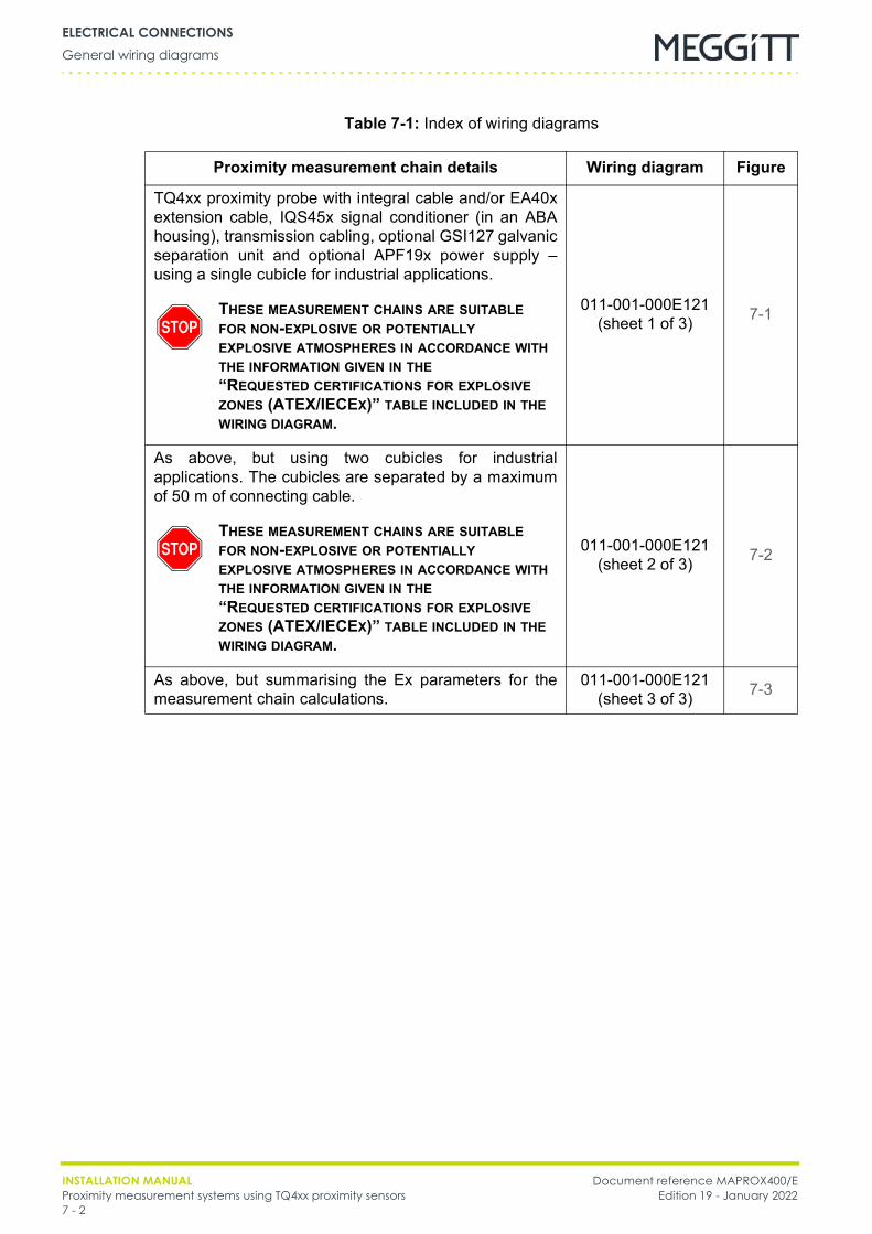
INSTALLATION MANUAL Document reference MAPROX400/EProximity measurement systems using TQ4xx proximity sensors Edition 19 - January 20227 - 2
General wiring diagramsELECTRICAL CONNECTIONS
Table 7-1: Index of wiring diagrams
Proximity measurement chain details Wiring diagram Figure
TQ4xx proximity probe with integral cable and/or EA40xextension cable, IQS45x signal conditioner (in an ABAhousing), transmission cabling, optional GSI127 galvanicseparation unit and optional APF19x power supply –using a single cubicle for industrial applications.
011-001-000E121 (sheet 1 of 3) 7-1
As above, but using two cubicles for industrialapplications. The cubicles are separated by a maximumof 50 m of connecting cable.
011-001-000E121 (sheet 2 of 3) 7-2
As above, but summarising the Ex parameters for themeasurement chain calculations.
011-001-000E121 (sheet 3 of 3) 7-3
THESE MEASUREMENT CHAINS ARE SUITABLEFOR NON-EXPLOSIVE OR POTENTIALLYEXPLOSIVE ATMOSPHERES IN ACCORDANCE WITHTHE INFORMATION GIVEN IN THE“REQUESTED CERTIFICATIONS FOR EXPLOSIVEZONES (ATEX/IECEX)” TABLE INCLUDED IN THEWIRING DIAGRAM.
THESE MEASUREMENT CHAINS ARE SUITABLEFOR NON-EXPLOSIVE OR POTENTIALLYEXPLOSIVE ATMOSPHERES IN ACCORDANCE WITHTHE INFORMATION GIVEN IN THE“REQUESTED CERTIFICATIONS FOR EXPLOSIVEZONES (ATEX/IECEX)” TABLE INCLUDED IN THEWIRING DIAGRAM.
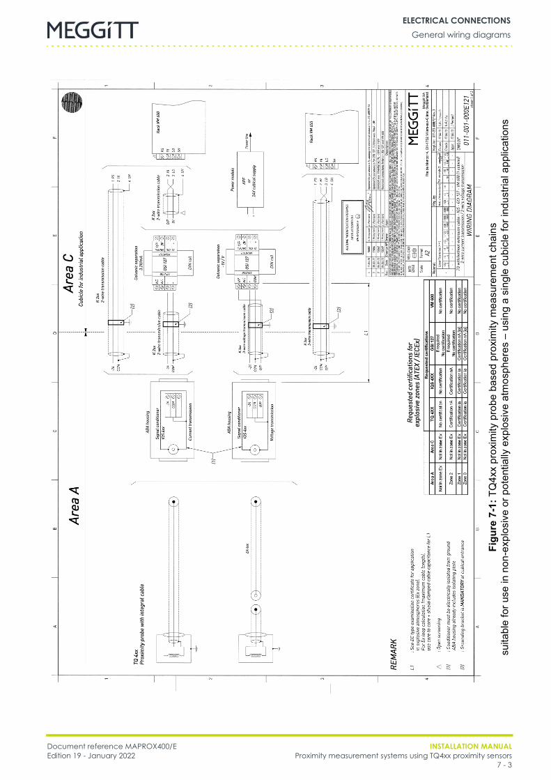
Document reference MAPROX400/E INSTALLATION MANUALEdition 19 - January 2022 Proximity measurement systems using TQ4xx proximity sensors
7 - 3
General wiring diagramsELECTRICAL CONNECTIONS
Figu
re7-
1:TQ
4xx
prox
imity
pro
be b
ased
pro
xim
ity m
easu
rem
ent c
hain
ssu
itabl
e fo
r use
in n
on-e
xplo
sive
or p
oten
tially
exp
losi
ve a
tmos
pher
es –
usi
ng a
sin
gle
cubi
cle
for i
ndus
trial
app
licat
ions
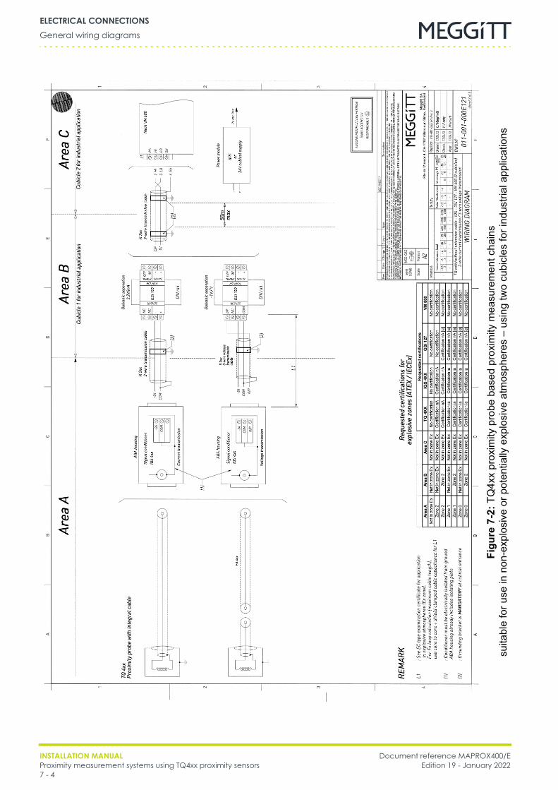
INSTALLATION MANUAL Document reference MAPROX400/EProximity measurement systems using TQ4xx proximity sensors Edition 19 - January 20227 - 4
General wiring diagramsELECTRICAL CONNECTIONS
Figu
re7-
2:TQ
4xx
prox
imity
pro
be b
ased
pro
xim
ity m
easu
rem
ent c
hain
ssu
itabl
e fo
r use
in n
on-e
xplo
sive
or p
oten
tially
exp
losi
ve a
tmos
pher
es –
usi
ng tw
o cu
bicl
es fo
r ind
ustri
al a
pplic
atio
ns
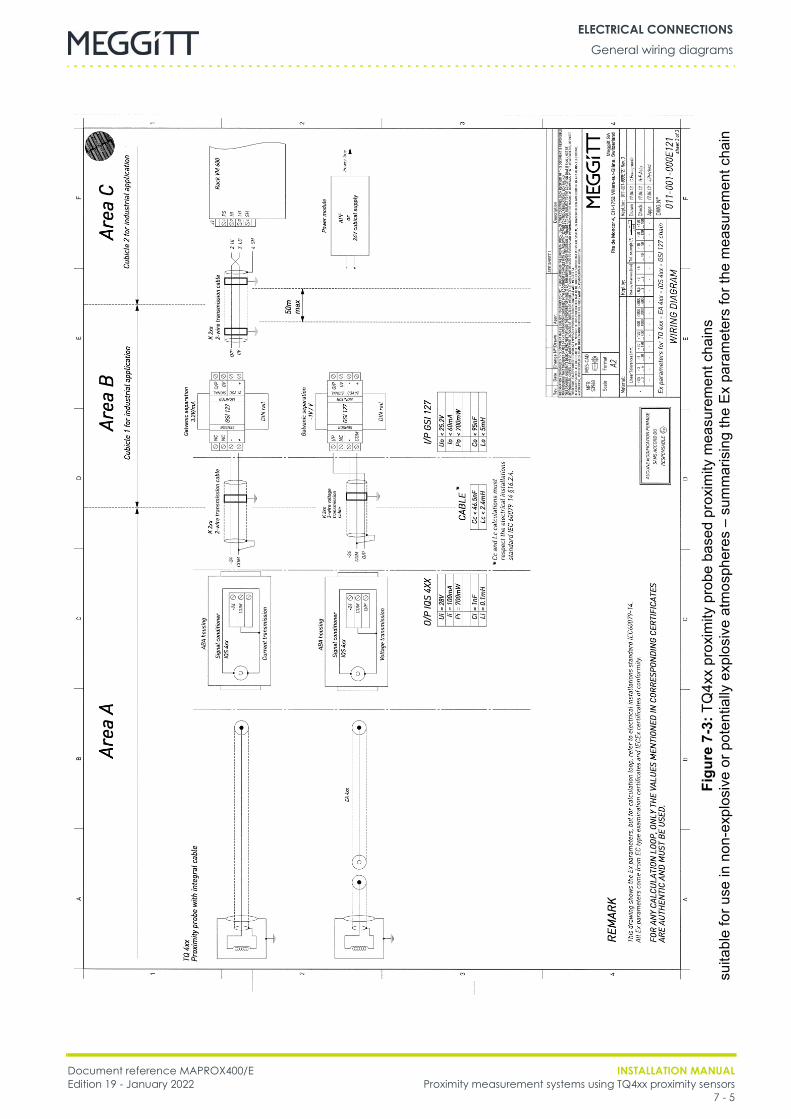
Document reference MAPROX400/E INSTALLATION MANUALEdition 19 - January 2022 Proximity measurement systems using TQ4xx proximity sensors
7 - 5
General wiring diagramsELECTRICAL CONNECTIONS
Figu
re7-
3:TQ
4xx
prox
imity
pro
be b
ased
pro
xim
ity m
easu
rem
ent c
hain
ssu
itabl
e fo
r use
in n
on-e
xplo
sive
or p
oten
tially
exp
losi
ve a
tmos
pher
es –
sum
mar
isin
g th
e Ex
par
amet
ers
for t
he m
easu
rem
ent c
hain
INSTALLATION MANUAL Document reference MAPROX400/EProximity measurement systems using TQ4xx proximity sensors Edition 19 - January 20227 - 6
General wiring diagramsELECTRICAL CONNECTIONS
THIS PAGE INTENTIONALLY LEFT BLANK
Document reference MAPROX400/E INSTALLATION MANUALEdition 19 - January 2022 Proximity measurement systems using TQ4xx proximity sensors
8 - 1
GeneralMAINTENANCE
8 MAINTENANCE
8.1 GeneralThe calibration of a TQ4xx-based proximity measurement system can be checkedperiodically by following the instructions given in 6.2 Electrical adjustment of the initial gap.Apart from periodic calibration, no specific maintenance is required for the TQ4xx-basedproximity measurement systems described in this manual, that is, for TQ4xx proximitytransducers, cabling or associated equipment such as IQS45x signal conditioners andGSI12x galvanic separation units.
NOTE: Any attempt by unauthorised personnel to modify or repair equipment still underguarantee will invalidate the warranty.
See 10.1 Contacting us for the contact details relevant to repairing defective hardware.
8.2 Requirements for equipment used in potentially explosive atmospheres
8.3 CleaningIt is not required to clean the components of TQ4xx-based proximity measurement systems.However, if cleaning does become necessary:• Clean with a damp cloth, then wipe with a dry cloth if required.• Keep away from live electrical parts.• Do not use any solvents or cleaning agents. Never pour or spray any cleaner or liquid on
the components.
WHERE MAINTENANCE IS REQUIRED, IT MUST BE PERFORMED ONLY BY EX QUALIFIEDPERSONNEL WITH THE APPROPRIATE MATERIAL.ANY MAINTENANCE WORK PERFORMED ON MEGGITT VIBRO-METER® EQUIPMENT THATCAN BE USED IN POTENTIALLY EXPLOSIVE ATMOSPHERES MUST RESPECT THECRITERIA DEFINED IN THE APPROPRIATE SECTIONS OF THE CORRESPONDINGEX CERTIFICATES.FOR FURTHER INFORMATION, SEE THE EX CERTIFICATES IN THE APPENDICES OF THISMANUAL. (THE EX CERTIFICATES ARE ALSO AVAILABLE FROM OUR WEBSITE ATWWW.MEGGITTSENSING.COM/ENERGY)DO NOT ATTEMPT TO MODIFY OR REPAIR EQUIPMENT FROM MEGGITT’SVIBRO-METER® PRODUCT LINE THAT IS USED IN POTENTIALLY EXPLOSIVEATMOSPHERES.
IF CLEANING BECOMES NECESSARY, USE A DAMP CLOTH ONLY AND KEEP AWAY FROMPOWERED (“LIVE”) ELECTRICAL PARTS.

INSTALLATION MANUAL Document reference MAPROX400/EProximity measurement systems using TQ4xx proximity sensors Edition 19 - January 20228 - 2
CleaningMAINTENANCE
THIS PAGE INTENTIONALLY LEFT BLANK
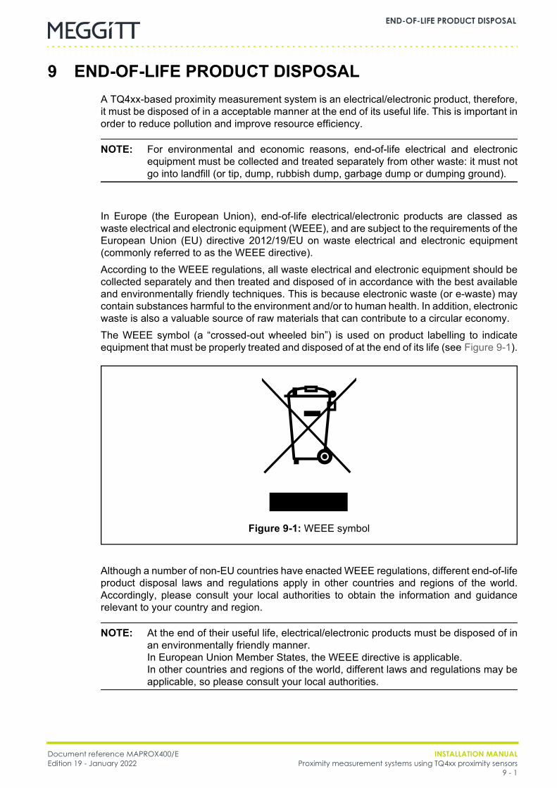
Document reference MAPROX400/E INSTALLATION MANUALEdition 19 - January 2022 Proximity measurement systems using TQ4xx proximity sensors
9 - 1
END-OF-LIFE PRODUCT DISPOSAL
9 END-OF-LIFE PRODUCT DISPOSALA TQ4xx-based proximity measurement system is an electrical/electronic product, therefore,it must be disposed of in a acceptable manner at the end of its useful life. This is important inorder to reduce pollution and improve resource efficiency.
NOTE: For environmental and economic reasons, end-of-life electrical and electronicequipment must be collected and treated separately from other waste: it must notgo into landfill (or tip, dump, rubbish dump, garbage dump or dumping ground).
In Europe (the European Union), end-of-life electrical/electronic products are classed aswaste electrical and electronic equipment (WEEE), and are subject to the requirements of theEuropean Union (EU) directive 2012/19/EU on waste electrical and electronic equipment(commonly referred to as the WEEE directive).According to the WEEE regulations, all waste electrical and electronic equipment should becollected separately and then treated and disposed of in accordance with the best availableand environmentally friendly techniques. This is because electronic waste (or e-waste) maycontain substances harmful to the environment and/or to human health. In addition, electronicwaste is also a valuable source of raw materials that can contribute to a circular economy.The WEEE symbol (a “crossed-out wheeled bin”) is used on product labelling to indicateequipment that must be properly treated and disposed of at the end of its life (see Figure 9-1).
Although a number of non-EU countries have enacted WEEE regulations, different end-of-lifeproduct disposal laws and regulations apply in other countries and regions of the world.Accordingly, please consult your local authorities to obtain the information and guidancerelevant to your country and region.
NOTE: At the end of their useful life, electrical/electronic products must be disposed of inan environmentally friendly manner.In European Union Member States, the WEEE directive is applicable.In other countries and regions of the world, different laws and regulations may beapplicable, so please consult your local authorities.
Figure 9-1: WEEE symbol

INSTALLATION MANUAL Document reference MAPROX400/EProximity measurement systems using TQ4xx proximity sensors Edition 19 - January 20229 - 2
END-OF-LIFE PRODUCT DISPOSAL
For additional end-of-life product disposal information and guidance, contact your localMeggitt representative. Alternatively, contact our main office:
Environment, health and safety departmentMeggitt SA
Route de Moncor 4Case postale1701 FribourgSwitzerland
Telephone: +41 26 407 11 11Email: [email protected]
Website: www.meggittsensing.com/energy

Document reference MAPROX400/E INSTALLATION MANUALEdition 19 - January 2022 Proximity measurement systems using TQ4xx proximity sensors
10 - 1
Contacting usSERVICE AND SUPPORT
10 SERVICE AND SUPPORT
10.1Contacting usMeggitt’s worldwide customer support network offers a range of support, including10.2 Technical support and 10.3 Sales and repairs support. For customer support, contactyour local Meggitt representative. Alternatively, contact our main office:
Customer support departmentMeggitt SA
Route de Moncor 4Case postale1701 FribourgSwitzerland
Telephone: +41 26 407 11 11Email: [email protected]
Website: www.meggittsensing.com/energy
10.2Technical supportMeggitt’s technical support team provide both pre-sales and post-sales technical support,including:• General advice• Technical advice• Troubleshooting• Site visits.
NOTE: For further information, contact Meggitt (see 10.1 Contacting us).
10.3Sales and repairs supportMeggitt’s sales team provide both pre-sales and post-sales support, including advice on:• New products• Spare parts• Repairs.
NOTE: If a product has to be returned for repairs, then it should be accompanied by acompleted Energy product return form, included on page 10-4.

INSTALLATION MANUAL Document reference MAPROX400/EProximity measurement systems using TQ4xx proximity sensors Edition 19 - January 202210 - 2
Customer feedbackSERVICE AND SUPPORT
10.4Customer feedbackAs part of our continuing commitment to improving customer service, we warmly welcomeyour opinions. To provide feedback, complete the Energy customer feedback form onpage 10-7 and return it to Meggitt SA’s main office (see 10.1 Contacting us).
Document reference MAPROX400/E INSTALLATION MANUALEdition 19 - January 2022 Proximity measurement systems using TQ4xx proximity sensors
10 - 3
Customer feedbackSERVICE AND SUPPORT
REPAIRS AND RETURNS
Energy product return procedure
If a Meggitt vibro-meter® Energy product needs to be returned to Meggitt Switzerland, pleaseuse the online product return procedure on the Meggitt vibro-meter® Energy website at www.meggittsensing.com/energy/service-and-support/repair
As described on the website, the product return procedure is as follows:1- Complete and submit online the Energy product return form that is available on the
website (note: * indicates a required field).For each Energy product to be returned, a separate Energy product return form must becompleted and submitted online. It is possible to return multiple items of the sameproduct type with the same form (same part number (PNR), multiple serial numbers(SNRs) – separated with a coma “,”).When an Energy product return form is submitted online, the website displays a messageconfirming that the form has been successfully sent.
2- When the Energy product return form has been processed by Meggitt Switzerland, areturn merchandise authorisation (RMA) document with a unique RMA # referencenumber and containing a pre-filled end-user certificate (EUC) will be emailed by return.Received forms are typically processed and the RMA document sent within 2 workingdays.
NOTE: Please do not return any products to Meggitt Switzerland without a supportingreturn merchandise authorisation (RMA) document.Please use the RMA # reference number in all future communicationsregarding a product return.
3- Review, complete and sign the RMA document and also review, complete and sign theEUC that the RMA contains (separate signatures are required for each).For each Energy product to be returned, an associated single-use end-user certificate(EUC) is required, unless your company has an annual end-user certificate (EUC) inplace. Either end-user certificate can be used to cover multiple products.Multiple items of the same product type (same part number (PNR), multiple serialnumbers (SNRs)) are allowed for a single RMA and EUC.
4- Optionally, to support your internal processes, you may want to issue one purchase order(PO) per product (may include multiple items / serial numbers) and send it to MeggittSwitzerland.
5- Send the Energy product(s) together with printed and signed copies of the returnmerchandise authorisation (RMA) document (or documents) and the end-user certificate(or certificates) to Meggitt Switzerland at:Meggitt SA, Energy repairs department, Route de Moncor 4, Case postale,1701 Fribourg, Switzerland.
NOTE: The Energy product return form reproduced below is included to support thegathering of information required for completion and submission online.

INSTALLATION MANUAL Document reference MAPROX400/EProximity measurement systems using TQ4xx proximity sensors Edition 19 - January 202210 - 4
Customer feedbackSERVICE AND SUPPORT
Energy product return form
Contact information
First name:* Last name:*
Job title: Company:*
Address:*
Country:* Email:*
Telephone:* Fax:
Product information
Product type:* Part number (PNR):*
Serial number (SER):
Note: Enter “Unknown” if the serial number (SER) is not known.
Ex product: SIL product:*
Yes Yes
No No
Meggitt SA purchase order number: Date of purchase (dd.mm.yyyy):
Product under warranty: Site where installed:
Yes
No
Don’t know
End user:
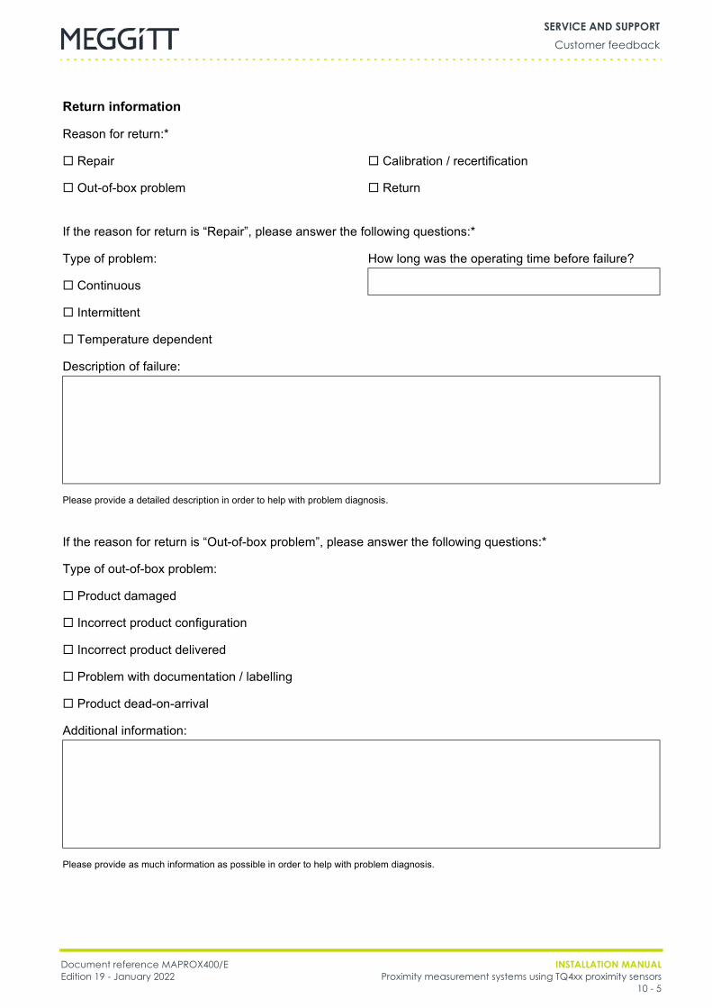
Document reference MAPROX400/E INSTALLATION MANUALEdition 19 - January 2022 Proximity measurement systems using TQ4xx proximity sensors
10 - 5
Customer feedbackSERVICE AND SUPPORT
Return information
Reason for return:*
Repair Calibration / recertification
Out-of-box problem Return
If the reason for return is “Repair”, please answer the following questions:*
Type of problem: How long was the operating time before failure?
Continuous
Intermittent
Temperature dependent
Description of failure:
Please provide a detailed description in order to help with problem diagnosis.
If the reason for return is “Out-of-box problem”, please answer the following questions:*
Type of out-of-box problem:
Product damaged
Incorrect product configuration
Incorrect product delivered
Problem with documentation / labelling
Product dead-on-arrival
Additional information:
Please provide as much information as possible in order to help with problem diagnosis.
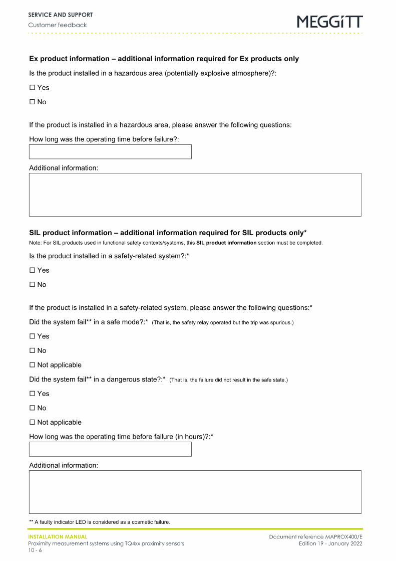
INSTALLATION MANUAL Document reference MAPROX400/EProximity measurement systems using TQ4xx proximity sensors Edition 19 - January 202210 - 6
Customer feedbackSERVICE AND SUPPORT
Ex product information – additional information required for Ex products only
Is the product installed in a hazardous area (potentially explosive atmosphere)?:
Yes
No
If the product is installed in a hazardous area, please answer the following questions:
How long was the operating time before failure?:
Additional information:
SIL product information – additional information required for SIL products only*Note: For SIL products used in functional safety contexts/systems, this SIL product information section must be completed.
Is the product installed in a safety-related system?:*
Yes
No
If the product is installed in a safety-related system, please answer the following questions:*
Did the system fail** in a safe mode?:* (That is, the safety relay operated but the trip was spurious.)
Yes
No
Not applicable
Did the system fail** in a dangerous state?:* (That is, the failure did not result in the safe state.)
Yes
No
Not applicable
How long was the operating time before failure (in hours)?:*
Additional information:
** A faulty indicator LED is considered as a cosmetic failure.

Document reference MAPROX400/E INSTALLATION MANUALEdition 19 - January 2022 Proximity measurement systems using TQ4xx proximity sensors
10 - 7
Customer feedbackSERVICE AND SUPPORT
FEEDBACK
Energy customer feedback form
Manual information
Title of manual:
Proximity measurement systems using TQ4xx proximity sensorsinstallation manual
Reference: MAPROX400/E Version: Edition 19
Date of issue: January 2022
Customer contact information
First name:* Last name:*
Job title: Company:*
Address:*
Country:* Email:*
Telephone:* Fax:
INSTALLATION MANUAL Document reference MAPROX400/EProximity measurement systems using TQ4xx proximity sensors Edition 19 - January 202210 - 8
Customer feedbackSERVICE AND SUPPORT
Feedback – general
Please answer the following questions:
Is the document well organised? Yes No
Is the information technically accurate? Yes No
Is more technical detail required? Yes No
Are the instructions clear and complete? Yes No
Are the descriptions easy to understand? Yes No
Are the examples and diagrams/photos helpful? Yes No
Are there enough examples and diagrams/photos? Yes No
Is the style/wording easy to read? Yes No
Is any information not included? Yes No
Please include any additional information in the “Feedback – additional” section below.
Feedback – additional
Additional information:
Please provide as much feedback as possible in order to help us improve our product documentation.Continue on a separate sheet if necessary …
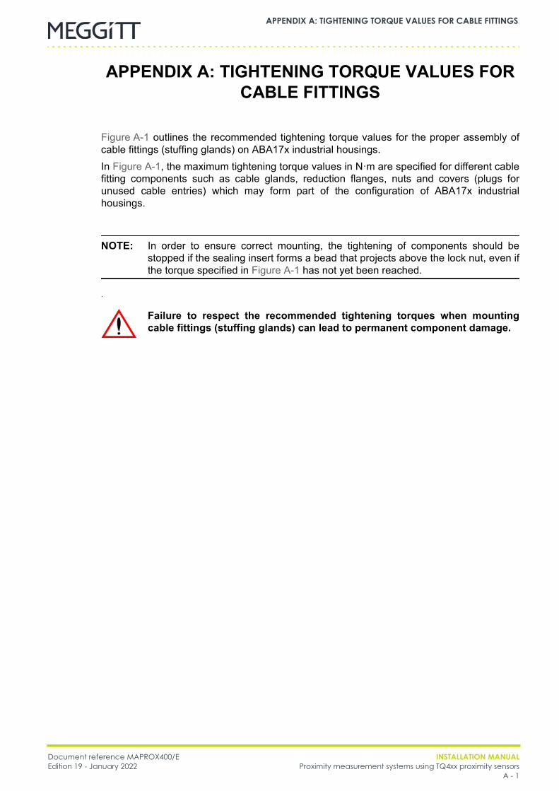
Document reference MAPROX400/E INSTALLATION MANUALEdition 19 - January 2022 Proximity measurement systems using TQ4xx proximity sensors
A - 1
APPENDIX A: TIGHTENING TORQUE VALUES FOR CABLE FITTINGS
APPENDIX A: TIGHTENING TORQUE VALUES FOR CABLE FITTINGS
Figure A-1 outlines the recommended tightening torque values for the proper assembly ofcable fittings (stuffing glands) on ABA17x industrial housings.In Figure A-1, the maximum tightening torque values in N·m are specified for different cablefitting components such as cable glands, reduction flanges, nuts and covers (plugs forunused cable entries) which may form part of the configuration of ABA17x industrialhousings.
NOTE: In order to ensure correct mounting, the tightening of components should bestopped if the sealing insert forms a bead that projects above the lock nut, even ifthe torque specified in Figure A-1 has not yet been reached.
.
Failure to respect the recommended tightening torques when mountingcable fittings (stuffing glands) can lead to permanent component damage.
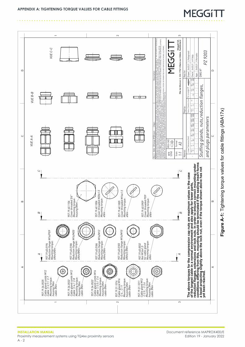
INSTALLATION MANUAL Document reference MAPROX400/EProximity measurement systems using TQ4xx proximity sensors Edition 19 - January 2022A - 2
APPENDIX A: TIGHTENING TORQUE VALUES FOR CABLE FITTINGS
Figu
reA
-1:T
ight
enin
g to
rque
val
ues
for c
able
fitti
ngs
(ABA
17x)
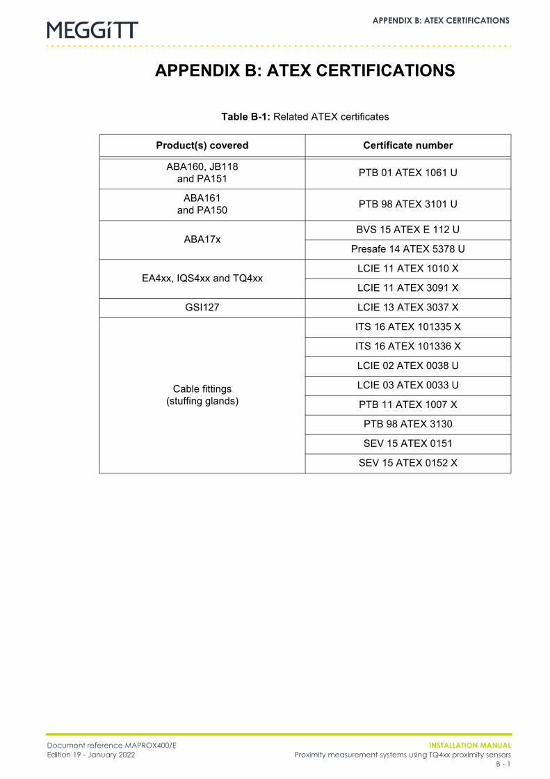
Document reference MAPROX400/E INSTALLATION MANUALEdition 19 - January 2022 Proximity measurement systems using TQ4xx proximity sensors
B - 1
APPENDIX B: ATEX CERTIFICATIONS
APPENDIX B: ATEX CERTIFICATIONS
Table B-1: Related ATEX certificates
Product(s) covered Certificate number
ABA160, JB118and PA151 PTB 01 ATEX 1061 U
ABA161and PA150 PTB 98 ATEX 3101 U
ABA17xBVS 15 ATEX E 112 U
Presafe 14 ATEX 5378 U
EA4xx, IQS4xx and TQ4xxLCIE 11 ATEX 1010 X
LCIE 11 ATEX 3091 X
GSI127 LCIE 13 ATEX 3037 X
Cable fittings(stuffing glands)
ITS 16 ATEX 101335 X
ITS 16 ATEX 101336 X
LCIE 02 ATEX 0038 U
LCIE 03 ATEX 0033 U
PTB 11 ATEX 1007 X
PTB 98 ATEX 3130
SEV 15 ATEX 0151
SEV 15 ATEX 0152 X

INSTALLATION MANUAL Document reference MAPROX400/EProximity measurement systems using TQ4xx proximity sensors Edition 19 - January 2022B - 2
APPENDIX B: ATEX CERTIFICATIONS
THIS PAGE INTENTIONALLY LEFT BLANK
DRAFT
EX
ATEX certificate PTB 01 ATEX 1061 UEdition 5 - April 2014
Meggitt SARoute de Moncor 4
PO Box 1616CH - 1701 Fribourg
Switzerland
www.meggittsensingsystems.comwww.vibro-meter.com
PTB_01_ATEX_1061_U
ATEX certificate:
PTB 01 ATEX 1061 U
for
ABA 15x / ABA 160 / JB 116 / JB 118 / PA 151
Although the certificate is available in twolanguages (English and German), the liability of thenotified body applies only on the text of the originalcopy of the certificate that it published.
Obwohl das Zertifikat in zwei Sprachen (Englischund Deutsch) übersetzt ist, können nur diebescheinigten Behörden, die den Text auf derOriginalausgabe des Zertifikates herausgegebenhaben, zur rechtlichen Verantwortung gezogenwerden.
EN
DE

THIS PAGE INTENTIONALLY LEFT BLANKCETTE PAGE EST LAISSÉE INTENTIONNELLEMENT VIDE
DIESE SEITE WURDE ABSICHTLICH LEER GELASSEN
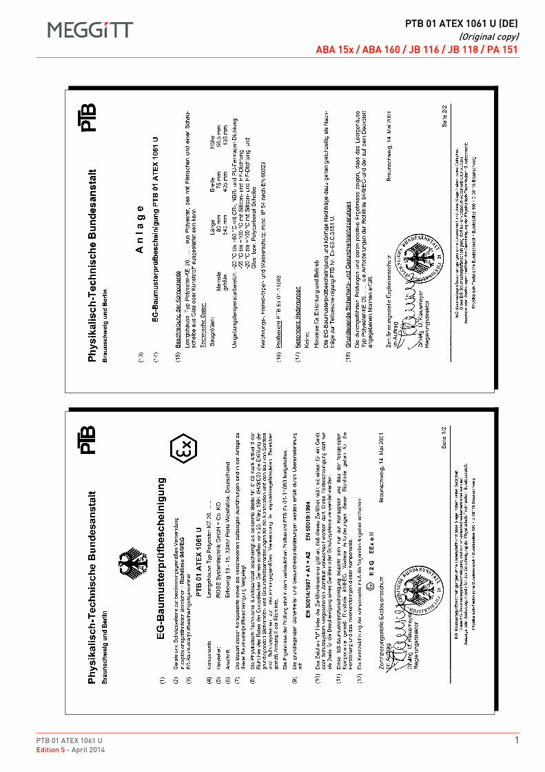
PTB 01 ATEX 1061 U 1Edition 5 - April 2014
DRAFT
PTB 01 ATEX 1061 U (DE)(Original copy)
ABA 15x / ABA 160 / JB 116 / JB 118 / PA 151PTB 01 ATEX 1061 U (DE)Original copyDEDEABA 15x / ABA 160 / JB 116 / JB 118 / PA 151ABA 15x / ABA 160 / JB 116 / JB 118 / PA 151
1
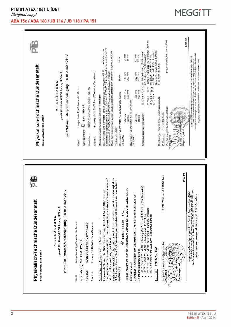
DRAFT
PTB 01 ATEX 1061 U (DE)(Original copy)
ABA 15x / ABA 160 / JB 116 / JB 118 / PA 151
2 PTB 01 ATEX 1061 UEdition 5 - April 2014
1
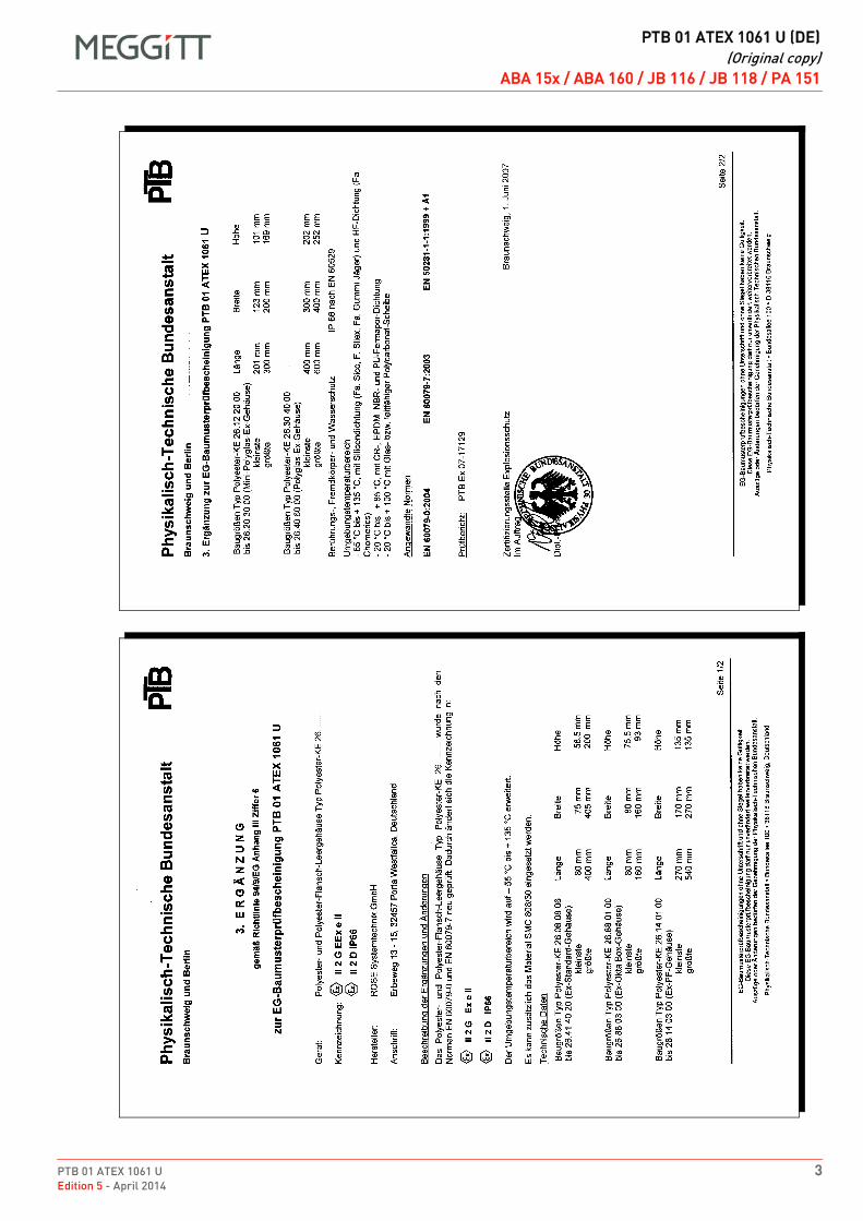
PTB 01 ATEX 1061 U 3Edition 5 - April 2014
DRAFT
PTB 01 ATEX 1061 U (DE)(Original copy)
ABA 15x / ABA 160 / JB 116 / JB 118 / PA 151
2
DRAFT
PTB 01 ATEX 1061 U (DE)(Original copy)
ABA 15x / ABA 160 / JB 116 / JB 118 / PA 151
4 PTB 01 ATEX 1061 UEdition 5 - April 2014
ABA 15x / ABA 160 (Rose) / JB 116 / JB 118 / PA 151
DE PTB 01 ATEX 1061 U (DE) Original copy DE
PTB 01 ATEX 1061 U 5Edition 5 - April 2014
DRAFT
PTB 01 ATEX 1061 U (DE)(Original copy)
ABA 15x / ABA 160 / JB 116 / JB 118 / PA 151
DRAFT
PTB 01 ATEX 1061 U (DE)(Original copy)
ABA 15x / ABA 160 / JB 116 / JB 118 / PA 151
6 PTB 01 ATEX 1061 UEdition 5 - April 2014
ABA 15x / ABA 160 (Rose) / JB 116 / JB 118 / PA 151
DE PTB 01 ATEX 1061 U (DE) Original copy DE
PTB 01 ATEX 1061 U 7Edition 5 - April 2014
DRAFT
PTB 01 ATEX 1061 U (DE)(Original copy)
ABA 15x / ABA 160 / JB 116 / JB 118 / PA 151ABA 15x / ABA 160 (Rose) / JB 116 / JB 118 / PA 151
DE PTB 01 ATEX 1061 U (DE) Original copy DE
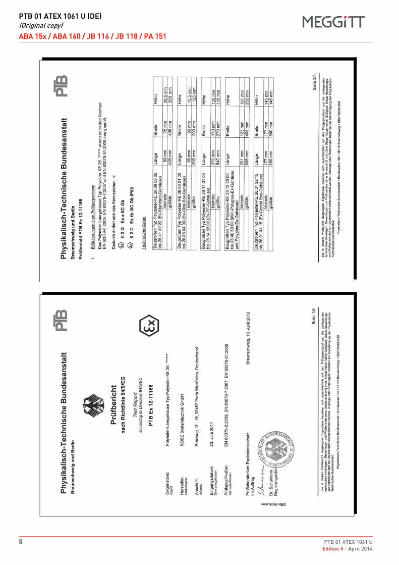
DRAFT
PTB 01 ATEX 1061 U (DE)(Original copy)
ABA 15x / ABA 160 / JB 116 / JB 118 / PA 151
8 PTB 01 ATEX 1061 UEdition 5 - April 2014
ABA 15x / ABA 160 (Rose) / JB 116 / JB 118 / PA 151
DE PTB 01 ATEX 1061 U (DE) Original copy DE
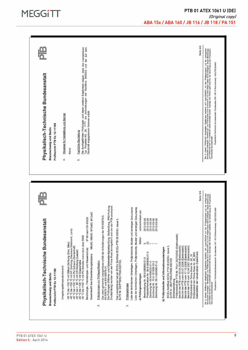
PTB 01 ATEX 1061 U 9Edition 5 - April 2014
DRAFT
PTB 01 ATEX 1061 U (DE)(Original copy)
ABA 15x / ABA 160 / JB 116 / JB 118 / PA 151ABA 15x / ABA 160 (Rose) / JB 116 / JB 118 / PA 151
DE PTB 01 ATEX 1061 U (DE) Original copy DE
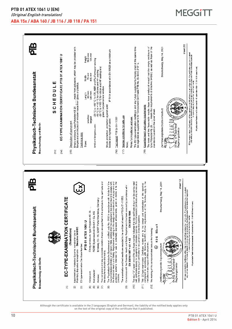
DRAFT
PTB 01 ATEX 1061 U (EN)(Original English translation)
ABA 15x / ABA 160 / JB 116 / JB 118 / PA 151
10 PTB 01 ATEX 1061 UEdition 5 - April 2014
Although the certificate is available in the 2 languages (English and German), the liability of the notified body applies only on the text of the original copy of the certificate that it published.
ABA 15x / ABA 160 (Rose) / JB 116 / JB 118 / PA 151
EN PTB 01 ATEX 1061 U (EN) Original English translation EN
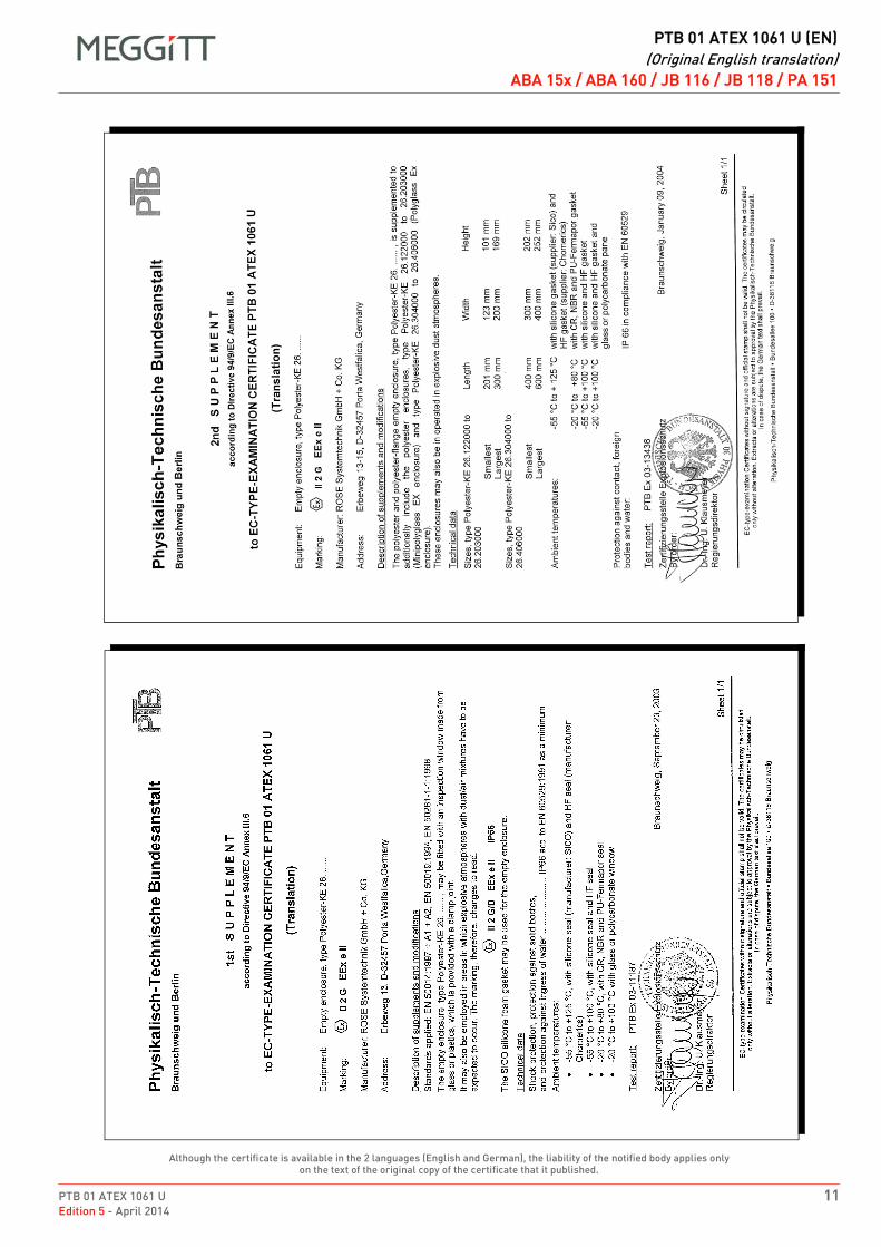
PTB 01 ATEX 1061 U 11Edition 5 - April 2014
DRAFT
PTB 01 ATEX 1061 U (EN)(Original English translation)
ABA 15x / ABA 160 / JB 116 / JB 118 / PA 151
Although the certificate is available in the 2 languages (English and German), the liability of the notified body applies only on the text of the original copy of the certificate that it published.
ABA 15x / ABA 160 (Rose) / JB 116 / JB 118 / PA 151
EN PTB 01 ATEX 1061 U (EN) Original English translation EN
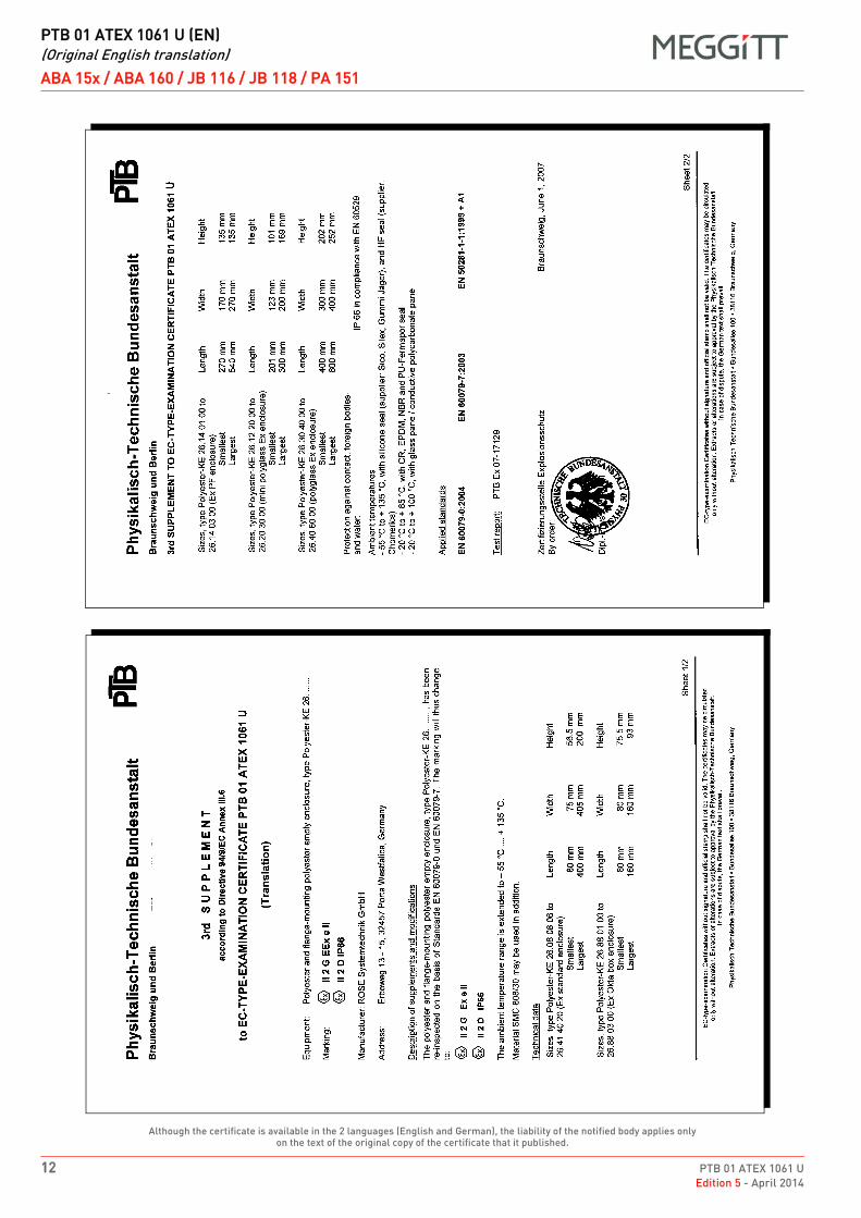
DRAFT
PTB 01 ATEX 1061 U (EN)(Original English translation)
ABA 15x / ABA 160 / JB 116 / JB 118 / PA 151
12 PTB 01 ATEX 1061 UEdition 5 - April 2014
Although the certificate is available in the 2 languages (English and German), the liability of the notified body applies only on the text of the original copy of the certificate that it published.
ABA 15x / ABA 160 (Rose) / JB 116 / JB 118 / PA 151
EN PTB 01 ATEX 1061 U (EN) Original English translation EN
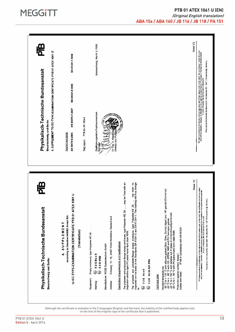
PTB 01 ATEX 1061 U 13Edition 5 - April 2014
DRAFT
PTB 01 ATEX 1061 U (EN)(Original English translation)
ABA 15x / ABA 160 / JB 116 / JB 118 / PA 151
Although the certificate is available in the 2 languages (English and German), the liability of the notified body applies only on the text of the original copy of the certificate that it published.
ABA 15x / ABA 160 (Rose) / JB 116 / JB 118 / PA 151
EN PTB 01 ATEX 1061 U (EN) Original English translation EN
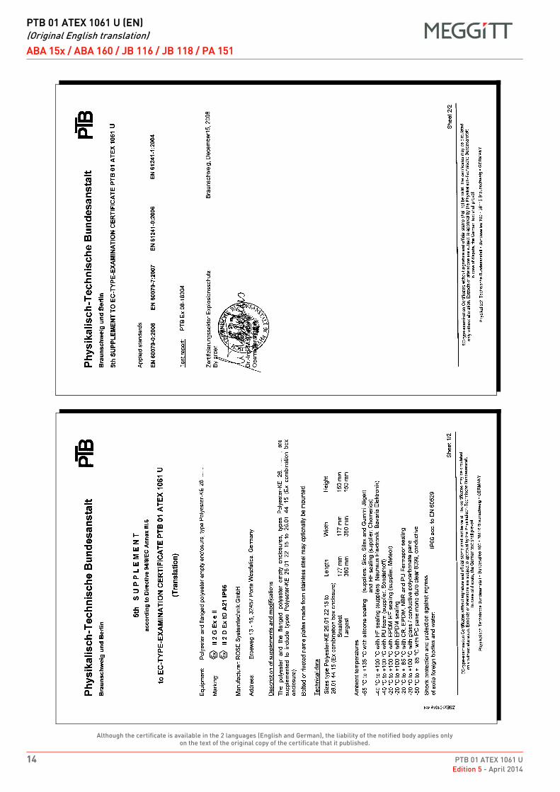
DRAFT
PTB 01 ATEX 1061 U (EN)(Original English translation)
ABA 15x / ABA 160 / JB 116 / JB 118 / PA 151
14 PTB 01 ATEX 1061 UEdition 5 - April 2014
Although the certificate is available in the 2 languages (English and German), the liability of the notified body applies only on the text of the original copy of the certificate that it published.
ABA 15x / ABA 160 (Rose) / JB 116 / JB 118 / PA 151
EN PTB 01 ATEX 1061 U (EN) Original English translation EN
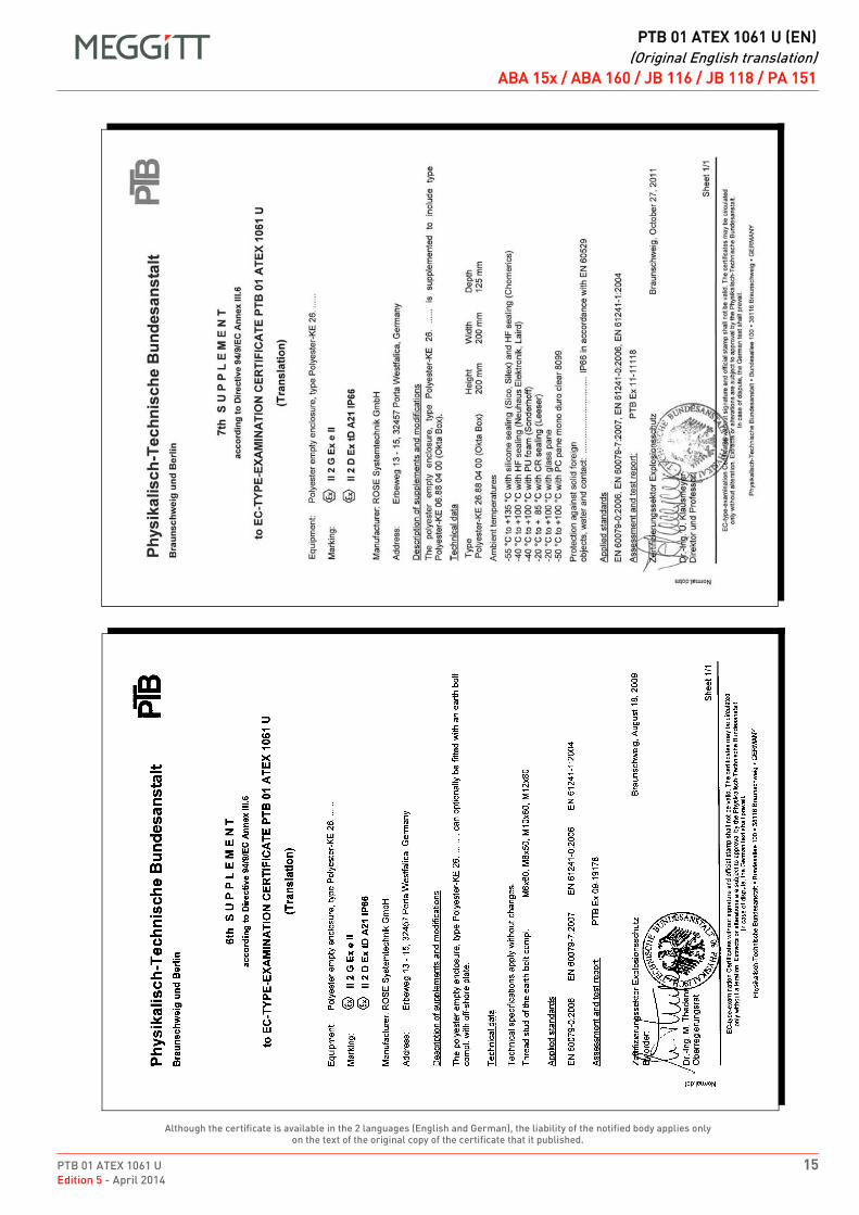
PTB 01 ATEX 1061 U 15Edition 5 - April 2014
DRAFT
PTB 01 ATEX 1061 U (EN)(Original English translation)
ABA 15x / ABA 160 / JB 116 / JB 118 / PA 151
Although the certificate is available in the 2 languages (English and German), the liability of the notified body applies only on the text of the original copy of the certificate that it published.
ABA 15x / ABA 160 (Rose) / JB 116 / JB 118 / PA 151
EN PTB 01 ATEX 1061 U (EN) Original English translation EN
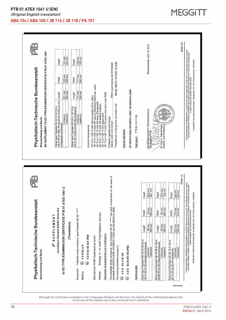
DRAFT
PTB 01 ATEX 1061 U (EN)(Original English translation)
ABA 15x / ABA 160 / JB 116 / JB 118 / PA 151
16 PTB 01 ATEX 1061 UEdition 5 - April 2014
Although the certificate is available in the 2 languages (English and German), the liability of the notified body applies only on the text of the original copy of the certificate that it published.
ABA 15x / ABA 160 (Rose) / JB 116 / JB 118 / PA 151
EN PTB 01 ATEX 1061 U (EN) Original English translation EN
DRAFT
EX
ATEX certificate PTB 98 ATEX 3101 UEdition 4 - May 2015
Meggitt SARoute de Moncor 4
PO Box 1616CH - 1701 Fribourg
Switzerland
www.meggittsensingsystems.comwww.vibro-meter.com
PTB_01_ATEX_1061_U
ATEX certificate:
PTB 98 ATEX 3101 U
for
ABA 161 and PA 150
Although the certificate is available in twolanguages (English and German), the liability of thenotified body applies only on the text of the originalcopy of the certificate that it published.
Obwohl das Zertifikat in zwei Sprachen (Englischund Deutsch) übersetzt ist, können nur diebescheinigten Behörden, die den Text auf derOriginalausgabe des Zertifikates herausgegebenhaben, zur rechtlichen Verantwortung gezogenwerden.
EN
DE

THIS PAGE INTENTIONALLY LEFT BLANKCETTE PAGE EST LAISSÉE INTENTIONNELLEMENT VIDE
DIESE SEITE WURDE ABSICHTLICH LEER GELASSEN
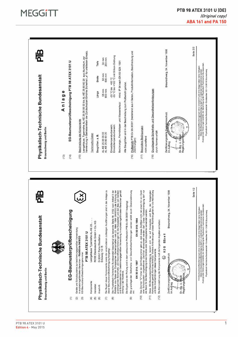
PTB 98 ATEX 3101 U 1Edition 4 - May 2015
DRAFT
PTB 98 ATEX 3101 U (DE)(Original copy)
ABA 161 and PA 150PTB 98 ATEX 3101 U (DE)Original copyDEDEABA 161 and PA 150ABA 161 and PA 150
1
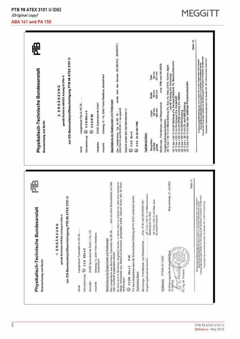
DRAFT
PTB 98 ATEX 3101 U (DE)(Original copy)
ABA 161 and PA 150
2 PTB 98 ATEX 3101 UEdition 4 - May 2015
1
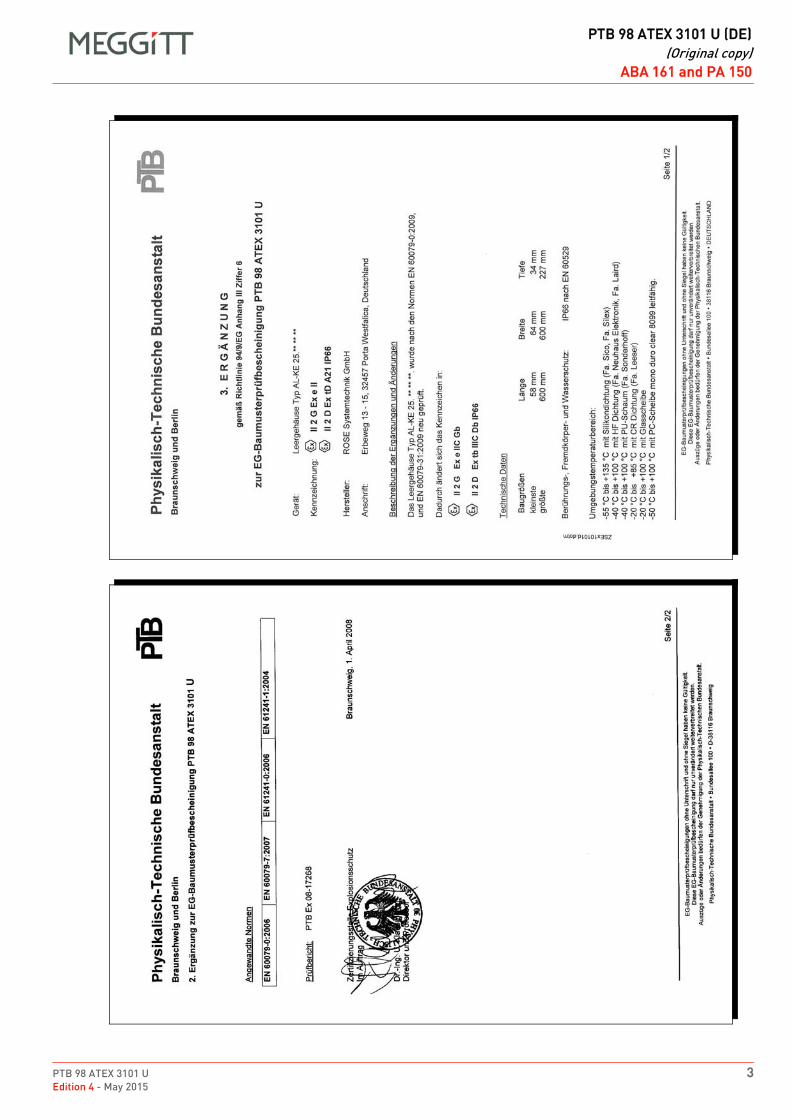
PTB 98 ATEX 3101 U 3Edition 4 - May 2015
DRAFT
PTB 98 ATEX 3101 U (DE)(Original copy)
ABA 161 and PA 150
2

DRAFT
PTB 98 ATEX 3101 U (DE)(Original copy)
ABA 161 and PA 150
4 PTB 98 ATEX 3101 UEdition 4 - May 2015
1
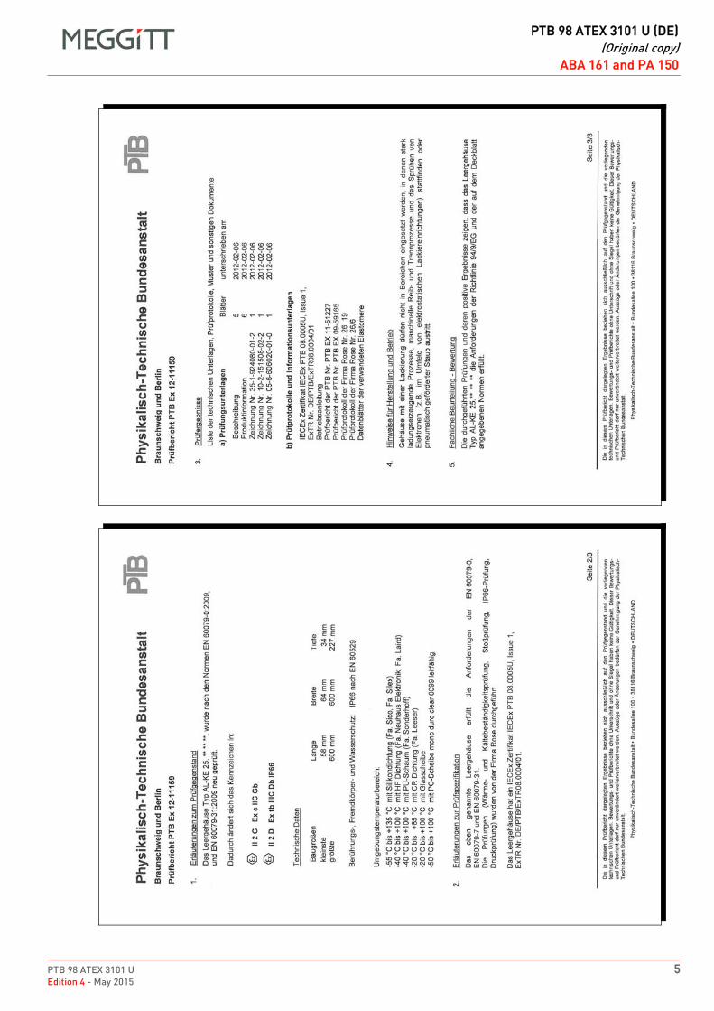
PTB 98 ATEX 3101 U 5Edition 4 - May 2015
DRAFT
PTB 98 ATEX 3101 U (DE)(Original copy)
ABA 161 and PA 150
2
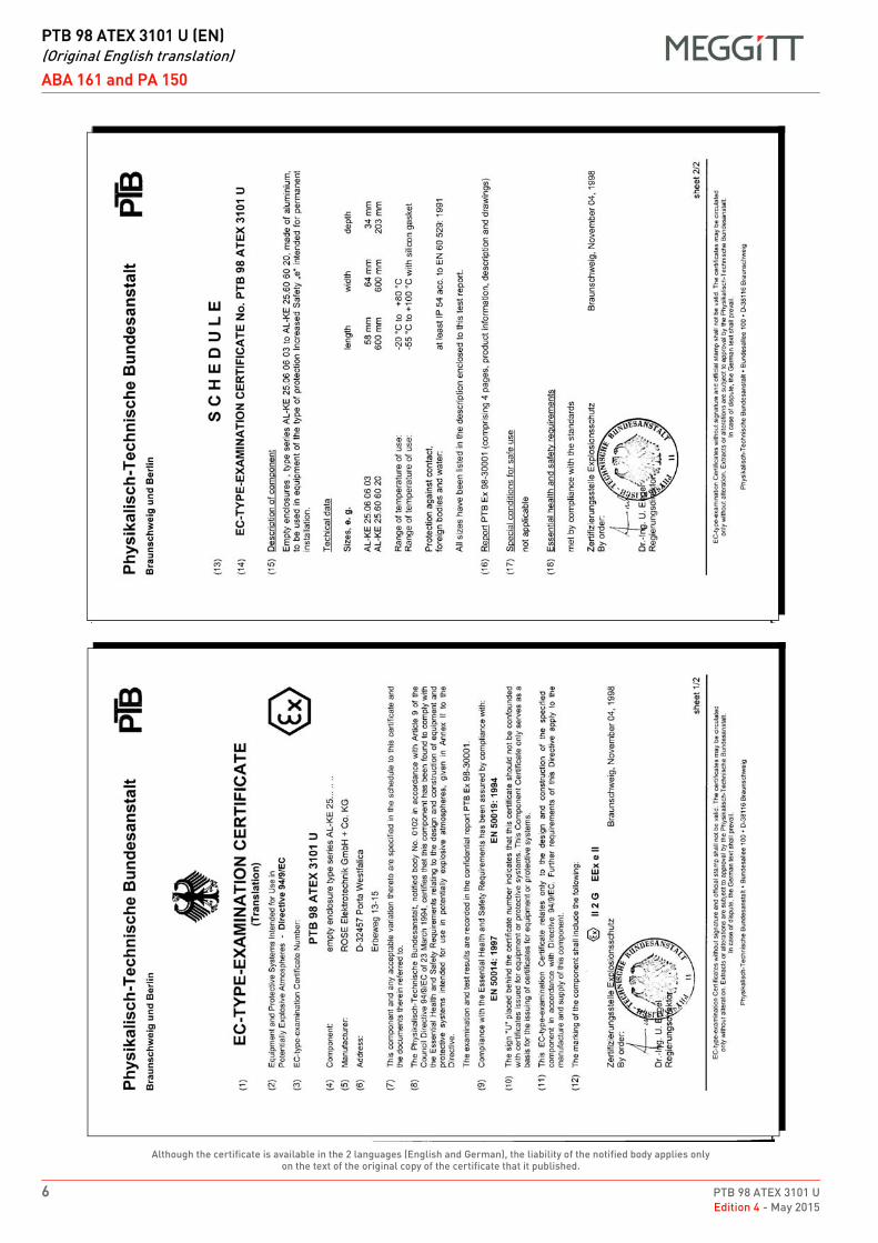
DRAFT
PTB 98 ATEX 3101 U (EN)(Original English translation)
ABA 161 and PA 150
6 PTB 98 ATEX 3101 UEdition 4 - May 2015
Although the certificate is available in the 2 languages (English and German), the liability of the notified body applies only on the text of the original copy of the certificate that it published.
ABA 15x / ABA 160 (Rose) / JB 116 / JB 118 / PA 151
EN PTB 98 ATEX 3101 U (EN) Original English translation EN
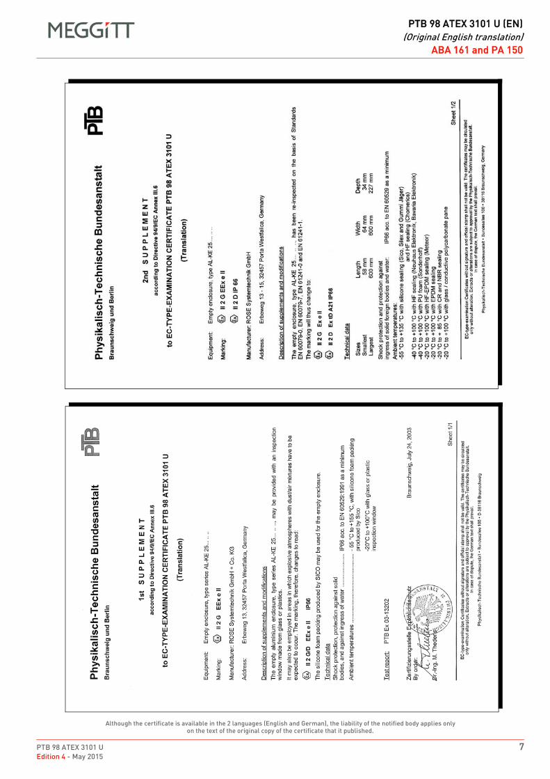
PTB 98 ATEX 3101 U 7Edition 4 - May 2015
DRAFT
PTB 98 ATEX 3101 U (EN)(Original English translation)
ABA 161 and PA 150
Although the certificate is available in the 2 languages (English and German), the liability of the notified body applies only on the text of the original copy of the certificate that it published.
ABA 15x / ABA 160 (Rose) / JB 116 / JB 118 / PA 151
EN PTB 98 ATEX 3101 U (EN) Original English translation EN
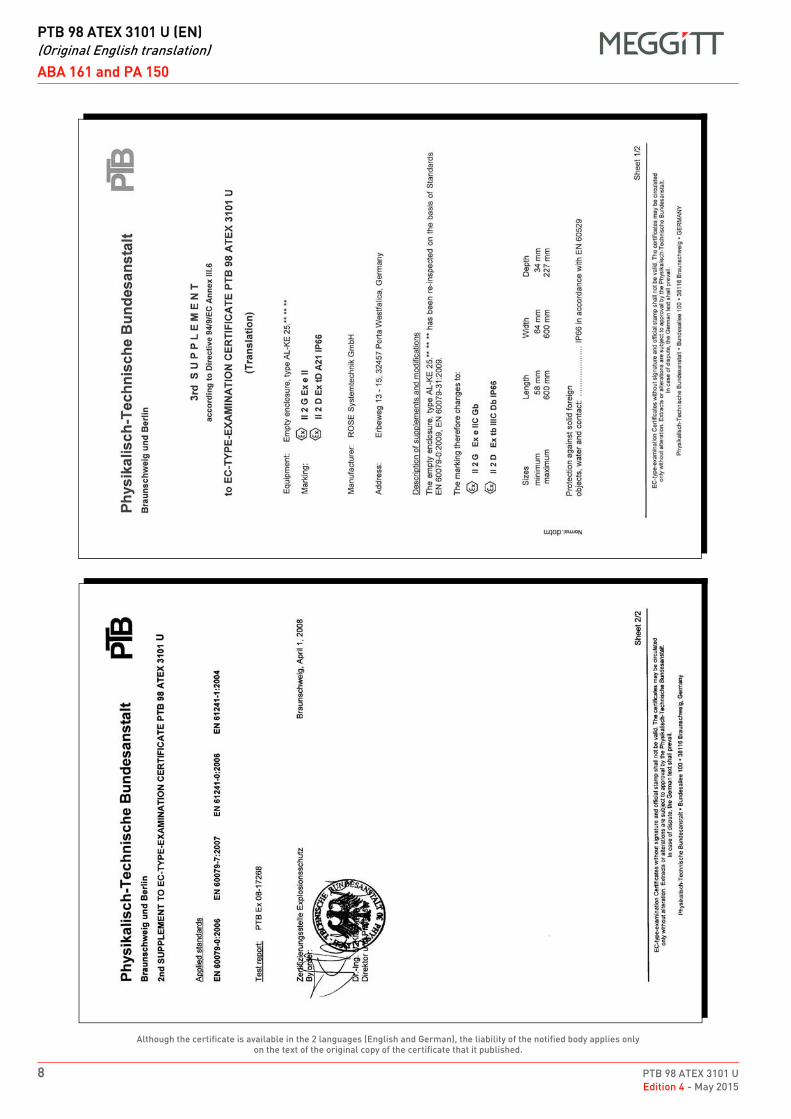
DRAFT
PTB 98 ATEX 3101 U (EN)(Original English translation)
ABA 161 and PA 150
8 PTB 98 ATEX 3101 UEdition 4 - May 2015
Although the certificate is available in the 2 languages (English and German), the liability of the notified body applies only on the text of the original copy of the certificate that it published.
ABA 15x / ABA 160 (Rose) / JB 116 / JB 118 / PA 151
EN PTB 98 ATEX 3101 U (EN) Original English translation EN
PTB 98 ATEX 3101 U 9Edition 4 - May 2015
DRAFT
PTB 98 ATEX 3101 U (EN)(Original English translation)
ABA 161 and PA 150
Although the certificate is available in the 2 languages (English and German), the liability of the notified body applies only on the text of the original copy of the certificate that it published.
ABA 15x / ABA 160 (Rose) / JB 116 / JB 118 / PA 151
EN PTB 98 ATEX 3101 U (EN) Original English translation EN
DRAFT
PTB 98 ATEX 3101 U (EN)(Original English translation)
ABA 161 and PA 150
10 PTB 98 ATEX 3101 UEdition 4 - May 2015
THIS PAGE INTENTIONALLY LEFT BLANKCETTE PAGE EST LAISSÉE INTENTIONNELLEMENT VIDE
DIESE SEITE WURDE ABSICHTLICH LEER GELASSEN
DRAFT
EX
ATEX certificate BVS 15 ATEX E 112 UEdition 1 – September 2018
Meggitt SARoute de Moncor 4
PO Box 16161701 Fribourg
Switzerland
[email protected]/energy
Title Page
ATEX certificate:
BVS 15 ATEX E 112 U
for
ABA17x
Although the certificate is available in twolanguages (English and German), the liability of thenotified body applies only on the text of the originalcopy of the certificate that it published.
Obwohl das Zertifikat in zwei Sprachen (Englischund Deutsch) übersetzt ist, können nur diebescheinigten Behörden, die den Text auf derOriginalausgabe des Zertifikates herausgegebenhaben, zur rechtlichen Verantwortung gezogenwerden.
EN
DE

THIS PAGE INTENTIONALLY LEFT BLANKDIESE SEITE WURDE ABSICHTLICH LEER GELASSEN
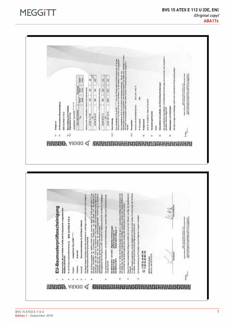
BVS 15 ATEX E 112 U 1Edition 1 - September 2018
DRAFT
BVS 15 ATEX E 112 U (DE, EN)(Original copy)
ABA17xBVS 15 ATEX E 112 U (DE, EN)ABA17xENOriginal copy
Man
ual B
VS
15
ATE
X E
112
U17
Ed
ition
Feb
ruar
y 20
18th
uba
Ltd
., C
H-4
002
Bas
elC
opyr
ight
S
witz
erla
nd
Man
ual B
VS
15
ATE
X E
112
U16
Ed
ition
Feb
ruar
y 20
18th
uba
Ltd
., C
H-4
002
Bas
elC
opyr
ight
S
witz
erla
nd
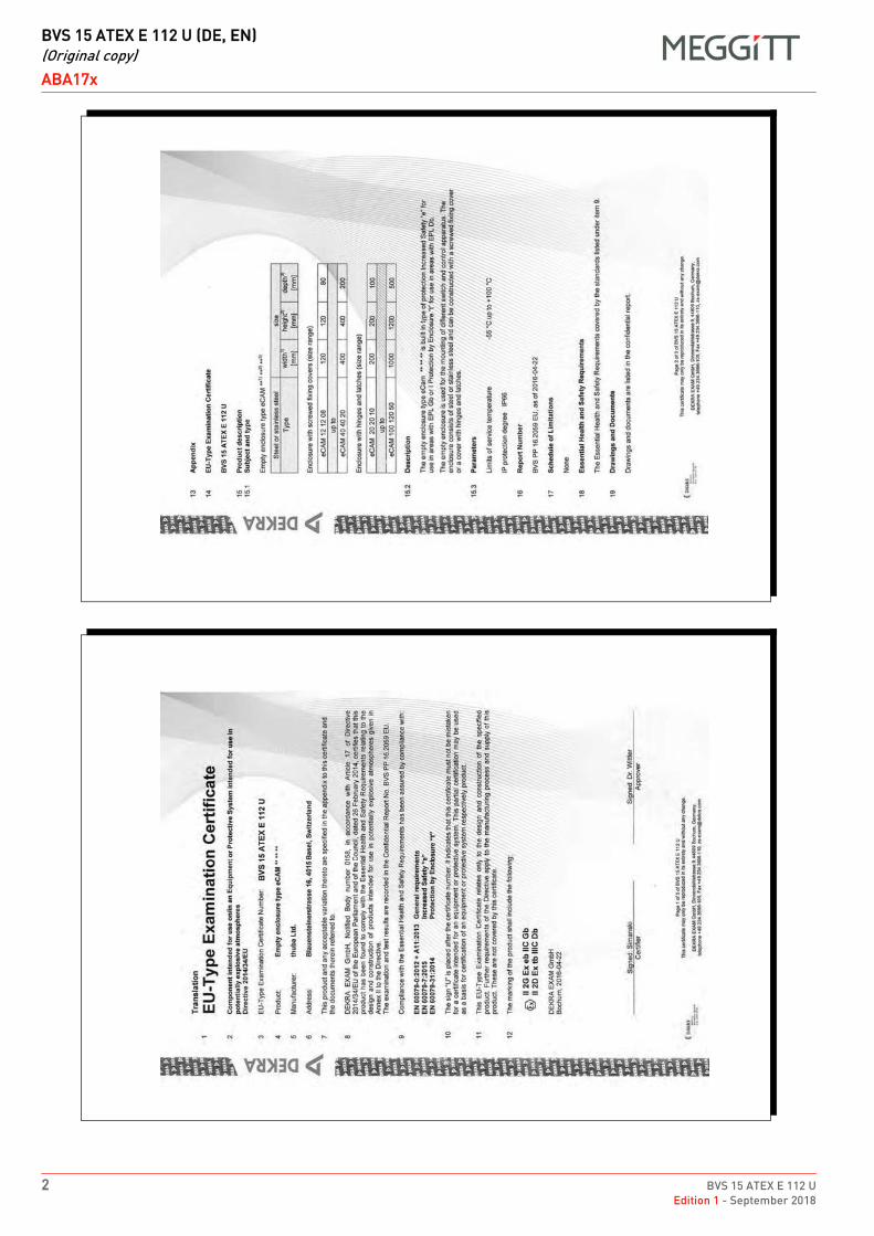
DRAFT
BVS 15 ATEX E 112 U (DE, EN)(Original copy)
ABA17x
2 BVS 15 ATEX E 112 UEdition 1 - September 2018
1
Man
ual B
VS
15
ATE
X E
112
U19
Ed
ition
Feb
ruar
y 20
18th
uba
Ltd
., C
H-4
002
Bas
elC
opyr
ight
S
witz
erla
nd
Man
ual B
VS
15
ATE
X E
112
U18
Ed
ition
Feb
ruar
y 20
18th
uba
Ltd
., C
H-4
002
Bas
elC
opyr
ight
S
witz
erla
nd
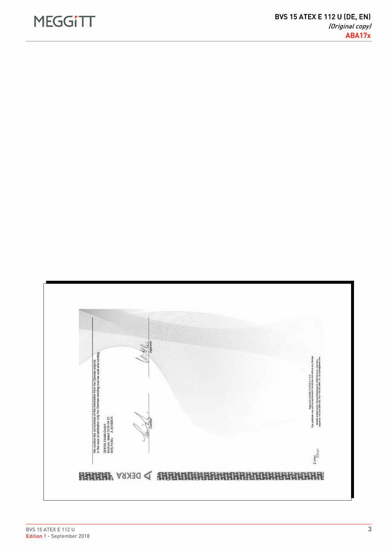
BVS 15 ATEX E 112 U 3Edition 1 - September 2018
DRAFT
BVS 15 ATEX E 112 U (DE, EN)(Original copy)
ABA17x
Man
ual B
VS
15
ATE
X E
112
U20
Ed
ition
Feb
ruar
y 20
18th
uba
Ltd
., C
H-4
002
Bas
elC
opyr
ight
S
witz
erla
nd
DRAFT
BVS 15 ATEX E 112 U (DE, EN)(Original copy)
ABA17x
4 BVS 15 ATEX E 112 UEdition 1 - September 2018
THIS PAGE INTENTIONALLY LEFT BLANKDIESE SEITE WURDE ABSICHTLICH LEER GELASSEN

DRAFT
EX
ATEX certificate Presafe 14 ATEX 5378 UEdition 1 - May 2015
Meggitt SARoute de Moncor 4
PO Box 1616CH - 1701 Fribourg
Switzerland
www.meggittsensingsystems.comwww.vibro-meter.com
PTB_01_ATEX_1061_U
ATEX certificate:
Presafe 14 ATEX 5378 U
for
ABA 17x
EN

THIS PAGE INTENTIONALLY LEFT BLANK
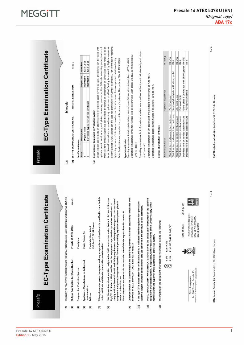
Presafe 14 ATEX 5378 U 1Edition 1 - May 2015
DRAFT
Presafe 14 ATEX 5378 U (EN)(Original copy)
ABA 17xPresafe 14 ATEX 5378 U (EN)Original copyENENABA 17xABA 17x
EC-T
ype
Exam
inat
ion
Cer
tific
ate
2 of
4
DNV
Nem
ko P
resa
fe A
S, G
aust
adal
léen
30,
037
3 O
slo, N
orw
ay
[13]
Sche
dule
[14]
EC
-TYP
E EX
AMIN
ATIO
N C
ERTI
FICA
TE N
o.:
Pres
afe
14 A
TEX
5378
U
Issu
e 1
Ce
rtifi
cate
His
tory
Is
sue
Desc
riptio
n Re
port
no.
Is
sue
date
0
Orig
inal
issu
e D0
0015
50
2014
-12-
05
1 Co
rrec
ted
Type
err
ors i
n th
e ce
rtifi
cate
D0
0015
50
2014
-12-
05
[1
5]
Desc
riptio
n of
Equ
ipm
ent o
r Pro
tect
ive
Syst
em
Cubo
X em
pty
boxe
s m
ade
of s
tain
less
ste
el o
r pa
inte
d st
eel i
n va
rious
size
s. E
nclo
sure
s ca
n be
fitt
ed w
ith
optio
nal
plas
tic w
indo
w o
r gl
and
plat
es,
mou
ntin
g ac
cess
orie
s lik
e DI
N-r
ails,
mou
ntin
g pl
ates
,bra
cket
s &
M
etric
or N
PT th
read
cou
pler
. Lid
can
be
fixed
by
scre
ws
or c
ombi
natio
n of
scr
ews
and
loos
e hi
nges
or q
uick
lo
cks.
Sev
eral
inte
rnal
and
ext
erna
l ear
thin
g op
tions
are
pro
vide
d. S
ealin
g is
ensu
red
by h
igh
tem
pera
ture
sil
icon
e ga
sket
(EP
DM g
aske
t ca
n be
use
d fo
r gl
and
plat
e or
Com
bo a
ssem
blie
s). F
or in
form
atio
n re
gard
ing
tight
enin
g to
rque
s, re
fer t
o in
stru
ctio
ns fo
r use
. See
att
achm
ent f
or m
ore
prod
uct d
etai
ls an
d ra
ting.
Re
fer P
rodu
ct N
omen
clat
ure
for t
he p
ossib
le v
aria
nts/
prov
ision
s. Th
is re
plac
es D
NV
11 A
TEX
9890
9U
Ty
pe Id
entif
icat
ion
O
pera
ting
tem
pera
ture
lim
its fo
r pla
in st
ainl
ess s
teel
enc
losu
re (w
ith o
r with
out g
land
pla
te):
-55°
C to
+16
0°C
Ope
ratin
g te
mpe
ratu
re li
mits
for s
tain
less
stee
l enc
losu
re w
ith L
exan
pla
stic
win
dow
, ear
thin
g op
tion
3:
-55°
C to
+10
0°C
Ope
ratin
g te
mpe
ratu
re li
mits
for p
aint
ed st
eel e
nclo
sure
(with
or w
ithou
t pla
stic
win
dow
and
gla
nd p
late
):
-55°
C to
+85
°C
Ope
ratin
g te
mpe
ratu
re E
PDM
gas
ket/
and
or q
uick
lock
s in
encl
osur
e: -5
5°C
to +
85°C
O
pera
ting
tem
pera
ture
pla
stic
switc
h ha
ndle
in e
nclo
sure
: -30
°C to
+45
°C
Degr
ees o
f pro
tect
ion
(IP C
ode)
:
Encl
osur
e m
ater
ial
Opt
iona
l acc
esso
ries
IP ra
ting
Stai
nles
s ste
el a
nd p
aint
ed st
eel e
nclo
sure
Pl
astic
win
dow
IP
66/6
7 St
ainl
ess s
teel
and
pai
nted
stee
l enc
losu
re
Stan
dard
gla
nd p
late
with
silic
on g
aske
t IP
66
Stai
nles
s ste
el o
r pai
nted
stee
l enc
losu
re
AISI
qui
ck lo
cks
IP66
/67
Stai
nles
s ste
el o
r pai
nted
stee
l enc
losu
re
Zink
qui
ck lo
cks
IP66
St
ainl
ess s
teel
or p
aint
ed st
eel e
nclo
sure
Gl
and
plat
e &
Com
bo b
ox w
ith E
PDM
gas
ket
IP66
/67
Stai
nles
s ste
el o
r pai
nted
stee
l enc
losu
re
Plas
tic sw
itch
hand
le
IP64
EC-T
ype
Exam
inat
ion
Cer
tific
ate
1 of
4
DNV
Nem
ko P
resa
fe A
S, G
aust
adal
léen
30,
037
3 O
slo, N
orw
ay
[2]
EQU
IPM
ENT
OR
PRO
TECT
IVE
SYST
EM IN
TEN
DED
FOR
USE
IN P
OTE
NTI
ALLY
EXP
LOSI
VE A
TMO
SPH
ERES
DIR
ECTI
VE 9
4/9/
EC
[3
] EC
-Typ
e Ex
amin
atio
n Ce
rtifi
cate
Num
ber:
Pres
afe
14 A
TEX
5378
U
Issu
e 1
[4]
Equi
pmen
t or P
rote
ctiv
e Sy
stem
: Em
pty
box
[5
] Ap
plic
ant
Man
ufac
ture
r or A
utho
rized
re
pres
enta
tive:
En
sto
Finl
and
Oy
[6]
Addr
ess:
En
sio
Mie
ttis
en k
atu
2 P.
O.B
ox 7
7, 0
6101
Por
voo
[7
] Th
is e
quip
men
t or p
rote
ctiv
e sy
stem
and
any
acc
epta
ble
varia
tion
ther
eto
is sp
ecifi
ed in
the
sche
dule
to
this
cer
tific
ate
and
the
docu
men
ts th
erei
n re
ferr
ed to
.
[8]
DNV
Nem
ko P
resa
fe A
S, n
otifi
ed b
ody
num
ber 2
460
in a
ccor
danc
e w
ith A
rtic
le 9
of C
ounc
il Di
rect
ive
94/9
/EC
of 2
3 M
arch
199
4, c
ertif
ies t
hat t
his e
quip
men
t or p
rote
ctiv
e sy
stem
has
bee
n fo
und
to
com
ply
with
the
Esse
ntia
l Hea
lth a
nd S
afet
y re
quire
men
ts re
latin
g to
the
desi
gn a
nd c
onst
ruct
ion
of
equi
pmen
t and
pro
tect
ive
syst
ems i
nten
ded
for u
se in
pot
entia
lly e
xplo
sive
atm
osph
eres
giv
en in
An
nex
II to
the
Dire
ctiv
e.
The
exam
inat
ion
and
test
resu
lts a
re re
cord
ed in
con
fiden
tial r
epor
ts li
sted
in se
ctio
n 14
.
[9]
Com
plia
nce
with
the
Esse
ntia
l Hea
lth a
nd S
afet
y Re
quire
men
ts h
as b
een
assu
red
by c
ompl
ianc
e w
ith:
EN 6
0079
-0: 2
012,
EN
600
79-7
:200
7 &
EN
600
79-3
1:20
14
[1
0]
syst
em is
subj
ect t
o sp
ecia
l con
ditio
ns fo
r saf
e us
e sp
ecifi
ed in
the
sche
dule
to th
is c
ertif
icat
e.
[1
1]
This
EC-
TYPE
EXA
MIN
ATIO
N C
ERTI
FICA
TE re
late
s onl
y to
the
desi
gn a
nd c
onst
ruct
ion
of th
e sp
ecifi
ed
equi
pmen
t or p
rote
cted
syst
em. I
f app
licab
le, f
urth
er re
quire
men
ts o
f thi
s Dire
ctiv
e ap
ply
to th
e m
anuf
actu
rer a
nd su
pply
of t
his e
quip
men
t or p
rote
ctiv
e sy
stem
.
[12]
Th
e m
arki
ng o
f the
equ
ipm
ent o
r pro
tect
ive
syst
em sh
all i
nclu
de th
e fo
llow
ing:
II
2 G
Ex
e II
C G
b
II
2 D
Ex tb
IIIC
Db
IP 6
4 /
66 /
67
____
____
____
Bjø
rn S
pong
svee
n
For D
NV
Nem
ko P
resa
fe A
S
I
nfor
mat
ion
on e
lect
roni
c sig
natu
re w
ww
.pre
safe
.com
PRO
D 02
1
Date
of i
ssue
: 20
14-1
2-10
Th
is Ce
rtifi
cate
repl
aces
pr
evio
usly
cer
tific
ate
DNV
11 A
TEX
9890
9U
issue
d by
DN
V
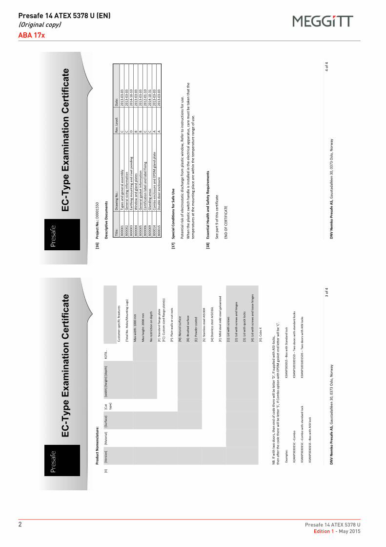
DRAFT
Presafe 14 ATEX 5378 U (EN)(Original copy)
ABA 17x
2 Presafe 14 ATEX 5378 UEdition 1 - May 2015
EC-T
ype
Exam
inat
ion
Cer
tific
ate
4 of
4
DNV
Nem
ko P
resa
fe A
S, G
aust
adal
léen
30,
037
3 O
slo, N
orw
ay
[16]
Pr
ojec
t No.
: D00
0155
0
Desc
riptiv
e Do
cum
ents
Title
: Dr
awin
g N
o.:
Rev.
Lev
el:
Date
: 80
0001
Ty
pes a
nd g
ener
al a
ssem
bly
C 20
13-0
3-03
80
0002
Ge
nera
l sizi
ng in
form
atio
n C
2013
-03-
03
8000
03
Eart
hing
mou
ntin
g an
d riv
et p
ondi
ng
D 20
14-1
0-10
80
0004
W
indo
w a
nd g
land
pla
tes
B 20
13-0
3-03
80
0005
Ge
nera
l gas
ket i
nfor
mat
ion
B 20
13-0
3-03
80
0006
Ce
rtifi
catio
n la
bel a
nd la
bel f
ixin
g C
2012
-01-
10
8000
09
Glan
ding
are
as
C 20
14-1
0-31
80
0014
Co
mbo
enc
losu
re a
nd E
PDM
gla
nd p
late
A
2013
-03-
03
8000
15
Doub
le d
oor e
nclo
sure
A
2013
-03-
03
[17]
Sp
ecia
l Con
ditio
ns fo
r Saf
e U
se
Pote
ntia
l risk
of e
lect
rost
atic
disc
harg
e fr
om p
last
ic w
indo
w, R
efer
to in
stru
ctio
ns fo
r use
. W
hen
the
plas
tic sw
itch
hand
le is
inst
alle
d in
the
elec
tric
al a
ppar
atus
, car
e m
ust b
e ta
ken
that
the
tem
pera
ture
s at t
he m
ount
ing
plac
e ar
e w
ithin
the
tem
pera
ture
rang
e of
use
. [1
8]
Esse
ntia
l Hea
lth a
nd S
afet
y Re
quire
men
ts
Se
e pa
rt 9
of t
his c
ertif
icat
e
END
OF
CERT
IFIC
ATE
EC-T
ype
Exam
inat
ion
Cer
tific
ate
3 of
4
DNV
Nem
ko P
resa
fe A
S, G
aust
adal
léen
30,
037
3 O
slo, N
orw
ay
Prod
uct N
omen
clat
ure:
[X]
[Ver
sion]
[M
ater
ial]
[Sur
face
] [C
ut
type
] [w
idth
] [he
ight
] [de
pth]
Cu
stom
er sp
ecifi
c fe
aatu
res
(Tot
al N
o. H
oles
/Mou
ntin
g Lu
gs)
M
ax w
idth
: 100
0 m
m
Max
hei
ght:
2000
mm
No
rest
rictio
n on
dep
th
[F
]: St
anda
rd fl
ange
pla
te
[FC]
: Cus
tom
size
d fla
nge
plat
e(s)
[P]:
Plai
n w
alls
or c
ut-o
uts
[N
]: N
atur
al su
rfac
e
[B]:
Brus
hed
surf
ace
[E]:
Pow
der c
oate
d
[S
]: St
ainl
ess s
teel
AIS
I304
[A]:S
tain
less
stee
l AIS
I316
L
[F]:
Mild
stee
l mild
stee
l gal
vani
zed
[1
]: Li
d w
ith sc
rew
s
[2]:
Lid
with
scre
ws a
nd h
inge
s
[3]:
Lid
with
qui
ck lo
cks
[4]:
Lid
with
scre
ws a
nd lo
ose
hing
es
[X
]: Cu
bo X
NB.
If w
ith tw
o do
ors,
then
end
of c
ode
ther
e w
ill b
e le
tter
'D',
if su
pplie
d w
ith A
ISI-l
ocks
, th
en a
fter
the
code
ther
e w
ill b
e le
tter
'S',
if Co
mbo
opt
ion
with
EPD
M g
aske
t end
lett
er w
ill b
e 'C
'. Ex
ampl
es:
X2AN
P303
015C
Co
mbo
X3
ANP3
0301
5C
Com
bo w
ith st
anda
rd lo
ck
X3AN
P303
015S
Bo
x w
ith A
ISI l
ock
X3AN
P303
015
Box
with
Sta
ndar
d lo
ck
X3AN
P100
1001
5D
Tw
o do
ors w
ith st
anda
rd lo
cks
X3AN
P100
1001
5DS
Tw
o do
ors w
ith A
ISI l
ocks
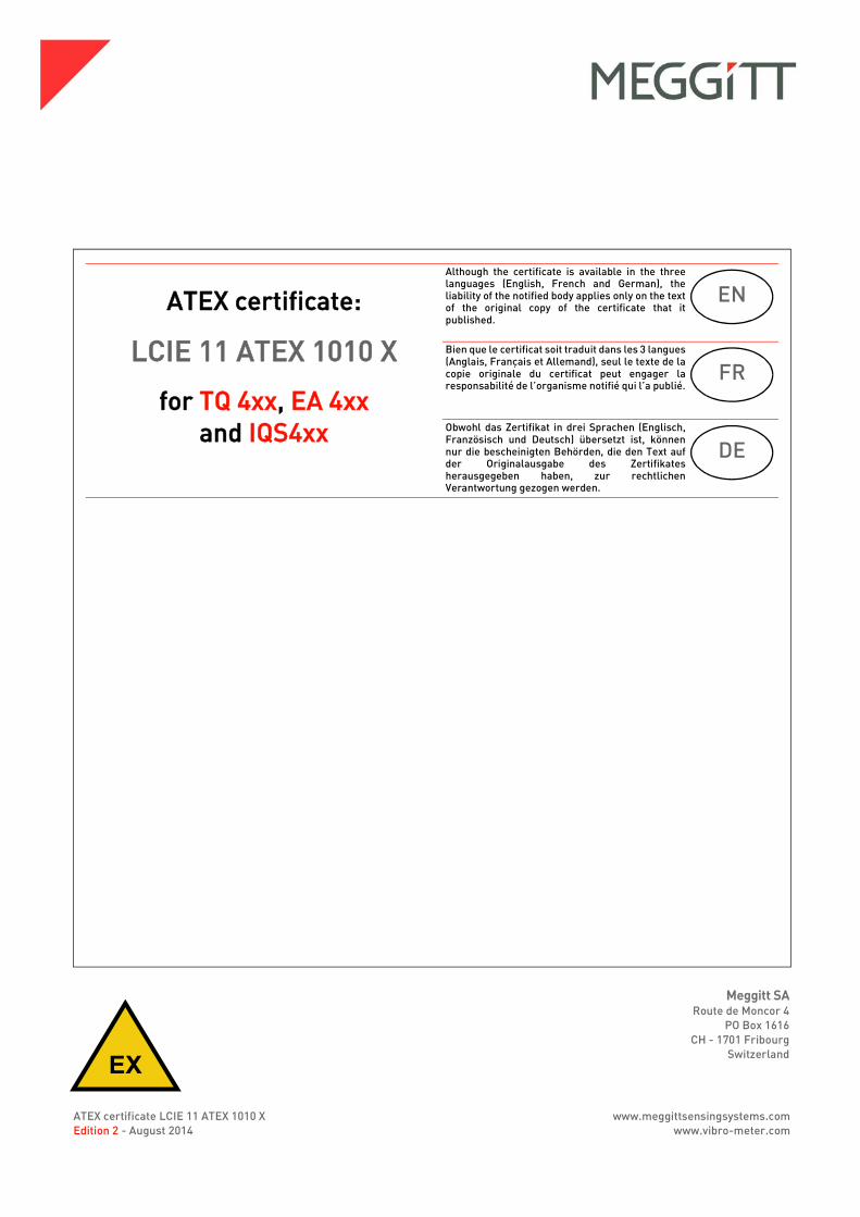
DRAFT
EX
ATEX certificate LCIE 11 ATEX 1010 XEdition 2 - August 2014
Meggitt SARoute de Moncor 4
PO Box 1616CH - 1701 Fribourg
Switzerland
www.meggittsensingsystems.comwww.vibro-meter.com
Title Page
ATEX certificate:
LCIE 11 ATEX 1010 X
for TQ 4xx, EA 4xxand IQS4xx
Although the certificate is available in the threelanguages (English, French and German), theliability of the notified body applies only on the textof the original copy of the certificate that itpublished.
Bien que le certificat soit traduit dans les 3 langues(Anglais, Français et Allemand), seul le texte de lacopie originale du certificat peut engager laresponsabilité de l’organisme notifié qui l’a publié.
Obwohl das Zertifikat in drei Sprachen (Englisch,Französisch und Deutsch) übersetzt ist, könnennur die bescheinigten Behörden, die den Text aufder Originalausgabe des Zertifikatesherausgegeben haben, zur rechtlichenVerantwortung gezogen werden.
EN
FR
DE

THIS PAGE INTENTIONALLY LEFT BLANKCETTE PAGE EST LAISSÉE INTENTIONNELLEMENT VIDE
DIESE SEITE WURDE ABSICHTLICH LEER GELASSEN
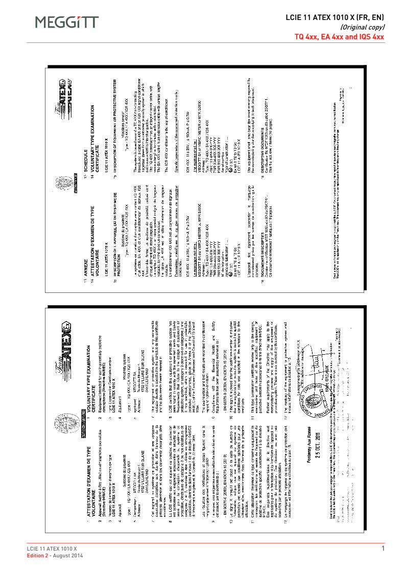
LCIE 11 ATEX 1010 X 1Edition 2 - August 2014
DRAFT
LCIE 11 ATEX 1010 X (FR, EN)(Original copy)
TQ 4xx, EA 4xx and IQS 4xxLCIE 11 ATEX 1010 X (FR, EN)TQ 4xx, EA 4xx and IQS 4xxENFROriginal copy
1
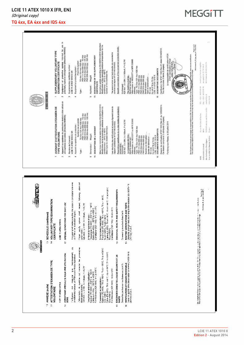
DRAFT
LCIE 11 ATEX 1010 X (FR, EN)(Original copy)
TQ 4xx, EA 4xx and IQS 4xx
2 LCIE 11 ATEX 1010 XEdition 2 - August 2014
1
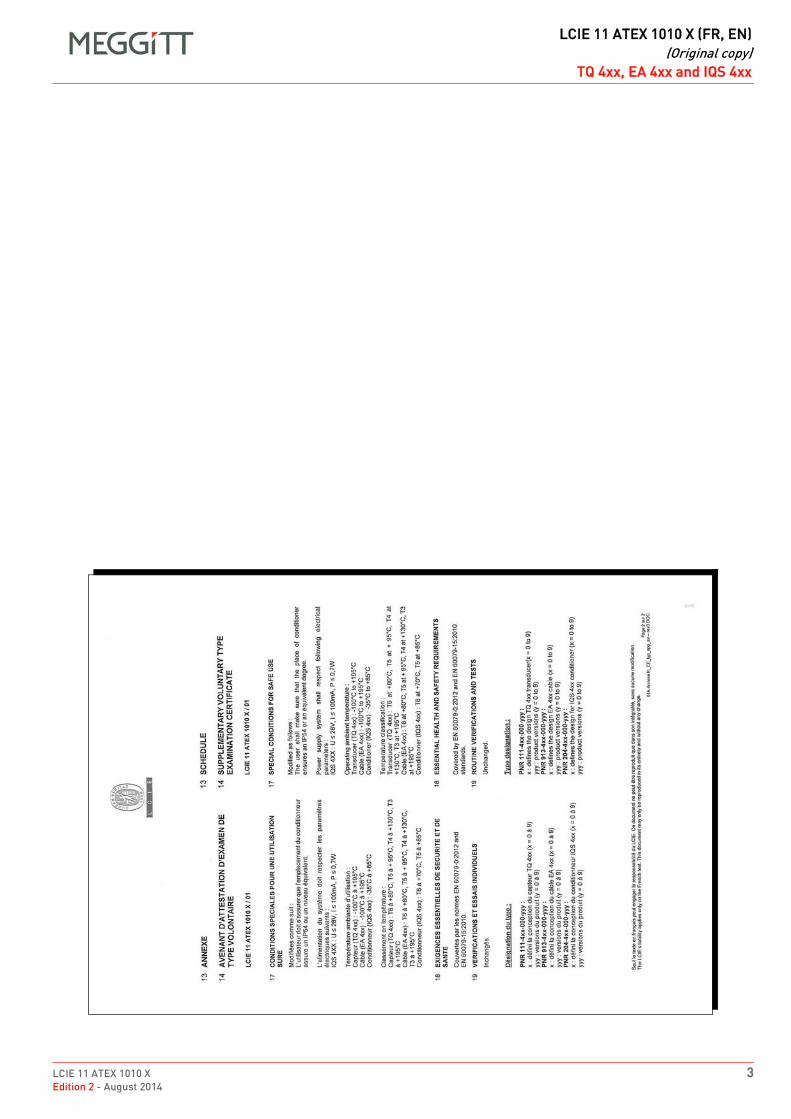
LCIE 11 ATEX 1010 X 3Edition 2 - August 2014
DRAFT
LCIE 11 ATEX 1010 X (FR, EN)(Original copy)
TQ 4xx, EA 4xx and IQS 4xx
1
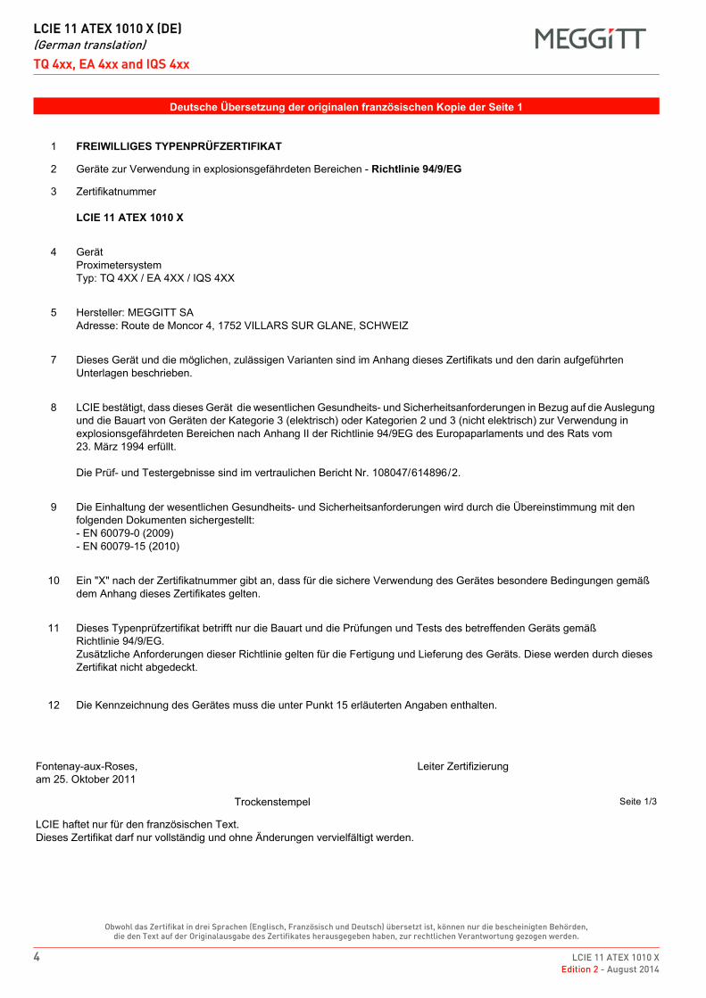
DRAFT
LCIE 11 ATEX 1010 X (DE)(German translation)
TQ 4xx, EA 4xx and IQS 4xx
4 LCIE 11 ATEX 1010 XEdition 2 - August 2014
Obwohl das Zertifikat in drei Sprachen (Englisch, Französisch und Deutsch) übersetzt ist, können nur die bescheinigten Behörden, die den Text auf der Originalausgabe des Zertifikates herausgegeben haben, zur rechtlichen Verantwortung gezogen werden.
DE LCIE 11 ATEX 1010 X (DE) German translation DE
Deutsche Übersetzung der originalen französischen Kopie der Seite 1
1 FREIWILLIGES TYPENPRÜFZERTIFIKAT
2 Geräte zur Verwendung in explosionsgefährdeten Bereichen - Richtlinie 94/9/EG
3 Zertifikatnummer
LCIE 11 ATEX 1010 X
4 GerätProximetersystemTyp: TQ 4XX / EA 4XX / IQS 4XX
5 Hersteller: MEGGITT SAAdresse: Route de Moncor 4, 1752 VILLARS SUR GLANE, SCHWEIZ
7 Dieses Gerät und die möglichen, zulässigen Varianten sind im Anhang dieses Zertifikats und den darin aufgeführten Unterlagen beschrieben.
8 LCIE bestätigt, dass dieses Gerät die wesentlichen Gesundheits- und Sicherheitsanforderungen in Bezug auf die Auslegung und die Bauart von Geräten der Kategorie 3 (elektrisch) oder Kategorien 2 und 3 (nicht elektrisch) zur Verwendung in explosionsgefährdeten Bereichen nach Anhang II der Richtlinie 94/9EG des Europaparlaments und des Rats vom 23. März 1994 erfüllt.
Die Prüf- und Testergebnisse sind im vertraulichen Bericht Nr. 108047/614896/2.
9 Die Einhaltung der wesentlichen Gesundheits- und Sicherheitsanforderungen wird durch die Übereinstimmung mit den folgenden Dokumenten sichergestellt:- EN 60079-0 (2009)- EN 60079-15 (2010)
10 Ein "X" nach der Zertifikatnummer gibt an, dass für die sichere Verwendung des Gerätes besondere Bedingungen gemäß dem Anhang dieses Zertifikates gelten.
11 Dieses Typenprüfzertifikat betrifft nur die Bauart und die Prüfungen und Tests des betreffenden Geräts gemäßRichtlinie 94/9/EG.Zusätzliche Anforderungen dieser Richtlinie gelten für die Fertigung und Lieferung des Geräts. Diese werden durch dieses Zertifikat nicht abgedeckt.
12 Die Kennzeichnung des Gerätes muss die unter Punkt 15 erläuterten Angaben enthalten.
Fontenay-aux-Roses,am 25. Oktober 2011
Leiter Zertifizierung
Trockenstempel Seite 1/3
LCIE haftet nur für den französischen Text.Dieses Zertifikat darf nur vollständig und ohne Änderungen vervielfältigt werden.
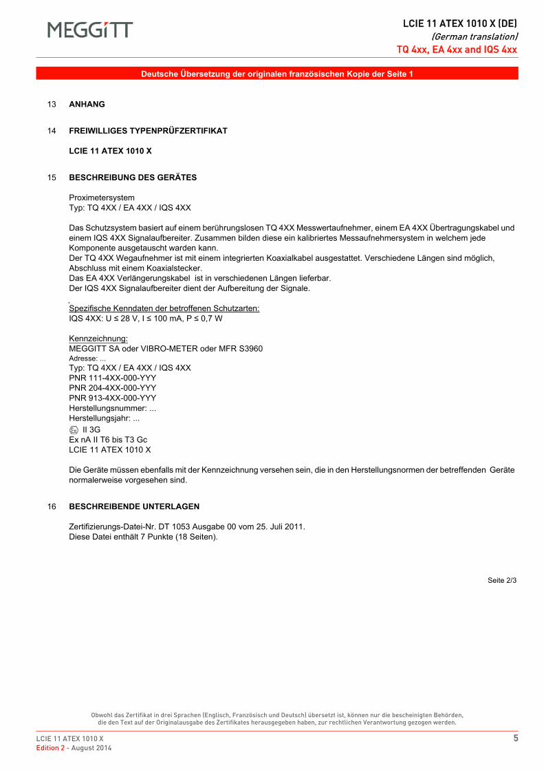
LCIE 11 ATEX 1010 X 5Edition 2 - August 2014
DRAFT
LCIE 11 ATEX 1010 X (DE)(German translation)
TQ 4xx, EA 4xx and IQS 4xx
Obwohl das Zertifikat in drei Sprachen (Englisch, Französisch und Deutsch) übersetzt ist, können nur die bescheinigten Behörden, die den Text auf der Originalausgabe des Zertifikates herausgegeben haben, zur rechtlichen Verantwortung gezogen werden.
Deutsche Übersetzung der originalen französischen Kopie der Seite 1
13 ANHANG
14 FREIWILLIGES TYPENPRÜFZERTIFIKAT
LCIE 11 ATEX 1010 X
15 BESCHREIBUNG DES GERÄTES
ProximetersystemTyp: TQ 4XX / EA 4XX / IQS 4XX
Das Schutzsystem basiert auf einem berührungslosen TQ 4XX Messwertaufnehmer, einem EA 4XX Übertragungskabel und einem IQS 4XX Signalaufbereiter. Zusammen bilden diese ein kalibriertes Messaufnehmersystem in welchem jede Komponente ausgetauscht warden kann.Der TQ 4XX Wegaufnehmer ist mit einem integrierten Koaxialkabel ausgestattet. Verschiedene Längen sind möglich, Abschluss mit einem Koaxialstecker.Das EA 4XX Verlängerungskabel ist in verschiedenen Längen lieferbar.Der IQS 4XX Signalaufbereiter dient der Aufbereitung der Signale.
Spezifische Kenndaten der betroffenen Schutzarten:IQS 4XX: U ≤ 28 V, I ≤ 100 mA, P ≤ 0,7 W
Kennzeichnung:MEGGITT SA oder VIBRO-METER oder MFR S3960Adresse: ...Typ: TQ 4XX / EA 4XX / IQS 4XXPNR 111-4XX-000-YYYPNR 204-4XX-000-YYYPNR 913-4XX-000-YYYHerstellungsnummer: ...Herstellungsjahr: ...
II 3GEx nA II T6 bis T3 GcLCIE 11 ATEX 1010 X
Die Geräte müssen ebenfalls mit der Kennzeichnung versehen sein, die in den Herstellungsnormen der betreffenden Geräte normalerweise vorgesehen sind.
16 BESCHREIBENDE UNTERLAGEN
Zertifizierungs-Datei-Nr. DT 1053 Ausgabe 00 vom 25. Juli 2011.Diese Datei enthält 7 Punkte (18 Seiten).
Seite 2/3
DRAFT
LCIE 11 ATEX 1010 X (DE)(German translation)
TQ 4xx, EA 4xx and IQS 4xx
6 LCIE 11 ATEX 1010 XEdition 2 - August 2014
Obwohl das Zertifikat in drei Sprachen (Englisch, Französisch und Deutsch) übersetzt ist, können nur die bescheinigten Behörden, die den Text auf der Originalausgabe des Zertifikates herausgegeben haben, zur rechtlichen Verantwortung gezogen werden.
Deutsche Übersetzung der originalen französischen Kopie der Seite 2
13 ANHANG
14 FREIWILLIGES TYPENPRÜFZERTIFIKAT
LCIE 11 ATEX 1010 X
17 BESONDERE BEDINGUNGEN FÜR DIE SICHERE ANWENDUNG
Der Benutzer muss sicherstellen, dass der Standort des Conditioners der Schutzklasse IP54 oder einer gleichwertigen Richtlinie entspricht.
Das Stromversorgungssystem muss folgende elektrische Parameter aufweisen:IQS 4XX: U ≤ 28 V, I ≤ 100 mA, P ≤ 0,7 W
Umgebungstemperatur:Wegaufnehmer (TQ 4XX): −100 °C bis +195 °C Kabel (EA 4XX): −100 °C bis +195 °C Signalaufbereiter (IQS 4XX): 0 °C bis +70 °C
Temperaturklassifizierung:Wegaufnehmer (TQ 4XX): T6 bis +80 °C, T5 bis +95 °C, T4 bis +130 °C, T3 bis +195 °CKabel (EA 4XX): T6 bis +80 °C, T5 bis +95 °C, T4 bis +130 °C, T3 bis +195 °CSignalaufbereiter (IQS 4XX): T6 bis +70 °C
18 WESENTLICHE ANFORDERUNGEN IM BEZUG AUF SICHERHEIT UND GESUNDHEIT
Siehe unter Punkt 9 aufgelistete Bestimmungen.
19 ROUTINEPRÜFUNGEN UND TESTS
Elektrische Durchschlagsfestigkeit geprüft gemäss der Norm EN 60079-15 (2010) Abschnitt 23.2.1.
Seite 3/3
LCIE 11 ATEX 1010 X 7Edition 2 - August 2014
DRAFT
LCIE 11 ATEX 1010 X (DE)(German translation)
TQ 4xx, EA 4xx and IQS 4xx
Obwohl das Zertifikat in drei Sprachen (Englisch, Französisch und Deutsch) übersetzt ist, können nur die bescheinigten Behörden, die den Text auf der Originalausgabe des Zertifikates herausgegeben haben, zur rechtlichen Verantwortung gezogen werden.
Deutsche Übersetzung der originalen französischen Kopie der Seite 2
1 ZUSÄTZLICHES FREIWILLIGES TYPENPRÜFUNGSZERTIFIKAT
2 Betriebsmittel oder Schutzsystem zur bestimmungsgemäßen Verwendung in explosionsgefährdeten Bereichen - Richtlinie 94/9/EG
3 Zusätzliche Zertifikatnummer:
LCIE 11 ATEX 1010 X / 01
4 Gerät oder Schutzsystem:
ProximetersystemTyp: TQ 4xx / EA 4xx / IQS 4xxPNR: 111-4xx-000-yyy : TQ 4xxPNR: 913-4xx-000-yyy : EA 4xxPNR: 204-4xx-000-yyy : IQS 4xx
5 Hersteller: MEGGITT
15 BESCHREIBUNG DES ZUSÄTZLICHEN ZERTIFIKATS
Standardaktualisierungen gemäß folgender Richtlinien: EN 60079-0:2012.Änderungen der Betriebsumgebungstemperatur der Signalaufbereiter: −35°C bis +85°C.Update der technischen Unterlagen.
Die Prüf- und Testergebnisse sind im vertraulichen Bericht Nr. 127146-654902 aufgezeichnet.
Spezifische Kenndaten der betroffenen Schutzarten:
Unverändert:IQS 4xx: U ≤ 28 V, I ≤ 100 mA, P ≤ 0,7 W
Die Kennzeichnung lautet wie folgt:Wie folgt modifiziert:Vibro-Meter oder MEGGITT oder MFR S3960Adresse: ...Typ: TQ 4xx / EA 4xx / IQS 4xxPNR 111-4xx-000-yyyPNR 204-4xx-000-yyyPNR 913-4xx-000-yyyHerstellungsnummer: ...Herstellungsjahr: ...
II 3GEx nA II T6 bis T3 GcLCIE 11 ATEX 1010 X
16 BESCHREIBENDE UNTERLAGEN
Zertifizierungs-Datei-Nr. DT 1053 Ausgabe 01 vom 12. März 2014.Diese Datei enthält 3 Punkte (5 Seiten).
Seite 1/2
DRAFT
LCIE 11 ATEX 1010 X (DE)(German translation)
TQ 4xx, EA 4xx and IQS 4xx
8 LCIE 11 ATEX 1010 XEdition 2 - August 2014
Obwohl das Zertifikat in drei Sprachen (Englisch, Französisch und Deutsch) übersetzt ist, können nur die bescheinigten Behörden, die den Text auf der Originalausgabe des Zertifikates herausgegeben haben, zur rechtlichen Verantwortung gezogen werden.
Deutsche Übersetzung der originalen französischen Kopie der Seite 3
13 ANHANG
14 ZUSÄTZLICHES FREIWILLIGES TYPENPRÜFUNGSZERTIFIKAT
LCIE 11 ATEX 1010 X / 01
17 BESONDERE BEDINGUNGEN FÜR DIE SICHERE ANWENDUNG
Wie folgt modifiziert:Der Benutzer muss sicherstellen, dass der Standort des Conditioners der Schutzklasse IP54 oder einer gleichwertigen Richtlinie entspricht.
Das Stromversorgungssystem muss folgende elektrische Parameter aufweisen:IQS 4xx: U ≤ 28 V, I ≤ 100 mA, P ≤ 0,7 W
Umgebungstemperatur:Wegaufnehmer (TQ 4xx): −100°C bis +195°C Kabel (EA 4xx): −100°C bis +195°C Signalaufbereiter (IQS 4xx): −35°C bis +85°C
Temperaturklassifizierung:Wegaufnehmer (TQ 4xx): T6 bis +80°C, T5 bis +95°C, T4 bis +130°C, T3 bis +195°CKabel (EA 4xx): T6 bis +80°C, T5 bis +95°C, T4 bis +130°C, T3 bis +195°CSignalaufbereiter (IQS 4xx): T6 bis +70°C, T5 bis +85°C
18 WESENTLICHE ANFORDERUNGEN IM BEZUG AUF SICHERHEIT UND GESUNDHEIT
Werden von folgenden Richtlinien abgedeckt: EN 60079-0:2012 und EN 60079-15:2010.
19 ROUTINEPRÜFUNGEN UND TESTS
Unverändert.
Typenbezeichnung:
PNR 111-4xx-000-yyy:x: definiert das Design des TQ 4xx Wegaufnehmer (x = 0 bis 9) yyy: definiert die Version des Produkts (y = 0 bis 9)
PNR 913-4xx-000-yyy:x: definiert das Design des EA 4xx Kabel (x = 0 bis 9) yyy: definiert die Version des Produkts (y = 0 bis 9)
PNR 204-4xx-000-yyy:x: definiert das Design des IQS 4xx Signalaufbereiter (x = 0 bis 9) yyy: definiert die Version des Produkts (y = 0 bis 9)
Seite 2/2

DRAFT
EX
ATEX certificate LCIE 11 ATEX 3091 XEdition 3 - August 2014
Meggitt SARoute de Moncor 4
PO Box 1616CH - 1701 Fribourg
Switzerland
www.meggittsensingsystems.comwww.vibro-meter.com
Title Page
ATEX certificate:
LCIE 11 ATEX 3091 X
for TQ 4xx, EA 4xxand IQS 4xx
Although the certificate is available in the threelanguages (English, French and German), theliability of the notified body applies only on the textof the original copy of the certificate that itpublished.
Bien que le certificat soit traduit dans les 3 langues(Anglais, Français et Allemand), seul le texte de lacopie originale du certificat peut engager laresponsabilité de l’organisme notifié qui l’a publié.
Obwohl das Zertifikat in drei Sprachen (Englisch,Französisch und Deutsch) übersetzt ist, könnennur die bescheinigten Behörden, die den Text aufder Originalausgabe des Zertifikatesherausgegeben haben, zur rechtlichenVerantwortung gezogen werden.
EN
FR
DE

THIS PAGE INTENTIONALLY LEFT BLANKCETTE PAGE EST LAISSÉE INTENTIONNELLEMENT VIDE
DIESE SEITE WURDE ABSICHTLICH LEER GELASSEN
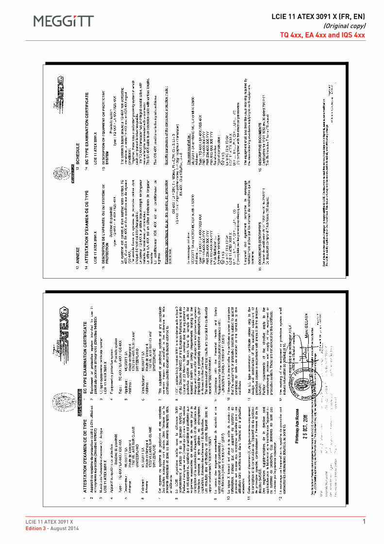
LCIE 11 ATEX 3091 X 1Edition 3 - August 2014
DRAFT
LCIE 11 ATEX 3091 X (FR, EN)(Original copy)
TQ 4xx, EA 4xx and IQS 4xxLCIE 11 ATEX 3091 X (FR, EN)TQ 4xx, EA 4xx and IQS 4xx ENFROriginal copy
1
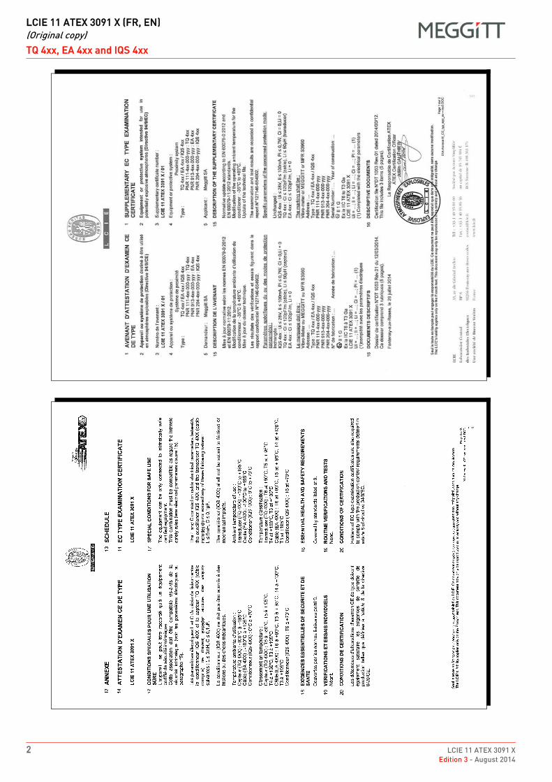
DRAFT
LCIE 11 ATEX 3091 X (FR, EN)(Original copy)
TQ 4xx, EA 4xx and IQS 4xx
2 LCIE 11 ATEX 3091 XEdition 3 - August 2014
1
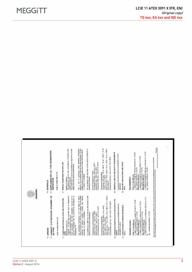
LCIE 11 ATEX 3091 X 3Edition 3 - August 2014
DRAFT
LCIE 11 ATEX 3091 X (FR, EN)(Original copy)
TQ 4xx, EA 4xx and IQS 4xx
1
DRAFT
LCIE 11 ATEX 3091 X (DE)(German translation)
TQ 4xx, EA 4xx and IQS 4xx
4 LCIE 11 ATEX 3091 XEdition 3 - August 2014
Obwohl das Zertifikat in drei Sprachen (Englisch, Französisch und Deutsch) übersetzt ist, können nur die bescheinigten Behörden, die den Text auf der Originalausgabe des Zertifikates herausgegeben haben, zur rechtlichen Verantwortung gezogen werden.
DE LCIE 11 ATEX 3091 X (DE) German translation DE
Deutsche Übersetzung der originalen französischen Kopie der Seite 11 EG-PRÜFZERTIFIKAT
2 Geräte und Schutzsysteme zur Verwendung in explosionsgefährdeten Bereichen - Richtlinie 94/9/EG
3 ZertifikatnummerLCIE 11 ATEX 3091 X
4 Gerät oder SchutzsystemProximetersystemTyp: TQ 4XX / EA 4XX / IQS 4XX
5 Antragsteller: Meggitt SAAdresse: Route de Moncor 4
BP 1752 Villars sur GlaneSchweiz
6 Hersteller: Meggitt SAAdresse: Route de Moncor 4
BP 1752 Villars sur GlaneSchweiz
7 Dieses Gerät und die möglichen, zulässigen Varianten sind im Anhang dieses Zertifikats und den darin aufgeführten Unterlagen beschrieben.
8 LCIE, eingetragen unter der Nummer 0081 gemäß Artikel 9 der Richtlinie 94/9/EG des Europaparlamentes und des Rates vom 23. März 1994, bestätigt, dass dieses Gerät oder Schutzsystem die wesentlichen Gesundheits- und Sicherheitsanforderungen in Bezug auf die Auslegung und die Bauart von Geräten und Schutzsystemen zur Verwendung in explosionsgefährdeten Bereichen nach Anhang II der Richtlinie erfüllt.Die Prüf- und Testergebnisse sind im vertraulichen Bericht Nr. 108047/614896 /1 aufgezeichnet.
9 Die Einhaltung der wesentlichen Gesundheits- und Sicherheitsanforderungen wird durch die Übereinstimmung mit den folgenden Dokumenten sichergestellt:- EN 60079-0 (2009)- EN 60079-11 (2007)
10 Ein "X" nach der Zertifikatnummer gibt an, dass für die sichere Verwendung des Gerätes besondere Bedingungen gemäß dem Anhang dieses Zertifikates gelten.
11 Dieses Typenprüfzertifikat betrifft nur die Bauart und die Prüfungen und Tests des betreffenden Geräts gemäßRichtlinie 94/9/EG.Zusätzliche Anforderungen dieser Richtlinie gelten für die Fertigung und Lieferung des Geräts oder Schutzsystems. Diese werden durch dieses Zertifikat nicht abgedeckt.
12 Die Kennzeichnung des Gerätes muss die unter Punkt 15 erläuterten Angaben enthalten.
Fontenay-aux-Roses,am 25. Oktober 2011
Leiter Zertifizierung
Trockenstempel Seite 1/3
LCIE haftet nur für den französischen Text.Dieses Zertifikat darf nur vollständig und ohne Änderungen vervielfältigt werden.
LCIE 11 ATEX 3091 X 5Edition 3 - August 2014
DRAFT
LCIE 11 ATEX 3091 X (DE)(German translation)
TQ 4xx, EA 4xx and IQS 4xx
Obwohl das Zertifikat in drei Sprachen (Englisch, Französisch und Deutsch) übersetzt ist, können nur die bescheinigten Behörden, die den Text auf der Originalausgabe des Zertifikates herausgegeben haben, zur rechtlichen Verantwortung gezogen werden.
Deutsche Übersetzung der originalen französischen Kopie der Seite 113 ANHANG
14 EG-PRÜFZERTIFIKAT
LCIE 11 ATEX 3091 X
15 BESCHREIBUNG DES GERÄTES ODER SCHUTZSYSTEMS
ProximetersystemTyp: TQ 4XX / EA 4XX / IQS 4XX
Das Schutzsystem basiert auf einem berührungslosen TQ 4XX Messwertaufnehmer, einem EA 4XX Übertragungskabel und einem IQS 4XX Signalaufbereiter. Zusammen bilden diese ein kalibriertes Messaufnehmersystem in welchem jede Komponente ausgetauscht warden kann.Der TQ 4XX Wegaufnehmer ist mit einem integrierten Koaxialkabel ausgestattet. Verschiedene Längen sind möglich, Abschluss mit einem Koaxialstecker.Das EA 4XX Verlängerungskabel ist in verschiedenen Längen lieferbar.Der IQS 4XX Signalaufbereiter dient der Aufbereitung der Signale.
Spezifische Kenndaten der betroffenen Schutzarten:IQS 4XX: Ui = 28 V, Ii = 100 mA, Pi = 0,7 W, Ci = 0, Li = 0TQ 4XX: Ci ≤ 120 pF/m (Kabel), Li ≤ 50 µH (Wegaufnehmer)EA 4XX: Ci ≤ 120 pF/m, Li = 0
Kennzeichnung:MEGGITT SA oder VIBRO-METER oder MFR S3960Adresse: ...Typ: TQ 4XX / EA 4XX / IQS 4XXPNR 111-4XX-000-YYYPNR 204-4XX-000-YYYPNR 913-4XX-000-YYYHerstellungsnummer: ...Herstellungsjahr: ...
II 1GEx ia IIC T6 bis T3 GaLCIE 11 ATEX 3091 XUi = ..., Ii = ..., Pi = ..., Ci = ..., Li = ..., (1)(1) vervollständigt mit den elektrischen Werten.
Die Geräte müssen ebenfalls mit der Kennzeichnung versehen sein, die in den Herstellungsnormen der betreffenden Geräte normalerweise vorgesehen sind.
16 BESCHREIBENDE UNTERLAGEN
Zertifizierungs-Datei-Nr. DT 1053 Ausgabe 00 vom 25. Juli 2011.Diese Datei enthält 7 Punkte (18 Seiten).
Seite 2/3
DRAFT
LCIE 11 ATEX 3091 X (DE)(German translation)
TQ 4xx, EA 4xx and IQS 4xx
6 LCIE 11 ATEX 3091 XEdition 3 - August 2014
Obwohl das Zertifikat in drei Sprachen (Englisch, Französisch und Deutsch) übersetzt ist, können nur die bescheinigten Behörden, die den Text auf der Originalausgabe des Zertifikates herausgegeben haben, zur rechtlichen Verantwortung gezogen werden.
Deutsche Übersetzung der originalen französischen Kopie der Seite 213 ANHANG
14 EG-PRÜFZERTIFIKAT
LCIE 10 ATEX 3091 X
17 BESONDERE BEDINGUNGEN FÜR DIE SICHERE ANWENDUNG
Das Gerät darf nur an zertifizierte eigensichere Komponenten angeschlossen warden.Diese Kombination muss bezüglich der Regeln der Eigensicherheit kompatibel sein (siehe elektrische Parameter in Klausel 15).
Die elektrischen Werte L und C des Verbindungskabels zwischen dem IQS 4XX Signalaufbereiter und dem TQ 4XX Messwertaufnehmer (einschliesslich integriertem Kabel) überschreiten keinen der folgenden Werte:L ≤ 5 mH, C ≤ 0,1 µF
Der Signalaufbereiter (IQS 4XX) darf nicht Reibung oder mechanischen Einwirkungen ausgesetzt warden.
Umgebungstemperatur:Wegaufnehmer (TQ 4XX): −100 °C bis +195 °C Kabel (EA 4XX): −100 °C bis +195 °C Signalaufbereiter (IQS 4XX): 0 °C bis +70 °C
Temperaturklassifizierung:Wegaufnehmer (TQ 4XX): T6 bis +80 °C, T5 bis +95 °C, T4 bis +130 °C, T3 bis +195 °CKabel (EA 4XX): T6 bis +80 °C, T5 bis +95 °C, T4 bis +130 °C, T3 bis +195 °CSignalaufbereiter (IQS 4XX): T6 bis +70 °C
18 WESENTLICHE ANFORDERUNGEN IM BEZUG AUF SICHERHEIT UND GESUNDHEITSiehe unter Punkt 9 aufgelistete Bestimmungen.
19 ROUTINEPRÜFUNGEN UND TESTSKeine.
20 ZULASSUNGSSBEDINGUNGEN
Inhaber von EG-Baumusterprüfbescheinigungen müssen die Anforderungen an die Produktionssteuerung nach Artikel 8 der Richtlinie 94/9/EC erfüllen.
Seite 3/3
LCIE 11 ATEX 3091 X 7Edition 3 - August 2014
DRAFT
LCIE 11 ATEX 3091 X (DE)(German translation)
TQ 4xx, EA 4xx and IQS 4xx
Obwohl das Zertifikat in drei Sprachen (Englisch, Französisch und Deutsch) übersetzt ist, können nur die bescheinigten Behörden, die den Text auf der Originalausgabe des Zertifikates herausgegeben haben, zur rechtlichen Verantwortung gezogen werden.
Deutsche Übersetzung der originalen französischen Kopie der Seite 2
1 ZUSÄTZLICHES FREIWILLIGES TYPENPRÜFUNGSZERTIFIKAT
2 Betriebsmittel oder Schutzsystem zur bestimmungsgemäßen Verwendung in explosionsgefährdeten Bereichen - Richtlinie 94/9/EG
3 Zusätzliche Zertifikatnummer:
LCIE 11 ATEX 3091 X / 01
4 Gerät oder Schutzsystem:
ProximetersystemTyp: TQ 4xx / EA 4xx / IQS 4xxPNR: 111-4xx-000-yyy : TQ 4xxPNR: 913-4xx-000-yyy : EA 4xxPNR: 204-4xx-000-yyy : IQS 4xx
5 Hersteller: MEGGITT SA
15 BESCHREIBUNG DES ZUSÄTZLICHEN ZERTIFIKATS
Standardaktualisierungen gemäß folgender Richtlinien: EN 60079-0:2012 und EN 60079-11:2012.Änderungen der Betriebsumgebungstemperatur der Signalaufbereiter: −35°C bis +85°C.Update der technischen Unterlagen.
Die Prüf- und Testergebnisse sind im vertraulichen Bericht Nr. 127146-654902 aufgezeichnet.
Spezifische Kenndaten der betroffenen Schutzarten:
Unverändert:IQS 4xx: Ui ≤ 28 V, Ii = 100 mA, Pi = 0,7 W, Ci = 0, Li = 0TQ 4xx: Ci ≤ 120 pF/m (Kabel), Li ≤ 50 µH (Wegaufnehmer)EA 4xx: Ci ≤ 120 pF/m, Li = 0
Die Kennzeichnung lautet wie folgt:Vibro-Meter oder MEGGITT oder MFR S3960Adresse: ...Typ: TQ 4xx / EA 4xx / IQS 4xxPNR 111-4xx-000-yyyPNR 913-4xx-000-yyyPNR 204-4xx-000-yyyHerstellungsnummer: ...Herstellungsjahr: ...
II 1GEx iA IIC T6 bis T3 GaLCIE 11 ATEX 3091 XUi = ..., Ii = ..., Li = ..., Ci = ..., Pi = ..., (1)(1) vervollständigt mit den elektrischen Werten.
16 BESCHREIBENDE UNTERLAGEN
Zertifizierungs-Datei-Nr. DT 1053 Ausgabe 01 vom 12. März 2014.Diese Datei enthält 3 Punkte (5 Seiten).
Seite 1/2
DRAFT
LCIE 11 ATEX 3091 X (DE)(German translation)
TQ 4xx, EA 4xx and IQS 4xx
8 LCIE 11 ATEX 3091 XEdition 3 - August 2014
Obwohl das Zertifikat in drei Sprachen (Englisch, Französisch und Deutsch) übersetzt ist, können nur die bescheinigten Behörden, die den Text auf der Originalausgabe des Zertifikates herausgegeben haben, zur rechtlichen Verantwortung gezogen werden.
Deutsche Übersetzung der originalen französischen Kopie der Seite 3
13 ANHANG
14 ZUSÄTZLICHES FREIWILLIGES TYPENPRÜFUNGSZERTIFIKAT
LCIE 11 ATEX 3091 X / 01
17 BESONDERE BEDINGUNGEN FÜR DIE SICHERE ANWENDUNG
Wie folgt modifiziert:Das Gerät darf nur an zertifizierte eigensichere Komponenten angeschlossen warden.Diese Kombination muss bezüglich der Regeln der Eigensicherheit kompatibel sein (siehe elektrische Parameter in Klausel 15).
Die Induktivität (L) und Kapazität (C) des elektrischen Kabels zwischen den IQS 4xx Signalaufbereiter und dem TQ 4xx Wegaufnehmer (Kabel enthalten) nicht größer als irgendeine der folgenden Werte sein: L ≤ 3,5 mH, C ≤ 0,083 µF.
Die Signalaufbereiter (IQS 4xx) darf nicht zu Reibungen oder mechanische Einwirkungen eingereicht werden.
Umgebungstemperatur:Wegaufnehmer (TQ 4xx): −100°C bis +195°C Kabel (EA 4xx): −100°C bis +195°C Signalaufbereiter (IQS 4xx): −35°C bis +85°C
Temperaturklassifizierung:Wegaufnehmer (TQ 4xx): T6 bis +80°C, T5 bis +95°C, T4 bis +130°C, T3 bis +195°CKabel (EA 4xx): T6 bis +80°C, T5 bis +95°C, T4 bis +130°C, T3 bis +195°CSignalaufbereiter (IQS 4xx): T6 bis +70°C, T5 bis +85°C
18 WESENTLICHE ANFORDERUNGEN IM BEZUG AUF SICHERHEIT UND GESUNDHEIT
Werden von folgenden Richtlinien abgedeckt: EN 60079-0:2012 und EN 60079-11:2012.
19 ROUTINEPRÜFUNGEN UND TESTS
Keine.
Typenbezeichnung:
PNR 111-4xx-000-yyy:x: definiert das Design des TQ 4xx Wegaufnehmer (x = 0 bis 9) yyy: definiert die Version des Produkts (y = 0 bis 9)
PNR 913-4xx-000-yyy:x: definiert das Design des EA 4xx Kabel (x = 0 bis 9) yyy: definiert die Version des Produkts (y = 0 bis 9)
PNR 204-4xx-000-yyy:x: definiert das Design des IQS 4xx Signalaufbereiter (x = 0 bis 9) yyy: definiert die Version des Produkts (y = 0 bis 9)
Seite 2/2
DRAFT
EX
ATEX certificate LCIE 13 ATEX 3037 XEdition 2 - April 2017
Meggitt SARoute de Moncor 4
PO Box 1616CH - 1701 Fribourg
Switzerland
www.meggittsensingsystems.comwww.vibro-meter.com
Title Page
ATEX certificate:
LCIE 13 ATEX 3037 X
for
GSI 127
Although the certificate is available in the threelanguages (English, French and German), theliability of the notified body applies only on the textof the original copy of the certificate that itpublished.
Bien que le certificat soit traduit dans les 3 langues(Anglais, Français et Allemand), seul le texte de lacopie originale du certificat peut engager laresponsabilité de l’organisme notifié qui l’a publié.
Obwohl das Zertifikat in drei Sprachen (Englisch,Französisch und Deutsch) übersetzt ist, könnennur die bescheinigten Behörden, die den Text aufder Originalausgabe des Zertifikatesherausgegeben haben, zur rechtlichenVerantwortung gezogen werden.
EN
FR
DE

THIS PAGE INTENTIONALLY LEFT BLANKCETTE PAGE EST LAISSÉE INTENTIONNELLEMENT VIDE
DIESE SEITE WURDE ABSICHTLICH LEER GELASSEN
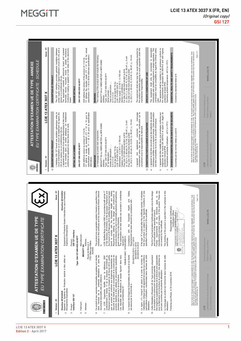
LCIE 13 ATEX 3037 X 1Edition 2 - April 2017
DRAFT
LCIE 13 ATEX 3037 X (FR, EN)(Original copy)
GSI 127LCIE 13 ATEX 3037 X (FR, EN)GSI 127ENFROriginal copy
1
ATT
ESTA
TIO
N D
’EXA
MEN
UE
DE
TYPE
- A
NN
EXE
EU
TY
PE
EX
AM
INA
TIO
N C
ER
TIFI
CA
TE -
SC
HE
DU
LE
Seu
l le
text
e en
fran
çais
peu
t eng
ager
la re
spon
sabi
lité
du L
CIE
. Ce
docu
men
t ne
peut
être
repr
odui
t que
dan
s so
n in
tégr
alité
, san
s au
cune
mod
ifica
tion.
Il e
st
étab
li en
acc
ord
avec
le ré
fére
ntie
l de
certi
ficat
ion
ATE
X du
LC
IE. T
he L
CIE
’s li
abili
ty a
pplie
s on
ly o
n th
e Fr
ench
text
. Thi
s do
cum
ent m
ay o
nly
be re
prod
uced
in
its e
ntire
ty a
nd w
ithou
t any
cha
nge.
It is
issu
ed in
acc
orda
nce
with
LC
IE’s
ATE
X C
ertif
icat
ion
Rul
es.
CE
RT-
ATEX
-FO
RM
04
Rev
. 02
Page
2 o
f 3
1 Ve
rsio
n : 0
1 LC
IE 1
3 A
TEX
3037
X
Issu
e : 0
1
12
DES
CR
IPTI
ON
DU
PR
OD
UIT
DES
CR
IPTI
ON
OF
PRO
DU
CT
L’
inte
rface
GS
I 12
7 fo
urni
t un
e is
olat
ion
galv
aniq
ue e
ntre
le
circ
uit d
’alim
enta
tion
ou le
circ
uit d
e tra
item
ent d
e si
gnal
(E
x nA
) et u
n ca
pteu
r ou
un c
ondi
tionn
eur (
Ex
ia).
L’
appa
reil
se c
ompo
se d
’une
car
te é
lect
roni
que
et d
es b
orne
s à
vis
mon
tées
dan
s un
boî
tier
plas
tique
. U
n re
vête
men
t co
nfor
me
est a
ppliq
ué s
ur d
eux
face
s de
la c
arte
.
Th
e G
SI
127
inte
rface
pro
vide
s ga
lvan
ic in
sola
tion
betw
een
pow
er s
uppl
y ci
rcui
t or
sign
al tr
eatm
ent c
ircui
t (E
x nA
) an
d a
sens
or o
r a c
ondi
tione
r (E
x ia
).
The
equi
pmen
t co
nsis
ts o
f el
ectro
nic
boar
d an
d sc
rew
ed
term
inal
s bl
ocks
m
ount
ed
insi
de
a pl
astic
en
clos
ure.
C
onfo
rmal
coa
ting
is a
pplie
d on
bot
h si
des
of t
he e
lect
roni
c bo
ard.
D
ETA
IL D
E LA
GA
MM
E
RA
NG
E D
ETA
ILS
24
4 -12
7-00
0-XX
X-A
2-B
YY
XX
X dé
finit
la v
ersi
on d
u pr
odui
t (X
= 0
à 9)
. Y
Y dé
finit
le m
ode
de t
rans
fert
(YY
= 01
à 1
9 po
ur l
a sp
écifi
catio
n ac
tuel
le;
YY =
20
à 39
pou
r la
spé
cific
atio
n al
tern
ativ
e).
24
4-12
7-00
0-XX
X-A
2-B
YY
XX
X de
fines
the
vers
ion
of th
e pr
oduc
t (X
= 0
to 9
). Y
Y de
fines
the
tra
nsfe
r m
ode
(YY
= 01
to
19 f
or a
ctua
l sp
ecifi
catio
n; Y
Y =
20 to
39
for a
ltern
ate
spec
ifica
tion)
.
M
AR
QU
AG
E
MA
RK
ING
Le m
arqu
age
du p
rodu
it do
it co
mpr
endr
e :
Th
e m
arki
ng o
f the
pro
duct
sha
ll in
clud
e th
e fo
llow
ing
:
M
EG
GIT
T S
A o
u V
IBR
O-M
ETE
R o
u M
FR S
3960
Adr
esse
: …
.. Ty
pe :
244-
127-
000-
XXX-
A2-
BY
Y
N°
de fa
bric
atio
n : …
A
nnée
de
fabr
icat
ion
: …
� II
3 (1
) G
Ex
nA [i
a G
a] II
C T
4 G
c LC
IE 1
3 A
TEX
3037
X
Alim
enta
tion
: U ≤
30
V, I
≤ 15
0 m
A C
apte
ur o
u co
nditi
onne
ur :
Pou
r 244
-127
-000
-XX
X-A
2-B
01 à
B19
: U
o: 25
,2 V
; Io:
60 m
A; P
o: 0,
7 W
; Co:
95 n
F; L
o: 5
mH
P
our 2
44-1
27-0
00-X
XX-
A2-
B20
à B
39:
Uo:
25,2
V; I
o: 45
mA
; Po:
0,5
W; C
o: 95
nF;
Lo:
10 m
H
M
EG
GIT
T S
A o
r VIB
RO
-ME
TER
or M
FR S
3960
Add
ress
: ...
Type
: 244
-127
-000
-XX
X-A
2-B
YY
S
eria
l num
ber:
...
Ye
ar o
f con
stru
ctio
n: …
�
II 3
(1) G
E
x nA
[ia
Ga]
IIC
T4
Gc
LC
IE 1
3 A
TEX
3037
X
Pow
er s
uppl
y : U
≤ 3
0 V
, I ≤
150
mA
Sen
sor o
r con
ditio
ner :
Fo
r 244
-127
-000
-XX
X-A
2-B
01 to
B19
: U
o: 25
.2 V
; Io:
60 m
A; P
o: 0.
7 W
; Co:
95 n
F; L
o: 5
mH
Fo
r 244
-127
-000
-XX
X-A
2-B
20 to
B39
: U
o: 25
.2 V
; Io:
45 m
A; P
o: 0.
5 W
; Co:
95 n
F; L
o: 10
mH
L’
appa
reil
doit
égal
emen
t co
mpo
rter
le
mar
quag
e no
rmal
emen
t pr
évu
par
les
norm
es d
e co
nstru
ctio
n qu
i le
co
ncer
nent
sou
s la
resp
onsa
bilit
é du
fabr
ican
t.
Th
e eq
uipm
ent s
hall
also
bea
r the
usu
al m
arki
ng re
quire
d by
th
e pr
oduc
t sta
ndar
ds a
pply
ing
to s
uch
equi
pmen
t und
er th
e m
anuf
actu
rer r
espo
nsib
ility.
13
CO
ND
ITIO
NS
PAR
TIC
ULI
ERES
D'U
TILI
SATI
ON
SPEC
IFIC
CO
ND
ITIO
NS
OF
USE
a.
L’ap
pare
il ne
doi
t être
racc
ordé
qu'
à de
s m
atér
iels
de
sécu
rité
intri
nsèq
ue c
ertif
iés
ou à
un
appa
reil
sim
ple.
Cet
te a
ssoc
iatio
n do
it êt
re c
ompa
tible
vis
-à-v
is d
e la
séc
urité
intri
nsèq
ue.
Th
e eq
uipm
ent
shal
l on
ly
be
conn
ecte
d to
as
soci
ated
in
trins
ical
ly s
afe
certi
fied
equi
pmen
t or s
impl
e ap
para
tus.
Thi
s co
mbi
natio
n m
ust b
e co
mpa
tible
as
rega
rd th
e in
trins
ic s
afet
y ru
les.
b.
L’
appa
reil
doit
être
inst
allé
dan
s un
e en
velo
ppe
conf
orm
e au
x ex
igen
ces
de l
a no
rme
EN
600
79-0
et
ayan
t un
deg
ré d
e pr
otec
tion
min
imal
IP54
.
Th
e ap
para
tus
shal
l be
inst
alle
d in
an
encl
osur
e co
nfor
m t
o th
e re
quire
men
ts o
f st
anda
rd E
N 6
0079
-0 a
nd w
ith in
gres
s pr
otec
tion
at le
ast I
P54.
c
Tem
péra
ture
am
bian
te d
’util
isat
ion
: -40
°C à
+70
°C.
O
pera
ting
ambi
ent t
empe
ratu
re: -
40°C
to +
70°C
.
14
EXIG
ENC
ES E
SSEN
TIEL
LES
DE
SAN
TE E
T D
E SE
CU
RIT
E
ESSE
NTI
AL
HEA
LTH
AN
D S
AFE
TY R
EQU
IREM
ENTS
C
ouve
rtes
par l
es n
orm
es li
stée
s au
poi
nt 8
.
C
over
ed b
y st
anda
rds
liste
d at
8.
ATT
ESTA
TIO
N D
’EXA
MEN
UE
DE
TYPE
E
U T
YP
E E
XA
MIN
ATI
ON
CER
TIFI
CA
TE
Seu
l le
text
e en
fran
çais
peu
t eng
ager
la re
spon
sabi
lité
du L
CIE
. Ce
docu
men
t ne
peut
être
repr
odui
t que
dan
s so
n in
tégr
alité
, san
s au
cune
mod
ifica
tion.
Il e
st
étab
li en
acc
ord
avec
le ré
fére
ntie
l de
certi
ficat
ion
ATE
X du
LC
IE. T
he L
CIE
’s li
abili
ty a
pplie
s on
ly o
n th
e Fr
ench
text
. Thi
s do
cum
ent m
ay o
nly
be re
prod
uced
in
its e
ntire
ty a
nd w
ithou
t any
cha
nge.
It is
issu
ed in
acc
orda
nce
with
LC
IE’s
ATE
X C
ertif
icat
ion
Rul
es.
CE
RT-
ATEX
-FO
RM
04
Rev
. 02
Page
1 o
f 3
1 Ve
rsio
n : 0
1 LC
IE 1
3 A
TEX
3037
X
Issu
e : 0
1
D
irect
ive
2014
/34/
UE
D
irect
ive
2014
/34/
EU
2 A
ppar
eil
ou S
ystè
me
de P
rote
ctio
n de
stin
é à
être
util
isé
en
Atm
osph
ères
Exp
losi
bles
Equ
ipm
ent o
r Pro
tect
ive
Sys
tem
Inte
nded
for u
se in
Pot
entia
lly
Exp
losi
ve A
tmos
pher
es
3 P
rodu
it :
P
rodu
ct :
In
terf
ace
GSI
127
GSI
127
inte
rfac
e
Ty
pe: 2
44-1
27-0
00-X
XX-A
2-B
YY
4 Fa
bric
ant :
Man
ufac
ture
r :
M
EGG
ITT
SA
5 A
dres
se :
Add
ress
:
R
oute
de
Mon
cor 4
17
52 V
illars
-sur
-Glâ
ne
SU
ISS
E
6 C
e pr
odui
t et s
es v
aria
ntes
éve
ntue
lles
acce
ptée
s so
nt d
écrit
s da
ns
I'ann
exe
de
la
pr
ésen
te
atte
stat
ion
et
dans
le
s do
cum
ents
des
crip
tifs
cité
s en
réfé
renc
e.
Th
is p
rodu
ct a
ny a
ccep
tabl
e va
riatio
n th
eret
o is
spe
cifie
d in
the
sche
dule
to th
is c
ertif
icat
e an
d th
e do
cum
ents
ther
ein
refe
rred
to.
7 Le
LC
IE,
Org
anis
me
Not
ifié
sous
la
ré
fére
nce
0081
co
nfor
mém
ent
à l’a
rticl
e 17
de
la d
irect
ive
2014
/34/
UE
du
Par
lem
ent e
urop
éen
et d
u C
onse
il du
26
févr
ier
2014
, cer
tifie
qu
e ce
pro
duit
est
conf
orm
e au
x E
xige
nces
Ess
entie
lles
de
Séc
urité
et d
e S
anté
pou
r la
con
cept
ion
et la
con
stru
ctio
n de
pr
odui
ts d
estin
és à
être
util
isés
en
atm
osph
ères
exp
losi
bles
, do
nnée
s da
ns l’
anne
xe II
de
la D
irect
ive.
LC
IE, N
otifi
ed B
ody
num
ber 0
081
in a
ccor
danc
e w
ith a
rticl
e 17
of
the
Dire
ctiv
e 20
14/3
4/E
U o
f th
e Eu
rope
an P
arlia
men
t an
d th
e C
ounc
il of
26
Febr
uary
201
4 ce
rtifie
s th
at p
rodu
ct h
as b
een
foun
d to
co
mpl
y w
ith
the
Ess
entia
l H
ealth
an
d S
afet
y R
equi
rem
ents
re
latin
g to
th
e de
sign
an
d co
nstru
ctio
n of
pr
oduc
ts in
tend
ed fo
r use
in p
oten
tially
exp
losi
ve a
tmos
pher
es,
give
n in
Ann
ex II
to th
e D
irect
ive.
Les
résu
ltats
des
vér
ifica
tions
et
essa
is f
igur
ent
dans
le(
s)
rapp
ort(s
) con
fiden
tiel(s
) N°
:
The
exam
inat
ion
and
test
res
ults
are
rec
orde
d in
con
fiden
tial
repo
rt(s)
N°:
1080
46-6
1494
7; 1
4152
9-68
5013
8 Le
resp
ect d
es E
xige
nces
Ess
entie
lles
de S
écur
ité e
t de
San
té
est a
ssur
é pa
r la
conf
orm
ité à
:
Com
plia
nce
with
th
e Es
sent
ial
Hea
lth
and
Safe
ty
Req
uire
men
ts h
as b
een
assu
red
by c
ompl
ianc
e w
ith :
E
N 6
0079
-0:2
012
+ A
11:2
013
E
N 6
0079
-11:
2012
E
N 6
0079
-15:
2010
9 Le
sig
ne «
X »
lor
squ'
il es
t pl
acé
à la
sui
te d
u nu
mér
o de
l’a
ttest
atio
n, in
diqu
e qu
e ce
t app
arei
l est
sou
mis
aux
con
ditio
ns
parti
culiè
res
d’ut
ilisat
ion ,
men
tionn
ées
dans
l’an
nexe
de
cette
at
test
atio
n.
If
the
sign
“X” i
s pl
aced
afte
r the
cer
tific
ate
num
ber,
it in
dica
tes
that
the
pro
duct
is s
ubje
ct t
o th
e Sp
ecifi
c C
ondi
tions
of
Use
sp
ecifi
ed in
the
sche
dule
to th
is c
ertif
icat
e.
10
Cet
te A
ttest
atio
n d'
Exa
men
UE
de
Type
con
cern
e un
ique
men
t la
con
cept
ion
et la
con
stru
ctio
n du
pro
duit
spéc
ifié.
This
EU
Typ
e E
xam
inat
ion
Cer
tific
ate
rela
tes
only
to th
e de
sign
an
d co
nstru
ctio
n of
the
spec
ified
pro
duct
.
Des
exi
genc
es s
uppl
émen
taire
s de
la d
irect
ive
sont
app
licab
les
pour
la fa
bric
atio
n et
la fo
urni
ture
du
prod
uit.
Ces
der
nièr
es n
e so
nt p
as c
ouve
rtes
par l
a pr
ésen
te a
ttest
atio
n.
Fu
rther
re
quire
men
ts
of
the
Dire
ctiv
e ap
ply
to
the
man
ufac
turin
g pr
oces
s an
d su
pply
of
this
pro
duct
. The
se a
re
not c
over
ed b
y th
is c
ertif
icat
e.
11 L
e m
arqu
age
du p
rodu
it es
t men
tionn
é da
ns l’
anne
xe d
e ce
tte
atte
stat
ion.
The
mar
king
of t
he p
rodu
ct is
spe
cifie
d in
the
sche
dule
to th
is
certi
ficat
e.
Fo
nten
ay-a
ux-R
oses
, le
30 n
ovem
bre
2016
Res
pons
able
de
Cer
tific
atio
n
Cer
tific
atio
n O
ffice
r Ju
lien
Gau
thie
r JJ
lililiiG
auauauauauauauththththththth
ieieeerrrrrr
JuJuJuJuJuJuJuJuJuJuliliilililile
nennnGGGGGG
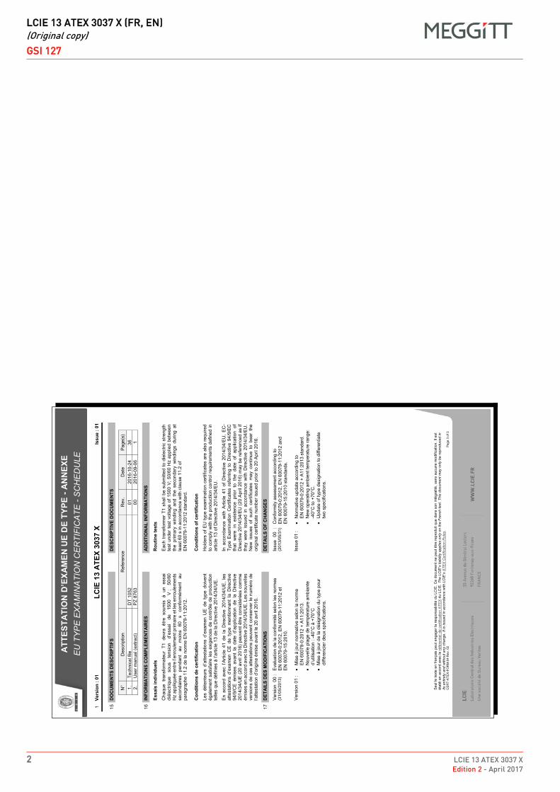
DRAFT
LCIE 13 ATEX 3037 X (FR, EN)(Original copy)
GSI 127
2 LCIE 13 ATEX 3037 XEdition 2 - April 2017
1
ATT
ESTA
TIO
N D
’EXA
MEN
UE
DE
TYPE
- A
NN
EXE
EU
TY
PE
EX
AM
INA
TIO
N C
ER
TIFI
CA
TE -
SC
HE
DU
LE
Seu
l le
text
e en
fran
çais
peu
t eng
ager
la re
spon
sabi
lité
du L
CIE
. Ce
docu
men
t ne
peut
être
repr
odui
t que
dan
s so
n in
tégr
alité
, san
s au
cune
mod
ifica
tion.
Il e
st
étab
li en
acc
ord
avec
le ré
fére
ntie
l de
certi
ficat
ion
ATE
X du
LC
IE. T
he L
CIE
’s li
abili
ty a
pplie
s on
ly o
n th
e Fr
ench
text
. Thi
s do
cum
ent m
ay o
nly
be re
prod
uced
in
its e
ntire
ty a
nd w
ithou
t any
cha
nge.
It is
issu
ed in
acc
orda
nce
with
LC
IE’s
ATE
X C
ertif
icat
ion
Rul
es.
CE
RT-
ATEX
-FO
RM
04
Rev
. 02
Page
3 o
f 3
1 Ve
rsio
n : 0
1 LC
IE 1
3 A
TEX
3037
X
Issu
e : 0
1
15
DO
CU
MEN
TS D
ESC
RIP
TIFS
DES
CR
IPTI
VE D
OC
UM
ENTS
N
° D
escr
iptio
n R
efer
ence
R
ev.
Dat
e P
age(
s)
1.
Tech
nica
l file
D
T 10
52
01
2016
-10-
24
36
2.
Use
r man
ual (
extra
ct)
PZ
8763
00
20
16-0
9-06
1
16
INFO
RM
ATI
ON
S C
OM
PLEM
ENTA
IRES
AD
DIT
ION
AL
INFO
RM
ATI
ON
S
Es
sais
indi
vidu
els
R
outin
e te
sts
C
haqu
e tra
nsfo
rmat
eur
T1 d
evra
être
sou
mis
à u
n es
sai
diél
ectri
que
sous
te
nsio
n d’
essa
i de
15
00
V ;
50/6
0 H
z ap
pliq
uée
entre
l’enr
oule
men
t prim
aire
et l
es e
nrou
lem
ents
se
cond
aire
s pe
ndan
t au
m
oins
60
s
conf
orm
émen
t au
pa
ragr
aphe
11.
2 de
la n
orm
e E
N 6
0079
-11:
2012
.
E
ach
trans
form
er T
1 sh
all b
e su
bmitt
ed to
die
lect
ric s
treng
th
test
und
er te
st v
olta
ge o
f 150
0 V
; 50/
60 H
z ap
plie
d be
twee
n th
e pr
imar
y w
indi
ng a
nd t
he s
econ
dary
win
ding
s du
ring
at
leas
t 60
s in
acc
orda
nce
with
cla
use
11.2
of
EN
600
79-1
1:20
12 s
tand
ard.
C
ondi
tions
de
cert
ifica
tion
C
ondi
tions
of c
ertif
icat
ion
Le
s dé
tent
eurs
d’a
ttest
atio
ns d
’exa
men
UE
de
type
doi
vent
ég
alem
ent s
atis
faire
les
exig
ence
s de
con
trôle
de
prod
uctio
n te
lles
que
défin
ies
à l’a
rticl
e 13
de
la D
irect
ive
2014
/34/
UE
.
H
olde
rs o
f EU
type
exa
min
atio
n ce
rtific
ates
are
als
o re
quire
d to
com
ply
with
the
prod
uctio
n co
ntro
l req
uire
men
ts d
efin
ed in
ar
ticle
13
of D
irect
ive
2014
/34/
EU
.
E
n ac
cord
ave
c l’A
rticl
e 41
de
la D
irect
ive
2014
/34/
UE
, le
s at
test
atio
ns d
’exa
men
CE
de
type
men
tionn
ant
la D
irect
ive
94/9
/CE
ém
ises
ava
nt l
a da
te d
’app
licat
ion
de l
a D
irect
ive
2014
/34/
UE
(20
avril
201
6) p
euve
nt ê
tre c
onsi
déré
es c
omm
e ém
ises
en
acco
rd a
vec
la D
irect
ive
2014
/34/
UE
. Les
nou
velle
s ve
rsio
ns d
e ce
s at
test
atio
ns p
euve
nt c
onse
rver
le n
umér
o de
l’a
ttest
atio
n d’
orig
ine
émis
e av
ant l
e 20
avr
il 20
16.
In
acc
orda
nce
with
Arti
cle
41 o
f D
irect
ive
2014
/34/
EU
, E
C-
Type
Exa
min
atio
n C
ertif
icat
es r
efer
ring
to D
irect
ive
94/9
/EC
th
at w
ere
in e
xist
ence
prio
r to
the
dat
e of
app
licat
ion
of
Dire
ctiv
e 20
14/3
4/E
U (2
0 A
pril
2016
) may
be
refe
renc
ed a
s if
they
wer
e is
sued
in a
ccor
danc
e w
ith D
irect
ive
2014
/34/
EU
. N
ew i
ssue
s of
suc
h ce
rtific
ates
may
con
tinue
to
bear
the
or
igin
al c
ertif
icat
e nu
mbe
r iss
ued
prio
r to
20 A
pril
2016
.
17
DET
AIL
S D
ES M
OD
IFIC
ATI
ON
S
D
ETA
ILS
OF
CH
AN
GES
V
ersi
on 0
0 :
(31/
05/2
013)
E
valu
atio
n de
la c
onfo
rmité
sel
on le
s no
rmes
E
N 6
0079
-0:2
012,
EN
600
79-1
1:20
12 e
t E
N 6
0079
-15:
2010
.
Is
sue
00 :
(2
013/
05/3
1)
Con
form
ity a
sses
smen
t acc
ordi
ng to
E
N 6
0079
-0:2
012,
EN
600
79-1
1:20
12 a
nd
EN
600
79-1
5:20
10 s
tand
ards
.
V
ersi
on 0
1 :
� M
ise
à jo
ur n
orm
ativ
e se
lon
la n
orm
e
EN
600
79-0
:201
2 +
A11
:201
3.
� N
ouve
lle p
lage
de
tem
péra
ture
am
bian
te
d’ut
ilisat
ion
: -40
°C à
+70
°C
� M
ise
à jo
ur d
e la
dés
igna
tion
du ty
pe p
our
diffé
renc
ier d
eux
spéc
ifica
tions
.
Is
sue
01 :
�
Nor
mat
ive
upda
te a
ccor
ding
to
EN
600
79-0
:201
2 +
A11
:201
3 st
anda
rd.
� N
ew o
pera
ting
ambi
ent t
empe
ratu
re ra
nge:
-4
0°C
to +
70°C
. �
Upd
ate
of ty
pe d
esig
natio
n to
diff
eren
tiate
tw
o sp
ecifi
catio
ns.
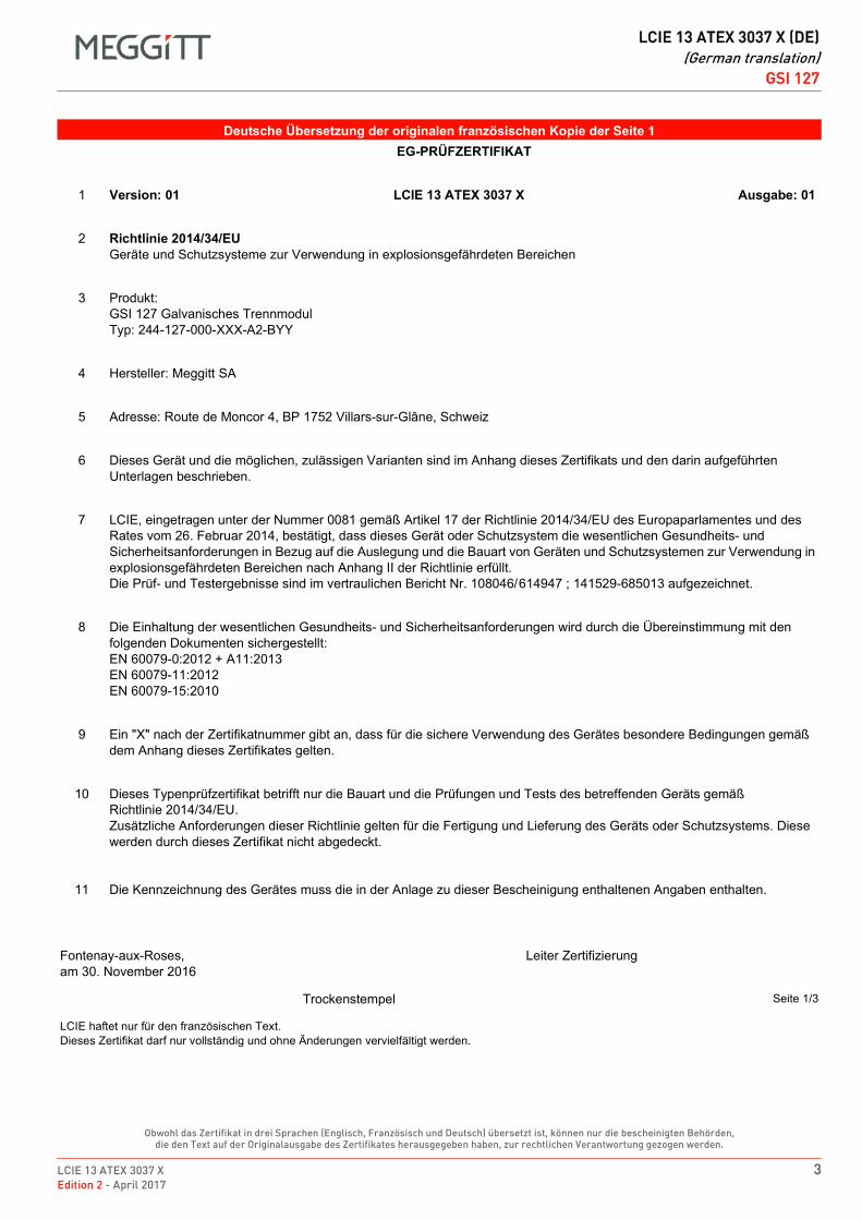
LCIE 13 ATEX 3037 X 3Edition 2 - April 2017
DRAFT
LCIE 13 ATEX 3037 X (DE)(German translation)
GSI 127
Obwohl das Zertifikat in drei Sprachen (Englisch, Französisch und Deutsch) übersetzt ist, können nur die bescheinigten Behörden, die den Text auf der Originalausgabe des Zertifikates herausgegeben haben, zur rechtlichen Verantwortung gezogen werden.
DE LCIE 13 ATEX 3037 X (DE) German translation DE
Deutsche Übersetzung der originalen französischen Kopie der Seite 1EG-PRÜFZERTIFIKAT
1 Version: 01 LCIE 13 ATEX 3037 X Ausgabe: 01
2 Richtlinie 2014/34/EUGeräte und Schutzsysteme zur Verwendung in explosionsgefährdeten Bereichen
3 Produkt:GSI 127 Galvanisches TrennmodulTyp: 244-127-000-XXX-A2-BYY
4 Hersteller: Meggitt SA
5 Adresse: Route de Moncor 4, BP 1752 Villars-sur-Glâne, Schweiz
6 Dieses Gerät und die möglichen, zulässigen Varianten sind im Anhang dieses Zertifikats und den darin aufgeführten Unterlagen beschrieben.
7 LCIE, eingetragen unter der Nummer 0081 gemäß Artikel 17 der Richtlinie 2014/34/EU des Europaparlamentes und des Rates vom 26. Februar 2014, bestätigt, dass dieses Gerät oder Schutzsystem die wesentlichen Gesundheits- und Sicherheitsanforderungen in Bezug auf die Auslegung und die Bauart von Geräten und Schutzsystemen zur Verwendung in explosionsgefährdeten Bereichen nach Anhang II der Richtlinie erfüllt.Die Prüf- und Testergebnisse sind im vertraulichen Bericht Nr. 108046/614947 ; 141529-685013 aufgezeichnet.
8 Die Einhaltung der wesentlichen Gesundheits- und Sicherheitsanforderungen wird durch die Übereinstimmung mit den folgenden Dokumenten sichergestellt:EN 60079-0:2012 + A11:2013EN 60079-11:2012EN 60079-15:2010
9 Ein "X" nach der Zertifikatnummer gibt an, dass für die sichere Verwendung des Gerätes besondere Bedingungen gemäß dem Anhang dieses Zertifikates gelten.
10 Dieses Typenprüfzertifikat betrifft nur die Bauart und die Prüfungen und Tests des betreffenden Geräts gemäßRichtlinie 2014/34/EU.Zusätzliche Anforderungen dieser Richtlinie gelten für die Fertigung und Lieferung des Geräts oder Schutzsystems. Diese werden durch dieses Zertifikat nicht abgedeckt.
11 Die Kennzeichnung des Gerätes muss die in der Anlage zu dieser Bescheinigung enthaltenen Angaben enthalten.
Fontenay-aux-Roses,am 30. November 2016
Leiter Zertifizierung
Trockenstempel Seite 1/3
LCIE haftet nur für den französischen Text.Dieses Zertifikat darf nur vollständig und ohne Änderungen vervielfältigt werden.
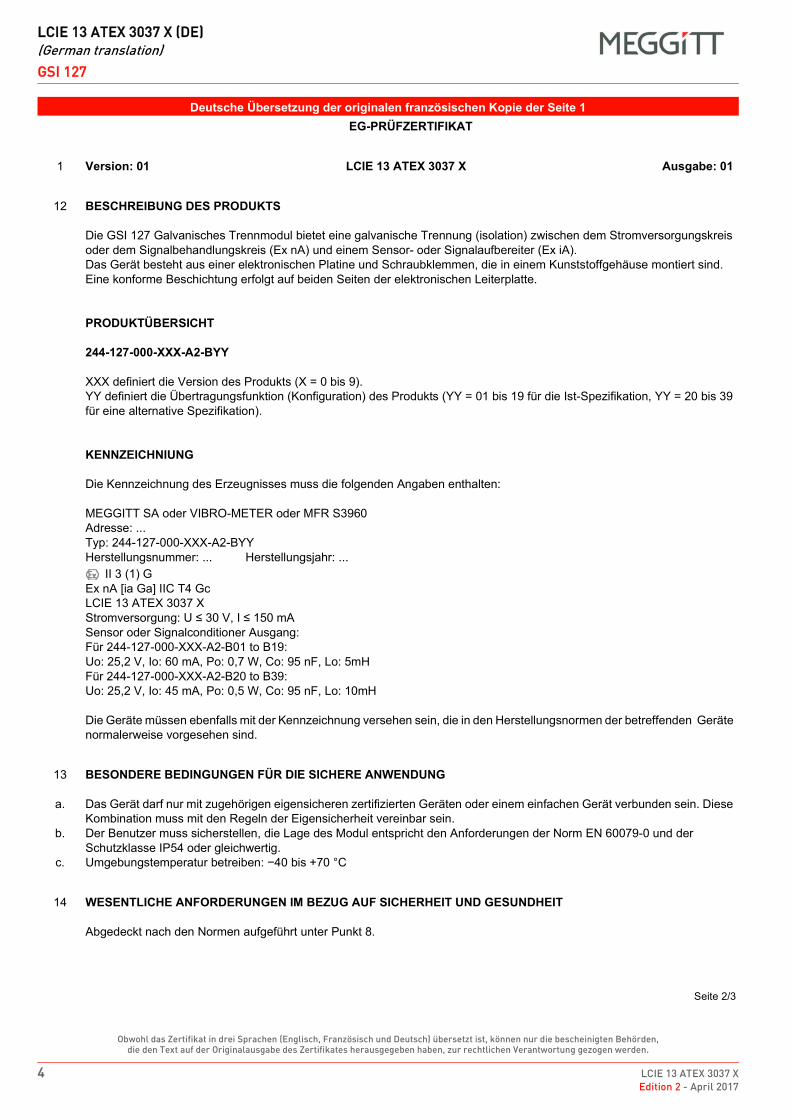
DRAFT
LCIE 13 ATEX 3037 X (DE)(German translation)
GSI 127
4 LCIE 13 ATEX 3037 XEdition 2 - April 2017
Obwohl das Zertifikat in drei Sprachen (Englisch, Französisch und Deutsch) übersetzt ist, können nur die bescheinigten Behörden, die den Text auf der Originalausgabe des Zertifikates herausgegeben haben, zur rechtlichen Verantwortung gezogen werden.
Deutsche Übersetzung der originalen französischen Kopie der Seite 1EG-PRÜFZERTIFIKAT
1 Version: 01 LCIE 13 ATEX 3037 X Ausgabe: 01
12 BESCHREIBUNG DES PRODUKTS
Die GSI 127 Galvanisches Trennmodul bietet eine galvanische Trennung (isolation) zwischen dem Stromversorgungskreis oder dem Signalbehandlungskreis (Ex nA) und einem Sensor- oder Signalaufbereiter (Ex iA).Das Gerät besteht aus einer elektronischen Platine und Schraubklemmen, die in einem Kunststoffgehäuse montiert sind. Eine konforme Beschichtung erfolgt auf beiden Seiten der elektronischen Leiterplatte.
PRODUKTÜBERSICHT
244-127-000-XXX-A2-BYY
XXX definiert die Version des Produkts (X = 0 bis 9).YY definiert die Übertragungsfunktion (Konfiguration) des Produkts (YY = 01 bis 19 für die Ist-Spezifikation, YY = 20 bis 39 für eine alternative Spezifikation).
KENNZEICHNIUNG
Die Kennzeichnung des Erzeugnisses muss die folgenden Angaben enthalten:
MEGGITT SA oder VIBRO-METER oder MFR S3960Adresse: ...Typ: 244-127-000-XXX-A2-BYYHerstellungsnummer: ... Herstellungsjahr: ...
II 3 (1) GEx nA [ia Ga] IIC T4 GcLCIE 13 ATEX 3037 XStromversorgung: U ≤ 30 V, I ≤ 150 mASensor oder Signalconditioner Ausgang:Für 244-127-000-XXX-A2-B01 to B19:Uo: 25,2 V, Io: 60 mA, Po: 0,7 W, Co: 95 nF, Lo: 5mHFür 244-127-000-XXX-A2-B20 to B39:Uo: 25,2 V, Io: 45 mA, Po: 0,5 W, Co: 95 nF, Lo: 10mH
Die Geräte müssen ebenfalls mit der Kennzeichnung versehen sein, die in den Herstellungsnormen der betreffenden Geräte normalerweise vorgesehen sind.
13
a.
b.
c.
BESONDERE BEDINGUNGEN FÜR DIE SICHERE ANWENDUNG
Das Gerät darf nur mit zugehörigen eigensicheren zertifizierten Geräten oder einem einfachen Gerät verbunden sein. Diese Kombination muss mit den Regeln der Eigensicherheit vereinbar sein.Der Benutzer muss sicherstellen, die Lage des Modul entspricht den Anforderungen der Norm EN 60079-0 und der Schutzklasse IP54 oder gleichwertig.Umgebungstemperatur betreiben: −40 bis +70 °C
14 WESENTLICHE ANFORDERUNGEN IM BEZUG AUF SICHERHEIT UND GESUNDHEIT
Abgedeckt nach den Normen aufgeführt unter Punkt 8.
Seite 2/3
LCIE 13 ATEX 3037 X 5Edition 2 - April 2017
DRAFT
LCIE 13 ATEX 3037 X (DE)(German translation)
GSI 127
Obwohl das Zertifikat in drei Sprachen (Englisch, Französisch und Deutsch) übersetzt ist, können nur die bescheinigten Behörden, die den Text auf der Originalausgabe des Zertifikates herausgegeben haben, zur rechtlichen Verantwortung gezogen werden.
Deutsche Übersetzung der originalen französischen Kopie der Seite 2EG-PRÜFZERTIFIKAT
1 Version: 01 LCIE 13 ATEX 3037 X Ausgabe: 01
15 BESCHREIBENDE UNTERLAGEN
Nummer (Nr.) Beschreibung Referenz Revision Datum Seiten1. Technische Datei DT 1052 01 2016-10-24 362. Benutzerhandbuch (Auszug) PZ 8763 00 2016-09-06 1
16 ZUSÄTZLICHE INFORMATION
RoutinePrüfungen und TestsJeder Transformator T1 muss einer Spannungsfestigkeit Test dauert 60 Sekunden eingereicht werden, mit einer 50/60 Hz Sinus von 1500 VRMS zwischen der Primärwicklung und der secondard Wicklungen, gemäß Abschnitt 11.2 der Norm EN 60079-11:2012.
ZertifizierungsbedingungenInhaber von Typenprüfzertifikaten (EG-Prèufzertifikaten) müssen die Anforderungen an die Produktionssteuerung nach Artikel 13 der Richtlinie 2014/34/EU erfüllen.Gemäß Artikel 41 der Richtlinie 2014/34/EU können Typenprüfzertifikaten, die sich auf 94/9/EU beziehen, die vor dem Tag der Anwendung der Richtlinie 2014/34/EU (20. April 2016) vorliegen, referenziert werden Als ob sie gemäß der Richtlinie 2014/34/EU ausgestellt würden. Neue Emissionen dieser Zertifikate können weiterhin die ursprüngliche Zertifikatsnummer tragen, die vor dem 20. April 2016 ausgestellt wurde.
Details der ÄnderungenAusgabe 00:Konformitätsbewertung nach den Normen EN 60079-0:2012, EN 60079-11:2012 und EN 60079-15:2010.
Ausgabe 01:Normative Aktualisierung nach der Norm EN 60079-0:2012 + A11:2013.Neuer Umgebungstemperatur betreiben: −40 bis +70 °C.Aktualisierung der Typbezeichnung zur Unterscheidung von zwei Spezifikationen.
Seite 3/3
DRAFT
LCIE 13 ATEX 3037 X (DE)(German translation)
GSI 127
6 LCIE 13 ATEX 3037 XEdition 2 - April 2017
THIS PAGE INTENTIONALLY LEFT BLANKCETTE PAGE EST LAISSÉE INTENTIONNELLEMENT VIDE
DIESE SEITE WURDE ABSICHTLICH LEER GELASSEN
Meggitt SA, Route de Moncor 4, Case postale, 1701 Fribourg, Switzerland Tel: +41 26 407 1111Fax: +41 26 407 1660
[email protected]/energy
www.meggitt.com
EX CERTIFICATE – ATEX
Document reference ITS 16 ATEX 101335 XEdition 2 – January 2022
Title page
ITS 16 ATEX 101335 Xfor
cable fittings (stuffing glands)
EX
Note: Although the Ex certificate may be included in more than one language, the liability ofthe notified body applies only on the text of the original copy of the certificate that it published.

THIS PAGE INTENTIONALLY LEFT BLANK
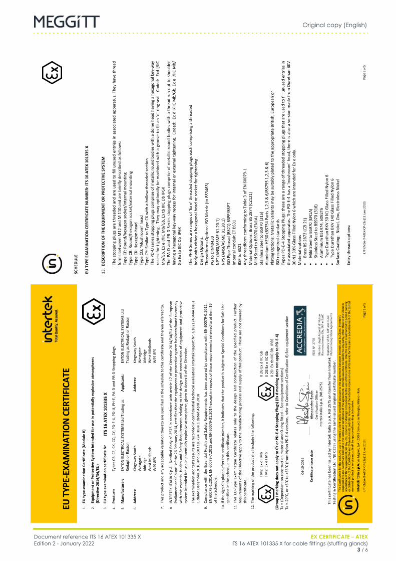
Original copy (English)
Document reference ITS 16 ATEX 101335 X EX CERTIFICATE – ATEXEdition 2 - January 2022 ITS 16 ATEX 101335 X for cable fittings (stuffing glands)
3 / 6
Cable fittings
FR ITS 16 ATEX 101335 X (EN) Original copy EN
SC
HEDU
LE
EU T
YPE
EXAM
INAT
ION
CER
TIFI
CATE
NU
MBE
R: IT
S 16
ATE
X 10
1335
X
LFT-
EMEA
-IT-A
TEX-
OP-2
3a (1
1 Ju
ne 2
019)
Pa
ge 2
of 5
13.
DESC
RIPT
ION
OF
THE
EQU
IPM
ENT
OR
PRO
TECT
IVE
SYST
EM
The
stop
ping
plu
gs a
re th
read
ed a
nd a
re u
sed
to fi
ll un
used
ent
ries
in a
ssoc
iate
d ap
para
tus.
The
y ha
ve th
read
fo
rms b
etw
een
M12
and
M 1
10 a
nd a
re b
riefly
des
crib
ed a
s fol
low
s:
Type
CF:
Rou
nd/h
exag
on so
cket
/inte
rnal
mou
ntin
g
Type
CB:
Rou
nd/h
exag
on so
cket
/ext
erna
l mou
ntin
g
Type
CK:
Hex
agon
hea
d
Type
CQ
: ‘M
ushr
oom
’ hea
d
Type
CY:
Sim
ilar t
o Ty
pe C
K w
ith a
hol
low
thre
aded
sect
ion
Th
e PD
-U se
ries s
topp
ing
plug
s com
prise
of m
etal
lic ro
und
bodi
es w
ith a
dom
e he
ad h
avin
g a
hexa
gona
l key
-way
re
cess
for t
ight
enin
g. T
hey
may
opt
iona
lly b
e m
achi
ned
with
a g
roov
e to
fit a
n ‘o
’ rin
g se
al.
Code
d: E
xd I/
IIC
Mb/
Gb,
Ex
e I/
IIC M
b/G
b, E
x tb
IIIC
Db
IP6X
Th
e PA
-D a
nd P
B-D
Serie
s st
oppi
ng p
lugs
com
prise
of m
etal
lic ro
und
bodi
es w
ith a
thre
ad r
un o
ut to
sho
ulde
r ha
ving
a h
exag
onal
key
-way
rece
ss fo
r int
erna
l or e
xter
nal t
ight
enin
g. C
oded
: Ex
d I/
IIC M
b/Gb
, Ex
e I/I
IC M
b/
Gb
Ex tb
IIIC
Db
IP6X
Th
e PH
-E S
erie
s are
rang
es o
f ‘Ex
e’ t
hrea
ded
stop
ping
plu
gs e
ach
com
prisi
ng a
thre
aded
bo
dy w
ith e
ither
a h
exag
onal
hea
d or
sock
et fo
r tig
hten
ing.
De
sign
Opt
ions
: Th
read
form
s Opt
ions
: ISO
Met
ric (t
o BS
3463
) PG
to D
IN40
430
NPT
(AN
SI/A
SME
B1.2
0.1)
N
PS (A
NSI
/ASM
E B1
.20.
1)
ISO
Pip
e Th
read
(BS2
1) B
SPP/
BSPT
Im
peria
l con
duit
ET B
S31
BSP
to B
S21
Any
thre
adfo
rm c
onfo
rmin
g to
Tab
le 3
of E
N 6
0079
-1
Mat
eria
l Opt
ions
: Bra
ss B
S 28
74 (C
Z121
) M
ild S
teel
to B
S970
(EN
1A)
Stai
nles
s Ste
el to
BS9
70 (3
16)
Alum
iniu
m H
E30
(BS7
54 P
arts
1,2
,3 &
6/B
S755
1,2
,3 &
6)
Plat
ing
Opt
ions
: Met
allic
var
iant
s may
be
suita
bly
plat
ed to
the
appr
opria
te B
ritish
, Eur
opea
n or
IS
O re
cogn
ized
stan
dard
s Ty
pes P
D-E-
4 St
oppi
ng P
lugs
: the
se a
re a
rang
e of
thre
aded
stop
ping
plu
gs th
at a
re u
sed
to fi
ll un
used
ent
ries i
n th
e as
soci
ated
app
arat
us. T
he P
D-E-
4 ha
s a
‘mus
hroo
m’ h
ead,
ther
e is
also
a v
ersio
n m
ade
from
Dur
etha
n BK
V 30
N1
30%
Gla
ss F
illed
Nyl
on 6
whi
ch a
re in
tend
ed fo
r Ex
e on
ly.
M
ater
ial o
ptio
ns
• Br
ass B
S 28
72 (C
ZI 2
1)
• M
ild S
teel
to B
S970
(EN
1A)
• St
ainl
ess S
teel
to B
S970
(316
) •
Alum
iniu
m B
S147
4, 6
082T
6 •
Type
Dur
etha
n BK
V 30
N1
Gla
ss F
illed
Nyl
on 6
•
Type
Dur
etha
n BK
V 14
0 G
lass
Fill
ed N
ylon
6
Surf
ace
Coat
ing:
Nic
kel,
Zinc
, Ele
ctro
less
Nic
kel
Entr
y th
read
s opt
ions
:
EU T
YPE-
EXAM
INAT
ION
CER
TIFI
CATE
This
Certi
ficat
e is
for t
he e
xclu
sive
use
of In
tert
ek's
clien
t and
is p
rovid
ed p
ursu
ant t
o th
e ag
reem
ent b
etw
een
Inte
rtek a
nd it
s Clie
nt. I
nter
tek's
re
spon
sibilit
y and
liabi
lity a
re lim
ited
to th
e te
rms a
nd co
nditi
ons o
f the
agr
eem
ent.
Inte
rtek
ass
umes
no
liabi
lity t
o an
y pa
rty, o
ther
than
to th
e Cl
ient
in
acco
rdan
ce w
ith th
e ag
reem
ent,
for a
ny lo
ss, e
xpen
se o
r dam
age
occa
sione
d by
the
use
of th
is Ce
rtific
ate.
Onl
y the
Clie
nt is
aut
horiz
ed to
per
mit
copy
ing
or d
istrib
utio
n of
this
Certi
ficat
e an
d th
en o
nly i
n its
ent
irety
. Any
use
of t
he In
terte
k n\a
me
or o
ne o
f its
mar
ks fo
r the
sale
or a
dver
tisem
ent o
f the
test
ed
mat
eria
l, pro
duct
or s
ervic
e m
ust f
irst\
be
appr
oved
in w
ritin
g by
Inte
rtek.
Inte
rtek
Ital
ia S
.p.A
. Via
Mig
lioli,
2/A
- 200
63 C
ernu
sco
sul N
avig
lio, M
ilano
- Ita
ly
LFT-
EMEA
-IT-A
TEX-
OP-2
3a (1
1 Ju
ne 2
019)
Pa
ge 1
of 5
04-1
0-20
19
Cert
ifica
te is
sue
date
Ales
sand
ro S
avio
Ce
rtifi
catio
n O
ffice
r In
tert
ek It
alia
S.p
.A. (
NB
2575
)
This
cert
ifica
te h
as b
een
issue
d by
Inte
rtek
Ital
ia S
.p.A
. NB
2575
on
tran
sfer
from
Inte
rtek
Te
stin
g &
Cer
tific
atio
n Lt
d. (N
B 03
59) u
sing
the
sam
e is
sued
orig
inal
cer
tific
ate
num
ber.
Ales
sand
roSa
vioi
1.
EU ty
pe-e
xam
inat
ion
Cert
ifica
te (M
odul
e B)
2.
Equi
pmen
t or P
rote
ctiv
e Sy
stem
inte
nded
for u
se in
pot
entia
lly e
xplo
sive
atm
osph
eres
(D
irect
ive
2014
/34/
EU)
3.
EU ty
pe e
xam
inat
ion
cert
ifica
te N
r IT
S 16
ATE
X 10
1335
X
4.
Prod
uct:
Type
s CB,
CF,
CK,
CQ
, CY,
PD-
E-4,
PD-
U, P
H-E,
PA-
D an
d PB
-D S
topp
ing
plug
s.
5.
Man
ufac
ture
r:
EATO
N E
LECT
RICA
L SY
STEM
S Lt
d Tr
adin
g as
Re
dapt
or R
axto
n Ap
plic
ant:
EA
TON
ELE
CTRI
CAL
SYST
EMS
Ltd
Trad
ing
as R
edap
t or R
axto
n
6.
Addr
ess:
Ki
ngsw
ay S
outh
W
estg
ate
Aldr
idge
W
est M
idla
nds
WS9
8FS
Addr
ess:
Ki
ngsw
ay S
outh
W
estg
ate
Aldr
idge
W
est M
idla
nds
WS9
8FS
7.
This
prod
uct a
nd a
ny a
ccep
tabl
e va
riatio
n th
eret
o ar
e sp
ecifi
ed in
the
sche
dule
to th
is ce
rtifi
cate
and
ther
ein
refe
rred
to.
8.
INTE
RTEK
ITAL
IA S
.p.A
., N
otifi
ed B
ody
n° 2
575
in a
ccor
danc
e w
ith a
rtic
le 1
7 of
the
Dire
ctiv
e 20
14/3
4/EU
of t
he E
urop
ean
Parli
amen
t and
Cou
ncil
of th
e 26
Feb
ruar
y 20
14, c
ertif
ies t
hat t
he e
quip
men
t or p
rote
ctiv
e sy
stem
has
bee
n fo
und
to co
mpl
y w
ith t
he e
ssen
tial H
ealth
and
Saf
ety
Requ
irem
ents
rel
atin
g to
the
des
ign
and
cons
truc
tion
of e
quip
men
t an
d pr
otec
tive
syst
em in
tend
ed fo
r use
in p
oten
tially
exp
losi
ve a
tmos
pher
e, g
iven
in A
nnex
II o
f the
Dire
ctiv
e.
The
exam
inat
ion
and
test
s res
ults
are
reco
rded
in c
onfid
entia
l tec
hnic
al e
valu
atio
n In
tert
ek R
epor
t Nr.
G10
2174
344A
Issu
e 1
date
d De
cem
ber 2
016
and
G10
3326
724
Issu
e 1
date
d Ap
ril 2
018
9.
Com
plia
nce
with
the
Esse
ntia
l Hea
lth a
nd S
afet
y Re
quire
men
ts h
as b
een
assu
red
by c
ompl
ianc
e w
ith E
N 6
0079
-0:2
012,
EN
600
79-1
:201
4, E
N 6
0079
-7:2
015
and
EN 6
0079
-31:
2014
exc
ept i
n re
spec
t of t
hose
requ
irem
ents
refe
rred
to a
t ite
m 1
6 of
the
Sche
dule
.
10. I
f the
sign
X is
pla
ced
afte
r the
cert
ifica
te n
umbe
r, it
indi
cate
s tha
t the
pro
duct
is su
bjec
t to
Spec
ial C
ondi
tions
for S
afe
Use
sp
ecifi
ed in
the
sche
dule
to th
is ce
rtifi
cate
.
11. T
his
EU-T
ype
Exam
inat
ion
Cert
ifica
te r
elat
es o
nly
to t
he d
esig
n an
d co
nstr
uctio
n of
the
spe
cifie
d pr
oduc
t. Fu
rthe
r re
quire
men
ts o
f the
Dire
ctiv
e ap
ply
to th
e m
anuf
actu
ring
proc
ess
and
supp
ly o
f thi
s pr
oduc
t. Th
ese
are
not c
over
ed b
y th
is ce
rtifi
cate
.
12. T
he m
arki
ng o
f the
pro
duct
shal
l inc
lude
the
follo
win
g:
I M
2 E
x d
I Mb
I M
2 E
x e
I Mb
II 2G
Ex
d IIC
Gb
II 2G
Ex
e IIC
Gb
II 2D
Ex
tb II
IC D
b IP
66
(Gro
up I
mar
king
doe
s not
app
ly to
CY
or P
D-E
-4 S
topp
ing
Plug
s) (E
x d
mar
king
doe
s not
app
ly to
PD
-E-4
)
Ta =
(Dep
enda
nt o
n co
nstr
uctio
n m
ater
ial a
nd O
-rin
g fit
ted
– Se
e eq
uipm
ent s
ectio
ns)
Ta =
-20°
C, o
r +5°
C to
+65
°C (f
rom
Nyl
on P
D-E-
4 ve
rsio
ns, r
efer
to C
ondi
tions
of C
ertif
icat
ion
6) S
ee e
quip
men
t sec
tion
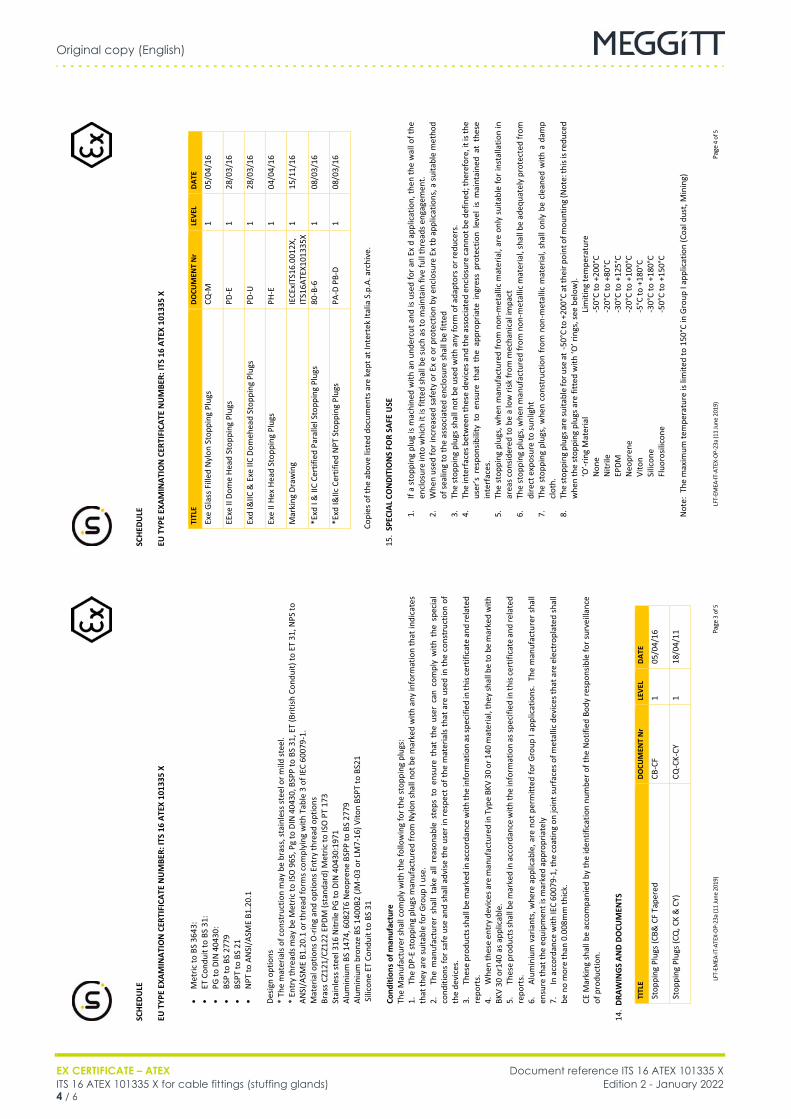
Original copy (English)
EX CERTIFICATE – ATEX Document reference ITS 16 ATEX 101335 XITS 16 ATEX 101335 X for cable fittings (stuffing glands) Edition 2 - January 20224 / 6
Cable fittings
FR ITS 16 ATEX 101335 X (EN) Original copy EN
SC
HEDU
LE
EU T
YPE
EXAM
INAT
ION
CER
TIFI
CATE
NU
MBE
R: IT
S 16
ATE
X 10
1335
X
LFT-
EMEA
-IT-A
TEX-
OP-2
3a (1
1 Ju
ne 2
019)
Pa
ge 4
of 5
TITL
E DO
CUM
ENT
Nr
LEVE
L DA
TE
Exe
Glas
s Fill
ed N
ylon
Sto
ppin
g Pl
ugs
CQ-M
1
05/0
4/16
EExe
II D
ome
Head
Sto
ppin
g Pl
ugs
PD-E
1
28/0
3/16
Exd
I&IIC
& E
xe II
C Do
meh
ead
Stop
ping
Plu
gs
PD-U
1
28/0
3/16
Exe
II He
x He
ad S
topp
ing
Plug
s PH
-E
1 04
/04/
16
Mar
king
Dra
win
g IE
CExI
TS16
.001
2X,
ITS1
6ATE
X101
335X
1
15/1
1/16
*Exd
I &
IIC
Cert
ified
Par
alle
l Sto
ppin
g Pl
ugs
80-B
-6
1 08
/03/
16
*Exd
I&IIc
Cer
tifie
d N
PT S
topp
ing
Plug
s PA
-D P
B-D
1 08
/03/
16
Copi
es o
f the
abo
ve li
sted
doc
umen
ts a
re k
ept a
t Int
erte
k Ita
lia S
.p.A
. arc
hive
.
15.
SPEC
IAL
CON
DITI
ON
S FO
R SA
FE U
SE
1.
If
a st
oppi
ng p
lug
is m
achi
ned
with
an
unde
rcut
and
is u
sed
for a
n Ex
d a
pplic
atio
n, th
en th
e w
all o
f the
en
clos
ure
into
whi
ch it
is fi
tted
shal
l be
such
as t
o m
aint
ain
five
full
thre
ads e
ngag
emen
t. 2.
W
hen
used
for i
ncre
ased
safe
ty o
r Ex
e or
pro
tect
ion
by e
nclo
sure
Ex
tb a
pplic
atio
ns, a
suita
ble
met
hod
of se
alin
g to
the
asso
ciat
ed e
nclo
sure
shal
l be
fitte
d 3.
Th
e st
oppi
ng p
lugs
shal
l not
be
used
with
any
form
of a
dapt
ors o
r red
ucer
s.
4.
The
inte
rfac
es b
etw
een
thes
e de
vice
s and
the
asso
ciat
ed e
nclo
sure
cann
ot b
e de
fined
; the
refo
re, i
t is t
he
user
’s r
espo
nsib
ility
to
ensu
re t
hat
the
appr
opria
te i
ngre
ss p
rote
ctio
n le
vel
is m
aint
aine
d at
the
se
inte
rfac
es.
5.
The
stop
ping
plu
gs, w
hen
man
ufac
ture
d fr
om n
on-m
etal
lic m
ater
ial,
are
only
sui
tabl
e fo
r ins
talla
tion
in
area
s con
sider
ed to
be
a lo
w ri
sk fr
om m
echa
nica
l im
pact
6.
Th
e st
oppi
ng p
lugs
, whe
n m
anuf
actu
red
from
non
-met
allic
mat
eria
l, sh
all b
e ad
equa
tely
pro
tect
ed fr
om
dire
ct e
xpos
ure
to su
nlig
ht
7.
The
stop
ping
plu
gs, w
hen
cons
truc
tion
from
non
-met
allic
mat
eria
l, sh
all o
nly
be c
lean
ed w
ith a
dam
p cl
oth.
8.
Th
e st
oppi
ng p
lugs
are
suita
ble
for u
se a
t -5
0°C
to +
200°
C at
thei
r poi
nt o
f mou
ntin
g (N
ote:
this
is re
duce
d w
hen
the
stop
ping
plu
gs a
re fi
tted
with
‘O’ r
ings
, see
bel
ow).
‘O’-r
ing
Mat
eria
l
Lim
iting
tem
pera
ture
N
one
-50°
C to
+20
0°C
Nitr
ile
-20°
C to
+80
°C
EPDM
-3
0°C
to +
125°
C N
eopr
ene
-20°
C to
+10
0°C
Vito
n
-5
°C to
+18
0°C
Silic
one
-30°
C to
+18
0°C
Fluo
rosil
icon
e
-50°
C to
+15
0°C
Not
e: T
he m
axim
um te
mpe
ratu
re is
lim
ited
to 1
50°C
in G
roup
I ap
plic
atio
n (C
oal d
ust,
Min
ing)
SC
HEDU
LE
EU T
YPE
EXAM
INAT
ION
CER
TIFI
CATE
NU
MBE
R: IT
S 16
ATE
X 10
1335
X
LFT-
EMEA
-IT-A
TEX-
OP-2
3a (1
1 Ju
ne 2
019)
Pa
ge 3
of 5
• M
etric
to B
S 36
43:
• ET
Con
duit
to B
S 31
: •
PG to
DIN
404
30:
• BS
P to
BS
2779
•
BSPT
to B
S 21
•
NPT
to A
NSI
/ASM
E B1
.20.
1 De
sign
optio
ns
* Th
e m
ater
ials
of c
onst
ruct
ion
may
be
bras
s, st
ainl
ess s
teel
or m
ild st
eel.
*
Entr
y th
read
s may
be
Met
ric to
ISO
965
, Pg
to D
IN 4
0430
, BSP
P to
BS
31, E
T (B
ritish
Con
duit)
to E
T 31
, NPS
to
ANSI
/ASM
E B1
.20.
1 or
thre
ad fo
rms c
ompl
ying
with
Tab
le 3
of I
EC 6
0079
-1.
Mat
eria
l opt
ions
O-r
ing
and
optio
ns E
ntry
thre
ad o
ptio
ns
Bras
s CZ1
21/C
Z122
EPD
M (s
tand
ard)
Met
ric to
ISO
PT
173
St
ainl
ess s
teel
316
Nitr
ile P
G to
DIN
404
30:1
971
Al
umin
ium
BS
1474
, 608
2T6
Neo
pren
e BS
PP to
BS
2779
Al
umin
ium
bro
nze
BS 1
400B
2 (JM
-03
or L
M7-
16) V
iton
BSPT
to B
S21
S
ilico
ne E
T Co
ndui
t to
BS 3
1
Cond
ition
s of m
anuf
actu
re
The
Man
ufac
ture
r sha
ll co
mpl
y w
ith th
e fo
llow
ing
for t
he st
oppi
ng p
lugs
:
1.
The
DP-E
stop
ping
plu
gs m
anuf
actu
red
from
Nyl
on sh
all n
ot b
e m
arke
d w
ith a
ny in
form
atio
n th
at in
dica
tes
that
they
are
suita
ble
for G
roup
I us
e.
2.
The
man
ufac
ture
r sh
all t
ake
all r
easo
nabl
e st
eps
to e
nsur
e th
at t
he u
ser
can
com
ply
with
the
spe
cial
co
nditi
ons
for s
afe
use
and
shal
l adv
ise th
e us
er in
resp
ect o
f the
mat
eria
ls th
at a
re u
sed
in th
e co
nstr
uctio
n of
th
e de
vice
s.
3.
Thes
e pr
oduc
ts sh
all b
e m
arke
d in
acc
orda
nce
with
the
info
rmat
ion
as sp
ecifi
ed in
this
cert
ifica
te a
nd re
late
d re
port
s.
4.
Whe
n th
ese
entr
y de
vice
s are
man
ufac
ture
d in
Typ
e BK
V 30
or 1
40 m
ater
ial,
they
shal
l be
to b
e m
arke
d w
ith
BKV
30 o
r140
as a
pplic
able
. 5.
Th
ese
prod
ucts
shal
l be
mar
ked
in a
ccor
danc
e w
ith th
e in
form
atio
n as
spec
ified
in th
is ce
rtifi
cate
and
rela
ted
repo
rts.
6.
Al
umin
ium
var
iant
s, w
here
app
licab
le, a
re n
ot p
erm
itted
for G
roup
I ap
plic
atio
ns.
The
man
ufac
ture
r sha
ll en
sure
that
the
equi
pmen
t is m
arke
d ap
prop
riate
ly
7.
In a
ccor
danc
e w
ith IE
C 60
079-
1, th
e co
atin
g on
join
t sur
face
s of m
etal
lic d
evic
es th
at a
re e
lect
ropl
ated
shal
l be
no
mor
e th
an 0
.008
mm
thic
k.
CE M
arki
ng s
hall
be a
ccom
pani
ed b
y th
e id
entif
icat
ion
num
ber o
f the
Not
ified
Bod
y re
spon
sible
for s
urve
illan
ce
of p
rodu
ctio
n.
14
. DR
AWIN
GS
AND
DOCU
MEN
TS
TITL
E DO
CUM
ENT
Nr
LEVE
L DA
TE
Stop
ping
Plu
gs (C
B& C
F Ta
pere
d CB
-CF
1 05
/04/
16
Stop
ping
Plu
gs (C
Q, C
K &
CY)
CQ
-CK-
CY
1 18
/04/
11
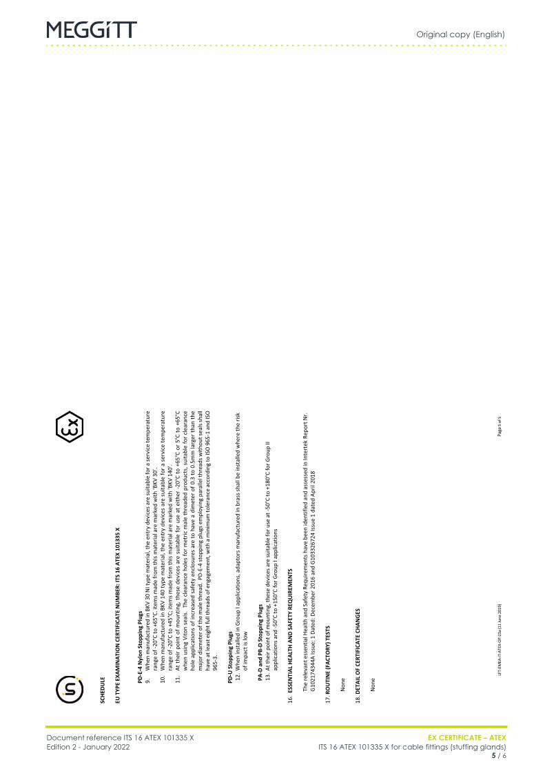
Original copy (English)
Document reference ITS 16 ATEX 101335 X EX CERTIFICATE – ATEXEdition 2 - January 2022 ITS 16 ATEX 101335 X for cable fittings (stuffing glands)
5 / 6
Cable fittings
FR ITS 16 ATEX 101335 X (EN) Original copy EN
SC
HEDU
LE
EU T
YPE
EXAM
INAT
ION
CER
TIFI
CATE
NU
MBE
R: IT
S 16
ATE
X 10
1335
X
LFT-
EMEA
-IT-A
TEX-
OP-2
3a (1
1 Ju
ne 2
019)
Pa
ge 5
of 5
PD-E
-4 N
ylon
Sto
ppin
g Pl
ugs
9.
Whe
n m
anuf
actu
red
in B
KV 3
0 N
I typ
e m
ater
ial,
the
entr
y de
vice
s are
suita
ble
for a
serv
ice
tem
pera
ture
ra
nge
of -2
0°C
to +
65°C
. ite
ms m
ade
from
this
mat
eria
l are
mar
ked
with
‘BKV
30’
. 10
. W
hen
man
ufac
ture
d in
BKV
140
type
mat
eria
l, th
e en
try
devi
ces
are
suita
ble
for a
ser
vice
tem
pera
ture
ra
nge
of -2
0°C
to +
45°C
; ite
ms m
ade
from
this
mat
eria
l are
mar
ked
with
‘BKV
140
’.
11.
At t
heir
poin
t of m
ount
ing,
the
se d
evic
es a
re s
uita
ble
for
use
at e
ither
-20°
C to
+65
°C o
r 5°
C to
+65
°C
whe
n us
ing
Vito
n se
als.
The
cle
aran
ce h
oles
for m
etric
mal
e th
read
ed p
rodu
cts,
sui
tabl
e fo
r cle
aran
ce
hole
app
licat
ions
of i
ncre
ased
saf
ety
encl
osur
es a
re to
hav
e a
dim
eter
of 0
.3 to
0.5
mm
larg
er th
an th
e m
ajor
dia
met
er o
f the
mal
e th
read
. PD
-E-4
stop
ping
plu
gs e
mpl
oyin
g pa
ralle
l thr
eads
with
out s
eals
shal
l ha
ve a
t lea
st e
ight
full
thre
ads o
f eng
agem
ent,
with
a m
inim
um to
lera
nce
acco
rdin
g to
ISO
965
-1 a
nd IS
O
965-
3.
PD-U
Sto
ppin
g Pl
ugs
12. W
hen
inst
alle
d in
Gro
up I
appl
icat
ions
, ada
ptor
s man
ufac
ture
d in
bra
ss sh
all b
e in
stal
led
whe
re th
e ris
k of
impa
ct is
low
PA
-D a
nd P
B-D
Stop
ping
Plu
gs
13. A
t the
ir po
int o
f mou
ntin
g, th
ese
devi
ces a
re su
itabl
e fo
r use
at -
50°C
to +
180°
C fo
r Gro
up II
ap
plic
atio
ns a
nd -5
0°C
to +
150°
C fo
r Gro
up I
appl
icat
ions
16.
ESSE
NTI
AL H
EALT
H A
ND
SAFE
TY R
EQU
IREM
ENTS
The
rele
vant
ess
entia
l Hea
lth a
nd S
afet
y Re
quire
men
ts h
ave
been
iden
tifie
d an
d as
sess
ed in
Inte
rtek
Rep
ort N
r. G
1021
7434
4A Is
sue:
1 D
ated
: Dec
embe
r 201
6 an
d G
1033
2672
4 Is
sue
1 da
ted
April
201
8
17. R
OU
TIN
E (F
ACTO
RY) T
ESTS
Non
e 18
. DET
AIL
OF
CERT
IFIC
ATE
CHAN
GES
Non
e

Original copy (English)
EX CERTIFICATE – ATEX Document reference ITS 16 ATEX 101335 XITS 16 ATEX 101335 X for cable fittings (stuffing glands) Edition 2 - January 20226 / 6
THIS PAGE INTENTIONALLY LEFT BLANK

Meggitt SA, Route de Moncor 4, Case postale, 1701 Fribourg, Switzerland Tel: +41 26 407 1111Fax: +41 26 407 1660
[email protected]/energy
www.meggitt.com
EX CERTIFICATE – ATEX
Document reference ITS 16 ATEX 101336 XEdition 2 – January 2022
Title page
ITS 16 ATEX 101336 Xfor
cable fittings (stuffing glands)
EX
Note: Although the Ex certificate may be included in more than one language, the liability ofthe notified body applies only on the text of the original copy of the certificate that it published.

THIS PAGE INTENTIONALLY LEFT BLANK
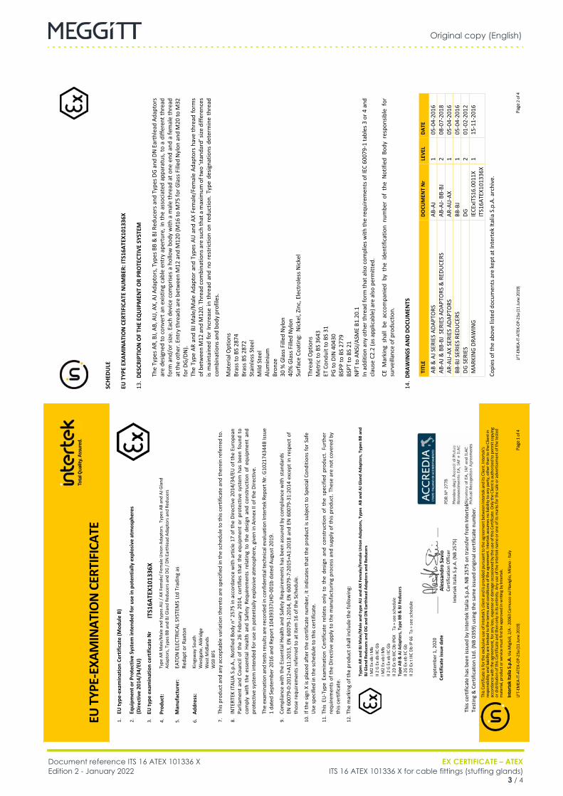
Original copy (English)
Document reference ITS 16 ATEX 101336 X EX CERTIFICATE – ATEXEdition 2 - January 2022 ITS 16 ATEX 101336 X for cable fittings (stuffing glands)
3 / 4
Cable fittings
FR ITS 16 ATEX 101336 X (EN) Original copy EN
SC
HED
ULE
EU
TYP
E EX
AMIN
ATIO
N C
ERTI
FICA
TE N
UM
BER:
ITS1
6ATE
X101
336X
LFT-
EMEA
-IT-A
TEX-
OP-2
3a (1
1 Ju
ne 2
019)
Pa
ge 2
of 4
13.
DES
CRIP
TIO
N O
F TH
E EQ
UIP
MEN
T O
R PR
OTE
CTIV
E SY
STEM
Th
e Ty
pes A
R, B
J, AB
, AU,
AX,
AJ A
dapt
ors,
Typ
es B
B &
BJ R
educ
ers a
nd T
ypes
DG
and
DN E
arth
lead
Ada
ptor
s ar
e de
signe
d to
con
vert
an
exist
ing
cabl
e en
try
aper
ture
, in
the
asso
ciat
ed a
ppar
atus
, to
a di
ffere
nt th
read
fo
rm a
nd/o
r size
. Eac
h de
vice
com
prise
s a
hollo
w b
ody
with
a m
ale
thre
ad a
t one
end
and
a fe
mal
e th
read
at
the
othe
r. En
try
thre
ads a
re b
etw
een
M12
and
M12
0 (M
16 to
M75
for G
lass
Fill
ed N
ylon
and
M20
to M
32
for D
G/D
N).
The
Type
AR
and
BJ M
ale/
Mal
e Ad
apto
r and
Typ
es A
U a
nd A
X Fe
mal
e/Fe
mal
e Ad
apto
rs h
ave
thre
ad fo
rms
of b
etw
een
M12
and
M12
0. T
hrea
d co
mbi
natio
ns a
re su
ch th
at a
max
imum
of t
wo
‘sta
ndar
d’ si
ze d
iffer
ence
s is
mai
ntai
ned
for
Incr
ease
in t
hrea
d an
d no
res
tric
tion
on r
educ
tion.
Typ
e de
signa
tions
det
erm
ine
thre
ad
com
bina
tions
and
bod
y pr
ofile
s.
Mat
eria
l Opt
ions
Br
ass t
o BS
287
4 Br
ass B
S 28
72
Stai
nles
s Ste
el
Mild
Ste
el
Alum
iniu
m
Bron
ze
30 %
Gla
ss F
illed
Nyl
on
40%
Gla
ss F
illed
Nyl
on
Surf
ace
Coat
ing:
Nic
kel,
Zinc
, Ele
ctro
less
Nic
kel
Thre
ad O
ptio
ns
Met
ric to
BS
3643
ET
Con
duit
to B
S 31
PG
to D
IN 4
0430
BS
PP to
BS
2779
BS
PT to
BS
21
NPT
to A
NSI
/ASM
E B1
.20.
1 In
add
ition
any
oth
er th
read
form
that
also
com
plie
s with
the
requ
irem
ents
of I
EC 6
0079
-1 ta
bles
3 o
r 4 a
nd
clau
se C
2.2
(as a
pplic
able
) are
also
per
mitt
ed.
CE M
arki
ng s
hall
be a
ccom
pani
ed b
y th
e id
entif
icat
ion
num
ber
of t
he N
otifi
ed B
ody
resp
onsib
le f
or
surv
eilla
nce
of p
rodu
ctio
n.
14
. DR
AWIN
GS A
ND
DOCU
MEN
TS
TITL
E DO
CUM
ENT
Nr
LEVE
L DA
TE
AB &
AJ S
ERIE
S AD
APTO
RS
AB-A
J 1
05-0
4-20
16
AB-A
J & B
B-BJ
SER
IES
ADAP
TORS
& R
EDU
CERS
AB
-AJ-
BB-B
J
2 08
-07-
2018
AR
-AU
-AX
SERI
ES A
DAPT
ORS
AR
-AU
-AX
1 05
-04-
2016
BB
-BJ S
ERIE
S RE
DUCE
RS
BB-B
J 1
05-0
4-20
16
DG S
ERIE
S DG
2
01-0
2-20
12
MAR
KIN
G D
RAW
ING
IE
CExI
TS16
.001
1X
ITS1
6ATE
X101
336X
1
15-1
1-20
16
Copi
es o
f the
abo
ve li
sted
doc
umen
ts a
re k
ept a
t Int
erte
k Ita
lia S
.p.A
. arc
hive
.
EU T
YPE-
EXAM
INAT
ION
CER
TIFI
CATE
This
Certi
ficat
e is
for t
he e
xclu
sive
use
of In
tert
ek's
clien
t and
is p
rovid
ed p
ursu
ant t
o th
e ag
reem
ent b
etw
een
Inte
rtek a
nd it
s Clie
nt. I
nter
tek's
re
spon
sibilit
y and
liabi
lity a
re lim
ited
to th
e te
rms a
nd co
nditi
ons o
f the
agr
eem
ent.
Inte
rtek
ass
umes
no
liabi
lity t
o an
y pa
rty, o
ther
than
to th
e Cl
ient
in
acco
rdan
ce w
ith th
e ag
reem
ent,
for a
ny lo
ss, e
xpen
se o
r dam
age
occa
sione
d by
the
use
of th
is Ce
rtific
ate.
Onl
y the
Clie
nt is
aut
horiz
ed to
per
mit
copy
ing
or d
istrib
utio
n of
this
Certi
ficat
e an
d th
en o
nly i
n its
ent
irety
. Any
use
of t
he In
terte
k nam
e or
one
of i
ts m
arks
for t
he sa
le o
r adv
ertis
emen
t of t
he te
sted
m
ater
ial, p
rodu
ct o
r ser
vice
mus
t firs
t be
appr
oved
in w
ritin
g by
Inte
rtek.
Inte
rtek
Ital
ia S
.p.A
. Via
Mig
lioli,
2/A
- 200
63 C
ernu
sco
sul N
avig
lio, M
ilano
- Ita
ly
LFT-
EMEA
-IT-A
TEX-
OP-2
3a (1
1 Ju
ne 2
019)
Pa
ge 1
of 4
Sept
embe
r 1, 2
020
Cert
ifica
te is
sue
date
Ales
sand
ro S
avio
Ce
rtifi
catio
n O
ffice
r In
tert
ek It
alia
S.p
.A. (
NB
2575
)
This
cert
ifica
te h
as b
een
issue
d by
Inte
rtek
Ital
ia S
.p.A
. NB
2575
on
tran
sfer
from
Inte
rtek
Te
stin
g &
Cer
tific
atio
n Lt
d. (N
B 03
59) u
sing
the
sam
e iss
ued
orig
inal
cer
tific
ate
num
ber.
Ales
sand
roSa
viiiioi
1.
EU ty
pe-e
xam
inat
ion
Cert
ifica
te (M
odul
e B)
2.
Equi
pmen
t or P
rote
ctiv
e Sy
stem
inte
nded
for u
se in
pot
entia
lly e
xplo
sive
atm
osph
eres
(D
irect
ive
2014
/34/
EU)
3.
EU ty
pe e
xam
inat
ion
cert
ifica
te N
r IT
S16A
TEX1
0133
6X
4.
Prod
uct:
Type
AR
Mal
e/M
ale
and
type
s AU
/ AX
Fem
ale/
Fem
ale
Uni
on A
dapt
ors.
Typ
es A
B an
d AJ
Gla
nd
Adap
tors
, Typ
es B
B an
d BJ
Gla
nd R
educ
ers a
nd D
G / D
N E
arth
lead
Ada
ptor
s and
Red
ucer
s
5.
Man
ufac
ture
r:
EATO
N E
LECT
RICA
L SY
STEM
S Lt
d Tr
adin
g as
Re
dapt
or R
axto
n
6.
Addr
ess:
Ki
ngsw
ay S
outh
W
estg
ate,
Ald
ridge
W
est M
idla
nds
WS9
8FS
7.
This
prod
uct a
nd a
ny a
ccep
tabl
e va
riatio
n th
eret
o ar
e sp
ecifi
ed in
the
sche
dule
to th
is ce
rtifi
cate
and
ther
ein
refe
rred
to.
8.
INTE
RTEK
ITAL
IA S
.p.A
., N
otifi
ed B
ody
n° 2
575
in a
ccor
danc
e w
ith a
rtic
le 1
7 of
the
Dire
ctiv
e 20
14/3
4/EU
of t
he E
urop
ean
Parli
amen
t an
d Co
unci
l of
the
26 F
ebru
ary
2014
, cer
tifie
s th
at t
he e
quip
men
t or
pro
tect
ive
syst
em h
as b
een
foun
d to
co
mpl
y w
ith t
he e
ssen
tial H
ealth
and
Saf
ety
Requ
irem
ents
rel
atin
g to
the
des
ign
and
cons
truc
tion
of e
quip
men
t an
d pr
otec
tive
syst
em in
tend
ed fo
r use
in p
oten
tially
exp
losiv
e at
mos
pher
e, g
iven
in A
nnex
II o
f the
Dire
ctiv
e.
The
exam
inat
ion
and
test
s res
ults
are
reco
rded
in c
onfid
entia
l tec
hnic
al e
valu
atio
n In
tert
ek R
epor
t Nr.
G10
2174
344B
Issu
e 1
date
d Se
ptem
ber 2
016
and
Repo
rt 1
0439
337L
HD-0
01b
date
d Au
gust
201
9.
9.
Com
plia
nce
with
the
Esse
ntia
l Hea
lth a
nd S
afet
y Re
quire
men
ts h
as b
een
assu
red
by c
ompl
ianc
e w
ith s
tand
ards
EN
600
79-0
:201
2+A1
1:20
13, E
N 6
0079
-1:2
014,
EN
600
79-7
:201
5+A1
:201
8 an
d EN
600
79-3
1:20
14 e
xcep
t in
res
pect
of
thos
e re
quire
men
ts re
ferr
ed to
at i
tem
16
of th
e Sc
hedu
le.
10. I
f the
sig
n X
is pl
aced
aft
er th
e ce
rtifi
cate
num
ber,
it in
dica
tes
that
the
prod
uct i
s su
bjec
t to
Spec
ial C
ondi
tions
for S
afe
Use
spec
ified
in th
e sc
hedu
le to
this
cert
ifica
te.
11. T
his
EU-T
ype
Exam
inat
ion
Cert
ifica
te r
elat
es o
nly
to t
he d
esig
n an
d co
nstr
uctio
n of
the
spe
cifie
d pr
oduc
t. Fu
rthe
r re
quire
men
ts o
f the
Dire
ctiv
e ap
ply
to th
e m
anuf
actu
ring
proc
ess
and
supp
ly o
f thi
s pr
oduc
t. Th
ese
are
not c
over
ed b
y th
is ce
rtifi
cate
.
12. T
he m
arki
ng o
f the
pro
duct
shal
l inc
lude
the
follo
win
g:
Type
s AR
and
BJ M
ale/
Mal
e an
d ty
pe A
U a
nd A
X Fe
mal
e/Fe
mal
e U
nion
Ada
ptor
s, T
ypes
AB
and
AJ G
land
Ada
ptor
s, T
ypes
BB
and
BJ G
land
Red
ucer
s and
DG
and
DN
Ear
thle
ad A
dapt
ors a
nd R
educ
ers
I M2
Ex d
b I M
b II
2 G
Ex d
b IIC
Gb
I M
2 Ex
eb
I Mb
II 2
G Ex
eb
IIC G
b
II 2D
Ex
tb II
IC D
b IP
6X
Ta
= se
e sc
hedu
le
Type
AB
& A
J Ada
pter
s, T
ype
BB &
BJ R
educ
ers
II
2G E
x eb
IIC
Gb
II 2D
Ex
t IIIC
Db
IP 6
6 T
a =
see
sche
dule
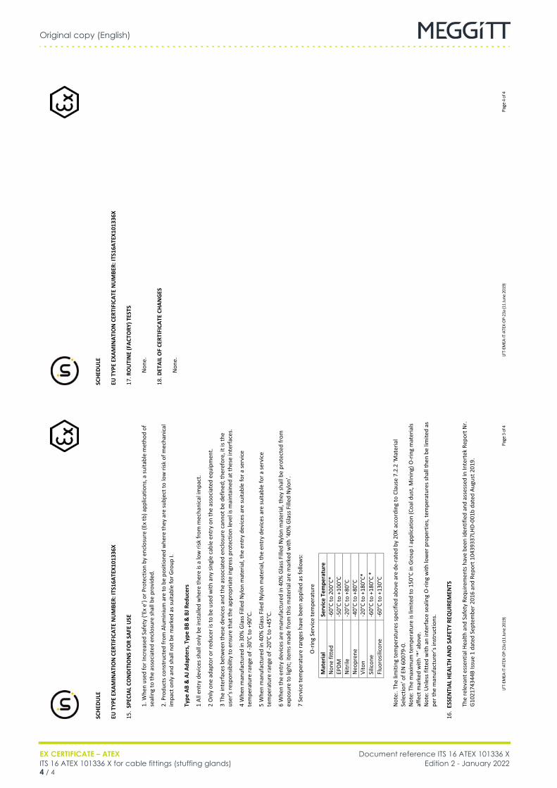
Original copy (English)
EX CERTIFICATE – ATEX Document reference ITS 16 ATEX 101336 XITS 16 ATEX 101336 X for cable fittings (stuffing glands) Edition 2 - January 20224 / 4
Cable fittings
FR ITS 16 ATEX 101336 X (EN) Original copy EN
SC
HED
ULE
EU
TYP
E EX
AMIN
ATIO
N C
ERTI
FICA
TE N
UM
BER:
ITS1
6ATE
X101
336X
LFT-
EMEA
-IT-A
TEX-
OP-2
3a (1
1 Ju
ne 2
019)
Pa
ge 4
of 4
17. R
OU
TIN
E (F
ACTO
RY) T
ESTS
Non
e.
18. D
ETAI
L O
F CE
RTIF
ICAT
E CH
ANG
ES
N
one.
SC
HED
ULE
EU
TYP
E EX
AMIN
ATIO
N C
ERTI
FICA
TE N
UM
BER:
ITS1
6ATE
X101
336X
LFT-
EMEA
-IT-A
TEX-
OP-2
3a (1
1 Ju
ne 2
019)
Pa
ge 3
of 4
15.
SPEC
IAL
CON
DITI
ON
S FO
R SA
FE U
SE
1.
Whe
n us
ed fo
r Inc
reas
ed S
afet
y (‘E
x e’
) or P
rote
ctio
n by
enc
losu
re (E
x tb
) app
licat
ions
, a su
itabl
e m
etho
d of
se
alin
g to
the
asso
ciat
ed e
nclo
sure
shal
l be
prov
ided
. 2.
Pro
duct
s con
stru
cted
from
Alu
min
ium
are
to b
e po
sitio
ned
whe
re th
ey a
re su
bjec
t to
low
risk
of m
echa
nica
l im
pact
onl
y an
d sh
all n
ot b
e m
arke
d as
suita
ble
for G
roup
I.
Type
AB
& A
J Ada
pter
s, T
ype
BB &
BJ R
educ
ers
1
All e
ntry
dev
ices
shal
l onl
y be
inst
alle
d w
here
ther
e is
a lo
w ri
sk fr
om m
echa
nica
l im
pact
. 2
Onl
y on
e ad
apto
r or r
educ
er is
to b
e us
ed w
ith a
ny si
ngle
cab
le e
ntry
on
the
asso
ciat
ed e
quip
men
t.
3 Th
e in
terf
aces
bet
wee
n th
ese
devi
ces a
nd th
e as
soci
ated
enc
losu
re c
anno
t be
defin
ed; t
here
fore
, it i
s the
us
er’s
resp
onsib
ility
to e
nsur
e th
at th
e ap
prop
riate
ingr
ess p
rote
ctio
n le
vel i
s mai
ntai
ned
at th
ese
inte
rfac
es.
4 W
hen
man
ufac
ture
d in
30%
Gla
ss F
illed
Nyl
on m
ater
ial,
the
entr
y de
vice
s are
suita
ble
for a
serv
ice
tem
pera
ture
rang
e of
-30°
C to
+90
°C.
5 W
hen
man
ufac
ture
d in
40%
Gla
ss F
iled
Nyl
on m
ater
ial,
the
entr
y de
vice
s ar
e su
itabl
e fo
r a se
rvic
e te
mpe
ratu
re ra
nge
of -2
0°C
to +
45°C
. 6
Whe
n th
e en
try
devi
ces a
re m
anuf
actu
red
in 4
0% G
lass
Fill
ed N
ylon
mat
eria
l, th
ey sh
all b
e pr
otec
ted
from
ex
posu
re to
ligh
t; ite
ms m
ade
from
this
mat
eria
l are
mar
ked
with
‘40%
Gla
ss F
illed
Nyl
on’.
7
Serv
ice
tem
pera
ture
rang
es h
ave
been
app
lied
as fo
llow
s:
O
-rin
g Se
rvic
e te
mpe
ratu
re
Mat
eria
l Se
rvic
e Te
mpe
ratu
re
Non
e fit
ted
-60°
C to
200
°C*
EPDM
-5
0°C
to +
100°
C N
itrile
-2
0°C
to +
80°C
N
eopr
ene
-4
0°C
to +
80°C
Vi
ton
-2
0°C
to +
180°
C*
Silic
one
-6
0°C
to +
180°
C *
Fluo
rosil
icon
e -6
0°C
to +
130°
C N
ote:
. The
lim
iting
tem
pera
ture
s spe
cifie
d ab
ove
are
de-r
ated
by
20K
acco
rdin
g to
Cla
use
7.2.
2 ‘M
ater
ial
Sele
ctio
n’ o
f EN
600
79-0
. N
ote:
The
max
imum
tem
pera
ture
is li
mite
d to
150
°C in
Gro
up I
appl
icat
ion
(Coa
l dus
t, M
inin
g) O
-rin
g m
ater
ials
affe
ct m
arke
d w
ith ‘*
’ abo
ve.
Not
e: U
nles
s fitt
ed w
ith a
n in
terf
ace
seal
ing
O-r
ing
with
low
er p
rope
rtie
s, te
mpe
ratu
res s
hall
then
be
limite
d as
pe
r the
man
ufac
ture
r’s in
stru
ctio
ns.
16.
ESSE
NTI
AL H
EALT
H A
ND
SAF
ETY
REQ
UIR
EMEN
TS
Th
e re
leva
nt e
ssen
tial H
ealth
and
Saf
ety
Requ
irem
ents
hav
e be
en id
entif
ied
and
asse
ssed
in In
tert
ek R
epor
t Nr.
G10
2174
344B
Issu
e 1
date
d Se
ptem
ber 2
016
and
Repo
rt 1
0439
337L
HD-0
01b
date
d Au
gust
201
9.
DRAFT
EX
ATEX certificate LCIE 02 ATEX 0038 UEdition 1 – September 2018
Meggitt SARoute de Moncor 4
PO Box 16161701 Fribourg
Switzerland
[email protected]/energy
Title Page
ATEX certificate:
LCIE 02 ATEX 0038 U
for
Cable stuffing glands
Although the certificate is available in twolanguages (English and French), the liability of thenotified body applies only on the text of the originalcopy of the certificate that it published.
Bien que le certificat soit traduit dans les 2 langues(Anglais et Français), seul le texte de la copieoriginale du certificat peut engager laresponsabilité de l’organisme notifié qui l’a publié.
EN
FR

THIS PAGE INTENTIONALLY LEFT BLANKCETTE PAGE EST LAISSÉE INTENTIONNELLEMENT VIDE
LCIE 02 ATEX 0038 U 1Edition 1 - September 2018
DRAFT
LCIE 02 ATEX 0038 U (FR, EN)(Original copy)
Cable stuffing glandsLCIE 02 ATEX 0038 U (FR, EN)Cable stuffing glandsENFROriginal copy
DRAFT
LCIE 02 ATEX 0038 U (FR, EN)(Original copy)
Cable stuffing glands
2 LCIE 02 ATEX 0038 UEdition 1 - September 2018
1
LCIE 02 ATEX 0038 U 3Edition 1 - September 2018
DRAFT
LCIE 02 ATEX 0038 U (FR, EN)(Original copy)
Cable stuffing glands
1
DRAFT
LCIE 02 ATEX 0038 U (FR, EN)(Original copy)
Cable stuffing glands
4 LCIE 02 ATEX 0038 UEdition 1 - September 2018
THIS PAGE INTENTIONALLY LEFT BLANKCETTE PAGE EST LAISSÉE INTENTIONNELLEMENT VIDE
DRAFT
EX
ATEX certificate LCIE 03 ATEX 0033 UEdition 1 - July 2015
Meggitt SARoute de Moncor 4
PO Box 1616CH - 1701 Fribourg
Switzerland
www.meggittsensingsystems.comwww.vibro-meter.com
PTB_01_ATEX_1061_U
ATEX certificate:
LCIE 03 ATEX 0033 U
for
Stuffing gland
Although the certificate is available in twolanguages (English and French), the liability of thenotified body applies only on the text of the originalcopy of the certificate that it published.
Bien que le certificat soit traduit dans les 2 langues(Anglais et Français), seul le texte de la copieoriginale du certificat peut engager laresponsabilité de l’organisme notifié qui l’a publié.
EN
FR

THIS PAGE INTENTIONALLY LEFT BLANKCETTE PAGE EST LAISSÉE INTENTIONNELLEMENT VIDE
DIESE SEITE WURDE ABSICHTLICH LEER GELASSEN
LCIE 03 ATEX 0033 U 1Edition 1 - July 2015
DRAFT
LCIE 03 ATEX 0033 U (FR, EN)(Original copy)
Stuffing glandLCIE 03 ATEX 0033 U (FR, EN)Original copyDEDEStuffing glandStuffing gland
1
DRAFT
LCIE 03 ATEX 0033 U (FR, EN)(Original copy)
Stuffing gland
2 LCIE 03 ATEX 0033 UEdition 1 - July 2015
1
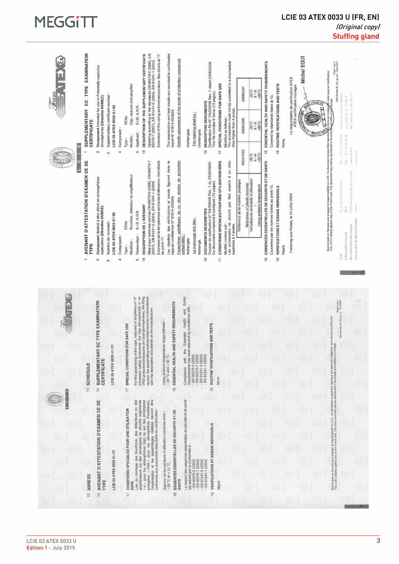
LCIE 03 ATEX 0033 U 3Edition 1 - July 2015
DRAFT
LCIE 03 ATEX 0033 U (FR, EN)(Original copy)
Stuffing gland
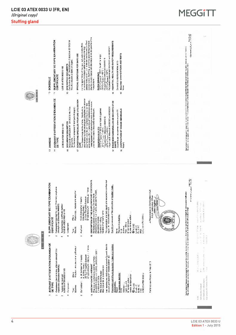
DRAFT
LCIE 03 ATEX 0033 U (FR, EN)(Original copy)
Stuffing gland
4 LCIE 03 ATEX 0033 UEdition 1 - July 2015
DRAFT
EX
ATEX certificate PTB 11 ATEX 1007 XEdition 1 - May 2015
Meggitt SARoute de Moncor 4
PO Box 1616CH - 1701 Fribourg
Switzerland
www.meggittsensingsystems.comwww.vibro-meter.com
PTB_01_ATEX_1061_U
ATEX certificate:
PTB 11 ATEX 1007 X
for
Stuffing gland DE

THIS PAGE INTENTIONALLY LEFT BLANKCETTE PAGE EST LAISSÉE INTENTIONNELLEMENT VIDE
DIESE SEITE WURDE ABSICHTLICH LEER GELASSEN
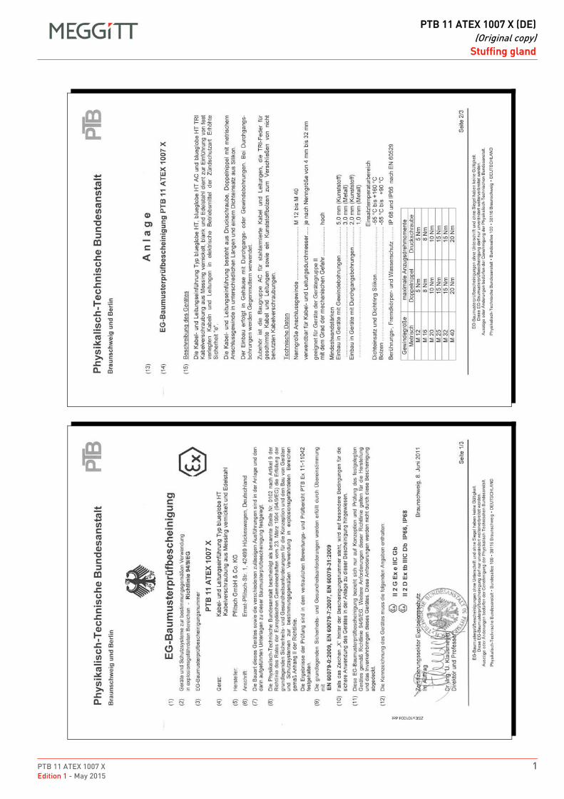
PTB 11 ATEX 1007 X 1Edition 1 - May 2015
DRAFT
PTB 11 ATEX 1007 X (DE)(Original copy)
Stuffing glandPTB 11 ATEX 1007 X (DE)Original copyDEDEStuffing glandStuffing gland
1
DRAFT
PTB 11 ATEX 1007 X (DE)(Original copy)
Stuffing gland
2 PTB 11 ATEX 1007 XEdition 1 - May 2015
DRAFT
EX
ATEX certificate PTB 98 ATEX 3130Edition 1 – September 2018
Meggitt SARoute de Moncor 4
PO Box 16161701 Fribourg
Switzerland
[email protected]/energy
Title Page
ATEX certificate:
PTB 98 ATEX 3130
for
Cable stuffing glands
EN

PTB 98 ATEX 3130 1Edition 1 - September 2018
DRAFT
PTB 98 ATEX 3130 (EN)(Original copy)
Cable stuffing glandsPTB 98 ATEX 3130 (EN)Cable stuffing glandsENOriginal copy
DRAFT
PTB 98 ATEX 3130 (EN)(Original copy)
Cable stuffing glands
2 PTB 98 ATEX 3130Edition 1 - September 2018
1

Meggitt SA, Route de Moncor 4, Case postale, 1701 Fribourg, Switzerland Tel: +41 26 407 1111Fax: +41 26 407 1660
[email protected]/energy
www.meggitt.com
EX CERTIFICATE – ATEX
Document reference SEV 15 ATEX 0151Edition 2 – October 2020
Title page
SEV 15 ATEX 0151for
cable fittings (stuffing glands)
EX
Note: Although the Ex certificate may be included in more than one language, the liability ofthe notified body applies only on the text of the original copy of the certificate that it published.

THIS PAGE INTENTIONALLY LEFT BLANK
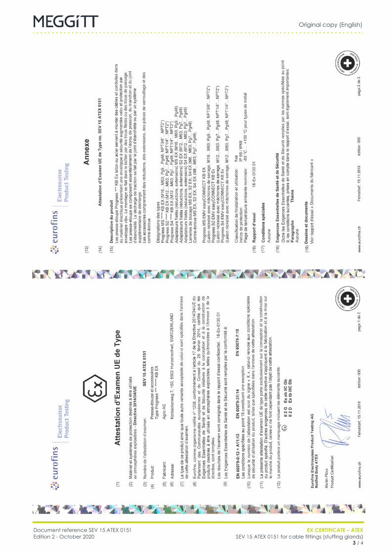
Original copy (English)
Document reference SEV 15 ATEX 0151 EX CERTIFICATE – ATEXEdition 2 - October 2020 SEV 15 ATEX 0151 for cable fittings (stuffing glands)
3 / 4
Cable fittings
FR SEV 15 ATEX 0151 (EN) Original copy EN

Original copy (English)
EX CERTIFICATE – ATEX Document reference SEV 15 ATEX 0151SEV 15 ATEX 0151 for cable fittings (stuffing glands) Edition 2 - October 20204 / 4
THIS PAGE INTENTIONALLY LEFT BLANK
Meggitt SA, Route de Moncor 4, Case postale, 1701 Fribourg, Switzerland Tel: +41 26 407 1111Fax: +41 26 407 1660
[email protected]/energy
www.meggitt.com
EX CERTIFICATE – ATEX
Document reference SEV 15 ATEX 0152 XEdition 3 – October 2020
Title page
SEV 15 ATEX 0152 Xfor
cable fittings (stuffing glands)
EX
Note: Although the Ex certificate may be included in more than one language, the liability ofthe notified body applies only on the text of the original copy of the certificate that it published.

THIS PAGE INTENTIONALLY LEFT BLANK
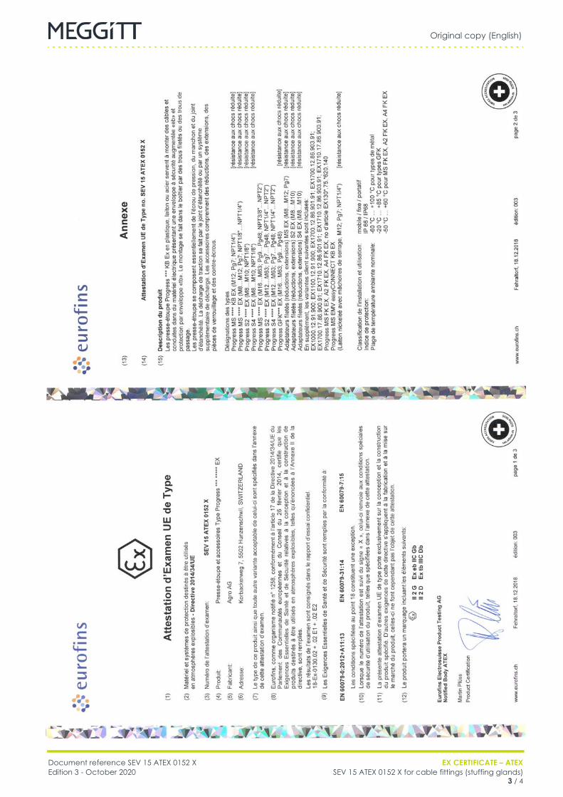
Original copy (English)
Document reference SEV 15 ATEX 0152 X EX CERTIFICATE – ATEXEdition 3 - October 2020 SEV 15 ATEX 0152 X for cable fittings (stuffing glands)
3 / 4
Cable fittings
FR SEV 15 ATEX 0152 X (EN) Original copy EN
Original copy (English)
EX CERTIFICATE – ATEX Document reference SEV 15 ATEX 0152 XSEV 15 ATEX 0152 X for cable fittings (stuffing glands) Edition 3 - October 20204 / 4
Cable fittings
FR SEV 15 ATEX 0152 X (EN) Original copy EN

Document reference MAPROX400/E INSTALLATION MANUALEdition 19 - January 2022 Proximity measurement systems using TQ4xx proximity sensors
C - 1
APPENDIX C: cCSAus CERTIFICATIONS
APPENDIX C: CCSAUS CERTIFICATIONS
Table C-1: Related CCSAUS certificates
Product(s) covered Certificate number
GSI127 CCSAUS 70001999
IQS4xx and TQ4xx CCSAUS 1514309

INSTALLATION MANUAL Document reference MAPROX400/EProximity measurement systems using TQ4xx proximity sensors Edition 19 - January 2022C - 2
APPENDIX C: cCSAus CERTIFICATIONS
THIS PAGE INTENTIONALLY LEFT BLANK

DRAFT
cCSAus certificate 70001999Edition 3 - April 2017
EX
Meggitt SARoute de Moncor 4
PO Box 1616CH - 1701 Fribourg
Switzerland
www.meggittsensingsystems.comwww.vibro-meter.com
Title Page
cCSAus certificate:
70001999
for
GSI 127
EN

THIS PAGE INTENTIONALLY LEFT BLANK
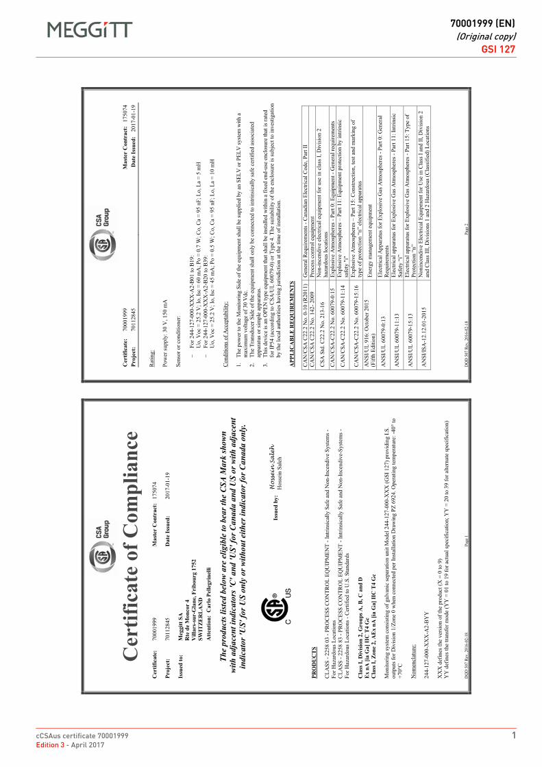
cCSAus certificate 70001999 1Edition 3 - April 2017
DRAFT
70001999 (EN)(Original copy)
GSI 127GSI 127FR 70001999 (EN) Original copy EN
DQ
D 5
07
Rev
. 20
16
-02
-18
Pag
e 1
Cer
tific
ate
of C
ompl
ianc
eC
ertif
icat
e:7
00
01
99
9M
aste
r C
ontr
act:
17
50
74
Proj
ect:
70
11
28
45
Dat
e Is
sued
:2
01
7-0
1-1
9
Issu
ed to
:M
eggi
tt SA
Rte
de
Mon
cor
4V
illar
s-su
r-G
lane
, Fri
bour
g 17
52SW
ITZE
RL
AN
DA
tten
tion:
Car
lo P
elle
grin
elli
The
prod
ucts
list
ed b
elow
are
elig
ible
to b
ear t
he C
SA M
ark
show
nw
ith a
djac
ent i
ndic
ator
s 'C
' and
'US'
for C
anad
a an
d U
S or
with
adj
acen
t in
dica
tor '
US'
for U
S on
ly o
r with
out e
ither
indi
cato
r for
Can
ada
only
.
Issu
ed b
y:H
oss
ein
Sa
leh
Hoss
ein S
aleh
PRO
DU
CT
S
CL
AS
S -
2258 0
3 -
PR
OC
ES
S C
ON
TR
OL
EQ
UIP
ME
NT
-In
trin
sica
lly S
afe
and
No
n-I
nce
nd
ive
Syst
ems
-
Fo
r H
azar
do
us
Lo
cati
on
s
CL
AS
S -
2258 8
3 -
PR
OC
ES
S C
ON
TR
OL
EQ
UIP
ME
NT
-In
trin
sica
lly S
afe
and
No
n-I
nce
nd
ive-
Syst
ems
-
Fo
r H
azar
do
us
Lo
cati
on
s -
Cer
tifi
ed t
o U
.S.
Sta
ndar
ds
Cla
ss I,
Div
ision
2, G
roup
s A, B
, C a
nd D
Ex
nA [i
a G
a] II
C T
4 G
cC
lass
I, Z
one
2, A
Ex
nA [i
a G
a] II
C T
4 G
c
Mo
nit
ori
ng s
yst
em c
on
sist
ing o
f gal
van
ic s
epar
atio
n u
nit
Mo
del
244
-12
7-0
00
-XX
X (
GS
I 1
27
) p
rovid
ing I
.S.
ou
tputs
fo
r D
ivis
ion
1/Z
on
e 0
wh
en c
onn
ecte
d p
er I
nst
alla
tio
n D
raw
ing P
Z 6
92
4.
Op
erat
ing t
emp
erat
ure
: -4
0°
to
+7
0°C
No
men
clat
ure
:
24
4-1
27
-00
0-X
XX
-A2
-BY
Y
XX
X d
efin
es t
he
ver
sio
n o
f th
e pro
duct
(X
= 0
to
9)
YY
def
ines
th
e tr
ansf
er m
od
e (Y
Y =
01
to
19
for
actu
al s
pec
ific
atio
n;
YY
= 2
0 t
o 3
9 f
or
alte
rnat
e sp
ecif
icat
ion
)
Cer
tific
ate:
70
00
19
99
Proj
ect:
70
11
28
45
Mas
ter
Con
trac
t:1
75
07
4
Dat
e Is
sued
:2
01
7-0
1-1
9
DQ
D 5
07
Rev
. 20
16
-02
-18
Pag
e 2
Rat
ing:
Po
wer
su
pp
ly:
30
V,
15
0 m
A
Sen
sor
or
con
dit
ion
er:
�F
or
24
4-1
27
-00
0-X
XX
-A2
-B0
1 t
o B
19
:
Uo
, V
oc
= 2
5.2
V;
Io,
Isc
= 6
0 m
A;
Po
= 0
.7 W
; C
o,
Ca
= 9
5 n
F;
Lo
, L
a =
5 m
H
�F
or
24
4-1
27
-00
0-X
XX
-A2
-B2
0 t
o B
39
:
Uo
, V
oc
= 2
5.2
V;
Io,
Isc
= 4
5 m
A;
Po
=0
.5 W
; C
o,
Ca
= 9
5 n
F;
Lo
, L
a =
10
mH
Co
nd
itio
ns
of
Acc
epta
bil
ity:
1.
Th
e p
ow
er t
o t
he
Mo
nit
ori
ng S
ide
of
the
equ
ipm
ent
shal
l be
supp
lied
by a
n S
EL
V o
r P
EL
V s
yst
em w
ith
a
max
imu
m v
olt
age
of
30
Vdc.
2.
Th
e T
ran
sdu
cer
Sid
e o
f th
e eq
uip
men
t sh
all
only
be
con
nec
ted
to
in
trin
sica
lly s
afe
cert
ifie
d a
sso
ciat
ed
app
arat
us
or
sim
ple
ap
par
atu
s.
3.
This
dev
ice
is a
n O
PE
N t
yp
e eq
uip
men
t th
at s
hal
l be
inst
alle
d w
ith
in a
fix
ed e
nd
-use
encl
osu
re t
hat
is
rate
d
for
IP5
4 (
acco
rdin
g t
o C
SA
/UL
60
07
9-0
) o
r T
yp
e 4
. T
he
suit
abil
ity o
f th
e en
closu
re i
s su
bje
ct t
o i
nves
tigat
ion
by t
he
loca
l au
tho
riti
es h
avin
g j
uri
sdic
tio
n a
t th
e ti
me
of
inst
alla
tio
n.
APP
LIC
AB
LE
REQ
UIR
EME
NT
S
CA
N/C
SA
C22.2
No. 0-1
0 (
R2011)
Gen
eral
Req
uir
emen
ts -
Can
adia
n E
lect
rica
l C
od
e, P
art
II
CA
N/C
SA
C22.2
No. 142
-2009
Pro
cess
con
tro
l eq
uip
men
t
CS
A S
td. C
22.2
No. 21
3-1
6N
on
-in
cen
div
e el
ectr
ical
equ
ipm
ent
for
use
in
cla
ss I
, D
ivis
ion
2
haz
ard
ou
s lo
cati
on
s
CA
N/C
SA
-C22.2
No. 60079-0
:15
Ex
plo
sive
Atm
osp
her
es -
Par
t 0
: E
quip
men
t -
Gen
eral
req
uir
emen
ts
CA
N/C
SA
-C22.2
No. 60079-1
1:1
4E
xp
losi
ve
Atm
osp
her
es –
Par
t 1
1:
Equ
ipm
ent
pro
tect
ion
by i
ntr
insi
c
safe
ty "
i"
CA
N/C
SA
-C22.2
No. 60079-1
5:1
6E
xp
losi
ve
Atm
osp
her
es –
Par
t 1
5:
Con
stru
ctio
n,
test
and
mar
kin
g o
f
type
of p
rote
ctio
n “n
” el
ectri
cal a
ppar
atus
AN
SI/
UL
916:
Oct
ober
2015
(Fif
th E
dit
ion)
En
ergy m
anag
em
ent
equ
ipm
ent
AN
SI/
UL
60
07
9-0
:13
Ele
ctri
cal
Ap
par
atu
s fo
r E
xp
losi
ve
Gas
Atm
osp
her
es -
Par
t 0
: G
ener
al
Req
uir
emen
ts
AN
SI/
UL
60079
-11
:13
Ele
ctri
cal
app
arat
us
for
Exp
losi
ve
Gas
Atm
osp
her
es -
Par
t 1
1:
Intr
insi
c
Safe
ty “
i”
AN
SI/
UL
60079
-15
:13
Ele
ctri
cal
app
arat
us
for
Exp
losi
ve
Gas
Atm
osp
her
es -
Par
t 1
5:
Typ
e of
Prot
ectio
n “n
”
AN
SI/
ISA
-12
.12
.01
-20
15
No
nin
cen
div
e E
lect
rica
l E
qu
ipm
ent
for
Use
in
Cla
ss I
an
d I
I, D
ivis
ion
2
and
Cla
ss I
II,
Div
isio
ns
1 a
nd
2 H
azar
do
us
(Cla
ssif
ied)
Lo
cati
on
s
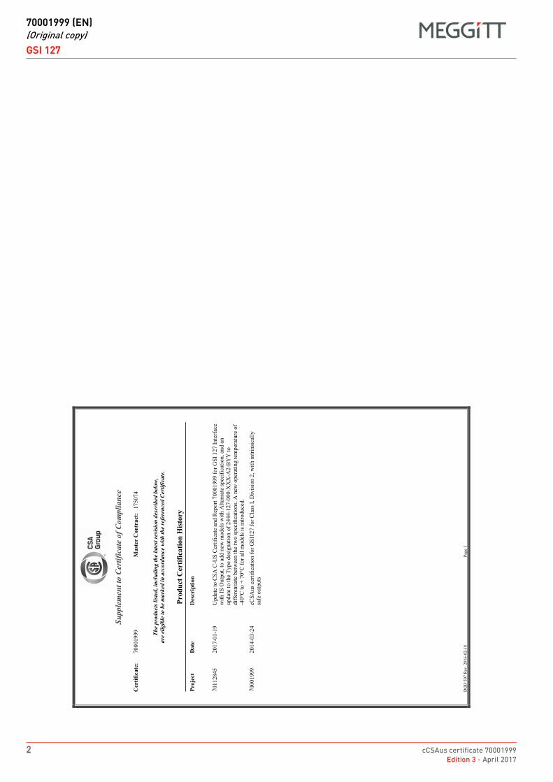
DRAFT
70001999 (EN)(Original copy)
GSI 127
2 cCSAus certificate 70001999Edition 3 - April 2017
GSI 127FR 70001999 (EN) Original copy EN
DQ
D 5
07
Rev
. 20
16
-02
-18
Pag
e 1
Supp
lem
ent t
o C
ertif
icat
e of
Com
plia
nce
Cer
tific
ate:
70
00
19
99
Mas
ter
Con
trac
t:1
75
07
4
The
prod
ucts
list
ed, i
nclu
ding
the
late
st re
visio
n de
scri
bed
belo
w,
are
elig
ible
to b
e m
arke
d in
acc
orda
nce
with
the
refe
renc
ed C
ertif
icat
e.
Prod
uct C
ertif
icat
ion
His
tory
Proj
ect
Dat
eD
escr
iptio
n
70
11
28
45
20
17
-01
-19
Up
dat
e to
CS
A C
-US
Cer
tifi
cate
an
d R
epo
rt 7
00
01
99
9 f
or
GS
I 1
27
In
terf
ace
wit
h I
S O
utp
ut,
to
add
new
mo
del
s w
ith
Alt
ern
ate
spec
ific
atio
n,
and
an
up
dat
e to
the
Typ
e d
esig
nat
ion
of
24
44
-12
7-0
00
-XX
X-A
2-B
YY
to
dif
fere
nti
ate
bet
wee
n t
he
two s
pec
ific
atio
ns.
A n
ew o
per
atin
g t
emp
erat
ure
of
-40
°C t
o +
70
°C f
or
all
mo
del
s is
intr
odu
ced
.
70
00
19
99
20
14
-03
-24
cCS
Au
s ce
rtif
icat
ion
for
GS
I12
7 f
or
Cla
ss I
, D
ivis
ion
2,
wit
h i
ntr
insi
call
y
safe
ou
tpu
ts
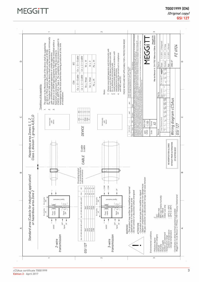
cCSAus certificate 70001999 3Edition 3 - April 2017
DRAFT
70001999 (EN)(Original copy)
GSI 127GSI 127FR 70001999 (EN) Original copy EN
DRAFT
70001999 (EN)(Original copy)
GSI 127
4 cCSAus certificate 70001999Edition 3 - April 2017
THIS PAGE INTENTIONALLY LEFT BLANK
DRAFT
cCSAus certificate 1514309Edition 6 - May 2012
EX
Meggitt SARoute de Moncor 4
PO Box 1616CH - 1701 Fribourg
Switzerland
www.meggittsensingsystems.comwww.vibro-meter.com
Title Page
cCSAus certificate:
1514309
for IQS 4xx and TQ 4xx
EN

THIS PAGE INTENTIONALLY LEFT BLANK
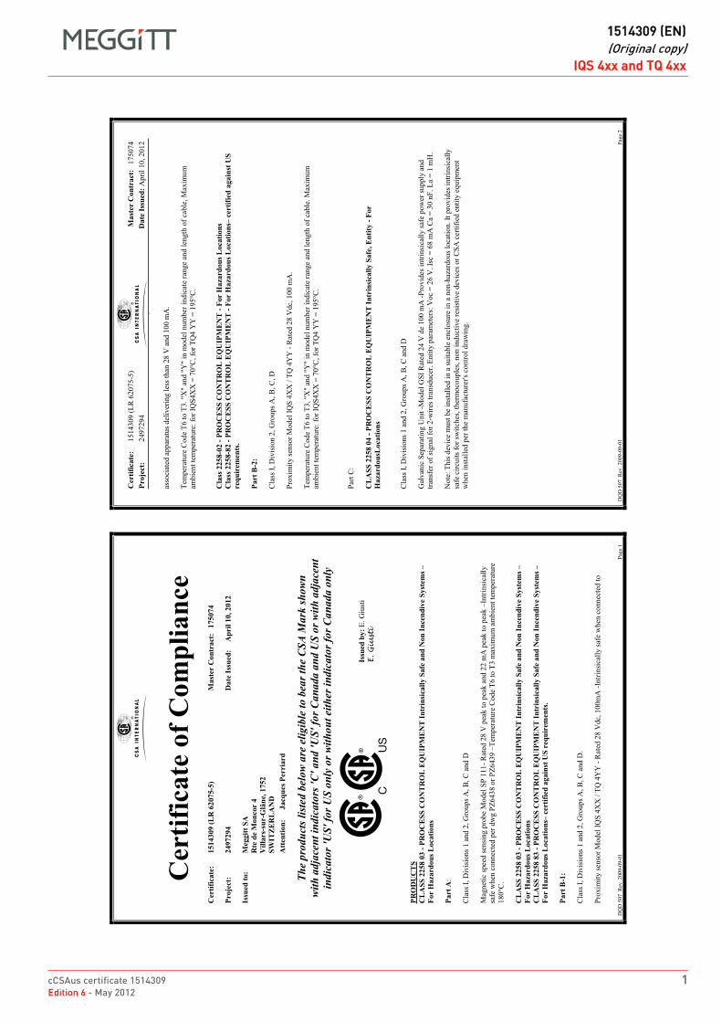
cCSAus certificate 1514309 1Edition 6 - May 2012
DRAFT
1514309 (EN)(Original copy)
IQS 4xx and TQ 4xxIQS 4xx and TQ 4xxFR 1514309 (EN) Original copy EN
FF0
002
DQ
D 5
07
R
ev.
200
9-0
9-0
1
Pag
e 1
Cer
tific
ate
of C
ompl
ianc
e C
ertif
icat
e:
1514
309
(LR
620
75-5
)
Mas
ter
Con
trac
t:
1750
74
Proj
ect:
24
9729
4
Dat
e Is
sued
: A
pril
10, 2
012
Issu
ed to
: M
eggi
tt SA
R
te d
e M
onco
r 4
V
illar
s-su
r-G
lâne
, 175
2
SWIT
ZER
LA
ND
A
tten
tion:
Ja
cque
s Per
riar
d
The
prod
ucts
list
ed b
elow
are
elig
ible
to b
ear t
he C
SA M
ark
show
n w
ith a
djac
ent i
ndic
ator
s 'C
' and
'US'
for C
anad
a an
d U
S or
with
adj
acen
t in
dica
tor '
US'
for U
S on
ly o
r with
out e
ither
indi
cato
r for
Can
ada
only
Issu
ed b
y: E
. G
iust
i E. G
iu
sti
PRO
DU
CT
S C
LA
SS 2
258
03 -
PRO
CE
SS C
ON
TR
OL
EQ
UIP
ME
NT
Intr
insi
cally
Saf
e an
d N
on In
cend
ive
Syst
ems
Fo
r H
azar
dous
Loc
atio
ns
Part
A:
Cla
ss I
, D
ivis
ions
1 a
nd 2
, G
roups
A, B
, C
and D
Mag
net
ic s
pee
d s
ensi
ng p
rob
e M
odel
SP
11
1-
Rat
ed 2
8 V
pea
k t
o p
eak a
nd
22
mA
pea
k t
o p
eak
Intr
insi
call
y
safe
when
con
nec
ted p
er d
wg P
Z6
43
8 o
r P
Z6
43
9
Tem
per
atu
re C
od
e T
6 t
o T
3 m
axim
um
am
bie
nt
tem
per
atu
re
180°C
.
CL
ASS
225
8 03
- PR
OC
ESS
CO
NT
RO
L E
QU
IPM
EN
T In
trin
sica
lly S
afe
and
Non
Ince
ndiv
e Sy
stem
s
For
Haz
ardo
us L
ocat
ions
C
LA
SS 2
258
83 -
PRO
CE
SS C
ON
TR
OL
EQ
UIP
ME
NT
Intr
insi
cally
Saf
e an
d N
on In
cend
ive
Syst
ems
Fo
r H
azar
dous
Loc
atio
ns c
ertif
ied
agai
nst U
S re
quir
emen
ts.
Part
B-1
: C
lass
I,
Div
isio
ns
1 a
nd 2
, G
roups
A, B
, C
and D
.
Pro
xim
ity s
enso
r M
od
el I
QS
4X
X /
TQ
4Y
Y -
Rat
ed 2
8 V
dc,
10
0m
A -
Intr
insi
call
y s
afe
wh
en c
on
nec
ted
to
Cer
tific
ate:
1
51
43
09
(L
R 6
20
75
-5)
Proj
ect:
24
97
29
4
Mas
ter
Con
trac
t: 1
75
07
4
Dat
e Is
sued
: Ap
ril
10
, 2
012
DQ
D 5
07
R
ev.
200
9-0
9-0
1
Pag
e 2
asso
ciat
ed a
pp
arat
us
del
iver
ing l
ess
than
28
V a
nd
10
0 m
A.
Tem
per
atu
re C
od
e T
6 t
o T
3.
"X"
and
"Y
" in
mo
del
num
ber
in
dic
ate
ran
ge
and
len
gth
of
cable
, M
axim
um
amb
ien
t te
mp
erat
ure
: fo
r IQ
S4
XX
= 7
0°C
, fo
r T
Q4
YY
= 1
95
°C.
Cla
ss 2
258-
02 -
PRO
CE
SS C
ON
TR
OL
EQ
UIP
MEN
T -
For
Haz
ardo
us L
ocat
ions
C
lass
225
8-82
- PR
OC
ESS
CO
NT
RO
L E
QU
IPM
ENT
- Fo
r H
azar
dous
Loc
atio
ns c
ertif
ied
agai
nst U
S re
quir
emen
ts.
Part
B-2
: C
lass
I,
Div
isio
n 2
, G
roups
A, B
, C
, D
Pro
xim
ity s
enso
r M
od
el I
QS
4X
X /
TQ
4Y
Y -
Rat
ed 2
8 V
dc,
10
0 m
A.
Tem
per
atu
re C
od
e T
6 t
o T
3,
"X"
and
"Y
" in
mo
del
num
ber
in
dic
ate
ran
ge
and
len
gth
of
cable
. M
axim
um
amb
ien
t te
mp
erat
ure
: fo
r IQ
S4
XX
= 7
0°C
, fo
r T
Q4
YY
= 1
95
°C.
Par
t C
:
CL
ASS
225
8 04
- PR
OC
ESS
CO
NT
RO
L E
QU
IPM
EN
T In
trin
sica
lly S
afe,
Ent
ity -
For
Haz
ardo
usL
ocat
ions
C
lass
I,
Div
isio
ns
1 a
nd 2
, G
roups
A, B
, C
and D
Gal
van
ic S
epar
atin
g U
nit
-M
od
el G
SI
Rat
ed 2
4 V
de
10
0 m
A -
Pro
vid
es i
ntr
insi
call
y s
afe
po
wer
su
pp
ly a
nd
tran
sfer
of
sign
al f
or
2-w
ires
tra
nsd
uce
r. E
nti
ty p
aram
eter
s: V
oc
= 2
6 V
. Is
c =
68
mA
Ca
= 3
0 n
F.
La
= 1
mH
.
No
te:
Th
is d
evic
e m
ust
be
inst
alle
d i
n a
su
itab
le e
ncl
osu
re i
n a
no
n-h
azar
do
us
loca
tio
n. It
pro
vid
es i
ntr
insi
call
y
safe
cir
cuit
s fo
r sw
itch
es, th
erm
oco
up
les,
no
n i
ndu
ctiv
e re
sist
ive
dev
ices
or
CS
A c
ert
ifie
d e
nti
ty e
qu
ipm
ent
wh
en i
nst
alle
d p
er t
he
man
ufa
ctu
rer's
con
tro
l d
raw
ing.
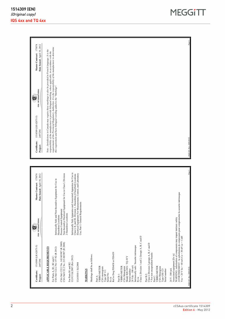
DRAFT
1514309 (EN)(Original copy)
IQS 4xx and TQ 4xx
2 cCSAus certificate 1514309Edition 6 - May 2012
IQS 4xx and TQ 4xxFR 1514309 (EN) Original copy EN
Cer
tific
ate:
1
51
43
09
(L
R 6
20
75
-5)
Proj
ect:
24
97
29
4
Mas
ter
Con
trac
t: 1
75
07
4
Dat
e Is
sued
: Ap
ril
10
, 2
012
DQ
D 5
07
R
ev.
200
9-0
9-0
1
Pag
e 3
APP
LIC
AB
LE
REQ
UIR
EME
NT
S F
or
Par
ts A
, B
1,
B2
an
d C
:
CS
A S
td.
C2
2.2
No
157
-92
(R
20
12)
Intr
insi
call
y S
afe
and
No
n-I
nce
nd
ive
Eq
uip
men
t fo
r U
se i
n
H
azar
dous
Loca
tions
CS
A S
td.
C2
2.2
No
. 14
2-M
19
87
(R
200
9)
P
roce
ss C
ontr
ol
Eq
uip
men
t
CS
A S
td C
22
.2 N
o.
213
-M1
98
7 (
R 2
00
8)
N
on
-In
cen
div
e E
lect
rica
l E
qu
ipm
ent
for
Use
in
Cla
ss I
, D
ivis
ion
2 H
azar
do
us
Lo
cati
on
s
Fo
r P
arts
B1 a
nd
B2:
UL
91
3 E
d.2
00
7 (
Rev
.20
12)
Intr
insi
call
y S
afe
Ap
par
atus
and
Ass
oci
ated
Ap
par
atu
s fo
r U
se i
n
Cla
ss I
, II
, an
d I
II, D
ivis
ion 1
, H
azar
dous
(Cla
ssif
ied)
Loca
tions
UL
61
01
0-1
Ed
.20
04
E
lect
rica
l E
quip
men
t F
or
Mea
sure
men
t, C
ontr
ol,
an
d L
abo
rato
ry
Use
; P
art
1:
Gen
eral
Req
uir
emen
ts
MA
RK
ING
S M
arkin
gs
shal
l b
e as
fo
llo
ws:
Par
t A
:
VIB
RO
-ME
TE
R
CS
A m
onogra
m
Typ
e S
P 1
11
Ser
ial
No
Ex i
a
Ref
to D
wg P
Z6438 o
r P
Z6439
Par
t B
-1:
VIB
RO
-ME
TE
R
CS
A M
onogra
m
Model
IQ
S 4
XX
/ T
Q 4
YY
Ser
ial
nu
mb
er
28
Vdc
- 1
00
mA
Intr
insi
call
y s
afe
/ S
ecu
rite
in
trin
seq
ue
Ex i
a
Cla
ss I
, D
ivis
ion 1
and 2
, G
roups
A, B
, C
and D
Par
t B
-2:
Cla
ss I
, D
ivis
ion 2
gro
ups
A, B
, C
and D
* F
or
no
n e
nca
psu
late
d b
oar
ds:
Par
t C
:
VIB
RO
-ME
TE
R
CS
A M
onogra
m
Type
GS
I 123
Ser
ial
nu
mb
er
24
V-
10
0 m
A
Ass
oci
ated
eq
uip
men
t [E
x i
a]
WA
RN
ING
: su
bst
itu
tio
n o
f co
mp
on
ents
may
im
pai
r in
trin
sic
safe
ty
AV
ER
TIS
SE
ME
NT
: l
a su
bst
ituti
on
de
com
po
san
ts p
eut
com
pro
met
tre
la s
ecu
rite
in
trin
seq
ue
Vo
c =
26
V I
sc =
68
mA
Ca
= 3
0 n
F L
a =
1 m
H
Cer
tific
ate:
1
51
43
09
(L
R 6
20
75
-5)
Proj
ect:
24
97
29
4
Mas
ter
Con
trac
t: 1
75
07
4
Dat
e Is
sued
: Ap
ril
10
, 2
012
DQ
D 5
07
R
ev.
200
9-0
9-0
1
Pag
e 4
No
te -
Ju
risd
icti
on
s in
Ca
na
da
ma
y re
qu
ire
thes
e m
ark
ing
s to
als
o b
e pro
vid
ed i
n F
ren
ch l
an
gu
ag
e. I
t is
th
e re
spo
nsi
bil
ity
of
the
ma
nufa
ctu
rer
to p
rovi
de
bil
ing
ual
ma
rkin
g,
wh
ere
ap
pli
cab
le,
in a
cco
rda
nce
wit
h t
he
req
uir
emen
ts o
f th
e P
rovi
nci
al
Reg
ula
tory
Au
thori
ties
. It
is
the
resp
on
sib
ilit
y of
the
ma
nu
fact
ure
r to
det
erm
ine
this
req
uir
emen
t a
nd
ha
ve b
ilin
gu
al
wo
rdin
g a
dd
ed t
o t
he
"Mark
ing
s".
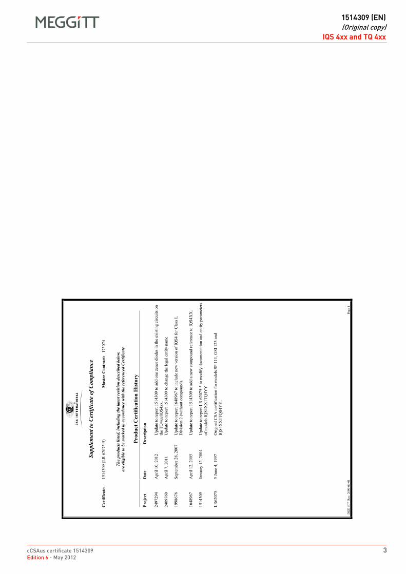
cCSAus certificate 1514309 3Edition 6 - May 2012
DRAFT
1514309 (EN)(Original copy)
IQS 4xx and TQ 4xxIQS 4xx and TQ 4xxFR 1514309 (EN) Original copy EN
DQ
D 5
07
R
ev.
200
9-0
9-0
1
Pag
e 1
Supp
lem
ent t
o C
ertif
icat
e of
Com
plia
nce
Cer
tific
ate:
1
51
43
09
(L
R 6
20
75
-5)
Mas
ter
Con
trac
t:
17
50
74
The
prod
ucts
list
ed, i
nclu
ding
the
late
st re
visio
n de
scri
bed
belo
w,
are
elig
ible
to b
e m
arke
d in
acc
orda
nce
with
the
refe
renc
ed C
ertif
icat
e.
Prod
uct C
ertif
icat
ion
His
tory
Pr
ojec
t D
ate
Des
crip
tion
24
97
29
4
Ap
ril
10
, 2
01
2
Up
dat
e to
rep
ort
15
14
30
9 t
o a
dd
one
zen
er d
iodes
in
th
e ex
isti
ng c
ircu
its
on
the
TQ
4x
x/I
QS
4x
x.
24
09
76
0
Ap
ril
7,
20
11
Up
dat
e to
rep
ort
15
14
30
9 t
o c
han
ge
the
legal
enti
ty n
ame
19
98
67
6
Sep
tem
ber
28
, 2
00
7
Up
dat
e to
rep
ort
16
48
96
7 t
o i
ncl
ud
e n
ew v
ersi
on
of
IQS
4 f
or
Cla
ss I
,
Div
isio
n 2
(w
ith
out
com
po
un
d).
16
48
96
7
Ap
ril
12
, 2
00
5
Up
dat
e to
rep
ort
15
14
30
9 t
o a
dd
a n
ew c
om
po
un
d r
efer
ence
to
IQ
S4
XX
.
15
14
30
9
Jan
uar
y 1
2,
20
04
Up
dat
e to
rep
ort
LR
62
07
5-5
to
mo
dif
y d
ocu
men
tati
on a
nd
enti
ty p
aram
eter
s
of
mo
del
s IQ
S4
XX
1T
Q4
YY
LR
62
07
5
5 J
un
e 4,
19
97
Ori
gin
al C
SA
cer
tifi
cati
on f
or
mo
del
s S
P 1
11
, G
SI
12
3 a
nd
IQS
4X
X1T
QS
4Y
Y.
DRAFT
1514309 (EN)(Original copy)
IQS 4xx and TQ 4xx
4 cCSAus certificate 1514309Edition 6 - May 2012
THIS PAGE INTENTIONALLY LEFT BLANK

Document reference MAPROX400/E INSTALLATION MANUALEdition 19 - January 2022 Proximity measurement systems using TQ4xx proximity sensors
D - 1
APPENDIX D: IECEX CERTIFICATIONS
APPENDIX D: IECEx CERTIFICATIONS
Table D-1: Related IECEx certificates
Product(s) covered Certificate number
ABA160 and JB118 IECEx PTB 08.0003U
ABA161 IECEx PTB 08.0005U
ABA17xIECEx BVS 16.0026U
IECEx PRE 14.0042U
EA4xx, IQS4xx and TQ4xx IECEx LCI 11.0061X
EA4xx, IQS4xx and TQ4xx IECEx LCI 11.0063X
GSI127 IECEx LCIE 13.0026X
Cable fittings(stuffing glands)
IECEx ITS 16.0011X
IECEx ITS 16.0012X
IECEx LCI 10.0009U
IECEx PTB 03.0000
IECEx PTB 11.0019X
IECEx SEV 15.0018
IECEx SEV 15.0019X

INSTALLATION MANUAL Document reference MAPROX400/EProximity measurement systems using TQ4xx proximity sensors Edition 19 - January 2022D - 2
APPENDIX D: IECEX CERTIFICATIONS
THIS PAGE INTENTIONALLY LEFT BLANK
DRAFT
IECEx certificate IECEx PTB 08.0003UEdition 1 - May 2015
EX
Meggitt SARoute de Moncor 4
PO Box 1616CH - 1701 Fribourg
Switzerland
www.meggittsensingsystems.comwww.vibro-meter.com
Title Page
IECEx certificate:
IECEx PTB 08.0003U
for
ABA 15x, ABA 160,JB 116, JB 118 and PA 151
EN

THIS PAGE INTENTIONALLY LEFT BLANK
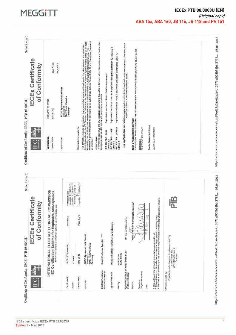
IECEx certificate IECEx PTB 08.0003U 1Edition 1 - May 2015
DRAFT
IECEx PTB 08.0003U (EN)(Original copy)
ABA 15x, ABA 160, JB 116, JB 118 and PA 151ABA 15x, ABA 160, JB 116, JB 118 and PA 151FR IECEx PTB 08.0003U (EN) Original copy EN
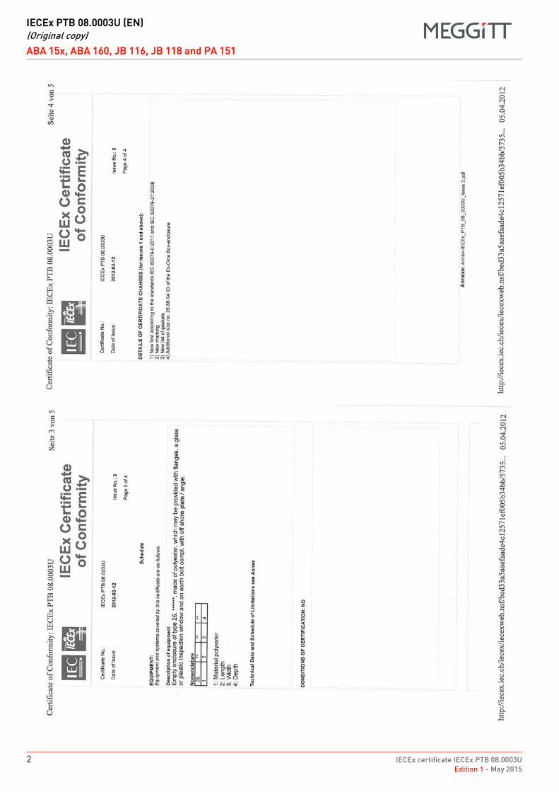
DRAFT
IECEx PTB 08.0003U (EN)(Original copy)
ABA 15x, ABA 160, JB 116, JB 118 and PA 151
2 IECEx certificate IECEx PTB 08.0003UEdition 1 - May 2015
ABA 15x, ABA 160, JB 116, JB 118 and PA 151FR IECEx PTB 08.0003U (EN) Original copy EN
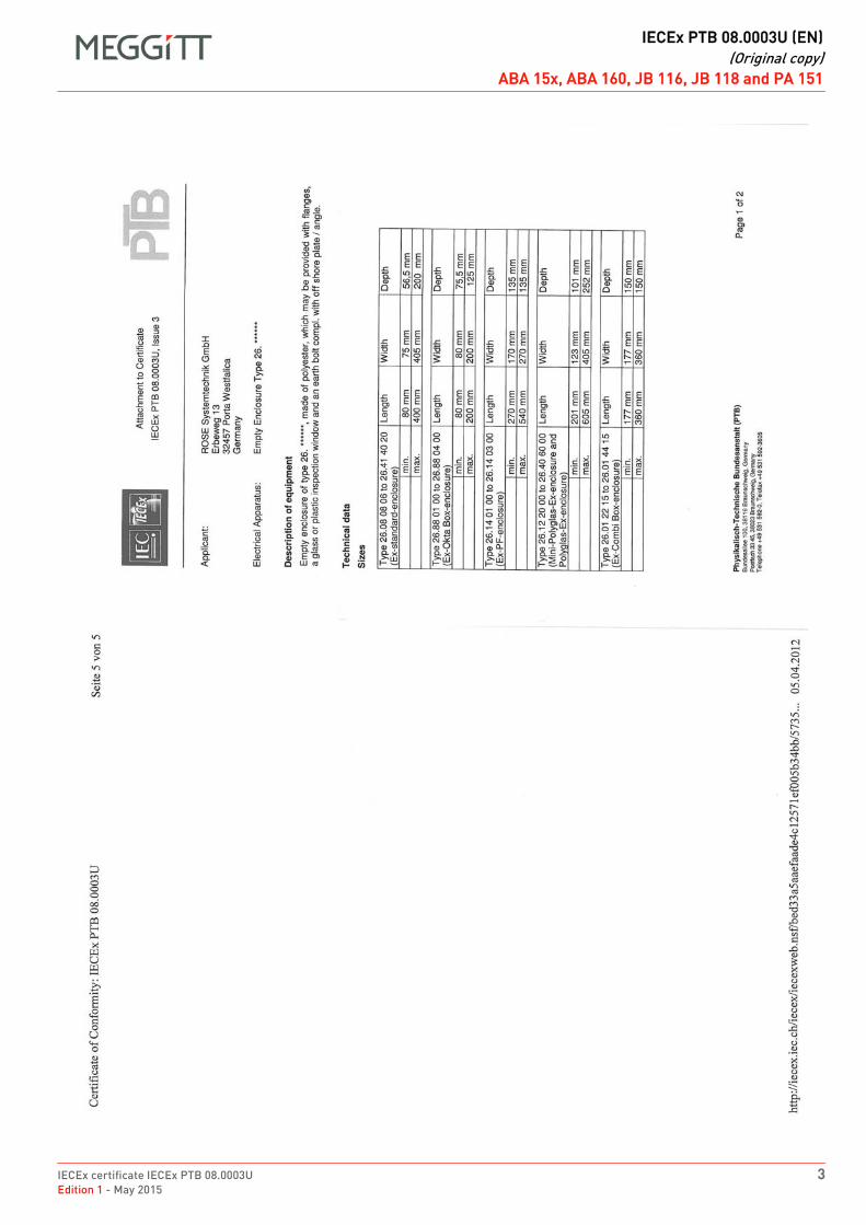
IECEx certificate IECEx PTB 08.0003U 3Edition 1 - May 2015
DRAFT
IECEx PTB 08.0003U (EN)(Original copy)
ABA 15x, ABA 160, JB 116, JB 118 and PA 151ABA 15x, ABA 160, JB 116, JB 118 and PA 151FR IECEx PTB 08.0003U (EN) Original copy EN
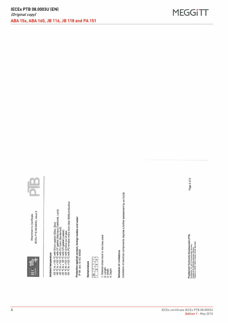
DRAFT
IECEx PTB 08.0003U (EN)(Original copy)
ABA 15x, ABA 160, JB 116, JB 118 and PA 151
4 IECEx certificate IECEx PTB 08.0003UEdition 1 - May 2015
ABA 15x, ABA 160, JB 116, JB 118 and PA 151FR IECEx PTB 08.0003U (EN) Original copy EN

DRAFT
IECEx certificate IECEx PTB 08.0005UEdition 1 - May 2015
EX
Meggitt SARoute de Moncor 4
PO Box 1616CH - 1701 Fribourg
Switzerland
www.meggittsensingsystems.comwww.vibro-meter.com
Title Page
IECEx certificate:
IECEx PTB 08.0005U
for
ABA 161 and PA 150
EN

THIS PAGE INTENTIONALLY LEFT BLANK
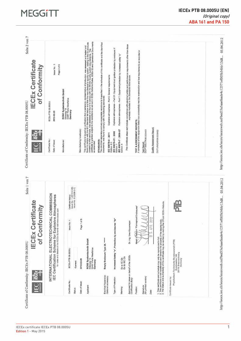
IECEx certificate IECEx PTB 08.0005U 1Edition 1 - May 2015
DRAFT
IECEx PTB 08.0005U (EN)(Original copy)
ABA 161 and PA 150ABA 161 and PA 150FR IECEx PTB 08.0005U (EN) Original copy EN
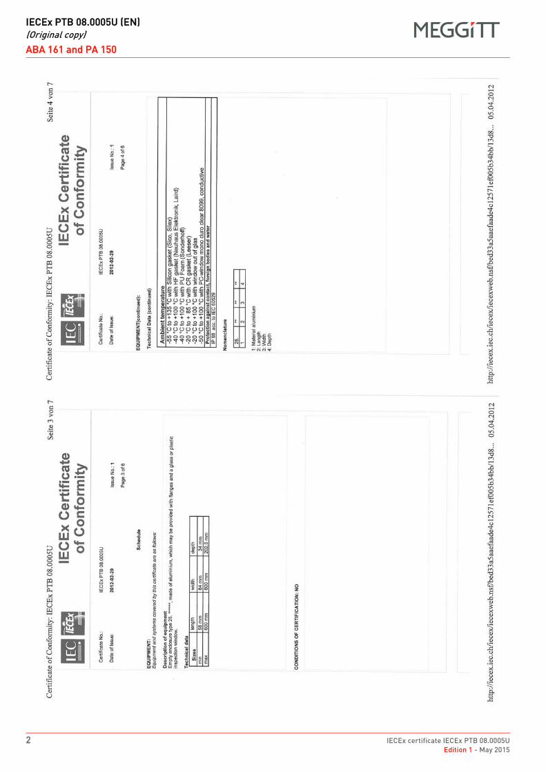
DRAFT
IECEx PTB 08.0005U (EN)(Original copy)
ABA 161 and PA 150
2 IECEx certificate IECEx PTB 08.0005UEdition 1 - May 2015
ABA 161 and PA 150FR IECEx PTB 08.0005U (EN) Original copy EN
IECEx certificate IECEx PTB 08.0005U 3Edition 1 - May 2015
DRAFT
IECEx PTB 08.0005U (EN)(Original copy)
ABA 161 and PA 150ABA 161 and PA 150FR IECEx PTB 08.0005U (EN) Original copy EN

THIS PAGE INTENTIONALLY LEFT BLANK
Meggitt SA, Route de Moncor 4, Case postale, 1701 Fribourg, Switzerland Tel: +41 26 407 1111Fax: +41 26 407 1660
[email protected]/energy
www.meggitt.com
EX CERTIFICATE – IECEx
Document reference IECEx BVS 16.0026UEdition 2 – January 2022
Title page
IECEx BVS 16.0026Ufor
ABA17x industrial housings
EX
Note: Although the Ex certificate may be included in more than one language, the liability ofthe notified body applies only on the text of the original copy of the certificate that it published.

THIS PAGE INTENTIONALLY LEFT BLANK
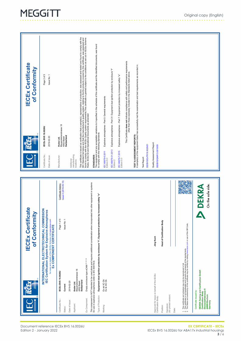
Original copy (English)
Document reference IECEx BVS 16.0026U EX CERTIFICATE – IECExEdition 2 - January 2022 IECEx BVS 16.0026U for ABA17x industrial housings
3 / 6
ABA17x
FR IECEx BVS 16.0026U (EN) Original copy EN
IECEx Certificate
of Conformity
Cer
tific
ate
No.
:IECEx BVS
16.0026U
Dat
e of
issu
e:20
19-0
2-20
Pag
e 2
of 5
Issu
e N
o: 1
Man
ufac
ture
r:thuba Ltd.
Bla
uens
tein
erst
rass
e 16
40
02 B
asel
Switzerland
Add
ition
al
man
ufac
turin
g lo
catio
ns:
This
cer
tific
ate
is is
sued
as
verif
icat
ion
that
a s
ampl
e(s)
, rep
rese
ntat
ive
of p
rodu
ctio
n, w
as a
sses
sed
and
test
ed a
nd fo
und
to c
ompl
y w
ith th
e IE
C S
tand
ard
list b
elow
and
that
the
man
ufac
ture
r's q
ualit
y sy
stem
, rel
atin
g to
the
Ex
prod
ucts
cov
ered
by
this
cer
tific
ate,
was
ass
esse
d an
d fo
und
to c
ompl
y w
ith th
e IE
CE
x Q
ualit
y sy
stem
requ
irem
ents
.Thi
s ce
rtific
ate
is g
rant
ed s
ubje
ct to
the
cond
ition
s as
set
out
in IE
CE
x S
chem
e R
ules
, IE
CE
x 02
and
Ope
ratio
nal D
ocum
ents
as
amen
ded
STANDARDS
:Th
e eq
uipm
ent a
nd a
ny a
ccep
tabl
e va
riatio
ns to
it s
peci
fied
in th
e sc
hedu
le o
f thi
s ce
rtific
ate
and
the
iden
tifie
d do
cum
ents
, was
foun
d to
com
ply
with
the
follo
win
g st
anda
rds
IEC
600
79-0
:201
1 E
ditio
n:6.
0E
xplo
sive
atm
osph
eres
- P
art 0
: Gen
eral
requ
irem
ents
IEC
600
79-3
1:20
13
Edi
tion:
2E
xplo
sive
atm
osph
eres
- P
art 3
1: E
quip
men
t dus
t ign
ition
pro
tect
ion
by e
nclo
sure
"t"
IEC
600
79-7
:201
5 E
ditio
n:5.
0
This
Cer
tific
ate does
not
indi
cate
com
plia
nce
with
saf
ety
and
perfo
rman
ce re
quire
men
ts
othe
r tha
n th
ose
expr
essl
y in
clud
ed in
the
Sta
ndar
ds li
sted
abo
ve.
TEST
& ASSESSMENT REPORTS:
A sa
mpl
e(s)
of t
he e
quip
men
t lis
ted
has
succ
essf
ully
met
the
exam
inat
ion
and
test
requ
irem
ents
as
reco
rded
in:
Test
Rep
ort:
Qua
lity
Ass
essm
ent R
epor
t:
DE
/BV
S/E
xTR
16.0
029/
01
DE
/BV
S/Q
AR
13.0
010/
05
IECEx Certificate
of Conformity
INTERNATIONAL ELECTROTECHNICAL COMMISSION
IEC
Certification System
for Explosive
Atmospheres
for r
ules
and
det
ails
of t
he IE
CE
x S
chem
e vi
sit w
ww
.iece
x.co
mEx COMPONENT CERTIFICATE
Cer
tific
ate
No.
:IECEx BVS
16.0026U
Sta
tus:
Current
Dat
e of
Issu
e:20
19-0
2-20
App
lican
t:thuba Ltd.
Bla
uens
tein
erst
rass
e 16
40
02 B
asel
Switzerland
Ex
Com
pone
nt:
Em
pty
encl
osur
e ty
pe e
CA
M *
* **
**
This
component
is NOT intended
to be used
alone
and
requires additional consideration when incorporated
into
other
equipment or systems
for use
in explosive
atmospheres
(refer
to IEC
60079-0).
Type
of P
rote
ctio
n:Equipment dust ignition
protection by
enclosure
"t", Equipment protection by
increased safety
''e''
Mar
king
:
Pag
e 1
of 5
Issu
e N
o: 1
Cer
tific
ate
hist
ory:
Issu
e 0
(201
6-05
-10)
Ex
eb II
C G
bE
x tb
IIIC
Db
1. 2. 3.App
rove
d fo
r iss
ue o
n be
half
of th
e IE
CE
x C
ertif
icat
ion
Bod
y:
Pos
ition
:
Sig
natu
re:
(for p
rinte
d ve
rsio
n)
Dat
e: This
cer
tific
ate
and
sche
dule
may
onl
y be
repr
oduc
ed in
full.
This
cer
tific
ate
is n
ot tr
ansf
erab
le a
nd re
mai
ns th
e pr
oper
ty o
f the
issu
ing
body
.Th
e S
tatu
s an
d au
then
ticity
of t
his
certi
ficat
e m
ay b
e ve
rifie
d by
vis
iting
ww
w.ie
cex.
com
or u
se o
f thi
s Q
R C
ode.
Cer
tific
ate
issu
ed b
y:
DE
KRA
Testing and Certification GmbH
Certification Body
Dinnendahlstrasse
9
44809 Bochum
Germany
Jörg
Koch
Head of
Certification Body
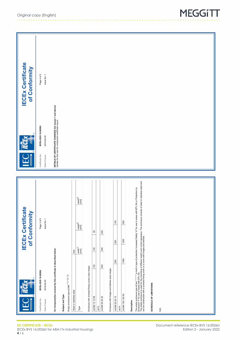
Original copy (English)
EX CERTIFICATE – IECEx Document reference IECEx BVS 16.0026UIECEx BVS 16.0026U for ABA17x industrial housings Edition 2 - January 20224 / 6
ABA17x
FR IECEx BVS 16.0026U (EN) Original copy EN
IECEx Certificate
of Conformity
Cer
tific
ate
No.
:IECEx BVS
16.0026U
Dat
e of
issu
e:20
19-0
2-20
Pag
e 4
of 5
Issu
e N
o: 1
DETAILS
OF CERTIFICATE
CHANGES
(for
issues
1 and
above)
Upd
ate
for t
he n
ew E
x co
mpo
nent
cer
tific
ate
layo
ut.
IECEx Certificate
of Conformity
Cer
tific
ate
No.
:IECEx BVS
16.0026U
Dat
e of
issu
e:20
19-0
2-20
Pag
e 3
of 5
Issu
e N
o: 1
Ex Component(s) covered
by this
certificate is
described
below:
SCHEDULE
OF LIMITATIONS:
Subject
and
Type
Em
pty
encl
osur
e ty
pe e
CA
M **
1) *
*2) *
*3)
size
Type
wid
th1)
[mm
]he
ight
2)
[mm
]de
pth3)
[mm
]
Enc
losu
re w
ith s
crew
ed fi
cov
ers
(siz
e ra
nge)
up to
eCA
M 4
0 40
20
400
400
Enc
losu
re w
ith h
inge
s an
d la
tche
s (s
ize
rang
e)
up to
500
Description
The
empt
y en
clos
ure
type
eC
am *
* **
**
is b
uilt
in ty
pe o
f pro
tect
ion
Incr
ease
d S
afet
y "e
" for
use
in a
reas
with
EP
L G
b or
Pro
tect
ion
by
Enc
losu
re "t
" for
use
in a
reas
with
EP
L D
b.
The
empt
y en
clos
ure
is u
sed
for t
he m
ount
ing
of d
iffer
ent s
witc
h an
d co
ntro
l app
arat
us. T
he e
nclo
sure
con
sist
s of
ste
el o
r sta
inle
ss s
teel
and
ca
n be
con
stru
cted
with
a s
crew
ed fi
cov
er o
r a c
over
with
hin
ges
and
latc
hes.
N/A
Original copy (English)
Document reference IECEx BVS 16.0026U EX CERTIFICATE – IECExEdition 2 - January 2022 IECEx BVS 16.0026U for ABA17x industrial housings
5 / 6
ABA17x
FR IECEx BVS 16.0026U (EN) Original copy EN
IECEx Certificate
of Conformity
Cer
tific
ate
No.
:IECEx BVS
16.0026U
Dat
e of
issu
e:20
19-0
2-20
Pag
e 5
of 5
Issu
e N
o: 1
Additional
information:
Parameters
-55
°C u
p to
+10
0 °C
IP p
rote
ctio
n de
gree
IP66

Original copy (English)
EX CERTIFICATE – IECEx Document reference IECEx BVS 16.0026UIECEx BVS 16.0026U for ABA17x industrial housings Edition 2 - January 20226 / 6
THIS PAGE INTENTIONALLY LEFT BLANK

DRAFT
IECEx certificate IECEx PRE 14.0042UEdition 1 - May 2015
EX
Meggitt SARoute de Moncor 4
PO Box 1616CH - 1701 Fribourg
Switzerland
www.meggittsensingsystems.comwww.vibro-meter.com
Title Page
IECEx certificate:
IECEx PRE 14.0042U
for
ABA 17x
EN

THIS PAGE INTENTIONALLY LEFT BLANK
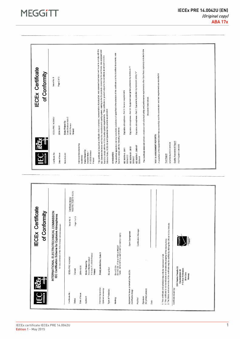
IECEx certificate IECEx PRE 14.0042U 1Edition 1 - May 2015
DRAFT
IECEx PRE 14.0042U (EN)(Original copy)
ABA 17xABA 17xFR IECEx PRE 14.0042U (EN) Original copy EN
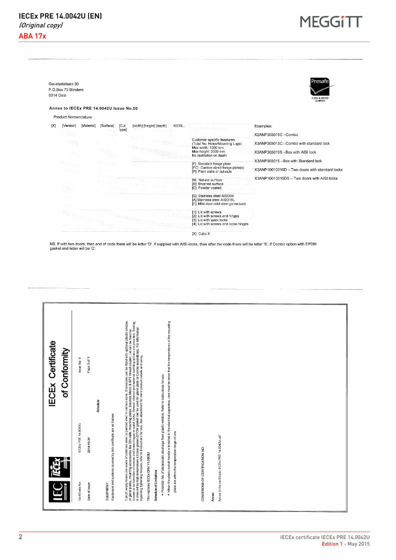
DRAFT
IECEx PRE 14.0042U (EN)(Original copy)
ABA 17x
2 IECEx certificate IECEx PRE 14.0042UEdition 1 - May 2015
ABA 17xFR IECEx PRE 14.0042U (EN) Original copy EN
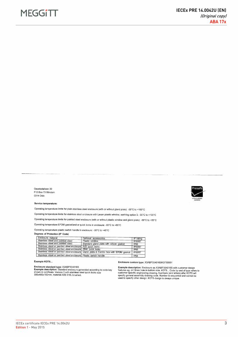
IECEx certificate IECEx PRE 14.0042U 3Edition 1 - May 2015
DRAFT
IECEx PRE 14.0042U (EN)(Original copy)
ABA 17xABA 17xFR IECEx PRE 14.0042U (EN) Original copy EN

THIS PAGE INTENTIONALLY LEFT BLANK
DRAFT
IECEx certificate IECEx LCI 11.0061XEdition 3 - December 2015
EX
Meggitt SARoute de Moncor 4
PO Box 1616CH - 1701 Fribourg
Switzerland
www.meggittsensingsystems.comwww.vibro-meter.com
Title Page
IECEx certificate:
IECEx LCI 11.0061X
for EA 4xx, IQS 4xxand TQ 4xx
EN

THIS PAGE INTENTIONALLY LEFT BLANK
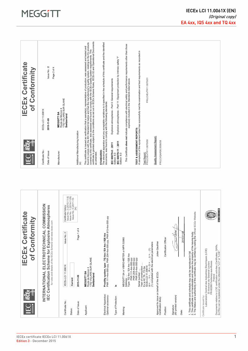
IECEx certificate IECEx LCI 11.0061X 1Edition 3 - December 2015
DRAFT
IECEx LCI 11.0061X (EN)(Original copy)
EA 4xx, IQS 4xx and TQ 4xxEA 4xx, IQS 4xx and TQ 4xxFR IECEx LCI 11.0061X (EN) Original copy EN

DRAFT
IECEx LCI 11.0061X (EN)(Original copy)
EA 4xx, IQS 4xx and TQ 4xx
2 IECEx certificate IECEx LCI 11.0061XEdition 3 - December 2015
EA 4xx, IQS 4xx and TQ 4xxFR IECEx LCI 11.0061X (EN) Original copy EN

DRAFT
IECEx certificate IECEx LCI 11.0063XEdition 2 - August 2014
EX
Meggitt SARoute de Moncor 4
PO Box 1616CH - 1701 Fribourg
Switzerland
www.meggittsensingsystems.comwww.vibro-meter.com
Title Page
IECEx certificate:
IECEx LCI 11.0063X
for EA 4xx, IQS 4xxand TQ 4xx
EN

THIS PAGE INTENTIONALLY LEFT BLANK
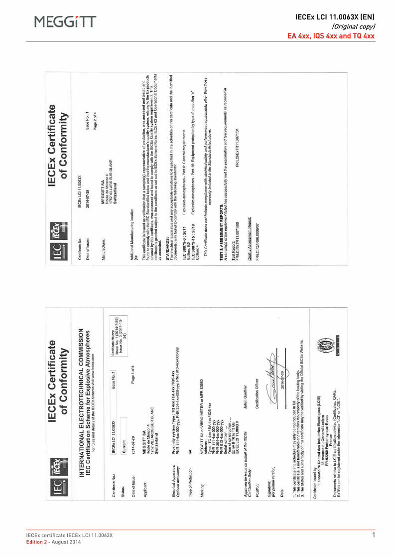
IECEx certificate IECEx LCI 11.0063X 1Edition 2 - August 2014
DRAFT
IECEx LCI 11.0063X (EN)(Original copy)
EA 4xx, IQS 4xx and TQ 4xxEA 4xx, IQS 4xx and TQ 4xxFR IECEx LCI 11.0063X (EN) Original copy EN

DRAFT
IECEx LCI 11.0063X (EN)(Original copy)
EA 4xx, IQS 4xx and TQ 4xx
2 IECEx certificate IECEx LCI 11.0063XEdition 2 - August 2014
EA 4xx, IQS 4xx and TQ 4xxFR IECEx LCI 11.0063X (EN) Original copy EN
DRAFT
IECEx certificate IECEx LCIE 13.0026XEdition 2 - April 2017
EX
Meggitt SARoute de Moncor 4
PO Box 1616CH - 1701 Fribourg
Switzerland
www.meggittsensingsystems.comwww.vibro-meter.com
Title Page
IECEx certificate:
IECEx LCIE 13.0026X
for
GSI 127
EN

THIS PAGE INTENTIONALLY LEFT BLANK
IECEx certificate IECEx LCIE 13.0026X 1Edition 2 - April 2017
DRAFT
IECEx LCIE 13.0026X (EN)(Original copy)
GSI 127GSI 127FR IECEx LCIE 13.0026X (EN) Original copy EN
����
����
��
DRAFT
IECEx LCIE 13.0026X (EN)(Original copy)
GSI 127
2 IECEx certificate IECEx LCIE 13.0026XEdition 2 - April 2017
GSI 127FR IECEx LCIE 13.0026X (EN) Original copy EN
IECEx certificate IECEx LCIE 13.0026X 3Edition 2 - April 2017
DRAFT
IECEx LCIE 13.0026X (EN)(Original copy)
GSI 127GSI 127FR IECEx LCIE 13.0026X (EN) Original copy EN
�
���
����
��
����
� �
���
���
���
���
����
����
����
���
�����
��
�
� �
�� �
���
�� �
����
�� �
���
���
� ��
���
���
����
����
��!
�����
��
���
�����
� �
���
��
��
���
� ��
!�#!
��$�
�� ��
���
����!
���
��
����
�$�
�� �
���
�%�
<>?
����
>@�\
^?
_ �
` ?
��% �
�
� ���
���
���
���
��!
�"#
����
��$
�%
�"��
��
�
��#�
���
���
����{
�&
&(��
)(��
�(��
�(�
�(*
++��
@@
@ ��
�����
���
��!�
���
�� ��
� #!
��$�
� |@
} �
�� ~
�% �
� ��
�����
���
�!��
��! �
���
|��
} ��
�� �
~ ��
! ��
$� �
#���
����
����
��
} ��
�� �
~ ��
! ���
!��
� �#
�����
����
��%
�� �
!��!
�� �
����!
����
�� ��
� ��
� �#
�����
����
��� �
�� ��
#� �
� #!�
�$��
�� �
�����
��
� ��
����
�{
�
��$
� �#�
�����
���
�{ �
``��
����
���@
@@�
���
���
�� �
�~
�
���!�
��
�#��
����
����{
�``
����
����
�@@
@��
���
�� ��
��~
��
� ��
���!�
���
����
���
����
� �#
�����
����
�� ��
���
� ��
���
��!�
���
���
#���
�� �
�$�
� �
����$
� ���
����
����
�� �
!����
� �
��#�
����
� #
!� ���
� ��
#!��
���
��!�
$�� �
�!�
% �
��! �
�$
� |��
�!��
�� !�
�%
� ��
�� !�
�% �
� �
���
����
��~�
��%
#�
%,
��.
�
_>
��
���
��
�! �
��?
^�_
>�>
? �
! _\?
��~
��
�
��!�
��{ %
%% ��
#�{ �
``��
����
���@
@@�
���
��
�
��!
�� �
$���
!{ %%%
��!
�� �
����
!$��
���{
�
>�
�� ��
�
� ��
< �
` �
�
�><
>�
�<�>
��%
����
@
���!
�$#
#��
{ �
��
�� �
�
�� �
� �
����
! �! �
����
�����
! {
\�! �
``��
����
���@
@@�
���
���
�� �
�~{ �
�{ ��
%� �
� ��{
�� �
�� �
�{ �%
� �
� ��{
~� �
\� �
�{ �
��
\�
! �``
����
����
�@@
@��
���
�� ��
��~
{ ��{
��%�
�� �
�{ `�
���
��{
�%�
�� �
�{ ~�
�\�
��{
�� �
�
%�
���
.$�
��
�! �
$##�
�{ �
�
� �
� �
���
��
���
��! �
! ���
�����
��!{
� \�!
�``
����
����
�@@
@��
���
�� ��
��~
{ ��{
��%�
�� �
�{ ��
���
��{
�%�
�� �
�{ ~�
�\�
��{
� �
�
� \�!
�``
����
����
�@@
@��
���
�� ��
��~
{ ��{
��%�
�� �
�{ `�
���
��{
�%�
�� �
�{ ~�
�\�
��{
�� �
�
%�
!��
���
��$�
�>
��
�!��
��!�
�! �
� ��
�� �
� �$
�����
�� ��
���
����
!�� �
�!���
�� ��
�� $
���!
����
���
���
�� �
���
�� �
����
��
##�
���
����
���
���
#!��
!�
���
����
��
���
����
��!
� �
����
���
�$!��
� �
���
� ��
� ��
��
�!�
���
����
��
$��
��%�
�� �
><
���
�~��
�{��
�� >
�% �
��
��
!�%
DRAFT
IECEx LCIE 13.0026X (EN)(Original copy)
GSI 127
4 IECEx certificate IECEx LCIE 13.0026XEdition 2 - April 2017
THIS PAGE INTENTIONALLY LEFT BLANK

Meggitt SA, Route de Moncor 4, Case postale, 1701 Fribourg, Switzerland Tel: +41 26 407 1111Fax: +41 26 407 1660
[email protected]/energy
www.meggitt.com
EX CERTIFICATE – IECEx
Document reference IECEx ITS 16.0011XEdition 2 – January 2022
Title page
IECEx ITS 16.0011Xfor
cable fittings (stuffing glands)
EX
Note: Although the Ex certificate may be included in more than one language, the liability ofthe notified body applies only on the text of the original copy of the certificate that it published.

THIS PAGE INTENTIONALLY LEFT BLANK
Original copy (English)
Document reference IECEx ITS 16.0011X EX CERTIFICATE – IECExEdition 2 - January 2022 IECEx ITS 16.0011X for cable fittings (stuffing glands)
3 / 6
Cable fittings
FR IECEx ITS 16.0011X (EN) Original copy EN
IECEx Certificate
of Conformity
Cer
tific
ate
No.
:IECEx ITS
16.0011X
Dat
e of
issu
e:20
19-0
8-06
Pag
e 2
of 6
Issu
e N
o: 2
IECEx Certificate
of Conformity
INTERNATIONAL ELECTROTECHNICAL COMMISSION
IEC
Certification System
for Explosive
Atmospheres
for r
ules
and
det
ails
of t
he IE
CE
x S
chem
e vi
sit w
ww
.iece
x.co
m
Cer
tific
ate
No.
:IECEx ITS
16.0011X
Sta
tus:
Current
Dat
e of
Issu
e:20
19-0
8-06
App
lican
t:Eaton
Electrical Systems Ltd Trading as
Raxton or
Redapt
Kin
gsw
ay S
outh
W
estg
ate
Ald
ridge
W
est M
idla
nds
WS
9 8F
S
United
Kingdom
Equ
ipm
ent:
Gland
Adaptors,
Reducers and Earthlead
Adaptors
Opt
iona
l acc
esso
ry:
Type
of P
rote
ctio
n:Ex db
Ex eb
and
Ex tb
Mar
king
:
Pag
e 1
of 6
Issu
e N
o: 2
Cer
tific
ate
hist
ory:
Issu
e 1
(201
9-02
-25)
Issu
e 0
(201
7-03
-17)
IEC
Ex
ITS
16.
0011
X
Adaptors,
Types
BB
and
BJ Gland
Reducers and DG
and
DN
Earthlead
Adaptors and Reducers
Ex
db I/
IIC M
b/G
bE
x eb
I/IIC
Mb/
Gb
Ex
tb II
I C D
b IP
6X
Ta =
see
sch
edul
e
Type
AB
& AJ Adapters,
Type BB
& BJ Reducers
Ex
eb II
C G
b, E
x tb
IIIC
Db
IP 6
6
1. 2. 3.App
rove
d fo
r iss
ue o
n be
half
of th
e IE
CE
x C
ertif
icat
ion
Bod
y:
Pos
ition
:
Sig
natu
re:
(for p
rinte
d ve
rsio
n)
Dat
e: This
cer
tific
ate
and
sche
dule
may
onl
y be
repr
oduc
ed in
full.
This
cer
tific
ate
is n
ot tr
ansf
erab
le a
nd re
mai
ns th
e pr
oper
ty o
f the
issu
ing
body
.Th
e S
tatu
s an
d au
then
ticity
of t
his
certi
ficat
e m
ay b
e ve
rifie
d by
vis
iting
ww
w.ie
cex.
com
or u
se o
f thi
s Q
R C
ode.
Cer
tific
ate
issu
ed b
y:
Intertek
Testing
& Certification Limited
ITS
House, Cleeve Road
Leatherhead
Surrey,
KT22 7SA
United
Kingdom
V K
Varma
Certification Officer
Original copy (English)
EX CERTIFICATE – IECEx Document reference IECEx ITS 16.0011XIECEx ITS 16.0011X for cable fittings (stuffing glands) Edition 2 - January 20224 / 6
Cable fittings
FR IECEx ITS 16.0011X (EN) Original copy EN
IECEx Certificate
of Conformity
Cer
tific
ate
No.
:IECEx ITS
16.0011X
Dat
e of
issu
e:20
19-0
8-06
Pag
e 4
of 6
Issu
e N
o: 2
EQUIPMENT:
E
quip
men
t and
sys
tem
s co
vere
d by
this
Cer
tific
ate
are
as fo
llow
s:
SPECIFIC
CONDITIONS
OF USE: YES
as shown below:
an e
xist
ing
cabl
e en
try a
pertu
re, i
n th
e as
soci
ated
app
arat
us, t
o a
diffe
rent
thre
ad fo
rm a
nd/o
r siz
e. E
ach
devi
ce c
ompr
ises
a h
ollo
w b
ody
with
a
mal
e th
read
at o
ne e
nd a
nd a
fem
ale
thre
ad a
t the
oth
er. E
ntry
thre
ads
are
betw
een
M12
and
M12
0. (M
16 to
M75
for G
lass
Fille
d N
ylon
and
M
20 to
M32
for D
G/D
N)
The
Type
AR
and
BJ
Mal
e/M
ale
Ada
ptor
and
Typ
es A
U a
nd A
X F
emal
e/Fe
mal
e A
dapt
ors
have
thre
ad fo
rms
of b
etw
een
M12
and
M12
0.
redu
ctio
n. T
ype
desi
gnat
ions
det
erm
ine
thre
ad c
ombi
natio
ns a
nd b
ody
prof
iles.
Mat
eria
l Opt
ions
Bra
ss to
BS
287
4
Bra
ss B
S 2
872
Sta
inle
ss S
teel
Mild
Ste
el
Alu
min
ium
Bro
nze
30 %
Gla
ss F
illed
Nyl
on
40%
Gla
ss F
illed
Nyl
on
Sur
face
Coa
ting:
Nic
kel,
Zinc
, Ele
ctro
less
Nic
kel
Thre
ad O
ptio
ns
Met
ric to
BS
364
3
ET
Con
duit
to B
S 3
1
PG
to D
IN 4
0430
BS
PP
to B
S 2
779
BS
PT
to B
S 2
1
NP
T to
AN
SI/A
SM
E B
1.20
.1
In a
dditi
on, a
ny o
ther
thre
ad fo
rm th
at a
lso
com
plie
s w
ith th
e re
quire
men
ts o
f IE
C 6
0079
-1 ta
bles
3 o
r 4 a
nd c
laus
e C
2.2
(as
appl
icab
le) a
re
also
per
mitt
ed
Con
ditio
ns o
f man
ufac
ture
1. T
he fe
mal
e th
read
s of
ada
ptor
s sh
all b
e re
stric
ted
to o
ne s
ize
larg
er th
an th
e m
ale
thre
ad s
ize.
3. T
hese
pro
duct
s sh
all b
e m
arke
d in
acc
orda
nce
with
the
info
rmat
ion
as s
peci
fied
in th
is c
ertif
icat
e an
d re
late
d re
ports
.
encl
osur
e sh
all b
e pr
ovid
ed.
IECEx Certificate
of Conformity
Cer
tific
ate
No.
:IECEx ITS
16.0011X
Dat
e of
issu
e:20
19-0
8-06
Pag
e 3
of 6
Issu
e N
o: 2
Man
ufac
ture
r:Eaton
Electrical Systems Ltd Trading as
Raxton or
Redapt
Kin
gsw
ay S
outh
W
estg
ate
Ald
ridge
W
est M
idla
nds
WS
9 8F
S
United
Kingdom
Add
ition
al
man
ufac
turin
g lo
catio
ns:
This
cer
tific
ate
is is
sued
as
verif
icat
ion
that
a s
ampl
e(s)
, rep
rese
ntat
ive
of p
rodu
ctio
n, w
as a
sses
sed
and
test
ed a
nd fo
und
to c
ompl
y w
ith th
e IE
C S
tand
ard
list b
elow
and
that
the
man
ufac
ture
r's q
ualit
y sy
stem
, rel
atin
g to
the
Ex
prod
ucts
cov
ered
by
this
cer
tific
ate,
was
ass
esse
d an
d fo
und
to c
ompl
y w
ith th
e IE
CE
x Q
ualit
y sy
stem
requ
irem
ents
.Thi
s ce
rtific
ate
is g
rant
ed s
ubje
ct to
the
cond
ition
s as
set
out
in IE
CE
x S
chem
e R
ules
, IE
CE
x 02
and
Ope
ratio
nal D
ocum
ents
as
amen
ded
STANDARDS
:Th
e eq
uipm
ent a
nd a
ny a
ccep
tabl
e va
riatio
ns to
it s
peci
fied
in th
e sc
hedu
le o
f thi
s ce
rtific
ate
and
the
iden
tifie
d do
cum
ents
, was
foun
d to
com
ply
with
the
follo
win
g st
anda
rds
IEC
600
79-0
:201
1 E
ditio
n:6.
0E
xplo
sive
atm
osph
eres
- P
art 0
: Gen
eral
requ
irem
ents
IEC
600
79-1
:201
4-06
E
ditio
n:7.
0E
xplo
sive
atm
osph
eres
- P
art 1
: Equ
ipm
ent p
rote
ctio
n by
flam
epro
of e
nclo
sure
s "d
"
IEC
600
79-3
1:20
13
Edi
tion:
2E
xplo
sive
atm
osph
eres
- P
art 3
1: E
quip
men
t dus
t ign
ition
pro
tect
ion
by e
nclo
sure
"t"
IEC
600
79-7
:201
5 E
ditio
n:5.
0
This
Cer
tific
ate does
not
indi
cate
com
plia
nce
with
saf
ety
and
perfo
rman
ce re
quire
men
ts
othe
r tha
n th
ose
expr
essl
y in
clud
ed in
the
Sta
ndar
ds li
sted
abo
ve.
TEST
& ASSESSMENT REPORTS:
A sa
mpl
e(s)
of t
he e
quip
men
t lis
ted
has
succ
essf
ully
met
the
exam
inat
ion
and
test
requ
irem
ents
as
reco
rded
in:
Test
Rep
orts
:
Qua
lity
Ass
essm
ent R
epor
ts:
GB
/ITS
/ExT
R16
.001
3/00
GB
/ITS
/ExT
R16
.001
3/01
GB
/ITS
/ExT
R16
.001
3/02
GB
/SIR
/QA
R06
.001
4/08
GB
/SIR
/QA
R07
.001
6/06
Original copy (English)
Document reference IECEx ITS 16.0011X EX CERTIFICATE – IECExEdition 2 - January 2022 IECEx ITS 16.0011X for cable fittings (stuffing glands)
5 / 6
Cable fittings
FR IECEx ITS 16.0011X (EN) Original copy EN
IECEx Certificate
of Conformity
Cer
tific
ate
No.
:IECEx ITS
16.0011X
Dat
e of
issu
e:20
19-0
8-06
Pag
e 6
of 6
Issu
e N
o: 2
DETAILS
OF CERTIFICATE
CHANGES
(for
issues
1 and
above)
as a
uni
vers
al ty
pe c
ertif
ied
to E
x db
, Ex
eb a
nd E
x tb
IECEx Certificate
of Conformity
Cer
tific
ate
No.
:IECEx ITS
16.0011X
Dat
e of
issu
e:20
19-0
8-06
Pag
e 5
of 6
Issu
e N
o: 2
2. P
rodu
cts
cons
truct
ed fr
om A
lum
iniu
m a
re to
be
posi
tione
d w
here
they
are
sub
ject
to lo
w ri
sk o
f mec
hani
cal i
mpa
ct o
nly
and
shal
l not
be
mar
ked
as s
uita
ble
for G
roup
I
. 1 A
ll en
try d
evic
es s
hall
only
be
inst
alle
d w
here
ther
e is
a lo
w ri
sk fr
om m
echa
nica
l im
pact
.
2 O
nly
one
adap
tor o
r red
ucer
is to
be
used
with
any
sin
gle
cabl
e en
try o
n th
e as
soci
ated
equ
ipm
ent.
the
appr
opria
te in
gres
s pr
otec
tion
leve
l is
mai
ntai
ned
at th
ese
inte
rface
s.
4 W
hen
man
ufac
ture
d in
30%
Gla
ss F
illed
Nyl
on m
ater
ial,
the
entry
dev
ices
are
sui
tabl
e fo
r a s
ervi
ce te
mpe
ratu
re ra
nge
of -3
0°C
to +
90°C
.
5 W
hen
man
ufac
ture
d in
40%
Gla
ss F
illed
Nyl
on m
ater
ial,
the
entry
dev
ices
are
sui
tabl
e fo
r a s
ervi
ce te
mpe
ratu
re ra
nge
of -2
0°C
to +
45°C
6 W
hen
the
entry
dev
ices
are
man
ufac
ture
d in
40%
Gla
ss F
illed
Nyl
on m
ater
ial,
they
sha
ll be
pro
tect
ed fr
om e
xpos
ure
to li
ght;
item
s m
ade
7 S
ervi
ce te
mpe
ratu
re ra
nges
hav
e be
en a
pplie
d as
follo
ws:
O-r
ing
Ser
vice
tem
pera
ture
Non
e fit
ted
-60°
C to
200
°C *
EP
DM
-50°
C to
+10
0°C
Nitr
ile -2
0°C
to +
80°C
Neo
pren
e -4
0°C
to +
80°C
Vito
n -2
0°C
to +
180°
C *
Silic
one
-60°
C to
+18
0°C
*
Fluo
rosi
licon
e -6
0°C
to +
130°
C
Note:.
Note:
Note:
inst
ruct
ions
Original copy (English)
EX CERTIFICATE – IECEx Document reference IECEx ITS 16.0011XIECEx ITS 16.0011X for cable fittings (stuffing glands) Edition 2 - January 20226 / 6
THIS PAGE INTENTIONALLY LEFT BLANK

Meggitt SA, Route de Moncor 4, Case postale, 1701 Fribourg, Switzerland Tel: +41 26 407 1111Fax: +41 26 407 1660
[email protected]/energy
www.meggitt.com
EX CERTIFICATE – IECEx
Document reference IECEx ITS 16.0012XEdition 2 – January 2022
Title page
IECEx ITS 16.0012Xfor
cable fittings (stuffing glands)
EX
Note: Although the Ex certificate may be included in more than one language, the liability ofthe notified body applies only on the text of the original copy of the certificate that it published.

THIS PAGE INTENTIONALLY LEFT BLANK
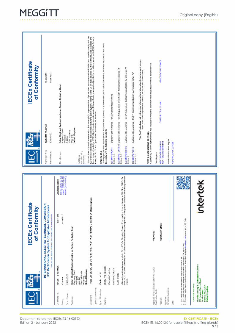
Original copy (English)
Document reference IECEx ITS 16.0012X EX CERTIFICATE – IECExEdition 2 - January 2022 IECEx ITS 16.0012X for cable fittings (stuffing glands)
3 / 6
Cable fittings
FR IECEx ITS 16.0012X (EN) Original copy EN
IECEx Certificate
of Conformity
Cer
tific
ate
No.
:IECEx ITS
16.0012X
Dat
e of
issu
e:20
19-1
0-23
Pag
e 2
of 5
Issu
e N
o: 3
Man
ufac
ture
r:Eaton
Electrical Systems trading as
Raxton,
Redapt or Capri
Kin
gsw
ay S
outh
W
estg
ate
Ald
ridge
W
est M
idla
nds
WS
9 8F
S
United
Kingdom
Add
ition
al
man
ufac
turin
g lo
catio
ns:
This
cer
tific
ate
is is
sued
as
verif
icat
ion
that
a s
ampl
e(s)
, rep
rese
ntat
ive
of p
rodu
ctio
n, w
as a
sses
sed
and
test
ed a
nd fo
und
to c
ompl
y w
ith th
e IE
C S
tand
ard
list b
elow
and
that
the
man
ufac
ture
r's q
ualit
y sy
stem
, rel
atin
g to
the
Ex
prod
ucts
cov
ered
by
this
cer
tific
ate,
was
ass
esse
d an
d fo
und
to c
ompl
y w
ith th
e IE
CE
x Q
ualit
y sy
stem
requ
irem
ents
.Thi
s ce
rtific
ate
is g
rant
ed s
ubje
ct to
the
cond
ition
s as
set
out
in IE
CE
x S
chem
e R
ules
, IE
CE
x 02
and
Ope
ratio
nal D
ocum
ents
as
amen
ded
STANDARDS
:Th
e eq
uipm
ent a
nd a
ny a
ccep
tabl
e va
riatio
ns to
it s
peci
fied
in th
e sc
hedu
le o
f thi
s ce
rtific
ate
and
the
iden
tifie
d do
cum
ents
, was
foun
d to
com
ply
with
the
follo
win
g st
anda
rds
IEC
600
79-0
:201
1 E
ditio
n:6.
0E
xplo
sive
atm
osph
eres
- P
art 0
: Gen
eral
requ
irem
ents
IEC
600
79-1
:201
4-06
E
ditio
n:7.
0E
xplo
sive
atm
osph
eres
- P
art 1
: Equ
ipm
ent p
rote
ctio
n by
flam
epro
of e
nclo
sure
s "d
"
IEC
600
79-3
1:20
13
Edi
tion:
2E
xplo
sive
atm
osph
eres
- P
art 3
1: E
quip
men
t dus
t ign
ition
pro
tect
ion
by e
nclo
sure
"t"
IEC
600
79-7
:201
5 E
ditio
n:5.
0
This
Cer
tific
ate does
not
indi
cate
com
plia
nce
with
saf
ety
and
perfo
rman
ce re
quire
men
ts
othe
r tha
n th
ose
expr
essl
y in
clud
ed in
the
Sta
ndar
ds li
sted
abo
ve.
TEST
& ASSESSMENT REPORTS:
A sa
mpl
e(s)
of t
he e
quip
men
t lis
ted
has
succ
essf
ully
met
the
exam
inat
ion
and
test
requ
irem
ents
as
reco
rded
in:
Test
Rep
orts
:
Qua
lity
Ass
essm
ent R
epor
t:
GB
/ITS
/ExT
R16
.001
4/00
GB
/ITS
/ExT
R16
.001
4/01
GB
/ITS
/ExT
R16
.001
4/02
GB
/ITS
/ExT
R16
.001
4/03
GB
/SIR
/QA
R06
.001
4/08
IECEx Certificate
of Conformity
INTERNATIONAL ELECTROTECHNICAL COMMISSION
IEC
Certification System
for Explosive
Atmospheres
for r
ules
and
det
ails
of t
he IE
CE
x S
chem
e vi
sit w
ww
.iece
x.co
m
Cer
tific
ate
No.
:IECEx ITS
16.0012X
Sta
tus:
Current
Dat
e of
Issu
e:20
19-1
0-23
App
lican
t:Eaton
Electrical Systems trading as
Raxton,
Redapt or Capri
Kin
gsw
ay S
outh
W
estg
ate
Ald
ridge
W
est M
idla
nds
WS
9 8F
S
United
Kingdom
Equ
ipm
ent:
Types CB, CF,
CK, CQ, CY,
PD-U, PH-E, PA-D, PA-U, PB-U/PB-D
and
PD-E4 Stopping plugs
Opt
iona
l acc
esso
ry:
Type
of P
rote
ctio
n:Ex db
, eb, tb
Mar
king
:
Pag
e 1
of 5
Issu
e N
o: 3
Cer
tific
ate
hist
ory:
Issu
e 2
(201
9-02
-22)
Issu
e 1
(201
8-04
-27)
Issu
e 0
(201
6-12
-20)
Ex
db I/
IIC M
b/G
b
mod
el.
1. 2. 3.App
rove
d fo
r iss
ue o
n be
half
of th
e IE
CE
x C
ertif
icat
ion
Bod
y:
Pos
ition
:
Sig
natu
re:
(for p
rinte
d ve
rsio
n)
Dat
e: This
cer
tific
ate
and
sche
dule
may
onl
y be
repr
oduc
ed in
full.
This
cer
tific
ate
is n
ot tr
ansf
erab
le a
nd re
mai
ns th
e pr
oper
ty o
f the
issu
ing
body
.Th
e S
tatu
s an
d au
then
ticity
of t
his
certi
ficat
e m
ay b
e ve
rifie
d by
vis
iting
ww
w.ie
cex.
com
or u
se o
f thi
s Q
R C
ode.
Cer
tific
ate
issu
ed b
y:
Intertek
Testing
& Certification Limited
ITS
House, Cleeve Road
Leatherhead
Surrey,
KT22 7SA
United
Kingdom
V K
Varma
Certificatin
Officer
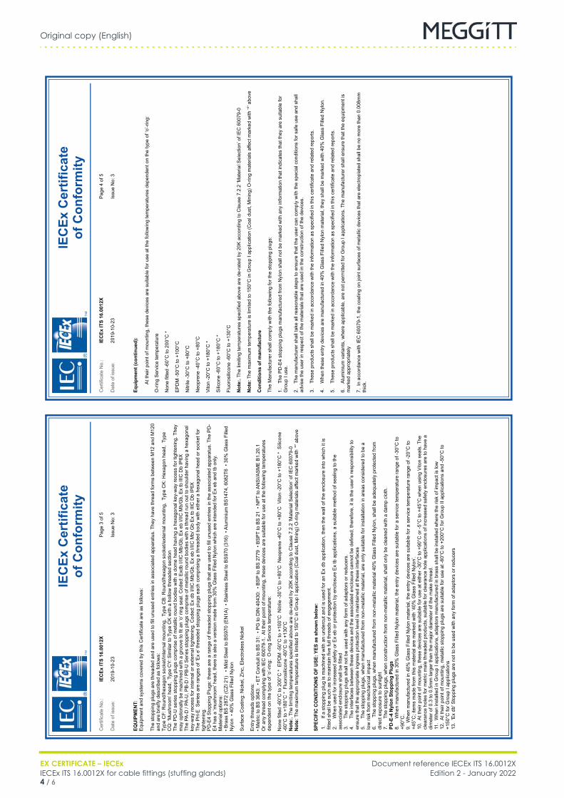
Original copy (English)
EX CERTIFICATE – IECEx Document reference IECEx ITS 16.0012XIECEx ITS 16.0012X for cable fittings (stuffing glands) Edition 2 - January 20224 / 6
Cable fittings
FR IECEx ITS 16.0012X (EN) Original copy EN
IECEx Certificate
of Conformity
Cer
tific
ate
No.
:IECEx ITS
16.0012X
Dat
e of
issu
e:20
19-1
0-23
Pag
e 4
of 5
Issu
e N
o: 3
Equipment (continued):
O-r
ing
Ser
vice
tem
pera
ture
Non
e fit
ted
-60°
C to
200
°C *
EP
DM
-50°
C to
+10
0°C
Nitr
ile -3
0°C
to +
80°C
Neo
pren
e -4
0°C
to +
80°C
Vito
n -2
0°C
to +
180°
C *
Silic
one
-60°
C to
+18
0°C
*
Fluo
rosi
licon
e -6
0°C
to +
130°
C
Note:.
Note:
Conditions
of manufacture
1.Th
e P
D-E
4 st
oppi
ng p
lugs
man
ufac
ture
d fro
m N
ylon
sha
ll no
t be
mar
ked
with
any
info
rmat
ion
that
indi
cate
s th
at th
ey a
re s
uita
ble
for
Gro
up I
use.
2.Th
e m
anuf
actu
rer s
hall
take
all
reas
onab
le s
teps
to e
nsur
e th
at th
e us
er c
an c
ompl
y w
ith th
e sp
ecia
l con
ditio
ns fo
r saf
e us
e an
d sh
all
advi
se th
e us
er in
resp
ect o
f the
mat
eria
ls th
at a
re u
sed
in th
e co
nstru
ctio
n of
the
devi
ces.
3.Th
ese
prod
ucts
sha
ll be
mar
ked
in a
ccor
danc
e w
ith th
e in
form
atio
n as
spe
cifie
d in
this
cer
tific
ate
and
rela
ted
repo
rts.
4. 5.Th
ese
prod
ucts
sha
ll be
mar
ked
in a
ccor
danc
e w
ith th
e in
form
atio
n as
spe
cifie
d in
this
cer
tific
ate
and
rela
ted
repo
rts.
6. mar
ked
appr
opria
tely
thic
k.
IECEx Certificate
of Conformity
Cer
tific
ate
No.
:IECEx ITS
16.0012X
Dat
e of
issu
e:20
19-1
0-23
Pag
e 3
of 5
Issu
e N
o: 3
EQUIPMENT:
E
quip
men
t and
sys
tem
s co
vere
d by
this
Cer
tific
ate
are
as fo
llow
s:
SPECIFIC
CONDITIONS
OF USE: YES
as shown below:
The
stop
ping
plu
gs a
re th
read
ed a
nd a
re u
sed
to fi
ll un
used
ent
ries
in a
ssoc
iate
d ap
para
tus.
The
y ha
ve th
read
form
s be
twee
n M
12 a
nd M
120
and
are
brie
fly d
escr
ibed
as
follo
ws:
The
PD
-U s
erie
s st
oppi
ng p
lugs
com
pris
e of
met
allic
roun
d bo
dies
with
a d
ome
head
hav
ing
a he
xago
nal k
ey-w
ay re
cess
for t
ight
enin
g. T
hey
The
PA-D
/ PA
-U, P
B-D
/ P
B-U
Ser
ies
stop
ping
plu
gs c
ompr
ise
of m
etal
lic ro
und
bodi
es w
ith a
thre
ad ru
n ou
t to
shou
lder
hav
ing
a he
xago
nal
key-
way
rece
ss fo
r int
erna
l or e
xter
nal t
ight
enin
g. C
oded
: Ex
db I/
IIC M
b/G
b, E
x eb
I/IIC
Mb/
Gb
Ex
tb II
IC D
b IP
6X
tight
enin
g.P
D-E
4 S
topp
ing
Plu
gs: t
hese
are
a ra
nge
of th
read
ed s
topp
ing
plug
s th
at a
re u
sed
to fi
ll un
used
ent
ries
in th
e as
soci
ated
app
arat
us. T
he P
D-
Mat
eria
l opt
ions
:
Note:.
Note:
fitte
d sh
all b
e su
ch a
s to
mai
ntai
n fiv
e fu
ll th
read
s of
eng
agem
ent.
asso
ciat
ed e
nclo
sure
sha
ll be
fitte
d
ensu
re th
at th
e ap
prop
riate
ingr
ess
prot
ectio
n le
vel i
s m
aint
aine
d at
thes
e in
terfa
ces
low
risk
from
mec
hani
cal i
mpa
ct
dire
ct e
xpos
ure
to s
unlig
ht
PD-E-4
Nylon
Stopping Plugs
+90°
C.
clea
ranc
e ho
les
for m
etric
mal
e th
read
ed p
rodu
cts,
sui
tabl
e fo
r cle
aran
ce h
ole
appl
icat
ions
of i
ncre
ased
saf
ety
encl
osur
es a
re to
hav
e a
+150
°C fo
r Gro
up I
appl
icat
ions
Original copy (English)
Document reference IECEx ITS 16.0012X EX CERTIFICATE – IECExEdition 2 - January 2022 IECEx ITS 16.0012X for cable fittings (stuffing glands)
5 / 6
Cable fittings
FR IECEx ITS 16.0012X (EN) Original copy EN
IECEx Certificate
of Conformity
Cer
tific
ate
No.
:IECEx ITS
16.0012X
Dat
e of
issu
e:20
19-1
0-23
Pag
e 5
of 5
Issu
e N
o: 3
DETAILS
OF CERTIFICATE
CHANGES
(for
issues
1 and
above)
G10
3326
724
Ex
d an
d E
x e
certi
fied

Original copy (English)
EX CERTIFICATE – IECEx Document reference IECEx ITS 16.0012XIECEx ITS 16.0012X for cable fittings (stuffing glands) Edition 2 - January 20226 / 6
THIS PAGE INTENTIONALLY LEFT BLANK

DRAFT
IECEx certificate LCI 10.0009UEdition 1 – September 2018
EX
Meggitt SARoute de Moncor 4
PO Box 16161701 Fribourg
Switzerland
[email protected]/energy
Title Page
IECEx certificate:
LCI 10.0009U
for
Cable stuffing glands
EN

THIS PAGE INTENTIONALLY LEFT BLANK
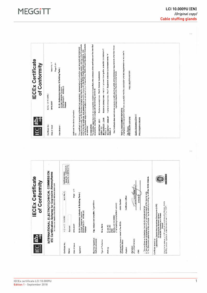
IECEx certificate LCI 10.0009U 1Edition 1 - September 2018
DRAFT
LCI 10.0009U (EN)(Original copy)
Cable stuffing glandsCable stuffing glands
FR LCI 10.0009U (EN) Original copy EN
DRAFT
LCI 10.0009U (EN)(Original copy)
Cable stuffing glands
2 IECEx certificate LCI 10.0009UEdition 1 - September 2018
Cable stuffing glands
FR LCI 10.0009U (EN) Original copy EN
IECEx certificate LCI 10.0009U 3Edition 1 - September 2018
DRAFT
LCI 10.0009U (EN)(Original copy)
Cable stuffing glandsCable stuffing glands
FR LCI 10.0009U (EN) Original copy EN

DRAFT
LCI 10.0009U (EN)(Original copy)
Cable stuffing glands
4 IECEx certificate LCI 10.0009UEdition 1 - September 2018
THIS PAGE INTENTIONALLY LEFT BLANK

DRAFT
IECEx certificate PTB 03.0000Edition 1 – September 2018
EX
Meggitt SARoute de Moncor 4
PO Box 16161701 Fribourg
Switzerland
[email protected]/energy
Title Page
IECEx certificate:
PTB 03.0000
for
Cable stuffing glands
EN

THIS PAGE INTENTIONALLY LEFT BLANK
IECEx certificate PTB 03.0000 1Edition 1 - September 2018
DRAFT
PTB 03.0000 (EN)(Original copy)
Cable stuffing glandsCable stuffing glands
FR PTB 03.0000 (EN) Original copy EN
DRAFT
PTB 03.0000 (EN)(Original copy)
Cable stuffing glands
2 IECEx certificate PTB 03.0000Edition 1 - September 2018
Cable stuffing glands
FR PTB 03.0000 (EN) Original copy EN
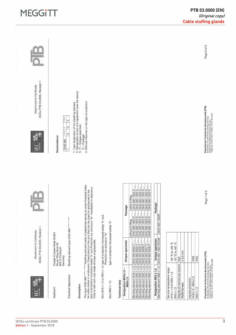
IECEx certificate PTB 03.0000 3Edition 1 - September 2018
DRAFT
PTB 03.0000 (EN)(Original copy)
Cable stuffing glandsCable stuffing glands
FR PTB 03.0000 (EN) Original copy EN
DRAFT
PTB 03.0000 (EN)(Original copy)
Cable stuffing glands
4 IECEx certificate PTB 03.0000Edition 1 - September 2018
THIS PAGE INTENTIONALLY LEFT BLANK

Meggitt SA, Route de Moncor 4, Case postale, 1701 Fribourg, Switzerland Tel: +41 26 407 1111Fax: +41 26 407 1660
[email protected]/energy
www.meggitt.com
EX CERTIFICATE – IECEx
Document reference IECEx PTB 11.0019XEdition 3 – October 2020
Title page
IECEx PTB 11.0019Xfor
cable fittings (stuffing glands)
EX
Note: Although the Ex certificate may be included in more than one language, the liability ofthe notified body applies only on the text of the original copy of the certificate that it published.

THIS PAGE INTENTIONALLY LEFT BLANK
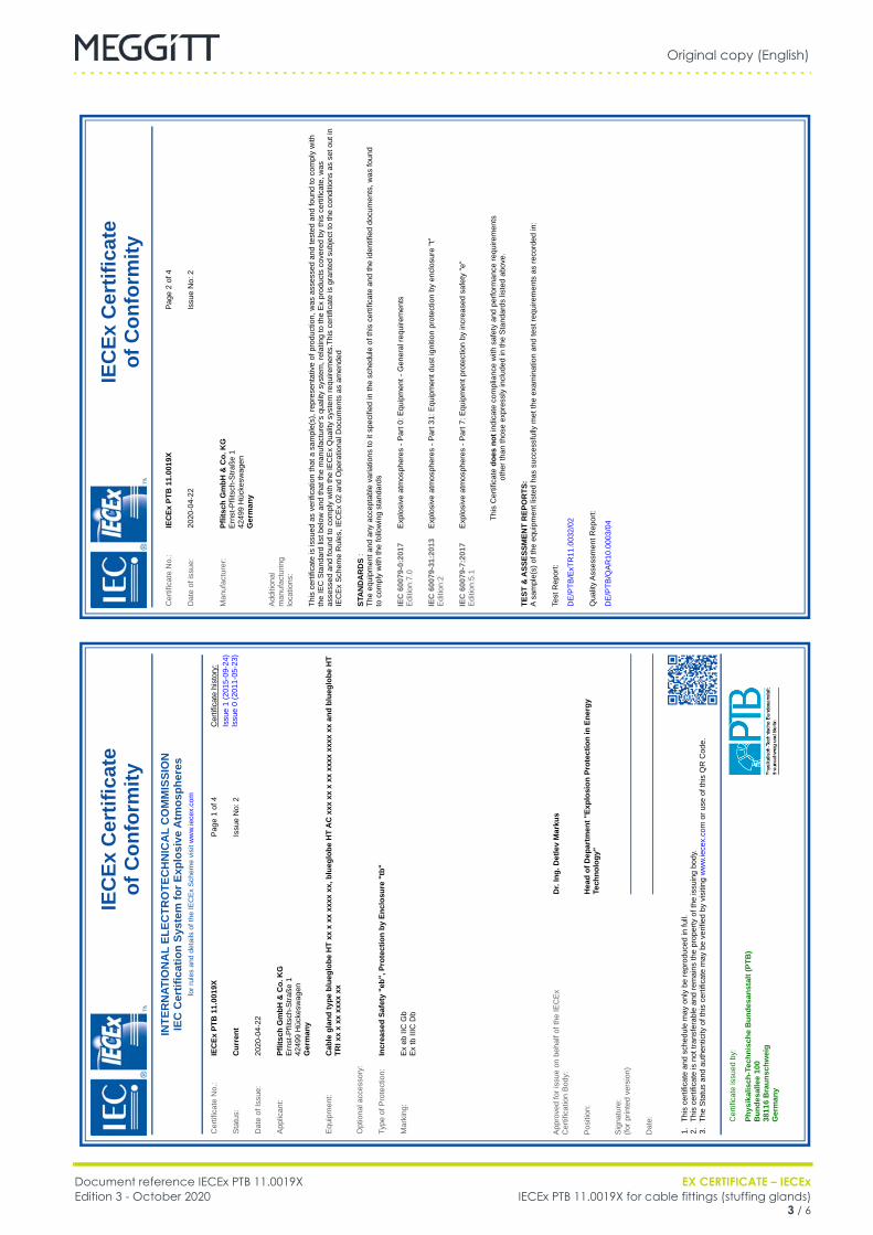
Original copy (English)
Document reference IECEx PTB 11.0019X EX CERTIFICATE – IECExEdition 3 - October 2020 IECEx PTB 11.0019X for cable fittings (stuffing glands)
3 / 6
Cable fittings
FR IECEx PTB 11.0019X (EN) Original copy EN
IEC
Ex C
ertif
icat
eof
Con
form
ityCer
tificat
e No.
:IE
CEx
PTB
11.
0019
X
Dat
e of
issu
e:20
20-0
4-22
Page
2 o
f 4
Issu
e No:
2
Man
ufac
ture
r:Pf
litsc
h G
mbH
& C
o. K
GEr
nst-P
flits
ch-S
traße
1
4249
9 H
ücke
swag
en
Ger
man
y
Addi
tiona
l m
anuf
actu
ring
loca
tions
:
This
cer
tificat
e is
issu
ed a
s ve
rificat
ion
that
a s
ampl
e(s)
, rep
rese
ntat
ive
of p
rodu
ctio
n, w
as a
sses
sed
and
test
ed a
nd fo
und
to c
ompl
y with
th
e IE
C S
tand
ard
list b
elow
and
that
the
man
ufac
ture
r's q
uality
syst
em, r
elat
ing
to th
e Ex
pro
duct
s co
vere
d by
this
cer
tificat
e, w
as
asse
ssed
and
foun
d to
com
ply
with
the
IECEx
Qua
lity
syst
em re
quire
men
ts.T
his
certi
ficat
e is
gra
nted
sub
ject
to th
e co
ndition
s as
set
out
in
IECEx
Sch
eme
Rul
es, I
ECEx
02
and
Ope
ratio
nal D
ocum
ents
as
amen
ded
STANDARDS
:Th
e eq
uipm
ent a
nd a
ny a
ccep
tabl
e va
riatio
ns to
it s
pecifie
d in
the
sche
dule
of t
his
certi
ficat
e an
d th
e id
entif
ied
docu
men
ts, w
as fo
und
to c
ompl
y with
the
follo
win
g st
anda
rds
IEC
600
79-0
:201
7 Ed
ition
:7.0
Expl
osive
atm
osph
eres
- Pa
rt 0:
Equ
ipm
ent -
Gen
eral
requ
irem
ents
IEC
600
79-3
1:20
13
Edition
:2Ex
plos
ive
atm
osph
eres
- Pa
rt 31
: Equ
ipm
ent d
ust i
gnition
pro
tect
ion
by e
nclo
sure
"t"
IEC
600
79-7
:201
7 Ed
ition
:5.1
Expl
osive
atm
osph
eres
- Pa
rt 7:
Equ
ipm
ent p
rote
ctio
n by
incr
ease
d sa
fety
"e"
This
Cer
tificat
e do
es n
ot in
dica
te c
ompl
ianc
e with
saf
ety
and
perfo
rman
ce re
quire
men
ts
othe
r tha
n th
ose
expr
essly
incl
uded
in th
e St
anda
rds
liste
d ab
ove.
TEST
& A
SSES
SMEN
T R
EPO
RTS
:A
sam
ple(
s) o
f the
equ
ipm
ent l
iste
d ha
s su
cces
sful
ly m
et th
e ex
amin
atio
n an
d te
st re
quire
men
ts a
s re
cord
ed in
:
Test
Rep
ort:
Qua
lity
Asse
ssm
ent R
epor
t:
DE/
PTB/
ExTR
11.0
032/
02
DE/
PTB/
QAR
10.0
003/
04
IEC
Ex C
ertif
icat
eof
Con
form
ityIN
TERNAT
IONA
L EL
ECTR
OTE
CHN
ICA
L CO
MM
ISSI
ON
IEC
Cer
tific
atio
n Sy
stem
for E
xplo
sive
Atm
osph
eres
for r
ules
and
det
ails
of t
he IE
CEx
Sch
eme
visit w
ww.
iece
x.co
m
Cer
tificat
e No.
:IE
CEx
PTB
11.
0019
X
Stat
us:
Cur
rent
Dat
e of
Issu
e:20
20-0
4-22
Appl
ican
t:Pf
litsc
h G
mbH
& C
o. K
GEr
nst-P
flits
ch-S
traße
1
4249
9 H
ücke
swag
en
Ger
man
y
Equi
pmen
t:C
able
gla
nd ty
pe b
lueg
lobe
HT
xx x
xx
xxxx
xx,
blu
eglo
be H
T A
C x
xx x
x x
xx x
xxx
xxxx
xx
and
blue
glob
e H
T TR
I xx
x xx
xxx
x xx
Opt
iona
l acc
esso
ry:
Type
of P
rote
ctio
n:In
crea
sed
Safe
ty "
eb",
Pro
tect
ion
by E
nclo
sure
"tb
"
Mar
king
:
Page
1 o
f 4
Issu
e No:
2
Cer
tificat
e hi
stor
y:Is
sue
1 (2
015-
09-2
4)Is
sue
0 (2
011-
05-2
3)
Ex e
b IIC
Gb
Ex tb
IIIC
Db
1. 2. 3.Appr
oved
for i
ssue
on
beha
lf of
the
IECEx
Cer
tificat
ion
Body
:
Positio
n:
Sign
atur
e:(fo
r prin
ted
vers
ion)
Dat
e: This
cer
tificat
e an
d sc
hedu
le m
ay o
nly
be re
prod
uced
in fu
ll.Th
is c
ertif
icat
e is
not
tran
sfer
able
and
rem
ains
the
prop
erty
of t
he is
suin
g bo
dy.
The
Stat
us a
nd a
uthe
nticity
of t
his
certi
ficat
e m
ay b
e ve
rifie
d by
visiting
ww
w.ie
cex.
com
or u
se o
f thi
s Q
R C
ode.
Cer
tificat
e is
sued
by:
Phys
ikal
isch
-Tec
hnis
che
Bun
desa
nsta
lt (P
TB)
Bun
desa
llee
100
3811
6 B
raun
schw
eig
Ger
man
y
Dr.
Ing.
Det
lev
Mar
kus
Hea
d of
Dep
artm
ent "
Expl
osio
n Pr
otec
tion
in E
nerg
y Te
chno
logy
"

Original copy (English)
EX CERTIFICATE – IECEx Document reference IECEx PTB 11.0019XIECEx PTB 11.0019X for cable fittings (stuffing glands) Edition 3 - October 20204 / 6
Cable fittings
FR IECEx PTB 11.0019X (EN) Original copy EN
IEC
Ex C
ertif
icat
eof
Con
form
ityCer
tificat
e No.
:IE
CEx
PTB
11.
0019
X
Dat
e of
issu
e:20
20-0
4-22
Page
4 o
f 4
Issu
e No:
2
DET
AIL
S O
F C
ERTI
FICAT
E C
HAN
GES
(for
issu
es 1
and
abo
ve)
Ann
ex:
CO
CA-
11.0
019X
Issu
e 2.
1) T
he p
ress
ure
scre
w c
an b
e op
tiona
lly e
quip
ped
with
a s
ilicon
e co
atin
g.2)
Two
diffe
rent
sea
ling
com
pone
nts
can
be u
sed:
sea
ling
com
pone
nt w
ith m
ould
ed in
let a
nd tw
o-pa
rt se
alin
g co
mpo
nent
.3)
New
test
acc
ordi
ng to
IEC
600
79-0
:201
7 (E
d. 7
), IE
C 6
0079
-7:2
015+
A1:2
017
(Ed.
5.1
) and
IEC
600
79-3
1:20
13 (E
d. 2
).
IEC
Ex C
ertif
icat
eof
Con
form
ityCer
tificat
e No.
:IE
CEx
PTB
11.
0019
X
Dat
e of
issu
e:20
20-0
4-22
Page
3 o
f 4
Issu
e No:
2
EQU
IPM
ENT:
Eq
uipm
ent a
nd s
yste
ms
cove
red
by th
is C
ertif
icat
e ar
e as
follo
ws:
SPEC
IFIC
CO
ND
ITIO
NS
OF
USE
: YES
as
show
n be
low
:
The
cabl
e gl
and
type
blu
eglo
be H
T xx
x x
x xx
xx x
x, b
lueg
lobe
HT
AC x
xx x
x x
xx x
xxx
xx a
nd b
lueg
lobe
HT
TRI x
x x
xx x
xxx
xx m
ade
of
bras
s bl
ank
or n
icke
l-pla
ted
and
stai
nles
s st
eel,
serv
es to
intro
duce
fixe
d ca
bles
into
ele
ctric
al a
ppar
atus
of t
he ty
pe o
f pro
tect
ion
incr
ease
d sa
fety
"eb"
and
pro
tect
ion
by e
nclo
sure
"tb"
. The
cab
le g
land
con
sist
s of
:- p
ress
ure
scre
w w
ithou
t cla
mpi
ng d
evice
- sea
ling
com
pone
nt w
ith m
ould
ed in
let o
r two-
part
seal
ing
com
pone
nt- d
oubl
e ni
pple
with
met
ric c
onne
ctio
n th
read
in d
iffer
ent l
engt
h an
d an
O-ri
n g.
For m
ount
ing
enclos
ures
with
thro
ugh
bore
-hol
es o
r thr
eade
d ho
les
are
used
. Loc
k nu
ts a
re u
sed
with
thro
ugh
bore
-hol
es.
Acce
ssor
y is
an
AC g
roup
for s
teel
arm
oure
d ca
bles
, a T
RI-s
prin
g fo
r shi
elde
d ca
bles
as
wel
l as
a pl
astic
bol
t for
sea
ling
of c
able
gla
nds
whi
ch a
re n
ot u
sed.
Tech
nica
l dat
a an
d Nom
enclat
ure
see
Anne
x.
Onl
y pe
rman
ently
wire
d ca
bles
may
be
ente
red.
The
use
r sha
ll pr
ovid
e th
e re
quire
d st
rain
relie
f.
Whe
n th
e te
sted
seal
ing
com
pone
nts a
re se
lect
ed, t
he m
axim
um th
erm
al lo
ad o
f the
cab
les i
ntro
duce
d m
ust b
e ta
ken
into
acc
ount
.
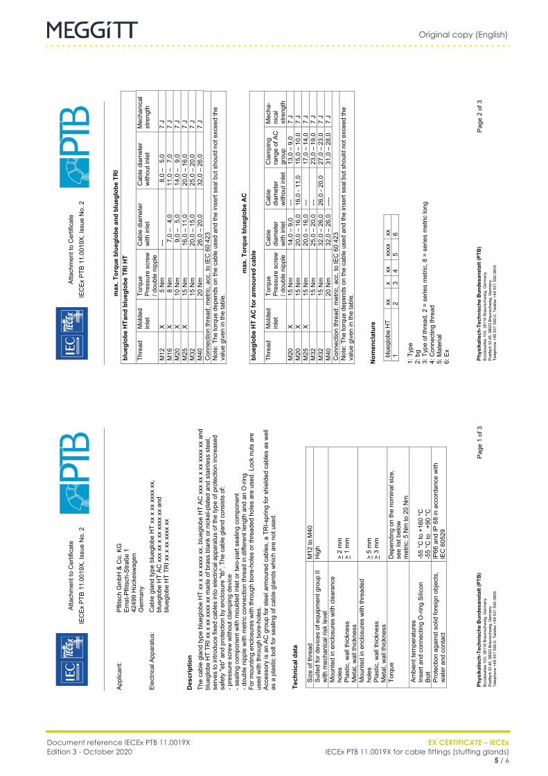
Original copy (English)
Document reference IECEx PTB 11.0019X EX CERTIFICATE – IECExEdition 3 - October 2020 IECEx PTB 11.0019X for cable fittings (stuffing glands)
5 / 6
Cable fittings
FR IECEx PTB 11.0019X (EN) Original copy EN
Atta
chm
ent t
o C
ertif
icat
e IE
CEx
PTB
11.
0019
X, Is
sue
No.
2
Ph
ysik
alis
ch-T
echn
isch
e B
unde
sans
talt
(PTB
) Bu
ndes
alle
e 10
0, 3
8116
Bra
unsc
hwei
g, G
erm
any
Post
fach
33
45, 3
8023
Bra
unsc
hwei
g, G
erm
any
Tele
phon
e +4
9 53
1 59
2-0,
Tel
efax
+49
531
592
-360
5
Page
2 o
f 3
max
. Tor
que
blue
glob
e an
d bl
uegl
obe
TRI
blue
glob
e H
Tand
blu
eglo
be T
RI H
T Th
read
M
olde
d in
let
Torq
ue
Pres
sure
scr
ew
/ dou
ble
nipp
le
Cab
le d
iam
eter
w
ith in
let
Cab
le d
iam
eter
w
ithou
t inl
et
Mec
hani
cal
stre
ngth
M12
X
5 N
m
---
8,0
–
5,0
7 J
M16
X
8 N
m
7,0
–
4,0
11,0
–
7,0
7 J
M20
X
10 N
m
9,0
–
5,0
14,0
–
9,0
7 J
M25
X
15 N
m
16,0
– 1
1,0
20,0
– 1
6,0
7 J
M32
15 N
m
20,0
– 1
5,0
25,0
– 2
0,0
7 J
M40
20 N
m
26,0
– 2
0,0
32,0
– 2
6,0
7 J
Con
nect
ion
thre
ad: m
etric
, acc
. to
IEC
60
423
N
ote:
The
torq
ue d
epen
ds o
n th
e ca
ble
used
and
the
inse
rt se
al b
ut s
houl
d no
t exc
eed
the
valu
e gi
ven
in th
e ta
ble.
max
. Tor
que
blue
glob
e A
C
blue
glob
e H
T A
C fo
r arm
oure
d ca
ble
Thre
ad
Mol
ded
inle
t To
rque
Pr
essu
re s
crew
/ d
oubl
e ni
pple
Cab
le
diam
eter
w
ith in
let
Cab
le
diam
eter
w
ithou
t inl
et
Cla
mpi
ng
rang
e of
AC
gr
oup
Mec
ha-
nica
l st
reng
th
M20
X
15 N
m
14,0
– 9
,0
---
13,0
– 9
,0
7 J
M20
X
15 N
m
20,0
– 1
6,0
16,0
- 11
,0
15,0
– 1
0,0
7 J
M25
X
15 N
m
20,0
– 1
6,0
---
17,0
– 1
4,0
7 J
M32
15 N
m
25,0
– 2
0,0
---
23,0
– 1
9,0
7 J
M32
15 N
m
32,0
– 2
6,0
26,0
- 20
,0
27,0
– 2
3,0
7 J
M40
20 N
m
32,0
– 2
6,0
----
31,0
– 2
8,0
7 J
Con
nect
ion
thre
ad: m
etric
, acc
. to
IEC
60
423
Not
e: T
he to
rque
dep
ends
on
the
cabl
e us
ed a
nd th
e in
sert
seal
but
sho
uld
not e
xcee
d th
e va
lue
give
n in
the
tabl
e.
Nom
encl
atur
e
blue
glob
e H
T xx
x
xx
xxxx
xx
1
2 3
4 5
6 1:
Typ
e
2: b
g 3:
Typ
e of
thre
ad, 2
= s
erie
s m
etric
, 8 =
ser
ies
met
ric lo
ng
4: C
onne
ctin
g th
read
5:
Mat
eria
l 6:
Ex
Atta
chm
ent t
o C
ertif
icat
e IE
CEx
PTB
11.
0019
X, Is
sue
No.
2
Ph
ysik
alis
ch-T
echn
isch
e B
unde
sans
talt
(PTB
) Bu
ndes
alle
e 10
0, 3
8116
Bra
unsc
hwei
g, G
erm
any
Post
fach
33
45, 3
8023
Bra
unsc
hwei
g, G
erm
any
Tele
phon
e +4
9 53
1 59
2-0,
Tel
efax
+49
531
592
-360
5
Page
1 o
f 3
Appl
ican
t: Pf
litsc
h G
mbH
& C
o. K
G
Er
nst-P
flits
ch-S
traße
1
42
499
Hüc
kesw
agen
Ger
man
y
Elec
trica
l App
arat
us:
Cab
le g
land
type
blu
eglo
be H
T xx
x x
x xx
xx x
x,
bl
uegl
obe
HT
AC x
xx x
x x
xx x
xxx
xx a
nd
bl
uegl
obe
HT
TRI x
x x
xx x
xxx
xx
Des
crip
tion
Th
e ca
ble
glan
d ty
pe b
lueg
lobe
HT
xx x
xx
xxxx
xx,
blu
eglo
be H
T AC
xxx
xx
x xx
xxx
x xx
and
bl
uegl
obe
HT
TRI x
x x
xx x
xxx
xx m
ade
of b
rass
bla
nk o
r nic
kel-p
late
d an
d st
ainl
ess
stee
l, se
rves
to in
trodu
ce fi
xed
cabl
es in
to e
lect
rical
app
arat
us o
f the
type
of p
rote
ctio
n in
crea
sed
safe
ty "e
b" a
nd p
rote
ctio
n by
enc
losu
re "t
b". T
he c
able
gla
nd c
onsi
sts
of:
- pre
ssur
e sc
rew
with
out c
lam
ping
dev
ice
- sea
ling
com
pone
nt w
ith m
ould
ed in
let o
r tw
o-pa
rt se
alin
g co
mpo
nent
- d
oubl
e ni
pple
with
met
ric c
onne
ctio
n th
read
in d
iffer
ent l
engt
h an
d an
O-ri
ng
For m
ount
ing
encl
osur
es w
ith th
roug
h bo
re-h
oles
or t
hrea
ded
hole
s ar
e us
ed. L
ock
nuts
are
us
ed w
ith th
roug
h bo
re-h
oles
. Ac
cess
ory
is a
n AC
gro
up fo
r ste
el a
rmou
red
cabl
es, a
TR
I-spr
ing
for s
hiel
ded
cabl
es a
s w
ell
as a
pla
stic
bol
t for
sea
ling
of c
able
gla
nds
whi
ch a
re n
ot u
sed.
Te
chni
cal d
ata
Si
ze o
f thr
ead
M12
to M
40
Suite
d fo
r dev
ices
of e
quip
men
t gro
up II
w
ith m
echa
nica
l ris
k le
vel
Hig
h
Mou
nted
in e
nclo
sure
s w
ith c
lear
ance
ho
les
Plas
tic, w
all t
hick
ness
M
etal
, wal
l thi
ckne
ss
> 2
mm
>
1 m
m
Mou
nted
in e
nclo
sure
s w
ith th
read
ed
hole
s Pl
astic
, wal
l thi
ckne
ss
Met
al, w
all t
hick
ness
> 5
mm
>
3 m
m
Torq
ue
D
epen
ding
on
the
nom
inal
siz
e,
see
list b
elow
m
etric
: 5 N
m to
20
Nm
Am
bien
t tem
pera
ture
s In
sert
and
conn
ectin
g O
-ring
Silic
on
Bolt
-55
°C to
+16
0 °C
-5
5 °C
to
+90
°C
Prot
ectio
n ag
ains
t sol
id fo
reig
n ob
ject
s,
wat
er a
nd c
onta
ct
IP66
and
IP 6
8 in
acc
orda
nce
with
IE
C 6
0529
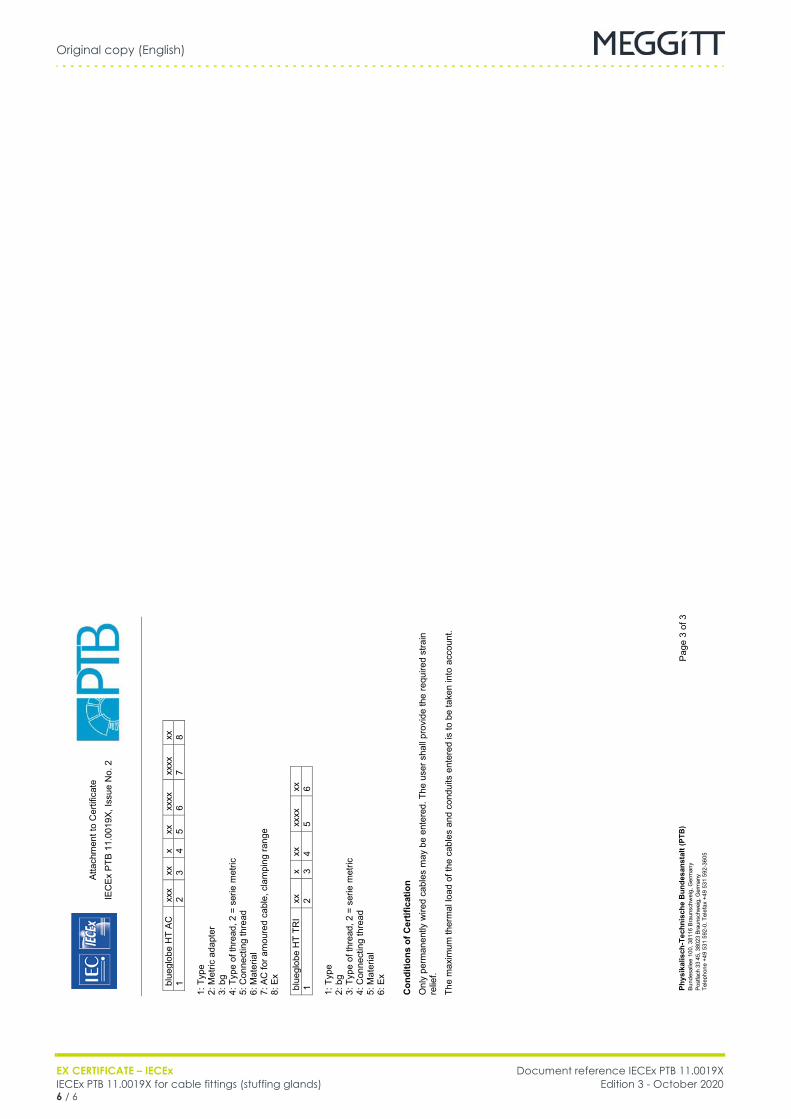
Original copy (English)
EX CERTIFICATE – IECEx Document reference IECEx PTB 11.0019XIECEx PTB 11.0019X for cable fittings (stuffing glands) Edition 3 - October 20206 / 6
Cable fittings
FR IECEx PTB 11.0019X (EN) Original copy EN
Atta
chm
ent t
o C
ertif
icat
e IE
CEx
PTB
11.
0019
X, Is
sue
No.
2
Ph
ysik
alis
ch-T
echn
isch
e B
unde
sans
talt
(PTB
) Bu
ndes
alle
e 10
0, 3
8116
Bra
unsc
hwei
g, G
erm
any
Post
fach
33
45, 3
8023
Bra
unsc
hwei
g, G
erm
any
Tele
phon
e +4
9 53
1 59
2-0,
Tel
efax
+49
531
592
-360
5
Page
3 o
f 3
bl
uegl
obe
HT
AC
xxx
xx
x xx
xx
xx
xxxx
xx
1
2 3
4 5
6 7
8 1:
Typ
e
2: M
etric
ada
pter
3:
bg
4: T
ype
of th
read
, 2 =
ser
ie m
etric
5:
Con
nect
ing
thre
ad
6: M
ater
ial
7: A
C fo
r am
oure
d ca
ble,
cla
mpi
ng ra
nge
8:
Ex
blue
glob
e H
T TR
I xx
x
xx
xxxx
xx
1
2 3
4 5
6 1:
Typ
e
2: b
g 3:
Typ
e of
thre
ad, 2
= s
erie
met
ric
4: C
onne
ctin
g th
read
5:
Mat
eria
l 6:
Ex
Con
ditio
ns o
f Cer
tific
atio
n
Onl
y pe
rman
ently
wire
d ca
bles
may
be
ente
red.
The
use
r sha
ll pr
ovid
e th
e re
quire
d st
rain
re
lief.
The
max
imum
ther
mal
load
of t
he c
able
s an
d co
ndui
ts e
nter
ed is
to b
e ta
ken
into
acc
ount
.

Meggitt SA, Route de Moncor 4, Case postale, 1701 Fribourg, Switzerland Tel: +41 26 407 1111Fax: +41 26 407 1660
[email protected]/energy
www.meggitt.com
EX CERTIFICATE – IECEx
Document reference IECEx SEV 15.0018Edition 2 – October 2020
Title page
IECEx SEV 15.0018for
cable fittings (stuffing glands)
EX
Note: Although the Ex certificate may be included in more than one language, the liability ofthe notified body applies only on the text of the original copy of the certificate that it published.

THIS PAGE INTENTIONALLY LEFT BLANK
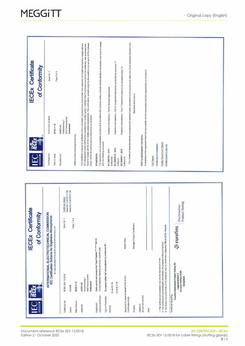
Original copy (English)
Document reference IECEx SEV 15.0018 EX CERTIFICATE – IECExEdition 2 - October 2020 IECEx SEV 15.0018 for cable fittings (stuffing glands)
3 / 4
Cable fittings
FR IECEx SEV 15.0018 (EN) Original copy EN

Original copy (English)
EX CERTIFICATE – IECEx Document reference IECEx SEV 15.0018IECEx SEV 15.0018 for cable fittings (stuffing glands) Edition 2 - October 20204 / 4
Cable fittings
FR IECEx SEV 15.0018 (EN) Original copy EN

Meggitt SA, Route de Moncor 4, Case postale, 1701 Fribourg, Switzerland Tel: +41 26 407 1111Fax: +41 26 407 1660
[email protected]/energy
www.meggitt.com
EX CERTIFICATE – IECEx
Document reference IECEx SEV 15.0019XEdition 4 – January 2022
Title page
IECEx SEV 15.0019Xfor
cable fittings (stuffing glands)
EX
Note: Although the Ex certificate may be included in more than one language, the liability ofthe notified body applies only on the text of the original copy of the certificate that it published.

THIS PAGE INTENTIONALLY LEFT BLANK
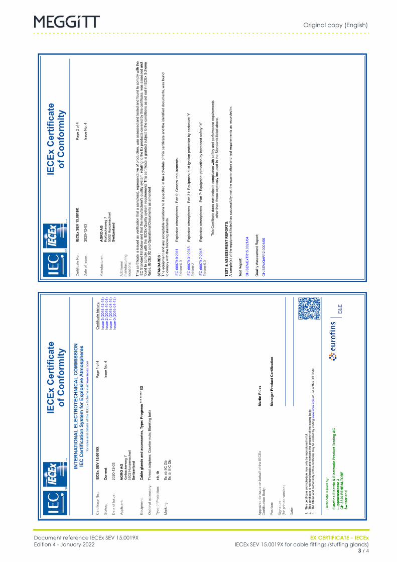
Original copy (English)
Document reference IECEx SEV 15.0019X EX CERTIFICATE – IECExEdition 4 - January 2022 IECEx SEV 15.0019X for cable fittings (stuffing glands)
3 / 4
Cable fittings
FR IECEx SEV 15.0019X (EN) Original copy EN
IECEx Certificate
of Conformity
Cer
tific
ate
No.
:IECEx SEV
15.0019X
Dat
e of
issu
e:20
20-1
2-03
Pag
e 2
of 4
Issu
e N
o: 4
Man
ufac
ture
r:AGRO
AG
Kor
back
erw
eg 7
55
02 H
unze
nsch
wil
Switzerland
Add
ition
al
man
ufac
turin
g lo
catio
ns:
This
cer
tific
ate
is is
sued
as
verif
icat
ion
that
a s
ampl
e(s)
, rep
rese
ntat
ive
of p
rodu
ctio
n, w
as a
sses
sed
and
test
ed a
nd fo
und
to c
ompl
y w
ith th
e IE
C S
tand
ard
list b
elow
and
that
the
man
ufac
ture
r's q
ualit
y sy
stem
, rel
atin
g to
the
Ex
prod
ucts
cov
ered
by
this
cer
tific
ate,
was
ass
esse
d an
d fo
und
to c
ompl
y w
ith th
e IE
CE
x Q
ualit
y sy
stem
requ
irem
ents
.Thi
s ce
rtific
ate
is g
rant
ed s
ubje
ct to
the
cond
ition
s as
set
out
in IE
CE
x S
chem
e R
ules
, IE
CE
x 02
and
Ope
ratio
nal D
ocum
ents
as
amen
ded
STANDARDS
:Th
e eq
uipm
ent a
nd a
ny a
ccep
tabl
e va
riatio
ns to
it s
peci
fied
in th
e sc
hedu
le o
f thi
s ce
rtific
ate
and
the
iden
tifie
d do
cum
ents
, was
foun
d to
com
ply
with
the
follo
win
g st
anda
rds
IEC
600
79-0
:201
1 E
ditio
n:6.
0E
xplo
sive
atm
osph
eres
- P
art 0
: Gen
eral
requ
irem
ents
IEC
600
79-3
1:20
13
Edi
tion:
2E
xplo
sive
atm
osph
eres
- P
art 3
1: E
quip
men
t dus
t ign
ition
pro
tect
ion
by e
nclo
sure
"t"
IEC
600
79-7
:201
5 E
ditio
n:5.
0
This
Cer
tific
ate does
not
indi
cate
com
plia
nce
with
saf
ety
and
perfo
rman
ce re
quire
men
ts
othe
r tha
n th
ose
expr
essl
y in
clud
ed in
the
Sta
ndar
ds li
sted
abo
ve.
TEST
& ASSESSMENT REPORTS:
A sa
mpl
e(s)
of t
he e
quip
men
t lis
ted
has
succ
essf
ully
met
the
exam
inat
ion
and
test
requ
irem
ents
as
reco
rded
in:
Test
Rep
ort:
Qua
lity
Ass
essm
ent R
epor
t:
CH
/SE
V/E
xTR
15.0
021/
04
CH
/SE
V/Q
AR
12.0
001/
06
IECEx Certificate
of Conformity
INTERNATIONAL ELECTROTECHNICAL COMMISSION
IEC
Certification System
for Explosive
Atmospheres
for r
ules
and
det
ails
of t
he IE
CE
x S
chem
e vi
sit w
ww
.iece
x.co
m
Cer
tific
ate
No.
:IECEx SEV
15.0019X
Sta
tus:
Current
Dat
e of
Issu
e:20
20-1
2-03
App
lican
t:AGRO
AG
Kor
back
erw
eg 7
55
02 H
unze
nsch
wil
Switzerland
Equ
ipm
ent:
Cable
glands and accessories,
Type:
Progress *** ***** EX
Opt
iona
l acc
esso
ry:
Thre
ad a
dapt
ers;
Cou
nter
nut
s; B
lank
ing
bolts
Type
of P
rote
ctio
n:eb, tb
Mar
king
:
Pag
e 1
of 4
Issu
e N
o: 4
Cer
tific
ate
hist
ory:
Issu
e 3
(201
8-12
-18)
Issu
e 2
(201
8-10
-01)
Issu
e 1
(201
8-07
-16)
Issu
e 0
(201
6-01
-13)
Ex
eb II
C G
bE
x tb
III C
Db
1. 2. 3.App
rove
d fo
r iss
ue o
n be
half
of th
e IE
CE
x C
ertif
icat
ion
Bod
y:
Pos
ition
:
Sig
natu
re:
(for p
rinte
d ve
rsio
n)
Dat
e: This
cer
tific
ate
and
sche
dule
may
onl
y be
repr
oduc
ed in
full.
This
cer
tific
ate
is n
ot tr
ansf
erab
le a
nd re
mai
ns th
e pr
oper
ty o
f the
issu
ing
body
.Th
e S
tatu
s an
d au
then
ticity
of t
his
certi
ficat
e m
ay b
e ve
rifie
d by
vis
iting
ww
w.ie
cex.
com
or u
se o
f thi
s Q
R C
ode.
Cer
tific
ate
issu
ed b
y:
Eurofins Electric
& Electronic Product
Testing AG
Luppmenstrasse 3
CH-8320 FEHRALTORF
Switzerland
Martin
Plüss
Manager
Product
Certification
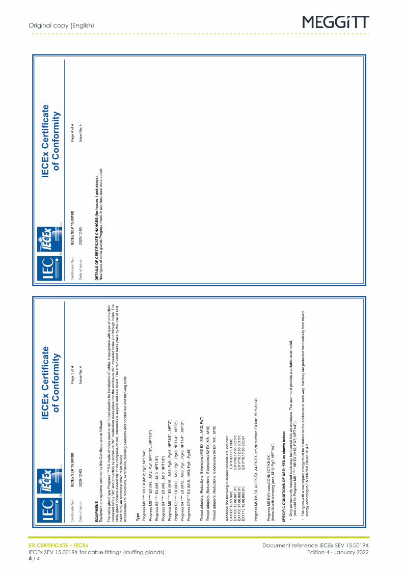
Original copy (English)
EX CERTIFICATE – IECEx Document reference IECEx SEV 15.0019XIECEx SEV 15.0019X for cable fittings (stuffing glands) Edition 4 - January 20224 / 4
Cable fittings
FR IECEx SEV 15.0019X (EN) Original copy EN
IECEx Certificate
of Conformity
Cer
tific
ate
No.
:IECEx SEV
15.0019X
Dat
e of
issu
e:20
20-1
2-03
Pag
e 4
of 4
Issu
e N
o: 4
DETAILS
OF CERTIFICATE
CHANGES
(for
issues
1 and
above)
New
type
s of
cab
le g
land
s P
rogr
ess
mad
e in
sta
inle
ss s
teel
wer
e ad
ded
IECEx Certificate
of Conformity
Cer
tific
ate
No.
:IECEx SEV
15.0019X
Dat
e of
issu
e:20
20-1
2-03
Pag
e 3
of 4
Issu
e N
o: 4
EQUIPMENT:
E
quip
men
t and
sys
tem
s co
vere
d by
this
Cer
tific
ate
are
as fo
llow
s:
SPECIFIC
CONDITIONS
OF USE: YES
as shown below:
The
cabl
e gl
and
type
Pro
gres
s **
* E
X m
ade
of b
rass
ste
el o
r rei
nfor
ced
plas
tics
for i
nsta
llatio
n of
cab
les
in e
quip
men
t with
type
of p
rote
ctio
n in
crea
sed
safe
ty "e
b" a
nd p
rote
ctio
n by
enc
losu
re "t
b". I
nsta
llatio
n ta
kes
plac
e in
to th
e en
clos
ure
with
thre
aded
hol
es a
nd th
roug
h ho
les.
The
ca
ble
glan
d co
nsis
ts e
ssen
tially
of t
he c
ompr
essi
on n
ut, i
nter
med
iate
sup
port
and
seal
inse
rt. T
he s
train
relie
f tak
es p
lace
by
the
use
of s
eal
inse
rt or
by
an a
dditi
onal
stra
in re
lief d
evic
e.A
cces
sorie
s ar
e re
duct
ions
, ext
ensi
ons,
bla
nkin
g el
emen
ts a
nd c
ount
er n
ut a
nd b
lank
ing
bolts
.
Type
Pro
gres
s M
S *
*** K
B E
X (M
12; P
g7; N
PT1
/4")
Add
ition
al th
e fo
llow
ing
cust
omer
var
iant
s ar
e in
clud
ed:
Pro
gres
s M
S FK
EX
, A2
FK E
X, A
4 FK
EX
, arti
cle
num
ber.
EX
130*
.75.
*620
.140
Pro
gres
s M
S E
MV
eas
yCO
NN
EC
T K
B E
X(b
rass
Ni w
ith c
lam
ping
jaw
s, M
12; P
g7; N
PT1
/4")
Onl
y pe
rman
ently
inst
alle
d ca
ble
may
be
inse
rted
into
an
encl
osur
e. T
he u
ser m
ust p
rovi
de a
sui
tabl
e st
rain
relie
f.
The
type
s w
ith a
low
impa
ct e
nerg
y m
ust b
e in
stal
led
on th
e en
clos
ure
in s
uch
way
, tha
t the
y ar
e pr
otec
ted
mec
hani
cally
from
impa
ct
ener
gy a
ccor
ding
to E
N 6
0079
-0 c
laus
e 26
.4.2
.

Document reference MAPROX400/E INSTALLATION MANUALEdition 19 - January 2022 Proximity measurement systems using TQ4xx proximity sensors
E - 1
APPENDIX E: KGS CERTIFICATIONS
APPENDIX E: KGS CERTIFICATIONS
Table E-1: Related KGS certificates
Product(s) covered Certificate number
EA4xx, IQS4xx and TQ4xx KGS 15-GA4BO-0664X
GSI127 KGS 17-GA4BO-0325X

INSTALLATION MANUAL Document reference MAPROX400/EProximity measurement systems using TQ4xx proximity sensors Edition 19 - January 2022E - 2
APPENDIX E: KGS CERTIFICATIONS
THIS PAGE INTENTIONALLY LEFT BLANK

DRAFT
KGS certificate 15-GA4BO-0664XEdition 1 - January 2016
EX
Meggitt SARoute de Moncor 4
PO Box 1616CH - 1701 Fribourg
Switzerland
www.meggittsensingsystems.comwww.vibro-meter.com
Title Page
KGS certificate:
15-GA4BO-0664X
for EA 4xx, IQS 4xxand TQ 4xx
KO

THIS PAGE INTENTIONALLY LEFT BLANK
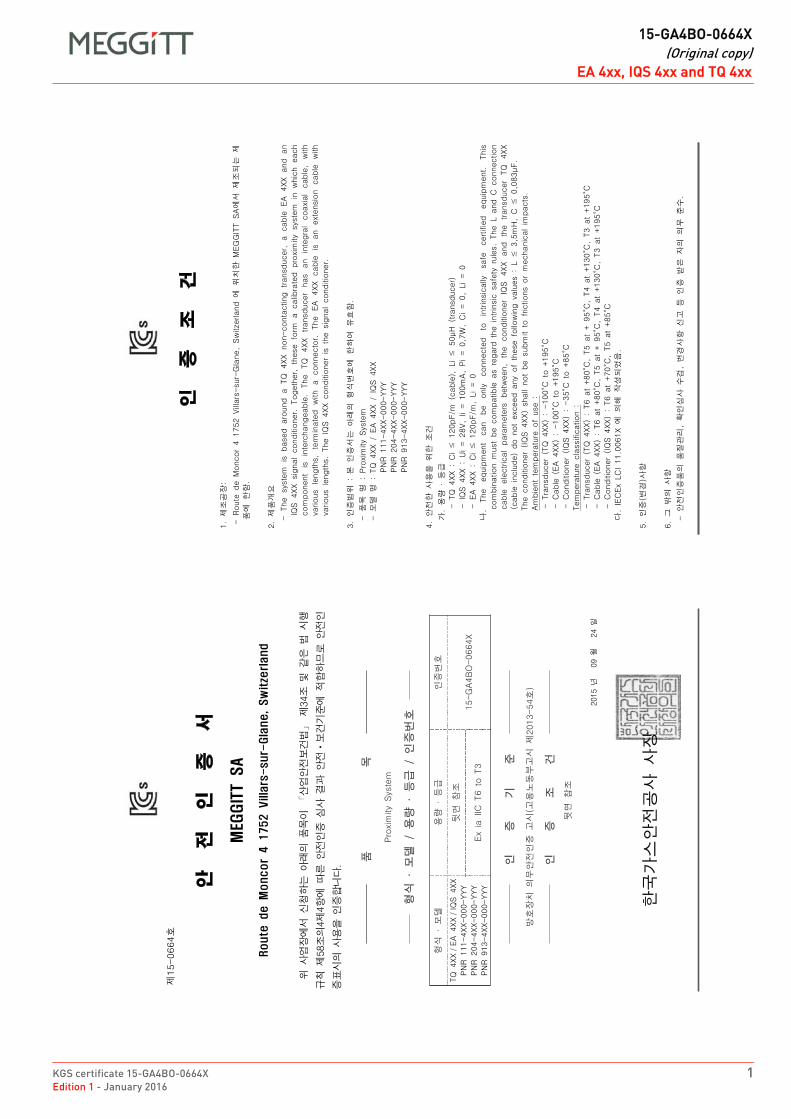
KGS certificate 15-GA4BO-0664X 1Edition 1 - January 2016
DRAFT
15-GA4BO-0664X(Original copy)
EA 4xx, IQS 4xx and TQ 4xxEA 4xx, IQS 4xx and TQ 4xxFR 15-GA4BO-0664X Original copy EN
DRAFT
15-GA4BO-0664X(Original copy)
EA 4xx, IQS 4xx and TQ 4xx
2 KGS certificate 15-GA4BO-0664XEdition 1 - January 2016
THIS PAGE INTENTIONALLY LEFT BLANK
DRAFT
KGS certificate 17-GA4BO-0325XEdition 1 - June 2017
EX
Meggitt SARoute de Moncor 4
PO Box 1616CH - 1701 Fribourg
Switzerland
www.meggittsensingsystems.comwww.vibro-meter.com
Title Page
KGS certificate:
17-GA4BO-0325X
for
GSI127
KO

THIS PAGE INTENTIONALLY LEFT BLANK
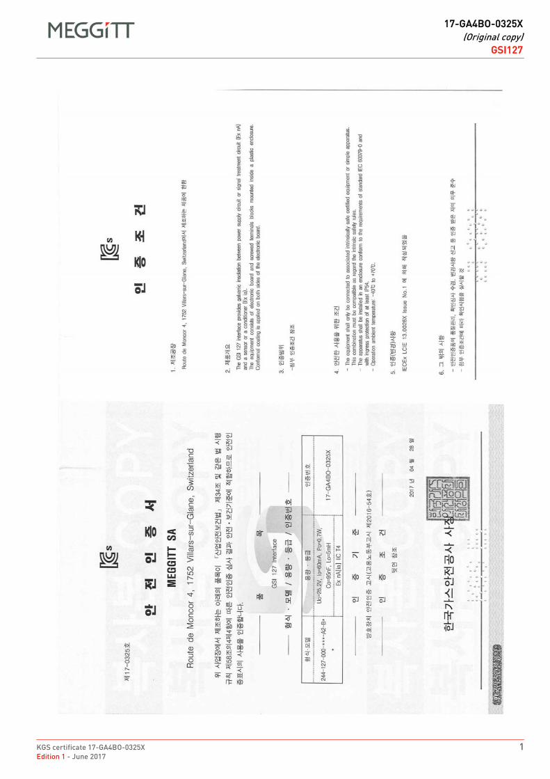
KGS certificate 17-GA4BO-0325X 1Edition 1 - June 2017
DRAFT
17-GA4BO-0325X(Original copy)
GSI127GSI127FR 17-GA4BO-0325X Original copy EN
DRAFT
17-GA4BO-0325X(Original copy)
GSI127
2 KGS certificate 17-GA4BO-0325XEdition 1 - June 2017
GSI127FR 17-GA4BO-0325X Original copy EN

Document reference MAPROX400/E INSTALLATION MANUALEdition 19 - January 2022 Proximity measurement systems using TQ4xx proximity sensors
F - 1
APPENDIX F: UK CERTIFICATIONS
APPENDIX F: UK CERTIFICATIONS
Table F-1: Related UK certificates
Product(s) covered Certificate number
GSI127 CML 21 UKEX 4542 X

INSTALLATION MANUAL Document reference MAPROX400/EProximity measurement systems using TQ4xx proximity sensors Edition 19 - January 2022F - 2
APPENDIX F: UK CERTIFICATIONS
THIS PAGE INTENTIONALLY LEFT BLANK
Meggitt SA, Route de Moncor 4, Case postale, 1701 Fribourg, Switzerland Tel: +41 26 407 1111Fax: +41 26 407 1660
[email protected]/energy
www.meggitt.com
EX CERTIFICATE – UK
Document reference CML 21 UKEX 4542 XEdition 1 – September 2021
Title page
CML 21 UKEX 4542 Xfor
GSI127 galvanic separation unit
EX
Note: Although the Ex certificate may be included in more than one language, the liability ofthe notified body applies only on the text of the original copy of the certificate that it published.

THIS PAGE INTENTIONALLY LEFT BLANK
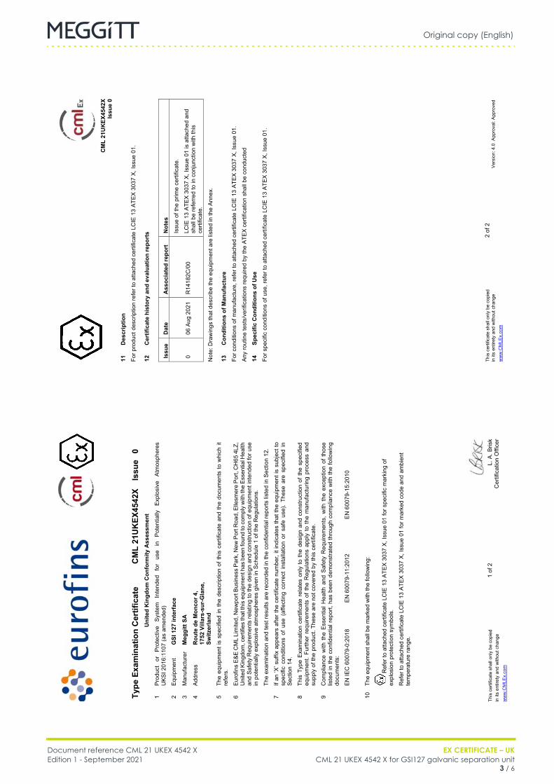
Original copy (English)
Document reference CML 21 UKEX 4542 X EX CERTIFICATE – UKEdition 1 - September 2021 CML 21 UKEX 4542 X for GSI127 galvanic separation unit
3 / 6
IQS9xx
FR CML 21 UKEX 4542 X (EN) Original copy EN
Th
is c
ertif
icat
e sh
all o
nly
be c
opie
d 1
of 2
L.
A. B
risk
in it
s en
tiret
y an
d w
ithou
t cha
nge
C
ertif
icat
ion
Offi
cer
ww
w.C
MLE
x.co
m
Type
Exa
min
atio
n C
ertif
icat
e C
ML
21U
KEX
4542
X Is
sue
0 U
nite
d K
ingd
om C
onfo
rmity
Ass
essm
ent
1 Pr
oduc
t or
Pr
otec
tive
Syst
em
Inte
nded
fo
r us
e in
Po
tent
ially
Ex
plos
ive
Atm
osph
eres
U
KSI 2
016:
1107
(as
amen
ded)
2 Eq
uipm
ent
GSI
127
inte
rfac
e
3 M
anuf
actu
rer
Meg
gitt
SA
4 Ad
dres
s R
oute
de
Mon
cor 4
, 17
52 V
illar
s-su
r-G
lane
, Sw
itzer
land
5 Th
e eq
uipm
ent i
s sp
ecifi
ed in
the
desc
riptio
n of
this
cer
tific
ate
and
the
docu
men
ts to
whi
ch it
re
fers
.
6 Eu
rofin
s E&
E C
ML
Lim
ited,
New
port
Busi
ness
Par
k, N
ew P
ort R
oad,
Elle
smer
e Po
rt, C
H65
4LZ
, U
nite
d Ki
ngdo
m, c
ertif
ies
that
this
equ
ipm
ent h
as b
een
foun
d to
com
ply
with
the
Esse
ntia
l Hea
lth
and
Safe
ty R
equi
rem
ents
rela
ting
to th
e de
sign
and
con
stru
ctio
n of
equ
ipm
ent i
nten
ded
for u
se
in p
oten
t ially
exp
losi
ve a
tmos
pher
es g
iven
in S
ched
ule
1 of
the
Reg
ulat
ions
.
The
exam
inat
ion
and
test
resu
lts a
re re
cord
ed in
the
conf
iden
tial r
epor
ts li
sted
in S
ectio
n 12
.
7 If
an ‘X
’ suf
fix a
ppea
rs a
fter t
he c
ertif
icat
e nu
mbe
r, it
indi
cate
s th
at th
e eq
uipm
ent i
s su
bjec
t to
spec
ific
cond
ition
s of
use
(af
fect
ing
corre
ct in
stal
latio
n or
saf
e us
e).
Thes
e ar
e sp
ecifi
ed in
Se
ctio
n 14
.
8 Th
is T
ype
Exam
inat
ion
certi
ficat
e re
late
s on
ly to
the
desi
gn a
nd c
onst
ruct
ion
of th
e sp
ecifi
ed
equi
pmen
t. Fu
rther
req
uire
men
ts o
f the
Reg
ulat
ions
app
ly to
the
man
ufac
turin
g pr
oces
s an
d su
pply
of t
he p
rodu
ct. T
hese
are
not
cov
ered
by
this
cer
tific
ate.
9 C
ompl
ianc
e w
ith th
e Es
sent
ial H
ealth
and
Saf
ety
Req
uire
men
ts, w
ith t
he e
xcep
tion
of th
ose
liste
d in
the
conf
iden
tial r
epor
t, ha
s be
en d
emon
stra
ted
thro
ugh
com
plia
nce
with
the
follo
win
g do
cum
ents
:
EN
IEC
600
79-0
:201
8 EN
600
79-1
1:20
12
EN 6
0079
-15:
2010
10
The
equi
pmen
t sha
ll be
mar
ked
with
the
follo
win
g:
R
efer
to a
ttach
ed c
ertif
icat
e LC
IE 1
3 AT
EX 3
037
X, Is
sue
01 fo
r spe
cific
mar
king
of
expl
osio
n pr
otec
tion
sym
bols
.
Ref
er to
atta
ched
cer
tific
ate
LCIE
13
ATEX
303
7 X,
Issu
e 01
for m
arke
d co
de a
nd a
mbi
ent
tem
pera
ture
rang
e.
CM
L 21
UK
EX45
42X
Issu
e 0
This
cer
tific
ate
shal
l onl
y be
cop
ied
2
of 2
in it
s en
tiret
y an
d w
ithou
t cha
nge
Vers
ion:
4.0
App
rova
l: Ap
prov
ed
ww
w.C
MLE
x.co
m
11
Des
crip
tion
For p
rodu
ct d
escr
iptio
n re
fer t
o at
tach
ed c
ertif
icat
e LC
IE 1
3 AT
EX 3
037
X, Is
sue
01.
12
Cer
tific
ate
hist
ory
and
eval
uatio
n re
port
s Is
sue
Dat
e A
ssoc
iate
d re
port
N
otes
0 06
Aug
202
1 R
1418
2C/0
0
Issu
e of
the
prim
e ce
rtific
ate.
LCIE
13
ATEX
303
7 X,
Issu
e 01
is a
ttach
ed a
nd
shal
l be
refe
rred
to in
con
junc
tion
with
this
ce
rtific
ate.
Not
e: D
raw
ings
that
des
crib
e th
e eq
uipm
ent a
re li
sted
in th
e An
nex.
13
Con
ditio
ns o
f Man
ufac
ture
For c
ondi
tions
of m
anuf
actu
re, r
efer
to a
ttach
ed c
ertif
icat
e LC
IE 1
3 AT
EX 3
037
X, Is
sue
01.
Any
rout
ine
test
s/ve
rific
atio
ns re
quire
d by
the
ATEX
cer
tific
atio
n sh
all b
e co
nduc
ted
14
Spec
ific
Con
ditio
ns o
f Use
For s
peci
fic c
ondi
tions
of u
se, r
efer
to a
ttach
ed c
ertif
icat
e LC
IE 1
3 AT
EX 3
037
X, Is
sue
01.
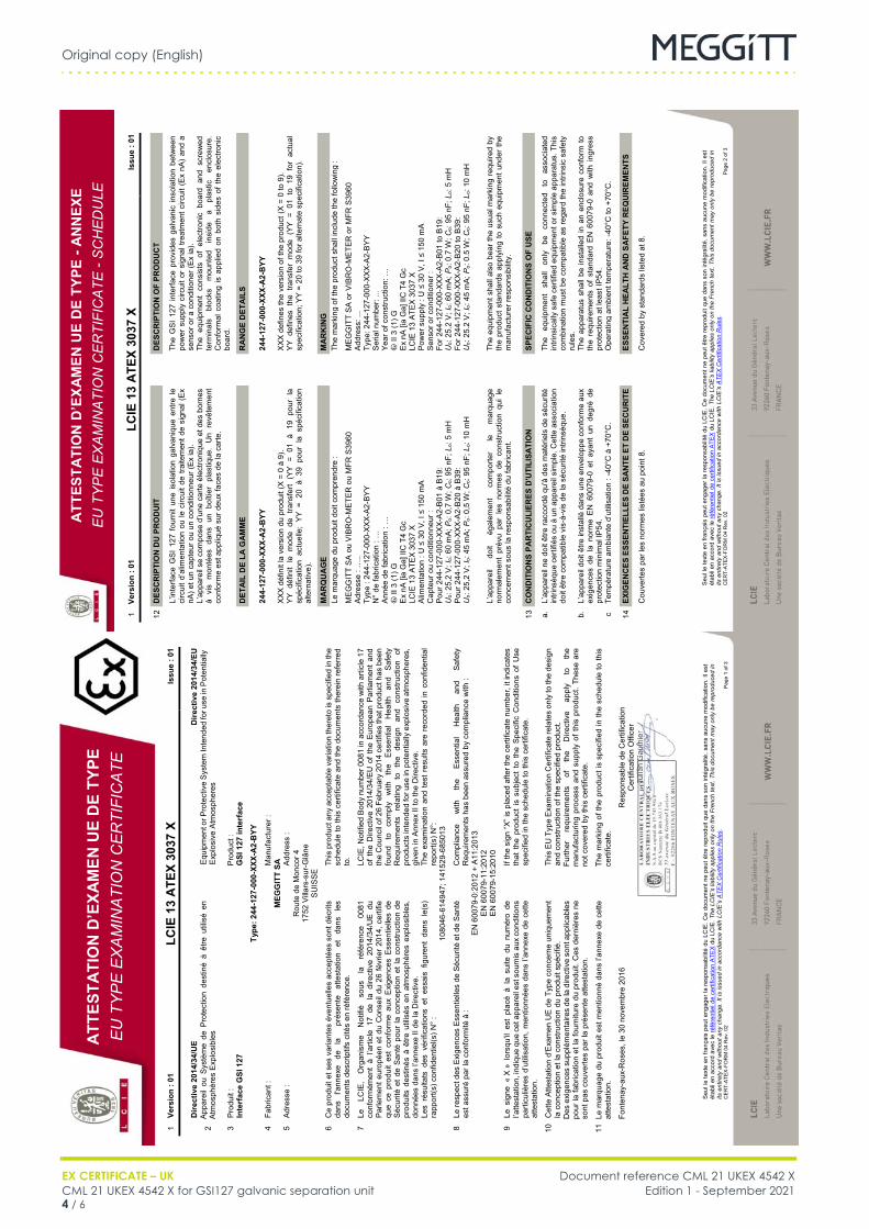
Original copy (English)
EX CERTIFICATE – UK Document reference CML 21 UKEX 4542 XCML 21 UKEX 4542 X for GSI127 galvanic separation unit Edition 1 - September 20214 / 6
IQS9xx
FR CML 21 UKEX 4542 X (EN) Original copy EN
ATT
ESTA
TIO
N D
’EXA
MEN
UE
DE
TYPE
E
U T
YP
E E
XA
MIN
ATI
ON
CER
TIFI
CA
TE
Seu
l le
text
e en
fran
çais
peu
t eng
ager
la re
spon
sabi
lité
du L
CIE
. Ce
docu
men
t ne
peut
être
repr
odui
t que
dan
s so
n in
tégr
alité
, san
s au
cune
mod
ifica
tion.
Il e
st
étab
li en
acc
ord
avec
le ré
fére
ntie
l de
certi
ficat
ion
ATE
X du
LC
IE. T
he L
CIE
’s li
abili
ty a
pplie
s on
ly o
n th
e Fr
ench
text
. Thi
s do
cum
ent m
ay o
nly
be re
prod
uced
in
its e
ntire
ty a
nd w
ithou
t any
cha
nge.
It is
issu
ed in
acc
orda
nce
with
LC
IE’s
ATE
X C
ertif
icat
ion
Rul
es.
CE
RT-
ATEX
-FO
RM
04
Rev
. 02
Page
1 o
f 3
1 Ve
rsio
n : 0
1 LC
IE 1
3 A
TEX
3037
X
Issu
e : 0
1
D
irect
ive
2014
/34/
UE
D
irect
ive
2014
/34/
EU
2 A
ppar
eil
ou S
ystè
me
de P
rote
ctio
n de
stin
é à
être
util
isé
en
Atm
osph
ères
Exp
losi
bles
Equ
ipm
ent o
r Pro
tect
ive
Sys
tem
Inte
nded
for u
se in
Pot
entia
lly
Exp
losi
ve A
tmos
pher
es
3 P
rodu
it :
P
rodu
ct :
In
terf
ace
GSI
127
GSI
127
inte
rfac
e
Ty
pe: 2
44-1
27-0
00-X
XX-A
2-B
YY
4 Fa
bric
ant :
Man
ufac
ture
r :
M
EGG
ITT
SA
5 A
dres
se :
Add
ress
:
R
oute
de
Mon
cor 4
17
52 V
illars
-sur
-Glâ
ne
SU
ISS
E
6 C
e pr
odui
t et s
es v
aria
ntes
éve
ntue
lles
acce
ptée
s so
nt d
écrit
s da
ns
I'ann
exe
de
la
pr
ésen
te
atte
stat
ion
et
dans
le
s do
cum
ents
des
crip
tifs
cité
s en
réfé
renc
e.
Th
is p
rodu
ct a
ny a
ccep
tabl
e va
riatio
n th
eret
o is
spe
cifie
d in
the
sche
dule
to th
is c
ertif
icat
e an
d th
e do
cum
ents
ther
ein
refe
rred
to.
7 Le
LC
IE,
Org
anis
me
Not
ifié
sous
la
ré
fére
nce
0081
co
nfor
mém
ent
à l’a
rticl
e 17
de
la d
irect
ive
2014
/34/
UE
du
Par
lem
ent e
urop
éen
et d
u C
onse
il du
26
févr
ier
2014
, cer
tifie
qu
e ce
pro
duit
est
conf
orm
e au
x E
xige
nces
Ess
entie
lles
de
Séc
urité
et d
e S
anté
pou
r la
con
cept
ion
et la
con
stru
ctio
n de
pr
odui
ts d
estin
és à
être
util
isés
en
atm
osph
ères
exp
losi
bles
, do
nnée
s da
ns l’
anne
xe II
de
la D
irect
ive.
LC
IE, N
otifi
ed B
ody
num
ber 0
081
in a
ccor
danc
e w
ith a
rticl
e 17
of
the
Dire
ctiv
e 20
14/3
4/E
U o
f th
e Eu
rope
an P
arlia
men
t an
d th
e C
ounc
il of
26
Febr
uary
201
4 ce
rtifie
s th
at p
rodu
ct h
as b
een
foun
d to
co
mpl
y w
ith
the
Ess
entia
l H
ealth
an
d S
afet
y R
equi
rem
ents
re
latin
g to
th
e de
sign
an
d co
nstru
ctio
n of
pr
oduc
ts in
tend
ed fo
r use
in p
oten
tially
exp
losi
ve a
tmos
pher
es,
give
n in
Ann
ex II
to th
e D
irect
ive.
Les
résu
ltats
des
vér
ifica
tions
et
essa
is f
igur
ent
dans
le(
s)
rapp
ort(s
) con
fiden
tiel(s
) N°
:
The
exam
inat
ion
and
test
res
ults
are
rec
orde
d in
con
fiden
tial
repo
rt(s)
N°:
1080
46-6
1494
7; 1
4152
9-68
5013
8 Le
resp
ect d
es E
xige
nces
Ess
entie
lles
de S
écur
ité e
t de
San
té
est a
ssur
é pa
r la
conf
orm
ité à
:
Com
plia
nce
with
th
e Es
sent
ial
Hea
lth
and
Safe
ty
Req
uire
men
ts h
as b
een
assu
red
by c
ompl
ianc
e w
ith :
E
N 6
0079
-0:2
012
+ A
11:2
013
E
N 6
0079
-11:
2012
E
N 6
0079
-15:
2010
9 Le
sig
ne «
X »
lor
squ'
il es
t pl
acé
à la
sui
te d
u nu
mér
o de
l’a
ttest
atio
n, in
diqu
e qu
e ce
t app
arei
l est
sou
mis
aux
con
ditio
ns
parti
culiè
res
d’ut
ilisat
ion ,
men
tionn
ées
dans
l’an
nexe
de
cette
at
test
atio
n.
If
the
sign
“X” i
s pl
aced
afte
r the
cer
tific
ate
num
ber,
it in
dica
tes
that
the
pro
duct
is s
ubje
ct t
o th
e Sp
ecifi
c C
ondi
tions
of
Use
sp
ecifi
ed in
the
sche
dule
to th
is c
ertif
icat
e.
10
Cet
te A
ttest
atio
n d'
Exa
men
UE
de
Type
con
cern
e un
ique
men
t la
con
cept
ion
et la
con
stru
ctio
n du
pro
duit
spéc
ifié.
This
EU
Typ
e E
xam
inat
ion
Cer
tific
ate
rela
tes
only
to th
e de
sign
an
d co
nstru
ctio
n of
the
spec
ified
pro
duct
.
Des
exi
genc
es s
uppl
émen
taire
s de
la d
irect
ive
sont
app
licab
les
pour
la fa
bric
atio
n et
la fo
urni
ture
du
prod
uit.
Ces
der
nièr
es n
e so
nt p
as c
ouve
rtes
par l
a pr
ésen
te a
ttest
atio
n.
Fu
rther
re
quire
men
ts
of
the
Dire
ctiv
e ap
ply
to
the
man
ufac
turin
g pr
oces
s an
d su
pply
of
this
pro
duct
. The
se a
re
not c
over
ed b
y th
is c
ertif
icat
e.
11 L
e m
arqu
age
du p
rodu
it es
t men
tionn
é da
ns l’
anne
xe d
e ce
tte
atte
stat
ion.
The
mar
king
of t
he p
rodu
ct is
spe
cifie
d in
the
sche
dule
to th
is
certi
ficat
e.
Fo
nten
ay-a
ux-R
oses
, le
30 n
ovem
bre
2016
Res
pons
able
de
Cer
tific
atio
n
Cer
tific
atio
n O
ffice
r Ju
lien
Gau
thie
r JJJ
llilliilllliGG
aauauuuuuauuauauauauaauauauuaauauauuaauuuuauaauauuuuuuuuuuuuauuuuuuuuuuuuuuuuauauuuuuuuuuaaauuuuuuuuuuauuuuuuuuaaaauuuauuuuaauuaaauuuuaauththtthttttthtttththttthttthtttttttthttttthhhhhhhhhhhhh
ieieieieerrrrrrrrrrrrr
JuJuJuJuJJJuJuJuJuJuJuJuJJuuJJuJJJuJuJJJJJJJJJJJJJJJJllllliillillllilililile
nennnnGGGGGGG
ATT
ESTA
TIO
N D
’EXA
MEN
UE
DE
TYPE
- A
NN
EXE
EU
TY
PE
EX
AM
INA
TIO
N C
ER
TIFI
CA
TE -
SC
HE
DU
LE
Seu
l le
text
e en
fran
çais
peu
t eng
ager
la re
spon
sabi
lité
du L
CIE
. Ce
docu
men
t ne
peut
être
repr
odui
t que
dan
s so
n in
tégr
alité
, san
s au
cune
mod
ifica
tion.
Il e
st
étab
li en
acc
ord
avec
le ré
fére
ntie
l de
certi
ficat
ion
ATE
X du
LC
IE. T
he L
CIE
’s li
abili
ty a
pplie
s on
ly o
n th
e Fr
ench
text
. Thi
s do
cum
ent m
ay o
nly
be re
prod
uced
in
its e
ntire
ty a
nd w
ithou
t any
cha
nge.
It is
issu
ed in
acc
orda
nce
with
LC
IE’s
ATE
X C
ertif
icat
ion
Rul
es.
CE
RT-
ATEX
-FO
RM
04
Rev
. 02
Page
2 o
f 3
1 Ve
rsio
n : 0
1 LC
IE 1
3 A
TEX
3037
X
Issu
e : 0
1
12
DES
CR
IPTI
ON
DU
PR
OD
UIT
DES
CR
IPTI
ON
OF
PRO
DU
CT
L’
inte
rface
GS
I 12
7 fo
urni
t un
e is
olat
ion
galv
aniq
ue e
ntre
le
circ
uit d
’alim
enta
tion
ou le
circ
uit d
e tra
item
ent d
e si
gnal
(E
x nA
) et u
n ca
pteu
r ou
un c
ondi
tionn
eur (
Ex
ia).
L’
appa
reil
se c
ompo
se d
’une
car
te é
lect
roni
que
et d
es b
orne
s à
vis
mon
tées
dan
s un
boî
tier
plas
tique
. U
n re
vête
men
t co
nfor
me
est a
ppliq
ué s
ur d
eux
face
s de
la c
arte
.
Th
e G
SI
127
inte
rface
pro
vide
s ga
lvan
ic in
sola
tion
betw
een
pow
er s
uppl
y ci
rcui
t or
sign
al tr
eatm
ent c
ircui
t (E
x nA
) an
d a
sens
or o
r a c
ondi
tione
r (E
x ia
).
The
equi
pmen
t co
nsis
ts o
f el
ectro
nic
boar
d an
d sc
rew
ed
term
inal
s bl
ocks
m
ount
ed
insi
de
a pl
astic
en
clos
ure.
C
onfo
rmal
coa
ting
is a
pplie
d on
bot
h si
des
of t
he e
lect
roni
c bo
ard.
D
ETA
IL D
E LA
GA
MM
E
RA
NG
E D
ETA
ILS
24
4 -12
7-00
0-XX
X-A
2-B
YY
XX
X dé
finit
la v
ersi
on d
u pr
odui
t (X
= 0
à 9)
. Y
Y dé
finit
le m
ode
de t
rans
fert
(YY
= 01
à 1
9 po
ur l
a sp
écifi
catio
n ac
tuel
le;
YY =
20
à 39
pou
r la
spé
cific
atio
n al
tern
ativ
e).
24
4-12
7-00
0-XX
X-A
2-B
YY
XX
X de
fines
the
vers
ion
of th
e pr
oduc
t (X
= 0
to 9
). Y
Y de
fines
the
tra
nsfe
r m
ode
(YY
= 01
to
19 f
or a
ctua
l sp
ecifi
catio
n; Y
Y =
20 to
39
for a
ltern
ate
spec
ifica
tion)
.
M
AR
QU
AG
E
MA
RK
ING
Le m
arqu
age
du p
rodu
it do
it co
mpr
endr
e :
Th
e m
arki
ng o
f the
pro
duct
sha
ll in
clud
e th
e fo
llow
ing
:
M
EG
GIT
T S
A o
u V
IBR
O-M
ETE
R o
u M
FR S
3960
Adr
esse
: …
.. Ty
pe :
244-
127-
000-
XXX-
A2-
BY
Y
N°
de fa
bric
atio
n : …
A
nnée
de
fabr
icat
ion
: …
� II
3 (1
) G
Ex
nA [i
a G
a] II
C T
4 G
c LC
IE 1
3 A
TEX
3037
X
Alim
enta
tion
: U ≤
30
V, I
≤ 15
0 m
A C
apte
ur o
u co
nditi
onne
ur :
Pou
r 244
-127
-000
-XX
X-A
2-B
01 à
B19
: U
o: 25
,2 V
; Io:
60 m
A; P
o: 0,
7 W
; Co:
95 n
F; L
o: 5
mH
P
our 2
44-1
27-0
00-X
XX-
A2-
B20
à B
39:
Uo:
25,2
V; I
o: 45
mA
; Po:
0,5
W; C
o: 95
nF;
Lo:
10 m
H
M
EG
GIT
T S
A o
r VIB
RO
-ME
TER
or M
FR S
3960
Add
ress
: ...
Type
: 244
-127
-000
-XX
X-A
2-B
YY
S
eria
l num
ber:
...
Ye
ar o
f con
stru
ctio
n: …
�
II 3
(1) G
E
x nA
[ia
Ga]
IIC
T4
Gc
LC
IE 1
3 A
TEX
3037
X
Pow
er s
uppl
y : U
≤ 3
0 V
, I ≤
150
mA
Sen
sor o
r con
ditio
ner :
Fo
r 244
-127
-000
-XX
X-A
2-B
01 to
B19
: U
o: 25
.2 V
; Io:
60 m
A; P
o: 0.
7 W
; Co:
95 n
F; L
o: 5
mH
Fo
r 244
-127
-000
-XX
X-A
2-B
20 to
B39
: U
o: 25
.2 V
; Io:
45 m
A; P
o: 0.
5 W
; Co:
95 n
F; L
o: 10
mH
L’
appa
reil
doit
égal
emen
t co
mpo
rter
le
mar
quag
e no
rmal
emen
t pr
évu
par
les
norm
es d
e co
nstru
ctio
n qu
i le
co
ncer
nent
sou
s la
resp
onsa
bilit
é du
fabr
ican
t.
Th
e eq
uipm
ent s
hall
also
bea
r the
usu
al m
arki
ng re
quire
d by
th
e pr
oduc
t sta
ndar
ds a
pply
ing
to s
uch
equi
pmen
t und
er th
e m
anuf
actu
rer r
espo
nsib
ility.
13
CO
ND
ITIO
NS
PAR
TIC
ULI
ERES
D'U
TILI
SATI
ON
SPEC
IFIC
CO
ND
ITIO
NS
OF
USE
a.
L’ap
pare
il ne
doi
t être
racc
ordé
qu'
à de
s m
atér
iels
de
sécu
rité
intri
nsèq
ue c
ertif
iés
ou à
un
appa
reil
sim
ple.
Cet
te a
ssoc
iatio
n do
it êt
re c
ompa
tible
vis
-à-v
is d
e la
séc
urité
intri
nsèq
ue.
Th
e eq
uipm
ent
shal
l on
ly
be
conn
ecte
d to
as
soci
ated
in
trins
ical
ly s
afe
certi
fied
equi
pmen
t or s
impl
e ap
para
tus.
Thi
s co
mbi
natio
n m
ust b
e co
mpa
tible
as
rega
rd th
e in
trins
ic s
afet
y ru
les.
b.
L’
appa
reil
doit
être
inst
allé
dan
s un
e en
velo
ppe
conf
orm
e au
x ex
igen
ces
de l
a no
rme
EN
600
79-0
et
ayan
t un
deg
ré d
e pr
otec
tion
min
imal
IP54
.
Th
e ap
para
tus
shal
l be
inst
alle
d in
an
encl
osur
e co
nfor
m t
o th
e re
quire
men
ts o
f st
anda
rd E
N 6
0079
-0 a
nd w
ith in
gres
s pr
otec
tion
at le
ast I
P54.
c
Tem
péra
ture
am
bian
te d
’util
isat
ion
: -40
°C à
+70
°C.
O
pera
ting
ambi
ent t
empe
ratu
re: -
40°C
to +
70°C
.
14
EXIG
ENC
ES E
SSEN
TIEL
LES
DE
SAN
TE E
T D
E SE
CU
RIT
E
ESSE
NTI
AL
HEA
LTH
AN
D S
AFE
TY R
EQU
IREM
ENTS
C
ouve
rtes
par l
es n
orm
es li
stée
s au
poi
nt 8
.
C
over
ed b
y st
anda
rds
liste
d at
8.
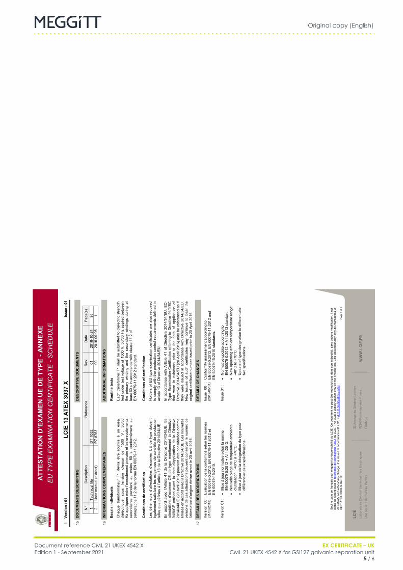
Original copy (English)
Document reference CML 21 UKEX 4542 X EX CERTIFICATE – UKEdition 1 - September 2021 CML 21 UKEX 4542 X for GSI127 galvanic separation unit
5 / 6
IQS9xx
FR CML 21 UKEX 4542 X (EN) Original copy EN
ATT
ESTA
TIO
N D
’EXA
MEN
UE
DE
TYPE
- A
NN
EXE
EU
TY
PE
EX
AM
INA
TIO
N C
ER
TIFI
CA
TE -
SC
HE
DU
LE
Seu
l le
text
e en
fran
çais
peu
t eng
ager
la re
spon
sabi
lité
du L
CIE
. Ce
docu
men
t ne
peut
être
repr
odui
t que
dan
s so
n in
tégr
alité
, san
s au
cune
mod
ifica
tion.
Il e
st
étab
li en
acc
ord
avec
le ré
fére
ntie
l de
certi
ficat
ion
ATE
X du
LC
IE. T
he L
CIE
’s li
abili
ty a
pplie
s on
ly o
n th
e Fr
ench
text
. Thi
s do
cum
ent m
ay o
nly
be re
prod
uced
in
its e
ntire
ty a
nd w
ithou
t any
cha
nge.
It is
issu
ed in
acc
orda
nce
with
LC
IE’s
ATE
X C
ertif
icat
ion
Rul
es.
CE
RT-
ATEX
-FO
RM
04
Rev
. 02
Page
3 o
f 3
1 Ve
rsio
n : 0
1 LC
IE 1
3 A
TEX
3037
X
Issu
e : 0
1
15
DO
CU
MEN
TS D
ESC
RIP
TIFS
DES
CR
IPTI
VE D
OC
UM
ENTS
N
° D
escr
iptio
n R
efer
ence
R
ev.
Dat
e P
age(
s)
1.
Tech
nica
l file
D
T 10
52
01
2016
-10-
24
36
2.
Use
r man
ual (
extra
ct)
PZ
8763
00
20
16-0
9-06
1
16
INFO
RM
ATI
ON
S C
OM
PLEM
ENTA
IRES
AD
DIT
ION
AL
INFO
RM
ATI
ON
S
Es
sais
indi
vidu
els
R
outin
e te
sts
C
haqu
e tra
nsfo
rmat
eur
T1 d
evra
être
sou
mis
à u
n es
sai
diél
ectri
que
sous
te
nsio
n d’
essa
i de
15
00
V ;
50/6
0 H
z ap
pliq
uée
entre
l’enr
oule
men
t prim
aire
et l
es e
nrou
lem
ents
se
cond
aire
s pe
ndan
t au
m
oins
60
s
conf
orm
émen
t au
pa
ragr
aphe
11.
2 de
la n
orm
e E
N 6
0079
-11:
2012
.
E
ach
trans
form
er T
1 sh
all b
e su
bmitt
ed to
die
lect
ric s
treng
th
test
und
er te
st v
olta
ge o
f 150
0 V
; 50/
60 H
z ap
plie
d be
twee
n th
e pr
imar
y w
indi
ng a
nd t
he s
econ
dary
win
ding
s du
ring
at
leas
t 60
s in
acc
orda
nce
with
cla
use
11.2
of
EN
600
79-1
1:20
12 s
tand
ard.
C
ondi
tions
de
cert
ifica
tion
C
ondi
tions
of c
ertif
icat
ion
Le
s dé
tent
eurs
d’a
ttest
atio
ns d
’exa
men
UE
de
type
doi
vent
ég
alem
ent s
atis
faire
les
exig
ence
s de
con
trôle
de
prod
uctio
n te
lles
que
défin
ies
à l’a
rticl
e 13
de
la D
irect
ive
2014
/34/
UE
.
H
olde
rs o
f EU
type
exa
min
atio
n ce
rtific
ates
are
als
o re
quire
d to
com
ply
with
the
prod
uctio
n co
ntro
l req
uire
men
ts d
efin
ed in
ar
ticle
13
of D
irect
ive
2014
/34/
EU
.
E
n ac
cord
ave
c l’A
rticl
e 41
de
la D
irect
ive
2014
/34/
UE
, le
s at
test
atio
ns d
’exa
men
CE
de
type
men
tionn
ant
la D
irect
ive
94/9
/CE
ém
ises
ava
nt l
a da
te d
’app
licat
ion
de l
a D
irect
ive
2014
/34/
UE
(20
avril
201
6) p
euve
nt ê
tre c
onsi
déré
es c
omm
e ém
ises
en
acco
rd a
vec
la D
irect
ive
2014
/34/
UE
. Les
nou
velle
s ve
rsio
ns d
e ce
s at
test
atio
ns p
euve
nt c
onse
rver
le n
umér
o de
l’a
ttest
atio
n d’
orig
ine
émis
e av
ant l
e 20
avr
il 20
16.
In
acc
orda
nce
with
Arti
cle
41 o
f D
irect
ive
2014
/34/
EU
, E
C-
Type
Exa
min
atio
n C
ertif
icat
es r
efer
ring
to D
irect
ive
94/9
/EC
th
at w
ere
in e
xist
ence
prio
r to
the
dat
e of
app
licat
ion
of
Dire
ctiv
e 20
14/3
4/E
U (2
0 A
pril
2016
) may
be
refe
renc
ed a
s if
they
wer
e is
sued
in a
ccor
danc
e w
ith D
irect
ive
2014
/34/
EU
. N
ew i
ssue
s of
suc
h ce
rtific
ates
may
con
tinue
to
bear
the
or
igin
al c
ertif
icat
e nu
mbe
r iss
ued
prio
r to
20 A
pril
2016
.
17
DET
AIL
S D
ES M
OD
IFIC
ATI
ON
S
D
ETA
ILS
OF
CH
AN
GES
V
ersi
on 0
0 :
(31/
05/2
013)
E
valu
atio
n de
la c
onfo
rmité
sel
on le
s no
rmes
E
N 6
0079
-0:2
012,
EN
600
79-1
1:20
12 e
t E
N 6
0079
-15:
2010
.
Is
sue
00 :
(2
013/
05/3
1)
Con
form
ity a
sses
smen
t acc
ordi
ng to
E
N 6
0079
-0:2
012,
EN
600
79-1
1:20
12 a
nd
EN
600
79-1
5:20
10 s
tand
ards
.
V
ersi
on 0
1 :
� M
ise
à jo
ur n
orm
ativ
e se
lon
la n
orm
e
EN
600
79-0
:201
2 +
A11
:201
3.
� N
ouve
lle p
lage
de
tem
péra
ture
am
bian
te
d’ut
ilisat
ion
: -40
°C à
+70
°C
� M
ise
à jo
ur d
e la
dés
igna
tion
du ty
pe p
our
diffé
renc
ier d
eux
spéc
ifica
tions
.
Is
sue
01 :
�
Nor
mat
ive
upda
te a
ccor
ding
to
EN
600
79-0
:201
2 +
A11
:201
3 st
anda
rd.
� N
ew o
pera
ting
ambi
ent t
empe
ratu
re ra
nge:
-4
0°C
to +
70°C
. �
Upd
ate
of ty
pe d
esig
natio
n to
diff
eren
tiate
tw
o sp
ecifi
catio
ns.
Original copy (English)
EX CERTIFICATE – UK Document reference CML 21 UKEX 4542 XCML 21 UKEX 4542 X for GSI127 galvanic separation unit Edition 1 - September 20216 / 6
THIS PAGE INTENTIONALLY LEFT BLANK
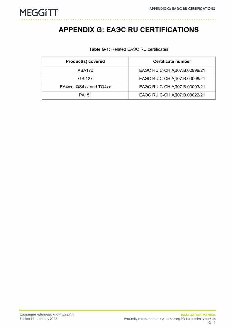
Document reference MAPROX400/E INSTALLATION MANUALEdition 19 - January 2022 Proximity measurement systems using TQ4xx proximity sensors
G - 1
APPENDIX G: EAЭC RU CERTIFICATIONS
APPENDIX G: EAЭC RU CERTIFICATIONS
Table G-1: Related EAЭC RU certificates
Product(s) covered Certificate number
ABA17x EAЭC RU C-CH.AД07.B.02998/21
GSI127 EAЭC RU C-CH.AД07.B.03008/21
EA4xx, IQS4xx and TQ4xx EAЭC RU C-CH.AД07.B.03003/21
PA151 EAЭC RU C-CH.AД07.B.03022/21

INSTALLATION MANUAL Document reference MAPROX400/EProximity measurement systems using TQ4xx proximity sensors Edition 19 - January 2022G - 2
APPENDIX G: EAЭC RU CERTIFICATIONS
THIS PAGE INTENTIONALLY LEFT BLANK
Meggitt SA, Route de Moncor 4, Case postale, 1701 Fribourg, Switzerland Tel: +41 26 407 1111Fax: +41 26 407 1660
[email protected]/energy
www.meggitt.com
EX CERTIFICATE – RU
Document reference EAЭC RU C-CH.AД07.B.02998/21 Edition 1 – March 2021
Title page
EAЭC RU C-CH.AД07.B.02998/21 for
ABA17x industrial housings
EX
Note: Although the Ex certificate may be included in more than one language, the liability ofthe notified body applies only on the text of the original copy of the certificate that it published.

THIS PAGE INTENTIONALLY LEFT BLANK

Original copy (Russian)
Document reference EAЭC RU C-CH.AД07.B.02998/21 EX CERTIFICATE – RUEdition 1 - March 2021 EAЭC RU C-CH.AД07.B.02998/21 for ABA17x
1 / 4
FR EAЭC RU C-CH.AД07.B.02998/21 (EN) Original copy EN

Original copy (Russian)
EX CERTIFICATE – RU Document reference EAЭC RU C-CH.AД07.B.02998/21 EAЭC RU C-CH.AД07.B.02998/21 for ABA17x Edition 1 - March 20212 / 4
FR EAЭC RU C-CH.AД07.B.02998/21 (EN) Original copy EN

Original copy (Russian)
Document reference EAЭC RU C-CH.AД07.B.02998/21 EX CERTIFICATE – RUEdition 1 - March 2021 EAЭC RU C-CH.AД07.B.02998/21 for ABA17x
3 / 4
FR EAЭC RU C-CH.AД07.B.02998/21 (EN) Original copy EN

Original copy (Russian)
EX CERTIFICATE – RU Document reference EAЭC RU C-CH.AД07.B.02998/21 EAЭC RU C-CH.AД07.B.02998/21 for ABA17x Edition 1 - March 20214 / 4
THIS PAGE INTENTIONALLY LEFT BLANK
Meggitt SA, Route de Moncor 4, Case postale, 1701 Fribourg, Switzerland Tel: +41 26 407 1111Fax: +41 26 407 1660
[email protected]/energy
www.meggitt.com
EX CERTIFICATE – RU
Document reference EAЭC RU C-CH.AД07.B.03008/21 Edition 1 – March 2021
Title page
EAЭC RU C-CH.AД07.B.03008/21 for
GSI127 galvanic separation unit
EX
Note: Although the Ex certificate may be included in more than one language, the liability ofthe notified body applies only on the text of the original copy of the certificate that it published.

THIS PAGE INTENTIONALLY LEFT BLANK
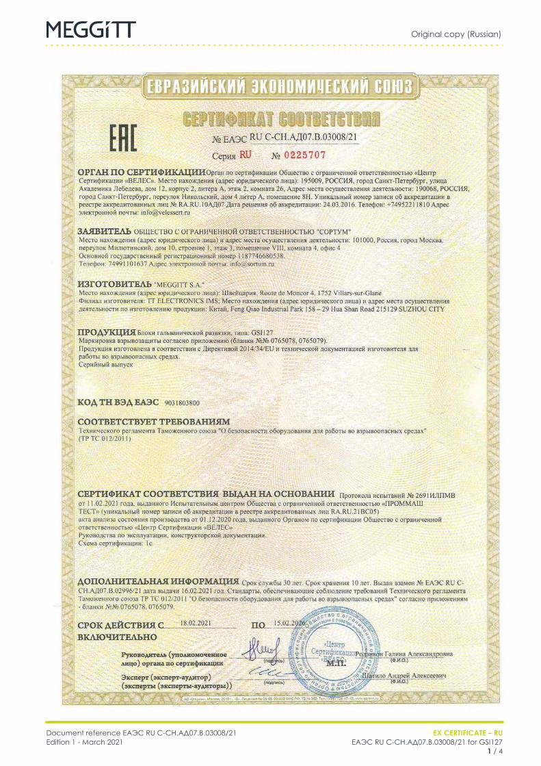
Original copy (Russian)
Document reference EAЭC RU C-CH.AД07.B.03008/21 EX CERTIFICATE – RUEdition 1 - March 2021 EAЭC RU C-CH.AД07.B.03008/21 for GSI127
1 / 4
FR EAЭC RU C-CH.AД07.B.03008/21 (EN) Original copy EN

Original copy (Russian)
EX CERTIFICATE – RU Document reference EAЭC RU C-CH.AД07.B.03008/21 EAЭC RU C-CH.AД07.B.03008/21 for GSI127 Edition 1 - March 20212 / 4
FR EAЭC RU C-CH.AД07.B.03008/21 (EN) Original copy EN

Original copy (Russian)
Document reference EAЭC RU C-CH.AД07.B.03008/21 EX CERTIFICATE – RUEdition 1 - March 2021 EAЭC RU C-CH.AД07.B.03008/21 for GSI127
3 / 4
FR EAЭC RU C-CH.AД07.B.03008/21 (EN) Original copy EN
Original copy (Russian)
EX CERTIFICATE – RU Document reference EAЭC RU C-CH.AД07.B.03008/21 EAЭC RU C-CH.AД07.B.03008/21 for GSI127 Edition 1 - March 20214 / 4
THIS PAGE INTENTIONALLY LEFT BLANK
Meggitt SA, Route de Moncor 4, Case postale, 1701 Fribourg, Switzerland Tel: +41 26 407 1111Fax: +41 26 407 1660
[email protected]/energy
www.meggitt.com
EX CERTIFICATE – RU
Document reference EAЭC RU C-CH.AД07.B.03003/21Edition 1 – March 2021
Title page
EAЭC RU C-CH.AД07.B.03003/21for
TQ4xx, EA4xx and IQS4xxproximity measurement systems
EX
Note: Although the Ex certificate may be included in more than one language, the liability ofthe notified body applies only on the text of the original copy of the certificate that it published.

THIS PAGE INTENTIONALLY LEFT BLANK
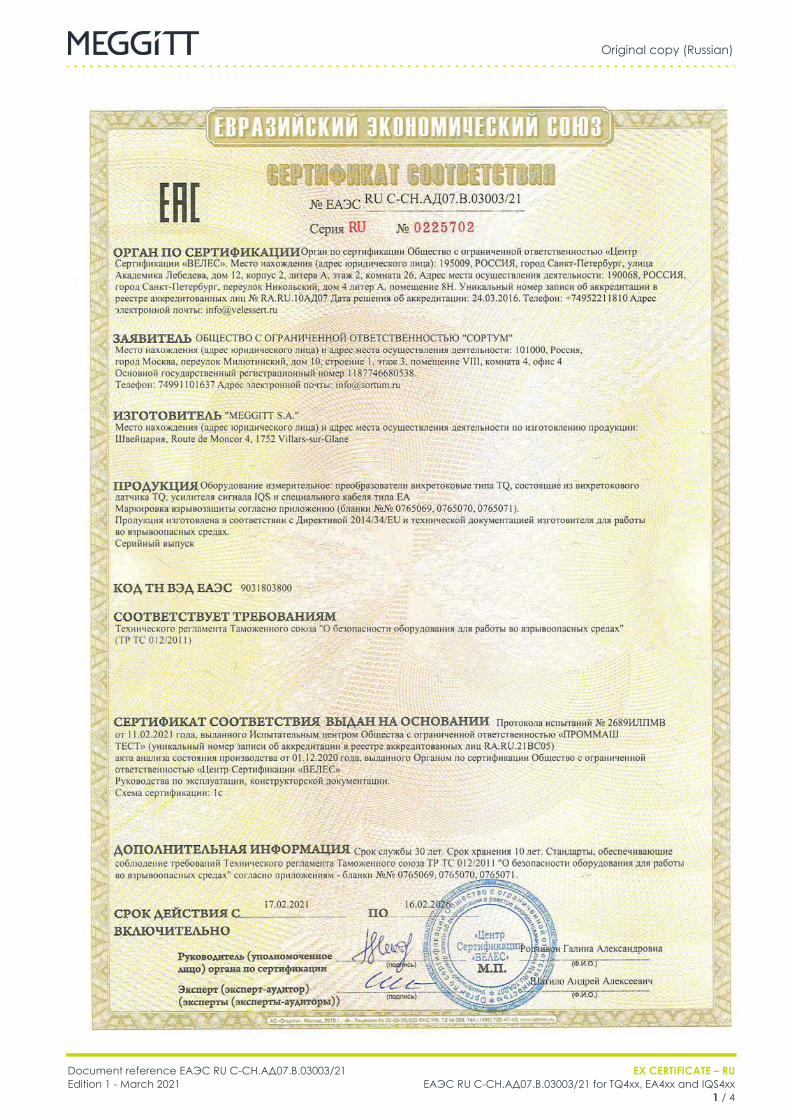
Original copy (Russian)
Document reference EAЭC RU C-CH.AД07.B.03003/21 EX CERTIFICATE – RUEdition 1 - March 2021 EAЭC RU C-CH.AД07.B.03003/21 for TQ4xx, EA4xx and IQS4xx
1 / 4
FR EAЭC RU C-CH.AД07.B.03003/21 (EN) Original copy EN

Original copy (Russian)
EX CERTIFICATE – RU Document reference EAЭC RU C-CH.AД07.B.03003/21EAЭC RU C-CH.AД07.B.03003/21 for TQ4xx, EA4xx and IQS4xx Edition 1 - March 20212 / 4
FR EAЭC RU C-CH.AД07.B.03003/21 (EN) Original copy EN
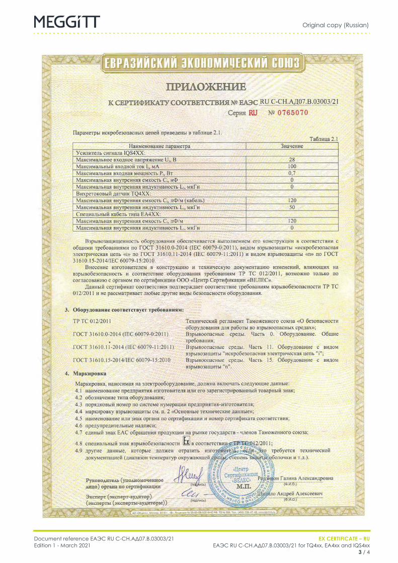
Original copy (Russian)
Document reference EAЭC RU C-CH.AД07.B.03003/21 EX CERTIFICATE – RUEdition 1 - March 2021 EAЭC RU C-CH.AД07.B.03003/21 for TQ4xx, EA4xx and IQS4xx
3 / 4
FR EAЭC RU C-CH.AД07.B.03003/21 (EN) Original copy EN

Original copy (Russian)
EX CERTIFICATE – RU Document reference EAЭC RU C-CH.AД07.B.03003/21EAЭC RU C-CH.AД07.B.03003/21 for TQ4xx, EA4xx and IQS4xx Edition 1 - March 20214 / 4
FR EAЭC RU C-CH.AД07.B.03003/21 (EN) Original copy EN
Meggitt SA, Route de Moncor 4, Case postale, 1701 Fribourg, Switzerland Tel: +41 26 407 1111Fax: +41 26 407 1660
[email protected]/energy
www.meggitt.com
EX CERTIFICATE – RU
Document reference EAЭC RU C-CH.AД07.B.03022/21Edition 1 – March 2021
Title page
EAЭC RU C-CH.AД07.B.03022/21for
PA151 probe mounting adaptor
EX
Note: Although the Ex certificate may be included in more than one language, the liability ofthe notified body applies only on the text of the original copy of the certificate that it published.

THIS PAGE INTENTIONALLY LEFT BLANK
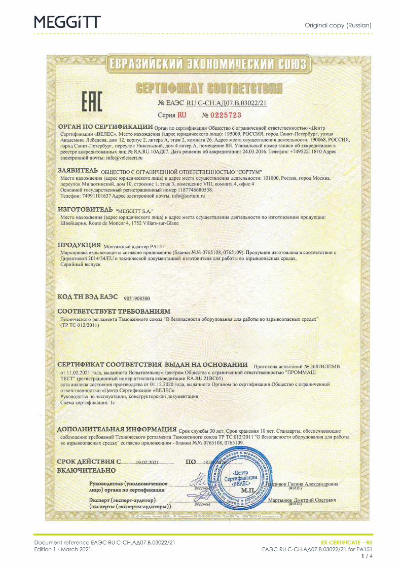
Original copy (Russian)
Document reference EAЭC RU C-CH.AД07.B.03022/21 EX CERTIFICATE – RUEdition 1 - March 2021 EAЭC RU C-CH.AД07.B.03022/21 for PA151
1 / 4
FR EAЭC RU C-CH.AД07.B.03022/21 (EN) Original copy EN

Original copy (Russian)
EX CERTIFICATE – RU Document reference EAЭC RU C-CH.AД07.B.03022/21EAЭC RU C-CH.AД07.B.03022/21 for PA151 Edition 1 - March 20212 / 4
FR EAЭC RU C-CH.AД07.B.03022/21 (EN) Original copy EN

Original copy (Russian)
Document reference EAЭC RU C-CH.AД07.B.03022/21 EX CERTIFICATE – RUEdition 1 - March 2021 EAЭC RU C-CH.AД07.B.03022/21 for PA151
3 / 4
FR EAЭC RU C-CH.AД07.B.03022/21 (EN) Original copy EN

Original copy (Russian)
EX CERTIFICATE – RU Document reference EAЭC RU C-CH.AД07.B.03022/21EAЭC RU C-CH.AД07.B.03022/21 for PA151 Edition 1 - March 20214 / 4
THIS PAGE INTENTIONALLY LEFT BLANK

Document reference MAPROX400/E INSTALLATION MANUALEdition 19 - January 2022 Proximity measurement systems using TQ4xx proximity sensors
H - 1
APPENDIX H: PESO CERTIFICATIONS
APPENDIX H: PESO CERTIFICATIONS
Table H-1: Related PESO certificates
Product(s) covered Certificate number
EA4xx, IQS4xx and TQ4xx PESO A/P/HQ/WB/104/5575 (P447944)
INSTALLATION MANUAL Document reference MAPROX400/EProximity measurement systems using TQ4xx proximity sensors Edition 19 - January 2022H - 2
APPENDIX H: PESO CERTIFICATIONS
THIS PAGE INTENTIONALLY LEFT BLANK
Meggitt SA, Rte de Moncor 4, PO Box 1616, CH-1701 Fribourg, Switzerland Tel: +41 26 407 1111Fax: +41 26 407 1660
[email protected]/energy
www.meggitt.com
EX CERTIFICATE – PESO
Document reference PESO A/P/HQ/WB/104/5575 (P447944)Edition 1 – May 2020
Title page
A/P/HQ/WB/104/5575 (P447944)for
TQ4xx, EA4xx and IQS4xxproximity measurement system
EX
Note: Although the Ex certificate may be included in more than one language, the liability ofthe notified body applies only on the text of the original copy of the certificate that it published.

THIS PAGE INTENTIONALLY LEFT BLANK
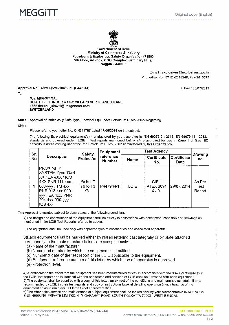
Original copy (English)
Document reference PESO A/P/HQ/WB/104/5575 (P447944) EX CERTIFICATE – PESOEdition 1 - May 2020 A/P/HQ/WB/104/5575 (P447944) for TQ4xx, EA4xx and IQS4xx
1 / 2
FR PESO A/P/HQ/WB/104/5575 (P447944) (EN) Original copy EN

Original copy (English)
EX CERTIFICATE – PESO Document reference PESO A/P/HQ/WB/104/5575 (P447944)A/P/HQ/WB/104/5575 (P447944) for TQ4xx, EA4xx and IQS4xx Edition 1 - May 20202 / 2
FR PESO A/P/HQ/WB/104/5575 (P447944) (EN) Original copy EN


