Embed Size (px)
Citation preview
1. KNKQ375 - 545A - Major Mod - 120410New Cingular Wireless PCS, LLC (KNKQ375)
Nevada 3 - Storey CMA 545A FCC Form 601 Attachment 1
Major Modification
Pursuant to Section 22.107(a), New Cingular Wireless PCS, LLC ("Applicant"), a subsidiary of AT&T Inc. ("AT&T"), is qualified to hold Commission licenses, as has previously been determined.
DEMONSTRATION OF APPLICANT'S QUALIFICATIONS
Pursuant to Section 1.919, Applicant relies on the current FCC Form 602 of Applicant, AT&T, or AT&T Mobility, LLC.
As required by Section 22.107(b), Applicant, the A-block cellular licensee in the Nevada 3 - Storey CMA (545A), herein proposes to add, modify and/or delete cell sites, as detailed in the attached Schedule Ds.
PUBLIC INTEREST STATEMENT
No sites involve any environmental action requiring FCC approval.
Taken together, these sites improve coverage within the CMA, providing increased capacity and continued high quality cellular service. Accordingly, the public interest, convenience, and necessity will be served by grant of this application.
As required pursuant to Section 22.107(d), the existing facilities will operate in compliance with all rules governing the Public Mobile service.
OPERATION OF FACILITY
The existing Cellular Geographic Service Area ("CGSA") shown on the attached map was derived from the most-recent CGSA submission filed with the Commission for this Call Sign.
EXISTING CGSA DETERMINATION
The revisions proposed in this application expand Applicant’s CGSA
CGSA REVISIONS
• within the CMA • into CMA 341, CMA 543, CMA 546 • the expanded CGSA includes areas adjacent to existing coverage • and includes areas of proposed expansion that are less than 50 square miles • and includes areas less than 50 square miles currently being served on a secondary basis where the Applicant is
now seeking protection
Page 1 of 17
New Cingular Wireless PCS, LLC (KNKQ375) Nevada 3 - Storey CMA 545A
FCC Form 601 Attachment 1
The alterations to the CGSA proposed in this application are depicted in the attached map provided in accordance with Section 22.929(c). Because the application expands the existing CGSA, it has been designated a Phase II application. The service area boundaries for the sites in this application were developed in accordance with Section 22.911(a).
The engineering calculations use a minimum of 98' HAAT, per FCC Rule 22.911(a)(3), and 0.1 Watt or 27 db less than maximum ERP, per FCC Rule 22.911(a)(4). Site specific information is provided below and polar antenna radiation patterns are appended hereto.
Applicant acknowledges that grant of this application does not convey the right to interference protection for the service area other than the defined CGSA.
This application includes SAB extensions into one or more adjacent CGSAs. Applicant or its affiliate is either the licensee of the adjacent CGSAs into which the SAB extends, and therefore no written SAB extension agreement is required, or Applicant has the required written SAB extension agreement in its files.
SAB EXTENSION AGREEMENTS
This application is for primary status for sites detailed in the Schedule Ds. The five-year build out period for all markets involved has expired.
ADMINISTRATIVE INFORMATION
Pursuant to Section 22.953(a)(3), the radial distance from the cell-transmitting antenna to its SAB has been calculated in accordance with Section 22.911(a).
TECHNICAL INFORMATION
In accordance with Sections 22.929(c) and 22.953(a)(2), attached to this exhibit is a reduced 8.5” x 11” map, which includes the existing 32 dBu contours of the new sites. The full-scale copy of the system map, as required by Sections 22.929(c) and 22.953(a)(1), will be filed manually under separate cover.
FULL-SIZE 1:500,000 SCALE MAP & REDUCED 8.5” X 11” MAP
[1] See Applications of AT&T Inc. and Cellco Partnership d/b/a Verizon Wireless, For Consent to Assign or Transfer Control of Licenses and Authorizations and Modify a Spectrum Leasing Arrangement, WT Docket No. 09-104, Memorandum Opinion and Order, 25 FCC Rcd 8704 (2010).
Page 2 of 17
New Cingular Wireless PCS, LLC (KNKQ375) Nevada 3 - Storey CMA 545A
FCC Form 601 Attachment 1
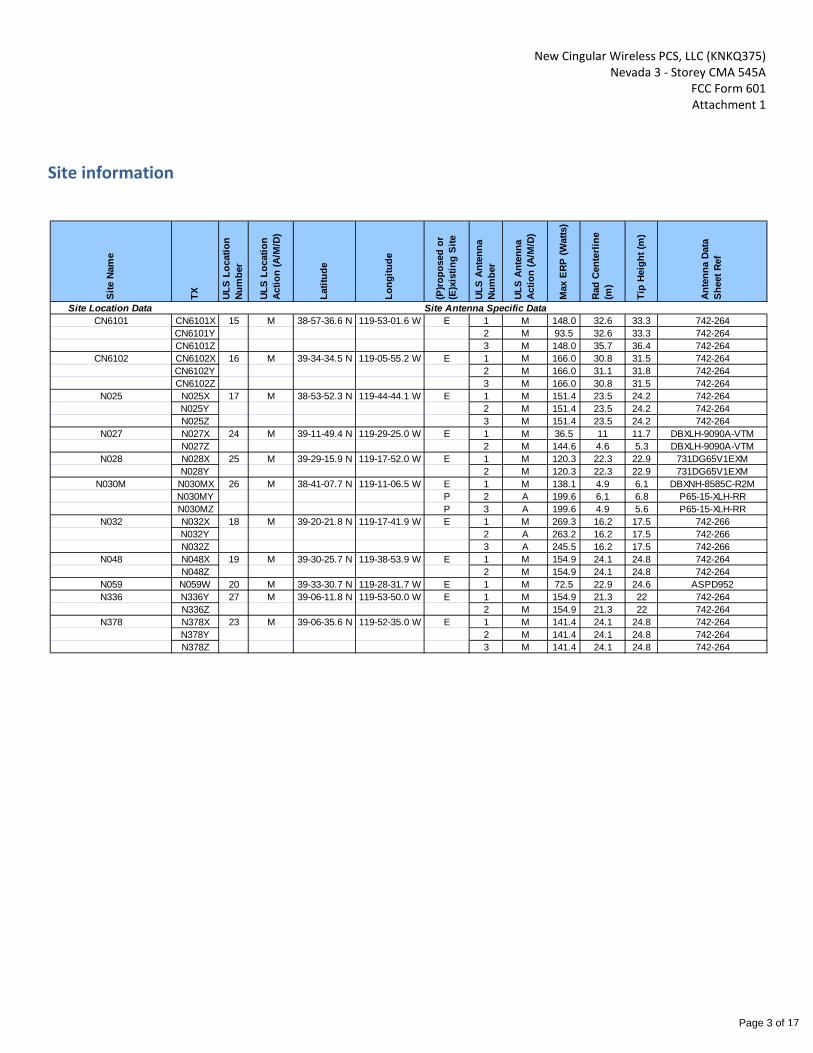
Site information
Site
Nam
e
TX ULS
Loca
tion
Num
ber
ULS
Loca
tion
Actio
n (A
/M/D
)
Latit
ude
Long
itude
(P)ro
pose
d or
(E
)xis
ting
Site
ULS
Ante
nna
Num
ber
ULS
Ante
nna
Actio
n (A
/M/D
)
Max
ERP
(Wat
ts)
Rad
Cent
erlin
e (m
)
Tip
Heig
ht (m
)
Ante
nna
Data
Sh
eet R
ef
Site Location Data Site Antenna Specific DataCN6101 CN6101X 15 M 38-57-36.6 N 119-53-01.6 W E 1 M 148.0 32.6 33.3 742-264
CN6101Y 2 M 93.5 32.6 33.3 742-264CN6101Z 3 M 148.0 35.7 36.4 742-264
CN6102 CN6102X 16 M 39-34-34.5 N 119-05-55.2 W E 1 M 166.0 30.8 31.5 742-264CN6102Y 2 M 166.0 31.1 31.8 742-264CN6102Z 3 M 166.0 30.8 31.5 742-264
N025 N025X 17 M 38-53-52.3 N 119-44-44.1 W E 1 M 151.4 23.5 24.2 742-264N025Y 2 M 151.4 23.5 24.2 742-264N025Z 3 M 151.4 23.5 24.2 742-264
N027 N027X 24 M 39-11-49.4 N 119-29-25.0 W E 1 M 36.5 11 11.7 DBXLH-9090A-VTMN027Z 2 M 144.6 4.6 5.3 DBXLH-9090A-VTM
N028 N028X 25 M 39-29-15.9 N 119-17-52.0 W E 1 M 120.3 22.3 22.9 731DG65V1EXMN028Y 2 M 120.3 22.3 22.9 731DG65V1EXM
N030M N030MX 26 M 38-41-07.7 N 119-11-06.5 W E 1 M 138.1 4.9 6.1 DBXNH-8585C-R2MN030MY P 2 A 199.6 6.1 6.8 P65-15-XLH-RRN030MZ P 3 A 199.6 4.9 5.6 P65-15-XLH-RR
N032 N032X 18 M 39-20-21.8 N 119-17-41.9 W E 1 M 269.3 16.2 17.5 742-266N032Y 2 A 263.2 16.2 17.5 742-266N032Z 3 A 245.5 16.2 17.5 742-266
N048 N048X 19 M 39-30-25.7 N 119-38-53.9 W E 1 M 154.9 24.1 24.8 742-264N048Z 2 M 154.9 24.1 24.8 742-264
N059 N059W 20 M 39-33-30.7 N 119-28-31.7 W E 1 M 72.5 22.9 24.6 ASPD952N336 N336Y 27 M 39-06-11.8 N 119-53-50.0 W E 1 M 154.9 21.3 22 742-264
N336Z 2 M 154.9 21.3 22 742-264N378 N378X 23 M 39-06-35.6 N 119-52-35.0 W E 1 M 141.4 24.1 24.8 742-264
N378Y 2 M 141.4 24.1 24.8 742-264N378Z 3 M 141.4 24.1 24.8 742-264
Page 3 of 17
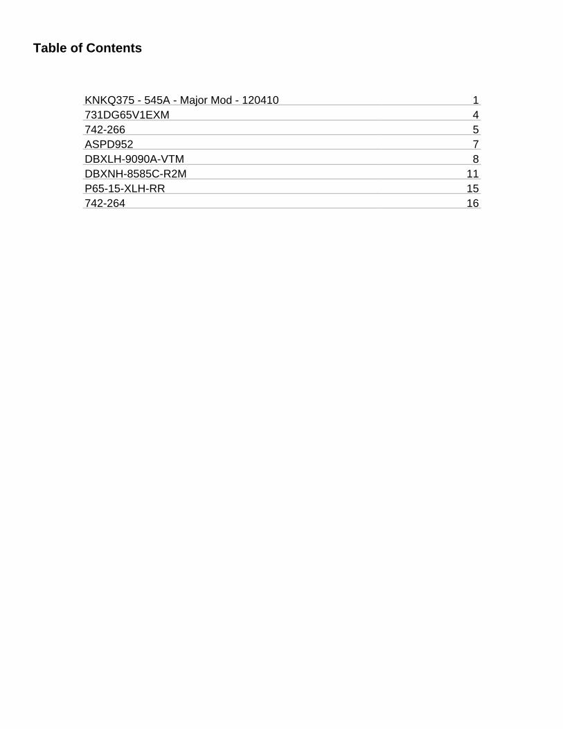
Table of Contents
KNKQ375 - 545A - Major Mod - 120410 1731DG65V1EXM 4742-266 5ASPD952 7DBXLH-9090A-VTM 8DBXNH-8585C-R2M 11P65-15-XLH-RR 15742-264 16
2. 731DG65V1EXM
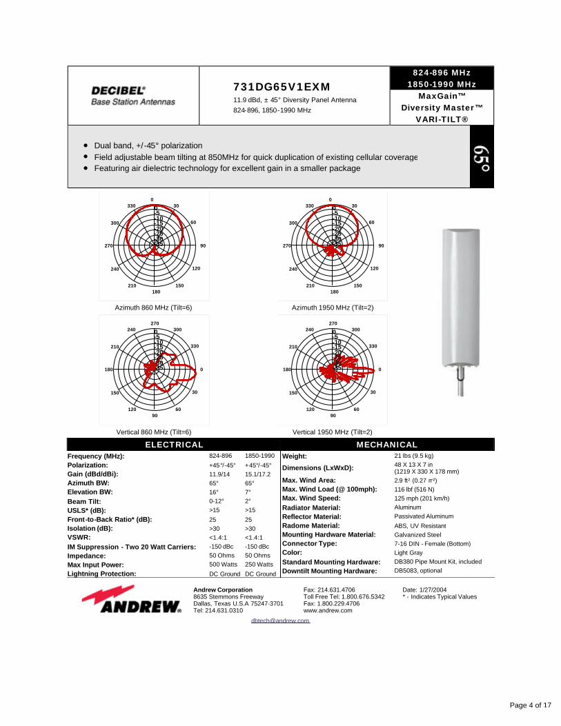
731DG65V1EXM 11.9 dBd, ± 45° Diversity Panel Antenna 824-896, 1850-1990 MHz
824-896 MHz 1850-1990 MHz
MaxGain™Diversity Master™
VARI-TILT®
l Dual band, +/-45° polarization l Field adjustable beam tilting at 850MHz for quick duplication of existing cellular coverage l Featuring air dielectric technology for excellent gain in a smaller package
Azimuth 860 MHz (Tilt=6)
90
120
150180
210
240
270
300
3300
30
60
0-5-10-15-20-25-30-35
Azimuth 1950 MHz (Tilt=2)
90
120
150180
210
240
270
300
3300
30
60
0-5-10-15-20-25-30-35
Vertical 860 MHz (Tilt=6)
0
30
6090
120
150
180
210
240270
300
330
0-5-10-15-20-25-30-35
Vertical 1950 MHz (Tilt=2)
0
30
6090
120
150
180
210
240270
300
330
0-5-10-15-20-25-30-35
ELECTRICALFrequency (MHz): 824-896 1850-1990Polarization: +45°/-45° +45°/-45°Gain (dBd/dBi): 11.9/14 15.1/17.2Azimuth BW: 65° 65°Elevation BW: 16° 7°Beam Tilt: 0-12° 2°USLS* (dB): >15 >15Front-to-Back Ratio* (dB): 25 25Isolation (dB): >30 >30VSWR: <1.4:1 <1.4:1IM Suppression - Two 20 Watt Carriers: -150 dBc -150 dBcImpedance: 50 Ohms 50 OhmsMax Input Power: 500 Watts 250 WattsLightning Protection: DC Ground DC Ground
MECHANICALWeight: 21 lbs (9.5 kg)
Dimensions (LxWxD): 48 X 13 X 7 in (1219 X 330 X 178 mm)
Max. Wind Area: 2.9 ft² (0.27 m²)Max. Wind Load (@ 100mph): 116 lbf (516 N)Max. Wind Speed: 125 mph (201 km/h)Radiator Material: AluminumReflector Material: Passivated AluminumRadome Material: ABS, UV ResistantMounting Hardware Material: Galvanized SteelConnector Type: 7-16 DIN - Female (Bottom)Color: Light GrayStandard Mounting Hardware: DB380 Pipe Mount Kit, includedDowntilt Mounting Hardware: DB5083, optional
Andrew Corporation 8635 Stemmons Freeway Dallas, Texas U.S.A 75247-3701 Tel: 214.631.0310
Fax: 214.631.4706 Toll Free Tel: 1.800.676.5342 Fax: 1.800.229.4706 www.andrew.com
Date: 1/27/2004 * - Indicates Typical Values
Page 4 of 17
3. 742-266
Kathrein Inc., Scala Division Post Office Box 4580 Medford, OR 97501 (USA) Phone: (541) 779-6500 Fax: (541) 779-3991Email: [email protected] Internet: www.kathrein-scala.com
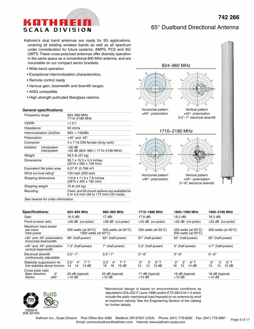
Kathrein’s dual band antennas are ready for 3G applications, covering all existing wireless bands as well as all spectrum under consideration for future systems, AMPS, PCS and 3G/UMTS. These cross-polarized antennas offer diversity operation in the same space as a conventional 800 MHz antenna, and are mountable on our compact sector brackets.
• Wide band operation.
• Exceptional intermodulation characteristics.
• Remote control ready.
• Various gain, beamwidth and downtilt ranges.
• AISG compatible.
• High strength pultruded fiberglass radome.
General specifications: Frequency range 824–960 MHz
1710–2180 MHz
VSWR <1.5:1
Impedance 50 ohms
Intermodulation (2x20w) IM3: <-150dBc
Polarization +45° and -45°
Connector 4 x 7-16 DIN female (long neck)
Isolation intrasystem >30 dB intersystem >50 dB (824–960 // 1710–2180 MHz)
Weight 59.5 lb (27 kg)
Dimensions 99.1 x 10.3 x 5.5 inches (2516 x 262 x 139 mm)
Equivalent flat plate area 8.27 ft2 (0.768 m2)
Wind survival rating* 120 mph (200 kph)
Shipping dimensions 110.8 x 11.9 x 7.8 inches (2815 x 302 x 192 mm)
Shipping weight 75 lb (34 kg)
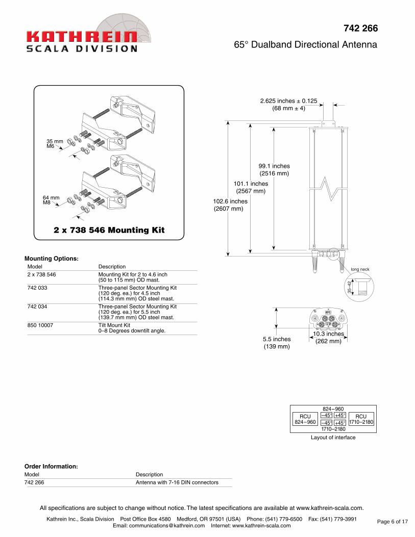
Mounting Fixed and tilt mount options are available for 2 to 4.6 inch (50 to 115 mm) OD masts.
See reverse for order information.
Horizontal pattern±45°- polarization
Vertical pattern±45°- polarization
0°–6° electrical downtilt
Vertical pattern±45°- polarization
0.5°–7° electrical downtilt
Horizontal pattern±45°- polarization
* Mechanical design is based on environmental conditions as stipulated in EIA-222-F (June 1996) and/or ETS 300 019-1-4 which include the static mechanical load imposed on an antenna by wind at maximum velocity. See the Engineering Section of the catalog for further details.
824–960 MHz
1710–2180 MHz
10635-K 936.3219/b
742 266
65° Dualband Directional Antenna
Specifications: 824–894 MHz 880–960 MHz 1710–1880 MHz 1850–1990 MHz 1900–2180 MHzGain 16.5 dBi 17 dBi 17.8 dBi 18.2 dBi 18.3 dBi
Front-to-back ratio >28 dB (co-polar) >28 dB (co-polar) >25 dB (co-polar) >25 dB (co-polar) >25 dB (co-polar)
Maximum input power per input 500 watts (at 50°C) 500 watts (at 50°C) 250 watts (at 50°C) 250 watts (at 50°C) 250 watts (at 50°C) total power 1000 watts (at 50°C) 500 watts (at 50°C)
+45° and -45° polarization 68° (half-power) 65° (half-power) 67° (half-power) 65° (half-power) 62° (half-power) horizontal beamwidth
+45° and -45° polarization 7.3° (half-power) 7° (half-power) 5.2° (half-power) 5° (half-power) 4.7° (half-power) vertical beamwidth
Electrical downtilt 0.5°–7° 0.5°–7° 0°–6° 0°–6° 0°–6° continuously adjustable
Sidelobe suppression for 0.5° 4° 7° T 0.5° 4° 7° T 0° 3° 6° T 0° 3° 6° T 0° 3° 6° T first sidelobe above horizon 14 14 14 dB 16 16 16 dB 13 13 13 dB 16 15 14 dB 15 15 15 dB
Cross polar ratio Main direction 0° 20 dB (typical) 20 dB (typical) 17 dB (typical) 18 dB (typical) 18 dB (typical) Sector ±60° >10 dB >10 dB >10 dB >10 dB >10 dB
Page 5 of 17
Kathrein Inc., Scala Division Post Office Box 4580 Medford, OR 97501 (USA) Phone: (541) 779-6500 Fax: (541) 779-3991Email: [email protected] Internet: www.kathrein-scala.com
All specifications are subject to change without notice. The latest specifications are available at www.kathrein-scala.com.
long neck
35–4
2
10.3 inches(262 mm)
102.6 inches(2607 mm)
99.1 inches(2516 mm)
5.5 inches(139 mm)
Order Information:Model Description
742 266 Antenna with 7-16 DIN connectors
742 266
65° Dualband Directional Antenna
101.1 inches(2567 mm)
2.625 inches ± 0.125(68 mm ± 4)
Mounting Options:Model Description
2 x 738 546 Mounting Kit for 2 to 4.6 inch (50 to 115 mm) OD mast.
742 033 Three-panel Sector Mounting Kit (120 deg. ea.) for 4.5 inch (114.3 mm mm) OD steel mast.
742 034 Three-panel Sector Mounting Kit (120 deg. ea.) for 5.5 inch (139.7 mm mm) OD steel mast.
850 10007 Tilt Mount Kit 0–8 Degrees downtilt angle.
2 x 738 546 Mounting Kit
35 mmM6
64 mmM8
Page 6 of 17
4. ASPD952
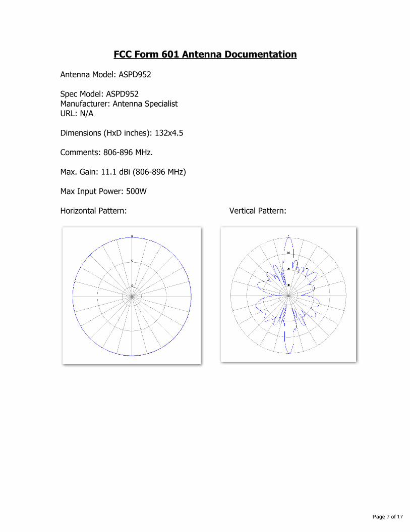
FCC Form 601 Antenna Documentation
Antenna Model: ASPD952
Spec Model: ASPD952
Manufacturer: Antenna Specialist URL: N/A
Dimensions (HxD inches): 132x4.5
Comments: 806-896 MHz.
Max. Gain: 11.1 dBi (806-896 MHz)
Max Input Power: 500W
Horizontal Pattern: Vertical Pattern:
Page 7 of 17
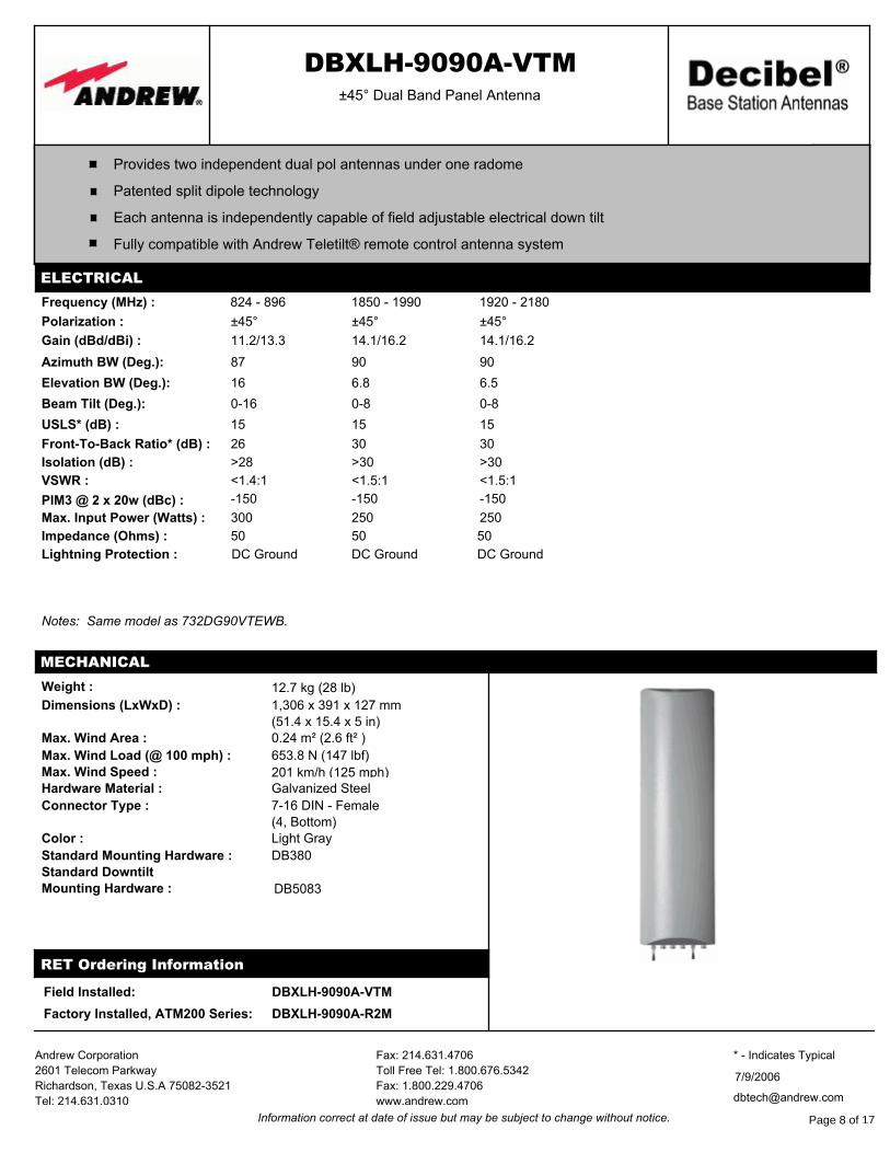
5. DBXLH-9090A-VTM DBXLH-9090A-VTM±45° Dual Band Panel Antenna
Each antenna is independently capable of field adjustable electrical down tilt
Fully compatible with Andrew Teletilt® remote control antenna system
Patented split dipole technology
Provides two independent dual pol antennas under one radome
ELECTRICAL
Frequency (MHz) : 824 - 896 1850 - 1990 1920 - 2180
Polarization : ±45° ±45° ±45°
Gain (dBd/dBi) : 11.2/13.3 14.1/16.2 14.1/16.2
Azimuth BW (Deg.): 87 90 90
Elevation BW (Deg.): 16 6.8 6.5
Beam Tilt (Deg.): 0-16 0-8 0-8
USLS* (dB) : 15 15 15
Front-To-Back Ratio* (dB) : 26 30 30
Isolation (dB) : >28 >30 >30
VSWR : <1.4:1 <1.5:1 <1.5:1
PIM3 @ 2 x 20w (dBc) : -150 -150 -150
Max. Input Power (Watts) : 300 250 250
Impedance (Ohms) : 50 50 50
Lightning Protection : DC Ground DC Ground DC Ground
Notes: Same model as 732DG90VTEWB.
DBXLH-9090A-VTMField Installed:
Weight : 12.7 kg (28 lb)
Dimensions (LxWxD) : 1,306 x 391 x 127 mm(51.4 x 15.4 x 5 in)
Max. Wind Area : 0.24 m² (2.6 ft² )
Max. Wind Load (@ 100 mph) : 653.8 N (147 lbf)
Max. Wind Speed : 201 km/h (125 mph)Hardware Material : Galvanized Steel
Connector Type : 7-16 DIN - Female(4, Bottom)
Color : Light Gray
Standard Mounting Hardware : DB380
Standard Downtilt Mounting Hardware : DB5083
MECHANICAL
RET Ordering Information
DBXLH-9090A-R2MFactory Installed, ATM200 Series:
Fax: 214.631.4706
Toll Free Tel: 1.800.676.5342
Fax: 1.800.229.4706
www.andrew.com
Andrew Corporation
2601 Telecom Parkway
Richardson, Texas U.S.A 75082-3521
Tel: 214.631.0310 [email protected]
7/9/2006
* - Indicates Typical
Information correct at date of issue but may be subject to change without notice. Page 8 of 17
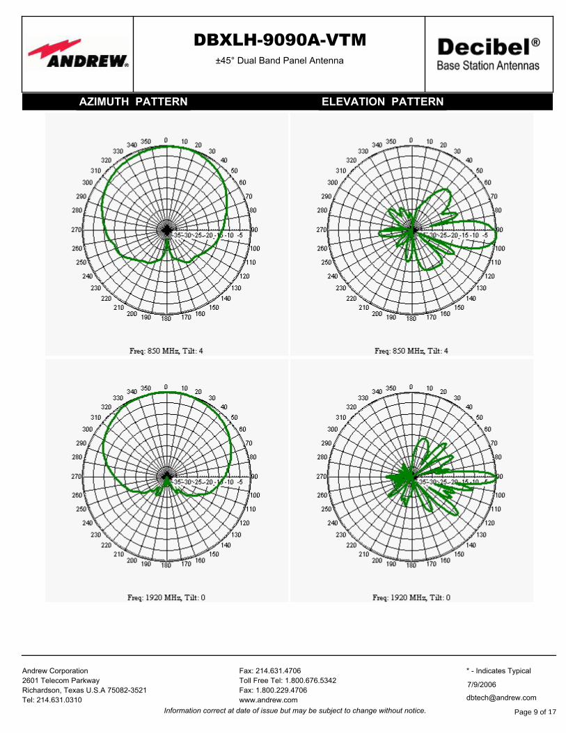
DBXLH-9090A-VTM±45° Dual Band Panel Antenna
AZIMUTH PATTERN ELEVATION PATTERN
Fax: 214.631.4706
Toll Free Tel: 1.800.676.5342
Fax: 1.800.229.4706
www.andrew.com
Andrew Corporation
2601 Telecom Parkway
Richardson, Texas U.S.A 75082-3521
Tel: 214.631.0310 [email protected]
7/9/2006
* - Indicates Typical
Information correct at date of issue but may be subject to change without notice. Page 9 of 17
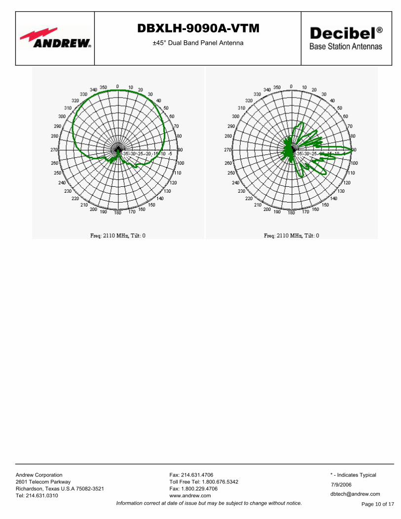
DBXLH-9090A-VTM±45° Dual Band Panel Antenna
Fax: 214.631.4706
Toll Free Tel: 1.800.676.5342
Fax: 1.800.229.4706
www.andrew.com
Andrew Corporation
2601 Telecom Parkway
Richardson, Texas U.S.A 75082-3521
Tel: 214.631.0310 [email protected]
7/9/2006
* - Indicates Typical
Information correct at date of issue but may be subject to change without notice. Page 10 of 17
6. DBXNH-8585C-R2M
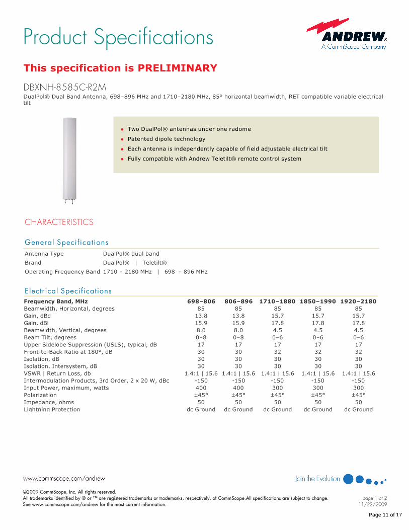
This specification is PRELIMINARY
DualPol® Dual Band Antenna, 698–896 MHz and 1710–2180 MHz, 85° horizontal beamwidth, RET compatible variable electrical tilt
DBXNH-8585C-R2M
l Two DualPol® antennas under one radome
l Patented dipole technology
l Each antenna is independently capable of field adjustable electrical tilt
l Fully compatible with Andrew Teletilt® remote control system
CHARACTERISTICS
General Specif ications Antenna Type DualPol® dual band
Brand DualPol® | Teletilt®
Operating Frequency Band 1710 – 2180 MHz | 698 – 896 MHz
Electrical SpecificationsFrequency Band, MHz 698–806 806–896 1710–1880 1850–1990 1920–2180Beamwidth, Horizontal, degrees 85 85 85 85 85Gain, dBd 13.8 13.8 15.7 15.7 15.7Gain, dBi 15.9 15.9 17.8 17.8 17.8Beamwidth, Vertical, degrees 8.0 8.0 4.5 4.5 4.5Beam Tilt, degrees 0–8 0–8 0–6 0–6 0–6Upper Sidelobe Suppression (USLS), typical, dB 17 17 17 17 17FronttoBack Ratio at 180°, dB 30 30 32 32 32Isolation, dB 30 30 30 30 30Isolation, Intersystem, dB 30 30 30 30 30VSWR | Return Loss, db 1.4:1 | 15.6 1.4:1 | 15.6 1.4:1 | 15.6 1.4:1 | 15.6 1.4:1 | 15.6Intermodulation Products, 3rd Order, 2 x 20 W, dBc 150 150 150 150 150Input Power, maximum, watts 400 400 300 300 300Polarization ±45° ±45° ±45° ±45° ±45°Impedance, ohms 50 50 50 50 50Lightning Protection dc Ground dc Ground dc Ground dc Ground dc Ground
Product Specifications
©2009 CommScope, Inc. All rights reserved.All trademarks identified by ® or ™ are registered trademarks or trademarks, respectively, of CommScope.All specifications are subject to change. See www.commscope.com/andrew for the most current information.
page 1 of 211/22/2009
Page 11 of 17
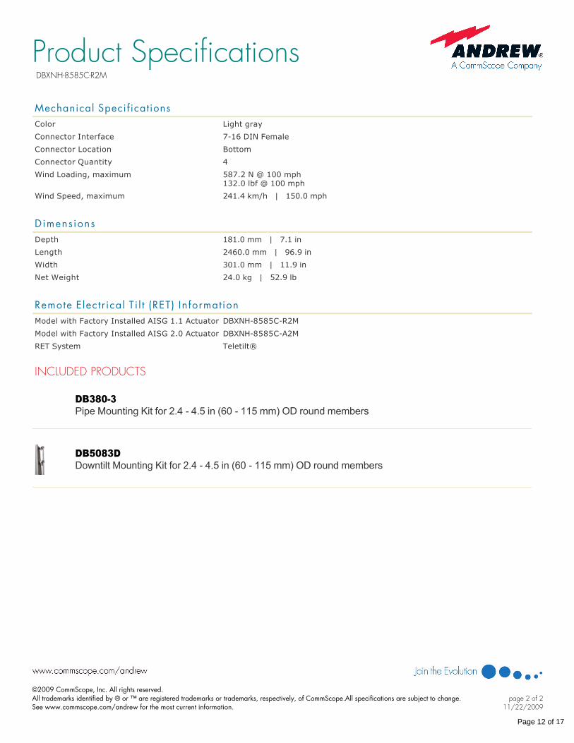
Mechanical Specif ications Color Light gray
Connector Interface 716 DIN Female
Connector Location Bottom
Connector Quantity 4
Wind Loading, maximum 587.2 N @ 100 mph132.0 lbf @ 100 mph
Wind Speed, maximum 241.4 km/h | 150.0 mph
Dimens ions Depth 181.0 mm | 7.1 in
Length 2460.0 mm | 96.9 in
Width 301.0 mm | 11.9 in
Net Weight 24.0 kg | 52.9 lb
Remote E lec t r ical T i l t (RET) In format ion Model with Factory Installed AISG 1.1 Actuator DBXNH8585CR2M
Model with Factory Installed AISG 2.0 Actuator DBXNH8585CA2M
RET System Teletilt®
INCLUDED PRODUCTS
DB3803 Pipe Mounting Kit for 2.4 4.5 in (60 115 mm) OD round members
DB5083D Downtilt Mounting Kit for 2.4 4.5 in (60 115 mm) OD round members
Product SpecificationsDBXNH-8585C-R2M
©2009 CommScope, Inc. All rights reserved.All trademarks identified by ® or ™ are registered trademarks or trademarks, respectively, of CommScope.All specifications are subject to change. See www.commscope.com/andrew for the most current information.
page 2 of 211/22/2009
Page 12 of 17
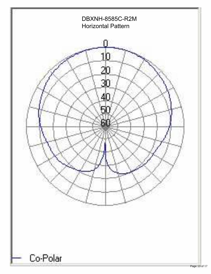
DBXNH-8585C-R2MHorizontal Pattern
Page 13 of 17
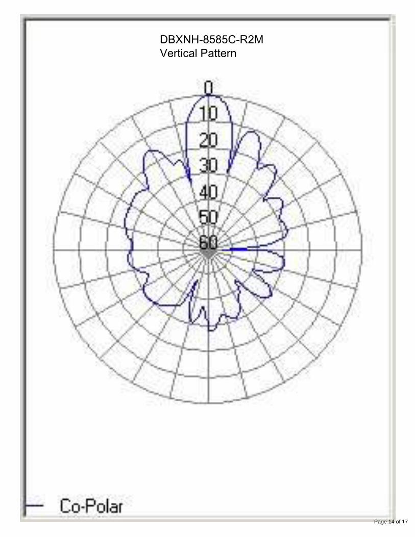
DBXNH-8585C-R2MVertical Pattern
Page 14 of 17
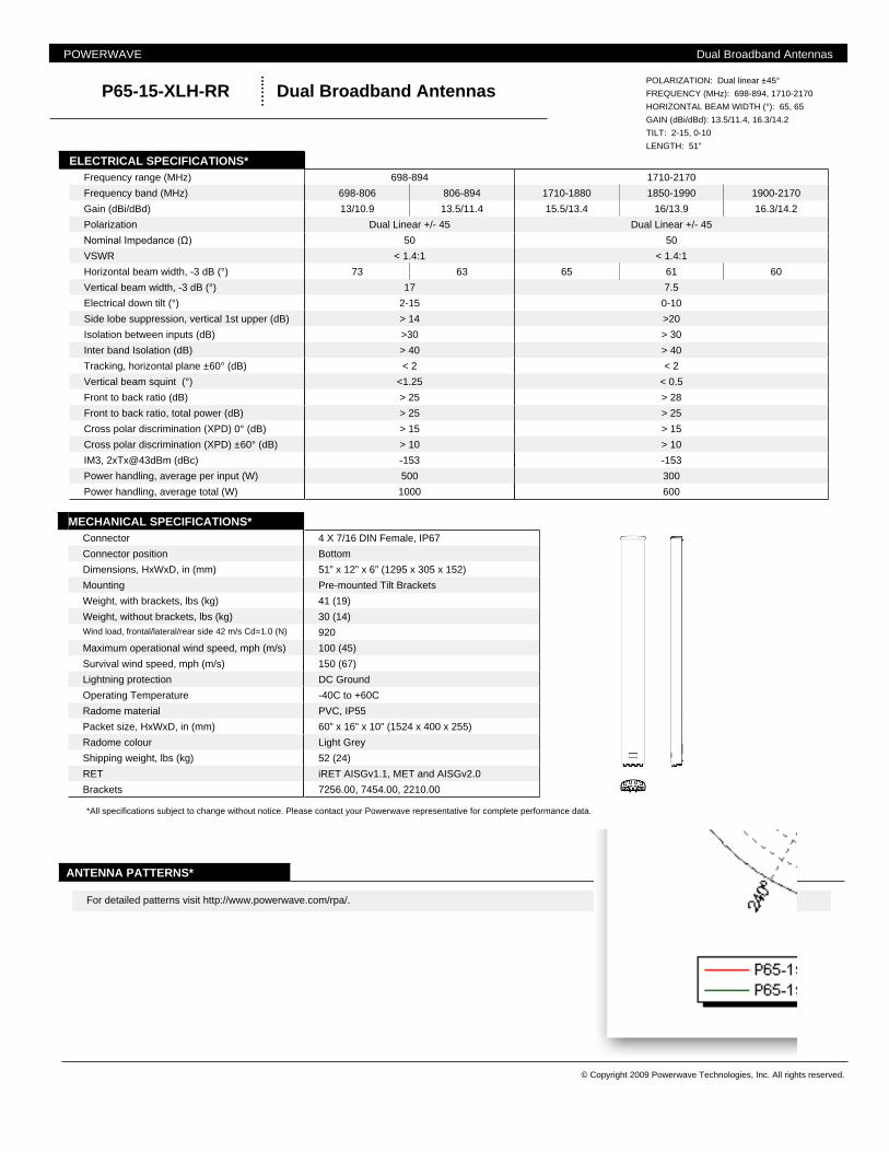
Dual Broadband AntennasP65-15-XLH-RR
ANTENNA PATTERNS*
*All specifications subject to change without notice. Please contact your Powerwave representative for complete performance data.
For detailed patterns visit http://www.powerwave.com/rpa/.
Frequency range (MHz) 698-894 1710-2170
Vertical beam squint (°) <1.25 < 0.5
Front to back ratio (dB) > 25 > 28
Tracking, horizontal plane ±60° (dB) < 2 < 2
Isolation between inputs (dB) >30 > 30
Inter band Isolation (dB) > 40 > 40
IM3, 2xTx@43dBm (dBc) -153 -153
Power handling, average per input (W) 500 300
Cross polar discrimination (XPD) ±60° (dB) > 10 > 10
Front to back ratio, total power (dB) > 25 > 25
Cross polar discrimination (XPD) 0° (dB) > 15 > 15
Polarization Dual Linear +/- 45 Dual Linear +/- 45
Nominal Impedance (Ω) 50 50
Gain (dBi/dBd) 13/10.9 13.5/11.4 15.5/13.4 16/13.9 16.3/14.2
Side lobe suppression, vertical 1st upper (dB) > 14 >20
Frequency band (MHz) 698-806 806-894 1710-1880 1850-1990 1900-2170
Electrical down tilt (°) 2-15 0-10
Power handling, average total (W) 1000 600
Vertical beam width, -3 dB (°) 17 7.5
VSWR < 1.4:1 < 1.4:1
Horizontal beam width, -3 dB (°) 73 63 65 61 60
ELECTRICAL SPECIFICATIONS*
GAIN (dBi/dBd): 13.5/11.4, 16.3/14.2
TILT: 2-15, 0-10
LENGTH: 51”
POLARIZATION: Dual linear ±45°
FREQUENCY (MHz): 698-894, 1710-2170
HORIZONTAL BEAM WIDTH (°): 65, 65
Operating Temperature -40C to +60C
Radome material PVC, IP55
Survival wind speed, mph (m/s) 150 (67)
Lightning protection DC Ground
Shipping weight, lbs (kg) 52 (24)
RET iRET AISGv1.1, MET and AISGv2.0
Packet size, HxWxD, in (mm) 60” x 16” x 10” (1524 x 400 x 255)
Radome colour Light Grey
Brackets 7256.00, 7454.00, 2210.00
Connector position Bottom
Dimensions, HxWxD, in (mm) 51” x 12” x 6” (1295 x 305 x 152)
Maximum operational wind speed, mph (m/s) 100 (45)
Connector 4 X 7/16 DIN Female, IP67
Weight, without brackets, lbs (kg) 30 (14)Wind load, frontal/lateral/rear side 42 m/s Cd=1.0 (N) 920
Mounting Pre-mounted Tilt Brackets
Weight, with brackets, lbs (kg) 41 (19)
MECHANICAL SPECIFICATIONS*
© Copyright 2009 Powerwave Technologies, Inc. All rights reserved.
POWERWAVE Dual Broadband Antennas
8. 742-264
Kathrein Inc., Scala Division Post Office Box 4580 Medford, OR 97501 (USA) Phone: (541) 779-6500 Fax: (541) 779-3991Email: [email protected] Internet: www.kathrein-scala.com
* Mechanical design is based on environmental conditions as stipulated in EIA-222-F (June 1996) and/or ETS 300 019-1-4 which include the static mechanical load imposed on an antenna by wind at maximum velocity. See the Engineering Section of the catalog for further details.
10633-K 936.2887/b
742264
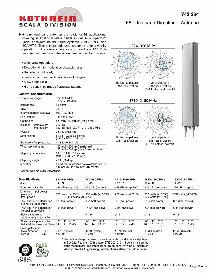
65° Dualband Directional Antenna
Kathrein’s dual band antennas are ready for 3G applications, covering all existing wireless bands as well as all spectrum under consideration for future systems, AMPS, PCS and 3G/UMTS. These cross-polarized antennas offer diversity operation in the same space as a conventional 800 MHz antenna, and are mountable on our compact sector brackets.
• Wide band operation.
• Exceptional intermodulation characteristics.
• Remote control ready.
• Various gain, beamwidth and downtilt ranges.
• AISG compatible.
• High strength pultruded fiberglass radome.
Horizontal pattern±45°- polarization
Vertical pattern±45°- polarization
0°–8° electrical downtilt
Vertical pattern±45°- polarization
0°–14° electrical downtilt
Horizontal pattern±45°- polarization
824–960 MHz
1710–2180 MHz
Generalspecifications:Frequency range 824–960 MHz
1710–2180 MHz
Impedance 50 ohms
VSWR <1.5:1
Intermodulation (2x20w) IM3: -150 dBc
Polarization +45° and -45°
Connector 4 x 7/16 DIN female (long neck)
Isolation intrasystem >30 dB intersystem >50 dB (824–960 // 1710–2180 MHz)
Weight 36.4 lb (16.5 kg)
Dimensions 51.8 x 10.3 x 5.5 inches (1316 x 262 x 139 mm)
Equivalent flat plate area 4.13 ft2 (0.384 m2)
Wind survival rating* 120 mph (200 kph) sustained 150 mph (240 kph) in a 3 second burst
Shipping dimensions 63.6 x 11.9 x 7.6 inches (1615 x 302 x 192 mm)
Shipping weight 45 lb (20.4 kg)
Mounting Fixed mount options are available for 2 to 4.6 inch (50 to 115 mm) OD masts.
See reverse for order information.
Specifications: 824–894MHz 870–960MHz 1710–1880MHz 1850–1990MHz 1920–2180MHzGain 14 dBi 14 dBi 16.5 dBi 16.8 dBi 17 dBi
Front-to-back ratio >26 dB (co-polar) >26 dB (co-polar) >25 dB (co-polar) >25 dB (co-polar) >25 dB (co-polar)
Maximum input power per input 500 watts (at 50°C) 500 watts (at 50°C) 250 watts (at 50°C) 250 watts (at 50°C) 250 watts (at 50°C) total power 1000 watts (at 50°C) 500 watts (at 50°C)
+45° and -45° polarization 68° (half-power) 65° (half-power) 65° (half-power) 65° (half-power) 63° (half-power) horizontal beamwidth
+45° and -45° polarization 16° (half-power) 14.5° (half-power) 7.8° (half-power) 7.3° (half-power) 6.8° (half-power) vertical beamwidth
Electrical downtilt 0°–14° 0°–14° 0°–8° 0°–8° 0°–8° continuously adjustable
Sidelobe suppression for 0° 7° 14° T 0° 7° 14° T 0° 4° 8° T 0° 4° 8° T 0° 4° 8° T first sidelobe above main beam 14 14 13 dB 14 14 13 dB 14 14 14 dB 16 16 15 dB 15 16 15 dB
Cross polar ratio Main direction 0° 20 dB (typical) 20 dB (typical) 16 dB (typical) 18 dB (typical) 20 dB (typical) Sector ±60° >10 dB >10 dB >10 dB >10 dB >10 dB
Page 16 of 17
Kathrein Inc., Scala Division Post Office Box 4580 Medford, OR 97501 (USA) Phone: (541) 779-6500 Fax: (541) 779-3991Email: [email protected] Internet: www.kathrein-scala.com
All specifications are subject to change without notice. The latest specifications are available at www.kathrein-scala.com.
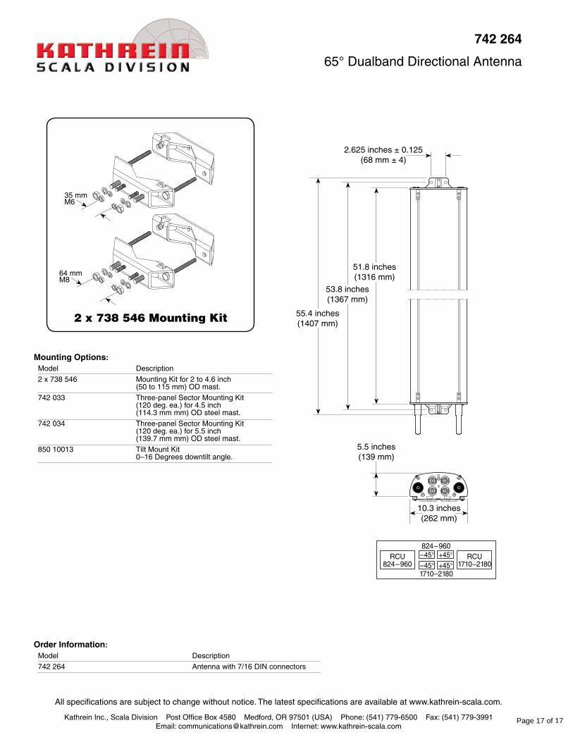
MountingOptions:Model Description
2 x 738 546 Mounting Kit for 2 to 4.6 inch (50 to 115 mm) OD mast.
742 033 Three-panel Sector Mounting Kit (120 deg. ea.) for 4.5 inch (114.3 mm mm) OD steel mast.
742 034 Three-panel Sector Mounting Kit (120 deg. ea.) for 5.5 inch (139.7 mm mm) OD steel mast.
850 10013 Tilt Mount Kit 0–16 Degrees downtilt angle.
OrderInformation:Model Description
742 264 Antenna with 7/16 DIN connectors
742264
65° Dualband Directional Antenna
10.3 inches(262 mm)
53.8 inches(1367 mm)
51.8 inches(1316 mm)
55.4 inches(1407 mm)
5.5 inches(139 mm)
2.625 inches ± 0.125(68 mm ± 4)
2 x 738 546 Mounting Kit
35 mmM6
64 mmM8
Page 17 of 17


