Embed Size (px)
Citation preview

NASA/TM-2003-212411
Low Cost Mars Surface Exploration: The Mars Tumbleweed
Jeffrey Antol, Philip Calhoun, John Flick, and Gregory HajosNASA Langley Research Center, Hampton, Virginia
Richard Kolacinski, Ph.D.Orbital Research Inc., Cleveland, Ohio
David MintonNorth Carolina State University, Raleigh, North CarolinaLangley Aerospace Research Summer Scholar (LARSS) Program, 2002
Rachel OwensHampton Christian High School, Hampton, VirginiaNASA Summer High School Apprenticeship Research Program (SHARP), 2002
Jennifer ParkerRensselaer Polytechnic Institute, Troy, New YorkNASA Co-op Program, Summer 2002
August 2003

The NASA STI Program Office . . . in Profile
Since its founding, NASA has been dedicated to the advancement of aeronautics and space science. The NASA Scientific and Technical Information (STI) Program Office plays a key part in helping NASA maintain this important role.
The NASA STI Program Office is operated by Langley Research Center, the lead center for NASA
’
s scientific and technical information. The NASA STI Program Office provides access to the NASA STI Database, the largest collection of aeronautical and space science STI in the world. The Program Office is also NASA
’
s institutional mechanism for disseminating the results of its research and development activities. These results are published by NASA in the NASA STI Report Series, which includes the following report types:
•
TECHNICAL PUBLICATION. Reports of completed research or a major significant phase of research that present the results of NASA programs and include extensive data or theoretical analysis. Includes compilations of significant scientific and technical data and information deemed to be of continuing reference value. NASA counterpart of peer-reviewed formal professional papers, but having less stringent limitations on manuscript length and extent of graphic presentations.
•
TECHNICAL MEMORANDUM. Scientific and technical findings that are preliminary or of specialized interest, e.g., quick release reports, working papers, and bibliographies that contain minimal annotation. Does not contain extensive analysis.
•
CONTRACTOR REPORT. Scientific and technical findings by NASA-sponsored contractors and grantees.
•
CONFERENCE PUBLICATION. Collected papers from scientific and technical conferences, symposia, seminars, or other meetings sponsored or co-sponsored by NASA.
•
SPECIAL PUBLICATION. Scientific, technical, or historical information from NASA programs, projects, and missions, often concerned with subjects having substantial public interest.
TECHNICAL TRANSLATION. English-language translations of foreign scientific and technical material pertinent to NASA
’
s mission.
Specialized services that complement the STI Program Office
’
s diverse offerings include creating custom thesauri, building customized databases, organizing and publishing research results . . . even providing videos.
For more information about the NASA STI Program Office, see the following:
•
Access the NASA STI Program Home Page at
http://www.sti.nasa.gov
•
Email your question via the Internet to [email protected]
•
Fax your question to the NASA STI Help Desk at (301) 621-0134
•
Telephone the NASA STI Help Desk at (301) 621-0390
•
Write to:NASA STI Help DeskNASA Center for AeroSpace Information7121 Standard DriveHanover, MD 21076-1320
National Aeronautics andSpace Administration
Langley Research CenterHampton, Virginia 23681-2199
NASA/TM-2003-212411
Low Cost Mars Surface Exploration: The Mars Tumbleweed
Jeffrey Antol, Philip Calhoun, John Flick, and Gregory HajosNASA Langley Research Center, Hampton, Virginia
Richard Kolacinski, Ph.D.Orbital Research Inc., Cleveland, Ohio
David MintonNorth Carolina State University, Raleigh, North CarolinaLangley Aerospace Research Summer Scholar (LARSS) Program, 2002
Rachel OwensHampton Christian High School, Hampton, VirginiaNASA Summer High School Apprenticeship Research Program (SHARP), 2002
Jennifer ParkerRensselaer Polytechnic Institute, Troy, New YorkNASA Co-op Program, Summer 2002
August 2003

Available from:
NASA Center for AeroSpace Information (CASI) National Technical Information Service (NTIS)7121 Standard Drive 5285 Port Royal RoadHanover, MD 21076-1320 Springfield, VA 22161-2171(301) 621-0390 (703) 605-6000
Acknowledgments
Special thanks to the LaRC researchers who took time to provide information and recommendations: KeithBelvin, Paul Brewster, John Connell, Pete Covell, Juan Cruz, David Dress, Alicia Dwyer (ICASE), Jil Hallenberg(Montana State University), Nancy Holloway, Luther Jenkins, Jerry Kegelman, Drew Landman (ODU), Joel Levine,Ken Lodding, Harry Morgan, John Quagliano, Frank Quinto, Kurt Severance, Walt Silva, Ralph Stevens, FredStillwagen, Ji Su, Butch Watkins, Judith Watson, Rich White, and Tom Yager.
Special thanks are due to the Library and Media Services Branch of the Langley Research Center who publishedthis document, with special acknowledgment to the NCI Technical Publications Support Group at Langley: DeniseStefula, editing; Dee Bullock, illustration and image preparation; Patricia Gottschall, desktop publishing; and MaryEdwards, proofing.
The use of trademarks or names of manufacturers in this report is for accurate reporting and does not constitute anofficial endorsement, either expressed or implied, of such products or manufacturers by the National Aeronautics andSpace Administration.

1. Introduction
1.1. Background
Many people throughout time have been fascinated with the planet Mars, from the early Greek andRoman civilizations who were intrigued by its unique reddish color to Galileo and Huygens who firstobserved Mars’ surface features by telescope in the 1600s. The Italian astronomer Schiaparelli sketchedthese surface features in the late 1800s, calling them “canals,” and Percival Lowell studied them exten-sively by telescope in the early 1900s. With the development of spaceflight capability in the mid-20thcentury, the opportunity for direct exploration of Mars became a reality. The first spacecraft to visit Marswas the NASA Mariner 4 probe, conducting a flyby mission in 1965, followed by Mariners 6 and 7 in1969. The project culminated with Mariner 9 achieving an orbit around Mars in 1971 and completing aglobal photographic survey that ultimately dispelled the notion of Martian canals (ref. 1).
In 1976 the Viking project achieved the first successful soft landing on the surface with two landersthat, in conjunction with two Viking orbiters, provided the first detailed scientific investigation of thesurface and atmosphere over a period of 6 years. The next successful mission to Mars would not beaccomplished until 1997 when Mars Pathfinder landed on the surface and deployed the Sojourner rover.This highly successful mission was followed by the Mars Surveyor orbiter, which is currently providingdetailed images of the surface, and the Mars Odyssey orbiter, which is currently conducting scientificinvestigations that indicate large volumes of frozen water may exist just below the surface.
Several missions to the surface of Mars are planned in the near future, beginning in the summer of2003 when NASA will launch a pair of Mars Exploration Rovers (MERs), as discussed in reference 2.The MERs are the first in what will be a series of advanced landers and rovers that will explore the RedPlanet throughout the decade (fig. 1). Each MER will weigh approximately 180 kg and carry a suite ofscientific instruments, including cameras. The MERs are solar powered and can travel up to 100 m in asingle Martian day, or sol, and are expected to survive for at least 90 sols, traveling approximately 9 km.While this 9-km total range is impressive compared with the several meters that the Sojourner rover trav-eled in 1997, it reflects only a small portion of the Martian surface.
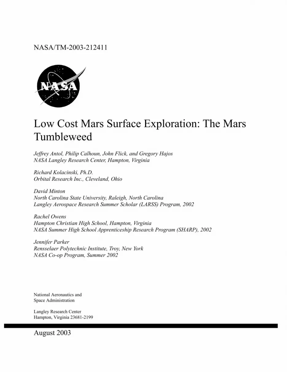
Figure 1. Cornell University artist depiction of a Mars Exploration Rover during surface operations.
2
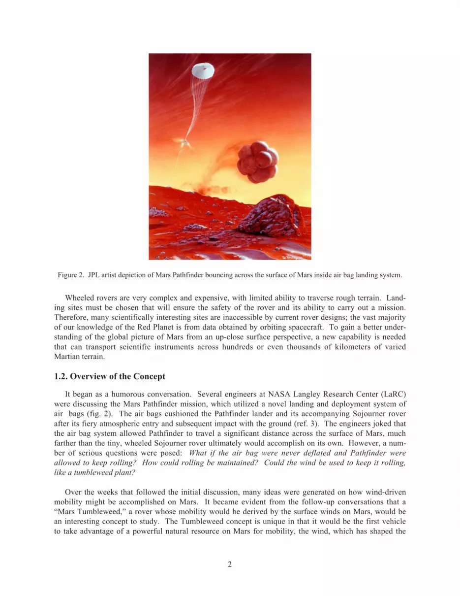
Figure 2. JPL artist depiction of Mars Pathfinder bouncing across the surface of Mars inside air bag landing system.
Wheeled rovers are very complex and expensive, with limited ability to traverse rough terrain. Land-ing sites must be chosen that will ensure the safety of the rover and its ability to carry out a mission.Therefore, many scientifically interesting sites are inaccessible by current rover designs; the vast majorityof our knowledge of the Red Planet is from data obtained by orbiting spacecraft. To gain a better under-standing of the global picture of Mars from an up-close surface perspective, a new capability is neededthat can transport scientific instruments across hundreds or even thousands of kilometers of variedMartian terrain.
1.2. Overview of the Concept
It began as a humorous conversation. Several engineers at NASA Langley Research Center (LaRC)were discussing the Mars Pathfinder mission, which utilized a novel landing and deployment system ofair bags (fig. 2). The air bags cushioned the Pathfinder lander and its accompanying Sojourner roverafter its fiery atmospheric entry and subsequent impact with the ground (ref. 3). The engineers joked thatthe air bag system allowed Pathfinder to travel a significant distance across the surface of Mars, muchfarther than the tiny, wheeled Sojourner rover ultimately would accomplish on its own. However, a num-ber of serious questions were posed: What if the air bag were never deflated and Pathfinder wereallowed to keep rolling? How could rolling be maintained? Could the wind be used to keep it rolling,like a tumbleweed plant?
Over the weeks that followed the initial discussion, many ideas were generated on how wind-drivenmobility might be accomplished on Mars. It became evident from the follow-up conversations that a“Mars Tumbleweed,” a rover whose mobility would be derived by the surface winds on Mars, would bean interesting concept to study. The Tumbleweed concept is unique in that it would be the first vehicleto take advantage of a powerful natural resource on Mars for mobility, the wind, which has shaped the

3
surface geology of Mars as much as water, volcanism, and meteor impacts. Taking advantage of thisresource is a great way to both improve the mobility of a science platform and reduce the complexity ofthe vehicle needed to transport it. It was recognized as a concept that may one day offer an efficient, cost-effective means of moving lightweight science payloads across vast distances. Mobility was defined bythe Space Studies Board of the National Research Council as essential for future exploration of the solarsystem (ref. 4).
However, achieving Mars wind-driven mobility is not a minor task. The density of the atmosphere onMars is approximately 60 to 80 times less than that on Earth. The static pressure is 1 percent that of Earthat sea level. Average Martian temperatures are −63 °C (the equivalent of a 35-km Earth altitude). Windspeeds are typically around 2 to 5 m/s during the day, with gusting periods of 10 to 20 m/s and seasonaldust storms wherein wind speeds exceed 25 m/s. But because of the low density of the Martian atmos-phere, even the strongest winds on Mars develop low dynamic pressures that equate to just a gentle breezeon Earth. A Mars Tumbleweed rover would therefore have to be extremely lightweight and equippedwith lightweight, low-power instruments. If the Tumbleweed rover design could be kept simple and in-expensive, it would allow relatively large numbers to be deployed for regional or perhaps global coverageof the Martian surface, gathering scientific data to complement missions such as those carried out by theMERs.
Because the Mars Tumbleweed concept appeared very promising, an additional question was posed:Had the concept previously been investigated? A brief literature search revealed that an idea for wind-driven rovers was developed in the late 1970s (ref. 5) by Jacques Blamont of the National Center forSpace Studies (CNES, or Centre National d’Etudes Spatiales in France). His idea evolved into theUniversity of Arizona Mars Ball concept, an inflatable rover whose mobility was produced throughsequenced inflation and deflation of air bags. Models were developed to test the Mars Ball concept;however, research into wind-driven rovers was not conducted because the idea did not appear feasible atthe time.
A study was therefore proposed to the LaRC Creativity and Innovation (C&I) initiative to research thecurrent feasibility of a Mars Tumbleweed rover. In the process of planning the C&I research activity,several other organizations were discovered that are also exploring Mars Tumbleweed concepts, includingthe Jet Propulsion Laboratory (JPL) (ref. 6) and Texas Technical University (TTU) (ref. 7). An additionalMars Tumbleweed effort by researchers at the Swiss Federal Institute of Technology was also recentlyidentified (ref. 8). More information on these concepts can be found in section 5.3.
1.3. Goals for the Study
Those goals established for the first-year C&I effort were modest. No funding was requested, onlytime to further explore the concept. Three goals would define the study’s focus: brainstorming sessionswith local experts, basic analyses to examine the feasibility of wind-driven mobility on Mars, and defini-tion of science investigations that could be conducted using a Mars Tumbleweed rover.
• Brainstorming Sessions: Discuss concept with LaRC structures, materials, and aerodynamicsexperts. Enlist particular experts as consultants.
• Feasibility Study: Determine aerodynamic and structural characteristics that will allow Marswind-driven mobility. Complete a literature search on similar research.
• Science Objectives: Define applicable science goals, associated science requirements, andinstrument complements.
4
2. Brainstorming Sessions
The first goal of this study was to discuss the concept with various engineers and researchers, primar-ily at LaRC and particularly those with expertise in structures/materials, aerodynamics, and dynamics.Feedback was sought on the validity of the concept, applicable technologies, and recommendations forfuture testing and analysis. Additionally, brainstorming discussions were held among core team membersto discuss the areas mentioned above as well as to define notional design concepts. The following areprimary areas that were investigated and the individuals contacted:
Structures and Materials
Ultralightweight structures—Keith Belvin
Inflatable rigidizable structures—Judith Watson, Bill Grahm, and Carl Knoll (ILC Dover, Inc.)
Thin films—John Connell
Active materials and structures—Nancy Holloway and Ji Su
Aerodynamics
Computational fluid dynamics—Harry Morgan
LaRC wind tunnels—Jerry Kegelman
Full-Scale Tunnel—Drew Landman (Old Dominion Univ.)
Low-Turbulence Pressure Tunnel—Frank Quinto
14- by 22-Foot Tunnel—David Dress
Transonic Dynamics Tunnel—Walter Silva
Basic Aerodynamic Research Tunnel—Luther Jenkins and Richard White
Low Reynolds number aerodynamics—Thomas J. Mueller (Univ. of Notre Dame)
Dynamics
Rolling resistance—Tom Yager
Several key results from the brainstorming discussions included:
• Developing several notional concepts of Mars Tumbleweed rovers in addition to the concepts thatresulted from initial discussions.
• Identifying a need to conduct aerodynamic analysis and/or wind-tunnel testing, at the appropriateReynolds numbers, to examine the aerodynamic characteristics of proposed Mars Tumbleweedconcepts.
• Identifying an interest in studying the rolling characteristics and drag properties of the tumble-weed plant to determine characteristics that could potentially be incorporated into the MarsTumbleweed rover design.

5
• Considering biologically inspired “swarming” strategies for coordinating multiple Tumbleweedrovers in order to maximize science return.
• Identifying lightweight materials and structures that could be applied to a Mars Tumbleweedrover.
3. Feasibility Study
The second goal of the study was to examine the basic feasibility of wind-driven mobility on the sur-face of Mars. The resulting analysis effort was divided into three areas: quasi-static analysis of a MarsTumbleweed rolling on a smooth flat surface, quasi-static analysis of a Mars Tumbleweed rolling througha typical Martian rock field, and dynamic analysis of a Mars Tumbleweed on a slope.
A literature search for information on related wind-driven rover research was also conducted as part ofthis goal, the results of which can be found in section 5.3.
3.1. Mars Atmosphere Data
A set of Mars environment data was collected in order to conduct consistent analyses. The followingassumptions on the Mars atmosphere were derived from the references indicated:
• Surface atmospheric density: 0.0155 kg/m3 (ref. 9)
• Mars surface wind speeds (ref. 10):
o Viking 1: 2 to 7 m/s (summer); 5 to 10 m/s (fall); 17 to 30 m/s (dust storm) (ref. 11)
• Dynamic pressure (calculated):
o 0.03 Newtons per square meter (N/m2) for wind speed of 2 m/s
o 0.8 N/m2 for wind speed of 10 m/s
• Mean surface atmospheric pressure: 636 N/m2 (6.4 mbars) (ref. 9)
• Kinematic viscosity estimate: 8.0 × 10⁻⁴ m2/s (refs. 9 and 12)
• Speed of sound estimate: 250 m/s (ref. 9)
• Diurnal temperature range (Viking 1 landing site): 184 to 242 K (ref. 10)
3.2. Quasi-static Analysis of a Tumbleweed Rolling on a Smooth Flat Surface
Given the above Mars atmospheric assumptions and initial ballpark estimates of the rover mass anddrag coefficient, listed below, a simple spherical Mars Tumbleweed rover was analyzed to obtain a first-order approximation of the required rover size and the associated required minimum wind speeds.
• Mars Tumbleweed mass: 5 kg (including instruments)
• Mars wind speeds: typical wind speeds of 2 m/s with periods of higher winds and gusts at 10 m/swere assumed

6
• Reynolds number: 14000 to 71000 (for a 6-m Tumbleweed in wind speeds ranging from 2 to10 m/s)
• Drag coefficient: 0.5 (typical for a sphere at the given Reynolds numbers) (ref. 13)
For this initial analysis, the Tumbleweed rover was assumed to be a nonrigid sphere in pure planarrolling motion (no sliding) on a flat, solid, rock-free surface (fig. 3).
FN
FD
U∞
+X
+YW
Py
a
r
Figure 3. Forces acting on a Mars Tumbleweed.
Note that a friction force is not defined in figure 3 because only rolling motion is occurring with nosliding. However, there is a rolling resistance effect due to a slight deformation that would occur betweenthe nonrigid rolling body and the surface at point P. This is accounted for by offsetting the normal force(FN) from the Tumbleweed’s center of mass at a distance a (ref. 14). Assuming a simple moment balanceabout point P,
M Wa F yP D∑ = ⇒ − =0 0 (1)
where W is the weight of the Tumbleweed rover, a is the offset distance of the normal force (FN), FD isthe drag force assumed to act through the center of mass, and y is the distance from the ground to thepoint where FD acts. The drag force is defined as
F C A qD D= ref (2)
where CD is the drag coefficient of a given Tumbleweed vehicle, Aref is the cross-sectional area of the
Tumbleweed, and q is the dynamic pressure, given by the equation 12
2ρU∞ , with ρ being the atmospheric
density and U∞ the free-stream velocity.
In order for the Mars Tumbleweed to begin moving from rest, the force due to wind must exceed therolling resistance. Solving equation (1) for FD and assuming that y ≅ r , where r is the Tumbleweedradius, yields a simple expression for the minimum force needed to initiate motion of the Tumbleweedrover (ref. 14):
FWarD = (3)

7
The Mars Tumbleweed weight (W) is given by
W mg= mars (4)
where m is the Tumbleweed mass and gmars is acceleration due to gravity on Mars (3.69 m/s2).
The ratio a/r, defined as the coefficient of rolling resistance, or µr, which typically ranges from 0.02 to0.12 for automobile tires on hard surfaces (ref. 15) with 0.06 being the maximum for tires on dry pave-ment (ref. 16). Because specific data were not available for a Tumbleweed structure rolling across aMartian surface, the coefficient of rolling resistance was assumed to be the tire maximum value of 0.06 inorder to approximate a Tumbleweed on a solid, rock-free surface.
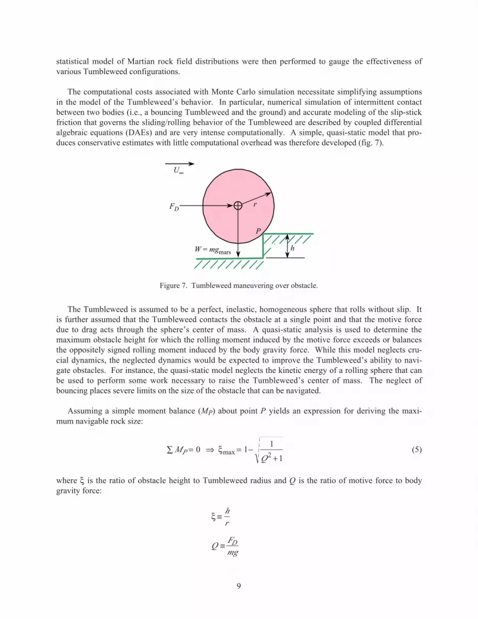
For the typical wind speed of 2 m/s, a 5-kg Tumbleweed rover with a drag coefficient of 0.5 wouldneed a radius of almost 5 m in order to achieve mobility on Mars (fig. 4).
However, the same Mars Tumbleweed is greatly reduced to a radius of approximately 1 m for thehigher gusting wind speed of 10 m/s (fig. 5).
If the drag coefficient is increased beyond the 0.5 of a simple smooth sphere to 1.0, the 5-kg MarsTumbleweed could operate at the lower typical wind speed of 2 m/s with a radius of approximately 3.5 m(fig. 6).
In summary, a 5-kg Tumbleweed rover having a drag coefficient of 0.5 would require a radius of 1 to5 m in order to initiate rolling on a smooth, flat Martian surface in winds from 10 m/s down to 2 m/s.This size appears feasible, because the Mars Pathfinder air bag system was approximately a 3-m radiuswhen inflated. If the mission can be accomplished by waiting for higher wind speeds, then the smallerradius Tumbleweed could be utilized. Or, a larger radius Tumbleweed could have an increased masscapability if used in higher winds, accommodating a larger payload. Likewise, the results show thatincreasing the drag coefficient to 1.0 or greater would have similar benefits.
0 2 4 6Tumbleweed radius, m
8 10
.5
1.0
1.5
2.0
2.5
3.0
3.5
4.0
4.5
Win
d fo
rce,
N
Force required to overcome rolling resistanceWind force on Tumbleweed
Figure 4. Wind force versus Tumbleweed radius (U∞ = 2 m/s, CD = 0.5, m = 5 kg).

8
0 2 4 6Tumbleweed radius, m
8 10
20
40
60
80
100
120
Win
d fo
rce,
N
Force required to overcome rolling resistanceWind force on Tumbleweed
Figure 5. Wind force versus Tumbleweed radius (U∞ = 10 m/s, CD = 0.5, m = 5 kg).
0 2 4 6Tumbleweed radius, m
8 10
1
2
3
4
5
6
7
8
9
Win
d fo
rce,
N
Force required to overcome rolling resistanceWind force on Tumbleweed
Figure 6. Wind force versus Tumbleweed radius (U∞ = 2 m/s, CD = 1.0, m = 5 kg).
These results are based on a highly simplified model, however, with assumptions (e.g., a smooth, flatsurface) that would not be valid in a majority of regions on Mars. In particular, the µr requires furtherinvestigation, perhaps laboratory testing, to obtain specific coefficients of rolling resistance for particularTumbleweed designs on various Martian terrains. Additional analyses to examine the effects of aTumbleweed rolling through a Martian rock field are also needed and are addressed in part subsequently.
3.3. Quasi-static Analysis of a Tumbleweed Rolling Through a Typical Martian Rock Field
Recognizing that the Tumbleweed rover will have to navigate varied Martian terrain, an analysis of asimple Tumbleweed’s ability to negotiate obstacles was performed. To this end, a typical Martian rockfield was modeled and used to perform feasibility and trade studies on Tumbleweed design parameters(e.g., radius and drag coefficient). Specifically, a simple, quasi-static model of an idealized MarsTumbleweed rolling over an obstacle was constructed and used to determine the maximum navigable rocksize for a given set of design parameters. Monte Carlo simulations that combined this model with a
9
statistical model of Martian rock field distributions were then performed to gauge the effectiveness ofvarious Tumbleweed configurations.
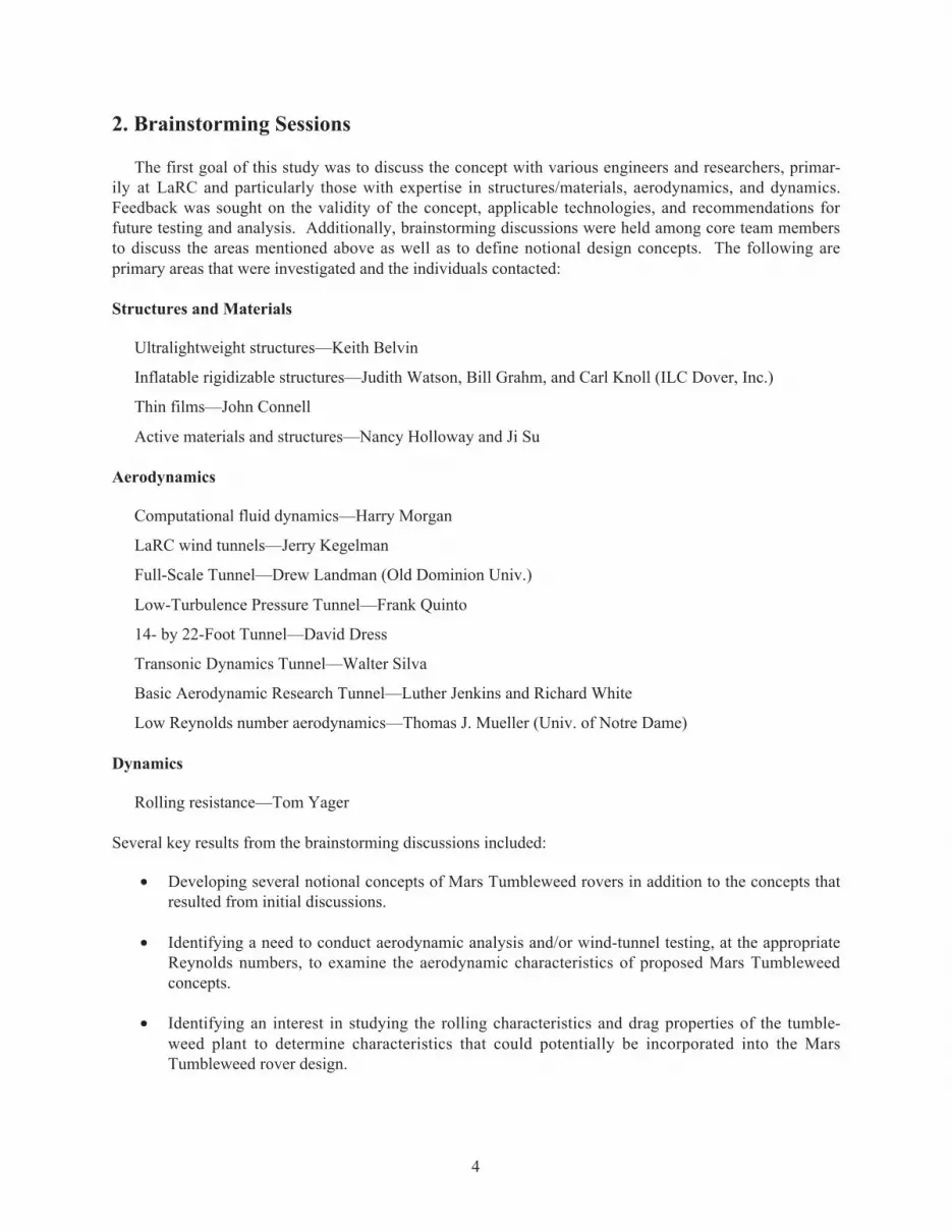
The computational costs associated with Monte Carlo simulation necessitate simplifying assumptionsin the model of the Tumbleweed’s behavior. In particular, numerical simulation of intermittent contactbetween two bodies (i.e., a bouncing Tumbleweed and the ground) and accurate modeling of the slip-stickfriction that governs the sliding/rolling behavior of the Tumbleweed are described by coupled differentialalgebraic equations (DAEs) and are very intense computationally. A simple, quasi-static model that pro-duces conservative estimates with little computational overhead was therefore developed (fig. 7).
FD
U∞
W = mgmars
P
h
r
Figure 7. Tumbleweed maneuvering over obstacle.
The Tumbleweed is assumed to be a perfect, inelastic, homogeneous sphere that rolls without slip. Itis further assumed that the Tumbleweed contacts the obstacle at a single point and that the motive forcedue to drag acts through the sphere’s center of mass. A quasi-static analysis is used to determine themaximum obstacle height for which the rolling moment induced by the motive force exceeds or balancesthe oppositely signed rolling moment induced by the body gravity force. While this model neglects cru-cial dynamics, the neglected dynamics would be expected to improve the Tumbleweed’s ability to navi-gate obstacles. For instance, the quasi-static model neglects the kinetic energy of a rolling sphere that canbe used to perform some work necessary to raise the Tumbleweed’s center of mass. The neglect ofbouncing places severe limits on the size of the obstacle that can be navigated.
Assuming a simple moment balance (MP) about point P yields an expression for deriving the maxi-mum navigable rock size:
MQ
P∑ = ⇒ = −+
0 11
12ξmax (5)
where ξ is the ratio of obstacle height to Tumbleweed radius and Q is the ratio of motive force to bodygravity force:
ξ ≡
≡
hr
QFmgD
10
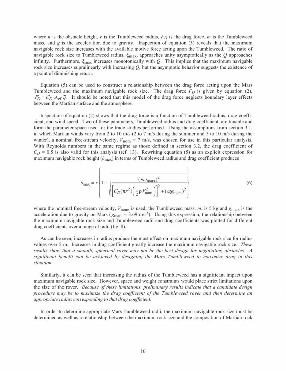
where h is the obstacle height, r is the Tumbleweed radius, FD is the drag force, m is the Tumbleweedmass, and g is the acceleration due to gravity. Inspection of equation (5) reveals that the maximumnavigable rock size increases with the available motive force acting upon the Tumbleweed. The ratio ofnavigable rock size to Tumbleweed radius, ξmax, approaches unity asymptotically as the Q approachesinfinity. Furthermore, ξmax increases monotonically with Q. This implies that the maximum navigablerock size increases supralinearly with increasing Q, but the asymptotic behavior suggests the existence ofa point of diminishing return.
Equation (5) can be used to construct a relationship between the drag force acting upon the MarsTumbleweed and the maximum navigable rock size. The drag force FD is given by equation (2),F C A qD D= ref . It should be noted that this model of the drag force neglects boundary layer effectsbetween the Martian surface and the atmosphere.
Inspection of equation (2) shows that the drag force is a function of Tumbleweed radius, drag coeffi-cient, and wind speed. Two of these parameters, Tumbleweed radius and drag coefficient, are tunable andform the parameter space used for the trade studies performed. Using the assumptions from section 3.1,in which Martian winds vary from 2 to 10 m/s (2 to 7 m/s during the summer and 5 to 10 m/s during thewinter), a nominal free-stream velocity, Vnom = 7 m/s, was chosen for use in this particular analysis.With Reynolds numbers in the same regime as those defined in section 3.2, the drag coefficient ofCD = 0.5 is also valid for this analysis (ref. 13). Rewriting equation (5) as an explicit expression formaximum navigable rock height (hmax) in terms of Tumbleweed radius and drag coefficient produces
h rmg
C r V mgD
max = −
+
12
2 12
22
2
( )
( ) ( )
mars
nom marsπ ρ
(6)
where the nominal free-stream velocity, Vnom, is used; the Tumbleweed mass, m, is 5 kg and gmars is theacceleration due to gravity on Mars ( gmars = 3.69 m/s2). Using this expression, the relationship betweenthe maximum navigable rock size and Tumbleweed radii and drag coefficients was plotted for differentdrag coefficients over a range of radii (fig. 8).
As can be seen, increases in radius produce the most effect on maximum navigable rock size for radiusvalues over 5 m. Increases in drag coefficient greatly increase the maximum navigable rock size. Theseresults show that a smooth, spherical rover may not be the best design for negotiating obstacles. Asignificant benefit can be achieved by designing the Mars Tumbleweed to maximize drag in thissituation.
Similarly, it can be seen that increasing the radius of the Tumbleweed has a significant impact uponmaximum navigable rock size. However, space and weight constraints would place strict limitations uponthe size of the rover. Because of these limitations, preliminary results indicate that a candidate designprocedure may be to maximize the drag coefficient of the Tumbleweed rover and then determine anappropriate radius corresponding to that drag coefficient.
In order to determine appropriate Mars Tumbleweed radii, the maximum navigable rock size must bedetermined as well as a relationship between the maximum rock size and the composition of Martian rock

11
2 4 6Tumbleweed radius, r, m
8 100
1
2
3
4
5
6
7
8
9
10
0.50
CD
0.751.001.251.501.75
h max
, m
Figure 8. Effect of drag coefficient on maximum navigable rock size (hmax versus r and CD).
fields. Once a realistic relationship has been constructed, the likelihood that a particular Tumbleweeddesign can traverse a Martian rock field under the motive power of the wind can be estimated via MonteCarlo simulation.
Several models of Martian rock fields exist in the literature. An exponential fit of the size-frequencydistribution of rocks in the vicinity of the Viking 1 lander proposed by Golombek and Rapp (ref. 17) atJPL was chosen for the rock field model in the Monte Carlo simulation. This distribution is given by theexpression
N D Le sD( ) = − (7)
where N(D) is the cumulative number of rocks per square meter with a diameter greater than or equal to agiven diameter, D. Parameters L and s are determined via a least square estimation using Viking imagedata. For rocks observed in the image near and far field but neglecting those in the vicinity of a craterrim, the parameters are
L
s
=
=
3 82
3 38
.
.
Comparison of the exponential curves with the actual data shows that the fit curves actually drop offmore slowly for large rock sizes than the actual data and therefore slightly overpredict the area covered bylarge rocks. By using the fit that neglects the rocks in the vicinity of a crater rim, we obtain a conserva-tive model of a Martian rock field in the absence of geologic disturbances.

12
Using this size-frequency distribution, a probability distribution function that describes the probabilityof encountering a rock of a particular size, D, in a 1-m2 area can be constructed. Examining the fre-quency interpretation of the probability density function,
f x xnnx( ) ∆ ∆≅ (8)
where ∆nx is the number of trials such that x ≤ x(ξ) < x + ∆x, and taking the limit as ∆x → 0, we obtainthe following relationship between the size frequency distribution ( f(D)) and the probability densityfunction:
f DN D N D D
N DD( ) lim
( ) ( )= − +→∆
∆∆0
(9)
N is the total number of rocks present in a 1-m2 area and is determined from equation (7) with D = 0:
N N Le Ls= = =−( ) ( )0 0
Substituting equation (7) into equation (9) and invoking L’Hospital’s rule yields
f D se sD( ) = − (10)
The probability distribution function is related to the density function by the relationship
f DdF DdD
( )( )= (11)
Therefore,
F D f d eD sD( ) ( )= = −∫ −ξ ξ0
1 (12)
where the probability distribution function F D( ) is defined as the likelihood that a rock encountered willhave a diameter, d, less than or equal to D or F D P d D( ) ( ).≡ ≤
For the Monte Carlo simulation, a Cartesian grid was constructed. A constant wind velocity of 7 m/sover the grid was assumed. The Mars Tumbleweed was then allowed to traverse the grid under the mo-tive force of the wind. At each point on the grid, representing 1 m2, it is assumed that the Tumbleweedencounters a rock. Four different ranges of rock size were identified:
1. Very small rocks (d ≤ hmax/10) that will not affect the Tumbleweed’s progress.
2. Fully navigable rocks (hmax/10 < d ≤ hmax) that the Tumbleweed can negotiate but rocks that mayalter the course of the Tumbleweed by inducing a lateral excursion and that do not prevent forwardmotion in the direction of the wind.
3. Larger, partially navigable rocks (hmax < d ≤ 1.5 hmax) that the Tumbleweed cannot roll over butmay be able to roll around.
4. Unnavigable rocks (1.5 hmax < d ) that the Tumbleweed cannot navigate over or around.
13
A random number is generated and, using equation (12), the size range of the rock encountered isdetermined. If the rock size is very small, the Tumbleweed is advanced in the direction of the wind to thenext grid point; if the rock is completely unnavigable, the Tumbleweed is assumed to be stopped and therun is terminated. The two remaining cases both allow advancement in the direction of the wind, butlateral excursions (normal to the wind direction) are also possible. If the rock is fully navigable, theTumbleweed is advanced to the next rank on the grid and a normally distributed random number is usedto determine the lateral excursion, if any. If the random number generated is less than one in magnitude,the Tumbleweed advances in the direction of the wind; if it is greater than one, a lateral excursion to anadjacent file occurs with the direction of the excursion determined by the sign of the random number. Inthe case of a partially navigable rock, a uniformly distributed random number between −0.5 and 0.5 isused to determine the appropriate motion. For values in a small neighborhood of zero, no motion is per-mitted and the run is terminated; otherwise, the Mars Tumbleweed is advanced to the next rank and to anadjacent file where the lateral excursion is again determined by the sign of the random number. Note thatthe normal distribution, N(0,1), used to model the lateral excursions has a zero mean by definition and astandard deviation of one, hence the case where the random value having a magnitude greater than one isa one sigma case.
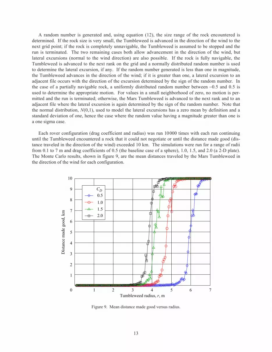
Each rover configuration (drag coefficient and radius) was run 10000 times with each run continuinguntil the Tumbleweed encountered a rock that it could not negotiate or until the distance made good (dis-tance traveled in the direction of the wind) exceeded 10 km. The simulations were run for a range of radiifrom 0.1 to 7 m and drag coefficients of 0.5 (the baseline case of a sphere), 1.0, 1.5, and 2.0 (a 2-D plate).The Monte Carlo results, shown in figure 9, are the mean distances traveled by the Mars Tumbleweed inthe direction of the wind for each configuration.
0.5
1.0
1.5
2.0
1 2 3 4 5 6Tumbleweed radius, r, m
70
1
2
3
4
5
6
7
8
9
10
CD
Dis
tanc
e m
ade
good
, km
Figure 9. Mean distance made good versus radius.
14
The results demonstrate that an increased drag coefficient will significantly improve the ability of theTumbleweed to negotiate a Martian rock field. A Mars Tumbleweed with a drag coefficient of 0.5 wouldrequire a radius of approximately 7 m or greater to negotiate the typical rock field whereas the radiusnecessary to negotiate a typical rock field falls to approximately 5 m for a drag coefficient of 1.0 and toapproximately 4 m for a drag coefficient of 1.5. The effectiveness of increasing the drag coefficientdecreases as the drag coefficient increases; however, in the range of drag coefficients that could reasona-bly be affected (1.25 ≤ CD ≤ 1.75), the increases still correspond to significant increases in performance.Assuming that the median value of this range, CD = 1.5 (approximately the drag of a low porosity para-chute), is achievable, it can be seen that the Tumbleweed concept is feasible with a radius of less than5 m.
The model used to construct the Monte Carlo results is simple and neglects many importantdynamics—such as surface friction, rolling resistance, deformation of the Tumbleweed, and bouncing—requiring consideration to provide a realistic model of a rolling Tumbleweed. The assumptions made inthe development of the model are conservative and should underpredict the efficacy of the tumbleweedconcept. The validity of assuming that these simplifications are conservative needs to be addressed byexamining the neglected dynamics.
3.4. Dynamic Analysis of a Tumbleweed on a Slope
A simplified mathematical model of the Tumbleweed dynamics was created in order to assess thefeasibility of the Tumbleweed concept and to derive basic sizing parameters. The approach was todevelop a planar model assuming rolling motion from a rest condition. This technique yields a size/weight relationship necessary for wind-propelled rolling motion as a function of wind speed. As dis-cussed in section 3.2, the wind force must exceed the rolling resistance for motion to initiate from rest.The rolling resistance is a function of normal force distribution, which arises from compression of theTumbleweed structure and/or deformation of the ground surface under the Tumbleweed’s weight. Thisanalysis assumes that the rolling resistance is dominated by the compression of the Tumbleweed struc-ture. This seems to be an appropriate assumption because the size/weight ratio of the Tumbleweed willbe large and the resulting structural stiffness small when compared with the compliance of Mars surface.Because ground speed is near zero for impending motion, viscous effects of the ground contact wereneglected in this preliminary analysis.
The first step in creating the initial model was to develop the planar rolling equation of motion. Thismodel will be developed with the following assumptions:
• Tumbleweed is constrained to simple planar rolling motion along an arbitrary ground slope.
• Tumbleweed motion is along smooth surface with no obstacles to maneuver (i.e., no rocks).
• Tumbleweed has rolling resistance due to nonpoint contact with the ground (i.e., Tumbleweed isnonrigid).
We begin with the translational and rotational equations of motion given by equations (13) and (14):
F = ma (13)
T = Iα (14)

15
O. lo
+X
+Y
Friction
Dragforce
Wind
Weight
Normal force(Note: Normal force offset)
Figure 10. Tumbleweed model.
where F is the total force on the Tumbleweed, m is the mass, a is the translational acceleration, T is thetotal moment on the Tumbleweed about the mass center, I is the moment of inertia about the mass center,and α is the rotational acceleration. Applying a rolling constraint, given in equation (15), results in aninstantaneous center of rotation about the contact point O.
V = rω (15)
where V is the velocity of the mass center, r is the Tumbleweed radius, and ω is the angular velocity ofthe Tumbleweed. Because the contact point O is assumed to be an instant center, the Tumbleweed rollingdynamics can be formulated by summing moments about the point O:
TO = IOα (16)
where TO is the total moment on the Tumbleweed about the contact point, and IO is the moment of inertiaabout the contact point. Assuming an arbitrary ground slope and no obstacles to maneuver (i.e., norocks), the total moment about the contact point may be expressed as the summation of torque due toaerodynamic drag, TD, gravity, Tg, and rolling resistance, Tr. Figure 10 shows a free body diagram of theforces acting on the Tumbleweed.
TO = TD + Tg + Tr (17)
The aerodynamic drag torque about the contact point can be expressed as a function of the deforma-tion of the Tumbleweed, δ, caused by interaction with the ground and measured along a line perpendicu-lar to the ground slope.
TD = FD(r + cp − δ) (18)
where FD is the drag force and cp is the distance from the Tumbleweed center of mass to the center ofpressure measured along a line perpendicular to the ground slope. The center of pressure of theTumbleweed may not be coincident with the geometric center because there is a wind boundary layer atthe Mars surface with an estimated height of approximately 5 m (ref. 18). However, the effects of the

16
boundary layer on drag force magnitude and center of pressure are considered secondary effects and thusneglected in this simplified analysis. As the model is developed further, additional fidelity will be addedand this assumption will be addressed in a more complete dynamic analysis. The drag force is given inequation (19):
F C A VD D=
ref tw
212
ρ (19)
where, similar to equation (2), CD is drag coefficient, Aref is the cross-sectional area, and 12
2ρVtw
is the
equation for dynamic pressure, where ρ is the atmospheric density and V tw is the velocity of the
Tumbleweed relative to the wind.
Given a Mars surface slope relative to the gravity vector, θS, the torque due to gravity about the con-tact point can be expressed as
Tg = mgmars (r − δ ) sin (θS) (20)
where m is the mass of the Tumbleweed and gmars is the acceleration due to gravity on Mars. The torquedue to rolling resistance can be determined by assuming some effective normal force offset, lO.
Tr = FN lO (21)
where FN is the normal force, which can be expressed in terms of the Tumbleweed weight as
Tr = mg cos (θS) lO (22)
The offset, lO, arises from the shift in the normal force center of pressure as the Tumbleweed liftsup along the downwind region of the ground contact footprint at the onset of rolling. As discussed insection 3.2, the offset can be approximately determined by assuming some rolling resistance coefficient,µr, which is defined as the ratio of lO to the Tumbleweed radius. Thus we have
µr = lO /r (23)
Typical values of rolling resistance range from 0.02 to 0.06 for tires on concrete, 0.06 to 0.12 for tireson a medium hard surface, and 0.16 to 0.3 for tires on sand (ref. 15). An alternative approach forapproximately determining rolling resistance is to assume some deformation of the Tumbleweed under itsown weight. Equation (24) provides an expression of the length of the Tumbleweed surface in contactwith the ground. This equation assumes a circular surface geometry with deformation as shown infigure 10.
lc = [4δ (2r − δ)]1/2 (24)
where δ is the deformation of the Tumbleweed measured along the radius and lc is the length of thesurface in contact with the ground (note: lc is a sector length, assuming a circular shape for theTumbleweed outer surface). Assuming that the normal force acts at a point 50 percent offset from thecenter of the contact patch yields
l l rO c= ( ) = ( ) −
14
14
1 22δ δ( )
/(25)

17
or
lO = r[ pδ(1 − pδ)]1/2 (26)
where pδ is the ratio of the Tumbleweed deformation (δ) to the diameter. Substituting equation (26) intoequation (23) results in an expression of the rolling resistance as a function of pδ.
µr = [ pδ(1 − pδ)]1/2 (27)
which, for small values of pδ, becomes
µr = ( pδ)1/2 (28)
Equation (28) can be used to determine approximate values of rolling resistance assuming somedeformation of the Tumbleweed under its own weight. For example, a deformation of 1 percent of thediameter ( pδ = 0.01) results in a rolling resistance equal to 0.10.
The structural stiffness can be determined by the following procedure: express the compressive force,Fc, as a linear stiffness constant, Ks, multiplied by the deformation
Fc = Ksδ (29)
Assuming that the Tumbleweed is deformed under its own weight, W, and expressing δ in terms of pδyields
W = Ks(2rpδ) (30)
Equation (30) can then be used to determine the stiffness of a Tumbleweed rover as a function ofweight and to determine size given a percentage deformation. This relation will be useful in derivingstructural sizing parameters given candidate materials and geometric configurations.
Equations (13) through (30) provide a basis for a simplified planar rolling dynamics model of a MarsTumbleweed on an arbitrary slope. Referring to figure 10, rolling motion from a rest state is initiated asthe drag force increases to the point where the drag torque on the Tumbleweed exceeds the combinationof torque from gravity and rolling resistance. At this point a torque balance is achieved. As drag forceincreases beyond this point the Tumbleweed undergoes positive acceleration and gains forward speed.The Tumbleweed moves with the wind and a new equilibrium rolling rate is reached as the drag forcelessens. Thus, performing a torque balance will provide the minimum conditions for impending motionfrom rest. Substituting the equations for torques acting on the Tumbleweed—equations (18), (20), and(22) into equation (17)—then setting this new expression equal to zero yields the conditions for torquebalance. Given a positive torque convention of positive rolling motion in the X direction yields thefollowing:
TO = FD(r + cp) − mg r sin (θS) − mg cos (θS) r µr = 0 (31)
or
CD Aref 12
2ρVtw
(r + cp) − mg r sin (θS) − mg cos (θS) r µr = 0 (32)

18
The friction force shown in figure 10 performs no work on the system undergoing rolling motion andtherefore is not included in this analysis. The velocity of the Mars Tumbleweed relative to the wind, Vtw,
will be assumed to be equal to an effective free-stream velocity, and cp will be set equal to zero for thepurpose of this initial analysis. These assumptions will most certainly need to be revisited as the analysismatures because the boundary layer of the wind blowing across the Martian surface is significant as com-pared with the estimated Tumbleweed size.
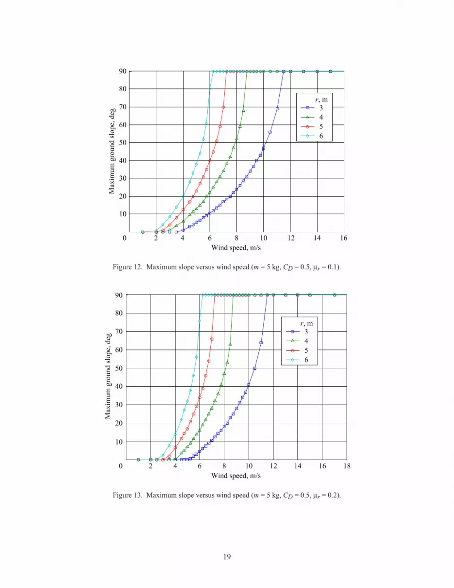
A torque balance was conducted using equation (32) for a range of values for rolling resistance, dragforce coefficient, mass, radius, wind speed, and slope. Figures 11 through 13 show the maximum groundslope that the Tumbleweed can traverse as a function of effective free-stream wind speed assuming thedrag coefficient of a smooth sphere (0.5) and a mass of 5 kg. The rolling resistance is varied from 0.0, fora rigid Tumbleweed in rolling contact, to 0.2, which is within the range of a low-pressure tire rolling on asand surface. As the rolling resistance is increased the wind speed threshold necessary to initiate forwardmotion increases. However, as the wind speed increases above this threshold the maximum attainableslope rapidly approaches 90°, especially for the larger radii. This effect is due to diminished rollingresistance as the normal force goes to zero when the slope approaches 90°. When the radius is large incombination with high wind the Tumbleweed can climb a near vertical slope. This should remain true ifthe rate of slope change is gradual enough that the wind boundary layer assumptions are valid forupslope conditions, that is, the wind is always flowing parallel to the slope. This assumption will berevisited for particular steep slope conditions with reduced boundary layer thickness. Increased rollingresistance may occur for steep slopes for which there is a significant free-stream wind component nonpar-allel to the local slope. However, the assumption of wind parallel to the slope should approximate a widerange of moderate slope conditions and provides a simple design requirement for traversing nonrockyterrain.
2 4 6 8 10Wind speed, m/s
12 14 16 180
10
20
30
40
Max
imum
gro
und
slop
e, d
eg
50
60
70
80
90
3r, m
456
Figure 11. Maximum slope versus wind speed (m = 5 kg, CD = 0.5, µr = 0.0).
19
2 4 6 8 10Wind speed, m/s
12 14 160
10
20
30
40
Max
imum
gro
und
slop
e, d
eg
50
60
70
80
90
3r, m
456
Figure 12. Maximum slope versus wind speed (m = 5 kg, CD = 0.5, µr = 0.1).
2 4 6 8 10Wind speed, m/s
12 14 16 180
10
20
30
40
Max
imum
gro
und
slop
e, d
eg
50
60
70
80
90
3r, m
456
Figure 13. Maximum slope versus wind speed (m = 5 kg, CD = 0.5, µr = 0.2).

20
Using a value of rolling resistance of about 0.1, which is within the range for a low inflation-pressuretire rolling on a medium hard surface, yields the following design sizing for a Tumbleweed with smoothspherical geometry. A radius of about 6 m is required to traverse a 30° slope with wind speed of 4.5 m/s(average summer wind, see section 3.1). A radius of about 3.5 m is required to traverse a 30° slope withwind speed of 7.5 m/s (average winter wind, see section 3.1). Figures 14 and 15 demonstrate the effectsof increasing drag coefficient and mass, respectively. As the drag coefficient is doubled, the radiusrequired to traverse a 30° slope is reduced to 4 m in average summer winds and to below 3 m in averagewinter winds. If the mass and the drag coefficient are doubled the resulting slope traversed for a givenradius and wind speed remains the same. When comparing figures 12 and 15 this equivalence is evident.Upon examination of equation (32), one notices that doubling of both mass and drag coefficient does notaffect the torque balance.
The analysis results in this section can be used to perform preliminary Tumbleweed rover sizing nec-essary to maneuver smooth terrain of a given slope. Tumbleweeds with radii of 3 to 6 m can climb theterrain of a 30° slope for reasonable ranges of mass, drag coefficient, wind speed, and rolling resistance.An approximate relationship among deformation, rolling resistance, and structural stiffness has been es-tablished in equations (23) through (30). The equations in this section can thus be used as a basis forperforming design trades of stiffness, weight, and drag coefficient for a range of selected materials andTumbleweed geometries. Future work will continue the development of this methodology by consideringimproved modeling of the wind boundary layer and the addition of a rock model for the evaluation ofmotion along a nonsmooth surface. The complete model will be used to update the rock field analysiscontained in section 3.3, allowing consideration of slope and Tumbleweed deformation in that analysis.The force and torque models developed will be used as the basis for a dynamics simulation that will beused to study start/stop, speed control, and coordinated motion for the purpose of controlled maneuveringof a single Mars Tumbleweed or group of Tumbleweeds (see sections 4.1 and 5.4 for descriptions of thesecapabilities).
2 4 6 8 10 120
10
20
30
40
Max
imum
gro
und
slop
e, d
eg
50
60
70
80
90
3r, m
456
Figure 14. Maximum slope versus wind speed (m = 5 kg, CD = 1.0, µr = 0.1).

21
2 4 6 8 10Wind speed, m/s
12 14 160
10
20
30
40
Max
imum
gro
und
slop
e, d
eg
50
60
70
80
90
3r, m
456
Figure 15. Maximum slope versus wind speed (m = 10 kg, CD = 1.0, µr = 0.1).
3.5. Summary
Based on the preliminary analysis results presented in sections 3.2 to 3.4, wind-driven Tumbleweedrovers appear feasible for application on the surface of Mars. However, the Tumbleweeds would need tobe lightweight (5 to 10 kg) and relatively large, with radii ranging from 3 to 6 m. The mathematicalmodels presented here will be enhanced in the second year of this study effort and additional analysesconducted to refine the results.
4. Science Objectives
4.1. Preliminary Science Objectives
The third and final goal of this study was to define a preliminary set of science objectives and associ-ated instruments applicable to the Tumbleweed rover concept. In general, what type of science could beconducted on Mars with a Tumbleweed rover?
The first step in answering this question was an examination of the Mars Exploration Program scien-tific goals and objectives, as defined by the Mars Exploration Program Advisory Group (MEPAG) inMarch 2001 (ref. 19). The MEPAG has defined four overarching program goals for Mars exploration.
• Determine if life ever arose on Mars.
• Investigate the climate on Mars.
• Determine the evolution of the surface and interior of Mars (geology).
• Prepare for human exploration.

22
The MEPAG also defined associated objectives within each of the above goals and correspondinginvestigations to accomplish those objectives. These objectives and investigations were reviewed and asubset identified as being potentially applicable to Tumbleweed rovers (the detailed subset of MEPAGobjectives/investigations can be found in the appendix). In particular, those investigations that requiremultiple vehicles and/or widespread coverage were considered primary candidates. The most promisingscience missions for the Mars Tumbleweed appear to be within the “search for life” and “climate”investigations.
The next step was to identify the types of scientific instruments needed to perform the investigations(see section 4.2 for a brief discussion of specific instrument technologies). Water sensors and biomarkerdetectors (such as mass spectrometers) are needed to search for signs of life, while microweather sensorsare needed for climate monitoring missions.
For certain scientific instrumentation, a Tumbleweed rover may need to remain stationary for a periodof time, perhaps for weeks or even months, in order to take particular measurements in sufficient num-bers. Therefore, a “control capability” may be needed to “command” a Tumbleweed to stop in locationsof interest, take data for a period of time, and begin moving again once the measurements are completeand the winds are favorable. This “start/stop” capability is most likely needed if the instrument is inte-grated with the rover. There are cases where a control capability may not be necessary; for example, asimple Tumbleweed with no instrumentation that is used only to track wind direction would need to beentirely at the mercy of the winds. A control capability may not be needed for a Tumbleweed roverwhose mission is to drop sensor packages and establish a sensor net as it is rolling.
A summary of the preliminary science goals and objectives for Tumbleweed rovers, the associatedinstrument types, and the control capability requirements is presented in table 1. The MEPAG science
Table 1. Preliminary Science Objectives
Science goal Objective/investigation Associated instrument Control capability
Climate Measure wind speed anddirection
None or tracking beacon None
Climate Measure temperature,pressure, wind speed
Microweather sensors
(dropped from rover)
None
Climate, life Measure temperature,pressure, wind speed
Search for water and complexorganic molecules
Microweather sensors
Microwater sensors/spectrometers
(integrated with rover)
Simple
(ability to stop/start)
Geology Mineralogy, geochemistry
Global seismic monitoring
Alpha proton or massspectrometer
Seismometers
Moderate
(ability to stop/start,maneuver)
Climate, geology, life Visual observations Camera Complex
(ability to stop/start,maneuver, point attargets)
23
goals and associated objectives/investigations are listed in the first and second columns, respectively. Thethird column identifies corresponding types of instruments, and the fourth column defines the extent ofcontrollability that may be needed by the instruments to accomplish the measurements.
The identified goals and objectives are listed in table 1 by increasing complexity of the control capa-bility that may be required. The simplest mission, as discussed previously, could involve a Tumbleweedwith no instrumentation that is used only to track wind direction (see row 1 of table 1). This would be afirst generation Tumbleweed design that could also serve as a proof-of-concept mission and would requirean orbiting vehicle to track the Tumbleweed using radar, visual observations, or through monitoring of atracking signal radiating from the Tumbleweed.
A second generation Tumbleweed mission (rows 2 and 3 of table 1) may utilize sensors to monitor theweather or search for biomarkers and thus will require supporting power, data, and communication sub-systems. The instruments could be microsensor packages integrated with the rover or dropped from therover in order to establish a sensor net on the surface. In the case of the dropped microsensor packages, acontrol capability may not be necessary whereas with the integrated sensors, a simple control capabilitymay be needed in order to stop and start the Tumbleweed to acquire science data at particular locationsand then to allow the Tumbleweed to be blown to new locations.
The third and fourth generation Tumbleweed rovers (rows 4 and 5, respectively, of table 1) wouldrequire more complexity in the control system, allowing science data to be taken at specific locations andperhaps at specific targets (e.g., rocks, land formations, etc.). The control capability would be more thana simple start/stop and could involve the use of smart materials, such as electroactive polymers, to providean actuation capability for steering or maneuvering of the vehicle. Swarming algorithms may also beused to coordinate the data collection of multiple Tumbleweed rovers in order to maximize the sciencereturn.
In summary, the science requirements will be a strong driver of the Tumbleweed design, not only inthe areas of system power, data, communications, and structural configuration, but also in aspects ofvehicle controllability. In the second year of this C&I study, the science objectives will be refined andspecific missions identified through discussions with Mars program scientists.
4.2. Microinstrument Technologies
The final step in the definition of the preliminary science objectives was an identification of existing,as well as planned, microinstrument technologies that could be used to accomplish the identified investi-gations. These technologies include:
• Existing microinstruments/sensors
o subsurface sample/water detection experiment (Deep Space 2, JPL)
o pressure, temperature, humidity and dust-loading sensors for network climatology (Pascalprobes, Ames Research Center)
o Mars microphone (Mars Polar Lander, Univ. of California Berkeley)
o Alpha Proton X-Ray Spectrometer (APXS) (Mars Pathfinder, JPL)
o Imager for Mars Pathfinder (IMP) (Mars Pathfinder, Univ. of Arizona)
24
• Advanced microinstruments/sensors
o Surface-penetrating radar for water detection (Johns Hopkins Univ.)
o Microweather station, Microseismometer, Microaccelerometers (JPL)
o “Sensitive Skin” flexible sensor array (Rensselaer Polytechnic Institute)
o Smart Dust (Univ. of California Berkeley)
o Lab-on-a-Chip (TTU)
o Sensor Web (JPL)
The instruments and sensors for Tumbleweed missions will not be limited to the above preliminary listof technologies. The mass, power, and data requirements of these and other sensors will be investigatedfurther in the second year of this C&I study effort to provide the requirements for trade studies ofsupporting subsystems.
5. Tumbleweed Concepts
5.1. NASA LaRC Design Concepts
Several notional design configurations of Tumbleweed rovers have been developed, consisting ofinflatable structures, kite-like structures, and those inspired by the tumbleweed plant. Simple models ofthese concepts have also been developed and preliminary tests using fans to propel them were conductedto examine basic rolling characteristics. An overview of each concept is presented herein.
The “Wedges” concept uses inflatable sphere sections to increase the apparent diameter of the system(fig. 16). Instead of using a single inflated sphere, the separate wedge sections are used to form a spheri-cal shape (a variation of this concept would use small spheres rather than wedges in order to simplify thedesign). The primary driver of the Wedges concept is to allow an instrument package, represented by thebox in the center, access to the Martian environment, whereas a single sphere may require protrusionsthrough the wall of the sphere to allow instrument access. While an inflatable design offers a simplisticand proven deployment system, the long-term survivability of an inflated object rolling and bouncingover the sharp, jagged rocks of the Martian landscape is questionable. However, in the case of theWedges concept, the use of numerous inflated sections may provide a level of redundancy over that of asingle inflated sphere.
The “Box Kite” concept employs fabric sails stretched around spring hoops in the manner used intents, automobile sunscreens, and children’s toys (fig. 17). This concept originated because of the con-cern for long-term survivability of inflatable structures. Fabric stretched over hoops may provide longerterm durability than inflatable structures. Packaging and deployment methods appear relatively simple toaccomplish; however, tearing of the fabric by dust during wind storms or by scraping against rocks duringrolling is a primary concern. Another equally important concern is the potential for this structure tobecome wedged on rocks because of the numerous open segments of the design.
The “Dandelion” concept (fig. 18) uses a spherically symmetric array of struts, legs, and spines toincrease the apparent diameter of the instrument pod. The concept arose from the idea to create a

25
Figure 16. “Wedges” concept. Figure 17. “Box Kite” concept.
Figure 18. “Dandelion” concept.
structure that increases drag in the same manner as an actual tumbleweed plant (Russian thistle), whichhas developed the capability to harness the wind for movement using an intricate, lightweight branchstructure. The Dandelion concept, with its deployable “branches,” was first conceived as an instrumentbox with numerous branches protruding from it; pads were later added to the ends to prevent sinking intosoft dust or sand. The pads could also house sensors, perhaps being dropped as the Mars Tumbleweedrolls along the ground. The result is a structure that resembles a dandelion more than a tumbleweed plant.This concept does not have the material drawbacks of the Wedge or Box Kite; however, the potentialexists for this structure to also become wedged on or between rocks.

26
Figure 19. “Hamster Ball” concept. Figure 20. NCSU “Tumble Cup” concept.
The “Hamster Ball” concept (fig. 19) makes use of a conventional roving vehicle within an inflatablesphere; the overall effect is an increase in the apparent tire diameter of the rover. Differential steering ofthe vehicle can provide some maneuvering of the system. The concept was developed in response to theconcern that a Tumbleweed rover would be at the mercy of the wind with no steering capability availableto direct it in particular directions. The long-term survivability of an inflatable object is a concern here asit was with the Wedges concept.
The “Tumble Cup” concept (fig. 20) consists of numerous open-ended cylinders around a sphericalcenter, such as a number of coffee cups glued to a ball. The concept seeks to maximize the surface areaavailable in order to maximize drag while also reducing rolling resistance by minimizing the surface thatis in contact with the ground. Packaging and deployment methods appear difficult to accomplish.
5.2. NASA LaRC Operations Concept
Tumbleweed rovers such as those in figures 21 and 22 could be delivered to Mars as secondary pay-loads (serving as ballast) on previously planned lander missions, or perhaps as an upcoming Mars ScoutMission of Opportunity. A dedicated mission may be required to deliver numerous Tumbleweed roversat one time to provide for global coverage.
The Tumbleweeds could be deployed from a Mars lander aeroshell or backshell after separation fromthe lander. They would then descend to the surface in a fashion similar to the Pathfinder air bag landingsystem. However, unlike the Pathfinder, the Tumbleweeds would remain deployed after landing. If theTumbleweeds were instead attached to the lander, deployment could be accomplished after successfullysetting down on the surface. In order to avoid having multiple Tumbleweeds clumping together, deploy-ment could be timed to occur at particular intervals (perhaps tied to the local wind speed), or eachdeployment could be commanded after visual observations confirm that the previous Tumbleweed is nolonger in the vicinity.

27
Figure 21. “Wedges” concept on surface of Mars.
Figure 22. “Dandelion” concept on surface of Mars.
The Tumbleweeds may be designed (mass, diameter, drag coefficient) to roll at particular wind speeds.Therefore, when the wind is below the prescribed speed, the Tumbleweed rover would be stationary, tak-ing data and/or communicating data back to Earth through one of the many communication relay systemsplanned for upcoming Mars orbiter missions.
Tumbleweed rovers may also be blown into canyons or valleys, which may allow areas to be reachedthat are not accessible by currently planned landers and rovers. Tumbleweeds may also become wedgedbetween rocks or in a crevice; this situation would not reduce the functionality of the vehicle, it wouldmerely convert the Tumbleweed into a stationary platform, performing the same functions at a fixedlocation.

28
5.3. Other Tumbleweed Design Concepts
Tumbleweed rover concepts are also being developed by the JPL, Texas Technical University (TTU),and the Swiss Federal Institute of Technology. Additionally, North Carolina State University (NCSU), incooperation with LaRC, initiated an effort in the fall of 2002 as a senior aerospace design class project.Collaborative efforts are being fostered with these organizations to leverage their research expertise withthat of LaRC.
5.3.1. NASA Jet Propulsion Laboratory
The JPL concept (fig. 23) is derived from the inflatable technology research program that developedthe Mars Pathfinder air bag system and is investigating inflatable rover designs (ref. 6). Jack Jones of JPLis leading the effort. A collaborative effort to study Tumbleweed structures, inflatables in particular, isbeing planned between JPL and LaRC.
5.3.2. Texas Technical University
The TTU Tumbleweed concepts (fig. 24) were developed as a senior mechanical engineering designclass project (ref. 7). The research is being continued through a grant from the Texas Space GrantConsortium and involves the TTU Wind Science and Engineering Research Department as well as themicroelectromechanical systems (MEMS) Sensor Technology Center at TTU. Dr. Alan Barhorst is lead-ing the activity. A collaborative effort is being planned between TTU and LaRC to investigate the Marswind surface boundary layer model and to define applicable microsensor technologies.
(a) Testing of Tumbleweed concept. (b) Artist rendition of Tumbleweed concept.
Figure 23. JPL Tumbleweed concept.
Figure 24. TTU Tumbleweed concepts.

29
Figure 25. NCSU Tumbleweed concepts.
5.3.3. North Carolina State University
The NCSU senior aerospace design class is a two-semester course that involves concept development,wind-tunnel testing, prototype development, and field testing. Dr. Fred DeJarnette is the faculty advisor.The idea to study a Mars Tumbleweed for the class project was initiated by Langley Aerospace ResearchSummer Scholar (LARSS) David Minton while working at LaRC during the summer of 2002. TheNCSU Tumbleweed concepts are based on the LaRC Wedges, Dandelion, Box Kite, and Tumble Cupconcepts (fig. 25). NCSU is also collaborating with students at Carnage Middle School in Raleigh, NorthCarolina. A prototype Tumbleweed rover, scaled for use on Earth, will be constructed during the secondsemester. The NCSU results will greatly aid the LaRC Tumbleweed rover research effort by providingpreliminary data on Tumbleweed design concepts.
5.3.4. Swiss Federal Institute of Technology
Thomas Estier of the Swiss Federal Institute of Technology has developed concepts for “collapsiblewire ‘windballs’” while working with the European Space Agency (ref. 8). The windballs would use ashape memory alloy to deploy into a spherical shape at night and when heated by the Sun during the daywould collapse into a disk. This activity has only recently been identified and thus no collaborativeefforts have been established at this date.
5.4. Advanced Biomimetic Concepts
Understanding how plants and animals operate in nature and then applying that knowledge to engi-neering problems is called biomimetics, or biologically inspired engineering. Biomimetics involves thestudy of a natural system to understand the underlying principles governing its behavior or structure, andthen applying those principles to an engineering problem where applicable. The fundamental ideaunderlying this paradigm is that one takes the information from biologists (either already available orobtained via concurrent research) and uses it to construct the highest fidelity analog possible, to the pointof even replicating features whose purposes or relevances are not understood. The idea is to introduce anelement of serendipity to the design process such that the inclusion of these features will make the designmore successful, the logic being that evolutionary processes are known to be excellent nonlinear optimiz-ers (i.e., genetic algorithms). Mother Nature has thus been performing an optimization over potentiallymillions of years and has most likely come up with clever and robust solutions. If we can duplicate these

30
Figure 26. Tumbleweed plant, or Russian thistle.
solutions, our chances of success increase dramatically. One can also say that the biological organismsthat we are trying to mimic present existing proof that such a design will work if implemented properly.
For example, the tumbleweed plant has developed the capability to harness the wind for movementusing an intricate, lightweight branch structure. By developing a similar structure, a high fidelitybiomimetic Tumbleweed rover concept could be created that may enhance mobility. Another exampleinvolves the rolling properties of the Russian thistle, which typically has a center of mass that is offsetfrom the center of the plant due to its oblong shape (fig. 26). While studying this structure, it may bedetermined that placement of the center of mass causes the plant to bounce and tumble more than it wouldif the plant were more symmetrical. Does this bouncing cause the plant to be able to travel farther bykeeping it in the air longer, thereby reducing rolling resistance with the ground? Or does the bouncingmotion help dislodge more seeds from the plant? Or is it both? Developing a high fidelity biomimeticTumbleweed rover with an offset center of mass may enhance mobility.
Another biomimetic discipline that may be applicable to the Tumbleweed concept is the use of swarmintelligence-based algorithms, such as that used by bees and ants, to coordinate multiple Tumbleweedrovers. For example, a group of Tumbleweed rovers may be searching for water or biomarkers in a par-ticular region of Mars. Each Tumbleweed rover may have unique sensor capabilities. When somethinginteresting is detected by one particular Tumbleweed, it would communicate its findings to the others,activating a swarm intelligence-based algorithm that would direct the others to proceed to the same gen-eral area and conduct additional sensing with their unique instruments. This process would require thatthe Tumbleweeds have a moderate to complex level of control capability (as discussed in section 4.1) inorder to maneuver, as the winds allow, in the desired direction.
These aspects of the biomimetic design paradigm will be further researched during the second year ofthis study in order to develop a high fidelity biomimetic Tumbleweed concept.

31
Table 2. Preliminary Subsystem Technologies
Subsystem Technology
Structures/materials • Inflatable
o Kevlaro Spectrao Vectran
o Phenylene benzobisoxide (PBO)
• Inflatable-rigidizable iso-grid
• Lightweight fabrics
o Electrospun fibers
• Shape memory materials
• Smart materials
o Electroactive polymers
Power • Batteries (nonrechargeable)
o Lithium thionyl chloride (Mars Pathfinder)
• Solar array/batteries (rechargeable)
o GaAs/Ge array (Mars Pathfinder)
o CuInSe2 thin film array (proposed for a Mars Flyer concept)
o Plastic solar cells (UC Berkeley)
o Lithium polymer, thin film battery (proposed for a MarsFlyer concept)
• Radioisotope microthermal power source
o Milliwatt radioisotope power supply (proposed forPASCAL Mars mission)
• Wind
o Wind turbine (windmill)
o Piezoelectric actuators (flapping leaf)
Communications • DS-2 or PASCAL derived system
Data handling • DS-2 microcontroller
6. Subsystem Technologies
A preliminary investigation of existing, as well as planned, subsystem technologies with potentialapplication to a Tumbleweed rover design was conducted, the results of which are summarized in table 2.An in-depth trade study of various subsystem options will be initiated in the second year of the study.
7. Concluding Remarks
7.1. Summary
A concept for a future rover propelled by Martian winds has been examined. The Mars Tumbleweedrover would be simple, lightweight, and inexpensive, equipped with microelectronic sensors for conduct-ing climate measurements, searching for life, or gathering geologic data. Tumbleweeds could be

32
deployed in large numbers to maximize coverage of the Martian surface and would complement the databeing gathered by more complex lander and rover missions.
Three primary goals served as the focus for this first year C&I effort: brainstorming discussions withLangley experts, basic analyses to examine the feasibility of wind-driven mobility on Mars, and definitionof science investigations that could be conducted using a Tumbleweed rover (see section 7.2 for a discus-sion of the corresponding results for each goal).
Several notional concepts of Tumbleweed rovers were developed, consisting of inflatable structures,kite-like structures, and those inspired by the tumbleweed plant. Simple models of these concepts werealso developed and the basic rolling characteristics of each concept were observed while being propelledby a fan.
Tumbleweed rover concepts are also being developed by North Carolina State University, the JetPropulsion Laboratory, Texas Technical University, and the Swiss Federal Institute of Technology. Col-laborative efforts are being explored with these organizations.
7.2. Conclusions
7.2.1. Brainstorming Sessions
Feedback was sought on the validity of the concept, applicable technologies, and recommendationsfor future analysis and/or testing. As a result of those discussions, a need was identified to conduct aero-dynamic analysis and/or wind-tunnel testing, at the appropriate Reynolds numbers, to examine the aero-dynamic characteristics of proposed Mars Tumbleweed concepts. An interest was also identified instudying the rolling characteristics and drag properties of the tumbleweed plant to determine characteris-tics that potentially could be incorporated into the Tumbleweed rover design. Biologically inspired“swarming” strategies were considered for coordinating multiple Tumbleweed rovers in order to maxi-mize science return, and lightweight materials and structures were identified that could be applied toTumbleweed rovers.
7.2.1. Feasibility Study
The feasibility study was divided into three parts:
1. Quasi-static analysis of a Tumbleweed rolling on a smooth, flat surface.
A 5-kg Tumbleweed rover having a drag coefficient of 0.5 would require a radius of 1 to 5 m in orderto initiate rolling on a smooth, flat surface in winds from 10 m/s down to 2 m/s. This size appears feasi-ble because the Mars Pathfinder air bag system had approximately a 3-m radius. If the mission can beaccomplished by waiting for higher wind speeds, then the smaller radius Tumbleweed could be utilized.Or, a larger radius Tumbleweed could have an increased mass capability if used in the higher winds,accommodating additional payload mass. Likewise, the results show that increasing the drag coefficient(CD) to 1.0 or greater would have similar benefits.
2. Quasi-static analysis of a Tumbleweed rolling through a typical Martian rock field.
A smooth, spherical Tumbleweed appears not to be the best design for negotiating obstacles and a sig-nificant benefit can be achieved by designing the rover to maximize drag in this situation. Similarly, it

33
can be seen that increasing the radius of the Tumbleweed has a significant impact upon the maximumnavigable rock size. However, space and weight constraints place strict limitations upon the size of theTumbleweed. Because of these limitations, preliminary results indicate that an optimum design proce-dure may be to maximize the drag coefficient of the Tumbleweed rover and then to determine an appro-priate radius corresponding to that drag coefficient.
The results of the Monte Carlo simulation also demonstrate that an increased drag coefficient will sig-nificantly improve the ability of the Tumbleweed to negotiate a Martian rock field. A Tumbleweed with adrag coefficient of 0.5 would require a radius of approximately 7 m or greater to negotiate the typical rockfield. Assuming that a median value drag coefficient can be obtained (CD = 1.5 is approximately the dragof a low porosity parachute), a Tumbleweed would require a radius of about 4 m to negotiate the typicalMartian rock field.
3. Dynamic analysis of a Tumbleweed on a slope.
The results show that Tumbleweeds with radii of 3 to 6 m can climb terrain with a 30° slope forreasonable ranges of mass, drag coefficient, wind speed, and rolling resistance. As the drag coefficient isdoubled, the radius, required to traverse a 30° slope, is reduced to 4 m in average summer winds and tobelow 3 m in average winter winds. If the mass and the drag coefficient are doubled, the resulting slopetraversed for a given radius and wind speed remains the same.
When the radius is large in combination with high wind the Mars Tumbleweed can climb a near verti-cal slope. This should remain true if the slope rate of change is gradual enough that the wind boundarylayer assumptions are valid for upslope conditions, that is, the wind is always flowing parallel to theslope.
7.2.1. Science Objectives
The most promising science missions for the Tumbleweed appear to be “search for life” and “climate”investigations. The science requirements will be a strong driver of the Tumbleweed design, not only inthe areas of system power, data, communications, and structural configuration, but also in aspects ofvehicle controllability. A “control capability” may be needed to command a Tumbleweed to stop in loca-tions of interest, take data for a period of time, and begin moving again once the measurements are com-plete and the winds are favorable. This “start/stop” capability is most likely needed if the instrument isintegrated with the rover.
7.3. Plans
The key areas to be addressed in the second year of this C&I study are:
• Science Objectives
o Refine science objectives/missions.
o Examine microinstrument technologies.
o Compare microinstrument requirements with potential capabilities of the tumbleweedconcepts.
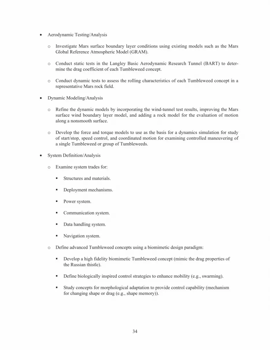
34
• Aerodynamic Testing/Analysis
o Investigate Mars surface boundary layer conditions using existing models such as the MarsGlobal Reference Atmospheric Model (GRAM).
o Conduct static tests in the Langley Basic Aerodynamic Research Tunnel (BART) to deter-mine the drag coefficient of each Tumbleweed concept.
o Conduct dynamic tests to assess the rolling characteristics of each Tumbleweed concept in arepresentative Mars rock field.
• Dynamic Modeling/Analysis
o Refine the dynamic models by incorporating the wind-tunnel test results, improving the Marssurface wind boundary layer model, and adding a rock model for the evaluation of motionalong a nonsmooth surface.
o Develop the force and torque models to use as the basis for a dynamics simulation for studyof start/stop, speed control, and coordinated motion for examining controlled maneuvering ofa single Tumbleweed or group of Tumbleweeds.
• System Definition/Analysis
o Examine system trades for:
� Structures and materials.
� Deployment mechanisms.
� Power system.
� Communication system.
� Data handling system.
� Navigation system.
o Define advanced Tumbleweed concepts using a biomimetic design paradigm:
� Develop a high fidelity biomimetic Tumbleweed concept (mimic the drag properties ofthe Russian thistle).
� Define biologically inspired control strategies to enhance mobility (e.g., swarming).
� Study concepts for morphological adaptation to provide control capability (mechanismfor changing shape or drag (e.g., shape memory)).

35
• Collaboration With Other Organizations
o A prototype Tumbleweed rover, scaled for use on Earth, will be constructed by the NorthCarolina State University students during the second semester. The results will greatly aidthe Langley Tumbleweed research effort by providing preliminary data on Tumbleweeddesign concepts.
o A collaborative effort to study Tumbleweed structures, inflatable structures in particular, isbeing planned between the Jet Propulsion Laboratory and Langley.
o A collaborative effort is being planned between Texas Technical University and Langley toinvestigate the Mars wind surface boundary layer model and to define applicable microsensortechnologies.

36
8. References
1. Snow, T. P.: Essentials of the Dynamic Universe, An Introduction to Astronomy. West Publishing Co., Thirded., 1990, pp. 156–159.
2. Mars Exploration Rover Mission. http://mars.jpl.nasa.gov/mer/ Accessed December 12, 2002.
3. Mars Pathfinder. http://mars.jpl.nasa.gov/MPF/index1.html Accessed December 12, 2002.
4. Committee on Planetary and Lunar Exploration, National Research Council. Scientific Rationale for Mobility inPlanetary Environments. National Academy Press, 1999.
5. Janes, D. M.: The Mars Ball: A Prototype Martian Rover (AAS 87-272). The Case for Mars III, Part II—Volume 75, AAS Science and Technology Series, ed. Carol R. Stoker, 1989, pp. 569–574.
6. Tumbleweed Inflatable Rover. http://www.jpl.nasa.gov/adv_tech/rovers/tmblweed.htm Accessed December 12,2002.
7. Wind Powered Martian Robot—Midterm Report, College of Engineering, Texas Technical University.http://www.tsgc.utexas.edu/tadp/reports/progress/TechTumbleweedGroup.pdf Accessed December 12, 2002.
8. Sample, I.: Swiss Roller. New Scientist Issue 2277. February 2001, p. 21.
9. Young, L. A.: Vertical Lift—Not Just for Terrestrial Flight. AHS/AIAA/RaeS/SAE International Powered LiftConference, Arlington, VA, October 30–November 1, 2000.
10. Lorenz, R. D.: Martian Surface Windspeeds, described by the Weibull distribution. J. Spacecr. and Rockets,vol. 33, 1996, pp. 754–756.
11. Mars Fact Sheet, National Space Science Data Center. http://nssdc.gsfc.nasa.gov/planetary/factsheet/marsfact.htmlAccessed December 12, 2002.
12. Sullivan, R.; Greeley, R.; Kraft, M.; Wilson, G.; Golombek, M.; Herkenhoff, K.; Murphy, J.; and Smith, P.:Results of the Imager for Mars Pathfinder Windsock Experiment. J. Geophys. Res., vol. 105, no. E10, 2000,pp. 24, 547.
13. White, F.: Fluid Mechanics. McGraw-Hill, 2nd ed., 1986, p. 285.
14. Morrow, H. W.: Statics and Strengths of Materials. Prentice-Hall, Inc., 1981, pp. 165–166.
15. Gillespie, T.: Fundamentals of Vehicle Dynamics. Society of Automotive Engineers, 1992.
16. Horne, W. B.; and Trafford, J. W.: A Method for Rating the Skid Resistance and Micro/Macrotexture Charac-teristics of Wet Pavements. NASA TN D-1376, 1962.
17. Golombeck, M.; and Rapp, D.: Size-Frequency Distribution of Rocks on Mars and Earth Analog Sites: Implica-tions for Future Landed Missions. J. Geophys. Res., vol. 102, February 25, 1997, pp. 4117–4129.
18. Justus, C. G.; and Johnson, D. L.: Mars Global Reference Atmosphere Model 2001 Version (Mars-GRAM2001): User’s Guide. NASA TM-2001-210961, 2001.
19. Mars Exploration Program Advisory Group, Mars Exploration Program, Scientific Goals, Objectives, Investiga-tions, and Priorities, ed. R. Greely, March 2, 2001.

37
Appendix
Potentially Applicable Objectives/Investigations
The subset of the Mars Exploration Program Advisory Group (MEPAG) objectives/investigations(ref. 19) with potential applicability to Tumbleweed rovers includes:
GOAL: Determine if life ever arose on Mars
• Objective: Determine if life exists today.
o Investigation: Carry out in situ exploration of areas suspected of harboring liquid water.
� For at least 20 stations at 4 targeted sites (based on remote sensing), conduct in situ geo-physical and chemical (e.g., “sniffers”) searches for subsurface water and other volatiles(e.g., carbon dioxide and reduced gases like methane and ammonia) over km2 surfaceareas.
• Objective: Assess the extent of prebiotic organic chemical evolution.
o Investigation: Search for complex organic molecules in rocks and soils.
� In situ/mobile platforms deployed to at least three well-characterized and diverse sites toassess the mineralogy (e.g., using laser Raman mapping spectroscopy, X-ray diffraction,X-ray fluorescence, etc.), geochemistry (e.g., alpha proton or mass spectrometermethods for elemental and isotopic compositions), and organic materials (e.g., gaschromatography-mass spectrometry; laser desorption spectroscopy, etc.).
GOAL: Determine climate on Mars
• Objective: Characterize Mars’ present climate and climate processes.
o Investigation: Determine the processes controlling the present distributions of water, carbondioxide, and dust.
� In situ meteorological measurements:
� Seasonal monitoring: Hourly measurements of temperature, pressure, and atmo-spheric column dust opacity from 16 or more globally distributed sites for 1 Marsyear.
� Weather monitoring: Diurnally resolved (e.g., hourly) measurements of pressure,wind speed and direction, temperature, and optical depths from sites at high, middle,and low latitudes, in both hemispheres, for a Mars year or longer (at polar sites, win-ter measurements are not required, but are desirable).
� Boundary layer processes: High frequency measurements (comparable with, orbetter than, 1 s sampling) of near-surface wind, temperature, and water vapor con-centration for representative portions (≈15 min sampling intervals) of diurnal cycle

38
(e.g., predawn, midmorning, midafternoon, and postsunset). Needed for representa-tive sites at low, mid, and high latitudes; low and high thermal inertia nonpolar sites;one site dominated by local topography (e.g., canyon or edge of layered terrain).Vertical temperature profiling (1 to 3 levels minimum) highly desired through firstfew meters.
GOAL: Determine the evolution of the surface and interior of Mars—Geology
• Objective: Determine the nature and sequence of the various geologic processes (volcanism,impact, sedimentation, alteration, etc.) that have created and modified the Martian crust andsurface.
o Investigation: Calibrate the cratering record and absolute ages for Mars.
� Measurement of current impact flux from seismic network and an infrasonic networkoperating for 1 Mars year, using 12 stations arrayed in triangular groups of 3 spaced100 to 200 km apart.
o Investigation: Evaluate igneous processes and their evolution through time, including thepresent.
� Global seismic monitoring of potential volcanic activity using an array of broadband(0.05 to 50 Hz) seismometers (12 stations in groups of 3 with an internal spacing of100 to 200 km) distributed globally.
• Objective: Determine the nature and sequence of the various geologic processes (volcanism, im-pact, sedimentation, alteration, etc.) that have created and modified the Martian crust and surface.
o Investigation: Characterize surface-atmosphere interactions on Mars, including polar,eolian, chemical, weathering, and mass-wasting processes.
� Network of at least 16 stations to monitor weather (temperature, pressure, wind velocity,and strength) with concurrent visual observations from the surface and from orbit.Mission lifetime of 3 Mars years to determine seasonal and internal variations.
o Investigation: Determine the large-scale vertical structure and chemical and mineralogicalcomposition of the crust and its regional variations.
� Long-term (at least 1 Mars year) global seismic measurements using an array ofbroadband (0.01 to 20 Hz) seismometers (at least 12 stations distributed in groups of atleast 3, with internal spacing of 100 to 200 km).

REPORT DOCUMENTATION PAGE Form ApprovedOMB No. 0704-0188
2. REPORT TYPE
Technical Memorandum 4. TITLE AND SUBTITLE
Low Cost Mars Surface Exploration: The Mars Tumbleweed5a. CONTRACT NUMBER
6. AUTHOR(S)
Jeffrey Antol, Philip Calhoun, John Flick, Gregory Hajos, Richard Kolacinski, Ph.D., David Minton, Rachel Owens, and Jennifer Parker
7. PERFORMING ORGANIZATION NAME(S) AND ADDRESS(ES)
NASA Langley Research CenterHampton, VA 23681-2199
9. SPONSORING/MONITORING AGENCY NAME(S) AND ADDRESS(ES)
National Aeronautics and Space AdministrationWashington, DC 20546-0001
8. PERFORMING ORGANIZATION REPORT NUMBER
L-18275
10. SPONSOR/MONITOR'S ACRONYM(S)
NASA
13. SUPPLEMENTARY NOTESAntol, Calhoun, Flick, and Hajos, Langley Research Center; Kolacinski, Orbital Research Inc.; Minton, North Carolina State University; Owens, Hampton Christian High School; Parker, Rensselaer Polytechnic Institute.An electronic version can be found at http://techreports.larc.nasa.gov/ltrs/ or http://ntrs.nasa.gov
12. DISTRIBUTION/AVAILABILITY STATEMENTUnclassified - UnlimitedSubject Category 18Availability: NASA CASI (301) 621-0390 Distribution: Standard
19a. NAME OF RESPONSIBLE PERSON
STI Help Desk (email: [email protected])
14. ABSTRACT
The "Mars Tumbleweed," a rover concept that would utilize surface winds for mobility, is being examined as a low cost complement to the current Mars exploration efforts. Tumbleweeds carrying microinstruments would be driven across the Martian landscape by wind, searching for areas of scientific interest. These rovers, relatively simple, inexpensive, and deployed in large numbers to maximize coverage of the Martian surface, would provide a broad scouting capability to identify specific sites for exploration by more complex rover and lander missions.
15. SUBJECT TERMS
Mars; Tumbleweed; Mars rover; Wind driven; Surface exploration
18. NUMBER OF PAGES
43
19b. TELEPHONE NUMBER (Include area code)
(301) 621-0390
a. REPORT
U
c. THIS PAGE
U
b. ABSTRACT
U
17. LIMITATION OF ABSTRACT
UU
Prescribed by ANSI Std. Z39.18Standard Form 298 (Rev. 8-98)
3. DATES COVERED (From - To)
5b. GRANT NUMBER
5c. PROGRAM ELEMENT NUMBER
5d. PROJECT NUMBER
5e. TASK NUMBER
5f. WORK UNIT NUMBER
274-00-03-36
11. SPONSOR/MONITOR'S REPORT NUMBER(S)
NASA/TM-2003-212411
16. SECURITY CLASSIFICATION OF:
The public reporting burden for this collection of information is estimated to average 1 hour per response, including the time for reviewing instructions, searching existing data sources, gathering and maintaining the data needed, and completing and reviewing the collection of information. Send comments regarding this burden estimate or any other aspect of this collection of information, including suggestions for reducing this burden, to Department of Defense, Washington Headquarters Services, Directorate for Information Operations and Reports (0704-0188), 1215 Jefferson Davis Highway, Suite 1204, Arlington, VA 22202-4302. Respondents should be aware that notwithstanding any other provision of law, no person shall be subject to any penalty for failing to comply with a collection of information if it does not display a currently valid OMB control number.PLEASE DO NOT RETURN YOUR FORM TO THE ABOVE ADDRESS.
1. REPORT DATE (DD-MM-YYYY)
08 - 200301-


