Embed Size (px)
Citation preview

LogiTemp™ Electronic Controller System
Operations Manual
(Full Gauge Version VX-1025E Plus)
PN: 219828REV 3/22

3. APPLICATIONS
Display Cases, Walk-in, Reach-in, Undercounter, Beverage Display, Chiller, Blast Freezer.
1. DESCRIPTIONThe VX-1025e plus is a digital temperature controller for refrigeration with a digital output for electronic expansion valve (EEV) control. Thus, it is able to control superheating in order to improve energy efficiency of refrigeration systems. A compact and integrated controller that offers a complete solution for electronic expansion valve control.In addition to superheating control, VX-1025e plus controls room temperature, defrost, fan, lighting and alarms. Economic setpoint and fast-freezing functionalities are available for ambient temperature control. In addition, there is a battery back-up dedicated to the expansion valve closure in the event of power outage, replacing the solenoid valves used for these applications.VX-1025e plus can be set as “Driver Only”, controlling just the electronic expansion valve and superheating of the refrigeration system. This way, it can be used as part of a larger control system, interconnecting with other controllers.Features serial communication output to Sitrad software, real-time clock for defrost events programming, tamper-proof function smart system and control functions shutdown mode. In addition, it features a digital filter that simulates mass increase in ambient sensor (S1), delaying response time due to thermal inertia and preventing unecessary compressor start-ups.Product conforming to UL Inc. (United States and Canada).
2. SAFETY RECOMMENDATIONS- Read this manual before installing and using this controller;- Make sure that the controller assembling is done properly;- Switch off power supply during controller’s installation;- Use appropriate Personal Protective Equipment (PPE);- Install the vinyl adehesive protector (included) in installations prone to water splashes, such as refrigerated counters, etc.- Installation procedures must be performed only by licensed technicians, subject to codes and regulations.
4. TECHNICAL SPECIFICATIONS
6. CONNECTION DIAGRAM
4. DISPLAY AND KEYS
LED indicator Defrost cycle
LED indicator temperature unit
LED indicator for the EEV
VX-1025e plus
Up Key
Down KeySet Key
Flatec Key
LED indicator for the auxiliary outlet enabled
LED indicator CompressorEnabled
LED indicator Fan enabled
5. INSTALLATION - PANEL AND ELECTRICAL CONNECTIONS
71 mm± 0,5
29
mm
± 0
,5
Panel (Front View) Panel (Side View)
Size of the Bay for inserting the device
CAUTION
WHERE THE INSTALLATION LOCATION NEEDS TO BE SEALED AGAINST LIQUIDS, THE OPENING IN WHICH THE CONTROLLER IS TO BE INSTALLED MUST BE NO MORE THA 70.5x29mm. THE SIDE CLASPS MUST BE SECURED IN SUCH A WAY AS TO CREATE A TIGHT RUBBER SEAL THAT PREVENTS ANY LIQUIDS ENTERING THE OPENING AND THE CONTROLLER.
A
6.2. Recommendations from NBR5410 and IEC60364 standardsa) Install surge protectors to the controller’s power supply.b) Install transient suppressors - suppressor filter (type RC) - in the circuit to increase the working life of the controller’s relay.c) The sensor cables can be together, but not in the same conduit as the power supply fot the controller or the loads.
NEW CONNECTION SYSTEM (QUICK CONNECTOR):
PUSH-IN WIRE CONNECTORS - QUICKLY
6.1. Connecting the temperature sensors- Connect the wires of the S1 Sensor to terminals ‘’11 and 12'’, the wires of the S2 sensor to terminals and ‘’13 and 14'’ and the wires of the S3 sensor to terminals ‘’15 and 16'’: the polarity is indifferent.- The length of the sensor cables can be increased by the user themselves up to 200 meters (650 ft.), using a 2x24 AWG PP cable.
Pluggable and Push-in - Quickly- Push-in Connection:- Hold the wire close to its end and insert it into the required opening.- If necessary, press the button to help make the connection.- Ferrule type terminals can be used.- For the signal connections, the ferrule must be at least 12mm.
T O D I S C O N N E C T T H E P U S H - I N CONNECTION:- To disconnect the wire, press the button and remove it.
NOTES 1 - Signal Connectors:- Connections 1 to 20 must use wire of a gauge between 0.2 and 1,5mm² (26 and 16AWG).
In the power connectors the pin must be at least 7mm.
NOTES 2 - Power Connectors:- Connections 21 to 25 must use wire of a gauge between 0.2 and 2.5mm² (26 and 12AWG).
Strip of the wire
Ferrule
1 5
11 1512 1613 1714 18 19 20
SITRAD
Source 12Vdc
PowerSupply
PowerSupply
12Vd
c
P1 V
CC
P1 O
UT
GR
EY
/ BL
UE
BL
AC
K
RE
D
YE
LL
OW
OR
AN
GE
CO
MM
ON
AUX DEFR FAN COMPP1
GN
D
- +
D1S3S2S1
2 63 74 8 9 10 21 22 23 24 25
A B
A @!#
EEV
A
A
BB
EEV
VX-1025e plusVX-1025e plus
VX
1025E
PLV
01-0
1T
(UL)-
18921
Ver
.01
VX-1025e plusDIGITAL REFRIGERATION CONTROLLER
WITH INTEGRATED MODULE FOR ANELECTRONIC EXPANSION VALVE
You can get this in the palm of your handf FG Finder application.
Switch offControl
Functions
FunctionLock
Programmingin Series
Degreeof protection
Quick couplingconnection
IP 65FRONT
Fast Freezing
Monitoring System
ElectronicExpansion
Valve
IEBPower Backup
Compatibility EEV / Models
SB88, SB89, SB90, SB91, SB92, SB93, SB94, SB108, SB110, SB114, SB118, SB124, SB130, SB132.
S1, S2 and S3 - Temperature SensorsP1 - Pressure TransducerD1 - Digital Input (Dry Contact)EEV - Electronic Expansion Valve
SB68 RED
VCC: 12Vdc OUT: 4~20mA
Electrical connection ofpressure transducer P1
BLACK
GREEN OR WHITEBROWNSB69
EEV
COM A AB B
E251415
Power supply
Pressure control range
Average consumption
Pressure sensor input
Temperature resolution
Digital input
Maximum Sizes (mm)
600 mA
4-20mA
0,1°C / 0,1°F
Configurable dry contact type
76 x 34 x 94 (WxHxD)
-14 to 850 psi -1 to 58.6 bar (operating range of the configurable sensor)
12Vdc +10%
Temperature control range
Pressure resolution
Working Humidity
Working temperature
Degree of protection
Bay Size (mm)
-50 to 105°C / -58 to 221°F
0,1 psi / 0,1 bar
10 a 90% RH (without condensation)
-20 to 60°C / -4 to 140°F
IP 65 (front)
X = 71 0,5 (See Diagram 5) ±0,5 Y= 29±
Output capacity
(UL certificate 60730)
COMP
DEFR
FAN
AUX / LIGHT
120-240 Vac, 12 A Resistive, 100k cycles 120-240 Vac, 8 A General Use, 100k cycles
240 Vac, 1 HP, 100k cycles 120 Vac, 1/2 HP, 100k cycles
120-240 Vac, 5 A Resistive
240 Vac, 1/8 HP 120 Vac, 1/10 HP
240 Vac, 1/8 HP 120 Vac, 1/10 HP
120-240Vac 5W General Use

8.3.4 How to determine when defrosting is complete using the
temperaturea) - Set the condition for starting defrosting as based on time, [F28] = 1; b) - Reset the functions related to the end of defrosting to their maximum value:- Refrigeration time (Interval between defrosting periods) [F29] = 9999min.- Temperature of the Evaporator to finish the defrost [F44] = 105°C / 221°F- Maximum time on defrost (for safety) [F46] = 999min.c) - Wait a while until a layer of ice has formed on the evaporator.d) - Defrost manually (using the ; key, go to [dEFr] and press / or press the < key for 4 seconds).e) - Monitor it melting .f) - Wait until all the ice on the evaporator has melted to determine when the defrosting is over.g) - When the defrosting has finished, check the temperature in the evaporator (S2) using the >key (see item 8.3.9).h) - Using the reading for S2, adjust the temperature to end the defrosting:- Temperature of the evaporator to finish the defrost [F44]= Temp. S2i) - As a safety measure, reset the maximum defrost duration, according to the type of defrosting set.Example:- Electric defrost (by resistance) [F46] = 45min.- Hot gas defrost [F46] = 20min.j)- Finally, adjust the refrigeration time (Interval between defrosts) [F29] to the desired value.
7. INSTALLATION PROCEDURE a) Cut out the panel plate (Diagram 5 - Item 14) where the controller is going to be installed, to a size where X = 71±0,5 mm and Y = 29±0,5 mm; b) Remove the side clasps (Diagram 6 - Item 14): to do this, press on the elliptical central part (with the Full Gauge Controls Logo) and slide the clasps back;c) Pass the wires through the opening (Diagram 7 - Item 14) and install the electrics as described in item 6;d) Insert the controller into the opening made in the panel, from the outside;e) Replace the clasps and move them until they are pressed against the panel, securing the controller to the housing (see arrow in Diagram 6 - Item 14);f) Adjust the parameters as described in item 9. WARNING: Where the installation needs to be sealed tight against liquids, the opening for the controller must be no more than 70.5x29mm. The side clasps must be secured in such a way as to create a tight rubber seal that prevents ant liquids entering the opening and the controller.Protective Film - Diagram 9 (item 14)This protects the controller when it is installed somewhere subject to splashing water, such as refrigerated counters. IMPORTANT: Only apply it after you have finished making the electrical connections:a) Pull the side clasps back (Diagram 6 - item 14); b) Remove the protective film from the adhesive vinyl strip;c) Apply the film to the entire upper part, folding the flaps, as indicated by the arrows - Diagram 9 (item 14);d) Replace the clasps. Note: The film is transparent, so that the electrical layout of the device can be seen.
8. OPERATIONS
8.1 Access Menu Map
Press the Access key ;(short touch) to navigate through the menu functions. Each press will display
the next function in the series. To confirm press the /key (short touch). The menu function map is below:
SELECT FUNCTION
;
FAST FREEZING (ON/OFF)
;
DEFROST (ON/OFF)
;
;
ECONOMIC SETPOINT (ON/OFF)
MANUAL MODE ON/OFF
NORMAL SETTING
;ECONOMIC SETPOINT
;
EXIT FUNCTIONS
;
LOCK FUNCTIONS
ADJUST DATE AND TIME
VIEW PROCESSES
;
;;
SUPERHEATING SETPOINT
LIGHT
;
TURN OFF
CONTROL FUNCTIONS
;
;
;
8.2 List of key functionsThe keys listed act as shortcuts for the following functions:
/
/
<
<
;;<
<and
<<<
Brief press: The current day, month, year, day of the week, hour and minutes will be shown in sequence on the display.
Press for 2 seconds: Adjust the Setpoints
Brief press: Displays maximum and minimum temperatures / pressures.
Press for 2 seconds: When displaying saved information, wipes the entry.
Press for 4 seconds: Starts Manual Defrost.
Press for 2 seconds: Stops warning alarms.
Enter the Access Menu
Press for 5 seconds: Turns off control functions.
Enters select function.
Press for 4 seconds: Switches to displaying the measurements / processes briefly.
8.3 Basic Operation
8.3.1 Operation modeTo enter the setpoint adjustment menu, press / for 2 seconds. The message [,,sp] will appear on the display, followed by the value for adjusting the normal setpoint. Use the < or > keys to change the value and confirm by pressing /. Next the message [SP-E] will be displayed showing that the economic setpoint to be changed. Again, use the < or > keys to change the value and confirm by pressing. Finally, the display will read [----] to show that configuration is complete. Setpoints can also be changed individually in the access menu.
8.3.2 Economic Setpoint (SPE)The [SP-E] uses more flexible parameters for controlling the temperature which results in better energy savings ([F08] - Desired temperature - Economic setpoint and [F12] - Switching differential - Economic setpoint (hysteresis)).When it is activem the message [,ECO] is displayed, alternating with the temperature and other messages.Economy mode can be activated or deactivated using the commands:
8.3.3 Manual defrostThe defrosting process can be activated / deactivated manually through the access menu, using the
[defr]option or by pressing the < key for 4 secondds or by using an external switch connected to digital input ([F55] = 11 or 12). Activation or deactivation is indicated by the message [defr][On,,]or [defr][OFF,]respectively.
8.3.5 Fast Freezing In fast freezing mode, the refrigeration output is permanently on and therefore the refrigeration or freezing process is accelerated. This operating mode can be activated or deactivated in the access menu, using option [Fast] or an external switch connected to the digital input ([F55]= 9 or 10). It can also be switched off automatically according to temperature [F19] or time [F20]. While fast freezing is on, the connected compressor display will flash rapidly and defrosting will continue. If, on activating the fast freezing mode, the controller identifies that there is a defrost cycle programmed to start during this period of time, the defrost will be run first and then it will go into fast freezing mode.
8.3.6 Turn Light On /OffUsing option [Lamp], in the access menu, it is possible to turn the lamp on /off manually if the AUX output is configured as a lamp ([F60]=1) and the defrosting of the tray is not configured to use the AUX output([F36]= 2). Note: When switching on the lamp manually, the time for when the lamp will be switched off after the door is closed [F59] will be reset.
8.3.7 Adjust date and timeThe date and time can be adjusted using option [ClO,], from the access menu. This option is accessed with the ;(Flatec) and confirmed with the /key.In the date and time setting mode, use the<or>keys to change the value and, when ready, press/ to store the value set. If the date entered is invalid, the message [ECLO] will appear on the display.
8.3.8 View date and timeBy briefly pressing the /key (brief press), the date and time set on the controller will be displayed.The current date ([,--d]),month ([,--m]), year ([,--y]), day of the week ([day-]), hour and minutes ([00:00]) will be shown in sequence on the display.Note: The controller leaves the factory with the clock disabled. To enable it follow the directions in item 8.3.7Example:[day1] equals Sunday.
[f15][f16][f17]
[f18]
[f18]
[f55]= [1] or [2]
[f55]= [7] or [8]
[f58]
-
-
-
-
Time to come on Activate
Activate
Desactive
Deactivate
Deactive
Keep turned off
Keep turned off
Activate / Deactivate
Activate / Deactivate
Not dependent on time, only
deactivated when door is opened
Maximum temperature in economic mode
Maximum temperature in economic mode = 0 (Off)
Indicates door is open (digital input)
External key (digital input)
Time to activate after door is closed
Determined by the Access Menu ([ECO,])
Error measuring ambient temperature (S1)
On switching on the instrument
Fast Freezing
Function Command Ação
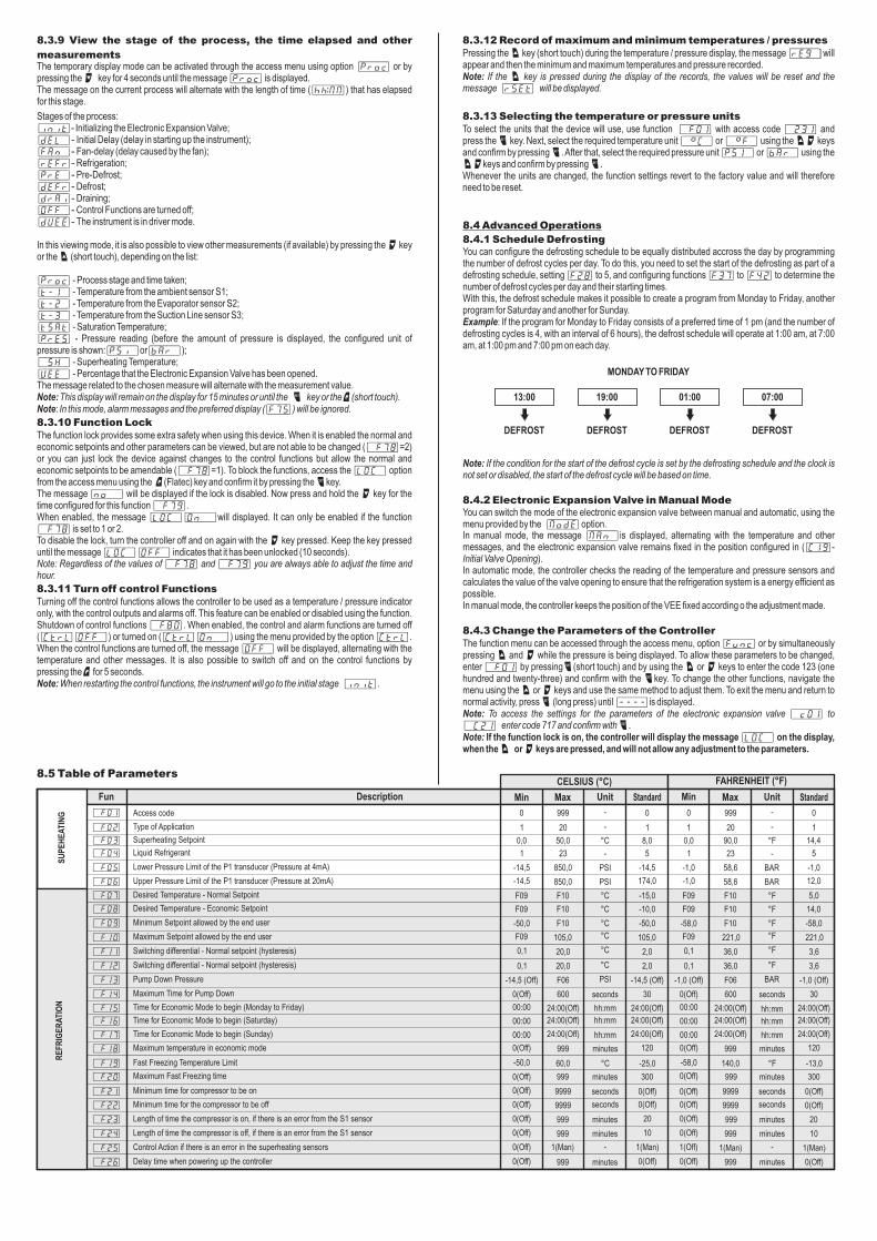
8.3.9 View the stage of the process, the time elapsed and other
measurementsThe temporary display mode can be activated through the access menu using option [Proc] or by pressing the > key for 4 seconds until the message [Proc] is displayed.The message on the current process will alternate with the length of time ([hh:mm]) that has elapsed for this stage.
Stages of the process:[init]- Initializing the Electronic Expansion Valve;[dEL,]- Initial Delay (delay in starting up the instrument);[Fan,]- Fan-delay (delay caused by the fan);[rEFr]- Refrigeration;[Pre,]- Pre-Defrost;[dEFr]- Defrost;[dRAi]- Draining;[Off,]- Control Functions are turned off;[dVee]- The instrument is in driver mode.
In this viewing mode, it is also possible to view other measurements (if available) by pressing the > key or the < (short touch), depending on the list:
[Proc] - Process stage and time taken;[t-1,] - Temperature from the ambient sensor S1;[t-2,] - Temperature from the Evaporator sensor S2;[t-3,] - Temperature from the Suction Line sensor S3;[tSat] - Saturation Temperature;[Pres] - Pressure reading (before the amount of pressure is displayed, the configured unit of pressure is shown:[Psi,]or[bar,]);[,SH,] - Superheating Temperature;[Vee,] - Percentage that the Electronic Expansion Valve has been opened.The message related to the chosen measure will alternate with the measurement value.Note: This display will remain on the display for 15 minutes or until the / key or the ;(short touch). Note: In this mode, alarm messages and the preferred display ([F75]) will be ignored.
8.3.10 Function Lock The function lock provides some extra safety when using this device. When it is enabled the normal and economic setpoints and other parameters can be viewed, but are not able to be changed ([,f78]=2) or you can just lock the device against changes to the control functions but allow the normal and economic setpoints to be amendable ([,f78]=1). To block the functions, access the [LOC,] option from the access menu using the ;(Flatec) key and confirm it by pressing the /key. The message [no,,] will be displayed if the lock is disabled. Now press and hold the > key for the time configured for this function [,f79]. When enabled, the message [LOC,][On,,]will displayed. It can only be enabled if the function [,f78] is set to 1 or 2.To disable the lock, turn the controller off and on again with the > key pressed. Keep the key pressed until the message [LOC,][OFF,] indicates that it has been unlocked (10 seconds).Note: Regardless of the values of [,F78] and [,F79] you are always able to adjust the time and hour.
8.3.11 Turn off control FunctionsTurning off the control functions allows the controller to be used as a temperature / pressure indicator only, with the control outputs and alarms off. This feature can be enabled or disabled using the function. Shutdown of control functions [,F80]. When enabled, the control and alarm functions are turned off ([CTRL][OFF,]) or turned on ([Ctrl][ON,,]) using the menu provided by the option [Ctrl]. When the control functions are turned off, the message [OFF,] will be displayed, alternating with the temperature and other messages. It is also possible to switch off and on the control functions by pressing the ; for 5 seconds.Note: When restarting the control functions, the instrument will go to the initial stage [init].
8.3.12 Record of maximum and minimum temperatures / pressuresPressing the < key (short touch) during the temperature / pressure display, the message [rEg,] will appear and then the minimum and maximum temperatures and pressure recorded.Note: If the < key is pressed during the display of the records, the values will be reset and the message [rsEt] will be displayed.
8.3.13 Selecting the temperature or pressure unitsTo select the units that the device will use, use function [,F01] with access code [,231] and press the / key. Next, select the required temperature unit [,=C,] or [,=F,] using the <> keys and confirm by pressing /. After that, select the required pressure unit [PSI,] or [Bar,] using the <>keys and confirm by pressing /.Whenever the units are changed, the function settings revert to the factory value and will therefore need to be reset.
8.4 Advanced Operations
8.4.1 Schedule DefrostingYou can configure the defrosting schedule to be equally distributed accross the day by programming the number of defrost cycles per day. To do this, you need to set the start of the defrosting as part of a defrosting schedule, setting [F28] to 5, and configuring functions [F37] to [F42] to determine the number of defrost cycles per day and their starting times.With this, the defrost schedule makes it possible to create a program from Monday to Friday, another program for Saturday and another for Sunday.Example: If the program for Monday to Friday consists of a preferred time of 1 pm (and the number of defrosting cycles is 4, with an interval of 6 hours), the defrost schedule will operate at 1:00 am, at 7:00 am, at 1:00 pm and 7:00 pm on each day.
Note: If the condition for the start of the defrost cycle is set by the defrosting schedule and the clock is not set or disabled, the start of the defrost cycle will be based on time.
8.4.2 Electronic Expansion Valve in Manual ModeYou can switch the mode of the electronic expansion valve between manual and automatic, using the menu provided by the [modE] option.In manual mode, the message [Man,]is displayed, alternating with the temperature and other messages, and the electronic expansion valve remains fixed in the position configured in ([C19]- Initial Valve Opening).In automatic mode, the controller checks the reading of the temperature and pressure sensors and calculates the value of the valve opening to ensure that the refrigeration system is a energy efficient as possible.In manual mode, the controller keeps the position of the VEE fixed according o the adjustment made.
8.4.3 Change the Parameters of the ControllerThe function menu can be accessed through the access menu, option [Func] or by simultaneously pressing < and > while the pressure is being displayed. To allow these parameters to be changed, enter [,F01] by pressing/(short touch) and by using the < or > keys to enter the code 123 (one hundred and twenty-three) and confirm with the /key. To change the other functions, navigate the menu using the < or > keys and use the same method to adjust them. To exit the menu and return to normal activity, press / (long press) until [----]is displayed.Note: To access the settings for the parameters of the electronic expansion valve [,c01] to [,C21] enter code 717 and confirm with /.Note: If the function lock is on, the controller will display the message [LOC,] on the display, when the < or > keys are pressed, and will not allow any adjustment to the parameters.
MONDAY TO FRIDAY
DEFROST DEFROST DEFROST DEFROST
13:00 19:00 01:00 07:00
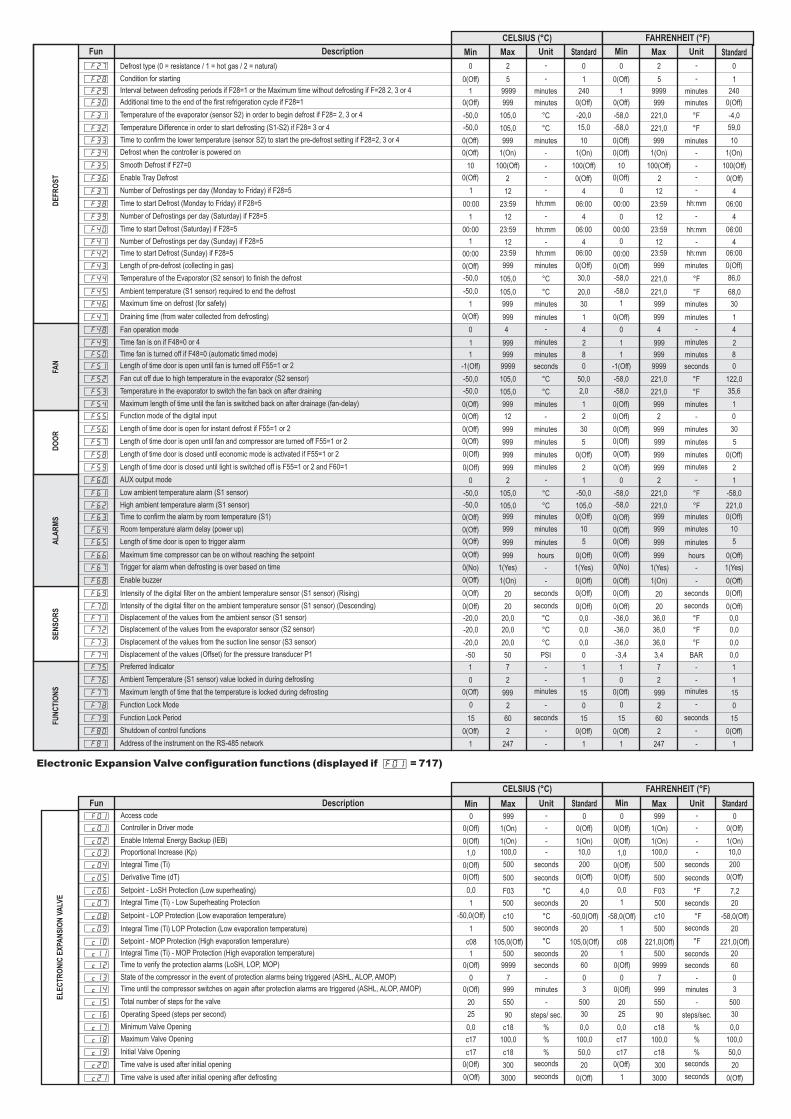
8.5 Table of Parameters
SU
PE
HE
AT
ING
Min Max StandardUnitDescriptionFun
[,F01]
[,F02]
[,F03]
[,F04]
[,F05]
[,F06]
[,F07]
[,F08]
[,F09]
[,F10]
[,F11]
[,F12]
[,F13]
[,F14]
[,F15]
[,F16]
[,F17]
[,F18]
[,F19]
Min Max StandardUnit
0
999
0
0
0
999
105,0
221,0
1
1
1
2,0
3,6
-
-
°C
°F
-
-
PSI
BAR
20
8,0
14,4
20
90,0
58,6
0,0
2,0
-25,0
0(Off)
0(Off)
0(Off)
0(Off)
0(Off)
0(Off)
0(Off)
20
0(Off)
10
0(Off)
1(Man)
1(Off)
1(Man)
0(Off)
300
300
3,6
0,1
50,0
°C
°F
-
-
PSI
BAR
°C
°F
°C
°F
seconds
seconds
minutes
minutes
minutes
minutes
minutes
850,0
30
30
20
24:00(Off)
24:00(Off)
24:00(Off)
9999
9999
24:00(Off)
24:00(Off)
24:00(Off)
PSI
BAR
°C
°F
hh:mm
hh:mm
hh:mm
hh:mm
hh:mm
hh:mm
minutes
°C
seconds
seconds
minutes
minutes
minutes
minutes
°F
seconds
seconds
°C
°F
°C
°F
20,0
36,0
F06
F06
23
F10
F10
F10
105,0
221,0
20,0
36,0
850,0
-14,5
-1,0
-10,0
14,0
-50,0
-58,0
F10
600
999
999
999
999
600
999
999
24:00(Off)
24:00(Off)
24:00(Off)
24:00(Off)
24:00(Off)
24:00(Off)
999
60,0
999
140,0
,0
1
0,1
9999
9999
-50,0
-58,0
-13,0
0(Off)
0,0
1
5
5
1
23
F10
58,6
F10
-1,0
F09
F09
0(Off)
-15,0
5,0
-14,5
-14,5
174,0
12,0
-1,0
F09
F09
0,1
0,1
00:00
00:00
00:00
-50,0
-58,0
00:00
00:00
00:00
0(Off)
120
120
0(Off)
-14,5 (Off)
-14,5 (Off)
-1,0 (Off)
-1,0 (Off)
F09
F09
0(Off)
0(Off)
0(Off)
0(Off)
0(Off)
0(Off)
0(Off)
0(Off)
Access code
Type of Application
Superheating Setpoint
Liquid Refrigerant
Lower Pressure Limit of the P1 transducer (Pressure at 4mA)
Upper Pressure Limit of the P1 transducer (Pressure at 20mA)
Desired Temperature - Normal Setpoint
Desired Temperature - Economic Setpoint
Minimum Setpoint allowed by the end user
Maximum Setpoint allowed by the end user
Switching differential - Normal setpoint (hysteresis)
Switching differential - Normal setpoint (hysteresis)
Pump Down Pressure
Maximum Time for Pump Down
Time for Economic Mode to begin (Monday to Friday)
Time for Economic Mode to begin (Saturday)
Time for Economic Mode to begin (Sunday)
Maximum temperature in economic mode
Fast Freezing Temperature Limit
Maximum Fast Freezing time
Minimum time for compressor to be on
Minimum time for the compressor to be off
Length of time the compressor is on, if there is an error from the S1 sensor
CELSIUS (°C) FAHRENHEIT (°F)
[,F20]
[,F21]
[,F22]
[,F23]
-
-
999
1(Man)
999
10
1(Man)
0(Off)
Length of time the compressor is off, if there is an error from the S1 sensor
Control Action if there is an error in the superheating sensors
Delay time when powering up the controller
[,F24]
[,F25]
[,F26]
RE
FR
IGE
RA
TIO
N
DE
FR
OS
TD
OO
RS
EN
SO
RS
Min Max StandardUnitDescriptionFun
[,F27]
[,F48]
[,F69]
[,c09]
[,F28]
[,F49]
[,F70]
[,c10]
[,F29]
[,F50]
[,F71]
[,c11]
[,c13]
[,F30]
[,F51]
[,F72]
[,c12]
[,c14]
[,F31]
[,F52]
[,F73]
[,c15]
[,F32]
[,F53]
[,c16]
[,F33]
[,F54]
[,F74]
[,c17]
[,F34]
[,F55]
[,F75]
[,c18]
[,F35]
[,F56]
[,F76]
[,c19]
[,F36]
[,F57]
[,F77]
[,c20]
[,F37]
[,F58]
[,F78]
[,c21]
[,F38]
[,F59]
[,F79]
[,F39]
[,F60]
[,c01]
[,F01]
[,F80]
[,F40]
[,F61]
[,c02]
[,F81]
[,F41]
[,F62]
[,F42]
[,F63]
[,c03]
[,F43]
[,F64]
[,c04]
[,F44]
[,F65]
[,c05]
[,F45]
[,F66]
[,c06]
Min Max StandardUnit
0
0
0(Off)
1
2
4
20
500
0
4
0(Off)
20
0
4
0(Off)
20
0
0
0(Off)
1
2
4
20
500
0(Off)
5
15
20
0(Off)
5
15
20
1
2
0(Off)
105,0(Off)
1
2
0(Off)
221,0(Off)
0(Off)
1
0(Off)
c08
4
0(Off)
0
0(Off)
4
0(Off)
0
0(Off)
-
-
seconds
seconds
-
-
seconds
seconds
hh:mm
hh:mm
hh:mm
hh:mm
hh:mm
hh:mm
minutes
seconds
minutes
seconds
-
minutes
seconds
°C
-
minutes
seconds
°F
-
-
-
-
-
-
-
-
-
-
5
999
20
105,0(Off)
240
8
0,0
20
0
240
8
0,0
20
0
5
999
20
221,0(Off)
9999
999
36,0
500
7
221,0
221,0
90
1
1
-36,0
1
0
06:00
2
15
20,0
0(Off)
4,0
1
0(Off)
-50,0(Off)
0(Off)
0(Off)
-58,0(Off)
1
0(No)
1
30
1(Yes)
20
30
1(Yes)
20
06:00
2
15
00:00
0(Off)
15
9999
999
20,0
500
7
minutes
minutes
°C
seconds
-
minutes
minutes
minutes
°F
seconds
-
minutes
seconds
°C
seconds
minutes
seconds
°F
seconds
minutes
°C
°C
°C
-
°F
°F
°F
-
minutes
minutes
PSI
%
minutes
minutes
BAR
%
-
-
-
%
-
-
-
%
°C
-
-
°F
-
-
minutes
-
seconds
minutes
-
seconds
105,0
105,0
90
06:00
-50,0
1(On)
1
06:00
-58,0
1(On)
1
4
105,0
06:00
0(Off)
10,0
0(Off)
10
200
999
1(On)
c10
999
1(On)
c10
4
221,0
06:00
0(Off)
10,0
0(Off)
10
200
°C
°C
steps/ sec.
°F
°F
steps/sec.
-
minutes
-
%
-
minutes
-
%
-
°C
minutes
minutes
-
minutes
seconds
-
°F
minutes
minutes
-
minutes
seconds
°C
minutes
seconds
°C
hours
°C
minutes
-
°C
°F
minutes
seconds
°F
hours
°F
minutes
-
°F
-
minutes
minutes
seconds
-
minutes
minutes
seconds
-
minutes
-
seconds
-
minutes
-
seconds
23:59
999
60
23:59
999
60
12
2
1(On)
999
2
12
2
1(On)
999
2
999
9999
20,0
9999
999
999
999
50
c18
100(Off)
999
2
c18
100(Off)
999
2
c18
2
999
999
300
2
999
999
300
12
999
2
3000
12
999
2
3000
105,0
105,0
20,0
550
-20,0
50,0
0,0
500
-4,0
122,0
0,0
500
1(On)
2
1
100,0
1(On)
0
1
100,0
100(Off)
30
1
50,0
100(Off)
30
1
50,0
1(On)
12
7
100,0
23:59
105,0
1(On)
247
999
1(Yes)
500
23:59
221,0
1(On)
247
999
1(Yes)
500
12
105,0
23:59
999
100,0
999
999
500
12
221,0
23:59
999
100,0
999
999
500
105,0
999
500
105,0
999
F03
221,0
999
500
221,0
999
F03
0(Off)
1
0(Off)
c08
00:00
0(Off)
15
10
0(Off)
0
c17
10
0(Off)
0
c17
68,0
0(Off)
7,2
1
0(Off)
-58,0(Off)
1
1
-20,0
1
0
0(Off)
-1(Off)
-20,0
0(Off)
0(Off)
0(Off)
0
0,0
60
3
0(Off)
0
0,0
60
3
0(Off)
-1(Off)
-36,0
0(Off)
0(Off)
999
9999
36,0
9999
999
999
999
3,4
c18
221,0
221,0
36,0
550
1(On)
2
7
100,0
-58,0
-58,0
-36,0
20
0(Off)
0(Off)
-3,4
0,0
0(Off)
0(Off)
1
c17
00:00
-58,0
0(Off)
1
10
1
0
0,0
10
1
0,0
0,0
-50,0
-50,0
-20,0
20
-50,0
-50,0
25
15,0
2,0
30
59,0
35,6
30
-58,0
-58,0
25
0(Off)
0(Off)
0(Off)
0(Off)
0(Off)
0(Off)
0(Off)
0(Off)
0
0(Off)
0
1
1
0(Off)
0
0(Off)
1
-50,0
00:00
0(Off)
1,0
0(Off)
0(Off)
0(Off)
-50,0
0(Off)
0,0
-58,0
0(Off)
0,0
0
-58,0
00:00
0(Off)
1,0
0(Off)
0(Off)
0(Off)
-50,0
0(Off)
0(Off)
30,0
5
0(Off)
86,0
5
0(Off)
-58,0
0(Off)
0(Off)
1
0
0(Off)
0
0(Off)
4
1
0(Off)
0
0(Off)
4
1
0(Off)
0
0(Off)
0
0
0(Off)
0
0(Off)
0(Off)
0(Off)
-50
0,0
0(Off)
0(Off)
1
c17
00:00
-50,0
0(Off)
1
1
0(No)
1
0(Off)
0(Off)
-50,0(Off)
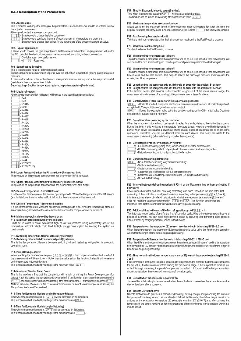
Defrost type (0 = resistance / 1 = hot gas / 2 = natural)
Fan operation mode
Intensity of the digital filter on the ambient temperature sensor (S1 sensor) (Rising)
Integral Time (Ti) LOP Protection (Low evaporation temperature)
Condition for starting
Time fan is on if F48=0 or 4
Intensity of the digital filter on the ambient temperature sensor (S1 sensor) (Descending)
Setpoint - MOP Protection (High evaporation temperature)
Interval between defrosting periods if F28=1 or the Maximum time without defrosting if F=28 2, 3 or 4
Time fan is turned off if F48=0 (automatic timed mode)
Displacement of the values from the ambient sensor (S1 sensor)
Integral Time (Ti) - MOP Protection (High evaporation temperature)
State of the compressor in the event of protection alarms being triggered (ASHL, ALOP, AMOP)
Additional time to the end of the first refrigeration cycle if F28=1
Length of time door is open until fan is turned off F55=1 or 2
Displacement of the values from the evaporator sensor (S2 sensor)
Time to verify the protection alarms (LoSH, LOP, MOP)
Time until the compressor switches on again after protection alarms are triggered (ASHL, ALOP, AMOP)
Temperature of the evaporator (sensor S2) in order to begin defrost if F28= 2, 3 or 4
Fan cut off due to high temperature in the evaporator (S2 sensor)
Displacement of the values from the suction line sensor (S3 sensor)
Total number of steps for the valve
Temperature Difference in order to start defrosting (S1-S2) if F28= 3 or 4
Temperature in the evaporator to switch the fan back on after draining
Operating Speed (steps per second)
Time to confirm the lower temperature (sensor S2) to start the pre-defrost setting if F28=2, 3 or 4
Maximum length of time until the fan is switched back on after drainage (fan-delay)
Displacement of the values (Offset) for the pressure transducer P1
Minimum Valve Opening
Defrost when the controller is powered on
Function mode of the digital input
Preferred Indicator
Maximum Valve Opening
Smooth Defrost if F27=0
Length of time door is open for instant defrost if F55=1 or 2
Ambient Temperature (S1 sensor) value locked in during defrosting
Initial Valve Opening
Enable Tray Defrost
Length of time door is open until fan and compressor are turned off F55=1 or 2
Maximum length of time that the temperature is locked during defrosting
Time valve is used after initial opening
Number of Defrostings per day (Monday to Friday) if F28=5
Length of time door is closed until economic mode is activated if F55=1 or 2
Function Lock Mode
Time valve is used after initial opening after defrosting
Time to start Defrost (Monday to Friday) if F28=5
Length of time door is closed until light is switched off is F55=1 or 2 and F60=1
Function Lock Period
Number of Defrostings per day (Saturday) if F28=5
AUX output mode
Controller in Driver mode
Access code
Shutdown of control functions
Time to start Defrost (Saturday) if F28=5
Low ambient temperature alarm (S1 sensor)
Enable Internal Energy Backup (IEB)
Address of the instrument on the RS-485 network
Number of Defrostings per day (Sunday) if F28=5
High ambient temperature alarm (S1 sensor)
Time to start Defrost (Sunday) if F28=5
Time to confirm the alarm by room temperature (S1)
Proportional Increase (Kp)
Length of pre-defrost (collecting in gas)
Room temperature alarm delay (power up)
Integral Time (Ti)
Temperature of the Evaporator (S2 sensor) to finish the defrost
Length of time door is open to trigger alarm
Derivative Time (dT)
Ambient temperature (S1 sensor) required to end the defrost
Maximum time compressor can be on without reaching the setpoint
Setpoint - LoSH Protection (Low superheating)
Maximum time on defrost (for safety)
Trigger for alarm when defrosting is over based on time
Integral Time (Ti) - Low Superheating Protection
Draining time (from water collected from defrosting)
Enable buzzer
Setpoint - LOP Protection (Low evaporation temperature)
CELSIUS (°C) FAHRENHEIT (°F)
[,F46]
[,F67]
[,c07]
[,F47]
[,F68]
[,c08]
FAN
AL
AR
MS
FU
NC
TIO
NS
EL
EC
TR
ON
IC E
XPA
NS
ION
VA
LVE
Min Max StandardUnitDescriptionFun Min Max StandardUnit
CELSIUS (°C) FAHRENHEIT (°F)
Electronic Expansion Valve configuration functions (displayed if [F01] = 717)
F01 - Access Code:This is required to change the settings of the parameters. This code does not need to be entered to view the adjusted parameters.Allows you to enter the access codes provided:[,123]- Enables you to change the table parameters;[,231]- Enables you to configure the units of measurement for temperature and pressure;[,717]- Enables you to change the settings for the parameters of the electronic expansion valve.
F02 - Type of application:It allows you to choose the type of application that the device will control. Pre-programmed values for the PID control of the electronic expansion valve are loaded, according to the chosen option:[,,,1] - Cold chamber - slow performance;[,,,2] to [,,20] - Reserved.
F03 - Superheating Setpoint:This is the reference value for control of superheating.Superheating indicates how much vapor is over the saturation temperature (boiling point) at a given pressure.A pressure transducer in the suction line and a temperature sensor are required at the evaporator outlet (useful) or at the compressor inlet (total).Superheating = Suction temperature - satured vapor temperature (fluid curve).
F04 - Liquid refrigerant:Allows you to choose which refrigerant will be used in the superheating calculation/;[,,,1]- R22[,,,2]- R32[,,,3]- R134A[,,,4]- R290[,,,5]- R404A[,,,6]- R407A[,,,7]- R407C[,,,8]- R407F[,,,9]- R410A[,,10]- R422A[,,11]- R422D[,,12]- R427A[,,13]- R441A[,,14]- R448A[,,15]- R449A[,,16]- R450A[,,17]- R452A[,,18]- R507A[,,19]- R513A[,,20]- R600A[,,21]- R744[,,22]- R1234YF[,,23]- R1234ZE (E)
F05 - Lower Pressure Limit of the P1 transducer (Pressure at 4mA):The pressure on the pressure sensor when it has a current of 4mA at its output.
F06 - Upper Pressure Limit of the P1 transducer (Pressure at 20mA):The pressure on the pressure sensor when it has a current of 20mA at its output.
F07 - Desired Temperature - Normal Setpoint:It is the control temperature of the normal operating mode. When the temperature of the S1 sensor (ambient) is lower than the value set for this function the compressor will be turned off.
F08 - Desired Temperature - Economic Setpoint:It is the control temperature when the economic operating mode is on. When the temperature of the S1 sensor (ambient) is lower than the value set for this function the compressor will be turned off.
F09 - Minimum setpoint allowed by the end user:F10 - Maximum setpoint allowed by the end user:Limits set in order to avoid excessivelt high or low temperatures being accidentally set for the temperature setpoint, which could lead to high energy consumption by keeping the system on continuously.
F11 - Switching differential - Normal setpoint (hysteresis):F12 - Switching differential - Economic setpoint (hysteresis)This is the temperature difference between switching off and restarting refrigeration in economic operating mode.
F13 - Pump Down pressure :When reaching the temperature setpoint ([F07] or [F08]), the compressor will not be turned off if the pressure on the P1 transducer is higher than the value set for this function. Instead it will remain on until the pressure reduces this value.This function can be turned off by setting it to the minimum value [OFF,].
F14 - Maximum Time for Pump Down:This is the maximum time that the compressor will remain on during the Pump Down process (for safety). After this period the compressor is switched off. If this function is set to a minimum value off 0 [OFF,], the compressor will be turned off only if the pressure on the P1 transducer is less than [F13].Note: In the event of an error in the S1 ambient temperature or the P1 transducer pressure sensor, the Pump Down feature will be disabled.
F15- Time for Economic Mode to begin (Monday to Friday):Time when the economic setpoint [SP-E] will be activated on working days.This function can be turned off by setting it to the maximum value [OFF,].
F16- Time for Economic Mode to begin (Saturday)Time when the economic setpoint[SP-E] will be activated on Saturdays..This function can be turned off by setting it to the maximum value [OFF,].
F17 - Time for Economic Mode to begin (Sunday):Time when the economic setpoint [SP-E] will be activated on Sundays.This function can be turned off by setting it to the maximum value [OFF,].
F18 - Maximum temperature in economic mode:Allows you to set the maximum length of time economy mode will operate for. After this time, the setpoint returns to economy mode in normal operation. If this is set to [OFF,] this time will be ignored.
F19 - Fast Freezing Temperature Limit:This is the minimum temperature that the instrument can reach during the Fast Freezing process.
F20 - Maximum Fast Freezing time:This the duration of the Fast Freezing process.
F21 - Minimum time for compressor to be on:This is the minimum amount of time the compressor will be on, i.e. The period of time between the last section and the next time it is stopped. This helps to avoid power surges from the electricity grid.
F22 - Minimum time for compressor to be off:This is the minimum amount of time the compressor will be off, i.e. The period of time between the last time it stops and the next section. This helps to relieve the discharge pressure and increases the working life of the compressor.
F23 - Length of time the compressor is on, if there is an error with the ambient S1 sensor:F24 - Length of time the compressor is off, if there is an error with the ambient S1 sensor:If the ambient sensor (S1 sensor) is disconnected or goes out of the measurement range, the compressor will switch on or off according to the parameters set in these functions.
F25 - Control Action if there is an error in the superheating sensors:[OFF,] - Control turned off. Keeps the electronic expansion valve closed and all control outputs off, except the AUX output if it is configured as an alarm output.[Man,] - Keeps the expansion valve set to the position configured in (C19 - Initial Valve Opening) and all control outputs operate normally.
F26 - Delay time when powering up the controller:When the instrument is turned on, it can remain disabled for a while, delaying the start of the process. During this time, it only works as a temperature / pressure gauge. Helps to avoid high demands for power, when power returns after a power cut, where several pieces of equipment are all on the same connection. Therefore, you can set different times for each device. This delay can relate to the compressor or defrosting (where defrosting is part of the sequence)
F27 - Defrost type (0=coils / 1 = hot gas / 2 = natural):[,,,0] - Electrical Defrosting (using coils), which only applies to the defrost outlet.[,,,1] - Hot Gas Defrosting, which only applies to the compressor and defrosting outlets.[,,,2] - Natural defrosting, which only applies to the fan outlet.
F28 - Condition for starting defrosting:[Off,] - No automatic defrosting, only manual defrosting;[,,,1] - Set time to start defrosting;[,,,2] - Set temperature to start defrosting;[,,,3] - Set temperature difference (S1-S2) to start defrosting;[,,,4] - Set temperature and temperature difference (S1-S2) to start defrosting;[,,,5] - Schedule Defrosting.
F29 - Interval between defrosting periods if F28=1 or the Maximum time without defrosting if F28=3 or 4:It determines how often and after how long defrosting take place, based on the time of the last defrosting. If the controller is configured to defrost according to temperature ([F28]= 2, 3 or 4), this time acts as a level of safety in situations in which the evaporator temperature (S2 sensor) does not reach the values programmed in [F31] or [F32]. This function determines the maximum time that the controller will wait before carrying out defrosting.
F30 - Additional time to the end of the first refrigeration cycle if [F28] = 1:This is to set a longer period of time for the first refrigeration cycle. Where there are setups with several pieces of euipment, you can avoid high demand peaks by ensuring that defrosting takes place at different times by assigning different values to this function.
F31 - Temperature of the evaporator (S2 sensor) in order to begin defrosting if F28=2, 3 or 4.When the temperature of the evaporator (S2 sensor) reaches a value using this function, the controller will wait for the length of time before beginning defrosting.
F32 - Temperature Difference in order to start defrosting (S1-S2) if F28=3 or 4.When the difference between the temperature of the ambient sensor (S1 sensor) and the temperature of the evaporator (S2 sensor) reaches a value using this function, the controller will wait for the length of time before beginning defrosting.
F33 - Time to confirm the lower temperature (sensor S2) to start the pre-defrost setting if F28=2, 3 or 4If the controller is configured to defrost according to temperature, the moment the temperature reaches the set value, it will run a delay before starting the pre-defrost stage. If the temperature remains low, while this stage is running, the pre-defrost process is started. If it doesn’t and the temperature rises above the set value, the system will return to a refrigeration cycle.
F34 - Defrost when the controller is powered onThis enables a defrosting to be conducted when the controller is powered on. For example, when the electricity returns after a power cut.
F35 - Smooth Defrost if F27=0:Smooth Defrost mode provides a smoother defrosting, saving energy and preventing the ambient temperature from rising as much as in a standard defrost. In this mode, the defrost output remains on as long as the evaporator temperature (S2 sensor) is less than 2°C (35.6°F) and, after passing that temperature, the output remains on for the percentage of time configured in this function, within a 2-minute period.
8.5.1 Description of the Parameters

F36 - Enable Tray Defrost:[OFF,]- Deactives Tray Defrosting;[,,,1]- Defrosting the tray using the FAN outlet;[,,,2]- Defrosting the tray using the AUX outlet;The chosen output acts as a second defrosting output. This output is activated during the pre-defrost, defrost and drain periods. The functionality related to the control of this output (FAN or AUX) will be disregarded.
F37 - Number of Defrostings per day (Monday to Friday) if F28=5Defrosting is set to take place at equal intervals according to the number programmed per day, always taking preferred times into account. It can be adjusted using values of 1, 2, 3, 4, 6, 8 or 12.This function is to program this for Monday to Friday.
F38 - Time to start Defrost (Monday to Friday) if F28=5Enables the preferred start time of one of the daily defrost cycles to be adjusted. This function is to program this for Monday to Friday.
F39 - Number of Defrostings per day (Saturday) if F28=5Defrosting is set to take place at equal intervals according to the number programmed per day, always taking preferred times into account. It can be adjusted using values of 1, 2, 3, 4, 6, 8 or 12. This functions is to program this for Saturday
F40 - Time to start Defrost (Saturday) if F28 = 5:Enables the preferred start time of one of the daily defrost cycles to be adjusted. This function is to program this for Saturday.
F41 - Number of Defrostings per day (Sunday) if F28=5:Defrosting is set to take place at equal intervals according to the number programmed per day, always taking preferred times into account. It can be adjusted using values of 1, 2, 3, 4, 6, 8 or 12. This function is to program this for Sunday.
F42 - Time to start Defrost (Sunday) if F28=5Enables the preferred start time of one of the daily defrost cycles to be adjusted. This function is to program this for Sunday.
F43 - Length of pre-defrost (collecting in gas):When the defrost starts, the controller will only use the fan during this time, in order to take advantage of the residual energy of the gas.
F44 - Temperature of the Evaporator (S2 sensor) to finish the defrost:If the temperature in the evaporator (sensor S2) reaches the set value, the defrost cycle will be halted, i.e. Temperature controlled. This way it improves the defrosting process.
F45 - Temperature of the Ambient Sensor (S1 sensor) to finish the defrost:If the ambient temperature (sensor S1) reaches the set value, the defrost cycle will be halted, i.e. Temperature controlled.
F46 - Maximum time on defrost (for safety):This function adjusts the maximum duration of a defrost cycle. If the defrosting is not complete, during this period, according to the temperature, a dot will begin flashing in the lower right corner of the display (if it's enabled in [F67]), indicating that the time set for the defrost has ended by the required temperature has not been reached. This can happen when the temperature set is too high, the time limit is insufficient, the S2 sensor is disconnected or it isn't in contact with the evaporator.
F47 - Draining time (from water collected from defrosting):Time required for removing excess water, i.e. for the last drops of water to drain from the evaporator. During this period, all outputs remain switched off. This function can be turned off by setting it to the minimum value [OFF,].
F48 - Fan operation mode:[,,,0]- Automatic according to time: the fan will be on when the compressor is on. When the compressor is off, the fan will oscillate according to the times set in [F49] and [F50];[,,,1] - Automatic according to temperature: When the compressor is switched on, the fan stays on. With the compressor off, the fan turns on when the temperature is higher than the setpoint + 60% of the hysteresis and turns off when the temperature is lower than the setpoint + 20% of the hysteresis;[,,,2]- Continuous: the fan is always on;[,,,3] - Dependent: the fan operates together with the compressor;[,,,4] - For a period of time after the compressor is turned off: after turning off the compressor, the fan will remain on for the time set in [F49].Note1: Modes 0 and 1 will only switch the fan on if the temperature of the S2 sensor is lower thanthe temperature of the S1 sensor.Note2: Mode 1 will activate the fan only if the temperature of sensor S2 is lower than theconfigured setpoint.
F49 -Time fan is on if F48=0 or 4This is how long the fan is on for.
F50 - Time fan is turned off if F48=0 (automatic timed mode):This is how long the fan is off for.
F51 - Length of time door is open until fan is turned off F55=1 or 2:This is the length of time that the fan will continue to run after the door is opened. If you set a minimum value of the fan will not switch off if the door is opened. If you set a value of the fan [OFF,], r [,,,0], will switch off immediately if the door is opened.
F52 - Fan cut off due to high temperature in the evaporator (S2 sensor):This is intended to disconnect the evaporator fan when the ambient temperature is not within the design range for the refrigeration device, avoiding high temperatures and suction pressures that could damage the compressor. If the evaporator temperature exceeds the set value, the fan is turned off and will be restarted at a fixed hysteresis of 2 ° C (3.6 ° F). This is a useful function to use when, for example, a refrigerator is used that has been idle for days or when restocking units or counters with products.
F53 - Temperature in the evaporator to switch the fan back on after draining:After drainage is complete, it starts a fan-delay cycle. The compressor will start up immediately, because the temperature in the evaporator is high, but the fan will only start after the temperature in the evaporator falls below the set value. This function is used to remove the heat in the evaporator after a defrost cycle, to ensure it is not opened up immediately to the ambient temperature.
F54 - Maximum length of time until the fan is switched back on after drainage (fan-delay):For safety, if the temperature in the evaporator does not reach the value set by function or the [F53] S2 sensor is disconnected, the fan will only come on after the time set for this function has expired.
F55 - :Function mode of the digital input[,,,0] - Digital Input deactivated;[,,,1] - NO Contact: Door Sensor;[,,,2] - NC Contact: Door Sensor;[,,,3] - NO Contact: External Alarm;[,,,4]- NC Contact: External Alarm;[,,,5] - NO Contact: Switch off the Control System;[,,,6] - NC Contact: Switch off the Control System;[,,,7] - NO Pulsator: Economic Mode;[,,,8] - NC Pulsator: Economic Mode;[,,,9] - NO Pulsator: Fast Freezing;[,,10] - NC Pulsator: Fast Freezing;[,,11]- NO Pulsator: Defrosting;[,,12]-NC Pulsator: Defrosting.Note: (c01 = [On,,]), With the instrument operating in driver mode the digital input will be automatically configured as an external signal input (compressor) in order to enable the electronic expansion valve.ddddddddddddddddddddddddddddddddddddddddddddddddddddddddddd
: In options 5 and 6, the Sitrad supervisory system has priority over the digital input. Thus, if Sitrad Obssends a command to turn on / off the control functions, the digital input is temporarily disabled and a transition in its state will be necessary to enable it again.
F56 - Length of time door is open for instant defrost if F55=1 or 2:If the door is kept open for a period longer than that defined in this function, instant defrosting will take place, as long as the temperature in the evaporator (S2 sensor) is less than and the ambient [F44] temperature (S1 sensor) is less than [F45].
F57 - Length of time door is open until fan and compressor are turned off F55=1 or 2:For safety, if the door remains open longer than the time set here, both the compressor and fan will be switched off.
F58 - Length of time door is closed until economic mode is activated if F55= 1 or 2:With the door closed, this parameter defines how long until economic mode is activated. Setpoint is switched to the economic setpoint.
F59 - Length of time door is closed until light is switched off if F55= 1 or 2 and F60=1:With the door closed, this parameter defines how long it will be until the lamp is turned off. Helps save electricity. With this function set to the minimum value all functions related to lamp activation [OFF,], are ignored and the output remains off.
F60 - AUX output mode:[,,,0] - Output switched off;[,,,1] - Light switching;[,,,2] - Alarm switching.Note: If it is set up as an alarm switch, the AUX output will be turned on in the event of the following alarms: open door, high / low ambient temperature, compressor on without reaching the setpoint, external alarm (digital input), low superheating, MOP, LOP, Internal Energy Backup error or error in the electronic expansion valve.
F61 - Low ambient temperature alarm (S1 sensor):This is the ambient temperature (S1), below which the instrument will trigger the low temperature alarm. The differential for switching off the alarm is set in 0.1 ° C / 0.1 ° F. During the Fast Freezing operation, the low temperature alarm is deactivated. When this process is over it is reactivated when the temperature is no longer within the range of the alarm.
F62- High ambient temperature alarm (S1 sensor):This is the ambient temperature (S1), above which the instrument will trigger the temperature alarm. The differential for the alarm to switch off is fixed at 0.1 ° C / 0.1 ° F. This alarm takes into account the temperature shown on the display and is therefore determined by the temperature reading locked during the defrost cycle [F76].
F63- Time to confirm the alarm by room temperature (S1):This is the length of time, during which the ambient temperature alarm (low or high) will be inactive, even if the conditions exist to trigger it.
F64- Room temperature alarm delay (power up):During this time the alarm remains off while waiting for the system to go back to an operating mode. The (low or high) ambient temperature alarms are enabled after this time has elapsed or the setpoint temperature has been reached.
F65- Length of time door is open to trigger alarm:When the door is opened, the message appears on the display and the door open timer [Open] starts. If this time is longer than the time that is set for this function, the alarm will be triggered
F66- Maximum time compressor can be on without reaching the setpoint:The alarm is triggered if the compressor remains on without reaching the setpoint, for a longer time than the length specified in this function.
F67-Trigger for alarm when defrosting is over based on time:When the defrost cycle has been running for the length of time set, but has not reached the temperature set, the user is notified via a flashing dot in the lower right corner of the display ([,,,.]).
F68- Enable Buzzer:Enables or disables the internal buzzer to sound alarms.
F69- Intensity of the digital filter on the ambient temperature sensor (S1 sensor) (Rising):F70- Intensity of the digital filter on the ambient temperature sensor (S1 sensor) (Descending):The value set by these functions represents the time (in seconds) in which the temperature may vary 0.1ºC / 0.1 ° F either up or down. Note: A typical use for this type of filter is in freezers for ice cream and frozen foods. When the door is opened, a quantity of hot air will fall directly on the sensor, causing a rapid rise in the temperature reading and, often, activating the compressor unnecessarily.
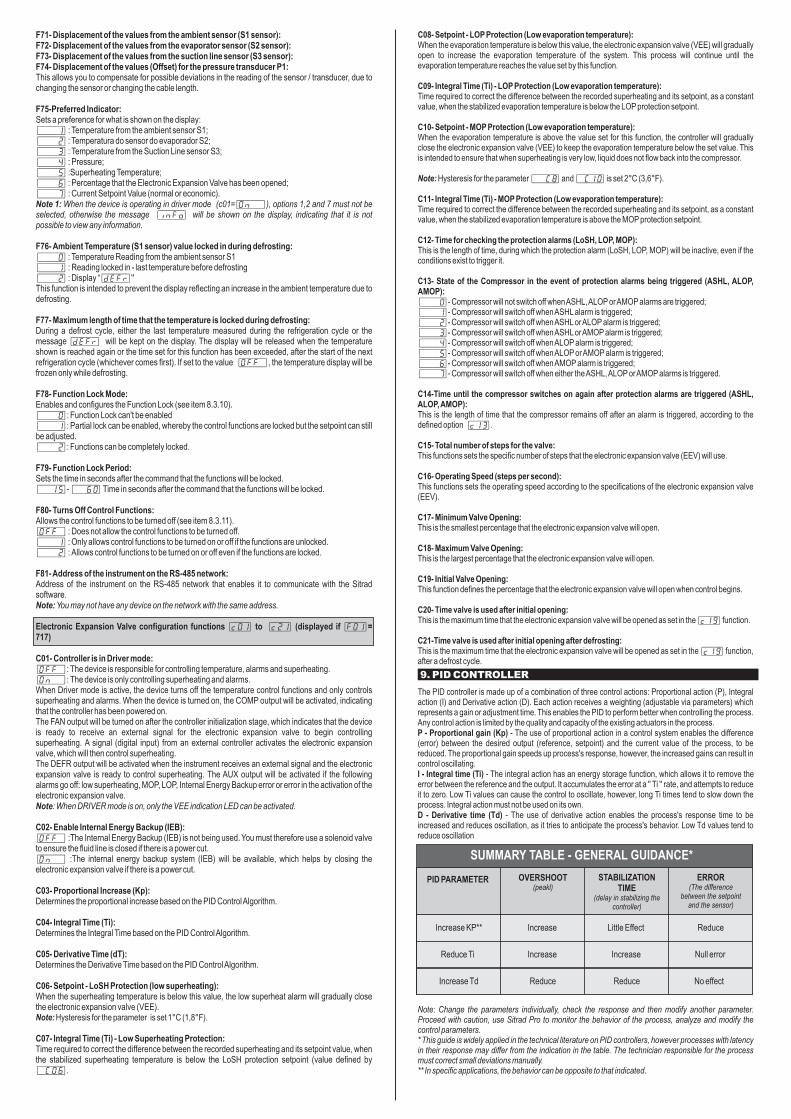
C08- Setpoint - LOP Protection (Low evaporation temperature):When the evaporation temperature is below this value, the electronic expansion valve (VEE) will gradually open to increase the evaporation temperature of the system. This process will continue until the evaporation temperature reaches the value set by this function.
C09- Integral Time (Ti) - LOP Protection (Low evaporation temperature):Time required to correct the difference between the recorded superheating and its setpoint, as a constant value, when the stabilized evaporation temperature is below the LOP protection setpoint.
C10- Setpoint - MOP Protection (Low evaporation temperature):When the evaporation temperature is above the value set for this function, the controller will gradually close the electronic expansion valve (VEE) to keep the evaporation temperature below the set value. This is intended to ensure that when superheating is very low, liquid does not flow back into the compressor.
Note: Hysteresis for the parameter [,,C8] and [,C10] is set 2°C (3,6°F).
C11- Integral Time (Ti) - MOP Protection (Low evaporation temperature):Time required to correct the difference between the recorded superheating and its setpoint, as a constant value, when the stabilized evaporation temperature is above the MOP protection setpoint.
C12- Time for checking the protection alarms (LoSH, LOP, MOP):This is the length of time, during which the protection alarm (LoSH, LOP, MOP) will be inactive, even if the conditions exist to trigger it.
C13- State of the Compressor in the event of protection alarms being triggered (ASHL, ALOP, AMOP):[,,,0]- Compressor will not switch off when ASHL, ALOP or AMOP alarms are triggered;[,,,1]- Compressor will switch off when ASHL alarm is triggered;[,,,2]- Compressor will switch off when ASHL or ALOP alarm is triggered;[,,,3]- Compressor will switch off when ASHL or AMOP alarm is triggered;[,,,4]- Compressor will switch off when ALOP alarm is triggered;[,,,5]- Compressor will switch off when ALOP or AMOP alarm is triggered;[,,,6]- Compressor will switch off when AMOP alarm is triggered;[,,,7]- Compressor will switch off when either the ASHL, ALOP or AMOP alarms is triggered.
C14-Time until the compressor switches on again after protection alarms are triggered (ASHL, ALOP, AMOP):This is the length of time that the compressor remains off after an alarm is triggered, according to the defined option [c13].
C15- Total number of steps for the valve:This functions sets the specific number of steps that the electronic expansion valve (EEV) will use.
C16- Operating Speed (steps per second):This functions sets the operating speed according to the specifications of the electronic expansion valve (EEV).
C17- Minimum Valve Opening:This is the smallest percentage that the electronic expansion valve will open.
C18- Maximum Valve Opening:This is the largest percentage that the electronic expansion valve will open.
C19- Initial Valve Opening:This function defines the percentage that the electronic expansion valve will open when control begins.
C20- Time valve is used after initial opening:This is the maximum time that the electronic expansion valve will be opened as set in the [c19] function.
C21-Time valve is used after initial opening after defrosting:This is the maximum time that the electronic expansion valve will be opened as set in the [c19] function, after a defrost cycle.
The PID controller is made up of a combination of three control actions: Proportional action (P), Integral action (I) and Derivative action (D). Each action receives a weighting (adjustable via parameters) which represents a gain or adjustment time. This enables the PID to perform better when controlling the process. Any control action is limited by the quality and capacity of the existing actuators in the process. P - Proportional gain (Kp) - The use of proportional action in a control system enables the difference (error) between the desired output (reference, setpoint) and the current value of the process, to be reduced. The proportional gain speeds up process's response, however, the increased gains can result in control oscillating.I - Integral time (Ti) - The integral action has an energy storage function, which allows it to remove the error between the reference and the output. It accumulates the error at a '' Ti '' rate, and attempts to reduce it to zero. Low Ti values can cause the control to oscillate, however, long Ti times tend to slow down the process. Integral action must not be used on its own.D - Derivative time (Td) - The use of derivative action enables the process's response time to be increased and reduces oscillation, as it tries to anticipate the process's behavior. Low Td values tend to reduce oscillation
Note: Change the parameters individually, check the response and then modify another parameter. Proceed with caution, use Sitrad Pro to monitor the behavior of the process, analyze and modify the control parameters.* This guide is widely applied in the technical literature on PID controllers, however processes with latency in their response may differ from the indication in the table. The technician responsible for the process must correct small deviations manually.** In specific applications, the behavior can be opposite to that indicated.
F71- Displacement of the values from the ambient sensor (S1 sensor):F72- Displacement of the values from the evaporator sensor (S2 sensor):F73- Displacement of the values from the suction line sensor (S3 sensor):F74- Displacement of the values (Offset) for the pressure transducer P1:This allows you to compensate for possible deviations in the reading of the sensor / transducer, due to changing the sensor or changing the cable length.
F75-Preferred Indicator:Sets a preference for what is shown on the display:[,,,1] : Temperature from the ambient sensor S1;[,,,2] : Temperatura do sensor do evaporador S2;[,,,3] : Temperature from the Suction Line sensor S3;[,,,4] : Pressure;[,,,5] :Superheating Temperature;[,,,6] : Percentage that the Electronic Expansion Valve has been opened;[,,,7] : Current Setpoint Value (normal or economic).Note 1: When the device is operating in driver mode (c01=[On,,]), options 1,2 and 7 must not be selected, otherwise the message [info] will be shown on the display, indicating that it is not possible to view any information.
F76- Ambient Temperature (S1 sensor) value locked in during defrosting:[,,,0] : Temperature Reading from the ambient sensor S1[,,,1] : Reading locked in - last temperature before defrosting[,,,2] : Display “[deFr]''This function is intended to prevent the display reflecting an increase in the ambient temperature due to defrosting.
F77- Maximum length of time that the temperature is locked during defrosting:During a defrost cycle, either the last temperature measured during the refrigeration cycle or the message [deFr] will be kept on the display. The display will be released when the temperature shown is reached again or the time set for this function has been exceeded, after the start of the next refrigeration cycle (whichever comes first). If set to the value [Off,], the temperature display will be frozen only while defrosting.
F78- Function Lock Mode:Enables and configures the Function Lock (see item 8.3.10).[,,,0]: Function Lock can't be enabled[,,,1]: Partial lock can be enabled, whereby the control functions are locked but the setpoint can still be adjusted.[,,,2]: Functions can be completely locked.
F79- Function Lock Period:Sets the time in seconds after the command that the functions will be locked.[,,15]- [,,60] Time in seconds after the command that the functions will be locked.
F80- Turns Off Control Functions:Allows the control functions to be turned off (see item 8.3.11).[Off,] : Does not allow the control functions to be turned off.[,,,1] : Only allows control functions to be turned on or off if the functions are unlocked.[,,,2] : Allows control functions to be turned on or off even if the functions are locked.
F81- Address of the instrument on the RS-485 network:Address of the instrument on the RS-485 network that enables it to communicate with the Sitrad software.Note: You may not have any device on the network with the same address.
Electronic Expansion Valve configuration functions [c01] to [c21] (displayed if [F01]= 717)
C01- Controller is in Driver mode:[Off,]: The device is responsible for controlling temperature, alarms and superheating.[On,,]: The device is only controlling superheating and alarms.When Driver mode is active, the device turns off the temperature control functions and only controls superheating and alarms. When the device is turned on, the COMP output will be activated, indicating that the controller has been powered on.The FAN output will be turned on after the controller initialization stage, which indicates that the device is ready to receive an external signal for the electronic expansion valve to begin controlling superheating. A signal (digital input) from an external controller activates the electronic expansion valve, which will then control superheating.The DEFR output will be activated when the instrument receives an external signal and the electronic expansion valve is ready to control superheating. The AUX output will be activated if the following alarms go off: low superheating, MOP, LOP, Internal Energy Backup error or error in the activation of the electronic expansion valve.Note: When DRIVER mode is on, only the VEE indication LED can be activated.
C02- Enable Internal Energy Backup (IEB):[Off,] :The Internal Energy Backup (IEB) is not being used. You must therefore use a solenoid valve to ensure the fluid line is closed if there is a power cut.[On,,] :The internal energy backup system (IEB) will be available, which helps by closing the electronic expansion valve if there is a power cut.
C03- Proportional Increase (Kp):Determines the proportional increase based on the PID Control Algorithm.
C04- Integral Time (Ti):Determines the Integral Time based on the PID Control Algorithm.
C05- Derivative Time (dT):Determines the Derivative Time based on the PID Control Algorithm.
C06- Setpoint - LoSH Protection (low superheating):When the superheating temperature is below this value, the low superheat alarm will gradually close the electronic expansion valve (VEE).Note: Hysteresis for the parameter is set 1°C (1,8°F).
C07- Integral Time (Ti) - Low Superheating Protection:Time required to correct the difference between the recorded superheating and its setpoint value, when the stabilized superheating temperature is below the LoSH protection setpoint (value defined by [,C06].
9. PID CONTROLLER
SUMMARY TABLE - GENERAL GUIDANCE*
PID PARAMETER OVERSHOOT(peakl)
STABILIZATION TIME
(delay in stabilizing the controller)
Increase KP** Increase Little Effect Reduce
Increase Increase Null error
No effectReduce Reduce
Reduce Ti
Increase Td
ERROR(The difference
between the setpoint and the sensor)
[oPEn]
[Off,]
[PrES]
[,SH,]
[AoPn]
[Ert2]
[UEE,]
[Athi]
[Ert3]
[t-1,]
[atLO]
[t-2,]
[Alrc]
[ErP1]
[t-3,]
[inib]
[ErSH]
[tSAt]
[Alre]
[EClO]
[ECO,]
[ASHL]
[EiEb]
[ClO,]
[AlOp]
[ErUE]
[DEFr]
[AmoP]
[ECAl]
[,,,,.]
[Ert1]
[PPPP]
[inFo]
[Man,]
[LOC,]
[LOC,]
[On,,]
[OFF,]
[8888]
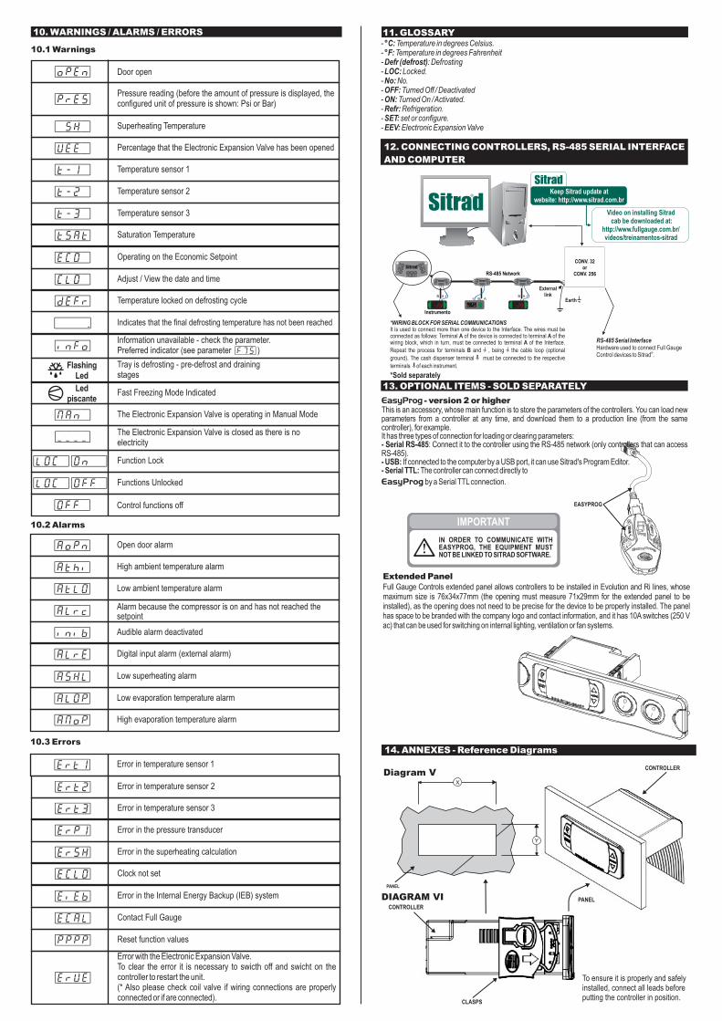
10. WARNINGS / ALARMS / ERRORS
Door open
Control functions off
Superheating Temperature
Open door alarm
Error in temperature sensor 2
Percentage that the Electronic Expansion Valve has been opened
High ambient temperature alarm
Error in temperature sensor 3
Temperature sensor 1
Low ambient temperature alarm
Temperature sensor 2
Alarm because the compressor is on and has not reached the setpoint
Error in the pressure transducer
Temperature sensor 3
Audible alarm deactivated
Error in the superheating calculation
Saturation Temperature
Digital input alarm (external alarm)
Clock not set
Operating on the Economic Setpoint
Low superheating alarm
Error in the Internal Energy Backup (IEB) system
Adjust / View the date and time
Low evaporation temperature alarm
Temperature locked on defrosting cycle
High evaporation temperature alarm
Contact Full Gauge
Indicates that the final defrosting temperature has not been reached
Error in temperature sensor 1
Reset function values
Pressure reading (before the amount of pressure is displayed, theconfigured unit of pressure is shown: Psi or Bar)
Information unavailable - check the parameter. Preferred indicator (see parameter [F75])
Fast Freezing Mode Indicated
The Electronic Expansion Valve is operating in Manual Mode
Function Lock
Functions Unlocked
Tray is defrosting - pre-defrost and drainingstages
The Electronic Expansion Valve is closed as there is noelectricity
Extended PanelFull Gauge Controls extended panel allows controllers to be installed in Evolution and Ri lines, whose maximum size is 76x34x77mm (the opening must measure 71x29mm for the extended panel to be installed), as the opening does not need to be precise for the device to be properly installed. The panel has space to be branded with the company logo and contact information, and it has 10A switches (250 V ac) that can be used for switching on internal lighting, ventilation or fan systems.
EASYPROG
IMPORTANT
IN ORDER TO COMMUNICATE WITH EASYPROG, THE EQUIPMENT MUST NOT BE LINKED TO SITRAD SOFTWARE.
13. OPTIONAL ITEMS - SOLD SEPARATELY
EasyProg - version 2 or higherThis is an accessory, whose main function is to store the parameters of the controllers. You can load new parameters from a controller at any time, and download them to a production line (from the same controller), for example. It has three types of connection for loading or clearing parameters:- Serial RS-485: Connect it to the controller using the RS-485 network (only controllers that can access RS-485).- USB: If connected to the computer by a USB port, it can use Sitrad's Program Editor.- Serial TTL: The controller can connect directly to
EasyProg by a Serial TTL connection.
@
FlashingLed
$
Led piscante
AB
MT-530 super
A AB B
A B
AB
A AB B
A B
AB
A AB B
A B
RS-485 Serial Interface Hardware used to connect Full Gauge
®Control devices to Sitrad .
Instrumento
RS-485 Network
Earth
Externallink
®
CONV. 32 or
CONV. 256
A AB B
A B
*WIRING BLOCK FOR SERIAL COMMUNICATIONSIt is used to connect more than one device to the Interface. The wires must be connected as follows: Terminal A of the device is connected to terminal A of the wiring block, which in turn, must be connected to terminal A of the Interface.
Repeat the process for terminals B and , being the cable loop (optional
ground). The cash dispenser terminal must be connected to the respective
terminals of each instrument.
*Sold separately
MT-530 super
Keep Sitrad update at website: http://www.sitrad.com.br
®
12. CONNECTING CONTROLLERS, RS-485 SERIAL INTERFACE
AND COMPUTER
Video on installing Sitrad cab be downloaded at:
http://www.fullgauge.com.br/videos/treinamentos-sitrad
11. GLOSSARY- °C: Temperature in degrees Celsius.- °F: Temperature in degrees Fahrenheit- Defr (defrost): Defrosting- LOC: Locked. - No: No.- OFF: Turned Off / Deactivated- ON: Turned On / Activated.- Refr: Refrigeration.- SET: set or configure. - EEV: Electronic Expansion Valve
DIAGRAM VI PANEL
CLASPS
CONTROLLER
CONTROLLER
14. ANNEXES - Reference Diagrams
Diagram V
Y
X
PANEL
To ensure it is properly and safely installed, connect all leads before putting the controller in position.
10.1 Warnings
10.2 Alarms
10.3 Errors
Error with the Electronic Expansion Valve.To clear the error it is necessary to swicth off and swicht on the controller to restart the unit. (* Also please check coil valve if wiring connections are properly connected or if are connected).

15. WARRANTY
ENVIRONMENTAL INFORMATIONPackaging:Full Gauge products use packaging made from entirely recycled materials. Please dispose of it through specialized recyclers.
Product:The components used in Full Gauge controllers can be recycled and reused if they are dismantled by specialists.
Disposal:Do not burn or throw controllers in the domestic waste, once they have reached the end of their working life. Follow the current legislation applicable to your area in relation to disposing of electronic waste. If you have any questions, contact Full Gauge Controls.
WA
RR
AN
TY -
FULL
GA
UG
E C
ON
TRO
LS
Products manufactured by Full Gauge Controls, from May 2005, have a warranty period of 10 (ten) years direct from the factory and 01 (one) year from accredited retailers, starting from the consignment date on the sales invoice. After this year, the warranty will continue to be honored for purchases from retailers if the device is sent directly to Full Gauge Controls. This period is valid in Brazil. Other countries provide a guarantee for 2 years. The products are guaranteed in the event of a manufacturing fault that makes them unsuitable or inappropriate for the uses to which they were intended. The warranty is limited to the maintenance of devices manufactured by Full Gauge Controls, regardless of any other form of costs, such as any indemnity due to damage caused to other equipment.
WARRANTY EXCEPTIONS
The Warranty does not cover transport and / or insurance costs for sending products believed to have defects or to have malfunctioned to Technical Support. The following events are also not covered: natural wear of parts, external damage caused by falls or improper packing of products. LOSS OF COVER
The product will automatically no longer be covered if:-The instructions for use and assembly contained in the technical description and installation procedures listed in the NBR5410 standard are not observed;- It is subjected to conditions beyond the limits specified in its technical description;- If it is opened up or repaired by a person who is not part of Full Gauge's technical team;- The damage which has taken place was the result of a fall, blow or impact, water damage, electrical surge or atmospheric discharge.
USING THE WARRANTYTo take advantage of the warranty, the customer must send the product properly packed, together with the
corresponding purchase invoice, to Full Gauge Controls. The delivery cost for the product is borne by the client. You will also need to send as much information as possible regarding the defect that has been detected, thus making it possible to streamline the analysis, testing and servicing.These processes and any eventual maintenance of the product will only be carried out by Full Gauge Controls' Technical Support, at the Company's head office - Rua Júlio de Castilhos, 250 - Zip Code 92120-030 - Canoas - Rio Grande do Sul - Brazil. Rev. 03
Copyright 2021 Full Gauge Controls All rights reserved

Refrigerated Solutions Group891 County Road UHudson, WI 54016
800-955-5253 Norlake Foodservice Sales 800-477-5253 Norlake Scientific Sales 800-388-5253 Norlake Parts/Service
800-647-1284 Master-Bilt Sales 800-684-8988 Master-Bilt Parts/Service
Email: [email protected]
PN: 219828REV 3/22