Embed Size (px)
Citation preview

VII Minsk International Seminar “Heat Pipes, Heat Pumps, Refrigerators, Power Sources”, Minsk, Belarus, September 8–11, 2008
HEAT PIPES TO INCREASE THE EFFICIENCY OF NEW POWER SOURCES LEONARD L. VASILIEV
Luikov Heat and Mass Transfer Institute, National Academy of Sciences of Belarus, P. Brovka 15, 220072, Minsk, Belarus
Abstract The goal of this work is to suggest, design and develop new heat pipes to increase power sources (fuel cell, photovoltaic systems, ets.) efficiency. At least two types of heat pipe coolers are welcomed. The first one is heat pipe spreader to equalize the temperature field inside the fuel cell stack. The second one ensures the waste heat dissipation in the surrounding. Besides this category of heat pipe application in fuel cells thermal control there are possibilities to apply heat pipes in ancillary systems as ffuel cartridges thermal control and systems for fuel cells heat recovery (co-generation and tri-generation). Heat pipes for fuel cell thermal management ought to have high effective thermal conductivity and be insensitive to the gravity forces. The vacant porous media for micro/mini heat pipes is a metal sintered powder wick or a silicon/carbon porous wafer with biporous (micro/macro pores) composition, saturated with working fluid. KEYWORDS Heat pipe, wick, porous structure, evaporation, heat and mass transfer INTRODUCTION Recently fuel cell development, modeling and performance analysis has received much attention due to their potential for distributed power which is a critical issue for energy security and environmental protection [1]. The big market now is available in portable electronics such as mobile phones, PDAs and laptop computers with mini/micro fuel cells application. Several companies such as Samsung, Toshiba and Panasonic are developing portable direct methanol fuel cells, as one of the best approaches to small fuel cell systems and a considerable amount of research is being conducted in this area. The market for portable electronics now is much more accessible to fuel cells than automotive applications. For example, the development of cellular phones with digital broadcast reception may spur the integration of fuel cells into these devices. The automotive fuel cells application with hybrid power systems functioning in cars, planes and tracks is also very promising; the fuel cells converting the fuel directly into electricity are to be functioning without combustion or mechanical energy. There were zero carbon-dioxide emissions, the wastewater being used to cool the fuel-cell stack. In residential sector with the internal combustion engines, polymer electrolyte fuel cells (PEFCs), and solid oxide fuel cells (SOFCs) are welcomed as micro-CHP. Heat pipes fuel cell thermal management can be performed as [1, 2]:
1) Micro/mini heat pipes for micro/mini fuel cells (< 10 W) 2) Heat pipes for medium fuel cells ( 10 – 100 W) 3) Heat pipes for portable fuel cells ( > 100 W) 4) Heat pipes systems for stationary fuel cells (stationary electricity generation)
Besides this category of heat pipe application in fuel cells thermal control there are possibilities to apply heat pipes in ancillary systems as:
1) Fuel cartridges thermal control 2) Systems for fuel cells heat recovery (co-generation and tri-generation)
In this paper we would like to show, that fuel cells thermal management can be efficiently performed using heat pipes of different types. For micro/mini fuel cells thermal control so called “Micro heat pipe” phenomena is efficient to consider. “Micro heat pipe” (MHP) phenomena is often available in nature. For example there is an analogy between MHP operation and functioning of a sweat gland [3]. Open – type MHPs are considered in [4, 5], as a system of thermal control of biological objects and drying technology. The MHP concept is interesting to realize for micro/mini fuel cells, that includes a fuel cell stack and ancillary systems.
Potential applications of heat pipes for fuel cells thermal management includes also systems of wasted heat recovery and fuel cartridges. Thermal link between fuel cell stack and fuel cartridge, or between fuel cell stack and energy recovery system (heat pump) can be also efficiently organized by heat pipe heat exchangers. Micro/mini heat pipes for fuel cells thermal management (< 10 W)
The thermal-fluids management system uses passive approaches for fuel storage and delivery, air breathing, water management, CO2 release, and thermal management [6]. Fuel cell stack is a complex device, but it consists on some units which are similar. Each elementary fuel cell has several layers (bi-polar plate, gas diffusion layers, catalyst layers, membrane), working at the same conditions. Therefore the thermal management of the device can be performed for the fuel cell stack in general. Different modes of the heat pipe based fuel cell thermal management are shown on Fig.1, [7].
Evaporator
Condenser
Evaporator
Condenser
Fig.1 Schematic of mini heat pipe spreader (left) or two-phase forced convection cooling system with mechanical pump (right).
The study of heat pipe thermal control first of all is related with two-phase heat transfer and hydrodynamics in the heat pipe evaporator. In particular, for miniature heat pipes the presence of a high heat flow rate is due to the enormous heat flux that occurs in the contact line region of the evaporating curved film [8]. The fluid evaporation in the meniscus strongly depends on the heat conductivity of the solid wall and slip velocity at the liquid-solid interface.
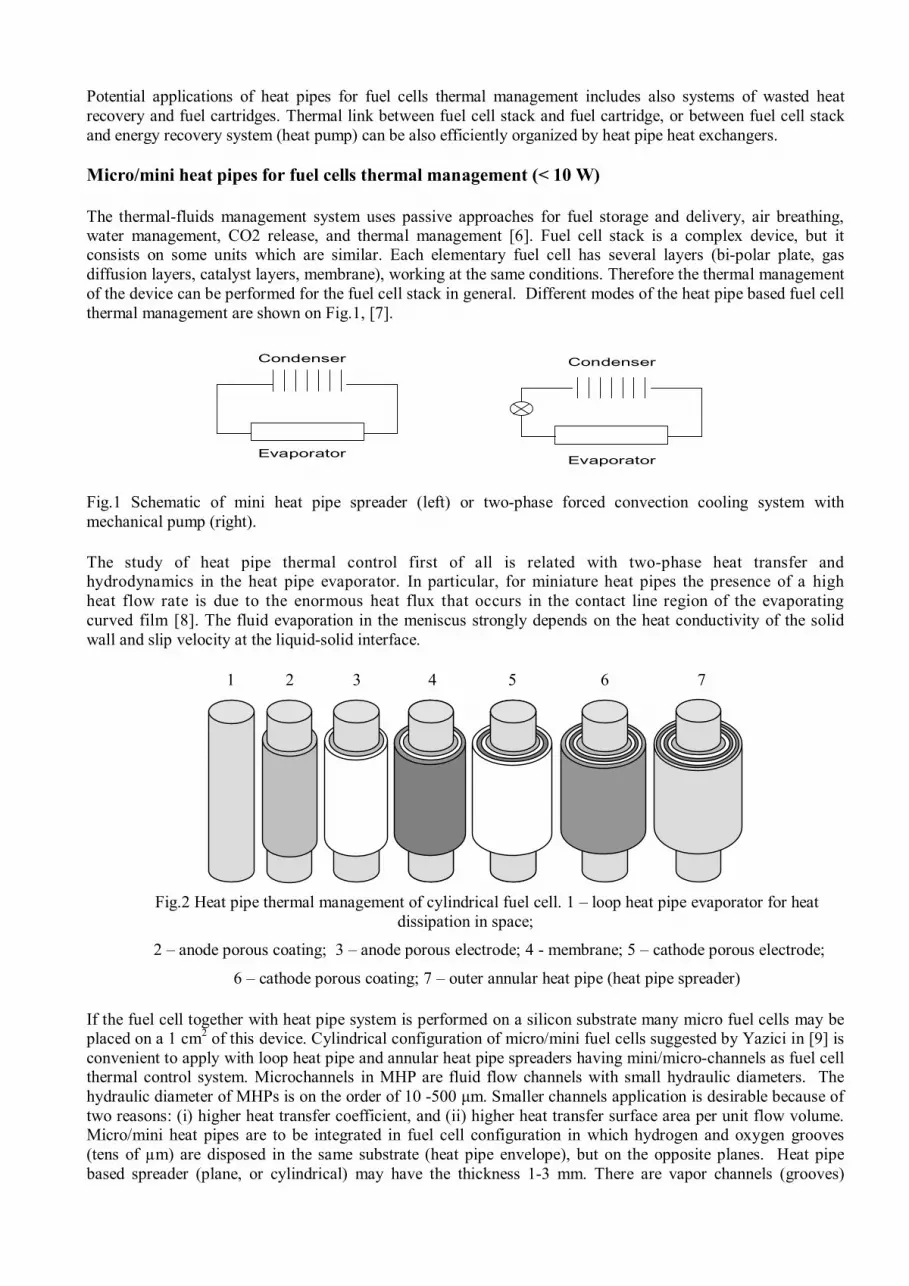
1 2 3 4 5 6 7
Fig.2 Heat pipe thermal management of cylindrical fuel cell. 1 – loop heat pipe evaporator for heat
dissipation in space;
2 – anode porous coating; 3 – anode porous electrode; 4 - membrane; 5 – cathode porous electrode;
6 – cathode porous coating; 7 – outer annular heat pipe (heat pipe spreader)
If the fuel cell together with heat pipe system is performed on a silicon substrate many micro fuel cells may be placed on a 1 cm2 of this device. Cylindrical configuration of micro/mini fuel cells suggested by Yazici in [9] is convenient to apply with loop heat pipe and annular heat pipe spreaders having mini/micro-channels as fuel cell thermal control system. Microchannels in MHP are fluid flow channels with small hydraulic diameters. The hydraulic diameter of MHPs is on the order of 10 -500 μm. Smaller channels application is desirable because of two reasons: (i) higher heat transfer coefficient, and (ii) higher heat transfer surface area per unit flow volume. Micro/mini heat pipes are to be integrated in fuel cell configuration in which hydrogen and oxygen grooves (tens of µm) are disposed in the same substrate (heat pipe envelope), but on the opposite planes. Heat pipe based spreader (plane, or cylindrical) may have the thickness 1-3 mm. There are vapor channels (grooves)
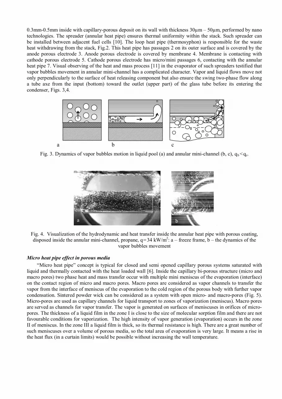
0.3mm-0.5mm inside with capillary-porous deposit on its wall with thickness 30µm – 50µm, performed by nano technologies. The spreader (annular heat pipe) ensures thermal uniformity within the stack. Such spreader can be installed between adjacent fuel cells [10]. The loop heat pipe (thermosyphon) is responsible for the waste heat withdrawing from the stack, Fig.2. This heat pipe has passages 2 on its outer surface and is covered by the anode porous electrode 3. Anode porous electrode is covered by membrane 4. Membrane is contacting with cathode porous electrode 5. Cathode porous electrode has micro/mini passages 6, contacting with the annular heat pipe 7. Visual observing of the heat and mass process [11] in the evaporator of such spreaders testified that vapor bubbles movement in annular mini-channel has a complicated character. Vapor and liquid flows move not only perpendicularly to the surface of heat releasing component but also ensure the swing two-phase flow along a tube axe from the input (bottom) toward the outlet (upper part) of the glass tube before its entering the condenser, Figs. 3,4.
a b c
Fig. 3. Dynamics of vapor bubbles motion in liquid pool (a) and annular mini-channel (b, c), qb <qc.
Fig. 4. Visualization of the hydrodynamic and heat transfer inside the annular heat pipe with porous coating, disposed inside the annular mini-channel, propane, q= 34 kW/m2: a – freeze frame, b – the dynamics of the
vapor bubbles movement
Micro heat pipe effect in porous media “Micro heat pipe” concept is typical for closed and semi opened capillary porous systems saturated with
liquid and thermally contacted with the heat loaded wall [6]. Inside the capillary bi-porous structure (micro and macro pores) two phase heat and mass transfer occur with multiple mini meniscus of the evaporation (interface) on the contact region of micro and macro pores. Macro pores are considered as vapor channels to transfer the vapor from the interface of meniscus of the evaporation to the cold region of the porous body with further vapor condensation. Sintered powder wick can be considered as a system with open micro- and macro-pores (Fig. 5). Micro-pores are used as capillary channels for liquid transport to zones of vaporization (meniscus). Macro pores are served as channels for vapor transfer. The vapor is generated on surfaces of meniscuses in orifices of micro-pores. The thickness of a liquid film in the zone I is close to the size of molecular sorption film and there are not favourable conditions for vaporization. The high intensity of vapor generation (evaporation) occurs in the zone II of meniscus. In the zone III a liquid film is thick, so its thermal resistance is high. There are a great number of such meniscuses over a volume of porous media, so the total area of evaporation is very large. It means a rise in the heat flux (in a curtain limits) would be possible without increasing the wall temperature.
b a

Fig. 5. Schematic of the sintered powder coating in mini-channel (a) and liquid pool (b). 1 – micro-pore, 2 –
meniscus, 3 – macro-pore, 4 – vapor bubble, 5 – liquid flow in the mini-channel, 6 – two phase flow in the mini channel, 7 – zone of evaporation Q – heat flow
In the unit of volume there is a constant ratio between micro and macro pores (for one macropore there are some micropores, depending on the wick thickness), Fig. 5. The number of active meniscus of the evaporation depends proportionally on the heat flux number. The heat flow Q is equal to N (the number of the meniscus), multiplied on latent heat of the evaporation hlv, (local heat transfer coefficient) and the surface S of evaporation, for ∆Tevap = constant. Q = Nmenuscus hlv S ∆T .
MINI LOOP HEAT PIPES
Such types of bi-porous wicks (metal sintered powder, or expanded graphite) are also applicable for mini loop heat pipes (LHP), Fig. 8. MHPs actually are mostly interesting to be implemented directly in the silicon, or Al2O3/Al substrate. Compared to other materials, silicon provides several advantages. It has a good heat conductivity (150 W/ (mK)), and permits to obtain much smaller devices than other metals because of the etching process accuracy. Moreover, as the МНР can be machined in the core of the substrate, the thermo-mechanical constraints are lower compared to other materials. Its thermal expansion coefficient is 7 times lower than that of copper and 10 times lower than aluminium.
Fig.6 Mini loop heat pipe with evaporator made from coherent silicon substrate [11].
The evaporator, a key element of an LHP, determines the serviceability and efficiency of heat pipe. It consists of the envelope, wick, vapor and liquid lines. The evaporator is joined to a compensation chamber or a reservoir, into which the liquid from the condenser is entering. The heat supplied to the outer surface of the wall penetrates through it and then is transferred through the wick to evaporating menisci. The generated vapor is collected in the vapor grooves and then is moved off to a condenser by the vapor line. The liquid inflow into the evaporating zone is realized from the reservoir through the wick. This new technology is a type of Micro Electro Mechanical Systems (MEMS) process that allows one to “drill” a pattern of micron-sized holes in a silicon wafer [12]. In fuel cells and heat pipes, the flow characteristics in the porous media (gas diffusion layers or capillary wick) are useful in modelling performance. Permeability is a parameter that describes the relationship between pressure drop and mass transport through porous media. In heat pipes effective pore radius is a parameter used to describe the
2
1
l I I I I I I
7 Q
2 1
3 4
a b

available pressure rise for liquid pumping. In the LHP there is a possibility to use an evaporator above the condenser, the vapour flows through the vapour channels towards the condenser and the liquid goes back the evaporator due to the capillary pressure head of the porous wick. The assembly of the loop heat pipe with some evaporators and condensers is shown on Fig. 7.
Fig.7 Loop heat pipe assembly with some evaporators embedded in the FC stack and condensers
SORPTION HEAT PIPE Sorption heat pipes are to be used for fuel cells thermal control in active mode, if it is necessary. Sorption heat pipe closed type has a possibility to actively cool the fuel cell stack at heavy power consumption. Sorption heat pipe open type is interesting to apply to cool the total fuel cell assembly, if it is transparent for the fluid penetration and made from permeable materials. Water sorption heat pipe is capable to suck the excess of the water, stimulate the transport of water in terms of start up, including freeze-start, transient response and degradation. At higher currents, excessive water condensation can lead to “flooding” of the cathode porous layers. Sorption heat pipe is capable to suck discrete water droplets through the pores of the gas diffusion layer into the micro-channels and after into the heat pipe sorbent bed. The original design of such a sorption heat pipe was patented in the USSR (patent USSR 174411 “Heat pipe”, B. I. 24, 30.06.1992). Sorption heat pipe includes the advantages of conventional heat pipes and sorption machines in one unit. The major its advantage is ability to ensure the convective two-phase heat transfer through capillary-porous wick under the pressure drop due to sorbent wick action inside the heat pipe. In sorption heat pipe the same working fluid is used as sorbate and as a heat transfer media. Such heat pipe includes some basic phenomena interacting with each other: 1) in the sorbent bed there is a vapor flow (two phase flow) with kinetic reaction rate and pressure, vapor pressure, geometry, conductive and convective heat transport with radial heat transfer; 2) in the condenser and evaporator there is a vapor flow, liquid flow, interface position, radial heat transfer with kinetic reaction pressure, liquid pressure, vapor pressure, condensation and evaporation, shear stress, geometry, adhesion pressure, convective heat transport, radial heat transfer under the influence of the gravity field.
Fig. 7 Sorption heat pipe (patent USSR 174411 “Heat pipe”, B. I. 24, 30.06.1992).; 1 – vapor channel; 2 –
sorption structure; 3 – finned surface of heat pipe evaporator/condenser; 4 – porous wick ; 5- porous valve; 6 – low temperature evaporator with porous wick;7- working fluid; 8 – cold box with thermal insulation.
Sorption loop heat pipe is convenient to be applied for the whole fuel cell assembly thermal and water control at higher currents and excessive water condensation. Heat pipe promote water transport, mitigate flooding and the associated blockage of reactant transport, performance losses and degradation mechanisms, ensures high Reynolds numbers of two-phase flows [13].

Fig.8 Schematic of the sorption heat pipe for fuel cell heat recovery. The heat exchanger on sorption heat pipes, fig.8 is interesting in combination with fuel cell device (SOFC) to increase its efficiency. Loop thermosyphons for portable fuel cells (> 100 W) Since loop thermosyphons have larger critical heat flux than conventional thermosyphons it is convenient to use such devices in many different applications, for example, for thermal control in ancillary systems such as fuel cartridges, heat recovery devices (co-generation and tri-generation). The loop thermosyphon evaporator needs to have a good thermal contact with the stack; the condenser ought to be cooled by air, or water. The loop thermosyphon transports thermal energy from a heat source to a sink by natural two-phase convective circulation without any external power supply (no electric pump). Thermosyphon evaporator and condenser are installed separately, but connected to each other by small diameter bendable pipes (liquid and vapour lines). Due to the coupling between momentum and energy transport theoretical analysis of the loop performance is very complicate, therefore it is necessary that these problems be solved by experimental investigation before applying the loop thermosyphon to heat exchanger design.
Fig. 9. Copper/water loop thermosyphon for the FC stack thermal management In the loop thermosyphon the heat transfer is considered to be affected by many factors, such as type and quantity of working fluid, pipe diameter, pipe length, and ratio of cooled surface to heated surface, the length of the adiabatic zone between heated and cooled sections, heat flux and operating temperature. The evaporator and condenser of the loop thermosyphon can be made of carbon-steel, cupper, aluminium and recently reinforced polymer tubes. Propane, R 134a, R 600, ammonia or water can be used as working fluid. When the copper is allowed to be applied water is the best working fluid. In order to establish heat transfer correlations for the application in the design program for the loop thermosyphon heat exchanger, regression analysis could be applied to experimental data for heat transfer coefficients in evaporator and condenser.
Activated carbon Steel tube
Porous wick Fins Wick in
evaporator
Sorption unit Transport zone
Evaporator/ Condenser

Typical loop thermosyphon with the flat evaporator is shown on Fig.9. This thermosyphon is capable to transport Qmax near 100 W at the temperature of the adiabatic zone less 100 0C. The condenser is cooled by water circulation. The thermal resistance of thermosyphon R is 0.03 K/W. Loop heat pipes are more flexible to compare with loop thermosyphons, due to its insincerity to the gravity field. Typical LHP for PEMFC with optimal heat flow rate 800 W at the working temperature near 80 0C is shown on Fig.10. LHP with the non inverted meniscus of the evaporation designed and tested in the Luikov Institute is made from copper and has the wick performed from copper sintered powder. The working fluid is water. The typical maximum heat flow rate of such evaporator is near 1500 W, the thermal resistance of the evaporator Re = 0.06 К/W. The length of the evaporator is 70 mm, width – 60 mm and thickness 12 mm. The wick porosity is > 45% and the effective thermal conductivity of the wick 40 W/m K. .
Fig. 10 LHP with copper flat evaporator. The wick is made from sintered powder porous structure and has mini grooves for liquid suction. Pulsating heat pipe panels Another alternative to the conventional heat pipe is an aluminium (multi-channel) heat pipe panel (Fig. 11) with propane as a working fluid to cool FC stack. Pulsating heat pipe (PHP) is one of several oscillatory thermal transport cycles under development that are receiving attention as a potential semi-passive, high-power, high flux heat transport device. The PHP is unique in that it is capable of generating driving pressures in excess of many mechanically pumped loops. Capillary forces do not limit the PHP and it is capable of transferring high heat loads over long distances and against significant resistance (i.e. gravity, small tube diameters, etc.).
Fig. 11. Aluminum pulsating heat pipe panel with mini channels inside and mini fins on the outer surface. The main parameters of flat heat pipe panels developed in the Luikov Institute, Minsk are: HP width -70mm, HP height - 7 mm, HP length - 700 mm, evaporator length - 98 mm, condenser length - 500 mm, mass - 0, 43 kg. HP thermal resistance R = 0.05 K/W, evaporator heat transfer coefficient = 8500 W/m2K, condenser heat transfer coefficient = 2500 W/m2K. The working fluid (hydrocarbons) dynamic movement is stable with liquid filling ratio near 0.6 of the heat pipe volume. The way to increase fuel cells efficiency Fuel sells, with unmatched efficiency and potentially greater reliability than other energy systems (because of greatly lower part counts, for example, and solid state construction in the case of SOFTs) are quite competitive in many applications. But even fuel cells need to improve their efficiency due to the heat dissipation inside on the level of 50 %. It can be realized with the help of solid and liquid sorption machines [14]. Sorption machines (heat pumps, refrigerators, heat transformers, ets) is a good way to combine
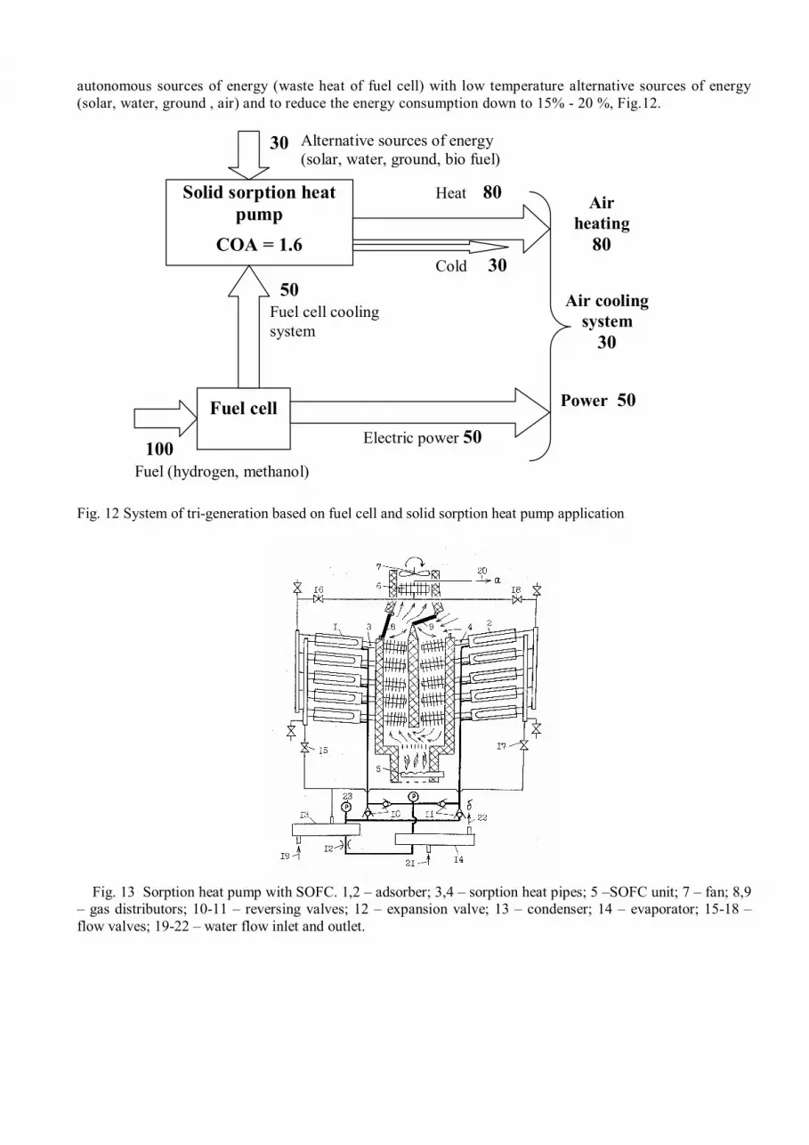
autonomous sources of energy (waste heat of fuel cell) with low temperature alternative sources of energy (solar, water, ground , air) and to reduce the energy consumption down to 15% - 20 %, Fig.12.
Fig. 12 System of tri-generation based on fuel cell and solid sorption heat pump application Fig. 13 Sorption heat pump with SOFC. 1,2 – adsorber; 3,4 – sorption heat pipes; 5 –SOFC unit; 7 – fan; 8,9 – gas distributors; 10-11 – reversing valves; 12 – expansion valve; 13 – condenser; 14 – evaporator; 15-18 – flow valves; 19-22 – water flow inlet and outlet.
Fuel cell
Solid sorption heat pump
COA = 1.6
100
Cold 30
Heat 80
Electric power 50
Fuel cell cooling system
Air heating
80
Air cooling system
30
Power 50
Alternative sources of energy (solar, water, ground, bio fuel)
Fuel (hydrogen, methanol)
50
30

Conclusions New power sources efficiency (cogeneration, trigeneration systems, fuel cells, photovoltaic systems) have a good perspective to be increased combined with the renewable energy resources through solid sorption heat pumps, refrigerators, accumulators of the heat and cold, heat transformers, natural and hydrogen storage systems. Heat pipe concept as a thermal control system for Fuel Cells is a powerful tool to increase FC efficiency. Mini/Micro heat pipes are considered as advanced thermal control for Mini Fuel Cells with power generation 10 W - 100 W, Loop heat pipes, pulsating heat pipes and sorption heat pipes are suggested as an advanced thermal control system for portable Fuel Cells with power generation > 100 W.
Bibliography 1. Amir Faghri, Zhen Guo, Challenges and opportunities of thermal management issues related to
fuel cell technology and modeling, International Journal of Heat and Mass Transfer
2. L.L. Vasiliev, O.S. Filatova, A.G. Kulakov, L.L. Vasiliev Jr., A.P. Tsitovich, Heat Pipes in new power sources technology, Proceedings of the VI Minsk International Heat and Mass Transfer Forum, 19-23 May, 2008, Minsk, Belarus, Vol.2, pp.21 -24
3. Dunn P.D., Reay D.A. Heat Pipes, Pergamon Press, 1976. pp.258 – 260. 4. Vasiliev L.L. Open – type miniature heat pipes // Journal of Engineering Physics and
Thermophysics, 1993. Vol. 65, No.1, Pp. 625 - 631 5. Reutskii V.G., Vasiliev L.L. // Dokl. Akad. Nauk, Minsk, 1981, Vol. 24, 11, Pp. 1033 – 1036.
6. S. Litster and N. Djilaly, Performance analysis of microstructured fuel cells for portable applications, , S. Kakac, A. Pramuanjaroenkij and L. Vasiliev (eds), Mini-Micro Fuel Cells, Springer Science+Business Media B.V. 2008, pp.47 -74.
7. Sashidhar S. Panchamgam1, Arya Chatterjee, Joel L. Plawsky, Peter С Wayner Jr. *, Comprehensive experimental and theoretical study of fluid flow and heat transfer in a microscopic evaporative meniscus in miniature heat exchanger, International Journal of Heat and Mass Transfer
8. Vasiliev L.L. , Heat Pipe Technology in CIS Countries, Proceedings of Fourth International Heat Pipe Symposium, Tsukuba, May 16 – 18, 1994, pp.12 - 24
9. Yazici M.S., Passive air management for cylindrical cartridge fuel cells, Journal of Power Sources, Vol. 166, pp. 137 – 142, 2007
10. L.Vasiliev, A.Zhuravlyov, A. Shapovalov, A. Konon, Two-phase Heat transfer in a Mini-
Channel with Porous Heat-Loaded Wall, Heat Transfer Research, 2008, Vol.39, No.5,pp.391 – 401
11. Vasiliev L. , Lapotko D., Lukianova E., A. Zhuravlyov, A. Shapovalov, L. Vasiliev Jr., Two phase heat transfer enhancement in micro channels and heat pipe evaporators with nano porous structures, Proceedings of the 14 th International Heat Pipes Conference
(14 th IHPC), Florianopolis, Brazil, April 22 – 27 , 2007 12. Weislogel M.M., Golliher E., McQuillen L., Bacich M.A., Davidson J.J., and Sala M.A.,Recent results of the micro scale pulse thermal loop in: International two-phase Thermal Control Technology Workshop, Newton White Mansion, Mitchelville (2002).
13. Vasiliev L., Vasiliev L., Jr., Sorption heat pipe –a new thermal control device for space and
ground application, International Journal of Heat and Mass Transfer 48 (2005) 2464-2472
14. Vasiliev L.L. , Solid sorption heat pumps in tri-generation, HEAT TRANSFER AND RENEWABLE SOURCES OF ENERGY, HTRSE – 2006, Ed. by J.Mikielewicz, W. Nowak and A.A. Stachel, Szczecin, 2006, pp.371-382


