Embed Size (px)
Citation preview
Vertical Laminar Flow CabinetBBS-DDC /BBS-SDC /BBS-DSC /BBS-SSC
User Manual
BIOBASE GROUP
Version 2022.01

1
PrefaceThank you very much for purchasing our Vertical Type Laminar Flow Cabinet ModelBBS-DDC/SDC/DSC/SSC.Please read the “Operating Instructions” and “Warranty” carefully before operating this unit to assureproper operation. After reading these documents, be sure to store them securely together with the“Warranty” within reach for future reference.
Warning: Before operating the unit, be sure to read carefully and fully understand important
warnings in the operating instructions.
2
ContentPreface....................................................................................................................................................1
Content................................................................................................................................................... 2
1. Unpacking, Installation and Debugging.............................................................................................4
1.1 Unpacking................................................................................................................................. 4
1.2 Accessories Checking................................................................................................................6
1.3 Installation Conditions and Operating Environment.................................................................8
1.4 Installation.................................................................................................................................9
1.5 Inspection after Installation.....................................................................................................13
2. User Instructions...............................................................................................................................14
2.1 Functions................................................................................................................................. 14
2.1.1 Product Concept............................................................................................................ 14
2.1.2 Operating Principle/Air flow Pattern (Picture 7).......................................................... 14
2.1.3 Protected Object............................................................................................................ 14
2.1.4Technical Parameters..................................................................................................... 14
1) Vibration Amplitude................................................................................................................. 16
2) Illumination...............................................................................................................................16
3) Electrical Characteristic............................................................................................................ 16
2.2 Product Structure.....................................................................................................................17
2.2.1 Structural Composition of BBS-DDC/BBS-SDC (Picture 8)....................................... 17
2.2.2 Structural composition of BBS-DSC/BBS-SSC (Picture 9)......................................... 18
2.2.3 Structure Introduction....................................................................................................18
2.3 Instructions for Operation....................................................................................................... 20
2.3.1 Normal Operation Notice.............................................................................................. 20
2.3.2 Operation Process..........................................................................................................20
2.4 Daily Maintenance.................................................................................................................. 21
2.4.1 Clean the operating area surface................................................................................... 21
2.4.2 Clean the external surface and front window................................................................21
2.4.3 Comprehensive maintenance period............................................................................. 21
3
2.4.4 Maintenance methods....................................................................................................21
2.4.5 Storage conditions......................................................................................................... 22
2.5 Replacement parts list(For parts purchase)............................................................................. 22
2.6 Wiring Diagram (Picture 12)...................................................................................................24
3. Trouble Shooting and Solution.........................................................................................................25
3.1 Common faults and solution....................................................................................................25
3.2 Replacement of Fuse............................................................................................................... 26
3.3 Replacement of LED Lamp.....................................................................................................27
3.4 Replacement of UV Lamp.......................................................................................................27
3.5 Label Description.................................................................................................................... 28
4. Warranty...........................................................................................................................................28
4
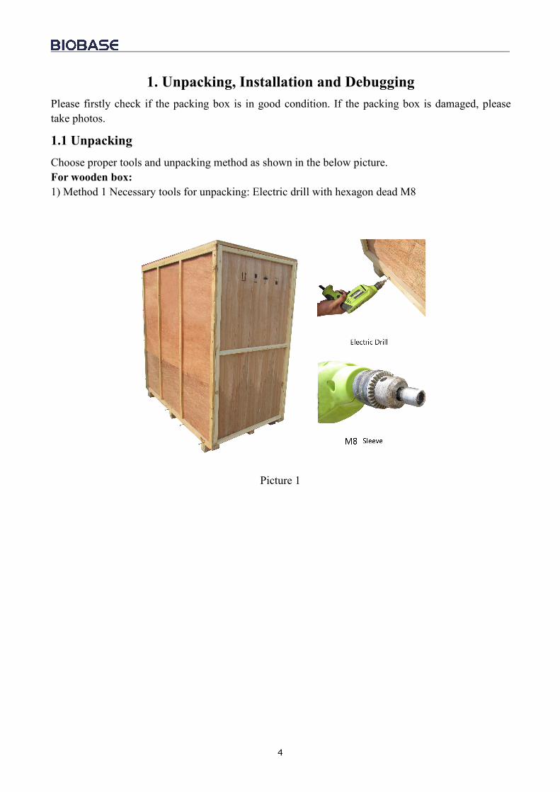
1. Unpacking, Installation and DebuggingPlease firstly check if the packing box is in good condition. If the packing box is damaged, pleasetake photos.
1.1 UnpackingChoose proper tools and unpacking method as shown in the below picture.For wooden box:1) Method 1 Necessary tools for unpacking: Electric drill with hexagon dead M8
Picture 1
5
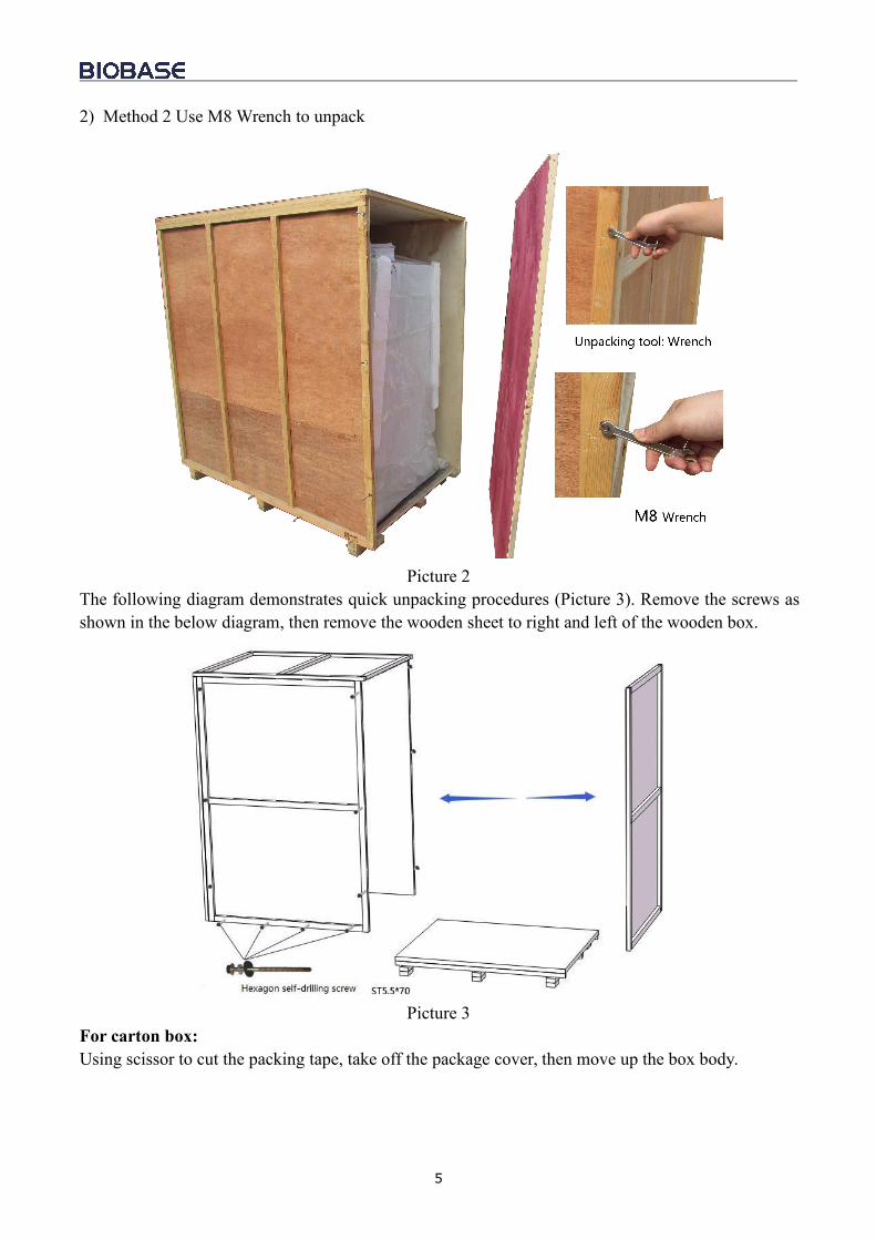
2) Method 2 Use M8 Wrench to unpack
Picture 2The following diagram demonstrates quick unpacking procedures (Picture 3). Remove the screws asshown in the below diagram, then remove the wooden sheet to right and left of the wooden box.
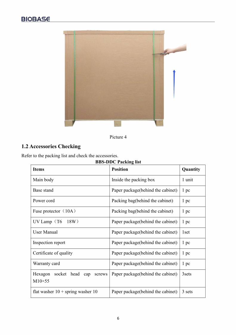
Picture 3For carton box:Using scissor to cut the packing tape, take off the package cover, then move up the box body.
6
Picture 4
1.2 Accessories CheckingRefer to the packing list and check the accessories.
BBS-DDC Packing listItems Position Quantity
Main body Inside the packing box 1 unit
Base stand Paper package(behind the cabinet) 1 pc
Power cord Packing bag(behind the cabinet) 1 pc
Fuse protector(10A) Packing bag(behind the cabinet) 1 pc
UV Lamp(T6 18W) Paper package(behind the cabinet) 1 pc
User Manual Paper package(behind the cabinet) 1set
Inspection report Paper package(behind the cabinet) 1 pc
Certificate of quality Paper package(behind the cabinet) 1 pc
Warranty card Paper package(behind the cabinet) 1 pc
Hexagon socket head cap screwsM10×55
Paper package(behind the cabinet) 3sets
flat washer 10 + spring washer 10 Paper package(behind the cabinet) 3 sets
7
Hexagon wrench Paper package(behind the cabinet 1 set
BBS-SDC Packing listItems Position Quantity
Main body Inside the packing box 1 unit
Base stand Paper package(behind the cabinet) 1 pc
Power cord Packing bag(behind the cabinet) 1 pc
Fuse protector(10A) Packing bag(behind the cabinet) 1 pc
UV Lamp(T6 30W) Paper package(behind the cabinet) 1 pc
User Manual Paper package(behind the cabinet) 1set
Inspection report Paper package(behind the cabinet) 1 pc
Certificate of quality Paper package(behind the cabinet) 1 pc
Warranty card Paper package(behind the cabinet) 1 pc
Hexagon socket head cap screwsM10×55
Paper package(behind the cabinet) 3 sets
flat washer 10 + spring washer 10 Paper package(behind the cabinet) 3 sets
Hexagon wrench Paper package(behind the cabinet 1 set
BBS-DSC Packing listItems Position Quantity
Main body Inside the packing box 1 unit
Base stand Paper package(behind the cabinet) 1 pc
Power cord Packing bag(behind the cabinet) 1 pc
Fuse protector(10A) Packing bag(behind the cabinet) 1 pc
UV Lamp(T6 18W) Paper package(behind the cabinet) 1 pc
User Manual Paper package(behind the cabinet) 1set
Inspection report Paper package(behind the cabinet) 1 pc
Certificate of quality Paper package(behind the cabinet) 1 pc
Warranty card Paper package(behind the cabinet) 1 pc
8
Hexagon socket head cap screwsM10×55
Paper package(behind the cabinet) 5sets
flat washer 10 + spring washer 10 Paper package(behind the cabinet) 5sets
Hexagon wrench Paper package(behind the cabinet 1 set
BBS-SSC Packing listItems Position Quantity
Main body Inside the packing box 1 unit
Base stand Paper package(behind the cabinet) 1 pc
Power cord Packing bag(behind the cabinet) 1 pc
Fuse protector(10A) Packing bag(behind the cabinet) 1 pc
UV Lamp(T6 30W) Paper package(behind the cabinet) 1 pc
User Manual Paper package(behind the cabinet) 1set
Inspection report Paper package(behind the cabinet) 1 pc
Certificate of quality Paper package(behind the cabinet) 1 pc
Warranty card Paper package(behind the cabinet) 1 pc
Hexagon socket head cap screwsM10×55
Paper package(behind the cabinet) 5 sets
flat washer 10 + spring washer 10 Paper package(behind the cabinet) 5 sets
Hexagon wrench Paper package(behind the cabinet 1 set
1.3 Installation Conditions and Operating EnvironmentLaminar flow cabinet should be placed in a position where the airflow can be protected.Laminar flow cabinet should not be installed opposite to door or window and far away from the airoutlet of air conditioner. It should avoid airflow influence from ventilating system, air conditioner,door, window and movement of people.At least 300mm gap must be kept in the side and back side of the Laminar Air Flow for cleanoperating and for inspection.Working environment:(1) Only applicable to indoor operation;(2) Ambient temperature: 15~35;(3) Relative Humidity: ≤75%;(4) Atmospheric pressure range: 70 kPa~106 kPa;(5) Electrical parameters: Adequate power supply to the Laminar flow cabinet (See 2.1.4 Technical
9
Parameters );(6) Power supply need to be grounded; (Judging method: test the live wire and the neutral wire of the
socket with multimeter. The voltage between live and ground should equal to the voltage of localelectrical grid, and the voltage between neutral and ground should equal to 0. Otherwise thepower supply is not grounded correctly);
1.4 Installationa. Remove all the packing materials;b. Check for Physical damage or scratch the surface of main body during transit. Make sure thereis no damage, scratch, deformation or foreign bodies;c. Carefully check the accessories and material according to packing list in the manual.d. Before breaking the package, move the entire equipment to the place where it is going to beinstalled.
NOTE: Direct installation is completed for base stand part at the time of transport or it isput at the back of the laminar flow cabinet. Base stand should be taken out before installing:When carrying the laminar flow cabinet, top-for-bottom, dumping place and dismantling areforbidden.
10
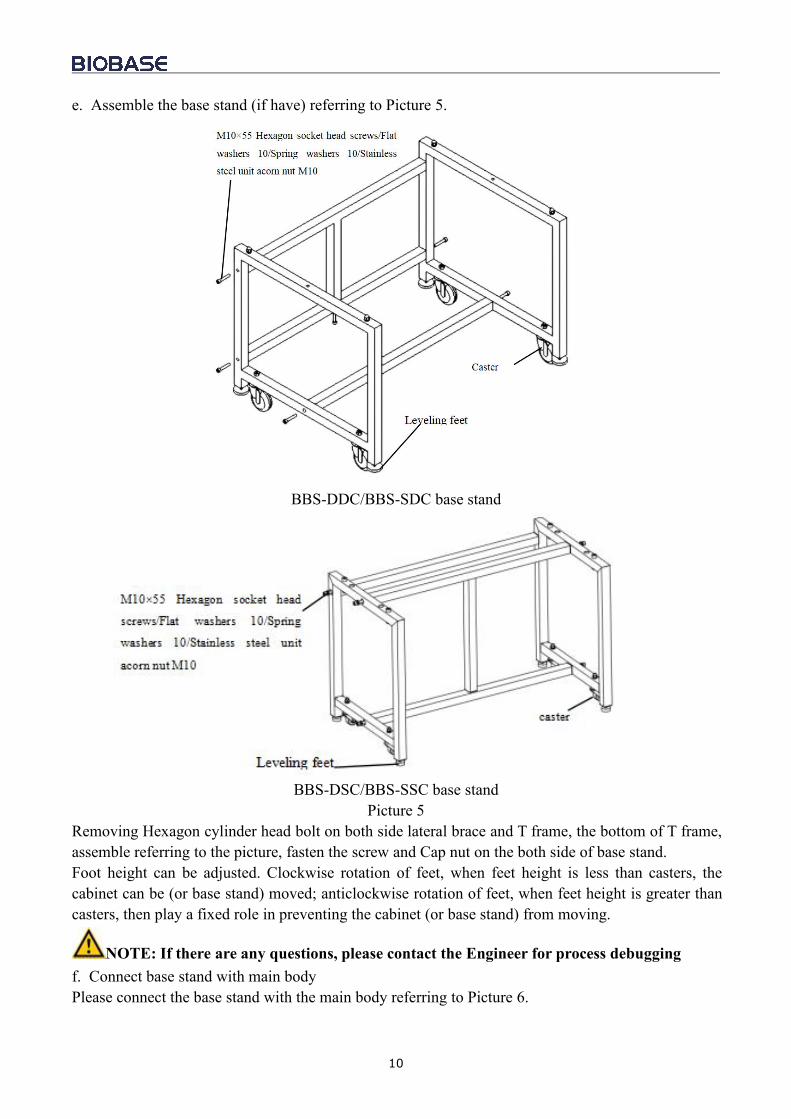
e. Assemble the base stand (if have) referring to Picture 5.
BBS-DDC/BBS-SDC base stand
BBS-DSC/BBS-SSC base standPicture 5
Removing Hexagon cylinder head bolt on both side lateral brace and T frame, the bottom of T frame,assemble referring to the picture, fasten the screw and Cap nut on the both side of base stand.Foot height can be adjusted. Clockwise rotation of feet, when feet height is less than casters, thecabinet can be (or base stand) moved; anticlockwise rotation of feet, when feet height is greater thancasters, then play a fixed role in preventing the cabinet (or base stand) from moving.
NOTE: If there are any questions, please contact the Engineer for process debuggingf. Connect base stand with main bodyPlease connect the base stand with the main body referring to Picture 6.
11
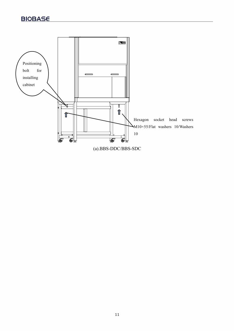
(a).BBS-DDC/BBS-SDC
Hexagon socket head screws
M10×55/Flat washers 10/Washers
10
Positioning
bolt for
installing
cabinet
12
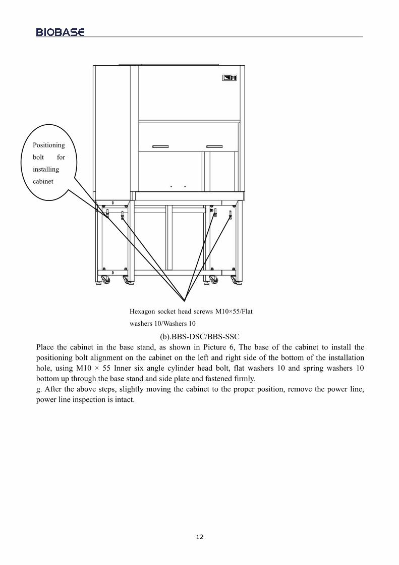
(b).BBS-DSC/BBS-SSCPlace the cabinet in the base stand, as shown in Picture 6, The base of the cabinet to install thepositioning bolt alignment on the cabinet on the left and right side of the bottom of the installationhole, using M10 × 55 Inner six angle cylinder head bolt, flat washers 10 and spring washers 10bottom up through the base stand and side plate and fastened firmly.g. After the above steps, slightly moving the cabinet to the proper position, remove the power line,power line inspection is intact.
Positioning
bolt for
installing
cabinet
Hexagon socket head screws M10×55/Flat
washers 10/Washers 10
13
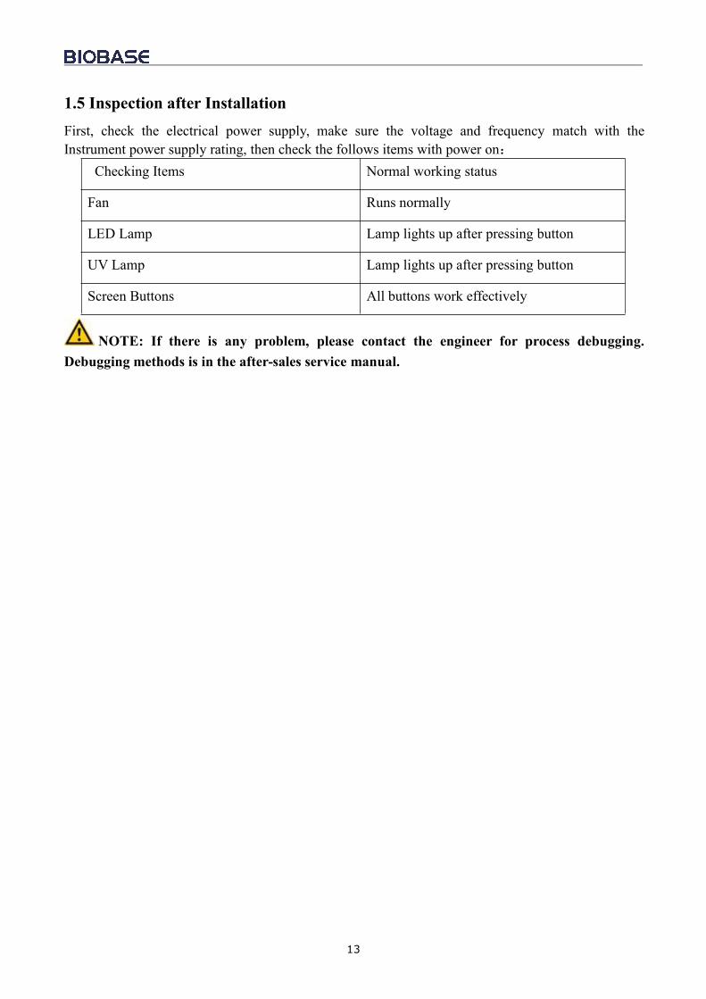
1.5 Inspection after InstallationFirst, check the electrical power supply, make sure the voltage and frequency match with theInstrument power supply rating, then check the follows items with power on:
Checking Items Normal working status
Fan Runs normally
LED Lamp Lamp lights up after pressing button
UV Lamp Lamp lights up after pressing button
Screen Buttons All buttons work effectively
NOTE: If there is any problem, please contact the engineer for process debugging.Debugging methods is in the after-sales service manual.
14
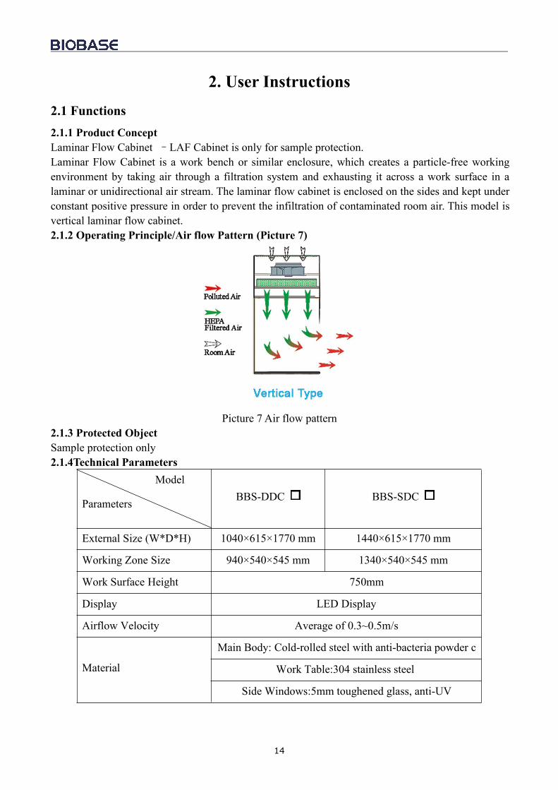
2. User Instructions2.1 Functions2.1.1 Product ConceptLaminar Flow Cabinet –LAF Cabinet is only for sample protection.Laminar Flow Cabinet is a work bench or similar enclosure, which creates a particle-free workingenvironment by taking air through a filtration system and exhausting it across a work surface in alaminar or unidirectional air stream. The laminar flow cabinet is enclosed on the sides and kept underconstant positive pressure in order to prevent the infiltration of contaminated room air. This model isvertical laminar flow cabinet.2.1.2 Operating Principle/Air flow Pattern (Picture 7)
Picture 7 Air flow pattern2.1.3 Protected ObjectSample protection only2.1.4Technical Parameters
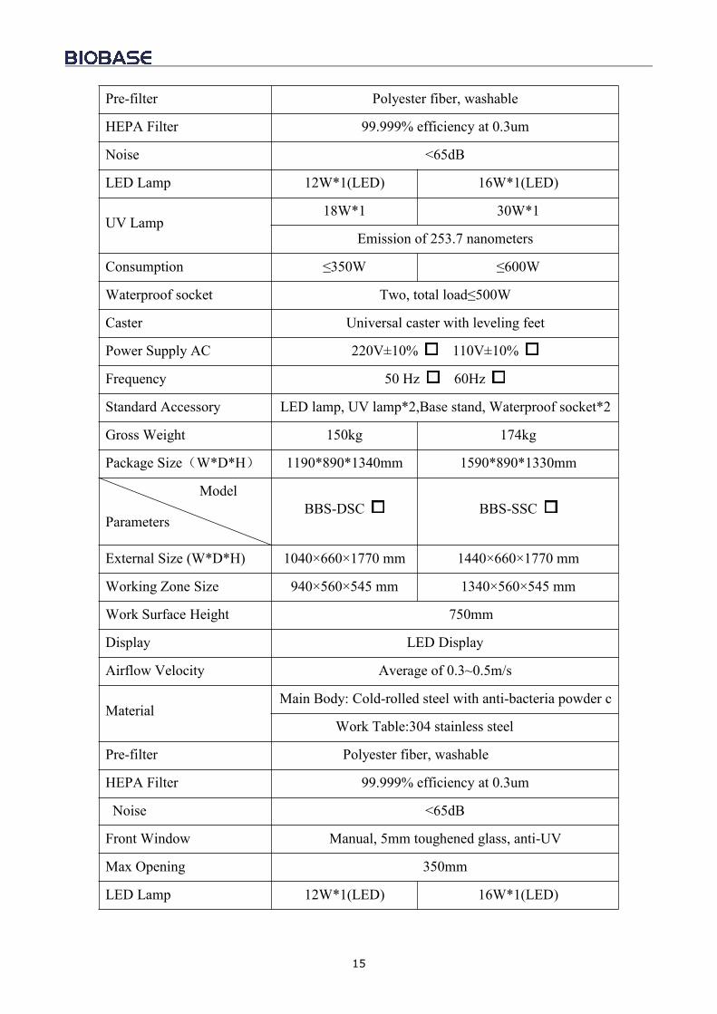
Model
Parameters BBS-DDC BBS-SDC
External Size (W*D*H) 1040×615×1770 mm 1440×615×1770 mm
Working Zone Size(W*D*H)
940×540×545 mm 1340×540×545 mm
Work Surface Height 750mm
Display LED Display
Airflow Velocity Average of 0.3~0.5m/s
Material
Main Body: Cold-rolled steel with anti-bacteria powder coatingWork Table:304 stainless steel
Side Windows:5mm toughened glass, anti-UV
15
Pre-filter Polyester fiber, washable
HEPA Filter 99.999% efficiency at 0.3um
Noise <65dB
LED Lamp 12W*1(LED) 16W*1(LED)
UV Lamp18W*1 30W*1
Emission of 253.7 nanometers
Consumption ≤350W ≤600W
Waterproof socket Two, total load≤500W
Caster Universal caster with leveling feet
Power Supply AC 220V±10% 110V±10%
Frequency 50 Hz 60Hz
Standard Accessory LED lamp, UV lamp*2,Base stand, Waterproof socket*2
Gross Weight 150kg 174kg
Package Size(W*D*H) 1190*890*1340mm 1590*890*1330mm
Model
ParametersBBS-DSC BBS-SSC
External Size (W*D*H) 1040×660×1770 mm 1440×660×1770 mm
Working Zone Size(W*D*H)
940×560×545 mm 1340×560×545 mm
Work Surface Height 750mm
Display LED Display
Airflow Velocity Average of 0.3~0.5m/s
MaterialMain Body: Cold-rolled steel with anti-bacteria powder c
oatingWork Table:304 stainless steel
Pre-filter Polyester fiber, washable
HEPA Filter 99.999% efficiency at 0.3um
Noise <65dB
Front Window Manual, 5mm toughened glass, anti-UV
Max Opening 350mm
LED Lamp 12W*1(LED) 16W*1(LED)
16
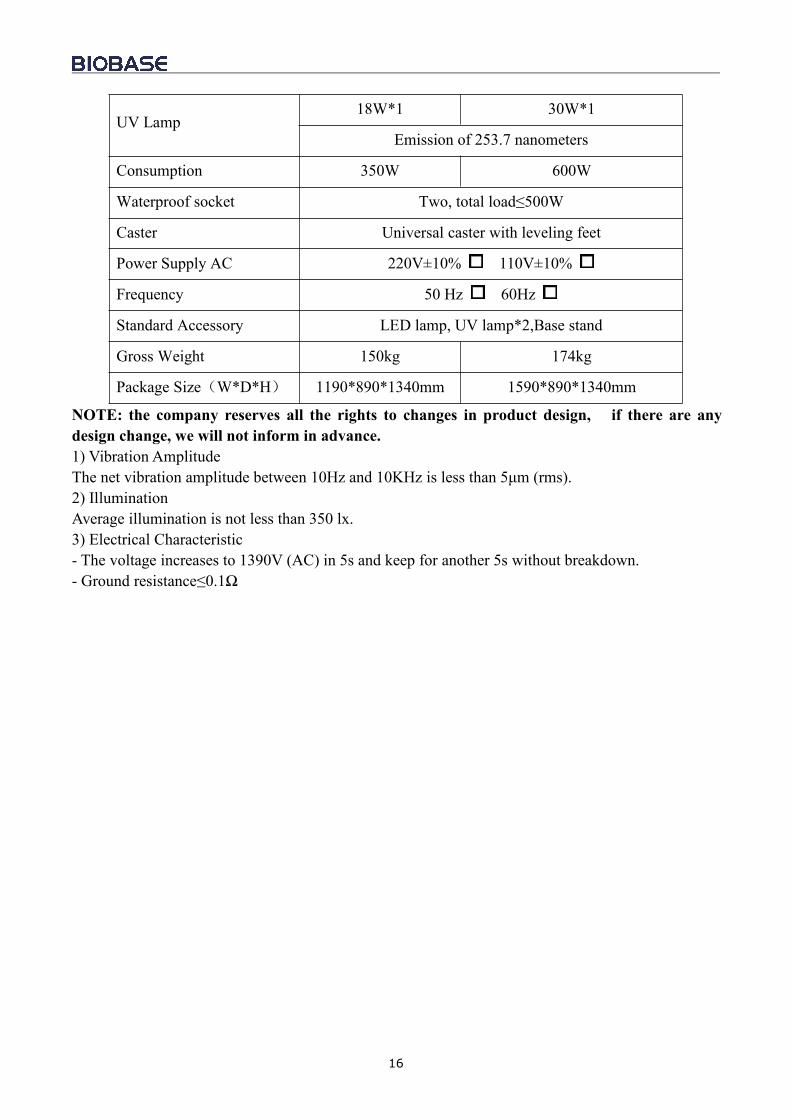
UV Lamp18W*1 30W*1
Emission of 253.7 nanometers
Consumption 350W 600W
Waterproof socket Two, total load≤500W
Caster Universal caster with leveling feet
Power Supply AC 220V±10% 110V±10%
Frequency 50 Hz 60Hz
Standard Accessory LED lamp, UV lamp*2,Base stand
Gross Weight 150kg 174kg
Package Size(W*D*H) 1190*890*1340mm 1590*890*1340mm
NOTE: the company reserves all the rights to changes in product design, if there are anydesign change, we will not inform in advance.1) Vibration AmplitudeThe net vibration amplitude between 10Hz and 10KHz is less than 5μm (rms).2) IlluminationAverage illumination is not less than 350 lx.3) Electrical Characteristic- The voltage increases to 1390V (AC) in 5s and keep for another 5s without breakdown.- Ground resistance≤0.1Ω
17
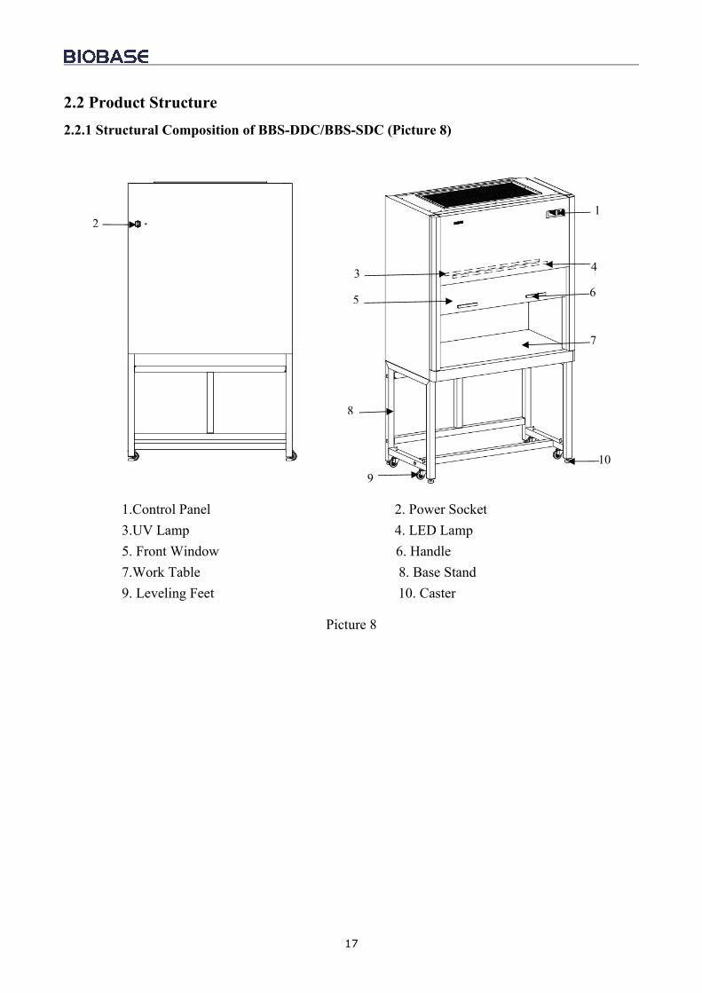
2.2 Product Structure2.2.1 Structural Composition of BBS-DDC/BBS-SDC (Picture 8)
1.Control Panel 2. Power Socket3.UV Lamp 4. LED Lamp5. Front Window 6. Handle7.Work Table 8. Base Stand9. Leveling Feet 10. Caster
Picture 8
4
1
7
910
8
65
3
2
18
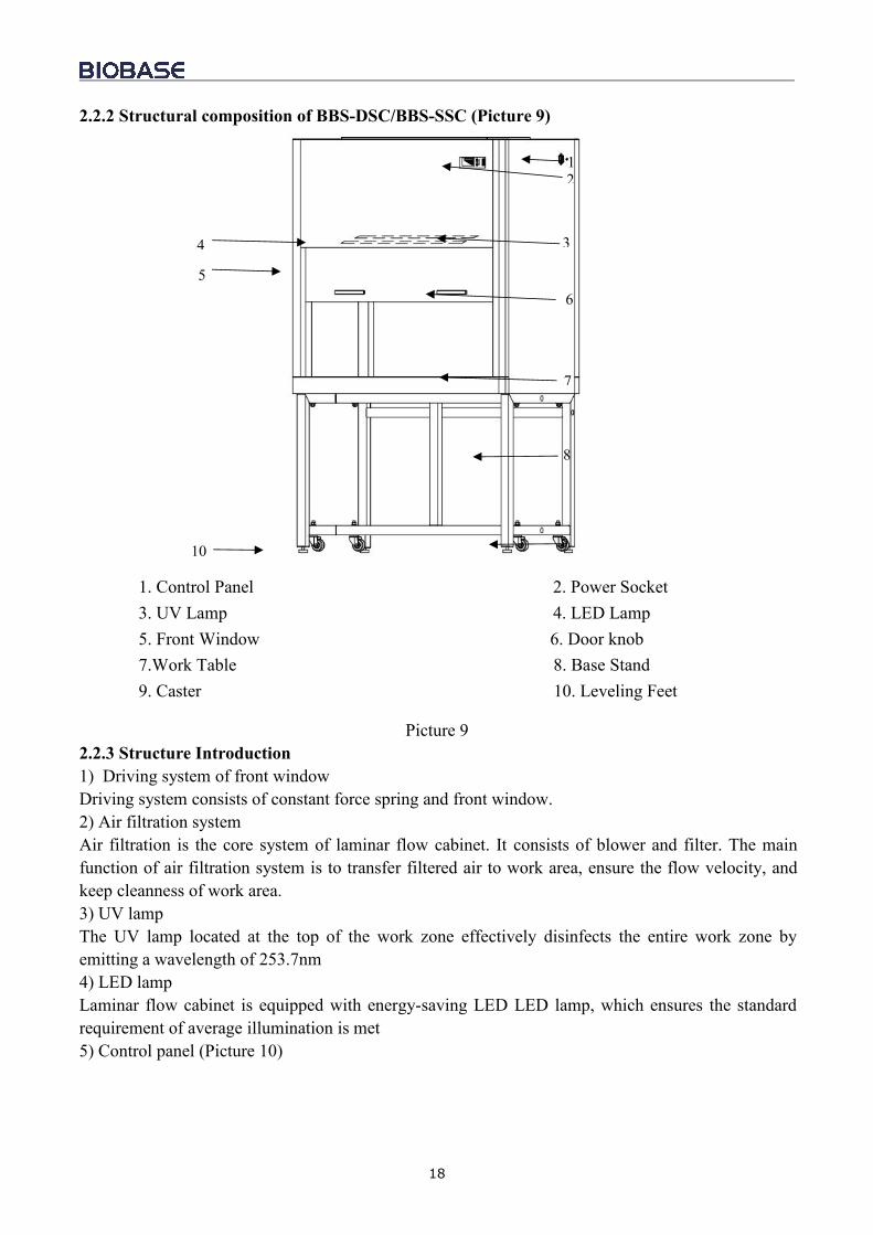
2.2.2 Structural composition of BBS-DSC/BBS-SSC (Picture 9)
1. Control Panel 2. Power Socket3. UV Lamp 4. LED Lamp5. Front Window 6. Door knob7.Work Table 8. Base Stand9. Caster 10. Leveling Feet
Picture 92.2.3 Structure Introduction1) Driving system of front windowDriving system consists of constant force spring and front window.2) Air filtration systemAir filtration is the core system of laminar flow cabinet. It consists of blower and filter. The mainfunction of air filtration system is to transfer filtered air to work area, ensure the flow velocity, andkeep cleanness of work area.3) UV lampThe UV lamp located at the top of the work zone effectively disinfects the entire work zone byemitting a wavelength of 253.7nm4) LED lampLaminar flow cabinet is equipped with energy-saving LED LED lamp, which ensures the standardrequirement of average illumination is met5) Control panel (Picture 10)
4
5
10
12
3
6
7
8
9
19
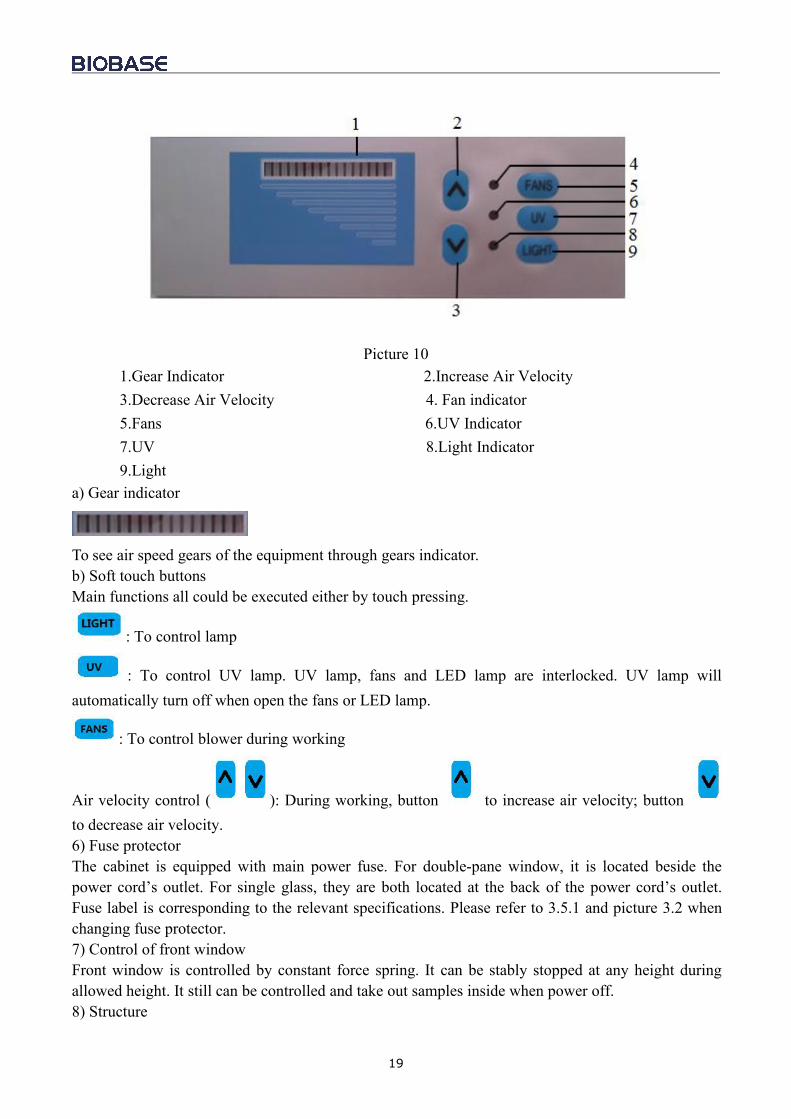
Picture 101.Gear Indicator 2.Increase Air Velocity3.Decrease Air Velocity 4. Fan indicator5.Fans 6.UV Indicator7.UV 8.Light Indicator9.Light
a) Gear indicator
To see air speed gears of the equipment through gears indicator.b) Soft touch buttonsMain functions all could be executed either by touch pressing.
: To control lamp
: To control UV lamp. UV lamp, fans and LED lamp are interlocked. UV lamp willautomatically turn off when open the fans or LED lamp.
: To control blower during working
Air velocity control ( ): During working, button to increase air velocity; buttonto decrease air velocity.6) Fuse protectorThe cabinet is equipped with main power fuse. For double-pane window, it is located beside thepower cord’s outlet. For single glass, they are both located at the back of the power cord’s outlet.Fuse label is corresponding to the relevant specifications. Please refer to 3.5.1 and picture 3.2 whenchanging fuse protector.7) Control of front windowFront window is controlled by constant force spring. It can be stably stopped at any height duringallowed height. It still can be controlled and take out samples inside when power off.8) Structure
20
a) Cabinet body is made up of 1.2mm cold-rolled steel with anti-bacteria powder coating. Thestructural strength and stability are enhanced.b) Work area is made up of 304 stainless steel, which provides corrosion resistance and attractiveappearance.c) Base stand is made up of metal with anti-bacteria powder coating.d) Control panel adopts soft touch buttons, which provides attractive appearance and easy operation..
2.3 Instructions for Operation2.3.1 Normal Operation Noticea) Making sure input voltage is correct and stable. The rated load of main power socket should behigher than cabinet consumption. Plug must be well grounded. If socket can not plug in, pleaseinstall a grounding type power socket by a electrician.b) Moving principles of different samples inside cabinet: When two or more samples need to bemoved in, be sure that low-polluting samples should be moved first then high-polluting samples.Movement of items should also follow the principles of moving slowly and steadily.c) The weight of items placed in the cabinet should not be more than 23Kg/25×25cm2;d) Avoiding vibration: avoid using vibration equipment (eg centrifuges, vortex oscillator, etc.) insidethe cabinet. The contamination might drop from the HEPA filter and affect the samples and theoperatore) NO FLAME: An open flame would create turbulence which disrupts the pattern of HEPA-filteredair supplied to the work surface. If sterilization is required during the experiment, infrared sterilizeris highly recommended.f) HEPA filter life: With the usage time increasing, dust and bacteria accumulate inside HEPA filter.Filter Resistance is getting bigger, when it reaches the maximum point, the speed requirements can’tbe met. Then need contact BIOBASE service department to get a new one. The used filter should beprocessed as medical waste.g) Air duct has been sealed strictly. Please do NOT remove or loose the screws of those parts. Tocontact service personnel for special technical requirementsh) The maximum storage period is one year. A performance inspection should be done if the storageperiod exceeds one year.
Serious declaration:NOTE: BIOBASE WILL NOT BE RESPONSIBLE FOR ANY RISK OR DAMAGEARISING FAILURE DURING USAGE BY UNTRAINED OPERATOR ANDMISHANDLING THE LAF. THE OPERATOR OF THE LAMINAR FLOW CABINETSHOULD BE TRAINED ENOUGH BEFORE USING THE LAF.2.3.2 Operation Processa) Connect the powerb) Press relevant button (please reference to 2.2.3 about button function and operation). Check if thebuttons in accordance to operation results. If the equipment is function normally, air velocity, UVlamp and LED lamp according to technical parameters.c) The cabinet should be sterilized by UV lamp for at least 30 minutes with the window fully closedbefore any experiment.
21
NOTE:(1) For safety of eyes and skin, people should leave the room during UV sterilization.(2)UV lamp should be checked regularly. It should be replaced when either the total workingtime reaches 600 hours or the intensity is lower than the requirement.
d) Please move up the front window to reasonable height above the work table and turn on theblower. Make sure the experiment should be started after fan working for at least 30 minutes.
NOTE: For operating safety, please put testing materials inside the cabinet in advanceAfter finishing the experiment, please fully close the front window, and make sure to sterilize thecabinet by UV lamp for 30 minutes before turning off the cabinet.
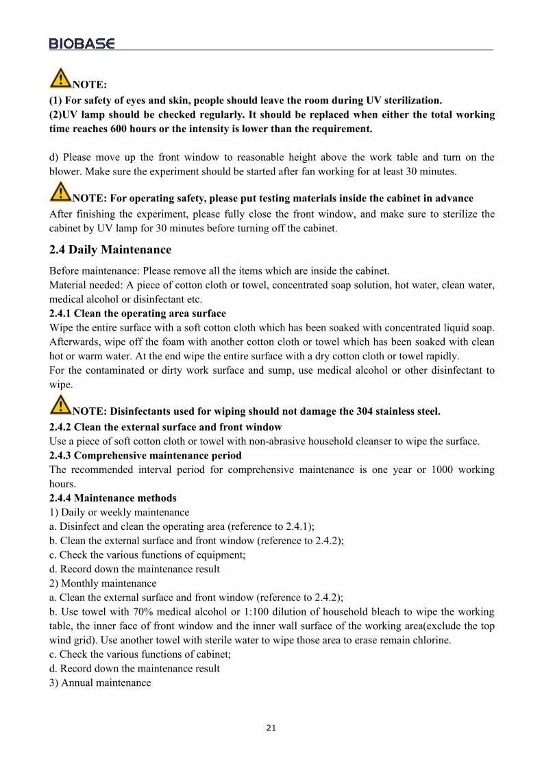
2.4 Daily MaintenanceBefore maintenance: Please remove all the items which are inside the cabinet.Material needed: A piece of cotton cloth or towel, concentrated soap solution, hot water, clean water,medical alcohol or disinfectant etc.2.4.1 Clean the operating area surfaceWipe the entire surface with a soft cotton cloth which has been soaked with concentrated liquid soap.Afterwards, wipe off the foam with another cotton cloth or towel which has been soaked with cleanhot or warm water. At the end wipe the entire surface with a dry cotton cloth or towel rapidly.For the contaminated or dirty work surface and sump, use medical alcohol or other disinfectant towipe.
NOTE: Disinfectants used for wiping should not damage the 304 stainless steel.2.4.2 Clean the external surface and front windowUse a piece of soft cotton cloth or towel with non-abrasive household cleanser to wipe the surface.2.4.3 Comprehensive maintenance periodThe recommended interval period for comprehensive maintenance is one year or 1000 workinghours.2.4.4 Maintenance methods1) Daily or weekly maintenancea. Disinfect and clean the operating area (reference to 2.4.1);b. Clean the external surface and front window (reference to 2.4.2);c. Check the various functions of equipment;d. Record down the maintenance result2) Monthly maintenancea. Clean the external surface and front window (reference to 2.4.2);b. Use towel with 70% medical alcohol or 1:100 dilution of household bleach to wipe the workingtable, the inner face of front window and the inner wall surface of the working area(exclude the topwind grid). Use another towel with sterile water to wipe those area to erase remain chlorine.c. Check the various functions of cabinet;d. Record down the maintenance result3) Annual maintenance
22
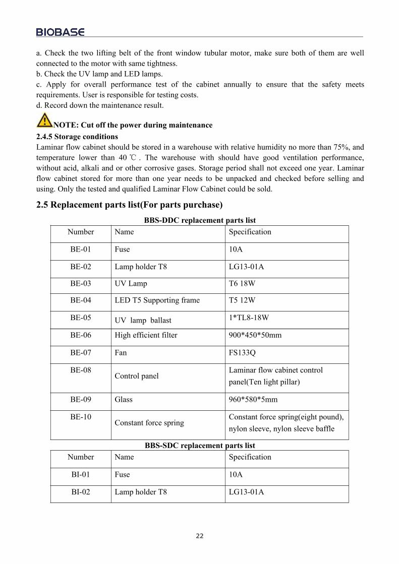
a. Check the two lifting belt of the front window tubular motor, make sure both of them are wellconnected to the motor with same tightness.b. Check the UV lamp and LED lamps.c. Apply for overall performance test of the cabinet annually to ensure that the safety meetsrequirements. User is responsible for testing costs.d. Record down the maintenance result.
NOTE: Cut off the power during maintenance2.4.5 Storage conditionsLaminar flow cabinet should be stored in a warehouse with relative humidity no more than 75%, andtemperature lower than 40 . The warehouse with should have good ventilation performance,without acid, alkali and or other corrosive gases. Storage period shall not exceed one year. Laminarflow cabinet stored for more than one year needs to be unpacked and checked before selling andusing. Only the tested and qualified Laminar Flow Cabinet could be sold.
2.5 Replacement parts list(For parts purchase)BBS-DDC replacement parts list
Number Name Specification
BE-01 Fuse 10A
BE-02 Lamp holder T8 LG13-01A
BE-03 UV Lamp T6 18W
BE-04 LED T5 Supporting frame T5 12W
BE-05 UV lamp ballast 1*TL8-18W
BE-06 High efficient filter 900*450*50mm
BE-07 Fan FS133Q
BE-08Control panel
Laminar flow cabinet controlpanel(Ten light pillar)
BE-09 Glass 960*580*5mm
BE-10Constant force spring
Constant force spring(eight pound),nylon sleeve, nylon sleeve baffle
BBS-SDC replacement parts listNumber Name Specification
BI-01 Fuse 10A
BI-02 Lamp holder T8 LG13-01A
23
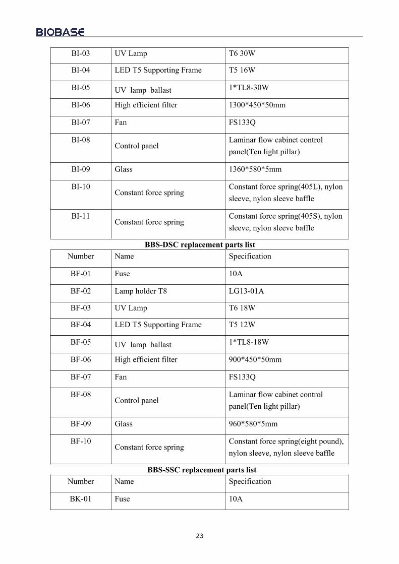
BI-03 UV Lamp T6 30W
BI-04 LED T5 Supporting Frame T5 16W
BI-05 UV lamp ballast 1*TL8-30W
BI-06 High efficient filter 1300*450*50mm
BI-07 Fan FS133Q
BI-08Control panel
Laminar flow cabinet controlpanel(Ten light pillar)
BI-09 Glass 1360*580*5mm
BI-10Constant force spring
Constant force spring(405L), nylonsleeve, nylon sleeve baffle
BI-11Constant force spring
Constant force spring(405S), nylonsleeve, nylon sleeve baffle
BBS-DSC replacement parts listNumber Name Specification
BF-01 Fuse 10A
BF-02 Lamp holder T8 LG13-01A
BF-03 UV Lamp T6 18W
BF-04 LED T5 Supporting Frame T5 12W
BF-05 UV lamp ballast 1*TL8-18W
BF-06 High efficient filter 900*450*50mm
BF-07 Fan FS133Q
BF-08Control panel
Laminar flow cabinet controlpanel(Ten light pillar)
BF-09 Glass 960*580*5mm
BF-10Constant force spring
Constant force spring(eight pound),nylon sleeve, nylon sleeve baffle
BBS-SSC replacement parts listNumber Name Specification
BK-01 Fuse 10A
24
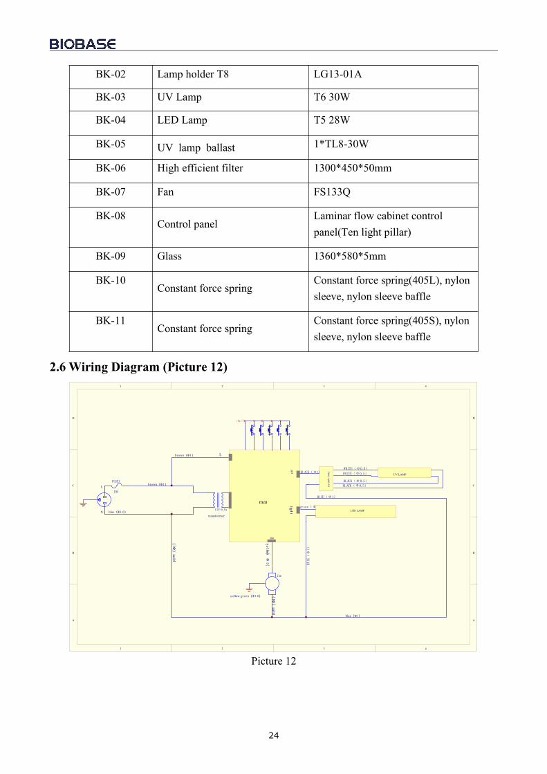
BK-02 Lamp holder T8 LG13-01A
BK-03 UV Lamp T6 30W
BK-04 LED Lamp T5 28W
BK-05 UV lamp ballast 1*TL8-30W
BK-06 High efficient filter 1300*450*50mm
BK-07 Fan FS133Q
BK-08Control panel
Laminar flow cabinet controlpanel(Ten light pillar)
BK-09 Glass 1360*580*5mm
BK-10Constant force spring
Constant force spring(405L), nylonsleeve, nylon sleeve baffle
BK-11Constant force spring
Constant force spring(405S), nylonsleeve, nylon sleeve baffle
2.6 Wiring Diagram (Picture 12)
1 2 3 4
A
B
C
D
4321
D
C
B
A
fan
FUSE1
10A
L
N
mcu
brown(Φ1)
brown(Φ1)
blue(Φ1.0)
blue(Φ1)
transformer
light
uv
L
fan
yellow(Φ1)
blue(Φ1)
blue(Φ1)
1 2V/0.3A
UV LAMP
UV BALLASTBLACK(Φ1) WHITE(Φ0.5)
BLACK(Φ0.5)
WHITE(Φ0.5)
BLACK(Φ0.5)
BLUE(Φ1)
green(Φ1)
BLUE(Φ1)
UP
UV
DOWN
+5v
FAN
LIGHT
y e llow green(Φ1.0)
LED LAMP
Picture 12
25
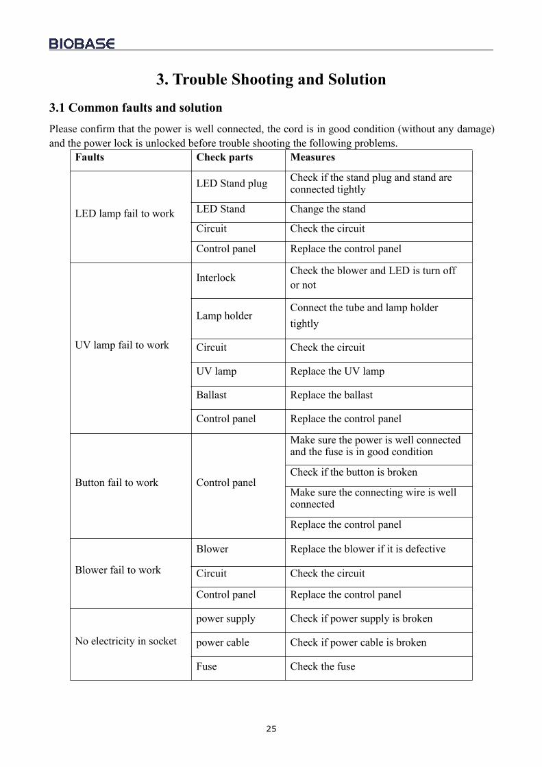
3. Trouble Shooting and Solution3.1 Common faults and solutionPlease confirm that the power is well connected, the cord is in good condition (without any damage)and the power lock is unlocked before trouble shooting the following problems.
Faults Check parts Measures
LED lamp fail to work
LED Stand plug Check if the stand plug and stand areconnected tightly
LED Stand Change the stand
Circuit Check the circuit
Control panel Replace the control panel
UV lamp fail to work
Interlock Check the blower and LED is turn offor not
Lamp holderConnect the tube and lamp holdertightly
Circuit Check the circuit
UV lamp Replace the UV lamp
Ballast Replace the ballast
Control panel Replace the control panel
Button fail to work Control panel
Make sure the power is well connectedand the fuse is in good condition
Check if the button is broken
Make sure the connecting wire is wellconnected
Replace the control panel
Blower fail to work
Blower Replace the blower if it is defective
Circuit Check the circuit
Control panel Replace the control panel
No electricity in socket
power supply Check if power supply is broken
power cable Check if power cable is broken
Fuse Check the fuse
26
Transformer Check it
Control panel Change the control panel
Display fail to work
Connection wires Check if connected
Display screen Check whether the screen is in goodcondition
Control panel Replace the control panel
NOTE:(1)The above trouble shooting methods should be done by qualified electricians under safeconditions (cut off power supply). Other components should not be removed. Risk caused byfailing to follow those instructions would be responsible by user.;(2)Please contact Biobase or our agent technical department if a failure could not be traced orsolved. Do NOT repair the equipment without a qualified electrician;(3) The trouble shooting and repair of this equipment only could be undertaken by trained andrecognized technicians;(4)Please contact Biobase or our agent technical department or agent to order requiredcomponent or part. The model number and the serial number of purchased cabinet need to beindicated.
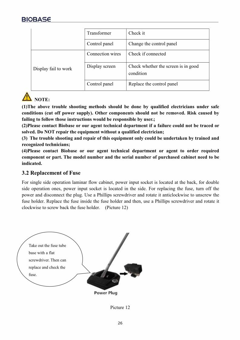
3.2 Replacement of FuseFor single side operation laminar flow cabinet, power input socket is located at the back, for doubleside operation ones, power input socket is located in the side. For replacing the fuse, turn off thepower and disconnect the plug. Use a Phillips screwdriver and rotate it anticlockwise to unscrew thefuse holder. Replace the fuse inside the fuse holder and then, use a Phillips screwdriver and rotate itclockwise to screw back the fuse holder. (Picture 12)
Picture 12
Take out the fuse tube
base with a flat
screwdriver. Then can
replace and check the
fuse.
27
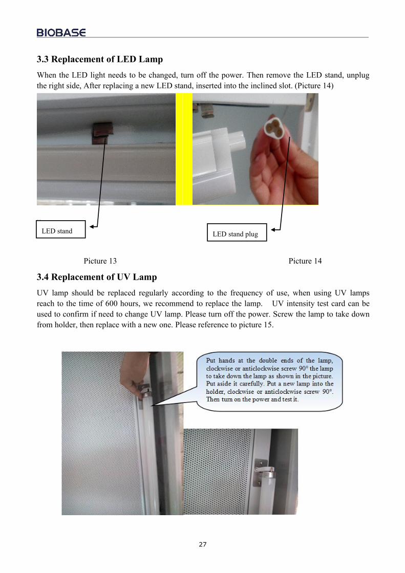
3.3 Replacement of LED LampWhen the LED light needs to be changed, turn off the power. Then remove the LED stand, unplugthe right side, After replacing a new LED stand, inserted into the inclined slot. (Picture 14)
v
Picture 13 Picture 14
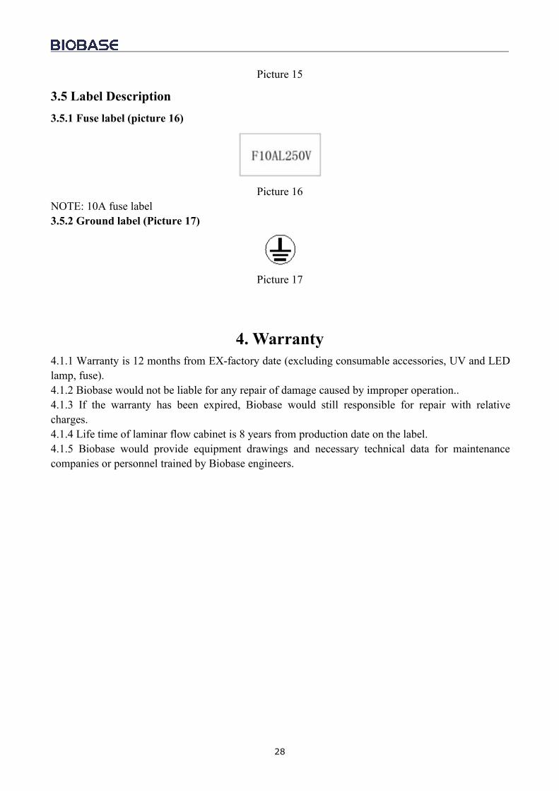
3.4 Replacement of UV LampUV lamp should be replaced regularly according to the frequency of use, when using UV lampsreach to the time of 600 hours, we recommend to replace the lamp. UV intensity test card can beused to confirm if need to change UV lamp. Please turn off the power. Screw the lamp to take downfrom holder, then replace with a new one. Please reference to picture 15.
LED stand LED stand plug
28
Picture 15
3.5 Label Description3.5.1 Fuse label (picture 16)
Picture 16NOTE: 10A fuse label3.5.2 Ground label (Picture 17)
Picture 17
4. Warranty4.1.1 Warranty is 12 months from EX-factory date (excluding consumable accessories, UV and LEDlamp, fuse).4.1.2 Biobase would not be liable for any repair of damage caused by improper operation..4.1.3 If the warranty has been expired, Biobase would still responsible for repair with relativecharges.4.1.4 Life time of laminar flow cabinet is 8 years from production date on the label.4.1.5 Biobase would provide equipment drawings and necessary technical data for maintenancecompanies or personnel trained by Biobase engineers.

BIOBASE GROUP2# building, No.9 Gangxing Road, High-tech Zone, Jinan City, Shandong Province,ChinaTel: +86-531-81219803/01Fax: +86-531-81219804Inquiry: [email protected]: [email protected] service: [email protected]; [email protected]: www.biobase.cc/www.meihuatrade.com / www.biobase.com


