Embed Size (px)
Citation preview
oml OAK RIDGE NATIONAL LABORATORY
LOCKHEED HI A R r-nry^
ORNL/RASA-95/14
RECEIVED DEC 2 8 1995 OSTI
Results of the Radiological Verification Survey at the Former
Herring-Hall-Marvin Safe Company, 1550 Grand Boulevard, Hamilton Ohio
(HO001V)
M. E. Murray J. F. Allred
C. A. Johnson
MANAGED BY DISTFU p! m A M f\r T:\tn ••%,-,„, .-.„... m.„ ,_ , wOi<v« Or am uUUJfcicNI IS tJC§ ||TP
LOCKHEED MARTIN ENERGYSYSTEMS, INC. *» i W!
FOR THE UNITED STATES _«^tftfi Bj-ffi^&V
DEPARTMENT OF ENERGY
UCN-13673 (36 6-95)
This report has been reproduced directly from the best available copy.
Available to DOE and DOE contractors from the Office of Scientific and Technical Information, P.O. Box 62, Oak Ridge, TN 37831; prices available from (615) 576-8401, FTS 626-8401.
Available to the public from the National Technical Information Service, U.S. Department of Commerce, 5285 Port Royal Rd., Springfield, VA 22161.
This report was prepared as an account of work sponsored by an agency of the United States Government. Neither the United States Government nor any agency thereof, nor any of their employees, makes any warranty, express or implied, or assumes any legal liability or responsibility for the accuracy, completeness, or usefulness of any information, apparatus, product, or process disclosed, or represents that its use would not infringe privately owned rights. Reference herein to any specific commercial product, process, or service by trade name, trademark, manufacturer, or otherwise, does not necessarily constitute or imply its endorsement, recommendation, or favoring by the United States Government or any agency thereof. The views and opinions of authors expressed herein do not necessarily state or reflect those of the United States Government or any agency thereof.
DISCLAIMER
Portions of this document may be illegible in electronic image products. Images are produced from the best available original document
ORNL/RASA-95/14
HEALTH SCIENCES RESEARCH DIVISION Environmental Restoration and Waste Management Non-Defense Programs
(Activity No. EX 20 20 01 0; ADS317AEX))
Results of the Radiological Verification Survey at the Former Herring-Hall-Marvin Safe Company, 1550 Grand
Boulevard, Hamilton Ohio (HO001V)
M. E. Murray, J. F. Allredi and C. A. Johnson
Date issued —November 1995
Investigation Team R. D. Foley — Measurement Applications and Development Manager
M. E. Murray - FUSRAP Project Director J. F. Allred— Field Survey Team Leader
Survey Team Members J. f. Allred D. E. Rice J. P. Abston D. A. Roberts G. H. Cofer D. A. Rose D. D. McKinney* W. H. Shinpaugh* M. E. Murray W. Winton
W. A. Williams**
•Midwest Technical, Inc **U. S. Department of Energy
Work performed by the Measurement Applications and Development Group
Prepared by the OAK RIDGE NATIONAL LABORATORY
Oak Ridge, Tennessee 37831-6285 managed by
LOCKHEED MARTIN ENERGY SYSTEMS, INC. for the
U. S. DEPARTMENT OF ENERGY under contract DE-AC05-84OR21400
Dimmmi OF V«. L\,-C.«;I IS U M W "ok
CONTENTS
LIST OF FIGURES v
LIST OF TABLES vii
ACKNOWLEDGMENTS ix
ABSTRACT xi
INTRODUCTION 1
VERIFICATION PROCEDURES 2 OBJECTIVES 2 SURVEY METHODS 2
VERIFICATION SURVEY AND ANALYSIS 2 Third Floor Core Holes 3 South Zone.... 3 East Zone 4
West Zone 4
CONCLUSIONS 5
REFERENCES 6
ni

LIST OF FIGURES
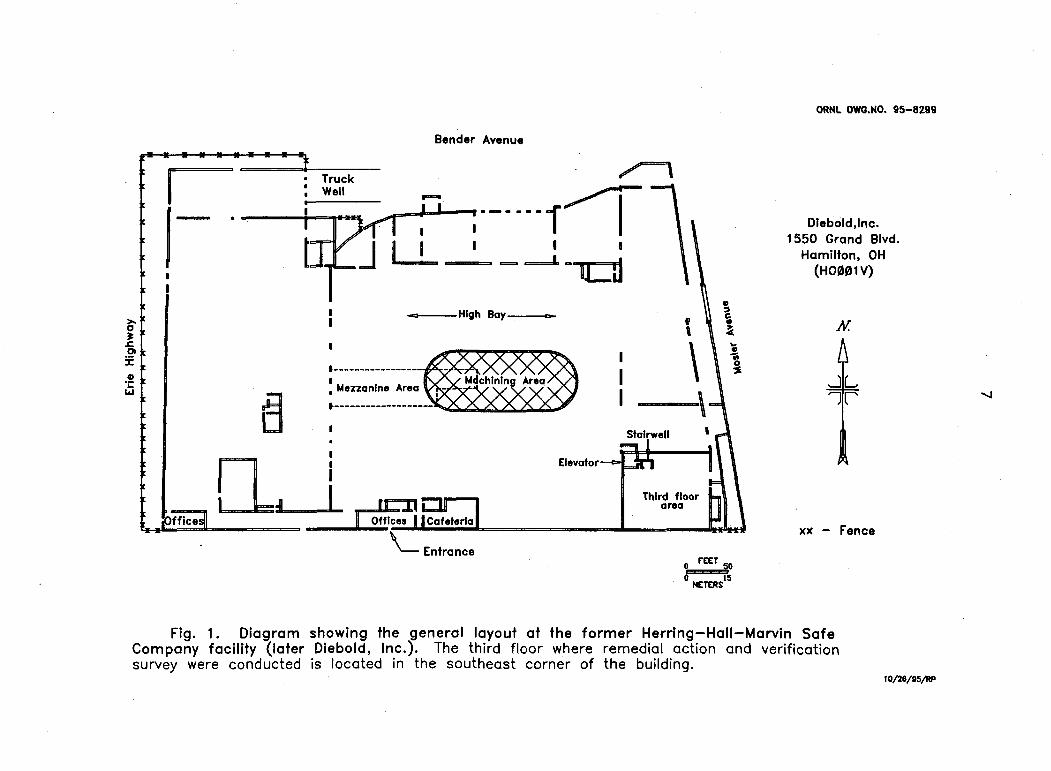
1 Diagram showing the general layout at the former Herring-Hall-Marvin-Safe Company facility (later Diebold Inc.)
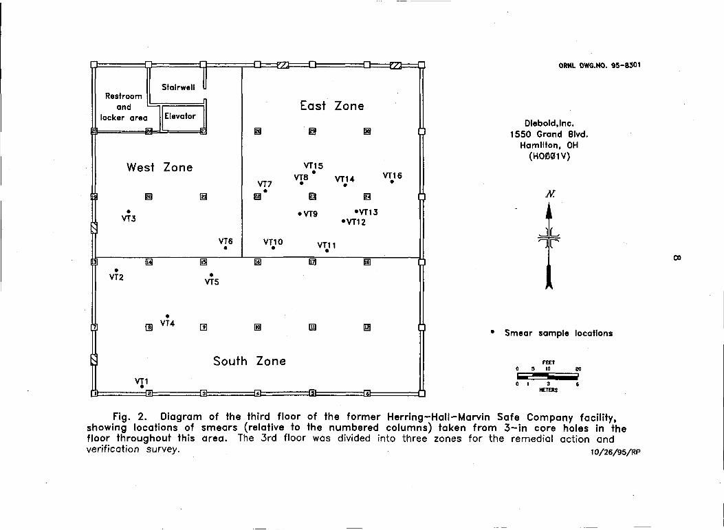
Diagram of the third floor of the former Herring-Hall-Marvin Safe Company facility, showing locations of smears (relative to the numbered columns) taken from 3-in core holes in the floor throughout this area
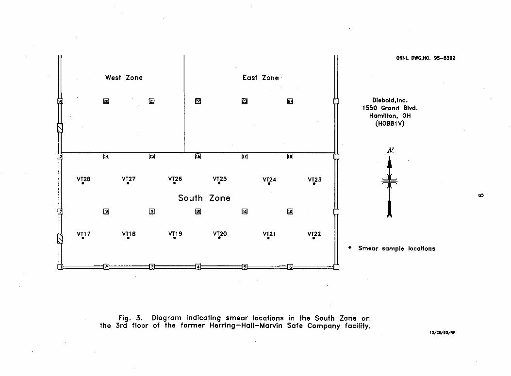
Diagram indicating smear locations in the South Zone on the 3rd floor of the former Herring-Hall-Marvin Safe Company facility
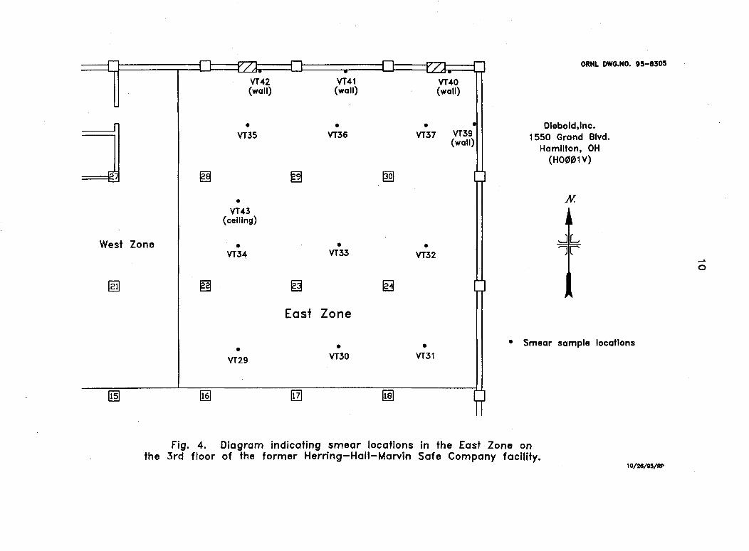
Diagram indicating smear locations in the East Zone on the 3rd floor of the former Herring-Hall-Marvin Safe Company facility 10
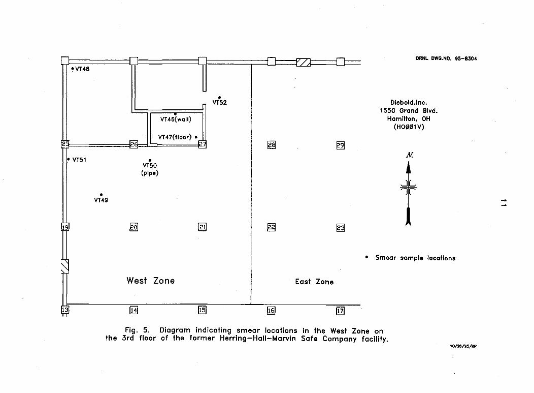
Diagram indicating smear locations in the West Zone on the 3rd floor of the former Herring-Hall-Marvin Safe Company facility 11
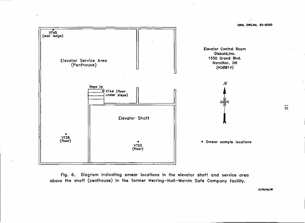
Diagram indicating smear locations in the elevator shaft and service area above the shaft (penthouse) in the former Herring-Hall-Marvin Safe Company facility 12
Photographs of the verification work in progress on the 3rd floor of the Herring-Hall-Marvin Safe Co. facility 13
v

LIST OF TABLES
1 Applicable guidelines for protection against radiation 14
2 Smear samples taken for the verification of the former Herring-Hall-Marvin Safe Company facility (3rd floor) 15
vn
ACKNOWLEDGMENTS
This project was sponsored by the Office of Environmental Restoration, U. S. Department of Energy, under contract DE-AC05-84OR21400 with Lockheed Martin Energy Systems, Inc. The authors wish to acknowledge the contributions of D. A. Roberts, D. A. Rose, and R. C. Phillips of the Measurement Applications and Development Group for participation in the sample preparation and analyses, graphics, and reporting of data for this survey. The surveying assistance of the staff on the survey team is also gratefully acknowledged.
IX
ABSTRACT
During the period between the 1940s and early 1950s, the Herring-Hall-Marvin Safe Company, 1550 Grand Boulevard, Hamilton, Ohio, was one company under subcontract to the Manhattan Engineer District (MED), and the Atomic Energy Commission (AEC), the lead agencies in the development of nuclear energy for defense-related projects. The U. S. Department of Energy (DOE) conducted radiological surveys of these sites to evaluate current radiological conditions as part of the Formerly Utilized Sites Remedial Action Program (FUSRAP). In 1988, a radiological survey of the Herring-Hall-Marvin Safe Company facility was conducted, and after small fragments of uranium metal were removed, no beta or gamma radiation above background was detected and the building was dismissed from any additional DOE restrictions.
In 1993, it was discovered that a portion of the actual machining work was conducted on the third floor of the facility, located in the southeastern comer of the building. At the request of DOE, this part of the facility was radiologically surveyed by an ORNL survey team to determine whether fixed surface contamination could be found that might exceed the DOE guidelines. Results of this radiological survey indicated 2 3 8 U contamination in excess of the DOE criteria for surface contamination, and the site was recommended for remediation.
In February and March of 1995, a verification survey of the third floor of the former Herring-Hall-Marvin Safe Company facility by an ORNL survey team was performed in conjunction with decontamination operations conducted under the supervision of Bechtel National Incorporated. The verification survey included gamma scans at the surface and at one meter, alpha and beta-gamma scans for fixed contamination, and smears for transferable contamination.
Based on the remedial action and verification survey data reported in this document, and the results of the 1988 survey as reported in ORNL/RASA-88/59, all radiological measurements fall below the limits prescribed by DOE radiological guidelines established for this site, and the facility successfully meets the DOE radiological guidelines for unrestricted use.
xi
Results of the Radiological Verification Survey at the Former Herring-Hall-Marvin Safe Company,
1550 Grand Boulevard, Hamilton Ohio (HO001V)*
INTRODUCTION
During the period from the early 1940s to the early 1950s, the Herring-Hall-Marvin Safe Company in Hamilton, Ohio, machined uranium slugs from rolled stock for the Manhattan Engineer District (MED) and the Atomic Energy Commission (AEC). This commercial property was later purchased by the Diebold Safe Company and eventually sold to the present owner, who currently leases portions of the facility as a storage warehouse. The facility is a large industrial building (-300,000 ft2), built in stages as evidenced by the many types of construction materials and architectural styles. An overall view of the building is shown in Fig. 1.
In the 1980s, follow-up radiological surveys to reevaluate the current radiological conditions at these sites were conducted by the U. S. Department of Energy (DOE) under the Formally Utilized Sites Remedial Action Program (FUSRAP). In August 1988 and April 1989, radiological surveys were conducted at this site at the request of DOE, by members of the Measurement Applications and Development (MAD) Group of the Oak Ridge National Laboratory (ORNL). The surveys covered portions of the exterior grounds, roof sections, and interior sections where the Diebold management understood the earlier uranium work to have taken place.1 Very little uranium was found (small fragments of uranium metal were left from the machining operations), and after removal of these samples, no beta or gamma radiation above background could be detected and the building was dismissed from any additional DOE restrictions.2
During the spring of 1993, public attention was drawn to the Diebold facility by former workers who stated that the earlier radiological surveys did not include that part of the structure which contained the third floor (an area of -9000 ft2, located in the southeastern corner of the building, Fig. 1) where a portion of the actual machining work was conducted. In August 1993, the third floor was radiologically surveyed by the ORNL team to determine whether fixed surface contamination could be found that might exceed the DOE guidelines. The primary focus of the survey was the third floor, the elevator (including the shaft) and the stairwell leading to the third floor, all of which are in the southeastern corner of the structure. This section of the building is constructed almost entirely of concrete and concrete blocks. Results of this radiological survey indicated 2 3 8 U contamination in excess of the DOE criteria for surface contamination, and the site was recommended for remediation.3
Decontamination of the facility to current guidelines was conducted by subcontractor personnel under the direction of Bechtel National Incorporated (BNI), the project management contractor for FUSRAP. ThermoAnalytical (TMA) Eberline was the radiological support subcontractor.
The survey was performed by members of the Measurement Applications and Development Group of the Health Sciences Research Division at Oak Ridge National Laboratory under DOE contract DE-AC05-84OR21400.
2
The DOE adopted a policy to assign an independent verification contractor to ensure the effectiveness of remedial actions performed within FUSRAP and to confirm the site's compliance with DOE guidelines. The Measurement Applications and Development Group at ORNL (the independent verification contractor for this property), was assigned this responsibility. In February and March of 1995, verification surveys were performed in conjunction with decontamination operations on the third floor of the former Herring-Hall-Marvin Safe Company facility. This report describes the methods and results of that verification.
VERIFICATION PROCEDURES
OBJECTIVES
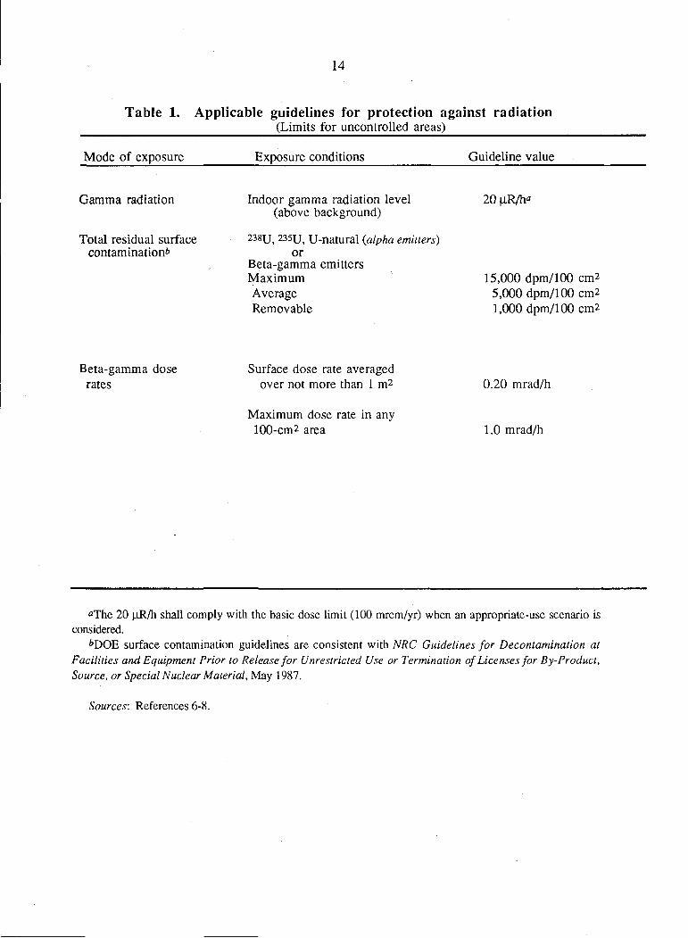
The objective of the verification activities was to confirm (1) that available documentation adequately and accurately describes the post-remedial action of the portion of the property that is to be verified, and (2) that the remedial action reduced contamination levels to within authorized limits. Applicable DOE residual radioactivity guidelines for protection of the general public are summarized in Table 1.
SURVEY METHODS
The post-remedial action/verification survey was performed on this property as described for a generic site.4-5 Instrument calibrations were verified and background checked before each survey session.
The radiological verification survey of the third floor area included: (1) a gamma scan at the surface of walls and floors, and at one meter above the floor, using sodium iodide (Nal) gamma scintillation detectors; (2) alpha and beta-gamma scans of the walls, floors, floor drains, ceilings and overhead structures with ZnS scintillation detectors and "pancake" GM detectors, respectively; (3) a comprehensive scan of the floor surface for alpha-beta-gamma activity, using large area gas flow proportional detectors; and (4) systematic smear sampling of accessible surfaces (analyzed in alpha and beta-gamma smear counters) to detect possible transferable contamination.
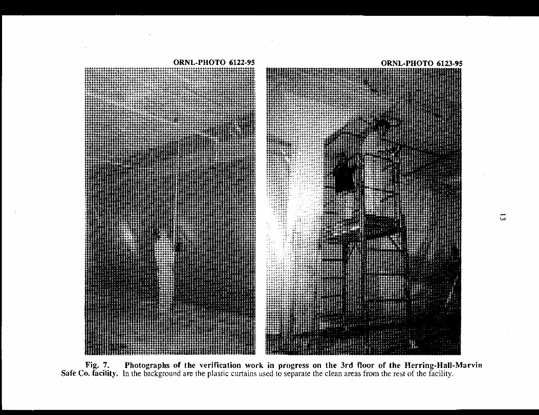
Survey methods followed guidelines outlined in References 4 and 5. Figures 2-6 are diagrams of the third floor and area above the elevator shaft showing the locations of the smears. Photographs of the verification survey in progress are shown in Fig. 7.
VERIFICATION SURVEY AND ANALYSIS
Applicable DOE guidelines are summarized in Table 1. A background range of 7 to 9 |iR/h found in the initial survey of the third floor was used for comparison with survey results presented in this section.
Verification surveys were performed in conjunction with decontamination operations of the third floor (including elevator penthouse), elevator and elevator shaft. Decontamination of the facility to current DOE guidelines before being released for
3
verification was under the direction of Bechtel National Incorporated (BNI), with TMA Eberline providing continuous health physics oversight for subcontractor personnel during all cleanup operations.
All overhead pipes and conduits and -30% of all exposed ceilings were scanned for alpha and beta-gamma radiation. Where detectable levels of contamination were observed on overhead pipes and conduits, the adjacent ceiling was thoroughly scanned. A complete scan was conducted of all wall sections previously identified as exceeding fixed contamination guidelines, while other wall areas not so identified were scanned over ~30 percent of their surface area.
All floor areas, with the exception of the elevator penthouse and elevator shaft floor, were scanned with the floor monitor for detectable alpha and beta-gamma contamination. Additionally, direct alpha readings were systematically collected over exposed wall and floor surfaces.
Gamma scintillation detector surveys were conducted to quantify exposure rates caused primarily by naturally occurring radioactivity concentrated in the masonry building materials. Accessible surfaces of wall and floor drains were also scanned for beta-gamma radiation. Smears were systematically collected throughout the areas surveyed to ensure that remedial efforts left no residual transferable radioactivity above established guidelines.
Beta-gamma contamination levels were recorded in gross counts per minute (cpm), background adjusted and converted to disintegrations per minute (dpm/lOOcm2) using standard geometry factors for beta-gamma pancake probe/Bicron ratemeter combination. Transferable radioactivity levels (smears) are reported as net counts with background subtracted. Gamma measurements are gross readings; background radiation levels have not been subtracted.
To assist in defining the locations of contaminated areas, the third floor was divided into three distinct zones (East, West, and South, Figs. 2-6). Radiological verification surveys were conducted in areas made accessible by the remedial activities to confirm that these areas met DOE guidelines. As requested by the ORNL team, as each zone was released by BNI to be verified, it was temporarily separated by a plastic curtain to isolate it from the rest of the area to prevent the possible transfer of contamination into the cleaned areas. The plastic curtains remained in place around each zone until the entire area of the third floor was verified below guidelines by the ORNL verification team. Results of the verification survey were noted on field drawings and data sheets. Verification of the facility proceeded as the following paragraphs indicate.
Third Floor Core Holes
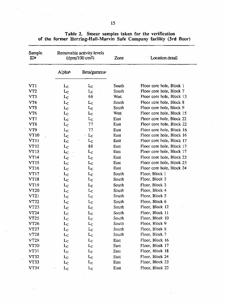
The radiological verification survey began by collecting and analyzing smears from 3-inch core holes across the entire third floor. Cores were cut from the floor by the remediating subcontractor to remove lead floor anchors. No discernible radioactivity above naturally occurring background was detected in scans or on smears collected from the core holes in any of the three established zones. Locations of transferable smear samples are shown on Fig. 2 and analytical results are presented in Table 2.
South Zone
The survey in the south zone included alpha, gamma and beta-gamma scans of the floors and walls, including columns and wall drains. Smears for transferable
4
contamination were systematically collected and analyzed for alpha and beta-gamma activity.
Fixed beta-gamma activity on floors, walls, columns and wall drains ranged up to 1300 dpm/100 cm 2 . Fixed beta-gamma activity on ceilings ranged up to 700 dpm/100 cm 2. Alpha activity on the floors and walls was below guidelines. Gamma exposure rates at one meter above floor level ranged from 3 to 5 [iR/h. Results of the smear analysis showed that all smears were below guidelines for transferable alpha and beta-gamma activity. Locations of the smears are shown in Fig. 3, and analytical results are presented in Table 2.
The south zone was verified by the ORNL survey team as having no fixed or transferable contamination in excess of established guidelines, and the zone remained isolated by the plastic curtain until the entire third floor was verified below guidelines.
East Zone
Initially, the investigation of the east zone revealed numerous areas in which established guidelines were still exceeded, requiring additional remediation (e.g., beta-gamma residuals measured up to 120,000 dpm/100 cm 2 around the column located in the southwest corner of block 22. Other areas within the east zone ranged from just slightly above guideline levels up to 21,000 dpm/100 cm 2). These areas were identified with paint to expedite remedial efforts within the zone. Remediation continued in the evenings, and areas not meeting guidelines were rechecked for residuals the next morning.
Following these remedial efforts, the east zone was resurveyed over all overhead pipes and conduits, floor surfaces, walls, wall drains, and support columns. Approximately 30 % of the ceiling was surveyed for beta-gamma and ~ 1% of the same surface was scanned for alpha radiation. Systematic smear samples were collected and analyzed for transferable radioactivity.
Final fixed alpha contamination of the floor and walls ranged from none detectable up to 140 dpm/100 cm 2 . Maximum fixed beta-gamma activity on floors was 1100 dpm/100 cm 2 , and maximum fixed beta-gamma on walls, including columns and wall drains measured 4500 dpm/100 cm 2. Fixed beta-gamma on ceilings ranged from none detectable up to 4100 dpm/100cm2. Gamma exposure rates at one meter above floor level ranged from 3 to 5 |iR/h. Analysis of the smears taken from the east zone indicated that all transferable radioactivity levels were below guidelines. Locations of the smears are shown in Fig. 4, and analytical results are presented in Table 2.
The east zone was verified below established cleanup guidelines and a memo to that effect was provided at the request of the Bechtel site supervisor.
West Zone
The west zone included the elevator penthouse and elevator shaft. The initial survey located limited contamination in excess of established guidelines on the third floor and elevator penthouse (e.g., one small floor area on the third floor just south of the elevator doorway measured 31,000 dpm/100 cm 2 of fixed beta-gamma activity. Several deposits of beta-gamma contamination were located on the floor of the elevator shaft where a maximum of 128,000 dpm was measured. Most of these deposits were around the interface between the elevator shaft walls and elevator shaft floor). One small deposit of
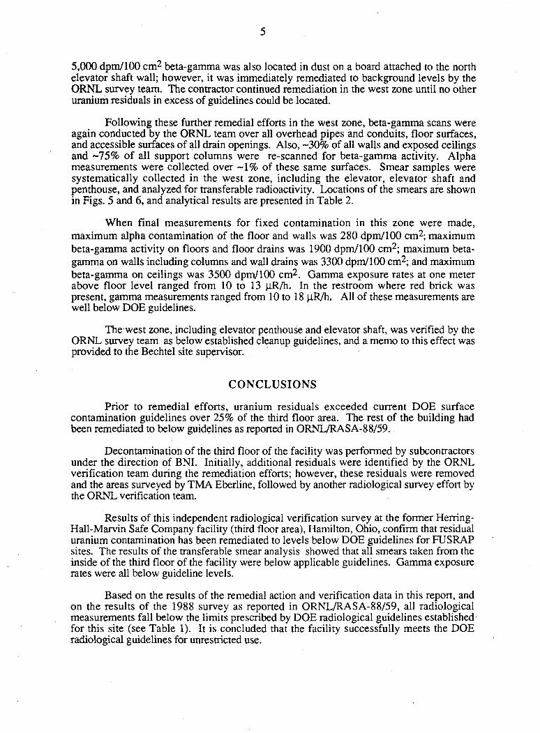
5
5,000 dpm/100 cm 2 beta-gamma was also located in dust on a board attached to the north elevator shaft wall; however, it was immediately remediated to background levels by the ORNL survey team. The contractor continued remediation in the west zone until no other uranium residuals in excess of guidelines could be located.
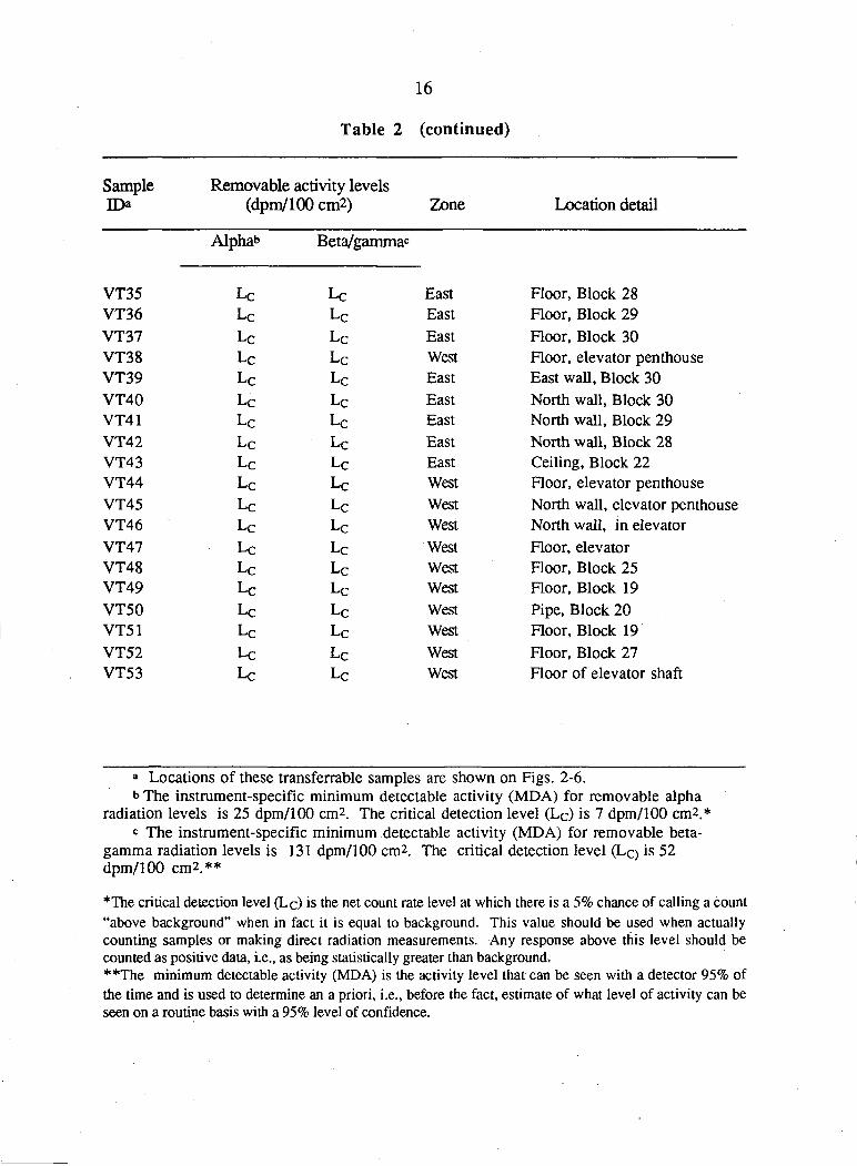
Following these further remedial efforts in the west zone, beta-gamma scans were again conducted by the ORNL team over all overhead pipes and conduits, floor surfaces, and accessible surfaces of all drain openings. Also, ~30% of all walls and exposed ceilings and ~75% of all support columns were re-scanned for beta-gamma activity. Alpha measurements were collected over - 1 % of these same surfaces. Smear samples were systematically collected in the west zone, including the elevator, elevator shaft and penthouse, and analyzed for transferable radioactivity. Locations of the smears are shown in Figs. 5 and 6, and analytical results are presented in Table 2.
When final measurements for fixed contamination in this zone were made, maximum alpha contamination of the floor and walls was 280 dpm/100 cm 2; maximum beta-gamma activity on floors and floor drains was 1900 dpm/100 cm 2; maximum beta-gamma on walls including columns and wall drains was 3300 dpm/100 cm 2; and maximum beta-gamma on ceilings was 3500 dpm/100 cm 2. Gamma exposure rates at one meter above floor level ranged from 10 to 13 |iR/h. In the restroom where red brick was present, gamma measurements ranged from 10 to 18 {iR/h. All of these measurements are well below DOE guidelines.
The west zone, including elevator penthouse and elevator shaft, was verified by the ORNL survey team as below established cleanup guidelines, and a memo to this effect was provided to the Bechtel site supervisor.
CONCLUSIONS
Prior to remedial efforts, uranium residuals exceeded current DOE surface contamination guidelines over 25% of the third floor area. The rest of the building had been remediated to below guidelines as reported in ORNL/RASA-88/59.
Decontamination of the third floor of the facility was performed by subcontractors under the direction of BNI. Initially, additional residuals were identified by the ORNL verification team during the remediation efforts; however, these residuals were removed and the areas surveyed by TMA Eberline, followed by another radiological survey effort by the ORNL verification team.
Results of this independent radiological verification survey at the former Herring-Hall-Marvin Safe Company facility (third floor area), Hamilton, Ohio, confirm that residual uranium contamination has been remediated to levels below DOE guidelines for FUSRAP sites. The results of the transferable smear analysis showed that all smears taken from the inside of the third floor of the facility were below applicable guidelines. Gamma exposure rates were all below guideline levels.
Based on the results of the remedial action and verification data in this report, and on the results of the 1988 survey as reported in ORNL/RASA-88/59, all radiological measurements fall below the limits prescribed by DOE radiological guidelines established for this site (see Table 1). It is concluded that the facility successfully meets the DOE radiological guidelines for unrestricted use.
6
REFERENCES
Memo, W. D. Morwood, M. D., Metallurgical Laboratory, Hamilton, Ohio, to H. L. Henkel, Herring-Hall-Marvin Safe Company, 1550 Grand Boulevard, Hamilton, Ohio, August 4, 1943.
R. D. Foley and L. M. Floyd, Results of the Radiological Survey at Diebold Safe company, 1550 Grand Boulevard, Hamilton, Ohio (HOOOl), ORNL/RASA-88/59, Martin Marietta Energy Systems, Inc., Oak Ridge Natl. Lab, February 1990.
M. E. Murray and C. A. Johnson, Results of the Radiological Survey at the former Herring-Hall-Marvin Safe Company (3rd Floor), 1550 Grand Boulevard, Hamilton, Ohio (HOOOl) ORNL/RASA-94/1, Martin Marietta Energy Systems, Inc., Oak Ridge Natl. Lab, March 1994.
T. E. Myrick, B. A. Berven, W. D. Cottrell, W, A. Goldsmith, and F. F. Haywood, Procedures Manual for the ORNL Radiological Survey Activities (RASA) Program, ORNL/TM-8600, Martin Marietta Energy Systems, Inc., Oak Ridge Natl. Lab., April 1987.
Health Sciences Research Division, Assessment Technology Section, Measurement Applications and Development Group Guidelines, ORNL-6782, Martin Marietta Energy Systems, Inc., Oak Ridge Natl. Lab., January 1995.
U. S. Department of Energy, Guidelines for Residual Radioactive Material at Formerly Utilized Sites Remedial Action Program and Remote Surplus Facilities Management Program Sites , Rev. 2, March 1987.
U. S. Department of Energy, Radiation Protection of the Public and the Environment, DOE Order 5400.5, April 1990.
U. S. Department of Energy, U. S. Department of Energy Radiological Control Manual, DOE N 5480.6 (DOE/EH-256T), June 1992.
ORNL OWG.NO. 95-8299
Bender Avenue
Diebold,Inc. 1550 Grand Blvd.
Hamilton, OH (HO001V)
N.
A J n
L r
xx - Fence
METERS
Fig. 1. Diagram showing the general layout at the former Herring-Hall-Marvin Safe Company facility (later Diebold, Inc.). The third floor where remedial action and verification survey were conducted is located in the southeast corner of the building.
I0/26/85/RP
D
&
o
Stairwell Restroom
and locker area
B
0
I
l i t
Elevator
=13
West Zone
VT3
0
VT2
[1 VT4
VT1
dlt
d3
VT6
-D ?Z2=C£
East Zone
= a = E Z j = a
@
VT7
VT15 VT8 *
>VT9
VT14 VT16
13 •VT13
•VT12
VT10 VT11
01 in m VT5
in m
South Zone
m
=Qt :Gfc =5t zm=
0
a
ORNL DWG.NO. 95-8301
Diebold.lnc. 1550 Grand Blvd.
Hamilton, OH (HO001V)
i JL nr
i Smear sample locations
00
Fig. 2. Diagram of the third floor of the former Herring-Hall-Marvin Safe Company facility, showing locations of smears (relative to the numbered columns) taken from 3- in core holes in the floor throughout this area. The 3rd floor was divided into three zones for the remedial action and verification survey. IO/26/95/RP
ORNL DWG.NO. 95-8302
Dlebold.lnc. 1550 Grand Blvd.
Hamilton, OH (HO001V)
N.
i J L nr
i Smear sample locations
(O
Fig. 3. Diagram indicating smear locations in the South Zone on the 3rd floor of the former Herring-Hall-Marvin Safe Company facility.
10/26/95/RP
o
West Zone
G=E Aw Q VT42 (wall)
VT35
VT43 (ceiling)
VT34
VT29
VT41 (wall)
VT36
VT33
East Zone
VT30
0=E£=Q
[H m
VT40 (wall)
VT37 VT39 (wall)
VT32
VT31
a
0
ff
ORNL DWG.NO. 9S-830S
Dlebold.lnc. 1550 Grand Blvd.
Hamilton, OH (HO001V)
N.
i JL nr
i • Smear sample locations
Fig. 4. Diagram indicating smear locations in the East Zone on the 3rd floor of the former Herring-Hall-Marvin Safe Company facility.
10/26/95/RP
•VT48
&=
VT51
19
3
13 TT
VT49
26
VT46(wall)
VT47(floor) d27
VT52
VT50 (pipe)
20 21
West Zone
0 15
a 2J
East Zone
m 17
ORNL DWG.NO. 95-8304
DIebold.lnc. 1550 Grand Blvd.
Hamilton, OH (HO001V)
N.
i JL nr
i * Smear sample locations
Fig. 5. Diagram indicating smear locations in the West Zone on the 3rd floor of the former Herring-Hall-Marvin Safe Company facility.
10/26/95/RP
ORNL DWG.No. 95-8300
VT45 (wall ledge)
Elevator Service Area (Penthouse)
Steps Up r
• VT38
(floor)
• VT44 (floor under steps)
• VT38
(floor)
VT44 (floor under steps)
• VT38
(floor)
VT44 (floor under steps)
• VT38
(floor)
VT44 (floor under steps)
• VT38
(floor)
• VT38
(floor)
Elevator Shaft
• VT53
(floor)
Elevator Control Room Dlebold.lnc.
1550 Grand Blvd. Hamilton, OH
(HOJ001V)
N.
A \. L r
1 I
ro
• Smear sample locations
Fig. 6. Diagram indicating smear locations in the elevator shaft and service area above the shaft (penthouse) in the former Herring-Hall-Marvin Safe Company facility.
10/26/S5/RP
ORNL-PHOTO 6122-95 ORNL-PHOTO 6123-95
Fig. 7. Photographs of the verification work in progress on the 3rd floor of the Herring-Hall-Marvin Safe Co. facility. In the background are the plastic curtains used to separate the clean areas from the rest of the facility.
...... w
14
Table 1. Applicable guidelines for protection against radiation (Limits for uncontrolled areas)
Mode of exposure Exposure conditions Guideline value
Gamma radiation
Total residual surface contamination*
Indoor gamma radiation level (above background)
238Tj( 235TJ) Tj-natural {alpha emitters) or
Beta-gamma emitters Maximum Average Removable
20nR/fo*
15,000 dpm/100 cm 2
5,000 dpm/100 cm2 1,000 dpm/100 cm 2
Beta-gamma dose rates
Surface dose rate averaged over not more than 1 m 2
Maximum dose rate in any 100-cm2 area
0.20 mrad/h
1.0 mrad/h
<*The 20 uR/h shall comply with the basic dose limit (100 mrem/yr) when an appropriate-use scenario is considered.
*DOE surface contamination guidelines are consistent with NRC Guidelines for Decontamination at Facilities and Equipment Prior to Release for Unrestricted Use or Termination of Licenses for By-Producl, Source, or Special Nuclear Material, May 1987.
Sources: References 6-8.
15
Table 2. Smear samples taken for the verification of the former Herring-Hall-Marvin Safe Company facility (3rd floor)
Sample Removable activity levels D> (dpm/100cm2) Zone Location detail
Alphab Beta/gammac
VT1 Lc Lc South Floor core hole, Block 1 VT2 Lc Lc South Floor core hole, Block 7 VT3 Lc 66 West Floor core hole, Block 13 VT4 Lc Lc South Floor core hole, Block 8 VT5 L c Lc South Floor core hole, Block 9 VT6 Lc Lc West Floor core hole, Block 15 VT7 Lc Lc East Floor core hole, Block 22 VT8 Lc 77 East Floor core hole, Block 22 VT9 Lc 77 East Floor core hole, Block 16 VT10 Lc L c East Floor core hole, Block 16 VT11 Lc L C East Floor core hole, Block 17 VT12 Lc 88 East Floor core hole, Block 17 VT13 Lc Lc East Floor core hole, Block 17 VT14 Lc Lc East Floor core hole, Block 23 VT15 Lc Lc East Floor core hole, Block 23 VT16 Lc Lc East Floor core hole, Block 24 VT17 Lc Lc South Floor, Block 1 VT18 Lc Lc South Floor, Block 2 VT19 Lc Lc South Floor, Block 3 VT20 Lc Lc South Floor, Block 4 VT21 Lc Lc South Floor, Block 5 VT22 Lc Lc South Floor, Block 6 VT23 Lc Lc South Floor, Block 12 VT24 Lc Lc South Floor, Block 11 VT25 Lc Lc South Floor, Block 10 VT26 L c Lc South Floor, Block 9 VT27 Lc Lc South Floor, Block 8 VT28 L c L c
South Floor, Block 7 VT29 L c Lc East Floor, Block 16 VT30 Lc Lc East Floor, Block 17 VT31 Lc Lc East Floor, Block 18 VT32 Lc Lc East Floor, Block 24 VT33 Lc Lc East Floor, Block 23 VT34 L C Lc East Floor, Block 22
16
Table 2 (continued)
Sample Removable activity levels D> (dpm/100 cm2) Zone Location detail
Alpha b Beta/gammac
VT35 Lc L c East Floor, Block 28
VT36 Lc Lc East Floor, Block 29 VT37 Lc L c
East Floor, Block 30 VT38 Lc Lc West Floor, elevator penthouse VT39 Lc Lc East East wall, Block 30 VT40 Lc Lc East North wall, Block 30 VT41 Lc Lc East North wall, Block 29 VT42 Lc Lc East North wall, Block 28 VT43 Lc Lc East Ceiling, Block 22 VT44 Lc L c
West Floor, elevator penthouse VT45 Lc Lc West North wall, elevator penthouse VT46 Lc Lc West North wall, in elevator VT47 Lc Lc West Floor, elevator VT48 Lc Lc West Floor, Block 25 VT49 Lc L c
West Floor, Block 19 VT50 Lc L c
West Pipe, Block 20 VT51 Lc L C
West Floor, Block 19 VT52 Lc Lc West Floor, Block 27 VT53 Lc Lc West Floor of elevator shaft
a Locations of these transferrable samples are shown on Figs. 2-6. b The instrument-specific minimum detectable activity (MDA) for removable alpha
radiation levels is 25 dpm/100 cm2. The critical detection level (L c ) is 7 dpm/100 cm2.* c The instrument-specific minimum detectable activity (MDA) for removable beta-
gamma radiation levels is 131 dpm/100 cm 2. The critical detection level (Lc> is 52 dpm/100 cm 2.**
*The critical detection level (Lc) is the net count rate level at which there is a 5% chance of calling a count "above background" when in fact it is equal to background. This value should be used when actually counting samples or making direct radiation measurements. Any response above this level should be counted as positive data, i.e., as being statistically greater than background* **The minimum detectable activity (MDA) is the activity level that can be seen with a detector 95% of the time and is used to determine an a priori, i.e., before the fact, estimate of what level of activity can be seen on a routine basis with a 95% level of confidence.
17
ORNL/RASA-95/14
INTERNAL DISTRIBUTION
1. J. F. Allred 13. R. E. Swaja 2. K. J. Brown 14. M. S. Uziel 3. R. F. Carrier 15. J. K. Williams 4. R. D. Foley 16. Central Research Library
5-7. C. A. Johnson 17-18. Laboratory Records 8-10. M. E. Murray 19. Laboratory Records-RC
11. P. T.Owen 20. ORNL Patent Section 12. R. E. Rodriguez 21. ORNL Technical Library, Y-12
22-27. MAD Records Center
EXTERNAL DISTRIBUTION
28. D. G. Adler, Former Sites Restoration Div., Oak Ridge Field Office, U. S. DOE, P.O. Box 2001, Oak Ridge, TN 37831-8723
29. W. L. Beck, Oak Ridge Associated Universities, E/ESD, 1299 Bethal Valley Rd., Oak Ridge, TN 37831
30. Jack Russell, Booz-Allen & Hamilton, Inc., 4330 East-West Highway, Bethesda, MD 20814
31. James J. Fiore, Director, Office of Eastern Area Programs, Office of Environmental Restoration, EM-24, U.S. Department of Energy, 19901 Germantown Rd., Germantown, MD 20874-1290
32. R. R. Harbert, Bechtel National, Inc., FUSRAP Department, Oak Ridge Corporate Center, 151 Lafayette Drive, P.O. Box 350, Oak Ridge, TN 37831-0350
33. FUSRAP Document Center, Science Applications International Corporation, P.O. Box 2501, 301 Laboratory Road, Oak Ridge, TN 37831
34. L. K. Price, Director, Former Sites Restoration Division, Oak Ridge Field Office, U.S. Department of Energy, P.O. Box 2001, Oak Ridge, TN 37831-8723
35. James W. Wagoner II, Director, Division of Off-Site Programs, Office of Eastern Area Programs, Office of Environmental Restoration, EM-421, U.S. Department of Energy, 19901 Germantown Rd., Germantown, MD 20874-1290
36-40. W. Alexander Williams, Designation and Certification Manager, Division of Off-Site Programs, Office of Eastern Area Programs, Office of Environmental Restoration, EM-421, U.S. Department of Energy, 19901 Germantown Rd., Germantown, MD 20874-1290
41-42. Office of Scientific and Technical Information, U.S. Department of Energy, P.O. Box 62, Oak Ridge, TN 37831


