Embed Size (px)
Citation preview
L3Locating Methods
Dr. Dinesh Kumar
Department of production and Industrial Engineering
NIT Jamshedpur
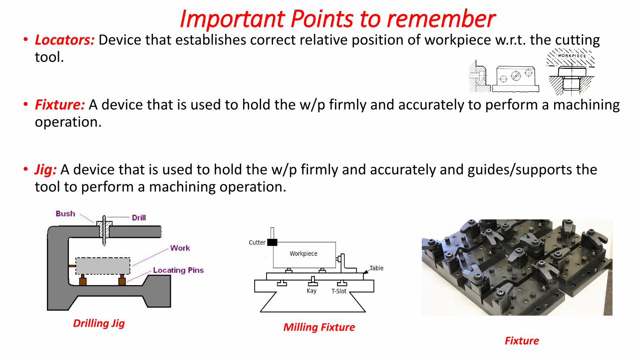
Important Points to remember• Locators: Device that establishes correct relative position of workpiece w.r.t. the cutting
tool.
• Fixture: A device that is used to hold the w/p firmly and accurately to perform a machining operation.
• Jig: A device that is used to hold the w/p firmly and accurately and guides/supports the tool to perform a machining operation.
Drilling Jig Milling FixtureFixture
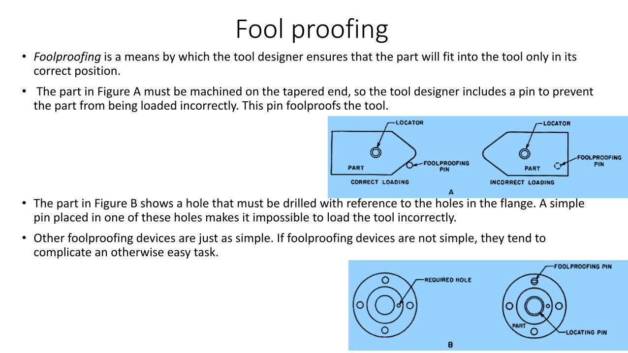
Fool proofing• Foolproofing is a means by which the tool designer ensures that the part will fit into the tool only in its
correct position.
• The part in Figure A must be machined on the tapered end, so the tool designer includes a pin to prevent the part from being loaded incorrectly. This pin foolproofs the tool.
• The part in Figure B shows a hole that must be drilled with reference to the holes in the flange. A simple pin placed in one of these holes makes it impossible to load the tool incorrectly.
• Other foolproofing devices are just as simple. If foolproofing devices are not simple, they tend to complicate an otherwise easy task.
Important Points to remember
1. Configuration is a major factor that determines the way of location of a w/p.
2. Configuration of a w/p is determined by a combination of flat, circular and
irregular surfaces.
3. Additionally, these surfaces may be rough or finished.
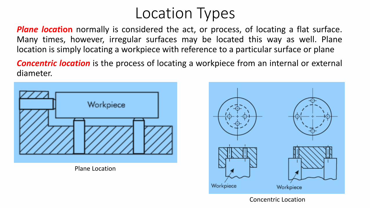
Location TypesPlane location normally is considered the act, or process, of locating a flat surface.Many times, however, irregular surfaces may be located this way as well. Planelocation is simply locating a workpiece with reference to a particular surface or plane
Concentric location is the process of locating a workpiece from an internal or externaldiameter.
Plane Location
Concentric Location
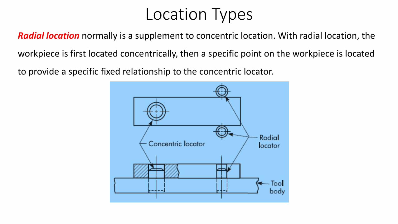
Location TypesRadial location normally is a supplement to concentric location. With radial location, the
workpiece is first located concentrically, then a specific point on the workpiece is located
to provide a specific fixed relationship to the concentric locator.
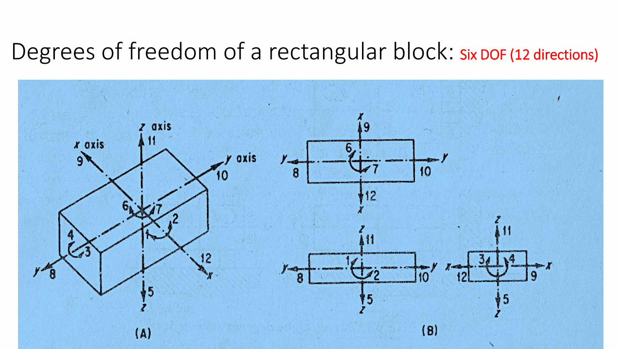
Degrees of freedom of a rectangular block: Six DOF (12 directions)
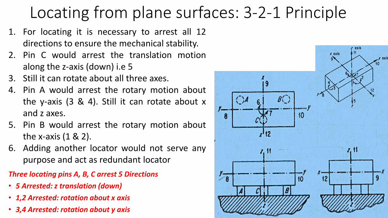
Locating from plane surfaces: 3-2-1 Principle
Three locating pins A, B, C arrest 5 Directions
• 5 Arrested: z translation (down)
• 1,2 Arrested: rotation about x axis
• 3,4 Arrested: rotation about y axis
1. For locating it is necessary to arrest all 12directions to ensure the mechanical stability.
2. Pin C would arrest the translation motionalong the z-axis (down) i.e 5
3. Still it can rotate about all three axes.4. Pin A would arrest the rotary motion about
the y-axis (3 & 4). Still it can rotate about xand z axes.
5. Pin B would arrest the rotary motion aboutthe x-axis (1 & 2).
6. Adding another locator would not serve anypurpose and act as redundant locator
Locating from plane surfaces: 3-2-1 Principle
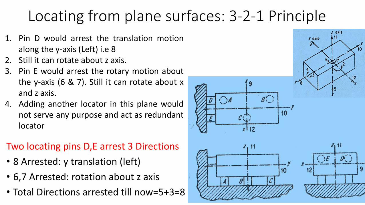
Two locating pins D,E arrest 3 Directions
• 8 Arrested: y translation (left)
• 6,7 Arrested: rotation about z axis
• Total Directions arrested till now=5+3=8
1. Pin D would arrest the translation motionalong the y-axis (Left) i.e 8
2. Still it can rotate about z axis.3. Pin E would arrest the rotary motion about
the y-axis (6 & 7). Still it can rotate about xand z axis.
4. Adding another locator in this plane wouldnot serve any purpose and act as redundantlocator
Locating from plane surfaces: 3-2-1 Principle
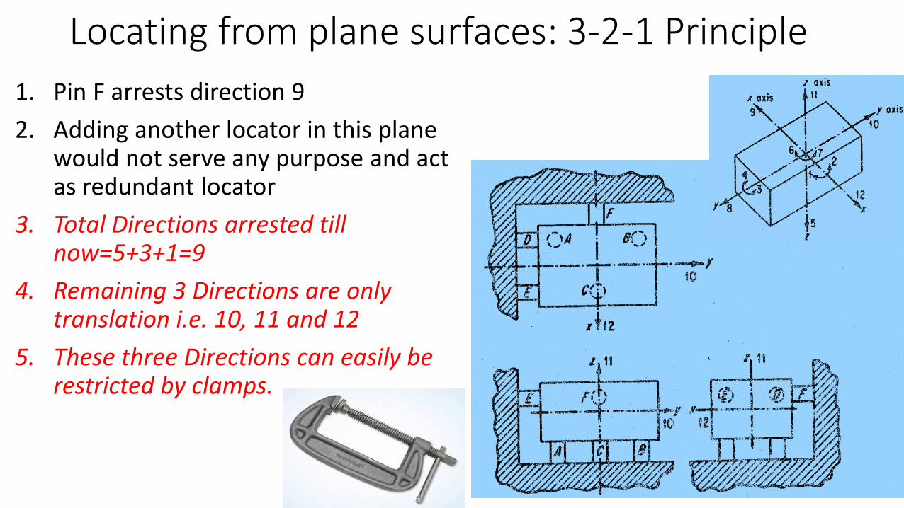
1. Pin F arrests direction 9
2. Adding another locator in this plane would not serve any purpose and act as redundant locator
3. Total Directions arrested till now=5+3+1=9
4. Remaining 3 Directions are only translation i.e. 10, 11 and 12
5. These three Directions can easily be restricted by clamps.
Locating from plane surfaces
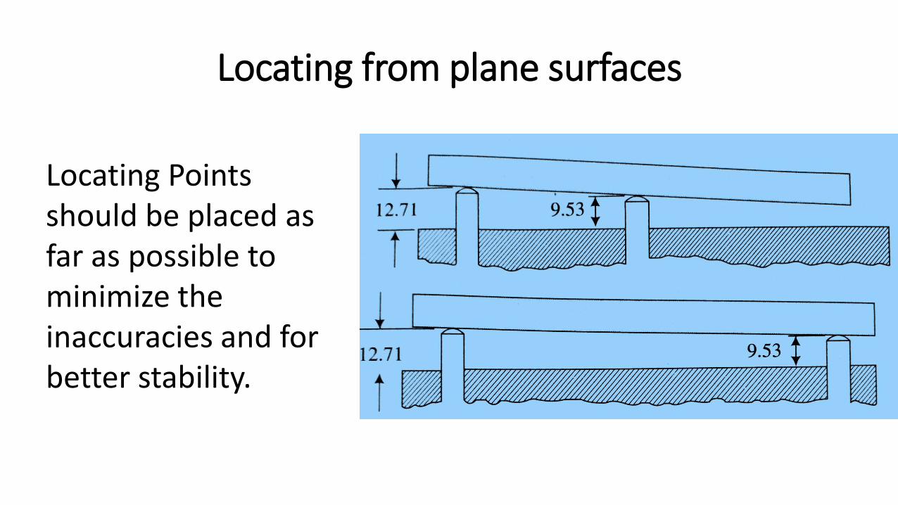
Locating Points should be placed as far as possible to minimize the inaccuracies and for better stability.
Locating from plane surfaces
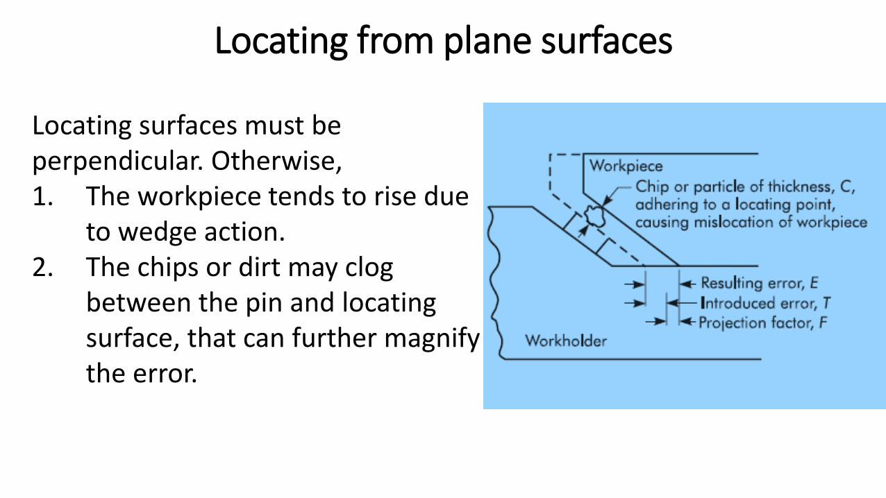
Locating surfaces must be perpendicular. Otherwise,1. The workpiece tends to rise due
to wedge action.2. The chips or dirt may clog
between the pin and locating surface, that can further magnify the error.
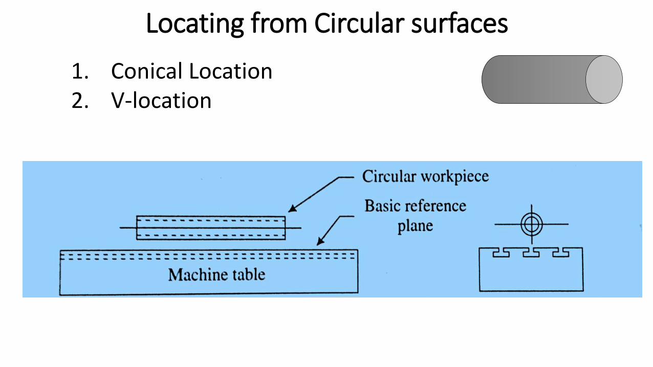
Locating from Circular surfaces
1. Conical Location2. V-location
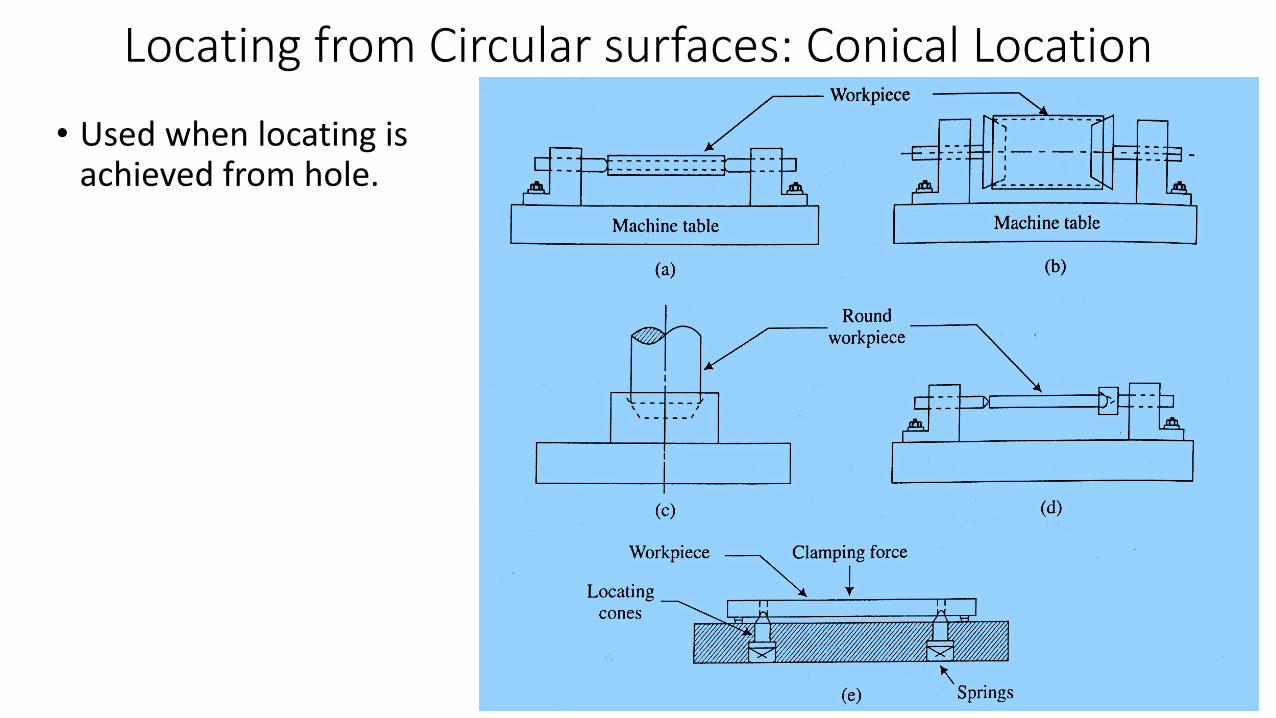
Locating from Circular surfaces: Conical Location
• Used when locating is achieved from hole.
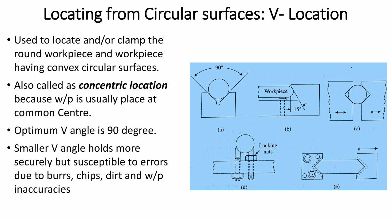
Locating from Circular surfaces: V- Location
• Used to locate and/or clamp the round workpiece and workpiece having convex circular surfaces.
• Also called as concentric locationbecause w/p is usually place at common Centre.
• Optimum V angle is 90 degree.
• Smaller V angle holds more securely but susceptible to errors due to burrs, chips, dirt and w/p inaccuracies
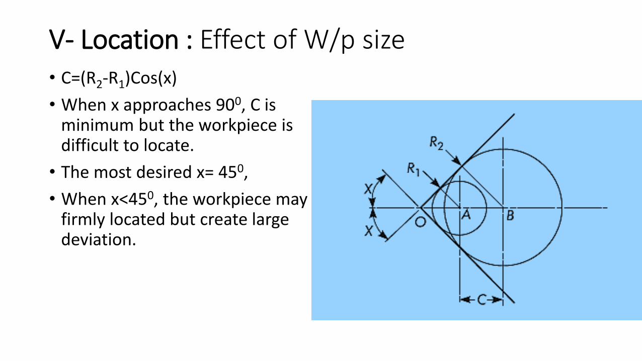
V- Location : Effect of W/p size• C=(R2-R1)Cos(x)
• When x approaches 900, C is minimum but the workpiece is difficult to locate.
• The most desired x= 450,
• When x<450, the workpiece may be firmly located but create large deviation.
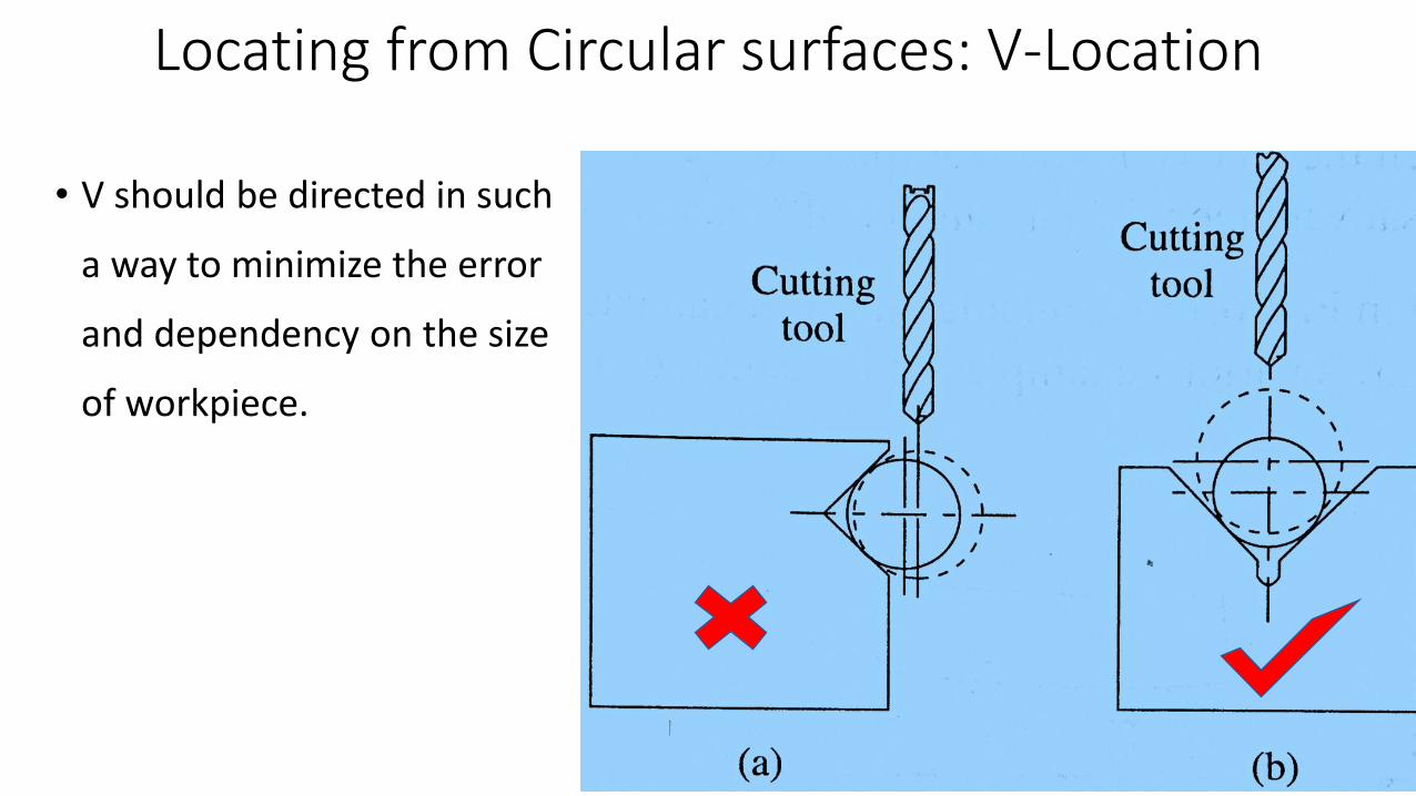
Locating from Circular surfaces: V-Location
• V should be directed in such
a way to minimize the error
and dependency on the size
of workpiece.
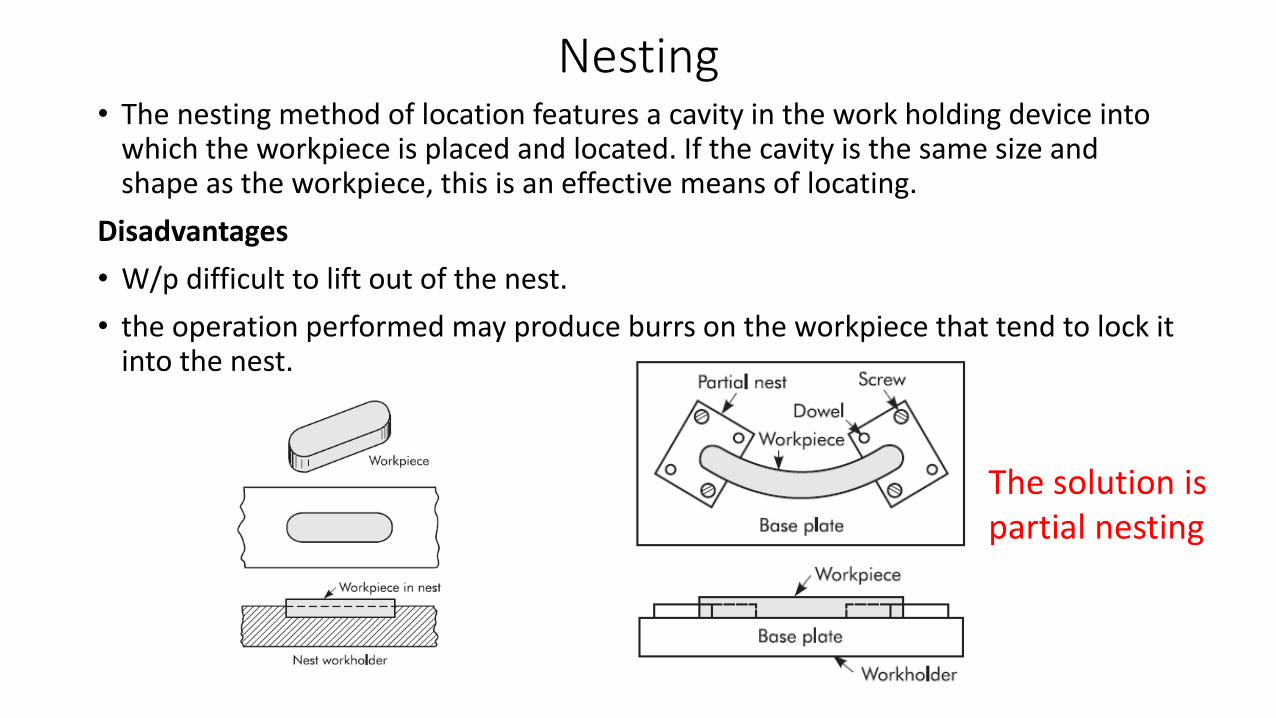
Nesting• The nesting method of location features a cavity in the work holding device into
which the workpiece is placed and located. If the cavity is the same size and shape as the workpiece, this is an effective means of locating.
Disadvantages
• W/p difficult to lift out of the nest.
• the operation performed may produce burrs on the workpiece that tend to lock it into the nest.
The solution is partial nesting
Adjustable locators: For locating the Irregular surfaces
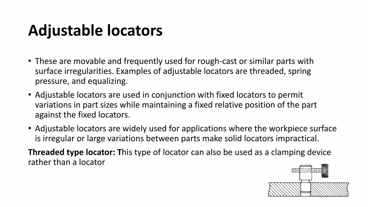
Adjustable locators
• These are movable and frequently used for rough-cast or similar parts with surface irregularities. Examples of adjustable locators are threaded, spring pressure, and equalizing.
• Adjustable locators are used in conjunction with fixed locators to permit variations in part sizes while maintaining a fixed relative position of the part against the fixed locators.
• Adjustable locators are widely used for applications where the workpiece surface is irregular or large variations between parts make solid locators impractical.
Threaded type locator: This type of locator can also be used as a clamping device rather than a locator
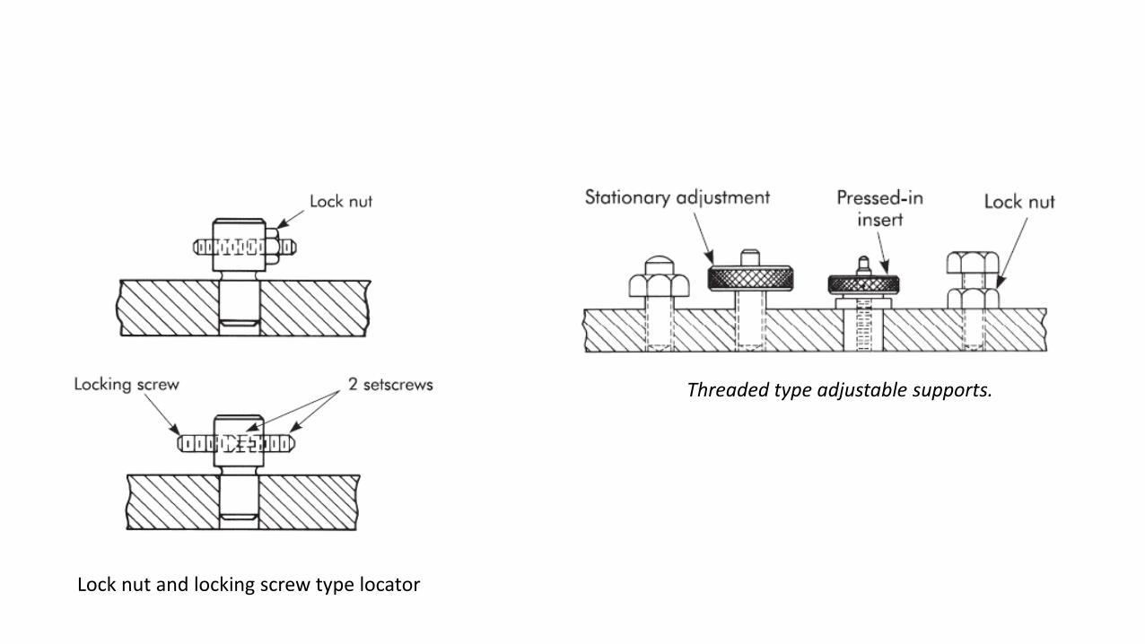
Lock nut and locking screw type locator
Threaded type adjustable supports.
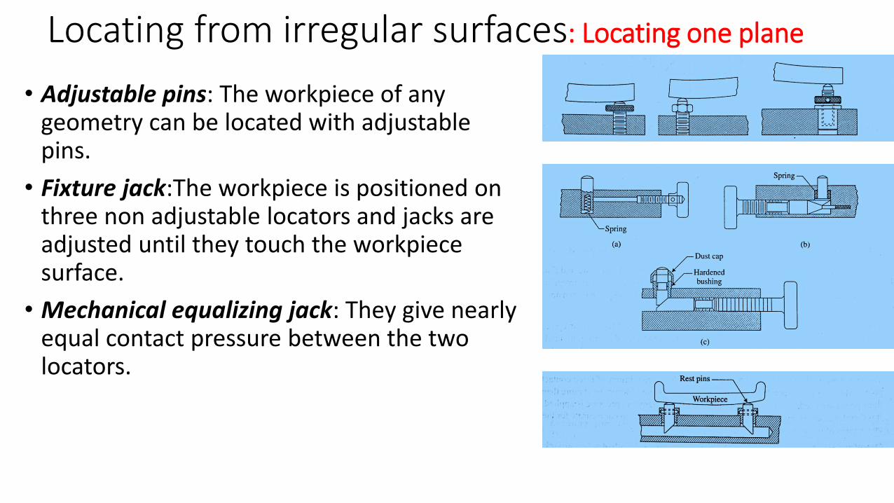
Locating from irregular surfaces: Locating one plane
• Adjustable pins: The workpiece of any geometry can be located with adjustable pins.
• Fixture jack:The workpiece is positioned on three non adjustable locators and jacks are adjusted until they touch the workpiece surface.
• Mechanical equalizing jack: They give nearly equal contact pressure between the two locators.
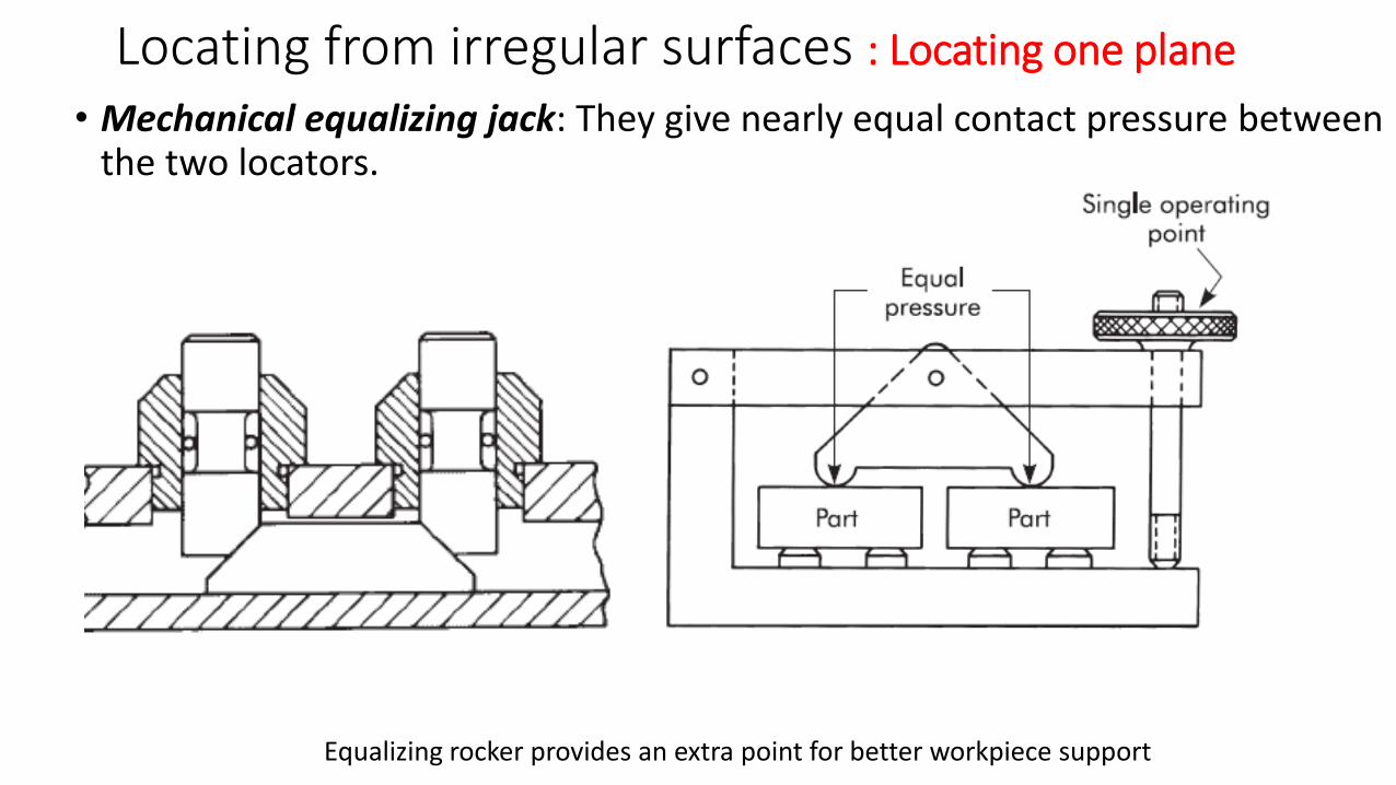
Locating from irregular surfaces : Locating one plane
• Mechanical equalizing jack: They give nearly equal contact pressure between the two locators.
Equalizing rocker provides an extra point for better workpiece support
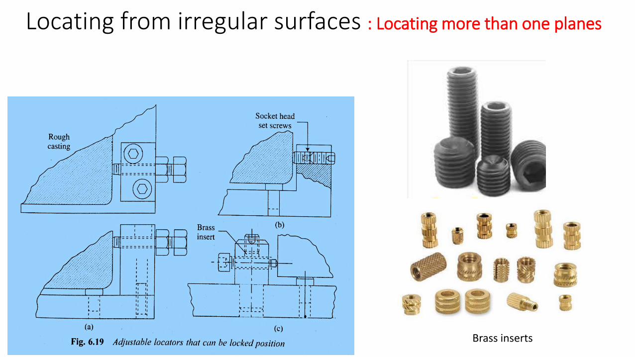
Locating from irregular surfaces : Locating more than one planes
Brass inserts
Locating from irregular surfaces : Locating more than one planes
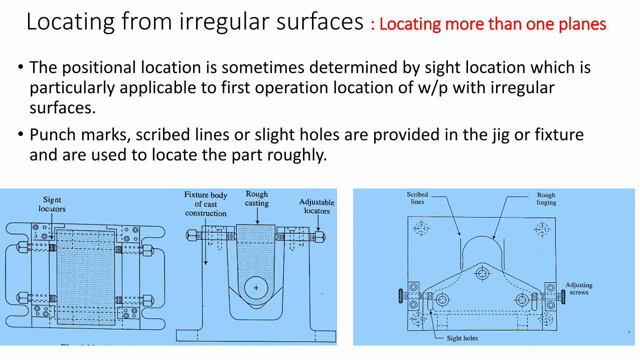
• The positional location is sometimes determined by sight location which is particularly applicable to first operation location of w/p with irregular surfaces.
• Punch marks, scribed lines or slight holes are provided in the jig or fixture and are used to locate the part roughly.
Brass inserts
Locating Methods and Devices
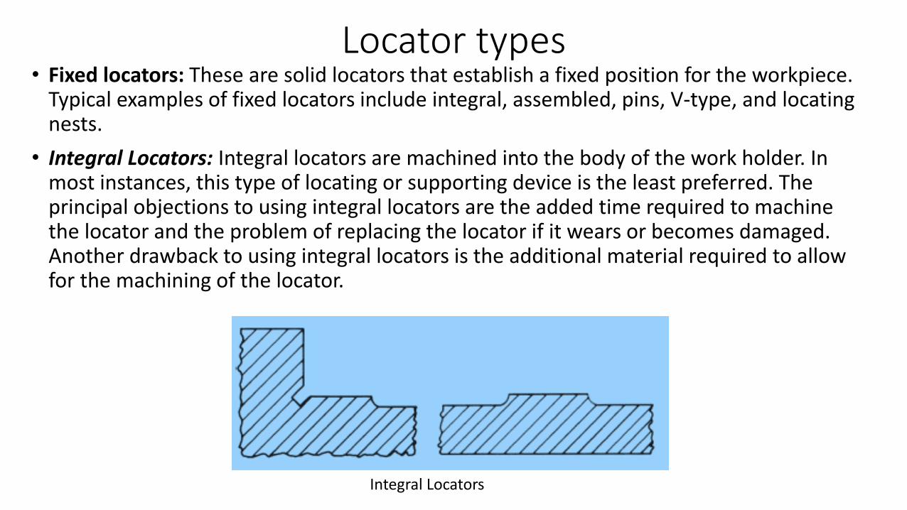
Locator types• Fixed locators: These are solid locators that establish a fixed position for the workpiece.
Typical examples of fixed locators include integral, assembled, pins, V-type, and locating nests.
• Integral Locators: Integral locators are machined into the body of the work holder. In most instances, this type of locating or supporting device is the least preferred. The principal objections to using integral locators are the added time required to machine the locator and the problem of replacing the locator if it wears or becomes damaged. Another drawback to using integral locators is the additional material required to allow for the machining of the locator.
Integral Locators
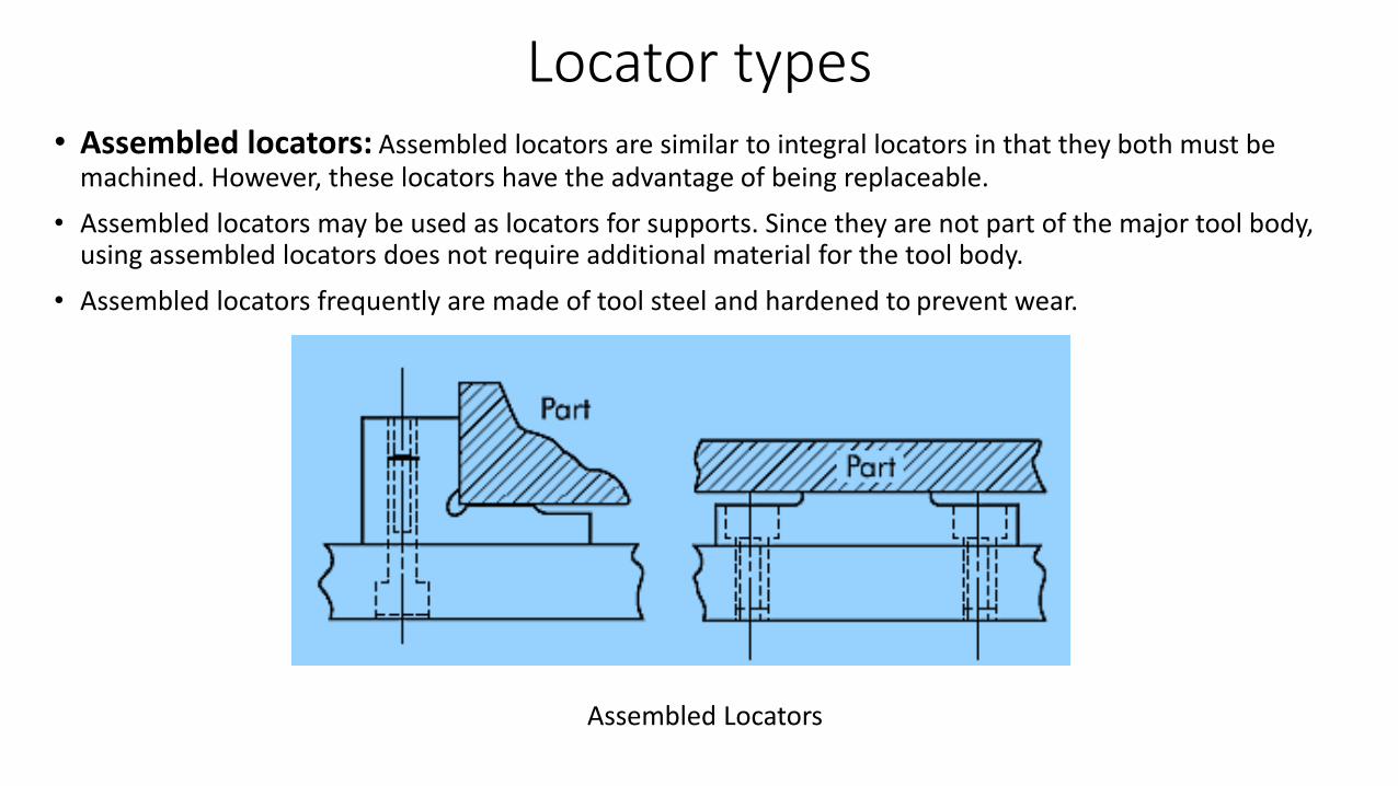
Locator types• Assembled locators: Assembled locators are similar to integral locators in that they both must be
machined. However, these locators have the advantage of being replaceable.
• Assembled locators may be used as locators for supports. Since they are not part of the major tool body, using assembled locators does not require additional material for the tool body.
• Assembled locators frequently are made of tool steel and hardened to prevent wear.
Assembled Locators
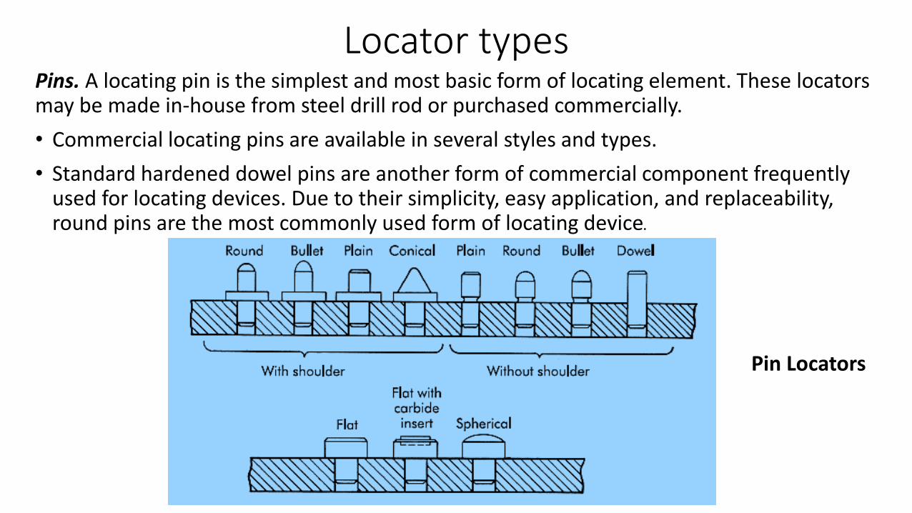
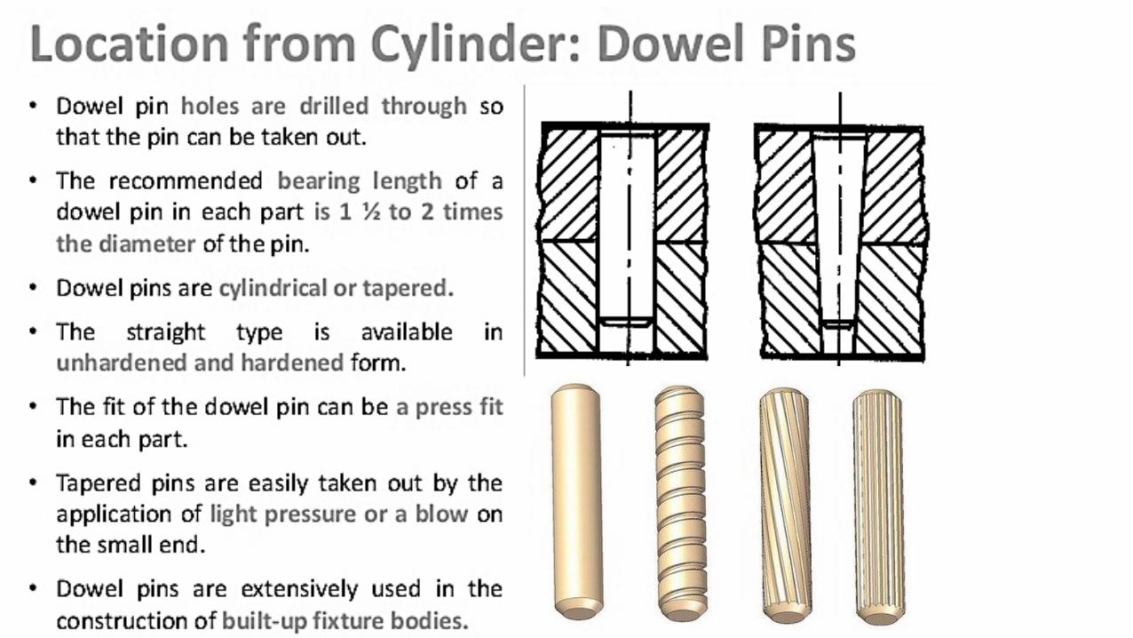
Locator typesPins. A locating pin is the simplest and most basic form of locating element. These locators may be made in-house from steel drill rod or purchased commercially.
• Commercial locating pins are available in several styles and types.
• Standard hardened dowel pins are another form of commercial component frequently used for locating devices. Due to their simplicity, easy application, and replaceability, round pins are the most commonly used form of locating device.
Pin Locators
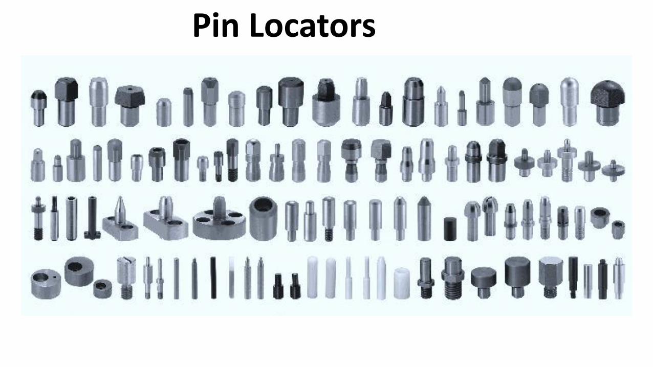
Pin Locators
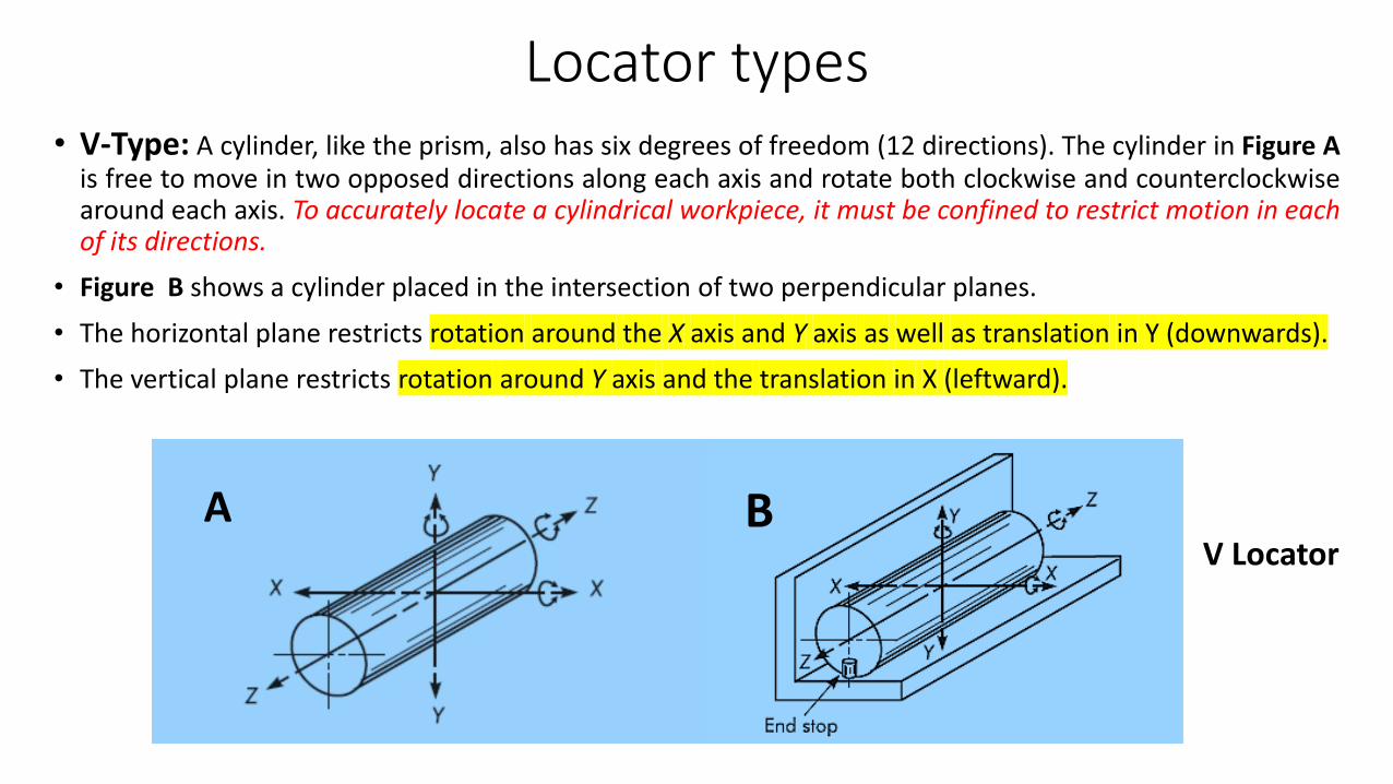
Locator types• V-Type: A cylinder, like the prism, also has six degrees of freedom (12 directions). The cylinder in Figure A
is free to move in two opposed directions along each axis and rotate both clockwise and counterclockwisearound each axis. To accurately locate a cylindrical workpiece, it must be confined to restrict motion in eachof its directions.
• Figure B shows a cylinder placed in the intersection of two perpendicular planes.
• The horizontal plane restricts rotation around the X axis and Y axis as well as translation in Y (downwards).
• The vertical plane restricts rotation around Y axis and the translation in X (leftward).
V LocatorA B
αα R2R1
C
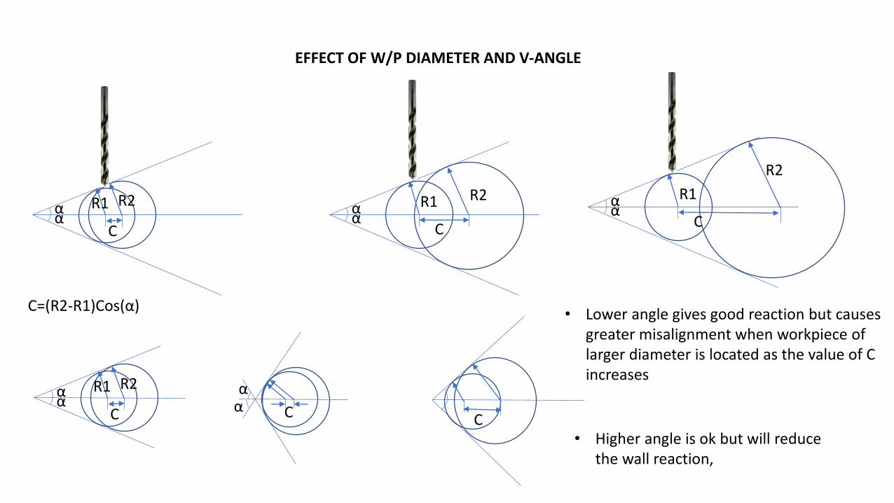
C=(R2-R1)Cos(α)
αα
R2R1
Cαα
R2
R1
C
αα R2R1
C αα
C C• Higher angle is ok but will reduce
the wall reaction,
• Lower angle gives good reaction but causes greater misalignment when workpiece of larger diameter is located as the value of C increases
EFFECT OF W/P DIAMETER AND V-ANGLE
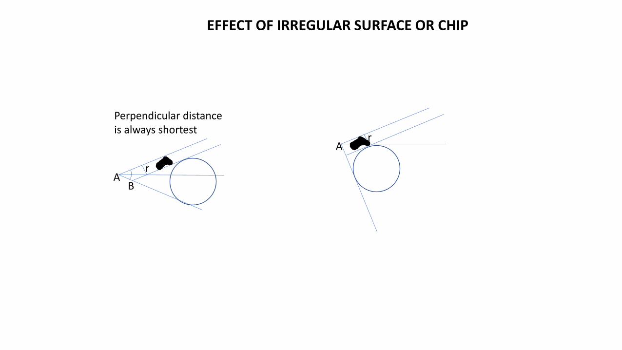
rA
B
Perpendicular distance is always shortest
EFFECT OF IRREGULAR SURFACE OR CHIP
rA
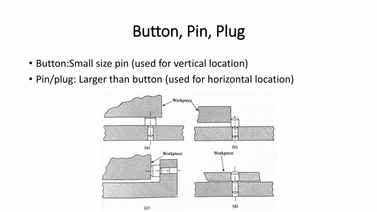
Button, Pin, Plug
• Button:Small size pin (used for vertical location)
• Pin/plug: Larger than button (used for horizontal location)
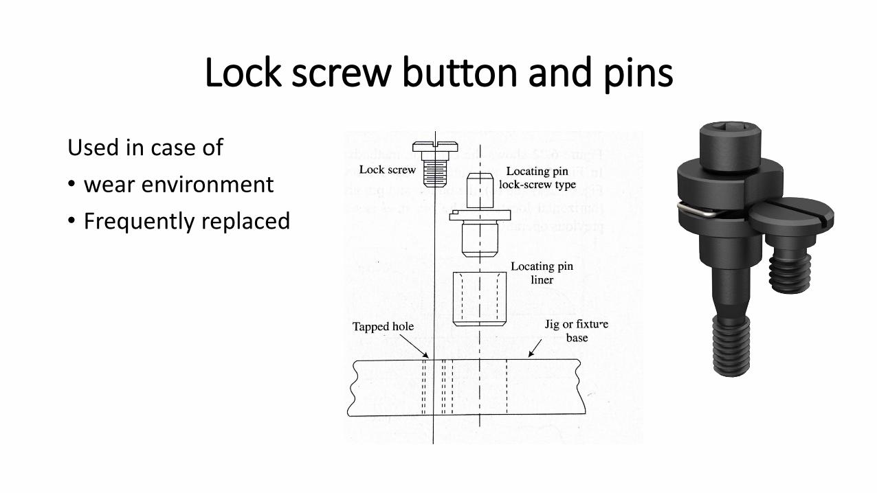
Lock screw button and pins
Used in case of
• wear environment
• Frequently replaced

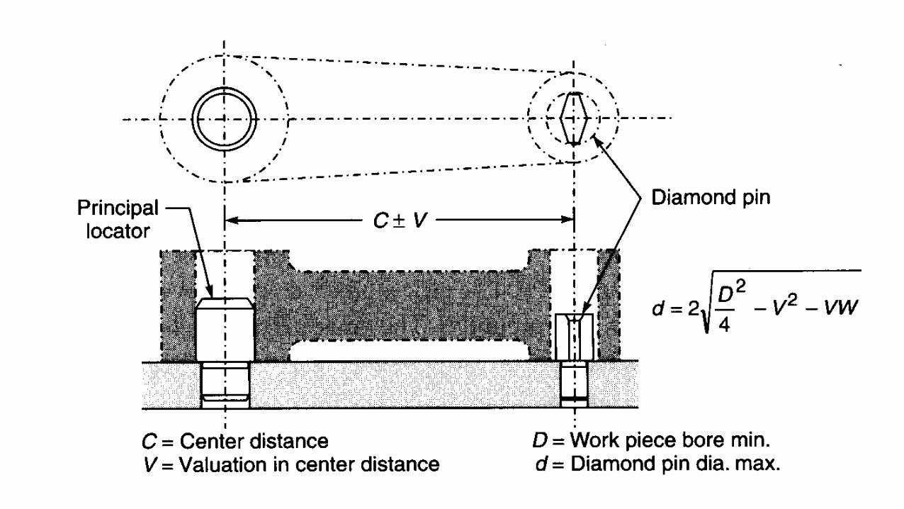
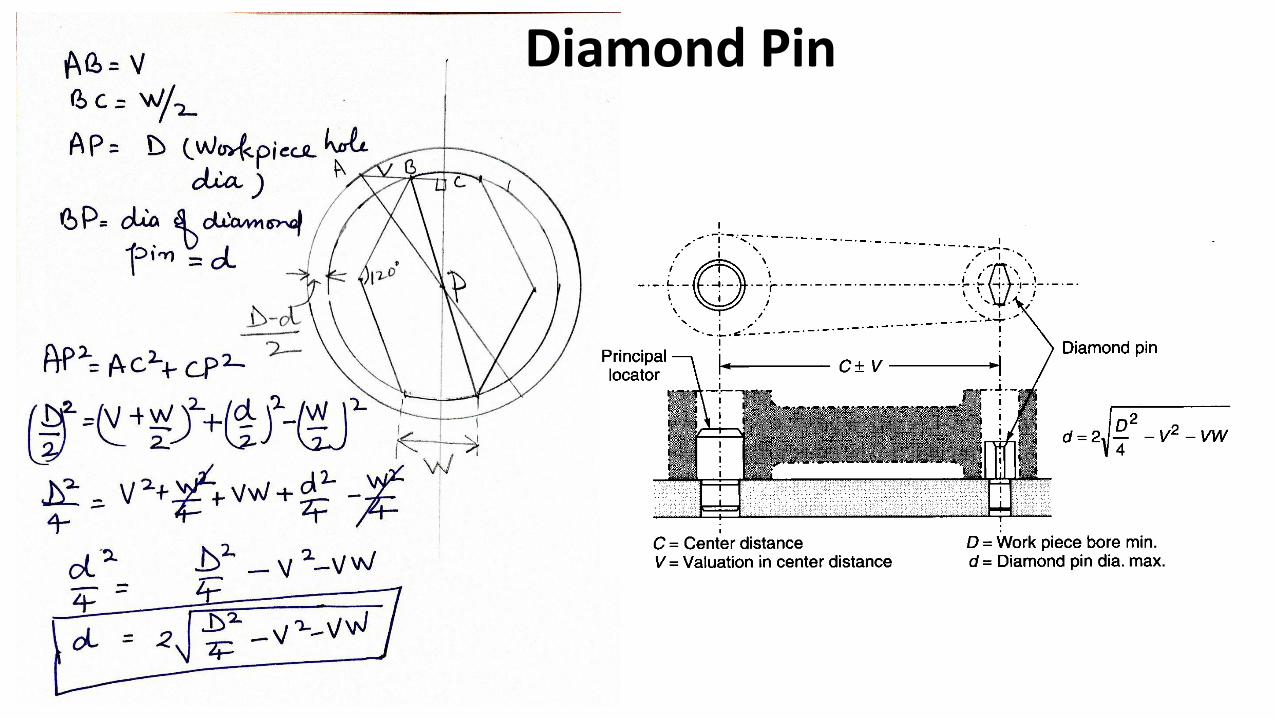
Diamond pins
•Diamond pins are used for radial location in conjunction with round locating pins.
• It is possible to accurately locate a workpiece with two round pins, but allowances must be made for the variations encountered in hole sizes and locations.
Diamond Pin
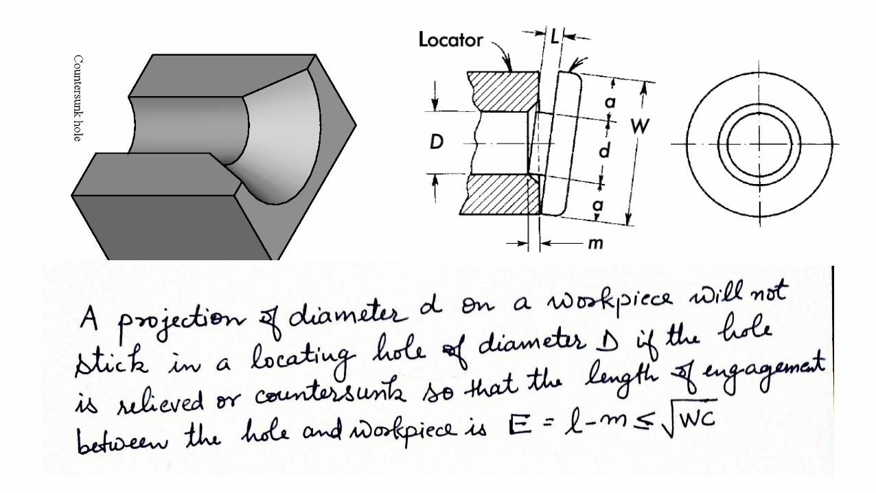
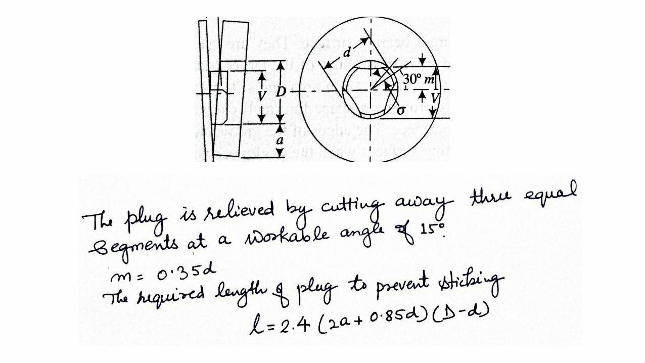
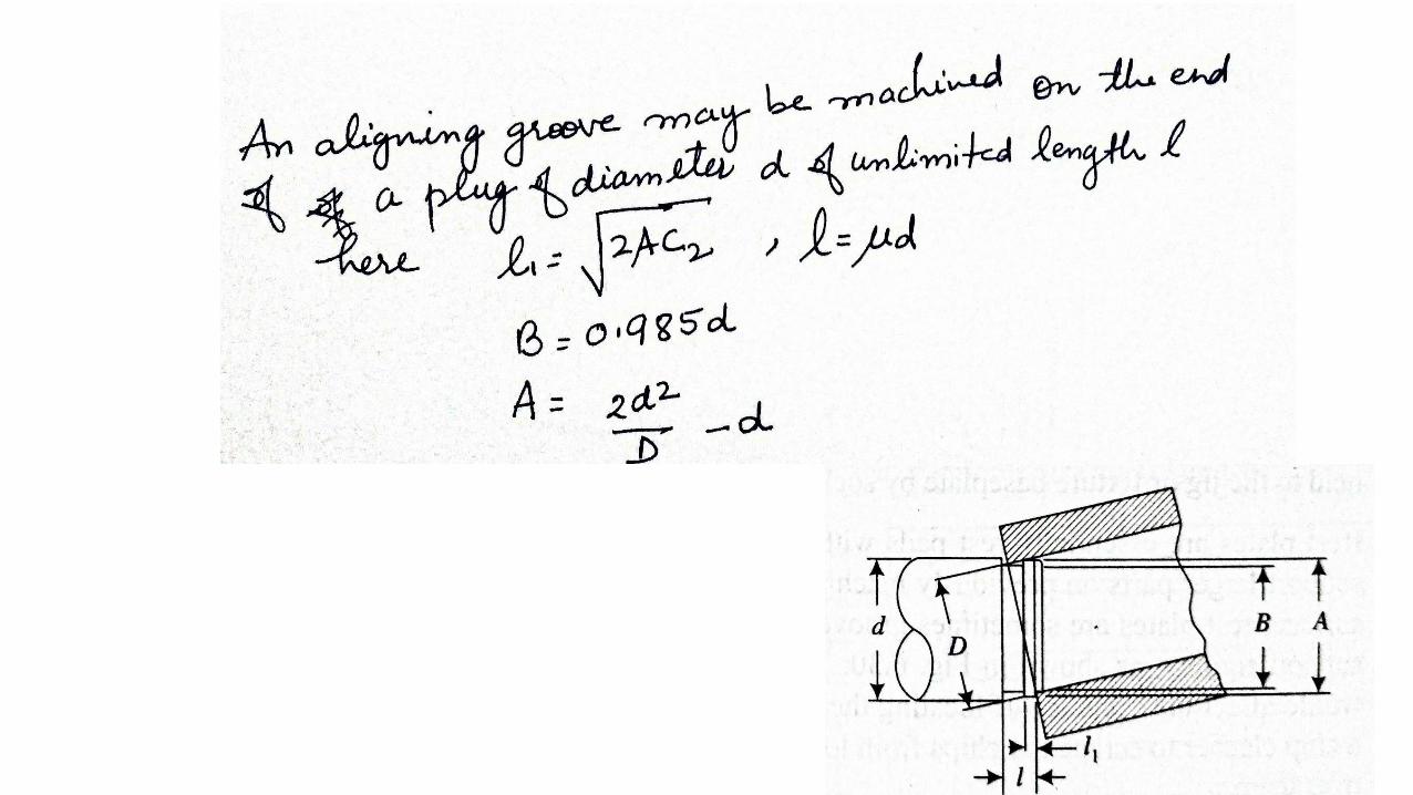
Design of non sticking plugs/pins
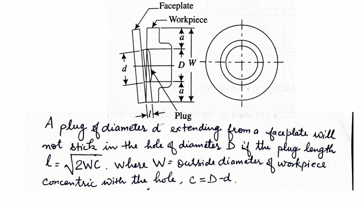
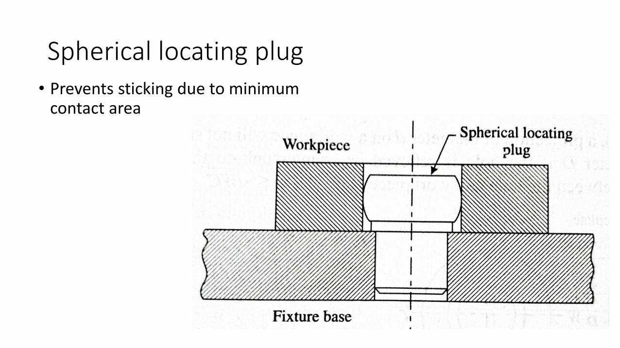
Spherical locating plug• Prevents sticking due to minimum
contact area
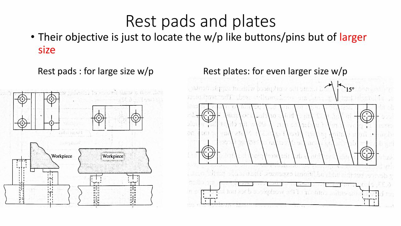
Rest pads and plates• Their objective is just to locate the w/p like buttons/pins but of larger
size
Rest pads : for large size w/p Rest plates: for even larger size w/p
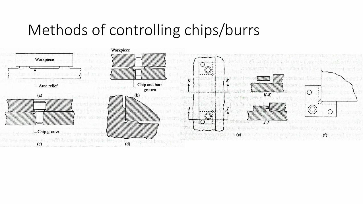
Methods of controlling chips/burrs


