Embed Size (px)
Citation preview
INTERNATIONAL CONFERENCE ON ENGINEERING DESIGN, ICED11 15 - 18 AUGUST 2011, TECHNICAL UNIVERSITY OF DENMARK
KNOWLEDGE CONFIGURATION MANAGEMENT FOR PRODUCT DESIGN AND NUMERICAL SIMULATION J. Badin(1,2), D. Monticolo(3), D. Chamoret(1), S. Gomes(1) 1 - Mechatronics, University of Technology UTBM, France 2 - Digital Product Simulation, France. 3 - ERPI Laboratory, National Polytechnic Institute of Lorraine, France.
ABSTRACT This paper focuses on industrial design and simulation processes especially in automotive and aerospace areas. Designers use business models (called expert models) such as CAD (Computed Aided Design) and CAE (Computed Aided Engineering) models to optimize and streamline the engineering process. Each expert model is driven by fine grained data (with knowledge encapsulated) such as parameters, expert rules, mathematic relations (parametric models, for example) which are shared by several users and in several different domains (mechanical, thermal, acoustic, fluid, etc) and exploited at the same time in a concurrent engineering context. It is the basis of an imperfect collaboration process due to the fact that existing tools do not manage encapsulated knowledge well and are unable to ensure that parameters and rules are consistent (same value of parameters for example) throughout different heterogeneous expert models. In this context, we propose an approach to manage knowledge using configurations synchronized with expert models which enable designers to use parameters consistently in a collaborative context. Our approach is called KCModel (Knowledge Configuration Model): it allows capitalization on, traceability, re-use and consistency of explicit knowledge used in configuration.
Keywords: Numerical simulation, Routine design, Concurrent engineering, Configuration management, Knowledge management
1 INTRODUCTION AND CONTEXT In this section, we browse the engineering process to identify design and simulation methods which are performed in product development. It allows fixing the problematic about using parameters and constraints in CAx model illustrated in the next section.
1.1 Product design Within the current economical and industrial context, companies would like to obtain a better cost control and to streamline their product design in order to reach the famous “cost/quality/delay” objectives [1] [2] [3]. It involves the development of new methods in design process [4] with the enhancement of concurrent engineering contexts [5] [6]. Indeed, the design process has evolved from sequential engineering [7] to parallel design activities and therefore the development of collaborative and shared contexts of information and data (parallel activities need to use and share information and data at the same time in the latest version). These developments were followed by a new design approach called KBD: Knowledge Based Design or more generally KBE: Knowledge Based Engineering [8] [9]. Thus, companies understood the advantages of capitalizing on and re-using knowledge in product development. Furthermore, nowadays, with the use of 3D geometrical product components in CAD files, engineers include parameters and expert rules to drive the geometry in CAD models through parametric and variational approaches (4D CAD [10]). The aim is to reduce routine design (80% of the estimated design process [11]), test a large range of product architectures, especially in the upstream phase of the design process and enhance the product quality with time and cost reduction. This is in accordance with DFX: the Design For X approach [12] which emphasizes the importance of considering the overall constraints of several design activities, and especially in the upstream phase of design process, to avoid major conflicts and to limit the redesign cycle. Although the design process has evolved, the numerical simulations have also evolved considerably to become a key area in product design. Initially
used at the end of the design process as validation or presentation of activities, simulation is currently used in the overall design process and especially in the upstream phase (trade-off, pre-sizing) using CAD/CAE integration and parametric models.
1.2 Numerical simulation Nowadays it seems as necessary to use numerical simulation to lead the way to innovation. In the early design phases numerical simulation allows for the management of a better and quicker design [13] [14]. This is particularly true in the area of mechatronics systems (combination of synergistic and systemic Mechanical, Electronic, Computer, Control, and Systems Design engineering) and specifically in the automotive and aerospace industry. Mechatronics is rapidly evolving towards a numerical simulation driven design approach which integrates increasingly complex models and simulations in various areas of expertise. Numerical simulation driven design leads to many heterogeneous computational models which interact with each other. The large amount of miscellaneous information handled in this process, combined with the low level of interconnection between modeling and simulation software tools, often leads to data discrepancy and inconsistency [15]. Indeed there is a gap between designers and analysts. Moreover, data and information are often scattered and duplicated, thus preventing data consistency, traceability, and re-use, and inhibiting the following of design step sequence. This situation prevents companies from turning the information and know-how embedded in their geometric and simulation models into a shared structured knowledge that can be capitalized on[16] [17].
2 SHARING PARAMETERS AND EXPERTS RULES THROUGH SEVERAL CAD AND CAE MODELS CAD and CAE models used in upstream design activity enable linking between the geometrical design and numerical simulation to construct “workbenches” dedicated to specific product components and physical domains (e.g. the thermal piston workbench, the CFD1 cylinder-block workbench, etc.). The workbench allows engineers to test several component architectures very quickly and identify the main design concepts. It is an iterative process during which engineers modify parameters and expert rules encapsulated in CAD/CAE files, which are considered as fine granularity data or knowledge2
The entire workbenches (also called expert models) are very different and heterogeneous because they are used in a large diversity of practice, with a diversity of tools, in a diversity of physical domains and moments in the design process. The expert models are based on various geometric representations with the advantage of product representations tailored to each individual situation. However, they introduce many difficulties in piloting, maintenance, consistency and access to the valid information, which all make them cumbersome to use and hence inhibit innovation. Thus the knowledge encapsulated in each expert model can potentially be used by another one and so has to be shared and coherent. Today, it often happens that calculations are started using the wrong parameter configuration in different workbenches on related parts, which leads to a greater or lesser loss of time and money depending on the moment of discovery of the error.
.
Thus our problematic is focused parameters and constraint encapsulated in CAx models which need to be exchanged and consistent in the design process. We identify four categories to describe the problem (Figure 1); they are called CTRC for Capitalization on, Traceability, Re-use, and Consistency. Several workbenches are used at the same time in a concurrent engineering context. Every CAD or CAE model encapsulates knowledge as parameters and rules which need to be shared and coherent throughout design and simulation activities (during iterative and dynamic modification process). The first problem is focused on parameters and rules Capitalization: they are capitalized on in each individual model unit, thus causing duplication and bad lifecycle management. Parameters and rules need to have their own life cycle independent from the model lifecycle. Next come Traceability problems: if the capitalization is not efficient, it is very difficult to follow the development of the parameters. It is impossible to know when the parameter is used, by whom, during what design activity, why, etc. Moreover, engineers do not have any history of the modifications.
1 CFD : Computational Fluid Dynamic 2 Knowledge definition: Information corresponds to any data likely to take a particular meaning for an individual. Information is transformed into knowledge when an individual understands its necessity for an activity [18].
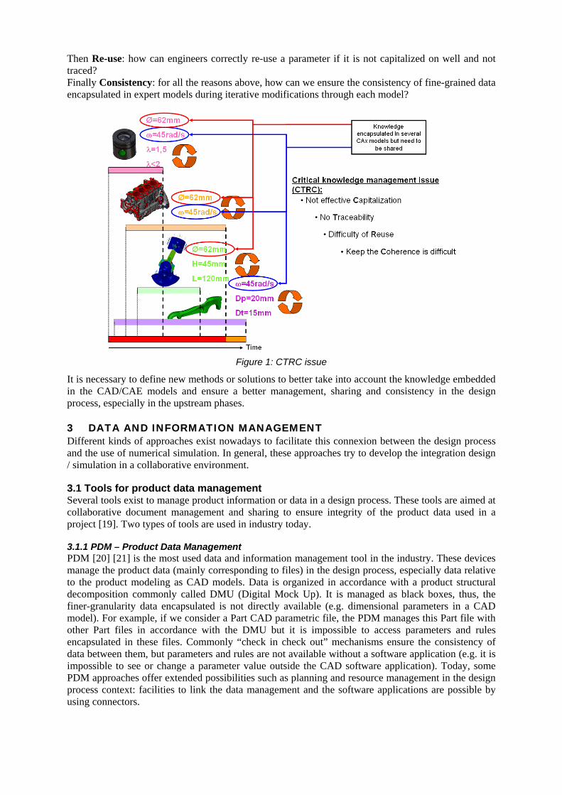
Then Re-use: how can engineers correctly re-use a parameter if it is not capitalized on well and not traced? Finally Consistency: for all the reasons above, how can we ensure the consistency of fine-grained data encapsulated in expert models during iterative modifications through each model?
Figure 1: CTRC issue
It is necessary to define new methods or solutions to better take into account the knowledge embedded in the CAD/CAE models and ensure a better management, sharing and consistency in the design process, especially in the upstream phases.
3 DATA AND INFORMATION MANAGEMENT Different kinds of approaches exist nowadays to facilitate this connexion between the design process and the use of numerical simulation. In general, these approaches try to develop the integration design / simulation in a collaborative environment.
3.1 Tools for product data management Several tools exist to manage product information or data in a design process. These tools are aimed at collaborative document management and sharing to ensure integrity of the product data used in a project [19]. Two types of tools are used in industry today.
3.1.1 PDM – Product Data Management PDM [20] [21] is the most used data and information management tool in the industry. These devices manage the product data (mainly corresponding to files) in the design process, especially data relative to the product modeling as CAD models. Data is organized in accordance with a product structural decomposition commonly called DMU (Digital Mock Up). It is managed as black boxes, thus, the finer-granularity data encapsulated is not directly available (e.g. dimensional parameters in a CAD model). For example, if we consider a Part CAD parametric file, the PDM manages this Part file with other Part files in accordance with the DMU but it is impossible to access parameters and rules encapsulated in these files. Commonly “check in check out” mechanisms ensure the consistency of data between them, but parameters and rules are not available without a software application (e.g. it is impossible to see or change a parameter value outside the CAD software application). Today, some PDM approaches offer extended possibilities such as planning and resource management in the design process context: facilities to link the data management and the software applications are possible by using connectors.
3.1.2 SDM – Simulation Data Management SDM are newer tools which have emerged only in recent years in industry [22]. They are more specialized in numerical simulation data because specific needs may occur for which PDM is inefficient. • First the data lifecycle: the simulation data has a specific lifecycle different from the product
data lifecycle and so, a PDM cannot manage both lifecycles together at the same time. • Next, the simulation file size is much larger than a CAD model with several calculation output
types (several Go. each time). • Then, the simulation involves specific workflow, that does not really exist in CAD and which
must be considered as data management (some information can be considered as an input or output in several contexts).
• The simulation data cannot be easily structured in DMU and a specific organization is needed, especially in upstream phases of the design process where CAE models can be used although no CAD models exist yet.
• Finally, Simulation data needs to be linked with a range of heterogeneous simulation tools not taken into account by PDM, especially because CAD models are often used only in design software.
3.1.3 New additional requirements when using PDM and SDM systems If PDM and SDM tools are commonly used in industry, there are some shortfalls in managing fine- grained data such as parameters or rules, considered as knowledge encapsulated in each CAD or CAE model. Data managed by these tools mainly corresponds to files considered as being black boxes. Pikosz [23] highlights this limit in PDM systems, which only manage documents via metadata and cannot access the knowledge they encapsulate. This knowledge, of a more refined level of granularity than that of a file, is therefore outside the scope of control [17]. Some research projects [24] [25] have tried to link parameters and rule databases in PDM but problems still exist because they are much more oriented and linked with product data organized in the DMU. Thus, it is necessary to define new ways or tools that manage parameters and rules in addition to using PDM or SDM systems. This new approach must be oriented towards capitalization, traceability, re-use, and consistency of parameters and rules to give them their own structure and lifecycle in the design process.
3.2 Configuration management Configuration management is a field of management that focuses on establishing and maintaining consistency of a system's or product's performance and its functional and physical attributes with its requirements, design, and operational information throughout its lifecycle [26]. Configuration management is defined first in ISO 10007:1995 [27] and next in ISO 10007:2003 [28] releases: • Configuration:
•
interrelated functional and physical characteristics of a product defined in product configuration information. Product configuration information:
In product configuration information, requirements are simplistic terms which can be understood in the same way as all the technical information, tools, documents or expert models used in product design process. Thus, a product configuration ensures the consistency through the design process by managing configuration information organized into “Configuration Items”. All the configuration items must be coherent over all the design process following the evolution into an iterative process and keep traceability of any changes.
requirements for the design, implementation, verification and support of a product.
Configuration management can be particularly interesting to manage parameters and rules used in several expert models. That can give some ways to keep the consistency control and traceability between parameters shared through CAD and CAE models. An iterative process taking account into configuration management, is in accordance with iterative engineer’s changes in CAD and CAE models. This allows for engineers to converge to a single coherent product definition avoiding errors, and so, reducing development time and cost. Moreover, allowing for communication between several heterogeneous expert models is very difficult, but allowing for communication between several configurations including parameters and rules is easier and promotes inter-operability between expert models in the design process.
As part of our research, we propose to manage parameters and rules in configurations contextualized and synchronized with expert models.
4 KCMODEL METHOD The aim of our research is to propose a new tool which helps users to ensure data, information, and knowledge consistency when shared in several and heterogeneous experts CAD and CAE models. This tool will focus on a new generic approach called KCModel: “Knowledge Configuration Model” based on knowledge configurations synchronized with expert models [16]. KCModel is formalized into meta-models in UML Language. In this paper we do not present meta-models but the KCModel methodology. In the context of KCModel, we consider as: • technical data, the parameters and expert rules extracted from experts models, • information, the data capitalized on, structured and organized into a specific entity to construct
a technical and generic product information baseline, • knowledge, a set of technical product information entities instantiated from the baseline in a
configuration used in specific design or simulation activity. This configuration is synchronized with a specific CAD or CAE model.
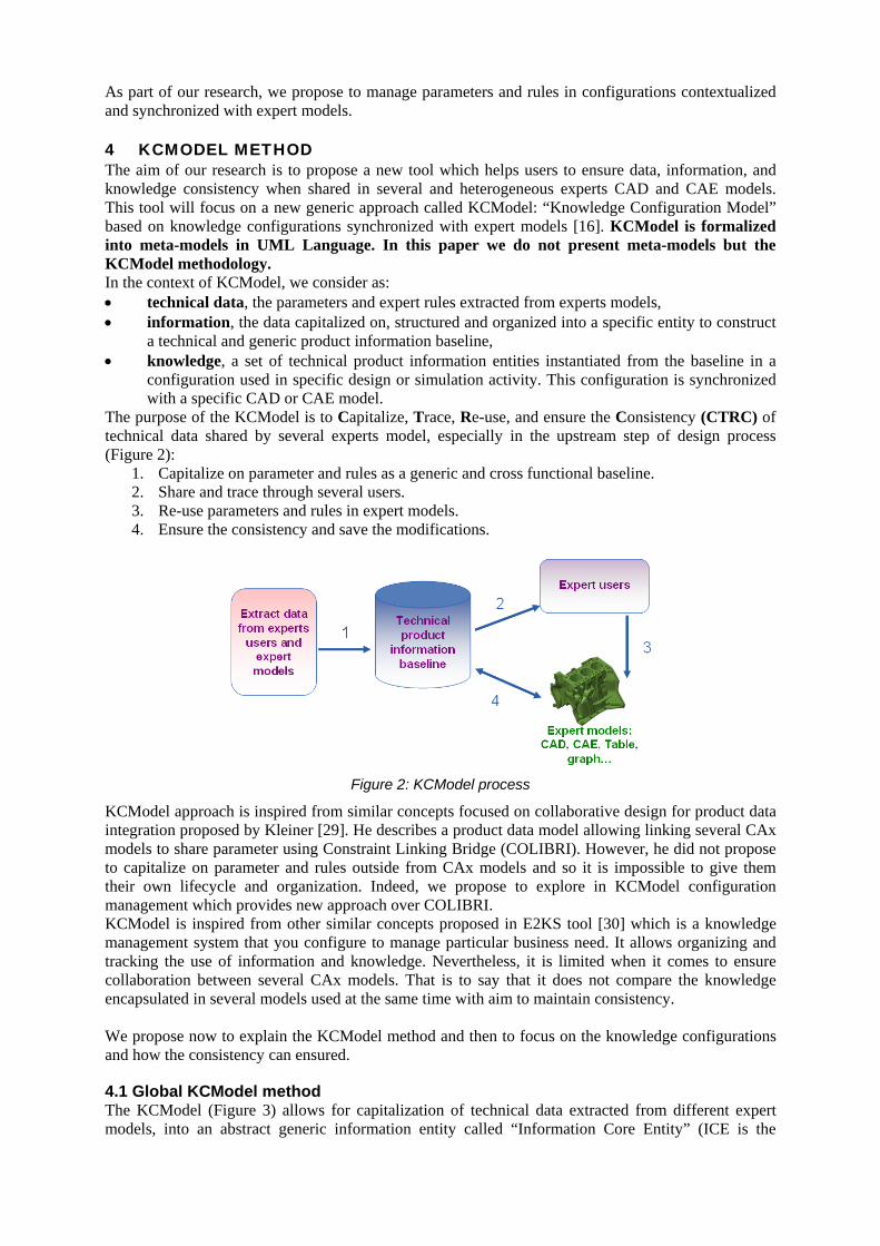
The purpose of the KCModel is to Capitalize, Trace, Re-use, and ensure the Consistency (CTRC) of technical data shared by several experts model, especially in the upstream step of design process (Figure 2):
1. Capitalize on parameter and rules as a generic and cross functional baseline. 2. Share and trace through several users. 3. Re-use parameters and rules in expert models. 4. Ensure the consistency and save the modifications.
Figure 2: KCModel process
KCModel approach is inspired from similar concepts focused on collaborative design for product data integration proposed by Kleiner [29]. He describes a product data model allowing linking several CAx models to share parameter using Constraint Linking Bridge (COLIBRI). However, he did not propose to capitalize on parameter and rules outside from CAx models and so it is impossible to give them their own lifecycle and organization. Indeed, we propose to explore in KCModel configuration management which provides new approach over COLIBRI. KCModel is inspired from other similar concepts proposed in E2KS tool [30] which is a knowledge management system that you configure to manage particular business need. It allows organizing and tracking the use of information and knowledge. Nevertheless, it is limited when it comes to ensure collaboration between several CAx models. That is to say that it does not compare the knowledge encapsulated in several models used at the same time with aim to maintain consistency. We propose now to explain the KCModel method and then to focus on the knowledge configurations and how the consistency can ensured.
4.1 Global KCModel method The KCModel (Figure 3) allows for capitalization of technical data extracted from different expert models, into an abstract generic information entity called “Information Core Entity” (ICE is the
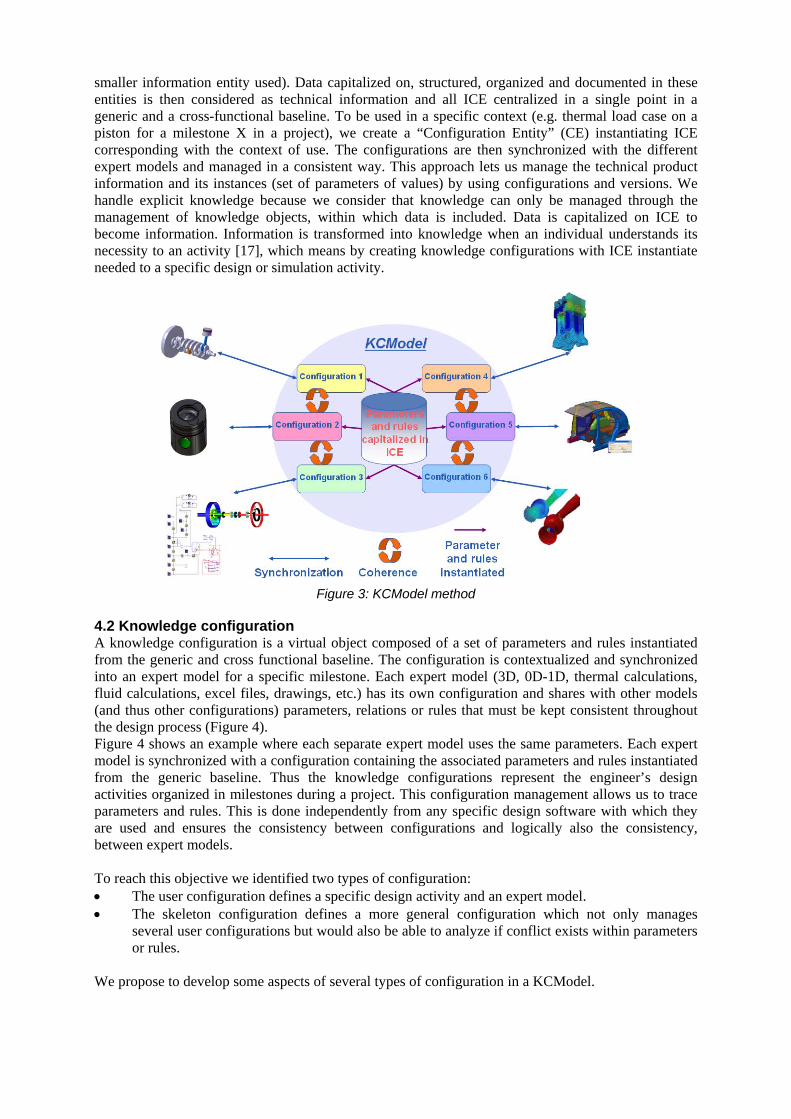
smaller information entity used). Data capitalized on, structured, organized and documented in these entities is then considered as technical information and all ICE centralized in a single point in a generic and a cross-functional baseline. To be used in a specific context (e.g. thermal load case on a piston for a milestone X in a project), we create a “Configuration Entity” (CE) instantiating ICE corresponding with the context of use. The configurations are then synchronized with the different expert models and managed in a consistent way. This approach lets us manage the technical product information and its instances (set of parameters of values) by using configurations and versions. We handle explicit knowledge because we consider that knowledge can only be managed through the management of knowledge objects, within which data is included. Data is capitalized on ICE to become information. Information is transformed into knowledge when an individual understands its necessity to an activity [17], which means by creating knowledge configurations with ICE instantiate needed to a specific design or simulation activity.
Figure 3: KCModel method
4.2 Knowledge configuration A knowledge configuration is a virtual object composed of a set of parameters and rules instantiated from the generic and cross functional baseline. The configuration is contextualized and synchronized into an expert model for a specific milestone. Each expert model (3D, 0D-1D, thermal calculations, fluid calculations, excel files, drawings, etc.) has its own configuration and shares with other models (and thus other configurations) parameters, relations or rules that must be kept consistent throughout the design process (Figure 4). Figure 4 shows an example where each separate expert model uses the same parameters. Each expert model is synchronized with a configuration containing the associated parameters and rules instantiated from the generic baseline. Thus the knowledge configurations represent the engineer’s design activities organized in milestones during a project. This configuration management allows us to trace parameters and rules. This is done independently from any specific design software with which they are used and ensures the consistency between configurations and logically also the consistency, between expert models. To reach this objective we identified two types of configuration: • The user configuration defines a specific design activity and an expert model. • The skeleton configuration defines a more general configuration which not only manages
several user configurations but would also be able to analyze if conflict exists within parameters or rules.
We propose to develop some aspects of several types of configuration in a KCModel.
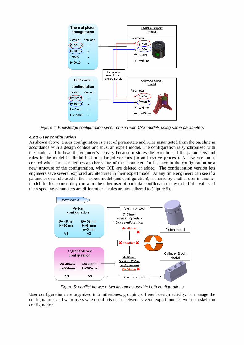
Figure 4: Knowledge configuration synchronized with CAx models using same parameters
4.2.1 User configuration As shown above, a user configuration is a set of parameters and rules instantiated from the baseline in accordance with a design context and thus, an expert model. The configuration is synchronized with the model and follows the engineer’s activity because it stores the evolution of the parameters and rules in the model in diminished or enlarged versions (in an iterative process). A new version is created when the user defines another value of the parameter, for instance in the configuration or a new structure of the configuration, when ICE are deleted or added. The configuration version lets engineers save several explored architectures in their expert model. At any time engineers can see if a parameter or a rule used in their expert model (and configuration), is shared by another user in another model. In this context they can warn the other user of potential conflicts that may exist if the values of the respective parameters are different or if rules are not adhered to (Figure 5).
Figure 5: conflict between two instances used in both configurations
User configurations are organized into milestones, grouping different design activity. To manage the configurations and warn users when conflicts occur between several expert models, we use a skeleton configuration.
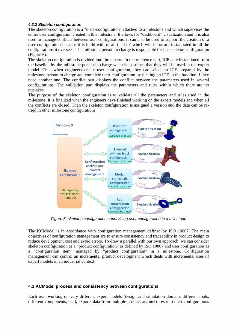
4.2.2 Skeleton configuration The skeleton configuration is a "meta-configuration" attached to a milestone and which supervises the entire user configuration created in this milestone. It allows for “dashboard” visualization and it is also used to manage conflicts between user configurations. It can also be used to support the creation of a user configuration because it is build with of all the ICE which will be or are instantiated in all the configurations it oversees. The milestone person in charge is responsible for the skeleton configuration (Figure 6). The skeleton configuration is divided into three parts. In the reference part, ICEs are instantiated from the baseline by the milestone person in charge when he assumes that they will be used in the expert model. Thus when engineers create user configuration, they can select an ICE prepared by the milestone person in charge and complete their configuration by picking an ICE in the baseline if they need another one. The conflict part displays the conflict between the parameters used in several configurations. The validation part displays the parameters and rules within which there are no mistakes. The purpose of the skeleton configuration is to validate all the parameters and rules used in the milestone. It is finalized when the engineers have finished working on the expert models and when all the conflicts are closed. Then the skeleton configuration is assigned a version and the data can be re-used in other milestone configurations.
Figure 6: skeleton configuration supervising user configuration in a milestone
The KCModel is in accordance with configuration management defined by ISO 10007. The main objectives of configuration management are to ensure consistency and traceability in product design to reduce development cost and avoid errors. To draw a parallel with our own approach, we can consider skeleton configuration as a “product configuration” as defined by ISO 10007 and user configuration as a “configuration item” managed by “product configuration” in a milestone. Configuration management can control an incremental product development which deals with incremental uses of expert models in an industrial context.
4.3 KCModel process and consistency between configurations Each user working on very different expert models (design and simulation domain, different tools, different components, etc.), exports data from multiple product architectures into their configurations
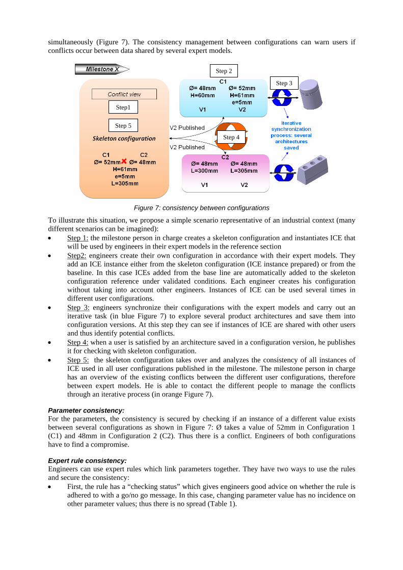
simultaneously (Figure 7). The consistency management between configurations can warn users if conflicts occur between data shared by several expert models.
Figure 7: consistency between configurations
To illustrate this situation, we propose a simple scenario representative of an industrial context (many different scenarios can be imagined): • Step 1:
•
the milestone person in charge creates a skeleton configuration and instantiates ICE that will be used by engineers in their expert models in the reference section Step2:
•
engineers create their own configuration in accordance with their expert models. They add an ICE instance either from the skeleton configuration (ICE instance prepared) or from the baseline. In this case ICEs added from the base line are automatically added to the skeleton configuration reference under validated conditions. Each engineer creates his configuration without taking into account other engineers. Instances of ICE can be used several times in different user configurations. Step 3:
Figure 7 engineers synchronize their configurations with the expert models and carry out an
iterative task (in blue ) to explore several product architectures and save them into configuration versions. At this step they can see if instances of ICE are shared with other users and thus identify potential conflicts.
• Step 4:
•
when a user is satisfied by an architecture saved in a configuration version, he publishes it for checking with skeleton configuration. Step 5:
Figure 7
the skeleton configuration takes over and analyzes the consistency of all instances of ICE used in all user configurations published in the milestone. The milestone person in charge has an overview of the existing conflicts between the different user configurations, therefore between expert models. He is able to contact the different people to manage the conflicts through an iterative process (in orange ).
Parameter consistency: For the parameters, the consistency is secured by checking if an instance of a different value exists between several configurations as shown in Figure 7: Ø takes a value of 52mm in Configuration 1 (C1) and 48mm in Configuration 2 (C2). Thus there is a conflict. Engineers of both configurations have to find a compromise.
Expert rule consistency: Engineers can use expert rules which link parameters together. They have two ways to use the rules and secure the consistency: • First, the rule has a “checking status” which gives engineers good advice on whether the rule is
adhered to with a go/no go message. In this case, changing parameter value has no incidence on other parameter values; thus there is no spread (Table 1).
Step1
Step 2
Step 3
Step 4
Step 5
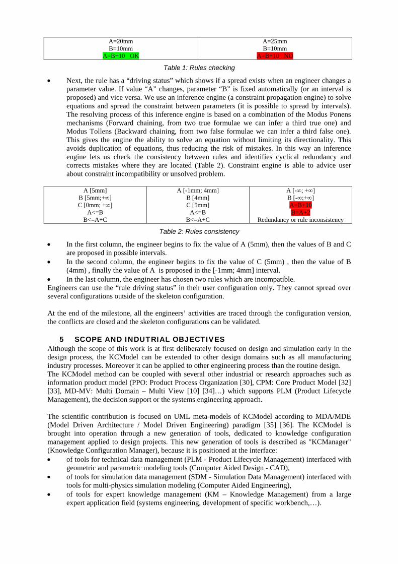
A=20mm B=10mm
A=B+10 OK
A=25mm B=10mm
A=B+10 NO
Table 1: Rules checking
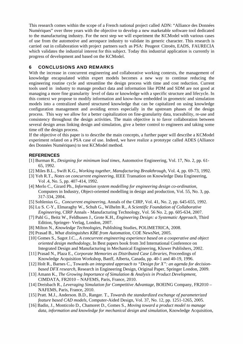
• Next, the rule has a “driving status” which shows if a spread exists when an engineer changes a parameter value. If value “A” changes, parameter “B” is fixed automatically (or an interval is proposed) and vice versa. We use an inference engine (a constraint propagation engine) to solve equations and spread the constraint between parameters (it is possible to spread by intervals). The resolving process of this inference engine is based on a combination of the Modus Ponens mechanisms (Forward chaining, from two true formulae we can infer a third true one) and Modus Tollens (Backward chaining, from two false formulae we can infer a third false one). This gives the engine the ability to solve an equation without limiting its directionality. This avoids duplication of equations, thus reducing the risk of mistakes. In this way an inference engine lets us check the consistency between rules and identifies cyclical redundancy and corrects mistakes where they are located (Table 2). Constraint engine is able to advice user about constraint incompatibility or unsolved problem.
A [5mm]
B [5mm;+∞] C [0mm; +∞]
A<=B B<=A+C
A [-1mm; 4mm] B [4mm] C [5mm]
A<=B B<=A+C
A [-∞; +∞] B [-∞;+∞] A=B+10 B=A+2
Redundancy or rule inconsistency
Table 2: Rules consistency
• In the first column, the engineer begins to fix the value of A (5mm), then the values of B and C are proposed in possible intervals.
• In the second column, the engineer begins to fix the value of C (5mm) , then the value of B (4mm) , finally the value of A is proposed in the [-1mm; 4mm] interval.
• In the last column, the engineer has chosen two rules which are incompatible. Engineers can use the “rule driving status” in their user configuration only. They cannot spread over several configurations outside of the skeleton configuration. At the end of the milestone, all the engineers’ activities are traced through the configuration version, the conflicts are closed and the skeleton configurations can be validated.
5 SCOPE AND INDUTRIAL OBJECTIVES Although the scope of this work is at first deliberately focused on design and simulation early in the design process, the KCModel can be extended to other design domains such as all manufacturing industry processes. Moreover it can be applied to other engineering process than the routine design. The KCModel method can be coupled with several other industrial or research approaches such as information product model (PPO: Product Process Organization [30], CPM: Core Product Model [32] [33], MD-MV: Multi Domain – Multi View [10] [34]…) which supports PLM (Product Lifecycle Management), the decision support or the systems engineering approach. The scientific contribution is focused on UML meta-models of KCModel according to MDA/MDE (Model Driven Architecture / Model Driven Engineering) paradigm [35] [36]. The KCModel is brought into operation through a new generation of tools, dedicated to knowledge configuration management applied to design projects. This new generation of tools is described as "KCManager" (Knowledge Configuration Manager), because it is positioned at the interface: • of tools for technical data management (PLM - Product Lifecycle Management) interfaced with
geometric and parametric modeling tools (Computer Aided Design - CAD), • of tools for simulation data management (SDM - Simulation Data Management) interfaced with
tools for multi-physics simulation modeling (Computer Aided Engineering), • of tools for expert knowledge management (KM – Knowledge Management) from a large
expert application field (systems engineering, development of specific workbench,…).
This research comes within the scope of a French national project called ADN: “Alliance des Données Numériques” over three years with the objective to develop a new marketable software tool dedicated to the manufacturing industry. For the next step we will experiment the KCModel with various cases of use from the automotive and aerospace industry to validate its generic character. This research is carried out in collaboration with project partners such as PSA: Peugeot Citroën, EADS, FAURECIA which validates the industrial interest for this subject. Today this industrial application is currently in progress of development and based on the KCModel.
6 CONCLUSIONS AND REMARKS With the increase in concurrent engineering and collaborative working contexts, the management of knowledge encapsulated within expert models becomes a new way to continue reducing the engineering routine cycle and streamline the design process with time and cost reduction. Current tools used in industry to manage product data and information like PDM and SDM are not good at managing a more fine granularity level of data or knowledge with a specific structure and lifecycle. In this context we propose to modify information and know-how embedded in geometric and simulation models into a centralized shared structured knowledge that can be capitalized on using knowledge configuration management and avoiding errors especially in the upstream phases of the design process. This way we allow for a better capitalization on fine-granularity data, traceability, re-use and consistency throughout the design activities. The main objective is to favor collaboration between several design areas linking design and simulation, give a better control to engineers and taking some time off the design process. If the objective of this paper is to describe the main concepts, a further paper will describe a KCModel experiment related on a PSA case of use. Indeed, we have realize a prototype called ADES (Alliance des Données Numériques) to test KCModel method.
REFERENCES [1] Burman R., Designing for minimum lead times, Automotive Engineering, Vol. 17, No. 2, pp. 61-
65, 1992. [2] Miles B.L., Swift K.G., Working together, Manufacturing Breakthrough, Vol. 4, pp. 69-73, 1992. [3] Yeh R.T., Notes on concurrent engineering, IEEE Transation on Knowledge Data Engineering,
Vol .4, No. 5, pp. 407-414, 1992. [4] Merlo C., Girard Ph., Information system modelling for engineering design co-ordination,
Computers in Industry, Object-oriented modelling in design and production, Vol. 55, No. 3, pp. 317-334, 2004.
[5] Sohlenius G., Concurrent engineering, Annals of the CIRP, Vol. 41, No. 2, pp. 645-655, 1992. [6] Lu S. C-Y., Elmaraghy W., Schuh G., Wilhelm R., A Scientific Foundation of Collaborative
Engineering, CIRP Annals - Manufacturing Technology, Vol. 56 No. 2, pp. 605-634, 2007. [7] Pahl G., Beitz W., Feldhusen J., Grote K.H., Engineering Design: a Systematic Approach, Third
Edition, Springer- Verlag, London, 2007. [8] Milton N., Knowledge Technologies, Publishing Studies, POLIMETRICA, 2008. [9] Prasad B., What distinguishes KBE from Automation, COE NewsNet, 2005. [10] Gomes S., Sagot J.C.., A concurrent engineering experience based on a cooperative and object
oriented design methodology, In Best papers book from 3rd International Conference on Integrated Design and Manufacturing in Mechanical Engineering, Kluwer Publishers, 2002.
[11] Prasad N., Plaza E., Corporate Memories as Distributed Case Libraries, Proceedings of Knowledge Acquisition Workshop, Banff, Alberta, Canada, pp. 40-1 and 40-19, 1996.
[12] Holt R., Barnes C., Towards an integrated approach to “Design for X”: an agenda for decision-based DFX research, Research in Engineering Design, Original Paper, Springer London, 2009.
[13] Amann K., The Growing Importance of Simulation & Analysis in Product Development, CIMDATA, FR2010 – NAFEMS, Paris, France, 2010.
[14] Dreisbach R., Leveraging Simulation for Competitive Advantage, BOEING Company, FR2010 – NAFEMS, Paris, France, 2010.
[15] Pratt. M.J., Anderson. B.D., Ranger. T., Towards the standardized exchange of parameterized feature based CAD models, Computer-Aided Design, Vol. 37, No. 12, pp. 1251-1265, 2005.
[16] Badin, J., Monticolo D., Chamoret D., Gomes S., Moving toward a product model to manage data, information and knowledge for mechanical design and simulation, Knowledge Acquisition,
Reuse and Evaluation (KARE 2010) December 15th - December 18th, Kuala Lumpur, Malaysia, 2010.
[17] Louis-Sidney L., Cheulet V., Lamouri S., Puron O., Mezza A., A design logistics support tool on an operational level, 21st CIRP Design Conference, KAIST, Daejeon, Korea, 27-29, 2011.
[18] Grundstein M., Sabroux C. R., Pachulski A., A decision support for identifying crucial knowledge requiring capitalizing operation, European Journal of Operational Research 145 pp 256–272, 2003.
[19] Chan. E., Yu. K.M., A concurrency control model for PDM systems, Computers in Industry, Vol. 58, No. 8-9, pp. 823-831, 2007.
[20] Eynard B., Gallet T., Roucoules L., Ducellier G., PDM System Implementation based on UML, Mathematics and Computers in Simulation, vol. 70, No 5-6, pp. 247-442, 2006.
[21] Charles S., Ducellier G., Li L., Eynard, B., Improvement of 3D data exchanges in the product lifecycle management, International Conference on Product Lifecycle Management - PLM 2005, Lumiere University of Lyon, France, 11-13 July 2005.
[22] Charles S., Eynard B., Definition of a Simulation Data Management Environment integrated with PDM, International Conference on Engineering Design - ICED 2005, Melbourne, Australia, August 15-18, 2005.
[23] Pikosz. P., Malmqvist. J., Possibilities and Limitations when using PDM Systems to support the product development process, Proceedings of NordDesign'96, s.165-176, Helsinki, 1996.
[24] Ducellier G., Charles S., Eynard B., Caillaud E., Traceability of simulation data in a PLM Environment: proposition of Step-based system that support parameter integration, International Design Conference – DESIGN’06, Dubrovnik, Croatia, 15-18 May 2006.
[25] Ducellier G., Eynard B., Caillaud E., Integration of CAD Knowledge with PLM: Application 162 to Product Development Process During Requirements Clarification and Detailed Design Phases, International Conference on Product Lifecycle Management – PLM 2006, Bangalore, India, 10-12 July 2006.
[26] MIL-HDBK-61A Configuration Management Guidance 7 February 2001. [27] Standard ISO 10007:1995 Quality management -- Guidelines for configuration management,
1995 [28] Standard ISO 10007:2003 Quality management -- Guidelines for configuration management,
2003 [29] Kleiner S., Anderl R., Grab R., A collaborative design system for product data integration,
Journal of Engineering Design, Vol. 14, No.4, December 2003, 421-428. [30] E2KS – Entreprise Engineering Knowledge System, http://e2ks.com/solutions.html. [31] Noël F., Roucoules L., Teissandier D., Specification of product modeling concept dedicated to
information sharing in collaborative design context, IDMME, Bath-UK, 2004. [32] Fenves J., A core product model for representing design information, USA: National institute of
Standards and Technology, NISTIR 6736, Gaithersburg, MD 20899, USA, 2001. [33] Fenves J., Foufou S., Bock C., Sriram R.D., CPM2: A Core Model for Product Data, Journal of
Computing and Information Science in Engineering, Vol. 8 / 014501-1, 2008. [34] Demoly F., Gomes S., Eynard B., Rivest L., Sagot J.C., Assembly-oriented product structure
based on preliminary assembly process engineering, International Conference on Engineering Design - ICED 2009,Stanford University, Stanford, USA, August 24-27, 2009.
[35] Seidewitz E., What models mean. IEEE Software, 20(5):26–32, pp. 28 and 128, 2003. [36] OMG, The Object Management Group, www.omg.org.
J. Badin Mechatronics, methods, models and skills Laboratory-M3M, University of Technology UTBM, 90010 Belfort, France DPS: Digital Product Simulation, 2-4 rue Hans List, 78290 Croissy-Sur Seine, France. D. Monticolo ERPI Laboratory, 8 rue Bastien Lepage, National Polytechnic Institute of Lorraine, 54010 Nancy, France.
D. Chamoret Mechatronics, methods, models and skills Laboratory-M3M, University of Technology UTBM, 90010 Belfort, France S. Gomes Mechatronics, methods, models and skills Laboratory-M3M, University of Technology UTBM, 90010 Belfort, France 2DPS: Digital Product Simulation, 2-4 rue Hans List, 78290 Croissy-Sur Seine, France.


