Embed Size (px)
Citation preview

Journal of Intelligent and Robotic Systems 34: 315–329, 2002.© 2002 Kluwer Academic Publishers. Printed in the Netherlands.
315
Semi-autonomous Navigation of a RoboticWheelchair
ANTONIS ARGYROS, PANTELIS GEORGIADIS, PANOS TRAHANIAS andDIMITRIS TSAKIRISInstitute of Computer Science, Foundation for Research and Technology – Hellas (FORTH),Vasilika Vouton, P.O. Box 1385, 71110 Heraklion, Crete, Greece;e-mail: {argyros,georgiad,trahania,tsakiris}@ics.forth.gr
Abstract. The present work considers the development of a wheelchair for people with specialneeds, which is capable of navigating semi-autonomously within its workspace. This system is ex-pected to prove useful to people with impaired mobility and limited fine motor control of the upperextremities. Among the implemented behaviors of this robotic system are the avoidance of obstacles,the motion in the middle of the free space and the following of a moving target specified by theuser (e.g., a person walking in front of the wheelchair). The wheelchair is equipped with sonars,which are used for distance measurement in preselected critical directions, and with a panoramiccamera with a 360 degree field of view, which is used for following a moving target. After suitablyprocessing the color sequence of the panoramic images using the color histogram of the desiredtarget, the orientation of the target with respect to the wheelchair is determined, while its distanceis determined by the sonars. The motion control laws developed for the system use the sensorydata and take into account the non-holonomic kinematic constraints of the wheelchair, in order toguarantee certain desired features of the closed-loop system, such as stability. Moreover, they areas simplified as possible to minimize implementation requirements. An experimental prototype hasbeen developed at ICS–FORTH, based on a commercially-available wheelchair. The sensors, thecomputing power and the electronics needed for the implementation of the navigation behaviorsand of the user interfaces (touch screen, voice commands) were developed as add-on modules andintegrated with the wheelchair.
Key words: wheelchairs, robot navigation, non-holonomic mobile robots, person following, sensor-based control, panoramic cameras.
1. Introduction
People with impaired mobility are faced with multiple challenges when movingin environments designed for people without such problems. Existing assistivedevices, such as wheelchairs, are primarily useful to people whose mobility prob-lems are not combined with limited fine motor control of their upper extremitiesor reduced ability for perception of their environment, which render control of awheelchair problematic. Such combinations of mobility, motor control and percep-tion problems are not uncommon. Thus, the advances in robotic technology, that

316 A. ARGYROS ET AL.
initially targeted mobile robot navigation [8], become relevant in building moreeffective assistive devices.
The present work considers the enhancement of a commercially-available powerwheelchair (usually driven manually through a joystick) by the computational andsensory apparatus necessary for automating certain frequently-occurring naviga-tion tasks. The implemented tasks are:• Motion in the middle of the free space defined by the obstacles and the envi-
ronmental layout.• Following of a target (e.g., a moving person) specified by the user.• Obstacle avoidance.• Motion towards a desired direction which is specified by the user using ap-
propriate man–machine interfaces (e.g., touch screen, voice commands).Some of these tasks are carried out in cooperation with the user, hence the term
semi-autonomous navigation. The difference from the usual mode of operation ofsuch a wheelchair is that the user is relieved from its continuous control via thejoystick during the execution of such a task and has merely to issue some high-level commands, usually when the task is initiated (e.g., to select the person tobe followed by pointing on a touch screen, to select the direction of motion byappropriate voice commands, etc.).
Various approaches to robotic navigation range considerably in the degree ofautonomy they support. On one end lies “manually-controlled” platform motion,whereas, on the other lies fully autonomous navigation in unstructured environ-ments. For the case of robotic wheelchairs, the former approach has already ledto market products. Regarding autonomous navigation approaches, they are cur-rently far from being both reliable and cheap enough in order to be introducedin this sector. However, there is a clear demand for technology that would in-crease the independence of people with special needs [5, 4]. Towards this end,the proposed approach for assistive navigation presents a good compromise re-garding the autonomy/reliability trade-off. It relieves the user from the continuousoperation of the wheelchair, involving him/her only in higher level decisions. Thecurrent implementation of the above navigation behaviors does not support nav-igation in non-visible areas, nor recognition of the target objects. It is, however,of utmost importance that the enhanced navigation capabilities are offered withoutcompromising robustness and reliability in platform operation.
The sensory modalities used for the development of the robotic wheelchair areodometry, sonars and panoramic vision. The sonars measure range in preselectedcritical directions around the wheelchair. The panoramic camera provides visualdata from a 360◦ field of view and constitutes an important source of sensoryinformation for some of the developed navigation capabilities.
The rest of the paper is organized as follows: Section 2 presents issues relatedto panoramic cameras that constitute essential background to this work. Section 3discusses the system’s navigation behaviors. Section 4 provides some details on theexperimental prototype that was built. Finally, Section 5 summarizes the paper.

SEMI-AUTONOMOUS NAVIGATION OF A ROBOTIC WHEELCHAIR 317
2. Panoramic Vision
Panoramic cameras have been extensively studied in previous works [9, 12]. Theirmain advantage in robotic navigation is their ability to “look” simultaneously inarbitrary directions and thus, robotic tasks requiring movement in one directionand observation of environmental features in a different one, are greatly facilitated.In mobile robotics, the main alternative to panoramic cameras are moving camerasmounted on pan-and-tilt platforms or multiple-camera systems mounted on therobot. The use of a moving, limited-f.o.v. camera on a wheelchair necessitates itsprecise orientation, especially when the wheelchair is also moving; this can be achallenging control problem [15]. Looking in a direction outside the current fieldof view of the camera requires repositioning the sensor, which, in turn, involves adelay that may be unacceptable when the environment also changes. This problembecomes more severe when the direction where the camera needs to look next isnot known a priori; time-consuming exploratory actions are then necessary. In thecase of multiple-camera systems, the lack of a common nodal point of the camerasand the elaborate calibration required, complicate their use. Also, the duplication ofoptical and electronic components increases the cost of the system. Moreover, thesystem lacks flexibility in observing an arbitrary direction of interest. In contrastto the above, panoramic cameras offer the capability of extracting information si-multaneously from all desired directions of their visual field. Neither moving parts,
Figure 1. Sample panoramic image of an indoors environment.

318 A. ARGYROS ET AL.
Figure 2. Unfolded panoramic images: person tracking sequence.
nor elaborate control mechanisms or expensive hardware is required to achieve thiscapability.
A panoramic image can be “unfolded” giving rise to a cylindrical image, usinga polar-to-Cartesian transformation. Different columns of the resulting cylindricalimage correspond to different viewing directions. Figure 1 shows an example ofa panoramic image and Figure 2 shows examples of unfolded ones. Note that theleftmost and rightmost parts of each image correspond to the same visual direction.The property of the resulting image is that the full 360◦ field of view is mapped onits horizontal dimension. In the remainder of this paper, unless otherwise stated,the term panoramic image refers to an unfolded one.

SEMI-AUTONOMOUS NAVIGATION OF A ROBOTIC WHEELCHAIR 319
Let F denote a feature of the environment and let φ be the bearing angle offeature F in the panoramic image. Since we deal with panoramic images, the bear-ing angle of feature F can easily be computed as: φ = 2πx/s, where x is thex-coordinate of the feature in the image, and s is the width of the panoramic image(both measured in pixels). Thus, recovering the orientation of an environmentalfeature with respect to the panoramic camera becomes trivial, once the feature hasbeen identified in the panoramic image.
3. Navigation Behaviors
The main navigation capabilities developed on the robotic wheelchair are the mo-tion in the middle of the free space defined by obstacles or environment features,the following of a target (e.g., a moving person) specified by the user and themotion towards a desired direction which is specified by the user using a touchscreen or voice commands. In this section we present the first two behaviors inmore detail. It should also be noted that a low-level obstacle avoidance behavioris implemented, which assumes the control of the platform as soon as an immi-nent collision with obstacles in the environment is predicted through sonar dataprocessing.
3.1. MOTION IN THE MIDDLE OF FREE SPACE
The wheelchair employed is kinematically equivalent to a mobile robot of the uni-cycle type. We suppose that it is moving on a planar surface inside a “corridor”formed by obstacles, which can be locally approximated by two straight parallelwalls. We further suppose that appropriate sensors able to specify distance to thewalls are mounted on the wheelchair (e.g., sonars) (Figure 3).
Consider an inertial coordinate system {FO} centered at a point O of the planeand aligned with one of the walls, a moving coordinate system {FM} attached to the
Figure 3. Coordinate systems defined for analyzing wheelchair motion in the middle of freespace.

320 A. ARGYROS ET AL.
middle M of the wheelchair’s wheel axis and another moving one {FC} attachedto the nodal point C of the range finder. Let (x, y) be the position of the point Mand θ be the orientation of the wheelchair with respect to the coordinate system{FO}. Let δ � 0 be the distance of the point C from M and ε > 0 the width of thecorridor. We suppose that the wheels of the mobile platform roll without slippingon the plane supporting the system. This induces a non-holonomic constraint onthe motion of the wheelchair, due to the fact that the instantaneous velocity lateralto the heading direction of the mobile platform has to be zero. From this, we getthe usual unicycle kinematic model [2] for the mobile platform
x = v cos θ, y = v sin θ, θ = ω, (1)
where vdef= x cos θ + y sin θ is the heading speed and ω is the angular velocity of
the unicycle. Consider the rays d1 and d2 in the forward directions φ1 and −φ2 withrespect to the heading direction of the wheelchair (Figure 3). We suppose that d1
intersects the left wall, while d2 intersects the right wall of the corridor and thaty ∈ (0, ε) and θ ∈ (−φ, φ), with 0 < φ < π/2. Let φ1 = φ2 = φ.
The task of staying in the middle of the corridor consists of using the angularvelocity ω of the system to drive the lateral distance of the wheelchair from thewalls, as well as its orientation, to desired values. This amounts to asymptoticallystabilizing the state (y, θ) of the subsystem
y = v sin θ, θ = ω (2)
of the unicycle kinematics of Equation (1) to (y�, θ�) = (ε/2, 0), using only theangular velocity ω as the control of the system. The heading speed v(t) cannotbe controlled, but we suppose that it is known at all times (for details on stabilityconcepts and methods, see [7, 16]).
When reconstruction of the state (y, θ) from the sensory data is possible, a path-following control scheme, similar to the one developed in [10] can be applied tothe system.
In the case that reconstruction of the state (y, θ) from the sensory data is notdesirable or possible, a motion control scheme based on the scaled difference ofinverse depths from the corridor walls is possible (cf. [14] for details.) In the casethat v is time-varying, but strictly positive (v(t) > 0, ∀t � 0), the angular velocitycontrol
ω = −k1v sinφ
(1
d1− 1
d2
), (3)
with positive gain k1, can be shown to locally asymptotically stabilize the system ofEquation (2) to (y�, θ�). An input scaling procedure [10] can be used to reduce thelinearization of the closed-loop system around the desired equilibrium to a lineartime-invariant system whose asymptotic stability can be established by classicalresults like the Routh–Hurwitz test. Linear theory tools can also be employed toselect the gain k1 (e.g., for critical damping of the trajectory).

SEMI-AUTONOMOUS NAVIGATION OF A ROBOTIC WHEELCHAIR 321
PROPOSITION 1. Let the heading speed v of the unicycle of Equation (1) be time-varying and assume that it is strictly positive at all times, piecewise continuous andbounded. Let d1 and d2 be the distances from the walls as specified in Figure 3. Theangular velocity ω of Equation (3) with gain k1 > 0, stabilizes locally asymptot-ically the subsystem of Equation (2) of the unicycle kinematics to the equilibrium(y�, θ�) = (ε/2, 0).
When v is negative, a similar approach, employing “backwards looking” rayscan be employed.
Figure 4 shows MATLAB simulations of the system for the controls of Equa-tion (3) and for the case where the heading speed of the mobile robot is strictlypositive and varies periodically with time. The state (y, θ) is not being recon-structed in this case. The control ω is used to achieve stabilization of (y, θ) tothe desired values (5, 0) starting from the initial state (4, 0.4).
In the experimental prototype developed, this behavior is implemented usingsonars. However, in [14] we have shown that by computing optical flow in selectedareas of a panoramic image, we can derive the quantity (1/d1 − 1/d2), and usepanoramic vision for implementing this behavior. The method presented in [14]is based on the method proposed in [1] and it is inspired by experiments on thenavigational capabilities of bees [3, 11].
3.2. PERSON FOLLOWING
In order to implement the person-following behavior, both the color panoramiccamera and the ring of sonars of the wheelchair are used. By processing the imagesacquired by the camera, the orientation of the moving target with respect to thewheelchair is computed. Sonar data provide the distance between the wheelchairand the moving target.
In order to specify the orientation of the moving person with respect to thewheelchair from panoramic vision, color information from the panoramic imagesis exploited. More specifically, a modification of the Color Indexing Scheme [13],has been employed. This algorithm identifies an object by comparing its colorcharacteristics to the color characteristics of objects in a database. In our system,first the user selects the person to be tracked. This is done through a touch screenand an appropriate software interface. Based on this selection, the system buildsan internal human body representation, consisting of three image regions that cor-respond to the head, torso and legs of the person to be tracked. For each of theseregions, a normalized color histogram is built. Normalization is performed in orderto make the system less vulnerable to changes in the global image illuminationdue to changes in lighting conditions. In subsequent image frames, a window isdefined, in which the above–mentioned regions are searched for. This is done bycomparing the color histograms of a reference model to every possible location inthe search window. The locations of several of the best matches for each one of the

322 A. ARGYROS ET AL.
Figure 4.
SEMI-AUTONOMOUS NAVIGATION OF A ROBOTIC WHEELCHAIR 323
model regions are stored. The locations are optimized globally, in the sense thatthey should obey certain geometric relations (e.g., head above torso, torso abovelegs, etc.). The best location for the model regions defines the best estimate for thelocation of the person being tracked and, thus, its orientation with respect to thewheelchair. Finally, the models of the head, body and torso parts of the movingperson are updated (both with respect to color information and to the size of thecorresponding image areas), in order to accommodate changes in the appearanceof the moving person.
This tracking method assumes that the processing of the image sequences pro-ceeds fast enough to guarantee that the appearance of the moving person betweensubsequent image frames does not change significantly. In practice, we have beenable to acquire and process panoramic frames at 3 Hz on a typical Pentium IIIprocessor, which proved sufficient for our case. The system fails in cases wheremoving persons are dressed in colors very similar to the scene background (e.g.,people dressed in white in a room with white walls). Figure 2 shows a sequenceof eight panoramic images, where the person inside the white windows is beingtracked, as it moves from the middle of the scene in the first image to the left of itin the last one.
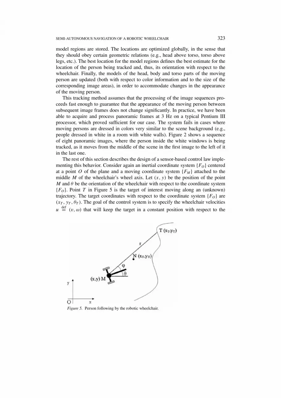
The rest of this section describes the design of a sensor-based control law imple-menting this behavior. Consider again an inertial coordinate system {FO} centeredat a point O of the plane and a moving coordinate system {FM} attached to themiddle M of the wheelchair’s wheel axis. Let (x, y) be the position of the pointM and θ be the orientation of the wheelchair with respect to the coordinate system{FO}. Point T in Figure 5 is the target of interest moving along an (unknown)trajectory. The target coordinates with respect to the coordinate system {FO} are(xT , yT , θT ). The goal of the control system is to specify the wheelchair velocities
udef= (v, ω) that will keep the target in a constant position with respect to the
Figure 5. Person following by the robotic wheelchair.

324 A. ARGYROS ET AL.
wheelchair. This constant position can be represented by a virtual point N (cf.Figure 5), with constant relative coordinates (xMN, yMN) with respect to the coor-dinate system {FM} and with coordinates (xN, yN) with respect to the coordinatesystem {FO}. The control goal can then be expressed as minimizing the deviationof point N from point T or as minimizing the tracking error
edef= (ex, ey) = (xN − xT , yN − yT ).
It can be easily seen that
xN = x + xMN cos θ − yMN sin θ, yN = y + xMN sin θ + yMN cos θ.
Since the motion of the wheelchair is subject to the non-holonomic constraints ofEquation (1), the change of the tracking error during the motion (error equations)is
e = B(θ)u− χT , (4)
with
B(θ) =(
cos θ −(xMN sin θ + yMN cos θ)sin θ xMN cos θ − yMN sin θ
), (5)
where χTdef= (xT , yT ) is the translational velocity of the target. The matrix B(θ) is
invertible whenever xMN is nonzero.
PROPOSITION 2. Let xMN be nonzero. If the target translational velocity χT isuniformly bounded and sufficiently small (but not necessarily zero when the erroris zero), then the control law
u(e, θ) = B−1(θ)Ae, (6)
where A is a Hurwitz matrix, will maintain the tracking error ultimately uniformlybounded (i.e., uniformly bounded after a finite initial time).
The closed-loop system of Equations (4) and (6) can be seen as an exponen-tially stable nominal system with non-vanishing perturbation. Under the aboveconditions on χT , the proposition follows from known robustness results [7].
For simplicity, we choose A = −kI, where I is the 2×2 unit matrix. The abovestate-feedback law then becomes u(e, θ) = −kB−1(θ)e. This control law dependson the state θ and on the tracking error e. The first is not known and the secondneeds to be estimated from sensory data. It turns out that, while doing so, it ispossible to eliminate the dependence of u on θ , as described below. Observe thatthe control law of Equation (6) does not depend explicitly on the target velocitywhich is treated as a perturbation.
Let φ be the relative orientation of the target with respect to the wheelchair andr be the corresponding distance, as shown in Figure 5. Earlier in this section, a

SEMI-AUTONOMOUS NAVIGATION OF A ROBOTIC WHEELCHAIR 325
method for the estimation of φ from a sequence of color panoramic images waspresented. The tracking error e is related to the sensory information φ and r by
ex = xMN cos θ − yMN sin θ − r cos(θ + φ),
ey = xMN sin θ + yMN cos θ − r sin(θ + φ).(7)
Using Equation (7), the previous control law is made to depend exclusively on thesensory information (r, φ) and takes the form
u(r, φ) =(v(r, φ)
ω(r, φ)
)
=( −k[xMN(xMN − r cos φ)+ yMN(yMN − r sinφ)
]/xMN
−k(yMN − r sinφ)/xMN
). (8)
The quantities xMN and yMN are parameters determining the position where thetarget will be held with respect to the wheelchair.
Figure 6 shows the results of MATLAB simulations for the case where we at-tempt to track a target moving with velocity xT = sin t , yT = 2 + cos t , θT = 0.3,using the sensor-based control law of Equation (8) with parameters xMN = 1,yMN = 1 and k = 1. Figure 6(a) shows the (x, y) trajectories of the wheelchair andof the target and Figure 6(b) shows the tracking error (ex, ey). We observe that theerror remains bounded, despite neglecting the target velocity in the control law de-sign and despite the subsequent simplifications of this control law. In experimentswith the robotic wheelchair prototype, this source of error is negligible.
4. The Experimental Prototype
An experimental prototype of a robotic wheelchair was built at ICS–FORTH (Fig-ure 7). It is based on a commercially-available power wheelchair, where the sen-sors, the computing power and the electronics needed for the implementation ofthe navigation behaviors and of the user interfaces (touch screen, voice commands)were developed as add-on modules. The main hardware components of the roboticwheelchair (Figure 8) are:• The power wheelchair: A MEYRA Eurosprint wheelchair is used as the base
of the developed system. The wheelchair is actuated by two DC motors drivingindependently each rear wheel. Its motion is controlled by the user, eitherdirectly through a joystick, or indirectly through a computer, which commu-nicates with the wheelchair through a serial port.
• The sensors: The sensory modalities employed are odometry, sonars and pan-oramic vision. A ring of 6 Polaroid sonars with a range of 6 m and beam widthof 20◦ are used, as well as a Neuronics panoramic camera with a paraboloidmirror and a 360◦ field of view. The electronics interfacing the sensors to thecomputer system, as well as those necessary for controlling the sensors andfor data collection, were built in-house.

326 A. ARGYROS ET AL.
Figure 6. Person-following by the robotic wheelchair.

SEMI-AUTONOMOUS NAVIGATION OF A ROBOTIC WHEELCHAIR 327
Figure 7. Side view of the developed experimental robotic wheelchair prototype.
Figure 8. Hardware architecture of the robotic wheelchair.

328 A. ARGYROS ET AL.
• The computer system: It is composed of a portable computer and of a set of5 PIC micro-controllers interconnected through a CAN network. The portablecomputer processes the vision data and communicates with the user throughthe appropriate software interfaces. Among the micro-controllers, one is ded-icated to the communication with the portable computer and with the wheel-chair control unit through serial ports, three are dedicated to controlling thesonars and to receiving and processing their data and one to receiving andprocessing odometry data (cf. Figure 8).
Extensive tests have been performed with the developed prototype to evaluateits behavior in a variety of operating conditions. Movies of the robotic wheelchairprototype can be seen in [6]. Among its navigation capabilities, obstacle avoidance,the motion towards a specified direction and the motion in the middle of the freespace work quite robustly at this stage. The following of a moving target worksreliably under moderate lighting conditions. When significant variations in light-ing occur during the movement of the wheelchair, the color-based visual trackingmay lose the target or confuse it with another one. Further work to enhance theindependence of the tracking scheme from lighting conditions is currently underway.
5. Concluding Remarks
The experimental prototype of a robotic wheelchair with the capability of semi-autonomous navigation was presented. Issues related to the processing and use ofsensory information from sonars and a panoramic camera mounted on the wheel-chair, to the control of the system based on the sensory information, as well as to thehardware and software architecture of the system were discussed. Such a systemmay potentially assist people with impaired mobility, who may have limited finemotor control.
Acknowledgements
This work was partially supported by the General Secretariat for Research andTechnology of the Hellenic Ministry of Development through project DRIVER,contract No. 98AMEA 18. The contributions of M. Maniadakis, O. Bantiche andD. Muti in this project are gratefully acknowledged.
References
1. Argyros, A. A. and Bergholm, F.: Combining central and peripheral vision for reactive ro-bot navigation, in: Proc. of Computer Vision and Pattern Recognition Conf. (CVPR’99), FortCollins, CO, USA, 23–25 June 1999.
2. Canudas de Wit, C., Siciliano, B., and Bastin, G. (eds): Theory of Robot Control, Springer,Berlin, 1996.
3. Collett, T.: Measuring beelines to food, Science 287 (2000), 817–818.

SEMI-AUTONOMOUS NAVIGATION OF A ROBOTIC WHEELCHAIR 329
4. Donna, E., Bacon, C., Rahman, T., and Harwin W. S. (eds): Proc. 4th Internat. Conf. on Re-habilitation Robotics, Applied Science and Engineering Lab., Univ. of Delaware/A.I. duPontInst., Wilmington, DE, USA, 1994.
5. Foulds, R.: Interactive robotic aids – one option for independent living: An internationalperspective, Monograph 37, World Rehabilitation Fund, New York, 1986, pp. 7–17.
6. http://www.ics.forth.gr/~tsakiris.7. Khalil, H. K.: Nonlinear Systems, Macmillan, New York, 1992.8. Laumond, J.-P. (ed.): Robot Motion Planning and Control, Lecture Notes in Control and
Information Sciences 229, Springer, New York, 1998.9. Nayar, S. K. and Baker, S.: A theory of catadioptric image formation, Technical Report CUCS-
015-97, Dept. of Computer Science, Columbia Univ., USA, 1997, p. 30.10. Samson, C.: Control of chained systems: application to path following and time-varying point-
stabilization of mobile robots, IEEE Trans. Automat. Control 40 (1995), 64–77.11. Srinivasan, M. V., Zhang, S., Altwein, M., and Tautz, J.: Honeybee navigation: Nature and
calibration of the ‘odometer’, Science 287 (2000), 851–853.12. Svoboda, T., Pajdla, T., and Hlavac, V.: Epipolar geometry for panoramic cameras, in: Proc.
5th European Conf. on Computer Vision, Lecture Notes in Computer Science 1406, Springer,New York, 1998.
13. Swain, M. J. and Ballard, D. H.: Indexing via color histograms, in: Proc. Internat. Conf. onComputer Vision, 1990.
14. Tsakiris, D. P. and Argyros, A. A.: Corridor following by mobile robots equipped withpanoramic cameras, in: Proc. of the 8th IEEE Medit. Conf. on Control and Automation(MED’2000), Rio, Greece, 17–19 July 2000.
15. Tsakiris, D. P., Rives, P., and Samson, C.: Extending visual servoing techniques to nonholo-nomic mobile robots, in: G. Hager, D. Kriegman, and S. Morse (eds), The Confluence of Visionand Control, Lecture Notes in Control and Information Systems 237, Springer, New York,1998.
16. Vidyasagar, M.: Nonlinear Systems Analysis, Prentice-Hall, Englewood Cliffs, NJ, 1978.


