Embed Size (px)
Citation preview

145
Isolation Equipment Index
Description Figure Page Isolation 2 Bolt Pipe Clamp 107 151 Isolation 3 Bolt Pipe Clamp 108 152 Isolation Pipe Saddle 109 150 Clip Strip 110 150 Isolation U-Bolt – Castellated Profile (Grip Type) 111 148 Isolation U-Bolt – PTFE Lined (Non-Grip Type) 112 148 Isolation U-Bolt (Grip Type) 113G 149 Isolation U-Bolt (Non-Grip Type) 113NG 149 Anti-Vibration Pad 115 153 Anti-Vibration Pad 116 153 Slider Unit 117 153 Isolation Pad 118 150
If you can’t find the size support you are after, or you need a special/bespoke size, please
contact our sales team on +44(0)1686 629898 for more assistance.

Isolation Equipment – Pictorial Index
146
Fig. Page Description Pictorial
107 151 2 Bolt Pipe
Clamp
108 152 3 Bolt Pipe
Clamp
109 150 Pipe Saddle
110 150 Clip Strip
111 148
U-Bolt Castellated
Profile (Grip Type)
112 148 U-Bolt
PTFE Lined (Non-Grip)
Fig. Page Description Pictorial
113G 149 U-Bolt (Grip Type)
113NG 149 U-Bolt (Non-Grip)
115 153 Anti-
Vibration Pad
116 153 Anti-
Vibration Pad
117 153 Slider Unit
118 150 Isolation
Pad

147
Introduction
Isolation QPS offers a wide range of isolating products to suit stainless steel, duplex, super duplex and cupro-nickel piping. These products incorporate moulded isolation / encasing materials such as:-
Neoprene (temperature range -30°C to 100°C) VHT Silicone (temperature range -70°C to 350°C)
Both materials offer extensive performance qualities and can be utilised in a wide range of pipework installations. Benefits
Clamping damage restraint to thin wall pipes. Prevention of electrolytic erosion between dissimilar metals. Curtailment of noise and vibration. Cost effective and time saving. Wide range of standard products/sizes available. Bespoke sizes/designs available on request based on client’s specification.
Properties and Isolating Material The steel parts of both u-bolts and clamps are isolated from the pipe utilising either extruded 70/80 flame retardant neoprene (conforming to BS4255) or very high temperature flame retardant silicone. 70/80 FR Neoprene This material is strong, resilient and achieves an extremely high performance in the reduction of noise and vibration in pipework. Neoprene also has an outstanding resistance to a wide range of chemicals, including; acids, alkalis, fats, oils, greases and solvents. It has advantageous physical properties including resistance to tear and abrasion, ozone and weathering.
Working temperature range -30°C to 100°C Specific gravity 1.5 Elongation at break 150 min, (%) Accelerated ageing o Hardness change IRHD plus 10 max. o Change T/S% minus 15% max. o Change in E/B% minus 40% max.
Hardness IRHD 76 – 85 Tensile strength 10.5 min. (Mpa) Compression set 25% max. Static ozone resistance – No cracks Low temperature hardness change IRHD
plus 12 max. Colour: Black
VHT/FR Silicone Silicone rubber is a chemically inert synthetic elastomer which differs from other synthetic and natural rubbers in that it is able to maintain excellent elasticity and resilience over a wide temperature range. It has excellent resistance to fire, very low toxicity and can perform at temperatures up to 300°C (max) with minimum loss of characteristics. The material has excellent resistance to ozone, weathering and a wide range of chemicals, solvents, oils and greases.
Working temperature range -70°C to 300°C Density 1.44 (gms/cubic cm) Elongation at break 165 (%) Tear strength 10 (KN/M) Flame resistance UL94 VO 2 mm Oxygen index 39% (norm NFT 5107 1) Colour: Grey
Shore hardness 60 (A±5 deg) Tensile strength 7.8 (Mpa) Compression set 30% (70hrs @ 150°C) Static ozone resistance – No cracks Smoke toxicity to AFNOR norm NFX.70100
CT approx. 2.3 BS6853 category 1

148
Isolation Equipment – Fig. 111 & Fig. 112
Fig. 111 – Grip Isolation U-Bolt (C.S./S.S. Pipe) Pipe Size
A B C D E H WxT Max
Load Kg NB O/D 15 21.3 60 60 37 6 60 11.5 25x10 220 20 26.9 65 60 43 6 70 14.5 25x10 220 25 33.7 65 60 50 6 75 17 25x10 220 32 42.4 80 75 69 10 95 21 25x10 545 40 48.3 80 70 75 10 100 24.5 25x10 545 50 60.3 90 75 87 10 110 30.5 25x10 545 65 76.1 95 75 102 12 135 38 30x10 1000 80 88.9 100 75 115 12 140 44.5 30x10 1000 100 114.3 110 75 141 12 170 57.5 30x10 1000 150 168.3 180 120 210 16 250 84 50x10 1635 200 219.1 200 120 262 16 315 109.5 50x10 1635 250 273 235 130 324 20 375 136.5 50x10 3405 300 323.9 265 130 375 20 425 162 50x10 3405
Fig. 111 – Grip Isolation U-Bolt (CuNi Pipe) Part No.
O/D A B C D E WxT Max
Load Kg16 16 60 60 32 6 60 25x10 220 20 20 65 65 36 6 70 25x10 220 25 25 65 65 41 6 75 25x10 220 30 30 75 70 48 6 85 25x10 220 38 38 80 75 64 10 95 25x10 545 45 44.5 80 70 71 10 100 25x10 545 57 57 90 75 83 10 110 25x10 545 76 76.1 95 75 101 12 135 30x10 1000 89 88.9 100 75 115 12 140 30x10 1000
108 108 110 75 134 12 170 30x10 1000 159 159 180 120 201 16 250 50x10 1635 219 219.1 200 120 262 16 315 50x10 1635 267 267 235 130 318 20 370 50x10 3405 324 323.9 265 130 375 20 425 50x10 3405
Fig. 112 – U-Bolt with PTFE Lining (C.S./S.S. Pipe) Pipe Size
A B C D E G H WxT Max
Load Kg NB O/D 15 21.3 60 60 37 M6 60 21 10.5 25x10 220 20 26.9 65 60 43 M6 70 27 13.5 25x10 220 25 33.7 65 60 50 M6 75 34 17 25x10 220 32 42.4 80 75 69 M10 95 42 21 25x10 545 40 48.3 80 70 75 M10 100 49 24.5 25x10 545 50 60.3 90 75 87 M10 110 61 30.5 25x10 545 65 76.1 95 75 102 M12 135 76 38 30x10 1000 80 88.9 100 75 115 M12 140 89 44.5 30x10 1000 100 114.3 110 75 141 M12 170 115 57.5 30x10 1000 150 168.3 180 120 210 M16 250 168 84 50x10 1635 200 219.1 200 120 262 M16 315 219 109.5 50x10 1635 250 273 235 130 324 M20 375 273 136.5 50x10 3405 300 323.9 265 130 375 M20 425 324 162 50x10 3405
Fig. 112 – U-Bolt with PTFE Lining (CuNi Pipe) Part No.
O/D A B C D E G H WxT Max Load
Kg 16 16 60 60 32 M6 60 16 8 25x10 220 20 20 65 65 36 M6 70 20 10 25x10 220 25 25 65 60 41 M6 75 25 12.5 25x10 220 30 30 75 70 48 M6 85 30 15 25x10 220 38 38 80 75 64 M10 95 38 19 25x10 545 45 44.5 80 70 71 M10 100 45 22.5 25x10 545 57 57 90 75 83 M10 110 57 28.5 25x10 545 76 76.1 95 75 101 M12 135 76 38 30x10 1000 89 88.9 100 75 115 M12 140 89 44.5 30x10 1000 108 108 110 75 134 M12 170 108 54 30x10 1000 159 159 180 120 201 M16 250 159 79.5 50x10 1635 219 219.1 200 120 262 M16 315 219 109.5 50x10 1635 267 267 235 130 318 M20 370 267 133.5 50x10 3405 324 323.9 265 130 375 M20 425 324 182 50x10 3405
Fig. 111 Materials: U-Bolt: Carbon Steel Base Pad: 70/80 FR Neoprene Sleeve: Extruded 70/80 FR Neoprene 2 x Full Nuts 2 x Locknuts 2 x Washers Please Specify:- Figure Number: Part Number (CuNi): NB (CS/SS Lines): O/D (CuNi Lines):
Fig. 112 Materials: U-Bolt: Carbon Steel Base Pad: 70/80 FR Neoprene Sleeve: Extruded 70/80 FR Neoprene PTFE: Etched & Bonded 4 x Full Nuts 4 x Washers 2 x Steel Bushes Please Specify:- Figure Number: Part Number (CuNi): NB (CS/SS Lines): O/D (CuNi Lines):

149
Isolation Equipment – Fig. 113G & Fig. 113NG
Fig. 113G – Gripping Isolation U-Bolt (C.S. / S.S. Pipe) Pipe Size
A B C D E G H WxT Max LoadKg NB O/D
15 21.3 60 60 37 M6 60 21 10.5 25X10 220 20 26.9 65 60 43 M6 70 27 13.5 25X10 220 25 33.7 65 60 50 M6 75 34 17 25X10 220 32 42.4 80 70 69 M10 95 43 21 25X10 545 40 48.3 80 70 75 M10 100 49 24.5 25X10 545 50 60.3 90 75 87 M10 110 61 30.5 25X10 545 65 76.1 95 75 102 M12 135 76 38 30X10 1000 80 88.9 100 75 115 M12 140 89 44.5 30X10 1000 100 114.3 110 75 141 M12 170 115 57.5 30X10 1000 150 168.3 180 120 210 M16 250 168 84 50X10 1635 200 219.1 200 120 262 M16 315 219 109.5 50X10 1635 250 273 235 120 324 M20 375 273 136.5 50X10 3405 300 323.9 265 120 375 M20 425 324 162 50X10 3405
Fig. 113NG – Non-Grip Isolation U-Bolt (C.S. / S.S. Pipe)
Pipe Size A B C D E G H WxT
Max Load Kg NB O/D
15 21.3 60 60 37 M6 60 23 11.5 25x10 220 20 26.9 65 60 43 M6 70 29 14.5 25x10 220 25 33.7 65 60 50 M6 75 36 18 25x10 220 32 42.4 80 70 69 M10 95 45 22.5 25x10 545 40 48.3 80 70 75 M10 100 52 26 25x10 545 50 60.3 90 75 87 M10 110 64 32 25x10 545 65 76.1 95 75 102 M12 135 79 39.5 30x10 1000 80 88.9 100 75 115 M12 140 92 46 30x10 1000 100 114.3 110 75 141 M12 170 118 59 30x10 1000 150 168.3 180 120 210 M16 250 172 86 50x10 1635 200 219.1 200 120 262 M16 315 224 112 50x10 1635 250 273 235 130 324 M20 375 278 139 50x10 3405 300 323.9 265 130 375 M20 425 329 164.5 50x10 3405
Fig. 113NG – Non-Grip Isolation U-Bolt (CuNi Pipe)
Part No.
O/D A B C D E G H WxT Max Load Kg
16 16 60 60 32 M6 60 18 9 25x10 220 20 20 65 65 36 M6 70 23 11.5 25x10 220 25 25 65 60 41 M6 75 28 14 25x10 220 30 30 75 70 48 M6 85 33 16.5 25x10 220 38 38 80 75 64 M10 95 41 20.5 25x10 545 45 44.5 80 70 71 M10 100 48 24 25x10 545 57 57 90 75 83 M10 110 60 30 25x10 545 76 76.1 95 75 102 M12 135 79 39.5 30x10 1000 89 88.9 100 75 115 M12 140 92 46 30x10 1000 108 108 110 75 134 M12 170 112 56 30x10 1000 159 159 180 120 201 M16 250 163 81.5 50x10 1635 219 219.1 200 120 262 M16 315 224 112 50x10 1635 267 267 235 130 318 M20 370 272 136 50x10 3405 324 323.9 265 130 375 M20 425 329 164.5 50x10 3405
Fig. 113G – Gripping Isolation U-Bolt (CuNi Pipe)
Part No.
O/D A B C D E G H WxTMax
Load Kg16 16 60 60 32 M6 60 16 8 25x10 220 20 20 65 65 36 M6 70 20 10 25x10 220 25 25 65 60 41 M6 75 25 12.5 25x10 220 30 30 75 65 46 M6 85 30 15 25x10 220 38 38 80 70 64 M10 95 38 19 25x10 545 45 44.5 80 70 71 M10 100 45 22.5 25x10 545 57 57 90 75 83 M10 110 57 28.5 25x10 545 76 76.1 95 75 102 M12 135 76 38 30x10 1000 89 88.9 100 75 115 M12 140 89 44.5 30x10 1000 108 108 110 75 134 M12 170 108 54 30x10 1000 159 159 180 120 201 M16 250 159 79.5 50x10 1635 219 219.1 200 120 262 M16 315 219 109.5 50x10 1635 267 267 235 120 318 M20 370 267 133.5 50x10 3405 324 323.9 265 120 375 M20 425 324 162 50x10 3405
Fig. 113G Materials: U-Bolt: Carbon Steel Base Pad: HT/FR Silicone Sleeve: Extruded HT/FR Silicone 2 x Full Nuts 2 x Locknuts 2 x Washers Please Specify:- Figure Number: Part Number (CuNi): Nominal Pipe Size:
Fig. 113NG Materials: U-Bolt: Carbon Steel Base Pad: HT/FR Silicone Sleeve: Extruded HT/FR Silicone 4 x Full Nuts 2 x Steel Bushes 4 x Washers Please Specify:- Figure Number: Part Number (CuNi): Nominal Pipe Size:

150
Isolation Equipment – Fig. 109, 110 & 118
Fig. 109 – Isolation Pipe Saddle (CuNi Pipe) Pipe O/D
WxT A B C D R Max Load Kg
D1 D2 16 35x5 53 68 8 M10 14 170 270 20 35x5 53 68 10 M10 16 170 270 25 35x5 55 70 12.5 M10 18.5 170 210 30 35x5 57 72 15 M10 21 170 210 38 35x8 64 82 19 M12 25 315 285
44.5 35x8 79 97 22 M12 28 315 285 57 35x8 81 99 28.5 M12 34.5 315 200
76.1 50x10 89 113 38 M16 44 465 330 88.9 50x10 99 123 44.5 M16 50.5 465 280 108 50x10 108 132 54 M16 60 465 220 133 60x15 136 166 66 M20 72.5 990 410 159 60x15 155 185 79.5 M20 85.5 990 410
193.7 60x15 175 205 97 M20 103 990 315 219.1 60x15 185 215 109.5 M20 115.5 990 315 267 60x15 215 245 133.5 M20 139.5 2060 280
323.9 60x15 240 270 162 M20 168 2060 280
Fig. 109 – Isolation Pipe Saddle (C.S. / S.S. Pipe) Pipe Size
WxT A B C D R Max Load Kg
NB O/D D1 D2 15 21.3 35x5 53 68 10 M10 16.5 170 270 20 26.9 35x5 55 70 13 M10 19.5 170 210 25 33.7 35x5 57 72 16 M10 23 170 175 32 42.4 35x8 64 82 20 M12 27 315 285 40 48.3 35x8 79 97 23 M12 30 315 250 50 60.3 35x8 81 99 29 M12 36 315 200 65 76.1 50x10 89 113 36 M16 44 465 330 80 88.9 50x10 99 123 43 M16 50.5 465 280 100 114.3 50x10 108 132 55 M16 63 465 220 150 168.3 60x15 160 190 82 M20 90 990 410 200 219.1 60x15 185 215 107 M20 115.5 990 315 250 273.0 60x15 215 245 135 M20 142.5 2060 280 300 323.9 60x15 240 270 160 M20 168 2060 280
Fig. 110A Fig. 110B Ref. A B C D E Ref. A B C D E27x5 37 27 7.5 5 5 35x2 45 35 6 2 5 32x5 42 32 7.5 5 5 45x2 55 45 6 2 5 42x6 52 42 8.5 6 5 55x2 65 55 6 2 5 52x6 62 52 8.5 6 5 65x2 75 65 6 2 5 67x6 77 67 8.5 6 5 75x2 85 75 6 2 5 82x6 110 82 10 6 14 85x2 95 85 6 2 5
90x9.5 105 90 14.5 9.5 7.5 95x2 105 95 6 2 5 110x9.5 125 110 14.5 9.5 7.5 105x2 115 105 6 2 5 130x9.5 145 130 14.5 9.5 7.5 115x2 125 115 6 2 5
135x2 145 135 6 2 5
Fig.118A – For Stainless Steel Pipes
Part No. Pipe Size
C H x T NB O/D
21 15 21.3 60
25x10
27 20 26.9 70 34 25 33.7 75 43 32 42.4 95 49 40 48.3 100 61 50 60.3 110 77 65 76.1 135
30x10 89 80 88.9 140 115 100 114.3 170 168 150 168.3 250
50x10 219 200 219.1 315 273 250 273 375 324 300 323.9 425
Fig.118B – For CuNi Pipes
Part No. Pipe Size
C H x T O/D
16 16 60
25x10
20 20 60 25 25 70 30 30 75 38 38 95 45 44.5 100 57 57 110
30x10 76 76.1 135 89 88.9 140 108 108 170
50x10 159 159 250 219 219 315 267 267 375 324 323.9 425
Fig. 109 Material: Carbon Steel Clipstrip: HT/FR Silicone Base Pad: HT/FR Silicone Rubber Elastomer 2 x Full Nuts 2 x Locknuts Please Specify:- Figure Number: NB (CS/SS Lines): O/D (CuNi Lines): Finish:
D1
D2 D2
Fig. 110A & 110B Material: HT/FR Silicone
Please Specify:- Figure Number: Ref.: Pipe O/D: Other sizes available on request
Fig. 118A & 118B Material: Extruded 70/80 FR Neoprene (-30 to 100°C)
Please Specify:- Figure Number: Part Number:

151
Isolation Equipment – Fig. 107
Fig. 107 – Isolation 2 Bolt Clamp (C.S. / S.S. Pipe) Pipe Size
A B C D H *L R Spacer WxTMax Load
Kg NB O/D 15 21.3 100 15 10 M10 12 85 16.5 10NB 35x5 280 20 26.9 105 15 10 M10 12 91 19.5 10NB 35x5 280 25 33.7 110 15 10 M10 12 112 23 10NB 35x5 280 32 42.4 120 18 12 M12 15 139 27 15NB 35x5 280 40 48.3 125 18 12 M12 15 158 30 15NB 35x5 280 50 60.3 140 18 12 M12 15 196 36 15NB 35x5 280 65 76.1 155 18 12 M12 15 245 44 15NB 35x5 280 80 88.9 170 18 12 M12 15 286 50.5 15NB 35x5 280 100 114.3 195 18 12 M12 15 365 63 15NB 35x5 280 150 168.3 255 24 16 M16 19 535 90 20NB 35x8 450 200 219.1 325 24 16 M16 19 695 115.5 20NB 35x8 450 250 273 380 24 16 M16 19 875 142.5 20NB 35x8 450 300 323.9 450 30 20 M20 24 1030 168 20NB 50x10 900
Fig. 107A – Isolation 2 Bolt Clamp (CuNi Pipe) Pipe O/D
A B C D H *L R Spacer WxT Max Load
kg 16 95 15 10 M10 12 67 14 10NB 35x5 280 20 95 15 10 M10 12 85 16 10NB 35x5 280 25 100 15 10 M10 12 91 18.5 10NB 35x5 280 30 105 15 10 M10 12 109 21 10NB 35x5 280 38 120 18 12 M12 15 134 25 15NB 35x5 280
44.5 120 18 12 M12 15 151 28 15NB 35x5 280 57 140 18 12 M12 15 190 34.5 15NB 35x5 280
76.1 155 18 12 M12 15 245 44 15NB 35x5 280 88.9 170 18 12 M12 15 286 50.5 15NB 35x5 280 108 190 18 12 M12 15 355 60 15NB 35x5 280 159 240 24 16 M16 19 515 86 20NB 35x8 450
219.1 325 24 16 M16 19 695 118 20NB 35x8 450 267 375 24 16 M16 19 855 140 20NB 35x8 450
323.9 450 30 20 M20 24 1030 168 20NB 50x10 900
Fig. 107/A Material: Carbon Steel Isolation: Silicone Rubber Elastomer Please Specify:- Figure Number: NB (CS/SS Lines): O/D (CuNi Lines): Finish:
*L = Developed length of isolator

152
Isolation Equipment – Fig. 108
Fig. 108 – 3 Bolt Isolation Clamp (C.S. / S.S. Pipe) Pipe Size
A B C D E H *L R Spacer WxT Max Load
Kg NB O/D 15 21.3 100 15 13 M10 70 12 85 16.5 10NB 35x5 280 20 26.9 105 15 13 M10 70 12 91 19.5 10NB 35x5 280 25 33.7 110 15 13 M10 70 12 112 23 10NB 35x5 280 32 42.4 120 18 15 M12 70 15 139 27 15NB 35x5 280 40 48.3 125 18 15 M12 85 15 158 30 15NB 35x5 280 50 60.3 140 18 15 M12 80 15 196 36 15NB 35x5 280 65 76.1 155 18 15 M12 105 15 245 44 15NB 35x5 280 80 88.9 170 18 15 M12 105 15 286 50 15NB 35x5 280
100 114.3 195 18 15 M12 105 15 365 63 15NB 35x5 280 150 168.3 255 24 19 M16 95 19 535 90 20NB 35x8 450 200 219.1 325 24 19 M16 100 19 695 115.5 20NB 35x8 450 250 273 380 24 19 M16 105 19 875 142.5 20NB 50x10 450 300 323.9 450 30 23 M20 115 24 1030 168 20NB 60x15 900
Fig. 108A – 3 Bolt Isolation Clamp (CuNi Pipe) Pipe O/D
A B C D E H *L R Spacer WxT Max Load
kg 16 95 15 13 M10 70 12 67 14 10NB 35x5 280 20 95 15 13 M10 70 12 85 16 10NB 35x5 280 25 100 15 13 M10 70 12 91 18.5 10NB 35x5 280 30 105 15 13 M10 70 12 109 21 10NB 35x5 280 38 120 18 15 M12 70 15 134 25 15NB 35x5 280
44.5 120 18 15 M12 85 15 151 28 15NB 35x5 280 57 140 18 15 M12 80 15 190 34.5 15NB 35x5 280
76.1 155 18 15 M12 105 15 245 44 15NB 35x5 280 88.9 170 18 15 M12 105 15 286 50.5 15NB 35x5 280 108 190 18 15 M12 105 15 355 60 15NB 35x5 280 159 240 24 19 M16 95 19 515 85.5 20NB 35x8 450
219.1 325 24 19 M16 100 19 695 115.5 20NB 35x8 450 267 375 24 19 M16 105 19 855 140 20NB 50x10 450
323.9 450 30 23 M20 95 24 1030 168 20NB 60x15 900
Fig. 108/A Material: Carbon Steel Isolation: Silicone Rubber Elastomer Please Specify:- Figure Number: NB (CS/SS Lines): O/D (CuNi Lines): Finish:
*L = Developed Length of Isolator

153
Isolation Equipment – Fig. 115, 116 & 117
Fig.117 – Slider Unit
Size Recommended Loading (Kgf)
M P L Movement Range
A B C 1 100-500 70 20 60 90 120 2 400-2000 90 40 80 110 140 3 800-4500 110 60 100 130 160 4 1500-8000 130 80 120 150 180 5 2500-13000 150 100 140 170 200 6 4000-22000 180 130 170 200 230 7 7000-43000 230 180 220 250 280 8 12000-70000 280 230 270 300 330
Fig. 115 Material: See Drawing Please Specify:- Figure Number: Dimension A, B, C & D:
Fig. 116 Material: See Drawing Please Specify:- Figure Number: Dimension A, B, C & D:
Fig. 117 Material: See Drawing
Please Specify:- Figure Number: Dimension L, M & P: Movement Range:
Notes: Adhesives available for bonding recessed PTFE will limit the maximum allowable temperature to 140°C. Alternative mechanical bonding using countersunk screws will allow a maximum temperature of 200°C.
Range A allows ± 13mm movement Range B allows ± 25mm movement Range C allows ± 40mm movement
Top plate can be supplied square or rectangular to cater for coordinate direction movements.
Standard sliders are designed for site welding, alternative bolted attachments can be supplied.
It is recommended that sliding contact surfaces are installed parallel throughout the movement range.
154
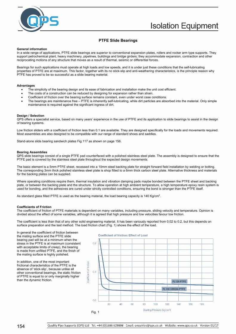
PTFE Slide Bearings
General information In a wide range of applications, PTFE slide bearings are superior to conventional expansion plates, rollers and rocker arm type supports. They support petrochemical plant, heavy machinery, pipelines, buildings and bridge girders; they accommodate expansion, contraction and other reciprocating motions of any structure that moves as a result of thermal, seismic or differential forces. Bearings for such applications must operate at high loads and low speeds, and it is under just these conditions that the self-lubricating properties of PTFE are at maximum. This factor, together with its no stick-slip and anti-weathering characteristics, is the principle reason why PTFE has proved to be so successful as a slide bearing material. Advantages
The simplicity of the bearing design and its ease of fabrication and installation make the unit cost efficient. The costs of a construction can be reduced by designing for expansion rather than strain. Coefficient of friction over the bearing surface remains constant, even under worst case conditions. The bearings are maintenance free – PTFE is inherently self-lubricating, while dirt particles are absorbed into the material. Only simple
maintenance is required against the significant ingress of dirt. Design / Selection QPS offers a specialist service, based on many years’ experience in the use of PTFE and its application to slide bearings to assist in the design of bearing systems. Low friction sliders with a coefficient of friction less than 0.1 are available. They are designed specifically for the loads and movements required. Most assemblies are also designed to be compatible with our range of standard shoes and saddles. Stand-alone slide bearing sandwich plates Fig.117 as shown on page 156. Bearing Assemblies QPS slide bearings consist of a single PTFE pad counterfaced with a polished stainless steel plate. The assembly is designed to ensure that the PTFE pad is covered by the stainless steel plate throughout the expected design movements. The basic element is a 5mm PTFE sheet, recessed into a 10mm steel backing plate for straight forward field installation by welding or bolting. The corresponding 3mm thick polished stainless steel plate is shop fitted to a 6mm thick carbon steel plate. Alternative thickness and materials for the backing plates can be supplied. Where operating conditions require them, thermal insulation and vibration damping pads maybe bonded between the PTFE sheet and backing plate, or between the backing plate and the structure. To allow operation at high ambient temperature, a high temperature epoxy resin system is used for bonding, and the adhesives are cured under strictly controlled conditions, ensuring the bond is stronger than the PTFE itself. As standard glass filled PTFE is used as the bearing material, the load bearing capacity is 140 Kg/cm2. Coefficients of Friction The coefficient of friction of PTFE materials is dependent on many variables, including pressure, sliding velocity and temperature. Opinion is divided about the effect of some variables, although it is agreed that high pressure and low velocities favour low friction. The coefficient is less than that of any other solid engineering material. It has been variously reported from 0.02 to 0.2, but this depends on surface preparation and the test method. The load friction chart (Fig. 1) shows the effect of the load. In general the coefficient of friction between the mating surface and the PTFE slide bearing pad will be at a minimum when the stress in the PTFE is at maximum (consistent with acceptable limits of creep), the bearing is made from unfilled PTFE, and the finish of the mating surface is highly polished. In addition, one of the most important frictional characteristics of the PTFE is the absence of ‘stick-slip’, because unlike all other conventional bearings, the static friction of PTFE is equal to or only marginally higher than the dynamic friction.
Fig. 1
FL129 PTFE
FL100 VIRGIN PTFE

155
PTFE Slide Bearings
Recommended Maximum Bearing Pressures Fig. 2 indicates the optimum pressure, but depending on circumstances, design pressures may be allowed to vary from the optimum. With the pressures, a design coefficient of friction 0.1 for unfilled PTFE or 0.12 for filled PTFE will give a significant margin of safety when operating conditions cannot accurately be predicted, but the figures obtained in practise will normally be considerably less than these. Thermal Insulation Where the temperature at the faces of the PTFE is likely to exceed 200°C by conduction through the bearing components, a thermal barrier must be interposed between the heat source and the sliding unit, QPS recommend using the use of Monolux 500 – the thickness required can be computed from the graph in Fig. 3. The graph shows the external surface temperature that can be anticipated using Monolux 500 in constructions up to 100mm thickness based on the practical tests. The actual surface temperature will differ with variations in surface conductance. Bonding of PTFE Chemical bonding is the recommended method for locating the bearing material on its support, because the shear value of the epoxy adhesive is greater than that of the PTFE. The temperature at the surface of the PTFE shall never exceed 140°C. All bonded PTFE elements are not adversely affected by exposure to ultra violet light providing the minimum thickness requirement of 1.5mm is met. Site bonding of PTFE is not recommended – strictly controlled conditions of cleanliness, pressure and temperature are required to obtain a satisfactory bond between PTFE and the substrate. Material Thickness The ideal thickness has been found to be 5mm, due to the recessing requirement. This is thick enough to allow for some constructional misalignment and to allow for dirt and grit embedment. Installation The bearing components can be located to the installation by bolting, tack-welding, full welding or mortar embedment, and the appropriate type of bearing should be chosen according to the installation method. The PTFE should be adequately protected against weld splatter, paint spray, metal swarf, etc. during installation. Pad Dimensions The top bearing pad should be larger than the bottom pad by an amount equal to the expected movement, in order to maintain a constant contact area. Bearing Temperature The temperature at the surface of the PTFE should generally be less than 120°C and should never exceed 200°C. As a rule of thumb, under normal conditions the temperature falls by 200°C for every 100mm from the heat source (in ambient air) – for example, a typical horizontal vessel operating at 500°C will have a bottom of saddle temperature of about 150°C. Temperature does not normally present a problem. However, if the bearing temperature is likely to exceed 200°C a thermal insulator should be fitted between the structure and the bearing back plate (see above topic – Thermal Insulation). Vibration / Acoustic Dampening Slide bearing units can be built with a variety of elastomer composite interlayers or backings to suit customers design parameters when acoustic or dampening is necessary. Elastomers may be used when simple angular or rotational movements are required.
Fig. 2
Fig. 3
FL129 PTFE
FL100 VIRGIN PTFE

156
PTFE Slide Bearings
Slideway Rigidity When a series of slide bearings is used to form a slideway, e.g. for oil rig movement, the slide supports must be sufficiently rigid to avoid deflection of the individual bearings or uneven loading. Deflection of only a few degrees could significantly increase the apparent coefficient of friction, and cause bearing failure if all the load is carriedby one end of the bearing pad. Design Steps The following steps will provide an indication of the slide bearing requirements for a particular application:
Determine the load of the structure – this will indicate the total load bearing area required at a suitable bearing pressure. Decide the number and position of the bearings according to the rigidity and function of the structure. Take account of operating temperature limits, and specify any necessary thermal insulation. Consider any unusual conditions affecting the bearings, such as the need for additional thermal insulation, damping pads, etc. Decide the most appropriate method of mounting the bearings. Select the types of bearings required and specify their dimensions.
Technical Advantages of PTFE Slide Bearings
PTFE has the lowest coefficient of friction of any known solid engineering material including lubricated metal. There is no stick-slip action. They have indefinite life, since chemicals and weather have no effect on PTFE – moisture absorption is less than 0.01% even under
icing conditions or immersion, and the material is chemically inert. No maintenance is required, PTFE will never cold weld to itself and therefore requires no lubrication. The bearings are easily installed, either pre-assembled or on site. PTFE bearings are far less bulky than alternative assemblies. There is no possibility of fatigue failure. Electrical and thermal insulation minimise galvanic corrosion and heat loss. Vibrations are damped. Small particles which may become embedded do not cause binding of the surfaces. The slide bearings can accommodate some misalignment in construction without setting up stress corrosion along a leading edge, as
can occur in conventional bearings.


