Embed Size (px)
Citation preview

ISO/IEC 29341-1-1 Edition 1.0 2011-09
INTERNATIONAL STANDARD
Information technology – UPnP device architecture – Part 1-1: UPnP Device Architecture Version 1.1
INTERNATIONAL ELECTROTECHNICAL COMMISSION XA ICS 35.200
PRICE CODE
ISBN 978-2-88912-656-9
colourinside
This is a preview - click here to buy the full publication
XXXX: © IEC:2010 — 1 —
CONTENTS
Introduction .......................................................................................................................... 4 0 Addressing ................................................................................................................... 10
0.1 Determining whether to use Auto-IP ..................................................................... 10 0.2 Choosing an address ........................................................................................... 10 0.3 Testing the address ............................................................................................. 11 0.4 Forwarding rules .................................................................................................. 11 0.5 Periodic checking for dynamic address availability ................................................ 12 0.6 Device naming and DNS interaction ..................................................................... 12 0.7 Name to IP address resolution ............................................................................. 12 0.8 References .......................................................................................................... 12
1 Discovery ..................................................................................................................... 13 1.1 SSDP message format ......................................................................................... 16
1.1.1 SSDP Start-line ........................................................................................ 16 1.1.2 SSDP message header fields ................................................................... 16 1.1.3 SSDP header field extensions .................................................................. 16 1.1.4 UUID format and RECOMMENDED generation algorithms ........................ 17 1.1.5 SSDP processing rules ............................................................................ 17
1.2 Advertisement ..................................................................................................... 17 1.2.1 Advertisement protocols and standards .................................................... 18 1.2.2 Device available - NOTIFY with ssdp:alive ................................................ 18 1.2.3 Device unavailable -- NOTIFY with ssdp:byebye ....................................... 24 1.2.4 Device Update – NOTIFY with ssdp:update .............................................. 25
1.3 Search ................................................................................................................ 27 1.3.1 Search protocols and standards ............................................................... 27 1.3.2 Search request with M-SEARCH .............................................................. 28 1.3.3 Search response ...................................................................................... 31
1.4 References .......................................................................................................... 33 2 Description ................................................................................................................... 33
2.1 Generic requirements on HTTP usage .................................................................. 36 2.2 Generic requirements on XML usage .................................................................... 38 2.3 Device description ............................................................................................... 38 2.4 UPnP Device Template ........................................................................................ 43 2.5 Service description .............................................................................................. 43
2.5.1 Defining and processing extended data types ........................................... 50 2.5.2 String equivalents of extended data types ................................................. 51 2.5.3 Generic requirements ............................................................................... 52 2.5.4 Ordering of Elements ............................................................................... 52 2.5.5 Versioning ............................................................................................... 53
2.6 UPnP Service Template ....................................................................................... 53 2.7 Non-standard vendor extensions and limitations ................................................... 53
2.7.1 Placement of Additional Elements and Attributes ...................................... 55 2.8 UPnP Device Schema .......................................................................................... 55 2.9 UPnP Service Schema ......................................................................................... 55 2.10 UPnP Datatype Schema ...................................................................................... 55 2.11 Retrieving a description using HTTP .................................................................... 55
29341-1-1 © ISO/IEC:2011(E)29341-1-1 © ISO/IEC:2011(E)
This is a preview - click here to buy the full publication
XXXX: © IEC:2010 — 2 —
2.12 References .......................................................................................................... 59 3 Control ......................................................................................................................... 59
3.1 Control protocols ................................................................................................. 62 3.1.1 SOAP Profile ........................................................................................... 62
3.2 Actions ................................................................................................................ 65 3.2.1 Action invocation ...................................................................................... 65 3.2.2 Action Response ...................................................................................... 68 3.2.3 UPnP Action Schema ............................................................................... 70 3.2.4 Recommendations and additional requirements ........................................ 71 3.2.5 Action error response ............................................................................... 71 3.2.6 UPnP Error Schema ................................................................................. 74
3.3 Query for variable ................................................................................................ 74 3.4 References .......................................................................................................... 75
4 Eventing ....................................................................................................................... 75 4.1 Unicast eventing .................................................................................................. 75
4.1.1 Subscription ............................................................................................. 77 4.1.2 SUBSCRIBE with NT and CALLBACK ....................................................... 79 4.1.3 Renewing a subscription with SUBSCRIBE with SID ................................. 81 4.1.4 Canceling a subscription with UNSUBSCRIBE .......................................... 82
4.2 Multicast Eventing ............................................................................................... 84 4.3 Event messages .................................................................................................. 85
4.3.1 Error Cases ............................................................................................. 86 4.3.2 Unicast eventing: Event messages: NOTIFY ............................................. 86 4.3.3 Multicast Eventing: Event messages: NOTIFY .......................................... 89
4.4 UPnP Event Schema ........................................................................................... 92 4.5 Augmenting the UPnP Device and Service Schemas ............................................ 92 4.6 References .......................................................................................................... 93
5 Presentation ................................................................................................................. 93 5.1 References .......................................................................................................... 94
Annex A (normative) IP Version 6 Support ........................................................................... 95 A.1 Introduction ......................................................................................................... 95 A.2 General Principles ............................................................................................... 95
A.2.1 Device operation ...................................................................................... 96 A.2.2 Control point operation ............................................................................. 96
A.3 Addressing .......................................................................................................... 96 A.3.1 Summary of boot/startup process ............................................................. 96 A.3.2 Short overview of protocol specified by RFC 2462 .................................... 97
A.4 Discovery ............................................................................................................ 97 A.4.1 Advertisement .......................................................................................... 98 A.4.2 Advertisement: Device unavailable ........................................................... 98 A.4.3 Advertisement: Device update .................................................................. 99 A.4.4 Search ..................................................................................................... 99 A.4.5 Search response ...................................................................................... 99
A.5 Description ........................................................................................................ 100 A.6 Control .............................................................................................................. 100 A.7 Eventing ............................................................................................................ 100 A.8 Presentation ...................................................................................................... 100 A.9 References ........................................................................................................ 101
29341-1-1 © ISO/IEC:2011(E)
This is a preview - click here to buy the full publication
XXXX: © IEC:2010 — 3 —
Annex B (informative) Schemas ........................................................................................ 102 B.1 UPnP Device Schema ........................................................................................ 102 B.2 UPnP Service Schema ....................................................................................... 106 B.3 UPnP Control Schema ....................................................................................... 110 B.4 UPnP Error Schema .......................................................................................... 111 B.5 UPnP Event Schema ......................................................................................... 112 B.6 Schema references ............................................................................................ 113
Figure 1: — Protocol stack .................................................................................................... 5 Figure 1-1: — Discovery architecture .................................................................................. 13 Figure 1-2: — Advertisement protocol stack ........................................................................ 18 Figure 1-3: — Initial and repeat announcements, no announcement spreading ..................... 20 Figure 1-4: — Initial and repeat announcements, message spreading of repeat announcements .................................................................................................................. 20 Figure 1-5: — Search protocol stack ................................................................................... 27 Figure 2-1: — Description architecture ................................................................................ 33 Figure 2-2: — Description retrieval protocol stack ................................................................ 56 Figure 3-1: — Control architecture ...................................................................................... 59 Figure 3-2: — Control protocol stack ................................................................................... 62 Figure 4-1: — Unicast eventing architecture ........................................................................ 75 Figure 4-2: — Unicast eventing protocol stack ..................................................................... 76 Figure 4-3: — Multicast eventing architecture ...................................................................... 84 Figure 4-4: — Mulitcast eventing protocol stack ................................................................... 85 Figure 5-1: — Presentation architecture .............................................................................. 93 Figure 5-2: — Presentation protocol stack ........................................................................... 94 Table 1 — Acronyms ............................................................................................................. 7 Table 1-1: — Root device discovery messages .................................................................... 19 Table 1-2: — Embedded device discovery messages ........................................................... 19 Table 1-3: — Service discovery messages .......................................................................... 19 Table 2-1: — Vendor extensions ......................................................................................... 53 Table 3-1: — SOAP 1.1 UPnP Profile .................................................................................. 62 Table 3-2: — mustUnderstand attribute ............................................................................ 64 Table 3-3: — UPnP Defined Action error codes ................................................................... 73 Table 4-4: — HTTP Status Codes indicating a Subscription Error ......................................... 81 Table 4-5: — HTTP Status Codes indicating a Resubscription Error ..................................... 82 Table 4-6: — HTTP Status Codes indicating a Cancel Subscription Error ............................. 83 Table 4-7: — HTTP Status Codes indicating a Notify Error ................................................... 89 Table 4-8: — Multicast event levels ..................................................................................... 91
29341-1-1 © ISO/IEC:2011(E)
This is a preview - click here to buy the full publication
INFORMATION TECHNOLOGY – UPNP DEVICE ARCHITECTURE –
Part 1-1: UPnP Device Architecture Version 1.1
FOREWORD
1) ISO (International Organization for Standardization) and IEC (International Electrotechnical Commission) form the specialized system for worldwide standardization. National bodies that are members of ISO or IEC participate in the development of International Standards. Their preparation is entrusted to technical committees; any ISO and IEC member body interested in the subject dealt with may participate in this preparatory work. International governmental and non-governmental organizations liaising with ISO and IEC also participate in this preparation.
2) In the field of information technology, ISO and IEC have established a joint technical committee, ISO/IEC JTC 1. Draft International Standards adopted by the joint technical committee are circulated to national bodies for voting. Publication as an International Standard requires approval by at least 75 % of the national bodies casting a vote.
3) The formal decisions or agreements of IEC and ISO on technical matters express, as nearly as possible, an international consensus of opinion on the relevant subjects since each technical committee has representation from all interested IEC and ISO member bodies.
4) IEC, ISO and ISO/IEC publications have the form of recommendations for international use and are accepted by IEC and ISO member bodies in that sense. While all reasonable efforts are made to ensure that the technical content of IEC, ISO and ISO/IEC publications is accurate, IEC or ISO cannot be held responsible for the way in which they are used or for any misinterpretation by any end user.
5) In order to promote international uniformity, IEC and ISO member bodies undertake to apply IEC, ISO and ISO/IEC publications transparently to the maximum extent possible in their national and regional publications. Any divergence between any ISO/IEC publication and the corresponding national or regional publication should be clearly indicated in the latter.
6) ISO and IEC provide no marking procedure to indicate their approval and cannot be rendered responsible for any equipment declared to be in conformity with an ISO/IEC publication.
7) All users should ensure that they have the latest edition of this publication.
8) No liability shall attach to IEC or ISO or its directors, employees, servants or agents including individual experts and members of their technical committees and IEC or ISO member bodies for any personal injury, property damage or other damage of any nature whatsoever, whether direct or indirect, or for costs (including legal fees) and expenses arising out of the publication of, use of, or reliance upon, this ISO/IEC publication or any other IEC, ISO or ISO/IEC publications.
9) Attention is drawn to the normative references cited in this publication. Use of the referenced publications is indispensable for the correct application of this publication.
10) Attention is drawn to the possibility that some of the elements of this International Standard may be the subject of patent rights. ISO and IEC shall not be held responsible for identifying any or all such patent rights.
International Standard ISO/IEC 29341-1-1 was prepared by UPnP Forum Steering committee1, was adopted, under the fast track procedure, by subcommittee 25: Interconnection of information technology equipment, of ISO/IEC joint technical committee 1: Information technology.
The list of all currently available parts of the ISO/IEC 29341 series, under the general title Information technology – UPnP device architecture, can be found on the IEC web site.
This International Standard has been approved by vote of the member bodies, and the voting results may be obtained from the address given on the second title page.
————————— 1 UPnP Forum Steering committee, UPnP Forum, 3855 SW 153rd Drive, Beaverton, Oregon 97006 USA. See also
“Introduction”.
29341-1-1 © ISO/IEC:2011(E)
This is a preview - click here to buy the full publication

IMPORTANT – The “colour inside” logo on the cover page of this publication indicates that it contains colours which are considered to be useful for the correct understanding of its contents. Users should therefore print this publication using a colour printer.
29341-1-1 © ISO/IEC:2011(E)
This is a preview - click here to buy the full publication
XXXX: © IEC:2010 — 4 —
Introduction
What is UPnP™1 Technology?
UPnP™ technology defines an architecture for pervasive peer-to-peer network connectivity of intelligent appliances, wireless devices, and PCs of all form factors. It is designed to bring easy-to-use, flexible, standards-based connectivity to ad-hoc or unmanaged networks whether in the home, in a small business, public spaces, or attached to the Internet. UPnP technology provides a distributed, open networking architecture that leverages TCP/IP and Web technologies to enable seamless proximity networking in addition to control and data transfer among networked devices.
The UPnP Device Architecture (UDA) is more than just a simple extension of the plug and play peripheral model. It is designed to support zero-configuration, "invisible" networking, and automatic discovery for a breadth of device categories from a wide range of vendors. This means a device can dynamically join a network, obtain an IP address, convey its capabilities, and learn about the presence and capabilities of other devices. Finally, a device can leave a network smoothly and automatically without leaving any unwanted state behind.
The technologies leveraged in the UPnP architecture include Internet protocols such as IP, TCP, UDP, HTTP, and XML. Like the Internet, contracts are based on wire protocols that are declarative, expressed in XML, and communicated via HTTP. Using Internet protocols is a strong choice for UDA because of its proven ability to span different physical media, to enable real world multiple-vendor interoperation, and to achieve synergy with the Internet and many home and office intranets. The UPnP architecture has been explicitly designed to accommodate these environments. Further, via bridging, UDA accommodates media running non-IP protocols when cost, technology, or legacy prevents the media or devices attached to it from running IP.
What is "universal" about UPnP technology? No device drivers; common protocols are used instead. UPnP networking is media independent. UPnP devices can be implemented using any programming language, and on any operating system. The UPnP architecture does not specify or constrain the design of an API for applications; OS vendors may create APIs that suit their customers’ needs.
UPnP™ Forum
The UPnP Forum is an industry initiative designed to enable easy and robust connectivity among stand-alone devices and PCs from many different vendors. The UPnP Forum seeks to develop standards for describing device protocols and XML-based device schemas for the purpose of enabling device-to-device interoperability in a scalable, networked environment.
The UPnP Implementers Corporation (UIC) is comprised of UPnP Forum member companies across many industries that promote the adoption of uniform technical device interconnectivity standards and testing and certifying of these devices. The UIC develops and administers the testing and certification process, administers the UPnP logo program, and provides information to UIC members and other interested parties regarding the certification of UPnP devices. The UPnP device certification process is open to any vendor who is a member of the UPnP Forum and UIC, has paid the UIC dues, and has devices that support UPnP functionality. For more information, see http://www.upnp-ic.org.
The UPnP Forum has set up working committees in specific areas of domain expertise. These working committees are charged with creating proposed device standards, building sample implementations, and building appropriate test suites. This document indicates specific technical decisions that are the purview of UPnP Forum working committees.
UPnP vendors can build compliant devices with confidence of interoperability and benefits of shared intellectual property and the logo program. Separate from the logo program, vendors may also build devices that adhere to the UPnP Device Architecture defined herein without a formal standards procedure. If vendors build non-standard devices, they determine technical decisions that would otherwise be determined by a UPnP Forum working committee. 1 UPnP™ is a certification mark of the UPnP™ Implementers Corporation.
29341-1-1 © ISO/IEC:2011(E)
This is a preview - click here to buy the full publication
XXXX: © IEC:2010 — 5 —
In this document
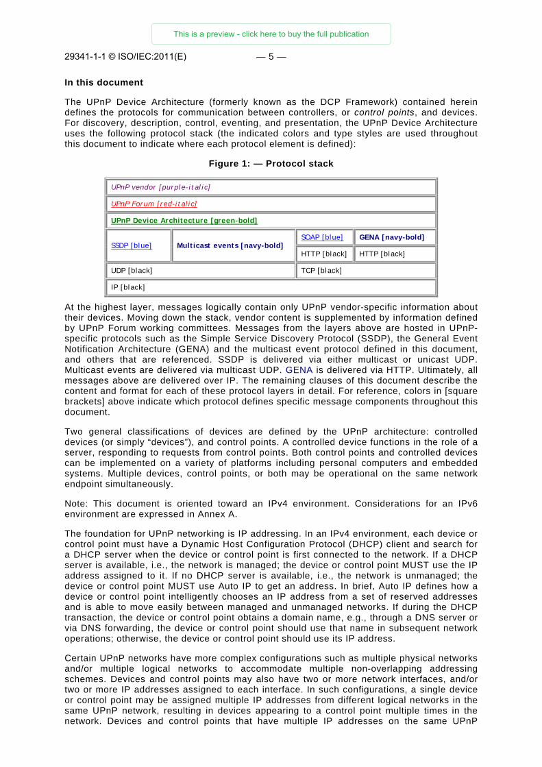
The UPnP Device Architecture (formerly known as the DCP Framework) contained herein defines the protocols for communication between controllers, or control points, and devices. For discovery, description, control, eventing, and presentation, the UPnP Device Architecture uses the following protocol stack (the indicated colors and type styles are used throughout this document to indicate where each protocol element is defined):
Figure 1: — Protocol stack
UPnP vendor [purple-italic]
UPnP Forum [red-italic]
UPnP Device Architecture [green-bold]
SSDP [blue] Multicast events [navy-bold] SOAP [blue] GENA [navy-bold]
HTTP [black] HTTP [black]
UDP [black] TCP [black]
IP [black]
At the highest layer, messages logically contain only UPnP vendor-specific information about their devices. Moving down the stack, vendor content is supplemented by information defined by UPnP Forum working committees. Messages from the layers above are hosted in UPnP-specific protocols such as the Simple Service Discovery Protocol (SSDP), the General Event Notification Architecture (GENA) and the multicast event protocol defined in this document, and others that are referenced. SSDP is delivered via either multicast or unicast UDP. Multicast events are delivered via multicast UDP. GENA is delivered via HTTP. Ultimately, all messages above are delivered over IP. The remaining clauses of this document describe the content and format for each of these protocol layers in detail. For reference, colors in [square brackets] above indicate which protocol defines specific message components throughout this document.
Two general classifications of devices are defined by the UPnP architecture: controlled devices (or simply “devices”), and control points. A controlled device functions in the role of a server, responding to requests from control points. Both control points and controlled devices can be implemented on a variety of platforms including personal computers and embedded systems. Multiple devices, control points, or both may be operational on the same network endpoint simultaneously.
Note: This document is oriented toward an IPv4 environment. Considerations for an IPv6 environment are expressed in Annex A.
The foundation for UPnP networking is IP addressing. In an IPv4 environment, each device or control point must have a Dynamic Host Configuration Protocol (DHCP) client and search for a DHCP server when the device or control point is first connected to the network. If a DHCP server is available, i.e., the network is managed; the device or control point MUST use the IP address assigned to it. If no DHCP server is available, i.e., the network is unmanaged; the device or control point MUST use Auto IP to get an address. In brief, Auto IP defines how a device or control point intelligently chooses an IP address from a set of reserved addresses and is able to move easily between managed and unmanaged networks. If during the DHCP transaction, the device or control point obtains a domain name, e.g., through a DNS server or via DNS forwarding, the device or control point should use that name in subsequent network operations; otherwise, the device or control point should use its IP address.
Certain UPnP networks have more complex configurations such as multiple physical networks and/or multiple logical networks to accommodate multiple non-overlapping addressing schemes. Devices and control points may also have two or more network interfaces, and/or two or more IP addresses assigned to each interface. In such configurations, a single device or control point may be assigned multiple IP addresses from different logical networks in the same UPnP network, resulting in devices appearing to a control point multiple times in the network. Devices and control points that have multiple IP addresses on the same UPnP
29341-1-1 © ISO/IEC:2011(E)
This is a preview - click here to buy the full publication
XXXX: © IEC:2010 — 6 —
network are referred to as multi-homed. Throughout this document, the term "UPnP-enabled interface" is used to refer to an interface which is assigned an IP address belonging to the UPnP network. Additional behaviors specific to multi-homed devices and control points will be covered in applicable clauses throughout the document. However, as a general principle, related interactions between control points and devices (e.g. action control request and response messages, event subscription and event messages) MUST occur using the same pair of outgoing and incoming UPnP-enabled interfaces.
Given an IP address, Step 1 in UPnP networking is discovery. When a device is added to the network, the UPnP discovery protocol allows that device to advertise its services to control points on the network. Similarly, when a control point is added to the network, the UPnP discovery protocol allows that control point to search for devices of interest on the network. The fundamental exchange in both cases is a discovery message containing a few essential specifics about the device or one of its services, e.g., its type, identifier, and a pointer to more detailed information. The clause on Discovery below explains how devices advertise, how control points search, and contains details about the format of discovery messages.
Step 2 in UPnP networking is description. After a control point has discovered a device, the control point still knows very little about the device. For the control point to learn more about the device and its capabilities, or to interact with the device, the control point must retrieve the device's description from the URL provided by the device in the discovery message. Devices may contain other logical devices, as well as functional units, or services. The UPnP description for a device is expressed in XML and includes vendor-specific manufacturer information like the model name and number, the serial number, the manufacturer name, URLs to vendor-specific Web sites, etc. The description also includes a list of any embedded devices or services, as well as URLs for control, eventing, and presentation. For each service, the description includes a list of the commands, or actions, to which the service responds, and parameters, or arguments for each action; the description for a service also includes a list of variables; these variables model the state of the service at run time, and are described in terms of their data type, range, and event characteristics. The clause on Description below explains how devices are described and how control points retrieve those descriptions.
Step 3 in UPnP networking is control. After a control point has retrieved a description of the device, the control point can send actions to a device's services. To do this, a control point sends a suitable control message to the control URL for the service (provided in the device description). Control messages are also expressed in XML using the Simple Object Access Protocol (SOAP). Like function calls, in response to the control message, the service returns any action-specific values. The effects of the action, if any, are modeled by changes in the variables that describe the run-time state of the service. The clause on Control below explains the description of actions, state variables, and the format of control messages.
Step 4 in UPnP networking is eventing. A UPnP description for a service includes a list of actions the service responds to and a list of variables that model the state of the service at run time. The service publishes updates when these variables change, and a control point may subscribe to receive this information. The service publishes updates by sending event messages. Event messages contain the names of one or more state variables and the current value of those variables. These messages are also expressed in XML. A special initial event message is sent when a control point first subscribes; this event message contains the names and values for all evented variables and allows the subscriber to initialize its model of the state of the service. To support scenarios with multiple control points, eventing is designed to keep all control points equally informed about the effects of any action. Therefore, all subscribers are sent all event messages, subscribers receive event messages for all evented variables that have changed, and event messages are sent no matter why the state variable changed (either in response to a requested action or because the state the service is modeling changed). Multicast eventing is a variant of Step 4 in UPnP networking. Through multicast eventing, control points can listen to state changes in services without subscription. This form of eventing is useful first when events which are not relevant to specific UPnP interactions should be delivered to control points to inform users, and second when multiple controlled devices want to inform multiple other control points. Multicast eventing is inherently unreliable since it is based on UDP. To increase the probability of successful transmission, the option to retransmit multicast event notifications is outlined. UPnP Working committees should define whether specific events are multicast events. The clause on Eventing below
29341-1-1 © ISO/IEC:2011(E)
This is a preview - click here to buy the full publication
XXXX: © IEC:2010 — 7 —
explains unicast event subscription and the format of both unicast and multicast event messages.
Step 5 in UPnP networking is presentation. If a device has a URL for presentation, then the control point can retrieve a page from this URL, load the page into a browser, and depending on the capabilities of the page, allow a user to control the device and/or view device status. The degree to which each of these can be accomplished depends on the specific capabilities of the presentation page and device. The clause on Presentation below explains the protocol for retrieving a presentation page.
Audience
The audience for this document includes UPnP device and control point vendors, members of UPnP Forum working committees, and anyone else who has a need to understanding the technical details of UPnP protocols.
This document assumes the reader is familiar with the HTTP, TCP, UDP, IP family of protocols; this document makes no attempt to explain them. This document also assumes most readers will be new to XML, and while it is not an XML tutorial, XML-related issues are addressed in detail given the centrality of XML to the UPnP Device Architecture. This document makes no assumptions about the reader's understanding of various programming or scripting languages.
Conformance terminology
In this document, features are described as REQUIRED, RECOMMENDED, OPTIONAL or DEPRECATED as follows:
REQUIRED (or MUST or MANDATORY).
These basic features MUST be implemented to comply with UPnP Device Architecture. The phrases “MUST NOT”, and “PROHIBITED” indicate behavior that is prohibited, i.e. that if performed means the implementation is not in compliance.
RECOMMENDED (or SHOULD).
These features add functionality supported by UPnP Device Architecture and SHOULD be implemented. RECOMMENDED features take advantage of the capabilities UPnP Device Architecture, usually without imposing major cost increases. Notice that for compliance testing, if a RECOMMENDED feature is implemented, it MUST meet the specified requirements to be in compliance with these guidelines. Some RECOMMENDED features could become requirements in the future. The phrase “SHOULD NOT” indicates behavior that is permitted but NOT RECOMMENDED.
OPTIONAL (or MAY).
These features are neither REQUIRED nor RECOMMENDED by UPnP Device Architecture, but if the feature is implemented, it MUST meet the specified requirements to be in compliance with these guidelines. These features are not likely to become requirements in the future.
DEPRECATED.
Although these features are still described in this specification, they should not be implemented except for backward compatibility. The occurrence of a deprecated feature during operation of an implementation compliant with the current specification has no effect on the implementation’s operation and does not produce any error conditions. Backward compatibility may require that a feature is implemented and functions as specified but it MUST never be used by implementations compliant with this specification.
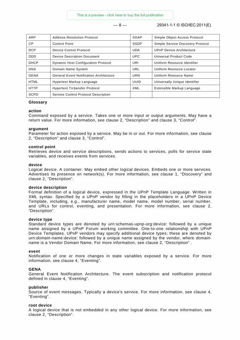
Acronyms
Table 1 — Acronyms
Acronym Meaning Acronym Meaning
29341-1-1 © ISO/IEC:2011(E)
This is a preview - click here to buy the full publication
XXXX: © IEC:2010 — 8 —
ARP Address Resolution Protocol SOAP Simple Object Access Protocol
CP Control Point SSDP Simple Service Discovery Protocol
DCP Device Control Protocol UDA UPnP Device Architecture
DDD Device Description Document UPC Universal Product Code
DHCP Dynamic Host Configuration Protocol URI Uniform Resource Identifier
DNS Domain Name System URL Uniform Resource Locator
GENA General Event Notification Architecture URN Uniform Resource Name
HTML Hypertext Markup Language UUID Universally Unique Identifier
HTTP Hypertext Trrdansfer Protocol XML Extensible Markup Language
SCPD Service Control Protocol Description
Glossary
action Command exposed by a service. Takes one or more input or output arguments. May have a return value. For more information, see clause 2, “Description” and clause 3, “Control”.
argument Parameter for action exposed by a service. May be in or out. For more information, see clause 2, “Description” and clause 3, “Control”.
control point Retrieves device and service descriptions, sends actions to services, polls for service state variables, and receives events from services.
device Logical device. A container. May embed other logical devices. Embeds one or more services. Advertises its presence on network(s). For more information, see clause 1, “Discovery” and clause 2, “Description”.
device description Formal definition of a logical device, expressed in the UPnP Template Language. Written in XML syntax. Specified by a UPnP vendor by filling in the placeholders in a UPnP Device Template, including, e.g., manufacturer name, model name, model number, serial number, and URLs for control, eventing, and presentation. For more information, see clause 2, “Description”.
device type Standard device types are denoted by urn:schemas-upnp-org:device: followed by a unique name assigned by a UPnP Forum working committee. One-to-one relationship with UPnP Device Templates. UPnP vendors may specify additional device types; these are denoted by urn:domain-name:device: followed by a unique name assigned by the vendor, where domain-name is a Vendor Domain Name. For more information, see clause 2, “Description” .
event Notification of one or more changes in state variables exposed by a service. For more information, see clause 4, “Eventing”.
GENA General Event Notification Architecture. The event subscription and notification protocol defined in clause 4, “Eventing”.
publisher Source of event messages. Typically a device's service. For more information, see clause 4, “Eventing”.
root device A logical device that is not embedded in any other logical device. For more information, see clause 2, “Description”.
29341-1-1 © ISO/IEC:2011(E)
This is a preview - click here to buy the full publication
XXXX: © IEC:2010 — 9 —
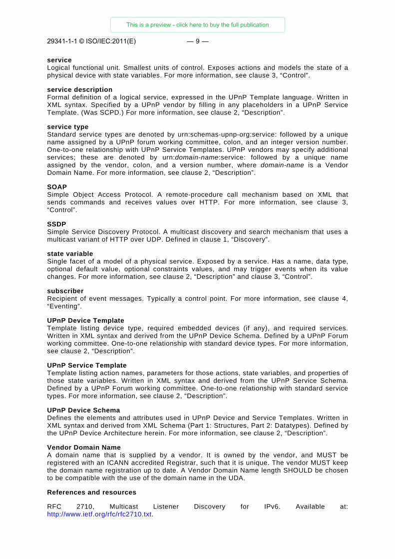
service Logical functional unit. Smallest units of control. Exposes actions and models the state of a physical device with state variables. For more information, see clause 3, “Control”.
service description Formal definition of a logical service, expressed in the UPnP Template language. Written in XML syntax. Specified by a UPnP vendor by filling in any placeholders in a UPnP Service Template. (Was SCPD.) For more information, see clause 2, “Description”.
service type Standard service types are denoted by urn:schemas-upnp-org:service: followed by a unique name assigned by a UPnP forum working committee, colon, and an integer version number. One-to-one relationship with UPnP Service Templates. UPnP vendors may specify additional services; these are denoted by urn:domain-name:service: followed by a unique name assigned by the vendor, colon, and a version number, where domain-name is a Vendor Domain Name. For more information, see clause 2, “Description”.
SOAP Simple Object Access Protocol. A remote-procedure call mechanism based on XML that sends commands and receives values over HTTP. For more information, see clause 3, “Control”.
SSDP Simple Service Discovery Protocol. A multicast discovery and search mechanism that uses a multicast variant of HTTP over UDP. Defined in clause 1, “Discovery”.
state variable Single facet of a model of a physical service. Exposed by a service. Has a name, data type, optional default value, optional constraints values, and may trigger events when its value changes. For more information, see clause 2, “Description” and clause 3, “Control”.
subscriber Recipient of event messages. Typically a control point. For more information, see clause 4, “Eventing”.
UPnP Device Template Template listing device type, required embedded devices (if any), and required services. Written in XML syntax and derived from the UPnP Device Schema. Defined by a UPnP Forum working committee. One-to-one relationship with standard device types. For more information, see clause 2, “Description”.
UPnP Service Template Template listing action names, parameters for those actions, state variables, and properties of those state variables. Written in XML syntax and derived from the UPnP Service Schema. Defined by a UPnP Forum working committee. One-to-one relationship with standard service types. For more information, see clause 2, “Description”.
UPnP Device Schema Defines the elements and attributes used in UPnP Device and Service Templates. Written in XML syntax and derived from XML Schema (Part 1: Structures, Part 2: Datatypes). Defined by the UPnP Device Architecture herein. For more information, see clause 2, “Description”.
Vendor Domain Name A domain name that is supplied by a vendor. It is owned by the vendor, and MUST be registered with an ICANN accredited Registrar, such that it is unique. The vendor MUST keep the domain name registration up to date. A Vendor Domain Name length SHOULD be chosen to be compatible with the use of the domain name in the UDA.
References and resources
RFC 2710, Multicast Listener Discovery for IPv6. Available at: http://www.ietf.org/rfc/rfc2710.txt.
29341-1-1 © ISO/IEC:2011(E)
This is a preview - click here to buy the full publication
XXXX: © IEC:2010 — 10 —
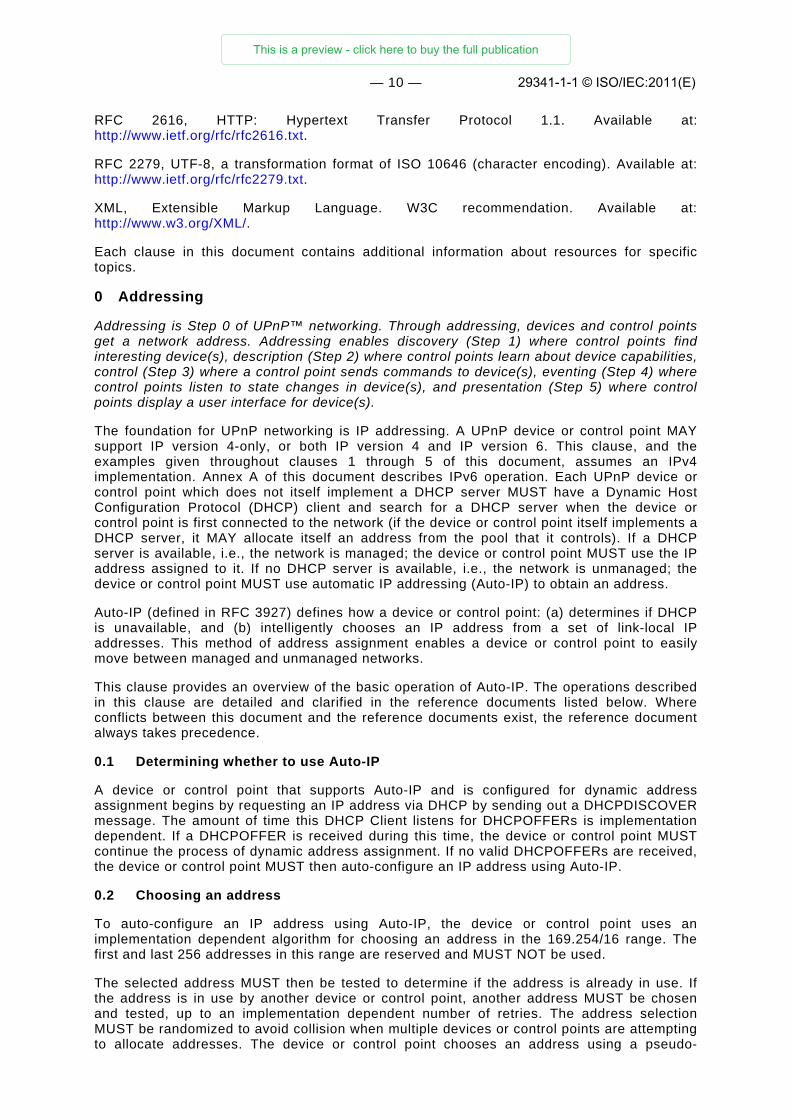
RFC 2616, HTTP: Hypertext Transfer Protocol 1.1. Available at: http://www.ietf.org/rfc/rfc2616.txt.
RFC 2279, UTF-8, a transformation format of ISO 10646 (character encoding). Available at: http://www.ietf.org/rfc/rfc2279.txt.
XML, Extensible Markup Language. W3C recommendation. Available at: http://www.w3.org/XML/.
Each clause in this document contains additional information about resources for specific topics.
0 Addressing
Addressing is Step 0 of UPnP™ networking. Through addressing, devices and control points get a network address. Addressing enables discovery (Step 1) where control points find interesting device(s), description (Step 2) where control points learn about device capabilities, control (Step 3) where a control point sends commands to device(s), eventing (Step 4) where control points listen to state changes in device(s), and presentation (Step 5) where control points display a user interface for device(s).
The foundation for UPnP networking is IP addressing. A UPnP device or control point MAY support IP version 4-only, or both IP version 4 and IP version 6. This clause, and the examples given throughout clauses 1 through 5 of this document, assumes an IPv4 implementation. Annex A of this document describes IPv6 operation. Each UPnP device or control point which does not itself implement a DHCP server MUST have a Dynamic Host Configuration Protocol (DHCP) client and search for a DHCP server when the device or control point is first connected to the network (if the device or control point itself implements a DHCP server, it MAY allocate itself an address from the pool that it controls). If a DHCP server is available, i.e., the network is managed; the device or control point MUST use the IP address assigned to it. If no DHCP server is available, i.e., the network is unmanaged; the device or control point MUST use automatic IP addressing (Auto-IP) to obtain an address.
Auto-IP (defined in RFC 3927) defines how a device or control point: (a) determines if DHCP is unavailable, and (b) intelligently chooses an IP address from a set of link-local IP addresses. This method of address assignment enables a device or control point to easily move between managed and unmanaged networks.
This clause provides an overview of the basic operation of Auto-IP. The operations described in this clause are detailed and clarified in the reference documents listed below. Where conflicts between this document and the reference documents exist, the reference document always takes precedence.
0.1 Determining whether to use Auto-IP
A device or control point that supports Auto-IP and is configured for dynamic address assignment begins by requesting an IP address via DHCP by sending out a DHCPDISCOVER message. The amount of time this DHCP Client listens for DHCPOFFERs is implementation dependent. If a DHCPOFFER is received during this time, the device or control point MUST continue the process of dynamic address assignment. If no valid DHCPOFFERs are received, the device or control point MUST then auto-configure an IP address using Auto-IP.
0.2 Choosing an address
To auto-configure an IP address using Auto-IP, the device or control point uses an implementation dependent algorithm for choosing an address in the 169.254/16 range. The first and last 256 addresses in this range are reserved and MUST NOT be used.
The selected address MUST then be tested to determine if the address is already in use. If the address is in use by another device or control point, another address MUST be chosen and tested, up to an implementation dependent number of retries. The address selection MUST be randomized to avoid collision when multiple devices or control points are attempting to allocate addresses. The device or control point chooses an address using a pseudo-
29341-1-1 © ISO/IEC:2011(E)
This is a preview - click here to buy the full publication
XXXX: © IEC:2010 — 11 —
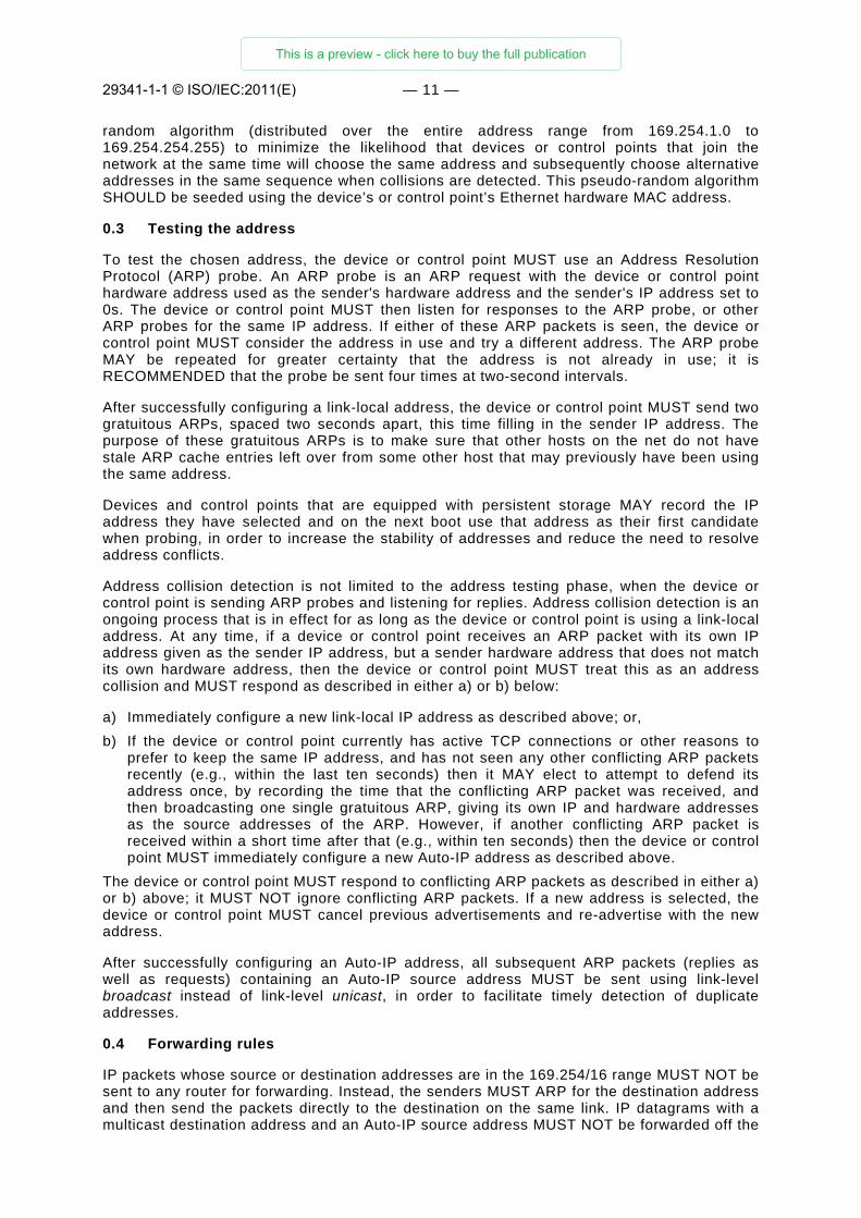
random algorithm (distributed over the entire address range from 169.254.1.0 to 169.254.254.255) to minimize the likelihood that devices or control points that join the network at the same time will choose the same address and subsequently choose alternative addresses in the same sequence when collisions are detected. This pseudo-random algorithm SHOULD be seeded using the device’s or control point’s Ethernet hardware MAC address.
0.3 Testing the address
To test the chosen address, the device or control point MUST use an Address Resolution Protocol (ARP) probe. An ARP probe is an ARP request with the device or control point hardware address used as the sender's hardware address and the sender's IP address set to 0s. The device or control point MUST then listen for responses to the ARP probe, or other ARP probes for the same IP address. If either of these ARP packets is seen, the device or control point MUST consider the address in use and try a different address. The ARP probe MAY be repeated for greater certainty that the address is not already in use; it is RECOMMENDED that the probe be sent four times at two-second intervals.
After successfully configuring a link-local address, the device or control point MUST send two gratuitous ARPs, spaced two seconds apart, this time filling in the sender IP address. The purpose of these gratuitous ARPs is to make sure that other hosts on the net do not have stale ARP cache entries left over from some other host that may previously have been using the same address.
Devices and control points that are equipped with persistent storage MAY record the IP address they have selected and on the next boot use that address as their first candidate when probing, in order to increase the stability of addresses and reduce the need to resolve address conflicts.
Address collision detection is not limited to the address testing phase, when the device or control point is sending ARP probes and listening for replies. Address collision detection is an ongoing process that is in effect for as long as the device or control point is using a link-local address. At any time, if a device or control point receives an ARP packet with its own IP address given as the sender IP address, but a sender hardware address that does not match its own hardware address, then the device or control point MUST treat this as an address collision and MUST respond as described in either a) or b) below:
a) Immediately configure a new link-local IP address as described above; or, b) If the device or control point currently has active TCP connections or other reasons to
prefer to keep the same IP address, and has not seen any other conflicting ARP packets recently (e.g., within the last ten seconds) then it MAY elect to attempt to defend its address once, by recording the time that the conflicting ARP packet was received, and then broadcasting one single gratuitous ARP, giving its own IP and hardware addresses as the source addresses of the ARP. However, if another conflicting ARP packet is received within a short time after that (e.g., within ten seconds) then the device or control point MUST immediately configure a new Auto-IP address as described above.
The device or control point MUST respond to conflicting ARP packets as described in either a) or b) above; it MUST NOT ignore conflicting ARP packets. If a new address is selected, the device or control point MUST cancel previous advertisements and re-advertise with the new address.
After successfully configuring an Auto-IP address, all subsequent ARP packets (replies as well as requests) containing an Auto-IP source address MUST be sent using link-level broadcast instead of link-level unicast, in order to facilitate timely detection of duplicate addresses.
0.4 Forwarding rules
IP packets whose source or destination addresses are in the 169.254/16 range MUST NOT be sent to any router for forwarding. Instead, the senders MUST ARP for the destination address and then send the packets directly to the destination on the same link. IP datagrams with a multicast destination address and an Auto-IP source address MUST NOT be forwarded off the
29341-1-1 © ISO/IEC:2011(E)
This is a preview - click here to buy the full publication
XXXX: © IEC:2010 — 12 —
local link. Devices and control points MAY assume that all 169.254/16 destination addresses are on-link and directly reachable. The 169.254/16 address range MUST NOT be subnetted.
0.5 Periodic checking for dynamic address availability
A device or control point that has auto-configured an IP address MUST periodically check for the existence of a DHCP server. This is accomplished by sending DHCPDISCOVER messages. How often this check is made is implementation dependent, but checking every 5 minutes would maintain a balance between network bandwidth required and connectivity maintenance. If a DHCPOFFER is received, the device or control point MUST proceed with dynamic address allocation. Once a DHCP assigned address is in place, the device or control point MAY release the auto-configured address, but MAY also choose to maintain this address for a period of time (or indefinitely) to maintain connectivity.
To switch over from one IP address to a new one, the device SHOULD, if possible, cancel any outstanding advertisements made on the previous address and MUST issue new advertisements on the new address. The clause on Discovery explains advertisements and their cancellations. In addition, any event subscriptions are deleted by the device (see clause on Eventing).
For a multi-homed device with multiple IP addresses, to switch one of the IP addresses to a new one, the device SHOULD cancel any outstanding advertisements made on the previous IP address, and MUST issue new advertisements on the new IP addresses. Furthermore, it MUST also issue appropriate update advertisements on all unaffected IP addresses. The clause on Discovery explains advertisements, their cancellations and updates. The clause on Eventing explains the effect on event subscriptions.
0.6 Device naming and DNS interaction
Once a device has a valid IP address for the network, it can be located and referenced on that network through that address. There may be situations where the end user needs to locate and identify a device. In these situations, a friendly name for the device is much easier for a human to use than an IP address. If a device chooses to provide a host name to a DHCP server and register with a DNS server, the device SHOULD either ensure the requested host name is unique or provide a means for the user to change the requested host name. Most often, devices do not provide a host name, but provide URLs using literal (numeric) IP addresses.
Moreover, names are much more static than IP addresses. Clients referring a device by name don't require any modification when the IP address of a device changes. Mapping of the device's DNS name to its IP address could be entered into the DNS database manually or dynamically according to RFC 2136. While devices supporting dynamic DNS updates can register their DNS records directly in the DNS, it is also possible to configure a DHCP server to register DNS records on behalf of these DHCP clients.
0.7 Name to IP address resolution
A device that needs to contact another device identified by a DNS name needs to discover its IP address. The device submits a DNS query according to RFC1034 and 1035 to the pre-configured DNS server(s) and receives a response from a DNS server containing the IP address of the target device. A device can be statically pre-configured with the list of DNS servers. Alternatively a device could be configured with the list of DNS server through DHCP, or after the address assignment through a DHCPINFORM message.
0.8 References
RFC1034, Domain Names - Concepts and Facilities. Available at: http://www.ietf.org/rfc/rfc1034.txt.
RFC1035, Domain Names - Implementation and Specification. Available at: http://www.ietf.org/rfc/rfc1035.txt.
29341-1-1 © ISO/IEC:2011(E)
This is a preview - click here to buy the full publication

XXXX: © IEC:2010 — 13 —
RFC 2131, Dynamic Host Configuration Protocol. Available at: http://www.ietf.org/rfc/rfc2131.txt.
RFC 2136, Dynamic Updates in the Domain Name System. Available at: http://www.ietf.org/rfc/rfc2136.txt.
RFC 3927, Dynamic Configuration of IPv4 Link-Local Addresses. Available at: http://www.ietf.org/rfc/rfc3927.txt.
1 Discovery
Discovery is Step 1 in UPnP™ networking. Discovery comes after addressing (Step 0) where devices get a network address. Through discovery, control points find interesting device(s). Discovery enables description (Step 2) where control points learn about device capabilities, control (Step 3) where a control point sends commands to device(s), eventing (Step 4) where control points listen to state changes in device(s), and presentation (Step 5) where control points display a user interface for device(s).
Discovery is the first step in UPnP networking. When a device is added to the network, the UPnP discovery protocol allows that device to advertise its services to control points on the network. Similarly, when a control point is added to the network, the UPnP discovery protocol allows that control point to search for devices of interest on the network. The fundamental exchange in both cases is a discovery message containing a few, essential specifics about the device or one of its services, e.g., its type, universally unique identifier, a pointer to more detailed information and optionally parameters that identify the current state of the device.
Figure 1-1: — Discovery architecture
29341-1-1 © ISO/IEC:2011(E)
This is a preview - click here to buy the full publication