Embed Size (px)
Citation preview
NBSIR 76-1059
Intermediate Minimum PropertyStandards for Solar Heating andDomestic Hot Water Systems
Solar Energy Program
Office of Housing and Building Technology
Center for Building Technology, lAT
National Bureau of Standards
Washington. D. C. 20234
April 1976
Interim Report
Prepared for
Department of Housing and Urban DevelopmentOffice of Policy Development and Research
Division of Energy, Building Technology and Standards
Washington, D. C. 20410

NBSIR 76-1059
INTERMEDIATE MINIMUM PROPERTYSTANDARDS FOR SOLAR HEATING ANDDOMESTIC HOT WATER SYSTEMS
Solar Energy Program
Office of Housing and Building Technology
Center for Building Technology, lAT
National Bureau of Standards
Washington, D. C. 20234
April 1976
Interim Report
Prepared for
Department of Housing and Urban Development
Office of Policy Development and Research
Division of Energy, Building Technology and Standards
Washington, D. C. 20410
U.S. DEPARTMENT OF COMMERCE, Elliot L. Richard«on. S^cMtary
James A. Baker. III. Under Seentary t^u^i^Dr. Betsy Ancker-Johnson. Assistant Secretary for Science and Technology
NATIONAL BUREAU OF STANDARDS, Emest Ambtor. Acting Director

ACKNOWLEDGEMENTS
The preparation of this interim document has been a joint effort of members of the
Solar Energy Program Team at the National Bureau of Standards, Center for BuildingTechnology. Team members include:
Office of Housing and Building Technology
Robert DikkersDave WaksmanJohn HoltonKenneth DeCorte
Thermal Engineering Section
Elmer Streed
James HillJohn JenkinsDennis Jones
Materials and Composite Section
Larry MastersLeopold SkodaElizabeth ClarkPaul Brown
Building Services Section
Robert BeausolielGrover Sherlin
Structures Section
William Greene
Architectural Research Section
Richard Crenshaw
Building Safety Section
Theresa Raper
Office of Building Standards and Codes Services
Robert EisenhardBertram Vogel
Program for Fire Control - Construction (Center for Fire Research)
Edward Budnick
Typing, Editing and Preparation by
Mary Lou MillerLinda SacchetLinda ArmitageVicki ReiderLinda Covel].
Preparation of Appendix C, Illustrated Definitions, was done by
the AIA Research Corporation
Invaluable critique and guidance has been given by:
Department of Housing and Urban Development
Joseph ShermanDavid MooreWilliam FreeborneMervln Dlzenfeld
Consultant Review Panel
William BeckmanJohn Bowen
John DuffleMel GreenMichael HoltzAlwln Newton, P.E.
Andrew ParkerRichard RittelmannDaniel TalbottGordon TulleyEd WachterEdgar Welsman
Professor, University of WisconsinChairman, Standards Committee, Solar Energy IndustriesAssociation (AMETEK Corporation)Professor, University of WisconsinInternational Conference of Building OfficialsAIA Research CorporationAmerican Society of Heating, Refrigerating and
Air Conditioning EngineersAIA Research CorporationAIA, Burt, HJll & AssociatesNational Association of Home BuildersAIA Research CorporationInternational Conference of Building OfficialsFalcon Construction Co., Inc.
11
PREFACE
The "Minimum Property Standards for One and Two Family Dwellings" 4900 and the "MinimumProperty Standards for Multifaraily Housing" 4910 have been set out to provide a soundtechnical basis for the planning and design of housing under numerous programs of the Dep-artment of Housing and Urban Development (HUD) . These "Intermediate Minimum PropertyStandards for Solar Heating and Domestic Hot Water Systems" are intended to provide a
companion technical basis for the planning and design of solar heating and domestic hotwater systems.
These standards have been prepared as a supplement to the MPS and consider only aspectsof planning and design that are different from conventional housing by reason of thesolar systems under consideration. To the greatest extent possible, they are based oncurrent state-of-the art practice and on nationally recognized standards including theMPS and the HUD "Interim Performance Criteria for Solar Heating and Combined Heating/Cooling Systems and Dwellings".
This document 'considers require^^ents and standards applicable to ',oth one and two familydwellings and multifamily housing and references made in the text to the MPS referto the same section in both the "Minimum Property Standards for 'Dne and Two FamilyDwellings" 4900.1 and the "Minimum Property Standard for Multifamily Housing" 4910.1unless otherwise noted.
In general, the Chapters and Divisions in this document are organized to parallel the
Chapters and Divisions contained in the MPS. Within Divisions, however, these standardsdo not follow the numbering of the MPS, but rather list the solar topics sequentially.It has been found that this method allows the presentation of these new topics in a
manner that is clearly related to the MPS and yet is not made cumbersome. Not all Chaptersor Divisions in the MPS have topics of solar concern; for example, there are no such topicsin Chapter 2, General Acceptability Criteria, nor in Division 512, Furnishings.
An example will help to illustrate the organization of this document:
Consider hail loads to be applied to solar collectors. Hail loadsare not a subject in the MPS, but would be covered in Chapters 6,
Division 1, General Structural Requirements if they were. In thesestandards they are located in Chapter 6, Division 1, Section S-601-7.For comparision, plumbing construction is covered in Chapters 6,
Division 15, Section 615-5 of the MPS. In these standards it is alsolocated in Chapter 6, Division 15, but in Section S-615-12.
MPS MPS Solar Supplement
Hail loads none S-601-7
Plumbing 615-5 S-615-12
It has frequently been found useful to include a commentary on a particular standard.The commentaries are not; mandatory , but are intended to give further explanation andguidance to users of the standards on topics which may have special consequences in
solar installations. Several appendicies are included which give additional informationfor assistance in use of the standards. Appendix A presents the calculation procedures for
determining the thermal performance of solar heating and domestic hot water systems andAppendix C presents graphic illustrations of terms used in the standard.
iii
The format developed for these standards has been structured to convey information in a
number of categories as follows:
S - the prefix used on all sections (for solar) to distinguish them from existant
MPS section
Conventional type - to present standards applicable to one and two family
dwellings and multifamily housing
BOLD FACF TYPF - to present standards and commentaries applicable to mult i /familyHOUSING only
Italics - to present aommentaries appliaable to one and two family dwellings and
rmlti family housing
SI CONVERSION UNITS
In view of the present accepted practice in this country for building technology, commonU.S. units of measurement have been used throughout this document. In recognition ofthe position of the United States as a signatory to the General Conference of Weightsand Measures, which gave official status to the metric SI system of units in 1960,assistance is given to the reader interested in making use of the coherent system ofSI units by giving conversion factors applicable to U.S. units used in this document.
Length1 in = 0.0254 meter (exactly)1 ft = 0.3048 meter (exactly)
A^e^2 -4 2
1 in„ = 6.45 X 10 meter1 ft = 0.09290 meter
Volume- _e; T
1 in = 1.639 X 10 ^ meter •
1 gal (U.S. liquid) = 3.785 x 10~ meter
Mass '
1 ounce-mass (avoirdupois) = 2.834 x 10 kilogram1 pound-mass (avoirdupois) = 0.4536 kilogram
Pressure or Stress (Force/Area)1 inch of mercury (60°F) = 3.377 x 10^ pascal1 pound-force/inch (psi) = 6.895 x 10 pascal
Energy
1 foot-pound-force (ft-lbf) = 1.356 joule1 Btu (International Table) = ].055 x 10 joule
Power^
1 watt = 1 X 10 erg/second1 btu/hr = 0.2929 watt
Temperatureto(, = 5/9 (top, - 32)
'
Heat
1 Btu-in/h-ft^- F = 1.442 x 10"^ W/m-K (thermal conductivity)1 Btu/lbm - °F = 4.184 X 10^ J/kg-K (heat capacity)1 langley = 4.184 x lO'* J/m^ = 1 cal/cm^ = 3.69 Btu/ft^
iv
GENERAL TABLE OF CONTENTS
Chapter 1 General Use 1-1
Chapter 2 (Not Used) 2-1
Chapter 3 Site Design 3-1
Chapter 4 Building Design 4-1
Chapter 5 Materials 5-1
Chapter 6 Construction 6-1
Appendix A Calculation Procedures for Determining the ThermalPerformance of Solar Domestic Hot Water and SpaceHeating Systems A-1
Appendix B Materials Tables B-1
Appendix C Illustrated Definitions C-1
Appendix D Definitions D-1
Appendix E Referenced Standards E-1
Appendix F Abbreviations F-1
V

CHAPTER 1
General Use
S-100 APPLICATION
These "Intermediate Minimum Property Standards for Solar Heating and DomesticHot Water Systems" are a supplement to MPS 4900.1, "Minimum Property Standardsfor One and Two Family Dwellings, and MPS 4910.1, "Minimum Property Standardsfor Multifamily Housing", and shall be used in conjunction with MPS 4900.1and MPS 4910.1 Furthermore, the solar components must provide for thecollection of solar energy, .conversion' of the solar energy to thermal energy,and distribution, storage and control of the thermal energy so obtained.Insofar as applicable, these standards apply to active and passive solar energysystems that utilize building elements, mechanical subsystems or combination thereof.
Commentary : MPS 4900.1, and MPS 4910.1 are available from HUD Regional Offices.
These standards are intended to encourage the use of new or innovativedesigns, technologies, methods or materials in solar applications. Thesefeatures include designs, methods of construction, systems, subsystems,components, materials and processes whic'-. do not comply with the MPS and
this document, whose acceptance cannot be determined by otherprovisions of this standard.
Alternatives, nonconventional or innovative designs, methods and materialsshall demonstrate, however, equivalent quality to these standards in
operating effectiveness, structural soundness, durability, economy of main-tenance or operation, and usability.
CommentoTij
One basis for design, fabrication, aonstruation and aaaeptanoe of new andinnovative solar systems, subsystems, components , materials and processesis the "Interim Performance Criteria for Solar Heating and Combined Heating/Cooling Systems and Dwellings", Jan. 1975, issued by HUD.
S-101 VARIATIONS TO STANDARDS
S-101-1 NEW MATERIALS AND TECHNOLOGIES
1-1

CHAPTER 3
SITE DESIGN
S-300 GENERAL
The provisions of this chapter are applicable to solar energy systemsincluding heating (H) , and domestic hot water (DH^O systems. This chapter is
a supplement to the Minimum Property Standards (MPS) Chapter 3.
S-301 PROPOSED SITE
S-301-1 Site Surroundings
S-301-1.1 Solar buildings and solar system components shall be located and designed in
such a manner as to harmonize with the surrounding community.
Commentary : Solar system components may include elements which ore largeand visually dominant when viewed from off-site. If not carefully designedand located^ such elements can produce a detrimental effect on the overallquality of a residential area.
S-303 LAND USE
S-303-1 SOLAR EQUIPMENT LOCATION AND ARRANGEMENT
Solar buildings and site located solar equipment shall be arranged andlocated to relate well to:
a. The natural topography.
Commentary^ : The location of the solar collector should be planned to avoidpockets where frost can collect or unprotected ridges where winds can he moreextreme in order to avoid heat losses due to low temperatures and high winds.
b. The climate.
Commentary : The location of the solar collector should, be planned to takeinto account prevailing winds in order to avoid excessive heat losses due to
wind and to drifting snow which impair the collection of solar energy. Forspecific requirements on tilt and, orientation see S-61S-2.1.2,
c. Attractive on-site and off-site views.
Commentary : Components of the solar system, may be large and. could blockattractive views from the building.
d. Existing and proposed site elements such as vegetation, fences, landforms
and buildings.
Commentary : Proper relationship of a solar collector to site elements can
minimize the shading of the collector and reduce air flow over the collector.
Location of the solar building in the northern portion of the site can help to
minimize the possibility of shading solar collector surfaces by future off-sitedevelopment
.
e. Existing and proposed circulation systems.
Commentary : Proper location of solar equipment to circulation may reduce
tampering and vandalism.
3-1
f. Existing and proposed surrounding buildings and facilities.
Cormientary : The location and orientation of the solar collector should
consider physical and chemical air home waste from nearby faoilitieo such asincinerators and factories which might have an impact on the efficiency ofthe solar collector. (See S-51S-1 .4)
S-303-2 SITE HAZARDS
Special considerations must be given to assure that elements of the solar
system do not create unnecessary safety hazards to users.
Cormentary : Hazards which require special attention include the reflection
of sunlight which creates visual distraction, the projection of sharp edgeswhich influence the movement of people near free-standing collectors , and the
proximity of solar components to recognized architectural hazards such asexterior overhangs, stairs, ramps, landings, doors, etc.
S-304 LOTS, YARDS AND BUILDING SETBACK DISTANCE
S- 304-1 PROJECTION INTO YARD AREA
The projection of solar collectors Into yards shall conform to those restric-tions placed on open balconies, bay windows and uncovered porches in Section304-2 of MPS.
S-304-2 USABLE OUTDOOR AREA
Components of the solar system shall not impinge on the requirements of
Section 304-3 of MPS.
Commentary : Reasonable outdoor open space must he maintained for liveahility,service, emergency access, isolation of fire, and protection of adjacentproperty
.
S-304-3 SNOW AND ICE
In areas which have a snow load of 20 pounds per square foot or greater,required by local codes, provisions should he made over entrances and locationsof pedestrian and vehicular ways to restrain or deflect sliding snow and icemasses ^^hicVi may slide off elevated solar system components.
Cormentary : Solar system components may often include smooth, slipperysurfaces located in elevated positions at steep angles. These elementsmay heat up rapidly and loosen masses of snow or ice which may slide-off.Means should be provided to prevent a hazard to people or property . Methodssuch as deflectors , restraints , low friction materials, or design of "safefall" areas (pedestrian or vehicular ways spaced away from the building)should he considered.
S-309 SERVICES
S-309-1 MAINTENANCE
Solar energy components located on the site should be accessible for cleaning,adjusting, servicing, examination, replacement or repair without tresspassingon adjoining property.
Commentary : Components should not be located unnecessarily under buildings orroads or in other places which ore difficult to reach. Storage tanks inparticular are large and may need periodic replacement or inspection.
3-2

Solar collectors on roofs over ? stories mjst have access providedfor cleaning and maintenance.
CoriMENTARY : ThE USE OF PORTABLE LADDERS IS NOT CONSIDERED TO BEADEOUATE UNDER THESE C I RCUf^STANCES .
S-311 DRAINAGE
S-311-5 DRAINAGE SWALES AND GUTTERS
Gutters shall be provided on solar collectors when the soil is of such a
nature that excessive erosion or expansion will occur.
S-311-7 DOWNSPOUTS
S-311-7.1 In addition to method of disposal of 311-7.1 of the MPS, downspouts
may be discharged into an acceptable non-potable water storage tank if it is
part of the solar system.
Commentca'ij : When downspoute are used as part of a solar system, it is accept-able for it to empty into a storage tank provided consideration has heen giventhe quality of the water and its effect on the solar system. (See 515-2. S)
S-312 PLANTING DESIGNf
S-312-3 NEW PLANT MATERIAL
S-312-3.9 Plant material should be selected and located to prevent the unwanted reductionof efficiency of a solar collector from shading, sap or other by-products of
plants
.
3-3

CHAPTER 4
S-400 GENERAL
The provisions of this chapter are applicable to solar energy systems includingheating (H) , and domestic hot water (DHW) systems. This chapter is a supple-ment to the Minimum Property Standards (MPS) Chapter 4.
S-401 SPACE PLANNING
S-401-1 PASSIVE SOLAR SYSTEMS
Where normal building spaces are designed to also be part of passive solar
energy collection, storage, distribution or control, provisions shall be madeso that this does not interfere with the intended use of these spaces.
S-401-1. 1 Radiant Temperatures
The temperatures of various surfaces in a living space, used as part of a
passive solar system, shall not exceed the following values:
Floor 78° [1]
Walls up to 6'-8" 84° [I]
Ceiling above 6"-8" 115° [2]
Commentary : When a living space is used as a solar collector , occupants ofthat space may experience discomfort from direct solar radiation, from the
longwave radiation emitted by the solar heated glass or from the floor or
walls of the space. To achieve the required conditions, means of control mayhe necessary such as shutters , draperies or louvered. screens.
S-401-1.2 Draft
The movement of air through a living space used to transport solar heated
air in a passive system shall not exceed 70 FPM measured in the occupant zone.
Commentary : See ASHRAE Standard 55-74.
S-402 ACCESS AND CIRCULATION
S-402-1 GENERAL
S-402-1.1 The design and Installation of the solar heating and domestic hot water systems
shall not impair the normal movement of occupants of the building or emergency
personnel.
Commentary : Special consideration should be given to the effectOF THE configuration OF ROOF-MOUNTED COLLECTORS ON FIRE EXITING^fire fighting or EMERGENCY RESCUE.
[1] Grandjean, Etienne. 1973. Ergonomics of the Home, New York: Halsted Press
[2] Flynn, John E. and Segil, Arthur W. 1970. Architectural Interior Systems .
New York: Van Nostrand Reinhold Co.
4-1
S-402-10 SOLAR ENERGY EQUIPMENT
Solar energy equipment shall be accessible for maintenance without dis-assembling any major structural or mechanical element. There shall besufficient space or clearance around solar equipment based upon solar equip-
ment sizes and potential maintenance equipment sizes to permit examination,replacement, adjusting, servicing and/or maintenance. See Section S-600-5.
Cormcntarij : Aooessihility for repair' and maintenance should refleat theexpected life of the equipment and the frequency of routine maintenancerequired. An element with a shorter maintenance cycle or life expectancyshould he- more accessible than one with a long maintenance cycle or lifeexpectancy
.
S-403 LIGHT AND VENTILATION
S-403-3 VENTILATION
When attics or structural spaces are used as part of a passive solar system,attic or structural space ventilation may be omitted if other means areprovided to prevent unwanted moisture build up in the building.
S-405 FIRE PROTECTION
S-405-1 GENERAL
S-405-1.1 The incorporation of the solar subsystems shall not reduce the fire resistanceratings required by Section 405 of >fPS,
Commentary : Roof-mounted collectors which are an integral part ofTHE roof construction MAY REDUCE THE FIRE RESISTANCE RATING OF THEROOF BELOW ACCEPTABLE LEVELS.
S-405-4 FIRE RESISTANCE REQUIRE>rENTS.
Penetrations through fire-rated assemblies shall not reduce the fire resistancebelow the levels specified in Section 405 of MPS.
S-405-6 EXITS
Components of the solar subsystem shall be located in such a way that a fire inthese components cannot block the primary means of occupant egress.
.Commentary : The location of solar equipment on a roof could reducethf usability of that roof for access or egress.
S-405-7 FIRESTOPPING.
... -
Any solar collectors Installed as an integral part of the roof assembly shallbe firestopped on all sides. Firestopping material shall be wood blocking ofminimum 2 in. nominal thickness or of noncombustlble materials providingequivalent protection.
4-2
TABLE OF CONTENTS
PageCHAPTER 5 - MATERIALS
S-500 GENERAL ,5-2
S-500-1 Applicable Standards 5-2
S-500-2 Exceptions and Re-Statements 5-2
S-500-3 Suitability of Alternate or Special Materials 5-2
S-501 GENERAL REQUIREMENTS 5-3
S-501-1 General 5-3
S-501-2 Labeling 5-3
S-501-3 Safety 5-3
S-508 DOORS, WINDOWS, GLAZING PANELS 5-4
S-508-7 Hardware 5-4
S-515 MECHANICAL - SOLAR POWERED EQUIPMENT 5-5
S-515-1 General Provisions 5-5
S-515-2 Collectors 5-6
S-515-3 Energy Transport System 5-20
S-515-4 Mechanical Supporting Devices 5-21
S-515-5 Valves 5-22
S-515-6 Pumps and Compressors 5-23
S-515-7 Thermal Storage Units 5-24
S-515-8 Heat Transfer Fluids 5-25
S-515-9 Heat Exchangers 5-27
S-515-10 Gaskets and Sealants 5-28
S-515-11 Insulation/Thermal and Moisture Protection 5-29
S-515-12 Catch Basins 5-30
S-515-13 Organic Coupling Hoses 5-31
5-1

CHAPTER 5
MATERIALS
S-500 GENERAL
The provisions in this chapter are applicable to solar energy systems includingheating (H) , and domestic hot water (DHW) systems. This chapter is a supple-ment to the Minimum Property Standards (MPS). Materials provisions (Chapter 5)
of the MPS are applicable in addition to the items explicitly discussed in thisdocument
.
S-500-1 APPLICABLE STANDARDS
Except as modified herein, materials, equipment and installation shall be in
accordance with the standards and nationally recognized model codes cited withinthe body of this document; the current applicable editions and titles or refer-enced standards and codes are contained in Appendix E. State and local codeswhich deviate from nationally recognized codes or standards in order to satisfylocal conditions may be accepted by HUD if such deviations are identified andsubstantiated with satisfactory engineering data.
S-500-2 EXCEPTIONS AND RE-STATEMENTS
S-500-2.1 Exceptions
Exceptions to the cited standards are included in this document where deemed
appropriate by HUD.
S-500-2. 2 Re-statements
Certain requirements that are already covered in the referenced standards arere-stated in this document to emphasize the need for implementing these require-
ments in HUD construction.
S-500-3 SUITABILITY OF ALTERNATE OR SPECIAL MATERIALS
Alternate or special materials or products, other than those contained hereinmay be used when found acceptable by established HUD procedures and Division513 of MPS and Section S-101 of this document.
5-2

DIVISION 1
S-501 GENERAL REQUIREMENTS
S-501-1 GEIJERAL
Materials installed shall be of such kind and quality as to assure that thesolar energy system will provide a) adequate structural strength, b) adequateresistance to weather, moisture, corrosion and fire, c) acceptable durabilityand economy of maintenance and market acceptance.
S-501-2 LABELING
Mandatory labeling requirements, where applicable, are contained herein forspecific materials and products. Additional labeling in accordance with theFederal Hazardous Substances Labeling Act (1960) shall be provided.
Cormentary : The "Federal Hazardous Substance Labeling Act, " Public Law 86-613,July 12, 1960, normally exempts parts of heating, cooling and refrigerationsystems. The newness and lack of familiarity with solar equipment and materialswarrants increased, readily accessible consumer information as provided by thisAct.
S-501-3 SAFETY
S-501-3.1 Protection of potable water and circulated air
No material, form of construction, fixture, appurtenance or item of equipmentshall be employed that will support the growth of micro-organisms or introducetoxic substances, impurities, bacteria or chemicals into potable water and aircirculation systems in quantities sufficient to cause disease or harmfulphysiological effects.
Commentary : This situation is of concern not only as it pertains to ducts,piping, filters and joints but also to storage areas, such as rock beds. Inaddition, the growth of fungus, mold and m.ildew is possible when collectors areapplied to a roof surface over the water tight membrane. If the collectors arein contact with the membrane or held away from the membrane to allow for drain-age, the shaded membrane area can support the growth of mildew and other fungusin some warm, moist climates. Special design considerations should be includedto avoid this problem in climates where it can occur.
5-3
DIVISION 8
S-508 DOORS, WINDOWS, GLAZING PANELS
S-508-7 HARDWARE
S-508-7.3 Screening
Louvered solar control insect screening for windows and doors shall have 16
mesh or equivalent in one direction.
Cormentary : There are louvered solar control insect screens which have elon-gated openings. These vary from the traditional square openings of screens andare effective in limiting incident solar radiation as well as keeping outinsects.
5-4
S-515
S-515-1
S-515-1.1
S-515-1.
2
S-515-1.
3
S-515-1.
4
S-515-1.
5
S-515-1.
6
DIVISION 15
>rECHANICAL - SOLAR POIJERED EQUIPMENT
GENERAL PROVISIONS
Assemblies and the materials used in the solar subsystems shall comply withthe nationally recognized codes for fire safety under all operating and non-operating conditions. The provisions of Section S-405 of this document andMPS Section 405, FIRE PROTECTION, shall apply.
Effects of external environment
The systems for heating (H) and for domestic hot water (DHW) and their varioussubassemblies shall not be affected by external environmental factors to anextent that will significantly impair their function during their intendeddesign life.
Temperature and Pressure Resistance
Components shall be capable of performing their functions for their intendeddesign life when exposed to the temperatures and pressures that can be developedin the system under both flow and no-flow conditions.
Materials Compatibility
All materials which are joined to or in contact with other materials shallhave sufficient chemical compatibility with those materials to prevent deterio-ration that will significantly impair their function during their intendeddesign life. Provisions shall be made to allow for differences in the expansionof joined materials.
Airborne Pollutants
Materials exposed to airborne pollutants while in service, such as ozone, salt
spray, sulfur dioxide, oxides of nitrogen and /or hydrogen chloride, shall not
be affected by those pollutants to an extent that will significantly impair
their function during their intended design life.
Chemical Decomposition Products
Materials shall not be affected by chemical decomposition products expelled
from components under in-use conditions to an extent that will significantly
impair their function during their intended design life.
Abrasive Wear
Exterior materials shall not be affected by abrasive wear caused either by clean-
ing or by natural factors such as wind blown sand to an extent that will
significantly impair their function during their intended design life.
Soil Corrosion
Materials that are intended to be buried in soils shall not be degraded under
in-use conditions to an extent that will significantly impair their function
during their intended design life.
5-5
S- 515-1.8 Corrosion by Leachable Substances
Substances that can be leached by moisture from any of the materials within
the system shall not cause corrosive deterioration of any other materials to
an extent that will significantly Impair their function during their Intended
design life.
S-515-2 COLLECTORS
S-515-2.1 General
Collectors shall perform their function for their Intended design life.
Commentary : Collector panels aan be used as the roofing membrane. They can
also be mounted over a roofing membrane or mounted remotely. The primaryfunction of a roofing membrane is to prevent the entrance of water into the
structure. When collector panels are designed to fulfill this function,leakage at joints becomes a factor of concern and must be considered in the
design.
When collectors are mounted over a roofing membrane, consideration should be
given to the growth of fungus, mola and mildew between the roofing membraneand the collector. Also, it is possible, due to extreme temperature differ-entials, to cause the formation of ice dams which could in turn back waterunder shingles or other roofing materials , causing rapid deterioration. Thisis discussed further in Section S^615-2. 1 . 4. Consideration should be givento the methods of applying non-integral collectors to roof structures and to
the choice of waterproofing membrane.
S-515-2. 1.1 Labeling
Collectors shall be labeled in accordance with 515-1.2 of the MPS. In addition,collector labels shall list total weight, cover plate materials, the types of
heat transfer fluids that can or cannot be used, maximum allowable operatingand no-flow temperatures, maximum allowable operating and no-flow pressures,maximum flow rates and collector efficiency as measured according to S-615-2.2.1.
S-515-2. 1.2 Thermal Stability
Collectors shall not have more than a 10% reduction in the intercept or av,hange in slope of more than 10% that results in decreased performance asmeasured according to the method in S-615-2.2.1, after being exposed to solarradiation having an average dally solar flux of 1500 Btu/ff^ at the tilt angleunder "no-flow" conditions for 30 days. At least one four hour period duringthe 30 day exposure shall have a minimum solar flux of 300 Btu/ft^/hr. Suffi-cient data points shall be taken before and after the 30 day exposure to verifythe slope and intercept of the efficiency curve. The 30 day "no-flow" expo-sure must be performed on a complete collector without the transfer medium.The angle of collector exposure should be + 10° of that used in service. Fortracking collectors, the exposure angles shall be the same as those used inservice
.
Commentary : The purpose of the no-flow test is to identify, in a short periodof time, potential problems with collector materials. The test will be re-ferred to for numerous materials in subsequent requirements. The ZO days donot necessarily have to be consecutive
.
5-6
S-515-2.1.3 Flashing
a. Flashing for collector panel supports that penetrate the primary roofmembrane shall be designed to prevent the penetration of water or meltingsnow for the life of the roof system.
b. Flashing systems shall be designed to permit minor repairs without dlstrub-ing the roof membrane, collector supports or collector panels.
c. In general, flashing for roof penetrations shall comply with applicableSections of 507-5 and 507-8 of the MPS.
Cormentaj'y : Suggested pvaatiaes for flashing used on no-slope or low sloperoofs and roof penetrations are provided in the National Roofing ContractorsAssociation's "A Manual of Roofing Practice", 1970.
S-515-2.1.4 Access to Components
If routine maintenance or repair of collector components is anticipated, thecollector shall be designed to permit easy access to those components.
Commentary : Some materials such as rubber hoses, joint sealants, exteriorcoatings , etc. may have to be replaced periodically. Also, in some geographiclocations , the cover plates may have to be cleaned occasionally . If materialsin the collector ajce likely to be replaced, repaired or maintained within thedesign life of the collector, it is important to provide easy access to thosem,aterials.
S-515-2.2 Cover Plates
S-515-2.2.1 General
The materials used as glazing for cover plates must meet the following require-ments based on materials properties as well as safety considerations. Thesafety requirements are made with respect to the physical location of theglazing and the exposure risk of persons nearby.
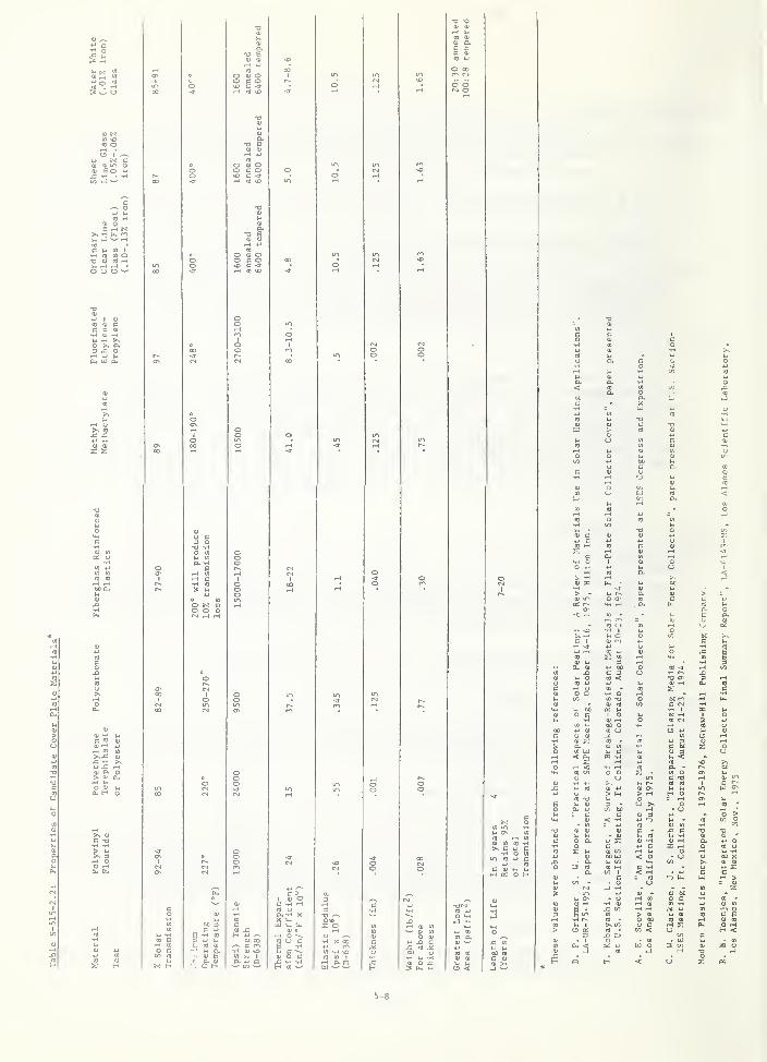
Commentary : Table S-51S-2. 2 lists a number of materials that have been usedfor cover plates and properties of the materinl!^
.
S-515-2.2. 2 Codes and Standards
Materials used as glazing for cover plates shall comply with MPS Section 508,
Section S-601 of this document and applicable sections of local building codes
and national standards *
S-515-2.2. 3 Labeling and product Description
In addition to the labeling requirements of Section 508-8.4 of the MPS,
product description shall include technical data regarding chemical composition,
physical, mechanical and thermal properties such as fire resistance, flamma-
bility and flamespread, weather resistance, electrical properties, products of
combustion, coefficient of expansion, transmittance ,impact resistance,
scratch resistance and recommended or disallowed cleaning methods.
S-515-2.2.4 .Structural Requirements
All glazing materials shall be of adequate strength and durability to withstand
the loads and forces required by Section S-601 of this document.
5-7
3 w O
O (I) OO C O\D C <t
(0 frs?
q) Oo r /-^
0) u~t O<u B o t-i
O Q) Oo c orH 0) vD
B rH J<>s -H U.
<S U O ^(U Oa oc -3-
V4 >H
3 J= O
Ps CO
(U <u
o ex.
> (UI
.-t MO OJ
.H OO ^ c <u y-. 1-.
s i-
0)
C(U ^
bO 00^ C t-l
T-t <u vo01 1-. Ia i-> Q
T3 /-V
X O
> -<i
j-4 r--
0 o-
0)
a.tc
.D-
Fnerj>.c:
CO 1-
a c-E
0a.
'co <'l (Tj
(U c 0)
o::
C 1
1
^, C>(U f*i
t-
Cctr. oc
c u-H -J
q)
uto
E wOJ
wo
CO
X <U 60 O to -43to
wa O
C 3to <4J
U o a.OJ f-i
3CO
c03 *-i
tH OO O
(ft -l->
(0 s: C•Ha
u<u
cnH Ow -oOJ CO
oCO
00 mc <^ •H
"4-1
<u
V. Ci£j
o ccc u
1 oo
•H 1
N iHX
1 ou
tfj J_t
OJ .-1
oo oto CMrH
:»
to
4-t
U00c U (U
CO o O w(0
t4
(JOJ
.-f
rH
1<u s:aCO UJ
(0 -
<U Ul
tn iJ 3C OC<U 3
z oo
< ^>-• Gm -H <u <^-
iJ
jg
(0
a •>^00
(U
03 i/i
1-1 4..
o ou in
u r-.
(0 oc -o(0 CO
Oi
1
uQ) m
X *-i to
uCO -o
>u
(U o\-H
o
P t4H Oin W ON
eo
U CD
C- 4JD - o
.HO
- uCO
'
o >~ c0)
c< -H
OJ 34-t
CO
V- -
a; CO
to CO oz
TD(U
o a<u
« (U
c -1^ CO
CU -H01 i-i
(Ua•oOJ
•
4J Oc:
•HCO
o c 4J C X r-i
Oo to u
U -Hu £ ^'
0)
Hi
00 [l] < O • CJC/1
o OO XXio
• a15 to
Uto l-l C -H o
OJ 01
iJ zdi
a CO 1
c< .-H
= CO u.eu;
cM Su<u
' o-J -H
Uto
= ot
zin u
- (J
(U -f~l CO
C 00o cCD -H
CO -
ta
<u
-H Hi -H 0) ^ *-» (0a> CO
oC E
•H r-.
CO
to> <u
O 00>-• wnj OJ
to
OiOJ to
>1-4 1
o «>, C/1
CO •
o ccn < O
0 ^H <
- 1 o • CO
I/)
• UJ3 c«
cCO
cc o«01 to
UJ o-o
H ci H u OS
5-8
S-515-2.2.5 Types of Applications
Applications include windows which act as cover plates for solar collectors,both integral with dwelling construction and freestanding components.
a . Outermost glazing near walking surface
Glazing materials exposed at ground level or at the level of a walk-ing surface must meet the intent of the requirements for safetyglazing as specified in A?TSI Z97. 1-1972 and >rPS Section 508-8.1.
Commentary : Consumer Product Safety Commission's 16 CFR, Part 1201was published in the Federal Register on February 11,1976. 180 daysafter issuance of a final standard in the Fed.eral Register
^
the
standard will be mandatory for the safety of arohitectural glass.(See Cormentary wrid-er b) below.
)
b . Vertically oriented outermost glazing materials in fixed panelswhich are installed above a rail or sill at least 3' - 6"
above the walk^^^ay or finished floor line must meet the intent of therequirements for glazing in MPS Section 508-8.3.
Commentary .- An additional consideration is that film-type glazingmaterials for the outermost cover plate, if unsupported, may be
unacceptable if they can he deflected under load, e.g. a person'shand pushing against the glazing, may present an opportunity forexposure of t^ie film (and the person's hand) to hot surfaces such asthe absorber plate. Also, there is a probability of exposure to
impact which may result in tearing of the film.
c. Glazing materials with slopes less than 45° which extend below6' 0" (from ground level) shall be safety glazed or otherwiseprotected against impact of falling bodies.
Cormentary : This commonly refers to glazing on which children mayclimb or against which a passerby may fall.
d. Glazing panels which are an integral part of a roof or rack-mountedsystem on a roof, not routinely accessible by the occupant, shall
meet the requirements of Section S-601. (Annealed glass or films
may be acceptable.)
S-515-2.2.6 Thermal Stability
After testing as described in S-515-2.1.2, there shall be no cracking,
crazing, warping, sagging or buckling of the cover plate (s) that will
significantly impair its function.
S-515-2.2.7 UV Stability
Documentation shall be provided that the decrease in transmittance , as
measured by ASTM E-424-71, will not significantly impair the function of
the cover plate (s) during its intended design life.
S-515-2.2.8 Dirt Retention
The cover plate (s) shall not collect or retain dirt to an extent that
would significantly reduce its ability to transmit sunlight.
Cormenzary : The possible collection and retention of dirt by the cover
plate arvd the effect of reatined dirt on collector performance may be
significant. The retention of dirt may depend on the tilt angle ofthe collector. Rainfall and snow melt are generally sufficient
5-9
to keep the coHeotor cover plates clean. If periodic scrubbing is
necessary for cleaning, the cover plates should be resistant to damage
by abrasion resulting from the scrubbing. If the collector is ventilated.^
provisions should be made for exclusion of dust by appropriate filters.
S-515-2.2.9 Outgassing of Volatiles
After exposure as described in S-515-2.1.2, there shall be no visiblesigns of outgassing products on the cover plate surface (s) that willsignificantly reduce the transmittance
.
Commentary : Outgassing from components inside the collector could lead to
condensation on the underside of the collector cover plate (s) which mayreduce the transm.issivity of the cover plate (s).
S-515-2.2.10 Condensation
Condensation formed on the underside of the cover plate (s) shall notsignificantly reduce its transmittance during its design life.
Commentary : If flat plate collectors are not hermetically sealed, thelikelihood of condensate forming on the underside of the cover plate (s)
is quite high. Dessicants in breather tubes or breather plugs can be usedto maintain a dry environment. TVie dessicants should be located in such away that they are not in contact with the collector plate.
One additional potential problem with collectors which are not hermeticallysealed is that, in industrial atmospheres, the introduction of dilutantsin condensate solution may cause permanent etching of the underside ofthe cover plate(s) over a period of time. Such etching can permanentlyreduce the transmittance. When this possible condition exists, designconsiderations must be given to avoid the problem.
S-515-2 . 2 . 11 Flamespread
Installation of glazing or other related components of the solar systemas part of the roof assembly shall not reduce the fire retardant character-istics of the roof covering below the accepted level against a fireoriginating outside the building in accordance with ASTM E 108-58, Methodsof Fire Tests of Roof Coverings (NFPA No. 256-1970).
S-515-2. 2. 12 Glass
Where tempered glass is used, it shall meet the requirements of ANSI -
Z97. 1-1972 and MPS, Section 508, as specified in S-515-2. 2. 5 of this
document. Other glass cover plates shall meet the requirements for glass
as specified in Federal Specification DD-G-A51C (June 15, 1972).
, , Commentary : Table S-515-2. 2 contains solar transmittance data and
recommended maximum continuous operating temperature for a number of
types of glass.
S-515-2. 2. 13 Other Materials
Cover plate materials other than glass shall conform to the requirements
of MPS, Section 513 and the intent of S-515-2 . 2 . 11. Table S-515-2. 2 lists
a number of materials that have been used for cover plates. Materials
5-10
shall not be used for cover plates if the maximum temperature to whichthey will be exposed in service under operating and non-operating condi-tions exceeds the maximum operating temperatures listed in Table S-515-2.2.
Absorber Plate
Thermal Stability
Any deformation that occurs in the test described in S-515-2.1.2 shallnot adversely affect the flow rate of the transfer medium.
Eros ion/Corrosion
The absorber plate or flow conduits shall not be adversely affectedby erosive wear, such as by the flow of a liquid transfer medium to anextent that will significantly impair its function during its intendeddesign life. In lieu of other documentation, compliance with this require-ment shall be demonstrated by testing with appropriate revisions of oneof the following methods:
NACE TM-02-7^NACE TM-02-70NACE TM-01-69ASTM D257C-73
Corrmentary : Appropriate revisions of the above tests should includeconditions which closely simulate in-service operation. The variableswhich have an important impact on the rate or erosion/corrosion are:1) the quantity and size distribution of solids in suspension2) the flow rate3) the pipe diameter4) the oxygen content of the fluid5) the angle of the change of flow direction6) the internal surface corudition of the pipe
Compatibility With Transfer Medium
a. The absorber plate or flow conduits shall not be pitted or otherwisecorroded by the heat transfer medium to an extent that will signif-icantly impair its function during its design life. In lieu of
other documentation, modifications of tests listed in Table S-515-2.3.1shall be used to demonstrate compliance with this requirement.
Corrmentary : SAE Report J447a(1964) , Prevention of Corrosion of Metals,provides guidance in preventing corrosion.
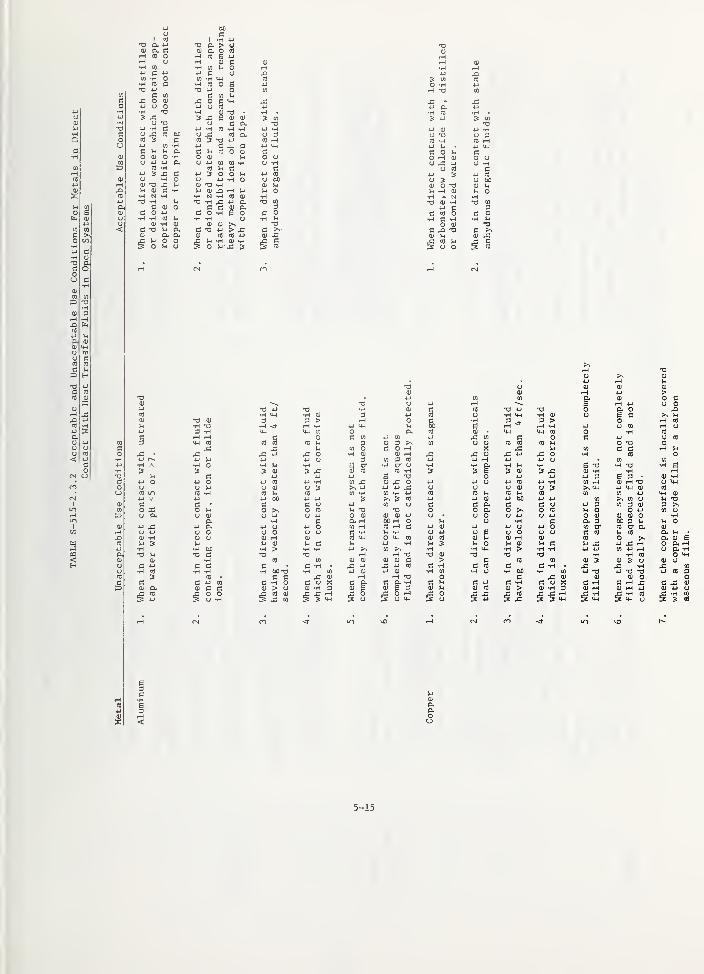
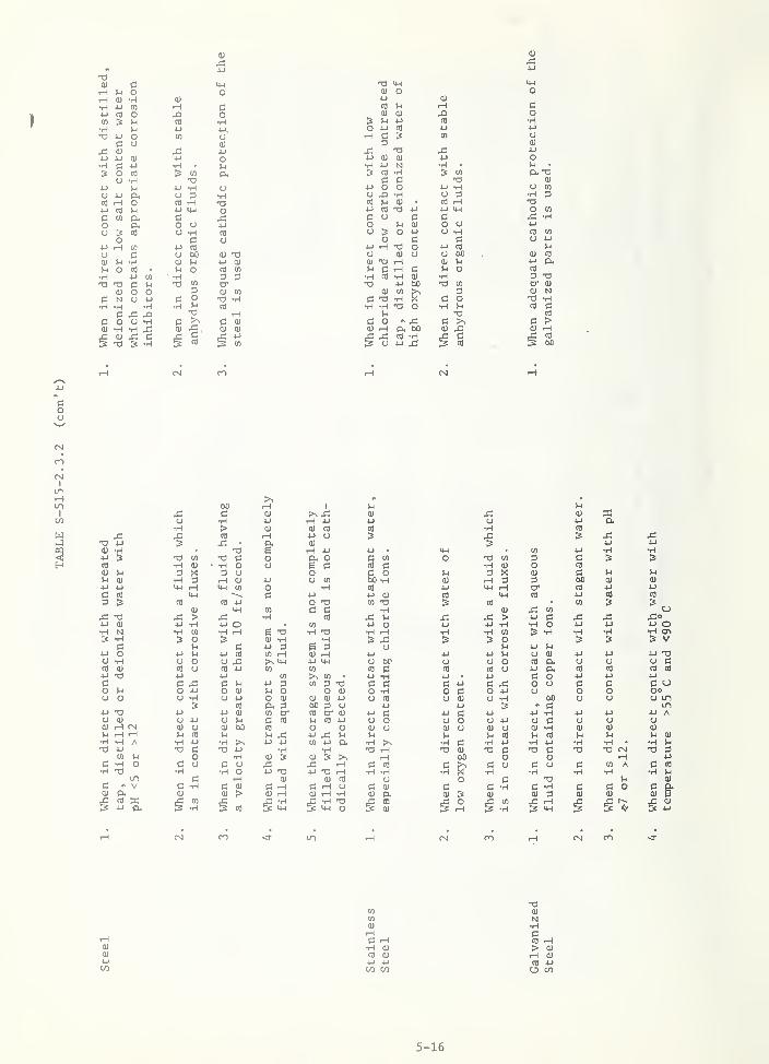
b. Metallic absorber plates or flow conduits in direct contact withheat transfer fluids in open systems shall be used in accordance withthe acceptable conditions listed in Table S-515-2.3.2, where applicable.Unacceptable conditions listed in this table shall not be used.
Documentation shall be provided to demonstrate that materials appli-cations not explicitly covered in Table S-515-2.3.2 meet the intent
of S-515-1.3 and S-515-2.3.3
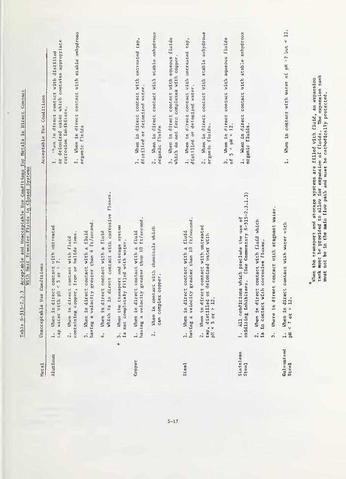
Metallic absorber plates or flow conduits in direct contact with heat
transfer fluids in closed systems shall be used in accordance with
the acceptable conditions listed in Table S-515-2.3.3 where applicable.
Unacceptable conditions listed in this table shall not be used.
Documentation shall be provided to demonstrate that materials appli-
cations not explicitly covered in Table S-515-2.3.3 meet the intent of
S-515-1.3 and S-515-2.3. 3
5-11
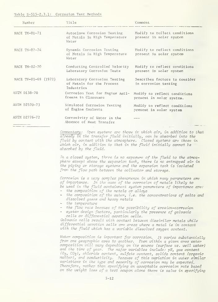
Table S-515-2.3.1: Corrosion Test Methods
Number Title Comment
NACE TM-01-71 Autoclave Corrosion Testingof Metals in High TemperatureWater
Modify to reflect conditionspresent in solar system
NACE TM-02-74 Dynamic Corrosion Testingof Metals in High TemperatureWater
Modify to reflect conditionspresent an solar system
NACE TM-02-70
NACE TM-01-69 (1972)
ASTM D138-70
ASTM D2570-73
ASTM D2776-72
Conducting Controlled VelocityLaboratory Corrosion Tests
Laboratory Corrosion Testingof Metals for the ProcessIndustries
Corrosion Test for Engine Anti-freeze in Glassware
Simulated Corrosion Testingof Engine Coolants
Corrosivity of Water in theAbsence of Heat Transfer
Modify to reflect conditionspresent in solar system
Describes factors to considerin corrosion testing
Modify to reflect conditionspresent in solar system.
Modify to reflect conditionspresent in solar system
Commentary : Open systems are those in which air, in addition to thatalready in the transfer fluid initially^ can he absorbed into thefluid by contact with the atmosphere. Closed systems are those inwhich air, in addition to that in the fluid initially cannot beabsorbed by the fluid.
In a closed system, there is no exposure of the fluid to the atmos-phere except above the expansion tank, there is no entrapped air inthe piping or storage systems and the expansion tank is isolatedfrom the flow path between the collector and storage.
Corrosion is a very complex phenom.enon in which many parameters areof importance. In the case of the corrosion of metals likely tobe used in the fluid containment system parameters of importance are:
the composition of the metals or alloys- the composition of the water, i.e. the concentrations of salts and
dissolved gases and heavy metals- the temperature
the flow rate because of the possibility of erosion-corrosion- system design factors, particularly the presence of galvanic
cells or differential aeration cells.Galvanic cells result with contact between dissimilar metals whiledifferential aeration cells are areas where a metal is in contactwith the fluid which has a variable dissolved oxygen content.
Water composition is important for corrosion. It varies substantiallyfrom one geographic area to another. Even within a given area watercomposition will vary depending on its source (surface vs. well water)and the time of year. The major variables include: pH, gas content(O2, 002)3 chloride content, sulfate content, solids content (organicmatter), and conductivity. Because of this variation in water similarvariations in the type and severity of corrosion may be expected.Therefore, rather thxin specifying an acceptable corrosion rate basedon the weight loss of a test coupon alone there is value in specifying
5-12
a maximum rate of penetration. A spec, of this type would, however,require interaction with design specifications because of minimimwall thickness to maintain adequate strength during the design lifeis necessary . Although the instnmentation by rihich corrosionpenetration (pitting) may be measured (x-ray, eddy current devices,etc. ) exists, recommended practices with regard to the frequency ofmeasurement and the points at which these measurements should becarried out require development.
Weight loss corrosion measurements are also important. While thelosses in wall thicknesses may not be significant the build-up ofcorrosion products could be. This could result either in flowrestriction or in pitting corrosion. Depending on the O2 content
of the transfer medium pitting corrosion as a result of differentialaeration at the pipe-deposit interface could occur. This type ofattack may also result because of scale formation. Because calciumcarbonate exhibits retrograde solubility , precipitation of thiscompound will occur in saturated room temperature water as it iswarmed. In addition each time make up water is added or the systemflushed and refilled additioyial scale will be built up. Softeningof water will help to alleviate this problem, and may be recommended.
Chlorides
Chlorides should be kept to a minimum since their presence in wateraccelerates pitting corrosion. Aside from its presence in waterthere are several potential sources of chloride in a solar unit:
1. Residual chloride from pickling treatment of metallic components.This may also be a source of sulfate. This is a rather unlikelysource of these ions but care should be taken that the components
of the system are thoroughly cleaned before assembly
.
2. Chloride from the decomtposition of nonmetallic components in thesystem.
3. Chloride from flux used in soldering or brazing components duringinstallation.
Galvaniziyig
Galvanizing has long been used to protect iron or steel from corrosion.Zinc is more active than iron and, when the two are in electricalcontact, will corrode preferentially. Thus, the iron is cathodicallyprotected. The rate of corrosion of zinc is much lower than that ofiron, so a relatively thin coating will last for quite a long time.
However, there are data indicating that at elevated temperatures ofabove 158 °F (70°C), this effect is reversed and the iron corrodesrather than the zinc. [1]
In addition, the corrosion rate of zinc itself increases rapidly inthe temperature range between 111 and Idi^F (55 and 90'^C).
Accordingly the use of galvanized steel in this temperature range
is not recommended.
Copper in a Recirculating System
In "once through" systems copper pipe is usually only connected
upstream from iron pipe. Residential plumbing is an example of this.
[1] G. Butler and H.C.K. Ison: Corrosion and its Prevention in Waters,
Reinhold Publishing N.Y. 1966.
5-13

This praatice is carried out because small mounts of copper tend,
to go into solution. When these copper ions contact more activemetals such as Fe or Al they are reduced to copper metal whichsubsequently deposits on the metal surface, l^en this occurs, a
galvanic cell is set up and rapid corrosion initiates. The presence
of a dielectric pipe joint between Cu and Al or Fe will not alleviate
this problem. Similar action may be expected for Al in the presence
of Fe.
pl
The pH of the transfer medium will }iave an important impact on
corrosion rates. However, the optimum pH to achieve minirmm corrosion
will change with temperature. [2] Because varying temperaturesoccur within a solar heating system and the temperature at a givenpoint will change with tim.e, care must be taken to optimize the pH.
Temperature
The temperature is an important consideration with regard to selec-
tion of containment materials . Corrosion in aqueous media generallyincreases rapidly with temperature until the boiling point is
approached . In open systems, the corrosion rate will tend to decreasedue to a sharp decrease in the solubility of oxygen in water at thesetemperatures. However, in a closed system, from which the dissolvedoxygen cannot escape, corrosion may continue at an accelerated rate.
Stress corrosion
This could be a problem in the collector panels where high strengthalloys (esp Al) are clad to higher purity Al. Residual stresses inroll bonded and blown collectors could be sufficient for stresscorrosion to occur. However, stress corrosion is unlikely unlesschloride is present.
O2 content of water
Generally corrosion will decrease with a decreasing amount of O2 inwater. In a closed system, O2 will be depleted and in theorycorrosioyi will cease. However, the probability of designing andconstructing a system in which there is no leakjage of oxygen isuncertain. If this were possible the only other sources of oxygenwould be that frari decomposition of organic components and fromchemicals added to elevate the boiling point of water. Corrosioninhibitor's would not be necessary in a completely closed containmentsystem composed of steel or copper ; if the proper pH is maintained.In the absence of oxygen, measurable corrosion of copper and steeldoes not occur.
The corrosion of aluminum, however, may continue even in the absenceof oxygen. Because aluminum is more electropositive than Cu, Fe orZn, an alternative cathodia process may occur. This is the reductionof water to molecular hydrogen. This reaction may be suppressed ifthe pH is maintained in the range between about 5 and 7. The presenceof chlorides and more noble metals should be avoided regardless ofthe oxygen content and the pH of the fluid since these factorsaccelerate pitting corrosion. Stainless steel is unacceptable foruse in contact with fluids, such as water/glycol mixtures, in closed
[2] P.. M. Diamant: The Prevention of Corrosion, Business Books Ltd.London 1971.
5-lA
uuHI
uHCC•H
CO
iHID4-1
OJ
o
4J
<D CO
B >-O•HU c•H (U
•a ac: oo
•H
to CO
T3•H
(U 3rH iH.a Pb<d
ki
a CU
<u
o •P
o aCD CD
c
o 4J
c a(S CU
<u
4J•3 H4-i 3o.(U 4-J
o Uo nJ
<: 4-1
co
CN CJ
T3 O. > OCU O. O CO•H CO B 4JH CD C•H CO V4 O
-C O C <4-l
:wi
Lch
1
•oc
3 X 1U
CU CU
C a 3 CO
•a
uCO 3
CO occ
4J
OCO
H CO •H -HCO a.
4-1
o•H3
4J^
CO •H u3 -a
Cu
cCO4-t
r-lc^
cot
4Jo4J
o.HP,
Coo
U CO
CU4-1 CO
O 0u
CO
coo
u
4-)
o
CO
3•H
-Hc0
4JO
CO >-i
3 ou o u
•H O4-)
oCO
00CU
uTJCU
N"c•H
)-l CU
>-i
T) -HCU J3 .-1 u
CU
uuo
•H u•H•T3
N -H CO CU •H•a CO
3in
e0
CU
CO
o
uc:1-1
13 C0 -H*H
0) aB o
oc•H
oV4
cCU
T3H CU
D- cCU lU
T3 4-) ^x c•a>^x;(U
S-l
o
aoi-i
aoo
(U CO
1-1 -HO V4
CO 4J
j: 3
CU
c:CO
CM CO
4J T3 4J T)CO •H cw •H CU
CU •0 lU 3 3 >^^ iH •0 iH <r iH •Hu 3 •H CH CH CO
c iH rH c 0CO 3 M-l CO CO CO CO Vh
c J3 V4
o s: 4J x: 0•H 4-> 4J 4-> 4-) u4J •H A •H 0 u H•H 3 3 3 HI 3 J=T3 Vj c 4J 4-)
c 4-1 0 4J 0 4J CO 4J •Ho o CJ CU CJ 3tj CO m CO •H CO u CO
4-1 4-) 4-J tD 4J 4JCU i:: C c c UCO 0 3; 0 H 0 0 CO
CJ a pe 0 it unt
4.J 4-) a u 0 4-> 0iH CJ 4J 0 0 0 0 0J3 CU •H CU u CU rH CU
CO i-< 3 u 14 CU Vj c4J •H •H 00 •H > •H •Ha T3 M T3 IS T3 •0CU CU H CO CO
o C 4-1 C c (= c •Ho •H CO •H •H 00 T3 •HCO 3 CO • (3 ac t:: C 4J CO c •-^ 0 C3 a» CU 13. CU C C CU > 0 CU •H
CO4-> Wh
0 00 -H Wh
CO CU
J3 COwh
3 CO
O r^^ -a
j= -4-1 a•H CO
3 4-1
o 3CU o -o
.H CU
CJ -H13
4-1 CO
O 60
0 CU CU
(U ID iH 4-1
4-1 CO CO 0. CU
U 4-1 rH B rH 4J
c CO o 4J •a 0 0. 03 4J CO 0 •H CH •H lU u B C
0 C •H 3 3 > 04-1 CH 1-1 00 g H <r
i-( •H 4-1 CJ CO
tx CO CU CH CH CO 0 •HC CO 4-1 to 4J j: CO C 0 c 4-1
3 0 3 >s CO CJ CU CO CO CO 1-1 0 -0CO 0 c 0 rH X u CO c c•H CU CU ^ x; J3 CU J3 4-J J3 0 •H CO
3 CO 3 CO 4J 4J rH 4J 4J 0 CO
e cr •H o- CJ •H •H •H I-I •H B -O •w -o3 CO CO H 3 3 i- 3 CU 3 J3 CU -H iH4-1 e T) 4J 4J 4-J 3 E 3 •
CO X CU j: 0 4-1 4-J 4-1 CO 4J •H CO 1-1 CU rH -a>^ 4J 4-1 4-1 CJ u CJ OJ CJ 3 CH 4-J CH CU
CO iH CO •H 4J CO CO M CO 1-1 CO CO CO 4J
3 ?N 3 CO 4-1 4-J CU 4-J 00 4J 4-1 CO >. CO CJ4J CO 0 c c (i 13 c 0 4J 3 CO 3 CU
ki -a T3 0 0 Q. 0 0 CO u 0 0 4J
0 CU CU CU 4-J 0 CJ 0 0 CJ 4-1 0 4) CU CU 0a iH 00 kJ CJ •H c a 3 00 3 V4CO iH CO c 4-1 CU 4-J 0 4-1 0 CO or CO tr aC -H u •H Cl 4-J 0 S 0 CJ 0 G CO IJ CO
CO CH 0 CH CO CU CO CU u CU iH CU CO
I-I 4J •H u 3 u 0 u CU I-I c ki 4J J3 rH4-1 CO >. •1-1 •H CH •H > •H •H 4-J 4-J CO 4-1 rH
iH rH •a CU T3 a •H •H CO
CU a) CU CU C > 13 CO CO 0) 3 CU 3 UJ3 4-J J3 4-1 CO 13 H C CO C c •H . J3 s: -H4J 0) 4-1 (U H CO •H 0 •H 00 •H CO 4-J 4-1 T3
iH T3 0 c J3 CU CU lU 0C a C D. •H c u C 4-1 c H c 0 X C iH c rH x:CU B CU e 3 CU u CU CO CU > 3) •H 3 0 rH 0) iH 4J
g 80CJ CH
00
J34-J
CO •£3 CH
J3 -H3 CH^ iH CO
3 CH 0
CU ED. rHO. -HO C4H
5-15
0)
.d4-1
(U CiH )-i o oiH (1) •H 0)
•H 4J 05 rH 34-) (0 O oCO U •H•H M 4-1 4-1.
•T3 O tn OO CU
(U J= 4-1
U 4-) 01 4-1 o•H c 4-1 •H •
l-l
? o nj CO O.o •H T)
t-i 4J •H OU 4J Ch o •Hn) 1-f o iH •34J 03 u 4-1 14-1 O
(0 a C 4So p- O O 4->
o & n) o •H Cfl
o C o4J iH tc 4-1 (0
o C O 60 (U T3(11 l-i •H CU M 4J 0)
t-l O CO • U O Cfl CO
•H 4J to ' iHCO
3 3-a •a C u cr
0) o o 3 CU CO
C N o u c O T3 •H.H u CO
c ^ iHc o o •H c C CU
(U •H •H (U (U Q)
ID c C '
4-1
13 •H cfl CO
n
d)
<U O Od)
H r<>•*
(U o•U •rl
o (d 4J1—
1
IS CO Cj
d)
T) 4>J
4-1 CJ d) 4-1 o•iJ N •H • M •
trJ •H IS W O*d)
4J o O 4-1 •H cj (0
O *^ •H Cj •rl 9CO >^ d) r—
1
\J
M nJ u-( O 03
3 o CO H QJ o O
tliO 3 o •U o •H Cu UJ
O O 4J4-1 I—
1
'O O 4-1 nJ
d) O o d) CO
CU 13 I—
1
dJ M 4-' &tJ-l t—
1
M O*H trJ •H d) '1"]
•3 4-J d)
QJ C/3
3 TJ •H 3 o •a -H•H •H o •H J-l CO 3
M (0
3 O 3 c >d)
CO ^^ c: C CO
a xi cd
CM
CO
eji
mIMw
eo iH 1 U t-l
0) >^x; (U 43 (U
u •H 4-1 rH W 4-1 O 4-1 3.•H > (U CU CO CO •H Cfl
x: X CO iH 4J O X 3 x: X-3 u D. 0) 3 4-J 4J
CU •H T3 B rH 4-1 4J CO 4-1 •H •H4-1 T3 CO •3 3 O (X O 3 CO o x) CO 3 3 3 3Cfl •rH (U • -H O a B 3 CO 3 •tH (U O CO
CU M 3 X 3 O o 3 O (-1 3 (U 3 Mu (U iH 3 r-l (U 4-1 O CO 00 -H CU rH 3 3 60 (U (U4-1 4J IM rH 14-1 CO o •H CO 4-1 C4H rH a" CO 4-1 4-1
3 CO 3 4-1 4-1 CU cfl "4-1 CO 4-1 Cd to
3 CO CO 4J O 13 CO T3 Cfl CO 3 3CO 3 3 •H <U X CO u
x: •3 X. > X •H CO X n X X > 4-J 3 X x; x:o4-1 CU 4-1 •H 4-J o CO 4-1 O 4-J 4-1 •H •H o 4J 4-J 4J o•H N •H CO •H iH B -3 H -3 •H rH •H •H CO 3 •H •H •H •H crv
•H O (U •H •H 3 x: 3 o 3 3 3 V3 >-l 3 4-1 3 B 3 o u 4J l-l
AJ o 4J u 4J CO CO ^ (U rH 4-1 4-1 4-J u O (U 4J 4-1 4J -ao •H O o O X >. 4J m O OP o O o CO D. O U o 3CO <U CO o CO 4-1 CO CO CO c cfl CO o 4-1 P- Cfl Cfl cfl to4-1 •3 4-1 4-1 CO >% CO 4-1 -H 4-1 4-1 3 O 4-J 4J 4-1
3 3 XI 3 u 4J 3 CO 3 Xl 3 C 3 4J 3 X O O 3 3 3 UO u O 4J O CU u O o (U O -rl O 3 o 4-1 o O O OoO o O •H O 4-J o <u CU (U 4-1 O cfl o CU o •H M o o CJ in
to a 3 CjO 3 O 4-1 4-1 3 3 u-i
4-1 3 4-1 4-1 CU CO CO o" CU M 3 4-1 3 u 4-1 •H 4J 4-1 4-1 AO CU O •u O u 3 CO ^1 cfl 4J O O o O o 4-J o 3 o a O(U H (U CJ 0) ta CO o O CU O (U O CU o CU •H CU CU 0)
)-l iH t-\ U (0 u U X 4-1 X u M V4 u cfl u CO M M t-l CU
•H •H A •H 4-1 •H >, 4-1 4-1 CO 4-1 a. •H >, •H 3 •H 4-J •H 4-1 •H •H •H"3 4J -3 3 -3 4-1 •H •H -3 rH -3 (U T3 3 •3 3 -3 13 cs -3 3
CO Vj O •H (U <u 3 >^ rH 60 o O rH 4-1
3 •H O 3 o 3 CJ X X rH 3 cfl 3 3 o 3 o 3 CO A 3 to•H 3 •H •H o 4-1 T) 4J rH •H -H •H •H •H •H •tH •H 1^
u-1 3 (U (U CO O O 3 u CU
3 V 3 •H 3 (U 3 iH 3 rH O 3 CU 3 3 •H 3 •iH 3 3 O 3 e<CU O. CU CU > (U r-l (U rH •H <u a. (U 3 CU (U 3 (U (U CU B
CO CO •H X -H "3 X (B o CO rH X X <u4-1 •H CO C4-I 3 <4-l O 3 0) rH •H
rH rH CN en rH CSI CT) <3-
(0CU
rH3 rHH (UCfl CU
•3(UN•H3cfl rH> (U
rH (U
Cfl 4JC3 CO
5-16
10 u -u
i-1 O 4J
c 3
u oco in
•H CO
3
CO 0)4-1 4-1
C CO
0) (U
OC 1-1
CO CO
>- 3
a 3cCO -a
4J C•H CO
3 J=
CO -H OJ 4J
4-1 13.
O OCO o
o
n —iH 4J
CO o
»H 4J rsj o
>• CO
u 3
C -u CO
4J 4-< U Cc oO -HCJ 01
C r-l A
C m o
(J •
•H CM
<u u
H j:
c -H
U-l X3
3 OJ
>*J -r-l
c Bo (0u
10
B Ca 0
T3»< n 91
<i) CCO Ua 01
CO X 4J
V 0V4
<u
rH rH
al
J= to oU V•rl Ti •a3 3 o
rH j:•o KH tj01 COr-l <4-l u1-1 o
aco
01 4Ju (0 91
CO c 3CO E
CO aB<u <a Cu CD
a u>, O JCa X-l
at
tu 3 o.00 oCO rH 3u rH oo cd rH4-1 U-l
01 oB
T3 •H
CO 0) Eu tH 01
1-1 > J=0 o uO. HmacC -H(0 41
)J .0 01
u01 (0 uX 3 Ou E s
aCO rH> 01
5-17
systems because hXitiir/glycol mixture;: pyccluflr the. use of oxidizing
inhibitors . Jn solutions with low oxygen oonte-nt, stainless steel
is susceptible to crevice corrosion because insufficient oxygen is
available to replenish the protective oxide layer once crevice
corrosion starts.
UV Stability
Absorber plates shall not degrade to an extent that will significantly
impair their function during theJr design life wlien exposed to UV radi-
al ion
.
Absorptive Coatings
General
Absorptive coatings are generally of two types, either selective or
nonselective. A nonselective coating has an absorptance to emmitance
ratio near unity whereas in a selective coating, the ratio is higher.
Appendix B-1 lists some characteristics of potential absorptive coatings.
Commentary : An effecient coating has a high absorptance (a) over the
solar spectrum (.3 to 2.0 \m) with low emittance (e) to reduce thermal
radiative heat losses.
For coatings applied by an electroplating process y as are many selective
coatings, the substrate finish, plating geometry, bath composition,
and current density may influence the properties necessary for optimum
solar applications.
Thermal Stability
After exposure as described in S-515-2.1.2, there shall be no evidenceof checking, cracking, blistering or flaking of the absorptive coating,that will significantly impair its function. ASTM methods D660-44 (1970),D661-44 (1975), D714-56 (1974) and D772-47 (1975) shall be used to
evaluate the above properties.
UV Stability
Documentation shall be provided that the absorptive coating is notadversely affected by UV radiation to an extent that will significantlyimpair its function during its intended design life. In lieu of otherdocumentation, the absorptive coating shall not exhibit checking, crack-ing, blistering or flaking after testing for 500 hours according to
ASTM D 822-60 (1973)
.
Corrmentary : The above tests shall be performed with a cover platebetween the absorptive coating and the light source (if so designed) tosimulate in-service conditions. The cover plate shall be of the sametype and configuration as used in an actual collector.
Moisture Stability
Documentation shall be provided that the absorptive coating is notadversely affected by moisture with which it comes in contact to anextent that will significantly impair its function during its intendeddesign life. In lieu of other documentation, the absorptive coatingshall not exhibit checking, cracking, blistering or flaking after testingfor 30 days according to ASTM D 2247-68 (1973).
5-18
Commentary : Moisture is not expected to come in co?itact with absorptivecoating in collectors which have a dessicant
.
S-515-2.4.5 Compatibility With Heat Transfer Medium
When absorptive coatings are in direct contact with the heat transfermedium, documentation shall be provided to show that they are notaffected by the medium to an extent that would significantly impair theirfunction during their design lives. In lieu of other documentation,the absorptive coating shall exhibit no checking, cracking, blisteringor flaking or signs of erosion after immersion in the fluid transfermedium for 100 hours at the maximum service temperature according to
ASTM D 1308-57 (1973)
.
S-515-2.5 Collector Enclosure
S-5 15-2. 5.1 Thermal Stability
After exposure as described in S-515-2.1.2, there shall be no crackingor warping of the collector enclosure materials that will significantlyimpair their function.
S-515-2.5. 2 UV Stability
Documentation shall be provided that materials used in the collectorenclosure do not degrade significantly over their intended lifetimeswhen exposed to solar radiation.
S-515-2.5 3 Materials
Collector enclosure materials shall be in accordance with applicablesections of Division 5 and 6 of the MPS.
S-515-2.5 4 Coating
Protective coatings, where used, shall be in accordance with Section509-7 of the MPS.
S-515-2.6 Reflective Surfaces
S-515-2.6.1 General
These provisions are applicable where reflective or antireflective
surfaces are an inherent part of the collector design.
S-515-2.6. 2 Thermal Stability
After exposure as in S-515-2.1.2, there shall be no cracking, crazing,
delamination or change in reflectance of the reflective surfaces that
will significantly impair their function.
S-515-2.6. 3 UV Stability
Documentation shall be provided that the reflectance properties of the
surfaces will not decrease by more than 10% below the design reflectance
when exposed to solar radiation for the intended life of the surface.
S-515-2.6. 4 Damage by Impact
The reflective surfaces shall not be adversely affected by impact, such
as by hail, to an extent that would significantly impair their function
during their design life.
5-19
ENERGY TRANSPORT SYSTEM
This section includes materials used to transport the heat transfer
medium to a heat exchanger or storage facility and also those necessary
components used to return the heat transfer medium from the heat
exchanger or storage facility to the collector subsystem.
Applicable Standards for Liquid Systems
Compliance with MPS
Materials used in the transport system shall be in accordance withSections 515-3.1, 515-3.2, 515-5.1, 515-5.2 and 515-6.4 of the MPS whereapplicable
.
Other Standards
Materials used for transporting fluids shall be shown to be in compliancewith applicable standards. Examples of some standards that may be usefulare given in Appendix Table B-2.
Cormentary : Most of the standards for piping shown in Appendix Table B-2
are the standards normally considered by the model plumbing codes.
Designers may use other ANSI^ ASTM, or Federal Standards or Specificationsthat may be more appropriate to their particular design. The standardsand specifications for each component of the piping system shall alsobe given on plans and specifications.
Thermal Stability
Components comprising the transport system shall not be damaged bynormal thermal expansion and contraction of piping materials uiider
in-use conditions. Proper pipe hangers and supports and fittings shallbe used to allow normal movement of piping. See Appendix Table B-2.
Chemical and Physical Compatibility
a. Materials comprising the transport system shall have sufficientchemical and physical compatibility with organic materials in thesystem, such as sealants and gaskets, to which they are joined or in
contact to prevent deterioration.
b. Materials comprising the piping or transport system shall havesufficient chemical and physical compatibility with the heattransfer medium to prevent corrosive wear and deterioration.(For metals, see S-515-3 . 1. 7 .
)
Erosion/Corrosion
Materials comprising the transport system shall be in conformance withS-515-2.3.2.
Joints Between Dissimilar Metals
Dissimilar materials joined to form the transport system shall beelectrically isolated from each other unless documentation is providedto demonstrate that the joints are sufficiently compatible to preventcorrosive wear and deterioration during their design lives.
5-20
Commentary : Dieleatria aouptings used to isolate dissimilar metalswhiah are buried in soil may be ineffective because of contact of themetals with ground water.
S-515-3.1.7 Metals
Metals used in the transport system which are in direct contact withheat transfer fluids shall be used in accordance with the acceptableconditions listed in Tables S-515-2.3.2 or S-515-2.3.3, where applicable.Unacceptable conditions listed in these tables shall not be used.Documentation shall be provided to demonstrate that material usagesnot covered in the tables meet the intent of S-515-1.3 and S-515-3.1.5.
S-515-3.2 Applicable Standards for Air Systems
Design of all warm air heating systems shall be in accordance with therecommendations of the ASHRAE Guide on applicable manuals of NESCA andARI. Installation shall comply with NFPA Standards 31 and 54 and eitherNFPA 90A or 90B, as applicable.
S-515-3.2.1 Size
Air distribution equipment shall be adequately sized to fulfill the heat-ing requirements of the system.
S-515-3.2. 2 Humidifiers of the central type shall be in compliance with ARI Standard610, "Standard for Central Humidifiers (197A)."
S-515-3.2. 2 Self Contained Humidifiers shall be in compliance with ARI Standard 620,"Standard for Self-Contained Humidifiers."
S-515-3.2.4 Air Filters shall conform to the requirements of UL 900 (ANSI B124. 1-1971)
S-515-3.2. 5 Heating supply and return air ducts in unconditioned spaces shall beinsulated with materials or have thermal characteristics as specified in
Section 515-3.1 of MPS.
S-515-4 MECHANICAL SUPPORTING DEVICES
S-515-4.1 General
Mechanical supporting devices shall be sufficiently durable to performtheir intended functions for their design lives.
S-515-4. 2 Roof Mounted Collectors
When collector panels are added to an existing roof, the attachmenthardware shall be fabricated of materials that will not be seriouslyaffected by weathering for the expected design life of the roof membrane.
S-515-4. 3 Remote Mounted Collectors
The materials used to support collector panels remotely located fromthe dwelling unit shall not be adversely affected by external environ-mental factors including solar radiation, temperature extremes or cycles
of moisture.
5-21
Wood
a. ^•Jhen mounting racks are constructed of wood, the applicableprovisions of Division 6, Chapter 5 of MPS shall apply.
b. When mounting racks are constructed of wood and may be subjectedto termite damage, Division 2 of Chapter 5 of MPS shall apply.
Concrete/Masonry
When concrete is used as any portion of mounting construction, the
applicable provisions of Division 3, Chapter 5 of MPS shall apply.When masonry is used as any portion of mounting construction the
applicable provisions of Division 4, Chapter 5 of MPS shall apply.
Metals
When metals are used as any portion of mounting rack construction theapplicable provisions of Division 5, Chapter 5 of MPS shall apply.
Coatings
Coatings on wood, concrete/masonry or metals, if used, shall comply toSection 509-7 of MPS
Pipe and Duct Hangers
Pipe and duct hangers, used to support Insulated pipes or ducts, shallbe designed to avoid damaging the insulation material.
Commentary : If pipe or duct hangers are installed over the insulationmater%al, metal surface plates should be used to avoid damapina theinsulation.
VALVES
Applicable Standards
Valves shall conform to one or more of the following standards asappropriate. Valves manufactured to other standards not listed butfulfilling the requirements of a particular solar heating system designmay be acceptable.
Standard for Solenoid Valves for use with volatile Refrigerants andWater (1975) — ARI Standard 760.
Valves, Pressure, Reducing and Regulating for Installation on DomesticWater Supply Lines ~ lAPMO PS15-71 [4]
Water Pressure Reducing Valves for Domestic Water Supply Systems —ASSE No. 1003, 1970,
Valves, Automatic Relief — ANSI 21.22 - 1971. (For Water /Steam)
.
Valves, Cast Iron Gate, 125 & 250 lb; Threaded and Flanged —WW-V-58a-1966
.
[4] International Association of Plumbing and Mechanical Officials,5032 Alhambra Ave., Los Angeles, California 90032
5-22
Combination Check and Relief Valves — lAPMO TSC-8-66
Valves, Ball -- WW-V-35a-1965
Valves, Bronze, Angle, Check and Globe, 125 and 150 lb. Threaded andFlanged or Soldered — WW-V-51d-1967
.
Valves, Water Heater Drain — ASSE 1005.
Globe Typp loglighter valves, angle or straight pattern — lAPMO PSlO-66
Valves, Electrically Operated (1955) — UL 429.
Valves (125 pound Bronze Gate) (1969) — MSS SP 37 [5]
Valves (150 pound Corrosion Resistant, Cast, Flanged) — MSS SP 42
Valves (Butterfly) 1966 — MSS SP67
Commentary : Standards for valves usually present pressure-temperatureratings. Appendix Table B-3 presents these ratings as an example forball valves i Federal Specification WW-V-3Sa-l975. The valve standardsdo not consider valve sealing materials. The sealing material may notbe compatible with the heat transfer fluid. The designer should consultthe valve manufacturer for advice concerning appropriate valves and seals.National standards do not cover all valves useful to solar heatingsystem design. Valves not covered by standards may be acceptable toHUD if a history of successful usage can be demonstrated by the valvemanufacturer or solar heating system designer.
S-515-6 Pmrps AOT) COMPRESSDRS
S-515-6.1 General
Pumps and compressors shall be in accordance with Section S-615-5
S-515-6. 2 Applicable Standards
a. Centrifugal, rotary and reciprocating pumps shall be in compliancewith the requirements of the Hydraulic Institute.
b. Sump pumps shall be tested, rated and labeled in conformance withthe current SPMA Domestic Sump Pump Standards.
c. Heat pumps shall be in compliance with ASHRAE Standard 37-69, "Methodof Testing for Unitary Air Conditioning and Heat Pump Equipment",
and /or the ARI Standard 240, Standard for Unitary Heat Pump Equip-ment (1975).
d. Fans shall comply with the applicable standards of the AMCA or HVI
and shall be tested, rated and labeled accordingly.
[5] Manufacturers Standardization Society of the Valve & Fitting Industry,
1815 North Fort Meyer Drive, Arlington, VA 22209
5-23
Comnentari] : A Hydraulic Institute Standard defines the product j material,
process or procedure with, reference to one or more of the following:nomenclature, composition, construction, dimensions, tolerances, safety,operating characteristics , performance, quality, rating, testing
and service for which designed [6]
THERMAL STORAGE UNITS
Thermal storage units are defined as any container, space or devicewhich has the capacity to store thermal energy or transfer media (liquid
or solid) containing thermal energy for later use.
General
Thermal storage units shall be of sufficient durability to fulfillthe heating storage requirements of the system for the intended designlife of the storage unit.
Cormentary : Storage units which are inaccessible for replacement,as defined in 615-1.5 of the MPS, should be designed to perform theirfunction for the lifetime of the building. Routine maintenanceand minor repairs is acceptable during the expected life of theunit.
Applicable Standards
Applicable standards for thermal storage units are presentedin Appendix Table B-4.
Contamination
Thermal storage tank materials, Including any interior protectivecoatings and the heat storage medium used, shall not Impart toxicity,undeBirable tastes, or odors to either air or water intended for humanconsumption.
Materials Compatibility
a. Materials comprising the thermal storage system shall have sufficientchemical compatibility with the heat transfer medium to preventcorrosive wear and deterioration.
b. Metals used in the thermal storage system which are in directcontact with heat transfer fluids shall be in accordance withthe acceptable conditions listed in Tables S-515-2.3.2 or S-515-2.3.3,where applicable. Unacceptable conditions listed in these tablesshall not be used. Documentation shall be provided to demonstratethat material usages not covered in the tables meet the intentof S-515-1.3 and S-515-7.4 a.
[6] Hydraulic Institute, 1230 Keith Building, Cleveland, Ohio 44115
HYDRAULIC INSTITUTE STANDARDS FOR CENTRIFUGAL, ROTARY & RECIPROCATINGPUMPS, thirteenth edition, 1975Library of Congress CArd No. A56-4036
5-24
S-515-8 HEAT TRANSFER FLUIDS
The heat trnasfer fluid Is generally a gas or liqu^d which transportsgenerated heat from the collector subsystem to the thermal storagesubsystem.
S-515-8.1 General
S-515-8.1.1 Labeling
The information described in the Federal Hazardous Substances LabelingAct (1960) is required for heat transfer fluids. In addition, heattransfer media must be classified and containers duly labeled with ref-erence to NFPA 30, the Flammable and Combustible Liquids Code.Flashpoint and classification as to flammability and combustibilityshall be given as indicated in the General Provisions of NFPA 30.
Labeling shall also include the following items:
° service temperature range° viscosity over service temperature range° freezing point° boiling point° specific heat* vapor pressure over service temperature range° materials with which it is compatible" instructions for inspection, treatment and disposal of the fluid
S-515-8.1. 2 Function - GenlT'al
The heat transfer fluid shall perform its intended functions withoutdeleterious effects to those parts of the solar energy system with whichit comes into contact. Appendix Table B-5 presents a partial listing of
properties of several types of heat transfer fluids.
S-515-8.2 Toxic and Flammable Fluids
S-515-8.2.1 General
Heat transfer fluids which require special handling (e.g., toxic,flammable, corrosive, explosive, etc.) shall not be used unless thesystems in which they are used are designed to avoid exposure to un-necessary or unreasonable hazards, see Sec. S-615-10.1
S-515-8.2. 2 Flashpoint
The flashpoint of the heat transfer medium shall not be less than AOO^F(204°C) as determined by NFPA 321, 1971, Standard on Basic Classificationof Flammable and Combustible Liquid except as provided in Section S-615-14.2.2
Commentary : The maximum temperature to which the heat transfer mediumwill he exposed is that achieved by the fluid in the collector duringno-flaw conditions.
S-515-8.2. 3 Atmospheric Concentration of Toxic Materials
The concentration of the vapor of the heat transfer medium in the interioratmospheric environment shall not exceed 1/lOth the threshold limit value(TLV) for that particular medium in an 8-hour period.
5-25
Comnentary : The TLV is primarily concerned with industrial exposures
.
Because routine household exposure could he for much longer time periods,
the 1/lOth value of the TLV is recommended. TLV's are under continuousreview; a list of currently adopted values is published by the AmericanConference of Government Industrial Hygienists
.
S- 515-8.2.4 Fluid Disposal - Biodegradability and Aquatic Quality
a. A list of the chemical components of the heat transfer medium must be
provided in mg/liter. This list must include any substances whichcomprise more than 0.10% of the medium.
b. The organic constituents of these substances must have a five-dayBiochemical Oxygen Demand (BOD), using sewage seed, of at least
70% of the theoretical oxygen demand. This test shall be in con-formance with the Standard Methods for the Examination of Water and
Waste Water, American Public Health Association (1971).
c. The concentration of chemical constituents must be compared with the
96 Hour LC-50* bioassay value for protection of aquatic life. Thiscomparison is to be made in accordance with the Water Quality Criteria1972 .
Using the gallon/day capacity of the local sewage treatment plant,approximate the concentration at the treatment plant. If the dilutionof the chemical constituents is 1/lOth the LC-50 value or greater at
the sewage treatment plant, the heat transfer medium must be dilutedbefore emptying into a public sewer.
Commentary : Means for the disposal of heat transfer fluids are discussedin Section S-62S-9 of this document. Consideration should also be givento the effect of flushing solar systems on the "Basic Design Loading" forsewage treatment. Section CS 603, HUD Handbook 4940.3, Minimum DesignStandards for Commimity Sewage Systems . A preliminary draft of theEnvironmental Protection Agency 's Quality Criteria for Water, October 10,
1975, is currently under review. After its publication in the FederalRegister, EPA's criteria will supercede those currently cited.
S-515-8.3 Changes in the Heat Transfer Fluid
Except when such changes are allowed by the design of the system, the heattransfer fluid shall not freeze, give rise to excessive precipitation,otherwise lose its homogeneity, boil, change pH or undergo changes inviscosity outside the design range when exposed to its intended servicetemperature and pressure range.
S-515-8.4 Chemical Compatibility
Heat transfer fluids designed to be used in contact with componentmaterials shall be sufficiently chemically compatible with those materialsto prevent deterioration that would impair their function during theirdesign lives. Inhibitors, added to the transfer fluid to prevent corrosion,shall be compatible with all components in the system with which they comein contact.
' Commentary : This problem is further discussed in Section S-525-2.3 of thisdocument. Appendix Table B-6 presents a list of inhibitors which have beenreported in the literature for use with various metals.
*LC = Lethal Concentration. See definitions in Appendix D.
5-26
S-515-8.5 Thermal Stability
The heat transfer fluid shall not degrade at the maximum temperatureto which it wil 1 reach in-service to an extent that would significantlyimpair its function during its design life.
Commentary : Tiiis maximum temperature will generally be reached under"no-flaw" conditions. Appendix Table b-5 includes data for a number oftypical transfer fluids. Some fluids may decompose somewhat at elevatedtemperatures. For example^ ethylene glycol can degrade to form organicacids. Buffers are usually included with such fluids to control the pH.
It may be desirable, if fluids decompose with time, to change the fluidsperiodically
.
S-515-9 HEAT EXCHANGERS
S-515-9.1 Coir.pllance with Standards
Heat exchangers shall be in compliance with the appropriate standardsgiven in S-515-9. 2 and S-515-9. 3. Exchangers manufactured to otherstandards not listed but fulfilling the requirements of a particularsolar heating system design may be acceptable.
S-515-9. 2 Tubular Heat Exchangers
Tubular heat exchangers shall be in compliance with the appropriaterequirements of TEMA.
S-515-9. 3 Heating Coils
Forced circulation air-heating coils shall be in compliance with therequirements of ARI Standard 410.
5-27
GASKETS AND SEALANTS
Applicable Standards
Caulking and sealants shall be in accordance with 507-6 of the MPS,
where applicable. Gaskets which seal pressurized systems shall with-stand the maximum service pressure when tested in accordance with ASTMD 1081-60 (1974).
Commentary : Since gaskets and sealants used in solar systems may not be
adequately covered by existing specifications. Appendix Table B-7 is
included to serve as a guide in selecting specific sealing materials.
Materials Performance
Thermal Stability
Gaskets and sealants included in the test described in S-515-2.1.2 shallnot exhibit cracking, loss of elasticity, outgassing, or loss of adhesionsufficient to impair their function at the completion of the test.
Commentary : A potential problem with sealants and gaskets used incollectors is that during no-flow conditions outgassing may occur withthe outgassing products being deposited on the interior surface of the
cover plate. Such deposits can reduce the transmittance of the coverplate.
Chemical and Physical Compatibility
a. Gaskets and sealants shall be chemically and physically compatiblewith the substrates to which they are joined.
Commentary : Compatibility of gaskets and sealants with substrates maybe evaluated in the process of testing materials for compliance withthe Federal Specifications listed in Appendix Table B-7.
h. Documentation shall be provided to show that gaskets and sealantsin direct contact with the heat transfer fluid are not degraded bythe fluid. In lieu of other documentation, gaskets and sealantswhich are in direct contact with heat transfer fluid shall not exhibitsignificant expansion, cracking, loss of elasticity or loss of adhesionwhen immersed for 100 hours in the heat transfer fluid at the maximumservice temperature. ASTM F82-67(1973) Standard Recommended Practicefor Fast Quality Check on Immersion For Nonmetallic Gasket Materials,shall be used as a guide in performing these tests.
UV Stability
Gaskets and sealants that are normally exposed to UV radiation in-serviceshall not be adversely affected by such radiation. Documentation shall beprovided demonstrating that such materials are capable of withstandingexposure to sunlight for their design lives without functional impairment.
Commentary : Gaskets of ethylene propylene diene monomer (EPDM) rubberor silicone rubber may be appropriate for these applications.
5-28
S-515-11 INSULATION/THERMAL AND MOISTURE PROTECTION
S-515-11.1 General
Materials used for insulation shall be of sufficient proven effective-ness and durability under the expected operating conditions to assurethat required design conditions concerning heat losses, sound conti;ol orfire rating are attained. Insulation in contact with the ground shall notbe adversely affected by soil, vermin or water. Insulating materialsshall be in accordance with Section 507-3 of the MPS.
S-515-11. 1.1 Flame Spread Classification
The flame spread classification index for all insulation materials shallnot exceed the following values:
plastic foam 25all other insulation material 150.
The ASTM E84-70 flame spread test method shall be the basis for evaluatingthe surface burning characteristics of the residential insulationmaterial. Where fibrous blankets with facings are to be used, thesurface burning characteristics of the complete faced insulation blanketshall be measured.
Commentary : No single test is sufficient to provide a full estimate ofperformance of a product in a fire. Plastic foams are difficult to
evaluate in ASTM E84-70. The requirement of flame spread classificationof 25 maximum for these foams will provide as much a safety assurance asis possible with current test methods. Such a classification (or anyother numerical classification) shall not be construed as the equivalent
of "noncombustible ." Many insulation materials , including those consisting
of cellulose, plastic foam and fibrous glass (containing organic binder)are combustible materials which will bum and release heat, especiallywhen exposed to continuous large fire sources.
S-515-11. 1.2 Flame Resistance Permanency
Chemical retardant insulations shall retain their flame resistance through-out their service lifetime. The procedures and equipment specified inASTM C739-73, Section 10.4, "Flame Resistance Permanency" shall be usedin judging the effect of aging on the permanence of any flame retardantsused during manufacture.
S-515-11. 2 Collector Insulation
S-515-11. 2.1 General
Collector insulation shall be sufficiently stable at the maximum tempera-ture to which it will be exposed in-service. Suggested upper temperaturelimits for several insulating materials are listed in Appendix Table B-8.
Commentary : Organic materials found in insulation have been known to
evolve from collector insulation during system operation, leaving a coating
on the cover plates which impairs collector performance. Normally the
insulation nearest the absorber plate is exposed to temperatures higher
than insulation near other parts of the collector. It may be possible
to use one type of insulation adjacent to the absorber plate and another
type in areas of the collector which willnot be exposed to extreme
temperatures. Fiberglass insulation with binders can be pre-heated to
expel volatiles prior to use in collectors . If such pretreatment is used,
the upper temperature limit becomes somewhat higher.
5-29
Some plastic foam insulations are available with various encapsulated
gases. Those using freon can cause severe outgassing problems while
those insulations blown with CO^ could be acceptable.
Thermal Stability
After exposure as described in S-515-2.1.2, there shall be no swelling
or other dimensional changes in the collector insulation that will
significantly affect the collector performance. In addition, the
insulation shall not, during operating or non-operating periods, give
off volatile materials that could affect the performance of components
of the solar energized system or the safety of the dwelling occupants.
Pipe or Duct Insulation
Pipe or duct Insulation shall be sufficiently stable at the maximumtemperature to which it will be exposed in-service. Suggested uppertemperature limits for several insulating materials are listed in
Appendix Table B-8.
Storage Subsystem Insulation
If insulation whose thermal properties are affected by water is used,
the insulation shall be protected in accordance with S-515-11.5 and
S-515-11.6 of this document.
Waterproofing and Dampprooflng
Materials used for waterproofing shall be in accordance with Section507-1 of the MPS.
Vapor Protection
Materials used for vapor barriers shall be in acccordance with Section507-2 of the MPS.
CATCH BASINS
General
Catch basins shall be of adequate size and construction to fulfill theirintended functions.
Materials Compatibility
Catch basin materials which are jointed to or in contact with othermaterials shall have sufficient chemical and physical compatibility withthose materials to prevent deterioration.
Coating -
The catch basin coating, when used, shall not be significantly deterioratedduring its design life by weathering or by the transfer medium with whichit comes in contact.
5-30
S-515-13 ORGANIC COUPLING HOSES
S-515-13. 1 General
Organic coupling hoses shall be of proven effectiveness and durabilityunder the expected operating and exposure conditions.
S_515_13,2 Materials Performance
S-515-13. 2.1 Thermal Stability
Organic coupling hoses included in the test described in S-515-2.1.2shall not exhibit cracking, loss of elasticity, or embrittlement at thecoraplet ion of the test that will significantly impair their function.
Commentary : The selection of coupling hoses and clamps is quite critical.Many failures have been noted due to the clamping of hoses with screw orspring-type olampSy exposing the hose to high temperatures which tend tovulcanize the area beneath the clamp, causing it to lose resiliency andbegin to leak. Further tightening of the clamps will temporarily stopleakage but further vulcanizing will occur with the end result being ahard non-resilient ring under the clamp which can no longer be tightenedto prevent leakage. Silicone rubber hose is one of the few materialswhich have been tested and tend to maintain their resiliency with notendency to take a thermal set. The silicone rubber hoses, however,tend to be so pliable that screw-type clamps with perforated bandsshould not be used as it is possible to extrude the material throughthe perforations in the band. If this material is used, smooth bandclamps should be utilized.
S-515-13. 2. 2 UV Stability
Organic coupling hoses which are exposed in service to UV radiation shall not
be adversely affected by the radiation. In lieu of other documentation,organic coupling hoses shall not exhibit significant cracking, loss ofelasticity or embrittlement after 500 hours exposure as described inASTM D750-68 (1974).
S-515-13. 2. 3 Compatibility with Heat Transfer Fluid
Documentation shall be provided to demonstrate that organic couplinghoses which are in direct contact with heat transfer fluids are not
significantly degraded by the fluids. In lieu of other documentation,the hoses shall not exhibit cracking, loss of elasticity or embrittlementthat will significantly impair their function when tested for 100 hoursat the maximum service temperature according to ASTM F82-67 (1973)
.
Commentary : SAE Standard J20e (1974) covers coolant system hoses forautomobiles . For solar systems using glycol fluids, this SAE Standardmay be applicable for demonstrating compliance with S-S15-13. 2. 2. It
is expected, however, that hoses in solar systems will be exposed to more
strenuous conditions than automobile hoses.
S-515-13. 2, 4 Compatibility with Piping Materials
Organic coupling hoses which are used to join piping shall be compatible
with the piping.
5-31
S-515-13.2.5 Ozone Degradation
Documentation shall be provided to demonstrate that organic couplinghoses which are exposed in-service to the environment are not significantlydegraded by ozone in the air. In lieu of other documentation, the hosesshall exhibit no cracking or loss of elasticity that will significantlyimpair their function when tested for 100 hours to an ozone atmosphereof 50 + 5 pphm/volume at 23''C according to ASTM 01149-64(1970).
5-32
TABLE OF CONTENTS
PageCHAPTER 6 CONSTRUCTION
S-600 GENERAL 6_3
S-600-1 Labeling 6_3
S-600-2 Alternate Construction 6-3
S-600-3 Installation, Operation, and Maintenance Manual 6-3
S-600-4 Replacement Parts 6-4
S-600-5 Maintainability of Systems and Subsystems 6-i4
S-600-6 Safety and Health Requirements 6-<4
S-601 GENERAL STRUCTURAL REQUIREMENTS 6-6
S-601-1 General 6-6
S-601-2 Design Dead Loads 6-6
S-601-3 Design Live Loads 6-6
S-601-4 Wind Loads 6-6
S-601-5 Snow Loads 6-7
S-601-6 Seismic Loads 6-8
S-601-7 Hail Loads 6-9
S-601-8 Maintenance Loads 6-15
S-601-9 Thermal Distortion 6-15
S-601-10 Collector Cover Plates 6-15
S-601-11 Connections of Collector Frames and/or OtherSupport Structures 6-15
S-601-12 Storage Tanks 6-16
S-601-13 Dynamic Loads 6-16
S-604 MASONRY 6-17
S-604-1 General 6-17
S-607 THERMAL AND MOISTURE PROTECTION 6-18
S-607-3 Building Insulation for Passive Solar Systems 6-18
S-615 MECHANICAL = 6-19
S-615-1 Thermal Design ;•.
6-19
S-615-2 Collectors 6-23
6-1

S-615-3 Mechanical Supporting Devices 6-27
S-615-4 Valves 6-27
S-615-5 Pumps and Compressors 6-27
S-615-6 Mechanical Vibration Isolation 6-27
S-615-7 Thermal Storage 6-28
S-615-8 Heat Transfer Fluids 6-30
S-615-9 Waste Disposal 6-30
S-615-10 Plumbing 6-31
S-615-11 Auxiliary Energy System 6-35
S-615-12 Heat Exchangers 6-3A
S-615-13 Air Distribution 6-36
S-615-14 Controls and Instrumentation 6-37
S-615-15 Chimneys and Vents 6-38
S-615-16 Mechanical Ventilation 6-38
6-2
CHAPTER 6
CONSTRUCTION
S-600 GENERAL
The provisions of this chapter are applicable to solar energy systems
including heating (H) and domestic hot water (DHW) systems. This chapteris a supplement to the Minimum Property Standards (MPS) . Buildingconstruction provisions (Chapter 6) of the MPS are applicable in additionto the items explicitly discussed in this document.
S-600-1 LABELING
Solar heating (H) and/or domestic hot water (DHW) systems, equipment andhazardous substances shall be labeled or given clear indication of theirinput and output, operating temperatures, pressures, flow and filled weightas appropriate.
S-600-2 ALTERNATE CONSTRUCTION
Alternate or special methods of construction other than those containedherein, may be used when found acceptable by established HUD procedures andSection S-101 of this document.
S-600-3 INSTALLATION OPERATION AND MAINTENANCE MANUAL
A manual shall be provided for the installation, operation and maintenance ofthe H and/or DHW systems.
Commentary
It is suggested that each manufacturer of a subsystem should provide installa-tion, operating and maintenance manuals for each subsystem he provides, andthat he show typical systems using his and other subsystems to complete thewhole. The installer, who is responsible for the complete installation andtherefore for the complete system should assemble all the manuals from thesubsystem manufacturers into a complete manual pertinent to the system. Heshould add any other information needed for an understanding of the system andits functioning. Control sequences are determined almost entirely in the fieldand should be described for the specific installation.
S-600-3. 1 Installation Instructions
The manual shall include physical, functional and procedural instructionsdescribing how the subassemblies of the H and/or DHW systems are to beinstalled
.
These instructions shall include descriptions of both interconnection andconnections with the dwelling and site.
S-600-3. 2 Maintenance and Operation Instructions
The manual shall completely describe the H and/or DHW systems, theirbreakdown into subsystems, their relationship to external systems andelements, their performance characteristics, and their required partsand procedures for meeting specified capabilities.
The manual shall list all parts of the systems, by subsystem, describingas necessary for clear understanding of operation, maintenance, repairand replacement, such characteristics as shapes, dimensions, materials,
6-3
weights, functions, and performance characteristics. The manual shall
include a tabulation of those specific performance requirements which are
dependent upon specific maintenance procedures. The maintenance procedures
including ordinary, preventive and minor repairs, shall be cross-referenced
for all subsystems and organized into a maintenance cycle. The manual shall
fully describe operating procedures for all parts of the system includingthose required for implementation of specified planned changes in mode of
operation.
S-600-3.3 Maintenance Plan
The manual shall include a comprehensive plan for maintaining the specifiedperformance of the H and/or DHW systems for their design service lives.
The plan shall include all the necessary ordinary maintenance, preventivemaintenance and minor repair work, and projections for equipment replacement,and should include important pressure, temperature and flow information as
checkpoints throughout the system to assist in troubleshooting.
S-600-4 REPLACEMENT PARTS
Parts, components, special tools and test equipment required for service,repair or replacement shall be commercially available or available fromthe system or subsystem manufacturer or supplier.
Cormentgpy
This oriterion is intended to prealude long periods of system down-timedue to the need for the repair or replacement of parts.
S-600-5 MAINTAINABILITY OF SYSTEMS AND SUBSYSTEMS
The H and DHW systems and subsystems shall be capable of being servicedwith a minimum amount of special equipment by a trained service technicianusing a maintenance manual and common tools.
Commentary
^ larger collector installations it may be desirable to make provisionsfor supplying electrical power and water for maintenance purposes.
S-600-6 SAFETY AND HEALTH REQUIREMENTS
S-600-6 . 1 General
Materials or construction used in the Installation of solar systems shallbe in accordance with the fire protection provisions of Section 405-7of MPS.
S-600-6. 2 Penetrations Through Fire Rated Assemblies
Penetrations through fire-^ated assemblies as a result of the solarsubsystems shall not reduce the fire resistance below the levels specifiedin Section 405 of MPS.
S-600-6. 3 Protection From Heated Components
The surface temperature of any accessible surfaces, exposed pipes and/orducts must be less than 150°F. Evidence shall be provided that no hazardexists from such exposure.
6-4
S-600-6.4 System Component Clearances
Any system components Installed within a confined area or as an integralpart of a structural assembly of the building which can be expected to
operate under elevated temperatures shall be installed in accordance withNFPA No. 89M-71, Clearances for Heat Producing Appliances.
S-600-6.5 Protection Against Over-Pressure and Over-Temperature
The total system shall be protected against excessive pressures and
temperatures. Pressures shall be limited as specified in S-615.14.2.
S-600-6.6 Personal Safety
Where access for service or cleaning of solar subsystems requires a personto balance on a narrow or (steeply) sloping surface, provisions shall be
made for securing a life-line, guard-rail or other personal protective device.
S_600-6.7 Growth of Fungi, Mold or Mildew
Components and materials used in the H and DHW systems shall not promotethe growth of fungi, mold or mildew in accordance with applicable codes,the test specification of Section 10, UL 181-74 and MPS, Appendix D, Section E.
S-600-6.8 Protection Against Vermin or Rodents
Solar energy systems (including piping, fixtures, appliances and otherequipment) should not contribute to the entry or growth of vermin orrodents. Maintenance of physical barriers, minimization of concealedspaces conducive to harboring vermin or rodents , provisions of access forcleaning shall be in accordance with applicable codes such as Section 2.13of the National Standard Plumbing Code.
S-600-6.9 Protection of Potable Water Supply
The design and installation of the complete system and its individualcomponents shall be completed in such a manner as to provide complete pro-tection of the potable water supply. Such installations shall be inaccordance with Chapter 10 of the National Standard Plumbing Code andother applicable codes (see Sec. S-615-10)
6-5
DIVISION 1
S-601 GENERAL STRUCTURAL REQUIRE>fENTS
S-601-1 GENERAL
This section contains those supplemental requirements to Chapter 6 of MPS
needed to cover solar systems which utilize conventional structuralmaterials (materials covered by the current >1PS edition). Unless specifically
modified herein, the requirements of MPS Chapter 6, apply in addition to the
supplemental requirements in this section.
All structural design for solar systems and their mounting structures shall
be based on generally accepted engineering practice. All loading shall be
in accordance with ANSI A58.1 except as shown otherwise in this document
or MPS.
S-601-2 DESIGN DEAD LOADS
In calculating the dead loads for solar systems, the weights of the transferfluid in the collector, fluid in storage tank, and fluid in other subsystemsand components shall be included.
S-601-3 DESIGN LIVE LOADS
S-601-3.1 Roof Mounted Solar Systems
Design live roof loads prescribed in Table 6-1.2 of MPS 4900.1 shall not berequired for flat plate collector panels that are mounted on roofs that donot form an integral part of the roof if adequate access is provided forservice and maintenance personnel. For flat plate collectors which forman integral part of the roof, the design live roof loads listed in Table6-1.2 shall be required.
Cormentarij
The design live loads contained in Table 6-1.2 of MPS 4900.1 constituteminimum loading requirements needed primarily for human safety. The roofwill need to be reparied from time to time; therefore^ it must support theworkman making the repairs, regardless of the wind and snow loading re-quirements. This is not the case for accessible roof-mounted collectors;they do not need to support workmen when being repaired. Hence, they needonly to sustain the required environmental loading (wind, snow and hail).
S-601-4 WIND LOADS
S -601-4.1 Flat Plate Collectors Mounted on Roofs and Walls
Wind loads on flat plate solar collectors shall be those specified forroofa and walls in Section 601-6 of the MPS or as modified In para-graphs S-601-4. 1.1, .2, .3, and .4 below.
S-601. 4. 1.1 Flat plate collectors that are mounted with their cover platesand back surfaces fln«h with t^e surface of the roof shall besubjected to the wind loads that would have been imposed onthose areas of the roof covered by the collectors.
S 601-4.1.2 Flat plate collectors mounted at an angle or parallel to the
6-6
surface of the roof on open racks can have an uplift load causedby the impingement of wind on the underside of the collector.This wind load is in addition to the equivalent roof area windloads to which the collectors shall be subjected, and shall bedetermined by utilizing accepted engineering procedures which mayinclude wind tunnel testing. Equivalent roof area wind loads arethose wind loads that would have been applied to the areas ofthe roof occupied by the collectors. Equivalent roof area windloads shall be applied to the outer cover plate of the collectors.
S-601-4.1.3 In calculating design wind loads for flat plate collectorsmounted on roofs, the internal pressure coefficients, Cpi, listedin Table 11, ANSI A58.1 shall be neglected. (See Commentary)
S-601-4.1.4 Wind loads on flat plate collectors mounted at an angle to a
vertical wall shall be the same as those required for equiv-alent roof eave area as stipulated in section 6.5.3.2.4 of ANSIA58.1. Wind loads on flat plate collectors mounted parallel to,
or integral with vertical walls shall be the same as those re-quired for exterior walls.
S-601-4.2 Concentrating Solar Collectors
Wind loading on concentrating solar collectors shall be deteruiind usingthe results of accepted eugineeriiig procedures or physical simulation,which may Include wind tunnel testing.
S-601-4.3 Roof Wind Loads
Roof loading due to wind effects on flat plate collector and concentratingcollector support structures and/or enclosures must be included notonly in the design of the roof support framing, but also in the designof all structural elements influenced by these loads.
S-601-4.4 Ground Mounted Collectors
Wind loading on ground-mounted flat plate collectors and their supportstructures shall be determined in the same manner as that for roof-mountedflat plate collectors. Where flat plate collectors are mounted on openracks, equivalent roof area wind loads shall be those given for non-enclosed structures as given in section 6.6, ANSI A58.1, taking intoaccount local terrain characteristics.
S-601-4.5 Exposed Storage Tanks
Wind loads on exposed storage tanks shall be determined in accordancewith ANSI A58.1.
Commentary
Paragraph. 4.1.3 It is assumed that no uplift pressure is exerted onthe underside of a aolleotor except as indicated in paragraph 4.1.2above. However^ in calculating the overall roof loading, internalpressure in the dwelling must be considered in the usual manner.
S-601-5 SNOW LOADS
S-601-5.1 Flat Plate Solar Collectors Mounted on Roofs and Walls
Snow loads acting on flat plate solar collectors or caused by theirinstallation shall be those required for roofs as specified in
6-7
Section 601.-5 of MPS or as modified in paragraphs S-601-5.1.1, .2, and .3 below
S-601-5.1.1 Flat plate collectors that are mounted with their cover platesand back surfaces parallel to the surface of a roof, and those
that are mounted at an angle to the surface of a roof, on open
or closed racks in a saw-tooth arrangement shall be designed to
support the snow loads that would otherwise have been imposed on
areas of the roof covered by the collectors. Where collectors
are mounted with their cover plates forming steep slopes, sheddingof snow from the collector may cause snow to accumulate at the
base of the collector or other hazardous conditions which must
be considered in the design of the roof.
S-601-5.1.2 Flat plate collectors mounted at an angle to the surface of a
wall, and supported by the wall, shall be designed to support
the same snow loads as an equivalent roof eave area.
S-601-5.1.3 Consideration shall be given to the potential local accumlationof snow under flat plate collectors.
S-601-5.2 Roof Loading
S-601-5.2.1 A single or multiple saw-tooth array of collectors may causesevere drifting between rack mounted collectors (and under openracks) in addition to the snow load on the cover plates. Theseunusual snow loads must be determined on the basis of local snowconditions.
S-601-5.2. 2 Snow loods on concentrating solar collectors shall be determinedby accepted engineering procedures.
S-601-6 SEISMIC LOADS
5-601-6.1 General
Seismic design requirements for the mechanical and electrical com-ponents of solar energy systems are covered in this section. Architecturaland structural components shall be designed in accord with MPS Sec. 601-9.The requirements of this section shall apply to the erection. Installation,relocation, or replacement of, or addition to, any mechanical orelectrical component of, p sr.'l.ar system. If elements of the solar energysystem are attached to any existing structural element, or if partsof any existing structural element are modified or replaced with partsdifferent in size and weight, the element, as well as its connectionsto the building shall be re-designed to comply with the seismic designrequirements of Section 601-9 of MPS.
S-601-6. 2 Design Provisions
S-601-6. 2.1 Mechanical or electrical components of a solar system aresubjected to seismic forces generated by their mass and may also beinfluenced by interaction with elements of the structural system.The design of all connections between the mechanical or electricalcomponents and the structural frame shall allow for anticipatedmovements of the structure. The details of the connections shall bemade a part of the design documents.
6-8
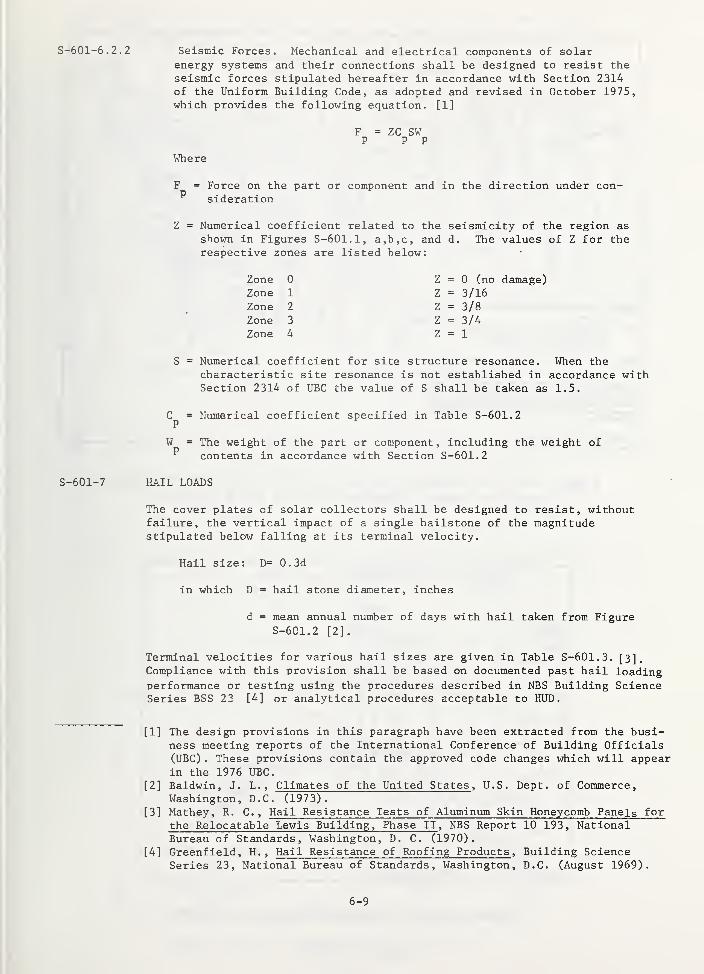
S-601-6.2.2 Seismic Forces. Mechanical and electrical components of solarenergy systems and their connections shall be designed to resist theseismic forces stipulated hereafter in accordance with Section 2314of the Uniform Building Code, as adopted and revised in October 1975,which provides the following equation. [1]
F = ZC SWP P P
Where
F = Force on the part or component and in the direction under con-^ sideration
Z = Numerical coefficient related to the seismiclty of the region as
shown in Figures S-601.1, a,b,c, and d. The values of Z for therespective zones are listed below:
Zone 0 Z = 0 (no damage)Zone 1 Z = 3/16Zone 2 Z = 3/8Zone 3 Z = 3/4Zone 4 Z = 1
S = Numerical coefficient for site structure resonance. When thecharacteristic site resonance is not established in accordance withSection 2314 of UBC the value of S shall be taken as 1.5.
C = Numerical coefficient specified in Table S-601.2P
W = The weight of the part or component, including the weight of^ contents in accordance with Section S-601.2
S-601-7 HAIL LOADS
The cover plates of solar collectors shall be designed to resist, withoutfailure, the vertical impact of a single hailstone of the magnitudestipulated below falling at its terminal velocity.
Hail size: D= 0.3d
in which D = hail stone diameter, inches
d » mean annual number of days with hail taken from FigureS-601.2 [2].
Terminal velocities for various hail sizes are given in Table S-601.3. [3],Compliance with this provision shall be based on documented past hail loadingperformance or testing using the procedures described in NBS Building ScienceSeries BSS 23 [4] or analytical procedures acceptable to HUD.
[1] The design provisions in this paragraph have been extracted from the busi-ness meeting reports of the International Conference of Building Officials(UBC) . These provisions contain the approved code changes which will appearin the 1976 UBC.
[2] Baldwin, J. L. , Climates of the United States , U.S. Dept. of Commerce,Washington, D.C. (1973).
[3] Mathey, R. C. , Hail Resistance Tests of Aluminum Skin Honeycomb Panels for
the Relocatable Lewis Building, Phase II , NBS Report 10 193, NationalBureau of Standards, Washington, D. C. (1970).
[4] Greenfield, H. , Hail Resistance of Roofing Products , Building ScienceSeries 23, National Bureau of Standards, Washington, D.C. (August 1969).
6-9

Figure S-601.1a Seismic zone map of Continental United States(Zone 4 is shown in figures S-601.1b and S-601.1c)
Figure S-601.1b Seismic zone map of Alaska.
6-10
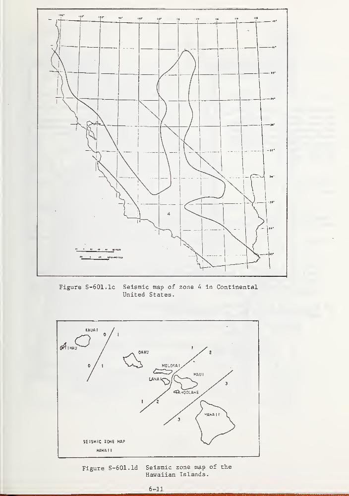
Figure S-601.1c Seismic map of zone 4 in ContinentalUnited States.
HAWA I
t
Figure S-601.1d Seismic zone map of the
Hawaiian Islands.
6^11
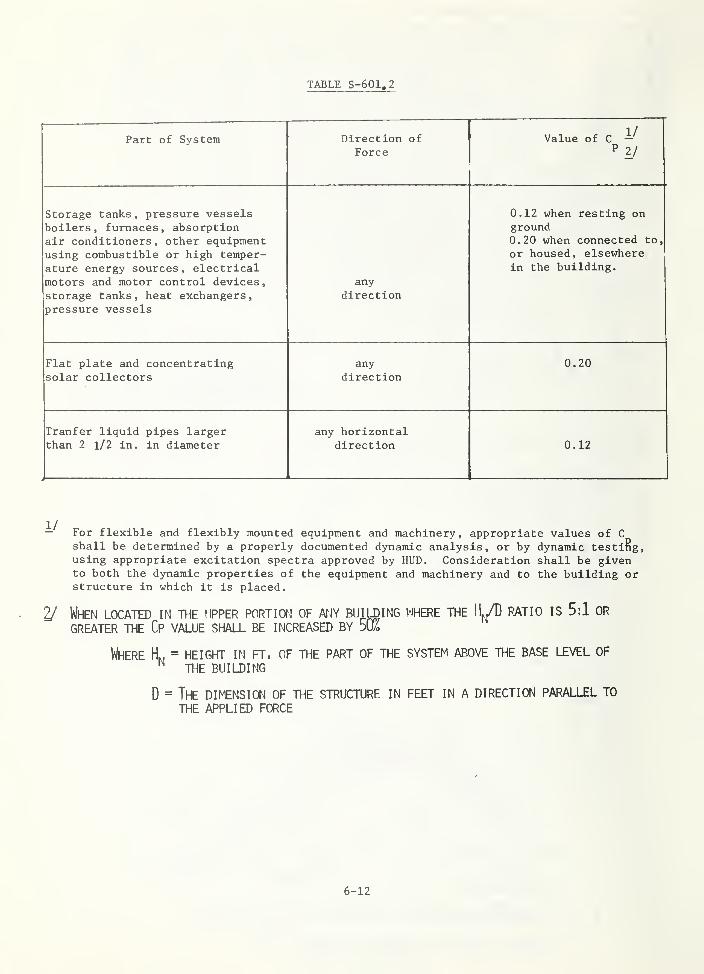
TABLE S-601.2
Part of System Direction of
ForceValue of C -
P 2 /
Storage tanks, pressure vesselsboilers, furnaces, absorptionair conditioners, other equipmentusing combustible or high temper-ature energy sources , electricalmotors and motor control devices
,
storage tanks, heat exchangers,pressure vessels
anydirection
0.12 when resting onground0.20 when connected to,
or housed, elsewherein the building.
Flat plate and concentratingsolar collectors
anydirection
0 . 20
Tranfer liquid pipes largerthan 2 l/2 in. in diameter
any horizontaldirection 0.12
— For flexible and flexibly mounted equipment and machinery, appropriate values of C
shall be determined by a properly documented dynamic analysis, or by dynamic testiRg,using appropriate excitation spectra approved by HUD. Consideration shall be givento both the dynamic properties of the equipment and machinery and to the building orstructure in which it is placed.
2/ When located in the upper portion of atjy building where the IL/D patio is 5:1 or
greater the cp value shall be increased by 50k
Where H^, = height in ft. of the part of the system above the base level of^ the building
D = The DIh€NSION of the structure in feet IN A DIRECTION PARALLEL TO
THE APPLIED FORCE
6-12
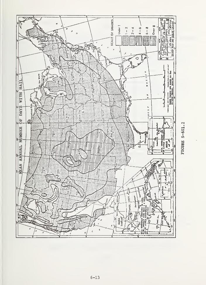
6-13
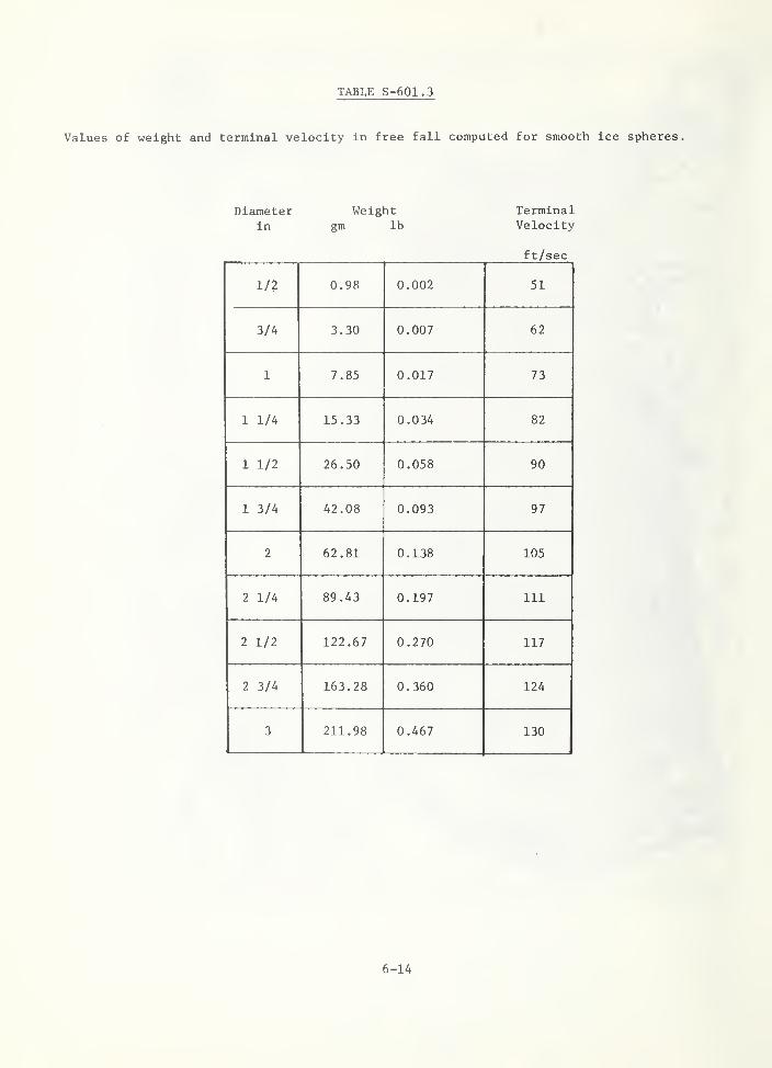
TABLE S-601.3
Values of weight and terminal velocity in free fall computed for smooth ice spheres.
Diameter Weight Terminalin gm lb Velocity
ft/sec
1/2 0.98 0.002 51
3/4 3.30 0.007 62
1 7.85 0.017 73
1 1/4 15.33 0.034 82
1 1/2 26.50 0.058 90
1 3/4 42.08 0.093 97
2 62.81 0.138 105
2 1/4 89.43 0.197 111
2 1/2 122.67 0.270 117
2 3/4 163.28 0.360 124
3 211.98 0.467 130
6-14
Commentary
The aorrelation of hail size with mean annual number of days with hailwas determined using data relating the probability of ocaurrenae of hailparticle size to the number of days with hail (tabulated in Ref. [1]) , andlimited statistical information relating the local area covered by a
hailstorm, and the regional area for which statistical data is compiled.The hail size indicated has a 5% probability of being exceeded in any oneyear (estimated 20 year recurrence interval) . The hail requirements in
this section are based on available information which does not containphysical test data. Therefore , local hailstone loading performance shouldbe considered in imrplementing the requirements of this section.
S-601-8 MAINTENANCE LOADS
All components of the solar energy systems which must support maintenancepersonnel shall be designed to resist a single concentrated load of 250 lbs.
distributed over a 4 sq. in. area, acting on the installed component in the
most critical locations. Special allowance shall also be made for heavymaintenance equipment, if used.
S-601-9 TKEKJIAL DISTORTION
(1) Thennal distortion of the mechanical or structural components of the
solar system during operation and periods of stagnation shall notcause deterioration of the system's performance.
(2) Thermal distortion of the solar system shall not cause distress to
the system or the supporting dwelling structure.
S-601-10 COLLECTOR COVER PLATES
(1) Deflection or local distress of cover plates resulting from the maximumdesign loading shall not impair the functioning of the unit. This shallbe demonstrated by analysis or physical simulation.
Commentary
Since wind can come from any direction, there will be maximum pressure(inward) loading for units mounted on the windward side of an installationand maximum suction (outward) loading for those mounted on the leewardside (unless shielding is provided). Depending on the installation,suction loading can, and often does, exceed pressure loading; hence, coverplate retainers must be adequately designed to prevent them from beingseparated from the collector frame or induce failure of the cover plateby suction loading.
S-601-11 CONNECTIONS OF COLLECTOR FRAMES AND/OR OTHER SUPPORT STRUCTURES
When collector frames and/or other support structures are mounted on walls,roofs, or other weather resistant surfaces, distortion of the frame fromimposed loading shall not cause penetrations or separations of these surfacessuch that moisture leaks occur through the weather resistant surfaces.
[1] Storm Data , U.S. Dept. of Commerce, National Oceanic and Atmosphere
Administration, Environmental Data Service (monthly periodical)
6-15
S-601-12 STORAGE TANKS
S-601-12.1 Design and Fabrication
Storage tanks shall be designed and fabricated to standards embodying
principles recognized as good engineering design and fabrication practices
for the materials used. These standards shall be approved by HUD.
S-601-12. 2 Testing
Each liquid storage tank shall be tested by the manufacturer or the
installation contractor to prove that leakage does not occur. The test
pressure shall be 1.5 times the maximum design pressure for pressures less
than 15 psi; however, these pressures shall not be less than 5 psi. For
tanks designed for pressures greater than 15 psi, the proof test pressures
shall be approved by HUD.
Storage tanks designed to contain dry heat storage material need not be
leak tested unless a safety hazard can result from a storage tank failure.
S-601-12. 3 Environmental and Vehicular Loading
In addition to the design, fabrication and test requirements, for storagetanks stipulated in the preceeding paragraphs of this section, the
following loading requirements shall be included in the design of storagetanks
.
S-601-12. 3.1 Above Ground
Unsheltered storage tanks shall be designed to resist loads resulting from,snow, wind, hail, and siesmic loading. Sheltered (completely enclosed)tanks need only be designed to resist seismic loading.
S-601-12. 3.1 Underground
Underground tanks shall be designed to resist soil and hydrostatic loadsand foundation loads transmitted to them; and they shall be anchored toprevent flotation resulting from flooding or high ground water level whenthe tanks are empty. For sites subject to commercial traffic or heavy trucktraffic, the wheel loads specified in AASHO H20-44 shall be used with noimpact. For areas subject to other vehicular or human traffic, the pertinantloads stipulated in the MPS, section 601-4.3 shall be used.
Cormentary
The oHterion speaifies the level of vehicular traffic for which buriedaomponents should be designed in cases where heavy vehicular traffic isanticipated to occur in service for purposes of access. The H20-44 truckis considered to be representative of load levels associated with heavyvehicles such as trucks for repair, maintenance , moving, and delivery of fuel.
S-601-13 DYNAMIC LOADS
Dynamic Loads resulting from sun tracking solar collectors or other movingequipment shall be taken in to account in the design of the dwelling frame.
6-16
DIVISION 4
S-604
S-604-1
S-604-1.1
MASONRY
GENERAL
Termination Height of Masonry Chimneys
Termination height of masonry chimneys shall be in accordance with NFPA 211.
Commentary
The pvesenae of solar equipment may -introduce building components that areelevated above the roof surface more than is usually required, thus producingwind distrubanoe at a higher level. The standard of NFPA 211 provides forproper clearance and separation.
6-17
DIVISION 7
S-607 THERMAL AND MOISTURE PROTECTION
S-607-3 BUILDING INSULATION FOR PASSIVE SOLAR SYSTEMS
S-607-3.1 Insulation Values
Insulation values may vary where they can be shown to improve the overall
energy balance of the building.
CoTmentavii
Section 607-2 of MPS was originally written to conserve energy orminimize the U-value of the exterior enclosure. For some solar systems it
may be desirable to vary the U-value in order to collect useful energy andprevent it from escaping or, at least, to provide a compromise U-value
between the collection and loss of useful energy. An example might be
a shuttered window which has single glazing. Wnen the shutters are open'the window collects energy and its U-value can be lower than those stated in607-3. When the shutters are closed the window conserves energy and the
U-value would fall at or higher than those stated in 607-2.
S-607-3. 2 Areas of Application
Materials used for thermal insulation may be applied in residential housingto the following areas: walls, roofs, ceilings, floors, pipes, ducts,vessels and equipment exposed to the external environment
.
Exposed plastic foam (untreated or fire-retardant treated) and non-fire-retardant treated cellulosic loose-fill insulation shall not be permittedin habitable areas. These materials should be protected by a layer ofgypsum board of 1/2 inch thickness or greater, or an equivalent fire barrier.
Installed insulation and vapor barrier shall not make contact with recessedlight fixtures, motors, fans, blowers, heaters, flues, and chimneys.Thermal insulation should not be installed within 24 inches of the top orwithin 3 inches of the side of a recessed electrical fixture enclosure,wiring compartment or ballast unless labeled for the purpose. To retainloose-fill insulation from making contact with other energy-dissipatingobjects, a minimum of 2 inches of air space should be provided and assuredby the use of blocking.
Cormentary
Although a degree of material combustibility is allowed, the intent is toallow insulating materials which are not more combustible (or flammable)than existing construction and insulation materials, and to preclude anyincreased fire hazard due to the retention of heat from energy-dissipatingobjects.
In areas where occupants are likely to be engaged in normal activities
,
the insulation should perform its intended function without the increasedrisk of ignition, rapid flame spread, and heat and smoke generation.Insulation in concealed spaces may be a praticular fire problem due to itssusaeptibilty to smouldering and its inaccessibility for firefighting
.
6-18
DIVISION 15
S-615 MECHANICAL
S-615-1 THEKMAL DESIGN
S-615-1.
1
General
The solar system shall be capable of collecting and converting solar energyinto thermal energy. Solar thermal energy shall be used, in combinationwith a conventional auxiliary energy source and other components suchas thermal storage or heat pumps to augment the system effectiveness to meetthe standards and requirements for space heating and domestic hot water setforth in Section 615 of MPS.
Cormentavy
Solar systems for residential applications generally are capable of storingand providing thermal energy to meet at least one design winter 24 hourheating load.
The solar energy system thermal energy contribution shall be backed up
100 per cent with a thermal energy subsystem utilizing a conventionalenergy source or a back-up system which will provide the same degree of
reliability and performance as a conventional system.
Commentary
The uncertainty in the availability of solar energy during inclement weatherrequires complete back-up of the solar system to meet comfort and hot waterstandards.
Heat load requirements used to determine the size of the auxiliary energysubsystems shall be calculated in accordance with the procedures and 97 1/2%design temperatures described in Section 615-3.1 of MPS
Uncertainties of +10 percent or more in the calculated heating load, aretolerated in sizing the auxiliary energy subsystem. Thermal load programsshould reflect the energy conserving features of the building constructionand operation such as insulation, thermal windows, actual indoor temperaturesand night-time set-back.
a. The solar energy system size shall be based upon monthly average heatloads detemined by a degree-day method using average monthly designtemperature and conditions as the maximum analytical time interval.Hourly or daily simulation times may be used if detailed local solarradiation is available. Calculations of building heat loss for use
S-615-1. 2 Back-up
S-615-1. 3 System Capacity - Space Heating
S-615-1. 3.1 Auxiliary Energy Subsystem
Commentary
S-615-1. 3. 2 Solar Energy System
6^9-
in sizing solar energy subsystem shall be performed for the full
heating season using a method at least as sophisticated as described
in Appendix A.
Cormentax'y
Since the methods of aalaulating heat losses and heat gain specified in
615-3.1 and 615-4.2 of the MPS may not be detailed enough to pvediot the
performanae of the heating and cooling systems fov buildings using passive
solar systems other approved methods may be used for making calculations
for passive solar buildings. An example of the considerations and level
,i of detailed analysis are presented in ASHRAE Standard 90-75 Energy
,.. ,. Conservation in Nei) Building Design .
b. The solar energy contribution shall be determined as a percentage of
the dwelling average annual space heating energy requirements.
Analytical simulations or correlations based upon simulations combining
the building heating load, solar system performance and climatic con-
ditions shall be utilized to predict the average monthly and annual energy
contribution to be provided by solar energy, auxiliary energy and
electrical operating energy as illustrated in Appendix A.
Commentary
Parametric studies have shown that a solar energy contribution of betweenSO to 70% for an active system is generally optimum when cost benefitshave been considered. Passive systems may contribute from 5 to 100%
depending upon the relationship between the demand/building/climate
.
S-615-1.4 System Capacity - Domestic Hot Water Heating
S-615-1.4.1 Auxiliary Energy Subsystem
The auxiliary energy domestic hot water heating system shall meet the
minimum requirements for storage, draw and recovery shown in Tables 615-2
or 615-3 of MPS.
S-615-1.4. 2 Solar Energy System
a. Determination of the average annual energy requirements for solar hotwater heating applications shall be based on average monthly conditionsas the maximum analytical simulation time interval to compare solarsystem performance with the load.
b. A minimum daily usage of 50 gal. of hot water from domestic use and 75
gal. when automatic cycle washers are included shall be used fordesign purposes.
6-20
Cormentaru
The desicrn shall al7-0hi fov the higher requivement wheve the potentiatincrease in use exists.
c. An average hot water temperature of 140°F and an average source watertemperature of 50°F shall be used for design purposes, if localtemperatures are unkno^m.
Commentary
Tap temperatures as lew as 120''F may be local option however lower storage
temperatures are usually combined with larger storage to provide equivalent
thermal capacity. Local source water temperature can vary from. 45 to 75°
F
with climate region and season.
d. The solar energy contribution shall be determined as a percentage of
the dwelling average annual DHW energy requirements. Analytical
simulations or correlations based upon simulations including the load,
solar system performance and climatic conditions shall be utilized to
predict the average monthly and annual energy contribution to be providedby solar energy and auxiliary energy as illustrated in Appendix A.
Commentary
Parametria studies have shown that a solar energy contribution of between
50 and 80% of the DHW load is generally optimum when cost benefits have
been considered.
S-615-1.5 System Capacity - Combined Space and Domestic Hot Water Heating Systems
a. The solar energy contribution shall be determined as a percentageof the combined dwelling average annual space heating and averageannual DHW energy requirements. Analytical simulations or correlationsbased upon simulations combining the space and DHW loads, solar
system performance and climatic conditions shall be utilized to
predict the average monthly and annual energy contributions to be
provided by solar energy, electrical operation energy and auxiliary
energy as illustrated in Appendix A.
S-615-1.6 Environmental Conditions - Integral Passive Systems
Where normal building spaces are designed to be part of a solar energycollection, storage, distribution or control system, indoor design conditionscan vary as long as they do not interfere with the normal use of a space.
S-615-1.6.1 Design Air Temperature for Passive System
The air temperature in hall and storage areas can be designed for fluctuation
from 57°F to 83°F [1]. Other areas can be designed for fluctuation from
62°F to 78°F [1] provided there are provisions for bringing the air temperature
up to design conditions required in section 6-15-3.16 of MPS when the space
is in use.
[1] Grandjean, Ftienne, 1973 Ergonometrics of the Home , New York,
Halstead Press.
6-21
Cormentary
The operation of a passive system is usually dependent upon natural oonveotiveor radiative heat transfer processes which are in turn dependent upon temp-erature gradients . Therefore the temperature differences of at least 4"? to
6''F are required in a completely passive system.
S-615-1.7 Protection Against Blockage of Fluid Flow
The entire heat transport system shall be protected to prevent contaminationby foreign substances that could impair the flow and quality of the heat
transfer fluid beyond acceptable limits.
Commentary
The heat transfer fluid passages in solar collectors and some heat exchangersmay have small cross sections in which blockage by dirt, scale, pieces ofgasket material, pieces of packing or other foreign matter in the heattransfer fluid could occur.
S-615-1.8 SYSTEM SHI Onoifi
The shutdown of the heating or domestic hot water system in one unit of amulti-family duelling shaix not interfere with the function of these systemsin any other unit.
CoftlENTARY
This is to permit the shutdw^in of equipment in an individual dwelling unitFOR repairs without IMPAIRING THE OPERATION OF THE EQUIPMENT IN OTHERDWELLING UNITS THAT ARE CONNECTED TO THE SAME CENTRAL SYSTEM.
6-22
S-615-2 COLLECTORS
S-615-2.1 General Provisions
S-615-2.1.1 Design Flow Rates
When an array of solar collectors is connected by manifolds, provision shallbe incorporated in the manifolds and/or collectors to maintain the designflow rate through each collector.
Commentary
An available method of balancing air and liquid HVAC equipment is describedin the National Standards for Field Measurement and Instrumentation : TotalSystem Balance, Vol. 1, No. 81266 (Associated Air Balance Council 2146Sunset Blvd., Los Angeles, California 90026). "Fhe method describes proceduresand measurements, but does not establish standard balance values.
S-615-2.1, 2 Tilt and Orientation
The collector shall be installed in a mount capable of maintaining tilt and
orientation to. within +10 degrees of design conditions.
Commentary
A collector tilt angle equal to the latitude plus 10 to IS degrees from thehorizontal is generally used to provide maximum collection during the winterseason for space heating applications. However, deviations of +10 degreesfrom this value, when using conventional flat plate collectors, will havelittle effect as illustrated in Figure S-615.4 which shows, for a particularexample, the effect on annual performance of variations of tilt angles for acollector facing south.
Conventional flat plate collector orientation should be such that the effectiveaperature generally faces south. However, deviations to the east or west by
up to 20° may not result in a significant decrease in incident radiation asindicated by the example of the influence of air collector orientation on the
solar fraction of total load shown in Figure S-61S.5.
A fixed collector tilt ar^le equal to the latitude or latitude +IS degrees fordomestic hot water applications is typically used to favor winter heatingrequirements . This angle will tend to maximize the year-round performance ofdomestic hot water heaters. The orientation of concentrator type collectors is
a function of the collector acceptance an^le design and may require trackingwithin specific limits.
S-615-2.1. 3 Shadowing
Shadowing of collectors shall be considered during the design so that
shadowing by trees or other obstructions do not exceed design limits.
Commentary
On east and west exposures during the entire year, and on south exposures
during the winter, and solar altitude may be low enough to cause direct
shading and a resultant loss in collection capability.
6-23
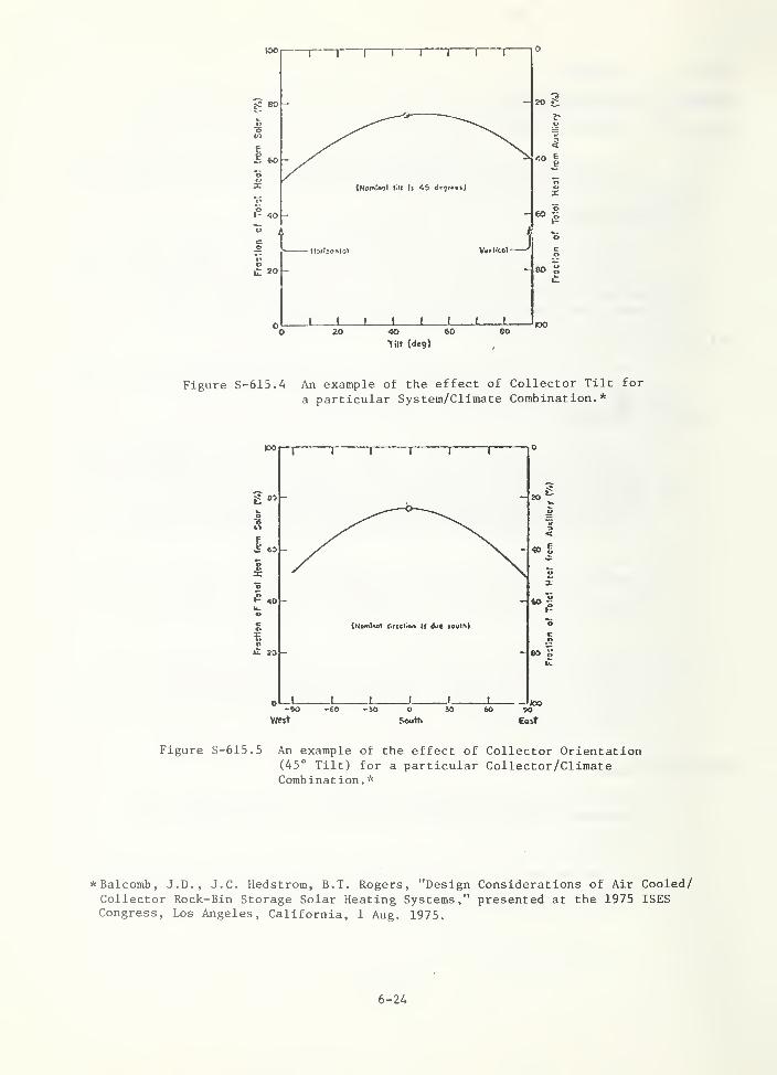
Figure S-615.A An example of the effect of Collector Tilt for
a particular System/Climate Combination.*
-90 -60 -JO O iO feO SO
West seulh Eoit
Figure S-615.5 An example of the effect of Collector Orientation(45° Tilt) for a particular Collector/ClimateCombination .
*
*Balcomb, J.D., J.C. Hedstrom, B.T. Rogers, "Design Considerations of Air Cooled/Collector Rock-Bin Storage Solar Heating Systems," presented at the 1975 ISESCongress, Los Angeles, California, 1 Aug. 1975.
6-24
S-615-2.1.4 Ice Dams and Snow Build Up
The design of solar buildings and systems shall provide for the possibilityof formation of ice dams and snow build up.
Commentary
In very cold climates, water flowing off a warm collector may freeze oncold surfaces immediately below it (such as exposed eves), thereby formingan ice dam which can cause water to back up under roofing or into thethe collector itself. This may be moderated by methods such as eliminationof the cold surface or provision of an impervious surface such as cont-inuous flashing. Snow sliding off a collector may pile up at the bottoyn andcover part of the collector. This would have a tendency to reduce theefficiency^ of the collector and increase the possibility of thermal breakageof glass in the collector. This may be moderated by methods such as theprovision of space below the collector for snow pile up or by the installationof heating cables.
S-615-2.1.5 Mud Splash
The design of solar buildings and systems shall minimize the possibilityof mud splash on collector surfaces
.
Commentary
Water running off collectors located close to the ground can cause mudsplashing to coat portions of the collector and reduce its efficiency
.
Remedies to this include: easy access for cleaning, position of collectorselevated sufficiently to avoid splashing, or provisions of gutters orsplash free material at the base of the collector.
S-615-2.1.6 Protection Against Maximum Temperature and Pressure
Collectors shall not be damaged or adversely affected by maximum temperatureand pressure that could occur during periods when heat transfer fluid is notflowing.
Commentary
Temperatures in excess of SOO'^F would probably occur within flat platecollectors that are not cooled by heat transfer fluid. Such conditionscould occur during normal shut down, loss of fluid flow resulting frompump or fan failure, system blockade, or loss of electric power.
The designer should either assure that the materials used in the collectorcan withstand the maximxm temperatures and pressures or provide temperatureand pressure relief from thermal cyling or shock.
S-615-2.2 Collector Thermal Performance
S-615-2.2.1 General
This section is intended to cover subsystem, component and integral collectorswhich can be flat plate, concentrating, reflector aided, fixed or trackingtypes
.
6-25
Flat Plate Collectors
This type collector can be characterized as a subsystem or component for
an active solar system requiring the use of powered mechanical equipment
to move the heat transfer fluid (liquid or gas) through the collector.
The collector thermal performance shall be based upon the slope-intercept
method of expressing efficiency for the range of operating conditions
including solar power density, heat transfer fluid temperature, ambient
temperature, wind, solar radiation incident angle, and flow rates, to be
used in the design.
Commentar'y
The oolleotoT performanae Gharaateristics can be measured using the National
Bureau of Standards proposed test method (NBSIR 74-635) for rating solarGolleators or any other method demonstrated, to have an overall limit-of-error
of less than +_5%. This method provides sufficient efficiency versus operatingcondition data to construct a curve normalized for insolation and temperature
difference between ambient and heat transfer' fluid temperature. Curves fortypical flat black and selective coated absorber panels with one and two
covers are shoim in Appendix A for air and water collectors. Collectors
with other geometric, optical or thermal characteristics may require addi-tional tests to fully describe their thermal performance for all environmentaland operating conditions. The operating electrical power is recorded andreported during all tests.
b. Combined Collectors and Storage Devices
This type of combined component system can be characterized as a systemwith integral construction and operation of the components such that the
solar radiation collection and storage phenomena cannot be measuredseparately in terms of flow rate and temperature changes. The systemthermal performance is determined by the short term (1 to 3 days) collec-tion and storage of thermal energy obtained from solar radiation and theamount of useful energy delivered to the load from storage for part andfull load conditions. Experimental performance data, in terms of heatcollected and stored or delivered to load, shall be provided for the designconditions including solar power density, heat transfer fluid temperature,ambient temperature, wind, solar radiation incident angle, and flow rates.The daily and average test period electrical operating requirements arereported with system performance.
Commentary
Although a consensus test method to rate and evaluate these systems does notexist, the efficiency in terms of converting incident solar energy into usefulthermal energy can be measured and reported as a function of the specifiedoperating conditions.
c. Integral Collector, Storage and Building (Passive)
An integral collector system can be characterized as one in which thecollector and storage components are an integral part of the building ina passive solar system. Auxiliary energy may be used for control purposesbut heating is generally achieved by natural heat transfer phenomena.Roof ponds, modified walls, roof sections with sky lights, or similarapplications where solar energy is used to supply a significant fractionof the building heating requirements, are examples of passive collectors.The thermal performance of an integral collector system can be obtainedfrom a detailed simulation analysis of the climate, building thermalproperties and occupancy thermal influence.
6-26
Commentary
A more detailed simulation of solar heating, building thermal aapaoitanae andthermal energy control must he included in the traditional building loaddetermination programs for the design and evaluation of an integral solarsystem. Experimental evaluation of the system performance includes measure-ment of the climatic conditions, auxiliary energy use and comfort level forsufficient periods to account for building thermal capacitance effects(minirmm of 7 days) and, preferably , monthly or seasonal averages are obtained.
S-615-3 MECHANICAL SUPPORTING DEVICES
S-615-3.1 Pipe Hangers and Supports
Pipe hangers and supports shall be installed in accordance with the prevailingmodel plumbing code having jurisdiction in the area.
S-615-4 VALVES
Gate valves or similar valves that open to nearly full pipe bore shall beused for shut off valves. Globe or similar valves shall be used for flowcontrol
.
S-615-5 PUMPS & COMPRESSORS
S-615-5.1 Applicable Standards
a. Pumps shall be installed in accordance with the requirements of the
Hydraulic Institute.*
b. Pump motors shall conform to appropriate NEMA Standards such as NEMA
Standard M Gl-18.615.
c. All moving machinery shall be protected and guarded to comply with the
current safety standards of ANSI B15.1 if such machinery is exposed to
other than maintenance personnel.
S-615-6 MECHANICAL VIBRATION ISOLATION
S-615-6.1 General Requirements
All operating mechanical equipment shall be isolated by suitable piping con-nections and where necessary by isolation pads or foundations to preventtransmission of noise or vibration. The dwelling shall be free of objectionablesound as required in HUD circular 1390.2, Noise Abatement and Control.
Equipment conforming to other sound level criteria referenced in these standardsshall also be acceptable.
^Hydraulic Institute Standards for Centrifugal, Rotary and Reciprocating Pumps, Thirte.
Edition, 1975. The Hydraulic Institute, 1230 Keith Building, Cleveland, Ohio 44115.
6-27
S-615-7 THERMAL STORAGE
S-615-7.1 Thermal Storage Requirements
S-615-7. 1.1 General Provisions
This section applies to sensible and latent heat type thermal energy storagedevices using gas or liquid as the heat transfer fluid and liquid or solidas the heat storage medium. The storage medium can be contained in a
separate enclosure, stored at more than one temperature, or can be a part
of the building structure. Some typical storage subsystem arrangements areshovm in Appendix C.
Cormentary : The interaction between storage temperature and colleatoroperating efficiency must be considered in the location and operation ofthe auxiliary energy source. Auxiliary energy supplied to the storagemedium directly can result in decreased system efficiency . Designs whichenhance normal storage temperature gradients and control the heat transferfluid mixing, which use electrical "peak shaving" power or which use solarassisted heat pumps may influence storage temperature or operation.
S-615-7. 1.2 Space Heating
The thermal energy storage capacity for space heating shall not be lessthan 500 Btu per square foot of solar collector area for a component(active) system. The thermal energy storage capacity for space heatingshall be not less than 1000 Btu per square foot of collector area for anintegral (passive) system.
Commentary : The relationship between the load fraction supplied by solarenergy to the storage capacity for liquid and air applications is presentedin Avvendix A. The storage heat capacity for integral (passive) systems isa function of the thermal coupling between storage and the load but, becauseof usual lower storage temperatures , a larger heat cajpaoity is desired.
S-615-7. 1.3 Domestic Hot Water Heating
The solar thermal energy storage for preheating domestic hot water shall havea volume capacity not less than the number of gallons shown in Tables 6-15.2or 6-15.3 of MPS.
Commentary
:
Although it is possible to design a hot water storage containerwith large temperature gradients permitting the auxiliary energy source tobe incorporated in the same container, it is preferred to add the auxiliaryenergy after the water has been removed from the solar heated container,
S-615-7. 1.4 Combined Space and Domestic Hot Water Heating
The thermal energy storage capacity for a solar energy system providingthermal energy for both space and domestic hot water shall not be less than500 Btu per square foot of solar collector area.
S-615-7. 1.5 Thermal Energy Loss
The thermal energy loss from storage containers shall not exceed 10 percentof the maximum operating thermal energy capacity over a 24 hour winterdesign day.
6-28
Ccrmentarij : Calculations of the thermal loss from tanks, piping, and valves
aan be performed using average fluid and ambient temperatures and thermal
insulation conductivity values with procedures described in the ASHRAE Hand-
book of Fundamentals. In addition to energy loss, consideration of the heatcontribution to occupied spaces can result in more insulation.
S-615-7.1.6 Tank Drainage
Each tank shall be provided with means of emptying the liquid. Each tanklocated above grade or floor level shall be provided with a valved pipeat its lowest point to permit emptying the tank. Each buried tank shallhave provisions for utilizing a pump or siphon or other means to allowemptying.
S-615-7.1.7 Vacuum Relief
The solar system, including collectors, pipes, tanks, and heat exchangersshall be designed with vacuum relief valves or otherwise protected againstpossible collapse.
Commentary : System components may be subjected to collapse if heatingsystem leakage were to occur or if the system were drained without venting.
S-615-7.1.8 Tank Filling
Tanks of large capacity should have an indicator or other means for determiningthat the tank is full. Tanks should have overflows with outlets located so
that spillage will not run into the building structure or damage the premises.Tanks that do not contain potable water but require make up water from the
potable water system shall be filled by way of an air gap or other meansacceptable to the administrative authority having jurisdiction.
I
6-29

S-615-8 HEAT TRANSFER FLUIDS
S-615-8.1 Toxic and/or Flammable Media
S-615-8. 1.1 General
Requirements for handling non-potable heat transfer fluids are discussed in
sections S-615-9, Waste Disposal; S-615-10, Plumbing; and S-615-12, HeatExchangers, of this document.
S-615-8. 1.2 Detection of Toxic and Flammable Fluids
If nonpotable heat transfer fluids are used, means shall be provided for thedetection of leaks and the warning of occupants when leaks occur.
Conmentavy : These substances shall be treated in a manner similar to airconditioning condensates, refrigerants (Chapter 14, ASHRAE Handbook ofFundamentals) , and gases (NFPA 54) when providing for tell-tale indicators
.
For instance, antifreeze agents, such as ethylene glycol, should be treatedwith non-toxic dyes which distinguish them clearly. Furthermore, if any suchmaterials are to be stored on the premises , they should be stored in con-tainers which are labeled in accordance with the Hazardous Substances LabelingAct and are protected from easy opening by children, e.g., childproof lids.
Safe storage locations should be provided.
S-615-9 WASTE DISPOSAL
S-615-9. 1 Catchment
Systems utilizing other than air or potable water as a heat transfer fluid
shall provide for the catchment and/or harmless removal of these fluids fromvents, drains or re-charge points. Potable water shall be discharged to
suitable drainage systems connected to the building or site drains. See
MPS Section 615-9.
S-615-9. 2 Provision of containment for discharge treatment of hazardous media
Adequately sized and protected recepticles shall be provided when liquidsrequiring special handling are used in order to collect and store the over-flow from pressure relief valves, liquids drained from the system when it
is being serviced, potential leakage, and accidental drainage. Provisionsof MPS Section 615-A.4 shall be applied.
Commentary : When a toxic heat transfer medium is used (see Section S-515-
8.2.4), a catch basin must be provided. It must be sufficiently large to
accept dilution as required by MPS Section 515-9 before disposal. If the
diluted medium is biodegradable through conventional sewage treatment , the
diluted medium is to be flushed into the sanitary sewer system (not the stormsewer system).
6-30
S-615-10 PLUMBING
S-615-10. 1 Handling of Nonpotable Substances
Potable water supply shall be protected against contamination in accordancewith the prevailing model plumbing code having jurisdiction in the area.
S-615-10. 1.1 Separation of Circulation Loops
Subsystems requiring the circulation of nonpotable heat transfer fluidsshall be separated from the domestic (potable) water system so thatcontamination of the domestic water will not occur.
S-615-10. 1.2 Identification of Nonpotable and Potable Water
In buildings where dual fluid systems, one potable water and the othernon-potable fluid, are installed each system may be identified either bycolor marking or metal tags as required in ANSI A13. 1-1956 [1] or other
appropriate method as may be approved by the Administrative Authority. Such
identification may not be required in all cases.
S-615-10. 1.3 Backflow Prevention
Backflow of nonpotable heat transfer fluids into the potable water systemshall be prevented in a manner approved by the Administrative Authority.
Cormentcanj : The use of air gaps and/ov mechanical backflow preventers aretwo possible solutions to this problem. The following are some recognizedstandards that may be acceptable to the administrative authority: Completetitles are given in Appendix F.
Air gaps - A1^SI-A112. 1.2
Backflow preventers - FCCCHR Chapter 10
lAPMO PS 31-74AWWA C506-69A.S.S.E. 1011
A.S.S.E. 1012A.S.S.E. 1013A.S.S.E. 1015A.S.S.E. 1020ANSI-A112.1.1
S-615-10. 2 Pipe Sizing
Pipe sizing shall be in accordance with recognized methods.
Commentary : Piping system design guidance is given in Model Plumbing CodeSj
the Hydraulic Institute ' s Pipe Friction Manual - 1967, and in handbooks suchas "Handbook of Hydraulics" by King and Brater. [2]
]] Scheme for the Identification of Piping Systems, ANSI A13.1 - 1956.
2] Handbook of Hydraulics for the Solution of Hydrostatic and Fluid-Flow Problems,
by Horcace Williams King and Ernest F. Brater (McGraw-Hill Book Company)
5th ed. 1962.6-31
S-615-10.
3
System Drainage
System designs incorporating automatic drainage of heat transfer fluid to
storage to prevent freezing of the fluid in solar collectors shall not be
constructed of materials which corrode in the presence of air or shall be
suitably protected. Liquid systems shall be designed so that completeisolation and drainage of all system components, piping, or storage tanks
can take place in a reasonable length of time for maintenance purposes.
See S-615-7.1.6, Tank Drainage.
Commentary : One means of preventing oorrosion during system drainage wouldbe by introducing an inert gas suoh as nitrogen.
S-615-10. 4 Protection from Scalding
All domestic hot water systems shall be equipped with means of limiting•
• . . temperature as required in MPS section 615-6.
S-615-10. 5 Provision of Valves and Fittings
S-615.10.5.1 Shutoffs
All domestic water heaters and water heating systems shall be valved to
provide shutoff from the cold water supply systems.
S-615-10. 5.2 Water Hammer Arresters
When a liquid is used as the transfer fluid in a solar energy system andquick-closing valves are employed in the design, the piping system shall be
able to control or withstand potential "water hammer". Water hammerarresters shall be in compliance with local codes
S-615-10. 5.3 Air Bleeds
When liquid heat transfer fluids are used in solar heating systems, the
systems shall be provided with suitable means for air removal from highpoints in the piping system.
S-615-10. 5.4 System Flushing
To facilitate solar heating system maintenance and repair, systems employingliquids shall be capable of being conveniently filled and drained. Suitableconnections shall be provided for flushing (cleaning) the system. Allpiping shall be pitched to drain completely.
6-32
S-615-10.6 Expansion Tanks
Adequate provisions for the thermal expansion of solar heat transfer andstorage liquids that would occur over the service temperature range shall beincorporated into the solar heating system design.
Expansion tanks shall be sized in accordance with the recommendations ofASHRAE Guide and Data Book.
S-615-10.7 Leak Testing
Those portions of heating systems which contain liquid heat transfer fluidsand are not directly connected to the potable water supply shall not leakwhen pressures of not less than 1-1/2 times their design pressure areimposed for a minimum of 15 minutes [1]. The pressure shall be graduallyapplied and sustained for a sufficient length of time to permit examinationof all pipe joints for leakage. Those portions of the system usingdomestic hot water shall not leak when tested in accordance with the codehaving jurisdiction in the area where the system is used. In areas havingno building code, a nationally recognized model code shall be used [!]•
Cormentarij : A hydrostatic test pressure of 1-1/2 times design pressvo'e is
considered a standard test pressure. {2]. For most applications , clear wateris used. The temperature of the water should he no lower than that of theambient atmosphere. Otherwise, sweating will result and proper examinationwill be difficult. In environments where freezing may occur, antifreeze or
hydrocarbons may be added to keep the water from freezing. Bleeder valvesor petcocks should be provided at the highest point or points in the systemto permit venting of all air in the piping during the filling operation [2],
Automatic vents must be protected from freezing
.
-615-10.8 Discharge of Liquids
Relief valves shall be piped to discharge to locations acceptable to the
administrative authority having jurisdiction.
10-615-10.9 Location of Exposed Piping
Piping and equipment shall be located so as not to interfere with normaloperation of windows, doors, or. other exit openings and so as to preventdamage to piping, equipment, or injury to persons.
S-615-10.10 Underground Piping
Undergound water service piping shall be installed in accordance with the
provisions of Section 615-5.3 of MPS. Underground heat distributionpiping shall be installed in accordance with Section 615-3.5 (k) of MPS.
S-615-10.11 Treatment of Water
When make-up water is of such a quality that excessive corrosion is knownto exist, a suitable water treatment system as recommended by the WaterConditioning Foundation shall be provided.
[1] The BOCA Basic Plumbing Code, Southern Standard Plumbing Code, and the Uniform
Plumbing Code.
[2] Piping Handbook, Remo C. King and Sabin Crocker, McGraw-Hill Book Company, 5th Edition.
6-33
S-615-10.12 Excess Collected Energy
Provisions for the dumping of thermal energy may be required when the energydemand is less than the collected useful energy.
Commentary : For systems in which it is not praatiaal to shut the oolleationsystem down, excess thermal energy can be disposed of by dumping to the
external environment.
S-615-11 AUXILIARY ENERGY SYSTEMS
S-615-11.1 Applicable Standards
a. Domestic water heaters shall comply with the following appropriatestandards
:
Oil UL-732
Gas AGA Listed
Electric UL-174
b. Heating systems shall comply with the following appropriate standards;
Oil UL-727 & 730
Gas AGA Listed
Electric UL-573, NFPA-70
Boiler (Steam & Water)
Oil MCA, SBI, IBR, UL-726 & 296
Gas MCA, SBI, AGA, IBR
Electric SBI, UL-174
Radiation
Baseboard IBR Rated
Finned Tube IBR Rated
Electric UL-1042, NESCA
Fuel Tanks UL-58
c. Heat pumps shall be installed in compliance with the requirements of
ANSI B9.1 - 1971, "Safety Code for Mechanical Refrigeration" (ASHRAE)and ARI Standard 260, "Standard for Application, Installation, andServicing of Unitary Systems" (1967)
.
6-34
S-615-12 HEAT EXCHANGERS
S-615-12.1 Sizing
a. A heat exchanger when used in conjunction with the solar collector andstorage shall be sized such that the effectiveness in transferring heatfrom the collector to storage is not less than 0.70. The heat exchangereffectiveness is expressed by:
E = (m c ) (t - t)/(lTl c ) . (t- - t)c p s 1 ' p mm 0
where
(m c ) . = the minimum capacitance rate of (m c ) collectorp mm p
(m c ) = flow circuitP s
t = storage temperature (°F)
tQ = collector outlet temperature (°F)
ti = collector inlet temperature (°F)= effectiveness of the collector - storage heat exchangers
in = flow rate of the working fluid (Ibm/min)Cp = fluid capacitance (Btu/lbm - °F)
b. The load heat exchanger heat transfer rate shall be selected such thatthe ratio of the heat exchanger effectiveness times the minimum capaci-tance rate to the total heating load is between a value of 1 and 5. Thisdimensionless parameter and relationship is expressed by:
1< ^p^min < 3
UA
where
e = Effectiveness of load heat exchanger
UA = Building heat loss factor (Btu/Day °F)
Commentary : Diagrams of the typiaal location and performance of heat exchangersare presented in Appendix A and C. Calculation methods for heat exchangerperformance are described in the ASHRAE Handbook of Fundamentals.
S-615-12. 2 Handling of Nonpotable Fluids
When nonpotable fluid is used in a solar energy system to transfer heat todomestic (potable) hot water, the design of the heat exchanger shall preventdiffusion or mixing of the toxic fluid into the potable water should a leakoccur in the heat exchanger. The system should be designed so that a leak is
readily apparent.
6-35
S-615-13 AIR DISTRIBUTION
S-615-13. I Applicable Standards
Design of all warm air heating systems shall be in accordance with applicablerecommendations of the ASHRAE GUIDE, manuals of NESCA and ARI. Installationshall comply with NFPA standards 90B, 31 and 54.
Cormentary : Duat work should be designed for the shortest practical run andelbows should he kept to a minimum. Constrictions should be avoided.
S-615-13. 2 Dust and Dirt Prevention
Duct and fan systems shall be protected against accumulation of deposits of
of dust or dirt that could reduce flow and efficiency in addition to creatinga potential health hazard when admitted into occupied spaces. Air filters arerequired on the outlet side of rockbed storage systems.
Commentary : The gravel used for rockbed storage with air systems is selectedfor size and freedom from dirt and dust. Therefore, smooth and washed materialcombined with the use of filtered air is desirable to provide a maintenancefree clean distribution system. Fan grilles should he removable or hinged topermit access to the fan and motor for cleaning, servicing , replacement, orrepair.
6- 36
S-615-14 CONTROLS AND INSTRUMENTATION
S-615-14. 1 Fall-Safe Controls
The control subsystem shall be designed so that in the event of a power failure,or a failure of any of the components in the subsystem, the temperatures and/orpressures developed in the H and DHW systems will not be damaging to any of thecomponents of the systems and the building or present a danger to the occupants.The safety devices shall meet the requirements of Section 515-6.4 of MPS andbe demonstrated to be adequately safe and protected for the intended application.
S-615-14. 2.1 Automatic Pressure and Temperature Relief Valves for Nonflammable orNoncombustible Fluids
Adequately sized pressure and/or temperature relief valves, such as in MPSSection 615-6.2, shall be provided in those parts of the energy transportsubsystem containing pressurized fluids.
Relief valves shall drain to locations acceptable to the local administrativecode authority.
Commentary : Precautions must he taken to assure that heat transfer solutionsdo not discharge on asphalt base roofing materials or other type of roofingor other locations which may he hazardous, cause structural damage y huildingfinish discoloration, or damage to shruhs and lawns.
S-615-14. 2. 2 Automatic Pressure and Temperature Relief Valves for Flammable or CombustibleFluids
The fluid transfer system shall include a pressure relief valve. The valveand its discharge system shall not permit fluid dischrage directly into theoccupancy. It is recommended that a holding tank be included in the systemfor collection of discharge. The pressure relief valve shall be designedbased on maximum temperature criteria for abnormal operating conditions suchas no-flow. (AP must be limited to comply with temperature criteria.)
The fluid transfer system shall include a temperature relief valve. It shallprevent further increase in temperature and provide discharge in the samemanner as the pressure relief valve.
Maximum fluid temperature at which temperature relief valve shall operate:
a) 100°F below flashpoint of f luid» flash point to be determined inaccordance with NFPA 321, 1971, Standard on Basic Classificationof Flammable and Combustible Liquids.
b) 400°F
Local alarm shall be required to indicate a failure of the fluid transfersystem (e.g., leakage, pump failure) or activation of relief valves. Alarmsshall be installed in accordance with NFPA 26, Supervision of Valves, andNFPA 72A.
S-615-14. 3 Identification and Location of Controls
Main shutoff valves and switches shall be considered comparable to electricalservice panels and be conspicuously marked and placed in an easily accessiblelocation in accordance with Section 240.24 of NFPA 70, and MPS, Section 616.
6-37
S-615-14.4 Indirect Water Heaters
Indirect domestic water heater installations shall include operating controls
for the heat source, of the type recommended by the boiler manufacturer. The
installation shall be made in accordance with the boiler manufacturer'sinstructions
.
615-14.5 Efficient Operation
A differential thermostat shall be utilized to control operation of the collector
heat transfer fluid pump.
Commentary : The collector operation is limited to conditions when the heat
transfer fluid temperature in the collector is greater than in storage or
for load requirements , a start-up AT" of 10"F and shutdown LT of 2°F are
aormonly used.
S-615-15 CHIMNEYS AND VENTS
S-615-15.1 Termination height of chimneys and vents
Termination height of chimneys and vents shall be in accordance with NFPA 211.
Commentary : The presence of solar equipment may introduce building componentsthat are elevated above the roof surface ^ thus producing wind disturbance ata higher level. The standards of NFPA 211 will provide for proper clearanceand separation.
S-615-16 MECHANICAL VENTILATION
S-615-16.1 Air Discharge Openings
Air discharge openings through roofs or exterior walls shall not be locatedsuch that their exhaust will cause the deposition of grease, lint, condensationor other deleterious materials on solar optical components.
6-38
APPENDIX A
Calculation Procedures for Determining
the Thermal Performance of Solar Space
Heating and Domestic Hot Water Systems

TABLE OF CONTENTS
PageINTRODUCTION A-1
SOLAR HEATING SYSTQIS A-3
Liquid Working Fluid A-3
Air Working Fluid A-5
SOLAR HEATING SYSTEM PERFORMANCE A-6
SYSTEM PERFORMANCE A-10
Total Heating Load A-10
Incident Solar Radiation A-13
Component Parameters A-15
Dimenslonaless Parameters A-17
Monthly Fraction of Total Heating LoadSupplied by Solar Energy A-17
Annual Fraction of Tol:al Heating LoadSupplied by Solar Energy A-19
A-1
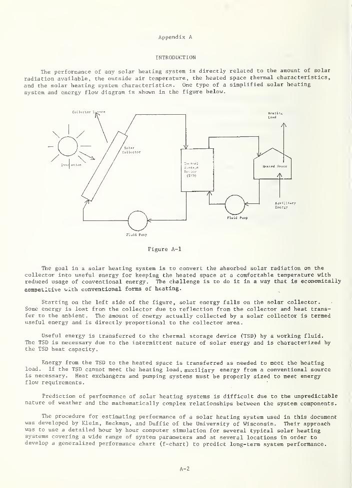
Appendix A
INTRODUCTION
The performance of any solar heating system is directly related to the amount of solar
radiation available, the outside air temperature, the heated space thermal characteristics,
and the solar heating system characteristics. One type of a simplified solar heating
system and energy flow diagram is shown in the figure below.
Fluid Pump
Figure A-1
The goal in a solar heating system is to convert the absorbed solar radiation on the
collector into useful energy for keeping the heated space at a comfortable temperature withreduced usage of conventional energy. The challenge is to do it In a way that is economically
competitive with conventional forms of heating.
Starting on the left side of the figure, solar energy falls on the solar collector.Some energy is lost from the collector due to reflection from the collector and heat trans-fer to the ambient. The amount of energy actually collected by a solar collector is termeduseful energy and is directly proportional to the collector area.
Useful energy is transferred to the thermal storage device (TSD) by a working fluid.The TSD is necessary due to the intermittent nature of solar energy and is characterized bythe TSD heat capacity.
Energy from the TSD to the heated space is transferred as needed to meet the heatingload. If the TSD cannot meet the heating load , auxiliary energy from a conventional sourceis necessary. Heat exchangers and pumping systems must be properly sized to meet energyflow requirements.
Prediction of performance of solar heating systems is difficult due to the unpredictablenature of weather and the mathematically complex relationships between the system components.
The procedure for estimating performance of a solar heating system used in this documentwas developed by Klein, Beckman, and Duffie of the University of Wisconsin. Their approachwas to use a detailed hour by hour computer simulation for several typical solar heatingsystems covering a wide range of system parameters and at several locations in order todevelop a generalized performance chart (f-chart) to predict long-term system performance.
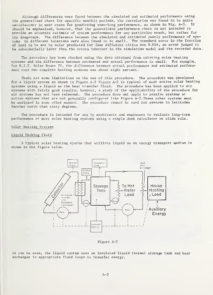
Although differences were found between the simulated and estimated performance using
the generalized chart for specific monthly periods, the correlation was found to be quite
satisfactory in most cases for predicting year-long performance, as shown in Fig. A-3. It
should be emphasized, however, that the generalized performance chart is not intended to
provide an accurate estimate of system performance for any particular month, but rather for
the long-term. The difference between the simulated and estimated yearly performance of sys-
tems in different locations were also found to be small. The standard error in the fraction
of load to be met by solar predicted for four different cities was 0.014, an error judged to
be substantially lower than the errors inherent in the simulation model and the recorded data.
The procedure has been checked using the data obtained from existing solar heatingsystems and the difference between estimated and actual performance is small. For example,for M.I.T. Solar House IV, the difference between actual performance and estimated perform-ance over two complete heating seasons was about eight percent.
There are some limitations on the use of this procedure. The procedure was developedfor a liquid system as shown in Figure A-2 Figure A-2 is typical of most active solar heating
systems using a liquid as the heat transfer fluid. The procedure has been applied to air
systems with fairly good results; however, a study of the applicability of the procedure for
air systems has not been released. The procedure does not apply to passive systems or
active systems that are not generally configured like Figure A-2. These other systems mustbe analyzed in some other manner. The procedure cannot be used for systems in latitudesfarther north than sixty degrees.
The procedure is intended for use by architects and engineers to evaluate long-termperformance of most solar heating systems using a simple desk calculator or slide rule.
Solar Heating Systems
Liquid Working Fluid
A typical solar heating system that utilizes liquid as an energy transport medium is
shown in the figure below.
Figure A-2
As can be seen, the liquid system uses an insulated liquid thermal storage tank and heatexchanger in appropriate fluid loops to transfer energy.
A-3
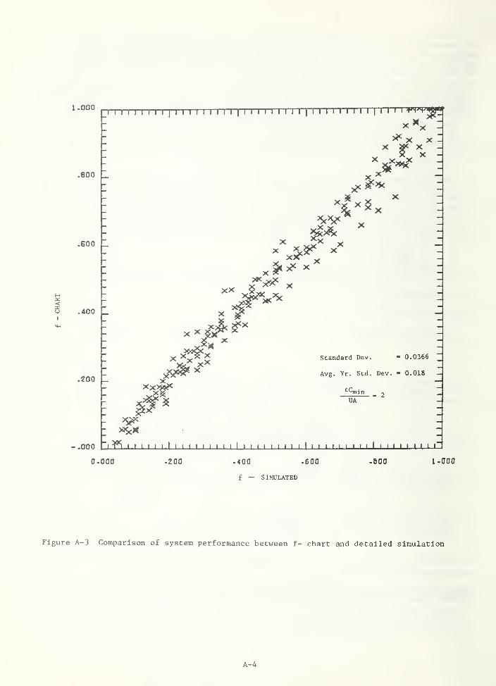
I.000I I I I I I I I I
II I I I I I I I I
I
I I I I I I I I II
I I I I I I I I II
I I ' ' -»'vv^'
.800 _
•GOO _
.400
.200 _
-.000
^ X X -I
X '^x
X)^
X * ^ X ^
X
x^x^x^X
XX
Standard Dev. - 0.0366~
Avg. Yr. Std, Dev. - 0.018 _
^^iln ^ 2UA
- ^"i Y\ ' ' ' ' ' ' 1 1 ' ' ' ' ' I ' ' I ' ' 1 1 1 ' 1 1 ' 1 1 ' ' I ' I ' ' ' I ' ' ' 1 1 1 ' 1
1
0.000 .200 .400 .600
f — SIMULATED
-BOO I. 000
Figure A-3 Comparison of system performance between f- chart and detailed simulation
A-4
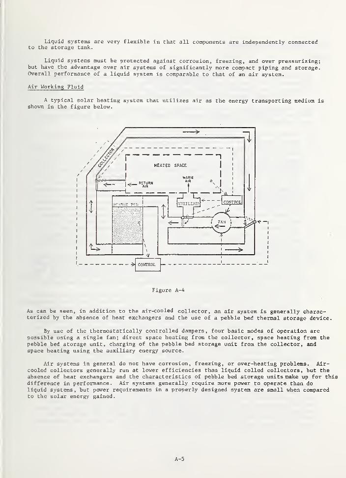
Liquid systems are very flexible in that all components are independently connectedto the storage tank.
Liquid systems must be protected against corrosion, freezing, and over pressurizing;but have the advantage over air systems of significantly more compact piping and storage.Overall performance of a liquid system is comparable to that of an air system.
Air Working Fluid
A typical solar heating system that utilizes air as the energy transporting medium isshown in the figure below.
Figure A-4
As can be seen, in addition to the air-cooled collector, an air system is generally charac-terized by the absence of heat exchangers and the use of a pebble bed thermal storage device.
By use of the thermostatically controlled dampers, four basic modes of operation arepossible using a single fan; direct space heating from the collector, space heating from thepebble bed storage unit, charging of the pebble bed storage unit from the collector, andspace heating using the auxiliary energy source.
Air systems in general do not have corrosion, freezing, or over-heating problems. Air-cooled collectors generally run at lower efficiencies than liquid colled collectors, but theabsence of heat exchangers and the characteristics of pebble bed storage units make up for thisdifference in performance. Air systems generally require more power to operate than doliquid systems, but power requirements in a properly designed system are small when comparedto the solar energy gained.
A-5
SOLAR HEATING SYSTEM PERFORMANCE
General
a) The following procedure allows the estimation of long-term solar heating system
performance applicable for combined space heating and domestic hot water systems.
The method is also applicable to air heating systems. The system evaluation
procedure is not intended to provide an accurate prediction of system performance
for any particular month, but rather for the long-term average.
b) The evaluation of system heating performance is applicable for systems schematically
identical to Figure 1 or similar simplified models. The following assumptions were
made in developing the procedure:
1) Thermal storage is contained within the heated structure and all storage heatlosses are considered to supplement the space heating load.
2) Auxiliary heat sources are provided to supply energy for both the space and waterheating when the energy in storage is depleted. The auxiliary energy source is
connected such that it does not heat the thermal storage unit directly. The rateof use of auxiliary energy is such that it provides just enough energy to
supplement the solar heating system in meeting the heating load.
3) For heating systems utilizing a liquid heat transfer fluid, a heat exchanger canbe used between the collector and the storage tank. When an anti-freeze solutionis circulated through the collector to avoid the problems of freezing and
corrosion, the use of a heat exchanger in conjunction with water storage may be
more economical than using the anti-freeze solution as the energy storage medium.
4) The heat transfer fluid is circulated through the collector whenever a positiveenergy gain can be achieved. During periods of low radiation (when the energygain becomes zero or negative), the collector pump or blower is turned off.
5) For the space heating load determination it was found that an energy per degreeday model was adequate. But in general, any procedure that accurately predictsthe building thermal load is acceptable.
6) The average domestic hot water demand as a function of the time of day and familysize was established in the development of the procedure, but in general is highlydependent upon the habits of the occupants. However, it has been determined thatthe actual time distribution of the water heating load will have only a small effectupon the long-term performance for solar heating systems combining domestic hotwater and space heating.
7) Since in most instances flat plate collectors are utilized for heating buildings,the collector component parameters are only valid for modeling flat plate collectors.Concentrating collectors or evacuated tubular collectors cannot be incorporatedinto the solar heating system evaluation as it is presently written in this Appendix.
8) The system evaluation procedure as outlined in this Appendix can only accuratelypredict system performance for systems using south facing collector arrays. Casesof different collector orientations must be analyzed using a different procedure.
c) The fluid mass flow rate through the collectors may vary considerably for differentsystems. The collector efficiency curve used as part of this evaluation procedureshall have been generated for the collector flow rate used in the system underconsideration.
d) To eliminate reductions in system performance resulting from an undersized load heatexchanger, the ratio of the capacitance rate in the heat exchanger to the heating load(as given in equation [1]) should be greater than or equal to 1. Additionally, formost considerations the ratio should be less than five. Cases involving a factoroutside this range may be evaluated by using a correction factor (K, ) for correctingthe fraction of the total heating supplied by solar. The method for utilizing thecorrection factor will be described later in the procedure. The ratio of capacitancerate in the heat exchanger to the heating load is given by:
A-6
1 _< L (liiCp)mln < 5
UA(1)
effectiveness of the load heat exchanger
actual heat transfermaximum possible heat transfer
minimum fluid capacitance rate / Btu \
Vh°F/
flowing across the load heat exchanger.
building load heat loss factor
Design Heat Loss Rate /StuN
Design Temperature Difference \h°F/
The water to air or air to water load heat exchanger effectiveness (e^^) is easilycalculated from methods given in the ASHRAE Handbook of Fundamentals or from datasupplied by the manufacturer of the heat exchanger.
e) In the evaluation procedure, an example problem has been included for a system usinga liquid as the transfer fluid. Notes are included within the example whenever adifferent calculation step would be required in evaluating a system using air.
f) The system evaluation procedure consists basically of six steps:
1) Calculate the monthly total heating load (L)
.
2) Calculate the monthly incident solar radiation on the collector array (S)
.
3) Determine the component parameters; i.e., collector area, effectiveness of heatexchangers, storage capacity, etc.
4) Knowing 1, 2, and 3 calculate two dimensionless parameters (D^, D2) for each month.5) Using D and D„ for each month, calculate the monthly fraction of the heating load
supplied by solar energy, (f)
6) With the monthly loads and monthly functions supplied by solar, calculate (F )
the annual fraction of the heating load supplied by solar energy. "
where
(mc )minP
UA =
A-7
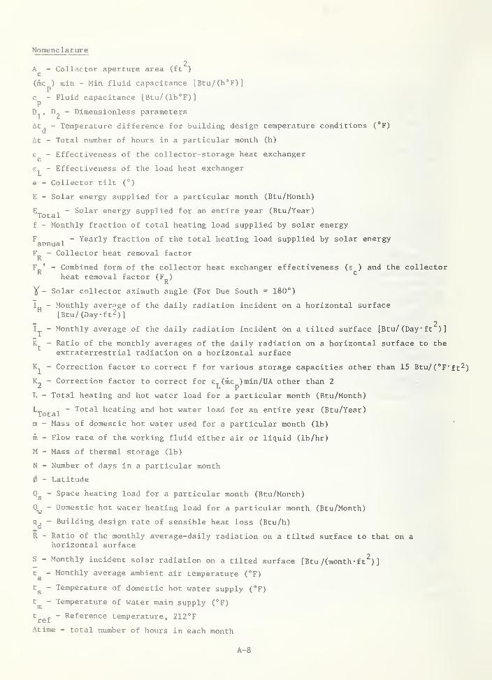
Nomenclature
2A - Collector aperture area (ft )
(mCp) min - Min fluid capacitance [Btu/(h°F)]
c - Fluid capacitance [Btu/(lb°F)]P
D^, ^2 ~ Dimensionless parameters
At^ - Temperature difference for building design temperature conditions (°F)
At - Total number of hours in a particular month (h)
- Effectiveness of the collector-storage heat exchanger
e - Effectiveness of the load heat exchanger1-1
© - Collector tilt (°)
E - Solar energy supplied for a particular month (Btu/Month)
^Total~ Solar energy supplied for an entire year (Btu/Year)
f - Monthly fraction of total heating load supplied by solar energy
^annual~ ^^^^^^ fraction of the total heating load supplied by solar energy
F - Collector heat removal factorR
F^' - Combined form of the collector heat exchanger effectiveness (e ) and the collectorheat removal factor (F )
R
Y- Solar collector azimuth angle (For Due South = 180°)
I - Monthly average of the daily radiation incident on a horizontal surface[Btu/(Dayft2)]
_ 2Irj, ~ Monthly average of the daily radiation incident on a tilted surface [Btu/(Dayft )]
- Ratio of the monthly averages of the daily radiation on a horizontal surface to theextraterrestrial radiation on a horizontal surface
- Correction factor to correct f for various storage capacities other than 15 Btu/(°F*ft2)
K„ - Correction factor to correct for (mc )min/UA other than 2Z L p
L - Total heating and hot water load for a particular month (Btu/Month)
'"Total~ heating and hot water load for an entire year (Btu/Year)
m - Mass of domestic hot water used for a particular month (lb)
m - Flow rate of the working fluid either air or liquid (Ib/hr)
M - Mass of thermal storage (lb)
N - Number of days in a particular month
0 - Latitude
- Space heating load for a particular month (Btu/Month)
- Domestic hot water heating load for a particular month (Btu/Month)
- Building design rate of sensible heat loss (Btu/h)
R - Ratio of the monthly average-daily radiation on a tilted surface to that on ahorizontal surface
S - Monthly incident solar radiation on a tilted surface [Btu /(month- ft^)
]
t - Monthly average ambient air temperature (°F)Si
t^ - Temperature of domestic hot water supply (°F)
t^ - Temperature of water main supply (°F)
t^^^ - Reference temperature, 212°F
Atime - total number of hours in each month
A-8
Nomenclature (cont'd)
Ta - Average transmissivity-absorptivity product for design purposes
(xa)^ - Transmissivity-absorptivity product at normal incidence
- Collector heat loss factor [Btu/ (h- °F- f t^)
]
UA - Building heat loss factor [Btu/(h-°F)
References Cited
1. Klein, S. A., Beckman, W. A., and J. A. Duffie, "Design Procedure for Solar HeatingSystems," presented at the 1975 International Solar Energy Congress, UCLA,Los Angeles, California, July 1975.
2. B. Y. H. Liu, R. C. Jordan, "Availability of Solar Energy for Flat-Plate Solar HeatCollectors," Low Temperature Engineering Application of Solar Energy , ASHRAE,New York, 1967.
A-9
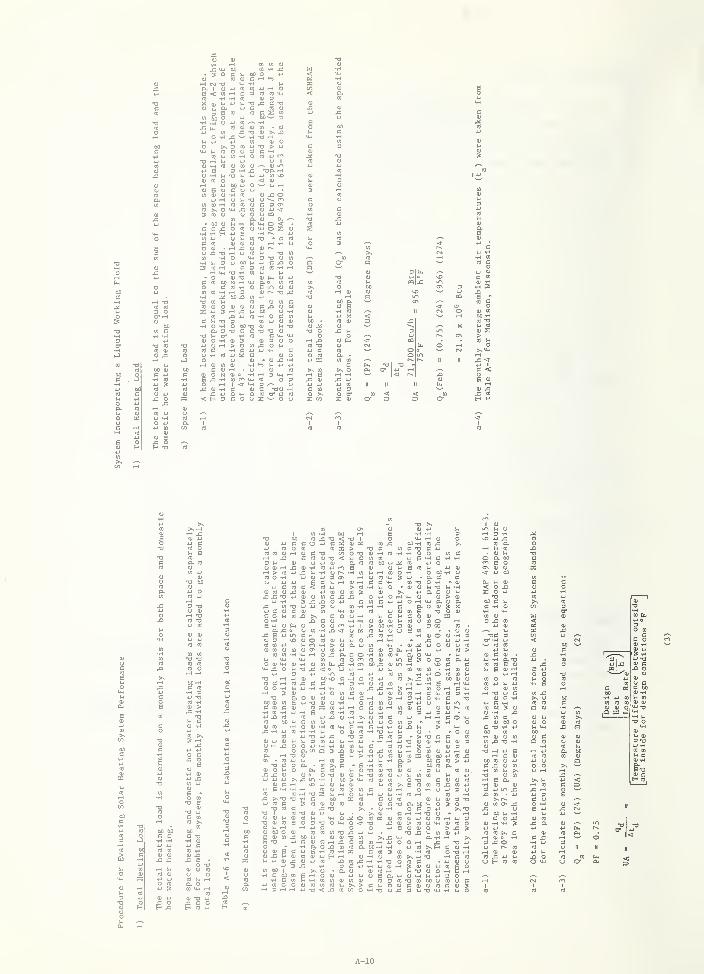
cn tA u
OC 0 u
U (0
U U iJ
<U » • 01
: -O 0)' ^ T) iH
U) OU -O > *-i
O cfl w CO
1 c ^I
1-1 HO ffl QJ O
w 3
0) 4J
o £ -a rH 4J nj u
-H Ui 3 O OO (j
rH U-l T3 05 U
3 T) QJi-t C ^
-O to CO
CO Qj o a; <u ID
I -H o c m
UOf-(>OC0XO(-i-H CO 4J ^2
4J O rH I
(0 J= 01 -H C(l) J= W Oad < H 3 c o
<U 3 0) O rH ^
•H fH 3 -H iH S
3 ^o CO cr co s ^ o
3 ^cq\j: in
3\0 ^ U
(0 ^
^ w |< r-
m co
oj m60 -HCO T3w (d
>CO U
c <
0) ^X (0
(0 «
(0 eg
4-1 CO OCO n) OJ .-H
2-D I
I PC >to o -o
I < V- cI o. CO
<U -H CO
to CO
CO 00 -u .
i> cO^JJC U -t-i ur^-H en4J CD 4J 3 CT^
> CO
I d) CO 31 X
1-1 f-t
U CO
•u o<U l-< 5 CO }-i 4-) OJ
X m w W 3 uU C (U C <U CO
c o CO >s c
* a c c-O O -H - OJ
OJ J-1 T3 -HU Q. C UQ) 0) > <1)
r-i a QJ ao. o <u 3
j: B w I
O 3(0 CO 4J
(U CO OJ
CO to
1-1 cw
CO C -HO O -H
3
CJ </} Xi <T U CC cOJ-1 CJUC - 4-1 CO J= CO
QJOcOQJJ-iJ-iO T-IU-iM m -H > - -
c oCO oOJ
e CO
•H cy O U 'H 3
; Q. c oCO O c^
I X i-< CT^
d 0) 3 I
•H m CO <
CO Oi I
00 x u '
OO^O C t-H C CO
, rH t-l
a o. e 3
CO to
•H
4-1 O <U O CO
CO to -H
4-) O to C 0)
o o CO a -u^ c cCO • -H to 014-1 O CO to i-1
U) bO 0) 0)
•HE r^ U-l
(0 O >-t C M-l
C 1-1 eg 3 -H
X to 4J iH C
CD W XI C tfl oI O 01 -H CO I
01 Ui 3
to 0)
C OJ rHU 4J
(0 c4J U OC -H -HiH T3 4J
e CO
I -H OJ to U C
D. -H OCO • to 4J Ui
o c 3 a
O atOQ 3j3 QJ-H ox WVjfH o
X SN-a -o -H c
\0 JJ OJI CO QJO 3 1-1
V-i > -H CJ C 0)
-O OJ
to QJ
(0 0) to
CO OJ -U 1
OJ 00 4-t
00 C CO
OO <0 p.
U CO >s E CO
rH O M 4-)
CO OJ 01
C X -oCO -O OJ *JOJ CO 1-1 <Me o 3 -o o '
rH U COJ (0 CO CO
'
X 00 1-1 OJ
C 0) C .H ,
•H a o X
U 4-) 0) X OJ 4J CO
OJ >j OJ 3 -O0JC'OCl.00MO3O>N 0)
CO cc: 01C rH -H -O O
X 0) > CO
to >nX '
(0 to -H 4-1 o u --1
a. 00 rH -H 4J (0 I
C CO 3 to -H CO
OJ -H O (0 4J T)X ^ -H -a o CO c4-> -H 4J OJ rH 3 '"
"
OJ CO rH U
QJ (0 rH 4J
O 4-1 OJ CO
O > XV-J CO OJ 4Ja -H iH
H C to M -HiJ m o O
to CO01 CO CO CO*J T) < X
OJ CO OJ
>to t/1 o
Ea4J0J-Hj-i4J3O"3CO-OtOOOOCOOOOiCQJOlcOCOl
4-( -H a-oto CO e QJ
B OJ --I
4J iH O C
CO 4J l-l 4J
O OJ toW TJ 4J CQJ C
4-1 OO M -Hcox0) -H y-1 34J 4-1
to to [t, crH 0( O iH3 X O
4-1 J-l rH
C O01 •HOJ u13 -H4J -aOJ cX o
o0)
y cC 000) -H
)-• OJ
4-* -H
A-10
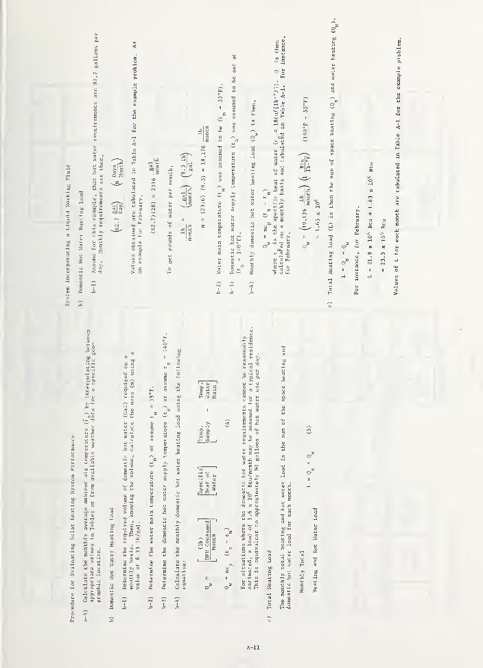
U (f)
CO -H
tn x: 60S u
c ou O CT.
0) J3> CO
CO H
O <-H O. -
3 O ^ -H
. . O. CO
CO a. ui
CJ « DO
X -H m4-1 cn
to 00
Cf-i >. oe ^a; 4-t au C ^<U O OJ
Q e >
C
4J <0
A-11
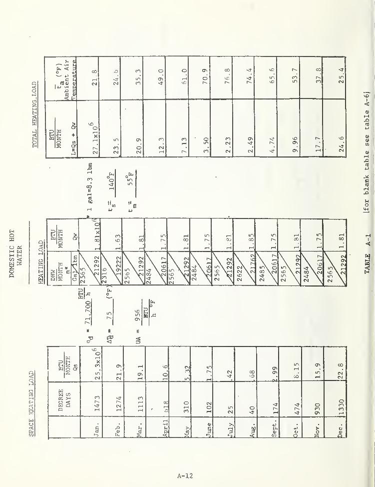
A-12

> S •
U CO
CO <u
"3 iSl&t:
I
S « 5 ,
§ < "60 <u
*
_5 c S I
*-> -H g
<; 1^ S
" P « -H
oicc:
< -H -H 0)
• 4J 4J
3 C -H -H
E 01 ^ tH
0) 4J C O. -H
;-1 ^ -H (u c c7? j= o e
E ,01
<D -H 00
5i £ c c o u
01 J3 -U .-H
o a> X <u
a CO
CD T3O. 0)
t>J (1> (fi
(0 -o
1- ^ . -Hm 00 v>
c 34-. ^ e
ti3 <l>
•H X3 ^ -a
CO <U4-» E
r-i o j:3 yu cd
OS ct
0) 4-1
^ o9 E
o It-i o
cd 14-1 at 3
it^c
<U 0)00 ^CO ^
O V-
c o^ u-(
-O IDScCO <u
.5
60 Il-H ^<U C O ^> -iH -H< > 4-» i)
O (0
>^ C 3 H^ ;2 cr iM
4-t
C 0)
Os
bO (0 to
01 ^ 4J
A-13
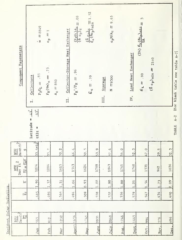
00
u0)
u0)
e««
ucd
d(3
O
too
cc•H
•H
Cd
K
cd
OCO
pcOJ
•ot-i
od
CM^1—
1
<(• o.> <) in cr> o CO o oo CO
oo m o O CO <! CM ON CMcn CO in sr in in in in in sr CN CO
15c
<! in CO <f 0^ CO 00 1—1^„ 1^ 00 !—
1
<}• 00 o- <)• <) CO CM COO CM vD in 00 r-^ in o
cd Im1—
t
I—
1
1—
1
r—
1
I—
<
f—
1
1—4 1—
1
1—1 0^ 1—
1
o 1—1 CO 00 O o 1-1 CO c^Iff: O a\ CO ON o CM in o
1—
1
f—
1
1—
1
1—
1
o 1—
1
1—1 I—I 1—1 (—1 (—
I
CM
4-' in vD X <r 0^ 00 00 OS <f o00 <!• O in in 1^ CO 00-J- ^ IT-, <! ir, LTi ITi in in in <J-
u-i1 a: «NJ 1—1 00 ^ in
B in ro ir CO -J- <}• •<J-
« 1—
(
CM <)• r- o o <1- ON u ONQ oo 1—
1
CM CM ON ir •O"
• +> •
c > oOS P <u o O•-3 < 2 •-3 < cn o 25 o
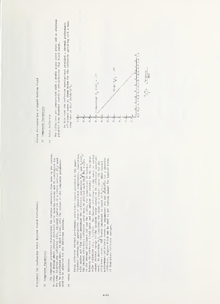
1- QJ
O X
C uO OJ
o ^o
re ^
4J I-
J L_J_ J L
U I-
K C CT.
r cc oi aC '-I
X 0. X —
*j u.(C X1- V.
a XE -0. O "- E X
" w E u
C C- 0. C. ^, - =^ - « CC
- - "re >-
4^ c - c T- - - 0 -1- - - X orX — o .X- > c
X -u oa X
o c c —X « <u c
E a C X u
1- T) .X C <b CJ~i CC X o-
C i- <l> (J -
J- O --H
i- Xa c cu o
c ^— f-
c — c
O 1- C X
CO, C T3 01 C
CO C -H O 4-1 X ^D- <U X -r- CO 3 <L
c 0. w --^ -r-t -<
C t m
I- 3C i-
o c1- a- *-
X a, u =- 3 cr c I
X -r- X
c >- cC CC C I
a> E 4-. 4-l_ O (C-COW
^- I- .H
<l< 0/ E c
I-
A-15
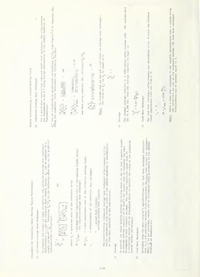
00 cC -H
<u
kl OJ
o j=auCO Bc•H
>>6
3 i-H
o3tn 0 03
u c00 u O (0 'n
c ll Dcr
o u OJ
01 o J= •D01
Qnj > oo tn 3H O c (0 (0
o o CO
u X 1^ CO
0) (0 O CN u •HX CO oi
tn lu m 1^ 01
-H X <U (0 3 o •o(0 4-1 3 4-1 * 4-1 c
CO CO «O (A OJ (U 0) ECJ 3 4-1 00 4.> o (A
J= C CO \D (0
(U 4-1 D CO u —
)
TD Ooo <U CN CO 0)to - pa 60 CI OJ O cU (A c X u II 01 0)
0 JD m (0 OJ c .-H >4J ^ so j: (0 c to
m o -H Oo X CO 00 e 0) O orH O2
wJ-»
CJ u.C CO
CuOu
II uInc 1-1H
01
<4-l
£ 00 o to t) CO w CO <u
01 (U < u00CO
J2 «U -H
X oT)
t-l TD a>
o (13 <U D4J O oCO z
OJ JD J=e 4J
iJ OrO u U
OJ CO
U OJ
CO rc
o <3 3
cr00 m
•H ooCJ CO
(0 1-1
a o
4-1 -H XI 01
OJ x5
0) (U OJ OJ
W O O CO
t-l M-i 01 01H O -H XCO " 4J 4-1
OJ 'OAJ iJ OJ
CO CO
O -H(0 £00
•O • 00C - -H<o 01 -H X M 14-
OJ CO C CO
4= a O -H BCO u 3 u
I- CJ QJ OCO 1-1 M-4
fH OJ Ij O l-<
OJ OJ <
iJ -oto -H
4-1 n 01 o
>> OJ CO 4JU-i C U CO
u enj o3 rH
M-i CO CO U-i
OJ -H tJ W OJ
C 01 6QJ > C00 CO OJ
I x: CO
; 5 a:
A-16
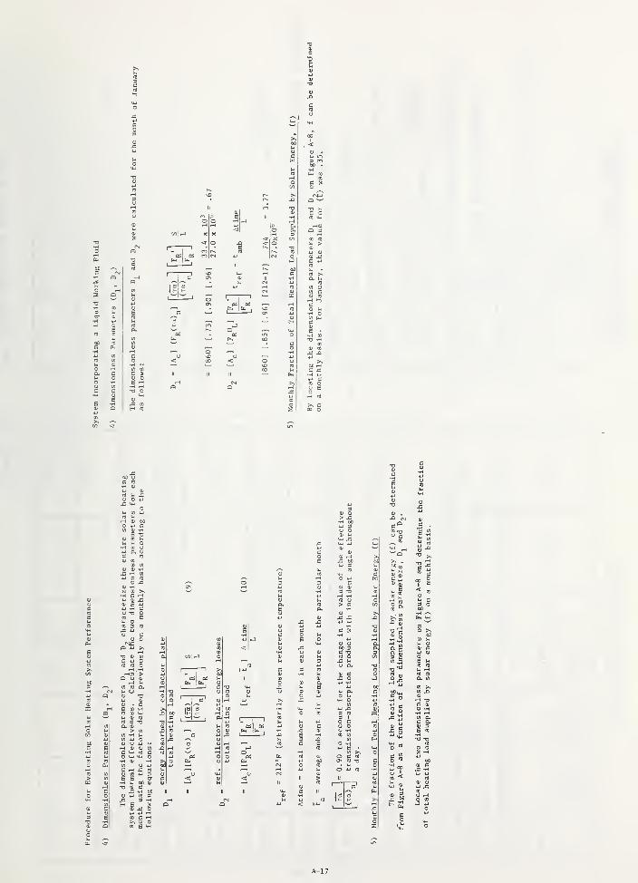
^ o
u in3 CO
N CO
1-1 lU
•HO -H
o *J
c
> c
A-17

iB(0
ft4
w
Ci.
o
oMino
ft,
oCD
CQ
CO
op-i
(04.1
o O4J
COUOu
CM
II II :3CCCO
IIII
1^in
to
cc«a
CM -
BTU
1
I"
o
00<!
CTn
10.5 15.2(—1
t-i
7.13 3.50 2.23 2.49 4.74 9.96 8.14 8.85
in in CO CO o o o o o o vOCO CO
1-1 r-l r-l r-l r-l
00I<
CO
r - <f O CO 00 COCM o O <t o oo rH rH rH vO
CO r-l CM CO CO r-> CO in
O < in in 00 mr-l r~- CM CO O OC CO in rH rHQ vC CO CM rH a\
r-i CM CO 00 rH t-l in CM
00 >x> CO O o 00 00 <f
pt.cd
r-<<!* in (Ti r-l d vO in CO in
o CM CM CO vO in CO CM
cto E vD <t- o O O <t O
•H •J- <!• CM CM CM CMc rs. rs r~
<(M CO-P O
rHEh K to |x!
P-I £-< <!• 00 CM <} in CTi <! O CO O 00 COON CO m d M3 d CO o- CM 1^
CMCMCO CO in in in in in in •vt- CO
X or-l
pq r-l in CO CO O CO a\
CO d CMr-l i/n CM <t
CM CM CM 1—1 CO CM CM f-HCM
r-l
c X) •rl <u >, 00 > Oto I-I c rH 3 a U (U•-) a D 3 < 0) o Q< •-J •n CO
A-18
COI
<

flj rH Cfi
"5 ° 1^
0) GO 5 CO
u c c^ o t.e ^ JS
o QJCO •H XH (U "Ti 4J rH 4-1
tj ^l x: 2 o 3 nl
to o u -2(u in 2
tH X) 4J ciH •H 0 H Q)
l-i H 0) (0 3cam. i2 4J CO 4-) f-H
" " n C 3 XI CO
o » o[/) O <U o >
0) S CO ^ to B ^-° OJ -u o
T) OJ 4-> 4-J CO
> 0) x: U) 1-1 4-1 34J >> O o •H
l-i I-" ^ CO CO «W rMa. -o td 7^ 00 r-
1
o 01 y 3 ^ < n3o > 0 u C CO C
1-1
ito A 3 01 to
c a _ (0 4-1 C 3 1-1
° >^ S o 3 O to c 4-1 3 31-1 c ^ (0 H <u to OO QJ
O 0) o S (U x: fi4 mu > ^ J3 >s
<u <urH U
X) 0)^ n (0 4-t .C 3 3 QJ
<U fl) 01 TO CO t-1 CO
OJ
i-i -H (0 « l-i
-O ^ 4J J= 3 to E x: 3 OC OJ 03 _ a; >.QJ V- rH *7
0)X3 <U tn
J= OJ
C (TJ U < 0) I-> 13 QJ
C i-< H 0) T3 a4J 03 0) o •H U u^ to
tn 3 O .-H B c iH • °V-C 0)
3 o CO X. <u0)
CO O il^^ j-t H 3 C0" 0) w 1^
01 u CO OJ x: Cn 4-)C •H O QJ -aU u OJ x: oo 4J to x: c3 0 0)' 4J >, HH H ^ to -
>-< u oo t-I o to
s* iSu ^ CO to c
o u o B o <u 3 CO 5ei OO to 1-. *U c -o CT to •H ft)-i .-H C O • •T3 -o 0) to QJ O -M CO r-(
CL 3 H-l CO 01 13 CO o00
U < IJ OO P -H OJ o -!
QJ QJ :=! O 14-1
(U -H OJ cn i-H •H o M 003 CO 0! M
£1 U . D- CO CI. 3 (0 >-< c (J to
4J 1-. XI a a 00 O 3 3 3 u o CO CO .-H
to W 01 3 a c CO -H o 3 0 u E CO4J D. -H ?^ CO 3 4-) CO 4J 3to cn --H u J-> .-1 CO to QJ D. 3 0) 3j: (0 (0 -u CO CO <U x: CJ • O 4-t 34J XI U) CO 0) 3 x: i-. CO i-> •H fO to
U 3 0; u 00 X. c o 3 •E ^•J 4-1 r-<
i-i 0 e >N OJ y- XI C --1 o c O 3c <u 0) to (0 x: •H -H QJ O
-H l-i (fl CO 01 c CO 3 4J cn J-i CO
.H 0) to C 0) w -H C .H J-i to 4J U U u to
jj O 01 O C l-l C X) u O CO 3 e to o > Xi o o oto C >. -H O to to <u 0) Ul x: + 4-1 to o 4J 4-1 o QJ 4J CJ
0) to '-^ 4J o to i-i o o 0 a I-I 1-1 O QJ
E CO Lw o ^ 3 c OJ 4-1 CO o o QJ to OJ Xi-a 1- QJ ^ CO o o to CO u -J fj- x: u-i X<U O O 3 dO c XI CO E 4-1 QJ 4J u 3 ^ >. II
c y-f c a 3 to <u £ 0 COII c 4J (Tl 3 CO
O i-- CO rH -H to 0) x: (U OJ o ^i.
CO o-H OJ e to 4-1 3 II 4-1
00 QJ
>s ^ -H QJ <: QJ -H 3 Eto
4J a. j-i u CO i-> u to CO to 4J u CO 4-1 3c o --t II II II 0) rH 3 £ OJ 3 O U QJ CO u N 'to
OJ e y-< 00 3 to CO 3 H 4J 1-1 C 0) o t-. U 0( H 3 3e Qj 1-. c o c XI d E 1-1 u C " 5 C CO
4J 0) -H ^ <u (0 OJ u O o .H O -3t
CO l-i M I- •H 3CO 0) cx 3 to .n o O 1-1 H CO c c o O -H o o 4J (0
CO >% 0 o H o W U to <u
QJ O C ^
A-19

DOUBLE GLASS GLAZING
NON SELECTIVE ABSORBER
IB SINGLE GLASS GLAZING
NON SELECTIVE ABSORBER
SINGLE" GLASS GLAZING
SELECTIVE ABSORBER
= .80
F, U,
DOUBLE GLASS GLAZING
SELECTIVE ABSORBER
F,(Ta)^ = 78
= .63L
J L
0.1 0.2 0.3 0.4 0.5 0.6 0.7 0.8 0.9 1.0 1.1
I ' Btu
Figure A-5 Thermal Efficiency Curves for Typical Flat PlateCollectors using a Liquid Working Fluid
A-20
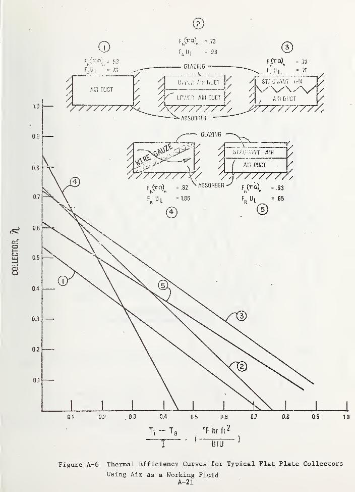
®
0.1 02 .03 0.4 05 06 0.7 0.8 0.9 1.0
Ti ~ Tg °F hr ft^
I ' ^ BTLT"^
Figure A-6 Thermal Efficiency Curves for Typical Flat Plate Collectors
Using Air as a Working FluidA-21
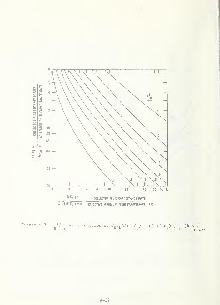
f ; ;
< " >"
COLLECTOR FLUP CAPACfTANCE RATE
« J I ih Cp ) min." EFFECTIVE MINIMUM FLUID CAPACITANCE RATE
Figure A-7 F '/F as a function of F^U.A/(iii C ) and (m C ) /e (m E )R R R L p^c ' p'c L p min
A-22
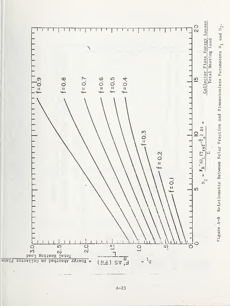
o
aUBXtj j;o:;Daxxo3 uo paqaosqy Agjaua d T
A-23
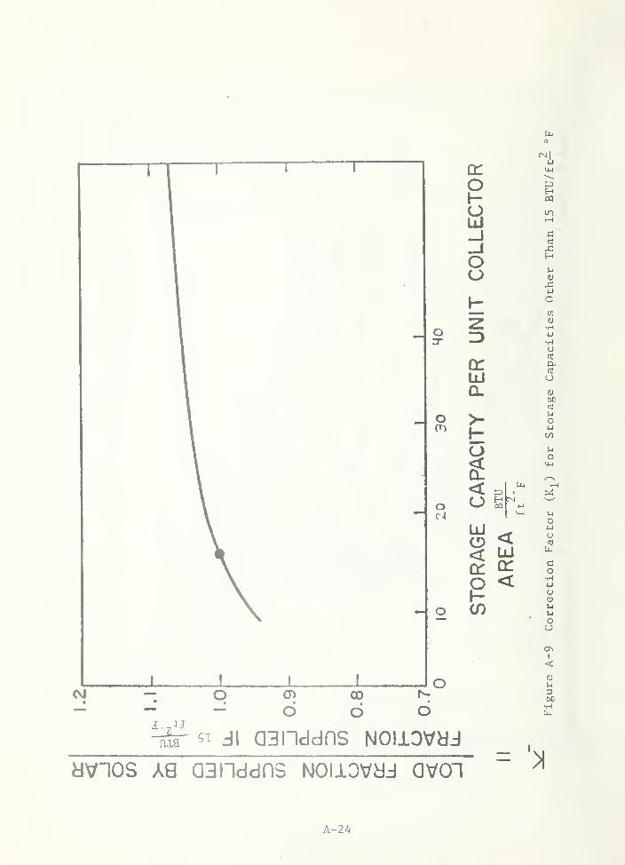
CM — O CD• • . . , •— - — o o o
dvnos A8 aaiiddns Noiiovyj avon
A-24

a:<c
>
OUJ
CLCLr)CO
o<Ll
O<
CM
O
QUJ
-JCLCL
CO
o<LL
IN
t3
1.0 -
.6
0.1
I I I I I I u I I I m
J I \ WWW0.5 1.0
£j"^^p) min
« I I t MM5.0 10.0
UA
Fleure A-10 Correction Factor (Ko) for Various Values of e (mc )/'-'^
° ^ p min
A-25
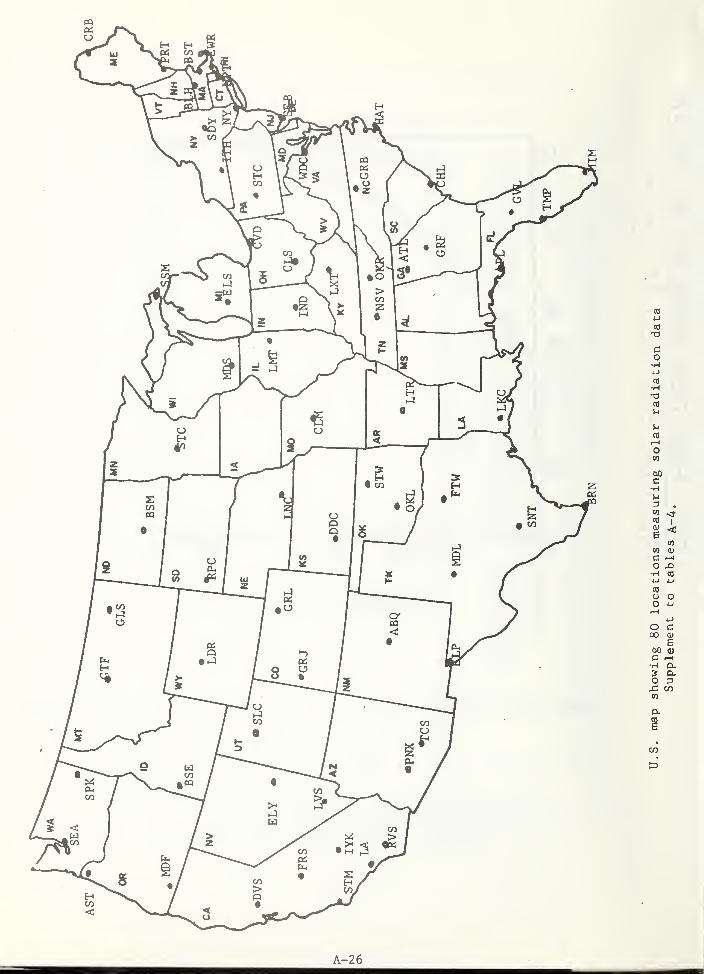
PQ
PQ
> W
CD
H
.1^
•o
Q
CO
co•H
to•Ht3CO
u
uCOi-t
o(0
00c•H
3 .
COI
i <CO
CO 0)
O X)•H CO
CO
o oO -u
O CCO 9)
E00 <uc ^
o D
PL.
CO
HCO<
s
PCS
U4
A-26
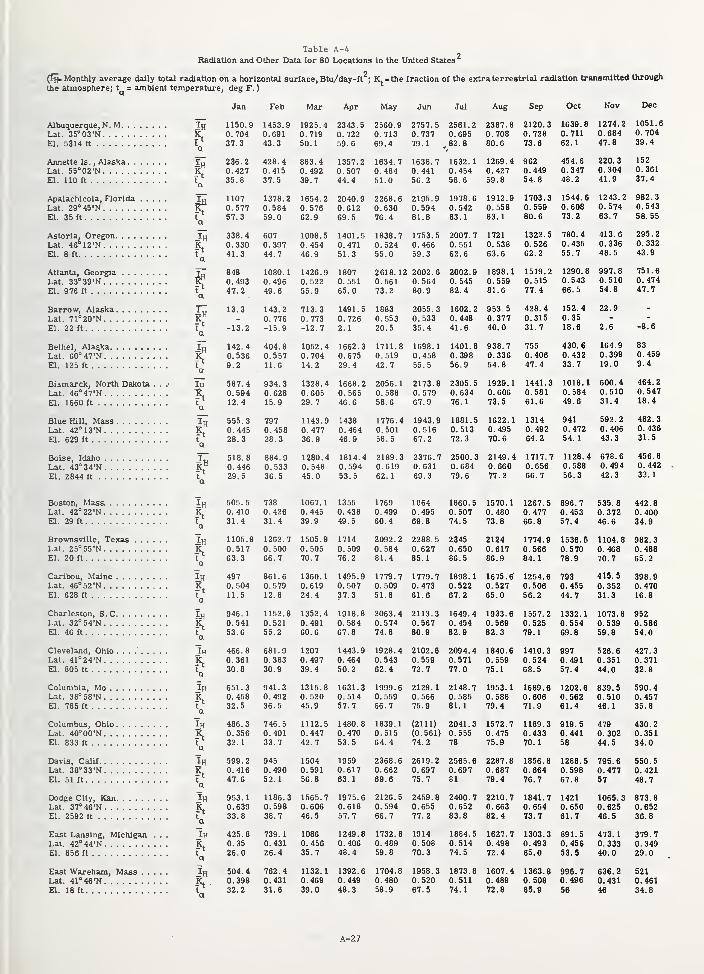
Table A-4Radiation and Other Data for 80 Locations In the United States
.2Monthly average dally total radiation on a horizontal surface, Btu/day-ft;Kj = the fraction of the extraterrestrial radiation transmitted through
Albuquerque, N. MLat. 35°03'NEl. 5314 ft
Annette Is.
, AlaskaLat. 55''02'N
n. 110 ft
Apalachlcola, Florida . . .
Lat. 29°45'NEl. 35 ft
Astoria, OregonLat. 46°12'NEl. 8 ft
Atlanta, GeorgiaLat. 33°39'NEl. 976 ft
Barrow, AlaskaLat. 71°20'NEl. 22 ft
Bethel, AlaskaLat. 60°47'N ,
El. 125 ft ,
Bismarck, North Dakota .
Lat. 46°47'NEl. 1660 ft
Blue Hill, MassLat. 42°13'NEl. 629 ft
Boise, Idaho
Lat. 43°34'NEl. 2844 ft
Boston, Mass.Lat. 42°22'NEl. 29 ft
Brownsville, Texas . . . .
Lat. 25''55'N
El. 20 ft
Caril»u, MaineLat. 46°52'NEl. 628 ft
Charleston, S.CLat. 32°54'NEl. 46 ft
Cleveland, Ohio .......Lat. 41°24'N ,
El. 805 ft
Columbia, MoLat. 38°58'NEl. 785 ft
Columbus, Ohio ,
Lat. 40''00'N ,
El. 833 ft,
Davis, Calif
Lat. 38''33'N
El. 51ft
Dodge City, KanLat, 37°46'NEl. 2592 ft
East Lansing, MichiganLat. 42°44'NEl. 856 ft
East Wareham, Mass . .
Lat. 41° 4674El. 18 ft
2h
Jh
-5a
a
In
a
Ih
hIh
in
ha
Ih
ba
ha
Ih
ha
ha
Ih
Jan
1150.90.70437.3
236.20.42735.8
11070.57757.3
338.40.33041.3
8480.49347.2
13.3
-13.2
142.40.5369.2
587.40.59412.4
555.30.44528.3
518.80.44629.5
Feb
1453.90.69143.3
428.40.41537.5
1378.20.58459.0
946.
1
0.54153.6
466.80.36130.8
651.30.45832.5
486.30.35632.1
599.20.41647.6
953.
1
0.63933.8
425.80.3526.0
504.40.39832.2
Mar
1925.40.71950.
1
883.40.49239.7
1654.20.57662.9
607 1008.50.397 0.45444.7 46.9
1080.
1
0.49649.6
143.20.776-15.9
1426.90.52255.9
713.30.773-12.7
404.8 1052.40.557 0.70411.6 14.2
934.30.62815.9
7970.45828.3
884.90.53336.5
505.5 738
0.410 0.42631.4 31.4
1105.9 1262.70.517 0.50063.3 66.7
497 861.60.504 0.57911.5 12.8
1152.80.52155.2
681.90.38330.9
941.30. 49236.5
746.50.40133.7
739.
1
0.43126.4
1328.40.60529.7
1143.90.47736.9
1280.40.54845.0
1067.
1
0.44539.9
1505.90.50570.7
1360.
1
0.61924.4
1352.40.49160.6
12070.49739.4
1315.80.52045.9
1112.50.44742.7
945 15040.490 0.59152.1 56.8
1186.3 1565.70.598 0.60638.7 46.5
10860.45635.7
762.4 1132.10.431 0.46931.6 39.0
Apr
2343.50. 722
59.6
1357.20.50744.4
2040.90.61269.5
1401.50.47151.3
18070.55165.0
1491.50.7262.1
1662.30.67529.4
1668.20.56546.6
1438
0.46446.9
1814.40.59453.5
1355
0.43849.5
1714
0. 50976.2
1495.90.50737.3
1918.80.58467.8
1443.90.46450.2
1631.30.51457.7
1480.80.47053.5
19590.61763.
1
1975.60.61857. 7
1249.80.40648.4
1392.60.44948.3
May Jun
2560.
9
2757.
5
0.713 0.73769.4 79.1
1634.
7
1638.
7
0.484 0. 441
51.0 56.2
2268.
6
2195.90.630 0.59476.4 81.8
1838.
7
1753.
5
0.524 0.46655.0 59.3
2618. 12 2002.
6
0.561 0.56473.2 80.9
1883 2055 .
3
0.553 0.53320.5 35.4
1711.
8
1698.
1
0. 519 0. 45842. 7 55.5
2056.
1
2173.80.588 0. 57958.6 67. 9
1776.4 1943.90.501 0. 51658. 5 67. 2
2189.3 2376.70. 619 0. 631
62. 1 69.3
1769 1C640.499 0.49560.4 69.8
2092.
2
2288.
5
0.584 0.62781.4 85. 1
1779.
7
1779.
7
0.509 0.47351.8 61.6
2063.
4
2113.
3
0.574 0. 56774.8 80.9
1928.
4
2102.
6
0. 543 0. 55962. 4 72. 7
1999.6 2129.
1
0. 559 0. 56666. 7 75.9
1839.
1
(2111)
0. 515 (0.561)
64. 4 74.2
2368.6 2619.
2
0.662 0.69769.6 75. 7
2126.5 2459.80.594 0.65566. 7 77.2
1732.8 19140.489 0.50859.8 70.3
1704.8 1958.30.480 0.52058.9 67.5
Jul
2561.20.695,82.8
1632.
1
0. 45458.6
1978.60.54283.
1
2007.70.55162.6
2002.90.54582.4
1602.20.44841.6
1401.80.39856.9
2305.50.63476.
1
1881.50.51372.3
2500.30.68479.6
Aug
2387.80. 708
80.6
1269.
4
0.42759.8
1912.90.55883.
1
1721
0.53863.6
1898.
1
0.55981.6
953. 5
0.37740.0
938. 7
0.33654.8
1929.
1
0.60673.5
1622.10. 49570.6
2149.40.66077. 2
1860.50.50774.5
23450.65086.5
1898.10.52267.2
1649.40.45482.9
2094.40.57177.0
2148.70.58581.
1
2041.30.55578
2565.60.69781
2400.70.65283.8
1884.50.51474.5
1873.80.51174.1
Sep
2120.30.72873.6
9620.44954.8
1703.30.55980.6
1322.50.52662.2
1519.20.51577.4
428.40.31531.7
7550.40647.4
1441.30.58161.6
13140.49264.2
1717.70.65666.7
1570.
1
0.48073.8
21240.61786.9
1675.60.52765.0
1933.60.56982.3
1840.60.55975.
1
1953.10.58879.4
1572.70.47575.9
2287.80.68779.4
2210.70.66382.4
1627.70.49872.4
1607.40.48972.8
Oct
1639.80.71162.
1
454.60.34748.2
1544.60.60873.2
780.40.43555.7
1290.80.54366.5
152.40.3518.6
430.60.43233.7
1267.50.47766.8
1774.90.56684.
1
1254.60.50656.2
1557.20.52579.1
1410.30.52468.5
1689.60.60671.9
1189.30.43370.
1
1856.80.66476.7
1841.70.65473.7
1303.30.49365.0
1363.80.50865.9
Nov
1274.20.68447.8
220.30.30441.9
1243.20.57463.7
Dec
1051.60.70439.4
1520.36137. 4
982.30.54358. 55
413.6 295.20.336 0.33248.5 43.9
997.80.51054.8
22.9
2.6
164.90.39919.0
1018.1 600.40.584 0.51049.6 31.4
9410.47254.
1
1128.40.58856.3
592.20.40643.3
678.60. 49442.3
896. 7
0.45357.4
1536.50.57078.9
793
0.45544.7
9970.49157.4
919.50.44158
4790.30244.5
14210.65061.7
891.50.45653.5
996.70.49656
751.60. 47447.7
-8.6
830.4599.4
464.20.54718.4
482. 3
0.43631. 5
456.80.44233.
1
535,8 442.80.372 0.40046.6 34.9
1104.8 982.30.468 0.48870.7 65.2
415.5 398.90.352 0.47031.3 16.8
1332.1 1073.8 9520.554 0.539 0.58669.8 59.8 54.0
526.6 427.30.351 0.37144.0 32.8
1202.6 839.5 590.40.562 0.510 0.45761.4 46.1 35.8
430.20.35134,0
1288.5 795.6 550.50.598 0.477 0.42167.8 57 48.7
1065.3 873.80.625 0.65246.5 36.8
473.1 379.70.333 0.34940.0 29.0
636.2 5210.431 0.46146 34.8
Ar-27
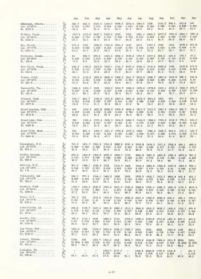
Jan Feb Mar Apr
Edmonton, AlberU lu 331.7 652.4 1165.3 1541.7
Lat. 53°35'N K 0.529 0.585 0.624 0.564El. 2219 ft T 10.4 14 26.3 42.9
Q
El Paso, Texas Ih 1247.6 1612.9 2048.7 2447.2Lat, 31°48'N ft 0.686 0.714 0.730 0.741El. 3916 « f 47.1 53.1 58.7 67.3
a
Ely, Nevada 'l^ 871.6 1255 1749.8 2103.3Lat. 39°17'N fC 0.618 0.660 0.692 0.664El. 6262 ft t 27.3 32.1 39.5 48.3
a
Fairbanks, Alaska Ih 66 283.4 860.5 1481.2Lat. 64'49'N R 0.639 0.556 0.674 0.647El. 436 ft t -7.0 0.3 13.0 32.2
a
Fort Worth, Texas Ih 936.2 1198.5 1597.8 1829.1Lat. 32'>50'N . . . K 0.530 0.541 0.577 0.556El. 544 ft t 48. 1 52.3 59.8 68.8
a
Fresno, Calif Ih 712.9 1116.6 1652.8 2049.4Lat. 36°46'N Tt 0.462 0.551 0.632 0.638El. 331 ft t 47.3 53.9 59.1 65.6
a
Gainesville, Fla Ih 1036.9 1324.7 1635 1956.4Lat. 29°39'N 'R^ 0.535 0.56 0.568 0.587El. 165 ft t 62. 1 63. 1 67.5 72.8
a
Glasgow, Mont Ifl 572.7 965.7 1437.6 1741.3Lat. 48°13'N R. 0.621 0.678 0.672 0.597El. 2277 ft t' 13.3 17.3 31.1 47.8
a
Grand JuncUon, Colo Ip 848 1210.7 1622.9 2002.2Lat. 39°07'N •. KL 0.597 0.633 0.643 0.632El. 4849 ft t^ 26.9 35.0 44.6 55.8
a
Grand Lake, Colo ^^ 735 1135.4 1579.3 1876.7Lat. 40°15'N K 0.541 0.615 0.637 0.597El. 8389 ft t 18.5 23.1 28.5 39.1
a
Great Falls, Mont l^ 524 869.4 1369.7 1621.4Lat. 47°29'N jC 0.552 0.596 0.631 0.551El. 3664 ft t 25.4 27.6 35.6 47.7
a
Greensboro, N.C Ih 743.9 1031.7 1323.2 1755.3Lat. 36°05'N K. 0.469 0.499 0.499 0.543El. 891 ft t 42.0 44,2 51.7 60.8
Q
Griffin, Georgia Ih 889.6 1135.8 1450.9 1923.6Lat. 33°15'N K 0.513 0.517 0.528 0.^86El. 980 ft y 48.9 51.0 59.1 66.7
Hatteras, N.C l^ 891.9 1184.1 1590.4 2128Lat. 35°13'N K 0.546 0.563 0.593 0.655El. 7 ft y 49.9 49.5 54.7 61.5
Indianapolis, Ind Ijj 526.2 797.4 1184.1 1481.2Lat. 39°44'N K 0.380 0.424 0.472 0.47El- 793 ft V 31.3 33.9 43.0 54.1
Inyokern, Calif 'l^ 1148.7 1554.2 2136.9 2594.8Lat. 35''39'N K. 0.716 0.745 0.803 0.8El. 2440 ft . . . y 47.3 53.9 59.1 65.6
Ithaca, N.Y 434,3 755 1074,9 1322,9Lat, 42°27'N vL 0,351 0,435 0.45 0 428El. 950 ft V 27.2 26.5 36 48.4
Lake Charles, La 1^ 899.2 1145.7 1487.4 1801.8Lat. 30'13'N K 0.473 0.492 0.521 0.542El. 12 ft V 55.3 58.7 63.5 70.9
Lander, Wyo Ih 786.3 1146.1 1638 1988,5Lat, 42°48'N IC 0.65 0.672 0.691 0.647El. 5370 ft y 20.2 26.3 34.7 45.5
Las Vepas, Nev Ih 1035.8 1438 1926.5 2322.8Lat. 36°05'N TL 0.654 0.697 0.728 0.719El. 2162ft y 47.5 53.9 60.3 69.5
Lemont, Ullnols 1^ (590) 879 1255.7 1481.5Lat. 41°40'N R (0.484) 0.496 0.520 0.477El. 595 ft y 28.9 30.3 39.5 49.7
Lexington, Ky I„ . . - 1334.
7
Lat. 38''02'N K - - - 0.575El- 979 ft V 36.5 38.8 47.4 57.8
May Jun Jul Aug Sep Oct Nov Dec
1900.4 1914.4 1964.9 1528 1113.3 704.4 413.6 245
0,558 0,514 0,549 0,506 0,506 0.504 0.510 0.492
55.4 61.3 66.6 63.2 54.2 44.1 26.7 14.0
2673 2731 2391.1 2350,5 2077,5 1704,8 1324,7 1051.6
0.743 0.733 0.652 0.669 0.693 0.695 0.647 0,626
75,7 84.2 84,9 83,4 78.5 69.0 56.0 48.5
2322.1 2649 2417 2307.7 1935 1473 1078.6 814.8
0,649 0,704 0,656 0.695 0.696 0.691 0.658 0.64
57.0 65.4 74.5 72.3 63.7 52.1 39.9 31.1
1806.2 1970.8 1702,9 1247,6 699.6 323.6 104.1 20.3
0.546 0.529 0.485 0.463 0.419 0.416 0.47 0.458
50.5 62.4 63.8 58.3 47.1 29.6 5.5 -6.6
2105.1 2437.6 2293.3 2216.6 1880.8 1476 1147.6 913,6
0.585 0.654 0.624 0.653 0.634 0.612 0.576 0,563
75,9 84.0 87.7 88.6 81.3 71.5 58.8 50.8
2409.2 2641.7 2512.2 2300.7 1897.8 1415.5 906.6 616.6
0.672 0.703 0.682 0.686 0.665 0.635 0.512 0.44
73.5 80.7 87.5 84.9 78.6 68.7 57.3 48.9
1934.7 1960.9 1895.6 1873.8 1615,1 1312,2 1169,7 919,5
0.538 , 0.531 0.519 0.547 0.529 0.515 0.537 0.508
79.4 83.4 83.8 84.1 82 75.7 67.2 62.4
2127.3 2261.6 2414.7 1984.5 1531 997 574.9 428,4
0.611 0.602 0.666 0.630 0.629 0.593 0.516 0.548
59.3 67.3 76 73.2 61.2 49.2 31.0 18 6
2300.3 2645.4 2517.7 2157.2 1957.5 1394.8 969.7 793.40.643 0.704 0.690 0.65 0.705 0.654 0.59 0.62166.3 75.7 82.5 79.6 71.4 58.3 42.0 31.4
1974.9 2369,7 2103,3 1708.5 1715.8 1212.2 775.6 660.50.553 0.63 0.572 0.516 0.626 0.583 0.494 0.54248.7 56.6 62.8 61.5 55.5 45.2 30.3 22.6
1970.8 2179.3 2383 1986.3 1536.5 984.9 575.3 420.70.565 0.580 0.656 0.627 0.626 0.574 0.503 0.51857.5 64.3 73.8 71.3 60.6 51.4 38.0 29.1
1988.5 2111.4 2033.9 1810.3 1517.3 1202.6 908.1 690.80.554 0.563 0.552 0.538 0.527 0.531 0.501 0.47969.9 78.0 80.2 78.9 73.9 62.7 51.5 43.2
2163.1 2176 2064.9 1961.2 1605.9 1352.4 1073.8 781.50.601 0.583 0.562 0.578 0.543 0.565 0.545 0.48774.6 81.2 83.0 82.2 78.4 68 57.3 49.4
2376.4 2438 2334.3 2085.6 1758.3 1337,6 1053,5 798,10,661 0,652 0,634 0,619 0,605 0,58 0,566 0.53569,9 77,2 80,0 79,8 76,7 67.9 59.1 51.3
1828 2042 2039.5 1832.1 1513.3 1094.4 662.4 491.10.511 0.543 0.554 0.552 0.549 0.520 0.413 0.39164.9 74.8 79.6 77.4 70.6 59.3 44.2 33.4
2925.4 3108.8 2908.8 2759.4 2409.2 1819.2 3170.1 1094.40.815 0.830 0.790 0.820 0.834 0.795 0.743 0.74273.5 80.7 87.5 84.9 78.6 68.7 57.3 48.9
1779.3 2025.8 2031.3 1736.9 1320.3 918.4 466.4 370,80,502 0,538 0.554 0.530 0.497 0.465 0.324 0.33759.6 68.9 73.9 71.9 64.2 53.6 41.5 29.6
2080.4 2213.3 1968.6 1910.3 1678.2 1505.5 1122.1 875.60.578 0.597 0.538 0.558 0.553 0.597 0.524 0.49477.4 83.4 84.8 85.0 81.5 73.8 62.6 56.9
2114 2492.2 2438.4 2120.6 1712.9 1301.8 837.3 694.80.597 0.662 0.665 0.649 0.647 0.666 0.589 0.64356.0 65.4 74.6 72.5 61.4 48.3 33.4 23.8
2629.5 2799.2 2524 2342 2062 1602.6 1190 964.20.732 0.746 0.685 0.697 0.716 0.704 0.657 0.66878.3 88.2 95.0 92.9 85.4 71.7 57.8 50.2
1866 2041.7 1990.8 1836.9 1469.4 1015.5 (639) (531)0.525 0.542 0.542 0.559 0.547 0.506 (0.433) (0.467)59.2 70.8 75.6 74.3 67.2 57.6 43.0 30.6
2171.2 - 2246.5 2064.9 1775.6 1315.8 - 681.50.606 - 0.610 0.619 0.631 0.604 - 0.51367.5 76.2 79.8 78.2 72.8 61.2 47.6 38.5
A-28
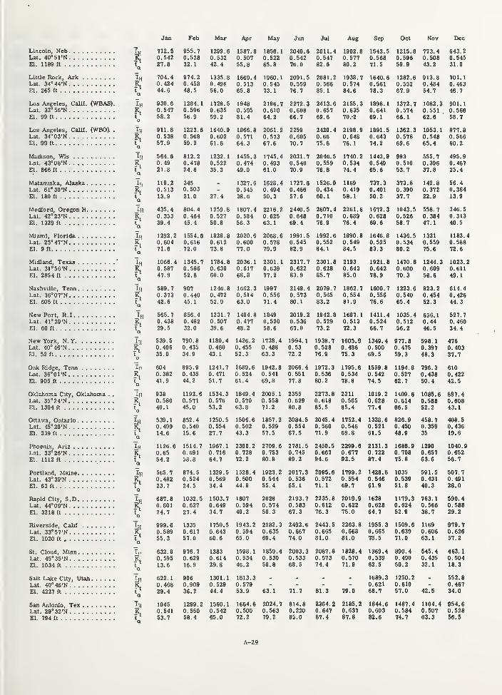
Lincoln, NebLat. 40°51'NQ. 1189 ft
Little Rock, ArkLat. 34°44'NEl. 265 ft
Los Angeles, Calif. (WBAS).Lat. 33°56'NEl. 99 ft
Los Angeles, Calif. (WBO). .
Lat. 34°03'NEl. 99 ft
Madison, WisLat. 43°08'NEl. 866 ft
Matanuska, AlaskaLat. 61°30'NEl. 180 ft
Medford, Oregon HLat. 42°23'NEl. 1329 ft
Miami, FloridaLat. 25°47'NEl. 9 ft
Midland, TexasLat. 31°56'NEl. 2854 ft
Nashville, TennLat. 36°07'NEl. 605 ft
New Port, R.ILat. 41°29'NEi. 60 ft
New York, N. YLat. 40°46'NEl. 52 ft
Oak Ridge, TennLat. 36°01'NEl. 905 ft
Oklahoma City, Oklahoma . .
Lat. 35°24'NEl. 1304 ft
Ottawa, OntarioLat. 45°20'NEl. 339 ft
Phoenix, ArizLat. 33°26'NEl. 1112 ft
Portland, MaineLat. 43°39'NQ. 63 ft
Rapid City, S.DLat. 44°09'NEl. 3218 ft
Riverside, Calif
Lat. 33°57'NEl. 1020 ft
St. Cloud, MinnLat. 45''35'N
El. 1034 ft
Salt Lake City, UtahLat. 40°46'NEl. 4227 ft
San Antonio, TexLat. 29°32'NEl. 794 ft
Q
ha
Ih
Q
In
Q
Ih
a
Ih
iH
ft
-5
iH
ft
iH
Jan
712.50.54227.8
704.40.42444.6
930.60.54756.2
911.80.53857.9
564.60.4921.8
119.20.51313.9
435.40.35339.4
1292.20.60471.6
1066.40.58747.9
589. 7
0.37342.6
565.70.43829.5
539.5 790.80.406 0.43535.0 34.9
Feb Mar
955. 7 1299.
6
0.528 0.53232.
1
42.4
974. 2 1335.
8
0.458 0.49648.5 56.0
1284.
1
1729.
5
0.596 0.63556.9 59.2
1223.6 1640.90.568 0.60259. 2 61.8
812. 2 1232.
1
0.478 0.52224.6 35.3
3450.503 -
21.0 27.4
804. 4 1259.
8
0.464 0.52745.4 50.8
1554. 6 1828.
8
0.616 0.61272.0 73.8
1345.
7
1784.80.596 0.63852.8 60.0
907 1246.
8
0. 440 0. 47245. 1 52.9
856.4 1231.70.482 0.50732.0 39.6
6040.38241.9
895.90.43544.2
938 1192.60.580 0.57140.1 45.0
539.
1
0.49914.6
852, 4
0.54015.6
1126.6 1514.70.65 0.69154.2 58.8
565.70.48223.7
874. 5
0.52424.5
687.8 1032.50.601 0.62724.7 27.4
999.60.58955.3
13350.61757.0
632.8 976.70.595 0.62913.6 16.9
622.1 9860.468 0.90929.4 36.2
1045 1299.20.541 0.55053.7 58.4
1180.40.48043.
1
1241.70.47151.7
1534.30.57653.2
1250.50.55427.7
1967.
1
0.71664.7
1329.50.56934.4
1503.70.64934.7
1750.50.64360.6
13830.61429.8
1301.10.52944.4
1560.10.54265.0
Apr
1587.80.50755.8
1669.40.51365.8
19480.59561.4
1866.80.57164.3
1455.30.47449.0
1327.60.54538.6
1807.40.58456.3
2020.60.60077.0
2036.
1
0.61768.8
1662.30.51463.0
1484.80.47748. 2
1426.20.45552.3
1689.60.52461.4
1849.40.57063.6
1506.60.50243.3
2388.20.72872.2
1528.40.50044.8
1807
0. 594
48.2
1943.20.59465. 0
1598,
1
0.53446.2
1813.30.57953.9
1664.60.50072.2
May
1856.
1
0.52265.8
1960.
1
0.54573.
1
2196.70.61064.2
2061.20.57367.6
1745.40.49361.0
1628.40.49450.3
2216.20.62563.
1
2068.60.57879.9
2301.
1
0.63977.2
19970.55671.4
18490.52058.6
1738.40.48863.3
1942.80.54169.8
2005.
1
0.55871.2
1857.20.52957.5
2709.60. 753
80,8
1923.20.54455.4
20280. 57458.3
2282.30.63569.4
1859.40.53058.8
Jun
2040.60.54276.0
2091.50.55976,7
2272,30,60866.7
22590.60570.7
2031.70.54070.9
1727.60.46657.6
2440.50.64869.4
1991.50.54582.9
2317.70.62283.9
2149.40.57380.
1
2019.20.53667.0
1994.10.5372.2
2066.
4
0.55177.8
23550.62980.6
2084.50.55467.5
2781.50.74589.2
2017.30.53665.
1
2193.70.58367.3
2492.60.66774.0
2003.30.53368.5
Jul
2011.40.54782.6
2081.20.56685.
1
2413.60.65769.6
2428.40.6675.8
2046.50.55976.8
1526.90.43460.
1
2607.40.71076.9
1992.60.55284.1
2301.80.62885.7
2079.70. 565
83.2
1942.80.52973.2
1938.70.52876.9
1972.30.53680.2
2273.80.61885.5
2045.40.56071.9
2450.50.66794.6
2095.60.57271.1
2235.80.61276.3
2443.50.66581.0
2087.80.57374.4
Aug
1902.60.57780.2
1938.70.57484.6
2155.30.63570 .-2
2198.90.64876. 1
1740.20.53474.4
11690.41958.
1
2261.60.68976.4
1890.80.54984.5
21930.64385,0
1862.70.55481.9
1687.
1
0.51372.3
1605.90.48675.3
1795.60.53478,8
22110.56585.4
1752.40.54669.8
2299.60.67792.5
1799.20.55469.7
2019.90.62275.0
2263.80.66881,0
1828.40.57071.9
63.
1
2024.70.56379.2
71.7
814.80.22085.0
81.3
2364.20.64787.4
79.0
2185.20.63787.8
Sep
1543.50.56871.5
1640.60.56178.3
1898, 1
0.64169.
1
1891,50.64374.2
1443.90.54965.6
737.30.40150.2
1672.30.62869.6
1646.80.52583.3
1921.80.64278,9
1600.70.55676.6
1411.40.52466,7
1349.40.50069.5
1559.80.54274. 5
1819.20.62877.4
1326.60.52161.5
2131.30.72287.4
1428.80.54661.9
16280.62864.7
1955.30.66578.5
1369.40.53962.5
1689.30.62168.7
1844.60.60382.6
Oct
1215.80.59659.9
Nov
773.40.50843.2
Dec
643.20.54531.8
1282.6 913.6 701.10.552 0.484 0.46367.9 54.7 46,7
1372.7 1082.30.574 0.55166.1 62.6
901. 1
0.56658, 7
1362.30. 57869.6
9930.51053.7
373.80.39037.7
1043.50.52658.7
1436.50.53480.2
1470.80.60070.3
1223,60. 54065,4
1035.40.51256.2
977.80.47559.3
1194.80.52762.7
1409.60.61466.5
826.90.45048.9
1688.90.70875.8
10350.53951.8
1053.1 877.80.548 0.56665.4 60.2
555.70.39637.8
495.90.46725.4
142.8 56.40.372 0.36422.9 13.9
558. 7
0.38447.1
346.50.31340.5
1321 1183,40.559 0.58875.6 72.6
1244.30.60956.6
1023.20.61149.
1
823.2 614,40.454 0.42652.3 44,3
656.
1
0.4446.5
527.70.46034,4
598. 1 4760.397 0.40348.3 37.7
796.30.43850.4
6100.42242.5
1085.6 897.40.588 0.60852.2 43.1
458.70.35935
12900.65763.6
591.50.43140.3
408,50.43619.6
1040.90.65256,7
507.70.49128.0
1179.3 763.1 590.40.624 0.566 0.58852,9 38.7 29.2
1509.6 1169 979.70.639 0.606 0.62671.0 63.1 57.2
890.40.49050.2
545.4 463.10.435 0.50432.1 18.3
1250.20.61057.0 42.
552.80.46734.0
1487.4 1104.4 954.60.584 0.507 0.52874.7 63.3 56.5
A^29.
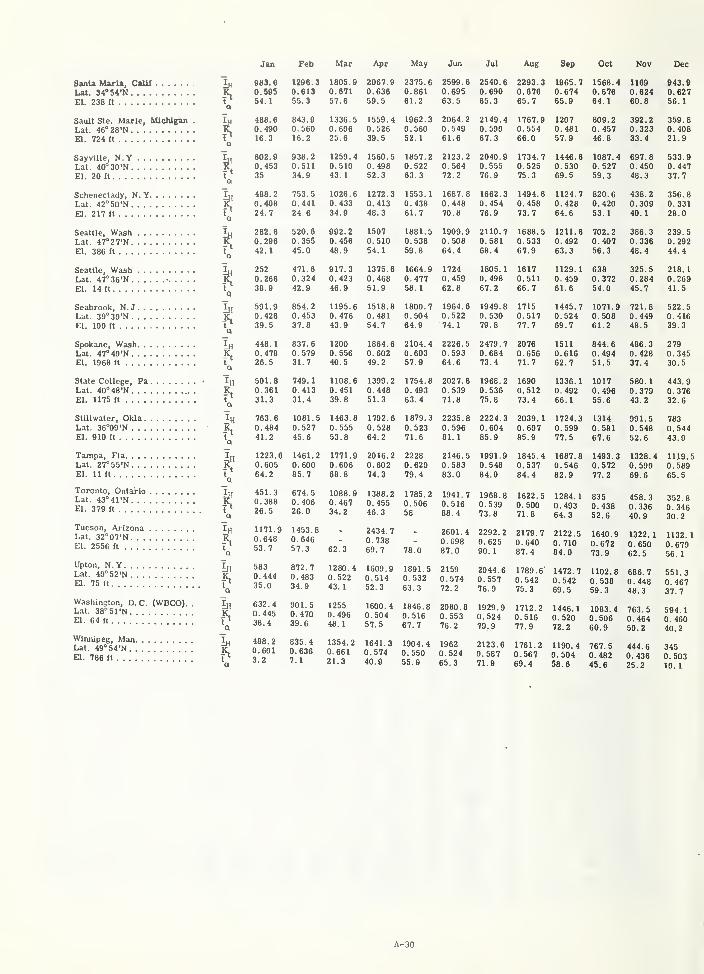
Jan Feb Mar Apr
SanU Maria, Call!
Lat. 34''54'N
El. 238 ft
Sault Ste. Marie, MichiganLat. 46°28'Na. 724 it
Sayville, N.YLat. 40°3O'NEl. 20 ft
Schenectady, N.YLat. 42''50'N
El. 217 ft
Seattle, WashLat. 47°27'NEl. 386 ft
Seattle, WashLat. 4T'36'N •. . . .
El. 14 ft
Seabrook, N.JLat. 39° 30 'NEl. 100 ft
Spokane, WashLat. 47°40'NEl. 1968 ft
State College, PaLat. 40°48'NEl. 1175 ft
Stillwater, OklaLat. 36''09'N
El. 910 ft
Tampa, FlaLat. 27°55'NEl. 11 ft
Toronto, OntarioLat. 43°41'NEl. 379 ft
Tucson, Ai'izonaLat. 32°07'NEl. 2556 ft
Upton, N.YLat. 40°52'NEl. 75 ft
Washington, D. C. (WBOO).Lat. 38°5rN
,
El. 64 ft,
Winnipeg, ManLat. 49°54'NEl. 786 ft
iH
In
-5
a
in
a
983.
6
1296.
3
0. 595 0.61354.1 55. 3
488.
6
843.
9
0. 490 0. 560
16.3 16.2
602.9 936. 2
0. 453 0. 511
35 34.9
488. 2 753. 5
0. 406 0. 441
24.7 24.6
282. 6 520.
6
0. 296 0. 355
42.
1
45.0
252 471.60. 266 0. 324
38.9 42.9
591.9 854. 2
0. 426 0. 45339.5 37.6
446.
1
837.
6
0. 478 0. 57926.5 31.7
501.
8
749. 1
0. 381 0. 41331.3 31.4
763. 8 1081.
5
0. 484 0. 52741.2 45.6
1223.
6
1461.
2
0. 605 0. 60064.2 65.7
451. 3 674. 5
0. 388 0. 40626.5 26.0
1171.9 1453.
8
0. 648 0. 64653.7 57.3
583 872 7
0. 444 0. 48335.0 34.
9
632.4 901.50.445 0.47038.4 39.6
488.2 835.40.601 0.6363.2 7.
1
1805.90.67157.6
1336.50.60625.6
1259.40.51043.
1
1026.60. 43334.9
992.20.45648.9
917.30.42346.9
1195.60.47643.9
12000.55640.5
1106.60.45139.8
1463.80.55553.8
1771.90.60668.8
1088.90. 46734.2
62.3
2067.90.63659.5
1559.40.52639.5
1560.50.49852.3
1272.30.41348.3
15070.51054. 1
1375.60.46851.9
1518.80.48154.7
1864.60.60249.2
1399.20.44851.3
1702.60.52864. 2
2016.20.60274.3
1388.20.45546. 3
2434.
7
0. 73869.7
1280.4 1609.90.522 0.51443.1 52.3
12550.49648.
1
1600.40.50457.5
May
2375.60.66161.2
1962.30.56052. 1
1857.20.52263. 3
1553.
1
0.43861.7
1881.50.53859.8
1664.90.47758.
1
1800.70.50464.9
2104.40.60357.9
1754.60.49363.4
1879.3
0.52371.6
22280.62079.4
1785.20.50658
78.0
1891.50.53263.3
1846.80.51667.7
Jun
2599.60.69563.5
2064.20. 54961.6
2123.20.56472.2
1687.80.44870.8
1909.90.50864.4
17240.45962.8
1964.60.52274.1
2226.50.59364.6
2027.60.53971.8
2235.80.59681. 1
2146.50.58383.0
1941.70.51668. 4
2601.40.69887.0
21590. 57472.2
Jul
2540.60.69065.3
2149.40.59067.3
2040.90.55576.9
1662.30. 454
76.9
2110.70.58168.4
1805.
1
0.49867.2
1949.80.53079.8
2479.70.68473.4
1968.20. 53675.8
2224.30.60485.9
1991.90.54884.0
1968.60. 53973.8
2292.20. 62590. 1
2044.60.55776.9
Aug Sep
2080.8 1929.90.553 0.52476.2 79.9
1354.2 1641.3 1904.40.661 0.574 0.55021.3 40.9 55.9
19620.52465.3
2123.60.58771.9
2293.30.67865.7
1767.90.55466.0
1734.70.52575.3
1494.80. 458
73.7
1688.50. 533
67.9
16170.51166. 7
17150.51777.7
20760.65671.7
16900.51273.4
2039.
1
0.60785.9
1845.40.53784.4
1622.
5
0. 50071.8
2179.70.64087.4
1789.60. 54275.3
1712.20.51677.9
1761.20.56769.4
1965.70.67465.9
12070. 481
57.9
1446.80.53069.5
1124.70.42664.6
1211.80.49263.3
1129.
1
0.45961.6
1445.70.52469.7
1511
0.61662.7
1336.10.49266. 1
1724.30.59977.5
1687.80.54682.9
1284.
1
0. 493
64. 3
2122.50. 71084.0
1472.70.54269.5
1446.10.52072.2
1190.40.50458.6
Oct
1566.40.67664.
1
809.20.45746.8
1087.40.52759.3
820. 6
0.42053. 1
702.20. 40756.3
6380.37254.0
1071.90.50861.2
844.60.49451.5
10170.49655.6
1314
0.58167.6
1493.30.57277.2
8350.43852.6
1640.90.67273.9
1102.60.53859.3
1083.40.50660.9
767.50. 48245.6
Nov
11690.62460.8
Dec
943.90.62756. 1
392.2 359.80.323 0.40833.4 21.9
697.8 533.90.450 0.44748.3 37.7
436.2 356.80.309 0.33140.1 28.0
386.30.33648.4
721.80. 449
48.5
486.30.42837.4
991.50.54852.6
1328.40.59069.6
458. 3
0. 33640.9
1322.
1
0. 65062.5
239.50. 29244.4
325.5 218.10.284 0.2G945.7 41.5
522.50.41639.3
2790.34530.5
580.1 443.90.379 0.37643.2 32.6
783
0.54443.9
1119.50.58965.5
352. 8
0. 34630.2
1132.
1
0.67956. 1
686.7 551.30.448 0.46748.3 37.7
763.5 594.10. 464 0. 46050.2 40.2
444.60.43625.2
3450.50310.1
A-30
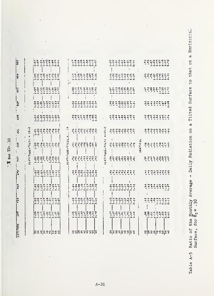
()
N•rH
Uo
I «n • — — o
cd
+->
ooooo — —
O-P
<u
CJ
ctf
Cm
CO
t:)
<u-p
oo ouuoooo
T r J' «r gi wt 4
d
o
o•H
a)
"I "!
•ooooooo —
Oltfl ni/tO(AOtAO
OOO — — r^rtir
I!
O IK O IP (1 >n u in o« o (/t o «n 'o tn o J» o o J* o in-o tfi cidi o
•H0}
Q
0bD(D
><t>> ofH
II
o XJ
!^
O
CmO
CJ
o 0)
•Hp
I
<
H
A-31
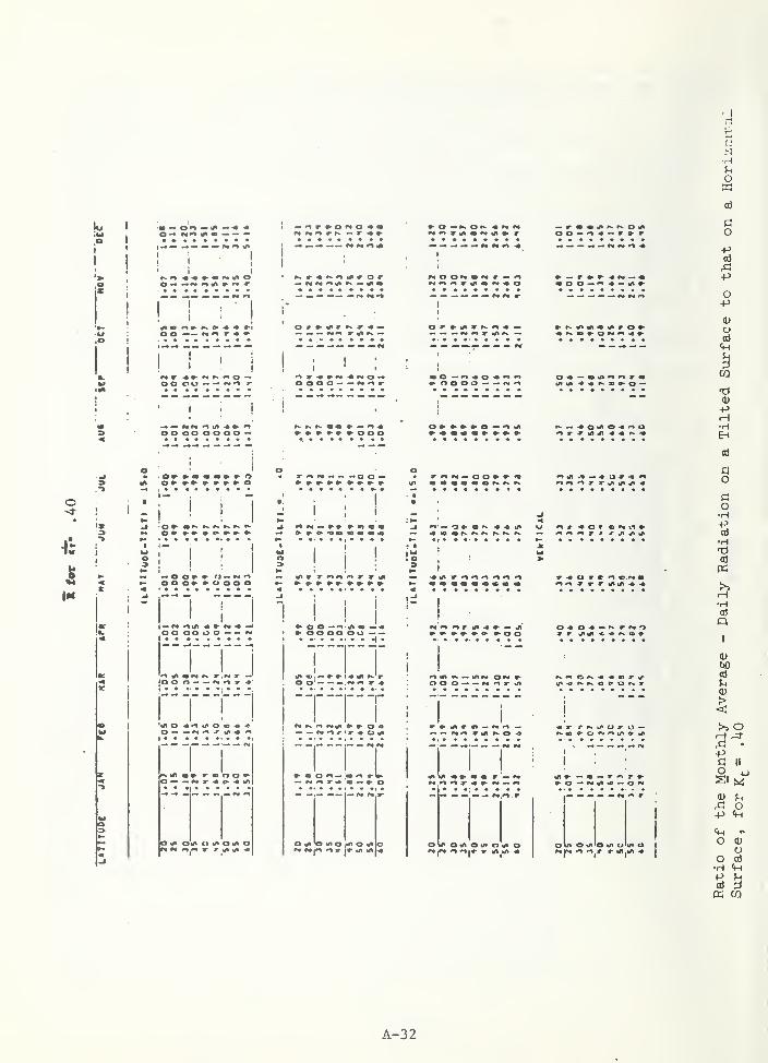
N•H
O
— tA «• • • • •
I '!
o o oo oooo —
» o —^ a K « <
«0 0-><^ -•'-tA»
co+»a)
+>
O+>
0)
o0)
CO
tJ<u+>H•HEH
I
rs, r«. »»
I » T « « r r
! !i
» o o — •^ m —» ooooou....... ^ .
' « -« «. o— »» •» »•
O tft O HI o»»• r<«
i*^in »
I Ul « — -« a »
O OtHOiA OtP O
^ o — *>««j»a» — o»>*
out o«ii'Oi/to«no
o
ao
•Htia«>>H•HOl
QI
<D
bO
^
>> o^ •
-Pa II
O 4J
(U
o-P
CmO (U
oO 0}
•H
aCO
A-32
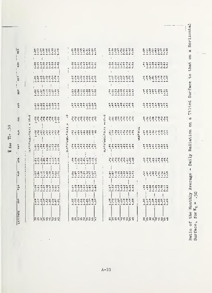
Ha-p
oN•HSh
Ow
i
! I
ooao ooo — —
0 — ^9* — <
+3
+»
O-P
o;
oa]
!h
CQ
-O(U
-PH•HEH
O
I-
-I I
I |00 OO O — — —
o
co•H+305•H
0}
«>»iH•HaQ
la-
III* o »/* ;o o
I I
I I
•M ^ O ^ O^MI/I
II
I ^ «/t « « IN »
0\A O b/< O rf» o »r o OhnotrOh/tOt/«o
0)
^^
><o
:^•
ntII
Mo
0) 5-1
O-p Cm
«Ho (D
Oo cd
•H+J
CO
A-33
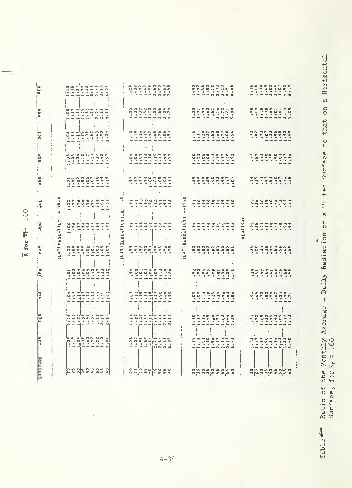
^ ^ 9m w « —• O M ^ ^ •
cd
-p
O
•H
o
L
iI ' I
I I
t ^ O V
OOO — —
f»# n *^ a* r». Ot/t O*^
— *^ #n 1/1 O tA
»»>*^#>oooo —
o
pcd
-p
o+^
<L)
O03Cm
0)
c
'X
• -»
It
i1 . J i
»- oo*>*>ooooo »
at o o lit o
0» 04lf>«»
r — 9^ — » «
U» ^ — J"
|r«a lA « Ori N n t/t
II i
o tit o hn o
' e« m
t/k O *AtO
— — — — ,-. r\ t>4 ^
EH
cd
O
o•H-p(d
•H
Cd
K>>H•HCd
«
bOod
><>i ohi
VO
ntII
o
Op
o 0)
oo cd
•H+Jod ^
CO
4
A-34od
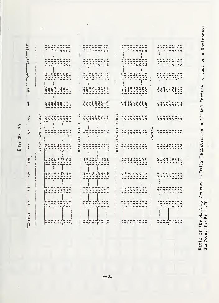
r
! >
!
! !:
OOO— — •M^X*
OOOOOO— — Oi
<Mrt T aJ — r»
I
'!
o o — — oti^ -m
i!
i
— <s« o X m f* ^— — — — MMMflMfX*
I
OOO— — ^urtXi/*
y r» — • <
— ^ « r>« r«
I » at N » e «
M M «• r t/i ^»
^ tn <• fx* »^ u
I I I
+icj
oN•Hfn
Owcd
C3o
-pcd
X!-P
o4->
(U
CJ
cd
Tf0)
-PH•H&H
cd
co
co•H•Pcd
•HT)a
>>H•HCd
QI
0bDed
?H0)
!>> O
-PII
O
otin
o 0O
o Cd•H
cd
« CO
A-35
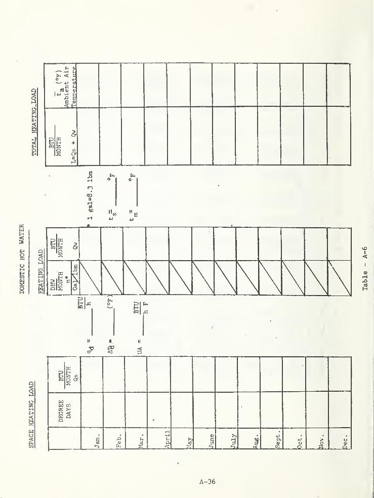
A-36
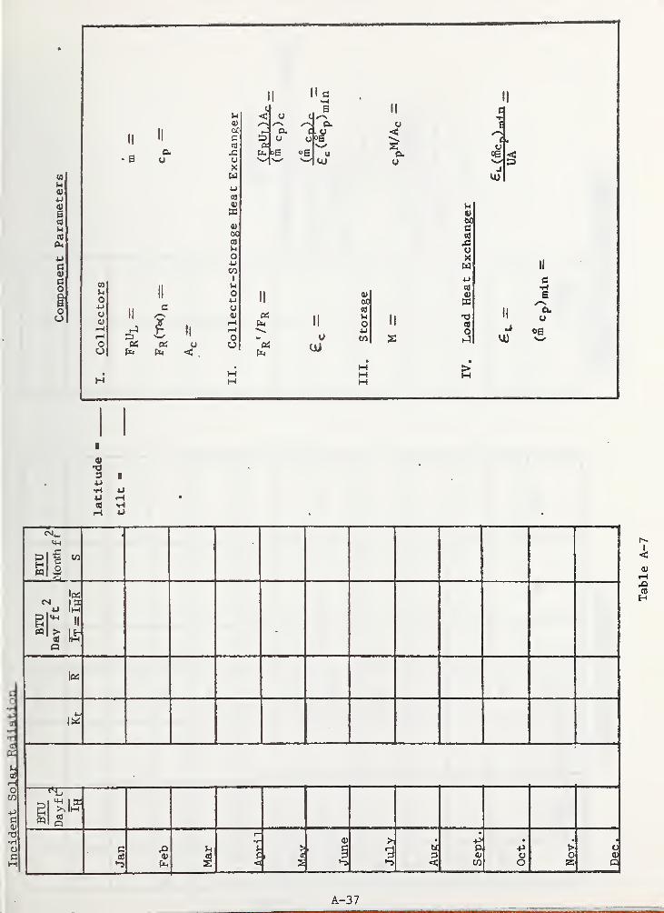
(0
u0)
u<u
e
u(0
uC3(U
ao
i1ou
cd
BTU Month
fr^
1S
BTU
^ 4 1 tl+j Im^
„
(d ImQ
?^ Ima
Jan Feb a)
•r^p<
>
' 1June
July
•
<
+>P4)
cnOct. Nov.
o<u
o
I
<0)M
Cc•H
<£
•HTjCd
^^
diHoCO
c0)
•Ho
A-37
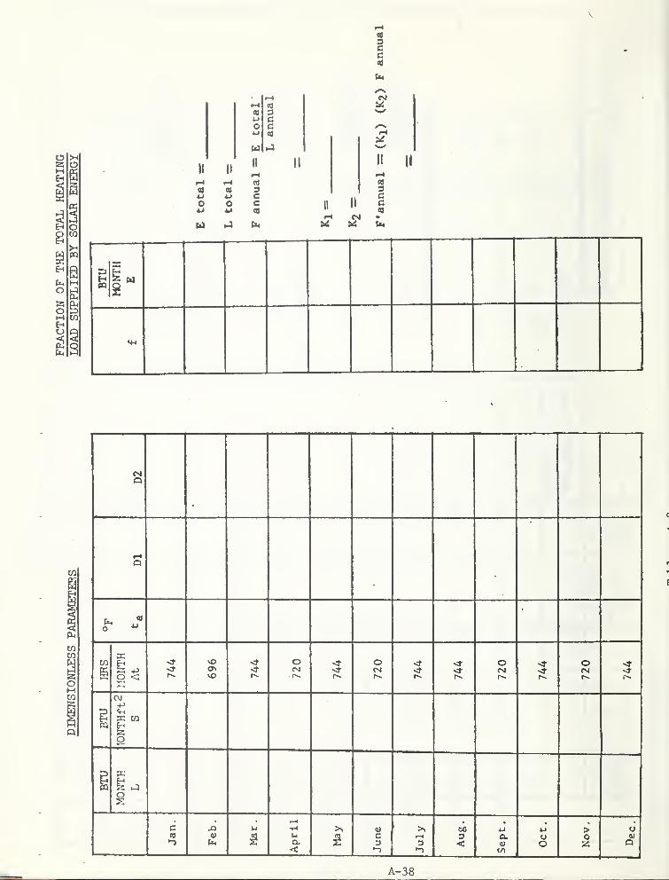
10
O25M
r-l
(0 34J CO cXJ 01
U •-3
II II
II
i-i
«J
a (0 3C
o o Cu CO
M
CM
11
US
II II
H Z w
U-4
PQ
0o
oMo
CD
CO
COCO
oMCO
D2
Dl
fx."
o ^
HRS
O <vt>^ o\
vO
ofsl
r>.sf
oCM
<»• or-
OCM
IBTU
C\J
X COEh
O
BTU
X
o
Jan. Feb. Mar.April
May JuneJuly
Aug, Sept.Oct, Nov.
O(UQ
A-38
APPENDIX B
MATERIALS TABLES

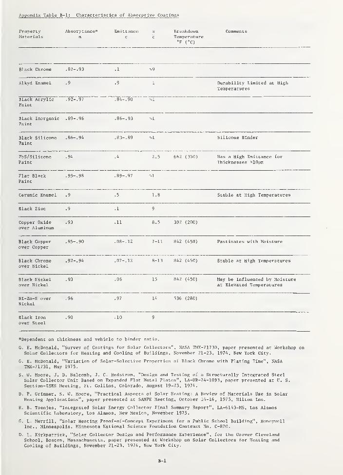
Appendix Table IS-1: Characteristics of Absorptive Coatings
PropertyMaterials
Absorptance*a
Emittancee
a
e"
Brea kd ownTemperature°F (°C)
Comments
Black Chrome .87- .93 . 1
Alkyd Enamel .9 .9 1 Durability Limited at HighTemperatures
Black AcrylicPaint
.92- .97 .84- .90
Black InorganicPaint
.89- .96 .86- .93
Black SiliconePaint
.86- .94 .83- .89 Silicone Binder
PbS/SiliconePaint
.94 .4 2.5 662 (350) Has a High Emittance for
Thicknesses >10pm
Flat BlackPaint
.95- .98 .89- .97 -vl
Ceramic Enamel .9 .5 1.8 Stable at High Temperatures
Black Zinc .9 .1 9
Copper Oxideover Aluminum
.93 .11 8.5 392 (200)
Black Copperover Copper
.85- .90 .08- .12 7-11 842 (450) Pastinates with Moisture
Black Chromeover Nickel
.92- .94 .07- .12 8-13 842 (450) Stable at High Temperatures
Black Nickelover Nickel
.93 .06 15 842 (450) May be Influenced by Moistureat Elevated Temperatures
Ni-Zn-S overNickel
.96 .97 14 536 (280)
Black Ironover Steel
.90 .10 9
*Dependent on thickness and vehicle to binder ratio.
G. E. McDonald, "Survey of Coatings for Solar Collectors", NASA TMX-71730, paper presented at Workshop on
Solar Collectors for Heating and Cooling of Buildings. November 21-23, 1974, New York City.
G. E. McDonald, "Variation of Solar-Selective Properties of Black Chrome with Plating Time", NASATMX-71731, May 1975.
S. W. Moore, J. D. Balcomb, J. C. Hedstrom, "Design and Testing of a Structurally Integrated SteelSolar Collector Unit Based on Expanded Flat Metal Plates", LA-UR-74-1093 , paper presented at U. S.
Section-ISES Meeting, Ft. Collins, Colorado, August 19-23, 1974.
D. P. Grimmer, S. W. Moore, "Practical Aspects of Solar Heating: A Review of Materials Use in SolarHeating Applications", paper presented at SAMPE Meeting, October 14-16, 1975, Hilton Inn.
R. B. Toenjes, "Integrated Solar Energy Collector Final Summary Report", LA-6143-MS, Los AlamosScientific Laboratory, Los Alamos, New Mexico, November 1975.
G. L. Merrill, "Solar Heating Proof-of-Concept Experiment for a Public School Building", HoneywellInc., Minneapolis, Minnesota National Science Foundation Contract No. C-870.
D. L. Kirkpatrick, "Solar Collector Design and Performance Experience", for the Grover ClevelandSchool, Boston, Massachusetts, paper presented at Workshop on Solar Collectors for Heating and
Cooling of Buildings, November 21-23, 1974, New York City.
B-1
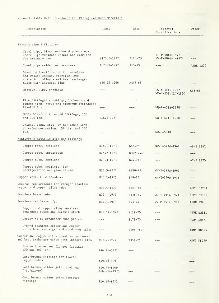
Appendix Table B-2: Standards for Piping and Duct Materials
Description ANSI ASTM FederalSpecifications
Other
Ferrous pipe & fittings
Steel pipe, black and hot dipped zinc-coated (galvanized) welded and seamlessfor ordinary use
Steel pipe welded and seamless
Standard Specification for seamlessand welded carbon, ferritic, andaustenitic alloy steel heat exchangertubes with integral fins
Nipples, Pipe, threaded
Pipe fittings: (bushings, locknuts andplugs) iron, steel and aluminum (threaded)125-150 lbs.
Malleable-iron threaded fittings, 150and 300 lbs.
Unions, pipe, steel or malleable iron;threaded connection, 150 lbs. and 250lbs.
Nonferrous metallic pipe and fittings
Copper pipe, seamless
Copper pipe, threadless
Copper tube, seamless
Copper tube, seamless, forrefrigeration and general use
Copper water tube seamless
General requirements for wrought seamlesscopper and copper alloy tube
Seamless brass tube
Seamless red brass pipe
Copper and copper alloy seamlesscondenser tubes and ferrule stock
Copper-alloy condenser tube plates
U-bend seamless copper and copperalloy heat exchanger and condenser tubes
Copper and copper alloy seamless condenserand heat exchanger tubes with integral fins
Bronze flanges and flanged fittings,150 and 300 lbs.
Cast-bronze fittings for flaredcopper tubes
Cast-bronze solder joint drainagefittings-DMV
Cast bronze solder joint pressurefittings
B125. 2-1972
B125. 1-1972
B36-55-1966
B16. 3-1971
H26. 1-1973
H26. 2-1973
H23. 3-1973
H23.5-197A
H23. 1-1973
H23. 4-1973
H36. 1-1973
H27. 1-1973
H23. 14-1973
H23. 7-1974
B16. 24-1971
B16. 26-1967
B16. 23-1969B16.23a-1973
B16. 18-1972
A120-73
A53-73
A498-68
WW-P-406D-197 3
WW-P-406D-1-1974
B42-75
B302-74a
B74-74b
B280-75
B88-75
B251-75
B136-74
B43-75
Blll-75
B171-75
B395-74b
B359-75
ASME SA53
WW-N-351b-1967 CS5-65WW-N-351b[l]-1970
WW-P-471B-1970
WW-P-521F-1968
WW-U-531D
WW-P-377d-1962 ASME SB42
ASME SB75
WW-T-775a-1962
WW-T-799D-1971
ASME SB251
WW-T-791A-1971 ASME SB135
WW-P-351a-1963 ASME SB43
ASME SBlll
ASME SB171
--- ASME SB395
ASME SB359
B-2
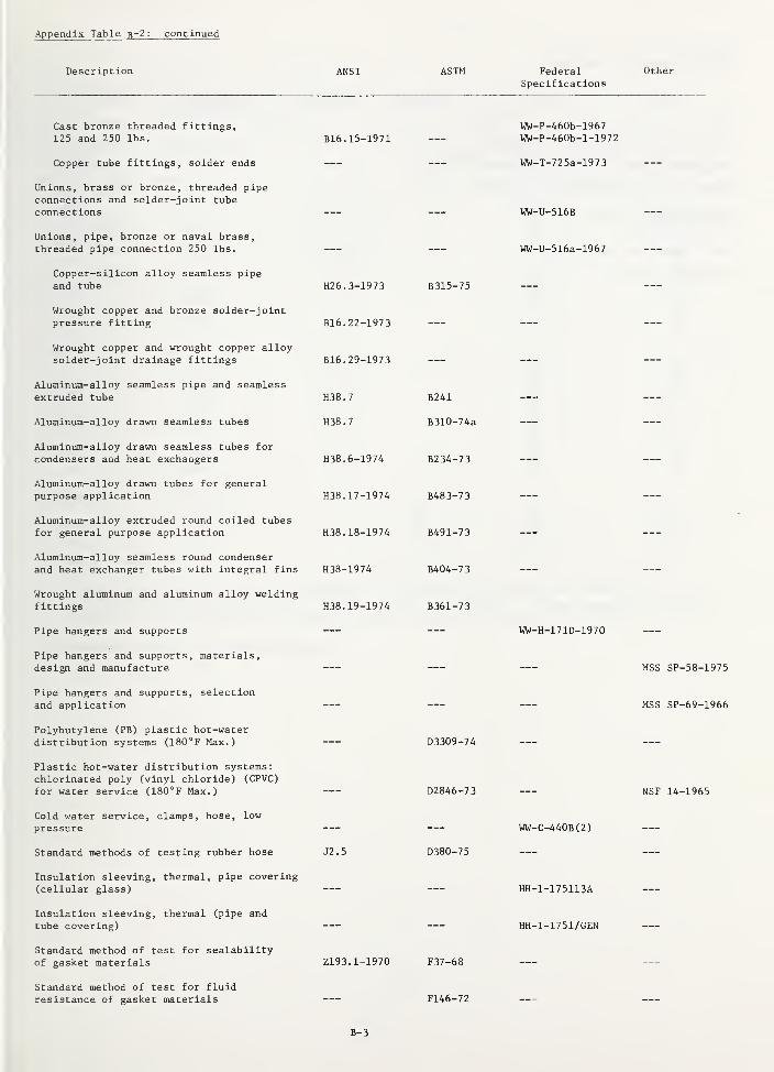
Appendix Table B~2 : continued
Description ANSI ASTM FederalSpecifications
Other
Cast bronze threaded fittings,125 and 250 lbs. B16. 15-1971
WW-P-460b-1967WW-P-460b-l-1972
Copper tube fittings, solder ends
Unions, brass or bronze, threaded pipeconnections and solder-joint tubeconnections
WW-T-725a-1973
WW-U-516B
Unions, pipe, bronze or naval brass,threaded pipe connection 250 lbs. WW-U-516a-1967
Copper-silicon alloy seamless pipeand tube H26. 3-1973 B315-75
Wrought copper and bronze solder-jointpressure fitting B16. 22-1973
Wrought copper and wrought copper alloysolder-joint drainage fittings B16. 29-1973
Aluminum-alloy seamless pipe and seamlessextruded tube H38.7
Aluminum-alloy drawn seamless tubes H38.7
B241
B310-74a
Aluminum-alloy drawn seamless tubes for
condensers and heat exchangers
Aluminum-alloy drawn tubes for generalpurpose application
Aluminum-alloy extruded round coiled tubesfor general purpose application
Aluminum-alloy seamless round condenserand heat exchanger tubes with integral fins
Wrought aluminum and aluminum alloy weldingfittings
Pipe hangers and supports
Pipe hangers and supports, materials,design and manufacture
H38. 6-1974
H38. 17-1974
H38. 18-1974
H38-1974
H38. 19-1974
B234-73
B483-73
B491-73
B404-73
B361-73
WW-H-171D-1970
MSS SP-58-1975
Pipe hangers and supports, selectionand application
Polybutylene (PB) plastic hot-waterdistribution systems (180°F Max.)
Plastic hot-water distribution systems:chlorinated poly (vinyl chloride) (CPVC)
for water service (180°F Max.)
D3309-74
D2846-73
MSS SP-69-1966
NSF 14-1965
Cold water service, clamps, hose, lowpressure
Standard methods of testing rubber hose
Insulation sleeving, thermal, pipe covering(cellular glass)
Insulation sleeving, thermal (pipe andtube covering)
Standard method of test for scalabilityof gasket materials
Standard method of test for fluidresistance of gasket materials
J2.5
Z193. 1-1970
D380-75
F37-68
F146-72
WW-C-440B(2)
HH-1-175113A
HH-1-1751/GEN
B-3
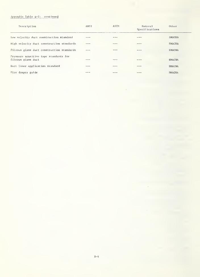
Appendix Table B-2: continued
Description ANSI ASTM FederalSpecifications
Other
Low velocity duct construction standard
High velocity duct construction standards
Fibrous glass duct construction standards
Pressure sensitive tape standards forfibrous glass duct
Duct liner application standard
Fire damper guide
SMACNA
SMACNA
SMACNA
SMACNA
SMACNA
SMACNA
B-4

Appendix Table B-3: Temperature and Pressure Ratings for Ball Valves—
Size Temperature
,
1 Id L. ^ 1- .1- CL J- l3 (Pressure in psi)
( inches
)
°F Bronze Iron Carbon Steel Alloy Steel
1/2 -20 to 100 200 and 400 1000 1000
150 400 850 850200 150 and 400 700 700
TO 250 152 /and 400 500 500
300 300 300 300
325 200 200 200
3/4 353 125 125 125
375 90 90 90
400 60 60 60
1 -20 to 100 400 720 720
150 400 710 710
200 400 700 700
TO 250 400 500 500
300 300 300 300
2 325 200 200 200353 125 125 125
375 90 90 90
400 60 60 60
2-1/2 -20 to 100 220 275 275
150 205 255 255
TO 200 190 240 240
12 250 180 225 225
1/ These ratings for ball valves, presented in Federal Specification WW-V-35a-1975, areintended for guidance and are not intended to be restrictive. Valves should not be usedfor pressures and temperatures exceeding the manufacturer
'
s rating.
2/ 15 pounds saturated steam temperature.
B-5
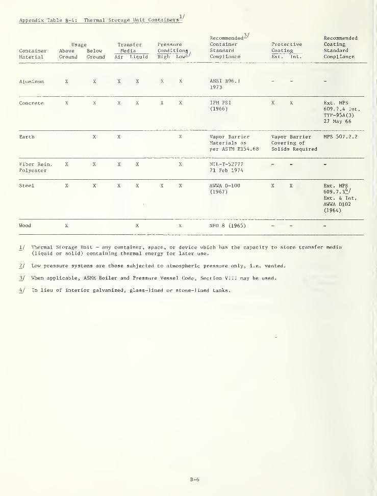
Appendix Table B-4 : Thermal Storage Unit Containers—
Recommended— Recommended
ContainerUsage
Above BelowTransferMedia
PressureConditions
ContainerStandard
ProtectiveCoating
CoatingStandard
Material Ground Ground Air Liquid High Low—' Compliance Ext. Int. Compliance
Aluminum X X X X X X ANSI B96.11973
Concrete X X X X X X IPM PS
I
(1966)
X X Ext. MPS609.7.4 Int.
TTP-95A(3)27 May 66
Earth X X X Vapor BarrierMaterials as
per ASTM E154.68
Vapor BarrierCovering of
Solids Required
MPS 507.2.2
Fiber Rein.
PolyesterX X X X X MIL-T-52777
21 Feb 1974
Steel X X X X X X AWWA D-lOO(1967)
X X Ext. MPS609. 7. 3^/
Ext. & Int.
AWWA D102
(1964)
Wood X X X NFO 8 (1965)
ll Thermal Storage Unit - any container, space, or device which has the capacity to store transfer media(liquid or solid) containing thermal energy for later use.
2^/ Low pressure systems are those subjected to atmospheric pressure only, i.e. vented.
2/ When applicable, ASME Boiler and Pressure Vessel Code, Section VIII may be used.
hj In lieu of interior galvanized, glass-lined or stone-lined tanks.
B-6

Appendix Table B-5 : Typical Heat Transfer Fluids
Water85% EthyleneGlycol/Water
50% PropyleneGlycol/Water
SiliconeFluid
AlkylatedPhenol
Paraf f inicOil
Freezing Point,
°F CO
Boiling Point,"F (°C) (at atm.
pressure)
Fluid Stability
Flash Point,°F (°C)
32 (0)
212 (100)
-33 (-36)
265 (130)
-28 (-33)
Requires pH Requires pHor inhibitor or inhibitormonitoring monitoring
None None
Requires pHor inhibitormonitoring
600 (315)
-58 (-50)
None
Good
-100 (-73)
358 (181)
Good to
575°F
600 (315) 145 (63)
700 (371)
Good
455 (235)
Specific Heat
(BTU/lb/°F)
1.0 0.65 0.85 0.34-0.48 0.42 0.46
Viscosity(cstk at 77°F)
0.9 21 5-50000
Toxicity None Low Low Low Moderate
B-7
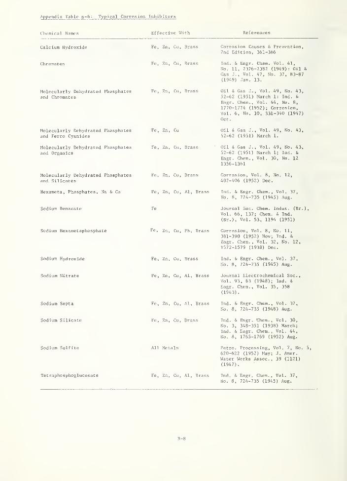
Appendix Table B-6: Typical Corrosion Inhibitors
Effective WithCliemical Names References
Calcium Hydroxide
Chromates
Molecularly Dehydrated Phosphatesand Chromates
Molecularly Dehydrated Phosphatesand Ferro Cyanides
Molecularly Dehydrated Phosphatesand Organic
s
Molecularly Dehydrated Phosphatesand Silicates
Hexameta, Phosphates, Na & Ca
Sodium Benzoate
Sodium Hexametaphosphate
Sodium Hydroxide
Sodium Nitrate
Sodium Septa
Sodium Silicate
Sodium Sulfite
Tetraphosphoglucosate
Fe, Zn, Cu, Brass
Fe, Zn, Cu, Brass
Fe, Zn, Cu, Brass
Fe, Zn, Cu
Fe, Zn, Cu, Brass
Fe, Zn, Cu, Brass
Fe, Zn, Cu, Al, Brass
Fe
Fe, Zn, Cu, Pb, Brass
Fe, Zn, Cu, Brass
Fe, Zn, Cu, Al, Brass
Fe, Zn, Cu, Al, Brass
Fe, Zn, Cu, Brass
All Metals
Fe, Zn, Cu, Al, Brass
Corrosion Causes & Prevention,2nd Edition, 361-366
Ind. & Engr. Chem. Vol. 41,
No. 11, 2376-2382 (1949): Oil &
Gas J., Vol. 47, No. 37, 83-87
(1949) Jan. 13.
Oil & Gas J., Vol. 49, No. 43,52-62 (1951) March 1: Ind. &
Engr. Chem., Vol. 44, No. 8,
1770-1774 (1952); Corrosion,Vol. 6, No. 10, 331-340 (1947)
Oct.
Oil & Gas J., Vol. 49, No. 43,
52-62 (1951) March 1.
Oil & Gas J., Vol. 49, No. 43,52-62 (1951) March 1; Ind. &
Engr. Chem., Vol. 30, No. 12
1356-1361
Corrosion, Vol. 8, No. 12,402-406 (1952) Dec.
Ind. & Engr. Chem., Vol. 37,
No. 8, 724-735 (1945) Aug.
Journal Soc. Chem. Indus. (Br.),
Vol. 66, 137; Chem. 6, Ind.
(Br.), Vol. 53, 1194 (1951)
Corrosion, Vol. 8, No. 11,
381-390 (1952) Nov; Ind. &
Engr. Chem., Vol. 32, No. 12,
1572-1579 (1938) Dec.
Ind. & Engr. Chem., Vol. 37,
No. 8, 724-735 (1945) Aug.
Journal Electrochemical Soc,Vol. 93, 63 (1948); Ind. &
Engr. Chem., Vol. 35, 358
(1943)
.
Ind. & Engr. Chem., Vol. 37,
No. 8, 724-735 (1948) Aug.
Ind. & Engr. them.. Vol. 30,
No. 3, 348-351 (1938) March;Ind. & Engr. Chem., Vol. 44,
No. 8, 1765-1769 (1952) Aug.
Petro. Processing, Vol. 7, No. 5,
620-622 (1952) May; J. Amer.
Water Works Assoc., 39 (1121)
(1947).
Ind. & Engr. Chem., Vol. 37,
No. 8, 724-735 (1945) Aug.
B-8
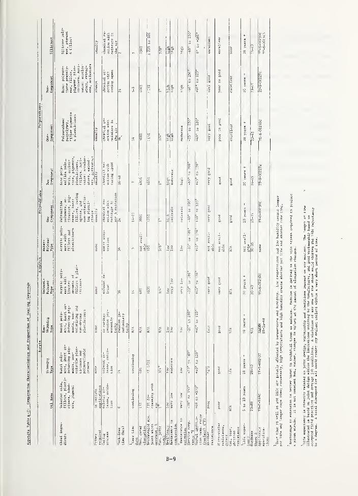
.1
,1
I
III
i":
MMllMli I
I
Mmmmmmm
:1|
ml
mir
lililil
if 5
.5.2 i
mIs
£5 5
il..
II
If
if
Is
^1
^1
III
hi
h
3 §
Mi
II
II
II
il
II
1
2
I ^
2
7 f
5
IPS
I. I
1^ I II!II i
II s 'ill
Is ii mih lit-
II
"
IS
ii
if !fl5
II IJMJ mi
I i: i«l1 5I fill
!^ ii
if P fill
1 H ii
ii PI:
II
!^ i! ilJi J: Mil
B-9

Appendix Table B-8: Upper Temperature Limits for Insulation Materials *
Insulation Materials Density(Ib/ft^)
Upper Temperature Limits°F (°C)
Fiberglass with Organic Binder 0.6 350 (177)1.0 350 (177)
1.5 350 (177)3.0 350 (177)
Fiberglass with Low Binder 1.5 850 (454)
Ceramic Fiber Blanket,
3.0 2300 (1260)
Mineral Fiber Blanket 10.0 ^ 1200 (649)
Calcium Silicate 13.0 1200 (649)
Urea-Formaldehyde Foam 0.7 210 (99)
Ureathane Foam 1-U 250-400 (121-204)
*Table from "Integrated Solar Energy Collector Final Summary Report", Robert B. Teonjes,LA-6143-MS, Los Alamos Scientific Laboratory, Los Alamos, New Mexico, November 1975.
B-10

APPENDIX C
ILLUSTRATED DEFINITIONS

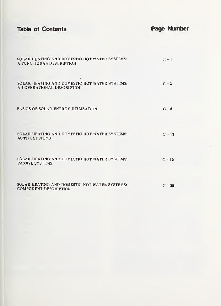
Table of Contents Page Number
SOLAR HEATING AND DOMESTIC HOT WATER SYSTEMS: C - 1
A FUNCTIONAL DESCRIPTION
SOLAR HEATING AND DOMESTIC HOT WATER SYSTEMS: C - 3
AN OPERATIONAL DESCRIPTION
BASICS OF SOLAR ENERGY UTILIZATION C - 6
SOLAR HEATING AND DOMESTIC HOT WATER SYSTEMS: C - 13ACTIVE SYSTEMS
SOLAR HEATING AND DOMESTIC HOT WATER SYSTEMS: C - 19PASSIVE SYSTEMS
SOLAR HEATING AND DOMESTIC HOT WATER SYSTEMS:COMPONENT DESCRIPTION
C - 20

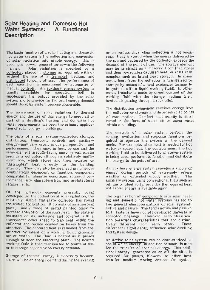
Solar Heating and Domestic HotWater Systems: A Functional
Description
The basic function of a solar heating and domestichot water system is the collection and conversion
of solar radiation into usable energy. This is
accomplished—in general terms—in the following
manner. Solar radiation is absorbed by a
collector , placed in storage as required, with or
without the use of a transport medium, anddistributed to point of use". The performance of
each operation is maintained by automatic or
manual controls . An auxiliary energy system is
usually available for operation, both to
supplement the output provided by the solar
system and to provide for the total energy demandshould the solar system become inoperable.
The conversion of solar radiation to thermalenergy and the use of this energy to meet all or
part of a dwelling's heating and domestic hot
water requirements has been the primary applica-tion of solar energy in buildings.
The parts of a solar system—collector, storage,
distribution, transport, controls and auxiliary
energy—may vary widely in design, operation, andperformance. They may, in fact, be one and thesame element (a south-facing masonry wall can beseen as a collector, although a relatively ineffi-
cient one, which stores and then radiates or
"distributes" heat directly to the building
interior). They may also be arranged in numerouscombinations dependent on function, componentcompatibility, climatic conditions, required per-formance, site characteristics, and architectural
requirements.
Of the numerous concepts presently beingdeveloped for the collection of solar radiation, therelatively simple flat-plate collector has foundthe widest application. It consists of an absorbingplate, usually made of metal painted black to
increase absorption of the sun's heat. This plate is
insulated on its underside and covered with atransparent cover sheet to trap heat within thecollector and reduce convection losses from theabsorber. The captured heat is removed from theabsorber by means of a working fluid, generallyair or water. The fluid is heated as it passesthrough or near the absorbing plate. The heatedworking fluid is then transported to points of useor to storage depending on energy demand.
Storage of thermal energy is necessary becausethere will be an energy demand during the evening
or on sunless days when collection is not occur-
ring. Heat is stored when the energy delivered bythe sun and captured by the collector exceeds the
demand at the point of use. The storage elementmay be as simple as a masonry floor that stores
and then re-radiates captured heat, or relatively
complex such as latent heat storage. In somecases, heat from the collector is transferred to
storage by means of a heat exchanger (primarily
in systems with a liquid working fluid). In other
cases, transfer is made by direct contact of the
working fluid with the storage medium (i.e.,
heated air passing through a rock pile).
The distribution component receives energy from
the collector or storage and dispenses it at points
of consumption. Comfort heat usually is distri-
buted in the form of warm air or warm water
within a building.
The controls of a solar system perform the
sensing, evaluation and response functions re-
quired to operate the system in the desired
mode. For example, when heat is needed for hot
water or space heat, the controls cause the hot
working fluid to be delivered to whatever system
is being used, perform its function and distribute
the energy to the point of use.
An auxiliary energy system provides a supply of
energy during periods of extremely severeweather or extended cloudy weather. Theauxiliary system, using conventional fuels such as
oil, gas or electricity, provides the required heatuntil solar energy is available again.
The organization of components into solar heat-ing and domestic hot water systems has led to
two general characterizations of solar systems:
active and passive. The terms active and passive
solar systems have not yet developed universally
accepted meanings. However, each classifica-
tion possesses characteristics that are distinc-
tively different from each other. Thesedifferences significantly influence solar dwelling
and system design.
An active solar system can be characterized as
one in which energy—in addition to solar—is used
for the transfer of thermal energy. This addi-
tional energy, generated on or off the site, is
required for pumps, blowers, or other heat
transfer medium moving devices for system
C - 1
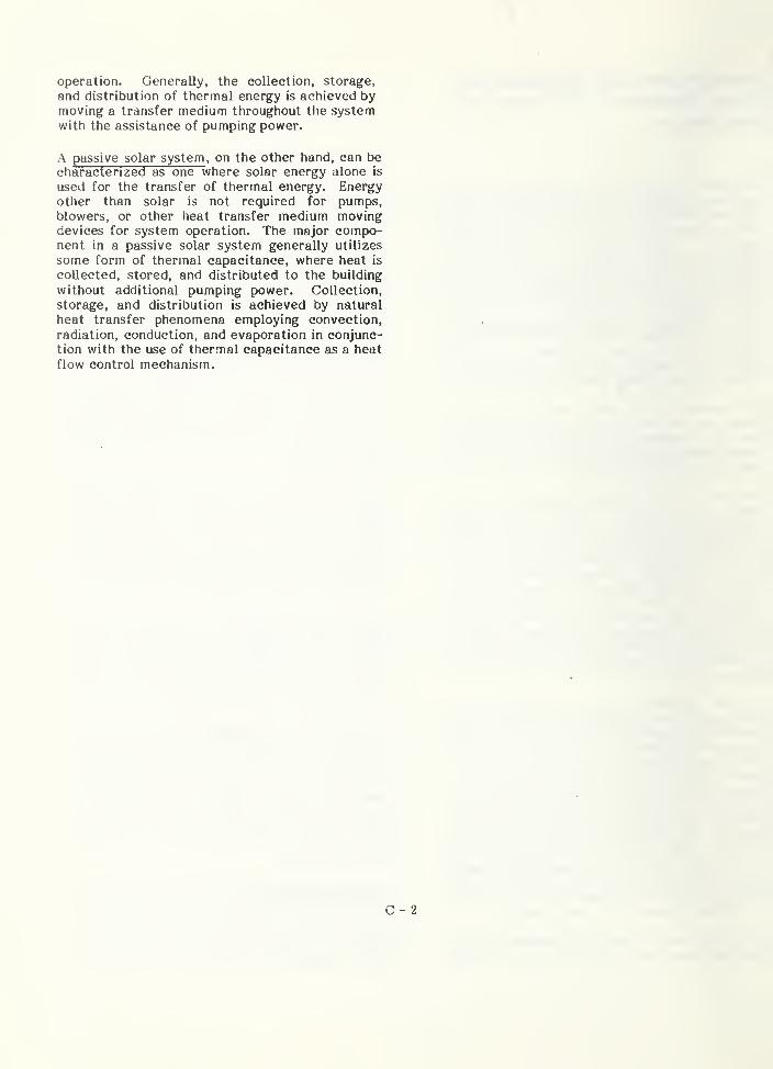
operation. Generally, the collection, storage,
and distribution of thermal energy is achieved bymoving a transfer medium throughout the systemwith the assistance of pumping power.
A passive solar system , on the other hand, can becharacterized as one where solar energy alone is
used for the transfer of thermal energy. Energyother than solar is not required for pumps,blowers, or other heat transfer medium movingdevices for system operation. The major compo-nent in a passive solar system generally utilizes
some form of thermal capacitance, where heat is
collected, stored, and distributed to the building
without additional pumping power. Collection,
storage, and distribution is achieved by natural
heat transfer phenomena employing convection,
radiation, conduction, and evaporation in conjunc-tion with the use of thermal capacitance as a heat
flow control mechanism.
C - 2

Solar Heating and DomesticHot Water Systems: AnOperational Description
Solar Systems may be designed to operate in a
number of different ways depending on function,
required performance, climatic conditions, compo-nent and system design, and architectural require-ments. Usually, however, solar systems are
PASSIVE SOLAR SYSTEM
HEATING HOUSE FROlVl COLLECTOR Solarradiation captured by the collectors and convertedto thermal energy can be used to directly heat thehouse.
HEATING STORAGE FROM COLLECTOR If the
house does not require heat, the captured (col-
lected) thermal energy can be placed in storagefor later use.
designed to operate in four basic modes. In a very
simplistic manner, the four modes of solar system
operation for both active and passive systems are
described and illustrated below.
ACTIVE SOLAR SYSTEM
C
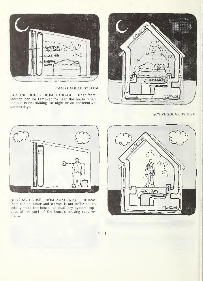
C - 4
I
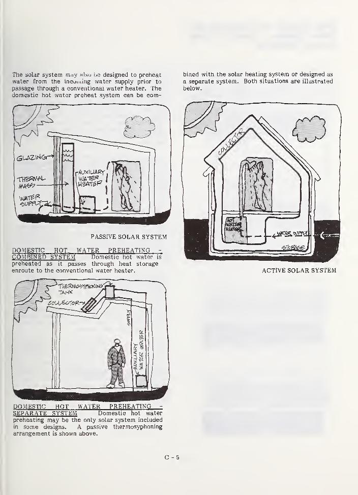
The solar system rr,Hy >i]su \jq designed to preheatwater from the incumiiig water supply prior to
passage through a conventional water heater. Thedomestic hot water preheat system can be com-
PASSIVE SOLAR SYSTEM
DOMESnC HOT WATER PREHEATING -
COMBINED SYSTEM Domestic hot water is
preheated as it passes through heat storage
enroute to the conventional water heater.
DOMESTIC HOT WATER PREHEATING -
SEPARATE SYSTEM Domestic hot waterpreheating may be the only solar system included
in some designs. A passive thermosyphoningarrangement is shown above.
bined with the solar heating system or designed as
a separate system. Both situations are illustrated
below.
ACTIVE SOLAR SYSTEM
C - 5
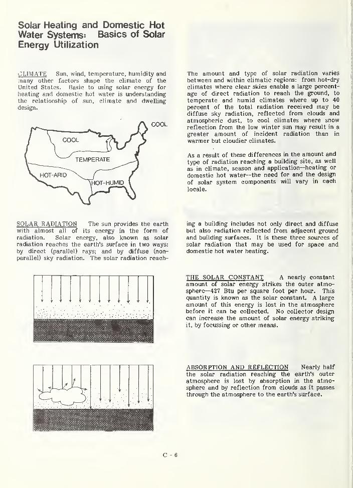
Solar Heating and Domestic HotWater SVstems: Basics of Solar
Energy Utilization
CLIMATE Sun, wind, temperature, humidity andmany other factors shape the climate of the
United States. Basic to using solar energy for
heating and domestic hot water is understanding
the relationship of sun, climate and dwelling
design.
COOL
The amount and type of solar radiation varies
between and within climatic regions: from hot-dry
climates where clear sl<ies enable a large percent-
age of direct radiation to reach the ground, to
temperate and humid climates where up to 40
percent of the total radiation received may be
diffuse sky radiation, reflected from clouds and
atmospheric dust, to cool climates where snowreflection from the low winter sun may result in a
greater amount of incident radiation than in
warmer but cloudier climates.
As a result of these differences in the amount and
type of radiation reaching a building site, as well
as in climate, season and application—heating or
domestic hot water—the need for and the design
of solar system components will vary in each
locale.
SOLAR RADIATION The sun provides the earth
with almost all of its energy in the form of
radiation. Solar energy, also i<nown as solar
radiation reaches the earth's surface in two ways:
by direct (parallel) rays; and by diffuse (non-
parallel) sky radiation. The solar radiation reach-
ing a building includes not only direct and diffuse
but also radiation reflected from adjacent groundand building surfaces. It is these three sources of
solar radiation that may be used for space anddomestic hot water heating.
THE SOLAR CONSTANT A nearly constant
amount of solar energy strikes the outer atmo-sphere—427 Btu per square foot per hour. This
quantity is known as the solar constant. A large
amount of this energy is lost in the atmospherebefore it can be collected. No collector design
can increase the amount of solar energy striking
it, by focussing or other mesms.
ABSORPTION AND REFLECTION Nearly half
the solar radiation reaching the earth's outer
atmosphere is lost by absorption in the atmo-sphere and by reflection from clouds as it passes
through the atmosphere to the earth's surface.
C - 6
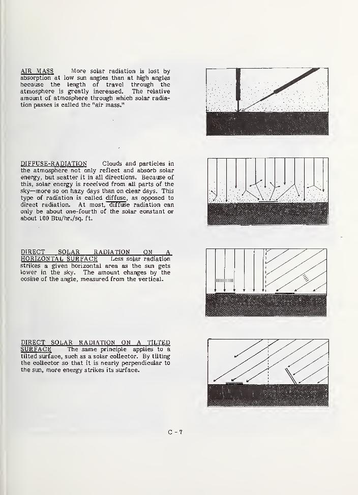
AIR MASS More solar radiation is lost byabsorption at low sun angles than at high anglesbecause the length of travel through the
atmosphere is greatly increased. The relative
amount of atmosphere through which solar radia-
tion passes is called the "air mass."
DIFFUSE-RADIATION Clouds and particles in
the atmosphere not only reflect and absorb solar
energy, but scatter it in all directions. Because of
this, solar energy is received from all parts of the
sky—more so on hazy days than on clear days. This
type of radiation is called diffuse , as opposed to
direct radiation. At most, diffuse radiation canonly be about one-fourth of the solar constant or
about 100 Btu/hr./sq. ft.
DIRECT SOLAR RADIATION ON AHORIZONTAL SURFACE Less solar radiation
strikes a given horizontal area as the sun getslower in the sky. The amount changes by thecosine of the angle, measured from the vertical.
DIRECT SOLAR RADIATION ON A TILTEDSURFACE The same principle applies to a
tilted surface, such as a solar collector. By tilting
the collector so that it is nearly perpendicular to
the sun, more energy strikes its surface.
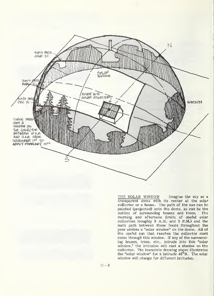
5
THE SOLAR WINDOW Imagine the sky as a
transparent dome with its center at the solar
collector or a house. The path of the sun can bepainted (projected) onto the dome, as can be the
outline of surrounding houses and trees. Themorning and afternoon limits of useful solar
collection (roughly 9 A.M. and 3 P.M.) and the
sun's path between those hours throughout the
year scribes a "solar window" on the dome. All of
the useful sun that reaches the collector mustcome through this window. If any of the surround-
ing houses, trees, etc., intrude into this "solar
window," the intrusion will cast a shadow on the
collector. The isometric drawing above illustrates
the "solar window" for a latitude 40°N. The solar
window wiU change for different latitudes.
C - 8
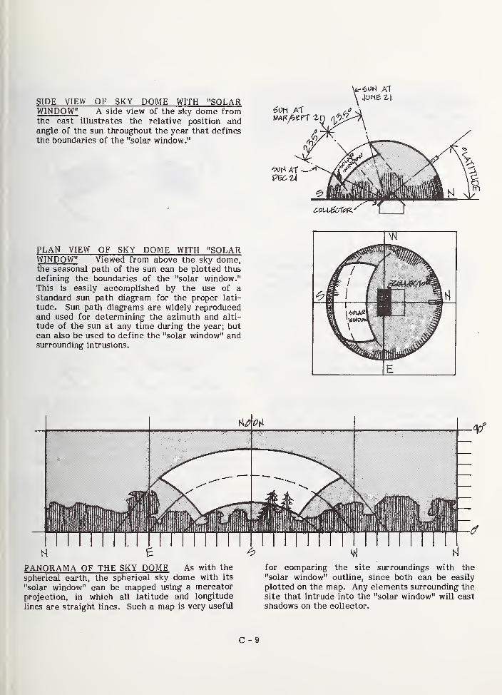
SIDE VIEW OF SKY DOME WITH "SOLARWINDOW" A side view of tlie sky dome fromthe east illustrates the relative position andangle of the sun throughout the year that defines
the boundaries of the "solar window."
\fc-6uM ATJune ^
PLAN VIEW OF SKY DOME WITH "SOLARWINDOW" Viewed from above the sky dome,the seasonal path of the sun can be plotted thus
defining the boundaries of the "solar window."This is easily accomplished by the use of astandard sun path diagram for the proper lati-
tude. Sun path diagrams are widely reproducedand used for determining the azimuth and alti-
tude of the sun at any time during the year; butcan also be used to define the "solar window" andsiirrounding intrusions.
60h AT
-foH ATpeon
PANORAMA OF THE SKY DOME As with the
spherical earth, the spherical sky dome with its
"solar window" can be mapped using a mercator
projection, in which all latitude and longitude
lines are straight lines. Such a map is very useful
for comparing the site surroundings with the
"solar window" outline, since both can be easily
plotted on the map. Any elements surrounding the
site that intrude into the "solar window" will cast
shadows on the collector.
C - 9
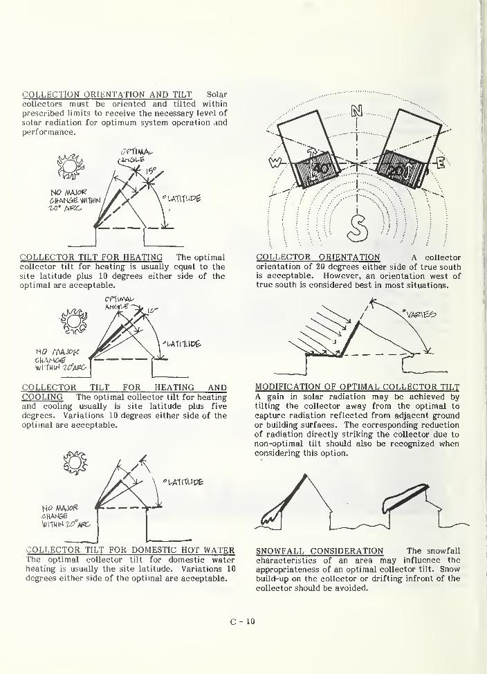
COLLECTION ORIENTATION AND TILT Solar
collectors must be oriented and tilted within
prescribed limits to receive the necessary level of
solar radiation for optimum system operation andperformance.
COLLECTOR TILT FOR HEATING The optimalcollector tilt for heating is usually equal to the
site latitude plus 10 degrees either side of theoptimal are acceptable.
COLLECTOR TILT FOR HEATING ANDCOOLING The optimal collector tilt for heatingand cooling usually is site latitude plus five
degrees. Variations 10 degrees either side of the
optimal are acceptable.
COLLECTOR TILT FOR DOMESTIC HOT WATERThe optimal collector tilt for domestic waterheating is usually the site latitude. Variations 10
degrees either side of the optimeil are acceptable.
COLLECTOR ORIENTATION A collector
orientation of 20 degrees either side of true southis acceptable. However, an orientation west oftrue south is considered best in most situations.
MODIFICATION OF OPTIMAL COLLECTOR TILTA gain in solar radiation may be achieved bytilting the collector away from the optimal to
capture radiation reflected from adjacent groundor building surfaces. The corresponding reduction
of radiation directly striking the collector due to
non-optimal tilt should also be recognized whenconsidering this option.
SNOWFALL CONSIDERATION The snowfall
characteristics of an area may influence the
appropriateness of an optimal collector tilt. Snowbuild-up on the collector or drifting infront of the
collector should be avoided.
C - 10
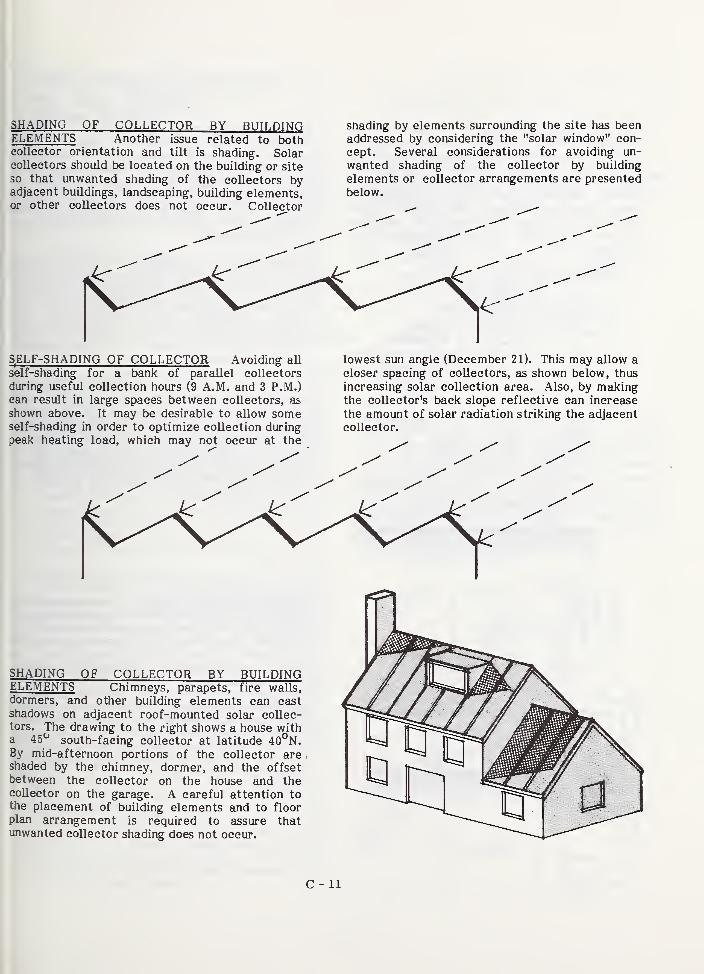
SHADING OF COLLECTOR BY BUILDINGELEMENTS Another issue related to bothcollector orientation and tilt is shading. Solarcollectors should be located on the building or site
so that unwanted shading of the collectors byadjacent buildings, landscaping, building elements,or other collectors does not occur. Collector
shading by elements surrounding the site has beenaddressed by considering the "solar window" con-
cept. Several considerations for avoiding un-
wanted shading of the collector by building
elements or collector arrangements are presented
below.
SELF-SHADING OF COLLECTOR Avoiding all
self-shading for a bank of parallel collectors
during useful collection hours (9 A.M. and 3 P.M.)can result in large spaces between collectors, as
shown above. It may be desirable to allow someself-shading in order to optimize collection duringpeak heating load, which may not occur at the
lowest sun angle (December 21). This may allow acloser spacing of collectors, as shown below, thus
increasing solar collection area. Also, by makingthe collector's back slope reflective can increase
the amount of solar radiation striking the adjacentcollector.
SHADING OF COLLECTOR BY BUILDINGELEMENTS Chimneys, parapets, fire walls,
dormers, and other building elements can castshadows on adjacent roof-mounted solar collec-tors. The drawing to the right shows a house witha 45^^ south-facing collector at latitude 40°N.By mid-afternoon portions of the collector areshaded by the chimney, dormer, and the offsetbetween the collector on the house and thecollector on the garage. A careful attention tothe placement of building elements and to floorplan arrangement is required to assure thatunwanted collector shading does not occur.
C - 11
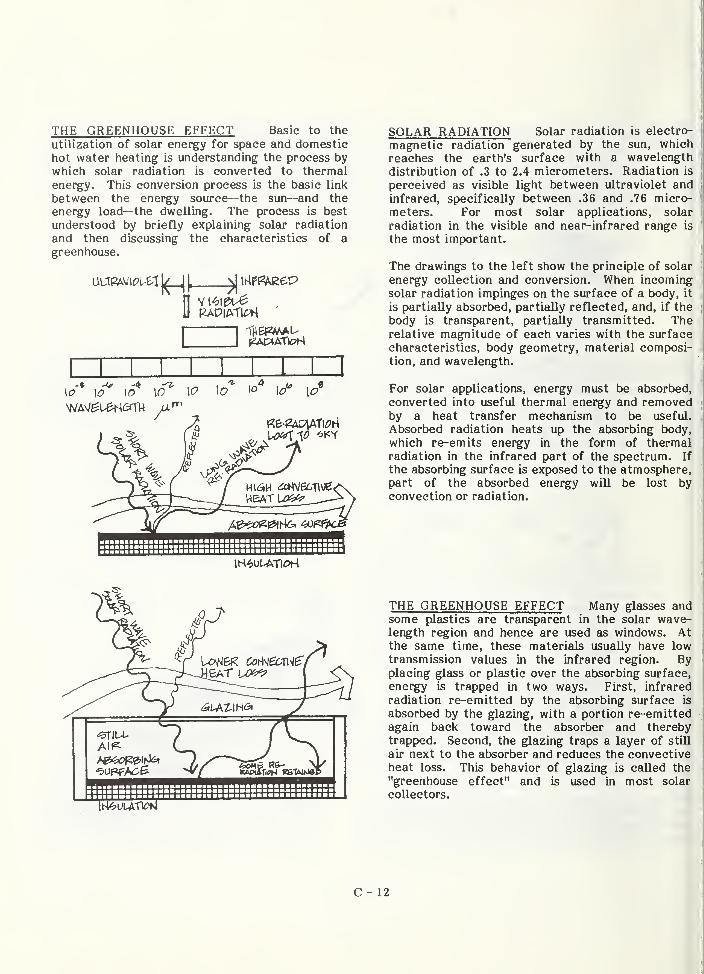
THE GREENHOUSE EFFECT Basic to the
utilization of solar energy for space and domestichot water heating is understanding the process bywhich solar radiation is converted to thermalenergy. This conversion process is the basic link
between the energy source—the sun—and the
energy load—the dwelling. The process is best
understood by briefly explaining solar radiation
and then discussing the characteristics of agreenhouse.
SOLAR RADIATION Solar radiation is electro-
magnetic radiation generated by the sun, which
reaches the earth's surface with a wavelength
distribution of .3 to 2.4 micrometers. Radiation is
perceived as visible light between ultraviolet andinfrared, specifically between .36 and .76 micro-
meters. For most solar applications, solar
radiation in the visible and near-infrared range is
the most important.
The drawings to the left show the principle of solar
energy collection and conversion. When incomingsolar radiation impinges on the surface of a body, it
is partially absorbed, partially reflected, and, if the
body is transparent, partially transmitted. Therelative magnitude of each varies with the surface
characteristics, body geometry, material composi-tion, and wavelength.
For solar applications, energy must be absorbed,
converted into useful thermal energy and removedby a heat transfer mechanism to be useful.
Absorbed radiation heats up the absorbing body,
which re-emits energy in the form of thermalradiation in the infrared part of the spectrum. If
the absorbing surface is exposed to the atmosphere,part of the absorbed energy will be lost byconvection or radiation.
THE GREENHOUSE EFFECT Many glasses andsome plastics are transparent in the solar wave-length region and hence are used as windows. Atthe same time, these materials usually have lowtransmission values in the infrared region. Byplacing glass or plastic over the absorbing surface,
energy is trapped in two ways. First, infrared
radiation re-emitted by the absorbing surface is
absorbed by the glazing, with a portion re-emittedagain back toward the absorber and therebytrapped. Second, the glazing traps a layer of still
air next to the absorber and reduces the convectiveheat loss. This behavior of glazing is called the
"greenhouse effect" and is used in most solar
collectors.
C - 12
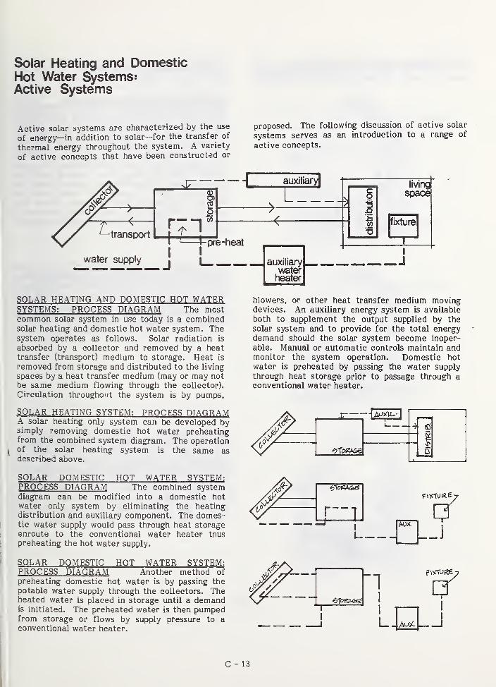
Solar Heating and DomesticHot Water Systems:Active Systems
Active solar systems are characterized by the use
of energy—in addition to solar—for the transfer of
thermal energy throughout the system. A variety
of active concepts that have been constructed or
proposed. The following discussion of active solar
systems serves as an introduction to a range of
active concepts.
-transport
water supply
[71I ' i pre-heat
I !
-I auxiliary!
SOLAR HEATING AND DOMESTIC HOT WATERSYSTEMS: PROCESS DIAGRAM The mostcommon solar system in use today is a combinedsolar heating and domestic hot water system. Thesystem operates as follows. Solar radiation is
absorbed by a collector and removed by a heattransfer (transport) medium to storage. Heat is
removed from storage and distributed to the living
spaces by a heat transfer medium (may or may not
be same medium flowing through the collector).
Circulation throughout the system is by pumps,
SOLAR HEATING SYSTEM: PROCESS DIAGRAMA solar heating only system can be developed bysimply removing domestic hot water preheatingfrom the combined system diagram. The operationof the solgir heating system is the same asdescribed above.
living
space
fixture
J
blowers, or other heat transfer medium movingdevices. An auxiliary energy system is available
both to supplement the output supplied by the
solar system and to provide for the total energydemand should the solar system become inoper-
able. Manual or automatic controls maintain andmonitor the system operation. Domestic hot
water is preheated by passing the water supply
through heat storage prior to passage through aconventional water heater.
SOLAR DOMESTIC HOT WATER SYSTEM:PROCESS DIAGRAM The combined systemdiagram can be modified into a domestic hot
water only system by eliminating the heatingdistribution and auxiliary component. The domes-tic water supply would pass through heat storageenroute to the conventional water heater thuspreheating the hot water supply.
SOLAR DOMESTIC HOT WATER SYSTEM:PROCESS DIAGRAM Another method of
preheating domestic hot water is by passing the
potable water supply through the collectors. Theheated water is placed in storage until a demandis initiated. The preheated water is then pumpedfrom storage or flows by supply pressure to aconventional water heater.
C - 13
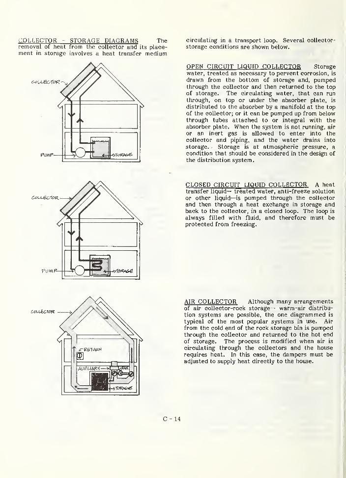
COLLECTOR - STORAGE DIAGRAMS Theremoval of heat from the collector and its place-ment in storage involves a heat transfer medium
circulating in a transport loop. Several collector-
storage conditions are shown below.
OPEN CIRCUIT LIQUID COLLECTOR Storage
water, treated as necessary to pervent corrosion, is
drawn from the bottom of storage and, pumpedthrough the collector and then returned to the topof storage. The circulating water, that can run
through, on top or under the absorber plate, is
distributed to the absorber by a manifold at the topof the collector; or it can be pumped up from belowthrough tut>es attached to or integral with the
absorber plate. When the system is not running, air
or an inert gas is allowed to enter into the
collector and piping, and the water drains into
storage. Storage is at atmospheric pressure, a
condition that should be considered in the design of
the distribution system.
CLOSED CIRCUIT LIQIIID COLLECTOR A heat
transfer liquid— treated water, anti-freeze solution
or other liquid— is pumped through the collector
and then through a heat exchange in storage andback to the collector, in a closed loop. The loop is
always filled with fluid, and therefore must beprotected from freezing.
AIR COLLECTOR Although many arrangementsof air collector-rock storage— warm-air distribu-
tion systems are possible, the one diagrammed is
typical of the most popular systems in use. Air
from the cold end of the rock storage bin is pumpedthrough the collector and returned to the hot endof storage. The process is modified when air is
circulating through the collectors and the house
requires heat. In this case, the dampers must be
adjusted to supply heat directly to the house.
C - 14
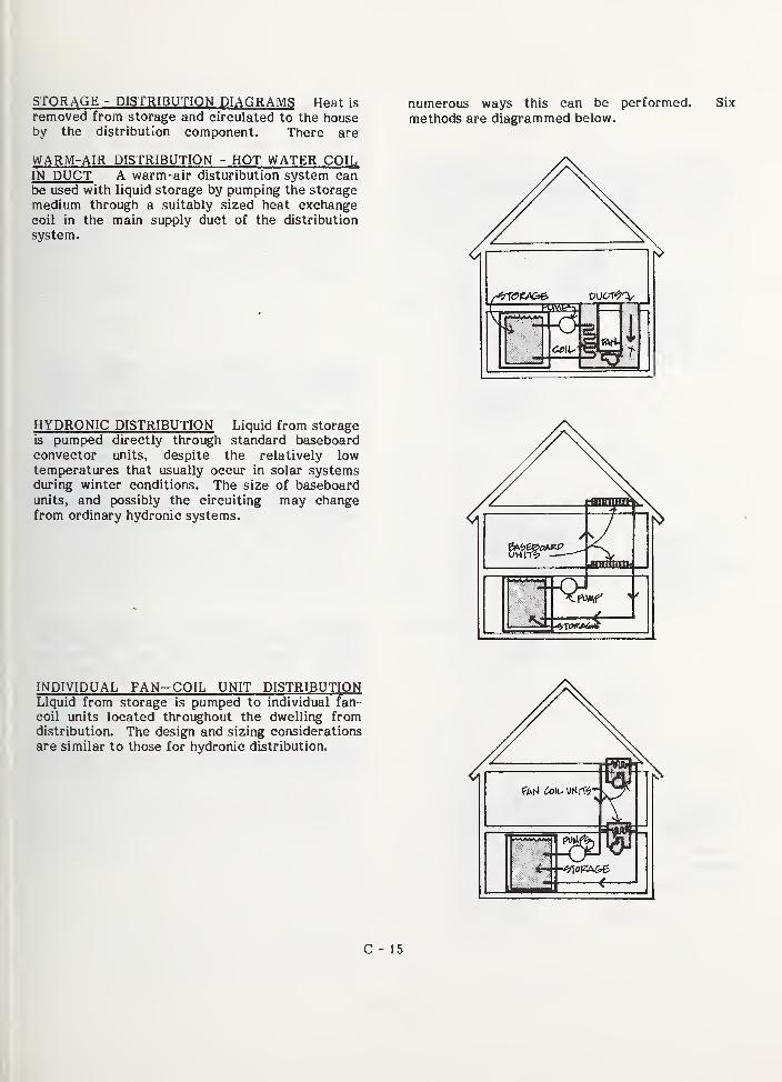
STORAGE - DISTRIBUTION DIAGRAMS Heat is
removed from storage and circulated to the houseby the distribution component. There are
WARM-AIR DISTRIBUTION - HOT WATER COILIN DUCT A warm-air disturibution system canbe used with liquid storage by pumping the storage
medium through a suitably sized heat exchangecoil in the main supply duct of the distribution
system.
numerous ways this can be performed,
methods are diagrammed below.
HYDRONIC DISTRIBUTION Liquid from storageis pumped directly through standard baseboardconvector units, despite the relatively lowtemperatures that usually occur in solar systemsduring winter conditions. The size of baseboardunits, and possibly the circuiting may changefrom ordinary hydronic systems.
INDIVIDUAL FAN—COIL UNIT DISTRIBUTIONLiquid from storage is pumped to individual fan-
coil units located throughout the dwelling fromdistribution. The design and sizing considerations
are similar to those for hydronic distribution.
ef
'
C - 15
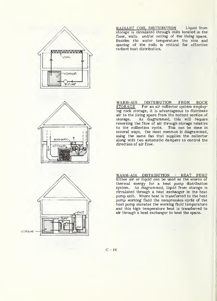
RADIANT COIL DISTRIBUTION Liquid fromstorage is circulated through coils located in the
floor, walls and/or ceiling of the living space.
Besides the water temperature the size andspacing of the coils is critical for effective
radiant heat distribution.ITiijiillTiTiTifiriiir,
f
m
WARM-AIR DISTRIBUTION FROM ROCKSTORAGE For an air collector system employ-ing rock storage, it is advantageous to distribute
air to the living space from the hottest section of
storage. As diagrammed, this will require
reversing the flow of air through storage relative
to the collection cycle. This can be done in
several ways, the most common is diagrammed,using the same fan that supplies the collector
along with two automatic dampers to control the
direction of air flow.
WARM-AIR DISTRIBUTION - HEAT PUMPEither air or liquid can be used as the source of
thermal energy for a heat pump distribution
system. As diagrammed, liquid from storage is
circulated through a heat exchanger in the heat
pump unit. Where heat is transferred to the heat
pump working fluid the compression cycle of the
heat pump elevates the working fluid temperatureand this high temperature heat is transferred to
air through a heat exchanger to heat the space.
C - 16
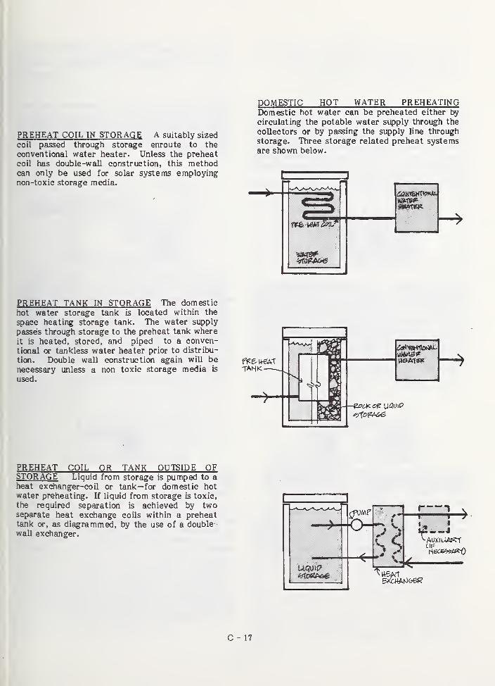
DOMESTIC HOT WATER PREHEATING
PREHEAT COIL IN STORAGE A suitably sized
coil passed through storage enroute to the
conventional water heater. Unless the preheat
coil has double-wall construction, this methodcan only be used for solar systems employingnon-toxic storage media.
Domestic hot water can be preheated either by
circulating the potable water supply through the
collectors or by passing the supply line through
storage. Three storage related preheat systemsare shown below.
1
PREHEAT TANK IN STORAGE The domestic
hot water storage tank is located within the
space heating storage tank. The water supply
passes through storage to the preheat tank where
it is heated, stored, and piped to a conven-
tional or tankless water heater prior to distribu-
tion. Double wall constructicai again wiU be
necessary unless a non toxic storage media is
used.
TAH<
PREHEAT COIL OR TANK OUTSIDE OFSTORAGE Liquid from storage is pumped to aheat exdianger-coil or tank—for domestic hotwater preheating. If liquid from storage is toxic,
the required separation is achieved by twoseparate heat exchange coils within a preheattank or, as diagrammed, by the use of a double •
wall exchanger.
r— 1 V
C - 17
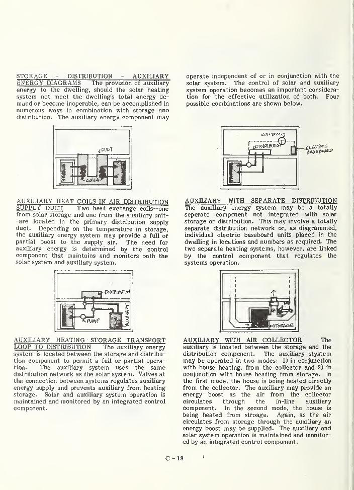
STORAGE - DISTRIBUTION - AUXILIARYENERGY DIAGRAMS The provision of auxiliary
energy to the dwelling, should the solar heating
system not meet the dwelling's total energy de-
mand or become inoperable, can be accomplished in
numerous ways in combination with storage anodistribution. The auxiliary energy component may
AUXILIARY HEAT COILS IN AIR DISTRIBUTIONSUPPLY DUCT Two heat exchange coils—onefrom solar storage and one from the auxiliary unit--are located in the primary distribution supplyduct. Depending on the temperature in storage,the auxiliary energy system may provide a full orpartial boost to the supply air. The need forauxiliary energy is determined by the controlcomponent that maintains and monitors both thesolar system and auxiliary system.
1 ^1
AUXILIARY HEATING STORAGE TRANSPORTLOOP TO DISTRIBUTION The auxiliary energysystem is located between the storage and distribu-
tion component to permit a full or partial opera-tion. The auxiliary system uses the samedistribution network as the solar system. Valves at
the connection between systems regulates auxiliary
energy supply and prevents auxiliary from heating
storage. Solar and auxiliary system operation is
maintained and monitored by an integrated control
component.
operate independent of or in conjunction with the
solar system. The control of solar and auxiliary
system operation becomes an important considera-
tion for the effective utilization of both. Four
possible combinations are shown below.
c
1^
AUXILIARY WITH SEPARATE DISTRIBUTIONThe auxiliary energy system may be a totally
seperate component not integrated with solar
storage or distribution. This may involve a totally
separate distribution network or, as diagrammed,individual electric baseboard units placed in the
dwelling in locations and numbers as required. Thetwo separate heating systems, however, are linked
by the control competent that regulates the
systems operation.
AUXILIARY WITH AIR COLLECTOR Theauxiliary is located between the storage and the
distribution compoient. The auxilisiry stystemmay be operated in two modes: 1) in conjunction
with house heating, from the collector and 2) in
conjunction with house heating from storage. In
the first mode, the house is being heated directly
from the collector. The auxiliary may provide anenergy boost as the air from the collector
circulates through the in-line auxiliary
compenent. In the second mode, the house is
being heated from stroage. Again, as the air
circulates from storage through the auxiliary anenergy boost may be supplied. The auxiliary andsolar system operation is maintained and monitor-ed by an integrated control component.
C - 18
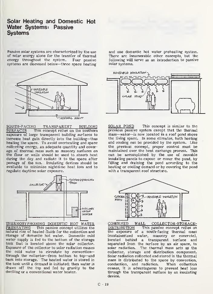
Solar Heating and Domestic HotWater Systems: PassiveSystems
Passive solar systems are characterized by the useof solar energy alone for the transfer of thermalenergy throughout the system. Four passive
systems are discussed below—three space heating
and one domestic hot water preheating system.
There are innumerable other concepts, but the
following will serve as an introduction to passive
solar systems.
SOUTH-FACING TRANSPARENT BUILDINGSURFACES This concept relies on the southernexposure of large transparent building surfaces to
increase heat gain directly into the building—thusheating the space. To avoid overheating and spacecollecting energy, an adequate quantity and cover-age of thermal mass such as masonry surfaces onthe floor or waUs should be used to absorb heatduring the day and radiate it to the space after
passage of the sun. Insulating devices should beavailable to minimize nighttime heat loss and to
regulate daytime solar exposure.
THERMOSYPHONING DOMESTIC HOT WATERPREHEATING This passive concept utilizes thenatural rise of heated fluids for the collection andstorage of domestic hot water. Domestic coldwater supply is fed to the bottom of the storagetank that is located above the solar collector.
Exposure of the collector to solar radiation causesthe cold water to circulate by convection-through the collector—from bottom to top—andback into storage. The heated water is stored in
the tank until a demand is initiated; then water is
drawn off the top and fed by gravity to thedwelling or a conventional water heater.
SOLAR POND This concept is similar to the
previous passive system except that the thermalmass—water—is now located in a roof pond abovethe living space. In some climates, both heatingand cooling can be provided by the system. Likethe previous concept, proper control must bemaintained over the heat exchange process. This
can be accomplished by the use of movableinsulating panels to expose or cover the pond, byfilling and draining the pond according to the
heating or cooling demand or by covering the pondwith a transparent roof structure.
COMBINED WALL COLLECTOR-STORAGE-DISTRIBUTION This passive concept relies onthe exposure of a south-facing thermal mass(containerized water, masonry or concrete),
located behind a transparent surface andseparated from the surface by an air space, to
solar radiation. The thermal mass acts as the
collector, storage and distribution component.Solar radiation collected and stored in the thermalmass is distributed to the space by convection,
conduction, and radiation. When collection
ceases, it is advantageous to prevent heat loss
through the transparent surface by an insulating
device.
C - 19
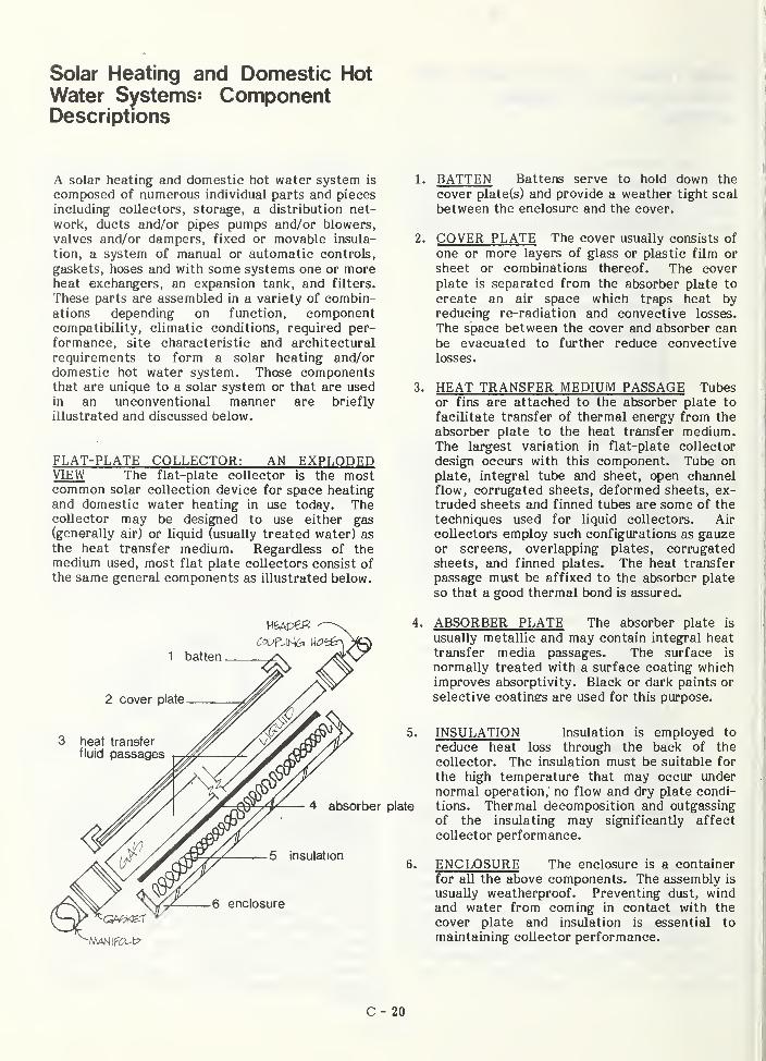
Solar Heating and Domestic HotWater Systems: ComponentDescriptions
A solar heating and domestic hot water system is
composed of numerous individual parts and pieces
including collectors, storage, a distribution net-
work, ducts and/or pipes pumps and/or blowers,
valves and/or dampers, fixed or movable insula-
tion, a system of manual or automatic controls,
gaskets, hoses and with some systems one or moreheat exchangers, an expansion tank, and filters.
These parts are assembled in a variety of combin-ations depending on function, componentcompatibility, climatic conditions, required per-
formance, site characteristic and architectural
requirements to form a solar heating and/ordomestic hot water system. Those componentsthat are unique to a solar system or that are usedin an unconventional manner are briefly
illustrated and discussed below.
FLAT-PLATE COLLECTOR: AN EXPLODEDVIEW The flat-plate collector is the mostcommon solar collection device for space heatingand domestic water heating in use today. Thecollector may be designed to use either gas(generally air) or liquid (usually treated water) as
the heat transfer medium. Regardless of themedium used, most flat plate collectors consist ofthe same general components as illustrated below.
^/ \\yLZ. _6 enclosure
1. BATTEN Battens serve to hold down the
cover plate(s) and provide a weather tight seal
between the enclosure and the cover.
2. COVER PLATE The cover usually consists of
one or more layers of glass or plastic film or
sheet or combinations thereof. The cover
plate is separated from the absorber plate to
create an air space which traps heat byreducing re-radiation and convective losses.
The space between the cover and absorber canbe evacuated to further reduce convective
losses.
3. HEAT TRANSFER MEDIUM PASSAGE Tubesor fins are attached to the absorber plate to
facilitate transfer of thermal energy from the
absorber plate to the heat transfer medium.The largest variation in flat-plate collector
design occurs with this component. Tube onplate, integral tube and sheet, open channelflow, corrugated sheets, deformed sheets, ex-truded sheets and finned tubes are some of the
techniques used for liquid collectors. Air
collectors employ such configurations as gauzeor screens, overlapping plates, corrugatedsheets, and finned plates. The heat transfer
passage must be affixed to the absorber plate
so that a good thermal bond is assured.
4. ABSORBER PLATE The absorber plate is
usually metallic and may contain integral heattransfer media passages. The surface is
normally treated with a surface coating whichimproves absorptivity. Black or dark paints or
selective coatings are used for this purpose.
5. INSULATION Insulation is employed to
reduce heat loss through the back of the
collector. The insulation must be suitable for
the high temperature that may occur under
normal operation, no flow and dry plate condi-
plate tions. Thermal decomposition and outgassing
of the insulating may significantly affect
collector performance.
6. ENCLOSURE The enclosure is a container
for all the above components. The assembly is
usually weatherproof. Preventing dust, windand water from coming in contact with the
cover plate and insulation is essential to
maintaining collector performance.
C - 20
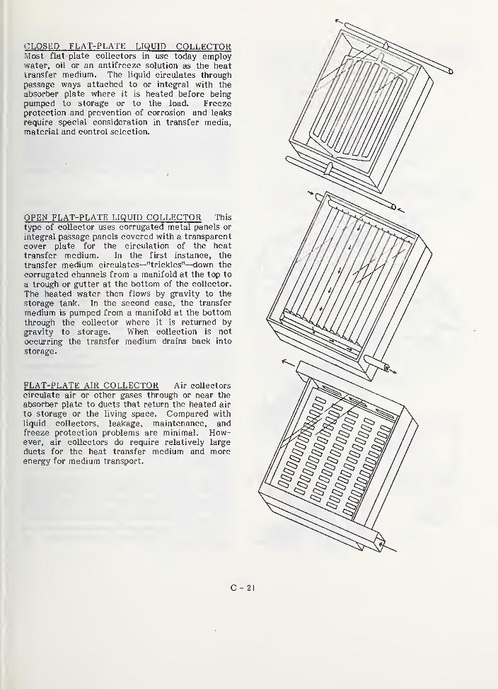
CLOSED FLAT-PLATE LIQUID COLLECTORMost flat-plate collectors in use today employwater, oil or an antifreeze solution as the heattransfer medium. The liquid circulates throughpassage ways attached to or integral with the
absorber plate where it is heated before beingpumped to storage or to the load. Freezeprotection and prevention of corrosion and leaks
require special consideration in transfer media,
material and control selection.
OPEN FLAT-PLATE LIQUID COLLECTOR This
type of collector uses corrugated metal panels or
integral passage panels covered with a transparent
cover plate for the circulation of the heat
transfer medium. In the first instance, the
transfer medium circulates—"trickles"—down the
corrugated channels from a manifold at the top to
a trough or gutter at the bottom of the collector.
The heated water then flows by gravity to the
storage tank. In the second case, the transfer
medium is pumped from a manifold at the bottomthrough the collector where it is returned by
gravity to storage. When collection is not
occurring the transfer medium drains back into
storage.
FLAT-PLATE AIR COLLECTOR Air coUectorscirculate air or other gases through or near the
absorber plate to ducts that return the heated air
to storage or the living space. Compared with
liquid collectors, leakage, maintenance, andfreeze protection problems are minimal. How-ever, air coUectors do require relatively large
ducts for the heat transfer medium and moreenergy for medium transport.
C
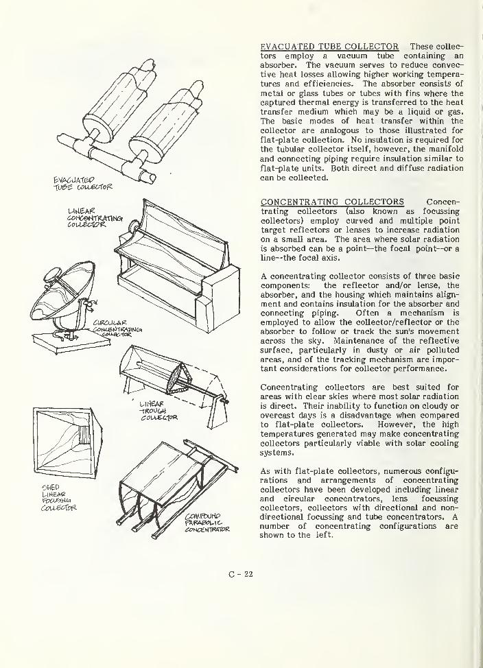
EVACUATED TUBE COLLECTOR These collec-
tors employ a vacuum tube containing anabsorber. The vacuum serves to reduce convec-tive heat losses allowing higher working tempera-tures and efficiencies. The absorber consists of
metal or glass tubes or tubes with fins where the
captured thermal energy is transferred to the heat
transfer medium which may be a liquid or gas.
The basic modes of heat transfer within the
collector are analogous to those illustrated for
flat-plate collection. No insulation is required for
the tubular collector itself, however, the manifold
and connecting piping require insulation similar to
flat-plate units. Both direct and diffuse radiation
can be collected.
CONCENTRATING COLLECTORS Concen-trating collectors (also known as focussing
collectors) employ curved and multiple point
target reflectors or lenses to increase radiation
on a smaU area. The area where solar radiation
is absorbed can be a point—the focal point—or aline—the focal axis.
A concentrating collector consists of three basic
components: the reflector and/or lense, the
absorber, and the housing which maintains align-
ment and contains insulation for the absorber andconnecting piping. Often a mechanism is
employed to allow the coUector/reflector or the
absorber to follow or track the sun's movementacross the sky. Maintenance of the reflective
surface, particularly in dusty or air polluted
areas, and of the tracking mechanism are impor-tant considerations for collector performance.
Concentrating collectors are best suited for
areas with clear skies where most solar radiation
is direct. Their inability to function on cloudy or
overcast days is a disadvantage when comparedto flat-plate collectors. However, the high
temperatures generated may make concentrating
collectors particularly viable with solar cooling
systems.
As with flat-plate collectors, numerous configu-
rations and arrangements of concentrating
collectors have been developed including linear
and circular concentrators, lens focussing
collectors, collectors with directional and non-directional focussing and tube concentrators. Anumber of concentrating configurations areshown to the left.
C - 22

FLAT-PLATE COLLECTOR MOUNTING Flat-plate collectors are generally mounted on theground or on a building in a fixed position at
prescribed angles of solar exposure—which vary
RACK MOUNTING CoUectors can be mountedat the prescribed angle on a structural framelocated on the site or attached to the building.
The structural connection between the collector
and the frame and the frame and the building or
site must be adequate to resist any loads such aswind that may impact on it.
STAND-OFF MOUNTING Elements that separatethe collector from the finished roof surface are
known as stand-offs. They allow air and rain waterto circulate under the collector thus minimizingproblems of mildew and leakage. The stand-offs
must have adequate structural properties to assure
the maintenance of a fixed collector mounting.Stand-offs are often used to support collectors at
an angle other than that of the roof to optimizecollector tilt.
DIRECT MOUNTING Collectors can be mounteddirectly on the roof surface. Generally, the
collectors are placed on a water-proof membraneon top of the roof sheathing. The finished roofsurface together with the necessary collector
structural attachments and flashing are built uparound the collector. A weatherproof seed
between the collector and the roof must beachieved or leakage, mildew, and rotting mayoccur.
INTEGRAL MOUNTING Integral mountingplaces the collector within spaces between struc-
tural roof members. The collector is attached to
and supported by the structural framing members.The top of the collector is located almost flush
with the finished roof surface. Weather tightness
is again crucial to avoid problems of waterdamage and mildew. This method of mounting is
frequently used for on-site built collectors.
according to the geographic location, collector
type, and the use of the absorbed heat. Flat-plate
collectors may be mounted in four general ways as
illustrated below.
C - 23
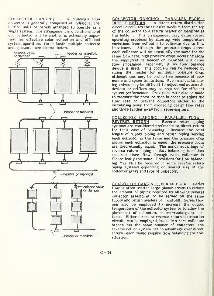
COLLECTOR GANGING A building's solar
collector is generally composed of individual col-
lection units or panels arranged to operate as asingle system. The arrangement and relationship ofone collector unit to another is extremely impor-tant for effective solar collection and efficient
system operation. Three basic multiple collector
arrangements are shown below.
header or manifoldbalance valveor damper
—- header or manifold
^ —balance \^veor damper
T I
Xheader or manifold
COLLECTOR GANGING: PARALLEL FLOW -
DIRECT RETURN A direct return distribution
circuit circulates the transfer medium from the top
of the collector to a return header or manifold at
the bottom. This arrangement may cause severe
operating problems by allowing wide temperaturevariations from collector to collector due to flow
imbalance. Although the pressure drops across
each collector will be essentially the same for the
same flow rate, high pressure drops occurring along
the supply/return header or manifold wiU causeflow imbalance, especially if no flow balancedevice is used. This problem can be reduced bysizing the header for minimum pressure drop,
although this may be prohibitive because of eco-
nomic and space limitations. Even manual balanc-
ing valves may be difficult to adjust and automaticdevices or orifices may be required for efficient
system performance. Provisions must also be madeto measure the pressure drop in order to adjust the
flow rate to prevent collectors closer to the
circulating pump from exceeding design flow rates
and those farther away from receiving less.
COLLECTOR GANGING: PARALLEL FLOW -
REVERSE RETURN Reverse return piping
systems are considered preferable to direct return
for their ease of balancing. Because the total
length of supply piping and return piping serving
each collector is the same tmd the pressure dropacross each collector is equal, the pressure dropsare theoretically equal. The major advantage of
reverse return piping is that balancing is seldomrequired since flow through each collector is
theoretically the same. Provisions for flow balanc-
ing may still be required in some reverse return
piping systems depending on overall size of the
collector array and type of collector.
COLLECTOR GANGING: SERIES FLOW Series
flow is often used in large planar arrays to reducethe amount of piping required by allowing several
collector assemblies to be served by the samesupply and return headers or manifolds. Series flow
can also be employed to increase the outputtemperature of the collector system or to allow the
placement of collectors on non-rectangular sur-
faces. Either direct or reverse return distribution
circuits can be employed, but unless each collector
branch has the same number of collectors, the
reverse return system has no advantage over direct
return—each would require flow t)alancing for this
situation.
C - 24
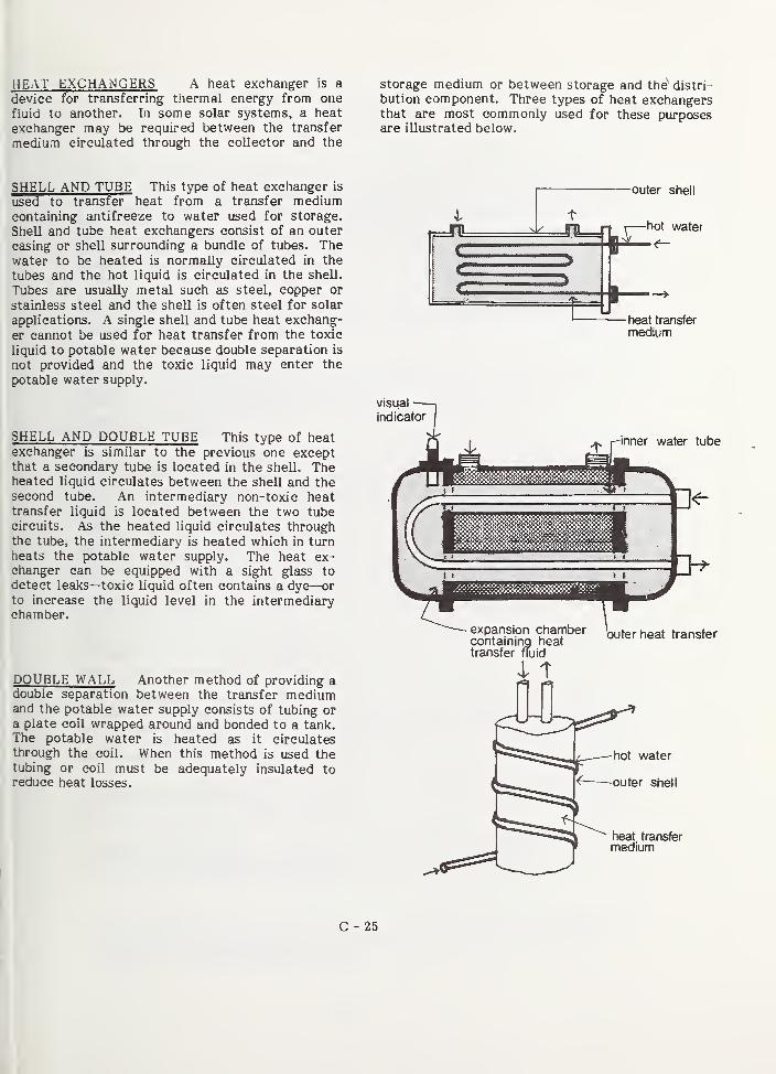
HEAT EXCHANGERS A heat exchanger is a
device for transferring thermal energy from one
fluid to another. In some solar systems, a heat
exchanger may be required between the transfer
medium circulated through the collector and the
SHELL AND TUBE This type of heat exchanger is
used to transfer heat from a trsinsfer mediumcontaining antifreeze to water used for storage.
SheU and tube heat exchangers consist of an outer
casing or shell surrounding a bundle of tubes. Thewater to be heated is normally circulated in the
tubes and the hot liquid is circulated in the shell.
Tubes are usually metal such as steel, copper or
stainless steel and the shell is often steel for solar
applications. A single shell and tube heat exchang-
er cannot be used for heat transfer from the toxic
liquid to potable water because double separation is
not provided and the toxic liquid may enter the
potable water supply.
SHELL AND DOUBLE TUBE This type of heatexchanger is similar to the previous one exceptthat a secondary tube is located in the shell. Theheated liquid circulates between the shell and thesecond tube. An intermediary non-toxic heattransfer liquid is located between the two tubecircuits. As the heated liquid circulates throughthe tube, the intermediary is heated which in turn
heats the potable water supply. The heat ex-changer can be equipped with a sight glass to
detect leaks—toxic liquid often contains a dye—or
to increase the liquid level in the intermediarychamber.
DOUBLE WALL Another method of providing adouble separation between the transfer mediumand the potable water supply consists of tubing ora plate coil wrapped around and bonded to a tank.The potable water is heated as it circulatesthrough the coil. When this method is used thetubing or coil must be adequately insulated toreduce heat losses.
storage medium or between storage and the'* distri-
bution component. Three types of heat exchangersthat are most commonly used for these purposesare illustrated below.
outer shell
heat transfer
medium
C - 25

APPENDIX D
DEFINITIONS
General : Abbreviations, terms, phrases, and words and their derivativesused in these Intermediate Standards for Solar Application shall have themeanings given in this Appendix. The terms defined herein apply only for
The Department of Housing and Urban Development (HUD) purposes and maydiffer in some respects from definitions prepared for building codes or
other purposes. Wherever possible, the meaning in common use in theresidential construction field is used.
Active Solar System : An assembly of collectors, thermal storage device (s)
,
and transfer media which converts solar energy into thermal energy, and
in which energy in addition to solar is used to accomplish the transfer of
thermal energy.
Air Gap : An air gap in a potable water distribution system is the un-obstructed vertical distance through the free atmosphere between thelowest opening from any pipe or faucet supplying water to a tank,pliambing fixture or other device and the flood level rim of thereceptacle. (NSPC) *
Auxiliary energy subsystem ; Equipment utilizing conventional energysources both to supplement the output provided by the solar energysystem as required by the design conditions, and to provide full energybackup requirements during periods when the solar H, or DHW systems areinoperable
.
Backflow : The unintentional reversal of flow in a potable water distri-bution system which may result in the transport of foreign materials orsubstances into the other branches of the distribution system. (NBS)
Backflow Preventer : A device or means to prevent backflow.
Back Pressure : Pressure created by any means in the water distributionsystem on the premises, which by being in excess of the pressure in thewater supply main could cause backflow. (NBS)
Back-Siphonage : The backflow of possibly contaminated water into thepotable water supply system as a result of the pressure in the potablewater system becoming unintentionally less than the atmospheric pressurein the plumbing fixtures, pools, tanks or vats that may be connected to
the potable water distribution piping. (NBS)
Biochemical Oxygen Demand : The quantity of oxygen used in the biochemicaloxidation of organic matter in a specified time, at a specified tempera-ture, and under specified conditions.
Chemical Compatibility : The ability of materials and components incontact with each other to resist mutual chemical degradation, such as
that caused by electrolytic action.
* Abbreviations in parentheses indicate the sources of the definitionsused here. (See Appendices E and F)
D-1
Collectors, combined : The collector and storage are constructed and
operated such that they functionally perform as one unit and the thermalperformance of the individual components cannot be meaningfully measured.
Collectors, component : Collector that is not structurally integratedwith the storage or building. The collector performance can be thermallycharacterized as an individual component with an active heat transferfluid.
Collectors, integrated : The collector is constructed and operated as
part of the building structure and heating system. The thermal performanceis considered a part of the building heating load and solar energy providesa significant fraction of the building heat requirements.
Components ; The smallest identifiable elements of a solar heating sub-system, such as valves, piping, controls, and containers, etc.
Contaminants : Materials (solids or liquids or gases) which when addedunintentionally (or intentionally) to the potable water supply and causeit to be unfit for human or animal consumption. (ASSE 1013)
Creep : A time-dependent deformation resulting from sustained loads whichcan be influenced by local environmental factors such as, thermal atmo-sphere and/or cycling, and solar radiation.
Cross Connection : Any physical connection or arrangement between twootherwise separate piping systems, one of which contains potable waterand the other either water of unknown or questionable safety or steam,gas, chemicals or other substances whereby there may be a flow from onesystem to the other, the direction of flow depending on the pressuredifferential between the two systems.
Design life : The period of time during which an H, and DHW systemis expected to perform its intended function without requiring majormaintenance or replacement
.
DHW : Domestic hot water system.
DWV: Drain, Waste, Vent
Energy transport subsystem : A portion of the H, and DHW systems whichtransports energy throughout the system.
Failure (structural ) : Failure of a structure or any structural element isdefined as one of the following
(a) Sudden, locally-increased curvature, major spalling, or structuralcollapse
.
(b) The inability of the structure to resist a further increase in load.
(c) Structural deflections under design loads that cause significantthermal performance degradation of the component or subsystem.
Flow Condition : The condition obtained when the heat transfer fluid isflowing through the collector array under normal operating conditions.
D-2
Forced-Circulation Air Coil : A coil for use in an air stream whosecirculation is caused by a difference in pressure produced by a fan orblower.
Forced-Circulation Air Heating Coil : A heat exchanger, with or withoutextended surfaces, through which either hot water or steam is circulatedfor the purposes of sensible heating of a forced-circulation air stream.
H: Heating system.
Heat Transfer Medium : A medium, either fluid or air, which is used to
transport thermal energy.
Laminated glass : Consists of two or more sheets of glass held togetherby an intervening layer or layers of plastic material.
Lethal Concentration (LC) : Any concentration of a substance in air towhich man has been reported to have been exposed for any given time thathas been reported to have caused death in man or any concentration to
which animals have been exposed for eight hours or less and that has beenreported to have caused death in animals.
Lethal Dose (LP) : Any dose of a substance introduced by any route otherthan inhalation over any given period of time and reported to have causeddeath in man or a single dose introduced in one or more divided portionsand reported to have caused death in animals
.
Load factors : Multipliers by which design loads are increased in orderto obtain the loads to be used in ultimate strength design of structuralelements
.
Maximum "flow" temperature : The maximum temperature that will be obtainedin a component when the heat transfer medium is flowing through the system.
Maximum "no-flow" temperature : The maximum temperature that will be obtainedin a component when the heat transfer medium is not flowing through the
system.
Maximum service temperature : The maximum temperature to which a componentwill be exposed in actual service, either with or without the flow of heat
transfer medium.
MPS 4900.1 : PHA "Minimum Property Standards For One And Two FamilyDwellings"
.
MPS 4910.1 : FHA "Minimum Property Standards For Multifamily Housing".
No-Flow Condition : The condition obtained when the heat transfer fluidis not flowing through the collector array due to shut-down or malfunction.
Outgassing : The emission of gases by materials and components, usually
during exposure to elevated temperature, or reduced pressure.
Passive Solar System : An assembly of collectors, thermal storage device(s),
and transfer media which converts solar energy into thermal energy and in
which no energy in addition to solar is used to accomplish the transfer of
thermal energy. The prime element is a passive solar system is usually
some form of thermal capacitance.
D-3
Physical Compatibility : The ability of materials and components in contactwith each other to resist degradation such as that caused by differentialcoefficients of thermal expansion.
pphm : Parts per hundred million
Safety glass : Glazing materials predominantly inorganic in character,which meets the appropriate requirements of this standard and includeslaminated glass, tempered glass, and wired glass.
Safety glazing materials : Glazing materials so constructed, treatedor combined with other materials as to minimize the likelihood of cuttingand piercing injuries resulting from human contact with these glazingmaterials
.
Service loads : Loads which are expected during the service life of a
structure and upon which the design of the structure is based.
Solar Building : A building which utilizes solar energy by means of anactive or passive solar system.
Solar degradation : The process by which exposure to sunlight deterioratesthe properties of materials and components.
Solar energy : The photon energy originating from the sun's radiation inthe wavelength region from 0.3 to 2.4 micrometers.
Solar Heating System : The complete assembly of subsystems and componentsnecessary to convert solar energy into thermal energy for heating purposes,in combination with auxiliary energy when required.
Solar Time : The hours of the day as reckoned by the apparent positionof the sun. Solar noon is that instant on any day at which the sun reachesits maximum altitude for that day.
Storage subsystem : The assembly used for storing thermal energy so thatit can be used when required.
Subsystem : One of several major elements of a solar heating system, suchas collectors, thermal storage device (s), heaters, etc.
System : The complete assembly necessary to supply heat to the dwellingin which it is installed.
Sustained load : A load that is considered to be applied to the structureover a projected period of time
Thermal Energy : Heat possessed by a material resulting from the motion ofmolecules and which can do work.
Toxic fluids : Gases or liquids which are poisonous, irritating and/orsuffocating, as classified in the Hazardous Substances Act, Part 191,Chapter I. Title 21.
Ultimate strength design : A method of proportioning structures or membersfor failure at a specified multiple of working loads, and assuming nonlineardistribution of flexural stresses.
UV: Ultra-violet
D-4
Water Hammer : The term used to identify the hammering noises and severeshocks that may occur in a pressurized water supply system when flow is
halted abruptly by the rapid closure of a valve or faucet (NBS)
Water hammer arrester : A manufactured device, other than an air chamber,containing a permanently sealed cushion of gas or air, designed to provideprotection against excessive shock pressure without maintenance.
Working stress design : A method of proportioning structures or members
for prescribed working loads at stresses well below the ultimate, and
assuming linear distribution of flexural stresses
.
D-5

APPENDIX E
REFERENCED STANDARDS
AASHO H20-44 Standard Specification for Highway Bridges
ANSI A13.1 (1956) Scheme for the Identification of Piping Systems
ANSI A58.1 Building Code Requirements for Minimum Design Loads in
Buildings and Other Structures
ANSI A112.1.1 (1971) Performance Requirements, Methods of Test for
(ASSE 1001-1970) Pipe-Applied Atmospheric-Type Anti-Siphon VacuumBreakers
ANSI A112.1.2 Air Gaps in Plumbing Systems (Reaffirmation and redesignationof A40. 4-1942)
ANSI B9.1 (1971) Safety Code for Mechanical Refrigeration
ANSI B15.1 (1972) Safety Standard for Mechanical Power TransmissionApparatus
ANSI B16.18 (1972) Cast Bronze Solder Joint Pressure Fittings
ANSI B31.1, Section I (1973) Power Piping
ANSI B96.1 (1973) Specification for Welded Aluminum-Alloy Field-ErectedStorage Tanks
ANSI B124.1 (1971) Safety Standard for Air Filter Units (UL 900-April 1971)
ANSI B137.1 (1971) Steel Underground Tanks for Flammable and CombustibleLiquids (UL 58-July 1971)
ANSI S2.8 (1972) Guide for Describing the Characteristics of ResilientMountings
ANSI Z95.1 (1974) Oil Burning Equipment (NFPA 31-1972)
ANSI Z97.1 (1972) Performance Specifications and Methods of Test forSafety Glazing Material Used in Buildings
ARI Standard 260 (1967) Standard for Application, Installation, and Servic-ing of Unitary Systems
ARI Standard 410 Forced Circulation Air-Cooling and Air-Heating Coils
ARI Standard 610 Standard for Central Humidifiers (1974)
ARI Standard 620 Standard for Self-Contained Humidifiers (1974)
ARI Standard 760 Standard for Solenoid Valves for Use with VolatileRefrigerants and Water, 1975
ASHRAE 55-74 (1974) Thermal Environmental Conditions for Human Occupancy
ASHRAE 90-75 (1975) Energy Conservation in New Building Design
E-1
ASHRAE Handbook of Fundamentals, Chapter 14
ASME SA-53, Section VIII Boiler and Pressure Vessel Code
ASSE 1011 Performance Requirements for Hose Connection Vacuum Breakers
ASSE 1012 Performance Requirements for Backflow Preventers with IntermediateAtomospheric Vent
ASSE 1013 Performance Requirements for Reduced Pressure Principle BackPressure Backflow Preventers
ASSE 1015 Performance Requirements for Double Check Valve Type Back PressureBackflow Preventers
ASSE 1020 Performance Requirements for Vacuum Breakers, Anti-Siphon, PressureType
ASTM A53-75 Specification for Welded and Seamless Steel Pipe
ASTM 739-73, Section 10.4 (1973) Flame Resistance Permanency
ASTM D660-44 (1970) Evaluating Degree of Resistance to Checking of ExteriorPaints
ASTM D661-44 (1975) Evaluating Degree of Resistance to Cracking of ExteriorPaints
ASTM D714-56 (1974) Evaluating Degree of Blistering of Paints
ASTM D750-68 (1974) Recommended Practice for Operating Light-and-WeatherExposure Apparatus (Carbon-Arc Type) for Artificial Weather Testing ofRubber Compounds
ASTM D772-47 (1975) Evaluating Degree of Flaking (Scaling) of Exterior Paint
ASTM D822-60 (1973) Recommended Practice for Operating Light-and-Water-ExposureApparatus (Carbon-Arc Type) for Testing Paint, Varnish, Lacquer, andRelated Products
ASTM D1081-60 (1974) Test for Evaluating Pressure Sealing Properties ofRubber and Rubber-Like Materials
ASTM D1149-64 (1970) Test for Accelerated Ozone Cracking of Vulcanized Rubber
ASTM D1308-57 (1973) Test for Effect of Household Chemical on Clear andPigmented Organic Finishes
ASTM D1384-70 Corrosion Test for Engine Antifreeze in Glassware
ASTM D2247-68 (1973) Testing Coated Metal Specimens at 100 Percent RelativeHumidity
ASTM D2570-73 Simulated Service Corrosion Testing of Engine Antifreeze
ASTM D2776-72 Tests for Corrosivity of Water in the Absence of Heat Transfer(Electrical Methods)
ASTM E72-74a Conducting Strength Tests of Panels for Building Construction
ASTM E84-70 (1970) Surface Burning Characteristics of Building Materials
E-2
ASTM E 108-75 (1975) Methods of Fire Tests of Roof Coverings (NFPA 256-1970)
ASTM E154-68 Testing Materials for Use as Vapor Barriers Under ConcreteSlabs and as Ground Cover in Crawl Spaces
ASTM E424-71 Test for Solar Energy Transmittance and Reflectance (Terrestrial)of Sheet Materials
ASTM F82-67 (1973) Recommended Practice for Fast Quality Check on Immersionfor Nonmetallic Gasket Materials
AWWA C506-69 Backflow Prevention Devices-Reduced Pressure Principle and
Double Check Valve Types
AWWA DlOO (1967) Steel Tanks - Standpipes, Reservoirs and Elevated Tanks
for Water Storage
AWWA D102 Painting and Repainting Steel Tanks, Standpipes, Reservoirs, and
Elevated Tanks for Water Storage
BMC, Section M302 (1975) Specific Requirements for the Materials, Designand Fabrication of Ductwork.
CPSC 16 CFR, Part 1201 (1976) Architectural Glazing (Code of Federal
Regulation)
Federal Hazardous Substances Labeling Act - Public Law 86-613, 12 July 1960
FCCCHR, Chapter 10 Manual of Cross-Connection Control (Foundation for Cross
Connection Control Research)
FS-DD-G-451C (1972) Glass, Plate, Sheet, Figured (Float, Flat, for Glazing,
Corrugated, Mirrors and Other Uses)
FS-TT-C-00598C(1) Caulking Compound, Oil and Resin Base Type (For BuildingConstruction) (18 March 1971)
FS-TT-S-001543A Sealing Compound: Silicone Rubber Base (For Caulking,
Sealing, and Glazing in Buildings and Other Structures) (9 June 1971)
FS-TT-S-001657 Sealing Compound: Single Component, Butyl Rubber Based,
Solvent Release Type (for Buildings and Other Types of Construction)8 October 1970
FS-TT-S-00227E(3) Sealing Compound Elastomeric Type, Multi-compound (For
Caulking, Sealing and Glazing in Buildings and Other Structures)
9 October 1970
FS-TT-S-00230C(2) Sealing Compound: Elastomeric Type, Single Component
(For Caulking, Sealing and Glazing in Buildings and Other Structures)
9 October 1970
FS-TT-P-95A(3) Paint, Rubber: For Swimming Pools and Other Concrete and
Masonry Surfaces, 27 May 1966
FS-WW-U-516B Unions, Brass or Bronze, Threaded Pipe Connections and Solder-
Joint Tube Connections
FS-WW-U-531D Unions, Pipe, Steel or Malleable Iron; Threaded Connection,
150 lbs. and 250 lbs.
FS-WW-V-35B Ball Valve
E-3
lAPMO PS 31-74 Specification for backflow Prevention Devices
lAPMO PSI Prefabircated Concrete Septic Tanks (1966)
NACE TM-01-69 (1972) Laboratory Corrosion Testing of Metals for the ProcessIndustries
NACE TM-02-70 Method of Conducting Controlled Velocity Laboratory CorrosionTests
NACE TM-01-71 Autoclave Corrosion Testing of Metals in High Temperature Water
NACE TM-02-74 Dynamic Corrosion Testing of Metals in High Temperature
National Primary Drinking Water Regulation - Federal Register, 24 December 1975
NEMA MGl-18.615 Hydraulic Institute Standards for Centrifugal, Rotary andReciprocating Pumps
NFPA 26 (1958) Supervision of Valves
NFPA 30 (1973) Flammable and Combustible Liquids Code
NFPA 31 Standard for the Installation of Oil Burning Equipment
NFPA 54 (1974) National Fuel Gas Code
NFPA 70, Section 240.24 Attachment Plugs
NFPA 72A (1974) Local Protective Signaling Systems
NFPA 89M-71 (1971) Heat Producing Appliance Clearances
NFPA 90B Standard for the Installation of Warm Air Heating and Air ConditioningSystems
NFPA 211 Standard for Chimneys, Fireplaces, and Vents
NFPA 321 (1973) Classification of Flammable Liquids
NFO 8 National Forest Products Association, The Wood Tank
NRCA - A Manual of Roofing Practice 1970 (71)
NSPC, Section 2.13 Ratproofing
MIL-T-52777 21 February 1974 Military Specifications for Tanks:Storage, Underground, Glass Fiber Reinforced Plastic
MSS SP-73 Silver Brazing Joints for Cast and Wrought Solder Joint Fittings
SAE J447e(1964) Prevention of Corrosion of Metals
SAE J20e(1974) Coolant System Hoses
Threshold Limit Values for Chemical Substances and Physical Agents in the Work-room Environment with Intended Changes, 1975 - American Conference of Govern-mental Industrial Hygienists
UL 58 (1973) Standard for Steel Underground Tanks for Flammable and CombustibleLiquids (ANSI B137. 1-1971)
E-4
UL 174 (1972) Standard for Household Electric Storage-Tank Water Heaters (ANSIC33. 87-1972)
UL 181-74, Section 10 Factory-Made Air Duct Materials and Air Duct Connectors
UL 296 (1974) Standard for Oil Burners
UL 573 (1972) Standard for Electric Space-Heating Equipment (ANSI C33. 12-1972)
UL 726 (1973) Standard for Oil-Fired Boiler Assemblies
UL 727 (1973) Standard for Oil-Fired Central Furnaces (ANSI Z96. 1-1973)
UL 730 (1974) Standard for Oil-Fired Wall Furnaces
UL 732 (1974) Standard for Oil-Fired Water Heaters
UL 900 (1971) Safety Standard for Air Filter Units (ANSI B124. 1-1971)
UL 1042 (1973) Standard for Electric Baseboard Heating Equipment (ANSI C33.95-1973)
Water Quality Criteria 1972, National Academy of Science and National Academyof Engineering
E-5

APPENDIX F
ABBREVIATIONS(Code Groups, Associations, and Gov't. Agencies)
AASHO American Association of State Highway OfficialsAGA American Gas AssociationAMCA Air Moving and Conditioning Association, Inc.
ANSI American National Standards InstituteARI Air-Conditioning and Refrigeration InstituteASHRAE American Society of Heating, Refrigerating, and Air
Conditioning EngineersASME American Society of Mechanical EngineersASSE American Society of Sanitary EngineeringASTM American Society for Testing and MaterialsAWWA American Water Works Association, Inc.
BMC Basic Mechanical Code (Division of BOCA)BOCA Building Officials and Code Administrators International, Inc.
CISPI Cast Iron Soil Pipe InstituteCPSC Consumer Product Safety CommissionCS Commercial StandardFCCCHR Foundation for Cross-Connection Control and Hydraulic ResearchFHSLA-1960 Federal Hazardous Substances Labeling Act, Public Law 86-613
July 12, 1960FS Federal SpecificationsHUD Department of Housing and Urban DevelopmentHVI Home Ventilating InstitutelAPMO International Association of Plumbing and Mechanical OfficialsIBR Institute of Boiler and Radiator ManufacturersICBO International Conference of Building OfficialslEC International Electrotechnical CommissionISO International Standards OrganizationMCA Mechanical Contractor's AssociationMSS Manufacturer's Standardization Society of the Valve and
Fitting IndustryNACE National Association of Corrosion EngineersNAS/NRC National Academy of Science/National Research CouncilNBS The National Bureau of StandardsNEMA National Electrical Manufacturer's AssociationNESCA National Environmental Systems Contractors AssociationNFO National Forest Products AssociationNFPA National Fire Protection AssociationNPC National Plumbing CodeNRCA National Roofing Contractor's AssociationNSF National Sanitation Foundation Testing Laboratory, Inc.
NSPC National Standard Plumbing CodePL Public LawSAE Society for Automotive EngineersSBI Steel Boiler InstituteSPMA Sump Pump Manufacturer's AssociationTEMA Tubular Exchanger Manufacture's Association, Inc.
UBC Uniform Building CodeUPC Uniform Plumbing CodeUMC Uniform Mechanical CodeUL Underwriter's Laboratories, Inc.
F-1

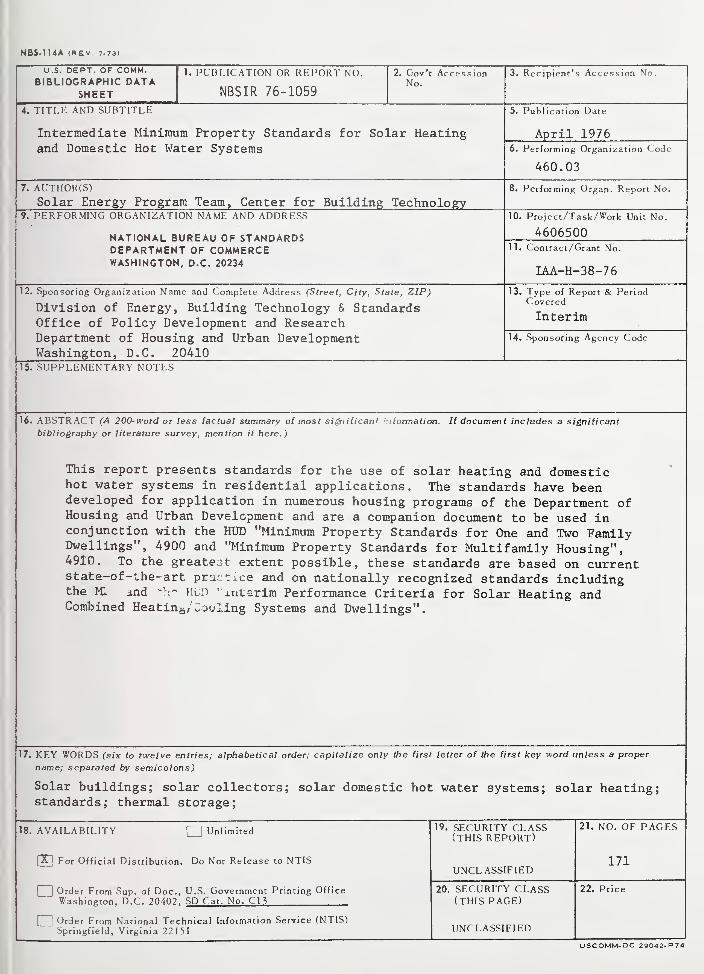
NBS.114A (REV. 7-73)
U.S. DEPT. OF COMM.BIBLIOGRAPHIC DATA
SHEET
1. PUBLICATION OR REPORT NO.
NBSIR 76-1059
2. Gov't AccessionNo.
3. Recipient's Accession No.
4. TITI.r-: AND SUBTITLE
Intermediate Minimum Property Standards for Solar Heatingand Domestic Hot Water Systems
5. Publication Date
April 19766. Performing Organization Code
460.03
7. AUTHOR(S)
Solar Energy Program Team, Center for Building Technology8. Performing Organ. Report No.
9. PERFORMING ORGANIZATION NAME AND ADDRESS
NATIONAL BUREAU OF STANDARDSDEPARTMENT OF COMMERCEWASHINGTON, D.C. 20234
10. Project/Task/Work Unit No.
460650011. Contract/Grant No.
IAA-H-38-76
12. Sponsoring Organization Name and Complete Address (Street, City, State, ZIP)
Division of Energy, Building Technology & StandardsOffice of Policy Development and ResearchDepartment of Housing and Urban DevelopmentWashington, D.C. 20410
13. Type of Report & PeriodCovered
Interim
14. Sponsoring Agency Code
15. SUPPLEMENTARY NOTES
16. ABSTRACT (A 200-word or less factual summary of most significan' :i formation. If document includes a significant
bibliography or literature survey, mention it here.)
This report presents standards for the use of solar heating and domestichot water systems in residential applications. The standards have beendeveloped for application in numerous housing programs of the Department ofHousing and Urban Development and are a companion document to be used inconjunction with the HUD "Minimum Property Standards for One and Two FamilyDwellings", 4900 and "Minimum Property Standards for Multifamily Housing",4910. To the greatest extent possible, these standards are based on currentstate-of-the-art pra: t tce and on nationally recognized standards includingthe Ml and HUD "interim Performance Criteria for Solar Heating andCombined Heating/Cooling Systems and Dwellings".
17. KEY WORDS (six to twelve entries; alphabetical order; capitalize only the first letter of the first key word unless a proper
name; separated by semicolons)
Solar buildings; solar collectors; solar domestic hot water systems; solar heating;standards; thermal storage;
18. AVAILABILITY ||Unlimited
[X] For Official Distribution. Do Not Release to NTIS
1 1Order From Sup. of Doc, U.S. Government Printing Office
Washineton. D.C. 20402. SD Cat. No. C13
1 ! Order From National Technical Information Service (NTIS)Springfield, Virginia 22151
19. SECURITY CLASS(THIS REPORT)
UNCL ASSIFIED
21. NO. OF PAGES
171
20. SECURITY CLASS(THIS PAGE)
UNCLASSIFIED
22. Price
USCOMM-DC 29042-P74

I