Embed Size (px)
Citation preview

NUREG-1544
Status Report: Intergranular Stress Corrosion Cracking of BWR Core Shrouds and Other Internal Components
Manuscript Completed: March 1996 Date Published: March 1996
J. Medoff, NRC Technical Monitor
Division of Engineering Office of Nuclear Reactor Regulation U.S. Nuclear Regulatory Commission Washington, DC 20555-0001
# ̂ "•V
DiSTRBiniON OF T«S DOCUMENT 8- UNUMmE

DISCLAIMER
Portions of this document may be illegible in electronic image products. Images are produced from the best available original document.

ABSTRACT On July 25, 1994, the U.S. Nuclear Regulatory Commission (NRC) issued Generic Letter (GL) 94-03 to obtain information needed to assess compliance with regulatory requirements regarding the structural integrity of core shrouds in domestic boiling water reactors (BWRs).
This report begins with a brief description of the safety significance of intergranular stress corrosion cracking (LGSCC) as it relates to the design and function of BWR core shrouds and other internal components. It then presents a brief history of shroud cracking events both in the U.S. and abroad, followed by an indepth summary of the industry actions to address the issue of IGSCC in BWR core shrouds and other internal components.
This report summarizes the staffs basis for issuing GL 94-03, as well as the staffs assessment of plant-specific responses to GL 94-03. The staff is continually evaluating the licensee inspection programs and the results from examinations of BWR core shrouds and other internal components. This report is representative of submittals to and evaluations by the staff as of September 30, 1995. An update of this report will be issued at a later date.
in NUREG—1544


CONTENTS Page
Abstract iii
List of Figures ix
List of Tables xi
List of Appendices xiii
Executive Summary xv
Acknowledgements xvii
1 Introduction 1-1
2 BWR and Core Shroud Designs 2-1
2.1 BWR and Core Shroud Design Characterstics 2-1
2.2 Construction Materials and Fabrication Methods 2-1
3 Intergranular Stress Corrosion Cracking of BWR Internal Components 3-1
4 BWR Core Shroud Cracking — Systems Evaluation and Safety Assessment 4-1
4.1 Structural Integrity Assessments 4-1
4.2 Safety Significance of 360° Through-Wall Cracks During Normal Operations
and Operational Transients 4-1
4.3 Safety Significance of 360° Through-Wall Cracks During Design Basis Accidents 4-2
5 BWR Core Shroud Cracking — Summary of Significant Operating Experience 5-1
5.1 Cracking at a Foreign BWR 5-1
5.2 Cracking at Brunswick Steam Electric Plant, Unit 1 5-1
5.3 Cracking at Commonwealth Edison Plants 5-1
5.4 Cracking at Oyster Creek Nuclear Generation Station 5-2
5.5 Cracking at Vermont Yankee Nuclear Power Station 5-2
6 Industry Efforts to Address the IGSCC Issue 6-1
6.1 Generic Approach Taken to Address the IGSCC Issue 6-1
6.2 Efforts by the Boiling Water Reactor Owners Group 6-1 v NUREG-1544

Page
6.3 Establishment of the Boiling Water Reactor Vessel and Internals Project 6-1
6.4 Activities of the General Electric Company 6-2
6.5 Activities of the Electric Power Research Institute 6-3
7 GL 94-03, "Intergranular Stress Corrosion Cracking of Core Shrouds in Boiling Water Reactors" ....;... 7-1
7.1 Content of GL 94-03 7-1
7.2 Generic Assessment of the Industry's Responses to GL 94-03 . 7-1
8 Plant-Specific Assessments and Results of Core Shroud Inspections or Repairs 8-1
8.0 Overview 8-1
8.1 Boston Edison Company 8-1
8.1.1 Assessment of the Response to GL 94-03 for the Pilgrim Nuclear Power Station 8-1
8.1.2 Repair of the Pilgrim Core Shroud 8-3
8.2 Carolina Power and Light Company , 8-3
8.2.1 Assessment of the Response to GL 94-03 for Brunswick Unit 1 8-3
8.2.2 Reinspection of the Brunswick Unit 1 Core Shroud 8-3
8.2.3 Assessment of the Response to GL 94-03 for Brunswick Unit 2 8-3
8.3 Commonwealth Edison Category "C" Plants 8-4
8.3.1 Assessment of the Response to GL 94-03 for Dresden Unit 3 and Quad Cities Unit 1 8-4
8.3.2 Assessment of the Response to GL 94-03 for Dresden Unit 2 and Quad Cities Unit 2 8-4
8.3.3 Repairs of the Dresden, Units 2 and 3, and Quad Cities, Units 1 and 2, Core Shrouds 8-5
8.4 General Public Utilities 8-5
8.4.1 Assessment of the Response to GL 94-03 for the Oyster Creek Nuclear Generation Station 8-5
8.4.2 Inspections and Repair of the Oyster Creek Core Shroud 8-6
8.5 Georgia Power Company 8-6
8.5.1 Assessment of the Response to GL 94-03 for Edwin I. Hatch Unit 1 8-6
8.5.2 Repair of the Edwin I. Hatch Unit 1 Core Shroud 8-6
NUREG—1544 vi

Page
8.5.3 Assessment of the Response to GL 94-03 for Edwin I. Hatch Unit 2 8-6
8.5.4 Repair of the Edwin I. Hatch Unit 2 Core Shroud 8-7
8.6 IES Utilities, Inc 8-7
8.6.1 Assessment of the Response to GL 94-03 for the Duane Arnold Energy Center 8-7
8.6.2 Inspection of the Duane Arnold Core Shroud 8-8
8.7 Nebraska Public Power District 8-8
8.7.1 Assessment of the Response to GL 94-03 for the Cooper Nuclear Station .- 8-8
8.7.2 Inspection Scope for the Cooper Core Shroud 8-8
8.8 Niagara Mohawk Power Corporation Category "C" Plants 8-9
8.8.1 Assessment of the Response to GL 94-03 for Nine Mile Point Unit 1 8-9
8.8.2 Repair of the Nine Mile Point Unit 1 Core Shroud 8-9
8.9 Northeast Nuclear Energy Company 8-9
8.9.1 Assessment of the Response to GL 94-03 for the Millstone Unit 1 Core Shroud 8-9
8.9.2 Reinspection Scope for the Millstone Unit 1 Core Shroud 8-10
8.10 Northern States Power Company 8-10
8.10.1 Assessment of the Response to GL 94-03 for the Monticello Nuclear Generation Station .... 8-10
8.10.2 Inspection of the Monticello Core Shroud 8-10
8.11 Philadelphia Electric Company Category "C" Plants 8-11
8.11.1 Assessment of the Response to GL 94-03 for Peach Bottom Atomic Power Station Unit 2 8-11
8.11.2 Inspection of the Peach Bottom Unit 2 Core Shroud 8-11
8.11.3 Assessment of the Response to GL 94-03 for Peach Bottom Atomic Power Station Unit 3 8-12
8.11.4 Reinspection Scope for the Peach Bottom Unit 3 Core Shroud 8-13
8.11.5 Peach Bottom Core Shroud Repair Designs 8-13
8.12Power Authority of the State of New York 8-13
8.12.1 Assessment of the Response to GL 94-03 for the James A. FitzPatrick Nuclear Power Plant 8-13
vii NUREG—1544

Page 8.12.2 Repair of the James A. FitzPatrick Core Shroud 8-14
8.13 Tennessee Valley Authority 8-14
8.13.1 Assessment of the Response to GL 94-03 for Browns Ferry Nuclear Units 1, 2, and 3 8-14
8.13.2 Inspection of the Browns Ferry Unit 1, 2, and 3 Core Shrouds 8-14
8.14 Vermont Yankee Nuclear Power Corporation 8-15
8.14.1 Assessment of the Response to GL 94-03 for the Vermont Yankee Nuclear Power Station 8-15
8.15 Plants with Category "B" Core Shrouds 8-15
8.16 Plants with Category "A" Core Shrouds 8-16
9 IGSCC in Other BWR Internal Components 9-1
9.1 Core Plate and Top Guide Cracking 9-1
9.2 Jet Pump Hold-Down Beams 9-2
9.3 Access Hole Covers 9-3
10 Conclusions and Future Actions 10-1
11 References 11-1
NUREG—1544 viii

LIST OF FIGURES
page Figure 2.1-1 Reactor Vessel Flow Paths in GE BWR-3, BWR-4, BWR-5, and BWR-6 Reactor Designs 2-3
Figure 2.2-1 Structural Configuration Typical of GE BWR-3, BWR-4, BWR-5, and BWR-6 Core Shroud Designs 2-4
Figure 2.2-2 Core Shroud Weld Locations Typical of GE BWR-3, BWR-4, BWR-5, and BWR-6 Core Shroud Designs 2-5
Figure 6.3-1 Typical Modification Design Proposed for Repair of BWR Core Shrouds 6-5
IX NUREG-1544

LIST OF TABLES Page
Table 6.2-1 BWRVIP Susceptibility Rankings and Core Shroud Inspection Recommendations 6-4
xi NUREG—1544


APPENDICES Page
A List of BWROG Members and BWRVIP Subcommittees A-l
B Plant-Specific BWR Core Shroud Summaries B-l
C List of BWR Utilities and Reactors C-l
D Abbreviations and Nomenclature , D-l
E List of Staff Contributors to NUREG—1544 E-l
xiii NUREG-1544

EXECUTIVE SUMMARY
Many internal components of boiling water reactor (BWR) vessels are made of materials susceptible to intergranular stress corrosion cracking (IGSCC), including stainless steel, alloy 600, alloy X750, and alloy 182 weld metal. IGSCC is a time dependent material degradation process, which is known to be caused and accelerated by the presence of crevices, residual stresses, material sensitization, irradiation, cold work, and corrosive environments. As operating BWRs age, the number of cracking incidents is expected to increase. The U.S. Nuclear Regulatory Commission (NRC) staff has been meeting every year since 1988 with the Boiling Water Reactor Owners Group and the General Electric Company, and later with the Boiling Water Reactor Vessel and Internals Project, to review the generic safety implications of reactor internal components that are considered to be susceptible to IGSCC.
In 1990, cracking of the core shroud was visually observed in an overseas BWR. The cracking was located in the heat-affected zone of a circumferential weld in the beitline elevation of the shroud. Cracking of BWR core shrouds reported at U.S. plants in 1993, 1994, and 1995 has been the most significant cracking of BWR internal components. The core shroud is a stainless steel cylinder that separates the feedwater in the reactor vessel's downcomer annulus region from cooling water flowing through the reactor core. The core shroud also performs the important functions of properly directing coolant flow through the core and maintaining the core geometry. For GE BWR—3 and later designs, the core shroud also provides a structural boundary to allow for reflooding of the reactor core to two-thirds core height under postulated accident conditions.
Significant circumferential cracking has been discovered at the Brunswick Unit 1, Dresden Unit 3, Quad Cities Unit 1, Oyster Creek, and Vermont Yankee nuclear stations. In light of the extent of cracking observed at these plants, the staff evaluated potential safety concerns associated with the possibility of a 360° circumferential separation of the shroud following a postulated loss-of-coolant accident (LOCA). The staff considered the potential for separation of the shroud during postulated accidents to either prevent full insertion of the control rods, or open a gap large enough to preclude the emergency core cooling systems from fulfilling their
intended safety functions. The accident scenarios of primary concern are the main steam line break and the recirculation line break. The more serious event associated with cracks in the upper shroud welds (e.g., H2, H3) is the steam line break, since the lifting forces generated may be sufficient to elevate the top guide and potentially cause difficulties with rod insertion. The recirculation line break is the more serious event associated with cracks in the lower elevations of the core shroud. The recirculation line break is a greater concern at lower weld elevations because this type of LOCA has the potential to result in a lateral displacement of the shroud. Such a lateral displacement of the shroud could affect the ability of control room operators to insert control rods into the core and could prevent adequate core cooling.
In consideration of the consequences of a 360° through-wall failure of the shroud coincident with a LOCA, the NRC has conservatively estimated the risk contribution from shroud cracking and determined that it does not pose a high degree of risk at this time. However, the NRC has also determined that structural margins specified in the American Society of Mechanical Engineers Boiler and Pressure Vessel Code could be exceeded if the cracks were sufficiently deep and continued propagating through the shroud during normal operating, transient or accident conditions, possibly resulting in the loss of a layer of the defense-in-depth strategy. Therefore, the staff has concluded that it is appropriate for BWR licensees to implement timely inspections and/or repairs of their core shrouds. To implement this position, the NRC staff issued Generic Letter (GL) 94-03 (July 25, 1994), requesting that BWR licensees inspect their core shrouds by the next refueling outage and justify continued safe operation until inspections can be completed. This position enabled the staff to verify compliance with the inservice inspection requirements of Section 50.55a of Title 10 of the Code of Federal Regulations, and ensured that the risk associated with core shroud cracking remains low.
As of early September 1994, the NRC staff received all of the BWR licensee submittals in response to GL 94-03. The staff has completed its evaluations of the licensee responses and has transmitted the safety evaluation reports to the appropriate BWR licensees. The staff concluded that, for all cases, BWR licensees had
NUREG-1544

provided sufficient justification to operate their facilities until core shroud inspections or repairs could be implemented. The staff based its conclusions on the following factors:
(1) No 360° through-wall core shroud cracking has been observed to date in any U.S. BWR at which the licensee performed a shroud inspection.
(2) All analyses performed by U.S. licensees to date indicate that, even if cracking did exist in a particular BWR core shroud, sufficient ligaments would remain in the shroud so that the structural integrity of the shroud would be ensured for the remainder of the plant's operating cycle.
(3) No U.S. BWR has exhibited any of the symptoms (power-to-flow mismatch) that would be indicative of leakage through a 360° through-wall shroud crack.
(4) Main steam line or recirculation line breaks are both considered to be low frequency events.
(5) There were only short durations until core shroud inspections were to be conducted or repairs were to be implemented by die individual BWR licensees.
To date, core shrouds have been repaired (modified) at the Brunswick Units 1 & 2, Hatch Units 1 & 2, FitzPatrick, Oyster Creek, Quad Cities Units 2,
Nine Mile Point Unit 1, and Pilgrim nuclear plants. Repairs will be made at additional plants if inspection results indicate that large scale cracking of circumferential shroud welds has occurred, or may be made at the discretion of the licensee in lieu of comprehensive core shroud examinations (pre-emptive core shroud modifications). These repairs or modifications are designed to ensure the structural integrity of the core shrouds based on an assumption that the shroud circumferential welds are completely cracked, and are being reviewed by the NRC staff on a case-by-case basis.
In the spring of 1994, the industry formed a new organization, the BWR Vessel and Internals Project (BWRVIP), to address the issue of IGSCC of BWR internal components. The BWRVIP is headed by several high level utility executives to ensure that top executives in the industry are aware of its function, purpose and efforts. The BWRVIP subsequently submitted documents addressing an integrated safety assessment of the issue, guidelines on performing nondestructive examinations (NDE) of core shroud welds, guidelines on inspection scopes for BWR core shrouds, and generic guidelines and acceptance criteria in regard to performing flaw evaluations and repairs of BWR core shrouds. The NRC staff has approved the generic repair criteria document, the latest revision to the BWRVIP guidelines regarding core shroud inspection scopes and flaw evaluations, and the BWRVIP guidelines regarding core shroud NDE methods.
NUREG-1544

ACKNOWLEDGEMENTS
The authors wish to thank the many persons who contributed immeasurably to the work documented in this report and to the quality of the final product. We would like to thank Mr. C.E. Carpenter and Mr. D.S. Brinkman, who were instrumental in coordinating the staff activities with members of the Boiling Water
Reactor Owners Group, the Boiling Water Reactor Vessel and Internals Project, the Electric Power Research Institute, and the General Electric Company. In addition, we would like to thank Ms. J. Beeson of the Technical Editing Staff, and Ms. A.D. Lowery and Ms. J.E. Brooks for proofreading this document.
xvu NUREG-1544

1 INTRODUCTION
In a memorandum dated January 4, 1994, the staff of the U.S. Nuclear Regulatory Commission (NRC) reported to the Commission that intergranular stress corrosion cracking (IGSCC) of the internal components of boiling water reactor (BWR) vessels was emerging as a technical issue (Ref. 1). The core shroud was one of the internal components listed in the memorandum as being susceptible to IGSCC.
On July 25, 1994, the NRC issued Generic Letter (GL) 94-03, "Intergranular Stress Corrosion Cracking of Core Shrouds in Boiling Water Reactors," which requested that BWR licensees inspect their core shrouds at the earliest refueling outage (RFO) for their plants (Ref. 2). Since then, most BWR licensees have inspected or repaired their core shrouds during planned RFOs. These inspections have shown that core shrouds can crack at circumferential weld locations. IGSCC has also been detected in other BWR components, including core spray spargers, feedwater spargers, jet pump hold-down beams, top guides, core support plates, and access hole covers. Nuclear licensees have implemented inspection and repair programs to ensure continued structural integrity of these components.
This report presents background information, current status, and future actions needed to address the issue of IGSCC in BWR internal components. Chapter 2 of this report describes BWR core shroud design characteristics and fabrication materials. Chapter 3 discusses the mechanism of IGSCC in BWR internal components. Chapter 4 presents an assessment of the safety significance of postulated accidents with 360° through-wall cracks. Chapter 5 of this report summarizes significant BWR cracking events in the industry. Chapters 6 and 7 of this report summarize the industry and NRC efforts taken to date to address the IGSCC issue. Chapter 8 summarizes the staffs assessment of the industry's plant-specific responses to GL 94-03. Chapter 9 of this report summarizes cracking events that have occurred in other BWR internals to date. Chapter 10 presents general staff conclusions with regard to the issue of IGSCC in BWR internals and addresses future actions to be taken. Chapter 11 provides a list of references.
This report also includes a number of appendices. Appendix A lists the industry members of the Boiling Water Reactor Owners Group (BWROG) and Boiling Water Reactor Vessel and Internals Project (BWRVIP) Subcommittees. Appendix B presents plant-specific core shroud data sheets summarizing important information provided by the licensees to assist the NRC in its evaluation of core shroud cracking. Appendix C lists the licensees, along with their corresponding BWR units. Appendix D presents a list of acronyms, abbreviations and scientific units used in this report. Appendix £ lists the staff members who have contributed to the staffs assessment of the issue of IGSCC in BWR internal components.
This report is representative of submittals to and evaluations by the staff as of September 30, 1995. An update of this report will be issued at a later date.
1-1 NUREG-1544

2 BWR AND CORE SHROUD DESIGNS
2.1 BWR and Core Shroud Design Characteristics
The core shroud in a BWR is a stainless steel, cylindrical component within the reactor pressure vessel (RPV) that surrounds the reactor core. The core shroud separates feedwater in the reactor vessel's downcomer annulus region from the cooling water flowing up through the reactor core. In addition, the core shroud laterally supports the fuel assemblies to maintain control rod insertion geometry during operational transients and postulated accidents. For GE BWR—3 and later designs, the core shroud also provides a refloodable volume for safe shutdown and cooling of the reactor core during postulated accident conditions.
The General Electric Company (GE) has been the only manufacturer of BWRs in the United States. GE models currently licensed for operation in the U.S. range from BWR-2 reactors with Mark I type containments (drywell-torus type) through BWR-6 reactors with Mark III containments (drywell-Weir wall type). All GE BWR models are equipped with low pressure emergency core cooling systems (ECCS), and some form of automatic depressurization system. ECCS designs for later BWR models (BWR-4, BWR-5 and BWR-6) also include high pressure spray or coolant injection systems.
Some distinct differences set GE BWR-2 reactors apart from later GE BWR designs (BWR-3 through BWR-6). In BWR-2 reactors, the core shroud is vertically supported by a conical core shroud support ring, which is welded to the core shroud at one end and to the reactor vessel wall at the other. In later GE BWR models, the core shrouds are supported by core shroud support legs or cylinders, which are in turn welded to the lower reactor vessel head. Another distinct characteristic of GE BWR-2 reactors is the absence of jet pumps and recirculation loops. As a result, the core in BWR-2 models must be cooled using natural circulation, rather than forced recirculation, the method of core cooling used in later designs.
The absence of jet pumps in BWR-2 reactors also precludes the design from having any direct systematic ties between the lower plenum area and the annulus region of the reactor vessel. This is important from a defense-in-depth standpoint. For BWR-3 and later designs, the presence of jet pumps provides an easy
means of maintaining emergency core cooling during postulated loss-of-coolant accidents (LOCAs), when ECCS actuation is necessary to maintain reactor safety. Recirculation of the emergency coolant back to the annulus region of the vessel, in this case, occurs by way of the jet pump diffusers. The height of the diffusers provides for a two-thirds core height re-flood capability of the reactor core. These designs allow for re-flood of the core in a relatively short time. Figure 2.1-1 depicts the reactor vessel flow paths typical of GE BWR-3, BWR-4, BWR-5 and BWR-6 reactor designs, and illustrates how the reactor water level achieved in these designs during normal operating conditions differs from that achieved during postulated LOCAs.
In contrast, short and long term cooling responses of non-jet pump (BWR-2) plants for large recirculation line breaks rely on core spray, as the vessel will not flood. Recirculation flow enters the reactor vessel from the bottom and the ECCS for large breaks are two redundant, double capacity, core sprays. Therefore, the degree of any resulting cooling deficiency depends on the final condition of the core spray system. Long term cooling is unchanged as containment flooding is unaffected.
2.2 Construction Materials and Fabrication Methods
BWR core shrouds are typically constructed from three shroud shells (the upper, middle and lower shrouds shells), and two support ring structures (the top guide support ring and core support rings). Some designs, such as the core shroud design at the Pilgrim Nuclear Power Station, have an additional support ring structure.
The core shroud shells are typically fabricated from welded, type 304 or 304L stainless steel plates. The ring supports are fabricated from either plates or ring forgings, of type 304 or 304L stainless steel. The carbon content of shroud plates or forgings fabricated from type 304 stainless steel in these shrouds typically ranges from 0.03% to 0.07%. The carbon content of shroud plates or forgings fabricated from 304L stainless steel is typically less than 0.03 %.
Fabrication of BWR core shrouds involves both axial and circumferential welds. Welding of the core shroud shells and ring segments is typically accomplished using
2-1 NUREG—1544

shielded metal arc welding (SMAW), automated submerged arc welding (SAW), automated gas tungsten arc welding (GTAW), automated gas metal arc welding (GMAW), or a combination of these welding techniques. Figure 2.2-1 illustrates the structural configuration that is typical of GE BWR-3, BWR-4, BWR-5 and BWR-6 core shroud designs. Figure 2.2-2 illustrates the locations of circumferential welds that are typical of these designs, although the exact number and numerical notation of the shroud welds may vary from plant to plant. The structural configuration of core shrouds in GE BWR-2 designs is similar to later designs, with the exception that the shroud is supported by a truncated conical support plate.
NUREG-1544 2-2

STEAM DRYERS
FEEDWATER INLET. (TYPICAL OF 6)
CORE SPRAY SPARGER
SHROUD JET PUMP
FUEL ASSEMBLY
CONTROL ROD GUIDE TUBE
CRD HOUSING
L » STEAM OUTLET (TYPICALOF4)
WATER LEVEL NORMAL OPERATION
TOP GUIDE
WATER LEVEL pi REFLOOD I k S a - — RECIRCINLET LJr-P (TYPICALOF10>
/ . 1 "X-» RECIRCULATION I J >—v LoopsucnoN
CORE PLATE
Figure 2.1-1 Reactor Vessel Flow Paths in GE BWR-3, BWR-4, BWR-5, and BWR-6 Reactor Designs
2-3 NUREG-1544

SUPfORT CONFIGURATION VARIES DEMENDMG ON BWR SEMES
Figure 2.2-1 Structural Configuration Typical of GE BWR-3, BWR-4, BWR-5, and BWR-6 Core Shroud Designs
NUREG—1544 2-4

VESSEL
Figure 2.2-2 Core Shroud Weld Locations Typical of GE BWR-3, BWR-4, BWR-5, and BWR-6 Core Shroud Designs
2-5 NUREG-1544

3 INTERGRANULAR STRESS CORROSION CRACKING OF BWR INTERNAL COMPONENTS
Many internal components of a BWR vessel are made of materials that are susceptible to IGSCC, such as stainless steels, alloy 600, alloy X750, and alloy 182 weld metal. Core shrouds are among the BWR internal components that have been shown to be susceptible to IGSCC. IGSCC is a time-dependent material degradation process which is known to be caused and accelerated by the presence of corrosive environments, crevices, residual stresses, material sensitization, cold work, and irradiation.
Industry experience has shown that the portions of the core shrouds most susceptible to IGSCC are commonly associated with shroud base metal located in areas immediately adjacent to the shroud welds. These base metal regions are known as the heat affected zones (HAZs) since they are known to undergo intense thermal cycling during the welding process. This thermal cycling may cause the HAZs to undergo a phenomenon known as "sensitization". During "sensitization" carbon diffuses to the grain boundaries of the HAZ base metal. This carbon precipitates out at the grain boundaries in the form of complex chromium carbides upon cooling of the weld melt. The precipitation of these carbides depletes the chromium in the steel material adjacent to the grain boundaries. Because the presence and distribution of chromium on the surfaces of the material provides corrosion resistance in stainless steels, its depletion increases the potential for the grain boundaries become crack initiation sites.
Sensitization of stainless steels typically occurs when the steels are exposed to temperatures ranging from 1000°F to 1500°F. Temperatures in this range are easily achievable during welding. The degree of sensitization increases with increasing carbon content of the stainless steel materials. By contrast, material resistance to IGSCC can be increased if the carbon content is kept below 0.030%. Therefore, low carbon stainless steels offer greater resistance to sensitization, and are therefore more resistant to initiation of IGSCC.
Welding processes can also increase IGSCC susceptibility by introducing high residual stresses in the stainless steel material located at the weld joint. These stresses result from thermal contraction of the weld
metal during cooling and are tensile in nature. Although weld stresses are not easily quantified, previous investigations indicate that tensile stresses on the weld surface may be as high as the yield stress of the material. The stress decreases to compressive levels in the center of the welded section.
The fabrication process used for the core support and top guide rings can also play an important role in IGSCC susceptibility. Current available inspection data indicate that shrouds fabricated with forged ring segments are more resistant to IGSCC than rings constructed from welded plate sections. The difference in susceptibility relates to differences in the shroud fabrication processes. Most plants have support rings fabricated from arc segments that are cut from rolled plates and welded to form the ring. This process exposes the short transverse direction in the material to the reactor coolant. In this case, elongated grains and stringers in the material are exposed to the reactor coolant environment, thereby increasing the probability for initiation of cracking or crack-like defects. Forged rings are typically not cut in this manner, and therefore do not have the "end grains" exposed to the environment.
The degree of reactor coolant water quality also correlates strongly with the degree of IGSCC susceptibility in BWR internal components. Industry experience has shown that shrouds operated in coolants with high ionic conductivities are more likely to be highly susceptible to IGSCC than shrouds operated in coolants with low ionic conductivities'. Furthermore, industry experience has shown that reactor coolant systems (RCSs) operated at highly positive, electrochemical potentials (ECPs) are more susceptible
1 Conductivity is a measure of the anionic and cationic content of liquids. As a reference, the conductivity of pure water is —0.05 jtS/cm (—0.05 ptmhos/cm). Reactor coolants with conductivities below 0.20 pS/cm (0.20 /tmhos/cm) are considered to be relatively ion free; reactor coolants with conductivities above 0.30 /tS/cm (0.30 /imhos/cm) are considered to have a relatively high ion content.
3-1 NUREG—1544

to IGSCC than RCSs operated at more negative ECPs2. The industry has made a considerable effort to improve water chemistry at nuclear facilities over the past 10 years. Industry initiatives have included introducting hydrogen water chemistry as a means of lowering ECPs (i.e., making the ECPs more negative) in the RCS, and introduction and using improved cleanup resins as a means of improving water purity in the RCS. The effectiveness of hydrogen water chemistry in reducing the susceptibility of core shrouds to IGSCC initiation has not been fully evaluated; however, its effectiveness in reducing IGSCC in recirculation piping has been demonstrated.
2 ECP is a measure of a material's susceptibility to corrosion. In the absence of an externally applied current (as is the case for reactor internal components in the RCS), the ECP is equal to the open circuit potential of the material. Industry experience has shown that crack growth rates in reactor internal components are low when the ECP < —0.230 V.
NUREG-1544 3-2
4 BWR CORE SHROUD CRACKING — SYSTEMS EVALUATION AND SAFETY ASSESSMENT
4.1 Structural Integrity Assessments
To assess the structural integrity of core shroud welds with cracks extending up to 360° in the circumferential direction, an analyst must consider the effects of loading conditions, material properties, and crack geometries on the shroud. The shroud is constructed of stainless steel, which has a high degree of fracture toughness. In fact, the core shrouds were fabricated from 1.5-inch to 2-inch thick plates primarily for stiffness during transport and installation. In addition, the operational and postulated accident loads produce low stress levels in the shroud. Therefore, as previously described, adequate structural integrity for the shroud can be maintained despite extensive cracking.
The core shrouds at most U.S. BWRs were not originally designed in accordance with the design rules of the American Society of Mechanical Engineers (ASME) Boiler and Pressure Vessel Code. However, the reactor internal components have been included in plant inservice inspection programs in accordance with Section 50.55a of Title 10 of the Code of Federal Regulations (10 CFR 50.55a), and are therefore within the scope of Section XI of the ASME Code. In addition, the NRC staff and the BWROG are currently developing a draft Subsection IWG to Section XI of the ASME Code, on requirements for reactor vessel components and internal structures. Subsection IWG will augment Section XI by providing additional details concerning examination, inspection, and acceptance standards for flaws in internal components.
The approaches in the ASME Code address both the linear elastic fracture mechanics of the limiting crack (LEFM analysis) and the potential for gross deformation and subsequent failure of the uncracked material in the vicinity of the crack (limit load or LLA analysis). To date, in reviewing these analyses for licensing purposes, the NRC has required that licensees substantiate the use of the LLA methodology by examining the stress intensification present at the crack tip through finite element modeling.
4.2 Safety Significance of 360° Through-Wall Cracks During Normal Operations and Operation Transients
In order to provide a bounding consequence assessment for the cracking observed to date, the NRC staff postulated complete weld failures at various locations during normal power operation. The intent of this consequence assessment was to demonstrate that fuel geometry and core cooling would be maintained given the unlikely occurrence of a through-wall failure of any horizontal weld, and to identify whether horizontal weld failures would be detectable. In their responses to Generic Letter 94-03, all licensees expected that any 360° through-wall crack would be detected during normal operations.
During normal operations with any horizontal weld sufficiently cracked, some upward displacement of the shroud could occur, depending on the postulated crack location, operating conditions, and plant type. A small amount of lift at the upper shroud weld locations would produce anomalies such as increased coolant temperatures and/or reduced coolant flow. These power anomalies, power/flow mismatch, are detectable during normal operations. After detection of such an anomaly, a normal shutdown is expected to be initiated until the cause of the anomaly is determined and corrected. Analogous results have been experienced at other operating reactors when the shroud head bolts were improperly engaged.
During most limiting operating conditions, 100% power and rated flow, the maximum expected vertical displacement can be postulated based on the pressure differences across the shroud head and the shroud support. Shroud lift above the top of the fuel channels has the potential to affect core geometry and control rod insertion. In most cases, the maximum postulated vertical displacement at H3 and H4 is not sufficient to disengage the top guide from the fuel channels. Shroud lift at H2 does not affect core geometry since H2 is located above the top guide. Some uncertainty remains
4-1 NUREG—1544

as to whether shroud displacement at the lower welds, H5 through H8, would be detectable during normal operations. Postulated shroud displacement, if any, at these locations would be small and would not affect the ability to insert the control rods if necessary.
The consequences of operation during anticipated operational transients with a 360° through-wall crack in the shroud are bounded by the design basis accident analysis in Section 4.3. It is expected that the following anticipated operational transients could increase shroud loads above those experienced during normal operation:
(1) pressure regulator failure - open;
(2) recirculation flow control failure - increasing to maximum flow;
(3) inadvertent actuation of the Automatic Depressurization System (ADS).
For a 360° through-wall crack, these loads could lead to complete weld separation and/or result in higher upward displacements than normal operations. All licensee analyses concluded that during such postulated events, MCPR Safety Limit, Low Water Level, and Reactor Overpressure Limit are not violated.
4.3 Safety Significance of 360° Through-Wall Cracks During Design Basis Accidents
In order to assess the significance of potential cracking beyond that observed to date, the staff has evaluated the safety implications of a postulated 360° circumferential separation of the shroud. The staff has determined that the detectability and consequences of 360° through^wall cracking relate directly to the cracked weld location. The main concern associated with cracks in the upper shroud welds arises during a postulated MSLB concurrent with a 360° through-wall failure of a shroud. During such a postulated accident, the resulting differential pressures are expected to be large enough to vertically displace the remaining upper shroud assembly. These lifting forces potentially could elevate the top guide above the fuel assemblies. The resulting safety concerns would include a loss of lateral support for the fuel assemblies, potential loss of control rod insertion capability, and potential damage to the core spray piping.
The main concern associated with cracks in the lower shroud welds arises during a RLB concurrent with a
postulated 360° through-wall failure of the shroud. The rapid depressurization that is characteristic of this event scenario has the potential to result in loads or moments which could cause a lateral displacement or tipping of the shroud. Such a lateral displacement or tipping of the shroud may affect the ability of plant operators to insert the control rods during the event, and may result in an opening of the shroud that could allow bypass leakage through the shroud and out of the pipe break. Large bypass leakage could potentially affect the ability of the plant operators to reflood the core, maintain adequate core cooling following the pipe break, and shut down the reactor with the standby liquid control system (SLCS).
The NRC has raised additional concerns in regard to the potential for a shroud displacement to damage other vessel internal components during postulated accident conditions. In particular, a vertical shroud displacement has the potential to damage the core shroud support legs as a result of the impact loadings that would occur upon resettling of the core shroud. Displacement of a core shroud also has the potential to damage core spray lines, particularly if the core spray lines have been degraded prior to the event.
The staff has developed a probabilistic safety assessment based on assessments of potential 360° through-wall failures of the circumferential shroud welds in the Dresden Unit 3 and Quad Cities Unit 1 core shrouds. The assessment estimated the potential contribution to core damage frequency resulting from the cracked shrouds. For the upper shroud welds (e.g., the H2 or H3 welds), the staff concluded that any 360° through-wall failure would be expected to be detected during normal operation (e.g., either by power/flow mismatch or noise monitoring). For lower shroud welds (H5 and lower), the staff has concluded that a 360° through-wall shroud failure would have to occur concurrent with a large rupture of either a main steam line or a recirculation line to be capable of achieving the loading magnitudes that could move the shroud. However, it should be noted that probabilistic risk assessments categorize such MSLBs and RLBs to be low frequency events. To date, no MSLB or RLB has ever occurred at an operating nuclear plant, and the unlikely occurrence of a 360° through-wall crack concurrent with a large pipe break would be necessary to pose any incremental risk. Finally, the shroud may not move in the most adverse manner during these events, and there is a good chance that core cooling and reactor shutdown would be achieved with no adverse consequences.
NUREG—1544 4-2

Considering these assessments, the staff concluded that core shroud cracking does not pose a high degree of risk for the short term, and that immediate plant shutdowns were not warranted for inspections. However, the staff concluded that degradation of the core shroud could impact plant safety if plants with degraded shrouds were allowed to continue to operate for extended periods. The staff therefore concluded that 360° cracking of the shroud was a safety concern for the long term based on the following considerations:
(1) the potential for exceeding the ASME Code structural margins if the cracks are sufficiently deep and continue to propagate through the subsequent operating cycle;
(2) the uncertainties associated with the behavior of a 360° through-wall cracked core shroud under accident conditions;
(3) elimination of a layer of defense-in-depth for plant safety.
To date, the majority of BWR industry licensees have conducted inspections, evaluations, and/or repairs of their core shrouds to address the issue of core shroud and BWR internal cracking. Such inspection, evaluation, and repair activities adequately ensure that simultaneous failure of multiple internal components will not result in adverse risk to the general public. Therefore, die staff has concluded that the current status of BWR core shrouds and internal components does not constitute a high degree of risk to the general public at this time.

5 BWR CORE SHROUD CRACKING - SUMMARY OF SIGNIFICANT OPERATING EXPERIENCE
5.1 Cracking at a Foreign BWR
In 1990, the General Electric Company (GE) reported the occurrence of cracking in the core shroud of a foreign BWR. The shroud cracks were located in the HAZ of a circumferential core shroud weld in the reactor's beltline region. The reactor had completed approximately 190 months of power operation before the flaw indications were discovered.
As a result of this discovery, GE issued Rapid Information Communication Services Information Letter (RICSIL) 054, "Core Support Shroud Crack Indications," on October 3, 1990 (Ref. 3), to all owners of GE-designed BWRs. RICSIL 054 summarized the cracking found in the core shroud of the foreign BWR. It also recommended that nuclear utilities owning BWRs with high-carbon steel core shrouds perform a visual examination of the accessible areas of the shroud seam (circumferential) welds and associated HAZs on the inside and outside shroud surfaces.
5.2 Cracking at Brunswick Steam Electric Plant. Unit 1
In early July 1993, the Carolina Power and Light Company (CP&L) performed enhanced visual testing (VT-1) examinations of the core shroud at the Brunswick Steam Electric Plant, Unit 1 (BR-1). CP&L conducted the VT-1 examinations of the core shroud welds on the inside and outside surfaces of the shroud, in accordance with the recommendations of GE RICSIL 054. The results of the VT-1 examinations revealed the presence of numerous flaw indications in the core shroud.
GE issued RICSIL 054, Rev. 1, "Core Shroud Cracks," dated July 21, 1993 (Ref. 4), to inform the industry of the cracking in the BR-1 shroud. In addition, the NRC informed the industry of the BR-1 shroud cracking in Information Notice (IN) 93-79, "Core Shroud Cracking at Beltline Region Welds in Boiling-Water Reactors," dated September 30, 1993 (Ref. 5).
The most extensive flaw indication in the BR-1 shroud was located on the inside shroud surface of the H3 weld. CP&L determined that the crack was located in the HAZ
of the weld. This circumferential weld joins the top guide support ring to the middle shroud shell. Using conservative assumptions, CP&L hypothesized that the crack could extend nearly 360° around the circumference of the weld. Boat samples taken from the H3 weld identified IGSCC as the cracking mechanism, and indicated that the H3 flaws could be more than 0.036 m (1.4 in) deep. The VT-1 examinations also revealed circumferential cracking along significant portions of welds HI and H2 (using conservative assumption, up to 74% and 68% of the weld circumferences, respectively). In addition, CP&L reported minor cracking associated with the HAZs of circumferential welds H4, H5, H6a, and H6b.
GE analyses of the cracks at the HI, H2, and H3 welds indicated that structural margins would still be maintained for the next operating cycle. Nonetheless, CP&L opted to modify the core shroud in order to ensure the structural integrity of the H2 and H3 welds during normal operating, transient and postulated accidental loading conditions. The modification involved installing a series of mechanical clamps around the H2 and H3 welds. These clamps were designed by the General Electric Company (GE) to provide an alternative load bearing capability in lieu of the H2 and H3 welds. The NRC reviewed the clamp design in the Fall of 1993 and accepted the design for implementation on January 14, 1994 (Ref. 6).
5.3 Cracking at Commonwealth Edison Plants
Commonwealth Edison Company (ComEd) reported cracking in the core shrouds of Dresden Unit 3 (DR-3) and Quad Cities Unit 1 (QC-1). ComEd discovered these cracks as a result of shroud examinations conducted during the DR-3 and QC-1 Spring 1994 refueling outages (RFOs). The most extensive cracking at each plant was associated with the H5 weld, which joins the mid-shroud shell to the shroud's core plate support ring. The licensee's examinations included both enhanced VT-1 and ultrasonic testing (UT) methods. Using conservative assumptions, ComEd determined that the cracks could extend nearly 360° around the circumference of the welds.
5-1 NUREG-1544

To inform the industry of the cracking at DR-3 and QC-1, the NRC issued IN 94-42, "Cracking in the Lower Region of the Core Shroud in Boiling-Water Reactors," dated June 7, 1994, and Supplement 1, dated July 19, 1994 (Refs. 7 and 8). Instead of opting to perform an immediate repair of the DR-3 and QC-1 core shrouds, ComEd proposed to operate these plants for an additional 24 months while they designed and fabricated a permanent repair.
To support the conclusion that both of these units could be operated safely, the licensee submitted a safety evaluation demonstrating the DR-3 and QC-1 core shrouds would meet the following safety criteria:
(1) The existing cracks would not propagate through the shroud wall during the next fuel cycle.
(2) The existing uncracked ligaments would continue to provide sufficient structural integrity and to meet the requirements of the ASME Code.
(3) The existing cracks would not compromise the safety function of the shroud under all postulated design-basis accident conditions.
ComEd concluded that the plants could be operated for their full cycles. The NRC reviewed the licensee's flaw evaluations and safety assessments regarding the DR-3 and QC-1 core shrouds. The NRC also performed independent analyses of the DR-3 and QC-1 core shrouds in order to validate the licensee's results and conclusions. The staff based the analyses on a bounding initial crack depth of 0.033 m (1.3 in) and a bounding crack growth rate of 3.5E-10 m/s (5E-5 in/hr). The staff did not allow for additional structural margin credit created by the inner diameter fillet weld at HS. Upon conclusion of the reviews, the staff determined that the ASME Code margins (and thereby, the requirements of 10 CFR 50.55a) would be satisfied for 15 months of hot operation commencing from the time of the DR-3 and QC-1 startups. The staff issued its Safety Evaluation Report (SER) regarding the cracking in the DR-3 and QC-1 core shrouds on July 21, 1994 (Ref. 9).
5.4 Crackiny at Ovster Creek Nuclear Generation Station
General Public Utilities (GPU), the licensee for the Oyster Creek Nuclear Generation Station (OCNGS) inspected the OCNGS core shroud during the Fall 1994
refueling outage. GPU's examinations of the OCNGS core shroud included UT inspections of accessible areas on shroud welds HI, H2, H4, H5, and H6a, and enhanced visual examinations of welds H3, H6b, and H9. The results of the shroud examinations indicated significant cracking at the H4 weld. This weld joins the upper mid-shroud shell to the lower mid-shroud shell, and is in the vicinity of the reactor beltline region. The results of the OCNGS shroud examinations also indicated some minor cracking at the H2 and H3 welds.
After completing the UT examinations of the H4 weld, GPU decided that they would modify the OCNGS core shroud before restarting the unit. GPU submitted its design for the OCNGS core shroud modification on October 25, 1994 (Ref. 10). The OCNGS core shroud modification involved installing a series of tie rod assemblies symmetrically around the shroud. These tie rod assemblies are designed by MPR to restrict vertical and lateral motion of the shroud, assuming that all circumferential welds in the core shroud fail coincident with a design basis event.
The staff issued its SER regarding the OCNGS core shroud modification on Nov. 25, 1994 (Ref. 11). The staff concluded that the shroud modification design selected by GPU provides an acceptable alternative load carrying capability for the OCNGS core shroud. The staff therefore concluded that the modification design was acceptable for implementation.
5.5 Cracking at Vermont Yankee Nuclear Power Station
The Vermont Yankee Nuclear Power Corporation (VYNPC), the licensee for the Vermont Yankee Nuclear Power Plant (VY), has completed NDEs of the VY core shroud and feedwater nozzles. These examinations were scheduled as part of VYNPC's GL 94-03 and NUREG—0619 activities, respectively. Preliminary results of VYNPC's core shroud examinations indicated that a significant degree of cracking ( « 340° — 345° in circumference) existed in VY core shroud weld H5, which joins the lower mid-shroud shell to the core support ring. VYNPC also determined that cracking of a lesser degree was indicated at shroud welds HI, H2, H3, H4, and H6. All feedwater nozzle examinations were negative for relevant indications.
VYNPC's flaw evaluations of indications in the HI, H2, H3, H4, and H6 welds indicated that the welds have sufficient structural margins for at least two additional
NUREG-1544 5-2

operating cycles. In evaluating these welds, VYNPC conservatively assumed that all relevant indications were through-wall cracks.
VYNPC's flaw evaluation of the H5 weld indicated that the H5 weld has sufficient structural margin to justify one more cycle of plant operation. In evaluating the H5 weld, VYNPC conservatively assumed that all uncracked areas and all areas with indications less than 0.013 m (0.5 in) deep contained cracks 0.013 m (0.5 in) in depth. VYNPC also conservatively assumed that areas not inspected contained continuous through-wall cracks, and that any relevant indications with crack depths greater than 0.013 m (0.5 in) were also through-wall in nature. The flaw evaluations also included conservative allowances for crack growth and NDE uncertainties. VYNPC submitted the results of its inspections and evaluations for review by the staff on April 20, 1995 (Ref. 12). VYNPC's submittals included a consequence analysis (safety analysis) of the VY core shroud.
The staff reviewed VYNPC's examination results, flaw evaluations and consequence analyses regarding the VY core shroud. The staff determined that the VY core shroud has sufficient remaining structural margins to justify one additional cycle of operation. The staff issued its SER regarding the structural integrity of the VY core shroud on April 27, 1995 (Ref. 13).


6 INDUSTRY EFFORTS TO ADDRESS THE IGSCC ISSUE
6.1 Generic Approach Taken to Resolve the IGSCC Issue
IGSCC in BWR internal components is a long-term problem. As BWRs begin to age, the number of IGSCC incidents in BWR internal components is expected to increase. For this reason, the NRC has encouraged the BWR industry to take a conservative, long-term approach to resolve the issue of IGSCC in BWR internal components. The approach involves the following steps:
(1) direct interaction between the NRC and the industry organizations, namely the Boiling Water Reactor Owners Group (BWROG) and the Boiling Water Reactor Vessels and Internals Project (BWRVIP)
(2) NRC assessment of generic guidelines established by the BWR industry organizations
(3) NRC assessment of plant specific actions on an individual basis
The important aspect of this approach is that it is proactive rather than reactive, since it encourages the industry to develop and implement appropriate inspections programs along with predetermined acceptance criteria and repair methods. Effective inspection programs will enable licensees to detect cracking before it becomes a safety concern, and predetermined acceptance criteria and repair methods will ensure optimal use of industry and NRC resources.
6.2 Efforts by the Boiling Water Reactor Owners Group
The BWROG submitted its criteria for evaluating BWR core shrouds in a letter to the NRC dated April 5, 1994 (Ref. 14). The inspection strategy detailed in the BWROG report focuses on a ranking system that bases a plant's IGSCC susceptibility according to its age, construction materials, and reactor coolant conductivity level. The BWROG then updated and refined its susceptibility rankings, which were forwarded to the NRC in a submittal dated July 13, 1994 (Ref. 15). In this submittal, the BWROG, in conjunction with GE, provided an evaluation of core shroud cracking observed in domestic BWRs that had previously been inspected.
The plants that have experienced the most extensive cracking have been operated for longer than 8 years and had histories of moderate to high coolant conductivities when averaged over the first 5 cycles of operation.
The BWROG evaluation indicated that the structural margins for the plants with the most susceptible core shrouds would be maintained for at least one additional cycle of operation at current conductivity levels. The BWROG concluded that it was unlikely that any development of cracking would fail to satisfy the safety margins specified in Section XI of the ASME Code. However, because of uncertainties in the assumptions used in the safety evaluation, such an occurrence could not be ruled out. The NRC issued GL 94-03, in part, "to ascertain the likelyhoodof such an occurrence and to take appropriate corrective action(s)" as necessary. Both the BWROG and individual licensees have indicated that repairs would be implemented for cases in which it is uncertain that ASME Code margins could be met.
Revision 1 of the BWROG's submittal dated July 13, 1994, was received on August 5, 1994 (Ref. 16), along with a response (Ref. 17) to a request for additional information (RAI) that the NRC forwarded to the BWROG on May 12, 1994 (Ref. 18). The BWROG's submittal of August 5, 1994, categorized BWR core shrouds into seven IGSCC susceptibility groups for ranking purposes. These susceptibility rankings were established to aid the individual BWR utilities in their efforts to address the criteria established in GL 94-03.
6.3 Establishment of the Boiling Water Reactor Vessel and Internals Project
In a meeting on June 28, 1994, the BWROG informed the staff that a new industry organization, the Boiling Water Reactor Vessel and Internals Project (BWRVIP) had been established solely to address the issue of age-related degradation of BWR internal components. The BWRVIP comprises five subcommittees: (1) Integration, (2) Inspection, (3) Assessment, (4) Mitigation, and (5) Repair. Each subcommittee is chaired by both a top executive from one of the BWROG member utilities and a engineering staff member from the industry. This organization is designed to ensure that the BWRVIP's
6-1 NUREG—1544

efforts are reviewed on both the technical and executive levels, and to encourage widespread industry acceptance of BWRVIP guidelines, criteria, and methods. To date, individual BWROG members have shown widespread support for the BWRVIP's efforts and activities.
On September 2, 1994, the BWRVIP submitted the "BWR Core Shroud Inspection and Evaluation Guidelines" to the NRC (Ref. 19). These guidelines supplemented and superseded the information regarding core shroud inspection scopes and flaw evaluations contained in the BWROG generic safety assessment of August 5, 1994. In summary, the "BWR Core Shroud Inspection and Evaluation Guidelines" reduced the number of susceptibility categories from seven to three. The factors considered in forming the categories included hot operating time (until next refueling outage), mean reactor coolant conductivity values when averaged over the first five operating cycles, carbon contents of the core shroud construction materials (Type 304 stainless steel vs. Type 304L stainless steel), and methods of fabrication. All operating BWR plants were then grouped into one of three categories ("A," "B," or "C") based on the potential of their internal components to develop IGSCC and on previous field inspection experience. Categories "A," "B," and "C" are described in more depth in Table 6.2-1. Plant-specific data regarding the BWRVIP rankings are provided in Appendix B of mis report. However, it should be noted that plant categorizations may change as plants accrue operating time.
The BWRVIP "BWR Core Shroud Inspection and Evaluation Guidelines" also recommended inspection schedules and scopes based on the susceptibility rankings of the plants. The BWRVIP inspection guidelines provided licensees with Category "A" plants the option of postponing core shroud inspections until eight cumulative years at power had elapsed at their facilities. The BWRVIP recommended that licensees with Category "B" plants perform limited VT-1 or UT inspections of their core shrouds at the next plant refueling outage. For licensees with Category "C" plants, the BWRVIP recommended VT-1 or UT inspections of welds HI through H7 (through HS for BWR-2 plants) at the next refueling outage.
The BWRVIP did not initially recommend 100% inspection of all accessible circumferential weld areas. Instead, the BWRVIP initially stated that weld coverages only had to be comprehensive to the extent they proved the existance of sufficiently long, unflawed ligaments
which would ensure each weld's integrity during power operation (Ref. 19). The staff informed the BWRVIP that this "minimum ligament inspection scope" was too narrow to give an accurate indication of cracking in a core shroud (Refs. 20 and 21). In Revision 1 to the "BWR Core Shroud Inspection and Evaluation Guidelines," dated April 21, 1995 (Ref. 22), the BWRVIP amended its earlier recommendations by recommending that inspection scope for Category "C" core shrouds cover 100% of the accessible areas of circumferential welds HI—H7 (through H8 for BWR-2 designs). The staff concluded that the BWRVIP's alternate inspection scope recommendation for Category "C" shrouds was acceptable (Ref. 23). The NRC issued its SERs regarding the "BWR Core Shroud Inspection and Evaluation Guidelines, " Revision 0 and Revision 1, on December 28, 1994, and June 16, 1995, respectively. (Refs. 21 and 23).
The BWRVIP has committed to submit additional correspondence regarding BWR core shroud and internal components in the future. The proposed submittals will provide an integrated safety assessment of the issue, re-inspection scopes and acceptance criteria, and mitigation measures, as well as changes to the core shroud repair criteria. A submittal from the BWRVIP Repair Technical Subcommittee regarding repair options was received by the staff on August 18, 1994 (Ref. 24). This submittal provided information regarding suggested criteria for the evaluation of licensee repair options. The staff issued its evaluation of the BWRVIP repair design criteria on September 29, 1994 (Ref. 25). Figure 6.3-1 provides an example of a typical core shroud modification (repair) design that has been submitted to the staff for review. The staff will continue to review core shroud modification design submittals on a case-by-case basis.
6.4 Activities of the General Electric Company
GE initially reported the cracking found at KKM in RICSIL 054. On October 4, 1993, GE issued Services Information Letter (SIL) 0572, Rev. 1 (Ref. 26), to incorporate domestic data on shroud cracking, and to update recommendations for inspecting BWR core shrouds.
In SIL 0572, Rev. 1, GE recommended that BWR licensees perform visual or ultrasonic inspections of their core shrouds for a statistically significant sample size of accessible welds and associated HAZs. GE also
NUREG-1544

recommended that the inspections be performed after six effective full-power years (EFPY) if the shroud is fabricated from normal carbon content austenitic stainless steel (0.03% to 0.08% C), or after 8 EFPY if the shroud is fabricated from austenitic stainless steel of a low carbon content ( < 0.03% C). GE also recommended that licensees reinspect the shrouds at every refueling outage if cracking was observed, or every two outages if cracking was not observed. No guidance was given concerning structural integrity or repair.
notches and realistic IGSCC defects . Qualification of UT techniques is normally conducted at the EPRI NDE Center in Charlotte, North Carolina. EPRI is also currently investigating whether or not eddy current testing (ET) is an appropriate NDE method for BWR internal components. However, the NRC has not yet accepted ET for use on BWR internal components.
Metallurgical aspects of cracks in core shrouds fabricated from Type 304L stainless steels were also discussed in GE RICSIL 068, Rev. 1, dated April 14, 1994 (Ref. 27). On May 6, 1994, GE issued RICSIL 068, Rev. 2 (Ref. 28) to supplement RICSIL 068, Rev. 1, and to update the lessons learned from core shroud visual and ultrasonic examination data of low-carbon "L"-grade stainless steel core shrouds. In RICSIL 068, Rev. 2, GE also provided cautions about the adequacy of visual examination procedures, and discussed whether ultrasonic examination methods are preferable to visual examination methods under certain circumstances.
6.5 Activities of the Electric Power Research Institute
Because core shroud examinations involve a complex, detailed set of activities, they must be planned well in advance in order to be effective. A licensee must first determine which core shroud welds must be included in the inspection scope to provide for a sufficient assessment of the core shroud, and then must determine which NDE methods are best suited for these examinations. Core shroud NDEs normally involve manipulation of complex instruments by utility NDE and engineering staff members.
The BWR industry has contracted with the Electric Power Research Institute (EPRI) to assist industry licensees in implementing NDE examinations of their BWR core shrouds and other internal components. EPRI's efforts have included the design of a series of core shroud mockups, that can be used to qualify the UT scanning equipment. These mockups are designed to contain electrodischarge machined (EDM) notches of known length and depth, and realistic IGSCC defects. Qualification of the UT examination techniques can then be accomplished by comparing the results of UT analyses to the known lengths and depths of the EDM
6-3 NUREG—1544

Table 6.2-1 BWRVIP Susceptibility Rankings and Core Shroud Inspection Recommendations'
CATEGORY INSPECTION RECOMMENDATIONS
PLANT CHARACTERISTICS PLANTS
"A" No inspection necessary at
this time.
Plants with 304 SS shrouds, < 6 years hot operating time, and avg. conductivities ^ 0.030 jiS/cm (0.030 ^mhos/cm) during the first five cycles of operation.
None "A" No inspection necessary at
this time.
Plants with 304L SS shrouds, < 8 years hot operating time, and avg. conductivities < 0.030 pS/cm (0.030 fimhos/cm) during the first five cycles of operation.
Clinton, Fermi 2, Perry, Hope Creek, Limerick 2, Nine Mile Point 2, Washington Nuclear Plant 2, River Bend
"B" Limited inspection: top guide support ring, core support ring, and
mid shroud shell circumferential welds;
also the bimetallic weld if accessible.
Plants with 304L SS shrouds, > 8 years hot operating time, and avg. conductivities ^ 0.030 fiS/cm (0.030 /tmhos/cm) during the first five cycles of operation.
Grand Gulf, Lasalle 1 & 2, Limerick 1, Susquehanna 1 & 2
"C" Comprehensive Inspection: circumferential shroud
welds HI - H7 (and H8 for BWR-2s)
Plants with 304 SS shrouds and > 6 years hot operating time, regardless of conductivity.
Shrouds — weld, plate rings "C" Comprehensive Inspection: circumferential shroud
welds HI - H7 (and H8 for BWR-2s)
Plants with 304 SS shrouds and > 6 years hot operating time, regardless of conductivity.
Brunswick 1 & 2, Dresden 2 & 3, FitzPatrick, Hatch 1, Millstone 1, Oyster Creek, Nine Mile Point 1, Pilgrim, Quad Cities 1 & 2
"C" Comprehensive Inspection: circumferential shroud
welds HI - H7 (and H8 for BWR-2s)
Plants with 304 SS shrouds and > 6 years hot operating time, regardless of conductivity.
Shrouds — forged rings
"C" Comprehensive Inspection: circumferential shroud
welds HI - H7 (and H8 for BWR-2s)
Plants with 304 SS shrouds and > 6 years hot operating time, regardless of conductivity.
Browns Ferry 1, 2, & 3, Peach Bottom 2 & 3, Vermont Yankee, Monticello, Cooper
"C" Comprehensive Inspection: circumferential shroud
welds HI - H7 (and H8 for BWR-2s)
Plants with 304L SS shrouds, > 8 years hot operating time, and avg. conductivities > 0.030 /*S/cm (0.030 /tmhos/cm) during the first five cycles of operation.
Duane Arnold, Hatch 2
NOTES: 1. Modiiied from Table 3.1, "BWR Core Shroud Inspection and Evaluation Guidelines." (Ref. 19)
ABBREVIATIONS: 304 SS — Type 304 Stainless Steel (Normal Carbon Content) 304L SS — Type 304L Stainless Steel (Low Carbon Content) j(S/cm — Unit of conductivity in microSiemens per centimeter
NUREG-1544 6-4

**&£££££"* NUREG-1544
6-5


7 GL 94-03, "INTERGRANULAR STRESS CORROSION CRACKING
OF CORE SHROUDS IN BOILING WATER REACTORS"
7.1 Content of GL 94-03
On July 25, 1994, the NRC issued GL 94-03, "Intergranular Stress Corrosion Cracking of Core Shrouds in Boiling Water Reactors," to all BWR licensees (with the exception of Big Rock Point, which does not have a core shroud). The NRC staff requested in GL 94-03 that licensee's take the following actions with respect to their core shrouds:
(1) Inspect BWR core shrouds no later than the plant's next refueling outage.
(2) Perform materials related and plant-specific safety analyses with respect to the core shrouds.
(3) Develop core shroud inspection plans, which address inspection of all core shroud welds and take into account the latest available technology developed by the industry for inspection of BWR internal components.
(4) Develop plans for core shroud evaluation and/or repair.
The staff also recommended in GL 94-03 that licensees work closely with the BWROG to address the issue of IGSCC of BWR internal components.
The NRC staff requested that licensees submit, under oath or affirmation, the following information in response to GL 94-03 within 30 days from the date of issuance:
(1) a core shroud inspection schedule
(2) a safety analysis supporting continued operation of the facility until inspections are conducted
(3) one or more drawings of the core shroud configurations
(4) a history of core shroud inspections completed to date
The NRC staff also requested that licensee's submit, under oath and affirmation, no later than 3 months before inspecting or repairing of their core shrouds, the scope of the planned core shroud inspections and their plans for evaluating and/or repairing their core shrouds based on inspection results. The NRC staff further requested that licensee's submit, under oath or affirmation, their core shroud inspection results within 30 days of completing their shroud examinations.
7.2 Generic Assessment of the Industry's Responses to GL 94-03
The NRC's reviews covered the following items in the plant-specific responses to GL 94-03:
(1) schedules for inspection or repair of BWR core shrouds
(2) safety assessments based on postulated core shroud failures
(3) scopes of BWR core shroud inspections
(4) plant-specific inspection results
(5) core shroud flaw evaluations, as appropriate
(6) core shroud repairs, as appropriate
To facilitate its reviews, the NRC grouped the industry core shrouds according to their relative susceptibility to IGSCC, as ranked by the BWRVIP Technical Subcommittee on Inspection. (The BWRVIP rankings have been discussed in more depth in Section 6.3 of this report.) The NRC men issued safety evaluation reports (SERs) for all BWRs in the industry, with the exception of Big Rock Point, which does not have a core shroud.
In order to simplify its task of determining whether or not individual BWR licensees could justify operation of their units to the respective RFOs, the NRC performed a generic assessment of the results of core shroud inspections conducted before July 1995. The staff
7-1 NUREG—1544

determined that no cases of 360° through-wall cracks occurred in any core shroud inspected before July 1995, and no BWR had exhibited any symptoms (power-to-flow mismatch) that would be indicative of bypass leakage from a 360° through-wall crack. Furthermore, the staff determined that, in all cases, sufficient ligaments remained in the core shrouds to provide a reasonable assurance that the structural integrity of the shrouds would be maintained during the current plant operating cycles. The staff also determined that, in all cases, the frequency of an initiating event which could challenge the structural integrity of a core shroud was low. In addition, the staff noted that only a short time remained before the scheduled RFOs when the licensees would inspect or repair their respective core shrouds. The NRC therefore concluded that, in all cases, the licensees provided sufficient technical bases to justify operation of their units to their next respective RFOs.
NUREG—1544 7-2

8 PLANT-SPECIFIC ASSESSMENTS AND RESULTS OF CORE SHROUD INSPECTIONS OR REPAIRS
8.0 Overview
This chapter provides the staffs assessments regarding the plant-specific responses to GL 94-03 and a discussion of the industry's inspection and repair activities to date. Appendix B augments this discussion by summarizing the plant-specific core shroud data, and providing an overview of pertinent information requested from licensees, concerning core shroud materials, operation, and fabrication. The NRC found this information essential to its assessments of the susceptibility of industry core shrouds to IGSCC. The plant-specific core shroud summaries also include discussions of the plant-specific inspections and repairs performed by the industry through the end of September 1995, and a list of the corresponding SERs and acknowledgement letters issued by the NRC in response to the industry's submittals to GL 94-03.
8.1 Boston Edison Company
8.1.1 Assessment of the Response to GL 94-03 for the Pilgrim Nuclear Power Station
Boston Edison Company (BECo), the licensee for the Pilgrim Nuclear Power Station (PNPS), responded to GL 94-03 on August 27, 1994 (Ref. 29). The licensee's response included a schedule for inspection of the PNPS core shroud and a safety assessment to support continued operation of PNPS until the April 1995 RFO. In a public meeting on October 4, 1994, and in submittals dated October 13, 1994 (Ref. 30), and October 28, 1994 (Ref. 31), BECo provided additional information to support its justification for continued operation (JCO) of PNPS until the April 1995 RFO.
BECo reviewed the plant-specific susceptibility factors regarding the PNPS core shroud. In submitting its findings to the staff in its plant-specific response to GL 94-03, BECo informed the NRC that the PNPS core shroud was fabricated from type 304 plate materials with carbon content typically in the range of 0.040—0.065 %. BECo also stated that PNPS had operated in excess of 15 years, and that average reactor coolant conductivity over the first five years of operation was in excess of 0.300 /iS/cm. BECo therefore concluded that the PNPS
core shroud was highly susceptible to IGSCC. In considering the plant-specific susceptibility factors for PNPS, as well as the industry-wide inspection experience and the uncertainties in the residual stress profile for the PNPS shroud, the staff concurred with BECo's susceptibility assessment of the PNPS core shroud. The staff therefore concluded that significant cracking in the PNPS core shroud could not be ruled out.
BECO performed a preliminary plant-specific flaw evaluation of the PNPS core shroud as part of its JCO. The results of the flaw evaluation showed that only a 5 % remaining ligament of the PNPS shroud wall was needed to maintain the structural integrity of the core shroud under all design conditions. This evaluation was based on a limit load analysis (LLA) of the PNPS core shroud. BECo also used the GE PLEDGE model to calculate a hypothetical crack growth rate for any postulated crack in the PNPS core shroud during the remaining time in the PNPS 1994—1995 operating cycle. However, since the initial flaw size was not known, BECo used the results of the BWROG's generic crack growth analysis as a bounding analysis for the PNPS core shroud.
The BWROG's generic crack growth analysis was benchmarked using the worst crack depth measurements associated with shroud inspections performed at Brunswick Steam Electric Plant, Unit 1 (BR-1). The results of the analysis predicted that the structural integrity of the shroud wall would be maintained even with a postulated 360° crack extending up to a depth of 80% of the shroud wall thickness. In addition, since hydrogen water chemistry was implemented at PNPS, BECo assumed that postulated cracks in the shroud would grow less than 2.54 x 10~* m (0.01 inch) during the remainder of the 1994—1995 operating cycle, even if a factor of 10 was applied to account for the uncertainties in the growth rate. BECo therefore concluded that a sufficient structural margin would be maintained in the PNPS shroud to justify operation of PNPS until the April 1995 RFO.
BECO also performed a plant-specific safety assessment of the PNPS core shroud. BECo's intent was to demonstrate that fuel geometry and core cooling would be maintained given the occurrence of a through-wall
8-1 NUREG—1544

circumferential weld failure concurrent with postulated main steam line break (MSLB) or recirculation line break (RLB) conditions. BECo also performed the safety assessment to determine whether any circumferential weld failures would be detectable by control room operators during normal operations.
BECo used the GE TRAC-G Model as the basic model for determining the differential pressures across the shroud head and shroud support during MSLB or RLB conditions. BECo concluded that any leakage through a weld separation of 0.05 or more meters (two or more inches) would be detectable during normal operations. BECo also stated that the ability to maintain reactivity control, fuel geometry, core cooling, and a refloodable volume was ensured with substantial margin, even though degraded performance was assumed in the design-basis event evaluations. On the basis of this assessment, BECo concluded that core shroud separation and/or displacement occurring during normal operations or anticipated events would have no effect on the primary safety functions of reactivity control and core cooling, which are required to mitigate design basis events.
The NRC staff used the results of the safety margin analyses of the BR-1 core shroud as its basis for evaluating the BECo safety assessment. The staff considered the BR-1 core shroud to be as susceptible to IGSCC as the shroud at PNPS. Although significant shroud cracking was identified at BR-1, the NRC staff determined that all welds had sufficient remaining ligaments to ensure adequate structural integrity of the shroud during normal operating, transient, and postulated design-basis accident conditions. The staff therefore concluded that any postulated IGSCC in the PNPS core shroud should be bounded by that detected at other BWRs of similar design. Therefore, considering that only a small remaining ligament is necessary to ensure core shroud structural integrity, and considering industry experience regarding shroud cracking, the staff concluded that the PNPS core shroud should have sufficient remaining ligament for the remainder of the operating cycle leading to the PNPS RFO in April 1995.
The NRC also performed a qualitative assessment of BECo's consequence assessment for the PNPS shroud. The staff found BECo's submittal to be a relatively complete assessment behavior expected from the PNPS
core shroud in response to a postulated MSLB, RLB (including acoustic and blowdown loads), MSLB plus seismic event, and RLB plus seismic event, given a postulated through-wall failure of one of the shroud's circumferential welds. During postulated MSLB conditions, BECo's calculations demonstrated that the top guide would not lift above the fuel, indicating that no lateral movement of the fuel would occur. The NRC staff concluded that this was reasonable; however, because of inherent uncertainties in BECo's analysis methods, the staff concluded that there was a small likelihood that the top guide would lift above the fuel assemblies during a postulated MSLB concurrent with a failure of one of the upper circumferential welds. Even if this were to occur, however, the staff concluded that safe shutdown of the reactor would be achieved by manual initiation of the standby liquid control system (SLCS).
For postulated through-wall failures of circumferential shroud welds, the other initiating event of concern would be the RLB. BECo's calculations indicated that, during a postulated failure of a lower circumferential weld concurrent with an RLB, the resulting blowdown forces would induce a momentary tipping of the shroud, but no permanent lateral movement. For such shroud response, the staff agreed that little core/annulus bypass would occur during the RLB, and that adequate core flooding would be maintained during the event. Modeling the behavior of shroud with a through-wall crack in response to a postulated RLB is quite complex. Such modeling involves making assumptions regarding crack surface frictional forces and competing forces in the vertical and lateral directions. The staff therefore concluded that lateral motion of the shroud following an RLB could not be precluded.
The staff concluded that a lateral displacement of the shroud less than the magnitude of the shroud thickness would result only in small bypass leakages. However, the staff also concluded that any large lateral movement of the PNPS shroud had the potential to open a significant leakage path through the shroud wall. In this case, the staff reached the following determinations:
(1) No 360° through-wall core shroud cracking had been observed to date in any U.S. BWR that had performed a shroud inspection.
NUREG-1544 8-2

(2) All analyses performed by the licensee for PNPS showed that even if cracking did exist in its shroud, sufficient ligaments would remain in the shroud to ensure its structural integrity during normal operating conditions, operational transients, and postulated design basis events.
(3) PNPS had not exhibited any of the symptoms (power-to-flow mismatch) caused by leakage through a 360° through-wall shroud crack.
(4) MSLB and RLB are low frequency events.
(5) Only a short time remained until a repair would be implemented at PNPS.
In addition, the staff noted that BECo replaced recirculation line piping, and operates the PNPS RCS with hydrogen water chemistry. These practices substantially lower the frequency of an RLB and somewhat mitigate the potential for IGSCC to occur in the core shroud. Therefore, based on these determinations, and the operational availability of the SLCS, the staff concluded that there was no undue risk to the public health and safety for the approximate four month period remaining in the PNPS 1994—1995 operating cycle, and that PNPS could safely continue to be operated until the April 1995 RFO. The NRC issued its SER regarding BECo's response to GL 94-03 on November 28, 1994 (Ref. 32)
8.1.2 Repair of the Pilgrim Core Shroud
BECo opted to install a pre-emptive repair (modification) of the PNPS core shroud during the April 1995 RFO. BECo's core shroud modification design was submitted to the NRC for review on January 16, 1995 (Ref. 33), and was later supplemented with additional information on February 24, 1995, March 14, 1995, and April 17, 1995 (Refs. 34—36). The NRC reviewed BECo's core shroud modification design, accepted the design in April of 1995, and issued its SER regarding the Pilgrim core shroud modification on May 12, 1995 (Ref. 37).
8.2. Carolina Power and Light Company
8.2.1 Assessment of the Response to GL 94-03 for Brunswick Unit 1
The Carolina Power and Light Company (CP&L), the licensee for the Brunswick Steam Electric Plant, Unit 1
(BR-1), responded to GL 94-03 on August 24, 1994 (Ref. 38). The licensee's response included CP&L's justification for continued operation (JCO) of the BR-1 reactor until RFO B110R1, which was scheduled to commence in March 1995.
CP&L response also included the licensee's review of the materials, fabrication, and operational histories of the BR-1 core shroud. CP&L originally inspected the BR-1 core shroud during RFO B109R1 in the summer of 1993, and submitted its inspection results and flaw evaluations to the staff in November 1993. The licensee's submittal indicated that CP&L performed UT inspections on accessible areas of welds HI—H6b. CP&L also performed VT-1 inspections on the accessible areas of welds H7, H8, and H9. (Section 5.2 summarizes the results of examinations performed on the BR-1 core shroud during the Summer 1993 RFO. Of particular note was the report of a 360° crack at the H3 weld.)
CP&L implemented a permanent repair of welds H2 and H3 in the BR-1 core shroud to ensure the structural integrity of the H2 and H3 welds during subsequent operating cycles. This repair design, which involved installing a series of clamps encompassing the H2 and H3 welds, was submitted to the staff in November 1993. On January 14, 1994, the staff issued a safety evaluation (Ref. 6), concluding that the structural integrity of the BR-1 core shroud would be maintained for the remainder of operating cycle leading to RFO B110R1 (Spring 1995).
8.2.2 Reinspection of the Brunswick Unit 1 Core Shroud
During RFO B110R1, CP&L reinspected the BR-1 core shroud to determine how much additional cracking of the BR-1 core shroud occurred during the plant's 10th operating cycle. On April 28, 1995, CP&L submitted the results of the RFO B110R1 shroud examinations (Ref. 39). The staff will issue its SER regarding the reinspections of the BR-1 core shroud after finalizing its review of the BWR VIP's generic guidance regarding core shroud reinspections.
8.2.3 Assessment of the Response to GL 94-03 for Brunswick Unit 2
CP&L, the licensee for the Brunswick Steam Electric Plant, Unit 2 (BR-2), responded to GL 94-03 on August 24, 1994 (Ref. 38). This response included
NUREG—1544

CP&L's justification for continued operation of BR-2 until RFO B212R1, as well as CP&L's review of materials, fabrication, and operational histories of the BR-2 core shroud. The staff assessed the materials, fabrication, and operational histories of the BR-2 core shroud and found them to be similar to those of BR-1. The NRC staff therefore concurred with CP&L's assessment that the BR-2 core shroud is highly susceptible to IGSCC.
CP&L originally inspected the BR-2 core shroud during RFO B211R1 in the Spring of 1994. CP&L did not include the H3 weld in its inspection scope during the outage. Instead, CP&L implemented a permanent repair of shroud welds H2 and H3 in the same manner used at BR-1 during RFO B109R1. CP&L also performed a 40-to 50-percent inspection of the H2 weld before the repair to confirm some indications at H2 that were recorded during an earlier maintenance outage. Other inspections of the BR-2 shroud included (a) visual inspection (VT-1) of 18 percent of the HI weld, (b) ultrasonic testing (UT) of 78 percent of the H4 weld from the outside diameter (OD) of the shroud, (c) VT-1 of 93 percent of weld H5 from the inner diameter (ID) and 30 percent from the OD, and (d) VT-1 of 11 percent of welds H6a, H6b, and H7 from the OD (all percentages relative to the total circumferential length of the welds). CP&L did not inspect welds H8 and H9 based on the acceptable results of the VT-1 examinations of the corresponding welds in the BR-1 core shroud.
The BR-2 core shroud inspection results identified 23 circumferential indications at weld H4, seven circumferential indications at weld H5, and one circumferential indication at weld H6a. The longest indications were 0.35 m (13.6 in) in length at weld H4, 0.30 m (11 in) in length at weld H5, and 0.038 m (1.5 in) in length at weld H6a. These inspection results confirm that the BR-2 core shroud is highly susceptible to IGSCC.
CP&L's previous inspections of the BR-2 core shroud were not as comprehensive as the inspections of the BR-1 shroud in 1993. However, the BR-2 core shroud inspections were performed before the issuance of GL 94-03. The inspection scope was sufficient to assess the current status of the BR-2 core shroud with regard to the presence of IGSCC. Although the BR-2 core shroud is considered highly susceptible to IGSCC, CP&L had gathered considerable inspection data regarding the current condition of the core shroud. The licensee completed evaluations of the flaws in the H4, H5, and
H6a welds, and included these flaw evaluations in its response to GL 94-03. The evaluations of these shroud welds indicated that the shroud would meet structural margins for all circumferential welds for the remainder of operating cycle No. 12. The NRC staff concluded that CP&L's previous inspection results and evaluations justified continued operation of BR-2 for the current operating cycle (Ref. 40). Reinspection of the BR-2 core shroud is scheduled for RFO B212R1 in the Summer of 1996.
8.3 Commonwealth Edison Category " C Plants
8.3.1 Assessment of the Response to GL 94-03 for Dresden Unit 3 and Quad Cities Unit 1
ComEd performed comprehensive examinations of the core shrouds at Dresden Unit 3 (DR-3) and Quad Cities Unit 1 (QC-1) during May of 1994 (Ref. 41). The licensee's UT results indicated the presence of significant cracking at the H5 locations of the DR-3 and QC-1 core shrouds. ComEd's inspection results confirmed that the DR-3 and QC-1 core shrouds are highly susceptible to IGSCC. ComEd performed flaw evaluations and integrated safety assessments of the DR-3 and QC-1 core shrouds, and submitted them to the staff for review (Refs. 42 and 43).
ComEd performed its flaw evaluations of the DR-3 and QC-1 core shrouds in accordance with the flaw evaluation guidelines and acceptance criteria specified in Section XI of the ASME Code. Section 5.3 of this report discusses the ComEd inspection results and flaw evaluations in greater depth. The staff reviewed the ComEd flaw evaluations and safety assessments, and concluded that sufficient ligaments remained in the DR-3 and QC-1 core shrouds to ensure their integrity for an additional 15 months of service. The NRC issued its SER regarding the operability of the DR-3 and QC-1 core shrouds on July 21, 1994 (Ref. 9).
8.3.2 Assessment of the Responses to GL 94-03 for Dresden Unit 2 and Quad Cities Unit 2
In its response to GL 94-03 (Ref. 41), ComEd submitted its review of the materials, fabrication and operational histories of the core shrouds at Dresden Unit 2 (DR-2) and the Quad Cities Unit 2 (QC-2). After reviewing this information, the NRC concluded that the DR-2 and QC-2 core shrouds are susceptible to IGSCC, and that significant cracking of the DR-2 and QC-2 core shrouds
NUREG-1544 8-4

could not be ruled out.
ComEd performed plant-specific safety assessments of the DR-2 and QC-2 core shrouds in order to justify continued operation of the DR-2 and QC-2 plants until their respective 1995 RFOs. ComEd assumed that cracks could potentially initiate in the DR-2 and QC-2 core shrouds after three effective full power years (EFPY) of operation. ComEd's structural integrity calculation for the DR-2 core shroud resulted in a bounding crack depth of 0.016 m (0.64 in) for the DR-2 core shroud. ComEd's calculation also indicated that ~ 9 % remaining shroud ligament would be necessary to maintain the structural integrity of the DR-2 core shroud, even under faulted conditions (the most severe operating conditions for the plant). In performing these calculations, ComEd used what they considered realistic crack growth rates, as determined from results of the GE PLEDGE model. ComEd concluded that the remaining ligaments projected for the DR-2 shroud welds would provide considerably greater margin than that required by Section XI of the ASME Code.
ComEd also stated that the worst crack depths measured at QC-1 during the recent inspections performed during the Spring RFO would be bounding for any postulated cracking in the QC-2 core shroud. ComEd based this conclusion on the observations that the water chemistry conditions over the first 5 years of operation were similar for the QC-1 and QC-2 units, and that QC-2 has operated at power for 2 years less time than QC-1.
The DR-2 and QC-2 core shrouds are of a construction similar to that of DR-3 and QC-1 core shrouds, which were both inspected in the spring of 1994. Consequently, the NRC assessed the DR-2 and QC-2 core shrouds by benchmarking the plant-specific data against data which was previously obtained through evaluations of the DR-3 and QC-1 core shrouds. The inspection results of the DR-3 and QC-1 core shrouds confirmed the existence of significant, circumferential cracks associated with the H5 welds of the DR-3 and QC-1 core shrouds. The NRC staff noted that the DR-2 unit had operated 2 years longer than the DR-3 reactor. However, based on plant-specific susceptibility criteria, the NRC staff concluded that the DR-2 core shroud appears less susceptible to IGSCC than the DR-3 shroud. The staff based this conclusion on the fact that the DR-2 reactor has been operating with hydrogen water chemistry for the past several operating cycles, and that ComEd had reported more incidents of cracking in safety related components at DR-3 than at DR-2.
With regard to the QC-2 core shroud, the NRC determined that QC-2 had been on-line for approximately the same amount of time as has QC-1, and had a reactor coolant water chemistry history similar to that of QC-1. The NRC therefore concluded that the as-found conditions and determinations given in the staffs SER regarding the cracking found at QC-1 and DR-3 (Ref. 9) would bound any cracking that could potentially occur in the QC-2 and DR-2 core shrouds. In addition, the NRC concluded that the DR-2 and QC-2 core shrouds should have sufficient remaining ligaments to justify continued operation of the DR-2 and QC-2 units to their respective summer and spring 1995 RFOs, and that operation of these units to the 1995 RFOs should not adversely affect to the health and safety of the public (Ref. 44).
8.3.3 Repairs of the Dresden, Units 2 and 3, and Quad Cities, Units 2 and 3, Core Shrouds
On January 16, 1995 and May 24, 1995, ComEd submitted its modification designs for the QC-1 & QC-2, and DR-2 & DR-3 core shrouds, respectively (Refs. 45 and 46). ComEd's design modification for the core shrouds involves installation of a series of GE designed tie rod assemblies around the OD of the shrouds. The tie rod assemblies are designed to provide an alternative load bearing capability during the most severe normal operating, transient and postulated design basis accident conditions for the plants, given the occurrence of a 360° through-wall failure of a circumferential shroud weld. The NRC reviewed and approved the modification design for the QC-1 and QC-2 core shrouds on June 8, 1995 (Ref. 47). The NRC evaluated and approved the core shroud modification design for DR-2 and DR-3 in the fall of 1995 (Oct. 10, 1995).3
8.4 General Public Utilities
8.4.1 Assessment of the Response to GL 94-03 for the Oyster Creek Nuclear Generation Station
General Public Utilities (GPU) submitted their response to GL 94-03 on August 24, 1994 (Ref. 48). The BWRVIP categorized the OCNGS shroud as being
3 Although the date of the staffs SER regarding the Dresden Core Shroud Modification Design is outside the time frame scope of this report, the date is listed here to indicate that the staff did approve the design for installation at the site.
NUREG-1544

highly susceptible to IGSCC, and rated the OCNGS shroud as a Category "C" shroud, based on shroudmaterials and fabrication data, the number of plant years on-line, and the plant specific reactor coolant chemistry history. Upon reviewing the materials, fabrication, and operational data regarding the OCNGS core shroud, the staff concluded that the BWRVIP's assessment of the OCNGS core shroud was appropriate (Ref. 49).
8.4.2 Inspections and Repair of the Oyster Creek Core Shroud
GPU inspected the OCNGS core shroud during RFO 15R which commenced on September 10, 1994. The examinations of the OCNGS core shroud revealed significant cracking in the H4 weld. After completing the UT examinations of the H4 weld, GPU decided to modify the OCNGS core shroud (Ref. 10). (Section 5.4 discusses the OCNGS core shroud examination results and repair design in greater detail.) The staff reviewed GPU's core shroud modification design and accepted the modification on Nov. 25, 1994 (Ref. 11).
8.5 Georgia Power Company
8.5.1 Assessment of the Response to GL 94-03 for Edwin I. Hatch Unit 1
Georgia Power Company (GPC), the licensee for Edwin I. Hatch Nuclear Plant Unit 1 (HAT-1), responded to GL 94-03 on August 24, 1994 (Ref. 50). This response included GPC's review of the materials, fabrication, and operational histories (water chemistry and on-line years) of the HAT-1 core shroud.
The BWRVIP determined that the HAT-1 shroud is highly susceptible to IGSCC, and rated it as a Category "C" shroud. The staff determined that the BWRVIP assessment of the HAT-1 shroud was appropriate, and concluded that significant cracking of the HAT-1 core shroud could not be ruled out (Ref. 51).
8.5.2 Repair of the Edwin I. Hatch Unit 1 Core Shroud
On September 2, 1994, GPC submitted a design modification for the HAT-1 core shroud (Ref. 52). In its SER of September 30, 1994 (Ref. 53), the staff concluded that the HAT-1 core shroud design modification would ensure the structural integrity of the core shroud during normal, transient, and postulated
design basis accident conditions, given the occurrence of a through-wall failure of a circumferential weld in the HAT-1 core shroud. GPC installed the proposed modification to the HAT-1 core shroud during the 1994 RFO, which commenced on September 15, 1994. (The core shroud modification was implemented in lieu of comprehensive core shroud examinations.) The modification involved the installation of a number of GE-designed tie rod assemblies placed symmetrically into the annulus between the reactor vessel wall and the core shroud wall.
8.5.3 Assessment of the Response to GL 94-03 for Edwin I. Hatch Unit 2
Georgia Power Company (GPC), the licensee for the Edwin I. Hatch Nuclear Plant Unit 2 (HAT-2), responded to GL 94-03 on August 24, 1994 (Ref. 50). The licensee has indicated that they have scheduled a modification of the HAT-2 core shroud during the fall 1995 refueling outage (RFO) in the same manner that was used to modify the HAT-1 shroud during the fall 1994 RFO.
The BWRVIP categorized the HAT-2 shroud as a Category "C" shroud. The NRC staff concluded that the BWRVIP assessment of the HAT-2 shroud was appropriate (Ref. 51).
GPC originally examined the HAT-2 core shroud during the spring 1994 RFO. These inspections were performed prior to issuance of GL 94-03. GPC performed the UT examinations of the HAT-2 core shroud using the GE O.D. Tracker UT Scanner, the GE SMART 2000 Data Acquisition/Analysis System, and a GE designed motion control system. GPC also performed enhanced VT-1 examinations in accordance with the recommendations found in GE SIL 0572, Revision 1, using a high-resolution camera capable of resolving a 2.54 x 10'5 m (0.001 in) wire on a gray background. The scope of GPC's examinations included 100-percent UT examinations (from the OD surface) of the accessible areas of welds HI — H4, and partial enhanced VT-1 inspections from the OD surface of shroud welds H5, H6a, H6b, H7, and H8, commencing at the 0° and 180° azimuthal locations.
GPC identified IGSCC indications at several of the circumferential welds, including: (1) five indications at shroud weld HI, the longest being 0.23 m (9 in) in length; (2) nine indications at shroud weld H2, the longest being 4.04 m (159 in) in length ( * l / 4 around
NUREG—1544 8-6

the circumference of the shroud at this location); (3) eight indications at shroud weld HI, the longest being 0.43 m (17 in) in length; and (4) fifteen indications at shroud weld H4, the longest indication being 0.30 m (11 in) in length. No relevant IGSCC indications were discovered by GPC in the areas inspected on the H5 — H8 welds.
GPC performed a flaw evaluation of the HI — H4 weld indications in order to show that the HAT-2 core shroud would maintain its structural margins for the next HAT-2 operating cycle (Ref. 50). GPC included this flaw evaluation as part their response to GL 94-03. GPC's flaw evaluation was used to calculate the maximum allowable flaw lengths based on the most conservative stress magnitudes in the core shroud. Both LLA and LEFM methods were used for the analysis of the H4 weld indications. Only LLA was performed for evaluation of the HI , H2, and H3 welds, where the neutron fluence levels are lower. GPC's flaw evaluations included adjustments to account for crack proximities, crack growth, and NDE examination uncertainties.
The staff reviewed GPC's flaw evaluation of the HAT-2 core shroud and determined that the evaluation used conservative methods to determine safety margins remaining in the HAT-2 shroud. The staff also determined that the calculated safety margins were within the required values as specified in Section XI of the ASME Code. The staff therefore concluded that the HAT-2 core shroud had sufficient ligament to justify operation of the HAT-2 reactor for the remainder of the operating cycle (Ref. 51).
8.5.4 Repair of the Edwin I. Hatch Unit 2 Core Shroud
On July 3, 1995, GPC submitted a proposed design modification for the HAT-2 core shroud (Ref. 54). The design modification involved installing a number of GE-designed tie rod assemblies symmetrically about the OD of the core shroud wall. In its SER dated September 25, 1995 (Ref. 55), the staff concluded that the HAT-2 core shroud modification would ensure the structural integrity of the core shroud during normal, transient, and postulated design basis accident conditions, given the occurrence of a through-wall failure of a circumferential weld in the HAT-2 core shroud. GPC installed the HAT-2 tie rod assemblies during the RFO in October 1995.
8.6 IES Utilities. Inc.
8.6.1 Assessment of the Response to GL 94-03 for the Duane Arnold Energy Center
IES Utilities (IES), the licensee for the Duane Arnold Energy Center (DAEC), responded to GL 94-03 on August 24, 1994 (Ref. 56). The IES response included a schedule for inspecting the DAEC core shroud, justification supporting continued operation (JCO) of the plant, a description of the shroud, and a discussion of past core shroud inspection results. IES based its JCO on the susceptibility of core shroud material to IGSCC, and on the absence of observed cracking in previous limited inspections of the shroud.
The core shroud at DAEC is constructed from type 304L stainless steel. The higher resistance to IGSCC of this material compared with type 304 stainless steel decreases the likelihood that extensive cracking will be observed in the DAEC core shroud. The average conductivity value of the DAEC reactor coolant during the first 5 years of operation was in the moderate range of conductivities for the industry. Although the NRC anticipated that some cracks may have initiated during the early years of operation, the staff concluded that the low carbon content of the DAEC shroud materials would tend to inhibit early IGSCC initiation.
During RFO No. 11 in 1990, IES performed limited inspections of the DAEC core shroud at accessible portions of several vertical shroud welds and at a single horizontal weld in the beltline region of the core. These inspections did not identify any indications of cracking in the DAEC core shroud. IES performed additional inspections of horizontal and vertical shroud welds in 1993 (RFO No. 12). These inspections again did not identify any flaw indications in the DAEC core shroud. However, because of the limited scope of past inspections, the NRC concluded that the possibility of significant cracks in the shroud could not be discounted.
In order to assess the IES JCO further, the staff applied its generic core shroud assessment (i.e., the assessment of core shrouds that were inspected before GL 94-03 was issued, as discussed in Section 7.2). In this case, the staff determined that its conclusions in the generic safety assessment were applicable to the DAEC core shroud.
NUREG—1544

In its generic core shroud assessment, the staff concluded that the most highly susceptible core shrouds could contain cracks up to 80-percent of the shroud wall thickness, and still satisfy the applicable safety margin requirements of Section XI of the ASME Code. The NRC concluded that the conditions needed for initiation and growth of IGSCC in the DAEC core shroud would be bounded by the conditions at the most highly susceptible BWRs. Consequently, any postulated IGSCC in the DAEC core shroud should be bounded by the most severe cracking identified at those BWRs. The staff therefore concluded that, while significant cracking could not be entirely ruled out, the DAEC core shroud should retain adequate structural margin to justify safe operation of DAEC until the February 1995 RFO (Ref. 56).
8.6.2 Inspection of the Duane Arnold Core Shroud
IES performed comprehensive inspections of the DAEC core shroud during the winter 1995 RFO. The scope of IES's examinations of the DAEC core shroud covered welds HI - H7. IES performed the examinations using the GE OD Tracker System. This system includes 45° shear wave and 60° longitudinal wave transducers. IES also used UT creeping wave methods for additional surface examinations of core shroud welds HI - H6A. All examinations of the DAEC core shroud were negative for relevant indications. The results of the DAEC shroud inspections justify operation of the DAEC core shroud for the current operating cycle.
8.7 Nebraska Public Power District
8.7.1 Assessment of the Response to GL 94-03 for the Cooper Nuclear Station
Nebraska Public Power District (NPPD), the licensee for Cooper Nuclear Station (CNS), responded to GL 94-03 on August 26, 1994 (Ref. 57). NPPD's response included its review of the materials, fabrication processes and operational histories (water chemistry and on-line years) of the CNS core shroud. The BWRVIP categorized the CNS core shroud as a Category " C shroud. The NRC staff reviewed the materials, fabrication, and operational history information provided by NPPD, and determined that the BWRVIP's susceptibility assessment of the CNS core shroud was appropriate. The staff therefore concluded that cracking in the CNS core shroud could not be ruled out.
NPPD performed a crack growth analysis using the GE PLEDGE Model to justify operation of the CNS unit until the October 1995 RFO. NPPD's analysis indicated that most of the growth of an IGSCC-initiated crack would occur during the early portions of plant life, but would be significantly reduced after the first five cycles. NPPD's analysis also indicated that only a 7-percent shroud ligament was necessary to ensure the structural integrity of the shroud.
The NRC did not accept the results of NPPD's crack growth analysis based on GE PLEDGE Model. Instead, based on the information provided by NPPD, the staff concluded that the material and water chemistry evaluations indicate that IGSCC initiation in the horizontal welds could occur in the CNS shroud welds. Since the initial depth of a postulated crack at CNS could not definitely be established, staff determined that its generic core shroud assessment was appropriate for its evaluation of the CNS core shroud. The staff concluded in its generic core shroud assessment that the most highly susceptible core shrouds could contain cracks extending up to 80-percent into the shroud wall thickness, and still satisfy the minimum required safety margins (as specified in Section XI of the ASME Core) during the operating cycle.
The staff concluded that a genetically determined crack depth of this size was conservative in relation to the thickness of the CNS shroud because the water chemistry at CNS was significantly better than that assumed in the generic evaluation. Even if this limiting crack depth value was assumed, the staff determined that sufficient structural margin would be maintained for the remainder of the current CNS operating cycle since the predicted crack growth for the current cycle was expected to be small. Based on these assessments, the staff determined that the proposed schedule for inspection or pre-emptive repair of the CNS core shroud was acceptable, and that CNS could safely continue to be operated until the October 1995 RFO (Ref. 59).
8.7.2 Inspection Scope for the Cooper Core Shroud
By letter dated July 14, 1995, NPPD submitted its inspection plan for the CNS core shroud (Ref. 60). NPPD's inspection scope includes UT examinations of the accessible portions of circumferential welds HI—H7. This scope is consistent with the latest inspection criteria established by the BWRVIP for Category "C" core shrouds (Ref. 22). The staff accepted NPPD's
NUREG-1544 8-8

inspection scope for the CNS core shroud on September 20, 1995 (Ref. 61).
8.8 Niagara Mohawk Power Corporation Category " C Plants
8.8.1 Assessment of the Response to GL 94-03 for Nine Mile Point Unit 1
The Niagara Mohawk Power Corporation (NMPC), the licensee for Nine Mile Point Unit 1 (NMP-1), responded to GL 94-03 on August 23, 1994 (Ref. 62). NMPC's response included a safety assessment to justify continued operation of NMP-1 until the core shroud inspection scheduled for the February 1995 RFO. On October 14, 1994, NMPC presented additional information to the staff during a meeting at the NRC headquarters regarding their structural integrity assessment of weld H8. During the meeting, NMPC also showed the staff portions of their videotape of previous inspections of weld H8. In its SER of January 13, 1995 (Ref. 63), the staff determined that its conclusions in the staffs generic assessment, as previously discussed in Section 7.2 of this report, were applicable to the NMP-1 core shroud. The staff therefore concluded that the presence of a remaining ligament in the NMP-1 core shroud, coupled with a low frequency of an initiating design-basis event and the availability of the NMP-1 SLCS, provided a reasonable assurance that the NMP-1 core shroud would meet the applicable safety margins (specified in Section XI of the ASME Code) for the remainder of the operating cycle leading to the Spring 1995 RFO.
8.8.2 Repair of the Nine Mile Point Unit 1 Core Shroud
NMPC submitted the NMP-1 core shroud modification design to the NRC on January 6, 1995 (Ref. 64). Initially, NMPC's scope for this modification proposed the installation of MPR-designed tie rod assemblies to assume the loads acting on welds HI—H7, and a number of MPR-designed brackets to assume the vertical load acting on weld H8. NMPC intended to examine the HI—H8 shroud welds in accordance with the BWR VIP inspection criteria and to install the tie-rod assemblies and/or the brackets only if the inspections revealed that the remaining ligaments in the shroud were not sufficient to meet the required ASME Code (Section XI) safety margins.
However, upon final review, NMPC decided to install the tie-rod assemblies in lieu of performing comprehensive core shroud examinations. NMPC did not install the brackets. NMPC's omission of the brackets in the design was based on the UT results of the H8 weld, which did not indicate the presence of any flaws in the weld. The tie rod assemblies were designed to provide a redundant load carrying capability for the NMP-1 shroud welds HI—H7. The staff reviewed the shroud modification hardware, considering structural, systems, materials, and fabrication factors. On the bases of that review, the staff concluded that the proposed modification of the NMP-1 core shroud was acceptable for implementation, and should ensure the integrity of the NMP-1 core shroud during subsequent operating cycles. The NRC issued its SER regarding the NMP-1 core shroud modification on March 31, 1995 (Ref. 65).
8.9 Northeast Nuclear Energy Company
8.9.1 Assessment of the Response to GL 94-03 for the Millstone Unit 1 Core Shroud
Northeast Nuclear Energy Company (NNECO, a subsidiary of Northeast Utilities), the licensee for the Millstone Unit 1 (MS-1), responded to GL 94-03 on August 24, 1994 (Ref. 66). However, this response omitted the detailed materials and fabrication history of the MS-1 core shroud and an operational history of the MS-1 reactor. The licensee's basis for omitting this information was that such information was not needed to justify operation of the unit during the current operating cycle (Cycle 15). Instead, NNECO provided the results of the core shroud inspections and flaw evaluations performed during the Cycle 14 RFO (Winter 1994) as its basis for justifying continued operation of the MS-1 unit during Operating Cycle 15. The staff agreed that this was an acceptable basis for omitting the fabrication and operational history in the response to GL 94-03.
Based on the staffs review of applicable plant specific data provided by the BWR VIP, the staff determined that the MS-1 core shroud is fabricated from a material known to be susceptible to IGSCC. However, the staff also determined that NNECO has typically kept the impurities in MS-1 reactor coolant at levels well below the industry norm. The staff therefore concluded that BWRVIP's categorization of the MS-1 core shroud as a moderately susceptible Category " C shroud was appropriate.
NUREG—1544

NNECO examined the MS-1 core shroud in accordance with the recommendations of GE SIL 572, Rev. 1 (Ref. 4), which contained the most up-to-date recommendations for performing shroud examinations at the time of the examinations. The MS-1 core shroud VT-1 examinations were performed from both the OD and ID of all accessible shroud weld surfaces. NNECO performed the VT-1 examinations to a resolution of at least a 2.54 x 10 s m (0.001 in or 1 mil) wire. NNECO cleaned the weld surface areas by manual brushing before performing the examinations. In addition, NNECO used a Westinghouse Model ETV-1250 black-and-white camera to inspect the welds and Westinghouse twin quartz tungsten lamp assemblies to illuminate the welds. All of these choices were in accordance with GE's recommendations for performing enhanced VT-1 examinations of core shroud welds.
The staff noted that NNECO inspected the MS-1 core shroud before GL 94-03 was issued. With the exception of omitting the inspection of the H5A weld, the licensee's inspection scope for the Cycle 14 RFO shroud examinations agreed with the staffs position recommending examination of 100% of the accessible weld area of core shroud welds HI—H7 (through weld H8 for GE BWR-2 designs).
NNECO indicated that all flaw indications in the MS-1 core shroud were evaluated per Plant Nonconformance Report # NCR 194-097. The licensee determined that all indications were acceptable for service during the current operating cycle. The staff did not formally review the licensee's method of evaluating the flaw indications in the MS-1 core shroud. Nontheless, upon reviewing the licensee's inspection results, the staff determined that the size of the flaws found by the licensee during the MS-1 shroud inspections were within the screening criteria previously established by the BWROG. These evaluation methods are consistent with the methods used to evaluate the structural integrity of the Brunswick Unit 1 core shroud, and are acceptable for use by the industry. The staff therefore concluded that sufficient structural margin exists in the MS-1 core shroud to justify operation of the MS-1 reactor during Operating Cycle 15 (Ref. 67).
8.9.2 Reinspection Scope for the Millstone Unit 1 Core Shroud
By letter dated July 14, 1995 (Ref. 68), NNECO submitted its scope for the MS-1 core shroud examinations scheduled for the Operating Cycle 15 RFO
(October 1995). NNECO's inspection scope includes UT examinations of the accessible portions of the accessible portions of circumferential welds HI—H7. This scope in consistent with the latest inspection criteria established by the BWRVIP for Category "C" core shrouds (Ref. 22). The staff accepted NNECO's inspection scope for the MS-1 core shroud on August 11, 1995 (Ref. 69).
8.10 Northern States Power Company
8.10.1 Assessment of the Response to GL 94-03 for the Monticello Nuclear Generation Plant
Northern States Power Company (NSP), the licensee for the Monticello Nuclear Generation Plant (MNGP), responded to GL 94-03 on August 23, 1994 (Ref. 70). NSP's response included its review of the materials, fabrication and operational histories (water chemistry and on-line years) of the MNGP core shroud.
The BWRVIP has categorized the MNGP core shroud as a moderately susceptible Category "C" shroud. The NRC staff concluded that the BWRVIP's ranking of the MNGP core shroud was appropriate because NSP used forged fabrication methods for manufacture of the core shroud rings, and because NSP was able to maintain the MNGP reactor coolant impurities at levels slightly lower than the industry averages (Ref 71).
8.10.2 Inspection of the Monticello Core Shroud
NSP completed comprehensive inspections of the MNGP core shroud during the September 1994 RFO. NSP inspected 100 percent of the accessible areas of shroud welds HI—H5 using qualified UT examination methods, and shroud welds H6, H8, and H9 using approved enhanced VT-1 examination methods. NSP also performed enhanced VT-1 examinations of the H4 and H5 welds to augment the UT examinations of those welds. These inspection were done in accordance with the guidance provided by the BWRVIP.
NSP did not examine the H7 shroud weld, as this weld area was inaccessible to both the UT tracker equipment (as a result of obstruction from the jet pump assemblies) and to the enhanced VT-1 camera (as a result of a weld backing bar). NSP also did not inspect the vertical welds in the MNGP core shroud on the basis that vertical welds were not necessary to maintain the structural integrity of the core shroud. The staff agreed
NUREG—1544 8-10

with the position that an inspection of vertical core shroud welds is unnecessary for core shrouds not modified by repairs. Therefore, the licensee's decision not to include these welds in the scope of the MNGP core shroud inspection was acceptable to the staff.
On October 25, 1994, NSP submitted the results of the MNGP shroud inspections performed during the fall 1994 RFO (Ref. 72). NSP indicated that the flaw evaluations of the MNGP core shroud were performed in accordance with the criteria of the ASME Code Section XI and the flaw evaluation guidance developed by the BWRVIP. NSP's examinations of the MNGP core shroud revealed minor indications at welds H2—H5. The maximum number of indications (five relevant flaw indications) occurred at weld H5. NSP's inspection results revealed that all flaw indications were less than 0.25 m (10 in) in length, even after adjusting crack lengths to account for crack proximity relationships. All other UT and enhanced VT-1 examinations performed by NSP were negative for relevant indications.
The staff determined that NSP's inspection results were within the screening criteria previously established by the BWR Owners Group, and that NSP's evaluation methods were consistent with the methods used to evaluate the structural integrity of the Brunswick Unit 1 (BR-1) core shroud (Ref. 6). The staff determined that these flaw evaluation methods were acceptable for use by the industry. The staff also concluded that, based on the licensee's evaluation of identified cracking, sufficient structural margin remained in the MNGP core shroud to justify operation of the MNGP reactor for the operating cycle following the fall 1994 RFO (Ref. 71).
8.11 Philadelphia Electric Company Category "C" Plants
8.11.1 Assessment of the Response to GL 94-03 for the Peach Bottom Atomic Power Station Unit 2
The Philadelphia Electric Company (PECo), the licensee for the Peach Bottom Atomic Power Station Unit 2 (PB-2), responded to GL 94-03 on August 24, 1994 (Ref. 73). PECo used the results of previous inspections of the Peach Bottom Atomic Power Station Unit 3 (PB-3) as its basis for justifying operation of PB-2 until the RFO 2R10 (September 1994). PECo has operated the PB-2 and PB-3 reactors for approximately the same number of years at power, and with similar reactor
coolant conductivities when averaged the initial 5 years of power operation.
From a materials standpoint, the PB-2 and PB-3 core shrouds were each constructed with ring segments fabricated from forged type 304 stainless steel, and shell segments fabricated from type 304 stainless steel plates. Previous inspections of circumferential and vertical welds in tiie PB-3 core shroud revealed a crack of moderate size (2.67 m or ~ 105 inches in length) in the lower HAZ of the shroud's H3 weld, and some less significant cracking at the HI and H4 weld locations. PECo therefore stated that any potential cracking of the PB-2 core shroud would be bounded by the amount of cracking in the PB-3 core shroud.
The BWRVIP classified the PB-2 core shroud as a susceptible Category "C" shroud. The staff concluded that the BWRVIP's categorization of the PB-2 core shroud was appropriate, and that the PB-2 core shroud should not be any more susceptible to IGSCC than the core shroud at PB-3 (Ref. 74).
8.11.2 Inspection of the Peach Bottom Unit 2 Core Shroud
By letter dated November 7, 1994 (Ref. 75), PECo resummarized the scope of the PB-2 core shroud inspections, and submitted the results of core shroud examinations performed during the RFO 2R10. PECo performed the PB-2 shroud examinations using GE's Smart-2000 Data Acquisition System, OD Tracker and suction cup scanners. The UT examinations used three types of transducers: a 45° shear wave transducer, a 60° longitudinal wave transducer, and a creeping wave transducer used to pick up surface indications. The creeping wave transducer was not used on the H3 weld because of equipment failure.
The scope of the UT examinations included all accessible portions of shroud welds HI—H7. This corresponded to approximately 33-percent coverage of weld HI, 84% to 89% coverage of welds H2—H5, and 9% to 10% coverage of welds H6 and H7. PECo's inspections of welds H6 (the core support ring-to-lower shroud weld) and H7 (the lower shroud-to-shroud support cylinder weld) were conducted through accessible areas of the access hole covers (AHCs). Interference from jet pump assemblies, the reactor core, and other internal components located at lower vessel elevations limited access of the UT equipment to these welds. PECo performed some additional enhanced VT-1
8-11 NUREG—1544

examinations of shroud weld H6 (~13 percent of the weld) to achieve some additional coverage.
PECo identified the following relevant indications using 45°S/60°L UT transducers:
11 indications at the HI weld, totalling 0.86 m (34 in), with the maximum length and maximum depth being 0.12 m (4.8 in) and 0.019 m (0.74 in), respectively (both at Indication #7)
19 indications at the H3 weld, totalling 1.74 m (68.5 in), with the maximum length being 0.22 m (8.75 in) at Indication #16
8 indications at the H4 weld, totalling 0.292 m (11.5 in), with the maximum length being 0.146 m (5.76 in) at Indication #4
1 indication at the H6 weld, 0.12 m (4.73 in) in length and 0.11 m (0.45 in) in depth
PECo identified a minor amount of cracking at the H4 and H5 welds using UT creeping wave methods. Examinations of core shroud welds H2 and H7 were negative for relevant indications.
PECo's inspection results were compared to the initial screening criteria established in GENE 523-176-1293, "Evaluation and Screening Criteria for the Peach Bottom Unit 2 Shroud" (Ref. 76). If unacceptable, these results were evaluated for safety margins using the LLA methodology found in the "BWR Core Shroud Inspection and Flaw Evaluation Guidelines" (Ref. 19). This methodology applies the most conservative loading conditions as the basis for performing flaw evaluations. This equated to using faulted condition loadings for evaluations of welds HI—H5, and upset condition loadings for evaluations of welds H6 and H7. PECo's LLAs of the HI—H7 welds indicated that the welds would meet the safety margin criteria specificed in Section XI of the ASME Code for all postulated loading conditions. The remaining ligaments of the H3 and H4 welds were also subject to evaluation using LEFM methods to account for the high-neutron fluences that are typical at these weld elevations. The LEFM analyses of the H3 and H4 welds also indicated that the welds would have sufficient structural margin to justify operation of PB-2 for the cycle.
The staff reviewed PECo's methodology for performing flaw evaluations of the PB-2 core shroud welds, and
determined that it was acceptable. The staff therefore concluded that PECo's evaluations of the PB-2 core shroud provided a reasonable assurance that the structural integrity of the PB-2 shroud would be with the ASME Code safety margins and that PB-2 could be safely operated for Operating Cycle No. 11 (Ref 74).
8.11.3 Assessment of the Response to GL 94-03 for the Peach Bottom Atomic Power Station Unit 3
The Philadelphia Electric Company (PECo), the licensee for the Peach Bottom Atomic Power Station Unit 3 (PB-3), responded to GL 94-03 on August 24, 1994 (Ref. 73). PECo completed an inspection of the PB-3 core shroud during the previous Fall 1993 refueling outage (RFO 3R9). PECo submitted the examination results and assessment of the PB-3 core shroud to the NRC by letter dated March 14, 1994 (Ref. 77).
PECo reviewed the materials, fabrication and operational histories of the PB-3 core shroud and included this information in its response to GL 94-03. PECo determined that the mean initial 5 year conductivity of the PB-3 reactor coolant was greater than the corresponding mean 5 year conductivity value for the industry. In addition, PECo determined that the shell portions of the PB-3 core shroud are fabricated from high carbon content Type 304 stainless steel plates. On these bases, both PECo and the BWRVIP has classified the PB-3 core shroud as a susceptible Category "C" shroud. The staff concluded that the BWRVIP's susceptibility assessment was appropriate. This conclusion was supported by the identification of moderate cracking during the previous core shroud inspections.
PECo's inspections of the PB-3 core shroud (completed during RFO 3R9) were performed in accordance with recommendations of SIL-572, Revision 1 (Ref. 26), and included enhanced VT-1 examinations at eight (8) cell locations in each of the HI—H5 welds. PECo expanded the inspection scope after discovering relevant flaw indications at the H3 and H4 welds. The expanded scope included the following enhanced VT-1 examinations:
100-percent examination of accessible"portions of the H3 and H4 welds from the ID
100-percent examination of accessible areas of weld H4 from the OD
NUREG—1544 8-12

examinations of the H3 weld from the OD in areas where cracking was not indicated on the ID
an examination of the H3 weld from the OD in areas where cracking was indicated on the ID
examinations at six locations of the H6 weld
examinations at two locations of the respective H7 and H8 welds
examination of a vertical weld between the H3 and H4 welds
examination of one of the mid shroud plates.
The licensee's VT-1 examinations identified a significant (2.67 m or 105 in) crack in the H3 weld (the weld joining the top guide support ring to the upper mid-shroud shell). Less extensive cracking was also found at the H4 weld (< 0.76 m or 30 in total). Minor cracking was determined to exist at weld HI and at one of the vertical shroud welds.
PECo performed flaw evaluations of the PB-3 shroud in accordance with the structural margin criteria found GENE-523-141-1093, Rev. 1 (Ref. 78). These criteria conform to the structural margin criteria found in Section XI of the ASME Code. The evaluations of the PB-3 core shroud indications, which included adjustments to account for crack proximities, crack growth and NDE uncertainties, indicated that the PB-3 core shroud would meet the safety margin criteria specified in Section XI of the ASME Code to justify operation during the current operating cycle (Operating Cycle 10). The staff reviewed PECo's inspection results and flaw evaluation methods, and concluded that they were acceptable to justify continued operation of PB-3 for Operating Cycle 10 (Ref. 74).
8.11.4 Reinspection Scope for the Peach Bottom Unit 3 Core Shroud
By letter dated June 16, 1995, PECo provided the NRC with its supplemental response to GL 94-03 (Ref. 79). This submittal provided PECo's scope for performing UT examinations of the PB-3 core shroud during RFO 3R10, in September/October of 1995. The NRC determined that PECo's proposed inspection scope was consistent with the guidelines of the BWRVIP "BWR Core Shroud Inspection and Flaw Evaluation
Guidelines," Rev. 1, dated April 21, 1995 (Ref. 22), and with the inspection scope previously approved for the PB-2 core shroud, which was inspected in the Fall of 1994. The NRC therefore concluded that PECo's proposed scope for inspection of the PB-3 core shroud was acceptable for implementation during RFO 3R10. The NRC accepted PECo's proposal for the UT inspection scope on September 25, 1995 (Ref. 80).
8.11.5 Peach Bottom Core Shroud Repair Designs
By letter dated September 16, 1994, PECO Energy Company (PECO) submitted the design details of a proposed core shroud stabilizer design for PB2 and PB3 (Ref. 81). The Peach Bottom core shroud repair involves the installation of GE-designed tie rod assemblies symmetrically around the circumference of the shroud. These tie-rod assemblies were designed to provide an alternative load carrying capability for the shroud in lieu of shroud welds HI— H7 during normal operating, transient, and postulated design basis accident and seismic conditions. The Peach Bottom repair design was submitted as an alternative to the requirements of the American Society of Mechanical Engineers (ASME) Boiler and Pressure Vessel (B&PV) Code, pursuant to 10 CFR 50.55a(a)(3)(i). The staff is currently in the process of reviewing PECo's submittal.
8.12 Power Authority of the State of New York
8.12.1 Assessment of the Response to GL 94-03 for the James A. FitzPatrick Nuclear Power Plant
The Power Authority of the State of New York (NYPA), the licensee for the James A. FitzPatrick Nuclear Power Plant (FITZ), responded to GL 94-03 on August 24, 1994 (Ref. 82), as supplemented with responses on October 18,1994, and November 30, 1994 (Refs. 83 and 84). The NRC staff considered the FITZ core shroud to be highly susceptible to IGSCC based on the following determinations:
(1) The average reactor coolant conductivity at FITZ during the first five years of plant operation was high in comparison to the industry norm.
(2) The FITZ core shroud was fabricated from Type 304 cut and rolled plate materials, which are considered to be more susceptible to IGSCC than forged Type 304 or Type 304L stainless steels.
8-13 NUREG-1544

(3) Weld residual stress levels resulting from fabrication of the shroud were considered to be high.
Therefore, the staff concluded that the BWRVIP's ranking of the FITZ core shroud as a highly susceptible Category "C" shroud was appropriate (Ref. 85).
8.12.2 Repair of the James A. FitzPatrick Core Shroud
NYPA originally indicated that inspections of the FTTZ core shroud would involve 100% UT inspections of all accessible areas on shroud welds HI—H5, UT and enhanced VT-1 examinations of welds H6a and H6b, and enhanced VT-1 inspections of welds H7, H8, and H9. On October 21, 1994, NYPA informed the staff that it would perform a pre-emptive modification of the FITZ shroud instead of a comprehensive shroud inspection (Ref. 86). The shroud modification was designed by MPR for the purpose of providing an alternative load path for the reactor core in lieu of the core shroud during normal operating, transient and postulated design basis accident conditions.
The licensee also informed the staff that the inspection scope for the FITZ core shroud would be revised to support implementation of the core shroud modification design. The revised inspection scope included, as a minimum, VT-1 inspections of the welds joining those gusset plates used in the repair design to the jet pump support plate and the reactor pressure vessel; UT inspection of at least one vertical seam weld below the H4 weld; and inspections of the H3, H6a, and H6b welds to gauge the extent of cracking in the shroud support rings. In the staffs SER dated January 5, 1995, the staff concluded that both NYPA's core shroud repair design and reduced core shroud inspection scope were acceptable for implementation at the plant site (Ref. 87).
8.13 Tennessee Valley Authority Core Shrouds
8.13.1 Assessment of the Response to GL 94-03 for Browns Ferry Nuclear Plant Units 1, 2, and 3
Tennessee Valley Authority (TVA), the licensee for Browns Ferry Nuclear Plant Units 1, 2, and 3 (BF-1, BF-2 and BF-3, respectively), responded to GL 94-03 on August 24, 1994 (Ref. 88). In the report "BWR Core Shroud Inspection and Flaw Evaluation Guidelines," (Ref. 19), the BWR VIP classified the Browns Ferry shrouds as being highly susceptible
Category "C" shrouds. The BWR VIP also recommended that TVA perform comprehensive inspections of the BF-1, BF-2, and BF-3 core shrouds. The staff concluded that the BWRVIP's assessment of the BF-1, BF-2 and BF-3 core shrouds was appropriate (Ref. 89). However, based on a review of the plant-specific IGSCC susceptibility factors, the staff concluded that, while the BF1, BF-2 and BF-3 core shrouds were likely to contain some cracking, the extent of any IGSCC would be less than that identified at other highly susceptible BWRs. The results of the BF-2 and BF-3 core shroud examinations confirm this conclusion for Units 2 and 3.
8.13.2 Inspections of the Browns Ferry Units 1, 2, and 3 Core Shrouds
In its response to GL 94-03, TVA stated that BF-1 has been in an prolonged defueled condition since 1985, and that no scheduled restart date has been scheduled for the reactor. TVA indicated, however, that should a decision be made to restart BF-1, the core shroud would be inspected before the unit was restarted. The inspection results would then be evaluated to justify operation of the unit for the upcoming cycle.
TVA stated that BF-3 has also been in a prolonged defueled condition. However, TVA completed an inspection of the BF-3 core shroud on July 14, 1994. The results of the BF-3 shroud inspections were presented to the NRC during a meeting held on August 11, 1994, and were submitted as an enclosure to the licensee's GL 94-03 response. The inspection identified cracking at three weld locations on the BF-3 core shroud. However, TVA determined that the extent of cracking in the BF-3 core shroud was limited. TVA, in conjunction with GE, completed an analysis which demonstrated that the BF-3 core shroud had adequate margin to justify operation of the unit. The staff reviewed the inspection results and flaw evaluation regarding the BF-3 core shroud, and found TVA's determination to be acceptable. Since both BF-1 and BF-3 have been idle since 1985, TVA did not submit a justification for continued operation (JCO) for these units.
TVA informed the NRC that it had scheduled inspections of the BF-2 unit for the September 1994 RFO. TVA completed the inspections of the BF-2 core shroud in October 1994, and submitted the results to theNRC on November 18, 1994 (Ref. 90). The scope of TVA's inspection of the BF-2 core shroud covered portions of
NUREG—1544 8-14

welds HI—H7. TVA performed the UT inspections using 45° shear wave and 60° longitudinal wave transducers. TVA also used UT creeping wave methods to determine near side surface conditions. TVA identified cracking in or adjacent to welds H2, H3, and H5. The indications, however, were minor. The largest linear crack was located at weld H3 and was less than 0.13 m (5 in) in length. The deepest indication was measured to be 0.024 m (0.96 in).
Cracks identified during the inspections were initially compared to plant-specific screening criteria. Thescreening criteria were consistent with the evaluation guidelines established by the BWROG in the "BWR Core Shroud Evaluation," GENE-523-148-1193, dated April 5, 1994 (Ref. 14). Thess criteria are similar to those approved for use in the flaw evaluations of cracking in the Brunswick Nuclear Plant Unit 1 core shroud. All indications in the BF-2 core shroud were determined to be below the inspection screening limits of the evaluation guidelines. The staff therefore concluded that the BF-2 reactor could safely operate for the current operating cycle without requiring a modification of its core shroud (Ref. 89).
8.14 Vermont Yankee Nuclear Power Corporation
8.14.1 Assessment of the Response to GL 94-03 for the Vermont Yankee Nuclear Power Station
Vermont Yankee Nuclear Power Corporation (VYNPC), the licensee for the Vermont Yankee Nuclear Power Station (VY), responded to GL 94-03 on August 17, 1994 (Ref. 91). The staff issued its SER regarding VYNPC's response to GL 94-03 on January 5, 1995 (Ref. 92)
VYNPC inspected the VY core shroud during the Spring 1995 RFO, which commenced on March 18, 1995. (Section 5.5 of this report discusses the scope and results of the VY core shroud examinations.) The staff reviewed the VY core shroud inspection results and flaw evaluations in April 1995, and issued its SER regarding these submittals on May 5, 1995 (Ref. 13). In that SER, the staff concluded that the VY core shroud had sufficient structural margin to justify one additional cycle of operation for the plant.
8.15 Plants with Category "B" Core Shrouds
In late August 1994, Commonwealth Edison Co. (ComEd), Philadelphia Electric Co. (PECo), Pennsylvania Power & Light Co. (PP&L), and Entergy Operations, Inc. (EOI) submitted their responses regarding the core shrouds at Lasalle Units 1 and 2 (LA-1 and LA-2), Limerick Unit 1 (LIM-1), Susquehanna Units 1 and 2 (SSES-1 and SSES-2), and Grand Gulf Unit 1 (GG-1), respectively (Refs. 41, 73, 93 and 94). The staff issued its SERs regarding these submittals on February 16, 1995, March 7, 1995, March 23, 1995, and March 29, 1995, respectively (Refs. 93—96).
In order to assist these licensees with their submittals to the staff, the BWRVIP performed a susceptibility assessment of these shrouds, and concluded these shrouds were not as highly susceptible to IGSCC as the core shrouds of Category "C" plants. The BWRVIP based its assessment of these shrouds on the following factors:
(1) The construction material for fabrication of these shrouds was low carbon content Type 304L stainless steel (a more IGSCC resistant material than Type 304 stainless steel).
(2) The reactor coolant chemistry impurity levels at these facilities were typically maintained at lower levels than at the norm for the industry.
The BWRVIP concluded, however, that some potential existed for cracking to initiate in these shrouds based on the amount of time that these plants had operated at power ( > 8 years of power operation). As a result, the BWRVIP categorized these shrouds as Category "B" shrouds and recommended that the licensees owning these facilities inspect the circumferential welds associated with the top guide support ring, core support plate ring and mid-shroud shell at the next available RFO. (Table 6.2-1 summarizes the BWRVIP's susceptibility rankings and inspection recommendations.)
Since July 1994, the licensees owning these Category "B" shrouds have performed limited inspections of the LA-1, LA-2, LIM-1, SSES-1, and GG-1 shrouds. PP&L has scheduled inspections of the SSES-2 core
8-15 NUREG—1544

shroud for the Fall 1995 (Ref. 93). By letter dated May 22,1995, PP&L submitted its scope for performing UT inspections of the SSES-2 core shroud (Ref. 99). The staff determined that PP&L's inspection scope for SSES-2 was consistent with the BWRVIP's inspection criteria for Category "B" shrouds. The staff accepted the inspection scope for the SSES-2 core shroud on August 7, 1995 (Ref. 100).
Of the inspections performed on these core shrouds to date, only the inspections of the SSES-1 core shroud have resulted in the identification of any IGSCC-related cracking in excess of 2.54 m (100 in). PP&L submitted the results of the SSES-1 core shroud UT examinations on April 21, 1995 and May 25, 1995 (Refs. 101 and 102). Of particular note were the reports of indications located in the SSES-1 H-4 and H-5 shroud welds. The flaw lengths at these welds totaled 4.75 m (187 in) and 4.80 m (189 in), respectively. This cracking is significant in that it was the first report of moderate cracking in Category "B" core shrouds to date. PP&L provided its flaw evaluation of the SSES-1 core shroud in its submittals to the NRC (Refs. 101 and 102). The results of PP&L's flaw evaluation indicate that the SSES-1 core shroud will meet the ASME Code, Section XI safety margins for the current cycle. On May 3, 1995, the NRC accepted the results of PP&L's flaw evaluation and approved the restart of SSES-1 (Ref. 103).
8.16 Plants with Category "A" Core Shrouds
In August 1995, the Philadelphia Electric Co. (PECo), Public Services Electric and Gas Company (PSE&G), Niagara Mohawk Power Corp. (NMPC), Entergy Operations, Inc. (EOI), Detroit Edison Company (DECo), Illinois Power Co. (IPC), Centerior Energy, Inc. (CEI) and Washington Public Power Supply System (WPPSS) submitted their responses regarding the core shrouds at Limerick Unit 2 (LIM-2), Hope Creek Station Unit 1 (HC-1), Nine Mile Point Unit 2 (NMP-2), River Bend Unit 1 (RVR-1), Fermi Unit 2 (FRM-2), Clinton Power Station (CPS), Perry Nuclear Power Plant (PRY) and Washington Nuclear Plant Unit 2 (WNP-2), respectively (Refs. 73, 104—110). In order to assist these licensees in their submittals to the staff, the BWR VIP performed a susceptibility assessment of these shrouds, and concluded that, of all core shrouds in the industry, these shrouds were least susceptible to IGSCC.
The BWR VIP based its assessments of these shrouds on the following factors:
(1) The construction material for fabrication of these shrouds was low carbon content Type 304L stainless steel (a more IGSCC resistant material of construction).
(2) The reactor coolant water chemistries at these plants, when averaged over the first five years of operation, were typically better than the norm for the industry.
(3) These reactors had been operated for only a limited amount of time at power, in comparison to other BWRs in the industry ( < 8 years total time at power).
The BWR VIP therefore grouped the core shrouds of these plants as Category "A" type shrouds, and suggested that licensees owning these facilities could defer examinations of their core shrouds until the first RFO commencing after their plants had surpassed 8 years of time at power. Upon reaching that point, the BWRVIP recommended that the licensees for these plants conduct examinations of these core shroud in accordance with the BWRVIP's recommendations for Category "B" shrouds (Refer to Section 7.2.15 and Table 6.2-1 of this report.).
The NRC reviewed the BWRVIP's assessment of these shrouds, and concluded that the assessments were appropriate based on the factors cited in the BWRVIP assessment. The staff therefore concluded that the licensees owning these plants could safely defer inspection of their shrouds until they had surpassed 8 years at power (Refs. 111-118).
To date, PECo (the licensee for LIM-2), PSE&G (the licensee for HC-1), IPC (the licensee for the CPS), and EOI (the licensee for the RVR-1), have deferred examinating their core shrouds at this time. DECo, NMPC, and WPPSS (the licensees for FRM-2, NMP-2, WNP-2, respectively) performed limited examinations of their core shrouds during the last RFOs for their nuclear facilities. No IGSCC-related cracking indications have been identified as a result of the limited examinations performed by these licensees.
NUREG—1544 8-16

9 IGSCC IN OTHER BWR INTERNAL COMPONENTS
9.1 Core Plate and Top Guide Cracking core plate to occur, inhibiting control rod insertion. La this event, SLC would be required for reactor shutdown. However, simultaneous failure of all of the core plate hold-down bolts is highly improbable.
In November 1994, IGSCC was reported in the top guide and core plate rings of a foreign BWR. On Novemeber 22, 1994, GE issued RICSIL 071 to inform the U.S. nuclear industry of this cracking (Ref. 119). In RICSIL 071, GE concluded that, while the design of the foreign BWR was not a GE design, there were enough similarities between the design of the foreign BWR and those of U.S. BWRs to warrant an investigation to determine whether domestic BWR top guides and core plates would similarly be susceptible to IGSCC. GE, however, did not provide any recommendations in RICSIL 071 in regard to performing inspections of BWR top guides and core plates.
In December 1994, the NRC requested that the BWRVIP provide them with the details of top guide and core plate configurations in domestic BWR designs, and assess the safety significance of the top guide and core plate cracking at U.S. BWR facilities. A preliminary response from the BWRVIP was received on December 23, 1994, and a revised response was received on January 3, 1995 (Refs. 120 and 121). GE subsequently issued SIL 588 (February 17, 1995) to update their position on safety significance and provide specific recommendations for inspections of BWR top guides and core plates (Refs. 122). The NRC reviewed the information submitted by the BWRVIP and GE regarding top guide and core plate cracking. Upon completion of thier review, the staff came to the following conclusions (Ref. 123):
(1) With regard to IGSCC susceptibility, it is reasonable to expect that U.S. BWRs (BWR-2 through BWR-5) operating with conditions similar to those found at Wuergassen (13 years operating time, moderate conductivity water chemistry) may experience cracking in the top guide and core plate rim ring welds.
(2) All U.S. BWRs have core plates with 36 to 70 hold-down bolts. With the hold-down bolts intact, core plate ring cracking has an insignificant impact on core plate displacements under design basis loading. If complete separation of all hold-down bolts is postulated in conjunction with a seismic event, the potential exists for lateral motion of the
(3) Lateral motions is also prevented in plants with hold-down bolts and four horizontal aligner pin assemblies.
(4) Vertical displacement of the core plate during design basis loading is limited to 0.013 m (0.5 in) due to the clearance between the core support plate and the fuel support structures. Vertical displacements of this magnitude were evaluated by the staff during the core shroud assessments and were not found to inhibit control rod insertion.
(5) Vertical displacement of the top guide during a LOCA with postulated through-wall cracking of the top guide ring weld is bounded by analyses performed during die core shroud assessments.
(6) A variety of designs exist for lateral and vertical restraint of top guides. Certain configurations are more susceptible than others to lateral displacements under design-basis loading. Specifically, for top guide designs which do not incorporate wedges or reinforcement blocks, failure of the pin/aligner supports due to IGSCC could result in lateral displacement of the top guide during seismic loading. The lateral displacement could inhibit control rod insertion and SLC would be required for safe shutdown. However, staff evaluations performed for GL 94-03 have indicated that full control rod insertion would likely occur under these conditions.
(7) Due to the potential consequences of the lateral displacement of top guide assemblies which do not incorporate wedges, SIL 588 recommends an enhanced VT-1 inspection of the members which provide the load path between the alignment pins, the top guide and the shroud during the next scheduled refueling outage. The staff agrees with this recommendation. For the core shroud bolts, the SIL recommends only an inspection to confirm
9-1 NUREG—1544

that the bolting is in place. While this is most likely sufficient based on the redundancy of the structure, the staff recommends that consideration be given to a more comprehensive inspection of a limited sampling of the core plate bolts. This recommendation has been communicated to the BWRVIP, and the staff expects that their revised report on top guide/core plate cracking will address this issue.
(8) With the SIL No. 588 recommended inspections, the NRC staff concurs with the BWRVIP and GE assessments that the potential cracking of the top guide and core plate rings does not have a significant impact on safety (Ref. 123).
9.2 Jet Pump Hold-Down Beams
Jet pump hold-down beams (JPHDBs) provide lateral support for the jet pump assemblies at the rams head diffuser elevations. In February 1980, a JPHDB failed at Dresden 3 (DR-3), resulting in disassembly of one of the plant's jet pump assemblies. As a result of the jet pump flow anomalies, Commonwealth Edison (ComEd, the licensee for the Dresden, Quad City, and Lasalle BWRs) commenced an orderly shutdown of the DR-3 unit. Subsequent visual and ultrasonic inspections, conducted at the direction of GE, disclosed that hold-down beams on other jet pumps at DR-3, Quad Cities Unit 2 (QC-2, March 15-16, 1980) and Pilgrim (PNPS, March 28, 1980) contained cracks in the ligament zone at the center of the beams. Investigations determined that these cracks were caused by IGSCC, which in the case of the JPHDB failures progressed very slowly over a period of years.
The NRC issued Inspection and Enforcement Bulletin (IEB) 80-07 "BWR Jet Pump Assembly Failure" in April 1980 to inform the industry of the JPHDB cracking at DR-3 (Ref. 124). In IEB 80-07, the NRC requested that licensees owning BWR-3 and BWR-4 facilities inspect their JPHDB assemblies arid begin operability surveillances to justify further operation of their units.
Failure of a JPHDB assembly and subsequent disassembly of a jet pump could potentially result in an increased flow area through the jet pump and lower the flooding elevation of the core during postulated LOCAs (Ref. 125). Such effects could adversely impact the water level in the core during a postulated LOCA, as
well as the assumed blowdown loads (Ref. 125). As a result, IGSCC of JPHDB assemblies has the potential to reduce safety margins during postulated LOCAs. Failure of a JPHDB assemblies can also result in loose parts, although events to date have not resulted in any damage to safety-related systems or equipment. However, failure of a JPHDB can be detected during power operation, thereby assuring prompt corrective action. BWR licensees are performing inspections of their JPHDBs and/or core flow balance tests, as required by Technical Specifications, to confirm the operability of their jet pumps.
In June 1980, GE issued a SIL No. 330, "Jet Pump Beam Cracks" to highlight the problem of JPHDB cracking (Ref. 126). As a result of the inspections performed at the request of the NRC, several other licensees reported cracking of JPHDBs at their facilities. These plants include DR-2, MS-1, PB-3, PNPS, QC-1 and VY. IEB 80-07 was closed out with the issuance of NUREG/CR-3052 (November 1984), which summarized the findings and actions taken to resolve the issue of JPHDB cracking in BWRs (Ref. 127).
On September 13, 1993, Entergy Operations, Incorporated (EOI), reported the occurrence of cracking in a JPHDB at the Grand Gulf Nuclear Power Station, Unit 1 (GG-1), during the 1993 RFO for the plant. EOI opted to replace all JPHDBs at the plant during the RFO. The JPHDB failure at GG-1 is unlike the earlier JPHDB failure at DR-3, in that the cracking at GG-1 occurred in the transition area between the main body of the beam and the beam end, while the failure at DR-3 involved IGSCC cracks initiated at the bolt hole in the center portion of the JPHDB.
EOI expanded the inspection scope to other JPHDBs, and determined that a second JPHDB was degraded in the center bolt-hole region (in the same portion of the JPHDB as the failure at DR-3). The JPHDB failures at GG-1 are the first JPHDB failures at a GE-designed BWR-6 facility. Grand Gulf decided to replace all of their beams during their ongoing refueling outage. On December 17, 1993, the NRC issued IN 93-101, "Jet Pump Hold-down Beam Failure," to inform the industry of the cracking discovered at GG-1 (Ref. 125).
During UT inspection of the hold-down beams in October 1993, the Illinois Power Company (IPC), the licensee for the Clinton Nuclear Station (CNS, a BWR-6 design) determined that one of the beams (No. 7) had crack indications around the center hole region.
NUREG—1544

IPC replaced the cracked component before returning the unit to service. In addition, on November 22, 1993, Pennsylvania Power and Light Company (PP&L) notified the NRC that they would be replacing all of the jet pump beams at the Susquehanna Steam Electric Station Unit 1 (SSES-1). This action was being taken after GE informed the licensee that they could not adequately predict, at this time, the crack initiation and crack growth rate of the beams, given the new failure mode of the Grand Gulf beam. The old method relied on predictable crack growth rates of IGSCC and cracks appearing at the center bolt hole region.
GE has recommended that licensees replace their JPHDBs at the earliest opportunity if the JPHDBs are of a design similar to that used at GG-1, and if the JPHDBs have a history of being in service for more than 8 years as of the next RFO. Although there are no requirements governing inspections of JPHDBs, licensees have been inspecting their JPHDBs at their own initiative.
9.3 Access Hole Covers
BWRs are designed with two access hole covers (AHCs) in the shroud support plates. These AHCs are located at the bottom of the annulus region between the reactor vessel wall and the core shroud, 180° apart from each other, where they provided access to the lower plenum areas during construction phases. AHC are mainly fabricated from Alloy 600, and were welded to the shroud support plate with Alloy 82 or 182 weld material before initial startup of the plants. Like Type 304 and 316 stainless steels, these alloys are known to be susceptible to IGSCC.
On January 21, 1988, PECo reported the occurrence of significant circumferential cracking in the welds joining the AHCs to the shroud support plate of the PB-3 nuclear plant. PECo discovered these cracks using a remotely operated ultrasonic inspection method. PECo's inspection results indicated that the cracks had initiated as a result of vertical crevices at the welds, and had propagated along the weld fusion lines. Other cases of AHC weld cracking were reported as a result of inspections performed at the QC-2 nuclear plant.
Three concerns have been identified with regard to a postulated failure of an access hole cover due to IGSCC.
1. Loose parts — In the event of complete failure of an AHC weld during normal operation, the slightly higher bottom head area pressure would lift the cover out of its recess. It would most likely fall to one side, but the potential exists for it to be swept into the re-circulation pump suction line and cause severe pump damage.
2. Core flow bypass (normal operation) — Loss of one or both cover plates would allow some recirculation system flow to bypass the core, from the jet pump discharge through the open hole to the recirculation pump suction. This flow transient would be readily detectable and would require reactor shutdown.
3. Core flow bypass (LOCA) — If an AHC weld were to fail as a result of a RLB, the bypass path would prevent the emergency core cooling system from reflooding the core to the two-thirds level. However, the core spray system would be capable of maintaining adequate core cooling.
GE issued SIL 462, including Supplement 1, Supplement 2, Supplement 2, Rev. 1, and Supplement 3, provided the industry with information regarding AHC cracking (Refs. 128-132). GE recommended that BWR licensees inspect the AHC welds at the next available RFO if the AHC weld areas had not been previously inspected. GE also recommended that licensees who had examined their AHC welds review the inspection results. Furthermore, GE recommended that licensees perform suitable repairs of the flaws if IGSCC is detected in AHC welds. In addition, the NRC also issued IN 88-03, "Cracks in Shroud Support Access Hole Cover Welds" (Ref. 133), and IN 92-57, "Radial Cracking of Shroud Support Access Hole Cover Welds" (Ref. 134), to inform the industry of the event at PB-3. Although there are no requirements governing inspections of AHCs, licensees have been inspecting their AHCs at their own initiative.
9-3 NUREG-1544


10 CONCLUSIONS AND FUTURE ACTIONS
The NRC staff has reviewed the licensee-specific responses to GL 94-03. In all cases, the staff has concluded that the BWR licensees have provided sufficient evidence to support continued operation of their BWR units until the refueling outages during which shroud inspections or repairs have been scheduled. The results of inspections performed by the industry indicate that IGSCC can occur in BWR core shrouds fabricated from Type 304 stainless steel rolled plate materials.
Prior to issuance of GL 94-03, the NRC analyzed the results of inspections and flaw evaluations performed at Brunswick Unit 1, Dresden Unit 3, and Quad Cities Unit 1 because of the severity of the flaw indications at these plants. In light of the extent of cracking observed at these plants, the staff evaluated potential safety concerns associated with the possibility of a 360° circumferential separation of the shroud following a postulated LOCA. The staffs evaluation considered the potential for separation of the shroud during postulated accidents to either prevent full insertion of the control rods, or open a gap large enough to preclude the ECCS from fulfilling their intended safety functions. The bounding case accident scenarios are the MSLB and the RLB. Of these postulated accidents, the MSLB is the more serious event associated with cracks in the upper shroud welds (e.g., H2, H3), and the RLB is the more serious event associated with cracks in the lower elevations of the core shroud.
In consideration of the consequences of a 360° through-wall failure of the shroud coincident with a LOCA, the NRC has conservatively estimated the risk contribution from shroud cracking and determined that it does not pose a high degree of risk at this time. However, the NRC has also determined that ASME Code structural margins could potentially be exceeded if the cracks were sufficiently deep and were to continue propagating through the shroud during normal operating, transient, or accident conditions, which could result in a loss of a layer of the defense-in-depth strategy. Therefore, in order to verify compliance with the inservice inspection requirements of 10 CFR 50.55a, and to ensure that the risk associated with core shroud cracking remains low, the staff has concluded that it was appropriate for BWR licensees to implement timely inspections and/or repairs of their core shrouds.
As of early September 1994, the NRC staff received all of the BWR licensee submittals in response to GL 94-03. The staff has completed its evaluations of the licensee responses to GL 94-03, and has transmitted the SERs to the appropriate BWR licensees. For all cases, the staff concluded that BWR licensee's have provided sufficient justification to operate their facilities until core shroud inspections or repairs could be implemented. The staff based its conclusions on the following factors:
(1) To date, no 360° through-wall core shroud cracking has been observed in any U.S. BWR that has performed a shroud inspection.
(2) All analyses performed by U.S. licensees to date indicate that, even if cracking did exist in a particular BWR core shroud, sufficient ligaments would remain in the shroud such that structural integrity of the shroud would be ensured for the remainder of the plant's operating cycle.
(3) No U.S. BWR has exhibited any of the symptoms (power-to-flow mismatch) that would indicate leakage through a 360° through-wall shroud crack.
(4) MSLBs or RLBs are both considered to be low frequency events.
(5) Only short durations remained until core shroud inspections or repairs would be implemented by the individual BWR licensees.
Since January 1994, the staff has reviewed and accepted the design modifications submitted in regard to repair of the core shrouds at Brunswick Units 1 and 2, Hatch Units 1 & 2, FitzPatrick, Oyster Creek, Quad Cities Units 1 & 2, Nine Mile Point Unit 1, and Pilgrim. The staff is currently reviewing the design modifications submitted by the Commonwealth Edison Company (ComEd) and Philadelphia Electric Company (PECo) in regard to repair of the core shrouds at Dresden Units 2 and 3, and Peach Bottom Units 2 and 3. Additional design modifications will be submitted if licensees determine that their shrouds are highly susceptible to IGSCC, or if inspection results indicate that large-scale cracking of circumferential shroud welds has occurred. These repairs or modifications are designed to ensure the structural integrity of the core shrouds in the long term,
10-1 NUREG—1544

and are being reviewed by the NRC staff on a case-by-case basis. The staff will continue to assess the scopes that have yet to be submitted by licensees concerning inspections or reinspections of their core shrouds. The staff will also continue to assess core shroud inspection results and any appropriate core shroud repair designs on a case-by-case basis. The staff will issue separate SERs regarding the acceptability of core shroud inspection results and core shroud repair designs.
The BWROG has formed an independent organization, the BWRVIP, for the purpose of providing recommendations and guidelines in regard to inspections, evaluations, and repairs of BWR internal components. The BWRVIP has submitted its initial guidelines regarding inspections, evaluations, and repairs of BWR core shrouds, and its guidelines regarding qualification of NDE techniques, to the staff. These guidelines have been reviewed and accepted by the staff. The BWRVIP has also submitted its revised criteria regarding qualifications of NDE techniques for inspection of BWR internal components, standardized repair submittal formats, and generic safety assessment regarding BWR internal components. These documents are currently under review by the staff. The BWRVIP has committed to submit in 1996 its recommended guidelines for performing reinspections of BWR core shrouds, and its recommended guidelines for performing augmented inspections of BWR core shroud repair assemblies. The staff will review these documents following their receipt.
The staff will continue to request timely submittals and responses by the BWRVIP Technical Subcommittees and individual licensees to meet the established schedules for plant startups. The staff has interacted with the BWRVIP and individual licensees on a request basis to achieve this goal. The staff will continue to interact with the industry in the future to encourage them in their efforts to address IGSCC and other forms of age-related degradation in BWR internal components.
NUREG-1544 10-2

11 REFERENCES
1 Memorandum from James M. Taylor, Executive Director of Operations to the NRC dated January 4, 1994, "Emerging Technical Issue: Cracking of BWR Vessel Internals."
2 NRC Generic Letter 94-03, dated July 25, 1994, "Intergranular Stress Corrosion Cracking of Core Shrouds in Boiling Water Reactors."
3 General Electric Company RICSIL 054, dated October 3, 1994, "Core Support Shroud Crack Indications."
4 General Electric Company RICSIL 054, Rev. 1, dated July 21, 1993, "Core Shroud Cracks."
5 NRC Information Notice 93-79, dated September 30, 1993, "Core Shroud Cracking at Beltline Region Welds in Boiling-Water Reactors."
6 Letter from the NRC to R. A. Anderson, Vice President, Brunswick Nuclear Project, Carolina Power and Light Company, dated January 14, 1994, "Evaluation and Repair of the Core Shroud Cracks, Brunswick Steam Electric Plant, Unit 1 (TAC No. M87270)."
7 NRC Information Notice 94-42, dated June 7, 1994, "Cracking in the Lower Region of the Core Shroud in Boiling-Water Reactors."
8 NRC Information Notice 94-42, Supplement 1, dated July 19, 1994, "Cracking in the Lower Region of the Core Shroud in Boiling-Water Reactors."
9 Letter from the NRC to D. L. Ferrar, Manager, Nuclear Regulatory Services, Commonwealth Edison Company, dated July 21, 1994, "Evaluation of Core Shroud Cracking at Dresden, Unit 3, and Quad Cities, Unit 1 (TAG Nos. M89871 and M89493)."
10 Letter from R. W. Keaten, Vice President and Director of Technical Functions, GPU Nuclear Corporation, to the NRC, dated October 25, 1994, "Oyster Creek Nuclear Generation Station Core Shroud Repair — Design Report," Rev. 0.
11 Letter from the NRC to J. J. Barton, Vice President and Director, GPU Nuclear Corporation, dated November 25, 1994, "Safety Evaluation Regarding the Oyster Creek Core Shroud Repair (TAC No. M90104)."
12 Letter from Vermont Yankee Nuclear Power Corporation to the NRC forwarding the Memorandum from S. R. Miller, Yankee Atomic Electric Company to R. D. Pagodin, Vermont Yankee Nuclear Power Corporation, dated April 20, 1995, "Vermont Yankee Core Shroud Inspection and Flaw Evaluations."
13 Letter from the NRC to D. A. Reid, Vice President of Operations, Vermont Yankee Nuclear Power Corporation, dated April 27, 1995, "Core Shroud Inspection and Flaw Evaluation, Vermont Yankee Nuclear Power Station (TAC No. M92050)."
14 Letter from L. A. England, Chairman, BWROG, to the NRC, dated April 5, 1994, "BWR Core Shroud Evaluation (GENE-523-148-1193)."
11-1 NUREG—1544

15 BWROG/GE letter to the NRC, dated July 13, 1994, "BWR Shroud Cracking Generic Safety Assessment (GENE-523-A107-0794)."
16 Letter from R. A. Pinelli, Chairman BWROG, to the NRC, dated Aug. 5, 1994, "BWR Shroud Cracking Generic Safety Assessment," Rev. 1.
17 Letter from R. A. Pinelli, Chairman BWROG, to the NRC, dated Aug. 5, 1994, "Responses to NRC Questions on Core Shroud and Reactor Internals."
18 Letter from the NRC to S. LaBruna, Chairman, BWROG Executive Oversight Committee, dated May 12, 1994, "Generic Questions Regarding Core Shroud Cracking."
19 Letter from C. Terry, Executive Chairman, Assessment Subcommittee, BWR Vessels and Internals Project, to the NRC, dated Sept. 2, 1994, "BWR Core Shroud Inspection and Evaluation Guidelines."
20 Letter from Brian W. Sheron, Director — Division of Engineering, Office of Nuclear Reactor Regulation, NRC, to J. T. Beckham, Chairman, BWRVIP, dated September 13, 1994, "Evaluation of BWR—VIP Report Entitled 'BWR Core Shroud Inspection and Evaluation Guidelines,' GENE-523-113-0894, September 2, 1994."
21 Letter from the NRC to J. T. Beckham, Chairman, BWRVIP, dated Dec. 28, 1994, "Evaluation of 'BWR Shroud Cracking Generic Safety Assessment, Revision 1,' GENE-523-A107P-0794, August 5, 1994 and 'BWR Core Shroud Inspection and Evaluation Guidelines,' GENE-523-113-0894, September 2, 1994."
22 Letter from C D . Terry, Executive Chairman — Assessment Subcommittee, BWR Vessel and Internals Project, to the NRC, dated April 21, 1995, "BWR Core Shroud Inspection and Evaluation Guidelines, Revision 1."
23 Letter from the NRC to J. T. Beckham, Chairman — BWRVIP, dated June 16, 1995, "Evaluation of 'BWR Core Shroud Inspection and Evaluation Guidelines,' GENE-523-113-0894, Revision 1, dated March 1995, and 'BWRVIP Core Shroud NDE Uncertainty and Procedure Standard,' dated November 22, 1994.
24 Letter from B. McCleod, Technical Chairman, BWRVIP Repair Technical Subcommittee, to the NRC, dated Aug. 18, 1994, "BWR Core Shroud Repair Design Criteria."
25 Letter from the NRC to B. McCleod, Technical Chairman, BWRVIP Repair Technical Subcommittee, dated Sept. 29, 1994, "Safety Evaluation on Boiling Water Reactor (BWR) Core Shroud Repair Design Criteria."
26 GE SIL 0572, Rev. 1, dated October 4, 1993, "Core Shroud Cracks."
27 GE RICSIL 068, Rev. 1, dated April 14, 1994, "Update on Core Shroud Cracking."
28 GE RICSIL 068, Rev. 2., dated May 6, 1994, "Update on Core Shroud Cracking."
29 Letter from L. J. Olivier, Vice President of Nuclear Operations, Boston Edison Company (BECo), to the NRC, dated August 27, 1994, "Response to Generic Letter 94-03, Integranular Stress Corrosion Cracking of Core Shrouds."
NUREG—1544 11-2

30 Letter from E. T. Bouiette, Ph.D., Senior Vice President — Nuclear, Boston Edison Company (BECo), to the NRC, dated October 13, 1994, "Pilgrim Shroud Analysis."
31 Letter from L. J. Olivier, Vice President of Nuclear Operations, Boston Edison Company (BECo), to the NRC, dated Oct. 28, 1994, "NRC Request for Additional Information, Pilgrim Shroud Analysis." (Response to RAI)
32 NRC letter to E. T. Bouiette, Ph.D., Senior Vice President — Nuclear, Boston Edison Company, dated November 28, 1994, "Safety Evaluation Report for Pilgrim Nuclear Station Regarding Generic Letter 94-03: 'Integranular Stress Corrosion Cracking of Core Shrouds in Boiling Water Reactors' (TACNo. M90108)."
33 Letter from E. T. Bouiette, Ph.D., Senior Vice President — Nuclear, Boston Edison Company (BECo), to the NRC, dated January 16 1995, "Pilgrim Nuclear Power Station Core Shroud Stabilizer Design."
34 Letter from E. T. Bouiette, Ph.D., Senior Vice President — Nuclear, Boston Edison Company (BECo), to the NRC, dated February 24, 1995, "PNPS Response to the NRC Staff Request for Additional Information Concerning the Proposed Repair of the Pilgrim Core Shroud."
35 Letter from E. T. Bouiette, Ph.D., Senior Vice President — Nuclear, Boston Edison Company (BECo), to the NRC, dated March 21, 1995, "PNPS Response to the NRC Staff Request for Additional Information Concerning the Proposed Repair of the Pilgrim Core Shroud."
36 Letter from E. T. Bouiette, Ph.D., Senior Vice President — Nuclear, Boston Edison Company (BECo), to the NRC, dated April 14, 1995, "Additional Information Concerning Our Planned Modification of the Pilgrim Core Shroud."
37 Letter from the NRC to E. T. Bouiette, Ph.D., Senior Vice President — Nuclear, Boston Edison Company, dated May 12, 1995, "Safety Evaluation Regarding the Pilgrim Nuclear Power Station Core Shroud Repair (TAC No. M91305)."
38 Letter from R. A. Anderson, Vice President, Carolina Power & Light Company, to the NRC, dated August 24, 1995, "Brunswick Steam Electric Plant, Unit Nos. 1 and 2, Docket Nos. 50-325 and 50-324/License Nos. DPR-71 and DPR-62, NRC Generic Letter 94-03, 'Intergranular Stress Corrosion Cracking of Core Shrouds in Boiling Water Reactors." (Response to GL 94-03)
39 Letter from R. A. Anderson, Vice President, Carolina Power & Light Company, to the NRC, dated April 28, 1995, "Brunswick Steam Electric Plant, Unit No. 1, Docket Nos. 50-325/License Nos. DPR-71, NRC Generic Letter 94-03, 'Intergranular Stress Corrosion Cracking of Core Shrouds in Boiling Water Reactors" (re-inspection results).
40 Letter from the NRC to R. A. Anderson, Vice President — Carolina Power and Light Company, dated January 3, 1995, "Generic Letter 94-03, 'Intergranular Stress Corrosion Cracking of Core Shrouds in Boiling Water Reactors,' Brunswick Steam Electric Plant, Units 1 and 2 (TAC Nos. M90Q84 and M90085."
41 Letter from G. G. Benes, Nuclear Licensing Administrator, Commonwealth Edison, to the NRC, dated August 23, 1994, "Dresden Nuclear Power Station Units 2 and 3, Quad Cities Nuclear Power Station Units 1 and 2, Lasalle County Nuclear Power Station Units 1 and 2, Commonwealth Edison (ComEd) Response to NRC Generic Letter (GL) 94-03, 'Integranular Stress Corrosion Cracking of Core Shrouds in Boiling Water Reactors,' NRC Docket Nos. 50-237/249, 50-254/249, 50-373/374."
11-3 NUREG—1544

42 Letter from M. D. Lyster, Site Vice-President — Dresden Station, to Mr. William T. Russell, Director Office of Nuclear Reactor Regulation, NRC, dated June 13, 1995, "Analytical Evaluation of Cracking Identified at Dresden Nuclear Power Station Unit 3, NRC Docket No. 50-249."
43 Letter from R. J. Walsh, Core Shroud Project Manager — Quad Cities Station, to Mr. William T. Russell, Director Office of Nuclear Reactor Regulation, NRC, dated June 13, 1995, "Analytical Evaluation of Cracking Identified at Quad Cities Nuclear Power Station Unit 1, NRC Docket No. 50-254."
44 Letter from the NRC to D. L. Farrar, Manager - Nuclear Regulatory Services, Commonwealth Edison Company, dated January 31, 1995, "Resolution of Generic Letter 94-03, 'Intergranular Stress Corrosion Cracking of Core Shrouds in Boiling Water Reactors,' at Dresden, Units 2 and 3, and Quad Cities, Units 1 and 2 (TAC Nos. M90088, M90089, M90109 and M90110)."
45 Letter from J. L. Schrage, Nuclear Licensing Administrator, Commonwealth Edison, to the NRC, dated January 16, 1995, "Quad Cities Nuclear Station Units 1 and 2, Core Shroud Modification Documents and Unit 2 Core Shroud Inspection Plan, NRC Docket Nos. 50-254 and 50-265."
46 Letter from J. L. Schrage, Nuclear Licensing Administrator, Commonwealth Edison, to the NRC, dated May 24, 1995, "Design Documents for the Dresden Station Core Shroud Repair, NRC Docket No.s 50-237 and 50-249."
47 Letter from the NRC to D. L. Farrar, Manager — Nuclear Regulatory Services, Commonwealth Edison Company, dated June 8, 1995, "Quad Cities Nuclear Power Station, Units 1 and 2, Safety Evaluation Regarding Core Shroud Repair (TAC Nos. M91301 and M91302)."
48 Letter from R. W. Keaten, Vice President and Director of Technical Functions, General Public Utilities (GPU), to the NRC, dated Aug. 24, 1994, "Oyster Creek Nuclear Generating Station (OCNGS), Docket No. 50-219, NRC Generic Letter 94-03, 'Intergranular Stress Corrosion Cracking of Core Shrouds in Boiling Water Reactors.'" (Response to Generic Letter 94-03)
49 Letter from the NRC to J. J. Barton, Vice President and Director, GPU Nuclear Corp., dated November 25, 1994, " Safety Evaluation Regarding the Oyster Creek Core Shroud Repair (TAC No. M90104)."
50 Letter from J. T. Beckham, Vice President — Plant Hatch, Georgia Power Company (GPC), to the NRC, dated August 24, 1994, "Edwin I. Hatch Nuclear Plant, BWR Core Shroud Cracking, Response to Generic Letter 94-03."
51 Letter from the NRC to J. T. Beckham, Vice President — Plant Hatch, Georgia Power Company (GCP), dated Feb. 23, 1995, SER regarding "Generic Letter 94-03, 'Intergranular Stress Corrosion Cracking of Core Shrouds in BWRs — Edwin I. Hatch Nuclear Plant, Units 1 and 2 (TAC Nos. M90094 and M99095)."
52 Letter from J. T. Beckham, Vice President — Plant Hatch, Georgia Power Company (GPC), to the NRC, dated September 2, 1994, "Edwin I. Hatch Nuclear Plant Unit 1, Installation of Core Shroud Stabilizers for Core Shroud Stabilizer Design Submittal."
53 Letter from the NRC to J. T. Beckham, Vice President — Plant Hatch, Georgia Power Company (GCP), dated September 30, 1994, "Safety Evaluation Report for Core Shroud Stabilizer Design, Edwin I. Hatch Nuclear Plant, Unit 1 (TAC No. M90270)."
NUREG—1544 11-4

54 Letter from J. T. Beckham, Vice President — Plant Hatch, Georgia Power Company (GPC), to the NRC, dated July 3, 1995, "Edwin I. Hatch Nuclear Plant — Unit 2, Core Shroud Stabilizer Design Submittal."
55 Letter from the NRC to J. T. Beckham, Vice President — Plant Hatch, Georgia Power Company, dated September 25, 1995, "Safety Evaluation for Core Shroud Stabilizer Design, Edwin I. Hatch Nuclear Plant, Unit 2 (TAC No. M92783)."
56 Letter from J. F. Franz, Vice President — Nuclear, IES Utilities Inc., to the NRC, dated August 24, 1994, "Duane Arnold Energy Center, Docket No. 50-331, Op. License No. DPR-49, Response to NRC Generic Letter 94-03, Integranular Stress Corrosion Cracking of Core Shrouds in Boiling Water Reactors, dated July 25, 1994."
57 NRC letter to Mr. Lee Liu, Chairman of the Board and Chief Executive Officer, IES Utilities Inc., dated March 1, 1995, SER regarding the "Duane Arnold Energy Center — Response to Generic Letter (GL) 94-03, 'Intergranular Stress Corrosion Cracking of Core Shroud in BWRs (TAC No. M90090)."
58 Letter from G. R. Horn, Vice President — Nuclear, Nebraska Public Power District (NPPD), to the NRC, dated Aug. 26, 1994, "Response to Generic Letter 94-03 — Core Shroud Cracking, Cooper Nuclear Station, Docket No. 50-298, DPR-46."
59 Letter from the NRC to G. R. Horn, Vice President — Nuclear, Nebraska Public Power District, dated April 12, 1995, SER regarding "Generic Letter (GL) 94-03, 'Intergranular Stress Corrosion Cracking of Core Shrouds in BWRs' — Cooper Nuclear Station (TAC No. M90087)."
60 Letter from G. R. Horn, Vice President — Nuclear, Nebraska Public Power District, to the NRC, dated July 14, 1995, "Core Shroud Inspection Plan, Cooper Nuclear Station, NRC Docket 50-298, DPR-46."
61 Letter from the NRC to G. R. Horn, Vice President — Nuclear, Nebraska Public Power District, dated September 20, 1995, "Cooper Nuclear Station — Generic Letter 94-03, Core Shroud Inspection Plan (TAC No. M93007)."
62 Letter from C. D. Terry, Vice President — Nuclear Engineering, Niagara Mohawk Power Corporation, to the NRC, dated August 23, 1994, "Response to Generic Letter 94-03, 'Intergranular Stress Corrosion Cracking of Core Shrouds in Boiling Water Reactors," for Nine Mile Point Unit 1.
63 Letter from the NRC to B. R. Sylvia, Executive Vice President — Nuclear, Niagara Mohawk Power Corporation, dated January 13, 1995, SER regarding the "Response to Generic Letter (GL) 94-03, 'Intergranular Stress Corrosion Cracking of Core Shrouds in BWRs,' for Nine Mile Point Nuclear Station Unit No. 1 (TAC No. M90102)."
64 Letter from C. D. Terry, Vice President — Nuclear Engineering, Niagara Mohawk Power Corporation, to the NRC, dated January 6, 1995, supplemental response to "Generic Letter 94-03, 'Integranular Stress Corrosion Cracking of Core Shrouds in Boiling Water Reactors (TAC No. M90102)," Nine Mile Point Unit 1 core shroud repair design.
65 Letter from the NRC to B. R. Sylvia, Executive Vice President — Nuclear, dated March 31, 1995, "Nine Mile Point Nuclear Station Unit No. 1 (NMP1), Evaluation of Core Shroud Stabilizer Design (TAC No. M91273)."
11-5 NUREG—1544

66 Letter from J. F. Opeka, Executive Vice President — Nuclear, Northeast Nuclear Energy Company (NNECO), to the NRC, dated August 24, 1994, "Millstone Nuclear Power Station, Unit No. 1, Response to Generic Letter 94-03."
67 Letter from the NRC to J. F. Opeka, Executive Vice President — Nuclear, Northeast Nuclear Energy Company, dated January 4, 1995, SER regarding the "Millstone Nuclear Power Station, Unit 1 — Generic Letter 94-03, 'Intergranular Stress Corrosion Cracking of Core Shrouds in BWRs' (TAC No. M90246)."
68 Letter from J. F. Opeka, Executive Vice President, Northeast Nuclear Energy Company, to the NRC, dated July 14, 1995, "Millstone Nuclear Power Station, Unit 1, Supplemental Response to Generic Letter 94-03."
69 Letter from the NRC to J. F. Opeka, Executive Vice President — Nuclear, Northeast Nuclear Energy Company, dated August 11, 1995, "Generic Letter 94-03, 'Intergranular Stress Corrosion Cracking of Core Shrouds in Boiling Water Reactors, Millstone Nuclear Power Station, Unit 1, Supplemental Response (TAC No. M92925)."
70 Letter from L. H. Waldinger, General Manager, Monticello Nuclear Site, to the NRC, dated August 23, 1994, "Monticello Nuclear Generating Plant, Docket No. 50-263, License No. DPR-22, Initial (30—Day) Response to NRC Generic Letter 94-03, 'Intergranular Stress Corrosion Cracking of Core Shrouds in Boiling Water Reactors."
71 Letter from the NRC to R. O. Anderson, Director Licensing and Management Issues, Northern States Power Company, dated January 20, 1995, SER regarding "Generic Letter (GL) 94-03, 'Integranular Stress Corrosion Cracking of Core Shrouds in Boiling Water Reactors,' Northern States Power Company (NSP), Monticello Nuclear Generation Plant (MNGP) (TAC No. M90101)."
72 Letter from W. J. Hill, Plant ManageT, Monticello Nuclear Generating Plant, to the NRC, dated October 25, 1994, "Monticello Nuclear Generating Plant, Docket No. 50-263, License No. DPR-22, Supplemental Response to NRC Generic Letter 94-03, 'Intergranular Stress Corrosion Cracking of Core Shrouds in Boiling Water Reactors."
73 Letter from M. C. Kray, Acting Director — Licensing, Philadelphia Electric Company, to the NRC, dated August 24, 1994, "Peach Bottom Atomic Power Station, Units 1 and 2, Limerick Generating Station, Units 1 and 2, Response to Generic Letter 94-03, 'Intergranular Stress Corrosion Cracking of Core Shrouds in Boiling Water Reactors."
74 Letter from the NRC to G. A. Hunger, Jr., Director — Licensing, PECo Energy Company, dated February 6, 1995, Safety Evaluation Report regarding "Generic Letter (GL) 94-03, -'Intergranular Stress Corrosion Cracking of Core Shrouds in BWRs,' Peach Bottom Atomic Power Station, Unit Nos. 2 and 3 (TAC Nos. M90105 and M90106)."
75 Letter from G. A. Hunger, Jr., Director — Licensing, Philadelphia Electric Company, to the NRC, dated November 7, 1994, "Peach Bottom Atomic Power Station, Unit 2, Supplemental Response to Generic Letter 94-03, Summary of Core Shroud Inspection Results."
76 GENE-523-176-1293, "Evaluation and Screening Criteria for the Peach Bottom Unit-2 Shroud," dated December 13, 1993.
NUREG—1544 11-6

77 Letter from G. A. Hunger, Jr., Director — Licensing, PECo Energy Company, to the NRC, dated March 14, 1994, "Peach Bottom Atomic Power Station, Unit 3, Evaluation of Core Shroud Indications."
78 GENE-523-141-1093, Rev. 1, "Evaluation and Screening Criteria for the Peach Bottom Unit-3 Shroud Indications," dated December 13, 1993."
79 Letter M. C. Kray, Acting for G. A. Hunger, Jr., Director — Licensing, Philadelphia Electric Company, to the NRC, dated June 16, 1995, "Peach Bottom Atomic Power Station, Unit 3, Submittal of Inspection Plan in Response to "Generic Letter 94-03, 'Intergranular Stress Corrosion Cracking of Core Shrouds in Boiling Water Reactors'."
80 Internal NRC Memorandum from R. A. Hermann to J. F. Stolz, dated September 25, 1995, "Staff Acknowledgement in Regard to Philadelphia Electric Company's Supplemental Response to Generic Letter 94-03."
81 Letter from G. A. Hunger, Director — Licensing, Philadelphia Electric Company, to the NRC, dated September 16, 1994, "Peach Bottom Atomic Power Station, Unit 2, Submittal of Proposed Alternative Repair Plan in Accordance with 10 CFR 50.55a(a)(3)."
82 Letter from W. A. Josiger, Acting Executive Vice President, New York Power Authority, to the NRC, dated August 24, 1994, "James A. FitzPatrick Nuclear Power Plant, Docket No. 50-333, Response to Generic Letter 94-03, 'Intergranular Stress Corrosion Cracking of Core Shrouds in BWRs'."
83 Letter from W. J. Cahill, Jr., Executive Vice President — Nuclear Generation, New York Power Authority, to the NRC, dated October 18, 1994, "Supplemental Response to Generic Letter 94-03, 'Intergranular Stress Corrosion Cracking of Core Shrouds in BWRs'."
84 Letter from William J. Cahill, Jr., Executive Vice President — Nuclear Generation, New York Power Authority, to the NRC, dated November 30, 1994, "Revision to Core Shroud Safety Assessment Report."
85 Letter from the NRC to W. J. Cahill, Jr., Executive Vice President — Nuclear Generation, New York Power Authority, dated February 5, 1995, Safety Evaluation regarding the "Response to Generic Letter 94-03 for the James A. FitzPatrick Nuclear Power Plant (TAC No. M90092)."
86 Letter from W. J. Cahill, Jr., Executive Vice President — Nuclear Generation, New York Power Authority, to the NRC, dated October 21, 1994, "Request for NRC Approval of the Fitzpatrick Core Shroud Repair."
87 Letter from the NRC to W. J. Cahill, Jr., Executive Vice President — Nuclear Generation, New York Power Authority, dated January 5, 1995, "Safety Evaluation Regarding the Core Shroud Repair for the James A. FitzPatrick Nuclear Power Plant (TAC No. M90964)."
88 Letter from R. D. Machon, Site Vice President, Browns Ferry Nuclear Plant, to the NRC, dated August 23, 1994, "Browns Ferry Nuclear Plant (BFN) — Units 1, 2, and 3 — Response to Generic Letter (GL) 94-03 — Intergranular Stress Corrosion Cracking (IGSCC) of Shrouds In Boiling Water Reactors."
89 Letter from the NRC to O. D. Kingsley, Jr., President and Chief Nuclear Officer, Tennessee Valley Authority, dated January 13, 1995, "Browns Ferry Nuclear Plant Units 1, 2, and 3, Safety Evaluation of Response to Generic Letter 94-03, (TAC Nos. M90081, M90082, and M90083)."
11-7 NUREG—1544

90 Letter from P. S. Salas, Site Licensing Manager, Browns Ferry Nuclear Plant, to the NRC, dated November 18, 1994, "Browns Ferry Nuclear Plant (BFN) — Unit 2 — Results of Core Shroud Inspection (TAC No. M90082)."
91 Letter from J. P. Pelletier, Vice President — Engineering, Vermont Yankee Nuclear Power Corporation, to the NRC, dated August 17, 1994, "Response to USNRC Generic Letter 94-03, 'Intergranular Stress Corrosion Cracking of Core Shrouds in BWRs'."
92 Letter from the NRC to D. A. Reid, Vice President of Operations, Vermont Yankee Nuclear Power Corporation, dated January 5, 1995, "Safety Evaluation for Vermont Yankee Nuclear Power Station Regarding Generic Letter 94-03, 'Intergranular Stress Corrosion Cracking of Core Shrouds in Boiling Water Reactors' (TAC No. M90114)."
93 Letter from R. G. Byram, Senior Vice President — Nuclear, Pennsylvania Power & Light Company, to the NRC, date August 24, 1994, "Susquehanna Steam Electric Station, Initial Response to Generic Letter 94-03, Docket Nos. 50-387 and 50-388."
94 Letter from C. R. Hutchinson, Vice President — Operations, Grand Gulf Nuclear Station, to the NRC, dated August 19, 1994, "Grand Gulf Nuclear Station Unit 1, Docket No. 50-416, License No. NPF-29, Response to Generic Letter 94-03."
95 Letter from the NRC to D. L. Farrar, Manager — Nuclear Regulatory Services, Commonwealth Edison Company, dated February 16, 1995, Safety Evaluation regarding "Lasalle County Station, Units 1 and 2 — Response to Generic Letter 94-03, (TAC Nos. M90097 and M90098)."
96 Letter from the NRC to G. A. Hunger, Jr., Director — Licensing, PECo Energy Company, dated March 7, 1995, Safety Evaluation regarding "Generic Letter (GL) 94-03, "Intergranular Stress Corrosion Cracking of Core Shrouds in BWRs,' Philadelphia Electric Company (PECo), Limerick Unit 1 (TAC No. M90099)."
97 Letter from the NRC to R. G. Byram, Senior Vice President Nuclear, Pennsylvania Power and Light Company, dated March 23, 1995, Safety Evaluation regarding "Generic Letter (GL) 94-03, 'Intergranular Stress Corrosion Cracking of Core Shrouds in BWRs,' Pennsylvania Power and Light Company, Susquehanna Steam Electric Station, Units 1 and 2 (TAC Nos. M90112 and M90113)."
98 Letter from the NRC to C. R. Hutchinson, Vice President of Operations — Grand Gulf Nuclear Station, Entergy Operations, Inc., dated March 29, 1995, Safety Evaluation regarding "Generic Letter (GL) 94-03, "Intergranular Stress Corrosion Cracking of Core Shrouds in BWRs,' Entergy Operations, Inc., Grand Gulf Nuclear Station, Unit 1 (TAC No. M90093)."
99 Letter from R. G. Byram, Senior Vice President — Nuclear, Pennsylvania Power and Light Company, to the NRC, dated December 19, 1994, "Susquehanna Steam Electric Station Interim Response to Generic Letter 94-03."
100 Letter from the NRC to R. G. Byram, Senior Vice President — Nuclear, Pennsylvania Power and Light Company, dated April 10, 1995, "Susquehanna Steam Electric Station, Units 1 and 2, Interim Response to Generic Letter 94-03, 'Intergranular Stress Corrosion Cracking of Core Shrouds in BWRs (TAC No. M90112 and M90113)."
101 Letter from R. G. Byram, Senior Vice President — Nuclear, Pennsylvania Power and Light Company, to the NRC, dated April 4, 1995, "Susquehanna Steam Electric Station, Generic Letter 94-03 Interim Inspection Report." (Docket 50-387)
NUREG-1544 11-8

102 Letter from R. G. Byram, Senior Vice President — Nuclear, Pennsylvania Power and Light Co., to the NRC, dated May 25, 1995, "Susquehanna Steam Electric Station, Generic Letter 94-03 Final Inspection Results for Unit 1 Core Shroud." (Docket 50-387)
103 Letter from the NRC to R. G. Byram, Senior Vice President — Nuclear, Pennsylvania Power and Light Company, dated May 3, 1995, "Susquehanna Steam Electric Station, Unit 1, Staff Acknowledgement in regard to Pennsylvania Power and Light Company's (PP&L) Supplemental Response to Generic Letter (GL) 94-03 (TAC No. M92098)."
104 Letter from S. LaBruna, Vice President — Nuclear Engineering, Public Service Electric and Gas Company, to the NRC, dated August 24, 1994, "Response to Generic Letter 94-03, 'Intergranular Stress Corrosion Cracking of Core Shrouds in Boiling Water Reactors, Hope Creek Generating Station, Docket No. 50-354."
105 Letter from C. D. Terry, Vice President — Nuclear Engineering, Niagara Mohawk Power Corporation, to the NRC, dated August 23, 1994, regarding the Nine Mile Unit 2 "Response to Generic Letter 94-03, 'Intergranular Stress Corrosion Cracking of Core Shrouds at Boiling Water Reactors."
106 Letter from J. J. Fisicaro, Director — Nuclear Safety, Entergy Operations, Incorporated, to the NRC, dated August 24, 1995, "Response to Generic Letter 94-03, River Bend Station — Unit 1/Docket No. 50-458."
107 Letter from D. R. Gibson, Senior Vice President — Nuclear Generation, Detroit Edison Company, to the NRC, dated August 24, 1994, "Detroit Edison Response to NRC Generic Letter 94-03."
108 Letter from J. G. Cook, Vice President, Illinois Power Company, to the NRC, dated August 24, 1994, "Illinois Power's (IP's), Clinton Power Station's (CPS's) Response to Generic Letter (GL) 94-03, "Intergranular Stress Corrosion Cracking of Core Shrouds in Boiling Water Reactors."
109 Letter from R. A. Stratman, Vice President - Nuclear Perry Station, Centerior Service Company, to the NRC, dated August 24, 1994, "Perry Nuclear Power Plant, Docket No. 50-440, Response to Generic Letter 94-03."
110 Letter from J. W. Baker, Acting Assistance Managing Director of Operations, Washington Public Power Supply System, to the NRC, dated August 24, 1994, "WNP-2, Operating License NPF-21, Response to Generic Letter 94-03, 'Intergranular Stress Corrosion Cracking of Core Shrouds'."
111 Letter from the NRC to G. A. Hunger, Jr., Director — Licensing, Philadelphia Electric Company, dated March 13, 1995, Safety Evaluation regarding "Generic Letter (GL) 94-03, 'Intergranular Stress Corrosion Cracking of Core Shrouds in BWRs,' Limerick Generation Station, Unit 2 (TAC No. M90100)."
112 Internal NRC Memorandum, dated December 13, 1994, "Safety Evaluation Reports for Licensee Responses to Generic Letter 94-03." Note that the actual Safety Evaluation Report regarding the response to GL 94-03 for Hope Creek Station was issued to Public Service Electric and Gas Company after September 30,1995, which is beyond the time scope of this NUREG.
11-9 NUREG—1544

113 Letter from the NRC to B. R. Sylvia, Executive Vice President — Nuclear, Niagara Mohawk Corporation, dated February 2, 1995, Safety Evaluation regarding "Generic Letter (GL) 94-03, 'Intergranular Stress Corrosion Cracking of Core Shrouds in BWRs,' Nine Mile Point Station, Unit 2 (NMP-2) (TAC No. M90103)."
114 Letter from the NRC to J. R. McGaha, Jr., Vice President, Entergy Operations, Incorporated, dated February 3, 1995, Safety Evaluation regarding "Generic Letter (GL) 94-03, 'Intergranular Stress Corrosion Cracking of Core Shrouds in BWRs,' Entergy Operations, Inc., River Bend Station (TAC No. M90111)."
115 Letter from the NRC to D. R. Gipson, Senior Vice President — Nuclear Generation, Detroit Edison Company, dated January 24, 1995, Safety Evaluation regarding "Generic Letter (GL) 94-03, 'Intergranular Stress Corrosion Cracking of Core Shrouds in BWRs,' Detroit Edison Company, Fermi 2 (TAC No. M90091)."
116 Letter from the NRC to R. F. Phares, Director — Licensing, Clinton Power Station, dated February 10, 1995, Safety Evaluation regarding "Response to Generic Letter (GL) 94-03, 'Intergranular Stress Corrosion Cracking of Core Shrouds in BWRs,' — Clinton Power Station (TAC No. M90086)."
117 Letter from the NRC to D. C. Shelton, Acting Vice President Nuclear — Perry, Centerior Service Company, dated February 10, 1995, Safety Evaluation regarding "Generic Letter (GL) 94-03, 'Intergranular Stress Corrosion Cracking of Core Shrouds in BWRs,' Perry Nuclear Plant, Unit No. 1 (TAC No. M90107)."
118 Letter from the NRC to J. V. Parrish, Vice President — Nuclear Operations, Washington Public Power Supply System, dated May 8, 1995, "Closeout of Generic Letter 94-03, 'Intergranular Stress Corrosion Cracking of Core Shrouds in BWRs,' for the Washington Public Power Supply System Nuclear Project No. 2 (TAC No. M90115)."
119 General Electric Company RICSIL 071, dated November 22, 1994, "Top Guide and Core Plate Cracking."
120 Letter from C. Terry, Executive Chairman, BWRVIP Assessment Committee, to the NRC, dated December 23, 1994, "Request for Information Regarding the Impact of BWR Core Plate and Top Guide Ring Cracking."
121 Letter from C. Terry, Executive Chairman, BWRVIP Assessment Committee, to the NRC, dated January 3, 1995, "Request for Information Regarding the Impact of BWR Core Plate and Top Guide Ring Cracking."
122 General Electric Company SIL 588, dated February 17, 1995, "Top Guide and Core Plate Cracking."
123 Internal NRC Memorandum, from B. W. Sheron, Director Division of Engineering, NRR, to A. C. Thadani, Associate Director for Technology, dated April 25, 1995, "Safety Assessment of BWR Core Plate Ring and Top Guide Ring Cracking."
124 NRC Inspection and Enforcement Bulletin (IEB) 80-07, dated April 4, 1980, "BWR Jet Pump Assembly Failure."
125 NRC Information Notice 93-101, dated December 17, 1993, "Jet Pump Hold-down Beam Failure."
NUREG—1544 11-10

126 GE SIL No. 330, dated June 1980, "Jet Pump Beam Cracks."
127 NRC NUREG/CR-3052, dated November 30, 1984, "Closeout of IE Bulletin 80-07: BWR Jet Pump Assembly Failure."
128 GE SIL No. 462, dated February 1, 1988, "Shroud Support Access Hole Cracks."
129 GE SIL No. 462, Supplement 1, dated February 22, 1989, "Shroud Support Access Hole Cracks."
130 GE SIL No. 462, Supplement 2, dated August 1990, "Shroud Support Access Hole Cracks."
131 GE SIL No. 462, Supplement 2, Revision 1, dated December 31, 1990, "Shroud Support Access Hole Cracks."
132 GE SIL No. 462, Supplement 3, dated June 8, 1992, "Radial Cracking in Creviced Inconel 600 AHC Weldments."
133 NRC Information Notice 88-03, dated February 2, 1988, "Cracks in Shroud Support Access Hole Covers."
134 NRC Information Notice 92-57, dated August 11, 1992, "Radial Cracking of Shroud Support Access Hole Cover Welds."
11-11 NUREG—1544


APPENDIX A LIST OF BWROG MEMBERS AND BWRVIP SUBCOMMITTEES
BWROG Members
Boston Edison Company
Carolina Power & Light Company
Centerior Energy, Incorporated
Commonwealth Edison Company
Detroit Edison Company
Entergy Operation, Incorporated
Georgia Power Company
General Public Utilities
Illinois Power Company
IES Utilities, Inc.
Nebraska Public Power District
Niagara Mohawk Power Corporation
Northeast Nuclear Energy Company
Northern States Power Company
Pennsylvania Power & Light Company
Philadelphia Electric Company
Power Authority of the State of New York
Public Services Electric and Gas Company
Tennessee Valley Authority
Vermont Yankee Nuclear Power Corporation
Washington Public Power Supply System
BWRVIP Subcommittees *
BWRVIP Chairman Thomas Beckham Southern Nuclear Operating Corp.
BWRVIP Vice Chairman Carl Terry Niagara Mohawk Power Company
Integration Subcommittee
Executive Chairman John Hosmer Commonwealth Edison
Inspection Subcommittee
Executive Chairman Robert Keaten General Public Utilities
Assessment Subcommittee
Executive Chairman Carl Terry Niagara Mohawk Power Co.
Mitigation Subcommittee
Executive Chairman Vacant
Repair Subcommittee
Executive Chairman William Campbell Carolina Power & Light
* As of January 3, 1996
Technical Chairman Vaughn Wagner CP&L
Technical Chairman Steve Leonard Niagara Mohawk
Technical Chairman Robin Dyle Southern Nuclear
Technical Chairman John Wilson PSE&G
Technical Chairman Bruce McLeod Georgia Power Co.
A-l NUREG-1544


APPENDIX B
PLANT-SPECIFIC BWR CORE SHROUD SUMMARIES
B-l NUREG-1544

PILGRIM NUCLEAR POWER PLANT DATA SHEET
LICENSEE: Boston Edison Company (BECo) PLANT NAME; Pilgrim Nuclear Power Station (PNPS) DOCKET NO.: 50-293 LICENSE NO.: DPR-35
BWRVIP CATEGORY GROUPING: Category " C
SHROUD FABRICATION DATA: SHROUD MANUFACTURER: P.F. Averv Corp. SHROUD SHELL CONSTRUCTION MATERIALS: ASTM A240-63 Type 304 stainless steel plate CARBON CONTENT RANGE SHELL SECTIONS: 0.045% C — 0.54% C SHROUD RING CONSTRUCTION MATERIALS: ASTM A240-63 Type 304 stainless steel plate CARBON CONTENT RANGE SHROUD RINGS: 0.054% C — 0.056% C
WELDING DATA: INITIAL PASS TECHNIQUE: Flange welds by SMAW: other shroud vert. & circ. welds by SAW INITIAL PASS WELD MATERIAL: E-308 electrodes for SMAW: ER-308L filler for SAW SUBSEQUENT PASS TECHNIQUE: Flange welds bv SMAW: other shroud vert. & circ. welds bv SAW SUBSEQUENT PASS WELD MATERIAL: E-308 electrodes for SMAW: ER-308L filler for SAW
OPERATIONAL DATA: AVERAGE CONDUCTIVITY VALUE OVER THE FIRST FIVE YEARS OF OPERATION: 0.53 uS/cm ELAPSED TIME AT POWER OPERATION: > 12.6 EFPY bv F1994
GENERIC LETTER INFORMATION: DATE GL 94-03 RESPONSE: August 27. 1994 BASIS FOR ACCEPTING JCO: Generic Safety Assessment DATE OF CORE SHROUD INSPECTION/REPAIR: RFO No. 10. April 1995 NRC SERs: (1) SER regarding BECo's response to GL 94-03. November 28. 1994
(21 SER regarding BECo modification of the PNPP core shroud. May 12. 1995
REMARKS: BECo opted to implement a modification of the PNPP core shroud in lieu of performing comprehensive core shroud examinations. Modification uses the GE tie rod assembly design. This design provides a redundant load path for the shroud under normal operating, transient and postulated design basis accident conditions given the occurrence of a 360° throughwall failure of a circumferential weld. Modification of the PNPP core shroud is designed to maintain the structural integrity of the PNPP core shroud during subsequent operating cycles. Staff approved the PNPP core shroud modification design in May 1995.
NUREG—1544 B-2

BRUNSWICK UNIT 1 DATA SHEET
LICENSEE: Carolina Power and Light Company fCP&L) PLANT NAME: Brunswick Steam Electric Plant. Unit 1 (BR-D DOCKET NO.: 50-325 LICENSE NO.: DPR-71
BWRVD? CATEGORY GROUPING: Category " C
SHROUD FABRICATION DATA: SHROUD MANUFACTURER: Sun Shin Building and Drv Dock Co. SHROUD SHELL CONSTRUCTION MATERIAL: A/SA 240 Type 304 stainless steel rolled plates CARBON CONTENT RANGE SHELL SECTIONS: 0.048% C — 0.064% C SHROUD RING CONSTRUCTION MATERIAL: A/SA 240 Type 304 stainless steel rolled plates CARBON CONTENT RANGE SHROUD RINGS: 0.063% C — 0.078% C
WELDING DATA: INITIAL PASS TECHNIQUE: SMAW or SAW methods INITIAL PASS WELD MATERIAL: E308 SUBSEQUENT PASS TECHNIQUE: SMAW or SAW methods SUBSEQUENT PASS WELD MATERIAL: E308
OPERATIONAL DATA: AVERAGE CONDUCTIVITY VALUE OVER THE FIRST FIVE YEARS OF OPERATION: 0.578 uS/cm ELAPSED TIME AT POWER OPERATION: > 9.8 EFPY bv F1994
GENERIC LETTER INFORMATION: DATE GL 94-03 RESPONSE: August 24. 1994 BASIS FOR ACCEPTING JCO: Results of F1993 flaw evaluation and implementation of shroud repair DATE OF CORE SHROUD INSPECTION/REPAIR: Inspect. S1993. Repair W1993/1994. Reinspection SP1995 NRC SERs: fit SER regarding BR-1 core shroud repair January 14. 1994
f2) SER regarding CP&L's response to GL 94-03. January 3. 1995
REMARKS: Initial VT-1 and UT examination of BR-1 core shroud in S1993. in accordance with rer.r>mmp.ndation's in GE RICSIL 054. Results of examinations indicated large scale (360°1 cracking at the H3 weld. Results also indicated a significant amount of cracking at welds HI and H2. and minor cracking at weld H4. CP&L implemented a modification of the BR-1 shroud using a series of mechanical clamps around the H2 and H3 welds. The clamps are designed to provide a redundant load path around the H2 and H3 welds. Modification design approved bv staff in January 1994. CP&L performed a second inspection fUT) of the BR-1 shroud in April 1995. No new crack initiation discovered: growth of existing indications minimal.
NUREG—1544

BRUNSWICK UNIT 2 DATA SHEET
LICENSEE: Carolina Power and Light Company (CP&L) PLANT NAME; Brunswick Steam Electric Plant. Unit 2 (BR-2) DOCKET NO.: 50-324 LICENSE NO.: DPR-62
BWRVEP CATEGORY GROUPING: Category "C"
SHROUD FABRICATION DATA: SHROUD MANUFACTURER: Sun Ship Building and Dry Dock Co. SHROUD SHELL CONSTRUCTION MATERIAL: A/SA 240 Type 304 rolled plates CARBON CONTENT RANGE SHELL SECTIONS: 0.046% C — 0.061% C SHROUD RING CONSTRUCTION MATERIAL: A/SA 240 Type 304 rolled plates CARBON CONTENT RANGE SHROUD RINGS: 0.047% C - 0.067% C
WELDING DATA: INITIAL PASS TECHNIQUE: SMAW or SAW methods INITIAL PASS WELD MATERIAL: E308L electrode or ER308L filler as appropriate SUBSEQUENT PASS TECHNIQUE: SMAW or SAW methods SUBSEQUENT PASS WELD MATERIAL: E308L electrode or ER308L filler as appropriate
OPERATIONAL DATA: AVERAGE CONDUCTIVITY VALUE OVER THE FIRST FIVE YEARS OF OPERATION: 0.714 uS/cm ELAPSED TIME AT POWER OPERATION: > 10.1 EFPY bv F1994
GENERIC LETTER INFORMATION: DATE GL 94-03 RESPONSE: August 24. 1994 BASIS FOR ACCEPTING JCO: Results of BR-1 S1993 shroud exams bounding for BR-2. also generic assessment DATE OF CORE SHROUD INSPECTION/REPAIR: S1994: Next inspection scheduled for S1996 NRC SERs: SER regarding response to GL 94-03. January 3. 1995
REMARKS: CP&L implemented a repair of the BR-2 core shroud during the SP1994 RFO. Repair design encompassed circumferential welds H2 and H3. Repair design was the same one as was used to modify the BR-1 core shroud in the W1994/1995. CP&L also performed examinations of BR-2 shroud welds that were not covered bv the design modification. These examinations included enhanced VT-1 inspections of the H1. H2. H4. H5. H6a. H6b. and H7 circumferential welds, and a UT inspection of the H4 weld. Only minor cracking was detected as a result of the examinations. Maximum circumferential crack length was 0.35 m (13.6 in) at weld H4 (an 0.28-m 11 l-inl crack was detected at weld H5: all other indications < 0.05 m f2 inl long). Flaw evaluation justifies current operation. _ _ _ _ _ ^ _
NUREG—1544 B-4
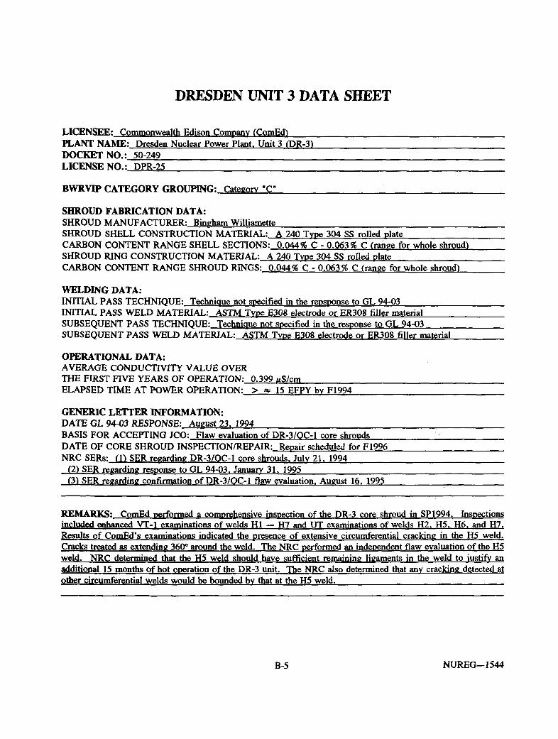
DRESDEN UNIT 3 DATA SHEET
LICENSEE; Commonwealth Edison Company (ComEd) PLANT NAME: Dresden Nuclear Power Plant. Unit 3 (DR-3) DOCKET NO.: 50-249 LICENSE NO.: DPR-25
BWRVIP CATEGORY GROUPING: Category ' C
SHROUD FABRICATION DATA: SHROUD MANUFACTURER: Bingham Williamette SHROUD SHELL CONSTRUCTION MATERIAL: A 240 Type 304 SS rolled plate CARBON CONTENT RANGE SHELL SECTIONS: 0.044% C - 0.063% C (range for whole shroud') SHROUD RING CONSTRUCTION MATERIAL: A 240 Type 304 SS rolled plate CARBON CONTENT RANGE SHROUD RINGS: 0.044% C - 0.063% C (range for whole shroud^
WELDING DATA: INITIAL PASS TECHNIQUE: Technique not specified in the repsponse to GL 94-03 INITIAL PASS WELD MATERIAL: ASTM Type E308 electrode or ER308 filler material SUBSEQUENT PASS TECHNIQUE: Technique not specified in the response to GL 94-03 SUBSEQUENT PASS WELD MATERIAL: ASTM Type E308 electrode or ER308 filler material
OPERATIONAL DATA: AVERAGE CONDUCTIVITY VALUE OVER THE FIRST FIVE YEARS OF OPERATION: 0.399 uS/cm ELAPSED TIME AT POWER OPERATION: > « 15 EFPY bv F1994
GENERIC LETTER INFORMATION: DATE GL 94-03 RESPONSE: August 23. 1994 BASIS FOR ACCEPTING JCO: Flaw evaluation of DR-3/OC-1 core shrouds '• DATE OF CORE SHROUD INSPECTION/REPAIR: Repair scheduled for F1996 NRC SERs: (D SER regarding DR-3/OC-1 core shrouds. July 21. 1994
(2) SER regarding response to GL 94-03. January 31. 1995 (3) SER regarding confirmation of DR-3/OC-1 flaw evaluation. August 16. 1995
REMARKS: ComEd performed a comprehensive inspection of the DR-3 core shroud in SP1994. Inspections included enhanced VT-1 examinations of welds HI — H7 and UT examinations of welds H2. H5. H6. and H7. Results of ComEd's examinations indicated the presence of extensive circumferential cracking in the H5 weld. Cracks treated as extending 360° around the weld. The NRC performed an independent flaw evaluation of the H5 weld. NRC determined that the H5 weld should have sufficient remaining ligaments in the weld to justify an additional 15 months of hot operation of the DR-3 unit. The NRC also determined that any cracking detected at other circumferential welds would be bounded bv that at the H5 weld.
B-5 NUREG-1544

QUAD CITIES UNIT 1 DATA SHEET
LICENSEE; Commonwealth Edison Company (ComEd) PLANT NAME: Quad Cities Nuclear Power Plant. Unit 1 (OC-1V DOCKET NO.: 50-254 LICENSE NO.: DPR-29
BWRVIP CATEGORY GROUPING: Category "C"
SHROUD FABRICATION DATA: SHROUD MANUFACTURER: Bingham Williamette SHROUD SHELL CONSTRUCTION MATERIAL: A 240 Type 304 SS rolled plate CARBON CONTENT RANGE SHELL SECTIONS: 0.044% C — 0.063% C (range for whole shroud) SHROUD RING CONSTRUCTION MATERIAL: A 240 Type 304 SS rolled plate CARBON CONTENT RANGE SHROUD RINGS: 0.044% C — 0.063% C (range for whole shroud')
WELDING DATA: INITIAL PASS TECHNIQUE: Technique not specified in the response to GL 94-03 INITIAL PASS WELD MATERIAL: ASTM Type E308 electrode or ER308 filler material SUBSEQUENT PASS TECHNIQUE: Technique not specified in the response to GL 94-03 SUBSEQUENT PASS WELD MATERIAL: ASTM Type E308 electrode or ER308 filler material
OPERATIONAL DATA: AVERAGE CONDUCTIVITY VALUE OVER THE FIRST FIVE YEARS OF OPERATION: 0.377 uS/cm ELAPSED TIME AT POWER OPERATION: > 16.0 EFPY by F1994
GENERIC LETTER INFORMATION: DATE GL 94-03 RESPONSE: August 23. 1994 BASIS FOR ACCEPTING JCO: Flaw evaluation of DR-3/OC-1 core shrouds DATE OF CORE SHROUD INSPECTION/REPAIR: Inspection performed SP1994 NRC SERs: (1) SER regarding DR-3/OC-1 core shrouds. July 21. 1994
(2) SER regarding response to GL 94-03. January 31. 1995 (3) SER regarding confirmation of DR-3/OC-1 flaw evaluation. August 16. 1995
REMARKS: ComEd performed a comprehensive inspection of the OC-1 core shroud in SP1994. Inspections included enhanced VT-1 examinations of welds HI — H7 and UT examinations of welds H2. H5. H6. and H7. Results of CnmF.d's examinations indicated the presence of extensive circumferential cracking in the H5 weld. Cracks treated as extending 360° around the weld. The NRC performed an independent flaw evaluation of the H5 weld. NRC determined that the H5 weld should have sufficient remaining ligaments in the weld to justify an additional 15 months of hot operation of the OC-1 unit. The NRC also determined that any cracking detected at other circumferential welds would be bounded by that at the H5 weld.
NUREG—1544 B-6

DRESDEN UNIT 2 DATA SHEET
LICENSEE: Commonwealth Edison Company (ComEd) PLANT NAME: Dresden Nuclear Power Plant. Unit 2 (DR-2) DOCKET NO.: 50-237 LICENSE NO.: DPR-19
BWRVIP CATEGORY GROUPING: Category " C
SHROUD FABRICATION DATA: SHROUD MANUFACTURER: Bingham Williamette SHROUD SHELL CONSTRUCTION MATERIAL: A 240 Type 304 SS rolled plate CARBON CONTENT RANGE SHELL SECTIONS: 0.044% C — 0.063% C (range for whole shroud) SHROUD RING CONSTRUCTION MATERIAL: A 240 Type 304 SS rolled plate CARBON CONTENT RANGE SHROUD RINGS: 0.044% C — 0.063% C (range for whole shroud)
WELDING DATA: INITIAL PASS TECHNIQUE: Technique not specified in response to GL 94-03 INITIAL PASS WELD MATERIAL: ASTM Type E308 electrode or ER308 filler material SUBSEQUENT PASS TECHNIQUE: Technique not specified in response to GL 94-03 SUBSEQUENT PASS WELD MATERIAL: ASTM Type E308 electrode or ER308 filler material
OPERATIONAL DATA: AVERAGE CONDUCTIVITY VALUE OVER THE FIRST FIVE YEARS OF OPERATION: 0.299 ^S/cm ELAPSED TIME AT POWER OPERATION: > 17.1 EFPY by F1994
GENERIC LETTER INFORMATION: DATE GL 94-03 RESPONSE: August 23. 1994 BASIS FOR ACCEPTING JCO: Results of DR-3/OC-1 flaw evaluations bounding for DR-2/OC-2 DATE OF CORE SHROUD INSPECTION/REPAIR: Repair scheduled for F/W1995 NRC SERs: (1) SER regarding the ComEd response to GL 94-03 for DR-2/OC-2. January 31. 1995
REMARKS: ComEd opted to implement a modification of the DR-2 core shroud in lieu of performing comprehensive core shroud examinations. The design involves installation of GE designed tie rod assemblies around the OD of the shroud. Tie rod assemblies are designed to provide an alternate load bearing capability for the shroud during normal operating, transient and postulated design basis accident conditions, given the occurrence of a 360° through-wall failure of a circumferential weld. Core shroud modification design currently under review bv the NRC staff. .
B-7 NUREG—1544

QUAD CITIES UNIT 2 DATA SHEET
LICENSEE: Commonwealth Edison Company (ComEd) PLANT NAME; Quad Cities Nuclear Power Plant, Unit 2 (OC-2) DOCKET NO.: 50-265 LICENSE NO.: DPR-30
BWRVTP CATEGORY GROUPING: Category "C"
SHROUD FABRICATION DATA: SHROUD MANUFACTURER: Bingham Williamette SHROUD SHELL CONSTRUCTION MATERIAL: A 240 Type 304 SS rolled plate CARBON CONTENT RANGE SHELL SECTIONS: 0.044% C — 0.063% C (range for whole shroud) SHROUD RING CONSTRUCTION MATERIAL: A 240 Type 304 SS rolled plate CARBON CONTENT RANGE SHROUD RINGS: 0.044% C — 0.063% C (range for whole shroud)
WELDING DATA: INITIAL PASS TECHNIQUE: Technique not specified in response to GL 94-03 INITIAL PASS WELD MATERIAL: ASTM Type E308 electrode or ER308 filler material SUBSEQUENT PASS TECHNIQUE: Technique not specified in response to GL 94-03 SUBSEQUENT PASS WELD MATERIAL: ASTM Type E308 electrode or ER308 filler material
OPERATIONAL DATA: AVERAGE CONDUCTIVITY VALUE OVER THE FIRST FIVE YEARS OF OPERATION: 0.377 uS/cm ELAPSED TIME AT POWER OPERATION: > 16.1 EFPY bv F1994
GENERIC LETTER INFORMATION: DATE GL 94-03 RESPONSE: August 23. 1995 BASIS FOR ACCEPTING JCO: Results of DR-3/OC-1 flaw evaluation bounding for DR-2/OC-2 DATE OF CORE SHROUD INSPECTION/REPAIR: Repair implemented SP/S1995 NRC SERs: (1) SER regarding the response to GL-94-03 for DR-2/OC-2. January 31. 1995
(2) OC-2 core shroud repair (modification) SER. June 8. 1995
REMARKS: CnmPA opted to implement a modification of the OC-2 core shroud in lieu of performing comprehensive core shroud examinations. The design involves installation of GE designed tie rod assemblies around the OD of the shroud. Tie rod assemblies are designed to provide an alternate load bearing capability for the shroud during normal operating, transient and postulated design basis accident conditions, given the occurrence of a 360° through-wall failure of a circumferential weld. The NRC approved the modification design for the OC-2 core shroud on June 8. 1995.
NUREG-1544 B-8

OYSTER CREEK DATA SHEET
LICENSEE: General Public Utilities (GPU) PLANT NAME: Oyster Creek Nuclear Generation Station (OCNGS) DOCKET NO.: 50-219 LICENSE NO.: DPR-16
BWRVTP CATEGORY GROUPING: Category "C"
SHROUD FABRICATION DATA: SHROUD MANUFACTURER: P.F. Averv SHROUD SHELL CONSTRUCTION MATERIAL: A 240 Type 304 SS rolled plates CARBON CONTENT RANGE SHELL SECTIONS: 0.042% C — 0.062% c SHROUD RING CONSTRUCTION MATERIAL: A 240 Type 304 SS rolled plates CARBON CONTENT RANGE SHROUD RINGS: 0.056% C — 0.064% C
WELDING DATA: INITIAL PASS TECHNIQUE: Information not provided in response to GL 94-03 INITIAL PASS WELD MATERIAL: Information not provided in response to GL 94-03 SUBSEQUENT PASS TECHNIQUE: Information not provided in response to GL 94-03 SUBSEQUENT PASS WELD MATERIAL: Information not provided in response to GL 94-03
OPERATIONAL DATA: AVERAGE CONDUCTIVITY VALUE OVER THE FIRST FIVE YEARS OF OPERATION: 0.526 ttS/cm ELAPSED TIME AT POWER OPERATION: > 15.5 EFPY bv F1994
GENERIC LETTER INFORMATION: DATE GL 94-03 RESPONSE: August 24. 1994 BASIS FOR ACCEPTING JCO: Generic Safety Assessment and Short time to F1994 RFO DATE OF CORE SHROUD INSPECTION/REPAIR: Inspection. Repair during F1994 RFO NRC SERs: (1) SER regarding the OCNGS core shroud repair. November 25. 1994
(21 SER regarding the response to GL 94-03 for OCNGS. February 23. 1995
REMARKS: GPU performed comprehensive UT (w/ some VT-ll inspections of the OCNGS core shroud during the F1994 RFO. Inspection coverages ranged from 12%—27% for welds HI—H3. and 31%—49% for welds H4—H6B. Welds H7 and H8 were not included in the inspections due to the presence of additional structural brackets in the shroud design. Inspections of the H4 revealed the presence of substantial cracking (taken to be 360°) in the welds HAZ. OCNGS opted to perform a corrective repair of the OCNGS core shroud prior to restart of the OCNGS unit. The repair involved the installation of a number of MPR-designed tie rod assemblies around the outer circumference of the shroud. GPU's core shroud modification design for the OCNGS was approved bv the staff prior to restart of the unit.
B-9 NUREG—1544

HATCH UNIT 1 DATA SHEET
LICENSEE: Georgia Power Company fGPO PLANT NAME: Edwin I. Hatch Nuclear Plant. Unit 1 (HAT-H DOCKET NO.: 50-321
LICENSE NO.: DPR-57
BWRVIP CATEGORY GROUPING: Category "C"
SHROUD FABRICATION DATA: SHROUD MANUFACTURER: Sun Ship Building and Drv Dock Co. SHROUD SHELL CONSTRUCTION MATERIAL: A/SA 240 Type 304 SS rolled plate CARBON CONTENT RANGE SHELL SECTIONS: Information not provided in the response to GL 94-03 SHROUD RING CONSTRUCTION MATERIAL: A/SA 240 Type 304 SS rolled plate CARBON CONTENT RANGE SHROUD RINGS: Information not provided in the response to GL 94-03 WELDING DATA: INITIAL PASS TECHNIQUE: Information not provided in the response to GL 94-03 INITIAL PASS WELD MATERIAL: Information not provided in the response to GL 94-03 SUBSEQUENT PASS TECHNIQUE: Information not provided in the response to GL 94-03 SUBSEQUENT PASS WELD MATERIAL: Information not provided in the response to GL 94-03
OPERATIONAL DATA: AVERAGE CONDUCTIVITY VALUE OVER THE FIRST FIVE YEARS OF OPERATION: 0.411 uS/cm ELAPSED TIME AT POWER OPERATION: > 12.8 EFPY by F1994
GENERIC LETTER INFORMATION: DATE GL 94-03 RESPONSE: August 24. 1994 BASIS FOR ACCEPTING JCO: Generic Safety and Assessment and Short time duration until the F1994 RFO DATE OF CORE SHROUD INSPECTION/REPAIR: Repair. September/October 1994 NRC SERs: (I) SER regarding the HAT-1 core shroud repair. September 30. 1994
(2) SER regarding GPC's response to GL 94-03 for HAT-l/HAT-2. February 23. 1995
REMARKS: GPC opted to perform pre-emptive repair of the HAT-1 core shroud during the September 1994 RFO in lieu of comprehensive core shroud examinations. HAT-1 shroud modification design submitted to the staff on September 2. 1994. The design involves installation of GE designed tie rod assemblies around the OD of the shroud. Tie rod assemblies are designed to provide an alternate load bearing capability for the shroud during normal operating, transient and postulated design basis accident conditions, given the occurrence of a 360° through-wall failure of a circumferential weld. Design approved bv the NRC prior to restart of the HAT-1 unit.
NUREG-1544 B-10

HATCH UNIT 2 DATA SHEET
LICENSEE: Georgia Power Company (GPC) PLANT NAME: Edwin I. Hatch Nuclear Plant. Unit 2 (HAT-2) DOCKET NO.: 50-366 LICENSE NO.: NPF-5
BWRVIP CATEGORY GROUPING: Category "C"
SHROUD FABRICATION DATA: SHROUD MANUFACTURER: Sun Ship Building and Dry Dock Co. SHROUD SHELL CONSTRUCTION MATERIAL: A/SA 240 Type 304 SS rolled plate CARBON CONTENT RANGE SHELL SECTIONS: Information not provided in the response to GL 94-03 SHROUD RING CONSTRUCTION MATERIAL: A/SA 240 Type 304 SS rolled plate CARBON CONTENT RANGE SHROUD RINGS: Information not provided in the response to GL 94-03
WELDING DATA: INITIAL PASS TECHNIQUE: Information not provided in the response to GL 94-03 INITIAL PASS WELD MATERIAL: Information not provided in the response to GL 94-03 SUBSEQUENT PASS TECHNIQUE: Information not provided in the response to GL 94-03 SUBSEQUENT PASS WELD MATERIAL: Information not provide in the response to GL 94-03
OPERATIONAL DATA: AVERAGE CONDUCTIVITY VALUE OVER THE FIRST FIVE YEARS OF OPERATION: 0.459 fiS/cm ELAPSED TIME AT POWER OPERATION: > 10.0 EFPY by F1994
GENERIC LETTER INFORMATION: DATE GL 94-03 RESPONSE: August 24. 1994 BASIS FOR ACCEPTING JCO: Inspection results and flaw evaluations of the HAT-2 shroud during SP1994 RFO DATE OF CORE SHROUD INSPECTION/REPAIR: Inspection SP1994: repair scheduled for F1995 NRC SERs: (1) SER regarding GPC's response to GL 94-03. February 23. 1995
(2) SER regarding the HAT-2 core shroud repair. September 25. 1995 ;
REMARKS: GPC performed UT inspections of the H1-H4 circumferential welds during the HAT-2 SP1994 RFO: GPC also performed partial VT-1 examinations of welds H5-H8. UT examinations of accessible portions of the H2 weld indicated the presence of cracking totaling 5.54 m (218 in) in length, with the longest indication being «159 inches in length. UT inspections of the HAT-2 shroud also revealed a minor amount of cracking at welds HI . H3. and H4 welds. Partial VT-1 examinations of the lower shroud welds were negative for flaw indications. The results of flaw evaluations of the HAT-2 shroud justified operation of the unit to the F1995 RFO. Repair design will involve the installation of a number of GE-design tie rod assemblies around the outer circumference of the shroud. Repair design approved by the NRC in September 1995. _ _ _ _ _ _
B-ll NUREG—1544

DUANE ARNOLD ELECTRIC CENTER DATA SHEET
LICENSEE: IES Utilities. Inc. (IES) PLANT NAME; Duane Arnold Energy Center fDAEQ DOCKET NO.; 50-331 LICENSE NO.: DPR-49
BWRVIP CATEGORY GROUPING: Category "C"
SHROUD FABRICATION DATA: SHROUD MANUFACTURER: Bingham Williamette SHROUD SHELL CONSTRUCTION MATERIAL: Type 304L stainless steel CARBON CONTENT RANGE SHELL SECTIONS: Information not provided in the response to GL 94-03 SHROUD RING CONSTRUCTION MATERIAL: Type 304L stainless steel CARBON CONTENT RANGE SHROUD RINGS: Information not provided in the response to GL 94-03
WELDING DATA: INITIAL PASS TECHNIQUE: Information not provided in the response to GL 94-03 INITIAL PASS WELD MATERIAL: Information not provided in the response to GL 94-03 SUBSEQUENT PASS TECHNIQUE: Information not provided in the response to GL 94-03 SUBSEQUENT PASS WELD MATERIAL: Information not provided the in response to GL 94-03
OPERATIONAL DATA: AVERAGE CONDUCTIVITY VALUE OVER THE FIRST FIVE YEARS OF OPERATION: near mid range conductivity for the industry (« 0.3 fiS/cm) ELAPSED TIME AT POWER OPERATION: > 13.5 EFPY by F1994
GENERIC LETTER INFORMATION: DATE GL 94-03 RESPONSE: August 24. 1994 BASIS FOR ACCEPTING JCO: Generic safety assessment DATE OF CORE SHROUD INSPECTION/REPAIR: Comprehensive UT examinations during W/SP1995 RFO NRC SERs: SER regarding response to GL 94-03. March 1. 1995
REMARKS: Comprehensive UT examinations of DAEC core shroud during W/SP1995 RFO. Examinations covered accessible portions of HI— H7 from the OP. IES performed the UT examinations using the GE OD Tracker, with 45° shear wave. 60° longitudinal wave and creep UT techniques. Weld coverage ranged from 52.4% at weld H2 to 78.8 % at weld H4. No flaw indications evident as a result of the examinations performed during the W1995 RFO.
NUREG—1544 B-12

NINE MILE POINT UNIT 1 DATA SHEET
LICENSEE: Niagara Mohawk Power Corporation (NMPQ PLANT NAME: Nine Mile Point Station. Unit 1 (NMP-11 DOCKET NO.: 50-220 LICENSE NO.: DPR-63
BWRVIP CATEGORY GROUPING: Category " C
SHROUD FABRICATION DATA: SHROUD MANUFACTURER: P.F. Averv SHROUD SHELL CONSTRUCTION MATERIAL: A 240 Type 304 SS plate CARBON CONTENT RANGE SHELL SECTIONS: 0.042% C — 0.062% C SHROUD RING CONSTRUCTION MATERIAL: A 240 Type 304 SS plate (shroud support ring: SA 336 type F8 CARBON CONTENT RANGE SHROUD RINGS: 0.056% C — 0.064% C
WELDING DATA: INITIAL PASS TECHNIQUE: SAW INITIAL PASS WELD MATERIAL: A-371 Type ER308 Filler (5% minimum ferrite contend SUBSEQUENT PASS TECHNIQUE:_SAW SUBSEQUENT PASS WELD MATERIAL: A-371 Type ER308 Filler (5% minimum ferrite content)
OPERATIONAL DATA: AVERAGE CONDUCTIVITY VALUE OVER THE FIRST FIVE YEARS OF OPERATION: 0.457 uS/cm ELAPSED TIME AT POWER OPERATION: > 14.4 EFPY by F1994
GENERIC LETTER INFORMATION: DATE GL 94-03 RESPONSE: August 23. 1994 BASIS FOR ACCEPTING JCO: Generic Safety Assessment DATE OF CORE SHROUD INSPECTION/REPAIR: Repair of NMP-1 SP1995 RFO NRC SERs: (1) SER regarding the response to GL 94-03 for NMP-1. January 13. 1995
(2) SER regarding the NMP-1 core shroud repair. March 31. 1995
REMARKS: NMPC performed a pre-emptive repair (modification) of the NMP-1 core shroud in SP1995 RFO. This modification was implemented in lieu of performing in depth core shroud examinations. NMPC submitted the modification design on Jan. 6. 1995. The modification design involves the use of tie rod assemblies designed by the GE Company. The tie rod assemblies are designed to provide an alternate load path for the core shroud, and are designed to assume the worst case loading conditions during normal operating, transient, and postulated design basis accident conditions, given the occurrence of a 360° through-wall failure of a circumerential weld. The NRC approved the modification for implementation on March 31. 1995.
B-13 NUREG—1544

COOPER NUCLEAR STATION DATA SHEET
LICENSEE: Nebraska Public Power District fNPPDt PLANT NAME: Cooper Nuclear Station fCNS^ DOCKET NO.: 50-298 LICENSE NO.: DPR-46
BWRVIP CATEGORY GROUPING: Category "C"
SHROUD FABRICATION DATA: SHROUD MANUFACTURER: Bingham Williamette SHROUD SHELL CONSTRUCTION MATERIAL: A 240 Type 304 SS hot rolled, annealed plate CARBON CONTENT RANGE SHELL SECTIONS: 0.043% C — 0.068% C SHROUD RING CONSTRUCTION MATERIAL: A 240 Type 304 SS hot rolled annealed plate CARBON CONTENT RANGE SHROUD RINGS: 0.052% C — 0.058% C
WELDING DATA: INITIAL PASS TECHNIQUE: SAW INITIAL PASS WELD MATERIAL: ER308 Filler SUBSEQUENT PASS TECHNIQUE: SAW SUBSEQUENT PASS WELD MATERIAL: ER308 Filler
OPERATIONAL DATA: AVERAGE CONDUCTIVITY VALUE OVER THE FIRST FIVE YEARS OF OPERATION: 0.188 uS/cm ELAPSED TIME AT POWER OPERATION: > 14.6 EFPY bv F1994
GENERIC LETTER INFORMATION: DATE GL 94-03 RESPONSE: August 26. 1994 BASIS FOR ACCEPTING JCO: Generic Safety Assessment: coupled with history of clean reactor coolant DATE OF CORE SHROUD INSPECTION/REPAIR: Comprehensive UT Inspection scheduled for October 1995 NRC SERs: (1) SER regarding response to GL 94-03. April 12. 1995
(2) Acknowledgement letter of core shroud inspection scope. September 20. 1995
REMARKS: Last licensee with a Category "C" plant to inspect its core shroud. This inspection will complete the initial set of inspections/repairs Category "C" shrouds. The proposed inspection scope for CNS shroud is consistent with the content of other Category "C" inspection scopes that have been submitted to the NRC. Inspection scope approved bv NRR.
NUREG—1544 B-14

MILLSTONE UNIT 1 DATA SHEET
LICENSEE: Northeast Nuclear Energy Company (NNECO) PLANT NAME: Millstone Unit 1 (MS-11 DOCKET NO.: 50-245 LICENSE NO.: DPR-21
BWRVBP CATEGORY GROUPING: Category "C"
SHROUD FABRICATION DATA: SHROUD MANUFACTURER: P.F. Averv SHROUD SHELL CONSTRUCTION MATERIAL: Type 304 SS plate CARBON CONTENT RANGE SHELL SECTIONS: Information not provided in the response to GL 94-03 SHROUD RING CONSTRUCTION MATERIAL: Type 304 SS plate CARBON CONTENT RANGE SHROUD RINGS: Information not provided in the response to GL 94-03
WELDING DATA: INITIAL PASS TECHNIQUE: Information not provided in the response to GL 94-03 INITIAL PASS WELD MATERIAL: Information not provided in the response to GL 94-03 SUBSEQUENT PASS TECHNIQUE: Information not provided in the response to GL 94-03 SUBSEQUENT PASS WELD MATERIAL: Information not provided in the response to GL 94-03
OPERATIONAL DATA: AVERAGE CONDUCTIVITY VALUE OVER THE FIRST FIVE YEARS OF OPERATION: < < 0 . 1 6 0 u S / c m ELAPSED TIME AT POWER OPERATION: > 10.0 EFPY bv F1994
GENERIC LETTER INFORMATION: DATE GL 94-03 RESPONSE: August 24. 1994 BASIS FOR ACCEPTING JCO: Results of VT-1 examinations performed during W1994 RFO (Cycle 14 RFOI DATE OF CORE SHROUD INSPECTION/REPAIR: In depth UT scheduled for Cvcle 15 RFO (F1995) NRC SERs: (11 SER regarding response to GL 94-03. January 4. 1995
(2) Acknowledgement letter regarding MSI core shroud inspection scope. August 7. 1995
REMARKS: NNECO performed enhanced VT-1 examinations of the MSI core shroud during the Cvcle 14 RFO (W1994—95). The scope of the VT-1 examinations covered welds HI—H4 and H6A—H7 from the OP and H3. H4. and H5 from the ID. Results of the VT-1 examinations indicated the presence of only minor cracking in the MSI core shroud. Only 6 indications were identified with the longest being 0.292 m (11.5 in). All indications were found acceptable per NNECO NCR194-097. Furthermore, all indications were less than the initial screening criteria approved for evaluations of the BR-1 core shroud. Results of the MSI flaw evaluation justify operation of MSI to the Cvcle 15 RFO.
B-15 NUREG—1544

MONTTCELLO NUCLEAR GENERATION PLANT DATA SHEET
LICENSEE: Northern States Power Company (NSP) PLANT NAME; Monticello Nuclear Generation Plant (MNGP) DOCKET NO.: 50-263 LICENSE NO.: DPR-22
BWRVIP CATEGORY GROUPING: Category "C"
SHROUD FABRICATION DATA: SHROUD MANUFACTURER: Rotterdam Drv Dock SHROUD SHELL CONSTRUCTION MATERIAL: A 240 TP304 SS plate CARBON CONTENT RANGE SHELL SECTIONS: 0.043% C — 0.050% C SHROUD RING CONSTRUCTION MATERIAL: A 182 F304 SS forsings CARBON CONTENT RANGE SHROUD RINGS: 0.031% C — 0.056% C
WELDING DATA: INITIAL PASS TECHNIQUE: manual GTAW. manual SMAW. or automatic SAW INITIAL PASS WELD MATERIAL: E308 or ER 308 SUBSEQUENT PASS TECHNIQUE: manual GTAW. manual SMAW. or automatic SAW SUBSEQUENT PASS WELD MATERIAL: E308 or ER308
OPERATIONAL DATA: AVERAGE CONDUCTIVITY VALUE OVER THE FIRST FIVE YEARS OF OPERATION: 0.299 uS/cm (chlorides 10.6 ppb) ELAPSED TIME AT POWER OPERATION: > 17.8 EFPY bv F1994
GENERIC LETTER INFORMATION: DATE GL 94-03 RESPONSE: August 23. 1994 BASIS FOR ACCEPTING JCO: Generic Safety Assessment, extremely short time to F1994 RFO (Sept. 1994) DATE OF CORE SHROUD INSPECTION/REPAIR: In depth UT examinations during F1994 RFO (Sent. 1994") NRC SERs: (1) SER regarding response to GL 94-03 and NSP's core shroud inspection results and flaw evaluations. January 20. 1995
REMARKS: In depth UT/VT-1 examinations of the MNGP core shroud during the F1994 RFO (Sept. 15. 1994). UT inspections performed with GE OD-Tracker. using 45 °S and 60°L transducers. Creeping wave used for near side surface examinations. Inspection scope covered UT examinations of accessible portions of the HI—H5 welds from the OD (coverage ranged from 32%—54%). and enhanced VT-1 examinations of the H4. H5. H6. H8. and H9 welds to supplement the UT examinations ( » 8—15 % coverage). Welds H6-H9 were inaccessible to the tracker (Weld H7 was notable to the obstruction from a backing ring). All indications less than 0.25 m (10 in) in length. All indications less than initial screening criteria limit approved for evaluation of the BR-1 shroud. Operation justified.
NUREG-1544 B-16

PEACH BOTTOM UNIT 2 DATA SHEET LICENSEE; Philadelphia Electric Company (PECo) PLANT NAME;. Peach Bottom Atomic Power Station. Unit 2 (PB-2) DOCKET NO.; 50-277 LICENSE NO.; DPR-44
BWRVEP CATEGORY GROUPING; Category " C
SHROUD FABRICATION DATA: SHROUD MANUFACTURER: Rotterdam Drv Dock SHROUD SHELL CONSTRUCTION MATERIAL: A 240 Type 304 SS plate CARBON CONTENT RANGE SHELL SECTIONS: 0.056% C - 0.062% C SHROUD RING CONSTRUCTION MATERIAL: A 182 F304 SS forgings CARBON CONTENT RANGE SHROUD RINGS: 0.028% C — 0.035% C
WELDING DATA: INITIAL PASS TECHNIQUE: H7 by GMAW: other welds bv SAW INITIAL PASS WELD MATERIAL: H7 using Alloy 82: other welds using ASTM A371 ER308 SUBSEQUENT PASS TECHNIQUE: H7 bv GMAW; other welds bv SAW SUBSEQUENT PASS WELD MATERIAL: H7 using Alloy 82: other welds using ASTM A317 ER308
OPERATIONAL DATA: AVERAGE CONDUCTIVITY VALUE OVER THE FIRST FIVE YEARS OF OPERATION: 0.593 ttS/cm ELAPSED TIME AT POWER OPERATION: > 11.8 EFPY bv F1994
GENERIC LETTER INFORMATION: DATE GL 94-03 RESPONSE: August 24. 1994 BASIS FOR ACCEPTING JCO: Any cracking at PB-2 would be bounded bv evaluations of cracking at PB-3 DATE OF CORE SHROUD INSPECTION/REPAIR: RFO 2R010. Sept./Oct. 1994 NRC SERs: (1) SER regarding the PECo response to GL 94-03 for the Peach Bottom Units. February 6. 1995
REMARKS: PECo's performed UT inspections of the PB-2 core shroud during RFO 2R010. UT examinations were performed using the GE OD Tracker (45°S. 60"L and creeping wave transducers). UT examinations covered 30% of weld HI . 83%—89% of welds H2—H5. and 9—10% of welds H6 and H7. An additional 13% of weld H6 was inspected bv enhanced VT-1 methods. UT examinations revealed some indications at welds HI. H3. and H4. totaling 0.861 m (33.9 in). 1.74 m (68.5 in), and 0.292 m (11.5 in) in length, respectively. Extremely minor cracking was also detected at welds H5 and H6 (one indication at each weld, both less than 0.13 m f5 inl in length). Flaw evaluations indicate that safety margins requirements for the PB-2 shroud would be satisfied for the next cycle.
B-17 NUREG-1544

PEACH BOTTOM UNIT 3 DATA SHEET
LICENSEE: Philadelphia Electric Company (PECo) PLANT NAME: Peach Bottom Atomic Power Station. Unit 3 (PB-3) DOCKET NO.: 50-278 LICENSE NO.: DPR-56
BWRVIP CATEGORY GROUPING: Category " C
SHROUD FABRICATION DATA: SHROUD MANUFACTURER: Rotterdam Drv Dock SHROUD SHELL CONSTRUCTION MATERIAL: A 240 Type 304 SS plate CARBON CONTENT RANGE SHELL SECTIONS: 0.050% C — 0.065% C SHROUD RING CONSTRUCTION MATERIAL: A 182 F304 SS forgings CARBON CONTENT RANGE SHROUD RINGS: 0.030% C — 0.035% C
WELDING DATA: INITIAL PASS TECHNIQUE: H7 bv GMAW: other welds by SAW INITIAL PASS WELD MATERIAL: H7 using Alloy 82: other welds using ASTM A371 ER308 SUBSEQUENT PASS TECHNIQUE: H7 bv GMAW: other welds bv SAW SUBSEQUENT PASS WELD MATERIAL: H7 using Allov 82: other welds using ASTM A317 ER308
OPERATIONAL DATA: AVERAGE CONDUCTIVITY VALUE OVER THE FIRST FIVE YEARS OF OPERATION: 0.695 uS/cm ELAPSED TIME AT POWER OPERATION: > 11.0 EFPY as of F1994
GENERIC LETTER INFORMATION: DATE GL 94-03 RESPONSE: August 24. 1994 BASIS FOR ACCEPTING JCO: VT-1 examinations and evaluations of the PB-3 shroud justify operation of PB3. DATE OF CORE SHROUD INSPECTION/REPAIR: Enhanced VT-1 examinations during RFO 3R9. Oct. 1993 NRC SERs: (1) SER regarding PECo response to GL 94-03 for the Peach Bottom Units. February 6. 1995
REMARKS: Enhanced VT-1 examinations performed during RFQ 3R9. Inspection scope covered 100% of the accessible areas of the H3 and H4 welds from the ID and 100 % of the accessible area of the H4 weld from the OD. Partial VT-1 examinations were performed on the H6. H7. and H8 welds. In addition, one vertical weld located between the H3 and H4 welds was examined. The VT-1 examinations identified some cracking at weld H3. totaling 2.67 m (105 in) in length. Less extensive cracking identified at weld H4 (< 0.76 m f30 inl in length), and minor cracking identified at weld HI and the vertical weld. The results of PECo's flaw evaluation of the PB-3 core shroud justify operation of the PB-3 unit for the cycle leading to RFO 3R10 (F1995).
NUREG—1544 B-18

FITZPATRICK DATA SHEET
LICENSEE: Power Authority of the State of New York (NYPA') PLANT NAME: James A. FitzPatrick Nuclear Power Plant (FITZ^ DOCKET NO.: 50-333 LICENSE NO.: DPR-S9
BWRVTP CATEGORY GROUPING: Category "C"
SHROUD FABRICATION DATA: SHROUD MANUFACTURER: Sun Ship Building and Dry Dock Co. SHROUD SHELL CONSTRUCTION MATERIAL: A240 Type 304 SS plates CARBON CONTENT RANGE SHELL SECTIONS: 0.036% C — 0.069% C SHROUD RING CONSTRUCTION MATERIAL: A240 Type 304 SS plates CARBON CONTENT RANGE SHROUD RINGS: 0.056% C — 0.078% C
WELDING DATA: INITIAL PASS TECHNIQUE: Fabrication should be similar to that of the Brunswick Units. INITIAL PASS WELD MATERIAL: E308 weld wire SUBSEQUENT PASS TECHNIQUE: Fabrication should be similar to that of the Brunswick Units. SUBSEQUENT PASS WELD MATERIAL: E308 weld wire
OPERATIONAL DATA: AVERAGE CONDUCTIVITY VALUE OVER THE FIRST FIVE YEARS OF OPERATION: 0.631 uS/cm NYPA calculation (0.718 uS/cm by BWRVIP) ELAPSED TIME AT POWER OPERATION: > 12.8 EFPY by F1994
GENERIC LETTER INFORMATION: DATE GL 94-03 RESPONSE: August 24. 1994 BASIS FOR ACCEPTING JCO: Short duration until W1994-95 RFO: bounded by evaluations of BR-1 DATE OF CORE SHROUD INSPECTION/REPAIR: Repair (modification^ W1994-95 RFO NRC SERs: (I) SER regarding FITZ core shroud repair. January 5. 1995
(2) SER regarding NYPA's response to GL 94-03. February 5. 1995
REMARKS: NYPA opted to perform a modification of the FITZ core shroud in lieu of performing comprehensive core shroud examinations. The FITZ core shroud modification design involves installation of a series of MPR-design tie rod assemblies around the circumference of the shroud. The tie rod assemblies are designed to assume the loading of the shroud in the event of a 360° through-wall failure of the shroud during normal operating, transient and postulated design basis accident conditions. The NRC approved NYPA's proposed shroud modification design on January 5. 1995.
B-19 NUREG-1544

BROWNS FERRY UNIT 1 DATA SHEET
LICENSEE: Tennessee Valley Authority (TVA) PLANT NAME: Browns Ferrv Nuclear Plant. Unit 1 fBF-11 DOCKET NO.: 50-259 LICENSE NO.: DPR-33
BWRVIP CATEGORY GROUPING: Category " C
SHROUD FABRICATION DATA: SHROUD MANUFACTURER: Rotterdam Drv Dock SHROUD SHELL CONSTRUCTION MATERIAL: A240 Type 304 SS plates finconel 600 below HI) CARBON CONTENT RANGE SHELL SECTIONS: 0.030% C — 0.060% C SHROUD RING CONSTRUCTION MATERIAL: A182 F304 forgings CARBON CONTENT RANGE SHROUD RINGS: 0.030% C — 0.060% C
WELDING DATA: INITIAL PASS TECHNIQUE: Techniques not provided in the response to GL 94-03 INITIAL PASS WELD MATERIAL: E308 or ER308 (INCQ182 for H71 SUBSEQUENT PASS TECHNIQUE: Techniques not provided in the response to GL 94-03 SUBSEQUENT PASS WELD MATERIAL: E308 or ER308 (INCQ182 for H71
OPERATIONAL DATA: AVERAGE CONDUCTIVITY VALUE OVER THE FIRST FIVE YEARS OF OPERATION: 0.364 uS/cm ELAPSED TIME AT POWER OPERATION: « 6.5 EFPY
GENERIC LETTER INFORMATION: DATE GL 94-03 RESPONSE: August 23. 1994 BASIS FOR ACCEPTING JCO: Reactor is currently in indefinite shutdown and defueled condition DATE OF CORE SHROUD INSPECTION/REPAIR: Deferred NRC SERs: (11 SER regarding response to GL 94-03. January 13. 1995
REMARKS: BF-1 is currently in an indefinite shutdown, defueled condition. TVA has indicated that it would perform inspections of the BF-1 core shroud prior to any reloading and restart of the BF-1 reactor. No inspections of the BF-1 reactor are needed at this time.
NUREG-1544 B-20

BROWNS FERRY UNIT 2 DATA SHEET
LICENSEE: Tennessee Vallev Authority fTVA~) PLANT NAME: Browns Ferrv Nuclear Plant. Unit 2 (BF-21 DOCKET NO.: 50-260 LICENSE NO.: DPR-52
BWRVIP CATEGORY GROUPING: Category "C"
SHROUD FABRICATION DATA: SHROUD MANUFACTURER: Rotterdam Drv Dock SHROUD SHELL CONSTRUCTION MATERIAL: A240 Type 304 SS plates (Inconel 600 below H71 CARBON CONTENT RANGE SHELL SECTIONS: 0.030% C — 0.060% C SHROUD RING CONSTRUCTION MATERIAL: A182 F304 forgings CARBON CONTENT RANGE SHROUD RINGS: 0.030% C — 0.060% C
WELDING DATA: INITIAL PASS TECHNIQUE: Technique not provided in the response to GL 94-03 INITIAL PASS WELD MATERIAL: E308 or ER308 (INCQ182 for H7) SUBSEQUENT PASS TECHNIQUE: Technique not provided in the response to GL 94-03 SUBSEQUENT PASS WELD MATERIAL: E308 or ER308 aNCQ182 for H7)
OPERATIONAL DATA: AVERAGE CONDUCTIVITY VALUE OVER THE FIRST FIVE YEARS OF OPERATION: 0.384 uS/cm ELAPSED TIME AT POWER OPERATION: > 9.0 EFPY by F1994
GENERIC LETTER INFORMATION: DATE GL 94-03 RESPONSE: August 23. 1994 BASIS FOR ACCEPTING JCO: Improved material of construction and short time to F1994 RFO DATE OF CORE SHROUD INSPECTION/REPAIR: Inspected September/October 1994 NRC SERs: (1) SER regarding response to GL 94-03. January 13. 1995
REMARKS: TVA performed UT inspections of die BF-2 core shroud during the September/October 1994 RFO. The UT inspections were performed using the GE OD Tracker System. The UT examinations included 45 °S. 60°L. and creeping wave techniques. Inspections covered approximately 33% of weld HI. 61—63% of welds H2—H5 and 2—3 % welds H6 and H7. The majority of the H6 and H7 welds were inaccessible to the tracker. The inspections of die BF-2 shroud revealed minor cracking of the shroud at welds H2. H3. and H5. Total lengths of indications at the H2. H3. and H5 welds were all less than 0.25 m (10.0 in). The results of TVA's flaw evaluation of the BF-2 shroud justifies operation of the BF-2 unit for the current cycle.
B-21 NUREG-1544

BROWNS FERRY UNIT 3 DATA SHEET
LICENSEE: Tennessee Valley Authority (TVA) PLANT NAME: Browns Ferrv Nuclear Plant. Unit 3 (BF-3) DOCKET NO.: 50-296 LICENSE NO.: DPR-68
BWRVIP CATEGORY GROUPING: Category "C"
SHROUD FABRICATION DATA: SHROUD MANUFACTURER: Rotterdam Drv Dock SHROUD SHELL CONSTRUCTION MATERIAL: A240 Type 304 SS plates (Inconel 600 below H7) CARBON CONTENT RANGE SHELL SECTIONS: 0.030% C - 0.060% C SHROUD RING CONSTRUCTION MATERIAL: A182 F304 forcings CARBON CONTENT RANGE SHROUD RINGS: 0.030% C - 0.060% C
WELDING DATA: INITIAL PASS TECHNIQUE: Technique not provided in the response to GL 94-03 INITIAL PASS WELD MATERIAL: E308 or ER308 (INCQ182 for H7) SUBSEQUENT PASS TECHNIQUE: Technique not provided in the response to GL 94-03 SUBSEQUENT PASS WELD MATERIAL: E308 or ER308 (INCQ182 for H7)
OPERATIONAL DATA: AVERAGE CONDUCTIVITY VALUE OVER THE FIRST FIVE YEARS OF OPERATION: 0.303 uS/cm ELAPSED TIME AT POWER OPERATION: - 5.0 EFPY
GENERIC LETTER INFORMATION: DATE GL 94-03 RESPONSE: August 23. 1994 BASIS FOR ACCEPTING JCO: Reactor is currently in indefinite defueled condition DATE OF CORE SHROUD INSPECTION/REPAIR: UT and VT-1 inspections during July 1994 RFO NRC SERs: (1) SER regarding response to GL 94-03. January 13. 1995
REMARKS: TVA performed UT and VT-1 inspections of the BF-3 core shroud during the July 1994 RFO. The UT inspections were performed using the GE OD Tracker System. The UT examinations included 45°S. 60°L. and creeping wave techniques. The inspections covered approximately 40—41 % of welds HI and H5. 68—83% of welds H2—H4. and 4% of welds H6 and H7. The majority of the H6 and H7 welds were inaccessible to the tracker. The inspections of the BF-3 shroud revealed some cracking at H5. totaling 2.1m (82 in) in length. Minor cracking of was detected at shroud welds HI and H4 (less than 0.05 m \2 in! in total length). The results of TVA's flaw evaluation of the BF-3 shroud satisfy ASME safety margins. ;
NUREG-1544 B-22

VERMONT YANKEE NUCLEAR POWER PLANT DATA SHEET
LICENSEE: Vermont Yankee Nuclear Power Corporation (VYNPO PLANT NAME: Vermont Yankee Nuclear Power Station (VY) DOCKET NO.: 50-271 LICENSE NO.: DPR-28
BWRVIP CATEGORY GROUPING: Category "C"
SHROUD FABRICATION DATA: SHROUD MANUFACTURER: Rotterdam Drv Dock SHROUD SHELL CONSTRUCTION MATERIAL: ASTM A240 Type stainless steel plates CARBON CONTENT RANGE SHELL SECTIONS: <, 0.070 % C SHROUD RING CONSTRUCTION MATERIAL: ASTM A182 Grade F304 stainless steel forgings CARBON CONTENT RANGE SHROUD RINGS: < 0.060% C
WELDING DATA: INITIAL PASS TECHNIQUE: Information not provided in the response to GL 94-03 INITIAL PASS WELD MATERIAL: Information not provided in the response to GL 94-03 SUBSEQUENT PASS TECHNIQUE: Information not provided in the response to GL 94-03 SUBSEQUENT PASS WELD MATERIAL: Information not provided in the response to GL 94-03
OPERATIONAL DATA: AVERAGE CONDUCTIVITY VALUE OVER THE FIRST FIVE YEARS OF OPERATION: 0.286 fiS/cm ELAPSED TIME AT POWER OPERATION: > 16.9 EFPY by F1994
GENERIC LETTER INFORMATION: DATE GL 94-03 RESPONSE: August 17. 1994 BASIS FOR ACCEPTING JCO: Generic Safety Assessment and results of RFO No. 17 VT-1 exams. (Oct. 93) DATE OF CORE SHROUD INSPECTION/REPAIR: Comprehensive UT. April 1995 (RFO No.18) NRC SERs: (1) SER regarding initial response to GL 94-03. January 5. 1995
(2Y Acknowledgement letter of VY core shroud inspection scope. April 25. 1995 (3) SER regarding VY core shroud flaw evaluation. April 27. 1995
REMARKS: Comprehensive UT inspection of the VY shroud using new inspection technology by Babcock arid Wilcox Nuclear Technology (BWNT). BWNT inspection technology approved for use by NRC. UT examinations included 45°S. 60°L. and creeping wave UT techniques. Results of core shroud examinations indicate me presence of significant cracking at weld H5. Cracks at the H5 welds encompass approximately 11/12 of weld's circumference. Flaw evaluations of H5 weld indicate that the H5 weld will have sufficient remaining structural ligaments to justify operation for the next cycle. Evaluations of any cracking discovered at other circumferential welds bounded by evaluation of cracking at weld H5.
B-23 NUREG—1544

SUSQUEHANNA UNIT 1 DATA SHEET
LICENSEE; Pennsylvania Power & Light Company (PP&L) PLANT NAME; Susquehanna Steam Electric Station. Unit 1 (SSES-1) DOCKET NO.; 50-387 LICENSE NO.; NPF-14
BWRVTP CATEGORY GROUPING; Category "B"
SHROUD FABRICATION DATA: SHROUD MANUFACTURER: Chicago Bridge and Iron Works SHROUD SHELL CONSTRUCTION MATERIAL: SA 240 TP 304L hot rolled plate CARBON CONTENT RANGE SHELL SECTIONS: 0.014% C — 0.027% C SHROUD RING CONSTRUCTION MATERIAL: SA 240 TP 304L hot rolled plate CARBON CONTENT RANGE SHROUD RINGS: 0.025% C — 0.026% C
WELDING DATA: INITIAL PASS TECHNIQUE: SMAW for HI— H6 and H8—H9 welds: GTAW for H7 weld INITIAL PASS WELD MATERIAL: SFA 5.4 E308 for SMAW: SFA 5.14 ERNiCr-3 for GTAW SUBSEQUENT PASS TECHNIQUE: SAW for HI—H3 and H6a—H6b welds. SMAW for H4—H5. H7—H9 SUBSEQUENT PASS WELD MATERIAL:SFA E308 most welds: SFA 5.9 ER308L for HI: ERNiCrFe-3 for H7
OPERATIONAL DATA: AVERAGE CONDUCTIVITY VALUE OVER THE FIRST FIVE YEARS OF OPERATION: 0.205 ^S/cm ELAPSED TIME AT POWER OPERATION: ~ 9 EFPY at the time of RFO No. 8RIO
GENERIC LETTER INFORMATION: DATE GL 94-03 RESPONSE: August 24. 1994 BASIS FOR ACCEPTING JCO:Categorv "B" criteria and results of limited VT-ls at RFO No. 7RIO (F1993) DATE OF CORE SHROUD INSPECTION/REPAIR: Limited UT examinations during Spring 1995 RFO (8RIO) NRC SERs: (1) SER regarding response to GL 94-03. March 23. 1995.
(2) Acknowledgement letter of SSES-1 inspection scope. April 10. 1995. (3) SER regarding the SSES-1 core shroud inspection results and flaw evaluation. May 3. 1995.
REMARKS: Limited inspection of the SSES-1 core shroud during RFO No. 8RIO. Scope in accordance with the recommendations of the BWRVIP for Category *B" core shrouds. Inspections included UT of H3. H4. H5. H6a. H6b. and H7 welds, and enhanced VT-1 of the H8 and H9 welds. Results of the UT inspections revealed a significant number of flaw indications at welds H2. H4. H5. and H6b welds totalling 13.8 m (54.4 in). 4.76 m (187.5 in). 4.80 m (189.9 in), and 1.66 m (65.3 in) in length at each weld, respectively. Minor amount of cracking also detected welds HI and H6A (less than 0.13 m 15 inl total at each weld). Results of inspections of other welds were negative for indications. Flaw evaluations support operation for the next operating cycle.
NUREG-1544 B-24

SUSQUEHANNA UNIT 2 DATA SHEET
LICENSEE: Pennsylvania Power & Light Company (PP&O PLANT NAME: Susquehanna Steam Electric Station. Unit 2 (SSES-2) DOCKET NO.: 50-388 LICENSE NO.: NPF-22
BWRVIP CATEGORY GROUPING: Category "B"
SHROUD FABRICATION DATA: SHROUD MANUFACTURER: Chicago Bridge and Iron Works SHROUD SHELL CONSTRUCTION MATERIAL: SA 240 TP 304L hot rolled plate CARBON CONTENT RANGE SHELL SECTIONS: 0.014% C — 0.025% C SHROUD RING CONSTRUCTION MATERIAL: SA 240 TP 304L hot rolled plate CARBON CONTENT RANGE SHROUD RINGS: 0.025% C — 0.027% C
WELDING DATA: INITIAL PASS TECHNIQUE: SMAW for HI—H6 and H8—H9 welds: GTAW for H7 weld INITIAL PASS WELD MATERIAL: SFA 5.4 E308 for SMAW: SFA 5.14 ERNiCr-3 for GTAW SUBSEQUENT PASS TECHNIQUE: SAW for H1-H3 and H6a-H6b welds. SMAW for H4—H5. H7-H9 SUBSEQUENT PASS WELD MATERIAL.-SFA E308 most welds: SFA 5.9 ER308L for HI: ERNiCrFe-3 for H7
OPERATIONAL DATA: AVERAGE CONDUCTIVITY VALUE OVER THE FIRST FIVE YEARS OF OPERATION: 0.198 x̂S/cm ELAPSED TIME AT POWER OPERATION: 6.2 EFPY at RFO No. 6RIO: ~ 8.0 EPFY at RFO No. 7RIO
GENERIC LETTER INFORMATION: DATE GL 94-03 RESPONSE: August 24. 1994 BASIS FOR ACCEPTING JCO:Categorv "B" criteria DATE OF CORE SHROUD INSPECTION/REPAIR: Scheduled for U2 RFO No. 7RIO NRC SERs: (V) SER regarding PP&L's response to GL 94-03 for SSES-1/SSES2. March 23. 1995.
REMARKS: No limited examinations performed during U2 RFO No. 6RIO since unit had not operated for more than 8 EPFY. Limited examinations scheduled for U2 RFO No. 7RIO in September/October 1995.
B-25 NUREG-1544

LASALLE UNIT 1 DATA SHEET
LICENSEE; Commonwealth Edison Company PLANT NAME; Lasalle Unit 1 fLA-n DOCKET NO.; 50-373 LICENSE NO.; NPF-11
BWRVIP CATEGORY GROUPING; Category "B"
SHROUD FABRICATION DATA: SHROUD MANUFACTURER: Sun Ship Building and Drv Dock Co. SHROUD SHELL CONSTRUCTION MATERIAL: SA 240 Type 304L Stainless Steel CARBON CONTENT RANGE SHELL SECTIONS: 0.019% C - 0.028% C SHROUD RING CONSTRUCTION MATERIAL: SA 240 Type 304L Stainless Steel CARBON CONTENT RANGE SHROUD RINGS: 0.021 % C - 0.024% C
WELDING DATA: INITIAL PASS TECHNIQUE: Not provided in the response to GL 94-03 INHTAL PASS WELD MATERIAL: Not provided in the response to GL 94-03 SUBSEQUENT PASS TECHNIQUE: Not provided in the response to GL 94-03 SUBSEQUENT PASS WELD MATERIAL: Not provided in the response to GL 94-03
OPERATIONAL DATA: AVERAGE CONDUCTIVITY VALUE OVER THE FIRST FIVE YEARS OF OPERATION: 0.272 aS/cm ELAPSED TIME AT POWER OPERATION: As of February 1994, 8.04 years at power
GENERIC LETTER INFORMATION: DATE GL 94-03 RESPONSE: August 23. 1994 BASIS FOR ACCEPTING JCO: Inspection results of April 1994 core shroud inspections. DATE OF CORE SHROUD INSPECTION/REPAIR: Inspection. April 20-Mav 2. 1994. NRC SERs: (I) SER regarding the ComEd response to Generic Letter for LA-l/LA-2. February 16. 1995.
REMARKS: Enhanced VT-1 inspection of the LA-1 shroud using ETV-1250 black and white video camera with "twin 50" type lighting. Inspections covered accessible portions of welds HI—H8 from the OD. and portions of the H3. H4. and H5 welds that were accessible from the ID through open cell locations during refueling. No indications detected during the examinations. :
NUREG—1544 B-26

LASALLE UNIT 2 DATA SHEET
LICENSEE; Commonwealth Edison Company (CnmPjft PLANT NAME; Lasalle Unit 2 fLA-2) DOCKET NO.; 50-374 LICENSE NO.; NPF-18
BWRVIP CATEGORY GROUPING: Category "B" _ _
SHROUD FABRICATION DATA: SHROUD MANUFACTURER; Sun Shipbuilding and Drv Dock Co. SHROUD SHELL CONSTRUCTION MATERIAL: SA 240 Type 3Q4L Stainless Steel CARBON CONTENT RANGE SHELL SECTIONS: 0.018 C — 0.024% C SHROUD RING CONSTRUCTION MATERIAL: SA 240 Type 304L Stainless Steel CARBON CONTENT RANGE SHROUD RINGS: 0.022% C - 0.028% C
WELDING DATA: INITIAL PASS TECHNIQUE: Not provided in the response to GL 94-03 INITIAL PASS WELD MATERIAL: Not provided in the response to GL 94-03 SUBSEQUENT PASS TECHNIQUE: Not provided in the response to GL 94-03 SUBSEQUENT PASS WELD MATERIAL: Not provided in the response to GL 94-03
OPERATIONAL DATA: AVERAGE CONDUCTIVITY VALUE OVER THE FIRST FIVE YEARS OF OPERATION: 0.272 uS/cm ELAPSED TIME AT POWER OPERATION: 8.53 EFPY projected to the February 1995 RFO
GENERIC LETTER INFORMATION: DATE GL 94-03 RESPONSE: August 23. 1994 BASIS FOR ACCEPTING JCO: Results of the April 1994 LA-1 core shroud inspections bounding for LA-2. DATE OF CORE SHROUD INSPECTION/REPAIR: Inspection. March 20-April 10. 1995. NRC SERs: f 11 SER regarding the ComEd response to Generic Letter for LA-l/LA-2. February 16. 1995.
(2) Acknowledgement Letter of LA-2 core shroud inspection scope. February 6. 1995.
REMARKS; UT Inspection of the LA-2 shroud performed using the GE O.D. Tracker, including 45°S. 60°L. and creeping wave UT techniques. Inspections covered accessible portions of welds H3—H6 and weld H8 from the OD. No indications detected during the examinations.
B-27 NUREG—1544

GRAND GULF UNIT 1 DATA SHEET
LICENSEE; Entergy Operations. Incorporated (EOH PLANT NAME; Grand Gulf Unit 1 (GG-11 DOCKET NO.; 50-416 LICENSE NO.; NPF-29
BWRVIP CATEGORY GROUPING; Category "B"
SHROUD FABRICATION DATA: SHROUD MANUFACTURER: Bingham Williamette SHROUD SHELL CONSTRUCTION MATERIAL: SA 240 Type 304L hot Rolled Plate CARBON CONTENT RANGE SHELL SECTIONS: 0.015% C — 0.019% C SHROUD RING CONSTRUCTION MATERIAL: SA 240 Type 304L hot Rolled Plate CARBON CONTENT RANGE SHROUD RINGS: 0.011 % C — 0.016% C
WELDING DATA: INITIAL PASS TECHNIQUE: HI— H6B welds. SAW INITIAL PASS WELD MATERIAL: ER308L filler metal SUBSEQUENT PASS TECHNIQUE: HI—H6B welds, SAW SUBSEQUENT PASS WELD MATERIAL: ER308L filler metal
OPERATIONAL DATA: AVERAGE CONDUCTIVITY VALUE OVER THE FIRST FIVE YEARS OF OPERATION: 0.0235 uS/cm (0.222 uS/cm full life to datel ELAPSED TIME AT POWER OPERATION: « 8.6 EFPY as of April 1995 RFO (No. RFQ7^
GENERIC LETTER INFORMATION: DATE GL 94-03 RESPONSE: August 19. 1994 BASIS FOR ACCEPTING JCO: Category "B" criteria DATE OF CORE SHROUD INSPECTION/REPAIR: Limited inspections performed April 1995 RFO (No. RFQ7) NRC SERs: (1) SER regarding the response to GL 94-03 for GG-1. March 29. 1995
REMARKS: Limited UT inspections of the GG-1 core shroud performed in accordance with the BWRVIP guidelines for Category "B" core shrouds. Inspection scope covered H3. H4. H6A. and H7 welds. Creeping wave technique used as a supplement for examining the OD surface. No evidence of cracking detected as a result of the examinations.
B-28

LIMERICK UNIT 1 DATA SHEET
LICENSEE; Philadelphia Electric Company (PECo) PLANT NAME; Limerick Unit 1 fLIM-l) DOCKET NO.; 50-352 LICENSE NO.; NPF-39
BWRVIP CATEGORY GROUPING: Category "B"
SHROUD FABRICATION DATA: SHROUD MANUFACTURER: Sun Shin Building and Dry Dock SHROUD SHELL CONSTRUCTION MATERIAL: A 240 Type 304L Stainless Steel CARBON CONTENT RANGE SHELL SECTIONS: 0.018% C — 0.024% C SHROUD RING CONSTRUCTION MATERIAL: A 240 Type 304L Stainless Steel CARBON CONTENT RANGE SHROUD RINGS: 0.024% C — 0.026% C
WELDING DATA: INITIAL PASS TECHNIQUE: Not provided in the response to GL 94-03 INITIAL PASS WELD MATERIAL: Not provided in the response to GL 94-03 SUBSEQUENT PASS TECHNIQUE: Not provided in the response to GL 94-03 SUBSEQUENT PASS WELD MATERIAL: Not provided in the response to GL 94-03
OPERATIONAL DATA: AVERAGE CONDUCTIVITY VALUE OVER THE FIRST FIVE YEARS OF OPERATION: 0.15 uSIcm ELAPSED TIME AT POWER OPERATION: As of August 24. 1994. 6.4 EFPY
GENERIC LETTER INFORMATION: DATE GL 94-03 RESPONSE: August 24. 1994 BASIS FOR ACCEPTING JCO: Category "B" criteria: average RCS conductivity, shroud construction material DATE OF CORE SHROUD INSPECTION/REPAIR: Limited inspection scheduled for RFO 1R06. January 1996 NRC SERs: (1) SER regarding the PECo response to GL 94-03 for LIM-1. March 7. 1995
REMARKS:
B-29 NUREG—1544

HOPE CREEK UNIT 1 DATA SHEET
LICENSEE: Public Service Electric and Gas Company (PSE&G) PLANT NAME: Hope Creek Station Unit 1 (HC-1) DOCKET NO.: 50-354 LICENSE NO.: NPF-57
BWRVIP CATEGORY GROUPING: Category "A"
SHROUD FABRICATION DATA: SHROUD MANUFACTURER: Rotterdam Drv Dock SHROUD SHELL CONSTRUCTION MATERIAL: ASTM A-240 Type 304L Stainless Steel Plates CARBON CONTENT RANGE SHELL SECTIONS: 0.008% C— 0.025% C SHROUD RING CONSTRUCTION MATERIAL: SA 102 Type 304L Stainless Steel Forcings CARBON CONTENT RANGE SHROUD RINGS: 0.021 %C — 0.030% C
WELDING DATA: INITIAL PASS TECHNIQUE: Not provided in the response to GL 94-03 INITIAL PASS WELD MATERIAL: Not provided in the response to GL 94-03 SUBSEQUENT PASS TECHNIQUE: Not provided in the response to GL 94-03 SUBSEQUENT PASS WELD MATERIAL: Not provided in the response to GL 94-03
OPERATIONAL DATA: AVERAGE CONDUCTIVITY VALUE OVER THE FIRST FIVE YEARS OF OPERATION: 0.155 uS/cm ELAPSED TIME AT POWER OPERATION: 7.7 EFPY by the 6th RFO
GENERIC LETTER INFORMATION: DATE GL 94-03 RESPONSE: August 24. 1994 BASIS FOR ACCEPTING JCO: Category "A" criteria DATE OF CORE SHROUD INSPECTION/REPAIR: Deferred to the March 1997 RFO NRC SERs: (1) SER regarding the PSE&G response to GL 94-03 for HC-1 (issue date was October 10. 1995).
REMARKS: The SER for Hope Creek was issued on October 10. 1995. This date is outside the time frame scope of this NUREG. However, the date is listed in this data sheet to indicate that an SER was issued to PSE&G regarding its response to GL 94-03.
NUREG—1544 B-30

NINE MILE POINT UNIT 2 DATA SHEET
LICENSEE; Niagara Mohawk Power Corporation (NMPC) PLANT NAME; Nine Mile Point Unit 2 (NMP-2) DOCKET NO.; 50-410 • - - -LICENSE NO.; NPF-69
BWRVIP CATEGORY GROUPING: Category "A"
SHROUD FABRICATION DATA; SHROUD MANUFACTURER: Sun Ship Building and Drv Dock SHROUD SHELL CONSTRUCTION MATERIAL: SA 240 Type 304L Plate CARBON CONTENT RANGE SHELL SECTIONS: 0.017% C — 0.030% C SHROUD RING CONSTRUCTION MATERIAL: SA 240 Type 304L Plate CARBON CONTENT RANGE SHROUD RINGS: 0.014% C — 0.021% C
WELDING DATA: INITIAL PASS TECHNIQUE: SAW for circ. and vert, welds: SMAW for flange segments INITIAL PASS WELD MATERIAL: ASME SFA-5.9 ER308 (SAW) SUBSEQUENT PASS TECHNIQUE: SAW for circ. and vert, welds; SMAW for flange segments SUBSEQUENT PASS WELD MATERIAL: ASME SFA-5.9 ER308 fSAW>
OPERATIONAL DATA: AVERAGE CONDUCTIVITY VALUE OVER THE FIRST FIVE YEARS OF OPERATION: 0.0129 ^S/cm ELAPSED TIME AT POWER OPERATION: 8 EFPY projected in September 1998 assuming 18 month cycles
GENERIC LETTER INFORMATION: DATE GL 94-03 RESPONSE: August 23. 1994 BASIS FOR ACCEPTING JCO: Category "A" criteria DATE OF CORE SHROUD INSPECTION/REPAIR:_r2eferred . NRC SERs: SER regarding response to GL 94-03. Feb. 2. 1995.
REMARKS: Limited VT-1 of NMP-2 core shroud performed during the October 1993 RFO (RF-03). No indications were evident as a result of the examinations.
B-31 NUREG-1544

RIVER BEND UNIT 1 DATA SHEET
LICENSEE: Entergy Operations. Incorporated (EOI) PLANT NAME: River Bend Unit 1 (RVR-D DOCKET NO.: 50-458 LICENSE NO.: NPF-47
BWRVIP CATEGORY GROUPING: Category "A"
SHROUD FABRICATION DATA: SHROUD MANUFACTURER: Sun Ship Building and Drv Dock SHROUD SHELL CONSTRUCTION MATERIAL: SA 240 Type 304L Stainless Steel CARBON CONTENT RANGE SHELL SECTIONS: 0.022% C - 0.025% C SHROUD RING CONSTRUCTION MATERIAL: SA 240 Type 304L Stainless Steel CARBON CONTENT RANGE SHROUD RINGS: 0.018% C — 0.029% C
WELDING DATA: INITIAL PASS TECHNIQUE: Automated SAW INITIAL PASS WELD MATERIAL: ER-308L Filler SUBSEQUENT PASS TECHNIQUE: Automated SAW SUBSEQUENT PASS WELD MATERIAL: ER-308L Filler
OPERATIONAL DATA: AVERAGE CONDUCTIVITY VALUE OVER THE FIRST FIVE YEARS OF OPERATION: 0.160 uS/cm ELAPSED TIME AT POWER OPERATION: Projected to be 7.3 EFPY at RFO No. 6 fSeptember 1995)
GENERIC LETTER INFORMATION: DATE GL 94-03 RESPONSE: August 24. 1994 BASIS FOR ACCEPTING JCO: Category "A* criteria DATE OF CORE SHROUD INSPECTION/REPAIR: Deferred in accordance with Category "A" guidelines NRC SERs: SER regarding response to GL 94-03, February 3. 1995
REMARKS:
NUREG—1544 B-32

FERMI UNIT 2 DATA SHEET
LICENSEE: Detroit Edison Company (DECo) PLANT NAME; Fermi Unit 2 fFRM-2) DOCKET NO.: 50-341 LICENSE NO.: NPF-43
BWRVIP CATEGORY GROUPING: Category "A"
SHROUD FABRICATION DATA: SHROUD MANUFACTURER: Core Shroud: Rotterdam Dry Dock: Core Support Plate: Combustion Eng. SHROUD SHELL CONSTRUCTION MATERIAL: 304L rolled plate CARBON CONTENT RANGE SHELL SECTIONS: 0.013% C — 0.029% C SHROUD RING CONSTRUCTION MATERIAL: 304L forged rings CARBON CONTENT RANGE SHROUD RINGS: 0.020% C — 0.035% C
WELDING DATA: INITIAL PASS TECHNIQUE: Not provided in the response to GL 94-03 INITIAL PASS WELD MATERIAL:_ER308L SUBSEQUENT PASS TECHNIQUE: Not provided in the response to GL 94-03 SUBSEQUENT PASS WELD MATERIAL: ER308L
OPERATIONAL DATA: AVERAGE CONDUCTIVITY VALUE OVER THE FIRST FIVE YEARS OF OPERATION: Better than the norm for the industry: value not provided ELAPSED TIME AT POWER OPERATION: As of December 25. 1993. 4.36 EFPY
GENERIC LETTER INFORMATION: DATE GL 94-03 RESPONSE: August 24. 1994 BASIS FOR ACCEPTING JCO: Category "A" criteria, and results of previous shroud examinations. DATE OF CORE SHROUD INSPECTION/REPAIR: Enhanced VT-1 in accordance with SIL 054. April 1991 NRC SERs: SER regarding Response to GL 94-03. January 24. 1995
REMARKS: Enhanced VT-1 examinations performed at recommendation of GE after event at KKM. F.xaminations included VT-1 of accessible portions of welds HI—H7 from the OD. and VT-1 of H2. H3. and H4 from the ID. through accessible portions of peripheral fuels cells with control rod blades withdrawn. VT-1 exams performed using a color camera system and a S-VHS high resolution video recording system, capable of resolving a 1 mil wire (calibration standard^. No flaw indications detected as a result of the VT-1 examinations.
B-33 NUREG—1544

LIMERICK UNIT 2 DATA SHEET
LICENSEE; Philadelphia Electric Company (PECo) PLANT NAME: Limerick Unit 2 (LIM-2) DOCKET NO.: 50-353 LICENSE NO.: NPF-85
BWRVIP CATEGORY GROUPING: Category "A"
SHROUD FABRICATION DATA: SHROUD MANUFACTURER: Not provided in the response to GL 94-03 SHROUD SHELL CONSTRUCTION MATERIAL: A 240 Type 304L Stainless Steel CARBON CONTENT RANGE SHELL SECTIONS: 0.018% C - 0.024% C SHROUD RING CONSTRUCTION MATERIAL: A 240 Type 304L Stainless Steel CARBON CONTENT RANGE SHROUD RINGS: 0.024% C - 0.026% C
WELDING DATA: INITIAL PASS TECHNIQUE: Not provided in the response GL 94-03 INITIAL PASS WELD MATERIAL: Not provided in the response GL 94-03 SUBSEQUENT PASS TECHNIQUE: Not provided in the response to GL 94-03 SUBSEQUENT PASS WELD MATERIAL: Not provided in the response to GL 94-03
OPERATIONAL DATA: AVERAGE CONDUCTIVITY VALUE OVER THE FIRST FIVE YEARS OF OPERATION: 0.123 uS/cm ELAPSED TIME AT POWER OPERATION: As of August 24. 1994. 3.6 EFPY
GENERIC LETTER INFORMATION: DATE GL 94-03 RESPONSE: August 24. 1994 BASIS FOR ACCEPTING JCO: Category "A" criteria DATE OF CORE SHROUD INSPECTION/REPAIR: Deferred in accordance with Category "A" Guidelines NRC SERs: SER regarding response to GL 94-03. March 13. 1995
REMARKS:
NUREG-1544 B-34

CLINTON DATA SHEET
LICENSEE: Illinois Power Company (IPO PLANT NAME: Clinton Power Station (CPS) DOCKET NO.: 50-461 LICENSE NO.: NPF-62
BWRVIP CATEGORY GROUPING: Category "A'
SHROUD FABRICATION DATA: SHROUD MANUFACTURER: Sun Ship Building and Dry Dock (Shroud Support - CBIW> SHROUD SHELL CONSTRUCTION MATERIAL: SA 240 Type 304L CARBON CONTENT RANGE SHELL SECTIONS: 0.018% C — 0.021% C SHROUD RING CONSTRUCTION MATERIAL: SA 240 Type 304L CARBON CONTENT RANGE SHROUD RINGS: 0.024 % C — 0.026% C
WELDING DATA: INITIAL PASS TECHNIQUE: Not provided in the response to GL 94-03 INITIAL PASS WELD MATERIAL: Either ER308 Filler or ER308L Filler SUBSEQUENT PASS TECHNIQUE: Not provided in response to GL 94-03 SUBSEQUENT PASS WELD MATERIAL: Either ER308 Filler or ER308L Filler
OPERATIONAL DATA: AVERAGE CONDUCTIVITY VALUE OVER THE FIRST FIVE YEARS OF OPERATION: 0.188 „S/cm ELAPSED TIME AT POWER OPERATION: 5.4 EFPY
GENERIC LETTER INFORMATION: DATE GL 94-03 RESPONSE: August 24. 1994 BASIS FOR ACCEPTING JCO: Category "A" inspection criteria DATE OF CORE SHROUD INSPECTION/REPAIR: Deferred according the Category "A" guidelines NRC SERs: SER regarding response to GL 94-03. Feb. 10. 1995
REMARKS: (11 Ave, sulfate for first five years: 3.40 ppb. (2*) Avg. chloride for first five years: 2.10 ppb." (3) Ave. Chromate for first five years: 34.2 ppb.
B-35 NUREG—1544

PERRY UNIT 1 DATA SHEET
LICENSEE; Centerior Energy. Inc. (CEI) PLANT NAME; Perrv Nuclear Power Plant (PRY) DOCKET NO.; 50-440 LICENSE NO.; NPF-58
BWRVIP CATEGORY GROUPING; Category "A"
SHROUD FABRICATION DATA: SHROUD MANUFACTURER: Bingham Williamette SHROUD SHELL CONSTRUCTION MATERIAL: SA 240 Type 304L Stainless Steel CARBON CONTENT RANGE SHELL SECTIONS: 0.021 % C Max. SHROUD RING CONSTRUCTION MATERIAL: SA 240 Type 304L Stainless Steel CARBON CONTENT RANGE SHROUD RINGS: 0.016% C Max.
WELDING DATA: INITIAL PASS TECHNIQUE:_SAW INITIAL PASS WELD MATERIAL: E308L Filler SUBSEQUENT PASS TECHNIQUE:_SAW SUBSEQUENT PASS WELD MATERIAL: E308L Filler
OPERATIONAL DATA: AVERAGE CONDUCTIVITY VALUE OVER THE FIRST FIVE YEARS OF OPERATION: 0.20 uS/Cm (0.13 uS/cm last two cycles) ELAPSED TIME AT POWER OPERATION: As of August 24. 1994. 4.1 EFPY (4 Cycles of operation)
GENERIC LETTER INFORMATION: DATE GL 94-03 RESPONSE: August 24. 1994 BASIS FOR ACCEPTING JCO: Category "A" plant criteria DATE OF CORE SHROUD INSPECTION/REPAIR: Deferred NRC SERs: GL 94-03 Response SER. February 10. 1995
REMARKS: (1) Limited examinations of the H3 and H4 welds during RFO No. 4. No evidence of cracking. Additional inspections deferred until 8 EFPY has been surpassed.
NUREG—1544 B-36

WNP-2 DATA SHEET
LICENSEE; Washington Public Power Supply System (WPPSS) PLANT NAME; Washington Nuclear Plant. Unit 2 (WNP-2) DOCKET NO.: 50-397 LICENSE NO.; NPF-21
BWRYTP CATEGORY GROUPING: Category "A"
SHROUD FABRICATION DATA: SHROUD MANUFACTURER: Chicago Bridge and Iron Works SHROUD SHELL CONSTRUCTION MATERIAL: SA 240 Type 304L Stainless Steel CARBON CONTENT RANGE SHELL SECTIONS:Shell & Ring carbon contents range: 0.010% C—0.024% C SHROUD RING CONSTRUCTION MATERIAL: SA 240 Tvoe 304L Stainless Steel CARBON CONTENT RANGE SHROUD RINGS: Shell & Ring carbon contents range: 0.010% C—0.024% C
WELDING DATA: INITIAL PASS TECHNIQUE: Not provided in the response to GL 94-03 INITIAL PASS WELD MATERIAL: Not provided in the response to GL 94-03 ' SUBSEQUENT PASS TECHNIQUE: Not provided in the response to GL 94-03 SUBSEQUENT PASS WELD MATERIAL: Not provided in the response to GL 94-03
OPERATIONAL DATA: AVERAGE CONDUCTIVITY VALUE OVER THE FIRST FIVE YEARS OF OPERATION: 0.242 aS/cm (0.175 uS/cm over last five cycles') ELAPSED TIME AT POWER OPERATION: As of the April 1994 RFO. 5.8 EFPY
GENERIC LETTER INFORMATION: DATE GL 94-03 RESPONSE: August 24. 1994 BASIS FOR ACCEPTING JCO: Category "A" plant criteria. DATE OF CORE SHROUD INSPECTION/REPAIR: Deferred NRC SERs: SER regarding response to GL 94-03. May 8. 1995
REMARKS: (1) Limited Examination of H3 and H4 welds during April 1994 RFO. No indications of IGSCC. (21 Average shroud Phosphorous Content: 0.020% P. (3) Average Shroud Sulfur Content: 0.014% S.
NUREG—1544


APPENDIX C LIST OF BWR UTILITIES AND REACTORS
Abbreviation
Boston Edison Company . . BECo
Pilgrim Nuclear Power Station PNPS
Carolina Power & Light Company CP&L
Brunswick Steam Electric Plant Unit 1 BR-1
Brunswick Steam Electric Plant Unit 2 BR-2
Centerior Energy, Incorporated CEI
Perry Nuclear Power Station PRY
Commonwealth Edison Company ComEd
Dresden Unit 2 DR-2
Dresden Unit 3 DR-3
Quad Cities Unit 1 QC-1
Quad Cities Unit 2 QC-2
. . . . . Lasalle Unit 1 . LA-1
. . . . .Lasalle Unit2 . . , LA-2
Detroit Edison Company DECo
. . . . . Fermi Unit2 . . . . . FRM-2
Entergy Operation, Incorporated EOI
. Grand Gulf Unit 1 . GG-1
River Bend Unit 1 RVR-1
General Public Utilities GPU
Oyster Creek Nuclear Generation Station OCNGS
C-l NUREG—1544

Abbreviation Georgia Power Company GPC
Edwin I. Hatch Unit 1 HAT-1
Edwin I. Hatch Unit 2 HAT-2
Illinois Power Company IPC
Clinton Power Station CPS
IES Utilities, Incorporated IES
Duane Arnold Energy Center DAEC
Nebraska Public Power District NPPD
Cooper Nuclear Station CNS
Niagara Mohawk Power Corporation NMPC
Nine Mile Point Unit 1 NMP-1
Nine Mile Point Unit 2 NMP-2
Northeast Nuclear Energy Company NNECo
Millstone Unit 1 M-l
Northern States Power Company NSP
Monticello Nuclear Generation Plant MNGP
Pennsylvania Power & Light Company PP&L
Susquehanna Steam Electric Station, Unit 1 SSES-1
Susquehanna Steam Electric Station, Unit 2 SSES-2
Philadelphia Electric Company PECo
Limerick Unit 1 LIM-1
Limerick Unit 2 LIM-2
Peach Bottom Unit 2 PB-2
Peach Bottom Unit 3 PB-3
NUREG—1544 C-2

Abbreviation Power Authority of the State of New York NYPA
James A. FitzPatrick Nuclear Power Plant FITZ
Public Services Electric and Gas Company PSE&G
Hope Creek Station Unit 1 HC-1
Tennessee Valley Authority TVA
Browns Ferry Unit 1 BF-1
Browns Ferry Unit 2 BF-2
Browns Ferry Unit 3 BF-3
Vermont Yankee Nuclear Power Corporation VYNPC
Vermont Yankee Nuclear Power Station VY
Washington Public Power Supply System WPPSS
Washington Nuclear Plant Unit 2 WNP-2
C-3 NUREG-1544

APPENDIX D ABBREVIATIONS AND NOMENCLATURE
10 CFR Title 10. Code of Federal Regulations
AHC Access Hole Cover
ASME American Society of Mechanical Engineers
ASTM American Society for Testing and Materials
BWNT Babcock and Wilcox Nuclear Technology
BWR boiling water reactor
BWROG Boiling Water Reactor Owners Group
BWRVIP BWR Vessel and Internals Project
circ. circumferential
CS core spray system
ECCS emergency core cooling systems
ECP electrochemical potential
EDM electrodischarge machined
EFPY effective full-power years
EOC end of cycle
EOL end of life
EPFM elastic plastic fracture mechanics
EPRI Electric Power Research Institute
ET eddy current testing
F19xx Fall, Year 19xx
GE General Electric Company
GL generic letter
GMAW gas metal arc welding
GTAW gas tungsten arc welding
HAZ heat affected zone
ID inner diameter
IGSCC intergranular stress corrosion cracking
IN information notice
JCO justification for continued operation
JPHDB jet pump hold down beam
LEFM linear elastic fracture mechanics
LLA limit load analysis
LOCA loss of coolant accident
MPR MPR Associates
MSLB main steam line break
NCR Nonconformance Report
NDE nondestructive examination
NRC Nuclear Regulatory Commission
OD outer diameter
PRA probabilistic risk assessment
RAI request for additional information
RCS reactor coolant system
RFO refueling outage
RICSIL Rapid Information Communication Services Information Letter
RLB recirculation line break
D-l NUREG—1544

RPV reactor pressure vessel
S19xx Summer, Year 19xx
SAW submerged arc welding
SER safety evaluation report
SIL Services Information Letter
SLCS standby liquid control system
SMAW shielded metal arc welding
SP19xx Spring, Year 19xx
SS stainless steel
Commonly
in length in inches
in/hr velocity or growth rate in inches per hour
m length in meters
m/s velocity or growth rate in meters per second
Ul Unit l
U2 Unit 2
U3 Unit 3
UT ultrasonic testing
VT visual testing
vert. vertical
W19xx Winter, Year 19xx
W/SP19xx Late Winter, Early Spring, Year 19xx
Scientific Units
jiS/cm microSiemens per centimeter, unit of electrical conductivity (this is equivalent to a unit in jtimhos/cm, micromhos per centimeter)
V volt, unit of electrochemical potential (ECP)
NUREG-1544 D-2

APPENDIX E LIST OF STAFF CONTRIBUTORS TO NUREG—1544
This report was compiled by Mr. James Medoff of the Materials and Chemical Engineering Branch in the Office of Nuclear Reactor Regulation, Division of Engineering. Other contributors to this report and to the staffs efforts regarding the issue of IGSCC in BWR internal components are listed below. The efforts of these staff members have made issuance of this report possible.
Materials and Chemical Engineering Branch. Division of Engineering
Jack R. Strosnider Robert A. Hermann David Terao Edwin M. Hackett James Medoff William H. Koo Phillip J. Rush Bamidele E. Akins
Branch Chief Senior Level Materials Engineer Chief, Chemical Engineering and Metallurgy Section Senior Materials Engineer, Materials Integrity Section Materials Engineer, Materials Integrity Section Senior Materials Engineer, Chemical Engineering and Metallurgy Section Materials Engineer, Inservice Inspection Section Engineering Aide — Chemical Engineering COOP Student
Mechanical Engineering Branch. Division of Engineering
Richard H. Wessman Branch Chief Kamal A. Manoly Jai R. Rajan C. Gary Hammer Mark Hartzman Pat Patnaik
Section Chief, Component Integrity Section Mechanical Engineer, Component Integrity Section Mechanical Engineer, Component Integrity Section Senior Mechanical Engineer, Component Integrity Section Mechanical Engineer, Component Integrity Section
Reactor Systems Branch. Division of Systems and Safety Assessment
Robert C. Jones Branch Chief Laurence E. Phillips Section Chief, BWR Reactor Section Kerri A. Kavanagh Reactor Systems Engineer, BWR Reactor Section Amy E. Cubbage Reactor Systems Engineer, Special Projects and Advanced Reactor Systems Section
Probabilistic Safety Assessment Branch. Division of Systems and Safety Assessment
Mark P. Rubin Section Chief, Program Integration and Application Section
Project Directorate 1-1. Division of Reactor Projects I/II C. E. Carpenter Project Manager — Project Directorate 1-1 and
Lead Project Manager — BWR Internals Cracking Issue Don S. Brinkman Project Manager, Project Directorate 1-1
Consultants Carl J. Czajkowski Brookhaven National Laboratory
E-l NUREG—1544

NRC FORM 335 U.S. NUCLEAR REGULATORY COMMISSION (2-89) NRCM1102, 3201 3202 BIBLIOGRAPHIC DATA SHEET
(See instructions on the reverse)
1. REPORT NUMBER (A«igned by NRC. Add Vol., Supp., Rev., and Addendum Numbers, if any.)
NUREG-1544 2. T ITLE AND SUBTITLE
Status Report: Intergranular Stress Corrosion Cracking of BWR Core Shrouds and Other Internal Components
2. T ITLE AND SUBTITLE
Status Report: Intergranular Stress Corrosion Cracking of BWR Core Shrouds and Other Internal Components 3. DATE REPORT PUBLISHED
2. T ITLE AND SUBTITLE
Status Report: Intergranular Stress Corrosion Cracking of BWR Core Shrouds and Other Internal Components
MONTH | YEAR
March 1996
2. T ITLE AND SUBTITLE
Status Report: Intergranular Stress Corrosion Cracking of BWR Core Shrouds and Other Internal Components
4. FIN OR GRANT NUMBER
5. AUTHOR(S)
NRC Staff Report
6. TYPE OF REPORT
Technical
5. AUTHOR(S)
NRC Staff Report 7. PERIOD COVERED (Inclusive Dates!
September 30, 1995 8. PERFORMING ORGANIZATION - NAME AND ADDRESS (If NRC, provide Division, Office or Region. U.S. Nuclear Regulatory Commission, and mailing address: if contractor, provide
name and mailing address.)
Division of Engineering Off ice of Nuclear Reactor Regulation U.S. Nuclear Regulatory Commission Washington, D.C. 20555-0001
9. SPONSORING ORGANIZATION - NAME AND ADDRESS (If NRC, type "Same as above"; if contractor, provide NRC Division, Office or Reg/on, U.S. Nuclear Regulatory Commission, and mailing address.)
Same as above
10. SUPPLEMENTARY NOTES
3. Medoff, NRC Technical Monitor 11 . ABSTRACT (200 vsords or less)
On July 25, 1994, the U.S. Nuclear Regulatory Commission (NRC) issued Generic Let ter (GL) 94-03 to obtain informat ion needed to assess compliance with regulatory requirements regarding the structural in tegr i ty of core shrouds in domestic boiling water reactors (B W Rs).
This report begins with a br ief description of the safety significance of intergranular stress corrosion cracking (IGSCC) as i t relates to the design and funct ion of BWR core shrouds and other internal components. I t then presents a brief history of shroud cracking events both in the U.S. and abroad, fol lowed by an indeptn summary of the industry actions to address the issue of IGSCC in BWR core shrouds and other internal components.
This report summarizes the staf f 's basis fo r issuing GL 94-03, as well as the staf f 's assessment of plant-specif ic responses to GL 94-03. The s ta f f is continually evaluating the licensee inspection programs and the results from examinations of B W R core shrouds and other internal components. This report is representative of submittals to and evaluations by the s taf f as of September 30, 1995. An update of this report wi l l be issued at a la ter date.
12. KEY WORDS/DESCRIPTORS (List words or phrases that will assist researchers in locating the report J
Boiling Water Reactor, Core Shroud, BWR Internal Components Intergranular Stress Corrosion Cracking, IGSCC, Generic Let ter 94-03
13. AVAILABILITY STATEMENT
Unlimited 12. KEY WORDS/DESCRIPTORS (List words or phrases that will assist researchers in locating the report J
Boiling Water Reactor, Core Shroud, BWR Internal Components Intergranular Stress Corrosion Cracking, IGSCC, Generic Let ter 94-03
14. SECURITY CLASSIFICATION
12. KEY WORDS/DESCRIPTORS (List words or phrases that will assist researchers in locating the report J
Boiling Water Reactor, Core Shroud, BWR Internal Components Intergranular Stress Corrosion Cracking, IGSCC, Generic Let ter 94-03 (This Page)
Unclassif ied (This Report)
Unci ass i f ied
12. KEY WORDS/DESCRIPTORS (List words or phrases that will assist researchers in locating the report J
Boiling Water Reactor, Core Shroud, BWR Internal Components Intergranular Stress Corrosion Cracking, IGSCC, Generic Let ter 94-03
15. NUMBER OF PAGES
16. PRICE
NRC FORM 335 12-89)

Printed on recycled
paper
Federal Recycling Program