Embed Size (px)
Citation preview
WebUI Guide
This software user's guide provides a brief overview and explanation of how to configure and monitor In|Sync, In|Sync:Fusion and In|Sync:Thermal system components.
PN: 510-00005Rev 1.7
July 2017

All rights reserved. No parts of this work may be reproduced in any form or by any means - graphic,electronic, or mechanical, including photocopying, recording, taping, or information storage and retrieval
systems - without the written permission of the publisher.
Products that are referred to in this document may be either trademarks and/or registered trademarks of
the respective owners. The publisher and the author make no claim to these trademarks.
This product contains open source software. Notices and licenses are provided in the In|Sync WebUI’sHelp documentation or within the In|Sync Kiosk online help, and are incorporated herein by reference.
While every precaution has been taken in the preparation of this document, the publisher and the authorassume no responsibility for errors or omissions, or for damages resulting from the use of information
contained in this document or from the use of programs and source code that may accompany it. In noevent shall the publisher and the author be liable for any loss of profit or any other commercial damage
caused or alleged to have been caused directly or indirectly by this document.
In|Sync is protected by U.S. Patent Nos. 8,050,854; 8,103,436; 8,253,592, 8,653,989, 8,922,392 B,8922392 B1, 8253592 B1 and other patents-pending.
Rhythm Engineering11228 Thompson Ave.
Lenexa, KS 66219913-227-0603
Please inquire about updated information after January 31, 2018.

TABLE OF CONTENTS
Introduction . . . . . . . . . . . . . . . . . . . . . . . . . . . . . . . . . . . . . . . . . . . . . . 1How In|Sync works . . . . . . . . . . . . . . . . . . . . . . . . . . . . . . . . . . . . . . . . . . . . . . . . . . . . . . . . 1In|Sync installation: A two-phase process . . . . . . . . . . . . . . . . . . . . . . . . . . . . . . . . . . 2What is Detector mode? . . . . . . . . . . . . . . . . . . . . . . . . . . . . . . . . . . . . . . . . . . . . . 3What is Adaptive mode? . . . . . . . . . . . . . . . . . . . . . . . . . . . . . . . . . . . . . . . . . . . . . 3What is CameraIO? . . . . . . . . . . . . . . . . . . . . . . . . . . . . . . . . . . . . . . . . . . . . . . . . . 3What is SuperVision? . . . . . . . . . . . . . . . . . . . . . . . . . . . . . . . . . . . . . . . . . . . . . . . . 3
Related Documents . . . . . . . . . . . . . . . . . . . . . . . . . . . . . . . . . . . . . . . . . . . . . . . . . . . . . . . 4Access Online Help . . . . . . . . . . . . . . . . . . . . . . . . . . . . . . . . . . . . . . . . . . . . . . . . . . . . . . . 4User Guide Conventions . . . . . . . . . . . . . . . . . . . . . . . . . . . . . . . . . . . . . . . . . . . . . . . . . . . 5Contact Rhythm Engineering Support. . . . . . . . . . . . . . . . . . . . . . . . . . . . . . . . . . . . . . . . . 6
Web access . . . . . . . . . . . . . . . . . . . . . . . . . . . . . . . . . . . . . . . . . . . . . . . . . . . . . . . . . 6Email access . . . . . . . . . . . . . . . . . . . . . . . . . . . . . . . . . . . . . . . . . . . . . . . . . . . . . . . . . 6Telephone access. . . . . . . . . . . . . . . . . . . . . . . . . . . . . . . . . . . . . . . . . . . . . . . . . . . . . 6
The In|Sync WebUI Interface . . . . . . . . . . . . . . . . . . . . . . . . . . . . . . . . 7What you need . . . . . . . . . . . . . . . . . . . . . . . . . . . . . . . . . . . . . . . . . . . . . . . . . . . . . . . . . . 7Logging in to In|Sync . . . . . . . . . . . . . . . . . . . . . . . . . . . . . . . . . . . . . . . . . . . . . . . . . . . . . . 8
View failed login attempts . . . . . . . . . . . . . . . . . . . . . . . . . . . . . . . . . . . . . . . . . . . . . . 9The Dashboard . . . . . . . . . . . . . . . . . . . . . . . . . . . . . . . . . . . . . . . . . . . . . . . . . . . . . . . . . 10Screen Conventions. . . . . . . . . . . . . . . . . . . . . . . . . . . . . . . . . . . . . . . . . . . . . . . . . . . . . . 11
Menus. . . . . . . . . . . . . . . . . . . . . . . . . . . . . . . . . . . . . . . . . . . . . . . . . . . . . . . . . . . . . 12
Viewing an Intersection . . . . . . . . . . . . . . . . . . . . . . . . . . . . . . . . . . . 13Camera Basics . . . . . . . . . . . . . . . . . . . . . . . . . . . . . . . . . . . . . . . . . . . . . . . . . . . . . . . . . . 13
What are unprocessed views? . . . . . . . . . . . . . . . . . . . . . . . . . . . . . . . . . . . . . . . . . . 13Cartoon view . . . . . . . . . . . . . . . . . . . . . . . . . . . . . . . . . . . . . . . . . . . . . . . . . . . . . . . 14Camera view icons . . . . . . . . . . . . . . . . . . . . . . . . . . . . . . . . . . . . . . . . . . . . . . . . . . . 16
Viewing Multiple Cameras at an Intersection . . . . . . . . . . . . . . . . . . . . . . . . . . . . . . . . . . 18Change view styles. . . . . . . . . . . . . . . . . . . . . . . . . . . . . . . . . . . . . . . . . . . . . . . . . . . 19Enlarge and condense camera views. . . . . . . . . . . . . . . . . . . . . . . . . . . . . . . . . . . . . 19Set the Refresh rate . . . . . . . . . . . . . . . . . . . . . . . . . . . . . . . . . . . . . . . . . . . . . . . . . . 19Rearrange camera views . . . . . . . . . . . . . . . . . . . . . . . . . . . . . . . . . . . . . . . . . . . . . . 20Open the Multiple Camera View in its own window . . . . . . . . . . . . . . . . . . . . . . . . . 20Pause camera images. . . . . . . . . . . . . . . . . . . . . . . . . . . . . . . . . . . . . . . . . . . . . . . . . 20
In|Sync® WebUI User’s Guide Page | i
510-00005
Add and remove rows . . . . . . . . . . . . . . . . . . . . . . . . . . . . . . . . . . . . . . . . . . . . . . . . 20Viewing In|Sync Intersection Status . . . . . . . . . . . . . . . . . . . . . . . . . . . . . . . . . . . . . . . . . . 21Viewing Processor Status . . . . . . . . . . . . . . . . . . . . . . . . . . . . . . . . . . . . . . . . . . . . . . . . . . 22Viewing a Single Camera . . . . . . . . . . . . . . . . . . . . . . . . . . . . . . . . . . . . . . . . . . . . . . . . . . 22
Viewing camera status . . . . . . . . . . . . . . . . . . . . . . . . . . . . . . . . . . . . . . . . . . . . . . . . 23
Reports. . . . . . . . . . . . . . . . . . . . . . . . . . . . . . . . . . . . . . . . . . . . . . . . .27Working with Graphs . . . . . . . . . . . . . . . . . . . . . . . . . . . . . . . . . . . . . . . . . . . . . . . . . . . . . 27
Show or hide phases . . . . . . . . . . . . . . . . . . . . . . . . . . . . . . . . . . . . . . . . . . . . . . . . . 27Zoom in on an area of the graph . . . . . . . . . . . . . . . . . . . . . . . . . . . . . . . . . . . . . . . . 28Navigate within the graph . . . . . . . . . . . . . . . . . . . . . . . . . . . . . . . . . . . . . . . . . . . . . 28View graph details . . . . . . . . . . . . . . . . . . . . . . . . . . . . . . . . . . . . . . . . . . . . . . . . . . . 28
Daily Summary . . . . . . . . . . . . . . . . . . . . . . . . . . . . . . . . . . . . . . . . . . . . . . . . . . . . . . . . . . 28Generate a Daily Summary. . . . . . . . . . . . . . . . . . . . . . . . . . . . . . . . . . . . . . . . . . . . . 28
Statistics . . . . . . . . . . . . . . . . . . . . . . . . . . . . . . . . . . . . . . . . . . . . . . . . . . . . . . . . . . . . . . . 30Viewable Statistical Reports . . . . . . . . . . . . . . . . . . . . . . . . . . . . . . . . . . . . . . . . . . . . 31
Vehicle Graphs. . . . . . . . . . . . . . . . . . . . . . . . . . . . . . . . . . . . . . . . . . . . . . . . . . . . 31Phase Volume Playback . . . . . . . . . . . . . . . . . . . . . . . . . . . . . . . . . . . . . . . . . . . . . 32Splits . . . . . . . . . . . . . . . . . . . . . . . . . . . . . . . . . . . . . . . . . . . . . . . . . . . . . . . . . . . 33Pedestrian Graphs . . . . . . . . . . . . . . . . . . . . . . . . . . . . . . . . . . . . . . . . . . . . . . . . . 34Period Graph . . . . . . . . . . . . . . . . . . . . . . . . . . . . . . . . . . . . . . . . . . . . . . . . . . . . . 35Count Totals . . . . . . . . . . . . . . . . . . . . . . . . . . . . . . . . . . . . . . . . . . . . . . . . . . . . . 35Processor Graphs. . . . . . . . . . . . . . . . . . . . . . . . . . . . . . . . . . . . . . . . . . . . . . . . . . 36
Download Statistics . . . . . . . . . . . . . . . . . . . . . . . . . . . . . . . . . . . . . . . . . . . . . . . . . . 37History Viewer . . . . . . . . . . . . . . . . . . . . . . . . . . . . . . . . . . . . . . . . . . . . . . . . . . . . . . . . . . 37
Monitoring Management Groups . . . . . . . . . . . . . . . . . . . . . . . . . . .39Portal . . . . . . . . . . . . . . . . . . . . . . . . . . . . . . . . . . . . . . . . . . . . . . . . . . . . . . . . . . . . . . . . . 40
What is it?. . . . . . . . . . . . . . . . . . . . . . . . . . . . . . . . . . . . . . . . . . . . . . . . . . . . . . . . . . 40How does it work? . . . . . . . . . . . . . . . . . . . . . . . . . . . . . . . . . . . . . . . . . . . . . . . . . . . 40Why use it? . . . . . . . . . . . . . . . . . . . . . . . . . . . . . . . . . . . . . . . . . . . . . . . . . . . . . . . . . 41How do I use it? . . . . . . . . . . . . . . . . . . . . . . . . . . . . . . . . . . . . . . . . . . . . . . . . . . . . . 41
Managing Content in the Portal . . . . . . . . . . . . . . . . . . . . . . . . . . . . . . . . . . . . . . . . . . . . 41Auto generate a portal . . . . . . . . . . . . . . . . . . . . . . . . . . . . . . . . . . . . . . . . . . . . . . . . 41Create a portal for the first time. . . . . . . . . . . . . . . . . . . . . . . . . . . . . . . . . . . . . . . . . 41
Add Management Groups. . . . . . . . . . . . . . . . . . . . . . . . . . . . . . . . . . . . . . . . . . . 42
Add intersections . . . . . . . . . . . . . . . . . . . . . . . . . . . . . . . . . . . . . . . . . . . . . . . 42
Add cameras . . . . . . . . . . . . . . . . . . . . . . . . . . . . . . . . . . . . . . . . . . . . . . . . . . . 42
Page | ii In|Sync® WebUI User’s Guide
510-00005
Add DIN relays . . . . . . . . . . . . . . . . . . . . . . . . . . . . . . . . . . . . . . . . . . . . . . . . . 42
Add a map . . . . . . . . . . . . . . . . . . . . . . . . . . . . . . . . . . . . . . . . . . . . . . . . . . . . 42
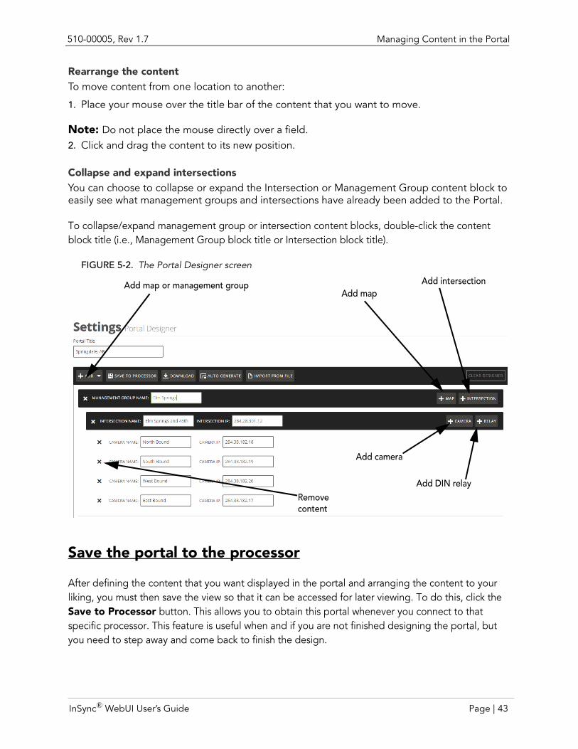
Rearrange the content . . . . . . . . . . . . . . . . . . . . . . . . . . . . . . . . . . . . . . . . . . . 43
Collapse and expand intersections. . . . . . . . . . . . . . . . . . . . . . . . . . . . . . . . . . 43
Save the portal to the processor . . . . . . . . . . . . . . . . . . . . . . . . . . . . . . . . . . . . . . . . 43Propagate the portal to several processors . . . . . . . . . . . . . . . . . . . . . . . . . . . . . . . . 44Edit content in the Portal Designer . . . . . . . . . . . . . . . . . . . . . . . . . . . . . . . . . . . . . . 44
The Management Group View. . . . . . . . . . . . . . . . . . . . . . . . . . . . . . . . . . . . . . . . . . . . . . 45What is it?. . . . . . . . . . . . . . . . . . . . . . . . . . . . . . . . . . . . . . . . . . . . . . . . . . . . . . . . . . 45How does it work? . . . . . . . . . . . . . . . . . . . . . . . . . . . . . . . . . . . . . . . . . . . . . . . . . . . 45Why use it? . . . . . . . . . . . . . . . . . . . . . . . . . . . . . . . . . . . . . . . . . . . . . . . . . . . . . . . . . 46How do I use it? . . . . . . . . . . . . . . . . . . . . . . . . . . . . . . . . . . . . . . . . . . . . . . . . . . . . . 46
Managing Content in the Management Group View . . . . . . . . . . . . . . . . . . . . . . . . . . . . 47Create a Management Group View for the first time. . . . . . . . . . . . . . . . . . . . . . . . . 47
Add intersections. . . . . . . . . . . . . . . . . . . . . . . . . . . . . . . . . . . . . . . . . . . . . . . . . . 47Add all of an intersection’s cameras . . . . . . . . . . . . . . . . . . . . . . . . . . . . . . . . . . . 47Add a custom camera to a column . . . . . . . . . . . . . . . . . . . . . . . . . . . . . . . . . . . . 48Rearrange the content. . . . . . . . . . . . . . . . . . . . . . . . . . . . . . . . . . . . . . . . . . . . . . 48Add gaps between camera views . . . . . . . . . . . . . . . . . . . . . . . . . . . . . . . . . . . . . 48Delete cameras and gaps from the view . . . . . . . . . . . . . . . . . . . . . . . . . . . . . . . . 48
Save the management group view to the processor . . . . . . . . . . . . . . . . . . . . . . . . . 48Propagate the management group view to several processors. . . . . . . . . . . . . . . . . 49Change Management Group View content . . . . . . . . . . . . . . . . . . . . . . . . . . . . . . . . 49
Status . . . . . . . . . . . . . . . . . . . . . . . . . . . . . . . . . . . . . . . . . . . . . . . . . . . . . . . . . . . . . . . . . 50What is it?. . . . . . . . . . . . . . . . . . . . . . . . . . . . . . . . . . . . . . . . . . . . . . . . . . . . . . . . . . 50How does it work? . . . . . . . . . . . . . . . . . . . . . . . . . . . . . . . . . . . . . . . . . . . . . . . . . . . 50Why use it? . . . . . . . . . . . . . . . . . . . . . . . . . . . . . . . . . . . . . . . . . . . . . . . . . . . . . . . . . 50How do I use it? . . . . . . . . . . . . . . . . . . . . . . . . . . . . . . . . . . . . . . . . . . . . . . . . . . . . . 50
The Map. . . . . . . . . . . . . . . . . . . . . . . . . . . . . . . . . . . . . . . . . . . . . . . . . . . . . . . . . . . . . . . 51What is it?. . . . . . . . . . . . . . . . . . . . . . . . . . . . . . . . . . . . . . . . . . . . . . . . . . . . . . . . . . 51
Configuring In|Sync . . . . . . . . . . . . . . . . . . . . . . . . . . . . . . . . . . . . . . .53Configuring In|Sync detection cameras . . . . . . . . . . . . . . . . . . . . . . . . . . . . . . . . . . . . . . . 55
Add In|Sync detection cameras . . . . . . . . . . . . . . . . . . . . . . . . . . . . . . . . . . . . . . . . . 55Add advanced detection cameras. . . . . . . . . . . . . . . . . . . . . . . . . . . . . . . . . . . . . 57
Add a camera . . . . . . . . . . . . . . . . . . . . . . . . . . . . . . . . . . . . . . . . . . . . . . . . . . 57
Assign detection zones to camera . . . . . . . . . . . . . . . . . . . . . . . . . . . . . . . . . . 58
Assign the advanced camera to a lane . . . . . . . . . . . . . . . . . . . . . . . . . . . . . . . 58
Add detection zones . . . . . . . . . . . . . . . . . . . . . . . . . . . . . . . . . . . . . . . . . . . . . . . . . 59
In|Sync® WebUI User’s Guide Page | iii
510-00005
Detection zone tips . . . . . . . . . . . . . . . . . . . . . . . . . . . . . . . . . . . . . . . . . . . . . . . . 61Edit or remove detection zones . . . . . . . . . . . . . . . . . . . . . . . . . . . . . . . . . . . . . . 62
Add segment lines for detection zones . . . . . . . . . . . . . . . . . . . . . . . . . . . . . . . . . . . 63Delete segments . . . . . . . . . . . . . . . . . . . . . . . . . . . . . . . . . . . . . . . . . . . . . . . . . . 64Edit segments . . . . . . . . . . . . . . . . . . . . . . . . . . . . . . . . . . . . . . . . . . . . . . . . . . . . 65
Define presence segments. . . . . . . . . . . . . . . . . . . . . . . . . . . . . . . . . . . . . . . . . . . . . 66Set fog zones (In:Sync and In:Sync:Fusion only). . . . . . . . . . . . . . . . . . . . . . . . . . . . . 67
Fog zone tips . . . . . . . . . . . . . . . . . . . . . . . . . . . . . . . . . . . . . . . . . . . . . . . . . . . . . 68Remove fog zones . . . . . . . . . . . . . . . . . . . . . . . . . . . . . . . . . . . . . . . . . . . . . . . . . 69
Set Stabilization zones (In|Sync:Thermal Only) . . . . . . . . . . . . . . . . . . . . . . . . . . . . . . 70Stabilization tips. . . . . . . . . . . . . . . . . . . . . . . . . . . . . . . . . . . . . . . . . . . . . . . . . . . 71Remove stabilization zones . . . . . . . . . . . . . . . . . . . . . . . . . . . . . . . . . . . . . . . . . . 71
Set Ignore Zones (In|Sync:Thermal Only) . . . . . . . . . . . . . . . . . . . . . . . . . . . . . . . . . . 72Remove ignore zones . . . . . . . . . . . . . . . . . . . . . . . . . . . . . . . . . . . . . . . . . . . . . . 73
Confirm good edge lines . . . . . . . . . . . . . . . . . . . . . . . . . . . . . . . . . . . . . . . . . . . . . . 73Configure external detectors (In|Sync:Fusion) . . . . . . . . . . . . . . . . . . . . . . . . . . . . . . 74
Unassign an external detector from a lane . . . . . . . . . . . . . . . . . . . . . . . . . . . . . . 76Change a detector’s settings. . . . . . . . . . . . . . . . . . . . . . . . . . . . . . . . . . . . . . . . . 76
Confirm detection cameras/external detectors are correctly assigned . . . . . . . . . . . 77Save the configuration . . . . . . . . . . . . . . . . . . . . . . . . . . . . . . . . . . . . . . . . . . . . . . . . 79
Grabbing Camera Backgrounds . . . . . . . . . . . . . . . . . . . . . . . . . . . . . . . . . . . . . . . . . . . . 80Configuring a Multi-Processor Intersection . . . . . . . . . . . . . . . . . . . . . . . . . . . . . . . . . . . . 82
Remotely Controlling an Intersection . . . . . . . . . . . . . . . . . . . . . . . .83Using Manual Controls. . . . . . . . . . . . . . . . . . . . . . . . . . . . . . . . . . . . . . . . . . . . . . . . . . . . 83
Place the system into Detector mode . . . . . . . . . . . . . . . . . . . . . . . . . . . . . . . . . . . . 84Place a detection on a phase (force presence). . . . . . . . . . . . . . . . . . . . . . . . . . . . . . 84Place a manual vehicle call on a phase (manual call) . . . . . . . . . . . . . . . . . . . . . . . . . 85Place a manual pedestrian call . . . . . . . . . . . . . . . . . . . . . . . . . . . . . . . . . . . . . . . . . . 85
Rebooting a Camera . . . . . . . . . . . . . . . . . . . . . . . . . . . . . . . . . . . . . . . . . . . . . . . . . . . . . 85Toggling a Camera into Emergency Mode . . . . . . . . . . . . . . . . . . . . . . . . . . . . . . . . . . . . 86Overriding Fog Mode (In|Sync/In|Sync:Fusion Only) . . . . . . . . . . . . . . . . . . . . . . . . . . . . . 86
Scheduling a Video Recording . . . . . . . . . . . . . . . . . . . . . . . . . . . . . .87Adding a Recording. . . . . . . . . . . . . . . . . . . . . . . . . . . . . . . . . . . . . . . . . . . . . . . . . . . . . . 87Deleting a Scheduled Recording. . . . . . . . . . . . . . . . . . . . . . . . . . . . . . . . . . . . . . . . . . . . 89Viewing a Recording . . . . . . . . . . . . . . . . . . . . . . . . . . . . . . . . . . . . . . . . . . . . . . . . . . . . . 89
Page | iv In|Sync® WebUI User’s Guide
510-00005
In|Sync Administrative Tasks . . . . . . . . . . . . . . . . . . . . . . . . . . . . . . .91Setting the NTP Server . . . . . . . . . . . . . . . . . . . . . . . . . . . . . . . . . . . . . . . . . . . . . . . . . . . 92Synchronize NTP time . . . . . . . . . . . . . . . . . . . . . . . . . . . . . . . . . . . . . . . . . . . . . . . . . . . . 93Syncing time after inital install or processor replacement . . . . . . . . . . . . . . . . . . . . . . . . . 93Renaming Phases. . . . . . . . . . . . . . . . . . . . . . . . . . . . . . . . . . . . . . . . . . . . . . . . . . . . . . . . 95Saving an Archive . . . . . . . . . . . . . . . . . . . . . . . . . . . . . . . . . . . . . . . . . . . . . . . . . . . . . . . 96Restoring a Configuration . . . . . . . . . . . . . . . . . . . . . . . . . . . . . . . . . . . . . . . . . . . . . . . . . 96
From a file uploaded to the processor . . . . . . . . . . . . . . . . . . . . . . . . . . . . . . . . . . . 96From an auto-saved file on the processor . . . . . . . . . . . . . . . . . . . . . . . . . . . . . . . . . 97
Deploying the Application. . . . . . . . . . . . . . . . . . . . . . . . . . . . . . . . . . . . . . . . . . . . . . . . . 97Changing GPS Coordinates. . . . . . . . . . . . . . . . . . . . . . . . . . . . . . . . . . . . . . . . . . . . . . . . 98
To set the processor GPS location with an approximate location: . . . . . . . . . . . . . . 98To set the processor’s GPS coordinates at the intersection with an exact location: . 98
Managing Users. . . . . . . . . . . . . . . . . . . . . . . . . . . . . . . . . . . . . . . . . .99User Permissions . . . . . . . . . . . . . . . . . . . . . . . . . . . . . . . . . . . . . . . . . . . . . . . . . . . . . . . 100Adding a User . . . . . . . . . . . . . . . . . . . . . . . . . . . . . . . . . . . . . . . . . . . . . . . . . . . . . . . . . 101Editing Users . . . . . . . . . . . . . . . . . . . . . . . . . . . . . . . . . . . . . . . . . . . . . . . . . . . . . . . . . . 103Deleting a User . . . . . . . . . . . . . . . . . . . . . . . . . . . . . . . . . . . . . . . . . . . . . . . . . . . . . . . . 104
Configuration Best Practices . . . . . . . . . . . . . . . . . . . . . . . . . . . . . .105Intersection Naming . . . . . . . . . . . . . . . . . . . . . . . . . . . . . . . . . . . . . . . . . . . . . . . . . . . . 105Detector Naming . . . . . . . . . . . . . . . . . . . . . . . . . . . . . . . . . . . . . . . . . . . . . . . . . . . . . . . 105Camera Detection Zone Setup . . . . . . . . . . . . . . . . . . . . . . . . . . . . . . . . . . . . . . . . . . . . 105External Detector Setup (In|Sync:Fusion only) . . . . . . . . . . . . . . . . . . . . . . . . . . . . . . . . . 106
In|Sync® WebUI User’s Guide Page | v
510-00005
Page | vi In|Sync® WebUI User’s Guide
CHAPTER 1 INTRODUCTION
In|Sync is an adaptive traffic signal system developed by Rhythm Engineering that uses our In|Sync Processor’s artificial intelligence with either:
Our video detection system (In|Sync and In|Sync:Thermal)
Our video detection fused with your existing and preferred detection devices (In|Sync:Fusion)
These elements are integrated into a system that automatically optimizes local traffic signals and coordinates signals along roadway arterials according to real-time traffic demand.
This guide provides information on how to configure, monitor and maintain In|Sync from the WebUI, which is easily available from any web browser using any modern web browser on a connected laptop or computer, or using the In|Sync Processor.
For information on installing and maintaining the In|Sync hardware, refer to the In|Sync Installation and Maintenance Guide.
How In|Sync worksTraffic coordination at an intersection has traditionally been managed by a cabinet’s traffic controller using timing plans created for expected traffic conditions. With the introduction of In|Sync through the installation of its plug-in processor, coordination can now be managed using real-time traffic conditions instead of expected traffic conditions. The installation involves:
Installing an industrial computer in the form of the In|Sync Processor.
Installing detection cameras.
For In|Sync and In|Sync:Thermal installations, the detection cameras determine how many cars are present in each lane. For In|Sync:Fusion installations, detection cameras are used in conjunction with existing detection methods to determine queue at an approach. With this queue estimation derived from real-time traffic demand, the processor is then able to determine real-time adaptive coordination.
InSync® WebUI User’s Guide Page | 1
How In|Sync works 510-00005, Rev 1.7
In|Sync installation: A two-phase process
The installation of an In|Sync system can be broken into two phases:
Hardware Installation
• Install the In|Sync equipment.
• Confirm camera views.
• Configure the In|Sync intersection using the Configuration Management application.
• Grab camera backgrounds.
• Map controller inputs and outputs.
• Connect In|Sync to cabinet/controller
• Test all of In|Sync’s communications with the controller
• Confirm that In|Sync is receiving all the information that it needs from the field inputs
• Confirm that In|Sync is sending all the information that it needs to send to the control-ler and that the controller is receiving the signal.
• Complete the installation checklist. The intersection is now in Detector mode.
Note: There is no difference in how traffic is serviced before In|Sync was installed and after In|Sync is installed and set to Detector mode.
Adaptive Turn On
• Change settings on the controller (referred to as “Freeing up the controller”) so thatthe controller is no longer responsible for coordination
• Turn In|Sync’s Adaptive mode on
Note: One significant change in how you perform your job after switching to Adaptive mode is in how you view placed calls. You will not be able to accurately view presence through the controller’s display. Instead, you must use the In|Sync WebUI to view placed calls. This can be done either through a monitor and keyboard connected to the processor (at the cabinet), a laptop connected to the network (at the cabinet), or through a computer remotely connected to the processor.
Why is this? Because In|Sync places at most two calls to the controller at a time even when there are calls from the detectors on other phases. These two calls are the phases that In|Sync determines needs service. This means that the controller only receives those calls and not the calls on the other phases.
The only way to accurately view detections on the controller’s display is to switch back to Detector mode. However, putting the In|Sync Processor back into Detector mode will break coordination, as the controller will still be in Free mode (no coordination). One option to guard against having no coordination at an intersection is to set up the Free Mode pin to run a default timing plan (see the Troubleshooting chapter in the In|Sync Installation and Maintenance Guide for more information on the Free Mode function).
Page | 2 InSync® WebUI User’s Guide
510-00005, Rev 1.7 How In|Sync works
WHAT IS DETECTOR MODE?
Detector mode is a state in which the In|Sync Processor simply sends detections directly to the controller, allowing the controller to continue to be responsible for traffic coordination, just like it was before In|Sync was installed. After installing the In|Sync Processor, you should run Detector mode for two weeks to verify that inputs and outputs are being sent properly and to allow enough time for a management group to be installed. For instance, a 10-intersection management group may take up to a week to have processors installed at each intersection. The two-week time period allows for enough time to get all intersections installed, running, and tested with the In|Sync Processor.
WHAT IS ADAPTIVE MODE?
Adaptive mode is a state in which the In|Sync Processor analyzes queue and spontaneously chooses the phases and sequences that best serve actual traffic demand. During Adaptive mode, the system determines priority so it can serve approaches intelligently. The system chooses from the states (concurrently permissible phasing) available to it and requests the traffic controller actuate green lights accordingly.
WHAT IS CAMERAIO?
Every once in a while, the term “CameraIO” appears in the In|Sync WebUI Guide. The term “CameraIO” refers to the part of the In|Sync software that reads and processes images coming from each camera (video detection), which is then sent to the In|Sync WebUI. A separate instance of CameraIO runs for each camera at the intersection. You can view each camera’s CameraIO process through a button on the In|Sync Processor desktop.
WHAT IS SUPERVISION?
In addition to seeing CameraIO every once in a while in the In|Sync WebUI Guide, you may also see the term "SuperVision." “SuperVision” refers to the part of the In|Sync software that reads and processes images coming from each thermal detection camera, whereas, CameraIO refers to the software that reads and processes images coming from video detection cameras. Like CameraIO, a separate instance of SuperVision runs for each camera at the intersection. You can view each camera’s SuperVision process through a button on the In|Sync Processor kiosk.
InSync® WebUI User’s Guide Page | 3
Related Documents 510-00005, Rev 1.7
Related DocumentsThe In|Sync Installation and Maintenance Guide provides complete information about the installation, configuration, and maintenance of the In|Sync hardware components and is available by contacting Rhythm Engineering. For information regarding In|Traffic, the traffic configuration companion to In|Sync, refer to the In|Traffic User Guide.
Access Online HelpSelect the Help menu item located on the upper right side of the page to obtain more information regarding using the In|Sync WebUI application.
The help documentation includes a Table of Contents with detailed instructions and explanations of system details.
Page | 4 InSync® WebUI User’s Guide
510-00005, Rev 1.7 User Guide Conventions
User Guide ConventionsThis document uses these conventions and symbols for notes, cautions, and warnings:
Field Names
This style indicates that the text will be found on a clickable button on a screen. For example:
Click the Back button to return to the Web page you last viewed.
[Keyboard function]
A key on the keyboard is shown in this style. For example:
Optionally, to move between fields you can use the [Tab] key.
User input
Text that the user has to type, either on the command line, or into a text box on a screen, is displayed in this style. In the following example, text is displayed in this style:
To log into the WebUI using the default view access, type User into the Log In dialog box.
Note: Means reader take note. Notes contain helpful suggestions or references to materials not contained in this manual.
CAUTION: Means reader be careful. In this situation, you might do something that could result in equipment damage or loss of information.
WARNING:Means that you are in a situation that could cause bodily injury. Before you work on any equipment, be aware of the hazards involved with electrical circuitry and be familiar with standard practices for preventing accidents.
InSync® WebUI User’s Guide Page | 5
Contact Rhythm Engineering Support 510-00005, Rev 1.7
Contact Rhythm Engineering SupportRhythm Engineering technical support will ensure that the fast and easy access that you have come to expect from your In|Sync products will be maintained. You can reach us through the following methods:
Web access
http://www.rhythmtraffic.com
Email access
Technical requests can also be sent to [email protected].
Telephone access
913-6–Rhythm (913–674–9846)
Page | 6 InSync® WebUI User’s Guide
CHAPTER 2 THE IN|SYNC WEBUI INTERFACE
Read this chapter to learn how to navigate the In|Sync WebUI screen, log into the In|Sync WebUI, and customize the screens.
What you needTo access the In|Sync WebUI, you need one of the following
Monitor and keyboard to access the WebUI from the In|Sync Processor
Laptop with either Internet Explorer 7+, Chrome, Safari or Firefox installed to access the WebUI from the In|Sync Processor
Computer with either Internet Explorer 7+, Chrome, Safari or Firefox installed with outside network connectivity to access the In|Sync Processor remotely
Note: Although you can operate the In|Sync WebUI within Internet Explorer 10, we recommend the use of other browsers for a better UI experience.
Note: If your computer screen is set to a 1024 x 768 resolution, it is recommended that you run the In|Sync WebUI in full screen mode. Full screen mode can be turned on/off by pressing the F11 key.
The following ports must be open to use the In|Sync WebUI:
HTTP access (port 80) and/or HTTPS access (port 443) to each In|Sync network device (In|Sync Processor, monitoring camera, DIN Relay, and Ethernet repeater) and the WebUI
RDP access (port 3389) to each In|Sync Processor
SMTP access (port 25) for outbound access to Rhythm mail server at notify.rhythmtraffic.com
Port 20000 and 445 for In|Sync communications
554: RTSP port
4520: Device control and streaming for ActiveX Control
943: Silverlight policy
InSync® WebUI User’s Guide Page | 7
Logging in to In|Sync 510-00005, Rev 1.7
Port 123 for NTP (outbound to NTP server 12.40.33.99)
Multiple user access for at least 4 user accounts via the VPN connection
A router that has been installed and configured to enable VPN capabilities
DNS:
• Primary: 8.8.8.8
• Alternate: 8.8.4.4
Note: If you cannot access the WebUI, check with your network administrator to be sure these ports are open.
In addition, you will need a user name and password (provided by Rhythm Engineering) in order to log in to the In|Sync WebUI.
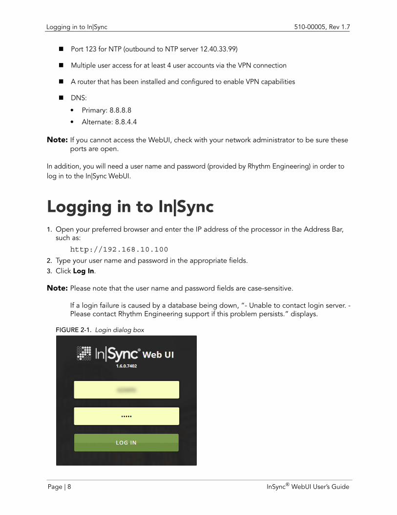
Logging in to In|Sync1. Open your preferred browser and enter the IP address of the processor in the Address Bar,
such as:
http://192.168.10.100
2. Type your user name and password in the appropriate fields.3. Click Log In.
Note: Please note that the user name and password fields are case-sensitive.
If a login failure is caused by a database being down, “- Unable to contact login server. -Please contact Rhythm Engineering support if this problem persists.” displays.
FIGURE 2-1. Login dialog box
Page | 8 InSync® WebUI User’s Guide
510-00005, Rev 1.7 Logging in to In|Sync
Note: If your account is set to timeout after a certain amount of time, you are automatically logged out of In|Sync after the associated inactive time is reached. If you are logged out because of inactivity, re-logging into In|Sync displays the last screen opened before you were logged out.
The functionality that is available to you through the WebUI is dependent upon the user access set up for your username. This can be accessed by an administrator on the Edit Users screen.
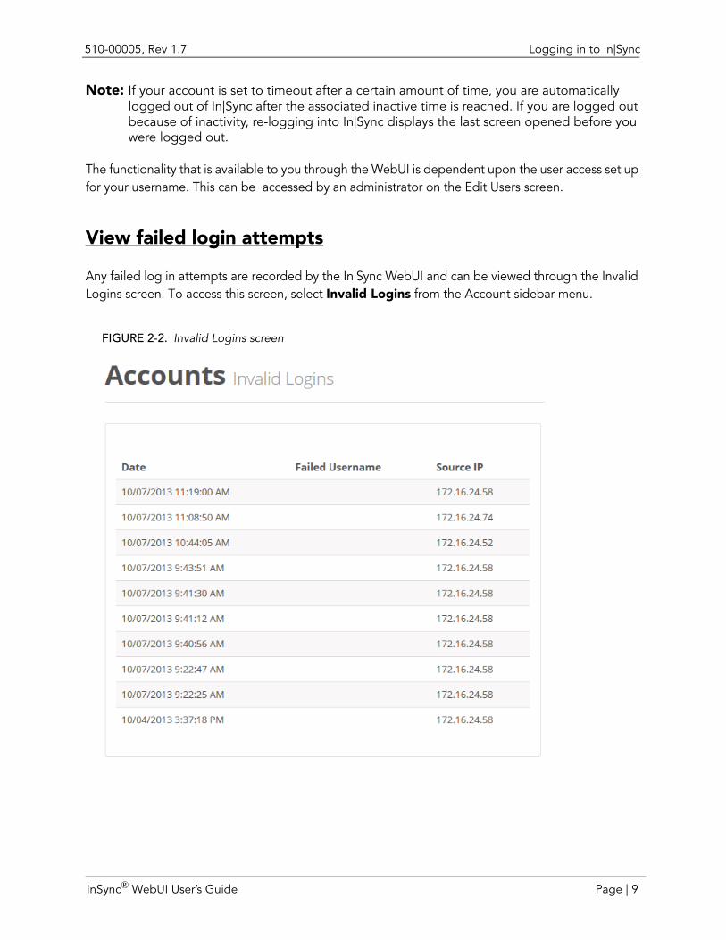
View failed login attempts
Any failed log in attempts are recorded by the In|Sync WebUI and can be viewed through the Invalid Logins screen. To access this screen, select Invalid Logins from the Account sidebar menu.
FIGURE 2-2. Invalid Logins screen
InSync® WebUI User’s Guide Page | 9
The Dashboard 510-00005, Rev 1.7
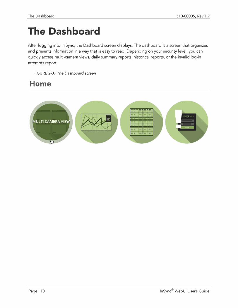
The DashboardAfter logging into In|Sync, the Dashboard screen displays. The dashboard is a screen that organizes and presents information in a way that is easy to read. Depending on your security level, you can quickly access multi-camera views, daily summary reports, historical reports, or the invalid log-in attempts report.
FIGURE 2-3. The Dashboard screen
Page | 10 InSync® WebUI User’s Guide
510-00005, Rev 1.7 Screen Conventions
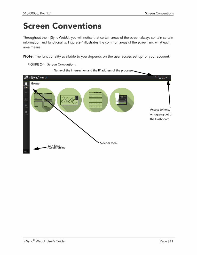
Screen ConventionsThroughout the In|Sync WebUI, you will notice that certain areas of the screen always contain certain information and functionality. Figure 2-4 illustrates the common areas of the screen and what each area means.
Note: The functionality available to you depends on the user access set up for your account.
FIGURE 2-4. Screen Conventions
Name of the intersection and the IP address of the processor
Access to help,
Sidebar menuAccess onlinehelp here
or logging out ofthe Dashboard
InSync® WebUI User’s Guide Page | 11
Screen Conventions 510-00005, Rev 1.7
Menus
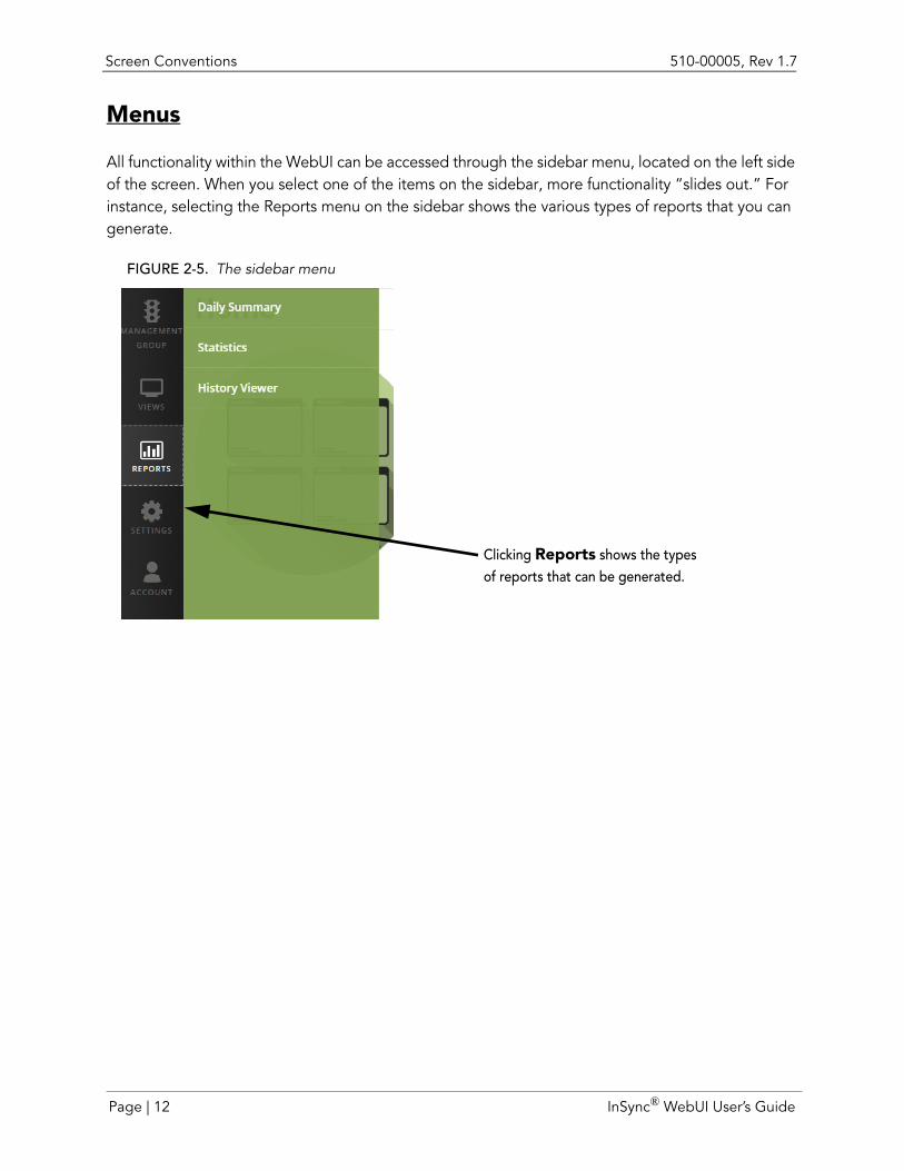
All functionality within the WebUI can be accessed through the sidebar menu, located on the left side of the screen. When you select one of the items on the sidebar, more functionality “slides out.” For instance, selecting the Reports menu on the sidebar shows the various types of reports that you can generate.
FIGURE 2-5. The sidebar menu
Clicking Reports shows the typesof reports that can be generated.
Page | 12 InSync® WebUI User’s Guide
CHAPTER 3 VIEWING AN INTERSECTION
There are several ways to watch the operation of an intersection. You can choose to look at all cameras at the intersection by selecting Multi Camera View from the Views menu or you can choose to view a single direction by selecting Single Camera View from the Views menu. Within the Multi Camera View, you can also choose to see a cartoon representation of the operation of an intersection.
With either intersection viewing choice, there are many methods for monitoring the intersection. The following sections detail what those methods are and how to use each viewing choice.
Camera BasicsWithin the In|Sync WebUI, you can choose to view traffic exactly as the view is coming off the camera (unprocessed) or by the default view. The default view, or processed view, includes various text and icons that indicate the traffic conditions In|Sync has recognized and how it is operating based on that information.
What are unprocessed views?
Unprocessed view simply means that the view you see is the raw footage that is coming straight from the camera.
InSync® WebUI User’s Guide Page | 13
Camera Basics 510-00005, Rev 1.7
FIGURE 3-1. Single, unprocessed camera view does not include markings
Cartoon view
In addition to being able to view processed or unprocessed views from the camera, there is a viewing option available from within the Multiple Cameras view called Cartoon View. The Cartoon View can be accessed through the View Styles drop-down list box.
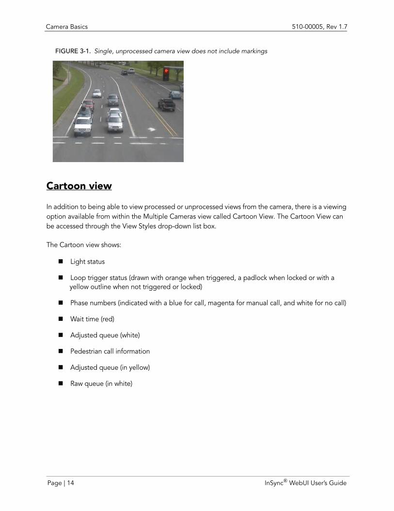
The Cartoon view shows:
Light status
Loop trigger status (drawn with orange when triggered, a padlock when locked or with a yellow outline when not triggered or locked)
Phase numbers (indicated with a blue for call, magenta for manual call, and white for no call)
Wait time (red)
Adjusted queue (white)
Pedestrian call information
Adjusted queue (in yellow)
Raw queue (in white)
Page | 14 InSync® WebUI User’s Guide
510-00005, Rev 1.7 Camera Basics
FIGURE 3-2. Cartoon view
System time displays at the top right corner of the Cartoon View. If the light is unresponsive to In|Sync calls, a crossed out signal head indicator appears in the top left corner of the Cartoon View.
Pedestrianinformation
Light status
Wait time
Raw queue
Adjust queue
Loop triggerstatus Phase numbers
System time
InSync® WebUI User’s Guide Page | 15
Camera Basics 510-00005, Rev 1.7
Camera view icons
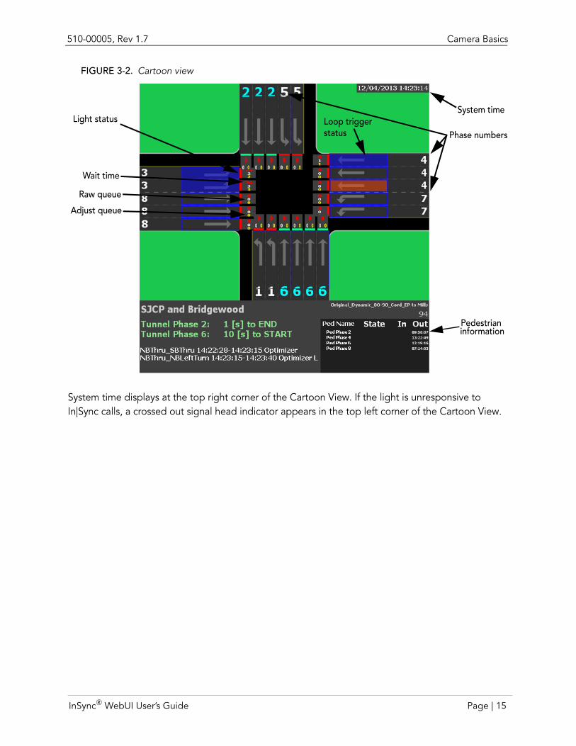
Under certain conditions, you may see the following icons display on the camera view. These icons indicate certain failure conditions and are represented as follows:
Icon MeaningThere is no response from the IP address associate with the camera for several sec-onds.
A person has placed the camera in "Emergency Mode" via the In|Sync web inter-face.
The image processing has determined the view is compromised based on analysis of the fog zones.
In|Sync camera’s Fog mode is disabled temporarily.
An In|Sync camera is currently recording video.
The image processing has determined the view is compromised based on overall image analysis. This is looking for characteristics of the sun refracting on the lens.
This icon actually has nothing to do with the actual image or camera. In|Sync can be set to compare the traffic pattern to historical traffic patterns. If the traffic drops sig-nificantly below the historical level, it will go into "low flow" mode and display this icon.Indicates that a phase on the particular camera view has been waiting one and a half times the current period. If in Detector or tunnel-less mode, the yellow triangle appears when a vehicle on that phase has been waiting one and a half times the maximum wait time setting for that phase.Indicates a serious issue with the In|Sync optimizer. Contact Rhythm support as soon as possible.
Emergency Vehicle Preemption: This icon displays when In|Sync is configured to listen to an emergency vehicle preemption signal (configured in the IO Mapper). This icon appears only when the signal is being received and disappears when the signal is dropped.Offline Mode: Displays whenever any intersection on the management group loses network connectivity. Even the still-connected intersections in the management group run in Offline mode so that coordination is maintained.Railroad Preemption: Displays when In|Sync is configured to listen to an railroad preemption signal (configured in the IO Mapper). This icon appears only when the signal is being received and disappears when the signal is dropped.
Page | 16 InSync® WebUI User’s Guide
510-00005, Rev 1.7 Camera Basics
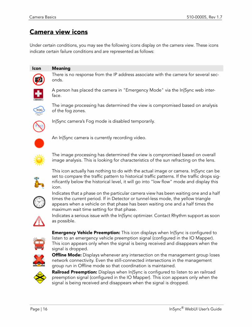
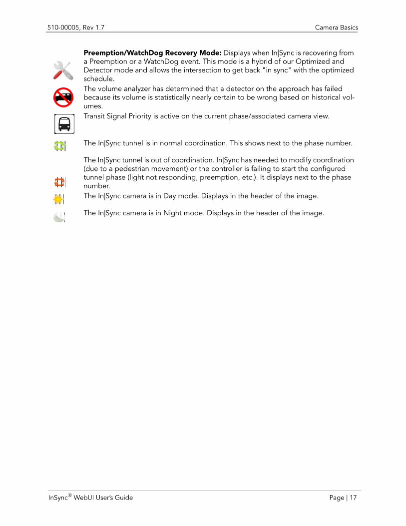
Preemption/WatchDog Recovery Mode: Displays when In|Sync is recovering from a Preemption or a WatchDog event. This mode is a hybrid of our Optimized and Detector mode and allows the intersection to get back "in sync" with the optimized schedule.The volume analyzer has determined that a detector on the approach has failed because its volume is statistically nearly certain to be wrong based on historical vol-umes.Transit Signal Priority is active on the current phase/associated camera view.
The In|Sync tunnel is in normal coordination. This shows next to the phase number.
The In|Sync tunnel is out of coordination. In|Sync has needed to modify coordination (due to a pedestrian movement) or the controller is failing to start the configured tunnel phase (light not responding, preemption, etc.). It displays next to the phase number.The In|Sync camera is in Day mode. Displays in the header of the image.
The In|Sync camera is in Night mode. Displays in the header of the image.
InSync® WebUI User’s Guide Page | 17
Viewing Multiple Cameras at an Intersection 510-00005, Rev 1.7
Viewing Multiple Cameras at an IntersectionWithin the Multiple Camera view, there are several options available to you for viewing the cameras at the intersection.
Note: All camera views can be paused by pressing the [P] key on the keyboard. Camera views also automatically pause when you minimize the browser (note the time not changing to verify views are paused) or change tabs within a browser.
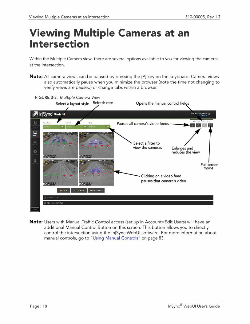
FIGURE 3-3. Multiple Camera View
Note: Users with Manual Traffic Control access (set up in Account>Edit Users) will have an additional Manual Control Button on this screen. This button allows you to directly control the intersection using the In|Sync WebUI software. For more information about manual controls, go to “Using Manual Controls” on page 83.
Enlarges and
Select a layout style Refresh rate
Select a filter to view the cameras
reduces the view
Full screenmode
Pauses all camera’s video feeds
Clicking on a video feedpauses that camera’s video
Opens the manual control fields
Page | 18 InSync® WebUI User’s Guide
510-00005, Rev 1.7 Viewing Multiple Cameras at an Intersection
Change view styles
The Multiple Camera view provides several different styles for viewing cameras, which can be selected from the View Styles drop-down list box:
Standard: Camera views displays in two columns.
Diamond: Camera views are displayed in a diamond shape.
3 Column: Camera views display in three columns.
4 Column: Camera views display in four columns.
Cartoon View: Displays a cartoon view representation of the following traffic conditions at the intersection:
• Light status
• Loop trigger status (drawn with orange when triggered, a padlock when locked or witha yellow outline when not triggered or locked)
• Phase calls (indicated with a blue for call, magenta for manual call, and white for nocall)
• Wait time (red)
• Adjusted queue (white)
• Pedestrian phase information
Enlarge and condense camera views
The views can be enlarged or reduced by clicking the zoom icons, which are located on the top right side of the screen.
Set the Refresh rate
The Refresh rate is the frequency at which the camera sends images to the In|Sync WebUI. You can select between:
Fastest
Every 1/2 second
Every Second
Every 2 Seconds
Every 5 Seconds
InSync® WebUI User’s Guide Page | 19
Viewing Multiple Cameras at an Intersection 510-00005, Rev 1.7
Every 30 Seconds
Every 60 Seconds
Note: The faster the frame rate, the higher the processor’s bandwidth usage.
Note: Your network’s speed may limit you to a lower frame rate (i.e., the frame rate used to process views may be slower than the actual frame rate you selected when you are on a slower network.)
Rearrange camera views
You can move camera views around by clicking on a camera view and dragging it to the new position on the screen. To restore the layout to its default view, click the Reset Layout button at the bottom of the camera views.
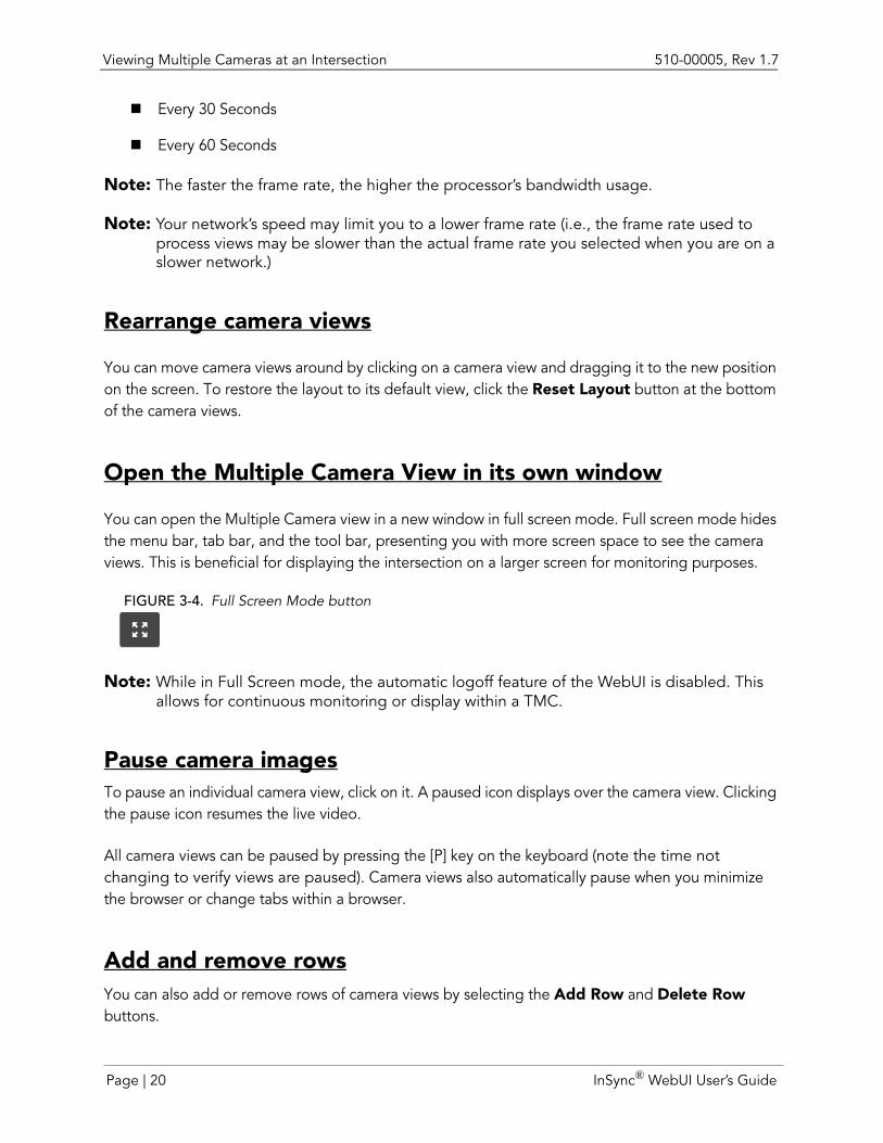
Open the Multiple Camera View in its own window
You can open the Multiple Camera view in a new window in full screen mode. Full screen mode hides the menu bar, tab bar, and the tool bar, presenting you with more screen space to see the camera views. This is beneficial for displaying the intersection on a larger screen for monitoring purposes.
FIGURE 3-4. Full Screen Mode button
Note: While in Full Screen mode, the automatic logoff feature of the WebUI is disabled. This allows for continuous monitoring or display within a TMC.
Pause camera imagesTo pause an individual camera view, click on it. A paused icon displays over the camera view. Clicking the pause icon resumes the live video.
All camera views can be paused by pressing the [P] key on the keyboard (note the time not changing to verify views are paused). Camera views also automatically pause when you minimize the browser or change tabs within a browser.
Add and remove rowsYou can also add or remove rows of camera views by selecting the Add Row and Delete Row buttons.
Page | 20 InSync® WebUI User’s Guide
510-00005, Rev 1.7 Viewing In|Sync Intersection Status
Viewing In|Sync Intersection StatusIn addition to viewing all the cameras at an intersection through the Multiple Camera view, you can also see important status information regarding the In|Sync installation. To view In|Sync Status information, scroll down below the camera views and click In|Sync Status. The area expands with the following status items:
Build: The build number of the In|Sync software running on the processor.
Mode: Indicates whether or not the intersection is running in adaptive or detector mode.
Intersection: The name of the intersection.
NTP Status: Displays whether or not the In|Sync Processor is able to communicate with the NTP server. The NTP server keeps time synchronized between all processors.
Time: Current time in HH:MM:SS, military-style format.
Configuration: The name of the configuration currently running.
Railroad Preemption: Displays whether railroad preemption is currently running. This only displays if a railroad preemption is taking place.
Emergency Preemption: Displays whether emergency preemption is currently running. This only displays if an emergency preemption is taking place.
Recovery Mode: Displays whether the intersection is currently recovering from being in railroad or emergency preemption. This only displays if In|Sync is in recovery mode.
IO Board Version (i.e., FusionIO (v4): The version number of the IO board(s) configured at the intersection. This can be more than one (i.e., SDLC, Intercept Module, V2 board). For instance, if you are connecting to your signals using an SDLC connection, you would have an IO board version number for both the SDLC module and the In|Sync Processor’s Fusion IO board.
Firmware: The version number of the firmware within the In|Sync Processor. This can be more than one (i.e., SDLC, Intercept Module, V2 board). For instance, if you are connecting to your signals using an SDLC connection, you would have a firmware version for both the SDLC module and the In|Sync Processor’s Fusion IO board.
Volume Analyzer: Indicates whether the processor software is communicating with the software that provides detector information (vehicle triggers).
Intersection IP: The IP address assigned to the In|Sync Processor at the intersection.
Intersection Subnet: The subnet address assigned to the In|Sync Processor at the intersection.
InSync® WebUI User’s Guide Page | 21

Viewing Processor Status 510-00005, Rev 1.7
Intersection Gateway: The subnet gateway assigned to the In|Sync Processor at the intersection.
Intersection DNS: The IP address of the domain name server.
Active Triggers: The type of trigger, priority, start condition, end condition, name of the configuration that runs when the trigger is detected, and if the trigger type is Phase Omit, the vehicle and pedestrian phases that are omitted from the configuration
Note: The Active Triggers information only displays if a trigger has been initiated.
Viewing Processor StatusYou can also obtain important hardware performance information regarding the In|Sync Processor from the Multiple Camera view. To see this information, scroll to the bottom of the screen and click Processor Status. You can then view:
Core temperature of the CPU
Load percentage: The percentage of CPU being used (i.e., 50% load means the CPU is working at 50% of the maximum load it can handle).
Note: This information can be handy in diagnosing issues.
Viewing a Single CameraThe single camera view allows for a more in-depth look from a single camera. From this screen you can choose which camera direction you want to view by selecting the camera from the Camera drop-down list box. You can also select a different frame rate at which the screen refreshes by selecting the rate from the Refresh drop-down list box.
Finally, you can choose from several filters to view the camera:
Normal: Shows the raw footage coming from the camera along with markings indicating what In|Sync has recognized and how it is operating based on that information.
Unprocessed: Shows only the raw footage coming from the camera.
Edge: Shows the sharp edge boundaries in the image, such as the edge between a subject and a background of a contrasting color; this is helpful for confirming that a certain object creates a good edge line for drawing a fog zone.
Foreground: Shows the foreground image (such as moving vehicles) within a camera view and displays only those foreground images along with the detection zones on that approach.
Page | 22 InSync® WebUI User’s Guide
510-00005, Rev 1.7 Viewing a Single Camera
To obtain a Foreground view, In|Sync compares a captured background image with the current camera view. Pixels in the image that are “different enough” from the reference background image are then classified as foreground pixels.
Background: Detects the background image within a camera view and only displays those background images along with fog zones that are drawn around background images. The background image is initially grabbed by a user (usually during the installation), and then is automatically updated by the software to reflect the changing conditions being seen by the camera.
Note: Grabbing a background image is functionality available to users with Cameras access (set in Accounts>Edit Users). For instructions on grabbing background images, go to “Grabbing Camera Backgrounds” on page 80.
Viewing camera status
Camera status information is available at the bottom of the Single Camera View. To view information about the camera, scroll to the bottom of the screen and click Camera Status. The following general camera information displays:
Note: The only camera status items available for In|Sync:Thermal cameras are the camera’s IP address, camera model, hardware version number and whether or not the camera is set to record.
IP Address: The camera’s IP address.
Camera Model: Indicates the type of detection camera at the approach (Axis 221, Samsung 5200 or Samsung 6320).
Impaired View: Indicates when In|Sync believes the camera view is not suitable for image processing. When impaired in any way, historical information and light state is used to calculate the “Fog Mode” presence and queue values.
Fog Mode Allowed: Indicates whether In|Sync is honoring or ignoring any analysis that a camera view is impaired.
Night Fog Mode Allowed: Indicates whether In|Sync is honoring or ignoring any analysis that a camera view is impaired during nighttime hours.
Obstruction Analysis: Indicates if a view is obstructed when looking at the whole image instead of just fog zones. Possible values are “Off,” “Night Only,” “Day and Night.”
Tail Processing: Indicates whether or not tail processing is turned on.
Tail processing is the tracking of movements of vehicles within a detection zone - starting at the first video frame in which it is detected to the point where a vehicle exits the lane and enters the intersection. This tracking creates a "tail." Tails are useful in determining whether a moving object is in fact a vehicle. In theory, long tails represent vehicles
InSync® WebUI User’s Guide Page | 23
Viewing a Single Camera 510-00005, Rev 1.7
moving in a lane. Short tails represent miscellaneous objects that may enter and exit a lane quickly, like a deer crossing the road.
There may be situations in which a vehicle does create a short tail, like when a driveway is situated in close proximity to an intersection. In this situation, a car entering a lane from the driveway would not register a long tail. In those specific instances, you may want to turn tail processing off so that vehicle would register as a detection.
Recording: Indicates whether the camera is currently recording.
Video performance is directly affected by network connection quality. As the network signal degrades, the amount of data transferred decreases, and the video frame rate goes down. The following camera status information helps in determining if connection quality has weakened:
Frame acquisition: The MJPEG Acquire time is the amount of time it takes CameraIO to read a complete single image frame from the network. The In|Sync detection cameras are typically continuously streaming a series of JPEG streams. The processor pulls data from that stream continuously. Whenever the end of a JPEG image frame is reached, it is eligible for processing. The Frame acquisition is the it took to acquire the last image frame, along with the minimum, maximum, and average. Typically the range of these numbers should be in the 50-150 milliseconds range. An average that exceeds 200ms is problematic.
• Last frame acquisition: The time it took to acquire the last image frame.• Min: The minimum time between acquired image frames. This number resets every
15 seconds.
• Max: The maximum time between acquired image frames. This number resets every15 seconds.
• Avg: The average time it takes between acquired images frames. This number resetsevery 15 seconds.
Note: If the In|Sync Processor is receiving a weak signal from a detection camera, consider installing an Ethernet Repeater and PoE between the cameras and the equipment panel. An Ethernet Repeater boosts Ethernet signal strength, which in turn can quicken processing speeds.
Frame Processing: Once a frame has been acquired, it is placed into a buffer to wait for processing. Once that frame starts processing, CameraIO times how long the analysis of that frame takes. This is the processing time.
Processing times should be fast (under 50ms). This time is impacted by quite a few things, and varies greatly. However, if it exceeds 50ms on average or regularly, you may want to investigate. The Frame Processing field is broken into several pieces of information:
• Last frame processing: The time it took to process the last frame.
• Min: The minimum time CameraIO has processed the frame. This number resets every15 seconds.
• Max: The maximum amount of time CameraIO has processed the frame. This numberresets every 15 seconds.
Page | 24 InSync® WebUI User’s Guide
510-00005, Rev 1.7 Viewing a Single Camera
• Avg: The average amount of time CameraIO takes to process a frame. This numberresets every 15 seconds.
FPS: (frames per second) This field is broken into two pieces of information:
• The instantaneous FPS that CameraIO is processing data.
• FPS (running avg): A continuous running average of the FPS
FPS should be at 5 or above, and can go as high as 15. FPS values consistently below5 indicate an issue and will cause video detection to run in a sensitive mode.
Detection Zone Coverage: The percentage of the image that is occupied by video detection lanes. Knowing this percentage can help when dealing with CPU overload scenarios. A "normal" view probably uses about 20-30% of the image.
Sensitivity: This indicates how sensitive the video detection algorithm is set to allow objects to be classified/not classified as a detection that normally would/would not be classified as detection. Fifty percent is the default value in CameraIO, which is considered normal sensitivity.
You may want to increase sensitivity in situations where video detection produces a lot of false negatives (missing detection that is present). This can happen when there is constantly heavy traffic over an extended period of time or if there is a poor camera view or badly drawn detection zones.
Alternatively, you may want to decrease sensitivity in situations where video detection produces a lot of false positives (detecting objects that do not exist). Instances of false positives occur in situations where traffic lanes have distinguishing marks, such as stripes/arrows or tar patches), when the images coming from the detection cameras are jerky due to camera movement caused by wind, etc., or when detection zones are drawn too small.
NightSensitivity: This indicates how sensitive the video detection algorithm is set during the nighttime hours to allow objects to be classified/not classified as a detection that normally would/would not be classified as detection. Fifty percent is the default value in CameraIO, which is considered normal sensitivity. For reasons for increasing sensitivity, see the previous definition of Sensitivity.
Lag: This indicates the estimated delay between the image that is being processed by the video detection system and the actual traffic at the intersection.
Poor network connections to the camera causes the camera to buffer images sent to the video processor. As a result, the video detection system starts to operate on images in the past, thereby producing vehicle detection results from the past. To counteract this, In|Sync monitors lag time. When it drifts too far from real-time, the stream is disconnected and reconnected to clear the buffer.
# Reference Images: Lists the number of images In|Sync is using to compare to the current image for obstruction analysis
InSync® WebUI User’s Guide Page | 25
Viewing a Single Camera 510-00005, Rev 1.7
Largest Ref Mismatch: Indicates the size of the largest “obstruction” detected by the Obstruction Analysis algorithm.
Brightness level: Brightness of the frame, related to sunblind detection.
Page | 26 InSync® WebUI User’s Guide
CHAPTER 4 REPORTS
In|Sync records a tremendous amount of data. This data can be very useful in determining trends, reviewing what happened at an intersection at a particular moment in time, or evaluating In|Sync’s performance. Through the In|Sync WebUI, there are three different types of reports available:
Daily Summary
Statistics
History Viewer
Before discussing each report type, the following sections detail the various methods for navigating graphs and tables.
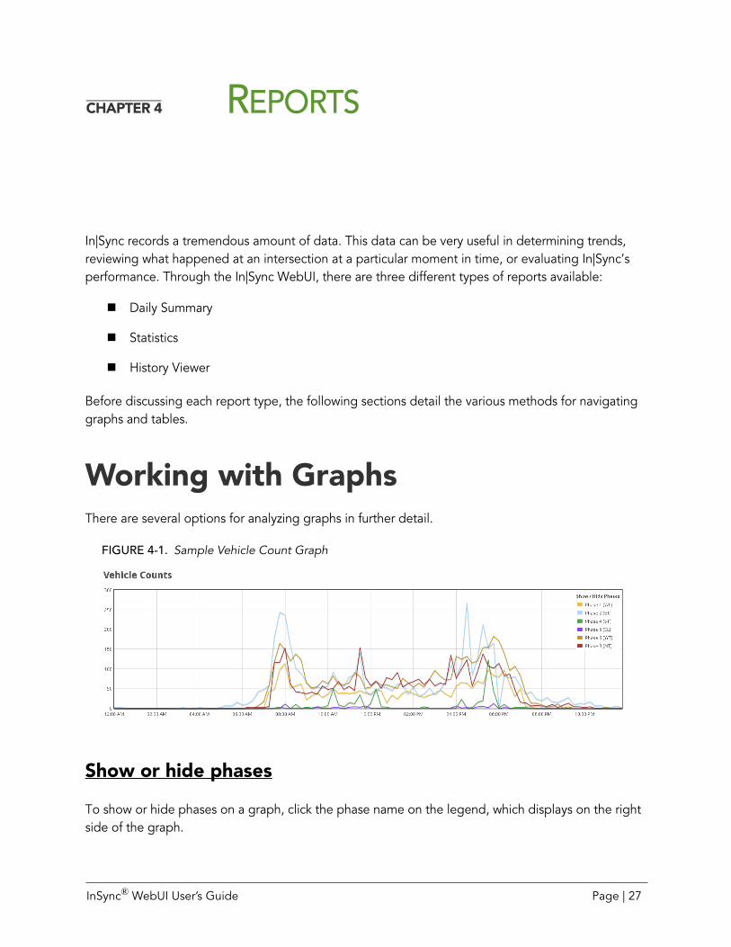
Working with GraphsThere are several options for analyzing graphs in further detail.
FIGURE 4-1. Sample Vehicle Count Graph
Show or hide phases
To show or hide phases on a graph, click the phase name on the legend, which displays on the right side of the graph.
InSync® WebUI User’s Guide Page | 27
Daily Summary 510-00005, Rev 1.7
Zoom in on an area of the graph
To enlarge an area of the map, double-click on the area of the map that you want enlarged, or roll your mouse’s middle wheel.
Navigate within the graph
To move within the graph, click anywhere on the graph and drag the graph until the area you want to view is displayed.
View graph details
You can view the data points within the graph by hovering the mouse over a plotted point. Detailed graph data displays in a tool tip.
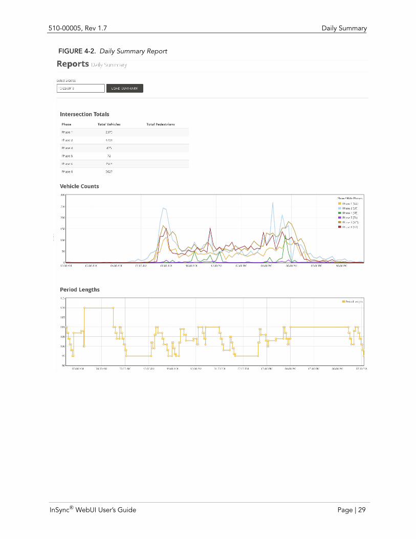
Daily SummaryThe Daily Summary report provides several pieces of information:
Intersection Totals:
• Total vehicles counts for the selected day/time period per phase
• Total pedestrian counts for the selected day/time period per phase
Vehicle Counts: The Vehicle Count section presents a graphical display of vehicle counts per phase at each hour of the day.
Period Lengths: The Period Length section presents a graphical display of period lengths per phase for a time period.
Generate a Daily Summary
To generate a Daily Summary report:
1. Select Daily Summary from the Dashboard or from the Reports menu.2. Click in the Date field. A calendar for selecting a date displays.3. Select the month and day for which you want to display a summary report.4. Click Load Summary. The Summary Report displays.
Page | 28 InSync® WebUI User’s Guide
510-00005, Rev 1.7 Daily Summary
FIGURE 4-2. Daily Summary Report
InSync® WebUI User’s Guide Page | 29
Statistics 510-00005, Rev 1.7
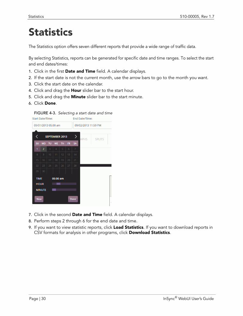
StatisticsThe Statistics option offers seven different reports that provide a wide range of traffic data.
By selecting Statistics, reports can be generated for specific date and time ranges. To select the start and end dates/times:
1. Click in the first Date and Time field. A calendar displays.2. If the start date is not the current month, use the arrow bars to go to the month you want. 3. Click the start date on the calendar.4. Click and drag the Hour slider bar to the start hour.5. Click and drag the Minute slider bar to the start minute.6. Click Done.
FIGURE 4-3. Selecting a start date and time
7. Click in the second Date and Time field. A calendar displays.8. Perform steps 2 through 6 for the end date and time.9. If you want to view statistic reports, click Load Statistics. If you want to download reports in
CSV formats for analysis in other programs, click Download Statistics.
Page | 30 InSync® WebUI User’s Guide
510-00005, Rev 1.7 Statistics
Viewable Statistical Reports
The following reports are viewable through the In|Sync WebUI.
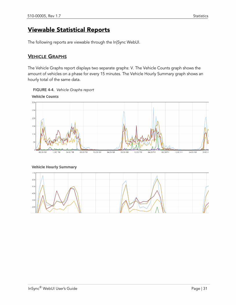
VEHICLE GRAPHS
The Vehicle Graphs report displays two separate graphs: V. The Vehicle Counts graph shows the amount of vehicles on a phase for every 15 minutes. The Vehicle Hourly Summary graph shows an hourly total of the same data.
FIGURE 4-4. Vehicle Graphs report
InSync® WebUI User’s Guide Page | 31
Statistics 510-00005, Rev 1.7
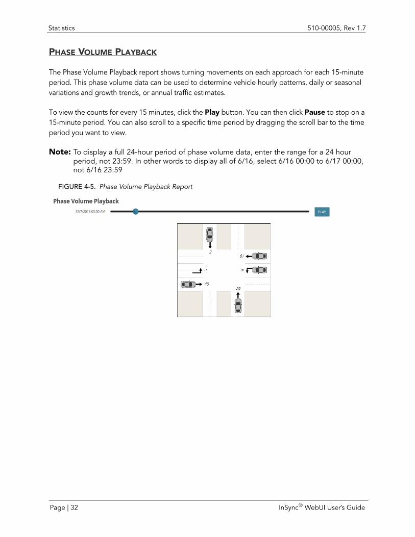
PHASE VOLUME PLAYBACK
The Phase Volume Playback report shows turning movements on each approach for each 15-minute period. This phase volume data can be used to determine vehicle hourly patterns, daily or seasonal variations and growth trends, or annual traffic estimates.
To view the counts for every 15 minutes, click the Play button. You can then click Pause to stop on a 15-minute period. You can also scroll to a specific time period by dragging the scroll bar to the time period you want to view.
Note: To display a full 24-hour period of phase volume data, enter the range for a 24 hour period, not 23:59. In other words to display all of 6/16, select 6/16 00:00 to 6/17 00:00, not 6/16 23:59
FIGURE 4-5. Phase Volume Playback Report
Page | 32 InSync® WebUI User’s Guide
510-00005, Rev 1.7 Statistics
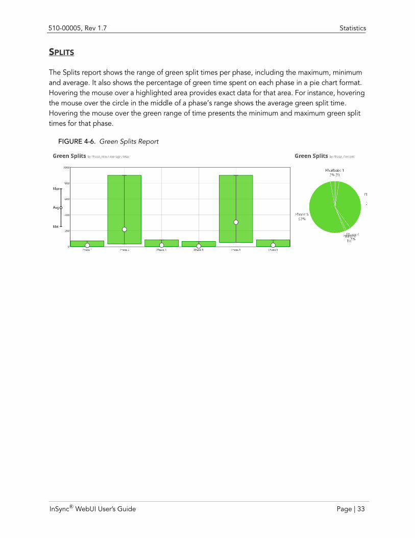
SPLITS
The Splits report shows the range of green split times per phase, including the maximum, minimum and average. It also shows the percentage of green time spent on each phase in a pie chart format. Hovering the mouse over a highlighted area provides exact data for that area. For instance, hovering the mouse over the circle in the middle of a phase’s range shows the average green split time. Hovering the mouse over the green range of time presents the minimum and maximum green split times for that phase.
FIGURE 4-6. Green Splits Report
InSync® WebUI User’s Guide Page | 33
Statistics 510-00005, Rev 1.7
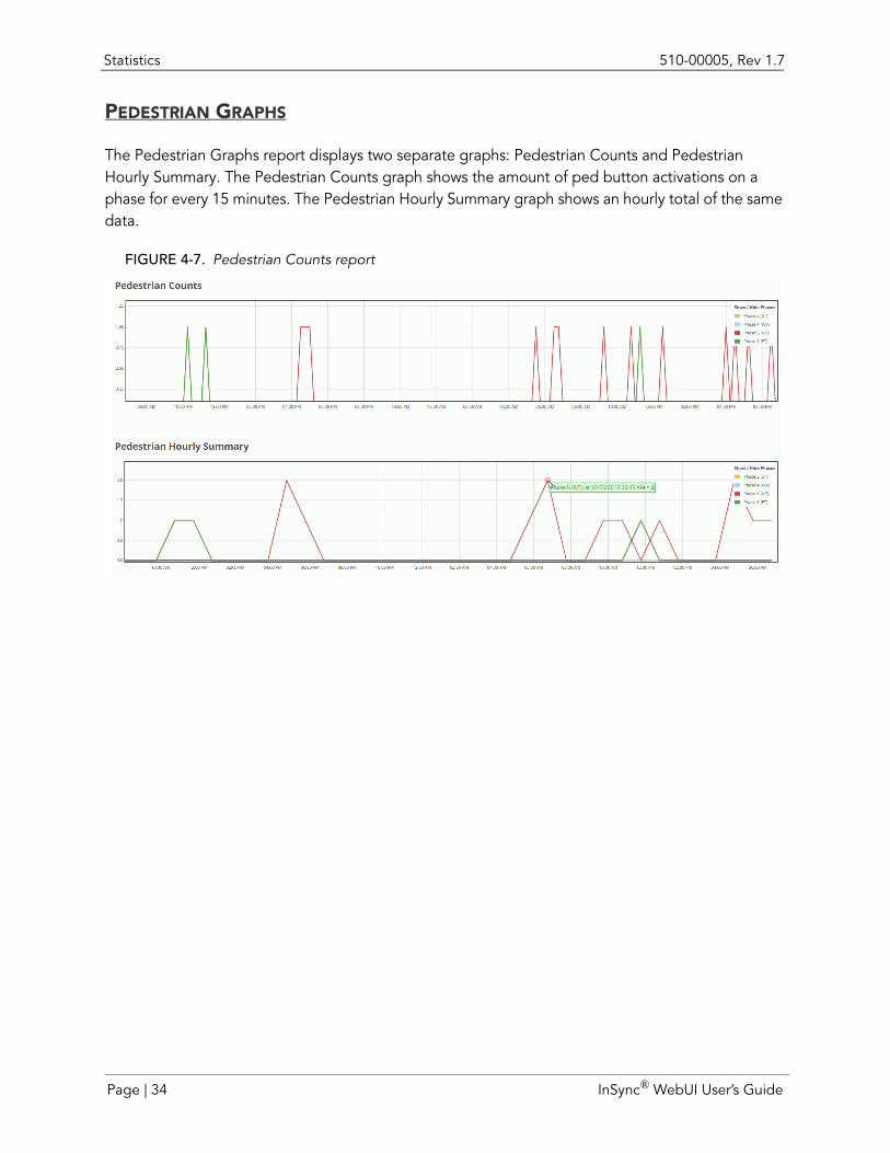
PEDESTRIAN GRAPHS
The Pedestrian Graphs report displays two separate graphs: Pedestrian Counts and Pedestrian Hourly Summary. The Pedestrian Counts graph shows the amount of ped button activations on a phase for every 15 minutes. The Pedestrian Hourly Summary graph shows an hourly total of the same data.
FIGURE 4-7. Pedestrian Counts report
Page | 34 InSync® WebUI User’s Guide
510-00005, Rev 1.7 Statistics
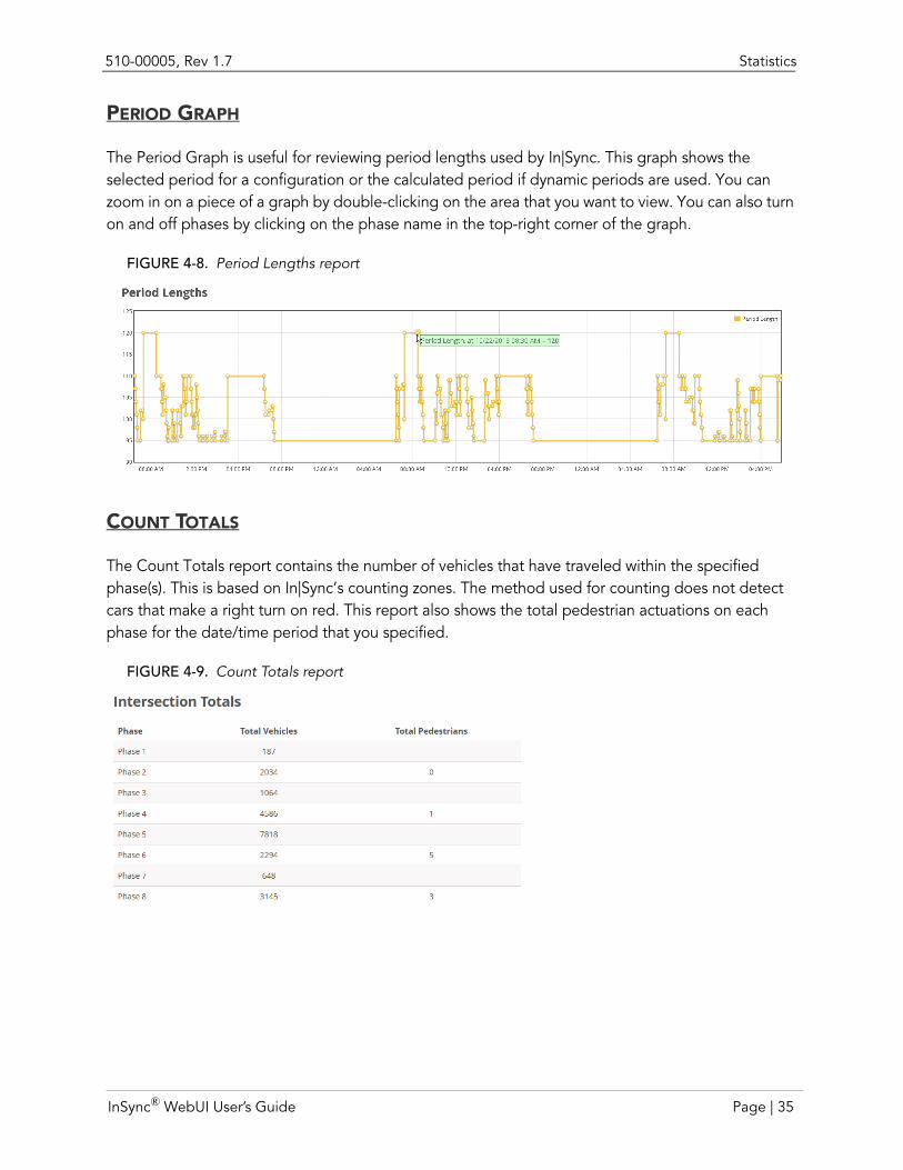
PERIOD GRAPH
The Period Graph is useful for reviewing period lengths used by In|Sync. This graph shows the selected period for a configuration or the calculated period if dynamic periods are used. You can zoom in on a piece of a graph by double-clicking on the area that you want to view. You can also turn on and off phases by clicking on the phase name in the top-right corner of the graph.
FIGURE 4-8. Period Lengths report
COUNT TOTALS
The Count Totals report contains the number of vehicles that have traveled within the specified phase(s). This is based on In|Sync’s counting zones. The method used for counting does not detect cars that make a right turn on red. This report also shows the total pedestrian actuations on each phase for the date/time period that you specified.
FIGURE 4-9. Count Totals report
InSync® WebUI User’s Guide Page | 35
Statistics 510-00005, Rev 1.7
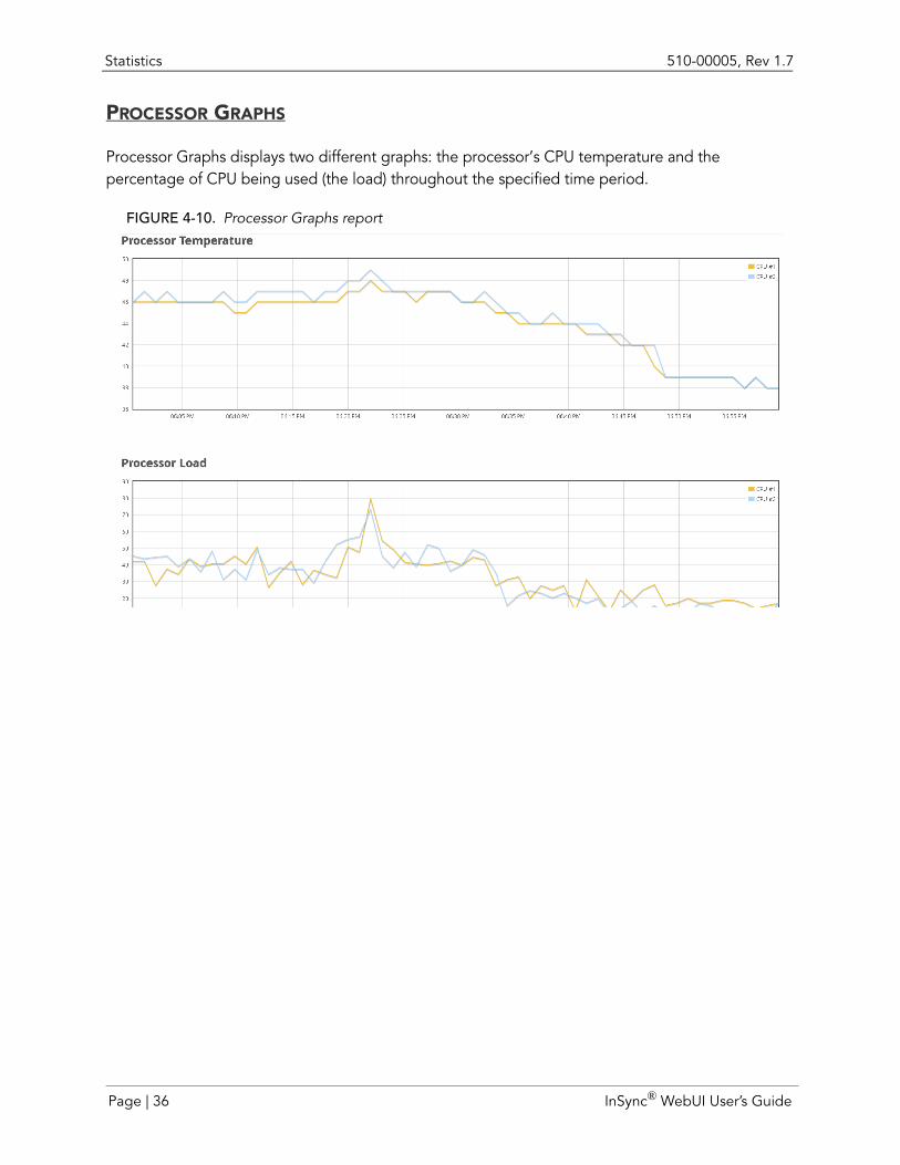
PROCESSOR GRAPHS
Processor Graphs displays two different graphs: the processor’s CPU temperature and the percentage of CPU being used (the load) throughout the specified time period.
FIGURE 4-10. Processor Graphs report
Page | 36 InSync® WebUI User’s Guide
510-00005, Rev 1.7 History Viewer
Download Statistics
You can also download statistics for viewing in another software program, such as Microsoft Excel. Before clicking Download Statistics, you must first specify the start date/time and the end date/time. After clicking the Download Statistics button, a list of options display. You can choose to download the following types of information:
Vehicle Counts: Outputs each phase’s turning movement counts for every 15 minutes of the specified time period.
Pedestrian Counts: Outputs each phase’s pedestrian button actuations for every 15 minutes of the specified time period.
Hourly Summaries: Outputs each phase’s turning movements in four 15-minute blocks and shows the summation of those counts into a total for every hour.
After specifying which report data you want outputted, you can either save the file as a .csv or as a .txt file. The .csv file contains only count information, while the .txt file includes all the data the server stores, including stop delays, extended counts, sub-phase counts, ped wait times, and stuck detector information.
History ViewerThe In|Sync Processor collects and saves operational information into a historical log. This log can then be used for future use and historical reporting and includes timing, detection actuation, lane saturation, lane volume, coordination, and adaptive trigger information. Selecting History Viewer allows you to generate reports based on historical logs kept on the In|Sync Processor. These logs detail the activities of the In|Sync system by time of day and day of week.
Note: In|Sync stores the last 30 days of historical data at any given time.
You can see precise historical phasing and intersection information for particular days and times of day. The History Viewer uses icons to show exactly which movement In|Sync served at particular times of day, the duration of the movement, and other conditions at the intersection at that time such as queue lengths and wait times. It also shows when In|Sync has gone into and out of Adaptive mode.
At the global level, you can see coordinated movements served and any adaptive qualities applied to the coordinated movement, such as whether the tunnel was truncated due to low demand, or whether the period length (time between tunnels) changed. Pedestrian call, preemption and flash status data are also available, allowing you to determine the reason for In|Sync's decisions.
Note: In|Sync detects that an intersection is in Flash in one of two ways:
• The controller has sent an indication that the intersection is in Flash
InSync® WebUI User’s Guide Page | 37
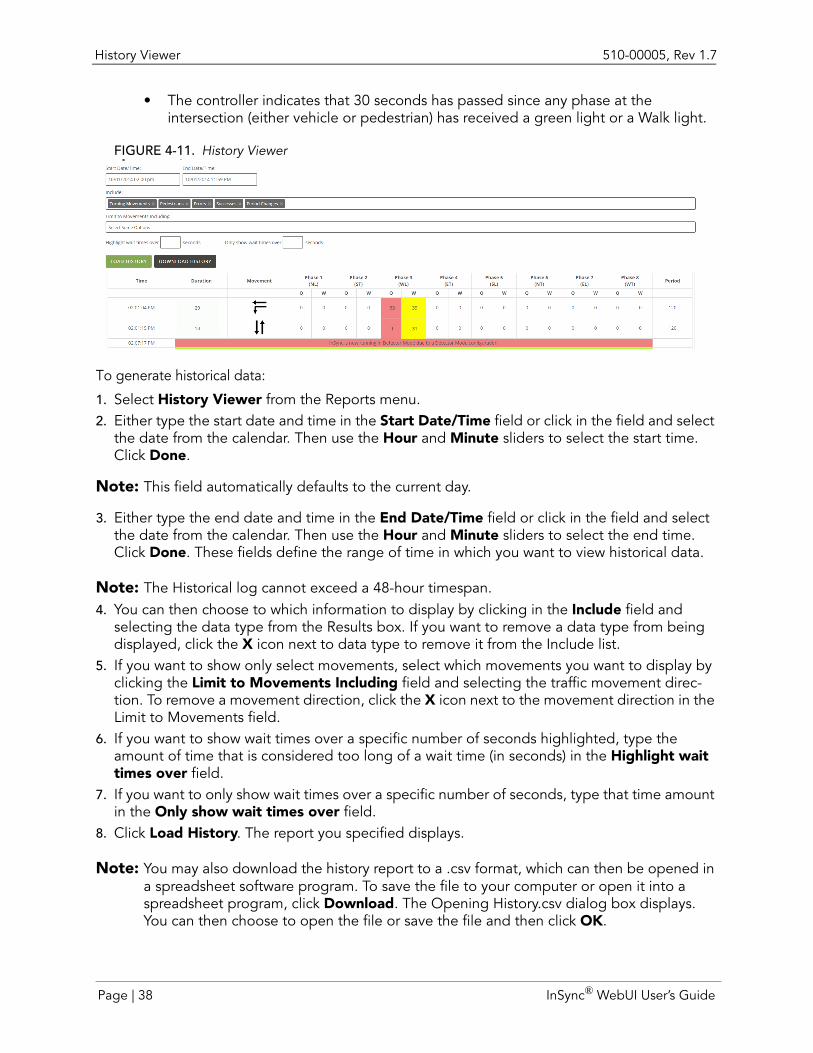
History Viewer 510-00005, Rev 1.7
• The controller indicates that 30 seconds has passed since any phase at the intersection (either vehicle or pedestrian) has received a green light or a Walk light.
FIGURE 4-11. History Viewer
To generate historical data:
1. Select History Viewer from the Reports menu.2. Either type the start date and time in the Start Date/Time field or click in the field and select
the date from the calendar. Then use the Hour and Minute sliders to select the start time. Click Done.
Note: This field automatically defaults to the current day.
3. Either type the end date and time in the End Date/Time field or click in the field and select the date from the calendar. Then use the Hour and Minute sliders to select the end time. Click Done. These fields define the range of time in which you want to view historical data.
Note: The Historical log cannot exceed a 48-hour timespan.4. You can then choose to which information to display by clicking in the Include field and
selecting the data type from the Results box. If you want to remove a data type from being displayed, click the X icon next to data type to remove it from the Include list.
5. If you want to show only select movements, select which movements you want to display by clicking the Limit to Movements Including field and selecting the traffic movement direc-tion. To remove a movement direction, click the X icon next to the movement direction in the Limit to Movements field.
6. If you want to show wait times over a specific number of seconds highlighted, type the amount of time that is considered too long of a wait time (in seconds) in the Highlight wait times over field.
7. If you want to only show wait times over a specific number of seconds, type that time amount in the Only show wait times over field.
8. Click Load History. The report you specified displays.
Note: You may also download the history report to a .csv format, which can then be opened in a spreadsheet software program. To save the file to your computer or open it into a spreadsheet program, click Download. The Opening History.csv dialog box displays. You can then choose to open the file or save the file and then click OK.
Page | 38 InSync® WebUI User’s Guide
CHAPTER 5 MONITORING MANAGEMENT GROUPS
You have the ability to monitor a management group by accessing any single processor because every processor is set up as a web host, meaning that each networked processor can “talk” to all the others. When a remote computer accesses one of the processors through the WebUI, it can then access not only the data from the processor it is connected to, but the other processors that are talking with it, thereby allowing a remote computer to show every intersection in a management group on one web page. In|Sync also provides a way to list links to all the In|Sync equipment located on all your management groups installed with In|Sync.
In|Sync provides several methods to monitor the management group within the In|Sync WebUI, which are available in the Management Group menu. From this menu you can:
Portal: Provides a list of links to management groups, intersections, cameras, DIN Relays, and map views
Management Group view: Provides a screen displaying all camera views along the management group
Map: Provides a map view showing which green splits are being served at that point in time along the management group, along with the ability to display a live camera feed directly from the map.
Status: Provides real-time communication status (online/offline) of the In|Sync Processors within the management group and pinpoints where communication breakdowns are occurring.
InSync® WebUI User’s Guide Page | 39
Portal 510-00005, Rev 1.7
Portal
What is it?
Note: The Portal menu item is available only to users with In|Sync Maintenance access (set in the Account>Edit Users screen).
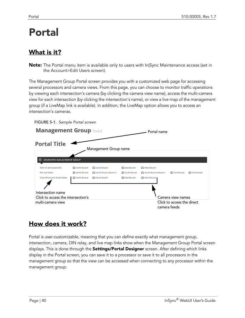
The Management Group Portal screen provides you with a customized web page for accessing several processors and camera views. From this page, you can choose to monitor traffic operations by viewing each intersection’s camera (by clicking the camera view name), access the multi-camera view for each intersection (by clicking the intersection's name), or view a live map of the management group (if a LiveMap link is available). In addition, the LiveMap option allows you to access an intersection’s cameras.
FIGURE 5-1. Sample Portal screen
How does it work?
Portal is user-customizable, meaning that you can define exactly what management group, intersection, camera, DIN relay, and live map links show when the Management Group Portal screen displays. This is done through the Settings/Portal Designer screen. After defining which links display in the Portal screen, you can save it to a processor or save it to all processors in the management group so that the view can be accessed when connecting to any processor within the management group.
Portal name
Management Group name
Intersection nameCamera view namesClick to access the intersection’s
multi-camera view Click to access the directcamera feeds
Page | 40 InSync® WebUI User’s Guide
510-00005, Rev 1.7 Managing Content in the Portal
Why use it?The Portal is a great way to consolidate access to views across management groups. For instance, you may have In|Sync Processors installed on several management groups and as part of your daily morning routine, you would like to check in on each management group. Instead of opening a new browser for each management group, the Portal allows you to quickly click each link to view intersections on all management groups.
How do I use it?Before using the Portal, you must define what management groups, intersections, cameras, DIN Relays and Map View links you want listed on the Portal View page (see the next section). This is done in the Portal Designer (accessible from the Settings menu). After defining the information on the page, you can then save it to the processor or save it to all processors on the management group. Then you can select Portal from the Management Group menu to display the Portal screen.
Managing Content in the PortalThe Portal Designer can be found in the Settings sidebar. From this screen, you can define exactly which management group, intersection, camera, and DIN Relay links are displayed in the Portal.
Auto generate a portal
This option allows you to create a portal by using the latest management group configuration information on the processor and extracting information about each intersection along the management group, which is then listed in the Portal. This option extracts out only the intersection information for the connected processor’s management group. If you want other management groups or Live Maps displayed in the portal, you must add them in manually.
Note: In order to use the auto-generate feature, you must have more than one intersection in a management group and the intersections within the management group must be configured to communicate with each other.
Create a portal for the first time
When you first open the Portal, there are no links. You must first design the Portal in the Portal Designer. To design the Portal:
1. Select Portal Designer from the Settings menu.2. Type a name for the portal in the field below the Settings heading.
InSync® WebUI User’s Guide Page | 41
Managing Content in the Portal 510-00005, Rev 1.7
3. You can either try to auto-generate the Portal by clicking the Auto Generate button or you can manually create the Portal. To manually create the Portal, add management groups, inter-sections, camera IP addresses, maps and DIN relays.
Note: You must know the IP addresses for all the equipment you want to monitor.
ADD MANAGEMENT GROUPS
To manually add a management group:
1. Select Management Group from the + Add menu. A row for adding a management group displays at the bottom of the page.
2. Type a name for the management group in the Management Group Name field.
Add intersections
To add intersections:
1. Click the +Intersection button. A row for adding an intersection displays at the bottom of the page.
2. Type the names of the intersecting approaches (e.g., Main and 7th Street) in the Intersection Name field.
3. Type the IP address of the In|Sync Processor located at the intersection in the Intersection IP field.
Add camerasTo add cameras to the intersection:
1. Click the + CAMERA button. A row for adding a camera displays at the bottom of the Inter-section box.
2. Type the name of the camera (e.g., West Bound) in the Camera Name field.3. Type the IP address associated with the camera in the IP field.
Add DIN relaysTo add DIN relays:
1. Click the + RELAY button. A row for adding a DIN relay displays at the bottom of the Inter-section box.
2. Type a name for the DIN Relay in the Relay Name field.3. Type the IP address of the DIN Relay in the Relay IP field.
Add a mapTo add a map for the management group:
1. Click the + MAP button next to the management group name. A row for adding a map dis-plays at the bottom of the management group’s intersections.
2. Type a name for the map in the Map Name field.3. Type the URL address for accessing the map in the Map URL field.
Page | 42 InSync® WebUI User’s Guide
510-00005, Rev 1.7 Managing Content in the Portal
Rearrange the contentTo move content from one location to another:
1. Place your mouse over the title bar of the content that you want to move.
Note: Do not place the mouse directly over a field. 2. Click and drag the content to its new position.
Collapse and expand intersectionsYou can choose to collapse or expand the Intersection or Management Group content block to easily see what management groups and intersections have already been added to the Portal.
To collapse/expand management group or intersection content blocks, double-click the content block title (i.e., Management Group block title or Intersection block title).
FIGURE 5-2. The Portal Designer screen
Save the portal to the processor
After defining the content that you want displayed in the portal and arranging the content to your liking, you must then save the view so that it can be accessed for later viewing. To do this, click the Save to Processor button. This allows you to obtain this portal whenever you connect to that specific processor. This feature is useful when and if you are not finished designing the portal, but you need to step away and come back to finish the design.
Add intersectionAdd map
Add DIN relay
Add camera
Remove
Add map or management group
content
InSync® WebUI User’s Guide Page | 43
Managing Content in the Portal 510-00005, Rev 1.7
Propagate the portal to several processors
Propagating the portal to other processors saves the Portal to every In|Sync Processor in the same management group as the processor to which you are connected. It allows users to access the view when accessing the In|Sync WebUI from any processor in the management group, meaning that you do not have to design a Portal on every In|Sync Processor.
To save the Portal to every In|Sync Processor, click the Save and Propagate button.
Edit content in the Portal Designer
You can also change what management groups/intersections/camera views/maps are listed and the order in which they are listed by going into the Portal Designer screen. The portal for that particular processor displays in this screen. Change the listing of management group data in the same manner that it was added (see page 41 for instructions on adding content).
In addition, you can also delete content, such as intersections. To delete any content within the Portal, click the icon.
Note: The Download button is for downloading an In|Sync configuration file and the Import from File button is for uploading an In|Sync configuration file. Both options are for troubleshooting purposes for Rhythm personnel only.
Page | 44 InSync® WebUI User’s Guide
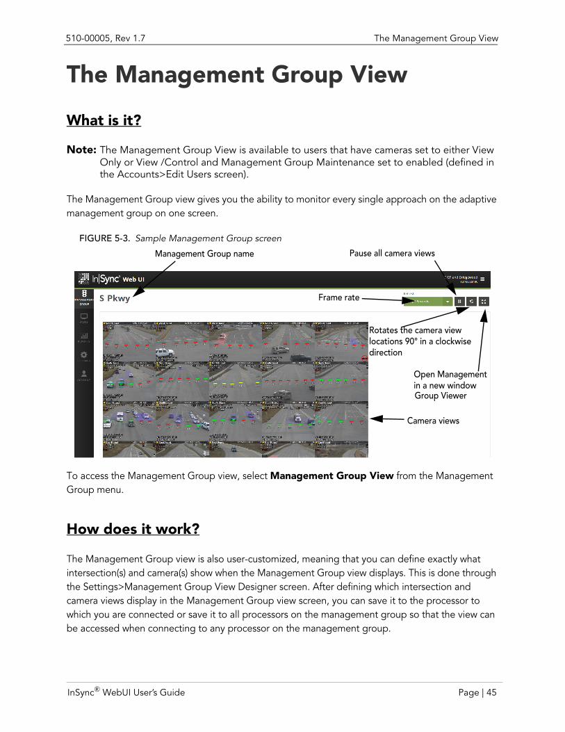
510-00005, Rev 1.7 The Management Group View
The Management Group View
What is it?
Note: The Management Group View is available to users that have cameras set to either View Only or View /Control and Management Group Maintenance set to enabled (defined in the Accounts>Edit Users screen).
The Management Group view gives you the ability to monitor every single approach on the adaptive management group on one screen.
FIGURE 5-3. Sample Management Group screen
To access the Management Group view, select Management Group View from the Management Group menu.
How does it work?
The Management Group view is also user-customized, meaning that you can define exactly what intersection(s) and camera(s) show when the Management Group view displays. This is done through the Settings>Management Group View Designer screen. After defining which intersection and camera views display in the Management Group view screen, you can save it to the processor to which you are connected or save it to all processors on the management group so that the view can be accessed when connecting to any processor on the management group.
Management Group name
Frame rate
Pause all camera views
Open Management
Camera views
in a new window
Rotates the camera viewlocations 90° in a clockwisedirection
Group Viewer
InSync® WebUI User’s Guide Page | 45
The Management Group View 510-00005, Rev 1.7
Why use it?
Using the Management Group Viewer provides a handy view of all cameras along the management group. This allows you to easily troubleshoot which cameras are experiencing issues, check on current traffic conditions along the management group, and organize camera views to make better sense of the traffic flow.
How do I use it?
Before using the Management Group view, you must define what intersections and cameras you want shown on the Management Group view page. This is done using the Management Group View Designer, which is accessible from the Settings menu. After defining the information on the page, you can then save it to the processor or save it to all processors on the management group. To view the management group, select Management Group View from the Management Group menu. The Management Group View displays.
Within the Management Group View screen, there is a Refresh drop-down list box, a Pause button, and a Full Screen Mode button:
The Refresh drop-down list box allows you to select how often In|Sync refreshes the camera views on the screen.
The Pause button pauses all camera images in the Management Group Viewer.
Finally, the Full Screen Mode button opens the Management Group Viewer screen in its own Window. When the Management Group Viewer opens in a new window, the Refresh drop-down list box and Pause button still displays, along with the Collapse button. If you click the Collapse button, the management group name, Refresh drop-down list box, and Pause button disappears. Clicking this button again re-displays the management group name, Refresh drop-down list box, and Pause button.
Page | 46 InSync® WebUI User’s Guide
510-00005, Rev 1.7 Managing Content in the Management Group View
Managing Content in the Management Group ViewThe Management Group View Designer can be found in the Settings menu. From this screen, you can change the order of the cameras, add intersections, add cameras, change the order of the intersections, or manually change the Management Group Viewer.xml file that specifies the order of management group viewer content.
Note: In order to manage management group view content, you must have access enabled for Configure Intersection (set in the Account>Edit Users screen).
Create a Management Group View for the first time
When you first open the Management Group view, you will only see the camera views for the intersection for which you are connected. You must add in other intersections and cameras in the management group by adding the names of the intersections, the intersection’s In|Sync Processor IP address, camera names, and each camera’s IP address. To design the Management Group view:
1. Select Management Group View Designer from the Settings menu.2. Type a name for the management group view in the Management Group Title field.3. You can then create the Management Group View by adding intersections and cameras. See
the following sections for more about adding/rearranging intersection and camera views.
ADD INTERSECTIONS
To add an intersection:
1. Select Intersection from the + Add menu. The Add Intersection dialog box displays.2. Type the processor’s IP address (e.g., 172.19.23.21) in the Intersection IP field and click OK.
The Management Group Designer retrieves a list of camera IP addresses assigned to that intersection and displays all the camera views in a new column.
ADD ALL OF AN INTERSECTION’S CAMERAS
To add cameras to the intersection:
1. Click the +CAMERA button in the column where you want to add a camera. The Configure Camera dialog box displays.
2. Select a camera from list of available of camera views in the Camera drop-down list.3. Click the Save button. The camera view is added to the bottom of the column.
InSync® WebUI User’s Guide Page | 47
Managing Content in the Management Group View 510-00005, Rev 1.7
ADD A CUSTOM CAMERA TO A COLUMN
Instead of displaying all the cameras for an intersection within one column, you may want to display a camera in a new column. To do that, complete the following steps:
1. Add COLUMN from the + Add menu.2. Give the column a name by replacing "Unnamed Column" with a meaningful name.3. Click the + Camera button. The Add Custom Camera dialog box displays.4. In the Intersection IP field, type the IP address of the processor located on the intersection
where the camera resides.5. Click Update List. A list of Camera Names is updated in the Camera Name drop-down list
box.6. Select the camera you want displayed from the Camera Name drop-down list box.7. Click Save.
REARRANGE THE CONTENT
You can move camera views within a column or move columns into a different order. To do so:
1. Place your mouse over the content that you want to move.
Note: Do not place the mouse directly over a field.
2. Click and drag the content to its new position.
Note: You can also rotate the location of all camera views by clicking the button.
ADD GAPS BETWEEN CAMERA VIEWS
You can add gaps between the camera views. This creates a separator between camera views. To add a gap between a camera view, click the + GAP button. The gap is added at the bottom of the column. You can then drag the empty space to the correct location in the column.
DELETE CAMERAS AND GAPS FROM THE VIEW
To delete a camera or gap within the management group view designer, click the X icon next to the content that you want deleted.
Save the management group view to the processor
After defining content that you want displayed in the management groupmanagement group view and arranging the content to your liking, you must then save the view to be accessed for later
Page | 48 InSync® WebUI User’s Guide
510-00005, Rev 1.7 Managing Content in the Management Group View
viewing. To do this, click the Save to Processor button. This allows any user to obtain this management group view whenever he or she connects to that specific processor. This feature is handy if you are not finished designing the management group view, but you need to step away and come back to finish up the design.
Propagate the management group view to several processors
Propagating the Management Group View to other processors saves the management group view to every In|Sync Processor in the management group. It allows you to access the portal view when accessing the In|Sync WebUI from any processor in the management group, meaning that you do not have to design a Management Group view for every intersection’s In|Sync Processor.
To save the Management Group view to every In|Sync Processor, click the Save and Propagate button.
Change Management Group View content
To change the content or order of content that displays within the Management Group View, you can go into the Management Group View designer to add, remove, and rearrange content. See page 47 for instructions on adding, removing and rearranging content.
Note: The Download button is for downloading an management group view file and the Import from File button is for uploading a management group view file. Both options are for troubleshooting purposes for Rhythm personnel only.
InSync® WebUI User’s Guide Page | 49
Status 510-00005, Rev 1.7
Status
What is it?The Status page provides a real-time status of communications between In|Sync Processors within the management group, allowing you to troubleshoot network problems. It provides the following information:
Whether or not a processor is online or offline
If a processor is online, but unable to physically reach certain processors.
For instance, if a management group contains three intersections — A, B and C — and C is down, A and B individually report that they are online but unable to talk with C. Once all communications is restored, this page will indicate that it is waiting for the processors to validate communications.
How does it work?The Status page is updated by processors coordinating with each other via communications. This information is reported as frequently as it is possible for processors to all synchronize with each other on the network.
Why use it?The Status page is a great troubleshooting tool for diagnosing network communication problems. From this page, you can concentrate your efforts on exactly which In|Sync Processor is experience network connectivity issues.
How do I use it?The Status page is available to all users by selecting Status from the Management Group menu.
Page | 50 InSync® WebUI User’s Guide
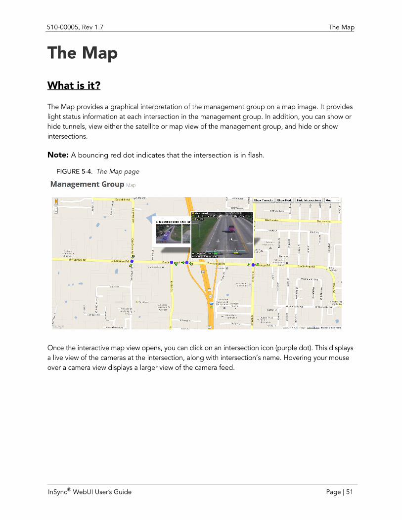
510-00005, Rev 1.7 The Map
The Map
What is it?
The Map provides a graphical interpretation of the management group on a map image. It provides light status information at each intersection in the management group. In addition, you can show or hide tunnels, view either the satellite or map view of the management group, and hide or show intersections.
Note: A bouncing red dot indicates that the intersection is in flash.
FIGURE 5-4. The Map page
Once the interactive map view opens, you can click on an intersection icon (purple dot). This displays a live view of the cameras at the intersection, along with intersection’s name. Hovering your mouse over a camera view displays a larger view of the camera feed.
InSync® WebUI User’s Guide Page | 51
The Map 510-00005, Rev 1.7
Page | 52 InSync® WebUI User’s Guide
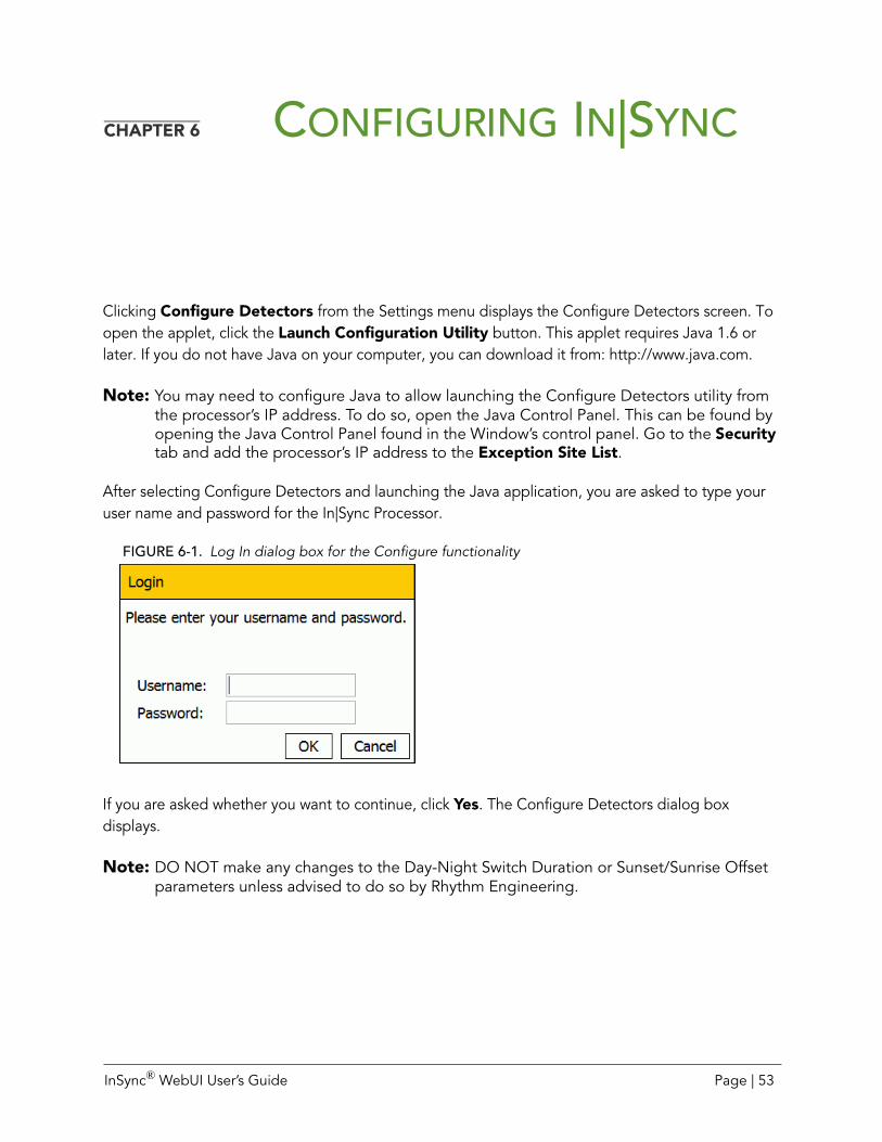
CHAPTER 6 CONFIGURING IN|SYNC
Clicking Configure Detectors from the Settings menu displays the Configure Detectors screen. To open the applet, click the Launch Configuration Utility button. This applet requires Java 1.6 or later. If you do not have Java on your computer, you can download it from: http://www.java.com.
Note: You may need to configure Java to allow launching the Configure Detectors utility from the processor’s IP address. To do so, open the Java Control Panel. This can be found by opening the Java Control Panel found in the Window’s control panel. Go to the Security tab and add the processor’s IP address to the Exception Site List.
After selecting Configure Detectors and launching the Java application, you are asked to type your user name and password for the In|Sync Processor.
FIGURE 6-1. Log In dialog box for the Configure functionality
If you are asked whether you want to continue, click Yes. The Configure Detectors dialog box displays.
Note: DO NOT make any changes to the Day-Night Switch Duration or Sunset/Sunrise Offset parameters unless advised to do so by Rhythm Engineering.
InSync® WebUI User’s Guide Page | 53
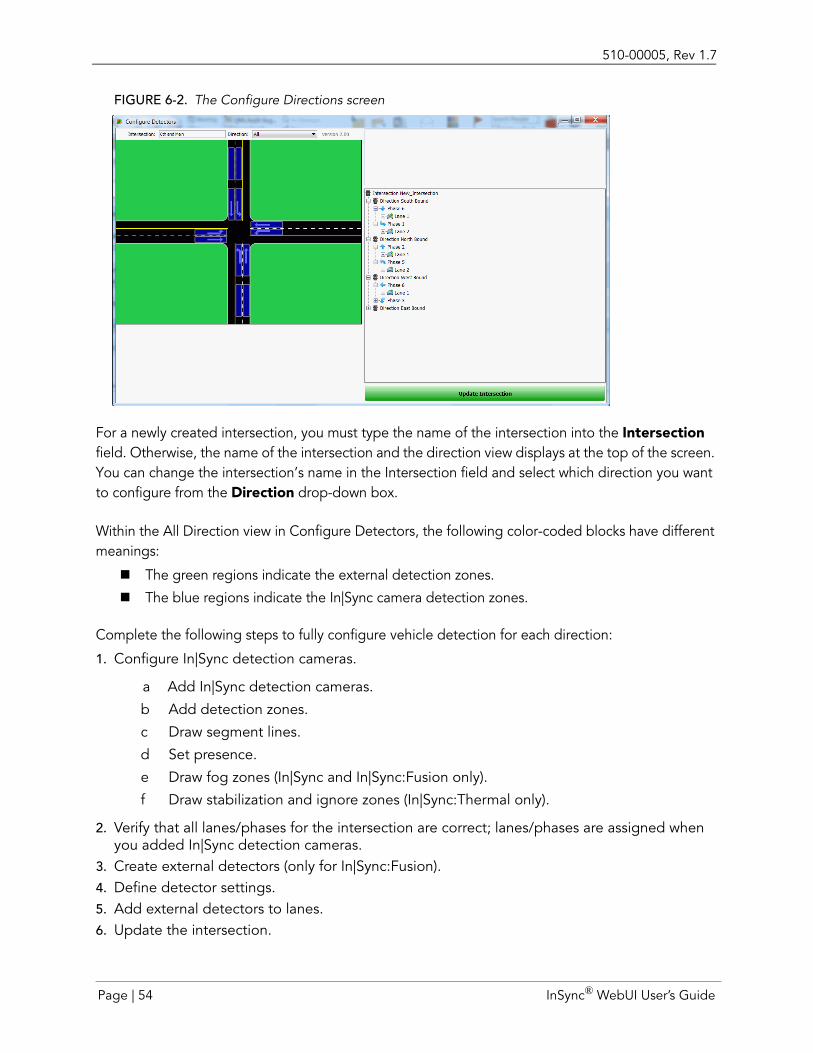
510-00005, Rev 1.7
FIGURE 6-2. The Configure Directions screen
For a newly created intersection, you must type the name of the intersection into the Intersection field. Otherwise, the name of the intersection and the direction view displays at the top of the screen. You can change the intersection’s name in the Intersection field and select which direction you want to configure from the Direction drop-down box.
Within the All Direction view in Configure Detectors, the following color-coded blocks have different meanings:
The green regions indicate the external detection zones.
The blue regions indicate the In|Sync camera detection zones.
Complete the following steps to fully configure vehicle detection for each direction:
1. Configure In|Sync detection cameras.
a Add In|Sync detection cameras.
b Add detection zones.
c Draw segment lines.
d Set presence.
e Draw fog zones (In|Sync and In|Sync:Fusion only).
f Draw stabilization and ignore zones (In|Sync:Thermal only).
2. Verify that all lanes/phases for the intersection are correct; lanes/phases are assigned when you added In|Sync detection cameras.
3. Create external detectors (only for In|Sync:Fusion).4. Define detector settings.5. Add external detectors to lanes.6. Update the intersection.
Page | 54 InSync® WebUI User’s Guide
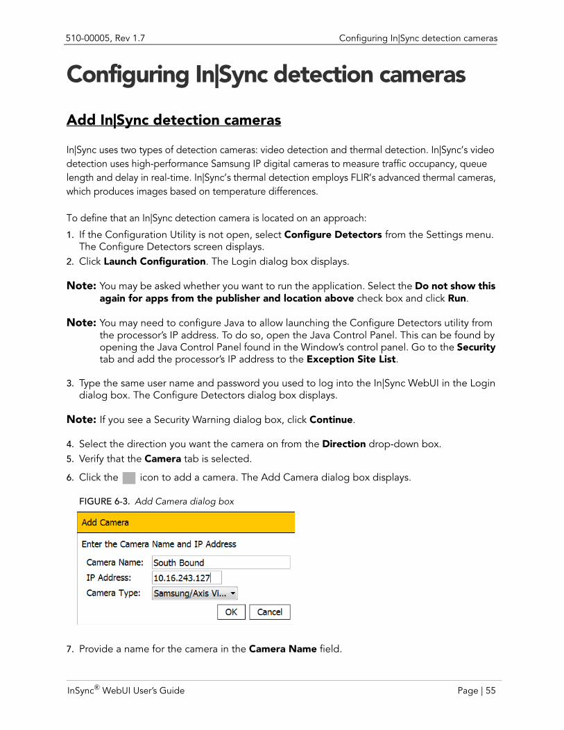
510-00005, Rev 1.7 Configuring In|Sync detection cameras
Configuring In|Sync detection cameras
Add In|Sync detection cameras
In|Sync uses two types of detection cameras: video detection and thermal detection. In|Sync’s video detection uses high-performance Samsung IP digital cameras to measure traffic occupancy, queue length and delay in real-time. In|Sync’s thermal detection employs FLIR’s advanced thermal cameras, which produces images based on temperature differences.
To define that an In|Sync detection camera is located on an approach:
1. If the Configuration Utility is not open, select Configure Detectors from the Settings menu. The Configure Detectors screen displays.
2. Click Launch Configuration. The Login dialog box displays.
Note: You may be asked whether you want to run the application. Select the Do not show this again for apps from the publisher and location above check box and click Run.
Note: You may need to configure Java to allow launching the Configure Detectors utility from the processor’s IP address. To do so, open the Java Control Panel. This can be found by opening the Java Control Panel found in the Window’s control panel. Go to the Security tab and add the processor’s IP address to the Exception Site List.
3. Type the same user name and password you used to log into the In|Sync WebUI in the Login dialog box. The Configure Detectors dialog box displays.
Note: If you see a Security Warning dialog box, click Continue.
4. Select the direction you want the camera on from the Direction drop-down box.5. Verify that the Camera tab is selected.
6. Click the icon to add a camera. The Add Camera dialog box displays.
FIGURE 6-3. Add Camera dialog box
7. Provide a name for the camera in the Camera Name field.
InSync® WebUI User’s Guide Page | 55
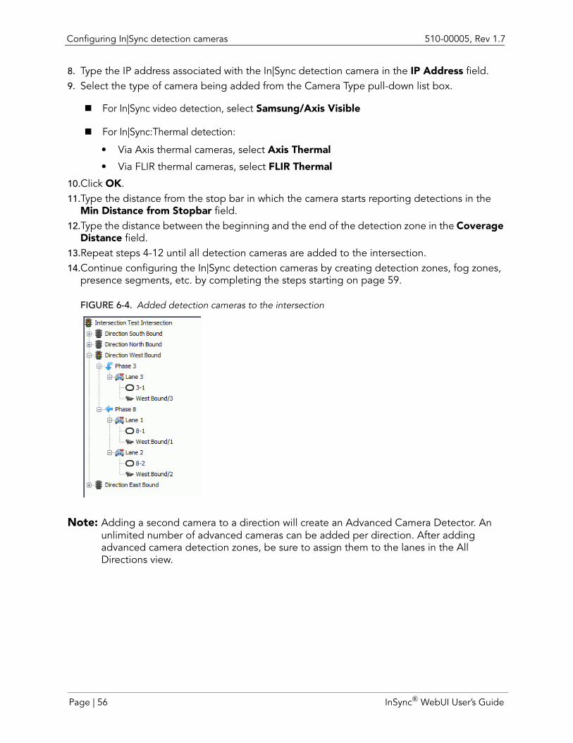
Configuring In|Sync detection cameras 510-00005, Rev 1.7
8. Type the IP address associated with the In|Sync detection camera in the IP Address field. 9. Select the type of camera being added from the Camera Type pull-down list box.
For In|Sync video detection, select Samsung/Axis Visible
For In|Sync:Thermal detection:
• Via Axis thermal cameras, select Axis Thermal
• Via FLIR thermal cameras, select FLIR Thermal
10.Click OK.11.Type the distance from the stop bar in which the camera starts reporting detections in the
Min Distance from Stopbar field.12.Type the distance between the beginning and the end of the detection zone in the Coverage
Distance field.13.Repeat steps 4-12 until all detection cameras are added to the intersection.14.Continue configuring the In|Sync detection cameras by creating detection zones, fog zones,
presence segments, etc. by completing the steps starting on page 59.
FIGURE 6-4. Added detection cameras to the intersection
Note: Adding a second camera to a direction will create an Advanced Camera Detector. An unlimited number of advanced cameras can be added per direction. After adding advanced camera detection zones, be sure to assign them to the lanes in the All Directions view.
Page | 56 InSync® WebUI User’s Guide
510-00005, Rev 1.7 Configuring In|Sync detection cameras
ADD ADVANCED DETECTION CAMERAS
Advanced detection cameras are secondary cameras that measures traffic volume that is set back a user-specified distance from the stop bar instead of traffic volume starting from the stop bar. It is used in conjunction with stop bar detection cameras to provide the most accurate data to the In|Sync Processor. To set up and assign an advanced detection camera within the Configuration utility:
Add a camera1. If the Configuration Utility is not open, select Configure Detectors from the Settings menu.
The Configure Detectors screen displays.2. Click Launch Configuration. The Login dialog box displays.
Note: You may be asked whether you want to run the application. Select the Do not show this again for apps from the publisher and location above check box and click Run.
3. Type the same user name and password you used to log into the In|Sync WebUI in the Login dialog box. The Configure Detectors dialog box displays.
Note: If you see a Security Warning dialog box, click Continue.
4. Click the Direction drop-down box, and select the direction you want the advanced detec-tion camera on.
5. Make sure the Camera tab is selected.
6. Click the icon to add a camera. The Add Camera dialog box displays.7. Provide a name for the camera in the Camera Name field.8. Type the IP address associated with the In|Sync detection camera in the IP Address field. 9. Select the type of camera being added from the Camera Type pull-down list box.
For In|Sync video detection, select Samsung/Axis Visible
For In|Sync:Thermal detection:
• Via Axis thermal cameras, select Axis Thermal
• Via FLIR thermal cameras, select FLIR Thermal
10.Click OK.11.Type the distance from the stop bar in which the camera starts reporting detections in the
Min Distance from Stopbar field.12.Type the distance from the beginning of the detection zone to the end of the detection zone
in the Coverage Distance field.
InSync® WebUI User’s Guide Page | 57
Configuring In|Sync detection cameras 510-00005, Rev 1.7
Assign detection zones to camera1. Click the Detection Zone button.2. Click the Add button.3. Draw your zone by clicking on the image with the mouse. A polygon is created by joining the
points clicked with the mouse.
Note: If you make a mistake, click Clear and re-start.
4. When finished defining points, click the OK button to complete the zone/lane. A dialog box opens, displaying a choice of available phase numbers to associate with the detection zones.
5. Choose your phase number for the detection zone and click OK. 6. Repeat steps 2-5 for each detection zone/lane.
Assign the advanced camera to a lane1. Select All from the Direction drop-down box.2. Click the + icon next to the direction for which the advanced detection camera resides.3. Click the + icon next to the phase for which the advanced detection camera resides.4. Right-click the lane on which the advanced detection camera resides and select Add Detec-
tor/"Camera Detector Name" from the shortcut menu. The advanced camera displays on the cartoon view for that phase/lane.
Page | 58 InSync® WebUI User’s Guide
510-00005, Rev 1.7 Configuring In|Sync detection cameras
Add detection zones
The proper placement of detection zones is critical for In|Sync to function properly. A detection zone needs to be drawn for each lane visible in the camera view, which is used for serving vehicle demand. Sometimes right-turn only lanes are ignored. A detection zone can be added or edited by clicking the Detection Zone button. When you click Detection Zone, the area above the Add and Remove buttons is populated with the detection zone numbers and associated phase numbers.
To add a detection zone:
1. If the Configuration Utility is not open, select Configure Detectors from the Settings menu. The Configure Detectors screen displays.
2. Click Launch Configuration. The Login dialog box displays.
Note: You may be asked whether you want to run the application. Select the Do not show this again for apps from the publisher and location above check box and click Run.
3. Type the same user name and password you used to log into the In|Sync WebUI in the Login dialog box. The Configure Detectors dialog box displays.
Note: If you see a Security Warning dialog box, click Continue.
4. Make sure the correct direction and camera is selected by selecting the camera direction from the Direction drop-down box and the camera from the Camera drop-down box.
5. Click the Detection Zone button.6. Click the Add button.7. Draw your zone by clicking on the image with the mouse. A polygon is created by joining the
points clicked with the mouse.
Note: If you make a mistake, click Clear and re-start.
InSync® WebUI User’s Guide Page | 59
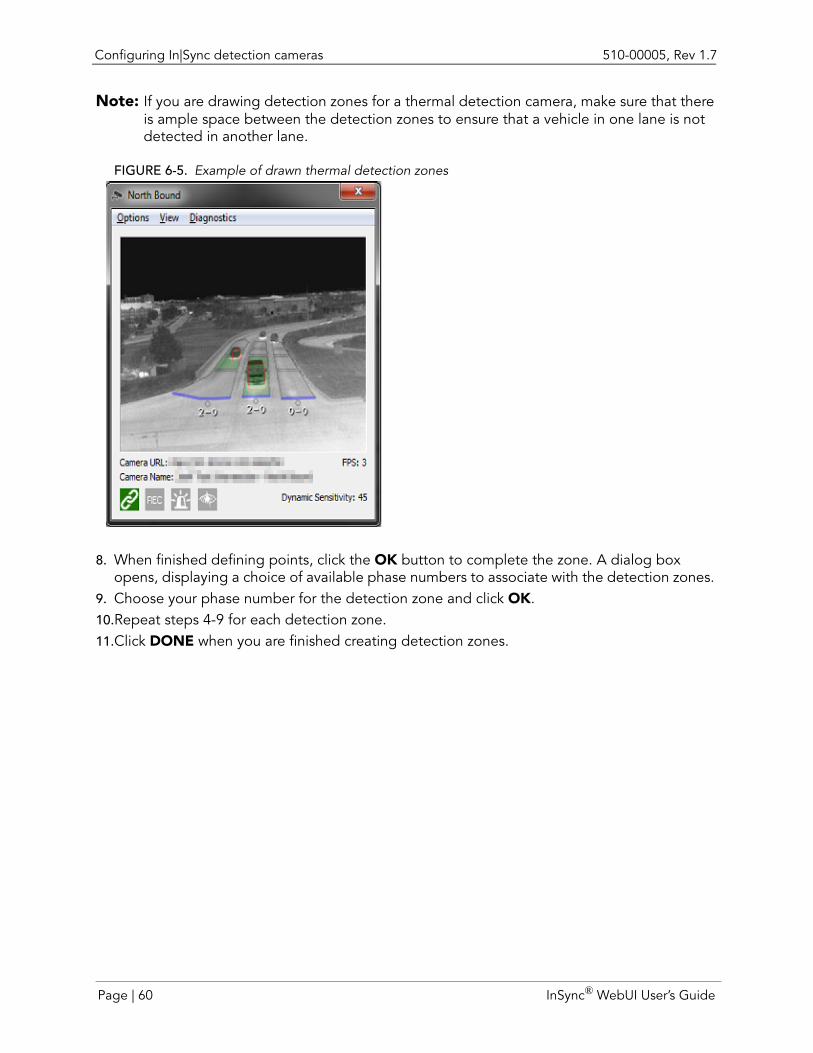
Configuring In|Sync detection cameras 510-00005, Rev 1.7
Note: If you are drawing detection zones for a thermal detection camera, make sure that there is ample space between the detection zones to ensure that a vehicle in one lane is not detected in another lane.
FIGURE 6-5. Example of drawn thermal detection zones
8. When finished defining points, click the OK button to complete the zone. A dialog box opens, displaying a choice of available phase numbers to associate with the detection zones.
9. Choose your phase number for the detection zone and click OK. 10.Repeat steps 4-9 for each detection zone.11.Click DONE when you are finished creating detection zones.
Page | 60 InSync® WebUI User’s Guide
510-00005, Rev 1.7 Configuring In|Sync detection cameras
DETECTION ZONE TIPS
Draw detection zones inside the lane striping. Including lane striping can cause false positives if the camera shakes.
Do not make the zone too narrow. Making it too narrow may cause In|Sync to miss headlights during night mode.
If the camera angle is low and off to the side, the zones may need to be drawn above the roadway to capture cars/headlights inside of them.
Make all lanes, except for turn bays, approximately the same length. Turn bays may not extend as far back and thru lanes.
Extend the zone forward at least ½ of a car length beyond the stop bar to cover traffic that may creep forward and extend back as far as the lane is visible in the image.
If the lane is exceptionally wide, only surround the area where cars are likely to travel.
Zones should not overlap. If you are drawing detection zones for a thermal detection camera, make sure that there is ample space between the detection zones to ensure that a vehicle in one lane is not detected in another lane.
InSync® WebUI User’s Guide Page | 61
Configuring In|Sync detection cameras 510-00005, Rev 1.7
EDIT OR REMOVE DETECTION ZONES
To edit or remove a detection zone:
1. If the Configuration Utility is not open, select Configure Detectors from the Settings menu. The Configure Detectors screen displays.
2. Click Launch Configuration. The Login dialog box displays.
Note: You may be asked whether you want to run the application. Select the Do not show this again for apps from the publisher and location above check box and click Run.
3. Type the same user name and password you used to log into the In|Sync WebUI in the Login dialog box. The Configure Detectors dialog box displays.
Note: If you see a Security Warning dialog box, click Continue.
4. Make sure the correct direction and camera is selected by selecting the camera direction from the Direction drop-down box and the camera from the Camera drop-down box.
5. Click the Detection Zone button.6. Select one of the zones in the list. The zone in the approach will be highlighted in deep blue. 7. Delete the zone by clicking the Remove button
or
modify the corner points by clicking the Edit button, moving the corner points, and clicking OK when done.
Page | 62 InSync® WebUI User’s Guide
510-00005, Rev 1.7 Configuring In|Sync detection cameras
Add segment lines for detection zones
FIGURE 6-6. Added Segment Lines
Segment lines are added after detection zones are drawn. They are used to divide detection zones into segments that are approximately one car length, which then can be used to approximate queue. To add segment lines:
1. If the Configuration Utility is not open, select Configure Detectors from the Settings menu. The Configure Detectors screen displays.
2. Click Launch Configuration. The Login dialog box displays.
Note: You may be asked whether you want to run the application. Select the Do not show this again for apps from the publisher and location above check box and click Run.
3. Type the same user name and password you used to log into the In|Sync WebUI in the Login dialog box. The Configure Detectors dialog box displays.
Note: If you see a Security Warning dialog box, click Continue.
4. Make sure the correct direction and camera is selected by selecting the camera direction from the Direction drop-down box and the camera from the Camera drop-down box.
5. Click the Segment Line button to draw segment lines that divide the detection zones into segments.
6. Click the mouse at the start of the segment.7. Click the mouse at the end of the segment.
Note: The length of a segment should be approximately the length of a typical passenger car.
TIP: Click the Refresh button to capture an image with an actual car for better scaling.
8. Repeat as necessary to divide the entire zone into segments.9. Click the Done button after all segment lines have been drawn.
InSync® WebUI User’s Guide Page | 63
Configuring In|Sync detection cameras 510-00005, Rev 1.7
By default, all segments are Advanced Segments, which do not trigger a detection. It is necessary that the first two to three segments be marked as Presence Segments in order to generate vehicle calls that are passed along to the controller. See page 66 for details regarding defining Presence Segments.
Note: You should draw at least two segment lines (thereby creating three detection zone segments) for each detection zone. Occasionally, short turn bays will not allow for three detection zone segments. While not ideal, this is acceptable.
DELETE SEGMENTS
To delete a single segment:
1. If the Configuration Utility is not open, select Configure Detectors from the Settings menu. The Configure Detectors screen displays.
2. Click Launch Configuration. The Login dialog box displays.
Note: You may be asked whether you want to run the application. Select the Do not show this again for apps from the publisher and location above check box and click Run.
3. Type the same user name and password you used to log into the In|Sync WebUI in the Login dialog box. The Configure Detectors dialog box displays.
Note: If you see a Security Warning dialog box, click Continue.
4. Make sure the correct direction and camera is selected by selecting the camera direction from the Direction drop-down box and the camera from the Camera drop-down box.
5. Click the Segment Line button.6. Click Delete Segment.7. Click on the segment you want to delete.8. Click Done.
To delete all segments:
1. Make sure the correct direction and camera is selected by selecting the camera direction from the Direction drop-down box and the camera from the Camera drop-down box.
2. Click the Segment Line button.3. Click Clear. You are asked if you are sure you want to delete all segments.4. Click Yes to delete all segments.5. Click Done.
Page | 64 InSync® WebUI User’s Guide
510-00005, Rev 1.7 Configuring In|Sync detection cameras
EDIT SEGMENTS
To edit a segment:
1. If the Configuration Utility is not open, select Configure Detectors from the Settings menu. The Configure Detectors screen displays.
2. Click Launch Configuration. The Login dialog box displays.
Note: You may be asked whether you want to run the application. Select the Do not show this again for apps from the publisher and location above check box and click Run.
3. Type the same user name and password you used to log into the In|Sync WebUI in the Login dialog box. The Configure Detectors dialog box displays.
Note: If you see a Security Warning dialog box, click Continue.
4. Make sure the correct direction and camera is selected by selecting the camera direction from the Direction drop-down box and the camera from the Camera drop-down box.
5. Click the Segment Line button.6. Click Edit.7. Click on one end of the segment line and drag it to its new position.8. Click on the other end of the segment line and drag it to its new position.9. Click Done.
InSync® WebUI User’s Guide Page | 65
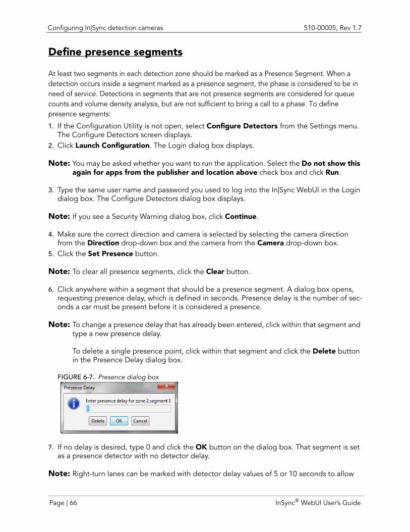
Configuring In|Sync detection cameras 510-00005, Rev 1.7
Define presence segments
At least two segments in each detection zone should be marked as a Presence Segment. When a detection occurs inside a segment marked as a presence segment, the phase is considered to be in need of service. Detections in segments that are not presence segments are considered for queue counts and volume density analysis, but are not sufficient to bring a call to a phase. To define presence segments:
1. If the Configuration Utility is not open, select Configure Detectors from the Settings menu. The Configure Detectors screen displays.
2. Click Launch Configuration. The Login dialog box displays.
Note: You may be asked whether you want to run the application. Select the Do not show this again for apps from the publisher and location above check box and click Run.
3. Type the same user name and password you used to log into the In|Sync WebUI in the Login dialog box. The Configure Detectors dialog box displays.
Note: If you see a Security Warning dialog box, click Continue.
4. Make sure the correct direction and camera is selected by selecting the camera direction from the Direction drop-down box and the camera from the Camera drop-down box.
5. Click the Set Presence button.
Note: To clear all presence segments, click the Clear button.
6. Click anywhere within a segment that should be a presence segment. A dialog box opens, requesting presence delay, which is defined in seconds. Presence delay is the number of sec-onds a car must be present before it is considered a presence.
Note: To change a presence delay that has already been entered, click within that segment and type a new presence delay.
To delete a single presence point, click within that segment and click the Delete button in the Presence Delay dialog box.
FIGURE 6-7. Presence dialog box
7. If no delay is desired, type 0 and click the OK button on the dialog box. That segment is set as a presence detector with no detector delay.
Note: Right-turn lanes can be marked with detector delay values of 5 or 10 seconds to allow
Page | 66 InSync® WebUI User’s Guide
510-00005, Rev 1.7 Configuring In|Sync detection cameras
vehicles to make a right-turn on red. A 10 second delay is standard.
The delay value is shown in all segments that have been set as Presence Segments.
8. Click the Done button after all Presence Segments have been marked.
Note: There should be at least two presence segments at the front of each detection zone.
Do not mark every segment as a presence segment. This can lead to false positives. Typically two to four presence segments per lane are adequate.
Set fog zones (In:Sync and In:Sync:Fusion only)
Note: The following instructions pertain only to In|Sync and In|Sync:Fusion installations.
Fog zones are used by In|Sync to verify that the camera has a clear view of traffic. Fog zones are drawn around unchanging features in the camera view that have high contrast with the background, such as traffic signals and sidewalks. When In|Sync can no longer see high contrast within the fog zone(s), the camera information is considered unreliable and fog mode is entered. At least one fog zone must be defined.
Note: You must set one fog zone for an In|Sync thermal detection camera, but the placement of the fog zone is irrelevant since thermal detection cameras use heat signatures to detect vehicles.
To add fog zones:
FIGURE 6-8. Red shaded areas denote fog zones
InSync® WebUI User’s Guide Page | 67
Configuring In|Sync detection cameras 510-00005, Rev 1.7
1. If the Configuration Utility is not open, select Configure Detectors from the Settings menu. The Configure Detectors screen displays.
2. Click Launch Configuration. The Login dialog box displays.
Note: You may be asked whether you want to run the application. Select the Do not show this again for apps from the publisher and location above check box and click Run.
3. Type the same user name and password you used to log into the In|Sync WebUI in the Login dialog box. The Configure Detectors dialog box displays.
Note: If you see a Security Warning dialog box, click Continue.
4. Make sure the correct direction and camera is selected by selecting the camera direction from the Direction drop-down box and the camera from the Camera drop-down box.
5. Click the Fog Zone button.6. Click the Add button. 7. Click points within the view to define the edges of the fog zones. If you make a mistake, click
the Clear button to start over.8. When done defining fog zones, click the Done button. If you are finished with all your edit-
ing, click the Update Intersection button.
FOG ZONE TIPS
Fog zones can be drawn around objects that have high contrast with the background.
Do not draw a single fog zone around multiple objects.
Make the fog zone large enough around the point of interest to allow for camera shake.
Avoid objects that might be obscured or that have a background that changes often.
Good candidates for fog zones include light poles, traffic signs, business signs, and stone markers.
Bad candidates for fog zones include temporary signs, bushes, and objects in front of a parking lot.
Two to three fog zones is typically enough.
Check the Edge View check box and click the Refresh button to see the areas/edges of high contrast in the image (see page 73).
Page | 68 InSync® WebUI User’s Guide
510-00005, Rev 1.7 Configuring In|Sync detection cameras
REMOVE FOG ZONES
To remove fog zones:
1. If the Configuration Utility is not open, select Configure Detectors from the Settings menu. The Configure Detectors screen displays.
2. Click Launch Configuration. The Login dialog box displays.
Note: You may be asked whether you want to run the application. Select the Do not show this again for apps from the publisher and location above check box and click Run.
3. Type the same user name and password you used to log into the In|Sync WebUI in the Login dialog box. The Configure Detectors dialog box displays.
Note: If you see a Security Warning dialog box, click Continue.
4. Make sure the correct direction and camera is selected by selecting the camera direction from the Direction drop-down box and the camera from the Camera drop-down box.
5. Click the Fog Zone button.6. Select the appropriate zone number in the zone list. The selected zone is highlighted in red.7. Click the Remove button.
InSync® WebUI User’s Guide Page | 69
Configuring In|Sync detection cameras 510-00005, Rev 1.7
Set Stabilization zones (In|Sync:Thermal Only)
Stabilization zones are areas within the camera's view that are fixed. These reference points establish areas that are known to have no movement and should be positioned on the edges of the camera view. Do not position of stabilization zone on the area of screen that is to be monitored for movement. It should also never be blocked by other objects, such as parked cars. Good objects that can be used for stabilization zones are tree trunks or buildings.
Note: A minimum of two zones, one on each side of the camera view, is required for optimal image stabilization.
To add stabilization zones:
FIGURE 6 - 9. Defining Stabilization Zones
1. Make sure the correct direction and camera is selected by selecting the camera direction from the Direction drop-down box and the camera from the Camera drop-down box.
2. Click the Stabilization Zone button.3. Click the Add button. 4. Click points within the view to define the edges of the stabilization zones. If you make a mis-
take, click the Clear button to start over.5. When done defining stabilization zones, click the OK button. If you are finished with all your
editing, click the Update Intersection button.
Page | 70 InSync® WebUI User’s Guide
510-00005, Rev 1.7 Configuring In|Sync detection cameras
STABILIZATION TIPS
It's beneficial to have at least two stabilization zones, one on each side of the camera view. Each stabilization zone works to pin down the image. When there's only a single stabilization zone, that pin becomes a pivot. Any image shaking due to camera movement causes the entire frame to “twist” slightly around that area. Having one stabilization zone on the left and one on the right does a better job of nailing down the image.
When drawing a stabilization zone, use areas of the screen then will never have vehicle or pedestrian traffic entering into the zone. Always consider whether a passing vehicle might move through the proposed stabilization zone. If a vehicle could possibly obstruct the view, do not use it as a stabilization zone.
REMOVE STABILIZATION ZONES
To remove stabilization zones:
1. Make sure the correct direction and camera is selected by selecting the camera direction from the Direction drop-down box and the camera from the Camera drop-down box.
2. Click the Stabilization Zone button.3. Select the appropriate zone number in the zone list or the stabilization zone on the camera
view. The selected zone is highlighted in red.4. Click the Remove button.
InSync® WebUI User’s Guide Page | 71
Configuring In|Sync detection cameras 510-00005, Rev 1.7
Set Ignore Zones (In|Sync:Thermal Only)
Ignore zones are the areas of the camera view that In|Sync should disregard when looking for motion. Items that a user may want to ignore are things that can sway in the wind, such as signs, tree branches or flags or items that can block vehicle detection, like traffic signal heads. This helps to eliminate false positives caused by movement that is not vehicle movements, such as span wires crossing the camera’s view of the oncoming traffic and signal heads blocking some portion of the approach.
Note: Since In|Sync only looks for motion within defined detection zones, do not draw ignore zones outside of detection zones. It won't cause any particular detriment for processing to draw ignore zones outside of detection zones but it's not a good use of resources in general.
To add ignore zones:
FIGURE 6 - 10. Defining Ignore Zones
1. Make sure the correct direction and camera is selected by selecting the camera direction from the Direction drop-down box and the camera from the Camera drop-down box.
2. Click the Ignore Zone button.3. Click the Add button. 4. Click points within the view to define the edges of the ignore zones. If you make a mistake,
click the Clear button to start over.5. When done defining ignore zones, click the OK button. If you are finished with all your edit-
ing, click the Update Intersection button.
Page | 72 InSync® WebUI User’s Guide
510-00005, Rev 1.7 Configuring In|Sync detection cameras
REMOVE IGNORE ZONES
To remove ignore zones:
1. Make sure the correct direction and camera is selected by selecting the camera direction from the Direction drop-down box and the camera from the Camera drop-down box.
2. Click the Ignore Zone button.3. Select the appropriate zone number in the zone list or the ignore zone on the camera view.
The selected zone is highlighted in red.4. Click the Remove button.
Confirm good edge lines
Note: The following instructions pertain only to In|Sync and In|Sync:Fusion installations that use In|Sync video detection cameras.
FIGURE 6-11. Edge View
To confirm that a certain object creates a good edge line to draw a fog/contrast zone over:
1. If the Configuration Utility is not open, select Configure Detectors from the Settings menu. The Configure Detectors screen displays.
2. Click Launch Configuration. The Login dialog box displays.
Note: You may be asked whether you want to run the application. Select the Do not show this again for apps from the publisher and location above check box and click Run.
InSync® WebUI User’s Guide Page | 73
Configuring In|Sync detection cameras 510-00005, Rev 1.7
3. Type the same user name and password you used to log into the In|Sync WebUI in the Login dialog box. The Configure Detectors dialog box displays.
Note: If you see a Security Warning dialog box, click Continue.
4. Click Update Intersection to update the camera information.5. Click the Edge View check box (bottom left corner of the screen). 6. Click the Refresh button. An edge view is generated (see Figure 6-11).
7. De-select the Edge View check box and click the Refresh button again to return to the nor-mal camera view.
8. Click Done after all fog zones have been verified.
Configure external detectors (In|Sync:Fusion)
Note: The following instructions pertain only to In|Sync:Fusion installations.
After defining the lanes within a phase, you must associate detection zones with the lane. If you have already set up external detectors within In|Sync:
1. If the Configuration Utility is not open, select Configure Detectors from the Settings menu. The Configure Detectors screen displays.
2. Click Launch Configuration. The Login dialog box displays.
Note: You may be asked whether you want to run the application. Select the Do not show this again for apps from the publisher and location above check box and click Run.
3. Type the same user name and password you used to log into the In|Sync WebUI in the Login dialog box. The Configure Detectors dialog box displays.
Note: If you see a Security Warning dialog box, click Continue.
4. If the cartoon map view of the intersection is not showing, select All from the Direction drop-down box.
5. Click the + icon next to the direction where you want to assign the external detector. This shows all the phases within the direction.
6. Click the + icon next to phase in which you want to assign the external detector. This shows all the lanes within the phase.
7. Right-click the lane and select Add Detector. A list of detectors will display in the short-cut menu. Select the one you want from the menu.
If no detectors currently exist within In|Sync:
1. If the Configuration Utility is not open, select Configure Detectors from the Settings menu. The Configure Detectors screen displays.
2. Click Launch Configuration. The Login dialog box displays.
Page | 74 InSync® WebUI User’s Guide
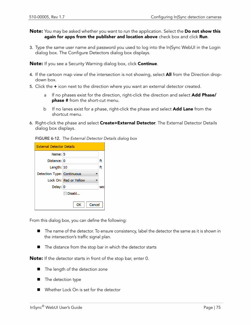
510-00005, Rev 1.7 Configuring In|Sync detection cameras
Note: You may be asked whether you want to run the application. Select the Do not show this again for apps from the publisher and location above check box and click Run.
3. Type the same user name and password you used to log into the In|Sync WebUI in the Login dialog box. The Configure Detectors dialog box displays.
Note: If you see a Security Warning dialog box, click Continue.
4. If the cartoon map view of the intersection is not showing, select All from the Direction drop-down box.
5. Click the + icon next to the direction where you want an external detector created.
a If no phases exist for the direction, right-click the direction and select Add Phase/phase # from the short-cut menu.
b If no lanes exist for a phase, right-click the phase and select Add Lane from the shortcut menu.
6. Right-click the phase and select Create>External Detector. The External Detector Details dialog box displays.
FIGURE 6-12. The External Detector Details dialog box
From this dialog box, you can define the following:
The name of the detector. To ensure consistency, label the detector the same as it is shown in the intersection’s traffic signal plan.
The distance from the stop bar in which the detector starts
Note: If the detector starts in front of the stop bar, enter 0.
The length of the detection zone
The detection type
Whether Lock On is set for the detector
InSync® WebUI User’s Guide Page | 75
Configuring In|Sync detection cameras 510-00005, Rev 1.7
Delay, which is the amount of time before a detection should register a presence
Note: If you know that there is a potential for a car to slip past a detector so that it is not going to register a presence, we recommend that you turn on the Lock On attribute. Selecting Red or Yellow Lock On is recommended, but at least Lock On Red should be configured in this case. Lock On Yellow only locks when the signal is Yellow and may not be sufficient in this case.
UNASSIGN AN EXTERNAL DETECTOR FROM A LANE
To remove an external detector from a lane:
1. If the Configuration Utility is not open, select Configure Detectors from the Settings menu. The Configure Detectors screen displays.
2. Click Launch Configuration. The Login dialog box displays.
Note: You may be asked whether you want to run the application. Select the Do not show this again for apps from the publisher and location above check box and click Run.
3. Type the same user name and password you used to log into the In|Sync WebUI in the Login dialog box. The Configure Detectors dialog box displays.
Note: If you see a Security Warning dialog box, click Continue.
4. Right-click the detector in the tree view.5. Select Delete from the shortcut menu.
Note: The definition of the detector still exists; it has just been removed from the lane.
CHANGE A DETECTOR’S SETTINGS
To change the settings assigned to a detector:
1. If the Configuration Utility is not open, select Configure Detectors from the Settings menu. The Configure Detectors screen displays.
2. Click Launch Configuration. The Login dialog box displays.
Note: You may be asked whether you want to run the application. Select the Do not show this again for apps from the publisher and location above check box and click Run.
3. Type the same user name and password you used to log into the In|Sync WebUI in the Login dialog box. The Configure Detectors dialog box displays.
Note: If you see a Security Warning dialog box, click Continue.
4. Click the external detector that you want to change.5. Click the Edit Detector Details button. The External Detector Details dialog box displays.6. Enter the new settings (distance from stopbar, length, etc.) into the External Detector Details
dialog box and then click OK.
Page | 76 InSync® WebUI User’s Guide
510-00005, Rev 1.7 Configuring In|Sync detection cameras
If you would like to change the name of the external detector, complete the following steps:
1. If the Configuration Utility is not open, select Configure Detectors from the Settings menu. The Configure Detectors screen displays.
2. Click Launch Configuration. The Login dialog box displays.
Note: You may be asked whether you want to run the application. Select the Do not show this again for apps from the publisher and location above check box and click Run.
3. Type the same user name and password you used to log into the In|Sync WebUI in the Login dialog box. The Configure Detectors dialog box displays.
Note: If you see a Security Warning dialog box, click Continue.
4. Click the direction on which the external detector resides from the Direction drop-down box.5. Click the External Detectors tab.6. Click the external detector that you want to edit in the list and click the Edit button. From this
External Detector Details dialog box, you can change the detector’s name.
Confirm detection cameras/external detectors are correctly assigned
After defining all detection cameras, verify that each camera is assigned to the correct direction and phase and that all lanes are correctly assigned. To do this:
1. If the Configuration Utility is not open, select Configure Detectors from the Settings menu. The Configure Detectors screen displays.
2. Click Launch Configuration. The Login dialog box displays.
Note: You may be asked whether you want to run the application. Select the Do not show this again for apps from the publisher and location above check box and click Run.
3. Type the same user name and password you used to log into the In|Sync WebUI in the Login dialog box. The Configure Detectors dialog box displays.
Note: If you see a Security Warning dialog box, click Continue.
4. Select All from the Direction drop-down box. A cartoon view representation of the intersec-tion displays on the left, while a tree organizational view displays to the right.
5. Click the + icon in the tree view for each direction to verify that all phases for an approach exist.
6. Click the + icon in the tree view for each phase to verify that all lanes exist within each phase.
If a phase/lane is incorrectly assigned to a detection camera:
1. Right-click on the direction and select Clear from the short-cut menu. 2. Select the camera direction from the Direction pull-down menu.
3. Click the icon to add a camera. The Add Camera dialog box displays.
InSync® WebUI User’s Guide Page | 77
Configuring In|Sync detection cameras 510-00005, Rev 1.7
4. Click the icon to add a camera. The Add Camera dialog box displays.5. Provide a name for the camera in the Camera Name field.6. Type the IP address associated with the In|Sync detection camera in the IP Address field. 7. Select the type of camera being added from the Camera Type pull-down list box.
For In|Sync video detection, select Samsung/Axis Visible
For In|Sync:Thermal detection:
• Via Axis thermal cameras, select Axis Thermal
• Via FLIR thermal cameras, select FLIR Thermal
8. Click OK.9. Type the distance from the stop bar in which the camera starts reporting detections in the
Min Distance from Stopbar field.10.Type the distance from the beginning of the detection zone to the end of the detection zone
in the Coverage Distance field.11.Click Detection Zone.12.Click Add to add the detection zones.13.Draw the detection zones.14.Click OK to indicate that you are finished drawing the detection zone. The Zone Information
dialog box displays.15.Select the correct phase from the Choose a Phase drop-down list.16.Click OK.
If a phase is incorrectly assigned to an external detector:
1. Find the external detector within the tree view.2. Right-click on the detector and select Delete from the short-cut menu. The external detector
is removed from the lane; however, it is not removed from the Configuration utility.3. Right-click on the lane in the tree view and either select Add Detector to assign an existing
external detector to the lane or click Create Detector to create a new external detector to the lane.
Page | 78 InSync® WebUI User’s Guide
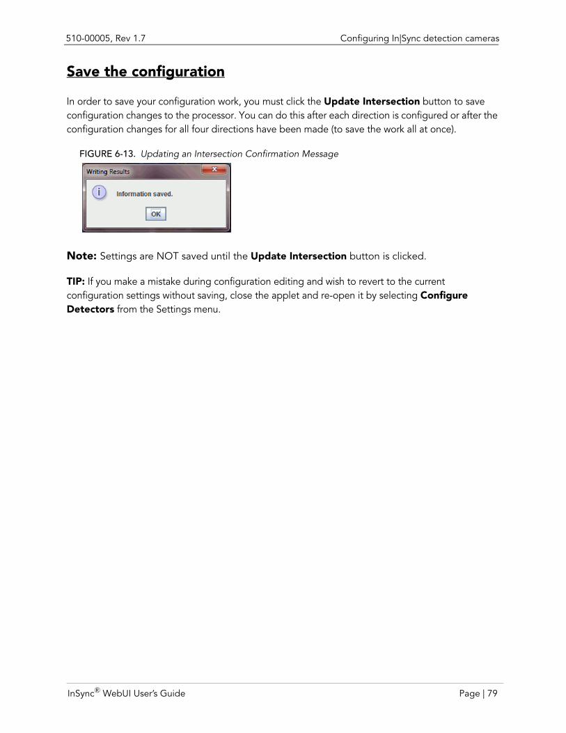
510-00005, Rev 1.7 Configuring In|Sync detection cameras
Save the configuration
In order to save your configuration work, you must click the Update Intersection button to save configuration changes to the processor. You can do this after each direction is configured or after the configuration changes for all four directions have been made (to save the work all at once).
FIGURE 6-13. Updating an Intersection Confirmation Message
Note: Settings are NOT saved until the Update Intersection button is clicked.
TIP: If you make a mistake during configuration editing and wish to revert to the current configuration settings without saving, close the applet and re-open it by selecting Configure Detectors from the Settings menu.
InSync® WebUI User’s Guide Page | 79
Grabbing Camera Backgrounds 510-00005, Rev 1.7
Grabbing Camera Backgrounds After creating or adjusting configuration details within the Configure applet, you must grab camera backgrounds for each camera view. The background is used as a reference for car detection and should be representative of average lighting/visibility conditions (ideally captured in late morning or early afternoon). It is also used to determine visibility conditions.
Note: Make sure there are no cars in the detection zone when grabbing a background image.
Grabbing camera backgrounds can be performed from the In|Sync WebUI or from the In|Sync kiosk (through the Views button).
1. In the In|Sync WebUI, select Single Camera View from the Views menu.2. Choose the camera direction from the Camera drop-down box.
If possible, wait until the lanes are free of traffic.3. Click the Grab Background button.4. Repeat for the next camera view.
The camera moves into fog mode when the processor determines that it does not have a clear image for dependable video vehicle detection. In this situation, In|Sync references historical data collected for each phase associated with the unclear view. The historical data is based on green splits for that time of day, on that particular day of the week, for the past 4 weeks, in 15 minute increments. This allows In|Sync to make a reasonable estimation of how much time should be allotted to each phase affected by the fog mode (preferable to MAX RECALL).
Page | 80 InSync® WebUI User’s Guide
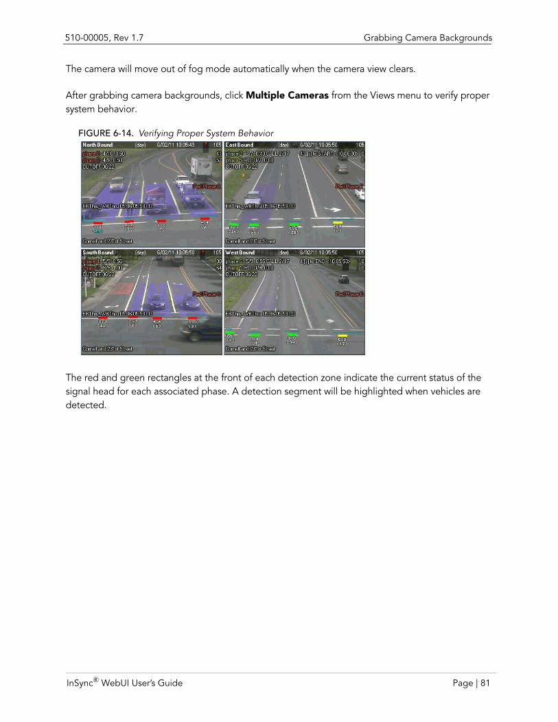
510-00005, Rev 1.7 Grabbing Camera Backgrounds
The camera will move out of fog mode automatically when the camera view clears.
After grabbing camera backgrounds, click Multiple Cameras from the Views menu to verify proper system behavior.
FIGURE 6-14. Verifying Proper System Behavior
The red and green rectangles at the front of each detection zone indicate the current status of the signal head for each associated phase. A detection segment will be highlighted when vehicles are detected.
InSync® WebUI User’s Guide Page | 81
Configuring a Multi-Processor Intersection 510-00005, Rev 1.7
Configuring a Multi-Processor IntersectionIn a multi-processor setup (an intersection with 6 or more In|Sync detection cameras), specific steps need to be taken to configure both In|Sync Processors. Multi-processor intersections are primarily used in diamond interchanges where only one controller, and therefore one cabinet, controls two intersections. Other possible locations are where there are two closely spaced intersections that need to have overlaps to prevent backing up between the intersections, or intersections with several camera detectors.
1. Identify the IP addresses of the two processors that will be used for the multi-processor con-figuration.
For example, IP address 192.168.1.100 runs the In|Sync software and processes In|Sync detection cameras on the Eastbound, Eastbound Advanced, and Southbound approaches, while IP address 192.168.1.101 only processes the remaining In|Sync detection cameras on the Westbound, Westbound Advanced, and Northbound approaches.
2. Log into the intersection that runs the In|Sync Processor software (in the example above, 192.168.1.100) by typing its IP address into the Address bar of a web browser and logging in by typing the user name and password.
3. Select Configure Detectors from the Settings menu.4. Click the Launch Configuration Utility button.5. Type the user name and password for the processor that runs the In|Sync software. 6. Add the In|Sync detection cameras as you would normally do (see “Configuring In|Sync
detection cameras” on page 55.
7. Type the IP address of the In|Sync Processor that will be used to process that In|Sync Camera detector in the Host Machine field. For example, processor 192.168.1.100 will be entered for the Eastbound, Eastbound Advanced, and Southbound approaches, while processor 192.168.1.101 will be entered for the Westbound, Westbound Advanced, and Northbound approaches.
Note: Although a processor can handle up to five camera views, if you have two processors it is a good idea to evenly distribute the processing load between them (e.g., three cameras on each processor).
8. Draw detection zones, segments lines, presence segments and fog zones as you normally would.
9. Click Update Intersection when done.10.Verify that video processor is running on the secondary processor by clicking CameraIO from
the Advanced tab on the In|Sync kiosk. The video processor should show camera processes for which it is responsible and each camera’s current status.
Note: You do not have to set NTP Server settings and GPS coordinates on video only processors.
Page | 82 InSync® WebUI User’s Guide

CHAPTER 7 REMOTELY CONTROLLING AN INTERSECTION
With In|Sync’s live camera views, you can see how In|Sync is responding to real-time traffic demand. You can also, with the correct permission level, manually control an intersection’s traffic signals remotely using the In|Sync WebUI. In addition, you can perform troubleshooting steps remotely to save you a trip to an intersection. The following section details how to use the manual controls that come with the In|Sync WebUI.
Using Manual ControlsNote: Manual intersection control is available to users with Camera View/Control and Manual Traffic
Controls permissions turned on.
The Multiple Camera screen contains a Manual Controls button that provides all the options you need to manually control an intersection. From this dialog box you can manually control which phases are receiving detections and which phases are receiving calls.
Note: If you try to manually control an intersection that another user is currently trying to control, a dialog box displays warning you that another user is logged into the Manual Controls dialog box. You can choose to take control of the dialog box (Yes), give up control of the dialog box (No), or view the dialog box without being able to make and changes (Read Only). If you decided to take control of the page, a message displays for the other user that someone else has taken over control of the intersection. The other user is then in read only mode.
InSync® WebUI User’s Guide Page | 83
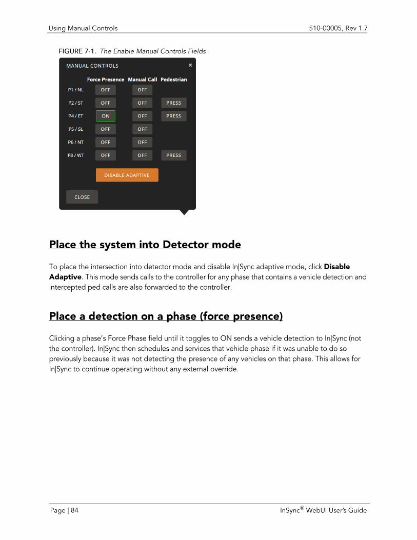
Using Manual Controls 510-00005, Rev 1.7
FIGURE 7-1. The Enable Manual Controls Fields
Place the system into Detector mode
To place the intersection into detector mode and disable In|Sync adaptive mode, click Disable Adaptive. This mode sends calls to the controller for any phase that contains a vehicle detection and intercepted ped calls are also forwarded to the controller.
Place a detection on a phase (force presence)
Clicking a phase’s Force Phase field until it toggles to ON sends a vehicle detection to In|Sync (not the controller). In|Sync then schedules and services that vehicle phase if it was unable to do so previously because it was not detecting the presence of any vehicles on that phase. This allows for In|Sync to continue operating without any external override.
Page | 84 InSync® WebUI User’s Guide
510-00005, Rev 1.7 Rebooting a Camera
Place a manual vehicle call on a phase (manual call)
Clicking a phase’s Manual Control field until it toggles to ON sends calls only from that phase to the controller, completely overriding the calls that In|Sync may be trying to send.
WARNING: These calls will interfere with In|Sync’s adaptive operation. Use with care.
Place a manual pedestrian call
If the intersection is configured with pedestrian interception, manual Ped Call controls are also available to you. Click the relevant ped phase to turn it ON. In|Sync sees the call like it does a Ped button press from the field and incorporates it into its adaptive control. These ped calls come in addition to any ped or vehicle calls that In|Sync is already sending to the controller.
Rebooting a CameraRebooting a camera may help if a camera is experiencing any issues, like unresponsiveness, no image, low frame rate, stuck at an incorrect exposure, etc. Sometimes a reboot fixes these issues. To reboot a camera:
1. Select Single Camera View from the Views menu.2. Choose the camera direction from the Camera drop-down box.3. Click the Reboot Camera button.
Note: Rebooting the camera is only available to users with administrative access.
InSync® WebUI User’s Guide Page | 85
Toggling a Camera into Emergency Mode 510-00005, Rev 1.7
Toggling a Camera into Emergency ModeNote: Toggling a camera into Emergency mode is only available to users that have permission to
View/Control Cameras (set up in Edit Users in the Accounts menu).
You may want to use emergency mode if the camera view is obstructed in any way. For instance you may want to toggle a camera into emergency mode if the camera is unable to see oncoming traffic, but the fog zones are clear. In this case, the camera doesn’t enter Fog Mode automatically and may need to be toggled into emergency mode. Also, if the camera view is permanently compromised (like a camera knocked out of alignment), it is a good idea to turn on emergency mode until the camera is corrected.
A camera view can be manually placed into emergency mode from the Single Camera View page by clicking the Toggle Emergency button. This operates just like fog mode, but remains active until manually turned off. To turn on emergency mode:
1. Select Single Camera View from the Views menu.2. Choose the camera direction from the Camera drop-down box.3. Click the Toggle Emergency button.
Note: Toggling a camera into emergency mode puts all phases in the camera view into emergency mode.
Overriding Fog Mode (In|Sync/In|Sync:Fusion Only)Note: Overriding Fog Mode is only available to users with administration access.
Selecting this button disables fog mode. It is an override for when the cameras think they have a compromised view, but a human has confirmed that they can see just fine. When you click this button, you disable Fog Mode for that calendar day. It is then automatically re-enabled the next morning. To override fog mode:
1. Select Single Camera View from the Views menu.2. Choose the camera direction from the Camera drop-down box.3. Click the Override Fog Mode button.
Page | 86 InSync® WebUI User’s Guide
CHAPTER 8 SCHEDULING A VIDEO RECORDING
The reasons for wanting to record video taken at an intersection are varied. Having a recording of an intersection can provide:
Before/after study data (e.g., an agency wants to record 30 minutes of video 7:00, noon and 5:00 for manual counts every weekday for two weeks)
Troubleshooting information (e.g., a user want to record an approach where a citizen reports a sporadic issue at night around 11:45 pm until they figure out what is going on)
Evidence (e.g., traffic barrels are being moved by someone as a prank in the middle of the night, further delaying construction starts in the morning)
Note: Recording video is available to users with View/Control Cameras access (set in the Account>Edit Users screen.
Adding a Recording
To schedule the recording of an intersection’s camera view:
Note: Videos can only be recorded to a USB device, such as a flash drive or an external hard drive with a USB connector, connected to the In|Sync Processor.
1. Connect an external hard drive or flash drive to the In|Sync Processor via the USB port.2. Log in to In|Sync either remotely or at the processor using a keyboard and monitor.3. Select Recording Options from the Views menu.4. Select the Use radio button next to the USB drive to which you want video recorded.5. Click the Add Recording Event button. The Schedule New Recording dialog box displays.
InSync® WebUI User’s Guide Page | 87
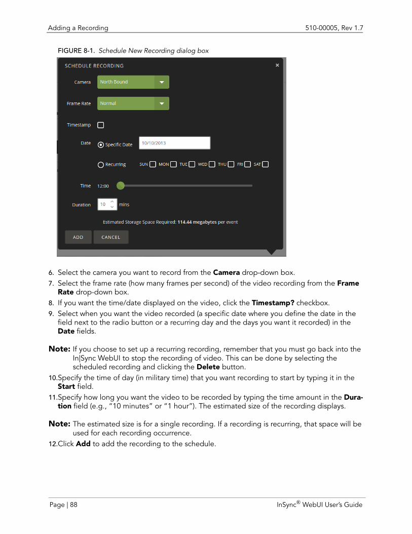
Adding a Recording 510-00005, Rev 1.7
FIGURE 8-1. Schedule New Recording dialog box
6. Select the camera you want to record from the Camera drop-down box.7. Select the frame rate (how many frames per second) of the video recording from the Frame
Rate drop-down box.8. If you want the time/date displayed on the video, click the Timestamp? checkbox.9. Select when you want the video recorded (a specific date where you define the date in the
field next to the radio button or a recurring day and the days you want it recorded) in the Date fields.
Note: If you choose to set up a recurring recording, remember that you must go back into the In|Sync WebUI to stop the recording of video. This can be done by selecting the scheduled recording and clicking the Delete button.
10.Specify the time of day (in military time) that you want recording to start by typing it in the Start field.
11.Specify how long you want the video to be recorded by typing the time amount in the Dura-tion field (e.g., “10 minutes” or “1 hour”). The estimated size of the recording displays.
Note: The estimated size is for a single recording. If a recording is recurring, that space will be used for each recording occurrence.
12.Click Add to add the recording to the schedule.
Page | 88 InSync® WebUI User’s Guide
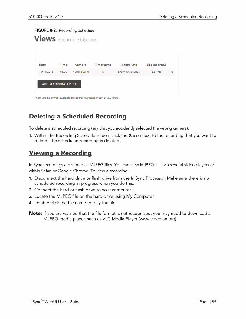
510-00005, Rev 1.7 Deleting a Scheduled Recording
FIGURE 8-2. Recording schedule
Deleting a Scheduled Recording
To delete a scheduled recording (say that you accidently selected the wrong camera):
1. Within the Recording Schedule screen, click the X icon next to the recording that you want to delete. The scheduled recording is deleted.
Viewing a Recording
In|Sync recordings are stored as MJPEG files. You can view MJPEG files via several video players or within Safari or Google Chrome. To view a recording:
1. Disconnect the hard drive or flash drive from the In|Sync Processor. Make sure there is no scheduled recording in progress when you do this.
2. Connect the hard or flash drive to your computer.3. Locate the MJPEG file on the hard drive using My Computer.4. Double-click the file name to play the file.
Note: If you are warned that the file format is not recognized, you may need to download a MJPEG media player, such as VLC Media Player (www.videolan.org).
InSync® WebUI User’s Guide Page | 89
Viewing a Recording 510-00005, Rev 1.7
Page | 90 InSync® WebUI User’s Guide
CHAPTER 9 IN|SYNC ADMINISTRATIVE TASKS
The functionality covered in this chapter should be preformed by users that have administrative access to In|Sync, as the tasks covered require a deeper understanding of In|Sync. In this chapter, you will learn how to:
Set the NTP server
Rename phases
Restore a configuration
Save an archive
Deploy the application
Set GPS coordinates
InSync® WebUI User’s Guide Page | 91
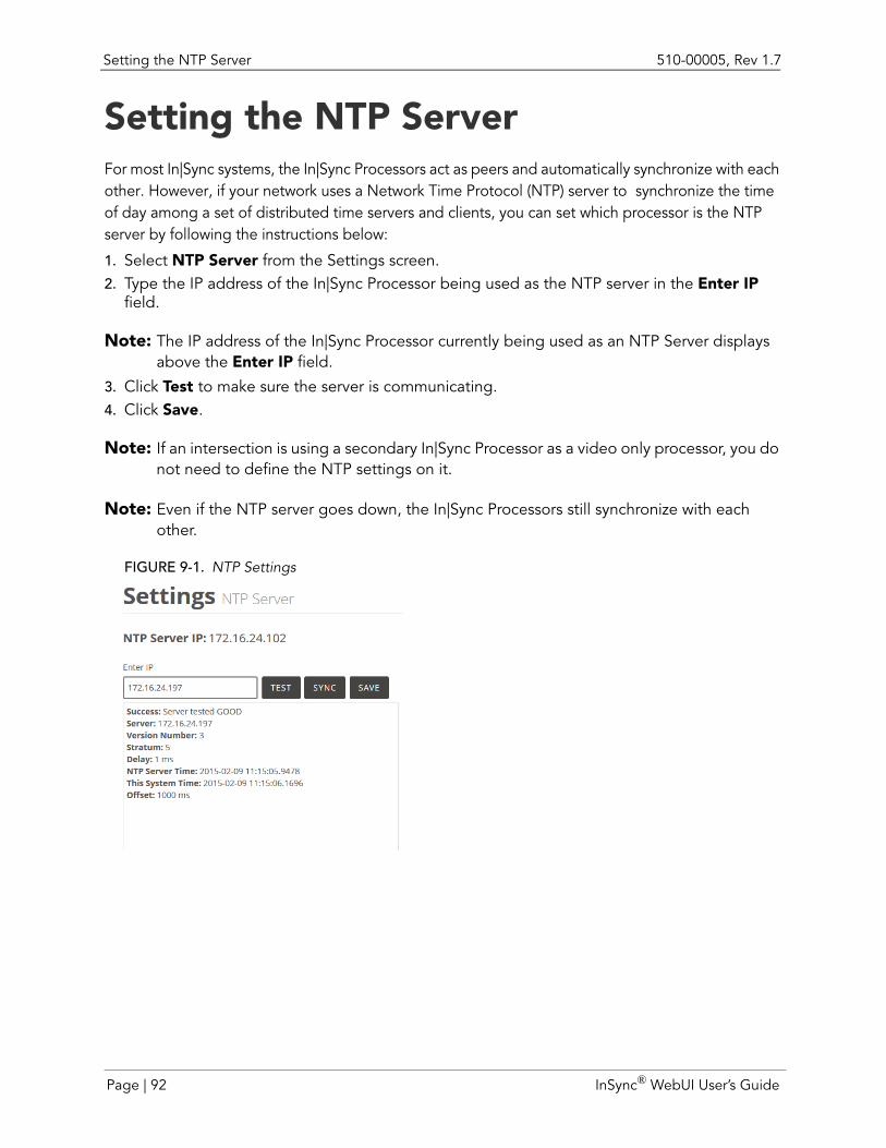
Setting the NTP Server 510-00005, Rev 1.7
Setting the NTP ServerFor most In|Sync systems, the In|Sync Processors act as peers and automatically synchronize with each other. However, if your network uses a Network Time Protocol (NTP) server to synchronize the time of day among a set of distributed time servers and clients, you can set which processor is the NTP server by following the instructions below:
1. Select NTP Server from the Settings screen.2. Type the IP address of the In|Sync Processor being used as the NTP server in the Enter IP
field.
Note: The IP address of the In|Sync Processor currently being used as an NTP Server displays above the Enter IP field.
3. Click Test to make sure the server is communicating.4. Click Save.
Note: If an intersection is using a secondary In|Sync Processor as a video only processor, you do not need to define the NTP settings on it.
Note: Even if the NTP server goes down, the In|Sync Processors still synchronize with each other.
FIGURE 9-1. NTP Settings
Page | 92 InSync® WebUI User’s Guide
510-00005, Rev 1.7 Synchronize NTP time
Synchronize NTP timeThe NTP Server page that is available through the Settings menu provides the ability to compare the time on a processor with the NTP Server system time. To do so:
1. Type the IP address of the processor you want to compare to the system in the Enter IP field.2. Click Test. The NTP Server Time for the processor and the System Time displays below.
If the two times are greatly different (the offset should be less than 1000 ms.), you can synchronize the times by clicking the Sync button. This sets the NTP Time on the processor to the System Time.
Syncing time after inital install or processor replacementThe following steps should be performed after:
Installing a new processor into an existing management group
Replacing a processor into an existing management group.
To sync NTP time of a new or replacement processor, complete the following steps:
1. Turn on the In|Sync Processor. 2. Restore the configuration, if not done prior to replacement.
If this is a replacement processor and the configuration has not been loaded, select Restore the configuration from the Kiosk's Home screen.
If you restored configuration prior to replacement, the processor automatically synchronizes with an NTP server or another intersection the first time the system boots (if configured and if network communication is available). The processor date, time, and time zone needs to be verified, as well as the time synchronization status with the NTP server or other intersections on the management group.
3. Set/verify the date and time zone.
From the Kiosk, go to Settings > Date/Time and verify that the date, time, and time zone settings are correct. If not, make the necessary changes.
If this is a replacement processor, only modify the date or time zone, if needed. Avoid adjusting the time. Only set the time if the NTP server or another intersection is unavailable to sync with.
4. Verify that the system is synchronized.
a If the NTP server or another intersection is available, verify that the current system
InSync® WebUI User’s Guide Page | 93
Syncing time after inital install or processor replacement 510-00005, Rev 1.7
time is synchronized.
b From the Kiosk, go to Settings > NTP Server. Type the NTP server address in the Enter IP field and click Save. To verify that you entered a valid NTP server, click Test. If the test is not successful, enter a new IP and click Test. Make sure to save the NTP server.
c If the NTP server is online, click Sync to synchronize the system time with the NTP server. To verify that the sync was successful, click Test. The offset should be less than 1000 ms.
d If the NTP server is unavailable, you must ensure that all intersections are synchronized with each other. To do this, type the IP address of another intersection on the management group into the Enter IP field and click Sync. Verify the sync was successful by clicking Test. The offset should be less than 1000 ms.
Page | 94 InSync® WebUI User’s Guide
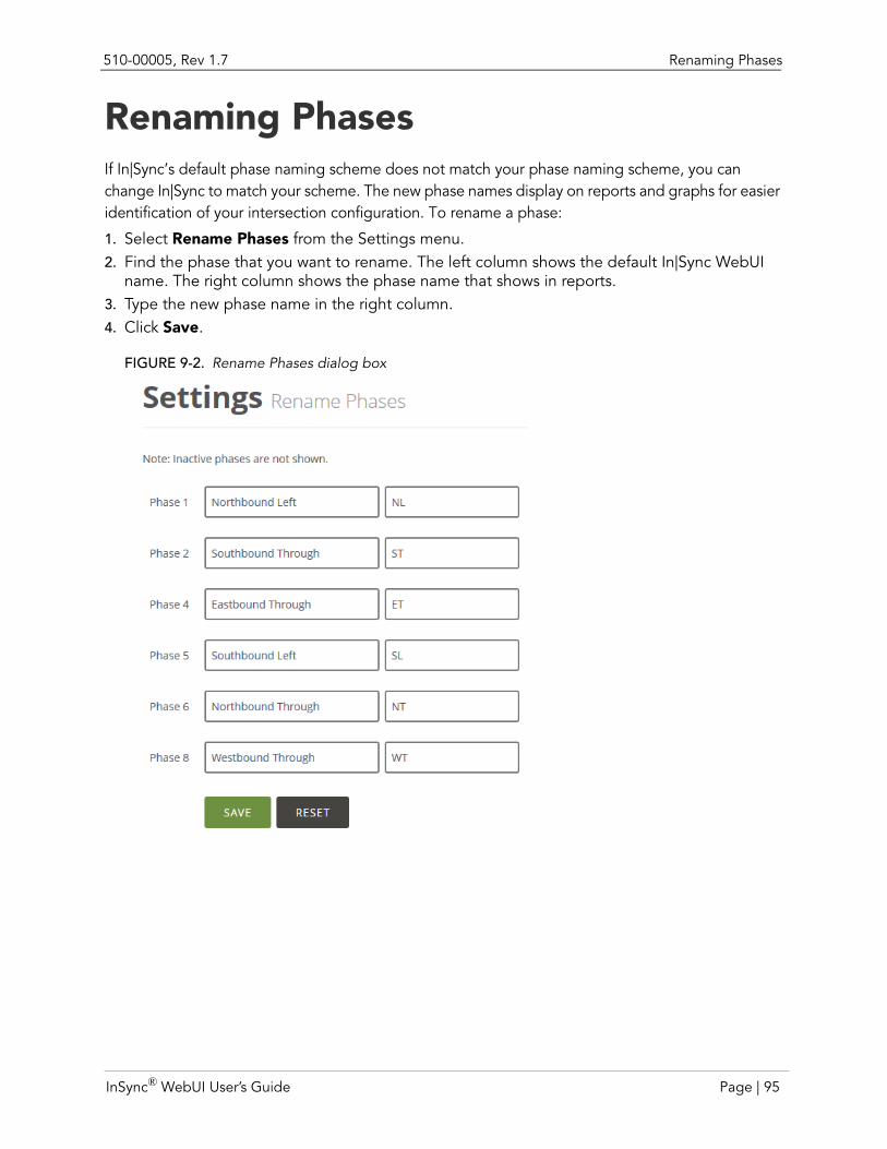
510-00005, Rev 1.7 Renaming Phases
Renaming PhasesIf In|Sync’s default phase naming scheme does not match your phase naming scheme, you can change In|Sync to match your scheme. The new phase names display on reports and graphs for easier identification of your intersection configuration. To rename a phase:
1. Select Rename Phases from the Settings menu.2. Find the phase that you want to rename. The left column shows the default In|Sync WebUI
name. The right column shows the phase name that shows in reports.3. Type the new phase name in the right column.4. Click Save.
FIGURE 9-2. Rename Phases dialog box
InSync® WebUI User’s Guide Page | 95

Saving an Archive 510-00005, Rev 1.7
Saving an ArchiveIn|Sync configuration files are automatically saved every time the configuration files change. In addition, you can download an archive of the configuration file and save it remotely. Besides the configuration file, you can also save Statistic files by selecting the Include Statistic Files check box. To save an archive of the configuration:
1. Select Maintenance from the Settings menu.2. If you want to include statistics into the archived configuration file, check the Include Statis-
tics Files next to the Save Archive section.3. Click Download. The Opening dialog box displays.4. Click the Save File radio button and click OK.
Restoring a ConfigurationThe Restore configuration feature allows you to restore your previous configuration using the backup configuration file. In the event that an In|Sync configuration file seems to be corrupt or not working the way you want it, you can revert to an old In|Sync configuration file using the Restore process.
From a file uploaded to the processor
To restore an In|Sync configuration file:
1. Select Maintenance from the Settings menu.2. Click the Upload button from the Restore Configuration dialog box. The Upload Archive dia-
log box displays.3. Click Choose File. The Open dialog box displays.4. Navigate to the location of the archived configuration and select it from the Files list.
Note: Each filename contains the year the file was archived (in four digits), the month (two digits), and the date (two digits). It is then followed by an underscore character (_), and the hour, minute, and seconds (in military time format).
5. Click OK in the Restore Configuration dialog box. An Restore Archive dialog box displays, indicating that the upload is complete.
6. Click Yes to continue to restore the configuration file. The Processor Type dialog box dis-plays.The system then restores the configuration.
Note: If the processor you are uploading the configuration to is a video only processor, click the Secondary Video Processor check box.
Page | 96 InSync® WebUI User’s Guide
510-00005, Rev 1.7 Deploying the Application
From an auto-saved file on the processor
Configuration files are automatically backed up any time a change is made to the processor. To restore a configuration from a file that was automatically saved to the processor, complete the following:
1. Select Maintenance from the Settings menu.2. Click the In|Sync Auto-Saves button from the Restore Configuration buttons. The Select
Archive dialog box displays.3. Select the date from which you want a backup restored from the drop-down list.4. Click Yes when you are asked if you want to restore over the existing configuration.5. If the In|Sync Processor is a video-only processor, select the Secondary Video Processor
check box.6. Click OK.
Deploying the ApplicationTo deploy new code from Rhythm Engineering on to an In|Sync Processor, complete the following steps:
1. Select Maintenance from the Settings menu.2. Click Upload Software from the Application Deployment group. The Upload Deployment
File dialog box displays.3. Click the Choose File button. The File Upload dialog box displays.4. Select the file from the dialog box and click Open.5. Click Upload. The Select Destination dialog box displays.6. Select whether you want to deploy the configuration file to only the connected processor or
to the whole management group. To deploy to only the connected intersection’s processor, click This Intersection. To deploy to all the processors in the management group, click Man-agement Group.
7. A message displays indicating that video only processors are also going to be updated. If a video only processor update fails, you can choose to Continue, Retry or Cancel.
Retry makes another attempt to update the software of the video only processor.
Continue skips over the failed video only processor and continues installing the software update.
Cancel stops the software update for any processor that has not been updated.
8. The software is updated on the processor. Depending on what changes were made, the pro-cessor may or may not reboot.
9. Wait until the message "USB drive(s) 'D:\' can now be safely removed" displays. You can now remove the USB drive.
InSync® WebUI User’s Guide Page | 97
Changing GPS Coordinates 510-00005, Rev 1.7
Changing GPS CoordinatesGPS coordinates are usually set only once, when you initially set up the processor at an intersection. We recommend that GPS coordinates are set from the In|Traffic software; however, if you are in the field deploying an In|Sync Processor, you can use the Change GPS Coordinates functionality to quickly estimate the GPS coordinates until you get change them to a more accurate setting later.
Note: If an intersection is using a secondary In|Sync Processor as a video only processor, you do not need to define the NTP settings on it.
To set the processor GPS location with an approximate location:1. Use the scroll wheel on the mouse to zoom in to an area of the map. Additionally, you can
click and drag an area of the map to view it better.2. Click an approximate area of the map where the processor is located. The GPS coordinates
are automatically entered in the Latitude and Longitude fields. 3. Click Save.
To set the processor’s GPS coordinates at the intersection with an exact location: 1. Select GPS Coordinates from the Settings menu.2. Type in the latitude of the intersection’s location in the Latitude field.
Note: The entered GPS coordinates must be in decimal notation (minutes.fractional seconds).
3. Type in the longitude of the intersection’s location in the Longitude field.4. Click Save.
Note: To change the values back to the original latitude and longitude parameters, click Cancel.
Page | 98 InSync® WebUI User’s Guide

CHAPTER 10 MANAGING USERS
Logging into In|Sync requires you to have a user account. Setting up a user account requires you to have a user name and password, along with access to certain functionalities. This information is set up in the Edit Users screen. From the Edit Users screen, you can:
Add a new user account
Edit existing user account’s functionality access
Change a user’s password
Delete a user account
Note: Managing user accounts is a functionality that is available to users that have Administer Users access (set in the Account>Edit Users screen).
Note: In|Sync provides two default user accounts upon installation: ADMIN and VIEW. We recommend that you either change each account’s password or delete these accounts entirely and create accounts unique to each user of the In|Sync system.
InSync® WebUI User’s Guide Page | 99
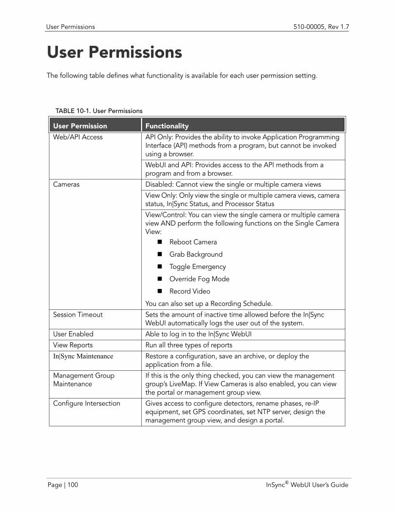
User Permissions 510-00005, Rev 1.7
User PermissionsThe following table defines what functionality is available for each user permission setting.
TABLE 10-1. User Permissions
User Permission Functionality
Web/API Access API Only: Provides the ability to invoke Application Programming Interface (API) methods from a program, but cannot be invoked using a browser.
WebUI and API: Provides access to the API methods from a program and from a browser.
Cameras Disabled: Cannot view the single or multiple camera views
View Only: Only view the single or multiple camera views, camera status, In|Sync Status, and Processor Status
View/Control: You can view the single camera or multiple camera view AND perform the following functions on the Single Camera View:Reboot Camera
Grab Background
Toggle Emergency
Override Fog Mode
Record Video
You can also set up a Recording Schedule.
Session Timeout Sets the amount of inactive time allowed before the In|Sync WebUI automatically logs the user out of the system.
User Enabled Able to log in to the In|Sync WebUI
View Reports Run all three types of reports
In|Sync Maintenance Restore a configuration, save an archive, or deploy the application from a file.
Management Group Maintenance
If this is the only thing checked, you can view the management group’s LiveMap. If View Cameras is also enabled, you can view the portal or management group view.
Configure Intersection Gives access to configure detectors, rename phases, re-IP equipment, set GPS coordinates, set NTP server, design the management group view, and design a portal.
Page | 100 InSync® WebUI User’s Guide
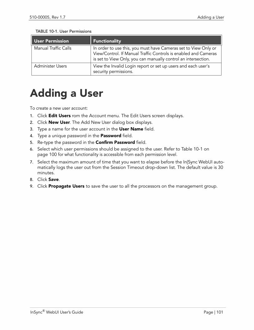
510-00005, Rev 1.7 Adding a User
Adding a UserTo create a new user account:
1. Click Edit Users rom the Account menu. The Edit Users screen displays.2. Click New User. The Add New User dialog box displays. 3. Type a name for the user account in the User Name field.4. Type a unique password in the Password field.5. Re-type the password in the Confirm Password field.6. Select which user permissions should be assigned to the user. Refer to Table 10-1 on
page 100 for what functionality is accessible from each permission level.
7. Select the maximum amount of time that you want to elapse before the In|Sync WebUI auto-matically logs the user out from the Session Timeout drop-down list. The default value is 30 minutes.
8. Click Save.9. Click Propagate Users to save the user to all the processors on the management group.
Manual Traffic Calls In order to use this, you must have Cameras set to View Only or View/Control. If Manual Traffic Controls is enabled and Cameras is set to View Only, you can manually control an intersection.
Administer Users View the Invalid Login report or set up users and each user's security permissions.
TABLE 10-1. User Permissions
User Permission Functionality
InSync® WebUI User’s Guide Page | 101
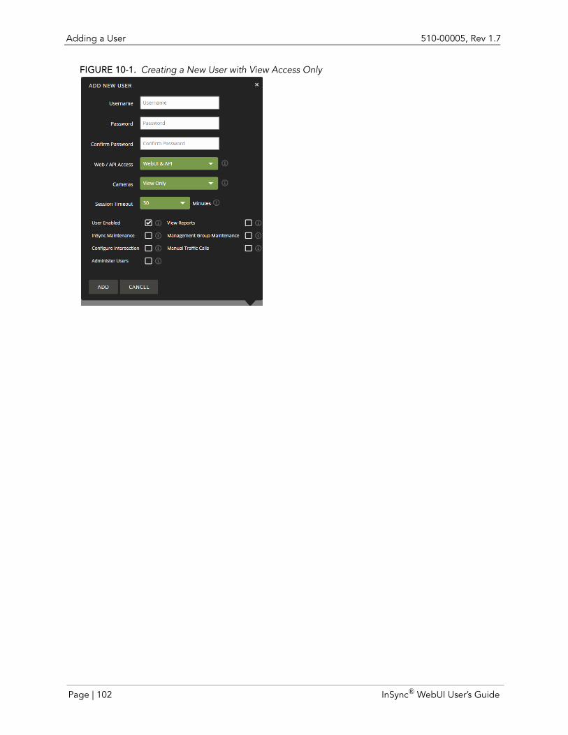
Adding a User 510-00005, Rev 1.7
FIGURE 10-1. Creating a New User with View Access Only
Page | 102 InSync® WebUI User’s Guide
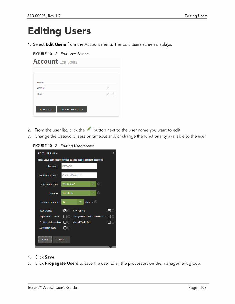
510-00005, Rev 1.7 Editing Users
Editing Users1. Select Edit Users from the Account menu. The Edit Users screen displays.
FIGURE 10 - 2. Edit User Screen
2. From the user list, click the button next to the user name you want to edit. 3. Change the password, session timeout and/or change the functionality available to the user.
FIGURE 10 - 3. Editing User Access
4. Click Save.5. Click Propagate Users to save the user to all the processors on the management group.
InSync® WebUI User’s Guide Page | 103
Deleting a User 510-00005, Rev 1.7
Deleting a User1. From the user list, click the next to the name. The Delete User dialog box displays. 2. Click Yes when the confirmation prompt appears.3. Click Propagate Users to remove the user from all the processors on the management
group.
Page | 104 InSync® WebUI User’s Guide
CHAPTER 11 CONFIGURATION BEST PRACTICES
Intersection NamingVerify that all intersections in the management group are labeled with meaningful names for
identification purposes.
• Accepted symbols include: alphanumeric letters (A through Z; 0 through 9), hash mark (#),and underscores ( _ ). You cannot use hyphens, or backslashes.
Detector NamingVerify that all detectors in the management group are labeled with meaningful names for
identification purposes.
Accepted symbols include: alphanumeric letters (A through Z; 0 through 9), hash mark (#), and underscores ( _ ). You cannot use hyphens or backslashes.
Make sure you use the detector number that is assigned on the intersection's traffic signal plan to avoid confusion.
Camera Detection Zone SetupDraw one detection zone per lane. Do not include more than one lane in a detection zone.
When feasible, draw detection zones inside the lane striping. Including lane striping can cause false positives if the camera shakes.
Note: You may draw outside lane striping if the camera view is offset, which would prevent a direct view of the lane.
Do not make the zone too narrow. Making it too narrow may cause In|Sync to miss headlights during night mode.
Extend the zone forward at least 1/2 of a car length beyond the stop bar to cover traffic that may creep forward. Extend the zone back as far as the lane is visible in the image.
InSync® WebUI User’s Guide Page | 105
External Detector Setup (In|Sync:Fusion only) 510-00005, Rev 1.7
Make all lanes, except for turn bays, approximately the same length. Turn bays may not extend as far back and through lanes.
If the lane is exceptionally wide and there is no lane striping, consider splitting it into two zones (left and right).
Do not overlap zones.
Verify that zones are long enough to allow for three segments.
At intersections where the only option is to either turn left or right, create two separate detection zones (one for the right turning lane and one for the left turning lane). This allows you to set different presence delay values for right/left turns.
External Detector Setup (In|Sync:Fusion only)Verify that distances between stop bar and detectors are accurate. Inaccurate measurements
will lead to poorer traffic optimization results.
When one detector is associated with a single lane of traffic, use the shortest distance between the stop bar and the detector in the Distance field.
Add detectors that are electrically tied across lanes as one detector.
When one detector is being used in multiple lanes, use the farthest distance to the stop bar (from any of the lanes) in the Distance field of the External Detector Details dialog box.
For example, detector 4 spans across three lanes of traffic. Lane 1’s distance from the stop bar to the detector is 6 ft; lane 2’s distance is 10 ft; lane 3’s distance is 14 ft. For this example, you should enter 14 into the Distance field.
Add every detector input available at an intersection into In|Sync.
If you know that there is a potential for a car to slip past a detector so that it is not going to register a presence, turn on the Lock On attribute. Selecting Red or Yellow Lock On is recommended, but at least Lock On Red should be configured in this case. Lock On Yellow only locks when the signal is Yellow and may not be sufficient in this case.
Measure to the point of detection closest to the stop bar.
Page | 106 InSync® WebUI User’s Guide
510-00005, Rev 1.7 External Detector Setup (In|Sync:Fusion only)
InSync® WebUI User’s Guide Page | 107
External Detector Setup (In|Sync:Fusion only) 510-00005, Rev 1.7
Page | 108 InSync® WebUI User’s Guide
AAccount management 99Adaptive mode 2, 3Adaptive turn on 2Advanced camera detector 56Advanced segments 64After hours phone number 6Amber Lock On 76, 106Application update 97Archives 96Auto generate a portal 41Automatic logoff 9Auto-saved configurations 97
BBackground filter 23Backup configurations 96
CCamera basics 13Camera detection zone 105Camera icons 16Camera layout 19Camera status 23CameraIO 3Cartoon view 14Compromised image 16Configuration files 96Configuration name 21Configuration utility 53Configurations 96Core temperature 22Count totals 35CPU core temperature 22CPU load percentage 22Create user 101
DDaily summary 27Dashboard 10Day mode 17Day-Night Switch Duration 53Delay 76Detection zone coverage 25Detection zones 59Detector delay 66Detector mode 2, 3, 84Detector name 105
Diamond layout 19Disable adaptive 84Disable fog mode 86Disabled fog mode 16Download statistics 37
EEdge filter 22Edge lines 73Email address 6Emergency mode 16, 86Emergency preemption 21Emergency vehicle preemption 16Ethernet repeater 24External detector setup 106External detectors 74
FFailed login attemps 9Filters 22Firmware 97Firmware version 21Fog mode 16, 80Fog Mode Allowed status 23Fog zones 67, 68Force presence 84Foreground filter 22FPS 25
GGPS coordinates 98
HHardware installation 2History viewer 27, 37Hourly summaries 37
IIcons 16Ignore zones 72Impaired view 23Installation 2InSync and InSync
Fusion configuration 53
In|Sync® WebUI User’s Guide Page | 1
InSync detection cameras 55InSync Installation 2InSync status 21Intersection name 105Intersection status 21IO board version 21IP address 21
LLast frame processing 24Latitude 98Load percentage 22Lock On 75, 106Log 37Logging in 8Long wait warning 16Longitude 98Low flow mode 16
MManagement group view 45Manual controls 83Manual conventions 5Manual pedestrian call 85Manual vehicle call 85Map view 51Max recall 80Menu 12MJPEG Acquire 24MJPEG files 89Multiple camera view 18Multi-processor intersection 82
NNight mode 17Normal coordination 17NTP server 92NTP status 21
OOffline mode 16Online help 4Out of coordination warning 17Override fog mode 86
PPed call 85Pedestrian counts 34, 37Pedestrian hourly summary 34Period graph 35Period lengths 28Phase renaming 95Phase Volume playback 32Phone numbers 6PoE 24Port requirements 7Portal view 40Ports 7Preemption/WatchDog recovery mode 17Presence delay 66Presence segments 64, 66Processing time 24Processor graphs 36Processor status 22Propagate management group view 49Propagate portal 44
QQuad layout 19
RRailroad preemption 16, 21Reboot camera 85Recording status 24Recording video 87Recovery mode 21Red Lock On 76, 106Refresh rate 19Requirements 7Restore configurations 96Rhythm Engineering support 6RTSP port 7
SSave archive 96Save management group view 48Save portal 43Screen conventions 11Segment lines 63Silverlight policy 8Single camera view 22Software update 97
Page | 2 In|Sync® WebUI User’s Guide
Splits 33Stabilization zones 70, 71Statistics 27, 30Sunset/Sunrise Offset 53System Requirements 7
TTechnical support 6
UUnprocessed filter 22Unprocessed view 13Unresponsive camera 16Update Intersection 79Update software 97Upgrades 97User management 99
VVehicle counts 28, 31, 37Vehicle hourly summary 31Video performance 24Video recording 87Video recording icon 16View layout 19View recordings 89VLC Media Player 89Volume analyzer 17, 21
WWeb site URL 6
In|Sync® WebUI User’s Guide Page | 3

Page | 4 In|Sync® WebUI User’s Guide


