Embed Size (px)
Citation preview
INSULATEDCONDUCTOR SYSTEMSU 20 – U 30 – U 40
INSULATED CONDUCTORS U 20 – U 30 – U 40
2
19 12
INDEX U 20 U 30 U 40
Page Page PageBasic description 4 4 4Selection of conductors 5-10 5-10 5-10Conductors 11 24 34, 35Rigid joints 11 25 36Expansion joints 12 25 36Locating clamps 14 26 36End caps 14 26 36Feed terminals 12 26 37Contact paste 12 26 36Transfer guides 13 27 38Transfer funnels 13 29 –Sectionalizing 13 27 38Hangers 14 28 39Insulators 14 28 39Rail holders 14 28 39Compact hangers/Attachment hardware/Bracket profiles 15 29 –Collectors 16, 17 30 40Components and spares for collectors 18-22 30-33 41Examples for ordering 23 31 42Grounding device 43 43 43Questionnaire 44, 45 44, 45 44, 45 Typical installations 46 46 46
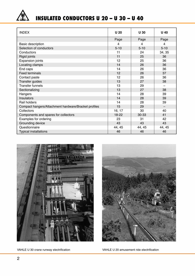
VAHLE U 30 crane runway electrification VAHLE U 20 amusement ride electrification
19 12INSULATED CONDUCTORS
3
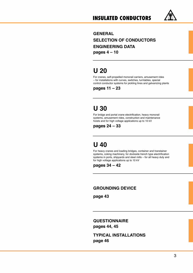
GENERAL
SELECTION OF CONDUCTORS
ENGINEERING DATApages 4 – 10
U 20For cranes, self-propelled monorail carriers, amusement rides – for installations with curves, switches, turntables, special control conductor systems for pickling lines and galvanizing plants
pages 11 – 23
U 30For bridge and portal crane electrification, heavy monorailsystems, amusement rides, construction and maintenancehoists and for high voltage applications up to 10 kV
pages 24 – 33
U 40For heavy cranes and loading bridges, container and transtainersystems, coking machinery, for dockside trench type electrificationsystems in ports, shipyards and steel mills – for all heavy duty andfor high voltage applications up to 10 kV
pages 34 – 42
GROUNDING DEVICE
page 43
QUESTIONNAIREpages 44, 45
TYPICAL INSTALLATIONS page 46
INSULATED CONDUCTORS
4
19 12
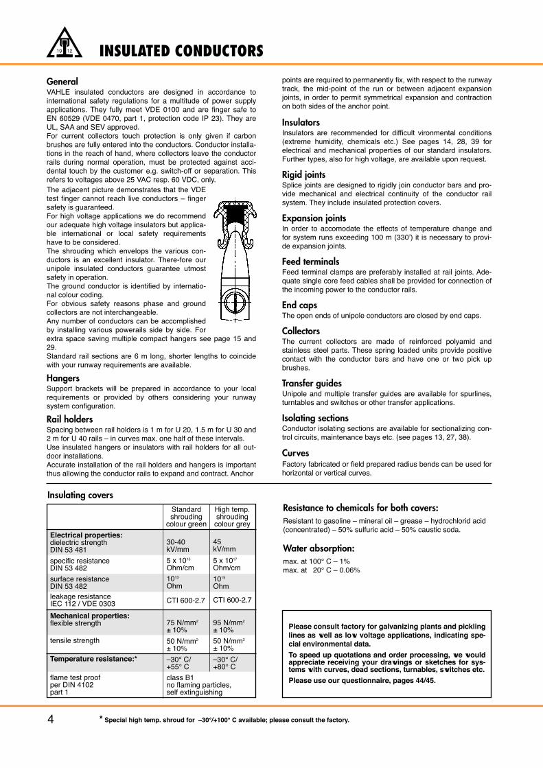
GeneralVAHLE insulated conductors are designed in accordance tointernational safety regulations for a multitude of power supplyapplications. They fully meet VDE 0100 and are finger safe toEN 60529 (VDE 0470, part 1, protection code IP 23). They areUL, SAA and SEV approved.For current collectors touch protection is only given if carbonbrushes are fully entered into the conductors. Conductor installa-tions in the reach of hand, where collectors leave the conductorrails during normal operation, must be protected against acci-dental touch by the customer e.g. switch-off or separation. Thisrefers to voltages above 25 VAC resp. 60 VDC, only.The adjacent picture demonstrates that the VDEtest finger cannot reach live conductors – fingersafety is guaranteed.For high voltage applications we do recommendour adequate high voltage insulators but applica-ble international or local safety requirementshave to be considered.The shrouding which envelops the various con-ductors is an excellent insulator. There-fore ourunipole insulated conductors guarantee utmostsafety in operation.The ground conductor is identified by internatio-nal colour coding.For obvious safety reasons phase and groundcollectors are not interchangeable.Any number of conductors can be accomplishedby installing various powerails side by side. Forextra space saving multiple compact hangers see page 15 and29. Standard rail sections are 6 m long, shorter lengths to coincidewith your runway requirements are available.
HangersSupport brackets will be prepared in accordance to your localrequirements or provided by others considering your runwaysystem configuration.
Rail holdersSpacing between rail holders is 1 m for U 20, 1.5 m for U 30 and2 m for U 40 rails – in curves max. one half of these intervals. Use insulated hangers or insulators with rail holders for all out-door installations.Accurate installation of the rail holders and hangers is importantthus allowing the conductor rails to expand and contract. Anchor
points are required to permanently fix, with respect to the runwaytrack, the mid-point of the run or between adjacent expansionjoints, in order to permit symmetrical expansion and contractionon both sides of the anchor point.
InsulatorsInsulators are recommended for difficult vironmental conditions(extreme humidity, chemicals etc.) See pages 14, 28, 39 forelectrical and mechanical properties of our standard insulators.Further types, also for high voltage, are available upon request.
Rigid jointsSplice joints are designed to rigidly join conductor bars and pro-vide mechanical and electrical continuity of the conductor railsystem. They include insulated protection covers.
Expansion jointsIn order to accomodate the effects of temperature change andfor system runs exceeding 100 m (330’) it is necessary to provi-de expansion joints.
Feed terminalsFeed terminal clamps are preferably installed at rail joints. Ade-quate single core feed cables shall be provided for connection ofthe incoming power to the conductor rails.
End capsThe open ends of unipole conductors are closed by end caps.
CollectorsThe current collectors are made of reinforced polyamid andstainless steel parts. These spring loaded units provide positivecontact with the conductor bars and have one or two pick upbrushes.
Transfer guidesUnipole and multiple transfer guides are available for spurlines,turntables and switches or other transfer applications.
Isolating sectionsConductor isolating sections are available for sectionalizing con-trol circuits, maintenance bays etc. (see pages 13, 27, 38).
CurvesFactory fabricated or field prepared radius bends can be used forhorizontal or vertical curves.
Resistance to chemicals for both covers:Resistant to gasoline – mineral oil – grease – hydrochlorid acid(concentrated) – 50% sulfuric acid – 50% caustic soda.
Water absorption:max. at 100° C – 1%max. at 20° C – 0.06%
Please consult factory for galvanizing plants and picklinglines as well as low voltage applications, indicating spe-cial environmental data.
To speed up quotations and order processing, we wouldappreciate receiving your drawings or sketches for sys-tems with curves, dead sections, turnables, switches etc.
Please use our questionnaire, pages 44/45.
Insulating coversStandardshrouding
colour green
High temp.shroudingcolour grey
Electrical properties:dielectric strengthDIN 53 481
specific resistanceDIN 53 482
surface resistanceDIN 53 482leakage resistanceIEC 112 / VDE 0303
Mechanical properties:flexible strength
tensile strength
Temperature resistance:*
flame test proofper DIN 4102part 1
30-40kV/mm
5 x 10¹⁵
Ohm/cm
1013
Ohm
5 x 10¹⁷
Ohm/cm
1015
Ohm
45kV/mm
CTI 600-2.7
75 N/mm2
± 10%
50 N/mm2
± 10%
–30° C/+55° C
class B1no flaming particles,self extinguishing
–30° C/+80° C
95 N/mm2
± 10%
50 N/mm2
± 10%
CTI 600-2.7
* Special high temp. shroud for –30°/+100° C available; please consult the factory.
SELECTION OF CONDUCTORS
5
19 12
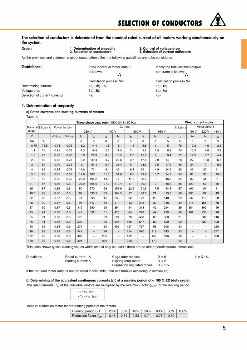
The selection of conductors is determined from the nominal rated current of all motors working simultaneously onthe system.Order: 1. Determination of ampacity 3. Control of voltage drop
2. Selection of conductors 4. Selection of current collectors
As the premises and statements about output often differ, the following guidelines are to be considered:
Guidelines: If the individual motor output If only the total installed output is known: per crane is known:
Calculation process No: Calculation process No:Determining current: 1a), 1b), 1c) 1d), 1e)Voltage drop 3a), 3b) 3a), 3c)Selection of current collector: 4a) 4b)
1. Determination of ampacitya) Rated currents and starting currents of motorsTable 1:
This table shows typical running values which should only be used if there are no other manufacturers instructions.
Directions: Rated current: IN Cage rotor motors: X = 6 IA = X · INStarting current: IA Slipring rotor motor: X = 2
Frequency regulated drives: X = 1.5
If the required motor outputs are not listed in this table, then use formula according to section 1d).
b) Determining of the equivalent continuous currents (ID) at a running period of < 100 % ED (duty cycle).The rated currents (IN) of the individual motors are multiplied by the reduction factor (ƒED) for the running period.
Table 2: Reduction factor for the running period of the motors.
Nominaloutput
Efficiency EfficiencyPower factors
230 V 400 V 500 V 660 V 110 V 220 V 440 V
CurrentThree-phase cage rotor (1500 U/min, 50 Hz) Direct current motor
Motor current
P � cos �N cos �A IN IA IN IA IN IA IN IA � IN IN INkW % A A A A A A A A % A A A
0.75 74.5 0.78 0.76 3.2 14.4 1.8 8.1 1.5 6.8 1.1 5 75 9.2 4.6 2.3
1.1 75 0.81 0.76 4.3 19.8 2.5 11.5 2 9.2 1.5 6.9 75 13.5 6.8 3.4
1.5 77 0.82 0.76 5.8 27.3 3.3 15.5 2.6 12.2 2 9.4 77 17.2 8.7 4.4
2.2 80 0.82 0.73 8.2 39.4 4.7 22.6 3.7 17.8 2.9 14 78 27 13.3 6.7
3 80 0.79 0.73 11.1 54.4 6.4 31.4 5 24.5 3.5 17.2 80 34 17 8.5
4 82 0.84 0.73 14.6 73 8.4 42 6.4 32 4.9 24.5 80 45 22 11
5.5 83 0.85 0.65 19.6 100 11.3 57.6 8.6 43.9 6.7 34.2 84 61 30 15.5
7.5 85 0.86 0.65 25.8 134.2 14.8 77 11.5 59.8 9 46.8 85 82 41 21
11 87 0.86 0.6 36.9 195.6 21.2 112.4 17 90.1 13 68.9 86 120 60 30
15 87 0.86 0.6 50 270 29 156.6 22.5 121.5 17.5 94.5 87 160 81 41
18.5 88 0.86 0.6 61 335.5 35 192.5 27 148.5 21 115.5 88 195 97 49
22 89 0.87 0.6 71 398 41 230 32 179 25 140 89 232 116 58
30 90 0.87 0.6 96 547 55 314 43 245 33 188 89 315 155 78
37 90 0.87 0.6 119 690 68 394 54 313 42 244 89 384 190 96
45 91 0.88 0.6 141 832 81 478 64 378 49 289 90 462 230 116
55 91 0.88 0.6 172 – 99 594 78 468 60 360 91 – 282 140
75 91 0.88 0.6 235 – 135 826 106 647 82 500 92 – 380 190
90 92 0.88 0.6 279 – 160 992 127 787 98 608 93 – – 225
110 92 0.88 0.6 341 – 196 – 154 970 118 743 93 – – 277
132 92 0.88 0.6 409 – 235 – 182 – 140 896 93 – – 330
160 93 0.88 0.6 491 – 282 – 220 – 170 – 93 – – –
ID = IN · ƒED
(PD = PN · ƒED)
Running period ED 20% 30% 40% 50% 60% 80% 100%Reduction factor ƒED 0.45 0.54 0.63 0.71 0.78 0.89 1
➪ ➪
Conductor railType
Leakagedistance of shroud
mm
Max.voltage
V
continuousampere capacity
A at 35° CResistance
Ohm/1000 m
ImpedanceOhm/1000 m
at 50 Hz
Conductorcross section mm2
Copper Al Steel
ƒR1 crane
ƒG2 cranes
ƒG3 cranes
ƒG4 cranes and more
U 20/ 50 AF 30 18 45 1000 60 0.938 0.954U 20/ 50 CE 30 18 45 1000 60 0.587 0.612U 20/ 50 AC 18 30 45 1000 120 0.483 0.600U 20/ 50 C 50 45 1000 210 0.376 0.416U 20/ 50 CH 50 45 1000 210 0.376 0.416U 30/125 AC 18 110 90 1000 280 0.226 0.284U 30/225 AC 18 210 90 1000 330 0.134 0.216U 30/120 CE 100 18 100 1000 330 0.178 0.222U 30/ 75 C 75 100 1000 280 0.238 0.280U 30/100 C 100 105 1000 330 0.178 0.264U 30/130 CH 130 95 1000 400 0.137 0.221U 30/150 C 150 95 1000 440 0.126 0.219U 30/200 C 200 90 1000 530 0.090 0.195U 30/200 CH 200 90 1000 530 0.090 0.195U 40/300 AC 50 250 130 1000 490 0.096 0.198U 40/200 C 200 130 1000 600 0.089 0.170U 40/300 C 300 135 1000 700 0.063 0.178U 40/300 CH 300 130 1000 700 0.063 0.178U 40/400 C 400 130 1000 860 0.047 0.168U 40/400 CH 400 130 1000 860 0.047 0.168U 40/500 C 500 125 1000 1000 0.038 0.161U 40/500 CH 500 120 1000 1000 0.038 0.161U 40/500 CHH 500 120 1000 1000 0.038 0.161
SELECTION OF CONDUCTORS
6
19 12
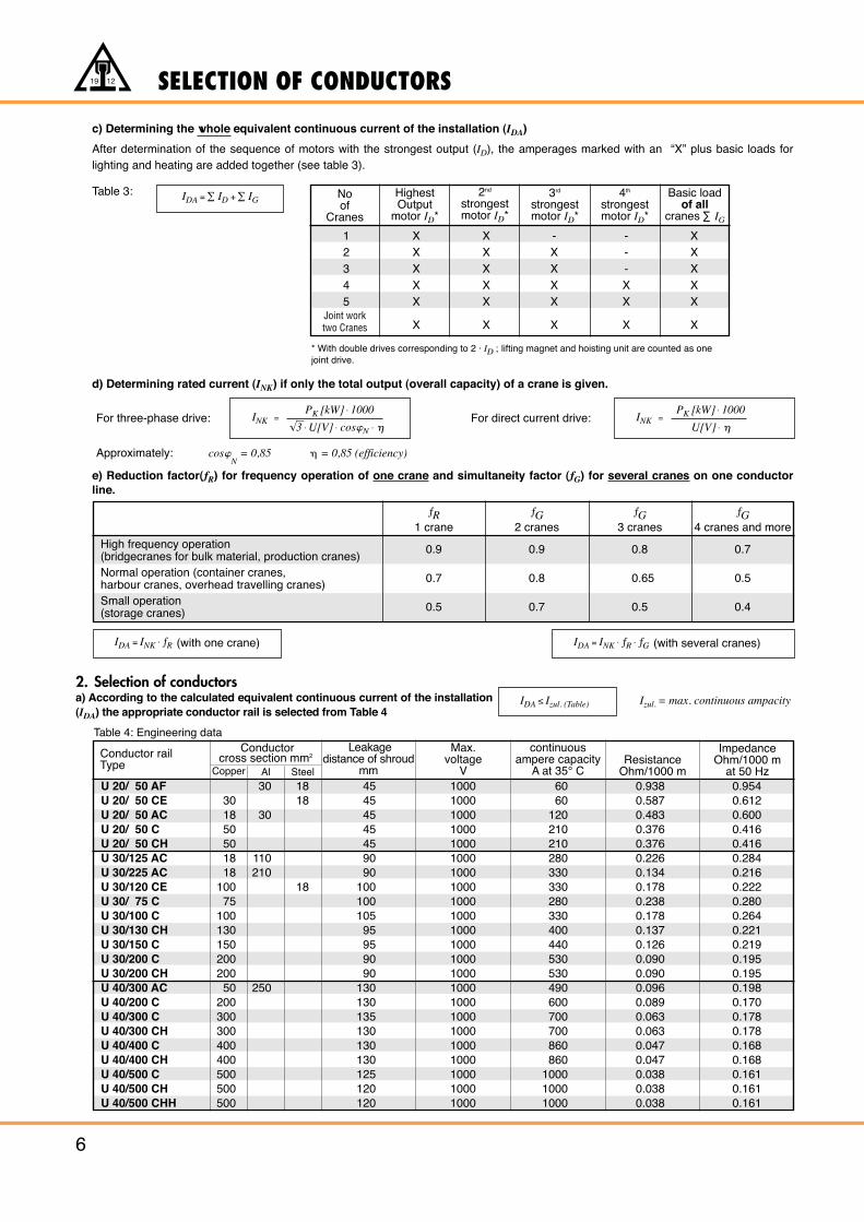
c) Determining the whole equivalent continuous current of the installation (IDA)
After determination of the sequence of motors with the strongest output (ID), the amperages marked with an “X” plus basic loads forlighting and heating are added together (see table 3).
Table 3:
d) Determining rated current (INK) if only the total output (overall capacity) of a crane is given.
For three-phase drive: For direct current drive:
Approximately: cos�N
= 0,85 � = 0,85 (efficiency)
e) Reduction factor(ƒR) for frequency operation of one crane and simultaneity factor (ƒG) for several cranes on one conductorline.
Noof
Cranes
HighestOutput
motor ID*
2nd
strongestmotor ID*
3rd
strongestmotor ID*
4th
strongestmotor ID*
Basic loadof all
cranes ∑ IG
1 X X - - X2 X X X - X3 X X X - X4 X X X X X5 X X X X X
X X X X XJoint worktwo Cranes
* With double drives corresponding to 2 · ID ; lifting magnet and hoisting unit are counted as onejoint drive.
INK = PK [kW] · 1000
√3 · U[V] · cos�N · �INK =
PK [kW] · 1000
U[V] · �
High frequency operation(bridgecranes for bulk material, production cranes)Normal operation (container cranes, harbour cranes, overhead travelling cranes)Small operation(storage cranes)
0.9
0.7
0.5
0.9
0.8
0.7
0.8
0.65
0.5
0.7
0.5
0.4
IDA = INK · ƒR (with one crane)
IDA <_ Izul. (Table) Izul. = max. continuous ampacity
IDA = INK · ƒR · ƒG (with several cranes)
2. Selection of conductorsa) According to the calculated equivalent continuous current of the installation(IDA) the appropriate conductor rail is selected from Table 4
Table 4: Engineering data
IDA = ∑ ID +∑ IG
Effectice length (l):
End feed:
Mid feed:
Feed at both ends:
Two feeds(best position):
Three feeds(best position):
Four feeds(best position):
l = L2
SELECTION OF CONDUCTORS
7
19 12
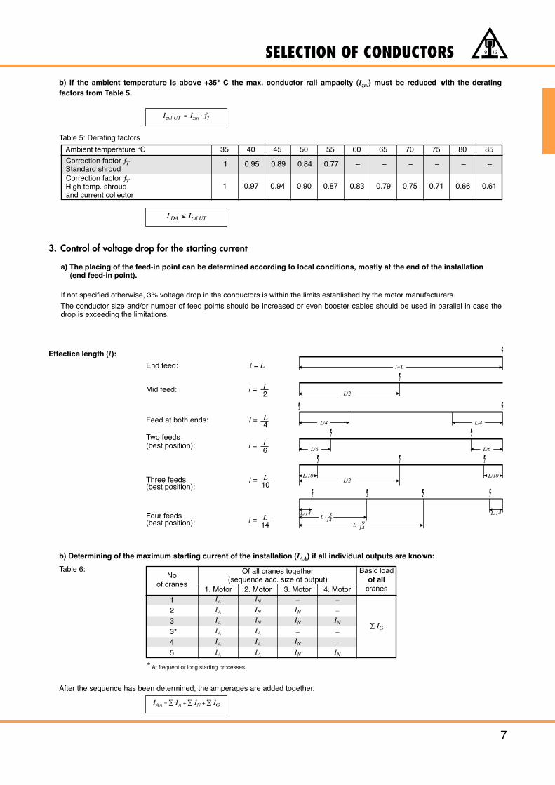
b) If the ambient temperature is above +35° C the max. conductor rail ampacity (Izul) must be reduced with the derating factors from Table 5.
Table 5: Derating factors
3. Control of voltage drop for the starting current
Izul UT = Izul · ƒT
I DA ≤ Izul UT
Ambient temperature °C
Correction factor ƒTStandard shroudCorrection factor ƒTHigh temp. shroudand current collector
35 40
1 0.95
1 0.97 0.94 0.90 0.87 0.83 0.79 0.75 0.71 0.66 0.61
0.89 0.84 0.77 – – – – – –
45 50 55 60 65 70 75 80 85
IAA = ∑ IA +∑ IN +∑ IG
After the sequence has been determined, the amperages are added together.
b) Determining of the maximum starting current of the installation (IAA) if all individual outputs are known:
Table 6:
* At frequent or long starting processes
Noof cranes
12
IA IN – –IA IN IN –IA IN IN IN
IA IA – –IA IA IN –IA IA IN IN
33*45
∑ IG
1. Motor 2. Motor 3. Motor 4. Motor
Of all cranes together(sequence acc. size of output)
Basic loadof all
cranes
l=L
L/2
L/2
L · 514
L/4 L/4
L/6
L/10 L/10
L/14L/14
L/6
L · 914
�
�
�
�
�
�
�
� �
��
�
�
�
�
� �
�
�
�
�
�
�
�
� �
a) The placing of the feed-in point can be determined according to local conditions, mostly at the end of the installation (end feed-in point).
If not specified otherwise, 3% voltage drop in the conductors is within the limits established by the motor manufacturers.
The conductor size and/or number of feed points should be increased or even booster cables should be used in parallel in case thedrop is exceeding the limitations.
l = L
l = L4
l = L6
l = L10
l = L14
SELECTION OF CONDUCTORS
8
19 12
�U = 2 · l · I AA · R · ƒ2
�U = 2 · l · I AA · Z · ƒ1
�U = ��3 · l · I AA · Z · ƒ1
Ambient TemperatureUT
Phase-Distancemm
U 20/50 AFU 20/50 CEU 20/50 ACU 20/50 CU 20/50 CHU 30/125 ACU 30/225 ACU 30/120 CEU 30/75 CU 30/100 CU 30/130 CHU 30/150 CU 30/200 CU 30/200 CHU 40/300 ACU 40/200 CU 40/300 CU 40/300 CHU 40/400 CU 40/400 CHU 40/500 CU 40/500 CHU 40/500 CHH
50
50
50
50
50
80
80
80
80
80
80
80
80
80
130
130
130
130
130
130
130
130
130
0.770
0.878
1.042
0.926
0.926
1.001
1.024
1.023
1.000
1.051
1.050
1.024
1.021
1.021
1.010
1.039
0.976
0.976
0.949
0.949
0.928
0.928
0.928
0.780
0.889
1.051
0.936
0.936
1.009
1.031
1.032
1.009
1.059
1.058
1.030
1.026
1.026
1.016
1.045
0.979
0.979
0.952
0.952
0.931
0.931
0.931
0.791
0.900
1.061
0.946
0.946
1.018
1.037
1.041
1.019
1.066
1.065
1.036
1.032
1.032
1.021
1.051
0.983
0.983
0.955
0.955
0.933
0.933
0.933
0.801
0.911
1.070
0.956
0.956
1.027
1.044
1.050
1.029
1.074
1.072
1.043
1.037
1.037
1.026
1.057
0.987
0.987
0.958
0.958
0.936
0.936
0.936
0.812
0.922
1.080
0.965
0.965
1.035
1.051
1.059
1.039
1.082
1.079
1.049
1.042
1.042
1.031
1.063
0.991
0.991
0.961
0.961
0.938
0.938
0.938
0.822
0.933
1.090
0.975
0.975
1.044
1.057
1.068
1.048
1.089
1.086
1.055
1.047
1.047
1.037
1.069
0.995
0.995
0.964
0.964
0.941
0.941
0.941
0.833
0.944
1.099
0.985
0.985
1.053
1.064
1.078
1.058
1.097
1.093
1.061
1.052
1.052
1.042
1.075
0.999
0.999
0.967
0.967
0.943
0.943
0.943
0.843
0.955
1.109
0.995
0.995
1.061
1.071
1.087
1.068
1.105
1.100
1.067
1.058
1.058
1.047
1.081
1.002
1.002
0.970
0.970
0.946
0.946
0.946
0.854
0.966
1.118
1.005
1.005
1.070
1.077
1.096
1.077
1.113
1.107
1.074
1.063
1.063
1.052
1.087
1.006
1.006
0.973
0.973
0.949
0.949
0.949
0.864
0.977
1.128
1.014
1.014
1.079
1.084
1.105
1.087
1.120
1.114
1.080
1.068
1.068
1.058
1.093
1.010
1.010
0.976
0.976
0.951
0.951
0.951
0.875
0.988
1.137
1.024
1.024
1.088
1.091
1.114
1.097
1.128
1.121
1.086
1.073
1.073
1.063
1.099
1.014
1.014
0.979
0.979
0.954
0.954
0.954
0.885
0.999
1.147
1.034
1.034
1.096
1.097
1.123
1.107
1.136
1.129
1.092
1.079
1.079
1.068
1.105
1.018
1.018
0.982
0.982
0.956
0.956
0.956
0.896
1.010
1.156
1.044
1.044
1.105
1.104
1.133
1.116
1.144
1.136
1.099
1.084
1.084
1.073
1.111
1.021
1.021
0.985
0.985
0.959
0.959
0.959
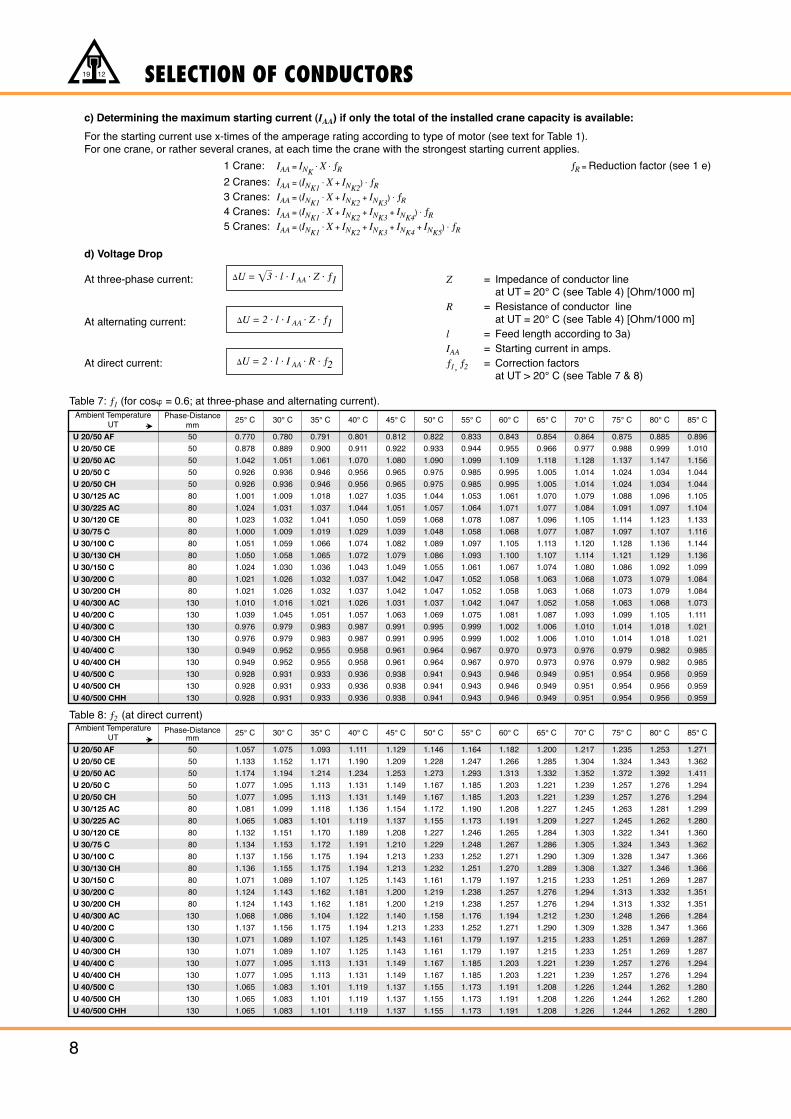
25° C 30° C 35° C 40° C 45° C 50° C 55° C 60° C 65° C 70° C 75° C 80° C 85° C
Ambient TemperatureUT
Phase-Distancemm
U 20/50 AFU 20/50 CEU 20/50 ACU 20/50 CU 20/50 CHU 30/125 ACU 30/225 ACU 30/120 CEU 30/75 CU 30/100 CU 30/130 CHU 30/150 CU 30/200 CU 30/200 CHU 40/300 ACU 40/200 CU 40/300 CU 40/300 CHU 40/400 CU 40/400 CHU 40/500 CU 40/500 CHU 40/500 CHH
50
50
50
50
50
80
80
80
80
80
80
80
80
80
130
130
130
130
130
130
130
130
130
1.057
1.133
1.174
1.077
1.077
1.081
1.065
1.132
1.134
1.137
1.136
1.071
1.124
1.124
1.068
1.137
1.071
1.071
1.077
1.077
1.065
1.065
1.065
1.075
1.152
1.194
1.095
1.095
1.099
1.083
1.151
1.153
1.156
1.155
1.089
1.143
1.143
1.086
1.156
1.089
1.089
1.095
1.095
1.083
1.083
1.083
1.093
1.171
1.214
1.113
1.113
1.118
1.101
1.170
1.172
1.175
1.175
1.107
1.162
1.162
1.104
1.175
1.107
1.107
1.113
1.113
1.101
1.101
1.101
1.111
1.190
1.234
1.131
1.131
1.136
1.119
1.189
1.191
1.194
1.194
1.125
1.181
1.181
1.122
1.194
1.125
1.125
1.131
1.131
1.119
1.119
1.119
1.129
1.209
1.253
1.149
1.149
1.154
1.137
1.208
1.210
1.213
1.213
1.143
1.200
1.200
1.140
1.213
1.143
1.143
1.149
1.149
1.137
1.137
1.137
1.146
1.228
1.273
1.167
1.167
1.172
1.155
1.227
1.229
1.233
1.232
1.161
1.219
1.219
1.158
1.233
1.161
1.161
1.167
1.167
1.155
1.155
1.155
1.164
1.247
1.293
1.185
1.185
1.190
1.173
1.246
1.248
1.252
1.251
1.179
1.238
1.238
1.176
1.252
1.179
1.179
1.185
1.185
1.173
1.173
1.173
1.182
1.266
1.313
1.203
1.203
1.208
1.191
1.265
1.267
1.271
1.270
1.197
1.257
1.257
1.194
1.271
1.197
1.197
1.203
1.203
1.191
1.191
1.191
1.200
1.285
1.332
1.221
1.221
1.227
1.209
1.284
1.286
1.290
1.289
1.215
1.276
1.276
1.212
1.290
1.215
1.215
1.221
1.221
1.208
1.208
1.208
1.217
1.304
1.352
1.239
1.239
1.245
1.227
1.303
1.305
1.309
1.308
1.233
1.294
1.294
1.230
1.309
1.233
1.233
1.239
1.239
1.226
1.226
1.226
1.235
1.324
1.372
1.257
1.257
1.263
1.245
1.322
1.324
1.328
1.327
1.251
1.313
1.313
1.248
1.328
1.251
1.251
1.257
1.257
1.244
1.244
1.244
1.253
1.343
1.392
1.276
1.276
1.281
1.262
1.341
1.343
1.347
1.346
1.269
1.332
1.332
1.266
1.347
1.269
1.269
1.276
1.276
1.262
1.262
1.262
1.271
1.362
1.411
1.294
1.294
1.299
1.280
1.360
1.362
1.366
1.366
1.287
1.351
1.351
1.284
1.366
1.287
1.287
1.294
1.294
1.280
1.280
1.280
25° C 30° C 35° C 40° C 45° C 50° C 55° C 60° C 65° C 70° C 75° C 80° C 85° C
Table 8: ƒ2 (at direct current)
c) Determining the maximum starting current (IAA) if only the total of the installed crane capacity is available:
For the starting current use x-times of the amperage rating according to type of motor (see text for Table 1).For one crane, or rather several cranes, at each time the crane with the strongest starting current applies.
1 Crane: IAA = INK· X · ƒR ƒR = Reduction factor (see 1 e)
2 Cranes: IAA = (INK1· X + INK2
) · ƒR
3 Cranes: IAA = (INK1· X + INK2
+ INK3) · ƒR
4 Cranes: IAA = (INK1· X + INK2
+ INK3+ INK4
) · ƒR
5 Cranes: IAA = (INK1· X + INK2
+ INK3+ INK4
+ INK5) · ƒR
d) Voltage Drop
At three-phase current: Z = Impedance of conductor lineat UT = 20° C (see Table 4) [Ohm/1000 m]
R = Resistance of conductor lineAt alternating current: at UT = 20° C (see Table 4) [Ohm/1000 m]
l = Feed length according to 3a)IAA = Starting current in amps.
At direct current: ƒ1, ƒ2 = Correction factors at UT > 20° C (see Table 7 & 8)
Table 7: ƒ1 (for cos� = 0.6; at three-phase and alternating current).
�
�
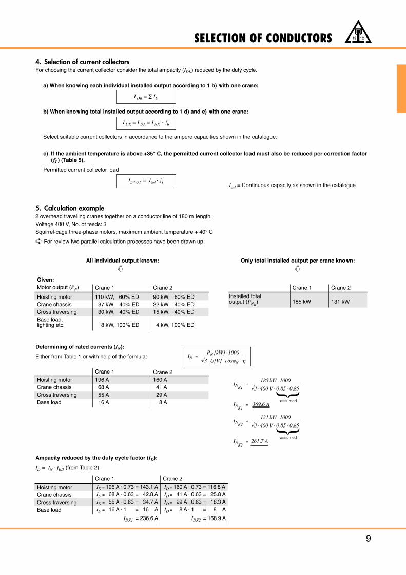
Determining of rated currents (IN):
Either from Table 1 or with help of the formula:
Ampacity reduced by the duty cycle factor (ID):
ID = IN · ƒED (from Table 2)
SELECTION OF CONDUCTORS
9
19 12
4. Selection of current collectorsFor choosing the current collector consider the total ampacity (IDK) reduced by the duty cycle.
a) When knowing each individual installed output according to 1 b) with one crane:
b) When knowing total installed output according to 1 d) and e) with one crane:
Select suitable current collectors in accordance to the ampere capacities shown in the catalogue.
c) If the ambient temperature is above +35° C, the permitted current collector load must also be reduced per correction factor(ƒT ) (Table 5).
Permitted current collector load
Izul = Continuous capacity as shown in the catalogue
5. Calculation example2 overhead travelling cranes together on a conductor line of 180 m length.Voltage 400 V, No. of feeds: 3Squirrel-cage three-phase motors, maximum ambient temperature + 40° C
➪ For review two parallel calculation processes have been drawn up:
All individual output known: Only total installed output per crane known:
Given:
Izul UT = Izul · ƒT
I DK = I DA = I NK · ƒR
I DK = ∑ ID
Motor output (PN) Crane 1 Crane 2 Crane 1 Crane 2
Hoisting motorCrane chassisCross traversingBase load,lighting etc.
110 kW, 60% ED37 kW, 40% ED30 kW, 40% ED
8 kW, 100% ED
90 kW, 60% ED22 kW, 40% ED15 kW, 40% ED
4 kW, 100% ED
Crane 1 Crane 2
Hoisting motorCrane chassisCross traversingBase load
ID = 196 A · 0.73 = 143.1 AID = 68 A · 0.63 = 42.8 AID = 55 A · 0.63 = 34.7 AID = 16 A · 1 = 16 A
IDK1 = 236.6 A
ID = 160 A · 0.73 = 116.8 AID = 41 A · 0.63 = 25.8 AID = 29 A · 0.63 = 18.3 AID = 8 A · 1 = 8 A
IDK2 = 168.9 A
Crane 1 Crane 2Hoisting motorCrane chassisCross traversingBase load
196 A68 A55 A16 A
160 A41 A29 A8 A
Installed totaloutput (PNK
) 185 kW 131 kW
IN = PN [kW] · 1000
√3 · U[V] · cos�N · �
INK1=
185 kW · 1000
√3 · 400 V · 0.85 · 0,85
INK1= 369.6 A
INK2=
131 kW · 1000
√3 · 400 V · 0.85 · 0,85
INK2= 261.7 A
➪➪
}
assumed
}
assumed
SELECTION OF CONDUCTORS
10
19 12
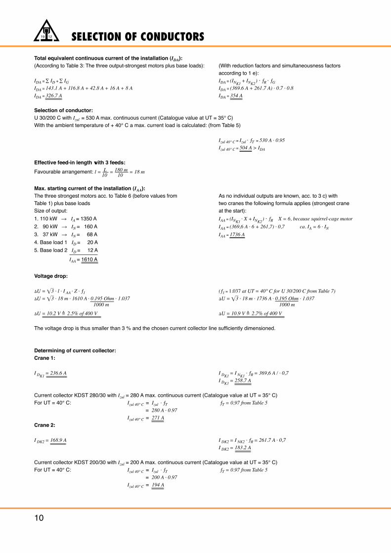
Total equivalent continuous current of the installation (IDA):(According to Table 3: The three output-strongest motors plus base loads): (With reduction factors and simultaneousness factors
according to 1 e):IDA = ∑ ID +∑ IG IDA = (INK1
+ INK2) · ƒR · ƒG
IDA = 143.1 A + 116.8 A + 42.8 A + 16 A + 8 A IDA = (369.6 A + 261.7 A) · 0.7 · 0.8
IDA = 326.7 A IDA = 354 A
Selection of conductor:U 30/200 C with Izul = 530 A max. continuous current (Catalogue value at UT = 35° C)With the ambient temperature of + 40° C a max. current load is calculated: (from Table 5)
Izul 40° C = Izul · ƒT = 530 A · 0.95
Izul 40° C = 504 A > IDA
Effective feed-in length with 3 feeds:
Favourable arrangement: l = L10
= 180 m10
= 18 m
Max. starting current of the installation (IAA):The three strongest motors acc. to Table 6 (before values from As no individual outputs are known, acc. to 3 c) withTable 1) plus base loads two cranes the following formula applies (strongest craneSize of output: at the start):
1. 110 kW � IA = 1350 A IAA = (INK1· X + INK2
) · ƒR X = 6, because squirrel-cage motor
2. 90 kW � IN = 160 A IAA = (369,6 A · 6 + 261,7) · 0,7 ca. IA = 6 · IN
3. 37 kW � IN = 68 A IAA = 1736 A
4. Base load 1 ID = 20 A
5. Base load 2 ID = 12 A
IAA = 1610 A
Voltage drop:
�U = ��3 · l · I AA · Z · ƒ1 (ƒ1 = 1.037 at UT = 40° C for U 30/200 C from Table 7)
�U = ��3 · 18 m · 1610 A · 0.195 Ohm · 1.037 �U = ��3 · 18 m · 1736 A · 0.195 Ohm · 1.0371000 m 1000 m
�U = 10.2 V =̂ 2.5% of 400 V �U = 10.9 V =̂ 2.7% of 400 V
The voltage drop is thus smaller than 3 % and the chosen current collector line sufficiently dimensioned.
Determining of current collector:Crane 1:
I DK1= 236.6 A I DK1
= I NK1· ƒR = 369,6 A / · 0,7
I DK1= 258.7 A
Current collector KDST 280/30 with Izul = 280 A max. continuous current (Catalogue value at UT = 35° C)For UT = 40° C: Izul 40° C = Izul · ƒT ƒT = 0,97 from Table 5
= 280 A · 0.97
Izul 40° C = 271 A
Crane 2:
I DK2 = 168.9 A I DK2 = I NK2 · ƒR = 261.7 A · 0,7
I DK2 = 183.2 A
Current collector KDST 200/30 with Izul = 200 A max. continuous current (Catalogue value at UT = 35° C)For UT = 40° C: Izul 40° C = Izul · ƒT ƒT = 0.97 from Table 5
= 200 A · 0.97
Izul 40° C = 194 A
10023 40
62166215
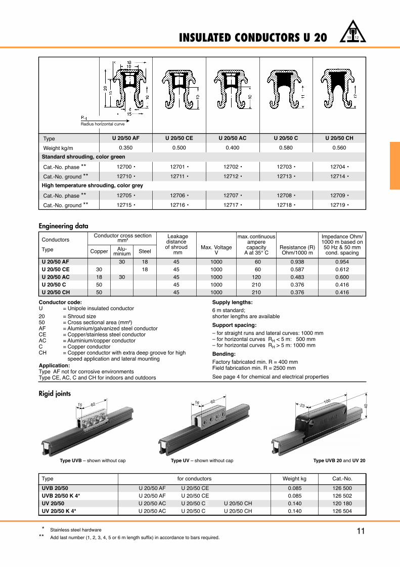
INSULATED CONDUCTORS U 20
11
19 12
Type
Weight kg/m
Cat.-No. phase **Cat.-No. ground **
Cat.-No. phase **Cat.-No. ground **
U 20/50 AF
0.350
12700 •
12710 •
12705 •
12715 •
U 20/50 CE
0.500
12701 •
12711 •
12706 •
12716 •
U 20/50 AC
0.400
12702 •
12712 •
12707 •
12717 •
U 20/50 C
0.580
12703 •
12713 •
12708 •
12718 •
U 20/50 CH
0.560
12704 •
12714 •
12709 •
12719 •
Standard shrouding, color green
High temperature shrouding, color grey
Rigid joints
Engineering data
Type UVB – shown without cap Type UVB 20 and UV 20Type UV – shown without cap
Conductors
Type
Leakagedistanceof shroud
mmMax. Voltage
V
max. continuousamperecapacity
A at 35° CResistance (R)Ohm/1000 m
Impedance Ohm/1000 m based on50 Hz & 50 mmcond. spacing
Conductor cross sectionmm2
Copper Alu-minium Steel
Type for conductors Weight kg
0.0850.0850.1400.140
126 500126 502120 180126 504
Cat.-No.
UVB 20/50UVB 20/50 K 4*UV 20/50UV 20/50 K 4*
U 20/50 AF U 20/50 CEU 20/50 AF U 20/50 CEU 20/50 AC U 20/50 CE U 20/50 CHU 20/50 AC U 20/50 CE U 20/50 CH
U 20/50 AFU 20/50 CEU 20/50 ACU 20/50 CU 20/50 CH
30185050
30
30
1818
4545454545
10001000100010001000
6060
120210210
0.9380.5870.4830.3760.376
0.9540.6120.6000.4160.416
Conductor code:U = Unipole insulated conductor
20 = Shroud size50 = Cross sectional area (mm2)AF = Aluminium/galvanized steel conductorCE = Copper/stainless steel conductorAC = Aluminium/copper conductorC = Copper conductorCH = Copper conductor with extra deep groove for high
speed application and lateral mountingApplication:Type AF not for corrosive environmentsType CE, AC, C and CH for indoors and outdoors
Supply lengths:6 m standard;shorter lengths are available
Support spacing:– for straight runs and lateral curves: 1000 mm– for horizontal curves RH < 5 m: 500 mm– for horizontal curves RH > 5 m: 1000 mm
Bending:Factory fabricated min. R = 400 mmField fabrication min. R = 2500 mm
See page 4 for chemical and electrical properties
* Stainless steel hardware
** Add last number (1, 2, 3, 4, 5 or 6 m length suffix) in accordance to bars required.
Radius horizontal curve
23100
19,5
40
23100
19,5
40
23100
19,5
40
16
62
M 10 x 2529140
60
80
338
325
43
0-30
23
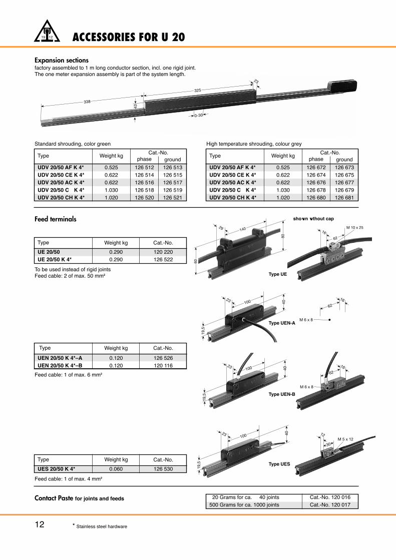
ACCESSORIES FOR U 20
12
19 12
Expansion sectionsfactory assembled to 1 m long conductor section, incl. one rigid joint.The one meter expansion assembly is part of the system length.
Feed terminals
To be used instead of rigid jointsFeed cable: 2 of max. 50 mm2
Type
UE 20/50UE 20/50 K 4*
0.2900.290
120 220126 522
Weight kg Cat.-No.
Feed cable: 1 of max. 4 mm2
Type
UES 20/50 K 4* 0.060 126 530
Weight kg Cat.-No.
shown wthout cap
Type UE
Type UES
Contact Paste for joints and feeds 20 Grams for ca. 40 joints500 Grams for ca. 1000 joints
Cat.-No. 120 016Cat.-No. 120 017
* Stainless steel hardware
16
62
M 6 x 8
16
62
M 6 x 8
12
30M 5 x 12
Type UEN-A
Type UEN-B
Type Weight kgphase
Cat.-No.ground
UDV 20/50 AF K 4*UDV 20/50 CE K 4*UDV 20/50 AC K 4*UDV 20/50 C K 4*UDV 20/50 CH K 4*
Standard shrouding, color green High temperature shrouding, colour grey
Feed cable: 1 of max. 6 mm2
Type
UEN 20/50 K 4*–AUEN 20/50 K 4*–B
0.1200.120
126 526120 116
Weight kg Cat.-No.
0.5250.6220.6221.0301.020
126 512126 514126 516126 518126 520
126 513126 515126 517126 519126 521
Type Weight kgphase
Cat.-No.ground
UDV 20/50 AF K 4*UDV 20/50 CE K 4*UDV 20/50 AC K 4*UDV 20/50 C K 4*UDV 20/50 CH K 4*
0.5250.6220.6221.0301.020
126 672126 674126 676126 678126 680
126 673126 675126 677126 679126 681
ACCESSORIES FOR U 20
13
19 12
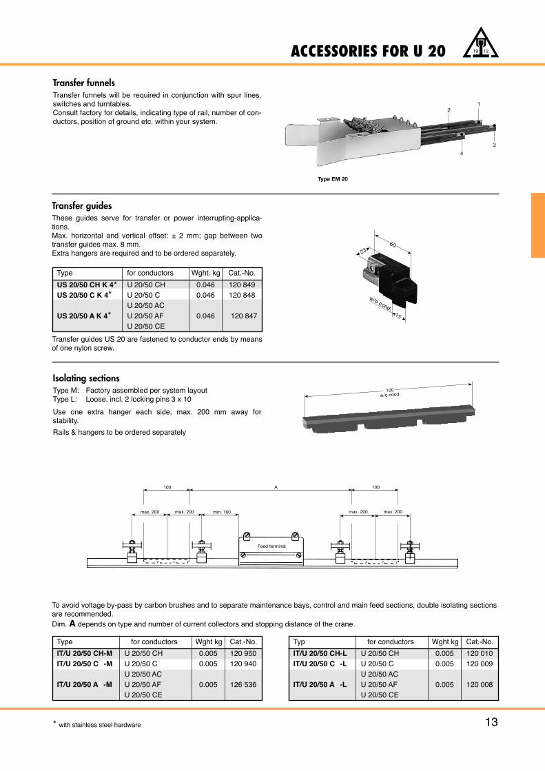
Isolating sectionsType M: Factory assembled per system layoutType L: Loose, incl. 2 locking pins 3 x 10
Use one extra hanger each side, max. 200 mm away for stability.
Rails & hangers to be ordered separately
Transfer funnels Transfer funnels will be required in conjunction with spur lines,switches and turntables.Consult factory for details, indicating type of rail, number of con-ductors, position of ground etc. within your system.
Transfer guidesThese guides serve for transfer or power interrupting-applica-tions.Max. horizontal and vertical offset: ± 2 mm; gap between twotransfer guides max. 8 mm.Extra hangers are required and to be ordered separately.
Transfer guides US 20 are fastened to conductor ends by meansof one nylon screw.
15
2360
w/o cond.
21
4
3
* with stainless steel hardware
Type EM 20
Type for conductors Wght kg Cat.-No.
IT/U 20/50 CH-MIT/U 20/50 CC-M
IT/U 20/50 AC-M
U 20/50 CHU 20/50 CU 20/50 ACU 20/50 AFU 20/50 CE
0.0050.005
0.005
120 950120 940
126 536
Typ for conductors Wght kg Cat.-No.
IT/U 20/50 CH-LIT/U 20/50 CC-L
IT/U 20/50 AC-L
U 20/50 CHU 20/50 CU 20/50 ACU 20/50 AFU 20/50 CE
0.0050.005
0.005
120 010120 009
120 008
To avoid voltage by-pass by carbon brushes and to separate maintenance bays, control and main feed sections, double isolating sectionsare recommended.Dim. A depends on type and number of current collectors and stopping distance of the crane.
max. 200 max. 200 min. 160
100 A
max. 200 max. 200
100
Feed terminal
100w/o cond.
Type
US 20/50 CH K 4*US 20/50 C K 4*
US 20/50 A K 4*
U 20/50 CHU 20/50 CU 20/50 ACU 20/50 AFU 20/50 CE
120 849 120 848
120 847
0.0460.046
0.046
for conductors Cat.-No.Wght. kg
ACCESSORIES FOR U 20
14
19 12
Type Weight kg
UK 20-LUK 20-M
0.0100.010
Cat.-No.
120 120120 987
Type Weight kg
UAS 20 K 4* 0.014
Cat.-No.
126 550
Type Weight kg
UAM 20UAM 20 K 4*
0.0250.025
Cat.-No.
126 540126 542
Type Weight kg
UAK 20UAK 20 K 4*
0.0100.010
Cat.-No.
126 546126 548
Type Weight kg
GH 40-M 6GH 40-M 6 K 4*
0.0750.075
Cat.-No.
121 060126 544
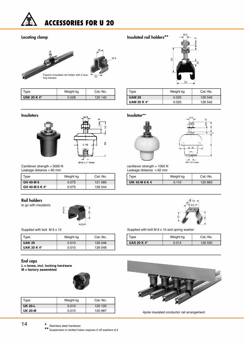
End capsL = loose, incl. locking hardwareM = factory assembled
Insulators
Rail holdersto go with insulators
Cantilever strength = 3000 NLeakage distance = 60 mm
Supplied with bolt M 6 x 10 and spring washerSupplied with bolt M 6 x 12
* Stainless steel hardware** Suspension in slotted holes requires 2 off washers 6,4
Type Weight kg
USK 20 K 4* 0.028
Cat.-No.
120 140
Locating clamp
Fixpoint (insulated rail holder with 2 loca-ting clamps)
M 6
25
22
24
25
max
. 9
M 6
20
21
11
20
1513
6,5
1220
Type Weight kg
UIK 42-M 6 K 4 0.110
Cat.-No.
120 883
Insulated rail holders**
4pole insulated conductor rail arrangement
Insulator**
cantilever strength = 1000 NLeakage distance = 62 mm
M 8
max
. 10
M6 x 8,5 deep
424
20
45
120 406120 778
Hardware BE 6Hardware BE 6 K 4*
0.0150.015
COMPACT ARRANGEMENT U 20
15
19 12
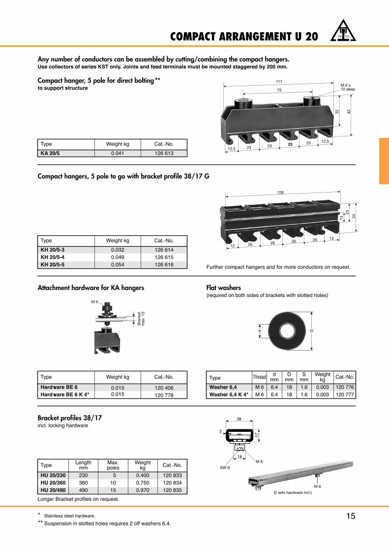
Any number of conductors can be assembled by cutting/combining the compact hangers.Use collectors of series KST only. Joints and feed terminals must be mounted staggered by 200 mm.
Compact hanger, 5 pole for direct bolting**to support structure
Type Weight kg
KA 20/5 0.041
Cat.-No.
126 613
Type Weight kg Cat.-No. Type Thread dmm
Dmm
Smm
Weightkg Cat.-No.
M 6M 6
6.46.4
1818
1.61.6
0.0030.003
120 776120 777
Washer 6,4Washer 6,4 K 4*
Type Weight kg
KH 20/5-3 0.032
Cat.-No.
126 614KH 20/5-4 0.049 126 615KH 20/5-5 0.054 126 616
Type
HU 20/230HU 20/360HU 20/490
Lengthmm
230360490
51015
0.4000.7500.970
120 833120 834120 835
Max.poles
Weightkg Cat.-No.
Attachment hardware for KA hangers
Bracket profiles 38/17incl. locking hardware
Further compact hangers and for more conductors on request.
Longer Bracket profiles on request.
Bra
cket
m
ax. 1
3
M 6
d D
117
75M 6 x10 deep
32 42
12,5 23 23 2323 23 12,5
38
3
17
18
SW 6
M 8
128
34
12 26
1226 26 26
23
13
Compact hangers, 5 pole to go with bracket profile 38/17 G
Flat washers(required on both sides of brackets with slotted holes)
M 6
(2 sets hardware incl.)
** Stainless steel hardware.
** Suspension in slotted holes requires 2 off washers 6,4.
CURRENT COLLECTORS FOR U 20
16
19 12
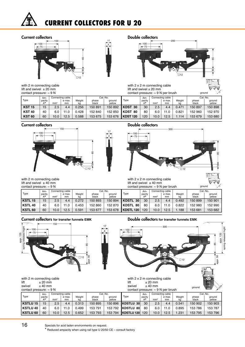
Current collectors Double collectors
Current collectors Double collectors
Current collectors for transfer funnels EMK Double collectors for transfer funnels EMK
TypeAm-
pacityA* mm2
ø max.mm
Weightkg
Connecting cablephaseblack
groundyellow
Cat.-No.
KST 15KST 40KST 60
154060
2.56.0
10.0
4.411.012.5
0.2560.4280.588
150 891152 840153 675
150 892152 850153 676
TypeAm-
pacityA* mm2
ø max.mm
Weightkg
Connecting cablephaseblack
groundyellow
Cat.-No.
KDST 30KDST 80KDST 120
3080
120
2.56.0
10.0
4.411.012.5
0.4710.8211.114
150 897152 960153 679
150 898152 970153 680
with 2 m connecting cablelift and swivel ± 20 mmcontact pressure: ~ 9 N
with 2 x 2 m connecting cablelift and swivel ± 20 mmcontact pressure: ~ 9 N per brush
TypeAm-
pacityA* mm2
ø max.mm
Weightkg
Connecting cablephaseblack
ground yellow
Cat.-No.
KSTL 15KSTL 40KSTL 60
154060
2.56.0
10.0
4.411.012.5
0.2720.4530.591
150 893152 860153 677
150 894152 870153 678
TypeAm-
pacityA* mm2
ø max.mm
Weightkg
Connecting cablephaseblack
groundyellow
Cat.-No.
KDSTL 30KDSTL 80KDSTL 120
3080
120
2.56.0
10.0
4.411.012.5
0.4920.8221.188
150 899152 980153 681
150 901152 990153 682
with 2 m connecting cablelift and swivel ± 40 mmcontact pressure: ~ 9 N
with 2 x 2 m connecting cablelift and swivel ± 40 mmcontact pressure: ~ 9 N per brush
TypeAm-
pacityA* mm2
ø max.mm
Weightkg
Connecting cablephaseblack
groundyellow
Cat.-No.
KSTLU 15KSTLU 40KSTLU 60
154060
2.56.0
10.0
4.411.012.5
0.3130.4990.652
150 895153 791153 793
150 896153 792153 794
TypeAm-
pacityA* mm2
ø max.mm
Weightkg
Connecting cablephaseblack
groundyellow
Cat.-No.
KDSTLU 30
KDSTLU 80
KDSTLU 120
3080
120
2.56.0
10.0
4.411.012.5
0.5410.8951.231
150 902153 786153 795
150 903153 787153 796
with 2 x 2 m connecting cablelift ± 20 mmswivel ± 40 mmcontact pressure: ~ 9 N per brush
with 2 m connecting cablelift ± 20 mmswivel ± 40 mmcontact pressure: ~ 9 N
Specials for acid laden environments on request.
* Reduced ampacity when using rail type U 20/50 CE – consult factory
75100
100
6518
12
4
17
4
17
75100
200
12
6518
85
12
18
10075
150
85
12
18
300
10075
85ap
pr.
50
10075
12
app
r. 13
5sp
ring
rele
ased
hig
ht
150
85
30010075
12
app
r. 50
app
r. 13
5
sprin
g re
leas
ed h
ight
4
17
12
12
12
ground
ground
ground
90(120
292
100
18
16
app
r. 13
5sp
ring
rele
ased
hig
ht
152 085154 438152 089154 443
phaseblack
groundyellow
Cat.-No.
152 086154 439152 091154 444
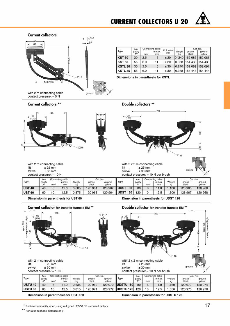
CURRENT COLLECTORS U 20
17
19 12
Current collector for transfer funnels EM ** Double collector for transfer funnels EM **
TypeAm-
pacityA* mm2
ø max.mm
Weightkg
Connecting cablephaseblack
groundyellow
Cat.-No.
USTU 40USTU 60
40 60
610
11.012.5
0.6350.815
120 969126 971
120 970126 972
with 2 m connecting cablelift ± 25 mmswivel ± 30 mmcontact pressure: ~ 10 N
Dimension in parenthesis for USTU 60
TypeAm-
pacityA* mm2
ø max.mm
Weightkg
Connecting cablephaseblack
groundyellow
Cat.-No.
UDSTU 80UDSTU 120
80120
610
11.012.5
1.1601.550
120 973126 975
120 974126 976
Dimension in parenthesis for UDSTU 120
Current collectors ** Double collectors **
TypeAm-
pacityA* mm2
ø max.mm
Weightkg
Connecting cablephaseblack
groundyellow
Cat.-No.
UST 40UST 60
40 60
610
11.012.5
0.6050.875
120 961120 963
120 962120 964
with 2 m connecting cablelift ± 25 mmswivel ± 30 mmcontact pressure: ~ 10 N
Current collectors
TypeAm-
pacityA* mm2
ø max.mm
Weightkg
lift & swivelmm
Connecting cable
KST 30KST 55KSTL 30KSTL 55
30553055
2.56.02.56.0
5115
11
0. 2400.3680.2400.368
± 20± 20± 30± 30
with 2 m connecting cablecontact pressure: ~ 5 N
with 2 x 2 m connecting cablelift ± 25 mmswivel ± 30 mmcontact pressure: ~ 10 N per brush
Dimension in parenthesis for UST 60
TypeAm-
pacityA* mm2
ø max.mm
Weightkg
Connecting cablephaseblack
groundyellow
Cat.-No.
UDST 80UDST 120
80120
610
11.012.5
1.1001.600
120 965126 967
120 966120 968
Dimension in parenthesis for UDST 120
Dimensions in parenthesis for KSTL
with 2 x 2 m connecting cablelift ± 25 mmswivel ± 30 mmcontact pressure: ~ 10 N per brush
* Reduced ampacity when using rail type U 20/50 CE – consult factory
** For 50 mm phase distance only
90(120)
292
16
100
18
4,4
13,5
90(120)
146
16
100
18
344
90(120)
146
16
100
18
app
r. 13
5sp
ring
rele
ased
hig
ht
344
8560
85 (9
5)
140 (190)
12
16
12ground
ground
16
ground
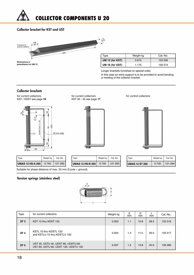
COLLECTOR COMPONENTS U 20
18
19 12
Collector bracketsfor current collectors for current collectors for control collectorsKST / KDST see page 16 KST 30 - 55 see page 17
Tension springs (stainless steel)
Collector bracket for KST and UST
Type
UM 12 (for KST)
UM 16 (for UST)
Weight kg
0.675
1.175
Cat.-No.
153 506
126 574
Longer brackets furnished on special order.
In this case an extra support is to be provided to avoid bendingor twisting of the collector bracket.
Type
ZF 3
ZF 4
ZF 5
KST 15 thru KDST 120 0.003
0.004
0.007
1.1
1.3
1.5
10.8
11.0
13.8
28.5
29.0
40.0
153 516
153 517
126 585
KSTL 15 thru KDSTL 120and KSTLU 15 thru KDSTLU 120
UST 40, USTU 40, UDST 80, UDSTU 80UST 60, USTU 60, UDST 120, UDSTU 120
for current collectors Weight kg Smm
Dmm
Lmm Cat.-No..
Prepared forground collector
600
(18)30
(12)16
S
L
D
Dimensions in parenthesis for UM 12
230
59
slot
ted
hol
e 11
x 3
0
18
12
6515
5990
37,5
40 mm wide
Type Weight kg Cat.-No.
121 0930.740UMAS 12 HS-B 200
Type Weight kg Cat.-No.
121 0920.740UMAS 12 HS-A 200
Type Weight kg Cat.-No.
121 0940.740UMAS 12 ST 200
Suitable for phase distance of max. 55 mm (3 pole + ground).
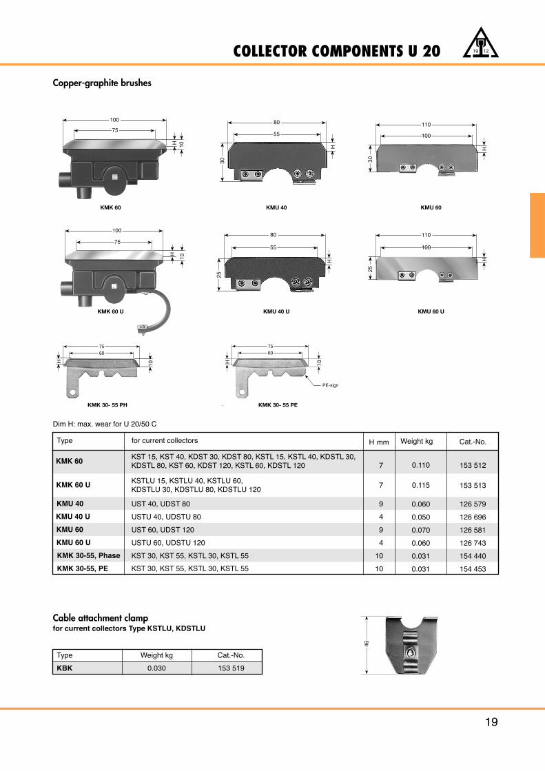
COLLECTOR COMPONENTS U 20
19
19 12
Copper-graphite brushes
Cable attachment clampfor current collectors Type KSTLU, KDSTLU
Type Weight kg Cat.-No.
KBK 0.030 153 519
46
100
75
H 10
80
55
H
30
110
100
H
30
100
75
H
10
80
55
H
25
110
100
H
25
KMK 60 KMU 40 KMU 60
KMK 60 U KMU 40 U KMU 60 U
7560
10H
7560
PE-sign
10H
KMK 30- 55 PH KMK 30- 55 PE
Type
KMK 60KST 15, KST 40, KDST 30, KDST 80, KSTL 15, KSTL 40, KDSTL 30,KDSTL 80, KST 60, KDST 120, KSTL 60, KDSTL 120 0.1107 153 512
KMK 60 U KSTLU 15, KSTLU 40, KSTLU 60,KDSTLU 30, KDSTLU 80, KDSTLU 120
0.1157 153 513
KMU 40 UST 40, UDST 80 0.0609 126 579
KMU 40 U USTU 40, UDSTU 80 0.0504 126 696
KMU 60 UST 60, UDST 120 0.0709 126 581
KMU 60 U USTU 60, UDSTU 120 0.0604 126 743
KMK 30-55, Phase KST 30, KST 55, KSTL 30, KSTL 55 0.03110 154 440
KMK 30-55, PE KST 30, KST 55, KSTL 30, KSTL 55 0.03110 154 453
for current collectors Weight kgH mm Cat.-No.
Dim H: max. wear for U 20/50 C
COLLECTOR COMPONENTS U 20
20
19 12
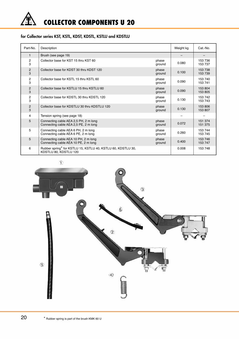
* Rubber spring is part of the brush KMK 60 U
for Collector series KST, KSTL, KDST, KDSTL, KSTLU and KDSTLU
4
1
6
2
3
5
Part-No. Description Weight kg Cat.-No.
1 Brush (see page 19) – –
2 Collector base for KST 15 thru KST 60 phase0.080
153 7363 ground 153 737
2 Collector base for KDST 30 thru KDST 120 phase0.100
153 7383 ground 153 739
2 Collector base for KSTL 15 thru KSTL 60 phase0.090
153 7403 ground 153 741
2 Collector base for KSTLU 15 thru KSTLU 60 phase0.090
153 8043 ground 153 805
2 Collector base for KDSTL 30 thru KDSTL 120 phase0.130
153 7423 ground 153 743
2 Collector base for KDSTLU 30 thru KDSTLU 120 phase0.130
153 8063 ground 153 807
4 Tension spring (see page 18) – –
5 Connecting cable AEA 2,5 PH, 2 m long phase0.072
151 374Connecting cable AEA 2,5 PE, 2 m long ground 151 375
5 Connecting cable AEA 6 PH, 2 m long phase0.260
153 744Connecting cable AEA 6 PE, 2 m long ground 153 745
5 Connecting cable AEA 10 PH, 2 m long phase0.400
153 746Connecting cable AEA 10 PE, 2 m long ground 153 747
6 Rubber spring* for KSTLU 15, KSTLU 40, KSTLU 60, KDSTLU 30, 0.008 153 748KDSTLU 80, KDSTLU 120
COLLECTOR COMPONENTS U 20
21
19 12
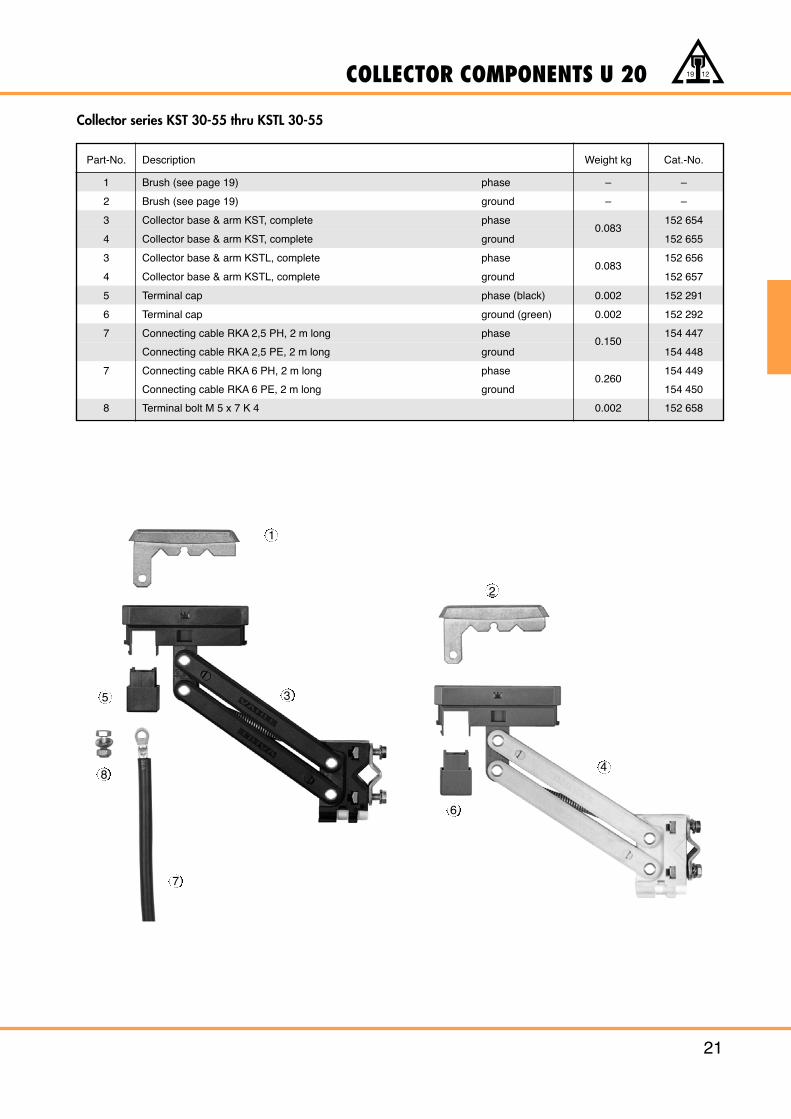
Collector series KST 30-55 thru KSTL 30-55
Part-No. Description Weight kg Cat.-No.
1 Brush (see page 19) phase – –
2 Brush (see page 19) ground – –
3 Collector base & arm KST, complete phase0.083
152 654
4 Collector base & arm KST, complete ground 152 655
3 Collector base & arm KSTL, complete phase0.083
152 656
4 Collector base & arm KSTL, complete ground 152 657
5 Terminal cap phase (black) 0.002 152 291
6 Terminal cap ground (green) 0.002 152 292
7 Connecting cable RKA 2,5 PH, 2 m long phase0.150
154 447
Connecting cable RKA 2,5 PE, 2 m long ground 154 448
7 Connecting cable RKA 6 PH, 2 m long phase0.260
154 449
Connecting cable RKA 6 PE, 2 m long ground 154 450
8 Terminal bolt M 5 x 7 K 4 0.002 152 658
1
2
5
8
7
6
4
3
COLLECTOR COMPONENTS U 20
22
19 12
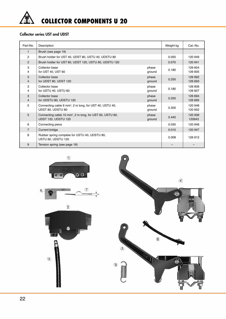
Collector series UST and UDST
Part-No. Description Weight kg Cat.-No.
1 Brush (see page 19)
2 Brush holder for UST 40, UDST 80, USTU 40, UDSTU 80 0.050 120 949
2 Brush holder for UST 60, UDST 120, USTU 60, UDSTU 120 0.070 120 941
3 Collector base phase0.180
126 6044 for UST 40, UST 60 ground 126 605
3 Collector base phase0.250
126 6924 for UDST 80, UDST 120 ground 126 693
3 Collector base phase0.180
126 6064 for USTU 40, USTU 60 ground 126 607
3 Collector base phase0.250
126 6944 for UDSTU 80, UDSTU 120 ground 126 695
5 Connecting cable 6 mm2, 2 m long, for UST 40, USTU 40, phase0.300
120 948UDST 80, UDSTU 80 ground 120 952
5 Connecting cable 10 mm2, 2 m long, for UST 60, USTU 60, phase0.445
120 939UDST 120, UDSTU 120 ground 120943
6 Connecting piece 0.030 120 946
7 Current bridge 0.010 120 947
8 Rubber spring complete for USTU 40, UDSTU 80,0.008 126 612
USTU 60, UDSTU 120
9 Tension spring (see page 18) – –
1
5
2
7
3
8
4
2
9
6
EXAMPLE FOR ORDERING U 20
23
19 12
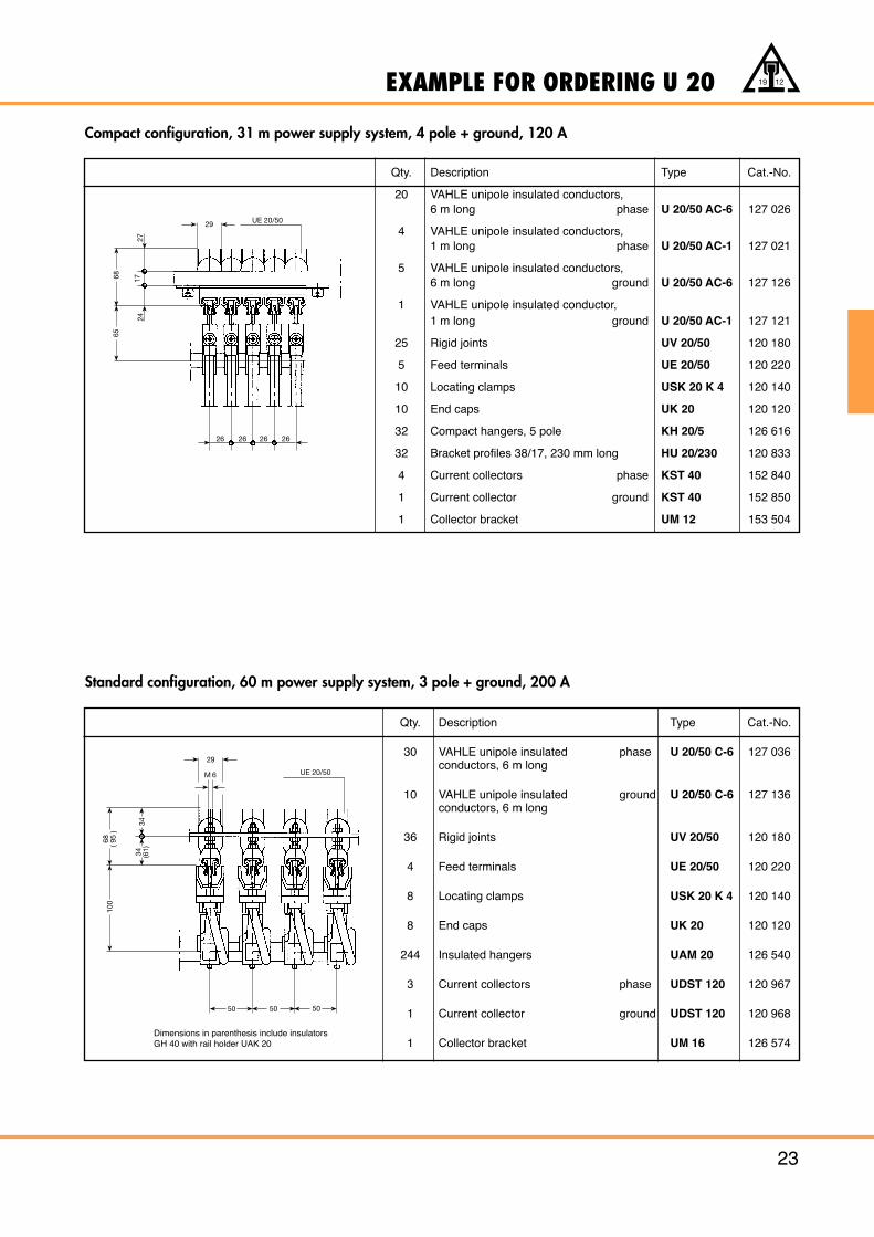
Qty. Description Type Cat.-No.
20 VAHLE unipole insulated conductors,6 m long phase U 20/50 AC-6 127 026
4 VAHLE unipole insulated conductors,1 m long phase U 20/50 AC-1 127 021
5 VAHLE unipole insulated conductors,6 m long ground U 20/50 AC-6 127 126
1 VAHLE unipole insulated conductor,1 m long ground U 20/50 AC-1 127 121
25 Rigid joints UV 20/50 120 180
5 Feed terminals UE 20/50 120 220
10 Locating clamps USK 20 K 4 120 140
10 End caps UK 20 120 120
32 Compact hangers, 5 pole KH 20/5 126 616
32 Bracket profiles 38/17, 230 mm long HU 20/230 120 833
4 Current collectors phase KST 40 152 840
1 Current collector ground KST 40 152 850
1 Collector bracket UM 12 153 504
Qty. Description Type Cat.-No.
30 VAHLE unipole insulated phase U 20/50 C-6 127 036conductors, 6 m long
10 VAHLE unipole insulated ground U 20/50 C-6 127 136conductors, 6 m long
36 Rigid joints UV 20/50 120 180
4 Feed terminals UE 20/50 120 220
8 Locating clamps USK 20 K 4 120 140
8 End caps UK 20 120 120
244 Insulated hangers UAM 20 126 540
3 Current collectors phase UDST 120 120 967
1 Current collector ground UDST 120 120 968
1 Collector bracket UM 16 126 574
Compact configuration, 31 m power supply system, 4 pole + ground, 120 A
Standard configuration, 60 m power supply system, 3 pole + ground, 200 A
Dimension in parenthesis at conductor U 20/50 C
Dimensions in parenthesis include insulators GH 40 with rail holder UAK 20
29
M 6 UE 20/50
100
68 ( 95
)
34 (61)
34
50 5050
6865
2417
27
29 UE 20/50
26 26 26 26
INSULATED CONDUCTORS U 30
24
19 12
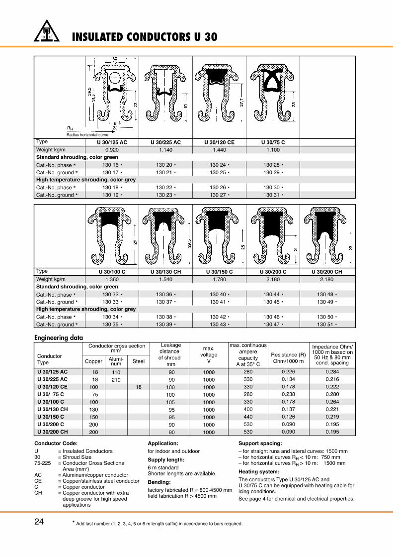
Type
Weight kg/mStandard shrouding, color green
Cat.-No. phase *Cat.-No. ground *High temperature shrouding, color grey
Cat.-No. phase *Cat.-No. ground *
U 30/125 AC0.920
130 16 •130 17 •
130 18 •130 19 •
U 30/225 AC1.140
130 20 •130 21 •
130 22 •130 23 •
U 30/120 CE1.440
130 24 •130 25 •
130 26 •130 27 •
U 30/75 C1.100
130 28 •130 29 •
130 30 •130 31 •
Type
Weight kg/mStandard shrouding, color green
Cat.-No. phase *Cat.-No. ground *High temperature shrouding, color grey
Cat.-No. phase *Cat.-No. ground *
U 30/100 C1.360
130 32 •130 33 •
130 34 •130 35 •
U 30/130 CH1.540
130 36 •130 37 •
130 38 •130 39 •
U 30/150 C1.780
130 40 •130 41 •
130 42 •130 43 •
U 30/200 C2.180
130 44 •130 45 •
130 46 •130 47 •
U 30/200 CH2.180
130 48 •130 49 •
130 50 •130 51 •
Engineering data
ConductorType
Leakagedistanceof shroud
mm
max.voltage
V
max. continuousamperecapacity
A at 35° C
Resistance (R)Ohm/1000 m
Impedance Ohm/1000 m based on50 Hz & 80 mmcond. spacing
Conductor cross section mm2
Copper Alumi-num Steel
U 30/125 ACU 30/225 ACU 30/120 CEU 30/ 75 CU 30/100 CU 30/130 CHU 30/150 CU 30/200 CU 30/200 CH
1818
10075
100130150200200
110210
18
90 90
10010010595959090
100010001000100010001000100010001000
280330330280330400440530530
0.2260.1340.1780.2380.1780.1370.1260.0900.090
0.2840.2160.2220.2800.2640.2210.2190.1950.195
Conductor Code:U = Insulated Conductors30 = Shroud Size75-225 = Conductor Cross Sectional
Area (mm2)AC = Aluminum/copper conductorCE = Copper/stainless steel conductorC = Copper conductorCH = Copper conductor with extra
deep groove for high speed applications
Application:for indoor and outdoor
Supply length:6 m standardShorter lenghts are available.
Bending:factory fabricated R = 800-4500 mmfield fabrication R > 4500 mm
Support spacing:– for straight runs and lateral curves: 1500 mm– for horizontal curves RH < 10 m: 750 mm– for horizontal curves RH > 10 m: 1500 mm
Heating system:The conductors Type U 30/125 AC and U 30/75 C can be equipped with heating cable foricing conditions.See page 4 for chemical and electrical properties.
* Add last number (1, 2, 3, 4, 5 or 6 m length suffix) in accordance to bars required.
Radius horizontal curve
ACCESSORIES FOR U 30
25
19 12
* Stainless steel hardware
24
204
190
21
204
19055
86
46,5
310
490
420
100
0-35
53
Cat.-No.Type Weight kg phase ground
Cat.-No.Type Weight kg phase ground
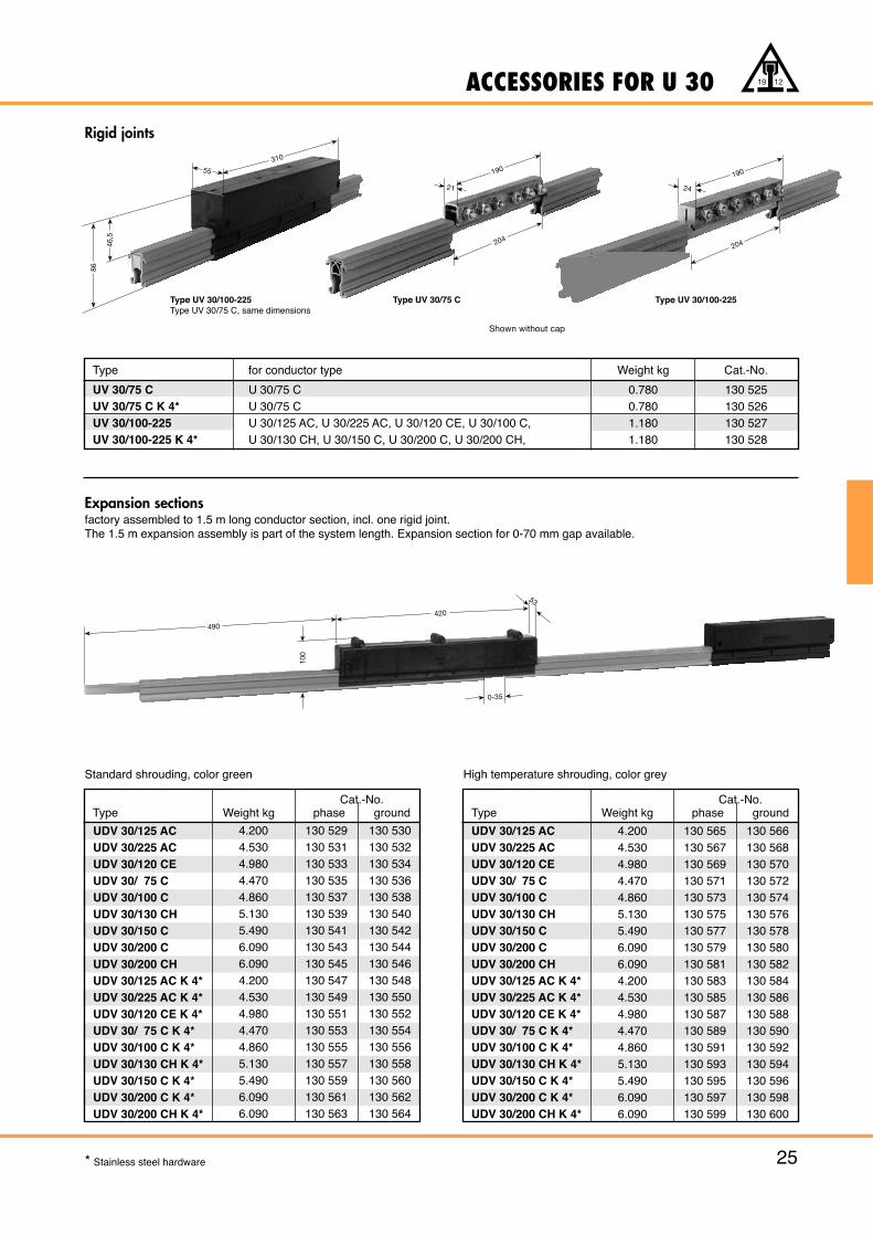
Type for conductor type Weight kg Cat.-No.
UV 30/75 C U 30/75 C 0.780 130 525UV 30/75 C K 4* U 30/75 C 0.780 130 526UV 30/100-225 U 30/125 AC, U 30/225 AC, U 30/120 CE, U 30/100 C, 1.180 130 527UV 30/100-225 K 4* U 30/130 CH, U 30/150 C, U 30/200 C, U 30/200 CH, 1.180 130 528
Expansion sectionsfactory assembled to 1.5 m long conductor section, incl. one rigid joint.The 1.5 m expansion assembly is part of the system length. Expansion section for 0-70 mm gap available.
UDV 30/125 ACUDV 30/225 ACUDV 30/120 CEUDV 30/ 75 CUDV 30/100 CUDV 30/130 CHUDV 30/150 CUDV 30/200 CUDV 30/200 CHUDV 30/125 AC K 4*UDV 30/225 AC K 4*UDV 30/120 CE K 4*UDV 30/ 75 C K 4*UDV 30/100 C K 4*UDV 30/130 CH K 4*UDV 30/150 C K 4*UDV 30/200 C K 4*UDV 30/200 CH K 4*
4.2004.5304.9804.4704.8605.1305.4906.0906.0904.2004.5304.9804.4704.8605.1305.4906.0906.090
130 529130 531130 533130 535130 537130 539130 541130 543130 545130 547130 549130 551130 553130 555130 557130 559130 561130 563
130 530130 532130 534130 536130 538130 540130 542130 544130 546130 548130 550130 552130 554130 556130 558130 560130 562130 564
UDV 30/125 ACUDV 30/225 ACUDV 30/120 CEUDV 30/ 75 CUDV 30/100 CUDV 30/130 CHUDV 30/150 CUDV 30/200 CUDV 30/200 CHUDV 30/125 AC K 4*UDV 30/225 AC K 4*UDV 30/120 CE K 4*UDV 30/ 75 C K 4*UDV 30/100 C K 4*UDV 30/130 CH K 4*UDV 30/150 C K 4*UDV 30/200 C K 4*UDV 30/200 CH K 4*
4.2004.5304.9804.4704.8605.1305.4906.0906.0904.2004.5304.9804.4704.8605.1305.4906.0906.090
130 565130 567130 569130 571130 573130 575130 577130 579130 581130 583130 585130 587130 589130 591130 593130 595130 597130 599
130 566130 568130 570130 572130 574130 576130 578130 580130 582130 584130 586130 588130 590130 592130 594130 596130 598130 600
Rigid joints
Standard shrouding, color green High temperature shrouding, color grey
Type UV 30/100-225Type UV 30/75 C, same dimensions
Type UV 30/75 C Type UV 30/100-225
Shown without cap
ACCESSORIES FOR U 30
26
19 12
* Stainless steel hardware
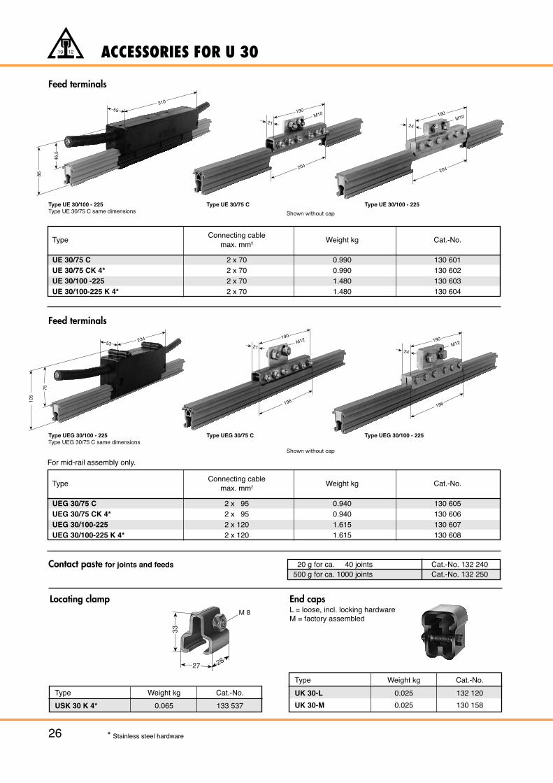
Locating clamp End capsL = loose, incl. locking hardwareM = factory assembled
Type Weight kg Cat.-No.
USK 30 K 4* 0.065 133 537
Type Weight kg Cat.-No.
UK 30-L 0.025 132 120
UK 30-M 0.025 130 158
M 8
2827
33
105
53234
7586
55
46,5
310
Feed terminals
TypeConnecting cable
Weight kg Cat.-No.max. mm2
UEG 30/75 C 2 x 95 0.940 130 605UEG 30/75 CK 4* 2 x 95 0.940 130 606UEG 30/100-225 2 x 120 1.615 130 607UEG 30/100-225 K 4* 2 x 120 1.615 130 608
Feed terminals
Contact paste for joints and feeds
TypeConnecting cable
Weight kg Cat.-No.max. mm2
UE 30/75 C 2 x 70 0.990 130 601UE 30/75 CK 4* 2 x 70 0.990 130 602UE 30/100 -225 2 x 70 1.480 130 603UE 30/100-225 K 4* 2 x 70 1.480 130 604
20 g for ca. 40 joints Cat.-No. 132 240500 g for ca. 1000 joints Cat.-No. 132 250
For mid-rail assembly only.
Type UE 30/100 - 225Type UE 30/75 C same dimensions
Type UE 30/75 C Type UE 30/100 - 225
Type UEG 30/100 - 225Type UEG 30/75 C same dimensions
Type UEG 30/75 C Type UEG 30/100 - 225
21
190
204
M10
24
190
204
M10
21
190M12
196
24
190M12
196
Shown without cap
Shown without cap
ACCESSORIES FOR U 30
27
19 12
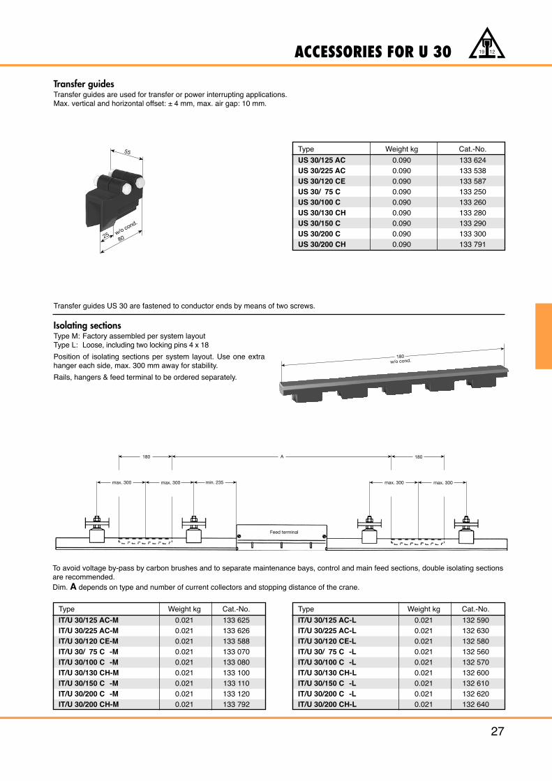
Transfer guidesTransfer guides are used for transfer or power interrupting applications.Max. vertical and horizontal offset: ± 4 mm, max. air gap: 10 mm.
Isolating sectionsType M: Factory assembled per system layoutType L: Loose, including two locking pins 4 x 18
Position of isolating sections per system layout. Use one extrahanger each side, max. 300 mm away for stability.
Rails, hangers & feed terminal to be ordered separately.
Type Weight kg Cat.-No.
US 30/125 AC 0.090 133 624US 30/225 AC 0.090 133 538US 30/120 CE 0.090 133 587US 30/ 75 C 0.090 133 250US 30/100 C 0.090 133 260US 30/130 CH 0.090 133 280US 30/150 C 0.090 133 290US 30/200 C 0.090 133 300US 30/200 CH 0.090 133 791
Type Weight kg Cat.-No.
IT/U 30/125 AC-M 0.021 133 625IT/U 30/225 AC-M 0.021 133 626IT/U 30/120 CE-M 0.021 133 588IT/U 30/ 75 C -M 0.021 133 070IT/U 30/100 C -M 0.021 133 080IT/U 30/130 CH-M 0.021 133 100IT/U 30/150 C -M 0.021 133 110IT/U 30/200 C -M 0.021 133 120IT/U 30/200 CH-M 0.021 133 792
Transfer guides US 30 are fastened to conductor ends by means of two screws.
Type Weight kg Cat.-No.
IT/U 30/125 AC-L 0.021 132 590IT/U 30/225 AC-L 0.021 132 630IT/U 30/120 CE-L 0.021 132 580IT/U 30/ 75 C -L 0.021 132 560IT/U 30/100 C -L 0.021 132 570IT/U 30/130 CH-L 0.021 132 600IT/U 30/150 C -L 0.021 132 610IT/U 30/200 C -L 0.021 132 620IT/U 30/200 CH-L 0.021 132 640
To avoid voltage by-pass by carbon brushes and to separate maintenance bays, control and main feed sections, double isolating sectionsare recommended.Dim. A depends on type and number of current collectors and stopping distance of the crane.
2580
w/o cond.
55
max. 300 max. 300 max. 300 max. 300
180 A 180
min. 235
Feed terminal
180w/o cond.
ACCESSORIES FOR U 30
28
19 12
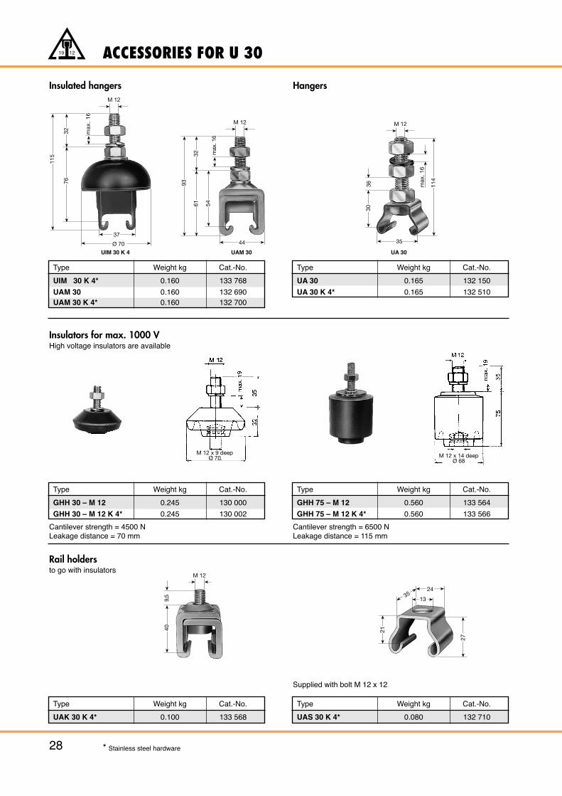
Type Weight kg Cat.-No.
UIM 30 K 4* 0.160 133 768
UAM 30 0.160 132 690UAM 30 K 4* 0.160 132 700
Insulated hangers Hangers
Type Weight kg Cat.-No.
UA 30 0.165 132 150
UA 30 K 4* 0.165 132 510
Insulators for max. 1000 VHigh voltage insulators are available
Type Weight kg Cat.-No.
GHH 75 – M 12 0.560 133 564
GHH 75 – M 12 K 4* 0.560 133 566
Type Weight kg Cat.-No.
GHH 30 – M 12 0.245 130 000
GHH 30 – M 12 K 4* 0.245 130 002
Cantilever strength = 4500 NLeakage distance = 70 mm
Cantilever strength = 6500 NLeakage distance = 115 mm
Rail holdersto go with insulators
Type Weight kg Cat.-No.
UAK 30 K 4* 0.100 133 568
Type Weight kg Cat.-No.
UAS 30 K 4* 0.080 132 710
Supplied with bolt M 12 x 12
* Stainless steel hardware
24
13
21
27
35
37
Ø 70
115
7632 m
ax.
16
M 12
44
93
6132 m
ax. 1
6
M 12
54
UIM 30 K 4 UAM 30 UA 30
M 12 x 9 deepØ 70 M 12 x 14 deep
Ø 68
35
114
M 12
max
. 16
3036
M 12
409,
5
COMPACT ARRANGEMENT U 30
29
19 12
Type Weight kg Cat.-No.
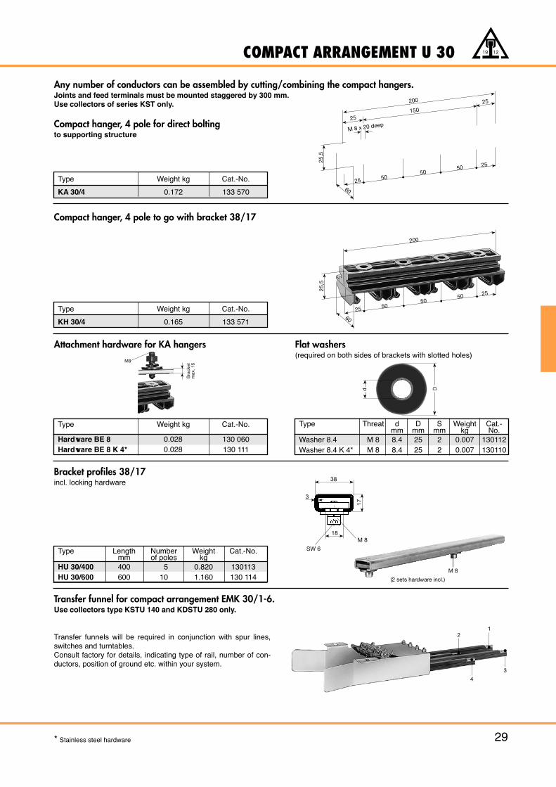
KA 30/4 0.172 133 570
Type Weight kg Cat.-No.
KH 30/4 0.165 133 571
Type Weight kg Cat.-No.
Hardware BE 8 130 060Hardware BE 8 K 4* 130 111
Type Threat d D S Weight Cat.-mm mm mm kg No.
Washer 8.4 M 8 8.4 25 2 0.007 130112Washer 8.4 K 4* M 8 8.4 25 2 0.007 130110
Compact hanger, 4 pole to go with bracket 38/17
Attachment hardware for KA hangers
Type Length Number Weight Cat.-No.mm of poles kg
HU 30/400 400 5 0.820 130113HU 30/600 600 10 1.160 130 114
Bracket profiles 38/17incl. locking hardware
Transfer funnel for compact arrangement EMK 30/1-6.Use collectors type KSTU 140 and KDSTU 280 only.
Transfer funnels will be required in conjunction with spur lines,switches and turntables.Consult factory for details, indicating type of rail, number of con-ductors, position of ground etc. within your system.
d D
200
25 5050
50 25
6025
,5
21
4
3
Bra
cket
m
ax. 1
5
M8
150
25
25 5050
50 25
60
25,5
200 25
M 8 x 20 deep
38
3
17
18
SW 6
M 8
0.0280.028
Any number of conductors can be assembled by cutting/combining the compact hangers.Joints and feed terminals must be mounted staggered by 300 mm. Use collectors of series KST only.
Compact hanger, 4 pole for direct boltingto supporting structure
* Stainless steel hardware
M 8
(2 sets hardware incl.)
Flat washers(required on both sides of brackets with slotted holes)
280 25 16.5 3.395 130 052 130 053280 25 16.5 3.535 130 054 130 055
140 25 16.5 1.935 130 048 130 049140 25 16.5 1.990 130 050 130 051
CURRENT COLLECTORS FOR U 30
30
19 12
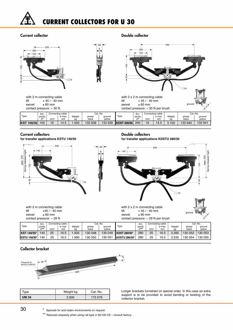
Current collector
TypeAm-
pacityA* mm2
ø max.mm
Weightkg
Connecting cablephaseblack
groundyellow
Cat.-No.
KST 100/30 100 16 14.5 1.550 133 938 133 939
with 2 m connecting cablelift + 45 / - 40 mmswivel ± 60 mmcontact pressure: ~ 30 N
Double collector
TypeAm-
pacityA* mm2
ø max.mm
Weightkg
Connecting cablephaseblack
groundyellow
Cat.-No.
KDST 200/30 200 16 14.5 3.100 133 940 133 941
with 2 x 2 m connecting cablelift + 45 / - 40 mmswivel ± 60 mmcontact pressure: ~ 30 N per brush
Current collectorsfor transfer applications KSTU 140/30
Collector bracket
TypeAm-
pacityA** mm2
ø max.mm
Weightkg
Connecting cablephaseblack
groundyellow
Cat.-No.
KST 140/30*KSTU 140/30*
with 2 m connecting cablelift +45 / - 40 mmswivel ± 60 mmcontact pressure: ~ 29 N
Double collectorsfor transfer applications KDSTU 280/30
TypeAm-
pacityA** mm2
ø max.mm
Weightkg
Connecting cablephaseblack
groundyellow
Cat.-No.
KDST 280/30*
KDSTU 280/30*
with 2 x 2 m connecting cablelift + 45 / - 40 mmswivel ± 60 mmcontact pressure: ~ 29 N per brush
* Specials for acid laden environments on request.
** Reduced ampacity when using rail type U 30/120 CE – consult factory.
Type Weight kg Cat.-No.
UM 24 2.600 175 076
Longer brackets furnished on special order. In this case an extrasupport is to be provided to avoid bending or twisting of thecollector bracket.
Prepared forground collector
600
35
24
45
24
200
120
155
500
155
45
250200120
24
42
6
250
140
155
50
24
app
r. 22
0S
prin
g re
leas
ed h
ight
500
140
155
50
24
app
r. 22
0
Sp
ring
rele
ased
hig
ht
425
2424
ground
ground
120
H58
COLLECTOR COMPONENTS U 30 · EXAMPLE FOR ORDERING
31
19 12
Qty. Description Type Cat.-No.
78 VAHLE unipole insulated phase U 30/200 C-6 130 446conductors, 6 m long
3 VAHLE unipole insulated phase U 30/200 C-1 130 441conductors, 1 m long
26 VAHLE unipole insulated ground U 30/100 C-6* 130 336conductors, 6 m long
1 VAHLE unipole insulated ground U 30/100 C-1* 130 331conductor, 1 m long
6 Expansion sections phase UDV 30/200 C 130 561each 1.5 m long
2 idem ground UDV 30/100 C* 130 538
104 Rigid joints UV 30/100-225 130 527
8 Feed terminals UE 30/100-225 130 603
24 Locating clamps USK 30 K 4 133 537
8 End caps UK 30 132 120
432 Insulated hangers UAM 30 132 690
6 Double collectors phase KDST 280/30 130 052
1 Current collector ground KDST 280/30* 130 053
2 Collector brackets UM 24 132 460
* Capacity reduces per VDE 0100, part 540
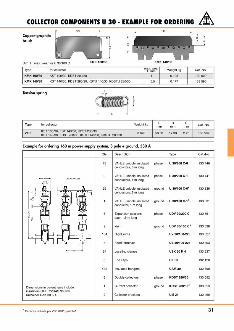
Copper-graphitebrush
Tension spring
Type for collector max. wear Weight kg Cat.-No.H mm
KMK 100/30 KST 100/30, KDST 200/30 4 0.198 130 609
KMK 140/30 KST 140/30, KDST 280/30, KSTU 140/30, KDSTU 280/30 5,5 0.177 133 590
KMK 100/30 KMK 140/30
Example for ordering 160 m power supply system, 3 pole + ground, 530 A
Type for collector Weight kg L D SCat.-No.mm mm mm
ZF 6KST 100/30, KST 140/30, KDST 200/30
0.020 56.50 17.30 2.25 133 592KST 140/30, KDST 280/30, KSTU 140/30, KDSTU 280/30
S
L
D
Dimensions in parenthesis includeinsulators GHH 75/UAS 30 withrailholder UAK 30 K 4
22
H
140
53
Dim. H: max. wear for U 30/100 C
UE 30/100-225
M12
80
15521
9 (2
84)
64 (129
)
55
COLLECTOR COMPONENTS U 30
32
19 12
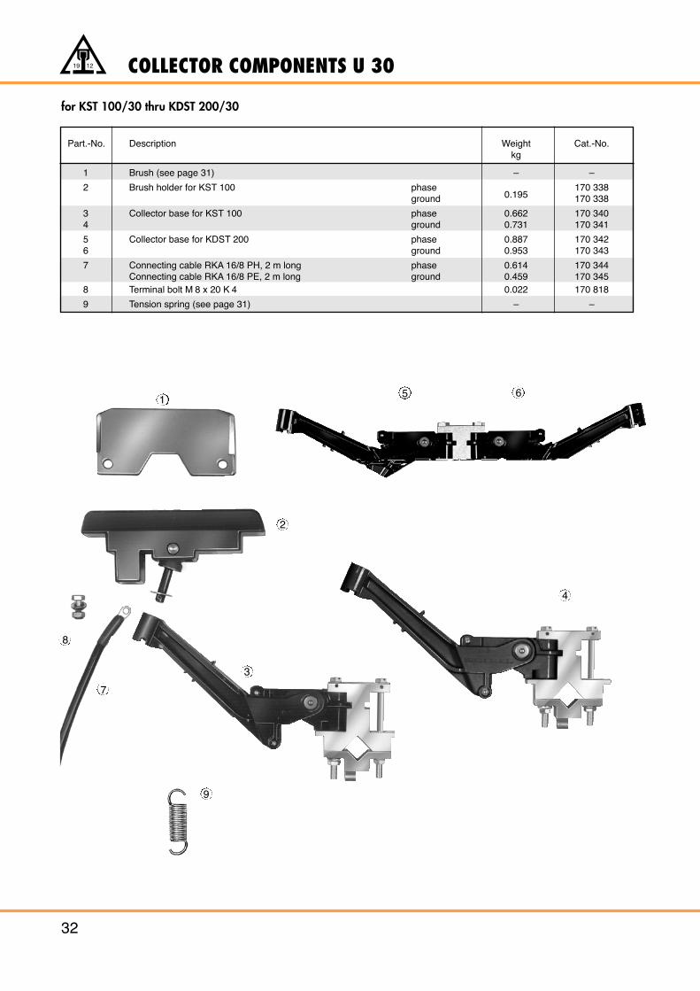
Part.-No. Description Weight Cat.-No.kg
1 Brush (see page 31) – –
2 Brush holder for KST 100 phase0.195
170 338ground 170 338
3 Collector base for KST 100 phase 0.662 170 3404 ground 0.731 170 341
5 Collector base for KDST 200 phase 0.887 170 3426 ground 0.953 170 343
7 Connecting cable RKA 16/8 PH, 2 m long phase 0.614 170 344Connecting cable RKA 16/8 PE, 2 m long ground 0.459 170 345
8 Terminal bolt M 8 x 20 K 4 0.022 170 818
9 Tension spring (see page 31) – –
for KST 100/30 thru KDST 200/30
1
2
3
4
8
9
5 6
7
COLLECTOR COMPONENTS U 30
33
19 12
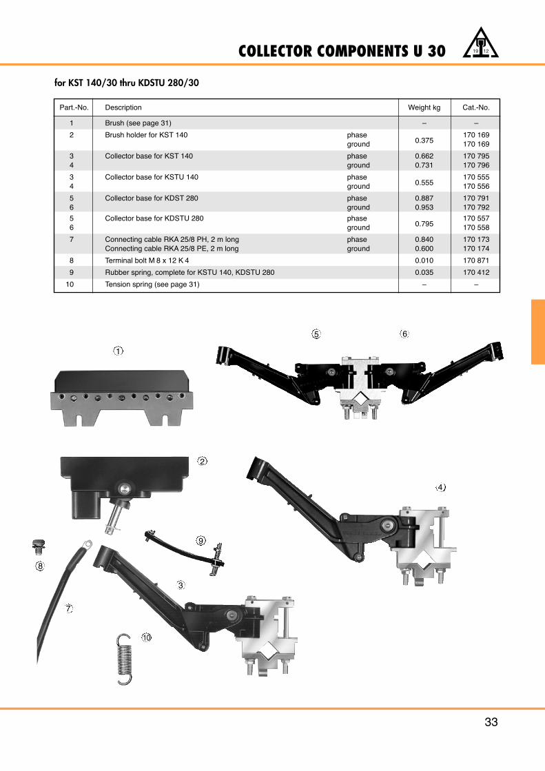
Part.-No. Description Weight kg Cat.-No.
1 Brush (see page 31) – –
2 Brush holder for KST 140 phase0.375
170 169ground 170 169
3 Collector base for KST 140 phase 0.662 170 7954 ground 0.731 170 796
3 Collector base for KSTU 140 phase0.555
170 5554 ground 170 556
5 Collector base for KDST 280 phase 0.887 170 7916 ground 0.953 170 792
5 Collector base for KDSTU 280 phase0.795
170 5576 ground 170 558
7 Connecting cable RKA 25/8 PH, 2 m long phase 0.840 170 173Connecting cable RKA 25/8 PE, 2 m long ground 0.600 170 174
8 Terminal bolt M 8 x 12 K 4 0.010 170 871
9 Rubber spring, complete for KSTU 140, KDSTU 280 0.035 170 412
10 Tension spring (see page 31) – –
for KST 140/30 thru KDSTU 280/30
1
2
3
4
8
9
10
5 6
7
INSULATED CONDUCTORS U 40
34
19 12
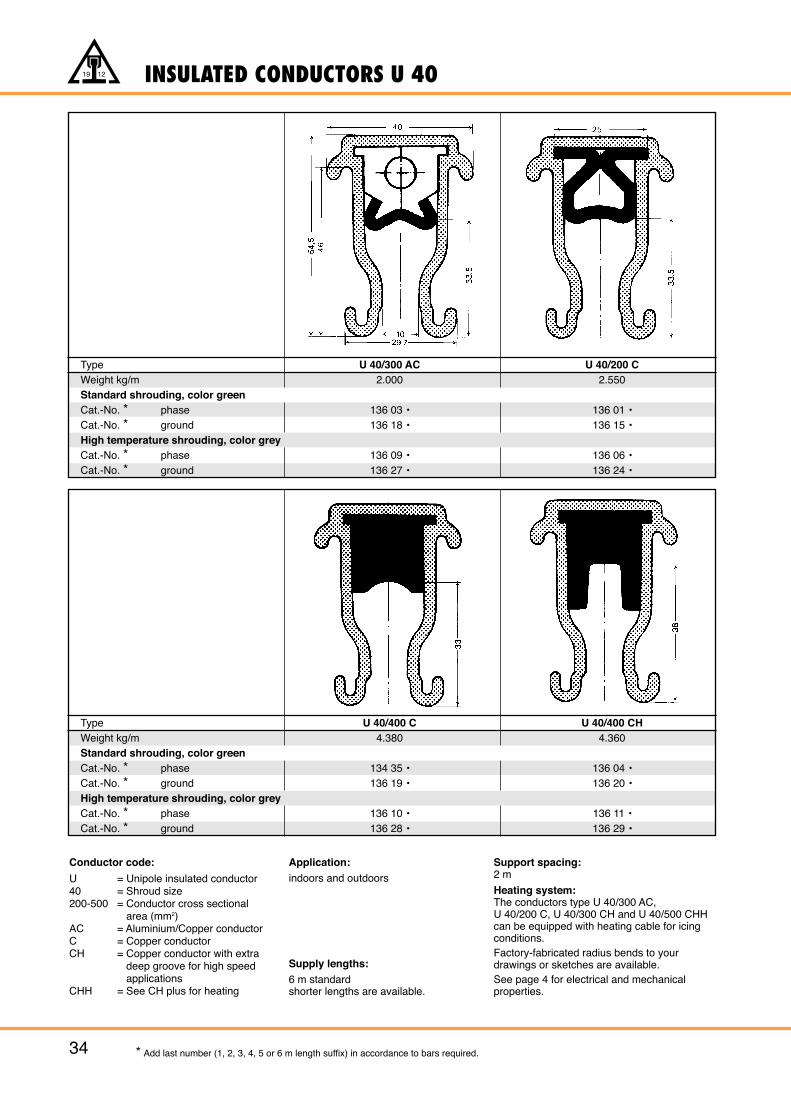
Conductor code:
U = Unipole insulated conductor40 = Shroud size200-500 = Conductor cross sectional
area (mm2)AC = Aluminium/Copper conductorC = Copper conductorCH = Copper conductor with extra
deep groove for high speedapplications
CHH = See CH plus for heating
Application:indoors and outdoors
Supply lengths:6 m standard shorter lengths are available.
Support spacing:2 m
Heating system:The conductors type U 40/300 AC, U 40/200 C, U 40/300 CH and U 40/500 CHH can be equipped with heating cable for icing conditions.Factory-fabricated radius bends to your drawings or sketches are available.See page 4 for electrical and mechanical properties.
* Add last number (1, 2, 3, 4, 5 or 6 m length suffix) in accordance to bars required.
Type U 40/300 AC U 40/200 CWeight kg/m 2.000 2.550Standard shrouding, color greenCat.-No. * phase 136 03 • 136 01 •Cat.-No. * ground 136 18 • 136 15 •High temperature shrouding, color greyCat.-No. * phase 136 09 • 136 06 •Cat.-No. * ground 136 27 • 136 24 •
Type U 40/400 C U 40/400 CHWeight kg/m 4.380 4.360Standard shrouding, color greenCat.-No. * phase 134 35 • 136 04 •Cat.-No. * ground 136 19 • 136 20 •High temperature shrouding, color greyCat.-No. * phase 136 10 • 136 11 •Cat.-No. * ground 136 28 • 136 29 •
35
19 12
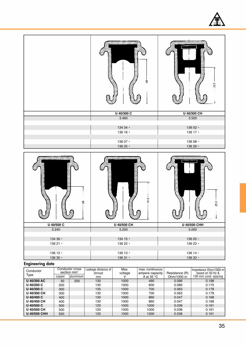
U 40/300 C U 40/300 CH3.460 3.500
134 34 • 136 02 •136 16 • 136 17 •
136 07 • 136 08 •136 25 • 136 26 •
U 40/500 C U 40/500 CH U 40/500 CHH5.240 5.250 5.000
134 36 • 134 15 • 136 05 •136 21 • 136 22 • 136 23 •
136 12 • 136 13 • 136 14 •136 30 • 136 31 • 136 32 •
Engineering data
ConductorType
Conductor crosssection mm2
copper aluminium
Leakage distance ofshroud
mm
Max.voltage
V
max. continuousampere capacity
A at 35 °CResistance (R)Ohm/1000 m
Impedance Ohm/1000 mbased on 50 Hz &
130 mm cond. spacingU 40/300 ACU 40/200 CU 40/300 CU 40/300 CHU 40/400 CU 40/400 CHU 40/500 CU 40/500 CHU 40/500 CHH
50200300300400400500500500
250 130130135130130130125120120
100010001000100010001000100010001000
490600700700860860
100010001000
0.0960.0890.0630.0630.0470.0470.0380.0380.038
0.1980.1700.1780.1780.1680.1680.1610.1610.161
M 1
0
71
36
0-35430
135
635
(33)36190
156
66248
4610
1
ACCESSORIES FOR U 40
36
19 12
* Stainless steel hardware
Cat.-No.Type Weight kgphase ground
Cat.-No.Type Weight kgphase ground
UDV 40/300 ACUDV 40/200 CUDV 40/300 CUDV 40/300 CHUDV 40/400 CUDV 40/400 CHUDV 40/500 CUDV 40/500 CHUDV 40/500 CHHUDV 40/300 AC K 4*UDV 40/200 C K 4*UDV 40/300 C K 4*UDV 40/300 CH K 4*UDV 40/400 C K 4 *UDV 40/400 CH K 4*UDV 40/500 C K 4*UDV 40/500 CH K 4*UDV 40/500 CHH K 4*
8.2509.350
11.17011.25013.01012.97014.73014.75014.2508.2509.350
11.17011.25013.01012.97014.73014.75014.250
135 211135 142134 690135 144134 710135 146134 730134 750135 390135 152135 154135 156135 148135 158135 150135 160135 162135 392
135 212135 143134 700135 145134 720135 147134 740134 760135 391135 153135 155135 157135 149135 159135 151135 161135 163135 393
UDV 40/300 ACUDV 40/200 CUDV 40/300 CUDV 40/300 CHUDV 40/400 CUDV 40/400 CHUDV 40/500 CUDV 40/500 CHUDV 40/500 CHHUDV 40/300 AC K 4*UDV 40/200 C K 4*UDV 40/300 C K 4*UDV 40/300 CH K 4*UDV 40/400 C K 4 *UDV 40/400 CH K 4*UDV 40/500 C K 4*UDV 40/500 CH K 4*UDV 40/500 CHH K 4*
8.2509.350
11.17011.25013.01012.97014.73014.75014.2508.2509.350
11.17011.25013.01012.97014.73014.75014.250
135 278135 272135 274135 276135 280135 282135 284135 286135 370135 294135 288135 290135 292135 296135 298135 300135 302135 372
135 279135 273135 275135 277135 281135 283135 285135 287135 371135 295135 289135 291135 293135 297135 299135 301135 303135 373
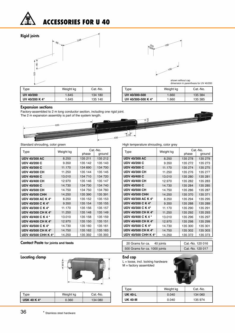
Rigid joints
Locating clamp
Contact Paste for joints and feeds
End capL = loose, incl. locking hardwareM = factory assembled
Type Weight kg Cat.-No.
USK 40 K 4* 0.360 134 080
Type Weight kg Cat.-No.
UK 40-L 0.040 134 060
UK 40-M 0.040 135 974
Standard shrouding, color green High temperature shrouding, color grey
20 Grams for ca. 40 joints Cat.-No. 120 016
500 Grams for ca. 1000 joints Cat.-No. 120 017
Type Weight kg Cat.-No.
UV 40/200 1.645 134 180UV 40/200 K 4* 1.645 135 140
Type Weight kg Cat.-No.
UV 40/300-500 1.660 135 384UV 40/300-500 K 4* 1.660 135 385
shown without capdimension in parenthesis for UV 40/200
Expansion sectionsFactory-assembled to 2 m long conductor section, including one rigid joint.The 2 m expansion assembly is part of the system length.
25466
190
136
196
190(33)36M 16
25466
190
136
ACCESSORIES FOR U 40
37
19 12
Type Weight kg Cat.-No.
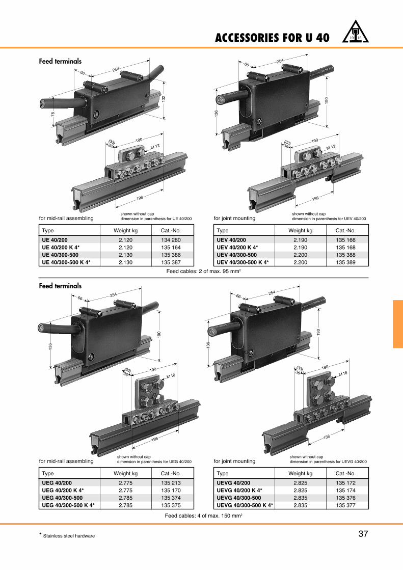
UE 40/200 2.120 134 280UE 40/200 K 4* 2.120 135 164UE 40/300-500 2.130 135 386UE 40/300-500 K 4* 2.130 135 387
Feed terminals
for mid-rail assembling
Type Weight kg Cat.-No.
UEV 40/200 2.190 135 166UEV 40/200 K 4* 2.190 135 168UEV 40/300-500 2.200 135 388UEV 40/300-500 K 4* 2.200 135 389
for joint mounting
Feed cables: 2 of max. 95 mm2
Type Weight kg Cat.-No.
UEG 40/200 2.775 135 213UEG 40/200 K 4* 2.775 135 170UEG 40/300-500 2.785 135 374UEG 40/300-500 K 4* 2.785 135 375
Feed terminals
for mid-rail assemblingshown without capdimension in parenthesis for UEG 40/200
Type Weight kg Cat.-No.
UEVG 40/200 2.825 135 172UEVG 40/200 K 4* 2.825 135 174UEVG 40/300-500 2.835 135 376UEVG 40/300-500 K 4* 2.835 135 377
Feed cables: 4 of max. 150 mm2
* Stainless steel hardware
190(33)36
196
M 12190(33)36
156
M 12
25466
190
136
156
190(33)36 M 16
25466
132
78
shown without capdimension in parenthesis for UEVG 40/200
shown without capdimension in parenthesis for UEV 40/200
shown without capdimension in parenthesis for UE 40/200
for joint mounting
ACCESSORIES FOR U 40
38
19 12
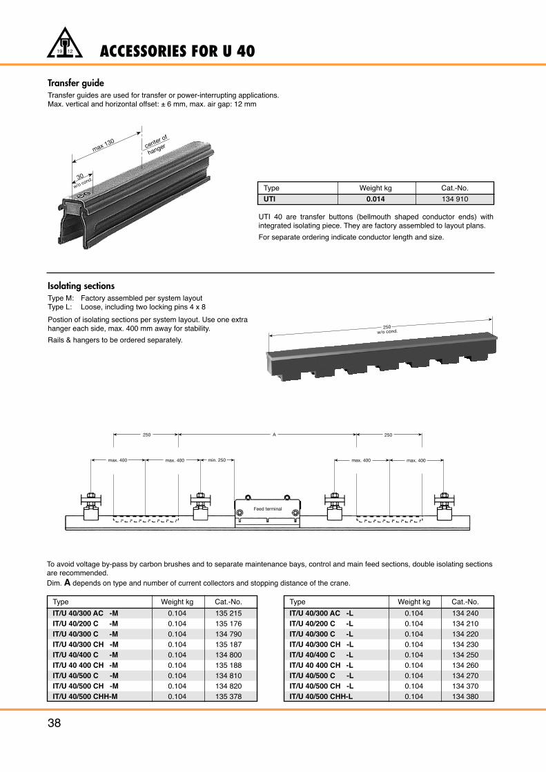
Transfer guideTransfer guides are used for transfer or power-interrupting applications.Max. vertical and horizontal offset: ± 6 mm, max. air gap: 12 mm
UTI 40 are transfer buttons (bellmouth shaped conductor ends) withintegrated isolating piece. They are factory assembled to layout plans.
For separate ordering indicate conductor length and size.
max 130
30
w/o cond.
center of
hanger
Isolating sectionsType M: Factory assembled per system layoutType L: Loose, including two locking pins 4 x 8
Postion of isolating sections per system layout. Use one extrahanger each side, max. 400 mm away for stability.
Rails & hangers to be ordered separately.
Type Weight kg Cat.-No.
UTI 0.014 134 910
To avoid voltage by-pass by carbon brushes and to separate maintenance bays, control and main feed sections, double isolating sectionsare recommended.Dim. A depends on type and number of current collectors and stopping distance of the crane.
Type Weight kg Cat.-No.
IT/U 40/300 AC -M 0.104 135 215IT/U 40/200 C -M 0.104 135 176IT/U 40/300 C -M 0.104 134 790IT/U 40/300 CH -M 0.104 135 187IT/U 40/400 C -M 0.104 134 800IT/U 40 400 CH -M 0.104 135 188IT/U 40/500 C -M 0.104 134 810IT/U 40/500 CH -M 0.104 134 820IT/U 40/500 CHH-M 0.104 135 378
Type Weight kg Cat.-No.
IT/U 40/300 AC -L 0.104 134 240IT/U 40/200 C -L 0.104 134 210IT/U 40/300 C -L 0.104 134 220IT/U 40/300 CH -L 0.104 134 230IT/U 40/400 C -L 0.104 134 250IT/U 40 400 CH -L 0.104 134 260IT/U 40/500 C -L 0.104 134 270IT/U 40/500 CH -L 0.104 134 370IT/U 40/500 CHH-L 0.104 134 380
max. 400 max. 400 max. 400 max. 400
250 A 250
min. 250
Feed terminal
250w/o cond.
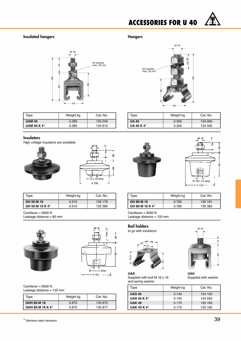
M 16
1445
32
24,5
17
2945
ACCESSORIES FOR U 40
39
19 12
Insulated hangers
Type Weight kg Cat.-No.
UAM 40 0.285 135 040UAM 40 K 4* 0.285 134 610
Hangers
Type Weight kg Cat.-No.
UA 40 0.300 134 090UA 40 K 4* 0.300 134 400
Type Weight kg Cat.-No.
GH 50-M 16 0.510 135 179GH 50-M 16 K 4* 0.510 135 380
Cantilever = 9000 NLeakage distance = 80 mm
Type Weight kg Cat.-No.
GH 80-M 16 0.780 135 181GH 80-M 16 K 4* 0.780 135 382
Cantilever = 9500 NLeakage distance = 120 mm
Rail holdersto go with insulators
Type Weight kg Cat.-No.
GHH 80-M 16 0.870 135 875GHH 80-M 16 K 4* 0.870 135 877
Cantilever = 9500 NLeakage distance = 125 mm
Type Weight kg Cat.-No.
UAS 40 0.140 134 100UAS 40 K 4* 0.140 134 550UAK 40 0.170 135 183UAK 40 K 4* 0.170 135 185
UAS UAKSupplied with bolt M 16 x 16 Supplied with washerand spring washer
* Stainless steel hardware
54
109
M 16
6940
60
for bracketmax. 20 mm
M 16
ca. 3
5
for bracketmax. 20 mm
100
60
48
InsulatorsHigh voltage insulators are available
deepdeep
deep
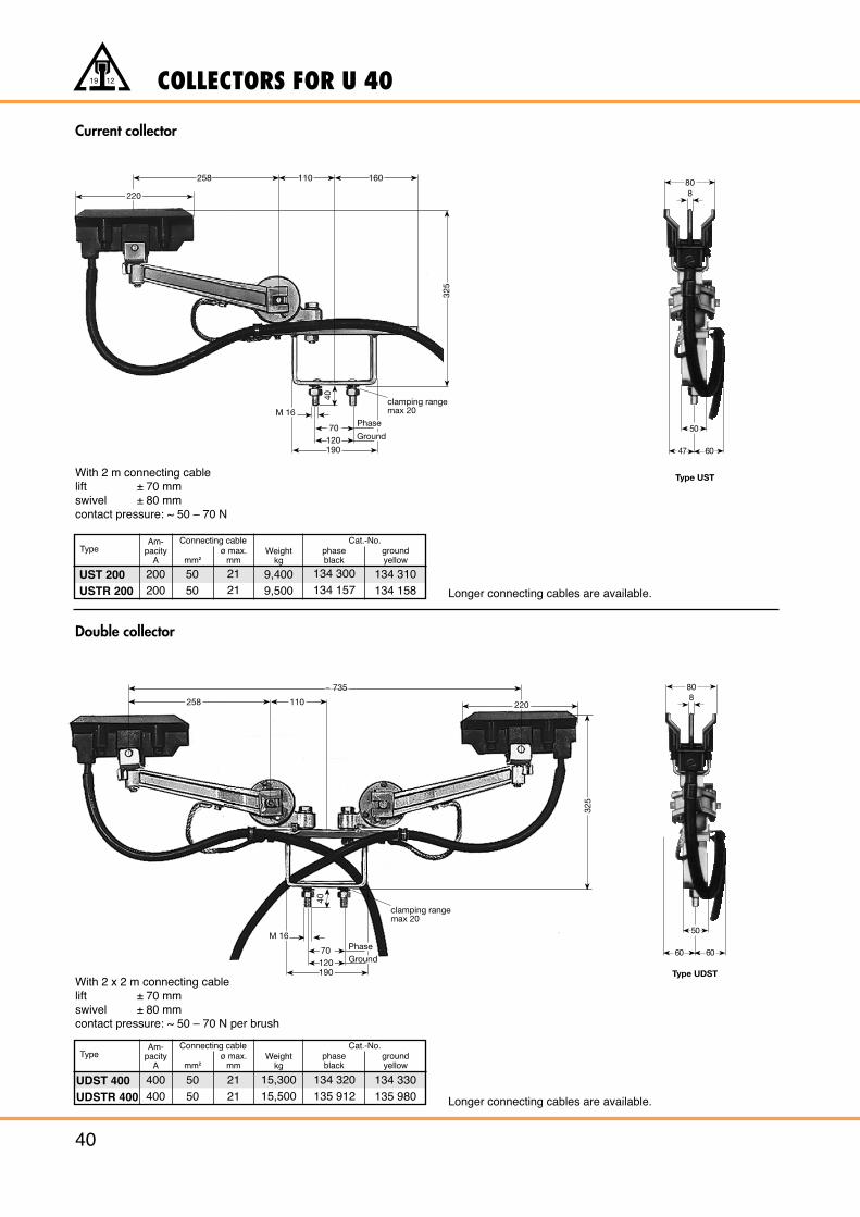
258 110 160
325
19012070
40
Phase
clamping rangemax 20
220
M 16
Ground
COLLECTORS FOR U 40
40
19 12
Current collector
With 2 m connecting cablelift ± 70 mmswivel ± 80 mmcontact pressure: ~ 50 – 70 N
Double collector
With 2 x 2 m connecting cablelift ± 70 mmswivel ± 80 mmcontact pressure: ~ 50 – 70 N per brush
Longer connecting cables are available.
Longer connecting cables are available.
19012070
40
clamping rangemax 20
M 16
258 110
~ 735
220
325
PhaseGround
5050
TypeAm-
pacityA mm2
ø max.mm
Weightkg
Connecting cablephaseblack
groundyellow
Cat.-No.
UST 200USTR 200
200200
2121
9,4009,500
134 300134 157
134 310134 158
5050
TypeAm-
pacityA mm2
ø max.mm
Weightkg
Connecting cablephaseblack
groundyellow
Cat.-No.
UDST 400UDSTR 400
400400
2121
15,30015,500
134 320135 912
134 330135 980
50
47
808
60
50
60
808
60
Type UST
Type UDST
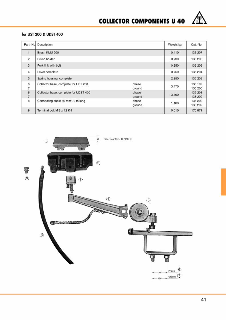
COLLECTOR COMPONENTS U 40
41
19 12
for UST 200 & UDST 400
Phase
Ground
171
2
3
4 5
8
6
770
120
Part.-No. Description Weight kg Cat.-No.
1 Brush KMU 200 0.410 135 207
2 Brush holder 0.730 135 206
3 Fork link with bolt 0.350 135 205
4 Lever complete 0.750 135 204
5 Spring housing, complete 2.250 135 203
6 Collector base, complete for UST 200 phase3.470
135 1997 ground 135 2006 Collector base, complete for UDST 400 phase
3.490135 201
7 ground 135 2028 Connecting cable 50 mm2, 2 m long phase
1.480135 208
ground 135 209
9 Terminal bolt M 8 x 12 K 4 0.010 170 871
max. wear for U 40 / 200 C
9
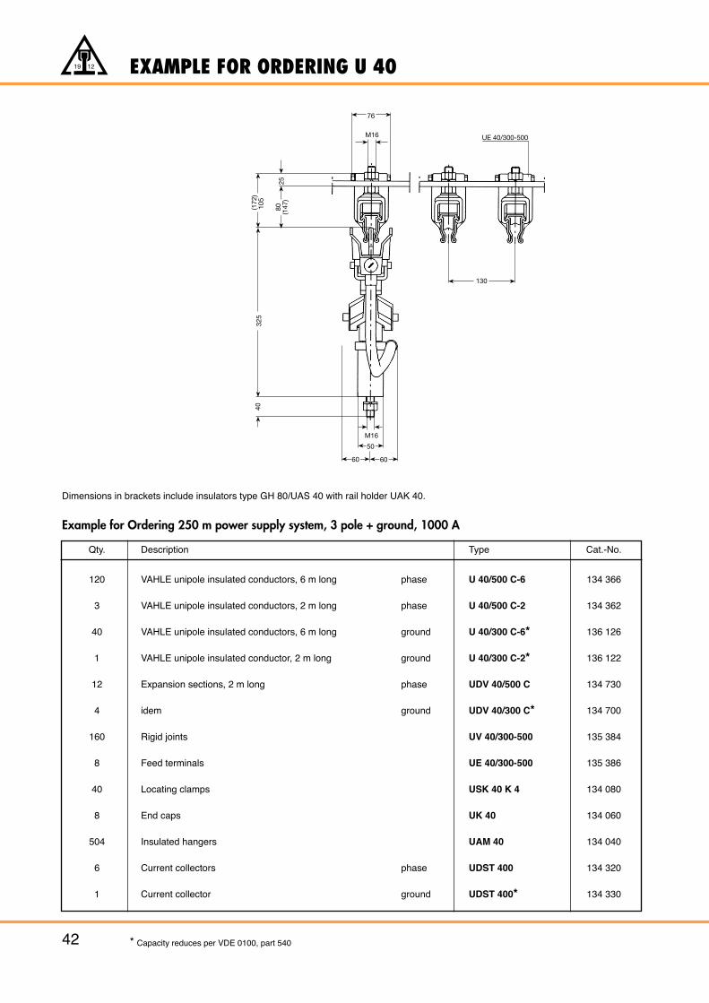
EXAMPLE FOR ORDERING U 40
42
19 12
* Capacity reduces per VDE 0100, part 540
Qty. Description Type Cat.-No.
120 VAHLE unipole insulated conductors, 6 m long phase U 40/500 C-6 134 366
3 VAHLE unipole insulated conductors, 2 m long phase U 40/500 C-2 134 362
40 VAHLE unipole insulated conductors, 6 m long ground U 40/300 C-6* 136 126
1 VAHLE unipole insulated conductor, 2 m long ground U 40/300 C-2* 136 122
12 Expansion sections, 2 m long phase UDV 40/500 C 134 730
4 idem ground UDV 40/300 C* 134 700
160 Rigid joints UV 40/300-500 135 384
8 Feed terminals UE 40/300-500 135 386
40 Locating clamps USK 40 K 4 134 080
8 End caps UK 40 134 060
504 Insulated hangers UAM 40 134 040
6 Current collectors phase UDST 400 134 320
1 Current collector ground UDST 400* 134 330
Dimensions in brackets include insulators type GH 80/UAS 40 with rail holder UAK 40.
Example for Ordering 250 m power supply system, 3 pole + ground, 1000 A
UE 40/300-500
76
M16
13025
(172
)10
5
80 (147
)
325
40
M16
50
6060
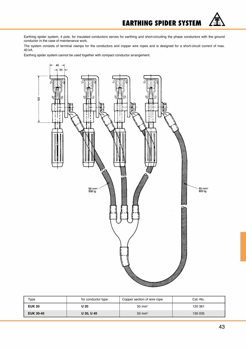
EARTHING SPIDER SYSTEM
43
19 12
Earthing spider system, 4 pole, for insulated conductors serves for earthing and short-circuiting the phase conductors with the groundconductor in the case of maintenance work.
The system consists of terminal clamps for the conductors and copper wire ropes and is designed for a short-circuit current of max. 40 kA.
Earthing spider system cannot be used together with compact conductor arrangement.
Type for conductor type Copper section of wire rope Cat.-No.
EUK 20 U 20 50 mm2 120 361
EUK 30-40 U 30, U 40 50 mm2 130 035

QUESTIONNAIRE
44
19 12
Adress:
Customer
1. Type of crane/machine to be electrified:
2. Voltage: Volts: Phases: c/s:
3. Length of conductor system:
4. Number of conductors: power lines: control lines: neutral (ground):
5. Indoor: Outdoor:
6. Special site conditions (humidity, dust, chemical influences etc.):
7. Temperature conditions: °C min. °C max.
8. Number and position of feeder points:
9. Mounting position envisaged ?(prints and sketches should be submitted whenever obtainable)
10. Number of cranes / machines electrified from the one system:
11. Ampere load of each crane/machine:(use table on reverse page)
12. Travelling speed of machinery:
Remarks:
Please submit prints or sketches for curved tracks, discontinuous circuits etc.
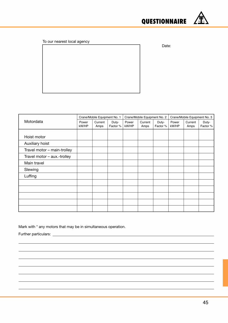
QUESTIONNAIRE
45
19 12
Date:To our nearest local agency
Mark with * any motors that may be in simultaneous operation.
Further particulars:
Crane/Mobile Equipment No. 1
Power Current Duty-kW/HP Amps Factor %
Crane/Mobile Equipment No. 2
Power Current Duty-kW/HP Amps Factor %
Crane/Mobile Equipment No. 3
Power Current Duty-kW/HP Amps Factor %
Motordata
Hoist motor
Auxiliary hoist
Travel motor – main-trolley
Travel motor – aux.-trolley
Main travel
Slewing
Luffing
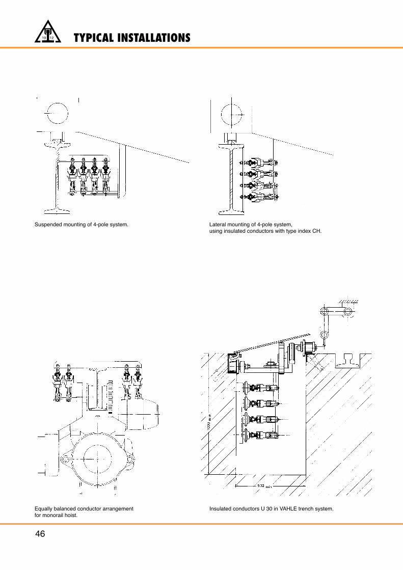
TYPICAL INSTALLATIONS
46
19 12
Suspended mounting of 4-pole system.
Equally balanced conductor arrangementfor monorail hoist.
Lateral mounting of 4-pole system,using insulated conductors with type index CH.
Insulated conductors U 30 in VAHLE trench system.
NOTES
47
19 12
In accordance with our company’s policy of continued improvement, we reserve the right to amend specifications and details at any time.
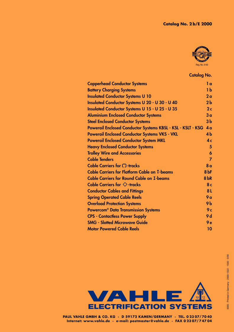
0005
· P
rinte
d in
Ger
man
y · 2
000-
1322
· 15
00 ·
5/00
Catalog No. 2 b/E 2000
PAUL VAHLE GMBH & CO. KG · D 59172 KAMEN/GERMANY · TEL. 0 23 07/ 70 40Internet: www.vahle.de · e-mail: postmaster @ vahle.de · FAX 0 23 07/ 7 47 04
Reg. No. 3140
Catalog No.
Copperhead Conductor Systems 1 aBattery Charging Systems 1 bInsulated Conductor Systems U 10 2 aInsulated Conductor Systems U 20 - U 30 - U 40 2 bInsulated Conductor Systems U 15 - U 25 - U 35 2 cAluminium Enclosed Conductor Systems 3 aSteel Enclosed Conductor Systems 3 bPowerail Enclosed Conductor Systems KBSL - KSL - KSLT - KSG 4 aPowerail Enclosed Conductor Systems VKS - VKL 4 bPowerail Enclosed Conductor System MKL 4 cHeavy Enclosed Conductor Systems 5Trolley Wire and Accessories 6Cable Tenders 7Cable Carriers for -tracks 8 aCable Carriers for Flatform Cable on -beams 8 bFCable Carriers for Round Cable on -beams 8 bRCable Carriers for -tracks 8 cConductor Cables and Fittings 8 LSpring Operated Cable Reels 9 aOverload Protection Systems 9 bPowercom® Data Transmission Systems 9 cCPS - Contactless Power Supply 9 dSMG - Slotted Microwave Guide 9 eMotor Powered Cable Reels 10


