Embed Size (px)
Citation preview
INST 242 (Analytical Measurement), section 1
Lab
Analytical measurement loop: Questions 91 and 92, completed objectives due by the end of day 5,section 3
Exam
Day 6 of section 3
Capstone Assessment takes the place of a mastery exam (see question 93)
Specific objectives for the optional “mastery” exam (worth +5% on the proportional exam score if passed thevery first time):• Electricity Review: Design a simple circuit to achieve a stated objective• Balancing a chemical reaction• Explain the operating principle of a specified analyzer type• Calculate temperatures or voltages in thermocouple and RTD circuits given access to thermocouple and
RTD tables• Solve for a specified variable in an algebraic formula (may contain exponents or logarithms)• Determine the possibility of suggested faults in a 4-20 mA loop circuit given measured values (voltage,
current), a schematic diagram, and reported symptoms• Motor/relay/3phase/PLC Review: Determine status of PLC output given input conditions and RLL
program• INST252 Review: Identify cause of poor loop performance from a trend graph• INST262 Review: Use decibels to calculate power gains and losses
Recommended daily schedule
Day 1
Theory session topic: Chemical concepts, terms, and symbols
Questions 1 through 20; answer questions 1-9 in preparation for discussion (remainder for practice)
Discuss the upcoming Capstone Assessment due by the end of the course (Question 93)
Day 2
Theory session topic: The Periodic Table, electron shells, and spectroscopy
Questions 21 through 40; answer questions 21-28 in preparation for discussion (remainder for practice)
Day 3
Theory session topic: Molecular quantities
Questions 41 through 60; answer questions 41-49 in preparation for discussion (remainder for practice)
Day 4
Theory session topic: Stoichiometry and energy in chemical reactions
Questions 61 through 80; answer questions 61-69 in preparation for discussion (remainder for practice)
Feedback questions (81 through 90) are optional and may be submitted for review at the end of the day
1

How To . . .
Access the worksheets and textbook: go to the Socratic Instrumentation website located athttp://www.ibiblio.org/kuphaldt/socratic/sinst to find worksheets for every 2nd-year course sectionorganized by quarter, as well as both the latest “stable” and “development” versions of the Lessons InIndustrial Instrumentation textbook. Download and save these documents to your computer.
Maximize your learning: complete all homework before class starts, ready to be assessed as describedin the “Inverted Session Formats” pages. Use every minute of class and lab time productively. Follow allthe tips outlined in “Question 0” as well as your instructor’s advice. Do not take constructive criticismpersonally. Make every reasonable effort to solve problems on your own before seeking help.
Identify upcoming assignments and deadlines: read the first page of each course worksheet.
Relate course days to calendar dates: reference the calendar spreadsheet file (calendar.xlsx), foundon the BTC campus Y: network drive. A printed copy is posted in the Instrumentation classroom.
Locate industry documents assigned for reading: use the Instrumentation Reference provided byyour instructor (on CD-ROM and on the BTC campus Y: network drive). There you will find a file named00 index OPEN THIS FILE.html readable with any internet browser. Click on the “Quick-Start Links” toaccess assigned reading documents, organized per course, in the order they are assigned.
Study for the exams: Mastery exams assess specific skills critically important to your success, listed nearthe top of the front page of each course worksheet for your review. Familiarize yourself with this list and payclose attention when those topics appear in homework and practice problems. Proportional exams featureproblems you haven’t seen before that are solvable using general principles learned throughout the current andprevious courses, for which the only adequate preparation is independent problem-solving practice every day.Answer the “feedback questions” (practice exams) in each course section to hone your problem-solving skills,as these are similar in scope and complexity to proportional exams. Answer these feedback independently(i.e. no help from classmates) in order to most accurately assess your readiness.
Calculate course grades: download the “Course Grading Spreadsheet” (grades template.xlsx) fromthe Socratic Instrumentation website, or from the BTC campus Y: network drive. Enter your quiz scores,test scores, lab scores, and attendance data into this Excel spreadsheet and it will calculate your coursegrade. You may compare your calculated grades against your instructors’ records at any time.
Identify courses to register for: read the “Sequence” page found in each worksheet.
Receive extra instructor help: ask during lab time, or during class time, or by appointment. Tony maybe reached by email at [email protected] or by telephone at 360-752-8477.
Identify job openings: regularly monitor job-search websites. Set up informational interviews atworkplaces you are interested in. Participate in jobshadows and internships. Apply to jobs long beforegraduation, as some employers take months to respond! Check your BTC email account daily for alerts.
Impress employers: sign the FERPA release form granting your instructors permission to share academicrecords, then make sure your performance is worth sharing. Document your project and problem-solvingexperiences for reference during interviews. Honor all your commitments.
Begin your career: participate in jobshadows and internships while in school to gain experience andreferences. Take the first Instrumentation job that pays the bills, and give that employer at least two yearsof good work to pay them back for the investment they have made in you. Employers look at delayedemployment, as well as short employment spans, very negatively. Failure to pass a drug test is an immediatedisqualifier, as is falsifying any information. Criminal records may also be a problem.
file howto
2

General Values, Expectations, and Standards
Success in this career requires professional integrity, resourcefulness, persistence, close attention to detail,and intellectual curiosity. If you are ever in doubt as to the values you should embody, just ask yourselfwhat kind of a person you would prefer to hire for your own enterprise. Those same values will be upheldwithin this program.
Learning is the purpose of any educational program, and a worthy priority in life. Every circumstance, everyincident, every day here will be treated as a learning opportunity, every mistake as a “teachable moment”.Every form of positive growth, not just academic ability, will be regarded as real learning.
Responsibility means ensuring the desired outcome, not just trying to achieve the outcome. To be aresponsible person means you own the outcome of your decisions and actions.
Integrity means being honest and forthright in all your words and actions, doing your very best every timeand never taking credit for the achievement of another.
Safety means doing every job correctly and ensuring others are not endangered. Lab safety standards includewearing closed-toed shoes and safety glasses in the lab room during lab hours, wearing ear protection aroundloud sounds, using ladders to reach high places, using proper lock-out/tag-out procedures, no energizedelectrical work above 30 volts without an instructor present in the lab room, and no power tool use withoutan instructor present in the lab room.
Diligence in study means exercising self-discipline and persistence, realizing that hard work is a necessarycondition for success. This means, among other things, investing the necessary time and effort in studying,reading instructions, paying attention to details, utilizing the skills and tools you already possess, andavoiding shortcuts. Diligence in work means the job is not done until it is done correctly: all objectivesachieved, all problems solved, all documentation complete, and no errors remaining.
Self-management means allocating your resources (time, equipment, labor) wisely, and not just focusingon the closest deadline.
Communication means clearly conveying your thoughts and paying attention to what others convey, acrossall forms of communication (e.g. oral, written, nonverbal).
Teamwork means working constructively with your classmates to complete the job at hand. Rememberthat here the first job is learning, and so teamwork means working to maximize everyone’s learning (not justyour own). The goal of learning is more important than the completion of any project or assignment.
Initiative means recognizing needs and taking action to meet those needs without encouragement ordirection from others.
Representation means your actions reflect this program and not just yourself. Doors of opportunity forall BTC graduates may be opened or closed by your own conduct. Unprofessional behavior during tours,jobshadows, internships, and/or jobs reflects poorly on the program and will negatively bias employers.
Trustworthiness is the result of consistently exercising these values: people will recognize you as someonethey can rely on to get the job done, and therefore someone they would want to employ.
Respect means acknowledging the intrinsic value, capabilities, and responsibilities of those around you.Respect is gained by consistent demonstration of valued behaviors, and it is lost through betrayal of trust.
3
General Values, Expectations, and Standards (continued)
Punctuality and Attendance: late arrivals are penalized at a rate of 1% grade deduction per incident.Absence is penalized at a rate of 1% per hour (rounded to the nearest hour) except when employment-related,school-related, weather-related, or required by law (e.g. court summons). Absences may be made up bydirecting the instructor to apply “sick hours” (12 hours of sick time available per quarter). Classmates maydonate their unused sick hours. Sick hours may not be applied to unannounced absences, so be sure to alertyour instructor and teammates as soon as you know you will be absent or late. Absence on an exam daywill result in a zero score for that exam, unless due to a documented emergency.
Mastery: any assignment or objective labeled as “mastery” must be completed with 100% competence(with multiple opportunities to re-try). Failure to complete by the deadline date caps your grade at a C−.Failure to complete by the end of the next school day results in a failing (F) grade for that course.
Time Management: Use all available time wisely and productively. Work on other useful tasks (e.g.homework, feedback questions, job searching) while waiting for other activities or assessments to begin.Trips to the cafeteria for food or coffee, smoke breaks, etc. must not interfere with team participation.
Orderliness: Keep your work area clean and orderly, discarding trash, returning tools at the end of everylab session, and participating in all scheduled lab clean-up sessions. Project wiring, especially in shared areassuch as junction boxes, must not be left in disarray at the end of a lab shift. Label any failed equipmentwith a detailed description of its symptoms.
Independent Study: the “inverted” instructional model used in this program requires independent readingand problem-solving, where every student must demonstrate their learning at the start of the class session.Question 0 of every worksheet lists practical study tips. The “Inverted Session Formats” pages found inevery worksheet outline the format and grading standards for inverted class sessions.
Independent Problem-Solving: make an honest effort to solve every problem before seeking help. Whenworking in the lab, help will not be given unless and until you run your own diagnostic tests.
Teamwork: inform your teammates if you need to leave the work area for any reason. Any student regularlycompromising team performance through absence, tardiness, disrespect, or other disruptive behavior(s) willbe removed from the team and required to complete all labwork individually. The same is true for studentsfound inappropriately relying on teammates.
Communication: check your email daily for important messages. Ask the instructor to clarify anyassignment or exam question you find confusing, and express your work clearly.
Academic Progress: your instructor will record your academic achievement, as well as comments on anynegative behavior, and will share all these records with employers if you sign the FERPA release form.You may see these records at any time, and you should track your own academic progress using the gradespreadsheet template. Extra-credit projects will be tailored to your learning needs.
Office Hours: your instructor’s office hours are by appointment, except in cases of emergency. Email is thepreferred method for setting up an appointment with your instructor to discuss something in private.
Grounds for Failure: a failing (F) grade will be earned in any course if any mastery objectives are pastdeadline by more than one school day, or for any of the following behaviors: false testimony (lying), cheatingon any assignment or assessment, plagiarism (presenting another’s work as your own), willful violation ofa safety policy, theft, harassment, sabotage, destruction of property, or intoxication. These behaviors aregrounds for immediate termination in this career, and as such will not be tolerated here.
file expectations
4

Program Outcomes for Instrumentation and Control Technology (BTC)
#1 Communication
Communicate and express concepts and ideas across a variety of media (verbal, written, graphical) usingindustry-standard terms.
#2 Time management
Arrives on time and prepared to work; Budgets time and meets deadlines when performing tasks andprojects.
#3 Safety
Complies with national, state, local, and college safety regulations when designing and performing workon systems.
#4 Analysis and Diagnosis
Analyze, evaluate, and diagnose systems related to instrumentation and control including electricaland electronic circuits, fluid power and signaling systems, computer networks, and mechanisms; Select andapply correct mathematical techniques to these analytical and diagnostic problems; Select and correctly useappropriate test equipment to collect data.
#5 Design and Commissioning
Select, design, construct, configure, and install components necessary for the proper function of systemsrelated to instrumentation and control, applying industry standards and verifying correct system operationwhen complete.
#6 System optimization
Improve technical system functions by collecting data and evaluating performance; Implement strategiesto optimize the function of these systems.
#7 Calibration
Assess instrument accuracy and correct inaccuracies using appropriate calibration procedures and testequipment; Select and apply correct mathematical techniques to these calibration tasks.
#8 Documentation
Interpret and create technical documents (e.g. electronic schematics, loop diagrams, functionaldiagrams, P&IDs, graphs, narratives) according to industry standards.
#9 Independent learning
Select and research information sources to learn new principles, technologies, and techniques.
#10 Job searching
Develop a professional resume and research job openings in the field of industrial instrumentation.
file outcomes program
5

INST 242 Course Outcomes
Each and every outcome in this course is assessed at a mastery level (i.e. 100% competence)
• Demonstrate proper use of safety equipment and application of safe procedures while using power tools,and working on live systems. [Ref: Program Learning Outcome #3]
• Communicate effectively with teammates to plan work, arrange for absences, and share responsibilitiesin completing all labwork. [Ref: Program Learning Outcomes #1 and #2]
• Construct and commission a working analytical loop consisting of a chemical analyzer, signal wiring,and indicator. [Ref: Program Learning Outcome #5]
• Generate an accurate loop diagram compliant with ISA standards documenting your team’s analyticalmeasurement system. [Ref: Program Learning Outcome #8]
• Calibrate analyzer to specified accuracy using industry-standard calibration equipment. [Ref: ProgramLearning Outcome #7]
• Design and build a circuit to fulfill a function randomly selected by the instructor (voltage divider,passive filter, capacitive time-delay, or phase shift network) and demonstrate its proper operation usinga signal generator and oscilloscope. [Ref: Program Learning Outcome #5]
• Diagnose a random fault placed in another team’s analytical measurement system by the instructorwithin a limited time using no test equipment except a multimeter, logically justifying your steps in theinstructor’s direct presence. [Ref: Program Learning Outcome #4]
• Construct a working control loop consisting of a pre-made process unit with transmitter and final controlelement, properly connected to a controller, within a limited time. Both the process and the controllerare randomly selected by the instructor, with measurement range values specified by the instructor.[Ref: Program Learning Outcomes #5 and #9]
file outcomes INST242
6

Sequence of second-year Instrumentation courses
INST 240 -- 6 crPressure/Level Measurement
INST 241 -- 6 crTemp./Flow Measurement
INST 242 -- 5 crAnalytical Measurement
INST 250 -- 5 cr
INST 251 -- 5 crPID Control
Final Control Elements
Loop TuningINST 252 -- 4 cr
Data Acquisition Systems
INST 262 -- 5 cr
INST 263 -- 5 crControl Strategies
Fall quarter Winter quarter Spring quarterSummer quarter
Offered 1st week ofINST 200 -- 1 wkIntro. to Instrumentation
Job Prep I
Job Prep II
INST 205 -- 1 cr
INST 206 -- 1 cr
INST25x, and INST26x coursesPrerequisite for all INST24x, Fall, Winter, and
Spring quarters
Offered 1st week ofFall, Winter, andSpring quarters
INST 260 -- 4 cr
CAD 1: Basics
including MATH 141 (Precalculus 1)Core Electronics -- 3 qtrs
Prerequisite for INST206
(Only if 4th quarter was Summer: INST23x)
All coursescompleted? No
Yes
Graduate!!!
Protective Relays (elective)
ENGT 134 -- 5 cr
recommended
INST 233 -- 4 cr
Jobshadow and/orInternship strongly
Digital Control Systems
7
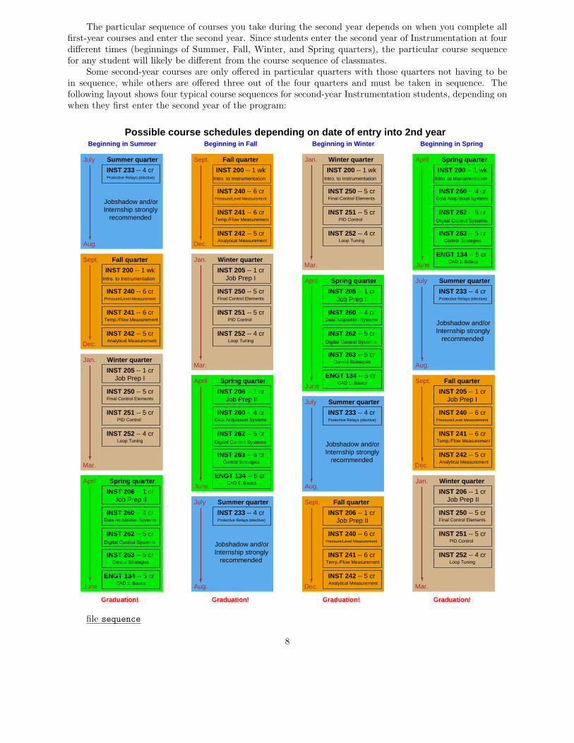
The particular sequence of courses you take during the second year depends on when you complete allfirst-year courses and enter the second year. Since students enter the second year of Instrumentation at fourdifferent times (beginnings of Summer, Fall, Winter, and Spring quarters), the particular course sequencefor any student will likely be different from the course sequence of classmates.
Some second-year courses are only offered in particular quarters with those quarters not having to bein sequence, while others are offered three out of the four quarters and must be taken in sequence. Thefollowing layout shows four typical course sequences for second-year Instrumentation students, depending onwhen they first enter the second year of the program:
INST 240 -- 6 crPressure/Level Measurement
INST 241 -- 6 crTemp./Flow Measurement
INST 242 -- 5 crAnalytical Measurement
Fall quarter
INST 200 -- 1 wkIntro. to Instrumentation
Winter quarter
Job Prep IINST 205 -- 1 cr
INST 250 -- 5 crFinal Control Elements
INST 251 -- 5 crPID Control
Loop TuningINST 252 -- 4 cr
Job Prep IIINST 206 -- 1 cr
Spring quarter
Data Acquisition SystemsINST 260 -- 4 cr
INST 262 -- 5 cr
INST 263 -- 5 crControl Strategies
CAD 1: Basics
Graduation!
Possible course schedules depending on date of entry into 2nd year
INST 240 -- 6 crPressure/Level Measurement
INST 241 -- 6 crTemp./Flow Measurement
INST 242 -- 5 crAnalytical Measurement
Fall quarter
INST 200 -- 1 wkIntro. to Instrumentation
Winter quarter
Job Prep IINST 205 -- 1 cr
INST 250 -- 5 crFinal Control Elements
INST 251 -- 5 crPID Control
Loop TuningINST 252 -- 4 cr
Job Prep IIINST 206 -- 1 cr
Spring quarter
Data Acquisition SystemsINST 260 -- 4 cr
INST 262 -- 5 cr
INST 263 -- 5 crControl Strategies
CAD 1: Basics
Graduation!
INST 240 -- 6 crPressure/Level Measurement
INST 241 -- 6 crTemp./Flow Measurement
INST 242 -- 5 crAnalytical Measurement
Fall quarter
Winter quarter
INST 250 -- 5 crFinal Control Elements
INST 251 -- 5 crPID Control
Loop TuningINST 252 -- 4 cr
Spring quarter
Data Acquisition SystemsINST 260 -- 4 cr
INST 262 -- 5 cr
INST 263 -- 5 crControl Strategies
CAD 1: Basics
Graduation!
INST 200 -- 1 wkIntro. to Instrumentation
Job Prep IINST 205 -- 1 cr
Job Prep IIINST 206 -- 1 cr
INST 200 -- 1 wkIntro. to Instrumentation
Job Prep IINST 205 -- 1 cr
Job Prep IIINST 206 -- 1 cr
Sept.
Dec.
Jan.
Mar.
April
June
Sept.
Dec.
Jan.
Mar.
April
June
Jan.
Mar.
April
June
Sept.
Dec.
April
June
Sept.
Dec.
Jan.
Mar.
Beginning in Summer Beginning in Fall Beginning in Winter Beginning in Spring
July
Aug.
July
July
Summer quarterJuly
Protective Relays (elective)
Aug.
Aug.
Aug.
ENGT 134 -- 5 cr
ENGT 134 -- 5 cr
ENGT 134 -- 5 cr
ENGT 134 -- 5 cr
INST 233 -- 4 cr
Jobshadow and/orInternship strongly
recommended
Summer quarter
Protective Relays (elective)
INST 233 -- 4 cr
Jobshadow and/orInternship strongly
recommended
Summer quarter
Protective Relays (elective)
INST 233 -- 4 cr
Jobshadow and/orInternship strongly
recommended
Summer quarter
Protective Relays (elective)
INST 233 -- 4 cr
Jobshadow and/orInternship strongly
recommended
Digital Control Systems
Digital Control Systems
Digital Control Systems
Digital Control Systems
file sequence
8

General tool and supply list
Wrenches• Combination (box- and open-end) wrench set, 1/4” to 3/4” – the most important wrench sizes are 7/16”,
1/2”, 9/16”, and 5/8”; get these immediately!• Adjustable wrench, 6” handle (sometimes called “Crescent” wrench)• Hex wrench (“Allen” wrench) set, fractional – 1/16” to 3/8”• Optional: Hex wrench (“Allen” wrench) set, metric – 1.5 mm to 10 mm• Optional: Miniature combination wrench set, 3/32” to 1/4” (sometimes called an “ignition wrench” set)
Note: always maximize surface engagement on a fastener’s head to reduce stress on that fastener. (e.g.Using box-end wrenches instead of adjustable wrenches; using the proper size and type of screwdriver; neverusing any tool that mars the fastener such as pliers or vise-grips unless absolutely necessary.)
Pliers• Needle-nose pliers• Diagonal wire cutters (sometimes called “dikes”)
Screwdrivers• Slotted, 1/8” and 1/4” shaft• Phillips, #1 and #2• Jeweler’s screwdriver set• Optional: Magnetic multi-bit screwdriver (e.g. Klein Tools model 70035)
Electrical• Multimeter, Fluke model 87-IV or better• Assortment of alligator-clip style jumper wires• Soldering iron (10 to 40 watt) and rosin-core solder• Resistor, potentiometer, diode assortments (from first-year lab kits)• Package of insulated compression-style fork terminals (14 to 18 AWG wire size, #10 stud size)• Wire strippers/terminal crimpers for 10 AWG to 18 AWG wire and insulated terminals• Optional: ratcheting terminal crimp tool (e.g. Paladin 1305, Ferrules Direct FDT10011, or equivalent)
Safety• Safety glasses or goggles (available at BTC bookstore)• Earplugs (available at BTC bookstore)
Miscellaneous• Simple scientific calculator (non-programmable, non-graphing, no conversions), TI-30Xa or TI-30XIIS
recommended. Required for some exams!• Portable personal computer capable of wired Ethernet connectivity, Wi-Fi connectivity, displaying PDF
documents, creating text documents, creating and viewing spreadsheets, running PLC programmingsoftware (MS Windows only), and executing command-line utilities such as ping.
• Masking tape (for making temporary labels)• Permanent marker pen• Teflon pipe tape• Utility knife• Tape measure, 12 feet minimum• Flashlight
file tools
9

Methods of instruction
This course develops self-instructional and diagnostic skills by placing students in situations where theyare required to research and think independently. In all portions of the curriculum, the goal is to avoid apassive learning environment, favoring instead active engagement of the learner through reading, reflection,problem-solving, and experimental activities. The curriculum may be roughly divided into two portions:theory and practical. All “theory” sessions follow the inverted format and contain virtually no lecture.
Inverted theory sessionsThe basic concept of an “inverted” learning environment is that the traditional allocations of student
time are reversed: instead of students attending an instructor-led session to receive new information and thenpracticing the application of that information outside of the classroom in the form of homework, studentsin an inverted class encounter new information outside of the classroom via homework and apply thatinformation in the classroom session under the instructor’s tutelage.
A natural question for instructors, then, is what their precise role is in an inverted classroom and howto organize that time well. Here I will list alternate formats suitable for an inverted classroom session, eachof them tested and proven to work.
Small sessions
Students meet with instructors in small groups for short time periods. Groups of 4 students meeting for30 minutes works very well, but groups as large as 8 students apiece may be used if time is limited. Each ofthese sessions begins with a 5 to 10 minute graded inspection of homework with individual questioning, tokeep students accountable for doing the homework. The remainder of the session is a dialogue focusing onthe topics of the day, the instructor challenging each student on the subject matter in Socratic fashion, andalso answering students’ questions. A second grade measures each student’s comprehension of the subjectmatter by the end of the session.
This format also works via teleconferencing, for students unable to attend a face-to-face session oncampus.
Large sessions
Students meet with instructors in a standard classroom (normal class size and period length). Eachof these sessions begins with a 10 minute graded quiz (closed-book) on the homework topic(s), to keepstudents accountable for doing the homework. Students may leave the session as soon as they “check off”with the instructor in a Socratic dialogue as described above (instructor challenging each student to assesstheir comprehension, answering questions, and grading the responses). Students sign up for check-off on thewhiteboard when they are ready, typically in groups of no more than 4. Alternatively, the bulk of the classsession may be spent answering student questions in small groups, followed by another graded quiz at theend.
Correspondence
This format works for students unable to attend a “face-to-face” session, and who must correspond withthe instructor via email or other asynchronous medium. Each student submits a thorough presentation oftheir completed homework, which the instructor grades for completeness and accuracy. The instructor thenreplies back to the student with challenge questions, and also answers questions the student may have. Aswith the previous formats, the student receives another grade assessing their comprehension of the subjectmatter by the close of the correspondence dialogue.
10
Methods of instruction (continued)
In all formats, students are held accountable for completion of their homework, “completion” beingdefined as successfully interpreting the given information from source material (e.g. accurate outlines ofreading or video assignments) and constructive effort to solve given problems. It must be understood in aninverted learning environment that students will have legitimate questions following a homework assignment,and that it is therefore unreasonable to expect mastery of the assigned subject matter. What is reasonable toexpect from each and every student is a basic outline of the source material (reading or video assignments)complete with major terms defined and major concepts identified, plus a good-faith effort to solve everyproblem. Question 0 (contained in every worksheet) lists multiple strategies for effective study and problem-solving.
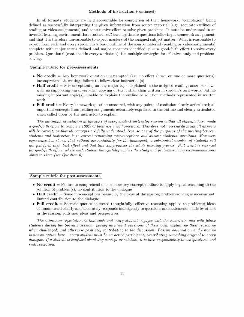
Sample rubric for pre-assessments
• No credit = Any homework question unattempted (i.e. no effort shown on one or more questions);incomprehensible writing; failure to follow clear instruction(s)
• Half credit = Misconception(s) on any major topic explained in the assigned reading; answers shownwith no supporting work; verbatim copying of text rather than written in student’s own words; outlinemissing important topic(s); unable to explain the outline or solution methods represented in writtenwork
• Full credit = Every homework question answered, with any points of confusion clearly articulated; allimportant concepts from reading assignments accurately expressed in the outline and clearly articulatedwhen called upon by the instructor to explain
The minimum expectation at the start of every student-instructor session is that all students have madea good-faith effort to complete 100% of their assigned homework. This does not necessarily mean all answerswill be correct, or that all concepts are fully understood, because one of the purposes of the meeting betweenstudents and instructor is to correct remaining misconceptions and answer students’ questions. However,experience has shown that without accountability for the homework, a substantial number of students willnot put forth their best effort and that this compromises the whole learning process. Full credit is reservedfor good-faith effort, where each student thoughtfully applies the study and problem-solving recommendationsgiven to them (see Question 0).
Sample rubric for post-assessments
• No credit = Failure to comprehend one or more key concepts; failure to apply logical reasoning to thesolution of problem(s); no contribution to the dialogue
• Half credit = Some misconceptions persist by the close of the session; problem-solving is inconsistent;limited contribution to the dialogue
• Full credit = Socratic queries answered thoughtfully; effective reasoning applied to problems; ideascommunicated clearly and accurately; responds intelligently to questions and statements made by othersin the session; adds new ideas and perspectives
The minimum expectation is that each and every student engages with the instructor and with fellowstudents during the Socratic session: posing intelligent questions of their own, explaining their reasoningwhen challenged, and otherwise positively contributing to the discussion. Passive observation and listeningis not an option here – every student must be an active participant, contributing something original to everydialogue. If a student is confused about any concept or solution, it is their responsibility to ask questions andseek resolution.
11
Methods of instruction (continued)
If a student happens to be absent for a scheduled class session and is therefore unable to be assessedon that day’s study, they may schedule a time with the instructor to demonstrate their comprehension atsome later date (before the end of the quarter when grades must be submitted). These same standards ofperformance apply equally make-up assessments: either inspection of homework or a closed-book quiz forthe pre-assessment, and either a Socratic dialogue with the instructor or another closed-book quiz for thepost-assessment.
Methods of instruction (continued)
Lab sessionsIn the lab portion of each course, students work in teams to install, configure, document, calibrate, and
troubleshoot working instrument loop systems. Each lab exercise focuses on a different type of instrument,with a limited time period typically for completion. An ordinary lab session might look like this:
(1) Start of practical (lab) session: announcements and planning(a) The instructor makes general announcements to all students(b) The instructor works with team to plan that day’s goals, making sure each team member has a
clear idea of what they should accomplish(2) Teams work on lab unit completion according to recommended schedule:
(First day) Select and bench-test instrument(s), complete prototype sketch of project(One day) Connect instrument(s) into a complete loop(One day) Each team member drafts their own loop documentation, inspection done as a team (withinstructor)(One or two days) Each team member calibrates/configures the instrument(s)(Remaining days, up to last) Each team member troubleshoots the instrument loop
(3) End of practical (lab) session: debriefing where each team reports on their work to the whole class
Troubleshooting assessments must meet the following guidelines:
• Troubleshooting must be performed on a system the student did not build themselves. This forcesstudents to rely on another team’s documentation rather than their own memory of how the system wasbuilt.
• Each student must individually demonstrate proper troubleshooting technique.• Simply finding the fault is not good enough. Each student must consistently demonstrate sound
reasoning while troubleshooting.• If a student fails to properly diagnose the system fault, they must attempt (as many times as necessary)
with different scenarios until they do, reviewing any mistakes with the instructor after each failedattempt.
file instructional
12

Distance delivery methods
Sometimes the demands of life prevent students from attending college 6 hours per day. In such cases,there exist alternatives to the normal 8:00 AM to 3:00 PM class/lab schedule, allowing students to completecoursework in non-traditional ways, at a “distance” from the college campus proper.
For such “distance” students, the same worksheets, lab activities, exams, and academic standards stillapply. Instead of working in small groups and in teams to complete theory and lab sections, though, studentsparticipating in an alternative fashion must do all the work themselves. Participation via teleconferencing,video- or audio-recorded small-group sessions, and such is encouraged and supported.
There is no recording of hours attended or tardiness for students participating in this manner. The paceof the course is likewise determined by the “distance” student. Experience has shown that it is a benefit for“distance” students to maintain the same pace as their on-campus classmates whenever possible.
In lieu of small-group activities and class discussions, comprehension of the theory portion of each coursewill be ensured by completing and submitting detailed answers for all worksheet questions, not just passingdaily quizzes as is the standard for conventional students. The instructor will discuss any incomplete and/orincorrect worksheet answers with the student, and ask that those questions be re-answered by the studentto correct any misunderstandings before moving on.
Labwork is perhaps the most difficult portion of the curriculum for a “distance” student to complete,since the equipment used in Instrumentation is typically too large and expensive to leave the school labfacility. “Distance” students must find a way to complete the required lab activities, either by arrangingtime in the school lab facility and/or completing activities on equivalent equipment outside of school (e.g.at their place of employment, if applicable). Labwork completed outside of school must be validated by asupervisor and/or documented via photograph or videorecording.
Conventional students may opt to switch to “distance” mode at any time. This has proven to be abenefit to students whose lives are disrupted by catastrophic events. Likewise, “distance” students mayswitch back to conventional mode if and when their schedules permit. Although the existence of alternativemodes of student participation is a great benefit for students with challenging schedules, it requires a greaterinvestment of time and a greater level of self-discipline than the traditional mode where the student attendsschool for 6 hours every day. No student should consider the “distance” mode of learning a way to havemore free time to themselves, because they will actually spend more time engaged in the coursework thanif they attend school on a regular schedule. It exists merely for the sake of those who cannot attend duringregular school hours, as an alternative to course withdrawal.
file distance
13
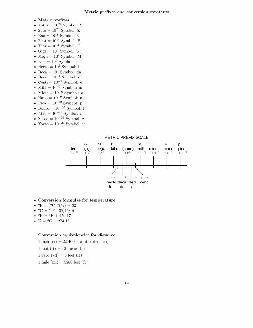
Metric prefixes and conversion constants
• Metric prefixes
• Yotta = 1024 Symbol: Y
• Zeta = 1021 Symbol: Z
• Exa = 1018 Symbol: E
• Peta = 1015 Symbol: P
• Tera = 1012 Symbol: T
• Giga = 109 Symbol: G
• Mega = 106 Symbol: M
• Kilo = 103 Symbol: k
• Hecto = 102 Symbol: h
• Deca = 101 Symbol: da
• Deci = 10−1 Symbol: d
• Centi = 10−2 Symbol: c
• Milli = 10−3 Symbol: m
• Micro = 10−6 Symbol: µ
• Nano = 10−9 Symbol: n
• Pico = 10−12 Symbol: p
• Femto = 10−15 Symbol: f
• Atto = 10−18 Symbol: a
• Zepto = 10−21 Symbol: z
• Yocto = 10−24 Symbol: y
1001031061091012 10-3 10-6 10-9 10-12(none)kilomegagigatera milli micro nano pico
kMGT m µ n p
10-210-1101102
deci centidecahectoh da d c
METRIC PREFIX SCALE
• Conversion formulae for temperature
• oF = (oC)(9/5) + 32
• oC = (oF - 32)(5/9)
• oR = oF + 459.67
• K = oC + 273.15
Conversion equivalencies for distance
1 inch (in) = 2.540000 centimeter (cm)
1 foot (ft) = 12 inches (in)
1 yard (yd) = 3 feet (ft)
1 mile (mi) = 5280 feet (ft)
14

Conversion equivalencies for volume
1 gallon (gal) = 231.0 cubic inches (in3) = 4 quarts (qt) = 8 pints (pt) = 128 fluid ounces (fl. oz.)= 3.7854 liters (l)
1 milliliter (ml) = 1 cubic centimeter (cm3)
Conversion equivalencies for velocity
1 mile per hour (mi/h) = 88 feet per minute (ft/m) = 1.46667 feet per second (ft/s) = 1.60934kilometer per hour (km/h) = 0.44704 meter per second (m/s) = 0.868976 knot (knot – international)
Conversion equivalencies for mass
1 pound (lbm) = 0.45359 kilogram (kg) = 0.031081 slugs
Conversion equivalencies for force
1 pound-force (lbf) = 4.44822 newton (N)
Conversion equivalencies for area
1 acre = 43560 square feet (ft2) = 4840 square yards (yd2) = 4046.86 square meters (m2)
Conversion equivalencies for common pressure units (either all gauge or all absolute)
1 pound per square inch (PSI) = 2.03602 inches of mercury (in. Hg) = 27.6799 inches of water (in.W.C.) = 6.894757 kilo-pascals (kPa) = 0.06894757 bar
1 bar = 100 kilo-pascals (kPa) = 14.504 pounds per square inch (PSI)
Conversion equivalencies for absolute pressure units (only)
1 atmosphere (Atm) = 14.7 pounds per square inch absolute (PSIA) = 101.325 kilo-pascals absolute(kPaA) = 1.01325 bar (bar) = 760 millimeters of mercury absolute (mmHgA) = 760 torr (torr)
Conversion equivalencies for energy or work
1 british thermal unit (Btu – “International Table”) = 251.996 calories (cal – “International Table”)= 1055.06 joules (J) = 1055.06 watt-seconds (W-s) = 0.293071 watt-hour (W-hr) = 1.05506 x 10¹⁰
ergs (erg) = 778.169 foot-pound-force (ft-lbf)
Conversion equivalencies for power
1 horsepower (hp – 550 ft-lbf/s) = 745.7 watts (W) = 2544.43 british thermal units per hour(Btu/hr) = 0.0760181 boiler horsepower (hp – boiler)
Acceleration of gravity (free fall), Earth standard
9.806650 meters per second per second (m/s2) = 32.1740 feet per second per second (ft/s2)
15

Physical constants
Speed of light in a vacuum (c) = 2.9979 × 10⁸ meters per second (m/s) = 186,281 miles per second(mi/s)
Avogadro’s number (NA) = 6.022 × 10²³ per mole (mol−1)
Electronic charge (e) = 1.602 × 10⁻¹⁹ Coulomb (C)
Boltzmann’s constant (k) = 1.38 × 10⁻²³ Joules per Kelvin (J/K)
Stefan-Boltzmann constant (σ) = 5.67 × 10⁻⁸ Watts per square meter-Kelvin4 (W/m2·K4)
Molar gas constant (R) = 8.314 Joules per mole-Kelvin (J/mol-K)
Properties of Water
Freezing point at sea level = 32oF = 0oC
Boiling point at sea level = 212oF = 100oC
Density of water at 4oC = 1000 kg/m3 = 1 g/cm3 = 1 kg/liter = 62.428 lb/ft3 = 1.94 slugs/ft3
Specific heat of water at 14oC = 1.00002 calories/g·oC = 1 BTU/lb·oF = 4.1869 Joules/g·oC
Specific heat of ice ≈ 0.5 calories/g·oC
Specific heat of steam ≈ 0.48 calories/g·oC
Absolute viscosity of water at 20oC = 1.0019 centipoise (cp) = 0.0010019 Pascal-seconds (Pa·s)
Surface tension of water (in contact with air) at 18oC = 73.05 dynes/cm
pH of pure water at 25o C = 7.0 (pH scale = 0 to 14)
Properties of Dry Air at sea level
Density of dry air at 20oC and 760 torr = 1.204 mg/cm3 = 1.204 kg/m3 = 0.075 lb/ft3 = 0.00235slugs/ft3
Absolute viscosity of dry air at 20oC and 760 torr = 0.018 centipoise (cp) = 1.8 × 10⁻⁵ Pascal-seconds (Pa·s)
file conversion constants
16
Question 0
How to get the most out of academic reading:• Outline, don’t highlight! Identify every major idea presented in the text, and express these ideas in your
own words. A suggested ratio is one sentence of your own thoughts per paragraph of text read.
• Articulate your thoughts as you read (i.e. “have a conversation” with the author). This will developmetacognition: active supervision of your own thoughts. Note points of agreement, disagreement,confusion, epiphanies, and connections between different concepts or applications.
• Work through all mathematical exercises shown within the text, to ensure you understand all the steps.
• Imagine explaining concepts you’ve just learned to someone else. Teaching forces you to distill conceptsto their essence, thereby clarifying those concepts, revealing assumptions, and exposing misconceptions.Your goal is to create the simplest explanation that is still technically accurate.
• Create your own questions based on what you read, as a teacher would to challenge students.
How to effectively problem-solve and troubleshoot:• Rely on principles, not procedures. Don’t be satisfied with memorizing steps – learn why those steps
work. Each step should make logical sense and have real-world meaning to you.
• Sketch a diagram to help visualize the problem. Sketch a graph showing how variables relate. Whenbuilding a real system, always prototype it on paper and analyze its function before constructing it.
• Identify what it is you need to solve, identify all relevant data, identify all units of measurement, identifyany general principles or formulae linking the given information to the solution, and then identify any“missing pieces” to a solution. Annotate all diagrams with this data.
• Perform “thought experiments” to explore the effects of different conditions for theoretical problems.When troubleshooting, perform diagnostic tests rather than just visually inspect for faults.
• Simplify the problem and solve that simplified problem to identify strategies applicable to the originalproblem (e.g. change quantitative to qualitative, or visa-versa; substitute easier numerical values;eliminate confusing details; add details to eliminate unknowns; consider simple limiting cases; applyan analogy). Remove components from a malfunctioning system to simplify it and better identify thenature and location of the problem.
• Check for exceptions – does your solution work for all conditions and criteria?
• Work “backward” from a hypothetical solution to a new set of given conditions.
How to manage your time:• Avoid procrastination. Work now and play later, every single day.
• Consider the place you’re in when deciding what to do. If there is project work to do and you haveaccess to the lab, do that work and not something that could be done elsewhere (e.g. homework).
• Eliminate distractions. Kill your television and video games. Turn off your mobile phone, or just leaveit at home. Study in places where you can concentrate, like the Library.
• Use your “in between” time productively. Don’t leave campus for lunch. Arrive to school early. If youfinish your assigned work early, begin working on the next assignment.
Above all, cultivate persistence, as this is necessary to master anything non-trivial. The keys topersistence are (1) having the desire to achieve that mastery, and (2) realizing challenges are normal andnot an indication of something gone wrong. A common error is to equate easy with effective: students oftenbelieve learning should be easy if everything is done right. The truth is that mastery never comes easy!
file question0
17
Checklist when reading an instructional text
“Reading maketh a full man; conference a ready man; and writing an exact man” – Francis Bacon
Francis Bacon’s advice is a blueprint for effective education: reading provides the learner with knowledge,writing focuses the learner’s thoughts, and critical dialogue equips the learner to confidently communicateand apply their learning. Independent acquisition and application of knowledge is a powerful skill, well worththe effort to cultivate. To this end, students should read these educational resources closely, write their ownoutline and reflections on the reading, and discuss in detail their findings with classmates and instructor(s).You should be able to do all of the following after reading any instructional text:
√Briefly OUTLINE THE TEXT, as though you were writing a detailed Table of Contents. Feel free
to rearrange the order if it makes more sense that way. Prepare to articulate these points in detail andto answer questions from your classmates and instructor. Outlining is a good self-test of thorough readingbecause you cannot outline what you have not read or do not comprehend.
√Demonstrate ACTIVE READING STRATEGIES, including verbalizing your impressions as you read,
simplifying long passages to convey the same ideas using fewer words, annotating text and illustrationswith your own interpretations, working through mathematical examples shown in the text, cross-referencingpassages with relevant illustrations and/or other passages, identifying problem-solving strategies appliedby the author, etc. Technical reading is a special case of problem-solving, and so these strategies workprecisely because they help solve any problem: paying attention to your own thoughts (metacognition),eliminating unnecessary complexities, identifying what makes sense, paying close attention to details, drawingconnections between separated facts, and noting the successful strategies of others.
√Identify IMPORTANT THEMES, especially GENERAL LAWS and PRINCIPLES, expounded in the
text and express them in the simplest of terms as though you were teaching an intelligent child. Thisemphasizes connections between related topics and develops your ability to communicate complex ideas toanyone.
√Form YOUR OWN QUESTIONS based on the reading, and then pose them to your instructor and
classmates for their consideration. Anticipate both correct and incorrect answers, the incorrect answer(s)assuming one or more plausible misconceptions. This helps you view the subject from different perspectivesto grasp it more fully.
√Devise EXPERIMENTS to test claims presented in the reading, or to disprove misconceptions. Predict
possible outcomes of these experiments, and evaluate their meanings: what result(s) would confirm, and whatwould constitute disproof? Running mental simulations and evaluating results is essential to scientific anddiagnostic reasoning.
√Specifically identify any points you found CONFUSING. The reason for doing this is to help diagnose
misconceptions and overcome barriers to learning.
18
General challenges following a tutorial reading assignment
• Summarize as much of the text as you can in one paragraph of your own words. A helpful strategy isto explain ideas as you would for an intelligent child: as simple as you can without compromising toomuch accuracy.
• Simplify a particular section of the text, for example a paragraph or even a single sentence, so as tocapture the same fundamental idea in fewer words.
• Where did the text make the most sense to you? What was it about the text’s presentation that madeit clear?
• Identify where it might be easy for someone to misunderstand the text, and explain why you think itcould be confusing.
• Identify any new concept(s) presented in the text, and explain in your own words.
• Identify any familiar concept(s) such as physical laws or principles applied or referenced in the text.
• Devise a proof of concept experiment demonstrating an important principle, physical law, or technicalinnovation represented in the text.
• Devise an experiment to disprove a plausible misconception.
• Did the text reveal any misconceptions you might have harbored? If so, describe the misconception(s)and the reason(s) why you now know them to be incorrect.
• Describe any useful problem-solving strategies applied in the text.
• Devise a question of your own to challenge a reader’s comprehension of the text.
General follow-up challenges for assigned problems
• Identify where any fundamental laws or principles apply to the solution of this problem.
• Describe in detail your own strategy for solving this problem. How did you identify and organized thegiven information? Did you sketch any diagrams to help frame the problem?
• Is there more than one way to solve this problem? Which method seems best to you?
• Show the work you did in solving this problem, even if the solution is incomplete or incorrect.
• What would you say was the most challenging part of this problem, and why was it so?
• Was any important information missing from the problem which you had to research or recall?
• Was there any extraneous information presented within this problem? If so, what was it and why didit not matter?
• Examine someone else’s solution to identify where they applied fundamental laws or principles.
• Simplify the problem from its given form and show how to solve this simpler version of it. Examplesinclude eliminating certain variables or conditions, altering values to simpler (usually whole) numbers,applying a limiting case (i.e. altering a variable to some extreme or ultimate value).
• For quantitative problems, identify the real-world meaning of all intermediate calculations: their unitsof measurement, where they fit into the scenario at hand.
• For quantitative problems, try approaching it qualitatively instead, thinking in terms of “increase” and“decrease” rather than definite values.
• For qualitative problems, try approaching it quantitatively instead, proposing simple numerical valuesfor the variables.
• Were there any assumptions you made while solving this problem? Would your solution change if oneof those assumptions were altered?
• Identify where it would be easy for someone to go astray in attempting to solve this problem.
• Formulate your own problem based on what you learned solving this one.
19

Creative Commons License
This worksheet is licensed under the Creative Commons Attribution 4.0 International PublicLicense. To view a copy of this license, visit http://creativecommons.org/licenses/by/4.0/ or send aletter to Creative Commons, 171 Second Street, Suite 300, San Francisco, California 94105, USA. The termsand conditions of this license allow for free copying, distribution, and/or modification of all licensed worksby the general public.
Simple explanation of Attribution License:
The licensor (Tony Kuphaldt) permits others to copy, distribute, display, and otherwise use thiswork. In return, licensees must give the original author(s) credit. For the full license text, please visithttp://creativecommons.org/licenses/by/4.0/ on the internet.
More detailed explanation of Attribution License:
Under the terms and conditions of the Creative Commons Attribution License, you may make freelyuse, make copies, and even modify these worksheets (and the individual “source” files comprising them)without having to ask me (the author and licensor) for permission. The one thing you must do is properlycredit my original authorship. Basically, this protects my efforts against plagiarism without hindering theend-user as would normally be the case under full copyright protection. This gives educators a great dealof freedom in how they might adapt my learning materials to their unique needs, removing all financial andlegal barriers which would normally hinder if not prevent creative use.
Nothing in the License prohibits the sale of original or adapted materials by others. You are free tocopy what I have created, modify them if you please (or not), and then sell them at any price. Once again,the only catch is that you must give proper credit to myself as the original author and licensor. Given thatthese worksheets will be continually made available on the internet for free download, though, few peoplewill pay for what you are selling unless you have somehow added value.
Nothing in the License prohibits the application of a more restrictive license (or no license at all) toderivative works. This means you can add your own content to that which I have made, and then exercisefull copyright restriction over the new (derivative) work, choosing not to release your additions under thesame free and open terms. An example of where you might wish to do this is if you are a teacher who desiresto add a detailed “answer key” for your own benefit but not to make this answer key available to anyoneelse (e.g. students).
Note: the text on this page is not a license. It is simply a handy reference for understanding the LegalCode (the full license) - it is a human-readable expression of some of its key terms. Think of it as theuser-friendly interface to the Legal Code beneath. This simple explanation itself has no legal value, and itscontents do not appear in the actual license.
file license
20
Questions
Question 1
Read and outline the introduction to the “Chemistry” chapter in your Lessons In IndustrialInstrumentation textbook.
After closely reading and outlining a text, you should be ready to share the following with your classmatesand instructor:
(1) Your written summary of all major points of the text, expressed as simply as possible in your own words.A “Table of Contents” format works well for this.
(2) Active helpful reading strategies (e.g. verbalizing your thoughts as you read, simplifying longsentences, working through mathematical examples, cross-referencing text with illustrations or othertext, identifying the author’s problem-solving strategies, etc.).
(3) General principles, especially physical laws, referenced in the text.(4) Questions of your own you would pose to another reader, to challenge their understanding.(5) Ideas for experiments that could be used to either demonstrate some concept applied in the text, or
disprove a related misconception.(6) Any points of confusion, and precisely why you found the text confusing.
file i04090
Question 2
Read and outline the “Atomic Theory and Chemical Symbols” section of the “Chemistry” chapter inyour Lessons In Industrial Instrumentation textbook.
After closely reading and outlining a text, you should be ready to share the following with your classmatesand instructor:
(1) Your written summary of all major points of the text, expressed as simply as possible in your own words.A “Table of Contents” format works well for this.
(2) Active helpful reading strategies (e.g. verbalizing your thoughts as you read, simplifying longsentences, working through mathematical examples, cross-referencing text with illustrations or othertext, identifying the author’s problem-solving strategies, etc.).
(3) General principles, especially physical laws, referenced in the text.(4) Questions of your own you would pose to another reader, to challenge their understanding.(5) Ideas for experiments that could be used to either demonstrate some concept applied in the text, or
disprove a related misconception.(6) Any points of confusion, and precisely why you found the text confusing.
file i04091
21
Question 3
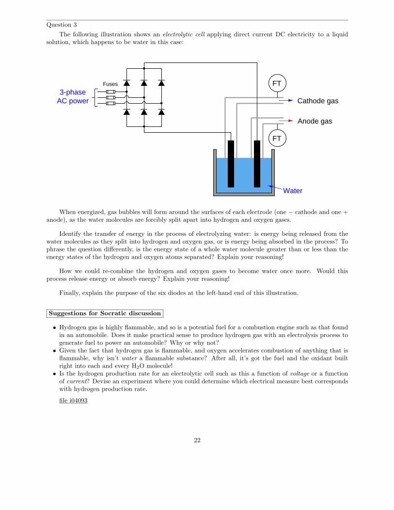
The following illustration shows an electrolytic cell applying direct current DC electricity to a liquidsolution, which happens to be water in this case:
3-phaseAC power
Fuses
Cathode gas
Anode gas
Water
FT
FT
When energized, gas bubbles will form around the surfaces of each electrode (one − cathode and one +anode), as the water molecules are forcibly split apart into hydrogen and oxygen gases.
Identify the transfer of energy in the process of electrolyzing water: is energy being released from thewater molecules as they split into hydrogen and oxygen gas, or is energy being absorbed in the process? Tophrase the question differently, is the energy state of a whole water molecule greater than or less than theenergy states of the hydrogen and oxygen atoms separated? Explain your reasoning!
How we could re-combine the hydrogen and oxygen gases to become water once more. Would thisprocess release energy or absorb energy? Explain your reasoning!
Finally, explain the purpose of the six diodes at the left-hand end of this illustration.
Suggestions for Socratic discussion
• Hydrogen gas is highly flammable, and so is a potential fuel for a combustion engine such as that foundin an automobile. Does it make practical sense to produce hydrogen gas with an electrolysis process togenerate fuel to power an automobile? Why or why not?
• Given the fact that hydrogen gas is flammable, and oxygen accelerates combustion of anything that isflammable, why isn’t water a flammable substance? After all, it’s got the fuel and the oxidant builtright into each and every H2O molecule!
• Is the hydrogen production rate for an electrolytic cell such as this a function of voltage or a functionof current? Devise an experiment where you could determine which electrical measure best correspondswith hydrogen production rate.
file i04093
22
Question 4
When an internal combustion engine starts up cold, water may be seen coming out of the exhaust pipe,at least until the exhaust pipes become hot enough to vaporize the water so you can’t see it anymore. Explainwhy water is a byproduct of any hydrocarbon fuel (e.g. gasoline or diesel) combustion, based on principlesof chemistry.
When coal is partially combusted (i.e. burned in a low-oxygen environment), one of the byproduct gasesis the flammable and toxic gas carbon monoxide (CO). This is also one of the major products of biomassgasification, where carbon-containing biomass fuels are heated in low-oxygen environments. Explain why anengine running on carbon monoxide gas as a fuel will not produce water as a byproduct of combustion.
Suggestions for Socratic discussion
• Is it possible to eliminate water from the exhaust gases of a car’s engine operating on gasoline?• Identify how we may identify fuels producing water vapor when burned, strictly by examining their
chemical formulae.• Identify how we may identify fuels which inherently produce no water vapor when burned, strictly by
examining their chemical formulae.
file i03001
Question 5
A common concern in industrial maintenance work is confined spaces. Research the definition of a“confined space” and explain the potential hazards of working in confined spaces, particularly from theperspective of chemistry.
Next, visit the website of a company selling personal safety gas monitors used by workers in confinedspaces and other industrial sites where certain toxic gases may be present. Identify some of the commonchemical compounds measured by these portable instruments, and also the relative costs of the sensors foreach compound.
file i00580
23

Question 6
Read the “Carbon dioxide” entry in the NIOSH Pocket Guide To Chemical Hazards (DHHS publicationnumber 2005-149) and answer the following questions:
Write the chemical formula for carbon dioxide gas, and identify its constituent elements.
Determine whether or not carbon dioxide is flammable.
Determine whether carbon dioxide gas is lighter than air or denser than air, based on the relative density(RGasD) figure provided in the NIOSH guide.
Identify some of the symptoms of excessive carbon dioxide exposure, and the “target organs” of thebody it affects.
Identify the type(s) of respirator equipment necessary for protection against high carbon dioxideconcentrations.
Suggestions for Socratic discussion
• Identify what “LEL” and “UEL” refer to, and how these parameters are useful for identifying acompound’s flammability.
• Sketch a displayed formula for carbon dioxide.• Explain the specific hazards carbon dioxide might pose to people working in a confined space where
ventilation is limited.• Identify common sources of carbon dioxide gas in the home or workplace.• Describe a general principle for determining proper respirator equipment: specifically whether filtration
is sufficient or supplied air is necessary.
file i04095
24
Question 7
Read the “Carbon monoxide” entry in the NIOSH Pocket Guide To Chemical Hazards (DHHSpublication number 2005-149) and answer the following questions:
Write the chemical formula for carbon monoxide gas, and identify its constituent elements.
Determine whether or not carbon monoxide is flammable.
Identify the relative density (RGasD) of carbon monoxide, then determine whether this is lighter thanair or heavier than air.
Identify some of the symptoms of excessive carbon monoxide exposure, and the “target organs” of thebody it affects.
Identify the type(s) of respirator equipment necessary for protection against high carbon monoxideconcentrations.
Identify how similar carbon monoxide is to carbon dioxide in its physical properties and effects on thehuman body.
Suggestions for Socratic discussion
• Identify what “LEL” and “UEL” refer to, and how these parameters are useful for identifying acompound’s flammability.
• Sketch a displayed formula for carbon monoxide.• Carbon monoxide molecules are similar to carbon dioxide molecules in their composition, but have
very different chemical and physical properties. Identify one property in which carbon monoxide differssubstantially from carbon dioxide, and try to explain why this is based on the differences in atomscontained within the two molecules.
• Identify some of the specific hazards carbon monoxide might pose to people working in a confined spacewhere ventilation is limited.
• Identify common sources of carbon monoxide gas in the home or workplace.• When carbon monoxide gas combusts (burns) with oxygen, what type of molecule is produced as a
result of that combustion?• Describe a general principle for determining proper respirator equipment: specifically whether filtration
is sufficient or supplied air is necessary.
file i04096
25

Question 8
Read the “Hydrogen sulfide” entry in the NIOSH Pocket Guide To Chemical Hazards (DHHS publicationnumber 2005-149) and answer the following questions:
Write the chemical formula for hydrogen sulfide gas, and identify its constituent elements.
Hydrogen sulfide is a byproduct of petroleum oil refining, and also of anaerobic bacterial decompositionof organic matter (e.g. municipal wastewater and wood pulp production). Identify the NIOSH recommendedexposure limit (REL) and the OSHA Permissible Exposure Limit (PEL) values for this gas.
Determine whether hydrogen sulfide gas is lighter than air or denser than air, based on the relativedensity (RGasD) figure provided in the NIOSH guide.
Identify the type(s) of respirator equipment necessary for protection against high hydrogen sulfideconcentrations.
Suggestions for Socratic discussion
• Identify what “LEL” and “UEL” refer to, and how these parameters are useful for identifying acompound’s flammability.
• Sketch a displayed formula for hydrogen sulfide.• Explain the specific hazards hydrogen sulfide might pose to people working in a confined space where
ventilation is limited.• Identify common sources of hydrogen sulfide gas in the home or workplace.• When hydrogen sulfide gas combusts (burns) with oxygen, what types of molecules are produced as a
result of that combustion?• Describe a general principle for determining proper respirator equipment: specifically whether filtration
is sufficient or supplied air is necessary.• A common unit of measurement for airborne chemical concentration of substances such as hydrogen
sulfide is “parts per million” or ppm. Explain in your own words what “ppm” means.
file i04094
Question 9
An important type of document used in industry is Safety Data Sheet or SDS. Various SDS databasesare available on the internet, although many of them are not free. Locate and list some of the URL’s forSDS databases.
Next, identify the type of information provided by a typical SDS, and how this information compareswith that found in the NIOSH Pocket Guide to Chemical Hazards.
file i00581
26
Question 10
Classify the following substances as particle, atom, element, molecule, compound, and/or mixture. Notethat some of these substances might be properly described by more than one classification:
• One gram of perfectly pure water• A proton• Oxygen• Carbon dioxide (CO2)• A quark• Gasoline• Air• Plutonium
Suggestions for Socratic discussion
• Why do we care about these labels? What practical importance is there, for example, in knowingwhether carbon dioxide is an element or a compound?
file i00551
Question 11
The three “elementary” constituent particles of atoms are called protons, neutrons, and electrons.Classify these three particle types according to their locations within an atom, their electrical charge, andtheir relative masses.
Furthermore, describe the effects that the number of protons, neutrons, and electrons have on thecharacteristics of an atom.
file i00552
Question 12
How many electrons, protons, and neutrons does a single atom of Carbon-12 (12C) contain? (Assumean electrically balanced atom.)
How many electrons, protons, and neutrons does the average atom of gold (Au) contain? (Assume anelectrically balanced atom.)
file i00553
Question 13
Hundreds of years ago, people known by the title of alchemists attempted to convert one type of elementinto another, most notably lead (Pb) into gold (Au). Their efforts failed miserably. Explain why!
What, specifically, would be necessary to convert an atom of lead into an atom of gold?file i00554
Question 14
What is the difference between these two notations: H2 and 2H?file i00555
27
Question 15
In 1808, an English schoolteacher named John Dalton published several postulates regarding substances,representing the state-of-the-art of atomic theory at that time:
• An element is composed of extremely small indivisible particles called atoms.• All atoms of a given element have identical properties, which differ from those of other elements.• Atoms cannot be created, destroyed, or transformed into atoms of another element.• Compounds are formed when atoms of different elements combine with each other in small whole-number
ratios.• The relative numbers and kinds of atoms are constant in a given compound.
Determine whether or not these postulates are still in agreement with modern atomic theory, and statethe nature of any deviations you discern.
file i00556
Question 16
Define the following chemical terms: solution, solute, and solvent.file i00557
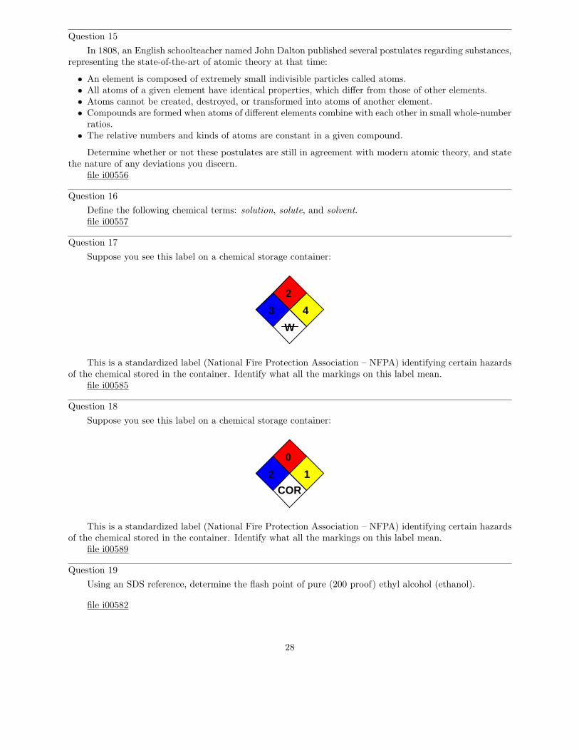
Question 17
Suppose you see this label on a chemical storage container:
3
2
4
W
This is a standardized label (National Fire Protection Association – NFPA) identifying certain hazardsof the chemical stored in the container. Identify what all the markings on this label mean.
file i00585
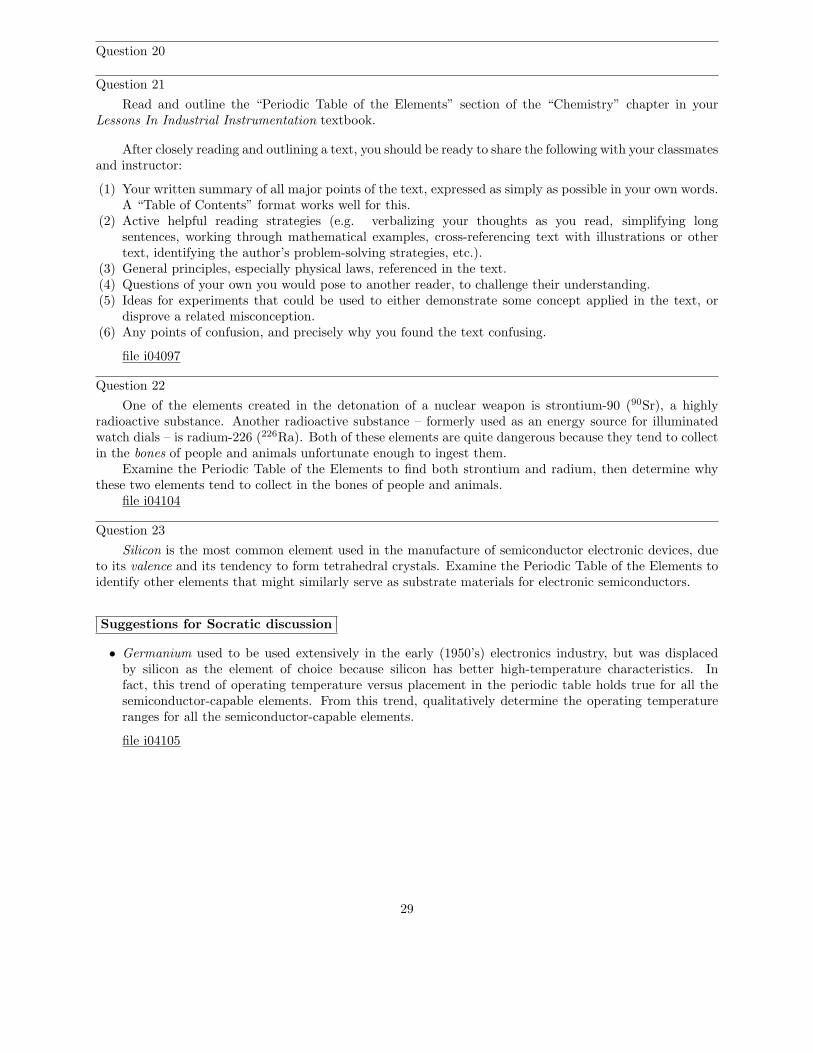
Question 18
Suppose you see this label on a chemical storage container:
COR
2
0
1
This is a standardized label (National Fire Protection Association – NFPA) identifying certain hazardsof the chemical stored in the container. Identify what all the markings on this label mean.
file i00589
Question 19
Using an SDS reference, determine the flash point of pure (200 proof) ethyl alcohol (ethanol).
file i00582
28
Question 20
Question 21
Read and outline the “Periodic Table of the Elements” section of the “Chemistry” chapter in yourLessons In Industrial Instrumentation textbook.
After closely reading and outlining a text, you should be ready to share the following with your classmatesand instructor:
(1) Your written summary of all major points of the text, expressed as simply as possible in your own words.A “Table of Contents” format works well for this.
(2) Active helpful reading strategies (e.g. verbalizing your thoughts as you read, simplifying longsentences, working through mathematical examples, cross-referencing text with illustrations or othertext, identifying the author’s problem-solving strategies, etc.).
(3) General principles, especially physical laws, referenced in the text.(4) Questions of your own you would pose to another reader, to challenge their understanding.(5) Ideas for experiments that could be used to either demonstrate some concept applied in the text, or
disprove a related misconception.(6) Any points of confusion, and precisely why you found the text confusing.
file i04097
Question 22
One of the elements created in the detonation of a nuclear weapon is strontium-90 (90Sr), a highlyradioactive substance. Another radioactive substance – formerly used as an energy source for illuminatedwatch dials – is radium-226 (226Ra). Both of these elements are quite dangerous because they tend to collectin the bones of people and animals unfortunate enough to ingest them.
Examine the Periodic Table of the Elements to find both strontium and radium, then determine whythese two elements tend to collect in the bones of people and animals.
file i04104
Question 23
Silicon is the most common element used in the manufacture of semiconductor electronic devices, dueto its valence and its tendency to form tetrahedral crystals. Examine the Periodic Table of the Elements toidentify other elements that might similarly serve as substrate materials for electronic semiconductors.
Suggestions for Socratic discussion
• Germanium used to be used extensively in the early (1950’s) electronics industry, but was displacedby silicon as the element of choice because silicon has better high-temperature characteristics. Infact, this trend of operating temperature versus placement in the periodic table holds true for all thesemiconductor-capable elements. From this trend, qualitatively determine the operating temperatureranges for all the semiconductor-capable elements.
file i04105
29

Question 24
Read and outline the “Electronic Structure” section of the “Chemistry” chapter in your Lessons InIndustrial Instrumentation textbook.
After closely reading and outlining a text, you should be ready to share the following with your classmatesand instructor:
(1) Your written summary of all major points of the text, expressed as simply as possible in your own words.A “Table of Contents” format works well for this.
(2) Active helpful reading strategies (e.g. verbalizing your thoughts as you read, simplifying longsentences, working through mathematical examples, cross-referencing text with illustrations or othertext, identifying the author’s problem-solving strategies, etc.).
(3) General principles, especially physical laws, referenced in the text.(4) Questions of your own you would pose to another reader, to challenge their understanding.(5) Ideas for experiments that could be used to either demonstrate some concept applied in the text, or
disprove a related misconception.(6) Any points of confusion, and precisely why you found the text confusing.
file i04099
30

Question 25
An interesting way to denote the spectroscopic electron shell structure of elements is shown here:
Element Electron configurationHydrogen 1s1
Helium 1s2
Lithium [He]2s1
Beryllium [He]2s2
Boron [He]2s22p1
Carbon [He]2s22p2
Nitrogen [He]2s22p3
Oxygen [He]2s22p4
Fluorine [He]2s22p5
Neon [He]2s22p6
Sodium [Ne]3s1
Magnesium [Ne]3s2
Aluminum [Ne]3s23p1
Silicon [Ne]3s23p2
Phosphorus [Ne]3s23p3
Sulfur [Ne]3s23p4
Chlorine [Ne]3s23p5
Argon [Ne]3s23p6
Potassium [Ar]4s1
Explain how this notation condenses what is otherwise a very lengthy and unwieldy format (showingall shells in each atom), without omitting any crucial information.
Suggestions for Socratic discussion
• The bracketed element name is sometimes referred to as an “electron core” in spectroscopic notation.Explain why this label makes sense.
• Examine this table of electron notations, and identify the “periods” (intervals) comprising each row ina periodic table.
• Identify elements in this table which are the easiest to positively ionize (i.e. remove one electron from).• Identify elements in this table which are the easiest to negatively ionize (i.e. add one electron to).
file i00562
31
Question 26
Read and outline the “Spectroscopy” section of the “Chemistry” chapter in your Lessons In IndustrialInstrumentation textbook.
After closely reading and outlining a text, you should be ready to share the following with your classmatesand instructor:
(1) Your written summary of all major points of the text, expressed as simply as possible in your own words.A “Table of Contents” format works well for this.
(2) Active helpful reading strategies (e.g. verbalizing your thoughts as you read, simplifying longsentences, working through mathematical examples, cross-referencing text with illustrations or othertext, identifying the author’s problem-solving strategies, etc.).
(3) General principles, especially physical laws, referenced in the text.(4) Questions of your own you would pose to another reader, to challenge their understanding.(5) Ideas for experiments that could be used to either demonstrate some concept applied in the text, or
disprove a related misconception.(6) Any points of confusion, and precisely why you found the text confusing.
file i04101
Question 27
Bring a Compact Disk (CD) or a Digital Video Disk (DVD) to class and use the reflective surface asa reflection grating to display the spectrum of visible light sources (point-sources such as small light bulbswork best!). You may have to experiment with the angles you hold the disk in order to easily see differentspectra, but with practice you should be able to quickly locate the spectrum from any point-source of light.Safety note: DO NOT ATTEMPT TO VIEW SUNLIGHT OR LASER LIGHT IN THIS WAY, AS YOUMAY EASILY HURT YOUR EYES!
View the spectrum from several different point-light sources and note how those spectra are similar andhow they are different from each other:
• Incandescent light bulb
• Compact fluorescent light bulb
• “White” LED (light emitting diode)
• Colored LED (light emitting diode)
• Neon lamp
Identify which of these spectra appears to be the most “continuous” through all the colors, and whichappear the most “broken.” Explain what each spectrum reveals about the chemical nature of each lightsource.
Suggestions for Socratic discussion
• Astronomers use this basic principle (not actually using CDs, of course!) to analyze the chemicalcomposition of stars. Explain how this would work – what exactly would an astronomer look for in thespectrum of light received from a star?
file i04102
32
Question 28
One of the concerns surrounding depletion of Earth’s ozone layer in the upper atmosphere is its effecton ultraviolet light from the sun. Ozone is a triple-oxygen molecule (O3) with some unique chemicalcharacteristics different from regular molecular oxygen (O2). The more the ozone layer depletes, the moreultraviolet light reaches us on the ground.
Based on your knowledge of spectroscopy, would you classify this relationship between the ozone layerand “UV” light as an example of optical emission or optical absorption?
Suggestions for Socratic discussion
• Explain why ozone molecules (O3) exhibit this interaction with ultraviolet light, but regular oxygenmolecules (O2) do not.
• Describe how an ozone-sensing instrument might be constructed based on this principle of UV lightabsorption. Identify ways in which such an instrument might be “fooled” into giving false readings ofozone gas where none is present.
• Suppose a glass tube containing ozone gas were electrically stimulated by the application of high voltagebetween two electrodes within that tube. What sort of light might be emitted by that tube when theelectricity is applied?
file i04103
Question 29
Determine the number of protons and neutrons in the nucleus of one atom for each of the followingelements:
• 195Pt (Platinum-195) – Protons = ; Neutrons =
• 75As (Arsenic-75) – Protons = ; Neutrons =
• 235U (Uranium-235) – Protons = ; Neutrons =
• 40Ca (Calcium-40) – Protons = ; Neutrons =
Suggestions for Socratic discussion
• Which of these particle quantities defines the element?• What would be required to transmute one element into another, say lead into gold?• Breaking and creating new chemical bonds involves far lower energy levels than transmutating one
element into another. Explain what this fact tells us about the binding force of electrons to the nucleusof an atom versus the binding force between protons and neutrons within the nucleus of an atom.
• Explain what an isotope is, and how isotope identities relate to these particle numbers in an atomicnucleus.
file i04098
Question 30
Explain what the following notation means: 1s22s22p63s23p1
Define the word “orbital” as it applies to atomic electrons.file i04100
33
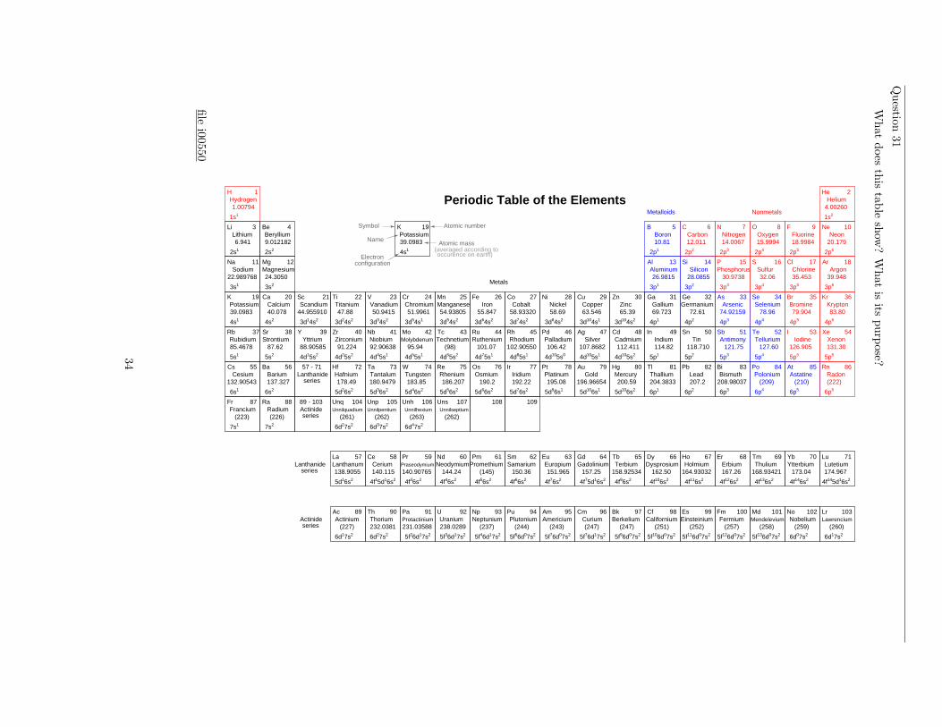
Question
31
What
does
this
table
show
?W
hat
isits
purp
ose?
PotassiumK 19
39.0983
4s1
CalciumCa 20
4s2
NaSodium
11
3s1
MagnesiumMg 12
3s2
H 1Hydrogen
1s1
LiLithium6.941
3
2s1
BerylliumBe 4
2s2
Sc 21Scandium
3d14s2
Ti 22Titanium
3d24s2
V 23Vanadium50.9415
3d34s2
Cr 24Chromium
3d54s1
Mn 25Manganese
3d54s2
Fe 26Iron
55.847
3d64s2
Co 27Cobalt
3d74s2
Ni 28Nickel
3d84s2
Cu 29Copper63.546
3d104s1
Zn 30Zinc
3d104s2
Ga 31Gallium
4p1
B 5Boron10.81
2p1
C 6Carbon12.011
2p2
N 7Nitrogen14.0067
2p3
O 8Oxygen15.9994
2p4
F 9Fluorine18.9984
2p5
He 2Helium
4.00260
1s2
Ne 10Neon
20.179
2p6
Ar 18Argon
39.948
3p6
Kr 36Krypton83.80
4p6
Xe 54Xenon131.30
5p6
Rn 86Radon(222)
6p6
KPotassium
19
39.0983
4s1
Symbol Atomic number
NameAtomic mass
Electronconfiguration Al 13
Aluminum26.9815
3p1
Si 14Silicon
28.0855
3p2
P 15Phosphorus
30.9738
3p3
S 16Sulfur32.06
3p4
Cl 17Chlorine35.453
3p5
Periodic Table of the Elements
Germanium
4p2
Ge 32 AsArsenic
33
4p3
SeSelenium
34
78.96
4p4
BrBromine
35
79.904
4p5
IIodine
53
126.905
5p5
Rubidium37
85.4678
5s1
SrStrontium
38
87.62
5s2
YttriumY 39
4d15s2
Zr 40Zirconium91.224
4d25s2
Nb 41Niobium92.90638
4d45s1
Mo 42Molybdenum
95.94
4d55s1
Tc 43Technetium
(98)
4d55s2
Ru 44Ruthenium
101.07
4d75s1
Rh 45Rhodium
4d85s1
Pd 46Palladium106.42
4d105s0
Ag 47Silver
107.8682
4d105s1
Cd 48Cadmium112.411
4d105s2
In 49Indium114.82
5p1
Sn 50Tin
118.710
5p2
Sb 51Antimony
121.75
5p3
Te 52Tellurium
127.60
5p4
Po 84Polonium
(209)
6p4
AtAstatine
85
(210)
6p5
Metals
Metalloids Nonmetals
Rb
Cs 55Cesium
132.90543
6s1
Ba 56Barium137.327
6s2
57 - 71Lanthanide
series
Hf 72Hafnium178.49
5d26s2
TaTantalum
73
180.9479
5d36s2
W 74Tungsten183.85
5d46s2
Re 75Rhenium186.207
5d56s2
Os 76Osmium
190.2
5d66s2
Ir 77
192.22Iridium
5d76s2
Pt 78Platinum195.08
5d96s1
AuGold
79
196.96654
5d106s1
Hg 80Mercury200.59
5d106s2
Tl 81Thallium204.3833
6p1
PbLead
82
207.2
6p2
BiBismuth
83
208.98037
6p3
Lanthanideseries
Fr 87Francium
(223)
7s1
Ra 88Radium(226)
7s2
89 - 103Actinideseries
Actinideseries
104UnqUnnilquadium
(261)
6d27s2
Unp 105Unnilpentium
(262)
6d37s2
Unh 106Unnilhexium
(263)
6d47s2
Uns 107Unnilseptium
(262)
108 109
1.00794
9.012182
22.989768 24.3050
40.078 44.955910 47.88 51.9961 54.93805 58.93320 58.69 65.39 69.723 72.61 74.92159
88.90585 102.90550
(averaged according tooccurence on earth)
La 57Lanthanum138.9055
5d16s2
Ce 58Cerium140.115
4f15d16s2
Pr 59Praseodymium
140.90765
4f36s2
Nd 60Neodymium
144.24
4f46s2
Pm 61Promethium
(145)
4f56s2
Sm 62Samarium
150.36
4f66s2
Eu 63Europium151.965
4f76s2
Gd 64Gadolinium
157.25
4f75d16s2
Tb 65
158.92534Terbium
4f96s2
Dy 66Dysprosium
162.50
4f106s2
Ho 67Holmium
164.93032
4f116s2
Er 68Erbium167.26
4f126s2
Tm 69Thulium
168.93421
4f136s2
Yb 70Ytterbium
173.04
4f146s2
Lu 71Lutetium174.967
4f145d16s2
AcActinium
89
(227)
6d17s2
Th 90Thorium232.0381
6d27s2
Pa 91Protactinium231.03588
5f26d17s2
U 92Uranium238.0289
5f36d17s2
Np 93Neptunium
(237)
5f46d17s2
Pu 94Plutonium
(244)
5f66d07s2
Am 95Americium
(243)
5f76d07s2
Cm 96Curium(247)
5f76d17s2
Bk 97Berkelium
(247)
5f96d07s2
Cf 98Californium
(251)
5f106d07s2
Es 99Einsteinium
(252)
5f116d07s2
Fm 100Fermium
(257)
5f126d07s2
Md 101Mendelevium
(258)
5f136d07s2
No 102Nobelium
(259)
6d07s2
Lr 103Lawrencium
(260)
6d17s2
file
i00550
34
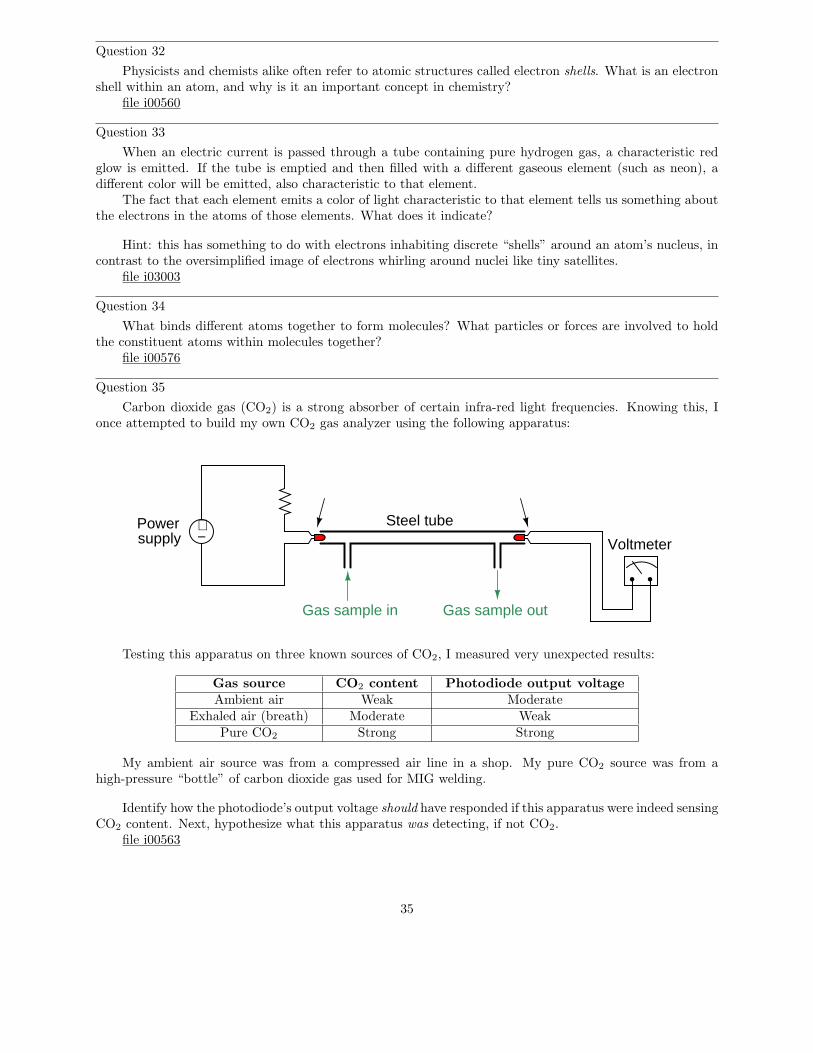
Question 32
Physicists and chemists alike often refer to atomic structures called electron shells. What is an electronshell within an atom, and why is it an important concept in chemistry?
file i00560
Question 33
When an electric current is passed through a tube containing pure hydrogen gas, a characteristic redglow is emitted. If the tube is emptied and then filled with a different gaseous element (such as neon), adifferent color will be emitted, also characteristic to that element.
The fact that each element emits a color of light characteristic to that element tells us something aboutthe electrons in the atoms of those elements. What does it indicate?
Hint: this has something to do with electrons inhabiting discrete “shells” around an atom’s nucleus, incontrast to the oversimplified image of electrons whirling around nuclei like tiny satellites.
file i03003
Question 34
What binds different atoms together to form molecules? What particles or forces are involved to holdthe constituent atoms within molecules together?
file i00576
Question 35
Carbon dioxide gas (CO2) is a strong absorber of certain infra-red light frequencies. Knowing this, Ionce attempted to build my own CO2 gas analyzer using the following apparatus:
+−
Powersupply
Steel tube
Voltmeter
Gas sample in Gas sample out
Testing this apparatus on three known sources of CO2, I measured very unexpected results:
Gas source CO2 content Photodiode output voltageAmbient air Weak Moderate
Exhaled air (breath) Moderate WeakPure CO2 Strong Strong
My ambient air source was from a compressed air line in a shop. My pure CO2 source was from ahigh-pressure “bottle” of carbon dioxide gas used for MIG welding.
Identify how the photodiode’s output voltage should have responded if this apparatus were indeed sensingCO2 content. Next, hypothesize what this apparatus was detecting, if not CO2.
file i00563
35

Question 36
What do you notice about the electron configurations for the elements in each of the vertical columnsof the periodic table? What does this tell you about the nature of those elements?
file i00564
36
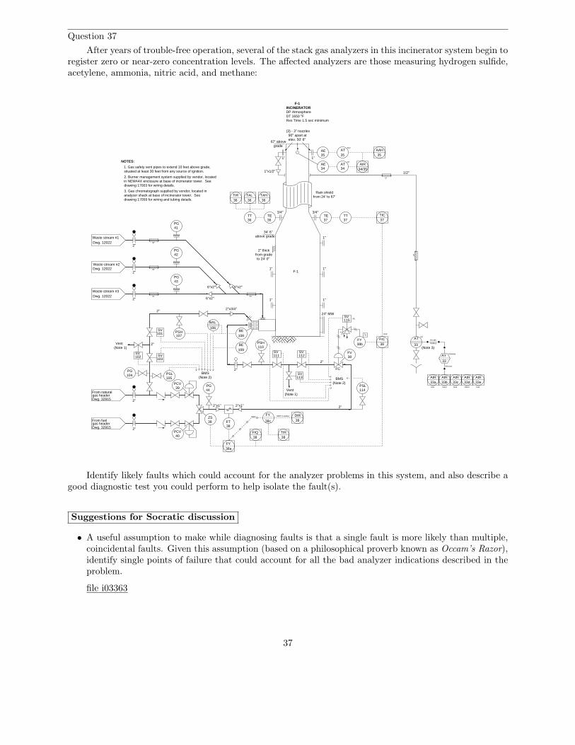
Question 37
After years of trouble-free operation, several of the stack gas analyzers in this incinerator system begin toregister zero or near-zero concentration levels. The affected analyzers are those measuring hydrogen sulfide,acetylene, ammonia, nitric acid, and methane:
F-1
2" thick
Waste stream #1Dwg. 12022
Dwg. 12022
Dwg. 12022
Waste stream #2
Waste stream #3
Vent(Note 1)
ET
FC
TE37 37
TTTETT3636
TAL TAH36 36
From fuel gas headerDwg. 32915
gas headerDwg. 32915
From natural
Vent(Note 1)
FT
AE35
FV
3838
FY38a
I/P
FY38b
38
FIC38
TIC37
RSP
FIQ38
FY
38c
HART to analog
TIR38
DIRHARTZS38
(Note 2)
PSH
PSL
BMS
NE
D
AE34
90o apart atelev. 50’ 6"
67’ abovegrade
PSH
PSL
BE
BE
BMS
(Note 3)
PG
ST
ST
ST
AT
AT
34
35
AIR34/35
O2
SO2
from gradeto 24’ 0"
34’ 6"above grade
AAH
BAL
PG
PG
PG
2"x1" 2"x1"
6"x2"
6"x2" 6"x2"
Rain shieldfrom 24’ to 67’
F-1
DP AtmosphereDT 1650 oF
INCINERATOR
(3) - 3" nozzles
35
ET
ET
33
AT
AIR
AY
33
Gateway
RS-485
Ethernet
Modbus
AIRAIR AIR33a 33b 33c 33d
HNO3
NOTES:
1. Gas safety vent pipes to extend 10 feet above grade,situated at least 30 feet from any source of ignition.
(Note 2)
drawing 17003 for wiring details.
3. Gas chromatograph supplied by vendor, located inanalyzer shack at base of incinerator tower. See drawing 17059 for wiring and tubing details.
24" MW
GC
AIR33e
2. Burner management system supplied by vendor, locatedin NEMA4X enclosure at base of incinerator tower. See
SV101
SVSV102
103
SV
SV SV
104105
106
107 108
109110
111 112
113
114H2S C2H2 NH3
PCV40
PCV39
41
42
43
PG44
1/2"
2"
2"
SV115
CH4
2"x3/4"2"
2"
2"
2"
2"
2"
2"
2"
3/4"3/4"
1" 1"
1"
1"1"
1"x1/2"
1"1"
TIR36
Res Time 1.5 sec minimum
Identify likely faults which could account for the analyzer problems in this system, and also describe agood diagnostic test you could perform to help isolate the fault(s).
Suggestions for Socratic discussion
• A useful assumption to make while diagnosing faults is that a single fault is more likely than multiple,coincidental faults. Given this assumption (based on a philosophical proverb known as Occam’s Razor),identify single points of failure that could account for all the bad analyzer indications described in theproblem.
file i03363
37

Question 38
The following process converts nitric acid (HNO3) and ammonia gas (NH3) into ammonium nitrate(NH4NO3) for use as an ingredient in synthetic fertilizer:
DP Atmosphere
P-102
5 GPM @ 80 oFRated head: 75 PSI
P-101
20 GPM @ 80 oFRated head: 80 PSI
P-103
V-6
MW24"
V-7
P-101
V-5
P-103P-102 P-104
Dwg. 12051Nitric acid supply
Ammonia /off-gasDwg. 10927
Dwg. 19320
Condensate
30 PSI steam
Dwg. 19320
Ammonium nitrateDwg. 18546
M
P
M
FT23FV
23
FT24
FE24
FT22
PFV25
M
FT25
LG21
LT26
TT27
ST
TV27
I/P
TY27
TIC
27
V-6NEUTRALIZER
10’-4" Dia 9’-8" Sidewall
DT 270 oF
V-7RUNDOWN TANK
DP Atmosphere
2"insul
V-5SCRUBBER
7’-6" Dia 20’-8" SidewallStack height 14’-6"DP Atmosphere
AIT
23
AIC
28
FIR22 L
HFIR H
L24
14’-0" Dia 7’-3" Sidewall
DT 250 oF
83% AMMONIUM NITRATE PUMP 83% AMMONIUM NITRATE PUMP SCRUBBER RECIRCULATION PUMPP-104
SCRUBBER RECIRCULATION PUMP1500 GPM @ 225 oF 1500 GPM @ 225 oFRated head: 10 PSI Rated head: 10 PSI
FY
23
Lead/Lag
LIC26
FIC
25
FFC
M
FT29
FIR29
LT30
LIR30
LG31
AIT32
AIT33
AIR
AIR
33
32
pH
pH
pH
28a
AITpH
AITpH
AY28
FOUNDATION Fieldbus
Median
Make-up waterDwg. 10537
P
LT35
FI IAS
LIC
35
LV35
P
FV
Ammonia vaporDwg. 10385
3636FTFT
37
FIC
36
FIR
37
H
L
28b
28c
Mixer
AIC33
P-105
Set @ 10 PSI
P-105NITRIC ACID METERING PUMP
2.4 GPM @ 70 oFRated head: 55 PSI
VFD
Examine the diagram and answer the following questions about this process:
Examine the reaction formula happening inside the “neutralizer” vessel V-6 (shown below) and identifywhether this reaction is endothermic or exothermic:
HNO3 + NH3 → NH4NO3
Explain why a ratio control system is used to balance the flows of ammonia vapor and nitric acid intothe neutralizer vessel.
file i03505
38
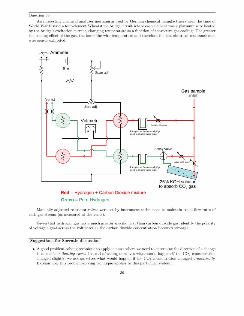
Question 39
An interesting chemical analyzer mechanism used by German chemical manufacturers near the time ofWorld War II used a four-element Wheatstone bridge circuit where each element was a platinum wire heatedby the bridge’s excitation current, changing temperature as a function of convective gas cooling. The greaterthe cooling effect of the gas, the lower the wire temperature and therefore the less electrical resistance eachwire sensor exhibited:
Voltmeter
6 V
Zero adj.
Span adj.
(vents)
25% KOH solution
3-way valve
Adjust for 50 cc/min
Adjust for 50 cc/min
to absorb CO2 gas
Gas sampleinlet
Red = Hydrogen + Carbon Dioxide mixture
Green = Pure Hydrogen
Ammeter
Phosphorus Pentoxide (P2O5)used to absorb water vapor
Phosphorus Pentoxide (P2O5)used to absorb water vapor
Manually-adjusted restrictor valves were set by instrument technicians to maintain equal flow rates ofeach gas stream (as measured at the vents).
Given that hydrogen gas has a much greater specific heat than carbon dioxide gas, identify the polarityof voltage signal across the voltmeter as the carbon dioxide concentration becomes stronger.
Suggestions for Socratic discussion
• A good problem-solving technique to apply in cases where we need to determine the direction of a changeis to consider limiting cases. Instead of asking ourselves what would happen if the CO2 concentrationchanged slightly, we ask ourselves what would happen if the CO2 concentration changed dramatically.Explain how this problem-solving technique applies to this particular system.
39
• What assumption(s), if any, must we make about the sample gas in order to trust the readings givenby this analyzer?
• Identify the purpose of the three-way valve shown in the diagram.• Which way should the “span adjustment” potentiometer wiper be moved to make this instrument more
sensitive (i.e. generate a greater voltage at the voltmeter for any given concentration of CO2 in thesample gas).
file i00979
Question 40
Question 41
Read and outline the “Molecular Quantities” section of the “Chemistry” chapter in your Lessons InIndustrial Instrumentation textbook.
After closely reading and outlining a text, you should be ready to share the following with your classmatesand instructor:
(1) Your written summary of all major points of the text, expressed as simply as possible in your own words.A “Table of Contents” format works well for this.
(2) Active helpful reading strategies (e.g. verbalizing your thoughts as you read, simplifying longsentences, working through mathematical examples, cross-referencing text with illustrations or othertext, identifying the author’s problem-solving strategies, etc.).
(3) General principles, especially physical laws, referenced in the text.(4) Questions of your own you would pose to another reader, to challenge their understanding.(5) Ideas for experiments that could be used to either demonstrate some concept applied in the text, or
disprove a related misconception.(6) Any points of confusion, and precisely why you found the text confusing.
file i04111
Question 42
Calculate the mass of the following quantities of pure chemical compound. In each case, feel free to useatomic mass values rounded to the nearest whole number (from a Periodic Table) in your calculations:
• 35.2 moles of alumina Al2O3 at 25 oC
• 10.6 moles of nitroglycerine C3H5N3O9 at 77 oC
• 3.7 moles of phosgene COCl2 at 145 oF
• 130 moles of tetraethyl pyrophosphate or “TEPP” [(CH3CH2O)2PO]2O at −10 oF
Suggestions for Socratic discussion
• Demonstrate how to estimate numerical answers for this problem without using a calculator.• Calculate the amount of heat required to warm 30 moles of water from 20 degrees Celsius to 25 degrees
Celsius.• Calculate the amount of heat required to warm 200 moles of hydrogen gas from 50 degrees Celsius to
70 degrees Celsius.
file i04113
40
Question 43
Calculate the molar quantity (n, in moles) for the following quantities of pure chemical substances.Feel free to use atomic mass values rounded to the nearest whole number (from a Periodic Table) in yourcalculations:
• 500 grams of pure iron at 10 oC and 1.2 atmospheres
• 1.1 kilograms of pure propane C3H8 at −30 oC and 3 atmospheres
• 250 kilograms of naphthalene C10H8 at 0 oC and 45 kPaA
• 71 grams of hexafluoroacetone (CF3)2CO at 110 oF and 50 bar (gauge)
Suggestions for Socratic discussion
• What effects do temperature and pressure have on the mass of a sample?• Demonstrate how to estimate numerical answers for this problem without using a calculator.• Does the phase of the substance (i.e. gas, liquid, solid) matter in these calculations? Why or why not?
file i04118
Question 44
Read and outline the “Gas Laws” subsection of the “Fluid Mechanics” section of the “Physics” chapterin your Lessons In Industrial Instrumentation textbook.
After closely reading and outlining a text, you should be ready to share the following with your classmatesand instructor:
(1) Your written summary of all major points of the text, expressed as simply as possible in your own words.A “Table of Contents” format works well for this.
(2) Active helpful reading strategies (e.g. verbalizing your thoughts as you read, simplifying longsentences, working through mathematical examples, cross-referencing text with illustrations or othertext, identifying the author’s problem-solving strategies, etc.).
(3) General principles, especially physical laws, referenced in the text.(4) Questions of your own you would pose to another reader, to challenge their understanding.(5) Ideas for experiments that could be used to either demonstrate some concept applied in the text, or
disprove a related misconception.(6) Any points of confusion, and precisely why you found the text confusing.
file i04112
41
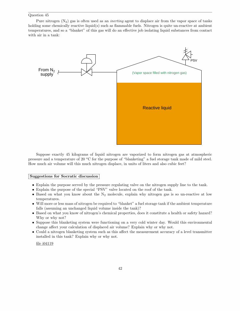
Question 45
Pure nitrogen (N2) gas is often used as an inerting agent to displace air from the vapor space of tanksholding some chemically reactive liquid(s) such as flammable fuels. Nitrogen is quite un-reactive at ambienttemperatures, and so a “blanket” of this gas will do an effective job isolating liquid substances from contactwith air in a tank:
Reactive liquid
From N2supply (Vapor space filled with nitrogen gas)
PSV
Suppose exactly 45 kilograms of liquid nitrogen are vaporized to form nitrogen gas at atmosphericpressure and a temperature of 20 oC for the purpose of “blanketing” a fuel storage tank made of mild steel.How much air volume will this much nitrogen displace, in units of liters and also cubic feet?
Suggestions for Socratic discussion
• Explain the purpose served by the pressure regulating valve on the nitrogen supply line to the tank.• Explain the purpose of the special “PSV” valve located on the roof of the tank.• Based on what you know about the N2 molecule, explain why nitrogen gas is so un-reactive at low
temperatures.• Will more or less mass of nitrogen be required to “blanket” a fuel storage tank if the ambient temperature
falls (assuming an unchanged liquid volume inside the tank)?• Based on what you know of nitrogen’s chemical properties, does it constitute a health or safety hazard?
Why or why not?• Suppose this blanketing system were functioning on a very cold winter day. Would this environmental
change affect your calculation of displaced air volume? Explain why or why not.• Could a nitrogen blanketing system such as this affect the measurement accuracy of a level transmitter
installed in this tank? Explain why or why not.
file i04119
42

Question 46
Dilute chemical concentrations are often measured in the unit of parts per million, abbreviated ppm.For extremely dilute solutions, the unit parts per billion (ppb) is used. These are nothing more than ratios,much like percentage. In fact, the unit of “percent” may be thought of as nothing more than “parts perhundred” although it is never conventionally expressed as such.
In light of this definition for ppm, express the tolerance of a ±5% carbon-composition resistor in ppminstead of percent.
Also calculate the following volumetric and mass concentrations in units of ppm:
• 3.6 milliliters of methyl alcohol mixed into 10.5 liters of pure water
• 55 cubic inches of natural gas released into a room of air 10 feet by 15 feet by 8 feet
• 10 grams of hydrofluoric acid added to 560 kg of water
• 140 grams of H2S gas released into open air
file i00587
Question 47
Research the NIOSH Pocket Guide To Chemical Hazards (DHHS publication number 2005-149) toanswer the following questions:
What does the NIOSH designation IDLH refer to?
What does the NIOSH designation REL refer to?
What does the OSHA designation PEL refer to?
Suggestions for Socratic discussion
• Identify some of the criteria used to establish the REL and PEL values.• Identify some common units of measurement for these exposure limits, citing a real example from the
NIOSH pocket guide.• Which seems the more conservative (safe) exposure limit, the NIOSH REL or the OSHA PEL?
file i04114
43

Question 48
High-temperature combustion causes some of the nitrogen molecules in the combustion air to join withoxygen molecules to form a gaseous pollutant called nitrogen dioxide (NO2). In large fossil-fuel power plants,one method of mitigating this pollutant involves injecting a spray of pure ammonia (NH3) into the exhauststream near a solid catalyst. The resulting chemical reaction eliminates the pollutant by reducing it to watervapor and pure nitrogen gas:
6NO2 + 8NH3 → 12H2O + 7N2
For every six molecules of nitrogen dioxide, it takes eight molecules of ammonia to reduce it to twelvemolecules of water and seven molecules of nitrogen gas.
Calculate the molar quantity of ammonia required to reduce 1350 moles of nitrogen dioxide gas.
Also, calculate the mass of this nitrogen dioxide quantity and the mass of this ammonia quantity.
Suggestions for Socratic discussion
• Is there such a thing as a Law of Molar Conservation as there is for mass and energy conservation?• What is so bad about nitrogen dioxide gas that we would try to scrub it from the exhaust? After all,
what has NO2 ever done to hurt you?• Calculate a mass ratio of ammonia to nitrogen dioxide to make it easy for anyone to compute the
required quantity (mass) of ammonia to neutralize any given quantity (mass) of nitrogen dioxide.
file i04116
44
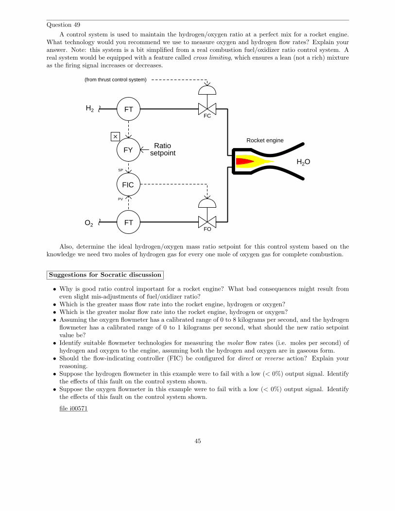
Question 49
A control system is used to maintain the hydrogen/oxygen ratio at a perfect mix for a rocket engine.What technology would you recommend we use to measure oxygen and hydrogen flow rates? Explain youranswer. Note: this system is a bit simplified from a real combustion fuel/oxidizer ratio control system. Areal system would be equipped with a feature called cross limiting, which ensures a lean (not a rich) mixtureas the firing signal increases or decreases.
H2 FT
(from thrust control system)
O2 FT
FY
FIC
SP
PV
Ratiosetpoint
Rocket engine
FO
FC
H2O
Also, determine the ideal hydrogen/oxygen mass ratio setpoint for this control system based on theknowledge we need two moles of hydrogen gas for every one mole of oxygen gas for complete combustion.
Suggestions for Socratic discussion
• Why is good ratio control important for a rocket engine? What bad consequences might result fromeven slight mis-adjustments of fuel/oxidizer ratio?
• Which is the greater mass flow rate into the rocket engine, hydrogen or oxygen?• Which is the greater molar flow rate into the rocket engine, hydrogen or oxygen?• Assuming the oxygen flowmeter has a calibrated range of 0 to 8 kilograms per second, and the hydrogen
flowmeter has a calibrated range of 0 to 1 kilograms per second, what should the new ratio setpointvalue be?
• Identify suitable flowmeter technologies for measuring the molar flow rates (i.e. moles per second) ofhydrogen and oxygen to the engine, assuming both the hydrogen and oxygen are in gaseous form.
• Should the flow-indicating controller (FIC) be configured for direct or reverse action? Explain yourreasoning.
• Suppose the hydrogen flowmeter in this example were to fail with a low (< 0%) output signal. Identifythe effects of this fault on the control system shown.
• Suppose the oxygen flowmeter in this example were to fail with a low (< 0%) output signal. Identifythe effects of this fault on the control system shown.
file i00571
45
Question 50
In chemistry, the unit of the mole is important when quantifying substances. What exactly is a mole?file i00565
Question 51
Calculate the mass (in grams) for each of these substance quantities:
• 1 mole of pure 12C
• 1 mole of carbon (naturally occurring)
• 1 mole of pure 56Fe
• 5.5 moles of mercury (naturally occurring)
• 0.002 moles of helium (naturally occurring)
Hint: you will find the Periodic Table of the Elements extremely helpful here!file i00566
Question 52
Calculate the mass (in grams) for each of these substance quantities (when calculating, round all atomicmasses to the nearest hundredth):
• 1 mole of water: H2O• 1 mole of heavy water (deuterium oxide, or D2O)• 1 mole of sulfuric acid: H2SO4
• 14 moles of methane: CH4
• 5 moles of ammonium carbonate: (NH4)2CO3
Note: “deuterium” is an isotope of hydrogen, each atom containing one proton and one neutron in thenucleus.
file i00567
Question 53
When acid attacks metal, the result is typically a release of hydrogen gas and the production of a salt. Ifwe immerse a piece of solid zinc metal (Zn) is into liquid sulfuric acid (H2SO4), we see this general tendencyin the production of hydrogen gas (H2) and a salt called zinc sulfate (ZnSO4). The chemical equationdescribing this reaction is shown here:
Zn + H2SO4 → ZnSO4 + H2
For every single atom of zinc, it takes one molecule of sulfuric acid to react. The reaction products forthe one atom of zinc and one molecule of sulfuric acid will be one molecule of zinc sulfate and one moleculeof hydrogen.
Identify how many moles of zinc metal and how many moles of pure sulfuric acid will be required toproduce 15 moles of hydrogen gas.
file i04115
46
Question 54
When “table” sugar is added to water, at first the sugar crystals seem to disappear as they dissolve.But, if enough sugar is added to the water, eventually sugar crystals will begin to form at the bottomof the container. In the context of this example, define the terms solute, solvent, solution, saturation,supersaturation, precipitate, and supernatant.
file i00558
Question 55
Contrast the following chemical terms: solution, suspension, and colloid. Furthermore, determinewhether each of these mixtures is a solution, a suspension, or a colloid:
• Muddy water• Household ammonia• Milk• Rubbing alcohol• Tobacco smoke in air• Battery acid• Whipped cream• Dusty air• Sugar water• Coffee
Colloids are often subdivided into the following types: aerosols, foams, emulsions, and sols. Explainwhat each of these different colloids are, and classify all colloids in the list above as one of these sub-categories.
file i00559
Question 56
Calculate the mass of 2.1 moles of ammonium carbonate (NH4)2CO3. Feel free to use atomic massvalues rounded to the nearest whole number (from a Periodic Table) in your calculation.
Suggestions for Socratic discussion
• Demonstrate how to estimate numerical answers for this problem without using a calculator.
file i04117
47

Question 57
When hydrogen and oxygen combine under sufficient pressure and/or temperature, they react to formwater (H2O) in a simple example of combustion. If these are the only elements involved, and the samplesare pure, water is the only byproduct of the reaction (in addition to heat energy, of course).
Hydrogen, as a gas at room temperature and atmospheric pressure, exists as pairs of atoms (a diatomicmolecule) denoted as H2. Likewise, oxygen as a gas at room temperature and atmospheric pressure existsas pairs of atoms (O2) as well.
If I have a quantity of pure hydrogen gas equal to 250 moles, how many moles of pure oxygen gas will beneeded to completely react with (burn) the hydrogen gas sample? Assume a gas pressure of 830 mm HgA.
Suggestions for Socratic discussion
• Should the ∆H value for the combustion reaction have a positive or a negative value?• The main engines on the Space Shuttle use hydrogen as the fuel and oxygen as the oxidizer. Thus,
the only emission in the exhaust of these engines is water vapor. Does that mean these engines arecompletely non-polluting?
file i00569
Question 58
When methyl alcohol (“methanol”) vapor is mixed with air at sea-level atmospheric pressure and roomtemperature (25 oC), a molecular concentration of 1 ppm (1 molecule of methanol for every 1,000,000 samplemolecules) is equivalent to a mass concentration of 1.31 milligrams methanol per cubic meter.
Use the Ideal Gas Law to prove this equivalence for methanol (1 ppm = 1.31 mg/m3).file i04120
48
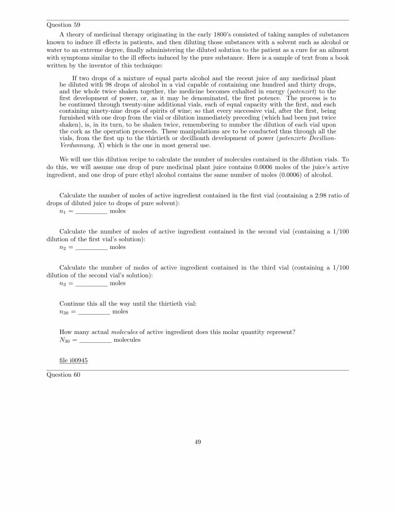
Question 59
A theory of medicinal therapy originating in the early 1800’s consisted of taking samples of substancesknown to induce ill effects in patients, and then diluting those substances with a solvent such as alcohol orwater to an extreme degree, finally administering the diluted solution to the patient as a cure for an ailmentwith symptoms similar to the ill effects induced by the pure substance. Here is a sample of text from a bookwritten by the inventor of this technique:
If two drops of a mixture of equal parts alcohol and the recent juice of any medicinal plantbe diluted with 98 drops of alcohol in a vial capable of containing one hundred and thirty drops,and the whole twice shaken together, the medicine becomes exhalted in energy (potenzirt) to thefirst development of power, or, as it may be denominated, the first potence. The process is tobe continued through twenty-nine additional vials, each of equal capacity with the first, and eachcontaining ninety-nine drops of spirits of wine; so that every successive vial, after the first, beingfurnished with one drop from the vial or dilution immediately preceding (which had been just twiceshaken), is, in its turn, to be shaken twice, remembering to number the dilution of each vial uponthe cork as the operation proceeds. These manipulations are to be conducted thus through all thevials, from the first up to the thirtieth or decillionth development of power (potenzirte Decillion-Verdunnung, X) which is the one in most general use.
We will use this dilution recipe to calculate the number of molecules contained in the dilution vials. Todo this, we will assume one drop of pure medicinal plant juice contains 0.0006 moles of the juice’s activeingredient, and one drop of pure ethyl alcohol contains the same number of moles (0.0006) of alcohol.
Calculate the number of moles of active ingredient contained in the first vial (containing a 2:98 ratio ofdrops of diluted juice to drops of pure solvent):
n1 = moles
Calculate the number of moles of active ingredient contained in the second vial (containing a 1/100dilution of the first vial’s solution):
n2 = moles
Calculate the number of moles of active ingredient contained in the third vial (containing a 1/100dilution of the second vial’s solution):
n3 = moles
Continue this all the way until the thirtieth vial:n30 = moles
How many actual molecules of active ingredient does this molar quantity represent?N30 = molecules
file i00945
Question 60
49
Question 61
Read and outline the introduction to the “Stoichiometry” section of the “Chemistry” chapter in yourLessons In Industrial Instrumentation textbook.
After closely reading and outlining a text, you should be ready to share the following with your classmatesand instructor:
(1) Your written summary of all major points of the text, expressed as simply as possible in your own words.A “Table of Contents” format works well for this.
(2) Active helpful reading strategies (e.g. verbalizing your thoughts as you read, simplifying longsentences, working through mathematical examples, cross-referencing text with illustrations or othertext, identifying the author’s problem-solving strategies, etc.).
(3) General principles, especially physical laws, referenced in the text.(4) Questions of your own you would pose to another reader, to challenge their understanding.(5) Ideas for experiments that could be used to either demonstrate some concept applied in the text, or
disprove a related misconception.(6) Any points of confusion, and precisely why you found the text confusing.
file i04106
Question 62
Read and outline the “Balancing Chemical Equations Using Algebra” subsection of the “Stoichiometry”section of the “Chemistry” chapter in your Lessons In Industrial Instrumentation textbook.
After closely reading and outlining a text, you should be ready to share the following with your classmatesand instructor:
(1) Your written summary of all major points of the text, expressed as simply as possible in your own words.A “Table of Contents” format works well for this.
(2) Active helpful reading strategies (e.g. verbalizing your thoughts as you read, simplifying longsentences, working through mathematical examples, cross-referencing text with illustrations or othertext, identifying the author’s problem-solving strategies, etc.).
(3) General principles, especially physical laws, referenced in the text.(4) Questions of your own you would pose to another reader, to challenge their understanding.(5) Ideas for experiments that could be used to either demonstrate some concept applied in the text, or
disprove a related misconception.(6) Any points of confusion, and precisely why you found the text confusing.
file i04108
50
Question 63
German submarines in World War II used highly purified hydrogen peroxide (H2O2) as a monopropellantfor their torpedo propulsion systems: when placed in contact with a catalyst, hydrogen peroxidespontaneously decomposes to produce water (H2O), oxygen (O2), and a lot of heat. Write a balancedequation showing all reactants and all reaction products in the proper proportions.
Also, determine how many moles of water and how many moles of O2 will be produced when exactlythree moles of hydrogen peroxide decomposes.
Suggestions for Socratic discussion
• Explain how to check your work to make sure the final equation is properly balanced.• Should the peroxide decomposition reaction have a positive or negative ∆H value written next to it?• Explain why this reaction is exothermic, based on an analysis of the reaction equation: where is energy
being absorbed, and where is energy being released? What can we tell about the relative bond strengthsof oxygen to H2O, versus oxygen to itself?
• Explain the purpose of using a catalyst to initiate the decomposition reaction of hydrogen peroxide insuch a torpedo.
• Will the catalyst be consumed in the decomposition reaction?
file i00903
Question 64
Orthophosphoric acid (H3PO4) is formed by combining tetraphosphorus decoxide (P4O10) with water(H2O). Write a balanced equation showing all reactants and all reaction products in the proper proportions.
Also, determine how many moles of tetraphosphorus decoxide need to be added to twenty moles of waterto completely react, and how many moles of acid will be produced as a result.
Suggestions for Socratic discussion
• Explain how to check your work to make sure the final equation is properly balanced.
file i00901
51
Question 65
Read and outline the introduction to the “Energy in Chemical Reactions” section as well as the “Heatsof Reaction and Activation Energy” subsection of the “Chemistry” chapter in your Lessons In IndustrialInstrumentation textbook.
After closely reading and outlining a text, you should be ready to share the following with your classmatesand instructor:
(1) Your written summary of all major points of the text, expressed as simply as possible in your own words.A “Table of Contents” format works well for this.
(2) Active helpful reading strategies (e.g. verbalizing your thoughts as you read, simplifying longsentences, working through mathematical examples, cross-referencing text with illustrations or othertext, identifying the author’s problem-solving strategies, etc.).
(3) General principles, especially physical laws, referenced in the text.(4) Questions of your own you would pose to another reader, to challenge their understanding.(5) Ideas for experiments that could be used to either demonstrate some concept applied in the text, or
disprove a related misconception.(6) Any points of confusion, and precisely why you found the text confusing.
file i04109
Question 66
Green plants convert carbon dioxide (CO2) and water (H2O) into glucose sugar (C6H12O6) and oxygengas (O2) using sunlight as the energy input, which is why this reaction is called photosynthesis. This reactionis catalyzed, with the catalyst being a green-colored substance called chlorophyll. Write a balanced equationshowing all reactants and all reaction products in the proper proportions.
Also, describe the role photosynthesis plays in the sustenance of biological life on earth, especially thelife of mammals such as ourselves who use glucose as a fuel to sustain our own bodies’ vital functions.Identify where chemical bonds are formed in the food chain, and where chemical bonds are broken in thefood chain, and how this relates to energy.
Suggestions for Socratic discussion
• Explain how to check your work to make sure the final equation is properly balanced.• Is the photosynthesis reaction exothermic or endothermic?• Should the photosynthesis reaction have a positive or negative ∆H value written next to it?• What happens to the chlorophyll after the reaction completes? Does it need to be replenished?• Explain why plants will not continue to grow if starved of sunlight.• Explain why some plants actually will grow (at least for a time) if cut off at ground level where there
is no longer any exposed surface area to collect sunlight.• Explain why photosynthesis does not occur in the absence of chlorophyll despite the presence of all
necessary reactants plus sunshine.• Would it be possible to grow plants under artificial light (from special electric lamps), then harvest
those plants and burn them as fuel to power a generator to keep the grow-lights lit? Explain why orwhy not.
file i03635
52
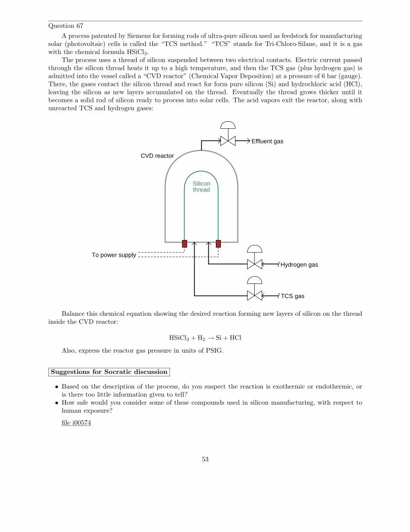
Question 67
A process patented by Siemens for forming rods of ultra-pure silicon used as feedstock for manufacturingsolar (photovoltaic) cells is called the “TCS method.” “TCS” stands for Tri-Chloro-Silane, and it is a gaswith the chemical formula HSiCl3.
The process uses a thread of silicon suspended between two electrical contacts. Electric current passedthrough the silicon thread heats it up to a high temperature, and then the TCS gas (plus hydrogen gas) isadmitted into the vessel called a “CVD reactor” (Chemical Vapor Deposition) at a pressure of 6 bar (gauge).There, the gases contact the silicon thread and react for form pure silicon (Si) and hydrochloric acid (HCl),leaving the silicon as new layers accumulated on the thread. Eventually the thread grows thicker until itbecomes a solid rod of silicon ready to process into solar cells. The acid vapors exit the reactor, along withunreacted TCS and hydrogen gases:
To power supply
Hydrogen gas
TCS gas
CVD reactor
Effluent gas
Siliconthread
Balance this chemical equation showing the desired reaction forming new layers of silicon on the threadinside the CVD reactor:
HSiCl3 + H2 → Si + HCl
Also, express the reactor gas pressure in units of PSIG.
Suggestions for Socratic discussion
• Based on the description of the process, do you suspect the reaction is exothermic or endothermic, oris there too little information given to tell?
• How safe would you consider some of these compounds used in silicon manufacturing, with respect tohuman exposure?
file i00574
53

Question 68
Read and outline the “Explosive Limits” subsection of the “Classified Areas and Electrical SafetyMeasures” section of the “Process Safety and Instrumentation” chapter in your Lessons In IndustrialInstrumentation textbook.
After closely reading and outlining a text, you should be ready to share the following with your classmatesand instructor:
(1) Your written summary of all major points of the text, expressed as simply as possible in your own words.A “Table of Contents” format works well for this.
(2) Active helpful reading strategies (e.g. verbalizing your thoughts as you read, simplifying longsentences, working through mathematical examples, cross-referencing text with illustrations or othertext, identifying the author’s problem-solving strategies, etc.).
(3) General principles, especially physical laws, referenced in the text.(4) Questions of your own you would pose to another reader, to challenge their understanding.(5) Ideas for experiments that could be used to either demonstrate some concept applied in the text, or
disprove a related misconception.(6) Any points of confusion, and precisely why you found the text confusing.
file i04110
54
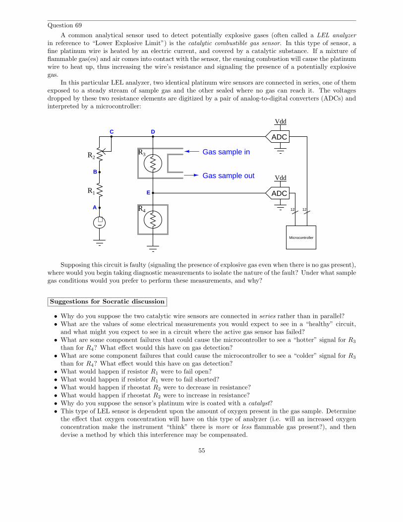
Question 69
A common analytical sensor used to detect potentially explosive gases (often called a LEL analyzerin reference to “Lower Explosive Limit”) is the catalytic combustible gas sensor. In this type of sensor, afine platinum wire is heated by an electric current, and covered by a catalytic substance. If a mixture offlammable gas(es) and air comes into contact with the sensor, the ensuing combustion will cause the platinumwire to heat up, thus increasing the wire’s resistance and signaling the presence of a potentially explosivegas.
In this particular LEL analyzer, two identical platinum wire sensors are connected in series, one of themexposed to a steady stream of sample gas and the other sealed where no gas can reach it. The voltagesdropped by these two resistance elements are digitized by a pair of analog-to-digital converters (ADCs) andinterpreted by a microcontroller:
Gas sample in
Gas sample out
+−
R1
R2R3
R4
ADC
ADC
Vdd
Vdd
12 12
Microcontroller
A
B
C D
E
Supposing this circuit is faulty (signaling the presence of explosive gas even when there is no gas present),where would you begin taking diagnostic measurements to isolate the nature of the fault? Under what samplegas conditions would you prefer to perform these measurements, and why?
Suggestions for Socratic discussion
• Why do you suppose the two catalytic wire sensors are connected in series rather than in parallel?• What are the values of some electrical measurements you would expect to see in a “healthy” circuit,
and what might you expect to see in a circuit where the active gas sensor has failed?• What are some component failures that could cause the microcontroller to see a “hotter” signal for R3
than for R4? What effect would this have on gas detection?• What are some component failures that could cause the microcontroller to see a “colder” signal for R3
than for R4? What effect would this have on gas detection?• What would happen if resistor R1 were to fail open?• What would happen if resistor R1 were to fail shorted?• What would happen if rheostat R2 were to decrease in resistance?• What would happen if rheostat R2 were to increase in resistance?• Why do you suppose the sensor’s platinum wire is coated with a catalyst?• This type of LEL sensor is dependent upon the amount of oxygen present in the gas sample. Determine
the effect that oxygen concentration will have on this type of analyzer (i.e. will an increased oxygenconcentration make the instrument “think” there is more or less flammable gas present?), and thendevise a method by which this interference may be compensated.
55

file i01592
Question 70
Silane is a flammable and toxic gas (SiH4, also called silicon tetrahydride) used widely in siliconsemiconductor manufacturing processes. If a leak develops in a pipe carrying silane, the result is immediatecombustion, each molecule of silane gas combining with two molecules of atmospheric oxygen (O2).
One of the products of silane + oxygen combustion is water vapor (2 molecules of H2O produced foreach molecule of silane). There is only one other combustion product. Determine what this product is, andhow many molecules of it are produced for each molecule of silane gas entering the reaction.
file i00575
Question 71
A popular concept for automotive fuel is hydrogen. One of the main attractions of hydrogen as a fuelis that it is clean: no pollutants are formed (ideally) when hydrogen is burned. If “burned” in a fuel cellinstead of by combustion in air, pure water is the only chemical byproduct of the reaction.
However, there are some serious public misconceptions about hydrogen as a fuel source. One of the mostcommon misconceptions is the availability of hydrogen fuel. Since most people know that water is comprisedof hydrogen and oxygen (H2O), a common public belief is that we have unlimited reserves of hydrogen fuelstored in the oceans. All we need to do, so goes the logic, is separate the hydrogen from the oxygen andthen we’ll have a limitless supply of fuel and all our energy problems will be solved.
Based on what you know of chemical reactions and energy exchange, explain why this belief isfundamentally flawed.
file i00578
56
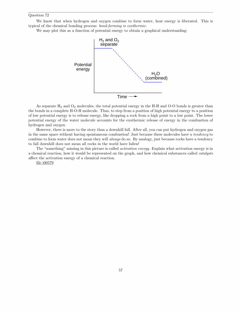
Question 72
We know that when hydrogen and oxygen combine to form water, heat energy is liberated. This istypical of the chemical bonding process: bond-forming is exothermic.
We may plot this as a function of potential energy to obtain a graphical understanding:
H2 and O2separate
H2O(combined)
Potentialenergy
Time
As separate H2 and O2 molecules, the total potential energy in the H-H and O-O bonds is greater thanthe bonds in a complete H-O-H molecule. Thus, to step from a position of high potential energy to a positionof low potential energy is to release energy, like dropping a rock from a high point to a low point. The lowerpotential energy of the water molecule accounts for the exothermic release of energy in the combustion ofhydrogen and oxygen.
However, there is more to the story than a downhill fall. After all, you can put hydrogen and oxygen gasin the same space without having spontaneous combustion! Just because these molecules have a tendency tocombine to form water does not mean they will always do so. By analogy, just because rocks have a tendencyto fall downhill does not mean all rocks in the world have fallen!
The “something” missing in this picture is called activation energy. Explain what activation energy is ina chemical reaction, how it would be represented on the graph, and how chemical substances called catalystsaffect the activation energy of a chemical reaction.
file i00579
57
Question 73
When methane (CH4) and oxygen (O2) gas combine under sufficient pressure and/or temperature,they react to form carbon dioxide (CO2) gas and water (H2O). The following chemical equation shows thecombustion of methane and oxygen to form carbon dioxide and water:
CH4 + O2 → CO2 + H2O
Unfortunately, this equation is incomplete. Although it does indicate the identities of the reactionproducts (carbon dioxide and water), it does not indicate their relative quantities. A simple head-count ofatoms on each side of the equation confirms this:
Reactants Reaction productsCarbon = 1 Carbon = 1
Hydrogen = 4 Hydrogen = 2Oxygen = 2 Oxygen = 3
Since we know it would violate the Law of Mass Conservation (one of the fundamental laws of physics)to have fewer atoms of each element coming out of a reaction than going into it, we know this equation mustbe incomplete.
To make this a balanced equation, we must determine how many molecules of methane, oxygen, carbondioxide, and water are involved in this reaction so that the numbers of atoms for each element are the sameon both sides of the equation.
Re-write this chemical equation so that it is balanced.
Furthermore, calculate the number of moles of oxygen gas needed to completely react (burn) 1400 molesof methane gas under ideal conditions.
file i00570
Question 74
When pentane (C5H12) is burned with oxygen (O2) under ideal conditions, the products are water vapor(H2O) and carbon dioxide (CO2). Write a balanced equation showing all reactants and all reaction productsin the proper proportions.
file i00905
Question 75
When propane (C3H8) is burned with oxygen (O2) under ideal conditions, the products are water vapor(H2O) and carbon dioxide (CO2). Write a balanced equation showing all reactants and all reaction productsin the proper proportions.
file i00902
Question 76
When butane (C4H10) is burned with oxygen (O2) under ideal conditions, the products are water vapor(H2O) and carbon dioxide (CO2). Write a balanced equation showing all reactants and all reaction productsin the proper proportions.
file i00904
58
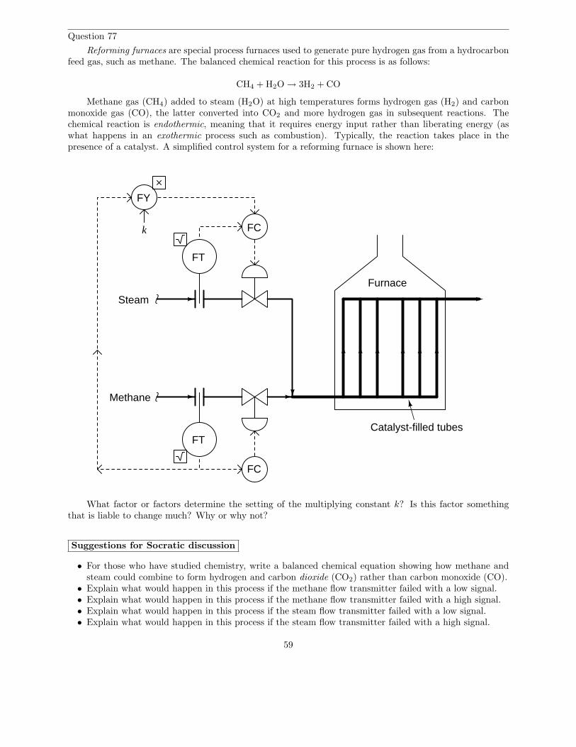
Question 77
Reforming furnaces are special process furnaces used to generate pure hydrogen gas from a hydrocarbonfeed gas, such as methane. The balanced chemical reaction for this process is as follows:
CH4 + H2O → 3H2 + CO
Methane gas (CH4) added to steam (H2O) at high temperatures forms hydrogen gas (H2) and carbonmonoxide gas (CO), the latter converted into CO2 and more hydrogen gas in subsequent reactions. Thechemical reaction is endothermic, meaning that it requires energy input rather than liberating energy (aswhat happens in an exothermic process such as combustion). Typically, the reaction takes place in thepresence of a catalyst. A simplified control system for a reforming furnace is shown here:
Furnace
Catalyst-filled tubes
Steam
Methane
FT
FT
FC
FC
FY
k
What factor or factors determine the setting of the multiplying constant k? Is this factor somethingthat is liable to change much? Why or why not?
Suggestions for Socratic discussion
• For those who have studied chemistry, write a balanced chemical equation showing how methane andsteam could combine to form hydrogen and carbon dioxide (CO2) rather than carbon monoxide (CO).
• Explain what would happen in this process if the methane flow transmitter failed with a low signal.• Explain what would happen in this process if the methane flow transmitter failed with a high signal.• Explain what would happen in this process if the steam flow transmitter failed with a low signal.• Explain what would happen in this process if the steam flow transmitter failed with a high signal.
59
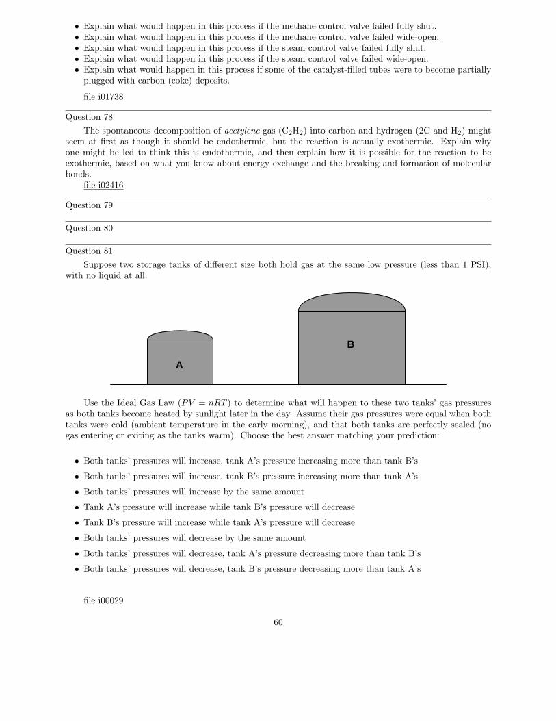
• Explain what would happen in this process if the methane control valve failed fully shut.• Explain what would happen in this process if the methane control valve failed wide-open.• Explain what would happen in this process if the steam control valve failed fully shut.• Explain what would happen in this process if the steam control valve failed wide-open.• Explain what would happen in this process if some of the catalyst-filled tubes were to become partially
plugged with carbon (coke) deposits.
file i01738
Question 78
The spontaneous decomposition of acetylene gas (C2H2) into carbon and hydrogen (2C and H2) mightseem at first as though it should be endothermic, but the reaction is actually exothermic. Explain whyone might be led to think this is endothermic, and then explain how it is possible for the reaction to beexothermic, based on what you know about energy exchange and the breaking and formation of molecularbonds.
file i02416
Question 79
Question 80
Question 81
Suppose two storage tanks of different size both hold gas at the same low pressure (less than 1 PSI),with no liquid at all:
A
B
Use the Ideal Gas Law (PV = nRT ) to determine what will happen to these two tanks’ gas pressuresas both tanks become heated by sunlight later in the day. Assume their gas pressures were equal when bothtanks were cold (ambient temperature in the early morning), and that both tanks are perfectly sealed (nogas entering or exiting as the tanks warm). Choose the best answer matching your prediction:
• Both tanks’ pressures will increase, tank A’s pressure increasing more than tank B’s
• Both tanks’ pressures will increase, tank B’s pressure increasing more than tank A’s
• Both tanks’ pressures will increase by the same amount
• Tank A’s pressure will increase while tank B’s pressure will decrease
• Tank B’s pressure will increase while tank A’s pressure will decrease
• Both tanks’ pressures will decrease by the same amount
• Both tanks’ pressures will decrease, tank A’s pressure decreasing more than tank B’s
• Both tanks’ pressures will decrease, tank B’s pressure decreasing more than tank A’s
file i00029
60

Question 82
Determine the number of moles of oxygen (O2) required to completely burn 1 mole of propane (C3H8)under ideal conditions, with the only combustion products being water vapor (H2O) and carbon dioxide(CO2). Write a balanced chemical equation for complete combustion of propane with oxygen to supportyour calculations.
Then, determine the number of pounds of oxygen required to completely burn 1 pound of propane,showing in your work how to calculate the required oxygen mass.
file i00623
61
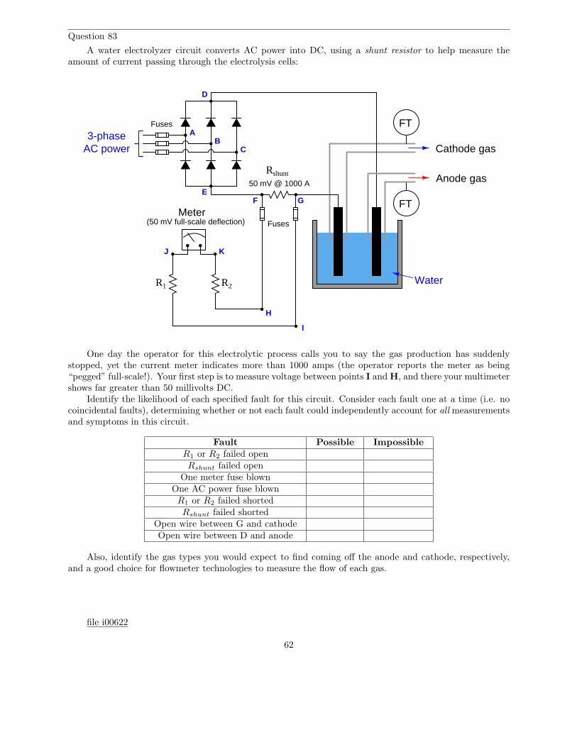
Question 83
A water electrolyzer circuit converts AC power into DC, using a shunt resistor to help measure theamount of current passing through the electrolysis cells:
3-phaseAC power
Fuses
Meter
R1 R2
Fuses
Rshunt
50 mV @ 1000 A
AB
C
D
EF G
H
I
Cathode gas
Anode gas
Water
(50 mV full-scale deflection)
FT
FT
J K
One day the operator for this electrolytic process calls you to say the gas production has suddenlystopped, yet the current meter indicates more than 1000 amps (the operator reports the meter as being“pegged” full-scale!). Your first step is to measure voltage between points I and H, and there your multimetershows far greater than 50 millivolts DC.
Identify the likelihood of each specified fault for this circuit. Consider each fault one at a time (i.e. nocoincidental faults), determining whether or not each fault could independently account for all measurementsand symptoms in this circuit.
Fault Possible ImpossibleR1 or R2 failed openRshunt failed open
One meter fuse blownOne AC power fuse blownR1 or R2 failed shortedRshunt failed shorted
Open wire between G and cathodeOpen wire between D and anode
Also, identify the gas types you would expect to find coming off the anode and cathode, respectively,and a good choice for flowmeter technologies to measure the flow of each gas.
file i00622
62
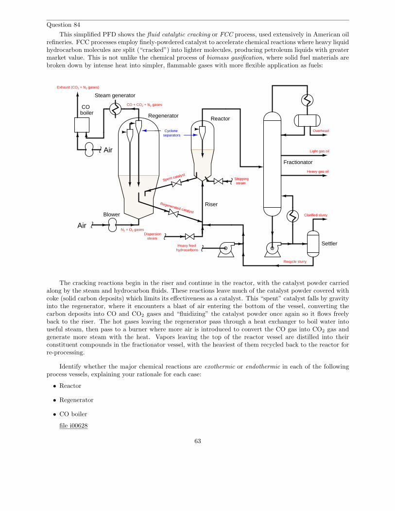
Question 84
This simplified PFD shows the fluid catalytic cracking or FCC process, used extensively in American oilrefineries. FCC processes employ finely-powdered catalyst to accelerate chemical reactions where heavy liquidhydrocarbon molecules are split (“cracked”) into lighter molecules, producing petroleum liquids with greatermarket value. This is not unlike the chemical process of biomass gasification, where solid fuel materials arebroken down by intense heat into simpler, flammable gases with more flexible application as fuels:
Dispersionsteam
Regenerator Reactor
Cycloneseparators
Strippingsteam
Air
Blower
RiserRegenerated catalyst
Spent catalyst
Light gas oil
Heavy gas oil
Overhead
Settler
Clarified slurry
Heavy feed
Fractionator
Air
COboiler
Steam generator
Recycle slurry
hydrocarbons
N2 + O2 gases
CO + CO2 + N2 gases
Exhaust (CO2 + N2 gases)
The cracking reactions begin in the riser and continue in the reactor, with the catalyst powder carriedalong by the steam and hydrocarbon fluids. These reactions leave much of the catalyst powder covered withcoke (solid carbon deposits) which limits its effectiveness as a catalyst. This “spent” catalyst falls by gravityinto the regenerator, where it encounters a blast of air entering the bottom of the vessel, converting thecarbon deposits into CO and CO2 gases and “fluidizing” the catalyst powder once again so it flows freelyback to the riser. The hot gases leaving the regenerator pass through a heat exchanger to boil water intouseful steam, then pass to a burner where more air is introduced to convert the CO gas into CO2 gas andgenerate more steam with the heat. Vapors leaving the top of the reactor vessel are distilled into theirconstituent compounds in the fractionator vessel, with the heaviest of them recycled back to the reactor forre-processing.
Identify whether the major chemical reactions are exothermic or endothermic in each of the followingprocess vessels, explaining your rationale for each case:
• Reactor
• Regenerator
• CO boiler
file i00628
63

Question 85
Suppose a gas turbine engine at the gas-fired power plant you are working at vents 47,000 SCFM ofexhaust gases while operating at full power. The measured NO2 concentration of the engine’s exhaust gasis 5 ppm (by volume) at full power. Calculate both the number of moles of NO2 emitted and the mass ofNO2 emitted by this engine per 24-hour day, assuming it runs at full power the whole time.
Assume “standard” conditions of 1 atmosphere and 68oF for the “SCFM” gas flow quantity. Be sure toshow all your work!
file i00682
64

Question 86
Solve for x, y, and z in this simultaneous system of equations:
x + 3y + 5z = 19
4x − y + 2z = 3
4x − y − z = 6
file i00931
65

Question 87
Explain where and how TIR-38 and DIR-38 get their data to display to the operators, based on theinformation in this P&ID for a waste gas incinerator. Specifically, which physical principles are used tomeasure these parameters of the gas?
F-1
2" thick
Waste stream #1Dwg. 12022
Dwg. 12022
Dwg. 12022
Waste stream #2
Waste stream #3
Vent(Note 1)
ET
FC
TE37 37
TTTETT3636
TAL TAH36 36
From fuel gas headerDwg. 32915
gas headerDwg. 32915
From natural
Vent(Note 1)
FT
AE35
FV
3838
FY38a
I/P
FY38b
38
FIC38
TIC37
RSP
FIQ38
FY
38c
HART to analog
TIR38
DIRHARTZS38
(Note 2)
PSH
PSL
BMS
NE
D
AE34
90o apart atelev. 50’ 6"
67’ abovegrade
PSH
PSL
BE
BE
BMS
(Note 3)
PG
ST
ST
ST
AT
AT
34
35
AIR34/35
O2
SO2
from gradeto 24’ 0"
34’ 6"above grade
AAH
BAL
PG
PG
PG
2"x1" 2"x1"
6"x2"
6"x2" 6"x2"
Rain shieldfrom 24’ to 67’
F-1
DP AtmosphereDT 1650 oF
INCINERATOR
(3) - 3" nozzles
35
ET
ET
33
AT
AIR
AY
33
Gateway
RS-485
Ethernet
Modbus
AIRAIR AIR33a 33b 33c 33d
HNO3
NOTES:
1. Gas safety vent pipes to extend 10 feet above grade,situated at least 30 feet from any source of ignition.
(Note 2)
drawing 17003 for wiring details.
3. Gas chromatograph supplied by vendor, located inanalyzer shack at base of incinerator tower. See drawing 17059 for wiring and tubing details.
24" MW
GC
AIR33e
2. Burner management system supplied by vendor, locatedin NEMA4X enclosure at base of incinerator tower. See
SV101
SVSV102
103
SV
SV SV
104105
106
107 108
109110
111 112
113
114H2S C2H2 NH3
PCV40
PCV39
41
42
43
PG44
1/2"
2"
2"
SV115
CH4
2"x3/4"2"
2"
2"
2"
2"
2"
2"
2"
3/4"3/4"
1" 1"
1"
1"1"
1"x1/2"
1"1"
TIR36
Res Time 1.5 sec minimum
file i03238
66
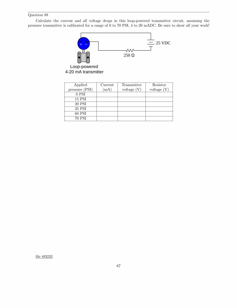
Question 88
Calculate the current and all voltage drops in this loop-powered transmitter circuit, assuming thepressure transmitter is calibrated for a range of 0 to 70 PSI, 4 to 20 mADC. Be sure to show all your work!
H L
Loop-powered4-20 mA transmitter
250 Ω
25 VDC
Applied Current Transmitter Resistorpressure (PSI) (mA) voltage (V) voltage (V)
0 PSI15 PSI20 PSI35 PSI60 PSI70 PSI
file i03232
67
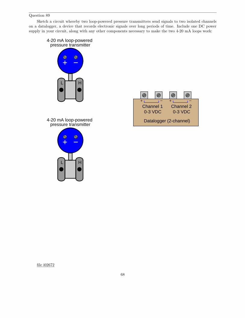
Question 89
Sketch a circuit whereby two loop-powered pressure transmitters send signals to two isolated channelson a datalogger, a device that records electronic signals over long periods of time. Include one DC powersupply in your circuit, along with any other components necessary to make the two 4-20 mA loops work:
HL
4-20 mA loop-poweredpressure transmitter
Channel 1 Channel 2
HL
4-20 mA loop-poweredpressure transmitter
Datalogger (2-channel)
0-3 VDC 0-3 VDC
file i02672
68

Question 90
A technician is troubleshooting a power supply circuit with no DC output voltage. The output voltageis supposed to be 15 volts DC, but instead it is actually outputting nothing at all (zero volts):
Fuse
- -
TP1
TP3TP4
TP5
TP6TP7TP8
DC voltage output
TP9
TP10
TP2
T1
D1 D2
D3 D4
C1
The technician measures 120 volts AC between test points TP1 and TP3. Based on this voltagemeasurement and the knowledge that there is zero DC output voltage, identify two possible faults (eitherone of which could account for the problem and all measured values in this circuit), and also identify twocircuit elements that could not possibly be to blame (i.e. two things that you know must be functioningproperly, no matter what else may be faulted). The circuit elements you identify as either possibly faultedor properly functioning can be wires, traces, and connections as well as components. Be as specific as youcan in your answers, identifying both the circuit element and the type of fault.
• Circuit elements that are possibly faulted1.2.
• Circuit elements that must be functioning properly1.2.
file i03176
69
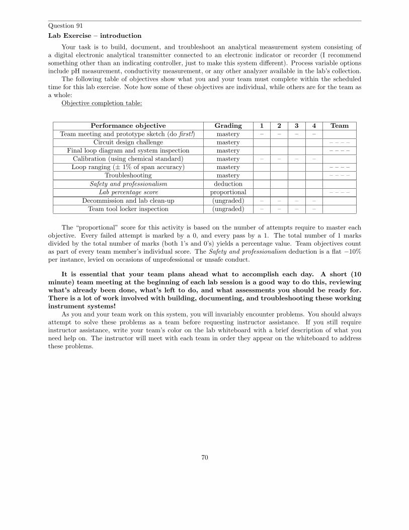
Question 91
Lab Exercise – introduction
Your task is to build, document, and troubleshoot an analytical measurement system consisting ofa digital electronic analytical transmitter connected to an electronic indicator or recorder (I recommendsomething other than an indicating controller, just to make this system different). Process variable optionsinclude pH measurement, conductivity measurement, or any other analyzer available in the lab’s collection.
The following table of objectives show what you and your team must complete within the scheduledtime for this lab exercise. Note how some of these objectives are individual, while others are for the team asa whole:
Objective completion table:
Performance objective Grading 1 2 3 4 TeamTeam meeting and prototype sketch (do first!) mastery – – – –
Circuit design challenge mastery – – – –Final loop diagram and system inspection mastery – – – –
Calibration (using chemical standard) mastery – – – –Loop ranging (± 1% of span accuracy) mastery – – – –
Troubleshooting mastery – – – –
Safety and professionalism deductionLab percentage score proportional – – – –
Decommission and lab clean-up (ungraded) – – – –Team tool locker inspection (ungraded) – – – –
The “proportional” score for this activity is based on the number of attempts require to master eachobjective. Every failed attempt is marked by a 0, and every pass by a 1. The total number of 1 marksdivided by the total number of marks (both 1’s and 0’s) yields a percentage value. Team objectives countas part of every team member’s individual score. The Safety and professionalism deduction is a flat −10%per instance, levied on occasions of unprofessional or unsafe conduct.
It is essential that your team plans ahead what to accomplish each day. A short (10minute) team meeting at the beginning of each lab session is a good way to do this, reviewingwhat’s already been done, what’s left to do, and what assessments you should be ready for.There is a lot of work involved with building, documenting, and troubleshooting these workinginstrument systems!
As you and your team work on this system, you will invariably encounter problems. You should alwaysattempt to solve these problems as a team before requesting instructor assistance. If you still requireinstructor assistance, write your team’s color on the lab whiteboard with a brief description of what youneed help on. The instructor will meet with each team in order they appear on the whiteboard to addressthese problems.
70
Lab Exercise – objectives and expectations
Each objective is assessed at the mastery level, which means it is not complete until it meets allexpectations. Re-tries are allowed, but failed attempts will be recorded and factored into your score forthis lab exercise.
Team meeting and prototype sketch
Read the lab exercise documentation and discuss with your teammates the objectives to beachieved and the time allotted to do so. Formulate a plan to achieve these objectives and draft aprototype design for the system you intend to build. Then, meet with your instructor to presentyour team’s action plan and prototype design. This prototype sketch should be annotated with allexpected physical parameters (e.g. voltage polarities, current directions, fluid pressures, etc.). Beprepared to answer all manner of questions about your team’s goals, planned schedule of work, availableresources, and prototype design, including analysis of the design for specific faults and condition changes.Do not begin construction until your design has been analyzed and approved! Note that multiple meetingsmay be required if the instructor’s assistance is needed to select components influencing your design.
Circuit design challenge
Design, build, and demonstrate the operation of a simple circuit based on random selections by theinstructor, using a digital oscilloscope as the test instrument.
Final loop diagram and system inspection
Create a complete loop diagram of your team’s completed system according to the ISA 5.1 standard, thenshow that the constructed system meets or exceed all standards described in the lab exercise documentation.
Instrument calibration
Calibrate an analytical transmitter against a trusted chemical standard, using a trusted test instrumentfor verifying signal current values. Complete both As-Found and As-Left calibration tables, and tag whencomplete.
Loop ranging
Set the lower- and upper-range values (LRV and URV) in both the transmitter and indicator as randomlyselected by the instructor, demonstrating accurate measurement of the process variable to within ± 1% ofspan.
Troubleshooting
Logically diagnose the nature and location of a fault placed in a working system that your team did notbuild. This will be limited in time, with each student passing or failing individually.
71
Lab Exercise – objectives and expectations (continued)
Lab percentage score
Successful completion of the lab exercise requires demonstrated mastery of all objectives. A percentagevalue is based on the number of attempts required to achieve mastery on these objectives: the number ofobjectives divided by the number of total attempts equals the percentage. Thus, a perfect lab percentagescore is possible only by completing all objectives on the first attempt. Marks given for team objectives factorinto each individual’s score. If one or more members of a team repeatedly compromise team performance,they may be removed from the team and required to complete remaining lab exercises alone.
Deductions from this percentage value will be levied for instances of unsafe or unprofessional conduct(see below), the final result being the lab percentage score.
Safety and professionalism (deduction)
In addition to completing the specified learning objectives in each lab exercise, each student is responsiblefor abiding by all lab safety standards and generally conducting themselves as working professionals (see theGeneral Values, Expectations, and Standards page near the beginning of every worksheet for more detail).Expectations include maintaining an orderly work environment and returning all tools and test equipment bythe end of every school day (team), as well as following clear instructions (e.g. instructions given in equipmentmanuals, lab documentation, verbally by the instructor), communicating with teammates, formulating aplan to complete the lab project in the allotted time, and productively managing time. As with the otherobjectives, chronic patterns of poor performance in this domain may result in the offending student beingremoved from the team. Deductions to the lab percentage score will not be made for performance alreadygraded such as tardiness and attendance.
General format and philosophy
This lab exercise is project-based: the instructor serves as the project engineer, while each student’srole is to implement the standards set for the project while budgeting time and resources to complete it bythe deadline date. Students perform real work as part of the lab exercise, managing their work day andfunctioning much the same as they will on the job. The tools and equipment and materials used are allindustry-standard, and the problems encountered are realistic. This instructional design is intentional, as itis proven effective in teaching project management skills and independent working habits.
When you require the instructor’s assistance to answer a question or to check off an objective, writeyour name (or your team’s name) on the lab room whiteboard. Questions take priority over checkoffs,so please distinguish questions from other requests (e.g. writing a question-mark symbol “?” after yourname makes this clear). There will be times when you must wait for extended periods while theinstructor is busy elsewhere – instant service is an impossibility. Adequate time does exist to complete thelab exercise if you follow all instructions, communicate well, and work productively. Use all “down time”wisely: filling it with tasks not requiring the instructor’s assistance such as other lab objectives, homework,feedback questions, and job searches.
Remember that the lab facility is available to you at all hours of the school day. Students may performnon-hazardous work (e.g. circuit work at less than 30 volts, documentation, low air pressures, generalconstruction not requiring power tools) at any time during the school day without the instructor’s presenceso long as that work does not disturb the learning environment for other students.
DO NOT TAKE SHORTCUTS when completing tasks! Learning requires focused attention andtime on task, which means that most ‘shortcuts” actually circumvent the learning process. Read the labexercise instructions, follow all instructions documented in equipment manuals, and follow all advice givento you by your instructor. Make a good-faith effort to solve all problems on your own before seeking the helpof others. Always remember that this lab exercise is just a means to an end: no one needs you to build thisproject; it is an activity designed to develop marketable knowledge, skills, and self-discipline. In the end itis your professional development that matters most, not the finished project!
72

Lab Exercise – team meeting, prototype sketch, and instrument selection
An important first step in completing this lab exercise is to meet with your instructor as a teamto discuss safety concerns, team performance, and specific roles for team members. If you would like toemphasize exposure to certain equipment (e.g. use a particular type of control system, certain power tools),techniques (e.g. fabrication), or tasks to improve your skill set, this is the time to make requests of yourteam so that your learning during this project will be maximized.
An absolutely essential step in completing this lab exercise is to work together as a team to sketch aprototype diagram showing what you intend to build. This usually takes the form of a simple electricalschematic and/or loop diagram showing all electrical connections between components, as well as any tubingor piping for fluids. This prototype sketch need not be exhaustive in detail, but it does need to show enoughdetail for the instructor to determine if all components will be correctly connected for their safe function.
For example, if you intend to connect field devices to a PLC (Programmable Logic Controller), yourprototype sketch must show how those devices will connect to typical input/output terminals on the PLC,where electrical power will be supplied, etc. Prototype sketches need not show all intermediary connectionsbetween components, such as terminal blocks in junction boxes between the field device and the controller.
You should practice good problem-solving techniques when creating your prototype sketch, such asconsulting equipment manuals for information on component functions and marking directions of electriccurrent, voltage polarities, and identifying electrical sources/loads. Use this task as an opportunity tostrengthen your analytical skills! Remember that you will be challenged in this program to do all of thison your own (during “capstone” assessments), so do not make the mistake of relying on your teammates tofigure this out for you – instead, treat this as a problem you must solve and compare your results with thoseof your teammates.
Your team’s prototype sketch is so important that the instructor will demand you provide this planbefore any construction on your team’s working system begins. Any team found constructing their systemwithout a verified plan will be ordered to cease construction and not resume until a prototype plan hasbeen drafted and approved! Similarly, you should not deviate from the prototype design without instructorapproval, to ensure nothing will be done to harm equipment by way of incorrect connections. Each memberon the team should have ready access to this plan (ideally possessing their own copy of the plan) throughoutthe construction process. Prototype design sketching is a skill and a habit you should cultivate in schooland take with you in your new career.
When selecting field instruments for this lab exercise, choose a process analyzer (a pH analyzer isrecommended) with electronic (4-20 mA) signal output. Many analyzer types, pH included, use remotely-mounted sensing elements along with the transmitter unit. Be sure to locate the appropriate sensing elementsfor your analyzer. For a pH analyzer, this takes the form of a combination electrode stored with its glasssensing bulb immersed in a liquid to prevent dehydration.
Consult documentation from the manufacturer’s website to identify how to properly wire, power, andcalibrate the transmitter. Your instructor will check to see you have located and are familiar with theequipment manual(s).
After locating a suitable instrument and its associated documentation, you should qualitatively test itprior to installing it in your system. For a pH transmitter, this entails inserting the sensing electrode in acup of tap water to see that it registers a pH value somewhere near 7.0 (it may be as low as 5.0 or as highas 8.0, depending on the water quality and the condition of the sensing electrode). If the transmitter fails torespond properly, consult the instructor for assistance before tagging it with a label explaining what it does(or what it fails to do). Be sure not to let the pH electrode become dry, as dehydration will very quicklyruin it!
Bear in mind that analyzers powered by their own (non-loop) power source typically behave as currentsources, and must be connected to the indicating instrument differently than a loop-powered device! Consultthe manufacturer’s documentation for wiring details.
Planning a functioning system should take no more than an hour if the team is workingefficiently, and will save you hours of frustration (and possible component destruction!).
73

Lab Exercise – circuit design challenge
Design, build, and test a circuit to fulfill one of the functions listed below (randomly selected by yourinstructor). All electrical connections must be made using a terminal strip (no solderless breadboards, twistedwires, crimp splices, wire nuts, spring clips, or “alligator” clips permitted). The only electrical source allowedin this circuit will be the function generator.
This exercise tests your ability to apply basic electrical principles to the design, construction, andproving (testing) of a simple passive circuit intended to fulfill a specific function, as well as your ability touse a digital oscilloscope and function generator.
Terminal strip
A B Alt Chop Add
Volts/Div A
Volts/Div B
DC Gnd AC
DC Gnd AC
Invert Intensity Focus
Position
Position
Position
Off
Beam find
LineExt.
AB
ACDC
NormAutoSingle
Slope
Level
Reset
X-Y
Holdoff
LF RejHF Rej
Triggering
Alt
Ext. input
Cal 1 V Gnd Trace rot.
Sec/Div0.5 0.2 0.1
1
10
5
2
20
50 m
20 m
10 m
5 m
2 m
0.5 0.2 0.11
10
5
2
20
50 m
20 m
10 m
5 m
2 m
1 m5 m
25 m
100 m
500 m
2.51
250 µ50 µ
10 µ
2.5 µ
0.5 µ
0.1 µ0.025 µ
off
Digital oscilloscope
Hz
FUNCTION GENERATOR
1 10 100 1k 10k 100k 1M
outputDCfinecoarse
Function generator
The following components and materials will be available to you: terminal strips ; lengths of hook-upwire ; digital oscilloscope ; and function generator. You must provide all electronic components, tools,and digital multimeter (DMM) as well as a copy of this page for your instructor to mark objectives.
SEQUENCE: (1) Instructor chooses criteria; (2) You build and test circuit without any power sources atall; (3) Instructor observes you energizing the circuit for the first time; (4) You demonstrate to the instructorthat the circuit fulfills its intended function.
Circuit function (randomly selected by the instructor):
• Voltage divider with total resistance between and ohms, with a division ratioof :
• Low-pass filter with total impedance between and ohms, with a cutoff frequencyof Hz
• High-pass filter with total impedance between and ohms, with a cutoff frequencyof Hz
• Time-delay charging where the voltage rises to a value of percent of the final (maximum)in seconds
• Time-delay discharging where the voltage falls to a value of percent of the initial (maximum)in seconds
• Phase-shifter with total impedance between and ohms, where the output voltagelags the input voltage by degrees
• Phase-shifter with total impedance between and ohms, where the output voltageleads the input voltage by degrees
Study references: all your textbooks and lessons from the first year of the program. Also,specific modules contained in the Modular Electronics Learning Project which is found online athttp://www.ibiblio.org/kuphaldt/socratic/model/index.html.
74
Lab Exercise – building the system
The Instrumentation lab is set up to facilitate the construction of working instrument “loops,” with overa dozen junction boxes, pre-pulled signal cables, and “racks” set up with 2-inch vertical pipes for mountinginstruments. The only wires you should need to install to build a working system are those connecting thefield instrument to the nearest junction box, and then small “jumper” cables connecting different pre-installedcables together within intermediate junction boxes.
After getting your prototype sketch approved by the instructor, you are cleared to begin building yoursystem. Many analyzers are designed to be panel-mounted rather than field-mounted (attached to 2-inchpipes using special brackets and U-bolts). Feel free to set your panel-mount analyzer on a table or shelf inlieu of mounting it in an actual panel.
Select a specific loop controller or indicator to act as a display for the measured chemical concentration.Your instructor may choose the indicator for your team.
Finally, your analyzer system needs to have a loop number, so all instruments may be properly labeled.This loop number needs to be unique, so that another team does not label their instruments and cables thesame as yours. One way to make your loop number unique is to use the equivalent resistor color-code valuefor your team’s color in the loop number. For example, if you are the “Red” team, your loop number couldbe “2”.
Common mistakes:
• Neglecting to consult the manufacturer’s documentation for field instruments (e.g. how to wire them,how to calibrate them).
• Mounting the field instrument(s) in awkward positions, making it difficult to reach connection terminalsor to remove covers when installed.
• Failing to tug on each and every wire where it terminates to ensure a mechanically sound connection.• Students working on portions of the system in isolation, not sharing with their teammates what they
did and how. It is important that the whole team learns all aspects of their system!
Building a functioning system should take no more than one full lab session (3 hours) ifall components are readily available and the team is working efficiently!
75
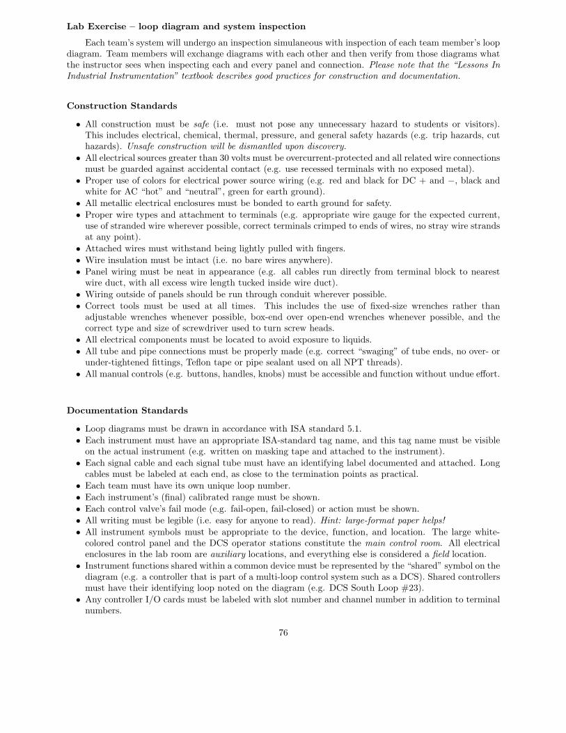
Lab Exercise – loop diagram and system inspection
Each team’s system will undergo an inspection simulaneous with inspection of each team member’s loopdiagram. Team members will exchange diagrams with each other and then verify from those diagrams whatthe instructor sees when inspecting each and every panel and connection. Please note that the “Lessons InIndustrial Instrumentation” textbook describes good practices for construction and documentation.
Construction Standards
• All construction must be safe (i.e. must not pose any unnecessary hazard to students or visitors).This includes electrical, chemical, thermal, pressure, and general safety hazards (e.g. trip hazards, cuthazards). Unsafe construction will be dismantled upon discovery.
• All electrical sources greater than 30 volts must be overcurrent-protected and all related wire connectionsmust be guarded against accidental contact (e.g. use recessed terminals with no exposed metal).
• Proper use of colors for electrical power source wiring (e.g. red and black for DC + and −, black andwhite for AC “hot” and “neutral”, green for earth ground).
• All metallic electrical enclosures must be bonded to earth ground for safety.
• Proper wire types and attachment to terminals (e.g. appropriate wire gauge for the expected current,use of stranded wire wherever possible, correct terminals crimped to ends of wires, no stray wire strandsat any point).
• Attached wires must withstand being lightly pulled with fingers.
• Wire insulation must be intact (i.e. no bare wires anywhere).
• Panel wiring must be neat in appearance (e.g. all cables run directly from terminal block to nearestwire duct, with all excess wire length tucked inside wire duct).
• Wiring outside of panels should be run through conduit wherever possible.
• Correct tools must be used at all times. This includes the use of fixed-size wrenches rather thanadjustable wrenches whenever possible, box-end over open-end wrenches whenever possible, and thecorrect type and size of screwdriver used to turn screw heads.
• All electrical components must be located to avoid exposure to liquids.
• All tube and pipe connections must be properly made (e.g. correct “swaging” of tube ends, no over- orunder-tightened fittings, Teflon tape or pipe sealant used on all NPT threads).
• All manual controls (e.g. buttons, handles, knobs) must be accessible and function without undue effort.
Documentation Standards
• Loop diagrams must be drawn in accordance with ISA standard 5.1.
• Each instrument must have an appropriate ISA-standard tag name, and this tag name must be visibleon the actual instrument (e.g. written on masking tape and attached to the instrument).
• Each signal cable and each signal tube must have an identifying label documented and attached. Longcables must be labeled at each end, as close to the termination points as practical.
• Each team must have its own unique loop number.
• Each instrument’s (final) calibrated range must be shown.
• Each control valve’s fail mode (e.g. fail-open, fail-closed) or action must be shown.
• All writing must be legible (i.e. easy for anyone to read). Hint: large-format paper helps!
• All instrument symbols must be appropriate to the device, function, and location. The large white-colored control panel and the DCS operator stations constitute the main control room. All electricalenclosures in the lab room are auxiliary locations, and everything else is considered a field location.
• Instrument functions shared within a common device must be represented by the “shared” symbol on thediagram (e.g. a controller that is part of a multi-loop control system such as a DCS). Shared controllersmust have their identifying loop noted on the diagram (e.g. DCS South Loop #23).
• Any controller I/O cards must be labeled with slot number and channel number in addition to terminalnumbers.
76

• Each location (e.g. field, junction box, control room) must be clearly delineated with vertical seperationlines on the diagram.
• Each diagram must be sufficiently detailed so that no other student will have difficulty locatingcomponents (e.g. “Where is the controller for this loop?”) or determining important configurationparameters (e.g. range settings).
Sample diagrams are provided in this worksheet (immediately following the lab exercise documentation),and each student is urged to use these sample diagrams as references when drafting their own. The “LessonsIn Industrial Instrumentation” textbook also describes ISA-standard documentation practices.
Common mistakes:
• Incorrect tag name format, using letters that do not conform to the ISA 5.1 standard (e.g. including“PLC” or “DCS” in a controller’s tag name).
• Forgetting that every instrument’s tag name in a loop must begin with the same letter, and that thisfirst letter represents the process variable being measured/controlled.
• Forgetting to label all field instruments with their own tag names (e.g. AT-83).• Failing to label termination points (e.g. terminal block screws) exactly as they are labeled in real life.• Poor use of space on the diagram paper, causing some portions of the diagram to become “crowded”
rather than all components being evenly spaced. Hint: begin your diagram by sketching the fieldinstrument at the far left of the paper and the control room instrument at the far right of the paper, thendraw all other instruments and connections in between!
• Forgetting to label all signal wires (see example loop diagrams).• Forgetting to note all wire colors.• Forgetting to put your name on the loop diagram!• Leaving junction box cables outside of wire duct, looking messy.• Leaving wire duct covers off.• Basing your diagram off of a team-mate’s diagram, rather than closely inspecting the system for yourself.• Not placing loop sheet instruments in the correct orientation (field instruments on the left, control room
instruments on the right).
Creating and inspecting accurate loop diagrams should take no more than one full labsession (3 hours) if the team is working efficiently!
77

Lab Exercise – instrument calibration
Each team must calibrate the transmitter to ensure it interprets chemical composition accurately andoutputs an accurate current. Then, each team member must configure the transmitter for a unique range(set the LRV and URV parameters) and scale the indicator to register in the proper engineering units (e.g. apH analyzer ranged for 4 to 12 pH should actually register 4 to 12 pH back at the control room display). Theaccuracy of this ranging will be checked by the instructor stimulating the analyzer with a random samplewhile each student verifies the indicator display.
As in all cases where an instrument must be calibrated, you will need to check the instrument’s responseagainst one or more standards. In this case, the ideal standard to use for an analyzer is a chemical solutionof precisely known composition. For pH instruments, this takes the form of pH buffer solutions, easily mixedfrom distilled water and pH buffer powder. For gas analyzers, this takes the form of either ambient air(21% oxygen content) or more likely bottled calibration gases. Chemical calibration standards will be madeavailable by the instructor, and should be used sparingly as they tend to be expensive.
78
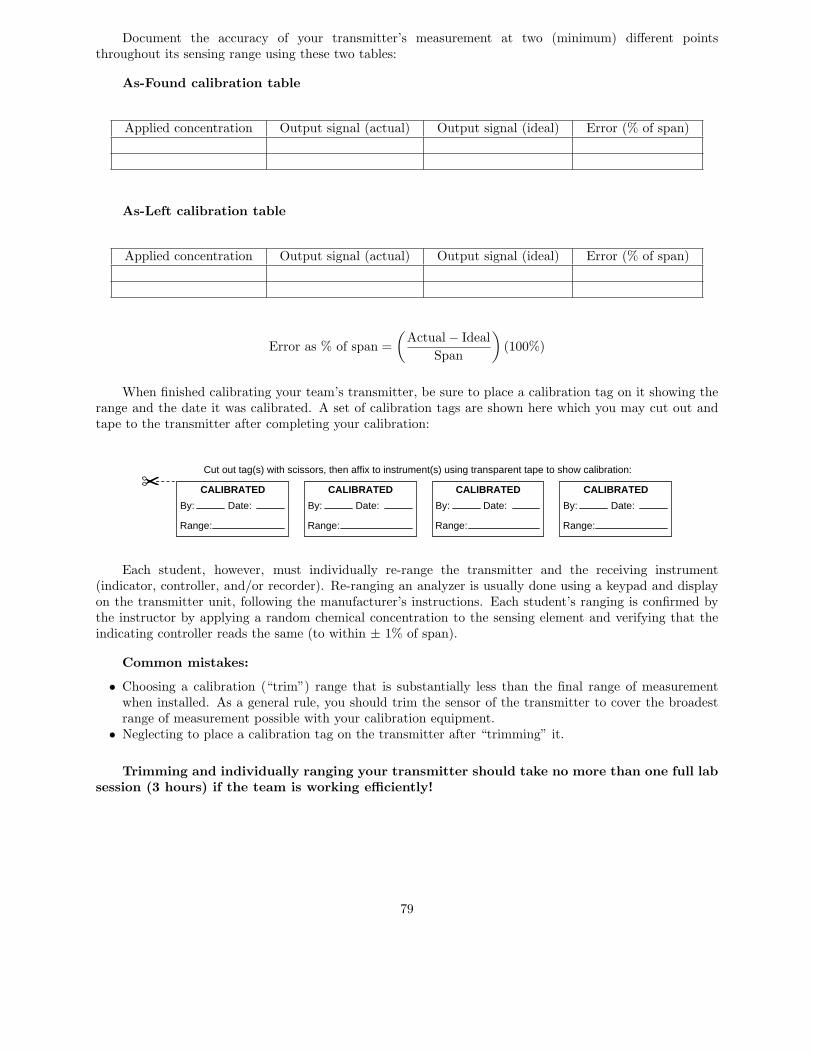
Document the accuracy of your transmitter’s measurement at two (minimum) different pointsthroughout its sensing range using these two tables:
As-Found calibration table
Applied concentration Output signal (actual) Output signal (ideal) Error (% of span)
As-Left calibration table
Applied concentration Output signal (actual) Output signal (ideal) Error (% of span)
Error as % of span =
(
Actual − Ideal
Span
)
(100%)
When finished calibrating your team’s transmitter, be sure to place a calibration tag on it showing therange and the date it was calibrated. A set of calibration tags are shown here which you may cut out andtape to the transmitter after completing your calibration:
CALIBRATED
By: Date:
Range:
CALIBRATED
By: Date:
Range:
CALIBRATED
By: Date:
Range:
CALIBRATED
By: Date:
Range:
Cut out tag(s) with scissors, then affix to instrument(s) using transparent tape to show calibration:
Each student, however, must individually re-range the transmitter and the receiving instrument(indicator, controller, and/or recorder). Re-ranging an analyzer is usually done using a keypad and displayon the transmitter unit, following the manufacturer’s instructions. Each student’s ranging is confirmed bythe instructor by applying a random chemical concentration to the sensing element and verifying that theindicating controller reads the same (to within ± 1% of span).
Common mistakes:
• Choosing a calibration (“trim”) range that is substantially less than the final range of measurementwhen installed. As a general rule, you should trim the sensor of the transmitter to cover the broadestrange of measurement possible with your calibration equipment.
• Neglecting to place a calibration tag on the transmitter after “trimming” it.
Trimming and individually ranging your transmitter should take no more than one full labsession (3 hours) if the team is working efficiently!
79
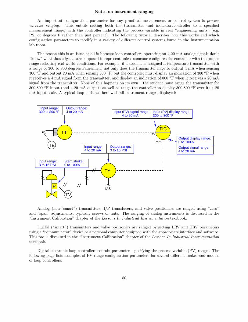
Notes on instrument ranging
An important configuration parameter for any practical measurement or control system is processvariable ranging. This entails setting both the transmitter and indicator/controller to a specifiedmeasurement range, with the controller indicating the process variable in real “engineering units” (e.g.PSI or degrees F rather than just percent). The following tutorial describes how this works and whichconfiguration parameters to modify in a variety of different control systems found in the Instrumentationlab room.
The reason this is an issue at all is because loop controllers operating on 4-20 mA analog signals don’t“know” what those signals are supposed to represent unless someone configures the controller with the properrange reflecting real-world conditions. For example, if a student is assigned a temperature transmitter witha range of 300 to 800 degrees Fahrenheit, not only does the transmitter have to output 4 mA when sensing300 oF and output 20 mA when sensing 800 oF, but the controller must display an indication of 300 oF whenit receives a 4 mA signal from the transmitter, and display an indication of 800 oF when it receives a 20 mAsignal from the transmitter. None of this happens on its own – the student must range the transmitter for300-800 oF input (and 4-20 mA output) as well as range the controller to display 300-800 oF over its 4-20mA input scale. A typical loop is shown here with all instrument ranges displayed:
TE
TT
TY
TIC
P IAS
TV
Input range: Output range:300 to 800 oF 4 to 20 mA
4 to 20 mA 300 to 800 oF
Output display range:
Output signal range:4 to 20 mA
0 to 100%Input range: Output range:4 to 20 mA 3 to 15 PSI
Input range:3 to 15 PSI
Stem stroke:0 to 100%
Input (PV) signal range: Input (PV) display range:
PV
Output
Analog (non-“smart”) transmitters, I/P transducers, and valve positioners are ranged using “zero”and “span” adjustments, typically screws or nuts. The ranging of analog instruments is discussed in the“Instrument Calibration” chapter of the Lessons In Industrial Instrumentation textbook.
Digital (“smart”) transmitters and valve positioners are ranged by setting LRV and URV parametersusing a “communicator” device or a personal computer equipped with the appropriate interface and software.This too is discussed in the “Instrument Calibration” chapter of the Lessons In Industrial Instrumentationtextbook.
Digital electronic loop controllers contain parameters specifying the process variable (PV) ranges. Thefollowing page lists examples of PV range configuration parameters for several different makes and modelsof loop controllers.
80

Notes on instrument ranging (continued)
• Siemens/Moore 352 controller: process variable range parameters are located in the “Operator’s Display”function block (FB15):→ LRV = Process Lo→ URV = Process Hi
• Siemens/Moore 352P and 353 controller: process variable range parameters are located in the “AnalogInput” function block (AIN):→ LRV = Minscale→ URV = Maxscale
• Emerson DeltaV DCS: process variable range parameters are located in the “Analog Input” functionblock (AI) and “PID” function block (PID):→ (AI block) = the OUT SCALE parameter contains both high and low range limits, engineering
units (e.g. deg F), and decimal point position. The L Type parameter needs to be set to “indirect”to allow scaling to occur (“direct” mode prohibits scaling), and the XD Scale parameter needs tobe ranged 0 to 100%. Note that the “direct” and “indirect” options for L Type have absolutelynothing to do with “direct” and “reverse” PID controller action, which is configured elsewhere.
→ (PID block) = the PV SCALE parameter contains both high and low range limits, engineeringunits (e.g. deg F), and decimal point position. Note: the PID block’s PV SCALE range mustexactly match the OUT SCALE range of the AI block!
• Honeywell UDC 2500 controller: process variable input #1 range parameters are located in the “Input1” set-up group of parameters:→ LRV = IN1 LO→ URV = IN1 HI
• Automation Direct “SOLO” controller: process variable range parameters are located in the followingregisters:→ LRV = P3-4 Input Range Low→ URV = P3-3 Input Range High
• Allen-Bradley PLC5, SLC500, and MicroLogix controllers: process variable scaling parameters aretypically located either in a “Scale” instruction (SCL) or a “Scale with Parameters” instruction (SCP).In either case, the instruction takes the raw count value from the input channel’s analog-to-digitalconverter and scales it into the desired process variable display range. A YouTube video on ourBTCInstrumentation channel shows how to do this for the networked MicroLogix PLCs in the labusing the SCP instruction. Note: SCP instruction parameters may be edited online. For this reason,downloading edits is not necessary for the MicroLogix PLCs in our lab. In fact, it is very important thatyou not save or download the PLC program, because doing so may alter the PLC’s network address andlead to communication problems. Just make the changes while the PLC is in “Run” mode and then exitthe program:→ (SCL instruction) = Rate and Offset values scale the signal according to the slope-intercept formula
y = mx + b, where Rate is 10000m and Offset is b
→ (SCP instruction LRV) = Scaled Min.→ (SCP instruction URV) = Scaled Max.
• Allen-Bradley Logix5000 controller: process variable scaling parameters are located in the “PID”instruction (PID):→ LRV = .MINS→ URV = .MAXS
81

Notes on instrument ranging (continued)
• caSCADA “pid” control program: process variable scaling parameters are located in one of the sourcecode files which must be modified using a text editor program, then recompiling the pid program so thenew parameters may take effect. This control program may be initiated from the Linux command lineby typing ./pid and pressing the Enter key, after which a set of instructions will appear on the screenshowing the default LRV and URV range values, and which file to find these parameters within. Afterediting and saving this file, you will need to type make at the Linux command line and press Enter torecompile the program. Finally, type ./pid and press Enter to initiate the recompiled program.→ LRV = pid[0].LRV→ URV = pid[0].URV
file ranging
82
Lab Exercise – troubleshooting
The most important aspect of this lab exercise is troubleshooting, where you demonstrate your abilityto logically isolate a problem in the system. All troubleshooting must be done on a system you did not helpbuild, so that you must rely on others’ documentation to find your way around the system instead of fromyour own memory of building it. Each student is given a limited amount of time to identify both the locationand nature of the fault. All troubleshooting activities must be proctored by the instructor to assess properdiagnostic reasoning and technique.
The standard procedure involves a group of no more than four students troubleshooting the same faultedsystem, with the builders of that system playing the role of operators. All troubleshooters are given a two-minute period to individually identify a plausible fault based on observable symptoms and submit it inwriting to the instructor for assessment. Those students whose faults are indeed plausible advance to thenext round, where each one takes turns making diagostic tests on the system. One minute is given to eachstudent for devising this test, but no time limit is placed on the execution of that test. Whenever someonedecides enough data has been collected to pinpoint the location and nature of the fault, they declare to havereached a conclusion and submit to the instructor in writing for assessment.
Individual troubleshooting with a five-minute time limit is also an acceptable format, but this generallyonly works with small class sizes.
Failure to correctly identify both the general location and nature of the fault within the allotted time,and/or failing to demonstrate rational diagnostic procedure to the supervising instructor will disqualify theeffort, in which case the student must re-try with a different fault.
A standard multimeter is the only test equipment allowed during the time limit. No diagnostic circuitbreaks are allowed except by instructor permission, and then only after correctly explaining what troublethis could cause in a real system.
The instructor will review each troubleshooting effort after completion, highlighting good and bad pointsfor the purpose of learning. Troubleshooting is a skill born of practice and failure, so do not be disappointedin yourself if you must make multiple attempts to pass! One of the important life-lessons embedded in thisactivity is how to deal with failure, because it will eventually happen to you on the job! There is no dishonorin failing to properly diagnose a fault after doing your level best. The only dishonor is in taking shortcutsor in giving up.
Common mistakes:
• Attempting to visually locate the fault.• Neglecting to take measurements with your multimeter.• Neglecting to check other measurements in the system (e.g. pressure gauge readings).• Incorrectly interpreting the loop diagram (e.g. thinking you’re at the wrong place in the system when
taking measurements).• Incorrect multimeter usage (e.g. AC rather than DC, wrong range, wrong test lead placement). This is
especially true when a student comes to lab unprepared and must borrow someone else’s meter that isdifferent from theirs!
The purpose of every troubleshooting exercise is to foster and assess your ability tointelligently diagnose a complex system. Finding the fault by luck, or by trial-and-errorinspection, is no demonstration of skill. Competence is only revealed by your demonstratedability to logically analyze and isolate the problem, correctly explaining all your steps!
Troubleshooting takes a lot of lab time, usually at least two 3-hour lab sessions for everyonein a full class to successfully pass. Budget for this amount of time as you plan your work, andalso be sure to take advantage of your freedom to observe others as they troubleshoot.
83

Lab Exercise – decommissioning and clean-up
The final step of this lab exercise is to decommission your team’s entire system and re-stock certaincomponents back to their proper storage locations, the purpose of which being to prepare the lab for thenext lab exercise. Remove your system documentation (e.g. loop diagram) from the common holding area,either discarding it or keeping it for your own records. Also, remove instrument tag labels (e.g. FT-101)from instruments and from cables. Perform general clean-up of your lab space, disposing of all trash, placingall tools back in their proper storage locations, sweeping up bits of wire off the floor and out of junctionboxes, etc.
Leave the following components in place, mounted on the racks:
• Large control valves and positioners• I/P transducers• Large electric motors• Large variable-frequency drive (VFD) units• Cables inside conduit interconnecting junction boxes together• Pipe and tube fittings (do not unscrew pipe threads)• Supply air pressure regulators
Return the following components to their proper storage locations:
• Sensing elements (e.g. thermocouples, pH probes, etc.)• Process transmitters• “Jumper” cables used to connect terminal blocks within a single junction box• Plastic tubing and tube fittings (disconnect compression-style tube fittings)• Power cables and extension cords• Adjustment (loading station) air pressure regulators
Finally, you shall return any control system components to their original (factory default) configurations.This includes controller PID settings, function block programs, input signal ranges, etc.
84

Lab Exercise – team tool locker inspection
The instructor will work with each team to inspect their tool locker for all required items, and also toensure nothing else is being stored there.
First, the locker will be entirely emptied. Next, the instructor will inspect each tool before placing itin the locker, following the order of the inventory list taped to the inside of the locker door. The team isresponsible for finding or replacing any missing items. Any items not on the inventory list will be left out ofthe locker.
Any damaged or worn components will be replaced. Inexpensive items such as drill bits and taps willbe replaced at student expense. More expensive items will be replaced at the school’s expense, with studentsdoing research to identify the replacement cost of the item(s) in question.
file i01294
85
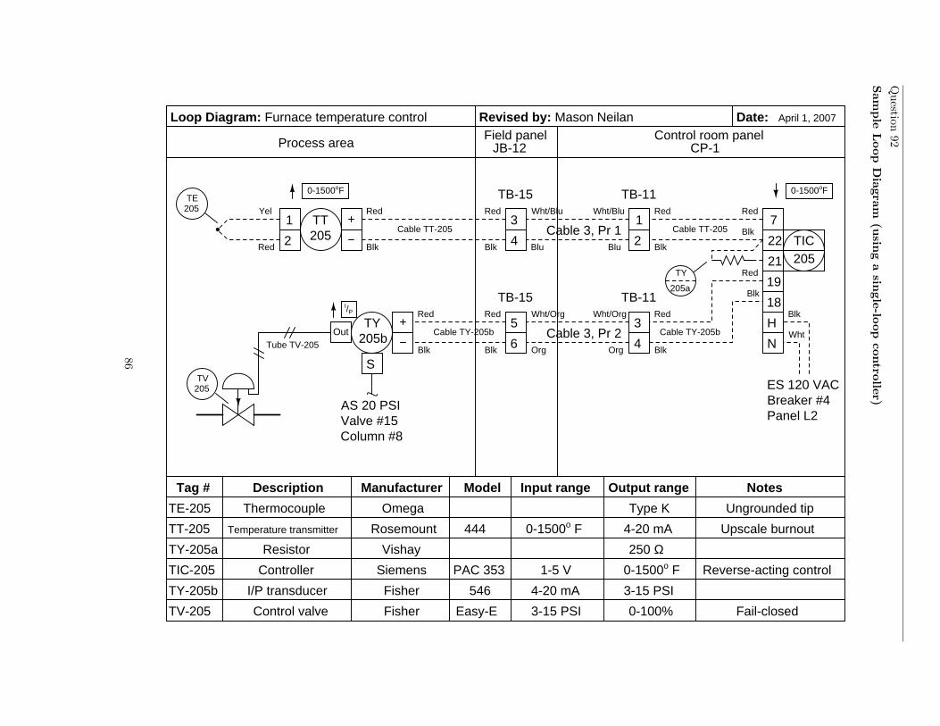
Question
92
Sam
ple
Loop
Dia
gra
m(u
sing
asin
gle
-loop
contro
ller)
Process areaField panel Control room panel
Controller
Resistor
I/P transducer
Control valve
I/P
ES 120 VAC
AS 20 PSI
Loop Diagram: Furnace temperature control
TT205
JB-12
TB-15
TB-15
3
4
1
2
Temperature transmitterTT-205 Rosemount 444
TE205
CP-1
TB-11
TB-11
1
2
7
Vishay 250 ΩTY-205a
TIC-205 Siemens PAC 353
TY-205b
TV-205 Fisher Easy-E 3-15 PSI
Fisher
H
N
3
4
22
21
19
18
TY205b
TY
205a
Breaker #4Panel L2
5
6Cable TY-205b
Cable TT-205 Cable TT-205
Cable TY-205b
TIC205
Revised by: Mason Neilan
TV205
Tube TV-205
Column #8Valve #15
546
0-1500oF 0-1500oF
Fail-closed
Reverse-acting control
TE-205 Thermocouple Omega Type K Ungrounded tip
Red
BlkRed
Yel Red
Blk
Red
Blk
Red
Blk
Wht/Blu
Blu Blu
Wht/Blu
Cable 3, Pr 1
Cable 3, Pr 2
Wht/Org
Org Org
Wht/Org
Blk
Red
Blk
Red
Blk
Wht
Red
Blk
Red
Blk
Upscale burnout
Description Manufacturer Model Notes
Date:
Tag # Input range Output range
0-1500o F 4-20 mA
4-20 mA 3-15 PSI
0-100%
1-5 V 0-1500o F
April 1, 2007
Out
S
86
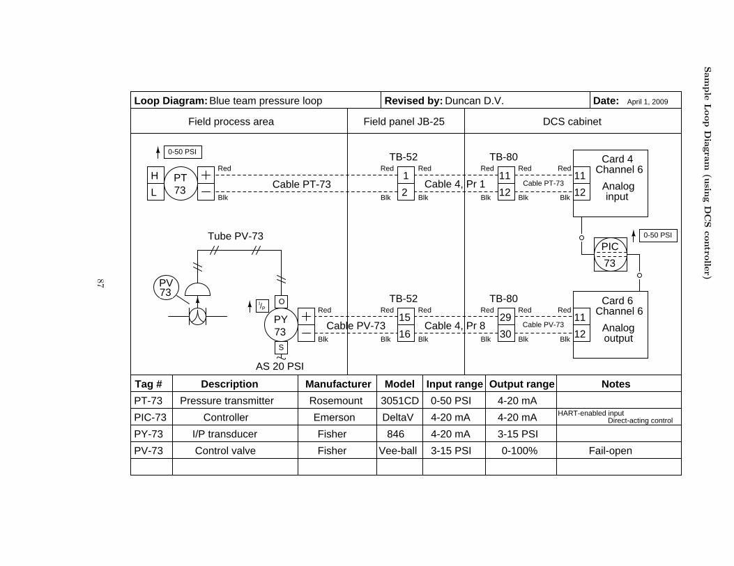
Sam
ple
Loop
Dia
gra
m(u
sing
DC
Scontro
ller)
Field process area
Description Manufacturer Model Notes
Loop Diagram: Revised by: Date:
DCS cabinet
Red
Blk
Red
Blk
Red
Blk
Fisher
Fisher
Tag # Input range Output range
Blue team pressure loop April 1, 2009
Card 4
Card 6Channel 6
Channel 611
12
29
30
Red
Blk
TB-80
TB-80
Field panel JB-25
TB-52
TB-52
PT-6 Pressure transmitter Rosemount 3051CD 0-50 PSI 4-20 mA
PIC6
PT6
Cable 4, Pr 1
Cable 4, Pr 8
1
2
15
16
Cable PT-6
Red
Blk
Red
Blk
Red
Blk
Red
Blk
Red
Blk
Red
Blk
Red
Blk
Red
Blk
Cable PV-6
11
12
11
12PY6
AS 20 PSI
PV6
0-50 PSI
I/P
0-50 PSI
846
Emerson DeltaV 4-20 mA 4-20 mA HART-enabled inputPIC-6
PY-6
PV-6
I/P transducer
Controller
Control valve Vee-ball
4-20 mA 3-15 PSI
3-15 PSI 0-100% Fail-open
Duncan D.V.
Tube PV-6
Cable PT-6
Cable PV-6
Analog input
Analogoutput
Direct-acting control
H
L
73
73
73 Cable PT-73 Cable PT-73
Cable PV-73Cable PV-73
PT-73
PIC-73
PY-73
PV-73
73
PIC
S
O
Tube PV-73
87
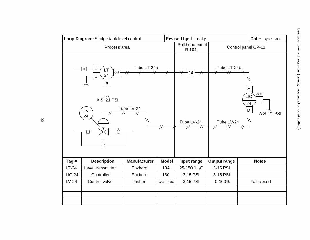
Sam
ple
Loop
Dia
gra
m(u
sing
pneum
atic
contro
ller)
Description Manufacturer Model Notes
Loop Diagram: Revised by: Date:
Tag # Input range Output range
LT24
In
H
LOut
C
D
A.S. 21 PSI
Tube LT-24a Tube LT-24b
A.S. 21 PSI
Process areaBulkhead panel
14
B-104Control panel CP-11
Tube LV-24
LV24
Tube LV-24
Supply
LIC
24
Tube LV-24
(vent)
Sludge tank level control I. Leaky April 1, 2008
LT-24 Level transmitter Foxboro 13A 25-150 "H2O 3-15 PSI
3-15 PSI 3-15 PSIFoxboroLIC-24 130
LV-24 Fisher Easy-E / 667 3-15 PSI 0-100% Fail closedControl valve
Controller
88
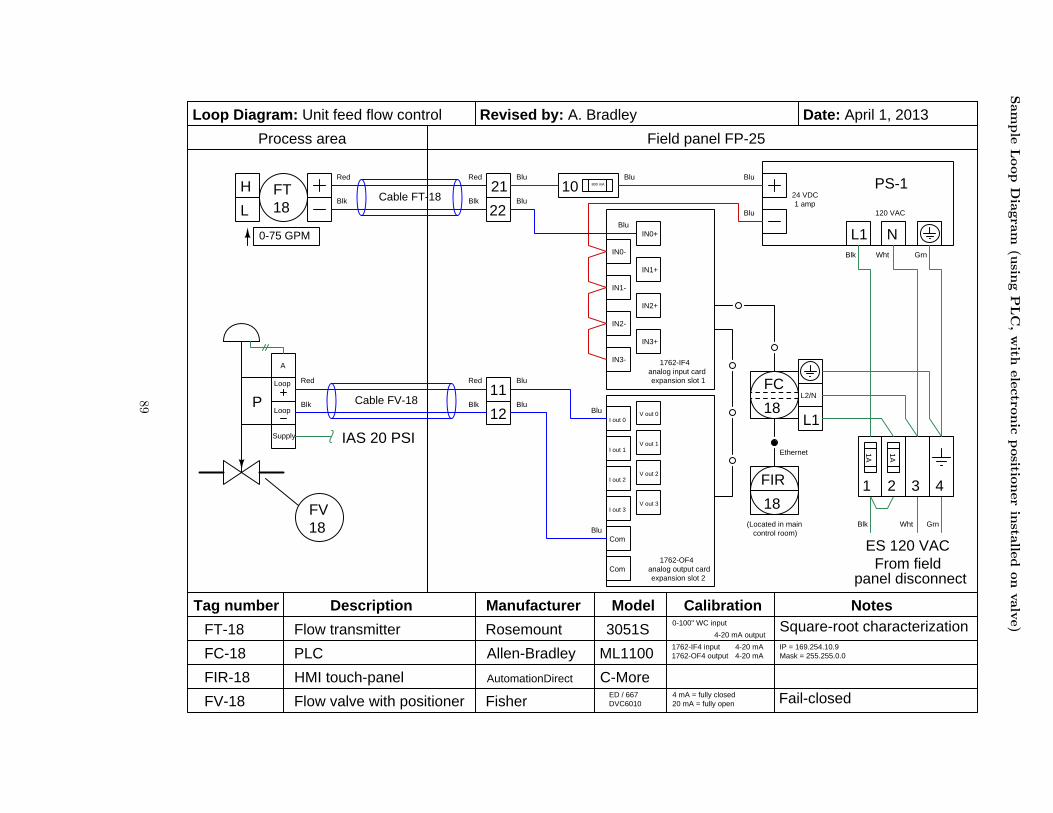
Sam
ple
Loop
Dia
gra
m(u
sing
PLC
,w
ithele
ctro
nic
positio
ner
insta
lled
on
valv
e)
Tag number Description Manufacturer Model Calibration Notes
ES 120 VAC
Red
Blk
Red
Process area
From fieldpanel disconnect
1 2 3 4
1A
Blk Wht Grn
21
11
12
1A10 PS-1
120 VAC
24 VDC1 amp
L1 NIN0+
IN1+
IN2+
IN3+
IN0-
IN1-
IN2-
IN3-
Blk Wht Grn
1762-IF4analog input card
L1
L2/N
Allen-Bradley ML11001762-IF4 input 4-20 mA
Rosemount 4-20 mA output
Blu Blu Blu
Blu
Blu
Blu
expansion slot 1
analog input cardexpansion slot 2
PLC
AutomationDirect C-More
Ethernet
Mask = 255.255.0.0
HMI touch-panel
800 mA
22BluBlk
FT
18
18
18
FIR
FC
1762-OF4
Cable FT-18
FT-18
FC-18
FIR-18
Flow transmitter 3051S0-100" WC input
IP = 169.254.10.91762-OF4 output 4-20 mA
P Cable FV-18V out 0
V out 1
V out 2
V out 3
Com
Com
I out 0
I out 1
I out 2
I out 3
Blu
Blu
Blu
Loop Red
Blk
Red
Blk
18FV
FV-18 Flow valve with positioner FisherED / 667DVC6010
IAS 20 PSI
4 mA = fully closed20 mA = fully open Fail-closed
Square-root characterization
H
L
Loop Diagram: Unit feed flow control Revised by: A. Bradley Date: April 1, 2013
Field panel FP-25
Loop
Supply
A
0-75 GPM
(Located in maincontrol room)
analog output card
89

Lab Exercise – loop diagram and system inspection
Each team’s system will undergo an inspection simulaneous with inspection of each team member’s loopdiagram. Team members will exchange diagrams with each other and then verify from those diagrams whatthe instructor sees when inspecting each and every panel and connection. Please note that the “Lessons InIndustrial Instrumentation” textbook describes good practices for construction and documentation.
Construction Standards
• All construction must be safe (i.e. must not pose any unnecessary hazard to students or visitors).This includes electrical, chemical, thermal, pressure, and general safety hazards (e.g. trip hazards, cuthazards). Unsafe construction will be dismantled upon discovery.
• All electrical sources greater than 30 volts must be overcurrent-protected and all related wire connectionsmust be guarded against accidental contact (e.g. use recessed terminals with no exposed metal).
• Proper use of colors for electrical power source wiring (e.g. red and black for DC + and −, black andwhite for AC “hot” and “neutral”, green for earth ground).
• All metallic electrical enclosures must be bonded to earth ground for safety.
• Proper wire types and attachment to terminals (e.g. appropriate wire gauge for the expected current,use of stranded wire wherever possible, correct terminals crimped to ends of wires, no stray wire strandsat any point).
• Attached wires must withstand being lightly pulled with fingers.
• Wire insulation must be intact (i.e. no bare wires anywhere).
• Panel wiring must be neat in appearance (e.g. all cables run directly from terminal block to nearestwire duct, with all excess wire length tucked inside wire duct).
• Wiring outside of panels should be run through conduit wherever possible.
• Correct tools must be used at all times. This includes the use of fixed-size wrenches rather thanadjustable wrenches whenever possible, box-end over open-end wrenches whenever possible, and thecorrect type and size of screwdriver used to turn screw heads.
• All electrical components must be located to avoid exposure to liquids.
• All tube and pipe connections must be properly made (e.g. correct “swaging” of tube ends, no over- orunder-tightened fittings, Teflon tape or pipe sealant used on all NPT threads).
• All manual controls (e.g. buttons, handles, knobs) must be accessible and function without undue effort.
Documentation Standards
• Loop diagrams must be drawn in accordance with ISA standard 5.1.
• Each instrument must have an appropriate ISA-standard tag name, and this tag name must be visibleon the actual instrument (e.g. written on masking tape and attached to the instrument).
• Each signal cable and each signal tube must have an identifying label documented and attached. Longcables must be labeled at each end, as close to the termination points as practical.
• Each team must have its own unique loop number.
• Each instrument’s (final) calibrated range must be shown.
• Each control valve’s fail mode (e.g. fail-open, fail-closed) or action must be shown.
• All writing must be legible (i.e. easy for anyone to read). Hint: large-format paper helps!
• All instrument symbols must be appropriate to the device, function, and location. The large white-colored control panel and the DCS operator stations constitute the main control room. All electricalenclosures in the lab room are auxiliary locations, and everything else is considered a field location.
• Instrument functions shared within a common device must be represented by the “shared” symbol on thediagram (e.g. a controller that is part of a multi-loop control system such as a DCS). Shared controllersmust have their identifying loop noted on the diagram (e.g. DCS South Loop #23).
• Any controller I/O cards must be labeled with slot number and channel number in addition to terminalnumbers.
90

• Each location (e.g. field, junction box, control room) must be clearly delineated with vertical seperationlines on the diagram.
• Each diagram must be sufficiently detailed so that no other student will have difficulty locatingcomponents (e.g. “Where is the controller for this loop?”) or determining important configurationparameters (e.g. range settings).
Sample diagrams are provided in this worksheet (immediately following the lab exercise documentation),and each student is urged to use these sample diagrams as references when drafting their own. The “LessonsIn Industrial Instrumentation” textbook also describes ISA-standard documentation practices.
Common mistakes:
• Incorrect tag name format, using letters that do not conform to the ISA 5.1 standard (e.g. including“PLC” or “DCS” in a controller’s tag name).
• Forgetting that every instrument’s tag name in a loop must begin with the same letter, and that thisfirst letter represents the process variable being measured/controlled.
• Forgetting to label all field instruments with their own tag names (e.g. AT-83).• Failing to label termination points (e.g. terminal block screws) exactly as they are labeled in real life.• Poor use of space on the diagram paper, causing some portions of the diagram to become “crowded”
rather than all components being evenly spaced. Hint: begin your diagram by sketching the fieldinstrument at the far left of the paper and the control room instrument at the far right of the paper, thendraw all other instruments and connections in between!
• Forgetting to label all signal wires (see example loop diagrams).• Forgetting to note all wire colors.• Forgetting to put your name on the loop diagram!• Leaving junction box cables outside of wire duct, looking messy.• Leaving wire duct covers off.• Basing your diagram off of a team-mate’s diagram, rather than closely inspecting the system for yourself.• Not placing loop sheet instruments in the correct orientation (field instruments on the left, control room
instruments on the right).
Creating and inspecting accurate loop diagrams should take no more than one full labsession (3 hours) if the team is working efficiently!
file i00654
91
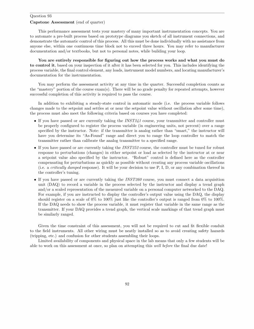
Question 93
Capstone Assessment (end of quarter)
This performance assessment tests your mastery of many important instrumentation concepts. You areto automate a pre-built process based on prototype diagrams you sketch of all instrument connections, anddemonstrate the automatic control of this process. All this must be done individually with no assistance fromanyone else, within one continuous time block not to exceed three hours. You may refer to manufacturerdocumentation and/or textbooks, but not to personal notes, while building your loop.
You are entirely responsible for figuring out how the process works and what you must doto control it, based on your inspection of it after it has been selected for you. This includes identifying theprocess variable, the final control element, any loads, instrument model numbers, and locating manufacturer’sdocumentation for the instrumentation.
You may perform the assessment activity at any time in the quarter. Successful completion counts asthe “mastery” portion of the course exam(s). There will be no grade penalty for repeated attempts, howeversuccessful completion of this activity is required to pass the course.
In addition to exhibiting a steady-state control in automatic mode (i.e. the process variable followschanges made to the setpoint and settles at or near the setpoint value without oscillation after some time),the process must also meet the following criteria based on courses you have completed:
• If you have passed or are currently taking the INST241 course, your transmitter and controller mustbe properly configured to register the process variable (in engineering units, not percent) over a rangespecified by the instructor. Note: if the transmitter is analog rather than “smart,” the instructor willhave you determine its “As-Found” range and direct you to range the loop controller to match thetransmitter rather than calibrate the analog transmitter to a specified range.
• If you have passed or are currently taking the INST252 course, the controller must be tuned for robustresponse to perturbations (changes) in either setpoint or load as selected by the instructor at or neara setpoint value also specified by the instructor. “Robust” control is defined here as the controllercompensating for perturbations as quickly as possible without creating any process variable oscillations(i.e. a critically damped response). It will be your decision to use P, I, D, or any combination thereof inthe controller’s tuning.
• If you have passed or are currently taking the INST260 course, you must connect a data acquisitionunit (DAQ) to record a variable in the process selected by the instructor and display a trend graphand/or a scaled representation of the measured variable on a personal computer networked to the DAQ.For example, if you are instructed to display the controller’s output value using the DAQ, the displayshould register on a scale of 0% to 100% just like the controller’s output is ranged from 0% to 100%.If the DAQ needs to show the process variable, it must register that variable in the same range as thetransmitter. If your DAQ provides a trend graph, the vertical scale markings of that trend graph mustbe similarly ranged.
Given the time constraint of this assessment, you will not be required to cut and fit flexible conduitto the field instruments. All other wiring must be neatly installed so as to avoid creating safety hazards(tripping, etc.) and confusion for other students assembling their loops.
Limited availability of components and physical space in the lab means that only a few students will beable to work on this assessment at once, so plan on attempting this well before the final due date!
92
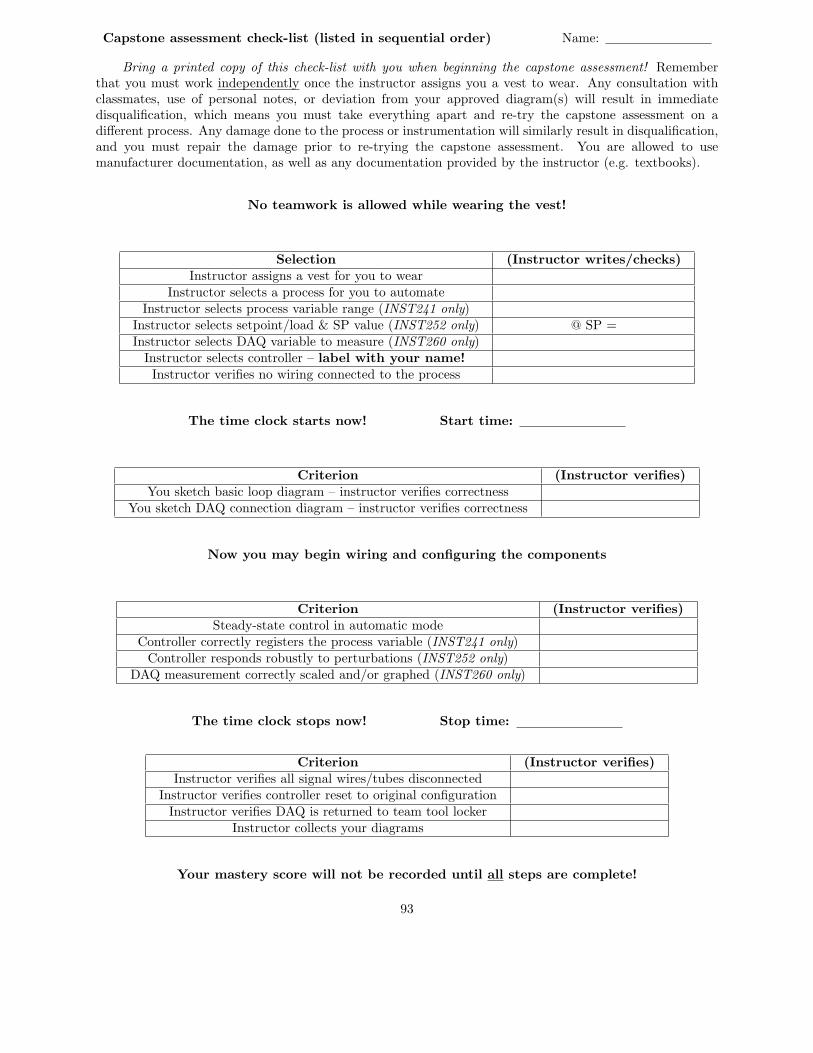
Capstone assessment check-list (listed in sequential order) Name:
Bring a printed copy of this check-list with you when beginning the capstone assessment! Rememberthat you must work independently once the instructor assigns you a vest to wear. Any consultation withclassmates, use of personal notes, or deviation from your approved diagram(s) will result in immediatedisqualification, which means you must take everything apart and re-try the capstone assessment on adifferent process. Any damage done to the process or instrumentation will similarly result in disqualification,and you must repair the damage prior to re-trying the capstone assessment. You are allowed to usemanufacturer documentation, as well as any documentation provided by the instructor (e.g. textbooks).
No teamwork is allowed while wearing the vest!
Selection (Instructor writes/checks)Instructor assigns a vest for you to wear
Instructor selects a process for you to automateInstructor selects process variable range (INST241 only)
Instructor selects setpoint/load & SP value (INST252 only) @ SP =Instructor selects DAQ variable to measure (INST260 only)
Instructor selects controller – label with your name!Instructor verifies no wiring connected to the process
The time clock starts now! Start time:
Criterion (Instructor verifies)You sketch basic loop diagram – instructor verifies correctness
You sketch DAQ connection diagram – instructor verifies correctness
Now you may begin wiring and configuring the components
Criterion (Instructor verifies)Steady-state control in automatic mode
Controller correctly registers the process variable (INST241 only)Controller responds robustly to perturbations (INST252 only)
DAQ measurement correctly scaled and/or graphed (INST260 only)
The time clock stops now! Stop time:
Criterion (Instructor verifies)Instructor verifies all signal wires/tubes disconnected
Instructor verifies controller reset to original configurationInstructor verifies DAQ is returned to team tool locker
Instructor collects your diagrams
Your mastery score will not be recorded until all steps are complete!
93

Notes on instrument ranging
An important configuration parameter for any practical measurement or control system is processvariable ranging. This entails setting both the transmitter and indicator/controller to a specifiedmeasurement range, with the controller indicating the process variable in real “engineering units” (e.g.PSI or degrees F rather than just percent). The following tutorial describes how this works and whichconfiguration parameters to modify in a variety of different control systems found in the Instrumentationlab room.
The reason this is an issue at all is because loop controllers operating on 4-20 mA analog signals don’t“know” what those signals are supposed to represent unless someone configures the controller with the properrange reflecting real-world conditions. For example, if a student is assigned a temperature transmitter witha range of 300 to 800 degrees Fahrenheit, not only does the transmitter have to output 4 mA when sensing300 oF and output 20 mA when sensing 800 oF, but the controller must display an indication of 300 oF whenit receives a 4 mA signal from the transmitter, and display an indication of 800 oF when it receives a 20 mAsignal from the transmitter. None of this happens on its own – the student must range the transmitter for300-800 oF input (and 4-20 mA output) as well as range the controller to display 300-800 oF over its 4-20mA input scale. A typical loop is shown here with all instrument ranges displayed:
TE
TT
TY
TIC
P IAS
TV
Input range: Output range:300 to 800 oF 4 to 20 mA
4 to 20 mA 300 to 800 oF
Output display range:
Output signal range:4 to 20 mA
0 to 100%Input range: Output range:4 to 20 mA 3 to 15 PSI
Input range:3 to 15 PSI
Stem stroke:0 to 100%
Input (PV) signal range: Input (PV) display range:
PV
Output
Analog (non-“smart”) transmitters, I/P transducers, and valve positioners are ranged using “zero”and “span” adjustments, typically screws or nuts. The ranging of analog instruments is discussed in the“Instrument Calibration” chapter of the Lessons In Industrial Instrumentation textbook.
Digital (“smart”) transmitters and valve positioners are ranged by setting LRV and URV parametersusing a “communicator” device or a personal computer equipped with the appropriate interface and software.This too is discussed in the “Instrument Calibration” chapter of the Lessons In Industrial Instrumentationtextbook.
Digital electronic loop controllers contain parameters specifying the process variable (PV) ranges. Thefollowing page lists examples of PV range configuration parameters for several different makes and modelsof loop controllers.
94
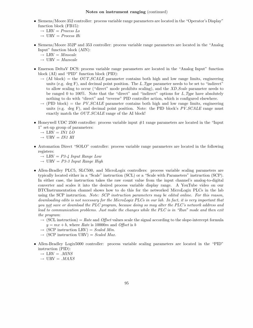
Notes on instrument ranging (continued)
• Siemens/Moore 352 controller: process variable range parameters are located in the “Operator’s Display”function block (FB15):→ LRV = Process Lo→ URV = Process Hi
• Siemens/Moore 352P and 353 controller: process variable range parameters are located in the “AnalogInput” function block (AIN):→ LRV = Minscale→ URV = Maxscale
• Emerson DeltaV DCS: process variable range parameters are located in the “Analog Input” functionblock (AI) and “PID” function block (PID):→ (AI block) = the OUT SCALE parameter contains both high and low range limits, engineering
units (e.g. deg F), and decimal point position. The L Type parameter needs to be set to “indirect”to allow scaling to occur (“direct” mode prohibits scaling), and the XD Scale parameter needs tobe ranged 0 to 100%. Note that the “direct” and “indirect” options for L Type have absolutelynothing to do with “direct” and “reverse” PID controller action, which is configured elsewhere.
→ (PID block) = the PV SCALE parameter contains both high and low range limits, engineeringunits (e.g. deg F), and decimal point position. Note: the PID block’s PV SCALE range mustexactly match the OUT SCALE range of the AI block!
• Honeywell UDC 2500 controller: process variable input #1 range parameters are located in the “Input1” set-up group of parameters:→ LRV = IN1 LO→ URV = IN1 HI
• Automation Direct “SOLO” controller: process variable range parameters are located in the followingregisters:→ LRV = P3-4 Input Range Low→ URV = P3-3 Input Range High
• Allen-Bradley PLC5, SLC500, and MicroLogix controllers: process variable scaling parameters aretypically located either in a “Scale” instruction (SCL) or a “Scale with Parameters” instruction (SCP).In either case, the instruction takes the raw count value from the input channel’s analog-to-digitalconverter and scales it into the desired process variable display range. A YouTube video on ourBTCInstrumentation channel shows how to do this for the networked MicroLogix PLCs in the labusing the SCP instruction. Note: SCP instruction parameters may be edited online. For this reason,downloading edits is not necessary for the MicroLogix PLCs in our lab. In fact, it is very important thatyou not save or download the PLC program, because doing so may alter the PLC’s network address andlead to communication problems. Just make the changes while the PLC is in “Run” mode and then exitthe program:→ (SCL instruction) = Rate and Offset values scale the signal according to the slope-intercept formula
y = mx + b, where Rate is 10000m and Offset is b
→ (SCP instruction LRV) = Scaled Min.→ (SCP instruction URV) = Scaled Max.
• Allen-Bradley Logix5000 controller: process variable scaling parameters are located in the “PID”instruction (PID):→ LRV = .MINS→ URV = .MAXS
95

Notes on instrument ranging (continued)
• caSCADA “pid” control program: process variable scaling parameters are located in one of the sourcecode files which must be modified using a text editor program, then recompiling the pid program so thenew parameters may take effect. This control program may be initiated from the Linux command lineby typing ./pid and pressing the Enter key, after which a set of instructions will appear on the screenshowing the default LRV and URV range values, and which file to find these parameters within. Afterediting and saving this file, you will need to type make at the Linux command line and press Enter torecompile the program. Finally, type ./pid and press Enter to initiate the recompiled program.→ LRV = pid[0].LRV→ URV = pid[0].URV
file ranging
96

Notes on controller action
An important set of configuration parameters for any control system are controller action and PIDtuning. Proper controller action means that the control system reacts to setpoint changes and processvariable disturbances in the correct direction (e.g. a temperature control system that acts to reduce heatinput when the process variable is above setpoint). Proper PID tuning means that the control system reactsto setpoint changes and process variable disturbances to an appropriate degree over time (e.g. a temperaturecontrol system that applies the right amount of additional heat input when the process variable goes belowsetpoint). A controller with the wrong action will cause a process to “run away” to one extreme value orthe other. A controller with poor PID tuning will fail to achieve setpoint, and/or oscillate needlessly. Thefollowing is a list of configuration parameters to modify in a variety of different control systems found in theInstrumentation lab room.
If the controller happens to be programmed using function blocks, these important parameters will befound in the “PID” function block. For other controller models, there will be a menu option with action(direct/reverse) and tuning (P/I/D) parameters. Note that some controllers provide a quick-access featureto edit the PID tuning parameters, but generally not for changing the direction of action. Here are someexamples:
• Siemens/Moore 352 controller: control action parameters are located in the “PID” function block(FB13). Note that the P, I, and D tuning parameters may be quickly accessed by pressing the “Tune”button rather than by entering the PID function block edit menu:→ Direction (Direct/Reverse)= SA1→ Proportional (P) = SPG1 as a unitless gain value→ Integral (I) = STI1 in units of minutes per repeat→ Derivative (D) = STD1 in units of minutes
• Siemens/Moore 352P and 353 controller: control action parameters are located in the “PID” functionblock (PID). Note that the P, I, and D tuning parameters may be quickly accessed by pressing the“Tune” button rather than by entering the PID function block edit menu:→ Direction (Direct/Reverse)= DIR ACT→ Proportional (P) = PG as a unitless gain value→ Integral (I) = TI in units of minutes per repeat→ Derivative (D) = TD in units of minutes
• Emerson DeltaV DCS: control action parameters are located in the “PID” function block (PID)conforming to the FOUNDATION Fieldbus standard:→ Direction (Direct/Reverse)= Found in the CONTROL OPTS set of parameters as a “check-box”
where a checked box sets direct action and an unchecked box sets reverse action.→ Proportional (P) = GAIN as a unitless gain value→ Integral (I) = RESET in units of seconds per repeat→ Derivative (D) = RATE in units of seconds
• Honeywell UDC 2500 controller: control direction is located in the “CONTRL” set-up group ofparameters, while the PID tuning coefficients are located in the “TUNING” set-up group of parameters:→ Direction (Direct/Reverse)= Action→ Proportional (P) = PB or Gain as a proportional band percentage or as a unitless gain value,
respectively→ Integral (I) = I Min or I RPM in units of minutes or repeats per minute, respectively→ Derivative (D) = Rate T in units of minutes
97

Notes on controller action (continued)
• Automation Direct “SOLO” controller: process variable range parameters are located in the followingregisters:→ Direction (Direct/Reverse)= P3-7 Heating/Cooling→ Proportional (P) = P1-4 Proportional band as a proportional band percentage→ Integral (I) = P1-5 Integral time in units of seconds→ Derivative (D) = P1-6 Derivative time in units of seconds
• Allen-Bradley PLC5, SLC500, and MicroLogix controllers: control action parameters are located in the“PID” instruction. A YouTube video on our BTCInstrumentation channel shows how to do this forthe networked MicroLogix PLCs in the lab (reading the PV on the first analog input and sending theoutput to the first analog output of the I/O card):→ Direction (Direct/Reverse)= Found in the Control Mode field where E=PV−SP represents direct
action and E=SP−PV represents reverse action.→ Proportional (P) = Controller Gain Kc as a unitless gain value→ Integral (I) = Reset Ti in units of minutes per repeat→ Derivative (D) = Rate Td in units of minutes
• Allen-Bradley Logix5000 controller: control action parameters are located in the “PID” instruction(PID):→ Direction (Direct/Reverse)= E where PV−SP represents direct action and SP−PV represents
reverse action.→ Proportional (P) = Kp or Kc as a unitless gain value→ Integral (I) = Ki in units of seconds per repeat→ Derivative (D) = Kd in units of minutes
• caSCADA “pid” control program: control action parameters are located on the operator interfacescreen, above the trend graph. This control program may be initiated from the Linux command lineby typing ./pid and pressing the Enter key. Once the pid control program is running (reading thePV on analog input AIN0 and sending the output to analog output DAC0 of the LabJack DAQ), eachparameter may be selected by pressing the S key as often as needed, and the parameter values changedby pressing the arrow and page up/down keys. Note that the control direction may only be switchedwhile the controller is in manual mode. Tuning parameters may be altered in either manual or automaticmodes.→ Direction (Direct/Reverse)= will either show “Direct-acting” or “Reverse-acting”→ Proportional (P) = K P as a unitless gain value→ Integral (I) = K I in units of repeats per minute→ Derivative (D) = K D in units of seconds
98

Notes on controller tuning
For those who have never tuned a controller before but need to set the PID parameters for basic loopstability in automatic mode, here are some tips for setting the P, I, and D parameter values. Every PIDcontroller provides means to alter the tuning coefficients named proportional (also called gain), integral (alsocalled reset), and derivative (also called rate or pre-act). Settings which are virtually assured to yield stablecontrol are as follows:
• P – a “gain” value of less than one (i.e. a “proportional band” value of at least 100%).• I – a “reset” value of zero repeats per minute, or the largest value possible for minutes per repeat.• D – a “rate” value of zero.
Mind you, these parameters will not yield good control, but merely stable control. In other words, thesetuning parameter values will make the controller fairly unresponsive, but at least it won’t oscillate out ofcontrol. Also bear in mind that having an integral (reset) value set for minimum action (i.e. zero repeatsper minute, or very high minutes per repeat) will result in a controller that never quite makes the processvariable value reach setpoint – instead, there will be a persistent “offset” between PV and SP with integralaction essentially turned off.
file control
99

file i00998
100

Answers
Answer 1
Answer 2
Answer 3
Answer 4
Hint: gasoline fuel molecules contain lots of hydrogen atoms!
Answer 5
I’ll let you do the research here!
Answer 6
Answer 7
Answer 8
Answer 9
I’ll let you do all the work on this question!
101
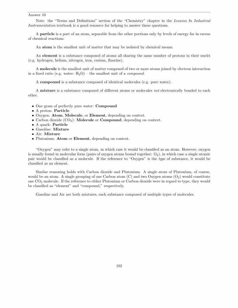
Answer 10
Note: the “Terms and Definitions” section of the “Chemistry” chapter in the Lessons In IndustrialInstrumentation textbook is a good resource for helping to answer these questions.
A particle is a part of an atom, separable from the other portions only by levels of energy far in excessof chemical reactions.
An atom is the smallest unit of matter that may be isolated by chemical means.
An element is a substance composed of atoms all sharing the same number of protons in their nuclei(e.g. hydrogen, helium, nitrogen, iron, cesium, fluorine).
A molecule is the smallest unit of matter composed of two or more atoms joined by electron interactionin a fixed ratio (e.g. water: H2O) – the smallest unit of a compound.
A compound is a substance composed of identical molecules (e.g. pure water).
A mixture is a substance composed of different atoms or molecules not electronically bonded to eachother.
• One gram of perfectly pure water: Compound• A proton: Particle• Oxygen: Atom, Molecule, or Element, depending on context.• Carbon dioxide (CO2): Molecule or Compound, depending on context.• A quark: Particle• Gasoline: Mixture• Air: Mixture• Plutonium: Atom or Element, depending on context.
“Oxygen” may refer to a single atom, in which case it would be classified as an atom. However, oxygenis usually found in molecular form (pairs of oxygen atoms bound together: O2), in which case a single atomicpair would be classified as a molecule. If the reference to “Oxygen” is the type of substance, it would beclassified as an element.
Similar reasoning holds with Carbon dioxide and Plutonium. A single atom of Plutonium, of course,would be an atom. A single grouping of one Carbon atom (C) and two Oxygen atoms (O2) would constituteone CO2 molecule. If the reference to either Plutonium or Carbon dioxide were in regard to type, they wouldbe classified as “element” and “compound,” respectively.
Gasoline and Air are both mixtures, each substance composed of multiple types of molecules.
102

Answer 11
Protons and neutrons reside in the center (or nucleus) of an atom, a very dense core. Electrons residein patterns surrounding the nucleus (many textbooks depict these patterns as orbits, like satellites orbitinga planet, but this model is not entirely accurate).
Protons and electrons are both electrically charged particles. Each proton has a positive electrical chargeof 1 unit, while each electron has a negative electrical charge of 1 unit. Neutrons are electrically neutral,possessing no charge at all.
Shown here is the ranking of elementary particles according to mass, in order from lightest to heaviest:
• Electron (lightest)• Proton• Neutron (heaviest)
The number of protons in the nucleus of an atom determines that atom’s atomic number, whichdetermines its identity (what type of element it is).
The number of neutrons in the nucleus, added to the atomic number (the number of protons in thenucleus) constitutes the atom’s atomic weight, also called atomic mass. This determines the gross mass ofthe atom, and may also determine some nuclear properties such as radioactivity.
The number of electrons surrounding the nucleus of an atom is ideally equal to the number of protonsin the nucleus (atomic number), to balance the opposing electric charges. Extra electrons may surround anatom, though, giving it an overall negative electric charge. Electrons may be “robbed” from an atom as well,giving it an overall positive electric charge. The number and arrangement of electrons in an atom determineits chemical properties (reactivity with other atoms).
Since the base number of electrons is established by the number of protons, it is the atomic number thatfundamentally determines an element’s physical properties (reactivity, boiling point, freezing point, etc.).Adding or subtracting electrons to/from an atom also affects certain chemical properties, but not to theextent that the atomic number does.
Answer 12
For Carbon-12, “12” represents the atom’s atomic mass (sum of protons and neutrons in the nucleus).Since the atomic number of Carbon is 6, we know there are 6 protons in the nucleus. Subtracting 6 from 12leaves us with 6 neutrons in the nucleus as well. For the atom to be electrically neutral, there must be 6electrons to balance the 6 protons.
For gold, the average atomic mass of 197 represents the sum of protons and neutrons in the nucleus.Since the atomic number of gold is 79, we know there are 79 protons in the nucleus. Subtracting 79 from197 leaves us with 118 neutrons in the nucleus. For the atom to be electrically neutral, there must be 79electrons to balance the 79 protons.
Answer 13
Physical forces, energy sources, and reactions common to everyday experience are insufficient to alterthe atomic number (number of protons in the nucleus) of any atom, because of the extremely high bindingforce between nuclear particles. Thus, the chemical identity of elements remains extremely stable.
Chemical reactions are merely exchanges and interactions involving electrons between atoms, not protonsor neutrons. Electrons are rather loosely bound around atoms compared to protons and neutrons, whichexplains why chemical changes may occur from simple physical processes such as heating and cooling, orexposure to light.
Three protons would have to be removed from an atom of lead (82Pb) into gold (79Au), and this wouldrequire the use of equipment such as particle accelerators. Although this is possible, it is not practical dueto the extremely high cost (it takes more money to convert lead into gold than the gold is worth!).
103

Answer 14
The former symbol (H2) represents two atoms of hydrogen (H) joined as a pair (a diatomic molecule).The latter symbol represents hydrogen with an atomic mass of 2, an isotope of hydrogen known as deuterium.In summary, the former symbol denotes a chemical state, while the latter symbol denotes a nuclear state.
Answer 15
An element is composed of extremely small indivisible particles called atoms. This is inagreement with modern theory, except that we now know atoms can be divided into smaller subcomponents(elementary particles), all of which are further divisible into yet smaller particles (quarks, etc.).
All atoms of a given element have identical properties, which differ from those of otherelements. Isotopes have slightly different within the same element definition. For some elements such ashydrogen (H), the isotopic mass ratios are substantial (Tritium:Deuterium:Hydrogen mass ratios = 3:2:1).For most isotopes, though, the difference in mass is slight, and requires precision equipment to differentiate.Certainly in Dalton’s time there was no equipment capable of detecting much less measuring these differencesin isotope mass.
Atoms cannot be created, destroyed, or transformed into atoms of another element. Modernscientists would agree that matter cannot be created or destroyed, but may be converted between differentforms (including energy!). Atoms most certainly can be transmutated into different elements. In nature,though, this happens on such a small scale as to be virtually unmeasurable, and it may only be synthesizedon a large scale by apparatus unavailable to scientists in Dalton’s time.
Compounds are formed when atoms of different elements combine with each other in smallwhole-number ratios. This is in perfect agreement with modern atomic theory, and in fact is an excellentdefinition of what a “compound” is.
The relative numbers and kinds of atoms are constant in a given compound. Again, this isin perfect agreement with modern theory.
104
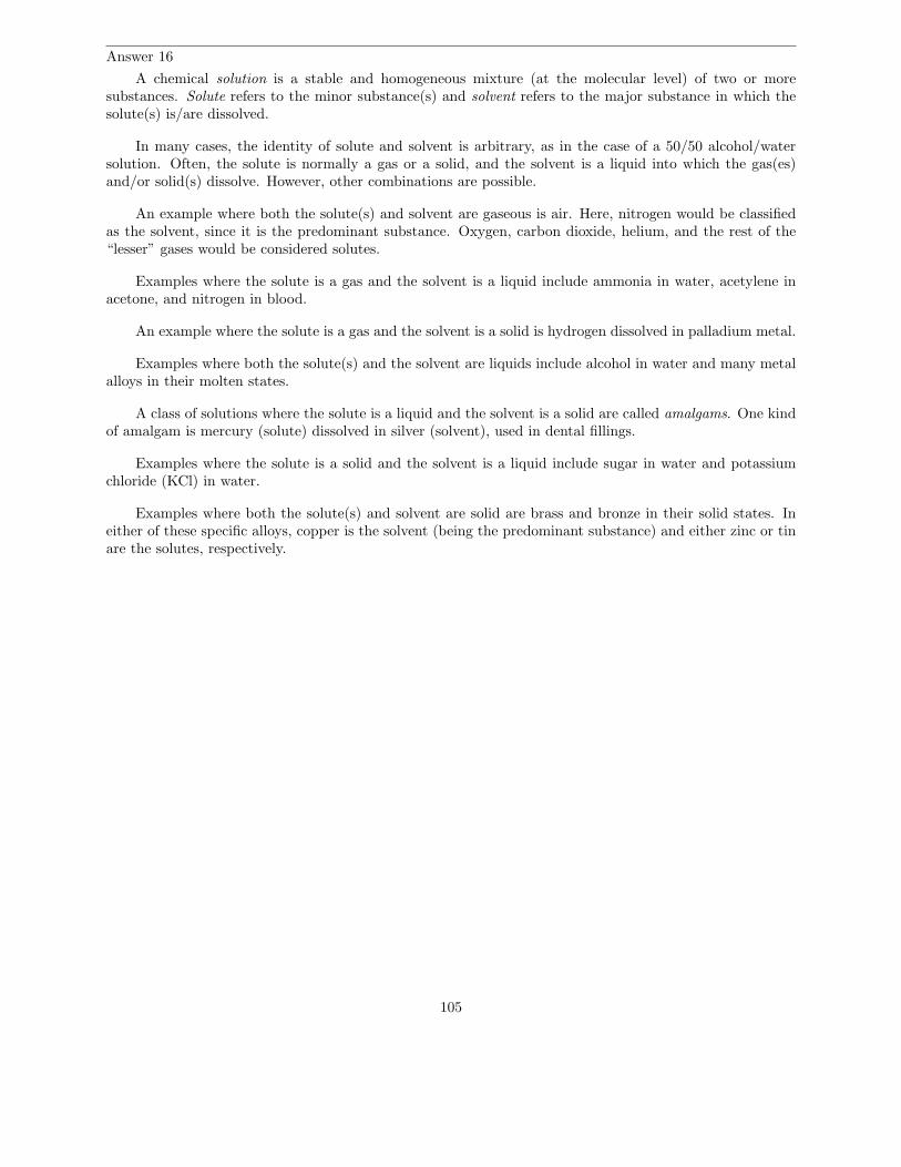
Answer 16
A chemical solution is a stable and homogeneous mixture (at the molecular level) of two or moresubstances. Solute refers to the minor substance(s) and solvent refers to the major substance in which thesolute(s) is/are dissolved.
In many cases, the identity of solute and solvent is arbitrary, as in the case of a 50/50 alcohol/watersolution. Often, the solute is normally a gas or a solid, and the solvent is a liquid into which the gas(es)and/or solid(s) dissolve. However, other combinations are possible.
An example where both the solute(s) and solvent are gaseous is air. Here, nitrogen would be classifiedas the solvent, since it is the predominant substance. Oxygen, carbon dioxide, helium, and the rest of the“lesser” gases would be considered solutes.
Examples where the solute is a gas and the solvent is a liquid include ammonia in water, acetylene inacetone, and nitrogen in blood.
An example where the solute is a gas and the solvent is a solid is hydrogen dissolved in palladium metal.
Examples where both the solute(s) and the solvent are liquids include alcohol in water and many metalalloys in their molten states.
A class of solutions where the solute is a liquid and the solvent is a solid are called amalgams. One kindof amalgam is mercury (solute) dissolved in silver (solvent), used in dental fillings.
Examples where the solute is a solid and the solvent is a liquid include sugar in water and potassiumchloride (KCl) in water.
Examples where both the solute(s) and solvent are solid are brass and bronze in their solid states. Ineither of these specific alloys, copper is the solvent (being the predominant substance) and either zinc or tinare the solutes, respectively.
105

Answer 17
This chemical is rated “extremely hazardous,” with a flash point somewhere between 100o F and 200o
F, and may detonate under normal conditions. Additionally, it is dangerous if it contacts water.
The left-hand (blue) diamond rates the substance according to its human health hazard:
• 0 = No hazard• 1 = Slight hazard• 2 = Moderately hazardous• 3 = Extremely hazardous• 4 = Deadly
The upper (red) diamond rates the substance according to its flammability (flash point):
• 0 = Will not burn• 1 = Above 200o F• 2 = Between 100o F and 200o F• 3 = Between 73o F (room temperature) and 100o F• 4 = Below 73o F (room temperature)
The right-hand (yellow) diamond rates the substance according to its chemical reactivity:
• 0 = Stable• 1 = Unstable if heated• 2 = Violent chemical change, no detonation• 3 = Shock or heat may detonate• 4 = May detonate under normal conditions
The lower (white) diamond is a place for abbreviations regarding additional properties. Standardizedabbreviations include:
• ACID = Acidic• ALK = Alkaline• COR = Corrosive• OX = Oxidizer• P = Polymerization (chemically reacts with itself under certain conditions)• W (with a line going through it) = Reacts with water
Answer 18
This chemical is rated “moderately hazardous,” is not flammable, but is unstable if heated. Additionally,it is corrosive.
106

Answer 19
(From SDS number CJGPK)
SDS Safety Information
FSC: 6810 NIIN: 00-264-5906 SDS Date: 03/01/1997 SDS Num: CJGPK
Submitter: D DG Tech Review: 03/10/2000 Status CD: C
Product ID: 200 PROOF ETHYL ALCOHOL MFN: 02
Article: N Kit Part: N
Fire and Explosion Hazard Information
Flash Point Method: TCC
Flash Point: = 14.4 C, 58.0 F Flash Point Text:
Autoignition Temp: Autoignition Temp Text: N/P
Lower Limits: 3.3 Upper Limits: 19
Answer 20
Answer 21
Answer 22
Hint: bones contain a lot of calcium.
Answer 23
Answer 24
Answer 25
Answer 26
Answer 27
Answer 28
Answer 29
• 195Pt (Platinum-195) – Protons = 78 ; Neutrons = 117
• 75As (Arsenic-75) – Protons = 33 ; Neutrons = 42
• 235U (Uranium-235) – Protons = 92 ; Neutrons = 143
• 40Ca (Calcium-40) – Protons = 20 ; Neutrons = 20
Answer 30
• 1s2 means 2 electrons reside in the “s” subshell of the first (K) shell (filled to capacity)• 2s2 means 2 electrons reside in the “s” subshell of the second (L) shell (filled to capacity)• 2p6 means 6 electrons reside in the “p” subshell of the second (L) shell (filled to capacity)• 3s2 means 2 electrons reside in the “s” subshell of the third (M) shell (filled to capacity)• 3p1 means 1 electron resides in the “p” subshell of the third (M) shell
An “orbital” is a pair of electrons comprising all or part of a subshell. This means each subshell holdsan even maximum number of electrons.
107

Answer 31
This table is called the periodic table of the elements, and it arranges all the known elements (uniquetypes of atoms) in order of their atomic number, atomic weight, and chemical characteristics.
Answer 32
When electrons cluster around the nucleus of an atom, they do not do so with equal status. Rather, theymust locate themselves in different energy “levels” known as shells, kind of like people sitting in differentlevels of seats in an amphitheater. Since the outermost level of electrons (the outermost “shell”) is the onemost likely to interact with electrons from other atoms to form chemical bonds, these electrons predominantlydetermine the chemical nature of the atom.
Many students find the analogy of an amphitheater particularly insightful. Just as people desire to sitas close to the action in an amphitheater as they can (the lowest-level seating), electrons seek the lowestenergy levels that they can.
We can even extend the analogy further, where money paid for amphitheater seating is analogous toenergy exchanged in electron shell filling: just as people must give up more money to sit closer to the actionin an amphitheater, electrons must lose more energy to occupy a lower-level shell. Conversely, just as youmust pay money to get someone to move to a higher-level seat in an amphitheater, you must infuse moreenergy in an electron to get it to “jump” to a higher-level shell.
Answer 33
The color of light emitted by an “excited” atom is due to energy emitted by its electrons after havingabsorbed energy from an external source (in this case, the electric current through the tube). It is knownthat free electrons (unbound to an atom) are able to absorb and release energy over a wide range of levels(corresponding to a wide range of optical colors). If electrons really were free-ranging “satellites” whirlingaround atomic nuclei, then they ought to be able to release a wide range of light colors just as they do whenfree. However, the electrons bound to an atom’s nucleus do not do so. Rather, they emit light of very specificfrequencies (colors) in the same way a tuning fork emits the same characteristic sound pitch, no matter howhard or how soft it has been struck.
This phenomenon clearly shows that electrons fall into discrete “states” when part of an atom. It isthis discrete, or quantum nature of atomic electrons that gives rise to predictable chemical behavior (bondsbetween atoms formed by electron interaction), and the periodicity of Mendeleyev’s table.
108
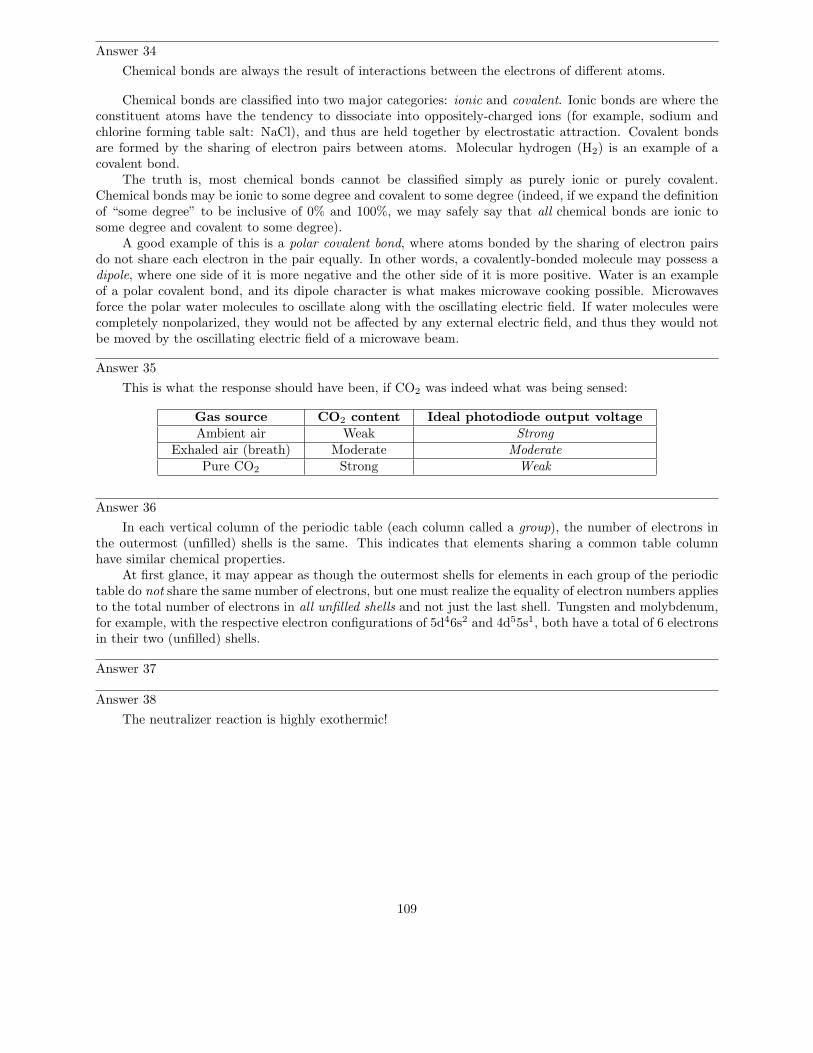
Answer 34
Chemical bonds are always the result of interactions between the electrons of different atoms.
Chemical bonds are classified into two major categories: ionic and covalent. Ionic bonds are where theconstituent atoms have the tendency to dissociate into oppositely-charged ions (for example, sodium andchlorine forming table salt: NaCl), and thus are held together by electrostatic attraction. Covalent bondsare formed by the sharing of electron pairs between atoms. Molecular hydrogen (H2) is an example of acovalent bond.
The truth is, most chemical bonds cannot be classified simply as purely ionic or purely covalent.Chemical bonds may be ionic to some degree and covalent to some degree (indeed, if we expand the definitionof “some degree” to be inclusive of 0% and 100%, we may safely say that all chemical bonds are ionic tosome degree and covalent to some degree).
A good example of this is a polar covalent bond, where atoms bonded by the sharing of electron pairsdo not share each electron in the pair equally. In other words, a covalently-bonded molecule may possess adipole, where one side of it is more negative and the other side of it is more positive. Water is an exampleof a polar covalent bond, and its dipole character is what makes microwave cooking possible. Microwavesforce the polar water molecules to oscillate along with the oscillating electric field. If water molecules werecompletely nonpolarized, they would not be affected by any external electric field, and thus they would notbe moved by the oscillating electric field of a microwave beam.
Answer 35
This is what the response should have been, if CO2 was indeed what was being sensed:
Gas source CO2 content Ideal photodiode output voltageAmbient air Weak Strong
Exhaled air (breath) Moderate ModeratePure CO2 Strong Weak
Answer 36
In each vertical column of the periodic table (each column called a group), the number of electrons inthe outermost (unfilled) shells is the same. This indicates that elements sharing a common table columnhave similar chemical properties.
At first glance, it may appear as though the outermost shells for elements in each group of the periodictable do not share the same number of electrons, but one must realize the equality of electron numbers appliesto the total number of electrons in all unfilled shells and not just the last shell. Tungsten and molybdenum,for example, with the respective electron configurations of 5d46s2 and 4d55s1, both have a total of 6 electronsin their two (unfilled) shells.
Answer 37
Answer 38
The neutralizer reaction is highly exothermic!
109

Answer 39
If there is no CO2 in the sample gas at all, all four resistance cells will experience the exact same amountof cooling, and the bridge will be balanced.
As sample gas CO2 concentration increases, the relative concentration of hydrogen increases in thegreen-colored tubing compared to the red-colored tubing because the CO2 is being absorbed by the potassiumhydroxide (KOH) solution. Since hydrogen has a much greater specific heat than carbon dioxide, the purehydrogen (green) stream will have greater cooling capacity than the mixed (red) stream, causing the green-shaded resistance cells to decrease in resistance. This unbalances the bridge, making the left-hand terminalof the voltmeter negative and the right-hand terminal positive.
Answer 40
Answer 41
Answer 42
• 35.2 moles of alumina Al2O3 at 25 oC = 3590.4 grams = 3.5904 kg
• 10.6 moles of nitroglycerine C3H5N3O9 at 77 oC = 2406.2 grams = 2.4062 kg
• 3.7 moles of phosgene COCl2 at 145 oF = 366.3 grams = 0.3663 kg
• 130 moles of tetraethyl pyrophosphate or “TEPP” [(CH3CH2O)2PO]2O at −10 oF = 37,700 grams =37.700 kg
Answer 43
Partial answer:
• 1.1 kilograms of pure propane C3H8 at −30 oC and 3 atmospheres = 25 moles
• 71 grams of hexafluoroacetone (CF3)2CO at 110 oF and 50 bar (gauge) = 0.4277 moles
Answer 44
Answer 45
V = 38,680 liters
Answer 46
Partial answer:
±5% (gold color code) is 50,000 ppm.
• 3.6 milliliters of methyl alcohol mixed into 10.5 liters of pure water = 342.74 ppm If your calculatedanswer was 342.86 ppm, you made a minor error: you took 10.5 liters to be the total volume of liquidafter adding the alcohol. 10.5 liters is just the water’s volume, not the total solution (mixed) volume!
• 10 grams of hydrofluoric acid added to 560 kg of water = 17.86 ppm
Answer 47
110

Answer 48
Partial answer:
m = 30,600 grams of ammonia = 30.6 kg.
Answer 49
Partial answer:
Hydrogen/Oxygen mass ratio = 0.12625:1
Oxygen/Hydrogen mass ratio = 7.9208:1
The “setpoint” variable in this control system needs to be set to 7.9208 (assuming both mass flowmetershave identical calibrated ranges).
Answer 50
A mole is a specific quantity of unit “entities,” usually molecules when used in the context of chemistry.The SI (Systeme International) definition of the mole is the amount of substance that contains 6.0221367 ×10²³ particles or entities. This very large constant is referred to as Avogadro’s number.
Answer 51
• 1 mole of pure 12C = 12 g
• 1 mole of carbon (naturally occurring) = 12.011 g
• 1 mole of pure 56Fe = 56 g
• 5.5 moles of mercury (naturally occurring) = 1.1032 kg
• 0.002 moles of helium (naturally occurring) = 8.0052 mg
To calculate each of these masses, simply multiply the number of moles by the atomic mass given orfound in the periodic table.
111

Answer 52
• Each molecule of H2O contains:• 2 atoms of H at 1.01 amu each• 1 atom of O at 16 amu each
(1 mol)[(2 atoms)(1.01 amu/atom) + (1 atom)(16 amu/atom)] = 18.02 g
• Each molecule of D2O contains:• 2 atoms of D (H2) at 2 amu each• 1 atom of O at 16 amu each
(1 mol)[(2 atoms)(2 amu/atom) + (1 atom)(16 amu/atom)] = 20 g
• Each molecule of H2SO4 contains:• 2 atoms of H at 1.01 amu each• 1 atom of S at 32.06 amu each• 4 atoms of O at 16 amu each
(1 mol)[(2 atoms)(1.01 amu/atom) + (1 atom)(32.06 amu/atom) + (4 atoms)(16 amu/atom)] = 98.08g
• Each molecule of CH4 contains:• 1 atom of C at 12.01 amu each• 4 atoms of H at 1.01 amu each
(14 mol)[(1 atom)(12.01 amu/atom) + (4 atoms)(1.01 amu/atom)] = 224.7 g
• Each molecule of (NH4)2CO3 contains:• 2 atoms of N at 14.01 amu each• 8 atoms of H at 1.01 amu each• 1 atom of C at 12.01 amu each• 3 atoms of O at 16 amu each
(5 mol)[(2 atoms)(14.01 amu/atom) + (8 atoms)(1.01 amu/atom) + (1 atom)(12.01 amu/atom) + (3atoms)(16 amu/atom)] = 480.55 g
Answer 53
15 moles of zinc and 15 moles of sulfuric acid are needed to produce 15 moles of hydrogen gas, since themolecular ratio for all reactants and products is 1:1.
112

Answer 54
• Solute: table sugar• Solvent: water• Solution: the liquid sugar/water mixture• Saturation: when the solution can accommodate no more sugar• Supersaturation: a condition beyond saturation, where any additional solute (sugar) forces a larger
quantity of solute to immediately fall out of the solution• Precipitate: the sugar left in solid form on the bottom of the container• Supernatant: the saturated solution above the precipitate
In this example, the sugar is the solute, the water the solvent, and the sugar/water mixture the solution.When enough solute has been added to solvent that the solvent can dissolve no more, the solution is said tobe saturated.
If additional solute is added to a saturated solution, the solution may become supersaturated. This is a“metastable” state that may exist for substantial periods of time only if the solution is undisturbed.
113
Answer 55
A solution is a stable and molecularly homogeneous mixture of two or more substances. A suspension isa heterogeneous mixture where separation of the components occurs over time. A colloid is a heterogeneousmixture where separation is negligible over time.
An aerosol is either a solid or a liquid dispersed in a gaseous medium. Foams are gaseous substancesdispersed in either liquid or solid media. Emulsions are liquids dispersed in either liquid or solid media.Finally, sols are solids dispersed in either liquid or solid media.
Colloidal mixtures may be viewed as in-between suspensions and true solutions. One way to distinguisha liquid colloidal mixture (often referred to as a colloidal dispersion) from a true solution is to use the Tyndalleffect of light scattering. When light passes though a clear solution, there will be no scattering, becausesolutions are homogeneous on a molecular level. With either a suspension or a colloid, though, the particlesare large enough to scatter light, and will become visibly apparent when a beam of light is passed through themixture. Once the particle size has been determined to be more than that in a true solution, the distinctionbetween colloid and suspension may be made by detection of settling.
Examples of colloids are smoke in air and calcium in water. Steel, being a mixture of iron, carbon,and other elements, is technically considered a solid colloid (“sol”) rather than a solid solution, due toparticle size. In other words, the granularity of the carbon particles is not fine enough to be “molecularlyhomogeneous.”
There are two easy tests used to divide gas-based and liquid-based mixtures into solutions, suspensions,and colloids: settling and light dispersal. If there is substantial settling over time, then the mixture is asuspension. If there is negligible settling, it may be either be a solution or a colloid. The latter distinctionis made on the basis of light scattering.
Muddy water is a suspension because the dirt particles will settle over time.
Household ammonia is a solution because settling never occurs and it does not scatter light.
Milk is a colloid emulsion (liquid/liquid) because settling never occurs and it scatters light.
Rubbing alcohol is a solution because settling never occurs and it does not scatter light.
Tobacco smoke in air is a colloid aerosol (solid/gas) because settling never occurs and it scatters light.
Battery acid is a solution because settling never occurs and it does not scatter light.
Whipped cream is a colloid foam (gas/liquid) because settling never occurs and it scatters light.
Dusty air is a suspension because the dirt particles will settle over time.
Sugar water is a solution because settling never occurs and it does not scatter light.
Coffee is a colloid sol (solid/liquid) because settling never occurs and it scatters light.
Answer 56
m = 201.6 grams = 0.2016 kg
114
Answer 57
125 moles of oxygen gas will be required to completely burn 250 moles of hydrogen gas, because thereare an equal number of hydrogen and oxygen atoms in one mole of each, and only one atom of oxygen isneeded for every 2 atoms of hydrogen.
The 830 mm HgA pressure is extraneous information, included for the purpose of challenging you toidentify whether or not information is relevant to solving a particular problem.
The question of whether or not these rocket engines are polluting requires some thinking beyond thechemistry of combustion in the engine. While the engines themselves only release water vapor (along withsome unreacted hydrogen and oxygen), the process by which hydrogen fuel is produced is indeed polluting.Large quantities of pure hydrogen are typically produced using a reforming reaction whereby a plentifulhydrocarbon compound such as natural gas (CH4) is reformed into hydrogen (H2) and carbon dioxide(CO2), the latter being a “greenhouse” gas pollutant.
Answer 58
Assuming “room temperature” to be 25 degrees Celsius and sea-level pressure to be 1 atmosphere. wemay calculate the number of moles of air molecules in a cubic meter of air as follows:
1 m3 = 1000 liters
PV = nRT
n =PV
RT
n =(1)(1000)
(0.0821)(298.15)= 40.85 moles
A concentration of 1 ppm means 1 molecule out of a million will be methanol, the other 999,999 beingair molecules. Thus, for a methanol vapor concentration of 1 ppm we would expect to find 0.00004058 molesof methyl alcohol in 40.85 moles of sample (1 cubic meter).
Given methanol’s molecular weight of CH4O 32.04 grams per mole, this equates to 0.0013089 grams(1.3089 mg) in one cubic meter.
115
Answer 59
Since the first vial contains two drops of 50% plant juice solution, consisting of one drop of pure plantjuice with one drop of alcohol, the first vial must contain 0.0006 moles of active ingredient:
n1 = 0.0006 moles
For each successive vial we take one drop of solution from the previous vial and mix it with 99 dropsof pure alcohol, making a 1
100dilution ratio. This means the second vial will have 1
100the amount of active
ingredient as the first vial:
n2 = 0.000006 moles
The third vial will contain 1
100of the second vial’s active ingredient:
n3 = 0.00000006 moles
In fact, we may generalize the dilution in the following equation:
nm =0.0006
100m−1
This means the 30th vial will contain the following number of moles of active ingredient:
nm =0.0006
10030−1= 6 × 10−62 mol
Recall that a single mole is equal to 6.022 × 10²³ molecules. This means a molar quantity of 6 × 10−62
moles is equal to 3.61 × 10−38 molecules. Since this number is less than 1, it is purporting to tell us the30th vial contains just a miniscule fraction of one molecule! We know this is impossible, since moleculescannot be divided (at least not without changing their essential properties). The only way to square thisamazingly low molar quantity with the indivisibility of real molecules is to conclude that the 30th vial onlyhas a probability of containing just a single molecule of the original active ingredient. To be precise, the30th vial has but a 1 in 2.77× 1037 chance of containing a single molecule of the original plant juice’s activeingredient.
Scientists of this era were aware of the Avogadro number and molecular quantities. When criticised onthis point, the inventor of this therapy responded thusly:
It is of little import whether the attenuation goes so far as to appear almost impossible toordinary physicians whose minds feed on no other ideas but what are gross and immaterial.
A footnote to this statement defends extreme dilutions in this way:
Mathematicians will inform them, that in whatever number of parts they may divide asubstance, each portion still retains a small share of the material; that, consequently the mostdiminutive part that can be conceived never ceases to be something, and can in no instance bereduced to, nothing. Physicians may learn from them that there exist immense powers which haveno weight, such as light and heat, and which are consequently infinitely lighter than the medicianlcontents of the smallest homeopathic doses. Let them weigh, if they can, the injurious words whichexcite a bilious fever, or the afflicting news of the death of a son, which terminates the existence of anaffectionate mother. Let them only touch, for a quarter of an hour, a magnet capable of carryinga weight of a hundred pounds, and the pain will soon teach them that even the imponderablebodies can also produce on man the most violent medicinal effects! Let any of these weak-mindedmortals of a delicate constitution but gently apply, during a few minutes, to the pit of the stomachthe extremity of the thumb of a vigorous mesmerist who has fixed his intent, and the disagreeablesensations that he experiences will soon make him repent having set limits to the boundless activityof nature.
116
Answer 60
Answer 61
Answer 62
Answer 63
Partial answer:
2H2O2 → 2H2O + O2
Answer 64
Partial answer:
3.33 moles of P4O10 needed to completely react with 20 moles of water, because the ratio of water totetraphosphorus decoxide in the balanced equation is 6:1.
Answer 65
Answer 66
6H2O + 6CO2 → C6H12O6 + 6O2
The energy required to sustain most life on Earth comes from the sun. Sunlight powers thephotosynthesis reaction, storing energy in the form of glucose, which animals consume in their food. Whendigested, the glucose becomes available to the animal body as fuel, and is “burned” by combination withoxygen. This slow “combustion” of glucose provides animals’ bodies with power to operate, and it alsoproduces CO2 which the plants then re-process (with sunlight as the energy source) into more glucose.
Answer 67
Answer 68
Answer 69
In a properly operating circuit with no explosive gas present, VR3 = VR4 or VD = 2VE . I will leave it toyou to identify good diagnostic tests!
Answer 70
SiH4 + 2O2 → 2H2O + SiO2
Silicon dioxide is also known as silica, and constitutes the mineral quartz. This means that a silane fireproduces particles of sand in addition to water vapor!
117
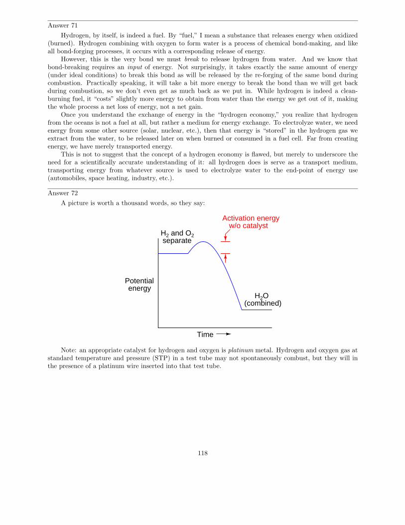
Answer 71
Hydrogen, by itself, is indeed a fuel. By “fuel,” I mean a substance that releases energy when oxidized(burned). Hydrogen combining with oxygen to form water is a process of chemical bond-making, and likeall bond-forging processes, it occurs with a corresponding release of energy.
However, this is the very bond we must break to release hydrogen from water. And we know thatbond-breaking requires an input of energy. Not surprisingly, it takes exactly the same amount of energy(under ideal conditions) to break this bond as will be released by the re-forging of the same bond duringcombustion. Practically speaking, it will take a bit more energy to break the bond than we will get backduring combustion, so we don’t even get as much back as we put in. While hydrogen is indeed a clean-burning fuel, it “costs” slightly more energy to obtain from water than the energy we get out of it, makingthe whole process a net loss of energy, not a net gain.
Once you understand the exchange of energy in the “hydrogen economy,” you realize that hydrogenfrom the oceans is not a fuel at all, but rather a medium for energy exchange. To electrolyze water, we needenergy from some other source (solar, nuclear, etc.), then that energy is “stored” in the hydrogen gas weextract from the water, to be released later on when burned or consumed in a fuel cell. Far from creatingenergy, we have merely transported energy.
This is not to suggest that the concept of a hydrogen economy is flawed, but merely to underscore theneed for a scientifically accurate understanding of it: all hydrogen does is serve as a transport medium,transporting energy from whatever source is used to electrolyze water to the end-point of energy use(automobiles, space heating, industry, etc.).
Answer 72
A picture is worth a thousand words, so they say:
H2 and O2separate
H2O(combined)
Potentialenergy
Time
Activation energyw/o catalyst
Note: an appropriate catalyst for hydrogen and oxygen is platinum metal. Hydrogen and oxygen gas atstandard temperature and pressure (STP) in a test tube may not spontaneously combust, but they will inthe presence of a platinum wire inserted into that test tube.
118
Answer 73
For each molecule of methane, there is a single atom of carbon (C) and four atoms of hydrogen (H4). Inorder to convert one atom of carbon into 1 molecule of carbon dioxide (CO2), one molecule of oxygen (O2)is required:
C + O2 → CO2
In order to convert four atoms of hydrogen into water, two more atoms of oxygen are required:
H4 + O2 → 2H2O
Thus, two molecules of O2 are needed to completely burn one molecule of CH4. This means, by extension,that two moles of oxygen gas will be required for every one mole of methane. So, if our methane quantity is1400 moles, our oxygen quantity must be 2800 moles.
Answer 74
C5H12 + 8O2 → 6H2O + 5CO2
Answer 75
C3H8 + 5O2 → 4H2O + 3CO2
Answer 76
2C4H10 + 13O2 → 10H2O + 8CO2
Answer 77
Stoichiometry is the primary determining factor for the value of k: setting the methane and steam massflow rates such that the proper numbers of molecules of each enter the reaction furnace to produce hydrogenand carbon monoxide gas.
Answer 78
An input of energy is required to force molecular bonds to break (i.e. separate molecules into individualatoms), while energy is released when new bonds are formed between atoms. Thus, it would appear at firstas though this decomposition (and in fact, any decomposition reaction) should be endothermic because weare taking atoms that were previously bound into a single molecule and making them separate.
However, since we are told that the decomposition of acetylene is exothermic, it must mean that somenew bonds have formed in the decomposition process, giving off more energy than what was required tobreak the bonds forming acetylene. One of the keys to this mystery is the geometric layout of the acetylenemolecule, which places the two hydrogen atoms far apart from each other (with the two carbon atomsbetween them). Thus, the separation of relatively weak H-C bonds to form a stronger H-H bond is part ofthe reason why this reaction is exothermic.
Answer 79
Answer 80
119

Answer 81
This is a graded question – no answers or hints given!
Answer 82
This is a graded question – no answers or hints given!
Answer 83
This is a graded question – no answers or hints given!
Answer 84
This is a graded question – no answers or hints given!
Answer 85
This is a graded question – no answers or hints given!
Answer 86
This is a graded question – no answers or hints given!
Answer 87
This is a graded question – no answers or hints given!
Answer 88
This is a graded question – no answers or hints given!
Answer 89
This is a graded question – no answers or hints given!
Answer 90
This is a graded question – no answers or hints given!
Answer 91
Answer 92
Your loop diagram will be validated when the instructor inspects the loop with you and the rest of yourteam.
Answer 93
The only “answer” to this question is a properly documented and functioning instrument loop!
120


