Embed Size (px)
Citation preview
IBM Z
Input/Output Configuration Program User's Guide for ICPIOCPSB10-7172-02
IBM

IBM Z
Input/Output Configuration Program User's Guide for ICPIOCPSB10-7172-02
IBM

Note:Before using this information and the product it supports, read the information in “Safety” onpage xi, Appendix G, “Notices,” on page 299, and IBM Systems Environmental Notices and UserGuide, Z125-5823.
This edition, SB10-7172-02 applies to ICP IOCP Version 5 Release 4 Modification 1 (5.4.1) (batch and stand-aloneversions). This edition replaces SB10-7172-01.
There might be a newer version of this document in a PDF file available on Resource Link. Go tohttp://www.ibm.com/servers/resourcelink and click Library on the navigation bar.
© Copyright IBM Corporation 2017, 2018.US Government Users Restricted Rights – Use, duplication or disclosure restricted by GSA ADP Schedule Contractwith IBM Corp.
Contents
Figures . . . . . . . . . . . . . . vii
Tables . . . . . . . . . . . . . . . ix
Safety . . . . . . . . . . . . . . . xiSafety notices . . . . . . . . . . . . . . xi
World trade safety information . . . . . . . xiLaser safety information . . . . . . . . . . xi
Laser compliance . . . . . . . . . . . xi
About this publication . . . . . . . . xiiiWhat is included in this user's guide . . . . . xivRevisions . . . . . . . . . . . . . . . xvRelated information . . . . . . . . . . . xv
OS/390. . . . . . . . . . . . . . . xvz/OS and z/OS.e . . . . . . . . . . . xvz/VM . . . . . . . . . . . . . . . xviz/VSE . . . . . . . . . . . . . . . xvi3907 models . . . . . . . . . . . . . xvi3906 models . . . . . . . . . . . . . xvi2965 models . . . . . . . . . . . . . xvi2964 models . . . . . . . . . . . . . xvi2828 models. . . . . . . . . . . . . xvii2827 models. . . . . . . . . . . . . xvii2818 models. . . . . . . . . . . . . xvii2817 models. . . . . . . . . . . . . xvii2098 models . . . . . . . . . . . . xviii2097 models . . . . . . . . . . . . xviii2096 models . . . . . . . . . . . . xviii2094 models . . . . . . . . . . . . xviii2086 models . . . . . . . . . . . . xviii2084 models . . . . . . . . . . . . xviiiEnterprise systems connection (ESCON) . . . xixFibre connection (FICON) . . . . . . . . xixOpen Systems Adapter (OSA) . . . . . . . xix
Note to all users . . . . . . . . . . . . xixAccessibility . . . . . . . . . . . . . . xix
Accessibility features . . . . . . . . . . xxKeyboard navigation . . . . . . . . . . xxConsult assistive technologies . . . . . . . xxIBM and accessibility . . . . . . . . . . xx
Related HMC and SE console information . . . . xxHow to send your comments . . . . . . . . xx
Summary of changes . . . . . . . . xxi
Chapter 1. IOCP introduction. . . . . . 1Hardware I/O configuration . . . . . . . . . 1
3907, 3906, 2965, 2964, 2828, 2827, 2818, and 2817models . . . . . . . . . . . . . . . 12098 and 2097 models . . . . . . . . . . 82096 and 2094 models . . . . . . . . . . 122086 and 2084 models . . . . . . . . . . 14
Using a PCHID report to help plan your I/Oconfiguration . . . . . . . . . . . . . 16Sample PCHID report . . . . . . . . . . 17
I/O configuration process . . . . . . . . . 18Card-image input to IOCP . . . . . . . . 19Console input to IOCP . . . . . . . . . 19
I/O configuration data sets . . . . . . . . . 19IOCDSs and CPC modes . . . . . . . . . 20
I/O configuration considerations . . . . . . . 20Defining multiple logical channel subsystems . . 20Control unit headers . . . . . . . . . . 21
Shared ESCON CTC considerations . . . . . . 24Shared CTC unit address ranges . . . . . . 24Shared CTC unit addresses . . . . . . . . 25
Coupling facility support . . . . . . . . . . 26Coupling facility channels . . . . . . . . 26
Open Systems Adapter (OSA) feature support . . . 30OSA support facility . . . . . . . . . . 31OSA channels. . . . . . . . . . . . . 31OSA-ICC channels (TYPE=OSC) . . . . . . 31OSA QDIO channels (TYPE=OSD) . . . . . . 31OSA non-QDIO channels (TYPE=OSE) . . . . 32OSA for zBX management network (TYPE=OSM) 32OSA for NCP channels (TYPE=OSN) . . . . . 32OSA for zBX data network (TYPE=OSX). . . . 32OSA channels for OSA-ICC (TYPE=OSC), QDIO(TYPE=OSD), non-QDIO (TYPE=OSE), zBXmanagement network (TYPE=OSM), NCP(TYPE=OSN), and zBX data network(TYPE=OSX) . . . . . . . . . . . . . 32OSA configuration considerations . . . . . . 32
Internal queued direct communication(HiperSockets) support . . . . . . . . . . 35
Defining IQD channels . . . . . . . . . 36Fibre Channel Protocol support . . . . . . . . 36
N_Port ID virtualization (NPIV) . . . . . . 37Defining FICON switch configurations . . . . . 37Managing logical paths for ESCON and FICONchannels . . . . . . . . . . . . . . . 39
Control unit allocation of logical paths . . . . 39Why manage logical paths? . . . . . . . . 39
Managing the establishment of logical paths . . . 40Logical path considerations . . . . . . . . 41Recommendations for managing logical paths . . 42
Channel path selection . . . . . . . . . . 43Rotation order . . . . . . . . . . . . 43Rotating path selection . . . . . . . . . 43Path selection using a preferred path . . . . . 43
Control unit types . . . . . . . . . . . . 44Versions of IOCP . . . . . . . . . . . . 44
Overview of the z/OS version of IOCP . . . . 45IOCP and z/OS hardware configurationdefinition . . . . . . . . . . . . . . 45Overview of the VM version of IOCP. . . . . 46IOCP and system generation of a VM operatingsystem . . . . . . . . . . . . . . . 46
© Copyright IBM Corp. 2017, 2018 iii
Overview of the z/VSE version of IOCP. . . . 47IOCP and system generation of a z/VSEoperating system . . . . . . . . . . . 48Overview of the stand-alone version of IOCP . . 49
Chapter 2. IOCP statements andfunctions. . . . . . . . . . . . . . 51Using this chapter . . . . . . . . . . . . 51Specifying IOCP statements . . . . . . . . . 51IOCP and z/OS I/O configuration. . . . . . . 52IOCP and z/VM I/O configuration . . . . . . 52IOCP and z/VSE I/O configuration . . . . . . 53IOCP definitions. . . . . . . . . . . . . 54ID . . . . . . . . . . . . . . . . . 56
ID Statement coding example . . . . . . . 57RESOURCE . . . . . . . . . . . . . . 58RESOURCE statement coding examples . . . . . 61
Example 1 . . . . . . . . . . . . . . 61Example 2 . . . . . . . . . . . . . . 61Example 3 . . . . . . . . . . . . . . 61
CHPID . . . . . . . . . . . . . . . . 62CHPID statement coding examples . . . . . . 77
Example 1 . . . . . . . . . . . . . . 77Example 2 . . . . . . . . . . . . . . 77Example 3 . . . . . . . . . . . . . . 78Example 4 . . . . . . . . . . . . . . 78Example 5 . . . . . . . . . . . . . . 78Example 6 . . . . . . . . . . . . . . 78Example 7 . . . . . . . . . . . . . . 78
CNTLUNIT . . . . . . . . . . . . . . 79CNTLUNIT statement coding examples . . . . . 88
Example 1 . . . . . . . . . . . . . . 88Example 2 . . . . . . . . . . . . . . 89Example 3 . . . . . . . . . . . . . . 89Example 4 . . . . . . . . . . . . . . 89Example 5 . . . . . . . . . . . . . . 89Example 6 . . . . . . . . . . . . . . 90
IODEVICE. . . . . . . . . . . . . . . 90IODEVICE statement coding examples . . . . 100
UUID . . . . . . . . . . . . . . . . 101UUID statement coding examples . . . . . 102
FUNCTION . . . . . . . . . . . . . . 102FUNCTION statement coding examples . . . 107
IOCP functions . . . . . . . . . . . . . 108Generating an IOCDS . . . . . . . . . 108Producing configuration reports . . . . . . 109
Chapter 3. Running the z/OS versionof IOCP . . . . . . . . . . . . . . 111General information . . . . . . . . . . . 111
Hardware configuration definition (HCD) notes: 111Authorizing an IOCDS write . . . . . . . . 112Building the IOCP module . . . . . . . . . 112IOCP storage requirements . . . . . . . . . 112Coding the JCL EXEC statement for generating anIOCDS. . . . . . . . . . . . . . . . 112
JCL examples of generating an IOCDS . . . . 114Coding the JCL EXEC statement for producingconfiguration reports . . . . . . . . . . . 115
Conditions for coding the REPORT options . . 116
JCL example of producing configuration reports 116Return codes . . . . . . . . . . . . . 116Methods of running the z/OS version of IOCP . . 117
Initial definition of I/O configuration data . . 117Redefinition and replacement of I/Oconfiguration data . . . . . . . . . . . 118
Chapter 4. Running the VM version ofIOCP . . . . . . . . . . . . . . . 119General information . . . . . . . . . . . 119
Hardware configuration definition (HCD) notes 119IOCP storage requirements . . . . . . . . . 119The IOCP command . . . . . . . . . . . 120
Program options . . . . . . . . . . . 121IOCDS generation options . . . . . . . . 121Configuration report options . . . . . . . 123Listing control options . . . . . . . . . 123System terminal options . . . . . . . . . 124IOCP CMS utility options . . . . . . . . 124IOCP command – general usage notes . . . . 125IOCP command – usage notes for VM . . . . 125Examples of generating an IOCDS . . . . . 126Examples of producing a configuration report 127
Return codes . . . . . . . . . . . . . 127Methods of running the VM version of IOCP. . . 128
Initial definition of I/O configuration data . . 128Redefinition and replacement of I/Oconfiguration data . . . . . . . . . . . 129
Chapter 5. Running the z/VSE versionof IOCP . . . . . . . . . . . . . . 131General information . . . . . . . . . . . 131IOCP storage requirements . . . . . . . . . 131Coding the JCL EXEC statement for generating anIOCDS . . . . . . . . . . . . . . . 131
JCL examples of generating an IOCDS . . . . 133Coding the JCL EXEC statement for producingconfiguration reports . . . . . . . . . . . 135
Conditions for coding the REPORT option. . . 135JCL example of producing configuration reports 135
Return codes . . . . . . . . . . . . . 136Methods of running the z/VSE version of IOCP 136
Initial definition of I/O configuration data . . 137Redefinition and replacement of I/Oconfiguration data . . . . . . . . . . . 137
Chapter 6. Running the stand-aloneversion of IOCP . . . . . . . . . . 139General information . . . . . . . . . . . 139Generating an input/output configuration data set 139
Creating an IOCDS source file for a new CPC 139Starting the program . . . . . . . . . . . 141Input/Output configuration window . . . . . 141IOCP options . . . . . . . . . . . . . 142
Overview of options . . . . . . . . . . 143IOCP view actions. . . . . . . . . . . . 144Methods of running the stand-alone version ofIOCP . . . . . . . . . . . . . . . . 144
Starter IOCDS information for the stand-aloneversion of IOCP . . . . . . . . . . . 144
iv IOCP User's Guide
Creating an IOCDS in a new CPC . . . . . 145Updating an IOCDS using the card-image inputeditor . . . . . . . . . . . . . . . 146Description of a stand-alone build of an IOCDS 147
IOCP wait state codes . . . . . . . . . . 148Enabled wait states . . . . . . . . . . 148Disabled wait states . . . . . . . . . . 148
Chapter 7. IOCP configuration reports 151Configuration report headings. . . . . . . . 151IOCDS totals report . . . . . . . . . . . 152
Sample IOCDS totals report . . . . . . . 153Partition report . . . . . . . . . . . . . 153
Sample partition report . . . . . . . . . 154FID summary report . . . . . . . . . . . 155
Sample FID summary report . . . . . . . 156PCHID summary report . . . . . . . . . . 156
Sample PCHID summary report . . . . . . 159Channel path identifier (CHPID) summary report 159
Sample CHPID summary report . . . . . . 161I/O device report . . . . . . . . . . . . 162
Sample I/O device report . . . . . . . . 164Channel path report . . . . . . . . . . . 166
Sample channel path report . . . . . . . 168Conditions for producing reports . . . . . . . 169
Chapter 8. IOCP messages . . . . . 171IOCP messages (ICP prefix) . . . . . . . . 171
IOCP messages (DMSICP prefix) . . . . . . 233
Appendix A. Coding IOCP statements 237Rules for coding IOCP statements . . . . . . 237Format and coding conventions . . . . . . . 238
Example . . . . . . . . . . . . . . 238
Appendix B. Lists of statement input 241
Appendix C. Characteristics of the I/Ointerface timeout function . . . . . . 243Timeout considerations . . . . . . . . . . 244
Appendix D. List of I/O devices andcontrol units . . . . . . . . . . . . 245
Appendix E. Configuration examples 253More than eight paths to an ESCON device . . . 253
IOCP input for the configuration . . . . . . 253Shared paths to an ESCON device . . . . . . 254
IOCP input for the configuration . . . . . . 254ESCON CTC point-to-point. . . . . . . . . 255
IOCP input for system 1 configuration . . . . 255IOCP input for system 2 configuration . . . . 255
ESCON CTC dynamic through an ESCON directorwith multiple paths . . . . . . . . . . . 256
IOCP input for the configuration . . . . . . 256FICON CTC and director with single path. . . . 257
IOCP input for the configuration . . . . . . 257Chained ESCON directors . . . . . . . . . 258
IOCP input for system 1 configuration . . . . 258IOCP input for system 2 configuration . . . . 258
Cascaded FICON directors . . . . . . . . . 259IOCP input for the configuration . . . . . . 259
Control unit logical addressing . . . . . . . 260IOCP input for the configuration . . . . . . 260
Channels through an ESCON converter . . . . 261IOCP input for the configuration . . . . . . 261
FCV channel configuration . . . . . . . . . 262IOCP input for the configuration . . . . . . 262
ESCON control units requiring unit address 00 . . 262OSA configuration with two logical partitions . . 262
IOCP input for the configuration . . . . . . 263OSA-ICC configuration . . . . . . . . . . 264
IOCP input for the configuration . . . . . . 264Partial manual session configuration file . . . 264
FCP channel configuration . . . . . . . . . 266Partial host operating system configurationdefinition. . . . . . . . . . . . . . 266IOCP input for the configuration . . . . . . 266Overview of the configuration definitions . . . 267
Coupling facility configuration . . . . . . . 267IOCP input for z/OS configuration . . . . . 267IOCP input for coupling facility configuration 268
ESCON CTC with shared and unshared channels 268IOCP input for System A (shared) . . . . . 268IOCP input for System B (unshared). . . . . 270
ESCON CTC with shared channels . . . . . . 271IOCP input for System A (shared) . . . . . 272IOCP input for System B (unshared). . . . . 275
FICON CTC with shared channels . . . . . . 277IOCP statements for System A. . . . . . . 278IOCP statements for System B . . . . . . . 281
Appendix F. Machine limits and rules 285Machine rules . . . . . . . . . . . . . 285Machine limits . . . . . . . . . . . . . 286Keyword applicability for channel paths andfunctions . . . . . . . . . . . . . . . 294CPC activation and power-on reset error . . . . 296
Appendix G. Notices . . . . . . . . 299Trademarks . . . . . . . . . . . . . . 300Class A Notices. . . . . . . . . . . . . 300
Index . . . . . . . . . . . . . . . 305
Contents v

vi IOCP User's Guide
Figures
1. I/O channel path configuration for arepresentative PCIe I/O drawer in a 2817, 2818,2827, 2828, 2964, 2965, and 3906 model . . . . 2
2. I/O channel path configuration for arepresentative PCIe I/O drawer in a 3907 model 3
3. I/O channel path configuration for arepresentative I/O cage in a 2827 and 2817model . . . . . . . . . . . . . . . 5
4. I/O channel path configuration for arepresentative I/O drawer in a 2965, 2964, 2828,2817, 2818, and 2827 model . . . . . . . 6
5. I/O channel path configuration for arepresentative I/O cage in a 2097 model . . . 9
6. I/O channel path configuration for arepresentative I/O drawer in a 2098 model . . 10
7. I/O channel path configuration for arepresentative I/O cage in a 2094 or 2096model . . . . . . . . . . . . . . 12
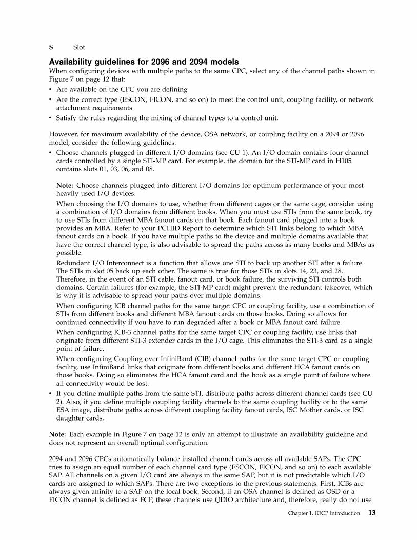
8. I/O channel path configuration for arepresentative I/O cage in a 2084 or 2086model . . . . . . . . . . . . . . 14
9. Sample PCHID report (Part 1 of 2) . . . . . 1710. Sample PCHID report (Part 2 of 2) . . . . . 1811. Valid control unit headers . . . . . . . . 2212. Control unit header that is incorrect . . . . 2413. Overview of z/OS version of IOCP . . . . 4514. Overview of VM version of IOCP . . . . . 4715. Overview of z/VSE version of IOCP . . . . 4816. Overview of stand-alone version of IOCP 5017. IOCP statements . . . . . . . . . . . 5218. Correspondence between IOCP statements and
SYSTEM CONFIG statements or HCPRIOstatements . . . . . . . . . . . . . 53
19. Correspondence between IOCP statements andz/VSE IPL ADD statements . . . . . . . 54
20. Sample IOCDS totals report . . . . . . . 15321. Sample partition report . . . . . . . . 154
22. Sample FID summary report . . . . . . 15623. Sample PCHID summary report . . . . . 15924. Sample CHPID summary report (Part 1 of 2) 16125. Sample CHPID summary report (Part 2 of 2) 16226. Sample I/O device report (Part 1 of 3) 16427. Sample I/O device report (Part 2 of 3) 16528. Sample I/O device report (Part 3 of 3) 16629. Sample channel path report (Part 1 of 2) 16830. Sample channel path report (Part 2 of 2) 16931. Sample IOCP statements . . . . . . . . 24132. Sample SYSTEM CONFIG statements for VM
I/O definition . . . . . . . . . . . 24133. HCPRIO file for VM system generation 24234. Source input for VSE system generation 24235. LPAR mode with more than eight paths to an
ESCON device . . . . . . . . . . . 25336. LPAR mode with shared paths to an ESCON
device . . . . . . . . . . . . . . 25437. ESCON CTC point-to-point . . . . . . . 25538. ESCON CTC dynamic through an ESCON
director with multiple paths . . . . . . 25639. FICON CTC and director with single path 25740. Chained ESCON directors . . . . . . . 25841. Cascaded FICON directors . . . . . . . 25942. Control unit logical addressing. . . . . . 26043. Channels through an ESCON converter 26144. FCV channel configuration . . . . . . . 26245. ESCON control units requiring unit address
00 . . . . . . . . . . . . . . . 26246. OSA configuration with two logical partitions 26347. OSA-ICC . . . . . . . . . . . . . 26448. FCP channel configuration . . . . . . . 26649. Coupling facility configuration. . . . . . 26750. ESCON CTC with shared and unshared
channels . . . . . . . . . . . . . 26851. ESCON CTC with shared channels . . . . 27252. FICON CTC (fully redundant) . . . . . . 278
© Copyright IBM Corp. 2017, 2018 vii
||||

viii IOCP User's Guide
Tables
1. EC levels that ICP IOCP supports . . . . . xiii2. Resource group and corresponding slots for
3907 model . . . . . . . . . . . . . 33. Resource group and corresponding slots for
3906 model . . . . . . . . . . . . . 34. Resource group and corresponding slots for
2964 and 2965 models . . . . . . . . . 45. Relationship of book jack numbers to MBAs 166. Input device by IOCP version . . . . . . 187. Summary of connectivity . . . . . . . . 338. Logical path summary by control unit . . . 399. Supported CHPARM values . . . . . . . 76
10. Valid VF ranges. . . . . . . . . . . 10511. Return codes for z/OS version of IOCP 11612. VM version of IOCP . . . . . . . . . 12713. Return codes for z/VSE version of IOCP 136
14. IOCP parameter values for IODEVICE andCNTLUNIT statements . . . . . . . . 245
15. z/OS considerations: . . . . . . . . . 24916. Machine rules . . . . . . . . . . . 28517. Constant machine limits . . . . . . . . 28618. Machine limits . . . . . . . . . . . 28719. Valid CHPID types. . . . . . . . . . 29120. Valid FUNCTION types . . . . . . . . 29221. Maximums by CPC . . . . . . . . . 29322. FCP Channel Path Limits . . . . . . . 29323. Keyword applicability for channel paths 29424. Keyword applicability for functions . . . . 29525. Statement and keyword applicability for
machine types . . . . . . . . . . . 29526. Activation and POR error message
hexadecimal values . . . . . . . . . 296
© Copyright IBM Corp. 2017, 2018 ix

x IOCP User's Guide
Safety
Safety noticesSafety notices may be printed throughout this guide. DANGER notices warn you of conditions orprocedures that can result in death or severe personal injury. CAUTION notices warn you of conditionsor procedures that can cause personal injury that is neither lethal nor extremely hazardous. Attentionnotices warn you of conditions or procedures that can cause damage to machines, equipment, orprograms.
World trade safety informationSeveral countries require the safety information contained in product publications to be presented in theirtranslation. If this requirement applies to your country, a safety information booklet is included in thepublications package shipped with the product. The booklet contains the translated safety informationwith references to the US English source. Before using a US English publication to install, operate, orservice this product, you must first become familiar with the related safety information in the SystemsSafety Notices, G229-9054. You should also refer to the booklet any time you do not clearly understandany safety information in the US English publications.
Laser safety informationAll IBM Z® (Z) and IBM LinuxONE™ (LinuxONE) models can use I/O cards such as FICON®, OpenSystems Adapter (OSA), InterSystem Channel-3 (ISC-3), zHyperLink Express, or other I/O features whichare fiber optic based and utilize lasers (short wavelength or long wavelength lasers).
Laser complianceAll lasers are certified in the US to conform to the requirements of DHHS 21 CFR Subchapter J for Class1 or Class 1M laser products. Outside the US, they are certified to be in compliance with IEC 60825 as aClass 1 or Class 1M laser product. Consult the label on each part for laser certification numbers andapproval information.
CAUTION: Data processing environments can contain equipment transmitting on system links withlaser modules that operate at greater than Class 1 power levels. For this reason, never look into theend of an optical fiber cable or open receptacle. (C027)
CAUTION: This product contains a Class 1M laser. Do not view directly with optical instruments.(C028)
© Copyright IBM Corp. 2017, 2018 xi

xii IOCP User's Guide
About this publication
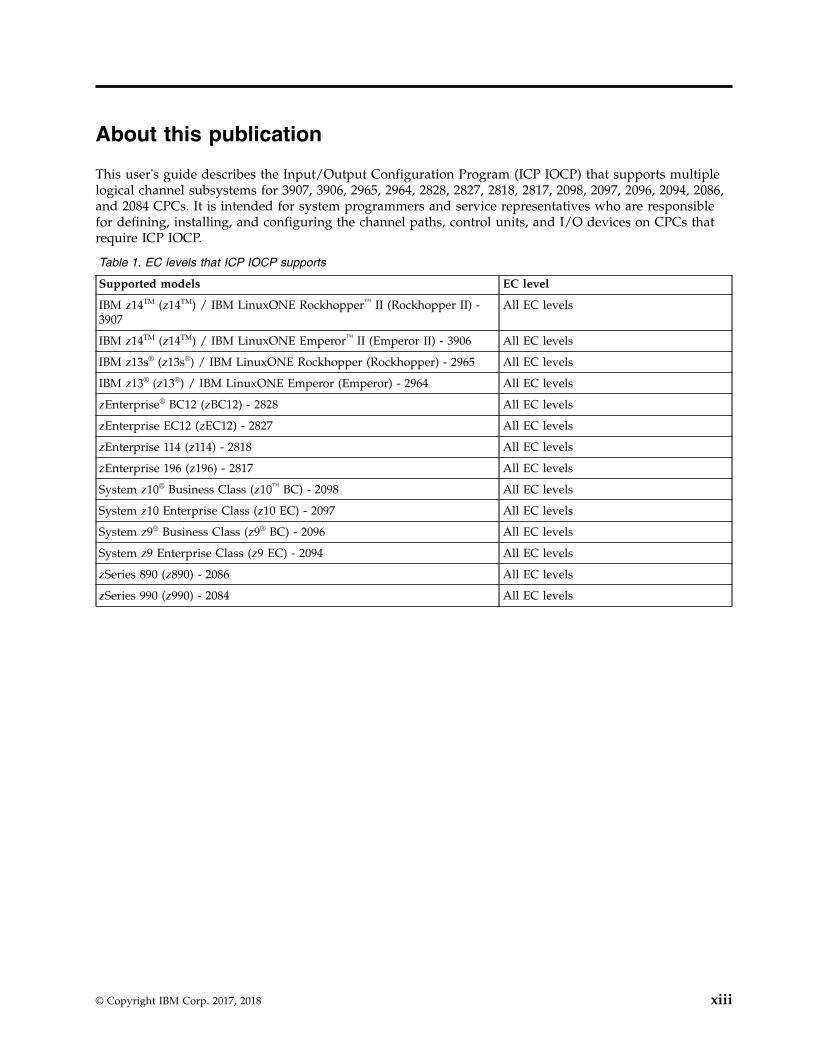
This user's guide describes the Input/Output Configuration Program (ICP IOCP) that supports multiplelogical channel subsystems for 3907, 3906, 2965, 2964, 2828, 2827, 2818, 2817, 2098, 2097, 2096, 2094, 2086,and 2084 CPCs. It is intended for system programmers and service representatives who are responsiblefor defining, installing, and configuring the channel paths, control units, and I/O devices on CPCs thatrequire ICP IOCP.
Table 1. EC levels that ICP IOCP supports
Supported models EC level
IBM z14TM (z14TM) / IBM LinuxONE Rockhopper™ II (Rockhopper II) -3907
All EC levels
IBM z14TM (z14TM) / IBM LinuxONE Emperor™ II (Emperor II) - 3906 All EC levels
IBM z13s® (z13s®) / IBM LinuxONE Rockhopper (Rockhopper) - 2965 All EC levels
IBM z13® (z13®) / IBM LinuxONE Emperor (Emperor) - 2964 All EC levels
zEnterprise® BC12 (zBC12) - 2828 All EC levels
zEnterprise EC12 (zEC12) - 2827 All EC levels
zEnterprise 114 (z114) - 2818 All EC levels
zEnterprise 196 (z196) - 2817 All EC levels
System z10® Business Class (z10™ BC) - 2098 All EC levels
System z10 Enterprise Class (z10 EC) - 2097 All EC levels
System z9® Business Class (z9® BC) - 2096 All EC levels
System z9 Enterprise Class (z9 EC) - 2094 All EC levels
zSeries 890 (z890) - 2086 All EC levels
zSeries 990 (z990) - 2084 All EC levels
© Copyright IBM Corp. 2017, 2018 xiii
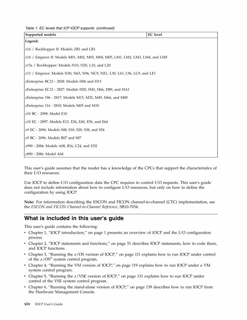
Table 1. EC levels that ICP IOCP supports (continued)
Supported models EC level
Legend:
z14 / Rockhopper II: Models ZR1 and LR1
z14 / Emperor II: Models M01, M02, M03, M04, M05, LM1, LM2, LM3, LM4, and LM5
z13s / Rockhopper: Models N10, N20, L10, and L20
z13 / Emperor: Models N30, N63, N96, NC9, NE1, L30, L63, L96, LC9, and LE1
zEnterprise BC12 - 2828: Models H06 and H13
zEnterprise EC12 - 2827: Models H20, H43, H66, H89, and HA1
zEnterprise 196 - 2817: Models M15, M32, M49, M66, and M80
zEnterprise 114 - 2818: Models M05 and M10
z10 BC - 2098: Model E10
z10 EC - 2097: Models E12, E26, E40, E56, and E64
z9 EC - 2094: Models S08, S18, S28, S38, and S54
z9 BC - 2096: Models R07 and S07
z990 - 2084: Models A08, B16, C24, and D32
z890 - 2086: Model A04
This user's guide assumes that the reader has a knowledge of the CPCs that support the characteristics oftheir I/O resources.
Use IOCP to define I/O configuration data the CPC requires to control I/O requests. This user's guidedoes not include information about how to configure I/O resources, but only on how to define theconfiguration by using IOCP.
Note: For information describing the ESCON and FICON channel-to-channel (CTC) implementation, seethe ESCON and FICON Channel-to-Channel Reference, SB10-7034.
What is included in this user's guideThis user's guide contains the following:v Chapter 1, “IOCP introduction,” on page 1 presents an overview of IOCP and the I/O configuration
process.v Chapter 2, “IOCP statements and functions,” on page 51 describes IOCP statements, how to code them,
and IOCP functions.v Chapter 3, “Running the z/OS version of IOCP,” on page 111 explains how to run IOCP under control
of the z/OS® system control program.v Chapter 4, “Running the VM version of IOCP,” on page 119 explains how to run IOCP under a VM
system control program.v Chapter 5, “Running the z/VSE version of IOCP,” on page 131 explains how to run IOCP under
control of the VSE system control program.v Chapter 6, “Running the stand-alone version of IOCP,” on page 139 describes how to run IOCP from
the Hardware Management Console.
xiv IOCP User's Guide
v Chapter 7, “IOCP configuration reports,” on page 151 shows the configuration reports that IOCPproduces.
v Chapter 8, “IOCP messages,” on page 171 lists the messages (with the prefix ICP and DMSICP) thatIOCP sends.
The appendixes in this user's guide include:v Appendix A, “Coding IOCP statements,” on page 237 describes the rules for coding IOCP statements
and the notation this document uses to show the syntax of the statements.v Appendix B, “Lists of statement input,” on page 241 shows sample lists of IOCP input files.v Appendix C, “Characteristics of the I/O interface timeout function,” on page 243 contains detailed
information about the timeout function.v Appendix D, “List of I/O devices and control units,” on page 245 shows the IOCP keyword values to
specify in the IODEVICE and CNTLUNIT statements.v Appendix E, “Configuration examples,” on page 253 shows several figures and their accompanying
IOCP input files that illustrate I/O configuration examples.v Appendix F, “Machine limits and rules,” on page 285 lists the machine limits and rules for the different
CPCs on which IOCP can run.v Appendix G, “Notices,” on page 299 contains electronic emission notices, legal notices, and trademarks.
RevisionsA technical change from the previous edition of this document is indicated by a vertical line (|) to the leftof the change.
New publications do not usually contain any revision notations. However, for the convenience of thosewho need to know the changes from the previous book, Input/Output Configuration Program User's Guidefor ICP IOCP, SB10-7163, revision notations have been added to illustrate these changes.
Related informationThe following documents contain information about topics related to IOCP.
OS/390v OS/390 Hardware Configuration Definition Planning, GC28-1750, explains the concepts, actions, and
general planning considerations needed to define and maintain an I/O configuration using theHardware Configuration Definition (HCD).
v OS/390 Hardware Configuration Definition User's Guide, SC28-1848, explains, along with onlineinformation, how to use HCD to define I/O configurations and eligible device tables to OS/390®.
v OS/390 Hardware Configuration Definition Scenarios, SC28-1850, contains about 20 scenarios of commonhardware configuration tasks.
v OS/390 Hardware Definition Configuration Messages, GC28-1849.v OS/390 HCD Reference Summary, SX22-0043, provides a short overview of HCD tasks, navigation
options, and information about online help. It also describes the relations among the configurationobjects and lists the actions and action codes for each object.
v MVS/ESA HCD and Dynamic I/O Reconfiguration Primer, SG24-4037.
z/OS and z/OS.ev z/OS Hardware Configuration Definition Planning, GA22-7525, explains the concepts, actions, and general
planning considerations needed to define and maintain an I/O configuration using the HardwareConfiguration Definition (HCD).
About this publication xv
v z/OS Hardware Configuration Definition User's Guide, SC33-7988, explains, along with online information,how to use HCD to define I/O configurations and eligible device tables to z/OS.
v z/OS Hardware Configuration Definition Scenarios, SC33-7987, contains about 20 scenarios of commonhardware configuration tasks.
v z/OS Hardware Configuration Definition Messages, SC33-7986.v z/OS and z/VM Hardware Configuration Manager User's Guide, SC33-7989.v z/OS HCD Reference Summary, SX33-9032, provides a short overview of HCD tasks, navigation options,
and information about online help. It also describes the relations among the configuration objects andlists the actions and action codes for each object.
z/VMv z/VM General Information , GC24-5944, describes the features of z/VM®.v z/VM Planning and Administration, SC24-5948, describes how to generate a z/VM system on CPC and
perform dynamic I/O configuration changes.v z/VM CP Command and Utility Reference, SC24-5967, describes the IOCP CMS utility.v z/VM Dynamic I/O Configuration Planning and Administration, SC24-6044, describes the use of the
Hardware Configuration Definition (HCD).v z/OS and z/VM Hardware Configuration Manager User's Guide, SC33-7989.
z/VSEv z/VSE Planning, SC33-8301.v z/VSE System Control Statements, SC33-8305.
3907 modelsv Hardware Management Console (HMC) and Support Element (SE) information can be found on the
console help system.v IBM Z PR/SM Planning Guide, SB10-7169v IBM Z Stand-Alone Input/Output Configuration Program User's Guide, SB10-7173v 3907 Installation Manual for Physical Planning (IMPP), GC28-6974.
3906 modelsv Hardware Management Console (HMC) and Support Element (SE) information can be found on the
console help system.v IBM Z PR/SM Planning Guide, SB10-7169v IBM Z Stand-Alone Input/Output Configuration Program User's Guide, SB10-7173v 3906 Installation Manual for Physical Planning (IMPP), GC28-6965.
2965 modelsv Hardware Management Console (HMC) and Support Element (SE) information can be found on the
console help system.v IBM z Systems PR/SM Planning Guide, SB10-7162v IBM z Systems Stand-Alone Input/Output Configuration Program User's Guide, SB10-7166v z13s Installation Manual for Physical Planning (IMPP), GC28-6938.
2964 modelsv Hardware Management Console (HMC) and Support Element (SE) information can be found on the
console help system.v IBM z Systems PR/SM Planning Guide, SB10-7162
xvi IOCP User's Guide

v IBM z Systems Stand-Alone Input/Output Configuration Program User's Guide, SB10-7166v z13 Installation Manual for Physical Planning (IMPP), GC28-6938.
2828 modelsv The content from the following publications is now incorporated into the Hardware Management
Console (HMC) and Support Element (SE) (Version 2.12.1) help system:– System z Hardware Management Console Operations Guide
– zEnterprise System Support Element Operations Guide
Hardware Management Console (HMC) and Support Element (SE) information can be found on theconsole help system.
v zEnterprise BC12 System Overview, SA22-1089v zEnterprise System PR/SM Planning Guide, SB10-7156v System z Stand-Alone Input/Output Configuration Program User's Guide, SB10-7152v zEnterprise BC12 Installation Manual for Physical Planning (IMPP), GC28-6914.
2827 modelsv zEnterprise EC12 System Overview, SA22-1088v zEnterprise System PR/SM Planning Guide, SB10-7156v System z Stand-Alone Input/Output Configuration Program User's Guide, SB10-7152v The content from the following publications is now incorporated into the Hardware Management
Console (HMC) and Support Element (SE) (Version 2.12.1) help system:– System z Hardware Management Console Operations Guide– zEnterprise System Support Element Operations Guide
Hardware Management Console (HMC) and Support Element (SE) information can be found on theconsole help system.
v System z Hardware Management Console Operations Guide (Version 2.12.0), SC28-6919v zEnterprise System Support Element Operations Guide (Version 2.12.0), SC28-6920v zEnterprise EC12 Installation Manual for Physical Planning (IMPP), GC28-6914.
2818 modelsv zEnterprise 114 System Overview, SA22-1087v zEnterprise System PR/SM Planning Guide, SB10-7155v System z Stand-Alone Input/Output Configuration Program User's Guide, SB10-7152v System z Hardware Management Console Operations Guide (Version 2.11.1), SC28-6905v zEnterprise System Support Element Operations Guide (Version 2.11.1), SC28-6906v zEnterprise 114 Installation Manual for Physical Planning (IMPP), GC28-6907.
2817 modelsv zEnterprise EC12 System Overview, SA22-1086v zEnterprise System PR/SM Planning Guide, SB10-7155v System z10 and System z9 Stand-Alone Input/Output Configuration Program User's Guide, SB10-7152v System z Hardware Management Console Operations Guide (Version 2.11.0), SC28-6895v zEnterprise System Support Element Operations Guide (Version 2.11.0), SC28-6896v zEnterprise EC12 Installation Manual for Physical Planning (IMPP), GC28-6897.
About this publication xvii
2098 modelsv System z10 Business Class System Overview, SA22-1085v System z10 Business Class Processor Resource/Systems Manager Planning Guide, SB10-7153v System z10 and System z9 Stand-Alone Input/Output Configuration Program User’s Guide, SB10-7152v System z Hardware Management Console Operations Guide, SC28-6873v System z10 Business Class Support Element Operations Guide, SC28-6879v System z10 Business Class Installation Manual for Physical Planning, GC28-6875.
2097 modelsv System z10 Enterprise Class System Overview, SA22-1084v System z10 Enterprise Class Processor Resource/Systems Manager Planning Guide, SB10-7153v System z10 and System z9 Stand-Alone Input/Output Configuration Program User’s Guide, SB10-7152v System z Hardware Management Console Operations Guide, SC28-6867v System z10 Enterprise Class Support Element Operations Guide, SC28-6868v System z10 Enterprise Class Installation Manual for Physical Planning, GC28-6865.
2096 modelsv System z9 Business Class System Overview, SA22-1083v System z9 Processor Resource Systems Manager Planning Guide, SB10-7153v System z9 Stand-Alone Input/Output Configuration Program User’s Guide, SB10-7152v System z Hardware Management Console Operations Guide, SC28-6867v System z9 Support Element Operations Guide, SC28-6868v System z9 Business Class Installation Manual for Physical Planning, GC28-6855.
2094 modelsv System z9 Enterprise Class System Overview, SA22-6833.v System z9 Processor Resource Systems Manager Planning Guide, SB10-7041v System z9 Stand-Alone Input/Output Configuration Program User’s Guide , SB10-7152v System z Hardware Management Console Operations Guide, SC28-6857v System z9 Support Element Operations Guide, SC28-6858v System z9 Enterprise Class Installation Manual for Physical Planning, GC28-6844.
2086 modelsv zSeries 890 System Overview, SA22-6832.v zSeries 890 and 990 Processor Resource Systems Manager Planning Guide, SB10-7036.v zSeries 890 and 990 Stand-Alone IOCP User's Guide, SB10-7040.v Hardware Management Console Operations Guide, SC28-6830.v zSeries 890 and 990 Support Element Operations Guide, SC28-6831.
2084 modelsv zSeries 990 System Overview, SA22-1032.v zSeries 890 and 990 Processor Resource Systems Manager Planning Guide, SB10-7036.v zSeries 890 and 990 Stand-Alone IOCP User's Guide, SB10-7040.v Hardware Management Console Operations Guide, SC28-6819.v zSeries 990 Support Element Operations Guide, SC28-6820.
xviii IOCP User's Guide
v zSeries 990 Installation Manual for Physical Planning, GC28-6824.
Enterprise systems connection (ESCON)v Introducing Enterprise Systems Connection, GA23-0383.v Introducing ESCON Directors, GA23-0363.v Planning for Enterprise Systems Connection Directors, GA23-0364.v ESCON and FICON Channel-to-Channel Reference, SB10-7034.v Planning for the 9032 Model 5 Director with FICON Converter Feature, SA22-7415.
Fibre connection (FICON)v Introduction to IBM S/390 FICON, SG24-5176.v Planning for the 9032 Model 5 Director with FICON Converter Feature, SA22-7415.v ESCON and FICON Channel-to-Channel Reference, SB10-7034.
Open Systems Adapter (OSA)v Open Systems Adapter-Express Customer's Guide and Reference, SA22-7935.v OS/390 Open Systems Adapter Support Facility Users Guide, SC28-1855.v VSE/Enterprise Systems Architecture Open Systems Adapter Support Facility Users Guide, SC28-1946.v Open Systems Adapter-Express Integrated Console Controller User's Guide, SA22-7990.
Note to all usersThis user's guide describes ICP IOCP. See Table 16 on page 285 for a list of the Central ProcessorComplex (CPC) models that require ICP IOCP. Any IOCDS that ICP IOCP creates runs only on the CPCmodels listed there. You cannot use ICP IOCP to print reports or read IOCDSs produced by IYP IOCP,IZP IOCP, or IXP IOCP.
IOCP requires a maximum of 214 MB of storage to run on z/OS and z/VSE® (MB equals 1 048 576bytes). On VM, IOCP uses 214 MB of storage in a CMS virtual machine. IOCP requires a variable amountof storage based on the type of IOCDS it is processing. To determine the amount of storage IOCP requiresfor a specific type of CPC model, see Table 18 on page 287.
When you perform any IOCP function, the z/OS IOCP program must be an APF-authorized program.
AccessibilityAccessible publications for this product are offered in EPUB format and can be downloaded fromResource Link® at http://www.ibm.com/servers/resourcelink.
If you experience any difficulty with the accessibility of any IBM Z® and IBM LinuxONE information, goto Resource Link at http://www.ibm.com/servers/resourcelink and click Feedback from the navigationbar on the left. In the Comments input area, state your question or comment, the publication title andnumber, choose General comment as the category and click Submit. You can also send an email [email protected] providing the same information.
When you send information to IBM®, you grant IBM a nonexclusive right to use or distribute theinformation in any way it believes appropriate without incurring any obligation to you.
About this publication xix
Accessibility features
The following list includes the major accessibility features in IBM Z and IBM LinuxONE documentation,and on the Hardware Management Console and Support Element console:v Keyboard-only operationv Interfaces that are commonly used by screen readersv Customizable display attributes such as color, contrast, and font sizev Communication of information independent of colorv Interfaces commonly used by screen magnifiersv Interfaces that are free of flashing lights that could induce seizures due to photo-sensitivity.
Keyboard navigationThis product uses standard Microsoft Windows navigation keys.
Consult assistive technologiesAssistive technology products such as screen readers function with our publications, the HardwareManagement Console, and the Support Element console. Consult the product information for the specificassistive technology product that is used to access the EPUB format publication or console.
IBM and accessibilitySee http://www.ibm.com/able for more information about the commitment that IBM has to accessibility.
Related HMC and SE console informationHardware Management Console (HMC) and Support Element (SE) information can be found on theconsole help system.
How to send your commentsYour feedback is important in helping to provide the most accurate and high-quality information. Sendyour comments by using Resource Link at http://www.ibm.com/servers/resourcelink. Click Feedback on theNavigation bar on the left. You can also send an email to [email protected]. Be sure to include thename of the book, the form number of the book, the version of the book, if applicable, and the specificlocation of the text you are commenting on (for example, a page number, table number, or a heading).
xx IOCP User's Guide
Summary of changes
Summary of Changes for SB10-7172-02 IBM Z Input/Output Configuration Program User's Guide ICP IOCP
This revision contains technical and editorial changes.
New Information:
v Support for IBM Adapter for NVMe (See “FUNCTION” on page 102).v Support for Licensed Machine Code partition MCS_1 so dynamic I/O changes can be made to a
stand-alone coupling facility (CF) CPC (See “RESOURCE” on page 58).
Summary of Changes for SB10-7172-01 IBM Z Input/Output Configuration Program User's Guide ICP IOCP
This revision contains technical and editorial changes.
New Information:
v Support for z14 model ZR1 and IBM LinuxONE Rockhopper II model LR1. See “Machine limits” onpage 286.
Summary of Changes for SB10-7172-00a IBM Z Input/Output Configuration Program User's Guide ICP IOCP
This revision contains technical and editorial changes.
New Information:
v Support for IBM LinuxONE Emperor II models (LM1, LM2, LM3, LM4, and LM5). See “Machinelimits” on page 286.
Summary of Changes for SB10-7172-00 IBM Z Input/Output Configuration Program User's Guide ICP IOCP
This revision contains technical and editorial changes.
New Information:
v New ICP IOCP release level: ICP IOCP Version 5 Release 4.0v Support for Coupling Express LR channel paths (TYPE=CL5; See “CHPID” on page 62) and was
introduced with ICP IOCP Version 5 Release 3.0.v Support for z14 models (See “Machine limits” on page 286).v Support for IBM zHyperLink Express® adapters (See “FUNCTION” on page 102).v Support for RoCE Express2 networking Ethernet PCIe feature (See “FUNCTION” on page 102).v Support for MIXTYPE keyword on CHPID statement.v Introduce FID summary report (See “FID summary report” on page 155).
Summary of Changes for SB10-7163-02 z Systems®
Input/Output Configuration Program User's Guide ICP IOCP
This revision contains technical and editorial changes.
New Information:
v New ICP IOCP release level: ICP IOCP Version 5 Release 2.1v Support for UUID statement
© Copyright IBM Corp. 2017, 2018 xxi
v Support for UID keyword on FUNCTION statement
Summary of Changes for SB10-7163-01 z SystemsInput/Output Configuration Program User's Guide ICP IOCP
This revision contains technical and editorial changes.
New Information:
v New ICP IOCP release level: ICP IOCP Version 5 Release 2.0v Support for z13s / Rockhopper 2965 models (See “Machine limits” on page 286)v Support for Emperor 2964 models (See “Machine limits” on page 286v Support for SMC-D virtual network connections (See “FUNCTION” on page 102)v Support for Regional Crypto Enablement PCIe feature (See “FUNCTION” on page 102)
Summary of Changes for SB10-7163-00 z SystemsInput/Output Configuration Program User's Guide ICP IOCP
This revision contains technical and editorial changes.
New Information:
v New ICP IOCP release level: ICP IOCP Version 5 Release 1.0v Support for IBM z13 2964 models (See Appendix F, “Machine limits and rules,” on page 285)
– Increase to 6 CSS, 85 partitions, 4 Subchannel sets– Increase to 256 Coupling channel paths– Increase to 32k device maximum on FICON and FCP channel paths– Increase in FUNCTION FID range.
v Support for new CHPID Type CS5 (See “CHPID” on page 62)v Support for shared 10Gb RoCE Express networking Ethernet PCIe feature (See “FUNCTION” on page
102)v Support for new VCHID keyword on CHPID statement for Hipersocket (TYPE=IQD) channels.
Summary of Changes for SB10-7037-11 System z®
Input/Output Configuration Program User's Guide ICP IOCP
This revision contains technical and editorial changes.
New Information:
v New ICP IOCP release level: ICP IOCP Version 4 Release 1.0v Support for the zEnterprise BC12 2828 models (See Appendix F, “Machine limits and rules,” on page
285)v Support for the new FUNCTION statement to define new PCIe card functionality and logical
partition(s) (See “FUNCTION” on page 102)v Support for 10Gb RoCE Express networking Ethernet PCIe featurev Support for zEDC Express compression PCIe featurev The 2828 models require power-on reset with an IOCDS written for the 2828 models. After an upgrade,
you cannot power-on reset with an IOCDS that was written for the prior CPC unless the 2828 IOCDSwas written in preparation of an upgrade.
Summary of Changes for SB10-7037-10 System zInput/Output Configuration Program User's Guide ICP IOCP
xxii IOCP User's Guide
This revision contains technical and editorial changes.
New Information:
v New ICP IOCP release level: ICP IOCP Version 3 Release 3.0v Support for the 2827 models (See Appendix F, “Machine limits and rules,” on page 285.)v The 2827 models require power-on reset with an IOCDS written for the 2827. After an upgrade, you
cannot power-on reset with an IOCDS that was written for the prior CPC unless the 2827 IOCDS waswritten in preparation of an upgrade.
Changed Information:
v ESCON is not supported on 2827 (and subsequent) models and should update to FICON.
Summary of Changes for SB10-7037-09 System zInput/Output Configuration Program User's Guide ICP IOCP
This revision contains technical and editorial changes.
New Information:
v New ICP IOCP release level: ICP IOCP Version 3 Release 2.0v Support for the 2818 models (See Appendix F, “Machine limits and rules,” on page 285.)v The 2818 models require power-on reset with an IOCDS written for the 2818. After an upgrade, you
cannot power-on reset with an IOCDS that was written for the prior CPC unless the 2818 IOCDS waswritten in preparation of an upgrade.
v Support for defining a HiperSocket CHPID (TYPE=IQD) for connecting to the intraensemble datanetwork (IEDN).
v Support for defining HiperSocket CHPIDs (TYPE=IQD) to be capable of being bridged to an externaluser network.
Changed Information:
v IOCP now expects all devices defined for an IQD CHPID to be device type (UNIT=) of IQD.v The Hardware Management Console diskette drive is not available on the zEnterprise System.
Summary of Changes for SB10-7037-08 System zInput/Output Configuration Program User's Guide ICP IOCP
This revision contains technical and editorial changes.
New Information:
v New ICP IOCP release level: ICP IOCP Version 3 Release 1.0v Support for the 2817 models (See Appendix F, “Machine limits and rules,” on page 285.)v The 2817 models require power-on reset with an IOCDS written for the 2817. After an upgrade, you
cannot power-on reset with an IOCDS that was written for the prior CPC unless the 2817 IOCDS waswritten in preparation of an upgrade.
v Support for the OSA for zBX data network channel paths (TYPE=OSX)v Support for the OSA for zBX management network channel paths (TYPE=OSM)v Support for a third subchannel set within a CSSv Support for up to 32 HiperSockets™ CHPIDsv Support for 128 coupling CHPIDs
Changed Information:
Summary of changes xxiii
v LPAR=YES in the PARM parameter of the EXEC statement for z/OS and z/VSE and the CMS optionLPAR are no longer supported. IOCP always generates an LPAR mode IOCDS.
Summary of Changes for SB10-7037-07 System zInput/Output Configuration Program User's Guide ICP IOCP
This revision contains technical and editorial changes.
New Information:
v New ICP IOCP release level (stand-alone and batch versions): ICP IOCP Version 2 Release 2.0v Support for the 2098 models. IOCP ignores the MAXDEV keyword on the RESOURCE statement and
reserves the maximum number of devices for these models. Also, IOCP reserves the maximum numberof CSSs and logical partitions for these models.
v The 2098 models require power-on reset with an IOCDS written for the 2098. After an upgrade, youcannot power-on reset with an IOCDS that was written for the prior CPC unless the 2098 IOCDS waswritten in preparation of an upgrade.
Changed Information:
v LPAR=YES in the PARM parameter of the EXEC statement for z/OS and VSE and the CMS optionLPAR are no longer supported. IOCP always generates an LPAR mode IOCDS.
Summary of Changes for SB10-7037-06 System zInput/Output Configuration Program User's Guide ICP IOCP
This revision contains technical and editorial changes.
New Information:
v New ICP IOCP release level (stand-alone and batch versions): ICP IOCP Version 2 Release 1.0v Support for the 2097 models. IOCP ignores the MAXDEV keyword on the RESOURCE statement and
reserves the maximum number of devices for these models. Also, IOCP reserves the maximum numberof CSSs and logical partitions for these models.
v The 2097 models require power-on reset with an IOCDS written for the 2097. After an upgrade, youcannot power-on reset with an IOCDS that was written for the prior CPC unless the 2097 IOCDS waswritten in preparation of an upgrade.
v Support for coupling over InfiniBand® channel paths (TYPE=CIB)v I/O configurations with reconfigurable FCP channel paths can reach the maximum number of FCP
valid subchannels for 2097 models. Prior models did not reach the maximum. See “Fibre ChannelProtocol support” on page 36 for more information about how valid subchannels are calculated forreconfigurable FCP channel paths.
Changed Information:
v The OS keyword on the CHPID statement is no longer supported (use CHPARM keyword instead).
Summary of Changes for SB10-7037-05System z9 Business Class and Enterprise Class andzSeries 890 and 990Input/Output Configuration Program User's Guide ICP IOCP
This revision contains technical and editorial changes.
New Information:
v New ICP IOCP release level (stand-alone and batch versions): ICP IOCP Version 1 Release 4.0v Support for the 2096 models
xxiv IOCP User's Guide
v The System z9 Enterprise Class (z9 EC) was formerly the System z9 109.
Summary of Changes for SB10-7037-04System z9 109 and zSeries 890 and 990Input/Output Configuration Program User's Guide ICP IOCP
This major revision contains technical and editorial changes.
New Information:
v New ICP IOCP release level (stand-alone and batch versions): ICP IOCP Version 1 Release 3.0v Support for the 2094 modelsv Support for the OSA for network control program (NCP) channel paths (TYPE=OSN)v Support for two subchannel sets within a CSS, using the new SCHSET keyword on the IODEVICE
statementv IOCP uses a variable amount of storage based on the type of IOCDS it is processing (see Table 18 on
page 287).
Summary of Changes for SB10-7037-03zSeries Input/Output Configuration Program User's Guide ICP IOCP
This minor revision contains technical and editorial changes.
New Information:
v Increase the number of FCV, FC, FCP, OSC, OSD, and OSE channels available on 2084 and 2086 models(see Table 18 on page 287).
Summary of Changes for SB10-7037-02zSeries Input/Output Configuration Program User's Guide ICP IOCP
This major revision contains technical and editorial changes.
New Information:
v Support for multiple control units on an OSD channel path so a single logical partition can have morethan 254 devices (84 TCP/IP stacks).
v Support for 1920 valid subchannels (640 TCP/IP stacks) on OSA-Express2 OSD channel paths whenpriority specification is disabled. See “OSA configuration considerations” on page 32.
Summary of Changes for SB10-7037-01zSeries Input/Output Configuration Program User's Guide ICP IOCP
This major revision contains technical and editorial changes.
New Information:
v New ICP IOCP release level (stand-alone and batch versions): ICP IOCP Version 1 Release 2.0v Support for the 2086 models (see Appendix F, “Machine limits and rules,” on page 285)v Support for OSA-Express integrated console controller channel paths (TYPE=OSC)v Reserved logical partitions can be specified which do not exist until a dynamic I/O configuration
change is made to define themv A null device candidate list can be specified for a CSS which excludes the device from the CSSv The following channel path types can now be spanned across multiple CSSs: FC, FCP, CFS, CFP, CBS,
CBP, OSC, OSD, and OSE.
Summary of changes xxv

Summary of Changes for SB10-7037-00azSeries Input/Output Configuration Program User's Guide ICP IOCP
This minor revision contains technical and editorial changes.
New Information:
v Hexadecimal value for Spanned ICP or IQD channel paths (See Table 26 on page 296).
Summary of Changes for SB10-7037-00zSeries Input/Output Configuration Program User's Guide ICP IOCP
This edition is the initial edition of this publication.
New Information:
v New ICP IOCP release level (stand-alone and batch versions): ICP IOCP Version 1 Release 1.0v Support for the 2084 models (See Appendix F, “Machine limits and rules,” on page 285)
xxvi IOCP User's Guide
Chapter 1. IOCP introduction
This chapter presents an overview of the following topics:v Hardware I/O configurationv I/O configuration processv I/O configuration data sets (IOCDSs)v I/O configuration considerationsv Shared ESCON CTC considerationsv Coupling facility supportv Open Systems Adapter (OSA) feature supportv Internal Queued Direct Communication (HiperSockets) supportv Fibre Channel Protocol supportv Defining FICON switch configurationsv Managing logical paths for ESCON and FICON channelsv Managing the establishment of logical pathsv Channel path selectionv Channel unit typesv Versions of IOCP
Hardware I/O configurationIn the CPC, the input/output (I/O) subsystem, which controls channel operations, requires specific dataabout the hardware I/O configuration.
To define the I/O configuration for the I/O subsystem, run the Input/Output Configuration Program(IOCP). To run IOCP, you need to specify:v Logical partitionsv Channel paths on the central processor complex (CPC) and their assignment to logical partitionsv Control units attached to the channel pathsv I/O devices assigned to the control unitsv PCIe adapter functions on the CPC and their assignment to logical partitions.
Also, to meet changing I/O requirements, you can replace an existing I/O configuration with a newconfiguration by running IOCP.
All control units and I/O devices that attach to the CPC must be defined to the channel subsystem byusing IOCP.
See Appendix D, “List of I/O devices and control units,” on page 245 for a partial list of control unitsand I/O devices available.
Note: Your CPC might not support all the devices listed in Appendix D, “List of I/O devices and controlunits,” on page 245.
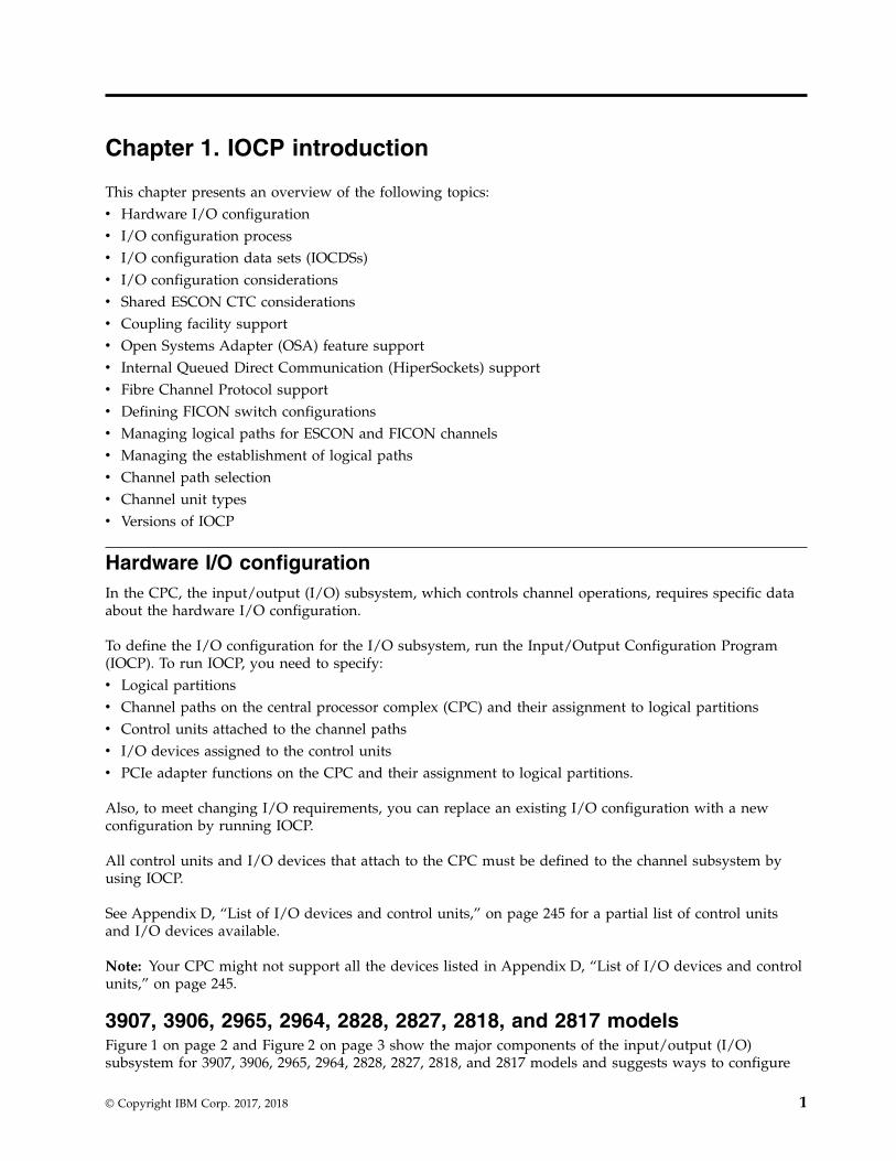
3907, 3906, 2965, 2964, 2828, 2827, 2818, and 2817 modelsFigure 1 on page 2 and Figure 2 on page 3 show the major components of the input/output (I/O)subsystem for 3907, 3906, 2965, 2964, 2828, 2827, 2818, and 2817 models and suggests ways to configure
© Copyright IBM Corp. 2017, 2018 1
I/O for maximum availability.
S01
S02
S03
S04
S06
S07
S08
S09
S11
S12
S13
S14
S16 S23
S17 S22
S18 S21
S19 S20
S34
S24
S05
S15
PCIe
PCIe
RII
RII
S38
S37
S36
S35
PCIe
PCIe
S33
S32
S31
S30
S28
S27
S25
S26
CU1
CU2
Figure 1. I/O channel path configuration for a representative PCIe I/O drawer in a 2817, 2818, 2827, 2828, 2964,2965, and 3906 model
2 IOCP User's Guide
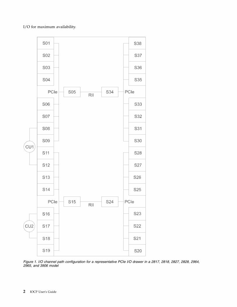
Legend
PCIe PCIe interface
RII Redundant I/O Interconnect bus
S Slot
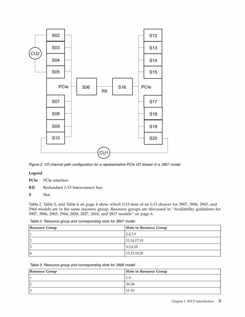
Table 2, Table 3, and Table 4 on page 4 show which I/O slots of an I/O drawer for 3907, 3906, 2965, and2964 models are in the same resource group. Resource groups are discussed in “Availability guidelines for3907, 3906, 2965, 2964, 2828, 2827, 2818, and 2817 models” on page 6.
Table 2. Resource group and corresponding slots for 3907 model
Resource Group Slots in Resource Group
1 2,4,7,9
2 12,14,17,19
3 3,5,8,10
4 13,15,18,20
Table 3. Resource group and corresponding slots for 3906 model
Resource Group Slots in Resource Group
1 1-9
2 30-38
3 11-19
S02
S03
S04
S05
S07
S08
S09
S10
PCIe S06
S12
S13
S14
S15
S17
S18
S19
S20
S16 PCIe
RII
CU2
CU1
Figure 2. I/O channel path configuration for a representative PCIe I/O drawer in a 3907 model
Chapter 1. IOCP introduction 3
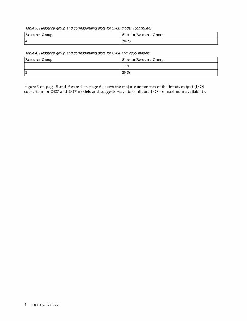
Table 3. Resource group and corresponding slots for 3906 model (continued)
Resource Group Slots in Resource Group
4 20-28
Table 4. Resource group and corresponding slots for 2964 and 2965 models
Resource Group Slots in Resource Group
1 1-19
2 20-38
Figure 3 on page 5 and Figure 4 on page 6 shows the major components of the input/output (I/O)subsystem for 2827 and 2817 models and suggests ways to configure I/O for maximum availability.
4 IOCP User's Guide
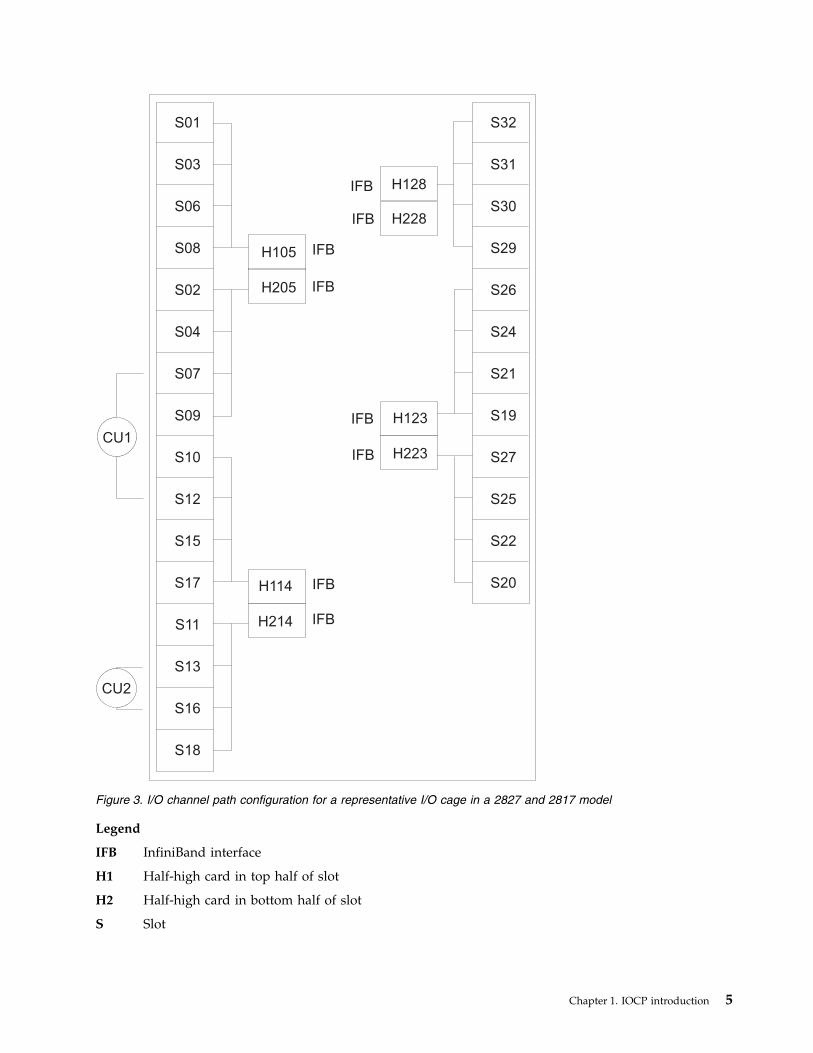
Legend
IFB InfiniBand interface
H1 Half-high card in top half of slot
H2 Half-high card in bottom half of slot
S Slot
S01
S03
S06
S08
S02
S04
S07
S09
S10
S12
S15
S17
S11
S13
S16
S18
H105
H205
IFB
IFB
IFB
IFB
IFB
IFB
IFB
IFB
H114
H214
H123
H223
H128
H228
S32
S31
S30
S29
S26
S24
S21
S19
S27
S25
S22
S20
CU1
CU2
Figure 3. I/O channel path configuration for a representative I/O cage in a 2827 and 2817 model
Chapter 1. IOCP introduction 5
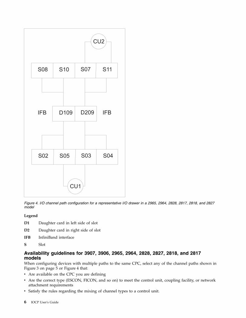
Legend
D1 Daughter card in left side of slot
D2 Daughter card in right side of slot
IFB InfiniBand interface
S Slot
Availability guidelines for 3907, 3906, 2965, 2964, 2828, 2827, 2818, and 2817modelsWhen configuring devices with multiple paths to the same CPC, select any of the channel paths shown inFigure 3 on page 5 or Figure 4 that:v Are available on the CPC you are definingv Are the correct type (ESCON, FICON, and so on) to meet the control unit, coupling facility, or network
attachment requirementsv Satisfy the rules regarding the mixing of channel types to a control unit.
CU2
CU1
S08
IFB
S02
S10
D109
S05
S07
D209
S03
S11
IFB
S04
Figure 4. I/O channel path configuration for a representative I/O drawer in a 2965, 2964, 2828, 2817, 2818, and 2827model
6 IOCP User's Guide
However, for maximum availability of the device, OSA network, coupling facility, or PCIe function on a3907, 3906, 2965, 2964, 2828, 2827, 2818, or 2817 model, consider the following guidelines.v Choose channels plugged in different I/O domains (see CU 1). An I/O domain in an I/O cage or I/O
drawer contains four channel cards controlled by a single IFB-MP card. For example, the domain forthe IFB-MP card in H105 in the I/O cage contains slots 01, 03, 06, and 08 and in D109 in the I/Odrawer contains slots 02, 05, 08, and 10. An I/O domain in a PCIe I/O drawer contains eight channelcards controlled by a single PCIe-IN card. For example, the domain for the PCIe-IN card in slot 05 inthe PCIe I/O drawer contains slots 1-4 and 5-9.
Note: This action is also recommended for optimum performance of your most heavily used I/Odevices.When choosing the I/O domains to use, whether from different cages/drawers or the samecage/drawer, consider using a combination of I/O domains from different books or CPC drawers.When you must use InfiniBand or PCIe links from the same book or CPC drawer , try to useInfiniBand or PCIe links from different Host Channel Adapter (HCA) or PCIe fanout cards on thatbook. Refer to your PCHID Report to determine which InfiniBand and PCIe links belong to whichfanout cards on a book. If you have multiple paths to the device and multiple domains available thathave the correct channel type, spread the paths across as many books and CPC drawers and fanoutcards as possible.Redundant I/O Interconnect is a function that allows one IFB-MP or PCIe-IN to back up anotherIFB-MP or PCIe-IN for a failure or repair. The IFB-MPs in slot 05 of the I/O cage back up each other.The same is true for IFB-MPs in slots 14, 23, and 28. In the I/O drawer, the IFB-MP cards in slot 09back up each other. The PCIe-IN cards in slots 05 and 34 of the PCIe I/O drawer back up each other.The same is true for the PCIe-IN cards in slots 15 and 24. Therefore, in the event an InfiniBand or PCIecable, fanout card, or book fails, the remaining IFB-MP or PCIe-IN card controls both domains. Certainfailures (for example, the IFB-MP or PCIe-IN card) might prevent the redundant takeover, which is areason to spread your paths over multiple domains.When configuring Coupling over InfiniBand (CIB) channel paths for the same target CPC or couplingfacility, use InfiniBand links that originate from different books or CPC drawers and different HCAfanout cards on those books/drawers. Doing so eliminates the HCA fanout card and the book as asingle point of failure where all connectivity would be lost.When configuring Coupling Short Reach Gen5 channels (Integrated Coupling Adapter (ICA SR)channel paths for the same target CPC or coupling facility, use ICA links that originate from differentCPC drawers and different ICA fanout cards on those drawers. This eliminates the ICA fanout cardand the drawer as a single point of failure where all connectivity would be lost.When configuring Coupling Express LR (CE LR) channel paths for the same target CPC or couplingfacility, use CE LR links that originate from different I/O drawers and different PCIe-IN fanout cardson those drawers. This eliminates the PCIe-IN fanout card and the drawer as a single point of failurewhere all connectivity would be lost.
v If you define multiple paths from the same InfiniBand or PCIe link, distribute paths across differentchannel cards (see CU 2). Also, if you define multiple coupling facility channels to the same couplingfacility or to the same ESA image, distribute paths across different coupling facility fanout cards, ISCmother cards, or ISC daughter cards.
v The following channel path and function types are associated with resource groups and managed bythe CPC: CL5 channel paths and ROCE, ROC2, and ZEDC functions. These channel paths and functiontypes are associated with the resource groups shown in Table 2 on page 3, Table 3 on page 3, andTable 4 on page 4. The same resource groups apply to all I/O drawers for the CPC. A resource groupcan become unavailable (for example, during an LMC patch install) and all of its channel paths andfunctions will become unavailable. When configuring CL5 channel paths for the same target CPC orcoupling facility, use CE LR links that originate from different resource groups. When configuring thesefunction adapter types, be aware that those which are in the same resource group can all becomeunavailable at the same time.
Chapter 1. IOCP introduction 7
Note: The examples shown in Figure 1 on page 2, Figure 2 on page 3, Figure 3 on page 5 and Figure 4on page 6 merely try to illustrate availability guidelines and do not represent overall optimalconfigurations.
The 3907, 3906, 2965, 2964, 2828, 2827, 2818, and 2817 CPCs have eliminated the concept of FICONchannels or channel cards having affinity to specific SAPs. Now each SAP handles FICON work more onan on-demand basis. That is, as FICON work for any channel arrives, the next available SAP handles thatrequest. It does not matter if it is an outbound request or an inbound interrupt, the next available SAPhandles the FICON work. There is no requirement to configure for "SAP affinity," because there is noaffinity for FICON. For the other channel types (ESCON, and so on), the 2828, 2827, 2818, and 2817 CPCsautomatically balance installed channel cards across all available SAPs. The CPC tries to assign an equalnumber of each channel card type to each available SAP. All channels on a given I/O card are always inthe same SAP, but it is not predictable which I/O cards are assigned to which SAPs. There are twoexceptions to the previous statements. First, Host Channel Adapters (HCAs) used for coupling are alwaysgiven affinity to a SAP on the local book. Second, if an OSA channel is defined as OSD, OSM, or OSX ora FICON channel is defined as FCP, these channels use QDIO architecture and, therefore, do not actuallyuse any SAP resource during normal operations. For all channel types simply follow the precedingrecommendations for configuring for RAS, and the SAPs handle the workload appropriately.
2098 and 2097 modelsFigure 5 on page 9 shows the major components of the input/output (I/O) subsystem for 2097 modelsand suggests ways to configure I/O for maximum availability.
8 IOCP User's Guide
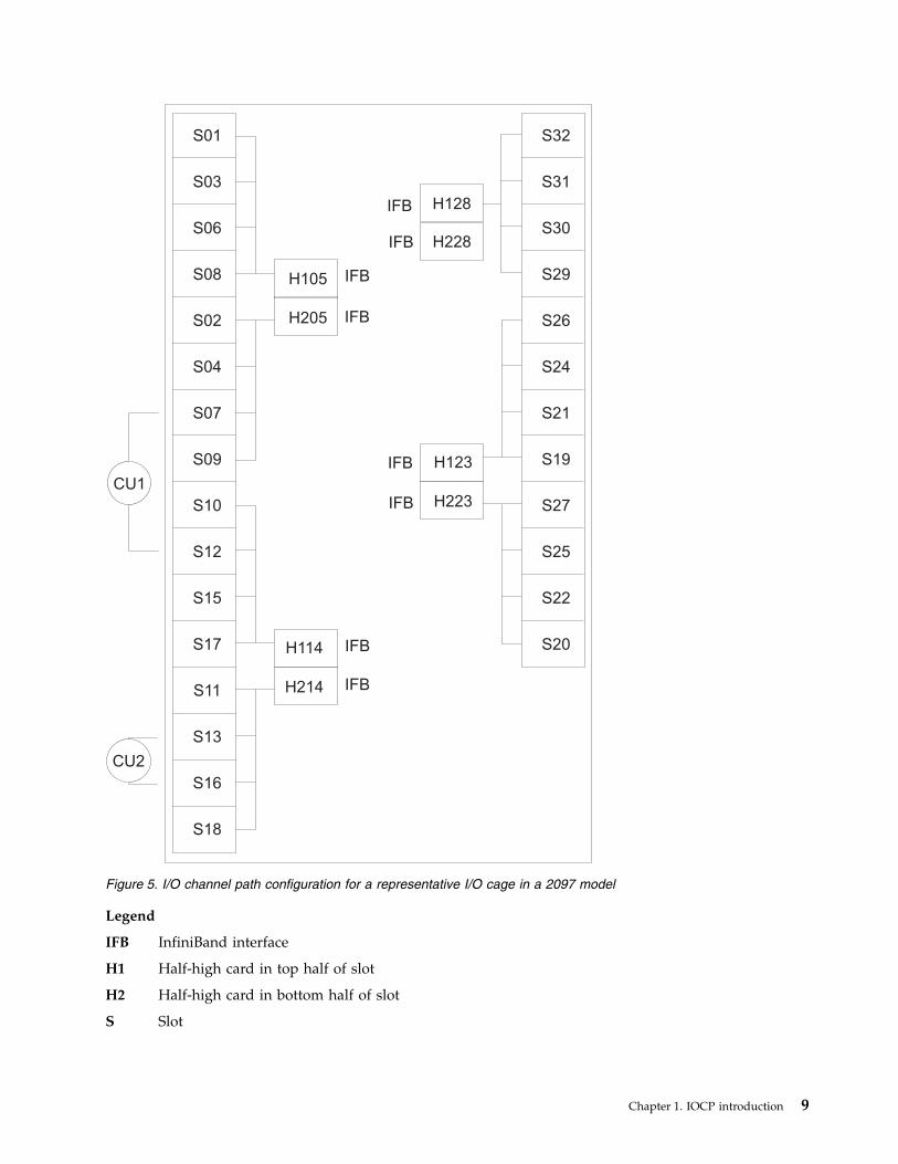
Legend
IFB InfiniBand interface
H1 Half-high card in top half of slot
H2 Half-high card in bottom half of slot
S Slot
S01
S03
S06
S08
S02
S04
S07
S09
S10
S12
S15
S17
S11
S13
S16
S18
H105
H205
IFB
IFB
IFB
IFB
IFB
IFB
IFB
IFB
H114
H214
H123
H223
H128
H228
S32
S31
S30
S29
S26
S24
S21
S19
S27
S25
S22
S20
CU1
CU2
Figure 5. I/O channel path configuration for a representative I/O cage in a 2097 model
Chapter 1. IOCP introduction 9
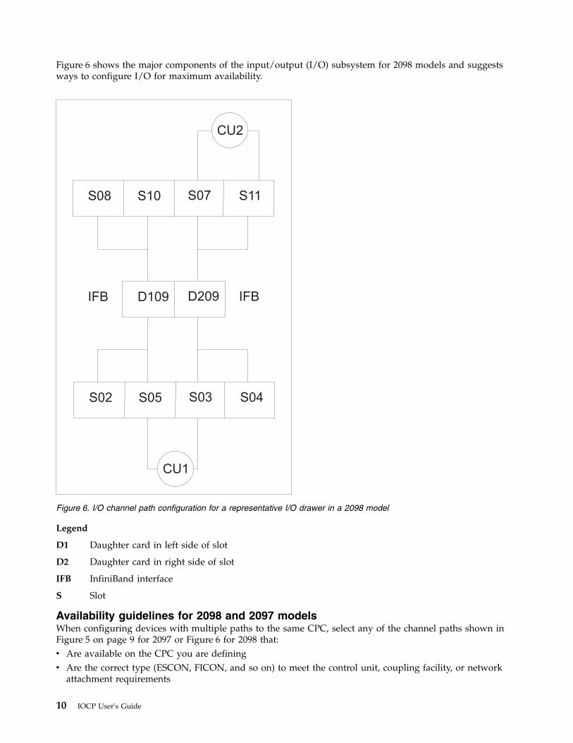
Figure 6 shows the major components of the input/output (I/O) subsystem for 2098 models and suggestsways to configure I/O for maximum availability.
Legend
D1 Daughter card in left side of slot
D2 Daughter card in right side of slot
IFB InfiniBand interface
S Slot
Availability guidelines for 2098 and 2097 modelsWhen configuring devices with multiple paths to the same CPC, select any of the channel paths shown inFigure 5 on page 9 for 2097 or Figure 6 for 2098 that:v Are available on the CPC you are definingv Are the correct type (ESCON, FICON, and so on) to meet the control unit, coupling facility, or network
attachment requirements
CU2
CU1
S08
IFB
S02
S10
D109
S05
S07
D209
S03
S11
IFB
S04
Figure 6. I/O channel path configuration for a representative I/O drawer in a 2098 model
10 IOCP User's Guide

v Satisfy the rules regarding the mixing of channel types to a control unit.
However, for maximum availability of the device, OSA network, or coupling facility on a 2097 or 2098model, consider the following guidelines.v Choose channels plugged in different I/O domains (see CU 1). An I/O domain contains four channel
cards controlled by a single IFB-MP card. For example, the domain for the IFB-MP card in H105contains slots 01, 03, 06, and 08 on a 2097 and in D109 contains slots 02, 05, 08, 10 on a 2098.
Note: This action is also recommended for optimum performance of your most heavily used I/Odevices.When choosing the I/O domains to use, whether from different cages/drawers or the samecage/drawer, consider using a combination of I/O domains from different books. When you must useInfiniBand links from the same book, try to use InfiniBand links from different Host Channel Adapter(HCA) fanout cards on that book. Refer to your PCHID Report to determine which InfiniBand linksbelong to which HCA fanout cards on a book. If you have multiple paths to the device and multipledomains available that have the correct channel type, spread the paths across as many books andHCAs as possible.Redundant I/O Interconnect is a function that allows one IFB-MP to back up another IFB-MP for afailure or repair. The IFB-MPs in slot 05 back up each other on a 2097. (The same is true for IFB-MPs inslots 14, 23, and 28.) On a 2098, the IFB-MP cards in slot 09 back up each other. Therefore, in the eventan InfiniBand cable, fanout card, or book fails, the remaining IFB-MP card controls both domains.Certain failures (for example, the IFB-MP card) might prevent the redundant takeover, which is areason to spread your paths over multiple domains.When configuring ICB-4 channel paths for the same target CPC or coupling facility, use a combinationof ICB links from different books and different MBA fanout cards on those books. Doing so allows forcontinued connectivity if you have to run degraded after a book or MBA fanout card failure.When configuring Coupling over InfiniBand (CIB) channel paths for the same target CPC or couplingfacility, use InfiniBand links that originate from different books and different HCA fanout cards onthose books. Doing so eliminates the HCA fanout card and the book as a single point of failure whereall connectivity would be lost.
v If you define multiple paths from the same InfiniBand link, distribute paths across different channelcards (see CU 2). Also, if you define multiple coupling facility channels to the same coupling facility orto the same ESA image, distribute paths across different coupling facility fanout cards, ISC Mothercards, or ISC daughter cards.
Note: The examples shown in Figure 5 on page 9 and Figure 6 on page 10 merely try to illustrateavailability guidelines and do not represent overall optimal configurations.
2097 and 2098 CPCs have eliminated the concept of FICON channels or channel cards having affinity tospecific SAPs. Now each SAP handles FICON work more on an on-demand basis. That is, as FICONwork for any channel arrives, the next available SAP handles that request. It does not matter if it is anoutbound request or an inbound interrupt, the next available SAP handles the FICON work. There is norequirement to configure for "SAP affinity", because there is no affinity for FICON. For the other channeltypes (ESCON, and so on), the 2097 and 2098 CPCs automatically balance installed channel cards acrossall available SAPs. The CPC tries to assign an equal number of each channel card type to each availableSAP. All channels on a given I/O card are always in the same SAP, but it is not predictable which I/Ocards are assigned to which SAPs. There are two exceptions to the previous statements. First, ICBs andHost Channel Adapters (HCAs) used for coupling are always given affinity to a SAP on the local book.Second, if an OSA channel is defined as OSD or a FICON channel is defined as FCP, these channels useQDIO architecture and, therefore, do not actually use any SAP resource during normal operations. For allchannel types simply follow the preceding recommendations for configuring for RAS, and the SAPshandle the workload appropriately.
Chapter 1. IOCP introduction 11
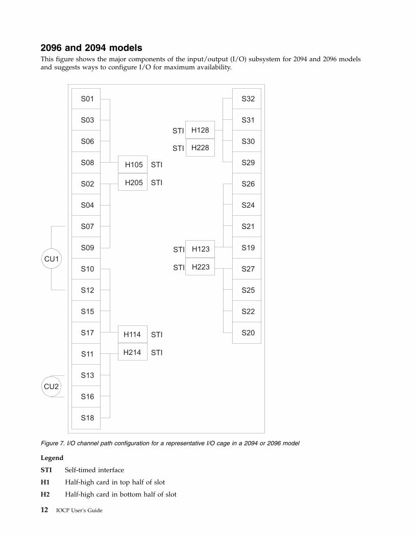
2096 and 2094 modelsThis figure shows the major components of the input/output (I/O) subsystem for 2094 and 2096 modelsand suggests ways to configure I/O for maximum availability.
Legend
STI Self-timed interface
H1 Half-high card in top half of slot
H2 Half-high card in bottom half of slot
S01
S03
S06
S08
S02
S04
S07
S09
S10
S12
S15
S17
S11
S13
S16
S18
H105
H205
STI
STI
STI
STI
STI
STI
STI
STI
H114
H214
H123
H223
H128
H228
S32
S31
S30
S29
S26
S24
S21
S19
S27
S25
S22
S20
CU1
CU2
Figure 7. I/O channel path configuration for a representative I/O cage in a 2094 or 2096 model
12 IOCP User's Guide
S Slot
Availability guidelines for 2096 and 2094 modelsWhen configuring devices with multiple paths to the same CPC, select any of the channel paths shown inFigure 7 on page 12 that:v Are available on the CPC you are definingv Are the correct type (ESCON, FICON, and so on) to meet the control unit, coupling facility, or network
attachment requirementsv Satisfy the rules regarding the mixing of channel types to a control unit.
However, for maximum availability of the device, OSA network, or coupling facility on a 2094 or 2096model, consider the following guidelines.v Choose channels plugged in different I/O domains (see CU 1). An I/O domain contains four channel
cards controlled by a single STI-MP card. For example, the domain for the STI-MP card in H105contains slots 01, 03, 06, and 08.
Note: Choose channels plugged into different I/O domains for optimum performance of your mostheavily used I/O devices.When choosing the I/O domains to use, whether from different cages or the same cage, consider usinga combination of I/O domains from different books. When you must use STIs from the same book, tryto use STIs from different MBA fanout cards on that book. Each fanout card plugged into a bookprovides an MBA. Refer to your PCHID Report to determine which STI links belong to which MBAfanout cards on a book. If you have multiple paths to the device and multiple domains available thathave the correct channel type, is also advisable to spread the paths across as many books and MBAs aspossible.Redundant I/O Interconnect is a function that allows one STI to back up another STI after a failure.The STIs in slot 05 back up each other. The same is true for those STIs in slots 14, 23, and 28.Therefore, in the event of an STI cable, fanout card, or book failure, the surviving STI controls bothdomains. Certain failures (for example, the STI-MP card) might prevent the redundant takeover, whichis why it is advisable to spread your paths over multiple domains.When configuring ICB channel paths for the same target CPC or coupling facility, use a combination ofSTIs from different books and different MBA fanout cards on those books. Doing so allows forcontinued connectivity if you have to run degraded after a book or MBA fanout card failure.When configuring ICB-3 channel paths for the same target CPC or coupling facility, use links thatoriginate from different STI-3 extender cards in the I/O cage. This eliminates the STI-3 card as a singlepoint of failure.When configuring Coupling over InfiniBand (CIB) channel paths for the same target CPC or couplingfacility, use InfiniBand links that originate from different books and different HCA fanout cards onthose books. Doing so eliminates the HCA fanout card and the book as a single point of failure whereall connectivity would be lost.
v If you define multiple paths from the same STI, distribute paths across different channel cards (see CU2). Also, if you define multiple coupling facility channels to the same coupling facility or to the sameESA image, distribute paths across different coupling facility fanout cards, ISC Mother cards, or ISCdaughter cards.
Note: Each example in Figure 7 on page 12 is only an attempt to illustrate an availability guideline anddoes not represent an overall optimal configuration.
2094 and 2096 CPCs automatically balance installed channel cards across all available SAPs. The CPCtries to assign an equal number of each channel card type (ESCON, FICON, and so on) to each availableSAP. All channels on a given I/O card are always in the same SAP, but it is not predictable which I/Ocards are assigned to which SAPs. There are two exceptions to the previous statements. First, ICBs arealways given affinity to a SAP on the local book. Second, if an OSA channel is defined as OSD or aFICON channel is defined as FCP, these channels use QDIO architecture and, therefore, really do not use
Chapter 1. IOCP introduction 13
any SAP resource during normal operations. Configure for normal RAS as described in the precedingparagraphs, and the machine balances the channels across your available SAPs.
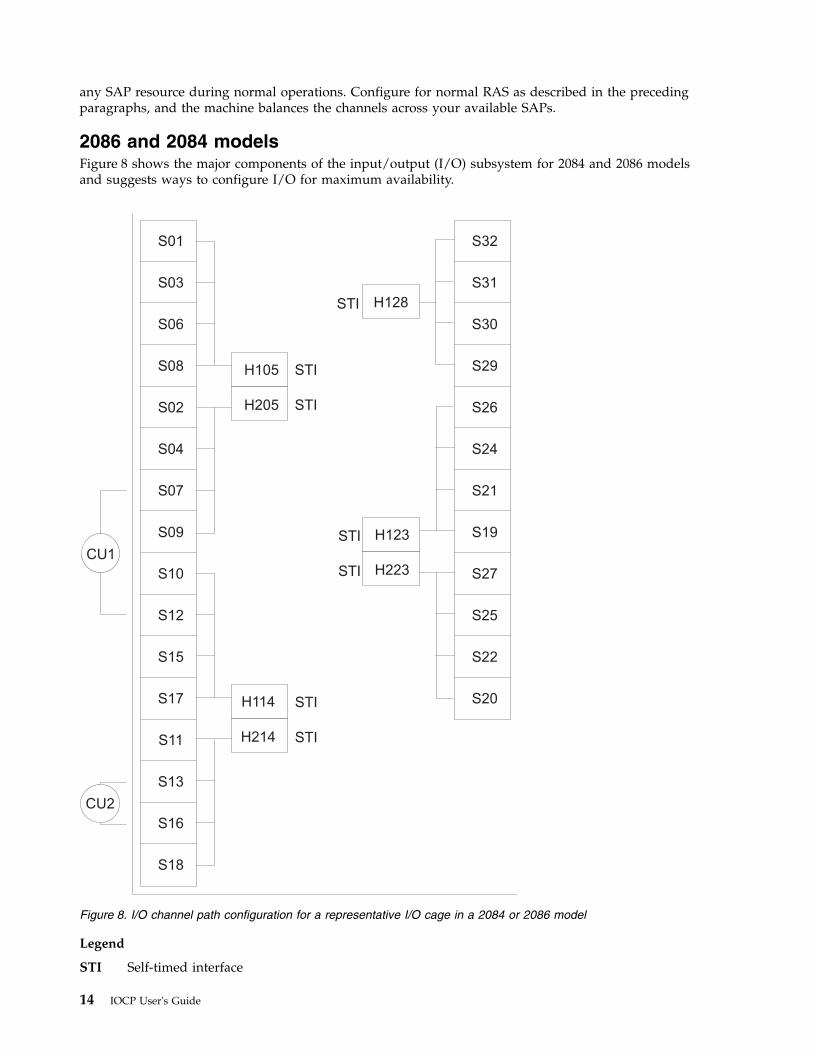
2086 and 2084 modelsFigure 8 shows the major components of the input/output (I/O) subsystem for 2084 and 2086 modelsand suggests ways to configure I/O for maximum availability.
Legend
STI Self-timed interface
S01
S03
S06
S08
S02
S04
S07
S09
S10
S12
S15
S17
S11
S13
S16
S18
H105
H205
STI
STI
STI
STI
STI
STI
STI
H114
H214
H123
H223
H128
S32
S31
S30
S29
S26
S24
S21
S19
S27
S25
S22
S20
CU1
CU2
Figure 8. I/O channel path configuration for a representative I/O cage in a 2084 or 2086 model
14 IOCP User's Guide
H1 Half-high card in top half of slot
H2 Half-high card in bottom half of slot
S Slot
Availability guidelines for 2086 and 2084 modelsWhen configuring devices with multiple paths to the same CPC, select any of the channel paths shown inFigure 7 on page 12 that:v Are available on the CPC you are definingv Are the correct type (ESCON, FICON, and so on) to meet the control unit, coupling facility, or network
attachment requirementsv Satisfy the rules regarding the mixing of channel types to a control unit.
However, for maximum availability of the device, OSA network, or coupling facility on a 2084 or 2086model, consider the following guidelines. 2086 models have a maximum of one I/O cage and one book.v For systems with multiple I/O cages, distribute paths across the I/O cages (not shown). When
choosing which self-timed interfaces (STIs) to use in different cages, use the guidelines in the followingbullet.
v For systems with multiple STIs, distribute paths across the STIs (see CU 1).
Note: You are also recommended to do so for optimum performance of your most heavily used I/Odevices.When choosing the STIs to use, whether from different cages or the same cage, consider using acombination of STIs from different books. When you must use STIs from the same book, try to use STIsfrom different MBAs on that book. Refer to Table 6 on page 18 or your Physical Channel Identifier(PCHID) Report to determine which STI links belong to which MBAs on a book. If you have multiplepaths to the device and multiple domains available that have the correct channel type, spreading thepaths across as many books and MBAs as possible is also advisable.Connecting your critical devices this way ensures access to those devices while running in a degradedmode. In the unlikely event of an MBA or book failure, you might be able to take advantage ofrunning degraded until the repair.When configuring ICB or coupling CHPIDs for the same target CPC or coupling facility, use acombination of STIs from different books and different MBAs on those books. Doing so allows forcontinued connectivity if you have to run degraded after a book or MBA failure.When configuring ICB-2 or ICB-3 channel paths for the same target CPC or coupling facility, use linksthat originate from different STI cards in the I/O cage. Doing so eliminates the STI card as a singlepoint of failure.
v If you define multiple paths from the same STI, distribute paths across different channel cards (see CU2). Also, if you define multiple coupling facility channels to the same coupling facility or to the sameESA image, distribute paths across different coupling facility fanout cards, ISC Mother cards, or ISCdaughter cards.
Note: Each example in Figure 7 on page 12 is only an attempt to illustrate an availability guideline anddoes not represent an overall optimal configuration.
2084 CPCs automatically balance installed channel cards across all available system assist processors(SAPs). The CPC tries to assign an equal number of each channel card type (ESCON, FICON, and so on)in each available SAP. All channels on a given I/O card are always in the same SAP, but it is notpredictable which I/O cards are assigned to which SAPs. Configure for normal RAS as described in thepreceding paragraphs, and the machine balances the channels across your available SAPs. 2086 modelshave a single SAP so all I/O is performed by that SAP.
The following table illustrates the relationship between the book jack numbers and the MBA thatsupports those STIs.
Chapter 1. IOCP introduction 15
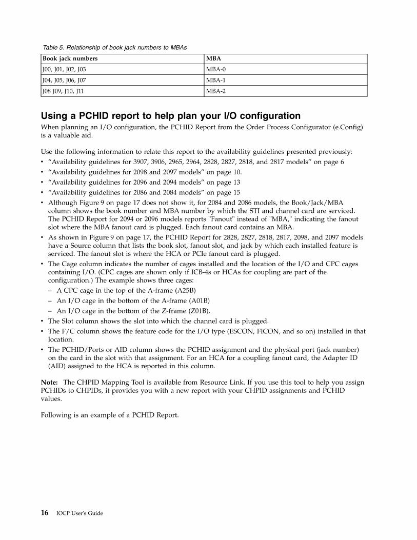
Table 5. Relationship of book jack numbers to MBAs
Book jack numbers MBA
J00, J01, J02, J03 MBA-0
J04, J05, J06, J07 MBA-1
J08 J09, J10, J11 MBA-2
Using a PCHID report to help plan your I/O configurationWhen planning an I/O configuration, the PCHID Report from the Order Process Configurator (e.Config)is a valuable aid.
Use the following information to relate this report to the availability guidelines presented previously:v “Availability guidelines for 3907, 3906, 2965, 2964, 2828, 2827, 2818, and 2817 models” on page 6v “Availability guidelines for 2098 and 2097 models” on page 10.v “Availability guidelines for 2096 and 2094 models” on page 13v “Availability guidelines for 2086 and 2084 models” on page 15v Although Figure 9 on page 17 does not show it, for 2084 and 2086 models, the Book/Jack/MBA
column shows the book number and MBA number by which the STI and channel card are serviced.The PCHID Report for 2094 or 2096 models reports "Fanout" instead of "MBA," indicating the fanoutslot where the MBA fanout card is plugged. Each fanout card contains an MBA.
v As shown in Figure 9 on page 17, the PCHID Report for 2828, 2827, 2818, 2817, 2098, and 2097 modelshave a Source column that lists the book slot, fanout slot, and jack by which each installed feature isserviced. The fanout slot is where the HCA or PCIe fanout card is plugged.
v The Cage column indicates the number of cages installed and the location of the I/O and CPC cagescontaining I/O. (CPC cages are shown only if ICB-4s or HCAs for coupling are part of theconfiguration.) The example shows three cages:– A CPC cage in the top of the A-frame (A25B)– An I/O cage in the bottom of the A-frame (A01B)– An I/O cage in the bottom of the Z-frame (Z01B).
v The Slot column shows the slot into which the channel card is plugged.v The F/C column shows the feature code for the I/O type (ESCON, FICON, and so on) installed in that
location.v The PCHID/Ports or AID column shows the PCHID assignment and the physical port (jack number)
on the card in the slot with that assignment. For an HCA for a coupling fanout card, the Adapter ID(AID) assigned to the HCA is reported in this column.
Note: The CHPID Mapping Tool is available from Resource Link. If you use this tool to help you assignPCHIDs to CHPIDs, it provides you with a new report with your CHPID assignments and PCHIDvalues.
Following is an example of a PCHID Report.
16 IOCP User's Guide
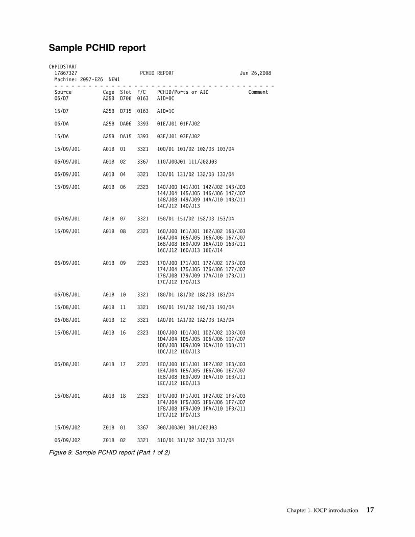
Sample PCHID report
CHPIDSTART17867327 PCHID REPORT Jun 26,2008Machine: 2097-E26 NEW1- - - - - - - - - - - - - - - - - - - - - - - - - - - - - - - - - - - - - - -Source Cage Slot F/C PCHID/Ports or AID Comment06/D7 A25B D706 0163 AID=0C
15/D7 A25B D715 0163 AID=1C
06/DA A25B DA06 3393 01E/J01 01F/J02
15/DA A25B DA15 3393 03E/J01 03F/J02
15/D9/J01 A01B 01 3321 100/D1 101/D2 102/D3 103/D4
06/D9/J01 A01B 02 3367 110/J00J01 111/J02J03
06/D9/J01 A01B 04 3321 130/D1 131/D2 132/D3 133/D4
15/D9/J01 A01B 06 2323 140/J00 141/J01 142/J02 143/J03144/J04 145/J05 146/J06 147/J07148/J08 149/J09 14A/J10 14B/J1114C/J12 14D/J13
06/D9/J01 A01B 07 3321 150/D1 151/D2 152/D3 153/D4
15/D9/J01 A01B 08 2323 160/J00 161/J01 162/J02 163/J03164/J04 165/J05 166/J06 167/J07168/J08 169/J09 16A/J10 16B/J1116C/J12 16D/J13 16E/J14
06/D9/J01 A01B 09 2323 170/J00 171/J01 172/J02 173/J03174/J04 175/J05 176/J06 177/J07178/J08 179/J09 17A/J10 17B/J1117C/J12 17D/J13
06/D8/J01 A01B 10 3321 180/D1 181/D2 182/D3 183/D4
15/D8/J01 A01B 11 3321 190/D1 191/D2 192/D3 193/D4
06/D8/J01 A01B 12 3321 1A0/D1 1A1/D2 1A2/D3 1A3/D4
15/D8/J01 A01B 16 2323 1D0/J00 1D1/J01 1D2/J02 1D3/J031D4/J04 1D5/J05 1D6/J06 1D7/J071D8/J08 1D9/J09 1DA/J10 1DB/J111DC/J12 1DD/J13
06/D8/J01 A01B 17 2323 1E0/J00 1E1/J01 1E2/J02 1E3/J031E4/J04 1E5/J05 1E6/J06 1E7/J071E8/J08 1E9/J09 1EA/J10 1EB/J111EC/J12 1ED/J13
15/D8/J01 A01B 18 2323 1F0/J00 1F1/J01 1F2/J02 1F3/J031F4/J04 1F5/J05 1F6/J06 1F7/J071F8/J08 1F9/J09 1FA/J10 1FB/J111FC/J12 1FD/J13
15/D9/J02 Z01B 01 3367 300/J00J01 301/J02J03
06/D9/J02 Z01B 02 3321 310/D1 311/D2 312/D3 313/D4
Figure 9. Sample PCHID report (Part 1 of 2)
Chapter 1. IOCP introduction 17
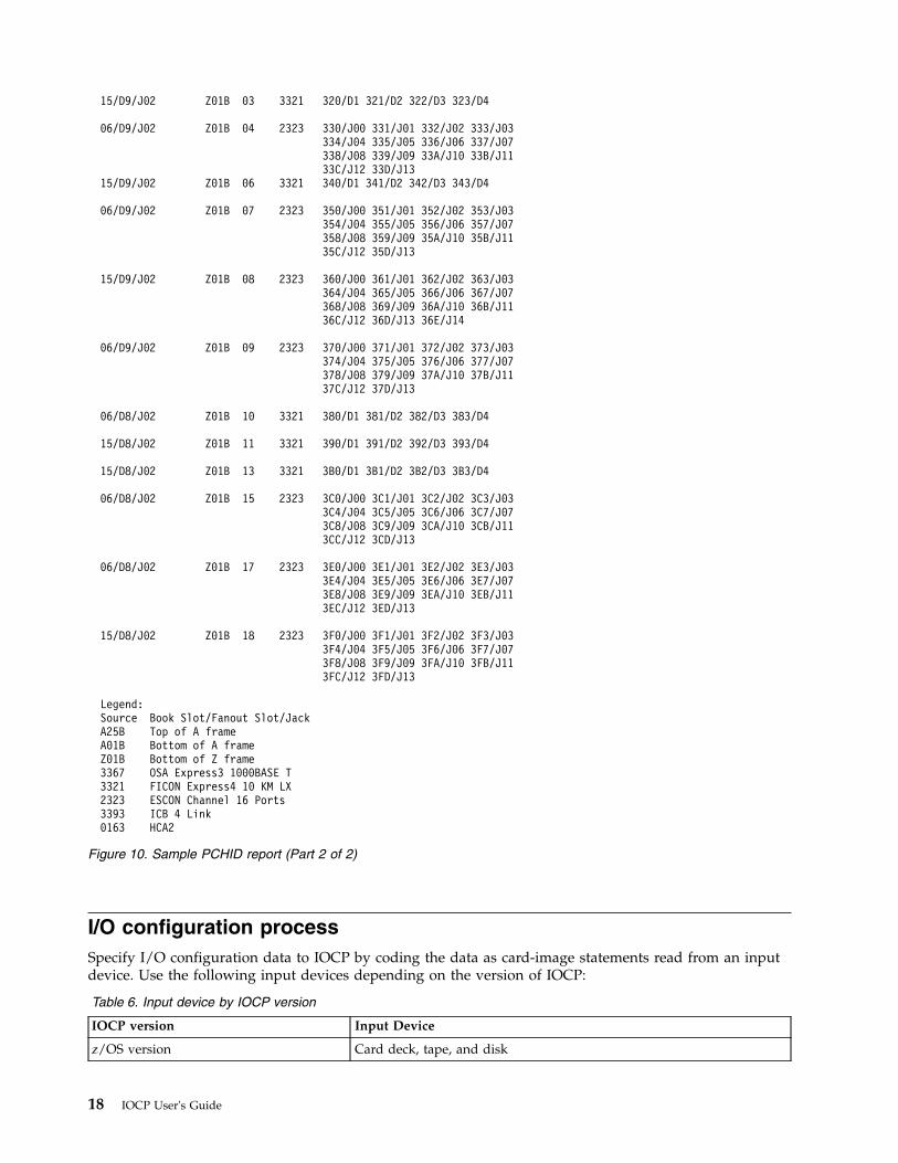
I/O configuration processSpecify I/O configuration data to IOCP by coding the data as card-image statements read from an inputdevice. Use the following input devices depending on the version of IOCP:
Table 6. Input device by IOCP version
IOCP version Input Device
z/OS version Card deck, tape, and disk
15/D9/J02 Z01B 03 3321 320/D1 321/D2 322/D3 323/D4
06/D9/J02 Z01B 04 2323 330/J00 331/J01 332/J02 333/J03334/J04 335/J05 336/J06 337/J07338/J08 339/J09 33A/J10 33B/J1133C/J12 33D/J13
15/D9/J02 Z01B 06 3321 340/D1 341/D2 342/D3 343/D4
06/D9/J02 Z01B 07 2323 350/J00 351/J01 352/J02 353/J03354/J04 355/J05 356/J06 357/J07358/J08 359/J09 35A/J10 35B/J1135C/J12 35D/J13
15/D9/J02 Z01B 08 2323 360/J00 361/J01 362/J02 363/J03364/J04 365/J05 366/J06 367/J07368/J08 369/J09 36A/J10 36B/J1136C/J12 36D/J13 36E/J14
06/D9/J02 Z01B 09 2323 370/J00 371/J01 372/J02 373/J03374/J04 375/J05 376/J06 377/J07378/J08 379/J09 37A/J10 37B/J1137C/J12 37D/J13
06/D8/J02 Z01B 10 3321 380/D1 381/D2 382/D3 383/D4
15/D8/J02 Z01B 11 3321 390/D1 391/D2 392/D3 393/D4
15/D8/J02 Z01B 13 3321 3B0/D1 3B1/D2 3B2/D3 3B3/D4
06/D8/J02 Z01B 15 2323 3C0/J00 3C1/J01 3C2/J02 3C3/J033C4/J04 3C5/J05 3C6/J06 3C7/J073C8/J08 3C9/J09 3CA/J10 3CB/J113CC/J12 3CD/J13
06/D8/J02 Z01B 17 2323 3E0/J00 3E1/J01 3E2/J02 3E3/J033E4/J04 3E5/J05 3E6/J06 3E7/J073E8/J08 3E9/J09 3EA/J10 3EB/J113EC/J12 3ED/J13
15/D8/J02 Z01B 18 2323 3F0/J00 3F1/J01 3F2/J02 3F3/J033F4/J04 3F5/J05 3F6/J06 3F7/J073F8/J08 3F9/J09 3FA/J10 3FB/J113FC/J12 3FD/J13
Legend:Source Book Slot/Fanout Slot/JackA25B Top of A frameA01B Bottom of A frameZ01B Bottom of Z frame3367 OSA Express3 1000BASE T3321 FICON Express4 10 KM LX2323 ESCON Channel 16 Ports3393 ICB 4 Link0163 HCA2
Figure 10. Sample PCHID report (Part 2 of 2)
18 IOCP User's Guide
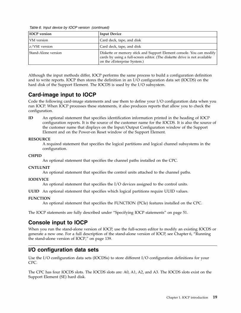
Table 6. Input device by IOCP version (continued)
IOCP version Input Device
VM version Card deck, tape, and disk
z/VSE version Card deck, tape, and disk
Stand-Alone version Diskette or memory stick and Support Element console. You can modifycards by using a full-screen editor. (The diskette drive is not availableon the zEnterprise System.)
Although the input methods differ, IOCP performs the same process to build a configuration definitionand to write reports. IOCP then stores the definition in an I/O configuration data set (IOCDS) on thehard disk of the Support Element. The IOCDS is used by the I/O subsystem.
Card-image input to IOCPCode the following card-image statements and use them to define your I/O configuration data when yourun IOCP. When IOCP processes these statements, it also produces reports that allow you to check theconfiguration.
ID An optional statement that specifies identification information printed in the heading of IOCPconfiguration reports. It is the source of the customer name for the IOCDS. It is also the source ofthe customer name that displays on the Input/Output Configuration window of the SupportElement and on the Power-on Reset window of the Support Element.
RESOURCEA required statement that specifies the logical partitions and logical channel subsystems in theconfiguration.
CHPIDAn optional statement that specifies the channel paths installed on the CPC.
CNTLUNITAn optional statement that specifies the control units attached to the channel paths.
IODEVICEAn optional statement that specifies the I/O devices assigned to the control units.
UUID An optional statement that specifies which logical partitions require UUID values.
FUNCTIONAn optional statement that specifies the FUNCTION (PCIe) features installed on the CPC.
The IOCP statements are fully described under “Specifying IOCP statements” on page 51.
Console input to IOCPWhen you run the stand-alone version of IOCP, use the full-screen editor to modify an existing IOCDS orgenerate a new one. For a full description of the stand-alone version of IOCP, see Chapter 6, “Runningthe stand-alone version of IOCP,” on page 139.
I/O configuration data setsUse the I/O configuration data sets (IOCDSs) to store different I/O configuration definitions for yourCPC.
The CPC has four IOCDS slots. The IOCDS slots are: A0, A1, A2, and A3. The IOCDS slots exist on theSupport Element (SE) hard disk.
Chapter 1. IOCP introduction 19
The configuration data in the IOCDS is accessed and transformed to a data format that the LicensedMachine Code (LMC) in the I/O subsystem uses when you perform a power-on reset by selectingPower-on Reset from the Support Element console or Hardware Management Console.
The I/O subsystem then controls I/O requests and uses the configuration data from the IOCDS that youspecify for the power-on reset.
IOCP can read from any IOCDS produced by the version of IOCP covered in this document. However,IOCP can write only to an IOCDS that is not write-protected.
You can write-protect each IOCDS individually and remove write-protection when you want to alter anIOCDS by using Input/Output Configuration window of the Support Element. Write-protection preventsyou from accidentally using IOCP to write over and destroy the configuration data in an IOCDS. Beforewriting an IOCDS, you must remove the write-protection from that IOCDS.
When defining a new configuration, you can perform the following actions:v Use the configuration in an existing IOCDS as your operating configurationv Run IOCP to generate and write a new I/O configuration to another IOCDSv Write-protect the new IOCDSv Perform a power-on reset (POR) and use the new configuration to test the system.
IOCDSs and CPC modesIOCP creates IOCDSs for LPAR mode only. For a complete description of LPAR mode, see the ProcessorResource/Systems Manager Planning Guide.
I/O configuration considerationsThe IOCP generation process requires as input an I/O configuration input file containing IOCPstatements. You can write an IOCDS with the z/OS, VM, z/VSE, or stand-alone version of IOCP.
Defining multiple logical channel subsystemsIOCP has been dramatically enhanced to allow the definition of an I/O configuration containing multiple,logical channel subsystems. A logical channel subsystem (CSS) is a complete definition of logicalpartitions, channels, control units, and devices as you might have defined for any previous CPC. Thedifference with this level of IOCP and the CPCs it supports is that multiple CSSs can be defined witheach CSS containing logical partitions, channels, control units, and devices. In addition, some CPCs nowsupport multiple subchannel sets, which allows a CSS to have more than twice as many devices.
IOCP has added the CSS parameter to many traditional keywords to identify the logical channelsubsystem to which the keyword parameters apply. IOCP has introduced a new keyword, SCHSET, to theIODEVICE statement to identify the subchannel set in a CSS to which a device belongs. See Chapter 2,“IOCP statements and functions,” on page 51 for complete syntax rules for using the CSS parameter andspecifying the SCHSET keyword. The following list summarizes the new keywords and parameters inIOCP in support of multiple logical channel subsystems and multiple subchannel sets:
RESOURCE statementPreviously the RESOURCE statement defined the logical partitions (LPs) and associated partitionnumbers (now called MIF image IDs) to be included in the configuration. With this level of IOCP,you prefix those values with a CSS ID. The LPs and MIF image IDs are defined in the specifiedCSS.
Note: What was called "partition number" in previous levels of IOCP is now called MIF imageID. It retains all the same characteristics (for example, a hex number from 1-F), and is used thesame for CTC control unit definitions. However, for CPCs that ICP IOCP supports, the MIF
20 IOCP User's Guide
image ID is no longer used in the PARTITION keyword of the CF statement in the policyinformation defined for the site's coupling facility resource management (CFRM) policy. Instead,the "partition ID" that is specified on the activation profile for the CF image on the SupportElement identifies the CF image.
CHPID statementThe PATH parameter has traditionally been used to mirror the CHPID number assigned by theCPC to the actual channel that is being defined. With ICP IOCP and the CPCs it supports, thePATH parameter specifies a logical CHPID number of your choosing. The PATH parameterallows the user to specify the CSSs and the CHPID number that is assigned to a channel path. Ifit is a physical channel (for example, FICON), the new PCHID keyword identifies the location ofthe physical channel in the CPC. For internal channels (for example internal coupling), thePCHID keyword is not allowed, and only the logical CHPID number is required.
When a channel path is defined to multiple CSSs using the PATH parameter, the channel path isdefined as spanned. The PARTITION or NOTPART keywords can also use the CSS parameter toindicate which LPs can access the channel in each CSS to which the channel path is assigned.
CNTLUNIT statementThe PATH and LINK keywords can have a CSS parameter that indicates the logical CHPIDs fromeach CSS that have access to the control unit and the associated destination link address for eachpath.
IODEVICE statementThe PATH keyword can have a CSS parameter to indicate a preferred path from each CSS for thedevice. Likewise, the PARTITION or NOTPART keywords can have a CSS parameter to indicate aunique device candidate list for each CSS that has access to the device. The SCHSET keywordidentifies the subchannel set in a CSS to which a device belongs; it can include a CSS parameter.
Note: If you are defining a single CSS configuration, the CSS parameter is optional.
Control unit headersThe I/O subsystem uses control unit headers to represent a set of physical control units that physically orlogically attach I/O devices in common. For example, a logical channel subsystem can use the controlunit header to establish a queue for I/O requests for the devices associated with the attaching physicalcontrol units.
Note: Control unit headers were previously called logical control units.
IOCP builds control unit headers from the information specified in the CNTLUNIT and IODEVICEstatements. If a device attaches to more than one physical control unit, the physical control units formpart of (or the whole of) a control unit header.
IOCP builds a control unit header for the following control units:v Each physical control unit with no I/O devices attached.v Each physical control unit that does not share any I/O devices with other physical control units.v Each group of two or more control units that share devices between them.
Figure 11 on page 22 shows examples of valid control unit headers.
When a physical control unit or a group of control units that share devices have channel paths inmultiple logical channel subsystems (CSSs), IOCP builds a control unit header (CUH) for each CSS. TheCUH in each CSS contains only the channel paths from the physical control units associated with thatCSS. The CUHs in each CSS are numbered independently of each other. The devices assigned to thephysical control unit or group of control units become subchannels in each CSS and are numberedindependently of each other. The subchannels in each CSS are associated with the CUH in the same CSSand its channel paths. In Figure 11 on page 22, CUH 3 is in CSS 0 with paths 01 and 02. CUH 19 is in
Chapter 1. IOCP introduction 21
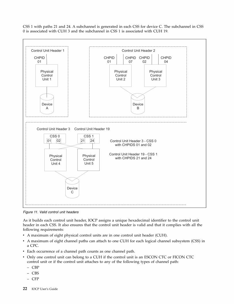
CSS 1 with paths 21 and 24. A subchannel is generated in each CSS for device C. The subchannel in CSS0 is associated with CUH 3 and the subchannel in CSS 1 is associated with CUH 19.
As it builds each control unit header, IOCP assigns a unique hexadecimal identifier to the control unitheader in each CSS. It also ensures that the control unit header is valid and that it complies with all thefollowing requirements:v A maximum of eight physical control units are in one control unit header (CUH).v A maximum of eight channel paths can attach to one CUH for each logical channel subsystem (CSS) in
a CPC.v Each occurrence of a channel path counts as one channel path.v Only one control unit can belong to a CUH if the control unit is an ESCON CTC or FICON CTC
control unit or if the control unit attaches to any of the following types of channel path:– CBP– CBS– CFP
PhysicalControlUnit 1
CHPID01
CHPID01
CHPID04
CHPID02
CHPID07
Control Unit Header 2Control Unit Header 1
Control Unit Header 3 Control Unit Header 19
CSS 0 CSS 1
01 2102 24
PhysicalControlUnit 2
PhysicalControlUnit 5
Control Unit Header 3 - CSS 0with CHPIDS 01 and 02
Control Unit Header 19 - CSS 1with CHPIDS 21 and 24
PhysicalControlUnit 4
PhysicalControlUnit 3
DeviceB
DeviceA
DeviceC
Figure 11. Valid control unit headers
22 IOCP User's Guide
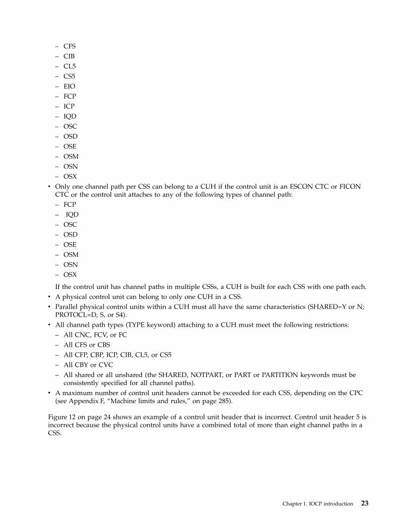
– CFS– CIB– CL5– CS5– EIO– FCP– ICP– IQD– OSC– OSD– OSE– OSM– OSN– OSX
v Only one channel path per CSS can belong to a CUH if the control unit is an ESCON CTC or FICONCTC or the control unit attaches to any of the following types of channel path:– FCP– IQD– OSC– OSD– OSE– OSM– OSN– OSX
If the control unit has channel paths in multiple CSSs, a CUH is built for each CSS with one path each.v A physical control unit can belong to only one CUH in a CSS.v Parallel physical control units within a CUH must all have the same characteristics (SHARED=Y or N;
PROTOCL=D, S, or S4).v All channel path types (TYPE keyword) attaching to a CUH must meet the following restrictions:
– All CNC, FCV, or FC– All CFS or CBS– All CFP, CBP, ICP, CIB, CL5, or CS5– All CBY or CVC– All shared or all unshared (the SHARED, NOTPART, or PART or PARTITION keywords must be
consistently specified for all channel paths).v A maximum number of control unit headers cannot be exceeded for each CSS, depending on the CPC
(see Appendix F, “Machine limits and rules,” on page 285).
Figure 12 on page 24 shows an example of a control unit header that is incorrect. Control unit header 5 isincorrect because the physical control units have a combined total of more than eight channel paths in aCSS.
Chapter 1. IOCP introduction 23
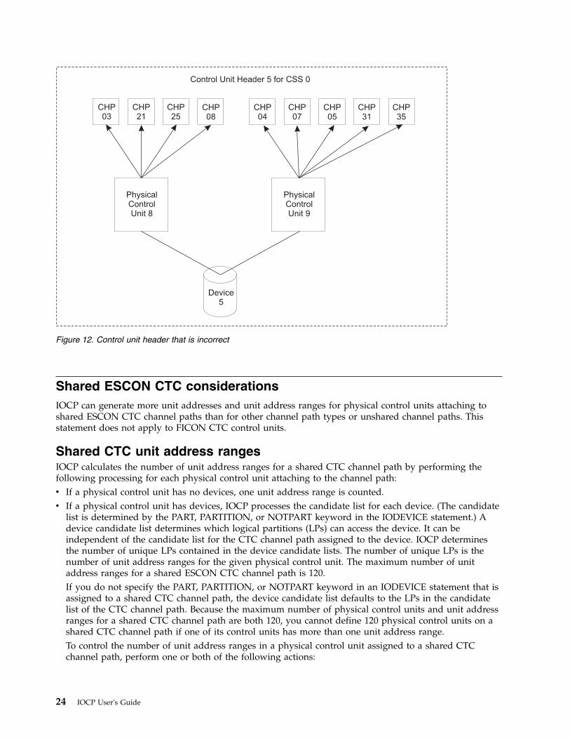
Shared ESCON CTC considerationsIOCP can generate more unit addresses and unit address ranges for physical control units attaching toshared ESCON CTC channel paths than for other channel path types or unshared channel paths. Thisstatement does not apply to FICON CTC control units.
Shared CTC unit address rangesIOCP calculates the number of unit address ranges for a shared CTC channel path by performing thefollowing processing for each physical control unit attaching to the channel path:v If a physical control unit has no devices, one unit address range is counted.v If a physical control unit has devices, IOCP processes the candidate list for each device. (The candidate
list is determined by the PART, PARTITION, or NOTPART keyword in the IODEVICE statement.) Adevice candidate list determines which logical partitions (LPs) can access the device. It can beindependent of the candidate list for the CTC channel path assigned to the device. IOCP determinesthe number of unique LPs contained in the device candidate lists. The number of unique LPs is thenumber of unit address ranges for the given physical control unit. The maximum number of unitaddress ranges for a shared ESCON CTC channel path is 120.If you do not specify the PART, PARTITION, or NOTPART keyword in an IODEVICE statement that isassigned to a shared CTC channel path, the device candidate list defaults to the LPs in the candidatelist of the CTC channel path. Because the maximum number of physical control units and unit addressranges for a shared CTC channel path are both 120, you cannot define 120 physical control units on ashared CTC channel path if one of its control units has more than one unit address range.To control the number of unit address ranges in a physical control unit assigned to a shared CTCchannel path, perform one or both of the following actions:
CHP04
CHP03
CHP07
PhysicalControlUnit 8
Control Unit Header 5 for CSS 0
PhysicalControlUnit 9
Device5
CHP21
CHP25
CHP08
CHP05
CHP31
CHP35
Figure 12. Control unit header that is incorrect
24 IOCP User's Guide
– Specify a CHPID candidate list that contains only the LPs that access the shared CTC channel path.If the CHPID candidate list does not contain all the LPs in the configuration, devices that do notspecify a device candidate list have fewer unit address ranges for their physical control unit.For example, if your configuration has 10 LPs and a CTC channel path is shared by 5 LPs in itscandidate list, each device assigned to the shared CTC channel path has a device candidate list thatdefaults to 5 LPs. The physical control unit assigned to the shared CTC channel path has 5 unitaddress ranges. Therefore, the maximum number of physical control units that you can define onthe shared CTC channel path is only 24 instead of 120 because this configuration first reaches themaximum of 120 unit address ranges on the shared CTC channel path.
– Specify a device candidate list for each device assigned to a physical control unit. If the devicecandidate lists of all the devices assigned to a physical control unit do not contain all the LPs in theconfiguration, fewer unit address ranges are defined for the physical control unit.For example, if your configuration has 10 LPs and all of them share a CTC channel path, eachdevice assigned to the shared CTC channel path has a device candidate list that defaults to all 10LPs. If you specify device candidate lists so that only 4 unique LPs can access any of the devices ona physical control unit, the control unit has 4 unit address ranges. Therefore, the maximum numberof physical control units that you can define on the shared CTC channel path is only 30 instead of120 because this configuration first reaches the maximum of 120 unit address ranges on the sharedCTC channel path.
You can increase the number of physical control units you can define on a shared CTC channel path upto the maximum of 120 by decreasing to one the number of unit address ranges on the control unitsassigned to the CTC channel path.
Shared CTC unit addressesIOCP calculates the number of unit addresses for a shared ESCON CTC channel path by multiplying thenumber of unit addresses defined with the UNITADD keyword on the CNTLUNIT statement by thenumber of unit address ranges for the physical control unit. (See “Shared CTC unit address ranges” onpage 24.) The maximum number of unit addresses for a shared ESCON CTC channel path is 512. Becausethe maximum number of both unit addresses and devices for a shared CTC channel path is 512, youcannot define 512 devices on a shared CTC channel path if one of its control units has more than one unitaddress range.
For example, if your configuration has 8 LPs and a CTC channel path is shared by 4 LPs in its candidatelist, each device assigned to the shared CTC channel path has a device candidate list that defaults to 4LPs. The physical control unit assigned to the shared CTC channel path has 4 unit address ranges. Themaximum number of unit addresses on the control unit is 128. Multiplying this number by the 4 unitaddress ranges gives 512. Therefore, the maximum number of devices that you can define is only 128because this configuration first reaches the maximum of 512 unit addresses on the shared CTC channelpath.
You can also control the number of devices per shared CTC channel path by specifying a devicecandidate list for each device assigned to a control unit. However, the number of unit address ranges fora control unit is based on the number of unique LPs in all the device candidate lists of the devicesassigned to the control unit.
You can increase the number of unit addresses and devices you can define on a shared CTC channel pathup to the maximum of 512 by decreasing to 1 the number of unit address ranges on each control unitassigned to the CTC channel path.
Chapter 1. IOCP introduction 25
Coupling facility supportIOCP supports the following coupling facility channel paths (TYPE keyword):v CFSv CFRv CFPv CBSv CBRv CBPv ICPv CIBv CL5v CS5
See Appendix F, “Machine limits and rules,” on page 285 to determine which channel path types yourCPC supports. You define coupling facility channel paths at the coupling facility and at the CPCs orlogical partitions (LPs) that connect to the coupling facility.
The coupling facility provides shared storage and shared storage management functions for the sysplex(for example, high speed caching, list processing, and locking functions). Applications running on z/OSimages in the sysplex define the shared structures used in the coupling facility.
The coupling facility allows applications, running on multiple z/OS images that are configured in asysplex, to efficiently share data so that a transaction processing workload can be processed in parallelacross the sysplex.
Processor Resource/Systems Manager™ (PR/SM™) LPAR allows you to define the coupling facility, whichis a special logical partition (LP) that runs the coupling facility control code. The coupling facility controlcode is Licensed Machine Code (LMC).
At LP activation, coupling facility control code automatically loads into the coupling facility LP from theSupport Element hard disk. No initial program load (IPL) of an operating system is necessary orsupported in the coupling facility LP.
Coupling facility control code runs in the coupling facility LP with minimal operator intervention.Operator activity is confined to the CPC hardware operator console. PR/SM LPAR limits the hardwareoperator controls typically available for LPs to avoid unnecessary operator activity.
Coupling facility channel hardware provides the connectivity required for data sharing between thecoupling facility and the CPCs directly attached to it. Coupling facility channels are point-to-pointconnections that require a unique channel definition at each end of the channel.
Coupling facility channels can also connect two coupling facilities together for a duplexing configuration.In this environment, coupling facility sender channels or coupling facility peer channels are configured tocoupling facilities to support communication between the coupling facilities. The following couplingfacility sections describe only ESA to coupling facility connections. However, they also apply to couplingfacility duplexing connections (CF to CF).
Coupling facility channelsCoupling facility channels are channels that provide the connectivity for data sharing between a couplingfacility and the CPCs or logical partitions (LPs) directly attached to it. IOCP provides controls for
26 IOCP User's Guide
defining coupling facility channels. However, IBM recommends that, when possible, you use theHardware Configuration Definition (HCD) to define the coupling facility channel configuration to the I/Osubsystem.
HCD provides controls for defining coupling facility channels. HCD also automatically generates thecontrol unit and device definitions associated with coupling facility sender and peer channel paths.
Coupling facility channels:v Require a point-to-point connection (direct channel attach between a CPC or LP and a coupling
facility).v Can connect a coupling facility to other LPs on the same CPC when a coupling facility is one of
multiple LPs running on a single CPC. Use internal coupling channels for these connections. InternalCoupling channels can be used only to connect a coupling facility and LPs on the same CPC.
v Can be redundantly configured (two or more coupling facility channels from each CPC involved incoupling facility data sharing) to enhance availability and avoid extended recovery time. Thisstatement does not apply to Internal Coupling channels.
v Require CFR or CBR channel path definition (coupling facility receiver channel capability) at thecoupling facility end of a coupling facility channel connection with a CFS or CBS channel pathdefinition (coupling facility sender channel capability) at the ESA end of a coupling facility channelconnection. You must use coupling facility sender and receiver channels when connecting to a CPC orCF that does not support coupling facility peer channels (for example, a 9672).
v Require CFP, CBP, ICP, CIB, CL5, or CS5or ICP channel path definition (coupling facility peer channelcapability) at the coupling facility and ESA ends of a coupling facility channel connection. Usingcoupling facility peer channels is the recommended way to connect to a CPC or CF that does supportpeer channels (for example, a 2084). Some CPCs that support peer channels do not support CIBchannels. Some CPCs that support CIB channels to not support CL5 and CS5 channels. CFP, CBP, ICP,CL5, CS5, or CIB channel paths can be shared by many ESA LPs and only one coupling facility LP atthe same time.
v Require the following connections:– The CFS channel path must be connected to a CFR channel path.– The CBS channel path must be connected to a CBR channel path.– The CFP channel path must be connected to another CFP channel path.– The CBP channel path must be connected to another CBP channel path. ICB-3 and ICB-4 links are
both defined as CBP channel paths. Additionally, an ICB-3 link must be connected to another ICB-3link, and an ICB-4 link must be connected to another ICB-4 link.
– The ICP channel path must be connected to another ICP channel path. Connect an ICP channel pathto another ICP channel path by specifying the CPATH keyword in the CHPID statement for everyICP channel path.
– The CIB channel path must be connected to another CIB channel path. Connect a CIB channel pathto another CIB channel path by specifying the CSYSTEM and CPATH keywords in the CHPIDstatement for every CIB channel path.
– The CS5 channel path must be connected to another CS5 channel path. Connect a CS5 channel pathto another CS5 channel path by specifying the CSYSTEM and CPATH keywords in the CHPIDstatement for every CS5 channel path.
– The CL5 channel path must be connected to another CL5 channel path. Connect a CL5 channel pathto another CL5 channel path by specifying the CSYSTEM and CPATH keywords in the CHPIDstatement for every CL5 channel path.
v Require a control unit definition and devices to communicate with the coupling facility end of acoupling facility channel connection. Coupling facility peer channels connecting to only ESA ends of aconnection do not require a control unit nor devices. Each coupling facility sender channel requires twodevices. Each coupling facility peer channel defined to a control unit (and therefore connected to a CFend of a connection) requires seven devices. When connecting two 2817 or later processors with Long
Chapter 1. IOCP introduction 27
Reach HCA adapters (for example, HCA2-O LR), each CIB channel path in the control unit shouldhave 32 devices defined. When connecting Short Reach ICA adapters (for example, ICA SR), each CS5channel path in the control unit should have 8 devices defined. When connecting Coupling Express LRadapters, each CL5 channel path in the control unit should have a minimum of 32 devices defined butIOCP tests for a minimum of eight.
You can configure coupling facility channels as follows:
Coupling facility sender channels (TYPE=CFS or TYPE=CBS)You can configure a CFS and CBS channel path as:v An unshared dedicated channel path to a single LP.v An unshared reconfigurable channel path that can be configured to only one CF LP at a time but that
can be dynamically moved to another CF LP in the same CSS by channel path reconfigurationcommands
v A shared channel path that can be concurrently used by the LPs in the same CSS to which it isconfigured.
v A spanned channel path that can be concurrently used by LPs in more than one CSS. Some CPCs donot support spanned CFS and CBS channel paths. See “Keyword applicability for channel paths andfunctions” on page 294.CFS and CBS channel paths are used when connecting to a coupling facility that does not supportcoupling facility peer channel paths. CFS channel paths are defined for ISC-3 links. CBS channel pathsare defined for ICB-2 links. Each CFS and CBS channel path should have two devices defined.
Coupling facility receiver channels (TYPE=CFR or TYPE=CBR)You can configure a CFR and CBR channel path as:v An unshared dedicated channel path to a single coupling facility LP.v An unshared reconfigurable channel path that can be configured to only one coupling facility LP at a
time but that can be dynamically moved to another coupling facility LP in the same CSS by channelpath reconfiguration commands.
CFR and CBR channel paths are used when connecting to a CPC that does not support coupling facilitypeer channel paths. CFR channel paths are defined for ISC-3 links. CBR channel paths are defined forICB-2 links.
Coupling facility peer channels (TYPE=CFP, TYPE=CBP, TYPE=ICP, TYPE=CIB,TYPE=CL5, or TYPE=CS5)You can configure a CFP, CBP, ICP, CIB, CL5, and CS5 channel path as:v An unshared dedicated channel path to a single LPv An unshared reconfigurable channel path that can be configured to only one LP at a time but that can
be dynamically moved to another LP in the same CSS by channel path reconfiguration commandsv A shared channel path that can be concurrently used by the LPs in the same CSS to which it is
configured.v A spanned channel path that can be concurrently used by LPs in more than one CSS. Some CPCs do
not support spanned CFP, CBP, and ICP channel paths. See “Keyword applicability for channel pathsand functions” on page 294.
Coupling facility peer channel paths can be shared by many ESA LPs and only one coupling facility LP atthe same time. CFP, CBP, CIB, CL5, and CS5 channel paths are used when connecting two CPCs thatsupport coupling facility peer channel paths. ICP channel paths are used when connecting couplingfacility and ESA LPs on the same CPC. CFP channel paths are defined for ISC-3 links. CBP channel pathsare defined for ICB-3 and ICB-4 links. CIB channel paths are defined for InfiniBand links. CS5 channelpaths are defined for Integrated Coupling Adapter links. CL5 channel paths are defined for Coupling
28 IOCP User's Guide
Express LR adapter links. Each CFP, CBP, ICP, CIB, CL5, and CS5 channel path assigned to a couplingfacility control unit should have seven, eight, or 32 devices defined.
Server Time Protocol: The Server Time Protocol (STP) provides time synchronization among CPCs. STPuses coupling facility peer channels and provides a timing network between CPCs. STP can replace oraugment the Sysplex Timer. If your timing network is for a coupling sysplex, no special I/O definition isrequired. STP operates over the existing coupling facility peer channel paths. However, if two systemsrequire a timing link but would not otherwise require coupling facility peer channel paths, a special I/Odefinition is required. This definition consists of two coupling facility peer channels connected together(one for each CPC). Each has a control unit definition with UNIT=STP specified and no devices.
Defining internal coupling channels (TYPE=ICP)Internal Coupling (IC) channels are virtual attachments and, as such, require no real hardware. However,they do require CHPID numbers and they do need to be defined in the IOCDS.
It is suggested that you define a minimum of Internal Coupling channels. For most customers, IBMsuggests defining just one pair of ICP channel paths for every two coupling facility logical partitions(LPs) in your configuration. For instance, if your general-purpose configuration has several ESA LPs andone CF LP, you would define one pair of connected ICP CHPIDs shared by all the LPs in yourconfiguration. If your configuration has several ESA LPs and two CF LPs, you still would define only oneconnected pair of ICP CHPIDs, but define one ICP CHPID as shared by the ESA LPs and one CF LP anddefine the other ICP CHPID as shared by the ESA LPs and the other CF LP. Both of these examples bestuse the peer capabilities of these coupling channels by using the "sending" and "receiving" buffers of bothchannels.
You must define an even number of ICP channel paths, and you must connect them in pairs. Use theCPATH keyword in the CHPID statement to connect ICP CHPIDs. For more information about definingInternal Coupling channels, see the Processor Resource/Systems Manager Planning Guide for your system.
Defining coupling over InfiniBand or PCIe-O (TYPE=CIB, TYPE=CL5, or TYPE CS5)channelsInfiniBand (IFB) links on a Host Channel Adapter (HCA) used for coupling are defined as CHPID typeCIB. Ethernet links on a Coupling Express LR (CE LR) adapter used for coupling are defined as CHPIDtype CL5. PCIe-O links on an Integrated Coupling Adapter (ICA) used for coupling are defined asCHPID type CS5. Configurations with CIB, CL5, and CS5 CHPID definitions require the following uniquekeywords:
LSYSTEM is on the ID statement. The value of this keyword is the name you want to assign to the local CPC.Use the same name as was specified for “CPC name” on the Hardware Management Console.
AIDis on the CHPID statement. This keyword is used only for CIB and CS5 channels. The value of thiskeyword is the Adapter ID assigned to the Host Channel Adapter (HCA) containing the InfiniBandlink or the Adapter ID assigned to the Integrated Coupling Adapter (ICA) containing the PCIe-O link.AID values are provided on the PCHID Report when an HCA or ICA is ordered (see “Using aPCHID report to help plan your I/O configuration” on page 16) and on Hardware ManagementConsole panels. Instead of the AID keyword, CL5 channels use the PCHID keyword on the CHPIDstatement as do most types of channel paths.
PORTis on the CHPID statement. The value of this keyword is the port number for the InfiniBand link onthe HCA, the Ethernet link on the CE LR, or the PCIe-O link on the ICA.
CSYSTEMis on the CHPID statement. This keyword is the name of the system with which this CHPIDconnects. That is, it is the name that the LSYSTEM value in its IOCDS gives to the attached system.
Chapter 1. IOCP introduction 29
CPATH is on the CHPID statement. The value of this keyword, like ICP, identifies the CSS and CHPID on theconnecting system (CSYSTEM) to which this channel path is to communicate.
You can define up to 16 CHPIDs on an HCA, distributed any way between its ports. You can define upto 4 CHPIDs per CE LR or ICA port for a total of 8 CHPIDs per CE LR or ICA. You might want to definemultiple CHPIDs on a physical link for the following reason: if one CPC has multiple coupling facility(CF) images, you can define a CHPID for each CF image, reducing the requirement for physical links andcables.
A configuration connecting two CIB CHPIDs or two CS5 CHPIDs within the same CPC using the sameAID and port is not supported. IOCP no longer allows this type of configuration. Also, a configurationconnecting two CL5 CHPIDs within the same CPC using the same PCHID and port is not supported.
Open Systems Adapter (OSA) feature supportThe OSA features provide connectivity options that allow direct attachment of Fast Ethernet, GigabitEthernet, 1000Base-T Ethernet, and Token Ring local area networks (LANs) to the CPC.
The OSA features, when defined as other than OSA-ICC and OSA for NCP, support the CPC acting as anenterprise-wide server for multiple networks. LANs, LAN backbones, high speed workstations, hubs,bridges, and routers that conform to these LAN interface standards can connect directly to the opensystems adapter, benefiting from the performance, connectivity, security, availability, and growthopportunities associated with the z/Architecture®.
All OSA 1000Base-T Ethernet features, when defined as an OSA-Express Integrated Console Controller(OSA-ICC), provide 3270 sessions that can serve as the system operator or master console for anoperating system so you can IPL. OSA-ICC replaces the 2074 Console Support Controller and local,non-SNA 3174 control units. It uses TCP/IP over an Ethernet LAN to attach to personal computers whichare running TN3270E emulators. OSA-ICC also provides support for connecting to TPF through 3215 datastreams.
The OSA-Express2 or later Gigabit Ethernet and 1000Base-T Ethernet features, when defined as an OSAfor network control program (NCP) channel support traffic between an operating system image and aCommunication Controller for Linux (CCL) image. An OSA for NCP channel (TYPE=OSN) and CCLreplace the 374x control unit. An operating system image (for example, z/OS) communicates with theOSN channel using the same Channel Data Link Control (CDLC) protocol it used when communicatingwith the 374x control unit (for example, using an ESCON channel). The NCP function of the 374x controlunit is performed by CCL, which communicates with the OSN channel using the QDIO architecture. CCLalso has access to LANs through another OSA channel. This enables the operating system image tocommunicate with the LANs connected to the CCL image. The operating system image communicateswith the OSN channel using devices defined in IOCP as 3745 (UNIT keyword on IODEVICE statement).CCL communicates with the OSN channel using devices defined in IOCP as OSN.
The OSA-Express3 or later 10 Gigabit Ethernet features, when defined as an OSA for zBX data networkchannel, supports the data traffic between the operating system and the zBX blade center. This definesthe connection to the zBX internal switch for the intraensemble data network (IEDN) providing physicalconnection from zEnterprise to the blades.
The OSA-Express3 or later 1000BaseT Ethernet features, when defined as an OSA for zBX managementnetwork channel, supports the management traffic between the operating system and the ensemblemanagement functions. This defines the connection to the intranode management network (INMN)providing blade management functions.
30 IOCP User's Guide
OSA support facilityThe OSA Support Facility for OS/390, z/OS, z/OS.e, z/VM, VSE/ESA, and z/VSE are applications thatprovide configuration and operations management capabilities for the open systems adapters in theconfiguration and allows you to install appropriate function onto open systems adapters to support clientserver applications integrated at the CPC. The OSA Support Facility is not used for OSA-ICC or CHPIDtypes OSM and OSX. For OSA for NCP channels, the OSA Support Facility does not provide anyconfiguration management capabilities but provides capabilities only for operations management.
OSA channelsOSA channels allow:v Direct connection of LANs using the Queued Direct I/O (QDIO) architecturev Connection of LANs using non-QDIO architecturesv Attachment of TN3270E emulators for channels running the non-SNA DFT protocol (OSA-ICC)v Connection to TPF through 3215 data streams (OSA-ICC)v Communication between operating system images and a CCL image (OSA for NCP)v Connection to the intraensemble data network (OSA for zBX data network)v Connection to the intranode management network (OSA for zBX management)
All OSA features through the OSA-Express3 feature support two channel paths being defined in IOCP.This is regardless of the number of ports on the feature, except for OSA-Express2 and OSA-Express3 10Gigabit Ethernet, which supports only one channel path.
All OSA-Express4S features and later support a single channel path in IOCP regardless of the number ofports on the feature.
DocumentsThe following documents provide additional information:v Open Systems Adapter-Express Customer's Guide and Reference, SA22-7935.v Open Systems Adapter-Express Integrated Console Controller User's Guide, SA22-7990.
OSA-ICC channels (TYPE=OSC)All OSA features of the following type support OSA-ICC:v 1000Base-T Ethernet.
OSA QDIO channels (TYPE=OSD)The following OSA features support QDIO:v OSA-Express
– Gigabit Ethernet– 1000Base-T Ethernet– Fast Ethernet– Token Ring
v OSA-Express2 and OSA-Express3– 10 Gigabit Ethernet– Gigabit Ethernet– 1000Base-T Ethernet.
v OSA-Express4S and later– 10 Gigabit Ethernet– Gigabit Ethernet
Chapter 1. IOCP introduction 31
OSA non-QDIO channels (TYPE=OSE)The following OSA features support non-QDIO:v OSA-Express
– 1000Base-T Ethernet– Fast Ethernet– Token Ring
v OSA-Express2 and later– 1000Base-T Ethernet.
OSA for zBX management network (TYPE=OSM)Beginning with OSA-Express3, the following feature type supports the zBX management network:v 1000Base-T Ethernet
OSA for NCP channels (TYPE=OSN)The following OSA-Express2, OSA-Express3, OSA-Express4S, and OSA-Express5S features support NCPemulation:v Gigabit Ethernetv 1000Base-T Ethernet.
OSA for zBX data network (TYPE=OSX)Beginning with OSA-Express3, the following feature supports the zBX data network:v 10 Gigabit Ethernet
OSA channels for OSA-ICC (TYPE=OSC), QDIO (TYPE=OSD), non-QDIO(TYPE=OSE), zBX management network (TYPE=OSM), NCP(TYPE=OSN), and zBX data network (TYPE=OSX)You can configure an OSC, OSD, OSE, OSM, OSN, or OSX channel path as:v An unshared dedicated channel path to a single logical partition (LP)v An unshared reconfigurable channel path that can be configured to only one LP at a time but that can
be dynamically moved to another LP in the same CSS using channel path reconfiguration commandsv A shared channel path that can be concurrently used by the LPs in the same CSS to which it is
configuredv A spanned channel path that can be concurrently used by LPs in more than one CSS. Some CPCs do
not support spanned OSC, OSD, and OSE channel paths. See “Keyword applicability for channel pathsand functions” on page 294.
OSA configuration considerationsIOCP supports the definition of open systems adapter (OSA) channels. OSA channels use either theQueued Direct I/O (QDIO) architecture or non-QDIO architectures, or (based on how they are defined inIOCP) they operate as one of the following:v An OSA-ICCv An OSA for NCPv An OSA for a zBX data networkv An OSA for a zBX management network
The following table summarizes the connectivity the various channels provide and the channel path typeto use to define the channel types to the I/O subsystem.
32 IOCP User's Guide
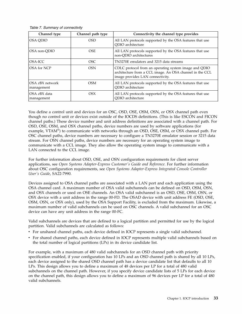
Table 7. Summary of connectivity
Channel type Channel path type Connectivity the channel type provides
OSA QDIO OSD All LAN protocols supported by the OSA features that useQDIO architecture
OSA non-QDIO OSE All LAN protocols supported by the OSA features that usenon-QDIO architectures
OSA-ICC OSC TN3270E emulators and 3215 data streams
OSA for NCP OSN CDLC protocol from an operating system image and QDIOarchitecture from a CCL image. An OSA channel in the CCLimage provides LAN connectivity.
OSA zBX networkmanagement
OSM All LAN protocols supported by the OSA features that useQDIO architecture
OSA zBX datamanagement
OSX All LAN protocols supported by the OSA features that useQDIO architecture
You define a control unit and devices for an OSC, OSD, OSE, OSM, OSN, or OSX channel path eventhough no control unit or devices exist outside of the IOCDS definitions. (This is like ESCON and FICONchannel paths.) These device number and unit address definitions are associated with a channel path. ForOSD, OSE, OSM, and OSX channel paths, device numbers are used by software applications (forexample, VTAM®) to communicate with networks through an OSD, OSE, OSM, or OSX channel path. ForOSC channel paths, device numbers are necessary to configure a TN3270E emulator session or 3215 datastream. For OSN channel paths, device numbers are necessary for an operating system image tocommunicate with a CCL image. They also allow the operating system image to communicate with aLAN connected to the CCL image.
For further information about OSD, OSE, and OSN configuration requirements for client serverapplications, see Open Systems Adapter-Express Customer's Guide and Reference. For further informationabout OSC configuration requirements, see Open Systems Adapter-Express Integrated Console ControllerUser's Guide, SA22-7990.
Devices assigned to OSA channel paths are associated with a LAN port and each application using theOSA channel card. A maximum number of OSA valid subchannels can be defined on OSD, OSM, OSN,and OSX channels or used on OSE channels. An OSA valid subchannel is an OSD, OSE, OSM, OSN, orOSX device with a unit address in the range 00-FD. The OSAD device with unit address FE (OSD, OSE,OSM, OSN, or OSX only), used by the OSA Support Facility, is excluded from the maximum. Likewise, amaximum number of valid subchannels can be used on OSC channels. A valid subchannel for an OSCdevice can have any unit address in the range 00-FC.
Valid subchannels are devices that are defined to a logical partition and permitted for use by the logicalpartition. Valid subchannels are calculated as follows:v For unshared channel paths, each device defined in IOCP represents a single valid subchannel.v For shared channel paths, each device defined in IOCP represents multiple valid subchannels based on
the total number of logical partitions (LPs) in its device candidate list.
For example, with a maximum of 480 valid subchannels for an OSD channel path with priorityspecification enabled, if your configuration has 10 LPs and an OSD channel path is shared by all 10 LPs,each device assigned to the shared OSD channel path has a device candidate list that defaults to all 10LPs. This design allows you to define a maximum of 48 devices per LP for a total of 480 validsubchannels on the channel path. However, if you specify device candidate lists of 5 LPs for each deviceon the channel path, this design allows you to define a maximum of 96 devices per LP for a total of 480valid subchannels.
Chapter 1. IOCP introduction 33
TCP/IP assigns each OSA device on an OSD or OSX channel path four outbound queues, each of whichhas a unique priority. These priorities allow the prioritization of outbound work based on TCP/IP Typeof Service (TOS) settings. If you choose not to use the priorities for a channel, the channel can supportfour times as many devices where each device has a single outbound queue with a single priority. Specifythe CHPARM keyword for the OSD, OSM, or OSX channel path with bit 6 of the CHPARM value on(CHPARM=02) to disable priority specification and support a maximum of 1920 OSA valid subchannels(640 TCP/IP stacks). Otherwise, an OSD or OSX channel path has priority specification enabled andsupports a maximum of 480 OSA valid subchannels (160 TCP/IP stacks). OSM channel paths default todisabled priority queuing. The only valid definition for OSM is CHPARM=02 (or omitting the CHPARMkeyword). Disabling priority specification is transparent to host policies and applications that set or affectthe setting of the TOS byte. For additional information about QDIO priority queuing and how it relates toTOS and quality of service for Internet Protocol networks, see the z/OS Communications Server IPConfiguration Guide, SC31-8775.
Attention: Disabling priority specification (CHPARM=02) is supported only for OSA-Express2 and laterfeatures. If it is disabled for an OSA-Express feature, the I/O subsystem flags the channel path with adefinition error and the channel path is unavailable until a dynamic I/O change is made or power-onreset is performed with a new IOCDS to resolve the error.
Use of the OSA feature has the following considerations:v For all OSA configurations:
– An OSA-Express, OSA-Express2 or later 10 Gigabit Ethernet channel path is associated with a singleport on an OSA channel card. An OSA-Express3 or later Gigabit and 1000Base-T Ethernet channelpath is associated with a pair of ports on the OSA channel card.
– For each OSA device on an OSD, OSE, OSM, or OSX channel path, specify UNIT=OSA on theIODEVICE statement.
– Unit address FF is not allowed.– The OSA feature using QDIO architecture uses the I/O device definitions and unit addresses in your
IOCDS.– A maximum of 480 OSA valid subchannels (160 TCP/IP stacks) can be defined on an OSD or OSX
channel path when priority specification is enabled (CHPARM=00).– A maximum of 1920 OSA valid subchannels (640 TCP/IP stacks) can be defined on an OSD channel
path on an OSA-Express2 or later feature, and on an OSM or OSX channel path on an OSA-Express3or later feature when priority specification is disabled (CHPARM=02).
v For OSA configurations using the OSA support facility:
– Define a device with unit address FE for every OSD, OSE, or OSN channel path managed by theOSA Support Facility, and specify UNIT=OSAD on the IODEVICE statement. For an OSD, OSM, orOSX channel path, the control unit assigned to this device must either have a CUADD keywordvalue of zero or have the CUADD keyword omitted. Otherwise, the device is unusable.
– A maximum of 240 OSA valid subchannels can be used on an OSE channel path even though IOCPallows you to define more than this number. The OSA Support Facility manages this maximum.
v For OSE configurations not using the OSA support facility:
– An OSA channel card port configured as an OSE channel path has unit addresses 00-01 associatedwith it when not using the OSA Support Facility.
– Only a single logical partition (LP) can use the OSE channel path. To ensure that the channel pathcan only be used by a single LP, do one of the following actions:- Define the channel path as dedicated or reconfigurable.- Define the channel path as shared but give it access to only one LP or define both OSA devices
with the same, single LP in their device candidate lists.- Define the channel path as shared and devices without device candidate lists but either configure
or activate host TCP/IP profiles for the OSA devices in only a single LP. At any time, only asingle LP can have a host TCP/IP profile active for the OSA devices.
34 IOCP User's Guide
v For OSC configurations:
– A maximum of 120 valid subchannels can be used on an OSC channel path even though IOCPallows you to define more than this number. The Support Element manages this maximum.
– Unit address FE is not allowed.– The OSC channel must be installed and defined as OSC and must be configured on the Support
Element using the Advanced Facilities window before TN3270E emulator sessions or 3215 datastreams can be used. Under Advanced Facilities, select either Panel Configuration Options orManual Configuration Options to configure each session you want to use.
– You can use an OSC channel path for either TN3270E emulator sessions or 3215 data streams butnot both. Only TPF supports 3215 data streams, and some CPCs require an RPQ be installed. Specifythe CHPARM keyword for the OSC channel path with bit 1 of the CHPARM value on(CHPARM=40) to use 3215 data streams with TPF. Otherwise, the OSC channel path supportsTN3270E emulator sessions.
v For OSN configurations:
– For each OSA device on an OSN channel, you must specify UNIT=OSN or UNIT=3745 on theIODEVICE statement.
– A maximum of 480 OSN valid subchannels and 180 3745 valid subchannels can be defined on anOSN channel path.
– To reduce the number of valid subchannels, use the device candidate list to restrict the OSN devicesto CCL images and the 3745 devices to operating system images.
Internal queued direct communication (HiperSockets) supportHiperSockets provide a high speed internal TCP/IP connection between applications running on a CPC.These applications (for example, z/OS Communication Server or Linux for zSeries) can be in differentz/VM images or different logical partitions. These "connections" are defined to the configuration withInternal Queued Direct (IQD) communication channel path types.
A CPC can support 4096 separate data queues. Typically each queue is represented by one data deviceand two control devices. IOCP ensures no more than 12288 (3*4096) valid subchannels are defined for allthe IQD channel paths in the configuration. Valid subchannels are devices that are defined to a logicalpartition and permitted for use by the logical partition. Valid subchannels are calculated as follows:v For unshared channel paths, each IQD device defined in IOCP represents a single valid subchannel.v For shared channel paths, each IQD device defined in IOCP represents multiple valid subchannels
based on the total number of logical partitions (LPs) in its device candidate list.
All devices defined on an IQD channel path should be defined with a device type (UNIT=) of IQD.
A CPC allows up to 16 or 32 (see Appendix F, “Machine limits and rules,” on page 285 for yourprocessor) IQD channel paths. However, the only reason to define more than one is to ensure separationof applications or if IQD special functions are required. If you require all applications in the CPC tocommunicate with each other then only one IQD channel path is needed. If you require LPs in differentCSSs to communicate, then the IQD channel path must be spanned. If you require one set of LPs tocommunicate with each other but not communicate with another set of LPs, then two channel paths needto be defined with each LP set defined in one of the CHPID candidate lists.
You can define up to 12288 valid subchannels or devices on a single IQD channel path. Use as manycontrol unit (CNTLUNIT) definitions as needed to define the necessary number of devices.
You can define up to 256 devices per control unit. Each CNTLUNIT statement for the IQD channel pathmust contain a unique CUADD value. A maximum of 64 control units can be defined per IQD channelpath.
Chapter 1. IOCP introduction 35

The TCP/IP maximum transmission unit (MTU) and maximum frame size for internal queued directcommunication is specified using the CHPARM keyword on the CHPID statement. The followingCHPARM keyword values are supported:v 00 for 8 KB MTU and 16 KB frame sizev 40 for 16 KB MTU and 24 KB frame sizev 80 for 32 KB MTU and 40 KB frame sizev C0 for 56 KB MTU and 64 KB frame size.
On 2828, 2827, 2817, and 2818 with enabling MCL applied or later processors, the following CHPARMvalues are provided:v 0x for 8 KB MTU and 16 KB frame sizev 4x for 16 KB MTU and 24 KB frame sizev 8x for 32 KB MTU and 40 KB frame sizev Cx for 56 KB MTU and 64 KB frame sizev x0 for a normal HiperSocket channel pathv x2 for a HiperSocket for IEDN channel pathv x4 for a HiperSocket capable to be externally bridged channel path.
Additional information about Internal Queued Direct Communication is in the z/OS CommunicationsServer IP Configuration Guide, SC31-8775.
Defining IQD channelsInternal queued direct (IQD) communication channels are virtual attachments and require no realhardware. However, they do require CHPID numbers, and they do need to be defined in the IOCDS.Also, beginning with the 2964 models, IQD channels require the VCHID keyword.
Define the minimum number of channel paths needed for separation of communicating LPs. Each IQDchannel path represents one internal LAN. If you have no requirement to separate LAN traffic betweenyour applications or are not enabling a special IQD function, only one IQD channel path needs to bedefined in the configuration.
Fibre Channel Protocol supportFibre Channel Protocol (FCP) channels provide for the attachment of SCSI devices using theindustry-standard Fibre Channel Protocol for SCSI. Devices can be attached directly to the CPC usingpoint-to-point connections or through a storage area network (SAN). The SAN may consist of anynumber of switches between the initiator (channel) and target (SCSI device) . Switch attachment fortargets may also include fibre channel arbitrated loops when supported by the switch. Devices withparallel SCSI interfaces must be attached using fibre-channel-to-SCSI bridges.
A fibre channel is placed in the FCP mode of operation by defining the CHPID as type FCP in the I/Oconfiguration. Unlike FICON channels, the subchannels (IODEVICEs) on an FCP CHPID do not eachrepresent specific remote SCSI devices, but instead define an entry point to a SAN or a communicationslink to a directly-attached SCSI device. The software uses the subchannel as the initiator of a connectionto a remote worldwide port name (WWPN) in order to address a specific SCSI logical unit number(LUN). The remote WWPN and LUN are provided by the software.
An FCP channel path supports a maximum number of valid subchannels. Valid subchannels are devicesthat are defined to a logical partition and permitted for use by the logical partition. Valid subchannels arecalculated as follows:v For unshared channel paths, each device defined in IOCP represents a single valid subchannel.v For shared channel paths, each device defined in IOCP represents multiple valid subchannels based on
the total number of logical partitions (LPs) in its device candidate list.
36 IOCP User's Guide
For example, with a maximum of 480 valid subchannels, if your configuration has 10 LPs and an FCPchannel path is shared by all 10 LPs, each device assigned to the shared FCP channel path has a devicecandidate to all LPs. This design allows you to define a maximum of 48 devices per LP for a total of 480valid subchannels on the channel path. However, if you specify device candidate lists of 5 LPs for eachdevice on the channel path, this design allows you to define a maximum of 96 devices per LP for a totalof 480 valid subchannels.
Unit addresses FE and FF are reserved and cannot be assigned to an FCP subchannel.
FCP channels use the Queued Direct I/O (QDIO) interface and support the QDIO Assist functions of theprocessor.
N_Port ID virtualization (NPIV)By default, all subchannels on an FCP channel path use the same local WWPN to access the fibre channellink. This means that SAN zoning and LUN masking cannot be used to manage the access rights of theindividual subchannels. In this mode, only one subchannel on the channel path may establish aconnection to a particular remote WWPN and LUN at a time. Permission to connect is granted on afirst-come, first-served basis to any subchannel on the channel path.
N_Port ID Virtualization (NPIV) is an industry-standard way to address this security issue. When NPIVis used, each subchannel is assigned a unique local WWPN that it uses when the subchannel logs into theSAN. The subchannel will be assigned a unique 3-byte fibre channel ID by the SAN and have all theattributes of a separate physical fibre channel adapter. Consequently, each subchannel appears as adifferent initiator to the SAN and target devices enabling the use of SAN zoning and LUN maskingaccess controls.
The NPIV mode of operation is not permitted in a point-to-point configuration.
When an FCP channel is shared among multiple partitions, the use of NPIV is configured separately foreach partition.
Because NPIV places additional resource requirements on both the SAN and the channel, IBMrecommends that the number of active subchannels on a single FCP channel be limited to a valuesignificantly lower than the configurable subchannel maximum. Care should be taken when defining theSAN zone, as each NPIV subchannel will register for state-change notifications, significantly increasingthe number of messages the fabric must generate when a zone member goes through recovery, loses alink, or logs in or out of the SAN. This and other recommended operational limits can be found inTable 22 on page 293. Exceeding these limits may lead to inaccessible devices during error recoveryscenarios.
Defining FICON switch configurationsA fibre channel switch topology is called a fabric. A FICON fibre channel fabric can consist of one or moreswitches. A FICON cascaded-switch fabric is a topology that consists of more than one switch between achannel and its control unit.
When a FICON (TYPE=FC) channel connects to a switch, the SWITCH keyword must be specified on theCHPID statement. The value specified is the switch number of the entry switch. The entry switch is theswitch to which the FICON channel actually connects. The switch number is an arbitrary value and is notthe same as the switch address. The switch number is required to be:v In the range of 01-FFv Unique from all other FICON switch numbers across the configurationv Unique from any ESCON switch numbers specified for channel path types CVC, CBY, CNC, CTC, and
FCV.
Chapter 1. IOCP introduction 37

Fibre channel port addressing identifies a destination port in a fibre channel fabric. Fibre channel portaddressing is always done with 3 bytes containing six hexadecimal digits, ddaapp. The first byte, dd, is theswitch domain ID or switch address. The switch address is set for a FICON switch by using switchcontrol panels. The second byte, aa, is the port area address or port address of the port on the switch.This port (with its port address) is where a control unit or channel is connected and is known as anF-Port. The third byte, pp, is an address on a fibre channel arbitrated loop. FICON does not supportarbitrated loops and for all FICON F-Ports in the fabric, the pp portion of the address must be a constantvalue. The pp value is never specified in IOCP.
To support cascaded switches, the fabric must be what is called a high integrity fabric. A high integrityfabric ensures data integrity by detecting any incorrect cabling within a FICON cascaded switch fabricthat could lead to I/O data being delivered to the wrong destination. A high integrity fabric is one thatboth supports and is configured to use fabric-binding and insistent domain IDs. Fabric-binding is the abilityof the fabric to prevent another switch from being added operationally to the fabric without properlyplanning for the new switch in the fabric and configuring the switch with the high integrity attributes.An insistent domain ID is a function of the fabric that does not allow the switch address to beautomatically changed when a duplicate switch address is added to the fabric. Instead, fabrics usinginsistent domain IDs require an operator to perform an overt action to change a switch address. Thecustomization of fabric-binding and the setting of an insistent domain ID are normally done only atswitch installation time or reinstallation time.
Note: Not all FICON switches support high integrity fabrics. Such switches can only be used in asingle-switch FICON fabric.
LINK address values for FICON control units are specified as 1 or 2 bytes as follows:v When a channel path is connected to a cascaded-switch fabric and has a control unit not connected to
the same switch as the channel (that is, not the entry switch), 2-byte LINK address values must bespecified for the channel path in all of its control unit definitions. You do not need to change otherLINK address values in the control units. Control units can contain a mixture of 1-byte and 2-byte linkaddresses.
v When all the control units for a channel path connect to the entry switch, the LINK address values forthe channel path in its control unit definitions can either be 1- or 2-byte addresses. Two-byte addressesare supported only if the switch is configured with the high-integrity attributes.
If 2-byte link addresses are specified for a channel and it is not connected to a high-integrity fabric, thechannel fails to initialize and is unusable until one of the following actions occurs:v The definitions are changed to 1-byte link addressesv The fabric is configured to support the high-integrity attributesv The channel connection is changed to a fabric that does support high-integrity.
A 2-byte LINK address value has a first byte with the switch address, dd, and a second byte with the portaddress, aa. A one-byte LINK address value consists of only the port address, aa.
Rules for defining a cascaded FICON switch configuration follow:v When a control unit is not connected to the entry switch for its channel path, the link address for that
path must be specified as a 2-byte address in the LINK keyword. Other paths to the control unit canuse 1- or 2-byte link addresses as appropriate.
v After a 2-byte address is specified for a channel path, all the link address values for that channel pathmust also be specified as 2 bytes. This statement is true even if a control unit is attached to the entryswitch for the channel path.
The following are recommendations, but not requirements, when configuring switches for FICON:
38 IOCP User's Guide
v For an easy transition to a cascaded environment, after your switch fully supports and is customizedfor high-integrity attributes, specify 2-byte link addresses for control units on that switch. This applieseven in a single switch configuration.
Note: Before converting to 2-byte link addresses, ensure that your applications and operating systemhave any needed updates to support cascading.
v When configuring your switches and assigning switch addresses to them, use unique switch addressesacross all the fabrics in your entire enterprise and not only for the switches within a single fabric.
Note: A switch can support only certain switch addresses or domain IDs instead of the full range of'00'-'FF'. For details, check the configuration information your switch vendor provides.
v When choosing the switch number (SWITCH keyword value) for your entry switch, try to use thesame value as the switch address of the switch to which the channel connects. Doing so reduces thenumber of ways the same switch is known.
v After a 2-byte link address has been specified for a channel path, try to specify 2-byte link addressesfor all paths (from the same CPC) that have the same entry switch (SWITCH keyword). Doing so canallow IOCP to perform better checking of the switch configuration.
Managing logical paths for ESCON and FICON channelsA logical path is a logical connection between a control unit and an ESCON channel (TYPE=CNC or CTC),a FICON channel (TYPE=FC), or a FICON channel attached to an ESCON Director (TYPE=FCV). Logicalpaths are important. For I/O operations to occur, a CPC requires the establishment of a logical pathbetween an ESCON or FICON channel and a control unit
Logical paths do not exist for ESCON channels attached to a 9034 ESCON Converter Model 1(TYPE=CBY or CVC). These channels connect to a parallel channel port on a control unit. However, somecontrol units that support both parallel and ESCON channels reserve a logical path for each attachedparallel channel port.
Logical paths do not exist for:v Coupling facility channel paths (TYPE=CFS, CFR, CFP, CBS, CBR, CBP, ICP, CIB, CL5, or CS5)v OSA channels (TYPE=OSC, OSD, OSE, OSM, OSN, or OSX)v Fiber channel protocol channels (TYPE=FCP),v Internal queued direct communication channels (TYPE=IQD)
Control unit allocation of logical pathsControl units allocate logical paths to channels dynamically on a first-come-first-served basis. Controlunits do not manage the allocation of logical paths. They allow channels to compete for logical pathsuntil all of the logical paths of a control unit are used.
Why manage logical paths?The ESCON and FICON environments (the use of ESCON and FICON channels and ESCON and FICONDirectors) greatly enhances the connectivity potential for control units. In addition, you can define sharedchannels that can request additional logical paths. However, control units can allocate only a limitednumber of logical paths in relation to the number of logical paths that channels can request. (See Table 8.)In configurations where channels request more logical paths than a control unit can allocate, you mustmanage logical paths to ensure that the I/O operations you intend take place.
Table 8. Logical path summary by control unit
Control unit Maximum physicallinks
Logical paths perlink
Maximum logicalpaths
2105 storage controller
Chapter 1. IOCP introduction 39
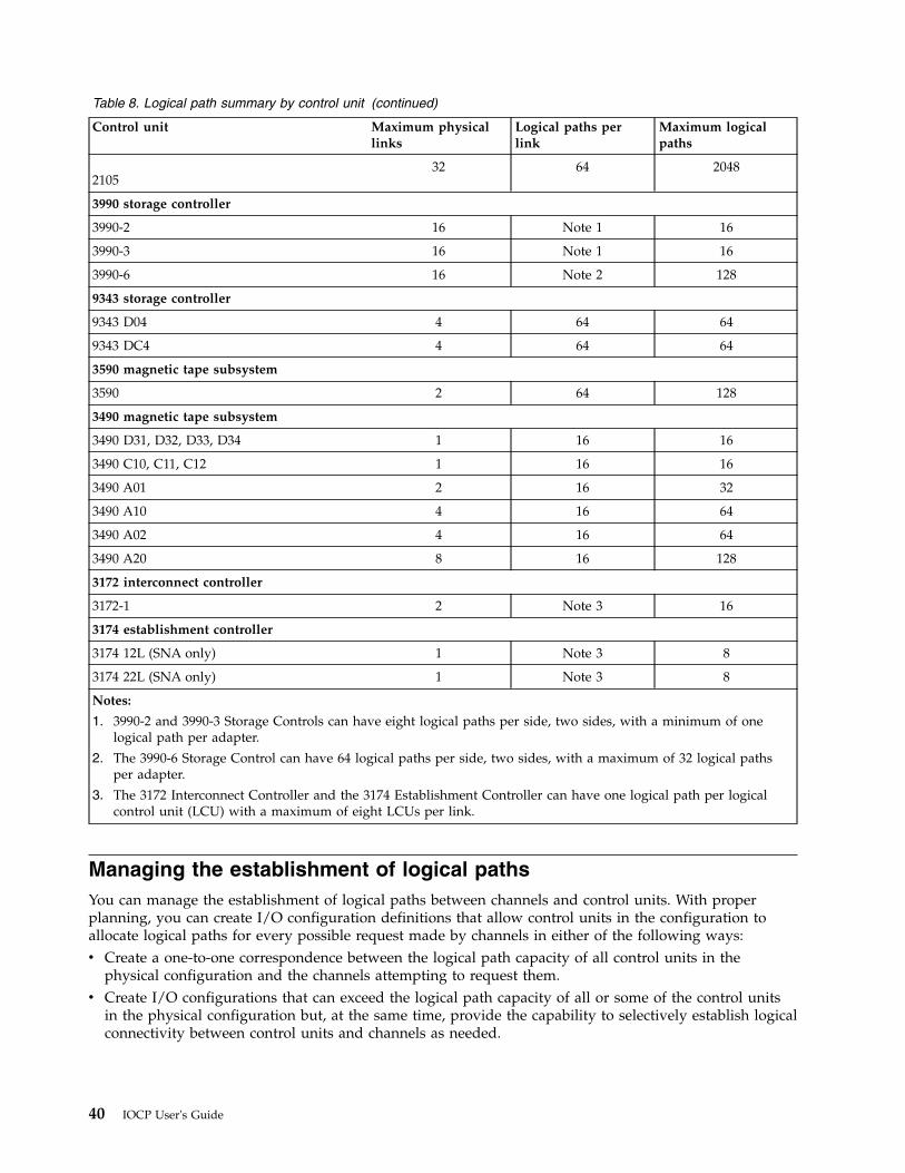
Table 8. Logical path summary by control unit (continued)
Control unit Maximum physicallinks
Logical paths perlink
Maximum logicalpaths
210532 64 2048
3990 storage controller
3990-2 16 Note 1 16
3990-3 16 Note 1 16
3990-6 16 Note 2 128
9343 storage controller
9343 D04 4 64 64
9343 DC4 4 64 64
3590 magnetic tape subsystem
3590 2 64 128
3490 magnetic tape subsystem
3490 D31, D32, D33, D34 1 16 16
3490 C10, C11, C12 1 16 16
3490 A01 2 16 32
3490 A10 4 16 64
3490 A02 4 16 64
3490 A20 8 16 128
3172 interconnect controller
3172-1 2 Note 3 16
3174 establishment controller
3174 12L (SNA only) 1 Note 3 8
3174 22L (SNA only) 1 Note 3 8
Notes:
1. 3990-2 and 3990-3 Storage Controls can have eight logical paths per side, two sides, with a minimum of onelogical path per adapter.
2. The 3990-6 Storage Control can have 64 logical paths per side, two sides, with a maximum of 32 logical pathsper adapter.
3. The 3172 Interconnect Controller and the 3174 Establishment Controller can have one logical path per logicalcontrol unit (LCU) with a maximum of eight LCUs per link.
Managing the establishment of logical pathsYou can manage the establishment of logical paths between channels and control units. With properplanning, you can create I/O configuration definitions that allow control units in the configuration toallocate logical paths for every possible request made by channels in either of the following ways:v Create a one-to-one correspondence between the logical path capacity of all control units in the
physical configuration and the channels attempting to request them.v Create I/O configurations that can exceed the logical path capacity of all or some of the control units
in the physical configuration but, at the same time, provide the capability to selectively establish logicalconnectivity between control units and channels as needed.
40 IOCP User's Guide
Logical path considerationsYou can better understand how to manage the establishment of logical paths by understanding thefollowing considerations:v Control unit considerationsv Connectivity considerationsv Channel configuration considerationsv 9035 ESCON Converter considerations
Control unit considerationsConsider the following factors concerning the allocation of logical paths by control units:v Control units allocate logical paths dynamically on a first-come-first-served basis.v Control units do not manage the allocation of logical paths. They allow channels to compete for logical
paths until all the logical paths of the control unit are used.v Control units vary in the number of logical paths they support. See Table 8 on page 39.v Some control units that support a mix of parallel and ESCON ports can reduce the number of logical
paths allocated to ESCON channels because they reserve a logical path for each parallel port.
Connectivity considerationsESCON and FICON system hardware, CPCs, and ESCON and FICON Directors, can significantly affectthe volume of logical path requests to a control unit as follows:v Control units can attach to one or more ports on a director or to additional ports on other directors.
Each director port can dynamically connect to many other ports to which attached channels arerequesting logical paths.
v Each logical partition with channels attaching to the same control unit competes for the logical paths ofthe same control unit.
v In a configuration where control units are shared by different CPCs, I/O configuration definitions forindividual control units are not coordinated automatically among the IOCDSs of the different CPCs.Each CPC competes for the logical paths of a control unit.
v Shared channels require the establishment of a logical path for each active logical partition sharing thechannel. This requirement can significantly increase the number of logical paths that a single channelrequests.
Channel configuration considerationsThe following configuration rules determine how logical paths are established for ESCON and FICONchannels.v A channel initially attempts to establish logical paths:
– For channels configured online to logical partitions that are activated at POR. Shared channelsattempt to establish logical paths only for those activated logical partitions with the channelconfigured online.
– When a logical partition is activated.– When configured online (if previously configured offline).
v A channel that cannot initially establish a logical path can reattempt to establish a logical path if thechannel detects or is notified of:– A change in the state of a control unit– A change in the state of a link or port– A dynamic I/O configuration change that frees previously allocated logical paths.
v A channel cannot establish a logical path or its logical path is removed if:– A logical partition is deactivated. A shared channel continues to operate for any other remaining
activated logical partitions to which it is defined. Logical paths to those logical partitions remainestablished.
Chapter 1. IOCP introduction 41
– The director that connects the channel to the control unit blocks either the channel port or controlunit port used in the path.
– The director that connects the channel to the control unit prohibits the dynamic connection orcommunication between the channel port and the control unit port used in the path.
– A link involved in the path fails or is disconnected. When a shared channel is affected by any of thefollowing circumstances, each logical partition sharing the channel is equally affected:- The blocking of a port- A prohibited dynamic connection or communication- A failing or disconnected link
All logical paths using the port or link are removed (regardless of the logical partition with whichthey are associated).
– The channel is configured offline. When a shared channel is configured offline for a logical partition,it continues to operate for any other logical partition that has the channel configured online. Logicalpaths to these other logical partitions remain established.
– Power to the channel, control units, or directors in the configuration is turned off.v A shared channel cannot establish a logical path to a control unit for a logical partition that cannot
access any of the I/O devices on the control unit. The PART, PARTITION, or NOTPART keyword onthe IODEVICE statement specifies which logical partitions are permitted to access a device.
v A channel does not establish a logical path to a control unit if no devices are defined on the controlunit.
9035 ESCON converter considerationsFor the 3990, 9035 configuration requires special Vital Product Data (VPD) specification. When an ESCONDirector blocks a port supporting a 9035 or prohibits a dynamic connection between the channel attachedto the 9035 and the control unit, the logical path is removed from the 3990. This path is now available toother channels: either to another 9035 configured in the VPD or to channels not attached to a 9035 thattry to establish a logical path. The 3990 always tries to establish a logical path to the 9035s configured inthe VPD before it allows a channel not attached to a 9035 to have a logical path.
Recommendations for managing logical pathsYou do not need to manage logical paths to a control unit if the control unit supports the number oflogical paths required by the I/O configuration. However, if a control unit does not support the numberof logical paths required by the I/O configuration, you can manage logical paths as follows:v Deactivate unneeded logical partitions (LPs).v Configure offline unneeded channels. For shared channels, configure offline unneeded channels on an
LP basis.v For a control unit attached to shared channels, limit the number of LPs that can access the I/O devices
attached to the control unit.To limit LP access to I/O devices, specify a device candidate list for each I/O device attached to thecontrol unit. The device candidate list (determined by the PART, PARTITION, or NOTPART keywordin the IODEVICE statement) indicates the LPs that can access the I/O device. LPs not in the devicecandidate list cannot access the I/O device.A shared channel does not establish a logical path from an LP to an attached control unit if all the I/Odevices attached to the control unit deny access to the LP.
v Use the director to block ports or prohibit dynamic connections or communication between ports.v Combinations of the preceding.
42 IOCP User's Guide
Channel path selectionA logical channel subsystem (CSS) uses a rotation order for the initiation of I/O requests to a device. Inaddition, you can select a preferred path which causes the CSS to always attempt the initial selection onthat path.
Rotation orderYou control the rotation order to a device with the order of the:v Control unit numbers of the control units that attach to the devicev Channel paths used by the control units
Note: See “CNTLUNIT” on page 79 for a description of the CUNUMBR and PATH keywords in theCNTLUNIT statement.
Rotation order does not apply to devices assigned to CFS, CFP, CBS, CBP, ICP, CIB, CL5, or CS5 channelpaths. The CSS selects the channel path that is likely to have the best response time.
The rotation order for a control unit header is built using the first channel path you specify for eachcontrol unit that attaches to a device, beginning with the lowest numbered control unit. The rotationorder then is built using the second channel path, if any, for each control unit beginning with the lowestnumbered control unit. The rotation order is built by repeating this procedure until all channel paths forall the control units contained in a control unit header have been added.
Control Unit Header 2 in Figure 11 on page 22 shows an example of how specifying paths in a controlunit header can affect the path rotation order. If you specify PATH=(01,07) in the CNTLUNIT statementfor physical control unit 2 and PATH=(02,04) for physical control unit 3, the rotation order for device B is01, 02, 07, 04. However, if you specify PATH=(07,01) in the CNTLUNIT statement for control unit 2 andPATH=(02,04) for control unit 3, the rotation order for device B is 07, 02, 01, 04.
Rotating path selectionThe CSS tries to initiate each new I/O request for an I/O device on a rotating channel path basis withinthe paths in the control unit header. The CSS tries the next channel path in the rotation order followingthe last channel path initially selected for an I/O request for the control unit header. If that channel pathis busy or unavailable, the CSS chooses the channel path in the control unit header that has the greatestlikelihood of availability. Therefore, the rotation order is only used for the initial attempt for an I/Orequest.
Path selection using a preferred pathWhen you specify a preferred path in the IODEVICE statement, the CSS always tries the preferred pathfirst. If it is busy or unavailable, the CSS chooses the channel path in the control unit header rotationorder that has the greatest likelihood of availability.
Channel paths to a device can belong to different logical partitions. I/O requests from any one logicalpartition use only the paths you assign to that logical partition. The rotation order for a device in alogical partition then follows the normal rotation order for the channel paths that belong to that logicalpartition.
When you specify a preferred path in an IODEVICE statement that is available to more than one logicalpartition, the device has a preferred path in all of its logical partitions in that CSS even though you canspecify only one channel path per CSS in an IODEVICE statement as a preferred path. The preferred pathfor each LP is the first path in the rotation order that is defined to the LP beginning with the specifiedpreferred path.
Chapter 1. IOCP introduction 43
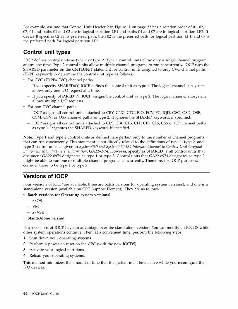
For example, assume that Control Unit Header 2 in Figure 11 on page 22 has a rotation order of 01, 02,07, 04 and paths 01 and 02 are in logical partition LP1 and paths 04 and 07 are in logical partition LP2. Ifdevice B specifies 02 as its preferred path, then 02 is the preferred path for logical partition LP1, and 07 isthe preferred path for logical partition LP2.
Control unit typesIOCP defines control units as type 1 or type 2. Type 1 control units allow only a single channel programat any one time. Type 2 control units allow multiple channel programs to run concurrently. IOCP uses theSHARED parameter on the CNTLUNIT statement for control units assigned to only CVC channel paths(TYPE keyword) to determine the control unit type as follows:v For CVC (TYPE=CVC) channel paths:
– If you specify SHARED=Y, IOCP defines the control unit as type 1. The logical channel subsystemallows only one I/O request at a time.
– If you specify SHARED=N, IOCP assigns the control unit as type 2. The logical channel subsystemallows multiple I/O requests.
v For non-CVC channel paths:– IOCP assigns all control units attached to CBY, CNC, CTC, EIO, FCV, FC, IQD, OSC, OSD, OSE,
OSM, OSN, or OSX channel paths as type 2. It ignores the SHARED keyword, if specified.– IOCP assigns all control units attached to CBS, CBP, CFS, CFP, CIB, CL5, CS5 or ICP channel paths
as type 1. It ignores the SHARED keyword, if specified.
Note: Type 1 and type 2 control units as defined here pertain only to the number of channel programsthat can run concurrently. This statement is not directly related to the definitions of type 1, type 2, andtype 3 control units as given in System/360 and System/370 I/O Interface Channel to Control Unit OriginalEquipment Manufacturers' Information, GA22-6974. However, specify as SHARED=Y all control units thatdocument GA22-6974 designates as type 1 or type 3. Control units that GA22-6974 designates as type 2might be able to run one or multiple channel programs concurrently. Therefore, for IOCP purposes,consider these to be type 1 or type 2.
Versions of IOCPFour versions of IOCP are available; three are batch versions (or operating system versions), and one is astand-alone version (available on CPC Support Element). They are as follows:v Batch versions (or Operating system versions)
– z/OS– VM– z/VSE
v Stand-Alone version
Batch versions of IOCP have an advantage over the stand-alone version. You can modify an IOCDS whileother system operations continue. Then, at a convenient time, perform the following steps:1. Shut down your operating systems2. Perform a power-on reset on the CPC (with the new IOCDS)3. Activate your logical partitions4. Reload your operating systems.
This method minimizes the amount of time that the system must be inactive while you reconfigure theI/O devices.
44 IOCP User's Guide
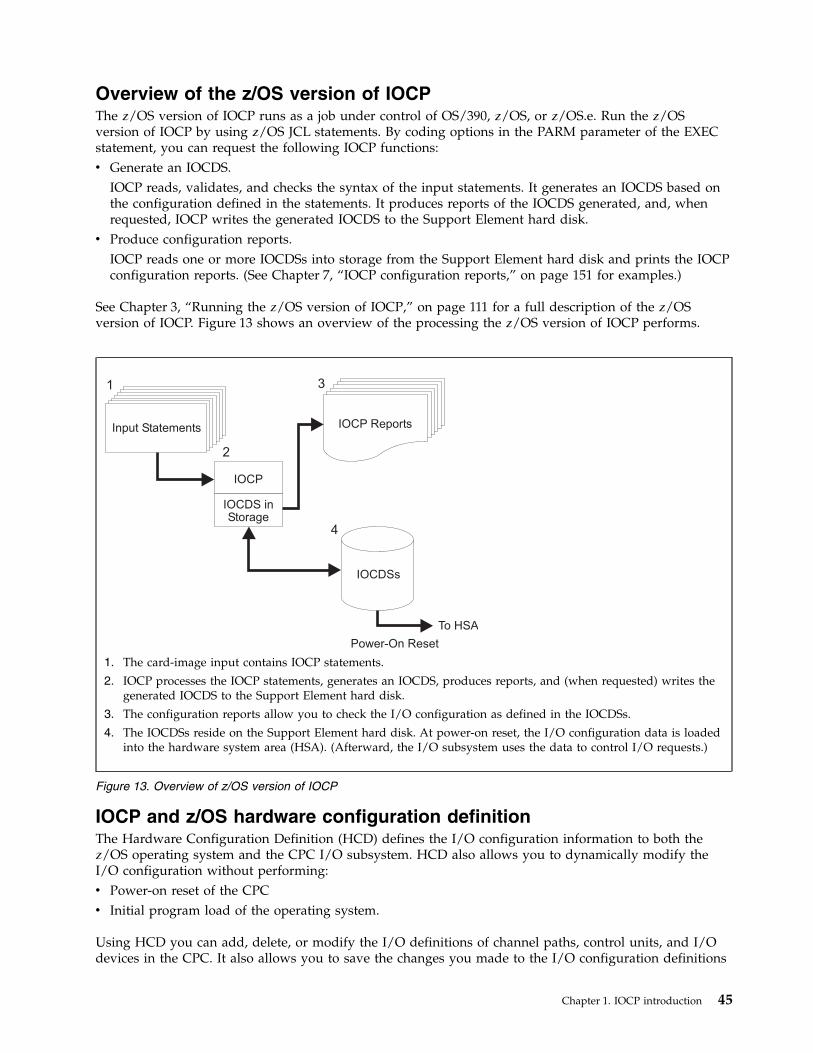
Overview of the z/OS version of IOCPThe z/OS version of IOCP runs as a job under control of OS/390, z/OS, or z/OS.e. Run the z/OSversion of IOCP by using z/OS JCL statements. By coding options in the PARM parameter of the EXECstatement, you can request the following IOCP functions:v Generate an IOCDS.
IOCP reads, validates, and checks the syntax of the input statements. It generates an IOCDS based onthe configuration defined in the statements. It produces reports of the IOCDS generated, and, whenrequested, IOCP writes the generated IOCDS to the Support Element hard disk.
v Produce configuration reports.IOCP reads one or more IOCDSs into storage from the Support Element hard disk and prints the IOCPconfiguration reports. (See Chapter 7, “IOCP configuration reports,” on page 151 for examples.)
See Chapter 3, “Running the z/OS version of IOCP,” on page 111 for a full description of the z/OSversion of IOCP. Figure 13 shows an overview of the processing the z/OS version of IOCP performs.
IOCP and z/OS hardware configuration definitionThe Hardware Configuration Definition (HCD) defines the I/O configuration information to both thez/OS operating system and the CPC I/O subsystem. HCD also allows you to dynamically modify theI/O configuration without performing:v Power-on reset of the CPCv Initial program load of the operating system.
Using HCD you can add, delete, or modify the I/O definitions of channel paths, control units, and I/Odevices in the CPC. It also allows you to save the changes you made to the I/O configuration definitions
IOCP
IOCDS inStorage
Input Statements IOCP Reports
IOCDSs
To HSA
Power-On Reset
1
4
2
3
1. The card-image input contains IOCP statements.
2. IOCP processes the IOCP statements, generates an IOCDS, produces reports, and (when requested) writes thegenerated IOCDS to the Support Element hard disk.
3. The configuration reports allow you to check the I/O configuration as defined in the IOCDSs.
4. The IOCDSs reside on the Support Element hard disk. At power-on reset, the I/O configuration data is loadedinto the hardware system area (HSA). (Afterward, the I/O subsystem uses the data to control I/O requests.)
Figure 13. Overview of z/OS version of IOCP
Chapter 1. IOCP introduction 45
and apply them to the power-on reset I/O configuration data set (POR IOCDS). You must use an IOCDSgenerated from an I/O definition file (IODF) to be able to dynamically modify the I/O configuration. Formore information, see OS/390 Hardware Configuration Definition User's Guide, SC28-1848, or z/OS HardwareConfiguration Definition User's Guide, SC33-7988.
IOCDS write authorizationIf you use HCD, you do not need to run IOCP directly to define the I/O configuration to the I/Osubsystem. However, HCD does run IOCP when it needs to write an IOCDS. You must be authorized towrite an IOCDS either through the system operator (IOCP message ICP050D prompts the operator) orthrough a security product (for example, RACF®). To avoid operator intervention and the IOCP messageprompt (ICP050D), see “Authorizing an IOCDS write” on page 112.
Overview of the VM version of IOCPThe VM version of IOCP runs under the control of z/VM. Run the VM version of IOCP in theconversational monitor system (CMS) environment. The CMS IOCP command runs IOCP and has optionsthat allow you to request the following IOCP functions:v Generate an IOCDS.
IOCP reads, validates, and checks the syntax of the input statements. It generates an IOCDS based onthe configuration defined in the statements. It produces reports of the IOCDS generated, and, whenrequested, IOCP writes the generated IOCDS to the Support Element hard disk.
v Produce configuration reports.IOCP reads one or more IOCDSs from the Support Element into storage and prints the IOCPconfiguration reports. (See Chapter 7, “IOCP configuration reports,” on page 151 for examples.)
For a full description of the VM version of IOCP, see Chapter 4, “Running the VM version of IOCP,” onpage 119.
IOCP and system generation of a VM operating systemYou must define your I/O configuration to the hardware and conditionally to VM. When you perform aninitial program load (IPL) of VM, VM creates its software I/O configuration by sensing the devices in thehardware I/O configuration. If all the devices return all the information VM needs, VM completes itssoftware I/O configuration. If not, you must specify this information in the system configuration file orthe real I/O configuration file.
To define the devices in your I/O configuration that VM cannot sense, use a set of I/O statements foryour VM operating system. Use the system configuration file (SYSTEM CONFIG) on the parm disk. Youcan also use the obsolete real I/O configuration file (HCPRIO) in the CP nucleus.
When you perform system generation, the control program uses the statements in the real I/Oconfiguration file to define the I/O configuration to the operating system. When you perform an IPL ofVM, VM uses a combination of the real I/O configuration file, the system configuration file, and thedevices it senses during IPL to define the I/O configuration to the operating system. VM also updates itssoftware I/O configuration by sensing devices when they are varied online or initialized.
To define your I/O configuration to hardware, you use a set of I/O statements in an IOCP file. Whenyou enter the IOCP command, the IOCP program uses the I/O statements in the IOCP file to define theI/O configuration to the CPC.
For more information about performing these tasks, see Chapter 3, “Running the z/OS version of IOCP,”on page 111. Figure 14 on page 47 shows an overview of the processing performed by the VM version ofIOCP.
46 IOCP User's Guide
IOCP and VM dynamic I/O configurationVM allows you to dynamically modify the I/O configuration without performing:v Power-on reset (POR) of the CPCv Initial program load of the operating system.
On z/VM you can use HCD and HCM to add, delete, or modify the I/O definitions of channel paths,control units, and I/O devices in the CPC. It also allows you to save the changes you made to the I/Oconfiguration definition data set (POR IOCDS). You must use an IOCDS generated from an I/O definitionfile (IODF) to be able to dynamically modify the I/O configuration using HCD. For more information, seez/VM Dynamic I/O Configuration Planning and Administration, SC24-6044.
Alternatively, using VM CP commands, you can add, delete, or modify the I/O definitions of channelpaths, control units, and I/O devices in the CPC. Using the IOCP utility on CMS (DYN option), you canwrite a new POR IOCDS containing the same I/O configuration changes. For more information, see thez/VM Planning and Administration, GA22-6974, and z/VM CP Command and Utility Reference, GA22-6974.
Overview of the z/VSE version of IOCP
SE The z/VSE version of IOCP runs under control of z/VSE. Run the z/VSE version of IOCP by usingz/VSE JCL statements. By coding options in the PARM parameter of the EXEC statement, you can:
IOCP
IOCDS inStorage
Input StatementsSYSTEMCONFIG
VM I/OConfiguration
IOCP Reports
IOCDSs
To HSA
Power-On Reset
1 4
5
2
3
1. Use the system configuration file (SYSTEM CONFIG) to define to the system control program those devices inthe I/O configuration that VM cannot sense. For VM system generation, you can also use the obsolete real I/Oconfiguration file (HCPRIO).
2. The input file contains the IOCP statements that define the I/O configuration to IOCP.
3. IOCP processes the IOCP statements, generates an IOCDS, produces reports, and, when requested, writes thegenerated IOCDS to the Support Element hard disk.
4. The configuration reports allow you to check the I/O configuration as defined in the IOCDSs.
5. The IOCDSs reside on the Support Element hard disk. At power-on reset, the Support Element loads the I/Oconfiguration data into the hardware system area (HSA). (Afterward, the I/O subsystem uses the data in thehardware system area (HSA) to control I/O requests.)
Figure 14. Overview of VM version of IOCP
Chapter 1. IOCP introduction 47
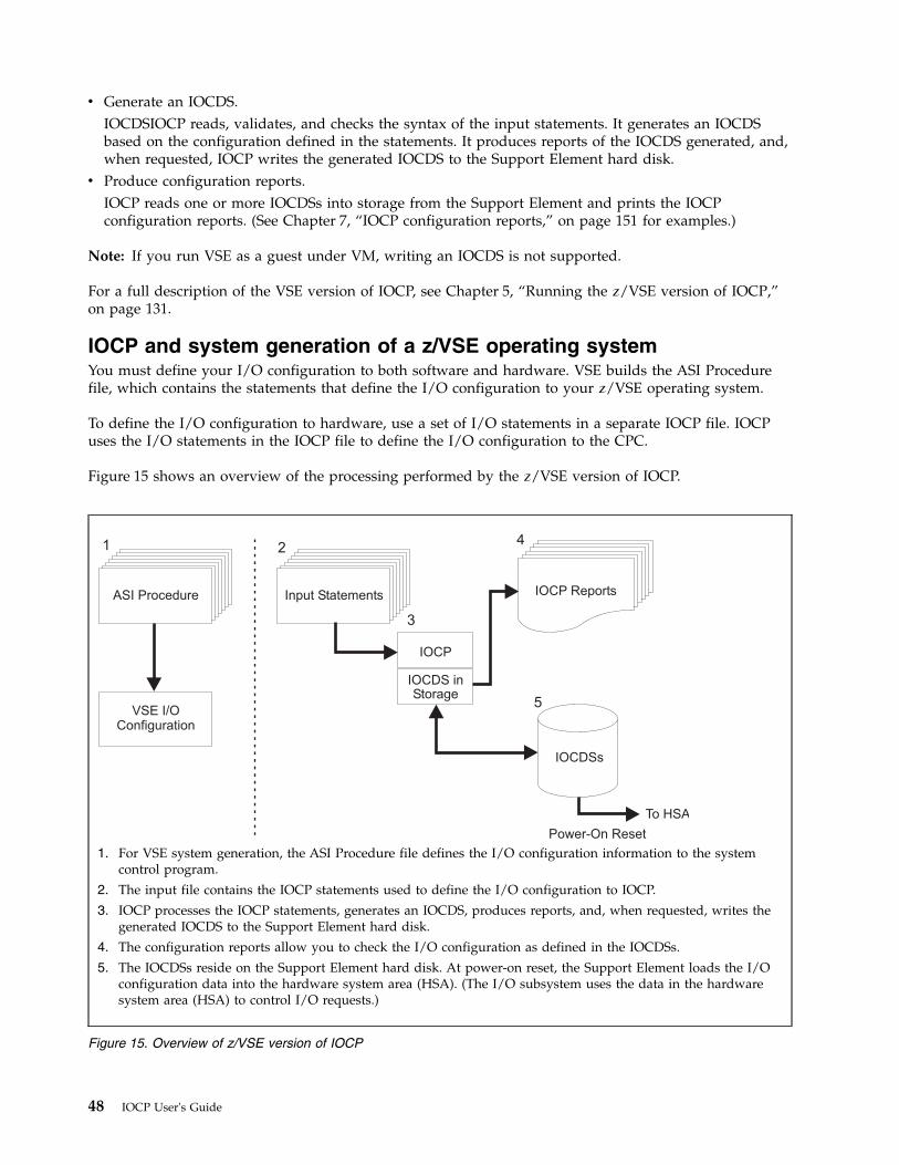
v Generate an IOCDS.IOCDSIOCP reads, validates, and checks the syntax of the input statements. It generates an IOCDSbased on the configuration defined in the statements. It produces reports of the IOCDS generated, and,when requested, IOCP writes the generated IOCDS to the Support Element hard disk.
v Produce configuration reports.IOCP reads one or more IOCDSs into storage from the Support Element and prints the IOCPconfiguration reports. (See Chapter 7, “IOCP configuration reports,” on page 151 for examples.)
Note: If you run VSE as a guest under VM, writing an IOCDS is not supported.
For a full description of the VSE version of IOCP, see Chapter 5, “Running the z/VSE version of IOCP,”on page 131.
IOCP and system generation of a z/VSE operating systemYou must define your I/O configuration to both software and hardware. VSE builds the ASI Procedurefile, which contains the statements that define the I/O configuration to your z/VSE operating system.
To define the I/O configuration to hardware, use a set of I/O statements in a separate IOCP file. IOCPuses the I/O statements in the IOCP file to define the I/O configuration to the CPC.
Figure 15 shows an overview of the processing performed by the z/VSE version of IOCP.
IOCP
IOCDS inStorage
Input StatementsASI Procedure
VSE I/OConfiguration
IOCP Reports
IOCDSs
To HSA
Power-On Reset
1 4
5
2
3
1. For VSE system generation, the ASI Procedure file defines the I/O configuration information to the systemcontrol program.
2. The input file contains the IOCP statements used to define the I/O configuration to IOCP.
3. IOCP processes the IOCP statements, generates an IOCDS, produces reports, and, when requested, writes thegenerated IOCDS to the Support Element hard disk.
4. The configuration reports allow you to check the I/O configuration as defined in the IOCDSs.
5. The IOCDSs reside on the Support Element hard disk. At power-on reset, the Support Element loads the I/Oconfiguration data into the hardware system area (HSA). (The I/O subsystem uses the data in the hardwaresystem area (HSA) to control I/O requests.)
Figure 15. Overview of z/VSE version of IOCP
48 IOCP User's Guide
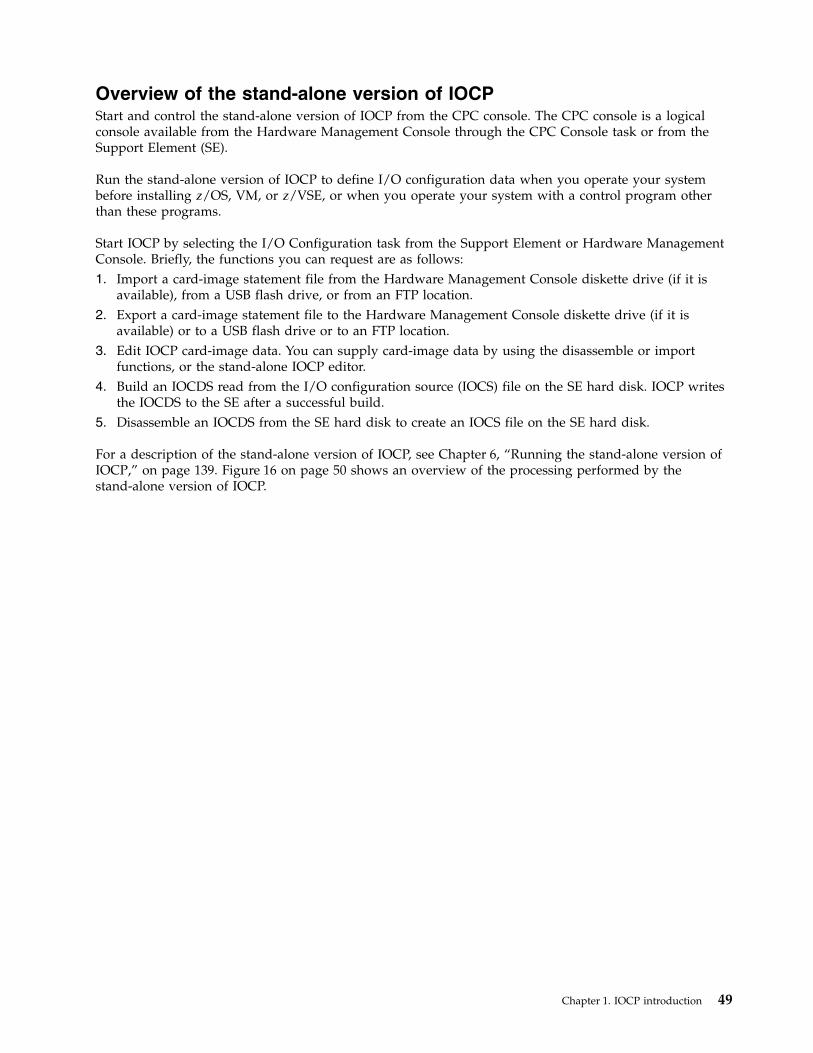
Overview of the stand-alone version of IOCPStart and control the stand-alone version of IOCP from the CPC console. The CPC console is a logicalconsole available from the Hardware Management Console through the CPC Console task or from theSupport Element (SE).
Run the stand-alone version of IOCP to define I/O configuration data when you operate your systembefore installing z/OS, VM, or z/VSE, or when you operate your system with a control program otherthan these programs.
Start IOCP by selecting the I/O Configuration task from the Support Element or Hardware ManagementConsole. Briefly, the functions you can request are as follows:1. Import a card-image statement file from the Hardware Management Console diskette drive (if it is
available), from a USB flash drive, or from an FTP location.2. Export a card-image statement file to the Hardware Management Console diskette drive (if it is
available) or to a USB flash drive or to an FTP location.3. Edit IOCP card-image data. You can supply card-image data by using the disassemble or import
functions, or the stand-alone IOCP editor.4. Build an IOCDS read from the I/O configuration source (IOCS) file on the SE hard disk. IOCP writes
the IOCDS to the SE after a successful build.5. Disassemble an IOCDS from the SE hard disk to create an IOCS file on the SE hard disk.
For a description of the stand-alone version of IOCP, see Chapter 6, “Running the stand-alone version ofIOCP,” on page 139. Figure 16 on page 50 shows an overview of the processing performed by thestand-alone version of IOCP.
Chapter 1. IOCP introduction 49
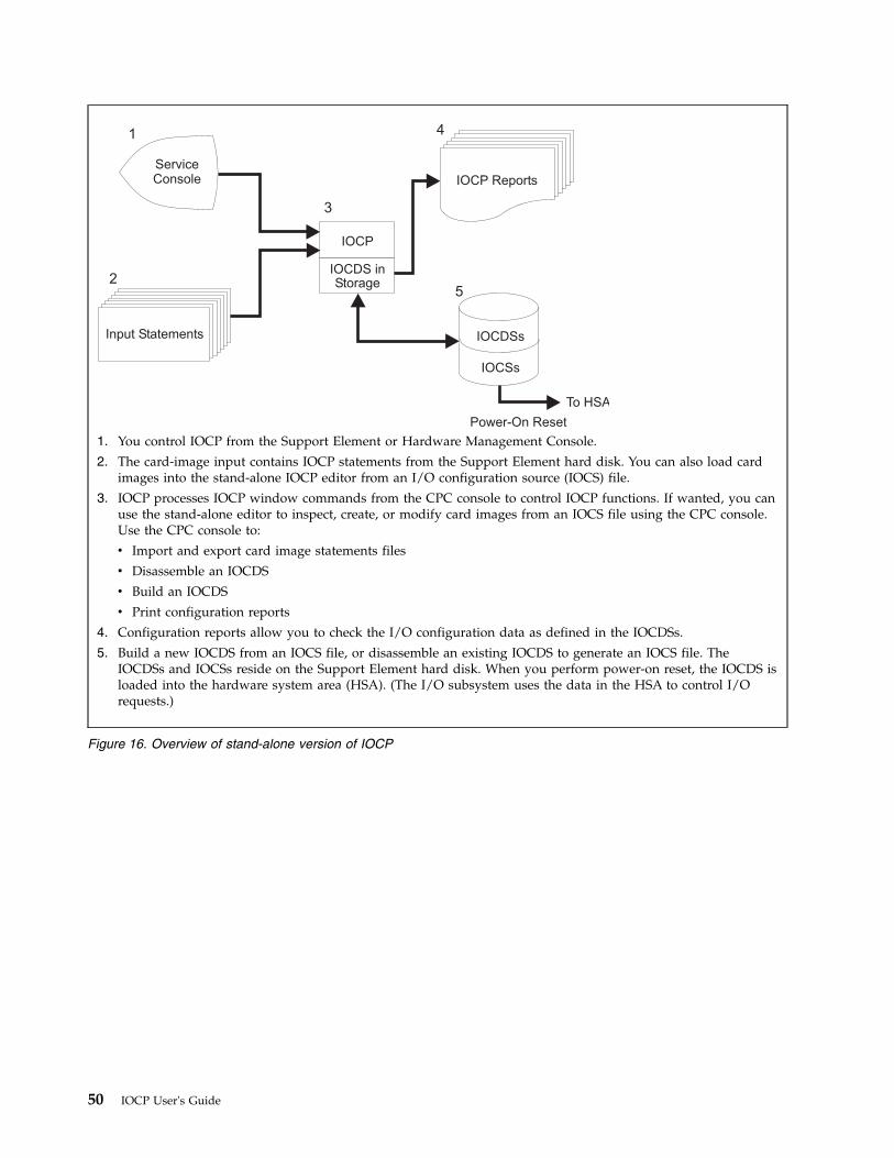
IOCP
IOCDS inStorage
Input Statements
ServiceConsole IOCP Reports
IOCDSs
IOCSs
To HSA
Power-On Reset
1 4
52
3
1. You control IOCP from the Support Element or Hardware Management Console.
2. The card-image input contains IOCP statements from the Support Element hard disk. You can also load cardimages into the stand-alone IOCP editor from an I/O configuration source (IOCS) file.
3. IOCP processes IOCP window commands from the CPC console to control IOCP functions. If wanted, you canuse the stand-alone editor to inspect, create, or modify card images from an IOCS file using the CPC console.Use the CPC console to:
v Import and export card image statements files
v Disassemble an IOCDS
v Build an IOCDS
v Print configuration reports
4. Configuration reports allow you to check the I/O configuration data as defined in the IOCDSs.
5. Build a new IOCDS from an IOCS file, or disassemble an existing IOCDS to generate an IOCS file. TheIOCDSs and IOCSs reside on the Support Element hard disk. When you perform power-on reset, the IOCDS isloaded into the hardware system area (HSA). (The I/O subsystem uses the data in the HSA to control I/Orequests.)
Figure 16. Overview of stand-alone version of IOCP
50 IOCP User's Guide
Chapter 2. IOCP statements and functions
This chapter describes the following:v Purpose of IOCP statementsv How to code them:
– Using z/OS– Using z/VM– Using z/VSE
Using this chapterThis chapter describes IOCP statements as you use them in z/OS, z/VM, and z/VSE operating systems.It takes special care to identify any information that is specific to an operating system. This information isidentified as follows:
For z/OS: Information placed in this box is specific to the z/OS operating system
Specifying IOCP statementsThe rules for coding IOCP card-image statements follow the rules for assembly language. SeeAppendix A, “Coding IOCP statements,” on page 237 for a summary of the rules for coding statementsand the notation used in this document to illustrate statements.
IOCP has seven statements: ID, RESOURCE, UUID, CHPID, CNTLUNIT, IODEVICE, and FUNCTION.The ID statement is optional; code it if you want specific identification information in the heading ofIOCP configuration reports and on Support Element (SE) displays. The RESOURCE statement is requiredand defines the logical partitions and logical channel subsystems in your configuration. The UUIDstatement is optional; code it if you want to enable UUID checking for functions in a logical partition.CHPID, CNTLUNIT, IODEVICE, and FUNCTION statements are optional. CHPID defines channel paths,CNTLUNIT defines control units, and IODEVICE defines I/O devices in your configuration. FUNCTIONdefines the function an adapter will perform in your configuration for some adapters that do not requirea channel path.
Note: While IOCP requires only the RESOURCE statement, most I/O configurations need CHPID,CNTLUNIT, and IODEVICE statements to be usable.
The following general rules apply to the sequence of IOCP statements in the input file:v You can code the ID statement only once, and it must precede other IOCP statements.v You can code the RESOURCE statement only once, and it must precede all CHPID, FUNCTION, and
UUID statements.v You can code the UUID statement only once, and it must precede all FUNCTION statements.v A CHPID statement that defines a channel path must precede a CNTLUNIT statement that refers to the
channel path.v A CNTLUNIT statement must follow the CHPID statement that defines the channel path to which the
control unit is attached.v An IODEVICE statement must follow the CNTLUNIT statement that defines the control unit to which
the device is assigned.v You can insert IOCP comment cards (specified by an asterisk (*) in column 1 or by .* in columns 1 and
2) in the input file where you want them.
© Copyright IBM Corp. 2017, 2018 51
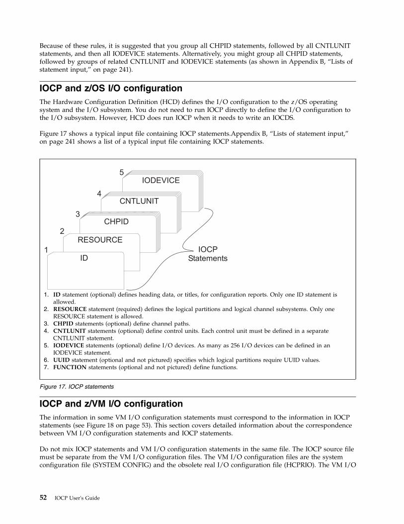
Because of these rules, it is suggested that you group all CHPID statements, followed by all CNTLUNITstatements, and then all IODEVICE statements. Alternatively, you might group all CHPID statements,followed by groups of related CNTLUNIT and IODEVICE statements (as shown in Appendix B, “Lists ofstatement input,” on page 241).
IOCP and z/OS I/O configurationThe Hardware Configuration Definition (HCD) defines the I/O configuration to the z/OS operatingsystem and the I/O subsystem. You do not need to run IOCP directly to define the I/O configuration tothe I/O subsystem. However, HCD does run IOCP when it needs to write an IOCDS.
Figure 17 shows a typical input file containing IOCP statements.Appendix B, “Lists of statement input,”on page 241 shows a list of a typical input file containing IOCP statements.
IOCP and z/VM I/O configurationThe information in some VM I/O configuration statements must correspond to the information in IOCPstatements (see Figure 18 on page 53). This section covers detailed information about the correspondencebetween VM I/O configuration statements and IOCP statements.
Do not mix IOCP statements and VM I/O configuration statements in the same file. The IOCP source filemust be separate from the VM I/O configuration files. The VM I/O configuration files are the systemconfiguration file (SYSTEM CONFIG) and the obsolete real I/O configuration file (HCPRIO). The VM I/O
CHPID
IOCP
StatementsID
1
2
3
4
5
RESOURCE
CNTLUNIT
IODEVICE
1. ID statement (optional) defines heading data, or titles, for configuration reports. Only one ID statement isallowed.
2. RESOURCE statement (required) defines the logical partitions and logical channel subsystems. Only oneRESOURCE statement is allowed.
3. CHPID statements (optional) define channel paths.4. CNTLUNIT statements (optional) define control units. Each control unit must be defined in a separate
CNTLUNIT statement.5. IODEVICE statements (optional) define I/O devices. As many as 256 I/O devices can be defined in an
IODEVICE statement.6. UUID statement (optional and not pictured) specifies which logical partitions require UUID values.7. FUNCTION statements (optional and not pictured) define functions.
Figure 17. IOCP statements
52 IOCP User's Guide
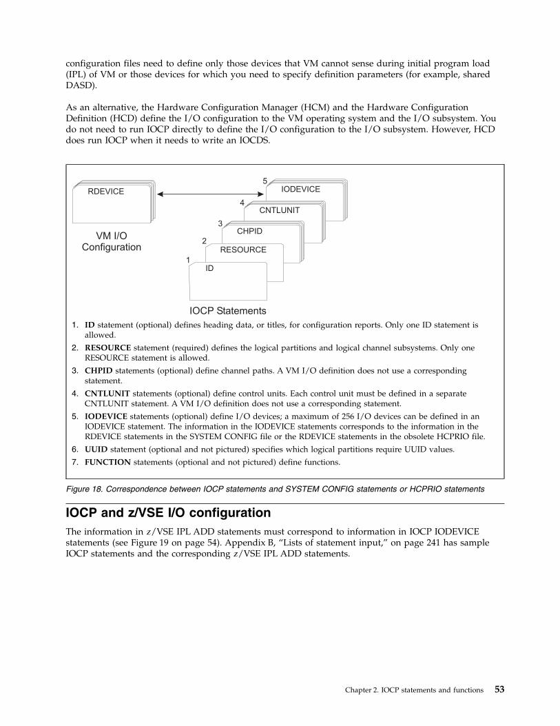
configuration files need to define only those devices that VM cannot sense during initial program load(IPL) of VM or those devices for which you need to specify definition parameters (for example, sharedDASD).
As an alternative, the Hardware Configuration Manager (HCM) and the Hardware ConfigurationDefinition (HCD) define the I/O configuration to the VM operating system and the I/O subsystem. Youdo not need to run IOCP directly to define the I/O configuration to the I/O subsystem. However, HCDdoes run IOCP when it needs to write an IOCDS.
IOCP and z/VSE I/O configurationThe information in z/VSE IPL ADD statements must correspond to information in IOCP IODEVICEstatements (see Figure 19 on page 54). Appendix B, “Lists of statement input,” on page 241 has sampleIOCP statements and the corresponding z/VSE IPL ADD statements.
CHPID
IOCP Statements
VM I/OConfiguration
ID
RDEVICE
1
2
3
4
5
RESOURCE
CNTLUNIT
IODEVICE
1. ID statement (optional) defines heading data, or titles, for configuration reports. Only one ID statement isallowed.
2. RESOURCE statement (required) defines the logical partitions and logical channel subsystems. Only oneRESOURCE statement is allowed.
3. CHPID statements (optional) define channel paths. A VM I/O definition does not use a correspondingstatement.
4. CNTLUNIT statements (optional) define control units. Each control unit must be defined in a separateCNTLUNIT statement. A VM I/O definition does not use a corresponding statement.
5. IODEVICE statements (optional) define I/O devices; a maximum of 256 I/O devices can be defined in anIODEVICE statement. The information in the IODEVICE statements corresponds to the information in theRDEVICE statements in the SYSTEM CONFIG file or the RDEVICE statements in the obsolete HCPRIO file.
6. UUID statement (optional and not pictured) specifies which logical partitions require UUID values.
7. FUNCTION statements (optional and not pictured) define functions.
Figure 18. Correspondence between IOCP statements and SYSTEM CONFIG statements or HCPRIO statements
Chapter 2. IOCP statements and functions 53
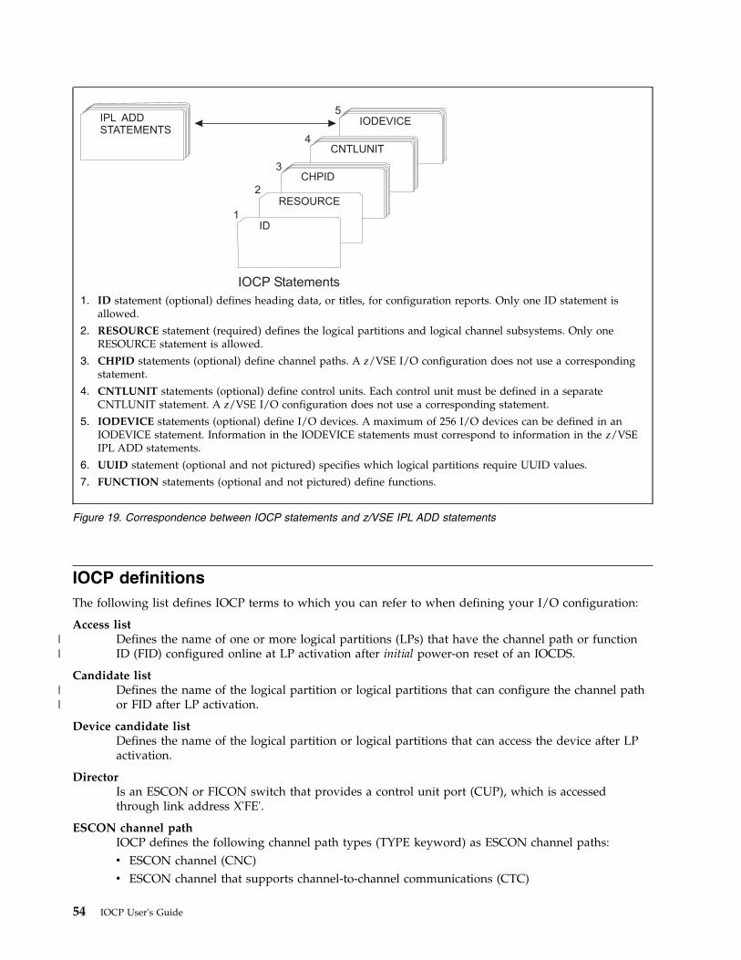
IOCP definitionsThe following list defines IOCP terms to which you can refer to when defining your I/O configuration:
Access listDefines the name of one or more logical partitions (LPs) that have the channel path or functionID (FID) configured online at LP activation after initial power-on reset of an IOCDS.
Candidate listDefines the name of the logical partition or logical partitions that can configure the channel pathor FID after LP activation.
Device candidate listDefines the name of the logical partition or logical partitions that can access the device after LPactivation.
DirectorIs an ESCON or FICON switch that provides a control unit port (CUP), which is accessedthrough link address X'FE'.
ESCON channel pathIOCP defines the following channel path types (TYPE keyword) as ESCON channel paths:v ESCON channel (CNC)v ESCON channel that supports channel-to-channel communications (CTC)
CHPID
IOCP Statements
ID
1
2
3
4
5
RESOURCE
IPL ADD
STATEMENTS
CNTLUNIT
IODEVICE
1. ID statement (optional) defines heading data, or titles, for configuration reports. Only one ID statement isallowed.
2. RESOURCE statement (required) defines the logical partitions and logical channel subsystems. Only oneRESOURCE statement is allowed.
3. CHPID statements (optional) define channel paths. A z/VSE I/O configuration does not use a correspondingstatement.
4. CNTLUNIT statements (optional) define control units. Each control unit must be defined in a separateCNTLUNIT statement. A z/VSE I/O configuration does not use a corresponding statement.
5. IODEVICE statements (optional) define I/O devices. A maximum of 256 I/O devices can be defined in anIODEVICE statement. Information in the IODEVICE statements must correspond to information in the z/VSEIPL ADD statements.
6. UUID statement (optional and not pictured) specifies which logical partitions require UUID values.
7. FUNCTION statements (optional and not pictured) define functions.
Figure 19. Correspondence between IOCP statements and z/VSE IPL ADD statements
54 IOCP User's Guide
||
||
v FICON channel attached to an ESCON Director (FCV).
ESCON control unitA control unit that attaches to CNC, CTC, or FCV channel paths (TYPE keyword). An ESCONcontrol unit can also attach to FC channel paths.
ESCON CTC control unitAn ESCON CTC control unit is one of the following:v A control unit that attaches to only TYPE=CTC channel pathsv A control unit that attaches to only TYPE=CNC or TYPE=FCV channel paths and has
UNIT=SCTC coded.
FICON CTC control unitA FICON CTC control unit is a control unit that attaches to only TYPE=FC channel paths and hasUNIT=FCTC coded.
ESCON deviceA device assigned to CNC, CTC, or FCV channel paths (TYPE keyword).
FICON channel pathA TYPE=FC channel path.
FICON directorA fibre channel switch that has a control unit port (CUP) and supports FC channel paths (TYPEkeyword).
FICON control unitA control unit that attaches to only FC channel paths (TYPE keyword).
FICON deviceA device assigned to only FC channel paths (TYPE keyword).
Parallel channel pathIOCP defines the following channel path types (TYPE keyword) as parallel channel paths:v ESCON channel (CVC) that attaches to a 9034 ESCON Converter Model 1 or similar converter
and operates as a block multiplexer channel.v ESCON channel (CBY) that attaches to a 9034 ESCON Converter Model 1 or similar converter
and operates as a byte multiplexer channel.
Parallel control unitA control unit that attaches to CBY or CVC channel paths (TYPE keyword).
Parallel deviceA device assigned to CBY or CVC channel paths (TYPE keyword).
Spanned channel pathIOCP defines a spanned channel path as a channel path that can be accessed by LPs in more thanone logical channel subsystem (CSS) at the same time. To define a spanned channel path, specifymore than one CSS ID in the CSS parameter of the PATH keyword on the CHPID statement. Aspanned channel path is also a shared channel path.
Shared channel pathIOCP defines a shared channel path as a channel path that can be accessed by more than one LPin the same logical channel subsystem (CSS) at the same time. To define a shared channel path,do one of the following actions:v Specify the SHARED, NOTPART, or IOCLUSTER keyword on the CHPID statementv Specify more than one logical partition in the access list of the PARTITION keyword on the
CHPID statement.v Define the channel path as spanned by specifying more than one CSS ID in the CSS parameter
of the PATH keyword on the CHPID statement.
Chapter 2. IOCP statements and functions 55
Reconfigurable channel pathIOCP defines a reconfigurable channel path as an unshared channel path that can be dynamicallymoved between logical partitions. To define a reconfigurable channel path, specify the RECparameter in the PARTITION keyword on the CHPID statement.
Dedicated channel pathIOCP defines a dedicated channel path as a channel path that can be accessed by only one logicalpartition and cannot be moved between logical partitions. A dedicated channel path is unsharedand non-reconfigurable. To define a dedicated channel path, do not specify SHARED, NOTPART,or REC in the CHPID statement and do one of the following actions:v Specify a single logical partition in the access list of the PARTITION keyword in the CHPID
statementv Specify a null access list and a single logical partition in the candidate list of the PARTITION
keyword in the CHPID statement.
IDID is an optional statement that can specify the following information:v Identification information printed in the heading of IOCP configuration reports on the ID1 and ID2
lines. See Chapter 7, “IOCP configuration reports,” on page 151 for examples of the headings used onthe reports.
v Data set name for each IOCDS that appears on the Input/Output Configuration window of theSupport Element for a CPC
v Set of machine limits and rules to be enforced by IOCP when processing the I/O configurationv Name of the local system.
When specified, the ID statement must precede all RESOURCE, CHPID, CNTLUNIT, IODEVICE, UUID,and FUNCTION statements in the input stream. Also, when specified, it must include at least onekeyword (for example, MSG1, MSG2, or SYSTEM). The ID statement can be specified only once in theinput file. The ID statement parameters can appear in any order but you must code at least oneparameter. If you do not specify the ID statement, no identifying information is printed on the ID1 andID2 lines of the report headings.
See Appendix A, “Coding IOCP statements,” on page 237 for a summary of the rules for codingstatements and the notation used in this document to illustrate statements.
The format of the ID statement is as follows:[symbol] ID {MSG1=’message’}
{MSG2=’message’}{SYSTEM=(processor[,number])}{LSYSTEM=name}{TOK=token}
MSG1=Specifies the identification information that is printed on the ID1 line of the heading on IOCPconfiguration reports. The Support Element also uses the first eight characters of MSG1= (bytes 1-8)as the customer name for the IOCDS that appears on the Input/Output Configuration window of theSupport Element for CPCs.
MSG2=Specifies the identification information that is printed on the ID2 line of the heading on IOCPconfiguration reports.
'message'Specifies a string of 1-64 characters of identification information. IOCP accepts any character in thestring. Any incorrect character is translated to a quotation mark. See the "English (U.S.) I/O InterfaceCode" table for EBCDIC characters in 3270 IDS Character Set Reference for a list of valid printable
56 IOCP User's Guide
characters. You must enclose the string within single quotation marks. Two consecutive singlequotation marks are counted as one character and indicate a single quotation mark within the string(such as, MSG1=’John’’s I/O Report’).
SYSTEM=Specifies the machine limits and rules that IOCP enforces for verification of the IOCP input or whenwriting an IOCDS in preparation of a CPC upgrade. The stand-alone version of IOCP ignores theSYSTEM keyword. It is also ignored when IOCP is writing an IOCDS using keywordCHECKCPC=YES in the PARM parameter of the EXEC statement (z/OS or z/VSE) or CMS optionCHECKCPC. In both cases, IOCP uses the machine limits and rules for the CPC on which IOCP iscurrently running.
When IOCP is writing an IOCDS in preparation of a CPC upgrade (keyword CHECKCPC=NO oroption NOCHKCPC is specified), IOCP uses the machine limits and rules based on the SYSTEMkeyword. IOCP requires the SYSTEM keyword when CHECKCPC=NO or NOCHKCPC is specified.
If the SYSTEM keyword is not specified and ICP IOCP runs on a CPC that it supports, IOCP uses themachine limits for that CPC. If the SYSTEM keyword is not specified and ICP IOCP runs on anunsupported CPC, IOCP uses default machine limits. See Table 16 on page 285 for the defaultSYSTEM value.
See Appendix F, “Machine limits and rules,” on page 285 for a complete list of valid SYSTEMkeyword values and their associated machine limits and rules.
processorSpecifies the machine type number of the target CPC for which the IOCP input is to be verified. Forexample, specify SYSTEM=(2084) if the IOCP input you need verified is for a 2084 CPC.
numberSpecifies the machine limits number associated with the target CPC machine type for which the IOCPinput is to be verified. Specify a single decimal number. The default value is the lowest numbersupported for the specified CPC machine type. For example, the default machine limits number forthe 2084 is one.
LSYSTEM=nameSpecifies the name of the local system. The name is a 1-8 alphanumeric (0-9, A-Z) name. IOCPrequires the LSYSTEM keyword when CIB, CL5, and CS5 channel paths are defined. The CPC usesthe local system name to identify itself when establishing a coupling facility connection using CIBchannel paths. It is helpful to use the same CPC name specified on the Hardware ManagementConsole.
TOK=tokenConfiguration programs use this keyword to pass to the CPC information required to enable thedynamic I/O configuration capability of any resulting IOCDS. This keyword is not intended fordirect IOCP user input. It is mentioned here to inform you that IOCP accepts the keyword and thegenerated value.
Some CPCs have a fixed storage size for the Hardware System Area (HSA). These CPCs require everyIOCDS to have a token. If the TOK keyword is not specified, IOCP generates a token of its own and,even though the Hardware Management Console might indicate dynamic I/O is enabled, nooperating system supports dynamic I/O configuration. See Table 16 on page 285 to determine if yourCPC has fixed HSA.
For HCD: Do not alter an IOCP input file generated by HCD and use it to write an IOCDS. Ifchanges are necessary, use HCD to regenerate the IOCP input.
ID Statement coding exampleThe following statement defines the identification information printed on lines ID1 and ID2 on theheading of IOCP configuration reports. TPCONFIG is your name for the IOCDS that appears on the
Chapter 2. IOCP statements and functions 57
Input/Output Configuration window of the Support Element. You have a 2084 Model A08 CPC and haveselected the appropriate machine limits and rules for your CPC with the SYSTEM keyword.ID00B ID MSG1=’TPCONFIG Configuration for Processor’, X
MSG2=’Revised by Plan 3’, XSYSTEM=(2084,1)
RESOURCERESOURCE is a required statement that defines:v Logical partition namesv Multiple Image Facility (MIF) image ID numbers assigned to the logical partitionsv Logical channel subsystems (CSSs)v The maximum number of devices that can be dynamically defined for a dynamic-capable IOCDSv Reserved logical partitions, for a dynamic-capable IOCDS.
The RESOURCE statement must:v Appear only once in an IOCP input filev Follow the ID statement (if specified)v Precede all CHPID, CNTLUNIT, IODEVICE, UUID, and FUNCTION statementsv Include every logical partition in the configurationv Have either the PART or PARTITION parameter specified.
If the RESOURCE statement is not specified or is in error, IOCP terminates all processing and does notvalidate the remaining IOCP statements.
See Appendix A, “Coding IOCP statements,” on page 237 for a summary of the rules for codingstatements and the notation used in this document to illustrate statements.
The format of the RESOURCE statement is as follows:[symbol] RESOURCE PART|PARTITION=((CSS(cssid),{name|({name|*}
[,MIF image ID])},...),...)[MAXDEV=((CSS(cssid),ss[,ss][,ss]),...)]
PART= PARTITION=
Specifies the logical partitions (LPs) in the configuration. You can use either form.
cssidSpecifies the logical channel subsystem (CSS) ID to define. The CSS ID is a 1-digit number in therange 0-n. See Table 18 on page 287 to determine the maximum CSS ID your CPC supports.
All the logical partitions following a CSS ID parameter are defined in the CSS. You can define asmany CSSs as your CPC supports.
If you are defining only CSS 0, the CSS parameter is optional. Also, if you are defining only a singleCSS, the PART or PARTITION parameter can be enclosed in a single set of parentheses. For example:PART=(CSS(1),LP1)
For a CPC with a fixed HSA storage size, IOCP defines any missing CSS so that every CSS your CPCsupports is defined. See Table 16 on page 285 to determine if your CPC has fixed HSA.
If you are defining the Licensed Machine Code (LMC) partition MCS_1, it must be defined in the lastCSS supported by your CPC. See Table 16 on page 285 to determine if your CPC supports the MCS_1partition.
58 IOCP User's Guide
|||
nameSpecifies the name of the logical partition (LP) to be defined. The LP name is a 1-8 alphanumeric (0-9,A-Z) character name that must have a nonnumeric first character.
The words PHYSICAL, REC, SYSTEM, and PRIMnnnn (where nnnn is a 4-digit decimal number) arereserved and cannot be used as the names of LPs.
Some CPCs support the definition of a special LMC partition named MCS_1 (also known as afirmware partition). The MCS_1 partition can be defined on a stand-alone coupling facility (CF) CPCso dynamic I/O changes can be made to it by using HCD from another CPC. Note that the CPCmust power-on reset with an IOCDS containing the MCS_1 partition before dynamic I/O changes canbe made to the CPC. The CPC using HCD does not require the MCS_1 partition be defined on it.Also, the MCS_1 partition cannot contain any I/O resources (for example, channel paths or functions)and UUID checking cannot be enabled for it. See Table 16 on page 285 to determine if your CPCsupports the MCS_1 partition.
You must specify all LPs in the configuration. You can define up to 15 LPs in a CSS. Each LP name inthe configuration must be unique. See Table 18 on page 287 to determine the maximum number ofLPs your CPC supports. Also see Table 17 on page 286 to determine how many partitions your CPCsupports in the maximum CSS ID for your CPC.
A logical partition specified on the RESOURCE statement can exist without any channel paths andfunctions assigned to it.
For z/OS: For coupling facility logical partitions (LPs), match the LP name specified in the PART orPARTITION keyword of the RESOURCE statement with the NAME keyword of the CF statement inthe policy information defined for the coupling facility resource management (CFRM) policy of thesite.
* Specifies reserving an LP in the specified CSS with the specified MIF image ID. A reserved LP can bespecified only for a dynamic-capable IOCDS (TOK keyword on ID statement). A dynamic-capableIOCDS is built when using HCD on OS/390, z/OS, or VM or when specifying IOCP CMS utilityoption DYN for VM. A dynamic-capable IOCDS is also built for CPCs that have a fixed HSA storagesize. Space in the HSA is allocated for reserved LPs but cannot be used until a dynamic I/Oconfiguration change is made to assign a name and other resources to the LP.
The following rules apply when specifying reserved LPs:v A reserved LP must have a user-specified MIF image ID.v A reserved LP cannot have any channel paths assigned to it.v An IOCDS cannot contain only reserved LPs.v At least one LP must be defined with a name.
For a CPC with fixed HSA, IOCP defines enough reserved LPs to ensure that the maximum numberof LPs that your CPC supports is available in every CSS. See Table 16 on page 285 to determine ifyour CPC has fixed HSA.
MIF image IDSpecifies the MIF (multiple image facility) image ID associated with a logical partition (LP). The MIFimage ID is a 1-digit hexadecimal number in the range 1-F (see note 9 on page 287). You can specifythe MIF image IDs non-consecutively in any order. MIF image IDs must be unique within a CSS butcan be duplicated in different CSSs. If you are defining the LMC partition MCS_1, it must be definedwith MIF image ID B or you may omit the MIF image ID and IOCP defaults to the correct value.
Shared channel paths used for ESCON CTC or FICON CTC communication require a MIF image ID.See the CUADD keyword “CUADD=address” on page 85 for more information.
If you do not specify a MIF image ID for every LP, IOCP arbitrarily assigns MIF image IDs to theunassigned LPs. The MIF image ID is different from the logical partition identifier (ID) displayed onthe General page of the image profile for CPCs.
Chapter 2. IOCP statements and functions 59
||||||||
||
||
For z/OS: For coupling facility logical partitions (LPs), the partition ID specified on the activationprofile for the CF image on the Support Element must match the number specified in the PARTITIONkeyword of the CF statement in the policy information defined for the coupling facility resourcemanagement (CFRM) policy of the site. It is helpful to use that the partition ID specified is aconcatenation of the CSS ID and MIF image ID. The MIF image ID is no longer used for this purpose.
MAXDEV=Specifies the maximum number of devices, including those devices defined in the IOCDS, that can bedynamically added to the configuration. IOCP ignores the MAXDEV keyword for CPCs that have afixed HSA storage size. For a CPC with fixed HSA, the maximum number of devices that aresupported by your CPC are available. See Table 16 on page 285 to determine if your CPC has fixedHSA.
If the MAXDEV keyword is specified, the IOCDS must be dynamic-capable (TOK keyword on IDstatement). A dynamic-capable IOCDS is built when using HCD on OS/390, z/OS, or VM orspecifying IOCP CMS utility option DYN for VM.
If the MAXDEV keyword is not specified for a dynamic-capable IOCDS, IOCP defaults the maximumnumber of devices to the maximum the CPC supports for subchannel set 0 for each defined CSS. Ifyou define devices in subchannel set 1 of any CSS, IOCP sets the default for the maximum number ofdevices for each subchannel set 1 with devices to the maximum the CPC supports. Otherwise,subchannel set 1 has a default value of zero.
If the MAXDEV keyword is specified for a dynamic-capable IOCDS but omits a defined CSS, IOCPsets the default for the maximum number of devices to the maximum the CPC supports forsubchannel set 0 for the CSS. If you define devices in subchannel set 1 of the omitted CSS, IOCP setsthe default for the maximum number of devices for subchannel set 1 to the maximum the CPCsupports. Otherwise, subchannel set 1 has a default value of zero.
cssidSpecifies the logical channel subsystem (CSS) ID associated with this parameter. The CSS ID is a1-digit number in the range of 0-n. See Table 18 on page 287 to determine the maximum CSS ID yourCPC supports.
The CSS ID must have been defined in the PART or PARTITION keyword on the RESOURCEstatement. You can specify as many CSSs as you defined. If only a single CSS was defined, the CSSparameter is optional. Also, if you only specify a single CSS, the MAXDEV parameter can be enclosedin a single set of parentheses. For example:MAXDEV=(CSS(1),60K)
ss Specifies the maximum number of devices, including those devices defined in the IOCDS, that can beused for dynamic I/O configuration in a subchannel set in a CSS. The first ss value defines themaximum number of devices for subchannel set 0 in a CSS. The second ss value defines themaximum number of devices for subchannel set 1 in the same CSS. See Table 18 on page 287 todetermine the number of subchannel sets your CPC supports. All CPCs support subchannel set 0.
To specify a value for subchannel set 1, you must also specify a value for subchannel set 0.
The format of ss is:{number | MIN | MAX}
numberSpecifies the maximum number of devices, including those devices defined in the IOCDS, thatcan be used for dynamic I/O configuration in a subchannel set in a CSS. The number can be a 1-to 5-digit decimal number in the range 0-n. The n is the maximum number of devices your CPCsupports for the subchannel set. The number can also be in the form nnK. The nn is a 1- or2-digit decimal number that is multiplied by 1024 to get the maximum number of devices. (Forexample, 60K and 61440 are equivalent values.) See Table 18 on page 287 to determine themaximum number of devices per subchannel set that your CPC supports. The configurationcannot contain more devices than the MAXDEV value.
60 IOCP User's Guide
MINSpecifies that the maximum device value in the I/O configuration is equal to the number ofdevices defined in the IOCDS for the subchannel set in the CSS. Therefore, no new devices can bedynamically added to the I/O configuration for the subchannel set in the CSS unless otherdevices have been deleted.
MAXSpecifies that the maximum device value in the I/O configuration for the subchannel set in theCSS is equal to the maximum number of devices supported by your CPC for the subchannel set(see Table 18 on page 287).
RESOURCE statement coding examples
Example 1RESOURCE PART=((LP2,2),(LP1,1),(LP3,3))
The preceding statement:v Defines logical channel subsystem (CSS) 0v Defines three logical partitions in CSS 0: LP1, LP2, and LP3v Assigns MIF image ID number 1 to LP1, MIF image ID number 2 to LP2, and MIF image ID number 3
to LP3.
Example 2RESOURCE PART=(CSS(1),(LP1,2),LP2,(LP3,5))
The preceding statement:v Defines CSS 1v Defines three logical partitions in CSS 1: LP1, LP2, and LP3v Assigns MIF image ID number 2 to LP1, MIF image ID number 5 to LP3, and IOCP arbitrarily assigns
a MIF image ID number to LP2.
Example 3RESOURCE PART=((CSS(0),(LP1,1),LP2),(CSS(1),(LPA,1),(*,5),(LPB,F))),
MAXDEV=((CSS(0),40K,12K),(CSS(1),56820))
The preceding statement:v Defines CSSs 0 and 1v Defines two logical partitions in CSS 0: LP1 and LP2v Defines two logical partitions and reserves space for one other logical partition in CSS 1: LPA and LPB
are defined and one logical partition is reserved until a future dynamic I/O change assigns a name tothe logical partition.
v Assigns MIF image ID number 1 to LP1 and LPA, MIF image ID number F to LPB, MIF image IDnumber 5 to the reserved logical partition in CSS 1, and IOCP arbitrarily assigns a MIF image IDnumber to LP2.
v Specifies that the maximum number of devices that can be defined, including dynamic I/O additions,in the configuration for CSS 0 is 40960 for subchannel set 0 and 12288 for subchannel set 1 and for CSS1 is 56820 for subchannel set 0. Assuming that there are no devices defined in subchannel set 1 in CSS1, the maximum number of dynamic I/O additions for subchannel set 1 is zero–that is, no dynamicI/O additions are allowed.
Chapter 2. IOCP statements and functions 61
CHPIDCHPID is an optional statement that defines:v Channel path identifiers (chpids)v Physical channel identifiers (pchids)v Channel path typesv chpid assignment to ESCON and FICON Directorsv Connecting chpids
v Channel path parameterv I/O cluster name owning a chpid
v Adapter identifiers (AIDs), ports, and connecting system namesv Availability of chpids to logical partitionsv Reconfigurability of chpids among logical partitionsv Shared chpids for logical partitionsv Spanned chpids for logical channel subsystemsv Physical network identifier.
When specified, the CHPID statement must:v Follow the ID statement (if specified) and the RESOURCE statementv Precede any CNTLUNIT statements that refer to the chpid it definesv Collectively, specify all chpids to use in the configuration.
Channel paths not specified in a CHPID statement cannot be used.
See Appendix A, “Coding IOCP statements,” on page 237 for a summary of the rules for codingstatements and the notation in this document to illustrate statements.
The format of the CHPID statement is as follows:[symbol] CHPID PATH=(CSS(cssid[,cssid]...),chpid number)
[PCHID=number][VCHID=number]TYPE={CBY | CVC | CNC | CTC | CFP | CFR | CFS |
CBP | CBR | CBS | ICP | CIB | CL5 | CS5 | OSC | OSD |OSE | OSM | OSN | OSX | FC | FCV | FCP | IQD }
[MIXTYPE][SWITCH=number][PART | PARTITION={(CSS(cssid),{name|0}[,REC])|
(CSS(cssid),access list)|(CSS(cssid),(access list)[,(candidate list)][,REC])|((CSS(cssid),(access list)[,(candidate list)]),...)}]
[NOTPART={(CSS(cssid),access list)|((CSS(cssid),(access list)[,(candidate list)]),...)}]
[SHARED][PNETID=([,...]physical network id[,...])[CPATH=(CSS(cssid),chpid number)][CHPARM=value][IOCLUSTER=name][AID=aid number][PORT=number][CSYSTEM=name]
PATH=
62 IOCP User's Guide
cssidSpecifies the logical channel subsystem (CSS) associated with this parameter. A CSS ID is a 1-digitnumber in the range 0-n. See Table 18 on page 287 to determine the maximum CSS ID your CPCsupports.
The CSS IDs must have been defined in the PART or PARTITION keyword on the RESOURCEstatement. You can specify as many CSSs as you defined. If only a single CSS was defined, theCSS parameter is optional.
If you specify multiple CSS IDs for a channel path, IOCP defines the channel path as spanned. Aspanned channel path is available for use by the logical partitions in each specified CSS. Allchannel paths can be spanned except CNC, CTC, CVC, CBY, FCV, CFR, and CBR (TYPEkeyword). See Table 23 on page 294 to determine which channel path types your CPC supportsbeing spanned.
chpid numberSpecifies a 2-digit hexadecimal channel path ID (chpid) number for the channel path for each CSSID specified in the CSS parameter. A chpid cannot be duplicated within a CSS. See Appendix F,“Machine limits and rules,” on page 285 to determine the valid chpid ranges your CPC supports.
PCHID=numberSpecifies the physical channel identification (pchid) number associated with the channel path. Thepchid number is a 1- to 3-digit hexadecimal number in the range 0-n where n is the maximum numberyour CPC supports. See Appendix F, “Machine limits and rules,” on page 285 to determine themaximum pchid number your CPC supports.
The pchid number identifies the physical location (cage, slot, card port) for a channel path in the CPC.The CPC maintains this mapping. This number can change; for example in ESCON port sparing, ifone card port fails, the CPC enables the spare port and assigns the pchid number to the new port.
PCHIDs are generally unique to the card slot, some slots have multiple PCHIDs, some only one. APCHID on a CHPID statement must not match a PCHID on a FUNCTION statement or the reverse.
The PCHID keyword is not allowed for internal channel paths ICP and IQD (TYPE keyword) and forCIB and CS5 channel paths. The PCHID keyword is required for all other channel path types. PCHIDand VCHID keywords are mutually exclusive and only one can be used on a given CHPID statement.
Multiple CL5 channel paths can be specified with the same pchid. You can define a maximum of 8CL5 channel paths with the same pchid.
The keyword is optional when performing a deck verification. It is required when writing an IOCDS.IOCP can validate an IOCP input file without pchids by performing a deck verification (WRTCDS=NOor NOWRTCDS). You can see the PCHIDs available for the I/O configuration of the CPC on thePCHID Report. (See “Using a PCHID report to help plan your I/O configuration” on page 16.) Youcan either use the PCHID Report and assign pchid numbers to channel paths or use the CHPIDMapping Tool. The CHPID Mapping Tool is available from Resource Link at www.ibm.com/servers/resourcelink. The tool can use the IOCP input file and add the appropriate pchid numbers for yourconfiguration to the CHPID statements. IOCP can then use the input file to write an IOCDS.
Note: An IOCP input file that HCD created without pchids must be migrated back into HCD after theCHPID Mapping Tool has added pchid numbers to the file. HCD can then write an IOCDS, or a newIOCP input file can then be created from HCD that stand-alone IOCP can use to write an IOCDS.
VCHID=numberSpecifies the virtual channel identification (vchid) number associated with the channel path. The vchidnumber is a 1- to 3-digit hexadecimal number in the range n-m where n is the minimum number andm is the maximum your CPC supports. See Table 18 on page 287 to determine the minimum andmaximum vchid numbers your CPC supports. If no vchid numbers are listed, then the VCHIDkeyword is not supported on that particular machine.
The vchid number identifies the (virtual) channel path in the CPC. The CPC maintains this mapping.
Chapter 2. IOCP statements and functions 63
The VCHID keyword is allowed only for channel path TYPE=IQD (internal queued directcommunication (HiperSockets)). The VCHID keyword is required for TYPE=IQD channel paths onCPCs that have a minimum and maximum vchid.
TYPE=Specifies the mode of I/O operation for the channel path. See Appendix F, “Machine limits andrules,” on page 285 to determine which channel path types your CPC supports.
CBYSpecifies that the channel path is an ESCON channel that attaches to a 9034 ESCON ConverterModel 1 or similar converter. IOCP defines CBY channel paths as parallel channel paths.
CBY channel paths operate the same as parallel byte multiplexer channel paths. They operate inburst mode or byte-interleave mode, depending on the attached control unit.
Notes:
1. CBY channel paths require ESCON channel hardware.2. If you define an ESCON channel as CBY but do not attach it to an ESCON Converter, the
channel is put into a permanent standby error state at power-on reset (POR). Put the channelin single channel service mode before POR to avoid the channel error. However, the channelis still unusable until it is attached to an ESCON Converter.
CVCSpecifies that the channel path is an ESCON channel that attaches to a 9034 ESCON ConverterModel 1 or similar converter. IOCP defines CVC channel paths as parallel channel paths.
CVC channel paths operate the same as parallel block multiplexer channel paths. They operateonly in burst mode and allow multiplexing between blocks. See Figure 43 on page 261 for CVCchannel path coding examples.
Notes:
1. CVC channel paths require ESCON channel hardware.2. If you define an ESCON channel as CVC but do not attach it to an ESCON Converter, the
channel is put into a permanent standby error state at POR. Put the channel in single channelservice mode before POR to avoid the channel error. However, the channel is still unusableuntil it is attached to an ESCON Converter.
CNCSpecifies that the channel path is an ESCON channel, and that all control units and I/O devicesthat attach to this channel path support the ESCON Architecture protocol. See Appendix E,“Configuration examples,” on page 253 for CNC channel path coding examples.
CTCSpecifies that the channel path is an ESCON channel that permits channel-to-channelcommunications. See Appendix E, “Configuration examples,” on page 253 for CTC channel pathcoding examples.
A CTC channel path communicates with CNC channel paths and, conversely, a CNC channelpath communicates with CTC channel paths. A CTC channel path cannot communicate withanother CTC channel path, nor can a CNC channel path communicate with another CNC channelpath.
Notes:
1. You must specify identical unit addresses in the CNTLUNIT statements for CTC and CNCchannel paths that communicate with each other.
64 IOCP User's Guide
2. You must specify the MIF image ID or logical partition numbers associated with shared CNCand CTC channel paths in the CUADD keyword on the CNTLUNIT statements for the CTCcommunication. See ESCON and FICON Channel-to-Channel Reference, SB10-7034, for moreinformation.
3. When specifying a control unit associated with an unshared CNC and CTC channel path, donot use the CUADD keyword.
CFPSpecifies that the channel path is a coupling facility peer channel. CFP channel paths are definedfor ISC-3 links. Each CFP channel path assigned to a control unit should have seven devicesdefined.
A CFP channel path connects to another CFP channel path.
CFRSpecifies that the channel path is a coupling facility receiver channel. CFR channel paths aredefined for ISC-3 links. You can define a CFR channel path only for a coupling facility logicalpartition to use.
A CFR channel path connects to a CFS channel path. A CFR channel path cannot connect toanother CFR channel path.
CFSSpecifies that the channel path is a coupling facility sender channel. CFS channel paths aredefined for ISC-3 links. Each CFS channel path should have two devices defined.
A CFS channel path connects to a CFR channel path. A CFS channel path cannot connect toanother CFS channel path.
CBPSpecifies that the channel path is an Integrated Cluster Bus coupling facility peer channel. CBPchannel paths are defined for ICB-3 and ICB-4 links. Each CBP channel path assigned to a controlunit should have seven devices defined.
A CBP channel path connects to another CBP channel path. However, an ICB-3 link must connectto another ICB-3 link and an ICB-4 link must connect to another ICB-4 link.
CBRSpecifies that the channel path is an Integrated Cluster Bus coupling facility receiver channel.CBR channel paths are defined for ICB-2 links. You can define a CBR channel path only for acoupling facility logical partition to use.
A CBR channel path connects to a CBS channel path. A CBR channel path cannot connect toanother CBR channel path.
CBSSpecifies that the channel path is an Integrated Cluster Bus coupling facility sender channel. CBSchannel paths are defined for ICB-2 links. Each CBS channel path should have two devicesdefined.
A CBS channel path connects to a CBR channel path. A CBS channel path cannot connect toanother CBS channel path.
ICPSpecifies that the channel path is an Internal Coupling facility peer channel. Each ICP channelpath assigned to a control unit should have seven devices defined.
An ICP channel path connects to another ICP channel path. You must connect every ICP channelpath to another ICP channel path by specifying the CPATH keyword in the CHPID statement.You cannot connect an ICP channel path to itself.
See “Defining internal coupling channels (TYPE=ICP)” on page 29 for recommendations ondefining ICP channel paths.
Chapter 2. IOCP statements and functions 65
CIBSpecifies that the channel path is a coupling over InfiniBand channel. Each CIB channel pathassigned to a control unit should have seven devices defined.
A CIB channel path connects to another CIB channel path. You must connect every CIB channelpath to another CIB channel path by specifying the CPATH and CSYSTEM keywords in theCHPID statement. You cannot connect a CIB channel path to itself. If a CIB channel path isdefined, the LSYSTEM keyword on the ID statement is required.
See “Defining coupling over InfiniBand or PCIe-O (TYPE=CIB, TYPE=CL5, or TYPE CS5)channels” on page 29 for more information about defining CIB channel paths.
CL5
Specifies that the channel path is a Coupling Express LR channel. Each CL5 channel pathassigned to a control unit should have 32 devices defined but IOCP tests for a minimum of eight.
A CL5 channel path connects to another CL5 channel path. You must connect every CL5 channelpath to another CL5 channel path by specifying the CPATH and CSYSTEM keywords in theCHPID statement. You cannot connect a CL5 channel path to itself. If a CL5 channel path isdefined, the LSYSTEM keyword on the ID statement is required
See “Defining coupling over InfiniBand or PCIe-O (TYPE=CIB, TYPE=CL5, or TYPE CS5)channels” on page 29 for more information about defining CL5 channel paths.
CS5Specifies that the channel path is a Coupling Short Reach channel (Integrated Coupling Adapter(ICA SR)). Each CS5 channel path assigned to a control unit should have eight devices defined.
A CS5 channel path connects to another CS5 channel path. You must connect every CS5 channelpath to another CS5 channel path by specifying the CPATH and CSYSTEM keywords in theCHPID statement. You cannot connect a CS5 channel path to itself. If a CS5 channel path isdefined, the LSYSTEM keyword on the ID statement is required.
See “Defining coupling over InfiniBand or PCIe-O (TYPE=CIB, TYPE=CL5, or TYPE CS5)channels” on page 29 for more information about defining CS5 channel paths.
OSCSpecifies that the channel path is an open systems adapter (OSA) channel that operates as anOSA-Express integrated console controller (OSA-ICC). An OSC channel path provides 3270sessions that can serve as the system operator or master console for an operating system so youcan IPL. An OSC channel path can also connect to TPF through 3215 data streams.
OSA-ICC is supported only on OSA-Express, OSA-Express2, and OSA-Express3 1000Base-TEthernet cards. If an OSC channel path is specified on any other type of channel hardware, theI/O subsystem flags the channel path with a definition error and the channel path is unavailableuntil a dynamic I/O change is made or power-on reset is performed with a new IOCDS toresolve the error.
For more OSC channel path configuration information, see Open Systems Adapter-Express IntegratedConsole Controller User's Guide, SA22-7990.
Note: Devices assigned to OSC channel paths must be configured on the Support Element beforeuse.
OSDSpecifies that the channel path is an open systems adapter (OSA) channel supporting the QueuedDirect I/O (QDIO) architecture. An OSD channel path supports IP applications providingconnectivity to Gigabit Ethernet, 10 Gigabit Ethernet, 1000Base-T Ethernet, Fast Ethernet, andToken Ring LANs. All OSA channel hardware supports OSD channel paths.
For more OSD channel path configuration information, see Open Systems Adapter-ExpressCustomer's Guide and Reference, SA22-7935.
66 IOCP User's Guide
OSESpecifies that the channel path is an open systems adapter (OSA) channel that uses non-QDIOarchitectures. An OSE channel path provides connectivity for all LAN protocols supported by thenon-QDIO architecture (1000Base-T Ethernet, Fast Ethernet, and Token Ring LANs). OSE channelpaths are supported on OSA-Express and OSA-Express2 features. All OSA channel hardwareexcept Gigabit Ethernet and 10 Gigabit Ethernet support OSE channel paths.
For more OSE channel path configuration information, see Open Systems Adapter-ExpressCustomer's Guide and Reference, SA22-7935.
OSMSpecifies that the channel path is an open systems adapter (OSA) channel providing the interfacefor the zBX management services. The OSM channel path provides access to the intranodemanagement network (INMN). Only OSA-Express3 or later 1000Base-T Ethernet can support theOSM CHPID type.
For more OSM channel path configuration information, see Open Systems Adapter-ExpressCustomer's Guide and Reference, SA22-7935.
OSNSpecifies that the channel path is an open systems adapter (OSA) channel for network controlprogram (NCP). An OSN channel path supports traffic between an operating system image (forexample, z/OS) and a Communication Controller for Linux (CCL) image. OSN channel paths aresupported on OSA-Express2 and OSA-Express3 features Gigabit Ethernet and 1000Base-TEthernet.
Note: OSA-Express-4S Gigabit Ethernet features do not support the OSN CHPID type.
For more OSN channel path configuration information, see Open Systems Adapter-ExpressCustomer's Guide and Reference, SA22-7935.
OSXSpecifies that the channel path is an open systems adapter (OSA) channel providing the interfacefor software to access data on the zBX blades. The OSX channel path provides access to theintraensemble data network (IEDN). Only OSA-Express3 or later 10 Gigabit Ethernet can supportthe OSX CHPID type.
For more OSX channel path configuration information, see Open Systems Adapter-ExpressCustomer's Guide and Reference, SA22-7935.
FC Specifies that the channel path is a FICON channel and that all control units and I/O devices thatattach to this channel path support the FICON Architecture protocol. All FICON channelhardware supports FC channel paths.
FC channel paths can communicate with each other in channel-to-channel communications. SeeAppendix E, “Configuration examples,” on page 253 for an FC channel-to-channel codingexample.
Notes on defining FICON CTC communication:
1. You must specify a control unit type (UNIT keyword) of FCTC for FC channel paths tocommunicate with each other.
2. You must specify identical unit addresses in the CNTLUNIT statements for FC channel pathsthat communicate with each other.
3. You must specify the CUADD keyword on the CNTLUNIT statements for CTCcommunication when the remote channel path is a shared FC channel path. If the remotechannel path is on a CPC that does not support multiple logical channel subsystems, then thelogical address specified must equal the partition number of the logical partition with whichyou want to communicate. If the remote channel path is on a CPC that does support multiplelogical channel subsystems, then the logical address specified must equal the combination ofthe CSS ID and the MIF image ID of the logical partition with which you want to
Chapter 2. IOCP statements and functions 67
communicate. (For example, specify CUADD=15 for MIF image ID 5 in CSS 1.) For additionalinformation, see the ESCON and FICON Channel-to-Channel Reference, SB10-7034.
4. When specifying an FCTC control unit associated with an unshared FC channel path, do notuse the CUADD keyword.
FCVSpecifies that the channel path is a FICON channel that attaches to an ESCON Director. IOCPdefines FCV channel paths as ESCON channel paths. FCV channel paths operate the same way asESCON channel paths.
Notes:
1. FCV channel paths require FICON Express LX channel hardware. If an FCV channel path isspecified on any other type of channel hardware, including FICON Express2 LX, the I/Osubsystem flags the channel path with a definition error and the channel path is unavailableuntil a dynamic I/O change is made or power-on reset is performed with a new IOCDS toresolve the error.
2. If you define a FICON channel as FCV but do not attach it to an ESCON Director, the channelis put into a permanent error state after POR. Put the channel in single channel service modebefore POR to avoid the channel error. However, the channel is still unusable until it isattached to an ESCON Director.
FCPSpecifies that the channel path is a FICON channel that operates as a Fibre Channel Protocolchannel. All FICON channel hardware supports FCP channel paths. See “Fibre Channel Protocolsupport” on page 36 for more information about FCP channel paths.
IQDSpecifies that the channel path is an internal queued direct communication (HiperSockets)channel. See “Defining IQD channels” on page 36 for recommendations on defining IQD channelpaths.
MIXTYPE=
Specifies that FC and FCP channel path types can be defined on the same FICON adapter. Beginningwith the FICON Express16S+ adapter, the two ports on the adapter must both be defined as either FCor FCP. If you define a mixture of channel path types on the adapter, one channel path will be usablewhile the other channel path will be placed in definition error and be unusable. CPCs that supportthe FICON Express 16S+ adapter may also have prior FICON adapters that do not have thisrestriction against mixing channel path types. On these CPCs, IOCP defaults to preventing the mixingof FC and FCP channel path types on an adapter. So if the CPC has any FICON adapters prior toFICON Express 16S+ for which you want to define FC and FCP channels on the same adapter, theMIXTYPE keyword must be specified for at least one of the CHPID statements to permit the channelpath type mixture. To determine if your CPC requires the MIXTYPE keyword to mix FC and FCPchannel path types for an adapter, see “Machine rules” on page 285.
The MIXTYPE keyword is valid only for FC and FCP channel paths. Also, the MIXTYPE keyword isignored if specified for a CPC that does not require the keyword to allow a channel path typemixture.
IOCP determines that channel paths are on the same adapter when their PCHIDs are in the samemodulo-4 PCHID slot.
SWITCH=numberSpecifies an arbitrary number for the IBM 9032 or 9033 ESCON Director or a FICON Director towhich the channel path is assigned. The number can range from 00-FF for a maximum of 256 for eachIOCDS. A channel path can be assigned to only one number. A FICON Director cannot have the sameswitch number as an ESCON Director.
For an ESCON channel path using multiple ESCON Directors, specify the switch number for thedirector that has dynamic connections for the channel path. For a FICON channel path, always
68 IOCP User's Guide
specify the switch number of the entry switch. The entry switch is the switch to which the FICONchannel actually connects. The switch number for a FICON Director is not the same as the switchaddress which is set up by using switch control panels. Whenever possible, try to use the same valuefor switch numbers and switch addresses to reduce the number of ways a director is known. Formore information about defining FICON Directors, see “Defining FICON switch configurations” onpage 37.
The SWITCH keyword is required as follows:v For channel paths to have dynamic connections through a directorv For FCV channel paths (TYPE keyword)v For managed channel paths (CHPARM keyword with, for example, a value of 01).
The SWITCH keyword is valid only for CBY, CVC, CNC, CTC, FCV, and FC channel paths (TYPEkeyword). For ESCON Directors, the SWITCH keyword is valid for CBY, CVC, CNC, CTC, and FCVchannel paths. However, CBY and CVC channel paths can have only dedicated connections throughan ESCON Director. For FICON Directors, the SWITCH keyword is valid for FC channel paths. SeeAppendix E, “Configuration examples,” on page 253 for SWITCH keyword coding examples.
In either of the following cases, the I/O subsystem flags the channel path with a definition error:v If you specify the SWITCH keyword for an FC channel path (TYPE keyword) that does not attach
to a FICON Directorv If you do not specify the SWITCH keyword for an FC channel path that does attach to a FICON
Director.
The channel path is unavailable until it is attached to or detached from a FICON Director to matchthe configuration definition and it is varied off and on, or until a dynamic I/O change is made orpower-on reset is performed with a new IOCDS to resolve the error.
PART=PARTITION=
Specifies the availability of chpids to logical partitions. All logical partition names and CSS IDs thatyou specify must match the ones specified in the RESOURCE statement.
You must specify the PART, PARTITION, NOTPART, SHARED, or IOCLUSTER keyword in everyCHPID statement or define the channel path as spanned (PATH keyword). You can specify the PARTor PARTITION keyword and the SHARED or NOTPART keywords in the same CHPID statement.However, you cannot specify the PART or PARTITION and NOTPART keywords for the same CSS IDin the same CHPID statement.
Either form of this keyword can be used in a CHPID statement. However, only one form of thiskeyword can be in each statement.
cssidSpecifies the logical channel subsystem (CSS) ID associated with this parameter. The CSS ID is a1-digit number in the range 0-n. See Table 18 on page 287 to determine the maximum CSS IDyour CPC supports.
Each CSS ID must have been specified in the PATH keyword for this channel path. You canspecify as many CSSs as you specified in the PATH keyword. If only a single CSS ID wasspecified in the PATH keyword, the CSS parameter is optional. If the channel path is spannedand more than one CSS was specified in the PATH keyword, the CSS parameter is required.
nameSpecifies the name of a logical partition (LP) that can access the channel path. The LP name is a1-8 alphanumeric (0-9, A-Z) character name that must have a nonnumeric first character and musthave been defined on the RESOURCE statement. You cannot specify a reserved logical partition(*) or the LMC partition MCS_1.
0 Specifies that no LPs can access the channel path following LP activation for the initial POR ofthe IOCDS. The zero indicates a null access list.
Chapter 2. IOCP statements and functions 69
|
If you specify a zero without parentheses, you cannot specify a candidate list and you must doone of the following actions:v Specify the SHARED keyword for a shared channel pathv Specify multiple CSS IDs in the PATH keyword for a spanned channel pathv Specify the REC parameter for a reconfigurable channel path.
access listSpecifies the logical partition (LP) or logical partitions (LPs) in the CSS that have the channelpath configured online at LP activation following initial power-on reset (POR) of an IOCDS.
After the initial POR of an IOCDS, PR/SM LPAR retains which LPs have the channel pathconfigured online at LP activation following subsequent PORs of the IOCDS. In this case, theaccess list used to build an IOCDS might not match the access list PR/SM LPAR retains.
Logical partitions that are not specified in the access list of a shared, spanned, or reconfigurablechannel path can access the channel path after POR through channel reconfiguration commands ifthe LP is specified in the channel candidate list of the path. (See “candidate list.”
The format of the access list is:{name[,name]...|0}
nameSee “name” on page 69.
0 Specifies that no LPs in the CSS accesses the channel path following LP activation for theinitial POR of the IOCDS. The zero indicates a null access list.
The following rules apply when specifying the access list:v If you specify more than one LP name, IOCP defines the channel path as shared. All channel
paths can be shared except CBY, CVC, CFR, and CBR (TYPE keyword).v If you specify a zero for a null access list in a CSS, you cannot specify a logical partition name
for the same CSS.v If you specify either one LP name or a zero (a zero indicates a null access list), the channel
path can be shared, reconfigurable, or dedicated (unshared and non-reconfigurable).v If you specify a zero as the access list (null access list), you must do one of the following
actions:– Specify the SHARED keyword for a shared channel path– Specify multiple CSS IDs in the PATH keyword for a spanned channel path– Specify the REC parameter for a reconfigurable channel path– Specify a candidate list consisting of one LP name for a dedicated channel path.
v An LP name can appear only once in an access list.
candidate listSpecifies the logical partitions (LPs) in the CSS that can access the channel path. LPs that are notspecified in a channel candidate list of the path cannot access the channel path.
If you specify a candidate list, you do not need to repeat the LP names specified in the access list.IOCP automatically includes in the candidate list the LP names specified in the access list.
The format of the candidate list is:{name[,name]...|=}
nameSee “name” on page 69.
= Specifies that the candidate list for the CSS is identical to its access list.
The following rules apply when specifying the candidate list:
70 IOCP User's Guide
v You cannot specify an equal sign (=) for a candidate list of the channel path if the access list iszero (0 indicates a null access list).
v If you do not specify a candidate list for a CSS to which the channel path is assigned and thechannel path is shared, spanned, or reconfigurable, the candidate list defaults to all logicalpartitions defined in each CSS to which the channel path is assigned, excluding reservedlogical partitions (*) and the LMC partition MCS_1.
v If you do not specify a candidate list and the channel path is dedicated, the candidate listdefaults to the logical partition specified in the access list.
v If a dedicated channel path has a zero specified as the access list (null access list), you mustspecify a candidate list of exactly one LP name.
v If the candidate list consists of more than one LP name, the channel path must either beshared, spanned, or reconfigurable.
v An LP name can appear only once in a candidate list.
RECSpecifies that the channel path is reconfigurable. Specifying a channel path as reconfigurableallows it to be dynamically moved between logical partitions (LPs) in a CSS. To move it you usechannel reconfiguration commands after power-on reset (POR) is complete.
The following rules apply when specifying the REC parameter for a channel path:v The channel path must have an access list of one LP name or zero (0 indicates a null access
list).v If a candidate list is specified, it must consist of one or more LP names.v If the candidate list is not specified, it defaults to all LPs defined in the CSS excluding reserved
LPs (*) and the LMC partition MCS_1.v You cannot specify:
– The REC parameter and the SHARED keyword– The REC parameter and an access list of more than one LP– The REC parameter for a spanned channel path– An access list of one LP and a candidate list with an LP other than the one in the access list,
unless you specify either the REC parameter or the SHARED keyword or define the channelpath as spanned.
– A zero as the access list (null access list) and a candidate list of two or more LPs, unless youspecify either the REC parameter or the SHARED keyword or define the channel path asspanned.
– A zero as the access list (null access list) and no candidate list, unless you specify either theREC parameter or the SHARED keyword or define the channel path as spanned.
NOTPART=Specifies the availability of chpids to logical partitions. All logical partition names and CSS IDs thatyou specify must match the ones specified in the RESOURCE statement.
You must specify the NOTPART, PART, PARTITION, SHARED, or IOCLUSTER keyword in everyCHPID statement or define the channel path as spanned (PATH keyword). You can specify theNOTPART keyword and the SHARED, PART, or PARTITION keywords in the same CHPIDstatement. However, you cannot specify the NOTPART and PART or PARTITION keywords for thesame CSS ID in the same CHPID statement.
The NOTPART keyword indicates that the channel path is shared. All channel paths can be sharedexcept CBY, CVC, CFR, and CBR (TYPE keyword).
cssidSpecifies the logical channel subsystem (CSS) ID associated with this parameter. The CSS ID is a1-digit number in the range 0-n. See Table 18 on page 287 to determine the maximum CSS ID
Chapter 2. IOCP statements and functions 71
|
|
your CPC supports. If the channel path is spanned and more than one CSS ID was specified inthe PATH keyword, the CSS parameter is required.
Each CSS ID must have been specified in the PATH keyword for this channel path. You canspecify as many CSSs as you specified in the PATH keyword. If only a single CSS was specifiedin the PATH keyword, the CSS parameter is optional.
access listSpecifies the logical partitions or partitions in a CSS that do not have the channel path configuredonline at LP activation after initial power-on reset (POR) of an IOCDS.
IOCP generates an access list for the channel path consisting of all LPs in the CSS not specified inthe NOTPART access list. For example, if a CSS has three LPs (LP1, LP2, and LP3) and youspecify NOTPART=LP2, IOCP generates an access list containing LP1 and LP3.
After the initial POR of an IOCDS, PR/SM LPAR retains which logical partitions have thechannel path configured online at LP activation after subsequent PORs of the IOCDS. In this case,the access list used to build an IOCDS might not necessarily match the access list PR/SM LPARretains.
Logical partitions that are not specified in the access list of a shared, spanned, or reconfigurablechannel path can access the channel path after POR through channel reconfiguration commands ifthe LP is specified in the candidate list of the channel path. (See “candidate list.”)
The format of the access list is:{name[,name]...|0}
nameSpecifies the name of a logical partition (LP) that cannot access the channel path. The LPname is a 1-8 alphanumeric (0-9, A-Z) character name. It must have a nonnumeric firstcharacter. It must have been defined on the RESOURCE statement. You cannot specify areserved logical partition (*). You can specify the LMC partition MCS_1 but if you do so youmust also specify it in the candidate list so it is excluded from both the access and candidatelists. The MCS_1 partition cannot contain any I/O resources. If you omit specifying theMCS_1 partition in the access list, IOCP automatically excludes it from the access list.
0 Specifies that no LPs in the CSS access the channel path following LP activation for the initialPOR of the IOCDS. A zero indicates a null access list.
The following rules apply when specifying the access list:v If you specify all LP names in a CSS or a zero, no LPs in the CSS access the channel path
following LP activation for the initial POR of the IOCDS. (IOCP generates a null accesslist.)
v If you specify a zero for a null access list in a CSS, you cannot specify a logical partitionname for the same CSS.
v If you specify a NOTPART candidate list, you do not need to repeat in the NOTPARTaccess list the LP names specified in the NOTPART candidate list. IOCP automaticallyexcludes from the generated access list the LP names specified in the NOTPART candidatelist.For example, if a CSS has three LPs (LP1, LP2, and LP3) and you specifyNOTPART=((LP2),(LP3)), IOCP generates an access list containing LP1.
v An LP name can appear only once in an access list.
candidate listSpecifies the logical partitions (LPs) in the CSS that cannot access the channel path.
IOCP generates a candidate list for the channel path consisting of all LPs in the CSS not specifiedin the NOTPART candidate list. For example, if a CSS has three LPs (LP1, LP2, and LP3) and youspecify NOTPART=((LP2),(LP3)), IOCP generates a candidate list containing LP1 and LP2.
LPs that are not in the candidate list IOCP generates cannot access the channel path.
72 IOCP User's Guide
||||
The format of the candidate list is:{name[,name]...|=}
nameSee “name” on page 72.
= Specifies that the candidate list of the channel path is identical to its access list.
The following rules apply when specifying the NOTPART candidate list:v You cannot specify an equal sign (=) for the candidate list of a channel path if the access list is
zero (0 indicates a null access list).v You cannot specify all LP names in a CSS because doing so generates a null candidate list for
the CSS.v If you do not specify a candidate list for a CSS to which the channel path is assigned for the
NOTPART keyword, the candidate list IOCP generates defaults to all LPs defined in the CSS orCSSs, excluding reserved logical partitions (*) and the LMC partition MCS_1.
v An LP name can appear only once in a candidate list.v If you specified the LMC partition MCS_1 in the access list, you must also specify it in the
candidate list so it is excluded from both the access and candidate lists. The MCS_1 partitioncannot contain any I/O resources. If you omit specifying the MCS_1 partition in the access andcandidate lists, IOCP automatically excludes it from the access and candidate lists.
SHAREDSpecifies that the channel path on the CHPID statement is shared. All channel paths can beshared except CBY, CVC, CFR, and CBR (TYPE keyword).
You must specify the SHARED, PART, PARTITION, NOTPART, or IOCLUSTER keyword in everyCHPID statement or define the channel path as spanned (PATH keyword).
A shared channel path can be accessed by more than one logical partition (LP) at the same time.Unshared channel paths can be accessed only by a single LP. Although a reconfigurable channelpath can be dynamically moved between LPs, only a single LP can access it at any given time.
The following rules apply to shared channel paths:v If a channel path has an access list of more than one LP or the NOTPART keyword is specified
for it, the channel path defaults to shared.v A spanned channel path (PATH keyword) defaults to shared.v If you specify SHARED without the PART or NOTPART keywords, the access and candidate
lists default to all LPs defined in the CSSs to which the channel path is assigned, excludingreserved logical partitions (*) and the LMC partition MCS_1.
v You cannot specify:– SHARED for reconfigurable channel paths– An access list of one LP and a candidate list with an LP (other than the LP in the access list
with the PART or PARTITION keyword), without specifying either the REC parameter, theSHARED keyword, or defining the channel path as spanned
– A zero as the access list (null access list) and a candidate list of two or more LPs with thePART or PARTITION keyword, without specifying either the REC parameter, the SHAREDkeyword, or defining the channel path as spanned
– A zero as the access list (null access list) and no candidate list with the PART or PARTITIONkeyword, without specifying either the REC parameter, the SHARED keyword, or definingthe channel path as spanned.
PNETID=(physical-network-id[,...])
Specifies the physical network identifiers (pnetids) associated with the ports on the channeladapter. Each pnetid is a 1-16 alphanumeric (0-9, A-Z) value.
Chapter 2. IOCP statements and functions 73
|
||||
|
The pnetid in the PNETID keyword is a positional parameter. One to four pnetids can be specifiedwhich correspond to the ports on the channel adapter. You can omit one or more pnetids byspecifying just a comma for that adapter port position in the keyword value. For example, to onlyspecify the second pnetid for a channel path to be associated with the second port of the adapter,you would specify PNETID=(,pnetid ).
Physical network IDs are used for channel path types OSD and IQD to establish the affinity to aparticular physical network. When network connections require two interfaces to be coordinated,as with the 10GB RoCE network function adapter and an associated OSD channel path, thepnetids should match. The network adapters that support the OSD channel path type have up tofour ports so four pnetids are supported.
An IQD channel path only uses a pnetid associated with the first port. For IQD channel pathtypes, all PNETID values must be unique.
CPATH=Specifies the ICP, CIB, CL5, or CS5 channel path to which the channel path being defined isconnected.
The CPATH keyword is valid only for ICP, CIB, CL5, and CS5 channel paths (TYPE keyword)and is required for all ICP, CIB, CL5, and CS5 definitions. It specifies the channel path thatconnects to the ICP, CIB, CL5, or CS5 channel path being defined.
For example, PATH=(FE),CPATH=(FF),TYPE=ICP,... specifies that ICP channel path FE is connectedto channel path FF. ICP channel paths are internal channel paths and therefore the connectedchannel paths exist on the same CPC. CIB, CL5, and CS5 channel paths connect to a CIB, CL5, orCS5 channel path, respectively, on the same CPC or a different CPC.
cssidSpecifies the logical channel subsystem (CSS) ID associated with this parameter. The CSS IDis a 1-digit number in the range 0-n. See Table 18 on page 287 to determine the maximumCSS ID the connecting CPC supports.
The CSS IDs must have been defined in the PART or PARTITION keyword on theRESOURCE statement of the CPC with the connecting channel path. For both internal andexternal connections, specify one CSS ID associated with the connecting channel path. If theconnecting channel path is spanned, only one CSS ID is specified in this parameter.
If the channel path being defined is spanned, the CSS parameter is required. If only a singleCSS ID was specified in the PATH keyword and the connecting channel path has the sameCSS ID, the CSS parameter is optional.
chpid numberSpecifies a 2-digit hexadecimal number for the connecting chpid number.
The CPATH keyword has extra syntax rules when the connected channel paths belong to thesame CPC (that is, they are internal connections). All ICP connections are internal. CIB, CL5,and CS5 connections are internal when the CSYSTEM keyword value matches the LSYSTEMkeyword value on the ID statement for the CPC. The following syntax rules apply whenspecifying the CPATH keyword for internal connections:v The channel path specified in the CPATH keyword does not need to be defined before its
use in CPATH but must be defined somewhere in the configuration.v Channel paths cannot connect to each other if they both have candidate lists with the same,
single logical partition. This restriction prevents the definition of ICP and internallyconnected CIB, CL5, or CS5 channels in a configuration with only one logical partition.
v An ICP, CIB, CL5, CS5 channel path must connect to another channel path of the sametype and can connect to only one path.
v A channel path cannot connect to itself.
74 IOCP User's Guide
v Connecting two CIB or CS5 channel paths that have the same AID and port is notsupported. Also, connecting two CL5 channel paths that have the same PCHID and port isnot supported. IOCP does not allow these types of configuration.
CHPARM=valueSpecifies a parameter for the channel path that indicates how the channel is to operate. The value is a2-digit hexadecimal number.
The CHPARM keyword identifies a channel path to be managed by dynamic CHPID management.When bit 7 of the CHPARM value is on (for example, X'01'), the channel path is managed. OnlyCNC, FCV, and FC channel paths (TYPE keyword) can be managed. A managed channel path cannotbe spanned (PATH keyword). Managed paths require that the IOCDS to be dynamic-capable (TOKkeyword). A dynamic-capable IOCDS is built when using HCD on OS/390, z/OS, or VM orspecifying IOCP CMS utility option DYN for VM.
The CHPARM keyword also specifies whether an OSD or OSX channel path is to disable priorityspecification. When bit 6 of the CHPARM keyword value is on (for example, X'02'), the OSD or OSXchannel path has priority specification disabled and the channel supports a maximum of 1920 OSAvalid subchannels (640 TCP/IP stacks). Otherwise, the OSD or OSX channel path has priorityspecification enabled, and the channel supports a maximum of 480 OSA valid subchannels (160TCP/IP stacks). OSM channel paths default to disabled priority queuing, and that is the only modesupported for OSM CHPIDs.
Disabling priority specification is supported only for OSA-Express2 or laterfeatures. If it is disabledfor an OSA-Express feature, the I/O subsystem flags the channel path with a definition error. Thechannel path is unavailable until a dynamic I/O change is made or a power-on reset is performedwith a new IOCDS to resolve the error. For additional information, see “I/O configurationconsiderations” on page 20.
The CHPARM keyword also specifies the TCP/IP maximum transmission unit (MTU) and the IQDIOframe size to use for I/O requests on IQD channel paths (TYPE keyword). Bits 0 and 1 of theCHPARM keyword value are used and support the following values for IQD channel paths:v 00 for 8 K MTU and 16 K frame sizev 40 for 16 K MTU and 24 K frame sizev 80 for 32 K MTU and 40 K frame sizev C0 for 56 K MTU and 64 K frame size.
On 2817 and 2818 with enabling MCL applied or 2828, 2827, or later processors, the followingCHPARM values are provided for HiperSocket IQD channel paths (TYPE keyword):v 0x for 8 KB MTU and 16 KB frame sizev 4x for 16 KB MTU and 24 KB frame sizev 8x for 32 KB MTU and 40 KB frame sizev Cx for 56 KB MTU and 64 KB frame sizev x0 for a normal HiperSocket channel pathv x2 for a HiperSocket for IEDN channel path. You can specify a CHPARM value of x2 for only one
IQD channel path.v x4 for a HiperSocket capable to be externally bridged channel path
The CHPARM keyword also specifies whether an OSC channel path is to connect to TPF through3215 data streams. When the required RPQ is installed on your CPC and bit 1 of the CHPARM valueis on (for example, X'40'), the channel path can connect to TPF using 3215 data streams. Otherwise,the OSC channel path supports TN3270E emulator sessions. Any undefined value is incorrect for allchannel path types.
The following table summarizes the supported CHPARM values:
Chapter 2. IOCP statements and functions 75
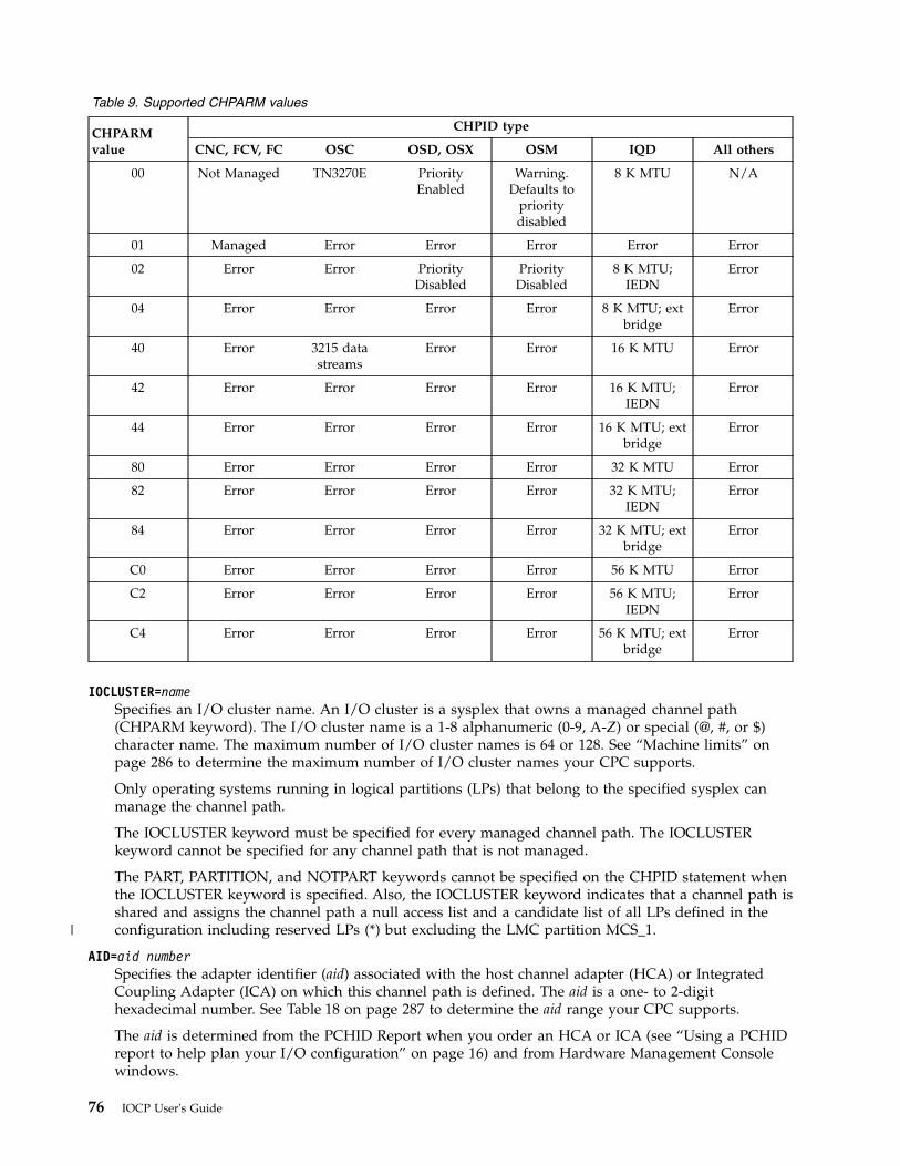
Table 9. Supported CHPARM values
CHPARMvalue
CHPID type
CNC, FCV, FC OSC OSD, OSX OSM IQD All others
00 Not Managed TN3270E PriorityEnabled
Warning.Defaults to
prioritydisabled
8 K MTU N/A
01 Managed Error Error Error Error Error
02 Error Error PriorityDisabled
PriorityDisabled
8 K MTU;IEDN
Error
04 Error Error Error Error 8 K MTU; extbridge
Error
40 Error 3215 datastreams
Error Error 16 K MTU Error
42 Error Error Error Error 16 K MTU;IEDN
Error
44 Error Error Error Error 16 K MTU; extbridge
Error
80 Error Error Error Error 32 K MTU Error
82 Error Error Error Error 32 K MTU;IEDN
Error
84 Error Error Error Error 32 K MTU; extbridge
Error
C0 Error Error Error Error 56 K MTU Error
C2 Error Error Error Error 56 K MTU;IEDN
Error
C4 Error Error Error Error 56 K MTU; extbridge
Error
IOCLUSTER=nameSpecifies an I/O cluster name. An I/O cluster is a sysplex that owns a managed channel path(CHPARM keyword). The I/O cluster name is a 1-8 alphanumeric (0-9, A-Z) or special (@, #, or $)character name. The maximum number of I/O cluster names is 64 or 128. See “Machine limits” onpage 286 to determine the maximum number of I/O cluster names your CPC supports.
Only operating systems running in logical partitions (LPs) that belong to the specified sysplex canmanage the channel path.
The IOCLUSTER keyword must be specified for every managed channel path. The IOCLUSTERkeyword cannot be specified for any channel path that is not managed.
The PART, PARTITION, and NOTPART keywords cannot be specified on the CHPID statement whenthe IOCLUSTER keyword is specified. Also, the IOCLUSTER keyword indicates that a channel path isshared and assigns the channel path a null access list and a candidate list of all LPs defined in theconfiguration including reserved LPs (*) but excluding the LMC partition MCS_1.
AID=aid numberSpecifies the adapter identifier (aid) associated with the host channel adapter (HCA) or IntegratedCoupling Adapter (ICA) on which this channel path is defined. The aid is a one- to 2-digithexadecimal number. See Table 18 on page 287 to determine the aid range your CPC supports.
The aid is determined from the PCHID Report when you order an HCA or ICA (see “Using a PCHIDreport to help plan your I/O configuration” on page 16) and from Hardware Management Consolewindows.
76 IOCP User's Guide
|
The AID keyword is valid only for CIB and CS5 channel paths (TYPE keyword) and is required forall CIB and CS5 definitions. Multiple CIB or CS5 channel paths can be specified with the same aid.You can define a maximum of 16 CIB channel paths or 8 CS5 channel paths with the same aid.
PORT=numberSpecifies the port on the host channel adapter (HCA), Coupling Express (CE LR) adapter, orIntegrated Coupling Adapter (ICA) to which this channel path is defined. The port number is a1-digit decimal number in the range 1-n where n is the maximum number of HCA, CE LR, or ICAports your CPC supports. See Table 17 on page 286 and Table 18 on page 287 to determine themaximum port numbers your CPC supports.
The PORT keyword is valid only for CIB, CL5, and CS5 channel paths (TYPE keyword) and isrequired for all CIB, CL5, and CS5 definitions. Multiple CIB and CS5 channel paths can be specifiedfor the same port on an AID. Multiple CL5 channel paths can be specified for the same port on aPCHID.
CSYSTEM=nameSpecifies the name of the system that connects to this channel path. The name is a 1-8 alphanumeric(0-9, A-Z) name.
For a coupling facility connection to be established, the specified CSYSTEM keyword value mustmatch the LSYSTEM keyword value for the CPC with the target CIB, CL5, and CS5 channel path.
The CSYSTEM keyword is valid only for CIB, CL5, and CS5 channel paths (TYPE keyword) and isrequired for all CIB definitions. The CSYSTEM keyword is optional for CL5 and CS5 definitions.
You cannot connect two CIB, CL5, or CS5 channel paths to the same destination channel path. Thatis, you cannot specify the same CSYSTEM and CPATH keyword values for two CIB, CL5, or CS5channel paths.
CHPID statement coding examples
Example 1CHPID PATH=17,PCHID=100,TYPE=CNC,PARTITION=((LP2),(LP1,LP4),REC),SWITCH=3E
The preceding statement:v Defines channel path 17 in the only CSS in the configuration for the card port associated with physical
channel ID 100v Specifies that the channel path operates as an ESCON channelv Specifies that logical partition LP2 initially accesses the channel path and that LP1 and LP4 are also
authorized to access the channel pathv Defines the chpid as reconfigurablev Defines the chpid the switch number 3E.
Example 2CHPID PATH=28,PCHID=100,TYPE=CNC,PART=((LP1,LP3),(LP2))
The preceding statement:v Defines channel path 28 in the only CSS in the configuration for the card port associated with physical
channel ID 100v Specifies that the channel operates as an ESCON channel pathv Implicitly defines the channel path as sharedv Specifies that logical partitions LP1 and LP3 initially access the channel path and that LP2 is also
authorized to access the channel path.
Chapter 2. IOCP statements and functions 77
Example 3CHPID PATH=28,PCHID=100,TYPE=CNC,NOTPART=((LP1,LP3),(LP2))
The preceding statement:v Defines channel path 28 in the only CSS in the configuration for the card port associated with physical
channel ID 100v Specifies that the channel operates as an ESCON channel pathv Implicitly defines the channel path as sharedv Specifies that all logical partitions in the configuration except LP1, LP2, and LP3 initially access the
channel path and that all logical partitions in the configuration except LP2 are also authorized to accessthe channel path.
Example 4CHPID PATH=35,PCHID=100,TYPE=CNC,PART=((0),(LP2,LP3)),SHARED
The preceding statement:v Defines channel path 35 in the only CSS in the configuration for the card port associated with physical
channel ID 100v Specifies that the channel path operates as an ESCON channelv Defines the channel path as sharedv Specifies that no logical partition initially accesses the channel path and that LP2 and LP3 are
authorized to access the channel path.
Example 5CHPID PATH=(CSS(1),35),PCHID=100,TYPE=FC,PART=(LP1,LP2)
The preceding statement:v Defines channel path 35 in CSS 1 for the card port associated with physical channel ID 100v Specifies that the channel path operates as a FICON channelv Implicitly defines the channel path as sharedv Specifies that logical partitions LP1 and LP2 in CSS 1 initially access the channel path. Any other
logical partitions in CSS1 in the configuration are also authorized to access the channel path.
Example 6CHPID PATH=(CSS(0,1),FF),TYPE=IQD,PART=((CSS(0),(LP1,LP2),(=)),(CSS(1),
(LPA),(=)))
The preceding statement:v Defines channel path FF in CSSs 0 and 1v Specifies that the channel path is a HiperSockets channelv Defines the channel path as spanned and implicitly as sharedv Specifies that only logical partitions LP1 and LP2 in CSS 0 and logical partition LPA in CSS 1 can
access the channel path.
Note: See Appendix E, “Configuration examples,” on page 253 for more CHPID statement codingexamples.
Example 7CHPID PATH=(CSS(0),80),TYPE=FC,SHARED,PCHID=1A0CHPID PATH=(CSS(2),86),TYPE=FCP,SHARED,PCHID=1A1,MIXTYPE
78 IOCP User's Guide
The preceding statements:v Defines channel path 80 in CSS 0 for PCHID 1A0v Defines channel path 86 in CSS 2 for PCHID 1A1v Specifies that the mixture of CHPID types is allowed on this CPC for these two channel paths. The
MIXTYPE keyword could be specified on either or both of the CHPID statements. If the CPC does notrequire the MIXTYPE keyword when mixing FC and FCP channel path types on an adapter, theMIXTYPE keyword is ignored and a warning message results. If the FICON adapter does not supportthe mixing of CHPID types, one of the channel paths will be in definition error and unusable.
CNTLUNITCNTLUNIT is an optional statement that describes the following:v The characteristics of the control unitv The channel paths to which the control unit is attachedv The unit addresses the control unit recognizes.
Each physical control unit in the I/O configuration must be specified in a separate CNTLUNIT statementto be used. This requirement includes control units that reside in the same physical unit as an I/O deviceor in another control unit.
You are recommended to define only one CNTLUNIT statement for each physical control unit, controlunit image (defined with CUADD values), or control-unit function in your configuration. However, thereare configurations that require you to use multiple CNTLUNIT statements:v Some storage controls (for example, the IBM 3990) contain multiple control-unit functions with the
number varying based on the mode of the storage control (for example, DLS or DLSE in the 3990model 3). You are recommended to code a CNTLUNIT statement for each control-unit function (storagedirector) provided in the storage control.
v You might require multiple logical partitions (LPs) to access a single control unit, perhaps withmultiple paths per LP. In this case, try to use shared channel paths to a single control unit definition.However, if doing so is not possible (for example, if the configuration calls for more than eight paths toa parallel control unit), you can use multiple CNTLUNIT statements to define the single control unitfunction. In this case, ensure that each LP does not have paths defined to more than one CNTLUNITdefinition.
v If your control unit supports both ESCON and parallel interfaces, you might want to use both types ofinterfaces to the same LP. You are recommended to avoid this type of configuration, but if you requirethe mixing of interfaces, you must consider the following rules:– You must choose between all-parallel or all-ESCON interfaces to any one LP at any one time. You
can use one CNTLUNIT statement to define a control-unit image for the parallel paths and anotherCNTLUNIT statement to define a control-unit image for the ESCON paths. Each CNTLUNIT mustbe accompanied with unique IODEVICE statements.
– When using the ESCON paths to the control unit, you must:- Vary offline all devices (that is, device numbers) defined to the parallel control-unit image.- Disable the parallel interfaces at the physical control unit.
– When using the parallel paths, vary offline all devices (that is, device numbers) defined to theESCON control-unit image by doing one of the following tasks:- If you have an ESCON Director, use the ESCON Manager (or the ESCON Director console) to
prohibit the connection between the control unit and the system- If your ESCON connections are point-to-point, configure the chpids offline using the operating
system, ESCON Manager or the CPC console.– When you are running VM with guest operating systems, you can use multiple CNTLUNIT
statements for a single physical control unit in certain environments to effectively dedicate the samephysical devices to more than one guest. This technique involves potential path-grouping
Chapter 2. IOCP statements and functions 79
considerations that create operational complications. Ensure you have determined possibleconsequences and that you use caution if employing this technique.
See Appendix F, “Machine limits and rules,” on page 285 for a list of machine limits and rules for yourCPC. See Appendix D, “List of I/O devices and control units,” on page 245 for a list of some control unittypes and their characteristics.
Based on information in the CNTLUNIT statements, IOCP constructs control unit headers for a logicalchannel subsystem (CSS) to use. A control unit header is a logical representation of one to eight physicalcontrol units. A control unit header is built for each one of the following units:v Physical control unit with no I/O devices attached.v Physical control unit that does not share any I/O devices with other physical control units.v Groups of two or more control units that share devices between them.
A CSS uses the control unit headers for queuing I/O requests for the devices attached to the associatedphysical control units. One I/O request queue exists for each control unit header. A CSS adds to the sameI/O request queue all I/O requests for all devices in the control unit header. (Devices in the control unitheader are all the devices attached to the set of physical control units that are in the control unit header.)
IOCP also establishes a rotation order for the channel paths associated with each control unit header.When initiating I/O requests associated with the control unit header, a CSS uses this rotation order todetermine the sequence for selecting channel paths. See “Rotation order” on page 43 for a description ofhow IOCP establishes the rotation order of the channel paths.
The CNTLUNIT statement must follow any CHPID statements that specify channel paths the control unituses. The CNTLUNIT statement must precede any IODEVICE statements that refer to the control unit.
See Appendix A, “Coding IOCP statements,” on page 237 for a summary of the rules for codingstatements and the notation used in this document to illustrate statements.
The format of the CNTLUNIT statement is as follows:[symbol] CNTLUNIT CUNUMBR=number
PATH=((CSS(cssid),chpid[,chpid]...),...)[LINK=((CSS(cssid),link address
[,link address]...),...)][CUADD=address][PROTOCL={D|S|S4}]SHARED={Y|N}UNIT=typeUNITADD=((address[,number]),...)
CUNUMBR=numberSpecifies the hexadecimal number that is assigned to the control unit. One to four hexadecimal digitsin the range of 0000-FFFE can be specified. You must assign a unique number to each control unit.The numbers can be assigned arbitrarily.
PATH=
cssidSpecifies the logical channel subsystem (CSS) IDs associated with this parameter. A CSS ID is a1-digit number in the range 0-n. See Table 18 on page 287 to determine the maximum CSS IDyour CPC supports.
The CSS IDs must have been defined in the PART or PARTITION keyword on the RESOURCEstatement. You can specify as many CSSs as you defined. If only a single CSS was defined, theCSS parameter is optional.
80 IOCP User's Guide
chpidSpecifies the channel paths in each CSS that are attached to the control unit. You must specifytwo hexadecimal digits for each channel path identifier (chpid) or two asterisks (**). You cannotduplicate chpid numbers within a CSS.
You can specify a maximum of eight chpids in a CSS. However, you can specify only one channelpath in a CSS for:v An ESCON CTC control unitv A FICON CTC control unitv A control unit defined for FCP, IQD, OSC, OSD, OSE, OSM, OSN, or OSX channel paths (TYPE
keyword).
You can specify a maximum of seven pairs of asterisks in a CSS. Each pair of asterisks specifiesthat a managed path (CHPARM keyword) can be added to the control unit and identifies thecontrol unit as being managed by dynamic CHPID management. The number of pairs of asterisksspecifies the number of managed paths that can be added to the control unit. The followingrestrictions apply to a managed control unit:v At least one chpid number must be specified in each CSSv You can specify a maximum of eight chpids and pairs of asterisks in a CSSv Only CNC, FCV, and FC channel paths (TYPE keyword) can be attached to the control unitv The channel paths attached to the control unit must be shared or spanned.
A spanned channel path is not required to attach to a control unit from each CSS to which thechannel path is assigned. The channel paths attaching to the control unit must be all unshared orall shared. You cannot mix shared and unshared channel paths to a control unit. All spannedchannel paths are also shared channel paths.
You can assign a CNC, CTC, or FC channel path (TYPE keyword) to only one control unit unlessone of the following statements is true:v The channel path is assigned to an ESCON or FICON Director (SWITCH keyword)v The control unit has a logical address (CUADD keyword).
You can assign a CFS, CFP, CBS, CBP, ICP, CIB, CL5, and CS5 channel path (TYPE keyword) toonly one control unit. You cannot assign a CFR or CBR channel path (TYPE keyword) to a controlunit. CFR and CBR channel paths do not require control units or devices. You can assign an OSC,OSE, OSN, or FCP channel path (TYPE keyword) to only one control unit.
You can assign an IQD, OSD, OSM, or OSX channel path (TYPE keyword) to only one controlunit unless the control unit has a logical address (CUADD keyword). If you need to define morethan 256 devices for an IQD channel path or 254 devices for an OSD, OSM, or OSX channel path,define multiple control units. Specify a unique logical address for each control unit using theCUADD keyword.
All channel path types (TYPE keyword) attaching to a control unit must meet the followingrestrictions:v All CBY or CVCv All CNC, FCV, or FCv CTCv All CFS or CBSv All CFP, CBP, ICP, CIB, CL5, or CS5v OSCv OSDv OSEv OSMv OSN
Chapter 2. IOCP statements and functions 81
v OSXv FCPv IQD
You can intermix FC channel paths with CNC and FCV channel paths. To ease migrating fromESCON channels to FICON channels using dynamic I/O configuration, mix FC channel pathswith CNC and FCV channel paths. The mixture allows you to dynamically add FC channel pathsto a control unit while keeping its devices operational. A second dynamic I/O configurationchange can then remove the CNC and FCV channels while keeping the devices operational.
For some types of control units and devices, there might be small operational performancedifferences when intermixing (for example, Resource Measurement Facility™ (RMF™) usagecalculations and channel path reconnection). Dynamic CHPID management cannot manage acontrol unit that contains intermixing. For these control units and devices, mixing of FC channelpaths with CNC and FCV channel paths should be temporary. Non-dynamic I/O users arerecommended to avoid mixing these channel paths.
When mixing ICP, CIB, CL5, and CS5 channel paths in the same control unit, the CSYSTEMkeyword value on the CIB, CL5, and CS5 (if specified) channel paths must be identical to thelocal system name of the CPC (LSYSTEM keyword). When mixing CIB, CL5, and CS5 channelpaths in the same control unit, any CSYSTEM keyword values that are specified for the channelpaths must be identical. If a CS5 or CL5 channel path did not specify a CSYSTEM keyword value,it is ignored.
Other types of control units and devices fully support this intermixing. To determine the level towhich your control units and devices support intermixing, see their device planning manuals. Forcontrol units that support intermixing, consult their performance white papers for guidance onhow to best configure channels from a performance perspective. To improve the balance ofworkload across channels in an intermixed environment, alternate ESCON (CNC and FCV) andFICON (FC) channel paths in the control unit header for this control unit. Use the followingpatterns:v For 6 ESCON and 2 FICON, use a sequence of E, E, E, F, E, E, E, Fv For 4 ESCON and 4 FICON, use a sequence of E, F, E, F, E, F, E, Fv For 2 ESCON and 6 FICON, use a sequence of E, F, F, F, E, F, F, F.
LINK=
cssidSpecifies the logical channel subsystem (CSS) IDs associated with this parameter. A CSS ID is a1-digit number in the range 0-n. See Table 18 on page 287 to determine the maximum CSS IDyour CPC supports.
Each CSS ID must have been specified in the PATH keyword for this control unit. You can specifyas many CSSs as you specified in the PATH keyword. If only a single CSS was specified in thePATH keyword, the CSS parameter is optional.
link addressSpecifies the link addresses to which the control unit is attached. The order in which the linkaddresses are specified for each CSS corresponds to the order in which the channel paths arespecified in the CSS parameters of the PATH keyword. For example, the second link addressidentified for CSS 1 in the LINK keyword corresponds to the second channel path identified forCSS 1 in the PATH keyword.
The LINK keyword is optional if none of the channel paths in the PATH keyword attach to anESCON or FICON Director (SWITCH keyword). You do not need to specify link addresses for aCSS if none of the channel paths specified for the same CSS ID in the PATH keyword attaches toan ESCON or FICON Director. You can specify two or four asterisks for link addresses thatcorrespond to channel paths not attached to a director. For ESCON channel paths not attached toa director, specify any valid link address values. FC channel paths not attaching to a director can
82 IOCP User's Guide
specify only link addresses of asterisks. A link address of asterisks must be specified for eachchannel path in the PATH keyword that is specified as two asterisks (**). This pairing of asterisksin the PATH and LINK keywords of the CNTLUNIT statement indicates the number of managedpaths (CHPARM keyword) that can be added to the control unit.
You must specify link addresses with two or four hexadecimal digits. The valid link addressrange is 01-FE for CBY, CVC, CNC, CTC, and FCV channel paths (TYPE keyword). The valid linkaddress range is 0000-FFFF for an FC channel path. To determine whether to specify a 2- or4-digit link address for an FC channel path and how to select a 4-digit link address, see “DefiningFICON switch configurations” on page 37. When you specify a 4-digit link address for an FCchannel path, every link address for that channel path must also be four digits. If you specify theLINK keyword for a CSS, you must specify either a valid link address or asterisks for everychannel path in the same CSS in the PATH keyword. If you do not specify the LINK keyword orspecify asterisks, IOCP assumes that the link address is arbitrary and assigns a link address of0D. Link addresses specified in the LINK keyword for dynamic connections through a directormust equal the link addresses associated with the physical ports on the director to which thecontrol unit is attached. However, link addresses specified for channel paths having dedicatedconnections through an ESCON Director can be arbitrary.
For channel paths having dedicated connections through an ESCON Director, specify thecorresponding link address on the CNTLUNIT statement as the link address associated with thephysical port on the ESCON Director to which the control unit is attached. If a CTC channel pathdoes not attach to an ESCON Director or has a dedicated connection through an ESCON Director,the link address specified here might not be the link address the CSS uses.
For maximum availability of a control unit and its devices, see Appendix D, “List of I/O devicesand control units,” on page 245 for recommendations for selecting the physical ports on anESCON Director to attach to the control unit.
The LINK keyword is valid only for CBY, CVC, CNC, CTC, FCV, and FC channel paths (TYPEkeyword).
Even though you can specify multiple link addresses for CBY and CVC channel paths (TYPEkeyword), the I/O subsystem does not support dynamic connections through an ESCON Directorfor CBY or CVC channel paths. A CBY or CVC channel path that attaches to an ESCON Directorcan have only a dedicated connection through it. Therefore, you can connect only one linkaddress on an ESCON Director to a CBY or CVC channel path at a time.
Note: If you specify no link address for a channel path that does not attach to a director, IOCPselects a link address of 0D to address the control units on the channel path. This arbitrary linkaddress is displayed by the I/O Problem Determination (IOPD) frame and the IOCDS Displayframe on the Support Element. However, the IOCP reports show that no link address wasspecified on its CNTLUNIT statements.
The I/O subsystem flags a channel path with a definition error in the following situations:v The channel path does not attach to an ESCON or FICON Director or has a dedicated
connection through an ESCON Director and has more than one link address specified on itsCNTLUNIT statements.
v The channel path has a dynamic connection through a director and no link address wasspecified on the CNTLUNIT statement.
v The channel path has 4-digit link addresses but is not connected to a high integrity fabric ofFICON switches. For more information about high integrity fabrics, see “Defining FICONswitch configurations” on page 37.
In these three instances, the channel path is unavailable and remains so until the error isresolved.
In addition to the preceding syntax rules, the following configuration rules also apply whenspecifying link addresses. For link addresses with four digits, rules are enforced against the
Chapter 2. IOCP statements and functions 83
switch to which the channel path is connected (that is, the entry switch) rather than the switch towhich the control unit is attached. When a 4-digit link address is specified for a channel path,specify four-digit link addresses for all paths that have the same entry switch. Otherwise, IOCPcannot enforce some of the following switch configuration rules.v Specifying more than one link address for an ESCON channel path is not allowed unless the
channel path is connected to an ESCON Director. Specifying any link address other thanasterisks for an FC channel path is not allowed unless the channel path is connected to aFICON Director.
v All channel path types (TYPE keyword) assigned to a link address on an ESCON Director mustbe identical, with the following exceptions:– CBY or CVC channel paths– CNC or FCV channel paths.
These channel paths are the only ones you can assign to the same link address on an ESCONDirector.
v Specification of any given path (pchid.link) on more than one control unit is not allowed unlessone of the following statements is true:– The control units attach to CBY or CVC channel paths (TYPE keyword).– The control units have unique logical addresses (CUADD keyword). See “Example 6” on
page 90 for CNTLUNIT definition considerations.v The specification of FICON CTC and non-FICON CTC control units (see “IOCP definitions” on
page 54) to the same link address on the same director is not allowed. The control units musteither all specify UNIT=FCTC or none of them can specify FCTC.
v The specification of multiple control units to the same link address on the same director is notallowed unless one of the following conditions is true:– The control units attach to CBY or CVC channel paths (TYPE keyword).– The control units are ESCON CTC or FICON CTC control units. (See “IOCP definitions” on
page 54.) The path (pchid.link.cuadd) attaching to each control unit is unique. That is, thepchid, link address, or logical address (CUADD keyword) for the control unit must bedifferent on each control unit.
– The control units have the same unit address ranges and none of the paths attaching to thedifferent control units belongs to the same logical partition. The logical partition intersectiontest is based on the initial access lists of the channel paths attaching to the control units.
– Unique logical addresses (CUADD keyword) were specified on all the CNTLUNITstatements.
FC control unit definition considerations:
FC channel paths (TYPE keyword) support a maximum number of unit address ranges and unitaddresses. (See Table 17 on page 286.) IOCP calculates the number of unit address ranges andunit addresses for a spanned FC channel path (PATH keyword in the CHPID statement) asfollows:v If a single link address is used for the channel path in each CSS of a control unit, one unit
address range is counted and the number of unit addresses specified with the UNITADDkeyword on the CNTLUNIT statement are counted once.
v If different link addresses are used for the channel path in any of the CSSs of a control unit,one unit address range is counted for each unique link address and the number of unitaddresses specified with the UNITADD keyword on the CNTLUNIT statement are countedonce for each unique link address.
For example, CHPID 10 is an FC channel path that is spanned to CSSs 0, 1, 2, and 3. It isassigned to a control unit in CSSs 0, 1, and 3. The channel path uses link address C0 in CSSs 0
84 IOCP User's Guide
and 1 and link address D0 in CSS 3. Because there are a total of two unique link addresses, twounit address ranges are counted. If the UNITADD keyword specified 128 unit addresses, a total of256 unit addresses are counted.
CUADD=addressSpecifies the logical address for the control unit.
For example, the IBM Enterprise Storage Server® (ESS) 2105 control unit requires that the logicaladdress specified with the CUADD keyword matches the control unit image address associated withthe corresponding control unit logical subsystem (LSS).
Note: Not all ESCON and FICON control units support logical addressing.
The address is 1-2 hexadecimal digits in the range 0-F for CNC, CTC, and FCV channel paths and inthe range 00-FF for FC, IQD, OSD, OSM, and OSX channel paths. However, if FC channel paths aremixed with CNC or FCV channel paths, the address must be in the range 0-F. The address allowsyou to specify a CNC, CTC, FCV, or FC channel path on multiple CNTLUNIT statements for a givenpath (pchid.link or switch.link) or to specify an IQD, OSD, OSM, or OSX channel path on multipleCNTLUNIT statements.v For CNC, CTC, and FCV channel paths, you can specify a maximum of 16 CNTLUNIT statements
to specify the same pchid or the same link address for a pchid on an ESCON Director.v For FC channel paths, you can specify a maximum of 256 CNTLUNIT statements to specify the
same pchid or the same link address for a pchid on a FICON Director.v For an IQD channel path, you can specify a maximum of 64 CNTLUNIT statements.v For an OSD, OSM, or OSX channel path, you can specify a maximum of 16 CNTLUNIT statements.
The OSAD device with unit address FE requires a control unit definition with a CUADD keywordvalue of zero or no CUADD keyword. Otherwise, the device is unusable.
Note: A CNC or CTC channel path not assigned to an ESCON Director is viewed as having a singlelink address.
The CUADD keyword is valid only for: CNC, CTC, FCV, FC, IQD, OSD, OSM, and OSX channelpaths (TYPE keyword).
For a channel path assigned to an ESCON CTC or FICON CTC control unit, the logical addressidentifies the logical partition to which this channel path is to communicate. If the remote channelpath to which this channel path must communicate is not shared, then the logical address must bezero or not specified. If the remote channel path to which this channel path must communicate isshared, then the logical address must equal the wanted MIF image ID1 from the RESOURCEstatement for the logical partition that the shared channel path can access. This applies to CNC, CTC,FCV, and FC remote channel paths that are shared.
However, if the remote channel path is a shared FC channel path on a CPC that supports multiplelogical channel subsystems (that is, if the IOCP described in this document supports the CPC), thenthe logical address must equal the combination of the wanted CSS ID and the MIF image ID for thelogical partition with which you want to communicate. For example, if the remote channel path isshared within CSS 1 and you want to communicate with the logical partition that has MIF image ID5, specify CUADD=15.
ESCON CTC and FICON CTC communications are on a logical partition basis even if a channel pathis shared by multiple logical partitions. You must define a control unit for every logical partition towhich you want to communicate.
Note: The preceding CTC requirements for the CUADD keyword apply to any type of remote CPC(for example, a 9672 CPC).
1. For IOCP programs not described by this document, the MIF image ID was called a partition number.
Chapter 2. IOCP statements and functions 85
For more information about ESCON CTC and FICON CTC communication, see ESCON and FICONChannel-to-Channel Reference, SB10-7034.
In addition to the preceding syntax rules, the following configuration rules also apply whenspecifying the CUADD keyword:v All CUADD values must be unique for a given path (pchid.link) regardless of whether a director
was specified. That is, the combination pchid.link.cuadd is allowed only once in the configuration.See“Example 6” on page 78 for CNTLUNIT definition considerations.
v For an IQD, OSD, OSM, or OSX channel path, you cannot duplicate CUADD values. Every controlunit on the channel path must specify a unique CUADD value.
v If the CUADD keyword is specified, the CUADD keyword must also be specified on all otherCNTLUNIT statements that have at least one path in common (same switch.link or pchid.link).
v If a channel path does not attach to a director (SWITCH keyword), specifying FICON CTC andnon-FICON CTC control units on the same channel path is not allowed. See “IOCP definitions” onpage 54. The control units must either all specify UNIT=FCTC or none of them can specify FCTC.
v All CUADD values must be unique for a given path through a director (switch.link) unless thefollowing conditions are true:– The control units are ESCON CTC or FICON CTC control units (see “IOCP definitions” on page
54), and the channel paths for each control unit are all the same type or a mixture of CNC andFCV.
– The control units have the same unit address range. The channel paths in each control unit areall the same type or a mix of CNC and FCV, and none of the paths attaching to the differentcontrol units belongs to the same logical partition. The logical partition intersection test is basedon the initial access lists of the channel paths attaching to the control units.
Otherwise, the combination switch.link.cuadd is allowed only once in the configuration.
PROTOCL=Specifies the interface protocol that the parallel control unit uses when operating with the channelpaths specified in the PATH parameter. The PROTOCL keyword is meaningful only for CVC channelpaths (TYPE keyword). IOCP ignores the PROTOCL keyword for all other channel path types. IOCPassigns PROTOCL=D to control units attached to CBY channel paths.
Note: Incorrect specification of the PROTOCL parameter might produce unpredictable results. Forexample, if you specify PROTOCL=S (data streaming) for a control unit that supports the DCinterlock protocol, I/O requests can result in detected errors (such as data overruns or interfacecontrol checks) or in undetected errors. Additionally, specifying PROTOCL=S for a control unit thatruns at a maximum data rate of 4.5 MB per second could cause bus parity checks.
D Specifies the direct-coupled interlock (DC interlock) protocol. This protocol is the standard I/Ointerface that requires a response to a demand. If you do not code PROTOCL, D is the default.
S Specifies data streaming protocol at a maximum data rate of 3.0 mps (megabytes per second).This protocol does not require the demand response but continues at the rate governed by thecontrol unit.
S4 Specifies data streaming protocol at a maximum data rate of 4.5 mps. This protocol does notrequire the demand response but continues at the rate governed by the control unit.
SHARED=Specifies the level of concurrency of I/O requests that the parallel channel path allows for the controlunit. IOCP automatically sets the control unit type (1 or 2) based on the SHARED parameter that youspecify. See Appendix D, “List of I/O devices and control units,” on page 245 for more informationabout specifying the SHARED parameter. (For further information about control unit types, see“Control unit types” on page 44.)
The SHARED keyword is meaningful only for CVC channel paths (TYPE keyword). IOCP ignores theSHARED keyword for all other channel path types. Control units that attach to CBY, CNC, CTC, FCV,
86 IOCP User's Guide
FC, FCP, IQD, OSC, OSD, OSE, OSM, OSN, or OSX channel paths are type 2. Control units thatattach to CFS, CFP, CBS, CBP, CIB, CL5, CS5, and ICP channel paths are type 1.
Y Specifies that the control unit supports:v Only one I/O request at a time, regardless of the number of I/O devices attached (for example,
the 3803 Tape Control Unit for magnetic tape units or the 3258, 3272, or 3274 Control Unit)v Disconnect command chaining (DCC) operations.
IOCP assigns the control unit as type 1.
The channel ensures that only one I/O request is processed at a time for all devices sharing thecontrol unit. If sense information is pending in the control unit for an I/O device attached to thecontrol unit, the channel ensures that I/O requests for other I/O devices attached to the controlunit are not initiated until the system control program has issued an I/O request to clear thepending sense information.
N Specifies that the control unit supports multiple I/O requests concurrently (one for each attachedI/O device). IOCP assigns the control unit as type 2. Specifying SHARED=N for a control unitthat does not support multiple concurrent requests can result in a control unit malfunction.
UNIT=typeSpecifies the type of control unit. You can specify as many as eight alphanumeric or special (-, #, @,or $) characters that identify the type of control unit. IOCP checks the syntax for alphanumeric orspecial characters.
IOCP takes special actions for control unit types SCTC and FCTC. See the LINK and CUADDkeyword sections for the CNTLUNIT statement. Also, control unit type FCTC is valid only for FCchannel paths (TYPE keyword).
You must specify a type for every control unit in your I/O configuration.
A Server Time Protocol (UNIT=STP) control unit with CIB, CL5, or CS5 channel paths (TYPEkeyword) must have only external connections. No CIB, CL5, or CS5 channel path in an STP controlunit can have a CSYSTEM keyword value that matches the local system name (LSYSTEM keyword)of the CPC, forming an internal connection. Also, an STP control unit cannot have ICP channel paths.
Notes:
1. To define a FICON channel-to-channel (CTC) connection between FC channel paths (TYPEkeyword), specify UNIT=FCTC for each CTC control unit defined on the FC channel path.
2. For integrated control unit/devices (such as the IBM 3800 Page Printer), specify the same typevalue in the UNIT parameter of the CNTLUNIT statement as in the UNIT parameter of theIODEVICE statement. For example, for the IBM 3800 Page Printer, specify UNIT=3800 in each ofthe two statements.
UNITADD=
addressSpecifies the unit addresses of the I/O devices that the control unit recognizes. You specify twohexadecimal digits in the range of 00-FF. For example, UNITADD=((0A),(0B),(0F)) specifies thatthe control unit recognizes unit addresses 0A, 0B, and 0F. At least one unit address must bespecified. A unit address does not need to represent an attached device.
numberSpecifies the number of sequential unit addresses the control unit recognizes. You specify a 1-, 2-,or 3-digit decimal value in the range of 1-256. For example, UNITADD=((0A,3)) indicates that thecontrol unit recognizes unit addresses 0A, 0B, and 0C. The unit address plus the number ofaddresses must not exceed an address of FF. If the number is omitted, a value of 1 is assumed.
You can specify a maximum of eight addresses or sets of address and number values for parallelcontrol units. For ESCON or FICON control units, you can specify only one range of unit addresses.
Chapter 2. IOCP statements and functions 87
The unit addresses specified for the CNTLUNIT statement must include the unit addresses of theattached devices. The unit address of a device is taken from the UNITADD parameter of theIODEVICE statement if specified or from the rightmost two digits of the device number specifiedwith the ADDRESS parameter of the IODEVICE statement.
Note: See Appendix D, “List of I/O devices and control units,” on page 245 for some exceptions andrecommendations that apply to specific device types. Some ESCON and FICON control units requireunit address range to begin with (hexadecimal) 00.
IOCP ignores the UNITADD keyword for control units attached to CFS, CFP, CBS, CBP, CIB, CL5,CS5, FCP, ICP, IQD, OSC, OSD, OSE, OSM, OSN, or OSX channel paths. IOCP defines unit addresses00-FE for control units attached to OSD, OSE, OSM, OSN, or OSX channel paths. IOCP defines unitaddresses 00-FD for control units attached to FCP or OSC channel paths. IOCP defines unit addresses00-FF for control units attached to IQD channel paths.
The full range of unit addresses that the control unit can address must be specified regardless ofwhether devices are attached. If you do not specify one or more of the unit addresses that the controlunit can address, missing interruption handler (MIH) situations result. However, this requirementdoes not apply to ESCON CTC or FICON CTC control units.
Notes:
1. Specify identical unit addresses in the CNTLUNIT statements for TYPE=CTC and TYPE=CNC orTYPE=FCV channel paths to communicate with each other. Specify identical unit addresses forFICON CTC control units to communicate with each other.
2. Unit addresses must be unique for each chpid on parallel control units. Two control units attachedto the same parallel channel path must have unique unit address ranges.
3. Unit addresses must be unique for each control unit (not for each chpid) for ESCON, FICON, IQD,OSD, OSM, and OSX devices. Two devices attached to the same ESCON, FICON, FC, IQD, OSD,OSM, or OSX control unit cannot have the same unit address. However, two devices attached tothe same CNC, CTC, FC, FCV, IQD, OSD, OSM, or OSX channel path (TYPE keyword) can havethe same unit address if they attach to different control units.
A shared CTC channel path (SHARED keyword specified in the CHPID statement) can generate moreunit addresses and unit address ranges than an unshared channel path. See “Shared ESCON CTCconsiderations” on page 24.
A spanned FC channel path (PATH keyword in the CHPID statement) can generate more unitaddresses and unit address ranges than an unspanned channel path. See "FC control unit definitionconsiderations" on page “FC control unit definition considerations:” on page 84.
CNTLUNIT statement coding examples
Example 1CU10A CNTLUNIT CUNUMBR=10A,PATH=06,N, X
UNIT=3800,UNITADD=((0A,3)),PROTOCL=S
The preceding statement:v Assigns the control unit number of 10A to an IBM 3800 Page Printer.v Names channel path 06 to which the printing subsystem is attached. The CSS parameter was not
specified for the PATH keyword because there is only one CSS in the configuration.v Specifies the 3.0 MB data-streaming protocol.v Defines unit addresses 0A-0C to the control unit.
88 IOCP User's Guide
Example 2CU180 CNTLUNIT CUNUMBR=180,PATH=05,PROTOCL=S4, X
N,UNIT=3490,UNITADD=((80,16))
The preceding statement:v Assigns the control unit number of 180 to an IBM 3490 Magnetic Tape Subsystem.v Names channel path 05 to which the control unit is attached. The CSS parameter was not specified for
the PATH keyword because there is only one CSS in the configuration.v Specifies the 4.5 MB data-streaming protocol.v Defines unit addresses 80-8F to the control unit.
Example 3CU11A CNTLUNIT CUNUMBR=11A,PATH=(06,07),LINK=(E0,E1) X
UNIT=3990,CUADD=1,UNITADD=((00,16))
The preceding statement:v Assigns the control unit number of 11A to an IBM 3990 Storage Control.v Names two channel paths (06 and 07) to which the control unit is attached. (These paths are defined as
TYPE=CNC and are assigned to an ESCON Director in the CHPID statement associated with thisCNTLUNIT statement.) The CSS parameter was not specified for the PATH keyword because there isonly one CSS in the configuration.
v Assigns link address E0 to channel path 06 and link address E1 to channel path 07.v Defines logical address 1.v Defines unit addresses 00-0F to the control unit.
Example 4CU987 CNTLUNIT CUNUMBR=987,PATH=3F,LINK=F0, X
UNIT=SCTC,UNITADD=((40,16))
The preceding statement:v Assigns 987 as the control unit number for an ESCON CTC control unit.v Assigns the control unit to channel path 3F in the only CSS in the configuration. (The path was defined
as TYPE=CTC and assigned to an ESCON Director in the CHPID statement associated with thisCNTLUNIT statement.)
v Assigns link address F0 to the channel path.v Defines unit addresses 40-4F to the control unit.
Example 5CNTLUNIT CUNUMBR=290,PATH=((CSS(0),34,79),(CSS(1),80)), X
LINK=((CSS(0),FE,FE),(CSS(1),FE)),UNIT=SWCH, XUNITADD=00
The preceding statement:v Assigns control unit number 290 to an ESCON Director Model 1.v Assigns the control unit to channel paths 34 and 79 in CSS 0 and channel path 80 in CSS 1. (These
paths are defined as TYPE=CNC in the CHPID statement associated with this CNTLUNIT statement.)v Assigns link address FE to all three channel paths.v Defines unit address 00 to the control unit.
Chapter 2. IOCP statements and functions 89
Example 6CHPID PCHID=100,PATH=(CSS(0,1),40),TYPE=FC,SWITCH=25
CNTLUNIT CUNUMBR=280,UNIT=2105,UNITADD=((00,256)),CUADD=01, XPATH=((CSS(0),40),(CSS(1),40)), XLINK=((CSS(0),D0),(CSS(1),D0))
The preceding statement performs the following actions:v Define a spanned FC channel path.v Assigns 280 as the control unit number of the IBM 2105 Enterprise Storage Server.v Defines unit addresses 00-FF for the logical control unit.v Defines logical address 01 for the logical control unit.v Assigns the control unit to channel path 40 in CSSs 0 and 1.v Assigns the same link address D0 to channel path 40 in both CSSs.
When configuring a spanned channel path to use the same link address in its CSSs for the same controlunit logical address (CUADD), define a single control unit containing all the CSSs for the channel path.Do not define separate control units for each CSS for the channel path. Doing so would violate the rulethat the path combination pchid.link.cuadd can occur only once in the configuration. For example, controlunit 280 in the preceding example could not be defined as follows:CNTLUNIT CUNUMBR=280,UNIT=2105,UNITADD=((00,256)),CUADD=01, X
PATH=((CSS(0),40)),LINK=((CSS(0),D0))CNTLUNIT CUNUMBR=281,UNIT=2105,UNITADD=((00,256)),CUADD=01, X
PATH=((CSS(1),40)),LINK=((CSS(1),D0))
See Appendix E, “Configuration examples,” on page 253 for more CNTLUNIT statement codingexamples.
IODEVICEIODEVICE is an optional statement that describes the following:v The I/O device numberv The device characteristicsv The control units to which the device is assigned.
Each uniquely addressable I/O device in your I/O configuration must be specified in an IODEVICEstatement to use for I/O requests.
See Appendix D, “List of I/O devices and control units,” on page 245 for a list of some I/O device typesand their characteristics.
For z/VM: VM does not necessarily support devices that IOCP supports. For a list of supported devices,see the General Information Manual for the VM operating system that you use
For z/VSE: z/VSE does not necessarily support devices that IOCP supports. For a list of supporteddevices, see System Control Statements for the z/VSE operating system that you use.
See Appendix F, “Machine limits and rules,” on page 285 for a list of machine limits and rules for yourCPC.
The IODEVICE statement must follow any CNTLUNIT statements that specify the control units thedevice uses.
90 IOCP User's Guide
See Appendix A, “Coding IOCP statements,” on page 237 for a summary of the rules for codingstatements and the notation used in this document to illustrate statements.
The format of the IODEVICE statement is as follows:[symbol] IODEVICE ADDRESS=(number[,count])
CUNUMBR=(number[,number]...)[MODEL=model][{PART | PARTITION | NOTPART}=
((CSS(cssid),{name|0}[,name]...),...)][PATH=((CSS(cssid),chpid),...)][SCHSET={ssid|((CSS(cssid),ssid),...)}][STADET={Y|N}][TIMEOUT={Y|N}]UNIT=device[UNITADD=address]
ADDRESS=
numberSpecifies the device number. Specify a 1-4 digit hexadecimal number in the range 0000-FFFF.
For z/OS: Although z/OS supports the definition and use of devices with 4-digit device numbers,not all products, subsystems, or applications that run under z/OS can use these devices. See theMVS/ESA SP 5.1 Conversion Notebook , GC28-1436, for more information.
For z/VSE: Prior to z/VSE 4.3, the supported address range is 0000-0FFF. For z/VSE 4.3 and later,the supported address range is 0000-FFFF. Devices with 4-digit device numbers can be ADDedduring IPL. The z/VSE system continues to work with 3-digit device numbers. Therefore, duringIPL the z/VSE system assigns each 4-digit device number a 3-digit one. The 3-digit devicenumber that is to be used by z/VSE can also be explicitly specified by the user. Applications,commands, messages continue to use the assigned 3-digit device number.
If you do not specify the UNITADD keyword in the IODEVICE statement, the last twohexadecimal digits in the device number specify the unit address that is transmitted on thechannel path to select the device. These two hexadecimal digits must match one of the unitaddresses specified in the UNITADD parameter of the CNTLUNIT statement that defines thecontrol units to which the device is attached.
If you specify the UNITADD parameter in the IODEVICE statement, the last two digits in thedevice number can be any value that follows the rules in Appendix D, “List of I/O devices andcontrol units,” on page 245 and makes the device number unique.
countSpecifies the number of sequential device numbers to be assigned to the devices. You specify a 1-,2-, or 3-digit decimal value in the range of 1-256. (For example, ADDRESS=(10A,3) specifies thatthe device numbers of 10A, 10B, and 10C are assigned.)
The unit address for a device defaults to the last two digits in the device number parameter ofthe ADDRESS keyword unless the UNITADD keyword is specified. The unit address plus thenumber of addresses specified in the count parameter of the ADDRESS keyword, minus 1, mustnot be larger than a hexadecimal value of FF. The device number specified in the ADDRESSkeyword plus the number of devices specified in the count parameter of the ADDRESS keyword,minus 1, must not be larger than a hexadecimal value of FFFF.
The specified device numbers are defined in the appropriate subchannel set (SCHSET keyword) ineach CSS to which the attached control units are assigned.
FCP, IQD, OSD, OSM, OSN, and OSX channel paths support a maximum number of validsubchannels. Valid subchannels are devices that are defined to a logical partition and permitted foruse by the logical partition. Valid subchannels are calculated as follows:
Chapter 2. IOCP statements and functions 91
v For unshared channel paths, each device defined in IOCP represents a single valid subchannel.Also, for reconfigurable FCP channel paths on CPCs without fixed HSA, each device defined inIOCP represents a single valid subchannel. See Table 16 on page 285 to determine if your CPC hasfixed HSA.
v For reconfigurable FCP channel paths on CPCs with fixed HSA, each device defined in IOCPrepresents multiple valid subchannels based on the total number of logical partitions (LPs) in itsCHPID candidate list.
v For shared channel paths, each device defined in IOCP represents multiple valid subchannels basedon the total number of LPs in its device candidate list.
When priority specification is enabled (CHPARM=00), a maximum of 480 OSA valid subchannels (160TCP/IP stacks) can be defined on an OSD or OSX channel path. When priority specification isdisabled (when CHPARM=02 is specified on CHPID statement), a maximum of 1920 OSA validsubchannels (640 TCP/IP stacks) can be defined on an OSD channel path on an OSA-Express2 orlater feature and on an OSM or OSX channel path on an OSA-Express3 or later feature. An OSAsubchannel is a device with a unit address in the range 00-FD. The OSAD device with unit addressFE is excluded from the maximum.
A maximum of 480 OSN valid subchannels and 180 3745 valid subchannels can be defined on anOSN channel path. OSN subchannels are defined with UNIT=OSN on the IODEVICE statement, and3745 subchannels are defined with UNIT=3745. Valid subchannels are devices with unit addresses inthe range 00-FD. The OSAD device with unit address FE is excluded from the maximums. Amaximum of 480 valid subchannels can be defined on an FCP channel path.
A maximum of 12288 valid subchannels can be defined on all IQD channel paths in the configuration.The maximum applies to the valid subchannels for all IQD channel paths.
Multiple I/O devices with the same device number can be defined as long as device numbers are notduplicated within the same logical partition and the same subchannel set. IOCP determines whetherdevices in the same subchannel set with duplicate device numbers belong to the same logicalpartition by testing the initial access lists of the chpids assigned to the devices along with the devicecandidate lists (PARTITION or NOTPART keyword in the IODEVICE statement). A duplicate devicenumber error occurs if an initial access list of a chpid assigned to each device includes the samelogical partition and the device candidate lists of each device also include the same logical partitionand the devices are in the same subchannel set.
Note: See Appendix D, “List of I/O devices and control units,” on page 245 for some exceptions andrecommendations that apply to specific device types.
OSD, OSM, or OSX device definition considerations: For information about how to configure OSD,OSM, or OSX devices, see “OSA configuration considerations” on page 32.
For VM: The ADDRESS keyword of the IODEVICE statement in the IOCP input file has valuesderived from the RDEVICE statement in the SYSTEM CONFIG file, if used. For example, thisRDEVICE statement is in the SYSTEM CONFIG file:RDEVICE 190-193 ...
The corresponding IODEVICE statement is:IODEVICE ADDRESS=(190,4),...
For z/VSE: The ADDRESS keyword of the IODEVICE statement in the IOCP input file has valuesderived from the ADD statement in the ASI Procedure file. For example, this ADD statement is in theASI Procedure file:ADD 0C0:0DF,...
The corresponding IODEVICE statement is:IODEVICE ADDRESS=(0C0,32),...
92 IOCP User's Guide
If you specify IODEVICE ADDRESS=(4900,32), ..., the corresponding ADD statement would be:ADD 4900:491F as cuu1:cuu2
where ccu1, cuu2 is the range of 3-digit device numbers that are used by the z/VSE system.
CUNUMBR=numberSpecifies the control unit numbers assigned to the control units (specified in the CUNUMBRparameter of the CNTLUNIT statement) to which the device is attached. You can specify one to fourhexadecimal digits in the range 0000-FFFE for each control unit.
The device is defined in each CSS to which the specified control units are assigned. A device can beassigned to a maximum of eight control units and eight paths in a CSS with the following exceptions:v A device assigned to an ESCON CTC or FICON CTC control unit can be assigned to only one
control unit and one path in a CSS.v A device assigned to CFS, CFP, CBS, CBP, ICP, CIB, CL5, and CS5 channel paths can be assigned to
only one control unit.v A device assigned to an FCP, IQD, OSC, OSD, OSE, OSM, OSN, or OSX channel path can be
assigned to only one control unit and one path in a CSS.
When the device is attached to more than one control unit (for example, through a string switch),each control unit must be specified.
If a device is attached to more than one control unit, all control units that attach to the device must:v Use the same unit address to access the devicev Have the same SHARED characteristic: Y or Nv Have the same PROTOCL characteristic: D, S, or S4v Not be attached to the same channel path in a CSSv Attach to all shared channel paths or all unshared channel paths.
All channel path types (TYPE keyword) assigned to a device must meet the following restrictions:v All CBY or CVCv All CNC, FCV, or FCv CTCv All CFS or CBSv All CFP, CBP, ICP, CIB, CL5, or CS5v OSCv OSDv OSEv OSMv OSNv OSXv FCPv IQD
You can intermix FC channel paths with CNC and FCV channel paths. Mixing FC channel paths withCNC and FCV channel paths can ease migration from ESCON channels to FICON channels usingdynamic I/O configuration. The mixture allows you to dynamically add FC channel paths to acontrol unit while keeping its devices operational. A second dynamic I/O configuration change canthen remove the CNC and FCV channels while keeping the devices operational.
For some types of control units and devices, there might be small operational performance differenceswhen intermixing (for example, RMF usage calculations and channel path reconnection), anddynamic CHPID management cannot manage a control unit that contains intermixing. For thesecontrol units and devices, mixing of FC channel paths with CNC and FCV channel paths betemporary. Non-dynamic I/O users are advised to avoid mixing these channel paths. Other types of
Chapter 2. IOCP statements and functions 93
control units and devices fully support this intermixing. To determine the level to which your controlunits and devices support intermixing, see their device planning manuals. For control units thatsupport intermixing, consult their performance white papers for guidance on how to best configurechannels from a performance perspective.
To improve the balance of workload across channels in an intermixed environment, alternate ESCON(CNC and FCV) and FICON (FC) channel paths in the control unit header for this device using thefollowing patterns:v For 6 ESCON and 2 FICON, use a sequence of E, E, E, F, E, E, E, Fv For 4 ESCON and 4 FICON, use a sequence of E, F, E, F, E, F, E, Fv For 2 ESCON and 6 FICON, use a sequence of E, F, F, F, E, F, F, F.
For VM: To code the control unit number for a device, you must find the correct CNTLUNITstatement. You must know the following information about the hardware I/O configuration:v The channel path to which the device and its control unit are attachedv How the control unit recognizes the device, that is, by which unit address
Find the CNTLUNIT statement that fulfills both of the following requirements:v A channel path that matches the channel path to which the device and control unit are attachedv A unit address that matches the unit address by which the control unit recognizes the device.
Use the value coded for the CUNUMBR parameter in the CNTLUNIT statement for the control unitnumber in the IODEVICE statement.
For example, eight 3380 Direct Access Storage units and their control unit are attached to chpid 07.The control unit recognizes the direct access storage units as attached at unit addresses 40-47.
However, the RDEVICE statement for this group of direct-access storage units could be:RDEVICE 350-357 TYPE 3380
The device numbers for these disk storage units are in the range 350-357.
The CHPID statement coded for this channel path is:CHPID PATH=(07),...
The chpid is 07. The physical unit addresses of these devices are 40-47. The CNTLUNIT statement thathas channel path 07 and unit addresses in the range 40-47 is:CNTLUNIT CUNUMBR=032,PATH=(07),...,UNITADD=((40,8))
The CUNUMBR parameter in the IODEVICE statement is 032:IODEVICE ADDRESS=(350,8),CUNUMBR=032,...,UNIT=3380,UNITADD=40
(The UNITADD parameter in the IODEVICE statement has the same number of unit addresses (eight)as the number specified in the ADDRESS parameter.)
This example uses the UNITADD parameter, which allows you to define device numbers (350-357)that do not contain their physical unit addresses (40-47).
MODEL=modelSpecifies the model number, if any, for the device. You can specify a maximum of four alphanumericor special characters (#, @, or $) that represent the model number of the device. IOCP checks only thesyntax for alphanumeric or special characters. IOCP does not validate the model value.
For VM: The MODEL=model parameter of the IODEVICE statement in the IOCP input file has thesame value as the MODEL=model parameter of the RDEVICE statement in the SYSTEM CONFIG file.
For example, the following RDEVICE statement is in the SYSTEM CONFIG file:RDEVICE ... MODEL 11
The corresponding IODEVICE statement is:IODEVICE ...,MODEL=11,...
94 IOCP User's Guide

PART | PARTITION=NOTPART=
Specifies the device candidate list that identifies the logical partitions (LPs) in a CSS that can accessthe device. An LP cannot access a device if the LP is not specified in the device candidate list for thedevice, even if the LP can access a channel path assigned to the device.
The PART or PARTITION keyword specifies the LPs that are in the device candidate list. TheNOTPART keyword specifies the LPs that are not in the device candidate list. For example, if a CSShas three LPs (LP1, LP2, and LP3) and you specify NOTPART=(LP2), LP1 and LP3 can access the device,but LP2 cannot.
cssidSpecifies the logical channel subsystem (CSS) ID associated with this parameter. The CSS ID is a1-digit number in the range 0-n. See Table 18 on page 287 to determine the maximum CSS IDyour CPC supports.
Each CSS ID must be associated with a control unit attached to this device. You can specify asmany CSSs as the attached control units have. If all the attached control units are associated withthe same, single CSS ID, the CSS parameter is optional.
nameSpecifies the name of a logical partition (LP) in a CSS that can access the channel path. The LPname is a 1-8 alphanumeric (0-9, A-Z) character name that must have a nonnumeric firstcharacter.
0 Specifies that no LPs in the CSS can access the device. A zero indicates a null device candidatelist. The device is excluded from the specified CSS and cannot be accessed by any LP in the CSS.A zero cannot be specified in the NOTPART keyword.
OSC, OSD, OSE, OSM, OSN, and OSX device definition considerations: For information abouthow to configure OSC, OSD, OSE, OSM, OSN, and OSX devices, see “OSA configurationconsiderations” on page 32.
IQD device definition considerations: For information about how to configure IQD devices, see“Internal queued direct communication (HiperSockets) support” on page 35.
FCP device definition considerations: For information about how to configure FCP devices, see“Fibre Channel Protocol support” on page 36.
Device candidate list specification rules: The following rules apply when specifying the devicecandidate list:v You cannot specify a device candidate list using both the NOTPART keyword and either the PART
or the PARTITION keyword for the same CSS ID in the same IODEVICE statement.v You can specify a device candidate list only for shared CNC, CTC, FCV, FC, FCP, IQD, OSC, OSD,
OSE, OSM, OSN, or OSX channel paths. You cannot specify a device candidate list for unsharedchannel paths or CFS, CFP, CBS, CBP, ICP, CIB, CL5, and CS5 channel paths.
v Device candidate list specification is optional.v You cannot specify the LMC partition MCS_1 on the PART or PARTITION keyword. The MCS_1
partition cannot contain any I/O resources. However, you can specify the MCS_1 partition on theNOTPART keyword but do not need to do so because IOCP automatically excludes it from adevice candidate list.
v If you do not specify a device candidate list for a CSS to which the device is assigned:– Devices assigned to a shared CTC, FCP, IQD, OSD, OSM, OSN, or OSX channel path have a
default device candidate list equal to the candidate list for the channel path. This statementexcludes reserved LPs (*). The LPs in the CTC, FCP, IQD, OSD, OSM, OSN, or OSX channel pathcandidate list are the only LPs in the default device candidate list.
– Devices assigned to all other shared channel paths types have a default device candidate listequal to all LPs in each CSS with access to the device. This statement includes reserved LPs (*).
Chapter 2. IOCP statements and functions 95
||||
– The LMC partition MCS_1 is excluded from all device candidate lists.v If you specify a device candidate list for a CSS, it excludes any reserved LPs (*) in the CSS and the
LMC partition MCS_1.v You can specify all LP names in a CSS in the NOTPART keyword so that no LPs in the CSS can
access the device. Doing so creates a null device candidate list and is equivalent to specifying azero in the PART or PARTITION keyword.
v You cannot specify null device candidate lists for every CSS to which the device has access. Doingso is equivalent to not defining the device.
v You cannot specify null device candidate lists for every CSS to which one of the device's controlunits have access. Doing so excludes the control unit from accessing the device. Instead, simplyomit the control unit from the CUNUMBR keyword for the device.
v You cannot specify null device candidate lists so that every device assigned to a control unitexcludes the same CSS. Channel paths in the excluded CSS of the control unit would not be able toaccess the control unit or any of its devices. Instead, simply omit the CSS from the PATH keywordfor the control unit.
v If you specify a zero for a null device candidate list in a CSS, you cannot specify a logical partitionname for the same CSS.
v You cannot specify an LP in the device candidate list that is not defined in the RESOURCEstatement.
v You can specify as many LPs as your CPC supports. See Appendix F, “Machine limits and rules,”on page 285.
v You can specify any LP in the configuration in the device candidate list as long as at least one ofthe LPs specified matches an LP in the channel path candidate lists for the channel paths assignedto the device. When building an IOCDS, IOCP sends a caution message identifying every LP in thedevice candidate list that cannot access the device. After power-on reset, the only way for an LPthat has no access to the device to gain access is through a dynamic I/O configuration change thatdoes one of the following actions:– Modifies the channel path candidate lists of the channel paths assigned to the device– Modifies the device candidate list– Adds a channel path to a control unit assigned to the device where the LP can access the
channel path.For example, if a device is assigned to a single channel path and the channel path has access toLPs LP1 and LP2, you cannot specify a device candidate list of LP3. However, you could specifyLP1 and LP3. In this case, IOCP sends a caution message that LP3 cannot access the device.
Using the device candidate list to limit logical path establishment: You can use the devicecandidate list to limit the establishment of logical paths to a control unit by not allowing an LP toaccess a device on the control unit. See “Managing the establishment of logical paths” on page 40 formore information.
PATH=
cssidSpecifies the logical channel subsystem (CSS) ID associated with this parameter. The CSS ID is a1-digit number in the range 0-n. See Table 18 on page 287 to determine the maximum CSS IDyour CPC supports.
Each CSS ID must be associated with a control unit attached to this device and must not havebeen excluded by specifying a null device candidate list with the PART, PARTITION, orNOTPART keyword. You can specify as many CSSs as the attached control units have. If all theattached control units have the same, single CSS ID, the CSS parameter is optional.
chpidSpecifies preferred channel paths for the CSSs that can access the device. Specify two hexadecimaldigits for a chpid assigned to the device for each wanted CSS.
96 IOCP User's Guide
|
||
IOCP ignores the PATH keyword, if specified, for devices assigned to CFS, CFP, CBS, CBP, CIB,CL5, CS5, CTC, FCP, ICP, IQD, OSC, OSD, OSE, OSM, OSN, or OSX channel paths (TYPEkeyword).
If specified, a CSS always first tries to use the preferred channel path to initiate I/O requests forthe device. If the preferred path is busy or unavailable, the CSS uses the other attached channelpaths. See “Path selection using a preferred path” on page 43 for more information.
SCHSET=Specifies the subchannel set that contains the device. A subchannel set other than set 0 is known as aalternate subchannel set. z/OS supports defining parallel access volumes (PAVs) and mirroringsecondary devices in an alternate subchannel set. Linux on System z also supports devices in analternate subchannel set. IOCP does not restrict the types of devices that can be defined in analternate subchannel set except as described in the information that follows.
cssidSpecifies the logical channel subsystem (CSS) ID associated with this parameter. The CSS ID is a1-digit number in the range 0-n. See Table 18 on page 287 to determine the maximum CSS IDyour CPC supports.
Each CSS ID must be associated with a control unit attached to this device. It must not have beenexcluded by specifying a null device candidate list with the PART, PARTITION, or NOTPARTkeyword. You can specify as many CSSs as the attached control units have. If the device is in thesame subchannel set in each CSS that can access it, the CSS parameter is optional (for example,SCHSET=1).
ssidSpecifies the subchannel sets that contain the device. The SS ID is a 1-digit number in the range0-n. See Table 18 on page 287 to determine the maximum SS ID your CPC supports. Some CPCssupport multiple subchannel sets in a CSS.
Subchannel sets within a CSS are separate from each other and support a maximum number ofdevices. See Table 18 on page 287 to determine the maximum number of devices each subchannelset on your CPC supports. A logical partition can have duplicate device numbers, provided theyare in different subchannel sets.
If you do not specify the SCHSET keyword, the default SS ID is 0. If you specify the CSSparameter but do not specify every CSS that can access the device, the device is defined insubchannel set 0 for the unspecified CSSs. Therefore, the SCHSET keyword is required only todefine a device in a subchannel set other than 0 in one or more CSSs.
Devices assigned to CBY, CVC, CFS, CFP, CBS, CBP, ICP, CIB, CL5, or CS5 channel paths can bedefined only in subchannel set 0.
Devices with different unit addresses attached to the same control unit can be defined in differentsubchannel sets in the same CSS. A single unit address on a control unit might not be associatedwith different devices in different subchannel sets in the same CSS.
STADET=Allows disabling of the Status Verification Facility. STADET=Y enables the facility; STADET=Ndisables the facility. The default for parallel devices is STADET=N. The default for ESCON andFICON devices is STADET=Y.
IOCP ignores the STADET keyword, if specified, for devices assigned to CBS, CBP, CFS, CFP, CIB,CL5, CS5, FCP, ICP, IQD, OSC, OSD, OSE, OSM, OSN, or OSX channel paths.
The Status Verification Facility provides the system with a means of indicating that it has beenpresented with device status that had a valid checking block code (CBC) but that contained acombination of bits that was inappropriate when the status byte was presented to the I/O subsystem.The indication is called device-status check.
Chapter 2. IOCP statements and functions 97
If a system that provides the Status Verification Facility replaces a system that does not provide thefacility, the replacing system might generate device-status-check conditions for events that thereplaced system ran without error. In this situation, it might be necessary to disable the facility forthe affected subchannel.
If a device can generate busy and status-modifier status in response to initial selection duringcommand chaining, the Status Verification Facility treats the status as an error when STADET=Y. Itdoes not treat the status as an error when STADET=N.
TIMEOUT=Specifies whether the I/O interface timeout function is active for the following I/O interfacesequences between the channel and the I/O device:v 4-second timeout for initial selectionv 30-second timeout for data transfer.
The TIMEOUT keyword is meaningful only for CVC channel paths. IOCP ignores the TIMEOUTkeyword, if specified, for all other channel path types. IOCP assigns TIMEOUT=Y to devices assignedto CBY channel paths.
Y Specifies making the I/O interface timeout function active for all sequences on the I/O interfaceexcept as noted in Appendix C, “Characteristics of the I/O interface timeout function,” on page243. With the timeout function active, if the I/O device fails to complete the initial selectionwithin 4 seconds, the channel ends the I/O request to the I/O device and generates aninterface-control-check interruption.
TIMEOUT=Y is the default if you do not code the TIMEOUT parameter, provided the keyword isnot ignored for the type of channel path assigned to the device.
N Specifies making the I/O interface timeout function inactive (timeout is inhibited) for some of thesequences on the I/O interface as described in Appendix C, “Characteristics of the I/O interfacetimeout function,” on page 243. With the timeout function inactive, the channel waits until theI/O device completes the tag sequence or initiates the next dependent sequence.
UNIT=deviceSpecifies the device type. You specify a maximum of 8 alphanumeric or special characters (#, @, or $)to define the device type (such as, 3390 or 3590). IOCP checks the syntax only for alphanumeric orspecial characters. IOCP does not validate the device value except for devices assigned to IQD, OSD,OSE, OSM, OSN, or OSX channel paths. For OSD, OSE, OSM, and OSX channel paths, ensure thatdevices with unit addresses in the range 00-FD have a value of OSA and that the device with unitaddress FE has a value of OSAD. For OSN channel paths, IOCP requires devices with unit addressesin the range 00-FD to have a value of OSN or 3745, and IOCP expects the device with unit addressFE to have a value of OSAD. For IQD channel paths, ensure all devices have a value of IQD.
If you code UNIT=33xxx or 9345x and the device attaches to CVC channel paths (TYPE keyword), theI/O subsystem activates unlimited prefetching of channel command words (CCWs). For moreinformation, see Enterprise Systems Architecture/390: Principles of Operation. To run applications thatrequire parallel basic mode CTC support in an ESCON environment, specify UNIT=BCTC. Any otherspecification in an ESCON environment results in extended mode CTC support. For moreinformation about ESCON CTC support for parallel CTC basic mode, see ESCON and FICONChannel-to-Channel Reference, SB10-7034.
See “OSA configuration considerations” on page 32 for more information concerning theconfiguration of specific devices.
For VM: The UNIT=device parameter of the IODEVICE statement in the IOCP input file has the samevalue associated with the TYPE parameter of the RDEVICE statement in the SYSTEM CONFIG file.For example, assume that the following RDEVICE statement is in the SYSTEM CONFIG file:RDEVICE 100 TYPE 3279
The corresponding IODEVICE statement is:
98 IOCP User's Guide
IODEVICE ...,UNIT=3279,...
UNITADD=addressSpecifies the unit address that is transmitted on the channel path to select the I/O device. You specifytwo hexadecimal digits in the range of 00-FF. (The control unit address must be physically set torecognize the address that is on the channel path.) These two hexadecimal digits must match one ofthe unit addresses specified in the UNITADD parameter of the CNTLUNIT statements that define thecontrol units to which the device is attached.
UNITADD allows you to assign a unit address to a device number in the ADDRESS parameter thatdoes not contain the actual physical unit address of the device. The UNITADD parameter that youspecify becomes the unit address that the control unit recognizes for the device. If you specified avalue for count in the ADDRESS parameter, that same number of sequential device numbers appliesto the UNITADD parameter. However, the UNITADD parameter plus the number of device numbersminus 1, must not exceed a value of FF.
Coupling facility device definition considerations: IOCP ignores the UNITADD keyword, ifspecified, for devices assigned to CFS, CFP, CBS, CBP, ICP, CIB, CL5, and CS5 channel paths.
OSC, OSD, OSE, OSM, OSN, and OSX device definition considerations: For information abouthow to configure OSC, OSD, OSE, OSM, OSN, and OSX devices, see “OSA configurationconsiderations” on page 32.
FCP device definition considerations: For information about configuring FCP devices, see “FibreChannel Protocol support” on page 36.
Notes:
1. If you use the UNITADD parameter, you must follow the same rules and restrictions that apply tothe last two digits of the ADDRESS parameter. For example, notes in Appendix D, “List of I/Odevices and control units,” on page 245 that apply to the unit address specified in the ADDRESSkeyword also apply to the unit address specified in the UNITADD keyword.
2. On parallel control units, unit addresses must be unique for each chpid. Two control units attachedto the same parallel channel path must have unique unit address ranges.
3. For ESCON or FICON devices, unit addresses must be unique for each control unit (not for eachchpid). Two devices attached to the same ESCON or FICON control unit cannot have the sameunit address. However, two devices attached to the same CNC, CTC, FCV, or FC channel path(TYPE keyword) can have the same unit address if they attach to different control units.
4. Unit addresses must be unique for devices defined to an OSC, OSE, OSN, or FCP control unit.Two devices defined to the same OSC, OSE, OSN, or FCP control unit cannot have the same unitaddress.
5. Unit addresses must be unique for each control unit (not for each chpid) for IQD, OSD, OSM, orOSX devices. Two devices defined to the same IQD, OSD, OSM, or OSX control unit cannot havethe same unit address. However, two devices defined to the same IQD, OSD, OSM, or OSXchannel path (TYPE keyword) can have the same unit address if they are defined to differentcontrol units.
For VM: To code the UNITADD parameter, you must know how the control unit recognizes thedevice, that is, by what unit address. You must code the actual physical unit address for theUNITADD parameter in the IODEVICE statement.
For example, the RDEVICE statement for a group of eight 3380 Magnetic Disk Storage units could be:RDEVICE 350-357 TYPE 3380
The device numbers for these disk storage units are in the range: 350-357. The control unit, however,recognizes the disk storage units as being attached at unit addresses 40-47.
The UNITADD parameter in the IODEVICE statement is 40:IODEVICE ADDRESS=(350,8),....UNIT=3380,UNITADD=40
Chapter 2. IOCP statements and functions 99
The UNITADD parameter in the IODEVICE statement takes the same number (8) as specified in theADDRESS parameter. This example uses the UNITADD parameter to define device numbers (350-357)that do not contain their physical unit addresses (40-47).
IODEVICE statement coding examples
Example 1DEV00E IODEVICE ADDRESS=00E,CUNUMBR=10A,MODEL=3, X
UNIT=3800,TIMEOUT=Y
The preceding statement:v Defines an IBM 3800 Page Printer Model 3 with an address of 00E.v Assigns it to control unit number 10A.
Example 2DEV2DD IODEVICE ADDRESS=(210,8),CUNUMBR=(1A0,1A1), X
UNIT=3390,TIMEOUT=Y
The preceding statement:v Defines eight IBM 3390 Direct Access Storage devices.v Assigns the addresses 210-217 to the devices.v Assigns the devices to the control unit numbers 1A0 and 1A1, which represent two storage directors of
an IBM 3990 Storage Control.
Example 3DEVDTT IODEVICE ADDRESS=(180,8),CUNUMBR=1EE, X
UNIT=3490,STADET=N,UNITADD=00
The preceding statement:v Defines eight IBM 3490 Magnetic Tape Subsystems.v Assigns the addresses 180-187 to the devices.v Assigns the devices to control unit number 1EE, which attaches to ESCON channel paths (TYPE=CNC).v Assigns unit addresses beginning at 00 to the devices for the control unit to recognize.
The default unit addresses for the devices are 80-87, and the control unit recognizes only unit addresses00-0F. Specify the UNITADD keyword to make the device unit addresses 00-07.
Example 4DEVDIR IODEVICE ADDRESS=(2C0),CUNUMBR=(290), X
UNIT=SWCH,UNITADD=00
The preceding statement:v Defines an ESCON Director Model 2.v Assigns the address 2C0 to the device.v Assigns the device to control unit number 290.v Assigns the unit address 00 to the device for the control unit to recognize.
The default unit address for the device is C0, and the control unit recognizes only unit address 00.Specify the UNITADD keyword to make the device unit address 00.
Example 5IODEVICE ADDRESS=(800,16),CUNUMBR=(800,801),UNIT=3390, X
PART=((CSS(0),LP1,LP2),(CSS(1),LPA))
100 IOCP User's Guide
The preceding statement:v Defines 16 IBM 3390 Direct Access Storage devices.v Assigns the addresses 800-80F to the devices.v Assigns the devices to the control unit numbers 800 and 801, which represent an IBM 3990 Storage
Control's two storage directors and which have channel paths in CSSs 0 and 1.v Specifies a device candidate list of LP1 and LP2 in CSS 0 and LPA in CSS 1 so that only those logical
partitions can access the devices.
Note: See Appendix E, “Configuration examples,” on page 253 for more IODEVICE statement codingexamples.
UUIDUUID is an optional statement that defines which logical partitions have UUID checking enabled. Logicalpartitions with UUID checking enabled must have a unique user-defined identifier (UID) for eachfunction defined in your configuration with access to that logical partition. A UID can be specified for afunction using the UID keyword on the FUNCTION statement. If a function is assigned to a partitionwith UUID checking enabled and does not have a UID defined, then IOCP assigns an arbitrary uniqueUID value.
When specified, the UUID statement mustv Follow the ID statement (if specified) and the RESOURCE statementv Precede all FUNCTION statements.
See Appendix A, “Coding IOCP statements,” on page 237 for a summary of rules for coding statementsand the notation in this document to illustrate statements.
The format of the UUID statement is as follows:[symbol] UUID {PART | PARTITION}=({name[,name]...] | *})
PART | PARTITION=Specifies the logical partitions for which UUID (unique user-defined identifier) checking is enabledfor functions. All logical partition (LP) names that you specify must match the ones specified in theRESOURCE statement.
Each LP name is a 1-8 alphanumeric (0-9, A-Z) character name that must have a non-numeric firstcharacter. If you want every LP in your configuration to have UUID checking enabled, you canspecify a single asterisk (*) instead of listing every LP name. You cannot specify the LMC partitionMCS_1 and it is excluded from the list of all partitions when you specify the asterisk.
The following rules apply when UUID checking is enabled for a LP:v Every function with a candidate list that includes that LP must have a unique UID (user-defined
identifier).v You must either specify the UID keyword on the FUNCTION statement or let IOCP pick a default
UID value. The default UID values chosen by IOCP will not interfere with any specified UIDnumbers.
v All UIDs in the LP must be unique.v The UID number must be a maximum of 4 hexadecimal digits (for example, FFFF)v When a function has a candidate list that contains both LPs that have UUID checking enabled and
LPs with UUID checking disabled, the uniqueness only applies to the partitions that have UUIDchecking enabled. However, the UID value must be a maximum of 4 digits.
For LPs that do not have UUID checking enabled, a UID value is not required for every function.Also, UID values that are specified can be duplicated for that LP.
Chapter 2. IOCP statements and functions 101
||
UUID statement coding examples
Example 1UUID PART=(LP1,LP3,LP4)
The preceding statement specifies that logical partitions LP1, LP3, and LP4 all have UUID checkingenabled. Any other logical partitions in the configuration do not have UUID checking enabled.
Example 2UUID PART=*
The preceding statement specifies that every logical partition in the configuration has UUID checkingenabled.
FUNCTIONFUNCTION is an optional statement that defines:v Function Identifier (FID)v Physical Channel Identifier (pchid)v Virtual Channel Identifier (vchid)
v Port on pchid
v Availability of FIDs to logical partitionsv Type of functionv Virtual Function numberv Physical network identifierv User-defined identifier (UID).
When specified, the FUNCTION statement mustv Follow the ID and UUID statements (if specified) and the RESOURCE statementv Collectivity, specify all functions to use in the configuration.
Functions not specified in a FUNCTION statement cannot be used.
A FUNCTION definition is a configuration wide definition. It is not associated with any one or groups oflogical channel subsystems (CSSs).
See Appendix A, “Coding IOCP statements,” on page 237 for a summary of the rules for codingstatements and the notation in this document to illustrate statements.
The format of the FUNCTION statement is as follows:[symbol] FUNCTION FID=function number
[PCHID=number][VCHID=number][PORT=number]PART=((access LP name),(candidate list))[TYPE=function type][VF=virtual function number][PNETID=([,...]physical network id[,...])][UID=number]
FID=function numberSpecifies a function identification (FID) number associated with an adapter. An adapter can havemultiple FIDs associated with it. The following rules apply to the function number specified.
102 IOCP User's Guide
v A 1- to 4- digit hexadecimal number in the range 0-n where n is the maximum number your CPCsupports. See Appendix F, “Machine limits and rules,” on page 285 to determine the maximum FIDnumber your CPC supports.
v The FID number is arbitrary and picked by the user.v Each FID must be unique in the entire configuration.
PCHID=pchid numberSpecifies the physical channel identification (pchid) number associated with the function. The pchidnumber is a 1- to 3- digit hexadecimal number in the range 0-n where n is the maximum numberyour CPC supports. See Appendix F, “Machine limits and rules,” on page 285 to determine themaximum pchid number your CPC supports. The following rules apply to the pchid value specified:v The pchid number identifies the physical location (cage and slot) for a function adapter in the CPC.
The CPC maintains this mapping.v A PCHID on a FUNCTION statement must not match a PCHID on a CHPID statement or the
reverse.
For a given FUNCTION statement, either the PCHID or VCHID keyword must be specified. PCHIDand VCHID keywords are mutually exclusive and only one can be used on a given FUNCTIONstatement. A PCHID is required for FUNCTION TYPEs of: HYL, NVME, RCE, ROCE, ROC2, andZEDC.
The PCHID slots in I/O drawers for functions are assigned to resource groups. Some CPCs restrictthe number of ROCE and ROC2 PCHIDs (TYPE keyword) that should exist in a resource group.Exceeding this limit can result in FIDs on those PCHIDs being unusable. To determine if your CPCrestricts the number of ROCE and ROC2 PCHIDs in a resource group and what the maximum is, seeTable 18 on page 287. To determine which PCHIDs and I/O slots are in the same resource group foryour CPC, see Table 3 on page 3.
VCHID=vchid numberSpecifies the virtual channel identification (vchid) number associated with the function. The vchidnumber identifies the (virtual) function in the CPC. The CPC maintains this mapping.v The vchid number is a 1- to 3-digit hexadecimal number in the range n-m where n is the minimum
number and m is the maximum your CPC supports. See “Machine limits” on page 286 todetermine the minimum and maximum vchid numbers your CPC supports. If no vchid numbers arelisted, then the VCHID keyword is not supported on that CPC.
v A VCHID on a FUNCTION statement must not match a VCHID on a CHPID statement or thereverse.
For a given FUNCTION statement, either the VCHID or PCHID keyword must be specified. VCHIDand PCHID keywords are mutually exclusive and only one can be used on a given FUNCTIONstatement. VCHID is required for FUNCTION TYPE of ISM.
PORT=numberSpecifies the port on the adapter to which FID is defined. The port number is a 1-digit decimalnumber in the range 1-2.
The PORT keyword is valid only for HYL and ROC2 FIDs (TYPE keyword) and is required for bothof these types.
PART=Specifies the availability of FIDs to logical partitions. All logical partition names that you specifymust match the ones specified in the RESOURCE statement.
access LP nameSpecifies the logical partition (LP) that has the channel path configured online at LP activationfollowing initial power-on reset (POR) of an IOCDS. After the initial POR of an IOCDS, the I/Osubsystem retains which LPs have the FID configured online at LP activation followingsubsequent PORs of the IOCDS. In this case, the access LP name used to build an IOCDS mightnot match the access LP name the I/O subsystem retains. Logical partitions that are not specified
Chapter 2. IOCP statements and functions 103
||
as the access LP name for a function can access the function after POR through reconfigurationcommands if the LP is specified in the candidate list for the function. (See “candidate list”).
The format of the access list is:{name| 0}
nameSpecifies the name of a logical partition (LP) that can access the function. The LP name is a1-8 alphanumeric (0-9, A-Z) character name that must have a nonnumeric first character andmust have been defined on the RESOURCE statement. You cannot specify a reserved logicalpartition (*) or the LMC partition MCS_1.
0 Specifies that no LPs in the CPC can access the function following LP activation for the initialPOR of the IOCDS. The zero indicate null access.
The following rules apply when specifying the access list:v If a LP name is specified, it must have been previously defined on the RESOURCE statement.v Only one LP name can be specified. Functions cannot be shared by multiple LPs at the same
time.v If you specify a zero as the access LP name, you must specify a candidate list consisting of at
least one LP name.
candidate listSpecifies the logical partitions (LPs) that can access the function. LPs that are not specified in afunction candidate list of the path cannot access the function. If you specify a candidate list, youdo not need to repeat the LP name specified in the access LP name. IOCP automatically includesin the candidate list the LP name specified in the access LP name.
The format of the candidate list is:{name [,name ]...|=}
nameSee “name.”
= Specifies that the candidate list is identical to the access LP name.
The following rules apply when specifying the candidate list:v You cannot specify an equal sign (=) for a candidate list of the function if the access LP name is
zero (0 indicates a null access).v If you do not specify a candidate list, a candidate list defaults to all logical partitions defined in
the configuration, excluding reserved logical partitions (*) and the LMC partition MCS_1.v An LP name can appear only once in a candidate list.
VF=virtual function numberSpecifies a virtual function number for a function adapter or one of its ports or for a virtual channelID (VCHID) so that multiple logical partitions can use the same adapter, port, or VCHID. Virtualfunction numbers are arbitrary. The following rules apply to the virtual function number.v The virtual function number is 1- to 3-digit decimal number in the range 1-n. See Table 10 on page
105 for the valid ranges for each function type.v Function types NVME and RCE do not support virtual functions. Therefore, an NVME or RCE
adapter can be used by only one logical partition.v For the 2827 and 2828 machine types, if a virtual function number is specified for a PCHID, then
all definitions for the same PCHID must have a virtual function number specified. Also, thesemachine types do not support the TYPE keyword and the maximum VF number is 15. Therefore,Table 10 on page 105 does not apply to these machine types.
v Beginning with the 2964 machine type, the VF keyword is required.
104 IOCP User's Guide
|||
|
|||
||
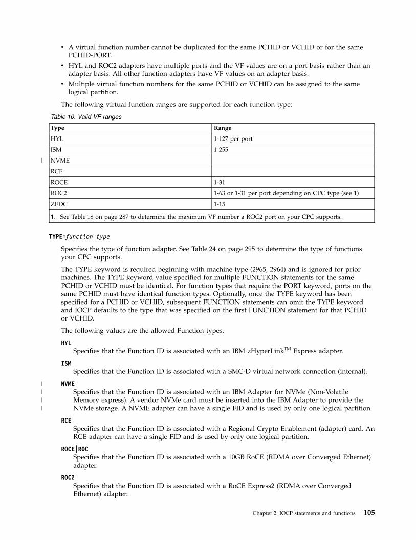
v A virtual function number cannot be duplicated for the same PCHID or VCHID or for the samePCHID-PORT.
v HYL and ROC2 adapters have multiple ports and the VF values are on a port basis rather than anadapter basis. All other function adapters have VF values on an adapter basis.
v Multiple virtual function numbers for the same PCHID or VCHID can be assigned to the samelogical partition.
The following virtual function ranges are supported for each function type:
Table 10. Valid VF ranges
Type Range
HYL 1-127 per port
ISM 1-255
NVME
RCE
ROCE 1-31
ROC2 1-63 or 1-31 per port depending on CPC type (see 1)
ZEDC 1-15
1. See Table 18 on page 287 to determine the maximum VF number a ROC2 port on your CPC supports.
TYPE=function type
Specifies the type of function adapter. See Table 24 on page 295 to determine the type of functionsyour CPC supports.
The TYPE keyword is required beginning with machine type (2965, 2964) and is ignored for priormachines. The TYPE keyword value specified for multiple FUNCTION statements for the samePCHID or VCHID must be identical. For function types that require the PORT keyword, ports on thesame PCHID must have identical function types. Optionally, once the TYPE keyword has beenspecified for a PCHID or VCHID, subsequent FUNCTION statements can omit the TYPE keywordand IOCP defaults to the type that was specified on the first FUNCTION statement for that PCHIDor VCHID.
The following values are the allowed Function types.
HYLSpecifies that the Function ID is associated with an IBM zHyperLinkTM Express adapter.
ISMSpecifies that the Function ID is associated with a SMC-D virtual network connection (internal).
NVMESpecifies that the Function ID is associated with an IBM Adapter for NVMe (Non-VolatileMemory express). A vendor NVMe card must be inserted into the IBM Adapter to provide theNVMe storage. A NVME adapter can have a single FID and is used by only one logical partition.
RCESpecifies that the Function ID is associated with a Regional Crypto Enablement (adapter) card. AnRCE adapter can have a single FID and is used by only one logical partition.
ROCE|ROCSpecifies that the Function ID is associated with a 10GB RoCE (RDMA over Converged Ethernet)adapter.
ROC2Specifies that the Function ID is associated with a RoCE Express2 (RDMA over ConvergedEthernet) adapter.
Chapter 2. IOCP statements and functions 105
|
||||
ZEDC|EDCSpecifies that the Function ID is associated with a zEnterprise Data Compression adapter.
PNETID=physical network id
Specifies the physical network identifiers (pnetids) associated with the ports on a function adapter orvirtual function. Each pnetid is a 1-16 alphanumeric (0-9, A-Z) value.
The pnetid in the PNETID keyword is a positional parameter. One to four pnetids can be specifiedwhich correspond to the ports on the function adapter. You can omit one or more pnetids byspecifying just a comma for that adapter port position in the keyword value. For example, to onlyspecify the second pnetid for a function to be associated with the second port of the adapter, youwould specify PNETID=(,pnetid ).
Physical network IDs are used for the function types ROCE, ROC2, and ISM to establish the affinityto a particular network. When network connections require two interfaces to be coordinated, as withthe 10GB RoCE network function adapter and an associated OSD channel path, the pnetids shouldmatch.
The ROCE adapters have two ports so only one to two pnetids are allowed. An ISM function onlyuses a pnetid associated with the first port.
The ROC2 adapter has two ports, but each port is defined on separate FUNCTION statements usingthe PORT keyword. Therefore, only a single pnetid is allowed and must be in the first parameterposition of the PNETID keyword.
The physical network ID of IEDN is reserved for intra-ensemble data network (IEDN) ports ornetwork connections, and if present, applies to all ports.
For the ISM and ROCE function types, when multiple FIDs are defined for the same VCHID orPCHID, the same PNETID value must be specified for all FIDs on that VCHID or PCHID. Also, whenPNETID values are specified for different VCHIDs for an ISM function type, all the PNETIDs must beunique.
For the ROC2 function type, when multiple FIDs are defined for the same port on a PCHID, the samePNETID value must be specified for all FIDs on that PCHID-PORT. The ports on a ROC2 PCHID canhave different PNETID values or no PNETID value.
If a pnetid is specified for the first FID defined for a PCHID, PCHID-PORT, or VCHID thensubsequent FIDs for that same PCHID, PCHID-PORT, or VCHID do not need to specify the PNETIDkeyword and they default to the original pnetid.
UID=number
Specifies the user-defined identifier (UID) associated with the function. The UID number is a 1- to4-digit hexadecimal number that is greater than zero. The UID number allows you to associate anumber to a function in addition to the FID.
The UID keyword is optional. However, when a logical partition (LP) in the function's candidate listhas unique user-defined identifier (UUID) checking enabled, every function with a candidate list thatincludes that LP must have a unique UID. UUID checking is enabled for an LP by specifying the LPname on the UUID statement.
The following rules apply when UUID checking is enabled for a LP:v Every function with a candidate list that includes that LP must have a unique UID. All UIDs in
that LP must be unique.v You must either specify the UID keyword on the FUNCTION statement or let IOCP pick a default
UID value. The default UID numbers chosen by IOCP will not interfere with any specified UIDnumbers.
v When a function has a candidate list that contains both LPs that have UUID checking enabled andLPs with UUID checking disabled, the uniqueness only applies to the partitions that have UUIDchecking enabled.
106 IOCP User's Guide
||
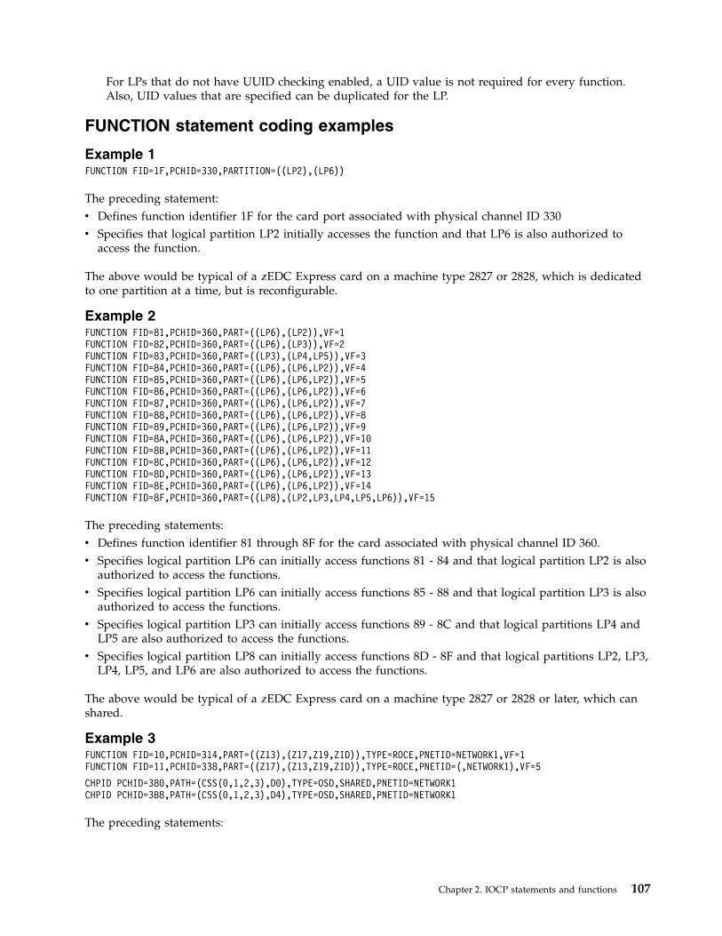
For LPs that do not have UUID checking enabled, a UID value is not required for every function.Also, UID values that are specified can be duplicated for the LP.
FUNCTION statement coding examples
Example 1FUNCTION FID=1F,PCHID=330,PARTITION=((LP2),(LP6))
The preceding statement:v Defines function identifier 1F for the card port associated with physical channel ID 330v Specifies that logical partition LP2 initially accesses the function and that LP6 is also authorized to
access the function.
The above would be typical of a zEDC Express card on a machine type 2827 or 2828, which is dedicatedto one partition at a time, but is reconfigurable.
Example 2FUNCTION FID=81,PCHID=360,PART=((LP6),(LP2)),VF=1FUNCTION FID=82,PCHID=360,PART=((LP6),(LP3)),VF=2FUNCTION FID=83,PCHID=360,PART=((LP3),(LP4,LP5)),VF=3FUNCTION FID=84,PCHID=360,PART=((LP6),(LP6,LP2)),VF=4FUNCTION FID=85,PCHID=360,PART=((LP6),(LP6,LP2)),VF=5FUNCTION FID=86,PCHID=360,PART=((LP6),(LP6,LP2)),VF=6FUNCTION FID=87,PCHID=360,PART=((LP6),(LP6,LP2)),VF=7FUNCTION FID=88,PCHID=360,PART=((LP6),(LP6,LP2)),VF=8FUNCTION FID=89,PCHID=360,PART=((LP6),(LP6,LP2)),VF=9FUNCTION FID=8A,PCHID=360,PART=((LP6),(LP6,LP2)),VF=10FUNCTION FID=8B,PCHID=360,PART=((LP6),(LP6,LP2)),VF=11FUNCTION FID=8C,PCHID=360,PART=((LP6),(LP6,LP2)),VF=12FUNCTION FID=8D,PCHID=360,PART=((LP6),(LP6,LP2)),VF=13FUNCTION FID=8E,PCHID=360,PART=((LP6),(LP6,LP2)),VF=14FUNCTION FID=8F,PCHID=360,PART=((LP8),(LP2,LP3,LP4,LP5,LP6)),VF=15
The preceding statements:v Defines function identifier 81 through 8F for the card associated with physical channel ID 360.v Specifies logical partition LP6 can initially access functions 81 - 84 and that logical partition LP2 is also
authorized to access the functions.v Specifies logical partition LP6 can initially access functions 85 - 88 and that logical partition LP3 is also
authorized to access the functions.v Specifies logical partition LP3 can initially access functions 89 - 8C and that logical partitions LP4 and
LP5 are also authorized to access the functions.v Specifies logical partition LP8 can initially access functions 8D - 8F and that logical partitions LP2, LP3,
LP4, LP5, and LP6 are also authorized to access the functions.
The above would be typical of a zEDC Express card on a machine type 2827 or 2828 or later, which canshared.
Example 3FUNCTION FID=10,PCHID=314,PART=((Z13),(Z17,Z19,ZID)),TYPE=ROCE,PNETID=NETWORK1,VF=1FUNCTION FID=11,PCHID=338,PART=((Z17),(Z13,Z19,ZID)),TYPE=ROCE,PNETID=(,NETWORK1),VF=5
CHPID PCHID=380,PATH=(CSS(0,1,2,3),D0),TYPE=OSD,SHARED,PNETID=NETWORK1CHPID PCHID=3B8,PATH=(CSS(0,1,2,3),D4),TYPE=OSD,SHARED,PNETID=NETWORK1
The preceding statements:
Chapter 2. IOCP statements and functions 107
v Defines function identifier 10 for a 10GB RoCE function adapter at physical channel ID 314. It isinitially used by logical partition (LP) Z13 and serially reconfigurable to LPs Z17, Z19, and ZID. Port 1of the adapter is associated with physical network NETWORK1. Virtual function number 1 is assignedto the FID.
v Defines function identifier 11 for a 10GB RoCE function adapter at physical channel ID 338. It isinitially used by LP Z17 and serially reconfigurable to LPs Z13, Z19, and ZID. Port 2 of the adapter isassociated with physical network NETWORK1. Virtual function number 5 is assigned to the FID.
v Defines CHPID D0 for physical channel ID 380 as an OSD channel path type. The first port of theadapter is associated with physical network NETWORK1.
v Defines CHPID D4 for physical channel ID 3B8 as an OSD channel path type. The first port of theadapter is associated with physical network NETWORK1.
v Are associated with a 2965 or 2964 or later CPC which requires the TYPE an VF keywords for ROCEfunctions.
It is normal practice to pair up any 10GB RoCE features with an OSD channel path.
Example 4FUNCTION FID=71,PCHID=33C,VF=1,TYPE=ROCE,PART=(LP6),(LP6,LP2))
The above statement:Defines function identifier 71 for the card type ROCE associated with physical channel ID 33C.Specifies that logical partition LP6 initially accesses the function, out of a partition candidate list ofLP2 and LP6.
The above would be typical of a ROCE card on a machine type 2965 or 2964 or above which can shared,but in this instance is only shown for one partition.
IOCP functionsWith IOCP, you can perform the following functions:v Generate a new IOCDS from a file containing source IOCP statementsv Produce configuration reports from an existing IOCDS.
For z/OS: The rules for coding the JCL EXEC statements for generating an IOCDS in z/OS and forproducing configuration reports are in Chapter 3, “Running the z/OS version of IOCP,” on page 111.
For z/VM: The rules for using the IOCP command in VM to generate IOCDSs and to produceconfiguration reports are in Chapter 4, “Running the VM version of IOCP,” on page 119.
For z/VSE: The rules for coding the JCL EXEC statements for generating an IOCDS in z/VSE and forproducing configuration reports are in Chapter 5, “Running the z/VSE version of IOCP,” on page 131.
Generating an IOCDSIOCP performs the following steps when you specify that you want to generate an IOCDS.
Note: Steps 1-5 on page 109 are repeated for each input statement as it is read (unless an error is foundas indicated in steps 3 and 4 on page 109).
IOCP:1. Reads each statement from the input device.2. Prints each statement on the output printer.3. Checks the syntax of each statement for correct format. If IOCP finds a syntax error (such as a
missing parenthesis), IOCP prints an error message on the output printer after the statement
108 IOCP User's Guide
containing the error. IOCP stops checking the syntax of a statement when it encounters the firstsyntax error in that statement. Therefore, if two or more syntax errors are in a single statement, thesecond and following errors are found on subsequent runs of IOCP.If IOCP finds an error in step 3 on page 108, IOCP returns to step 1 on page 108 and performs onlysteps 1 on page 108-4 for the remainder of the statements.
4. Checks the validity of each statement. For example, IOCP checks that a CNTLUNIT statement hasspecified a channel path that has been previously defined in a CHPID statement. If an error is found,IOCP prints an error message on the output printer after the statement containing the error.If IOCP finds an error in step 4, IOCP returns to step 1 on page 108 and performs only steps 1 onpage 108-4 for the remainder of the statements.
5. Builds the appropriate identification, channel path, control unit, or I/O device record and enters therecord into the IOCDS in storage.If more statements remain to be read, IOCP returns to step 1 on page 108.After all the input statements have been processed and all the records have been entered into theIOCDS in storage, IOCP performs step 6.
6. Generates the IOCDS and performs additional checking. If IOCP finds an error, IOCP sends an errormessage and then stops.After IOCP has successfully generated an IOCDS, IOCP performs Step 7.
7. Produces the IOCP configuration reports of the IOCDS.For z/OS and z/VSE: If requested (by a WRTCDS option other than NO), IOCP performs step 8.For VM: If requested (by a generation option of the IOCP command other than NOWRTCDS), IOCPperforms step 8.
8. Writes the generated IOCDS to the Support Element hard disk.For z/OS: IOCP requires authorization before it writes an IOCDS. See “Authorizing an IOCDS write”on page 112.For z/VM: The control program checks your privilege class. You must have privilege class C to writethe IOCDS to the SE hard disk. You must have privilege class B to enable the IOCDS for dynamic I/Oconfiguration changes.For z/VSE: This step requires permission from the system operator (through message ICP050D) beforeIOCP writes to the SE hard disk.
Producing configuration reportsIOCP performs the following steps when you request configuration reports:1. Reads one or more IOCDSs from the SE hard disk2. Prints the IOCP configuration reports that you specify.
If IOCP encounters any errors during processing, it sends appropriate error messages to the outputprinter. For examples of IOCP configuration reports, see Chapter 7, “IOCP configuration reports,” on page151.
Chapter 2. IOCP statements and functions 109

110 IOCP User's Guide
Chapter 3. Running the z/OS version of IOCP
This chapter describes the following topics:v General informationv Authorization required to write an IOCDSv How to build the IOCP modulev IOCP storage requirementsv JCL statements required to run IOCP functions (with examples)v Return codes IOCP can setv Methods you can follow to initially define the I/O configuration or to redefine an existing I/O
configuration.
General informationThe z/OS version of the Input/Output Configuration Program (IOCP) runs as a job under control ofOS/390, z/OS, or z/OS.e. The IOCP program name is ICPIOCP. By running ICPIOCP, you can verifyIOCP input statements for CPCs that require the ICP version of IOCP. See Table 18 on page 287 todetermine which CPCs require this version of IOCP.
Hardware configuration definition (HCD) notes:1. You do not need to run IOCP directly to define the I/O configuration to the I/O subsystem. However,
HCD does run IOCP when it needs to write an IOCDS.2. If z/OS is a guest on VM, you cannot write an IOCDS to a CPC that is part of an S/390®
microprocessor cluster.3. When HCD generates an IOCP input source file, it can include comments that HCD uses if the IOCP
source file is migrated into HCD. They have special meaning to HCD. These comments begin with*$HCDC$ or *$HCD$. For more information, see OS/390 Hardware Configuration Definition User's Guide,SC28-1848, or z/OS Hardware Configuration Definition User's Guide, SC33-7988.
4. When HCD generates an IOCP input source file without PCHIDs, the file must be migrated back intoHCD after the CHPID Mapping Tool adds PCHID numbers to the file. HCD can then write an IOCDSor a new IOCP input file can then be created from HCD. Stand-alone IOCP can use this file to writean IOCDS.
5. IOCP warning message ICP065I with return code 4 (RC=4) results when writing an IOCDS if yourI/O configuration contains an unsupported function or channel path type for the current EC level ofyour CPC. This situation in turn results in the following HCD message.CBDA676I IOCP completed with warning messages for <proc-id>.
See the IOCP output listing to view the IOCP warning messages.
Use JCL statements to run IOCP. In the EXEC statement, code options in the PARM keyword to directIOCP to do the following tasks:v Generate an IOCDS:
– Read, validate, and check the syntax of input statements– Generate an IOCDS based on the configuration defined in the statements– Produce reports of the IOCDS– When requested, write the generated IOCDS to the Support Element hard disk.
v Produce configuration reports:
© Copyright IBM Corp. 2017, 2018 111
– Read one or more IOCDSs from the Support Element hard disk– Print IOCP configuration reports (see Chapter 7, “IOCP configuration reports,” on page 151).
Authorizing an IOCDS writeWriting an IOCDS requires authorization in either of the following ways:v The z/OS system operator allows you by responding to message ICP050Dv A security product (for example, RACF) defines you as someone authorized to write an IOCDS.
The following conditions apply when you run IOCP directly to write an IOCDS or when you use theHardware Configuration Definition. (The HCD runs IOCP to build an IOCDS.)v If the CBD.CPC.IOCDS resource of the FACILITY class exists in an installed security product (for
example, RACF), IOCP does not send message ICP050D to the z/OS operator. IOCP determines yourauthorization to write an IOCDS from your authorization to update the CBD.CPC.IOCDS resource. Ifthe security administrator has authorized you to update this resource, IOCP writes the IOCDS. If youare not authorized to update the resource, IOCP does not write the IOCDS.
v If the CBD.CPC.IOCDS resource of the FACILITY class does not exist in an installed security product,IOCP sends message ICP050D. This message prompts the z/OS system operator to allow you to writethe IOCDS.
v The logical partition running IOCP must have I/O Configuration Control Authority enabled on theSupport Element.
Building the IOCP moduleThe IOCP program is on the SYS1.AOSC5 data set of the distribution library (DLIB). It is built when thedistribution libraries are loaded during the SMP product install procedure. During the SMP productinstall procedure, IOCP is link-edited from the DLIB into SYS1.LINKLIB as an APF-authorized program,authorization code AC=1, with the load module name ICPIOCP.
IOCP storage requirementsIOCP uses a variable amount of storage based on the type of IOCDS it is processing. To determine thespecific IOCP storage requirements for your CPC, see Table 18 on page 287. Specify a region size in theREGION parameter of the JOB statement that is large enough to ensure sufficient space for the job orspecify 0 MB.
Coding the JCL EXEC statement for generating an IOCDSIn the EXEC statement, code the name of the IOCP program in the PGM parameter and the followingPARM options to generate an IOCDS. (The examples later in this chapter describe the JOB and DDstatements for an IOCP job.)
Note: PARM parameter defaults allow you to generate an IOCDS and to produce reports. However, thedefaults do not allow you to write an IOCDS to the Support Element hard disk.
IOCP processes all input statements and parameters. IOCP flags as errors any non-IOCP input and alsoindicates errors found in IOCP statements and parameters. IOCP prints all input, including all commentcards (all cards with an asterisk (*) in column 1 or .* in columns 1 and 2).
WRTCDS=specifies whether or not IOCP writes an IOCDS to the support Element hard disk. All of the
PARM=’WRTCDS=Ax|NO,LINECOUNT=n|55,CHECKCPC=YES|NO’
112 IOCP User's Guide
WRTCDS options except NO cause IOCP to write an IOCDS. You can write an IOCDS only from anauthorized logical partition (that is, I/O Configuration Control Authority is enabled).
IOCP writes the IOCDS only if:v No errors are encountered during IOCP processingv The z/OS system operator grants permission in response to message ICP050D or the user
attempting to write the IOCDS is authorized by an installed security product (for example, RACF)v The IOCDS is not write protected.
Request IOCP to write the IOCDS only after you have done the following:v Checked the syntax of the input statementsv Generated an IOCDS based on the configuration defined in the statementsv Reviewed reports on the generated IOCDSv Checked to see whether or not the generated IOCDS is correct.
To replace a write protected IOCDS, you must first remove write protection. Click Disable WriteProtection n under Options on the Input/Output Configuration window of the Support Element toremove write protection.
HCD and write protection: You can use HCD to set and remove IOCDS write protection. For moreinformation, see z/OS Hardware Configuration Definition User's Guide, GC33-7988.
When IOCP writes an IOCDS to the Support Element hard disk, it overwrites the previousconfiguration data in that IOCDS, even if that IOCDS is the active IOCDS. (The active IOCDS is theone used for the last power-on reset or the last dynamic activation from the system control program(SCP).)
The valid options for WRTCDS are Ax and NO.
Ax specifies that IOCP should write the Ax IOCDS (where x is 0, 1, 2, or 3) to the Support Elementhard disk.
NO specifies that IOCP should not write the IOCDS to the Support Element hard disk.
NO is the default if you do not code WRTCDS.
Code or use the default WRTCDS=NO when you test the input file and do not want to write tothe Support Element hard disk until you have successfully tested and checked the input file.
Also, you must code or use the default WRTCDS=NO when you run IOCP on a CPC that doesnot require ICPIOCP. However, certain CPCs allow an IOCDS to be written in anticipation ofsupporting ICPIOCP.
LINECOUNT=
n specifies the number of lines that IOCP is to print on a page of the IOCP output listing andconfiguration reports, including the heading of the report. Code a decimal value in the range of20-99.
55 is the default number of lines (including the heading) that IOCP prints on a page of the IOCPoutput listing and configuration reports.
CHECKCPC=
YESspecifies that IOCP generates an IOCDS as follows:v Based on the CPC on which IOCP is running if writing an IOCDS. IOCP ignores the SYSTEM=
keyword on the ID statement if specified.v Based on the CPC on which IOCP is running if not writing an IOCDS and the SYSTEM=
keyword was not specified.v Based on the SYSTEM= parameter if specified and IOCP is not writing an IOCDS.
Chapter 3. Running the z/OS version of IOCP 113
YES is the default.
NO specifies that IOCP writes the IOCDS in preparation of a CPC upgrade. IOCP generates anIOCDS based on the SYSTEM= parameter on the ID statement and writes the IOCDS to thecurrent CPC. See “Machine rules” on page 285 to determine which SYSTEM= parameters arevalid with CHECKCPC=NO and which CPCs can have ICPIOCP write an IOCDS to them.
The IOCDS cannot be used to power-on reset the current CPC until it is upgraded to the type ofCPC that the IOCDS supports. For example, if IOCP generates an IOCDS for a 2084 CPC usingSYSTEM=(2084,1) and writes the IOCDS to a general purpose 2064 model 1xx, the IOCDS cannotbe used for power-on reset until the 2064 is upgraded to a 2084 model CPC.
A WRTCDS option other than NO is required. Also, the SYSTEM keyword on the ID statementmust be specified.
Attention: Use CHECKCPC=NO only in preparation of a CPC upgrade. After the upgrade, IBMrecommends that you write an IOCDS using CHECKCPC=YES at your earliest convenience. Thisprevents the possibility of using the initial IOCDS for a second upgrade to a CPC, which will notsupport the IOCDS and will fail power-on reset.
JCL examples of generating an IOCDS
Example 1The following example shows the JCL statements used to check an IOCP input file. IOCP requires SYSINas the ddname for the input data set and SYSPRINT as the ddname for the output data set. Reports aresent to SYSOUT.//IOCP1 JOB REGION=0M,...//TEST1 EXEC PGM=ICPIOCP,PARM=(’WRTCDS=NO’,// ’LINECOUNT=60’)//SYSIN DD DSNAME=USER.IOCD1.CARDS,DISP=SHR//SYSPRINT DD SYSOUT=A,DCB=(RECFM=FA)
In the example:
IOCP1specifies the JOB statement. Code parameters on the JOB statement that your installation requires.To determine the region size to use, see “IOCP storage requirements” on page 112.
TEST1specifies the EXEC statement and the program (ICPIOCP) to run. The PARM options are:
WRTCDS=NOspecifies not writing the IOCDS to the Support Element hard disk
LINECOUNT=60specifies 60 lines of output on the reports IOCP produces.
SYSINspecifies the DD statement that defines the input data set, which consists of statements with arecord length of 80 bytes.
SYSPRINTspecifies the DD statement that defines the output data set to receive messages and reports. (Notethat IOCP records contain ANSI device control characters and have a length of 133 bytes.)
Example 2The following example shows the JCL statements to process an IOCP input file, to generate an IOCDS,and to write the generated IOCDS to the A0 IOCDS on the Support Element hard disk. Reports of thegenerated IOCDS are sent to SYSOUT.
IOCP requires the ddnames SYSIN for the input data set and SYSPRINT for the output data set.
114 IOCP User's Guide
//IOCP2 JOB REGION=0M,...//WRITE1 EXEC PGM=ICPIOCP,PARM=’WRTCDS=A0’//SYSIN DD DSNAME=USER.IOCD2.CARDS,DISP=SHR//SYSPRINT DD SYSOUT=A,DCB=(RECFM=FA)
In the example:
IOCP2specifies the JOB statement. Code parameters on the JOB statement required by your installation.To determine the region size to use, see “IOCP storage requirements” on page 112.
WRITE1specifies the EXEC statement and the program (ICPIOCP) to run. The PARM options are:
WRTCDS=A0specifies writing the A0 IOCDS to the Support Element hard disk.
SYSINspecifies the DD statement that defines the input data set, which consists of statements with arecord length of 80 bytes.
SYSPRINTspecifies the DD statement that defines the output data set to receive messages and reports. (Notethat IOCP records contain ANSI device control characters and have a length of 133 bytes.)
Coding the JCL EXEC statement for producing configuration reportsIn the EXEC statement, code the name of the IOCP program in the PGM parameter and the followingPARM options to produce configuration reports. (The example later in this chapter describes the JOB andDD statements for an IOCP job.)
You must code the REPORT option to receive reports of an IOCDS.PARM=’REPORT=(A|Ax[,Ax...]),LINECOUNT=n|55’
REPORT=specifies that IOCP read one or more IOCDSs from the Support Element hard disk to produceconfiguration reports. You can code more than one REPORT option. If you code only one option, youcan omit the parentheses.
Notes:
1. You cannot use ICPIOCP to produce reports for IOCDSs created by IYPIOCP, IZPIOCP, orIXPIOCP.
2. An IOCDS can be read only from an authorized logical partition (that is, I/O ConfigurationControl Authority is enabled).
The valid options for REPORT= are:
Ax specifies the Ax IOCDS, where x is 0, 1, 2, or 3.
A specifies all the Ax IOCDSs. See Table 17 on page 286 to determine the Ax IOCDSs your CPCsupports.
LINECOUNT=
n specifies the number of lines that IOCP is to print on a page of the IOCP output listing andconfiguration reports, including the heading of the report. Code a decimal value in the range20-99.
55 Is the default number of lines (including the heading) that IOCP prints on a page of the IOCPoutput listing and configuration reports.
Chapter 3. Running the z/OS version of IOCP 115
Conditions for coding the REPORT optionsv You can code REPORT only if the IOCDSs to report were written with ICPIOCP; otherwise, IOCP ends
with an error.v You cannot code REPORT with the WRTCDS or CHECKCPC option. You cannot read an input file and
generate an IOCDS (which includes reports of the generated IOCDS), and produce reports by means ofthe REPORT option in the same job.
v You can code several REPORT options. Redundant or duplicate values are allowed. For example,REPORT=(A0,A1,A2,A3) is the same as REPORT=A. Regardless of the order in which you specify theoptions, the reports are always produced in the following order: A0, A1, A2, A3.
JCL example of producing configuration reportsThe following example shows the JCL statements to produce IOCP reports of all the Ax IOCDSs readfrom Support Element hard disk. Reports are sent to SYSOUT. Note that you do not need a DD statementto access an IOCDS from the Support Element hard disk.
IOCP requires SYSPRINT as the ddname for the output data set.//IOCP5 JOB REGION=0M,...//REPORT2 EXEC PGM=ICPIOCP,PARM=’REPORT=A’//SYSPRINT DD SYSOUT=A,DCB=(RECFM=FA)
In the example:
IOCP5specifies the JOB statement. Code the parameters on the JOB statement that your installationrequires. To determine the region size to use, see “IOCP storage requirements” on page 112.
REPORT2specifies the EXEC statement and the program (ICPIOCP) to run. The PARM option ofREPORT=A specifies reading all the Ax IOCDSs from the Support Element hard disk to producereports.
SYSPRINTspecifies the DD statement that defines the output data set to receive messages and reports. (Notethat IOCP records contain ANSI device control characters and have a length of 133 bytes.)
Return codesWhen you run the z/OS version of IOCP, it returns one of the following codes at the completion of thejob:
Table 11. Return codes for z/OS version of IOCP
Return code
Description and actionDecimal Hex
0 0 IOCP has completed the requested function without error and might have sentone or more informational messages. If so, the informational messages in theoutput listings or the reports describe the specific conditions.
2 2 IOCP has completed the requested function without error but has issued oneor more caution messages. The caution messages in the output listings or thereports describe the specific conditions.
4 4 IOCP has completed the requested function without error but has issued oneor more warning messages. The warning messages in the output listings or thereports describe the specific conditions.
8 8 IOCP has encountered an error and has ended processing before completingthe requested function. The error message in the output listing describes thespecific condition.
116 IOCP User's Guide
Table 11. Return codes for z/OS version of IOCP (continued)
Return code
Description and actionDecimal Hex
12 C IOCP has ended because the output data set DCB failed to open. IOCP wasunable to print messages or reports. Ensure that the DD statement for theoutput data set is correctly specified.
16 10 IOCP has ended because it could not obtain the needed storage by means ofthe GETMAIN statement. To determine the region size to use, see “IOCPstorage requirements” on page 112.
Methods of running the z/OS version of IOCPThis topic suggests the steps that you can use to run the z/OS version of IOCP to do the following:v Define and check the I/O configuration data to prepare for a new CPCv Redefine and replace an I/O configuration on an installed CPC.
Note: In z/OS, you use HCD to define and change your I/O configuration. HCD runs IOCP to write anIOCDS.
Initial definition of I/O configuration dataThe following example describes the steps that an installation can use to initially define and check theI/O configuration data to prepare for the installation of a new CPC.1. Determine, from your physical plan, the I/O configuration requirements that must be met to install
the CPC.2. Use HCD on a running z/OS system to define your I/O configuration for the new CPC. HCD
validates the I/O configuration rules. When the definition is complete, build a production IODF.3. If you are installing a new CPC, do one of the following:v If the new CPC will be connected using a LAN to the CPC where HCD is running and that CPC is
able to remotely write an IOCDS, you can use HCD to write the new IOCDS to the CPC after it isinstalled. HCD uses the APF-authorized ICPIOCP program to write an IOCDS. Inform the servicerepresentative which IOCDS to use.
v If you are upgrading an existing CPC, you might be able to use HCD to write an IOCDS to yourcurrent CPC in preparation for the upgrade. See “Machine rules” on page 285 to determine whichCPCs can write an IOCDS in preparation for an upgrade and which CPCs can have ICPIOCP writean IOCDS to them. If you can write an IOCDS to your current CPC in preparation for upgrading itto a new CPC, do so and inform the service representative which IOCDS to use. This is thepreferred method for writing the initial IOCDS when upgrading a CPC.
v If the new CPC will not be connected using a LAN to the CPC where HCD is running or you arenot upgrading or cannot write an IOCDS in preparation for the upgrade, use HCD to produce anIOCP input file. Download the input file to diskette (if it is available) or USB flash memory drive. Ifthe file is too big to fit, compress it using a zip compatible program. Source from a diskette must bein DOS file format or have been compressed. Source from a USB flash memory drive must be inVFAT or DOS file format or have been compressed. Give the diskette or USB flash memory drive tothe service representative, who uses this input file and stand-alone IOCP to write the IOCDS for thenew CPC. Instead of a diskette or USB flash memory drive, an uncompressed IOCP source file canbe imported to the SE from an FTP location by the service representative. System z9 and zSeriesservers do not support USB flash memory drives for IOCDS source files. See “Creating an IOCDSin a new CPC” on page 145 for an example using the stand-alone version of IOCP.
Note: See “Authorizing an IOCDS write” on page 112 for a description of how to authorize thewrite of an IOCDS.
Chapter 3. Running the z/OS version of IOCP 117
4. The service representative performs a power-on reset of the new CPC with the appropriate IOCDS.5. The service representative performs an initial program load (IPL) for the z/OS system with the IODF
built under Step 2 on page 117.
Redefinition and replacement of I/O configuration dataThe following example describes the steps the installation can use to replace the existing I/Oconfiguration data on a CPC.1. Use HCD to update your I/O configuration for the hardware and software in a work IODF based on
your currently active production IODF.2. Build a new production IODF from the updated work IODF.3. If the changes can be dynamically performed, use HCD or the z/OS Activate system command to
dynamically change the I/O configuration in the Hardware System Area (HSA) and in the z/OSsystem. The updated IODF now becomes the new active IODF. The details of dynamic I/Oreconfiguration are found in z/OS Hardware Configuration Definition Planning, GA22-7525.
4. Write the new IOCDS to the support Element of the CPC using HCD. HCD uses IOCP to write anIOCDS. If the IOCDS slot is write protected on the Support Element, click Disable Write Protectionunder Options on the Input/Output Configuration window of the Support Element.
Note: See “Authorizing an IOCDS write” on page 112 for a description of how to authorize the writeof an IOCDS.
5. Use HCD to switch the IOCDS to become the active one for the next power-on reset.6. If the I/O configuration changes cannot be dynamically performed (see Step 3), perform a power-on
reset of the CPC using the new IOCDS. Perform an IPL of the z/OS system with the new productionIODF.
7. Test the new configuration following the procedures established for your site.
118 IOCP User's Guide
Chapter 4. Running the VM version of IOCP
This chapter describes the following topics:v General informationv IOCP storage requirementsv CMS IOCP commands that run these functions (with examples)v Return codes IOCP can setv Methods you can follow to initially define the I/O configuration or to redefine an existing I/O
configuration
General informationThe VM version of IOCP runs under the control of z/VM.
Start the VM version of IOCP in the CMS environment. The CMS IOCP command runs IOCP and hasoptions you can use to request the following IOCP functions:1. Generate an IOCDS.
IOCP reads, validates, and checks the syntax of input statements. It generates an IOCDS based on theconfiguration defined in the statements. It produces reports of the IOCDS; and, when requested, IOCPwrites the generated IOCDS to the Support Element hard disk.
2. Produce configuration reports.IOCP reads one or more IOCDSs from the Support Element hard disk and prints the IOCPconfiguration reports. (See Chapter 7, “IOCP configuration reports,” on page 151 for examples.)
Hardware configuration definition (HCD) notes1. When using HCD to define the I/O configuration for VM, you need not run IOCP directly to define
the I/O configuration to the I/O subsystem. However, HCD does run IOCP when it must write anIOCDS. HCD users: Always use HCD (CBDSIOCP EXEC) to write an IOCDS from VM.
2. When HCD generates an IOCP input source file, it can include comments that HCD uses if the IOCPsource file is migrated into HCD. They have special meaning to HCD. These comments begin with*$HCDC$ or *$HCD$. For more information, see z/VM Dynamic I/O Configuration Planning andAdministration, SC24-6044.
3. When HCD generates an IOCP input source file without PCHIDs, the file must be migrated back intoHCD after the CHPID Mapping Tool adds PCHID numbers to the file. HCD can then write an IOCDSor a new IOCP input file can then be created from HCD, which a stand-alone IOCP can use to writean IOCDS.
4. IOCP warning message ICP065I with return code 4 (RC=4) results when writing an IOCDS if yourI/O configuration contains an unsupported function or channel path type for the current EC level ofyour CPC. This situation in turn results in the following HCD message.CBDA676I IOCP completed with warning messages for <proc-id>.
See the IOCP output listing to view any IOCP warning messages.
IOCP storage requirementsIOCP uses a variable amount of storage based on the type of IOCDS it is processing. However, todetermine the specific IOCP storage requirements for your CPC, see Table 18 on page 287. The IOCPcommand requires the storage size documented in the table, which is in addition to the storage CMSrequires.
© Copyright IBM Corp. 2017, 2018 119
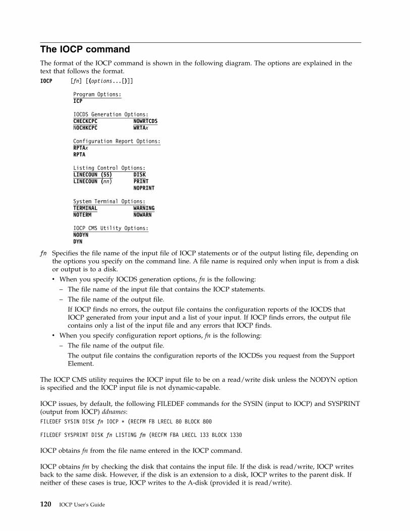
The IOCP commandThe format of the IOCP command is shown in the following diagram. The options are explained in thetext that follows the format.IOCP [fn] [(options...[)]]
Program Options:ICP
IOCDS Generation Options:CHECKCPC NOWRTCDSNOCHKCPC WRTAx
Configuration Report Options:RPTAxRPTA
Listing Control Options:LINECOUN (55) DISKLINECOUN (nn) PRINT
NOPRINT
System Terminal Options:TERMINAL WARNINGNOTERM NOWARN
IOCP CMS Utility Options:NODYNDYN
fn Specifies the file name of the input file of IOCP statements or of the output listing file, depending onthe options you specify on the command line. A file name is required only when input is from a diskor output is to a disk.v When you specify IOCDS generation options, fn is the following:
– The file name of the input file that contains the IOCP statements.– The file name of the output file.
If IOCP finds no errors, the output file contains the configuration reports of the IOCDS thatIOCP generated from your input and a list of your input. If IOCP finds errors, the output filecontains only a list of the input file and any errors that IOCP finds.
v When you specify configuration report options, fn is the following:– The file name of the output file.
The output file contains the configuration reports of the IOCDSs you request from the SupportElement.
The IOCP CMS utility requires the IOCP input file to be on a read/write disk unless the NODYN optionis specified and the IOCP input file is not dynamic-capable.
IOCP issues, by default, the following FILEDEF commands for the SYSIN (input to IOCP) and SYSPRINT(output from IOCP) ddnames:FILEDEF SYSIN DISK fn IOCP * (RECFM FB LRECL 80 BLOCK 800
FILEDEF SYSPRINT DISK fn LISTING fm (RECFM FBA LRECL 133 BLOCK 1330
IOCP obtains fn from the file name entered in the IOCP command.
IOCP obtains fm by checking the disk that contains the input file. If the disk is read/write, IOCP writesback to the same disk. However, if the disk is an extension to a disk, IOCP writes to the parent disk. Ifneither of these cases is true, IOCP writes to the A-disk (provided it is read/write).
120 IOCP User's Guide
Because the default FILEDEF commands specify DISK, you must use a file name in the IOCP commandunless you override those default FILEDEF commands. If you want to override a default FILEDEFcommand, issue your own FILEDEF command before running IOCP. The SYSPRINT FILEDEF isautomatically overridden if you specify PRINT or NOPRINT in the IOCP command. Note also that if youspecify a SYSPRINT FILEDEF, the IOCP command uses a system terminal option of NOTERM, whichcannot be overridden.
The input file type is, by default, IOCP. If the input file has a file type other than IOCP, issue a FILEDEFcommand to override the default file type.
Program optionsA program option designates the IOCP program for which the input IOCP statements were written.
The syntax of input IOCP statements can be checked on any CPC in which the CMS IOCP command isvalid. Syntax checking can be performed when the CPC for which the input IOCP statements werewritten is not available.
The valid program options are as follows:
ICPSpecifies that the ICP version of IOCP is to process the command options and input file to generatean IOCDS. ICP indicates the first three characters of the ICPPCNTL IOCP module and to the z/OSprogram name ICPIOCP. See Table 18 on page 287 to determine which CPCs require this version ofIOCP.
The ICP program option is the default for the IOCP command on 3907, 3906, 2965, 2964, 2828, 2827,2818, 2817, 2098, 2097, 2096, 2094, 2086, and 2084 CPCs.
xxxThree-character program option other than ICP. It is associated with CPCs that do not require the ICPversion of IOCP.
For example, the IYP program option runs the version of IOCP that is required on 2064 and 2066CPCs. The IYP program option is the default for the IOCP command on 2064 and 2066 CPCs.
The IZP program option runs the version of IOCP that is required on 9021, 9121, 9672, 2003, 3000,and 7060 CPCs that support the ESCON architecture and multiple image facility (MIF). The IZPprogram option is the default for the IOCP command on 9672, 2003, 3000, and 7060 CPCs.
The IXP program option runs the version of IOCP that is required on ES/3090, 9021, 9121, and 9221CPCs that support the ESCON Architecture, but not the multiple image facility (MIF). The IXPprogram option is the default for the IOCP command on 9021, 9121, and 9221 CPCs.
IOCP programs are designed to generate IOCDSs for specific CPCs. However, some IOCP programs cangenerate an IOCDS for a CPC it was not designed to support. For example, if IOCP writes an IOCDSwith the ICP program option on a CPC that does not support ICP IOCP, a power-on reset failure occurs ifthe IOCDS is used before the CPC is upgraded to a CPC that supports ICP IOCP.
IOCP programs are also designed to report on IOCDSs for specific CPCs. An IOCP program can reportonly on IOCDSs that were written by the same IOCP program. For example, if IOCP writes an IOCDSwith the ICP program option, only the ICP IOCP program can print a report. Errors occur when an IOCPprogram other than the one that generated the IOCDS tries to report on an IOCDS.
IOCDS generation optionsIOCP writes an IOCDS only if:v No errors are encountered during IOCP processing.
Chapter 4. Running the VM version of IOCP 121
v The user issuing the IOCP command has the correct privilege class. See Note 1 on page 125 in “IOCPcommand – usage notes for VM” on page 125.
v The IOCDS is not write-protected.v You specify a write IOCDS option WRTAx.
Use a write option WRTAx after you have:v Checked the syntax of the input statementsv Generated an IOCDS based on the configuration defined in the statementsv Reviewed reports on the generated IOCDSv Checked to see whether the I/O configuration generated by IOCP corresponds to the I/O configuration
in the system configuration file (SYSTEM CONFIG) on the parm disk or the obsolete real I/Oconfiguration file (HCPRIO) in the CP nucleus. While IOCP must define the entire I/O configuration,only the devices that VM cannot sense during IPL must be defined in the SYSTEM CONFIG orHCPRIO files.
If you want to replace an IOCDS that is write-protected, you must also remove the write protection. UseDisable Write Protection under Options on the Input/Output Configuration window of the SupportElement to remove write protection.
When IOCP writes the generated IOCDS to the Support Element hard disk, the previous configurationdata in that IOCDS is overlaid and lost, even if that IOCDS is the active IOCDS. (The active IOCDS is theone used for the last power-on reset or the last dynamic activation from the system control program(SCP).)
NOWRTCDSNOWRT
Specifies that IOCP is not to write an IOCDS to the Support Element hard disk. This option is adefault.
Use the NOWRTCDS option in either of the following situations:v You are checking the syntax of the input file and do not want to write to the Support Element hard
disk until you have successfully checked the input file.v You are using a CPC that does not require the IOCP that this publication describes.
However, certain CPCs permit an IOCDS to be written in anticipation of supporting ICP IOCP.
When you specify the NOWRTCDS option and IOCP finds no errors, the output file contains theconfiguration reports of the IOCDS that IOCP generates from your input, along with a list of yourinput file. If IOCP finds errors, your output file contains only a list of your input file and any errorsthat IOCP finds.
WRTAxWAx
Specifies that IOCP is to write the Ax (where x is 0, 1, 2, or 3) IOCDS to the Support Element harddisk. Privilege class C is required to write an IOCDS.
Note: An IOCDS can be written only from an authorized logical partition (that is, I/O ConfigurationControl Authority is enabled).
CHECKCPCSpecifies that IOCP generates an IOCDS as follows:v Based on the CPC on which IOCP is running if writing an IOCDS. IOCP ignores the SYSTEM=
keyword on the ID statement if specified.v Based on the CPC on which IOCP is running if not writing an IOCDS and the SYSTEM= keyword
was not specified.v Based on the SYSTEM= parameter if specified and IOCP is not writing an IOCDS.
122 IOCP User's Guide
This option is the default.
NOCHKCPCSpecifies that the IOCDS is being written in preparation of a CPC upgrade. IOCP generates an IOCDSbased on the SYSTEM= parameter on the ID statement and writes the IOCDS to the current CPC. See“Machine rules” on page 285 to determine which CPCs can write an IOCDS with NOCHKCPC andwhich CPCs can have an IOCDS written to them by ICP IOCP.
The IOCDS cannot be used to power-on reset the current CPC until it is upgraded to the type of CPCsupported by the IOCDS. For example, if IOCP generates an IOCDS for a 2084 CPC usingSYSTEM=(2084,1) and writes the IOCDS to a general purpose 2064 model 1xx, the IOCDS cannot beused for power-on reset until the 2064 is upgraded to a 2084 model CPC.
A WRTAx or WAx option is required. Also, the SYSTEM keyword on the ID statement must bespecified.
Attention:Use NOCHKCPC only in preparation of a CPC upgrade. After the upgrade, write an IOCDS usingCHECKCPC at your earliest convenience. Doing so precludes the possibility of using the initialIOCDS for a second upgrade to a CPC, which does not support the IOCDS and fails power-on reset.
Configuration report optionsThe valid options for reading an IOCDS and producing configuration reports are RPTAx and RPTA.
The user issuing the IOCP command to produce configuration reports must have the correct privilegeclass. See Note 1 on page 125 in “IOCP command – usage notes for VM” on page 125.
Note: You cannot use the ICP version of IOCP to produce reports for IOCDSs created by the IYP, IZP, orIXP versions of IOCP.
RPTAxRAx
Specifies that IOCP reads the Ax (where x is 0, 1, 2, or 3) IOCDS from the Support Element hard diskand generates a configuration report of that data set. You can repeat this option to generate reportson multiple IOCDS files. Privilege class C is required to read an IOCDS.
Note: An IOCDS can be read only from an authorized logical partition (that is, I/O ConfigurationControl Authority is enabled).
RPTARA Specifies that IOCP is to read all the Ax IOCDSs from the Support Element hard disk and is to
generate configuration reports of those data sets. See Appendix F, “Machine limits and rules,” onpage 285 to determine the Ax IOCDSs your CPC supports. Privilege class C is required to read anIOCDS.
Note: An IOCDS can be read only from an authorized logical partition (that is, I/O ConfigurationControl Authority is enabled).
Listing control optionsLINECOUN (55)LINECOUN (nn)
Specifies the number of lines (from 20 to 99) to print on each page including the report heading. Thedefault is LINECOUN (55). You must specify the number of lines if you use this option.
DISKDI Specifies that IOCP is to place the output listing on a minidisk. DISK is a default option.
Chapter 4. Running the VM version of IOCP 123
PR Specifies that IOCP is to send the output listing to the printer.
NOPRINTNOPR
Specifies that IOCP is not to generate any output listing.
System terminal optionsTERMINALTERM
Specifies that IOCP is to write diagnostic information from the IOCP output to your terminal.Diagnostic information consists of either of the following:v An IOCP message (see Chapter 8, “IOCP messages,” on page 171) and, preceding this message, the
nonblank line that caused the diagnostic messagev A display of the total message count for the IOCP output.
TERMINAL is a default option.
NOTERMSpecifies that IOCP is to suppress the display of diagnostic messages at your terminal.
WARNINGWARN
Specifies that IOCP is to write IOCP warning and caution messages to the terminal. This option isvalid only if you specify the TERMINAL option. WARNING is a default option.
NOWARNSpecifies that IOCP is to suppress the writing of warning and caution messages at your terminal.
IOCP CMS utility optionsThese options are valid only for the IOCP CMS utility. If an IOCP CMS utility option is specified, theutility processes the option and then calls the IOCP command with all specified options except the utilityoptions. The IOCP command does not accept the IOCP utility options.
NODYNSpecifies that the IOCP CMS utility is not to enable the dynamic I/O configuration capability of anyresulting IOCDS. This option is the default for CPCs that do not have a fixed storage size for theHardware System Area (HSA). See Table 16 on page 285 to determine if your CPC has fixed HSA.
NODYN disables any dynamic-capability of an IOCP input file. NODYN requires the IOCP input fileto be on a read/write disk unless the file is not dynamic-capable. Specify NODYN when you are notwriting an IOCDS and do not have privilege class B.
Note: You cannot specify utility option NODYN along with the MAXDEV keyword or reservedlogical partitions on the RESOURCE statement.
DYNSpecifies that the IOCP CMS utility is to enable the dynamic I/O configuration capability of anyresulting IOCDS. This option is the default for CPCs that have a fixed storage size for the HardwareSystem Area (HSA). See Table 16 on page 285 to determine if your CPC has fixed HSA. The DYNoption requires the following:v Privilege class Bv An IOCP input file on a read/write disk.
RestrictionsCMS/DOS does not recognize the IOCP command.
124 IOCP User's Guide
IOCP command – general usage notesThis topic lists some general notes to keep in mind when you use the IOCP command. Some aspects ofusing the command, though, vary with the operating system on which you run IOCP. For usage notesspecific to your operating system, see the topics that immediately follow this topic.
Notes:
1. Some IOCP command options cancel other IOCP command options. For this reason, when you codethe IOCP command, do not combine IOCDS generation options with configuration report options.(However, IOCP allows multiple configuration-report options.)If you inadvertently code conflicting options in the same IOCP command, IOCP uses the last enteredof those conflicting options; no warning message is sent.
2. The write option WRTAx, is incorrect if the data set that you want to replace is write-protected. (Toremove write protection, click Disable Write Protection under Options on the Input/OutputConfiguration window of the Support Element.)
3. The TERMINAL and WARNING options are not active if you provide your own SYSPRINT FILEDEFcommand.
IOCP command – usage notes for VMThis topic lists some notes to keep in mind when you use the IOCP command.
Notes:
1. You must have the correct privilege class. The control program checks your privilege class when IOCPattempts to read or write an IOCDS. You must have privilege class C to read or write an IOCDS; youmust also have privilege class C to avoid IOCP warning message ICP068I when performing a deckverification (option NOWRTCDS). You must have privilege class B if you specify IOCP utility optionDYN.If you try to read from an IOCDS or write an IOCDS and you do not have the required privilegeclasses, you receive the following messages:ICP402I IOCP RECEIVED AN UNEXPECTED RESPONSE CODE OF 01F0 HEX
ATTEMPTING READ OR WRITE OF AN IOCDS
ICP051I IOCP VERSION nn.nn.nnn TERMINATED. CODE=xx
Note: You can also receive the previous messages if you try to read or write an IOCDS when anotheruser is reading or writing an IOCDS. The messages are printed on the SYSPRINT device. IOCP thenstops processing.If you try to read or write an IOCDS or perform a deck verification (option NOWRTCDS) and you donot have the required privilege classes, you receive the following message:ICP068I **WARNING** IOCP WAS UNABLE TO DETERMINE IF THE CONFIGURATION
IS USABLE ON THE EC LEVEL OF THIS PROCESSOR (CODE 01F00000)
If you specify the DYN IOCP utility option and do not have the required privilege class, you receivethe following message from the IOCP utility:Error occurred generating hardware token.CP QUERY TOKEN command was not recognized.IOCP module has not been invoked.
2. For z/VM 4.4.0 and prior releases, if you do not have CP APAR VM63426 installed, you receive thefollowing message:ICP068I **WARNING** IOCP WAS UNABLE TO DETERMINE IF THE CONFIGURATION
IS USABLE ON THE EC LEVEL OF THIS PROCESSOR (CODE 40F00000)
3. You receive the following error messages and IOCP processing stops if you try to update an IOCDS orrequest a configuration report for an IOCDS while IOCP is running on a CPC that does not requirethe version of IOCP described in this publication:
Chapter 4. Running the VM version of IOCP 125
ICP400I READ/WRITE OF IOCDS IS INVALID ON THIS PROCESSOR (nnnn)
ICP051I IOCP VERSION nn.nn.nnn TERMINATED. CODE=xx
You receive similar error messages if you try to update an IOCDS or request a configuration reportfor an IOCDS on a CPC that supports ICP IOCP and a program option other than ICP was specified.
4. If you and another user attempt to read the same IOCDS at the same time, or if you and another userattempt to write the same IOCDS at the same time, you or the other user receive the followingmessages:ICP405I IOCP RECEIVED AN UNEXPECTED RETURN CODE OF 09 OR 65
HEX ATTEMPTING READ OR WRITE OF AN IOCDS
ICP051I IOCP VERSION nn.nn.nnn TERMINATED. CODE=xx
Wait several minutes and again attempt to read or write that IOCDS by issuing another IOCPcommand.
5. You must define your I/O configuration for the CPC using IOCP statements. When you perform aninitial program load (IPL) of VM, VM creates its software I/O configuration by sensing the devices inthe hardware I/O configuration. If all the devices return all of the information VM needs, VMcompletes its software I/O configuration. If not, you must specify this information in the systemconfiguration file or the obsolete real I/O configuration file.
6. If you try to write an IOCDS and either the IOCP abnormally ends or you issue the CMS commandHALT EXECUTION (HX) while IOCP is running, you prevent another authorized user from using anIOCDS. Under these circumstances, the system might have locked the IOCDS for you. If the otheruser tries to write to any IOCDS, the following messages are sent:ICP401I READ/WRITE IOCDS FACILITY TEMPORARILY BUSY (RC=4). RETRY LATER
ICP051I IOCP VERSION nn.nn.nnn TERMINATED. CODE=xx
The xx is a code that indicates IOCP encountered an error while trying to write the locked IOCDS.If the other user attempts to read the IOCDS that has been locked, the following messages aredisplayed to that user:ICP403I LEVEL Ax IOCDS IS INVALID
ICP051I IOCP VERSION nn.nn.nnn TERMINATED. CODE=xx
The xx is a code that indicates IOCP encountered an error while trying to read the locked IOCDS.These messages are sent each time the other user tries to run IOCP until you do one of the following:v Rerun IOCP to completion, successfully writing the locked IOCDS to the Support Element.v Send a SYSTEM RESET command to reset your virtual machine.v Send a LOGOFF command to log off your virtual machine.The other user can then access any of the IOCDSs.
Examples of generating an IOCDS
Example 1This example shows the IOCP command options that check an IOCP input file. IOCP displays anymessages at your terminal. The output file MIFILE LISTING contains the configuration reports for theconfiguration described by the input file MIFILE IOCP.IOCP MIFILE (NOWRTCDS LINECOUN (60)
MIFILEIs the name of the CMS file (file type IOCP) that contains IOCP statements.
126 IOCP User's Guide
NOWRTCDSSpecifies that IOCP does not write the IOCDS to the Support Element hard disk.
LINECOUN (60)Specifies that IOCP prints 60 lines of output on each page of the configuration reports.
Example 2This example shows the IOCP command options that perform the following tasks:v Process an IOCP input filev Generate an IOCDSv Write the generated IOCDS to the A0 slot on the Support Element hard disk.IOCP NEWIOCDS (WRTA0
NEWIOCDSIs the name of the CMS file (file type IOCP) that contains IOCP statements.
WRTA0Specifies that IOCP is to write the IOCDS generated to the A0 slot on the Support Element hard disk.
Examples of producing a configuration reportThis example shows the IOCP command options used to produce a report of every IOCDS on the CPC.Use these reports to analyze the present I/O configuration of your installation.IOCP IOCDSRPT (RPTA LINECOUN (65) DISK NOTERM
IOCDSRPTIs the file name of the output file that contains the configuration reports. The file type is LISTING.
RPTASpecifies that IOCP creates a configuration report for every IOCDS (A0, A1, A2, and A3 IOCDSs).
LINECOUN (65)Specifies that IOCP prints 65 lines of output on each page of a configuration report.
DISKSpecifies that IOCP sends its output to disk storage.
NOTERMSpecifies that IOCP does not display any diagnostic messages at the terminal.
Return codesWhen you run the VM version of IOCP, IOCP returns one of the following codes at the completion of thejob:
Table 12. VM version of IOCP
Return code(decimal)
Description and action
0 IOCP has completed the requested function without error, and might have sent one or moreinformational messages. If so, the informational messages in the output listings or thereports describe the specific conditions.
2 IOCP has completed the requested functions without error but has sent one or more cautionmessages. The caution messages in the output listings or the reports describe the specificconditions.
4 IOCP has completed the requested functions without error but has sent one or more warningmessages. The warning messages in the output listings or the reports describe the specificconditions.
Chapter 4. Running the VM version of IOCP 127
Table 12. VM version of IOCP (continued)
Return code(decimal)
Description and action
8 IOCP has encountered an error and has ended processing before completing the requestedfunction. The error message in the output listing describes the specific condition.
12 IOCP has ended because the output data set DCB failed to open. IOCP was unable to printmessages or reports. Ensure that the FILEDEF command for the output data set is correct.You can query the data definitions for all files by issuing the CMS FILEDEF command withoutoperands.
16 IOCP has ended because it was unable to obtain enough storage. To determine the necessaryamount of storage, see “IOCP storage requirements” on page 112. Define more virtualstorage, perform an IPL of CMS, and issue the IOCP command again.
In addition to the return codes listed, the CMS-IOCP interface module, DMSICP, sends its own errormessages with corresponding return codes for each message. For the return codes generated with errormessages, see “IOCP messages (DMSICP prefix)” on page 233.
Methods of running the VM version of IOCPThis topic suggests ways the installation can run the VM version of IOCP to:1. Initially define and validate the I/O configuration data for a new CPC2. Later redefine and replace the I/O configuration on an installed CPC.
Initial definition of I/O configuration dataBefore installing the CPC, you can create an IOCP input file on an existing system. The servicerepresentative uses this input file during the installation of the new CPC unless you are upgrading a CPCand were able to write an IOCDS in preparation of the upgrade. To prepare an input file, follow thesesteps:1. Determine, from your physical plan, the I/O configuration requirements that must be met to install
the CPC.2. Prepare an input file of IOCP statements that define your I/O configuration and system requirements.
The service representative uses this file when installing the CPC. For a sample input file containingIOCP statements, see Figure 31 on page 241.
3. Check the IOCP statement input by running the IOCP command under CMS. Code NOWRTCDS inthe IOCP command. Running this command checks the syntax of the IOCP statements and checks theconfiguration reports for the wanted configuration data.
Note: When you perform an initial program load (IPL) of VM, VM creates its software I/Oconfiguration by sensing the devices in the hardware I/O configuration. If all the devices return all ofthe information VM needs, VM completes its software I/O configuration. If not, you must specify thisinformation in the system configuration file or the obsolete real I/O configuration file. Ensure thatthis information corresponds to the information you code in the IOCP statements. Figure 32 on page241 contains sample SYSTEM CONFIG statements that correspond to some of the IOCP statements inFigure 31 on page 241. Figure 33 on page 242 contains a sample HCPRIO file that corresponds to thesample IOCP input file shown in Figure 31 on page 241.
4. If there are any errors in the IOCP statements, correct the errors and rerun IOCP (Step 3).5. Analyze the IOCP configuration reports (produced in Step 3) to ensure that the I/O configuration you
want is defined. If necessary, revise the IOCP statements and rerun IOCP.6. If you are upgrading to a CPC whose SYSTEM= value supports IOCDS generation option
NOCHKCPC, write the IOCDS for the new CPC on your current CPC using NOCHKCPC. See“Machine rules” on page 285 to determine which CPCs can write an IOCDS in preparation for anupgrade and which CPCs can have an IOCDS written to them by ICP IOCP. This method is the
128 IOCP User's Guide
preferred method for writing the initial IOCDS when upgrading a CPC. Inform the servicerepresentative which IOCDS to use after the upgrade. Skip Step 7.If you are upgrading to a CPC whose SYSTEM= value does not support parameter NOCHKCPC or ifthis installation is a new installation, continue with Step 7.
7. Download the input file to diskette (if it is available) or USB flash memory drive. If the file is toolarge to fit, compress it using a zip-compatible program. Source from a diskette must be in DOS fileformat or have been compressed. Source from a USB flash memory drive must be in VFAT or DOSfile format or have been compressed. Instead of a diskette or USB flash memory drive, anuncompressed IOCP source file can be imported to the SE from an FTP location by the servicerepresentative. System z9 and zSeries servers do not support USB flash memory drives for IOCDSsource files.
Note: During the physical installation of the CPC, the service representative uses your validated inputfile (with the stand-alone version of IOCP) to configure and test the I/O configuration for the newCPC. See “Creating an IOCDS in a new CPC” on page 145 for an example using the stand-aloneversion of IOCP.
Redefinition and replacement of I/O configuration dataThe following steps describe how your installation can replace the existing I/O configuration data on aCPC:1. Update the input file that contains the IOCP statements to reflect your new I/O configuration.
Figure 31 on page 241 contains a listing of a typical IOCP input file.2. Run the VM version of IOCP to check the input file you updated in Step 1. Use the NOWRTCDS
options in the CMS IOCP command.3. Correct any errors in the IOCP statements and rerun IOCP (Step 2).4. Analyze the IOCP configuration reports (produced in Step 2) to ensure that the I/O configuration
that you want is defined. If necessary, revise the IOCP statements and rerun IOCP (Step 2).5. Run the IOCP program by issuing the IOCP command with a write option WRTAx. This option
writes the I/O configuration to the specified IOCDS on the Support Element. All users must haveprivilege class C to write. You must have privilege class B if you specify IOCP utility option DYN.
Note: Continue with Steps 6-11 when you want to use the new IOCDS created in Step 5. Performthese steps at a convenient time, because they disrupt installation operations.
6. If necessary, revise the system configuration file or the real I/O configuration file to reflect thechanges made by IOCP. The real I/O configuration file is HCPRIO. The system configuration file isSYSTEM CONFIG.Figure 32 on page 241 contains sample SYSTEM CONFIG statements that correspond to some of theIOCP statements in Figure 31 on page 241. Figure 33 on page 242 contains a sample HCPRIO list thatcorresponds to the IOCP list in Figure 31 on page 241.
7. Generate the new VM system.8. Shut down VM.9. Perform a power-on reset of the CPC with the new IOCDS specified as the source of your
configuration data. Click Disable Write Protection under Options on the Input/OutputConfiguration window of the Support Element.
10. Load (IPL) VM.11. Test the new configuration. Follow the procedures established for your site.12. Save the file you used in Step 2 to provide a backup.
Chapter 4. Running the VM version of IOCP 129

130 IOCP User's Guide
Chapter 5. Running the z/VSE version of IOCP
This chapter describes the following:v General informationv IOCP storage requirementsv JCL statements required to run IOCP functions (with examples)v Return codes IOCP can setv Methods you can follow to initially define the I/O configuration or to redefine an existing I/O
configuration.
General informationThe z/VSE version of the input/output configuration program (IOCP) runs as a job under control ofz/VSE. The IOCP program name is ICPIOCP. By running ICPIOCP, you can verify IOCP input statementsfor CPCs that require the ICP version of IOCP. See Table 18 on page 287 to determine the CPCs thatrequire ICPIOCP.
In z/VSE, use JCL statements to run IOCP. In the EXEC statement, code options in the PARM keyword tooverride IOCP defaults. Use z/VSE to direct IOCP to do the following tasks:v Generate an IOCDS:
– Read, validate, and check the syntax of input statements– Generate an IOCDS based on the configuration defined in the statements– Produce reports of the IOCDS– When requested, write the generated IOCDS to the Support Element hard disk.
v Produce configuration reports:– Read one or more IOCDSs from the Support Element hard disk– Print IOCP configuration reports (see Chapter 7, “IOCP configuration reports,” on page 151).
IOCP storage requirementsIOCP uses a variable amount of storage based on the type of IOCDS it is processing. Use a partition sizelarge enough (at least 100 MB) to ensure sufficient space for the job. However, to determine the specificIOCP storage requirements for your CPC, see Table 18 on page 287.
Coding the JCL EXEC statement for generating an IOCDSIn the EXEC statement, code the name of the IOCP program in the PGM parameter and code thefollowing PARM options to generate an IOCDS. (The examples later in this chapter describe the JOB andASSGN statements for an IOCP job.)
Note: You can use PARM parameter defaults to generate an IOCDS and to produce reports. However, thedefaults do not allow you to write to the Support Element hard disk.PARM=’WRTCDS=Ax|NO,LINECOUNT=n,CHECKCPC=YES|NO’
WRTCDS=Specifies whether IOCP writes an IOCDS to the Support Element hard disk. All WRTCDS optionsexcept NO cause IOCP to write an IOCDS. You can write an IOCDS only from an authorized logicalpartition (that is, I/O Configuration Control Authority is enabled).
Note: If you run z/VSE as a guest under z/VM, writing an IOCDS is not supported.
© Copyright IBM Corp. 2017, 2018 131
IOCP writes the IOCDS only if:v No errors are encountered during IOCP processingv The system operator grants permission in response to message ICP050Dv The IOCDS is not write protected.
Request IOCP to write the IOCDS only after you have done the following tasks:v Checked the syntax of the input statementsv Generated an IOCDS based on the configuration defined in the statementsv Reviewed reports on the generated IOCDSv Checked to see whether the generated IOCDS is correct.
To replace a write-protected IOCDS, click Disable Write Protection under Options on theInput/Output Configuration window of the Support Element.
When IOCP writes an IOCDS to the Support Element hard disk, it overwrites the previousconfiguration data in that IOCDS, even if that IOCDS is the active IOCDS. (The active IOCDS is theone used for the last power-on reset.)
The valid options for WRTCDS are Ax and NO.
Ax Specifies that IOCP writes the Ax IOCDS (where x is 0, 1, 2, or 3) to the Support Element harddisk.
NO Specifies that IOCP does not write the IOCDS to the Support Element hard disk.
NO is the default if you do not code WRTCDS.
Code or use the default WRTCDS=NO when you test the input file and do not want to write tothe Support Element hard disk until you have successfully tested and checked the input file.
Also, you must code or use the default WRTCDS=NO when you run IOCP on a CPC that doesnot require the IOCP this publication describes. However, certain CPCs permit you to write anIOCDS in anticipation of supporting ICP IOCP.
LINECOUNT=nSpecifies the number of lines that IOCP prints on a page of the IOCP output listing and configurationreports, including the heading of the report. Code a decimal value in the range of 20-99.
If you do not specify LINECOUNT, use the equivalent z/VSE command SET LINECT=n.
CHECKCPC=
YESSpecifies that IOCP generate an IOCDS as follows:v Based on the CPC on which IOCP is running if writing an IOCDS. IOCP ignores the SYSTEM=
keyword on the ID statement if specified.v Based on the CPC on which IOCP is running if not writing an IOCDS and the SYSTEM=
keyword was not specified.v Based on the SYSTEM= parameter if specified and IOCP is not writing an IOCDS.
YES is the default.
NO Specifies writing the IOCDS in preparation of a CPC upgrade. IOCP generates an IOCDS basedon the SYSTEM= parameter on the ID statement and writes the IOCDS to the current CPC. See“Machine rules” on page 285 to determine which SYSTEM= parameters are valid withCHECKCPC=NO and which CPCs can have ICPIOCP write an IOCDS to them.
The IOCDS cannot be used to power-on reset the current CPC until it is upgraded to the type ofCPC the IOCDS supports. For example, if IOCP generates an IOCDS for a 2084 CPC usingSYSTEM=(2084,1) and writes the IOCDS to a general purpose 2064 model 1xx, the IOCDS cannotbe used for power-on reset until the 2064 is upgraded to a 2084 model CPC.
132 IOCP User's Guide
A WRTCDS option other than NO is required. Also, the SYSTEM keyword on the ID statementmust be specified.
Attention: Use CHECKCPC=NO only in preparation of a CPC upgrade. After the upgrade,write an IOCDS using CHECKCPC=YES at your earliest convenience. Doing so prevents thepossibility of using the initial IOCDS for a second upgrade to a CPC that does not support theIOCDS and fails power-on reset.
JCL examples of generating an IOCDS
Example 1The following example shows the JCL statements to check an IOCP input file embedded in the job. IOCPrequires SYSLST for the output data set and sends reports there.// JOB IOCP1// ASSGN SYSLST,cuu// ON $RC GE 8 GOTO $EOJ// EXEC PGM=ICPIOCP,SIZE=AUTO(Imbed your IOCP input statements here)/*/&
In the example:
JOBSpecifies the JOB statement.
SYSLSTSpecifies the printer to receive messages and reports. You must assign SYSLST to a physical printer orto a VSE/POWER spooled printer. (IOCP records contain ANSI device control characters and have alength of 133 bytes.)
ON $RC GE 8 GOTO $EOJSpecifies that if IOCP ends with an error (return code of 8 or greater), job processing ends.
EXECSpecifies the EXEC statement with the following options coded:
PGM=ICPIOCPSpecifies that you want to run the ICPIOCP program.
SIZE=AUTOSpecifies that the IOCP program uses the remaining partition size for GETVIS.
Example 2
This example shows the JCL statements used to do the following tasks:v Check an input filev Generate an IOCDSv Write the generated IOCDS to the A0 IOCDS slot on the Support Element.
IOCP requires SYSLST for the output data set and sends reports there.// JOB IOCP2// ASSGN SYSLST,cuu// ON $RC GE 8 GOTO label// EXEC PGM=ICPIOCP,SIZE=AUTO,PARM=’WRTCDS=A0’* $$ SLI ICCF=(membername),LIB=(lib)/*/. label/&
Chapter 5. Running the z/VSE version of IOCP 133
In the example:
JOBSpecifies the JOB statement.
SYSLSTSpecifies the printer to receive messages and reports. You must assign SYSLST to a physical printer orto a VSE/POWER spooled printer. (IOCP records contain ANSI device control characters and have alength of 133 bytes.)
ON $RC GE 8 GOTO labelSpecifies that if IOCP ends with an error (return code of 8 or greater), job processing continues atlabel.
EXECSpecifies the EXEC statement with the following options coded:
PGM=ICPIOCPSpecifies that you want to run the ICPIOCP program.
SIZE=AUTOSpecifies that the IOCP program uses the remaining partition size for GETVIS.
PARM='WRTCDS=A0' Specifies that IOCP write the A0 IOCDS to the hard disk of the Support Element.
ICCF=(membername)Specifies the name of the IOCP source member of a VSE/ICCF library.
LIB=(lib)Specifies the name of the VSE/ICCF-controlled library to search for the named SLI member.
Example 3The following example shows the JCL statements to check an IOCP input file. IOCP requires SYSLST forthe output data set and sends reports there.// JOB IOCP1// ASSGN SYSLST,cuu// ASSGN SYSIPT,cuu// ON $RC GE 8 GOTO $EOJ// EXEC PGM=ICPIOCP,SIZE=AUTO/*/&
In the example:
JOBSpecifies the JOB statement.
SYSLSTSpecifies the printer to receive messages and reports. You must assign SYSLST to a physical printer orto a VSE/POWER spooled printer. (IOCP records contain ANSI device control characters and have alength of 133 bytes.)
SYSIPTSpecifies the device that contains the input data set, which consists of statements with a record lengthof 80 bytes. You can assign SYSIPT to a disk, tape, or card reader.
ON $RC GE 8 GOTO $EOJSpecifies that if IOCP ends with an error (return code of 8 or greater), job processing ends.
EXECSpecifies the EXEC statement with the following options coded:
134 IOCP User's Guide
PGM=ICPIOCPSpecifies that you want to run the ICPIOCP program.
SIZE=AUTOSpecifies that the IOCP program uses the remaining partition size for GETVIS.
Coding the JCL EXEC statement for producing configuration reportsIn the EXEC statement, code the name of the IOCP program in the PGM parameter and the followingPARM options to produce configuration reports. (The example later in this chapter describes the JOB andASSGN statements for an IOCP job.)
You must code the REPORT option to receive reports of an IOCDS.PARM=’REPORT=A|Ax[,Ax...],LINECOUNT=n’
REPORT=Specifies that IOCP reads one or more IOCDSs from the Support Element hard disk to produceconfiguration reports. You can code more than one REPORT option. If you code only one option, youcan omit the parentheses.
Notes:
1. If you run z/VSE as a guest under z/VM, REPORT is not supported.2. You cannot use ICPIOCP to produce reports for IOCDSs produced by the IYP, IZP, or IXP versions
of IOCP.3. You can read an IOCDS only from an authorized logical partition (that is, I/O Configuration
Control Authority is enabled).
The valid options for REPORT are Ax and A.
Ax Specifies the Ax IOCDS, where x is 0, 1, 2, or 3.
A Specifies all the Ax IOCDSs. See Appendix F, “Machine limits and rules,” on page 285 todetermine the Ax IOCDSs your CPC supports.
LINECOUNT=nSpecifies the number of lines that IOCP prints on a page of the IOCP output listing and configurationreports, including the heading of the report. Code a decimal value in the range of 20-99.
If you do not use LINECOUNT, use the equivalent z/VSE command SET LINECT=n.
Conditions for coding the REPORT optionCode REPORT to apply to the following conditions:v Use it only for IOCDSs written with ICPIOCP to avoid IOCP ending with an error.v Use it in the absence of the WRTCDS and CHECKCPC options. You cannot read an input file and
generate an IOCDS (which includes reports of the generated IOCDS), and produce reports with theREPORT option in the same job.
v Code several REPORT options; IOCP supports redundant or duplicate REPORT values. For example,REPORT=(A0,A1,A2,A3) is the same as REPORT=A. Regardless of the order in which you specify theoptions, IOCP produces reports in the following order: A0, A1, A2, A3.
JCL example of producing configuration reportsThis example shows the JCL statements to produce IOCP reports of all the Ax IOCDSs read from theSupport Element hard disk. IOCP requires SYSLST for the output data set. It sends reports to SYSLST.You do not need an ASSGN statement to access an IOCDS from the Support Element hard disk.// JOB IOCP2// ASSGN SYSLST,cuu// EXEC PGM=ICPIOCP,SIZE=AUTO,PARM=’REPORT=A’
Chapter 5. Running the z/VSE version of IOCP 135
In the example:
JOBSpecifies the JOB statement.
SYSLSTSpecifies the printer to receive messages and reports. You must assign SYSLST to a physical printer orto a VSE/POWER spooled printer. (IOCP records contain ANSI device control characters and have alength of 133 bytes.)
EXECSpecifies the EXEC statement with the following options coded:
PGM=ICPIOCPSpecifies that you want to run the ICPIOCP program.
SIZE=AUTOSpecifies that the IOCP program uses the remaining partition size for GETVIS.
PARM='REPORT=A'Specifies that IOCP reads all the Ax IOCDSs from the Support Element hard disk to producereports.
Return codesWhen you run the z/VSE version of IOCP, it returns one of the following codes at the completion of thejob:
Table 13. Return codes for z/VSE version of IOCP
Return codes
Description and actionDecimal Hex
0 0 IOCP has completed the requested function without error and might have sentone or more informational messages. If so, the informational messages in theoutput listings or the reports describe the specific conditions.
2 2 IOCP has completed the requested function without error but has issued oneor more caution messages. The caution messages in the output listings or thereports describe the specific conditions.
4 4 IOCP has completed the requested function without error but has issued oneor more warning messages. The warning messages in the output listings or thereports describe the specific conditions.
8 8 IOCP has encountered an error and has ended processing before completingthe requested function. The error message in the output listing describes thespecific condition.
16 10 IOCP has ended because it was unable to obtain the needed storage with theGETVIS statement. To determine the partition size to use, see “IOCP storagerequirements” on page 131.
Methods of running the z/VSE version of IOCPThis topic suggests the steps that you can use to run the z/VSE version of IOCP to do the followingtasks:v Define and check the I/O configuration data to prepare for a new CPCv Redefine and replace an I/O configuration on an installed CPC.
136 IOCP User's Guide
Initial definition of I/O configuration dataThe following example describes the steps that you can use to initially define and check the I/Oconfiguration data to prepare for the installation of a new CPC. The example suggests that you develop acard-image input file (consisting of IOCP statements) and check the input file on an existing system. Theservice representative uses this input file to generate the I/O configuration data during the installation ofthe new CPC unless you are upgrading a CPC and were able to write an IOCDS in preparation of theupgrade. Use this input deck to generate new I/O configuration data after changing your I/Oconfiguration.1. Determine, from your physical plan, the I/O configuration requirements that you must meet to install
the CPC.2. Prepare an input file (containing IOCP statements) that defines your I/O configuration. Using this file,
run IOCP as described in the following steps. (Appendix B, “Lists of statement input,” on page 241shows a list of a typical IOCP input file containing IOCP statements.)
3. Run IOCP with JCL statements to validate the IOCP statements.In the PARM parameter of the EXEC statement, use the WRTCDS=NO option. This option checks thesyntax of the IOCP statements and checks the configuration reports for the wanted configuration data.
4. If there are any errors in the IOCP statements, correct the errors and rerun IOCP (Step 3).5. Analyze the IOCP configuration reports (produced in Step 3) to ensure that you have defined I/O
configuration that you want. If necessary, revise the IOCP statements and rerun IOCP.6. If you are upgrading to a CPC whose SYSTEM= value supports execution parameter
CHECKCPC=NO, write the IOCDS for the new CPC on your current CPC using CHECKCPC=NO.See “Machine rules” on page 285 to determine which CPCs can write an IOCDS in preparation for anupgrade and which CPCs can have ICPIOCP write an IOCDS to them. Inform the servicerepresentative which IOCDS to use after the upgrade. This method is the preferred method forwriting the initial IOCDS when upgrading a CPC. Skip Step 7.If you are upgrading to a CPC whose SYSTEM=value does not support execution parameterCHECKCPC=NO or if this installation is a new installation, continue with Step 7.
7. To save the validated input file the service representative to use during installation of the CPC,download the input file to diskette (if it is available) or USB flash memory drive. If the file is too largeto fit, compress it using a zip-compatible program. Source from a diskette must be in DOS file formator must have been compressed. Source from a USB flash memory drive must be in VFAT or DOS fileformat or have been compressed. Instead of a diskette or USB flash memory drive, an uncompressedIOCP source file can be imported to the SE from an FTP location by the service representative. Systemz9 and zSeries servers do not support USB flash memory drives for IOCDS source files.
Note: During the physical installation of the CPC, the service representative uses your validated inputfile (with a stand-alone version of IOCP) to configure and test the I/O configuration for the new CPC.See “Creating an IOCDS in a new CPC” on page 145 for an example using the stand-alone version ofIOCP.
Redefinition and replacement of I/O configuration dataThe following example describes the steps you can use to replace the existing I/O configuration data ona CPC. Use this procedure when the I/O configuration for the CPC changes and you must run IOCP.1. Update your IOCP input file to reflect your new I/O configuration.2. Run IOCP with JCL statements to validate the IOCP statements you updated in Step 1. In the PARM
parameter of the EXEC statement, use the WRTCDS=NO option.3. If there are any errors in the IOCP statements, correct the errors and rerun IOCP (Step 2).4. Analyze the IOCP configuration reports (produced in Step 2) to ensure that you have defined the I/O
configuration that you want. If necessary, revise the IOCP statements and rerun IOCP (Step 2).
Chapter 5. Running the z/VSE version of IOCP 137

5. Run IOCP using JCL statements that specify a write option (WRTCDS=Ax). IOCP writes the specifiedIOCDS to the Support Element hard disk. The system operator must respond YES to IOCP messageICP050D before IOCP writes to the Support Element hard disk.
6. Update your z/VSE IPL procedure ($IPL...) to reflect the changes you made to the IOCP input file.7. Perform a power-on reset of the CPC with the appropriate IOCDS specified as the source of your
configuration data. Click Disable Write Protection under Options on the Input/Output Configurationwindow of the Support Element to remove write protection.
8. Test the new configuration.
138 IOCP User's Guide
Chapter 6. Running the stand-alone version of IOCP
The following information is an overview of the stand-alone version of the input/output configurationprogram (IOCP). A separate document, Stand-Alone IOCP User's Guide, SB10-7173, provides detailedinstructions for using IOCP.
General informationThe stand-alone version of IOCP is shipped with the CPC as part of the Licensed Machine Code. Run thestand-alone version of IOCP to define the I/O configuration to the CPC before an operating systemversion of IOCP is installed.
The stand-alone program uses the object-action user interface and is designed for use with a keyboard ora mouse. If you are not familiar with using an object-oriented user interface, see “Related information” onpage xv for the Stand-Alone IOCP User's Guide appropriate to your system.
You can use the stand-alone version of IOCP to save the IOCDS source file to the hard disk of theSupport Element.
IOCDS source files on the SE hard disk can contain only 256,000 card records. Twenty additional recordsare reserved for IOCP messages. If the selected IOCP function includes writing the IOCDS source file tothe SE and the file is too large, IOCP removes IOCP messages from the file to reduce its size until it issmall enough to be written.
The stand-alone version of IOCP must be run in a logical partition that was activated with a minimum of256 MB (MB equals 1 048 576 bytes) of storage.
The stand-alone version of IOCP removes any comment card that begins with *ICP or *IYP. Stand-aloneIOCP uses *ICP comments for IOCP messages. When you generate an IOCDS, stand-alone IOCP removesthese IOCP messages so that the resultant IOCDS source file only contains IOCP messages from theselected function.
The stand-alone version of IOCP does not have I/O recovery capability. I/O error conditions cause IOCPto terminate.
Generating an input/output configuration data setThe CPC requires specific data about all attached control units and I/O devices. A text file must becreated to supply this information to the CPC. This file can be provided on diskette (if it is available) ortransferred from an FTP location to IOCP. If necessary, for a diskette, the file can be compressed using azip-compatible program. IOCP loads this data into the CPC and builds the IOCDS.
Note: The stand-alone version of IOCP is needed only:v When you generate (Build action) an IOCDS during initial installation.v If your operating system does not have a batch version of IOCP.
Creating an IOCDS source file for a new CPCAll logical partitions, channel paths, control units, and I/O devices must be defined in the IOCDS sourcefile to generate an IOCDS, which can then be used to perform power-on reset of the CPC.
Create an IOCDS source file as part of the installation procedure for a new CPC.
© Copyright IBM Corp. 2017, 2018 139
Use the text editor of your choice to create a file with the statements for the logical partitions, channelpaths (chpids), control units, and I/O devices.v The format and syntax of the IOCP statements are explained in detail in Chapter 2, “IOCP statements
and functions,” on page 51.v See Appendix D, “List of I/O devices and control units,” on page 245 for specific control unit and
device information.v Examples of IOCP statements are in Stand-Alone IOCP User's Guide, SB10-7172, and Appendix E,
“Configuration examples,” on page 253.
To create IOCP input statements:1. Create a drawing of the physical arrangement of control units and attached devices to show all
channel connections. You can use your own floor plan or some other source. It is much easier to becertain you have included all of the I/O devices on your system in the IOCP statements when youcan see where all of the devices are. For more information about floor plans, see the InstallationManual for Physical Planning for your CPC (for example, for System z10 EC, see the System z10Enterprise Class Installation Manual for Physical Planning, SC28-6868).
2. Enter the statements. Use Chapter 2, “IOCP statements and functions,” on page 51 and Appendix D,“List of I/O devices and control units,” on page 245 for specific information, and observe thefollowing tips:v Enter the ID statement first. The first eight characters of the MSG1 parameter are the IOCDS name
displayed on the Hardware Management Console when the IOCDS is built. Make certain theSYSTEM parameter matches your system.
v Enter the RESOURCE statement. Define each logical partition and logical channel subsystem.v Enter the UUID statement if you want to enable UUID checking for any logical partitions.v Enter the CHPID statements. Define each physical channel path installed on your system.v Enter the CNTLUNIT statements. It is important to match the PROTOCL and UNITADD
parameters with the values set in each control unit by the system installer.v Enter the IODEVICE statementsv Enter the FUNCTION statements.
After completing the input, save the edited file and exit the editor.
Use another CPC running an operating system version of IOCP (z/OS, z/VM, or z/VSE) to verify thecard-image input statements for this IOCDS source file. If you do not have access to an operating systemversion of IOCP capable of verifying an IOCDS source file, ask your service representative to verify theIOCDS source for you.
If you are upgrading to a CPC whose SYSTEM= value supports execution parameter CHECKCPC=NO,write the IOCDS for the new CPC on your current CPC using CHECKCPC=NO. See “Machine rules” onpage 285 to determine which CPCs can write an IOCDS in preparation for an upgrade and which CPCscan have an IOCDS written to them by ICP IOCP. Inform the service representative which IOCDS to useafter the upgrade.
If you are not upgrading or cannot write an IOCDS in preparation for the upgrade, use a utility availableto your personal computer and operating system to download the IOCDS source file to diskette (if it isavailable) or USB flash memory drive. Source from a diskette must be in DOS file format or have beencompressed using a zip-compatible program. Source from a flash memory drive can be in VFAT or DOSfile formats or have been compressed. The IOCDS source file you create must be available to the new CPCinstaller at the time the new CPC is installed. Instead of a diskette or USB flash memory drive, you canimport an uncompressed IOCP source file to the SE from an FTP location. System z9 and zSeries serversdo not support USB flash memory drives for IOCDS source files.
140 IOCP User's Guide
Starting the programStart and control the stand-alone version of IOCP from the Hardware Management Console or SEconsole. The CPC must be powered-on and a logical partition must be activated to build a new IOCDS.Begin the I/O configuration procedure as follows:v From the Support Element workplace window, click Task List from Views.v Open CPC Configuration tasks.v Open Groups from Views.v Open Images from Groups Work Area
v Select an activated logical partition image icon in the Groups Work Area. The logical partition must beactivated with I/O Configuration Control Authority enabled through its activation profile.
v Drag the image icon (using the right mouse button) and drop it on the Input/Output (I/O)Configuration task.
Input/Output configuration windowThe Input/Output Configuration window of the Support Element is the starting point for all of thestand-alone IOCP functions.
You can select a particular configuration to work with from this window or see the status of eachconfiguration. This window, found in the Stand-Alone IOCP User's Guide for your CPC, shows that thereare four IOCDSs identified as A0-A3, and these have names that you supply.
The fifth IOCDS, D0, is a diagnostic IOCDS. You cannot alter D0. It is intended for service personnel touse, with the following possible exception. If you cannot perform a power-on reset and activate a logicalpartition in ESA/390 mode using any of the A0-A3 IOCDSs, you can use D0 to perform the power-onreset. I/O cannot be accessed after a D0 power-on reset.
The Stand-Alone IOCP User's Guide explains the Input/Output Configuration window of the SupportElement and the Options and View actions (see “Related information” on page xv). This windowprovides access to all of the information about the IOCDSs currently available on the CPC. You can usethe functions under Options to change that information.
The Input/Output Configuration window of the Support Element displays the following information:
Data SetIs a 2-character identifier for the IOCDS. There are five IOCDSs (A0, A1, A2, A3, and D0).
Name Is an 8-character name that identifies the IOCDS. The name comes from the first eight charactersthat you have entered in the MSG1=keyword in the ID statement. The displayed name is saved fromthe IOCDS when it is written to the Support Element.
Write ProtectedWrite-protection prevents batch IOCP or stand-alone IOCP from overwriting the IOCDS.
NO Indicates that the IOCDS is not write-protected.
YESIndicates that the IOCDS is write-protected.
Date Is the month, day, and year when the IOCDS was built.
Time Is the hour and minute when the IOCDS was built. (Displayed in 24-hour format).
Data Set StatusCan be one of the following:
Valid Indicates the IOCDS is usable for power-on-reset purposes. Its content matches the sourceonly if the source status is Verified or Warnings.
Chapter 6. Running the stand-alone version of IOCP 141
InvalidSpecifies the IOCDS is not usable for power-on reset purposes. Either IOCP is currentlywriting to the IOCDS or the IOCDS was written in preparation for a CPC upgrade and isunusable until the CPC is upgraded to the type of CPC the IOCDS supports.
Active Specifies this IOCDS was used during the most recent power-on reset or was selected bya dynamic activation from the SCP. Only one IOCDS can be active at a given time. Theactive IOCDS is made write-protected by the Support Element during POR with theIOCDS or after a dynamic activation by the SCP.
Source StatusCan be one of the following:
VerifiedIndicates that the stand-alone IOCP Build was processed with the source for the selectedIOCDS and was successful with no warnings or errors.
WarningsIndicates that the stand-alone IOCP Build was processed with the source for the selectedIOCDS and was successful with one or more warnings or cautions.
Errors Indicates that the stand-alone IOCP Build was processed with the source for the selectedIOCDS and was not successful. There was a terminal error.
Note: No IOCDS is written and the IOCDS remains as it was before the build.
ModifiedIndicates that the source for the selected IOCDS has been changed by editing the file.This value also indicates that the source might not match the current IOCDS.
ImportedIndicates that an import overlaid the source file.
Empty Indicates that the source for the selected IOCDS has been deleted or was erased when abatch IOCP program wrote the IOCDS.
VersionNumber that identifies which version of IOCP was used to create the IOCDS.
IOCP optionsThe list of actions is displayed when you click Options in the Input/Output Configuration window ofthe Support Element.
You can select the action to be performed by clicking with the mouse or using the cursor movement andEnter keys.
Some of the option actions (Enable/Disable Write Protection, Open Source File, Copy Configuration,Import Source File, Export Source File, and Delete Source File) are performed using the HardwareManagement Console or Support Element console and do not require you to run stand-alone IOCP.
However, the Build Data Set, Disassemble Data Set, and Print Data Set Report actions automaticallystart stand-alone IOCP and run it on the CPC. When one of these functions is selected, you receive awarning stating that any CPC program or operating system running in the selected logical partition willshut down for stand-alone IOCP to perform these functions.
Following is a brief overview of each Options action. For detailed descriptions of these actions, see“Related information” on page xv for the Stand-Alone IOCP User's Guide appropriate for your system.
142 IOCP User's Guide
Overview of options
Enable/Disable Write ProtectionEnable protects the IOCDS and the IOCP source file on the hard disk from being overwritten. Disableresets the overwrite protection.
Copy ConfigurationCopies one IOCDS to another. You might use this option to duplicate an existing I/O configuration soyou can test some changes on the copy. Both the IOCDS source file and the IOCDS are copied.
Open Source FileCalls an editor to modify the IOCDS source file card-image data for the selected configuration or to createnew card-image data. (See “Creating an IOCDS in a new CPC” on page 145.)
Import Source FileTransfers the card image input to the CPC Support Element hard disk from any of the following, ifavailable:v A USB flash memory drive in the Hardware Management Consolev An FTP locationv A diskette in the Hardware Management Console's 3.5-inch A-drive
The IOCDS source file can then be edited and used to build an IOCDS. If you are importing fromdiskette, IOCDS source files must be in DOS file format or have been compressed using a zip-compatibleprogram. The source file name must have a maximum of 8 characters, and the file extension must have amaximum of 3 characters. If you are importing from a USB flash memory drive, IOCDS source files canbe in VFAT or DOS file format or have been compressed.
Note: USB flash memory drives are supported only for CPCs with fixed HSA. See Table 16 on page 285to determine if your CPC has fixed HSA.
Export Source FileTransfers the card-image IOCDS source file from the CPC Support Element hard disk to any of thefollowing, if available:v A USB flash memory drive in the Hardware Management Consolev An FTP locationv A diskette in the A-drive of the Hardware Management Console
Delete Source File
Note: Before using Delete Source File, make a backup of the IOCDS source file. (Use the Export actionto make the backup file.)
Erases the IOCDS source file and replaces it with a minimum default template file. Only the source file isdeleted. The IOCDS file is not deleted.
Note: Use this action with extreme care, because the IOCDS source file for the selected IOCDS is erased.
Build Data SetDoes the following:v Processes the IOCDS source file for the selected IOCDS.v Checks the syntax and validates the configuration.v Generates an IOCDS and, if there are no errors, writes the IOCDS to the CPC Support Element hard
disk.
Chapter 6. Running the stand-alone version of IOCP 143
v Writes the IOCDS source file to the CPC Support Element hard disk with any IOCP messagesembedded in the file.
Disassemble Data SetGenerates card-image statements (IOCDS source file) from an IOCDS on the CPC Support Element harddisk and writes an IOCDS source file. The new IOCDS source file contains the full I/O configuration andis the logical equivalent of the original IOCDS source file.
Print Data Set ReportPrints or writes to tape a formatted report of the IOCDS.
CancelLeaves the I/O Configuration Program.
IOCP view actionsUse the View actions to see what is written in the selected IOCDS. The information displayed using Viewis read directly from the IOCDS, not the IOCDS source file. Because both control unit and deviceinformation are displayed on a per-channel basis, you must select the channel (CHPID) to be displayed.
Methods of running the stand-alone version of IOCPFollowing are descriptions of various ways to run the stand-alone version of IOCP.
Before system installation, the service representative must find out if the IOCDS source file has beenpreviously prepared for use during installation. If you are upgrading a CPC and an IOCDS was writtenin preparation of the upgrade, use that IOCDS. Otherwise, a new IOCDS must be written.
If the IOCDS source file has been previously prepared, then it must be imported to the CPC SupportElement. The IOCDS source file can be on any of the following, if supported:v A location that can be accessed through FTP (uncompressed text file)v A USB flash memory drive in the Hardware Management Consolev A 3.5-inch diskette (DOS format or compressed file)
If no IOCDS or IOCDS source file is available, then it must be created at the time of installation. Use theeditor supplied with the stand-alone I/O Configuration program to create the IOCDS source file.
If a default or old IOCDS source file exists, you can use the Delete source file action to clear the file oruse the editor actions to Mark and Delete the default or existing statements in the selected IOCDS sourcefile rather than creating a new one.
Run the stand-alone version of IOCP to:v Create a new IOCDS during the installation of a new CPC if the IOCDS source file is not available.v Update an IOCDS on an existing CPC, using the Open Source File action. In some cases where the
IOCDS source file was not saved or if you are unsure of the IOCDS source file, you can select theDisassemble Data Set action to get an equivalent IOCDS source file from an existing IOCDS.
v Replace an IOCDS (using Import and Build) in a CPC if the IOCDS source file is available on adiskette.
Starter IOCDS information for the stand-alone version of IOCPFour starter IOCDSs are shipped with the machine for your use, and an additional diagnostic IOCDS isintended for service representatives to use. The starter IOCDSs are provided as examples only and are
144 IOCP User's Guide
not intended to match your actual I/O configuration. You can view the contents of the starter IOCDSs byusing any action under View or the Open Source File action under Options on the Input/OutputConfiguration window of the Support Element.
Creating an IOCDS in a new CPCAll IOCDS source files consist of RESOURCE, CHPID, CNTLUNIT, IODEVICE, and FUNCTIONstatements. All logical partitions, paths, control units, I/O devices, and functions must be defined in theIOCDS source file to generate an IOCDS, which can then be used to power-on reset the CPC.
Perform the steps that create an IOCP source file as part of the installation procedure for a new CPC.
The following example assumes that the IOCDS source file must be entered from scratch. All of thelogical partitions, I/O channel paths, control units, and installed device unit addresses must be definedand available to the service representative. When the new IOCDS source file is created, it defines theinitial I/O configuration for the new CPC. Comments are saved.
To create a new IOCDS for a new CPC complex:1. Perform a power-on reset of the system with the D0 IOCDS and activate a logical partition2. Select the I/O Configuration window. See “Starting the program” on page 141.3. Select the IOCDS to create.4. On the Input/Output Configuration window of the Support Element, click Options and then Delete
Source File to remove the existing IOCDS source file for the selected configuration. (If there is adefault or example IOCDS source file, the service representative must check with the IOCDS sourcefile owner to determine whether to save this file. (The service representative can use the ExportSource File action to move the IOCDS source file to a diskette (if it is available)).
5. Enter the statements for the logical partitions, channel paths (chpids), control units, and I/O devices.v The format and syntax of the IOCP statements are explained in detail in Chapter 2, “IOCP
statements and functions,” on page 51.v See Appendix D, “List of I/O devices and control units,” on page 245 for specific control unit and
device information.v Examples of IOCP statements are in Appendix E, “Configuration examples,” on page 253.To create an IOCDS source file:a. Use a drawing of the physical arrangement of control units and attached devices to show all
channel connections. This drawing might be from your own floor plan or some other source. It ismuch easier to be certain you have included all of the I/O devices on your system in the IOCPstatements when you can see where all of the devices are. For more information about floor plans,see the Installation Manual for Physical Planning for your CPC (for example, for System z10 EC, seethe System z10 Enterprise Class Installation Manual for Physical Planning, SC28-6868).
b. Enter the statements. Use Chapter 2, “IOCP statements and functions,” on page 51 andAppendix D, “List of I/O devices and control units,” on page 245 for specific information, andobserve the following tips:v Enter the ID statement first. The first eight characters of the MSG1 parameter are the IOCDS
name displayed on the Hardware Management Console when the IOCDS is built. Make certainthe SYSTEM parameter matches your system.
v Enter the RESOURCE statement. Define all logical partitions and logical channel subsystems.v Enter the UUID statement if you want to enable UUID checking for any logical partitions.v Enter the CHPID statements. Define each physical channel path installed on your system.v Enter the CNTLUNIT statements. It is important to match the PROTOCL and UNITADD
parameters with the values set in each control unit by the system installer.v Enter the IODEVICE statements.v Enter the FUNCTION statements.
Chapter 6. Running the stand-alone version of IOCP 145

After completing the input, save the edited IOCDS source file and exit the editor.6. Select the Build Data Set action to generate the system IOCDS. When successfully completed, the
IOCDS is written to the CPC Support Element hard disk. If the build is not successful, IOCP error andwarning messages are inserted in the card-image statements, and a copy of the IOCDS source file issaved on the CPC support Element hard disk. Return to the editor to correct the errors.
7. Exit the Input/Output Configuration window of the Support Element.8. Perform a power-on reset of the system with the IOCDS written in Step 6. Select the newly created
IOCDS and the appropriate system mode in the Power-on Reset window.
Updating an IOCDS using the card-image input editorThis procedure describes how to update the I/O configuration data in an IOCDS for an installed CPC.
To update the I/O configuration for a CPC:1. Ensure that the CPC is in a power-on-reset state with an appropriate existing IOCDS.2. Select the I/O Configuration task. See “Starting the program” on page 141.3. Select the IOCDS to update.4. Check to see if the IOCDS source file matches the contents of the IOCDS. (The source status is
Verified or Warnings, and the IOCDS status is Valid when the IOCDS was built from the IOCDSsource file). If the status for the IOCDS source file and the IOCDS do not match, then the IOCDSsource file for the selected IOCDS might be different than the IOCDS source file used to create theIOCDS. The IOCDS source file might have been imported from diskette (if it is available) or it mighthave been modified using the editor. You can create a reconstructed IOCDS source file by selectingthe Disassemble Data Set action. The Disassemble Data Set action reads the selected IOCDS andcreates an equivalent to the IOCDS source file used to create the IOCDS.
5. If you are adding (or deleting) I/O from your configuration, update the IOCDS source file (OpenSource File) to reflect any new I/O configured in the CPC.
6. Prepare the system line printer or channel-attached tape drive if you want printed output. Theprinter must be initialized (the print/forms buffer must be loaded).
7. Select the Build Data Set action under Options on the Input/Output Configuration window of theSupport Element.a. Select the appropriate parameters and press Enter.
During the build, IOCP reads the input statements, saves them as card-image data in storage,checks the syntax, validates it, and generates an IOCDS. It produces configuration reports of theIOCDS generated. (See Chapter 2, “IOCP statements and functions,” on page 51 for more details.)IOCP displays messages to give the status of the IOCDS build.
b. An error message is displayed if IOCP has detected errors in the IOCDS source file. To correctthe errors, on the Input/Output Configuration window of the Support Element after thecompletion message, click Options and then Open Source File.Errors IOCP detects are displayed in the editor. Errors are displayed in the form of IOCPcomments that begin with *ICP in column 1, followed by the error message number and themessage text. See Chapter 8, “IOCP messages,” on page 171 for an explanation of the errormessages. Correct the errors in the IOCDS source file. It is not necessary to remove the errormessages from the file. IOCP removes the messages when no errors are detected on subsequentbuilds.
8. View the generated IOCDS content using the View action (Control Unit Information and DeviceInformation windows) or analyze the configuration reports produced in Step 7a to ensure that theI/O configuration you want has been generated. If the IOCDS source file must be changed, use theeditor to modify the IOCDS source file on the Hardware Management Console and return to theBuild Data Set process (Step 7).
9. If the input file is correct and the build is complete, the IOCDS is on the CPC Support Element harddisk.
146 IOCP User's Guide
10. Export the IOCDS source file to provide a backup if editing was done on the Hardware ManagementConsole or SE console.
11. Exit IOCP by clicking the Cancel action on any IOCP window.The I/O configuration data in the new Ax IOCDS now contains your new configuration. Selecting apower-on reset, with Ax as the IOCDS parameter, activates the new configuration and makes the AxIOCDS the configuration that the I/O subsystem uses to control I/O requests. Select the IOCDS andthe system mode on the Power-on Reset window.
12. Test the new configuration following the procedures established for your installation.
Notes:
1. If you change the hardware configuration with the stand-alone version of IOCP and you use a z/OSsystem or if you use a VM system on which you have chosen to use HCM and HCD, make the samechanges using HCM or HCD and rewrite the IOCDS before performing the power-on reset. Thisaction ensures consistency between the software and hardware configurations and makes the CPCcapable of dynamic I/O configuration.
2. If you change the hardware configuration with the stand-alone version of IOCP and you use a VMsystem but do not use HCM and HCD, make any appropriate changes to the VM system beforeperforming the power-on reset. If VM cannot sense all the device changes in the hardwareconfiguration during initial program load (IPL), modify the real I/O configuration file and regenerateyour operating system, or modify the system configuration file and re-IPL your operating system.These actions ensure consistency between the software and hardware configurations. (The real I/Oconfiguration file is HCPRIO. The system configuration file is SYSTEM CONFIG.)For a CPC capable of dynamic I/O configuration, you must rewrite the IOCDS from VM using theDYN option and perform a power-on reset.
3. For a VSE system, if you change the hardware configuration with the stand-alone version of IOCP,update your software configuration to reflect the changes (modify the ASI Procedure file). Doing soensures consistency between the software and hardware configurations.
Description of a stand-alone build of an IOCDSIOCP performs the following steps when you specify that you want to generate or build an IOCDS usingthe Build data set action.1. The CPC Support Element resets the logical partition.2. The CPC Support Element loads stand-alone IOCP into central processor storage for the targeted
logical partition and starts the program.3. IOCP reads the IOCDS source file from the CPC Support Element hard disk.
Note: IOCP code Steps 4-5 are repeated for each input statement.4. IOCP checks the syntax of each statement for correct format. If a syntax error is found (such as a
missing parenthesis), IOCP inserts an error message in the IOCDS source file following the statementthat contains the error. IOCP stops checking the syntax of a statement when it encounters the firstsyntax error on that statement. Therefore, if there are two or more syntax errors on a singlestatement, the second and following errors are found on subsequent runs of IOCP.If IOCP finds an error in Step 4, it performs Steps 4 and Step 5 for the remainder of the statementsand then continues with Step 9 on page 148.
5. IOCP checks the validity of each statement. For example, IOCP checks that a CNTLUNIT statementhas specified a channel path that has been previously defined in a CHPID statement. If an error isfound, IOCP inserts an error message in the IOCDS source file following the statement that containsthe error.If IOCP finds an error in Step 5, IOCP returns to Step 4, and performs only Steps 4 and 5 for theremainder of the statements and then continues with Step 9 on page 148.
Chapter 6. Running the stand-alone version of IOCP 147
6. After all of the input statements have been processed, IOCP generates the IOCDS and makesadditional checks. For example, IOCP checks that the maximum number of control unit headers isnot exceeded. If IOCP finds an error, IOCP issues an error message to the Hardware ManagementConsole.
7. IOCP produces IOCP configuration reports of the IOCDS.8. IOCP writes the IOCDS to the CPC Support Element hard disk if no errors were found.9. IOCP writes the IOCDS source file to the CPC Support Element hard disk. If the build was
successful, then the IOCDS source file has any previous error messages removed. If errors have beendetected, they are embedded in the IOCDS source file.
10. The Hardware Management Console or SE console ends the IOCP program. (Starting stand-aloneIOCP after this point causes IOCP to time out and to put the logical partition in a B20 hard waitstate.)
IOCP wait state codes
Enabled wait statesWhen you run the stand-alone version of IOCP, the central processor enters many enabled wait states(PSW bit 7 is on). These are normal conditions while IOCP waits for the Support Element to respond toIOCP requests such as a read or write of an IOCDS. You can either wait for the Support Element to finishor click Cancel and restart IOCP at a later time.
Disabled wait statesWhen you run the stand-alone version of IOCP, IOCP sends the following disabled wait state codes whenthe indicated conditions occur.
Note: z/OS, z/VM, and z/VSE versions of IOCP do not send wait state codes.
B20
Explanation: The operator who is running the stand-alone version of IOCP has started IOCP processing after theIOCP function has completed, or IOCP was unable to read from the the selected function to perform.
Operator response: If IOCP completed the selected function, no action is required. Otherwise, notify your systemprogrammer.
Problem determination: If IOCP did not complete the selected function, save all associated output. Contact theservice representative.
B21
Explanation: A program-check interruption has occurred during processing of the stand-alone version of IOCP.
Operator response: Notify your system programmer.
Problem determination: Save all associated output. Call your service representative.
B22
Explanation: A machine-check interruption has occurred during processing of the stand-alone version of IOCP.
Operator response: Notify your system programmer.
Problem determination: Save all associated output. Call your service representative.
B20 • B22
148 IOCP User's Guide
B23
Explanation: An uncorrectable I/O error has occurred during processing of the stand-alone version of IOCP.
Operator response: Notify your system programmer.
Problem determination: Save all associated output. Call your service representative.
B24
Explanation: During processing of the stand-alone version of IOCP, IOCP has encountered an error in the andcannot communicate with the person operating IOCP.
Operator response: Notify your system programmer.
Problem determination: Save all associated output. Call your service representative.
B23 • B24
Chapter 6. Running the stand-alone version of IOCP 149

150 IOCP User's Guide
Chapter 7. IOCP configuration reports
This chapter describes the IOCP configuration reports. Use the reports to check the I/O configurationdata in an IOCDS. Following is a brief description of each configuration report with references to reportexamples. If you have any comments about the IOCP reports, see “How to send your comments” onpage xx.
Configuration report headingsSeven heading lines are present for each configuration report. Line 1 shows:v Time and date IOCP produced the reports.v IOCP version and release number of the IOCP release producing the reports Type of configuration
report (IOCDS TOTALS, PARTITION, FID SUMMARY, PCHID SUMMARY, CHPID SUMMARY, I/ODEVICE, or CHANNEL PATH).
v Report page number.
Line 2 shows:v Version and release of IOCP that wrote the IOCDS when the source of the report is an IOCDS from the
Support Element hard disk.v Blank line if the source of the report is card input; the version and release are not shown.
Line 3 shows:v Source of the report, which can be card input, an IOCDS from the Support Element hard disk, or
screen input (stand-alone editor).v Whether the IOCDS was ever modified by the stand-alone editor (YES or NO).v CHECKCPC=NO if you specified this keyword in the PARM parameter of the EXEC statement or CMS
option NOCHKCPC to write an IOCDS in preparation of an upgrade.
Line 4 (ID1=) shows:v Any identification information that you specified with the MSG1 parameter in the ID statement. (The
first eight characters of ID1= are the same as the customer name of the IOCDS that is on theInput/Output Configuration window of the Support Element.)
v The time and date IOCP last wrote the IOCDS for a report source that is an IOCDS from the SupportElement hard disk.
Line 5 (ID2=) shows:v Any additional identification information that you specified with the MSG2 parameter of the ID
statement.v The Support Element time stamp, when the report source is an IOCDS from the SE hard disk. (The SE
time stamp also is present on the Input/Output Configuration window of the Support Element.)
Line 6 (SYSTEM=) shows:v The SYSTEM keyword value used by IOCP to determine which machine limits and rules to enforce.v Whether IOCP performs a deck verification, attempts to write an IOCDS, or reports on an IOCDS from
the Support Element hard disk.v A warning if you are reporting on an IOCDS that was written to your CPC when the CPC was
represented by a different SYSTEM keyword value than the one that currently represents it. For
© Copyright IBM Corp. 2017, 2018 151
example, you have upgraded your CPC and a different SYSTEM keyword value now represents it. Donot use this IOCDS for power-on reset unless the I/O configuration for your current CPC is identicalto the configuration in the IOCDS.
Line 7 (DYNAMIC INFO:) shows:v Any dynamic I/O configuration information associated with the IOCP source input or an IOCDS that
supports dynamic I/O configuration.v IOCDS IS NOT DYNAMIC CAPABLE if IOCDS does not support dynamic I/O configuration.v The LSYSTEM keyword value specified on the ID statement or <NONE> if the keyword was not
specified and the CPC supports CIB, CL5, or CS5 channel paths.v For the IOCDS TOTALS report, the DYNAMIC INFO line is reported on line 8 and line 7 is blank.
IOCDS totals reportThe IOCDS Totals Report lists the configuration totals in the IOCDS. Three groupings of IOCDS totals areshown.v Channel paths, FIDs, and physical control unitsv CHPIDs and control unit headers for each CSS IDv Devices for each subchannel set in each CSS ID.
“Sample IOCDS totals report” on page 153 shows an example of the IOCDS Totals Report.
Note: Prior to the introduction of the report field for the total number of FIDs, IOCP included the totalnumber of PCHIDs and VCHIDs for FIDs with the total number of channel paths.
For CPCs that have a fixed storage size for the Hardware System Area (HSA), the MAXDEV keyword isnot used and the maximum resources supported by your CPC are allowed.
For CPCs that do not have fixed HSA, the following paragraphs apply.
If an IOCDS supports dynamic I/O configuration, the MAXDEV keyword specified on the RESOURCEstatement is shown.
Each grouping of IOCDS totals includes a column for MAX ALLOWED, which is the maximum numberallowed for your CPC. For channel paths, the report column is always N/A. For devices for an IOCDSthat supports dynamic I/O configuration, the maximum number allowed is based on the MAXDEVkeyword values specified on the RESOURCE statement.
Each grouping of IOCDS totals includes a column for DYNAMIC SPARES. If an IOCDS supportsdynamic I/O configuration, this column shows the number of extra units that can be dynamically addedto the configuration before exceeding the maximum number allowed. For channel paths, the reportcolumn is always N/A. If an IOCDS does not support dynamic I/O configuration, the report column isN/A for all totals.
IOCP lists informational message ICP069I at the end of this report when IOCP selects a nonzero defaultMAXDEV value.
A legend at the end of the report indicates which MAX ALLOWED column entries for devices are theresult of the default MAXDEV value being selected by IOCP or a value of MIN or MAX being specified.
152 IOCP User's Guide
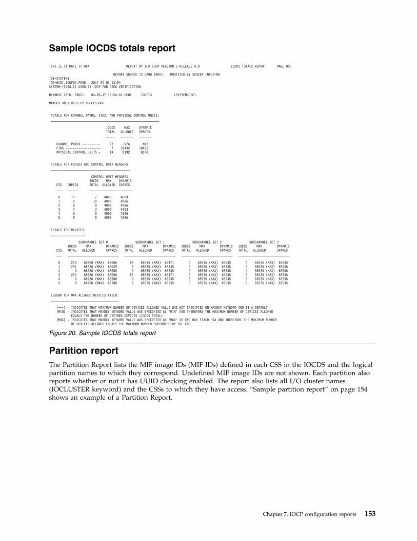
Sample IOCDS totals report
Partition reportThe Partition Report lists the MIF image IDs (MIF IDs) defined in each CSS in the IOCDS and the logicalpartition names to which they correspond. Undefined MIF image IDs are not shown. Each partition alsoreports whether or not it has UUID checking enabled. The report also lists all I/O cluster names(IOCLUSTER keyword) and the CSSs to which they have access. “Sample partition report” on page 154shows an example of a Partition Report.
TIME 15.11 DATE 17.094 REPORT BY ICP IOCP VERSION 5 RELEASE 4.0 IOCDS TOTALS REPORT PAGE 003
REPORT SOURCE IS CARD INPUT, MODIFIED BY SCREEN INPUT=NOID1=SYSTEM1ID2=HCDI.IODF02.PROD - 2017-04-03 13:54SYSTEM=(3906,1) USED BY IOCP FOR DECK VERIFICATION
DYNAMIC INFO: PROC1 04-03-17 13:54:42 HCDI IODF13 LSYSTEM=CPC1
MAXDEV <NOT USED BY PROCESSOR>
TOTALS FOR CHANNEL PATHS, FIDS, AND PHYSICAL CONTROL UNITS:___________________________________________________________
IOCDS MAX DYNAMICTOTAL ALLOWED SPARES_____ _______ _______
CHANNEL PATHS ---------- 23 N/A N/AFIDS ------------------- 7 18432 18425PHYSICAL CONTROL UNITS - 14 8192 8178
TOTALS FOR CHPIDS AND CONTROL UNIT HEADERS:___________________________________________
CONTROL UNIT HEADERSIOCDS MAX DYNAMIC
CSS CHPIDS TOTAL ALLOWED SPARES___ ______ _______________________
0 15 7 4096 40891 9 10 4096 40862 0 0 4096 40963 4 3 4096 40934 0 0 4096 40965 0 0 4096 4096
TOTALS FOR DEVICES:___________________
SUBCHANNEL SET 0 SUBCHANNEL SET 1 SUBCHANNEL SET 2 SUBCHANNEL SET 3IOCDS MAX DYNAMIC IOCDS MAX DYNAMIC IOCDS MAX DYNAMIC IOCDS MAX DYNAMIC
CSS TOTAL ALLOWED SPARES TOTAL ALLOWED SPARES TOTAL ALLOWED SPARES TOTAL ALLOWED SPARES___ ____________________________ ____________________________ ____________________________ ____________________________
0 214 65280 (MAX) 65066 64 65535 (MAX) 65471 0 65535 (MAX) 65535 0 65535 (MAX) 655351 241 65280 (MAX) 65039 0 65535 (MAX) 65535 0 65535 (MAX) 65535 0 65535 (MAX) 655352 0 65280 (MAX) 65280 0 65535 (MAX) 65535 0 65535 (MAX) 65535 0 65535 (MAX) 655353 224 65280 (MAX) 65056 64 65535 (MAX) 65471 0 65535 (MAX) 65535 0 65535 (MAX) 655354 0 65280 (MAX) 65280 0 65535 (MAX) 65535 0 65535 (MAX) 65535 0 65535 (MAX) 655355 0 65280 (MAX) 65280 0 65535 (MAX) 65535 0 65535 (MAX) 65535 0 65535 (MAX) 65535
LEGEND FOR MAX ALLOWED DEVICES FIELD:_____________________________________
(***) - INDICATES THAT MAXIMUM NUMBER OF DEVICES ALLOWED VALUE WAS NOT SPECIFIED ON MAXDEV KEYWORD AND IS A DEFAULT(MIN) - INDICATES THAT MAXDEV KEYWORD VALUE WAS SPECIFIED AS ’MIN’ AND THEREFORE THE MAXIMUM NUMBER OF DEVICES ALLOWED
EQUALS THE NUMBER OF DEFINED DEVICES (IOCDS TOTAL)(MAX) - INDICATES THAT MAXDEV KEYWORD VALUE WAS SPECIFIED AS ’MAX’ OR CPC HAS FIXED HSA AND THEREFORE THE MAXIMUM NUMBER
OF DEVICES ALLOWED EQUALS THE MAXIMUM NUMBER SUPPORTED BY THE CPC
Figure 20. Sample IOCDS totals report
Chapter 7. IOCP configuration reports 153
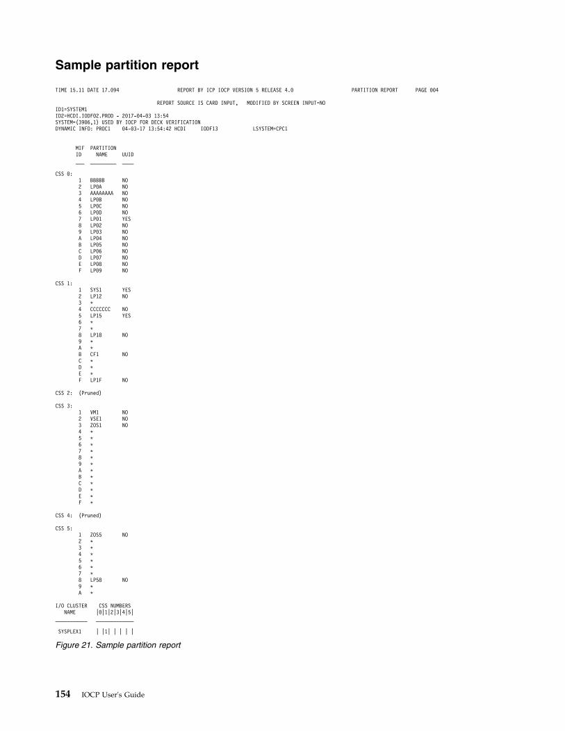
Sample partition report
TIME 15.11 DATE 17.094 REPORT BY ICP IOCP VERSION 5 RELEASE 4.0 PARTITION REPORT PAGE 004
REPORT SOURCE IS CARD INPUT, MODIFIED BY SCREEN INPUT=NOID1=SYSTEM1ID2=HCDI.IODF02.PROD - 2017-04-03 13:54SYSTEM=(3906,1) USED BY IOCP FOR DECK VERIFICATIONDYNAMIC INFO: PROC1 04-03-17 13:54:42 HCDI IODF13 LSYSTEM=CPC1
MIF PARTITIONID NAME UUID___ _________ ____
CSS 0:1 BBBBB NO2 LP0A NO3 AAAAAAAA NO4 LP0B NO5 LP0C NO6 LP0D NO7 LP01 YES8 LP02 NO9 LP03 NOA LP04 NOB LP05 NOC LP06 NOD LP07 NOE LP08 NOF LP09 NO
CSS 1:1 SYS1 YES2 LP12 NO3 *4 CCCCCCC NO5 LP15 YES6 *7 *8 LP18 NO9 *A *B CF1 NOC *D *E *F LP1F NO
CSS 2: (Pruned)
CSS 3:1 VM1 NO2 VSE1 NO3 ZOS1 NO4 *5 *6 *7 *8 *9 *A *B *C *D *E *F *
CSS 4: (Pruned)
CSS 5:1 ZOS5 NO2 *3 *4 *5 *6 *7 *8 LP58 NO9 *A *
I/O CLUSTER CSS NUMBERSNAME |0|1|2|3|4|5|
___________ _____________
SYSPLEX1 | |1| | | | |
Figure 21. Sample partition report
154 IOCP User's Guide
FID summary reportThe FID Summary Report lists the function IDs (FIDs) defined in the IOCDS. For each FID, the reportshows the following:v FID numberv PCHID number, PCHID and PORT numbers, or VCHID number the FID is associated with. VCHID
numbers are indicated by '(V)'.v VF numberv FID typev UID numberv PNETID valuesv Partitions that can use the FID. The partitions are identified by their CSS and MIF image ID number.
“Sample FID summary report” on page 156 shows an example of the FID Summary Report.
If the VF or UID keywords are not specified, dashes are reported. If the PNETID keyword was notspecified or a PNETID keyword value was skipped, dashes are reported. However, if the UID or PNETIDkeyword was not specified but IOCP provided a default value, the default value is reported.
If UUID checking is enabled for a partition that can access a FID, the UID value reported is appendedwith '*'.
If a FID type does not require the PORT keyword and multiple PNETID values are specified for theadapter's ports, the PNETID values are reported on successive lines. The first line is associated with thePNETID for port 1, the second line is associated with the PNETID for port 2, and so on.
The MIF IMAGE ID NUMBERS report column shows the MIF image IDs of logical partitions that the FIDcan access in the associated CSS. The CSS number that precedes a MIF image ID field is the CSS forwhich that field applies.v If a partition is in the access list of the FID, the MIF image ID number column contains an A for the
corresponding partition.v For each partition in the candidate list but not the access list of the FID, the MIF image ID number
column contains a C for the corresponding partition.v If a partition is in the access list of the FID and the partition has UUID checking enabled, the MIF
image ID number column contains an '&' for the corresponding partition.v For each partition in the candidate list but not the access list of the FID and the partition has UUID
checking enabled, the MIF image ID number column contains a U for the corresponding partition.v For all partitions not in the access or candidate lists of the FID, the corresponding MIF image ID
number columns are left blank.
A legend is located at the end of the FID Summary Report that describes the entries in the MIF IMAGEID NUMBERS report column.
At the end of the FID Summary Report, the totals are listed for each FID type your CPC supports.
Chapter 7. IOCP configuration reports 155
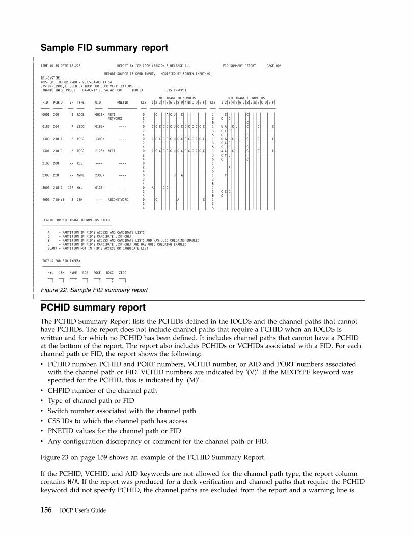
Sample FID summary report
PCHID summary reportThe PCHID Summary Report lists the PCHIDs defined in the IOCDS and the channel paths that cannothave PCHIDs. The report does not include channel paths that require a PCHID when an IOCDS iswritten and for which no PCHID has been defined. It includes channel paths that cannot have a PCHIDat the bottom of the report. The report also includes PCHIDs or VCHIDs associated with a FID. For eachchannel path or FID, the report shows the following:v PCHID number, PCHID and PORT numbers, VCHID number, or AID and PORT numbers associated
with the channel path or FID. VCHID numbers are indicated by '(V)'. If the MIXTYPE keyword wasspecified for the PCHID, this is indicated by '(M)'.
v CHPID number of the channel pathv Type of channel path or FIDv Switch number associated with the channel pathv CSS IDs to which the channel path has accessv PNETID values for the channel path or FIDv Any configuration discrepancy or comment for the channel path or FID.
Figure 23 on page 159 shows an example of the PCHID Summary Report.
If the PCHID, VCHID, and AID keywords are not allowed for the channel path type, the report columncontains N/A. If the report was produced for a deck verification and channel paths that require the PCHIDkeyword did not specify PCHID, the channel paths are excluded from the report and a warning line is
TIME 10.35 DATE 18.226 REPORT BY ICP IOCP VERSION 5 RELEASE 4.1 FID SUMMARY REPORT PAGE 006
REPORT SOURCE IS CARD INPUT, MODIFIED BY SCREEN INPUT=NOID1=SYSTEM1ID2=HCDI.IODF02.PROD - 2017-04-03 13:54SYSTEM=(3906,1) USED BY IOCP FOR DECK VERIFICATIONDYNAMIC INFO: PROC1 04-03-17 13:54:42 HCDI IODF13 LSYSTEM=CPC1
MIF IMAGE ID NUMBERS MIF IMAGE ID NUMBERSFID PCHID VF TYPE UID PNETID CSS |1|2|3|4|5|6|7|8|9|A|B|C|D|E|F| CSS |1|2|3|4|5|6|7|8|9|A|B|C|D|E|F|_____ _____ ___ ____ ____ ________________ ___ _______________________________ ___ _______________________________
0001 200 1 ROCE 0012* NET1 0 | |C| | |A|C|U| |C| | | | | | | 1 | |C| | | | | |C| | | | | | | |NETWORK2 2 | | | | | | | | | | | | | | | | 3 |C| |C| | | | | | | | | | | | |
4 | | | | | | | | | | | | | | | | 5 | | | | | | | |C| | | | | | | |0180 204 7 ZEDC 0180* ---- 0 |C|C|C|C|C|C|U|C|C|C|C|C|C|C|C| 1 |U|A| |C|U| | |C| | |C| | | |C|
2 | | | | | | | | | | | | | | | | 3 |C|C|C| | | | | | | | | | | | |4 | | | | | | | | | | | | | | | | 5 |C| | | | | | |C| | | | | | | |
1300 210-1 5 ROC2 1300* ---- 0 |C|C|C|C|C|C|U|C|C|C|C|C|C|C|C| 1 |U|A| |C|U| | |C| | |C| | | |C|2 | | | | | | | | | | | | | | | | 3 |C|C|C| | | | | | | | | | | | |4 | | | | | | | | | | | | | | | | 5 |C| | | | | | |C| | | | | | | |
1301 210-2 5 ROC2 F123* NET1 0 |C|C|C|C|C|C|U|C|C|C|C|C|C|C|C| 1 |&|C| |C|U| | |C| | |C| | | |C|2 | | | | | | | | | | | | | | | | 3 |C|C|C| | | | | | | | | | | | |4 | | | | | | | | | | | | | | | | 5 |C| | | | | | |C| | | | | | | |
2100 208 -- RCE ---- ---- 0 | | | | | | | | | | | | | | | | 1 | | | | | | | | | | | | | | | |2 | | | | | | | | | | | | | | | | 3 | | |A| | | | | | | | | | | | |4 | | | | | | | | | | | | | | | | 5 | | | | | | | | | | | | | | | |
2380 220 -- NVME 2380* ---- 0 | | | | | | |U| |A| | | | | | | 1 | |C| | | | | | | | | | | | | |2 | | | | | | | | | | | | | | | | 3 | | | | | | | | | | | | | | | |4 | | | | | | | | | | | | | | | | 5 | | | | | | | | | | | | | | | |
3500 218-2 127 HYL 0123 ---- 0 |A| | |C|C| | | | | | | | | | | 1 | | | | | | | | | | | | | | | |2 | | | | | | | | | | | | | | | | 3 |C|C|C| | | | | | | | | | | | |4 | | | | | | | | | | | | | | | | 5 |C| | | | | | | | | | | | | | |
4000 7E5(V) 2 ISM ---- ABCDNETWORK 0 | |C| | | | | |A| | | | | | |C| 1 | | | | | | | | | | | | | | | |2 | | | | | | | | | | | | | | | | 3 | | | | | | | | | | | | | | | |4 | | | | | | | | | | | | | | | | 5 | | | | | | | | | | | | | | | |
LEGEND FOR MIF IMAGE ID NUMBERS FIELD:______________________________________
A - PARTITION IN FID’S ACCESS AND CANDIDATE LISTSC - PARTITION IN FID’S CANDIDATE LIST ONLY& - PARTITION IN FID’S ACCESS AND CANDIDATE LISTS AND HAS UUID CHECKING ENABLEDU - PARTITION IN FID’S CANDIDATE LIST ONLY AND HAS UUID CHECKING ENABLEDBLANK - PARTITION NOT IN FID’S ACCESS OR CANDIDATE LIST
TOTALS FOR FID TYPES:_____________________
HYL ISM NVME RCE ROCE ROC2 ZEDC___ ___ ____ ___ ____ ____ ____1 1 1 1 1 2 1
Figure 22. Sample FID summary report
156 IOCP User's Guide
|||||||||||||||||||||||||||||||||||||||||||||||||||||||||
|
printed at the end of the report. PCHIDs are separated by a blank line on a modulo-16 basis which onsome CPCs indicates that the PCHIDs are associated with different card slots..
If a FID is being reported, the CHPID and SWITCH report columns contain N/A.
If the SWITCH keyword is not allowed for the channel path type, the report column contains N/A. If theSWITCH keyword is allowed but not specified for a channel path, then the column contains NONE.
If a CHPID or FID type supports multiple PNETID values, the PNETID values are reported on successivelines. The first line is associated with the PNETID for port 1, the second line is associated with thePNETID for port 2, and so on.
The CHANNEL CONFIGURATION DISCREPANCY OR COMMENT report column indicates whether achannel path has a configuration discrepancy. The report column also displays a comment for certainchannel path types when the channel path does not have a configuration discrepancy. NO indicates noconfiguration discrepancy exists. YES indicates that a configuration discrepancy exists and is accompaniedby a description of the discrepancy. More than one configuration discrepancy can exist for a channel pathbut only one discrepancy is reported. The report column displays a comment for FID types.
Channel configuration discrepancies are conditions that should not exist on your CPC. Because IOCPprocesses channel paths in ascending PCHID number order, it treats the lower numbered PCHIDs asaccurate and reports discrepancies against the higher numbered PCHIDs. An IOCDS is produced butIOCP reports the discrepancies so that they can be corrected. For an explanation of the channelconfiguration rules for your CPC, see Appendix F, “Machine limits and rules,” on page 285.
If no configuration discrepancy exists, a comment is displayed for certain channel path types and all FIDtypes. The following comments are displayed:v Channel path types that support a maximum number of valid subchannels (for example, FCP and
OSD) display the current number of valid subchannels defined on the channel path. For OSN channelpaths, the OSN and 3745 subchannel totals are both displayed. For IQD channel paths, the number ofsubchannels defined on the channel path and the total number of subchannels for all IQD channelpaths in the configuration are both displayed. For more information about the maximum subchannelssupported for a channel path type, see Appendix F, “Machine limits and rules,” on page 285.
v The current number of unit addresses defined on channel path types CNC, CTC, FC, and FCV aredisplayed. For more information about the maximum unit addresses supported for a channel pathtype, see Appendix F, “Machine limits and rules,” on page 285. IOCP might generate more unitaddresses for a spanned FC channel path (PATH keyword in the CHPID statement) than for anunspanned channel path. See “FC control unit definition considerations:” on page 84. Also, IOCP mightgenerate more unit addresses for a shared CTC channel path than for an unshared channel path. See“Shared ESCON CTC considerations” on page 24.
v The AID and PORT keyword values defined on channel path type CIB or CS5.v The PCHID and PORT keyword values defined on channel path type CL5.v The first FID number defined on a PCHID, PCHID-PORT, or VCHID.v The PCHID and PORT keyword values defined on function types HYL and ROC2.
The following channel configuration discrepancies can exist for a channel path:
YES - It exceeds max number of FICON+OSA | ISC-3 | CFS+CFR | CBS+CBR | CFP | CBP | ICP |FCV | OSA channel paths allowed.
This discrepancy indicates that the channel path type has exceeded the maximum number ofchannel paths allowed for your CPC for the indicated channel hardware type. This discrepancyexists for all higher numbered channel paths of the same channel hardware type.
YES - It exceeds max number of CIB Adapter IDs allowedThis discrepancy indicates that the CIB Adapter ID (AID) has exceeded the maximum number
Chapter 7. IOCP configuration reports 157
|
allowed for your CPC. This discrepancy exists for all other channel paths defined on the sameAID and for all channel paths on higher numbered AIDs.
In addition to the Channel Configuration Discrepancy report column, IOCP prints an informational lineafter a channel path that has certain discrepancies. These informational lines are as follows:PCHID xxx | CHPID xx in CSS y has exceeded the maximum number of FICON+OSA |CF Hardware | ISC-3 | CFS+CFR | CBS+CBR | CFP | CBP | ICP | FCV | OSA channelpaths allowed by your processor.
AID xx has exceeded the maximum number of Adapter IDs allowed by your processor
The following channel path types are associated with the channel hardware types listed in the firstinformational line:v FICON+OSA = FC, FCV, FCP, OSC, OSD, OSE, OSM, OSN, and OSXv CF Hardware = CFS, CFR, CFP, CBS, CBR, and CBPv ISC-3 = CFS, CFR, and CFPv CFS+CFR = CFS and CFRv CBS+CBR = CBS and CBRv OSA = OSC, OSD, OSE, OSM, OSN, and OSX
IOCP lists caution message ICP055I at the end of this report when any channel configurationdiscrepancies exist.
At the end of the PCHID Report, the totals are listed for each channel card type and FID type your CPCsupports. The totals for the internal channel path types and internal FID types your CPC supports arealso included.
158 IOCP User's Guide
|||
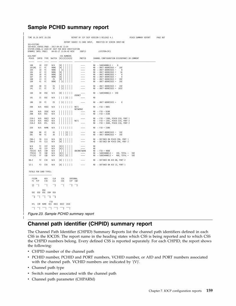
Sample PCHID summary report
Channel path identifier (CHPID) summary reportThe Channel Path Identifier (CHPID) Summary Reports list the channel path identifiers defined in eachCSS in the IOCDS. The report name in the heading states which CSS is being reported and to which CSSthe CHPID numbers belong. Every defined CSS is reported separately. For each CHPID, the report showsthe following:v CHPID number of the channel pathv PCHID number, PCHID and PORT numbers, VCHID number, or AID and PORT numbers associated
with the channel path. VCHID numbers are indicated by '(V)'.v Channel path typev Switch number associated with the channel pathv Channel path parameter (CHPARM)
TIME 10.35 DATE 18.226 REPORT BY ICP IOCP VERSION 5 RELEASE 4.1 PCHID SUMMARY REPORT PAGE 007
REPORT SOURCE IS CARD INPUT, MODIFIED BY SCREEN INPUT=NOID1=SYSTEM1ID2=HCDI.IODF02.PROD - 2017-04-03 13:54SYSTEM=(3906,1) USED BY IOCP FOR DECK VERIFICATIONDYNAMIC INFO: PROC1 04-03-17 13:54:42 HCDI IODF13 LSYSTEM=CPC1
AID-PORT CSS NUMBERSPCHID CHPID TYPE SWITCH |0|1|2|3|4|5| PNETID CHANNEL CONFIGURATION DISCREPANCY OR COMMENT_____ _____ ____ ______ _____________ ________________ ____________________________________________________________
100 10 FCP N/A |0| | | | | | ---- NO - SUBCHANNELS = 0101(M) 11 FC NONE |0| | | | | | ---- NO - UNIT ADDRESSES = 192104 10 FC NONE | |1| | | | | ---- NO - UNIT ADDRESSES = 8105 12 FC NONE |0| | | | | | ---- NO - UNIT ADDRESSES = 16106 18 FC NONE |0| | | | | | ---- NO - UNIT ADDRESSES = 0107 19 FC NONE |0| | | | | | ---- NO - UNIT ADDRESSES = 0108 13 FC 25 |0| | | | | | ---- NO - UNIT ADDRESSES = 192109 41 FC NONE | |1| | | | | ---- NO - UNIT ADDRESSES = 192
140 40 FC 25 | |1| | | | | ---- NO - UNIT ADDRESSES = 192141 21 FC 35 | |1| | | | | ---- NO - UNIT ADDRESSES = 1032
160 30 OSD N/A |0| | | | | | ---- NO - SUBCHANNELS = 240OSDNET
161 31 OSE N/A | | | |3| | | ---- NO
180 20 FC 25 | |1| | | | | ---- NO - UNIT ADDRESSES = 0
200 N/A ROCE N/A | | | | | | | NET1 NO - FID = 0001NETWORK2
204 N/A ZEDC N/A | | | | | | | ---- NO - FID = 0180208 N/A RCE N/A | | | | | | | ---- NO - FID = 2100
210-1 N/A ROC2 N/A | | | | | | | ---- NO - FID = 1300, PCHID 210, PORT 1210-2 N/A ROC2 N/A | | | | | | | NET1 NO - FID = 1301, PCHID 210, PORT 2218-2 N/A HYL N/A | | | | | | | ---- NO - FID = 3500, PCHID 218, PORT 2
220 N/A NVME N/A | | | | | | | ---- NO - FID = 2380
280 80 FC 45 | | | |3| | | ---- NO - UNIT ADDRESSES = 192281 90 FC 36 | | | |3| | | ---- NO - UNIT ADDRESSES = 192
290-1 F8 CL5 N/A |0| | | | | | ---- NO - DEFINED ON PCHID 290, PORT 1290-2 F9 CL5 N/A |0| | | | | | ---- NO - DEFINED ON PCHID 290, PORT 2
N/A FC ICP N/A |0|1| | | | | ---- NON/A FD ICP N/A |0|1| | | | | ---- NO7E5(V) N/A ISM N/A | | | | | | | ABCDNETWORK NO - FID = 40007F0(V) FE IQD N/A |0|1| | | | | ---- NO - SUBCHANNELS = 192, TOTAL = 5927F1(V) FF IQD N/A |0|1| |3| | | ---- NO - SUBCHANNELS = 400, TOTAL = 592
08-2 F2 CIB N/A |0| | | | | | ---- NO - DEFINED ON AID 08, PORT 2
12-1 F3 CS5 N/A |0| | | | | | ---- NO - DEFINED ON AID 12, PORT 1
TOTALS FOR CARD TYPES:______________________
FICON HCA CLR ICA INTERNALFC FCP CIB CL5 CS5 ICP IQD__ ___ ___ ___ ___ ___ ___12 1 1 2 1 2 2
OSAOSC OSD OSE OSM OSX___ ___ ___ ___ ___0 1 1 0 0
FIDHYL ISM NVME RCE ROCE ROC2 ZEDC___ ___ ____ ___ ____ ____ ____1 1 1 1 1 2 1
Figure 23. Sample PCHID summary report
Chapter 7. IOCP configuration reports 159
||||||||||||||||||||||||||||||||||||||||||||||||||||||||||||||||||||||||||||||
|
v Logical partition (LP) access method for the channel pathv MIF image ID numbers of logical partitions that the channel path can access.
Figure 24 on page 161 shows an example of the CHPID Summary Report.
If the SWITCH keyword is not allowed for the channel path type, the report column contains N/A. If theSWITCH keyword is allowed but not specified for a channel path, then the report column contains NONE.
If the CHPARM keyword is not allowed for the channel path type, the report column contains N/A. IfCHPARM is allowed but not specified or has a value of 00, either NONE or 00 is shown, depending on thechannel path type.
The LP ACCESS report column shows the logical partition access method for the channel path.v DED is reported if the channel path is dedicated to a single logical partitionv REC is reported if the channel path is defined as reconfigurablev SHARED is reported if the channel path is defined as sharedv SPANNED is reported if the channel path is defined as spanned.
The MIF IMAGE ID NUMBERS report column shows the MIF image IDs of logical partitions that theCHPID can access in the CSS.v For each partition in the access list of the CHPID, the MIF image ID number column contains an A for
the corresponding partition.v For each partition in the candidate list but not the access list of the CHPID, the MIF image ID number
column contains a C for the corresponding partition.v For all partitions not in the access or candidate lists of the CHPID, the corresponding MIF image ID
number columns are left blank.
Several legends are located at the end of the CHPID Summary Report. The first set of legends describesthe entries in the CHPARM report column for the channel path types that support the CHPARMkeyword. The last legend describes the entries in the MIF IMAGE ID NUMBERS report column.
At the end of the CHPID Summary Report, the totals are listed for each channel path type your CPCsupports in the CSS.
160 IOCP User's Guide
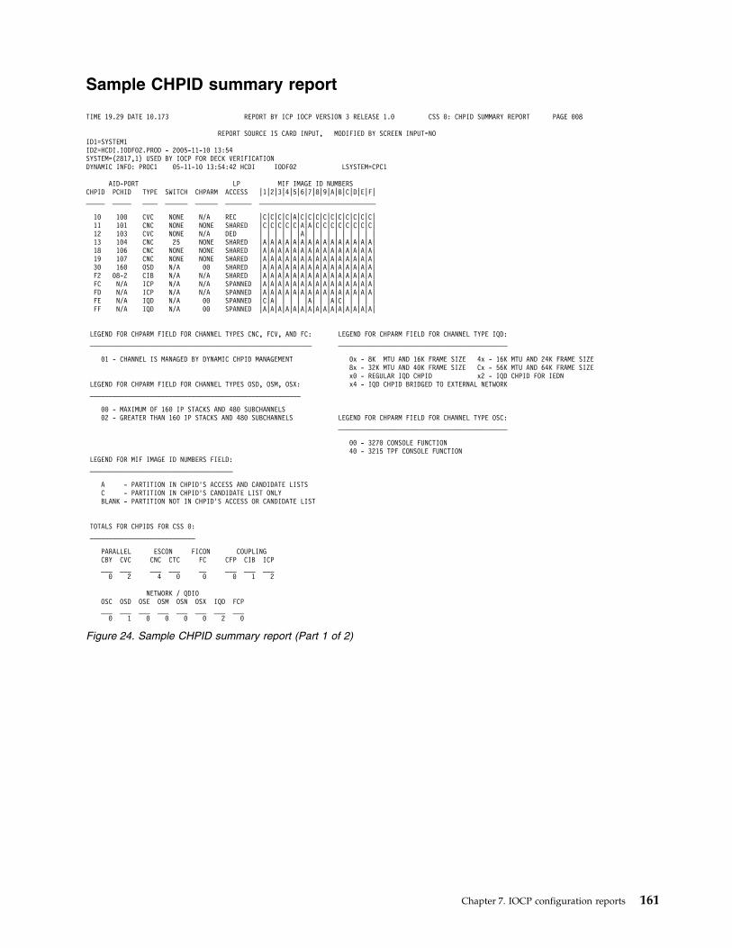
Sample CHPID summary report
TIME 19.29 DATE 10.173 REPORT BY ICP IOCP VERSION 3 RELEASE 1.0 CSS 0: CHPID SUMMARY REPORT PAGE 008
REPORT SOURCE IS CARD INPUT, MODIFIED BY SCREEN INPUT=NOID1=SYSTEM1ID2=HCDI.IODF02.PROD - 2005-11-10 13:54SYSTEM=(2817,1) USED BY IOCP FOR DECK VERIFICATIONDYNAMIC INFO: PROC1 05-11-10 13:54:42 HCDI IODF02 LSYSTEM=CPC1
AID-PORT LP MIF IMAGE ID NUMBERSCHPID PCHID TYPE SWITCH CHPARM ACCESS |1|2|3|4|5|6|7|8|9|A|B|C|D|E|F|_____ _____ ____ ______ ______ _______ _______________________________
10 100 CVC NONE N/A REC |C|C|C|C|A|C|C|C|C|C|C|C|C|C|C|11 101 CNC NONE NONE SHARED |C|C|C|C|C|A|A|C|C|C|C|C|C|C|C|12 103 CVC NONE N/A DED | | | | | |A| | | | | | | | | |13 104 CNC 25 NONE SHARED |A|A|A|A|A|A|A|A|A|A|A|A|A|A|A|18 106 CNC NONE NONE SHARED |A|A|A|A|A|A|A|A|A|A|A|A|A|A|A|19 107 CNC NONE NONE SHARED |A|A|A|A|A|A|A|A|A|A|A|A|A|A|A|30 160 OSD N/A 00 SHARED |A|A|A|A|A|A|A|A|A|A|A|A|A|A|A|F2 08-2 CIB N/A N/A SHARED |A|A|A|A|A|A|A|A|A|A|A|A|A|A|A|FC N/A ICP N/A N/A SPANNED |A|A|A|A|A|A|A|A|A|A|A|A|A|A|A|FD N/A ICP N/A N/A SPANNED |A|A|A|A|A|A|A|A|A|A|A|A|A|A|A|FE N/A IQD N/A 00 SPANNED |C|A| | | | |A| | |A|C| | | | |FF N/A IQD N/A 00 SPANNED |A|A|A|A|A|A|A|A|A|A|A|A|A|A|A|
LEGEND FOR CHPARM FIELD FOR CHANNEL TYPES CNC, FCV, AND FC: LEGEND FOR CHPARM FIELD FOR CHANNEL TYPE IQD:___________________________________________________________ _____________________________________________
01 - CHANNEL IS MANAGED BY DYNAMIC CHPID MANAGEMENT 0x - 8K MTU AND 16K FRAME SIZE 4x - 16K MTU AND 24K FRAME SIZE8x - 32K MTU AND 40K FRAME SIZE Cx - 56K MTU AND 64K FRAME SIZEx0 - REGULAR IQD CHPID x2 - IQD CHPID FOR IEDN
LEGEND FOR CHPARM FIELD FOR CHANNEL TYPES OSD, OSM, OSX: x4 - IQD CHPID BRIDGED TO EXTERNAL NETWORK________________________________________________________
00 - MAXIMUM OF 160 IP STACKS AND 480 SUBCHANNELS02 - GREATER THAN 160 IP STACKS AND 480 SUBCHANNELS LEGEND FOR CHPARM FIELD FOR CHANNEL TYPE OSC:
_____________________________________________
00 - 3270 CONSOLE FUNCTION40 - 3215 TPF CONSOLE FUNCTION
LEGEND FOR MIF IMAGE ID NUMBERS FIELD:______________________________________
A - PARTITION IN CHPID’S ACCESS AND CANDIDATE LISTSC - PARTITION IN CHPID’S CANDIDATE LIST ONLYBLANK - PARTITION NOT IN CHPID’S ACCESS OR CANDIDATE LIST
TOTALS FOR CHPIDS FOR CSS 0:____________________________
PARALLEL ESCON FICON COUPLINGCBY CVC CNC CTC FC CFP CIB ICP___ ___ ___ ___ __ ___ ___ ___0 2 4 0 0 0 1 2
NETWORK / QDIOOSC OSD OSE OSM OSN OSX IQD FCP___ ___ ___ ___ ___ ___ ___ ___0 1 0 0 0 0 2 0
Figure 24. Sample CHPID summary report (Part 1 of 2)
Chapter 7. IOCP configuration reports 161
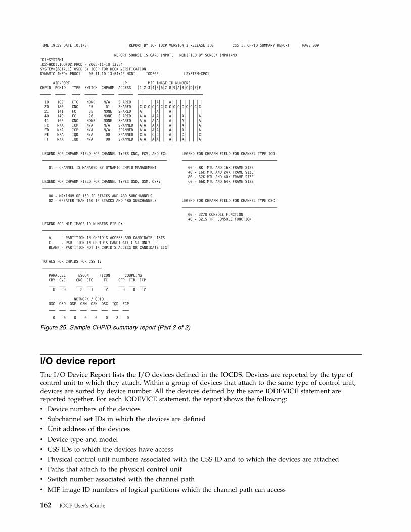
I/O device reportThe I/O Device Report lists the I/O devices defined in the IOCDS. Devices are reported by the type ofcontrol unit to which they attach. Within a group of devices that attach to the same type of control unit,devices are sorted by device number. All the devices defined by the same IODEVICE statement arereported together. For each IODEVICE statement, the report shows the following:v Device numbers of the devicesv Subchannel set IDs in which the devices are definedv Unit address of the devicesv Device type and modelv CSS IDs to which the devices have accessv Physical control unit numbers associated with the CSS ID and to which the devices are attachedv Paths that attach to the physical control unitv Switch number associated with the channel pathv MIF image ID numbers of logical partitions which the channel path can access
TIME 19.29 DATE 10.173 REPORT BY ICP IOCP VERSION 3 RELEASE 1.0 CSS 1: CHPID SUMMARY REPORT PAGE 009
REPORT SOURCE IS CARD INPUT, MODIFIED BY SCREEN INPUT=NOID1=SYSTEM1ID2=HCDI.IODF02.PROD - 2005-11-10 13:54SYSTEM=(2817,1) USED BY IOCP FOR DECK VERIFICATIONDYNAMIC INFO: PROC1 05-11-10 13:54:42 HCDI IODF02 LSYSTEM=CPC1
AID-PORT LP MIF IMAGE ID NUMBERSCHPID PCHID TYPE SWITCH CHPARM ACCESS |1|2|3|4|5|6|7|8|9|A|B|C|D|E|F|_____ _____ ____ ______ ______ _______ _______________________________
10 102 CTC NONE N/A SHARED | | | | |A| | |A| | | | | | | |20 180 CNC 25 01 SHARED |C|C|C|C|C|C|C|C|C|C|C|C|C|C|C|21 141 FC 35 NONE SHARED |A| | | |A| | |A| | | | | | | |40 140 FC 26 NONE SHARED |A|A| |A|A| | |A| | |A| | | |A|41 105 CNC NONE NONE SHARED |A|A| |A|A| | |A| | |A| | | |A|FC N/A ICP N/A N/A SPANNED |A|A| |A|A| | |A| | |A| | | |A|FD N/A ICP N/A N/A SPANNED |A|A| |A|A| | |A| | |A| | | |A|FE N/A IQD N/A 00 SPANNED |C|A| |C|C| | |A| | |C| | | |C|FF N/A IQD N/A 00 SPANNED |A|A| |A|A| | |A| | |A| | | |A|
LEGEND FOR CHPARM FIELD FOR CHANNEL TYPES CNC, FCV, AND FC: LEGEND FOR CHPARM FIELD FOR CHANNEL TYPE IQD:___________________________________________________________ _____________________________________________
01 - CHANNEL IS MANAGED BY DYNAMIC CHPID MANAGEMENT 00 - 8K MTU AND 16K FRAME SIZE40 - 16K MTU AND 24K FRAME SIZE80 - 32K MTU AND 40K FRAME SIZE
LEGEND FOR CHPARM FIELD FOR CHANNEL TYPES OSD, OSM, OSX: C0 - 56K MTU AND 64K FRAME SIZE________________________________________________________
00 - MAXIMUM OF 160 IP STACKS AND 480 SUBCHANNELS02 - GREATER THAN 160 IP STACKS AND 480 SUBCHANNELS LEGEND FOR CHPARM FIELD FOR CHANNEL TYPE OSC:
_____________________________________________
00 - 3270 CONSOLE FUNCTION40 - 3215 TPF CONSOLE FUNCTION
LEGEND FOR MIF IMAGE ID NUMBERS FIELD:______________________________________
A - PARTITION IN CHPID’S ACCESS AND CANDIDATE LISTSC - PARTITION IN CHPID’S CANDIDATE LIST ONLYBLANK - PARTITION NOT IN CHPID’S ACCESS OR CANDIDATE LIST
TOTALS FOR CHPIDS FOR CSS 1:____________________________
PARALLEL ESCON FICON COUPLINGCBY CVC CNC CTC FC CFP CIB ICP___ ___ ___ ___ __ ___ ___ ___0 0 2 1 2 0 0 2
NETWORK / QDIOOSC OSD OSE OSM OSN OSX IQD FCP___ ___ ___ ___ ___ ___ ___ ___
0 0 0 0 0 0 2 0
Figure 25. Sample CHPID summary report (Part 2 of 2)
162 IOCP User's Guide
v Any comments for the devices.
Figure 26 on page 164 shows an example of the I/O Device Report.
If a device is in a subchannel set other than 0, the DEVICE NUMBERS report column for the appropriateCSSs contains (n). The n represents the appropriate subchannel set number. If a device is in subchannelset 1 for a CSS, the DEVICE NUMBERS report column for the appropriate CSSs contains (1). For devicesin subchannel set 0 for a CSS, no special indication is present.
The path listed is the composite path that the CPC uses when communicating with the device. Thiscomposite path (chpid.link.cuadd) includes the channel path, the link address, and the control unit logicaladdress. If you do not specify LINK but you do specify CUADD, two asterisks (**) are displayed forLINK. If a control unit is managed (PATH keyword on CNTLUNIT statement), two asterisks (**) aredisplayed for the path.
If the SWITCH keyword is not allowed for the channel path type, the report column contains N/A. If theSWITCH keyword is allowed but not specified for a channel path, the report column contains NONE. If thecontrol unit path is a managed path (PATH keyword on CNTLUNIT statement), the report columncontains YES
The MIF IMAGE ID NUMBERS report column shows the MIF image ID numbers of logical partitionswhich the channel path can access. The following information is reported:v For each partition in the access list of the channel path, the MIF image ID column contains an A for the
corresponding partition.v For each partition in the candidate list but not the access list of the channel path, the MIF image ID
column contains a C for the corresponding partition.v For all partitions not in the access or candidate lists of channel path, the corresponding MIF image ID
columns are left blank.
You can use the PART, PARTITION, or NOTPART keyword in the IODEVICE statement to define adevice candidate list that includes or excludes LP access at the device level. The following information isreported in the MIF IMAGE ID NUMBERS report column for a device candidate list:v For the first report line for a device, the MIF image ID column contains an asterisk (*) for each
partition in the device candidate list.v A minus sign (-) for an LP indicates that the device candidate list excludes LP access to the device even
though the LP has access to a channel path assigned to the device.v A plus sign (+) for an LP indicates that the device candidate list includes LP access to the device even
though the LP currently does not have access to a channel path assigned to the device. The LP canaccess only the device following a dynamic I/O configuration change that adds the LP to the candidatelist of the channel path.
Notes:
1. For each device that has a plus sign (+) in the MIF IMAGE ID NUMBERS column, ensure that youspecified the correct LPs in the PARTITION or NOTPART keyword on the IODEVICE statement. Thedevice does not have access to those LPs, even though the channel path does have access, until adynamic I/O configuration change is made.
2. If the device has a device candidate list that is equivalent to the one it would have for a default, aplus sign (+) is not shown for LPs included in the device candidate list. A plus sign (+) is shown onlyif the device candidate list was specified, is not equivalent to the default one, and included an LP forwhich the path does not have access.
The COMMENT report column contains information that applies to the devices. The followinginformation is reported:v STADET if the device has value STADET=Y
Chapter 7. IOCP configuration reports 163
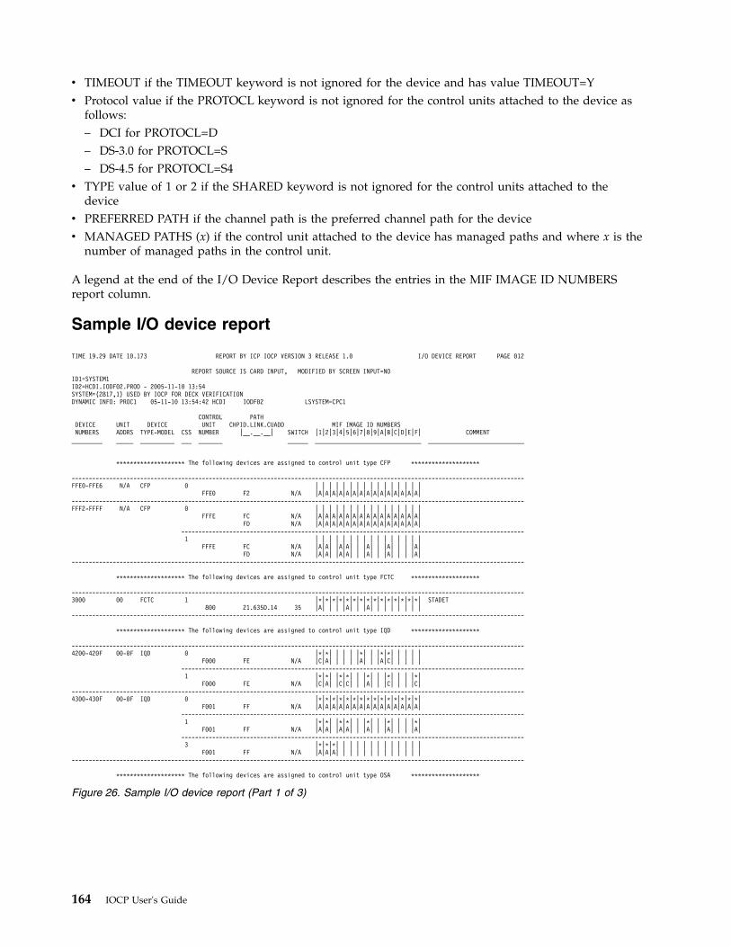
v TIMEOUT if the TIMEOUT keyword is not ignored for the device and has value TIMEOUT=Yv Protocol value if the PROTOCL keyword is not ignored for the control units attached to the device as
follows:– DCI for PROTOCL=D– DS-3.0 for PROTOCL=S– DS-4.5 for PROTOCL=S4
v TYPE value of 1 or 2 if the SHARED keyword is not ignored for the control units attached to thedevice
v PREFERRED PATH if the channel path is the preferred channel path for the devicev MANAGED PATHS (x) if the control unit attached to the device has managed paths and where x is the
number of managed paths in the control unit.
A legend at the end of the I/O Device Report describes the entries in the MIF IMAGE ID NUMBERSreport column.
Sample I/O device report
TIME 19.29 DATE 10.173 REPORT BY ICP IOCP VERSION 3 RELEASE 1.0 I/O DEVICE REPORT PAGE 012
REPORT SOURCE IS CARD INPUT, MODIFIED BY SCREEN INPUT=NOID1=SYSTEM1ID2=HCDI.IODF02.PROD - 2005-11-10 13:54SYSTEM=(2817,1) USED BY IOCP FOR DECK VERIFICATIONDYNAMIC INFO: PROC1 05-11-10 13:54:42 HCDI IODF02 LSYSTEM=CPC1
CONTROL PATHDEVICE UNIT DEVICE UNIT CHPID.LINK.CUADD MIF IMAGE ID NUMBERSNUMBERS ADDRS TYPE-MODEL CSS NUMBER |__.__.__| SWITCH |1|2|3|4|5|6|7|8|9|A|B|C|D|E|F| COMMENT_________ _____ __________ ___ _______ ______ _______________________________ ____________________________
******************** The following devices are assigned to control unit type CFP ********************
------------------------------------------------------------------------------------------------------------------------------------FFE0-FFE6 N/A CFP 0 | | | | | | | | | | | | | | | |
FFE0 F2 N/A |A|A|A|A|A|A|A|A|A|A|A|A|A|A|A|------------------------------------------------------------------------------------------------------------------------------------FFF2-FFFF N/A CFP 0 | | | | | | | | | | | | | | | |
FFFE FC N/A |A|A|A|A|A|A|A|A|A|A|A|A|A|A|A|FD N/A |A|A|A|A|A|A|A|A|A|A|A|A|A|A|A|
----------------------------------------------------------------------------------------------------1 | | | | | | | | | | | | | | | |
FFFE FC N/A |A|A| |A|A| | |A| | |A| | | |A|FD N/A |A|A| |A|A| | |A| | |A| | | |A|
------------------------------------------------------------------------------------------------------------------------------------
******************** The following devices are assigned to control unit type FCTC ********************
------------------------------------------------------------------------------------------------------------------------------------3000 00 FCTC 1 |*|*|*|*|*|*|*|*|*|*|*|*|*|*|*| STADET
800 21.635D.14 35 |A| | | |A| | |A| | | | | | | |------------------------------------------------------------------------------------------------------------------------------------
******************** The following devices are assigned to control unit type IQD ********************
------------------------------------------------------------------------------------------------------------------------------------4200-420F 00-0F IQD 0 |*|*| | | | |*| | |*|*| | | | |
F000 FE N/A |C|A| | | | |A| | |A|C| | | | |----------------------------------------------------------------------------------------------------1 |*|*| |*|*| | |*| | |*| | | |*|
F000 FE N/A |C|A| |C|C| | |A| | |C| | | |C|------------------------------------------------------------------------------------------------------------------------------------4300-430F 00-0F IQD 0 |*|*|*|*|*|*|*|*|*|*|*|*|*|*|*|
F001 FF N/A |A|A|A|A|A|A|A|A|A|A|A|A|A|A|A|----------------------------------------------------------------------------------------------------1 |*|*| |*|*| | |*| | |*| | | |*|
F001 FF N/A |A|A| |A|A| | |A| | |A| | | |A|----------------------------------------------------------------------------------------------------3 |*|*|*| | | | | | | | | | | | |
F001 FF N/A |A|A|A| | | | | | | | | | | | |------------------------------------------------------------------------------------------------------------------------------------
******************** The following devices are assigned to control unit type OSA ********************
Figure 26. Sample I/O device report (Part 1 of 3)
164 IOCP User's Guide
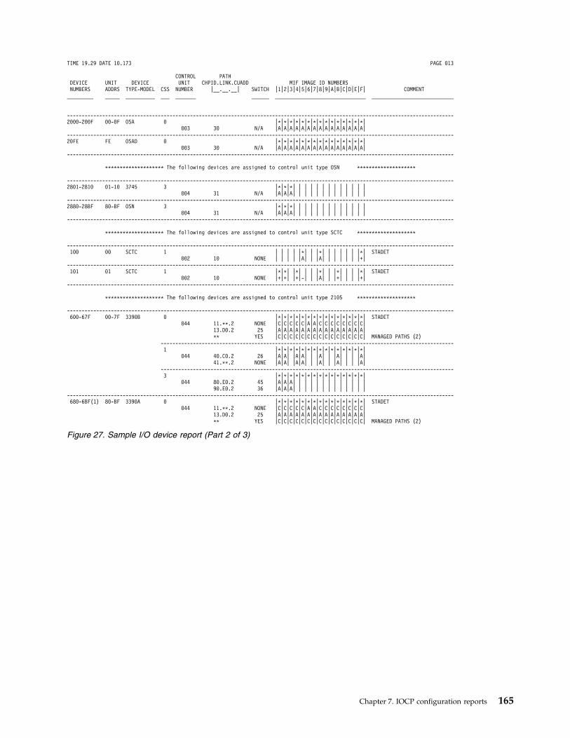
TIME 19.29 DATE 10.173 PAGE 013
CONTROL PATHDEVICE UNIT DEVICE UNIT CHPID.LINK.CUADD MIF IMAGE ID NUMBERSNUMBERS ADDRS TYPE-MODEL CSS NUMBER |__.__.__| SWITCH |1|2|3|4|5|6|7|8|9|A|B|C|D|E|F| COMMENT_________ _____ __________ ___ _______ ______ _______________________________ ____________________________
------------------------------------------------------------------------------------------------------------------------------------2000-200F 00-0F OSA 0 |*|*|*|*|*|*|*|*|*|*|*|*|*|*|*|
003 30 N/A |A|A|A|A|A|A|A|A|A|A|A|A|A|A|A|------------------------------------------------------------------------------------------------------------------------------------20FE FE OSAD 0 |*|*|*|*|*|*|*|*|*|*|*|*|*|*|*|
003 30 N/A |A|A|A|A|A|A|A|A|A|A|A|A|A|A|A|------------------------------------------------------------------------------------------------------------------------------------
******************** The following devices are assigned to control unit type OSN ********************
------------------------------------------------------------------------------------------------------------------------------------2801-2810 01-10 3745 3 |*|*|*| | | | | | | | | | | | |
004 31 N/A |A|A|A| | | | | | | | | | | | |------------------------------------------------------------------------------------------------------------------------------------2880-28BF 80-BF OSN 3 |*|*|*| | | | | | | | | | | | |
004 31 N/A |A|A|A| | | | | | | | | | | | |------------------------------------------------------------------------------------------------------------------------------------
******************** The following devices are assigned to control unit type SCTC ********************
------------------------------------------------------------------------------------------------------------------------------------100 00 SCTC 1 | | | | |*| | |*| | | | | | |*| STADET
002 10 NONE | | | | |A| | |A| | | | | | |+|------------------------------------------------------------------------------------------------------------------------------------101 01 SCTC 1 |*|*| |*| | | |*| | |*| | | |*| STADET
002 10 NONE |+|+| |+|-| | |A| | |+| | | |+|------------------------------------------------------------------------------------------------------------------------------------
******************** The following devices are assigned to control unit type 2105 ********************
------------------------------------------------------------------------------------------------------------------------------------600-67F 00-7F 3390B 0 |*|*|*|*|*|*|*|*|*|*|*|*|*|*|*| STADET
044 11.**.2 NONE |C|C|C|C|C|A|A|C|C|C|C|C|C|C|C|13.D0.2 25 |A|A|A|A|A|A|A|A|A|A|A|A|A|A|A|** YES |C|C|C|C|C|C|C|C|C|C|C|C|C|C|C| MANAGED PATHS (2)
----------------------------------------------------------------------------------------------------1 |*|*|*|*|*|*|*|*|*|*|*|*|*|*|*|
044 40.C0.2 26 |A|A| |A|A| | |A| | |A| | | |A|41.**.2 NONE |A|A| |A|A| | |A| | |A| | | |A|
----------------------------------------------------------------------------------------------------3 |*|*|*|*|*|*|*|*|*|*|*|*|*|*|*|
044 80.E0.2 45 |A|A|A| | | | | | | | | | | | |90.E0.2 36 |A|A|A| | | | | | | | | | | | |
------------------------------------------------------------------------------------------------------------------------------------680-6BF(1) 80-BF 3390A 0 |*|*|*|*|*|*|*|*|*|*|*|*|*|*|*| STADET
044 11.**.2 NONE |C|C|C|C|C|A|A|C|C|C|C|C|C|C|C|13.D0.2 25 |A|A|A|A|A|A|A|A|A|A|A|A|A|A|A|** YES |C|C|C|C|C|C|C|C|C|C|C|C|C|C|C| MANAGED PATHS (2)
Figure 27. Sample I/O device report (Part 2 of 3)
Chapter 7. IOCP configuration reports 165
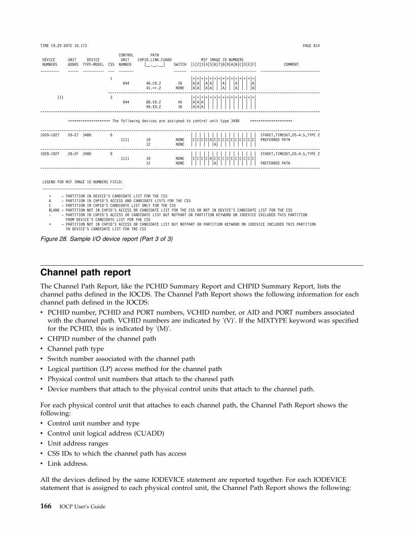
Channel path reportThe Channel Path Report, like the PCHID Summary Report and CHPID Summary Report, lists thechannel paths defined in the IOCDS. The Channel Path Report shows the following information for eachchannel path defined in the IOCDS:v PCHID number, PCHID and PORT numbers, VCHID number, or AID and PORT numbers associated
with the channel path. VCHID numbers are indicated by '(V)'. If the MIXTYPE keyword was specifiedfor the PCHID, this is indicated by '(M)'.
v CHPID number of the channel pathv Channel path typev Switch number associated with the channel pathv Logical partition (LP) access method for the channel pathv Physical control unit numbers that attach to the channel pathv Device numbers that attach to the physical control units that attach to the channel path.
For each physical control unit that attaches to each channel path, the Channel Path Report shows thefollowing:v Control unit number and typev Control unit logical address (CUADD)v Unit address rangesv CSS IDs to which the channel path has accessv Link address.
All the devices defined by the same IODEVICE statement are reported together. For each IODEVICEstatement that is assigned to each physical control unit, the Channel Path Report shows the following:
TIME 19.29 DATE 10.173 PAGE 014
CONTROL PATHDEVICE UNIT DEVICE UNIT CHPID.LINK.CUADD MIF IMAGE ID NUMBERSNUMBERS ADDRS TYPE-MODEL CSS NUMBER |__.__.__| SWITCH |1|2|3|4|5|6|7|8|9|A|B|C|D|E|F| COMMENT_________ _____ __________ ___ _______ ______ _______________________________ ____________________________
1 |*|*|*|*|*|*|*|*|*|*|*|*|*|*|*|044 40.C0.2 26 |A|A| |A|A| | |A| | |A| | | |A|
41.**.2 NONE |A|A| |A|A| | |A| | |A| | | |A|----------------------------------------------------------------------------------------------------
(1) 3 |*|*|*|*|*|*|*|*|*|*|*|*|*|*|*|044 80.E0.2 45 |A|A|A| | | | | | | | | | | | |
90.E0.2 36 |A|A|A| | | | | | | | | | | | |------------------------------------------------------------------------------------------------------------------------------------
******************** The following devices are assigned to control unit type 3490 ********************
------------------------------------------------------------------------------------------------------------------------------------1020-1027 20-27 3480 0 | | | | | | | | | | | | | | | | STADET,TIMEOUT,DS-4.5,TYPE 2
1111 10 NONE |C|C|C|C|A|C|C|C|C|C|C|C|C|C|C| PREFERRED PATH12 NONE | | | | | |A| | | | | | | | | |
------------------------------------------------------------------------------------------------------------------------------------1028-102F 28-2F 3480 0 | | | | | | | | | | | | | | | | STADET,TIMEOUT,DS-4.5,TYPE 2
1111 10 NONE |C|C|C|C|A|C|C|C|C|C|C|C|C|C|C|12 NONE | | | | | |A| | | | | | | | | | PREFERRED PATH
------------------------------------------------------------------------------------------------------------------------------------
LEGEND FOR MIF IMAGE ID NUMBERS FIELD:______________________________________
* - PARTITION IN DEVICE’S CANDIDATE LIST FOR THE CSSA - PARTITION IN CHPID’S ACCESS AND CANDIDATE LISTS FOR THE CSSC - PARTITION IN CHPID’S CANDIDATE LIST ONLY FOR THE CSSBLANK - PARTITION NOT IN CHPID’S ACCESS OR CANDIDATE LIST FOR THE CSS OR NOT IN DEVICE’S CANDIDATE LIST FOR THE CSS- - PARTITION IN CHPID’S ACCESS OR CANDIDATE LIST BUT NOTPART OR PARTITION KEYWORD ON IODEVICE EXCLUDED THIS PARTITION
FROM DEVICE’S CANDIDATE LIST FOR THE CSS+ - PARTITION NOT IN CHPID’S ACCESS OR CANDIDATE LIST BUT NOTPART OR PARTITION KEYWORD ON IODEVICE INCLUDED THIS PARTITION
IN DEVICE’S CANDIDATE LIST FOR THE CSS
Figure 28. Sample I/O device report (Part 3 of 3)
166 IOCP User's Guide
v Device numbers from the IODEVICE statement assigned to this channel pathv Subchannel set IDs in which the devices are definedv Unit addresses for the devicesv Device typev Model.
See Figure 29 on page 168 for an example of the Channel Path Report.
If the SWITCH keyword is not allowed for the channel path type, the report column contains N/A. If theSWITCH keyword is allowed but not specified for a channel path, the report column contains NONE.
The LP ACCESS report column shows the logical partition access method for the channel path.v DED is reported if the channel path is dedicated to a single logical partitionv REC is reported if the channel path is defined as reconfigurablev SHARED is reported if the channel path is defined as sharedv SPANNED is reported if the channel path is defined as spanned.
If a channel path is assigned to an I/O cluster (IOCLUSTER keyword), the I/O cluster name is reportedin the control unit columns.
For ICP channel paths, a CSS ID associated with the channel path and the CHPID number and CSS IDthat are associated with the connected channel path are reported in the control unit columns.
For CIB, CL5, and CS5 channel paths, a CSS ID associated with the channel path and the CHPID numberand CSS ID and CSYSTEM name associated with the connecting channel path are reported in the controlunit columns.
If the channel path type (TYPE keyword) does not permit logical addresses (CUADD keyword) to bespecified for physical control units, the report column contains N/A. If the channel path type permitslogical addresses but you did not specify any, the report column contains NONE.
If the channel path type (TYPE keyword) does not permit link addresses (LINK keyword) to be specifiedfor physical control units, the report column contains N/A. If the channel path type permits link addressesbut you did not specify any, the report column contains two asterisks (**).
If a device is in a subchannel set other than 0, (n) is contained in the DEVICE NUMBERS report columnfor the appropriate CSSs. The n represents the appropriate subchannel set number. For devices insubchannel set 0 for a CSS, no special indication is included.
Chapter 7. IOCP configuration reports 167
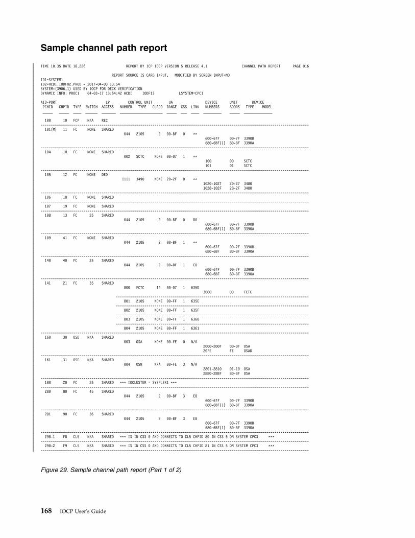
Sample channel path report
TIME 10.35 DATE 18.226 REPORT BY ICP IOCP VERSION 5 RELEASE 4.1 CHANNEL PATH REPORT PAGE 016
REPORT SOURCE IS CARD INPUT, MODIFIED BY SCREEN INPUT=NOID1=SYSTEM1ID2=HCDI.IODF02.PROD - 2017-04-03 13:54SYSTEM=(3906,1) USED BY IOCP FOR DECK VERIFICATIONDYNAMIC INFO: PROC1 04-03-17 13:54:42 HCDI IODF13 LSYSTEM=CPC1
AID-PORT LP CONTROL UNIT UA DEVICE UNIT DEVICEPCHID CHPID TYPE SWITCH ACCESS NUMBER TYPE CUADD RANGE CSS LINK NUMBERS ADDRS TYPE MODEL_____ _____ ____ ______ _______ _____________________ _____ ___ ____ _________ _____ ______________
100 10 FCP N/A REC------------------------------------------------------------------------------------------------------------------------------------101(M) 11 FC NONE SHARED
044 2105 2 00-BF 0 **600-67F 00-7F 3390B680-6BF(1) 80-BF 3390A
------------------------------------------------------------------------------------------------------------------------------------104 10 FC NONE SHARED
002 SCTC NONE 00-07 1 **100 00 SCTC101 01 SCTC
------------------------------------------------------------------------------------------------------------------------------------105 12 FC NONE DED
1111 3490 NONE 20-2F 0 **1020-1027 20-27 34801028-102F 28-2F 3480
------------------------------------------------------------------------------------------------------------------------------------106 18 FC NONE SHARED
------------------------------------------------------------------------------------------------------------------------------------107 19 FC NONE SHARED
------------------------------------------------------------------------------------------------------------------------------------108 13 FC 25 SHARED
044 2105 2 00-BF 0 D0600-67F 00-7F 3390B680-6BF(1) 80-BF 3390A
------------------------------------------------------------------------------------------------------------------------------------109 41 FC NONE SHARED
044 2105 2 00-BF 1 **600-67F 00-7F 3390B680-6BF 80-BF 3390A
------------------------------------------------------------------------------------------------------------------------------------140 40 FC 25 SHARED
044 2105 2 00-BF 1 C0600-67F 00-7F 3390B680-6BF 80-BF 3390A
------------------------------------------------------------------------------------------------------------------------------------141 21 FC 35 SHARED
800 FCTC 14 00-07 1 635D3000 00 FCTC
-----------------------------------------------------------------------------------------------801 2105 NONE 00-FF 1 635E
-----------------------------------------------------------------------------------------------802 2105 NONE 00-FF 1 635F
-----------------------------------------------------------------------------------------------803 2105 NONE 00-FF 1 6360
-----------------------------------------------------------------------------------------------804 2105 NONE 00-FF 1 6361
------------------------------------------------------------------------------------------------------------------------------------160 30 OSD N/A SHARED
003 OSA NONE 00-FE 0 N/A2000-200F 00-0F OSA20FE FE OSAD
------------------------------------------------------------------------------------------------------------------------------------161 31 OSE N/A SHARED
004 OSN N/A 00-FE 3 N/A2801-2810 01-10 OSA2880-28BF 80-BF OSA
------------------------------------------------------------------------------------------------------------------------------------180 20 FC 25 SHARED *** IOCLUSTER = SYSPLEX1 ***
------------------------------------------------------------------------------------------------------------------------------------280 80 FC 45 SHARED
044 2105 2 00-BF 3 E0600-67F 00-7F 3390B680-6BF(1) 80-BF 3390A
------------------------------------------------------------------------------------------------------------------------------------281 90 FC 36 SHARED
044 2105 2 00-BF 3 E0600-67F 00-7F 3390B680-6BF(1) 80-BF 3390A
------------------------------------------------------------------------------------------------------------------------------------290-1 F8 CL5 N/A SHARED *** IS IN CSS 0 AND CONNECTS TO CL5 CHPID 80 IN CSS 5 ON SYSTEM CPC3 ***
------------------------------------------------------------------------------------------------------------------------------------290-2 F9 CL5 N/A SHARED *** IS IN CSS 0 AND CONNECTS TO CL5 CHPID 81 IN CSS 5 ON SYSTEM CPC3 ***
------------------------------------------------------------------------------------------------------------------------------------
Figure 29. Sample channel path report (Part 1 of 2)
168 IOCP User's Guide
||||||||||||||||||||||||||||||||||||||||||||||||||||||||||||||||||||||||||||||||||||||
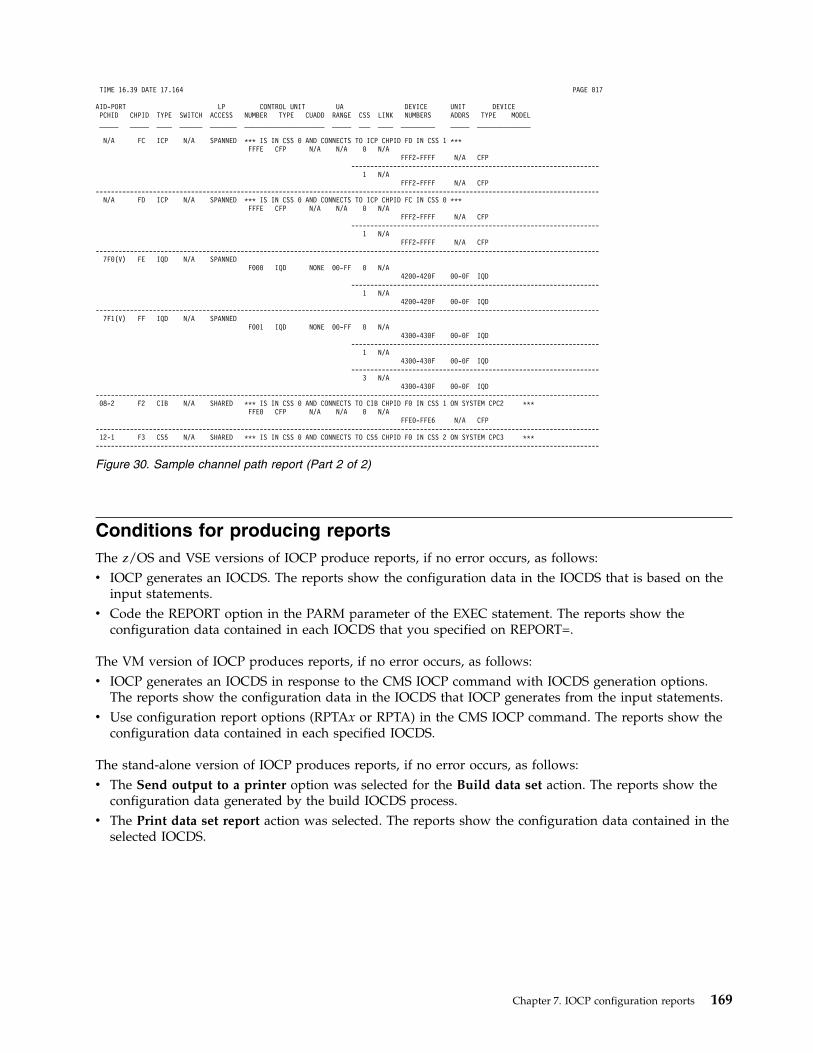
Conditions for producing reportsThe z/OS and VSE versions of IOCP produce reports, if no error occurs, as follows:v IOCP generates an IOCDS. The reports show the configuration data in the IOCDS that is based on the
input statements.v Code the REPORT option in the PARM parameter of the EXEC statement. The reports show the
configuration data contained in each IOCDS that you specified on REPORT=.
The VM version of IOCP produces reports, if no error occurs, as follows:v IOCP generates an IOCDS in response to the CMS IOCP command with IOCDS generation options.
The reports show the configuration data in the IOCDS that IOCP generates from the input statements.v Use configuration report options (RPTAx or RPTA) in the CMS IOCP command. The reports show the
configuration data contained in each specified IOCDS.
The stand-alone version of IOCP produces reports, if no error occurs, as follows:v The Send output to a printer option was selected for the Build data set action. The reports show the
configuration data generated by the build IOCDS process.v The Print data set report action was selected. The reports show the configuration data contained in the
selected IOCDS.
TIME 16.39 DATE 17.164 PAGE 017
AID-PORT LP CONTROL UNIT UA DEVICE UNIT DEVICEPCHID CHPID TYPE SWITCH ACCESS NUMBER TYPE CUADD RANGE CSS LINK NUMBERS ADDRS TYPE MODEL_____ _____ ____ ______ _______ _____________________ _____ ___ ____ _________ _____ ______________
N/A FC ICP N/A SPANNED *** IS IN CSS 0 AND CONNECTS TO ICP CHPID FD IN CSS 1 ***FFFE CFP N/A N/A 0 N/A
FFF2-FFFF N/A CFP-----------------------------------------------------------------
1 N/AFFF2-FFFF N/A CFP
------------------------------------------------------------------------------------------------------------------------------------N/A FD ICP N/A SPANNED *** IS IN CSS 0 AND CONNECTS TO ICP CHPID FC IN CSS 0 ***
FFFE CFP N/A N/A 0 N/AFFF2-FFFF N/A CFP
-----------------------------------------------------------------1 N/A
FFF2-FFFF N/A CFP------------------------------------------------------------------------------------------------------------------------------------
7F0(V) FE IQD N/A SPANNEDF000 IQD NONE 00-FF 0 N/A
4200-420F 00-0F IQD-----------------------------------------------------------------
1 N/A4200-420F 00-0F IQD
------------------------------------------------------------------------------------------------------------------------------------7F1(V) FF IQD N/A SPANNED
F001 IQD NONE 00-FF 0 N/A4300-430F 00-0F IQD
-----------------------------------------------------------------1 N/A
4300-430F 00-0F IQD-----------------------------------------------------------------
3 N/A4300-430F 00-0F IQD
------------------------------------------------------------------------------------------------------------------------------------08-2 F2 CIB N/A SHARED *** IS IN CSS 0 AND CONNECTS TO CIB CHPID F0 IN CSS 1 ON SYSTEM CPC2 ***
FFE0 CFP N/A N/A 0 N/AFFE0-FFE6 N/A CFP
------------------------------------------------------------------------------------------------------------------------------------12-1 F3 CS5 N/A SHARED *** IS IN CSS 0 AND CONNECTS TO CS5 CHPID F0 IN CSS 2 ON SYSTEM CPC3 ***------------------------------------------------------------------------------------------------------------------------------------
Figure 30. Sample channel path report (Part 2 of 2)
Chapter 7. IOCP configuration reports 169

170 IOCP User's Guide
Chapter 8. IOCP messages
IOCP messages (ICP prefix)This topic describes the messages produced by all versions (z/OS, z/VM, z/VSE, and stand-alone) of ICPIOCP. The messages are described in alphanumeric sequence by message identifier.
Message ICP050D is sent to the z/OS or VSE system console and requests action by the system operator.Messages ICP056I and ICP057I are sent to the z/OS or VSE system console and the output printer for theIOCP programmer. All other messages are sent to the output printer or card-image file for the IOCPprogrammer or to the system console for the IOCP operator.
The message format is:ICPnnns text
nnn Is the message serial number.
s Is the type code:
A Action. The operator must perform a specific action.
D Decision. The operator must choose an alternative.
I Information. No operator action is required. Most information messages are for the IOCPprogrammer.
W Wait. Processing stops until an action is determined and performed.
text Is the message text.
ICP000I UNDEFINED MESSAGE CODE. CODE=xxxxxxxx HEX
Explanation: IOCP has generated message code xxxxxxxx for which a message has not been defined. A logical errorhas occurred in IOCP.
System action: IOCP action is unpredictable.
Programmer response: Rerun the IOCP job. If the problem occurs again, save the console sheet and all associatedoutput. Report the problem to your service representative.
ICP050D SHOULD jobname WRITE TO LEVEL Ax IOCDS? REPLY 'YES', 'NO' OR 'CANCEL'
Explanation: A job with name jobname is running IOCP with a WRTCDS option other than NO in the PARMparameter of the EXEC statement. IOCP sends this message to request permission from the z/OS or VSE systemoperator for the job to write the Ax IOCDS to the Support Element hard disk.
z/OS users can prevent this message from being sent. See “Authorizing an IOCDS write” on page 112.
Note: If two (or more) jobs are allowed to update concurrently the Ax IOCDS, the outcome might be an IOCDS thatis logically inconsistent with the input from any one job. Using this IOCDS at power-on reset might produceundesirable results.
System action: If you enter YES, the job continues running IOCP and, if no errors are encountered, replaces theinput/output configuration data in the Ax IOCDS on the hard disk with the input/output configuration data itgenerates. Use Input/Output Configuration window of the Support Element to determine if the Ax IOCDS iswrite-protected.
If you enter NO, the job continues generating input/output configuration data in storage and to produce reports, butthe job does not replace the input/output configuration data in the Ax IOCDS on the SE hard disk.
If you enter CANCEL, the job ends immediately and receives system code X'222'.
© Copyright IBM Corp. 2017, 2018 171
Operator response: Contact your system programmer and respond as instructed.
Programmer response: Follow your site procedures and advise the operator.
Routing codes: 1 and 11
Descriptor code: 7
ICP051I IOCP VERSION nn.nn.nnn TERMINATED. CODE=xx
Explanation: IOCP version nn.nn.nnn has terminated for one of the following reasons:
Code Description
01 UNKNOWN PARM KEYWORD VALUE - yyyyyyyy. An unknown keyword value was found beginning withthe first character of string yyyyyyyy in the PARM parameter of the EXEC statement. (This code can resultfrom an extra left parenthesis after the REPORT keyword.)
02 DUPLICATE PARM KEYWORD - yyyyyyyy. A duplicate keyword was found beginning with the firstcharacter of string yyyyyyyy in the PARM parameter of the EXEC statement.
03 UNKNOWN PARM KEYWORD - yyyyyyyy. An unknown keyword was found beginning with the firstcharacter of string yyyyyyyy in the PARM parameter of the EXEC statement.
04 INVALID LINECOUNT VALUE. The keyword value on the LINECOUNT keyword in the PARM parameterof the EXEC statement was not within the allowed range.
05 CONFLICTING PARM KEYWORDS. Conflicting keywords were found in the PARM parameter of the EXECstatement.
06 PARM DELIMITER ERROR - yyyyyyyy. An extra or missing comma was found beginning with the firstcharacter of string yyyyyyyy in the PARM parameter of the EXEC statement. This code can result fromunbalanced parentheses around the REPORT parameters or an incorrect report keyword value.
07 One or more errors were found in the input card-image statements.
08 An error was found while IOCP was generating the IOCDS in storage.
09 A REPORT or WRTCDS option has been specified but ICP IOCP only reads or writes an IOCDS in a CPCthat supports ICP IOCP. If your CPC supports ICP IOCP, the IOCP release level you used does not supportyour CPC; you must use an IOCP level that supports your CPC.
10 IOCP was unable to connect to the VSE facility which reads and writes an IOCDS for one of the followingreasons:
v The facility is in use by another job. Wait a few minutes and rerun the job.
v The facility is unavailable due to a or VSE error.
v VSE is a guest under VM. VSE does not support reading or writing an IOCDS as a guest under VM. Usethe VM version of IOCP.
11 TOO MANY VM LEVELS. You attempted to read or write an IOCDS and multiple levels of VM are present.For z/OS, reading and writing an IOCDS is supported when z/OS is a guest of VM and only one level ofVM is present. For VM, reading and writing an IOCDS is supported only when performed from a first-levelVM.
12 IOCP was not authorized to write an IOCDS. The operator replied No to message ICP050D.
13 IOCP was not authorized to write an IOCDS. You are not authorized to update the CBD.CPC.IOCDSresource of the FACILITY class in the installed security product. (See “Authorizing an IOCDS write” on page112 for more information.)
14 PARM KEYWORD MISSING. Not all required execution keywords were specified. You specified keywordCHECKCPC=NO in the PARM parameter of the EXEC statement or CMS option NOCHKCPC to write anIOCDS in preparation of an upgrade, but you did not specify a keyword or option to write the IOCDS. Youmust specify a keyword value other than WRTCDS=NO or NOWRTCDS.
15 INSUFFICIENT STORAGE. IOCP could not obtain enough storage by using the GETMAIN statement (forz/OS and z/VM) or the GETVIS statement (for VSE).
ICP051I
172 IOCP User's Guide
4x IOCP encountered an error while reading the Ax (where x is 0, 1, 2, or 3) IOCDS from, or writing the AxIOCDS to the hard disk. See the listing for related error messages.
System action: If IOCP encountered an error while doing anything other than reading an IOCDS, it ends withreturn code 8. If IOCP encountered an error while reading an IOCDS, it ends the read operation for that IOCDS.However, IOCP tries to read each additional IOCDS that was specified before it ends with return code 8.
Programmer response: Ensure that the PARM parameter of the EXEC statement is coded correctly. For errors, savethe output listings and report the problem to the service representative.
ICP052I DCB DID NOT OPEN-SYSIN DD STATEMENT MAY BE MISSING/INVALID
Explanation: The device control block for the data set specified in the SYSIN DD statement did not open whenIOCP sent the OPEN statement.
System action: IOCP ends.
Programmer response: Ensure that the DD statement for the SYSIN data set is valid.
ICP053I IOCP VERSION nn.nn.nnn FAILED. INSUFFICIENT STORAGE
Explanation: IOCP version nn.nn.nnn could not obtain enough storage with the GETMAIN statement (for z/OS andz/VM) or the GETVIS statement (for VSE). If you are reporting on multiple IOCDSs, IOCP could not obtain enoughstorage to report on any of the IOCDSs. IOCP performs multiple storage allocations. If the first storage request fails,only this message is sent. If the second storage request fails, other messages are sent to the output data set.
System action: IOCP ends with a return code of 16.
Programmer response: For z/OS users, increase the region size. To determine the region size to use, see “IOCPstorage requirements” on page 112.
For z/VM users, define more virtual storage, perform an IPL of CMS, and issue the IOCP command again. For moreinformation, see “IOCP storage requirements” on page 112.
For z/VSE users, increase the partition size. Also, specify SIZE=AUTO on the EXEC statement of the job to allowIOCP to use the remaining partition size for GETVIS. For more information, see “IOCP storage requirements” onpage 112.
Routing codes: 11
Descriptor code: 6
ICP054I **WARNING** IOCP CANNOT DETERMINE LIMITS FOR PROCESSOR. CODE=xxxxxxxx
Explanation: IOCP does not recognize the CPC that it is running on. A logical error has occurred in IOCP. IOCDSswritten on this CPC might not be valid for this CPC.
System action: IOCP sends this warning message after the last statement has been processed, defaults to a set ofpredetermined machine limits and rules, and then continues processing.
Programmer response: To determine which machine limits and rules IOCP used as defaults, note the value of theSYSTEM= keyword in the editor or from the report headings and then see Appendix F, “Machine limits and rules,”on page 285. You can define all channel path types with IOCP. Ensure that the machine limits, channel limits, andrules are valid for your CPC before using the IOCDS for a power-on reset. Report the problem to your servicerepresentative.
ICP055I **CAUTION** CHANNEL CONFIGURATION CONTAINS DISCREPANCIES
Explanation: Your channel configuration contains one or more discrepancies. Discrepancies are channelconfiguration conditions that cannot exist on your CPC. The discrepancies are reported for each channel path in thePCHID Summary Report. See “PCHID summary report” on page 156 for a description of the channel configurationdiscrepancies.
System action: IOCP prints this message at the end of the PCHID Summary Report and continues processing.
Programmer response: Change your channel configuration to correct the discrepancies. For an explanation of thechannel configuration rules for your CPC, see Appendix F, “Machine limits and rules,” on page 285.
ICP052I • ICP055I
Chapter 8. IOCP messages 173
ICP056I IOCP JOB jobname FAILED. DID NOT BUILD LEVEL Ax IOCDS.
Explanation: A job with name jobname was running IOCP with a WRTCDS option other than NO in the PARMparameter of the EXEC statement. However, IOCP did not write the IOCDS. One of the following situations occurred:
v An error was detected in the IOCP input statements
v The z/OS or VSE system operator previously replied NO to message ICP050D
v The CBD.CPC.IOCDS resource of the FACILITY class has been defined to an installed security product and thez/OS security administrator has not authorized you to update the CBD.CPC.IOCDS resource. See “Authorizing anIOCDS write” on page 112.
IOCP sends this message to inform the programmer and the z/OS or VSE system operator (who previouslyresponded to message ICP050D) that this job failed to build the Ax IOCDS.
For z/OS users, IOCP only sends this message to the programmer (routing code 11) if the CBD.CPC.IOCDS resourceof the FACILITY class has been defined to an installed security product.
System action: IOCP ends the job with return code 8.
Operator response: Tell your system programmer that the job failed.
Programmer response: Review the messages in the job listing and take the necessary actions.
Routing codes: 2 and 11
Descriptor code: 6
ICP057I IOCP JOB jobname SUCCESSFUL. LEVEL Ax IOCDS REPLACED.
Explanation: A job with name jobname was running IOCP with a WRTCDS option other than NO in the PARMparameter of the EXEC statement. IOCP sends this message to inform the programmer and the z/OS or VSE systemoperator (who previously granted permission to write the IOCDS in response to message ICP050D) that this jobsuccessfully replaced the Ax IOCDS.
For z/OS users, IOCP only sends this message to the programmer (routing code 11) if the CBD.CPC.IOCDS resourceof the FACILITY class has been defined to an installed security product and the z/OS security administrator hasauthorized you to update the CBD.CPC.IOCDS resource.
System action: IOCP ends the job with return code 0, 2, or 4.
Operator response: Follow your site procedures.
Programmer response: No response is required. This message is an informational message only.
Routing codes: 2 and 11
Descriptor code: 6
ICP058I IOCP DID NOT WRITE IOCDS Ax
Explanation: IOCP was requested to write the Ax IOCDS to the hard disk. However, IOCP did not write the IOCDS.One of the following situations occurred:
v An error was detected in the IOCP input statements
v The z/OS or VSE system operator previously replied NO to message ICP050D
v The CBD.CPC.IOCDS resource of the FACILITY class has been defined to an installed security product and thez/OS security administrator has not authorized you to update the CBD.CPC.IOCDS resource. See “Authorizing anIOCDS write” on page 112.
v IOCP received an unexpected response code or return code attempting to write the IOCDS.
This message is an informational message only.
System action: IOCP prints this informational message at the end of the configuration reports. IOCP continuesprocessing.
Programmer response: Do one of the following actions:
v Correct the IOCP input statements
ICP056I • ICP058I
174 IOCP User's Guide
v Have the z/OS or VSE system operator reply YES to message ICP050D
v Have the z/OS security administrator authorize you to update the CBD.CPC.IOCDS resource of the FACILITYclass.
v Perform the programmer response associated with the unexpected response code or return code.
ICP059I IOCP SUCCESSFULLY WROTE IOCDS Ax
Explanation: IOCP was requested to write the Ax IOCDS to the Support Element hard disk. IOCP successfullywrote the IOCDS. This message is an informational message only.
System action: IOCP prints this informational message at the end of the configuration reports. IOCP continuesprocessing.
Programmer response: No response is required.
ICP060I IOCP COULD NOT OPEN OR WRITE TO OUTPUT DATASET
Explanation: IOCP could not open or write to the output data set specified in the SYSPRINT DD statement. TheSYSPRINT DD statement might be missing.
System action: IOCP ends with return code of 12.
Programmer response: Ensure that the DD statement for the SYSPRINT data set exists and is valid.
Routing codes: 11
Descriptor code: 6
ICP061I **WARNING** EXECUTION PARAMETER LPAR=YES IS INVALID
Explanation: You specified keyword LPAR=YES in the PARM parameter of the EXEC statement or CMS optionLPAR for an LPAR I/O configuration. However, IOCP supports only LPAR I/O configurations.
Note: Beginning with ICP IOCP 2.2.0, LPAR=YES and LPAR are disallowed.
System action: IOCP ignores the parameter and continues processing.
Programmer response: Do not specify LPAR=YES or LPAR.
ICP062I **WARNING** COMMENTS | MESSAGES REMOVED FROM CARD IMAGE FILE
Explanation: The card-image file was too large to read or write so stand-alone IOCP removed comments or IOCPmessages from the file to reduce its size. When reading a card-image file, stand-alone IOCP removes comments orIOCP messages if necessary to reduce the file size so that it can read the entire file. When writing a card-image file tothe Support Element hard disk, stand-alone IOCP removes comments or IOCP messages if necessary to reduce thefile size so that it can be written.
The restricts the size of I/O configuration source (IOCS) files to 256,000 card records. Twenty additional records arereserved for IOCP messages.
IOCP messages are messages that IOCP inserted into the card-image file during processing. If IOCP messages areremoved, the card-image file still contains the conditions that caused the messages but not the messages.
System action: IOCP inserts this message at the top of the card-image file and continues processing.
Programmer response: Reduce the size of the IOCS file you selected and then retry the IOCP function. To reducethe size of an IOCS file perform one or more of the following actions:
v Remove comment cards from the card-image file
v Consolidate IOCP statements that are continued across multiple cards onto a minimum number of cards
v Combine individual IODEVICE statements that attach to the same control unit or units by using common UNITand MODEL keyword values. Do not combine IODEVICE statements if they have conflicting keyword values.
ICP059I • ICP062I
Chapter 8. IOCP messages 175
ICP063I ERRORS=YES | NO | NA, MESSAGES=YES | NO | NA, REPORTS PRINTED=YES | NO | NA,IOCDS WRITTEN=YES | NO | NA, IOCS WRITTEN=YES | NO
Explanation: Stand-alone IOCP writes an I/O configuration source (IOCS) file for the Build data set andDisassemble data set functions. IOCP always includes this message in the IOCS file. The status of each item is YES,NO, or NA (not applicable for the requested IOCP function). YES indicates the following conditions:
ERRORSIOCP processing resulted in error messages.
MESSAGESIOCP processing resulted in caution or warning messages or both.
REPORTS PRINTEDIOCP successfully printed its reports.
IOCDS WRITTENIOCDS was successfully written to the Support Element hard disk.
IOCS WRITTEN IOCS was successfully written to the Support Element hard disk.
The Support Element restricts the size of I/O configuration source (IOCS) files to 256,000 card records. Twentyadditional records are reserved for IOCP messages.
If an IOCS is too large to write, IOCP writes an IOCS containing only this message and the status for IOCSWRITTEN is NO. Otherwise, this message is at the bottom of the IOCS file and the status for IOCS WRITTEN is YES.
System action: IOCP writes an IOCS containing this message and continues processing.
Programmer response: For ERRORS status of YES, correct all errors and retry the requested IOCP function.
For MESSAGES status of YES, ensure that the caution and warning messages do not indicate a condition that youmust correct even though an IOCDS might have been successfully written.
For IOCS WRITTEN status of NO, reduce the size of the IOCS file you selected and then retry the IOCP function. Toreduce the size of an IOCS file perform one or more of the following actions:
v Remove comment cards from the IOCS.
v Consolidate IOCP statements that are continued across multiple cards onto a minimum number of cards
v Combine individual IODEVICE statements that attach to the same control unit or units by using common UNITand MODEL keyword values. Do not combine IODEVICE statements if they have conflicting keyword values.
ICP064I **CAUTION** IOCDS IS UNUSABLE UNTIL PROCESSOR IS UPGRADED TO SYSTEM=(xxxx,n)PROCESSOR
Explanation: You wrote an IOCDS in preparation of a CPC upgrade using keyword CHECKCPC=NO in the PARMparameter of the EXEC statement (z/OS or VSE) or using CMS option NOCHKCPC. IOCP generated an IOCDSusing the machine limits and rules for a SYSTEM=(xxxx,n) CPC. However, your current CPC is not associated withSYSTEM=(xxxx,n). Therefore, the IOCDS cannot be used to perform a power-on reset until your current CPC isupgraded to a CPC associated with SYSTEM=(xxxx,n).
System action: IOCP prints this caution message after the last IOCP configuration report has been printed. IOCPcontinues processing.
Programmer response: If your CPC is scheduled to be upgraded to a SYSTEM=(xxxx,n) CPC, do not use this IOCDSbefore the upgrade and inform the service representative which IOCDS to use after the upgrade. If your CPC is notscheduled to be upgraded, change the SYSTEM keyword value to match your CPC and specify CHECKCPC=YES orCHECKCPC when running IOCP.
ICP065I **WARNING** THE CONFIGURATION IS UNUSABLE ON THE EC LEVEL OF THISPROCESSOR (xxxxxxxx xxxxxxxx)
Explanation: Beginning with ICP IOCP 1.2.0, your configuration is unusable on the EC level of this CPC. TheIOCDS contains an unsupported function or channel path type for this model CPC at its current EC level. xxxxxxxxxxxxxxxx is a hexadecimal value that indicates the unsupported function or channel type. See Table 26 on page 296 to
ICP063I • ICP065I
176 IOCP User's Guide
determine the meaning of the hexadecimal value. If the hexadecimal value is not defined in this edition of the IOCPUser's Guide, see the latest edition of the document.
For ICP IOCP 1.1.0, this message is a caution message and the following explanations apply:
v For batch IOCP users, your configuration is unusable on some EC levels of this CPC. The IOCDS contains anunsupported function or channel path type for this model CPC at some ECs. xxxxxxxx xxxxxxxx is a hexadecimalvalue which indicates the possible unsupported function or channel type. See Table 26 on page 296 to determinethe meaning of the hexadecimal value. If the hexadecimal value is not defined in this edition of the IOCP User'sGuide, see the latest edition of the document.
To determine what the EC installed on your CPC supports, select the I/O Configuration task on the SupportElement and click Supported I/O mask under View. If the IOCDS contains anything that your CPC does notsupport, the display includes Unsupported mask items, which shows the exact items that are not supported.
v For stand-alone IOCP users, your configuration is unusable on the EC level of this CPC. The IOCDS contains anunsupported function or channel path type for this model CPC at its current EC level. xxxxxxxx xxxxxxxx is ahexadecimal value which indicates the unsupported function or channel type. See Table 26 on page 296 todetermine the meaning of the hexadecimal value. If the hexadecimal value is not defined in this edition of theIOCP User's Guide, see the latest edition of the document.
For more information about this message, see “CPC activation and power-on reset error” on page 296.
System action: IOCP prints this message after all reports have been processed and continues processing.
Programmer response: Beginning with ICP IOCP 1.2.0, do not attempt to use the IOCDS at the current EC.Unsupported functions or channel types prevent an IOCDS from being used for power-on reset. If you intend to usethe IOCDS at the current EC, write a new IOCDS that does not use the unsupported functions or channel path types.If you intend to use the IOCDS at a new EC following an upgrade and that EC supports the function or channeltype, ignore this message.
For ICP IOCP 1.1.0, the following programmer responses apply:
v For batch IOCP users, if the EC installed on your CPC supports your configuration, ignore this message.Otherwise, do not attempt to use the IOCDS at the current EC. Unsupported functions or channel types prevent anIOCDS from being used for power-on reset. If you intend to use the IOCDS at the current EC, write a new IOCDSthat does not use the unsupported functions or channel path types. If you intend to use the IOCDS at a new ECfollowing an upgrade and that EC supports the function or channel type, ignore this message.
v For stand-alone IOCP users, do not attempt to use the IOCDS at the current EC. Unsupported functions or channeltypes prevent an IOCDS from being used for power-on reset. If you intend to use the IOCDS at the current EC,write a new IOCDS that does not use the unsupported functions or channel path types. If you intend to use theIOCDS at a new EC following an upgrade and that EC supports the function or channel type, ignore this message.If this message is in a disassembled I/O configuration source file after your CPC is upgraded, disassemble theIOCDS again to remove this message.
ICP066I **WARNING** THE IOCDS CONFIGURATION CONTAINS INFORMATION NOT SUPPORTEDBY THIS LEVEL OF IOCP (xxxxxxxx xxxxxxxx)
Explanation: IOCP is processing an IOCDS to print reports for batch or stand-alone, or to disassemble the IOCDSinto an I/O configuration source (IOCS) file on the Support Element hard disk for stand-alone only. The IOCDS waswritten by a higher level of IOCP than the one currently processing it and contains a function or channel path typethat the current IOCP level does not support. xxxxxxxx xxxxxxxx is a hexadecimal value that indicates theunsupported function or channel type. See Table 26 on page 296 to determine the meaning of the hexadecimal value.If the hexadecimal value is not defined in this edition of the IOCP User's Guide, see the latest edition of thedocument.
The current level of IOCP cannot correctly process the unsupported function or channel type.
System action: IOCP prints this message after all reports have been processed and continues processing. Forstand-alone IOCP function Disassemble Data Set, IOCP includes this message at the top of the IOCS file that IOCPcreates on the Support Element hard disk.
Programmer response: Use the same level of IOCP to report on the IOCDS as the level of IOCP that wrote it. Donot use stand-alone IOCP to process this IOCDS. Do not use a disassembled IOCS containing this message because itcan have incorrect or missing information.
For stand-alone IOCP users, do not attempt to use the IOCDS at the current EC. For batch IOCP users, if your levelof batch IOCP is greater than or equal to the level of stand-alone IOCP installed on this CPC, do not attempt to use
ICP066I
Chapter 8. IOCP messages 177
the IOCDS at the current EC. Unsupported functions or channel types prevent an IOCDS from being used forpower-on reset. If you intend to use the IOCDS at the current EC, write a new IOCDS that does not use theunsupported functions or channel path types. If you intend to use the IOCDS at a new EC following an upgrade andthat EC supports the function or channel type, ignore this message.
ICP067I **WARNING** IOCDS WAS WRITTEN WITH IOCP VERSION xx.xx.xx WHICH IS HIGHERTHAN VERSION OF IOCP PROCESSING IT
Explanation: IOCP is processing an IOCDS to print reports for batch or stand-alone or to disassemble the IOCDSinto an I/O configuration source (IOCS) file on the Support Element hard disk for stand-alone only. The IOCDS waswritten by a higher level of IOCP than the one currently processing it, and it might contain something the currentIOCP level does not support, for example, a new keyword.
System action: IOCP prints this message after all reports have been processed and continues processing. Forstand-alone IOCP function Disassemble Data Set, IOCP includes this message at the top of the IOCS file IOCP createson the Support Element hard disk.
Programmer response: Use the same level of IOCP to report on the IOCDS as the level of IOCP that wrote it. Forstand-alone IOCP function Disassemble Data Set, use the same level or a higher level of IOCP. Do not disassembleuntil after the correct EC is installed. If you receive this message without messages ICP065I and ICP066I, thedisassembled IOCS can be used if no significant differences exist between the IOCP that wrote the IOCDS and thecurrent IOCP.
ICP068I **WARNING** IOCP WAS UNABLE TO DETERMINE IF THE CONFIGURATION IS USABLE ONTHE EC LEVEL OF THIS PROCESSOR (CODE xxxxxxxx)
Explanation: IOCP attempted to determine the IOCP functions and channel path types supported by the EC level ofyour CPC using the I/O supported mask but was unsuccessful. Therefore, IOCP was unable to perform theverification involved with message ICP065I. Any IOCDS written by IOCP is valid for your model CPC at the latestEC level. However, IOCP was unable to verify that all of the functions and channel path types defined in the IOCDSare supported by the specific EC level of your CPC.
System action: IOCP prints this warning message after all reports have been processed and continues processing.
Programmer response: This message results when you are writing an IOCDS from a CPC this version of IOCP doesnot support (for example, 2064) to a CPC this program does support (for example, 2094). Ignore it. If you are writingan IOCDS from a CPC this version of IOCP supports, notify your service representative to determine why IOCP wasunsuccessful in reading the I/O supported mask from your CPC.
Any IOCDS written by IOCP is valid for your model CPC at the latest EC level. If the IOCDS contains any functionor channel path type not supported by the EC level of your CPC, you cannot use the IOCDS for power-on reset untilyou upgrade to the appropriate EC level.
Problem determination: If you are running IOCP on VM or as a guest on VM, see “IOCP command – usage notesfor VM” on page 125 for possible reasons for the unsuccessful operation.
ICP069I IOCP ASSIGNED A DEFAULT VALUE TO MAXDEV KEYWORD
Explanation: Beginning with ICP IOCP 1.3.0, IOCP assigned a default value to the MAXDEV keyword. The IOCPinput supports dynamic I/O configuration. If the MAXDEV keyword was not specified, IOCP assigns a default valuefor subchannel set 0 for each defined CSS and each subchannel set other than 0 that contains devices. If theMAXDEV keyword was specified, IOCP does the following actions:
v Assigns a default value for subchannel set 0 for each CSS that was defined on the RESOURCE statement but wasomitted from the MAXDEV keyword.
v Assigns a default value for each subchannel set other than 0 that has devices but was omitted from the MAXDEVkeyword.
The IOCP default value used is the maximum number of devices your CPC supports for a subchannel set. Thehardware system area (HSA) space is the maximum for the subchannel set. For additional information, see Table 18on page 287. This message is an informational message only.
System action: IOCP prints this informational message at the end of the IOCDS Totals Report and continuesprocessing.
ICP067I • ICP069I
178 IOCP User's Guide
Programmer response: In the device totals section of the IOCDS Totals Report, determine which subchannel setswere assigned a default value. Each default value has a special indicator following it (for example, '***'). If you wantto do so, specify a value for each defined subchannel set and CSS in the MAXDEV keyword.
ICP070I SEARCH FOR '*ICP' TO FIND EACH IOCP MESSAGE
Explanation: Stand-alone IOCP performed the action Build Data Set and included this message at the top of theIOCP source file (IOCS). Search for the character string *ICP to find all IOCP messages in the IOCS.
System action: IOCP includes this informational message at the top of the IOCS when building an IOCDS andcontinues processing.
Programmer response: To search for IOCP messages in a source file, search for the characters in the quoted string.
ICP071I IOCP GENERATED A DYNAMIC TOKEN HOWEVER DYNAMIC I/O CHANGES ARE NOTPOSSIBLE WITH THIS IOCDS
Explanation: Your CPC has a fixed storage size for the Hardware System Area (HSA) and therefore requires adynamic token in every IOCDS. Either no token was specified in the IOCP source file or a change was made to thecard-image file with the stand-alone IOCP editor. Therefore, IOCP generated a token of its own. However, nooperating system supports dynamic I/O configuration with this IOCDS.
System action: IOCP prints this informational message at the end of the IOCDS Totals Report and continuesprocessing.
Programmer response: For Hardware Configuration Definition (HCD) users, rebuild the IOCP source file from HCDand rewrite the IOCDS. For z/VM users who do not use HCD but want dynamic I/O configuration, specify the DYNoption when running IOCP and rewrite the IOCDS. Otherwise, do nothing. For all other operating system users, donothing. For stand-alone IOCP, if the IOCDS must support dynamic I/O configuration, import the I/O configurationsource file again and build the data set without using the editor to change anything. If dynamic I/O configuration isnot required, keep the modified IOCDS.
ICP072I **WARNING** IOCP WAS UNABLE TO QUERY THE TARGET CPC (CODE xxxxxxxx)
Explanation: The HCD requested that IOCP write an IOCDS to a target CPC. IOCP performed a query operation ofthe target CPC in preparation of the write, and the query failed with the listed code.
System action: IOCP prints this warning message following the ID statement and continues processing.
Programmer response: If an error occurred writing the IOCDS to the target CPC, perform the programmer responsefor the listed error message. If the IOCDS was successfully written, notify your service representative to determinewhy IOCP was unsuccessful in querying the target CPC in preparation of writing the IOCDS. The IOCDS is usable.
ICP073I IOCP VERSION nn.nn.nnn
Explanation: Stand-alone IOCP writes an I/O configuration source (IOCS) file for the Build data set andDisassemble data set functions. IOCP always includes this message in the IOCS file. It is an informational message toindicate the version of IOCP writing the data set.
System action: IOCP writes an IOCS containing this message and continues processing.
Programmer response: No response is required.
ICP100I SYMBOL IN NAME FIELD EXCEEDS 8 CHARACTERS AND/OR CONTAINS INVALIDCHARACTERS
Explanation: The symbolic name (label) in the name field contains more than eight characters or contains incorrectcharacters. It must contain 1 - 8 alphanumeric or special (#, @, $) characters. The first character must be alphabetic orspecial. Only uppercase characters are allowed.
System action: IOCP continues to validate and check the syntax of the remaining statements. However, it does notgenerate an IOCDS and it does not produce configuration reports.
Programmer response: Correct the name field.
ICP070I • ICP100I
Chapter 8. IOCP messages 179
ICP101I OPERATION FIELD NOT FOUND
Explanation: The operation field (statement name) was not found before column 72. The statement name must haveone or more blanks preceding and following it. A blank line results in this error.
System action: IOCP continues to validate and check the syntax of the remaining statements. However, it does notgenerate an IOCDS and it does not produce configuration reports.
Programmer response: Check for format errors and correct the errors.
ICP102I UNSUPPORTED OPERATION - xxxxxxxx
Explanation: IOCP did not recognize string xxxxxxxx as a valid IOCP statement. The statement name must have oneor more blanks preceding and following it.
System action: IOCP continues to validate and check the syntax of the remaining statements. However, it does notgenerate an IOCDS and it does not produce configuration reports.
Programmer response: Use a valid IOCP statement name in the operation field.
ICP103I **WARNING** ID STATEMENT IGNORED - OUT OF SEQUENCE
Explanation: IOCP found an ID statement after processing one or more other IOCP statements.
System action: IOCP ignores the ID statement that is out of sequence and continues processing.
Programmer response: Ensure that the ID statement is the first IOCP statement in the input.
ICP104I **WARNING** MORE THAN ONE ID STATEMENT - ONLY THE FIRST WAS USED
Explanation: More than one ID statement was found in the input statements. Only one ID statement can bespecified.
System action: IOCP processes the first ID statement, ignores any following ID statements, and continuesprocessing.
Programmer response: Ensure that there is only one ID statement in the input and that it is the first IOCPstatement.
ICP105I OPERAND FIELD NOT FOUND
Explanation: The operand field was not found before column 72.
System action: IOCP continues to validate and check the syntax of the remaining statements. However, it does notgenerate an IOCDS and it does not produce configuration reports.
Programmer response: Correct the operand field.
ICP106I NON-BLANK CHARACTER(S) FOUND IN COLUMNS 1-15 OF CONTINUATION CARD
Explanation: A nonblank character was found in columns 1 - 15. On a continuation card, columns 1 - 15 must beblank, and the operand field must start in column 16. (The preceding card had a nonblank character in column 72,indicating that this card is a continuation card.)
System action: IOCP continues to validate and check the syntax of the remaining statements. However, it does notgenerate an IOCDS and it does not produce configuration reports.
Programmer response: Ensure that the operand field on the continuation card starts in column 16.
ICP107I **WARNING** EXCEEDED THE ALLOWED NUMBER OF COMMENT CONTINUATION CARDS
Explanation: More than two continuation cards were found for an IOCP comment card.
System action: IOCP prints the extra comment continuation cards and continues processing.
Programmer response: Restructure the comment so that it can be contained in a total of three comment cards, orcode an asterisk in column 1 and remove the continuation characters in column 72 of the preceding cards.
ICP101I • ICP107I
180 IOCP User's Guide
ICP108I UNEXPECTED END OF FILE ON SYSTEM INPUT
Explanation: A continuation card was expected when an end-of-file condition occurred on the input data set. Thelast card contains a nonblank character in column 72.
System action: IOCP does not generate an IOCDS and does not produce configuration reports.
Programmer response: Ensure that no statements or comment cards are missing in the input.
ICP109I **WARNING** INVALID CHARACTER(S) IN MSG1 | MSG2 STRING TRANSLATED TO AVALID CHARACTER
Explanation: The message string for keyword MSG1 or MSG2 in the ID statement contains one or more incorrectcharacters. Each incorrect character is translated to a double quotation mark (") and is shown as such in theconfiguration report headings and on the IOCDSM frame of the Support Element. See the “English (U.S.) I/OInterface Code” table for EBCDIC characters in the 3270 IDS Character Set Reference, GA27-2837, for a list of validprintable characters.
System action: IOCP translates each incorrect character to the valid character and continues processing.
Programmer response: Correct the message string for MSG1 or MSG2.
ICP110I EXTRA LEFT PARENTHESIS - xxxxxxxx
Explanation: IOCP detected an extra left parenthesis as the first character of string xxxxxxxx. The parameter requiresone or two left parentheses to start the keyword value field.
System action: IOCP continues to validate and check the syntax of the remaining statements. However, it does notgenerate an IOCDS and it does not produce configuration reports.
Programmer response: Correct the parameter.
ICP111I DELIMITER ERROR, EXPECT COMMA - xxxxxxxx
Explanation: IOCP expected a comma as the first character of string xxxxxxxx. The parameter requires that you usea comma to separate the values.
System action: IOCP continues to validate and check the syntax of the remaining statements. However, it does notgenerate an IOCDS and it does not produce configuration reports.
Programmer response: Correct the parameter or the delimiter.
ICP112I DELIMITER ERROR, EXPECT BLANK OR COMMA - xxxxxxxx
Explanation: IOCP expected a blank or comma as the first character of string xxxxxxxx. This error can occur if akeyword value contains too many characters.
System action: IOCP continues to validate and check the syntax of the remaining statements. However, it does notgenerate an IOCDS and it does not produce configuration reports.
Programmer response: Correct the parameter or the delimiter.
ICP113I DELIMITER ERROR, EXPECT COMMA OR RIGHT PARENTHESIS - xxxxxxxx
Explanation: IOCP expected a comma or right parenthesis as the first character of string xxxxxxxx. This error canoccur if a keyword value contains too many characters.
System action: IOCP continues to validate and check the syntax of the remaining statements. However, it does notgenerate an IOCDS and it does not produce configuration reports.
Programmer response: Correct the parameter or the delimiter.
ICP108I • ICP113I
Chapter 8. IOCP messages 181
ICP114I DELIMITER ERROR, EXPECT LEFT PARENTHESIS - xxxxxxxx
Explanation: IOCP expected a left parenthesis as the first character of string xxxxxxxx. The parameter requires thatyou enclose the keyword value in parentheses.
System action: IOCP continues to validate and check the syntax of the remaining statements. However, it does notgenerate an IOCDS and it does not produce configuration reports.
Programmer response: Check for incorrect characters in the parameter and correct the delimiter.
ICP115I DELIMITER ERROR, EXPECT RIGHT PARENTHESIS - xxxxxxxx
Explanation: IOCP expected a right parenthesis as the first character of string xxxxxxxx. This error can occur if akeyword value contains too many characters or if more parameters than your CPC supports were specified.
System action: IOCP continues to validate and check the syntax of the remaining statements. However, it does notgenerate an IOCDS and it does not produce configuration reports.
Programmer response: Correct the parameter and correct the incorrect delimiter with a right parenthesis.
ICP116I **WARNING** CONTINUATION CARD TREATED AS A COMMENT BY IOCP
Explanation: IOCP issues this message following a continuation card that is treated as a comment by IOCP (that is,it is ignored). Any continuation cards for the same statement that follow this message are also treated as commentsby IOCP.
One of the following conditions is true:
v Card n is continued but the operand field on card n ends with a blank instead of a comma. Card n+1 receives thismessage and any keywords on card n+1 are ignored.
v Card n is continued but the operand field on card n+1 begins in column 17 or greater instead of column 16. Cardn+1 receives this message and any keywords on card n+1 are ignored.
System action: IOCP ignores the continuation cards being treated as comments and continues processing.
Programmer response: Verify that there are no keywords on the continuation cards being treated as comments. Ifthere are, fix the conditions that caused IOCP to treat them as comments. If there are no keywords and a validcomment exists on the continuation card, ignore the message or move the comment to a comment card. Commentcards begin with an asterisk (*) in column 1 or a period and asterisk (.*) in columns 1 and 2. See Appendix A,“Coding IOCP statements,” on page 237 for more information about how to code IOCP statements and comments.
ICP117I INVALID CONTROL UNIT NUMBER
Explanation: An incorrect control unit number was entered as the value for keyword CUNUMBR on either aCNTLUNIT or an IODEVICE statement. Control unit numbers must be one to four hexadecimal digits in the range0000-FFFE. FFFF is not a valid control unit number.
System action: IOCP continues to validate and check the syntax of the remaining statements. However, it does notgenerate an IOCDS and it does not produce configuration reports.
Programmer response: Correct the control unit number.
ICP118I PARAMETER CONTAINS INVALID CHARACTERS
Explanation: A parameter contains one or more incorrect characters. See the “English (U.S.) I/O Interface Code”table for EBCDIC characters in 3270 IDS Character Set Reference GA27-2837, for a list of valid printable characters.
System action: IOCP continues to validate and check the syntax of the remaining statements. However, it does notgenerate an IOCDS and it does not produce configuration reports.
Programmer response: Correct the incorrect characters in the parameter.
ICP114I • ICP118I
182 IOCP User's Guide
ICP119I BEGINNING APOSTROPHE NOT FOUND
Explanation: The beginning apostrophe was not found in a parameter that requires the keyword value to beenclosed in apostrophes.
System action: IOCP continues to validate and check the syntax of the remaining statements. However, it does notgenerate an IOCDS and it does not produce configuration reports.
Programmer response: Correct the parameter.
ICP120I ENDING APOSTROPHE NOT FOUND WITHIN ALLOWED LENGTH
Explanation: The ending apostrophe was not found in a parameter that requires the keyword value to be enclosedin apostrophes.
System action: IOCP continues to validate and check the syntax of the remaining statements. However, it does notgenerate an IOCDS and it does not produce configuration reports.
Programmer response: Correct the parameter.
ICP121I OPERAND FIELD IS TOO LONG TO PROCESS
Explanation: The length of the operand field is greater than the length IOCP can process for operand fields.Maximum length for an operand field is 1024 characters.
System action: IOCP continues to validate and check the syntax of the remaining statements. However, it does notgenerate an IOCDS and it does not produce configuration reports.
Programmer response: Check that the statement and continuation cards are correctly specified.
ICP122I REQUIRED KEYWORD IS MISSING - xxxxxxxxx
Explanation: One or more required keywords were not specified in the statement. String xxxxxxxxx is one of therequired keywords that is missing. String xxxxxxxxx is blank if no keyword is specified on the ID statement. The IDstatement does not require a specific keyword but requires specifying at least one keyword.
The SYSTEM keyword on the ID statement is required when IOCP is writing an IOCDS in preparation of a CPCupgrade (that is, keyword CHECKCPC=NO is specified in the PARM parameter of the EXEC statement (z/OS orVSE) or CMS option NOCHKCPC is specified).
System action: IOCP continues to validate and check the syntax of the remaining statements. However, it does notgenerate an IOCDS and it does not produce configuration reports.
Programmer response: Ensure that all required keywords are specified.
ICP123I DUPLICATE KEYWORDS ON STATEMENT
Explanation: A keyword parameter was found more than one time in the statement. Keyword parameters cannot berepeated in the same statement.
System action: IOCP continues to validate and check the syntax of the remaining statements. However, it does notgenerate an IOCDS and it does not produce configuration reports.
Programmer response: Ensure that keyword parameters are not duplicated.
ICP124I MISSING A REQUIRED KEYWORD FOR UNSPANNED CHPID
Explanation: The NOTPART, PARTITION, SHARED, or IOCLUSTER keyword must be specified for all unspannedchannel paths. An unspanned channel path is defined to only one CSS.
System action: IOCP continues to validate and check the syntax of the remaining statements. However, it does notgenerate an IOCDS and it does not produce configuration reports.
Programmer response: Ensure that each CHPID statement defining an unspanned channel path specifies theNOTPART, PARTITION, SHARED, or IOCLUSTER keyword.
ICP119I • ICP124I
Chapter 8. IOCP messages 183
ICP125I PARAMETER CONTAINS NON-NUMERIC CHARACTERS - xxxxxxxx
Explanation: In string xxxxxxxx, a character other than 0-9 was found in a parameter for a keyword value thatrequires a decimal value.
System action: IOCP continues to validate and check the syntax of the remaining statements. However, it does notgenerate an IOCDS and it does not produce configuration reports.
Programmer response: Correct the keyword value.
ICP126I PARAMETER CONTAINS NON-HEXADECIMAL CHARACTERS OR INCORRECT LENGTH -xxxxxxxx
Explanation: In string xxxxxxxx, a character other than 0-9 or A-F was found in a parameter for a keyword valuethat requires a hexadecimal value, or not enough digits were specified in a keyword value. (The channel pathidentifier in the PATH and CPATH parameters requires two digits. Also, link addresses in the LINK parameterrequire two or four digits.)
System action: IOCP continues to validate and check the syntax of the remaining statements. However, it does notgenerate an IOCDS and it does not produce configuration reports.
Programmer response: Correct the keyword value.
ICP127I UNKNOWN KEYWORD - xxxxxxxx
Explanation: IOCP found an unknown keyword parameter in string xxxxxxxx.
System action: IOCP continues to validate and check the syntax of the remaining statements. However, it does notgenerate an IOCDS and it does not produce configuration reports.
Programmer response: Correct the unknown keyword parameter.
ICP128I INVALID PROTOCL VALUE. MUST BE D, S, OR S4
Explanation: A character other than D, S, or S4 was found as the keyword value in the PROTOCL parameter.
System action: IOCP continues to validate and check the syntax of the remaining statements. However, it does notgenerate an IOCDS and it does not produce configuration reports.
Programmer response: Correct the keyword value.
ICP129I INVALID SHARED VALUE. MUST BE Y OR N
Explanation: A character other than Y or N was found as the keyword value in the SHARED parameter of theCNTLUNIT statement.
System action: IOCP continues to validate and check the syntax of the remaining statements. However, it does notgenerate an IOCDS and it does not produce configuration reports.
Programmer response: Correct the keyword value.
ICP130I **WARNING** [IOCDS WILL NOT SUPPORT DYNAMIC I/O CONFIGURATION | DYNAMICTOKEN ALTERED]
Explanation: A change was made to the card-image file with the stand-alone IOCP editor. For CPCs that do nothave a fixed storage size for the Hardware System Area (HSA), dynamic I/O configuration is not supported by theIOCDS written from the modified card-image file and the following conditions exist:
v The MAXDEV keyword on the RESOURCE statement is ignored
v Managed channel paths are unusable
v Any reserved logical partitions existing in the hardware system area (HSA) space cannot be used.
For CPCs that have fixed HSA, IOCP altered the dynamic token and dynamic I/O configuration is not supported byany operating system. See Table 16 on page 285 to determine which CPCs have fixed HSA.
System action: IOCP prints this warning message following the ID statement and continues processing.
ICP125I • ICP130I
184 IOCP User's Guide
Programmer response: If the IOCDS must support dynamic I/O configuration, import the I/O configuration source(IOCS) file again and build the data set without using the editor to change anything. If dynamic I/O configuration isnot required, keep the modified IOCDS.
ICP131I CONTINUATION CHARACTER EXPECTED BUT NOT FOUND
Explanation: IOCP expected to find a continuation character (any nonblank character in column 72) and did notfind one. IOCP expects a continuation character when the operand field of a statement ends with a comma. IOCPalso expects a continuation character when the operand field of a statement ends in column 71 and the next card hasblanks in columns 1-15 and a nonblank in column 16.
System action: IOCP continues to validate and check the syntax of the remaining statements. However, it does notgenerate an IOCDS and it does not produce configuration reports.
Programmer response: If you want a continued statement, place a nonblank character in column 72. If you do notwant a continued statement, remove the condition that caused IOCP to expect a continuation character (for example,remove the trailing comma).
ICP132I INVALID TIMEOUT VALUE. MUST BE Y OR N
Explanation: A character other than Y or N was found as the keyword value in the TIMEOUT parameter.
System action: IOCP continues to validate and check the syntax of the remaining statements. However, it does notgenerate an IOCDS and it does not produce configuration reports.
Programmer response: Correct the keyword value.
ICP133I INVALID TYPE VALUE
Explanation: The TYPE keyword on the CHPID or FUNCTION statement specified an invalid value. For the CHPIDstatement, see “CHPID” on page 62 for the valid TYPE keyword values. For the FUNCTION statement, see“FUNCTION” on page 102 for the valid TYPE keyword values.
System action: IOCP continues to validate and check the syntax of the remaining statements. However, it does notgenerate an IOCDS and it does not produce configuration reports.
Programmer response: Correct the keyword value.
ICP134I UNIT OR MODEL PARAMETER CONTAINS INVALID CHARACTERS
Explanation: An incorrect character was found in the UNIT or MODEL parameter. The allowable characters arealphanumeric and special (#, @, and $). Only uppercase characters are allowed. The UNIT keyword on theCNTLUNIT statement also accepts a hyphen (-) as a valid character.
System action: IOCP continues to validate and check the syntax of the remaining statements. However, it does notgenerate an IOCDS and it does not produce configuration reports.
Programmer response: Correct the UNIT or MODEL parameters.
ICP135I INVALID UNITADD NUMBER
Explanation: In the UNITADD parameter, a keyword value for number was not within the allowable range ofdecimal 1-256.
System action: IOCP continues to validate and check the syntax of the remaining statements. However, it does notgenerate an IOCDS and it does not produce configuration reports.
Programmer response: Correct the keyword value.
ICP136I INVALID DEVICE NUMBER COUNT
Explanation: In the ADDRESS parameter, a keyword value for count was not within the allowable range of decimal1-256.
System action: IOCP continues to validate and check the syntax of the remaining statements. However, it does notgenerate an IOCDS and it does not produce configuration reports.
ICP131I • ICP136I
Chapter 8. IOCP messages 185
Programmer response: Correct the keyword value.
ICP137I CHPID IS NOT SHARED AND NOT RECONFIGURABLE - INVALID CANDIDATE LIST
Explanation: The PART or PARTITION keyword has an incorrect candidate list because the channel path is notshared or reconfigurable. The following conditions in the PART or PARTITION keyword produce this error forunshared and non-reconfigurable channel paths:
v Null access list with no candidate list
v Null access list with a candidate list of two or more logical partitions (LP)
v An access list of one LP with a candidate list specifying a different LP.
System action: IOCP continues to validate and check the syntax of the remaining statements. However, it does notgenerate an IOCDS and it does not produce configuration reports.
Programmer response: For a reconfigurable channel path, specify the REC parameter in the PART or PARTITIONkeyword. For a shared channel path, specify the SHARED keyword or replace the PART or PARTITION keywordwith the NOTPART keyword. Otherwise, do one of the following actions:
v For a null access list, specify a candidate list with one LP
v For an access list of one LP, delete the candidate list or change it to an equal sign (=).
ICP138I NULL CANDIDATE LIST SPECIFIED FOR CHPID xx IN CSS y
Explanation: You generated a candidate list that contained no logical partitions (a null candidate list) for channelpath xx in CSS y by specifying in the CHPID statement one of the following groups of values:
v A zero as the access list and an equal sign (=) as the candidate list for CSS y using the PART, PARTITION, orNOTPART keyword.
v All logical partitions (LPs) in the configuration for CSS y in the candidate list parameter of the NOTPARTkeyword.
v CSS y in the PATH keyword where the only partition name defined in that CSS with the RESOURCE statement isMCS_1. MCS_1 cannot contain any I/O resource including channel paths which resulted in a null candidate list forchannel path xx in CSS y.
A channel path must have at least one LP in its generated candidate list from each CSS in which it is defined.
System action: IOCP continues to validate and check the syntax of the remaining statements. However, it does notgenerate an IOCDS and it does not produce configuration reports.
Programmer response: In the CHPID statement, do one of the following actions:
v Specify at least one LP in the candidate list for each CSS
v Delete at least one LP from CSS y in the candidate list parameter of the NOTPART keyword
v For a spanned channel path that you do not want to access any LP in a CSS, remove the CSS ID from the PATHkeyword of the CHPID statement.
v If the CSS ID has only partition MCS_1 defined in it, remove the CSS ID from the PATH keyword of the CHPIDstatement.
ICP139I **WARNING** PCHID KEYWORD WAS NOT SPECIFIED ON EVERY CHPID STATEMENTREQUIRING IT
Explanation: IOCP found one or more CHPID statements for a deck verification where the PCHID keyword isrequired but was not specified. IOCP performs a deck verification if the WRTCDS PARM keyword is not specified orif WRTCDS=NO or NOWRTCDS is specified. The PCHID keyword is required for all channel paths except ICP, CIB,CS5, and IQD (TYPE keyword).
System action: IOCP prints this message after the last statement is processed and then continues processing theconfiguration reports.
Programmer response: Specify the PCHID keyword on every CHPID statement that requires it before attempting towrite an IOCDS. The CHPID mapping tool can be used to assign PCHID numbers to channel paths. See “Using aPCHID report to help plan your I/O configuration” on page 16.
ICP137I • ICP139I
186 IOCP User's Guide
|||
||
ICP140I INVALID xxxxxxx VALUE
Explanation: The value specified for keyword xxxxxxx does not have the correct type of characters or is notsupported by your CPC. See the following explanations:
v For a PCHID keyword value, each character must be hexadecimal (0-9 or A-F), and your CPC must support thenumber.
v For a VCHID keyword value, each character must be hexadecimal (0-9 or A-F), and your CPC must support thenumber.
v For an AID keyword value, each character must be hexadecimal (0-9 or A-F), and your CPC must support thenumber.
v For a PORT keyword value, each character must be decimal (0-9), and your CPC must support the number.
v For a CSYSTEM keyword value, each character must be alphanumeric (0-9 or A-Z).
v For an LSYSTEM keyword value, each character must be alphanumeric (0-9 or A-Z).
v For a PNETID keyword value, each character must be alphanumeric (0-9 or A-Z).
v For a FID keyword value, each character must be hexadecimal (0-9 or A-F), and your CPC must support thenumber.
v For a UID keyword value, each character must be hexadecimal (0-9 or A-F) and cannot be zero.
v For a VF keyword value, each character must be decimal (0-9) and in the valid range for the given function type.
See Table 18 on page 287 to determine what your CPC supports. See Table 10 on page 105 to determine the valid VFrange for each function type.
System action: IOCP continues to validate and check the syntax of the remaining statements. However, it does notgenerate an IOCDS and it does not produce configuration reports
Programmer response: Correct the keyword value.
ICP141I **WARNING** MORE THAN ONE [RESOURCE | UUID] STATEMENT - ONLY THE FIRST WASUSED
Explanation: More than one RESOURCE or UUID statement was found in the input statements. Only oneRESOURCE or UUID statement can be specified.
System action: IOCP processes the first RESOURCE or UUID statement, ignores any following RESOURCE or UUIDstatements, and continues processing.
Programmer response: Ensure the following:v That there is only one RESOURCE statement in the input and that it follows the ID statement and precedes all
CHPID statements.v That there is only one UUID statement in the input and that it follows the RESOURCE statement and precedes all
FUNCTION statements.
ICP142I RESOURCE STATEMENT IS REQUIRED
Explanation: IOCP did not find a RESOURCE statement or the RESOURCE statement contained errors. TheRESOURCE statement is required.
System action: IOCP ends with a return code of 8.
Programmer response: Ensure that the RESOURCE statement is specified, that it precedes all CHPID statements,and it contains no errors.
ICP143I CHPID ERROR. CODE=xx
Explanation: IOCP detected one of the following errors on the CHPID statement:
Code Description
01 The IOCLUSTER keyword value is incorrect. The value must contain a maximum of eight alphanumeric orspecial (@, #, or $) characters.
02 Too many I/O cluster names have been defined with the IOCLUSTER keyword. See Appendix F, “Machinelimits and rules,” on page 285 to determine the maximum number of I/O clusters your CPC supports..
ICP140I • ICP143I
Chapter 8. IOCP messages 187
03 The IOCLUSTER keyword and PART, PARTITION, or NOTPART keyword were specified on the sameCHPID statement. Specify only one of these keywords.
04 The IOCLUSTER keyword was specified for a channel path that is not managed (CHPARM keyword). TheIOCLUSTER keyword is valid only for managed channel paths.
05 A channel path cannot be specified as spanned (defined in more than one CSS) and managed (CHPARMkeyword).
06 Managed channel paths require the IOCDS to be dynamic-capable (TOK keyword). A dynamic-capableIOCDS is built when using HCD or specifying IOCP CMS utility option DYN for VM.
System action: IOCP continues to validate and check the syntax of the remaining statements. However, it does notgenerate an IOCDS and it does not produce configuration reports.
Programmer response: Ensure that the CHPID statement is coded correctly.
ICP144I CNTLUNIT ERROR. CODE=xx
Explanation: IOCP detected one of the following errors on the CNTLUNIT statement:
Code Description
01 Only pairs of asterisks (**) were specified in the PATH keyword parameter. The PATH keyword parametermust contain at least one chpid number for each specified CSS.
02 All the channel paths attaching to a managed control unit (PATH keyword) must be shared.
03 The control unit is managed (PATH keyword) but a channel path type other than CNC, FCV, or FC attachesto the control unit. Only CNC, FCV, and FC channel paths can attach to a managed control unit.
04 A link address (LINK keyword) other than two asterisks (**) was specified for a channel path of twoasterisks (**) in the PATH keyword on the CNTLUNIT statement. The link address must be two asterisks.
05 A managed channel path (CHPARM keyword on CHPID statement) is defined on a control unit. Managedchannel paths cannot be defined on a control unit.
System action: IOCP continues to validate and check the syntax of the remaining statements. However, it does notgenerate an IOCDS and it does not produce configuration reports.
Programmer response: Ensure that the CNTLUNIT statement is coded correctly.
ICP145I DEVICE NUMBER EXCEEDS HEX FFFF
Explanation: In the ADDRESS parameter of the IODEVICE statement, the keyword value for the device numberplus the value for count minus one, exceeds the allowable value of hexadecimal FFFF for a device number.
System action: IOCP continues to validate and check the syntax of the remaining statements. However, it does notgenerate an IOCDS and it does not produce configuration reports.
Programmer response: Correct the keyword values.
ICP146I INVALID STADET VALUE. MUST BE Y OR N
Explanation: A character other than Y or N was found as the keyword value in the STADET parameter.
System action: IOCP continues to validate and check the syntax of the remaining statements. However, it does notgenerate an IOCDS and it does not produce configuration reports.
Programmer response: Correct the keyword value.
ICP147I INVALID PARTITION NAME [FOR THIS PROCESSOR] - xxxxxxxx
Explanation: The PARTITION name xxxxxxxx contains more than eight characters or contains incorrect characters orthe name is invalid for this CPC. The PARTITION name must contain from one to eight alphanumeric characters, thefirst of which must be alphabetic. Only uppercase characters are allowed. You can also specify an asterisk (*) toreserve a logical partition until a future dynamic I/O configuration change is made to assign a name to the logicalpartition. The words PHYSICAL, REC, SYSTEM, and PRIMxxxx (where xxxx is a 4-digit decimal number) are
ICP144I • ICP147I
188 IOCP User's Guide
|
||
reserved and cannot be used as the names of logical partitions.
You cannot specify a logical partition name of zero (0) for a candidate list on a CHPID statement. If you specify zero(0) for a null channel path access list or a null device candidate list, you cannot also specify a logical partition name.
If the partition name is invalid for your CPC, you specified LMC partition name MCS_1 on the RESOURCEstatement and your CPC does not support it. See Table 16 on page 285 to determine which CPCs support MCS_1.
System action: For the RESOURCE statement, IOCP ends with a return code of 8. For all other statements, IOCPcontinues to validate and check the syntax of the remaining statements. However, it does not generate an IOCDS andit does not produce configuration reports.
Programmer response: Correct the keyword value.
ICP148I INVALID PARTITION PARAMETER - xxxxxxxx
Explanation: The PARTITION keyword has an incorrect value beginning with the first character of string xxxxxxxx.IOCP expected the REC parameter value.
System action: IOCP continues to validate and check the syntax of the remaining statements. However, it does notgenerate an IOCDS and it does not produce configuration reports.
Programmer response: Correct the keyword value.
ICP149I PARTITION xxxxxxxx HAS NOT BEEN DEFINED [FOR CSS y]
Explanation: You specified partition name xxxxxxxx, which was not defined by the RESOURCE statement or wasdefined but not for CSS y. The RESOURCE statement must define all partition names in the configuration. Also, theCSS ID number, if specified, must be the one to which the partition has access.
System action: IOCP continues to validate and check the syntax of the remaining statements. However, it does notgenerate an IOCDS and it does not produce configuration reports.
Programmer response: Ensure the partition name on the CHPID or IODEVICE statement is correct. If the partitionname is correct but undefined, add it to the RESOURCE statement. If the partition name is correct but the CSS IDnumber is not, correct the CSS ID number.
ICP150I INVALID SYSTEM PARAMETER
Explanation: The SYSTEM parameter contains an incorrect value. The valid values are listed in Appendix F,“Machine limits and rules,” on page 285.
System action: IOCP continues to validate and check the syntax of the remaining statements. However, it does notgenerate an IOCDS and it does not produce configuration reports.
Programmer response: Correct the SYSTEM keyword value or remove the keyword.
ICP151I SYSTEM KEYWORD IGNORED. SYSTEM=(xxxx,n) USED BY ICP IOCP
Explanation: The SYSTEM keyword is ignored by the stand-alone version of IOCP and also when IOCP is writingan IOCDS. IOCP has used the machine limits and rules associated with the parameter SYSTEM=(xxxx,n). You havespecified a SYSTEM keyword value that does not support your CPC. For additional information, see Appendix F,“Machine limits and rules,” on page 285. This message is an informational message only.
System action: IOCP prints this message after the ID statement and then continues processing.
Programmer response: For stand-alone IOCP or when writing an IOCDS to a CPC that is not being upgraded,ignore the message or change the SYSTEM keyword value to match your CPC. If you are upgrading your CPC to aCPC that requires a different SYSTEM keyword value, you can do one of the following actions:
v Use the SYSTEM keyword value to verify that the IOCP input file is valid (IOCP processing parameterWRTCDS=NO or NOWRTCDS). You can give this IOCP input file to the service representative who will upgradethe CPC.
v Use the SYSTEM keyword value and write the IOCDS to your current CPC (IOCP processing parameterCHECKCPC=NO or NOCHKCPC) in preparation for its being upgraded. See “Machine rules” on page 285 todetermine if ICP IOCP supports writing an IOCDS to your current CPC in preparation for an upgrade.
ICP148I • ICP151I
Chapter 8. IOCP messages 189
||
|||
ICP152I SYSTEM=(xxxx,n) USED BY ICP IOCP
Explanation: You did not specify the SYSTEM keyword in the ID statement. IOCP sends this message to inform youthat IOCP used the machine limits and rules associated with the parameter SYSTEM=(xxxx,n). This message is aninformational message only.
System action: If an ID statement is present, IOCP prints this message after processing it. If it is not present, IOCPprints this message after the last statement is processed and then continues processing.
Programmer response: Ignore this message in the following situations:
v IOCP used the correct machine limits and rules for your configuration for a deck verification (WRTCDS=NO orNOWRTCDS)
v You are writing an IOCDS
v You are using a stand-alone version of IOCP.
Otherwise, specify the correct SYSTEM keyword value on the ID statement. For additional information, see “Machinelimits” on page 286.
You can prevent IOCP from issuing this message by specifying SYSTEM=(xxxx,n) in the ID statement.
ICP153I NOTPART AND PARTITION KEYWORDS CANNOT SPECIFY THE SAME CSS
Explanation: You cannot specify the same CSS ID in both the NOTPART and PARTITION keywords on the sameCHPID or IODEVICE statement. Specify the CSS ID in only one of these keywords on a statement.
System action: IOCP continues to validate and check the syntax of the remaining statements. However, it does notgenerate an IOCDS and it does not produce configuration reports.
Programmer response: Remove the duplicate CSS ID from the NOTPART or PART or PARTITION keyword fromthe statement.
ICP154I INVALID MIF IMAGE ID NUMBER x [FOR CSS y | FOR PARTITION zzzzzzzz]
Explanation: The PARTITION parameter on the RESOURCE statement contains incorrect MIF image ID number x.One of the following explanations apply:v If the message only includes the invalid MIF image ID number, the number must be a 1-digit hexadecimal number
in the range 1-F.v If the message is for CSS y, your CPC only supports MIF image ID numbers 1-A in the maximum CSS ID for your
CPC. See Table 17 on page 286 to determine the maximum logical partitions per CSS your CPC supports andwhich CPCs restrict MIF IDs to the range 1-A in the maximum CSS ID the CPC supports.
v If the message is for partition zzzzzzzz, you specified a partition name other than MCS_1 with MIF ID B in the lastCSS ID your CPC supports. Only the LMC partition MCS_1 can be defined with MIF ID B in the last CSS ID.
The number must be a 1-digit hexadecimal number in the range of 1-F.
System action: IOCP ends with a return code of 8.
Programmer response: Correct the keyword value.
ICP155I DUPLICATE MIF IMAGE ID NUMBERS SPECIFIED
Explanation: You specified the same MIF image ID number for more than one partition in a CSS on the RESOURCEstatement. Every partition in a CSS must have a unique MIF image ID number.
System action: IOCP ends with a return code of 8.
Programmer response: Correct the keyword value.
ICP156I DUPLICATE PARTITION NAMES SPECIFIED
Explanation: You specified the same partition name more than one time on the RESOURCE statement, anIODEVICE statement, or in the access list or the candidate list on a CHPID statement. You are not permitted toduplicate partition names in the following:
v RESOURCE statement
ICP152I • ICP156I
190 IOCP User's Guide
|
|||||||||
|
v Access list of a CHPID statement
v Candidate list of a CHPID statement
v IODEVICE statement
System action: For the RESOURCE statement, IOCP ends with a return code of 8. For all other statements, IOCPcontinues to validate and check the syntax of all other statements. It does not generate an IOCDS and it does notproduce configuration reports.
Programmer response: Correct the keyword value.
ICP157I TOO MANY PARTITION NAMES SPECIFIED [FOR CSS x]
Explanation: You specified too many partition names on the RESOURCE statement, an IODEVICE statement, theUUID statement, a FUNCTION statement, or in the access list or the candidate list on a CHPID statement. If CSS x isincluded in the message, then you specified too many partitions for that CSS. You cannot specify more than 15partition names in a CSS, and you cannot specify more partition names than your CPC supports. Also, some CPCssupport only 10 partitions in the maximum CSS ID supported by the CPC. For additional information or todetermine which CPCs support less than 15 partitions in the maximum CSS ID, see “Machine limits” on page 286.You can specify only the maximum number of partitions names that your CPC supports in the following:
v RESOURCE statement
v Access list of a CHPID statement
v Candidate list of a CHPID statement
v IODEVICE statement
v UUID statement
v FUNCTION statement.
System action: For the RESOURCE statement, IOCP ends with a return code of 8. For all other statements, IOCPcontinues to validate and check the syntax of all other statements. It does not generate an IOCDS and it does notproduce configuration reports.
Programmer response: Correct the keyword value.
ICP158I CHPIDS CANNOT BE SHARED AND RECONFIGURABLE
Explanation: You specified a channel path as both shared and reconfigurable, which is not allowed. A channel pathis shared if you specify the channel path as spanned or the SHARED keyword or an access list of more than onelogical partition in the CHPID statement. A channel path is reconfigurable if you specify the REC parameter of thePART or PARTITION keyword in the CHPID statement.
System action: IOCP continues to validate and check the syntax of the remaining statements. However, it does notgenerate an IOCDS and it does not produce configuration reports.
Programmer response: For a shared channel path, delete the REC parameter from the PARTITION keyword.Otherwise, delete the SHARED keyword or reduce the number of partitions in the access list to one or specify a nullaccess list.
ICP159I [MAXDEV KEYWORD | RESERVED LP (*)] NOT ALLOWED BECAUSE THE I/O DEFINITIONDOES NOT SUPPORT DYNAMIC I/O CONFIGURATION
Explanation: The MAXDEV keyword or a reserved logical partition (*) was specified for a non-dynamic-capable I/Oconfiguration (that is, TOK keyword on the ID statement is not present). You can specify the MAXDEV keyword andreserved logical partitions only for a dynamic-capable IOCDS. A dynamic-capable IOCDS is built when using HCDor specifying IOCP CMS utility option DYN for VM.
System action: IOCP continues to validate and check the syntax of the remaining statements. However, it does notgenerate an IOCDS and it does not produce configuration reports.
Programmer response: If the IOCDS must support a dynamic-capable I/O configuration, use HCD or IOCP CMSutility option DYN to write the IOCDS. If dynamic I/O configuration is not required (non-HCD users only), removethe MAXDEV keyword from the RESOURCE statement and remove all reserved logical partitions (*) from the PARTor PARTITION keyword on the RESOURCE statement.
ICP157I • ICP159I
Chapter 8. IOCP messages 191
|
||||||
ICP160I INVALID MAXDEV VALUE - xxxxx
Explanation: An incorrect maximum number of devices was entered as the value for keyword MAXDEV on theRESOURCE statement. The maximum number of devices can be specified as one to five decimal digits in the range 0- n, where n is the maximum number of devices your CPC supports. For additional information, see “Machine limits”on page 286. The maximum number of devices can also be specified as a K value, for example, 63K. A decimalnumber must precede the K.
System action: IOCP ends with a return code of 8.
Programmer response: Correct the keyword value.
ICP161I **WARNING** MAXDEV VALUE FOR SUBCHANNEL SET y IN CSS x EXCEEDS MAXIMUMNUMBER ALLOWED
Explanation: The maximum number of devices specified for subchannel set y in CSS x exceeded the maximumnumber of devices your CPC supports. For additional information, see “Machine limits” on page 286. IOCP used themaximum number of devices your CPC supports for the subchannel set.
System action: IOCP prints this message after the RESOURCE statement and then continues processing.
Programmer response: Correct the keyword value.
ICP162I **WARNING** MAXDEV KEYWORD NOT SPECIFIED. HSA FOR MAXIMUM NUMBER OFDEVICES WILL BE ALLOCATED
Explanation: The MAXDEV keyword was not specified on the RESOURCE statement and the IOCP input supportsdynamic I/O configuration. IOCP used the maximum number of devices your CPC supports for subchannel set 0 foreach CSS. IOCP also used the maximum number of devices your CPC supports for subchannel sets other than 0 foreach CSS that has devices defined in that subchannel. The hardware system area (HSA) space is the maximum forsubchannel set 0 for each CSS and for each subchannel set other than 0 that has devices. For additional information,see “Machine limits” on page 286.
System action: IOCP prints this message after the RESOURCE statement and then continues processing.
Programmer response: Specify the MAXDEV keyword with the appropriate value or values for each defined CSS.
ICP163I **WARNING** MAXDEV KEYWORD IGNORED
Explanation: The MAXDEV keyword was specified for a non-dynamic-capable I/O configuration that was at sometime dynamic-capable or for a CPC that has fixed HSA. A dynamic-capable IOCDS is built when using HCD onOS/390, z/OS, or z/VM or specifying IOCP CMS utility option DYN for VM. A dynamic-capable I/O configurationcan be rendered nondynamic when the IOCP input file is modified with stand-alone IOCP or the TOK keyword hasan incorrect value.
For CPCs that have fixed HSA, IOCP ignores the MAXDEV keyword. The maximum number of devices that aresupported by the CPC are available. See Table 16 on page 285 to determine which CPCs have fixed HSA.
System action: IOCP prints this message after the RESOURCE statement, sets the maximum number of devices foreach defined CSS to the maximum number your CPC supports, and then continues processing. See “Machine limits”on page 286.
Programmer response: For CPCs that do not have fixed HSA, use HCD or IOCP CMS utility option DYN toregenerate the IOCP input as dynamic. For CPCs that have fixed HSA, remove the MAXDEV keyword.
ICP164I MAXDEV KEYWORD DID NOT SPECIFY A VALUE FOR EVERY DEFINED CSS
Explanation: For ICP IOCP 1.1.0 and 1.2.0, the MAXDEV keyword did not specify a value for each CSS that wasdefined on the RESOURCE statement. IOCP used the maximum number of devices your CPC supports for eachunspecified CSS. The hardware system area (HSA) space is the maximum for each unspecified CSS. For additionalinformation, see “Machine limits” on page 286. This message is an informational message only.
System action: IOCP prints this message after the RESOURCE statement and then continues processing.
Programmer response: Specify a value for each defined CSS in the MAXDEV keyword.
ICP160I • ICP164I
192 IOCP User's Guide
ICP165I CSS PARAMETER IS REQUIRED ON KEYWORD xxxxxxxx
Explanation: The CSS parameter identifies the CSS to which the xxxxxxxx keyword values apply. CSS is required forthe following keywords and conditions:
v PART or PARTITION on the RESOURCE statement when a CSS ID other than zero is to be defined.
v MAXDEV when more than one CSS is defined.
v PATH on the CHPID and CNTLUNIT statements when more than one CSS is defined.
v NOTPART and PART or PARTITION on the CHPID statement when the channel path is spanned.
v CPATH when the connecting channel path is in a different CSS from the channel path being defined or the channelpath being defined is spanned.
v LINK when the control unit has paths in multiple CSSs.
v PATH, NOTPART, and PART or PARTITION on the IODEVICE statement when the device has access to channelpaths in multiple CSSs.
System action: IOCP continues to validate and check the syntax of the remaining statements. However, it does notgenerate an IOCDS and it does not produce configuration reports.
Programmer response: Specify the CSS parameter on keyword xxxxxxxx.
ICP166I CSS x HAS NOT BEEN DEFINED
Explanation: CSS x is specified in the CSS parameter value but is not defined on the RESOURCE statement.
When connecting CIB, CL5, or CS5 channel paths (TYPE keyword) on the same CPC (that is, internal couplingconnection), the CSS IDs in the CPATH keyword must have been defined on the RESOURCE statement.
System action: IOCP continues to validate and check the syntax of the remaining statements. However, it does notgenerate an IOCDS and it does not produce configuration reports.
Programmer response: If you are defining a CIB, CL5, or CS5 channel path and want an external couplingconnection, change the CSYSTEM keyword value so that it matches the local name (LSYSTEM keyword value on theID statement) of the target CPC. For all other definitions, correct the parameter value or define the CSS on theRESOURCE statement.
ICP167I INVALID CSS ID NUMBER - x
Explanation: An incorrect CSS ID number was specified as the value for the CSS parameter. CSS ID numbers mustbe one decimal digit in the range 0 to the maximum your CPC supports. For additional information, see “Machinelimits” on page 286.
System action: IOCP continues to validate and check the syntax of the remaining statements. However, it does notgenerate an IOCDS and it does not produce configuration reports.
Programmer response: Correct the CSS ID number.
ICP168I DUPLICATE CSS ID NUMBERS SPECIFIED
Explanation: A CSS ID number was found more than one time in the CSS parameters of a keyword. CSS IDnumbers cannot be repeated in the CSS parameters of a keyword.
System action: IOCP continues to validate and check the syntax of the remaining statements. However, it does notgenerate an IOCDS and it does not produce configuration reports.
Programmer response: Ensure that CSS ID numbers are not duplicated.
ICP169I CSS x NOT SPECIFIED IN PATH KEYWORD
Explanation: You specified CSS x which was not specified in the CSS parameter of the PATH keyword. On theCHPID and CNTLUNIT statements, only the CSS ID numbers specified on the PATH keyword can be specified in theCSS parameters of the other keywords on that statement.
System action: IOCP continues to validate and check the syntax of the remaining statements. However, it does notgenerate an IOCDS and it does not produce configuration reports.
ICP165I • ICP169I
Chapter 8. IOCP messages 193
Programmer response: Ensure only CSS ID numbers specified on the PATH keyword for CHPID and CNTLUNITstatements are specified on other keywords.
ICP170I PARTITION AND NOTPART KEYWORDS SPECIFIED TOO MANY CSS PARAMETERS
Explanation: The total number of CSS ID numbers specified in the CSS parameters of both the PARTITION andNOTPART keywords exceeds the maximum number of CSSs allowed for your CPC. You cannot specify more CSSsthan your CPC supports. For additional information, see “Machine limits” on page 286.
System action: IOCP continues to validate and check the syntax of the remaining statements. However, it does notgenerate an IOCDS and it does not produce configuration reports.
Programmer response: Reduce the number of CSSs specified by the PARTITION and NOTPART keywords.
ICP171I **WARNING** OS KEYWORD CONVERTED TO CHPARM KEYWORD
Explanation: The OS keyword has been converted to the CHPARM keyword.
Note: Beginning with ICP IOCP 2.1.0, the OS keyword is disallowed.
System action: IOCP prints this warning message following the CHPID statement in question and continuesprocessing.
Programmer response: Change all OS keywords to the CHPARM keyword.
ICP172I MIF IMAGE ID IS REQUIRED FOR RESERVED PARTITION
Explanation: You specified a reserved logical partition (*) without a MIF image ID. Each reserved logical partitionrequires a MIF image ID.
System action: IOCP ends with a return code of 8.
Programmer response: Specify a MIF image ID for every reserved logical partition.
ICP173I PARTITION NAME IS REQUIRED
Explanation: You specified only reserved logical partitions (*) and did not specify any logical partitions with names.An I/O configuration must have at least one logical partition defined with a name.
System action: IOCP ends with a return code of 8.
Programmer response: Specify a logical partition with a name.
ICP174I NO PARTITION NAMES DEFINED IN CSS x
Explanation: You specified CSS x in the PATH keyword but CSS x contains only reserved logical partitions (*). Youcannot assign a channel path to a CSS that only contains reserved logical partitions.
System action: IOCP continues to validate and check the syntax of the remaining statements. However, it does notgenerate an IOCDS and it does not produce configuration reports.
Programmer response: Assign the channel path to a CSS with a named logical partition.
ICP175I INVALID SCHSET ID NUMBER
Explanation: An incorrect subchannel set ID number was specified as the value for the SCHSET keyword parameter.Subchannel set ID numbers must be one digit in the range 0 to the maximum your CPC supports. For additionalinformation, see Table 18 on page 287.
System action: IOCP continues to validate and check the syntax of the remaining statements. However, it does notgenerate an IOCDS and it does not produce configuration reports.
Programmer response: Correct the subchannel set ID number.
ICP170I • ICP175I
194 IOCP User's Guide
ICP176I **WARNING** TOO MANY PARTITION NAMES SPECIFIED FOR xxxx-yyy
Explanation: You specified too many partition names on the RESOURCE statement for a CPC with machine typexxxx and model number yyy. The machine limits that IOCP used (SYSTEM= keyword) allow more partition namesthan model yyy supports. You can power-on reset an IOCDS containing more partition names than model yyysupports but you can activate only up to the maximum number supported. For additional information, seeAppendix F, “Machine limits and rules,” on page 285.
System action: IOCP prints this message and then continues processing.
Programmer response: If you plan on upgrading to a model that supports more partition names than model yyy, nochange is necessary. If you do not plan on upgrading, reduce the number of partition names to the maximumsupported by model yyy.
ICP177I **WARNING** xxxxxxx KEYWORD IGNORED FOR THIS PROCESSOR
Explanation: You specified keyword xxxxxxx and IOCP ignores that keyword for this CPC. The following keywordsare ignored on some CPCs:v MIXTYPE keyword on CHPID statement for CPCs prior to 3906v PORT keyword on FUNCTION statement for 2828 and 2827 CPCsv TYPE keyword on FUNCTION statement for 2828 and 2827 CPCs.
System action: IOCP prints this and continues processing.
Programmer response: Delete the unsupported keyword from all CHPID or FUNCTION statements.
ICP179I [xxxxxxxx STATEMENT |nnnnn KEYWORD] INVALID FOR THIS PROCESSOR
Explanation: You specified statement xxxxxxxx or keyword nnnnn which is invalid for this CPC. The following areinvalid on some CPCs:v FUNCTION statementv PNETID keyword on CHPID statementv UUID statementv UID keyword on FUNCTION statementv VCHID keyword on CHPID statement or FUNCTION statement.
See Table 25 on page 295 to determine which machine types support the statement or keyword in error.
System action: IOCP continues to validate and check the syntax of the remaining statements. However, it does notgenerate an IOCDS and it doe snot produce configuration reports.
Programmer response: Delete the unsupported statement or keyword.
ICP180I NULL CANDIDATE LIST SPECIFIED FOR FID xxxx
Explanation: You generated a candidate list that contained no logical partitions (a null candidate list) for FID xxxxby specifying in the FUNCTION statement a zero as the access list logical partition (LP) name and an equal sign (=)as the candidate list using the PART keyword. A function must have at least one LP in its generated candidate list.
System action: IOCP continues to validate and check the syntax of the remaining statements. However, it does notgenerate an IOCDS and it does not produce configuration reports.
Programmer response: In the PART keyword of the FUNCTION statement, do one of the following actions:
v Specify an LP in the access LP name parameter if you did not want the function to have null access for the initialPOR of the IOCDS.
v Specify at least one LP in the candidate list.
ICP181I UUID STATEMENT SPECIFIED AFTER FUNCTION STATEMENT
Explanation: The UUID statement was specified after a FUNCTION statement was specified. The UUID statement isoptional but if specified must precede all FUNCTION statements.
System action: IOCP continues to validate and check the syntax of the remaining statements. However, it does notgenerate an IOCDS and it does not produce configuration reports
ICP176I • ICP181I
Chapter 8. IOCP messages 195
Programmer response: Move the UUID statement so that it precedes all FUNCTION statements or delete it.
ICP182I INCOMPATIBLE KEYWORDS ON STATEMENT - PCHID AND VCHID
Explanation: You specified incompatible keywords on the CHPID or FUNCTION statement. The PCHID andVCHID keywords are mutually exclusive.
System action: IOCP continues to validate and check the syntax of the remaining statements. However, it does notgenerate an IOCDS and it does not produce configuration reports
Programmer response: Specify only one of the keywords for this statement.
ICP183I VCHID KEYWORD NOT ALLOWED ON THIS MACHINE TYPE
Explanation: VCHID keyword supported on M/T 2964 and later, but not on earlier machines.
System action: IOCP prints this message and then continues processing.
Programmer response: Correct and re-run IOCP.
ICP184I IF PNETID OF IEDN SPECIFIED, ALL PNETIDS MUST BE IEDN
Explanation: You specified a PNETID value of IEDN for a function type of ROCE. In this case, the following rulesapply:
v All PNETID values specified must be IEDN
v PNETID values prior to the port value that is IEDN cannot be skipped. They must all be specified and must all beIEDN.
System action: IOCP continues to validate and check the syntax of the remaining statements. However, it does notgenerate an IOCDS and it does not produce configuration reports.
Programmer response: Ensure no port values in the PNETID keyword are skipped and that they are all IEDN.
ICP185I [AID xx | PCHID yyy] PORT z PREVIOUSLY CONNECTED TO CSYSTEM=system-ID-1 CANNOTALSO CONNECT TO system-ID-2
Explanation: CSYSTEM is optional on some Coupling CHPIDs, but if specified, first CHPID found must include it,and all subsequent CHPIDs for a given AID xx or PCHID yyy and port z must match (or not be specified, defaultingto original).
System action: IOCP continues to validate and check the syntax of the remaining statements. However, it does notgenerate an IOCDS and it does not produce configuration reports.
Programmer response: Correct and re-run IOCP.
ICP186I THE CSYSTEM IS OPTIONAL, BUT IF SPECIFIED, IT MUST BE ON FIRST CHPID FOR [AID xx| PCHID yyy] PORT z
Explanation: CSYSTEM is optional on some Coupling CHPIDs, but if specified, first CHPID found must include it,and all subsequent CHPIDs for a given AID xx or PCHID yyy and port z must match (or not be specified, defaultingto original).
System action: IOCP continues to validate and check the syntax of the remaining statements. However, it does notgenerate an IOCDS and it does not produce configuration reports.
Programmer response: Correct and re-run IOCP.
ICP187I UID OUT OF ALLOWED RANGE (0001 to FFFF) for UUID PARTITION xxxxxxxx
Explanation: You specified the UID keyword for partition xxxxxxxx which has UUID checking enabled. The UIDkeyword must have a 1- to 4-digit hexadecimal value for any partition with UUID checking enabled. UUID checkingis enabled for partitions specified on the UUID statement.
System action: IOCP continues to validate and check the syntax of the remaining statements. However, it does notgenerate an IOCDS and it does not produce configuration reports.
ICP182I • ICP187I
196 IOCP User's Guide
Programmer response: Ensure that the UID keyword value is a maximum of 4 hexadecimal digits or remove thepartition from the UUID statement so that it does not have UUID checking enabled.
ICP188I [FID xxxx | VCHID yyy] PREVIOUSLY DEFINED PNETID zzzzzzzzzzzzzzzz
Explanation: You specified PNETID zzzzzzzzzzzzzzzz but it was previously defined by either FID xxxx or VCHIDyyy. ISM function types and IQD channel path types require that PNETIDs for different VCHIDs be unique.
System action: IOCP continues to validate and check the syntax of the remaining statements. However, it does notgenerate an IOCDS and it does not produce configuration reports.
Programmer response: Ensure that the PNETID values for ISM function types on different VCHIDs are unique andthat the PNETID values for all IQD channel path types are unique.
ICP189I All VFs of the same TYPE=xxxx [PCHID | PCHID PORT | VCHID] must have the same PNETIDs
Explanation: You specified multiple VFs and FIDs for the same function PCHID, PCHID port, or VCHID but theyhave different PNETID values. For ISM and ROCE function types, when multiple VFs and FIDs are defined for thesame VCHID or PCHID, the same PNETID values must be specified for all the VFs on that VCHID or PCHID. Forthe ROC2 function type, when multiple VFs and FIDs are defined for the same PCHID port, the same PNETIDvalues must be specified for all VFs on that same PCHID port.
System action: IOCP continues to validate and check the syntax of the remaining statements. However, it does notgenerate an IOCDS and it does not produce configuration reports.
Programmer response: Ensure that all the PNETID values for the VFs and FIDs on the same ISM VCHID, ROCEPCHID, or ROC2 PCHID port are identical.
ICP190I UID xxxx PREVIOUSLY DEFINED BY FID yyyy FOR UUID PARTITION zzzzzzzz
Explanation: You specified the UID xxxx for partition zzzzzzzz which has UUID checking enabled. However, FIDyyyy also defined UID xxxx for partition zzzzzzzz. Partitions with UUID checking enabled must have unique UIDvalues. UUID checking is enabled for partitions specified on the UUID statement.
System action: IOCP continues to validate and check the syntax of the remaining statements. However, it does notgenerate an IOCDS and it does not produce configuration reports.
Programmer response: Ensure that the UID keyword values are unique for partitions specified on the UUIDstatement or remove the partition from the UUID statement so that it does not have UUID checking enabled.
ICP191I PARTITION MCS_1 MUST BE IN CSS x WITH MIF ID y
Explanation: You specified partition MCS_1 in a CSS other than x or with a MIF image ID other than y (or both).The partition MCS_1 must be defined in the last CSS supported by your CPC (x) and with MIF ID B.
System action: IOCP ends with a return code of 8.
Programmer response: Specify MCS_1 with the correct CSS ID and MIF ID.
ICP192I PARTITION MCS_1 CANNOT CONTAIN ANY I/O RESOURCE
Explanation: You specified partition MCS_1 on an IOCP statement other than RESOURCE in such a way thatMCS_1 has an I/O resource associated with it. This is not allowed. You cannot specify MCS_1 in any PART orPARTITION keyword on a statement other than RESOURCE. If you specified MCS_1 on the NOTPART keyword of aCHPID statement, you must exclude MCS_1 from both the access and candidate lists for the channel path.
System action: IOCP continues to validate and check the syntax of the remaining statements. However, it does notgenerate an IOCDS and it does not produce configuration reports.
Programmer response: Delete partition MCS_1 from PART and PARTITION keywords on statements other thanRESOURCE. For the NOTPART keyword on the CHPID statement, do one of the following:
v Delete partition MCS_1 from the keyword and let IOCP automatically exclude MCS_1 from the access andcandidate lists of the channel path.
v Specify MCS_1 in the candidate list for the keyword to exclude it form the channel path's candidate list.
ICP188I • ICP192I
Chapter 8. IOCP messages 197
||
||
|
|
||
||||
||
||
||
|
ICP200I CHPID xx PREVIOUSLY DEFINED IN CSS y
Explanation: The user has defined a channel path (xx) in CSS y to be added to the IOCDS, but an entry for channelpath xx in CSS y exists in the IOCDS.
System action: IOCP continues to validate and check the syntax of the remaining statements. However, it does notgenerate an IOCDS and it does not produce configuration reports.
Programmer response: Ensure that duplicate channel paths in the same CSS are not specified in the CHPIDstatements.
ICP201I xxxxxxx KEYWORD NOT ALLOWED ON [CHPID TYPE=yyy | FUNCTION TYPE=yyyy]
Explanation: You specified the xxxxxxx keyword for a TYPE=yyy channel path or TYPE=yyyy function. Thefollowing list indicates valid values:
v The AID keyword is valid only for CIB and CS5 channel paths.
v The CPATH keyword is valid only for ICP, CIB, CL5, and CS5 channel paths.
v The CSYSTEM keyword is valid only for CIB, CL5, and CS5 channel paths.
v The MIXTYPE keyword is valid only for FC and FCP channel paths.
v The PCHID keyword is valid for all channel path types except CIB, CS5, ICP, and IQD.
v The PNETID keyword is valid only for IQD and OSD channel paths and ISM, ROCE, and ROC2 functions.
v The PORT keyword is valid only for CIB, CL5, and CS5 channel paths and HYL and ROC2 functions.
v The VCHID keyword is valid only for IQD channel paths.
v The VF keyword is valid for all function types except NVME and RCE.
System action: IOCP continues to validate and check the syntax of the remaining statements. However, it does notgenerate an IOCDS and it does not produce configuration reports.
Programmer response: Either delete keyword xxxxxxx, or change the channel path or function to the correct type.
ICP202I SWITCH KEYWORD NOT ALLOWED ON CHPID TYPE=xxx
Explanation: You specified the SWITCH keyword for a TYPE=xxx channel path. It is valid only for CVC, CBY, CNC,CTC, FCV, and FC channel paths.
System action: IOCP continues to validate and check the syntax of the remaining statements. However, it does notgenerate an IOCDS and it does not produce configuration reports.
Programmer response: Either delete the SWITCH keyword or change the channel path type.
ICP203I SWITCH xx ALREADY USED BY CHPID yy
Explanation: SWITCH number xx was already defined for channel path yy. FC channel paths (TYPE keyword)cannot use the same switch number as CVC, CBY, CNC, CTC, and FCV channel paths.
System action: IOCP continues to validate and check the syntax of the remaining statements. However, it does notgenerate an IOCDS and it does not produce configuration reports.
Programmer response: Change the switch number so that a director with FC channel paths has only FC channelpaths.
ICP204I MAXIMUM NUMBER OF CHANNEL PATHS ALLOWED FOR CHPID TYPE HAS BEENEXCEEDED [FOR PARTITION xxxxxxxx]
Explanation: The channel path cannot be defined for one of the following reasons:
v The maximum number of CFS, CFR, CFP, CBS, CBR, CBP, CIB, CL5, CS5, and ICP channel paths has been reachedfor your CPC.
v The maximum number of CIB, CL5, CS5, and ICP channel paths has been reached for your CPC in partitionxxxxxxxx.
v The maximum number of FC, FCV, and FCP channel paths has been reached for your CPC.
v The maximum number of IQD channel paths has been reached for your CPC.
ICP200I • ICP204I
198 IOCP User's Guide
|
v The maximum number of FCP, OSC, OSD, OSE, OSM, OSN, and OSX channel paths has been reached for yourCPC.
v The maximum number of OSC, OSD, OSE, OSM, OSN, and OSX channel paths has been reached for your CPC.
v The maximum number of FCP channel paths has been reached for your CPC.
See Table 18 on page 287 to find the maximum number of channel paths that your CPC supports for a particularchannel path type for the entire configuration or for a logical partition.
System action: IOCP continues to validate and check the syntax of the remaining statements. However, it does notgenerate an IOCDS and it does not produce configuration reports.
Programmer response: Adjust the number of channel paths to the number your CPC supports. If you exceeded themaximum number of channel paths for a partition, use the candidate list of PARTITION or NOTPART keyword onCHPID statements to adjust the number of channel paths in that partition to the number your CPC supports.
ICP205I TYPE=xxx CHPIDS CANNOT BE SPECIFIED AS SHARED
Explanation: You attempted to define a TYPE=xxx channel path as a shared channel path by specifying theSHARED, NOTPART, or IOCLUSTER keyword or an access list of more than one logical partition (LP) in the PARTor PARTITION keyword in the CHPID statement. All channel paths can be shared except CBY, CVC, CFR, and CBR.
System action: IOCP continues to validate and check the syntax of the remaining statements. However, it does notgenerate an IOCDS and it does not produce configuration reports.
Programmer response: Either change the channel path type or define an unshared channel path by deleting theSHARED, NOTPART, or IOCLUSTER keywords and reducing the access list in the PART or PARTITION keyword toone LP.
ICP206I [TYPE=xxx CHPIDS | TYPE=xxxx FIDS] INVALID FOR THIS PROCESSOR
Explanation: You specified a channel path type or function type for a CPC that does not support it. See Table 19 onpage 291 to determine the channel path types your CPC supports. See Table 20 on page 292 to determine the functiontypes your CPC supports.
System action: IOCP continues to validate and check the syntax of the remaining statements. However, it does notgenerate an IOCDS and it does not produce configuration reports.
Programmer response: Either change the channel path type or function type to one the CPC supports or change theSYSTEM keyword value to a CPC that supports the channel path type or function type you want to define.
ICP207I [PCHID xxx | FID yyyy] PREVIOUSLY DEFINED
Explanation: You have defined a physical channel ID (PCHID) xxx or function ID (FID) yyyy to be added to theIOCDS, but an entry for PCHID xxx or FID yyyy exists in the IOCDS.
System action: IOCP continues to validate and check the syntax of the remaining statements. However, it does notgenerate an IOCDS and it does not produce configuration reports.
Programmer response: Ensure that duplicate PCHIDs or FIDs are not specified in the CHPID or FUNCTIONstatements.
ICP208I [PCHID | VCHID] KEYWORD NOT ALLOWED ON CHPID TYPE=xxx
Explanation: You specified the PCHID or VCHID keyword for a TYPE=xxx channel path. The PCHID keyword isnot allowed for ICP, CIB, CS5, and IQD channel paths. The VCHID keyword can only be specified for an IQDchannel path on some CPCs. See Table 23 on page 294 to determine if your CPC requires VCHID for IQD channelpaths.
System action: IOCP continues to validate and check the syntax of the remaining statements. However, it does notgenerate an IOCDS and it does not produce configuration reports.
Programmer response: Either delete the PCHID or VCHID keyword or change the channel path type.
ICP205I • ICP208I
Chapter 8. IOCP messages 199
ICP209I TYPE=xxx CHPIDS CANNOT BE DEFINED AS SPANNED
Explanation: You attempted to define a TYPE=xxx channel path as spanned by specifying more than one CSS ID inthe CSS parameter of the PATH keyword in the CHPID statement. All channel paths can be spanned except CNC,CTC, CVC, CBY, FCV, CFR, and CBR. See “Keyword applicability for channel paths and functions” on page 294 todetermine which channel path types can be spanned on which CPCs.
System action: IOCP continues to validate and check the syntax of the remaining statements. However, it does notgenerate an IOCDS and it does not produce configuration reports.
Programmer response: Either change the channel path type or specify a single CSS ID in the CSS parameter of thePATH keyword.
ICP210I CHPARM=xx IS INVALID FOR TYPE=yyy CHPIDS
Explanation: You specified the CHPARM keyword with a value of xx for a TYPE=yyy channel path. The CHPARMkeyword is valid only for CNC, FCV, FC, OSD, and IQD channel paths. For CNC, FCV, and FC channel paths, thevalid values are 00 and 01. For OSD channel paths, the valid values are 00 and 02. For IQD channel paths, the validvalues are 00, 40, 80, and C0.
System action: IOCP continues to validate and check the syntax of the remaining statements. However, it does notgenerate an IOCDS and it does not produce configuration reports.
Programmer response: Ensure that CHPARM is specified only for channel path types that support it and specifiesonly a valid value for the channel path type.
ICP211I MAXIMUM NUMBER OF CHANNEL PATHS ALLOWED FOR AID xx HAS BEEN EXCEEDED
Explanation: The maximum number of CIB channel paths (TYPE keyword) has been reached for AID xx. You canspecify a maximum of 16 CIB channel paths on an AID.
System action: IOCP continues to validate and check the syntax of the remaining statements. However, it does notgenerate an IOCDS and it does not produce configuration reports.
Programmer response: Reduce the number of channel paths on the AID.
ICP212I **WARNING** CHPARM xx IS IGNORED FOR TYPE=yyy CHPIDS
Explanation: IOCP ignores the CHPARM value for the CHPID type. It substitutes a valid value. See Table 9 on page76 for additional information.
System action: IOCP prints this message and then continues processing.
Programmer response: Correct the CHPARM value.
ICP213I TOO MANY TYPE=xxxx [AIDS | PCHIDS | VCHIDS] DEFINED ('nnnn'X ALLOWED)
Explanation: The channel path or function cannot be defined because too many have already been defined. See thefollowing:
v The maximum number of CIB or CS5 AIDs has been reached for your CPC. You can define a maximum of nnnnhexadecimal AIDs for channel path type xxx.
v The maximum number of CL5 PCHIDs has been reached for your CPC. You can define a maximum of nnnnhexadecimal PCHIDs for channel path type xxx.
v The maximum number of ISM VCHIDs has been reached for your CPC. You can define a maximum of nnnnhexadecimal VCHIDs for function type ISM.
v The maximum number of RCE, ROCE, or ZEDC PCHIDs has been reached for your CPC. You can define amaximum of nnnn hexadecimal PCHIDs for function type xxxx.
See Table 18 on page 287 to find the maximum number of channel paths and functions that your CPC supports forall channel path and function types.
System action: IOCP continues to validate and check the syntax of the remaining statements. However, it does notgenerate an IOCS and does not produce configuration reports.
ICP209I • ICP213I
200 IOCP User's Guide
Programmer response: Adjust the number of AIDs, PCHIDs, or VCHIDs to the number your CPC supports for thegiven channel path or function type.
ICP214I CHPARM=xx IS ONLY SUPPORTED ON ONE TYPE=yyy CHPID
Explanation: You specified a CHPARM value of xx for a TYPE=yyy channel path. For IQD channel paths, IOCPallows only one channel path to have a CHPARM value of x2.
System action: IOCP continues to validate and check the syntax of the remaining statements. However, it does notgenerate an IOCDS and it does not produce configuration reports.
Programmer response: Change the CHPARM keyword value.
ICP215I VF xxx PREVIOUSLY DEFINED BY FID yyyy FOR [PCHID | VCHID] zzz [PORT w]
Explanation: You specified VF xxx but that VF was already defined by FID yyyy on PCHID or VCHID zzz or onPORT w for PCHID zzz. VF numbers must be unique for a given PCHID or VCHID or for a given port on a PCHID.
System action: IOCP continues to validate and check the syntax of the remaining statements. However, it does notgenerate an IOCDS and it does not produce configuration reports.
Programmer response: Change the VF keyword value.
ICP216I VCHID KEYWORD NOT ALLOWED ON CHPID TYPE=yyy CHPID
Explanation: VCHID keywords are only allowed on a subset of the CHPID types (IQD, ...). See Table 23 on page 294for more information.
System action: IOCP continues to validate and check the syntax of the remaining statements. However, it does notgenerate an IOCDS and it does not produce configuration reports. IOCP prints this message and then continuesprocessing.
Programmer response: Correct and re-run IOCP.
ICP217I TOO MANY PNETID PARAMETERS SPECIFIED FOR TYPE=xxxx WHICH HAS A MAXIMUM OFn
Explanation: You specified too many PNETID parameters for channel path or function type xxxx. IOCP limits thenumber of PNETID parameters to the number of ports that are available for the given channel path or function typewhich is n. However, the ROC2 function supports two ports but each FID is associated with only one of the portswhich is specified with the PORT keyword. Therefore, the ROC2 function type supports only one PNETID for a FIDdefinition.
System action: IOCP continues to validate and check the syntax of the remaining statements. However, it does notgenerate an IOCDS and it does not produce configuration reports.
Programmer response: Reduce the number of PNETID parameters so they do not exceed the maximum supported.
ICP218I AID xx OUT OF RANGE FOR TYPE=yyy CHPIDS
Explanation: You specified an AID value of xx for a TYPE=yyy channel path. For CIB and CS5 channel paths, theAID value must be in a range supported by your CPC. See Table 18 on page 287 to determine the AID rangesupported by your CPC for the given channel path type.
System action: IOCP continues to validate and check the syntax of the remaining statements. However, it does notgenerate an IOCDS and it does not produce configuration reports.
Programmer response: Change the AID keyword value.
ICP219I FUNCTION STATEMENT FOR PCHID xxx MISSING REQUIRED VF=
Explanation: You specified the FUNCTION statement with a PCHID keyword value of xxx but did not specify theVF keyword. Some function types (TYPE keyword on FUNCTION statement) require the VF keyword on some CPCs.See Table 23 on page 294 to determine which function types require the VF keyword on which CPCs.
System action: IOCP continues to validate and check the syntax of the remaining statements. However, it does not
ICP214I • ICP219I
Chapter 8. IOCP messages 201
generate an IOCDS and it does not produce configuration reports.
Programmer response: Correct and re-run IOCP.
ICP220I FUNCTION STATEMENT FOR PCHID xxx MISSING REQUIRED TYPE=
Explanation: You specified the FUNCTION statement with a PCHID keyword value of xxx but did not specify theTYPE keyword. The TYPE keyword on the FUNCTION statement is required on some CPCs. See Table 23 on page294 to determine which CPCs require the TYPE keyword.
System action: IOCP continues to validate and check the syntax of the remaining statements. However, it does notgenerate an IOCDS and it does not produce configuration reports.
Programmer response: Correct and re-run IOCP.
ICP221I VF OUT OF ALLOWED RANGE (1:N) FOR THIS FUNCTION TYPE
Explanation: You specified a VF keyword value that is invalid for the specified function type on this CPC. SeeTable 10 on page 105 to determine the valid VF range for this function type on this CPC.
System action: IOCP continues to validate and check the syntax of the remaining statements. However, it does notgenerate an IOCDS and it does not produce configuration reports.
Programmer response: Correct and re-run IOCP.
ICP222I FUNCTION TYPE KEYWORD CONFLICT WITH FID xxxx
Explanation: You specified a TYPE keyword value on a FUNCTION statement that conflicts with the TYPE specifiedfor FID xxxx. All function types for a given PCHID or VCHID must be identical or compatible. See “FUNCTION” onpage 102 TYPE keyword section to determine which function types are compatible.
System action: IOCP continues to validate and check the syntax of the remaining statements. However, it does notgenerate an IOCDS and it does not produce configuration reports.
Programmer response: Correct and re-run IOCP.
ICP223I MAXIMUM NUMBER OF CHANNEL PATHS PER PORT, [AID xx | PCHID yyy] HAS BEENEXCEEDED
Explanation: You specified too many channel paths on a port of AID xx or PCHID yyy. See Table 17 on page 286 todetermine the maximum number of channel paths for a CS5 AID port or CL5 PCHID port.
System action: IOCP continues to validate and check the syntax of the remaining statements. However, it does notgenerate an IOCDS and it does not produce configuration reports.
Programmer response: Correct and re-run IOCP.
ICP224I INVALID PORT VALUE FOR [TYPE=xxx CHPIDS | TYPE=xxxx FIDS]
Explanation: You specified an invalid PORT keyword value for a TYPE=xxx channel path or TYPE=xxxx function.See Table 17 on page 286 to determine the maximum port number supported by CL5 and CS5 channel paths andHYL and ROC2 functions.
System action: IOCP continues to validate and check the syntax of the remaining statements. However, it does notgenerate an IOCDS and it does not produce configuration reports.
Programmer response: Correct and re-run IOCP.
ICP225I CONTROL UNIT xxxx ALREADY DEFINED ON THE CHANNEL PATH ASSOCIATED WITHCHPID yy IN CSS z
Explanation: A CNC, CTC, FCV, or FC channel path (TYPE keyword) cannot attach to more than one control unitunless it attaches to an ESCON or FICON Director (SWITCH keyword) or unless the control units have uniquelogical addresses (CUADD keyword). An IQD, OSD, OSM, or OSX channel path (TYPE keyword) cannot have morethan one control unit defined to it unless the control units have unique logical addresses (CUADD keyword). Controlunit xxxx does not have a logical address and channel path yy in CSS z does not attach to a director.
ICP220I • ICP225I
202 IOCP User's Guide
System action: IOCP continues to validate and check the syntax of the remaining statements. However, it does notgenerate an IOCDS and it does not produce configuration reports.
Programmer response: Do one of the following:
v Attach the channel path to an ESCON or FICON Director
v If you are defining a control unit that supports logical addressing, specify the unique logical addresses that yourcontrol unit supports by using the CUADD keyword.
Note: Not all ESCON and FICON control units support logical addressing.
v If you must define more than 256 devices for an IQD channel path or 254 devices for an OSD, OSM, or OSXchannel path, multiple control units must be defined. Specify a unique logical address for each control unit usingthe CUADD keyword.
ICP226I LINK ADDRESS MUST BE SUPPLIED. CHPID xx IN CSS y ATTACHES TO SWITCH zz
Explanation: A valid link address (LINK keyword) must be supplied for all channel paths that attach to an ESCONor FICON Director (SWITCH keyword). A valid link address is a hexadecimal number in the range of 01-FE for CVC,CBY, CNC, CTC, and FCV channel paths (TYPE keyword). The range is 0000-FFFF for an FC channel path. A linkaddress of ** or **** is not valid for a channel path that attaches to a director.
System action: IOCP continues to validate and check the syntax of the remaining statements. However, it does notgenerate an IOCDS and it does not produce configuration reports.
Programmer response: Specify a valid link address for all channel paths in the PATH parameter of the CNTLUNITstatement that attach to a director.
ICP227I CHPID xx IN CSS y HAS NOT BEEN DEFINED
Explanation: The PATH parameter of the CNTLUNIT statement contains an undefined channel path. To eliminatecascading error messages, IOCP issues this message only if no error has been found while processing CHPIDstatements.
System action: IOCP continues to validate and check the syntax of the remaining statements. However, it does notgenerate an IOCDS and it does not produce configuration reports.
Programmer response: If the channel path attached to the control unit is not valid, specify the correct path to thecontrol unit. If channel path xx in CSS y is valid, define the channel path before you use it in a CNTLUNITstatement.
ICP228I CUADD SPECIFIED FOR CONTROL UNIT ATTACHING TO TYPE=xxx CHPIDS
Explanation: The CUADD keyword was specified for a control unit attaching to TYPE=xxx channel paths. TheCUADD keyword is valid only for control units that attach to CNC, CTC, FCV, FC, IQD, OSD, OSM, or OSX channelpaths (TYPE keyword).
System action: IOCP continues to validate and check the syntax of the remaining statements. However, it does notgenerate an IOCDS and it does not produce configuration reports.
Programmer response: Either delete the CUADD keyword from the CNTLUNIT statement or change the PATHkeyword values so that the control unit attaches to channel paths which support the CUADD keyword.
ICP229I LINK KEYWORD SPECIFIED FOR CONTROL UNIT ATTACHING TO TYPE=xxx CHPIDS
Explanation: You specified the LINK keyword for a control unit that attaches to TYPE=xxx channel paths. You canspecify the LINK keyword only for control units that attach to CVC, CBY, CNC, CTC, FCV, or FC channel paths(TYPE keyword).
System action: IOCP continues to validate and check the syntax of the remaining statements. However, it does notgenerate an IOCDS and it does not produce configuration reports.
Programmer response: Either delete the LINK keyword from the CNTLUNIT statement or change the PATHkeyword values so that the control unit attaches to channel paths which support the LINK keyword.
ICP226I • ICP229I
Chapter 8. IOCP messages 203
ICP230I CONTROL UNIT xxxx PREVIOUSLY DEFINED
Explanation: The user has defined a control unit (xxxx) to be added to the IOCDS, but an entry for control unit xxxxexists.
System action: IOCP continues to validate and check the syntax of the remaining statements. However, it does notgenerate an IOCDS and it does not produce configuration reports.
Programmer response: Ensure that duplicate control unit numbers are not specified in the CNTLUNIT statements.
ICP231I MAXIMUM NUMBER OF CONTROL UNITS EXCEEDED
Explanation: You have exceeded the number of PCUs IOCP supports on your CPC. See “Machine limits” on page286 to check the limits for your CPC.
System action: IOCP continues to validate and check the syntax of the remaining statements. However, it does notgenerate an IOCDS and it does not produce configuration reports.
Programmer response: Reduce the number of physical control units in your I/O configuration.
ICP232I DUPLICATE CHPID NUMBERS SPECIFIED IN CSS x
Explanation: An entry for a control unit to be added contains duplicate CHPIDs in CSS x.
System action: IOCP continues to validate and check the syntax of the remaining statements. However, it does notgenerate an IOCDS and it does not produce configuration reports.
Programmer response: Ensure that channel path identifiers are not duplicated in any CSS in the CNTLUNITstatement.
ICP233I UNIT ADDRESS SETS EITHER OVERLAP OR GENERATE HEX ADDRESS > FF
Explanation: An entry to add a control unit contains an incorrect unit address. The unit address (with the numberof addresses) either exceeds (hexadecimal) FF or duplicates another unit address for the control unit.
System action: IOCP continues to validate and check the syntax of the remaining statements. However, it does notgenerate an IOCDS and it does not produce configuration reports.
Programmer response: Change the unit addresses specified in the UNITADD parameter so that they are correct.
ICP234I INVALID MIX OF CHPID TYPES WERE SPECIFIED FOR THIS CONTROL UNIT
Explanation: An entry for a control unit contains an incorrect mixture of channel path types (TYPE keyword). Allchannel path types attaching to a control unit must meet the following restrictions:
v All CBY or CVC
v All CNC, FCV, or FC
v CTC
v All CFS or CBS
v All CFP, CBP, ICP, CIB, CL5, or CS5
v FCP
v IQD
v OSC
v OSD
v OSE
v OSM
v OSN
v OSX
System action: IOCP continues to validate and check the syntax of the remaining statements. However, it does notgenerate an IOCDS and it does not produce configuration reports.
Programmer response: Ensure that all of the channel paths attaching to the control unit are allowed to mix.
ICP230I • ICP234I
204 IOCP User's Guide
ICP235I TOO MANY CONTROL UNITS ASSIGNED TO THE CHANNEL PATH ASSOCIATED WITHCHPID xx IN CSS y
Explanation: The channel path associated with chpid xx in CSS y attaches to too many control units. A parallelchannel path can attach to a maximum of 48 control units. CNC and CTC channel paths can attach to a maximum of120 control units. IQD channel paths can attach to a maximum of 64 control units. OSD, OSM, and OSX channelpaths can attach to a maximum of 16 control units. FCV and FC channel paths can attach to a maximum of 256control units. CFS, CFP, CBS, CBP, CIB, CL5, CS5, FCP, ICP, OSC, OSE, and OSN channel paths can attach only to onecontrol unit.
System action: IOCP continues to validate and check the syntax of the remaining statements. However, it does notgenerate an IOCDS and it does not produce configuration reports.
Programmer response: Correct the I/O configuration so that no channel path attaches to more than the maximumnumber of control units allowed for its channel path type.
ICP236I ONLY ONE UNIT ADDRESS RANGE MAY BE SPECIFIED FOR CONTROL UNITS ATTACHINGTO TYPE=xxx CHPIDS
Explanation: The CNTLUNIT statement contains more than one unit address or unit address range on theUNITADD keyword. Control units attaching to CNC, CTC, FC, or FCV channel paths can have only one range ofunit addresses on the CNTLUNIT statement.
System action: IOCP continues to validate and check the syntax of the remaining statements. However, it does notgenerate an IOCDS and it does not produce configuration reports.
Programmer response: Specify only one unit address range for the control unit.
ICP237I ATTRIBUTES FOR ATTACHED CHPIDS ARE INCONSISTENT
Explanation: You have specified a mixture of shared and unshared channel paths in the PATH keyword of theCNTLUNIT statement. You cannot attach shared and unshared channel paths to the same control unit. A sharedchannel path has either the SHARED or NOTPART keyword specified in the CHPID statement or is spanned or hasan access list of more than one logical partition specified in the PART or PARTITION keyword of the CHPIDstatement.
System action: IOCP continues to validate and check the syntax of the remaining statements. However, it does notgenerate an IOCDS and it does not produce configuration reports.
Programmer response: Ensure that the channel paths attaching to the control unit are either all shared or allunshared.
ICP238I UNIT ADDRESS LIMIT HAS BEEN EXCEEDED FOR THE CHANNEL PATH ASSOCIATED WITHCHPID xx IN CSS y
Explanation: The channel path associated with chpid xx in CSS y exceeded the maximum number of unit addresses(devices) allowed for an ESCON or FICON channel path. See Table 17 on page 286 to find the number of unitaddresses (devices) for ESCON or FICON channel paths that your CPC supports.
IOCP might generate more unit addresses for a spanned FC channel path (PATH keyword in the CHPID statement)than for an unspanned channel path. See “FC control unit definition considerations:” on page 84. CSS y is always thelowest CSS ID number in the control unit associated with the channel path and is not necessarily the CSS that causedthe error.
System action: IOCP continues to validate and check the syntax of the remaining statements. However, it does notgenerate an IOCDS and it does not produce configuration reports.
Programmer response: Modify your I/O configuration so that the CNC, CTC, FCV, or FC channel path does notattach to more unit addresses than your CPC supports. You can accomplish this task by doing one or more of thefollowing:
v Reduce the unit address counts of the control units attached to the channel path
v Reduce the number of control units to which the channel path is attached
v For a spanned FC channel path, use the same link address in each CSS of a control unit for the channel path.
ICP235I • ICP238I
Chapter 8. IOCP messages 205
ICP239I TOO MANY CHPIDS ASSIGNED TO CONTROL UNIT
Explanation: A control unit attached to FCP, IQD, OSC, OSD, OSE, OSM, OSN, or OSX channel paths or an ESCONCTC or FICON CTC control unit can have only one channel path assigned to it in each CSS. IOCP defines an ESCONCTC control unit as either of the following:
v A control unit that attaches to only TYPE=CTC channel paths
v A control unit that attaches to only TYPE=CNC or TYPE= FCV channel paths and has UNIT=SCTC coded.
IOCP defines a FICON CTC control unit as a control unit that attaches to only TYPE=FC channel paths and hasUNIT=FCTC coded.
System action: IOCP continues to validate and check the syntax of the remaining statements. However, it does notgenerate an IOCDS and it does not produce configuration reports.
Programmer response: Ensure that the control unit only attaches to one channel path per CSS if the control unit isan ESCON CTC or FICON CTC control unit or the control unit attaches to FCP, IQD, OSC, OSD, OSE, OSM, OSN, orOSX channel paths.
ICP240I **WARNING** SHARED KEYWORD IGNORED FOR CONTROL UNITS ATTACHING TONON-CVC CHPIDS
Explanation: You specified the SHARED keyword in the CNTLUNIT statement for a control unit that attaches to achannel path type other than CVC. IOCP processes the SHARED keyword for control units that attach to only CVCchannel paths. IOCP ignores the SHARED keyword for control units attached to any other type of channel path.
System action: IOCP prints this warning message following the CNTLUNIT statement in question and continuesprocessing.
Programmer response: Either delete the SHARED keyword or change the channel path type.
ICP241I **WARNING** PROTOCL KEYWORD IGNORED FOR CONTROL UNITS ATTACHING TONON-CVC CHPIDS
Explanation: You specified the PROTOCL keyword for a control unit that attaches to a channel path type other thanCVC. IOCP processes the PROTOCL keyword for control units that attach to only CVC channel paths. IOCP ignoresthe PROTOCL keyword for control units attached to any other type of channel path.
System action: IOCP prints this warning message following the CNTLUNIT statement in question and continuesprocessing.
Programmer response: Either delete the PROTOCL keyword or change the channel path type.
ICP242I LINK ADDRESS xx ALREADY ESTABLISHED FOR CHPID yy IN CSS w BY CONTROL UNIT zzzz
Explanation: A CVC or CBY channel path (TYPE keyword) cannot have more than one link address (LINKkeyword) unless it attaches to an ESCON Director (SWITCH keyword). Channel path yy in CSS w does not attach toa director and has been assigned link address xx by control unit zzzz. Link address xx differs from the link addressthat was specified on the CNTLUNIT statement that is in error.
System action: IOCP continues to validate and check the syntax of the remaining statements. However, it does notgenerate an IOCDS and it does not produce configuration reports.
Programmer response: Remove all link addresses for the channel path, make all link addresses identical, or attachthe channel path to a director.
ICP243I CUADD INCONSISTENCY FOR LINK ADDRESS wwww ON CHPID xx IN CSS m WITHCONTROL UNIT yyyy DEFINED FOR CHPID zz IN CSS n
Explanation: Two ESCON, FICON, IQD, OSD, OSM, or OSX control units have the same path (css.chpid.link orswitch.link) but only one of the control units has a logical address (CUADD keyword). When a control unit logicaladdress (CUADD keyword) is defined for a path (css.chpid.link or switch.link), all other occurrences of the path mustalso have a control unit logical address.
System action: IOCP continues to validate and check the syntax of the remaining statements. However, it does not
ICP239I • ICP243I
206 IOCP User's Guide
generate an IOCDS and it does not produce configuration reports.
Programmer response: Either add the CUADD keyword to all control units attaching to the css.chpid.link orswitch.link in question or change the offending control unit so that it does not attach to the same css.chpid.link orswitch.link as control unit yyyy.
ICP244I CUADD ALREADY USED FOR LINK ADDRESS xxxx ON SWITCH yy BY CONTROL UNIT zzzz
Explanation: Two ESCON or FICON control units have the same path (switch.link) through an ESCON or FICONDirector (SWITCH keyword) and the same logical address (CUADD keyword). You cannot attach two ESCON orFICON control units to the same port on an ESCON or FICON Director and specify the same logical address for eachcontrol unit unless the channel paths are all the same type (TYPE keyword) or a mix of CNC and FCV channel pathsand you are trying to define one of the following:
v ESCON CTC communications
v FICON CTC communications
v A single physical control unit as multiple control units for use by different logical partitions (LPs).
Note: Two control units can never have the same path (css.chpid.link.cuadd) for a given channel path.
System action: IOCP continues to validate and check the syntax of the remaining statements. However, it does notgenerate an IOCDS and it does not produce configuration reports.
Programmer response: Do one of the following:
v If you are defining two physical control units, correct the switch number or link address for one of the controlunits so that the control units attach to different ESCON or FICON Directors or different link addresses on thesame director.
v If you are defining ESCON CTC or FICON CTC communications, ensure that both control units are defined asESCON CTC or FICON CTC control units (see “IOCP definitions” on page 54) and that the channel paths are allthe same type or a mix of CNC and FCV channel paths.
v If you are defining a single physical control unit as multiple control units for use by different LPs, ensure that thecontrol units have the same unit address ranges, the channel paths in each control unit are all the same type or allCNC and FCV, and none of the paths attaching to the different control units belong to the same LP. The logicalpartition intersection test is based on the initial access lists of the channel paths attaching to the control units.
v If you are defining a control unit that supports logical addressing, change the CUADD keyword values to theunique logical addresses that your control unit supports. Ensure that the channel paths in each control unit are thesame type or a mix of CNC and FCV channel paths.
Note: Not all ESCON and FICON control units support logical addressing.
ICP245I THERE IS NOT A 1-TO-1 CORRESPONDENCE BETWEEN CHPIDS AND LINK ADDRESSES INCSS x
Explanation: The LINK parameter for CSS x on the CNTLUNIT statement does not contain the same number of linkaddresses as the PATH parameter for CSS x contains channel paths. The number of channel paths must be the sameas the number of link addresses in a CSS.
System action: IOCP continues to validate and check the syntax of the remaining statements. However, it does notgenerate an IOCDS and it does not produce configuration reports.
Programmer response: Ensure that you have entered a valid link address or ** for every channel path in the PATHparameter for the CSS. Ensure that there are no extraneous channel paths in the PATH parameter and also that thereare no extraneous link addresses in the LINK parameter. Add or remove link addresses or channel paths as necessary.
ICP246I LINK ADDRESS xxxx ALREADY USED FOR SWITCH yy BY CONTROL UNIT zzzz
Explanation: One of the two following conditions exists:
v You have assigned both a parallel and an ESCON control unit to the same switch.link (yy.xx). You cannot attachparallel and ESCON control units to the same port on an ESCON Director.
ICP244I • ICP246I
Chapter 8. IOCP messages 207
v You have assigned two ESCON or FICON control units to the same switch.link (yy.xx or yy.xxxx). You can defineESCON or FICON control units to the same port on an ESCON or FICON Director only if the channel paths are allthe same type or a mix of CNC and FCV channel paths and you are trying to define one of the following:
– ESCON CTC communications
– FICON CTC communications
– A single physical control unit as multiple control units for use by different logical partitions (LPs)
– A control unit that supports logical addressing (CUADD keyword)
Note: Two control units can never have the same path (css.chpid.link.cuadd) for a given channel path.
System action: IOCP continues to validate and check the syntax of the remaining statements. However, it does notgenerate an IOCDS and it does not produce configuration reports.
Programmer response: For condition 1, do one of the following:
v Attach one of the control units to a different director or link.
v Change the types of channel paths to the control units so that they are all parallel or all CNC, CTC, and FCV.
For condition 2, do one of the following:
v If you are defining two physical control units, correct the switch number or link address for one of the controlunits so that the control units attach to different ESCON or FICON Directors or different link addresses on thesame director.
v If you are defining ESCON CTC or FICON CTC communications, ensure that both control units are defined asESCON CTC or FICON CTC control units (see “IOCP definitions” on page 54) and that all channel paths are thesame type or a mix of CNC and FCV channel paths.
v If you are defining a single physical control unit as multiple control units for use by different logical partitions(LPs), ensure that the control units have the same unit address ranges, the channel paths in each control unit areall the same type or a mix of CNC and FCV channel paths, and none of the paths attaching to the different controlunits belongs to the same logical partition. The logical partition intersection test is based on the initial access listsof the channel paths attaching to the control units.
v If you are defining a control unit that supports logical addressing, specify the unique logical addresses that yourcontrol unit supports by using the CUADD keyword on each of the CNTLUNIT statements, and ensure that thechannel paths in each control unit are all the same type.
Note: Not all ESCON and FICON control units support logical addressing.
ICP247I UNIT ADDRESS xx ALREADY RECOGNIZED BY CONTROL UNIT yyyy FOR LINK ADDRESS zzON SWITCH ww
Explanation: Two parallel control units both attach to the same path (switch.link) and have a unit address incommon. Unit address values for the control units must be unique. CVC and CBY control units that attach to thesame switch.link must be daisy-chained. All daisy-chained control units must have unique unit addresses.
System action: IOCP continues to validate and check the syntax of the remaining statements. However, it does notgenerate an IOCDS and it does not produce configuration reports.
Programmer response: Either change the UNITADD keyword values so that they are unique or attach one of thecontrol units to a different director or link.
ICP248I CUADD ALREADY USED BY CONTROL UNIT xxxx FOR THE CHANNEL PATH ASSOCIATEDWITH CHPID yy IN CSS z
Explanation: Two ESCON, FICON, OSD, or IQD control units both attach to the same channel path associated withchpid yy in CSS z and the same logical address (CUADD keyword). The CUADD values must be different. Thisdifference ensures that the combination css.chpid.cuadd is unique for all control units.
System action: IOCP continues to validate and check the syntax of the remaining statements. However, it does notgenerate an IOCDS and it does not produce configuration reports.
Programmer response: Change the CUADD keyword values so that they are unique.
ICP247I • ICP248I
208 IOCP User's Guide
ICP249I **WARNING** UNITADD KEYWORD IGNORED FOR CONTROL UNITS ATTACHING TOTYPE=xxx CHPIDS
Explanation: You specified the UNITADD keyword for a control unit that attaches to TYPE=xxx channel paths.IOCP ignores the UNITADD keyword for control units that attach to CFS, CFP, CBS, CBP, ICP, CIB, CL5, CS5, FCP,IQD, OSC, OSD, OSE, OSM, OSN, or OSX channel paths.
System action: IOCP prints this warning message following the CNTLUNIT statement in question and continuesprocessing.
Programmer response: Either delete the UNITADD keyword or change the channel path type.
ICP250I A CONTROL UNIT CANNOT ATTACH TO TYPE=xxx CHPIDS
Explanation: You specified a control unit that attaches to TYPE=xxx channel paths. You cannot attach a control unitto CFR or CBR channel paths. CFR or CBR channel paths do not require CNTLUNIT or IODEVICE statements.
System action: IOCP continues to validate and check the syntax of the remaining statements. However, it does notgenerate an IOCDS and it does not produce configuration reports.
Programmer response: Either delete the CNTLUNIT statement or change the channel path type.
ICP251I INVALID CUADD VALUE SPECIFIED FOR CONTROL UNIT ATTACHING TO TYPE=xxx CHPIDS
Explanation: You specified an incorrect control unit logical address (CUADD keyword) for a control unit thatattaches to TYPE=xxx channel paths. CNC, CTC, and FCV channel paths must have a CUADD value in the range00-0F. FC, IQD, OSD, OSM, and OSX channel paths must have a CUADD value in the range of 00-FF. However, if FCchannel paths are mixed with CNC, or FCV, channel paths, the CUADD value must be in the range 00-0F.
System action: IOCP continues to validate and check the syntax of the remaining statements. However, it does notgenerate an IOCDS and it does not produce configuration reports.
Programmer response: Either correct the CUADD keyword value or change the channel path type.
ICP252I INVALID LINK ADDRESS xxxx SPECIFIED FOR CONTROL UNIT ATTACHING TO TYPE=yyyCHPIDS
Explanation: You specified an incorrect link address (xxxx) for a control unit that attaches to TYPE=yyy channelpaths. A valid link address range is 01-FE for CBY, CVC, CNC, CTC, and FCV channel paths. The valid link addressrange is 0000-FFFF for an FC channel path.
System action: IOCP continues to validate and check the syntax of the remaining statements. However, it does notgenerate an IOCDS and it does not produce configuration reports.
Programmer response: Either correct the LINK keyword value or change the channel path type.
ICP253I LINK ADDRESS MUST NOT BE SPECIFIED. CHPID xx IN CSS y DOES NOT ATTACH TO ASWITCH
Explanation: You specified a link address other than two or four asterisks (** or ****) for channel path xx in CSS y,which does not attach to a switch. FC channel paths (TYPE keyword) that do not attach to a switch must either haveno link address or a link address of asterisks.
System action: IOCP continues to validate and check the syntax of the remaining statements. However, it does notgenerate an IOCDS and it does not produce configuration reports.
Programmer response: Delete the LINK keyword or specify a link address of two asterisks for all FC channel pathsthat do not attach to a switch.
ICP254I UNIT=FCTC INVALID FOR CONTROL UNITS ATTACHING TO TYPE=xxx CHPIDS
Explanation: You specified control unit type FCTC for a control unit attached to TYPE=xxx channel paths. FCTC isused to specify a FICON CTC control unit. FICON CTC control units require FC channel paths.
System action: IOCP prints this message following the CNTLUNIT statement in question and continues processing.
ICP249I • ICP254I
Chapter 8. IOCP messages 209
Programmer response: Change the UNIT keyword value or attach the control unit to only FC channel paths.
ICP255I LINK xxxx IS INCONSISTENT WITH A ONE-BYTE | TWO-BYTE LINK ALREADY SPECIFIEDFOR THE CHANNEL PATH ASSOCIATED WITH CHPID yy IN CSS z
Explanation: You specified link address xxxx, which is inconsistent with a link address already specified for thechannel path associated with chpid yy in CSS z. Link addresses for an FC channel path (TYPE keyword) must be all1-byte (2-digit) or 2-byte (4-digit) values.
System action: IOCP continues to validate and check the syntax of the remaining statements. However, it does notgenerate an IOCDS and it does not produce configuration reports.
Programmer response: Change the link address values for the FC channel path so that they are all the same size.See “Defining FICON switch configurations” on page 37 for more information about specifying link addresses for FCchannel paths.
ICP256I INCOMPATIBLE CONTROL UNIT TYPES FOR THE CHANNEL PATH ASSOCIATED WITHCHPID xx IN CSS y
Explanation: The two control units on the channel path associated with chpid xx in CSS y are incompatible. One is aFICON CTC control unit and the other is not. For FC channel paths that do not attach to a switch, all the controlunits on the channel path must either be FICON CTC control units or none of them can be FICON CTC control units.IOCP defines a FICON CTC control unit as a control unit that attaches to only TYPE=FC channel paths and hasUNIT=FCTC coded.
System action: IOCP continues to validate and check the syntax of the remaining statements. However, it does notgenerate an IOCDS and it does not produce configuration reports.
Programmer response: Ensure all the control units on the FC channel path are FCTC or none of them are FCTC.
ICP257I ALL TYPE=CIB|CL5|CS5 CHPIDS ATTACHED TO CONTROL UNIT MUST CONNECT TO THESAME SYSTEM
Explanation: You defined a control unit with CIB, CL5, or CS5 channel paths (TYPE keyword) where all of thechannel paths do not connect to the same target CPC (CSYSTEM keyword on CHPID statement). All CIB, CL5, andCS5 channel paths in a control unit must have identical CSYSTEM keyword values.
System action: IOCP continues to validate and check the syntax of the remaining statements. However, it does notgenerate an IOCDS and it does not produce configuration reports.
Programmer response: Ensure that all of the CIB, CL5, and CS5 channel paths attaching to the control unit all havethe same CSYSTEM keyword value.
ICP258I TYPE=xxx CHPIDS NOT CONNECTED TO THE LOCAL SYSTEM CANNOT BE MIXED WITHTYPE=ICP CHPIDS
Explanation: You defined a control unit with CIB, CL5, CS5, and ICP channel paths (TYPE keyword). ICP channelpaths can be used only for internal coupling connections. However, the CIB, CL5, or CS5 channel paths do notconnect to the local system because their CSYSTEM keyword values (CHPID statement) do not match the localsystem (LSYSTEM keyword on ID statement) for this I/O configuration.
System action: IOCP continues to validate and check the syntax of the remaining statements. However, it does notgenerate an IOCDS and it does not produce configuration reports.
Programmer response: Ensure that all of the CIB or CS5 channel path attaching to the control unit have CSYSTEMkeyword values that specify the local system (LSYSTEM keyword) or remove all ICP channel paths from the controlunit.
ICP259I UNIT=STP INVALID FOR CONTROL UNITS ATTACHED TO INTERNALLY COUPLED CHPIDS
Explanation: You defined a control unit for Server Time Protocol (STP) to provide a timing network between CPCs.ICP and internally coupled CIB, CL5, and CS5 channel paths (TYPE keyword) cannot be used for STP. CIB, CL5, andCS5 channel paths have an internal coupling connection when their CSYSTEM keyword values (CHPID statement)
ICP255I • ICP259I
210 IOCP User's Guide
match the local system name (LSYSTEM keyword on ID statement). See “Server Time Protocol” on page 29 for moreinformation about STP.
System action: IOCP continues to validate and check the syntax of the remaining statements. However, it does notgenerate an IOCDS and it does not produce configuration reports.
Programmer response: Remove all ICP channel paths from the control unit. Also, remove the CIB, CL5, or CS5channel paths from the control unit or connect the CIB, CL5, and CS5 channel paths to the external CPC by changingall of their CSYSTEM keyword values.
ICP300I UNIT ADDRESS EXCEEDS HEX ADDRESS FF
Explanation: The keyword value for the unit address (specified in either the UNITADD or the ADDRESS keywordin the IODEVICE statement) plus the keyword value for count (specified in the ADDRESS keyword), minus one,exceeds the maximum allowable value of (hexadecimal) FF for a unit address.
System action: IOCP continues to validate and check the syntax of the remaining statements. However, it does notgenerate an IOCDS and it does not produce configuration reports.
Programmer response: Correct the keyword values.
ICP301I DEVICE xxxx HAS EXCEEDED THE MAXIMUM NUMBER OF I/O DEVICES ALLOWED FORSUBCHANNEL SET z IN CSS y
Explanation: Device number xxxx has exceeded the maximum number of I/O devices supported in subchannel set zin CSS y. For a dynamic-capable IOCDS, IOCP enforces the MAXDEV keyword value specified for subchannel set zin CSS y. If no value was specified or if the IOCDS is not a dynamic-capable, IOCP enforces the subchannel setdevice limit that the CPC supports. See “Machine limits” on page 286 to check the device limits the CPC supports.
System action: IOCP continues to validate and check the syntax of the remaining statements. However, it does notgenerate an IOCDS and it does not produce configuration reports.
Programmer response: Do one or both of the following:
v Reduce the number of I/O devices in the configuration for the subchannel set for the CSS
v For a dynamic-capable IOCDS, increase the value specified with the MAXDEV keyword for the subchannel set forthe CSS up to the device limit the CPC supports.
ICP302I DUPLICATE CONTROL UNIT NUMBERS SPECIFIED
Explanation: An I/O device contains duplicate control unit numbers.
System action: IOCP continues to validate and check the syntax of the remaining statements. However, it does notgenerate an IOCDS and it does not produce configuration reports.
Programmer response: Ensure that control unit numbers are not duplicated in the IODEVICE statement.
ICP303I UNIT ADDRESS yy DOES NOT EXIST IN CONTROL UNIT xxxx
Explanation: An I/O device contains unit address yy, which does not exist in the range of unit addresses for controlunit xxxx.
System action: IOCP continues to validate and check the syntax of the remaining statements. However, it does notgenerate an IOCDS and it does not produce configuration reports.
Programmer response: Ensure that the correct range of unit addresses is specified in the CNTLUNIT statement andthe IODEVICE statement. Control units attaching to some channel path types (for example OSD channel paths) havea fixed unit address range that requires you to correct the range of unit addresses specified in the IODEVICEstatement.
ICP304I TOO MANY CHPIDS ASSIGNED TO I/O DEVICE IN CSS x
Explanation: You have assigned too many channel paths in CSS x to the I/O device based on the channel paths inCSS x in the control units that attach to the device. You can assign a maximum of eight channel paths to a device in aCSS.
ICP300I • ICP304I
Chapter 8. IOCP messages 211
System action: IOCP continues to validate and check the syntax of the remaining statements. However, it does notgenerate an IOCDS and it does not produce configuration reports.
Programmer response: Modify the I/O configuration so that the device does not attach to too many paths in anyCSS.
ICP305I ATTRIBUTES FOR ATTACHED CONTROL UNITS ARE INCONSISTENT
Explanation: An I/O device has specified two or more control units and the control units do not have the sameprotocol or are not the same type (1 or 2).
System action: IOCP continues to validate and check the syntax of the remaining statements. However, it does notgenerate an IOCDS and it does not produce configuration reports.
Programmer response: Ensure that the control units are correctly specified in the CNTLUNIT statements and thatthe I/O device is correctly specified in the IODEVICE statement.
ICP306I I/O DEVICE CONNECTED TO MORE THAN ONE CONTROL UNIT ON CHPID xx IN CSS y
Explanation: An I/O device has specified two or more control units, and two or more of the control units areattached to the same channel path xx in CSS y. When a device is assigned to more than one control unit, each controlunit must be attached to a different channel path in a CSS.
System action: IOCP continues to validate and check the syntax of the remaining statements. However, it does notgenerate an IOCDS and it does not produce configuration reports.
Programmer response: Ensure that the control units are correctly specified in the CNTLUNIT statements and thatthe I/O device is correctly specified in the IODEVICE statement.
ICP307I NO PATH TO CHPID xx IN CSS y FOR THIS DEVICE
Explanation: IOCP did not find a path from the device to the channel path that was specified by the PATH value inthe IODEVICE statement.
System action: IOCP continues to validate and check the syntax of the remaining statements. However, it does notgenerate an IOCDS and it does not produce configuration reports.
Programmer response: Ensure that the value specified in the PATH parameter is correct. Check the associatedCNTLUNIT and CHPID statements to ensure that there is a path from the device through a control unit to thespecified channel path and CSS.
ICP308I CONTROL UNIT NUMBER xxxx HAS NOT BEEN DEFINED
Explanation: Control unit xxxx has not been defined by a CNTLUNIT statement. To eliminate cascading errormessages, IOCP issues this message only if no error has been found while processing CHPID and CNTLUNITstatements.
System action: IOCP continues to validate and check the syntax of the remaining statements. However, it does notgenerate an IOCDS and it does not produce configuration reports.
Programmer response: Define control unit xxxx before the control unit is included in an IODEVICE statement.
ICP309I NONE OF THE PARTITIONS IN THE DEVICE CANDIDATE LIST IN CSS x CAN BE ACCESSEDBY THE CHPIDS ASSIGNED TO THIS DEVICE
Explanation: You specified the PART, PARTITION, or NOTPART keyword in the IODEVICE statement for thisdevice but none of the logical partitions (LPs) in the device candidate list in CSS x can be accessed by the channelpaths in CSS x assigned to this device. This situation indicates that there is no match between the LPs in thecombined candidate lists of the channel paths assigned to the device and the LPs in the device candidate list. If thereis no match, there can be no channel path access to the device in the CSS.
System action: IOCP continues to validate and check the syntax of the remaining statements. However, it does notgenerate an IOCDS and it does not produce configuration reports.
Programmer response: Ensure that the PART, PARTITION, or NOTPART keyword in the IODEVICE statement
ICP305I • ICP309I
212 IOCP User's Guide
generates a device candidate list with at least one LP that is also in the candidate list of one of the channel pathsassigned to the device for the CSS.
ICP310I **WARNING** TIMEOUT KEYWORD IGNORED FOR DEVICES ASSIGNED TO NON-CVCCHPIDS
Explanation: You specified the TIMEOUT keyword in the IODEVICE statement for a device assigned to channelpaths that are not CVC (TYPE keyword). IOCP processes the TIMEOUT keyword for devices assigned to only CVCchannel paths. IOCP ignores the TIMEOUT keyword for devices assigned to any other type of channel path.
System action: IOCP prints this warning message following the IODEVICE statement in question and continuesprocessing.
Programmer response: Either delete the TIMEOUT keyword or change the channel path type.
ICP311I CONTROL UNITS FOR THIS DEVICE CONTAIN AN INVALID MIX OF CHPID TYPES
Explanation: An entry for an I/O device contains an incorrect mix of channel path types (TYPE keyword) that areassociated with two or more control units. All channel path types assigned to a device must meet the followingrestrictions:
v All CBY or CVC
v All CNC or FCV or FC
v CTC
v All CFS or CBS
v All CFP, CBP, ICP, CL5, CS5, or CIB
v FCP
v IQD
v OSC
v OSD
v OSE
v OSM
v OSN
v OSX
System action: IOCP continues to validate and check the syntax of the remaining statements. However, it does notgenerate an IOCDS and it does not produce configuration reports.
Programmer response: Ensure that all channel paths attaching to control units for the I/O device are allowed tomix.
ICP312I TOO MANY CONTROL UNITS ASSIGNED TO DEVICE
Explanation: The device is attached to more than one control unit and one of the control units is either an ESCONCTC or FICON CTC control unit or a control unit attached to CFS, CFP, CBS, CBP, CIB, CL5, CS5, FCP, ICP, IQD,OSC, OSD, OSE, OSM, OSN, or OSX channel paths. A device can only attach to one control unit when the controlunit is an ESCON CTC or FICON CTC control unit or when the control unit attaches to CFS, CFP, CBS, CBP, CIB,CL5, CS5, FCP, ICP, IQD, OSC, OSD, OSE, OSM, OSN, or OSX channel paths.
An ESCON CTC control unit is defined as one of the following:
v A control unit that attaches to only TYPE=CTC channel paths
v A control unit that attaches to only TYPE=CNC or TYPE= FCV channel paths and has UNIT=SCTC coded.
A FICON CTC control unit is defined as a control unit that attaches to only TYPE=FC channel paths and hasUNIT=FCTC coded.
System action: IOCP continues to validate and check the syntax of the remaining statements. However, it does notgenerate an IOCDS and it does not produce configuration reports.
Programmer response: If the device is meant to attach to an ESCON CTC or FICON CTC control unit or to acontrol unit attached to CFS, CFP, CBS, CBP, CIB, CL5, CS5, FCP, ICP, IQD, OSC, OSD, OSE, OSM, OSN, or OSX
ICP310I • ICP312I
Chapter 8. IOCP messages 213
channel paths, delete all other control units from the IODEVICE statement. Otherwise, delete the ESCON CTC orFICON CTC control unit or the control unit attached to the CFS, CFP, CBS, CBP, CIB, CL5, CS5, FCP, ICP, IQD, OSC,OSD, OSE, OSM, OSN, or OSX channel paths from the IODEVICE statement.
ICP313I ATTRIBUTES FOR CHPIDS ASSIGNED TO THIS DEVICE ARE INCONSISTENT
Explanation: You have specified control units in the CUNUMBR keyword of the IODEVICE statement that attach toa mixture of shared and unshared channel paths. You cannot assign shared and unshared channel paths to the samedevice. A shared channel path has either the SHARED or NOTPART keyword specified in the CHPID statement or isspanned or has an access list of more than one logical partition specified in the PART or PARTITION keyword of theCHPID statement.
System action: IOCP continues to validate and check the syntax of the remaining statements. However, it does notgenerate an IOCDS and it does not produce configuration reports.
Programmer response: Ensure that the channel paths attaching to the control units for the device are either allshared or all unshared.
ICP314I **CAUTION** DEVICE CANNOT BE ACCESSED BY PARTITION xxxxxxxx IN CSS y
Explanation: You specified the PART, PARTITION, or NOTPART keyword in the IODEVICE statement and logicalpartition xxxxxxxx is in the device candidate list for CSS y. However, the logical partition (LP) cannot access thedevice because none of the channel paths in CSS y assigned to the device have access to the LP. That is, none of thechannel paths assigned to the device have the LP in their chpid candidate lists for CSS y.
System action: IOCP prints this caution message following the IODEVICE statement in question and continuesprocessing.
Programmer response: Ensure that the LP name belongs in the device candidate list and that the channel pathsassigned to the device are not to have access to the LP.
ICP315I NOTPART AND PARTITION KEYWORDS ARE NOT ALLOWED FOR DEVICES ASSIGNED TOUNSHARED CHPIDS
Explanation: You specified the PART, PARTITION, or NOTPART keyword in the IODEVICE statement of a devicethat is assigned to unshared channel paths. You can specify only the PART, PARTITION, or NOTPART keyword inthe IODEVICE statement for devices assigned to shared channel paths. A shared channel path has either theSHARED or NOTPART keyword specified in the CHPID statement or is spanned or has an access list of more thanone logical partition in the PART or PARTITION keyword of the CHPID statement.
System action: IOCP continues to validate and check the syntax of the remaining statements. However, it does notgenerate an IOCDS and it does not produce configuration reports.
Programmer response: Either delete the PART, PARTITION, or NOTPART keyword in the IODEVICE statement orassign the device to shared channel paths. You cannot mix shared and unshared channel paths to the same device.
ICP316I **WARNING** PATH KEYWORD IGNORED FOR DEVICES ASSIGNED TO TYPE=xxx CHPIDS
Explanation: You specified the PATH keyword in the IODEVICE statement for a device assigned to TYPE=xxxchannel paths. The PATH keyword is meaningful only for devices assigned to CBY, CVC, CNC, FCV, or FC channelpaths. IOCP ignores the PATH keyword for all other channel path types.
System action: IOCP prints this warning message following the IODEVICE statement in question and continuesprocessing.
Programmer response: Either delete the PATH keyword in the IODEVICE statement or change the channel pathtype.
ICP317I **WARNING** STADET KEYWORD IGNORED FOR DEVICES ASSIGNED TO TYPE=xxx CHPIDS
Explanation: You specified the STADET keyword in the IODEVICE statement for a device assigned to TYPE=xxxchannel paths. The STADET keyword is meaningful only for devices assigned to CBY, CVC, CNC, CTC, FCV, or FCchannel paths. IOCP ignores the STADET keyword for all other channel path types.
ICP313I • ICP317I
214 IOCP User's Guide
System action: IOCP prints this warning message following the IODEVICE statement in question and continuesprocessing.
Programmer response: Either delete the STADET keyword in the IODEVICE statement or change the channel pathtype.
ICP318I NOTPART AND PARTITION KEYWORDS ARE NOT ALLOWED FOR DEVICES ASSIGNED TOTYPE=xxx CHPIDS
Explanation: You specified the NOTPART, PART, or PARTITION keyword in the IODEVICE statement for a deviceassigned to TYPE=xxx channel paths. The NOTPART and PART or PARTITION keywords in the IODEVICEstatement are allowed only for CNC, CTC, FCV, FC, FCP, IQD, OSC, OSD, OSE, OSM, OSN, or OSX channel paths.
System action: IOCP continues to validate and check the syntax of the remaining statements. However, it does notgenerate an IOCDS and it does not produce configuration reports.
Programmer response: Either delete the NOTPART or PART or PARTITION keyword in the IODEVICE statement orchange the channel path type.
ICP319I **WARNING** UNITADD KEYWORD IGNORED FOR DEVICES ASSIGNED TO TYPE=xxxCHPIDS
Explanation: You specified the UNITADD keyword in the IODEVICE statement for a device assigned to TYPE=xxxchannel paths. IOCP ignores the UNITADD keyword for devices assigned to CFS, CFP, CBS, CBP, ICP, CIB, CL5, CS5,channel paths.
System action: IOCP prints this warning message following the IODEVICE statement in question and continuesprocessing.
Programmer response: Either delete the UNITADD keyword in the IODEVICE statement or change the channelpath type.
ICP320I **WARNING** UNIT=xxxx EXPECTED FOR DEVICES WITH UNIT ADDRESS yy ASSIGNED TOTYPE=zzz CHPIDS
Explanation: You specified a device type other than xxxx (UNIT keyword) for a device with unit address yy andassigned to TYPE=zzz channel paths. For OSD, OSE, OSM, and OSX channel paths, IOCP expects devices with unitaddresses in the range 00-FD to have a value of OSA and the device with unit address FE to have a value of OSAD.For OSN channel paths, IOCP expects the device with unit address FE to have a value of OSAD.
System action: IOCP prints this warning message following the IODEVICE statement in question and continuesprocessing.
Programmer response: Change the UNIT keyword value.
ICP321I DEVICE CANNOT BE ACCESSED BY CSS x
Explanation: You specified CSS x in the PATH, PART, PARTITION, or NOTPART keyword in the IODEVICEstatement. However, none of the control units attached to the device have channel paths in that CSS.
System action: IOCP continues to validate and check the syntax of the remaining statements. However, it does notgenerate an IOCDS and it does not produce configuration reports.
Programmer response: Ensure that the CSS ID specified is correct. Check the associated CNTLUNIT and CHPIDstatements to ensure that there is a channel path from the CSS through a control unit to the device.
ICP322I NULL DEVICE CANDIDATE LIST SPECIFIED FOR EACH CSS
Explanation: You specified a null device candidate list for every CSS to which this device has access. A device mustbe accessible by at least one CSS.
System action: IOCP continues to validate and check the syntax of the remaining statements. However, it does notgenerate an IOCDS and it does not produce configuration reports.
Programmer response: Either delete the device or modify the device candidate list so that at least one CSS canaccess the device.
ICP318I • ICP322I
Chapter 8. IOCP messages 215
For ICP IOCP 1.1.0:
ICP322I NULL DEVICE CANDIDATE LIST SPECIFIED IN CSS x
Explanation: You cannot specify a null device candidate list for a device. You generated the null device candidatelist by specifying all logical partitions (LPs) in the configuration in the device candidate list parameter of theNOTPART keyword in CSS x for the device. A device requires at least one LP in its generated device candidate listfor each CSS for which it has channel paths.
System action: IOCP continues to validate and check the syntax of the remaining statements. However, it does notgenerate an IOCDS and it does not produce configuration reports.
Programmer response: Delete one or more of the LP names in the CSS from the device candidate list parameter ofthe NOTPART keyword in the IODEVICE statement.
ICP323I **CAUTION** DEVICE WITH UNIT ADDRESS FE REQUIRES A CONTROL UNIT WITHCUADD=0 TO BE USABLE
Explanation: You specified a device with unit address FE on a control unit with a nonzero CUADD keyword value.For an OSD, OSM, or OSX channel path, the device with unit address FE (usually specified with UNIT=OSAD on theIODEVICE statement) can be used only when specified for a control unit without the CUADD keyword or with aCUADD keyword value of zero.
System action: IOCP prints this caution message following the IODEVICE statement in question and continuesprocessing.
Programmer response: Ensure that devices with unit address FE on OSD, OSM, or OSX channel paths are assignedonly to control units without the CUADD keyword or with a CUADD keyword value of zero.
ICP324I DEVICE CANDIDATE LIST PREVENTS CONTROL UNIT xxxx FROM ACCESSING DEVICE
Explanation: You specified a null device candidate list for every CSS with access to control unit xxxx. Therefore, thecontrol unit cannot access the device. Each control unit assigned to the device must be able to access the device.
System action: IOCP continues to validate and check the syntax of the remaining statements. However, it does notgenerate an IOCDS and it does not produce configuration reports.
Programmer response: Either remove the control unit from the CUNUMBR keyword for the device or modify thedevice candidate list so that the control unit can access the device from at least one CSS.
ICP325I DEVICES ASSIGNED TO TYPE=xxx CHPIDS CANNOT BE DEFINED IN SUBCHANNEL SET y
Explanation: You specified subchannel set y in the SCHSET keyword in the IODEVICE statement for a deviceassigned to TYPE=xxx channel paths. You can specify only subchannel set 0 for devices assigned to CBY, CVC, CFS,CFP, CBS, CBP, ICP, CIB, CL5, and CS5.
System action: IOCP continues to validate and check the syntax of the remaining statements. However, it does notgenerate an IOCDS and it does not produce configuration reports.
Programmer response: Do one of the following:
v Delete the SCHSET keyword in the IODEVICE statement.
v Specify only subchannel set ID 0.
v Change the channel path type.
ICP326I UNIT=xxxxxxxx IS NOT ALLOWED FOR DEVICES [WITH UNIT ADDRESS yy] ASSIGNED TOTYPE=zzz CHPIDS
Explanation: You specified device type xxxxxxxx (UNIT keyword) for a device assigned to TYPE=zzz channel paths.For OSN channel paths, IOCP requires devices with unit addresses in the range 00-FD to have a value of OSN or3745.
System action: IOCP continues to validate and check the syntax of the remaining statements. However, it does notgenerate an IOCDS and it does not produce configuration reports.
ICP323I • ICP326I
216 IOCP User's Guide
Programmer response: Change the UNIT keyword value.
ICP327I **WARNING** NULL DEVICE CANDIDATE LIST SPECIFIED FOR CSS x SO THE CSS ISIGNORED BY OTHER KEYWORDS
Explanation: You specified CSS x in the PATH or SCHSET keyword in the IODEVICE statement. However, youspecified a null device candidate list with the PART, PARTITION, or NOTPART keyword in the IODEVICE statementfor that same CSS, which prevents the device from being defined in that CSS. Therefore, IOCP ignores any CSS xparameters for the PATH and SCHSET keywords for the IODEVICE statement.
System action: IOCP prints this warning message following the IODEVICE statement in question and continuesprocessing.
Programmer response: Either correct the CSS parameter in the PATH or SCHSET keyword, or do not specify a nulldevice candidate list for the CSS.
ICP328I **WARNING** UNIT=xxx IS EXPECTED FOR DEVICES ASSIGNED TO TYPE=zzz CHPIDS
Explanation: You specified a device type xxx (UNIT keyword) for a device assigned to TYPE=zzz channel paths. ForIQD channel paths, IOCP expects the device type to have a value of IQD.
System action: IOCP prints this warning message following the IODEVICE statement in question and continuesprocessing.
Programmer response: Change the UNIT keyword value.
ICP350I MINIMUM CONFIGURATION WAS NOT DEFINED
Explanation: To generate an IOCDS, ICP IOCP 1.1.0 requires the following:
v For a dynamic-capable configuration (a configuration built by HCD or by specifying IOCP CMS utility option DYNfor VM), the following statements must be true:
– At least one logical partition must have a device defined on a CVC, CBY, CNC, FCV, FC, or FCP channel path(TYPE keyword) or
– If no device is defined on one of these channel path types, all logical channel subsystems (CSSs) must have anexternal coupling link capable of receiving messages defined (CFR, CFP, CBR, or CBP channel path)
– For a configuration that is not dynamic-capable, one of the following statements must be true for each definedCSS:
- A device is defined on a CVC, CBY, CNC, FCV, FC, or FCP channel path (TYPE keyword)
- An external coupling link capable of receiving messages is defined (CFR, CFP, CBR, or CBP channel path)
- An internal coupling link is defined (ICP channel path). But at least one CSS must have a device defined on aCVC, CBY, CNC, FCV, FC, or FCP channel path (TYPE keyword).
System action: IOCP does not complete the generation of an IOCDS and does not produce configuration reports.
Programmer response: Ensure that a minimum configuration is defined.
ICP351I ATTEMPTED TO ASSIGN PHYSICAL CONTROL UNIT xxxx TO TWO CONTROL UNITHEADERS
Explanation: IOCP attempted to assign physical control unit xxxx to two control unit headers. A logical error hasoccurred in IOCP.
System action: IOCP does not complete the generation of an IOCDS and does not produce configuration reports.
Programmer response: Analyze the control unit header that contains the physical control unit. If the control unitheader is valid, save the console sheet and all associated output and notify your service representative.
ICP327I • ICP351I
Chapter 8. IOCP messages 217
ICP352I DEVICE NUMBER wwww IN SUBCHANNEL SET n DUPLICATES UNIT ADDRESS xx IN CSS zON CONTROL UNIT yyyy
Explanation: When processing device number wwww in subchannel set n, IOCP detected unit address xx duplicatedon control unit yyyy in CSS z. This error occurs if two or more devices with the same unit address are assigned to thesame control unit in the same CSS.
System action: IOCP does not complete the generation of an IOCDS and does not produce configuration reports.
Programmer response: Ensure that unit addresses are not duplicated in the same CSS in IODEVICE statements thatattach to control unit yyyy.
ICP353I IOCP HAS GENERATED xxxxx CONTROL UNIT HEADERS FOR CSS y WHICH EXCEEDS THEMAXIMUM NUMBER ALLOWED
Explanation: IOCP tried to generate more control unit headers (CUHs) in a CSS than your CPC supports. Reviewthe limits and rules for the generation of CUHs for your CPC. See “Machine limits” on page 286 to verify what yourCPC supports.
System action: IOCP does not complete the generation of an IOCDS and does not produce configuration reports.
Programmer response: Ensure that the configuration does not exceed the maximum number of CUHs for a CSS.You might need to reduce the number of physical control units or have more control units share devices.
ICP354I **CAUTION** MINIMUM NUMBER OF DEVICES HAVE NOT BEEN DEFINED FOR [CHPID xxIN CSS y | THE CHANNEL PATHS IN CSS x IN CONTROL UNIT yyyy]
Explanation: You did not define the minimum number of devices recommended for a coupling facility channel pathor control unit. CFP, CBP, and ICP channel paths (TYPE keyword) assigned to a control unit must have a minimumof seven devices each. CIB channel paths assigned to a control unit must have a minimum of seven devices eachwhich is what IOCP tests but some adapters have a minimum of 32 devices. CL5 channel paths assigned to a controlunit must have a minimum of eight devices each, but IBM recommends that 32 be defined. CS5 channel pathsassigned to a control unit must have a minimum of eight devices each. CFS and CBS channel paths must have aminimum of two devices each. If the message is for channel path xx in CSS y, the channel path is a CFS or CBSchannel path and does not have a control unit. If the message is for the channel paths in CSS x in control unit yyyy,the minimum number of devices necessary to fully support the channel paths in CSS x in the control unit were notdefined. See “Coupling facility channels” on page 26 section to determine the correct number of devices to define foryour hardware type.
System action: IOCP prints this caution message and continues processing.
Programmer response: Define the minimum number of devices recommended for the channel path type for eitherthe channel path or the CSS in the control unit.
ICP355I CHANNEL PATH ASSOCIATED WITH CHPID xx IN CSS y HAS zzzzz VALID SUBCHANNELSWHICH EXCEEDS MAXIMUM ALLOWED [FOR {OSN | 3745} DEVICES]
Explanation: You specified too many valid subchannels for channel path xx in CSS y. Valid subchannels are deviceswhich are defined to a logical partition and permitted for use by the logical partition. Valid subchannels arecalculated as follows:
v For unshared channel paths and for reconfigurable FCP channel paths on CPCs without fixed HSA, each devicedefined in IOCP represents a single valid subchannel. See Table 16 on page 285 to determine if your CPC has fixedHSA.
v For reconfigurable FCP channel paths on CPCs with fixed HSA, each FCP device defined in IOCP representsmultiple valid subchannels based on the total number of logical partitions (LPs) in its CHPID candidate list.
v For shared channel paths, each device defined in IOCP represents multiple valid subchannels based on the totalnumber of LPs in its device candidate list.
One of the following conditions exists:
v You defined too many OSA valid subchannels on an OSD, OSM, or OSX channel path. A maximum of 480 OSAvalid subchannels can be defined on an OSD or OSX channel path when priority specification is enabled(CHPARM=00 is specified on CHPID statement). A maximum of 1920 OSA valid subchannels can be defined on an
ICP352I • ICP355I
218 IOCP User's Guide
OSD, OSM, or OSX channel path when priority specification is disabled (CHPARM=02 is specified). An OSAsubchannel is a device with a unit address in the range 00-FD. The device with unit address FE (OSAD) isexcluded from the maximum.
v You defined too many OSN or 3745 valid subchannels on an OSN channel path. A maximum of 480 OSN validsubchannels and 180 3745 valid subchannels can be defined on an OSN channel path. OSN subchannels aredefined with UNIT=OSN on the IODEVICE statement, and 3745 subchannels are defined with UNIT=3745. Validsubchannels are devices with unit addresses in the range 00-FD. The OSAD device with unit address FE isexcluded from the maximums
v You defined too many valid subchannels on an FCP channel path. A maximum of 480 valid subchannels can bedefined on an FCP channel path.
System action: IOCP does not complete the generation of an IOCDS and does not produce configuration reports.
Programmer response: For an unshared channel path or reconfigurable FCP channel paths on CPCs without fixedHSA, reduce the number of devices defined on the FCP channel path or defined on the OSD, OSM, OSN, or OSXchannel path with unit addresses in the range 00-FD.
For a reconfigurable FCP channel path on CPCs with fixed HSA, do one or both of the following:
v Reduce the number of devices defined on the FCP channel path
v Specify a CHPID candidate list for the FCP channel path with fewer logical partitions.
For a shared channel path, do one or both of the following:
v Reduce the number of devices defined on the FCP channel path or defined on the OSD, OSM, OSN, or OSXchannel path with unit addresses in the range 00-FD.
v Specify device candidate lists with fewer logical partitions for the devices defined on the FCP channel or definedon the OSD, OSM, OSN, or OSX channel path with unit addresses in the range 00-FD. For devices assigned toOSN channel paths, specify device candidate lists that restrict the OSN devices to CCL images and the 3745devices to operating system images.
For an OSD channel path on an OSA-Express2 or later feature or for an OSM or OSX channel path on anOSA-Express3 or later feature, if you want to disable priority specification to increase the maximum number of validsubchannels available on the channel, specify the appropriate CHPARM keyword value for the OSD or OSX channelpath (CHPARM=02).
ICP356I IOCP HAS GENERATED xxxxxx VALID SUBCHANNELS FOR TYPE=IQD CHPIDS WHICHEXCEEDS THE MAXIMUM NUMBER ALLOWED
Explanation: You specified too many valid subchannels for all TYPE=IQD channel paths in your configuration. Amaximum of 12288 valid subchannels can be defined on all IQD channel paths. Valid subchannels are devices thatare defined to a logical partition and permitted for use by the logical partition. Valid subchannels are calculated asfollows:
v For unshared channel paths, each device defined in IOCP represents a single valid subchannel.
v For shared channel paths, each device defined in IOCP represents multiple valid subchannels based on the totalnumber of logical partitions (LPs) in its device candidate list.
System action: IOCP does not complete the generation of an IOCDS and does not produce configuration reports.
Programmer response: For unshared channel paths, reduce the number of devices defined on IQD channel paths.For shared IQD channel paths, do one or both of the following:
v Reduce the number of devices defined.
v Specify device candidate lists with fewer logical partitions for the devices defined.
ICP357I TOO MANY LINK ADDRESSES ASSIGNED TO THE CHANNEL PATH ASSOCIATED WITHCHPID xx IN CSS y
Explanation: You have assigned too many link addresses to channel path xx in CSS y. CPCs limit the number of linkaddresses you can assign to CNC, CTC, FCV, and FC channel paths. See “Machine limits” on page 286 to verify whatyour CPC supports.
System action: IOCP does not complete the generation of an IOCDS and does not produce configuration reports.
ICP356I • ICP357I
Chapter 8. IOCP messages 219
Programmer response: Reduce the number of link addresses to which channel path xx is assigned.
ICP358I CONTROL UNIT xxxx DUPLICATES UNIT ADDRESS yy ON CHPID zz IN CSS w
Explanation: When processing control unit xxxx, IOCP detected unit address yy duplicated on parallel channel pathzz in CSS w. This error occurs if two or more control units with the same unit address attach to the same parallelchannel path.
System action: IOCP does not complete the generation of an IOCDS and does not produce configuration reports.
Programmer response: Ensure that control unit xxxx does not duplicate unit addresses for parallel channel path zz.
ICP359I TOO MANY UNIT ADDRESS RANGES ASSIGNED TO THE CHANNEL PATH ASSOCIATEDWITH CHPID xx IN CSS y
Explanation: One of the following conditions exist:
v Channel path xx in CSS y is a CBY or CVC channel path and has exceeded the maximum number of unit addressranges allowed for the channel path. The maximum number of unit address ranges for CNTLUNIT statements thatattach to a CBY or CVC channel path is 64.
v The maximum number of unit address ranges for control units that attach to shared CTC channel paths (SHAREDkeyword on CHPID statement) is 120. IOCP might generate more unit address ranges for control units attaching toshared CTC channel paths than for other channel path types or unshared CTC channel paths. See “Shared ESCONCTC considerations” on page 24 for more information.
v Channel path xx in CSS y is a spanned FC channel path (PATH keyword in the CHPID statement) and hasexceeded the maximum number of unit address ranges allowed for the channel path. The maximum number ofunit address ranges for CNTLUNIT statements that attach to an FC channel path is 256. IOCP might generate moreunit address ranges for a spanned FC channel path than for an unspanned channel path. See “FC control unitdefinition considerations:” on page 84. CSS y is always the lowest CSS ID number for the channel path and is notthe only CSS that caused the error.
System action: IOCP does not complete the generation of an IOCDS and does not produce configuration reports.
Programmer response: For a CBY or CVC channel path, reduce or consolidate the unit address ranges forCNTLUNIT statements attached to channel path xx in CSS y. For a shared CTC channel path, do one or more of thefollowing:
v Reduce the number of control units attached to channel path xx
v For the devices assigned to channel path xx, reduce the number of logical partitions (LPs) in their device candidatelists (PART, PARTITION, or NOTPART keyword on IODEVICE statement). The default device candidate list for adevice assigned to a shared CTC channel path contains all the LPs in the candidate list of the CTC channel path.Specify a subset of these LPs in the PART, PARTITION, or NOTPART keyword in the IODEVICE statements foreach device attaching to the same control unit.
For an FC channel path, do one or more of the following:
v Reduce the number of control units attached to channel path xx
v Use the same link address in each CSS of a control unit for channel path xx.
ICP360I UNIT ADDRESS LIMIT FOR THE CHANNEL PATH ASSOCIATED WITH CHPID xx IN CSS yHAS BEEN EXCEEDED
Explanation: The maximum number of unit addresses (UNITADD keyword on CNTLUNIT statement) for thecontrol units that attach to FC channel path xx or shared CTC path xx has been exceeded. See Appendix F, “Machinelimits and rules,” on page 285 to check the device (unit address) limit allowed for FC or CTC channel paths for yourCPC.
IOCP might generate more unit addresses for physical control units attaching to shared CTC channel paths than forother channel path types or unshared channel paths. See “Shared ESCON CTC considerations” on page 24 for moreinformation.
IOCP might generate more unit addresses for a spanned FC channel path (PATH keyword in the CHPID statement)than for an unspanned channel path. See “FC control unit definition considerations:” on page 84. CSS y is always thelowest CSS ID number for the channel path and is not the only CSS that caused the error.
ICP358I • ICP360I
220 IOCP User's Guide
System action: IOCP does not complete the generation of an IOCDS and does not produce configuration reports.
Programmer response: Do one or more of the following:
v Reduce the unit address counts of the control units attached to channel path xxin CSS y
v Reduce the number of control units attached to channel path xx in CSS y
v For a shared CTC channel path, reduce the number of logical partitions in their device candidate lists (PART,PARTITION, or NOTPART keyword on the IODEVICE statement) for the devices assigned to the channel path. Thedefault device candidate list for a device assigned to a shared CTC channel path contains all the LPs in thecandidate list of the CTC channel path. Specify a subset of these partitions in the PART, PARTITION, or NOTPARTkeyword on the IODEVICE statements for each device attaching to the same control unit.
v For a spanned FC channel path, use the same link address in each CSS of a control unit for channel path xx.
ICP361I DEVICE NUMBER xxxx IN SUBCHANNEL SET w ASSIGNED TO CONTROL UNIT yyyy ISDUPLICATED IN A LOGICAL PARTITION IN CSS z
Explanation: Device number xxxx in subchannel set w assigned to control unit yyyy was defined more than one timein a logical partition in CSS z. A logical partition cannot access more than one device in a subchannel set with thesame device number.
IOCP determines if a logical partition can access a device by testing the access lists of the chpids assigned to thedevices along with the device candidate lists (PART, PARTITION, or NOTPART keyword in the IODEVICEstatement). The duplicate device number error occurs if an access list of a chpid assigned to each device includes thesame logical partition and the device candidate lists of each device include the same logical partition and the devicesare in the same subchannel set.
System action: IOCP does not complete the generation of an IOCDS and does not produce configuration reports.
Programmer response: Ensure that device numbers in a subchannel set are not duplicated within a logical partition.Logical partitions must use unique device numbers in a subchannel set.
Do one of the following:
v Change the device number so that it is not duplicated
v Modify the initial access lists of the chpids assigned to the two devices so that they do not specify the same logicalpartition
v Modify the device candidate lists so that they do not specify the same logical partition
ICP362I TOO MANY DEVICES ASSIGNED TO CONTROL UNIT xxxx
Explanation: You specified too many devices for control unit xxxx. You can define a maximum of 256 devices for acontrol unit.
System action: IOCP does not complete the generation of an IOCDS and does not produce configuration reports.
Programmer response: Reduce the number of devices attaching to control unit xxxx.
ICP363I CONTROL UNIT HEADER SPECIFICATION ERROR FOUND WHILE PROCESSING CONTROLUNIT nnnn IN CSS x
Explanation: IOCP found a specification error while building a control unit header (CUH). A CUH can have amaximum of eight paths in it. The CUH in CSS x containing control unit nnnn exceeds this maximum.
System action: IOCP does not complete the generation of an IOCDS and does not produce configuration reports.
Programmer response: Either reduce the number of channel paths attaching to physical control units in the CUH orreduce the number of physical control units in the CUH by changing the way devices are shared between the controlunits.
ICP364I CHPID xx IN CSS w CONNECTS TO CHPID yy IN CSS z BUT CHPID yy IN CSS z [HAS NOTBEEN DEFINED | IS NOT TYPE=nnn | IS NOT AN INTERNALLY CONNECTED TYPE=nnnCHPID]
Explanation: You specified channel path yy in CSS z in the CPATH parameter on the CHPID statement for channelpath xx in CSS w. See the following explanations:
ICP361I • ICP364I
Chapter 8. IOCP messages 221
v HAS NOT BEEN DEFINED - channel path yy in CSS z must be defined in the I/O configuration and have thesame channel path type as channel path xx in CSS w
v IS NOT TYPE=nnn - channel path yy in CSS z does not have the same channel path type as channel path xx in CSSw (that is, ICP, CIB, CL5, or CS5)
v IS NOT AN INTERNALLY CONNECTED TYPE=nnn CHPID - channel path xx in CSS w specifies a CSYSTEMkeyword value (CHPID statement) that matches the LSYSTEM keyword value (ID statement) for the I/Oconfiguration. Therefore, channel path xx is defined for an internal coupling connection. However, the connectingchannel path yy in CSS z has a different CSYSTEM keyword value. Both CSYSTEM keyword values must matchthe LSYSTEM keyword value to establish an internal coupling connection.
System action: IOCP does not complete the generation of an IOCDS and does not produce configuration reports.
Programmer response: Ensure that the following statements are true:
v Channel path yy in CSS z is defined
v Channel path yy in CSS z has the same channel path type as channel path xx in CSS w
v For internally connected CIB, CL5, and CS5 channel paths, channel path yy in CSS z must specify the sameCSYSTEM keyword value as channel path xx in CSS w that matches the LSYSTEM keyword value. If the couplingconnection is not internal to the CPC, change the CSYSTEM keyword value for channel path xx in CSS w to matchthe name of the target CPC for channel path yy in CSS z.
ICP365I CHPID xx IN CSS m [ON CSYSTEM cccccccc] IS ALREADY CONNECTED TO CHPID yy IN CSS nAND CANNOT CONNECT TO CHPID zz IN CSS w
Explanation: If the message is not for CSYSTEM cccccccc, you specified ICP, CIB, CL5, or CS5 channel path xx inCSS m in the CPATH parameter on the CHPID statement for channel path yy in CSS n. However, channel path xx isalso in the CPATH parameter on the CHPID statement for channel path zz in CSS w. An ICP, CIB, CL5, or CS5channel path (TYPE keyword) can only connect to one channel path.
If the message is for CSYSTEM cccccccc, you attempted to connect CIB, CL5, or CS5 channel paths yy in CSS n and zzin CSS w to the same channel path xx in CSS m on system cccccccc. You cannot connect two CIB, CL5, or CS5 channelpaths to the same destination channel path. That is, you cannot specify the same CSYSTEM and CPATH keywordvalues for two CIB, CL5, or CS5 channel paths.
System action: IOCP does not complete the generation of an IOCDS and does not produce configuration reports.
Programmer response: If the message is not for CSYSTEM cccccccc, specify a different, available ICP, CIB, CL5, orCS5 channel path in the CPATH keyword for one of the channel paths yy or zz. However, if channel path xx is CIB,CL5, or CS5 and you want an external coupling connection, change the CSYSTEM keyword value for channel path xxto match the name of the target CPC (LSYSTEM keyword value on the ID statement).
If the message is for CSYSTEM cccccccc, specify a different, available CIB, CL5, or CS5 channel path in the CPATHkeyword or a different system name in the CSYSTEM keyword for one of the channel paths yy or zz.
ICP366I CHPIDS xx AND yy IN CSS z HAVE INVALID CANDIDATE LISTS
Explanation: Channel paths xx and yy in CSS z are ICP, CIB, CL5, or CS5 channel paths (TYPE keyword) and areconnected to each other. However, both channel paths have candidate lists with the same, single logical partition (LP)which is not allowed.
System action: IOCP does not complete the generation of an IOCDS and does not produce configuration reports.
Programmer response: Specify multiple LPs in at least one of the candidate lists for the channel paths, or specifydifferent LPs in each candidate list. However, if the channel paths are CIB, CL5, or CS5 and you want externalcoupling connections, change the CSYSTEM keyword value for each channel path to match the name of its targetCPC (LSYSTEM keyword value on the ID statement).
ICP367I CHPID xx IN CSS y CONNECTS TO ITSELF
Explanation: You specified ICP, CIB, CL5, or CS5 channel path xx in CSS y in the CPATH and PATH parameters ona CHPID statement such that the channel path connects to itself. You must connect an ICP, CIB, CL5, or CS5 channelpath to another channel path and not to itself.
System action: IOCP does not complete the generation of an IOCDS and does not produce configuration reports.
ICP365I • ICP367I
222 IOCP User's Guide
Programmer response: Connect channel path xx to another channel path. If the channel path is CIB, CL5, or CS5and you want an external coupling connection, change the CSYSTEM keyword value for the channel path to matchthe name of the target CPC (LSYSTEM keyword value on the ID statement).
ICP368I NONE OF THE DEVICES ASSIGNED TO CONTROL UNIT xxxx ACCESS CSS y
Explanation: You specified a null device candidate list for every device assigned to control unit xxxx such that nodevice accesses CSS y of the control unit. If a control unit has devices, every CSS for the control unit must have atleast one device that can access it.
System action: IOCP does not complete the generation of an IOCDS and does not produce configuration reports.
Programmer response: Either remove CSS y from the PATH keyword for the control unit or modify the devicecandidate lists so that at least one device can access CSS y on the control unit.
ICP369I LSYSTEM KEYWORD IS REQUIRED ON THE ID STATEMENT WHEN TYPE=xxx CHPIDS AREDEFINED
Explanation: You defined CIB, CL5, or CS5 channel paths (TYPE keyword) but did not specify the LSYSTEMkeyword on the ID statement. The LSYSTEM keyword is required when CIB, CL5, or CS5 channel paths are defined.
System action: IOCP does not complete the generation of an IOCDS and does not produce configuration reports.
Programmer response: Specify the LSYSTEM keyword on the ID statement.
ICP370I CHPIDS xx IN CSS m AND yy IN CSS n CONNECT TO EACH OTHER AND BOTH AREDEFINED ON PORT w OF [AID zz | PCHID zzz]
Explanation: You defined CIB, CL5, or CS5 channel paths (TYPE keyword) on the same port of an AID or PCHIDand connected them together with the CPATH keyword.
System action: IOCP does not complete the generation of an IOCDS and does not produce configuration reports.
Programmer response: When connecting CIB, CL5, or CS5 channel paths within the same CPC, ensure that eitherthey are from different ports on the same AID or PCHID or that they have different AIDs or PCHIDs.
ICP371I MIXTYPE KEYWORD REQUIRED FOR PCHID xxx BECAUSE PCHID yyy IS DEFINED ASTYPE=zzz
Explanation: You specified an invalid mix of channel path types for PCHIDs xxx and yyy. When defining FC andFCP channel paths on the same FICON adapter on some CPCs, the MIXTYPE keyword is required. See Table 16 onpage 285 to determine which CPCs require the MIXTYPE keyword when defining FC and FCP channel paths on thesame adapter.
System action: IOCP does not complete the generation of an IOCDS and does not produce configuration reports.
Programmer response: If the FICON adapter for the given PCHIDs supports the mixing of FC and FCP channelpaths, specify the MIXTYPE keyword on one or both of the CHPID statements for those PCHIDs. If the FICONadapter does not support mixing of FC and FCP channel paths, change one of the channel path types so that thePCHIDs have the same channel path type. See “MIXTYPE=” on page 68 for more information about the MIXTYPEkeyword on the CHPID statement and which FICON adapters support the mixing of channel path types.
ICP372I **CAUTION** PCHID xxx EXCEEDS THE MAXIMUM NUMBER OF PCHIDS ALLOWED FOR ITSRESOURCE GROUP (SEE PCHIDS: yyy, zzz)
Explanation: You specified too many PCHIDs for a resource group. The PCHID slots in I/O drawers on some CPCsare assigned to resource groups. Some CPCs restrict the number of ROCE and ROC2 function types that should existin a resource group. PCHIDs yyy and zzz are already defined in the same resource group and have reached themaximum number allowed and therefore PCHID xxx exceeds that maximum. Exceeding the maximum can result insome FIDs for these PCHIDs being unusable. To determine which PCHIDs and I/O slots are in the same resourcegroup for your CPC, see Table 3 on page 3. To determine the maximum number of ROCE and ROC2 PCHIDs yourCPC supports in a resource group, see Table 18 on page 287.
System action: IOCP prints this caution message and continues processing.
ICP368I • ICP372I
Chapter 8. IOCP messages 223
Programmer response: Move one of the ROCE or ROC2 PCHIDs to an I/O slot in another resource group.
ICP400I READ/WRITE OF IOCDS IS INVALID ON THIS PROCESSOR (xxxx)
Explanation: An option to print a report from an IOCDS or to write an IOCDS to the hard disk has been specified.However, running ICPIOCP (z/OS or z/VSE) or specifying ICP for the IOCP command program option (VM) onlyreads or writes an IOCDS for those CPCs that require the ICP version of IOCP. The CPC has a machine type of xxxx.See Table 18 on page 287 to determine which CPCs ICP IOCP supports.
System action: IOCP sends message ICP051I and ends.
Programmer response: If you are verifying an input file that was written for those CPCs that require the ICPversion of IOCP, perform one of the following and run the job again:
v For z/OS and z/VSE, omit the WRTCDS and REPORT options in the PARM parameters of the EXEC statements.
v For z/VM, enter the ICP program option and omit the configuration report and write IOCDS options in the IOCPcommand.
v If you want to read or write an IOCDS, you must use the IOCP required by your CPC.
Note: If your CPC supports ICP IOCP, you might not have the correct IOCP level for your CPC. You must use anIOCP release level that supports your CPC. To help you determine the minimum level of IOCP required for yourCPC, see “Summary of changes” on page xxi.
Problem determination: Related message ICP051I indicates the function IOCP attempted.
ICP401I READ/WRITE IOCDS FACILITY TEMPORARILY BUSY (RC=x). RETRY LATER
Explanation: IOCP attempted to read or write an IOCDS. However, the facility that reads and writes IOCDSs istemporarily busy. Return code 4 indicates that the is temporarily busy and could not process your read/write IOCDSrequest. Return code 8 indicates that the operating system facility that handles read/write IOCDS requests is busywith another request and could not process your request.
System action: IOCP sends message ICP051I and ends.
Programmer response: Wait a few minutes and rerun the IOCP. If the problem occurs again, notify the systemprogrammer.
Problem determination: Related message ICP051I indicates the function IOCP attempted.
ICP402I IOCP RECEIVED AN UNEXPECTED RESPONSE CODE OF xxxx HEX ATTEMPTING READ ORWRITE OF AN IOCDS
Explanation: IOCP attempted to read or write an IOCDS and received an unexpected response code. You mighthave received one of the following response codes:
v Response codes 0040 and 05F0 indicate that the read/write IOCDS facility of the is currently unavailable
v Response code 04F0 indicates that two users are attempting to write an IOCDS at the same time. Only one jobfails. The IOCDS written is associated with the successful job.
System action: IOCP ends the read or write operation.
Programmer response: For response codes 0040 and 05F0, reboot the support element, and then rerun the failingjob. Otherwise, wait a few minutes and rerun the failing job. If the problem occurs again, notify your servicerepresentative.
Problem determination: If you are running IOCP on VM or as a guest on VM, see “IOCP command – usage notesfor VM” on page 125 for possible reasons for unexpected response codes.
ICP403I LEVEL Ax IOCDS IS INVALID
Explanation: IOCP received a response from the SERVICE CALL SVC (SVC 122) where the return code field in theSERVICE CALL data block is 6A (hex). This message indicates that IOCP is trying to read an IOCDS that either isbeing updated or was not closed after the last time data was written to it. The IOCDS is not considered valid.
System action: IOCP ends the read operation.
ICP400I • ICP403I
224 IOCP User's Guide
Programmer response: Rerun the job. If the problem occurs again, rewrite the IOCDS.
ICP404I LEVEL Ax IOCDS HAS INVALID FORMAT OR DIRECTORY
Explanation: IOCP has read part of an IOCDS into storage from the hard disk and compared the member namesand sector sizes in the directory record and the IOCDS format against the expected values. Either the IOCDS formator directory does not match the expected values.
This situation occurs when the ICP IOCP tries to read an IOCDS that was written by a version of IOCP other thanICP (for example, IYPIOCP for z/OS and VSE and program option IYP for VM).
System action: IOCP ends the read operation.
Programmer response: Ensure that you have run the correct version of IOCP. Rerun the job. If the problem occursagain, notify the system programmer.
ICP405I IOCP RECEIVED AN UNEXPECTED RETURN CODE OF xxxx HEX ATTEMPTING READ ORWRITE OF AN IOCDS
Explanation: IOCP attempted to read or write an IOCDS and received an unexpected return code.
System action: IOCP ends the read or write operation.
Programmer response:
Code Description
09, 65 Either return code indicates that two users are attempting to read or write an IOCDS at the same time. Waita few minutes and rerun the job.
Note: If two jobs are attempting to write the same IOCDS, only one fails, but the IOCDS that is writtenmight be unusable.
50 You attempted to write an IOCDS to a remote CPC that is not defined to a Hardware Management Consolewith changes enabled. Restart HCD and attempt the IOCDS build again.
51 You attempted to write an IOCDS to a remote CPC, and it did not respond. Ensure that the for the CPC ispowered on and rerun the job.
66 You attempted to read from an IOCDS or write to an IOCDS that is incorrect for your CPC. Specify a validIOCDS and rerun the job.
67 You attempted to write one or more write-protected IOCDSs. Remove the write protection and rerun the job.
68 You attempted to write an IOCDS that the CPC does not support (that is, writing an IOCDS with ICP IOCPto a CPC that does not support ICP). If you attempted to write an IOCDS to a 2064 CPC in preparation forupgrading it, see “Machine rules” on page 285 to determine which 2064 CPCs allow writing an IOCDS withICP IOCP.
6A You attempted to read from an IOCDS made incorrect by a write. If a write is currently in progress, waituntil the write has completed and rerun the job. If a write is not in progress, you must rewrite the IOCDSbefore reading it.
80 You attempted to read an IOCDS that was never created. Specify an existing IOCDS and rerun the job.
82 You attempted to read an IOCDS from or write an IOCDS to the hard disk that is on the other side of aphysically partitioned multiprocessor; or you attempted to read an IOCDS from or write an IOCDS to thehard disk for a nonexistent side of a non-multiprocessor.
83, 84 Another logical partition has a read or write in progress. Wait a few minutes and then rerun the job.
85 You are reading an IOCDS or IOCP source file made incorrect for one of the following reasons:
v A previous partition reset occurred while an IOCP write operation was in progress.
v IOCP was previously canceled while a write operation was in progress.
If the IOCDS is invalid and you cannot print a report of it or disassemble it, you must rewrite the IOCDS. Ifthe IOCP source file is invalid and you cannot build a new IOCDS, you must disassemble the current
ICP404I • ICP405I
Chapter 8. IOCP messages 225
IOCDS and allow the IOCP source file to be completely written. Then you can import your new IOCPsource file. You cannot correct the IOCP source file by only importing a file or using the Support Elementeditor.
86 You attempted to read or write an IOCDS from an unauthorized logical partition. You can read or write anIOCDS only from an authorized logical partition. Use the Change Logical Partition Security to authorize anLP. For more information, see “Related information” on page xv for the appropriate operations guide.
Other return codes: If the return code is other than one listed in the preceding information, notify your servicerepresentative.
Users of z/OS, z/VM, or z/VSE can see message ICP051I for more information about which IOCDS caused theproblem.
ICP406I READ/WRITE IOCDS REQUEST FAILED WITH ERROR CODE xxxx HEX
Explanation: IOCP attempted to read or write an IOCDS. However, the facility which reads and writes IOCDSs isunavailable and failed with error code xxxx hexadecimal.
System action: IOCP sends message ICP0501I and terminates.
Programmer response: For z/VSE, ensure that VSE is not running as a guest under VM. VSE does not supportreading or writing an IOCDS as a guest under VM. Use the VM version of the IOCP.
If z/VSE is not running as a guest under VM, report the error code to your service representative.
For z/OS and z/VM, the read/write IOCDS facility of the CPC is not operational. Report the problem to your servicerepresentative.
For z/VM, if the service representative does not find any problems with the CPC, the problem might exist with theCMS-IOCP interface module (DMSICP).
Problem determination: Related message ICP051I indicates the function IOCP attempted.
ICP407I TARGET PROCESSOR xxxx-yyy DOES NOT MATCH REQUESTED PROCESSOR
Explanation: The Hardware Configuration Definition (HCD) requested that IOCP write an IOCDS to a target CPC ata specific SNA address. Machine type xxxx and model number yyy are associated with the target CPC on whichIOCP attempted to write the IOCDS. The machine type and model number of the target CPC are not compatible withthe machine type and model number of the CPC you requested in HCD. One of the following conditions exist:
v You defined the CPC in HCD with the wrong machine type or model number.
v The SNA address defined for the CPC in HCD is incorrect.
System action: IOCP ends the write operation. If the target IOCDS has a status of Invalid, it is incorrect andunusable. Otherwise, the IOCDS is unchanged.
Programmer response: Return to HCD, and do one of the following actions:
v Change the machine type and model number for the CPC to the correct values.
v Correct the SNA address for the requested CPC.
Attempt to build the IOCDS again.
Problem determination: Related message ICP051I indicates the function IOCP performed. The ID statement at thebeginning of the IOCP output listing contains information about the requested CPC.
ICP408I IOCDS Ax IS WRITE PROTECTED
Explanation: IOCP tried to write an IOCDS to the , but the IOCDS is write-protected.
System action: IOCP ends the write operation.
Programmer response: Remove the write protection and rerun the job. To remove the write protection, use DisableWrite Protection under Options on the .
ICP406I • ICP408I
226 IOCP User's Guide
ICP409I WRITE OF IOCDS IS INVALID BECAUSE IOCP CANNOT DETERMINE PROCESSOR MODELNUMBER (RC=xx)
Explanation: IOCP is unable to write the IOCDS because it cannot determine the model number of the CPC. Youroperating system might be missing maintenance that IOCP requires. IOCP uses the STSI machine instruction oroperating system services to determine the CPC model number.
System action: IOCP sends message ICP051I and ends.
Programmer response: Notify the service representative.
ICP410I IOCP WAS UNABLE TO OBTAIN SUFFICIENT STORAGE TO REPORT ON SYSTEM=(xxxx,n)IOCDS Ay
Explanation: IOCP could not obtain enough storage by using the GETMAIN statement (for z/OS and z/VM) or theGETVIS statement (for z/VSE) to report on IOCDS Ay associated with SYSTEM=(xxxx,n). The SYSTEM parameterassociated with the IOCDS might be different from the one associated with your CPC. IOCP uses a variable amountof storage based on the type of IOCDS it is processing (that is, the SYSTEM parameter). To determine the specificIOCP storage requirements for your CPC, see Table 18 on page 287.
System action: IOCP ends the read operation for the IOCDS. If you are reporting on multiple IOCDSs, IOCPcontinues with the next IOCDS.
Programmer response: Increase the amount of storage available for IOCP use.
For z/OS users, see “IOCP storage requirements” on page 112.
For z/VM users, define more virtual storage, perform an IPL of CMS, and issue the IOCP command again. For moreinformation, see “IOCP storage requirements” on page 131.
For z/VSE users, increase the size of your partition and specify SIZE=AUTO on the EXEC statement of the job toallow IOCP to use the remaining partition size for GETVIS. For more information, see “IOCP storage requirements”on page 131.
ICP412I IOCDS WAS WRITTEN WITH IOCP VERSION nn.nn.nnn AND IS TOO LARGE TO BE READ BYCURRENT VERSION OF IOCP
Explanation: IOCP has read part of an IOCDS into storage from the hard disk and compared the IOCDS membersizes in the directory record with the maximum sizes supported by this version of IOCP and determined that theIOCDS is too large to be read. This situation can occur when an IOCDS is written by a later version of IOCP than theone reading it. The IOCDS being read was written with IOCP version nn.nn.nnn.
System action: IOCP ends the read operation.
Programmer response: Read the IOCDS using the same version of IOCP that wrote it.
ICP500A PROCESSING COMPLETED. CHECK PRINTER FOR LISTING OR RETURN TO EDITOR.
Explanation: IOCP has processed the data entered on the display frame, completed the requested function, anddetected no errors. An output list was produced.
System action: IOCP waits for an operator response.
Operator response: Enter a command.
ICP501A PROCESSING COMPLETED. NO PRINTER SPECIFIED-NO LISTING. PROCEED.
Explanation: IOCP has completed the requested function, and detected no errors. An output list was not produced.
System action: IOCP waits for an operator response.
Operator response: Enter a command.
ICP409I • ICP501A
Chapter 8. IOCP messages 227
ICP502A PROCESSING COMPLETED BUT HAS MESSAGES. RETURN TO EDITOR.
Explanation: IOCP has processed the data entered on the display frame, completed the requested function, anddetected a warning or caution message (no errors).
System action: IOCP waits for an operator response.
Operator response: Return to the editor to inspect the warning or caution messages and make any necessarychanges.
ICP503A PROCESSING COMPLETED. PROCEED.
Explanation: IOCP has processed the data entered on the display frame, completed the requested function, anddetected no errors.
System action: IOCP waits for an operator response.
Operator response: Enter a command.
ICP504A IOCS IS TOO LARGE FOR IOCP TO READ
Explanation: The card-image file on the Support Element hard disk contains too many records for IOCP to read.IOCP can read a maximum of 256020 cards. Twenty records are reserved for IOCP messages.
System action: IOCP waits for an operator response.
Operator response: You can reduce the size of the card-image file by doing one or more of the following actions:
v Remove comment cards from the card-image file
v Consolidate IOCP statements that are continued across multiple cards onto a minimum number of cards
v Combine individual IODEVICE statements that attach to the same control unit or units by using common UNITand MODEL keyword values. Do not combine IODEVICE statements if they have conflicting keyword values.
If the card-image file size cannot be sufficiently reduced, contact your service representative or perform the IOCPfunction from z/OS, z/VM, or z/VSE if possible.
ICP505A IOCS IS TOO LARGE FOR IOCP TO WRITE
Explanation: The card-image file that IOCP read from the Support Element hard disk or disassembled from anIOCDS contains too many records for IOCP to write to the Support Element hard disk. The maximum size of acard-image file is 256020 cards, and 20 records are reserved for IOCP messages.
System action: IOCP waits for an operator response.
Operator response: For IOCP function Build data set, you can reduce the size of the card-image file by doing one ormore of the following actions:
v Remove comment cards from the IOCS.
v Consolidate IOCP statements that are continued across multiple cards onto a minimum number of cards.
v Combine individual IODEVICE statements that attach to the same control unit or units by using common UNITand MODEL keyword values. Do not combine IODEVICE statements if they have conflicting keyword values.
If the card-image file size cannot be sufficiently reduced, contact your service representative or perform the IOCPfunction from z/OS, z/VM, or z/VSE if possible.
For IOCP function Disassemble data set, contact your service representative.
ICP506A CARD INPUT ERROR(S) FOUND, RETURN TO EDITOR
Explanation: IOCP has been requested to Build an IOCDS. However, IOCP has detected that the card-image filecontains one or more errors.
System action: IOCP waits for an operator response.
Operator response: Return to the editor to inspect the error messages, correct the errors, and try again.
ICP502A • ICP506A
228 IOCP User's Guide

ICP507A IOCDS GENERATION ERROR, RETURN TO EDITOR
Explanation: IOCP has been requested to Build an IOCDS. However, IOCP has detected an error while trying togenerate an IOCDS.
System action: IOCP waits for an operator response.
Operator response: Return to the editor to inspect the error message, correct the error, and try again.
ICP508A CARD IMAGE FILE EXCEEDS ALLOCATED STORAGE
Explanation: IOCP has been requested to Build or Disassemble an IOCDS. However, IOCP does not contain enoughstorage for the card-image file.
System action: IOCP waits for an operator response.
Operator response: Select a logical partition with more storage allocated and perform the function again.
ICP509I ENTRIES BEING PROCESSED. PLEASE WAIT FOR COMPLETION.
Explanation: This message indicates that IOCP is processing the entries for the requested function.
System action: IOCP locks the keyboard until the function is complete.
Operator response: Wait for and respond to the next message.
ICP510I ENTRIES BEING PROCESSED. LISTING WILL BE PRINTED.
Explanation: IOCP is processing the requested function and the function includes producing an output list.
System action: IOCP locks the keyboard until the function is complete.
Operator response: Wait for and respond to the next message.
ICP511I ENTRIES BEING PROCESSED. PRINTER NOT SPECIFIED.
Explanation: IOCP is processing the entries for the requested function, and, because a printer was not specified, thefunction does not include an output list.
System action: IOCP locks the keyboard until the function is complete.
Operator response: Wait for and respond to the next message.
ICP512A LOGICAL PARTITION HAS INSUFFICIENT STORAGE
Explanation: You selected a logical partition with insufficient storage to perform the selected IOCP function.
System action: IOCP waits for an operator response.
Operator response: Select a logical partition with more storage allocated, and perform the function again. TheSupport Element enforces the correct minimum storage requirement for stand-alone IOCP. Contact your servicerepresentative.
ICP515W IOCP TERMINATED. WAIT STATE CODE = B2x
Explanation: IOCP has loaded the PSW with a wait state code of B20 through B24. See “IOCP wait state codes” onpage 148for an explanation of the wait state codes. Also, for more information, see “Related information” on page xvfor the appropriate stand-alone IOCP document.
System action: IOCP ends.
Operator response: See “IOCP wait state codes” on page 148.
Problem determination: See “IOCP wait state codes” on page 148.
ICP507A • ICP515W
Chapter 8. IOCP messages 229
ICP550A dddd, INT REQ, CC=3/NO PATH AVAILABLE
Explanation: Before reading from an input device or writing to an output device, IOCP received a not-operationalcondition code (code 3) on the path specified. In the message, dddd indicates the device address or number.
System action: IOCP waits for the operator to:
1. Correct the entry or make the path available.
2. Try the operation again.
Operator response:
1. If the entry for the device was incorrectly specified on the frame, correct the entry and try the operation again.
2. If the path is not available, turn on the path to the device (such as setting the channel or control unit switch) andtry the operation again.
3. If the path cannot be made available, run IOCP again using another device or path.
ICP551A dddd,INT REQ,cm,stat,sense
Explanation: Before reading from an input device or writing to an output device, IOCP detected a device thatrequires operator intervention.
In the message text, in hexadecimal, the fields are:
dddd The device address or number.
INT REQIntervention required.
cm The operation code of the channel command word (CCW) during whose execution the error occurred. If thechannel command word cannot be found, this field is shown as **.
stat The status portion of the channel status word (CSW).
sense The sense data can be a maximum of 23 bytes long. The first two sense bytes are for the error condition.
System action: IOCP waits for the operator either to end IOCP or to try the operation again.
Operator response: Do the following steps, and try the operation again:
v Make the unit ready. If the unit cannot be made ready, run IOCP again using another device.
v Place paper in the paper supply area.
v Remove paper from the output area.
ICP552A dddd,err,cm,stat,sense
Explanation: Before reading from an input device or writing to an output device, IOCP detected an I/O error thatcannot be corrected. Two consecutive commas or a blank field in the message text indicates that a field could not bedetermined.
In the message text, the fields are:
dddd The device address or number, in hexadecimal.
err A description of the error based on status and sense information:
BOC Bus-out check.
CCC Channel control check.
CDC Channel data check.
CHC Chaining check.
CMD Command reject.
CPC Channel program check.
DCK Data check.
EQC Equipment check.
ICP550A • ICP552A
230 IOCP User's Guide
ICC Interface control check.
IOE Input/output error (for errors other than those errors described).
OVR Data overrun.
PRC Channel protection check.
SEN A unit check occurred during a sense operation. (When this condition is present, the sense field isnot included in the message text.)
cm The command code, in hexadecimal, of the channel command word (CCW) being processed when the erroroccurred. If the channel command word cannot be found, this field is shown as **.
stat The status portion, in hexadecimal, of the channel status word (CSW).
sense The sense data can be a maximum of 23 bytes long. The first two sense bytes are for the error condition.
System action: IOCP waits for the operator either to try the operation again or to end IOCP.
Operator response: This error is probably a user or hardware error. Try another device on another channel.
Possible values of the err field and appropriate responses are as follows:
CMD REJECTCommand reject. Check that device entries on the frame are correct.
BOC Bus-out check.
EQC Equipment check.
ICC Interface control check.
OVR Data overrun.
These are permanent hardware faults. Service representative action is required.
ICP553A dddd, INT REQ, CC=3/NO PATH AVAILABLE
Explanation: While reading from an input device or writing to an output device, IOCP received a not-operationalcondition code (code 3) on the path specified. In the message, dddd indicates the device address or number.
System action: IOCP waits for the operator to make the path available and to signal IOCP by pressing Enter.
Operator response:
1. If the path is not available, turn on the path to the device (such as setting the channel or control unit switch) andtry the operation again.
2. If the path cannot be made available, run IOCP again using another path or device.
ICP554A dddd,INT,REQ,cm,stat,sense
Explanation: While reading from an input device or writing to an output device, IOCP detected that the devicerequires operator intervention.
In the message text, in hexadecimal, the fields are:
dddd The device address or number.
INT REQIntervention required.
cm The operation code of the channel command word (CCW) during whose execution the error occurred. If thechannel command word cannot be found, this field is shown as **.
stat The status portion of the channel status word (CSW).
sense The sense data can be a maximum of 24 bytes long. The first two sense bytes are for the error condition.
System action: IOCP waits for the operator to press Enter.
Operator response: Do the following steps:
ICP553A • ICP554A
Chapter 8. IOCP messages 231
v Make the unit ready. If the unit cannot be made ready, run IOCP again using another device.
v Place paper in the paper supply area.
v Remove paper from the output area.
Press Enter.
ICP555A dddd,err,cm,stat,sense
Explanation: While reading from an input device or writing to an output device, IOCP detected an error that can betried again or ignored. Two consecutive commas or a blank field in the message text indicates that the field could notbe determined.
In the message text, the fields are:
dddd The device address or number, in hexadecimal.
err A description of the error based on status and sense information:
DCK Data check
EQC Equipment check (card reader)
cm The command code, in hexadecimal, of the channel command word (CCW) being processed when the erroroccurred. If the channel command word cannot be found, this field is shown as **.
stat The status portion, in hexadecimal, of the channel status word (CSW).
sense The sense data can be a maximum of 23 bytes long. The first two sense bytes are for the error condition.
System action: IOCP waits for the operator to signal IOCP to try the operation again by pressing Enter. If the erroroccurred on the input device, IOCP tries the read operation again. If the error occurred on the output device, IOCPdoes not reprint the line.
Operator response: Have IOCP try the command again (by pressing Enter), or rerun IOCP using another device.
ICP556I dddd,err,cm,stat,sense
Explanation: While IOCP was reading from an input device or writing to an output device, IOCP detected an errorthat cannot be corrected. Two consecutive commas or a blank field indicates that a field could not be determined.
In the message text, the fields are:
dddd The device address or number, in hexadecimal.
err A description of the error based on status and sense information:
BOC Bus-out check.
CCC Channel control check.
CDC Channel data check.
CHC Chaining check.
CMD Command reject.
CPC Channel program check.
EQC Equipment check.
ICC Interface control check.
IOE Input/output error (for errors other than those errors described).
OVR Data overrun.
PRC Channel protection check.
REC Record error. (The record read was not 80 bytes or a multiple of 80 bytes.)
SEN A unit check occurred during a sense operation. (When this condition is present, the sense field isnot in the message text.)
ICP555A • ICP556I
232 IOCP User's Guide
cm The command code, in hexadecimal, of the channel command word (CCW) being processed when the erroroccurred. If the channel command word cannot be found, this field is shown as **.
stat The status portion, in hexadecimal, of the channel status word (CSW).
sense The sense data can be a maximum of 24 bytes long. The first two sense bytes are for the error condition.
System action: IOCP ends by loading a PSW with a wait state code of B23. This error is probably a hardware error.(Try another device on another channel.)
For a magnetic tape unit, do not unconditionally accept the results of the operation. Check that the tape being usedfor this job has not been replaced or removed. Consider each message as a potential warning of a marginal condition.
For a card reader, some abnormal error condition occurred. Depending on the severity of the error (check the statusinformation and the sense information) and, depending on the site requirements, take the appropriate action.
Possible values of the err field and appropriate responses are as follows:
CMD REJECTCommand reject. Correct the command and try the function again.
BOC Bus-out check.
EQC Equipment check.
ICC Interface control check.
OVR Data overrun.
These are permanent hardware faults. Service representative action is required.
IOCP messages (DMSICP prefix)Only the VM version of IOCP sends the following messages. The messages are arranged in alphanumericorder by message identifier.
The message format is:DMSICPnnnE text
nnn Is the message number.
text Is the message text.
Note: The CMS-IOCP interface module sends these error messages with corresponding return codes(RCs) for each message.
DMSICP001E No filename specified
Explanation: The IOCP command requires you to specify the name of the file containing the source IOCPstatements or the name of the file to contain the IOCP output file.
System action: Processing of the command ends. The system status remains the same. RC=24.
User response: Issue the command again and specify the file name of the IOCP input or output file.
DMSICP002E File 'filename' not found
Explanation: The specified file (file type IOCP) was not found on any accessed disk. Either the file is not on anyaccessed disk or the file name was misspelled.
System action: Processing of the command ends. The system status remains the same. RC=28.
User response: Find or create the wanted file. To make sure that the file exists, use either one of the followingcommands:
STATE filename IOCP *
or
DMSICP001E • DMSICP002E
Chapter 8. IOCP messages 233
LISTFILE filename IOCP *
Correct the command and issue it again.
DMSICP003E Invalid option: 'option'
Explanation: The specified option is incorrect.
v The option might have been misspelled.
v If the option can be truncated, it might have been truncated improperly.
v The option might conflict with another option in the command line.
System action: Processing of the command is ended. The system status remains the same. RC=24.
User response: Correct the command and issue it again.
DMSICP006E No read/write disk accessed
Explanation: You do not have access to a read/write disk on which the command can write its output file.
System action: Processing of the command ends. The system status remains the same. RC=36.
User response: Access a read/write disk and issue the command again, or use the CP LINK command to reset theA-disk to read/write mode. Access the A-disk again, and issue the command.
DMSICP007E File 'filename' IOCP is not fixed, 80-character records
Explanation: The specified file must have fixed-length, 80-character records for the command to be processed.
System action: Processing of the command ends. The system status remains the same. RC=32.
User response: It is possible that an incorrect file identification was specified in the command line. In this situation,issue the command again. If, however, the file identification was correct but the file has the wrong format or does notcontain 80-character records, change the format or record length of the file with the COPYFILE or XEDIT command.
DMSICP038E Fileid conflict for DDNAME SYSIN
Explanation: You issued the IOCP command for a file (file type IOCP) that exists on a disk. Before this command,you sent a FILEDEF command that does not point to the same file. The CMS-IOCP interface module does not choosebetween the two valid file definitions and sends this error instead.
System action: Processing of the command ends. The system status remains the same. RC=40.
User response: Check that you specified the correct file name with the IOCP command. Then, do one of thefollowing actions:
v If the file name is correct, issue a FILEDEF SYSIN CLEAR command for the file.
v If the file name is not correct, use a different file name on the IOCP command or erase the existing disk file (filetype IOCP).
DMSICP070E Invalid parameter 'parameter'
Explanation: An incorrect operand was specified in the command line.
System action: Processing of the command ends. The system status remains the same. RC=24.
User response: Correct the command line and issue the command again.
DMSICP075E Device 'devtyp' invalid for input
Explanation: The device specified for the input ddname (SYSIN) is incorrect. This message is displayed if the inputdevice specified is DUMMY, PRINTER, PUNCH, TERMINAL, or GRAF ('devtyp' = CRT).
System action: Processing of the command ends. The system status remains the same. RC=40.
User response: Issue the FILEDEF command again and specify the correct input device.
DMSICP003E • DMSICP075E
234 IOCP User's Guide

DMSICP099E CMS/DOS environment active
Explanation: The IOCP command cannot be processed while the CMS/DOS environment is active.
System action: Processing of the command ends. The system status remains the same. RC=40.
User response: Use the SET DOS command to deactivate the CMS/DOS environment. Then issue the IOCPcommand again.
DMSICP099E
Chapter 8. IOCP messages 235

236 IOCP User's Guide
Appendix A. Coding IOCP statements
This appendix describes the rules for coding IOCP card-image statements and the notation this documentuses to describe the statements.
Rules for coding IOCP statementsThe rules for coding IOCP statements are the rules of the assembly language. The following paragraphsare a summary of these rules as stated in High Level Assembler for MVS & VM & VSE Language Reference,SC26-4940.
IOCP statements have the following standard format:NameOperationOperandComments
Name Symbolically identifies the statement. If included, it must contain 1-8 alphanumeric or special (#,@, or $) characters. The first character must be an alphabetic or special character. Only uppercasecharacters are allowed. The name must begin in the first column of the statement and must befollowed by one or more blanks. IOCP ignores the name field of an IOCP statement.
OperationIdentifies the statement. It must be preceded and followed by one or more blanks. The operationfield can start in the second column of the statement if the name field is not used.
OperandContains parameters coded in any order and separated by commas. The operand field ends withone or more blanks placed after the last parameter. However, for the ID statement, IOCP permitsa comma to be coded as the last character of the operand field.
Most parameters consist of a keyword followed by an equal sign (=) and the keyword value. Thekeyword value can be a single value (or subfield) or a list of values (or subfields). If the keywordvalue consists of more than one subfield, the subfields must be separated by commas and the listof subfields must be enclosed in parentheses.
When a subfield contains multiple values (such as the UNITADD= subfield in the CNTLUNITstatement), these subparameters are positional and must be coded in the order shown. Theoperand field can contain a maximum of 1024 characters.
CommentsCan be written in an IOCP statement, but they must be separated from the last parameter of theoperand field by one or more blanks. You can use an entire card for a comment by placing anasterisk (*) in the first column or a period and asterisk (.*) in columns 1 and 2. A maximum oftwo continuation cards can be used for comments.
Note: Stand-alone IOCP removes all comments that begin with *ICP and *IYP. Stand-alone IOCP uses*ICP for IOCP messages inserted into the card-image file. By removing all preexisting *ICP comments,stand-alone IOCP ensures that all *ICP comments in the card-image file after IOCP processing are onlyIOCP messages.
For HCD: HCD might generate comments that begin with *$HCDC$ and *$HCD$. They have specialmeaning to HCD; see the OS/390 Hardware Configuration Definition User's Guide, SC28-1848, z/OS HardwareConfiguration Definition User's Guide, SC33-7988, or z/VM Dynamic I/O Configuration Planning andAdministration, SC24-6044.
© Copyright IBM Corp. 2017, 2018 237
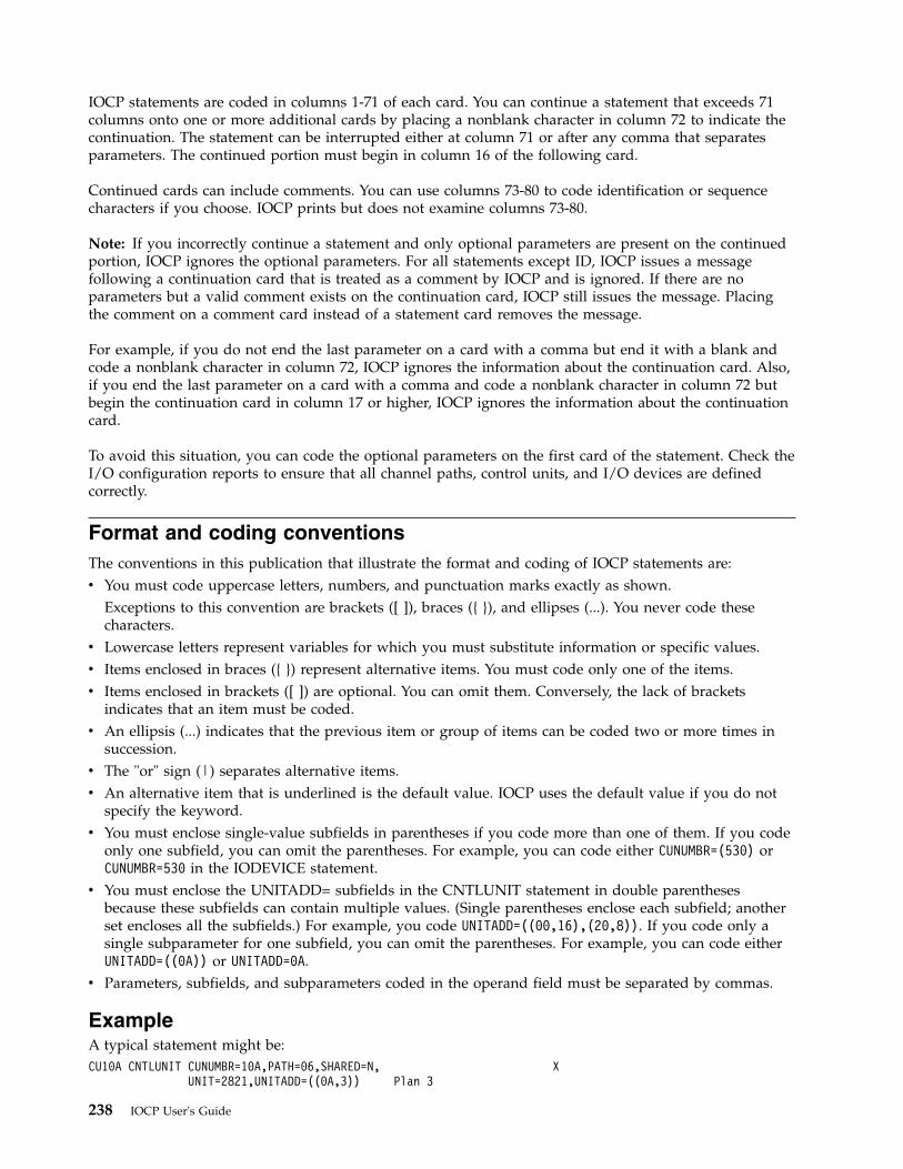
IOCP statements are coded in columns 1-71 of each card. You can continue a statement that exceeds 71columns onto one or more additional cards by placing a nonblank character in column 72 to indicate thecontinuation. The statement can be interrupted either at column 71 or after any comma that separatesparameters. The continued portion must begin in column 16 of the following card.
Continued cards can include comments. You can use columns 73-80 to code identification or sequencecharacters if you choose. IOCP prints but does not examine columns 73-80.
Note: If you incorrectly continue a statement and only optional parameters are present on the continuedportion, IOCP ignores the optional parameters. For all statements except ID, IOCP issues a messagefollowing a continuation card that is treated as a comment by IOCP and is ignored. If there are noparameters but a valid comment exists on the continuation card, IOCP still issues the message. Placingthe comment on a comment card instead of a statement card removes the message.
For example, if you do not end the last parameter on a card with a comma but end it with a blank andcode a nonblank character in column 72, IOCP ignores the information about the continuation card. Also,if you end the last parameter on a card with a comma and code a nonblank character in column 72 butbegin the continuation card in column 17 or higher, IOCP ignores the information about the continuationcard.
To avoid this situation, you can code the optional parameters on the first card of the statement. Check theI/O configuration reports to ensure that all channel paths, control units, and I/O devices are definedcorrectly.
Format and coding conventionsThe conventions in this publication that illustrate the format and coding of IOCP statements are:v You must code uppercase letters, numbers, and punctuation marks exactly as shown.
Exceptions to this convention are brackets ([ ]), braces ({ }), and ellipses (...). You never code thesecharacters.
v Lowercase letters represent variables for which you must substitute information or specific values.v Items enclosed in braces ({ }) represent alternative items. You must code only one of the items.v Items enclosed in brackets ([ ]) are optional. You can omit them. Conversely, the lack of brackets
indicates that an item must be coded.v An ellipsis (...) indicates that the previous item or group of items can be coded two or more times in
succession.v The "or" sign (|) separates alternative items.v An alternative item that is underlined is the default value. IOCP uses the default value if you do not
specify the keyword.v You must enclose single-value subfields in parentheses if you code more than one of them. If you code
only one subfield, you can omit the parentheses. For example, you can code either CUNUMBR=(530) orCUNUMBR=530 in the IODEVICE statement.
v You must enclose the UNITADD= subfields in the CNTLUNIT statement in double parenthesesbecause these subfields can contain multiple values. (Single parentheses enclose each subfield; anotherset encloses all the subfields.) For example, you code UNITADD=((00,16),(20,8)). If you code only asingle subparameter for one subfield, you can omit the parentheses. For example, you can code eitherUNITADD=((0A)) or UNITADD=0A.
v Parameters, subfields, and subparameters coded in the operand field must be separated by commas.
ExampleA typical statement might be:CU10A CNTLUNIT CUNUMBR=10A,PATH=06,SHARED=N, X
UNIT=2821,UNITADD=((0A,3)) Plan 3
238 IOCP User's Guide

CU10A is the symbolic name of the statement.
CNTLUNIT identifies the statement to the system.
CUNUMBR=10A, PATH=06, and SHARED=N are required parameters, separated by commas, containingkeywords and keyword values. Because the statement is continued, a comma follows SHARED=N, and anonblank character (X) is placed in column 72.
UNIT=2821, and UNITADD=((0A,3)) are also required parameters and start in column 16 of the continuedstatement. Because UNITADD=((0A,3)) is the last parameter, it is followed by a blank to indicate the end ofthe operand field.
Plan 3 is a comment.
Appendix A. Coding IOCP statements 239

240 IOCP User's Guide
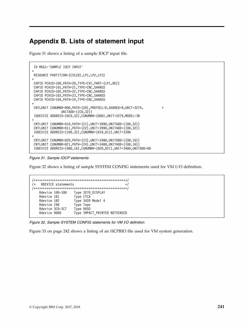
Appendix B. Lists of statement input
Figure 31 shows a listing of a sample IOCP input file.
Figure 32 shows a listing of sample SYSTEM CONFIG statements used for VM I/O definition.
Figure 33 on page 242 shows a listing of an HCPRIO file used for VM system generation.
ID MSG1=’SAMPLE IOCP INPUT’*RESOURCE PARTITION=(CSS(0),LP1,LP2,LP3)*CHPID PCHID=100,PATH=20,TYPE=CVC,PART=(LP1,REC)CHPID PCHID=101,PATH=21,TYPE=CNC,SHAREDCHPID PCHID=102,PATH=22,TYPE=CNC,SHAREDCHPID PCHID=103,PATH=23,TYPE=CNC,SHAREDCHPID PCHID=104,PATH=24,TYPE=CNC,SHARED*CNTLUNIT CUNUMBR=000,PATH=(20),PROTOCL=D,SHARED=N,UNIT=3274, +
UNITADD=((C0,32))IODEVICE ADDRESS=(0C0,32),CUNUMBR=(000),UNIT=3279,MODEL=3B*CNTLUNIT CUNUMBR=010,PATH=(21),UNIT=3990,UNITADD=((00,32))CNTLUNIT CUNUMBR=011,PATH=(22),UNIT=3990,UNITADD=((00,32))IODEVICE ADDRESS=(100,32),CUNUMBR=(010,011),UNIT=3390*CNTLUNIT CUNUMBR=020,PATH=(23),UNIT=3480,UNITADD=((00,16))CNTLUNIT CUNUMBR=021,PATH=(24),UNIT=3480,UNITADD=((00,16))IODEVICE ADDRESS=(480,16),CUNUMBR=(020,021),UNIT=3480,UNITADD=00
Figure 31. Sample IOCP statements
/***************************************************//* RDEVICE statements *//***************************************************/
Rdevice 100-108 Type 3270_DISPLAYRdevice 181 Type CTCARdevice 182 Type 3420 Model 4Rdevice 190 Type TapeRdevice 3C0-3C7 Type DASDRdevice 9000 Type IMPACT_PRINTER NOTSENSED
Figure 32. Sample SYSTEM CONFIG statements for VM I/O definition
© Copyright IBM Corp. 2017, 2018 241
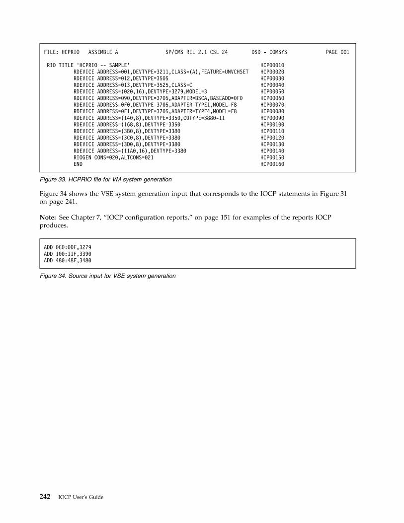
Figure 34 shows the VSE system generation input that corresponds to the IOCP statements in Figure 31on page 241.
Note: See Chapter 7, “IOCP configuration reports,” on page 151 for examples of the reports IOCPproduces.
FILE: HCPRIO ASSEMBLE A SP/CMS REL 2.1 CSL 24 DSD - COMSYS PAGE 001
RIO TITLE ’HCPRIO -- SAMPLE’ HCP00010RDEVICE ADDRESS=001,DEVTYPE=3211,CLASS=(A),FEATURE=UNVCHSET HCP00020RDEVICE ADDRESS=012,DEVTYPE=3505 HCP00030RDEVICE ADDRESS=013,DEVTYPE=3525,CLASS=C HCP00040RDEVICE ADDRESS=(020,16),DEVTYPE=3279,MODEL=3 HCP00050RDEVICE ADDRESS=090,DEVTYPE=3705,ADAPTER=BSCA,BASEADD=0F0 HCP00060RDEVICE ADDRESS=0F0,DEVTYPE=3705,ADAPTER=TYPE1,MODEL=F8 HCP00070RDEVICE ADDRESS=0F1,DEVTYPE=3705,ADAPTER=TYPE4,MODEL=F8 HCP00080RDEVICE ADDRESS=(140,8),DEVTYPE=3350,CUTYPE=3880-11 HCP00090RDEVICE ADDRESS=(168,8),DEVTYPE=3350 HCP00100RDEVICE ADDRESS=(3B0,8),DEVTYPE=3380 HCP00110RDEVICE ADDRESS=(3C0,8),DEVTYPE=3380 HCP00120RDEVICE ADDRESS=(3D0,8),DEVTYPE=3380 HCP00130RDEVICE ADDRESS=(11A0,16),DEVTYPE=3380 HCP00140RIOGEN CONS=020,ALTCONS=021 HCP00150END HCP00160
Figure 33. HCPRIO file for VM system generation
ADD 0C0:0DF,3279ADD 100:11F,3390ADD 480:48F,3480
Figure 34. Source input for VSE system generation
242 IOCP User's Guide
Appendix C. Characteristics of the I/O interface timeoutfunction
In the CPC, each channel path has I/O interface timeout functions that time the control unit delays incompleting the following I/O interface sequences:v A 4-second timeout for all selection and status presentation sequences. A timeout occurs if the sequence
is not complete within 4 seconds.v A 30-second timeout for data transfer. A timeout occurs if a byte of data is not transferred within 30
seconds.
If a timeout occurs, the channel terminates the I/O request to the control unit and generates aninterface-control-check interruption.
For additional information about these sequences, see System/360 and System/370 I/O Interface Channel toControl Unit Original Equipment Manufacturers' Information, GA22-6974.
Malfunctions in control units and I/O devices can cause a channel path to be unavailable to other controlunits and I/O devices. The timeout function detects these malfunctions.
When the timeout function is inactive (timeout is inhibited), control unit delays are not timed and thechannel unconditionally waits until the control unit completes the sequence or initiates the next tagsequence. If the control unit fails to complete a sequence because of a malfunction, the channel pathremains active to the control unit. In this situation, the channel path is unavailable for I/O requests toother control units until the failing control unit deactivates all in-tags (except metering-in and request-in)or until the channel path is reset.
The channel times I/O requests as follows:v If TIMEOUT=Y is specified, the I/O interface timeout function is active and the channel times all I/O tag
sequences and delays between dependent tag sequences that are initiated by either the channel or thecontrol unit. Some examples are:– The initial selection sequence resulting from a Start I/O instruction or a Start I/O Fast Release
instruction– A request-in tag sequence initiated by the control unit to reconnect to the I/O interface– Delays between data transfer tag sequences
v If TIMEOUT=N is specified, the I/O interface timeout function is inactive (timeout is inhibited) for:– Data transfer tag sequence– Delays between data transfer tag sequences
Timeout is inhibited from the rise of service-out that follows status-in during the initial selection sequenceuntil the rise of service-out that follows status-in during the ending sequence.
Examples follow that show when the timeout function is inactive if TIMEOUT=N is specified.
Example A. Channel initiated sequence (for example, SIO)Initial Data Ending status:selection transfer channel end andsequence sequences device end sequence
<---Timed-----><---Not timed-----><--------Timed------------->
Example B. Command chaining control unit initiated reconnection sequence
© Copyright IBM Corp. 2017, 2018 243
Device end Initial Data Ending status:reconnect selection transfer channel end andsequence sequence sequences device end sequence
<--------Timed------------><--Not timed--><---------Timed----------->
When a timeout condition is detected, the channel terminates the I/O request to the control unit byissuing a selective reset to the control unit and then generating an interface-control-check interruption. Achannel report word (CRW) is made pending, which indicates a channel-path-terminal condition.
If TIMEOUT=N is specified, detection of a timeout condition as a result of an interface associatedmalfunction might not occur (see the beginning of this appendix for a description of sequences that arenot timed when TIMEOUT=N is specified). Failure to detect and recover this condition might make variousresources unavailable to the control program. If continued operation is dependent on the availability ofthese resources, system degradation might be experienced until those resources are recovered. Recoverymight occur as a consequence of detecting a secondary error the CPC might develop from failing todetect the timeout condition. Generally, this situation does not occur and recovery of the resourcesrequires operator intervention. For these reasons, code TIMEOUT=N only when you decide a real need existsthat justifies the exposure.
Timeout considerationsSome control units and I/O devices have valid operational conditions that exceed the 30-second I/Ointerface timeout function limit. If timeout is active when such a condition occurs, the channel terminatesthe I/O request and generates an interface-control-check interruption, even though no malfunction exists.For example:v A timeout might occur during a read operation to a magnetic tape unit if the tape being read is blank.
While the magnetic tape unit searches for a data byte or the end-of-tape mark, it might exceed the30-second timeout function limit.
v A channel-to-channel adapter between two CPCs might time out if one system attempts tocommunicate with the other system while the other CPC is in a stopped state.
When timeout is active, the channel might terminate an I/O request and generate aninterface-control-check interruption even though no control unit or I/O device malfunction has occurred.
Note: For a device with valid operational conditions that can exceed the 30-second I/O interface timeoutlimit, inhibit the timeout function by specifying TIMEOUT=N in the IODEVICE statement. For other IBMI/O devices, specify the default TIMEOUT=Y.
244 IOCP User's Guide
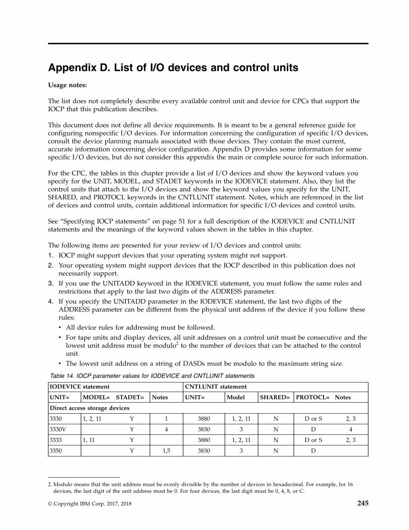
Appendix D. List of I/O devices and control units
Usage notes:
The list does not completely describe every available control unit and device for CPCs that support theIOCP that this publication describes.
This document does not define all device requirements. It is meant to be a general reference guide forconfiguring nonspecific I/O devices. For information concerning the configuration of specific I/O devices,consult the device planning manuals associated with those devices. They contain the most current,accurate information concerning device configuration. Appendix D provides some information for somespecific I/O devices, but do not consider this appendix the main or complete source for such information.
For the CPC, the tables in this chapter provide a list of I/O devices and show the keyword values youspecify for the UNIT, MODEL, and STADET keywords in the IODEVICE statement. Also, they list thecontrol units that attach to the I/O devices and show the keyword values you specify for the UNIT,SHARED, and PROTOCL keywords in the CNTLUNIT statement. Notes, which are referenced in the listof devices and control units, contain additional information for specific I/O devices and control units.
See “Specifying IOCP statements” on page 51 for a full description of the IODEVICE and CNTLUNITstatements and the meanings of the keyword values shown in the tables in this chapter.
The following items are presented for your review of I/O devices and control units:1. IOCP might support devices that your operating system might not support.2. Your operating system might support devices that the IOCP described in this publication does not
necessarily support.3. If you use the UNITADD keyword in the IODEVICE statement, you must follow the same rules and
restrictions that apply to the last two digits of the ADDRESS parameter.4. If you specify the UNITADD parameter in the IODEVICE statement, the last two digits of the
ADDRESS parameter can be different from the physical unit address of the device if you follow theserules:v All device rules for addressing must be followed.v For tape units and display devices, all unit addresses on a control unit must be consecutive and the
lowest unit address must be modulo2 to the number of devices that can be attached to the controlunit.
v The lowest unit address on a string of DASDs must be modulo to the maximum string size.
Table 14. IOCP parameter values for IODEVICE and CNTLUNIT statements
IODEVICE statement CNTLUNIT statement
UNIT= MODEL= STADET= Notes UNIT= Model SHARED= PROTOCL= Notes
Direct access storage devices
3330 1, 2, 11 Y 1 3880 1, 2, 11 N D or S 2, 3
3330V Y 4 3830 3 N D 4
3333 1, 11 Y 3880 1, 2, 11 N D or S 2, 3
3350 Y 1,5 3830 3 N D
2. Modulo means that the unit address must be evenly divisible by the number of devices in hexadecimal. For example, for 16devices, the last digit of the unit address must be 0. For four devices, the last digit must be 0, 4, 8, or C.
© Copyright IBM Corp. 2017, 2018 245
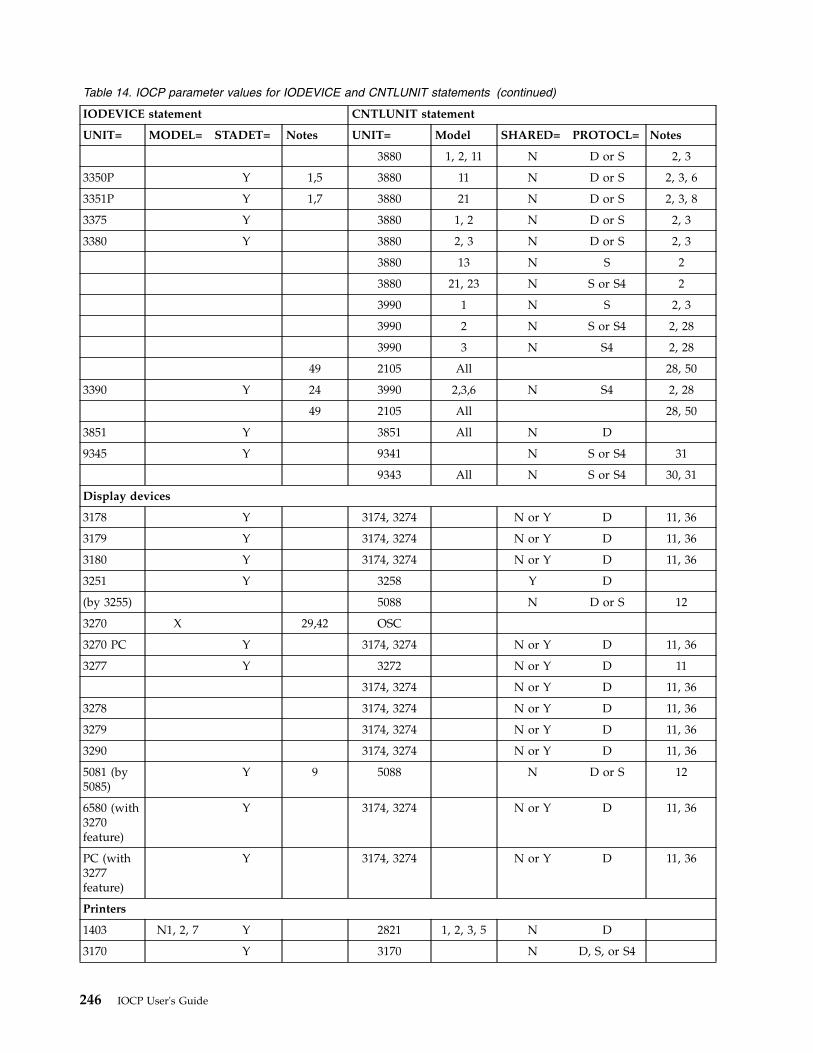
Table 14. IOCP parameter values for IODEVICE and CNTLUNIT statements (continued)
IODEVICE statement CNTLUNIT statement
UNIT= MODEL= STADET= Notes UNIT= Model SHARED= PROTOCL= Notes
3880 1, 2, 11 N D or S 2, 3
3350P Y 1,5 3880 11 N D or S 2, 3, 6
3351P Y 1,7 3880 21 N D or S 2, 3, 8
3375 Y 3880 1, 2 N D or S 2, 3
3380 Y 3880 2, 3 N D or S 2, 3
3880 13 N S 2
3880 21, 23 N S or S4 2
3990 1 N S 2, 3
3990 2 N S or S4 2, 28
3990 3 N S4 2, 28
49 2105 All 28, 50
3390 Y 24 3990 2,3,6 N S4 2, 28
49 2105 All 28, 50
3851 Y 3851 All N D
9345 Y 9341 N S or S4 31
9343 All N S or S4 30, 31
Display devices
3178 Y 3174, 3274 N or Y D 11, 36
3179 Y 3174, 3274 N or Y D 11, 36
3180 Y 3174, 3274 N or Y D 11, 36
3251 Y 3258 Y D
(by 3255) 5088 N D or S 12
3270 X 29,42 OSC
3270 PC Y 3174, 3274 N or Y D 11, 36
3277 Y 3272 N or Y D 11
3174, 3274 N or Y D 11, 36
3278 3174, 3274 N or Y D 11, 36
3279 3174, 3274 N or Y D 11, 36
3290 3174, 3274 N or Y D 11, 36
5081 (by5085)
Y 9 5088 N D or S 12
6580 (with3270feature)
Y 3174, 3274 N or Y D 11, 36
PC (with3277feature)
Y 3174, 3274 N or Y D 11, 36
Printers
1403 N1, 2, 7 Y 2821 1, 2, 3, 5 N D
3170 Y 3170 N D, S, or S4
246 IOCP User's Guide
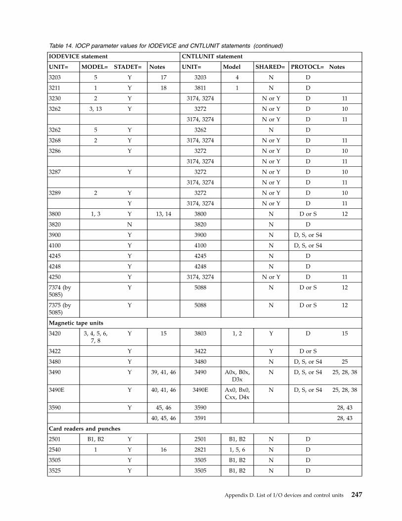
Table 14. IOCP parameter values for IODEVICE and CNTLUNIT statements (continued)
IODEVICE statement CNTLUNIT statement
UNIT= MODEL= STADET= Notes UNIT= Model SHARED= PROTOCL= Notes
3203 5 Y 17 3203 4 N D
3211 1 Y 18 3811 1 N D
3230 2 Y 3174, 3274 N or Y D 11
3262 3, 13 Y 3272 N or Y D 10
3174, 3274 N or Y D 11
3262 5 Y 3262 N D
3268 2 Y 3174, 3274 N or Y D 11
3286 Y 3272 N or Y D 10
3174, 3274 N or Y D 11
3287 Y 3272 N or Y D 10
3174, 3274 N or Y D 11
3289 2 Y 3272 N or Y D 10
Y 3174, 3274 N or Y D 11
3800 1, 3 Y 13, 14 3800 N D or S 12
3820 N 3820 N D
3900 Y 3900 N D, S, or S4
4100 Y 4100 N D, S, or S4
4245 Y 4245 N D
4248 Y 4248 N D
4250 Y 3174, 3274 N or Y D 11
7374 (by5085)
Y 5088 N D or S 12
7375 (by5085)
Y 5088 N D or S 12
Magnetic tape units
3420 3, 4, 5, 6,7, 8
Y 15 3803 1, 2 Y D 15
3422 Y 3422 Y D or S
3480 Y 3480 N D, S, or S4 25
3490 Y 39, 41, 46 3490 A0x, B0x,D3x
N D, S, or S4 25, 28, 38
3490E Y 40, 41, 46 3490E Ax0, Bx0,Cxx, D4x
N D, S, or S4 25, 28, 38
3590 Y 45, 46 3590 28, 43
40, 45, 46 3591 28, 43
Card readers and punches
2501 B1, B2 Y 2501 B1, B2 N D
2540 1 Y 16 2821 1, 5, 6 N D
3505 Y 3505 B1, B2 N D
3525 Y 3505 B1, B2 N D
Appendix D. List of I/O devices and control units 247
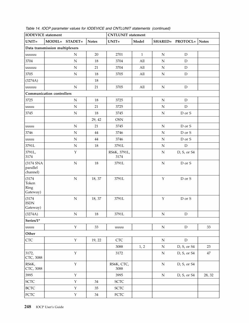
Table 14. IOCP parameter values for IODEVICE and CNTLUNIT statements (continued)
IODEVICE statement CNTLUNIT statement
UNIT= MODEL= STADET= Notes UNIT= Model SHARED= PROTOCL= Notes
Data transmission multiplexers
uuuuu N 20 2701 1 N D
3704 N 18 3704 All N D
uuuuu N 21 3704 All N D
3705 N 18 3705 All N D
(3274A) 18
uuuuu N 21 3705 All N D
Communication controllers
3725 N 18 3725 N D
uuuu N 21 3725 N D
3745 N 18 3745 N D or S
29, 42 OSN
uuuu N 21 3745 N D or S
3746 N 44 3746 N D or S
uuuu N 44 3746 N D or S
3791L N 18 3791L N D
3791L,3174
Y RS6K, 3791L,3174
N D, S, or S4
(3174 SNAparallelchannel)
N 18 3791L N D or S
(3174TokenRingGateway)
N 18, 37 3791L Y D or S
(3174ISDNGateway)
N 18, 37 3791L Y D or S
(3274A) N 18 3791L N D
Series/1*
uuuu Y 33 uuuu N D 33
Other
CTC Y 19, 22 CTC N D
3088 1, 2 N D, S, or S4 23
3172,CTC, 3088
Y 3172 N D, S, or S4 47
RS6K,CTC, 3088
Y RS6K, CTC,3088
N D, S, or S4
3995 Y 3995 N D, S, or S4 28, 32
SCTC Y 34 SCTC
BCTC Y 35 SCTC
FCTC Y 34 FCTC
248 IOCP User's Guide
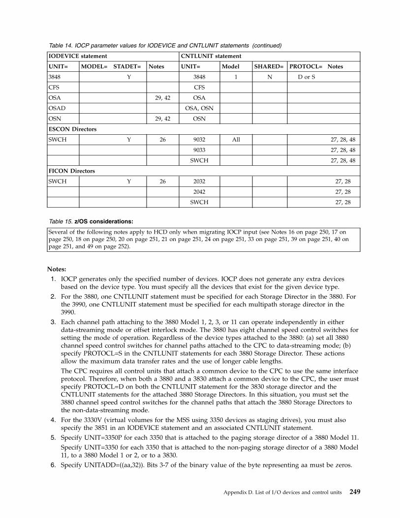
Table 14. IOCP parameter values for IODEVICE and CNTLUNIT statements (continued)
IODEVICE statement CNTLUNIT statement
UNIT= MODEL= STADET= Notes UNIT= Model SHARED= PROTOCL= Notes
3848 Y 3848 1 N D or S
CFS CFS
OSA 29, 42 OSA
OSAD OSA, OSN
OSN 29, 42 OSN
ESCON Directors
SWCH Y 26 9032 All 27, 28, 48
9033 27, 28, 48
SWCH 27, 28, 48
FICON Directors
SWCH Y 26 2032 27, 28
2042 27, 28
SWCH 27, 28
Table 15. z/OS considerations:
Several of the following notes apply to HCD only when migrating IOCP input (see Notes 16 on page 250, 17 onpage 250, 18 on page 250, 20 on page 251, 21 on page 251, 24 on page 251, 33 on page 251, 39 on page 251, 40 onpage 251, and 49 on page 252).
Notes:
1. IOCP generates only the specified number of devices. IOCP does not generate any extra devicesbased on the device type. You must specify all the devices that exist for the given device type.
2. For the 3880, one CNTLUNIT statement must be specified for each Storage Director in the 3880. Forthe 3990, one CNTLUNIT statement must be specified for each multipath storage director in the3990.
3. Each channel path attaching to the 3880 Model 1, 2, 3, or 11 can operate independently in eitherdata-streaming mode or offset interlock mode. The 3880 has eight channel speed control switches forsetting the mode of operation. Regardless of the device types attached to the 3880: (a) set all 3880channel speed control switches for channel paths attached to the CPC to data-streaming mode; (b)specify PROTOCL=S in the CNTLUNIT statements for each 3880 Storage Director. These actionsallow the maximum data transfer rates and the use of longer cable lengths.The CPC requires all control units that attach a common device to the CPC to use the same interfaceprotocol. Therefore, when both a 3880 and a 3830 attach a common device to the CPC, the user mustspecify PROTOCL=D on both the CNTLUNIT statement for the 3830 storage director and theCNTLUNIT statements for the attached 3880 Storage Directors. In this situation, you must set the3880 channel speed control switches for the channel paths that attach the 3880 Storage Directors tothe non-data-streaming mode.
4. For the 3330V (virtual volumes for the MSS using 3350 devices as staging drives), you must alsospecify the 3851 in an IODEVICE statement and an associated CNTLUNIT statement.
5. Specify UNIT=3350P for each 3350 that is attached to the paging storage director of a 3880 Model 11.Specify UNIT=3350 for each 3350 that is attached to the non-paging storage director of a 3880 Model11, to a 3880 Model 1 or 2, or to a 3830.
6. Specify UNITADD=((aa,32)). Bits 3-7 of the binary value of the byte representing aa must be zeros.
Appendix D. List of I/O devices and control units 249
To identify the paging storage director of a 3880 Model 11 in the configuration reports, you canspecify UNIT=3880P. The non-paging storage director of a 3880 Model 11 can be specifiedUNIT=3880.
7. Specify UNIT=3351P for each 3350 that is attached to the paging storage director of a 3880 Model 21.8. Specify UNITADD=((aa,16)). Bits 4-7 of the binary value of the byte representing aa must be zeros.
To identify the paging storage director of a 3880 Model 21 in the configuration reports, you canspecify UNIT=3880P. The non-paging storage director of a 3880 Model 21 can be specifiedUNIT=3880.
9. When you are using the 5081 in a 3250 compatibility mode, specify the 5081 as UNIT=2250,MODEL=3. When you are using the 5081 in full function mode, specify the 5080 as UNIT=HFGD.For more information, see Graphics Access Method/System Product: Initialization, Resource Definition, andCustomization, SC33-0141.The 5088 device can run either in DC interlock protocol or in data-streaming protocol, depending onthe channel. Ensure that the interface protocol specified matches the protocol specified in the 5088.
10. For a 3272 attached to a block-multiplexer channel path, use SHARED=Y if multiple devices areattached to the control unit. SHARED=N is required if a 3272 is attached to a byte multiplexerchannel path.When multiple devices are attached to the control unit and SHARED=N is specified, the possibilityof additional processor use in the control program increases because of deferred condition code 1I/O interruptions. If a single device is attached to the control unit, SHARED=N can be specifiedwithout increasing the processor use in the control program for interruption processing.
11. For a 3174 or 3274 attached to a block-multiplexer channel path, use SHARED=Y if multiple devicesare attached to the control unit. If necessary, you can specify SHARED=N when multiple devices areattached to the control unit. However, specifying SHARED=N might result in a control unitmalfunction or increase the possibility of additional processor use in the control program resultingfrom deferred condition code 1 I/O interruptions.If a single device is attached to the control unit (as is always the case for the 3174 (SNA) or 3274Model 1A), SHARED=N can be specified and does not increase the processor use in the controlprogram for interruption processing.
12. The control unit can run in either DC interlock protocol or data-streaming protocol, depending onthe channel. Ensure that the interface protocol specified matches the protocol specified in theCNTLUNIT statement.
13. Attach the 3800 to a block-multiplexer channel (TYPE=CVC) for best system performance.14. Specify TIMEOUT=Y when IBM-supplied programs are used with the 3800. Non-IBM programs
might require TIMEOUT=N for the 3800 because I/O requests might require more than 4 seconds tocomplete.
15. If the magnetic tape subsystem contains two to four control units that access the same group ofmagnetic tape units, define each control unit separately. Each of the control units must have adifferent channel path identifier, but all of the control units must specify the same address range.Specify in the IODEVICE statement that the magnetic tape units are attached to all of the controlunits. (The magnetic tape units might actually be only logically attached, but they are specified asthough they are physically attached.)
16. For HCD users, specify the 2540 with two IODEVICE statements: one with UNIT=2540R, the otherwith UNIT=2540P. See Table 15 on page 249..
17. For HCD users, for the 3203, only the Model 5 is supported. See Table 15 on page 249.18. For HCD users, a 3174 (SNA) or 3274 Model A is specified as a 3791L in the IODEVICE statement.
See Table 15 on page 249.19. For the channel-to-channel adapter (CTCA), specify TIMEOUT=N because I/O sequences on the
CTCA might require more than 4 seconds to complete. Because TIMEOUT=N, the CTCA cannot beattached to a byte multiplexer channel path.
250 IOCP User's Guide
20. For HCD users, in the UNIT parameter, you can specify any device or line that is attached to the2701. See Table 15 on page 249.
21. For HCD users, in the UNIT parameter, you can specify any device or line that is attached to the3704, 3705, 3725, and 3745. (This statement applies only to emulation program [EP] mode and bytemultiplexer mode.) See Table 15 on page 249.
22. For a 3088, specify UNITADD=b0 and ADDRESS=(aaa,n), where n=32 or n=64, depending on thenumber of unit addresses required.
23. For a 3088, specify UNITADD=((a0,n)), where n=32 or n=64, depending on the number of unitaddresses required.
24. For HCD users, the UNIT type must indicate the mode of operation for the device. If the device isset to 3380 track compatibility mode, use UNIT=3380. See Table 15 on page 249.
25. For a 3480 (all models) or a 3490 or 3490E (Models Axx or Bxx), specify UNITADD=((a0,16)).26. For 2032, 2042, 9032, 9033, and SWCH, always code UNITADD=00.27. For 2032, 2042, 9032, 9033, and SWCH, always code LINK=FE.28. The 2105, 3490, 3490E, 3590, 3591, 3990, 3995, 9032, 9033, and SWCH control units require the unit
address range to begin with 00 for ESCON channel paths CNC and FCV. The 2032, 2042, 2105, and3590 control units require the unit address range to begin with 00 for FICON channel path type FC.The 3990 requires the unit address range to begin with X'10' or X'20' if DASD string 0 is not installed.For more information, see 3990 Storage Control Planning, Installation, and Storage Administration Guide,GA32-0100.
29. For devices assigned to OSC, OSD, OSE, OSM, OSN, or OSX channel paths, do not specify theSTADET keyword because it is ignored.
30. Specify one CNTLUNIT statement for each storage cluster in the IBM 9340 Direct Access StorageSubsystem.
31. Specify UNITADD =((nn,32)). Bits 3-7 of the binary value of the byte representing nn must be zeros.32. Specify UNITADD=((a0,8)) or, if a Model 111 or Model 112 expansion unit is attached, specify
UNITADD=((a0,16)), where a is any hexadecimal digit unless the channel paths are ESCON. ForESCON channel paths, specify UNITADD=((00,8)) or UNITADD=((00,16)).
33. For HCD users, you can program a Series/1 to emulate a control unit with devices. In theCNTLUNIT statement, specify in the UNIT keyword the type of control unit being emulated. In theIODEVICE statement, specify in the UNIT keyword the type of device being emulated. See Table 15on page 249.
34. If you specify UNIT=SCTC for devices assigned to ESCON CTC channels, the I/O subsystem usesextended mode CTC. The I/O subsystem always uses extended mode CTC for devices assigned toFICON CTC control units.
35. To run applications that require parallel basic mode CTC support using ESCON channels, specifyUNIT=BCTC. Only the ESCON CTC channel end of the ESCON CTC connection needs theUNIT=BCTC specification. If UNIT=BCTC is not specified, the I/O subsystem uses extended modeCTC.
36. The description is valid only for devices on channel-attached non-SNA 3174s and 3274s. Devices onchannel-attached SNA 3x74s are not defined separately so only the SNA control unit must be codedin an IODEVICE statement. See the “Communication Controllers” section in Table 14 on page 245.
37. 3174s operating as a Token Ring or ISDN gateway must have only one IODEVICE and oneCNTLUNIT statement. The number value must be coded for both the ADDRESS= parameter in theIODEVICE statement and the UNITADD= parameter in the CNTLUNIT statement to match theaddress range the 3174 gateway supports.
38. For a 3490 or 3490E (Models Cxx or Dxx), specify UNITADD=((a0,2)).39. For HCD users, specify UNIT=3480. See Table 15 on page 249.40. For HCD users, specify UNIT=3490. See Table 15 on page 249.
Appendix D. List of I/O devices and control units 251
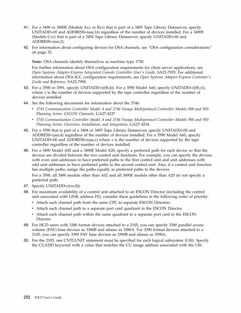
41. For a 3490 or 3490E (Models Axx or Bxx) that is part of a 3495 Tape Library Dataserver, specifyUNITADD=b0 and ADDRESS=(aaa,16) regardless of the number of devices installed. For a 3490E(Models Cxx) that is part of a 3494 Tape Library Dataserver, specify UNITADD=b0 andADDRESS=(aaa,2).
42. For information about configuring devices for OSA channels, see “OSA configuration considerations”on page 32.
Note: OSA channels identify themselves as machine type 1730.For further information about OSA configuration requirements for client server applications, seeOpen Systems Adapter-Express Integrated Console Controller User's Guide, SA22-7935. For additionalinformation about OSA-ICC configuration requirements, see Open Systems Adapter-Express Customer'sGuide and Reference, SA22-7990.
43. For a 3590 or 3591, specify UNITADD=((00,4)). For a 3590 Model A60, specify UNITADD=((00,x)),where x is the number of devices supported by the tape controller regardless of the number ofdevices installed.
44. See the following documents for information about the 3746:v 3745 Communication Controller Model A and 3746 Nways Multiprotocol Controller Models 900 and 950
Planning Series: ESCON Channels, GA27-4237v 3745 Communication Controller Model A and 3746 Nways Multiprotocol Controller Models 900 and 950
Planning Series: Overview, Installation, and Integration, GA27-4234.45. For a 3590 that is part of a 3494 or 3495 Tape Library Dataserver, specify UNITADD=00 and
ADDRESS=(aaa,4) regardless of the number of devices installed. For a 3590 Model A60, specifyUNITADD=00 and ADDRESS=(aaa,x) where x is the number of devices supported by the tapecontroller regardless of the number of devices installed.
46. For a 3490 Model A02 and a 3490E Model A20, specify a preferred path for each device so that thedevices are divided between the two control unit functions. For example, you can specify the deviceswith even unit addresses to have preferred paths to the first control unit and unit addresses withodd unit addresses to have preferred paths to the second control unit. Also, if a control unit functionhas multiple paths, assign the paths equally as preferred paths to the devices.For a 3590, all 3490 models other than A02 and all 3490E models other than A20 do not specify apreferred path.
47. Specify UNITADD=((nn,8)).48. For maximum availability of a control unit attached to an ESCON Director (including the control
unit associated with LINK address FE), consider these guidelines in the following order of priority:v Attach each channel path from the same CPC to separate ESCON Directorsv Attach each channel path to a separate port card quadrant in the ESCON Directorv Attach each channel path within the same quadrant to a separate port card in the ESCON
Director.49. For HCD users with 3380 format devices attached to a 2105, you can specify 3380 parallel access
volume (PAV) base devices as 3380B and aliases as 3380A. For 3390 format devices attached to a2105, you can specify 3390 PAV base devices as 3390B and aliases as 3390A.
50. For the 2105, one CNTLUNIT statement must be specified for each logical subsystem (LSS). Specifythe CUADD keyword with a value that matches the CU image address associated with the LSS.
252 IOCP User's Guide
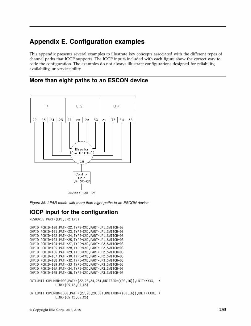
Appendix E. Configuration examples
This appendix presents several examples to illustrate key concepts associated with the different types ofchannel paths that IOCP supports. The IOCP inputs included with each figure show the correct way tocode the configuration. The examples do not always illustrate configurations designed for reliability,availability, or serviceability.
More than eight paths to an ESCON device
IOCP input for the configurationRESOURCE PART=(LP1,LP2,LP3)
CHPID PCHID=100,PATH=22,TYPE=CNC,PART=LP1,SWITCH=03CHPID PCHID=101,PATH=23,TYPE=CNC,PART=LP1,SWITCH=03CHPID PCHID=102,PATH=24,TYPE=CNC,PART=LP1,SWITCH=03CHPID PCHID=103,PATH=25,TYPE=CNC,PART=LP1,SWITCH=03CHPID PCHID=104,PATH=27,TYPE=CNC,PART=LP2,SWITCH=03CHPID PCHID=105,PATH=28,TYPE=CNC,PART=LP2,SWITCH=03CHPID PCHID=106,PATH=29,TYPE=CNC,PART=LP2,SWITCH=03CHPID PCHID=107,PATH=30,TYPE=CNC,PART=LP2,SWITCH=03CHPID PCHID=108,PATH=32,TYPE=CNC,PART=LP3,SWITCH=03CHPID PCHID=109,PATH=33 TYPE=CNC,PART=LP3,SWITCH=03CHPID PCHID=10A,PATH=34,TYPE=CNC,PART=LP3,SWITCH=03CHPID PCHID=10B,PATH=35,TYPE=CNC,PART=LP3,SWITCH=03
CNTLUNIT CUNUMBR=000,PATH=(22,23,24,25),UNITADD=((00,16)),UNIT=XXXX, XLINK=(C5,C5,C5,C5)
CNTLUNIT CUNUMBR=1000,PATH=(27,28,29,30),UNITADD=((00,16)),UNIT=XXXX, XLINK=(C5,C5,C5,C5)
Figure 35. LPAR mode with more than eight paths to an ESCON device
© Copyright IBM Corp. 2017, 2018 253
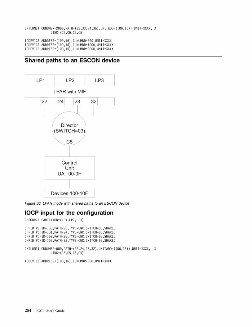
CNTLUNIT CUNUMBR=2000,PATH=(32,33,34,35),UNITADD=((00,16)),UNIT=XXXX, XLINK=(C5,C5,C5,C5)
IODEVICE ADDRESS=(100,16),CUNUMBR=000,UNIT=XXXXIODEVICE ADDRESS=(100,16),CUNUMBR=1000,UNIT=XXXXIODEVICE ADDRESS=(100,16),CUNUMBR=2000,UNIT=XXXX
Shared paths to an ESCON device
IOCP input for the configurationRESOURCE PARTITION=(LP1,LP2,LP3)
CHPID PCHID=100,PATH=22,TYPE=CNC,SWITCH=03,SHAREDCHPID PCHID=101,PATH=24,TYPE=CNC,SWITCH=03,SHAREDCHPID PCHID=102,PATH=28,TYPE=CNC,SWITCH=03,SHAREDCHPID PCHID=103,PATH=32,TYPE=CNC,SWITCH=03,SHARED
CNTLUNIT CUNUMBR=000,PATH=(22,24,28,32),UNITADD=((00,16)),UNIT=XXXX, XLINK=(C5,C5,C5,C5)
IODEVICE ADDRESS=(100,16),CUNUMBR=000,UNIT=XXXX
LP1 LP2 LP3
LPAR with MIF
22 24 28 32
Director(SWITCH=03)
C5
ControlUnit
UA 00-0F
Devices 100-10F
Figure 36. LPAR mode with shared paths to an ESCON device
254 IOCP User's Guide
ESCON CTC point-to-point
IOCP input for system 1 configurationRESOURCE PART=SYSTEM1
CHPID PCHID=100,PATH=(31),TYPE=CNC,PART=SYSTEM1
CNTLUNIT CUNUMBR=000,PATH=(31),UNITADD=((00,1)),UNIT=SCTC
IODEVICE ADDRESS=100,CUNUMBR=000,UNIT=SCTC
IOCP input for system 2 configurationRESOURCE PART=SYSTEM2
CHPID PCHID=100,PATH=(22),TYPE=CNC,PART=SYSTEM2
CNTLUNIT CUNUMBR=100,PATH=(22),UNITADD=((00,1)),UNIT=SCTC
IODEVICE ADDRESS=200,CUNUMBR=100,UNIT=SCTC
Note: You must specify the same unit address for devices from different logical partitions tocommunicate with each other (00 in this example). This example assumes that the application programsupports send and receive functions on a single device number.
Figure 37. ESCON CTC point-to-point
Appendix E. Configuration examples 255
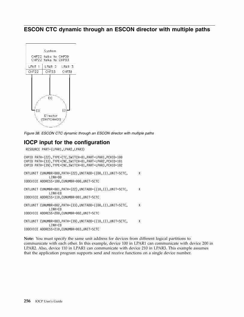
ESCON CTC dynamic through an ESCON director with multiple paths
IOCP input for the configurationRESOURCE PART=(LPAR1,LPAR2,LPAR3)
CHPID PATH=(22),TYPE=CTC,SWITCH=01,PART=LPAR1,PCHID=100CHPID PATH=(33),TYPE=CNC,SWITCH=01,PART=LPAR2,PCHID=101CHPID PATH=(39),TYPE=CNC,SWITCH=01,PART=LPAR3,PCHID=102
CNTLUNIT CUNUMBR=000,PATH=(22),UNITADD=((00,1)),UNIT=SCTC, XLINK=D0
IODEVICE ADDRESS=100,CUNUMBR=000,UNIT=SCTC
CNTLUNIT CUNUMBR=001,PATH=(22),UNITADD=((10,1)),UNIT=SCTC, XLINK=E0
IODEVICE ADDRESS=110,CUNUMBR=001,UNIT=SCTC
CNTLUNIT CUNUMBR=002,PATH=(33),UNITADD=((00,1)),UNIT=SCTC, XLINK=C0
IODEVICE ADDRESS=200,CUNUMBR=002,UNIT=SCTC
CNTLUNIT CUNUMBR=003,PATH=(39),UNITADD=((10,1)),UNIT=SCTC, XLINK=C0
IODEVICE ADDRESS=210,CUNUMBR=003,UNIT=SCTC
Note: You must specify the same unit address for devices from different logical partitions tocommunicate with each other. In this example, device 100 in LPAR1 can communicate with device 200 inLPAR2. Also, device 110 in LPAR1 can communicate with device 210 in LPAR3. This example assumesthat the application program supports send and receive functions on a single device number.
Figure 38. ESCON CTC dynamic through an ESCON director with multiple paths
256 IOCP User's Guide
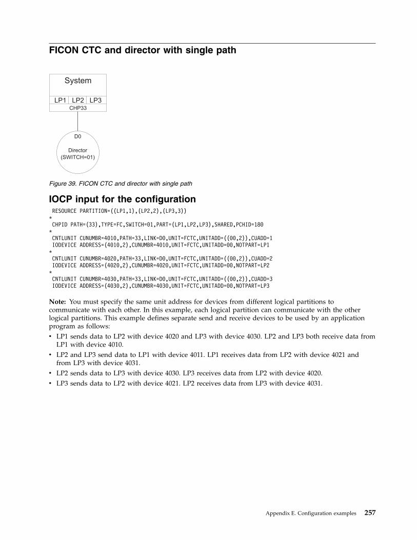
FICON CTC and director with single path
IOCP input for the configurationRESOURCE PARTITION=((LP1,1),(LP2,2),(LP3,3))
*CHPID PATH=(33),TYPE=FC,SWITCH=01,PART=(LP1,LP2,LP3),SHARED,PCHID=180
*CNTLUNIT CUNUMBR=4010,PATH=33,LINK=D0,UNIT=FCTC,UNITADD=((00,2)),CUADD=1IODEVICE ADDRESS=(4010,2),CUNUMBR=4010,UNIT=FCTC,UNITADD=00,NOTPART=LP1
*CNTLUNIT CUNUMBR=4020,PATH=33,LINK=D0,UNIT=FCTC,UNITADD=((00,2)),CUADD=2IODEVICE ADDRESS=(4020,2),CUNUMBR=4020,UNIT=FCTC,UNITADD=00,NOTPART=LP2
*CNTLUNIT CUNUMBR=4030,PATH=33,LINK=D0,UNIT=FCTC,UNITADD=((00,2)),CUADD=3IODEVICE ADDRESS=(4030,2),CUNUMBR=4030,UNIT=FCTC,UNITADD=00,NOTPART=LP3
Note: You must specify the same unit address for devices from different logical partitions tocommunicate with each other. In this example, each logical partition can communicate with the otherlogical partitions. This example defines separate send and receive devices to be used by an applicationprogram as follows:v LP1 sends data to LP2 with device 4020 and LP3 with device 4030. LP2 and LP3 both receive data from
LP1 with device 4010.v LP2 and LP3 send data to LP1 with device 4011. LP1 receives data from LP2 with device 4021 and
from LP3 with device 4031.v LP2 sends data to LP3 with device 4030. LP3 receives data from LP2 with device 4020.v LP3 sends data to LP2 with device 4021. LP2 receives data from LP3 with device 4031.
System
LP1 LP2 LP3CHP33
D0
Director
(SWITCH=01)
Figure 39. FICON CTC and director with single path
Appendix E. Configuration examples 257
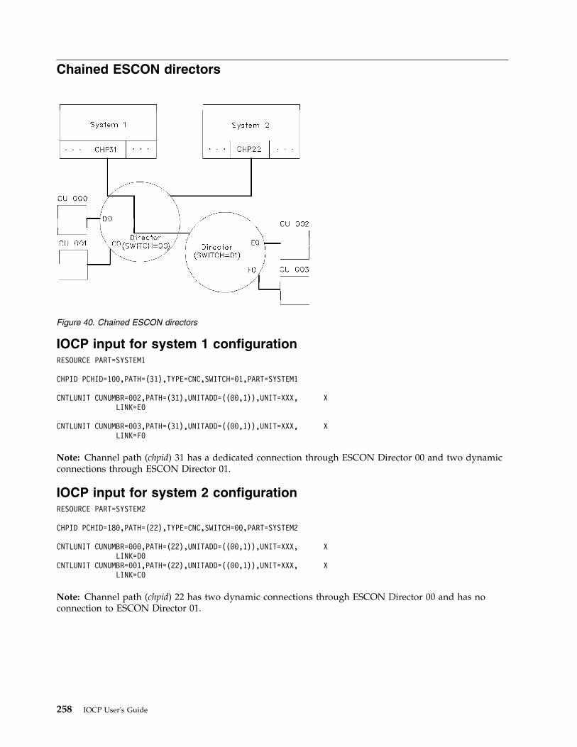
Chained ESCON directors
IOCP input for system 1 configurationRESOURCE PART=SYSTEM1
CHPID PCHID=100,PATH=(31),TYPE=CNC,SWITCH=01,PART=SYSTEM1
CNTLUNIT CUNUMBR=002,PATH=(31),UNITADD=((00,1)),UNIT=XXX, XLINK=E0
CNTLUNIT CUNUMBR=003,PATH=(31),UNITADD=((00,1)),UNIT=XXX, XLINK=F0
Note: Channel path (chpid) 31 has a dedicated connection through ESCON Director 00 and two dynamicconnections through ESCON Director 01.
IOCP input for system 2 configurationRESOURCE PART=SYSTEM2
CHPID PCHID=180,PATH=(22),TYPE=CNC,SWITCH=00,PART=SYSTEM2
CNTLUNIT CUNUMBR=000,PATH=(22),UNITADD=((00,1)),UNIT=XXX, XLINK=D0
CNTLUNIT CUNUMBR=001,PATH=(22),UNITADD=((00,1)),UNIT=XXX, XLINK=C0
Note: Channel path (chpid) 22 has two dynamic connections through ESCON Director 00 and has noconnection to ESCON Director 01.
Figure 40. Chained ESCON directors
258 IOCP User's Guide

Cascaded FICON directors
IOCP input for the configurationRESOURCE PART=(LP1,LP2,LP3)
CHPID PCHID=100,PATH=30,TYPE=FC,SWITCH=21,SHAREDCHPID PCHID=101,PATH=31,TYPE=FC,SWITCH=21,SHAREDCHPID PCHID=120,PATH=32,TYPE=FC,SWITCH=22,SHARED
CNTLUNIT CUNUMBR=001,PATH=(30,31,32),LINK=(C0,21C0,21C0),UNIT=XXX,...CNTLUNIT CUNUMBR=002,PATH=(31,32),LINK=(22C0,22C0),UNIT=XXX,...
Note: In this example, the switch numbers specified for the FICON Directors match the switch addressesassigned to the Directors through their switch control panels.
In this example, chpids 30, 31, and 32 are attached to control unit 001. Chpid 30 communicates only tocontrol units attached to switch 21 so it has used a 2-digit link address (C0) even though the switch isconfigured with the high integrity attributes and supports 4-digit link addresses. Chpids 31 and 32communicate to control units that are not connected to their entry switches so they must have 4-digit linkaddresses. The first two digits identify the switch address and the last two digits identify the portaddress to which the control unit is attached. Link address 21C0 identifies port C0 on the switch withswitch address 21. Link address 22C0 identifies port C0 on the switch with switch address 22. I/O forcontrol unit 001 for chpid 32 flows through both switches while chpid 31 uses only switch 21. I/O forcontrol unit 002 for chpid 31 flows through both switches while chpid 32 uses only switch 22.
Note: This example does not follow all recommendations. For example, chpid 31 connects to switch 21and uses 4-digit link addresses while chpid 30 also connects to switch 21 but uses 2-digit link addresses.When a 4-digit link address is specified for a channel path, ensure that all channel paths connected to thesame entry switch specify 4-digit link addresses so IOCP can perform better checking of the switchconfiguration. See “Defining FICON switch configurations” on page 37 for more information aboutcascading switches and specifying link addresses for FC channel paths.
Director(Switch Address=21)
Director(Switch Address=22)
CU 001
C0 C0
System
CHP 30 CHP 31 CHP 32
CU 002
Figure 41. Cascaded FICON directors
Appendix E. Configuration examples 259
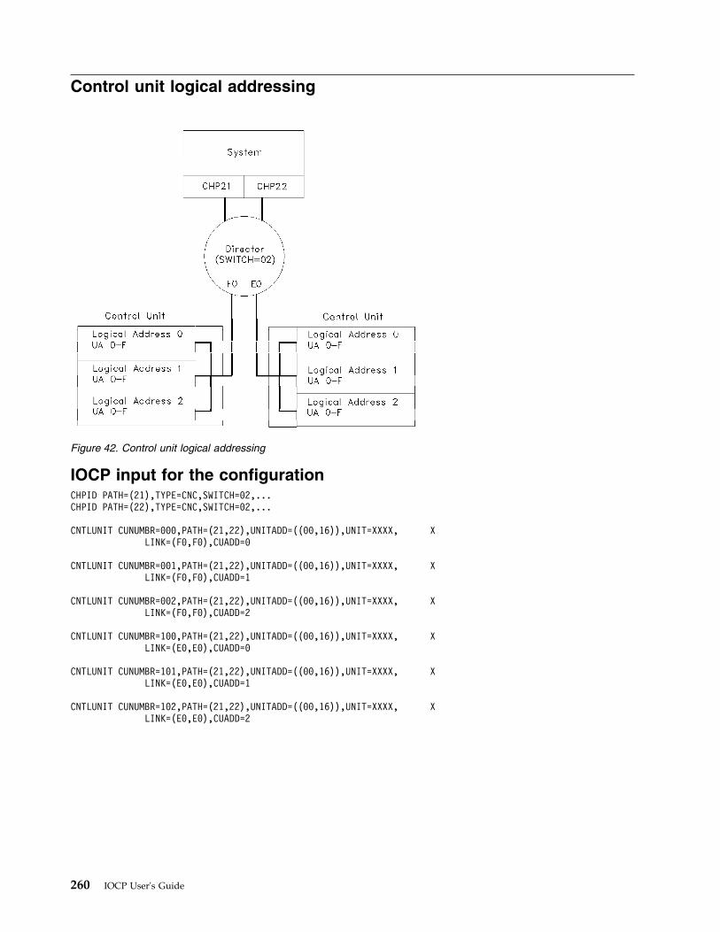
Control unit logical addressing
IOCP input for the configurationCHPID PATH=(21),TYPE=CNC,SWITCH=02,...CHPID PATH=(22),TYPE=CNC,SWITCH=02,...
CNTLUNIT CUNUMBR=000,PATH=(21,22),UNITADD=((00,16)),UNIT=XXXX, XLINK=(F0,F0),CUADD=0
CNTLUNIT CUNUMBR=001,PATH=(21,22),UNITADD=((00,16)),UNIT=XXXX, XLINK=(F0,F0),CUADD=1
CNTLUNIT CUNUMBR=002,PATH=(21,22),UNITADD=((00,16)),UNIT=XXXX, XLINK=(F0,F0),CUADD=2
CNTLUNIT CUNUMBR=100,PATH=(21,22),UNITADD=((00,16)),UNIT=XXXX, XLINK=(E0,E0),CUADD=0
CNTLUNIT CUNUMBR=101,PATH=(21,22),UNITADD=((00,16)),UNIT=XXXX, XLINK=(E0,E0),CUADD=1
CNTLUNIT CUNUMBR=102,PATH=(21,22),UNITADD=((00,16)),UNIT=XXXX, XLINK=(E0,E0),CUADD=2
Figure 42. Control unit logical addressing
260 IOCP User's Guide
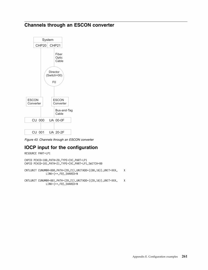
Channels through an ESCON converter
IOCP input for the configurationRESOURCE PART=LP1
CHPID PCHID=100,PATH=20,TYPE=CVC,PART=LP1CHPID PCHID=101,PATH=21,TYPE=CVC,PART=LP1,SWITCH=00
CNTLUNIT CUNUMBR=000,PATH=(20,21),UNITADD=((00,16)),UNIT=XXX, XLINK=(**,F0),SHARED=N
CNTLUNIT CUNUMBR=001,PATH=(20,21),UNITADD=((20,16)),UNIT=XXX, XLINK=(**,F0),SHARED=N
System
ESCONConverter
ESCONConverter
FiberOpticCable
Bus-and-TagCable
Director(Switch=00)
F0
CHP20 CHP21
CU 000 UA 00-0F
CU 001 UA 20-2F
Figure 43. Channels through an ESCON converter
Appendix E. Configuration examples 261
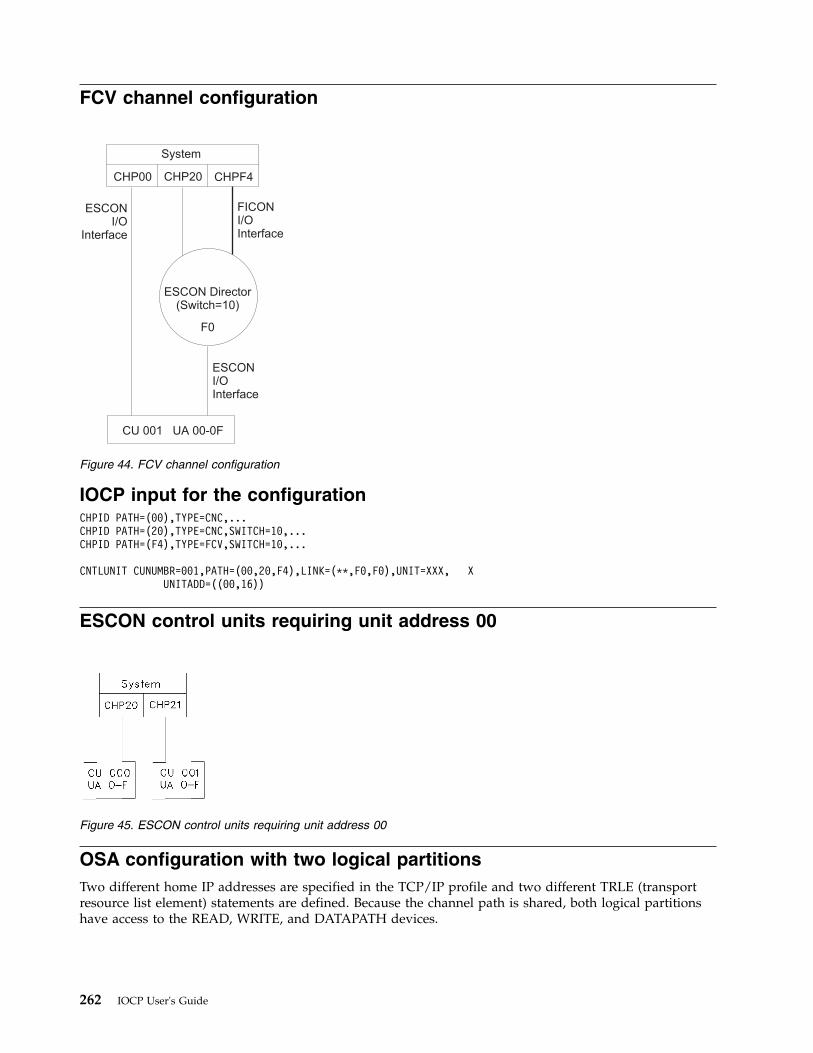
FCV channel configuration
IOCP input for the configurationCHPID PATH=(00),TYPE=CNC,...CHPID PATH=(20),TYPE=CNC,SWITCH=10,...CHPID PATH=(F4),TYPE=FCV,SWITCH=10,...
CNTLUNIT CUNUMBR=001,PATH=(00,20,F4),LINK=(**,F0,F0),UNIT=XXX, XUNITADD=((00,16))
ESCON control units requiring unit address 00
OSA configuration with two logical partitionsTwo different home IP addresses are specified in the TCP/IP profile and two different TRLE (transportresource list element) statements are defined. Because the channel path is shared, both logical partitionshave access to the READ, WRITE, and DATAPATH devices.
ESCON Director(Switch=10)
ESCONI/O
Interface
ESCONI/OInterface
FICONI/OInterface
System
CHP00 CHP20
F0
CHPF4
CU 001 UA 00-0F
Figure 44. FCV channel configuration
Figure 45. ESCON control units requiring unit address 00
262 IOCP User's Guide
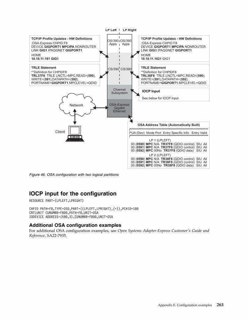
IOCP input for the configurationRESOURCE PART=(LPLEFT,LPRIGHT)
CHPID PATH=F8,TYPE=OSD,PART=((LPLEFT,LPRIGHT),(=)),PCHID=180CNTLUNIT CUNUMBR=F800,PATH=F8,UNIT=OSAIODEVICE ADDRESS=(590,3),CUNUMBR=F800,UNIT=OSA
Additional OSA configuration examplesFor additional OSA configuration examples, see Open Systems Adapter-Express Customer's Guide andReference, SA22-7935.
IOCP Input
Figure 46. OSA configuration with two logical partitions
Appendix E. Configuration examples 263
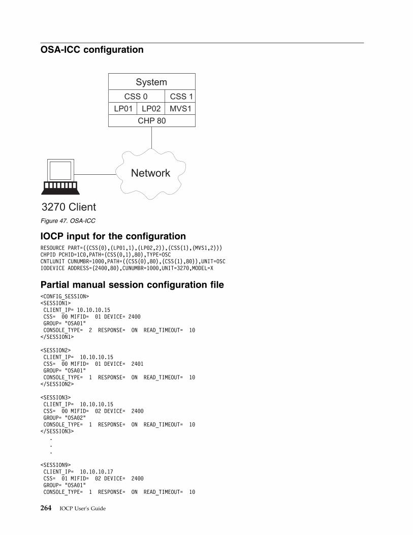
OSA-ICC configuration
IOCP input for the configurationRESOURCE PART=((CSS(0),(LP01,1),(LP02,2)),(CSS(1),(MVS1,2)))CHPID PCHID=1C0,PATH=(CSS(0,1),80),TYPE=OSCCNTLUNIT CUNUMBR=1000,PATH=((CSS(0),80),(CSS(1),80)),UNIT=OSCIODEVICE ADDRESS=(2400,80),CUNUMBR=1000,UNIT=3270,MODEL=X
Partial manual session configuration file<CONFIG_SESSION><SESSION1>CLIENT_IP= 10.10.10.15CSS= 00 MIFID= 01 DEVICE= 2400GROUP= "OSA01"CONSOLE_TYPE= 2 RESPONSE= ON READ_TIMEOUT= 10</SESSION1>
<SESSION2>CLIENT_IP= 10.10.10.15CSS= 00 MIFID= 01 DEVICE= 2401GROUP= "OSA01"CONSOLE_TYPE= 1 RESPONSE= ON READ_TIMEOUT= 10</SESSION2>
<SESSION3>CLIENT_IP= 10.10.10.15CSS= 00 MIFID= 02 DEVICE= 2400GROUP= "OSA02"CONSOLE_TYPE= 1 RESPONSE= ON READ_TIMEOUT= 10</SESSION3>
.
.
.
<SESSION9>CLIENT_IP= 10.10.10.17CSS= 01 MIFID= 02 DEVICE= 2400GROUP= "OSA01"CONSOLE_TYPE= 1 RESPONSE= ON READ_TIMEOUT= 10
Network
3270 Client
System
CSS 0 CSS 1
LP01 LP02 MVS1
CHP 80
Figure 47. OSA-ICC
264 IOCP User's Guide
</SESSION9>
<SESSION10>CLIENT_IP= 10.10.10.18CSS= 01 MIFID= 02 DEVICE= 2401GROUP= "OSAXX13" CONSOLE_TYPE= 1 RESPONSE= ON READ_TIMEOUT= 10
</SESSION10></CONFIG_SESSION>
Additional OSA-ICC configuration examplesFor additional OSA-ICC configuration examples, see Open Systems Adapter-Express Integrated ConsoleController User's Guide, SA22-7990.
Appendix E. Configuration examples 265
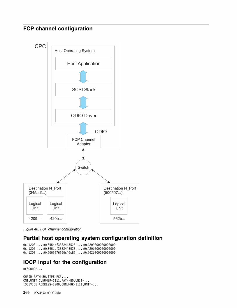
FCP channel configuration
Partial host operating system configuration definition0x 1200 ...:0x345adf3322443525 ...:0x42090000000000000x 1200 ...:0x345adf3322443525 ...:0x420b0000000000000x 1200 ...:0x5005076300c40c85 ...:0x562b000000000000
IOCP input for the configurationRESOURCE...
CHPID PATH=80,TYPE=FCP,...CNTLUNIT CUNUMBR=1111,PATH=80,UNIT=...IODEVICE ADDRESS=1200,CUNUMBR=1111,UNIT=...
Switch
LogicalUnit
LogicalUnit
LogicalUnit
Destination N_Port(345adf...)
4209... 420b...
Destination N_Port(500507...)
562b...
CPC
QDIO
FCP ChannelAdapter
Host Operating System
Host Application
SCSI Stack
QDIO Driver
Figure 48. FCP channel configuration
266 IOCP User's Guide
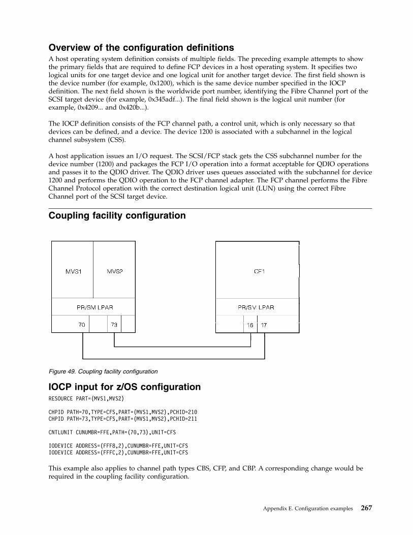
Overview of the configuration definitionsA host operating system definition consists of multiple fields. The preceding example attempts to showthe primary fields that are required to define FCP devices in a host operating system. It specifies twological units for one target device and one logical unit for another target device. The first field shown isthe device number (for example, 0x1200), which is the same device number specified in the IOCPdefinition. The next field shown is the worldwide port number, identifying the Fibre Channel port of theSCSI target device (for example, 0x345adf...). The final field shown is the logical unit number (forexample, 0x4209... and 0x420b...).
The IOCP definition consists of the FCP channel path, a control unit, which is only necessary so thatdevices can be defined, and a device. The device 1200 is associated with a subchannel in the logicalchannel subsystem (CSS).
A host application issues an I/O request. The SCSI/FCP stack gets the CSS subchannel number for thedevice number (1200) and packages the FCP I/O operation into a format acceptable for QDIO operationsand passes it to the QDIO driver. The QDIO driver uses queues associated with the subchannel for device1200 and performs the QDIO operation to the FCP channel adapter. The FCP channel performs the FibreChannel Protocol operation with the correct destination logical unit (LUN) using the correct FibreChannel port of the SCSI target device.
Coupling facility configuration
IOCP input for z/OS configurationRESOURCE PART=(MVS1,MVS2)
CHPID PATH=70,TYPE=CFS,PART=(MVS1,MVS2),PCHID=210CHPID PATH=73,TYPE=CFS,PART=(MVS1,MVS2),PCHID=211
CNTLUNIT CUNUMBR=FFE,PATH=(70,73),UNIT=CFS
IODEVICE ADDRESS=(FFF8,2),CUNUMBR=FFE,UNIT=CFSIODEVICE ADDRESS=(FFFC,2),CUNUMBR=FFE,UNIT=CFS
This example also applies to channel path types CBS, CFP, and CBP. A corresponding change would berequired in the coupling facility configuration.
Figure 49. Coupling facility configuration
Appendix E. Configuration examples 267
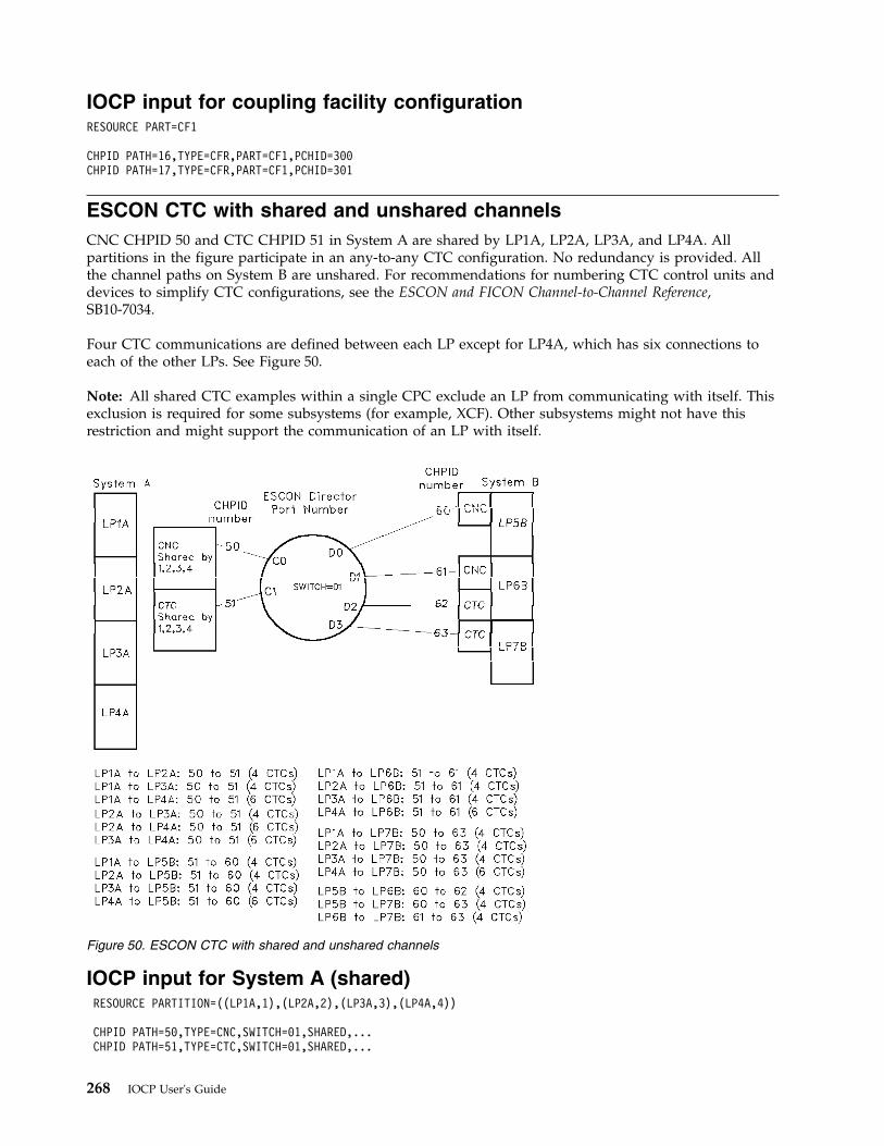
IOCP input for coupling facility configurationRESOURCE PART=CF1
CHPID PATH=16,TYPE=CFR,PART=CF1,PCHID=300CHPID PATH=17,TYPE=CFR,PART=CF1,PCHID=301
ESCON CTC with shared and unshared channelsCNC CHPID 50 and CTC CHPID 51 in System A are shared by LP1A, LP2A, LP3A, and LP4A. Allpartitions in the figure participate in an any-to-any CTC configuration. No redundancy is provided. Allthe channel paths on System B are unshared. For recommendations for numbering CTC control units anddevices to simplify CTC configurations, see the ESCON and FICON Channel-to-Channel Reference,SB10-7034.
Four CTC communications are defined between each LP except for LP4A, which has six connections toeach of the other LPs. See Figure 50.
Note: All shared CTC examples within a single CPC exclude an LP from communicating with itself. Thisexclusion is required for some subsystems (for example, XCF). Other subsystems might not have thisrestriction and might support the communication of an LP with itself.
IOCP input for System A (shared)RESOURCE PARTITION=((LP1A,1),(LP2A,2),(LP3A,3),(LP4A,4))
CHPID PATH=50,TYPE=CNC,SWITCH=01,SHARED,...CHPID PATH=51,TYPE=CTC,SWITCH=01,SHARED,...
Figure 50. ESCON CTC with shared and unshared channels
268 IOCP User's Guide
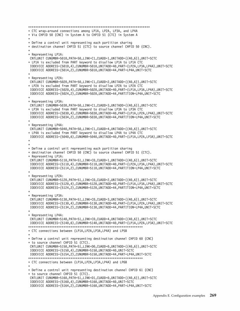
********************************************************************** CTC wrap-around connections among LP1A, LP2A, LP3A, and LP4A* Via CHPID 50 (CNC) in System A to CHPID 51 (CTC) in System A** Define a control unit representing each partition sharing* destination channel CHPID 51 (CTC) to source channel CHPID 50 (CNC).** Representing LP1A:CNTLUNIT CUNUMBR=5010,PATH=50,LINK=C1,CUADD=1,UNITADD=((40,6)),UNIT=SCTC
* LP1A is excluded from PART keyword to disallow LP1A to LP1A CTCIODEVICE ADDRESS=(5010,4),CUNUMBR=5010,UNITADD=40,PART=(LP2A,LP3A,LP4A),UNIT=SCTCIODEVICE ADDRESS=(5014,2),CUNUMBR=5010,UNITADD=44,PART=LP4A,UNIT=SCTC
** Representing LP2A:CNTLUNIT CUNUMBR=5020,PATH=50,LINK=C1,CUADD=2,UNITADD=((40,6)),UNIT=SCTC
* LP2A is excluded from PART keyword to disallow LP2A to LP2A CTCIODEVICE ADDRESS=(5020,4),CUNUMBR=5020,UNITADD=40,PART=(LP1A,LP3A,LP4A),UNIT=SCTCIODEVICE ADDRESS=(5024,2),CUNUMBR=5020,UNITADD=44,PARTITION=LP4A,UNIT=SCTC
** Representing LP3A:CNTLUNIT CUNUMBR=5030,PATH=50,LINK=C1,CUADD=3,UNITADD=((40,6)),UNIT=SCTC
* LP3A is excluded from PART keyword to disallow LP3A to LP3A CTCIODEVICE ADDRESS=(5030,4),CUNUMBR=5030,UNITADD=40,PART=(LP1A,LP2A,LP4A),UNIT=SCTCIODEVICE ADDRESS=(5034,2),CUNUMBR=5030,UNITADD=44,PARTITION=LP4A,UNIT=SCTC
** Representing LP4A:CNTLUNIT CUNUMBR=5040,PATH=50,LINK=C1,CUADD=4,UNITADD=((40,6)),UNIT=SCTC
* LP4A is excluded from PART keyword to disallow LP4A to LP4A CTCIODEVICE ADDRESS=(5040,6),CUNUMBR=5040,UNITADD=40,PART=(LP1A,LP2A,LP3A),UNIT=SCTC
*** Define a control unit representing each partition sharing* destination channel CHPID 50 (CNC) to source channel CHPID 51 (CTC).* Representing LP1A:CNTLUNIT CUNUMBR=5110,PATH=51,LINK=C0,CUADD=1,UNITADD=((40,6)),UNIT=SCTCIODEVICE ADDRESS=(5110,4),CUNUMBR=5110,UNITADD=40,PART=(LP2A,LP3A,LP4A),UNIT=SCTCIODEVICE ADDRESS=(5114,2),CUNUMBR=5110,UNITADD=44,PARTITION=LP4A,UNIT=SCTC
** Representing LP2A:CNTLUNIT CUNUMBR=5120,PATH=51,LINK=C0,CUADD=2,UNITADD=((40,6)),UNIT=SCTCIODEVICE ADDRESS=(5120,4),CUNUMBR=5120,UNITADD=40,PART=(LP1A,LP3A,LP4A),UNIT=SCTCIODEVICE ADDRESS=(5124,2),CUNUMBR=5120,UNITADD=44,PARTITION=LP4A,UNIT=SCTC
** Representing LP3A:CNTLUNIT CUNUMBR=5130,PATH=51,LINK=C0,CUADD=3,UNITADD=((40,6)),UNIT=SCTCIODEVICE ADDRESS=(5130,4),CUNUMBR=5130,UNITADD=40,PART=(LP1A,LP2A,LP4A),UNIT=SCTCIODEVICE ADDRESS=(5134,2),CUNUMBR=5130,UNITADD=44,PARTITION=LP4A,UNIT=SCTC
** Representing LP4A:CNTLUNIT CUNUMBR=5140,PATH=51,LINK=C0,CUADD=4,UNITADD=((40,6)),UNIT=SCTCIODEVICE ADDRESS=(5140,6),CUNUMBR=5140,UNITADD=40,PART=(LP1A,LP2A,LP3A),UNIT=SCTC
****************************************************************** CTC connections between (LP1A,LP2A,LP3A,LP4A) and LP5B** Define a control unit representing destination channel CHPID 60 (CNC)* to source channel CHPID 51 (CTC).CNTLUNIT CUNUMBR=5150,PATH=51,LINK=D0,CUADD=0,UNITADD=((40,6)),UNIT=SCTCIODEVICE ADDRESS=(5150,4),CUNUMBR=5150,UNITADD=40,UNIT=SCTCIODEVICE ADDRESS=(5154,2),CUNUMBR=5150,UNITADD=44,PART=LP4A,UNIT=SCTC
****************************************************************** CTC connections between (LP1A,LP2A,LP3A,LP4A) and LP6B** Define a control unit representing destination channel CHPID 61 (CNC)* to source channel CHPID 51 (CTC).CNTLUNIT CUNUMBR=5160,PATH=51,LINK=D1,CUADD=0,UNITADD=((40,6)),UNIT=SCTCIODEVICE ADDRESS=(5160,4),CUNUMBR=5160,UNITADD=40,UNIT=SCTCIODEVICE ADDRESS=(5164,2),CUNUMBR=5160,UNITADD=44,PART=LP4A,UNIT=SCTC
Appendix E. Configuration examples 269
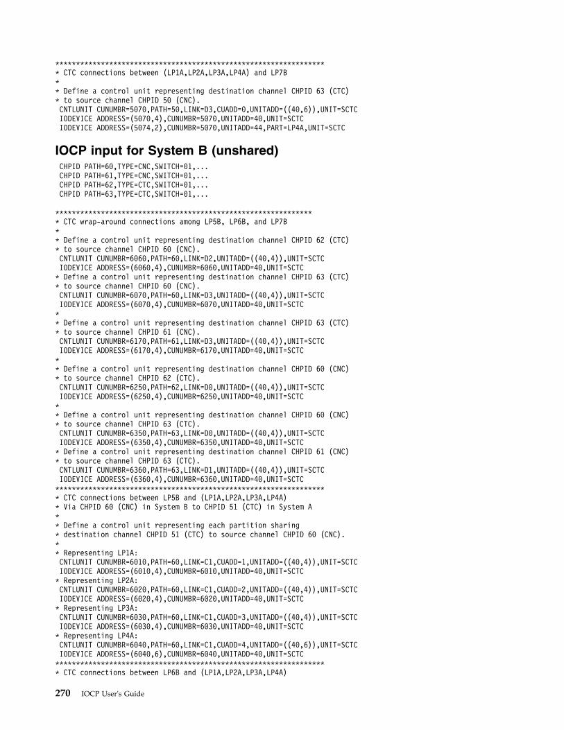
****************************************************************** CTC connections between (LP1A,LP2A,LP3A,LP4A) and LP7B** Define a control unit representing destination channel CHPID 63 (CTC)* to source channel CHPID 50 (CNC).CNTLUNIT CUNUMBR=5070,PATH=50,LINK=D3,CUADD=0,UNITADD=((40,6)),UNIT=SCTCIODEVICE ADDRESS=(5070,4),CUNUMBR=5070,UNITADD=40,UNIT=SCTCIODEVICE ADDRESS=(5074,2),CUNUMBR=5070,UNITADD=44,PART=LP4A,UNIT=SCTC
IOCP input for System B (unshared)CHPID PATH=60,TYPE=CNC,SWITCH=01,...CHPID PATH=61,TYPE=CNC,SWITCH=01,...CHPID PATH=62,TYPE=CTC,SWITCH=01,...CHPID PATH=63,TYPE=CTC,SWITCH=01,...
*************************************************************** CTC wrap-around connections among LP5B, LP6B, and LP7B** Define a control unit representing destination channel CHPID 62 (CTC)* to source channel CHPID 60 (CNC).CNTLUNIT CUNUMBR=6060,PATH=60,LINK=D2,UNITADD=((40,4)),UNIT=SCTCIODEVICE ADDRESS=(6060,4),CUNUMBR=6060,UNITADD=40,UNIT=SCTC* Define a control unit representing destination channel CHPID 63 (CTC)* to source channel CHPID 60 (CNC).CNTLUNIT CUNUMBR=6070,PATH=60,LINK=D3,UNITADD=((40,4)),UNIT=SCTCIODEVICE ADDRESS=(6070,4),CUNUMBR=6070,UNITADD=40,UNIT=SCTC** Define a control unit representing destination channel CHPID 63 (CTC)* to source channel CHPID 61 (CNC).CNTLUNIT CUNUMBR=6170,PATH=61,LINK=D3,UNITADD=((40,4)),UNIT=SCTCIODEVICE ADDRESS=(6170,4),CUNUMBR=6170,UNITADD=40,UNIT=SCTC** Define a control unit representing destination channel CHPID 60 (CNC)* to source channel CHPID 62 (CTC).CNTLUNIT CUNUMBR=6250,PATH=62,LINK=D0,UNITADD=((40,4)),UNIT=SCTCIODEVICE ADDRESS=(6250,4),CUNUMBR=6250,UNITADD=40,UNIT=SCTC** Define a control unit representing destination channel CHPID 60 (CNC)* to source channel CHPID 63 (CTC).CNTLUNIT CUNUMBR=6350,PATH=63,LINK=D0,UNITADD=((40,4)),UNIT=SCTCIODEVICE ADDRESS=(6350,4),CUNUMBR=6350,UNITADD=40,UNIT=SCTC* Define a control unit representing destination channel CHPID 61 (CNC)* to source channel CHPID 63 (CTC).CNTLUNIT CUNUMBR=6360,PATH=63,LINK=D1,UNITADD=((40,4)),UNIT=SCTCIODEVICE ADDRESS=(6360,4),CUNUMBR=6360,UNITADD=40,UNIT=SCTC****************************************************************** CTC connections between LP5B and (LP1A,LP2A,LP3A,LP4A)* Via CHPID 60 (CNC) in System B to CHPID 51 (CTC) in System A** Define a control unit representing each partition sharing* destination channel CHPID 51 (CTC) to source channel CHPID 60 (CNC).** Representing LP1A:CNTLUNIT CUNUMBR=6010,PATH=60,LINK=C1,CUADD=1,UNITADD=((40,4)),UNIT=SCTCIODEVICE ADDRESS=(6010,4),CUNUMBR=6010,UNITADD=40,UNIT=SCTC* Representing LP2A:CNTLUNIT CUNUMBR=6020,PATH=60,LINK=C1,CUADD=2,UNITADD=((40,4)),UNIT=SCTCIODEVICE ADDRESS=(6020,4),CUNUMBR=6020,UNITADD=40,UNIT=SCTC* Representing LP3A:CNTLUNIT CUNUMBR=6030,PATH=60,LINK=C1,CUADD=3,UNITADD=((40,4)),UNIT=SCTCIODEVICE ADDRESS=(6030,4),CUNUMBR=6030,UNITADD=40,UNIT=SCTC* Representing LP4A:CNTLUNIT CUNUMBR=6040,PATH=60,LINK=C1,CUADD=4,UNITADD=((40,6)),UNIT=SCTCIODEVICE ADDRESS=(6040,6),CUNUMBR=6040,UNITADD=40,UNIT=SCTC****************************************************************** CTC connections between LP6B and (LP1A,LP2A,LP3A,LP4A)
270 IOCP User's Guide
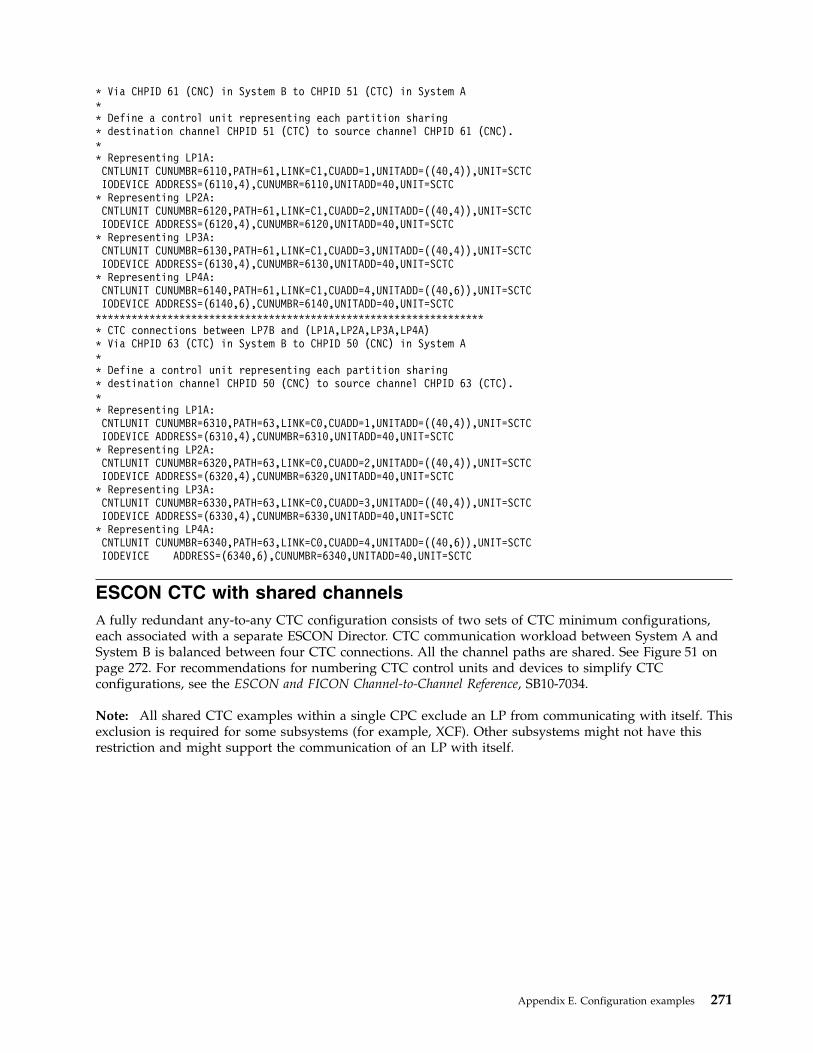
* Via CHPID 61 (CNC) in System B to CHPID 51 (CTC) in System A** Define a control unit representing each partition sharing* destination channel CHPID 51 (CTC) to source channel CHPID 61 (CNC).** Representing LP1A:CNTLUNIT CUNUMBR=6110,PATH=61,LINK=C1,CUADD=1,UNITADD=((40,4)),UNIT=SCTCIODEVICE ADDRESS=(6110,4),CUNUMBR=6110,UNITADD=40,UNIT=SCTC
* Representing LP2A:CNTLUNIT CUNUMBR=6120,PATH=61,LINK=C1,CUADD=2,UNITADD=((40,4)),UNIT=SCTCIODEVICE ADDRESS=(6120,4),CUNUMBR=6120,UNITADD=40,UNIT=SCTC
* Representing LP3A:CNTLUNIT CUNUMBR=6130,PATH=61,LINK=C1,CUADD=3,UNITADD=((40,4)),UNIT=SCTCIODEVICE ADDRESS=(6130,4),CUNUMBR=6130,UNITADD=40,UNIT=SCTC
* Representing LP4A:CNTLUNIT CUNUMBR=6140,PATH=61,LINK=C1,CUADD=4,UNITADD=((40,6)),UNIT=SCTCIODEVICE ADDRESS=(6140,6),CUNUMBR=6140,UNITADD=40,UNIT=SCTC
****************************************************************** CTC connections between LP7B and (LP1A,LP2A,LP3A,LP4A)* Via CHPID 63 (CTC) in System B to CHPID 50 (CNC) in System A** Define a control unit representing each partition sharing* destination channel CHPID 50 (CNC) to source channel CHPID 63 (CTC).** Representing LP1A:CNTLUNIT CUNUMBR=6310,PATH=63,LINK=C0,CUADD=1,UNITADD=((40,4)),UNIT=SCTCIODEVICE ADDRESS=(6310,4),CUNUMBR=6310,UNITADD=40,UNIT=SCTC
* Representing LP2A:CNTLUNIT CUNUMBR=6320,PATH=63,LINK=C0,CUADD=2,UNITADD=((40,4)),UNIT=SCTCIODEVICE ADDRESS=(6320,4),CUNUMBR=6320,UNITADD=40,UNIT=SCTC
* Representing LP3A:CNTLUNIT CUNUMBR=6330,PATH=63,LINK=C0,CUADD=3,UNITADD=((40,4)),UNIT=SCTCIODEVICE ADDRESS=(6330,4),CUNUMBR=6330,UNITADD=40,UNIT=SCTC
* Representing LP4A:CNTLUNIT CUNUMBR=6340,PATH=63,LINK=C0,CUADD=4,UNITADD=((40,6)),UNIT=SCTCIODEVICE ADDRESS=(6340,6),CUNUMBR=6340,UNITADD=40,UNIT=SCTC
ESCON CTC with shared channelsA fully redundant any-to-any CTC configuration consists of two sets of CTC minimum configurations,each associated with a separate ESCON Director. CTC communication workload between System A andSystem B is balanced between four CTC connections. All the channel paths are shared. See Figure 51 onpage 272. For recommendations for numbering CTC control units and devices to simplify CTCconfigurations, see the ESCON and FICON Channel-to-Channel Reference, SB10-7034.
Note: All shared CTC examples within a single CPC exclude an LP from communicating with itself. Thisexclusion is required for some subsystems (for example, XCF). Other subsystems might not have thisrestriction and might support the communication of an LP with itself.
Appendix E. Configuration examples 271
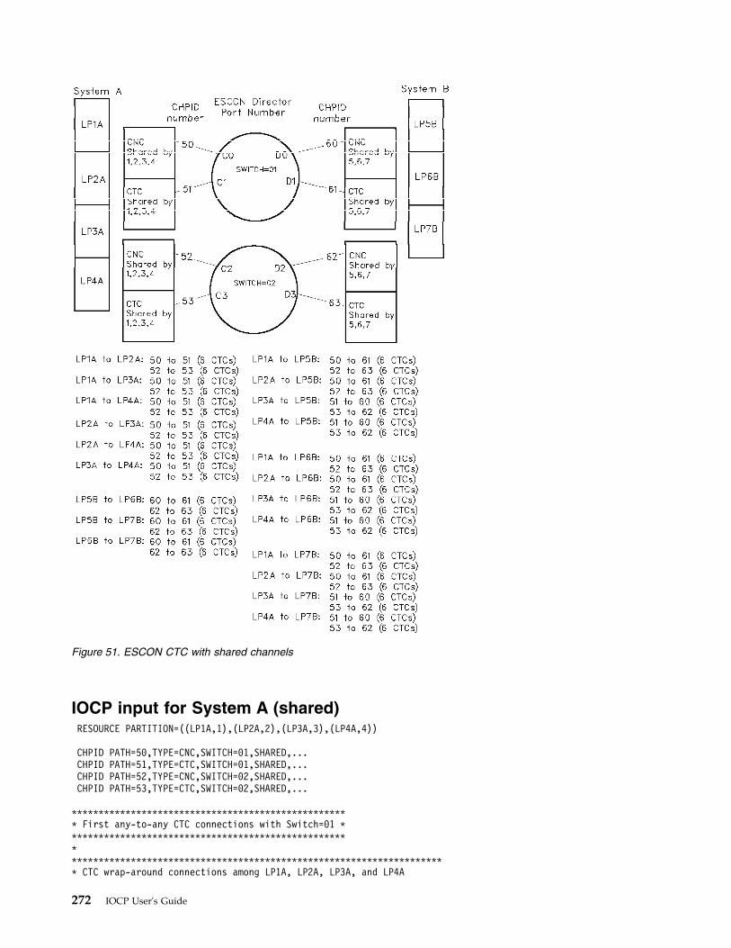
IOCP input for System A (shared)RESOURCE PARTITION=((LP1A,1),(LP2A,2),(LP3A,3),(LP4A,4))
CHPID PATH=50,TYPE=CNC,SWITCH=01,SHARED,...CHPID PATH=51,TYPE=CTC,SWITCH=01,SHARED,...CHPID PATH=52,TYPE=CNC,SWITCH=02,SHARED,...CHPID PATH=53,TYPE=CTC,SWITCH=02,SHARED,...
**************************************************** First any-to-any CTC connections with Switch=01 *************************************************************************************************************************** CTC wrap-around connections among LP1A, LP2A, LP3A, and LP4A
Figure 51. ESCON CTC with shared channels
272 IOCP User's Guide
* Via CHPID 50 (CNC) in System A to CHPID 51 (CTC) in System A** Define a control unit representing each partition sharing* destination channel CHPID 51 (CTC) to source channel CHPID 50 (CNC).** Representing LP1A:CNTLUNIT CUNUMBR=5010,PATH=50,LINK=C1,CUADD=1,UNITADD=((40,6)),UNIT=SCTC
* LP1A is excluded using NOTPART keyword to disallow LP1A to LP1A CTCIODEVICE ADDRESS=(5010,6),CUNUMBR=5010,UNITADD=40,NOTPART=(LP1A),UNIT=SCTC
** Representing LP2A:CNTLUNIT CUNUMBR=5020,PATH=50,LINK=C1,CUADD=2,UNITADD=((40,6)),UNIT=SCTC
* LP2A is excluded using NOTPART keyword to disallow LP2A to LP2A CTCIODEVICE ADDRESS=(5020,6),CUNUMBR=5020,UNITADD=40,NOTPART=(LP2A),UNIT=SCTC
** Representing LP3A:CNTLUNIT CUNUMBR=5030,PATH=50,LINK=C1,CUADD=3,UNITADD=((40,6)),UNIT=SCTC
* LP3A is excluded using NOTPART keyword to disallow LP3A to LP3A CTCIODEVICE ADDRESS=(5030,6),CUNUMBR=5030,UNITADD=40,NOTPART=(LP3A),UNIT=SCTC
** Representing LP4A:CNTLUNIT CUNUMBR=5040,PATH=50,LINK=C1,CUADD=4,UNITADD=((40,6)),UNIT=SCTC
* LP4A is excluded using NOTPART keyword to disallow LP4A to LP4A CTCIODEVICE ADDRESS=(5040,6),CUNUMBR=5040,UNITADD=40,NOTPART=(LP4A),UNIT=SCTC
** Define a control unit representing each partition sharing* destination channel CHPID 50 (CNC) to source channel CHPID 51 (CTC).* Representing LP1A:CNTLUNIT CUNUMBR=5110,PATH=51,LINK=C0,CUADD=1,UNITADD=((40,6)),UNIT=SCTCIODEVICE ADDRESS=(5110,6),CUNUMBR=5110,UNITADD=40,NOTPART=(LP1A),UNIT=SCTC
** Representing LP2A:CNTLUNIT CUNUMBR=5120,PATH=51,LINK=C0,CUADD=2,UNITADD=((40,6)),UNIT=SCTCIODEVICE ADDRESS=(5120,6),CUNUMBR=5120,UNITADD=40,NOTPART=(LP2A),UNIT=SCTC
** Representing LP3A:CNTLUNIT CUNUMBR=5130,PATH=51,LINK=C0,CUADD=3,UNITADD=((40,6)),UNIT=SCTCIODEVICE ADDRESS=(5130,6),CUNUMBR=5130,UNITADD=40,NOTPART=(LP3A),UNIT=SCTC
** Representing LP4A:CNTLUNIT CUNUMBR=5140,PATH=51,LINK=C0,CUADD=4,UNITADD=((40,6)),UNIT=SCTCIODEVICE ADDRESS=(5140,6),CUNUMBR=5140,UNITADD=40,NOTPART=(LP4A),UNIT=SCTC
************************************************************************* CTC connections between (LP1A,LP2A) and (LP5B,LP6B,LP7B)** Define a control unit representing each partition sharing* destination channel CHPID 61 (CTC) to source channel CHPID 50 (CNC).* Only LP1A and LP2A use 50-61 CTC connection for workload balance* Representing LP5B:CNTLUNIT CUNUMBR=5050,PATH=50,LINK=D1,CUADD=5,UNITADD=((40,6)),UNIT=SCTCIODEVICE ADDRESS=(5050,6),CUNUMBR=5050,UNITADD=40,PART=(LP1A,LP2A),UNIT=SCTC
** Representing LP6B:CNTLUNIT CUNUMBR=5060,PATH=50,LINK=D1,CUADD=6,UNITADD=((40,6)),UNIT=SCTCIODEVICE ADDRESS=(5060,6),CUNUMBR=5060,UNITADD=40,PART=(LP1A,LP2A),UNIT=SCTC
** Representing LP7B:CNTLUNIT CUNUMBR=5070,PATH=50,LINK=D1,CUADD=7,UNITADD=((40,6)),UNIT=SCTCIODEVICE ADDRESS=(5070,6),CUNUMBR=5070,UNITADD=40,PART=(LP1A,LP2A),UNIT=SCTC
************************************************************************** CTC connections between (LP3A,LP4A) and (LP5B,LP6B,LP7B)** Define a control unit representing each partition sharing* destination channel CHPID 60 (CNC) to source channel CHPID 51 (CTC).* Only LP3A and LP4A use 51-60 CTC connection for workload balance* Representing LP5B:CNTLUNIT CUNUMBR=5150,PATH=51,LINK=D0,CUADD=5,UNITADD=((40,6)),UNIT=SCTC
Appendix E. Configuration examples 273
IODEVICE ADDRESS=(5150,6),CUNUMBR=5150,UNITADD=40,PART=(LP3A,LP4A),UNIT=SCTC** Representing LP6B:CNTLUNIT CUNUMBR=5160,PATH=51,LINK=D0,CUADD=6,UNITADD=((40,6)),UNIT=SCTCIODEVICE ADDRESS=(5160,6),CUNUMBR=5160,UNITADD=40,PART=(LP3A,LP4A),UNIT=SCTC** Representing LP7B:CNTLUNIT CUNUMBR=5170,PATH=51,LINK=D0,CUADD=7,UNITADD=((40,6)),UNIT=SCTCIODEVICE ADDRESS=(5170,6),CUNUMBR=5170,UNITADD=40,PART=(LP3A,LP4A),UNIT=SCTC
***************************************************** Second any-to-any CTC connections with Switch=02 **************************************************************************************************************************** CTC wrap-around connections among LP1A, LP2A, LP3A, and LP4A* Via CHPID 52 (CNC) in System A to CHPID 53 (CTC) in System A** Define a control unit representing each partition sharing* destination channel CHPID 53 (CTC) to source channel CHPID 52 (CNC).** Representing LP1A:CNTLUNIT CUNUMBR=5210,PATH=52,LINK=C3,CUADD=1,UNITADD=((40,6)),UNIT=SCTC* LP1A is excluded using NOTPART keyword to disallow LP1A to LP1A CTCIODEVICE ADDRESS=(5210,6),CUNUMBR=5210,UNITADD=40,NOTPART=(LP1A),UNIT=SCTC** Representing LP2A:CNTLUNIT CUNUMBR=5220,PATH=52,LINK=C3,CUADD=2,UNITADD=((40,6)),UNIT=SCTC* LP2A is excluded using NOTPART keyword to disallow LP2A to LP2A CTCIODEVICE ADDRESS=(5220,6),CUNUMBR=5220,UNITADD=40,NOTPART=(LP2A),UNIT=SCTC** Representing LP3A:CNTLUNIT CUNUMBR=5230,PATH=52,LINK=C3,CUADD=3,UNITADD=((40,6)),UNIT=SCTC* LP3A is excluded using NOTPART keyword to disallow LP3A to LP3A CTCIODEVICE ADDRESS=(5230,6),CUNUMBR=5230,UNITADD=40,NOTPART=(LP3A),UNIT=SCTC** Representing LP4A:CNTLUNIT CUNUMBR=5240,PATH=52,LINK=C3,CUADD=4,UNITADD=((40,6)),UNIT=SCTC* LP4A is excluded using NOTPART keyword to disallow LP4A to LP4A CTCIODEVICE ADDRESS=(5240,6),CUNUMBR=5240,UNITADD=40,NOTPART=(LP4A),UNIT=SCTC** Define a control unit representing each partition sharing* destination channel CHPID 52 (CNC) to source channel CHPID 53 (CTC).* Representing LP1A:CNTLUNIT CUNUMBR=5310,PATH=53,LINK=C2,CUADD=1,UNITADD=((40,6)),UNIT=SCTCIODEVICE ADDRESS=(5310,6),CUNUMBR=5310,UNITADD=40,NOTPART=(LP1A),UNIT=SCTC** Representing LP2A:CNTLUNIT CUNUMBR=5320,PATH=53,LINK=C2,CUADD=2,UNITADD=((40,6)),UNIT=SCTCIODEVICE ADDRESS=(5320,6),CUNUMBR=5320,UNITADD=40,NOTPART=(LP2A),UNIT=SCTC** Representing LP3A:CNTLUNIT CUNUMBR=5330,PATH=53,LINK=C2,CUADD=3,UNITADD=((40,6)),UNIT=SCTCIODEVICE ADDRESS=(5330,6),CUNUMBR=5330,UNITADD=40,NOTPART=(LP3A),UNIT=SCTC** Representing LP4A:CNTLUNIT CUNUMBR=5340,PATH=53,LINK=C2,CUADD=4,UNITADD=((40,6)),UNIT=SCTCIODEVICE ADDRESS=(5340,6),CUNUMBR=5340,UNITADD=40,NOTPART=(LP4A),UNIT=SCTC************************************************************************* CTC connections between (LP1A,LP2A) and (LP5B,LP6B,LP7B)** Define a control unit representing each partition sharing* destination channel CHPID 63 (CTC) to source channel CHPID 52 (CNC).* Only LP1A and LP2A use 52-63 CTC connections for workload balance* Representing LP5B:CNTLUNIT CUNUMBR=5250,PATH=52,LINK=D3,CUADD=5,UNITADD=((40,6)),UNIT=SCTCIODEVICE ADDRESS=(5250,6),CUNUMBR=5250,UNITADD=40,PART=(LP1A,LP2A),UNIT=SCTC
274 IOCP User's Guide
** Representing LP6B:CNTLUNIT CUNUMBR=5260,PATH=52,LINK=D3,CUADD=6,UNITADD=((40,6)),UNIT=SCTCIODEVICE ADDRESS=(5260,6),CUNUMBR=5260,UNITADD=40,PART=(LP1A,LP2A),UNIT=SCTC
** Representing LP7B:CNTLUNIT CUNUMBR=5270,PATH=52,LINK=D3,CUADD=7,UNITADD=((40,6)),UNIT=SCTCIODEVICE ADDRESS=(5270,6),CUNUMBR=5270,UNITADD=40,PART=(LP1A,LP2A),UNIT=SCTC
************************************************************************** CTC connections between (LP3A,LP4A) and (LP5B,LP6B,LP7B)** Define a control unit representing destination channel CHPID 62 (CNC)* to source channel CHPID 53 (CTC).* Only LP3A and LP4A use 53-62 CTC connections for workload balance* Representing LP5B:CNTLUNIT CUNUMBR=5350,PATH=53,LINK=D2,CUADD=5,UNITADD=((40,6)),UNIT=SCTCIODEVICE ADDRESS=(5350,6),CUNUMBR=5350,UNITADD=40,PART=(LP3A,LP4A),UNIT=SCTC
* Representing LP6B:CNTLUNIT CUNUMBR=5360,PATH=53,LINK=D2,CUADD=6,UNITADD=((40,6)),UNIT=SCTCIODEVICE ADDRESS=(5360,6),CUNUMBR=5360,UNITADD=40,PART=(LP3A,LP4A),UNIT=SCTC
* Representing LP7B:CNTLUNIT CUNUMBR=5370,PATH=53,LINK=D2,CUADD=7,UNITADD=((40,6)),UNIT=SCTCIODEVICE ADDRESS=(5370,6),CUNUMBR=5370,UNITADD=40,PART=(LP3A,LP4A),UNIT=SCTC
IOCP input for System B (unshared)RESOURCE PARTITION=((LP5B,5),(LP6B,6),(LP7B,7))
CHPID PATH=60,TYPE=CNC,SWITCH=01,SHARED,...CHPID PATH=61,TYPE=CTC,SWITCH=01,SHARED,...CHPID PATH=62,TYPE=CNC,SWITCH=02,SHARED,...CHPID PATH=63,TYPE=CTC,SWITCH=02,SHARED,...
**************************************************** First any-to-any CTC connections with Switch=01 ******************************************************************************************************************** CTC wrap-around connections among LP5B, LP6B, LP7B* Via CHPID 60 (CNC) in System B to CHPID 61 (CTC) in System B** Define a control unit representing each partition sharing* destination channel CHPID 61 (CTC) to source channel CHPID 60 (CNC).** Representing LP5B:CNTLUNIT CUNUMBR=6050,PATH=60,LINK=D1,CUADD=5,UNITADD=((40,6)),UNIT=SCTC
* LP5B is excluded using NOTPART keyword to disallow LP5B to LP5B CTCIODEVICE ADDRESS=(6050,6),CUNUMBR=6050,UNITADD=40,NOTPART=(LP5B),UNIT=SCTC
** Representing LP6B:CNTLUNIT CUNUMBR=6060,PATH=60,LINK=D1,CUADD=6,UNITADD=((40,6)),UNIT=SCTC
* LP6B is excluded using NOTPART keyword to disallow LP6B to LP6B CTCIODEVICE ADDRESS=(6060,6),CUNUMBR=6060,UNITADD=40,NOTPART=(LP6B),UNIT=SCTC
** Representing LP7B:CNTLUNIT CUNUMBR=6070,PATH=60,LINK=D1,CUADD=7,UNITADD=((40,6)),UNIT=SCTC
* LP7B is excluded using NOTPART keyword to disallow LP7B to LP7B CTCIODEVICE ADDRESS=(6070,6),CUNUMBR=6070,UNITADD=40,NOTPART=(LP7B),UNIT=SCTC
*** Define a control unit representing each partition sharing* destination channel CHPID 60 (CNC) to source channel CHPID 61 (CTC).* Representing LP5B:CNTLUNIT CUNUMBR=6150,PATH=61,LINK=D0,CUADD=5,UNITADD=((40,6)),UNIT=SCTC
* LP5B is excluded using NOTPART keyword to disallow LP5B to LP5B CTCIODEVICE ADDRESS=(6150,6),CUNUMBR=6150,UNITADD=40,NOTPART=(LP5B),UNIT=SCTC
*
Appendix E. Configuration examples 275
* Representing LP6B:CNTLUNIT CUNUMBR=6160,PATH=61,LINK=D0,CUADD=6,UNITADD=((40,6)),UNIT=SCTC* LP6B is excluded using NOTPART keyword to disallow LP6B to LP6B CTCIODEVICE ADDRESS=(6160,6),CUNUMBR=6160,UNITADD=40,NOTPART=(LP6B),UNIT=SCTC** Representing LP7B:CNTLUNIT CUNUMBR=6170,PATH=61,LINK=D0,CUADD=7,UNITADD=((40,6)),UNIT=SCTC* LP7B is excluded using NOTPART keyword to disallow LP7B to LP7B CTCIODEVICE ADDRESS=(6170,6),CUNUMBR=6170,UNITADD=40,NOTPART=(LP7B),UNIT=SCTC*********************************************************************** CTC connections between (LP5B,LP6B,LP7B) and (LP1A,LP2A)* Via CHPID 61 (CTC) in System B to CHPID 50 (CNC) in System A** Define a control unit representing each partition sharing* destination channel CHPID 50 (CNC) to source channel CHPID 61 (CTC).* Representing LP1A:CNTLUNIT CUNUMBR=6110,PATH=61,LINK=C0,CUADD=1,UNITADD=((40,6)),UNIT=SCTCIODEVICE ADDRESS=(6110,6),CUNUMBR=6110,UNITADD=40,UNIT=SCTC** Representing LP2A:CNTLUNIT CUNUMBR=6120,PATH=61,LINK=C0,CUADD=2,UNITADD=((40,6),UNIT=SCTCIODEVICE ADDRESS=(6120,6),CUNUMBR=6120,UNITADD=40,UNIT=SCTC*********************************************************************** CTC connections between (LP5B,LP6B,LP7B) and (LP3A,LP4A)* Via CHPID 60 (CNC) in System B to CHPID 51 (CTC) in System A** Define a control unit representing each partition sharing* destination channel CHPID 51 (CTC) to source channel CHPID 60 (CNC).* Representing LP3A:CNTLUNIT CUNUMBR=6030,PATH=60,LINK=C1,CUADD=3,UNITADD=((40,6)),UNIT=SCTCIODEVICE ADDRESS=(6030,6),CUNUMBR=6030,UNITADD=40,UNIT=SCTC** Representing LP4A:CNTLUNIT CUNUMBR=6040,PATH=60,LINK=C1,CUADD=4,UNITADD=((40,6),UNIT=SCTCIODEVICE ADDRESS=(6040,6),CUNUMBR=6040,UNITADD=40,UNIT=SCTC
***************************************************** Second any-to-any CTC connections with Switch=02 ********************************************************************************************************************* CTC wrap-around connections among LP5B, LP6B, LP7B* Via CHPID 62 (CNC) in System B to CHPID 63 (CTC) in System B** Define a control unit representing each partition sharing* destination channel CHPID 63 (CTC) to source channel CHPID 62 (CNC).** Representing LP5B:CNTLUNIT CUNUMBR=6250,PATH=62,LINK=D3,CUADD=5,UNITADD=((40,6)),UNIT=SCTC* LP5B is excluded using NOTPART keyword to disallow LP5B to LP5B CTCIODEVICE ADDRESS=(6250,6),CUNUMBR=6210,UNITADD=40,NOTPART=(LP5B),UNIT=SCTC** Representing LP6B:CNTLUNIT CUNUMBR=6260,PATH=62,LINK=D3,CUADD=6,UNITADD=((40,6)),UNIT=SCTC* LP6B is excluded using NOTPART keyword to disallow LP6B to LP6B CTCIODEVICE ADDRESS=(6260,6),CUNUMBR=6260,UNITADD=40,NOTPART=(LP6B),UNIT=SCTC** Representing LP7B:CNTLUNIT CUNUMBR=6270,PATH=62,LINK=D3,CUADD=7,UNITADD=((40,6)),UNIT=SCTC* LP7B is excluded using NOTPART keyword to disallow LP7B to LP7B CTCIODEVICE ADDRESS=(6270,6),CUNUMBR=6270,UNITADD=40,NOTPART=(LP7B),UNIT=SCTC** Define a control unit representing each partition sharing* destination channel CHPID 62 (CNC) to source channel CHPID 63 (CTC).* Representing LP5B:CNTLUNIT CUNUMBR=6350,PATH=63,LINK=D2,CUADD=5,UNITADD=((40,6)),UNIT=SCTC* LP5B is excluded using NOTPART keyword to disallow LP5B to LP5B CTC
276 IOCP User's Guide
IODEVICE ADDRESS=(6350,6),CUNUMBR=6350,UNITADD=40,NOTPART=(LP5B),UNIT=SCTC** Representing LP6B:CNTLUNIT CUNUMBR=6360,PATH=63,LINK=D2,CUADD=6,UNITADD=((40,6)),UNIT=SCTC
* LP6B is excluded using NOTPART keyword to disallow LP6B to LP6B CTCIODEVICE ADDRESS=(6360,6),CUNUMBR=6360,UNITADD=40,NOTPART=(LP6B),UNIT=SCTC
** Representing LP7B:CNTLUNIT CUNUMBR=6370,PATH=63,LINK=D2,CUADD=7,UNITADD=((40,6)),UNIT=SCTC
* LP7B is excluded using NOTPART keyword to disallow LP7B to LP7B CTCIODEVICE ADDRESS=(6370,6),CUNUMBR=6370,UNITADD=40,NOTPART=(LP7B),UNIT=SCTC
*********************************************************************** CTC connections between (LP5B,LP6B,LP7B) and (LP1A,LP2A)* Via CHPID 63 (CTC) in System B to CHPID 52 (CNC) in System A** Define a control unit representing each partition sharing* destination channel CHPID 52 (CNC) to source channel CHPID 63 (CTC).* Representing LP1A:CNTLUNIT CUNUMBR=6310,PATH=63,LINK=C2,CUADD=1,UNITADD=((40,6)),UNIT=SCTCIODEVICE ADDRESS=(6310,6),CUNUMBR=6310,UNITADD=40,UNIT=SCTC
** Representing LP2A:CNTLUNIT CUNUMBR=6320,PATH=63,LINK=C2,CUADD=2,UNITADD=((40,6),UNIT=SCTCIODEVICE ADDRESS=(6320,6),CUNUMBR=6320,UNITADD=40,UNIT=SCTC
*********************************************************************** CTC connections between (LP5B,LP6B,LP7B) and (LP3A,LP4A)* Via CHPID 62 (CNC) in System B to CHPID 53 (CTC) in System A** Define a control unit representing each partition sharing* destination channel CHPID 53 (CTC) to source channel CHPID 62 (CNC).* Representing LP3A:CNTLUNIT CUNUMBR=6230,PATH=62,LINK=C3,CUADD=3,UNITADD=((40,6)),UNIT=SCTCIODEVICE ADDRESS=(6230,6),CUNUMBR=6230,UNITADD=40,UNIT=SCTC
** Representing LP4A:CNTLUNIT CUNUMBR=6240,PATH=62,LINK=C3,CUADD=4,UNITADD=((40,6),UNIT=SCTCIODEVICE ADDRESS=(6240,6),CUNUMBR=6240,UNITADD=40,UNIT=SCTC
FICON CTC with shared channelsA fully redundant any-to-any CTC configuration consists of two sets of CTC minimum configurations,each associated with a separate FICON Director. CTC communication is configured such that thedefinitions operate in half duplex on the FICON channels. See Figure 52 on page 278. Forrecommendations for numbering CTC control units and devices to simplify CTC configurations, see theESCON and FICON Channel-to-Channel Reference, SB10-7034.
Note: All shared CTC examples within a single CPC exclude an LP from communicating with itself. Thisexclusion is required for some subsystems (for example, XCF). Other subsystems might not have thisrestriction and might support an LP's communicating with itself.
This example uses a simple CTC configuration approach where the same channel path is always used forsending or receiving data and the same destination link address for a control unit number is always used.For example, System A always uses CHPID 50 on switch 01 for sending data and always uses CHPID 51on switch 01 for receiving data. Also, all CPCs always use FCTC control unit 4010 to send data to LP1Aon System A through link address C1 (CHPID 51) on System A. So a single destination link address (C1)is always associated with the same control unit number (4010).
This approach results in the FICON channels having half duplex definitions. That is, all FCTC I/O dataflow is on one fiber of the FICON channel resulting in its being half duplex. To balance I/O data flow onthe FICON channel in this case, put tape devices on the channels used for receive FCTC control units andput DASD devices on the channels used for send FCTC control units. For example, you would put tape
Appendix E. Configuration examples 277
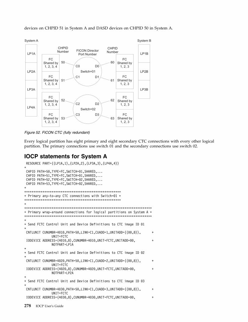
devices on CHPID 51 in System A and DASD devices on CHPID 50 in System A.
Every logical partition has eight primary and eight secondary CTC connections with every other logicalpartition. The primary connections use switch 01 and the secondary connections use switch 02.
IOCP statements for System ARESOURCE PART=((LP1A,1),(LP2A,2),(LP3A,3),(LP4A,4))*CHPID PATH=50,TYPE=FC,SWITCH=01,SHARED,...CHPID PATH=51,TYPE=FC,SWITCH=01,SHARED,...CHPID PATH=52,TYPE=FC,SWITCH=02,SHARED,...CHPID PATH=53,TYPE=FC,SWITCH=02,SHARED,...******************************************************* Primary any-to-any CTC connections with Switch=01 ****************************************************************************************************************************** Primary wrap-around connections for logical partitions on System A ************************************************************************* Send FCTC Control Unit and Device Definitions to CTC image ID 01*CNTLUNIT CUNUMBR=4010,PATH=50,LINK=C1,CUADD=1,UNITADD=((00,8)), +
UNIT=FCTCIODEVICE ADDRESS=(4010,8),CUNUMBR=4010,UNIT=FCTC,UNITADD=00, +
NOTPART=LP1A** Send FCTC Control Unit and Device Definitions to CTC image ID 02*CNTLUNIT CUNUMBR=4020,PATH=50,LINK=C1,CUADD=2,UNITADD=((00,8)), +
UNIT=FCTCIODEVICE ADDRESS=(4020,8),CUNUMBR=4020,UNIT=FCTC,UNITADD=00, +
NOTPART=LP2A** Send FCTC Control Unit and Device Definitions to CTC image ID 03*CNTLUNIT CUNUMBR=4030,PATH=50,LINK=C1,CUADD=3,UNITADD=((00,8)), +
UNIT=FCTCIODEVICE ADDRESS=(4030,8),CUNUMBR=4030,UNIT=FCTC,UNITADD=00, +
System A
CHPIDNumber
CHPIDNumberFICON Director
Port Number
Switch=01
Switch=02
C0 D0
C2 D2
C1 D1
C3 D3
LP1A
50
51
52
53
60
61
62
63
FCShared by1, 2, 3, 4
FCShared by
1, 2, 3
FCShared by1, 2, 3, 4
FCShared by
1, 2, 3
FCShared by1, 2, 3, 4
FCShared by
1, 2, 3
FCShared by1, 2, 3, 4
FCShared by
1, 2, 3
LP1B
LP2A LP2B
LP3A LP3B
LP4A
System B
Figure 52. FICON CTC (fully redundant)
278 IOCP User's Guide
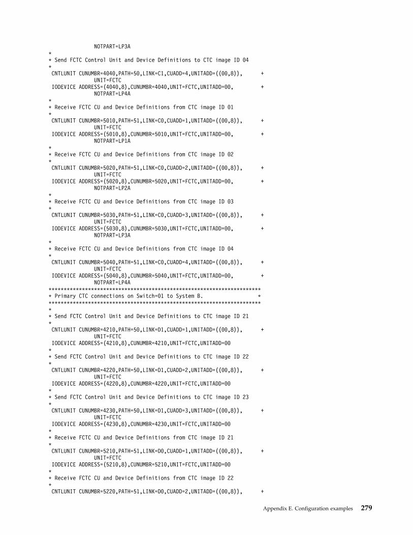
NOTPART=LP3A** Send FCTC Control Unit and Device Definitions to CTC image ID 04*CNTLUNIT CUNUMBR=4040,PATH=50,LINK=C1,CUADD=4,UNITADD=((00,8)), +
UNIT=FCTCIODEVICE ADDRESS=(4040,8),CUNUMBR=4040,UNIT=FCTC,UNITADD=00, +
NOTPART=LP4A** Receive FCTC CU and Device Definitions from CTC image ID 01*CNTLUNIT CUNUMBR=5010,PATH=51,LINK=C0,CUADD=1,UNITADD=((00,8)), +
UNIT=FCTCIODEVICE ADDRESS=(5010,8),CUNUMBR=5010,UNIT=FCTC,UNITADD=00, +
NOTPART=LP1A** Receive FCTC CU and Device Definitions from CTC image ID 02*CNTLUNIT CUNUMBR=5020,PATH=51,LINK=C0,CUADD=2,UNITADD=((00,8)), +
UNIT=FCTCIODEVICE ADDRESS=(5020,8),CUNUMBR=5020,UNIT=FCTC,UNITADD=00, +
NOTPART=LP2A** Receive FCTC CU and Device Definitions from CTC image ID 03*CNTLUNIT CUNUMBR=5030,PATH=51,LINK=C0,CUADD=3,UNITADD=((00,8)), +
UNIT=FCTCIODEVICE ADDRESS=(5030,8),CUNUMBR=5030,UNIT=FCTC,UNITADD=00, +
NOTPART=LP3A** Receive FCTC CU and Device Definitions from CTC image ID 04*CNTLUNIT CUNUMBR=5040,PATH=51,LINK=C0,CUADD=4,UNITADD=((00,8)), +
UNIT=FCTCIODEVICE ADDRESS=(5040,8),CUNUMBR=5040,UNIT=FCTC,UNITADD=00, +
NOTPART=LP4A*********************************************************************** Primary CTC connections on Switch=01 to System B. ************************************************************************* Send FCTC Control Unit and Device Definitions to CTC image ID 21*CNTLUNIT CUNUMBR=4210,PATH=50,LINK=D1,CUADD=1,UNITADD=((00,8)), +
UNIT=FCTCIODEVICE ADDRESS=(4210,8),CUNUMBR=4210,UNIT=FCTC,UNITADD=00
** Send FCTC Control Unit and Device Definitions to CTC image ID 22*CNTLUNIT CUNUMBR=4220,PATH=50,LINK=D1,CUADD=2,UNITADD=((00,8)), +
UNIT=FCTCIODEVICE ADDRESS=(4220,8),CUNUMBR=4220,UNIT=FCTC,UNITADD=00
** Send FCTC Control Unit and Device Definitions to CTC image ID 23*CNTLUNIT CUNUMBR=4230,PATH=50,LINK=D1,CUADD=3,UNITADD=((00,8)), +
UNIT=FCTCIODEVICE ADDRESS=(4230,8),CUNUMBR=4230,UNIT=FCTC,UNITADD=00
** Receive FCTC CU and Device Definitions from CTC image ID 21*CNTLUNIT CUNUMBR=5210,PATH=51,LINK=D0,CUADD=1,UNITADD=((00,8)), +
UNIT=FCTCIODEVICE ADDRESS=(5210,8),CUNUMBR=5210,UNIT=FCTC,UNITADD=00
** Receive FCTC CU and Device Definitions from CTC image ID 22*CNTLUNIT CUNUMBR=5220,PATH=51,LINK=D0,CUADD=2,UNITADD=((00,8)), +
Appendix E. Configuration examples 279
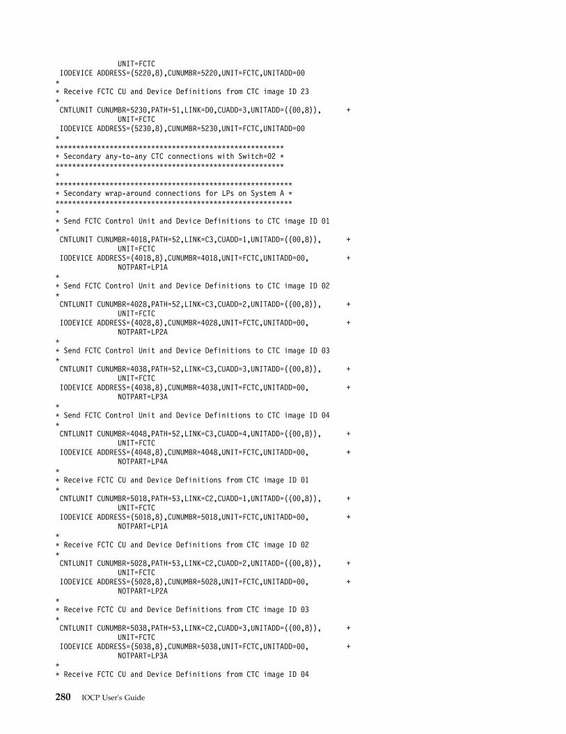
UNIT=FCTCIODEVICE ADDRESS=(5220,8),CUNUMBR=5220,UNIT=FCTC,UNITADD=00** Receive FCTC CU and Device Definitions from CTC image ID 23*CNTLUNIT CUNUMBR=5230,PATH=51,LINK=D0,CUADD=3,UNITADD=((00,8)), +
UNIT=FCTCIODEVICE ADDRESS=(5230,8),CUNUMBR=5230,UNIT=FCTC,UNITADD=00********************************************************* Secondary any-to-any CTC connections with Switch=02 ******************************************************************************************************************* Secondary wrap-around connections for LPs on System A ************************************************************ Send FCTC Control Unit and Device Definitions to CTC image ID 01*CNTLUNIT CUNUMBR=4018,PATH=52,LINK=C3,CUADD=1,UNITADD=((00,8)), +
UNIT=FCTCIODEVICE ADDRESS=(4018,8),CUNUMBR=4018,UNIT=FCTC,UNITADD=00, +
NOTPART=LP1A** Send FCTC Control Unit and Device Definitions to CTC image ID 02*CNTLUNIT CUNUMBR=4028,PATH=52,LINK=C3,CUADD=2,UNITADD=((00,8)), +
UNIT=FCTCIODEVICE ADDRESS=(4028,8),CUNUMBR=4028,UNIT=FCTC,UNITADD=00, +
NOTPART=LP2A** Send FCTC Control Unit and Device Definitions to CTC image ID 03*CNTLUNIT CUNUMBR=4038,PATH=52,LINK=C3,CUADD=3,UNITADD=((00,8)), +
UNIT=FCTCIODEVICE ADDRESS=(4038,8),CUNUMBR=4038,UNIT=FCTC,UNITADD=00, +
NOTPART=LP3A** Send FCTC Control Unit and Device Definitions to CTC image ID 04*CNTLUNIT CUNUMBR=4048,PATH=52,LINK=C3,CUADD=4,UNITADD=((00,8)), +
UNIT=FCTCIODEVICE ADDRESS=(4048,8),CUNUMBR=4048,UNIT=FCTC,UNITADD=00, +
NOTPART=LP4A** Receive FCTC CU and Device Definitions from CTC image ID 01*CNTLUNIT CUNUMBR=5018,PATH=53,LINK=C2,CUADD=1,UNITADD=((00,8)), +
UNIT=FCTCIODEVICE ADDRESS=(5018,8),CUNUMBR=5018,UNIT=FCTC,UNITADD=00, +
NOTPART=LP1A** Receive FCTC CU and Device Definitions from CTC image ID 02*CNTLUNIT CUNUMBR=5028,PATH=53,LINK=C2,CUADD=2,UNITADD=((00,8)), +
UNIT=FCTCIODEVICE ADDRESS=(5028,8),CUNUMBR=5028,UNIT=FCTC,UNITADD=00, +
NOTPART=LP2A** Receive FCTC CU and Device Definitions from CTC image ID 03*CNTLUNIT CUNUMBR=5038,PATH=53,LINK=C2,CUADD=3,UNITADD=((00,8)), +
UNIT=FCTCIODEVICE ADDRESS=(5038,8),CUNUMBR=5038,UNIT=FCTC,UNITADD=00, +
NOTPART=LP3A** Receive FCTC CU and Device Definitions from CTC image ID 04
280 IOCP User's Guide
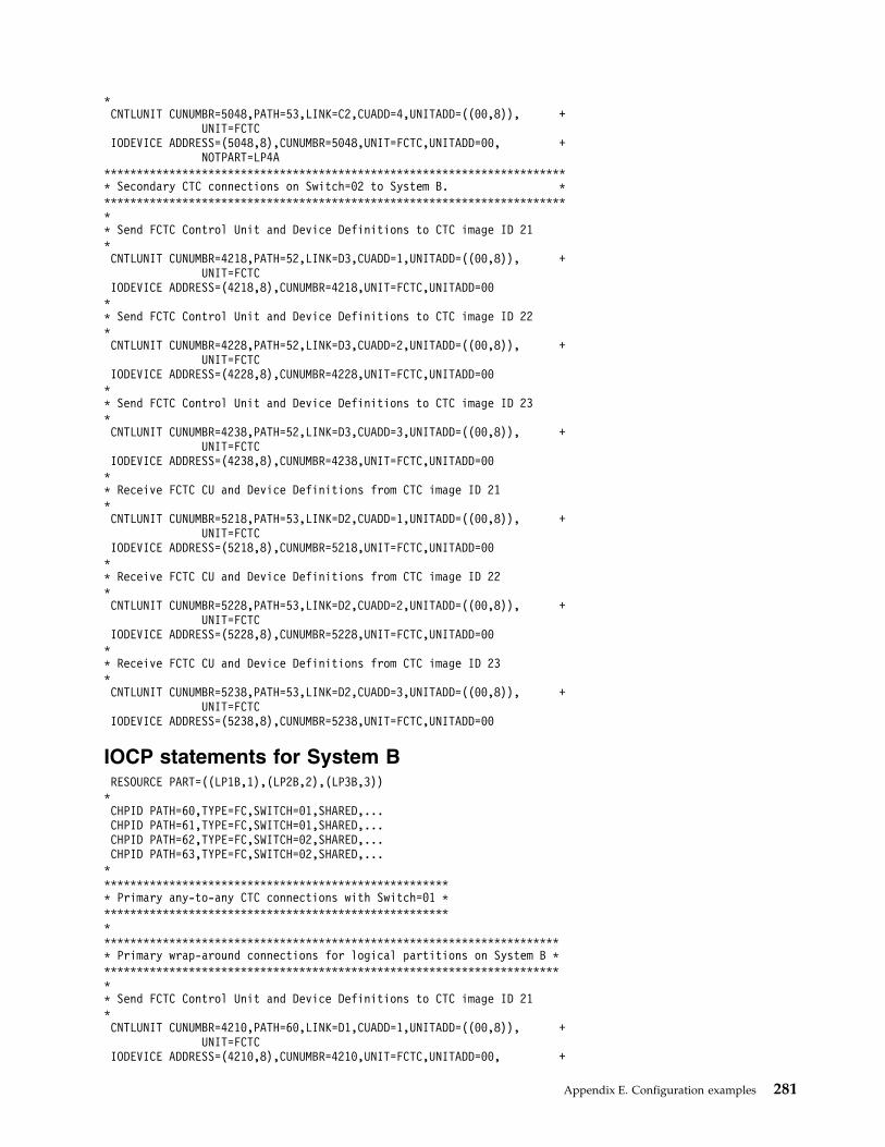
*CNTLUNIT CUNUMBR=5048,PATH=53,LINK=C2,CUADD=4,UNITADD=((00,8)), +
UNIT=FCTCIODEVICE ADDRESS=(5048,8),CUNUMBR=5048,UNIT=FCTC,UNITADD=00, +
NOTPART=LP4A************************************************************************ Secondary CTC connections on Switch=02 to System B. ************************************************************************** Send FCTC Control Unit and Device Definitions to CTC image ID 21*CNTLUNIT CUNUMBR=4218,PATH=52,LINK=D3,CUADD=1,UNITADD=((00,8)), +
UNIT=FCTCIODEVICE ADDRESS=(4218,8),CUNUMBR=4218,UNIT=FCTC,UNITADD=00
** Send FCTC Control Unit and Device Definitions to CTC image ID 22*CNTLUNIT CUNUMBR=4228,PATH=52,LINK=D3,CUADD=2,UNITADD=((00,8)), +
UNIT=FCTCIODEVICE ADDRESS=(4228,8),CUNUMBR=4228,UNIT=FCTC,UNITADD=00
** Send FCTC Control Unit and Device Definitions to CTC image ID 23*CNTLUNIT CUNUMBR=4238,PATH=52,LINK=D3,CUADD=3,UNITADD=((00,8)), +
UNIT=FCTCIODEVICE ADDRESS=(4238,8),CUNUMBR=4238,UNIT=FCTC,UNITADD=00
** Receive FCTC CU and Device Definitions from CTC image ID 21*CNTLUNIT CUNUMBR=5218,PATH=53,LINK=D2,CUADD=1,UNITADD=((00,8)), +
UNIT=FCTCIODEVICE ADDRESS=(5218,8),CUNUMBR=5218,UNIT=FCTC,UNITADD=00
** Receive FCTC CU and Device Definitions from CTC image ID 22*CNTLUNIT CUNUMBR=5228,PATH=53,LINK=D2,CUADD=2,UNITADD=((00,8)), +
UNIT=FCTCIODEVICE ADDRESS=(5228,8),CUNUMBR=5228,UNIT=FCTC,UNITADD=00
** Receive FCTC CU and Device Definitions from CTC image ID 23*CNTLUNIT CUNUMBR=5238,PATH=53,LINK=D2,CUADD=3,UNITADD=((00,8)), +
UNIT=FCTCIODEVICE ADDRESS=(5238,8),CUNUMBR=5238,UNIT=FCTC,UNITADD=00
IOCP statements for System BRESOURCE PART=((LP1B,1),(LP2B,2),(LP3B,3))
*CHPID PATH=60,TYPE=FC,SWITCH=01,SHARED,...CHPID PATH=61,TYPE=FC,SWITCH=01,SHARED,...CHPID PATH=62,TYPE=FC,SWITCH=02,SHARED,...CHPID PATH=63,TYPE=FC,SWITCH=02,SHARED,...
******************************************************* Primary any-to-any CTC connections with Switch=01 ****************************************************************************************************************************** Primary wrap-around connections for logical partitions on System B ************************************************************************* Send FCTC Control Unit and Device Definitions to CTC image ID 21*CNTLUNIT CUNUMBR=4210,PATH=60,LINK=D1,CUADD=1,UNITADD=((00,8)), +
UNIT=FCTCIODEVICE ADDRESS=(4210,8),CUNUMBR=4210,UNIT=FCTC,UNITADD=00, +
Appendix E. Configuration examples 281
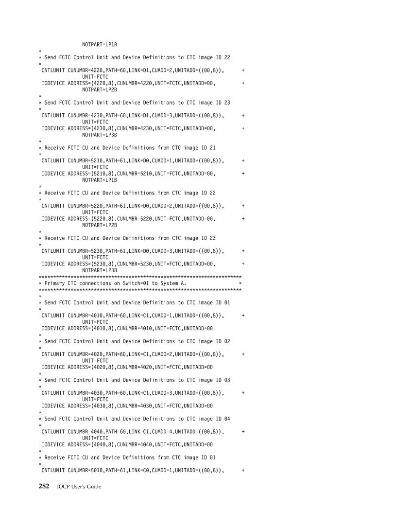
NOTPART=LP1B** Send FCTC Control Unit and Device Definitions to CTC image ID 22*CNTLUNIT CUNUMBR=4220,PATH=60,LINK=D1,CUADD=2,UNITADD=((00,8)), +
UNIT=FCTCIODEVICE ADDRESS=(4220,8),CUNUMBR=4220,UNIT=FCTC,UNITADD=00, +
NOTPART=LP2B** Send FCTC Control Unit and Device Definitions to CTC image ID 23*CNTLUNIT CUNUMBR=4230,PATH=60,LINK=D1,CUADD=3,UNITADD=((00,8)), +
UNIT=FCTCIODEVICE ADDRESS=(4230,8),CUNUMBR=4230,UNIT=FCTC,UNITADD=00, +
NOTPART=LP3B** Receive FCTC CU and Device Definitions from CTC image ID 21*CNTLUNIT CUNUMBR=5210,PATH=61,LINK=D0,CUADD=1,UNITADD=((00,8)), +
UNIT=FCTCIODEVICE ADDRESS=(5210,8),CUNUMBR=5210,UNIT=FCTC,UNITADD=00, +
NOTPART=LP1B** Receive FCTC CU and Device Definitions from CTC image ID 22*CNTLUNIT CUNUMBR=5220,PATH=61,LINK=D0,CUADD=2,UNITADD=((00,8)), +
UNIT=FCTCIODEVICE ADDRESS=(5220,8),CUNUMBR=5220,UNIT=FCTC,UNITADD=00, +
NOTPART=LP2B** Receive FCTC CU and Device Definitions from CTC image ID 23*CNTLUNIT CUNUMBR=5230,PATH=61,LINK=D0,CUADD=3,UNITADD=((00,8)), +
UNIT=FCTCIODEVICE ADDRESS=(5230,8),CUNUMBR=5230,UNIT=FCTC,UNITADD=00, +
NOTPART=LP3B*********************************************************************** Primary CTC connections on Switch=01 to System A. ************************************************************************* Send FCTC Control Unit and Device Definitions to CTC image ID 01*CNTLUNIT CUNUMBR=4010,PATH=60,LINK=C1,CUADD=1,UNITADD=((00,8)), +
UNIT=FCTCIODEVICE ADDRESS=(4010,8),CUNUMBR=4010,UNIT=FCTC,UNITADD=00** Send FCTC Control Unit and Device Definitions to CTC image ID 02*CNTLUNIT CUNUMBR=4020,PATH=60,LINK=C1,CUADD=2,UNITADD=((00,8)), +
UNIT=FCTCIODEVICE ADDRESS=(4020,8),CUNUMBR=4020,UNIT=FCTC,UNITADD=00** Send FCTC Control Unit and Device Definitions to CTC image ID 03*CNTLUNIT CUNUMBR=4030,PATH=60,LINK=C1,CUADD=3,UNITADD=((00,8)), +
UNIT=FCTCIODEVICE ADDRESS=(4030,8),CUNUMBR=4030,UNIT=FCTC,UNITADD=00** Send FCTC Control Unit and Device Definitions to CTC image ID 04*CNTLUNIT CUNUMBR=4040,PATH=60,LINK=C1,CUADD=4,UNITADD=((00,8)), +
UNIT=FCTCIODEVICE ADDRESS=(4040,8),CUNUMBR=4040,UNIT=FCTC,UNITADD=00** Receive FCTC CU and Device Definitions from CTC image ID 01*CNTLUNIT CUNUMBR=5010,PATH=61,LINK=C0,CUADD=1,UNITADD=((00,8)), +
282 IOCP User's Guide
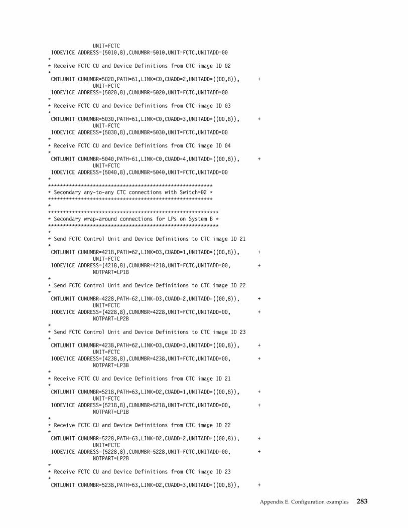
UNIT=FCTCIODEVICE ADDRESS=(5010,8),CUNUMBR=5010,UNIT=FCTC,UNITADD=00
** Receive FCTC CU and Device Definitions from CTC image ID 02*CNTLUNIT CUNUMBR=5020,PATH=61,LINK=C0,CUADD=2,UNITADD=((00,8)), +
UNIT=FCTCIODEVICE ADDRESS=(5020,8),CUNUMBR=5020,UNIT=FCTC,UNITADD=00
** Receive FCTC CU and Device Definitions from CTC image ID 03*CNTLUNIT CUNUMBR=5030,PATH=61,LINK=C0,CUADD=3,UNITADD=((00,8)), +
UNIT=FCTCIODEVICE ADDRESS=(5030,8),CUNUMBR=5030,UNIT=FCTC,UNITADD=00
** Receive FCTC CU and Device Definitions from CTC image ID 04*CNTLUNIT CUNUMBR=5040,PATH=61,LINK=C0,CUADD=4,UNITADD=((00,8)), +
UNIT=FCTCIODEVICE ADDRESS=(5040,8),CUNUMBR=5040,UNIT=FCTC,UNITADD=00
********************************************************* Secondary any-to-any CTC connections with Switch=02 ******************************************************************************************************************* Secondary wrap-around connections for LPs on System B ************************************************************ Send FCTC Control Unit and Device Definitions to CTC image ID 21*CNTLUNIT CUNUMBR=4218,PATH=62,LINK=D3,CUADD=1,UNITADD=((00,8)), +
UNIT=FCTCIODEVICE ADDRESS=(4218,8),CUNUMBR=4218,UNIT=FCTC,UNITADD=00, +
NOTPART=LP1B** Send FCTC Control Unit and Device Definitions to CTC image ID 22*CNTLUNIT CUNUMBR=4228,PATH=62,LINK=D3,CUADD=2,UNITADD=((00,8)), +
UNIT=FCTCIODEVICE ADDRESS=(4228,8),CUNUMBR=4228,UNIT=FCTC,UNITADD=00, +
NOTPART=LP2B** Send FCTC Control Unit and Device Definitions to CTC image ID 23*CNTLUNIT CUNUMBR=4238,PATH=62,LINK=D3,CUADD=3,UNITADD=((00,8)), +
UNIT=FCTCIODEVICE ADDRESS=(4238,8),CUNUMBR=4238,UNIT=FCTC,UNITADD=00, +
NOTPART=LP3B** Receive FCTC CU and Device Definitions from CTC image ID 21*CNTLUNIT CUNUMBR=5218,PATH=63,LINK=D2,CUADD=1,UNITADD=((00,8)), +
UNIT=FCTCIODEVICE ADDRESS=(5218,8),CUNUMBR=5218,UNIT=FCTC,UNITADD=00, +
NOTPART=LP1B** Receive FCTC CU and Device Definitions from CTC image ID 22*CNTLUNIT CUNUMBR=5228,PATH=63,LINK=D2,CUADD=2,UNITADD=((00,8)), +
UNIT=FCTCIODEVICE ADDRESS=(5228,8),CUNUMBR=5228,UNIT=FCTC,UNITADD=00, +
NOTPART=LP2B** Receive FCTC CU and Device Definitions from CTC image ID 23*CNTLUNIT CUNUMBR=5238,PATH=63,LINK=D2,CUADD=3,UNITADD=((00,8)), +
Appendix E. Configuration examples 283
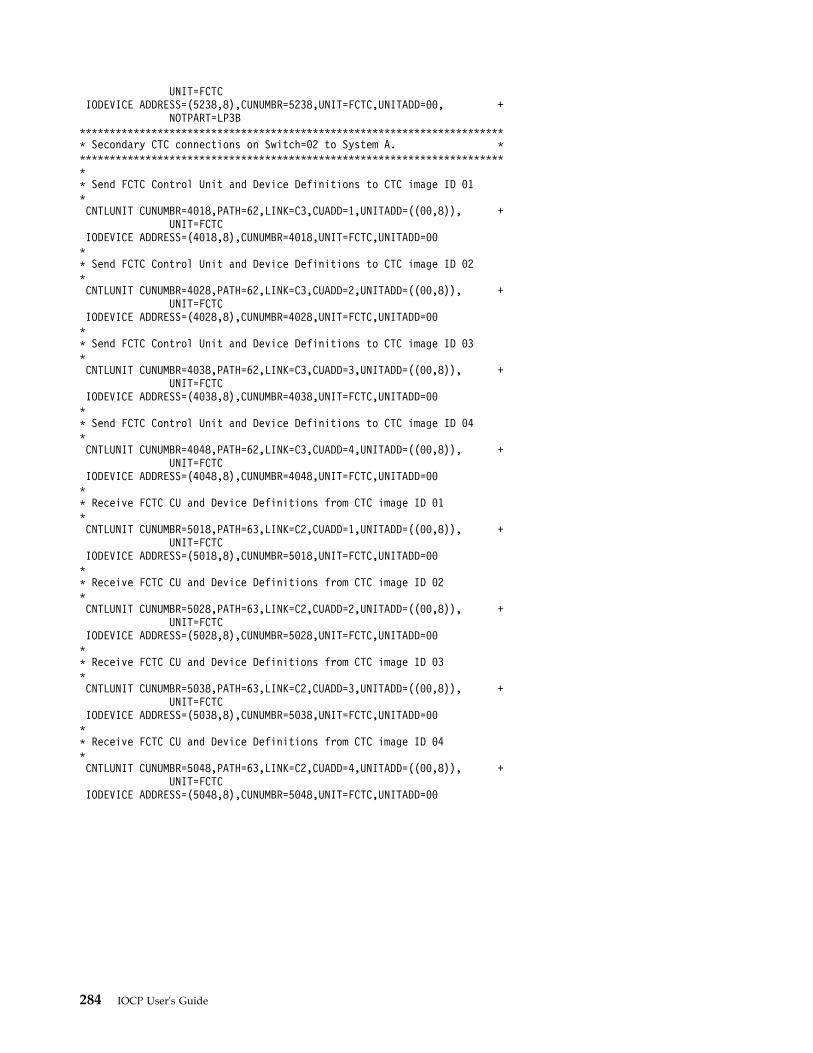
UNIT=FCTCIODEVICE ADDRESS=(5238,8),CUNUMBR=5238,UNIT=FCTC,UNITADD=00, +
NOTPART=LP3B************************************************************************ Secondary CTC connections on Switch=02 to System A. ************************************************************************** Send FCTC Control Unit and Device Definitions to CTC image ID 01*CNTLUNIT CUNUMBR=4018,PATH=62,LINK=C3,CUADD=1,UNITADD=((00,8)), +
UNIT=FCTCIODEVICE ADDRESS=(4018,8),CUNUMBR=4018,UNIT=FCTC,UNITADD=00** Send FCTC Control Unit and Device Definitions to CTC image ID 02*CNTLUNIT CUNUMBR=4028,PATH=62,LINK=C3,CUADD=2,UNITADD=((00,8)), +
UNIT=FCTCIODEVICE ADDRESS=(4028,8),CUNUMBR=4028,UNIT=FCTC,UNITADD=00** Send FCTC Control Unit and Device Definitions to CTC image ID 03*CNTLUNIT CUNUMBR=4038,PATH=62,LINK=C3,CUADD=3,UNITADD=((00,8)), +
UNIT=FCTCIODEVICE ADDRESS=(4038,8),CUNUMBR=4038,UNIT=FCTC,UNITADD=00** Send FCTC Control Unit and Device Definitions to CTC image ID 04*CNTLUNIT CUNUMBR=4048,PATH=62,LINK=C3,CUADD=4,UNITADD=((00,8)), +
UNIT=FCTCIODEVICE ADDRESS=(4048,8),CUNUMBR=4048,UNIT=FCTC,UNITADD=00** Receive FCTC CU and Device Definitions from CTC image ID 01*CNTLUNIT CUNUMBR=5018,PATH=63,LINK=C2,CUADD=1,UNITADD=((00,8)), +
UNIT=FCTCIODEVICE ADDRESS=(5018,8),CUNUMBR=5018,UNIT=FCTC,UNITADD=00** Receive FCTC CU and Device Definitions from CTC image ID 02*CNTLUNIT CUNUMBR=5028,PATH=63,LINK=C2,CUADD=2,UNITADD=((00,8)), +
UNIT=FCTCIODEVICE ADDRESS=(5028,8),CUNUMBR=5028,UNIT=FCTC,UNITADD=00** Receive FCTC CU and Device Definitions from CTC image ID 03*CNTLUNIT CUNUMBR=5038,PATH=63,LINK=C2,CUADD=3,UNITADD=((00,8)), +
UNIT=FCTCIODEVICE ADDRESS=(5038,8),CUNUMBR=5038,UNIT=FCTC,UNITADD=00** Receive FCTC CU and Device Definitions from CTC image ID 04*CNTLUNIT CUNUMBR=5048,PATH=63,LINK=C2,CUADD=4,UNITADD=((00,8)), +
UNIT=FCTCIODEVICE ADDRESS=(5048,8),CUNUMBR=5048,UNIT=FCTC,UNITADD=00
284 IOCP User's Guide
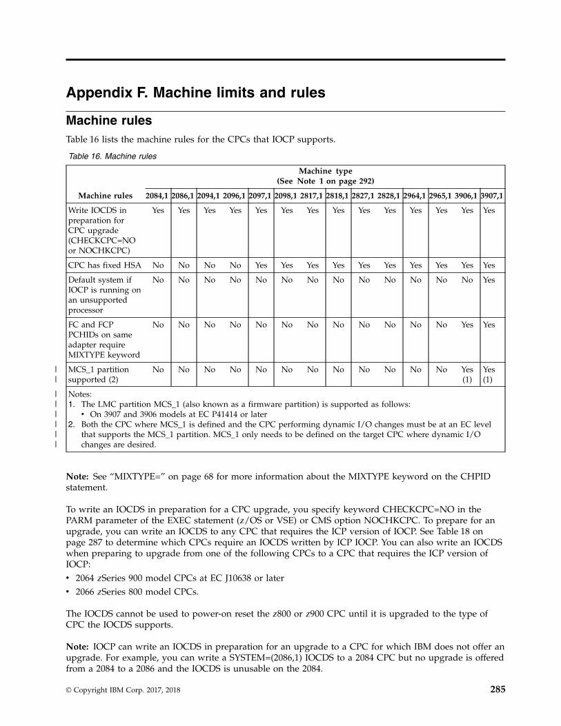
Appendix F. Machine limits and rules
Machine rulesTable 16 lists the machine rules for the CPCs that IOCP supports.
Table 16. Machine rules
Machine rules
Machine type(See Note 1 on page 292)
2084,1 2086,1 2094,1 2096,1 2097,1 2098,1 2817,1 2818,1 2827,1 2828,1 2964,1 2965,1 3906,1 3907,1
Write IOCDS inpreparation forCPC upgrade(CHECKCPC=NOor NOCHKCPC)
Yes Yes Yes Yes Yes Yes Yes Yes Yes Yes Yes Yes Yes Yes
CPC has fixed HSA No No No No Yes Yes Yes Yes Yes Yes Yes Yes Yes Yes
Default system ifIOCP is running onan unsupportedprocessor
No No No No No No No No No No No No No Yes
FC and FCPPCHIDs on sameadapter requireMIXTYPE keyword
No No No No No No No No No No No No Yes Yes
MCS_1 partitionsupported (2)
No No No No No No No No No No No No Yes(1)
Yes(1)
Notes:1. The LMC partition MCS_1 (also known as a firmware partition) is supported as follows:v On 3907 and 3906 models at EC P41414 or later
2. Both the CPC where MCS_1 is defined and the CPC performing dynamic I/O changes must be at an EC levelthat supports the MCS_1 partition. MCS_1 only needs to be defined on the target CPC where dynamic I/Ochanges are desired.
Note: See “MIXTYPE=” on page 68 for more information about the MIXTYPE keyword on the CHPIDstatement.
To write an IOCDS in preparation for a CPC upgrade, you specify keyword CHECKCPC=NO in thePARM parameter of the EXEC statement (z/OS or VSE) or CMS option NOCHKCPC. To prepare for anupgrade, you can write an IOCDS to any CPC that requires the ICP version of IOCP. See Table 18 onpage 287 to determine which CPCs require an IOCDS written by ICP IOCP. You can also write an IOCDSwhen preparing to upgrade from one of the following CPCs to a CPC that requires the ICP version ofIOCP:v 2064 zSeries 900 model CPCs at EC J10638 or laterv 2066 zSeries 800 model CPCs.
The IOCDS cannot be used to power-on reset the z800 or z900 CPC until it is upgraded to the type ofCPC the IOCDS supports.
Note: IOCP can write an IOCDS in preparation for an upgrade to a CPC for which IBM does not offer anupgrade. For example, you can write a SYSTEM=(2086,1) IOCDS to a 2084 CPC but no upgrade is offeredfrom a 2084 to a 2086 and the IOCDS is unusable on the 2084.
© Copyright IBM Corp. 2017, 2018 285
||
||||||
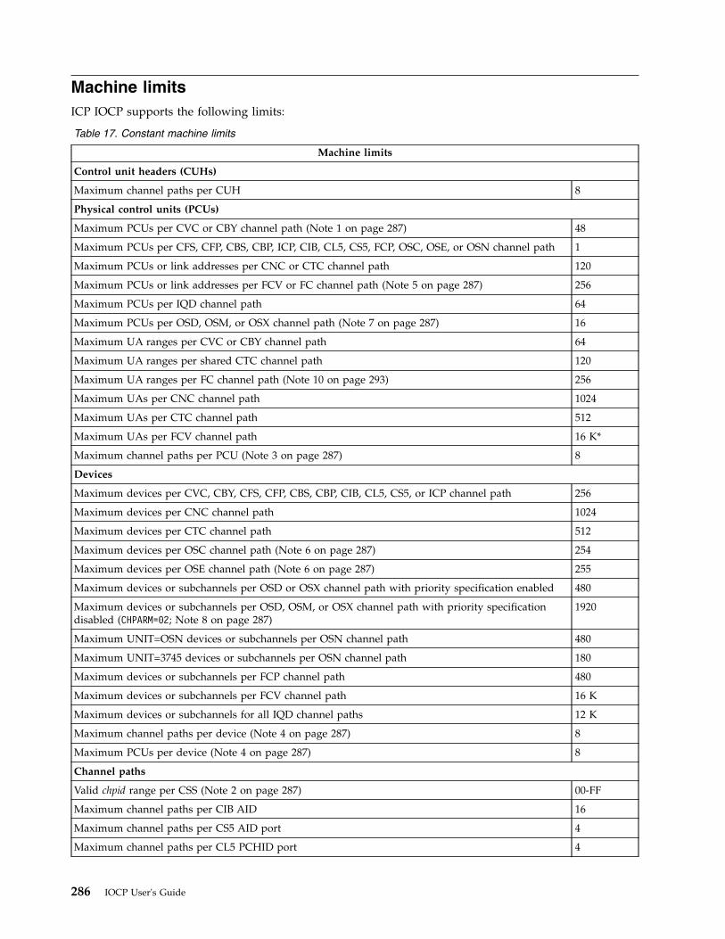
Machine limitsICP IOCP supports the following limits:
Table 17. Constant machine limits
Machine limits
Control unit headers (CUHs)
Maximum channel paths per CUH 8
Physical control units (PCUs)
Maximum PCUs per CVC or CBY channel path (Note 1 on page 287) 48
Maximum PCUs per CFS, CFP, CBS, CBP, ICP, CIB, CL5, CS5, FCP, OSC, OSE, or OSN channel path 1
Maximum PCUs or link addresses per CNC or CTC channel path 120
Maximum PCUs or link addresses per FCV or FC channel path (Note 5 on page 287) 256
Maximum PCUs per IQD channel path 64
Maximum PCUs per OSD, OSM, or OSX channel path (Note 7 on page 287) 16
Maximum UA ranges per CVC or CBY channel path 64
Maximum UA ranges per shared CTC channel path 120
Maximum UA ranges per FC channel path (Note 10 on page 293) 256
Maximum UAs per CNC channel path 1024
Maximum UAs per CTC channel path 512
Maximum UAs per FCV channel path 16 K*
Maximum channel paths per PCU (Note 3 on page 287) 8
Devices
Maximum devices per CVC, CBY, CFS, CFP, CBS, CBP, CIB, CL5, CS5, or ICP channel path 256
Maximum devices per CNC channel path 1024
Maximum devices per CTC channel path 512
Maximum devices per OSC channel path (Note 6 on page 287) 254
Maximum devices per OSE channel path (Note 6 on page 287) 255
Maximum devices or subchannels per OSD or OSX channel path with priority specification enabled 480
Maximum devices or subchannels per OSD, OSM, or OSX channel path with priority specificationdisabled (CHPARM=02; Note 8 on page 287)
1920
Maximum UNIT=OSN devices or subchannels per OSN channel path 480
Maximum UNIT=3745 devices or subchannels per OSN channel path 180
Maximum devices or subchannels per FCP channel path 480
Maximum devices or subchannels per FCV channel path 16 K
Maximum devices or subchannels for all IQD channel paths 12 K
Maximum channel paths per device (Note 4 on page 287) 8
Maximum PCUs per device (Note 4 on page 287) 8
Channel paths
Valid chpid range per CSS (Note 2 on page 287) 00-FF
Maximum channel paths per CIB AID 16
Maximum channel paths per CS5 AID port 4
Maximum channel paths per CL5 PCHID port 4
286 IOCP User's Guide
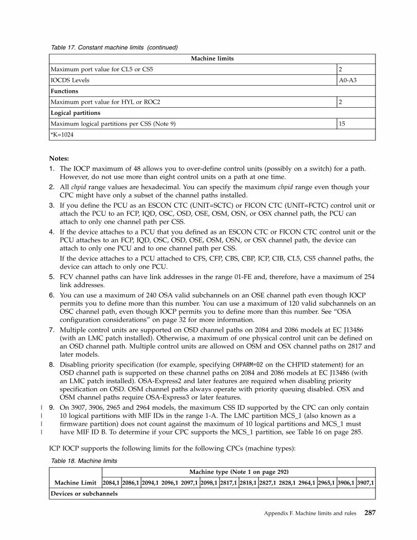
Table 17. Constant machine limits (continued)
Machine limits
Maximum port value for CL5 or CS5 2
IOCDS Levels A0-A3
Functions
Maximum port value for HYL or ROC2 2
Logical partitions
Maximum logical partitions per CSS (Note 9) 15
*K=1024
Notes:
1. The IOCP maximum of 48 allows you to over-define control units (possibly on a switch) for a path.However, do not use more than eight control units on a path at one time.
2. All chpid range values are hexadecimal. You can specify the maximum chpid range even though yourCPC might have only a subset of the channel paths installed.
3. If you define the PCU as an ESCON CTC (UNIT=SCTC) or FICON CTC (UNIT=FCTC) control unit orattach the PCU to an FCP, IQD, OSC, OSD, OSE, OSM, OSN, or OSX channel path, the PCU canattach to only one channel path per CSS.
4. If the device attaches to a PCU that you defined as an ESCON CTC or FICON CTC control unit or thePCU attaches to an FCP, IQD, OSC, OSD, OSE, OSM, OSN, or OSX channel path, the device canattach to only one PCU and to one channel path per CSS.If the device attaches to a PCU attached to CFS, CFP, CBS, CBP, ICP, CIB, CL5, CS5 channel paths, thedevice can attach to only one PCU.
5. FCV channel paths can have link addresses in the range 01-FE and, therefore, have a maximum of 254link addresses.
6. You can use a maximum of 240 OSA valid subchannels on an OSE channel path even though IOCPpermits you to define more than this number. You can use a maximum of 120 valid subchannels on anOSC channel path, even though IOCP permits you to define more than this number. See “OSAconfiguration considerations” on page 32 for more information.
7. Multiple control units are supported on OSD channel paths on 2084 and 2086 models at EC J13486(with an LMC patch installed). Otherwise, a maximum of one physical control unit can be defined onan OSD channel path. Multiple control units are allowed on OSM and OSX channel paths on 2817 andlater models.
8. Disabling priority specification (for example, specifying CHPARM=02 on the CHPID statement) for anOSD channel path is supported on these channel paths on 2084 and 2086 models at EC J13486 (withan LMC patch installed). OSA-Express2 and later features are required when disabling priorityspecification on OSD. OSM channel paths always operate with priority queuing disabled. OSX andOSM channel paths require OSA-Express3 or later features.
9. On 3907, 3906, 2965 and 2964 models, the maximum CSS ID supported by the CPC can only contain10 logical partitions with MIF IDs in the range 1-A. The LMC partition MCS_1 (also known as afirmware partition) does not count against the maximum of 10 logical partitions and MCS_1 musthave MIF ID B. To determine if your CPC supports the MCS_1 partition, see Table 16 on page 285.
ICP IOCP supports the following limits for the following CPCs (machine types):
Table 18. Machine limits
Machine Limit
Machine type (Note 1 on page 292)
2084,1 2086,1 2094,1 2096,1 2097,1 2098,1 2817,1 2818,1 2827,1 2828,1 2964,1 2965,1 3906,1 3907,1
Devices or subchannels
Appendix F. Machine limits and rules 287
||||
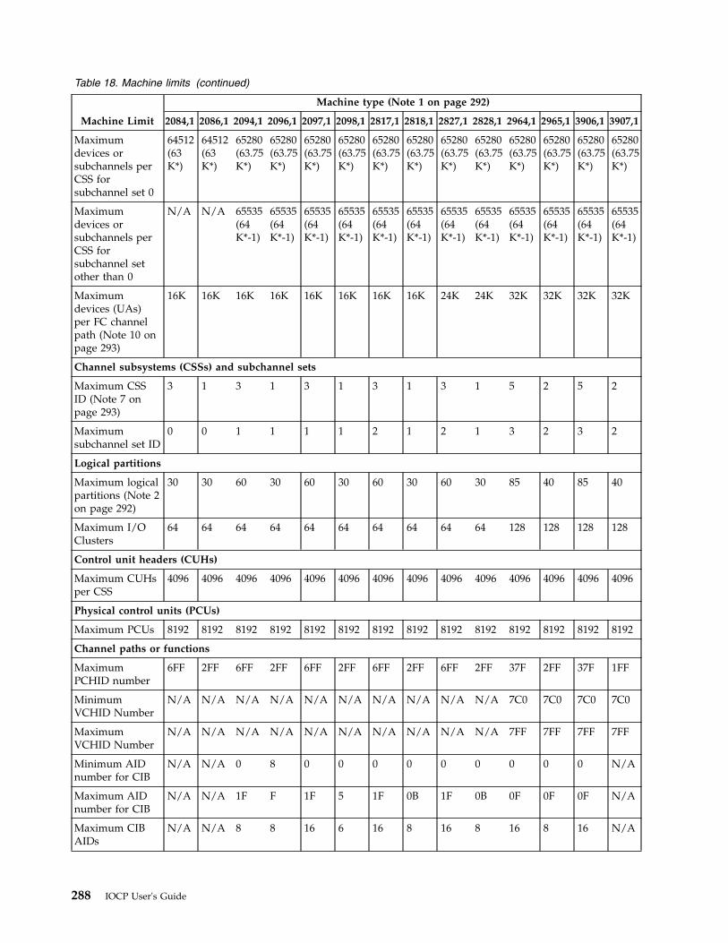
Table 18. Machine limits (continued)
Machine Limit
Machine type (Note 1 on page 292)
2084,1 2086,1 2094,1 2096,1 2097,1 2098,1 2817,1 2818,1 2827,1 2828,1 2964,1 2965,1 3906,1 3907,1
Maximumdevices orsubchannels perCSS forsubchannel set 0
64512(63K*)
64512(63K*)
65280(63.75K*)
65280(63.75K*)
65280(63.75K*)
65280(63.75K*)
65280(63.75K*)
65280(63.75K*)
65280(63.75K*)
65280(63.75K*)
65280(63.75K*)
65280(63.75K*)
65280(63.75K*)
65280(63.75K*)
Maximumdevices orsubchannels perCSS forsubchannel setother than 0
N/A N/A 65535(64K*-1)
65535(64K*-1)
65535(64K*-1)
65535(64K*-1)
65535(64K*-1)
65535(64K*-1)
65535(64K*-1)
65535(64K*-1)
65535(64K*-1)
65535(64K*-1)
65535(64K*-1)
65535(64K*-1)
Maximumdevices (UAs)per FC channelpath (Note 10 onpage 293)
16K 16K 16K 16K 16K 16K 16K 16K 24K 24K 32K 32K 32K 32K
Channel subsystems (CSSs) and subchannel sets
Maximum CSSID (Note 7 onpage 293)
3 1 3 1 3 1 3 1 3 1 5 2 5 2
Maximumsubchannel set ID
0 0 1 1 1 1 2 1 2 1 3 2 3 2
Logical partitions
Maximum logicalpartitions (Note 2on page 292)
30 30 60 30 60 30 60 30 60 30 85 40 85 40
Maximum I/OClusters
64 64 64 64 64 64 64 64 64 64 128 128 128 128
Control unit headers (CUHs)
Maximum CUHsper CSS
4096 4096 4096 4096 4096 4096 4096 4096 4096 4096 4096 4096 4096 4096
Physical control units (PCUs)
Maximum PCUs 8192 8192 8192 8192 8192 8192 8192 8192 8192 8192 8192 8192 8192 8192
Channel paths or functions
MaximumPCHID number
6FF 2FF 6FF 2FF 6FF 2FF 6FF 2FF 6FF 2FF 37F 2FF 37F 1FF
MinimumVCHID Number
N/A N/A N/A N/A N/A N/A N/A N/A N/A N/A 7C0 7C0 7C0 7C0
MaximumVCHID Number
N/A N/A N/A N/A N/A N/A N/A N/A N/A N/A 7FF 7FF 7FF 7FF
Minimum AIDnumber for CIB
N/A N/A 0 8 0 0 0 0 0 0 0 0 0 N/A
Maximum AIDnumber for CIB
N/A N/A 1F F 1F 5 1F 0B 1F 0B 0F 0F 0F N/A
Maximum CIBAIDs
N/A N/A 8 8 16 6 16 8 16 8 16 8 16 N/A
288 IOCP User's Guide
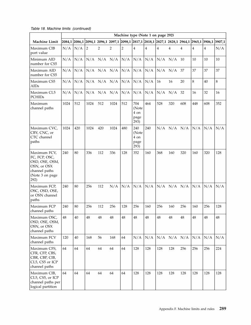
Table 18. Machine limits (continued)
Machine Limit
Machine type (Note 1 on page 292)
2084,1 2086,1 2094,1 2096,1 2097,1 2098,1 2817,1 2818,1 2827,1 2828,1 2964,1 2965,1 3906,1 3907,1
Maximum CIBport value
N/A N/A 2 2 2 2 4 4 4 4 4 4 4 N/A
Minimum AIDnumber for CS5
N/A N/A N/A N/A N/A N/A N/A N/A N/A N/A 10 10 10 10
Maximum AIDnumber for CS5
N/A N/A N/A N/A N/A N/A N/A N/A N/A N/A 37 37 37 37
Maximum CS5AIDs
N/A N/A N/A N/A N/A N/A N/A N/A 16 16 20 8 40 8
Maximum CL5PCHIDs
N/A N/A N/A N/A N/A N/A N/A N/A N/A N/A 32 16 32 16
Maximumchannel paths
1024 512 1024 512 1024 512 704(Note4 onpage293)
464 528 320 608 448 608 352
Maximum CVC,CBY, CNC, orCTC channelpaths
1024 420 1024 420 1024 480 240(Note4 onpage293)
240 N/A N/A N/A N/A N/A N/A
Maximum FCV,FC, FCP, OSC,OSD, OSE, OSM,OSN, or OSXchannel paths(Note 3 on page292)
240 80 336 112 336 128 352 160 368 160 320 160 320 128
Maximum FCP,OSC, OSD, OSE,or OSN channelpaths
240 80 256 112 N/A N/A N/A N/A N/A N/A N/A N/A N/A N/A
Maximum FCPchannel paths
240 80 256 112 256 128 256 160 256 160 256 160 256 128
Maximum OSC,OSD, OSE, OSM,OSN, or OSXchannel paths
48 40 48 48 48 48 48 48 48 48 48 48 48 48
Maximum FCVchannel paths
120 40 168 56 168 64 N/A N/A N/A N/A N/A N/A N/A N/A
Maximum CFS,CFR, CFP, CBS,CBR, CBP, CIB,CL5, CS5 or ICPchannel paths
64 64 64 64 64 64 128 128 128 128 256 256 256 224
Maximum CIB,CL5, CS5, or ICPchannel paths perlogical partition
64 64 64 64 64 64 128 128 128 128 128 128 128 128
Appendix F. Machine limits and rules 289
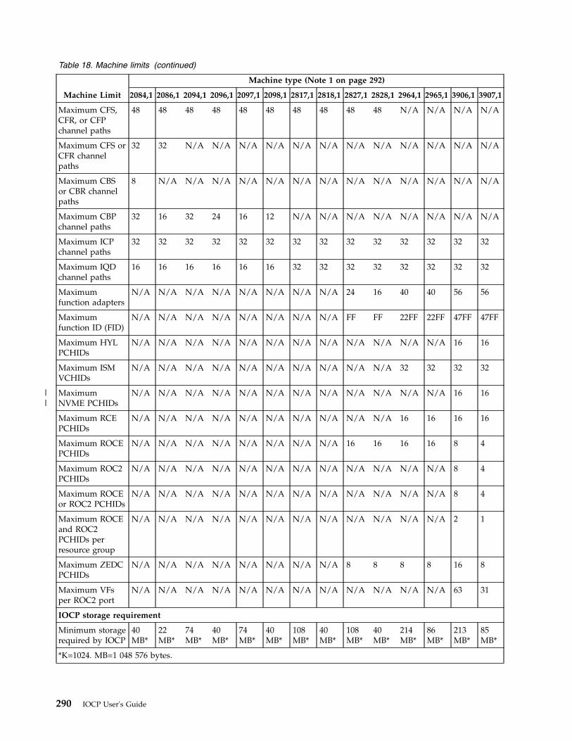
Table 18. Machine limits (continued)
Machine Limit
Machine type (Note 1 on page 292)
2084,1 2086,1 2094,1 2096,1 2097,1 2098,1 2817,1 2818,1 2827,1 2828,1 2964,1 2965,1 3906,1 3907,1
Maximum CFS,CFR, or CFPchannel paths
48 48 48 48 48 48 48 48 48 48 N/A N/A N/A N/A
Maximum CFS orCFR channelpaths
32 32 N/A N/A N/A N/A N/A N/A N/A N/A N/A N/A N/A N/A
Maximum CBSor CBR channelpaths
8 N/A N/A N/A N/A N/A N/A N/A N/A N/A N/A N/A N/A N/A
Maximum CBPchannel paths
32 16 32 24 16 12 N/A N/A N/A N/A N/A N/A N/A N/A
Maximum ICPchannel paths
32 32 32 32 32 32 32 32 32 32 32 32 32 32
Maximum IQDchannel paths
16 16 16 16 16 16 32 32 32 32 32 32 32 32
Maximumfunction adapters
N/A N/A N/A N/A N/A N/A N/A N/A 24 16 40 40 56 56
Maximumfunction ID (FID)
N/A N/A N/A N/A N/A N/A N/A N/A FF FF 22FF 22FF 47FF 47FF
Maximum HYLPCHIDs
N/A N/A N/A N/A N/A N/A N/A N/A N/A N/A N/A N/A 16 16
Maximum ISMVCHIDs
N/A N/A N/A N/A N/A N/A N/A N/A N/A N/A 32 32 32 32
MaximumNVME PCHIDs
N/A N/A N/A N/A N/A N/A N/A N/A N/A N/A N/A N/A 16 16
Maximum RCEPCHIDs
N/A N/A N/A N/A N/A N/A N/A N/A N/A N/A 16 16 16 16
Maximum ROCEPCHIDs
N/A N/A N/A N/A N/A N/A N/A N/A 16 16 16 16 8 4
Maximum ROC2PCHIDs
N/A N/A N/A N/A N/A N/A N/A N/A N/A N/A N/A N/A 8 4
Maximum ROCEor ROC2 PCHIDs
N/A N/A N/A N/A N/A N/A N/A N/A N/A N/A N/A N/A 8 4
Maximum ROCEand ROC2PCHIDs perresource group
N/A N/A N/A N/A N/A N/A N/A N/A N/A N/A N/A N/A 2 1
Maximum ZEDCPCHIDs
N/A N/A N/A N/A N/A N/A N/A N/A 8 8 8 8 16 8
Maximum VFsper ROC2 port
N/A N/A N/A N/A N/A N/A N/A N/A N/A N/A N/A N/A 63 31
IOCP storage requirement
Minimum storagerequired by IOCP
40MB*
22MB*
74MB*
40MB*
74MB*
40MB*
108MB*
40MB*
108MB*
40MB*
214MB*
86MB*
213MB*
85MB*
*K=1024. MB=1 048 576 bytes.
290 IOCP User's Guide
||
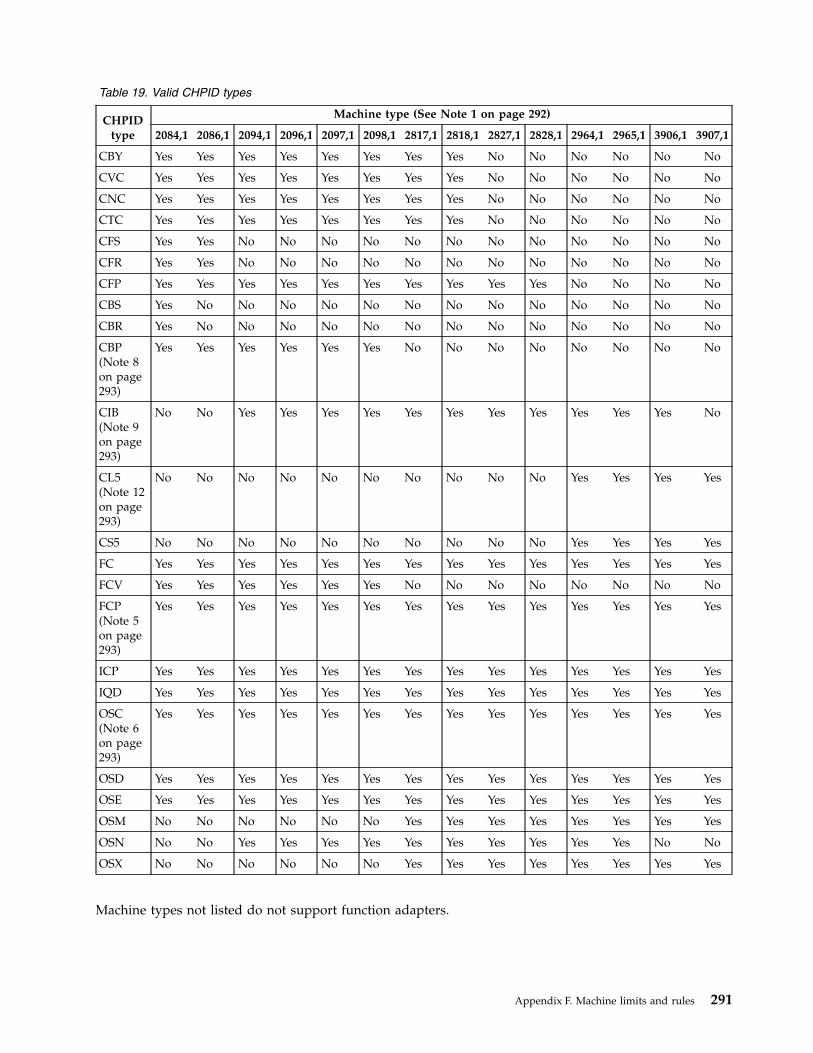
Table 19. Valid CHPID types
CHPIDtype
Machine type (See Note 1 on page 292)
2084,1 2086,1 2094,1 2096,1 2097,1 2098,1 2817,1 2818,1 2827,1 2828,1 2964,1 2965,1 3906,1 3907,1
CBY Yes Yes Yes Yes Yes Yes Yes Yes No No No No No No
CVC Yes Yes Yes Yes Yes Yes Yes Yes No No No No No No
CNC Yes Yes Yes Yes Yes Yes Yes Yes No No No No No No
CTC Yes Yes Yes Yes Yes Yes Yes Yes No No No No No No
CFS Yes Yes No No No No No No No No No No No No
CFR Yes Yes No No No No No No No No No No No No
CFP Yes Yes Yes Yes Yes Yes Yes Yes Yes Yes No No No No
CBS Yes No No No No No No No No No No No No No
CBR Yes No No No No No No No No No No No No No
CBP(Note 8on page293)
Yes Yes Yes Yes Yes Yes No No No No No No No No
CIB(Note 9on page293)
No No Yes Yes Yes Yes Yes Yes Yes Yes Yes Yes Yes No
CL5(Note 12on page293)
No No No No No No No No No No Yes Yes Yes Yes
CS5 No No No No No No No No No No Yes Yes Yes Yes
FC Yes Yes Yes Yes Yes Yes Yes Yes Yes Yes Yes Yes Yes Yes
FCV Yes Yes Yes Yes Yes Yes No No No No No No No No
FCP(Note 5on page293)
Yes Yes Yes Yes Yes Yes Yes Yes Yes Yes Yes Yes Yes Yes
ICP Yes Yes Yes Yes Yes Yes Yes Yes Yes Yes Yes Yes Yes Yes
IQD Yes Yes Yes Yes Yes Yes Yes Yes Yes Yes Yes Yes Yes Yes
OSC(Note 6on page293)
Yes Yes Yes Yes Yes Yes Yes Yes Yes Yes Yes Yes Yes Yes
OSD Yes Yes Yes Yes Yes Yes Yes Yes Yes Yes Yes Yes Yes Yes
OSE Yes Yes Yes Yes Yes Yes Yes Yes Yes Yes Yes Yes Yes Yes
OSM No No No No No No Yes Yes Yes Yes Yes Yes Yes Yes
OSN No No Yes Yes Yes Yes Yes Yes Yes Yes Yes Yes No No
OSX No No No No No No Yes Yes Yes Yes Yes Yes Yes Yes
Machine types not listed do not support function adapters.
Appendix F. Machine limits and rules 291
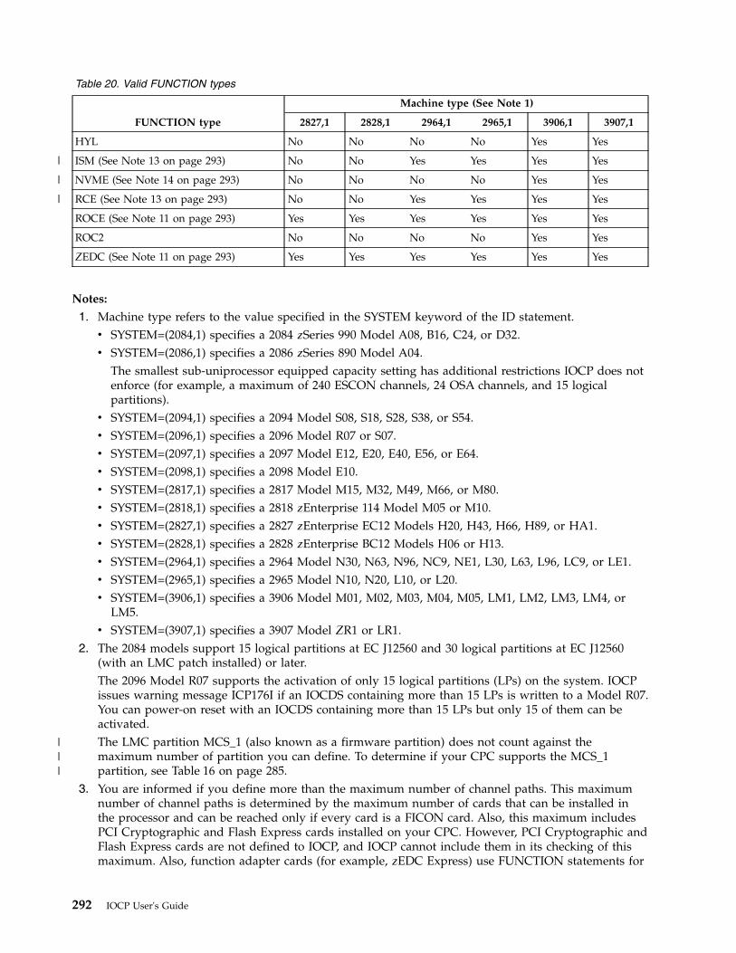
Table 20. Valid FUNCTION types
FUNCTION type
Machine type (See Note 1)
2827,1 2828,1 2964,1 2965,1 3906,1 3907,1
HYL No No No No Yes Yes
ISM (See Note 13 on page 293) No No Yes Yes Yes Yes
NVME (See Note 14 on page 293) No No No No Yes Yes
RCE (See Note 13 on page 293) No No Yes Yes Yes Yes
ROCE (See Note 11 on page 293) Yes Yes Yes Yes Yes Yes
ROC2 No No No No Yes Yes
ZEDC (See Note 11 on page 293) Yes Yes Yes Yes Yes Yes
Notes:
1. Machine type refers to the value specified in the SYSTEM keyword of the ID statement.v SYSTEM=(2084,1) specifies a 2084 zSeries 990 Model A08, B16, C24, or D32.v SYSTEM=(2086,1) specifies a 2086 zSeries 890 Model A04.
The smallest sub-uniprocessor equipped capacity setting has additional restrictions IOCP does notenforce (for example, a maximum of 240 ESCON channels, 24 OSA channels, and 15 logicalpartitions).
v SYSTEM=(2094,1) specifies a 2094 Model S08, S18, S28, S38, or S54.v SYSTEM=(2096,1) specifies a 2096 Model R07 or S07.v SYSTEM=(2097,1) specifies a 2097 Model E12, E20, E40, E56, or E64.v SYSTEM=(2098,1) specifies a 2098 Model E10.v SYSTEM=(2817,1) specifies a 2817 Model M15, M32, M49, M66, or M80.v SYSTEM=(2818,1) specifies a 2818 zEnterprise 114 Model M05 or M10.v SYSTEM=(2827,1) specifies a 2827 zEnterprise EC12 Models H20, H43, H66, H89, or HA1.v SYSTEM=(2828,1) specifies a 2828 zEnterprise BC12 Models H06 or H13.v SYSTEM=(2964,1) specifies a 2964 Model N30, N63, N96, NC9, NE1, L30, L63, L96, LC9, or LE1.v SYSTEM=(2965,1) specifies a 2965 Model N10, N20, L10, or L20.v SYSTEM=(3906,1) specifies a 3906 Model M01, M02, M03, M04, M05, LM1, LM2, LM3, LM4, or
LM5.v SYSTEM=(3907,1) specifies a 3907 Model ZR1 or LR1.
2. The 2084 models support 15 logical partitions at EC J12560 and 30 logical partitions at EC J12560(with an LMC patch installed) or later.The 2096 Model R07 supports the activation of only 15 logical partitions (LPs) on the system. IOCPissues warning message ICP176I if an IOCDS containing more than 15 LPs is written to a Model R07.You can power-on reset with an IOCDS containing more than 15 LPs but only 15 of them can beactivated.The LMC partition MCS_1 (also known as a firmware partition) does not count against themaximum number of partition you can define. To determine if your CPC supports the MCS_1partition, see Table 16 on page 285.
3. You are informed if you define more than the maximum number of channel paths. This maximumnumber of channel paths is determined by the maximum number of cards that can be installed inthe processor and can be reached only if every card is a FICON card. Also, this maximum includesPCI Cryptographic and Flash Express cards installed on your CPC. However, PCI Cryptographic andFlash Express cards are not defined to IOCP, and IOCP cannot include them in its checking of thismaximum. Also, function adapter cards (for example, zEDC Express) use FUNCTION statements for
292 IOCP User's Guide
|
|
|
|||
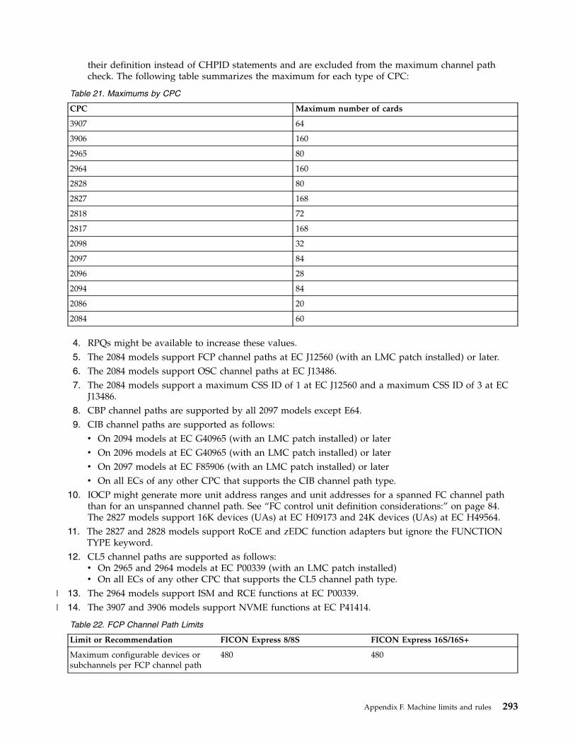
their definition instead of CHPID statements and are excluded from the maximum channel pathcheck. The following table summarizes the maximum for each type of CPC:
Table 21. Maximums by CPC
CPC Maximum number of cards
3907 64
3906 160
2965 80
2964 160
2828 80
2827 168
2818 72
2817 168
2098 32
2097 84
2096 28
2094 84
2086 20
2084 60
4. RPQs might be available to increase these values.5. The 2084 models support FCP channel paths at EC J12560 (with an LMC patch installed) or later.6. The 2084 models support OSC channel paths at EC J13486.7. The 2084 models support a maximum CSS ID of 1 at EC J12560 and a maximum CSS ID of 3 at EC
J13486.8. CBP channel paths are supported by all 2097 models except E64.9. CIB channel paths are supported as follows:v On 2094 models at EC G40965 (with an LMC patch installed) or laterv On 2096 models at EC G40965 (with an LMC patch installed) or laterv On 2097 models at EC F85906 (with an LMC patch installed) or laterv On all ECs of any other CPC that supports the CIB channel path type.
10. IOCP might generate more unit address ranges and unit addresses for a spanned FC channel paththan for an unspanned channel path. See “FC control unit definition considerations:” on page 84.The 2827 models support 16K devices (UAs) at EC H09173 and 24K devices (UAs) at EC H49564.
11. The 2827 and 2828 models support RoCE and zEDC function adapters but ignore the FUNCTIONTYPE keyword.
12. CL5 channel paths are supported as follows:v On 2965 and 2964 models at EC P00339 (with an LMC patch installed)v On all ECs of any other CPC that supports the CL5 channel path type.
13. The 2964 models support ISM and RCE functions at EC P00339.14. The 3907 and 3906 models support NVME functions at EC P41414.
Table 22. FCP Channel Path Limits
Limit or Recommendation FICON Express 8/8S FICON Express 16S/16S+
Maximum configurable devices orsubchannels per FCP channel path
480 480
Appendix F. Machine limits and rules 293
|
|
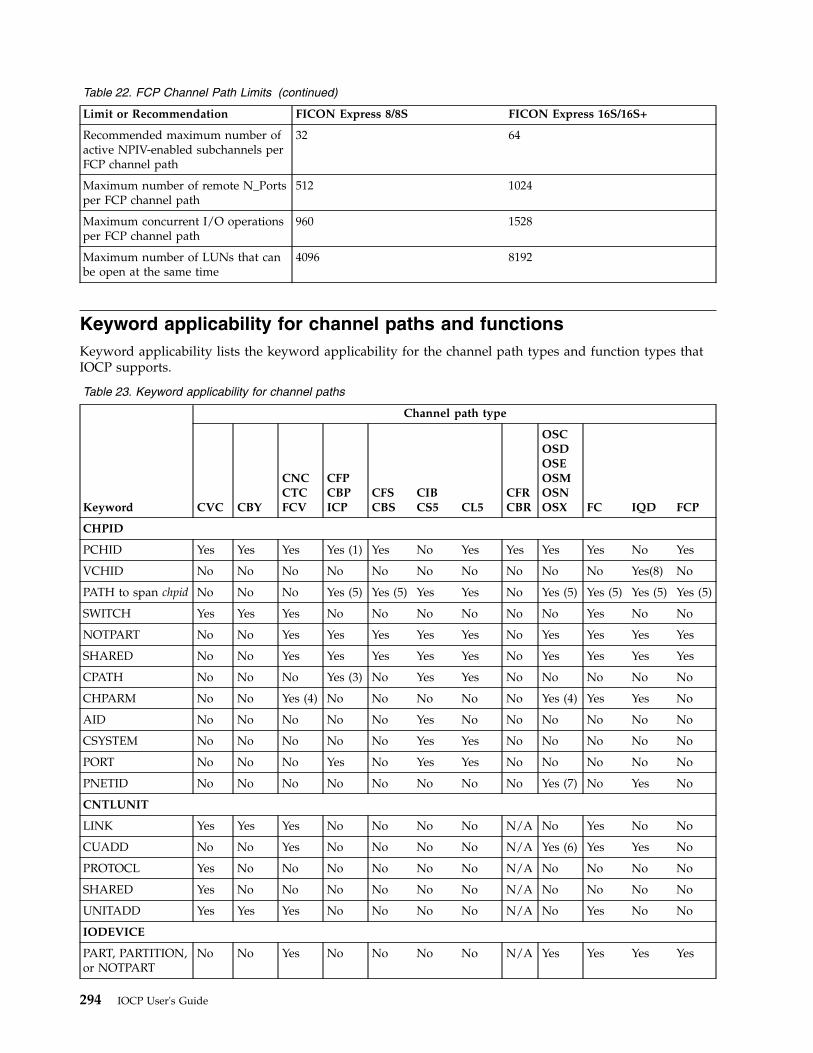
Table 22. FCP Channel Path Limits (continued)
Limit or Recommendation FICON Express 8/8S FICON Express 16S/16S+
Recommended maximum number ofactive NPIV-enabled subchannels perFCP channel path
32 64
Maximum number of remote N_Portsper FCP channel path
512 1024
Maximum concurrent I/O operationsper FCP channel path
960 1528
Maximum number of LUNs that canbe open at the same time
4096 8192
Keyword applicability for channel paths and functionsKeyword applicability lists the keyword applicability for the channel path types and function types thatIOCP supports.
Table 23. Keyword applicability for channel paths
Keyword
Channel path type
CVC CBY
CNCCTCFCV
CFPCBPICP
CFSCBS
CIBCS5 CL5
CFRCBR
OSCOSDOSEOSMOSNOSX FC IQD FCP
CHPID
PCHID Yes Yes Yes Yes (1) Yes No Yes Yes Yes Yes No Yes
VCHID No No No No No No No No No No Yes(8) No
PATH to span chpid No No No Yes (5) Yes (5) Yes Yes No Yes (5) Yes (5) Yes (5) Yes (5)
SWITCH Yes Yes Yes No No No No No No Yes No No
NOTPART No No Yes Yes Yes Yes Yes No Yes Yes Yes Yes
SHARED No No Yes Yes Yes Yes Yes No Yes Yes Yes Yes
CPATH No No No Yes (3) No Yes Yes No No No No No
CHPARM No No Yes (4) No No No No No Yes (4) Yes Yes No
AID No No No No No Yes No No No No No No
CSYSTEM No No No No No Yes Yes No No No No No
PORT No No No Yes No Yes Yes No No No No No
PNETID No No No No No No No No Yes (7) No Yes No
CNTLUNIT
LINK Yes Yes Yes No No No No N/A No Yes No No
CUADD No No Yes No No No No N/A Yes (6) Yes Yes No
PROTOCL Yes No No No No No No N/A No No No No
SHARED Yes No No No No No No N/A No No No No
UNITADD Yes Yes Yes No No No No N/A No Yes No No
IODEVICE
PART, PARTITION,or NOTPART
No No Yes No No No No N/A Yes Yes Yes Yes
294 IOCP User's Guide
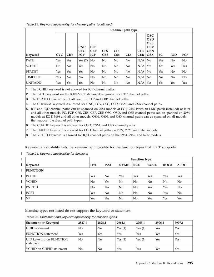
Table 23. Keyword applicability for channel paths (continued)
Keyword
Channel path type
CVC CBY
CNCCTCFCV
CFPCBPICP
CFSCBS
CIBCS5 CL5
CFRCBR
OSCOSDOSEOSMOSNOSX FC IQD FCP
PATH Yes Yes Yes (2) No No No No N/A No Yes No No
SCHSET No No Yes No No No No N/A Yes Yes Yes Yes
STADET Yes Yes Yes No No No No N/A No Yes No No
TIMEOUT Yes No No No No No No N/A No No No No
UNITADD Yes Yes Yes No No No No N/A Yes Yes Yes Yes
1. The PCHID keyword is not allowed for ICP channel paths.
2. The PATH keyword on the IODEVICE statement is ignored for CTC channel paths.
3. The CPATH keyword is not allowed for CFP and CBP channel paths.
4. The CHPARM keyword is allowed for CNC, FCV, OSC, OSD, OSM, and OSX channel paths.
5. ICP and IQD channel paths can be spanned on 2084 models at EC J12560 (with an LMC patch installed) or laterand all other models. FC, FCP, CFS, CBS, CFP, CBP, OSC, OSD, and OSE channel paths can be spanned on 2084models at EC J13486 and all other models. OSM, OSN, and OSX channel paths can be spanned on all modelsthat support the channel path types.
6. The CUADD keyword is allowed for OSD, OSM, and OSX channel paths.
7. The PNETID keyword is allowed for OSD channel paths on 2827, 2828, and later models.
8. The VCHID keyword is allowed for IQD channel paths on the 2964, 2965, and later models.
Keyword applicability lists the keyword applicability for the function types that IOCP supports.
Table 24. Keyword applicability for functions
Keyword
Function type
HYL ISM NVME RCE ROCE ROC2 ZEDC
FUNCTION
PCHID Yes No Yes Yes Yes Yes Yes
VCHID No Yes No No No No No
PNETID No Yes No No Yes Yes No
PORT Yes No No No No Yes No
VF Yes Yes No No Yes Yes Yes
Machine types not listed do not support the keyword or statement.
Table 25. Statement and keyword applicability for machine types
Statement or Keyword 2827,1 2828,1 2964,1 2965,1 3906,1 3907,1
UUID statement No No Yes (1) Yes (1) Yes Yes
FUNCTION statement Yes Yes Yes Yes Yes Yes
UID keyword on FUNCTIONstatement
No No Yes (1) Yes (1) Yes Yes
VCHID on CHPID statement No No Yes Yes Yes Yes
Appendix F. Machine limits and rules 295
||
|
|
|||||||
|
||||||||
||||||||
||||||||
||||||||
||||||||
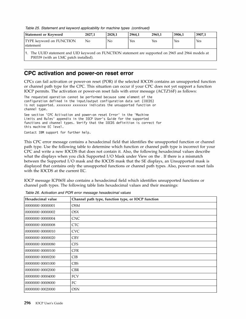
Table 25. Statement and keyword applicability for machine types (continued)
Statement or Keyword 2827,1 2828,1 2964,1 2965,1 3906,1 3907,1
TYPE keyword on FUNCTIONstatement
No No Yes Yes Yes Yes
1. The UUID statement and UID keyword on FUNCTION statement are supported on 2965 and 2964 models atP00339 (with an LMC patch installed).
CPC activation and power-on reset errorCPCs can fail activation or power-on reset (POR) if the selected IOCDS contains an unsupported functionor channel path type for the CPC. This situation can occur if your CPC does not yet support a functionIOCP permits. The activation or power-on reset fails with error message (ACTZ16F) as follows:The requested operation cannot be performed because some element of theconfiguration defined in the input/output configuration data set (IOCDS)is not supported. xxxxxxxx xxxxxxxx indicates the unsupported function orchannel type.
See section ’CPC Activation and power-on reset Error’ in the ’MachineLimits and Rules’ appendix in the IOCP User’s Guide for the supportedfunctions and channel types. Verify that the IOCDS definition is correct forthis machine EC level.
Contact IBM support for further help.
This CPC error message contains a hexadecimal field that identifies the unsupported function or channelpath type. Use the following table to determine which function or channel path type is incorrect for yourCPC and write a new IOCDS that does not contain it. Also, the following hexadecimal values describewhat the displays when you click Supported I/O Mask under View on the . If there is a mismatchbetween the Supported I/O mask and the IOCDS mask that the SE displays, an Unsupported mask isdisplayed that contains only the unsupported functions or channel path types. Also, power-on reset failswith the IOCDS at the current EC.
IOCP message ICP065I also contains a hexadecimal field which identifies unsupported functions orchannel path types. The following table lists hexadecimal values and their meanings:
Table 26. Activation and POR error message hexadecimal values
Hexadecimal value Channel path type, function type, or IOCP function
00000000 00000001 OSM
00000000 00000002 OSX
00000000 00000004 CNC
00000000 00000008 CTC
00000000 00000010 CVC
00000000 00000020 CBY
00000000 00000080 CFS
00000000 00000100 CFR
00000000 00000200 CIB
00000000 00001000 CBS
00000000 00002000 CBR
00000000 00004000 FCV
00000000 00008000 FC
00000000 00020000 OSN
296 IOCP User's Guide
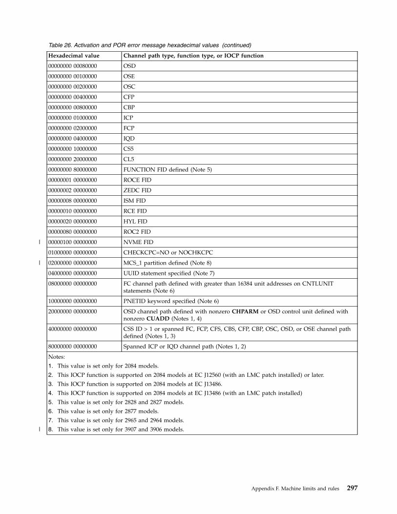
Table 26. Activation and POR error message hexadecimal values (continued)
Hexadecimal value Channel path type, function type, or IOCP function
00000000 00080000 OSD
00000000 00100000 OSE
00000000 00200000 OSC
00000000 00400000 CFP
00000000 00800000 CBP
00000000 01000000 ICP
00000000 02000000 FCP
00000000 04000000 IQD
00000000 10000000 CS5
00000000 20000000 CL5
00000000 80000000 FUNCTION FID defined (Note 5)
00000001 00000000 ROCE FID
00000002 00000000 ZEDC FID
00000008 00000000 ISM FID
00000010 00000000 RCE FID
00000020 00000000 HYL FID
00000080 00000000 ROC2 FID
00000100 00000000 NVME FID
01000000 00000000 CHECKCPC=NO or NOCHKCPC
02000000 00000000 MCS_1 partition defined (Note 8)
04000000 00000000 UUID statement specified (Note 7)
08000000 00000000 FC channel path defined with greater than 16384 unit addresses on CNTLUNITstatements (Note 6)
10000000 00000000 PNETID keyword specified (Note 6)
20000000 00000000 OSD channel path defined with nonzero CHPARM or OSD control unit defined withnonzero CUADD (Notes 1, 4)
40000000 00000000 CSS ID > 1 or spanned FC, FCP, CFS, CBS, CFP, CBP, OSC, OSD, or OSE channel pathdefined (Notes 1, 3)
80000000 00000000 Spanned ICP or IQD channel path (Notes 1, 2)
Notes:
1. This value is set only for 2084 models.
2. This IOCP function is supported on 2084 models at EC J12560 (with an LMC patch installed) or later.
3. This IOCP function is supported on 2084 models at EC J13486.
4. This IOCP function is supported on 2084 models at EC J13486 (with an LMC patch installed)
5. This value is set only for 2828 and 2827 models.
6. This value is set only for 2877 models.
7. This value is set only for 2965 and 2964 models.
8. This value is set only for 3907 and 3906 models.
Appendix F. Machine limits and rules 297
|
|
|

298 IOCP User's Guide
Appendix G. Notices
This information was developed for products and services offered in the USA.
IBM may not offer the products, services, or features discussed in this document in other countries.Consult your local IBM representative for information on the products and services currently available inyour area. Any reference to an IBM product, program, or service is not intended to state or imply thatonly that IBM product, program, or service may be used. Any functionally equivalent product, program,or service that does not infringe any IBM intellectual property right may be used instead. However, it isthe user's responsibility to evaluate and verify the operation of any non-IBM product, program, orservice.
IBM may have patents or pending patent applications covering subject matter described in thisdocument. The furnishing of this document does not grant you any license to these patents. You can sendlicense inquiries, in writing, to:
IBM Director of LicensingIBM CorporationNorth Castle DriveArmonk, NY 10504-1785 USA
INTERNATIONAL BUSINESS MACHINES CORPORATION PROVIDES THIS PUBLICATION “ AS IS”WITHOUT WARRANTY OF ANY KIND, EITHER EXPRESS OR IMPLIED, INCLUDING, BUT NOTLIMITED TO, THE IMPLIED WARRANTIES OF NON-INFRINGEMENT, MERCHANTABILITY ORFITNESS FOR A PARTICULAR PURPOSE. Some states do not allow disclaimer of express or impliedwarranties in certain transactions, therefore, this statement may not apply to you.
This information could include technical inaccuracies or typographical errors. Changes are periodicallymade to the information herein; these changes will be incorporated in new editions of the publication.IBM may make improvements and/or changes in the product(s) and/or the program(s) described in thispublication at any time without notice.
Any references in this information to non-IBM websites are provided for convenience only and do not inany manner serve as an endorsement of those websites. The materials at those websites are not part ofthe materials for this IBM product and use of those websites is at your own risk.
IBM may use or distribute any of the information you supply in any way it believes appropriate withoutincurring any obligation to you.
Any performance data contained herein was determined in a controlled environment. Therefore, theresults obtained in other operating environments may vary significantly. Some measurements may havebeen made on development-level systems and there is no guarantee that these measurements will be thesame on generally available systems. Furthermore, some measurements may have been estimated throughextrapolation. Actual results may vary. Users of this document should verify the applicable data for theirspecific environment.
Information concerning non-IBM products was obtained from the suppliers of those products, theirpublished announcements or other publicly available sources. IBM has not tested those products andcannot confirm the accuracy of performance, compatibility or any other claims related to non-IBMproducts. Questions on the capabilities of non-IBM products should be addressed to the suppliers ofthose products.
© Copyright IBM Corp. 2017, 2018 299
All statements regarding IBM's future direction or intent are subject to change or withdrawal withoutnotice, and represent goals and objectives only.
All IBM prices shown are IBM's suggested retail prices, are current and are subject to change withoutnotice. Dealer prices may vary.
This information is for planning purposes only. The information herein is subject to change before theproducts described become available.
This information contains examples of data and reports used in daily business operations. To illustratethem as completely as possible, the examples include the names of individuals, companies, brands, andproducts. All of these names are fictitious and any similarity to the names and addresses used by anactual business enterprise is entirely coincidental.
If you are viewing this information softcopy, the photographs and color illustrations may not appear.
TrademarksIBM, the IBM logo, and ibm.com® are trademarks of International Business Machines Corp., registered inmany jurisdictions worldwide. Other product and service names might be trademarks of IBM or othercompanies. A current list of IBM trademarks is available on the web at “Copyright and trademarkinformation” at www.ibm.com/legal/copytrade.shtml.
Linux is a registered trademark of Linus Torvalds in the United States, other countries, or both.
Microsoft and Windows are trademarks of Microsoft Corporation in the United States, other countries, orboth.
Class A NoticesThe following Class A statements apply to this IBM product. The statement for other IBM productsintended for use with this product will appear in their accompanying manuals.
Federal Communications Commission (FCC) Statement
Note: This equipment has been tested and found to comply with the limits for a Class A digital device,pursuant to Part 15 of the FCC Rules. These limits are designed to provide reasonable protection againstharmful interference when the equipment is operated in a commercial environment. This equipmentgenerates, uses, and can radiate radio frequency energy and, if not installed and used in accordance withthe instruction manual, may cause harmful interference to radio communications. Operation of thisequipment in a residential area is likely to cause harmful interference, in which case the user will berequired to correct the interference at his own expense.
Properly shielded and grounded cables and connectors must be used in order to meet FCC emissionlimits. IBM is not responsible for any radio or television interference caused by using other thanrecommended cables and connectors or by unauthorized changes or modifications to this equipment.Unauthorized changes or modifications could void the user's authority to operate the equipment.
This device complies with Part 15 of the FCC rules. Operation is subject to the following two conditions:(1) this device may not cause harmful interference, and (2) this device must accept any interferencereceived, including interference that may cause undesired operation.
Industry Canada Compliance Statement
This Class A digital apparatus complies with Canadian ICES-003.
300 IOCP User's Guide
Avis de conformité à la réglementation d'Industrie Canada
Cet appareil numérique de la classe A est conforme à la norme NMB-003 du Canada.
European Community Compliance Statement
This product is in conformity with the protection requirements of EU Council Directive 2014/30/EU onthe approximation of the laws of the Member States relating to electromagnetic compatibility. IBM cannotaccept responsibility for any failure to satisfy the protection requirements resulting from anon-recommended modification of the product, including the fitting of non-IBM option cards.
This product has been tested and found to comply with the limits for Class A Information TechnologyEquipment according to European Standard EN 55032. The limits for Class A equipment were derived forcommercial and industrial environments to provide reasonable protection against interference withlicensed communication equipment.
European Community contact:IBM Deutschland GmbHTechnical Regulations, Department M372IBM-Allee 1, 71139 Ehningen, GermanyTele: +49 (0) 800 225 5423 or +49 (0) 180 331 3233email: [email protected]
Warning: This is a Class A product. In a domestic environment, this product may cause radiointerference, in which case the user may be required to take adequate measures.
VCCI Statement - Japan
The following is a summary of the Japanese VCCI statement above:
This is a Class A product based on the standard of the VCCI Council. If this equipment is used in adomestic environment, radio interference may occur, in which case the user may be required to takecorrective actions.
Japan JIS C 61000-3-2 Compliance
For products less than or equal to 20 A per phase, the following statement applies:
("#)%&'()*+,-./ 012%3456789
/ :;に=づく@ABC%CD: のGHIの/Knowledge Center
/ / / / / / / / / / / / / JKページOP
!"#$%&' ()*JIS C 61000-3-2
Appendix G. Notices 301
For products greater than 20 A, single-phase, the following statements apply:
For products greater than 20 A per phase, three-phase, the following statements apply:
Electromagnetic Interference (EMI) Statement - People's Republic of China
Declaration: This is a Class A product. In a domestic environment, this product may cause radiointerference, in which case the user may need to perform practical action.
Electromagnetic Interference (EMI) Statement - Taiwan
The following is a summary of the Taiwan EMI statement above:
&'(は、「,-.は/0,-で23する678の,:;<=>
?ガイドライン」>FGH(,:;JKGH)です。
#$NO:6( 、PFC )!" #$%
:0PQRS
,:;3TUV WXYJIS C 61000-3-2
%&'()*+ ,-.JIS C 61000-3-2
/01は、「%56は78%5で:(する=>?の%&'ABC
Dガイドライン」CKLM(%&'OPLM)です。
"#ST :5 (3 、PFC )! "#$
UVWX :0
302 IOCP User's Guide
Warning: This is a Class A product. In a domestic environment, this product may cause radiointerference, in which case the user will be required to take adequate measures.
IBM Taiwan Contact Information:
Electromagnetic Interference (EMI) Statement - Korea
Germany Compliance Statement
Deutschsprachiger EU Hinweis: Hinweis für Geräte der Klasse A EU-Richtlinie zurElektromagnetischen Verträglichkeit
Dieses Produkt entspricht den Schutzanforderungen der EU-Richtlinie 2014/30/EU zur Angleichung derRechtsvorschriften über die elektromagnetische Verträglichkeit in den EU-Mitgliedsstaaten und hält dieGrenzwerte der EN 55032 Klasse A ein.
Um dieses sicherzustellen, sind die Geräte wie in den Handbüchern beschrieben zu installieren und zubetreiben. Des Weiteren dürfen auch nur von der IBM empfohlene Kabel angeschlossen werden. IBMübernimmt keine Verantwortung für die Einhaltung der Schutzanforderungen, wenn das Produkt ohneZustimmung von IBM verändert bzw. wenn Erweiterungskomponenten von Fremdherstellern ohneEmpfehlung von IBM gesteckt/eingebaut werden.
EN 55032 Klasse A Geräte müssen mit folgendem Warnhinweis versehen werden:
"Warnung: Dieses ist eine Einrichtung der Klasse A. Diese Einrichtung kann im WohnbereichFunk-Störungen verursachen; in diesem Fall kann vom Betreiber verlangt werden, angemesseneMaßnahmen zu ergreifen und dafür aufzukommen."
Deutschland: Einhaltung des Gesetzes über die elektromagnetische Verträglichkeit von Geräten
Dieses Produkt entspricht dem "Gesetz über die elektromagnetische Verträglichkeit von Geräten (EMVG)".Dies ist die Umsetzung der EU-Richtlinie 2014/30/EU in der Bundesrepublik Deutschland.
Zulassungsbescheinigung laut dem Deutschen Gesetz über die elektromagnetische Verträglichkeit vonGeräten (EMVG) (bzw. der EMC EG Richtlinie 2014/30/EU) für Geräte der Klasse A
Dieses Gerät ist berechtigt, in Übereinstimmung mit dem Deutschen EMVG das EG-Konformitätszeichen- CE - zu führen.
Verantwortlich für die Einhaltung der EMV Vorschriften ist der Hersteller:International Business Machines Corp.New Orchard RoadArmonk, New York 10504Tel: 914-499-1900
! ""# $%&( ')() *+,-./01 2 ""!34
56+ 7# 8&+# ! 91 :;<=" >?@, ABC;
DEFG 8&<# H1 I-() .4J.
A
Appendix G. Notices 303
Der verantwortliche Ansprechpartner des Herstellers in der EU ist:IBM Deutschland GmbHTechnical Regulations, Abteilung M372IBM-Allee 1, 71139 Ehningen, GermanyTel: +49 (0) 800 225 5423 or +49 (0) 180 331 3233email: [email protected]
Generelle Informationen:
Das Gerät erfüllt die Schutzanforderungen nach EN 55024 und EN 55032 Klasse A.
Electromagnetic Interference (EMI) Statement - Russia
304 IOCP User's Guide
Index
Special characters* IOCP comment card 237*$HCD$ 111, 119*$HCDC$ 111, 119** and **** for link addresses 82*IOCP comment card 51
Numerics9035 ESCON converter
considerations 42
AA keyword value
in REPORT option 115, 135access list 70, 72, 103accessibility xix
contact IBM xixfeatures xx
ADDRESS keyword 91AID keyword 76assistive technologies xixasterisks for link addresses 82Ax keyword value
in REPORT option 115, 135in WRTCDS option 113, 132
Ccandidate list 70, 72candidate list names 104card-image input
introduction 19IOCP statements 51
CBP keyword value 65CBR keyword value 65CBS keyword value 65CBY keyword value 64CFP keyword value 65CFR keyword value 65CFS keyword value 65channel path selection
for ESA/390 mode 43preferred path 43
channel pathsintroduction 1specifying in CHPID statement 63
channel subsystem 20CHECKCPC option
in IOCP command 122in PARM parameter of EXEC
statement 113, 132CHPARM keyword 75chpid number 63CHPID statement
correspondence with HCPRIO file 53description 62format 62
CHPID statement (continued)introduction 19, 21
CIB keyword value 66CL5 keyword value 66CMS/DOS 124CNC keyword value 64CNTLUNIT statement
correspondence with HCPRIO file 53description 79format 80introduction 19, 21keyword values 245
codesreturn 116, 127, 136wait state 148
comment cards, IOCP 51, 237CONFIG frame 20configuration considerations 20configuration data
initially defining 117, 128introduction 1redefining 118, 129specifying 18updating 118, 129
configuration reportsconditions for producing 169description 151heading, ID statement 56JCL example 115, 135producing 109, 123
console 19continuation 238control unit headers 21control unit types 44control units
examples 23introduction 1restrictions 22specifying in CNTLUNIT
statement 79, 80, 245types 44
coupling facility 26coupling facility channels 26CPATH keyword 74CPC modes and the IOCDS 20create IOCDS for channel subsystem 20CS5 keyword value 66CSS ID 58, 60CSS keyword parameter
in CPATH keywordin CHPID statement 74
in LINK keywordin CNTLUNIT statement 82
in MAXDEV keywordin RESOURCE statement 60
in NOTPART keywordin CHPID statement 71in IODEVICE statement 95
in PART or PARTITION keywordin CHPID statement 69in IODEVICE statement 95
CSS keyword parameter (continued)in PART or PARTITION keyword
(continued)in RESOURCE statement 58
in PATH keywordin CHPID statement 62in CNTLUNIT statement 80in IODEVICE statement 96
CSYSTEM keyword 77CTC keyword value 64CUADD keyword 85CUNUMBR keyword
in CNTLUNIT statement 80in IODEVICE statement 93
customer name for IOCDS 56CVC keyword value 64
Ddata streaming protocol
3 MB/sec 864.5 MB/sec 86
DC interlock protocolin PROTOCL keyword 86
definingIQD channels 36
device candidate list 95DISK option in IOCP command 123DMSICP messages 233DYN option in IOCP command 124
EESA/390 mode
channel path selectionpreferred path 43
control unit headers 21control unit types 44
ESCON channel path 64examples of statement lists 241
FFC keyword value 67FCP channels 36FCP keyword value 68FCV keyword value 68Fibre Channel Protocol (FCP)
support 36FICON channels 67FID keyword 102file ID 120FILEDEF command 120, 125format of statements
CHPID 62CNTLUNIT statement 80FUNCTION 102ID 56IODEVICE 91RESOURCE 58
© Copyright IBM Corp. 2017, 2018 305
format of statements (continued)rules for coding 237UUID 101
FUNCTION statementexamples 107format 102introduction 19
Ggenerating
VSE version 48generating an IOCDS
overview 19stand-alone version 49, 144VM version 46
examples 126VSE version 48z/OS version 45
JCL examples 114z/VSE version
JCL examples 133
Hhardware configuration definition 45HCD
VM version 47, 119z/OS version 45, 111
HCPRIO file 53HYL keyword value 105
II/O configuration data
specifying 18, 51I/O configuration data set 1I/O devices
introduction 1specifying in IODEVICE
statement 90, 245I/O interface timeout function 243I/O interface timeout function. 243I/O subsystem 1ICP
generating an IOCDSstand-alone version 49VM version 126z/OS version 45
in CPATH keywordin CHPID statement 74
in PATH keywordin IODEVICE statement 96
keyword value 65option in IOCP command 122
ID statementdescription 56example 57format 56in configuration reports 151introduction 19
ID1=, ID2= 56in IOCP reports 151
identification information 56in FUNCTION statement
PORT keyword 103
in FUNCTION statement (continued)TYPE keyword 105
input to IOCPintroduction 19IOCP statements 51
input/output configuration data set 19input/output configuration program. 1Input/Output Configuration window of
the Support Element 20integrated cluster bus channels 26, 65internal coupling channels 26introduction to IOCP 1IOCDS
configuration considerations 20configuration reports 108, 151CPC modes 20customer name 56generating
stand-alone version 144VM version 46z/OS version 114
initially defining 117, 128, 137, 139,144
overview 19redefining 118, 129, 137, 146write-protection 20, 143
IOCLUSTER keyword 76IOCP
codes 116, 127, 136, 148comment card 51configuration considerations 20configuration reports 151CPC modes 20introduction 1keyword values 245messages
about VM only 233about z/OS, VM, and VSE 171
return codes 116, 127, 136running VM version 119running z/OS version 111specifying statements 51statements 51version and release number on the
reports 151versions 44wait state codes 148
IOCP commandCHECKCPC option 122DISK option 123DYN option 124general usage notes 125ICP option 121LINECOUN option 123NOCHKCPC option 123NODYN option 124NOPRINT option 124NOTERM option 124NOWARN option 124NOWRTCDS option 122PRINT option 124RPTA option 123RPTAx option 123TERMINAL option 124WARNING option 124WRTAx option 122
IOCP command general usage notes 125
IOCP configuration report 151IOCP messages 171IOCP statements and functions 51IODEVICE statement
correspondence with HCPRIO file 53description 90examples 100format 91introduction 19keyword values 245
IQD channels, defining 36IQD keyword value 68ISM keyword value 105
JJCL statements
z/OS versiongenerating an IOCDS 112introduction 45, 111producing configuration
reports 115z/VSE version
generating an IOCDS 131introduction 131producing configuration
reports 135
Kkeyboard
navigation xixkeyword values
in IODEVICE and CNTLUNIT 245keywords
in CHPID statementCHPARM 75CPATH 74CSYSTEM 77IOCLUSTER 76MIXTYPE 68NOTPART 71PART 69PARTITION 69PATH 63PCHID 63PORT 77SHARED 73SWITCH 68TYPE 64VCHID 63
in CNTLUNIT statementCUADD 85CUNUMBR 80LINK 82PATH 80PROTOCL 86SHARED 86UNIT 87UNITADD 87
in FUNCTION statementFID 102PART 103PCHID 103PNETID 106PORT 103
306 IOCP User's Guide
keywords (continued)in FUNCTION statement (continued)
TYPE 105UID 106VCHID 103VF 104
in ID statementMSG1 56MSG2 56SYSTEM 57TOK 57
in IODEVICE statementADDRESS 91CUNUMBR 93MODEL 94NOTPART 95PART 95PARTITION 95PATH 96STADET 97TIMEOUT 98UNIT 98UNITADD 99
in RESOURCE statementMAXDEV 60PART 58PARTITION 58
in UUID statementPART 101PARTITION 101
LLINECOUN option in IOCP
command 123LINECOUNT option
in PARM parameter of EXECstatement 113, 115, 132, 135
LINK keyword 82in CNTLUNIT statement 82
lists of statements 241logical channel subsystem (CSS) 20logical path management 40LPAR
mode 20LSYSTEM keyword 57
Mmachine limits and rules 285managed channel 75MAXDEV keyword 60messages, IOCP
about VM only 233z/OS, z/VM, and z/VSE 171
methods of running IOCPstand-alone version 139VM version 128z/OS version 117z/VSE version 136
MIN keyword value 61MIXTYPE keyword 68MODEL keyword
in IODEVICE statement 94modes and the IOCDS 20
MSG1 keywordin ID statement 56
MSG2 keywordin ID statement 56
NN keyword value
in SHARED keyword 87in STADET 97in TIMEOUT keyword 98
name 59, 69, 72, 95navigation
keyboard xixNO keyword value
in CHECKCPC option 114, 132in WRTCDS option 113, 132
NOCHKCPC option in IOCPcommand 123
NODYN option in IOCP command 124NOPRINT option in IOCP
command 124NOTERM option in IOCP command 124NOTPART keyword
in CHPID statement 71in IODEVICE statement 95
NOWARN option in IOCPcommand 124
NOWRTCDS option in IOCPcommand 122
NVME keyword value 105
Oopen systems adapter 30open systems adapter Support
Facility 31options, program 121Order Process Configurator 16OSA 30OSA channels 31OSA Support Facility
for VSE/ESA 31for z/OS 31
OSA-ICC 31OSC channels 31, 32, 33OSC keyword value 66OSD channels 31, 32OSD keyword value 66OSE channels 32OSE keyword value 67OSM channels 32OSM keyword value 67OSN channels 32OSN keyword value 67OSX channels 32OSX keyword value 67
PPARM options
generating an IOCDS 111, 131in EXEC statement 45, 111, 131producing configuration reports 115,
135
PART keywordin CHPID statement 69in FUNCTION statement 103in IODEVICE statement 95in RESOURCE statement 58in UUID statement 101
PARTITION keywordin CHPID statement 69in IODEVICE statement 95in RESOURCE statement 58in UUID statement 101
PATH keywordin CHPID statement 63in CNTLUNIT statement 80in IODEVICE statement 96
PCHID keywordin CHPID statement 63in FUNCTION statement 103
PCHID report 16from the Order Process
Configurator 16PCIe adapter
introduction 1PNETID keyword
in CHPID statement 73in FUNCTION statement 106
PORT keywordin CHPID statement 77in FUNCTION statement 103
power-on reset 45, 47, 50preferred path
in IODEVICE statement 96introduction 43
PRINT option in IOCP command 124privilege class 121program options
purpose 121PROTOCL keyword
in CNTLUNIT statement 86
RRCE keyword value 105REC keyword value
in PARTITION keyword 71REPORT option
condition for coding 116, 135in PARM parameter of EXEC
statement 115, 135reports. 109reserved logical partition 59RESOURCE statement
description 58format 58introduction 20
return codes 116, 127, 136ROC2 keyword value 105ROCE|ROC keyword value 105RPTA option in IOCP command 123RPTAx option in IOCP command 123rules for coding statements 237running IOCP
stand-alone version 49, 139VM version 46, 119z/OS version 45, 111z/VSE version 47
Index 307
Ssample lists of statements 241SCHSET keyword
in IODEVICE statement 97SE
with stand-alone version of IOCPoverview 49, 139running IOCP 141, 142
with VM version of IOCPgenerating an IOCDS 126overview 46
with z/OS version of IOCPgenerating an IOCDS 114overview 45
with z/VSE version of IOCPgenerating an IOCDS 133
SE (Support Element)with stand-alone version of IOCP
overview 139service representative 128, 137, 140, 145shared channel 73SHARED keyword
in CHPID statement 73in CNTLUNIT statement 86
shortcut keys xixspanned channel 63specifying I/O configuration data 18specifying IOCP statements 51STADET keyword 97stand-alone version of IOCP
overview 49statement
IOCPCHPID 62CNTLUNIT 79FUNCTION 102ID 56IODEVICE 90RESOURCE 58UUID 101
list of input 241rules for coding 237
status verification facility 97storage requirements for IOCP 112, 119subchannel set 20, 97Support Element
with stand-alone version of IOCPrunning IOCP 142
with VM version of IOCPoverview 46
Support Element (SE) 47with stand-alone version of IOCP
overview 49running IOCP 141
with VM version of IOCPgenerating an IOCDS 126
with z/OS version of IOCPgenerating an IOCDS 114overview 45
with z/VSE version of IOCPgenerating an IOCDS 133
SWITCH keyword 68syntax of statements
CHPID 62CNTLUNIT 79ID 56IODEVICE 90
syntax of statements (continued)RESOURCE 58rules for coding 237
SYSIN FILEDEF 120SYSPRINT FILEDEF 120, 125system console
input to IOCP 19running IOCP 18starting IOCP 49
system generation, VMrelationship to IOCP 46statements
RDEVICE 53SYSTEM keyword 57
TTERMINAL option in IOCP
command 124timeout function 243TIMEOUT keyword
in IODEVICE statement 98, 243TOK keyword 57TYPE keyword
in CHPID statement 64in FUNCTION statement 105
UUID keyword 106UNIT keyword
in CNTLUNIT statement 87in IODEVICE statement 98
UNITADD keywordin CNTLUNIT statement 87in IODEVICE statement 99
UUID statementexamples 102format 101introduction 19
VVCHID keyword 63
in CHPID statement 63in FUNCTION statement 103
versions of IOCP 44VF keyword 104VM version of IOCP
methods of running 128overview 46using 119
Wwait state codes 148WARNING option in IOCP
command 124with z/VSE version of IOCP
overview 47write-protection 20, 143WRTAx option in IOCP command 122
WRTCDS optionin PARM parameter of EXEC
statementfor z/OS 112for z/VSE 131
YY keyword value
in SHARED keyword 87in STADET keyword 97in TIMEOUT keyword 98
YES keyword valuein CHECKCPC option 113, 132
Zz/OS version of IOCP
JCL statements 112, 115list examples 241messages 171methods of running 117overview 45, 52using 111
z/VM version of IOCPmessages 171, 233overview 52
z/VSE version of IOCPJCL statements 135messages 171methods of running 136overview 47, 53
ZEDC|EDC keyword value 106
308 IOCP User's Guide


IBM®
Printed in USA
SB10-7172-02


