Embed Size (px)
Citation preview

Composites: Part A 84 (2016) 196–208
Contents lists available at ScienceDirect
Composites: Part A
journal homepage: www.elsevier .com/locate /composi tesa
Influence of pinning on static strength of co-cured metal-GFRP hybridsingle lap joints
http://dx.doi.org/10.1016/j.compositesa.2016.01.0111359-835X/� 2016 Elsevier Ltd. All rights reserved.
⇑ Corresponding author. Tel.: +61 2 93516949.E-mail address: [email protected] (L. Tong).
M.S. Islam a,b, Liyong Tong a,⇑a School of Aerospace Mechanical and Mechatronic Engineering, The University of Sydney, Sydney, NSW 2006, AustraliabCooperative Research Centre for Advanced Composite Structures (CRC-ACS), 1/320 Lorimer Street, Port Melbourne, Victoria 3207, Australia
a r t i c l e i n f o
Article history:Received 2 September 2015Received in revised form 11 January 2016Accepted 17 January 2016Available online 23 January 2016
Keywords:A. HybridA. Polymer-matrix composites (PMCs)D. Mechanical testingE. Joints/joining
a b s t r a c t
This study presents an experimental investigation into the effects of through-thickness pinning reinforce-ment on the static strength and damage tolerance of hybrid mild steel–glass fibre prepreg co-cured com-posite single lap joints (SLJ). Stainless steel pins of 0.3 mm in diameter were inserted as mechanicalfastening, in addition to adhesive bonding, to form hybrid joints between metal and glass fibre reinforcedpolymer substrates. Using the hybrid SLJ tensile testing, the failure modes and static strength were exper-imentally determined for mild steel–glass fibre prepreg co-cured composites. It is revealed that pinningcan improve the static failure load via bridging mechanism by as much as 58% depending on the numberand location of pins and the presence of clamping due to bent-ends.
� 2016 Elsevier Ltd. All rights reserved.
1. Introduction
Hybrid joints use bothmechanical fastening and adhesive bond-ing simultaneously to join similar or dissimilar structural compo-nents in order to increase joining strength and fatigueperformance and to decrease weight and stress concentrations[1,2]. Single lap joints have been used to assess the benefits ofcombining mechanical fastening and adhesive bonding in termsof static tensile strength. The mechanical fastening entity used incomposite–composite or metal–composite joints has differentdiameter scales ranging from bolts in several millimetres [3–7] topins or stitches in sub millimetres [8–13] and even in nanometres[14,15].
In the previous studies using bolts of several millimetre diame-ters, single and multiple bolts were used in bonded-bolted singlelap joints subjected to tensile load [3–6]. Single steel bolt of6.35 mm diameter was used with adhesive bonding in the staticand fatigue tests of adhesive/bolted composite joints by Fu andMallick [3]. Kweon et al. [5] conducted experiments on tensile test-ing of hybrid bonded-bolted composite-to-aluminium double lapjoints with single bolt (of 4.763 mm bolt hole diameter) in the cen-tre of the overlap and reported an improved hybrid joint strengthwhen mechanical fastening was stronger than adhesive bonding.Recently, Matsuzaki et al. [6] reported that hybrid GFRP-aluminium single lap joints using bolted/co-cured hybrid method
with patterned M2 � 12 mm steel bolts had 1.84 times highermaximum shear strength and a quarter of the standard deviationcompared with the adhesive failure strength of the co-cured jointsfor GFRP/aluminium single lap joints. It is evident that bolt diam-eter used in the tests in [3–6] has been reduced from 6.35 mm to2 mm. In addition to bolt diameter, other parameters, such aswasher size, clamping force [3] and bolt-to-washer clearance [7],also play a role in affecting the joint strength of hybrid single lapjoints.
Technologies, such as stitching and pinning, have been an alter-native method to introduce mechanical fastening using stitchesand pins as bolts with small diameter on the order of millimetre,sub millimetre [2] or even nanometre [14,15]. They have been usedin three dimensional reinforced composites and structures and alsoin structural joints of similar and dissimilar materials. An improve-ment in static strength of stitched and pinned composite-to-composite single lap joints has been observed [8–10]. Theimprovement in joint strength is remarkable given the volumecontent of stitches or pins on the order of 1–5%, and it could beattributed to many factors including the crack bridging processor the clamping effect due to stitch pretension.
Recently, various additive manufacturing techniques have beendeveloped to produce mechanically pinned and adhesively bondedhybrid metal–composite single lap joints [11–13]. Ucsnik et al. [11]employed a cold metal transfer (CMT) process to arc weld smallpins of 0.8 mm in diameter with and without ball-heads on metalsurface and prepared double lap joints. Their test results show thatthe static tensile strength can be improved by 11% and 52% for the

M.S. Islam, L. Tong / Composites: Part A 84 (2016) 196–208 197
cases of pins without and with ball-heads. Graham et al. [12] usedlaser metal deposition (LMD) to add pins of 1 mm diameter in theform of an array of macro-scale projections for hybrid joiningbetween metal and CFRP prepreg laminates. They have found animprovement of 60–157% in measured ultimate strength withhybrid joints over plain co-cured joints. Parkes et al. [13] employedthe direct metal laser sintering process to build six by six pin (of�1 mm diameter) arrays from a bed of titanium powder and pre-pared hybrid titanium-CFRP single lap joints. Their results showthat the static ultimate tensile strength can be improved by 6.5times compared to adhesively bonded joints. Additive manufactur-ing processes often require special equipments and tools, usuallyinvolving intellectual property, and thus accessing to such tech-nologies may be limited. To our best knowledge, there is no reportavailable in open literature studying behaviour of hybrid jointswith metallic pins with sub millimetre diameter inserted by usingconventional mechanical fastening methods, such as bolting andriveting. Hence the aim of this study is to investigate the influenceof metallic pins on static strength of hybrid joints by using tradi-tional mechanical fastening methods to insert pins.
In the present study, we develop a mechanical fastening and co-curing (bonding) process that allows insertion of metallic pins inthe overlap of hybrid mild-steel and glass fibre reinforced polymer(GFRP) single lap joints. Metallic pins of 0.3 mm in diameters wereused in selected patterns and with and without clamping to assesstheir effects on the static failure loads and modes of the mild-steel/glass-fibre prepreg co-cured interface. Clamping was introduced byusing washers and bending both free ends of each pin. Experimen-tal results show that the presence of the metallic pins can increasethe static failure load by 58% when compared to that of adhesivelybonded joints. The proposed hybrid joint can find its applicationsin aerospace, defence, automotive and oil and gas infrastructure.
2. Experimental
2.1. Materials
The metal substrates used in this study were Bluescope XLER-PLATE (AS/NZS 3678-2505) equivalent to A36. The plate was3 mm thick mild carbon steel with a composition of 0.22% C,1.7% Mn, 0.55% Si, 0.03% S, 0.1% Al, 0.04% Ti and 0.04% P and yieldstrength of 280 MPa and elongation at break of 23–45%. Stainlesssteel pins with 0.3 mm in diameter and 22 mm in length weresourced from Fine Science Tools, Canada.
The GFRP prepreg used in this study comes in 300 mm widthrolls and comprises a Duomat 750 E-glass fabric. Duomat 750 ismade up of a 150 gsm layer of chopped stranded mat (CSM),attached to a woven roving composed of 350 gsm glass in the warpdirection and 280 gsm glass in the weft direction, via 5 gsm ofpolyester stitching yarns. The GFRP fabric was pre-impregnatedto a total areal weight of about 1730 gsm to produce a GFRP pre-preg with a thickness of approximately 1 mm. An amine curedepoxy resin (out of water usable epoxy primer) was used betweenthe GFRP prepreg and surfaced-prepared steel at a thickness ofabout 1150 gsm.
2.2. Methods
2.2.1. Surface preparationBased on the results of our previous study on six surface prepa-
ration methods, i.e. garnet grit blasting, disk sanding, needle gun,flap wheel, strip wheel and wire brush [18], garnet grit blastingtechnique was adopted in this study. Firstly, the steel plates werecleaned using acetone and lint free cloth. Then the top faces ofthe steel plates were prepared using a grit blasting technique with
a garnet grit of 30–60 grit size (sourced from Burwell Technologies,Australia). The grit blasting was carried out using compressed airregulator set to 0.55 MPa, a nozzle angle of approximately 45�,and a nozzle diameter of 7 mm positioned approximately100 mm from the surface under preparation using a HafcoMetalmaster SB-420 sand blasting cabinet.
2.2.2. Manufacture of SLJ specimensTwo lines 24 mm apart were drawn from the edge along the
width of a steel adherend plate (overlapping region of the plate)with 310 mm length, 105 mm width and 3 mm thickness using ascribe as shown in Fig. 1. Twenty five 0.5 mm holes were drilledon each line in such a way that they are located close to the overlapends. First half of the steel plate had 15 holes (left hand side) oneach line to accommodate three holes in each of the five specimenswhile second half of the plate had 10 holes (right hand side) oneach of the lines to accommodate two holes on each of the fivespecimens. 33.5 mm space on the right hand side of the platewas left free of holes to be able to clamp it during water jet cutting.The choice of placing pins near overlap ends in a SLJ was based onour previous study of the stitched composite SLJ [8,16] and thestitched composite double cantilever beam (DCB) [17], in whichstitches were placed near overlap ends.
The steel substrate had a thickness of 3 mm, whilst the prepregsubstrate thickness was approximately 6 mm. The thicknesses ofthe substrates differed from those prescribed in ASTM D5868[16] due to the steel having a 3 mm minimum thickness, whilstthe steel substrate thickness prescribed in the standard was1.5 mm. The required GFRP adherend thickness was determinedby bending rigidity of the steel and GFRP adherends in which thesecond moment of area was varied.
The surface of the steel in the overlapping region was preparedin accordance with ISO standard 8501-1:2007 by grit blasting asdescribed above. The overlapping region of the steel adherendplate was wiped down with a lint free cloth and placed on a20 mm thick cork sheet placed on an aluminium tool plate coveredwith release film. The base steel spacer plate with 310 mm length,150 mm width and also 3 mm thickness, was covered with releasefilm, and placed into contact with the adherend plate on the corksheet, such that the edges oriented along with width were placedinto contact with one another. Single lap joints (SLJs) comprisedof A36 steel and GFRP substrates, with an out of water usableepoxy resin primer in between, were manufactured for tests perguideline detailed in ASTM D5868 [16].
The upper Aluminium spacer plate with 310 mm length, 77 mmin width and 10 mm thickness, was covered in release film andplaced on top of the steel adherend plate, such that the steel adher-end plate had a distance of 25 mm in the length direction that wasleft uncovered. This upper spacer plate acted as a resin dam duringconsolidation and cure. Weights were placed on top of the alu-minium plate during layup to prevent it from moving. The prepregstack was laid up with laminate configuration of six ply [0�]6 (all inweft direction) and [90�]6 (all in warp direction) and with the CSMlayer in contact with the primer. A GFRP adherend with [0�]6 or[90�]6 refers to the case where the weft or warp direction of allplies align with the loading direction of the SLJ. Pressure wasapplied using an 80 mm � 20 mm diameter fin consolidation rollerbetween each ply. A layer of release film was placed over laminate,such that it extended a minimum distance of 10 mm from eachcorner. 0.3 mm pins were then pushed through the 0.5 mm holesof the adherend plate. Cure temperature was 55 �C for 48 h. A steelplate of 25 mm thickness and of equal in-plane dimensions to thelaminate was placed on top of the release film and underlying lam-inate to be used as weights to apply consolidation pressure ofapproximately 2 kPa to the surface of the flat laminate parts duringthe curing process which produced 0.2–0.4 mm thick adhesive

Fig. 1. Dimensions of the steel plate and pin-hole arrangements. (For interpretation of the references to colour in this figure legend, the reader is referred to the web versionof this article.)
198 M.S. Islam, L. Tong / Composites: Part A 84 (2016) 196–208
layer between the steel and GFRP adherends. The manufacturingset-up of the specimens is shown in Fig. 2.
Once the sample curing was completed, protruded part of thehalf of the pins of the plate was cut-off from the surface of metallicand GFRP adherend ends. The other half of the protruded pins wasclamped by putting 5 mm washer and bending the pins as shownin Figs. 3 and 4. For the bent pin specimens with six pins, four ofthe pins were bent in the loading direction and two of them werebent transverse to the loading direction. For the bent pin speci-mens with four pins, two of them were bent along the loadingdirection and two of them were bent transverse to the loadingdirection.
The dimensions of the SLJ specimens obtained using water jetcutting are shown in Fig. 4. Approximately 10 specimens wereobtained from each of the manufactured plates. The laminatetransverse direction (90�) was aligned with the 185 mm side,hence, the joint loading direction. Approximately 50 mm was allo-cated for clamping.
All the SLJ specimens are labelled using the format given inTable 1 where i represent the sample number varying from 1 to6. B-4 and P-6 correspond to hybrid specimens with GFRP adher-end of [0�]6 (all in weft direction) with 4 bent and 6 unbent pinsrespectively; B-6 and P-4 refer to specimens with GFRP adherendof [90�]6 (all in warp direction) with 6 bent and 4 unbent pinsrespectively. For example, C-0-1-weft means controlled specimennumber 1 with weft direction aligned in the loading direction. Atotal of 20 specimens were fabricated for pinned hybrid SLJ testingwith the dimensions given in Fig. 4. For controlled (without rein-forcing pins) testing another 11 specimens with the same dimen-sions were manufactured using the same method describedabove and tested. 4 specimens for each category of pinned hybridSLJ samples were tested.
2.2.3. Micro-Computed Tomography (Micro-CT) analysisTo determine the location and arrangements of the pins, 3D
Micro-Computed Tomography (Micro-CT) analysis was performed
310 mm x 105 ste
310 mm x 105 mm x
Aluminium tool p
Glass fibre pr
Epoxy resin primer
Fig. 2. Manufacture of
using an Xradia MicroXCT-400 Micro-Computed Tomographymachine. ThepinnedSLJ specimenswereplacedonto aplatformver-tically and placed into a chamber. X-ray energy source of 50 keVwasused with an average scan time of 10 min for each specimen.
2.2.4. Single Lap Shear Joint (SLJ) testingThe SLJ testing for the controlled and pinned specimens was
performed in accordance with ASTM D5868-01. A 30 kN load cellwith a crosshead speed of 0.5 mm/min was used. The SLJ testingfor controlled and pinned reinforced samples were carried out atroom temperature. Fig. 5 shows the set-up for SLJ testing. A gaugelength of 135 mm was maintained leaving a total of 50 mm forgripping (25 mm on each end) for each of the specimens.
3. Results and discussion
3.1. Micro-CT scans for Pin location and alignment
Due to the use of a hand pinning process in the current study,the difficulty in aligning the pins in the vertical direction throughthe joint was encountered. Fig. 6 presents the 3D view of the loca-tion and arrangement of the pins of the overlap joints of the pinnedhybrid SLJ specimens that showsmisalignment of the pins from thevertical direction but by a very low angle. The average misalign-ment from vertical direction was approximately 1� for most ofthe specimens although misalignment as high as 3� was alsoobserved. The misalignment was found to be random relative tothe vertical direction. The cause of the misalignment could beattributed to the pressure exerted on the pins during curing as wellas cutting and bending of the pins after the curing process.
3.2. Load–displacement curves
The load–displacement curves of all the controlled SLJ andhybrid SLJ specimens are shown in Fig. 7(a)–(f). From the curves,it can be seen that for the controlled SLJ specimens, C-1-i-warp
mm x 25 mm el mass
3 mm steel
late
epregRelease Film
SLJ test specimen.

Stee
l wid
th10
5 m
m
Com
posi
te w
idth
105
mm
25 m
m
over
lap
wid
thPi
n di
amet
er
∅=
0.3
mm
9 mm
Specimen width 25 mm
1 mm waterjet cut thickness
30 mm clamp width for water jet cut
4 mm trim width
Sample length310 mm
3.5 mmSpecimen
width 25 mm
12.5 mm
10 mm 2 mm(a)
(b)
Fig. 3. (a) Dimensions of the manufactured plates and the dimensions of the specimens for water jet cutting and (b) Manufactured plates ready for water jet cutting. (Forinterpretation of the references to colour in this figure legend, the reader is referred to the web version of this article.)
Fig. 4. Test configurations for SLJ specimen. (For interpretation of the references to colour in this figure legend, the reader is referred to the web version of this article.)
M.S. Islam, L. Tong / Composites: Part A 84 (2016) 196–208 199
SLJ specimens had higher load carrying capacity than theC-0-i-weft SLJ specimens. From the comparison of the controlledand hybrid SLJ specimens, it can be seen that the hybrid SLJ spec-imens had a higher load carrying capability than the controlled SLJspecimens, indicating that the inserted pin has a reinforcing effect
in the overlap region of the pinned SLJ specimens. It can also beseen that SLJ specimens with six bent pins in the warp direction(B-6-i-warp) had the greatest load carrying capability, followedby SLJ specimens with four unbent pins in the warp direction(P-4-i-warp), then SLJ specimens with six unbent pins in the weft

Table 1Labelling of the SLJ specimens.
Specimen type GFRP adherend [0�]6(all in weft direction)
GFRP adherend [90�]6(all in warp direction)
Controlled specimenswithout pinreinforcement
C-0-i-weft C-1-i-warp
Hybrid Specimens B-4-i-weft B-6-i-warpP-6-i-weft P-4-i-warp
200 M.S. Islam, L. Tong / Composites: Part A 84 (2016) 196–208
direction (P-6-i-weft) and finally SLJ specimens with four bent pinsin the weft direction (B-4-i-weft) which had the lowest load carry-ing capability. Table 1 can be seen for the description of thespecimens.
From this figure, it can also be seen that for all the specimensthe failure mode was brittle in nature as can be identified by thesudden drop of the failure load of the curves. For all the controlledSLJ and pinned SLJ specimens, the curves were found to increase ata linear rate up to failure load except for the P-4-iwarp SLJ speci-mens. For the P-4-i-warp SLJ specimens, transient drop in theload-capacity of the joint was recorded for specimens 1 and 2,although the specimens quickly recovered and was able to with-stand further loading. For specimens 3 and 4, gradual drop in theload-capacity of the joint was seen and these specimens werefound to gradually recover and withstand further loading. Theseunbent four-pin specimens were found to eventually fail at ahigher load and displacement limit.
3.3. Maximum loads and displacements
Table 2 tabulates the average maximum failure loads, displace-ments and corresponding failure modes as well as one standarddeviation for the controlled SLJ and hybrid SLJ specimens. For spec-imens C-0-i-weft, B-4-i-weft and P-6-i-weft with GFRP all in weftdirection, the increase of the average maximum load is 51% forthe P-6-i-weft specimens and 32% for the B-4-i-weft specimens,respectively, compared to that of the corresponding controlledspecimen C-0-i-weft. For specimens C-1-i-warp, B-6-i-warp andP-4-i-warp with GFRP all in warp direction, the increase in the
Fig. 5. Testing arrangements for the SLJ specimens. (For interpretation of the references t
average maximum load is 58% for the B-6-i-warp specimens and57% for the P-4-i-warp specimens, respectively, compared to thatof the corresponding controlled specimen C-1-i-warp. It is worthnoting that the average load at first load-drop for P-4-i-warp is8.30, which is 23% higher than that of C-1-i-warp.
From Table 2, it can be seen that the greatest average displace-ment at break was found to be 3.64 mm for P-4-i-warp specimens,followed by 2.67 mm for B-6-i-warp specimens, then 2.08 mm B-4-i-weft specimens, 1.82 mm P-6-i-weft specimens and finally1.66 mm and 1.63 mm for the controlled C-1-i-warp and C-0-i-weft specimens, which had the lowest maximum displacement atfailure. The corresponding increase of the average maximum dis-placement at failure is 61% and 119% for B-6-i-warp and P-4-i-warp specimens comparing to that of C-1-i-warp specimens, andis 28% and 12% for B-4-i-weft and P-6-i-weft specimens when com-pared to that of C-0-i-weft specimens. As noted in Table 1, theaverage displacement at which the first load drop occurs for P-4-i-warp specimens is 2.41 mm, which is only 45% larger than thatof C-1-i-warp specimens.
It is evident that the average maximum failure loads and dis-placements increase with the presence of pin reinforcement asshown by the results in Table 2 and Fig. 7. Specimen group B-6-i-warp exhibits the largest failure loads and displacements. Theresults in Table 2 also reveal that the average maximum failureloads for specimens with GFRP in weft or warp direction increasewith the number of pins used for the two considered pin arrange-ment cases. This means that for specimens with GFRP in weft orwarp direction the associated average maximum failure loads with6 pins are larger than those with 4 pins, which are subsequentlylarger than the corresponding unpinned.
3.4. Failure modes and mechanisms
The failure modes and strengthening mechanism of the pinnedjoints were found to vary along with the number of pins andwhether the pins were bent or unbent i.e. whether the clampingforce of the pins was present or not. Three types of failure modesfor the controlled SLJ and pinned SLJ specimens were seen asshown in Fig. 8.
o colour in this figure legend, the reader is referred to the web version of this article.)

Fig. 6. Pictures taken using Micro-CT scan showing the location and arrangements of the pins (a) B-6-3-warp (b) P-6-1-weft (c) B-4-1-weft and (d) P-4-1-warp.
M.S. Islam, L. Tong / Composites: Part A 84 (2016) 196–208 201
Failure mode type 1 (Fig. 9(a)) or failure by bond line debondingby rapid delamination cracking that caused the separation of steeland prepreg adherents was observed for the controlled SLJ speci-mens. Approximately 3% and 5% cohesive failure was also observedfor C-0-i-weft and C-1-i-warp specimens respectively.
Failure mode type 2 or failure by debonding of bond line andplastic shear deformation of the pins were observed for P-4-i-warp and P-6-i-weft SLJ specimens. P-4-i-warp SLJ specimens werefound to have a much larger pull-out and shear deformation of thepins (Fig. 9(c)) than the P-6-i-weft SLJ specimens (Fig. 9(e)). For

(a) (b)
(c) (d)
(e) (f)
0
2
4
6
8
0 0.5 1 1.5 2
Load
(kN
)
Displacement (mm)
C-0-1-weftC-0-2-weftC-0-3-weftC-0-4-weftC-0-5-weft
0
2
4
6
8
0 0.5 1 1.5 2
Load
(kN
)
Displacement (mm)
C-1-1-warpC-1-2-warpC-1-3-warpC-1-4-warpC-1-6-warp
0
2
4
6
8
10
12
0 0.5 1 1.5 2 2.5
Load
(kN
)
Displacement (mm)
B-4-1-weftB-4-2-weftB-4-3-weftB-4-4-weft
0
2
4
6
8
10
12
0 0.5 1 1.5 2 2.5 3
Load
(kN
)
Displacement (mm)
B-6-1-warpB-6-2-warpB-6-3-warpB-6-4-warp
0
2
4
6
8
10
12
0 0.5 1 1.5 2 2.5 3 3.5 4 4.5 5
Load
(kN
)
Displacement (mm)
P-4-1-warpP-4-2-warpP-4-3-warpP-4-4-warp
0
2
4
6
8
10
12
0 0.5 1 1.5 2 2.5
Load
(kN
)
Displacement (mm)
P-6-1-weftP-6-2-weftP-6-3-weftP-6-4-weft
Fig. 7. Load–displacement curves of SLJ specimens: (a) C-0-i-weft, (b) C-1-i-warp, (c) B-4-i-weft, (d) B-6-i-warp, (e) P-4-i-warp and (f) P-6-i-weft. (For interpretation of thereferences to colour in this figure legend, the reader is referred to the web version of this article.)
202 M.S. Islam, L. Tong / Composites: Part A 84 (2016) 196–208
P-4-i-warp pins, all pins were pulled out with plastic shear defor-mation except specimen P-4-3-warp where one pin at the edge ofresin end failed. Both interfacial and cohesive failure with matrixcracking and fibre breakage around the location of the pins wasobserved. For P-6-i-weft pins, small pull-outs and mostly interfa-cial debonding with a very little cohesive failure was observed.Fractured surface of these specimens were found to have debond-ing and matrix cracking around the location of the pins.
Failure mode type 3 or failure by bond line debonding, fractureand pull-out of the pins were observed for B-4-i-weft and B-6-i-warp SLJ specimens with relatively more fracture and pull-out ofthe pins (Fig. 9(b)) were observed for B-6-i-warp specimens thanB-4-i-weft specimens (Fig. 9(d)). In addition to that, fractured sur-face of the B-6-i-warp specimens was found to appear with larger
amount of matrix cracking and fibre breakage around the locationof the pins than that of B-4-i-weft specimens. For B-4-i-weft spec-imens, all pins were intact with a bit pull out except specimen B-4-1-weft where both of the pins at the resin end failed with the pinsat the steel end pulled out with plastic shear deformation. For B-6-i-warp specimens, all three pins at the resin end failed for B-6-1-warp and B-6-4-warp, one pin at the edge of resin end failed forB-6-2-warp and all six pins failed with pins at the steel endstrained/pulled out for B-6-3-warp specimen. All of the other pinspulled out with plastic shear deformation. The failure mode type ofeach of the controlled SLJ and pinned SLJ specimens are sum-marised in Table 2.
The transfer of the applied load between the steel and prepregadherents by the pins is believed to be responsible for the
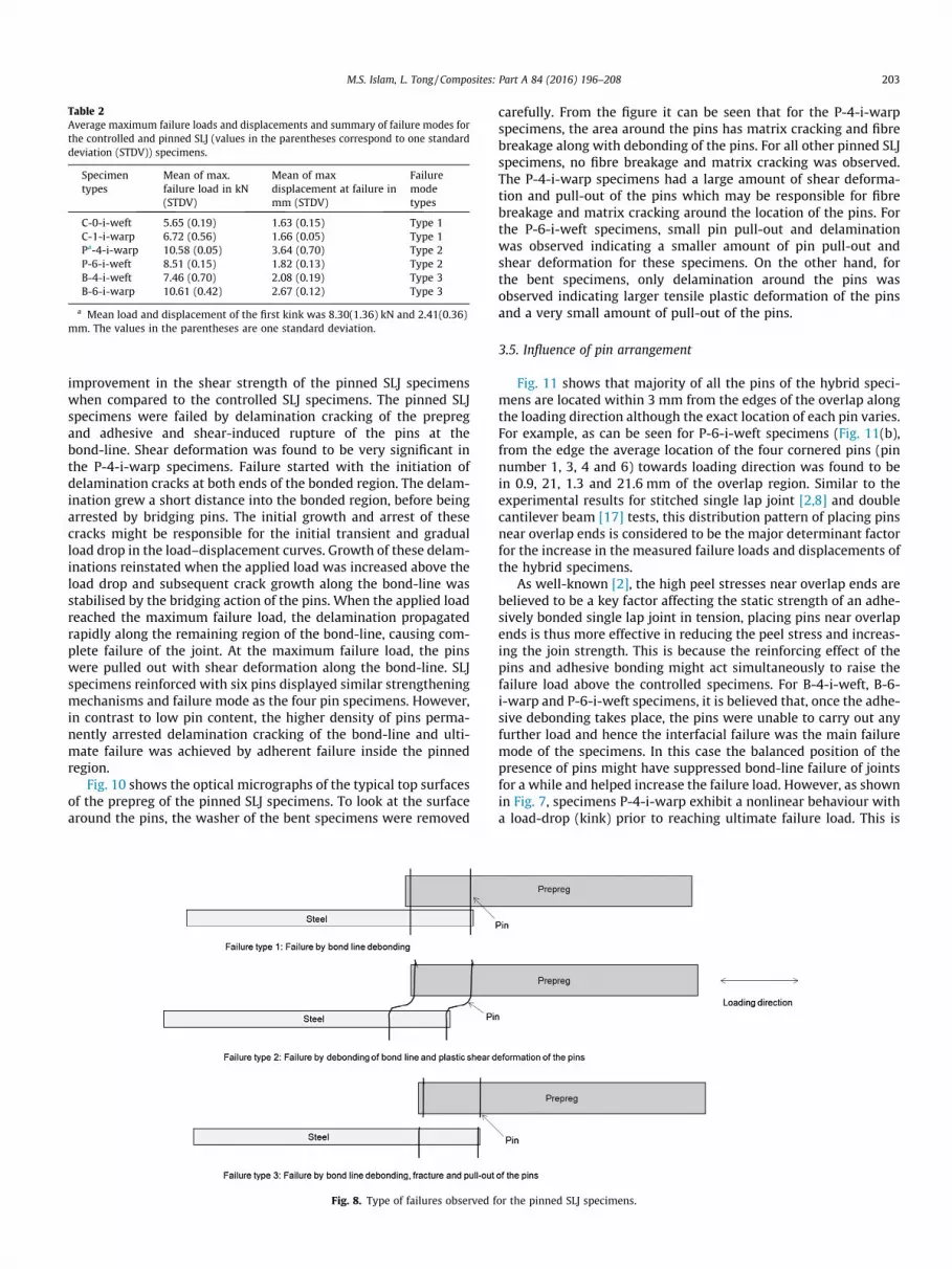
Table 2Average maximum failure loads and displacements and summary of failure modes forthe controlled and pinned SLJ (values in the parentheses correspond to one standarddeviation (STDV)) specimens.
Specimentypes
Mean of max.failure load in kN(STDV)
Mean of maxdisplacement at failure inmm (STDV)
Failuremodetypes
C-0-i-weft 5.65 (0.19) 1.63 (0.15) Type 1C-1-i-warp 6.72 (0.56) 1.66 (0.05) Type 1Pa-4-i-warp 10.58 (0.05) 3.64 (0.70) Type 2P-6-i-weft 8.51 (0.15) 1.82 (0.13) Type 2B-4-i-weft 7.46 (0.70) 2.08 (0.19) Type 3B-6-i-warp 10.61 (0.42) 2.67 (0.12) Type 3
a Mean load and displacement of the first kink was 8.30(1.36) kN and 2.41(0.36)mm. The values in the parentheses are one standard deviation.
M.S. Islam, L. Tong / Composites: Part A 84 (2016) 196–208 203
improvement in the shear strength of the pinned SLJ specimenswhen compared to the controlled SLJ specimens. The pinned SLJspecimens were failed by delamination cracking of the prepregand adhesive and shear-induced rupture of the pins at thebond-line. Shear deformation was found to be very significant inthe P-4-i-warp specimens. Failure started with the initiation ofdelamination cracks at both ends of the bonded region. The delam-ination grew a short distance into the bonded region, before beingarrested by bridging pins. The initial growth and arrest of thesecracks might be responsible for the initial transient and gradualload drop in the load–displacement curves. Growth of these delam-inations reinstated when the applied load was increased above theload drop and subsequent crack growth along the bond-line wasstabilised by the bridging action of the pins. When the applied loadreached the maximum failure load, the delamination propagatedrapidly along the remaining region of the bond-line, causing com-plete failure of the joint. At the maximum failure load, the pinswere pulled out with shear deformation along the bond-line. SLJspecimens reinforced with six pins displayed similar strengtheningmechanisms and failure mode as the four pin specimens. However,in contrast to low pin content, the higher density of pins perma-nently arrested delamination cracking of the bond-line and ulti-mate failure was achieved by adherent failure inside the pinnedregion.
Fig. 10 shows the optical micrographs of the typical top surfacesof the prepreg of the pinned SLJ specimens. To look at the surfacearound the pins, the washer of the bent specimens were removed
Fig. 8. Type of failures observed f
carefully. From the figure it can be seen that for the P-4-i-warpspecimens, the area around the pins has matrix cracking and fibrebreakage along with debonding of the pins. For all other pinned SLJspecimens, no fibre breakage and matrix cracking was observed.The P-4-i-warp specimens had a large amount of shear deforma-tion and pull-out of the pins which may be responsible for fibrebreakage and matrix cracking around the location of the pins. Forthe P-6-i-weft specimens, small pin pull-out and delaminationwas observed indicating a smaller amount of pin pull-out andshear deformation for these specimens. On the other hand, forthe bent specimens, only delamination around the pins wasobserved indicating larger tensile plastic deformation of the pinsand a very small amount of pull-out of the pins.
3.5. Influence of pin arrangement
Fig. 11 shows that majority of all the pins of the hybrid speci-mens are located within 3 mm from the edges of the overlap alongthe loading direction although the exact location of each pin varies.For example, as can be seen for P-6-i-weft specimens (Fig. 11(b),from the edge the average location of the four cornered pins (pinnumber 1, 3, 4 and 6) towards loading direction was found to bein 0.9, 21, 1.3 and 21.6 mm of the overlap region. Similar to theexperimental results for stitched single lap joint [2,8] and doublecantilever beam [17] tests, this distribution pattern of placing pinsnear overlap ends is considered to be the major determinant factorfor the increase in the measured failure loads and displacements ofthe hybrid specimens.
As well-known [2], the high peel stresses near overlap ends arebelieved to be a key factor affecting the static strength of an adhe-sively bonded single lap joint in tension, placing pins near overlapends is thus more effective in reducing the peel stress and increas-ing the join strength. This is because the reinforcing effect of thepins and adhesive bonding might act simultaneously to raise thefailure load above the controlled specimens. For B-4-i-weft, B-6-i-warp and P-6-i-weft specimens, it is believed that, once the adhe-sive debonding takes place, the pins were unable to carry out anyfurther load and hence the interfacial failure was the main failuremode of the specimens. In this case the balanced position of thepresence of pins might have suppressed bond-line failure of jointsfor a while and helped increase the failure load. However, as shownin Fig. 7, specimens P-4-i-warp exhibit a nonlinear behaviour witha load-drop (kink) prior to reaching ultimate failure load. This is
or the pinned SLJ specimens.

Fig. 9. Optical micrographs of the typical fractured surfaces of controlled (a) C-0-1-weft and pinned (b) B-6-3-warp (c) P-6-4-weft (d) B-4-1-weft and (e) P-4-1-warp SLJspecimens. (For interpretation of the references to colour in this figure legend, the reader is referred to the web version of this article.)
204 M.S. Islam, L. Tong / Composites: Part A 84 (2016) 196–208

Fig. 9 (continued)
M.S. Islam, L. Tong / Composites: Part A 84 (2016) 196–208 205
quite different from B-4-i-weft, B-6-i-warp and P-6-i-weftspecimens.
As shown in Fig. 11(d) for P-4-i-warp, specimens 1 and 2 werefound to have average pin locations (2.3, 14.3, 2.8 and 14.8) andspecimens 3 and 4 were found to have average pin locations (8.5,20.3, 4.3, 20.8) along the horizontal direction perpendicular tothe load direction in the overlap region. Specimens 1 and 2 werefound to follow a sharp initial kink and specimens 3 and 4 werefound to follow a gradual kink in the load displacement curves.However, the load was found to pick up from the kink and thespecimens were found to fail close to the average failure load ofB-6-i-warp specimens (Fig. 11(a)). The similar load–displacementcurves for specimens 1 and 2 and different load–displacementcurve for specimens 3 and 4 support the dependency of the loadon the location of the pins along the horizontal direction as wellas the distance between the two pins at each overlap end. Asshown in Fig. 11(c) and (d), the distance in horizontal directionbetween the two pins at each overlap end for P-4-i-warp is largerthan that for B-4-i-weft, in addition to the difference in the hori-
zontal distance between a pin and the nearest free overlap edge.These are also regarded as a major contributing factor to the dis-crepancy between the load–displacement curves between speci-mens B-4-i-weft and P-4-i-warp. Due to strain hardening of steelduring drilling holes in the steel plate, it was difficult to controlthe pin symmetry about the specimen centreline. However, asdiscussed above, in experimental testing minor errors in load anddisplacement was observed for centreline deviation of the locationof the pins.
3.6. Relative efficiency of mechanical fastening in hybrid joints
Since the material and geometrical parameters and loading con-ditions used in the literatures [5,6,11–13] for hybrid joints are dif-ferent, the measured failure loads and load variation due toinsertion of fastening vary significantly. Thus it is difficult to makea direct comparison amongst the reported data. Therefore, to mea-sure the efficiency of mechanical fastening in a hybrid joint and tomake a comparison amongst various hybrid joints, we introduce

Fig. 10. Optical micrographs of the typical top surfaces of the prepreg of the pinned SLJ specimens (a) B-6-3-warp (b) P-6-1-weft (c) B-4-1-weft and P-4-1-warp. (Forinterpretation of the references to colour in this figure legend, the reader is referred to the web version of this article.)
206 M.S. Islam, L. Tong / Composites: Part A 84 (2016) 196–208
the following mechanical fastening efficiency factor based on rela-tive change in measured apparent shear strength as used in ASTMstandards such as D5868:
g ¼ ðPh � PbÞðAf þ AbÞPbAf
¼ ðrh � rbÞðAf þ AbÞrbAf
where g is a factor for relative efficiency of mechanical fasteningin a hybrid joint, Ph and rh denotes the failure load or stress ofthe hybrid joint, Pb and rb represents the failure load and stressof adhesively bonded joint (with no mechanical fastening), Af
denotes the total cross sectional area of all the mechanical fasten-ers, and Ab represents the overall bonding area in a hybrid joint. Itis evident that the term ðPh � PbÞ=Pb or ðrh � rbÞ=rb represents therelative failure load or stress variation due to insertion of mechan-ical fastening in adhesively bonded joints, and the termAf =ðAf þ AbÞ denotes the ratio of the mechanical fastening area tothe overall overlap area. To certain extent this efficiency factorreflects the efficiency of mechanical fastening insertion in affectingthe failure strength because of the inclusion of percentage changes
in failure loads/strengths in the definition of the factor. It is wellknown that both peel and shear stresses are present at the endsof an overlap of a balanced or unbalanced bonded joint, such asa single lap joint under tensile loading even aligned along themid-plane of an adhesive layer or a double lap joint due to local-ized bending effect; and the pins placed at the end of an overlapplay a role in reducing peak peel and shear stresses [16]. It is alsoworth noting that the measured apparent shear strength forsingle-lap and double-lap joints contains effects of various geo-metrical and material arrangements, such as adhesive thickness,mixed peel and shear effects.
Table 3 lists the values of these four parameters and the calcu-lated efficiency factors for the present hybrid joints and othersreported in the literature. The comparison reveals that the pin dis-tribution used in this study is highly efficient in terms of the staticstrength of hybrid joints. This is because for single-lap and double-lap joints in tension, maximum peel stress occurs near overlapends. Thus it is naturally more effective to place pins or fastenersnear overlap ends to counteract the peel stress as observed in pre-vious studies [8,16,17].

0 5 10 15 20 2525
20
15
10
5
0
Location of Pins (mm)
Loca
tion
of P
ins
(mm
)
Load
ing
dire
ctio
n
Pin 3Pin 2Pin 1
Pin 6Pin 5Pin 4
B-6-1-warp B-6-2-warp B-6-3-warp B-6-4-warp
0 5 10 15 20 2525
20
15
10
5
0
Load
ing
dire
ctio
n
Pin 3Pin 2Pin 1
Pin 6Pin 5
P-6-1-weft P-6-2-weft P-6-3-weft P-6-4-weft
Loca
tion
of P
ins
(mm
)
Location of Pins (mm)
Pin 4
(a) (b)
0 5 10 15 20 2525
20
15
10
5
0
Pin 4Pin 3
Pin 2Pin 1
Load
ing
dire
ctio
n
Location of Pins (mm)
Loca
tion
of P
ins
(mm
)
B-4-1-weftB-4-2-weftB-4-3-weftB-4-4-weft
0 5 10 15 20 2525
20
15
10
5
0
Location of Pins (mm)
Loca
tion
of P
ins
(mm
)
Load
ing
dire
ctio
nPin 4Pin 3
Pin 2Pin 1
P-4-1-warp P-4-2-warp P-4-3-warp P-4-4-warp
(c) (d)
Fig. 11. Diagram for the experimental location of the pins in the overlap region of the hybrid SLJ specimens.
Table 3A list of the values of four parameters (Ph=rh; Pb=rb ;Af ;Ab) and the calculatedefficiency factor (g) for the present hybrid joints and others reported in the literature.
References Ph (kN)/rh (MPa)
Pb (kN)/rb (MPa)
Af
(mm2)Af þ Ab
(mm2)g
Present 10.61 kN 6.72 kN 0.4 625.4 854Parkes et al. [13]
(Baseline geometry)25 kN 5 kN 28.3 673.4 95
Parkes et al. [13](Alternate geometry)
32.5 kN 5 kN 28.3 673.4 131
Matsuzaki et al. [6] 6.09 MPa 3.37 MPa 12.6 512. 6 33Ucsnik et al. [11] 32.85 kN 21.5 kN 35.2 1535.2 23Kweon et al. [5] (Film
Type Adhesive)440 MPa 453 MPa 35.6 1326.0 �1
Kweon et al. [5] (PasteType Adhesive)
192 MPa 67.1 MPa 35.6 1326.0 69
Graham et al. [12] 17.43 MPa 8.76 MPa 24.4 649.4 26
M.S. Islam, L. Tong / Composites: Part A 84 (2016) 196–208 207
4. Conclusions
In this study, the failure modes and shear strength were exper-imentally determined for mild steel–glass epoxy co-bonded com-posite hybrid single-lap joints. It has been demonstrated that pinreinforcement improves the static strength of hybrid single lapjoints for steel glass fibre prepreg co-bonded composites. Themajor factor which influenced the static strength of the pinnedSLJ specimens the most was whether the GFRP prepreg was inwarp or weft direction. The dominant strengthening mechanismwas crack bridging by the specimens with six pins, whichincreased the static strength by as much as 58%. The calculated
mechanical fastening efficiency factor revealed significantly highdistribution efficiency of the selected pin arrangement in the cur-rent study. Further studies can be performed to assess the fatiguebehaviours of the pinned SLJ composites, to investigate the effectsof various geometrical and material parameters, such as adhesivethickness, pin arrangements and peak peel-shear stress mixity, aswell as surface preparation methods on failure loads and modes.
Acknowledgements
This work was undertaken as part of a CRC-ACS researchprogram, established and supported under the AustralianGovernment’s Cooperative Research Centres Program. The authorswould like to thank Dr Paul Falzon, General Manager of ACS,Australia Pty Ltd, Port Melbourne, Australia for his suggestions asProject Leader. LT would like to acknowledge the support ofAustralian Research Council (DP130103958). The authors alsothankful to Mr Michael Marelli, Senior Technical Officer ofCRC-ACS, Prestons, NSW for technical assistance and Mr TrevorShearing, Senior Technical Officer of AMME, The University ofSydney for his assistance with testing.
References
[1] Hart-Smith LJ. Bonded-bolted composite joints. J Aircraft 1985;22(11):993–1000.
[2] Tong L, Mouritz AP, Bannister MK. 3D fiber reinforced polymercomposites. Oxford, UK: Elsevier; 2002.
[3] Fu M, Mallick PK. Fatigue of hybrid (adhesive/bolted) joints in SRIMcomposites. Int J Adhes Adhes 2001;21:145–59.
[4] Kelly G. Load transfer in hybrid (bonded/bolted) composite single-lap joints.Compos Struct 2005;69:35–43.

208 M.S. Islam, L. Tong / Composites: Part A 84 (2016) 196–208
[5] Kweon J-H, Jung J-W, Kim T-H, Choi J-H, Kim D-H. Failure of carbon composite-to-aluminum joints with combined mechanical fastening and adhesivebonding. Compos Struct 2006;75(1–4):192–8.
[6] Matsuzaki R, Shibata M, Todoroki A. Improving performance of GFRP/Aluminum single lap joints using bolted/co-cured hybrid method. Compos AAppl Sci Manuf 2008;39:154–63.
[7] Tong L. Bearing failure of composite bolted joints with non-uniform bolt-to-washer clearance. Compos A Appl Sci Manuf 2000;31(6):609–15.
[8] Tong L, Jain LK, Leong KH, Kelly D, Hertzberg I. Failure of transversely stitchedRTM lap joints. Compos Sci Technol 1998;58(2):221–7.
[9] Chang P, Mouritz AP, Cox BN. Tensile properties and failure mechanisms of z-pinned composite lap joints. Compos Sci Technol 2006;66:2163–76.
[10] Cartie DDR, Dell Anno G, Poulin E, Partridge IK. 3D reinforcement of stiffener-to-skin t-joints by z-pinning and tufting. Eng Fract Mech 2006;73:2532–40.
[11] Ucsnik S, Scheerer M, Zaremba S, Pahr DH. Experimental investigation of anovel hybrid metal-composite joining technology. Compos A Appl Sci Manuf2010;41:369–74.
[12] Graham DP, Rezai A, Baker D, Smith PA, Watts JF. The development andscalability of a high strength, damage tolerant, hybrid joining scheme forcomposite–metal structures. Compos A Appl Sci Manuf 2014;64:11–24.
[13] Parkes PN, Butler R, Meyer J, de Oliveira A. Static strength of metal-compositejoints with penetrative reinforcement. Compos Struct 2014;118:250–6.
[14] Yang L, He XD, Mei L, Tong L, Wang RG, Li YB. Interfacial shear behavior of 3Dcomposites reinforced with chemically connected CNTs. Compos A Appl SciManuf 2012;43(8):1410–8.
[15] Tong L, Sun X, Tan P. Effect of long multi-walled carbon nanotubes onenhancing delamination toughness of laminated composites. J Compos Mater2008;42(1):5–23.
[16] Tong L, Steven GP. Analysis and design of structural bonded joints. Boston,USA: Kluwer Academic Publishers; 1999.
[17] Wood MD, Sun X, Tong L, Kaltzos A, Rispler A, Mai Y-W. Effect of stitchdistribution on mode I delamination toughness of stitched laminatedcomposites – experimental results and simulation. Compos Sci Technol2007;67(6):1058–72.
[18] Islam MS, Tong L, Falzon PJ. Influence of metal surface preparation on itssurface profile, contact angle, surface energy and adhesion with glass fibreprepreg. Int J Adhes Adhes 2014;51:32–41.


