Embed Size (px)
Citation preview
Physica B 160 (1989) 204-210
North-Holland. Amsterdam
INELASTIC NEUTRON
Roger PYNN
SCATTERING WITH POLARIZATION ANALYSIS
Los Alamos Neutron Scattering Center, Los Alamos National Laboratory, Los Alamos, NM 8754.5, USA
Jean-Paul BOUCHER and Louis-Pierre REGNAULT Department de Recherche Fondamentale, Service de Physique, Groupes DSPE et MDN,
Centre d’Etudes Nucleaires de Grenoble, 85X, 38041 Grenoble Cedex, France
Received 16 February 1989
This paper is dedicated to the memory of Wally Koehler, one of the pioneers of the technique of neutron polarization analysis
Advances in neutron technology made during the past decade have permitted neutron inelastic scattering experiments to
be performed with full polarization analysis. The power of this technique for the identification of components of dynamic
spin fluctuations in magnetic systems is illustrated in this presentation by two experiments on the one-dimensional, x-y
antiferromagnet TMMC. In one experiment, spin fluctuations due to rr-solitons were measured for the first time and
information was obtained on soliton-soliton collision processes. In the other, a theory which apparently described
finite-energy magnetic excitations measured with unpolarized neutrons was shown to be deficient. Both of these
experiments were carried out at the Institut Laue-Langevin in Grenoble, France.
1. Introduction
In a seminal paper published in 1969, Moon, Riste and Koehler [l] described the technique of neutron polarization analysis. They also pre- sented experimental examples of the application of this technique to nuclear and magnetic scatter- ing of elastic and inelastic origin. At the time, the Oak Ridge reactor, where the work was performed, was the world’s highest flux source. Furthermore, the authors used the best available polarizers and flippers. Yet it was clear that, even for the demonstration experiments they presented, the count rates were very low. Thus, although the new technique was potentially very powerful, it was of limited practical use, and could not be applied, for example, to inelastic scattering where signals are weak.
In the intervening years new polarizers and flippers have been developed which permit the technique of polarization analysis to be exploited for both elastic and inelastic scattering of cold and thermal neutrons. Some of these advances will be described in this article. To demonstrate
the power of the technique we will describe experiments with the one-dimensional, x-y anti- ferromagnet TMMC. In all of these experiments polarization analysis was used to identify the fluctuating component of the magnetization which was responsible for the observed neutron inelastic scattering.
2. Recent advances in polarizers and flippers
There are three techniques which can be used to polarize a neutron beam, two of which offer polarization over a broad wavelength band while the third provides simultaneous polarization and monochromatization. The first of the broad band techniques, which we will not describe here in detail, involves filters which absorb one of the neutron spin states [2]. The second method in- volves the reflection of neutrons of one spin state by a magnetized mirror [3] or supermirror [4]. Devices based on the supermirror technology have made it possible to carry out routinely
0921-4526/89/$03.50 0 Elsevier Science Publishers B.V. (North-Holland Physics Publishing Division)
Roger Pynn et al. I Inelastic neutron scattering with polarization analysis
inelastic scattering experiments with polarization analysis using cold neutrons (neutrons of wave- length greater than 4 A or energy less than 5 meV).
To understand how supermirrors work it is simplest to consider first mirror reflection of neutrons from the surface of a magnetized ma- terial. The critical angle of reflection, below which neutrons are reflected from the surface, is given by
7’ = h(Nbl2n T m/_&(B - H) lh2)1’2 ) (1)
where Nb is the mean coherent scattering length density; A, m and p are the wavelength, mass and magnetic moment of the neutron respective- ly, and B is the magnetic induction of the mirror in an applied field H. In eq. (1)) y: is the critical angle for neutrons whose magnetic moment is parallel to B while r, is the angle for antiparallel alignment. Both values of -y, are small (~0.5” for
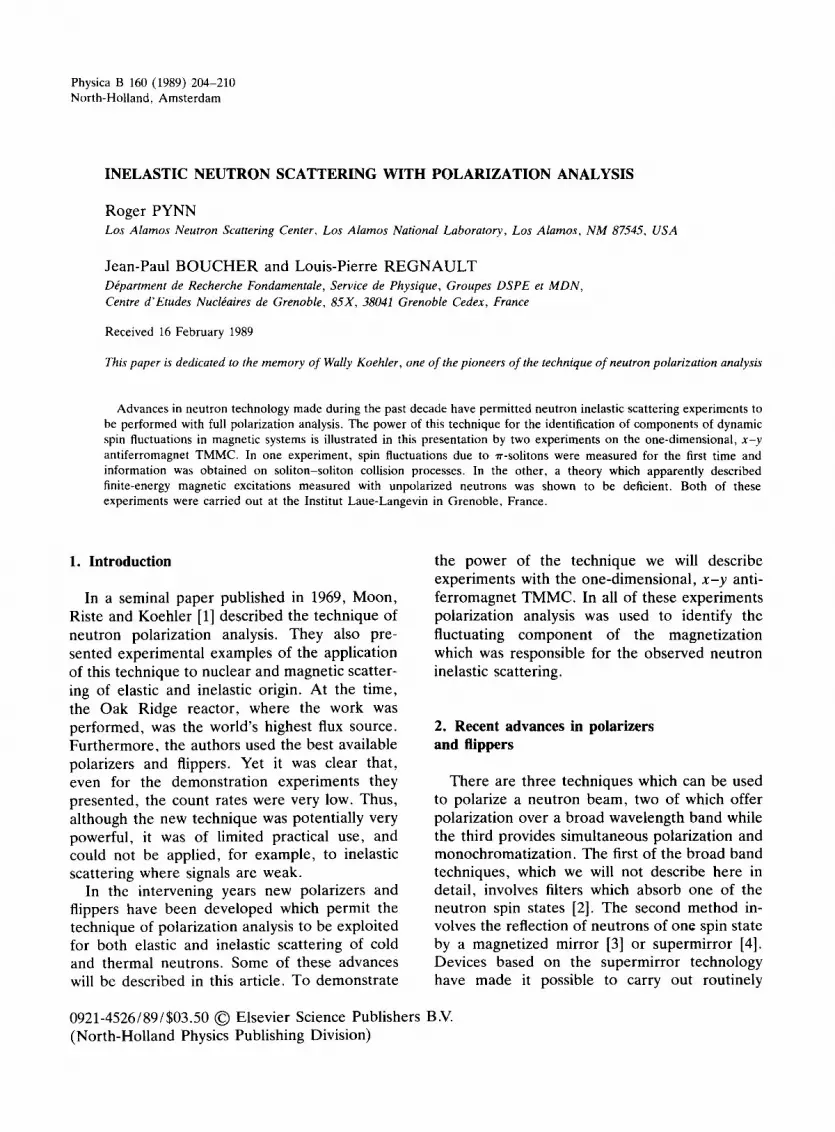
5 A neutrons) as a result of the weak interaction between neutrons and matter. However, by judi- cious choice of materials, the critical angle -yI may be made to approach zero while -y, remains finite. In this case, a beam of neutrons which is perfectly reflected by the surface will be polar- ized because only the state for which the neutron moment is antiparallel to B will be reflected. An example of this behaviour is shown in fig. la for a magnetized FeCo mirror.
The practical disadvantage of mirror polarizers is the small value of 7;. Only a well collimated beam of neutrons can be polarized. This often results in an intensity penalty because the colli- mation is better than is really necessary. To increase the critical angle Mezei [4] and, in- dependently, Turchin [5] suggested the concept of a supermirror. By depositing a sequence of bilayers of appropriate materials on a substrate, increased values of y, can be achieved because there is constructive interference between neu- trons reflected at the various interfaces. Using this technique with iron and silver, Mezei was able to obtain the reflectives shown in fig. lb for neutrons with moments aligned parallel and anti- parallel to the applied field. Evidently, although rz has been increased by this technique, y ,’ is
b)
O/A(deg/A) -
J 0 a05 01 a15 ax ,
Wk!deg/Al-
Fig. 1. Spin up (0) and spin down (0) reflectivity of various polarizing mirrors as a function of 0/h (0 = scattering angle; A = neutron wavelength) measured with 7A neutrons by Schkpf (private communication). (a) FeCo alloy mirror; (b) 80 layer FeAg supermirror; (c) 80 layer CoTi supermirror.
now also finite, again making a device made from an FeAg supermirror difficult to use in practice. The real breakthrough in this technolo- gy was the construction by Scharpf [6] of CoTi supermirrors whose reflectivities are demon- strated in fig. lc. For these devices the value of y, has been increased bv a factor of more than two with respect to the simple mirrors and 7,’ is essentially zero. The “trick” used by Scharpf involves the evaporation of an antireflecting layer of Ti and Gd on the substrate before the supermirror coating is applied. This underlayer has a critical angle which is approximately zero so that the neutrons whose moments are parallel to B, which are not reflected by the supermirror coating, penetrate the antireflecting layer. There they are absorbed by the gadolinium.
Schirpf’s supermirrors provided the technical advance which made neutron polarization effi- cient at long wavelengths. However, even though the critical angle of such supermirrors is relatively large, an inconveniently long mirror would be required to polarize a wide beam of neutrons. To overcome this, a number of thin glass plates, coated with supermirror on both

206 Roger Pynn et al. I Inelastic neutron scattering with polarization analysis
sides, are arranged side-by-side to produce a device which resembles a Soller collimator whose blades are curved to avoid direct line of sight. For neutrons to traverse this so-called “bender” they must suffer at least one reflection. The device, mounted in a modest magnetic field of a few hundred oersteds, functions as an efficient transmission polariser which, when added to a traditional neutron spectrometer, immediately permits the implementation of polarization anal- ysis. For neutrons of wavelength -4 8, the neu- tron polarization achieved is close to 100% and the transmission for the required neutron spin state is -70% for beams collimated to -60’ (FWHM). A bender of this type, mounted on the cold-neutron, three-axis spectrometer IN12 at the Institut Laue-Langevin, was used for the soliton experiment described below.
Another polarizing device which has been sub- stantially improved in recent years is the Heusler alloy monochromator. Work by Freund et al. [7] showed that good quality crystals of Cu,MnAl Heusler alloy could be grown. When this materi- al is appropriately magnetized, only neutrons whose moments are parallel to the applied field can be Bragg reflected by (111) planes. Such reflection therefore provide simultaneous mono- chromatization and polarization of neutron beams. The device shown in fig. 2 is the Heusler alloy monochromator mounted on the thermal- neutron, three-axis spectrometer IN20 at ILL. Each of the seven rectangular Heulser crystals is 75 mm long, 17 mm high and 3 mm thick. The crystals are mounted on horizontal spindles which pierce the poles of a theta-frame magnet. Blocks of SmCo, provide a horizontal field of -1 kOe to magnetize the Heusler crystals. A cam-driven device in the center of the mono- chromator turret allows the crystals to be rotated slightly about their horizontal axes to produce a curvature of the monochromator and hence a focussing of the reflected neutron beam in the vertical direction. For neutrons of energy 14.8 meV, collimated horizontally to 40’ FWHM, the device shown in fig. 2 provides a neutron intensity at the sample position of about 10’ cm-’ s -’ on the IN20 spectrometer.
The flipper used by Moon, Riste and Koehler
Fig. 2. Monochromator unit for the IN20, thermal-neutron,
three-axis spectrometer at ILL. The turret usually supports
four different 120 mm high monochromators (pyrolytic
graphite, copper ( 1 1 1) , copper (0 0 2) and Heusler ( 1 1 1) )
each of which may be vertically focussed by the mechanism in
the center of the turret. Only the Heusler monochromator
has been installed for this photograph. The theta-frame
SmCo, magnet which provides a horizontal field on this
momochromator is covered by B,C neutronic shielding.
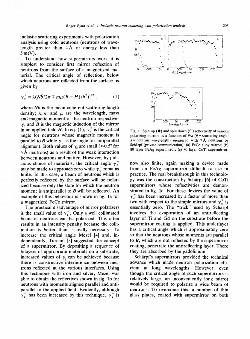
[l] was a radio-frequency device which was both cumbersome and expensive. Today this would be replaced either by a cryo-flipper [8] or by the simple spin-turn coil shown in fig. 3. The coil is placed in a vertical (z) guide field which is used to maintain the polarization of the neutron beam. The currents in the windings are adjusted so that the guide field is cancelled within the coil and an appropriate field is imposed in the horizontal ( y) direction. This field has a theoreti-
Roger Pynn et al. I Inelastic neutron scattering with polarization analysis 207
neutron beam
Fig. 3. Flat coil DC flipper. The unit is usually placed in a guide field directed along the z-axis and one coil is tuned to cancel the guide field within the flipper. A field along y, generated by the remaining coil, causes the neutron spin to undergo a Larmor precession of n radians within the flipper. Thus neutrons with spins directed along fz before the flipper, have spins along ?z after it.
cal magnitude of
H,, = 67.825
@I d km1 Oe (2)
so that neutrons of wavelength A (A) undergo a Larmor precession of exactly n radians during their passage through the flipper. Although spin- turn coils of the type shown in fig. 3 can some- times be difficult to tune if there is a large stray field from sample-environment equipment, they usually provide a simple way of achieving flip- ping efficiencies of 99% or more for mono- chromatic neutron beams.
3. Rules for neutron polarization analysis
In order to understand the power of the tech- nique of neutron polarization analysis it is well to recall the “rules” which govern the method [l]. To define the spin direction of neutrons during a scattering process a magnetic guide field, which need not be more than a few oersteds, must be applied to the neutron beam. Depending on the nature of the scattering process, the neutron spin (which is antiparallel to its magnetic moment) either retains its orientation with respect to the applied field or is reversed. Scattering events for which the spin is reversed are referred to as
spin-flip processes whereas those for which the spin direction remains unchanged are non-spin- flip.
The rules are: (i) nuclear coherent scattering is always non-spin-flip as is scattering which results from isotopic incoherence; (ii) nuclear incoher- ent scattering causes the spins of $ of scattered neutrons to be flipped; (iii) neutrons are mag- netically scattered by spatial and temporal fluc- tuations in the magntisation M of a sample. Because the coupling between the neutron mag- netic moment and the sample magnetization is dipolar in origin, only the component, M,, of the magnetization which is perpendicular to the neutron momentum change hQ is effective in scattering; (iv) fluctuations of M, which are par- allel to the magnetic field, H, applied to the sample cause non-spin-flip scattering, whereas fluctuations perpendicular to H give rise to spin- flip scattering.
For the problems to be described below, in which only magnetic scattering is relevant, the technique of neutron polarization analysis thus provides a method of distinguishing between magnetization fluctuations in different directions. In particular, when non-spin-flip magnetic scat- tering is observed, only magnetization fluctua- tions parallel to the field applied to the sample can be responsible. Since the method may be applied on many existing types of neutron spec- trometers, it is often possible to measure simul- taneously the energy and wavevector depen- dence of the magnetic fluctuation spectrum as well as the Cartesian components of fluctuating magnetization which are responsible for the scat- tering.
4. Solitons in TMMC
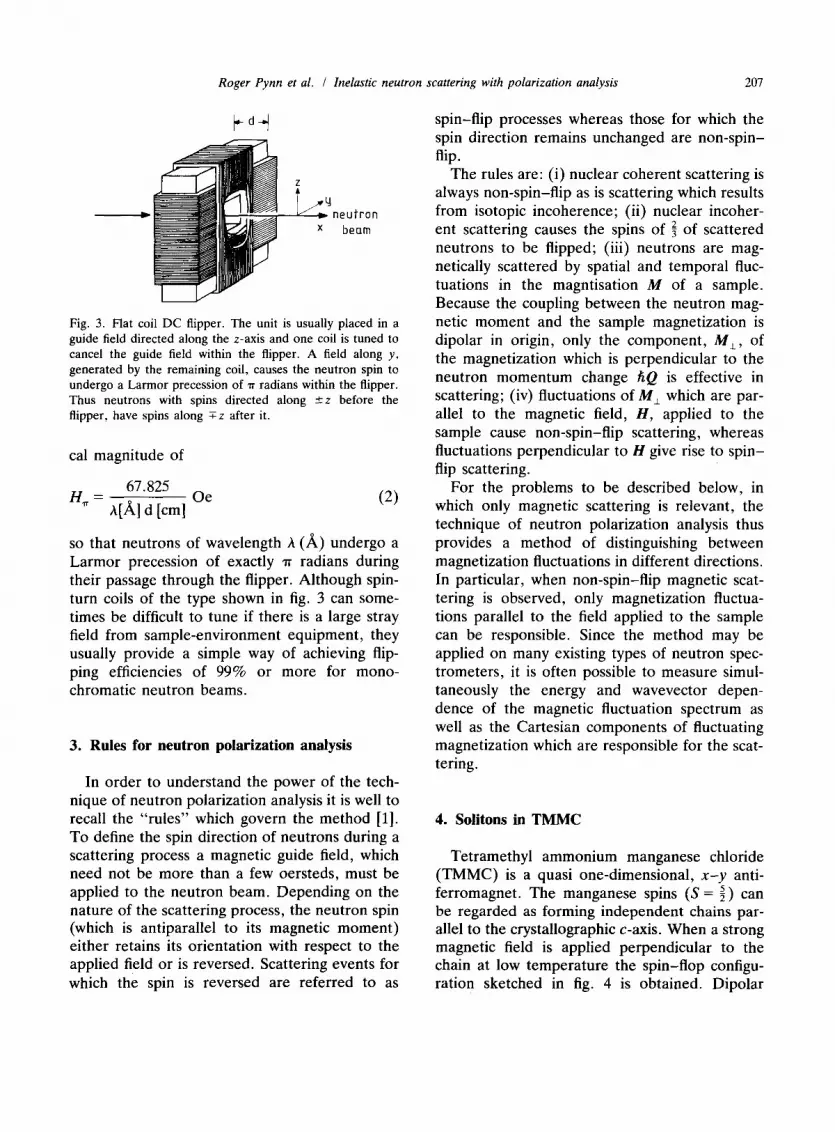
Tetramethyl ammonium manganese chloride (TMMC) is a quasi one-dimensional, x-y anti- ferromagnet. The manganese spins (S = 2 ) can be regarded as forming independent chains par- allel to the crystallographic c-axis. When a strong magnetic field is applied perpendicular to the chain at low temperature the spin-flop configu- ration sketched in fig. 4 is obtained. Dipolar
208 Roger Pynn et al. I Inelastic neutron scattering with polarization analysis
Fig. 4. Cartesian coordinate system used for the TMMC
experiments. The arrows represent a chain of manganese
spins which have been forced into the spin-flop configuration
by the applied field H. The scattering vector Q is contained in
the y-z-plane.
interactions between spins guarantee that they remain in the x-y-plane. The spin configuration depicted in fig. 4 gives rise to magnetic Bragg peaks at odd multiples of IT/C when neutrons are diffracted from TMMC. If the temperature of the system is raised, topological excitations, known as solitons, may be excited. These objects which are depicted schematically in fig. 5, may be thought of as mobile domain walls separating regions in which the magnetic sublattices are interchanged. Since the solitons destroy long- range order they cause magnetic Bragg reflec- tions to have a finite momentum width. Their movement introduces an energy width to the Bragg peaks. Both of these widths have been measured by neutron scattering [9] at a variety of temperatures and applied fields and the soliton model has been found to describe the results with remarkable accuracy. Nevertheless, meas- urements of magnetic Bragg peaks record only the effect of solitons on long-range magnetic order and do not constitute observation of the solitons themselves. In the geometry depicted in fig. 4, long-range magnetic order occurs in the
Fig. 5. Schematic illustration of a n-soliton in an anti-
ferromagnetic chain.
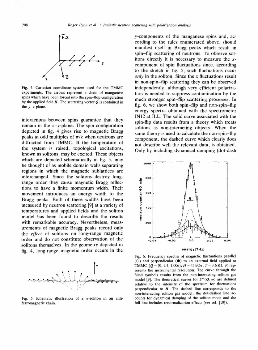
y-components of the manganese spins and, ac- cording to the rules enumerated above, should manifest itself in Bragg peaks which result in spin-flip scattering of neutrons. To observe sol- itons directly it is necessary to measure the X- component of spin fluctuations since, according to the sketch in fig. 5, such fluctuations occur only in the soliton. Since the x fluctuations result in non-spin-flip scattering they can be observed independently, although very efficient polariza- tion is needed to suppress contamination by the much stronger spin-flip scattering processes. In fig. 6, we show both spin-flip and non-spin-flip energy spectra obtained with the spectrometer IN12 at ILL. The solid curve associated with the spin-flip data results from a theory which treats solitons as non-interacting objects. When the same theory is used to calculate the non-spin-flip component, the dashed curve which clearly does not describe well the relevant data, is obtained. Only by including dynamical damping (dot-dash
.E E
-0.04 -0.02 0.0 0.02 0.04
energy(THz)
Fig. 6. Frequency spectra of magnetic fluctuations parallel (0) and perpendicular (0) to an external field applied to
TMMC (Q = (0, 1.4,1.006); H = 45 kOe; T= 3.6 K). R rep-
resents the instrumental resolution. The curve through the
filled symbols results from the non-interacting soliton gas
model [9]. The theoretical curves for S’“(Q, w) are defined
relative to the intensity of the spectrum for fluctuations
perpendicular to H. The dashed line corresponds to the
non-interacting soliton gas model, the dot-dashed line ac-
counts for dynamical damping of the soliton mode and the full line includes renormalization effects (see ref. [lo]).
Roger Pynn et al. I Inelastic neutron scattering with polarization analysis 209
curve) and renormalization effects (solid curve) can the non-spin-flip scattering be explained adequately [lo]. The main lesson to be drawn from fig. 6, is that polarization analysis is the only technique which allows Bragg and soliton scattering to be separated in TMMC. For any spin system in which fluctuations in different directions involve different dynamics, polariza- tion analysis is an essential tool.
5. Finite energy excitations in TMMC
In 1981 Heilmann et al. [ll] published the results of a study of collective magnetic excita- tions in TMMC which had been carried out with unpolarized neutrons. When a field of 7 tesla was applied perpendicular to the chain axis, these authors were able to measure the dispersion relations of two excitation branches. When the magnetic field was increased, as many as four well-defined excitations were observed at the magnetic zone centre. Two of these modes are spin waves: one corresponds to spin fluctuations in the x-direction of fig. 4, and is called the in-plane mode (IPM) while the other involves z- fluctuations and is the out-of-plane mode (OPM). The two additional modes observed by Heilmann et al. were interpreted as double mag- non modes. A detailed theory of double magnon excitations was developed by Osano et al. [12] who showed that, at high fields, one such mode was expected to involve spin fluctuations along the y-axis of fig. 4, while the other was predicted to manifest predominantly z-fluctuations. Al- though Heilmann et al. tried to identify the fluctuating spin components associated with each of the modes they observed, unpolarized neutron scattering is not well-suited to this task. Without polarization analysis the only recourse is to ob- serve the change of intensity of modes as a function of QY. As QY is varied at constant Q,, the mode energies are unchanged as a result of the one-dimensional magnetic properties of TMMC. However, the relative contributions of y- and z-fluctuations to the scattering do change (c.f. section 3 above), allowing, in principle at least, discrimination of different components of
the spin fluctuations. In practice this method of separation of spin components is complicated by changes of the magnetic form factor and the instrumental resolution as QY varies. When the observed scattering is weak the method may be completely unreliable.
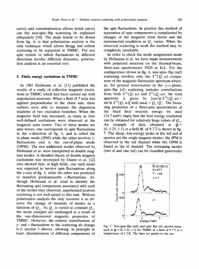
In order to check the mode assignments made by Heilmann et al. we have made measurements with polarized neutrons on the thermal-beam, three-axis spectrometer IN20 at ILL. For the configuration shown in fig. 4, non-spin-flip (nsf) scattering involves only the SXX( Q, w) compo- nent of the magnetic fluctuation spectrum where- as, for general wavevectors in the y-z-plane, spin-flip (sf) scattering includes contributions from both Syy( Q, w) and SZZ( Q, 0): the total spectrum is given by [co& Syy( Q, w) + sin24 ,Y( Q, o)] with tan4 = Q,/Q,. The focus- sing properties of a three-axis spectrometer at the fixed final neutron energy we used (14.7 meV) imply that the best energy resolution can be obtained for relatively large values of Qy . An example of data obtained at Q = (0,1.25,1.1) in a field H, of 9.7 T is shown in fig. 7. The sharp, low-energy peaks in the nsf and sf spectra are the single magnon modes: the IPM is observed in the nsf channel while the OPM is found in the sf channel. The remaining modes (two sf and one nsf) can be classified generically
2 3 Energy (meV)
Fig. 7. Non-spin-flip (nsf) and spin-flip (sf) spectra meas-
ured at Q = (0,1.25,1.1) for TMMC in a field of 9.7 T at a temperature of 1.5 K. The lines are guides to the eye.

210 Roger Pynn et al. I Inelastic neutron scattering with polarization analysis
z 3 750- .r
n.s.f. + s.f.
E z SOO- t
‘t
$ ’ t z 250- + + E 4 +
* z
..‘.. ~~*‘b*~( ,(,( b+*+n.b .,...
0 0
1 2 3
Energy(meV)
Fig. 8. The sum of the sf and nsf cross sections displayed in
fig. 7. This is the result which would be obtained without
polarization analysis.
as multi-magnon excitations. In fact the two modes seen in the sf channel correspond to those predicted by the theory of Osano et al. [12] while the mode observed at a2.3 meV in the nsf chan- nel in fig. 7 is absent from current theories. To explain the mode requires, in fact, a detailed analysis of non-linear terms in the equations of motion for spins in a planar antiferromagnet
[131. It is not at all obvious which of the multimag-
non modes were observed by Heilmann et al. To illustrate the problem, we show in fig. 8 the sum of the nsf and sf spectra depicted in fig. 7. This would be the result of an experiment carried out with unpolarized neutrons. Clearly it is not even possible to tell that the OPM and IPM single magnon modes have different energies and only two multimagnon excitations are apparent in the figure rather than the three displayed in fig. 7. Furthermore, the energies ascribed to the mul- timagnon excitations in an experiment with un- polarized neutrons are incorrect, rendering com- parison with theory of dubious value.
6. Conclusions
The experiments described above demonstrate that polarization analysis is an essential tool in the investigation of magnetic fluctuations in anisotropic materials. Since neutron spectrome- ters capable of implementing this technique have only recently become available, we expect a plethora of new results. Some of these, like the experiments described here, will apply to prob- lems which have already been well-studied with unpolarized neutrons and which have, ostensibly at least, been understood.
References
[II
PI
[31
[41
Ul
[61
[71
@I
[91
[lOI
Ull
[I21
[I31
R.M. Moon, T. Riste and W.C. Koehler, Phys. Rev.
181 (1969) 920.
For a review see, J.B. Hayter, in: Neutron Diffraction,
H. Dachs, ed. (Springer, Berlin, 1978).
J.B. Hayter, J. Penfold and W.G. Williams, J. Phys. E
11 (1978) 4.54.
F. Mezei, Commun. Phys. 1 (1976) 8;
F. Mezei and P. Dagleish, Commun. Phys. 2 (1977) 41.
V.F. Turchin, Deposited Papers, USSR Atomic Energy
(1967) p. 22.
0. Scharpf, A.I.P. Conf. Proc. No. 89, Neutron Scatter-
ing, John Faber, ed. (AIP, New York, 1981).
A. Freund, R. Pynn, W.G. Stirling and C.M.E. Zeyen,
Physica B 120 (1983) 86.
F. Tasset, Physica B 156 & 157 (1989) 627.
L.P. Regnault, J.P. Boucher, J. Rossat-Mignod, J.P.
Renard, J. Bouillot and W.G. Stirling, J. Phys. C 15
(1982) 1261.
J.P. Boucher, L.P. Regnault, R. Pynn, J. Bouillot and
J.P. Renard, Europhys. Lett. 1 (1986) 415.
I.U. Heilmann, J.K. Kjems, Y. Endoh, G.F. Reiter and
G. Shirane, Phys. Rev. B 24 (1981) 3939.
K. Osano, H. Shiba and Y. Endoh, Prog. Theor. Phys.
(Kyoto) 67 (1982) 995.
3.P. Boucher, R. Pynn, L.P. Regnault and M. Re-
moissenet, Phys. Rev. Lett. (submitted).


