Embed Size (px)
Citation preview

July 3, 2013 9:56 WSPC/Guidelines-IJMPB S0217979213300132
International Journal of Modern Physics BVol. 27, No. 19 (2013) 1330013 (28 pages)c© World Scientific Publishing Company
DOI: 10.1142/S0217979213300132
INDUCED MAGNETISM AT OXIDE INTERFACES
JACOBO SANTAMARIA∗, JAVIER GARCIA-BARRIOCANAL,ZOUHAIR SEFRIOUI and CARLOS LEON
GFMC, Departamento Fisica Aplicada III, Universidad Complutense Madrid
28040 Madrid, Spain∗[email protected]
Received 13 June 2013Accepted 14 June 2013Published 3 July 2013
Interfaces between correlated oxides are attracting great interest. Electron correlationsgive rise to novel forms of couplings between electronic ground states at both sides ofthe interface. The bonding discontinuity at the interface between magnetic and nonmag-netic oxides is at the origin of a form of low dimensional magnetism in the otherwisenonmagnetic material. Its origin is the splitting of its bands due to the hybridizationwith the exchange split bands of the magnetic material. This induced magnetism couldfind interesting functionalities in devices with operation controlled by the interface suchas tunnel or field effect devices of interest in spintronics.
Keywords: Oxide interfaces; magnetism; superconductivity.
PACS numbers: 73.20.-r, 75.70.Ch, 74.78.Fk
1. Introduction
Complex transition metal oxides are a wide family of materials which contain
elements with incomplete d shells, what gives rise to different forms of magnetic
interactions. Almost every electronic or lattice groundstate of solid matter can be
found including superconductivity, ferromagnetism, antiferromagnetism, ferroelec-
tricity, multiferroicity etc.1,2 Distinct members of this class of materials are high Tc
superconductors and colossal magnetoresistance manganites which have gathered
one of the strongest research efforts in the history of science in terms of number
and impact of research articles and number of researchers involved. Many complex
oxides share a common perovskite structure where the basic building block is the
oxygen octahedron surrounding the transition metal ion. The strong crystal (elec-
tric) field generated by the oxygen ions act on the otherwise 5 fold degenerate d
levels of the transition metal ion splitting them in eg and t2g levels which are double
and triple degenerate respectively. d orbitals are directional and their overlap me-
diated by the oxygen p orbitals is weak what yields the narrow d bands with large
1330013-1
Int.
J. M
od. P
hys.
B 2
013.
27. D
ownl
oade
d fr
om w
ww
.wor
ldsc
ient
ific
.com
by 2
07.9
7.22
6.12
8 on
06/
22/1
4. F
or p
erso
nal u
se o
nly.

July 3, 2013 9:56 WSPC/Guidelines-IJMPB S0217979213300132
J. Santamaria et al.
effective masses. Electrons have thus low mobilities and strongly feel the lattice giv-
ing rise to the strong electron lattice coupling (Jahn–Teller) which may further split
the degeneracy of crystal field levels. But more importantly, narrow and directional
bands poorly screen the electrostatic repulsion between electrons. The unscreened
Coulomb interaction gives rise to strong correlations in the electron system.2 As a
result, the electronic properties cannot be described within conventional one elec-
tron band pictures. In a system with one electron per site, expected to be a metal in
the one electron band theory of solids, the electrostatic repulsion opens a gap at the
Fermi energy. This is the so called Mott gap. Strong electron correlations underlie
the strong entanglement between the various interactions in these materials with a
multiplicity of competing phases with similar characteristic energies. This is prob-
ably at the origin of the rich phase diagrams and of the inhomogeneous ground
states displayed by many transition metal oxides.3 Most likely this competition
between interactions also underlies the complex (often giant) collective responses
exhibited by these materials upon small perturbations whose understanding and
prediction remains a major challenge of condensed matter physics for the years to
come.4
In recent years there has been a lot of activity directed to the growth of het-
erostructures combining complex transition metal oxides. The strongly correlated
nature of the conduction electrons underlying the interplay between the various
degrees of freedom is at the origin of the rich variety of new effects and phenomena
found at oxide interfaces. The fabrication technique of these oxide heterostructures
has reached a level of control comparable to the semiconductor technology and in-
terfaces can be grown with atomic precision allowing the lattices with dissimilar
materials to match with a high degree of crystalline perfection. Much in the same
way than in the history of semiconductor devices, where interesting effects and
phenomena and even novel states of matter have been found at their rather inert
interfaces, oxide interfaces constitute an appealing playground for the exploration
of exciting new physics.5,6 The broken symmetry at the interface between dissim-
ilar correlated oxides underlies the nucleation of emergent electronic phases with
unexpected properties far from those of the constituent oxides. Charge density n,
repulsion energy U , and band width W , the important parameters critically control-
ling the properties of correlated oxides are known to vary at interfaces providing
interesting avenues to tailor their electronic structure. On the one hand, charge
density is known to leak across interfaces as the result from differences between
electrochemical potentials, varying smoothly across the interface over the Thomas
Fermi screening length. Repulsive interaction U is also known to depend critically
on the ionic environment and band width W is controlled by bond reconstruction
(length and angle) at the interface. Since many of these oxides are doped insulators
in the vicinity of a metal to insulator transition, the charge density profile at the
interface has a critical influence in nucleating novel phases at (the most stable) indi-
vidual values in a process called electronic reconstruction.7 Furthermore, since not
only n but also U and W change at the interface lattice discontinuity, novel phases
1330013-2
Int.
J. M
od. P
hys.
B 2
013.
27. D
ownl
oade
d fr
om w
ww
.wor
ldsc
ient
ific
.com
by 2
07.9
7.22
6.12
8 on
06/
22/1
4. F
or p
erso
nal u
se o
nly.

July 3, 2013 9:56 WSPC/Guidelines-IJMPB S0217979213300132
Induced Magnetism at Oxide Interfaces
nucleate at individual values of n, U and W with unexpected spin and conducting
properties in a more general scenario named electronic metamorphosis.5
A paradigmatic example of unexpected electronic states appearing at oxide
interfaces is the metallic low dimensional electronic state at the LAO/STO interface
between two band insulators.8,9 It has been proposed that electrons are transferred
to the interface as the result of the polarity mismatch between the (100) planes of
the LAO (polar) and the STO (nonpolar). Within this scenario, charge is transferred
from the surface of the LAO to the interface to avoid divergence of the electrostatic
energy stored in the LAO when its thickness is increased.10,11 Alternative scenarios
have been proposed related to the presence of oxygen vacancies12–15 or to intermix-
ing processes16–18 which dope the interface layer with electrons. The carrier density
of the 2D electron gas is electrically tuneable19,20 and its ground state can be con-
trolled to change from superconducting21 to (ferro) magnetic22 just by changing the
carrier density. This finding has triggered the launch of a truly new research field
aimed at designing and controlling the electronic structure at the interfaces. The
wide variety of possibilities offered by oxide interfaces to stabilize new electronic
ground states holds an appealing technological promise of new device concepts,
which relies on being able to manipulate and control them with external stimuli.
At interfaces the discontinuity in the bonding structure may result in interesting
forms of interfacially induced magnetism. The rationale is as follows. At interfaces
between magnetic and nonmagnetic species, induced moments due to hybridiza-
tion become important in the ultrathin limit when layer thickness is comparable
to lattice spacing. The antecedents to these magnetically induced moments are
found in the field of metallic superlattices. At the interface between transition met-
als the electron gas of the nonmagnetic element is spin polarized via an indirect
exchange interaction, which has an oscillatory character. This is the interaction
responsible for the oscillatory coupling of metallic superlattices exhibiting giant
magnetoresistance.23 There are three important length scales involved. When the
thickness of the nonmagnetic spacer is of the order of or smaller than its electron
mean free path, spin dependent scattering originates the giant magnetoresistance.
Its magnitude is influenced by interface roughness due to spin dependent scattering
at the interface.24–29 Oscillatory coupling itself evolves with the inverse of the Fermi
wave vector. On the other hand, when the thickness on the spacer metal becomes
comparable to lattice spacing a different mechanism comes into play related to the
hybridization between the bands of both species. XMCD experiments have supplied
evidence for this form of induced magnetism at interfaces between 3d ferromagnets
(Fe, Co, Ni) and 3d (Pt, Cu, V, Ti)30 and 5d (W, Ir)31,32 elements. The explanation
put forward33 relies on the strong hybridization between the minority band of the
ferromagnet and the spin down band of the nonmagnetic element. As a result the
hybridized bands are shifted down in energy (as compared to the nonhybridized
bands which are further apart in energy) and become more filled, which results
in a net spin moment that is aligned antiparallel to the ferromagnetic moment.
The induced moments significantly determine various magnetic properties like the
1330013-3
Int.
J. M
od. P
hys.
B 2
013.
27. D
ownl
oade
d fr
om w
ww
.wor
ldsc
ient
ific
.com
by 2
07.9
7.22
6.12
8 on
06/
22/1
4. F
or p
erso
nal u
se o
nly.

July 3, 2013 9:56 WSPC/Guidelines-IJMPB S0217979213300132
J. Santamaria et al.
magnetotransport properties,34 the magneto-optic response,35 and the magnetic
anisotropy.36,37
The reconstructed bond at oxide interfaces constitutes a new superexchange
path between different elements. The different orbital structure and filling, which
may be influenced by charge transfer or strain, may cause profound changes of the
spin–spin interaction at the interface determining its sign (ferromagnetic versus
antiferromagnetic respect to the inductor magnetic moment). It is known that
in these oxides in which the orbital degree of freedom is quenched the spin–spin
interaction is determined by the orbital structure and filling.1,2 In transition metal
oxides, crystal field interaction mixes wave functions in such a way that the z com-
ponent of the orbital angular momentum is zero. Thus, magnetic structure is largely
governed by spins and their interactions, although in some cases the small spin orbit
interaction of transition metal ions can partially restore the orbital component. Spin
interaction is controlled by real and/or virtual charge transfer processes. For orthog-
onal nonoverlapping orbitals charge transfer is not allowed and the interaction is
by direct potential exchange which is ferromagnetic as in the intra-atomic Hund
coupling. On the other hand, for overlapping orbitals (through the p states of an
intermediate oxygen anion) the charge transfer process may be real as in double
exchange or virtual as in superexchange. Orbital geometry and filling determines
the spin–spin structure according to the Goodenough–Kanamori rule,38,39 a hi-
erarchy which determines the sign of the interaction as a function of filling and
overlap according to the Pauli Exclusion Principle. If a superexchange process con-
nects two partially filled orbitals Pauli Exclusion Principle requires that the super-
exchange process is AF. If on the other hand, one of the levels is partially filled
and the other is empty the superexchange interaction is ferromagnetic as in double
exchange.
Epitaxial strain is a main player in this game in determining the orbital occu-
pancy at the interface. It has been known already for many years that epitaxial
strain can modify the occupation of the orbitals at the interface.40 The orbital
lobes tend to accommodate along the elongated dimension, such that in plane ten-
sile strain promotes egx2−y2 or t2gxy in plane occupation while compressive strain
promotes eg 3z2 − r2 or t2g xz or yz out of plane orbital occupation. Changes in
orbital occupancy determine spin–spin interaction and supply a path to modify
interfacial magnetism. It turns out that oxide heterostructures are able to accom-
modate large amount of strain as compared to their semiconductor counterparts
without breaking into islands. For example, the epitaxially coherent growth of a
few unit cells of fluorite yttria stabilized zirconia on perovskite SrTiO3 despite a
7% lattice mismatch.41 Such a high level of strain keeping epitaxy has to our knowl-
edge never been achieved in semiconductors, and is probably connected with the
ability of the oxygen sublattice to distort, rotate or tilt. This amplifies the oppor-
tunity of using strain to modify the magnetic structure of interfaces through its
effect on orbital structure.42
1330013-4
Int.
J. M
od. P
hys.
B 2
013.
27. D
ownl
oade
d fr
om w
ww
.wor
ldsc
ient
ific
.com
by 2
07.9
7.22
6.12
8 on
06/
22/1
4. F
or p
erso
nal u
se o
nly.

July 3, 2013 9:56 WSPC/Guidelines-IJMPB S0217979213300132
Induced Magnetism at Oxide Interfaces
Probing interface magnetism is a difficult matter for a variety of reasons. In-
terfaces usually are a small mass fraction of the sample what makes SQUID or
VSM magnetometry not suited for its detection. Interfaces are buried and usu-
ally shape anisotropy sets in plane magnetization directions which rules out using
contact probes like magnetic force microscopy. Moreover, interfacial magnetism is
a ground state induced in a nonmagnetic oxide as a result of an interfacial bond
with a magnetic oxide. This also rules out polarized neutron reflectometry which
will be dominated by the most abundant magnetic species. We thus need a tech-
nique capable of probing the magnetic state with element sensitivity, such as X-ray
absorption with polarization analysis (XMCD). The use of circularly polarized pho-
tons provides access to the magnetic structure of the valence band. We offer here
a survey of the very basic ideas and refer the reader to a more specialized text for
an in depth review.43,44 Absorption of circularly polarized photons transfers their
angular momentum to the photoelectrons, which will be spin polarized in a way
determined by the spin orbit coupling of the core level. In particular, transitions
between the 2p and 3d levels give rise to resonant X-ray scattering what increases
the absorption (cross section) intensity by more than a factor of 20 as compared
to the absorption between p and s levels. Comparing the absorption of circularly
polarized photons with opposite helicities provides direct access to the magnetic
state of the d shell allowing direct determination of the spin and orbital moment
in a way which is element specific. The 2p level is spin orbit split in 2p3/2 (L3) and
2p1/2 levels (L2). In a first step one can think that the circularly polarized photons
transfer its angular momentum (±~) to the excited photoelectrons. Now since L3
and L2 levels have opposite spin orbit coupling, for a given helicity (say minus, for
which photons are left polarized) photoelectrons will have an angular momentum
increased by ~. Depending on whether they are coming from the L3 or the L2 level,
for which spin orbit coupling is l+s or l−s respectively, they will be mostly spin up
or spin down respectively. In other words, for left polarized photons L3 absorption
probes the spin up band and L2 absorption probes the spin down band (with differ-
ent transition rates). Conversely, given a core level absorption say L3, left and right
polarized photons probe spin up and spin down bands respectively. The spin split
density of states of a magnetic d band will act as a detector of the spin polarization
of the excited photoelectrons. Moreover, if the d band has an angular momentum,
it will also “analyze” the angular momentum of the excited photoelectrons. The
difference in absorption between both helicities thus provides a measure of the or-
bital and spin polarization of the band in a way determined by the selection rules,
which determine spin and orbital moment as a function of the integrated intensities
under the dichroic signal at the two absorption edges. The alignment of the orbital
moment respect to the spin moment is determined mostly by the filling of the 3d
band according to the third Hund’s rule, although breakdown of the rule is found
near to half filling.
In this paper we review recent progress on magnetic ground states induced by the
superexchange interaction at interfaces between magnetic and nonmagnetic oxides.
1330013-5
Int.
J. M
od. P
hys.
B 2
013.
27. D
ownl
oade
d fr
om w
ww
.wor
ldsc
ient
ific
.com
by 2
07.9
7.22
6.12
8 on
06/
22/1
4. F
or p
erso
nal u
se o
nly.
July 3, 2013 9:56 WSPC/Guidelines-IJMPB S0217979213300132
J. Santamaria et al.
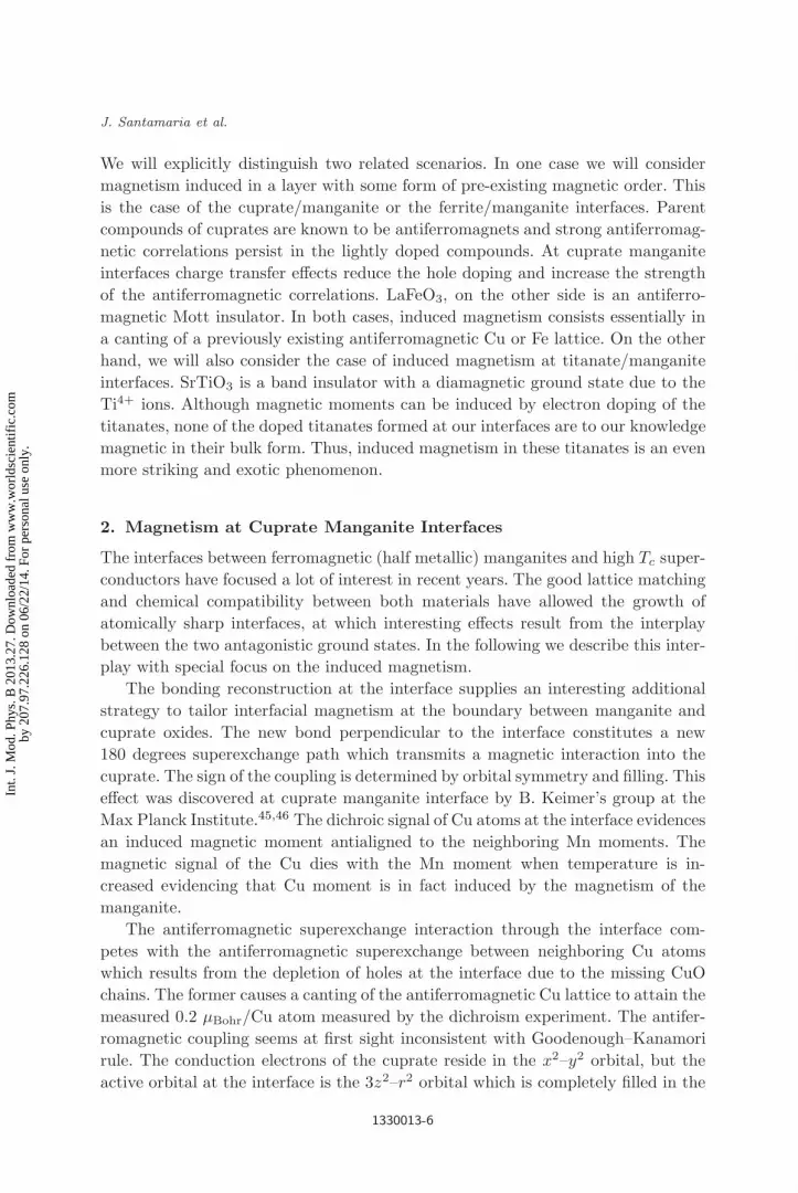
We will explicitly distinguish two related scenarios. In one case we will consider
magnetism induced in a layer with some form of pre-existing magnetic order. This
is the case of the cuprate/manganite or the ferrite/manganite interfaces. Parent
compounds of cuprates are known to be antiferromagnets and strong antiferromag-
netic correlations persist in the lightly doped compounds. At cuprate manganite
interfaces charge transfer effects reduce the hole doping and increase the strength
of the antiferromagnetic correlations. LaFeO3, on the other side is an antiferro-
magnetic Mott insulator. In both cases, induced magnetism consists essentially in
a canting of a previously existing antiferromagnetic Cu or Fe lattice. On the other
hand, we will also consider the case of induced magnetism at titanate/manganite
interfaces. SrTiO3 is a band insulator with a diamagnetic ground state due to the
Ti4+ ions. Although magnetic moments can be induced by electron doping of the
titanates, none of the doped titanates formed at our interfaces are to our knowledge
magnetic in their bulk form. Thus, induced magnetism in these titanates is an even
more striking and exotic phenomenon.
2. Magnetism at Cuprate Manganite Interfaces
The interfaces between ferromagnetic (half metallic) manganites and high Tc super-
conductors have focused a lot of interest in recent years. The good lattice matching
and chemical compatibility between both materials have allowed the growth of
atomically sharp interfaces, at which interesting effects result from the interplay
between the two antagonistic ground states. In the following we describe this inter-
play with special focus on the induced magnetism.
The bonding reconstruction at the interface supplies an interesting additional
strategy to tailor interfacial magnetism at the boundary between manganite and
cuprate oxides. The new bond perpendicular to the interface constitutes a new
180 degrees superexchange path which transmits a magnetic interaction into the
cuprate. The sign of the coupling is determined by orbital symmetry and filling. This
effect was discovered at cuprate manganite interface by B. Keimer’s group at the
Max Planck Institute.45,46 The dichroic signal of Cu atoms at the interface evidences
an induced magnetic moment antialigned to the neighboring Mn moments. The
magnetic signal of the Cu dies with the Mn moment when temperature is in-
creased evidencing that Cu moment is in fact induced by the magnetism of the
manganite.
The antiferromagnetic superexchange interaction through the interface com-
petes with the antiferromagnetic superexchange between neighboring Cu atoms
which results from the depletion of holes at the interface due to the missing CuO
chains. The former causes a canting of the antiferromagnetic Cu lattice to attain the
measured 0.2 µBohr/Cu atom measured by the dichroism experiment. The antifer-
romagnetic coupling seems at first sight inconsistent with Goodenough–Kanamori
rule. The conduction electrons of the cuprate reside in the x2–y2 orbital, but the
active orbital at the interface is the 3z2–r2 orbital which is completely filled in the
1330013-6
Int.
J. M
od. P
hys.
B 2
013.
27. D
ownl
oade
d fr
om w
ww
.wor
ldsc
ient
ific
.com
by 2
07.9
7.22
6.12
8 on
06/
22/1
4. F
or p
erso
nal u
se o
nly.

July 3, 2013 9:56 WSPC/Guidelines-IJMPB S0217979213300132
Induced Magnetism at Oxide Interfaces
bulk. The Cu–O–Mn superexchange interaction would be thus mediated by virtual
charge transfer from the Cu 3z2–r2 orbital into the half-filled 3z2–r2 orbital in the
manganite, which should be ferromagnetic due to the Cu intra-atomic Hund rule
interaction. The antiferromagnetic coupling observed experimentally constitutes a
direct indication that the electronic reconstruction at the interface encompasses also
an orbital reconstruction where orbital occupancy changes respect to bulk values.
Linear dichroism experiments comparing fluorescence signal (more sensitive to the
bulk) and total electron yield (more sensitive to the interface) has shown significant
polarization of the 3z2–r2 orbitals of the cuprates indicating that some hole pop-
ulation, contrary to the bulk where holes reside in the x2–y2 orbitals. It has been
proposed that orbital reconstruction results from covalent bonding in the direction
perpendicular to the interface. Spin up 3z2-r2 molecular hybrids with a strong Hund
coupling to t2g Mn electrons, have their energy reduced due to hybridization. As a
result of the difference in electrochemical potential the spin up antibonding orbital
is higher in energy than the Cu x2–y2 hybrids where the holes reside. This causes
transfer of holes from the x2–y2 orbitals to the 3z2–r2 orbitals, what accounts for
the orbital reconstruction.
Recent studies on La0.7Ca0.3MnO3 (LCMO)/YBa2Cu3O7 (YBCO) epitaxial
heterostructures have evidenced suppression of the superconducting critical tem-
perature over length scales much larger (1–2 orders of magnitude) than the coher-
ence length of the cuprate.47–49 Figure 1(a) shows the resistance curves of a series
of LCMO/YBCO superlattices with fixed thickness of the manganite and changing
the thickness of the cuprate in unit cell steps. F/S/F trilayers and heterostructures
were grown by sputter deposition in pure oxygen pressure47–49 on (100) SrTiO3
substrates. A strong suppression of the critical temperature can be seen when the
thickness of the YBCO is reduced. Figure 1(b) shows the evolution of the crit-
ical temperature of trilayers with magnetic (LCMO) and PrBa2Cu3O7 (PBCO)
bottom and top layers sandwiching the superconducting layers. Notice that super-
conductivity is further suppressed in heterostructures involving a magnetic material
suggesting a proximity effect which occurs over a very long length scale (10 nm),
orders of magnitude larger than the superconducting coherence length (0.1–0.3 nm
in the c direction). This can be hardly explained in terms of a (singlet) proximity
effect given the high spin polarization of the manganite and the sub-nanometer
coherence length of the cuprate. In the ferromagnet (F)/superconductor (S) prox-
imity effect50,51 the superconducting condensate leaks into the ferromagnet, so that
Cooper pairs directly experience the exchange interaction.52–60 The effect is short
range, and its length-scale shortens when the spin polarization of the ferromagnet
increases, vanishing in the limit of full spin polarization of a half metal. Supercon-
ductivity is also suppressed in the superconducting layer over the superconducting
coherence length. Other explanations in terms of (self) diffusion of spin polarized
quasiparticles61 or induction of a triplet superconductivity component62,63 also do
not account for the long length scale of the superconductivity suppression in the
cuprate. The effect of the induced magnetism at the interface is to create a spin
1330013-7
Int.
J. M
od. P
hys.
B 2
013.
27. D
ownl
oade
d fr
om w
ww
.wor
ldsc
ient
ific
.com
by 2
07.9
7.22
6.12
8 on
06/
22/1
4. F
or p
erso
nal u
se o
nly.

July 3, 2013 9:56 WSPC/Guidelines-IJMPB S0217979213300132
J. Santamaria et al.
(a)
(b)
Fig. 1. (Color online) (a) Resistance curves of LCMO/YBCO superlattices with fixed thick-ness of the manganite of 15 unit cells and changing the thickness of the cuprate in unit cellsteps. (b) Critical temperature obtained from the zero resistance value (in a linear scale) ofLCMO/YBCO/LCMO trilayers with magnetic (LCMO) and nonmagnetic PrBa2Cu3O7 (PBCO)top and bottom layers. Figures adapted from Refs. 47 and 48.
polarization in the electron gas of the cuprate over a short distance from the inter-
face, which, as it has been theoretically shown recently, may have a drastic effect
in suppressing superconductivity in ultrathin layers. In fact, as we discuss later,
this induced spin polarization is responsible from an anomalous proximity effect
reported previously in manganite cuprate heterostructures.
In the following we will argue that, in fact, the low dimensional Cu magnetism
induced at both interfaces resulting from the atomic reconstruction imposed by the
epitaxial growth process is at the origin of the superconductivity suppression. To
describe the interface structure we will focus on a series of F/S/F trilayers with
1330013-8
Int.
J. M
od. P
hys.
B 2
013.
27. D
ownl
oade
d fr
om w
ww
.wor
ldsc
ient
ific
.com
by 2
07.9
7.22
6.12
8 on
06/
22/1
4. F
or p
erso
nal u
se o
nly.
July 3, 2013 9:56 WSPC/Guidelines-IJMPB S0217979213300132
Induced Magnetism at Oxide Interfaces
fixed 15 nm thick top and bottom LCMO layers while the YBCO thickness ranges
between 7 and 47 nm. Samples were grown by high pressure pure oxygen sputter-
ing, a technique which has proven the growth of oxides layers with good epitaxial
properties.64–66 Samples with YBCO thicker showed weaker superconductivity sup-
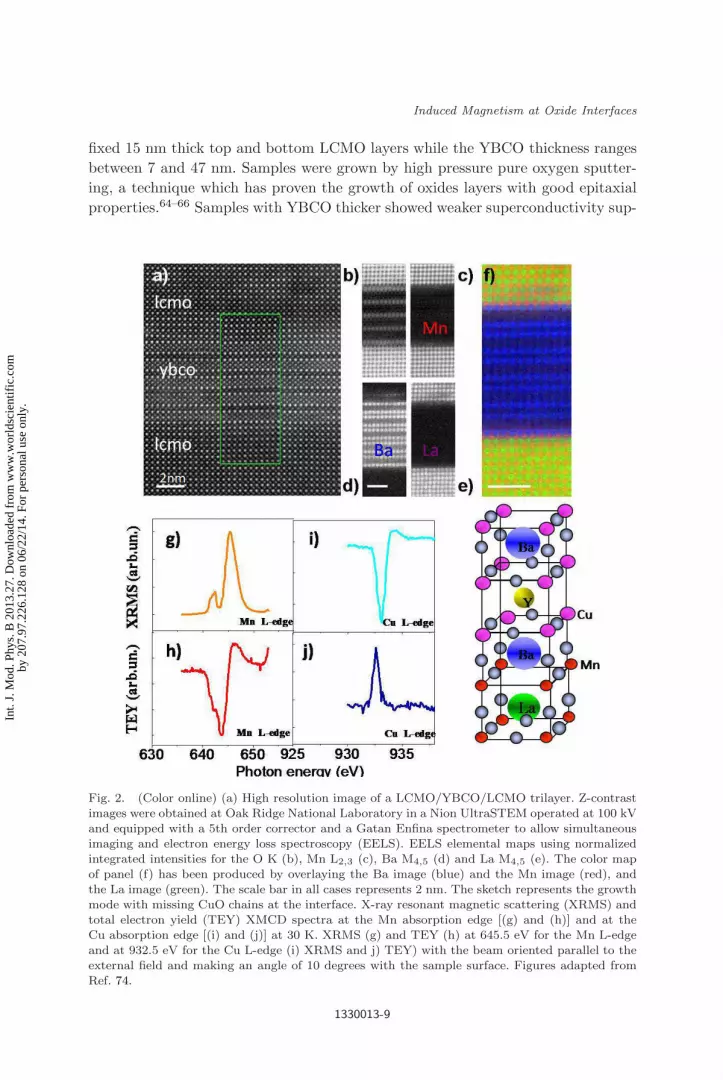
Fig. 2. (Color online) (a) High resolution image of a LCMO/YBCO/LCMO trilayer. Z-contrastimages were obtained at Oak Ridge National Laboratory in a Nion UltraSTEM operated at 100 kVand equipped with a 5th order corrector and a Gatan Enfina spectrometer to allow simultaneousimaging and electron energy loss spectroscopy (EELS). EELS elemental maps using normalizedintegrated intensities for the O K (b), Mn L2,3 (c), Ba M4,5 (d) and La M4,5 (e). The color mapof panel (f) has been produced by overlaying the Ba image (blue) and the Mn image (red), andthe La image (green). The scale bar in all cases represents 2 nm. The sketch represents the growthmode with missing CuO chains at the interface. X-ray resonant magnetic scattering (XRMS) andtotal electron yield (TEY) XMCD spectra at the Mn absorption edge [(g) and (h)] and at theCu absorption edge [(i) and (j)] at 30 K. XRMS (g) and TEY (h) at 645.5 eV for the Mn L-edgeand at 932.5 eV for the Cu L-edge (i) XRMS and j) TEY) with the beam oriented parallel to theexternal field and making an angle of 10 degrees with the sample surface. Figures adapted fromRef. 74.
1330013-9
Int.
J. M
od. P
hys.
B 2
013.
27. D
ownl
oade
d fr
om w
ww
.wor
ldsc
ient
ific
.com
by 2
07.9
7.22
6.12
8 on
06/
22/1
4. F
or p
erso
nal u
se o
nly.

July 3, 2013 9:56 WSPC/Guidelines-IJMPB S0217979213300132
J. Santamaria et al.
pression until for samples thicker than 15 nm bulk Tc is recovered, ruling out oxygen
deficiency as the origin of Tc reduction.67–70 X-ray and neutron nuclear depth pro-
files (not shown) indicate that the roughness of the top LCMO layer is larger than
those of the bottom LCMO layer and that the average magnetization is reduced.
An additional suppression of the top LCMO layer magnetization is observed at the
interface with YBCO, which has previously been interpreted to result from electron
transfer from the manganite into the cuprate.71,72 Interface structure and compo-
sition examined by aberration corrected STEM show good epitaxial properties and
coherent growth. EELS spectrum images were acquired to investigate the interface
structure. Figure 2(a) displays a high magnification Z contrast STEM image of a
LCMO (top)/YBCO (middle)/LCMO (bottom) trilayer. The darker planes corre-
sponding to CuO chains of YBCO are missing at both interfaces. Elemental maps
corresponding to the O K, Mn L2,3, Ba M4,5, and La M4,5 edges are shown in
Figs. 2(b)–2(e), respectively. The atomic lattices of all these elements are clearly
resolved. Interestingly, the LCMO layer looks chemically wider on the Mn image
than on the La map. These maps indicate a (BaO) atomic plane termination for
both the top and bottom interfaces of the cuprate and MnO2 of the manganite at
both interfaces. These results are consistent with both interfaces displaying the same
termination with a plane sequence YBCO–BaO–CuO2–Y–CuO2–BaO–MnO2–(La,
Ca O)–LCMO as reported previously by some of us in similar samples.71 This ob-
servation is more evident when the compositional maps are coloured and overlay as
done in Fig. 2(f): a blue BaO plane faces a red MnO2 plane for both the top and
bottom interfaces.
Soft X-rays in the energy range of Mn and Cu L-absorption edges were used
to obtain element specific dichroic spectra where the magnetic signal is given by
the difference between the right and left circularly polarized signals. In Fig. 2(g)–
2(j) we show X-ray resonant magnetic scattering (XRMS) and total electron yield
(TEY) XMCD data as a function of the photon energy taken at the Mn and Cu
L3-absorption edge. A field of H = −500 Oe was applied in the plane of the sample
along the [110] crystallographic direction at a temperature of 30 K. The induced Cu
moment observed at the Cu L3-edge is clearly observed. In contrast to absorption
(TEY) spectroscopy, the reflectivity signal is also sensitive to dispersive parameters
and necessitates modelling to extract absolute value for the magnetic moment of
each LCMO layer. The signal was monitored while sweeping the magnetic field to
record a hysteresis loop as shown in the bottom panel of Fig. 3.73 It should be noted
though, that the ratio of the steps in a multilayered sample can deviate from the
expected values due to changes in the interference conditions with changes in the
magnetic configuration.
The hysteresis loops with the field applied along [100] and [110] axes taken at
the Mn L3-edge highlight the different coercivities of both manganite layers. This
probably results from a difference in the strain state, since during the growth of the
YBCO layer the first LCMO layer will be fully strained while the top LCMO layer is
(partially) strain relaxed. The larger coercivity and remanent magnetization along
1330013-10
Int.
J. M
od. P
hys.
B 2
013.
27. D
ownl
oade
d fr
om w
ww
.wor
ldsc
ient
ific
.com
by 2
07.9
7.22
6.12
8 on
06/
22/1
4. F
or p
erso
nal u
se o
nly.

July 3, 2013 9:56 WSPC/Guidelines-IJMPB S0217979213300132
Induced Magnetism at Oxide Interfaces
(a)
(b)
Fig. 3. (Color online) XMCDmeasurements performed at the Advanced Photon Source (ArgonneNational Laboratory) at beamline 4-ID-C X-ray magnetic reflectivity loops taken at L3 Mn (a)and Cu (b) absorption edges at 30 K applying the field along [100] (red line) and [110] (blacksymbols). Figures adapted from Ref. 74.
the [110] direction is indicative of magnetic fields aligned with the easy axis.74
Figure 3(b) shows the hysteretic behavior of the Cu magnetic moments through
XMRS hysteresis loops. Cu and Mn loops display similar shape and coercivities:
it becomes clear that the Cu moments switch follows closely the switching of the
Mn moments. This is because the Cu magnetism results from the antiferromagnetic
coupling to the interfacial Mn. Moreover, the fact that the magnetic response of
Cu and Mn are similar indicates that the Cu at both interfaces is responding in
the same proportion to Mn magnetic moments. Due to the surface sensitivity of
the dichroism experiments, similar samples with thicker YBCO (12 nm and higher)
showed only the Cu signal due to the top interface.
The symmetric interface reconstruction at both cuprate interfaces in
LCMO/YBCO/LCMO structures evidences that there is a spin polarization in-
duced at (both) interfacial Cu atoms, consistent with the symmetrical interface
reconstruction. It is worth to mention here that other growth techniques, such as
pulsed laser deposition, show different terminations at both interfaces.75,76 Recent
experiments in ultrathin cuprate layers with depressed (or suppressed) supercon-
ductivity in contact with manganites exhibit different temperature evolution de-
pending on the existence or not of superconductivity.77 The Cu magnetic state
seems to survive up to higher temperatures in superconducting samples, indicating
that the magnetic ground state is affected by the superconductivity. The interplay
1330013-11
Int.
J. M
od. P
hys.
B 2
013.
27. D
ownl
oade
d fr
om w
ww
.wor
ldsc
ient
ific
.com
by 2
07.9
7.22
6.12
8 on
06/
22/1
4. F
or p
erso
nal u
se o
nly.

July 3, 2013 9:56 WSPC/Guidelines-IJMPB S0217979213300132
J. Santamaria et al.
between the interfacial magnetism and the mechanism of the high Tc superconduc-
tivity is an interesting question to pursue, which may provide important clues of
the mechanism of the high Tc superconductivity itself.
As discussed below, the finding of Cu magnetism at both interfaces provide a
firm footing for the applicability of recent models that explain the inverse super-
conducting spin switch behaviour of these trilayers in terms of the cancellation of
the magnetic field associated with induced Cu moments by the applied field.
2.1. Inverse superconducting spin switch
The F/S/F trilayer system constitutes an experimental realization of the ferromag-
netic superconducting proximity effect, which has attracted particular attention due
to the possibility of amplified superconductivity modulation by controlling the rel-
ative magnetic alignment states of the F layers (parallel, P versus antiparallel, AP).
The AP state has been proposed to average out the effect of the exchange field over
the coherence volume resulting in large magnetoresistance ratios ((RP −RAP)/RP
with RP > RAP) at a given temperature.78–84
In oxide-based La0.7Ca0.3MnO3 (LCMO)/YBa2Cu3O7 (YBCO)/
La0.7Ca0.3MnO3 (LCMO) trilayers,85–91 quite contrarily, there is a different mech-
anism in which the Tc is reduced in the AP alignment.92–94 Figures 4(a) and 4(b)
(a)
(b)
(c)
(d)
Fig. 4. (Color online) (a) Resistive transitions of LCMO/YBCO/LCMO trilayers with 15 nmLCMO layers and (a) thin (8 nm) and (b) thick (28 nm) YBCO layer. The red (blue) curves cor-respond to magnetization of the electrodes aligned parallel (antiparallel) to each other. (c) Mag-netic field sweeps at selected temperatures along the transition yield a positive magnetoresistanceplateaus which correspond to the increased resistance in the antiparallel configuration, as shownin panel (d). Notice that samples in a, b and c, d are different. Figures adapted from Refs. 88and 90.
1330013-12
Int.
J. M
od. P
hys.
B 2
013.
27. D
ownl
oade
d fr
om w
ww
.wor
ldsc
ient
ific
.com
by 2
07.9
7.22
6.12
8 on
06/
22/1
4. F
or p
erso
nal u
se o
nly.

July 3, 2013 9:56 WSPC/Guidelines-IJMPB S0217979213300132
Induced Magnetism at Oxide Interfaces
display resistive transitions of LCMO/YBCO/LCMO trilayers with 8 and 18 nm
thick YBCO respectively measured with the current in plane geometry. In each
panel the red and blue curves correspond to antiparallel and parallel alignment of
the magnetization of the electrodes. Notice that resistance curves are shifted to
higher temperatures in the parallel alignment, suggesting that superconductivity
is favoured in this configuration. At a given temperature this yields a resistivity
increase when the magnetic moments of the LCMO layers are aligned antiparallel.
Figure 4(c) shows magnetic field sweeps at selected temperatures along the resis-
tive transition. Notice that this yields positive MR plateaus for AP alignment of the
magnetization of the F layers.
See Fig. 4(d) showing hysteresis loops together with magnetoresistance sweeps.
The terms direct- and inverse superconducting spin switch have been introduced
to describe enhanced (DSS) or depressed (ISS) superconductivity for antiparallel
alignment of the magnetizations of the ferromagnetic layers. It has been accepted
that an ISS governed by AP alignment ought to exhibit a well-defined positive
plateau in the magnetoresistance (MR) between the two coercive fields of top and
bottom layers,82,83 while a DSS governed by the exchange field effect would have a
negative MR plateau. Different explanations have been proposed to the ISS rang-
ing from quasiparticle confinement in the S layer resulting from spin dependent
scattering at the F/S interfaces to the effect of stray fields generated by domains
or domain walls95,96 in a way that in FSF structures may also be determined by
magnetic alignment.80,92,93 While all these effects depend on the relative alignment
of the magnetizations of the ferromagnetic electrodes, recent experimental evidence
obtained from detailed polarized neutron scattering experiments in rotating mag-
netic fields indicates that what matters is in fact the alignment of the magnetization
to the applied magnetic field.97
Salafranca and Okamoto98 have recently considered the anomalous proximity
phenomena occurring at cuprate manganite interface from the perspective
of competing interactions at the interfaces. The model considers a trilayer
LCMO/YBCO/LCMO structure along the [001] direction. The pairing interaction
in the cuprate involves the x2–y2 electrons. At the interface the 3z2–r2 electrons
of the cuprate become active due to the orbital reconstruction and hybridize with
the eg electrons of the manganite. This coupling is antiferromagnetic. The strong
Hund coupling interaction of the cuprate couples the x2–y2 electrons to the 3z2–
r2 electrons ferromagnetically, and as a result the antiferromagnetic interaction at
the interface is transmitted to the x2–y2 electrons. The model shows that as a
result of the effective antiferromagnetic interaction of x2–y2 electrons to Mn core
t2g electrons there is an induced negative spin polarization at the cuprate, oppo-
site to the positive spin polarization that one would expect in a spin injection
scenario.99 Induced spin polarization at the interface suppresses superconductivity.
Superconductivity is completely suppressed when YBCO thickness is 2 unit cells in
accordance with the experiment and survives (although with reduced Tc) up to a
1330013-13
Int.
J. M
od. P
hys.
B 2
013.
27. D
ownl
oade
d fr
om w
ww
.wor
ldsc
ient
ific
.com
by 2
07.9
7.22
6.12
8 on
06/
22/1
4. F
or p
erso
nal u
se o
nly.

July 3, 2013 9:56 WSPC/Guidelines-IJMPB S0217979213300132
J. Santamaria et al.
thickness of 5 unit cells where bulk values are recovered. The length scale is set by
the screening of the induced magnetization in the cuprate which occurs within 2 to
3 unit cells from the interface in absence of superconductivity. This is an important
theoretical result which shows that the induced magnetization in the Cu lattice is
not restricted to the interface plane as one would guess from a pure orbital picture,
but it extends into the cuprate with a short length scale determined by the hopping
rate in the z direction. In presence of superconductivity interface magnetization is
reduced and screening becomes oscillatory up to a thickness of 4 to 5 unit cells
from the interface where induced spin polarization vanishes. This model correctly
captures the long length scale of the anomalous proximity effect of 8 to 10 unit cells
observed in trilayers and superlattices where superconductivity is being suppressed
at the two interfaces of the cuprate layer.
The inverse superconducting spin switch effect is also correctly accounted for by
Okamoto and Salafranca’s model. Looking now at the effect of an applied magnetic
field on a trilayer system, the key idea is how the externally applied magnetic field
(parallel to the layers) competes with the exchange field of the induced spin polar-
ization of the cuprate. Right at the interface this exchange field may be very large
(∼ 100 T), but it decays exponentially away from it. For parallel alignment of the
manganite moments, the applied magnetic field compensates the exponential tail
of the exchange field due to the Cu spin polarization. This gives rise to a recovery
of Tc in this region. For antiparallel alignment of the magnetic moments of the
electrodes the system is symmetric against an inversion of H and although there
may be a compensation of the exchange field at one interface there will add up at
the other. The Tc recovery in the parallel configuration due to the compensation
of the Cu exchange field, which does not occur in the antiparallel configuration,
is the reason underlying the inverse superconducting spin switch which seems to
favor superconductivity in the parallel configuration. This also explains the positive
magnetoresistance peaks (plateaus) observed in isothermal resistance versus mag-
netic field sweeps when the manganite layers are antiferromagnetically aligned. At
a given temperature, enhancement of Tc in the parallel configuration is responsible
for a lower resistance level as compared to the antiferromagnetic configuration.
3. Ti Magnetism at Titanate Manganite Interfaces
In this section we examine interfacial Ti magnetism in heterostructures combining
manganites and titanates. The Mn-O-Ti superexchange path at the interface splits
the Ti band and induces a magnetic moment which is detected by XMCD. Con-
trolling epitaxial strain allows changing the orbital occupancy at the interface what
provides a path to control orbital reconstruction and magnetic interaction.
3.1. LaMnO3/SrTiO3 interface
Let us start with the LaMnO3/SrTiO3 (LMO/STO) heteroepitaxy, a system with
a variety of interesting ingredients. Despite their common perovskite structures
1330013-14
Int.
J. M
od. P
hys.
B 2
013.
27. D
ownl
oade
d fr
om w
ww
.wor
ldsc
ient
ific
.com
by 2
07.9
7.22
6.12
8 on
06/
22/1
4. F
or p
erso
nal u
se o
nly.

July 3, 2013 9:56 WSPC/Guidelines-IJMPB S0217979213300132
Induced Magnetism at Oxide Interfaces
there is substantial epitaxial mismatch strain which may play a role in stabilizing
distortions and rotations of the oxygen octahedra. For [001] growth there is also
a polarity mismatch at the interface similar to that found in the LAO/STO sys-
tem (LMO planes are polar while STO planes are nonpolar), and similar physics
might be at play. Moreover, both materials are also electronically very different.
In LaMnO3, Mn3+ ion has a d4 electronic configuration, the t2g band is fully oc-
cupied and there is a single electron in the eg levels. In its bulk form the strong
crystal field and electron–lattice (JT) interactions lift orbital degeneracy giving rise
to an in-plane ordering of the eg orbitals which yields the A type antiferromagnetic
states, where Mn ions couple ferromagnetically in plane while neighboring planes
are antiferromagnetically coupled. In titanates with a trivalent A site element, such
as LaTiO3, Ti3+ is in a d1 state and thus the t2g band is singly occupied. The small
overlap of t2g orbitals, mediated by weak O π bonds which are not directed along
[100] bond directions, give rise to the small crystal field splitting and the weak JT
coupling as compared to manganites with eg orbitals. Owing to the nearly cubic
environment of the Ti ions, they exhibit a larger tendency to orbital degeneracy and
may thus display orbital moments and low temperature ferromagnetism. However,
there are important open questions such as the lack (or very small values) of the
orbital moment100–103 or the experimental absence of the theoretically predicted
ferromagnetism for LaTiO3,42,104 whose importance at our interfaces will become
clear later.
Samples were [LMOM/ STON]8 superlattices consisting of 8 periods of M unit
cells of LMO and N unit cells of STO grown by high pressure oxygen sputter-
ing.105,106 M ranged from 3 to 17 and N from 2 to 12 unit cells. Interfaces were
sharp as identified by X-ray diffraction [Fig. 5(a)] and STEM images (Fig. 5(b)].
X-ray absorption and electron energy loss spectroscopy (EELS) with atomic column
resolution indicate the presence of Ti3+ ions in the STO layers.105,106 These elec-
trons reside in the t2g orbitals of a Ti band at the interfacial plane which essentially
behaves as an “artificially doped” interfacial titanate. In other words, due to the ex-
istence of a LaO termination plane the interface behaves as a LaTiO3 unit cell thick
layer. The interfacial MnO2 plane has an oxidation state close to 3+ (from EELS)
with the 3t2g levels half-filled (due to Hund coupling) and one electron occupying
the eg band. There is also hole doping in the manganite layers characteristic of
LMO in thin film form. Thin film LMO usually displays a ferromagnetic insulating
ground state resulting from unintentional hole doping associated stoichiometry im-
balances. The transport and magnetic properties are controlled by epitaxial strain
through its dependence on the thickness ratio. For a given thickness of the titanate
layer of 2 unit cells, the thickness of the manganite layer controls epitaxial strain:
In the following we will focus on experiments on samples exhibiting two extreme
behaviors. One is a sample with 17 unit cell thick LMO and 2 unit cells of STO
[LMO 17/STO 2], and the other has 3 unit cells of LMO and 2 unit cells of STO
[LMO 3/STO 2]. For very thin manganite in a 3/2 superlattice, structure matches
the STO in plane lattice parameters while for 17/2 superlattices with thick relaxed
1330013-15
Int.
J. M
od. P
hys.
B 2
013.
27. D
ownl
oade
d fr
om w
ww
.wor
ldsc
ient
ific
.com
by 2
07.9
7.22
6.12
8 on
06/
22/1
4. F
or p
erso
nal u
se o
nly.
July 3, 2013 9:56 WSPC/Guidelines-IJMPB S0217979213300132
J. Santamaria et al.
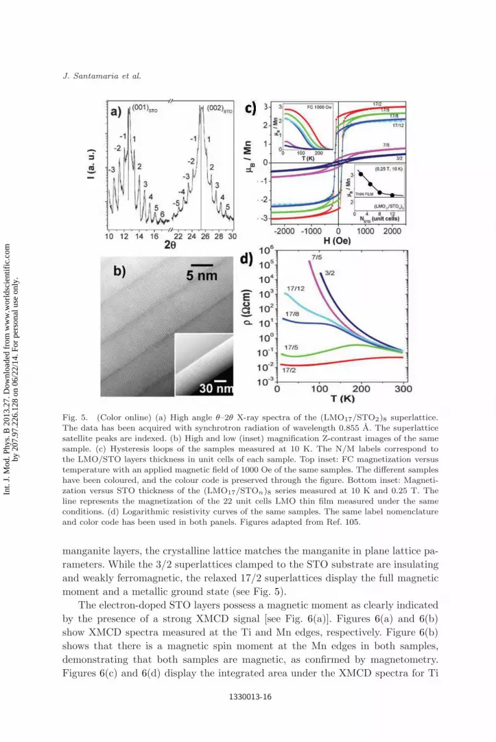
Fig. 5. (Color online) (a) High angle θ–2θ X-ray spectra of the (LMO17/STO2)8 superlattice.The data has been acquired with synchrotron radiation of wavelength 0.855 A. The superlatticesatellite peaks are indexed. (b) High and low (inset) magnification Z-contrast images of the samesample. (c) Hysteresis loops of the samples measured at 10 K. The N/M labels correspond tothe LMO/STO layers thickness in unit cells of each sample. Top inset: FC magnetization versustemperature with an applied magnetic field of 1000 Oe of the same samples. The different sampleshave been coloured, and the colour code is preserved through the figure. Bottom inset: Magneti-zation versus STO thickness of the (LMO17/STOn)8 series measured at 10 K and 0.25 T. Theline represents the magnetization of the 22 unit cells LMO thin film measured under the sameconditions. (d) Logarithmic resistivity curves of the same samples. The same label nomenclatureand color code has been used in both panels. Figures adapted from Ref. 105.
manganite layers, the crystalline lattice matches the manganite in plane lattice pa-
rameters. While the 3/2 superlattices clamped to the STO substrate are insulating
and weakly ferromagnetic, the relaxed 17/2 superlattices display the full magnetic
moment and a metallic ground state (see Fig. 5).
The electron-doped STO layers possess a magnetic moment as clearly indicated
by the presence of a strong XMCD signal [see Fig. 6(a)]. Figures 6(a) and 6(b)
show XMCD spectra measured at the Ti and Mn edges, respectively. Figure 6(b)
shows that there is a magnetic spin moment at the Mn edges in both samples,
demonstrating that both samples are magnetic, as confirmed by magnetometry.
Figures 6(c) and 6(d) display the integrated area under the XMCD spectra for Ti
1330013-16
Int.
J. M
od. P
hys.
B 2
013.
27. D
ownl
oade
d fr
om w
ww
.wor
ldsc
ient
ific
.com
by 2
07.9
7.22
6.12
8 on
06/
22/1
4. F
or p
erso
nal u
se o
nly.

July 3, 2013 9:56 WSPC/Guidelines-IJMPB S0217979213300132
Induced Magnetism at Oxide Interfaces
(a) (b)
(c) (d)
Fig. 6. (Color online) Ti (a) and Mn (b) normalized XMCD spectra of the [LMO 3/STO 2] and[LMO 17/STO 2] superlattices measured at 6 K. The XMCD measurements are normalized tothe L3 t2g (Ti) and L3 (Mn) edge jump values. Inset: Mn hysteresis loops of the same samplesobtained from Mn XMCD signal. Integrated values of the Ti (c) and Mn (d) normalized XMCDspectra of the [LMO 17/STO 2] and [LMO 3/STO 2] superlattices. Figures adapted from Ref. 106.
(c) and Mn (d) edges, which is directly proportional to the orbital moment. Inter-
estingly, while the integrals of the Mn XMCD spectra show that the orbital moment
is essentially quenched as expected, there is a significant orbital component to the
magnetic moment of the Ti [see Fig. 6(c)]. The shape of the XMCD signal of both
the Mn and Ti [see Figs. 6(a) and 6(b)] depends strongly on the thickness ratio of
the superlattices. Notice that both samples display opposite signs of the integrated
intensity under the Ti XMCD signal [see Fig. 6(c)], clearly indicating a change in
the coupling mechanism of the Ti and Mn spin moments at the interface. Note that
the value of the Ti spin moment estimated from the application of the sum rules
(0.2 µB/Ti for the [LMO 3/STO 2] and 0.15 µB/Ti for the [LMO 17/STO 2]) are
to great extent underestimated. Furthermore, the temperature dependence of the
Ti moment closely follows that of the Mn moment, and essentially vanishes at the
Curie temperature of the manganite suggesting that the Mn–O–Ti superexchange
is responsible for the Ti ferromagnetism in this sample.
1330013-17
Int.
J. M
od. P
hys.
B 2
013.
27. D
ownl
oade
d fr
om w
ww
.wor
ldsc
ient
ific
.com
by 2
07.9
7.22
6.12
8 on
06/
22/1
4. F
or p
erso
nal u
se o
nly.

July 3, 2013 9:56 WSPC/Guidelines-IJMPB S0217979213300132
J. Santamaria et al.
The plots of the integrals of the XMCD signals indicate that the orbital and spin
moments of the Ti 3d electrons are aligned antiparallel according to 3rd Hund’s rule,
evidencing the effect of spin orbit interaction. Spin-orbit coupling is a mechanism
by which spins feel the distribution of the electronic density (orbits) and contrary
to eg systems, the matrix elements of the orbital momentum operator acting on
t2g states are nonzero (though small, typically spin orbit interaction is ∼ 20 meV
for titanates).2 The unambiguous presence of an orbital moment anti-aligned to the
spin, constitutes direct evidence that the orbital degeneracy is not completely lifted
(which would result in a complete quenching of the orbital moment). It is worthwhile
recalling that experimental evidence in bulk LTO suggests that the orbital moment
is almost completely quenched and no evidence of orbital magnetism has been found
so far,103 making this finding even more surprising and unexpected.
The change of the sign of the coupling interaction between Mn and Ti spin
moments from antiferromagnetic in the 17/2 to ferromagnetic in the 3/2 superlat-
tice can be explained in terms of changes in the orbital polarization of the inter-
face resulting from the different strain states.107 In the 17/2 superlattice there is
preferential occupation of Mn 3z2–r2 band at the interface, while in the strained
3/2 superlattice Mn x2–y2 are preferentially occupied.106,107 Semicovalent bonds
at the interface result from the hybridization of 3z2–r2 and t2g xz and yz active
orbitals (both spin up and spin down). It can be observed in Fig. 7(a) that in the
[LMO 17/STO 2] superlattice there is strong hybridization between the preferen-
tially occupied Mn 3z2–r2 band at the interface and the empty 3z2–r2 band of Ti.
The occupation of the hybridized orbitals at the interface explains the AF align-
ment of the Ti moment with respect to the Mn moment.99 Three of the electrons
of the Mn occupy the spin up 3z2–r2 and the active t2g xz and yz hybrids, while
the fourth occupies an inactive t2g xy orbital which does not participate in bond-
ing. The Ti t2g electron occupies the spin down t2g hybrid, and thus its alignment
is antiferromagnetic [see Fig. 6(d)]. The dominant superexchange process occurs
between the Ti t2g electrons and the half-filled Mn t2g bands and, according to
Goodenough–Kanamori rules, is antiferromagnetic. In the [LMO 3/STO 2] super-
(a) (b)
Fig. 7. (Color online) Schematic energy diagrams of the orbital hybrids proposed for LMO/STO
interfaces as a function of Mn orbital polarization: (a) Preferential Mn 3z2–r2 orbital occupationand (b) Preferential Mn x2–y2 orbital occupation. (Adapted from Ref. 106.)
1330013-18
Int.
J. M
od. P
hys.
B 2
013.
27. D
ownl
oade
d fr
om w
ww
.wor
ldsc
ient
ific
.com
by 2
07.9
7.22
6.12
8 on
06/
22/1
4. F
or p
erso
nal u
se o
nly.

July 3, 2013 9:56 WSPC/Guidelines-IJMPB S0217979213300132
Induced Magnetism at Oxide Interfaces
lattices the occupation of the Mn x2–y2 orbitals at the interface identified by XMLD
changes the hybridization pattern.106 The hybridization between the occupied Mn
x2–y2 and Ti orbitals across the interface is negligibly small. A finite overlap be-
tween Ti t2g and Mn 3z2–r2 orbitals resulting from the GdFeO3-type distortion of
the manganite may yield finite values of the transfer integral between 3z2–r2 and
t2g active orbitals xz and yz. Ferromagnetic coupling in [LMO 3/STO 2] results
from the superexchange interaction through the virtual excitation of electrons from
Ti xz, yz to Mn 3z2–r2 [see Fig. 7(b)]. This simple molecular orbital picture, with
mean-field type treatment for the interaction, provides a simple explanation for the
magnetic coupling of Ti and Mn moments at the interface. At this stage we cannot
make a definitive statement on the importance of corrections due to many-body
effects or more complex spin-orbital superexchange processes not considered here.
The experiments on LMO/STO heterointerfaces between an electron-doped ti-
tanate and a manganite show evidence for Ti spin and orbital magnetism. The
orbital magnetic moment requires the presence of a small splitting between t2glevels. This result constitutes a practical realization of orbital magnetism at an
interfacial titanate layer which is not found in bulk titanates. Depending on the
strain state of the superlattice, controlled by the manganite-to-titanate thickness
ratio, the sign of the spin–spin coupling at the interface is reversed, outlining the
role played by the orbital reconstruction at the interface in tailoring exchange in-
teractions. This novel form of interface magnetism will provide important clues for
the understanding of the effects of orbital degeneracy in superexchange
3.2. La0.7Sr0.3MnO3 /SrTiO3 interface
The finding of induced magnetism at the interface between the Mott insulator
LaMnO3 and the band insulator SrTiO3105,106 has motivated further studies in the
technologically more relevant La0.7Sr0.3MnO3 (LSMO)/SrTiO3(STO) interface.108
Interfacial magnetism may have important practical implications in the operation
of magnetic tunnel junctions where spin polarization of the injected current may
be influenced by the spin structure at the interface. Among correlated electron
systems, LSMO has been extensively studied as a possible source of spin polarized
electrons at room temperature.109 The large values of tunnelling magnetoresistance
(TMR) reported for LSMO/STO/LSMO tunnel junctions at low temperature drops
way below the Curie temperature of the magnetic electrodes, suggesting that a de-
polarisation of the injected current may occur at the interface.110 This effect has
been attributed to deteriorated magnetic properties of the manganite layer at the
interface, a so called “dead layer” whose origin is still not well understood.111,112
When the magnetic structure of the interface is examined in the light of its mod-
ified orbital structure, a magnetic moment induced at the Ti is also found which
results from the orbital reconstruction. Charge leaks into the otherwise empty t2gorbitals of the titanate which, as a result of the hybridization with Mn orbitals, be-
come magnetic. This is fundamentally different from previous reports of interfacial
1330013-19
Int.
J. M
od. P
hys.
B 2
013.
27. D
ownl
oade
d fr
om w
ww
.wor
ldsc
ient
ific
.com
by 2
07.9
7.22
6.12
8 on
06/
22/1
4. F
or p
erso
nal u
se o
nly.

July 3, 2013 9:56 WSPC/Guidelines-IJMPB S0217979213300132
J. Santamaria et al.
magnetism like the case of Cu45 or Fe119 where the interfacial magnetism is a con-
sequence of a reordering of pre-existing moments. In our case, Ti atoms, nominally
in a 4+ state, have no magnetic moment in absence of electronic reconstruction.
In the following results are described corresponding to two series of
[LSMO6/STO2]8 superlattices consisting of 8 bilayers of 6 LSMO unit cells (u.c.)
and 2 STO u.c., grown on (100) STO substrates using a high-pressure pure oxygen
sputtering technique. The Ti oxidation state examined by atomic column resolu-
tion EELS has been shown to evolve from Ti3.75+ when STO is 2 u.c. thick to Ti4+
when STO is 8 u.c. thick. While Ti atoms at the bulk of the layer are in a 4+
oxidation state when bilayer index (and STO layer thickness) increases, the inter-
facial Ti seems to exhibit a reduced oxidation state according to the EELS maps.
The Mn oxidation state, on the other hand, remains constant and close to the 3.3+
expected for the nominal stoichiometry. The reduced oxidation state found for the
Ti in the ultrathin STO layers most likely result from an electronic reconstruction
at the manganite-titanate interface. La–Sr intermixing could also cause the reduced
oxidation state of Ti. However, if electron doping of STO were caused by La enrich-
ment this would imply a hole enrichment of the LSMO near the interface, which in
fact is not observed.
XMCD experiments were also performed on superlattices with different STO
thicknesses. Figure 8(a) shows XMCD spectra taken at the Mn and Ti L edge of
a [LSMO6/STO2]8 sample measured at 6 K and with an applied field of 10 kOe.
A clear dichroic signal is also observed at the Ti edge demonstrating the induced
magnetism at the STO, a remarkable result considering that bulk STO is a diamag-
netic band insulator. The temperature dependence of the XMCD signal shown on
Fig. 8(b) evidences that the Ti (466 eV) XMCD signal closely follows Mn (642 eV)
signal and magnetization. The magnitude of the Ti signal scales with the magnitude
of the Mn signal, demonstrating that the origin of the Ti moment is the interaction
with the Mn moment. A rough estimate of the magnitude of the magnetic moment
of Ti Ms = −0.04 µB/atTi was obtained by applying sum rules.113 The negative
value of the Ti moment indicates that its direction is opposite to the magnetic field,
and hence that the Mn–Ti coupling is antiferromagnetic.
An explanation for the antiferromagnetic Mn–Ti coupling at the interface can be
offered in terms of the modified bonding at the interface in the same line as we did
in the case of the LMO/STO system. Since t2g orbitals in STO are located slightly
above the Fermi level of the manganite, orbital hybridization may drive an elec-
tronic reconstruction at this interface.7 In particular we propose a scenario where
hybridized “down” xz, yz bonding orbitals reside lower in energy than hybridized
“up” bonding 3z2–r2 orbital, thus yielding the antiferromagnetic Ti state. This
hybridized-orbital picture is a natural consequence of the lattice mismatch between
STO and LSMO and the reduced electron density in LSMO compared with undoped
LaMnO3. The former increases the energy level of the bonding 3z2–r2 orbital, and
the latter suppresses the occupation of the bonding 3z2–r2 orbital. These effects
1330013-20
Int.
J. M
od. P
hys.
B 2
013.
27. D
ownl
oade
d fr
om w
ww
.wor
ldsc
ient
ific
.com
by 2
07.9
7.22
6.12
8 on
06/
22/1
4. F
or p
erso
nal u
se o
nly.

July 3, 2013 9:56 WSPC/Guidelines-IJMPB S0217979213300132
Induced Magnetism at Oxide Interfaces
Fig. 8. (Color online) XMCD measurements performed in a [LMSO6/STO2]8 superlattice.(a) XMCD signals obtained from the Ti L2,3 edge (red) Mn L2,3 edge (blue). Ti signal hasbeen multiplied by a factor of 10. (b) Temperature dependence of the XMCD signal. Ti (red opencircles) and Mn (blue solid circles) XMCD signal taken at 452 eV and 642 eV, respectively and
VSM measurement (black line), all measurements are normalized to the value at 4 K. Figuresadapted from Ref. 108.
cooperatively destabilize the ferromagnetic coupling via either the double-exchange
or superexchange interaction mediated by the 3z2–r2 orbital as discussed by Garcia-
Barriocanal et al.105,106 Because of the charge transfer occurring at this interface
and electron doping by La0.7Sr0.3O layer, Ti is in a mixed 3+/4+ oxidation state at
the interface, resulting in the antiferromagnetic coupling with respect to Mn. The
destabilization of the out of plane ferromagnetic interaction in the manganite may
be the origin of a stronger decrease of the ordered moment than in the bulk when
temperature is increased.99 This effect might account for the rapid suppression of
the tunnelling magnetoresistance of LSMO/STO magnetic tunnel junctions when
temperature is increased.
A related interesting scenario is the induced Ti magnetism in La0.7Sr0.3MnO3/
BaTiO3/Fe magnetic tunnel junctions.114 The charge redistribution theoretically
predicted at Fe/BaTiO3 interfaces may modify the spin polarization at the inter-
face depending on the direction of the ferroelectric polarization of the BaTiO3 layer,
and be the source of interesting magnetoelectric coupling effects.115–118 Recipro-
1330013-21
Int.
J. M
od. P
hys.
B 2
013.
27. D
ownl
oade
d fr
om w
ww
.wor
ldsc
ient
ific
.com
by 2
07.9
7.22
6.12
8 on
06/
22/1
4. F
or p
erso
nal u
se o
nly.

July 3, 2013 9:56 WSPC/Guidelines-IJMPB S0217979213300132
J. Santamaria et al.
cally, it has been recently shown that there is magnetism induced at the Ti edge at
the BTO/Fe interface suggesting a new path towards artificially designed multifer-
roics. Evidence of a Ti ferromagnetic state has been obtained from X-ray resonant
magnetic scattering hysteresis loops at Ti L2,3 and O K edges. Combined interface
imaging by aberration corrected STEM EELS and modeling suggests that in this
case Ti is in a 4+ state. Ti atoms are spin polarized due to the hybridization with
Fe and spin polarized oxygen atoms suggesting that the mechanism at play may be
different from that outlined previously in manganite/titanate heterojuctions.
4. Magnetism at Manganite Ferrite La0.7Sr0.3MnO3/BiFeO3
Interfaces
Induced magnetism at La0.7Sr0.3MnO3/BaFeO3 (LSMO/BFO) interfaces has been
recently examined by Ramesh’s group.119 This is an interesting case where the
BFO is a multiferroic with an antiferromagnetic groundstate. The superexchange
interaction with the ferromagnetic manganese at the interface induces a canting in
the antiferromagnetic lattice of Fe moments. A new phenomenology shows up in this
system due to the effect of orbital reconstruction in lifting the eg degeneracy, what
causes a change in the magnetic interaction at the interface. I.e., the strong orbital
hybridization in the growth direction originates a x2–y2 orbital polarization at the
interface which destabilizes the ferromagnetic interaction along the z direction. As
a result, the interfacial Mn may change its intra plane and interplane coupling to
the next Mn in the second layer, giving rise to an interface Mn layer with modified
magnetic properties coupled AF to the second Mn layers. The resulting interfacial
magnetic coupling is thus controlled by the orbital reconstruction at the interface.
In this system, Fe in a 3+ oxidation state is in a d5 electronic state such that
charge transfer is prohibited due to the ground state electronic structure of the tran-
sition metal at the interface. Contrary to the case of the cuprate interface where the
(unpolarized) x2–y2 level lies just above the Mott gap allowing the charge transfer
process, in the case of Fe3+ in a high spin state the down spin x2–y2 state is located
far above the gap, and thus charge transfer is not allowed. At this interface with
a multivalent Mn (3+/4+) transition metal ion, a modification of the magnetic
ground state of the manganite occurs. The proposed bond reconstruction at the
interface is as follows. It is assumed that the eg energy levels of the BFO lie lower
in energy than those of LSMO. There is a strong hybridization between 3z2–r2
orbitals to form a 3z2–r2 bonding state, lower in energy, and a 3z2–r2 antibonding
state, higher in energy. x2–y2 orbitals will not be influenced because their symme-
try does not allow hybridization at (001) interfaces. The lowest electronic states,
occupied by bond reconstruction will be the hybrid 3z2–r2 bonding states and the
Mn x2–y2 nonhybridizing states. According to the Goodenough-Kanamori rule,38,39
the superexchange coupling between Fe3+ and Mn3+ (with in plane x2–y2 orbital
ordering) or Mn4+ is expected to be strongly ferromagnetic. On the other hand the
interfacial Mn layer with modified x2–y2 orbital ordering naturally leads to the anti-
1330013-22
Int.
J. M
od. P
hys.
B 2
013.
27. D
ownl
oade
d fr
om w
ww
.wor
ldsc
ient
ific
.com
by 2
07.9
7.22
6.12
8 on
06/
22/1
4. F
or p
erso
nal u
se o
nly.

July 3, 2013 9:56 WSPC/Guidelines-IJMPB S0217979213300132
Induced Magnetism at Oxide Interfaces
ferromagnetic coupling with its neighboring Mn layer. As a result the interfacial Fe
spins and the Mn spins in the bulk LSMO region are coupled antiferromagnetically.
This behavior suggests the possibility of exploiting the competition between
ground states with similar characteristic energies which can be preferentially stabi-
lized due to changes in the bond or orbital symmetry occurring at the interfaces.
5. Magnetism at the LaAlO3/SrTiO3 Interface
The finding of a conducting interface between two band insulators in LaAlO3 and
SrTiO3 bilayer by Ohtomo and Hwang8,9 has generated a tremendous scientific
interest. The interfacial conductivity has been proposed to originate at a charge
transfer process from the surface of the LAO down to the interface to avoid the po-
lar catastrophe,11,12 namely the unlimited growth of the electrostatic energy which
would result from the polar nature of the (001) planes of the LAO. Due to the
built up electric field band bending (tilting) occurs, and above a thickness of 3 to
4 unit cells of LAO the valence band edge of the LAO reaches the Fermi level al-
lowing the charge transfer process. Other explanations in terms of extrinsic effects
such as oxygen vacancies12–15 or cation diffusion16–18 and structural distortion or
orbital reconstruction120 have also been proposed. The tunability of the interfa-
cial carrier density by using a gate voltage has allowed exploring a wide variety of
phenomena which appear to compete at this interface, including superconductiv-
ity,21 magnetism,22 and their coexistence.121,123,124 While the superconductivity of
doped STO has been known for years important open questions regard the nature
and origin (extrinsic or intrinsic) of the magnetic state of the STO and whether or
not the coexistence with superconductivity is an exotic ground state of the corre-
lated electron liquid at the interface. The coexistence of both orders inferred from
hysteretic magnetoresistance in doped STO layers and interfaces have led to the
conclusion that band filling and Coulomb repulsion may indeed play a role, and a
carrier controlled mechanism has been proposed.125 The first reports of magnetism
by Brinkman and colleagues22 were based on low temperature hysteretic magnetore-
sistance of LAO/STO samples prepared at high oxygen pressures to ensure a low
carrier density. However, recently, room temperature ferromagnetism was claimed
by Ariando for 10 unit cells of LaAlO3 on SrTiO3 in fields up to 0.2 T based on
SQUID magnetometry.122 Li et al.,123 based on torque magnetometry measure-
ments reported moments of 5 10 −10 Am2 for an ultrathin 5 unit cells thick layer
of LaAlO3 on SrTiO3. Finally, Bert et al.,,124 using a scanning Hall probe contact
microscopy have found evidence of micron size magnetic patches with a large as-
sociated dipole field consistent with magnetism generated by localized carriers. On
the other hand, neutron scattering experiments on LAO/STO superlattices with
conducting and nonconducting interfaces do not detect the signature of a ferro-
magnetic interface state.126 It is known that polarized neutron reflectometry is well
suited to explore magnetism at surfaces or interfaces, and in particular, the spin
asymmetry is very sensitive to small magnetization values. The spin asymmetry,
1330013-23
Int.
J. M
od. P
hys.
B 2
013.
27. D
ownl
oade
d fr
om w
ww
.wor
ldsc
ient
ific
.com
by 2
07.9
7.22
6.12
8 on
06/
22/1
4. F
or p
erso
nal u
se o
nly.

July 3, 2013 9:56 WSPC/Guidelines-IJMPB S0217979213300132
J. Santamaria et al.
the difference between integrated intensities under a Bragg peak for magnetic fields
applied parallel or anti parallel to the spin polarization of the neutron beam, is ex-
tremely sensitive to interface magnetism, while the spin asymmetry at the critical
angle probes the magnetization averaged over the entire superlattice. No significant
spin difference was measured near the critical edge of the LaAlO3/SrTiO3 super-
lattice. On the other hand, by measuring the spin asymmetry under the first Bragg
peak established an upper limit of 2 G for the magnetization change across the
LaAlO3/SrTiO3interfaces (laterally averaged) at 11 T and 1.7 K. If attributed to
Ti, the 2 G upper limit for the magnetic moment would correspond to 0.7% of Ti3+
per unit cell. If averaged over the entire superlattice this magnetization is likely to
be less than the upper limit of 1 G inferred from measurement of substrate control
experiments. In summary, the upper level of 2 G found126 using a technique well
suited to probe interface magnetism questions the intrinsic origin of the magnetism
ascribed to the LAO/STO interfaces.
6. Summary and Outlook
We have described a class of low dimensional magnetism appearing at the interface
between magnetic and nonmagnetic oxides. It originates at the new superexchange
path occurring at the bonding discontinuity at the interface, and traces a new route
to induce magnetism in the otherwise nonmagnetic material. The phenomenon is
quite ubiquitous, and has been observed experimentally at interfaces involving man-
ganites,45,46,105,106,108 ferrites119 and nickelates.127 Its origin is the splitting of its
bands due to the hybridization with the exchange split bands of the magnetic mate-
rial. The sign of the magnetic coupling between the magnetic and the nonmagnetic
elements forming the reconstructed bond can be controlled by external variables
such as charge transfer and epitaxial strain through their effect on orbital symmetry
and filling. The ability to tune this magnetic state128,129 is of utmost importance
since it opens the possibility of controlling the induced magnetism by external pa-
rameters such as electric polarization or electric field. The strong electric fields at
the interfaces with tunnel barriers may induce charge transfer processes and thus
modify band filling. Furthermore, it may modify the relative energy position of
the energy levels corresponding to the materials building an interface, especially
if charge depleted (space charge) regions occur as a result of differences in the
electrochemical potential. These space charge regions can be very narrow, of the
width comparable to one unit cell, at junctions between a metal and a Mott in-
sulating barrier. A very large electric field may thus develop in a narrow region
at the interfaces which may change the energy separation between levels of both
materials, allowing for changes in the orbital reconstruction. Of particular interest
is to explore induced magnetism at interfaces with ferroelectric materials.130–134 At
interfaces with ferroelectrics, the reversal of the polarization, aside from changes
in the carrier density occurring to screen the polarization charges,135 may cause
changes in the hybridization at the interface resulting from the lattice distortions
1330013-24
Int.
J. M
od. P
hys.
B 2
013.
27. D
ownl
oade
d fr
om w
ww
.wor
ldsc
ient
ific
.com
by 2
07.9
7.22
6.12
8 on
06/
22/1
4. F
or p
erso
nal u
se o
nly.

July 3, 2013 9:56 WSPC/Guidelines-IJMPB S0217979213300132
Induced Magnetism at Oxide Interfaces
associated to the polarization states. This may allow for charge transfer processes
or level splitting which may profoundly modify the induced magnetic moments at
the interface, as it has been recently theoretically shown.115–118 The possibility of
modifying the magnetic ground state of interfaces with the polarization states may
be an interesting pathway towards electric field control of magnetism.
Another interesting direction is to exploit the tendency of correlated oxides
to phase separation to stabilize at interfaces electronic ground states with spe-
cific (magnetic) functionalities. This is the case of the electronic reconstruc-
tion occurring at the interface between two manganese perovskite oxides, one
being ferromagnetic-metallic (La0.7Ca0.3MnO3) and the other antiferromagnetic-
insulating (La0.3Ca0.7MnO3).136 As a result, an insulating phase with a significant
interface-induced magnetic moment is stabilized at the interface. This phase, which
according to the bulk phase diagram is not expected, is functionalized as an active
barrier in magnetic tunnel junctions and mimics a spin-filtering behavior. At man-
ganite interfaces and surfaces, electronic phases different from those of the bulk
compounds may be stabilized as a consequence of a subtle competition between the
kinetic energy (that favor ferromagnetism) and the localizing interactions (which
favor antiferromagnetism and insulating behavior). The ground state properties of
manganites are determined by the competition between at least four independent
energy scales: the antiferromagnetic (AF) interaction between the Mn spins, the
electron phonon coupling, the electronic repulsion, and the kinetic energy of the
carriers. In manganites, the energies involved in these interactions are comparable
so very different states can have very similar energies. Consequently, by slightly
varying parameters such as carrier concentration, strain, disorder, or temperature,
different ground states can be experimentally observed. Extending this approach to
antiferromagnetic oxides with high ordering temperature should expand dramati-
cally the range of simple spin-filter materials and inspire novel concepts in oxide
spintronics. This may constitute a promising route towards novel magnetoelectric
effects to manipulate spin-polarized currents, and to circumvent the scarcity of
spin-filter materials, offering new opportunities in spintronics.
In summary, interfacially induced magnetism occurring at interfaces between
correlated oxides could find interesting functionalities in devices with operation
controlled by the interface such as tunnel or field effect devices. In particular mag-
netic interfacially induced states in Mott insulating barriers could be useful to
modify the spin polarization of injected currents or have spin selective transport
yielding interesting novel spin filtering functionalities of interest in spintronics.
Acknowledgments
We want to thank Maria Varela and Steve Pennycook of the STEM Group at
the Electron Microscopy at the Materials Science & Technology Division at Oak
Ridge National Laboratory for performing the electron microscopy and spectroscopy
structures. Suzanne te Velthuis, Yaohua Liu and Axel Hoffmann of the Materi-
1330013-25
Int.
J. M
od. P
hys.
B 2
013.
27. D
ownl
oade
d fr
om w
ww
.wor
ldsc
ient
ific
.com
by 2
07.9
7.22
6.12
8 on
06/
22/1
4. F
or p
erso
nal u
se o
nly.

July 3, 2013 9:56 WSPC/Guidelines-IJMPB S0217979213300132
J. Santamaria et al.
als Science Division, Argonne National Laboratory and Mike Fitzsimmons from
Los Alamos National Laboratory for polarized neutron reflectometry experiments
and collaboration and discussion. Agnes Barthelemy and Manuel Bibes from Unite
Mixte de Physique CNRS/Thales for steady collaboration and discussions. The
theory support and stimulating discussions with Satoshi Okamoto are also ac-
knowledged. We acknowledge financial support by Spanish MICINN through grants
MAT2011-27470-C02 and Consolider Ingenio 2010 CSD2009-00013 (Imagine), by
CAM through grant S2009/MAT-1756 (PHAMA).
References
1. M. Imada, A. Fujimori and Y. Tokura, Rev. Mod. Phys. 70, 1039 (1998).2. S. Maekawa et al., in Physics of Transition Metal Oxides (Springer, 2004), Chap. 1.3. E. Dagotto, Science 309, 257 (2005).4. E. Dagotto and Y. Tokura, MRS Bull. 33, 1037 (2008).5. J. Mannhart and D. G. Schlom, Science 327, 1607 (2010).6. H. Y. Hwang, Nat. Mater. 11, 103 (2012).7. S. Okamoto and A. Millis, Nature 428, 630 (2004).8. A. Ohtomo et al., Nature 419, 378 (2002).9. A. Ohtomo and H. Hwang, Nature 427, 423 (2004).
10. N. Nakagawa, H. Y. Hwang and D. A. Muller, Nat. Mater. 5, 204 (2006).11. For a review see, J. N. Eckstein, Nature 6, 473 (2007).12. K. Yoshimatsu et al., Phys. Rev. Lett. 101, 026802 (2008).13. S. A. Chambers, Phys. Rev. Lett. 102, 199703 (2009).14. K. Yoshimatsu et al., Phys. Rev. Lett. 102, (2009) 199704.15. A. Kalabukhov et al., Phys. Rev. B 75, 121404(R) (2007).16. P. R. Willmott et al., Phys. Rev. Lett. 99, 155502 (2007).17. A. S. Kalabukhov et al., Phys. Rev. Lett. 103, 146101 (2009).18. A. Kalabukhov et al., Europhys. Lett. 93, 37001 (2011).19. S. Thiel et al., Science 313, 1942 (2006).20. A. D. Caviglia et al., Nature 456, 624 (2008).21. N. Reyren et al., Science 317, 1196 (2007).22. A. Brinkman et al., Nat. Mater. 6, 493 (2007).23. M. Baibich et al., Phys. Rev. Lett. 61, 2472 (1988).24. M. C. Cyrille et al., Phys. Rev. B 62, 15079 (2000).25. M. C. Cyrille et al., Phys. Rev. B 62, 3361 (2000).26. J. Santamaria et al., Phys. Rev. B 65, 012412 (2002).27. J. Santamaria et al., Phys. Rev. Lett. 89, 190601 (2002).28. M. E. Gomez et al., Eur. Phys. J. B 30, 17 (2002).29. M. E. Gomez et al., Phys. Rev. B 71, 125410 (2005).30. A. Scherz, H. Wende and K. Baberschke, Appl. Phys. A 78, 843 (2004).31. H. Wende et al., J. Phys.: Condens. Matter 15, S547.32. F. Wilhelm et al., Phys. Rev. Lett. 87, 207202 (2001).33. R. Tyer et al., Phys. Rev. B 67, 104409 (2003)34. R. Coehoorn, J. Magn. Magn. Mater. 151, 341 (1995).35. E. R. Moog, J. Zak and S. D. Bader, J. Appl. Phys. 69, 4559 (1991).36. N. Nakajima et al., Phys. Rev. Lett. 81, 5229 (1998).37. R. Wu, C. Li and A. J. Freeman, J. Magn. Magn. Mater. 81, 71 (1991).38. J. B. Goodenough, Phys. Rev. B 100, 564 (1955).
1330013-26
Int.
J. M
od. P
hys.
B 2
013.
27. D
ownl
oade
d fr
om w
ww
.wor
ldsc
ient
ific
.com
by 2
07.9
7.22
6.12
8 on
06/
22/1
4. F
or p
erso
nal u
se o
nly.

July 3, 2013 9:56 WSPC/Guidelines-IJMPB S0217979213300132
Induced Magnetism at Oxide Interfaces
39. J. Kanamori, J. Phys. Chem. Solids 10, 87 (1959).40. Y. Tokura and N. Nagaosa, Science 288, 462 (2000).41. J. Garcia-Barriocanal et al., Science 321, 678 (2008).42. T. Mizokawa, D. I. Khomskii and G. Sawatzky, Phys. Rev. B 60, 7309 (1999).43. J. Stohr, J. Magn. Magn. Mater. 200, 470 (1999).44. H. Wende, Rep. Prog. Phys. 67, 2105 (2004).45. J. Chakhalian et al., Nat. Phys. 2, 244 (2006).46. J. Chakhalian et al., Science 318, 114 (2007).47. Z. Sefrioui, et al., Appl. Phys. Lett. 81, 4568 (2002).48. Z. Sefrioui et al., Phys. Rev. B 67, 214511 (2003).49. V. Pena et al., Phys Rev. B 69, 224502 (2004).50. A. I. Buzdin, Rev. Mod. Phys. 77, 935 (2005).51. F. S. Bergeret, A. F. Volkov and K. B. Efetov, Rev. Mod. Phys. 77, 1321 (2005).52. J. Y. Gu et al., Phys. Rev. Lett. 89 , 267001 (2002).53. A. Potenza and C. H. Marrows, Phys. Rev. B 71, 180503(R) (2005).54. R. Steiner and P. Ziemann, Phys. Rev. B 74, 094504 (2006).55. I. C. Moraru, W. P. Pratt Jr. and N. O. Birge, Phys. Rev. Lett. 96, 037004 (2006).56. A. Y. Rusanov et al., Phys. Rev. Lett. 93, 057002 (2004).57. A. Singh, C. Surgers and H. V. Lohneysen, Phys. Rev. B B75, 024513 (2007).58. D. Stamopoulos, E. Manios and M. Pissas, Supercond. Sci. Technol. 20, 1205 (2007).59. G.-X. Miao, A. V. Ramos and J. S. Moodera, Phys. Rev. Lett. 101, 137001 (2008).60. J. Zhu et al., Phys. Rev. Lett. 103, 027004 (2009).61. S. Soltan, J. Albrecht and H. U. Habermeier, Phys. Rev. B 70, 144517 (2004).62. T. Hu et al., Phys. Rev. B 80, R060506 (2009).63. C. Visani et al., Nat. Phys. 8, 539 (2012).64. M. Varela et al., Phys. Rev. Lett. 83, 3936 (1999).65. M. Varela et al., Phys Rev. Lett. 86, 5156 (2001).66. X. J. Chen et al., Phys. Rev. B 72, 104403 (2005).67. Z. Sefrioui et al., Phys. Rev. B 60, 15423 (1999).68. Z. Sefrioui et al., Europhys. Lett. 48, 679 (1999).69. T. Endo et al., Phys. Rev. B 54, R3750 (1996).70. V. Pena et al., Phys. Rev. Lett. 97, 177005 (2006)71. M. Varela et al., Solid State Electron. 47, 2245 (2003).72. A. Hoffmann et al., Phys. Rev. B 72, R140407 (2005).73. J. W. Freeland et al., J. Phys. Cond. Mat. 19, 315210 (2007).74. C. Visani et al., Phys. Rev. B 81, 094512 (2010).75. R. Werner et al., Phys. Rev. B 82, 224509 (2010).76. Z. L. Zhang et al., Appl. Phys. Lett. 95, 242505 (2009).77. S. R. Giblin et al., Phys. Rev. Lett. 109, 137005 (2012).78. J. Y. Gu et al., Phys. Rev. Lett. 89, 267001 (2002).79. A. Potenza and C. H. Marrows, Phys. Rev. B 71 , 180503(R) (2005).80. R. Steiner and P. Ziemann, Phys. Rev. B 74, 094504 (2006).81. I. C. Moraru, W. P. Pratt Jr. and N. O. Birge, Phys. Rev. Lett. 96, 037004 (2006).82. A. Yu. Rusanov, S. Habraken and J. Aarts, Phys. Rev. B 73, 060505 (2006).83. A. Singh, C. Surgers and H. V. Lohneysen, Phys. Rev. B 75, 024513 (2007).84. G.-X. Miao, A. V. Ramos and J. S. Moodera, Phys. Rev. Lett. 101, 137001 (2008).85. V. Pena et al., Phys Rev. Lett. 94, 57002 (2005).86. V. Pena et al., Phys Rev. B 73, 104513 (2006).87. C. Visani et al., Phys. Rev. B 75, 54501 (2007).88. N. M. Nemes et al., Phys. Rev. B 78, 094515 (2008).
1330013-27
Int.
J. M
od. P
hys.
B 2
013.
27. D
ownl
oade
d fr
om w
ww
.wor
ldsc
ient
ific
.com
by 2
07.9
7.22
6.12
8 on
06/
22/1
4. F
or p
erso
nal u
se o
nly.
July 3, 2013 9:56 WSPC/Guidelines-IJMPB S0217979213300132
J. Santamaria et al.
89. N. M. Nemes et al., Phys. Rev. B 81, 024512 (2010).90. C. Visani et al., Phys. Rev. B 81, 094512 (2010).91. N. M. Nemes et al., Appl. Phys. Lett. 97, 032501 (2010).92. J. Zhu et al., Phys. Rev. Lett. 103, 027004 (2009)93. D. Stamopoulos, E. Manios and M. Pissas, Phys. Rev. B 75, 014501 (2007).94. K. Dybko et al., Euro Phys. Lett. 85, 57010 (2009).95. W. Gillijns et al., Phys. Rev. Lett. 95, 227003 (2005).96. L. Y. Zhu, T. Y. Chen and C. L. Chien, Phys. Rev. Lett. 101, 017004 (2008).97. Y. Liu et al., Phys. Rev. Lett. 108, 207205 (2012).98. J. Salafranca and S. Okamoto, Phys. Rev. Lett. 105, 256804 (2010).99. S. Okamoto, Phys. Rev. B 82, 024427 (2010).
100. C. Ulrich et al., Phys. Rev. Lett. 103, 107205 (2009).101. B. Keimer et al., Phys. Rev. Lett. 85, 3946 (2000).102. G. Khaliullin and S. Maekawa, Phys. Rev. Lett. 85, 3950 (2000).103. M. W. Haverkort et al., Phys. Rev. Lett. 94, 056401 (2005).104. T. Mizokawa and A. Fujimori, Phys. Rev. B 54, 5368 (1996).105. J. Garcia-Barriocanal et al., Adv. Mat. 22, 627 (2010).106. J. Garcia-Barriocanal et al., Nat. Commun. 1, 82 (2010) doi:10.1038/ncomms1080.107. A. Tebano et al., Phys. Rev. Lett. 100, 137401 (2008).108. F. Y. Bruno et al., Phys. Rev. Lett. 106, 147205 (2011).109. J. H. Park et al., Nature 392, 794 (1998).110. M. Bowen et al., Appl. Phys. Lett. 82, 233 (2003).111. M. Izumi et al., Phys. Rev. B 64, 064429 (2001).112. J. Z. Sun et al., Appl. Phys. Lett. 73, 1008 (1998).113. C. T. Chen et al., Phys. Rev. Lett. 75, 152 (1995).114. S. Valencia et al., Nat. Mater. 10, 753 (2011).115. C.-G. Duan, S. S. Jaswal and E. Y. Tsymbal, Phys. Rev. Lett. 97, 047201 (2006).116. M. Fechner et al., Phys. Rev. B 78 , 212406 (2008).117. M. Fechner, S. Ostanin and I. Mertig, Phys. Rev. B 80, 094405 (2009).118. H. L. Meyerheim et al., Phys. Rev. Lett. 106, 087203 (2011).119. P. Yu et al., Phys. Rev. Lett. 105, 027201 (2010).120. M. Salluzzo et al., Phys. Rev. Lett. 102, 166804 (2009).121. D. A. Dikin et al., Phys. Rev. Lett. 107, 056802 (2011).122. A. X. Wang et al., Nature Commun. 2, 188 (2011).123. L. Li et al., Nat. Phys. 7, 762 (2011).124. J. A. Bert et al., Nat. Phys. 7, 767 (2011).125. P. Moetakef et al., Phys. Rev. X 2, 21014 (2012).126. M. R. Fitzsimmons et al., Phys. Rev. Lett. 107, 217201 (2011).127. M. Gibert et al., Nat. Mater. 11, 195 (2012).128. D. K. Satapathy et al., Phys. Rev. Lett. 108, 197201 (2012).129. J. W. Seo et al., Phys. Rev. Lett. 105, 167206 (2010).130. V. Garcia et al., Nature 460, 81 (2010).131. A. Gruverman et al., Nano Lett. 9, 3539 (2009).132. P. Maksymovych et al., Science 324, 1421 (2009).133. V. Garcia et al., Science 327, 1106 (2010).134. A. Chanthbouala et al., Nat. Nanotech. 7, 101 (2012).135. Y. W. Yin et al., Nat. Mater. 12, 397 (2013)136. Z. Sefrioui et al., Adv. Mat. 22, 5029 (2010).
1330013-28
Int.
J. M
od. P
hys.
B 2
013.
27. D
ownl
oade
d fr
om w
ww
.wor
ldsc
ient
ific
.com
by 2
07.9
7.22
6.12
8 on
06/
22/1
4. F
or p
erso
nal u
se o
nly.


