Embed Size (px)
Citation preview
I
Ma
b
c
R
a
ARRAA
KDRP
1
ctutliipDbihmw
eha
tdmt
0d
Electric Power Systems Research 80 (2010) 582–591
Contents lists available at ScienceDirect
Electric Power Systems Research
journa l homepage: www.e lsev ier .com/ locate /epsr
mprovement of DEA performance against harmonic distortion
. García-Graciaa,∗, N. El Halabia, A. Montanésb, H.M. Khodrc, M. Villéna
CIRCE, Research Center of Consumption and Energy Resource, C/Maria de Luna 3, 50018, Zaragoza, SpainDepartment of Electrical Engineering, University of Zaragoza, SpainGECAD – Knowledge Engineering and Decision-Support Research Center of the Polytechnic Institute of Porto (ISEP/IPP),ua Dr. António Bernardino de Almeida 431, 4200-072 Porto, Portugal
r t i c l e i n f o
rticle history:eceived 3 February 2009
a b s t r a c t
This paper presents a filtering application to improve the behavior of the Differential Equation Algorithm(DEA) against harmonic distortion in transmission and distribution power systems. The proposed filter
eceived in revised form 24 July 2009ccepted 24 October 2009vailable online 3 December 2009
eywords:istance protection algorithm
is based on Fast Fourier Transform (FFT) techniques during steady-state conditions. The voltage andcurrent continuous-time equations are also considered, in fault conditions, to estimate the fundamentalcomponent waveforms of voltage and current. Simulations results show the singularities problems ofDEA algorithm against harmonic distortion and the accurate operation achieved within 0.32 cycles usingthis filtering application.
elaying systemower system
. Introduction
The basic requirement of a distance protection algorithm is theapability of high speed and selective isolation of faulted sections inhe power system. Fourier analysis techniques are the most widelysed tools in signal processing for distance relaying [1]. However,he time these methods need for operation is in the range of ateast one and a half cycles. Protection algorithms based on travel-ng waves principle [2–4] offer the fastest operation time after faultnception, but put too high demands on current and voltage sam-ling time for accurate operation [4,5]. Unlike these algorithms, theifferential Equation Algorithm (DEA) [5–9] has an operating timeelow 0.32 cycles with less sample time requirements than travel-
ng wave techniques. Thus, a relay based on the DEA is suitable sinceigh speed operation is achieved including fault detection, esti-ation of fault location, fault classification and tripping decisionithin the operation time.
In [9] the behavior of the DEA algorithm is analyzed under differ-nt situations in a power distribution system without consideringarmonic distortion and fault resistance, resulting in an efficientlgorithm for fault detection and location.
However, the increasing application of electronic power facili-
ies in the industrial environment bears to a significant harmonicistortion in the waveforms of voltages and currents [10]. This har-onic distortion in conjunction with the fault resistance and theransient components contained in the waveforms of voltages and
∗ Corresponding author. Tel.: +34 976761923; fax: +34 976762226.E-mail address: [email protected] (M. García-Gracia).
378-7796/$ – see front matter © 2009 Elsevier B.V. All rights reserved.oi:10.1016/j.epsr.2009.10.012
© 2009 Elsevier B.V. All rights reserved.
currents during the fault period, introduces important measuringerrors in the DEA algorithm [8]. These uncertainties implicit in themeasured data must be removed to avoid misoperations and powerdisruption. This emphasizes the need to analyze the behavior ofDEA in a power system with harmonic distortion aiming to developsuitable filtering methods to enhance the accuracy of the algorithm.
Some authors have proposed different filtering applications forharmonic waveforms. In [1] a mimic phasor estimator is proposedby using discrete Fourier Transform, where the filtered waveform isestablished in at least 0.5 cycles, but it is based on an iterative adap-tive scheme for voltage and current phasors where convergencedepends on variation of fault parameters. Otherwise, [8] proposesa medium post-filtering for DEA algorithm that rejects singulari-ties problems due to harmonic distortion; however it demands anadditional time in this stage before an accurate convergence to thefault distance. In [11] a recursive algorithm based on minimiza-tion of the absolute error in the waveform estimation is presented,where convergence time is in the range of 2.5 cycles and it isapplied to study symmetrical components in unbalanced powersystems. Unlike digital filters, several active filters have been pro-posed [12–15] to mitigate harmonic current effect over the powerquality of the power system. These active filters offer a selectiveelimination of harmonic components, however under fault con-ditions, the accuracy of harmonic elimination is reduced and thefiltered fundamental waveform may be misleading for DEA algo-
rithm.The method introduced in this paper takes the presumptionthat the peak value relation between the fundamental frequencycomponent and the harmonic components remains similar in bothprefault and fault state. Under this scope, a straightforward filter-
er Sy
iottti
dspa
2
2
rpr
•
••
dp[
wclaaLr
a
R
we
bt
i
M. García-Gracia et al. / Electric Pow
ng application is proposed for estimating fundamental waveformsf voltages and currents by means of continuous-time equationsaking into account the information of prefault state to acceleratehe estimation of the waveforms. Then, using the differential equa-ion that describes an electric circuit, the algorithm determines thenductance and resistance seen by the relay.
The proposed algorithm provides capability for fast trippingecisions within 0.32 cycles, taking into account both accuracy andecurity. Extensive simulations and comparative studies of the pro-osed algorithm with the conventional DEA and Fourier techniquesre reported and discussed.
. The Differential Equation Algorithm
.1. Presumptions and general equations in continuous time
Here is presented a summarized derivation of the DEA. A suitableeference for detailed derivation of DEA, considering mutual cou-ling effect, is [9]. The derivation of the equations for this algorithmequires the following presumptions:
voltage and current transformers are ideal in the frequency rangefrom 50 to 500 Hzthe line is perfectly transposedshunt capacitance is neglected
The DEA algorithm is based on the differential equation thatescribes an electric circuit. Therefore, under fault conditions, therotected line is modeled as follows:
ua
ub
uc
]= krR1
[laibic
]+ klL1
d
dt
[iaibic
](1)
here, ua, ub, uc and ia, ib, ic are the phase quantities of voltages andurrents, respectively. The parameters kr and kl are the relative lineength for the resistive part and the inductive part, respectively. For
fault on the protected line, both should be bounded between 0nd 1. In an ideal case, kr and kl should be similar. The arrays R andare the resistance and the inductance array for the whole line,
espectively.Through the presumption of perfect transposition mentioned
bove, the following expressions are obtained:
=(
Rs Rm Rm
Rm Rs Rm
Rm Rm Rs
); L =
(Ls Lm Lm
Lm Ls Lm
Lm Lm Ls
)(2)
here the subscripts s and m are used for self and mutual param-ters, respectively. The relation between these parameters is:
L1 = Ls − Lm
R1 = Rs − Rm
L0 = Ls + 2Lm
R0 = Rs + 2Rm
(3)
eing the subscripts 0 and 1 the zero and positive sequence, respec-ively. Subtracting self and mutual parameters in (3) gives:
L0 − L1 = 3Lm
R0 − R1 = 3Rm(4)
Using (4), and considering that the zero sequence current is:
0 = (ia + ib + ic)3
(5)
stems Research 80 (2010) 582–591 583
Eq. (1) can be rewritten as follows:[ua
ub
uc
]= krR1
[iaibic
]+ klL1
d
dt
[iaibic
]
+ kr(R0 − R1)
[i0i0i0
]+ kr(L0 − L1)
d
dt
[i0i0i0
](6)
and expressed in a general form as follows:
u = krir + klL1dildt
(7)
being the derivation of variables u, ir and il different for each typeof fault (three phases, double phase to ground and SLG) [8].
2.2. Single line to ground faults
Considering a SLG fault on phase a at a relative distance k of thetotal length of the protected line, the voltage of the faulty phase isgiven by:
ua = kr[R1ia + (R0 − R1)i0] + kl
[L1
diadt
+ (L0 − L1)di0dt
](8)
Eq. (8) can be expressed as the general form (7), considering thefollowing variables:
u = ua
ir = R1ia + (R0 − R1)i0il = L1.ia + (L0 − L1)i0
(9)
2.3. Double phase to ground fault
For a double phase to ground fault between phases a and b, theequation is:
(ua − ub) = krR1(ia − ib) + klL1d
dt(ia − ib) (10)
Expressing (10) as the general form (7) leads to the followingconsiderations:
u = ua − ub
ir = R1(ia − ib)il = L1(ia − ib)
(11)
2.4. Three phase fault
Assuming a symmetrical fault at a distance k of the protectedline, the general Eq. (1) is rewritten as:[
ua
ub
uc
]= krR1 ·
[iaibic
]+ klL1 · d
dt
[iaibic
](12)
Since it is a symmetrical fault, that is i0 = 0, the network can betreated as a single phase system. Any phase can be used to deter-mine the values of kr and kl. Using two sets of samples of voltageand current of the phase a, the equations that allow the values ofkr and kl to be obtained are:
[uan
uan+1
]=
⎡⎢⎣ R1ian L1
dian
dt
R1ian+1 L1dian+1
dt
⎤⎥⎦[
kr
kl
](13)
2.5. Solution of the continuous-time equations in discrete-time
The solutions of (8), (10) and (13) are expressed in reference [5]in discrete-time domain. The two unknown parameters kr and kl
584 M. García-Gracia et al. / Electric Power Systems Research 80 (2010) 582–591
odel w
c[
d
k
k
wii
� 7)
2d
pqvttaCtMfbct
o
tives of the current limits are to limit the maximum individualfrequency voltage harmonic to 3% of the fundamental and THDVto 5% for systems without a major parallel resonance at one of theinjected harmonic frequencies [18]. The value of each harmonic
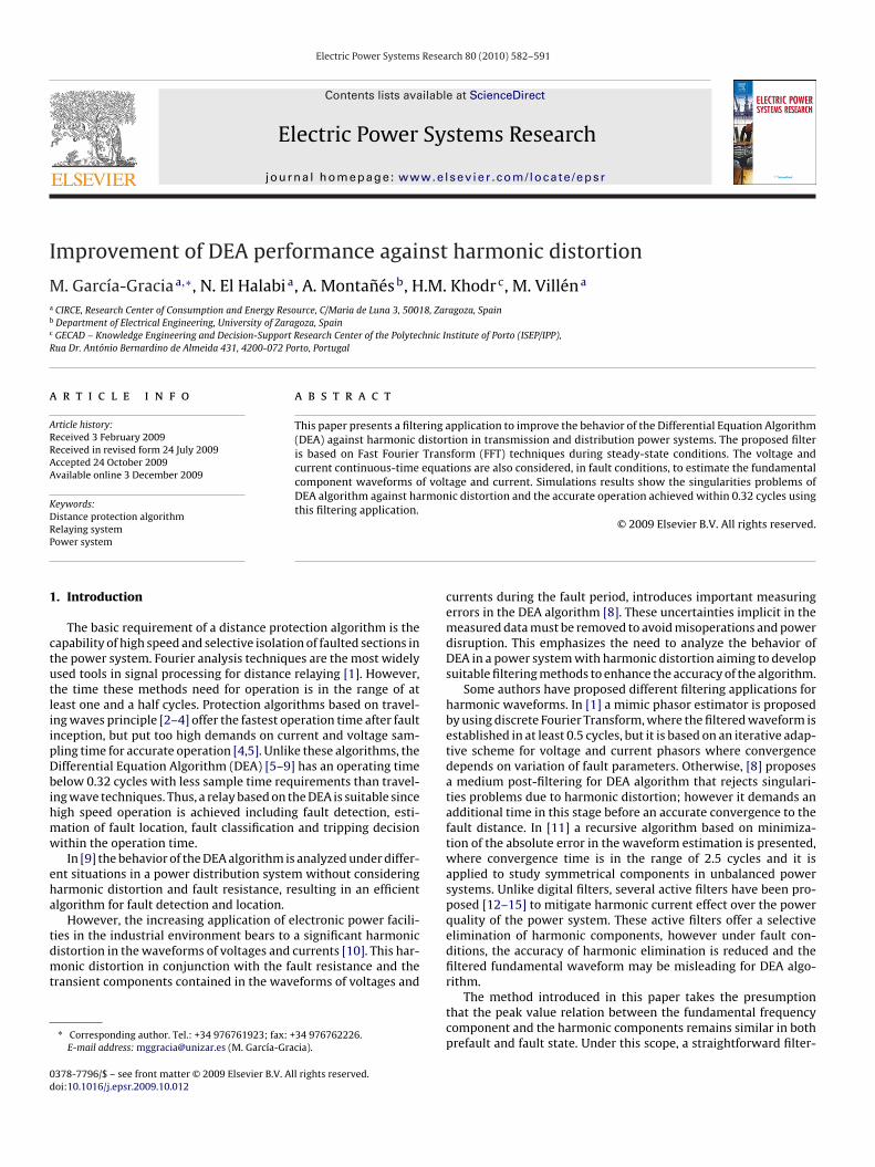
Fig. 1. Overview of the m
an be estimated by differentiating (7) as follows:
udu
dt
]=
⎡⎣ ir Ll
dildt
dirdt
Lld2ildt2
⎤⎦[ kr
kl
](14)
Subsequently, by using three continuous samples of i and u, faultistance is given by:
rn = (iln − il(n−1))(u(n−1) + u(n−2)) − (il(n−1) − il(n−2))(un + u(n−1))�T
(15)
ln =(
�
2
)× −(irn − ir(n−1))(u(n−1)+u(n−2))+(ir(n−1) − ir(n−2))(un+u(n−1))
�T(16)
here � is the frequence sampling of the protective device, n thendex of time and �T the determinant of the inverse of the matrixn (14) expressed as follows:
T = (ir(n−1) + ir(n−2))(iln − il(n−1)) − (irn + ir(n−1))(il(n−1) + il(n−2))(1
.6. Singularities problems present in DEA against harmonicistortion
As (17) is a discrete-time signal, it has implicit a repetitiveerturbation at a constant period which introduces a periodic fre-uency deformation. Therefore, when the determinant (17) getsalues near to zero, kr and kl result in a mathematical indetermina-ion. This indetermination is proportionally incremented the higherhe frequency components that appear in the current waveformre. Such is the case of harmonic distortion in the power system.onsequently, if the sampling time fits with the frequency deforma-ion, it results in an extremely poor estimation of the fault distance.
oreover, the inverse proportionality between fault resistance andault current makes the numerical differentiation in (15) and (16)
ecome closer to the zero axis. Thus, poor estimation and lack ofonvergence are expected to be obtained by DEA algorithm due tohe fault resistance.To deal with these additional factors that decrease the accuracyf DEA algorithm, it is necessary to introduce a filtering application
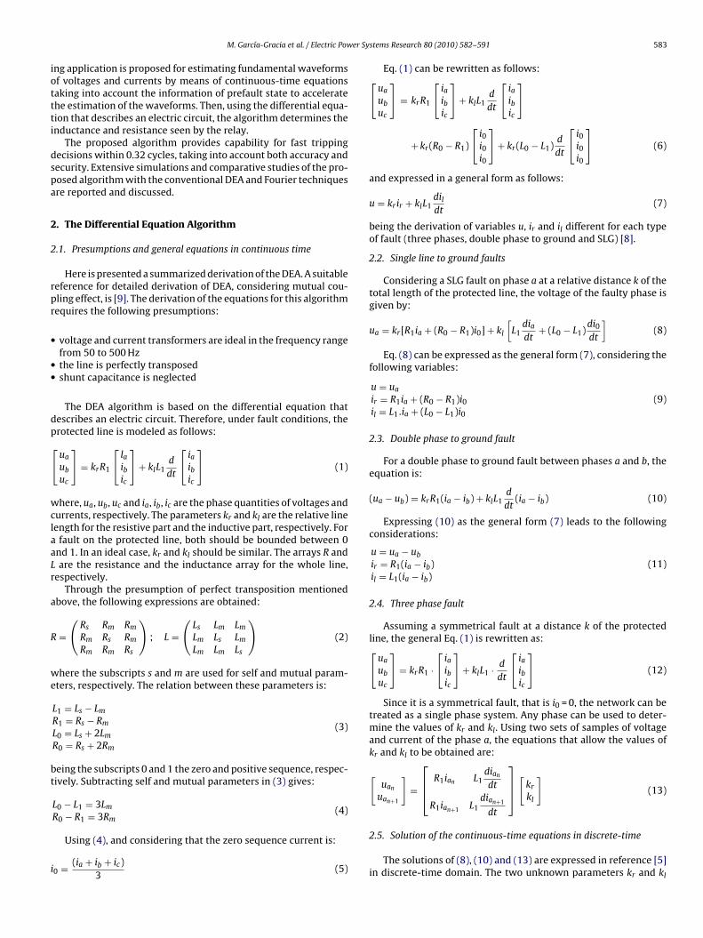
Fig. 2. Power system modeled for analyze
ith filtering application.
as shown in Fig. 1. The proposed filter is based on continuous-timeequations (22) and (28) of voltage and current, respectively, as it isexplained in Section 5.
3. Power system test case simulation
3.1. Power system modeled
The power system shown in Fig. 2 has been considered for thisstudy. The simulation has been done using PSCAD-EMTDC package[16,17] and with a sampling time of at least 50 kHz.
This power system consists in a 45 kV system that feeds a loadof 1.5 MW and 0.53 Mvar through line 1 of 7.7 km and a load of3.93 MW and 2.58 Mvar through line 2 (7.7 km). These loads arealso connected to bus 2, through lines 3 and 4, both of 9.4 km. Theelectrical network connected to bus 1 and bus 2 is represented byits Thévenin equivalents, which are given by:
Zth1 = 4.25/84.4◦ � Zth2 = 8.46/ − 20.57◦ �Uth1 = 49.49/84.4◦ V Uth2 = 44.74/ − 23.3◦ V
subscript th1 and th2 makes reference to the positive and negativeThévenin equivalents, respectively.
Sequence data of the lines 1 and 2, modeled with mutual cou-pling, are the following:
R1 = 1.314 � R0 = 2.650 �L1 = 0.0092 H L0 = 0.0354 H
The THD in voltage waveform (THDV) is generated accordingto [18] with a maximum value of 5.5% in steady-state conditions,resulting a THD in the current waveform (THDI) of 3.3%. The objec-
component of the voltage waveform is shown in Table 1. The plan-ning levels are specified by the electrical utility for all the voltagelevels as internal quality objectives. According to reference [19],the THDV limit expected in HV systems must be lower than 3% andfor LV and MV systems must be within 6%.
the behavior of the DEA algorithm.
M. García-Gracia et al. / Electric Power Sy
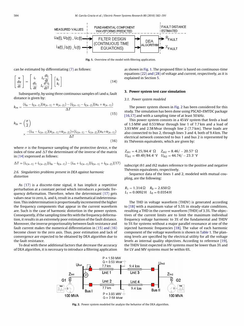
Table 1Harmonic distortion of the applied voltage waveform in the simulated powersystem.
Frequency (Hz) Harmonic number Fundamental voltage percent (%)
60 1 100120 2 1.5180 3 2.0240 4 1.5300 5 2.0420 7 2.0540 9 1.5660 11 1.5780 13 1.5
3
oweca
dp(
u(t) = Upeak 1 sin(ωt − �1) +∑
Upeak h sin(hωt − �h) (18)
1020 17 1.01140 19 1.0
.2. Behavior of the DEA algorithm against harmonic distortion
Fig. 3 shows the reactance estimated by DEA when a SLG faultccurs at instant t = 0.087 s and at 25% of the protected line length,ithout considering harmonic distortion and fault resistance. Oth-
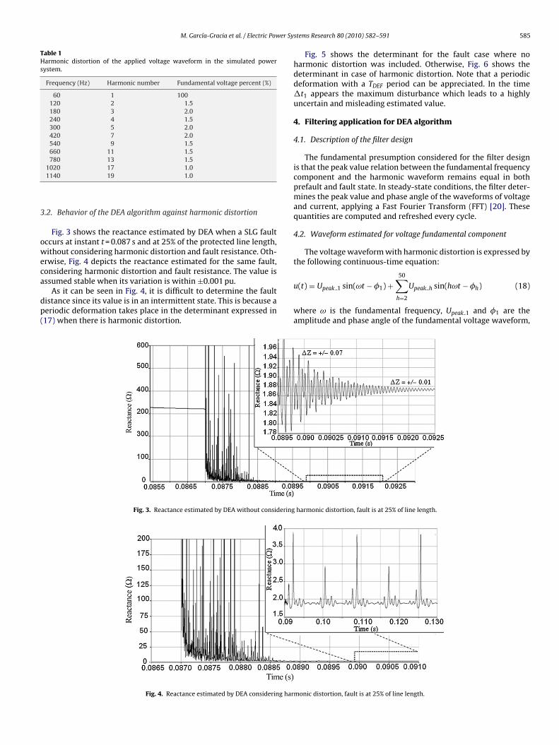
rwise, Fig. 4 depicts the reactance estimated for the same fault,onsidering harmonic distortion and fault resistance. The value isssumed stable when its variation is within ±0.001 pu.
As it can be seen in Fig. 4, it is difficult to determine the faultistance since its value is in an intermittent state. This is because aeriodic deformation takes place in the determinant expressed in17) when there is harmonic distortion.
Fig. 3. Reactance estimated by DEA without considering
Fig. 4. Reactance estimated by DEA considering har
stems Research 80 (2010) 582–591 585
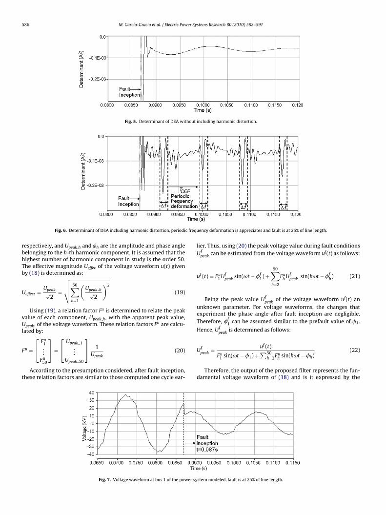
Fig. 5 shows the determinant for the fault case where noharmonic distortion was included. Otherwise, Fig. 6 shows thedeterminant in case of harmonic distortion. Note that a periodicdeformation with a TDEF period can be appreciated. In the time�t1 appears the maximum disturbance which leads to a highlyuncertain and misleading estimated value.
4. Filtering application for DEA algorithm
4.1. Description of the filter design
The fundamental presumption considered for the filter designis that the peak value relation between the fundamental frequencycomponent and the harmonic waveform remains equal in bothprefault and fault state. In steady-state conditions, the filter deter-mines the peak value and phase angle of the waveforms of voltageand current, applying a Fast Fourier Transform (FFT) [20]. Thesequantities are computed and refreshed every cycle.
4.2. Waveform estimated for voltage fundamental component
The voltage waveform with harmonic distortion is expressed bythe following continuous-time equation:
50
h=2
where ω is the fundamental frequency, Upeak 1 and �1 are theamplitude and phase angle of the fundamental voltage waveform,
harmonic distortion, fault is at 25% of line length.
monic distortion, fault is at 25% of line length.
586 M. García-Gracia et al. / Electric Power Systems Research 80 (2010) 582–591
Fig. 5. Determinant of DEA without including harmonic distortion.
c frequ
rbhTb
U
vUl
F
t
Fig. 6. Determinant of DEA including harmonic distortion, periodi
espectively, and Upeak h and �h are the amplitude and phase angleelonging to the h-th harmonic component. It is assumed that theighest number of harmonic component in study is the order 50.he effective magnitude Ueffec of the voltage waveform u(t) giveny (18) is determined as:
effect = Upeak√2
=
√√√√ 50∑h=1
(Upeak h√
2
)2
(19)
Using (19), a relation factor Fu is determined to relate the peakalue of each component, Upeak h, with the apparent peak value,peak, of the voltage waveform. These relation factors Fu are calcu-
ated by:⎡Fu
1⎤ ⎡
Upeak 1⎤
u = ⎣ ...Fu
50
⎦ = ⎣ ...Upeak 50
⎦ 1Upeak
(20)
According to the presumption considered, after fault inception,hese relation factors are similar to those computed one cycle ear-
Fig. 7. Voltage waveform at bus 1 of the power sy
ency deformation is appreciates and fault is at 25% of line length.
lier. Thus, using (20) the peak voltage value during fault conditionsUf
peakcan be estimated from the voltage waveform uf(t) as follows:
uf (t) = Fu1 Uf
peaksin(ωt − �f
1) +50∑
h=2
Fuh Uf
peaksin(hωt − �f
h) (21)
Being the peak value Ufpeak
of the voltage waveform uf(t) anunknown parameter. For voltage waveforms, the changes thatexperiment the phase angle after fault inception are negligible.Therefore, �f
1 can be assumed similar to the prefault value of �1.
Hence, Ufpeak
is determined as follows:
uf (t)
Ufpeak=
Fu1 sin(ωt − �1) +
∑50h=2Fu
hsin(hωt − �h)
(22)
Therefore, the output of the proposed filter represents the fun-damental voltage waveform of (18) and is it expressed by the
stem modeled, fault is at 25% of line length.
M. García-Gracia et al. / Electric Power Systems Research 80 (2010) 582–591 587
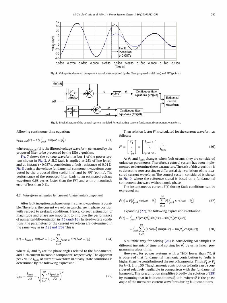
Fig. 8. Voltage fundamental component waveform computed by the filter proposed (solid line) and FFT (points).
for est
f
u
wp
taFppwe
4
bwmott
i
wapd
I
Fig. 9. Block diagram of the control system modeled
ollowing continuous-time equation:
filter out(t) = Fu1 Uf
peaksin(ωt + �f
1) (23)
here ufilter out(t) is the filtered voltage waveform generated by theroposed filter to be processed by the DEA algorithm.
Fig. 7 shows the voltage waveform at bus 1 of the power sys-em shown in Fig. 2. A SLG fault is applied at 25% of line lengthnd at instant t = 0.087 s, considering a fault resistance of 0.01 �.ig. 8 depicts the voltage fundamental component waveform com-uted by the proposed filter (solid line) and by FFT (points). Theerformance of the proposed filter leads to an estimated voltageaveform 0.68 cycles faster than the FFT and with a magnitude
rror of less than 0.1%.
.3. Waveform estimated for current fundamental component
After fault inception, a phase jump in current waveform is possi-le. Therefore, the current waveform can change in phase positionith respect to prefault conditions. Hence, correct estimation ofagnitude and phase are important to improve the performance
f numerical differentiation in (15) and (16). In steady-state condi-ions, the parameters of the current waveform are determined inhe same way as in (19) and (20). This is:
(t) = Ipeak 1 sin(ωt − �1) +50∑
h=2
Ipeak h sin(hωt − �h) (24)
here, �1 and �h are the phase angles related to the fundamentalnd h-th current harmonic component, respectively. The apparenteak value Ipeak of current waveform in steady-state conditions isetermined by the following expression:
effec = Ipeak√2
=
√√√√ 50∑h=1
(Ipeak h√
2
)2
(25)
imating current fundamental component waveform.
Then relation factor Fc is calculated for the current waveform asfollows:
Fc =
⎡⎣ Fc
1...
Fc50
⎤⎦ =
⎡⎣ Ipeak 1
...Ipeak 50
⎤⎦ · 1
Ipeak(26)
As �h and Ipeak changes when fault occurs, they are consideredunknown parameters. Therefore, a control system has been imple-mented to determine these parameters. The task of this algorithm isto detect the zero crossing or differential sign variations of the mea-sured current waveform. The control system considered is shownin Fig. 9, where the reference signal is based on a fundamentalcomponent sinewave without angle phase.
The instantaneous current if(t) during fault conditions can beexpressed as:
if (t) = Fc1If
peaksin(ωt − �f
1) +50∑
h=2
FchIf
peaksin(hωt − �f
h) (27)
Expanding (27), the following expression is obtained:
if (t) = Ifpeak
Fc1(cos(�f
1)sin(ωt) − sin(�f1)cos(ωt))
+ Ifpeak
50∑h=2
Fch(cos(�f
h)sin(hωt) − sin(�f
h)cos(hωt)) (28)
A suitable way for solving (28) is considering 50 samples indifferent instants of time and solving for �f
hby using linear pro-
gramming algorithms.However, for power systems with a THDI lower than 7%, it
is observed that fundamental harmonic contribution to faults ishigher than the contribution of the rest of harmonics. This is Fc
1 � Fch
for h = 2, 3, . . ., 50. Thus, harmonic contribution to faults can be con-sidered relatively negligible in comparison with the fundamentalharmonic. This presumption simplifies broadly the solution of (28)by assuming that in fault conditions �f
1∼= �f , where �f is the phase
angle of the measured current waveform during fault conditions.
588 M. García-Gracia et al. / Electric Power Systems Research 80 (2010) 582–591
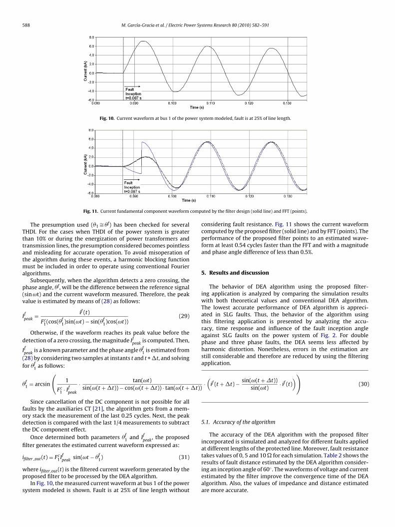
Fig. 10. Current waveform at bus 1 of the power system modeled, fault is at 25% of line length.
comp
Tttatma
p(v
I
d
I
(f
��t))
fodt
fi
i
wp
s
Fig. 11. Current fundamental component waveform
The presumption used (�1 ∼= �f) has been checked for severalHDI. For the cases when THDI of the power system is greaterhan 10% or during the energization of power transformers andransmission lines, the presumption considered becomes pointlessnd misleading for accurate operation. To avoid misoperation ofhe algorithm during these events, a harmonic blocking function
ust be included in order to operate using conventional Fourierlgorithms.
Subsequently, when the algorithm detects a zero crossing, thehase angle, �f, will be the difference between the reference signalsin ωt) and the current waveform measured. Therefore, the peakalue is estimated by means of (28) as follows:
fpeak
= if (t)
Fc1(cos(�f
1)sin(ωt) − sin(�f1)cos(ωt))
(29)
Otherwise, if the waveform reaches its peak value before theetection of a zero crossing, the magnitude If
peakis computed. Then,
fpeak
is a known parameter and the phase angle �f1 is estimated from
28) by considering two samples at instants t and t + �t, and solvingor �f
1 as follows:
f1 = arcsin
(1
Fc1 · If
peak
· tan(ωt)sin(ω(t + �t)) − cos(ω(t + �t)) · tan(ω(t +
Since cancellation of the DC component is not possible for allaults by the auxiliaries CT [21], the algorithm gets from a mem-ry stack the measurement of the last 0.25 cycles. Next, the peaketection is compared with the last 1/4 measurements to subtracthe DC component effect.
Once determined both parameters �f1 and If
peak, the proposed
lter generates the estimated current waveform expressed as:
filter out(t) = Fc1If sin(ωt − �f ) (31)
peak 1
here ifilter out(t) is the filtered current waveform generated by theroposed filter to be processed by the DEA algorithm.
In Fig. 10, the measured current waveform at bus 1 of the powerystem modeled is shown. Fault is at 25% of line length without
uted by the filter design (solid line) and FFT (points).
·(
if (t + �t) − sin(ω(t + �t))sin(ωt)
· if (t)))
(30)
considering fault resistance. Fig. 11 shows the current waveformcomputed by the proposed filter (solid line) and by FFT (points). Theperformance of the proposed filter points to an estimated wave-form at least 0.54 cycles faster than the FFT and with a magnitudeand phase angle difference of less than 0.5%.
5. Results and discussion
The behavior of DEA algorithm using the proposed filter-ing application is analyzed by comparing the simulation resultswith both theoretical values and conventional DEA algorithm.The lowest accurate performance of DEA algorithm is appreci-ated in SLG faults. Thus, the behavior of the algorithm usingthis filtering application is presented by analyzing the accu-racy, time response and influence of the fault inception angleagainst SLG faults on the power system of Fig. 2. For doublephase and three phase faults, the DEA seems less affected byharmonic distortion. Nonetheless, errors in the estimation arestill considerable and therefore are reduced by using the filteringapplication.
5.1. Accuracy of the algorithm
The accuracy of the DEA algorithm with the proposed filterincorporated is simulated and analyzed for different faults appliedat different lengths of the protected line. Moreover, fault resistancetakes values of 0, 5 and 10 � for each simulation. Table 2 shows the
results of fault distance estimated by the DEA algorithm consider-ing an inception angle of 60◦. The waveforms of voltage and currentestimated by the filter improve the convergence time of the DEAalgorithm. Also, the values of impedance and distance estimatedare more accurate.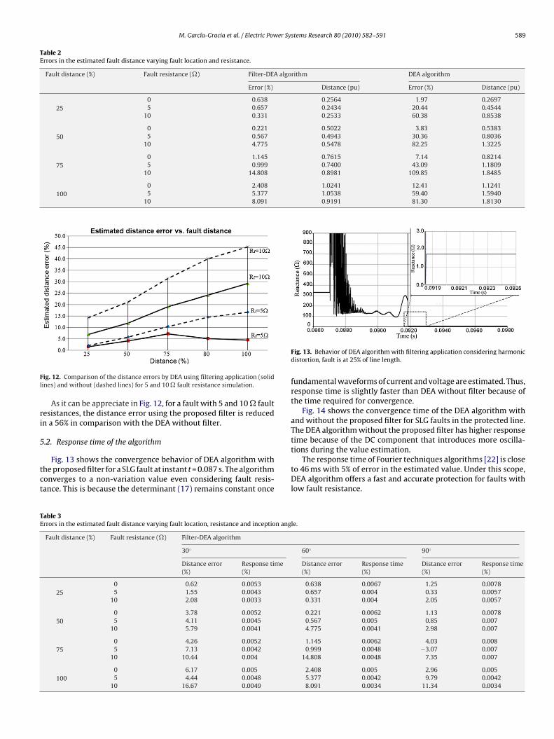
M. García-Gracia et al. / Electric Power Systems Research 80 (2010) 582–591 589
Table 2Errors in the estimated fault distance varying fault location and resistance.
Fault distance (%) Fault resistance (�) Filter-DEA algorithm DEA algorithm
Error (%) Distance (pu) Error (%) Distance (pu)
250 0.638 0.2564 1.97 0.26975 0.657 0.2434 20.44 0.4544
10 0.331 0.2533 60.38 0.8538
500 0.221 0.5022 3.83 0.53835 0.567 0.4943 30.36 0.8036
10 4.775 0.5478 82.25 1.3225
750 1.145 0.7615 7.14 0.82145 0.999 0.7400 43.09 1.1809
10 14.808 0.8981 109.85 1.8485
1000 2.408 1.0241 12.41 1.12415 5.377 1.0538 59.40 1.5940
10 8.091 0.9191 81.30 1.8130
Fl
ri
5
tct
TE
ig. 12. Comparison of the distance errors by DEA using filtering application (solidines) and without (dashed lines) for 5 and 10 � fault resistance simulation.
As it can be appreciate in Fig. 12, for a fault with 5 and 10 � faultesistances, the distance error using the proposed filter is reducedn a 56% in comparison with the DEA without filter.
.2. Response time of the algorithm
Fig. 13 shows the convergence behavior of DEA algorithm withhe proposed filter for a SLG fault at instant t = 0.087 s. The algorithmonverges to a non-variation value even considering fault resis-ance. This is because the determinant (17) remains constant once
able 3rrors in the estimated fault distance varying fault location, resistance and inception ang
Fault distance (%) Fault resistance (�) Filter-DEA algorithm
30◦
Distance error(%)
Response time(%)
250 0.62 0.00535 1.55 0.0043
10 2.08 0.0033
500 3.78 0.00525 4.11 0.0045
10 5.79 0.0041
750 4.26 0.00525 7.13 0.0042
10 10.44 0.004
1000 6.17 0.0055 4.44 0.0048
10 16.67 0.0049
Fig. 13. Behavior of DEA algorithm with filtering application considering harmonicdistortion, fault is at 25% of line length.
fundamental waveforms of current and voltage are estimated. Thus,response time is slightly faster than DEA without filter because ofthe time required for convergence.
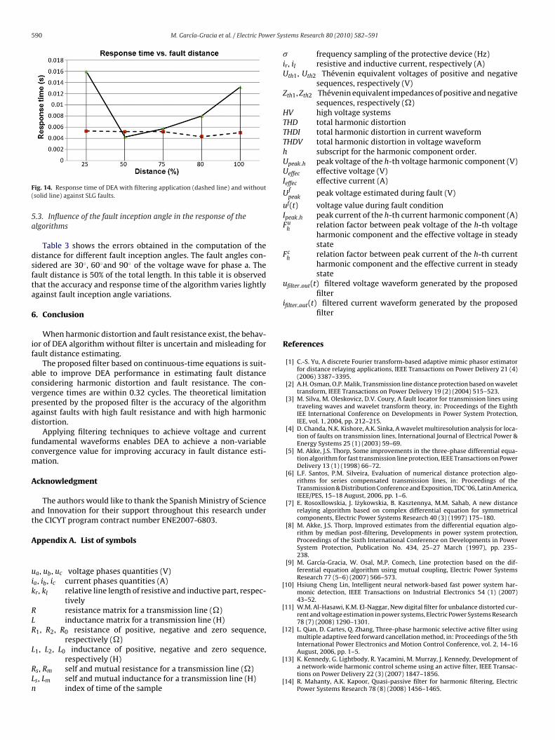
Fig. 14 shows the convergence time of the DEA algorithm withand without the proposed filter for SLG faults in the protected line.The DEA algorithm without the proposed filter has higher responsetime because of the DC component that introduces more oscilla-
tions during the value estimation.The response time of Fourier techniques algorithms [22] is closeto 46 ms with 5% of error in the estimated value. Under this scope,DEA algorithm offers a fast and accurate protection for faults withlow fault resistance.
le.
60◦ 90◦
Distance error(%)
Response time(%)
Distance error(%)
Response time(%)
0.638 0.0067 1.25 0.00780.657 0.004 0.33 0.00570.331 0.004 2.05 0.0057
0.221 0.0062 1.13 0.00780.567 0.005 0.85 0.0074.775 0.0041 2.98 0.007
1.145 0.0062 4.03 0.0080.999 0.0048 −3.07 0.007
14.808 0.0048 7.35 0.007
2.408 0.005 2.96 0.0055.377 0.0042 9.79 0.00428.091 0.0034 11.34 0.0034
590 M. García-Gracia et al. / Electric Power Sy
F(
5a
dsfta
6
if
acvpad
fcm
A
at
A
uik
RLR
L
RLn
[
[
[
ig. 14. Response time of DEA with filtering application (dashed line) and withoutsolid line) against SLG faults.
.3. Influence of the fault inception angle in the response of thelgorithms
Table 3 shows the errors obtained in the computation of theistance for different fault inception angles. The fault angles con-idered are 30◦, 60◦and 90◦ of the voltage wave for phase a. Theault distance is 50% of the total length. In this table it is observedhat the accuracy and response time of the algorithm varies lightlygainst fault inception angle variations.
. Conclusion
When harmonic distortion and fault resistance exist, the behav-or of DEA algorithm without filter is uncertain and misleading forault distance estimating.
The proposed filter based on continuous-time equations is suit-ble to improve DEA performance in estimating fault distanceonsidering harmonic distortion and fault resistance. The con-ergence times are within 0.32 cycles. The theoretical limitationresented by the proposed filter is the accuracy of the algorithmgainst faults with high fault resistance and with high harmonicistortion.
Applying filtering techniques to achieve voltage and currentundamental waveforms enables DEA to achieve a non-variableonvergence value for improving accuracy in fault distance esti-ation.
cknowledgment
The authors would like to thank the Spanish Ministry of Sciencend Innovation for their support throughout this research underhe CICYT program contract number ENE2007-6803.
ppendix A. List of symbols
a, ub, uc voltage phases quantities (V)a, ib, ic current phases quantities (A)r, kl relative line length of resistive and inductive part, respec-
tivelyresistance matrix for a transmission line (�)inductance matrix for a transmission line (H)
1, R2, R0 resistance of positive, negative and zero sequence,respectively (�)
1, L2, L0 inductance of positive, negative and zero sequence,respectively (H)
s, Rm self and mutual resistance for a transmission line (�)s, Lm self and mutual inductance for a transmission line (H)
index of time of the sample
[
[
stems Research 80 (2010) 582–591
� frequency sampling of the protective device (Hz)ir, il resistive and inductive current, respectively (A)Uth1, Uth2 Thévenin equivalent voltages of positive and negative
sequences, respectively (V)Zth1, Zth2 Thévenin equivalent impedances of positive and negative
sequences, respectively (�)HV high voltage systemsTHD total harmonic distortionTHDI total harmonic distortion in current waveformTHDV total harmonic distortion in voltage waveformh subscript for the harmonic component order.Upeak h peak voltage of the h-th voltage harmonic component (V)Ueffec effective voltage (V)Ieffec effective current (A)
Ufpeak
peak voltage estimated during fault (V)
uf(t) voltage value during fault conditionIpeak h peak current of the h-th current harmonic component (A)Fu
hrelation factor between peak voltage of the h-th voltageharmonic component and the effective voltage in steadystate
Fch
relation factor between peak current of the h-th currentharmonic component and the effective current in steadystate
ufilter out(t) filtered voltage waveform generated by the proposedfilter
ifilter out(t) filtered current waveform generated by the proposedfilter
References
[1] C.-S. Yu, A discrete Fourier transform-based adaptive mimic phasor estimatorfor distance relaying applications, IEEE Transactions on Power Delivery 21 (4)(2006) 3387–3395.
[2] A.H. Osman, O.P. Malik, Transmission line distance protection based on wavelettransform, IEEE Transactions on Power Delivery 19 (2) (2004) 515–523.
[3] M. Silva, M. Oleskovicz, D.V. Coury, A fault locator for transmission lines usingtraveling waves and wavelet transform theory, in: Proceedings of the EighthIEE International Conference on Developments in Power System Protection,IEE, vol. 1, 2004, pp. 212–215.
[4] D. Chanda, N.K. Kishore, A.K. Sinka, A wavelet multiresolution analysis for loca-tion of faults on transmission lines, International Journal of Electrical Power &Energy Systems 25 (1) (2003) 59–69.
[5] M. Akke, J.S. Thorp, Some improvements in the three-phase differential equa-tion algorithm for fast transmission line protection, IEEE Transactions on PowerDelivery 13 (1) (1998) 66–72.
[6] L.F. Santos, P.M. Silveira, Evaluation of numerical distance protection algo-rithms for series compensated transmission lines, in: Proceedings of theTransmission & Distribution Conference and Exposition, TDC ’06, Latin America,IEEE/PES, 15–18 August, 2006, pp. 1–6.
[7] E. Rosoxllowskia, J. Izykowskia, B. Kasztennya, M.M. Sahab, A new distancerelaying algorithm based on complex differential equation for symmetricalcomponents, Electric Power Systems Research 40 (3) (1997) 175–180.
[8] M. Akke, J.S. Thorp, Improved estimates from the differential equation algo-rithm by median post-filtering, Developments in power system protection,Proceedings of the Sixth International Conference on Developments in PowerSystem Protection, Publication No. 434, 25–27 March (1997), pp. 235–238.
[9] M. García-Gracia, W. Osal, M.P. Comech, Line protection based on the dif-ferential equation algorithm using mutual coupling, Electric Power SystemsResearch 77 (5–6) (2007) 566–573.
10] Hsiung Cheng Lin, Intelligent neural network-based fast power system har-monic detection, IEEE Transactions on Industrial Electronics 54 (1) (2007)43–52.
11] W.M. Al-Hasawi, K.M. El-Naggar, New digital filter for unbalance distorted cur-rent and voltage estimation in power systems, Electric Power Systems Research78 (7) (2008) 1290–1301.
12] L. Qian, D. Cartes, Q. Zhang, Three-phase harmonic selective active filter usingmultiple adaptive feed forward cancellation method, in: Proceedings of the 5thInternational Power Electronics and Motion Control Conference, vol. 2, 14–16
August, 2006, pp. 1–5.13] K. Kennedy, G. Lightbody, R. Yacamini, M. Murray, J. Kennedy, Development ofa network-wide harmonic control scheme using an active filter, IEEE Transac-tions on Power Delivery 22 (3) (2007) 1847–1856.
14] R. Mahanty, A.K. Kapoor, Quasi-passive filter for harmonic filtering, ElectricPower Systems Research 78 (8) (2008) 1456–1465.
er Sy
[
[[
[
[
[
[
[
MhZEsg
systems; and optimization.
M. García-Gracia et al. / Electric Pow
15] M.M. Begovic, P.M. Djuric, S. Dunlap, A.G. Phadke, Frequency tracking in powernetworks in the presence of harmonics power delivery, IEEE Transactions onPower Delivery 8 (2) (1993) 480–486.
16] PSCAD v4.2, Manitoba HVDC Research Centre, 2006.17] H.W. Dommel, Digital computer solution of electromagnetic transients in
single-and multiphase networks, IEEE Transactions on Power Apparatus andSystems PAS-4 (1969) 388–399.
18] IEEE Recommend Practices and Requirements for Harmonic Control in Electri-cal Power Systems, IEEE Std. 519-1992, 1992, pp. 55–88.
19] International Electrotechnical Commission, Assessment of emission limits fordistorting loads in MV and HV power systems, Technical Report IEC 61000-3-7- Electromagnetic Compatibility (EMC), Part 3, Section 6, 2006, pp. 12–59.
20] P. Duhamel, M. Vetterli, Fast Fourier transforms: a tutorial review and a stateof the art, Signal Processing 19 (1990) 259–299.
21] J. Barry, I.F. Morrison, Digital calculation of impedance for transmission lineprotection, IEEE Transactions on Power Apparatus and Systems PAS-90 (1971)270–276.
22] D. D’Amore, A. Ferrero, A simplified algorithm for digital distance protectionbased on Fourier techniques, IEEE Transactions on Power Delivery 4 (1) (1989)157–164.
iguel García-Gracia was born in Saint-Brieuc, France on April 23, 1963. He receivedis B.S. (1986), M.Sc. (1989), and Ph.D. (1996) degrees from the University ofaragoza. He is presently Lecturer of Electrical Engineering and Area Director oflectric Power System at Circe. His main research interests are in the field of powerystem, power system protection, electrical energy system, renewable energy inte-ration, lightning protections and dielectrics.
stems Research 80 (2010) 582–591 591
N. El Halabi received the Electrical Engineering degree in 2006 from UniversidadSimón Bolívar, Venezuela. He is currently performing the Ph.D. in Renewable Energyat Universidad de Zaragoza, Spain. His research interests are Power system protec-tion, integration and planning of hybrid power systems.
Antonio Montanés received his M.S. (2003) degree from the University of Zaragoza.He is presently Lecturer of Electrical Engineering, University of Zaragoza. His fieldsof interest include protective relaying, and fault location in transmission line, andhe is presently continuing his work towards a PhD in the area of fault location indistribution systems.
H.M. Khodr received the Ph.D., M.Sc., and Engineer degrees in electrical engineer-ing from the José Antonio Echeverría Higher Polytechnic Institute (ISPJAE), Havana,Cuba, in 1997 and 1993, respectively. He is a former Associate Professor of electricalengineering at Universidad Simón Bolívar, Caracas, Venezuela. He was a Researcherat INESC Porto, Porto, Portugal. Presently, he is a Researcher at GECAD, Porto. Hehas participated in a number of projects performed for the local industries. His cur-rent research activities are concentrated on planning, operation, and economics ofelectrical distribution and industrial power systems; electricity market; grounding
M. Villén received her B.S. (2002) and M.Sc. (2008) degrees in Industrial Engineeringfrom the University of Zaragoza. She is currently performing the Ph.D. in ElectricPower Systems at the University of Zaragoza. Her research interests are modelingElectrical machines and Relaying systems.


