Embed Size (px)
Citation preview
EDAN Agile PLM Electronic Signature Information--Signatures related to this document and performed in EDAN Agile PLM.
文件名称(Document Name):iM3 说明书_英文文件编号(Number):01.54.457703版本(Version):1.1产品型号(Product Model):iM3项目编码(Project Code):00004I002 签批信息(Signature): 作者(Originator) : 陈 艳娟 (chenyanjuan) 2017-08-23 10:53:00 审核人(Reviewers) : 程 亮 (chengliang) 2017-08-24 13:01:47 审核人(Reviewers) : 史 洪华 (shihonghua) 2017-08-23 11:16:51 审核人(Reviewers) : 韦 华彪 (weihuabiao) 2017-08-23 11:19:01 审核人(Reviewers) : 陈 良款 (chenliangkuan) 2017-08-23 13:23:34 批准人(Approvers) : 夏 欢欢 (xiahuanhuan) 2017-08-29 18:57:24 批准人(Approvers) : 陈 浩杰 (chenhaojie) 2017-08-29 16:16:36 版权©深圳市理邦精密仪器股份有限公司 (Copyright©Edan Instrument,Inc.)


I
About this Manual
P/N: 01.54.457703
MPN: 01.54.457703011
Release Date: August 2017
© Copyright EDAN INSTRUMENTS, INC. 2017. All rights reserved.
Statement
This manual will help you understand the operation and maintenance of the product better. It is
reminded that the product shall be used strictly complying with this manual. User‘s operation
failing to comply with this manual may result in malfunction or accident for which EDAN
INSTRUMENTS, INC. (hereinafter called EDAN) cannot be held liable.
EDAN owns the copyrights of this manual. Without prior written consent of EDAN, any
materials contained in this manual shall not be photocopied, reproduced or translated into other
languages.
Materials protected by the copyright law, including but not limited to confidential information
such as technical information and patent information are contained in this manual, the user shall
not disclose such information to any irrelevant third party.
The user shall understand that nothing in this manual grants him, expressly or implicitly, any
right or license to use any of the intellectual properties of EDAN.
EDAN holds the rights to modify, update, and ultimately explain this manual.
Responsibility of the Manufacturer
EDAN only considers itself responsible for any effect on safety, reliability and performance of
the equipment if:
Assembly operations, extensions, re-adjustments, modifications or repairs are carried out by
persons authorized by EDAN, and
The electrical installation of the relevant room complies with national standards, and
The instrument is used in accordance with the instructions for use.

II
Terms Used in this Manual
This guide is designed to give key concepts on safety precautions.
WARNING
A WARNING label advises against certain actions or situations that could result in personal
injury or death.
CAUTION
A CAUTION label advises against actions or situations that could damage equipment, produce
inaccurate data, or invalidate a procedure.
NOTE
A NOTE provides useful information regarding a function or a procedure.

III
Table of Contents
Chapter 1 Intended Use and Safety Guidance ................................................................................ 1
1.1 Intended Use/Indications for Use ........................................................................................... 1
1.2 Safety Guidance ..................................................................................................................... 1
1.3 Explanation of Symbols on the Monitor ................................................................................ 6
Chapter 2 Installation ........................................................................................................................ 9
2.1 Initial Inspection..................................................................................................................... 9
2.2 Mounting the Monitor ............................................................................................................ 9
2.3 Connecting the Power Cable .................................................................................................. 9
2.4 Checking the Monitor ............................................................................................................ 9
2.5 Connecting Sensor to Patient ............................................................................................... 10
2.6 Checking the Recorder ......................................................................................................... 10
2.7 Setting Date and Time .......................................................................................................... 10
2.8 Handing Over the Monitor ................................................................................................... 10
Chapter 3 Basic Operation .............................................................................................................. 11
3.1 Overview .............................................................................................................................. 11
3.1.1 Front View ................................................................................................................. 11
3.1.2 Rear View .................................................................................................................. 13
3.1.3 Side View .................................................................................................................. 15
3.2 Operating and Navigating .................................................................................................... 16
3.2.1 Using Keys ................................................................................................................ 19
3.3 Operating Mode ................................................................................................................... 21
3.3.1 Demo Mode ............................................................................................................... 21
3.3.2 Standby Mode ........................................................................................................... 21
3.3.3 Night Mode ............................................................................................................... 22
3.3.4 Other Modes .............................................................................................................. 22
3.4 Changing Monitor Settings .................................................................................................. 22
3.4.1 Adjusting Screen Brightness ..................................................................................... 22
3.4.2 Adjusting Volume ...................................................................................................... 23
3.5 Checking Your Monitor Information ................................................................................... 23
3.6 Networked Monitoring ......................................................................................................... 23
3.7 Common Settings ................................................................................................................. 24
3.8 Disabling the Touch Screen.................................................................................................. 24
3.9 Using the Barcode Scanner .................................................................................................. 24
3.10 Using Keyboard and Mouse ............................................................................................... 24
Chapter 4 Alarms ............................................................................................................................. 25
4.1 Alarm Category .................................................................................................................... 25
4.1.1 Physiological Alarms ................................................................................................ 25
4.1.2 Technical Alarms ....................................................................................................... 25
4.1.3 Prompts ..................................................................................................................... 25
IV
4.2 Selecting Alarm Tone Type .................................................................................................. 25
4.3 Alarm Levels ........................................................................................................................ 26
4.4 Controlling Alarm ................................................................................................................ 27
4.4.1 Setting Parameter Alarm ........................................................................................... 27
4.4.2 Audio Alarm Paused .................................................................................................. 28
4.4.3 Audio Alarm off ........................................................................................................ 29
4.4.4 Alarm Reset ............................................................................................................... 29
4.5 Latching Alarms ................................................................................................................... 30
4.6 Alarm of SpO2 Sensor Off .................................................................................................... 30
4.7 Network Disconnected Alarms ............................................................................................ 30
4.8 Delete All Alarm Events ...................................................................................................... 30
4.9 Testing Alarms...................................................................................................................... 31
Chapter 5 Alarm Information ......................................................................................................... 32
5.1 Physiological Alarm Information ......................................................................................... 32
5.2 Technical Alarm Information ............................................................................................... 33
5.3 Prompts ................................................................................................................................ 40
5.4 Adjustable Range of Alarm Limits ....................................................................................... 41
Chapter 6 Managing Patients ......................................................................................................... 43
6.1 Monitor Mode ...................................................................................................................... 43
6.1.1 Admitting a Patient .................................................................................................... 43
6.1.2 Quick Admit .............................................................................................................. 44
6.1.3 Editing Patient Information ....................................................................................... 44
6.2 Round Mode ......................................................................................................................... 44
6.2.1 Patient Management .................................................................................................. 44
6.2.2 Choose Patient for Measurement .............................................................................. 46
6.2.3 Round Record ........................................................................................................... 46
6.3 Spot-checking Mode ............................................................................................................ 47
6.3.1 Admit Patient ............................................................................................................. 47
6.3.2 Modify Patient Information....................................................................................... 47
6.4 Inquire for Patient Information via Network ....................................................................... 47
6.5 Central Monitoring System .................................................................................................. 48
Chapter 7 User Interface ................................................................................................................. 49
7.1 Setting Interface Style .......................................................................................................... 49
7.2 Selecting Display Parameters ............................................................................................... 49
7.3 Changing Parameter and Waveform Colors ......................................................................... 49
7.4 User Configuration ............................................................................................................... 49
7.5 Default Configuration .......................................................................................................... 50
Chapter 8 Monitoring SpO2 ............................................................................................................ 51
8.1 Overview .............................................................................................................................. 51
8.2 SpO2 Safety Information ...................................................................................................... 51
V
8.3 Measuring SpO2 ................................................................................................................... 52
8.4 Measurement Limitations .................................................................................................... 53
8.5 Assessing the Validity of a SpO2 Reading ............................................................................ 54
8.6 SpO2 Alarm Delay ................................................................................................................ 54
8.7 Perfusion Index (PI)* ........................................................................................................... 55
8.8 Setting Pitch Tone ................................................................................................................ 55
8.9 Setting Sensitivity ................................................................................................................ 55
8.10 NIBP/SpO2 Simul Measurement Setting ........................................................................... 55
8.11 SatSeconds Alarm Management* ....................................................................................... 56
8.11.1 Describing SatSeconds ............................................................................................ 56
8.11.2 SatSeconds ―Safety Net‖ ......................................................................................... 57
8.11.3 Setting SatSeconds Duration ................................................................................... 57
Chapter 9 Monitoring PR ................................................................................................................ 58
9.1 Overview .............................................................................................................................. 58
9.2 PR Source ............................................................................................................................. 58
9.3 Setting PR Volume ............................................................................................................... 58
Chapter 10 Monitoring NIBP ......................................................................................................... 59
10.1 Overview ............................................................................................................................ 59
10.2 NIBP Safety Information ................................................................................................... 59
10.3 Measurement Limitations .................................................................................................. 60
10.4 Measurement Methods ....................................................................................................... 61
10.5 Measurement Procedures ................................................................................................... 61
10.5.1 Operation Prompts .................................................................................................. 63
10.5.2 Correcting the Measurement if Limb is not at Heart Level .................................... 64
10.6 NIBP Multi-Review Window ............................................................................................. 64
10.7 Resetting NIBP .................................................................................................................. 64
10.8 Calibrating NIBP ................................................................................................................ 65
10.9 Leakage Test ....................................................................................................................... 65
10.10 Setting Inflation Value ...................................................................................................... 66
10.11 Measuring PR ................................................................................................................... 66
10.12 NIBP Auto Recording ...................................................................................................... 66
Chapter 11 Monitoring TEMP ........................................................................................................ 67
11.1 Quick TEMP with T2A Module ......................................................................................... 67
11.1.1 Introduction ............................................................................................................. 67
11.1.2 Measuring Procedure............................................................................................... 68
11.1.3 TEMP Setup for T2A Module ................................................................................. 69
11.2 Quick TEMP with F3000 Module ...................................................................................... 69
11.2.1 Introduction ............................................................................................................. 69
11.2.2 Probe Covers —Applying & Removing ................................................................. 71
11.2.3 Changing Isolation Chambers and Probes .............................................................. 71
VI
11.2.4 Measuring Mode ..................................................................................................... 72
11.2.5 Measuring Procedure............................................................................................... 73
11.2.6 TEMP Setup for F3000 Module .............................................................................. 74
11.3 Infrared TEMP with TH Module ........................................................................................ 75
11.3.1 Introduction ............................................................................................................. 75
11.3.2 Measuring Procedure............................................................................................... 76
11.3.3 Replacing the Battery .............................................................................................. 78
Chapter 12 Review (in Monitor Mode) .......................................................................................... 80
12.1 Trend Graph Review .......................................................................................................... 80
12.1.1 Selecting Trend Graph of Specific Parameter ......................................................... 80
12.1.2 Adjusting Trend Scale ............................................................................................. 80
12.1.3 Setting Interval ........................................................................................................ 80
12.1.4 Scrolling Left and Right the Screen ........................................................................ 80
12.2 Trend Table Review ........................................................................................................... 80
12.2.1 Setting Interval ........................................................................................................ 81
12.2.2 Scrolling the Screen ................................................................................................ 81
12.3 NIBP Review...................................................................................................................... 81
12.3.1 Scrolling the Screen ................................................................................................ 81
12.4 Alarm Review..................................................................................................................... 81
12.4.1 Scrolling the Screen ................................................................................................ 81
12.4.2 Selecting Alarm Event of Specific Parameter ......................................................... 82
12.4.3 Setting Time Index .................................................................................................. 82
12.5 Technical Alarm Checking ................................................................................................. 82
12.6 Event Marking .................................................................................................................... 82
Chapter 13 Review (in Round or Spot-checking Mode) ............................................................... 83
13.1 Round Record Management ............................................................................................... 83
13.2 Review Spot-checking Data ............................................................................................... 83
13.3 Spot-checking Data Trend Table ........................................................................................ 84
Chapter 14 Recording ...................................................................................................................... 85
14.1 Performance of the Recorder ............................................................................................. 85
14.2 Starting and Stopping Recording ....................................................................................... 86
14.3 Recorder Operations and Status Messages ........................................................................ 87
14.3.1 Record Paper Requirement ..................................................................................... 87
14.3.2 Proper Operation ..................................................................................................... 87
14.3.3 Paper Out ................................................................................................................. 87
14.3.4 Replacing Paper ...................................................................................................... 87
14.3.5 Removing Paper Jam............................................................................................... 89
Chapter 15 Other Functions............................................................................................................ 90
15.1 Nurse Call .......................................................................................................................... 90
15.2 Wi-Fi .................................................................................................................................. 90
VII
15.3 E-link Function .................................................................................................................. 91
15.4 Uploading Data to Network Server .................................................................................... 92
15.5 Storing Data in the Storage Device .................................................................................... 92
15.5.1 Data Stored in the Storage Device .......................................................................... 92
15.5.2 Selecting a Storage Device ...................................................................................... 93
15.5.3 Reviewing Data Stored in the Storage Device ........................................................ 94
15.5.4 Deleting Data Stored in the Storage Device ............................................................ 94
15.5.5 Exporting Data Stored in the Internal Storage Device ............................................ 94
15.5.6 Ejecting a Removable Device ................................................................................. 95
15.5.7 Recording Data by Recorder ................................................................................... 95
15.5.8 Formatting the Internal Storage Device .................................................................. 95
15.6 Warning-Score System ....................................................................................................... 96
15.6.1 Warning-Score Interface ......................................................................................... 96
15.6.2 Warning-Score Method ........................................................................................... 96
15.6.3 Warning-Score Criteria ........................................................................................... 96
15.6.4 Warning-Score Result ............................................................................................. 98
15.6.5 Warning-Score Trend Table ..................................................................................... 99
15.7 Alert Setup .......................................................................................................................... 99
Chapter 16 Using Battery .............................................................................................................. 101
16.1 Battery Safety Information ............................................................................................... 101
16.2 Battery Power Indicator ................................................................................................... 102
16.3 Battery Status on the Main Screen ................................................................................... 102
16.4 Checking Battery Performance ........................................................................................ 102
16.5 Replacing the Battery ....................................................................................................... 103
16.6 Recycling the Battery ....................................................................................................... 103
16.7 Maintaining the Battery.................................................................................................... 103
Chapter 17 Care and Cleaning ..................................................................................................... 104
17.1 General Points .................................................................................................................. 104
17.2 Cleaning ........................................................................................................................... 104
17.2.1 Cleaning the Monitor ............................................................................................ 105
17.2.2 Cleaning the Reusable Accessories ....................................................................... 105
17.3 Disinfection ...................................................................................................................... 106
17.3.1 Disinfecting the Monitor ....................................................................................... 106
17.3.2 Disinfecting the Reusable Accessories.................................................................. 107
17.4 Cleaning and Disinfecting Other Accessories .................................................................. 108
Chapter 18 Maintenance ............................................................................................................... 109
18.1 Inspecting ......................................................................................................................... 109
18.2 Maintenance Task and Test Schedule ............................................................................... 109
Chapter 19 Warranty and Service ................................................................................................ 110
19.1 Warranty ........................................................................................................................... 110
VIII
19.2 Contact Information ......................................................................................................... 110
Chapter 20 Accessories .................................................................................................................. 111
20.1 SpO2 Accessories ............................................................................................................. 111
20.2 NIBP Accessories ............................................................................................................. 112
20.3 TEMP Accessories ........................................................................................................... 113
20.4 Other Accessories ............................................................................................................. 114
A Product Specification ................................................................................................................. 116
A.1 Classification ..................................................................................................................... 116
A.2 Physical Specifications ...................................................................................................... 116
A.2.1 Size and Weight ...................................................................................................... 116
A.2.2 Environment Specification ..................................................................................... 116
A.2.3 Display ................................................................................................................... 117
A.2.4 Battery Specification .............................................................................................. 117
A.2.5 Recorder ................................................................................................................. 118
A.2.6 Data Storage ........................................................................................................... 118
A.3 NIBP .................................................................................................................................. 119
A.4 SpO2 .................................................................................................................................. 122
A.5 TEMP ................................................................................................................................ 123
A.6 Adjustable Range of Alert Limits ...................................................................................... 125
A.7 Wi-Fi.................................................................................................................................. 126
A.8 E-link ................................................................................................................................. 126
A.9 Interfaces ........................................................................................................................... 127
A.9.1 Nurse Call ............................................................................................................... 127
A.9.2 USB Interfaces ....................................................................................................... 127
A.9.3 OTG Interfaces ....................................................................................................... 127
A.9.4 Network Interface ................................................................................................... 127
B EMC Information ....................................................................................................................... 128
B.1 Electromagnetic Emissions ............................................................................................... 128
B.2 Electromagnetic Immunity ................................................................................................ 128
B.3 Electromagnetic Immunity ................................................................................................ 130
B.4 Recommended Separation Distances ................................................................................ 132
C Default Settings ........................................................................................................................... 134
C.1 Patient Information Default Settings ................................................................................. 134
C.2 Alarm Default Settings ...................................................................................................... 134
C.3 SpO2 Default Settings ........................................................................................................ 134
C.4 PR Default Settings ........................................................................................................... 135
C.5 NIBP Default Settings ....................................................................................................... 135
C.6 TEMP Default Settings ...................................................................................................... 136
D Abbreviations .............................................................................................................................. 137
Vital Signs Monitor User Manual Intended Use and Safety Guidance
- 1 -
Chapter 1 Intended Use and Safety Guidance
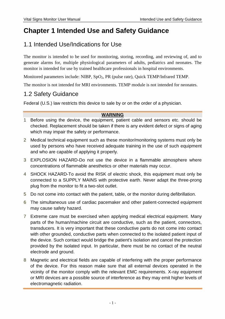
1.1 Intended Use/Indications for Use
The monitor is intended to be used for monitoring, storing, recording, and reviewing of, and to
generate alarms for, multiple physiological parameters of adults, pediatrics and neonates. The
monitor is intended for use by trained healthcare professionals in hospital environments.
Monitored parameters include: NIBP, SpO2, PR (pulse rate), Quick TEMP/Infrared TEMP.
The monitor is not intended for MRI environments. TEMP module is not intended for neonates.
1.2 Safety Guidance
Federal (U.S.) law restricts this device to sale by or on the order of a physician.
WARNING 1 Before using the device, the equipment, patient cable and sensors etc. should be
checked. Replacement should be taken if there is any evident defect or signs of aging
which may impair the safety or performance.
2 Medical technical equipment such as these monitor/monitoring systems must only be
used by persons who have received adequate training in the use of such equipment
and who are capable of applying it properly.
3 EXPLOSION HAZARD-Do not use the device in a flammable atmosphere where
concentrations of flammable anesthetics or other materials may occur.
4 SHOCK HAZARD-To avoid the RISK of electric shock, this equipment must only be
connected to a SUPPLY MAINS with protective earth. Never adapt the three-prong
plug from the monitor to fit a two-slot outlet.
5 Do not come into contact with the patient, table, or the monitor during defibrillation.
6 The simultaneous use of cardiac pacemaker and other patient-connected equipment
may cause safety hazard.
7 Extreme care must be exercised when applying medical electrical equipment. Many
parts of the human/machine circuit are conductive, such as the patient, connectors,
transducers. It is very important that these conductive parts do not come into contact
with other grounded, conductive parts when connected to the isolated patient input of
the device. Such contact would bridge the patient's isolation and cancel the protection
provided by the isolated input. In particular, there must be no contact of the neutral
electrode and ground.
8 Magnetic and electrical fields are capable of interfering with the proper performance
of the device. For this reason make sure that all external devices operated in the
vicinity of the monitor comply with the relevant EMC requirements. X-ray equipment
or MRI devices are a possible source of interference as they may emit higher levels of
electromagnetic radiation.
Vital Signs Monitor User Manual Intended Use and Safety Guidance
- 2 -
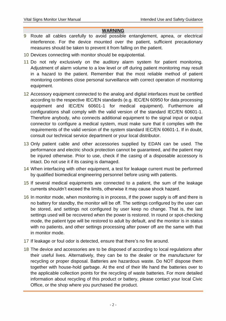
WARNING 9 Route all cables carefully to avoid possible entanglement, apnea, or electrical
interference. For the device mounted over the patient, sufficient precautionary
measures should be taken to prevent it from falling on the patient.
10 Devices connecting with monitor should be equipotential.
11 Do not rely exclusively on the auditory alarm system for patient monitoring.
Adjustment of alarm volume to a low level or off during patient monitoring may result
in a hazard to the patient. Remember that the most reliable method of patient
monitoring combines close personal surveillance with correct operation of monitoring
equipment.
12 Accessory equipment connected to the analog and digital interfaces must be certified
according to the respective IEC/EN standards (e.g. IEC/EN 60950 for data processing
equipment and IEC/EN 60601-1 for medical equipment). Furthermore all
configurations shall comply with the valid version of the standard IEC/EN 60601-1.
Therefore anybody, who connects additional equipment to the signal input or output
connector to configure a medical system, must make sure that it complies with the
requirements of the valid version of the system standard IEC/EN 60601-1. If in doubt,
consult our technical service department or your local distributor.
13 Only patient cable and other accessories supplied by EDAN can be used. The
performance and electric shock protection cannot be guaranteed, and the patient may
be injured otherwise. Prior to use, check if the casing of a disposable accessory is
intact. Do not use it if its casing is damaged.
14 When interfacing with other equipment, a test for leakage current must be performed
by qualified biomedical engineering personnel before using with patients.
15 If several medical equipments are connected to a patient, the sum of the leakage
currents shouldn‟t exceed the limits, otherwise it may cause shock hazard.
16 In monitor mode, when monitoring is in process, if the power supply is off and there is
no battery for standby, the monitor will be off. The settings configured by the user can
be stored, and settings not configured by user keep no change. That is, the last
settings used will be recovered when the power is restored. In round or spot-checking
mode, the patient type will be restored to adult by default, and the monitor is in status
with no patients, and other settings processing after power off are the same with that
in monitor mode.
17 If leakage or foul odor is detected, ensure that there‟s no fire around.
18 The device and accessories are to be disposed of according to local regulations after
their useful lives. Alternatively, they can be to the dealer or the manufacturer for
recycling or proper disposal. Batteries are hazardous waste. Do NOT dispose them
together with house-hold garbage. At the end of their life hand the batteries over to
the applicable collection points for the recycling of waste batteries. For more detailed
information about recycling of this product or battery, please contact your local Civic
Office, or the shop where you purchased the product.
Vital Signs Monitor User Manual Intended Use and Safety Guidance
- 3 -
WARNING
19 The packaging is to be disposed of according to local or hospital‟s regulations;
otherwise, it may cause environmental contamination. Place the packaging at the
place which is inaccessible to children.
20 This equipment is not intended for home usage.
21 Do not service or maintain the monitor or any accessory which is in use with the patient.
22 The appliance coupler or mains plug is used as isolation means from supply mains.
Position the monitor in a location where the operator can easily access the
disconnection device.
23 Assembly of the monitor and modifications during actual service life shall be
evaluated based on the requirements of IEC60601-1.
24 The monitors are MR Unsafe. The monitors are not intended for use in an MRI environment.
25 Only recommended batteries can be used for the monitor.
26 In monitor mode, without use of data store function, all data measured (including trend
data, review data, alarm events and so on) are cleared either when the monitor is
turned off or when the monitor is powered down in the process of monitoring.
27 Additional multiple socket-outlets or extension cords can‟t be connected to the
system.
28 Only items that have been specified as part of the system or specified as being
compatible with the system can be connected to the system.
29 Connecting any accessory (such as external printer) or other device (such as the
computer) to this monitor makes a medical system. In that case, additional safety
measures should be taken during installation of the system, and the system shall
provide:
a) Within the patient environment, a level of safety comparable to that provided by
medical electrical equipment complying with IEC/EN 60601-1, and
b) Outside the patient environment, the level of safety appropriate for non-medical
electrical equipment complying with other IEC or ISO safety standards.
30 The medical electrical equipment needs to be installed and put into service according
to the EMC Information provided in this user manual.
31 Portable and mobile RF communications equipment can affect medical electrical
equipment; refer to the recommended separation distances provided in this user
manual.
32 Using accessories other than those specified may result in increased electromagnetic
emission or decreased electromagnetic immunity of the monitoring equipment.
Vital Signs Monitor User Manual Intended Use and Safety Guidance
- 4 -
WARNING
33 The monitor should not be used adjacent to or stacked with other equipment. If
adjacent or stacked use is necessary, you must check that normal operation is
possible in the necessary configuration before you start monitoring patients.
34 Do not touch accessible parts of medical or non-medical electrical equipment in the
patient environment and the patient simultaneously, such as USB connector, VGA
connector or other signal input/output connectors.
35 SHOCK HAZARD - Don't connect electrical equipment, which has not been supplied
as a part of the system, to the multiple portable socket-outlet supplying the system.
36 SHOCK HAZARD - Don't connect electrical equipment, which has been supplied as a
part of the system, directly to the wall outlet when the non-medical equipment is
intended to be supplied by a multiple portable socket-outlet with an isolation
transformer.
37 Operation of the equipment exceeding specified physiological signal or the
operational specification may cause inaccurate results.
38 The equipment can provide protective means to prevent the patient from being
burned when used with HF SURGICAL EQUIPMENT. The equipment can protect
against the effects of the discharge of a defibrillator. Use only EDAN-approved
accessories.
39 When the monitor is used with HF surgical equipment, the transducer and the cables
must be avoided from conductive connection to the HF equipment. This is to protect
against burns to the patient.
40 To protect the monitor from damage during defibrillation, for accurate measurement
information and to protect against noise and other interference, use only accessories
specified by EDAN.
41 No modification of this equipment is allowed without authorization of the manufacturer.
If this equipment is modified, appropriate inspection and testing must be conducted to
ensure continued safe operation.
42 Clinical decision making based on the output of the device is left to the discretion of
the provider.
43 The monitor is equipped with Wi-Fi to receive RF electromagnetic energy. Therefore,
any other equipment complying with CISPR radiation requirements may also interfere
with the wireless communication and make it interrupted.
44 If the earth protection system is not stable, use the batteries for power supply.
Vital Signs Monitor User Manual Intended Use and Safety Guidance
- 5 -
WARNING
45 Wireless LAN equipment contains an intentional RF radiator that has the potential of
interfering with other medical equipment, including patient implanted devices. Be sure
to perform the electromagnetic compatibility test, as described in the Wireless LAN
System Installation, before installation and any time new medical equipment is added
to the Wireless LAN coverage area.
46 Portable RF communications equipment (including peripherals such as antenna
cables and external antennas) should be used no closer than 30 cm (12 inches) to
any part of the monitor, including cables specified by the manufacturer. Otherwise,
degradation of the performance of this equipment could result.
47 When the monitor is used with HF surgical equipment, user (doctor or nurse) should
be cautious about patient safety.
48 If device conflict occurs when monitor is connected to gateway, please modify the IP
address of the conflicted monitor.
CAUTION
1 Electromagnetic Interference - Ensure that the environment in which the patient
monitor is installed is not subject to any sources of strong electromagnetic
interference, such as radio transmitters, mobile telephones, microwaves, etc.
2 Keep the environment clean. Avoid vibration. Keep it far away from corrosive
medicine, dust area, high temperature and humid environment.
3 Do not immerse transducers in liquid. When using solutions, use sterile wipes to avoid
pouring fluids directly on the transducer.
4 Do not use autoclave or gas to sterilize the monitor, recorder or any accessories.
5 The device and reusable accessories may be sent back to the manufacturer for
recycling or proper disposal after their useful lives.
6 Disposable devices are intended for single use only. They should not be reused as
performance could degrade or contamination could occur.
7 Remove a battery whose life cycle has expired from the monitor immediately.
8 To ensure patient safety, use only parts and accessories manufactured or
recommended by EDAN.
9 Before connecting the monitor to the AC power, make sure the voltage and the power
frequency are consistent with the requirements indicated on the device label or in this
user manual.
10 Protect the device against mechanical damage resulting from falls, impacts, and
vibration.
Vital Signs Monitor User Manual Intended Use and Safety Guidance
- 6 -
CAUTION
11 Do not touch the touch screen with a sharp object.
12 A ventilated environment is required for monitor installation. Do not block up the
ventilation grille at the back of the device.
13 The device must be connected to the ground to avoid signal interference.
14 To protect eyes from damage, don't look directly at supplementary LED for long time.
15 Poor connection might be caused by frequently plugging and unplugging the power
cord. Check the power cord regularly and replace it in time.
NOTE:
1 Position the device in a location where the operator can easily see the screen and
access the operating controls.
2 The monitor can only be used on one patient at a time.
3 If the monitor gets damp or liquid pours on the monitor, please contact the service
personnel of EDAN.
4 This monitor is not a device for treatment purposes.
5 The pictures and interfaces in this manual are for reference only.
6 Regular preventive maintenance should be carried out every two years. You are
responsible for any requirements specific to your country.
7 The monitor may not be compatible with all models of USB flash drives. Use the USB
flash drives that are recommended by EDAN.
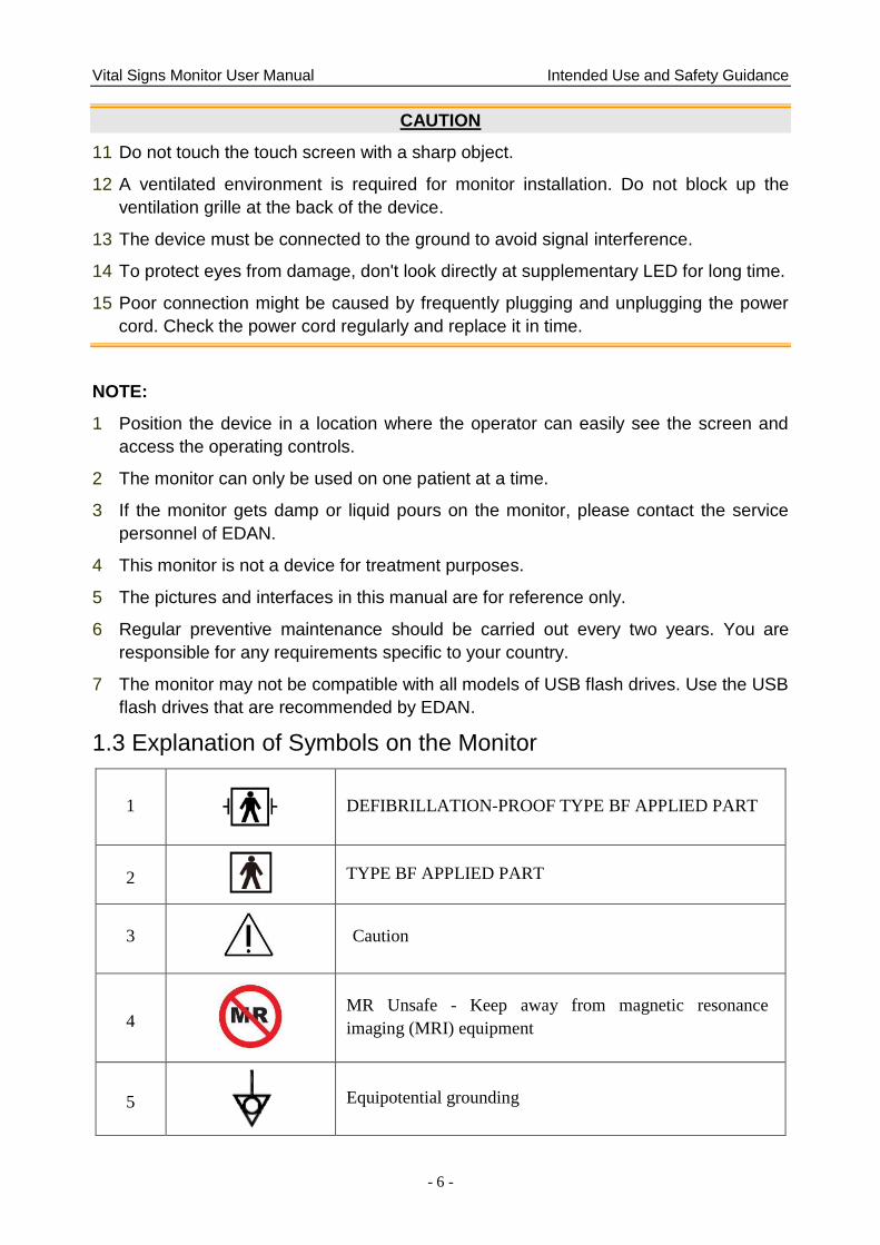
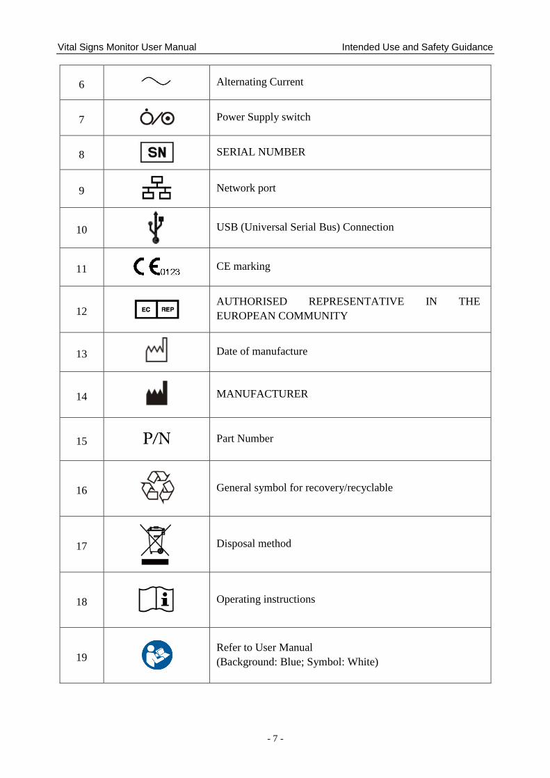
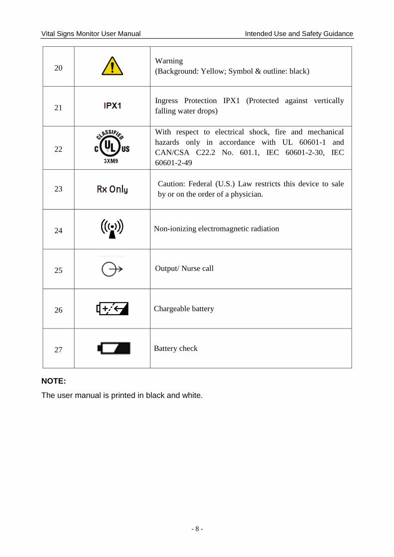
1.3 Explanation of Symbols on the Monitor
1
DEFIBRILLATION-PROOF TYPE BF APPLIED PART
2
TYPE BF APPLIED PART
3
Caution
4
MR Unsafe - Keep away from magnetic resonance
imaging (MRI) equipment
5
Equipotential grounding
Vital Signs Monitor User Manual Intended Use and Safety Guidance
- 7 -
6 Alternating Current
7
Power Supply switch
8 SERIAL NUMBER
9
Network port
10
USB (Universal Serial Bus) Connection
11 CE marking
12
AUTHORISED REPRESENTATIVE IN THE
EUROPEAN COMMUNITY
13
Date of manufacture
14
MANUFACTURER
15 Part Number
16
General symbol for recovery/recyclable
17
Disposal method
18
Operating instructions
19
Refer to User Manual
(Background: Blue; Symbol: White)
Vital Signs Monitor User Manual Intended Use and Safety Guidance
- 8 -
20
Warning
(Background: Yellow; Symbol & outline: black)
21
Ingress Protection IPX1 (Protected against vertically
falling water drops)
22
With respect to electrical shock, fire and mechanical
hazards only in accordance with UL 60601-1 and
CAN/CSA C22.2 No. 601.1, IEC 60601-2-30, IEC
60601-2-49
23 Caution: Federal (U.S.) Law restricts this device to sale
by or on the order of a physician.
24
Non-ionizing electromagnetic radiation
25
Output/ Nurse call
26 Chargeable battery
27
Battery check
NOTE:
The user manual is printed in black and white.
Vital Signs Monitor User Manual Installation
- 9 -
Chapter 2 Installation
NOTE:
1 The monitor installations and settings must be configured by the authorized hospital
personnel.
2 To ensure that the monitor works properly, please read the user manual and follow
the steps before using the monitor.
2.1 Initial Inspection
Before unpacking, check the packaging and ensure that there are no signs of mishandling or
damage. If the shipping cartons are damaged, contact the carrier for compensation and package
them again.
Open the package carefully and remove the monitor and accessories. Check that the contents are
complete and that the correct options and accessories have been delivered.
If you have any question, please contact your local supplier.
2.2 Mounting the Monitor
If all situations are normal, please place the monitor on a flat, level surface, on a trolley or mount
on a wall. About how to install the trolley or wall mount for the monitor, please refer to Trolley
Installation Guide or Wall Mounting Bracket Assembly Instruction.
WARNING
1 The wall mounting bracket can be fixed only on a concrete wall.
2 The safe loads of the wall mounting bracket and the trolley are 7.5 kg and 11 kg
respectively. Exceeding the safe load may cause bracket to fail and the device to fall.
2.3 Connecting the Power Cable
Connection procedure of the AC power line is listed below:
1 Make sure the AC power supply complies with the following specifications: 100 V-240 V~,
50 Hz/60 Hz.
2 Connect the power cord provided with the monitor. Connect the power cord to connector of
the monitor. Connect the other end of the power cord to a grounded power outlet.
NOTE:
1 Connect the power cable to the socket specialized for hospital use.
2 Only use the power cable supplied by EDAN.
2.4 Checking the Monitor
Make sure there is no damage on the measurement accessories and cables. Then turn on the
monitor, check whether the monitor can start normally. Make sure all alarm lamps light up and
the alarm sound is heard when turning on the monitor. Please refer to chapter Testing Alarms.
Vital Signs Monitor User Manual Installation
- 10 -
WARNING
If any sign of damage is detected, or the monitor displays some error messages, do not
use it on any patient. Contact customer service center immediately.
NOTE:
1 Check all the functions of the monitor and make sure that the monitor is in good
status.
2 If rechargeable batteries are provided, charge them after using the device every time,
to ensure the electric power is enough.
3 After long-time continuous running, please restart the monitor to ensure the monitor‟s
steady performance and long lifespan.
2.5 Connecting Sensor to Patient
Connect all the necessary patient sensors between the monitor and the patient.
NOTE:
For information on correct connection, refer to related chapters.
2.6 Checking the Recorder
If your monitor is equipped with a recorder, open the recorder‘s door to check if paper is properly
installed in the slot. If no paper exists, refer to Chapter Recording for details.
2.7 Setting Date and Time
To set the date and time:
1. Select Menu > System Setup > Date/Time.
2. Adjust the date display format based on the user‘s habit.
3. Set the correct time of year, month, day, hour, min and sec.
2.8 Handing Over the Monitor
If you are handing over the monitor to the end-users directly after configuration, make sure that it
is in normal working status and let user know the status.
The users must be adequately trained to use the monitor before monitoring a patient. To achieve
this, they should have access to, and read, the following documentation delivered with the
monitor:
User Manual (this book) - for full operating instructions.
Quick Reference Card - for quick reminders during use.
Vital Signs Monitor User Manual Basic Operation
- 11 -
Chapter 3 Basic Operation
This user manual describes all features and options. Your monitor may not have all of them; they
are not all available in all geographies. Your monitor is highly configurable. What you see on the
screen, how the menus appear and so forth, depend on the way it has been tailored for your
hospital and may not be exactly as shown here.
You may frequently use the follow functions:
SpO2 monitoring (Refer to Monitoring SpO2 for more information.)
PR monitoring (Refer to Monitoring PR for more information.)
NIBP monitoring (Refer to Monitoring NIBP for more information.)
TEMP monitoring (Refer to Monitoring TEMP for more information.)
Alarm (Refer to Alarms for more information.)
3.1 Overview
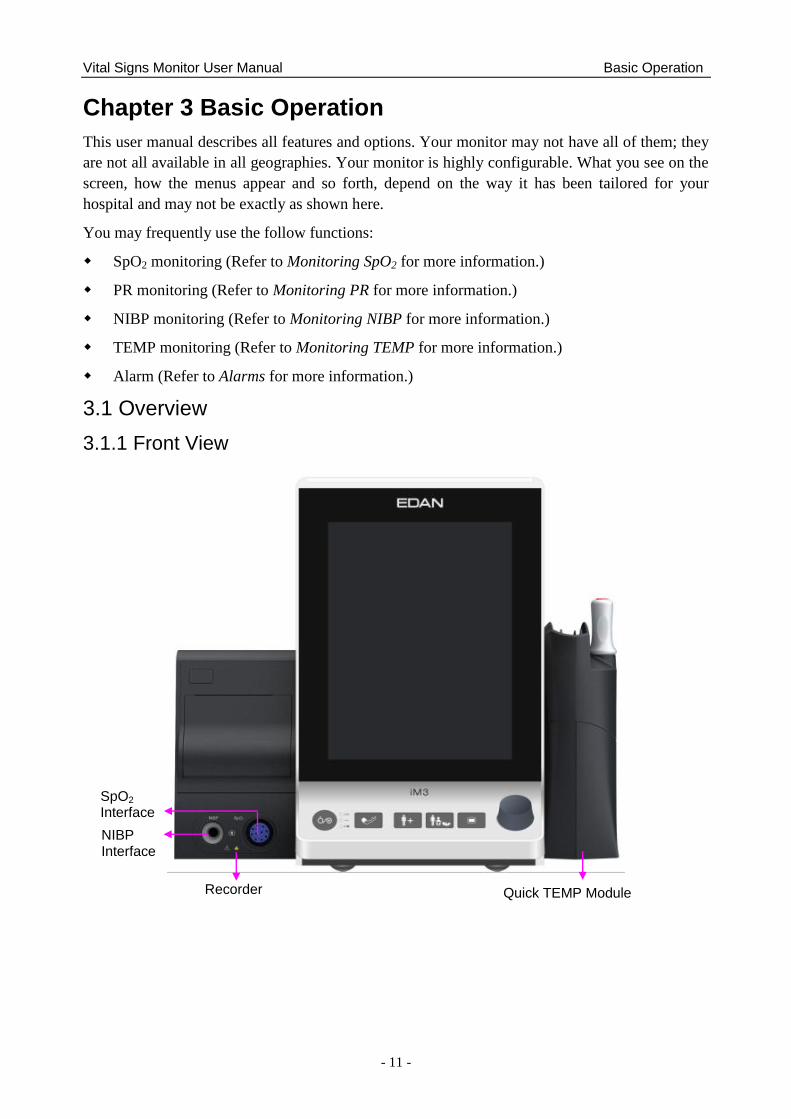
3.1.1 Front View
Recorder Quick TEMP Module
NIBP
Interface
SpO2
Interface
Vital Signs Monitor User Manual Basic Operation
- 12 -
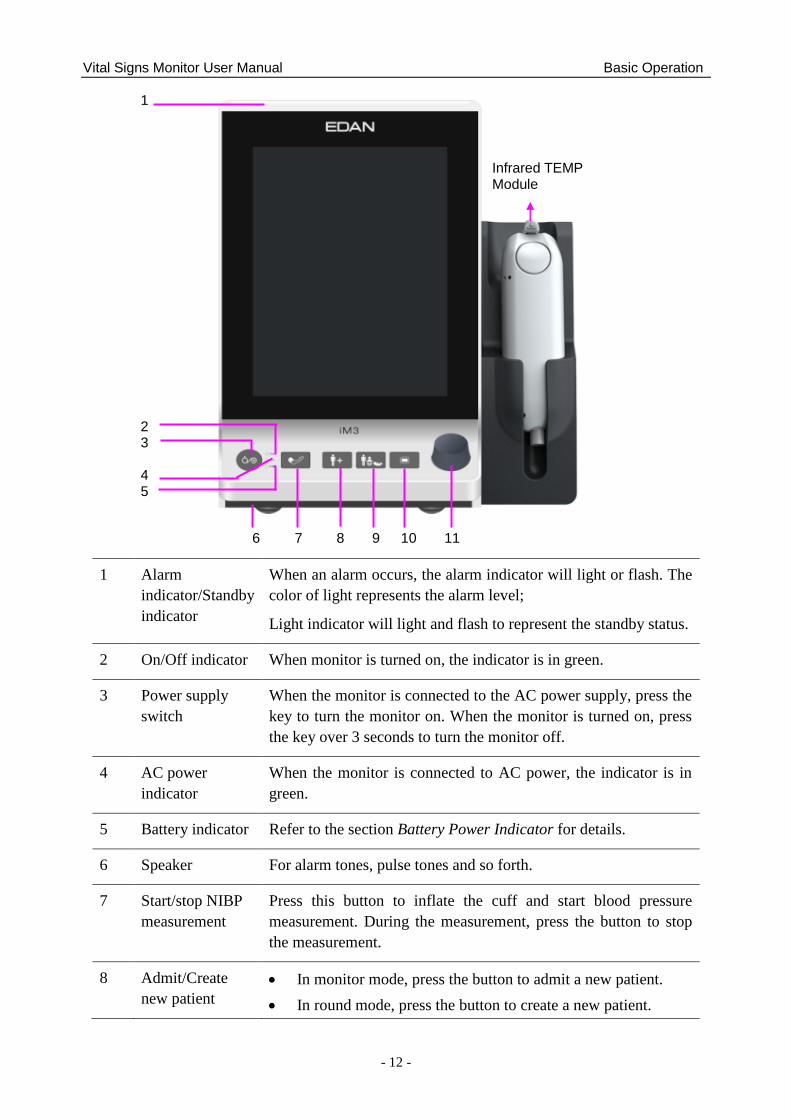
1 Alarm
indicator/Standby
indicator
When an alarm occurs, the alarm indicator will light or flash. The
color of light represents the alarm level;
Light indicator will light and flash to represent the standby status.
2 On/Off indicator When monitor is turned on, the indicator is in green.
3 Power supply
switch
When the monitor is connected to the AC power supply, press the
key to turn the monitor on. When the monitor is turned on, press
the key over 3 seconds to turn the monitor off.
4 AC power
indicator
When the monitor is connected to AC power, the indicator is in
green.
5 Battery indicator Refer to the section Battery Power Indicator for details.
6 Speaker For alarm tones, pulse tones and so forth.
7 Start/stop NIBP
measurement
Press this button to inflate the cuff and start blood pressure
measurement. During the measurement, press the button to stop
the measurement.
8 Admit/Create
new patient
In monitor mode, press the button to admit a new patient.
In round mode, press the button to create a new patient.
Infrared TEMP Module
1
2 3 4 5
6 7 8 9 10 11
Vital Signs Monitor User Manual Basic Operation
- 13 -
In spot-checking mode, press the button to admit a new
patient. The parameters data displayed in interface will be
cleared. Series No. will be automatically added by one and
other setting items are empty by default.
9 Switch patient
type
It is used to switch patient type, and relevant configuration will be
updated.
In monitor mode, press the button to switch patient type. A
confirmation window will be displayed.
In round and spot-checking mode, press and hold the button
to switch patient type. There is no window to be displayed.
10 Menu Press the button to open main menu.
When the main menu is open, press this button to return to the
main interface
11 Rotary Knob
(hereinafter
called knob)
The user can rotate the knob clockwise or anticlockwise. This
operation can make the highlighted item shift up, down, left or
right to choose the desired item. Remember, when using the
knob, rotate this button to highlight, and press it to select the
item.
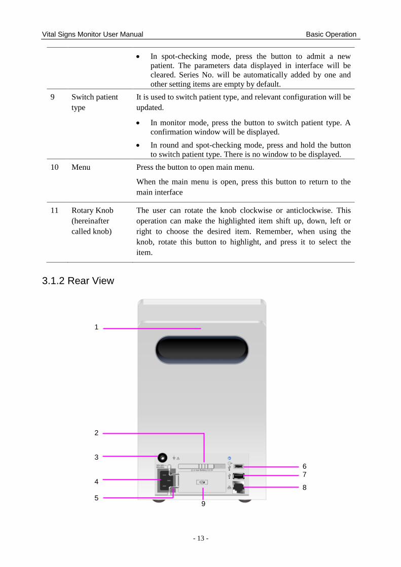
3.1.2 Rear View
6 7 8
1 2 3 4 5
9
Vital Signs Monitor User Manual Basic Operation
- 14 -
1 Portable handle/Accessory collecting
2 Battery compartment latch
3 Equipotential grounding terminal. If the monitor is used together
with other devices, connect this terminal to eliminate potential
ground differences between devices.
4 AC power input
5 Power cable safety latch. Used to prevent the power supply cord
from falling.
6 OTG interface/nurse call port.
OTG interface: it connects the monitor to computer via
data-line. The data in monitor can be transformed into CSV
file and exported to computer.
Nurse call port: it connects the monitor to the hospital‘s
nurse call system. Alarms indications are alerted through the
nurse call system if configured to do so.
7 USB interface. They are used to connect the USB device.
8 Network interface. It connects the monitor to the central
monitoring system (also named as MFM-CMS) via standard
network cable.
9 Battery
Vital Signs Monitor User Manual Basic Operation
- 15 -
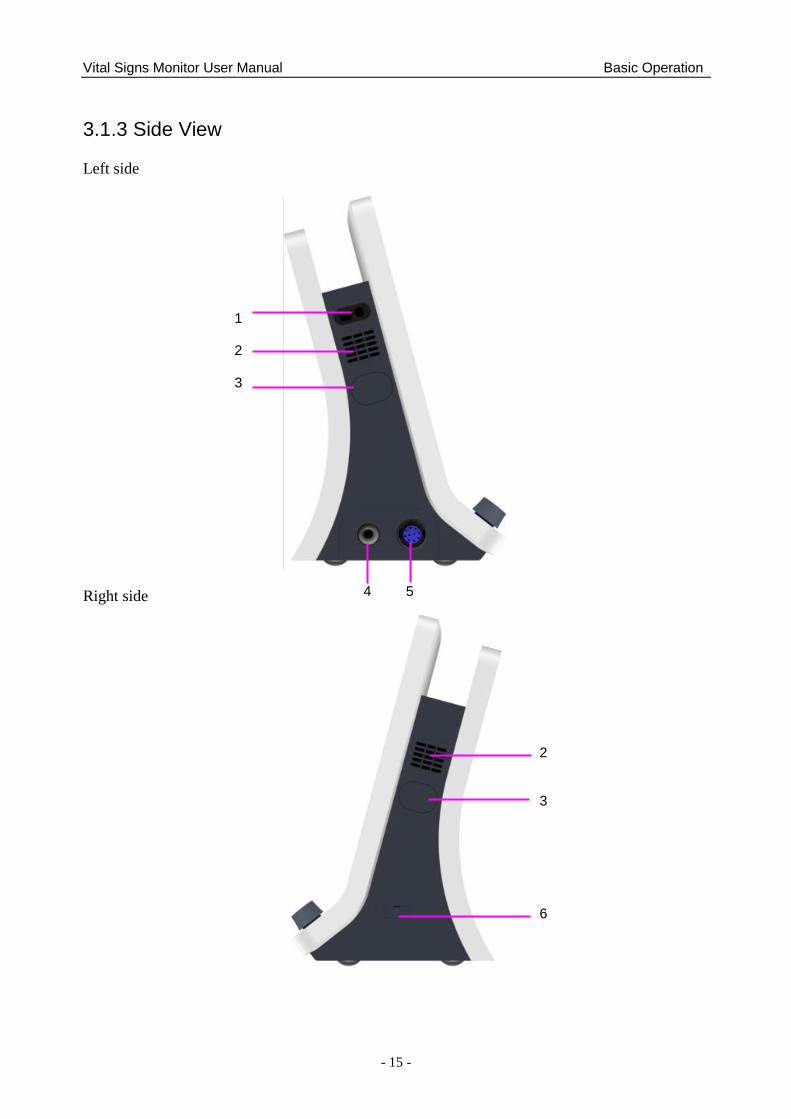
3.1.3 Side View
Left side
Right side
4 5
1 2 3
2 3 6
Vital Signs Monitor User Manual Basic Operation
- 16 -
1 Built-in barcode scanner window
2 Heat sink
3 Built-in interface (there is Vent & dust-free
baffle inside for NIBP on the left side.)
4 NIBP interface
5 SpO2 interface
6 TEMP communication interface
NOTE:
To avoid blocking and affecting NIBP measurement, user can open the built-in interface
coverplate and clean vent & dust-free baffle routinely. If NIBP measurement is still
affected after cleaning, please contact the service personnel of EDAN.
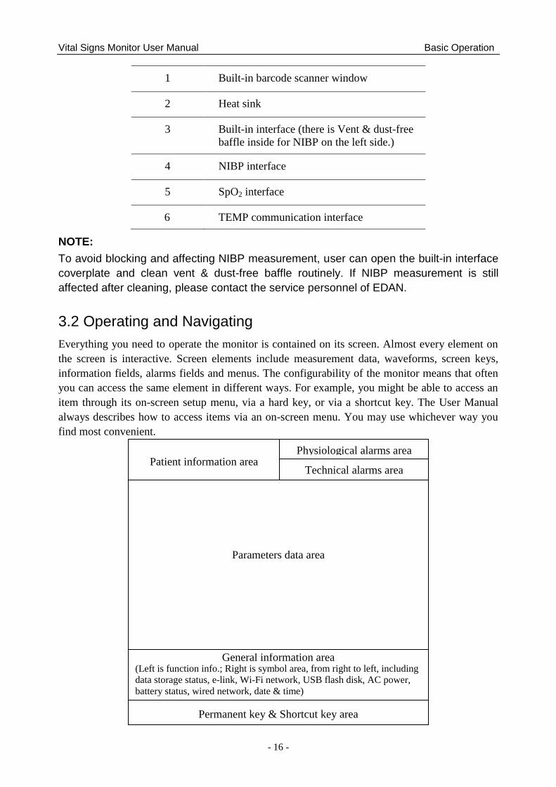
3.2 Operating and Navigating
Everything you need to operate the monitor is contained on its screen. Almost every element on
the screen is interactive. Screen elements include measurement data, waveforms, screen keys,
information fields, alarms fields and menus. The configurability of the monitor means that often
you can access the same element in different ways. For example, you might be able to access an
item through its on-screen setup menu, via a hard key, or via a shortcut key. The User Manual
always describes how to access items via an on-screen menu. You may use whichever way you
find most convenient.
Patient information area Physiological alarms area
Parameters data area
Technical alarms area
Permanent key & Shortcut key area
General information area (Left is function info.; Right is symbol area, from right to left, including
data storage status, e-link, Wi-Fi network, USB flash disk, AC power,
battery status, wired network, date & time)
Vital Signs Monitor User Manual Basic Operation
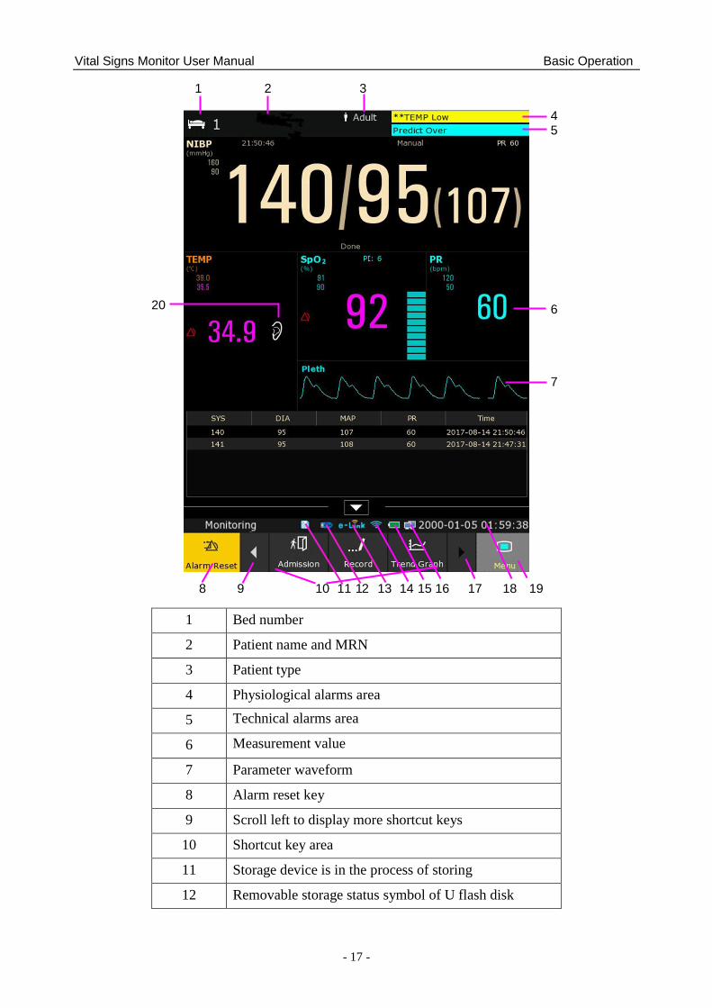
- 17 -
1 Bed number
2 Patient name and MRN
3 Patient type
4 Physiological alarms area
5 Technical alarms area
6 Measurement value
7 Parameter waveform
8 Alarm reset key
9 Scroll left to display more shortcut keys
10 Shortcut key area
11 Storage device is in the process of storing
12 Removable storage status symbol of U flash disk
1 2 3
4 5 6 7
8 9 10 11 12 13 14 15 16 17 18 19
20
Vital Signs Monitor User Manual Basic Operation
- 18 -
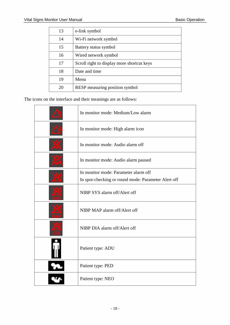
13 e-link symbol
14 Wi-Fi network symbol
15 Battery status symbol
16 Wired network symbol
17 Scroll right to display more shortcut keys
18 Date and time
19 Menu
20 RESP measuring position symbol
The icons on the interface and their meanings are as follows:
In monitor mode: Medium/Low alarm
In monitor mode: High alarm icon
In monitor mode: Audio alarm off
In monitor mode: Audio alarm paused
In monitor mode: Parameter alarm off
In spot-checking or round mode: Parameter Alert off
NIBP SYS alarm off/Alert off
NIBP MAP alarm off/Alert off
NIBP DIA alarm off/Alert off
Patient type: ADU
Patient type: PED
Patient type: NEO
Vital Signs Monitor User Manual Basic Operation
- 19 -
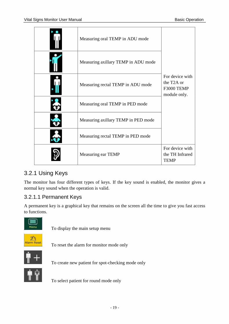
Measuring oral TEMP in ADU mode
For device with
the T2A or
F3000 TEMP
module only.
Measuring axillary TEMP in ADU mode
Measuring rectal TEMP in ADU mode
Measuring oral TEMP in PED mode
Measuring axillary TEMP in PED mode
Measuring rectal TEMP in PED mode
Measuring ear TEMP
For device with
the TH Infrared
TEMP
3.2.1 Using Keys
The monitor has four different types of keys. If the key sound is enabled, the monitor gives a
normal key sound when the operation is valid.
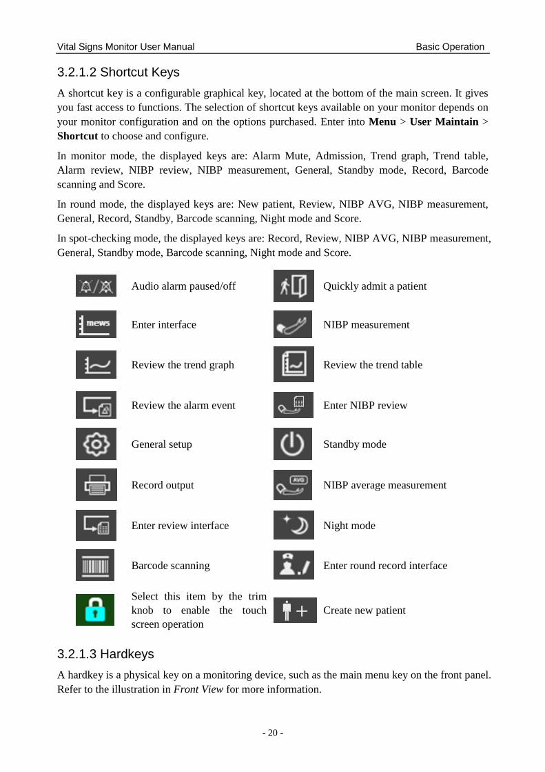
3.2.1.1 Permanent Keys
A permanent key is a graphical key that remains on the screen all the time to give you fast access
to functions.
To display the main setup menu
To reset the alarm for monitor mode only
To create new patient for spot-checking mode only
To select patient for round mode only
Vital Signs Monitor User Manual Basic Operation
- 20 -
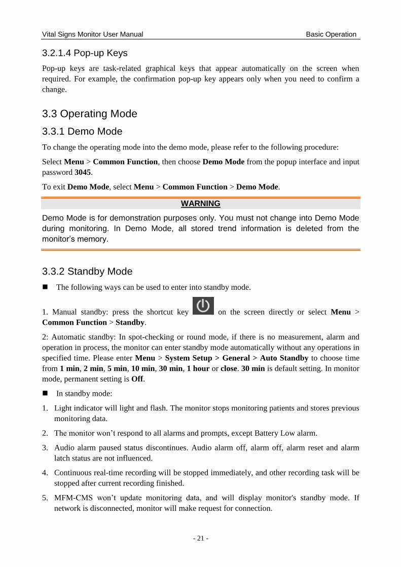
3.2.1.2 Shortcut Keys
A shortcut key is a configurable graphical key, located at the bottom of the main screen. It gives
you fast access to functions. The selection of shortcut keys available on your monitor depends on
your monitor configuration and on the options purchased. Enter into Menu > User Maintain >
Shortcut to choose and configure.
In monitor mode, the displayed keys are: Alarm Mute, Admission, Trend graph, Trend table,
Alarm review, NIBP review, NIBP measurement, General, Standby mode, Record, Barcode
scanning and Score.
In round mode, the displayed keys are: New patient, Review, NIBP AVG, NIBP measurement,
General, Record, Standby, Barcode scanning, Night mode and Score.
In spot-checking mode, the displayed keys are: Record, Review, NIBP AVG, NIBP measurement,
General, Standby mode, Barcode scanning, Night mode and Score.
Audio alarm paused/off
Quickly admit a patient
Enter interface
NIBP measurement
Review the trend graph
Review the trend table
Review the alarm event
Enter NIBP review
General setup
Standby mode
Record output
NIBP average measurement
Enter review interface
Night mode
Barcode scanning
Enter round record interface
Select this item by the trim
knob to enable the touch
screen operation Create new patient
3.2.1.3 Hardkeys
A hardkey is a physical key on a monitoring device, such as the main menu key on the front panel.
Refer to the illustration in Front View for more information.
Vital Signs Monitor User Manual Basic Operation
- 21 -
3.2.1.4 Pop-up Keys
Pop-up keys are task-related graphical keys that appear automatically on the screen when
required. For example, the confirmation pop-up key appears only when you need to confirm a
change.
3.3 Operating Mode
3.3.1 Demo Mode
To change the operating mode into the demo mode, please refer to the following procedure:
Select Menu > Common Function, then choose Demo Mode from the popup interface and input
password 3045.
To exit Demo Mode, select Menu > Common Function > Demo Mode.
WARNING
Demo Mode is for demonstration purposes only. You must not change into Demo Mode
during monitoring. In Demo Mode, all stored trend information is deleted from the
monitor‟s memory.
3.3.2 Standby Mode
The following ways can be used to enter into standby mode.
1. Manual standby: press the shortcut key on the screen directly or select Menu >
Common Function > Standby.
2: Automatic standby: In spot-checking or round mode, if there is no measurement, alarm and
operation in process, the monitor can enter standby mode automatically without any operations in
specified time. Please enter Menu > System Setup > General > Auto Standby to choose time
from 1 min, 2 min, 5 min, 10 min, 30 min, 1 hour or close. 30 min is default setting. In monitor
mode, permanent setting is Off.
In standby mode:
1. Light indicator will light and flash. The monitor stops monitoring patients and stores previous
monitoring data.
2. The monitor won‘t respond to all alarms and prompts, except Battery Low alarm.
3. Audio alarm paused status discontinues. Audio alarm off, alarm off, alarm reset and alarm
latch status are not influenced.
4. Continuous real-time recording will be stopped immediately, and other recording task will be
stopped after current recording finished.
5. MFM-CMS won‘t update monitoring data, and will display monitor's standby mode. If
network is disconnected, monitor will make request for connection.
Vital Signs Monitor User Manual Basic Operation
- 22 -
The monitor exits standby mode in any of the conditions:
1. The user clicks anywhere on the screen or presses any key.
2. Battery Low alarm occurs.
3. MFM-CMS or gateway sends exit order to monitor.
After exiting standby mode, the monitor resumes monitoring, including parameter monitoring,
storage and alarm; users need to press Recorder key to restart recording.
NOTE:
The monitor is unable to enter into standby mode when exporting data.
3.3.3 Night Mode
To switch to night mode, you may:
Select the shortcut key on the main screen, or
Select Menu> Common Function> Night Mode.
NOTE:
In night mode, the sound of key and pulse is muted; the alarm volume and screen
brightness are down to their minimum; the settings including key volume, PR volume,
alarm volume and screen brightness are unavailable.
3.3.4 Other Modes
Select Menu> System Setup > Mode to choose Monitoring Mode (also called Monitor mode in
this text), Spot Mode (also called Spot-checking mode in this text) or Round Mode. Then, the
selected working mode will be displayed in left part of general information area. Details of these
3 modes refer to Chapter Managing Patients.
NOTE:
1. After the mode switch, the history data can be checked in the previous working mode.
2. In these 3 modes, each setting item is respectively independent. For instance, in
monitor mode, NIBP parameter is selected in parameters setup, but this setting is not
affected and still keeps unchanged when the monitor enters spot-checking mode or
round mode.
3.4 Changing Monitor Settings
3.4.1 Adjusting Screen Brightness
To change the screen brightness, select Menu > System Setup > General, and select the
appropriate setting for the screen brightness. 10 is the brightest, 1 is the least bright.
Vital Signs Monitor User Manual Basic Operation
- 23 -
3.4.2 Adjusting Volume
3.4.2.1 Adjusting Key Volume
The key volume is the volume you hear when you select any field on the monitor screen or when
you turn the knob.
To adjust the key volume, select Menu > System Setup > General, then select the appropriate
setting for the key volume: six levels represent volume and level five represents the maximum,
and level zero represents volume off.
3.4.2.2 Adjusting Alarm Volume
To change the alarm volume, select Menu > System Setup > General and select the desired
setting for the AlarmVolume item: five levels represent volume and level five represents the
maximum, and level one represents minimum. Alarm volume cannot be off.
3.4.2.3 Adjusting Alert Volume
In monitoring or spot mode, to change the alert volume, select Menu > System Setup > General
and select the desired setting for the Alert Volume item: six levels represent volume and level
five represents the maximum, and level zero represents volume off.
3.5 Checking Your Monitor Information
To check the monitor information, please select Menu > Common Function > Device
Information. Monitor information includes Device, Config, About, Network.
Device includes: Device Name, Department, Serial Number.
Config includes: the configuration monitor supported (such as Wi-Fi, Wired, USB, Barcode, etc.),
Factory model of the parts supported and Protocol Version. The currently used configurations are
marked with √.
About includes: software version, parameters version and so on.
Network includes: Network method, the monitor IP, server IP (such as MFM-CMS) and so on.
3.6 Networked Monitoring
Your monitor can be connected to the wired network and the wireless network. If the monitor is
networked, a network symbol is displayed on the screen.
NOTE:
1 Be aware that some network-based functions may be limited for monitors on wireless
networks in comparison to those on wired networks.
2 When selecting dynamic IP mode, please check the IP address from MFM-CMS.
Vital Signs Monitor User Manual Basic Operation
- 24 -
3.7 Common Settings
Select Menu > User Maintain, then type the correct password ABC into the displayed interface.
Common settings include: Department, Language, Nurse call, Internal Scanner Mode, Scanner
Management, Scanner Setup, Format internal storage device and so on.
WARNING
Change to date and time will influence the storage of trend data.
NOTE:
To make the language change validate, please restart the monitor.
3.8 Disabling the Touch Screen
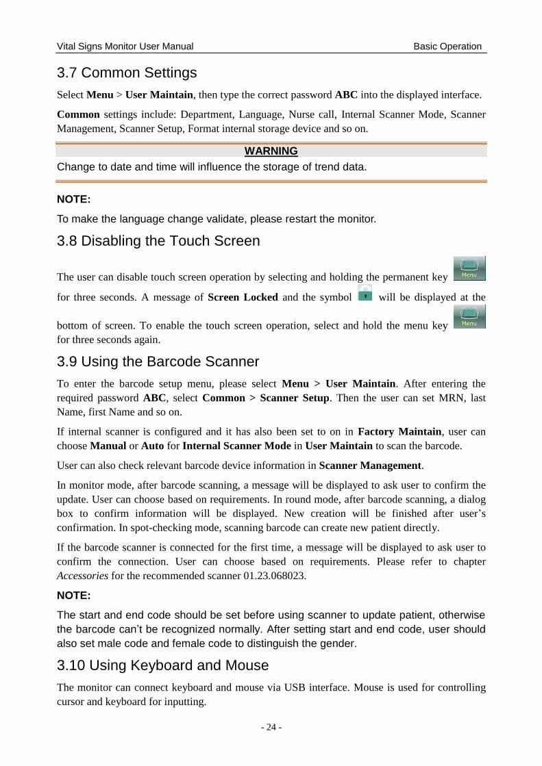
The user can disable touch screen operation by selecting and holding the permanent key
for three seconds. A message of Screen Locked and the symbol will be displayed at the
bottom of screen. To enable the touch screen operation, select and hold the menu key
for three seconds again.
3.9 Using the Barcode Scanner
To enter the barcode setup menu, please select Menu > User Maintain. After entering the
required password ABC, select Common > Scanner Setup. Then the user can set MRN, last
Name, first Name and so on.
If internal scanner is configured and it has also been set to on in Factory Maintain, user can
choose Manual or Auto for Internal Scanner Mode in User Maintain to scan the barcode.
User can also check relevant barcode device information in Scanner Management.
In monitor mode, after barcode scanning, a message will be displayed to ask user to confirm the
update. User can choose based on requirements. In round mode, after barcode scanning, a dialog
box to confirm information will be displayed. New creation will be finished after user‘s
confirmation. In spot-checking mode, scanning barcode can create new patient directly.
If the barcode scanner is connected for the first time, a message will be displayed to ask user to
confirm the connection. User can choose based on requirements. Please refer to chapter
Accessories for the recommended scanner 01.23.068023.
NOTE:
The start and end code should be set before using scanner to update patient, otherwise
the barcode can‟t be recognized normally. After setting start and end code, user should
also set male code and female code to distinguish the gender.
3.10 Using Keyboard and Mouse
The monitor can connect keyboard and mouse via USB interface. Mouse is used for controlling
cursor and keyboard for inputting.
Vital Signs Monitor User Manual Alarms
- 25 -
Chapter 4 Alarms
The alarm information here applies to all measurements. Measurement-specific alarm
information is discussed in the sections of individual measurements.
WARNING
A potential hazard can exist if different alarm presets are used for the same or similar
equipment in any single area, e.g. an intensive care unit or cardiac operating room.
4.1 Alarm Category
In monitor mode, the monitor provides two types of alarms: physiological alarms and technical
alarms. Also, the monitor provides prompts.
In round or spot-checking mode, the monitor provides alert information (please refer to chapter
Alert Setup for details) instead of physiological alarms, and technical alarms. Battery Low will
be displayed in a special audio and visual way. The mode is ―DO-DO-DO‖, which is triggered
once every 25 seconds. The alarm indicator flashes in yellow, with frequency of 0.4 Hz ~ 0.8 Hz.
4.1.1 Physiological Alarms
If one or several physiological parameters of the currently monitored patient exceed the
predefined alarm limit, the monitor will give an alarm, and this type of alarm is called
physiological alarms. About the detailed alarm information, please refer to the Section
Physiological Alarm Information.
4.1.2 Technical Alarms
If one or several technical status of the device is in abnormal status, the monitor will give an
alarm. And this type of alarm is called technical alarms. Technical alarms can‘t be disabled.
About the detailed alarm information, please refer to Section Technical Alarm Information.
4.1.3 Prompts
The monitor can give the character indication of monitoring process or other functions. And this
character is called prompts. About the detailed alarm information, please refer to Section
Prompts.
4.2 Selecting Alarm Tone Type
The user can select the alarm tone type as desired.
1. Select Menu > User Maintain, and enter the required password ABC.
2. Select Alarm, and set Alarm Tone to Standard or Mode 1.
Standard: Standard alarm sound according to IEC 60601-1-8.
Mode 1: User customized alarm sound according to clinical applications.
Vital Signs Monitor User Manual Alarms
- 26 -
4.3 Alarm Levels
In terms of severity, the device‘s alarm levels can be classified into three categories: high level
alarms, medium level alarms and low level alarms.
1. High level alarms
A high level alarm intensively warns the operator of a high priority alarm condition which
requires immediate operator response. Failure to respond to the cause of the alarm condition
is likely to result in death or irreversible injury of the patient.
2. Medium level alarms
A medium level alarm warns the operator of a medium priority alarm condition which
requires prompt operator response. Failure to respond to the cause of the alarm condition is
likely to result in reversible injury of the patient.
3. Low level alarms
A low level alarm reminds the operator of a low priority alarm condition which requires
response. And the response time for a low priority alarm condition can be greater than that for
a medium priority alarm condition. Failure to respond to the cause of the alarm condition is
likely to result in discomfort or reversible minor injury of the patient.
The high/medium/low-level alarms are indicated by the system in following different ways:
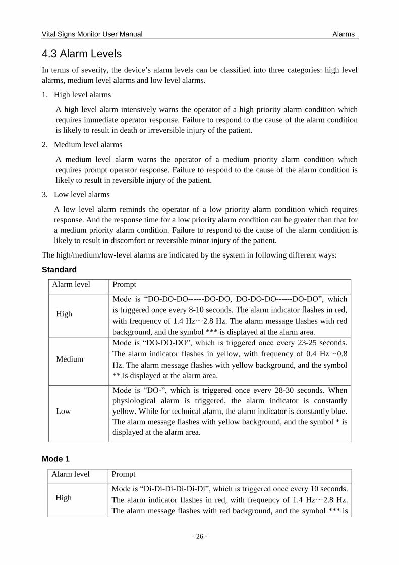
Standard
Alarm level Prompt
High
Mode is ―DO-DO-DO------DO-DO, DO-DO-DO------DO-DO‖, which
is triggered once every 8-10 seconds. The alarm indicator flashes in red,
with frequency of 1.4 Hz~2.8 Hz. The alarm message flashes with red
background, and the symbol *** is displayed at the alarm area.
Medium
Mode is ―DO-DO-DO‖, which is triggered once every 23-25 seconds.
The alarm indicator flashes in yellow, with frequency of 0.4 Hz~0.8
Hz. The alarm message flashes with yellow background, and the symbol
** is displayed at the alarm area.
Low
Mode is ―DO-‖, which is triggered once every 28-30 seconds. When
physiological alarm is triggered, the alarm indicator is constantly
yellow. While for technical alarm, the alarm indicator is constantly blue.
The alarm message flashes with yellow background, and the symbol * is
displayed at the alarm area.
Mode 1
Alarm level Prompt
High Mode is ―Di-Di-Di-Di-Di-Di‖, which is triggered once every 10 seconds.
The alarm indicator flashes in red, with frequency of 1.4 Hz~2.8 Hz.
The alarm message flashes with red background, and the symbol *** is
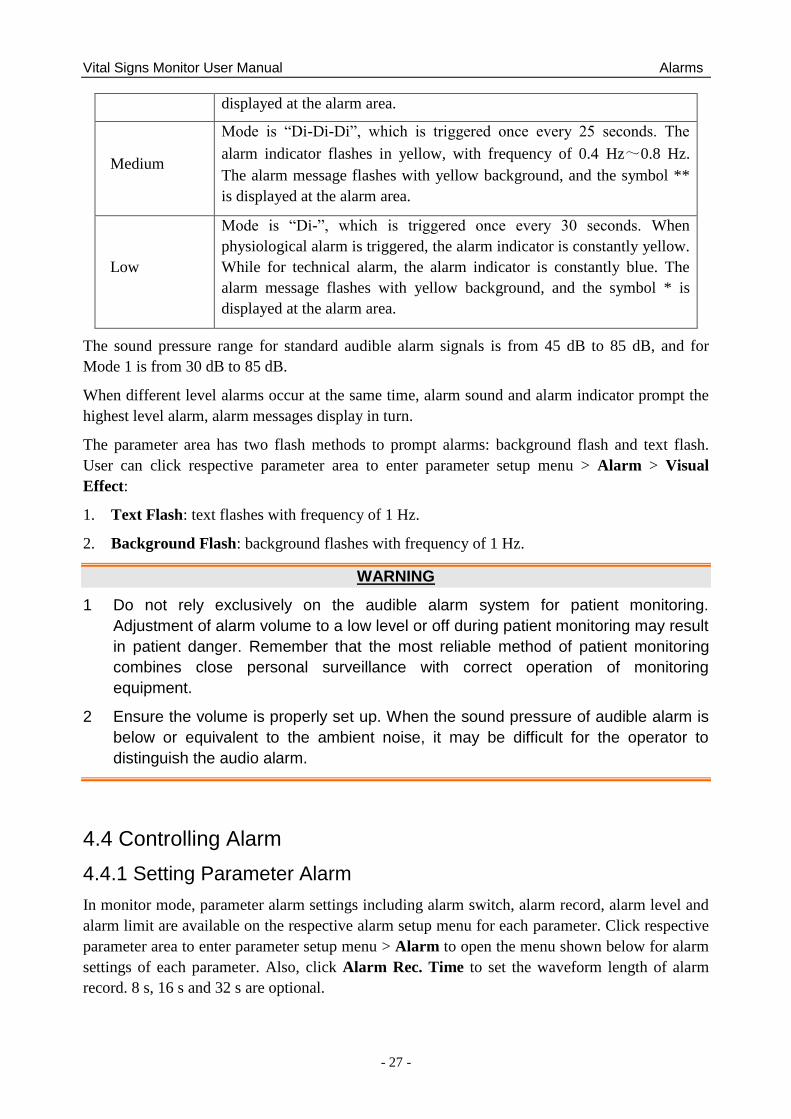
Vital Signs Monitor User Manual Alarms
- 27 -
displayed at the alarm area.
Medium
Mode is ―Di-Di-Di‖, which is triggered once every 25 seconds. The
alarm indicator flashes in yellow, with frequency of 0.4 Hz~0.8 Hz.
The alarm message flashes with yellow background, and the symbol **
is displayed at the alarm area.
Low
Mode is ―Di-‖, which is triggered once every 30 seconds. When
physiological alarm is triggered, the alarm indicator is constantly yellow.
While for technical alarm, the alarm indicator is constantly blue. The
alarm message flashes with yellow background, and the symbol * is
displayed at the alarm area.
The sound pressure range for standard audible alarm signals is from 45 dB to 85 dB, and for
Mode 1 is from 30 dB to 85 dB.
When different level alarms occur at the same time, alarm sound and alarm indicator prompt the
highest level alarm, alarm messages display in turn.
The parameter area has two flash methods to prompt alarms: background flash and text flash.
User can click respective parameter area to enter parameter setup menu > Alarm > Visual
Effect:
1. Text Flash: text flashes with frequency of 1 Hz.
2. Background Flash: background flashes with frequency of 1 Hz.
WARNING
1 Do not rely exclusively on the audible alarm system for patient monitoring.
Adjustment of alarm volume to a low level or off during patient monitoring may result
in patient danger. Remember that the most reliable method of patient monitoring
combines close personal surveillance with correct operation of monitoring
equipment.
2 Ensure the volume is properly set up. When the sound pressure of audible alarm is
below or equivalent to the ambient noise, it may be difficult for the operator to
distinguish the audio alarm.
4.4 Controlling Alarm
4.4.1 Setting Parameter Alarm
In monitor mode, parameter alarm settings including alarm switch, alarm record, alarm level and
alarm limit are available on the respective alarm setup menu for each parameter. Click respective
parameter area to enter parameter setup menu > Alarm to open the menu shown below for alarm
settings of each parameter. Also, click Alarm Rec. Time to set the waveform length of alarm
record. 8 s, 16 s and 32 s are optional.
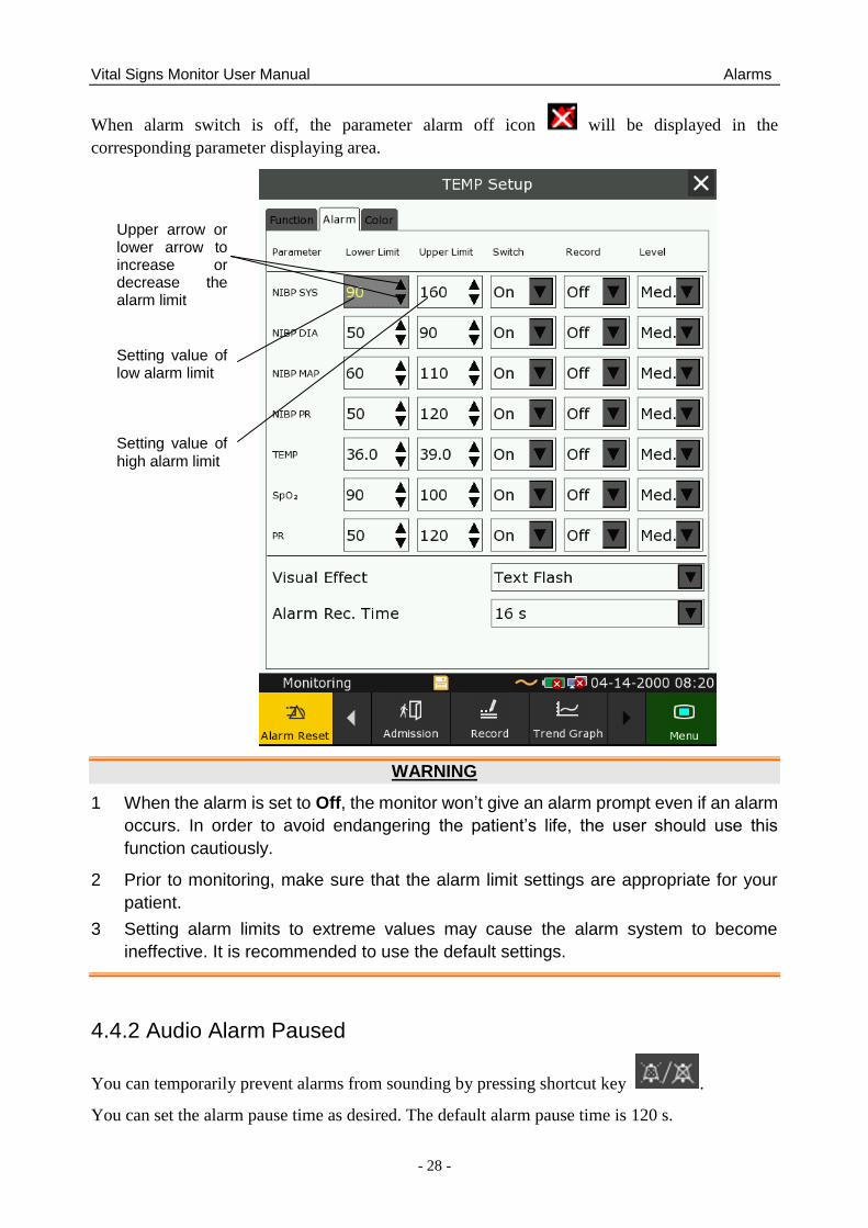
Vital Signs Monitor User Manual Alarms
- 28 -
When alarm switch is off, the parameter alarm off icon will be displayed in the
corresponding parameter displaying area.
WARNING
1 When the alarm is set to Off, the monitor won‟t give an alarm prompt even if an alarm
occurs. In order to avoid endangering the patient‟s life, the user should use this
function cautiously.
2 Prior to monitoring, make sure that the alarm limit settings are appropriate for your
patient.
3 Setting alarm limits to extreme values may cause the alarm system to become
ineffective. It is recommended to use the default settings.
4.4.2 Audio Alarm Paused
You can temporarily prevent alarms from sounding by pressing shortcut key .
You can set the alarm pause time as desired. The default alarm pause time is 120 s.
Upper arrow or lower arrow to increase or decrease the alarm limit
Setting value of low alarm limit
Setting value of high alarm limit
Vital Signs Monitor User Manual Alarms
- 29 -
1. Select Menu > User Maintain, and enter the required password ABC.
2. Select Alarm, and set Pause Time to 60 s, 120 s, or 180 s.
When alarms are paused,
The audio alarm is turned off, and no alarms are sounding.
The visual alarm indications are still displayed.
The monitor displays the audio alarm paused icon .
The monitor displays the remaining pause time in seconds with red background.
When the alarm pause time expires, the audio alarm paused status is automatically terminated and
alarm is sounding. You can also terminate the alarm paused status by pressing shortcut key
.
NOTE:
If a new alarm occurs during the audio alarm paused period, the new alarm will not be
sounding.
4.4.3 Audio Alarm off
Set Pause Time to Permanent, press shortcut key , the monitor displays information:
please confirm whether to activate audio alarm off function? Click Yes, the monitor will
enter into audio alarm off status. Click No, the monitor will keep current status.
The audio alarm is turned off, and no alarms are sounding.
The visual alarm indications are still displayed.
Remind signal: Audio alarm off symbol and Audio Alarm off on a red colored
background are displayed with an interval of 2 s during the audio alarm off status.
Pressing shortcut key again can resume the audio alarm.
NOTE:
If a new alarm occurs during the audio alarm off period, the new alarm will not be
sounding.
4.4.4 Alarm Reset
Select the shortcut key on the screen directly or select Menu > Alarm Setup >
Alarm Reset. When the alarm is reset,
No alarms are sounding until a new alarm occurs.
As for the active alarms, the visual alarm indications are still displayed.
Vital Signs Monitor User Manual Alarms
- 30 -
All latching alarms are cleared. If the alarm condition is no longer present, all alarm
indications stop and the alarm is reset.
It will not influence the configuration of physiological alarm off, audio paused, and audio off
status.
NOTE:
If a new alarm occurs after the alarm is reset, the new alarm will be sounding.
4.5 Latching Alarms
To configure the alarm latching setting, select Menu > Maintenance > User Maintain > Alarm
and choose Alarm Latch which can be set to On or Off. When it is set to Off, alarm indications
end when the alarm condition ends. When it is set to On, the visual and audible alarm indications
are still displayed after the alarm condition ends; meanwhile, the alarm time is also displayed for
the latched alarm for your reference. The indication lasts until you acknowledge the alarm.
You can use the permanent key on the screen to acknowledge the latched alarm.
4.6 Alarm of SpO2 Sensor Off
In monitor mode, user can enter Menu > User Maintain > Alarm to adjust the alarm level of
SpO2 Sensor Off to High, Med. or Low. It is set to Low by default.
In monitor mode, it is processed and displayed as prompt without adjustable level.
4.7 Network Disconnected Alarms
To configure the network disconnected alarms, select Menu > User Maintain > Network and
choose Disconnect Alarm which can be set to On or Off. The alarm is off by default.
NOTE:
1. When the monitor is connected with the central monitoring system, you must set
Disconnect Alarm to On.
2. If Disconnect Alarm occurs during audio alarm paused or audio alarm off status, the
monitor will prompt a sounding alarm with information of NetWork Disconnect.
During the network disconnected status, activating audio alarm paused or audio alarm
off function can disable the audio alarm signal of Disconnect Alarm.
4.8 Delete All Alarm Events
Select Menu > User Maintain > Alarm > Clear Alarm Log to delete.
WARNING
The deleted alarm events are beyond retrieve. Please use this function cautiously.

Vital Signs Monitor User Manual Alarms
- 31 -
4.9 Testing Alarms
When you switch the monitor on, a self test is started with two ―Di‖ tone. You must check that
the alarm indicator lights (it lights in red, yellow and blue in turn during starting up) and that you
hear a single tone (that is same with low level alarm sound). This indicates that the visible and
auditory alarm indicators are functioning correctly. For further testing of individual measurement
alarms, perform the measurement on yourself or use a simulator. Adjust alarm limits and check
that appropriate alarm behavior is observed.
NOTE:
The monitor will reboot in 3 seconds due to self-test failure.
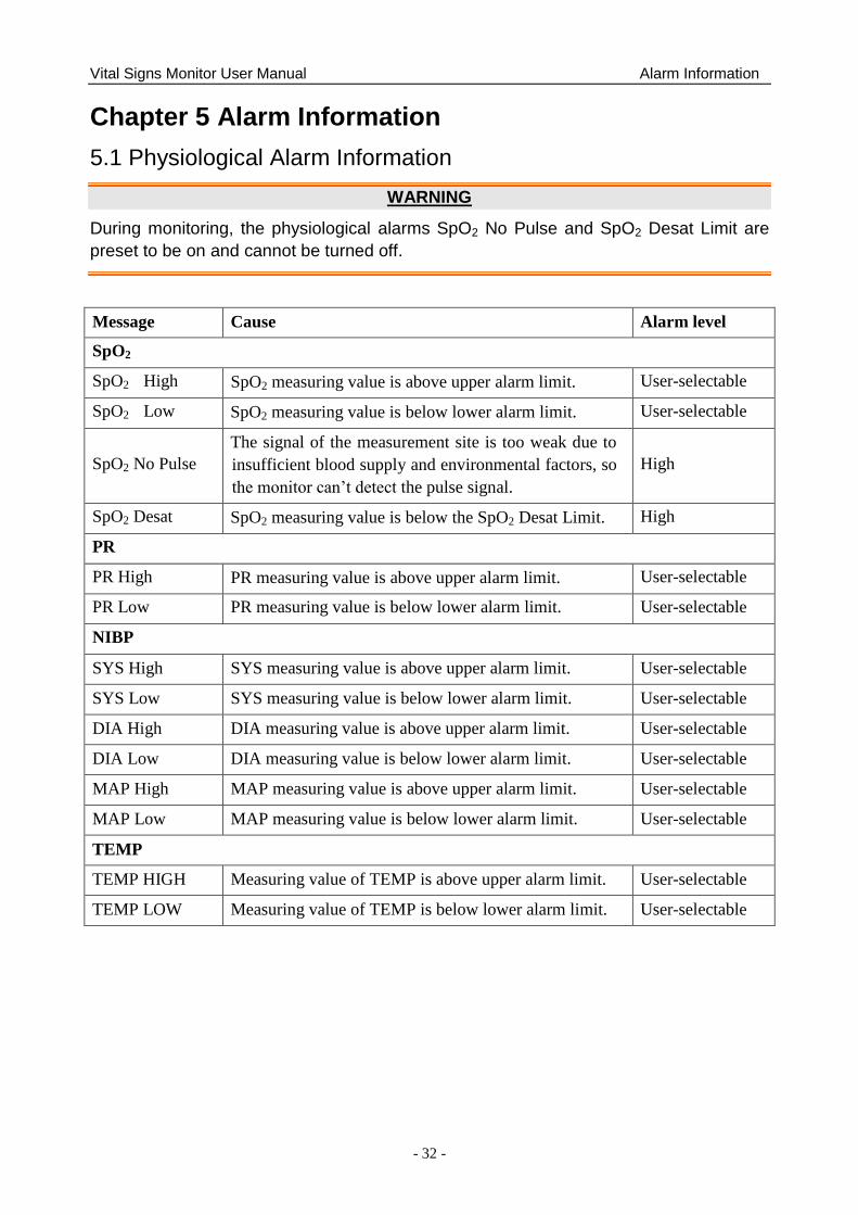
Vital Signs Monitor User Manual Alarm Information
- 32 -
Chapter 5 Alarm Information
5.1 Physiological Alarm Information
WARNING
During monitoring, the physiological alarms SpO2 No Pulse and SpO2 Desat Limit are
preset to be on and cannot be turned off.
Message Cause Alarm level
SpO2
SpO2 High SpO2 measuring value is above upper alarm limit. User-selectable
SpO2 Low SpO2 measuring value is below lower alarm limit. User-selectable
SpO2 No Pulse
The signal of the measurement site is too weak due to
insufficient blood supply and environmental factors, so
the monitor can‘t detect the pulse signal.
High
SpO2 Desat SpO2 measuring value is below the SpO2 Desat Limit. High
PR
PR High PR measuring value is above upper alarm limit. User-selectable
PR Low PR measuring value is below lower alarm limit. User-selectable
NIBP
SYS High SYS measuring value is above upper alarm limit. User-selectable
SYS Low SYS measuring value is below lower alarm limit. User-selectable
DIA High DIA measuring value is above upper alarm limit. User-selectable
DIA Low DIA measuring value is below lower alarm limit. User-selectable
MAP High MAP measuring value is above upper alarm limit. User-selectable
MAP Low MAP measuring value is below lower alarm limit. User-selectable
TEMP
TEMP HIGH Measuring value of TEMP is above upper alarm limit. User-selectable
TEMP LOW Measuring value of TEMP is below lower alarm limit. User-selectable
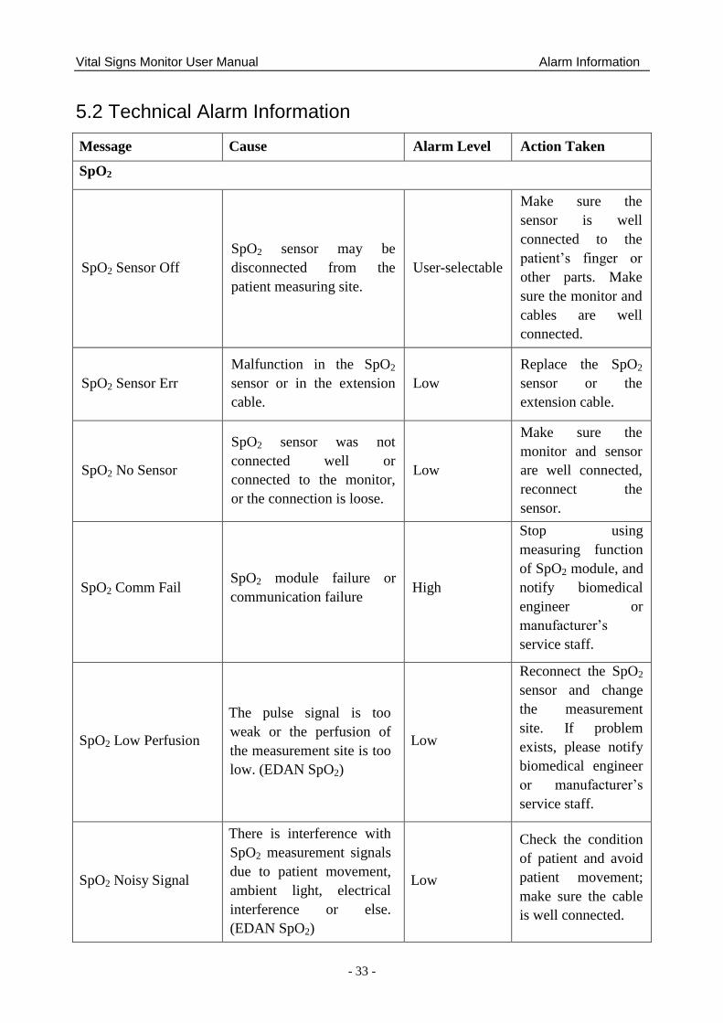
Vital Signs Monitor User Manual Alarm Information
- 33 -
5.2 Technical Alarm Information
Message Cause Alarm Level Action Taken
SpO2
SpO2 Sensor Off
SpO2 sensor may be
disconnected from the
patient measuring site.
User-selectable
Make sure the
sensor is well
connected to the
patient‘s finger or
other parts. Make
sure the monitor and
cables are well
connected.
SpO2 Sensor Err
Malfunction in the SpO2
sensor or in the extension
cable.
Low
Replace the SpO2
sensor or the
extension cable.
SpO2 No Sensor
SpO2 sensor was not
connected well or
connected to the monitor,
or the connection is loose.
Low
Make sure the
monitor and sensor
are well connected,
reconnect the
sensor.
SpO2 Comm Fail SpO2 module failure or
communication failure High
Stop using
measuring function
of SpO2 module, and
notify biomedical
engineer or
manufacturer‘s
service staff.
SpO2 Low Perfusion
The pulse signal is too
weak or the perfusion of
the measurement site is too
low. (EDAN SpO2)
Low
Reconnect the SpO2
sensor and change
the measurement
site. If problem
exists, please notify
biomedical engineer
or manufacturer‘s
service staff.
SpO2 Noisy Signal
There is interference with
SpO2 measurement signals
due to patient movement,
ambient light, electrical
interference or else.
(EDAN SpO2)
Low
Check the condition
of patient and avoid
patient movement;
make sure the cable
is well connected.
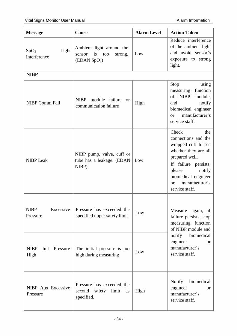
Vital Signs Monitor User Manual Alarm Information
- 34 -
Message Cause Alarm Level Action Taken
SpO2 Light
Interference
Ambient light around the
sensor is too strong.
(EDAN SpO2)
Low
Reduce interference
of the ambient light
and avoid sensor‘s
exposure to strong
light.
NIBP
NIBP Comm Fail NIBP module failure or
communication failure High
Stop using
measuring function
of NIBP module,
and notify
biomedical engineer
or manufacturer‘s
service staff.
NIBP Leak
NIBP pump, valve, cuff or
tube has a leakage. (EDAN
NIBP)
Low
Check the
connections and the
wrapped cuff to see
whether they are all
prepared well.
If failure persists,
please notify
biomedical engineer
or manufacturer‘s
service staff.
NIBP Excessive
Pressure
Pressure has exceeded the
specified upper safety limit. Low Measure again, if
failure persists, stop
measuring function
of NIBP module and
notify biomedical
engineer or
manufacturer‘s
service staff.
NIBP Init Pressure
High
The initial pressure is too
high during measuring Low
NIBP Aux Excessive
Pressure
Pressure has exceeded the
second safety limit as
specified.
High
Notify biomedical
engineer or
manufacturer‘s
service staff.
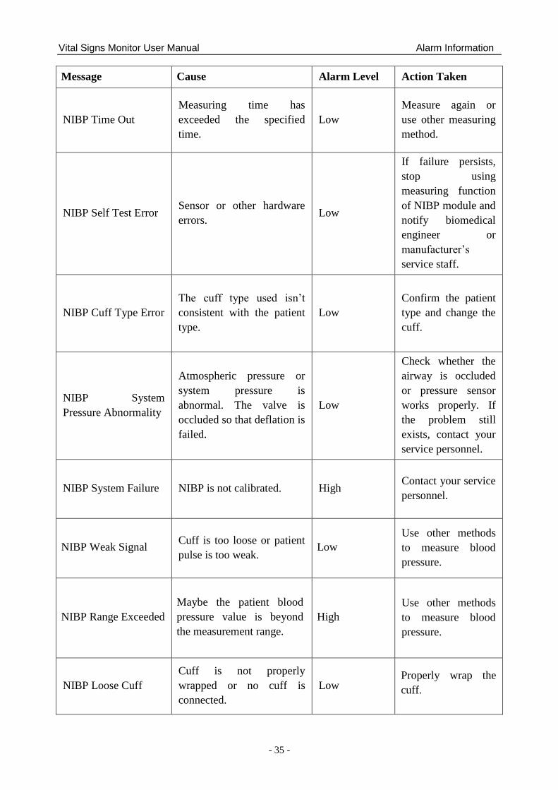
Vital Signs Monitor User Manual Alarm Information
- 35 -
Message Cause Alarm Level Action Taken
NIBP Time Out
Measuring time has
exceeded the specified
time.
Low
Measure again or
use other measuring
method.
NIBP Self Test Error Sensor or other hardware
errors. Low
If failure persists,
stop using
measuring function
of NIBP module and
notify biomedical
engineer or
manufacturer‘s
service staff.
NIBP Cuff Type Error
The cuff type used isn‘t
consistent with the patient
type.
Low
Confirm the patient
type and change the
cuff.
NIBP System
Pressure Abnormality
Atmospheric pressure or
system pressure is
abnormal. The valve is
occluded so that deflation is
failed.
Low
Check whether the
airway is occluded
or pressure sensor
works properly. If
the problem still
exists, contact your
service personnel.
NIBP System Failure NIBP is not calibrated. High Contact your service
personnel.
NIBP Weak Signal Cuff is too loose or patient
pulse is too weak. Low
Use other methods
to measure blood
pressure.
NIBP Range Exceeded
Maybe the patient blood
pressure value is beyond
the measurement range.
High
Use other methods
to measure blood
pressure.
NIBP Loose Cuff
Cuff is not properly
wrapped or no cuff is
connected.
Low Properly wrap the
cuff.
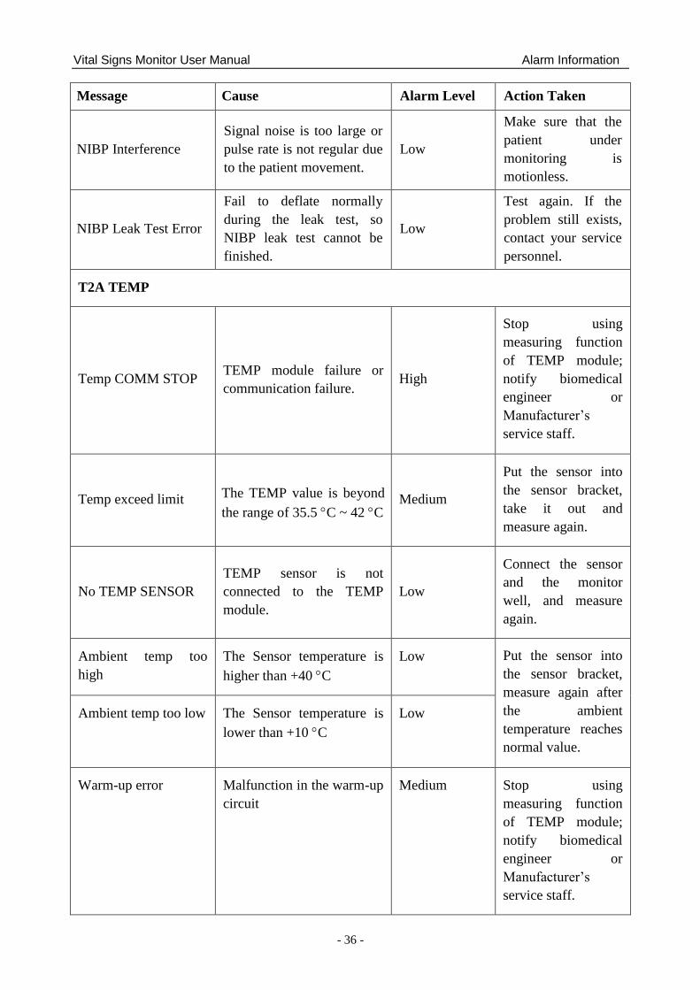
Vital Signs Monitor User Manual Alarm Information
- 36 -
Message Cause Alarm Level Action Taken
NIBP Interference
Signal noise is too large or
pulse rate is not regular due
to the patient movement.
Low
Make sure that the
patient under
monitoring is
motionless.
NIBP Leak Test Error
Fail to deflate normally
during the leak test, so
NIBP leak test cannot be
finished.
Low
Test again. If the
problem still exists,
contact your service
personnel.
T2A TEMP
Temp COMM STOP TEMP module failure or
communication failure. High
Stop using
measuring function
of TEMP module;
notify biomedical
engineer or
Manufacturer‘s
service staff.
Temp exceed limit The TEMP value is beyond
the range of 35.5 C ~ 42 C Medium
Put the sensor into
the sensor bracket,
take it out and
measure again.
No TEMP SENSOR
TEMP sensor is not
connected to the TEMP
module.
Low
Connect the sensor
and the monitor
well, and measure
again.
Ambient temp too
high
The Sensor temperature is
higher than +40 C
Low Put the sensor into
the sensor bracket,
measure again after
the ambient
temperature reaches
normal value.
Ambient temp too low The Sensor temperature is
lower than +10 C
Low
Warm-up error Malfunction in the warm-up
circuit
Medium Stop using
measuring function
of TEMP module;
notify biomedical
engineer or
Manufacturer‘s
service staff.
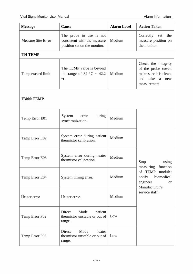
Vital Signs Monitor User Manual Alarm Information
- 37 -
Message Cause Alarm Level Action Taken
Measure Site Error
The probe in use is not
consistent with the measure
position set on the monitor.
Medium
Correctly set the
measure position on
the monitor.
TH TEMP
Temp exceed limit
The TEMP value is beyond
the range of 34 C ~ 42.2
C
Medium
Check the integrity
of the probe cover,
make sure it is clean,
and take a new
measurement.
F3000 TEMP
Temp Error E01 System error during
synchronization. Medium
Stop using
measuring function
of TEMP module;
notify biomedical
engineer or
Manufacturer‘s
service staff.
Temp Error E02 System error during patient
thermistor calibration. Medium
Temp Error E03 System error during heater
thermistor calibration. Medium
Temp Error E04 System timing error. Medium
Heater error Heater error. Medium
Temp Error P02
Direct Mode patient
thermistor unstable or out of
range.
Low
Temp Error P03
Direct Mode heater
thermistor unstable or out of
range.
Low
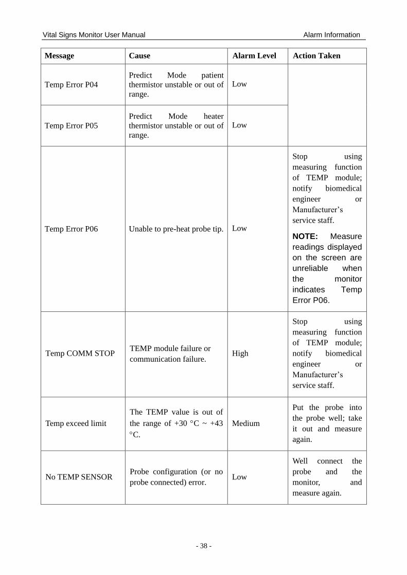
Vital Signs Monitor User Manual Alarm Information
- 38 -
Message Cause Alarm Level Action Taken
Temp Error P04
Predict Mode patient
thermistor unstable or out of
range.
Low
Temp Error P05
Predict Mode heater
thermistor unstable or out of
range.
Low
Temp Error P06 Unable to pre-heat probe tip. Low
Stop using
measuring function
of TEMP module;
notify biomedical
engineer or
Manufacturer‘s
service staff.
NOTE: Measure
readings displayed
on the screen are
unreliable when
the monitor
indicates Temp
Error P06.
Temp COMM STOP TEMP module failure or
communication failure. High
Stop using
measuring function
of TEMP module;
notify biomedical
engineer or
Manufacturer‘s
service staff.
Temp exceed limit
The TEMP value is out of
the range of +30 C ~ +43
C.
Medium
Put the probe into
the probe well; take
it out and measure
again.
No TEMP SENSOR Probe configuration (or no
probe connected) error. Low
Well connect the
probe and the
monitor, and
measure again.
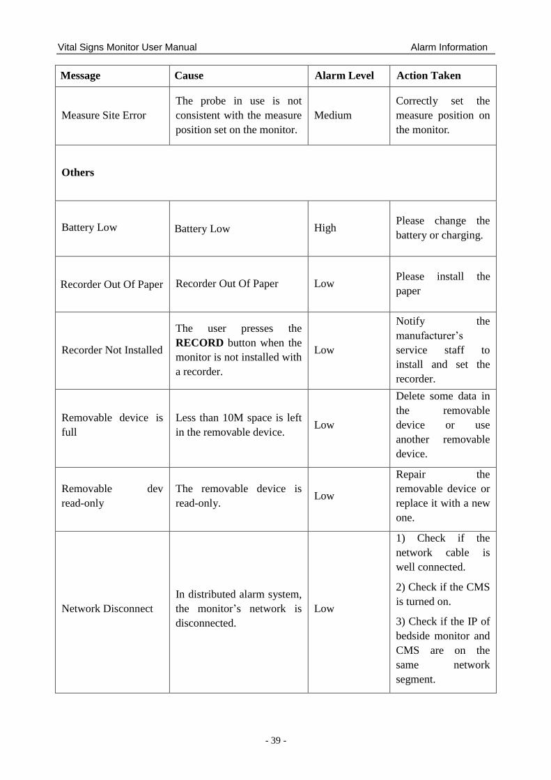
Vital Signs Monitor User Manual Alarm Information
- 39 -
Message Cause Alarm Level Action Taken
Measure Site Error
The probe in use is not
consistent with the measure
position set on the monitor.
Medium
Correctly set the
measure position on
the monitor.
Others
Battery Low Battery Low High Please change the
battery or charging.
Recorder Out Of Paper Recorder Out Of Paper Low Please install the
paper
Recorder Not Installed
The user presses the
RECORD button when the
monitor is not installed with
a recorder.
Low
Notify the
manufacturer‘s
service staff to
install and set the
recorder.
Removable device is
full
Less than 10M space is left
in the removable device. Low
Delete some data in
the removable
device or use
another removable
device.
Removable dev
read-only
The removable device is
read-only. Low
Repair the
removable device or
replace it with a new
one.
Network Disconnect
In distributed alarm system,
the monitor‘s network is
disconnected.
Low
1) Check if the
network cable is
well connected.
2) Check if the CMS
is turned on.
3) Check if the IP of
bedside monitor and
CMS are on the
same network
segment.
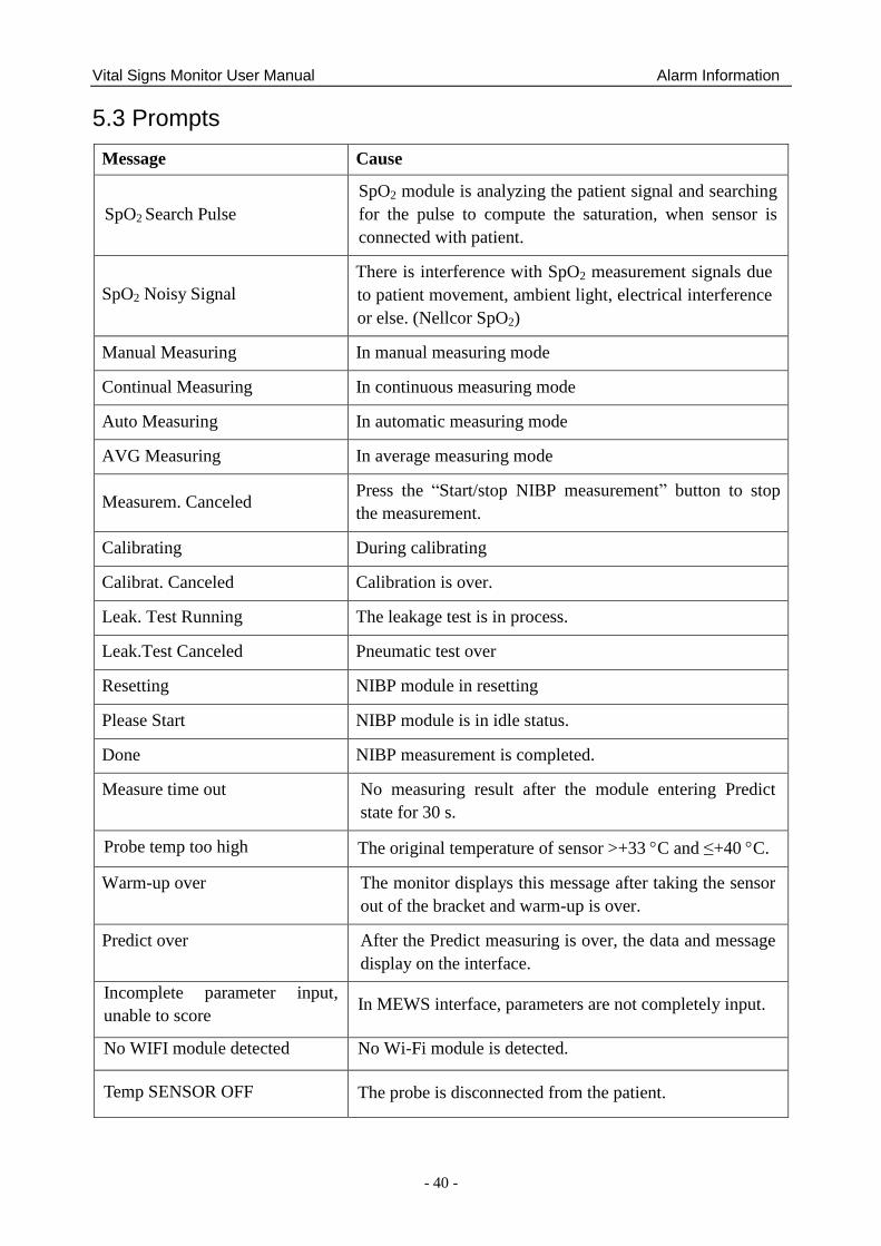
Vital Signs Monitor User Manual Alarm Information
- 40 -
5.3 Prompts
Message Cause
SpO2 Search Pulse
SpO2 module is analyzing the patient signal and searching
for the pulse to compute the saturation, when sensor is
connected with patient.
SpO2 Noisy Signal
There is interference with SpO2 measurement signals due
to patient movement, ambient light, electrical interference
or else. (Nellcor SpO2)
Manual Measuring In manual measuring mode
Continual Measuring In continuous measuring mode
Auto Measuring In automatic measuring mode
AVG Measuring In average measuring mode
Measurem. Canceled Press the ―Start/stop NIBP measurement‖ button to stop
the measurement.
Calibrating During calibrating
Calibrat. Canceled Calibration is over.
Leak. Test Running The leakage test is in process.
Leak.Test Canceled Pneumatic test over
Resetting NIBP module in resetting
Please Start NIBP module is in idle status.
Done NIBP measurement is completed.
Measure time out No measuring result after the module entering Predict
state for 30 s.
Probe temp too high The original temperature of sensor >+33 C and ≤+40 C.
Warm-up over The monitor displays this message after taking the sensor
out of the bracket and warm-up is over.
Predict over After the Predict measuring is over, the data and message
display on the interface.
Incomplete parameter input,
unable to score In MEWS interface, parameters are not completely input.
No WIFI module detected No Wi-Fi module is detected.
Temp SENSOR OFF The probe is disconnected from the patient.
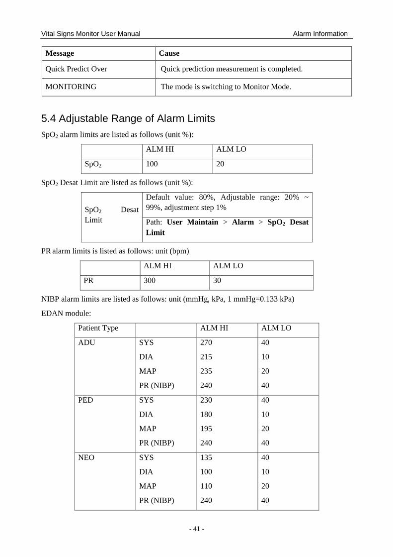
Vital Signs Monitor User Manual Alarm Information
- 41 -
Message Cause
Quick Predict Over Quick prediction measurement is completed.
MONITORING The mode is switching to Monitor Mode.
5.4 Adjustable Range of Alarm Limits
SpO2 alarm limits are listed as follows (unit %):
ALM HI ALM LO
SpO2 100 20
SpO2 Desat Limit are listed as follows (unit %):
SpO2 Desat
Limit
Default value: 80%, Adjustable range: 20% ~
99%, adjustment step 1%
Path: User Maintain > Alarm > SpO2 Desat
Limit
PR alarm limits is listed as follows: unit (bpm)
ALM HI ALM LO
PR 300 30
NIBP alarm limits are listed as follows: unit (mmHg, kPa, 1 mmHg=0.133 kPa)
EDAN module:
Patient Type ALM HI ALM LO
ADU SYS
DIA
MAP
PR (NIBP)
270
215
235
240
40
10
20
40
PED SYS
DIA
MAP
PR (NIBP)
230
180
195
240
40
10
20
40
NEO SYS
DIA
MAP
PR (NIBP)
135
100
110
240
40
10
20
40
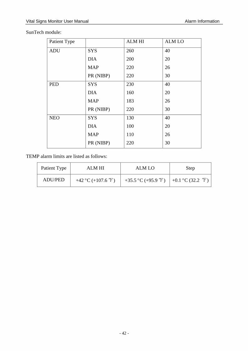
Vital Signs Monitor User Manual Alarm Information
- 42 -
SunTech module:
Patient Type ALM HI ALM LO
ADU SYS
DIA
MAP
PR (NIBP)
260
200
220
220
40
20
26
30
PED SYS
DIA
MAP
PR (NIBP)
230
160
183
220
40
20
26
30
NEO SYS
DIA
MAP
PR (NIBP)
130
100
110
220
40
20
26
30
TEMP alarm limits are listed as follows:
Patient Type ALM HI ALM LO Step
ADU/PED +42 C (+107.6 ℉) +35.5 C (+95.9 ℉) +0.1 C (32.2 ℉)
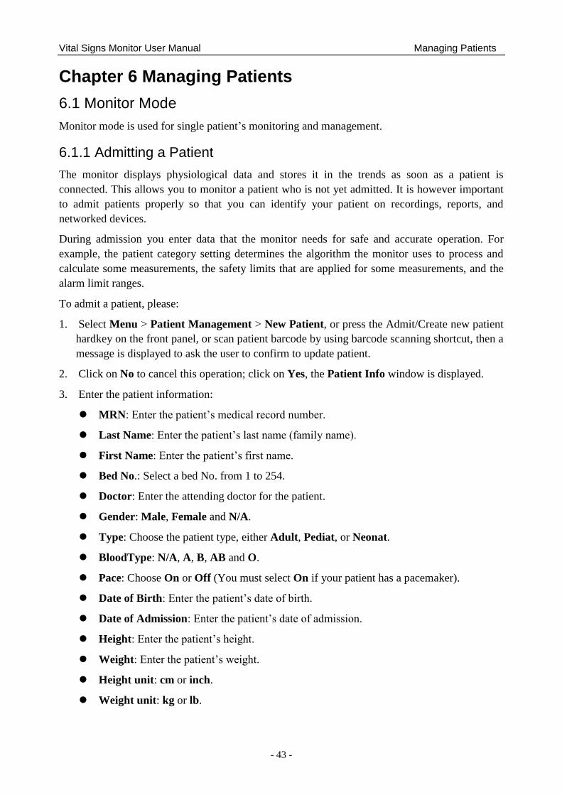
Vital Signs Monitor User Manual Managing Patients
- 43 -
Chapter 6 Managing Patients
6.1 Monitor Mode
Monitor mode is used for single patient‘s monitoring and management.
6.1.1 Admitting a Patient
The monitor displays physiological data and stores it in the trends as soon as a patient is
connected. This allows you to monitor a patient who is not yet admitted. It is however important
to admit patients properly so that you can identify your patient on recordings, reports, and
networked devices.
During admission you enter data that the monitor needs for safe and accurate operation. For
example, the patient category setting determines the algorithm the monitor uses to process and
calculate some measurements, the safety limits that are applied for some measurements, and the
alarm limit ranges.
To admit a patient, please:
1. Select Menu > Patient Management > New Patient, or press the Admit/Create new patient
hardkey on the front panel, or scan patient barcode by using barcode scanning shortcut, then a
message is displayed to ask the user to confirm to update patient.
2. Click on No to cancel this operation; click on Yes, the Patient Info window is displayed.
3. Enter the patient information:
MRN: Enter the patient‘s medical record number.
Last Name: Enter the patient‘s last name (family name).
First Name: Enter the patient‘s first name.
Bed No.: Select a bed No. from 1 to 254.
Doctor: Enter the attending doctor for the patient.
Gender: Male, Female and N/A.
Type: Choose the patient type, either Adult, Pediat, or Neonat.
BloodType: N/A, A, B, AB and O.
Pace: Choose On or Off (You must select On if your patient has a pacemaker).
Date of Birth: Enter the patient‘s date of birth.
Date of Admission: Enter the patient‘s date of admission.
Height: Enter the patient‘s height.
Weight: Enter the patient‘s weight.
Height unit: cm or inch.
Weight unit: kg or lb.
Vital Signs Monitor User Manual Managing Patients
- 44 -
NOTE:
Creating new patient and updating patient will clear the history data in the monitor
associated with the patient.
6.1.1.1 Patient Category
The patient category setting determines the algorithm which the monitor uses to process and
calculate some measurements, the safety limits that are applied for some measurements, and the
alarm limit ranges.
WARNING
Changing the patient category may change the relevant configuration (such as alarm
limits). Always check alarm limits to make sure that they are appropriate for your patient.
6.1.2 Quick Admit
If you do not have the time or information to fully admit a patient, you can use Quick Admit to
quickly admit a patient and complete the rest of the patient information later. To quickly admit a
patient, please:
1. Select the shortcut key on the screen directly, or
2. Select Menu > Patient Management > Quick Admit, then a message is displayed to ask
the user to confirm to update patient.
3. Click on No to cancel this operation; click on Yes to continue and the Quick Admit window
is displayed.
4. Configure Type and Pace to the correct setting and click Yes to finish the quick patient
admission operation. If you want to quit the operation, click No.
6.1.3 Editing Patient Information
To edit the patient information after a patient has been admitted, select Menu > Patient
Management > Patient Info., and make the required changes on the popup interface.
6.2 Round Mode
Round mode is used for parameter measurement and for multiple patients‘ round data
management (maximum 1000 patients at the same time).
6.2.1 Patient Management
Select Menu > Patient Management to enter Patient Management window where patients
information are listed, including bed No., name, patient type and patient ID. If monitor is power
off, this information list will be stored.
Also, user can create, import and delete patients in this window, or click one patient line to edit
patient information.
Vital Signs Monitor User Manual Managing Patients
- 45 -
6.2.1.1 Create New Patient
To create new patient, you may:
1. Select Menu > Patient Management > New Patient, or
2. Select the shortcut key on the main screen, or
3. Press Admit/Create new patient hardkey on the front panel, or
4. Use Select Patient permanent key, and then click icon + in popup window , or
5. Scan patient barcode by using barcode scanning shortcut key.
In patient creation window, user can input patient information. When patients‘ number exceeds
the upper limit 1000, monitor will display a prompt.
6.2.1.2 Import Patient
Select Patient Management > Import to enter import patient window and choose Source which
includes: USB flash disk or Network.
If USB flash disk is select, before importing, please set the imported data file to CSV format, and
file name should be fixed as: ImportPatientList.csv
When you need to edit the patient information in the file, the following ways are optional:
Use Excel to edit: patient information format should be ‗bed No. + first name + last name +
patient type + MRN‘. Patient type can only be English, such as: 23 Wang Xiaoming adult
123456.
Use OneNote to edit: patient information format should be ‗bed No., first name, last name,
patient type, MRN‘. Patient type can only be English and the comma in English should also
be kept, such as: 23, Wang, Xiaoming, adult, 123456.
NOTE:
1 In the patient list of CSV data file, first name, last name and MRN cannot be more
than 63 bits for each, and bed No. cannot be more than 5 bits and must also be the
numbers from 1 to 99999.
2 In importing process, the monitor will import the patient information that meets the
requirements, and the wrong patient information will be prompted. The wrong patient
information needs to be revised and re-imported.
All patients to be imported will be listed in a new window. Choose patients you want and click
Import.
During importing, if the total patients in the monitor exceed upper limit (1000 patients), a
confirmation box will be popped up. Choose OK to enter patient management window and delete
part of existing patients, then return to import patient window to import again. Choose NO to
return to import patient window and delete part of patients who need to be imported, then import
again.
Vital Signs Monitor User Manual Managing Patients
- 46 -
If patient bed NO. has conflict, a confirmation box will be popped up ‗Bed NO.XXX has
conflict. Update now?‘. Choose OK to replace the current patient information which has bed
No. conflict. Choose all to replace information of all patients who have bed No. conflicts. Choose
NO to prevent the current replacing and continue importing. Choose ALL NOT to prevent
replacing of all patients who have bed No. conflicts.
6.2.1.3 Delete Patient
Select Patient Management > Delete > choose patients who need to be deleted > Delete
Selected, or directly select Delete Page or Delete All.
This operation can only delete the patient information in patient management window but cannot
delete patient history data.
6.2.2 Choose Patient for Measurement
Choose the patient for measurement and the patient information will be displayed in the main
interface. Also, this patient information keeps the same with that in patient management window.
Click Select Patient shortcut key to enter select patient window:
All patients‘ bed No. and name are displayed in window. The circle near bed No. shows
measurement status by colour. Green means a measured patient has normal measurement
value; Red means a measured patient has abnormal measurement value; white means a
measured patient has invalid measurement value or patient was not measured.
To choose patient for current measurement, Click one patient and the patient information will
be displayed in the main interface.
Click icon + to create new patient who will be displayed in the place where the icon + is, and
whose information will be synchronized to patient management window.
Refresh: when new round is needed, press this key to refresh all patients‘ measurement
status and enter into pending status.
6.2.3 Round Record
6.2.3.1 Original Data Table
The Original data table of single patient is displayed at the bottom of the main interface, is stable
and cannot be hidden. If the displayed data exceed maximum 20 groups, the earliest data will be
replaced by the latest one. The corresponding original data for round record cannot be deleted.
In the table, SpO2 data will be updated by following ways:
By time interval: Click SpO2 parameter area to enter SpO2 parameter setup menu > SpO2
Storage Inteval, choose from 30 S, 1 min, 2 mins and 5 mins. 30 S is default setting;
By spot-checking data: when TEMP value is got and when NIBP starts to be measured.
Vital Signs Monitor User Manual Managing Patients
- 47 -
6.2.3.2 Round Record Confirmation
Choose round record
Choose manually: in original data table, click the grey reversed triangle and choose data as the
parameter‘s round record. Or in the original data table area, choose parameter value as round
record.
Choose automatically: the round record is subject to the latest valid measurement by default.
Generate round record
Generate manually: by clicking round record generation key in round record area.
Generate automatically: by switching patient, power off or standby operation, the valid
measurement data will automatically generate the round record.
Round record time is subject to the time when round record generates from original data.
6.3 Spot-checking Mode
Spot-checking mode is used for spot-checking measurement and for management of multiple
patients‘ spot-checking data.
6.3.1 Admit Patient
There are following ways to admit patient. If monitor is connected to network server, the patient
information can be synchronized to the network server after admission.
1. Select Menu > Patient Management, click New Patient to enter new patient window.
2. Select permanent key of create new patient, or press Admit/create new patient hardkey, or
scan patient barcode by using barcode scanning shortcut key, and the monitor will
automatically finish admitting new patient (that is, series No. will be automatically added by
one and other setting items are empty by default, or the monitor updates the information to
main interface according to barcode scanning).
6.3.2 Modify Patient Information
Select Patient Management > Patient Info, or directly click patient information area in main
interface to check and modify (serial No. is not editable).
If the monitor is shut down and restarted, the patient information will be restored by default, that
is, the patient type is adult and the other information is blank.
6.4 Inquire for Patient Information via Network
In monitor, round or spot-checking mode, if the monitor is connected to network server and ADT
Query (in User Maintain) is also set to on, patient information can be checked by MRN.
Select Menu > Patient Management > New Patient > input MRN and click Search to get
patient information and the patient information will be updated to the monitor.
Vital Signs Monitor User Manual Managing Patients
- 48 -
6.5 Central Monitoring System
The monitor can be connected to the central monitoring system only in monitor mode. Through
the network:
1. The monitor sends patient information, real-time monitoring or measurement data to the
central monitoring system.
2. The real-time monitoring information is displayed on the central monitoring system as the
same to the monitor, and the central monitoring system can perform some bilateral control.
For example: changing patient information, receiving patient, discharging patient and so
forth.
For detailed information, please refer to MFM-CMS Central Monitoring System User Manual.
And the monitor supports HL 7 protocol.
NOTE:
1 Use wired instead of wireless networking when connecting the monitor to central
monitoring system in the operating room because the ESU will interfere with a
wireless network, which may cause networking failure.
2 Make sure the network connection between the monitor and the central monitoring
system is in good condition when the time synchronization function on the monitor is
active (default setting is off. Setting path: System Setup > Date/Time > Sync Time).
If the setting is on, the monitor will accept time synchronization from MFM-CMS.
3 The time synchronization function might not be available to all software versions of
MFM-CMS. Consult our technical service department or your local distributor for
more information.
Vital Signs Monitor User Manual User Interface
- 49 -
Chapter 7 User Interface
Changing some settings may have the risk, so only the authorized person can change them. After
changing the settings, please notify the operator.
7.1 Setting Interface Style
The user can set the interface based on the requirement, such as: Parameters needing to be
monitored.
7.2 Selecting Display Parameters
The user can select the display parameters based on the monitoring and measurement
requirements.
Click Menu > Module Setup to select the required parameters from the popup interface.
Exit the menu and the screen will adjust the parameters automatically.
7.3 Changing Parameter and Waveform Colors
The user can set the display colors of parameter and waveform as desire. Click respective
parameter area to enter parameter setup menu > Color Setup to make color changes on parameter
and waveform.
7.4 User Configuration
Users can save the current monitor‘s configuration, delete the saved user configuration and
rename it. Three pieces of user configuration can be saved in the monitor. User can select as
desire. The one labeled with ● is current configuration.
To save the user configuration:
1. Select Menu > Default Setup > User Configure.
2. Click on Save, enter a file name for the configuration and confirm it. A message will display
after the operation.
To delete the user configuration:
1. Select Menu > Default Setup > User Configure.
2. Select the configuration file needed to delete from the list, click on Delete and confirm the
operation. A message will display after the operation.
To rename the user configuration:
1. Select Menu > Default Setup > User Configure.
2. Select a configuration file needed to rename from the list and click on Rename.
3. Enter a name for the configuration file and confirm it.
Vital Signs Monitor User Manual User Interface
- 50 -
7.5 Default Configuration
To set default configuration, select Menu > Default Setup. On the Default menu, users can
choose a factory configuration (adult, pediatric or neonate) based on the patient category. Also,
users can choose a user configuration saved in the monitor if it is available. For more information
about user configuration, refer to User Configuration.
To check the configuration currently used, select Menu > Default Setup. The one labeled with
● is current configuration. If there's no labeled configuration, it means the currently used
configuration is not one of them.
Vital Signs Monitor User Manual Monitoring SpO2
- 51 -
Chapter 8 Monitoring SpO2
8.1 Overview
SpO2 is based on the absorption of pulse blood oxygen to red and infrared light by means of
finger sensor and SpO2 measuring unit. SpO2 Plethysmogram measurement is employed to
determine the oxygen saturation of hemoglobin in the arterial blood. If, for example, 97% of the
hemoglobin molecules in the red blood cells of the arterial blood combine with oxygen, then the
blood has a SpO2 oxygen saturation of 97%. The SpO2 numeric on the monitor will read 97%.
The SpO2 numeric shows the percentage of hemoglobin molecules which have combined with
oxygen molecules to form oxyhemoglobin. The SpO2/PLETH parameter can also provide a pulse
rate signal and a plethysmogram wave.
8.2 SpO2 Safety Information
WARNING
1 If the SpO2 sensor cannot work properly, please reconnect the sensor or change a
new one.
2 Do not use the SpO2 sensors if the packaging or the sensor is damaged and return
them to the vendor.
3 Prolonged and continuous monitoring may increase the risk of unexpected change of
dermal condition such as abnormal sensitivity, rubescence, vesicle, repressive
putrescence, and so on. It is especially important to check the sensor placement of
neonate and patient of poor perfusion or immature dermogram by light collimation and
proper attaching strictly according to changes of the skin. More frequent examinations
may be required for different patients.
4 Tissue damage may be caused by incorrect application or prolonged measurement
duration using the sensor (more than 4 hours). Inspect the sensor periodically
according to the sensor user manual.
5 Use only EDAN permitted sensors and extension cables with the monitor. Other
sensors or extension cables may cause improper monitor performance and/or minor
personal injury.
6 High oxygen levels may predispose a premature infant to retrolental fibroplasia. If this
is a consideration do NOT set the high alarm limit to 100%, which is equivalent to
switching the alarm off.
7 When serious arrhythmia is present, the SpO2 pulse rate may differ from ECG heart
rate but this does not indicate an inaccurate SpO2 value.
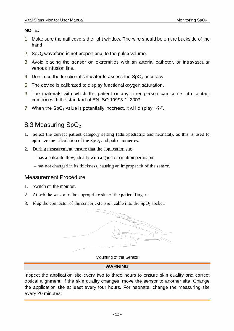
Vital Signs Monitor User Manual Monitoring SpO2
- 52 -
NOTE:
1 Make sure the nail covers the light window. The wire should be on the backside of the
hand.
2 SpO2 waveform is not proportional to the pulse volume.
3 Avoid placing the sensor on extremities with an arterial catheter, or intravascular
venous infusion line.
4 Don‟t use the functional simulator to assess the SpO2 accuracy.
5 The device is calibrated to display functional oxygen saturation.
6 The materials with which the patient or any other person can come into contact
conform with the standard of EN ISO 10993-1: 2009.
7 When the SpO2 value is potentially incorrect, it will display “-?-”.
8.3 Measuring SpO2
1. Select the correct patient category setting (adult/pediatric and neonatal), as this is used to
optimize the calculation of the SpO2 and pulse numerics.
2. During measurement, ensure that the application site:
– has a pulsatile flow, ideally with a good circulation perfusion.
– has not changed in its thickness, causing an improper fit of the sensor.
Measurement Procedure
1. Switch on the monitor.
2. Attach the sensor to the appropriate site of the patient finger.
3. Plug the connector of the sensor extension cable into the SpO2 socket.
Mounting of the Sensor
WARNING
Inspect the application site every two to three hours to ensure skin quality and correct
optical alignment. If the skin quality changes, move the sensor to another site. Change
the application site at least every four hours. For neonate, change the measuring site
every 20 minutes.
Vital Signs Monitor User Manual Monitoring SpO2
- 53 -
NOTE:
Injected dyes such as methylene blue or intravascular dyshemoglobins such as
methemoglobin and carboxyhemoglobin may lead to inaccurate measurements.
8.4 Measurement Limitations
Certain patient conditions can affect the measurements and cause the loss of the pulse signal.
Inaccurate measurements can be caused by:
incorrect sensor application
high levels of ambient light sources, such as surgical lights (especially those with a xenon
light source), bilirubin lamps, fluorescent lights, infrared heating lamps, and direct sunlight
failure to cover the sensor with opaque material in high levels of ambient light conditions
dysfunctional hemoglobins
poor peripheral perfusion
excessive patient movement
venous pulsations
intravascular dyes, such as indocyanine green or methylene blue
externally applied coloring agents (nail polish, dye, pigmented cream)
defibrillation
placement of the sensor on an extremity with a blood pressure cuff, arterial catheter, or
intravascular line
electromagnetic interference
low perfusion
Loss of pulse signal can occur for the following reasons:
the sensor is applied too tightly
a blood pressure cuff is inflated on the same extremity as the one with the sensor attached
there is arterial occlusion proximal to the sensor
poor peripheral perfusion
NOTE:
1 Clean and remove any substances such as nail polish from the application site.
Periodically check to ensure that the sensor remains properly positioned on the
patient.
2 To prevent interference from ambient light, ensure that the sensor is properly applied,
and cover the sensor site with opaque material.
3 Move the sensor to a less active site, and keep the patient still, if possible.
Vital Signs Monitor User Manual Monitoring SpO2
- 54 -
4 For Nellcor SpO2 module, the algorithm automatically extends the amount of data
required for measuring SpO2 and PR depending on the measurement conditions.
During normal measurement conditions the averaging time is 6 to 7 seconds. During
conditions such as those caused by low perfusion, interference (e.g., external
interference such as ambient light or patient movement), or a combination of these,
the algorithm automatically extends the amount of data required beyond 7 seconds. If
the resulting dynamic averaging time exceeds 20 seconds, the screen will display
prompt message “SpO2 Search Pulse” and SpO2 and PR will continue to be updated
every second. As these conditions extend, the amount of data required continues to
increase. If the dynamic averaging time reaches 40 seconds, the screen will display
high-level alarm message “SpO2 No Pulse” indicating a loss-of-pulse condition.
8.5 Assessing the Validity of a SpO2 Reading
You can check the quality of the pleth wave and the stability of the SpO2 values to assess whether
the sensor functions properly and whether the SpO2 readings are valid. Always use these two
indications simultaneously to assess the validity of a SpO2 reading.
Generally, the quality of the SpO2 pleth wave reflects the quality of the light signals obtained by
the sensor. A wave of poor quality manifests a decline of the signal validity. On the other hand,
the stability of the SpO2 values also reflects the signal quality. Different from varying SpO2
readings caused by physiological factors, unstable SpO2 readings are resulted from the sensor‘s
receiving signals with interference. The problems mentioned above may be caused by patient
movement, wrong sensor placement or sensor malfunction. To obtain valid SpO2 readings, try to
limit patient movement, check the placement of the sensor, measure another site or replace the
sensor.
NOTE:
1 The SpO2 accuracy has been validated in controlled human studies against arterial
blood sample reference measured with a CO-oximeter. Pulse oximeter
measurements are statistically distributed, only about two-thirds of the
measurements can be expected to fall within the specified accuracy compared to
CO-oximeter measurements. The volunteer population in the studies are composed
of local healthy men and women from age 19 to 37 (for EDAN SpO2 module), from 18
to 50 (for Nellcor SpO2 module), with various skin pigmentations. Note that the study
population was healthy adults and not in the actual intended use population.
2 The pulse rate accuracy is obtained by comparison to the pulse rate generated with
an arterial oxygen simulator (also an electronic pulse simulator).
8.6 SpO2 Alarm Delay
There is a delay between a physiological event at the measurement site and the corresponding
alarm at the monitor. This delay has two components:
1. The time between the occurrence of the physiological event and when this event is
represented by the displayed numerical values. This delay depends on the algorithmic
Vital Signs Monitor User Manual Monitoring SpO2
- 55 -
processing time and the sensitivity setting. The lower the sensitivity configured, the longer
the time needed until the numerical values reflect the physiological event.
2. The time between the displayed numerical values exceeding an alarm limit and the alarm
indication on the monitor. This delay is the combination of the configured alarm delay time
plus the general system delay time.
8.7 Perfusion Index (PI)*
* Only applicable to the EDAN SpO2 module.
PI is a numeric value indicating perfusion level. It reflects the perfusion level at the monitoring
site.
As the measurement of SpO2 is based on the pulsation caused by the blood flow through the
vessel, PI is in relation to the strength of the pulse. Also, you can use PI as a signal quality
indicator for the measurement of SpO2.
PI is indicated by a value ranging from 0 to 10. The bigger the value is, the better the perfusion
and the signal quality will be. The perfusion level and the signal quality are at their maximum
when the value reaches 10. When PI is below 2, it indicates the low perfusion and the poor signal
quality at the monitoring site; you need to reposition the sensor or find a better site.
The PI value will be displayed in the SpO2 parameter area.
8.8 Setting Pitch Tone
If tone modulation is on, the PR sound lowers when the SpO2 level drops. In the SpO2 Setup
menu, select pitch tone to toggle between On and Off.
8.9 Setting Sensitivity
The different sensitivity indicates different refresh frequency. High indicates the refresh
frequency of SpO2 value is the most frequent. To change the sensitivity, please follow the steps:
1 Select the SpO2 Setup menu;
2 Select Sensitivity on the interface and select the desired sensitivity from the popup list.
8.10 NIBP/SpO2 Simul Measurement Setting
Enter SpO2 Setup > NIBP Simul to choose ON or OFF. t1~t2 is the beginning and ending time.
T1 and t2 respectively means beginning and ending (cuff deflation over) NIBP measurement.
When NIBP/SpO2 Simul measurement is set to on:
General information area displays NIBP Simul;
During t1~t2, there are no SpO2 and PR physiological alarms
Before t1 and after t2, there are normal SpO2 and PR physiological alarms
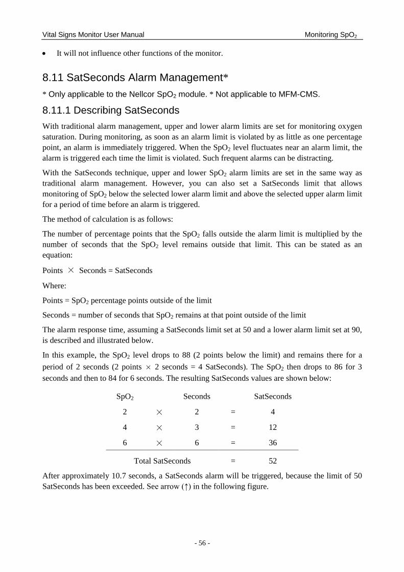
Vital Signs Monitor User Manual Monitoring SpO2
- 56 -
It will not influence other functions of the monitor.
8.11 SatSeconds Alarm Management*
* Only applicable to the Nellcor SpO2 module. * Not applicable to MFM-CMS.
8.11.1 Describing SatSeconds
With traditional alarm management, upper and lower alarm limits are set for monitoring oxygen
saturation. During monitoring, as soon as an alarm limit is violated by as little as one percentage
point, an alarm is immediately triggered. When the SpO2 level fluctuates near an alarm limit, the
alarm is triggered each time the limit is violated. Such frequent alarms can be distracting.
With the SatSeconds technique, upper and lower SpO2 alarm limits are set in the same way as
traditional alarm management. However, you can also set a SatSeconds limit that allows
monitoring of SpO2 below the selected lower alarm limit and above the selected upper alarm limit
for a period of time before an alarm is triggered.
The method of calculation is as follows:
The number of percentage points that the SpO2 falls outside the alarm limit is multiplied by the
number of seconds that the SpO2 level remains outside that limit. This can be stated as an
equation:
Points × Seconds = SatSeconds
Where:
Points = SpO2 percentage points outside of the limit
Seconds = number of seconds that SpO2 remains at that point outside of the limit
The alarm response time, assuming a SatSeconds limit set at 50 and a lower alarm limit set at 90,
is described and illustrated below.
In this example, the SpO2 level drops to 88 (2 points below the limit) and remains there for a
period of 2 seconds (2 points × 2 seconds = 4 SatSeconds). The SpO2 then drops to 86 for 3
seconds and then to 84 for 6 seconds. The resulting SatSeconds values are shown below:
SpO2 Seconds SatSeconds
2 × 2 = 4
4 × 3 = 12
6 × 6 = 36
Total SatSeconds = 52
After approximately 10.7 seconds, a SatSeconds alarm will be triggered, because the limit of 50
SatSeconds has been exceeded. See arrow (↑) in the following figure.
Vital Signs Monitor User Manual Monitoring SpO2
- 57 -
Alarm Response with SatSeconds
Saturation levels may fluctuate rather than remaining steady for a period of several seconds.
Often, the patient SpO2 may fluctuate above and below the alarm limit, re-entering the non-alarm
range several times. During such fluctuation, the monitor integrates the number of SpO2 points,
both positive and negative, until either the SatSeconds limit is reached, or the patient SpO2
returns within a normal range and remains there.
8.11.2 SatSeconds “Safety Net”
The SatSeconds ―Safety Net‖ is for patients whose saturation makes frequent excursions below or
above the SpO2 limit but does not remain in violation long enough for the SatSeconds limit to be
reached. If three or more SpO2 alarm limit violations occur within a 60-second period, an alarm
will be triggered even if the SatSeconds limit has not been reached.
8.11.3 Setting SatSeconds Duration
You can set SatSeconds to Off or to the duration among 10, 25, 50 and 100. To configure the
SatSeconds settings, enter the SpO2 Setup menu and select the desired SatSeconds setting from
the SatSeconds list.
Vital Signs Monitor User Manual Monitoring PR
- 58 -
Chapter 9 Monitoring PR
9.1 Overview
The pulse numeric counts the arterial pulsations that result from the mechanical activity of the
heart in beats per minute (bpm). You can display a pulse from any measured SpO2 signal or NIBP
measurement.
9.2 PR Source
PR source can be from SpO2 or NIBP, and is not selectable. SpO2 is preferred source if PR from
SpO2 is valid. If PR is on, and SpO2 & NIBP both are off, PR parameter area will display No
source.
9.3 Setting PR Volume
Select Function in PR Setup menu, then select the appropriate setting for the PR volume: five
bars represent the maximum volume and one bar represents the minimum volume. If none of bars
are selected, the PR volume will be off. Beat frequency has positive correlation with
measurement value.
Vital Signs Monitor User Manual Monitoring NIBP
- 59 -
Chapter 10 Monitoring NIBP
10.1 Overview
This monitor uses the oscillometric method for measuring NIBP. It can be used for adult,
pediatric and neonatal patients. It is also intended for use with pregnant, including pre-eclamptic
patients.
Oscillometric devices measure the amplitude of pressure changes in the occluding cuff as the cuff
deflates from above systolic pressure. The amplitude suddenly increases as the pulse breaks
through the occlusion in the artery. As the cuff pressure decreases further, the pulsations increase
in amplitude, reach a maximum (which approximates to the mean pressure), and then diminish.
The blood pressure measurements determined with this device comply with the American
National Standard for Electronic or Automated Sphygmomanometers (ANSI/AAMI/ISO
81060-2:2013) in relation to mean error and standard deviation.
10.2 NIBP Safety Information
WARNING
1 Do not measure NIBP on patients with sickle-cell disease or any condition where skin
damage has occurred or is expected.
2 Do not measure NIBP on the arm of the same side with a mastectomy.
3 Use clinical judgement to decide whether to perform frequent blood pressure
measurements on patients with severe blood clotting disorders because of the risk of
hematoma in the limb fitted with the cuff.
4 Ensure that the correct setting is selected when performing measurements. It may be
dangerous for the neonate to use an over pressure level. Not using the neonate mode
on a neonatal patient can block the blood flow, potentially causing harm to the patient.
5 The equipment is suitable for use in the presence of electrosurgery.
6 Before starting a measurement, verify that you have selected a setting appropriate for
your patient (adult, child or neonate.)
7 Do not apply the cuff to a limb that has an intravenous infusion or catheter in place.
This could cause tissue damage around the catheter when infusion is slowed or
blocked during cuff inflation.
8 Make sure that the air conduit connecting the blood pressure cuff and the monitor is
neither blocked nor tangled.
9 Do not attach the cuff to a limb being used for IV infusions as the cuff inflation can
block the infusion, potentially causing harm to patient.
10 Measuring of blood pressure can temporarily cause malfunctioning of other medical
monitoring devices on the same limb.
Vital Signs Monitor User Manual Monitoring NIBP
- 60 -
WARNING
11 Do not apply the cuff to a limb where intravascular access or therapy, or an
arterio-venous (A-V) shunt is present, otherwise, it may result in injury to the patient.
12 NIBP readings can be affected by the measurement site, the position of the patient,
exercise, or the patient's physiologic conditions.
13 Continuous cuff pressure due to connection tubing kinking can block the blood flow,
and may result in injury to the patient.
14 Verifying the calibration is only applicable for adults, and it cannot be operated in
automatic measuring interval. Continuous measuring cannot be operated in automatic
measuring interval either.
NOTE:
1 It is suggested that the user should not start NIBP measuring when the low battery
displays, or the monitor may be turned off automatically.
2 If you spill liquid onto the equipment or accessories, particularly if there is a chance
that it can get inside the tubing or the measurement device, contact your service
personnel.
3 Continuous use of the automatic measuring mode for short intervals may lead to the
discomfort of patient. Continuous measuring and automatic measuring in neonatal or
pediatric mode may result in tissue damage or ischemia to the patient.
4 NIBP measurement can be affected by extremes of temperature, humidity and
altitude.
5 NIBP measurement value should be explained by qualified professionals.
10.3 Measurement Limitations
Measurements are impossible with pulse rate extremes of less than 40 bpm or greater than 240
bpm, or if the patient is on a heart-lung machine.
The measurement may be inaccurate or impossible in the following situations:
A regular arterial pressure pulse is hard to detect.
Patients with cardiac arrhythmias.
Patients with excessive and continuous movement such as shivering or convulsions.
Patients with rapid blood pressure changes.
Patients with severe shock or hypothermia that reduces blood flow to the peripheries.
Patients with obesity, where a thick layer of fat surrounding a limb dampens the oscillations
coming from the artery.
Patients on an edematous extremity.
Vital Signs Monitor User Manual Monitoring NIBP
- 61 -
10.4 Measurement Methods
There are four methods of measuring NIBP:
Manual - measurement on demand. Manual is the default setting in round and spot-checking
mode.
Auto - continually repeated measurements (between 1 and 480 minute adjustable interval).
Auto is used in monitor mode only.
Continual- the measurement will run consecutively in five minutes with intervals of 5
seconds, then the monitor enters manual mode or auto mode.
Average – between 1 and 5 minute adjustable AVG interval, measurement will run as
specified AVG times (3 or 5 times are optional), then gets average value. Average is used in
round or spot-checking mode only. After finishing average measurement, the monitor enters
manual mode.
To change Measure Mode, Interval, AVG Interval and AVG Times, please select NIBP
Setup > Function Setup.
WARNING
Prolonged non-invasive blood pressure measurements in Auto mode may be associated
with purpura, ischemia and neuropathy in the limb wearing the cuff. When monitoring a
patient, examine the extremities of the limb frequently for normal color, warmth and
sensitivity. If any abnormality is observed, stop the blood pressure measurements.
10.5 Measurement Procedures To obtain accurate measurements, the following operating steps need to be observed:
1. Ensure the patient position in normal use, including
Comfortably seated (or lie flat on back)
Legs uncrossed
Feet flat on the floor
Back and arm supported
Middle of the cuff at the level of the right atrium of the heart
2. Relax as much as possible and do not talk during the measurement.
3. Wait for five minutes until the first reading is taken.
NOTE:
If an NIBP measurement is suspect, repeat the measurement. If you are still uncertain
about the reading, use another method to measure the blood pressure.
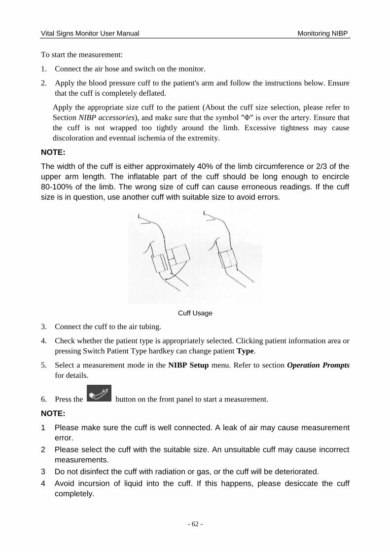
Vital Signs Monitor User Manual Monitoring NIBP
- 62 -
To start the measurement:
1. Connect the air hose and switch on the monitor.
2. Apply the blood pressure cuff to the patient's arm and follow the instructions below. Ensure
that the cuff is completely deflated.
Apply the appropriate size cuff to the patient (About the cuff size selection, please refer to
Section NIBP accessories), and make sure that the symbol "Φ" is over the artery. Ensure that
the cuff is not wrapped too tightly around the limb. Excessive tightness may cause
discoloration and eventual ischemia of the extremity.
NOTE:
The width of the cuff is either approximately 40% of the limb circumference or 2/3 of the
upper arm length. The inflatable part of the cuff should be long enough to encircle
80-100% of the limb. The wrong size of cuff can cause erroneous readings. If the cuff
size is in question, use another cuff with suitable size to avoid errors.
Cuff Usage
3. Connect the cuff to the air tubing.
4. Check whether the patient type is appropriately selected. Clicking patient information area or
pressing Switch Patient Type hardkey can change patient Type.
5. Select a measurement mode in the NIBP Setup menu. Refer to section Operation Prompts
for details.
6. Press the button on the front panel to start a measurement.
NOTE:
1 Please make sure the cuff is well connected. A leak of air may cause measurement
error.
2 Please select the cuff with the suitable size. An unsuitable cuff may cause incorrect
measurements.
3 Do not disinfect the cuff with radiation or gas, or the cuff will be deteriorated.
4 Avoid incursion of liquid into the cuff. If this happens, please desiccate the cuff
completely.
Vital Signs Monitor User Manual Monitoring NIBP
- 63 -
5 NIBP parameter area can display real-time cuff pressure value till displaying SYS
value.
6 NIBP parameter area keeps measured value for 30 mins. If there is no measurement
to continue, the area will display invalid value after 30 mins.
10.5.1 Operation Prompts
1. Manual Measuring
Access the NIBP Setup > Function menu and set the Measure Mode item to Manual. Then
press the button on the front panel to start a manual measurement. During measurement,
pressing this button at any time can stop measurement.
2. Automatical Measurement
Access the NIBP Setup > Function menu and set the Measure Mode item to Auto, then press the
button on the front panel to start the automatical measurement according to the selected time
interval. During measurement:
If measurement is failed or monitor receives the command for suspending, measurement will be
stopped. The next measurement will be continued after interval. If alarms of NIBP Excessive
Pressure or NIBP Aux Excessive Pressure are present, the whole measurement will be stopped.
Manually operation is necessary for a new auto measurement.
During interval, if interval is changed, after ending of new interval countdown, monitor will start
measurement automatically.
During interval, if user manually starts the measurement, the next auto measurement will start
after the ending of countdown which starts from the latest manual measurement; During interval,
if user makes a continuous measurement, the whole measurement will be over on the basis of
continuous measurement.
3. Continuous measurement
Access the NIBP Setup menu; click Continual to start a continuous measurement. The
continuous measurement will last 5 minutes.
4. AVG measurement
Access NIBP Setup > Function menu, set AVG interval and AVG times, and click NIBP AVG; or
click AVG shortcut key directly to start measurement. During measurement:
The parameter interface will display AVG-n for the Nth measurement;
Invalid value will not be used for counting average. Invalid value every measurement will result
in invalid average;
There will have sounding of DU… after entire measurement is finished. At that time, a final
average value can be displayed. The bottom part of the interface displays done, and meanwhile,
alert information and technical alarms of the last measurement will be cleared, and alert
Vital Signs Monitor User Manual Monitoring NIBP
- 64 -
information can work normally. The value for each measurement and final average value will be
stored in round records/spot-checking trend table which uses icon * to mark the average value;
In specified interval, if interval and times have been changed again, the whole average
measurement will be ended and measurement times will be zero;
Other operations, such as changing patient type, entering DEMO or standby mode and so on, can
stop the measurement. Meanwhile, parameter interface will be updated;
At the end of the last measurement, if user presses NIBP measurement key before monitor gets
average value with DU… sounding, a new round of average measurement will be started with
prompt AVG-1 (n) and NIBP average value of the last round will not be displayed. N in AVG-1
(n) means the specified AVG times.
5. Stopping measurement
During measurement, press the button on the front panel at any time to stop
measurement.
NOTE:
1 In auto or average mode, when measurement is in process, pressing the
button can only stop the current measurement, and cannot end the entire
measurement mode. At the end of countdown, monitor continues to finish the NIBP
measurement; when measurement is in interval, pressing the button can
start measurement in advance.
2 To end the whole AVG measurement, please click AVG measurement shortcut key,
or click Stop in NIBP setup menu.
10.5.2 Correcting the Measurement if Limb is not at Heart Level
To correct the measurement if the limb is not at heart level to the displayed value:
Add 0.75 mmHg (0.10 kPa) for each centimeter
higher or
Deduct 0.75 mmHg (0.10 kPa) for each
centimeter lower or
Add 1.9 mmHg (0.25 kPa) for each inch higher Deduct 1.9 mmHg (0.25 kPa) for each inch
lower
10.6 NIBP Multi-Review Window
In monitor mode, clicking the triangle icon at the bottom of main interface can display/hide NIBP
multi-review window.
10.7 Resetting NIBP
Available for EDAN module only.
Vital Signs Monitor User Manual Monitoring NIBP
- 65 -
When the pressure does not work properly and the system fails to give a message for the problem,
pick Reset in the User Maintain > NIBP menu to activate self-test procedure, and thus restore
the system from abnormal performance.
10.8 Calibrating NIBP
NIBP is not user-calibrated. Cuff-pressure transducers must be verified and calibrated, if
necessary, at least once every two years by a qualified service professional. See the Service
Manual for details.
10.9 Leakage Test
WARNING
This leakage test other than being specified in the EN 1060-1 standard is to be used by
the user to simply determine whether there are air leaks in the NIBP airway. If at the end
of the test the system gives the prompt that the NIBP airway has air leaks, please contact
the manufacturer for repair.
Procedure of Leakage Test
1. Connect the cuff securely with the socket for NIBP air hole.
2. Wrap the cuff around the cylinder of an appropriate size.
3. Make sure the patient type has been set to Adult.
4. Access Menu > User Maintain.
5. Select Leakage Test in NIBP. Then the prompt Leak. Test Running will appear indicating
that the system has started the leakage test.
For EDAN module:
The system will automatically inflate the pneumatic system to about 180 mmHg. After 20
seconds to 40 seconds, if system leakage has detected, the system will automatically open the
deflating valve to stop the leak test and indicates NIBP Leak. If no system leakage is detected
when the pneumatic system is inflated to 180 mmHg, the system will perform a deflation to an
approximate value of 40 mmHg and subsequently perform the second phase leak test. After 20
seconds to 40 seconds, the system will automatically open the deflating valve and provide
corresponding indication based on the test result.
For SunTech module:
NOTE:
When applying high pressures; take special care to increase the pressure at a rate that
will not cause unwanted overpressure errors (300 mmHg).
Manually inflate the pneumatic system to approximately 250 mmHg. Start the timer and wait 60
seconds for the pneumatic system to reach its pressure equilibrium point. After the waiting period,
record the pneumatic pressure level (P1) and wait another 60 seconds and record the pneumatic
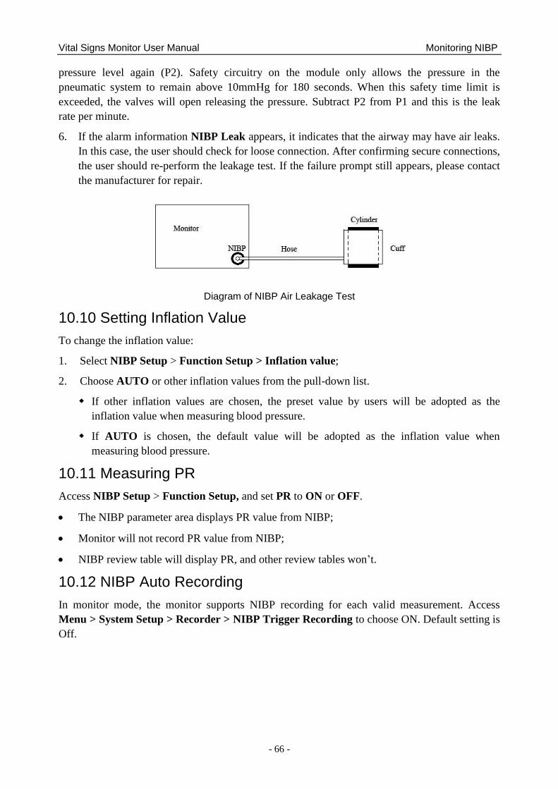
Vital Signs Monitor User Manual Monitoring NIBP
- 66 -
pressure level again (P2). Safety circuitry on the module only allows the pressure in the
pneumatic system to remain above 10mmHg for 180 seconds. When this safety time limit is
exceeded, the valves will open releasing the pressure. Subtract P2 from P1 and this is the leak
rate per minute.
6. If the alarm information NIBP Leak appears, it indicates that the airway may have air leaks.
In this case, the user should check for loose connection. After confirming secure connections,
the user should re-perform the leakage test. If the failure prompt still appears, please contact
the manufacturer for repair.
Diagram of NIBP Air Leakage Test
10.10 Setting Inflation Value
To change the inflation value:
1. Select NIBP Setup > Function Setup > Inflation value;
2. Choose AUTO or other inflation values from the pull-down list.
If other inflation values are chosen, the preset value by users will be adopted as the
inflation value when measuring blood pressure.
If AUTO is chosen, the default value will be adopted as the inflation value when
measuring blood pressure.
10.11 Measuring PR
Access NIBP Setup > Function Setup, and set PR to ON or OFF.
The NIBP parameter area displays PR value from NIBP;
Monitor will not record PR value from NIBP;
NIBP review table will display PR, and other review tables won‘t.
10.12 NIBP Auto Recording
In monitor mode, the monitor supports NIBP recording for each valid measurement. Access
Menu > System Setup > Recorder > NIBP Trigger Recording to choose ON. Default setting is
Off.
Vital Signs Monitor User Manual Monitoring TEMP
- 67 -
Chapter 11 Monitoring TEMP
11.1 Quick TEMP with T2A Module
11.1.1 Introduction
iM3 with the T2A module takes a temperature in either Predict or Monitor Mode. In the Predict
mode, the monitor measures oral/axillary/rectal TEMP in a short time, calculates and gets the
measuring results. In Monitor mode, it can monitor patient for 10 min. The Oral/Axillary sensor
and Rectal sensor are of standard configuration.
The monitor can only measure temperature of adult and pediatric patients. If the user measure
temperature of neonate patient, the monitor will not display data.
Making a TEMP Measurement
Select the correct sensor according to the measuring position and patient type.
Apply the sensor to the patient. You are advised to use a protective rubber cover on sensor.
Ensure the alarm settings (on or off, higher alarm or lower alarm limit) are appropriate for
the patient and the type of temperature measurement.
Select the correct measuring position in menu.
Switch on the monitor.
It takes 5min for the body temperature to stabilize.
WARNING
1 To ensure optimal accuracy, always confirm that the correct mode and alarm limit are
selected. Changing the measure position may lead to the change of alarm limit.
2 Verify probe cables fault detection before the beginning of monitoring phase. Unplug
the temperature probe cable from the socket, and then the screen will display the
error message TEMP SENSOR OFF and the audible alarm is activated.
3 Take the TEMP probe and cable carefully. When they are not in use, you should coil
up the probe and cable into a loose circle. If the wire inside the cable is tensely pulled,
it may cause mechanical damage to the probe and the cable.
4 Verification of the temperature module is necessary as frequently as dictated by your
Hospital Procedures Policy. When you need to calibrate the temperature
measurement, please contact the manufacturer.
5 Patient actions may interfere with accurate oral temperature readings. Ingesting hot or
cold liquids, eating food, chewing gum or mints, brushing teeth, smoking or
performing strenuous activity may affect temperature readings for up to 20min after
activity has ended.
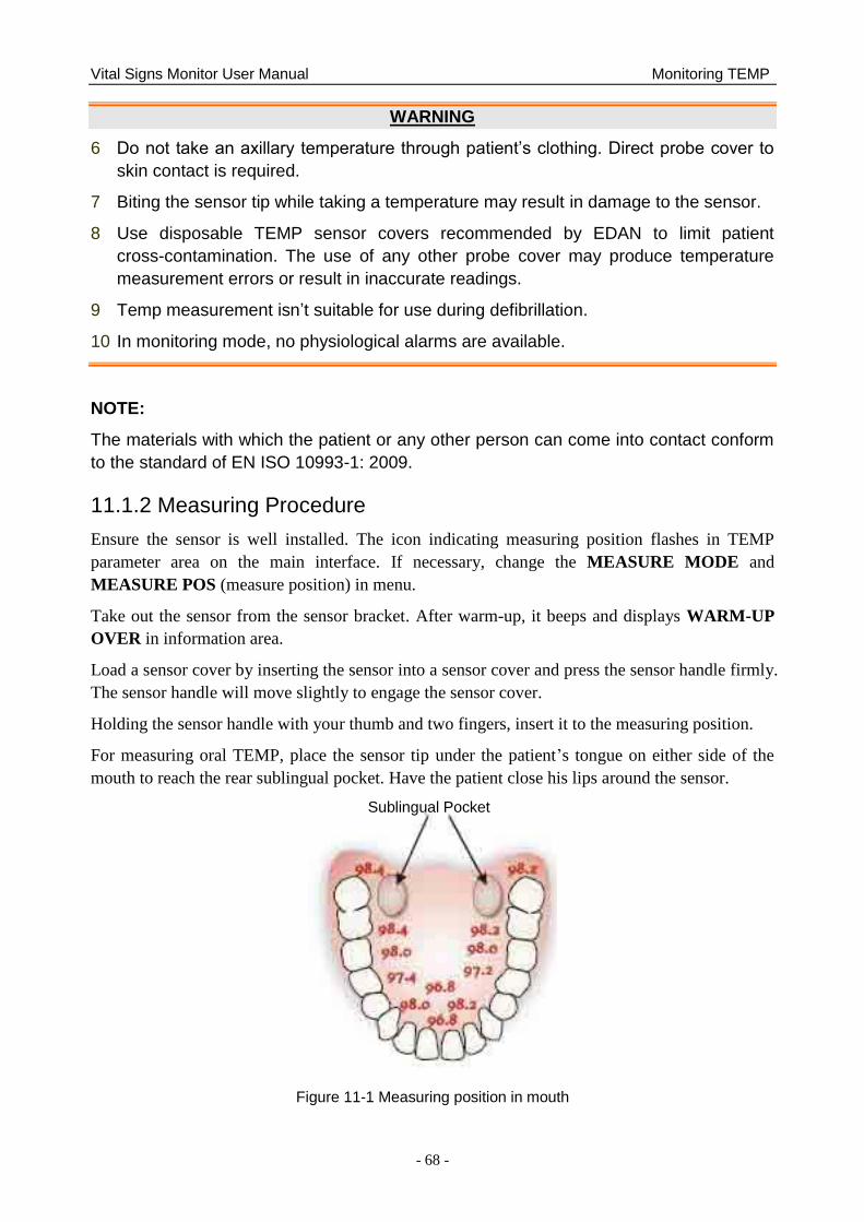
Vital Signs Monitor User Manual Monitoring TEMP
- 68 -
WARNING
6 Do not take an axillary temperature through patient‟s clothing. Direct probe cover to
skin contact is required.
7 Biting the sensor tip while taking a temperature may result in damage to the sensor.
8 Use disposable TEMP sensor covers recommended by EDAN to limit patient
cross-contamination. The use of any other probe cover may produce temperature
measurement errors or result in inaccurate readings.
9 Temp measurement isn‟t suitable for use during defibrillation.
10 In monitoring mode, no physiological alarms are available.
NOTE:
The materials with which the patient or any other person can come into contact conform
to the standard of EN ISO 10993-1: 2009.
11.1.2 Measuring Procedure
Ensure the sensor is well installed. The icon indicating measuring position flashes in TEMP
parameter area on the main interface. If necessary, change the MEASURE MODE and
MEASURE POS (measure position) in menu.
Take out the sensor from the sensor bracket. After warm-up, it beeps and displays WARM-UP
OVER in information area.
Load a sensor cover by inserting the sensor into a sensor cover and press the sensor handle firmly.
The sensor handle will move slightly to engage the sensor cover.
Holding the sensor handle with your thumb and two fingers, insert it to the measuring position.
For measuring oral TEMP, place the sensor tip under the patient‘s tongue on either side of the
mouth to reach the rear sublingual pocket. Have the patient close his lips around the sensor.
Figure 11-1 Measuring position in mouth
Sublingual Pocket
Vital Signs Monitor User Manual Monitoring TEMP
- 69 -
For measuring oral TEMP, do not take an axillary temperature through patient‘s clothing.
The monitor enters PREDICT measuring mode, — — — displays in the TEMP parameter area.
After Predict measuring is over, the measuring result displays, and MEASURE OVER appears
on the interface.
If the predict measuring is successfully finished, the monitor enters MONITOR mode after 30s;
otherwise the monitor enters MONITOR mode immediately after the predict measuring. The
monitoring state lasts for 10 min, and then the monitor enters waiting state. — — — displays in the
TEMP parameter area on interface. Put the sensor back into the sensor bracket.
If necessary, repeat the measurement according to the procedure above.
NOTE:
1. After one measurement, the user should put the sensor back to the sensor bracket
and then take it out for starting a new measurement.
2. The reference body site temperature is the same as the temperature of the measuring
site.
The monitor‘s state can change from the PREDICT mode into the MONITOR mode, but it can
not change from the MONITOR mode into the PREDICT mode.
11.1.3 TEMP Setup for T2A Module
Enter TEMP SETUP to set the following items:
MEASURE MODE: Set the measuring mode to PREDICT or MONITOR.
MEASURE POS: Set the measuring position to ORAL, AXILLARY or RECTA. The
axillary sensor can be used for measuring oral/axillary temperature, while the rectal sensor
for measuring rectal temperature.
Make sure MEASURE POS is properly set up every time before you withdraw the probe from
the probe well. After withdrawing the probe from the probe well, make sure MEASURE MODE
is properly set up.
11.2 Quick TEMP with F3000 Module
11.2.1 Introduction
iM3 with the F3000 module measures patient temperatures by oral, axillary or rectal means.
The monitor can only measure temperature of adult and pediatric patients. If the user measure
temperature of neonate patient, the monitor will not display data.
The electromagnetic compatibility of this device has been verified by test according to the
EN60601-1-2: 2007 requirements.
Vital Signs Monitor User Manual Monitoring TEMP
- 70 -
WARNING
1 Do not use this device near flammable anesthetics. Not suitable for use in the
presence of flammable anesthetic mixture with air, oxygen or nitrous oxide.
2 Do not use this thermometer without first installing a new probe cover.
3 Do not reuse the disposable probe covers.
4 Use probe covers supplied by the manufacturer with this thermometer only. Use of
any other probe cover will result in erroneous temperature readings.
5 The thermometer and probe covers are Non-sterile. Do not use on abraded tissue.
6 To limit cross contamination, use Blue devices for Oral and Axillary temperature
taking only.
7 Use RED devices only for RECTAL temperatures.
8 Thoroughly dry all electrical contacts on both probe and thermometer after washing,
or device may fail to function properly.
9 For re-calibration, service or integrity checks, refer to a qualified Biomedical
Technician or return to the manufacturer.
10 Do not open the F3000 module. No user-serviceable parts inside. Opening of the
module may affect calibration and voids warranty.
11 Disposal of used probe covers must be performed in accordance with current
medical practices or local regulations regarding disposal of infectious, biological
medical waste.
12 Cleaning frequency and practices must be consistent with institutional policy for
cleaning of non-sterile devices.
13 The F3000 module is not intended for neonatal patients.
14 In monitoring mode of TEMP module, no physiological alarms are available.
15 Verification of the temperature module is necessary as frequently as dictated by your
Hospital Procedures Policy. When you need to calibrate the temperature
measurement, please contact the manufacturer.
NOTE:
1. The materials with which the patient or any other person can come into contact
conform with the standard of EN ISO 10993:2009
2. Even though this device has been designed to minimize the effects of electromagnetic
interference, it does generate radio frequency energy. If not used in accordance with
the instructions, the device could cause interference in other equipment operating
within its vicinity. If the device is causing interference, the following actions may be
taken in an attempt to correct the interference:
• Re-orient or re-locate the receiving device.
• Increase the separation between the devices.
Vital Signs Monitor User Manual Monitoring TEMP
- 71 -
• Consult a customer service representative.
3. Verification of the temperature module is necessary as frequently as dictated by your
Hospital Procedures Policy. When you need to calibrate the temperature
measurement, please contact the manufacturer.
4. The reference body site temperature is the same as the temperature of the measuring
site.
11.2.2 Probe Covers —Applying & Removing
1. Open probe cover box by lifting tab at top corner and pulling to remove top panel.
2. Insert box of probe covers into top of isolation chamber.
NOTE:
To aid infection control, never switch boxes between blue and red isolation chambers.
Also, never switch probes between blue and red isolation chambers. Keep like colors
together.
3. Remove probe from the probe well. This automatically turns on the thermometer.
4. To help remind the user to apply or remove a probe cover, a probe icon with flashing probe
cover will be displayed when the probe is withdrawn from the probe well and following a
completed temperature measurement.
5. Insert the probe end into a cover in the box. Push the handle firmly until you feel the cover
―snap‖ into place.
6. Take appropriate temperature measurement (oral, axillary or rectal).
7. Eject the used cover into bio-waste container by pressing top button.
8. Remove, discard and replace box when empty.
11.2.3 Changing Isolation Chambers and Probes
NOTE:
1 For aiding in infection control, use only the Blue probe and Blue isolation chamber for
Oral and Axillary temperature taking. The Red probe and Red isolation chamber
must only be used for rectal temperature taking.
2 Do not attach a Red probe to a Blue isolation chamber or vice-versa.
1. To remove or replace any isolation chamber/probe assembly, grasp the isolation chamber
from each side as shown.
2. Squeeze inward releasing the snaps and slide the isolation chamber up to pull off.
3. To replace, align probe well finger with opening in the top of the unit.
4. Slide the isolation chamber down until the side snaps ―click‖ into place.
5. The probe is connected to the thermometer automatically.
Vital Signs Monitor User Manual Monitoring TEMP
- 72 -
6. To change probes, remove the isolation chamber as described previously.
7. Grasp the sides of the L-shaped connector piece with one hand and then using other hand
pull backward on the latch holding the end of the L-shaped connector.
8. Once free of the latch, slide the L-shaped connector out of isolation chamber.
9. To replace, properly align the top of the L-shaped connector to the slot on the back of the
isolation chamber.
10. Then slide the connector up into the slot pressing firmly on the bottom of the connector until
it ―clicks‖ into place.
11.2.4 Measuring Mode
Predictive Mode
When MEASURE MODE is set to PREDICT, the monitor operates in Predictive Mode to
provide fast and accurate temperature measurements.
Quick Predictive Mode
When MEASURE MODE is set to QUICK PREDICT, the monitor operates in Quick
Predictive Mode which is an oral predictive measurement mode intended for situations where fast
temperature measurements are desired.
Quick Predictive Mode allows clinicians to rapidly identify patients with ―normal‖ body
temperatures. If the patient temperature is outside of the ―normal‖ range, the monitor will
automatically switch into its standard predictive mode to provide a more accurate reading.
Quick Predictive Mode is not available when in Cold Mode.
Monitoring Mode
When MEASURE MODE is set to MONITOR, the monitor will perform continual temperature
measurement for a maximum of 10 minutes.
Besides, in the following instances, the monitor will automatically switch to Monitoring Mode and
perform temperature measurement for a maximum of 5 minutes until the temperature stabilizes:
1. When the monitor operates in Predictive Mode, no measurement site is detected or the
temperature does not stabilize.
2. When the monitor operates in Predictive Mode or Quick Predictive Mode, the ambient
temperature is greater than 35 °C (95 °F).
Cold Mode
Cold Mode is provided for use in applications where body temperatures may be lower than
―normal‖, such as for patients recently out of surgery.
The accuracy and measurement time of Cold Mode measurements are equivalent to standard
prediction measurements at the respective body sites.
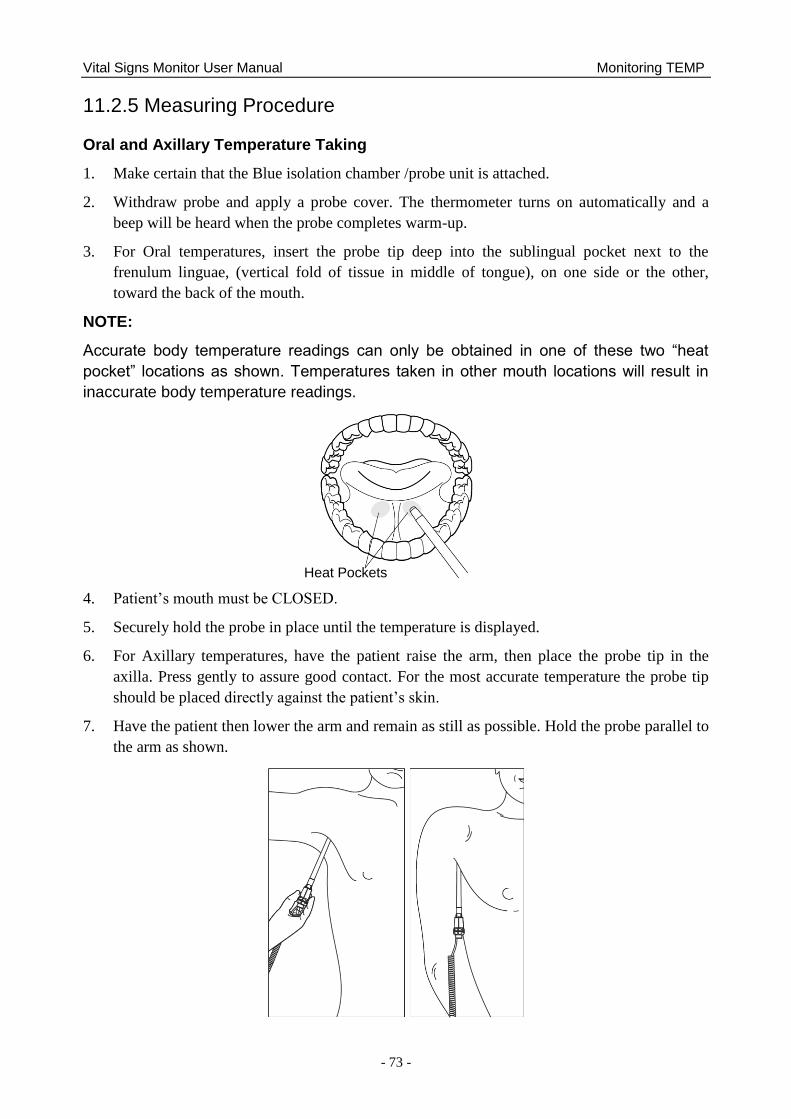
Vital Signs Monitor User Manual Monitoring TEMP
- 73 -
11.2.5 Measuring Procedure
Oral and Axillary Temperature Taking
1. Make certain that the Blue isolation chamber /probe unit is attached.
2. Withdraw probe and apply a probe cover. The thermometer turns on automatically and a
beep will be heard when the probe completes warm-up.
3. For Oral temperatures, insert the probe tip deep into the sublingual pocket next to the
frenulum linguae, (vertical fold of tissue in middle of tongue), on one side or the other,
toward the back of the mouth.
NOTE:
Accurate body temperature readings can only be obtained in one of these two “heat
pocket” locations as shown. Temperatures taken in other mouth locations will result in
inaccurate body temperature readings.
4. Patient‘s mouth must be CLOSED.
5. Securely hold the probe in place until the temperature is displayed.
6. For Axillary temperatures, have the patient raise the arm, then place the probe tip in the
axilla. Press gently to assure good contact. For the most accurate temperature the probe tip
should be placed directly against the patient‘s skin.
7. Have the patient then lower the arm and remain as still as possible. Hold the probe parallel to
the arm as shown.
Heat Pockets
Vital Signs Monitor User Manual Monitoring TEMP
- 74 -
8. If three short beeps are heard, it means the unit switched to Monitoring Mode for this
temperature only.
9. Two beeps are sounded when measurement is complete and the final temperature is
displayed.
10. Eject the used cover into a bio-waste container by pushing top button.
Rectal Temperature Taking
1. Make certain that the Red isolation chamber/probe unit is attached.
2. Withdraw the probe and apply a probe cover. Thermometer turns on automatically a beep
will be heard when the probe completes warm-up.
3. Apply lubrication if desired.
4. Insert the probe into the patient‘s rectum. To ensure proper tissue contact, angle the probe
slightly after insertion.*
5. Depth of insertion is recommended at 1/2‖ to 3/4‖ (12 mm ~ 19 mm) for adults and 1/4‖ to
1/2‖ (6 mm ~ 13 mm) for children.
6. If three short beeps are heard, it means the unit switched to Monitoring Mode for this
temperature only.
7. Two beeps are sounded when measurement is complete and the final temperature is
displayed.
8. Eject the used cover into a bio-waste container by pushing top button.
NOTE:
1 Probe movement during a measurement can affect the thermometer‟s ability to
measure the site temperature and may lengthen the time required to obtain a
reading.
2 If a beep is not heard 10 seconds after withdrawing the probe from the probe well
and starting temperature measurement in Predictive Mode or Quick Predictive Mode,
check the physical connection of the F3000 module.
11.2.6 TEMP Setup for F3000 Module
Click TEMP SETUP in the SYSTEM MENU, and the following settings are available:
MEASURE MODE: Set the measuring mode to PREDICT, QUICK PREDICT or
MONITOR.
MEASURE POS: Set the measuring position to ORAL, AXILLARY or RECTA.
COLD MODE: Activate /deactivate the cold mode by setting it to ON /OFF.
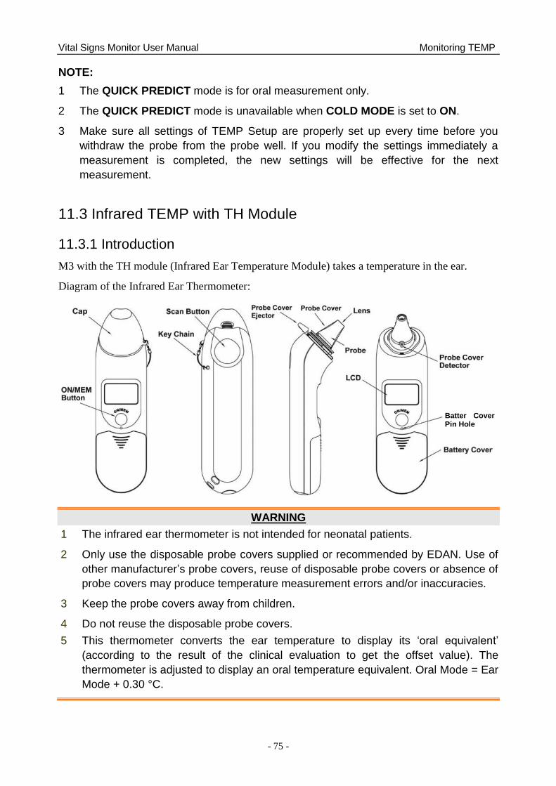
Vital Signs Monitor User Manual Monitoring TEMP
- 75 -
NOTE:
1 The QUICK PREDICT mode is for oral measurement only.
2 The QUICK PREDICT mode is unavailable when COLD MODE is set to ON.
3 Make sure all settings of TEMP Setup are properly set up every time before you
withdraw the probe from the probe well. If you modify the settings immediately a
measurement is completed, the new settings will be effective for the next
measurement.
11.3 Infrared TEMP with TH Module
11.3.1 Introduction
M3 with the TH module (Infrared Ear Temperature Module) takes a temperature in the ear.
Diagram of the Infrared Ear Thermometer:
WARNING
1 The infrared ear thermometer is not intended for neonatal patients.
2 Only use the disposable probe covers supplied or recommended by EDAN. Use of
other manufacturer‟s probe covers, reuse of disposable probe covers or absence of
probe covers may produce temperature measurement errors and/or inaccuracies.
3 Keep the probe covers away from children.
4 Do not reuse the disposable probe covers.
5 This thermometer converts the ear temperature to display its „oral equivalent‟
(according to the result of the clinical evaluation to get the offset value). The
thermometer is adjusted to display an oral temperature equivalent. Oral Mode = Ear
Mode + 0.30 °C.
Batter Cover Pin Hole
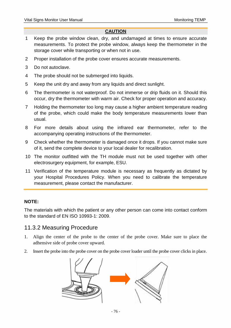
Vital Signs Monitor User Manual Monitoring TEMP
- 76 -
CAUTION
1 Keep the probe window clean, dry, and undamaged at times to ensure accurate
measurements. To protect the probe window, always keep the thermometer in the
storage cover while transporting or when not in use.
2 Proper installation of the probe cover ensures accurate measurements.
3 Do not autoclave.
4 The probe should not be submerged into liquids.
5 Keep the unit dry and away from any liquids and direct sunlight.
6 The thermometer is not waterproof. Do not immerse or drip fluids on it. Should this
occur, dry the thermometer with warm air. Check for proper operation and accuracy.
7 Holding the thermometer too long may cause a higher ambient temperature reading
of the probe, which could make the body temperature measurements lower than
usual.
8 For more details about using the infrared ear thermometer, refer to the
accompanying operating instructions of the thermometer.
9 Check whether the thermometer is damaged once it drops. If you cannot make sure
of it, send the complete device to your local dealer for recalibration.
10 The monitor outfitted with the TH module must not be used together with other
electrosurgery equipment, for example, ESU.
11 Verification of the temperature module is necessary as frequently as dictated by
your Hospital Procedures Policy. When you need to calibrate the temperature
measurement, please contact the manufacturer.
NOTE:
The materials with which the patient or any other person can come into contact conform
to the standard of EN ISO 10993-1: 2009.
11.3.2 Measuring Procedure
1. Align the center of the probe to the center of the probe cover. Make sure to place the
adhensive side of probe cover upward.
2. Insert the probe into the probe cover on the probe cover loader until the probe cover clicks in place.
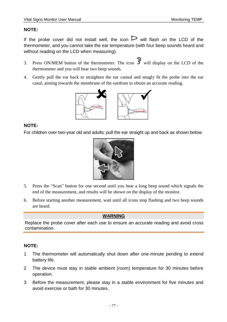
Vital Signs Monitor User Manual Monitoring TEMP
- 77 -
NOTE:
If the probe cover did not install well, the icon will flash on the LCD of the
thermometer, and you cannot take the ear temperature (with four beep sounds heard and
without reading on the LCD when measuring).
3. Press ON/MEM button of the thermometer. The icon will display on the LCD of the
thermometer and you will hear two beep sounds.
4. Gently pull the ear back to straighten the ear cannal and snugly fit the probe into the ear
canal, aiming towards the membrane of the eardrum to obtain an accurate reading.
NOTE:
For children over two-year old and adults: pull the ear straight up and back as shown below:
5. Press the ―Scan‖ button for one second until you hear a long beep sound which signals the
end of the measurement, and results will be shown on the display of the monitor.
6. Before starting another measurement, wait until all icons stop flashing and two beep sounds
are heard.
WARNING
Replace the probe cover after each use to ensure an accurate reading and avoid cross contamination.
NOTE:
1 The thermometer will automatically shut down after one-minute pending to extend
battery life.
2 The device must stay in stable ambient (room) temperature for 30 minutes before
operation.
3 Before the measurement, please stay in a stable environment for five minutes and
avoid exercise or bath for 30 minutes.
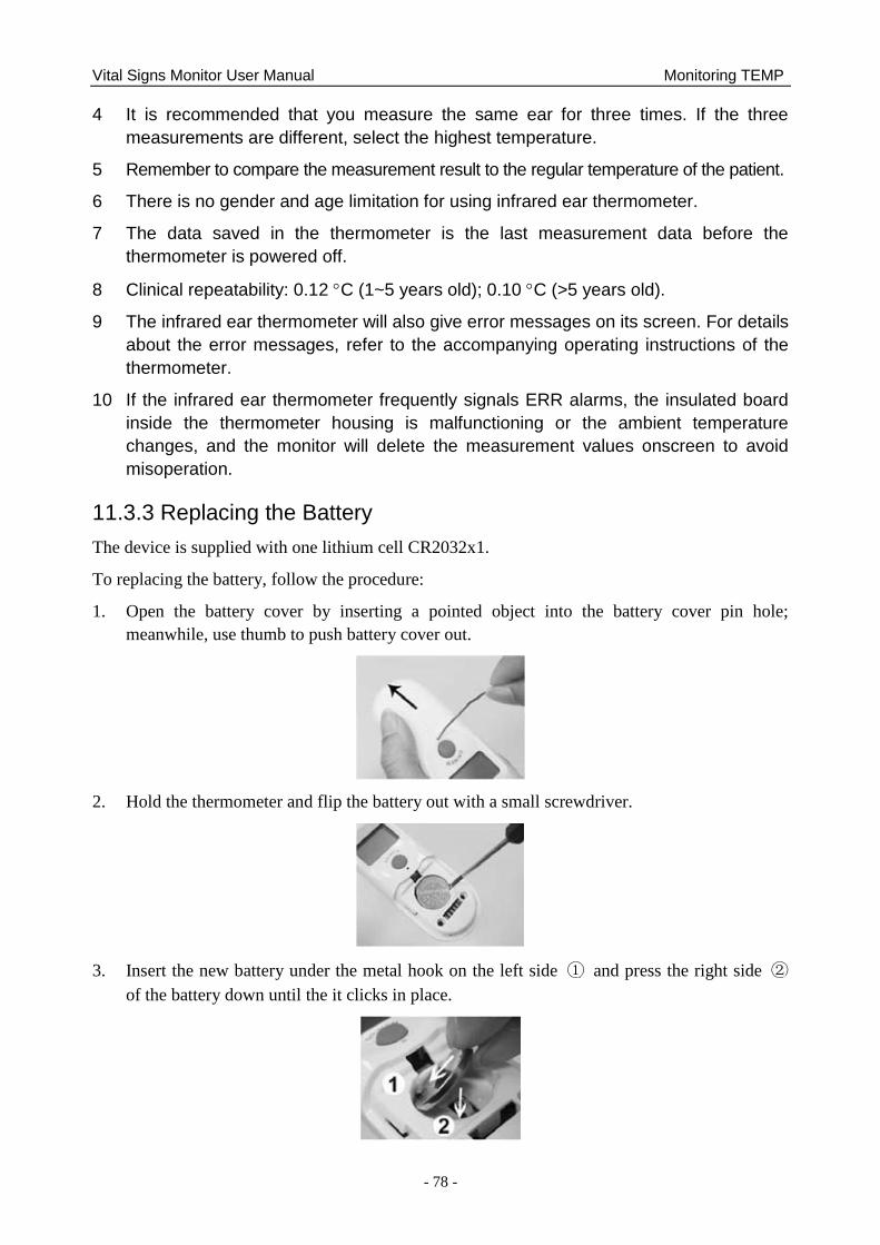
Vital Signs Monitor User Manual Monitoring TEMP
- 78 -
4 It is recommended that you measure the same ear for three times. If the three
measurements are different, select the highest temperature.
5 Remember to compare the measurement result to the regular temperature of the patient.
6 There is no gender and age limitation for using infrared ear thermometer.
7 The data saved in the thermometer is the last measurement data before the
thermometer is powered off.
8 Clinical repeatability: 0.12 C (1~5 years old); 0.10 C (>5 years old).
9 The infrared ear thermometer will also give error messages on its screen. For details
about the error messages, refer to the accompanying operating instructions of the
thermometer.
10 If the infrared ear thermometer frequently signals ERR alarms, the insulated board
inside the thermometer housing is malfunctioning or the ambient temperature
changes, and the monitor will delete the measurement values onscreen to avoid
misoperation.
11.3.3 Replacing the Battery
The device is supplied with one lithium cell CR2032x1.
To replacing the battery, follow the procedure:
1. Open the battery cover by inserting a pointed object into the battery cover pin hole;
meanwhile, use thumb to push battery cover out.
2. Hold the thermometer and flip the battery out with a small screwdriver.
3. Insert the new battery under the metal hook on the left side ① and press the right side ②
of the battery down until the it clicks in place.

Vital Signs Monitor User Manual Monitoring TEMP
- 79 -
WARNING
1 Keep the battery away from children.
2 Ensure the positive (+) side is up and the negative (-) side down.
Vital Signs Monitor User Manual Review (in Monitor Mode)
- 80 -
Chapter 12 Review (in Monitor Mode)
In monitor mode, the monitor provides 120-hour trend data of all parameters, storage of 1200
NIBP measurement results, 200 alarm events and so on. This chapter gives detailed instruction
for review of all data.
12.1 Trend Graph Review
■ The latest 1-hour trend is displayed every 1 or 5 seconds.
■ The latest 120-hour trend is displayed every 1, 5 or 10 minutes.
To review Trend Graph, please press the Trend Graph shortcut key on the screen or select
Menu > Review > Trend Graph, then the trend graph interface is displayed.
In the trend graph, the y-axis stands for the measurement value and x-axis stands for the time.
12.1.1 Selecting Trend Graph of Specific Parameter
The monitor can review trend graph of different parameters. To change the existing trend graph,
please select Menu > Review > Trend Graph and select a required parameter name from the
popup list.
12.1.2 Adjusting Trend Scale
You can use Zoom on the trend graph review interface to adjust the trend scale. Once you adjust
the trend scale on the trend graph review interface, you also change the trend scale of the related
parameters for the screen trend displayed on the main screen.
12.1.3 Setting Interval
The monitor can support five kinds of interval. To set an appropriate interval, please select
Menu > Review > Trend Graph and an interface is displayed. Choose Interval on the interface
to open the list and select an appropriate interval among 1 s, 5 s, 1 min, 5 min and 10 min.
NOTE:
Please select 1 sec interval if completed NIBP data is expected to display on the screen.
12.1.4 Scrolling Left and Right the Screen
All trend graphs can‘t be displayed on the current screen due to the screen limitation. The user
can scroll left and right the screen manually to see measurement trends that do not fit in the
current view by selecting and pressing the symbol and displayed on the trend graph.
12.2 Trend Table Review
To review the trend table, please press the Trend Table key on the screen or select Menu >
Review > Trend Table, then the trend table is displayed.
Vital Signs Monitor User Manual Review (in Monitor Mode)
- 81 -
12.2.1 Setting Interval
The monitor can support eleven kinds of interval. To set an appropriate interval, please select
Menu > Review > Trend Table and an interface is displayed. Choose Interval on the interface
to open the list and select an appropriate interval among 1 s, 5 s, 30 s, 1 min, 3 min, 5 min, 10
min, 15 min, 30 min, 60 min and NIBP.
12.2.2 Scrolling the Screen
All trend tables can‘t be displayed on the current screen due to the screen limitation. The user can
scroll left, right, up and down the screen manually to see measurement trend tables that do not fit
in the current view by selecting and pressing the symbol and displayed on the trend
graph.
12.3 NIBP Review
To review the NIBP measurement data, select the NIBP Review shortcut key on the screen or
select Menu > Review > NIBP or click NIBP Multi-Review Window at the bottom of main
interface, then the NIBP Review window is displayed.
12.3.1 Scrolling the Screen
All measurement data can‘t be displayed on the current screen due to the screen limitation. The
user can scroll up and down the screen manually to see measurement data that doesn‘t fit in the
current view by selecting and pressing the symbol and displayed on the NIBP Review
interface.
12.4 Alarm Review
To review the alarm event, select the Alarm Review shortcut key on the screen or select Menu >
Review > Alarm, then the Alarm Review Window is displayed.
NOTE:
The monitor can store a maximum of 200 alarm events. As soon as the alarm event
storage is full, the earliest alarm event will be replaced by the latest one.
12.4.1 Scrolling the Screen
All alarm events can‘t be displayed on the current screen due to the screen limitation. The user
can scroll up and down the screen manually to see alarm events that don‘t fit in the current view
by selecting and pressing the symbol and displayed on the Alarm Review interface.
Vital Signs Monitor User Manual Review (in Monitor Mode)
- 82 -
12.4.2 Selecting Alarm Event of Specific Parameter
The monitor can review alarm event of the specific parameters. To view the alarm event of the
specific parameter, please select Menu > Review > Alarm Review and choose Event Type to
select the required parameter name from the popup list.
12.4.3 Setting Time Index
The user can set end time of alarm review by selecting the Time Index option displayed on the
alarm review interface.
If the user selects Current Time on the popup interface, the alarm events occurring before the
current time are displayed on the alarm event review interface.
If the user selects User Define, he can define the review time by setting time box displayed on
the interface. The alarm events occurring before the User Define option are displayed on the
alarm event review interface.
12.5 Technical Alarm Checking
Click technical alarm area to check the current technical alarms. Technical alarms which have
happened earlier and do not presently exist cannot be checked.
12.6 Event Marking
Event mark is used to note the classified events which are related with patient or may have
influence on parameters monitoring, such as take or inject medicine, or kinds of treatments. There
are four kinds of event marking at most: event A, event B, event C and event D.
Access Menu > Common Function > Event Setup to check event mark. Besides, these areas
can also display event mark: trend graph window, trend table window and alarm review window.
Vital Signs Monitor User Manual Review (in Round or Spot-checking Mode)
- 83 -
Chapter 13 Review (in Round or Spot-checking Mode)
13.1 Round Record Management
Select Menu > Review, or click review shortcut key directly to enter round record
management window.
Click Time Span to display round record in specified period. The valid round records in 12
hours before the latest valid round record will be displayed by default.
Click All to display all round records in specified period. Abnormal value is displayed in red.
Choose Alert to display abnormal value in specified period. All is the default setting which
will be recovered if user exit and enter this window again.
The round record is in order by Bed No. or Time. Time order is the default setting which
will be recovered if user exit and enter this window again.
Upload, Record, Export or Delete is used for uploading, record outputting, exporting or
deleting the round records user chose (not including its original data). The round record can
be printed automatically once each record is generated. Enter Menu > System Setup >
Recorder > Auto Recording to choose On/Off. Default setting is on.
Clicking one round record can display its original data (20 groups at most), including patient
information, parameters value and this round record. Clicking Confirm can output the
original data in this window.
If monitor is powered off, the parameters data and original data in main interface will be cleared
and round record will be stored. Each 1GB space can store 100 thousand groups of round records
at least, including patient information and 20 original records.
13.2 Review Spot-checking Data
Select Menu > Review, or directly select review shortcut key to enter review window.
Click double triangle to turn page.
Set the time to display spot-checking data in specified period. The valid spot-checking data
in 12 hours before the latest valid spot-checking data will be displayed by default.
Click All to display all spot-checking data in specified period. Abnormal value is displayed
in red. Choose Alert to display abnormal value in specified period. All is the default setting
which will be recovered if user exit and enter this window again.
Upload, Record, Export or Delete is used for uploading, record outputting, exporting or
deleting all spot-checking data in specified period. Monitor will upload all patient
information & data which haven‘t been uploaded by default. User can also choose and
upload all patient data manually, including the data which have been uploaded. Also, the
spot-checking data can be printed automatically once each spot-checking data is generated.
Vital Signs Monitor User Manual Review (in Round or Spot-checking Mode)
- 84 -
Enter Menu > System Setup > Recorder > Auto Recording to choose On/Off. Default
setting is on.
Spot-checking data can be sent by HL7 gateway and uploaded to network server. Also, it can be
uploaded in real time once each valid spot-checking is finished, if the monitor is in networking
and is also connected with network server.
13.3 Spot-checking Data Trend Table
Spot-checking Data Trend Table locates the bottom of main interface. First line is the latest data.
Click triangle at the bottom to show/hide trend table.
If monitor is powered off, parameters data and trend data in main interface will be cleared. User
can check history data in review menu.
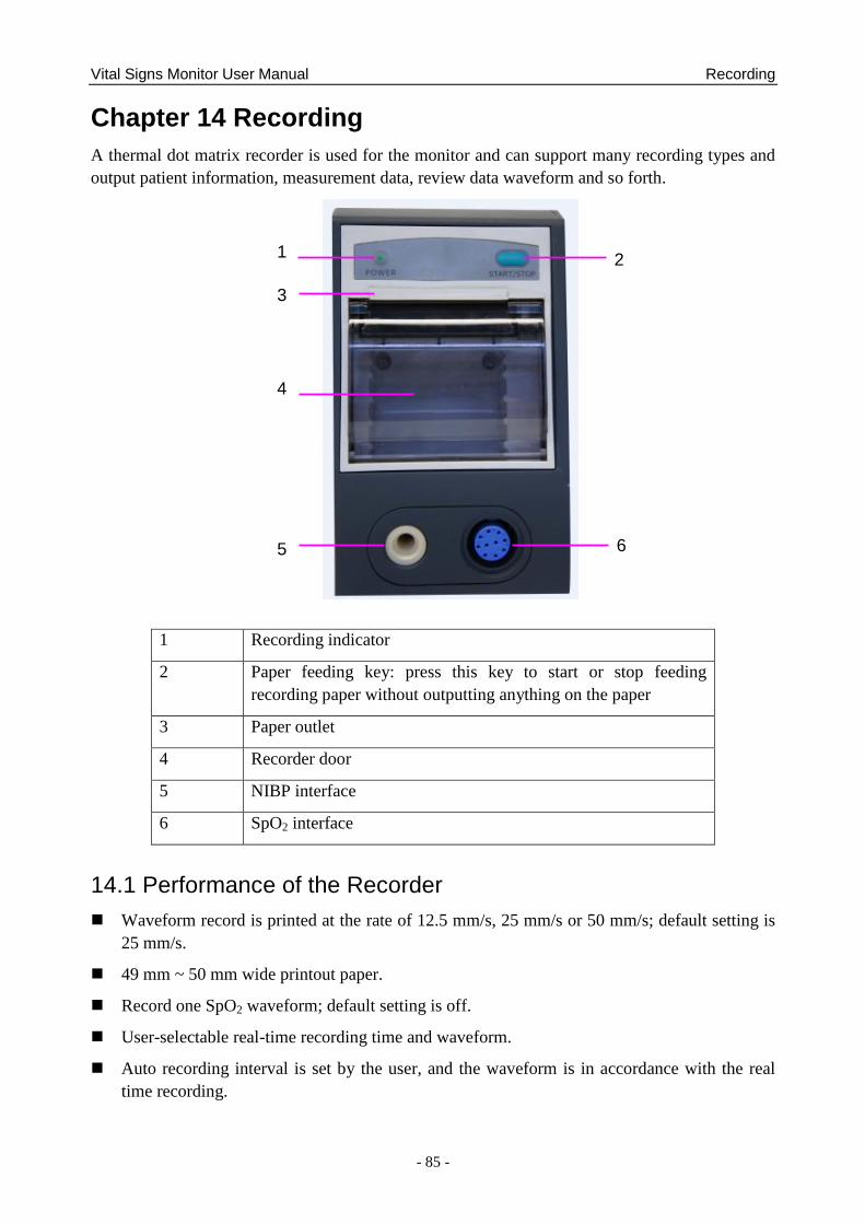
Vital Signs Monitor User Manual Recording
- 85 -
Chapter 14 Recording
A thermal dot matrix recorder is used for the monitor and can support many recording types and
output patient information, measurement data, review data waveform and so forth.
1 Recording indicator
2 Paper feeding key: press this key to start or stop feeding
recording paper without outputting anything on the paper
3 Paper outlet
4 Recorder door
5 NIBP interface
6 SpO2 interface
14.1 Performance of the Recorder
Waveform record is printed at the rate of 12.5 mm/s, 25 mm/s or 50 mm/s; default setting is
25 mm/s.
49 mm ~ 50 mm wide printout paper.
Record one SpO2 waveform; default setting is off.
User-selectable real-time recording time and waveform.
Auto recording interval is set by the user, and the waveform is in accordance with the real
time recording.
1 3 4 5
2
6
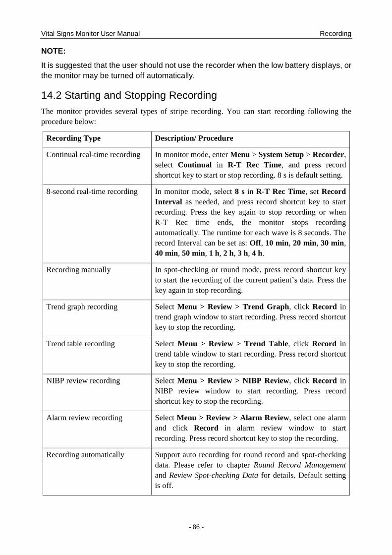
Vital Signs Monitor User Manual Recording
- 86 -
NOTE:
It is suggested that the user should not use the recorder when the low battery displays, or
the monitor may be turned off automatically.
14.2 Starting and Stopping Recording
The monitor provides several types of stripe recording. You can start recording following the
procedure below:
Recording Type Description/ Procedure
Continual real-time recording In monitor mode, enter Menu > System Setup > Recorder,
select Continual in R-T Rec Time, and press record
shortcut key to start or stop recording. 8 s is default setting.
8-second real-time recording In monitor mode, select 8 s in R-T Rec Time, set Record
Interval as needed, and press record shortcut key to start
recording. Press the key again to stop recording or when
R-T Rec time ends, the monitor stops recording
automatically. The runtime for each wave is 8 seconds. The
record Interval can be set as: Off, 10 min, 20 min, 30 min,
40 min, 50 min, 1 h, 2 h, 3 h, 4 h.
Recording manually In spot-checking or round mode, press record shortcut key
to start the recording of the current patient‘s data. Press the
key again to stop recording.
Trend graph recording Select Menu > Review > Trend Graph, click Record in
trend graph window to start recording. Press record shortcut
key to stop the recording.
Trend table recording Select Menu > Review > Trend Table, click Record in
trend table window to start recording. Press record shortcut
key to stop the recording.
NIBP review recording Select Menu > Review > NIBP Review, click Record in
NIBP review window to start recording. Press record
shortcut key to stop the recording.
Alarm review recording Select Menu > Review > Alarm Review, select one alarm
and click Record in alarm review window to start
recording. Press record shortcut key to stop the recording.
Recording automatically Support auto recording for round record and spot-checking
data. Please refer to chapter Round Record Management
and Review Spot-checking Data for details. Default setting
is off.
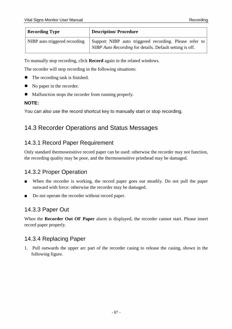
Vital Signs Monitor User Manual Recording
- 87 -
Recording Type Description/ Procedure
NIBP auto triggered recording Support NIBP auto triggered recording. Please refer to
NIBP Auto Recording for details. Default setting is off.
To manually stop recording, click Record again in the related windows.
The recorder will stop recording in the following situations:
The recording task is finished.
No paper in the recorder.
Malfunction stops the recorder from running properly.
NOTE:
You can also use the record shortcut key to manually start or stop recording.
14.3 Recorder Operations and Status Messages
14.3.1 Record Paper Requirement
Only standard thermosensitive record paper can be used: otherwise the recorder may not function,
the recording quality may be poor, and the thermosensitive printhead may be damaged.
14.3.2 Proper Operation
■ When the recorder is working, the record paper goes out steadily. Do not pull the paper
outward with force: otherwise the recorder may be damaged.
■ Do not operate the recorder without record paper.
14.3.3 Paper Out
When the Recorder Out OF Paper alarm is displayed, the recorder cannot start. Please insert
record paper properly.
14.3.4 Replacing Paper
1. Pull outwards the upper arc part of the recorder casing to release the casing, shown in the
following figure.
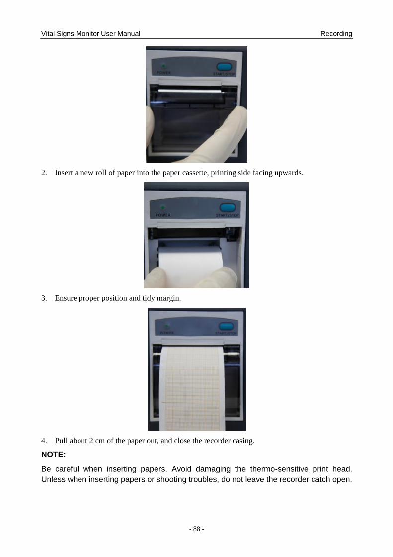
Vital Signs Monitor User Manual Recording
- 88 -
2. Insert a new roll of paper into the paper cassette, printing side facing upwards.
3. Ensure proper position and tidy margin.
4. Pull about 2 cm of the paper out, and close the recorder casing.
NOTE:
Be careful when inserting papers. Avoid damaging the thermo-sensitive print head.
Unless when inserting papers or shooting troubles, do not leave the recorder catch open.

Vital Signs Monitor User Manual Recording
- 89 -
14.3.5 Removing Paper Jam
When the recorder functions or sounds improperly, you should open the recorder casing to check
for a paper jam. Remove the paper jam in the following way:
■ Cut the record paper from the feeding edge.
■ Open the recorder casing.
■ Re-insert the paper.
NOTE:
1. If the monitor is not installed with a recorder, it will indicate RECORDER SETUP
NEEDED after pressing the Record button.
2. Do not touch the thermo-sensitive print head when performing continuous recording.
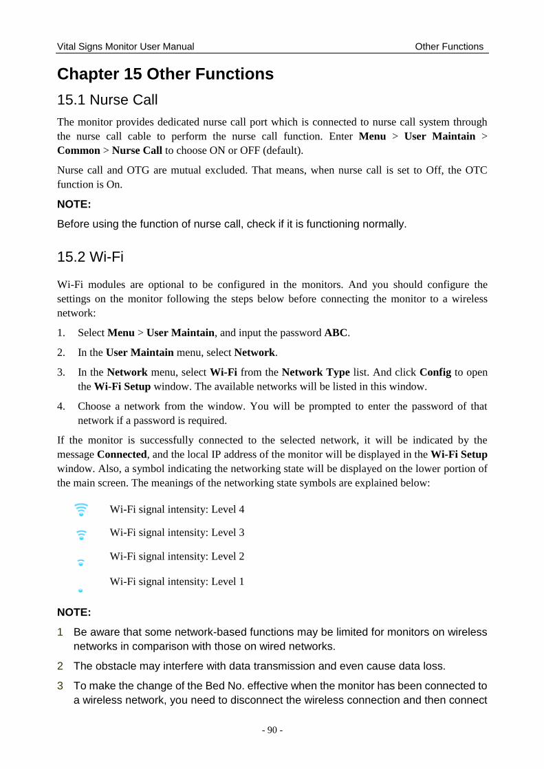
Vital Signs Monitor User Manual Other Functions
- 90 -
Chapter 15 Other Functions
15.1 Nurse Call
The monitor provides dedicated nurse call port which is connected to nurse call system through
the nurse call cable to perform the nurse call function. Enter Menu > User Maintain >
Common > Nurse Call to choose ON or OFF (default).
Nurse call and OTG are mutual excluded. That means, when nurse call is set to Off, the OTC
function is On.
NOTE:
Before using the function of nurse call, check if it is functioning normally.
15.2 Wi-Fi
Wi-Fi modules are optional to be configured in the monitors. And you should configure the
settings on the monitor following the steps below before connecting the monitor to a wireless
network:
1. Select Menu > User Maintain, and input the password ABC.
2. In the User Maintain menu, select Network.
3. In the Network menu, select Wi-Fi from the Network Type list. And click Config to open
the Wi-Fi Setup window. The available networks will be listed in this window.
4. Choose a network from the window. You will be prompted to enter the password of that
network if a password is required.
If the monitor is successfully connected to the selected network, it will be indicated by the
message Connected, and the local IP address of the monitor will be displayed in the Wi-Fi Setup
window. Also, a symbol indicating the networking state will be displayed on the lower portion of
the main screen. The meanings of the networking state symbols are explained below:
Wi-Fi signal intensity: Level 4
Wi-Fi signal intensity: Level 3
Wi-Fi signal intensity: Level 2
Wi-Fi signal intensity: Level 1
NOTE:
1 Be aware that some network-based functions may be limited for monitors on wireless
networks in comparison with those on wired networks.
2 The obstacle may interfere with data transmission and even cause data loss.
3 To make the change of the Bed No. effective when the monitor has been connected to
a wireless network, you need to disconnect the wireless connection and then connect
Vital Signs Monitor User Manual Other Functions
- 91 -
it again or reboot the monitor.
4 If the monitor fails to connect to any wireless network or no available wireless network
is in the Wireless Setup window, switch the Network Type from Wireless to Wired and
then to Wireless again. Then retry to connect to a wireless network.
5 Use the wireless device recommended by EDAN, otherwise some exceptional
situations such as frequent network disconnection may occur on the monitor.
6 The wireless driver is compatible with channels 1-11 only.
7 When signal intensity is level 2 or less, signal may be unstable and signal
transmission may be influenced.
15.3 E-link Function
The monitor can transmit data through e-link if it is configured with e-link module.
To activate/disable the function, select User Maintain > input password ABC > select
Network > set e-link to on/off. Default setting is OFF. When monitor is normally connected to
communication device, e-link symbol for connection will be displayed in general information
area. Otherwise, the e-link symbol for disconnection will be displayed.
e-link Name setup
When e-link switch is turned on, the e-link Name of monitor can be set. E-link name setup for
monitors of same model has fixed rules. 20 characters are supported at most. For example: iM3
default e-link name ―VS_3_XXXX‖.
the pairing code setup
Connection permission (e.g. pairing code) is needed for the first connection. Enter User
Maintain > Network > e-link Key to set the pairing code which only includes 10 numerics at
most. Default pairing code is 1234. If connection is successful, e-link symbol for connection will
be displayed in general information area, and then the data can be transmitted to communication
device.
Data transmission. The supported data includes: patient information, parameter measurement
data.
1. The monitor automatically transmits real-time data to communication device when every
measurement finishes. The data to be transmitted include:
Continual measurement data: SpO2 data, transmission time;
Spot-checking measurement data: NIBP, SpO2, TEMP (prediction data of Quick TEMP and
infrared TEMP data), and transmission time.
2. The monitor responds to the communication device‘s request to transmit data. The data to be
transmitted include:
The data displayed in current interface: NIBP, SpO2, TEMP (prediction data of Quick TEMP and
infrared TEMP data), transmission time.
3. Batch data transmission. The data to be transmitted include:
Vital Signs Monitor User Manual Other Functions
- 92 -
Round records stored in the monitor: NIBP, SpO2, TEMP (prediction data of Quick TEMP and
infrared TEMP data), manual confirmation mark, and transmission time. All round records which
haven‘t been transmitted in the round record interface will be transmitted by default. User can
also select the data as needed.
Spot-checking trend data: the Spot-checking trend data and transmission time.
After batch transmission, user can separately enter ―all records‖ interface to check the
transmission result of round records, and enter ―review‖ interface to check the transmission result
of spot-checking trend data. All data which have been transmitted successfully will be marked.
NOTE:
1 The supported e-link version is BLE4.0, which is applicable in 3 system environments:
iOS, Android and Windows.
2 When the monitor is powered off or enters standby mode, e-link is automatically
disconnected and needs to be reconnected next time.
15.4 Uploading Data to Network Server
The data of round records and spot-checking records can be uploaded to network server.
Upload manually: Click Menu > Review > Upload or click review shortcut key directly, user
can choose as needed and upload the round/spot records. The upload results will be prompted by
pop-up window.
Upload automatically: in User Maintain > Network > Real-time Upload, if the setting is ON,
when monitor is in networking and is also connected with network server, after each round/spot
record is stored in Review window, monitor will upload this round/spot record to network server
in real time. The upload results can be identified in Review > Upload window. The data which
have been uploaded successfully will be displayed in grey font.
15.5 Storing Data in the Storage Device
15.5.1 Data Stored in the Storage Device
In monitor mode, a single piece of patient data maximally contains the following information:
Patient information MRN, name, date of birth, date of admission, gender, type,
height, weight, blood type, doctor, bed No., department
Trend graph and trend table 240 hours
NIBP measurement review 1200 sets
Alarm review 200 sets
NOTE:
When store time for single patient data reaches 240 hours, the monitor will create a new
folder for continuous data store.
Vital Signs Monitor User Manual Other Functions
- 93 -
In round mode, storage data maximally contains the following information:
Round record MRN, name, type, bed No., round record
and original record
Up to 800 thousand sets
SpO2 Storage starting time, SpO2 value, PR value Up to 20 sets for a single patient
NIBP SYS, DIA, MAP, PR, measurement time Up to 20 sets for a single patient
TEMP TEMP value, measurement time Up to 20 sets for a single patient
In spot-checking mode, storage data maximally contains the following information:
16 million sets of spot-checking data for multiple patients.
When data reach the maximum, you can choose to Keep storing (default) or Stop storing by
selecting Menu > System Setup > Storage > if storage space is full.
If you choose Keep storing, as soon as the data is full, the earliest data will be replaced by the
latest one.
If you choose Stop storing, the monitor will stop data storing and the latest data cannot be stored
when the data reach the maximum.
15.5.2 Selecting a Storage Device
To configure the storage device, select Menu > System Setup > Storage > Storage Device, and
choose the storage medium from the pop-up list as desired.
In round or spot-checking mode, Storage Device is fixed as Internal Storage Device.
In monitor mode, Internal Storage Device (default) and Removable Device can be selected.
When you choose Internal Storage Device as the storage medium, if configured, the storage
device name will automatically become Internal Storage Device. If not configured, Null will be
displayed in the storage device name. You may plug several removable devices into the monitor
at the same time, but only one is operative. You can select a removable device as a working one
among the plugging devices by selecting Menu > System Setup > Storage > Storage Device
and choosing the device name from the list.
After you configure the appropriate storage device, click exit. If the storage device is successfully
starting data storing, the monitor will be indicated by the symbol . If there is no enough
space in storage device, or the storage device is read-only/damaged, the symbol will be
displayed.
The monitor will stop storing data in the storage device under the following circumstances:
There is no enough space in the storage device for storing data.
The removable device is read-only.
The monitor is switched off.
Vital Signs Monitor User Manual Other Functions
- 94 -
The power supply is off.
CAUTION
1 Not all the removable devices are compatible with the monitor, Use the removable
devices recommended by EDAN.
2 Do not set the read-only switch on the removable device to on when the removable
device is inserted in the monitor.
3 It is recommended to format the USB flash drive to the FAT file type via PC prior to
use.
15.5.3 Reviewing Data Stored in the Storage Device
In monitor mode:
To review data stored in the storage device, select Menu > Review > History Patient. You can
choose to review the storage device as desired from the pop-up list. Choose a patient from the list
to review the data including patient information, trend graph, trend table, NIBP measurements,
arrhythmia event, alarm event and waveform.
If Internal Storage Device is selected, clicking Export all data can export all patients‘ data.
Choosing one patient‘s data in history patient list, and clicking Export Current Data can export
this patient‘s data.
In round or spot-checking mode:
Please refer to chapter Round Record Management or Review Spot-checking Data for review
data.
15.5.4 Deleting Data Stored in the Storage Device
In monitor mode:
To delete data of one patient, choose the patient from the list after selecting Menu > Review >
History Patient, and then click Delete data on the Review menu. Further confirmation of
deletion is required.
To delete data of all patients, select Menu > Review > History Patient and click Delete all data
on the History Patient Review menu. Further confirmation is required.
In round or spot-checking mode:
Please refer to chapter Round Record Management or Review Spot-checking Data for review
data.
15.5.5 Exporting Data Stored in the Internal Storage Device
In monitor mode, to export data of one patient from the internal storage device to the
removable device:
Choose the patient from the list after selecting Menu > Review > History Patient, and then click
Vital Signs Monitor User Manual Other Functions
- 95 -
Export Current Data on the Review menu.
To export data of all patients, select Menu> Review> History Patient and click Export all.
You can also use the OTG interface to connect the monitor to the PC, and user can view and copy
the data which stored in internal storage device through the PC.
In round or spot-checking mode, to export round records/spot-checking records in the
specified time to the removable device , and also to the internal storage device:
Choose Menu > Review > Export, and confirm the operation as needed.
If no removable device is connected, the data will be exported to the internal storage device
directly. User can view the data through OTG interface.
In round and spot-checking mode, the formats of exported CSV data file names are ‗XXX-
Round-Records‘ and ‗XXX-Spot-Review.csv‘ respectively, in which the XXX means export time.
15.5.6 Ejecting a Removable Device
Before unplugging a removable device from the monitor, you need to select Menu > System
Setup > Storage > Removable Device and click Eject to uninstall the removable device. In this
menu, you can also check the remaining capacity of the storage device.
CAUTION
Do not remove the removable device without ejecting it during data storing, or the
removable device might be damaged.
15.5.7 Recording Data by Recorder
In monitor mode:
To recording the review data, please enter Menu> Review > History Patient > choose one
patient data in history patient window > Review > choose your desired data to review > Record.
The data to be recorded include: trend graph, trend table, NIBP review and alarm review.
In round or spot-checking mode:
Please refer to chapter Round Record Management or Review Spot-checking Data for review
data.
15.5.8 Formatting the Internal Storage Device
To format the internal storage device, select Menu> User Maintain > Common > Format
internal storage device. Further confirmation is required.
NOTE:
1 As soon as the internal storage device is formatted, all the data will be cleared.
2 You have no need to restart the monitor after formatting is successful. The internal
Vital Signs Monitor User Manual Other Functions
- 96 -
storage device can be identified and loaded automatically.
3 If formatting is failed, try again. Restart the monitor and retry the formatting, or contact
the service personnel of the manufacturer if formatting is failed repeatedly.
15.6 Warning-Score System
User can use warning-score system to get score and sum up based on measurement value or input
value of each vital sign. Depending on the score calculated, an action list with appropriate
recommendations is displayed. Warning-score system includes EWS, NEWS and MEWS system,
which are mutual excluded. That is, only one system can be used at the same time.
15.6.1 Warning-Score Interface
The interface includes EWS, NEWS and MEWS sub-interface.
To enter the interface: 1. By shortcut key. Click User Maintain > Shortcut to select Score. Then
click Warning Score shortcut key to enter; 2. By menu. Click Menu > Score to enter.
To exit the interface: 1. By shortcut key. Click Score shortcut key to exit; 2. By menu. Click X
button on the top right of the interface.
Before exiting interface, if selected Method is score calculator, the monitor can exit not only this
interface, but also this function; if selected Method is auto score, the monitor can only exit this
interface instead of this function.
The above rule is also applicable to the switchover between sub-interface. (e.g., if selected
Method is auto score, sub-interface is switched over from EWS to NEWS, however, EWS
function is still in working.)
NOTE:
Operations, including power-off, updating patient and entering standby or Demo mode,
will stop current warning-score, and also monitor will exit this function.
15.6.2 Warning-Score Method
Warning-Score method includes score calculator (default) and auto score. If score calculator is
selected, user needs to input information manually, such as HR/PR, TMEP, Consciousness and
so on, and then click Start to Score. The monitor will calculate and display score result.
NOTE:
If any of above information is not completely input, the monitor will prompt information:
Incomplete parameter input, unable to score.
15.6.3 Warning-Score Criteria
In EWS interface, select Criteria to check score criteria as following:
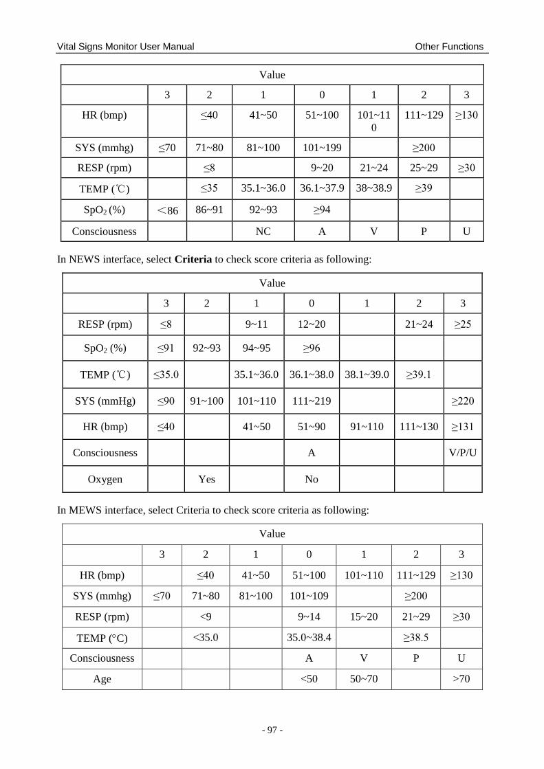
Vital Signs Monitor User Manual Other Functions
- 97 -
Value
3 2 1 0 1 2 3
HR (bmp) ≤40 41~50 51~100 101~11
0
111~129 ≥130
SYS (mmhg) ≤70 71~80 81~100 101~199 ≥200
RESP (rpm) ≤8 9~20 21~24 25~29 ≥30
TEMP (℃) ≤35 35.1~36.0 36.1~37.9 38~38.9 ≥39
SpO2 (%) <86 86~91 92~93 ≥94
Consciousness NC A V P U
In NEWS interface, select Criteria to check score criteria as following:
Value
3 2 1 0 1 2 3
RESP (rpm) ≤8
9~11 12~20
21~24 ≥25
SpO2 (%) ≤91 92~93 94~95 ≥96
TEMP (℃) ≤35.0
35.1~36.0 36.1~38.0 38.1~39.0 ≥39.1
SYS (mmHg) ≤90 91~100 101~110 111~219
≥220
HR (bmp) ≤40
41~50 51~90 91~110 111~130 ≥131
Consciousness
A
V/P/U
Oxygen
Yes
No
In MEWS interface, select Criteria to check score criteria as following:
Value
3 2 1 0 1 2 3
HR (bmp) ≤40 41~50 51~100 101~110 111~129 ≥130
SYS (mmhg) ≤70 71~80 81~100 101~109 ≥200
RESP (rpm) <9 9~14 15~20 21~29 ≥30
TEMP (C) <35.0 35.0~38.4 ≥38.5
Consciousness A V P U
Age <50 50~70 >70
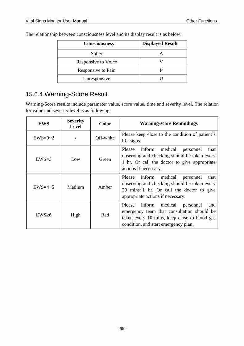
Vital Signs Monitor User Manual Other Functions
- 98 -
The relationship between consciousness level and its display result is as below:
Consciousness Displayed Result
Sober A
Responsive to Voice V
Responsive to Pain P
Unresponsive U
15.6.4 Warning-Score Result
Warning-Score results include parameter value, score value, time and severity level. The relation
for value and severity level is as following:
EWS Severity
Level Color Warning-score Remindings
EWS=0~2 / Off-white Please keep close to the condition of patient‘s
life signs.
EWS=3 Low Green
Please inform medical personnel that
observing and checking should be taken every
1 hr. Or call the doctor to give appropriate
actions if necessary.
EWS=4~5 Medium Amber
Please inform medical personnel that
observing and checking should be taken every
20 mins~1 hr. Or call the doctor to give
appropriate actions if necessary.
EWS≥6 High Red
Please inform medical personnel and
emergency team that consultation should be
taken every 10 mins, keep close to blood gas
condition, and start emergency plan.
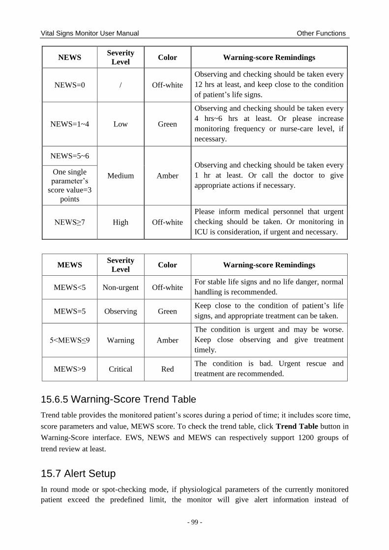
Vital Signs Monitor User Manual Other Functions
- 99 -
NEWS Severity
Level Color Warning-score Remindings
NEWS=0 / Off-white
Observing and checking should be taken every
12 hrs at least, and keep close to the condition
of patient‘s life signs.
NEWS=1~4 Low Green
Observing and checking should be taken every
4 hrs~6 hrs at least. Or please increase
monitoring frequency or nurse-care level, if
necessary.
NEWS=5~6
Medium Amber
Observing and checking should be taken every
1 hr at least. Or call the doctor to give
appropriate actions if necessary.
One single
parameter‘s
score value=3
points
NEWS≥7 High Off-white
Please inform medical personnel that urgent
checking should be taken. Or monitoring in
ICU is consideration, if urgent and necessary.
MEWS Severity
Level Color Warning-score Remindings
MEWS<5 Non-urgent Off-white For stable life signs and no life danger, normal
handling is recommended.
MEWS=5 Observing Green Keep close to the condition of patient‘s life
signs, and appropriate treatment can be taken.
5<MEWS≤9 Warning Amber
The condition is urgent and may be worse.
Keep close observing and give treatment
timely.
MEWS>9 Critical Red The condition is bad. Urgent rescue and
treatment are recommended.
15.6.5 Warning-Score Trend Table
Trend table provides the monitored patient‘s scores during a period of time; it includes score time,
score parameters and value, MEWS score. To check the trend table, click Trend Table button in
Warning-Score interface. EWS, NEWS and MEWS can respectively support 1200 groups of
trend review at least.
15.7 Alert Setup
In round mode or spot-checking mode, if physiological parameters of the currently monitored
patient exceed the predefined limit, the monitor will give alert information instead of
Vital Signs Monitor User Manual Other Functions
- 100 -
physiological alarms.
Enter the respective parameter setup menu to set alert limit and alert switch.
Alert can be indicated by the system in following different ways:
Parameter area has two flash methods to prompt: background flash and text flash. User can
select one method from Visual Effect.
A sound of DU is used to indicate alert.
Parameters storage table (including the table in main interface and the table in data
management window) and has red mark to indicate the alert value.
Alert information area displays prompts with blue background. (alert information area is the
physiological alarm area in monitor mode.)
NOTE:
1 For TEMP module, TEMP alert can only be used in predictive mode of quick TEMP
and in infrared TEMP.
2 Generally, monitor displays SYS alert value. When multiple values are abnormal,
alert value will be displayed in order of SYS, DIA and MAP.
3 When alert is set to Off, the monitor won‟t give a prompt even if an alert occurs. In
order to avoid endangering the patient‟s life, the user should use this function
cautiously.
4 Prior to monitoring, make sure that the limit settings are appropriate for your patient.
5 Setting limits to extreme values may cause the alert system to become ineffective. It
is recommended to use the default settings.

Vital Signs Monitor User Manual Using Battery
- 101 -
Chapter 16 Using Battery
This monitor can run on battery power, which ensures its uninterrupted operation even when AC
power supply is interrupted. The battery recharges whenever the monitor is connected to the AC
power source. During monitoring, if the AC power is interrupted, the monitor will take power
from the internal battery. If the monitor is powered by battery, the monitor will switch off
automatically before the battery is completely depleted.
16.1 Battery Safety Information
WARNING
1 Before using the rechargeable lithium-ion battery (hereinafter called battery), be sure
to read the user manual and safety precautions thoroughly.
2 The service life of the battery depends on the service frequency and time. The service
life of the battery is about three years if the battery is well maintained and stored. The
service life of the battery may shorten if it is used inappropriately.
3 Periodic checks on the battery performance are required. Change the battery if
necessary.
4 Do not connect the positive (+) and negative (-) terminals with metal objects, and do
not put the battery together with metal objects, which can result in short circuits.
5 Do not unplug the battery when working is in process.
6 Do not heat or throw the battery into a fire.
7 Do not use, leave the battery close to fire or other places where temperature may be
above 60 C.
8 Do not immerse, throw, or wet the battery in water/seawater.
9 Do not destroy the battery: do not pierce the battery with a sharp object such as a
needle; do not hit with a hammer, step on or throw or drop to cause strong shock; do
not disassemble or modify the battery.
10 Use the battery only in the monitor. Do not solder the leading wire and the battery
terminal directly.
11 If liquid leaking from the battery gets into your eyes, do not rub your eyes. Wash them
well with clean water and go to see a doctor immediately. If liquid leaks of the battery
splash onto your skin or clothes, wash well with fresh water immediately.
12 Keep away from fire immediately when leakage or foul odor is detected.
13 Stop using the battery if abnormal heat, odor, discoloration, deformation or abnormal
condition is detected during use, charge, or storage. Keep it away from the monitor.
14 Do not use a battery with serious scratch or deformation.
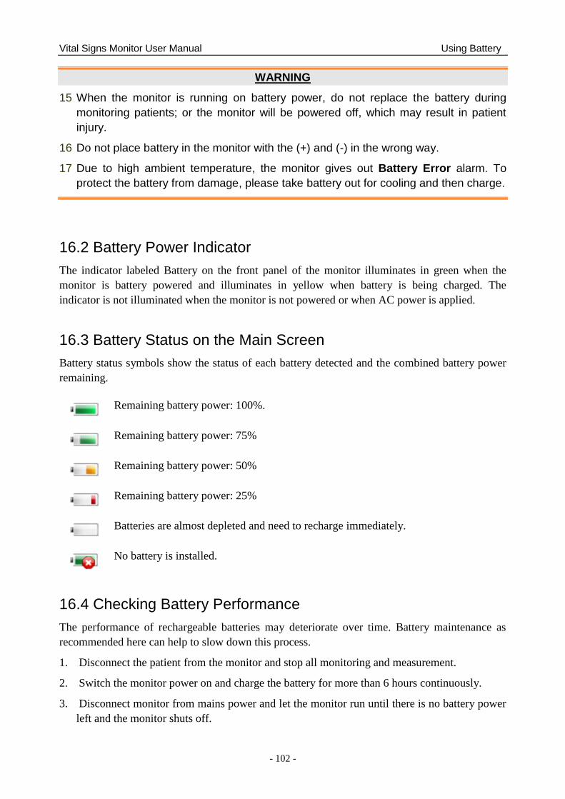
Vital Signs Monitor User Manual Using Battery
- 102 -
WARNING
15 When the monitor is running on battery power, do not replace the battery during
monitoring patients; or the monitor will be powered off, which may result in patient
injury.
16 Do not place battery in the monitor with the (+) and (-) in the wrong way.
17 Due to high ambient temperature, the monitor gives out Battery Error alarm. To
protect the battery from damage, please take battery out for cooling and then charge.
16.2 Battery Power Indicator
The indicator labeled Battery on the front panel of the monitor illuminates in green when the
monitor is battery powered and illuminates in yellow when battery is being charged. The
indicator is not illuminated when the monitor is not powered or when AC power is applied.
16.3 Battery Status on the Main Screen
Battery status symbols show the status of each battery detected and the combined battery power
remaining.
Remaining battery power: 100%.
Remaining battery power: 75%
Remaining battery power: 50%
Remaining battery power: 25%
Batteries are almost depleted and need to recharge immediately.
No battery is installed.
16.4 Checking Battery Performance
The performance of rechargeable batteries may deteriorate over time. Battery maintenance as
recommended here can help to slow down this process.
1. Disconnect the patient from the monitor and stop all monitoring and measurement.
2. Switch the monitor power on and charge the battery for more than 6 hours continuously.
3. Disconnect monitor from mains power and let the monitor run until there is no battery power
left and the monitor shuts off.
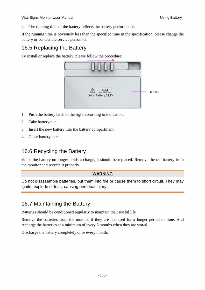
Vital Signs Monitor User Manual Using Battery
- 103 -
4. The running time of the battery reflects the battery performance.
If the running time is obviously less than the specified time in the specification, please change the
battery or contact the service personnel.
16.5 Replacing the Battery
To install or replace the battery, please follow the procedure:
1. Push the battery latch to the right according to indication.
2. Take battery out.
3. Insert the new battery into the battery compartment.
4. Close battery latch.
16.6 Recycling the Battery
When the battery no longer holds a charge, it should be replaced. Remove the old battery from
the monitor and recycle it properly.
WARNING
Do not disassemble batteries, put them into fire or cause them to short circuit. They may
ignite, explode or leak, causing personal injury.
16.7 Maintaining the Battery
Batteries should be conditioned regularly to maintain their useful life.
Remove the batteries from the monitor if they are not used for a longer period of time. And
recharge the batteries at a minimum of every 6 months when they are stored.
Discharge the battery completely once every month.
Battery
Vital Signs Monitor User Manual Care and Cleaning
- 104 -
Chapter 17 Care and Cleaning
Use only the EDAN-approved substances and methods listed in this chapter to clean or disinfect
your equipment. Warranty does not cover damage caused by using unapproved substances or
methods.
EDAN Instruments has validated the cleaning and disinfection instructions included in this User
Manual. It is the responsibility of the healthcare professional to ensure that the instructions are
followed so as to ensure adequate cleaning and disinfection.
17.1 General Points
Keep your monitor, cables and accessories free of dust and dirt. To prevent the device from
damage, please follow the procedure:
Use only recommended cleaning substances and disinfectants listed in this manual. Others
may cause damage (not covered by warranty), reduce product lifetime or cause safety
hazards.
Always dilute according to the manufacturer‘s instructions.
Unless otherwise specified, do not immerse any part of the equipment or any accessories in
liquid.
Do not pour liquid onto the system.
Do not allow liquid to enter the case.
Never use abrasive material (such as steel wool or silver polish).
Inspect the monitor and reusable accessories after they are cleaned and disinfected.
CAUTION
If you spill liquid on the equipment, battery, or accessories, or they are accidentally
immersed in liquid, contact your service personnel or EDAN service engineer.
17.2 Cleaning
If the device or accessory has been in contact with the patient, then cleaning and disinfection is
required after every use. If there has been no patient contact and there is no visible contamination
then daily cleaning and disinfection is appropriate.
The validated cleaning agents for cleaning the monitor and reusable accessories are:
Mild near neutral detergent
Ethanol (75%)
Isopropanol (70%)
Cleaning agents should be applied and removed using a clean, soft, non-abrasive cloth or paper
towel.

Vital Signs Monitor User Manual Care and Cleaning
- 105 -
17.2.1 Cleaning the Monitor
WARNING
Before cleaning the monitor, make sure that the monitor is switched off and disconnected
from the power line.
To surface-clean the monitor, follow these steps:
1. Switch off the monitor and disconnect it from the power line.
2. Wipe the entire exterior surface, including the screen, of the equipment using a soft cloth
dampened with the cleaning solution thoroughly until no visible contaminants remain..
3. After cleaning, wipe off the cleaning solution with a fresh cloth or towel dampened with tap
water until no visible cleaning agent remains.
4. Dry the monitor in a ventilated and cool place.
17.2.2 Cleaning the Reusable Accessories
17.2.2.1 Cleaning the Blood Pressure Cuff
Cleaning the Cuff:
1. Take out the air bladder before cleaning.
2. Hand wash the cuff with the cleaning solution; clean the air bladder with a soft cloth
dampened with the cleaning solution. until no visible contaminants remain
3. Rinse the cuff and after cleaning, wipe off the cleaning solution with a fresh cloth or towel
dampened with tap water until no visible cleaning agent remains.
4. Wipe off residual moisture with a dry cloth.
5. Air dry the cuff thoroughly after cleaning.
Replacing the Air Bladder:
After cleaning, replace the air bladder into the cuff following the steps below:
1. Roll the bladder lengthwise and insert it into the cuff from the large opening at one end of
the cuff.
2. Thread the hose from within the cuff and out through the small hole at the top of the cuff.
3. Adjust the bladder until it is in position.
17.2.2.2 Cleaning the SpO2 Sensor
1. Wipe the surfaces of the sensor and cable using a soft cloth dampened with the cleaning
solution until no visible contaminants remain.
Vital Signs Monitor User Manual Care and Cleaning
- 106 -
2. Wipe the patient contact area of the sensor with the cotton swab dampened with the cleaning
solution. until no visible contaminants remain
3. After cleaning, wipe off the cleaning solution with a fresh cloth or towel dampened with tap
water until no visible cleaning agent remains.
4. Wipe off residual moisture with a dry cloth.
5. Leave the sensor to air dry.
17.2.2.3 Cleaning the TEMP Sensor/Quick TEMP Probe
1. Wipe the sensor/probe with a soft cloth dampened with the cleaning solution until no visible
contaminants remain.
2. After cleaning, wipe off the cleaning solution with a fresh cloth or towel dampened with tap
water until no visible cleaning agent remains.
3. Wipe off residual moisture with a dry cloth.
4. Leave the sensor/probe to air dry.
17.3 Disinfection
For devices or accessories that have been in contact mucosal surface, High Level disinfection
must occur, for all other accessories, low level disinfection is appropriate. Clean the monitor and
reusable accessories before they are disinfected. The validated disinfectants for cleaning the
monitor and reusable accessories are:
Ethanol (75%)
Isopropanol (70%)
If Ethanol or Isopropanol is used for both cleaning and disinfecting, then a new cloth is required
to be used for the disinfection step.
WARNING
The monitor and reusable accessories shall be disinfected to avoid patient cross
infection.
17.3.1 Disinfecting the Monitor
WARNING
Before disinfecting the monitor, make sure that the monitor is switched off and
disconnected from the power line.
Vital Signs Monitor User Manual Care and Cleaning
- 107 -
To disinfect the monitor, follow these steps:
1. Switch off the monitor and disconnect it from the power line.
2. Wipe the display screen using a soft, clean cloth dampened with the disinfectant solution.
3. Wipe the exterior surface of the equipment using a soft cloth dampened with the disinfectant
solution.
4. Wipe off the disinfectant solution with a dry cloth after disinfection if necessary.
5. Dry the monitor for at least 30 minutes in a ventilated and cool place.
17.3.2 Disinfecting the Reusable Accessories
17.3.2.1 Disinfecting the Blood Pressure Cuff
Disinfecting the Cuff:
1. Take out the air bladder before disinfection.
2. Wipe the cuff and the air bladder with a soft cloth dampened with the disinfectant solution.
3. Leave the cuff and air bladder to air dry for at least 30 minutes.
Replacing the Air Bladder:
After disinfection, replace the air bladder into the cuff. Refer to Section 16.2.2.1 for more
information.
NOTE:
Prolonged use of disinfectant may cause discoloration of the cuff.
17.3.2.2 Disinfecting the SpO2 Sensor
1. Wipe the surfaces of the sensor and cable using a soft cloth dampened with the disinfection
solution.
2. Wipe the patient contact area of the sensor with the cotton swab dampened with the
disinfection solution.
3. Wipe off the disinfection solution with a dry cloth after disinfection.
4. Leave the sensor to air dry for at least 30 minutes.
17.3.2.3 Disinfecting the TEMP sensor
For TEMP sensors, disinfect them as follows using ethanol or isopropanol only:
1. Wipe the sensor with a soft cloth dampened with the disinfectant solution (ethanol or
isopropanol).
2. Wipe off the disinfectant solution with a dry cloth after disinfection.
3. Leave the sensor to air dry.

Vital Signs Monitor User Manual Care and Cleaning
- 108 -
17.4 Cleaning and Disinfecting Other Accessories
For cleaning and disinfecting other accessories, refer to the instructions delivered with the
accessories. If the accessories are not accompanied by instructions, refer to this manual for the
methods of cleaning and disinfecting the monitor.

Vital Signs Monitor User Manual Maintenance
- 109 -
Chapter 18 Maintenance
WARNING
1 Failure on the part of the responsible individual hospital or institution employing the
use of this equipment to implement a satisfactory maintenance schedule may cause
undue equipment failure and possible health hazards.
2 If you discover a problem with any of the equipment, contact your service personnel,
or your authorized supplier.
18.1 Inspecting
The overall check of the monitor, including the safety check, should be performed only by
qualified personnel every 24 months, and each time after fix up.
The following items should be checked:
If the environment condition and power supply meet requirement.
If the power supply cord has damage and insulativity meets requirement.
If the device and accessories have damage.
Specified accessories.
If the alarm system can work properly.
If the recorder can work properly and the paper meets the requirement.
Battery performance
If all functions are in good conditions.
If the grounding resistance and leakage current meet requirement.
If any damage or abnormality is found, please don‘t use the monitor and contact local Customer
Service Center.
18.2 Maintenance Task and Test Schedule
Maintenance shall be carried out at least once every two years, or as specified by local
regulations. The following tasks are for EDAN-qualified service professionals only. Contact an
EDAN-qualified service provider if your monitor needs a safety or performance test. Clean and
disinfect equipment to decontaminate it before testing or maintaining it.
Maintenance and Test Schedule Frequency
Safety checks. Selected tests on
the basis of IEC60601-1
At least once every two years, or as needed, after any
repairs where the power supply is removed or replaced,
or if the monitor has been dropped.
Check all monitoring functions
and measuring functions
At least once every two years, or as needed.
Vital Signs Monitor User Manual Warranty and Service
- 110 -
Chapter 19 Warranty and Service
19.1 Warranty
EDAN warrants that EDAN‘s products meet the labeled specifications of the products and will be
free from defects in materials and workmanship that occur within warranty period.
The warranty is void in cases of:
a) damage caused by mishandling during shipping.
b) subsequent damage caused by improper use or maintenance.
c) damage caused by alteration or repair by anyone not authorized by EDAN.
d) damage caused by accidents.
e) replacement or removal of serial number label and manufacture label.
If a product covered by this warranty is determined to be defective because of defective materials,
components, or workmanship, and the warranty claim is made within the warranty period, EDAN
will, at its discretion, repair or replace the defective part(s) free of charge. EDAN will not provide
a substitute product for use when the defective product is being repaired.
19.2 Contact Information
If you have any question about maintenance, technical specifications or malfunctions of devices,
contact your local distributor.
Alternatively, you can send an email to EDAN service department at: [email protected].
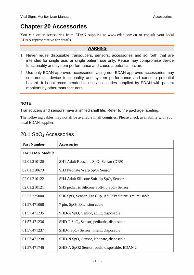
Vital Signs Monitor User Manual Accessories
- 111 -
Chapter 20 Accessories
You can order accessories from EDAN supplies at www.edan.com.cn or consult your local
EDAN representative for details.
WARNING
1 Never reuse disposable transducers, sensors, accessories and so forth that are
intended for single use, or single patient use only. Reuse may compromise device
functionality and system performance and cause a potential hazard.
2 Use only EDAN-approved accessories. Using non-EDAN-approved accessories may
compromise device functionality and system performance and cause a potential
hazard. It is not recommended to use accessories supplied by EDAN with patient
monitors by other manufacturers.
NOTE:
Transducers and sensors have a limited shelf life. Refer to the package labeling.
The following cables may not all be available in all countries. Please check availability with your
local EDAN supplier.
20.1 SpO2 Accessories
Part Number Accessories
For EDAN Module
02.01.210120 SH1 Adult Reusable SpO2 Sensor (DB9)
02.01.210673 SH3 Neonate Warp SpO2 Sensor
02.01.210122 SH4 Adult Silicone Soft-tip SpO2 Sensor
02.01.210121 SH5 pediatric Silicone Soft-tip SpO2 Sensor
02.57.225000 SH6 SpO2 Sensor, Ear Clip, Adult/Pediatric, 1m, reusable
01.57.471068 7 pin, SpO2 Extension cable
01.57.471235 SHD-A SpO2 Sensor, adult, disposable
01.57.471236 SHD-P SpO2 Sensor, pediatric, disposable
01.57.471237 SHD-I SpO2 Sensor, Infant, disposable
01.57.471238 SHD-N SpO2 Sensor, Neonate, disposable
01.57.471746 SHD-A SpO2 Sensor, adult, disposable, EDAN 2
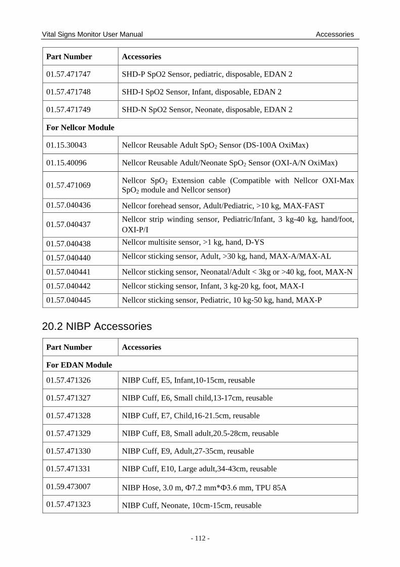
Vital Signs Monitor User Manual Accessories
- 112 -
Part Number Accessories
01.57.471747 SHD-P SpO2 Sensor, pediatric, disposable, EDAN 2
01.57.471748 SHD-I SpO2 Sensor, Infant, disposable, EDAN 2
01.57.471749 SHD-N SpO2 Sensor, Neonate, disposable, EDAN 2
For Nellcor Module
01.15.30043 Nellcor Reusable Adult SpO2 Sensor (DS-100A OxiMax)
01.15.40096 Nellcor Reusable Adult/Neonate SpO2 Sensor (OXI-A/N OxiMax)
01.57.471069 Nellcor SpO2 Extension cable (Compatible with Nellcor OXI-Max
SpO2 module and Nellcor sensor)
01.57.040436 Nellcor forehead sensor, Adult/Pediatric, >10 kg, MAX-FAST
01.57.040437 Nellcor strip winding sensor, Pediatric/Infant, 3 kg-40 kg, hand/foot,
OXI-P/I
01.57.040438 Nellcor multisite sensor, >1 kg, hand, D-YS
01.57.040440 Nellcor sticking sensor, Adult, >30 kg, hand, MAX-A/MAX-AL
01.57.040441 Nellcor sticking sensor, Neonatal/Adult < 3kg or >40 kg, foot, MAX-N
01.57.040442 Nellcor sticking sensor, Infant, 3 kg-20 kg, foot, MAX-I
01.57.040445 Nellcor sticking sensor, Pediatric, 10 kg-50 kg, hand, MAX-P
20.2 NIBP Accessories
Part Number Accessories
For EDAN Module
01.57.471326 NIBP Cuff, E5, Infant,10-15cm, reusable
01.57.471327 NIBP Cuff, E6, Small child,13-17cm, reusable
01.57.471328 NIBP Cuff, E7, Child,16-21.5cm, reusable
01.57.471329 NIBP Cuff, E8, Small adult,20.5-28cm, reusable
01.57.471330 NIBP Cuff, E9, Adult,27-35cm, reusable
01.57.471331 NIBP Cuff, E10, Large adult,34-43cm, reusable
01.59.473007 NIBP Hose, 3.0 m, Ф7.2 mm*Ф3.6 mm, TPU 85A
01.57.471323 NIBP Cuff, Neonate, 10cm-15cm, reusable
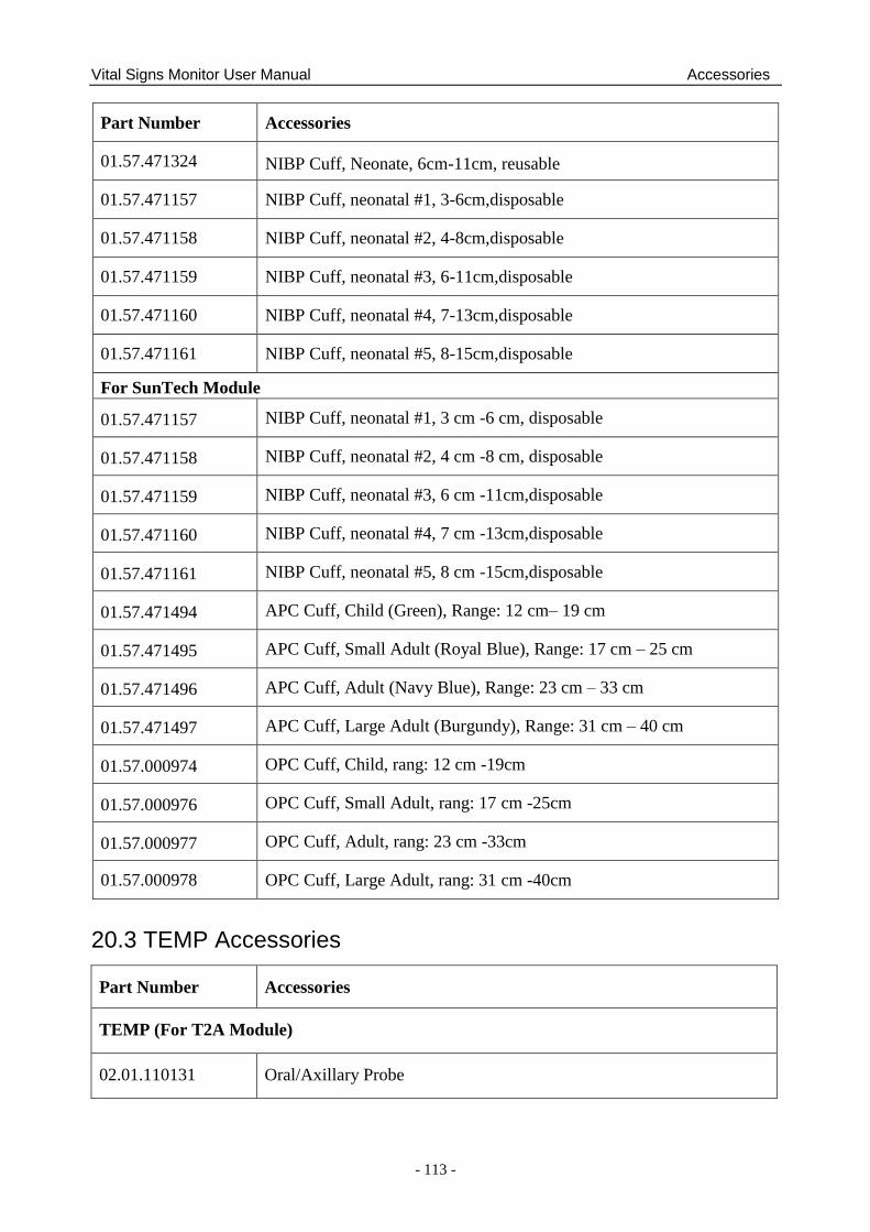
Vital Signs Monitor User Manual Accessories
- 113 -
Part Number Accessories
01.57.471324 NIBP Cuff, Neonate, 6cm-11cm, reusable
01.57.471157 NIBP Cuff, neonatal #1, 3-6cm,disposable
01.57.471158 NIBP Cuff, neonatal #2, 4-8cm,disposable
01.57.471159 NIBP Cuff, neonatal #3, 6-11cm,disposable
01.57.471160 NIBP Cuff, neonatal #4, 7-13cm,disposable
01.57.471161 NIBP Cuff, neonatal #5, 8-15cm,disposable
For SunTech Module
01.57.471157 NIBP Cuff, neonatal #1, 3 cm -6 cm, disposable
01.57.471158 NIBP Cuff, neonatal #2, 4 cm -8 cm, disposable
01.57.471159 NIBP Cuff, neonatal #3, 6 cm -11cm,disposable
01.57.471160 NIBP Cuff, neonatal #4, 7 cm -13cm,disposable
01.57.471161 NIBP Cuff, neonatal #5, 8 cm -15cm,disposable
01.57.471494 APC Cuff, Child (Green), Range: 12 cm– 19 cm
01.57.471495 APC Cuff, Small Adult (Royal Blue), Range: 17 cm – 25 cm
01.57.471496 APC Cuff, Adult (Navy Blue), Range: 23 cm – 33 cm
01.57.471497 APC Cuff, Large Adult (Burgundy), Range: 31 cm – 40 cm
01.57.000974 OPC Cuff, Child, rang: 12 cm -19cm
01.57.000976 OPC Cuff, Small Adult, rang: 17 cm -25cm
01.57.000977 OPC Cuff, Adult, rang: 23 cm -33cm
01.57.000978 OPC Cuff, Large Adult, rang: 31 cm -40cm
20.3 TEMP Accessories
Part Number Accessories
TEMP (For T2A Module)
02.01.110131 Oral/Axillary Probe
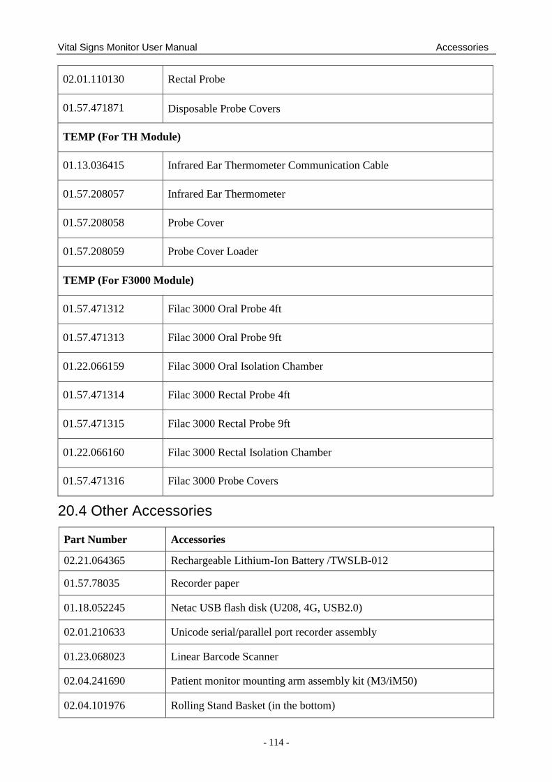
Vital Signs Monitor User Manual Accessories
- 114 -
02.01.110130 Rectal Probe
01.57.471871 Disposable Probe Covers
TEMP (For TH Module)
01.13.036415 Infrared Ear Thermometer Communication Cable
01.57.208057 Infrared Ear Thermometer
01.57.208058 Probe Cover
01.57.208059 Probe Cover Loader
TEMP (For F3000 Module)
01.57.471312 Filac 3000 Oral Probe 4ft
01.57.471313 Filac 3000 Oral Probe 9ft
01.22.066159 Filac 3000 Oral Isolation Chamber
01.57.471314 Filac 3000 Rectal Probe 4ft
01.57.471315 Filac 3000 Rectal Probe 9ft
01.22.066160 Filac 3000 Rectal Isolation Chamber
01.57.471316 Filac 3000 Probe Covers
20.4 Other Accessories
Part Number Accessories
02.21.064365 Rechargeable Lithium-Ion Battery /TWSLB-012
01.57.78035 Recorder paper
01.18.052245 Netac USB flash disk (U208, 4G, USB2.0)
02.01.210633 Unicode serial/parallel port recorder assembly
01.23.068023 Linear Barcode Scanner
02.04.241690 Patient monitor mounting arm assembly kit (M3/iM50)
02.04.101976 Rolling Stand Basket (in the bottom)
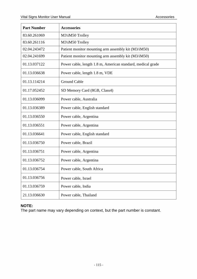
Vital Signs Monitor User Manual Accessories
- 115 -
Part Number Accessories
83.60.261069 M3\iM50 Trolley
83.60.261116 M3\iM50 Trolley
02.04.243472 Patient monitor mounting arm assembly kit (M3/iM50)
02.04.241699 Patient monitor mounting arm assembly kit (M3/iM50)
01.13.037122 Power cable, length 1.8 m, American standard, medical grade
01.13.036638 Power cable, length 1.8 m, VDE
01.13.114214 Ground Cable
01.17.052452 SD Memory Card (8GB, Class4)
01.13.036099 Power cable, Australia
01.13.036389 Power cable, English standard
01.13.036550 Power cable, Argentina
01.13.036551 Power cable, Argentina
01.13.036641 Power cable, English standard
01.13.036750 Power cable, Brazil
01.13.036751 Power cable, Argentina
01.13.036752 Power cable, Argentina
01.13.036754 Power cable, South Africa
01.13.036756 Power cable, Israel
01.13.036759 Power cable, India
21.13.036630 Power cable, Thailand
NOTE: The part name may vary depending on context, but the part number is constant.
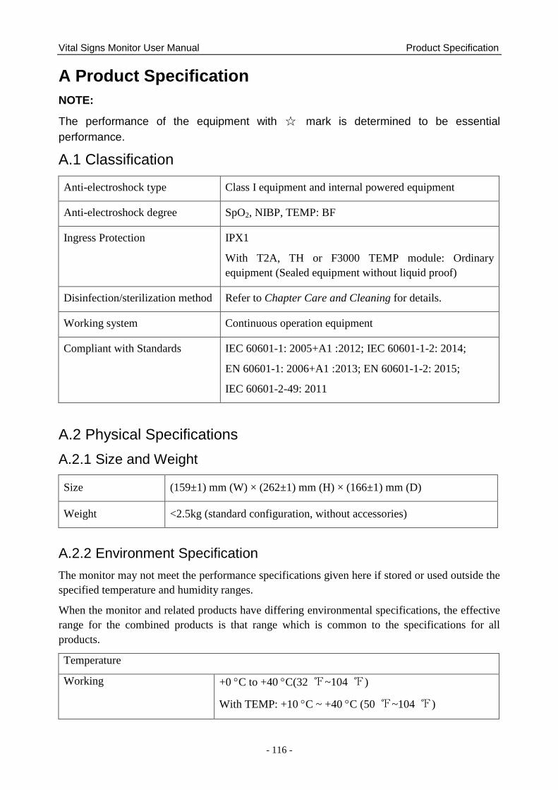
Vital Signs Monitor User Manual Product Specification
- 116 -
A Product Specification
NOTE:
The performance of the equipment with ☆ mark is determined to be essential
performance.
A.1 Classification
Anti-electroshock type Class I equipment and internal powered equipment
Anti-electroshock degree SpO2, NIBP, TEMP: BF
Ingress Protection IPX1
With T2A, TH or F3000 TEMP module: Ordinary
equipment (Sealed equipment without liquid proof)
Disinfection/sterilization method Refer to Chapter Care and Cleaning for details.
Working system Continuous operation equipment
Compliant with Standards IEC 60601-1: 2005+A1 :2012; IEC 60601-1-2: 2014;
EN 60601-1: 2006+A1 :2013; EN 60601-1-2: 2015;
IEC 60601-2-49: 2011
A.2 Physical Specifications
A.2.1 Size and Weight
Size (159±1) mm (W) × (262±1) mm (H) × (166±1) mm (D)
Weight <2.5kg (standard configuration, without accessories)
A.2.2 Environment Specification
The monitor may not meet the performance specifications given here if stored or used outside the
specified temperature and humidity ranges.
When the monitor and related products have differing environmental specifications, the effective
range for the combined products is that range which is common to the specifications for all
products.
Temperature
Working +0 C to +40 C(32 ℉~104 ℉)
With TEMP: +10 C ~ +40 C (50 ℉~104 ℉)
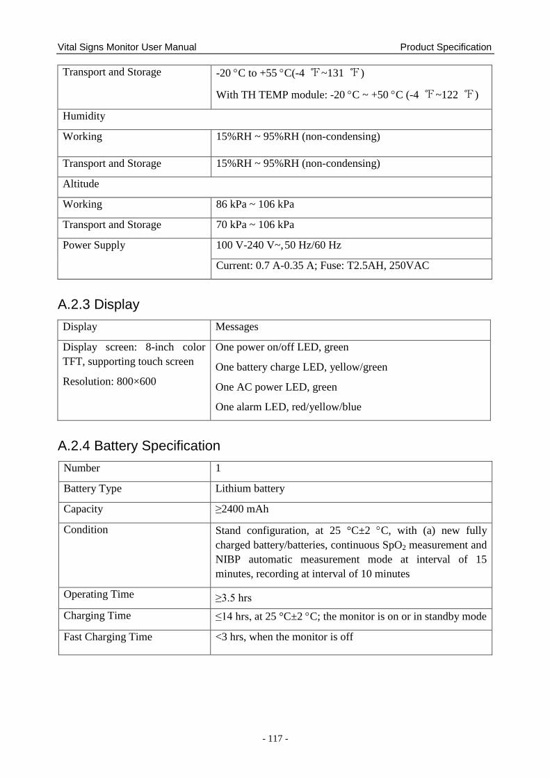
Vital Signs Monitor User Manual Product Specification
- 117 -
Transport and Storage -20 C to +55 C(-4 ℉~131 ℉)
With TH TEMP module: -20 C ~ +50 C (-4 ℉~122 ℉)
Humidity
Working 15%RH ~ 95%RH (non-condensing)
Transport and Storage 15%RH ~ 95%RH (non-condensing)
Altitude
Working 86 kPa ~ 106 kPa
Transport and Storage 70 kPa ~ 106 kPa
Power Supply 100 V-240 V~, 50 Hz/60 Hz
Current: 0.7 A-0.35 A; Fuse: T2.5AH, 250VAC
A.2.3 Display
Display Messages
Display screen: 8-inch color
TFT, supporting touch screen
Resolution: 800×600
One power on/off LED, green
One battery charge LED, yellow/green
One AC power LED, green
One alarm LED, red/yellow/blue
A.2.4 Battery Specification
Number 1
Battery Type Lithium battery
Capacity ≥2400 mAh
Condition Stand configuration, at 25 °C±2 C, with (a) new fully
charged battery/batteries, continuous SpO2 measurement and
NIBP automatic measurement mode at interval of 15
minutes, recording at interval of 10 minutes
Operating Time ≥3.5 hrs
Charging Time ≤14 hrs, at 25 °C±2 C; the monitor is on or in standby mode
Fast Charging Time <3 hrs, when the monitor is off
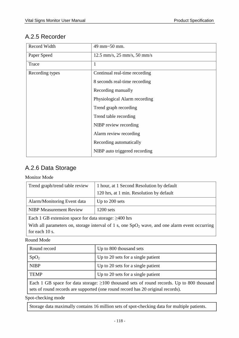
Vital Signs Monitor User Manual Product Specification
- 118 -
A.2.5 Recorder
Record Width 49 mm~50 mm.
Paper Speed 12.5 mm/s, 25 mm/s, 50 mm/s
Trace 1
Recording types Continual real-time recording
8 seconds real-time recording
Recording manually
Physiological Alarm recording
Trend graph recording
Trend table recording
NIBP review recording
Alarm review recording
Recording automatically
NIBP auto triggered recording
A.2.6 Data Storage
Monitor Mode
Trend graph/trend table review 1 hour, at 1 Second Resolution by default
120 hrs, at 1 min. Resolution by default
Alarm/Monitoring Event data Up to 200 sets
NIBP Measurement Review 1200 sets
Each 1 GB extension space for data storage: ≥400 hrs
With all parameters on, storage interval of 1 s, one SpO2 wave, and one alarm event occurring
for each 10 s.
Round Mode
Round record Up to 800 thousand sets
SpO2 Up to 20 sets for a single patient
NIBP Up to 20 sets for a single patient
TEMP Up to 20 sets for a single patient
Each 1 GB space for data storage: ≥100 thousand sets of round records. Up to 800 thousand
sets of round records are supported (one round record has 20 original records).
Spot-checking mode
Storage data maximally contains 16 million sets of spot-checking data for multiple patients.
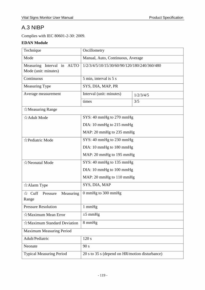
Vital Signs Monitor User Manual Product Specification
- 119 -
A.3 NIBP
Complies with IEC 80601-2-30: 2009.
EDAN Module
Technique Oscillometry
Mode Manual, Auto, Continuous, Average
Measuring Interval in AUTO
Mode (unit: minutes)
1/2/3/4/5/10/15/30/60/90/120/180/240/360/480
Continuous 5 min, interval is 5 s
Measuring Type SYS, DIA, MAP, PR
Average measurement Interval (unit: minutes) 1/2/3/4/5
times 3/5
☆Measuring Range
☆Adult Mode SYS: 40 mmHg to 270 mmHg
DIA: 10 mmHg to 215 mmHg
MAP: 20 mmHg to 235 mmHg
☆Pediatric Mode SYS: 40 mmHg to 230 mmHg
DIA: 10 mmHg to 180 mmHg
MAP: 20 mmHg to 195 mmHg
☆Neonatal Mode SYS: 40 mmHg to 135 mmHg
DIA: 10 mmHg to 100 mmHg
MAP: 20 mmHg to 110 mmHg
☆Alarm Type SYS, DIA, MAP
☆ Cuff Pressure Measuring
Range
0 mmHg to 300 mmHg
Pressure Resolution 1 mmHg
☆Maximum Mean Error ±5 mmHg
☆Maximum Standard Deviation 8 mmHg
Maximum Measuring Period
Adult/Pediatric 120 s
Neonate 90 s
Typical Measuring Period 20 s to 35 s (depend on HR/motion disturbance)
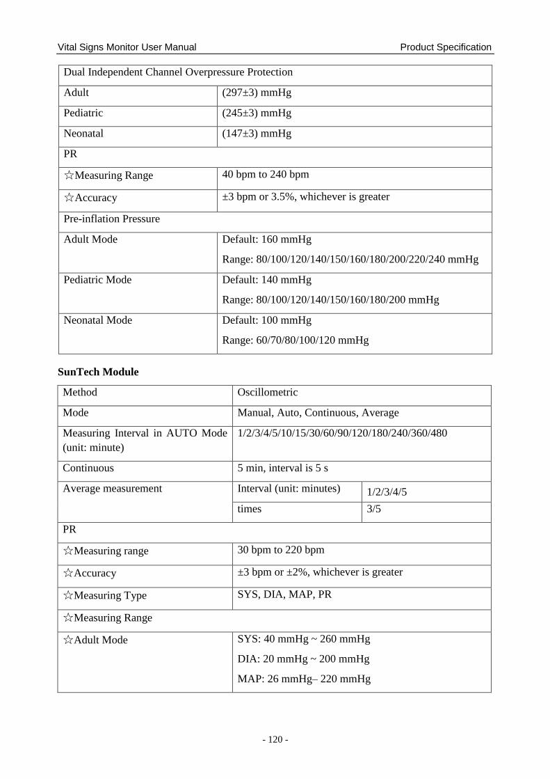
Vital Signs Monitor User Manual Product Specification
- 120 -
Dual Independent Channel Overpressure Protection
Adult (297±3) mmHg
Pediatric (245±3) mmHg
Neonatal (147±3) mmHg
PR
☆Measuring Range 40 bpm to 240 bpm
☆Accuracy ±3 bpm or 3.5%, whichever is greater
Pre-inflation Pressure
Adult Mode Default: 160 mmHg
Range: 80/100/120/140/150/160/180/200/220/240 mmHg
Pediatric Mode Default: 140 mmHg
Range: 80/100/120/140/150/160/180/200 mmHg
Neonatal Mode Default: 100 mmHg
Range: 60/70/80/100/120 mmHg
SunTech Module
Method Oscillometric
Mode Manual, Auto, Continuous, Average
Measuring Interval in AUTO Mode
(unit: minute)
1/2/3/4/5/10/15/30/60/90/120/180/240/360/480
Continuous 5 min, interval is 5 s
Average measurement Interval (unit: minutes) 1/2/3/4/5
times 3/5
PR
☆Measuring range 30 bpm to 220 bpm
☆Accuracy ±3 bpm or ±2%, whichever is greater
☆Measuring Type SYS, DIA, MAP, PR
☆Measuring Range
☆Adult Mode SYS: 40 mmHg ~ 260 mmHg
DIA: 20 mmHg ~ 200 mmHg
MAP: 26 mmHg– 220 mmHg
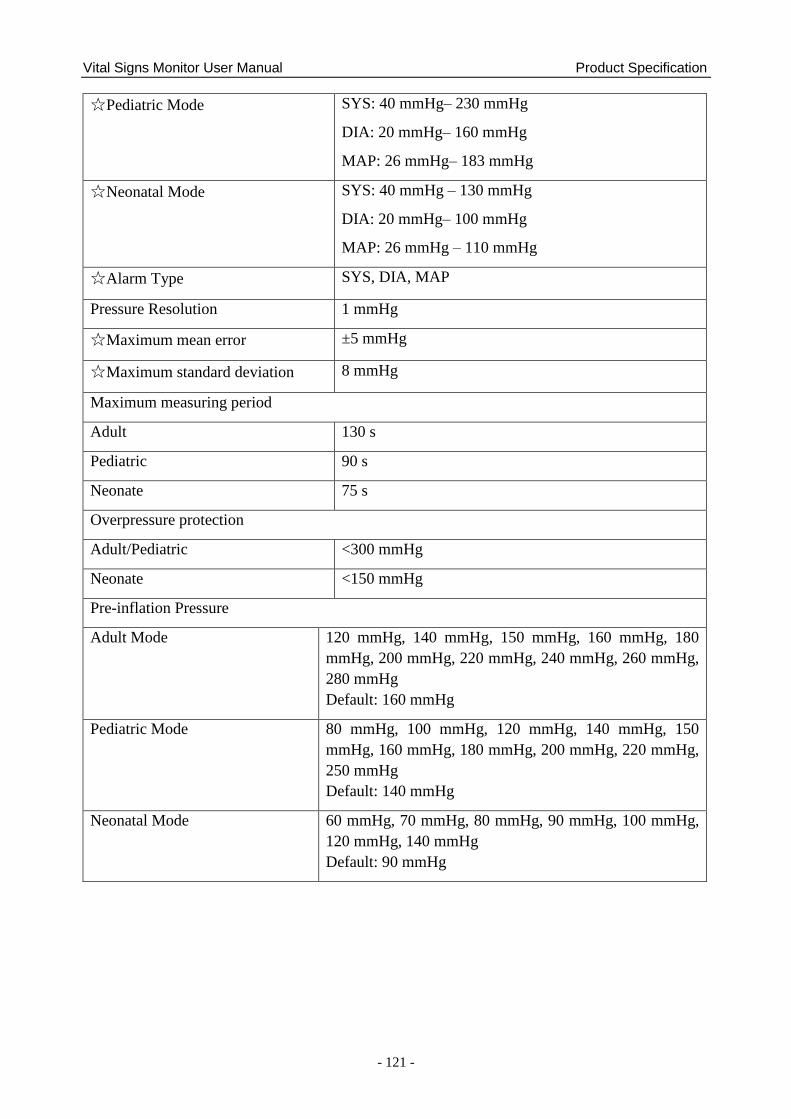
Vital Signs Monitor User Manual Product Specification
- 121 -
☆Pediatric Mode SYS: 40 mmHg– 230 mmHg
DIA: 20 mmHg– 160 mmHg
MAP: 26 mmHg– 183 mmHg
☆Neonatal Mode SYS: 40 mmHg – 130 mmHg
DIA: 20 mmHg– 100 mmHg
MAP: 26 mmHg – 110 mmHg
☆Alarm Type SYS, DIA, MAP
Pressure Resolution 1 mmHg
☆Maximum mean error ±5 mmHg
☆Maximum standard deviation 8 mmHg
Maximum measuring period
Adult 130 s
Pediatric 90 s
Neonate 75 s
Overpressure protection
Adult/Pediatric <300 mmHg
Neonate <150 mmHg
Pre-inflation Pressure
Adult Mode 120 mmHg, 140 mmHg, 150 mmHg, 160 mmHg, 180
mmHg, 200 mmHg, 220 mmHg, 240 mmHg, 260 mmHg,
280 mmHg
Default: 160 mmHg
Pediatric Mode 80 mmHg, 100 mmHg, 120 mmHg, 140 mmHg, 150
mmHg, 160 mmHg, 180 mmHg, 200 mmHg, 220 mmHg,
250 mmHg
Default: 140 mmHg
Neonatal Mode 60 mmHg, 70 mmHg, 80 mmHg, 90 mmHg, 100 mmHg,
120 mmHg, 140 mmHg
Default: 90 mmHg
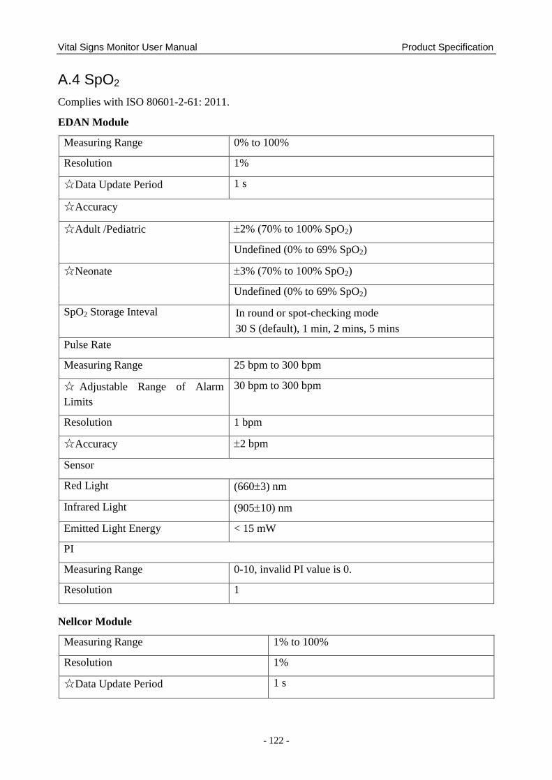
Vital Signs Monitor User Manual Product Specification
- 122 -
A.4 SpO2
Complies with ISO 80601-2-61: 2011.
EDAN Module
Measuring Range 0% to 100%
Resolution 1%
☆Data Update Period 1 s
☆Accuracy
☆Adult /Pediatric 2% (70% to 100% SpO2)
Undefined (0% to 69% SpO2)
☆Neonate 3% (70% to 100% SpO2)
Undefined (0% to 69% SpO2)
SpO2 Storage Inteval In round or spot-checking mode
30 S (default), 1 min, 2 mins, 5 mins
Pulse Rate
Measuring Range 25 bpm to 300 bpm
☆ Adjustable Range of Alarm
Limits
30 bpm to 300 bpm
Resolution 1 bpm
☆Accuracy 2 bpm
Sensor
Red Light (6603) nm
Infrared Light (90510) nm
Emitted Light Energy < 15 mW
PI
Measuring Range 0-10, invalid PI value is 0.
Resolution 1
Nellcor Module
Measuring Range 1% to 100%
Resolution 1%
☆Data Update Period 1 s
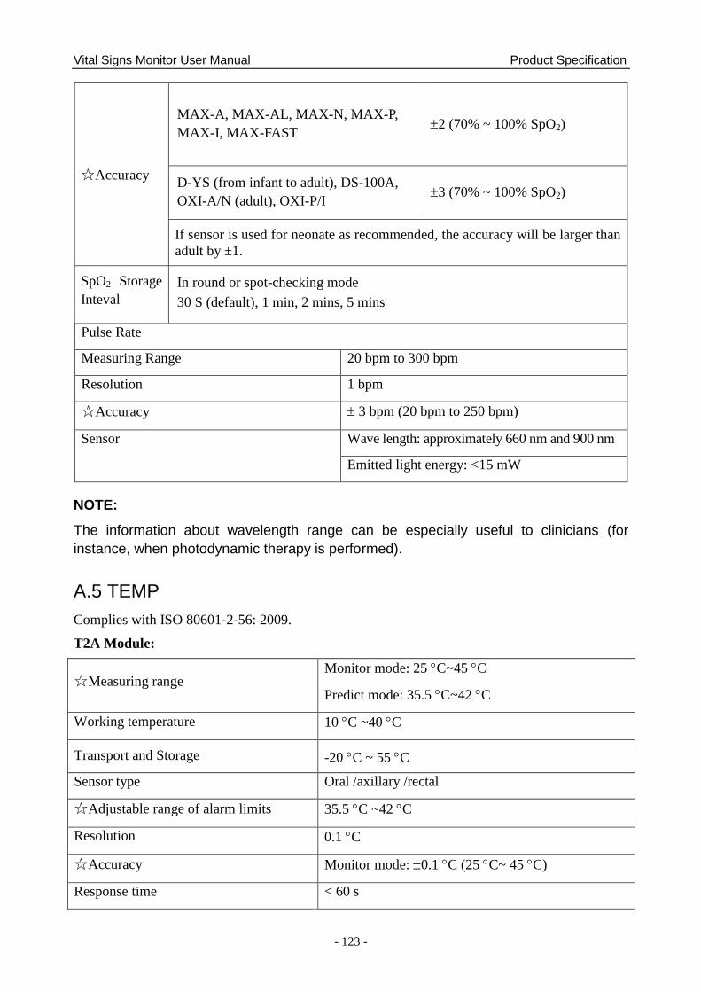
Vital Signs Monitor User Manual Product Specification
- 123 -
☆Accuracy
MAX-A, MAX-AL, MAX-N, MAX-P,
MAX-I, MAX-FAST 2 (70% ~ 100% SpO2)
D-YS (from infant to adult), DS-100A,
OXI-A/N (adult), OXI-P/I 3 (70% ~ 100% SpO2)
If sensor is used for neonate as recommended, the accuracy will be larger than
adult by ±1.
SpO2 Storage
Inteval
In round or spot-checking mode
30 S (default), 1 min, 2 mins, 5 mins
Pulse Rate
Measuring Range 20 bpm to 300 bpm
Resolution 1 bpm
☆Accuracy 3 bpm (20 bpm to 250 bpm)
Sensor Wave length: approximately 660 nm and 900 nm
Emitted light energy: <15 mW
NOTE:
The information about wavelength range can be especially useful to clinicians (for
instance, when photodynamic therapy is performed).
A.5 TEMP
Complies with ISO 80601-2-56: 2009.
T2A Module:
☆Measuring range Monitor mode: 25 C~45 C
Predict mode: 35.5 C~42 C
Working temperature 10 C ~40 C
Transport and Storage -20 C ~ 55 C
Sensor type Oral /axillary /rectal
☆Adjustable range of alarm limits 35.5 C ~42 C
Resolution 0.1 C
☆Accuracy Monitor mode: 0.1 C (25 C~ 45 C)
Response time < 60 s
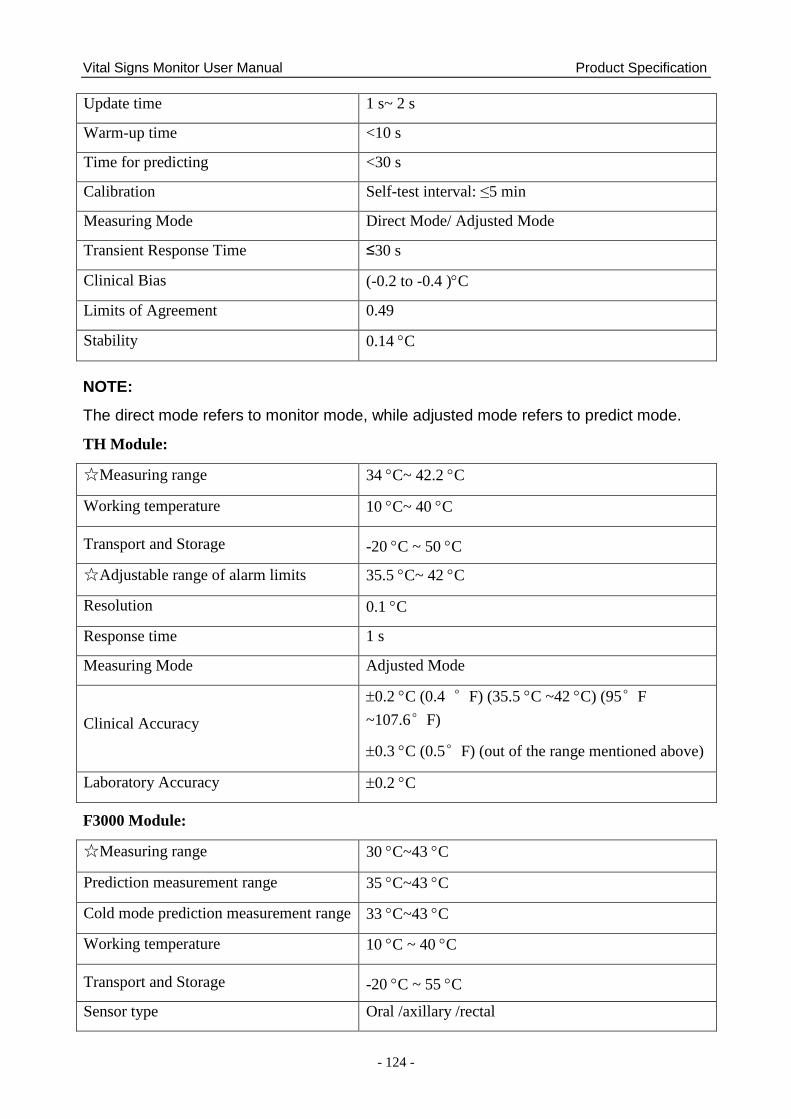
Vital Signs Monitor User Manual Product Specification
- 124 -
Update time 1 s~ 2 s
Warm-up time <10 s
Time for predicting <30 s
Calibration Self-test interval: ≤5 min
Measuring Mode Direct Mode/ Adjusted Mode
Transient Response Time ≤30 s
Clinical Bias (-0.2 to -0.4 )C
Limits of Agreement 0.49
Stability 0.14 C
NOTE:
The direct mode refers to monitor mode, while adjusted mode refers to predict mode.
TH Module:
☆Measuring range 34 C~ 42.2 C
Working temperature 10 C~ 40 C
Transport and Storage -20 C ~ 50 C
☆Adjustable range of alarm limits 35.5 C~ 42 C
Resolution 0.1 C
Response time 1 s
Measuring Mode Adjusted Mode
Clinical Accuracy
0.2 C (0.4 °F) (35.5 C ~42 C) (95°F
~107.6°F)
0.3 C (0.5°F) (out of the range mentioned above)
Laboratory Accuracy 0.2 C
F3000 Module:
☆Measuring range 30 C~43 C
Prediction measurement range 35 C~43 C
Cold mode prediction measurement range 33 C~43 C
Working temperature 10 C ~ 40 C
Transport and Storage -20 C ~ 55 C
Sensor type Oral /axillary /rectal
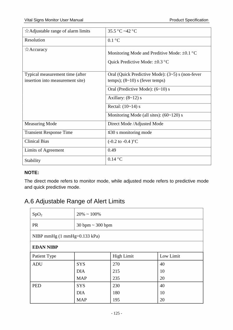
Vital Signs Monitor User Manual Product Specification
- 125 -
☆Adjustable range of alarm limits 35.5 C ~42 C
Resolution 0.1 C
☆Accuracy Monitoring Mode and Preditive Mode: 0.1 C
Quick Predictive Mode: 0.3 C
Typical measurement time (after
insertion into measurement site)
Oral (Quick Predictive Mode): (3~5) s (non-fever
temps); (8~10) s (fever temps)
Oral (Predictive Mode): (6~10) s
Axillary: (8~12) s
Rectal: (10~14) s
Monitoring Mode (all sites): (60~120) s
Measuring Mode Direct Mode /Adjusted Mode
Transient Response Time ≤30 s monitoring mode
Clinical Bias (-0.2 to -0.4 )C
Limits of Agreement 0.49
Stability 0.14 C
NOTE:
The direct mode refers to monitor mode, while adjusted mode refers to predictive mode
and quick predictive mode.
A.6 Adjustable Range of Alert Limits
SpO2 20% ~ 100%
PR 30 bpm ~ 300 bpm
NIBP mmHg (1 mmHg=0.133 kPa)
EDAN NIBP
Patient Type High Limit Low Limit
ADU SYS
DIA
MAP
270
215
235
40
10
20
PED SYS
DIA
MAP
230
180
195
40
10
20
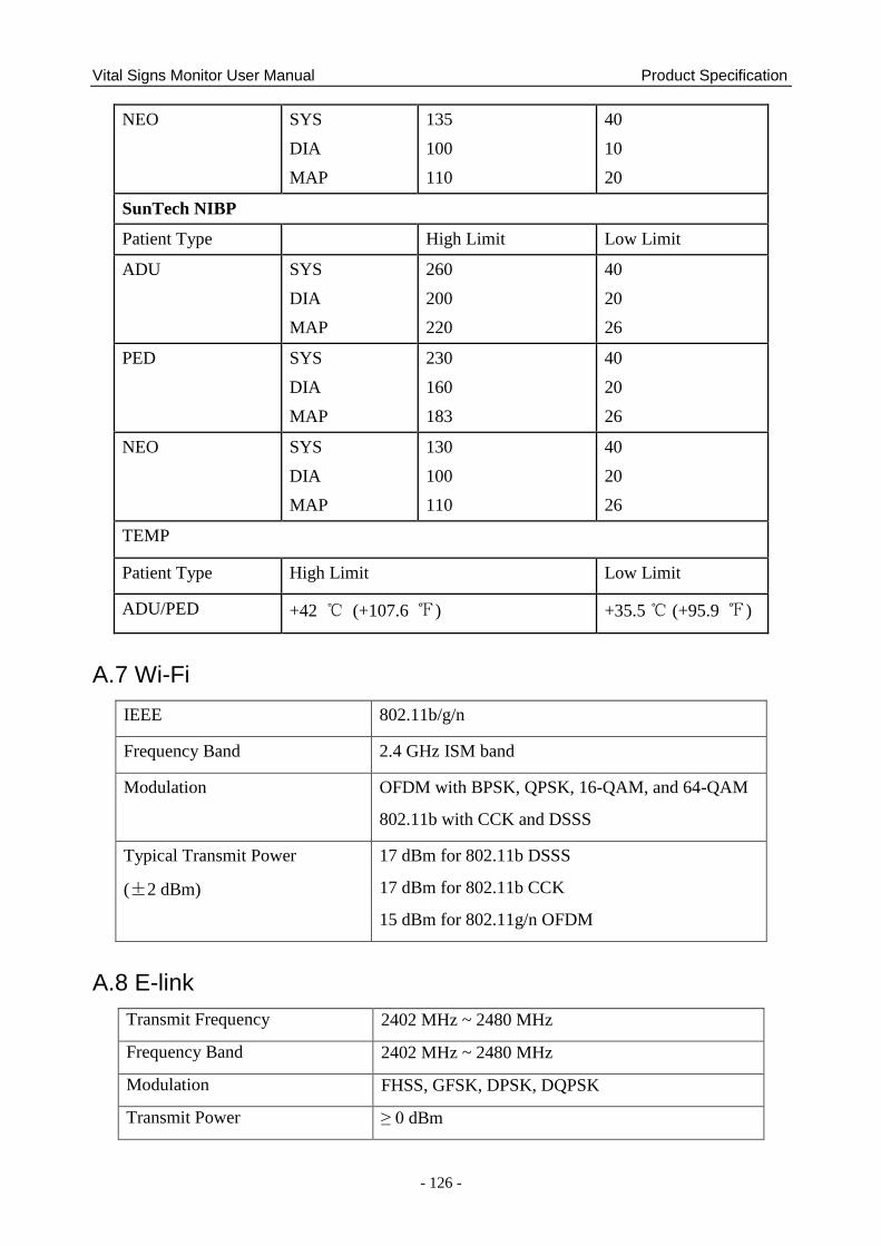
Vital Signs Monitor User Manual Product Specification
- 126 -
NEO SYS
DIA
MAP
135
100
110
40
10
20
SunTech NIBP
Patient Type High Limit Low Limit
ADU SYS
DIA
MAP
260
200
220
40
20
26
PED SYS
DIA
MAP
230
160
183
40
20
26
NEO SYS
DIA
MAP
130
100
110
40
20
26
TEMP
Patient Type High Limit Low Limit
ADU/PED +42 ℃ (+107.6 ℉) +35.5 ℃ (+95.9 ℉)
A.7 Wi-Fi
IEEE 802.11b/g/n
Frequency Band 2.4 GHz ISM band
Modulation OFDM with BPSK, QPSK, 16-QAM, and 64-QAM
802.11b with CCK and DSSS
Typical Transmit Power
(±2 dBm)
17 dBm for 802.11b DSSS
17 dBm for 802.11b CCK
15 dBm for 802.11g/n OFDM
A.8 E-link
Transmit Frequency 2402 MHz ~ 2480 MHz
Frequency Band 2402 MHz ~ 2480 MHz
Modulation FHSS, GFSK, DPSK, DQPSK
Transmit Power ≥ 0 dBm
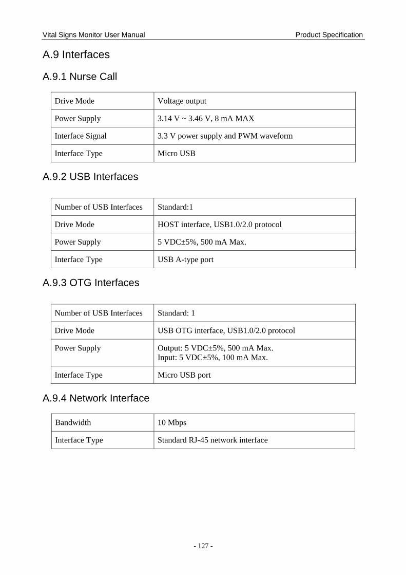
Vital Signs Monitor User Manual Product Specification
- 127 -
A.9 Interfaces
A.9.1 Nurse Call
Drive Mode Voltage output
Power Supply 3.14 V ~ 3.46 V, 8 mA MAX
Interface Signal 3.3 V power supply and PWM waveform
Interface Type Micro USB
A.9.2 USB Interfaces
A.9.3 OTG Interfaces
A.9.4 Network Interface
Bandwidth 10 Mbps
Interface Type Standard RJ-45 network interface
Number of USB Interfaces Standard:1
Drive Mode HOST interface, USB1.0/2.0 protocol
Power Supply 5 VDC±5%, 500 mA Max.
Interface Type USB A-type port
Number of USB Interfaces Standard: 1
Drive Mode USB OTG interface, USB1.0/2.0 protocol
Power Supply Output: 5 VDC±5%, 500 mA Max.
Input: 5 VDC±5%, 100 mA Max.
Interface Type Micro USB port
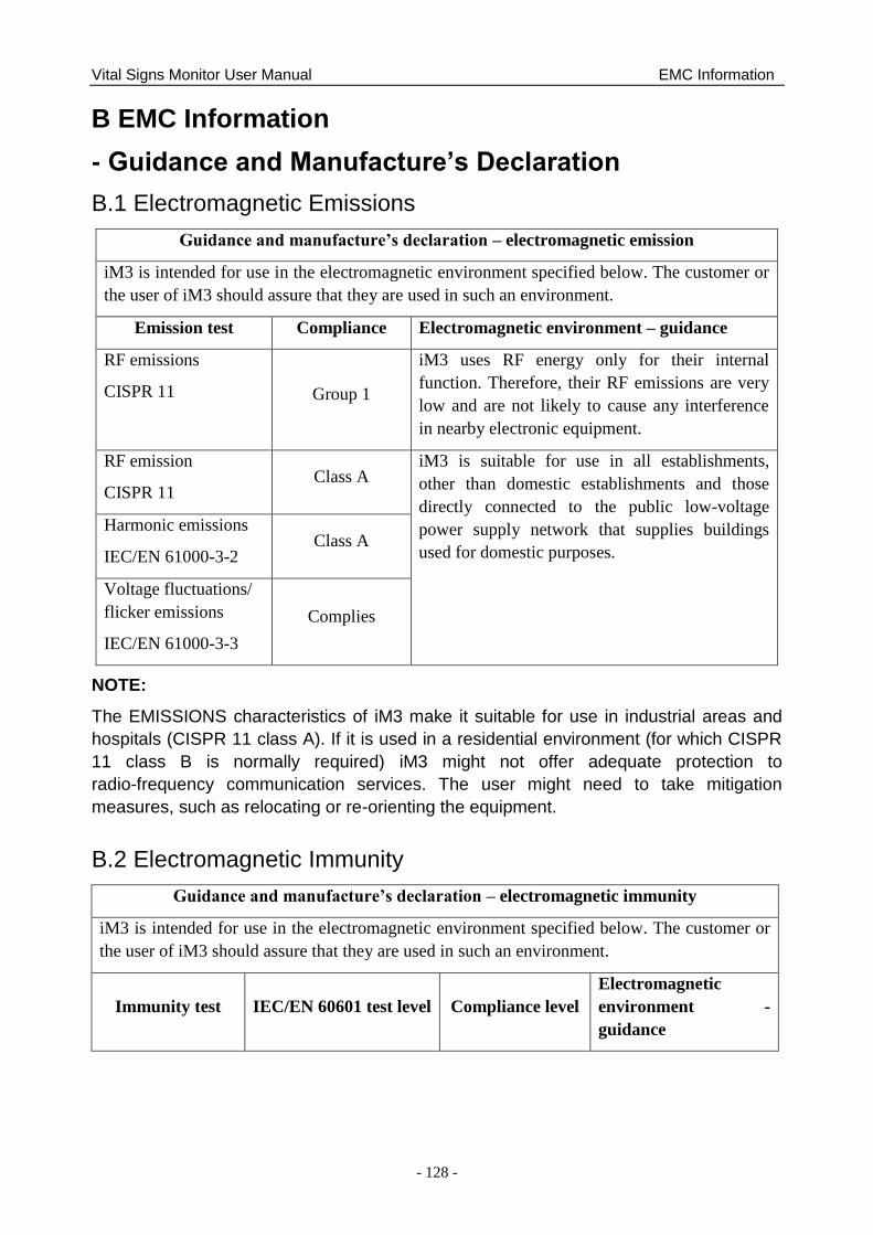
Vital Signs Monitor User Manual EMC Information
- 128 -
B EMC Information
- Guidance and Manufacture’s Declaration
B.1 Electromagnetic Emissions
Guidance and manufacture’s declaration – electromagnetic emission
iM3 is intended for use in the electromagnetic environment specified below. The customer or
the user of iM3 should assure that they are used in such an environment.
Emission test Compliance Electromagnetic environment – guidance
RF emissions
CISPR 11 Group 1
iM3 uses RF energy only for their internal
function. Therefore, their RF emissions are very
low and are not likely to cause any interference
in nearby electronic equipment.
RF emission
CISPR 11 Class A
iM3 is suitable for use in all establishments,
other than domestic establishments and those
directly connected to the public low-voltage
power supply network that supplies buildings
used for domestic purposes.
Harmonic emissions
IEC/EN 61000-3-2 Class A
Voltage fluctuations/
flicker emissions
IEC/EN 61000-3-3
Complies
NOTE:
The EMISSIONS characteristics of iM3 make it suitable for use in industrial areas and
hospitals (CISPR 11 class A). If it is used in a residential environment (for which CISPR
11 class B is normally required) iM3 might not offer adequate protection to
radio-frequency communication services. The user might need to take mitigation
measures, such as relocating or re-orienting the equipment.
B.2 Electromagnetic Immunity
Guidance and manufacture’s declaration – electromagnetic immunity
iM3 is intended for use in the electromagnetic environment specified below. The customer or
the user of iM3 should assure that they are used in such an environment.
Immunity test IEC/EN 60601 test level Compliance level
Electromagnetic
environment -
guidance
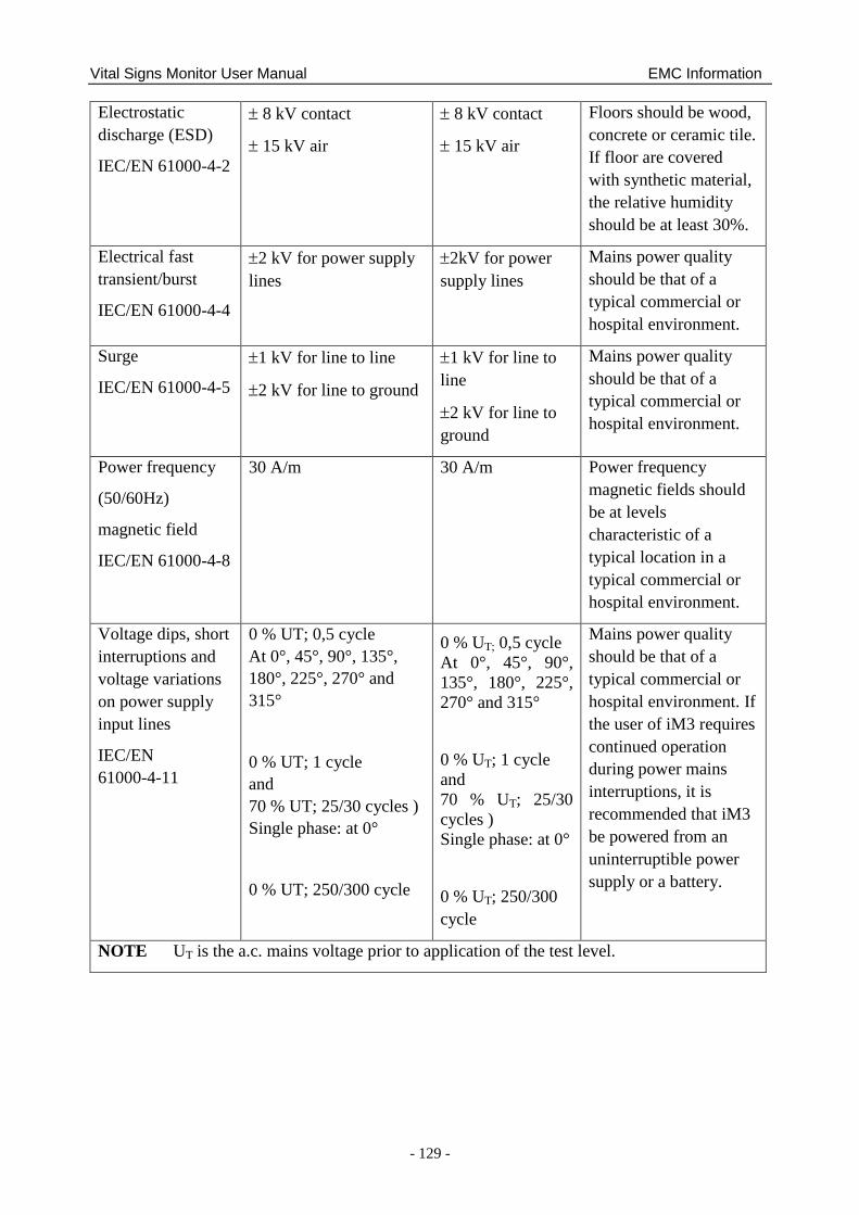
Vital Signs Monitor User Manual EMC Information
- 129 -
Electrostatic
discharge (ESD)
IEC/EN 61000-4-2
8 kV contact
15 kV air
8 kV contact
15 kV air
Floors should be wood,
concrete or ceramic tile.
If floor are covered
with synthetic material,
the relative humidity
should be at least 30%.
Electrical fast
transient/burst
IEC/EN 61000-4-4
2 kV for power supply
lines
2kV for power
supply lines
Mains power quality
should be that of a
typical commercial or
hospital environment.
Surge
IEC/EN 61000-4-5
1 kV for line to line
2 kV for line to ground
1 kV for line to
line
2 kV for line to
ground
Mains power quality
should be that of a
typical commercial or
hospital environment.
Power frequency
(50/60Hz)
magnetic field
IEC/EN 61000-4-8
30 A/m 30 A/m Power frequency
magnetic fields should
be at levels
characteristic of a
typical location in a
typical commercial or
hospital environment.
Voltage dips, short
interruptions and
voltage variations
on power supply
input lines
IEC/EN
61000-4-11
0 % UT; 0,5 cycle
At 0°, 45°, 90°, 135°,
180°, 225°, 270° and
315°
0 % UT; 1 cycle
and
70 % UT; 25/30 cycles )
Single phase: at 0°
0 % UT; 250/300 cycle
0 % UT; 0,5 cycle
At 0°, 45°, 90°,
135°, 180°, 225°,
270° and 315°
0 % UT; 1 cycle
and
70 % UT; 25/30
cycles )
Single phase: at 0°
0 % UT; 250/300
cycle
Mains power quality
should be that of a
typical commercial or
hospital environment. If
the user of iM3 requires
continued operation
during power mains
interruptions, it is
recommended that iM3
be powered from an
uninterruptible power
supply or a battery.
NOTE UT is the a.c. mains voltage prior to application of the test level.
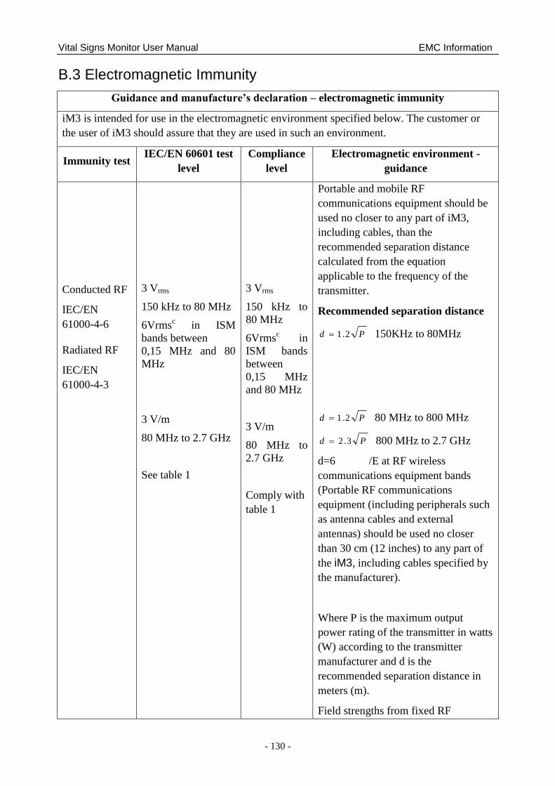
Vital Signs Monitor User Manual EMC Information
- 130 -
B.3 Electromagnetic Immunity
Guidance and manufacture’s declaration – electromagnetic immunity
iM3 is intended for use in the electromagnetic environment specified below. The customer or
the user of iM3 should assure that they are used in such an environment.
Immunity test IEC/EN 60601 test
level
Compliance
level
Electromagnetic environment -
guidance
Conducted RF
IEC/EN
61000-4-6
Radiated RF
IEC/EN
61000-4-3
3 Vrms
150 kHz to 80 MHz
6Vrmsc in ISM
bands between
0,15 MHz and 80
MHz
3 V/m
80 MHz to 2.7 GHz
See table 1
3 Vrms
150 kHz to
80 MHz
6Vrmsc in
ISM bands
between
0,15 MHz
and 80 MHz
3 V/m
80 MHz to
2.7 GHz
Comply with
table 1
Portable and mobile RF
communications equipment should be
used no closer to any part of iM3,
including cables, than the
recommended separation distance
calculated from the equation
applicable to the frequency of the
transmitter.
Recommended separation distance
Pd 2.1 150KHz to 80MHz
Pd 2.1 80 MHz to 800 MHz
Pd 3.2 800 MHz to 2.7 GHz
d=6 /E at RF wireless
communications equipment bands
(Portable RF communications
equipment (including peripherals such
as antenna cables and external
antennas) should be used no closer
than 30 cm (12 inches) to any part of
the iM3, including cables specified by
the manufacturer).
Where P is the maximum output
power rating of the transmitter in watts
(W) according to the transmitter
manufacturer and d is the
recommended separation distance in
meters (m).
Field strengths from fixed RF
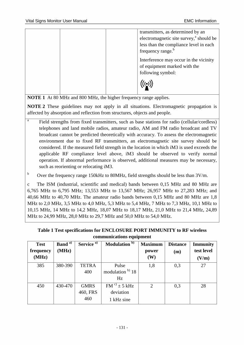
Vital Signs Monitor User Manual EMC Information
- 131 -
transmitters, as determined by an
electromagnetic site survey,a should be
less than the compliance level in each
frequency range.b
Interference may occur in the vicinity
of equipment marked with the
following symbol:
NOTE 1 At 80 MHz and 800 MHz, the higher frequency range applies.
NOTE 2 These guidelines may not apply in all situations. Electromagnetic propagation is
affected by absorption and reflection from structures, objects and people.
a Field strengths from fixed transmitters, such as base stations for radio (cellular/cordless)
telephones and land mobile radios, amateur radio, AM and FM radio broadcast and TV
broadcast cannot be predicted theoretically with accuracy. To assess the electromagnetic
environment due to fixed RF transmitters, an electromagnetic site survey should be
considered. If the measured field strength in the location in which iM3 is used exceeds the
applicable RF compliance level above, iM3 should be observed to verify normal
operation. If abnormal performance is observed, additional measures may be necessary,
such as reorienting or relocating iM3.
b Over the frequency range 150kHz to 80MHz, field strengths should be less than 3V/m.
c The ISM (industrial, scientific and medical) bands between 0,15 MHz and 80 MHz are
6,765 MHz to 6,795 MHz; 13,553 MHz to 13,567 MHz; 26,957 MHz to 27,283 MHz; and
40,66 MHz to 40,70 MHz. The amateur radio bands between 0,15 MHz and 80 MHz are 1,8
MHz to 2,0 MHz, 3,5 MHz to 4,0 MHz, 5,3 MHz to 5,4 MHz, 7 MHz to 7,3 MHz, 10,1 MHz to
10,15 MHz, 14 MHz to 14,2 MHz, 18,07 MHz to 18,17 MHz, 21,0 MHz to 21,4 MHz, 24,89
MHz to 24,99 MHz, 28,0 MHz to 29,7 MHz and 50,0 MHz to 54,0 MHz.
Table 1 Test specifications for ENCLOSURE PORT IMMUNITY to RF wireless
communications equipment
Test
frequency
(MHz)
Band a)
(MHz)
Service a)
Modulation b)
Maximum
power
(W)
Distance
(m)
Immunity
test level
(V/m)
385 380-390 TETRA
400
Pulse
modulation b)
18
Hz
1,8 0,3 27
450 430-470 GMRS
460, FRS
460
FM c)
± 5 kHz
deviation
1 kHz sine
2 0,3 28
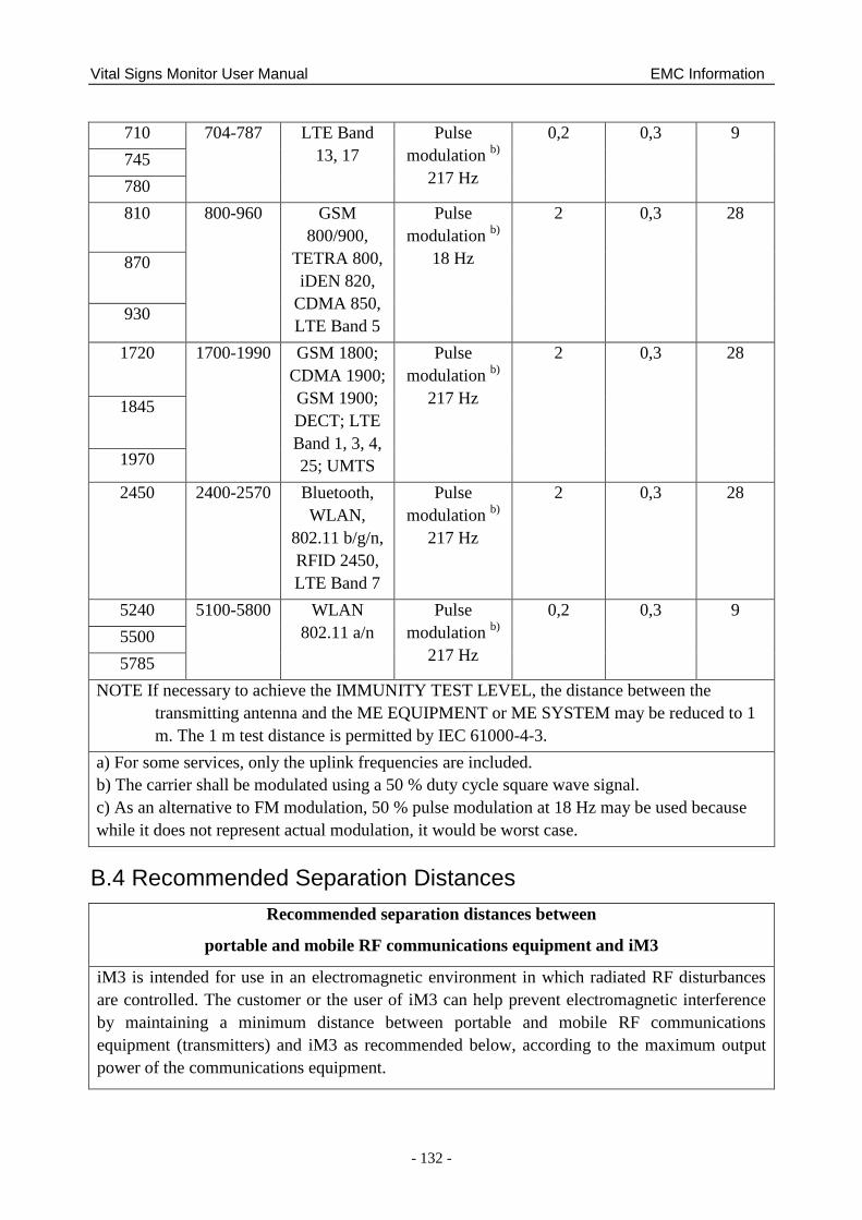
Vital Signs Monitor User Manual EMC Information
- 132 -
710 704-787 LTE Band
13, 17
Pulse
modulation b)
217 Hz
0,2 0,3 9
745
780
810 800-960 GSM
800/900,
TETRA 800,
iDEN 820,
CDMA 850,
LTE Band 5
Pulse
modulation b)
18 Hz
2 0,3 28
870
930
1720 1700-1990 GSM 1800;
CDMA 1900;
GSM 1900;
DECT; LTE
Band 1, 3, 4,
25; UMTS
Pulse
modulation b)
217 Hz
2 0,3 28
1845
1970
2450 2400-2570 Bluetooth,
WLAN,
802.11 b/g/n,
RFID 2450,
LTE Band 7
Pulse
modulation b)
217 Hz
2 0,3 28
5240 5100-5800 WLAN
802.11 a/n
Pulse
modulation b)
217 Hz
0,2 0,3 9
5500
5785
NOTE If necessary to achieve the IMMUNITY TEST LEVEL, the distance between the
transmitting antenna and the ME EQUIPMENT or ME SYSTEM may be reduced to 1
m. The 1 m test distance is permitted by IEC 61000-4-3.
a) For some services, only the uplink frequencies are included.
b) The carrier shall be modulated using a 50 % duty cycle square wave signal.
c) As an alternative to FM modulation, 50 % pulse modulation at 18 Hz may be used because
while it does not represent actual modulation, it would be worst case.
B.4 Recommended Separation Distances
Recommended separation distances between
portable and mobile RF communications equipment and iM3
iM3 is intended for use in an electromagnetic environment in which radiated RF disturbances
are controlled. The customer or the user of iM3 can help prevent electromagnetic interference
by maintaining a minimum distance between portable and mobile RF communications
equipment (transmitters) and iM3 as recommended below, according to the maximum output
power of the communications equipment.
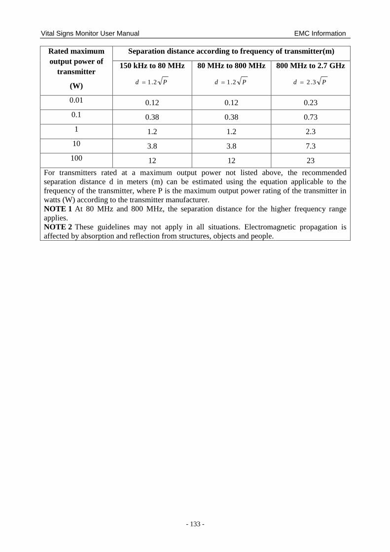
Vital Signs Monitor User Manual EMC Information
- 133 -
Rated maximum
output power of
transmitter
(W)
Separation distance according to frequency of transmitter(m)
150 kHz to 80 MHz
Pd 2.1
80 MHz to 800 MHz
Pd 2.1
800 MHz to 2.7 GHz
Pd 3.2
0.01 0.12 0.12 0.23
0.1 0.38 0.38 0.73
1 1.2 1.2 2.3
10 3.8 3.8 7.3
100 12 12 23
For transmitters rated at a maximum output power not listed above, the recommended
separation distance d in meters (m) can be estimated using the equation applicable to the
frequency of the transmitter, where P is the maximum output power rating of the transmitter in
watts (W) according to the transmitter manufacturer.
NOTE 1 At 80 MHz and 800 MHz, the separation distance for the higher frequency range
applies.
NOTE 2 These guidelines may not apply in all situations. Electromagnetic propagation is
affected by absorption and reflection from structures, objects and people.
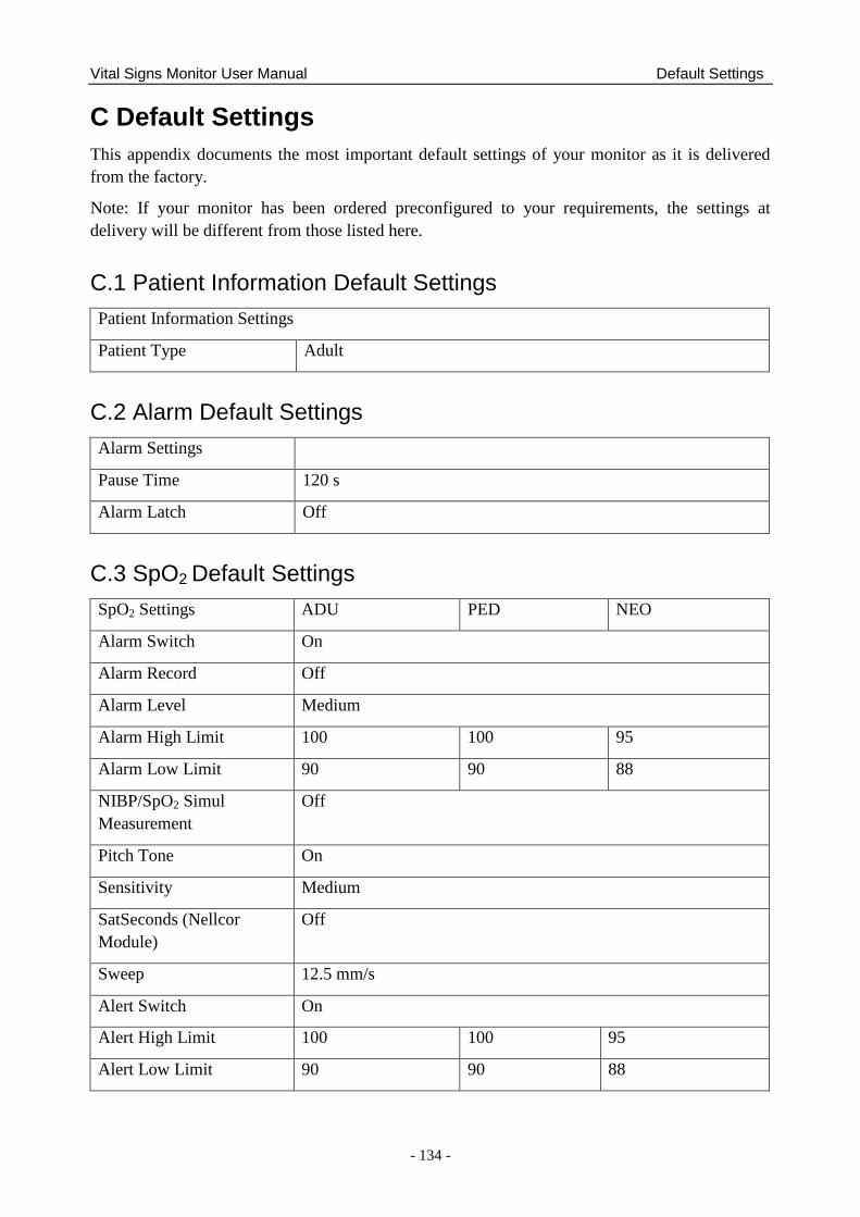
Vital Signs Monitor User Manual Default Settings
- 134 -
C Default Settings
This appendix documents the most important default settings of your monitor as it is delivered
from the factory.
Note: If your monitor has been ordered preconfigured to your requirements, the settings at
delivery will be different from those listed here.
C.1 Patient Information Default Settings
Patient Information Settings
Patient Type Adult
C.2 Alarm Default Settings
Alarm Settings
Pause Time 120 s
Alarm Latch Off
C.3 SpO2 Default Settings
SpO2 Settings ADU PED NEO
Alarm Switch On
Alarm Record Off
Alarm Level Medium
Alarm High Limit 100 100 95
Alarm Low Limit 90 90 88
NIBP/SpO2 Simul
Measurement
Off
Pitch Tone On
Sensitivity Medium
SatSeconds (Nellcor
Module)
Off
Sweep 12.5 mm/s
Alert Switch On
Alert High Limit 100 100 95
Alert Low Limit 90 90 88
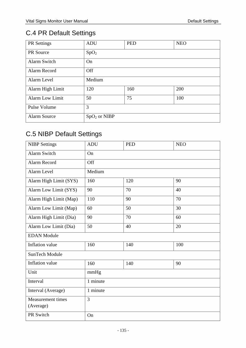
Vital Signs Monitor User Manual Default Settings
- 135 -
C.4 PR Default Settings
PR Settings ADU PED NEO
PR Source SpO2
Alarm Switch On
Alarm Record Off
Alarm Level Medium
Alarm High Limit 120 160 200
Alarm Low Limit 50 75 100
Pulse Volume 3
Alarm Source SpO2 or NIBP
C.5 NIBP Default Settings
NIBP Settings ADU PED NEO
Alarm Switch On
Alarm Record Off
Alarm Level Medium
Alarm High Limit (SYS) 160 120 90
Alarm Low Limit (SYS) 90 70 40
Alarm High Limit (Map) 110 90 70
Alarm Low Limit (Map) 60 50 30
Alarm High Limit (Dia) 90 70 60
Alarm Low Limit (Dia) 50 40 20
EDAN Module
Inflation value 160 140 100
SunTech Module
Inflation value 160 140 90
Unit mmHg
Interval 1 minute
Interval (Average) 1 minute
Measurement times
(Average)
3
PR Switch On
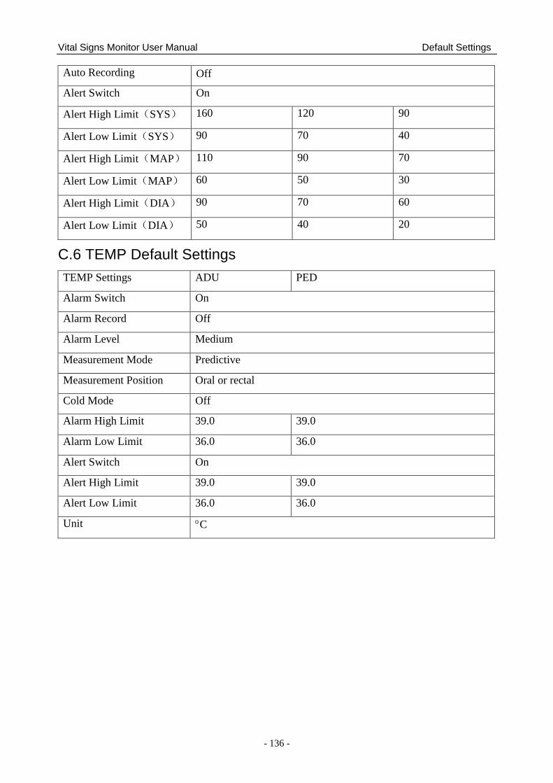
Vital Signs Monitor User Manual Default Settings
- 136 -
Auto Recording Off
Alert Switch On
Alert High Limit(SYS) 160 120 90
Alert Low Limit(SYS) 90 70 40
Alert High Limit(MAP) 110 90 70
Alert Low Limit(MAP) 60 50 30
Alert High Limit(DIA) 90 70 60
Alert Low Limit(DIA) 50 40 20
C.6 TEMP Default Settings
TEMP Settings ADU PED
Alarm Switch On
Alarm Record Off
Alarm Level Medium
Measurement Mode Predictive
Measurement Position Oral or rectal
Cold Mode Off
Alarm High Limit 39.0 39.0
Alarm Low Limit 36.0 36.0
Alert Switch On
Alert High Limit 39.0 39.0
Alert Low Limit 36.0 36.0
Unit C
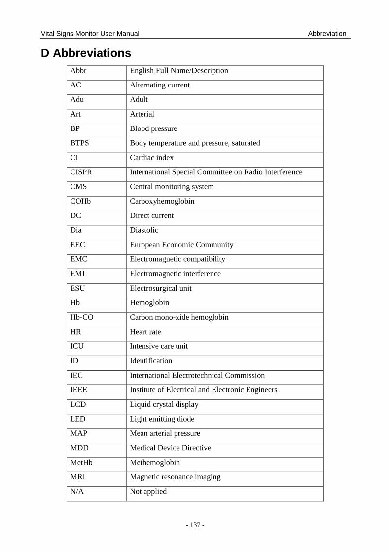
Vital Signs Monitor User Manual Abbreviation
- 137 -
D Abbreviations
Abbr English Full Name/Description
AC Alternating current
Adu Adult
Art Arterial
BP Blood pressure
BTPS Body temperature and pressure, saturated
CI Cardiac index
CISPR International Special Committee on Radio Interference
CMS Central monitoring system
COHb Carboxyhemoglobin
DC Direct current
Dia Diastolic
EEC European Economic Community
EMC Electromagnetic compatibility
EMI Electromagnetic interference
ESU Electrosurgical unit
Hb Hemoglobin
Hb-CO Carbon mono-xide hemoglobin
HR Heart rate
ICU Intensive care unit
ID Identification
IEC International Electrotechnical Commission
IEEE Institute of Electrical and Electronic Engineers
LCD Liquid crystal display
LED Light emitting diode
MAP Mean arterial pressure
MDD Medical Device Directive
MetHb Methemoglobin
MRI Magnetic resonance imaging
N/A Not applied
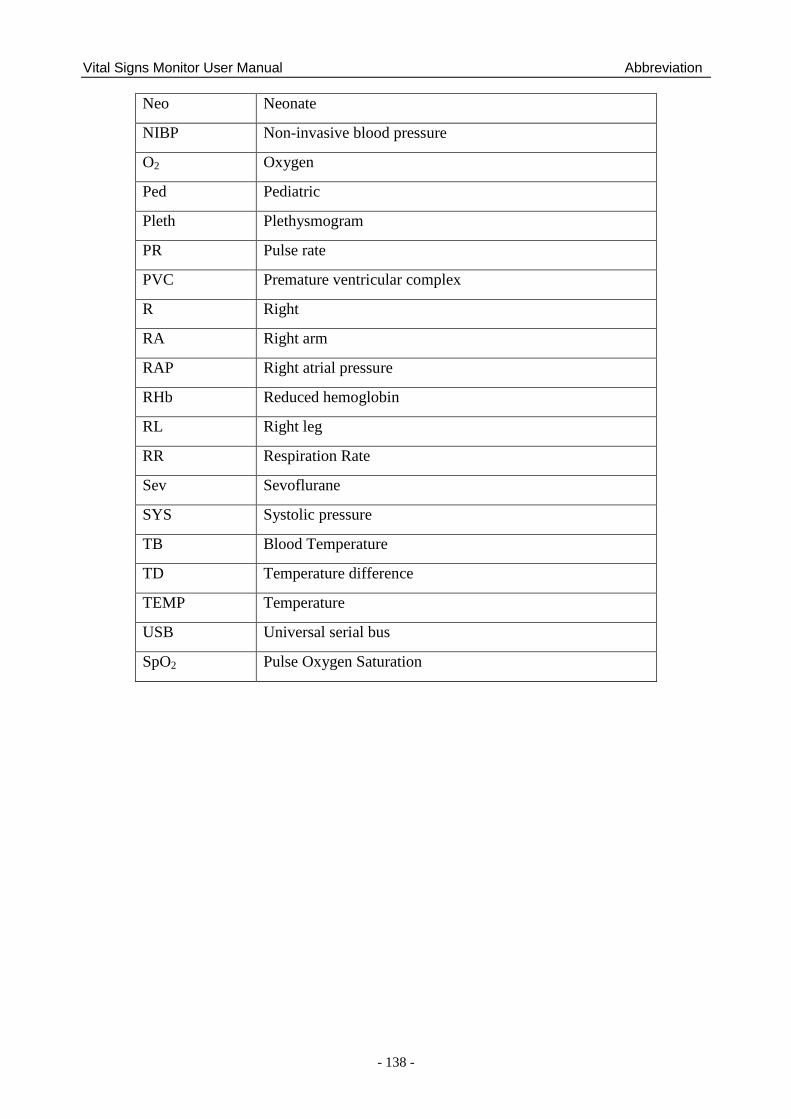
Vital Signs Monitor User Manual Abbreviation
- 138 -
Neo Neonate
NIBP Non-invasive blood pressure
O2 Oxygen
Ped Pediatric
Pleth Plethysmogram
PR Pulse rate
PVC Premature ventricular complex
R Right
RA Right arm
RAP Right atrial pressure
RHb Reduced hemoglobin
RL Right leg
RR Respiration Rate
Sev Sevoflurane
SYS Systolic pressure
TB Blood Temperature
TD Temperature difference
TEMP Temperature
USB Universal serial bus
SpO2 Pulse Oxygen Saturation