Embed Size (px)
Citation preview
arX
iv:2
007.
1340
1v3
[ee
ss.S
P] 3
Aug
202
01
IEEE 802.11be – Wi-Fi 7: New Challenges and
OpportunitiesCailian Deng*, Xuming Fang, Senior Member, IEEE, Xiao Han*, Xianbin Wang, Fellow, IEEE, Li Yan, Student
Member, IEEE, Rong He, Yan Long, Member, IEEE, and Yuchen Guo
Abstract—With the emergence of 4k/8k video, the throughputrequirement of video delivery will keep grow to tens of Gbps.Other new high-throughput and low-latency video applicationsincluding augmented reality (AR), virtual reality (VR), and onlinegaming, are also proliferating. Due to the related stringentrequirements, supporting these applications over wireless localarea network (WLAN) is far beyond the capabilities of thenew WLAN standard – IEEE 802.11ax. To meet these emergingdemands, the IEEE 802.11 will release a new amendment stan-dard IEEE 802.11be – Extremely High Throughput (EHT), alsoknown as Wireless-Fidelity (Wi-Fi) 7. This article provides thecomprehensive survey on the key medium access control (MAC)layer techniques and physical layer (PHY) techniques beingdiscussed in the EHT task group, including the channelizationand tone plan, multiple resource units (multi-RU) support,4096 quadrature amplitude modulation (4096-QAM), preambledesigns, multiple link operations (e.g., multi-link aggregationand channel access), multiple input multiple output (MIMO)enhancement, multiple access point (multi-AP) coordination (e.g.,multi-AP joint transmission), enhanced link adaptation andretransmission protocols (e.g., hybrid automatic repeat request(HARQ)). This survey covers both the critical technologies beingdiscussed in EHT standard and the related latest progresses fromworldwide research. Besides, the potential developments beyondEHT are discussed to provide some possible future researchdirections for WLAN.
Index Terms—IEEE 802.11be, EHT, Wi-Fi 7, Multi-link Op-eration, Multi-AP Coordination, MIMO Enhancement, HARQ.
I. INTRODUCTION
SINCE its adoption in 1990s, WLAN continues its growth
in market share over the years and is becoming more
and more important for providing wireless data services by
using Wi-Fi technology. Home, enterprise and hotspots are
increasingly dependent on Wi-Fi technology as their main
Manuscript received XXX XX, 2019; revised XXX XX, XX.The work of C. Deng, X. Fang, L. Yan, and R. He was supported in
part by NSFC and High-Speed Rail Joint Foundation under Grant U1834210,Sichuan Provincial Applied Basic Research Plan under Grant 2020YJ0218,and Huawei HIRP Flagship Project under Grant HF2017060002. The workof Y. Long was supported in part by NSFC under Grant 61601380. (Corre-sponding author: Xuming Fang.)
C. Deng, X. Fang, L. Yan, R. He, and Y. Long are with the KeyLaboratory of Information Coding and Transmission, Southwest JiaotongUniversity, Chengdu 611756, China (e-mail:[email protected];[email protected]; [email protected]; [email protected];[email protected]).
X. Han and Y. Guo are with the WT Laboratory, Huawei, Shenzhen 518129,China (e-mail: [email protected]; [email protected]).
X. Wang is with the Department of Electrical and Computer Engineering,University of Western Ontario, London, ON N6A 5B9, Canada (e-mail:[email protected]).
*Co-first author.
access network. According to a recent study from the Wi-
Fi Alliance [1], more than 9 billion Wi-Fi devices, including
personal computers, smartphones, televisions, tablets, sensors,
and so on, are currently in use worldwide. Video traffic is
the dominant traffic type over WLAN, and its throughput
requirement will keep increasing due to the emergence of
4k and 8k video whose uncompressed data rate is up to
20Gbps. Meanwhile, new ultra-high throughput and stringent
low-latency applications are also proliferating, such as VR
or AR, gaming (e.g., latency lower than 5ms for online
gaming), telecommuting, online video conference, and cloud
computing. While the recently released IEEE 802.11ax puts
more focus on the network performance and user experience
of the high-dense deployment scenarios, meeting the above
high-throughput and low-latency requirements is well beyond
the capabilities of IEEE 802.11ax. To meet these new needs,
IEEE 802.11 standard organization is going to release a
new amendment standard IEEE 802.11be EHT beyond IEEE
802.11ax, namely Wi-Fi 7. To be consistent with the IEEE
802.11be proposals, we mainly use the terminology “EHT”
for IEEE 802.11be in this article. IEEE 802.11 working group
has established a task group in May 2019 and specified the
scope of the new generation WLAN, i.e., enabling new PHY
and MAC modes to support a maximum throughput of at
least 30 Gbps, and using carrier frequency operation between
1 and 7.250 GHz while ensuring backward compatibility
and coexistence with legacy IEEE 802.11 devices in 2.4, 5
and 6 GHz bands [2]. To achieve these goals, challenges
of EHT have been identified and some enhanced PHY and
MAC technologies have been explored as potential solutions
to overcome these challenges.
A. PHY Enhancements for EHT
1) Providing expanded bandwidth of more than 160 MHz:
Due to the limited and crowded unlicensed spectra in 2.4
GHz and 5 GHz, the existing 802.11 WLANs (e.g., IEEE
802.11ax [3]) will inevitably suffer from low Quality of
Service (QoS) when running new emerging applications, such
as VR/AR. To fulfill the promise of a maximum throughput
of at least 30 Gbps, EHT is envisioned to add new bandwidth
modes including contiguous 240 MHz, noncontiguous 160+80
MHz, contiguous 320 MHz and noncontiguous 160+160 MHz
[4]. Nevertheless, the channelization and tone plan for these
new bandwidth modes are still under discussion, such as
whether 240 MHz/160+80 MHz is formed by puncturing at
320/160+160 MHz, repeating the IEEE 802.11ax tone plan or
2
Interaction or cross-layer design between two protocol layers
RLC
PDCP
PHY
Channelization and Tone
Plan
Multi-RU Support
EHT Preamble Design and
Preamble Puncturing
4096-QAM Support
PHY
Channelization and Tone
Plan
Multi-RU Support
EHT Preamble Design and
Preamble Puncturing
4096-QAM Support
MAC
Multi-link Operation
Multi-AP Coordination
Other MAC-related Issues
MIMO Enhancement
HARQ
MAC
Multi-link Operation
Multi-AP Coordination
Other MAC-related Issues
MIMO Enhancement
HARQ
Sub-MAC
Channel Access Based on
One Primary Channel
Channel Access Based on
Multiple Primary Channels
Temporary Primary
Channel Access
Primary Channel Access
Independently
Fast Switching
Between Multi-
link
Dedicated
Control Link
Synchronized/
Asynchronized
Multi-link
Multi-link Transmission
Multi-link Channel Access
United MAC for Multi-link Aggregation
Implicit
Enhancement
ϕ Only FeedbackTime Domain
Channel
Feedback
Differential Given s Rotation
Variable Angle Quantization
Multiple Component
Feedback
Finite
Feedback
Two-way Channel
Sounding
Enhanced Explicit/Implicit Feedback
Implicit
Enhancement
ϕ Only FeedbackTime Domain
Channel
Feedback
Differential Given s Rotation
Variable Angle Quantization
Multiple Component
Feedback
Finite
Feedback
Two-way Channel
Sounding
Enhanced Explicit/Implicit Feedback
Sub-MAC
Channel Access Based on
One Primary Channel
Channel Access Based on
Multiple Primary Channels
Temporary Primary
Channel Access
Primary Channel Access
Independently
Fast Switching
Between Multi-
link
Dedicated
Control Link
Synchronized/
Asynchronized
Multi-link
Multi-link Transmission
Multi-link Channel Access
United MAC for Multi-link Aggregation
Implicit
Enhancement
ϕ Only FeedbackTime Domain
Channel
Feedback
Differential Given s Rotation
Variable Angle Quantization
Multiple Component
Feedback
Finite
Feedback
Two-way Channel
Sounding
Enhanced Explicit/Implicit Feedback
Sub-MAC
HARQ at A-MPDU Level HARQ at MPDU Level
Chase Combining
(CC)
Incremental
Redundancy(IR)
Punctured CC
(PCC)
HARQ Granularity/Process/Method
HARQ at Codeword (CW) Level
HARQ at A-MPDU Level HARQ at MPDU Level
Chase Combining
(CC)
Incremental
Redundancy(IR)
Punctured CC
(PCC)
HARQ Granularity/Process/Method
HARQ at Codeword (CW) Level
Coordinated OFDMA
(C-OFDMA)
Coordinated Beamforming
(CBF)
Joint Transmission (JXT)Coordinated Spatial Reuse
(CSR)
Multi-AP Transmission
Coordinated OFDMA
(C-OFDMA)
Coordinated Beamforming
(CBF)
Joint Transmission (JXT)Coordinated Spatial Reuse
(CSR)
Multi-AP Transmission
Explicit Multi-AP Sounding Implicit Multi-AP Sounding
Multi-AP Sounding
Coordinated OFDMA
(C-OFDMA)
Coordinated Beamforming
(CBF)
Joint Transmission (JXT)Coordinated Spatial Reuse
(CSR)
Multi-AP Transmission
Explicit Multi-AP Sounding Implicit Multi-AP Sounding
Multi-AP Sounding
Power
Management
Hybrid
Beamforming
Coexistence in the 6 GHz
Band
Integrating Low and High-
frequency Bands
Guaranteed QoS provisioning
Based on Machine Learning
New Research Directions
Power
Management
Hybrid
Beamforming
Coexistence in the 6 GHz
Band
Integrating Low and High-
frequency Bands
Guaranteed QoS provisioning
Based on Machine Learning
New Research Directions
Sub-MAC
HARQ at A-MPDU Level HARQ at MPDU Level
Chase Combining
(CC)
Incremental
Redundancy(IR)
Punctured CC
(PCC)
HARQ Granularity/Process/Method
HARQ at Codeword (CW) Level
Coordinated OFDMA
(C-OFDMA)
Coordinated Beamforming
(CBF)
Joint Transmission (JXT)Coordinated Spatial Reuse
(CSR)
Multi-AP Transmission
Explicit Multi-AP Sounding Implicit Multi-AP Sounding
Multi-AP Sounding
Power
Management
Hybrid
Beamforming
Coexistence in the 6 GHz
Band
Integrating Low and High-
frequency Bands
Guaranteed QoS provisioning
Based on Machine Learning
New Research Directions
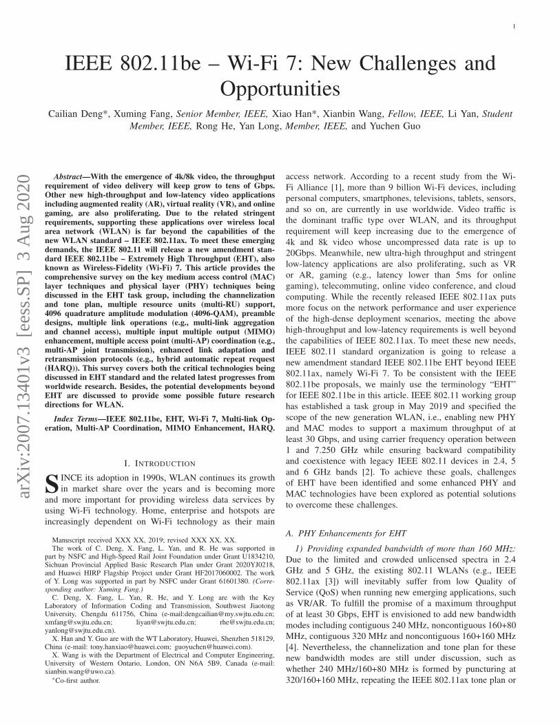
Fig. 1. Overview of the related technologies covered in this survey and their relationships.
defining a new tone plan for 160+160 MHz/320 MHz. Besides,
EHT is supposed to design effective methods to improve the
spectrum utilization of wideband and non-contiguous band-
width.
2) Supporting multi-RU assignment to a single user (SU):
In IEEE 802.11ax, each user is only assigned to a specific RU
for transmitting or receiving frames, which significantly limits
the flexibility of the spectrum resource scheduling. To solve
this problem and further enhance the spectral efficiency, the
motion of allowing multi-RU assignment to a single user has
been approved in the EHT task group [4]. However, the related
technical details are still pending in EHT, including multi-RU
assignments, multi-RU combinations, coding and interleaving
schemes for multi-RU, and signaling designs, and therefore
more efforts in dealing with the relevant multi-RU issues are
needed to realize the standardization of multi-RU in EHT.
3) Introducing 4096-QAM for the peak data rate improve-
ment: The available highest-order modulation scheme of IEEE
802.11ax is 1024-QAM, where a modulated symbol carries
10 bits. To further improve the peak rate, 4096-QAM has
been recommended for EHT to enable a modulated symbol
to carry 12 bits. Therefore, given the same coding rate, EHT
can gain a 20% increase in data rate compared to 1024-QAM .
Nevertheless, feasible configurations for 4096-QAM, such as
coding strategies, the number of streams, error vector mag-
nitude (EVM) requirements and multiple receiving antennas,
still need to be explored and clarified for SU transmission and
multi-user (MU) transmission modes.
4) Providing efficient preamble formats and puncturing
mechanisms: Until EHT, different preamble formats have been
introduced in each generation of WLAN standards, which
can enable functions including synchronization, automatic gain
control, time/frequency correction, channel estimation, auto-
detection to differentiate the version of a physical protocol data
unit (PPDU) and necessary signaling (e.g., resource allocation
information), etc. According to the PAR [5], the EHT preamble
design should ensure backward compatibility and coexistence
with legacy PPDUs transmitted on 2.4 GHz, 5 GHz, and 6 GHz
bands. Besides, bringing future compatibility to preambles
starting with EHT was proposed in [6]. Since in EHT many
new features like multi-RU and MU-MIMO are still being
considered, formats and details of the preamble for supporting
different technologies and scenarios are still pending. By
bonding channels in a non-continuous way, the new preamble
puncturing in IEEE 802.11ax allows a Wi-Fi device to transmit
the MU PPDU over the entire bandwidth (e.g., 80 MHz,
80+80 MHz or 160 MHz) except for the punctured preamble
part. However, due to the absence of the SIG-B field and the
puncturing-related signaling in the preamble in the SU PPDU,
the SU PPDU is not allowed to employ preamble puncturing
and must be transmitted over the entire available contiguous
bandwidth. Thus, in EHT, there may be a need to improve the
puncturing design for the MU PPDU and add the puncturing
design for the SU PPDU.
B. MAC Enhancement for EHT
1) Multi-link operation over dramatically increased band-
width: Due to the limited and crowded unlicensed spectra
in 2.4 GHz and 5 GHz, the existing IEEE 802.11 WLANs
(e.g., IEEE 802.11ax) suffer low QoS to serve new emerging
3
application use cases, such as VR/AR. To fulfill the promise
of a maximum throughput of at least 30 Gbps, EHT expands
its bandwidth by multi-band aggregation across 2.4 GHz, 5
GHz and 6 GHz bands, gaining up to 320 MHz bandwidth.
However, challenges such as channel frequency selectivity
over a much broader and noncontiguous bandwidth, different
types of multi-band operations and backward compatibility
and coexistence with existing legacy STAs in 2.4 GHz, 5 GHz
and 6 GHz bands will arise when multi-band aggregation is
performed. In the legacy multi-band operations (e.g., fast ses-
sion transfer (FST) [7]), there is a limitation that MAC service
data units (MSDUs) belonging to a single traffic identification
(TID) can only use single band, resulting in significant MAC
overheads for session transfer. Thus, to improve the transmis-
sion flexibility and minimize the MAC overhead, the existing
MAC models may need a major improvement in EHT, that
is, an STA can transmit frames of the same TID or different
TIDs over multiple bands concurrently or non-concurrently.
For such MAC enhancement, the terminology “multi-kink”
used in EHT is preferred over the “multi-band” [8]. However,
to standardize multi-link support in EHT, discussions and
efforts on multi-link architecture, operation, and functions still
need to continue.
2) Supporting increased spatial streams and MIMO en-
hancements: To meet the growing traffic demands generated
by the increasing number of Wi-Fi devices, APs have con-
tinued to increase the number of antennas and better spatial
multiplexing capabilities over the recent years. Currently, in
IEEE 802.11ax [3], an AP equipped with 8 antennas can
simultaneously serve up to 8 users for uplink (UL)/downlink
(DL) transmission, through MU-MIMO. Continuing the trend
of upgrading AP’s spatial multiplexing capability, EHT rec-
ommends the maximum spatial streams of 16 to gain higher
network capacity. However, increasing the number of spatial
streams comes with an attendant increase in the overhead of
acquiring CSI (channel state information). With 16 spatial
streams in EHT, reusing the same channel sounding method
specified in the current IEEE 802.11ax will result in the
enormous CSI feedback overhead. For this reason, EHT needs
to improve existing explicit and implicit feedback schemes for
overhead reduction or develop completely new CSI feedback
schemes.
3) Distributed operations among neighboring APs: IEEE
802.11ax only supports transmission to/from a single AP and
spatial reuse between APs and STAs without coordination
among neighboring APs. As a result, its capability to utilize
the flexibility of time, frequency and spatial resources is sig-
nificantly limited. To improve this, EHT extends its capability
to support sharing data and control information among APs
via wired or wireless links, thus improving the spectrum
efficiency, increasing the peak throughput and reducing the
latency. This major feature differentiating EHT from IEEE
802.11ax is referred to as multi-AP coordination, which can
be divided into coordinated spatial reuse (CSR), coordinated
orthogonal frequency-division multiple access (C-OFDMA),
coordinated beamforming (CBF) and joint transmission (JXT)
according to different coordination complexity. The selection
of multi-AP transmission modes is based on the scenario
requirements. In a typical multi-AP network architecture (e.g.,
enterprise network) without a central node, an AP has to
communicate with each neighboring AP for coordination,
which will result in substantial signaling overhead and process-
ing complexity. Therefore, an efficient coordination procedure
(including the multi-AP sounding, the multi-AP selection and
multi-AP transmission) with low overhead and processing
complexity is needed to support all types of multi-AP co-
ordination. Besides, precise phase/time synchronization and
proper resource allocation functions are crucial to avoid mutual
interference between neighboring APs, as imperfect synchro-
nization may cause peak throughput degradation significantly.
4) Enhanced link adaptation and retransmission mecha-
nism: Transmission reliability is also another major concern
for EHT. Current IEEE 802.11 systems rely on the retrans-
mission of MAC protocol data unit (MPDU) (s) to ensure
transmission reliability in randomly varying and error-prone
wireless channels. In the automatic repeat request (ARQ)
protocol, the receiver simply discards the erroneous MPDU(s)
before receiving its retransmitted MPDU(s). With the re-
quirement on higher reliability and lower latency, HARQ is
expected to implement in EHT, which enables soft combining
or additional parity at the receiver to improve the likelihood
of correct decoding. Unlike ARQ, in HARQ, the receiver will
store incorrectly decoded packets and combine them with sub-
sequent retransmissions before decoding. Nevertheless, several
issues regarding implementation of HARQ in the 802.11-like
system are raised, including retransmission granularity (e.g.,
Aggregate MPDU (A-MPDU), MPDU or codeword (CW)),
HARQ process, HARQ method (e.g., chase combining (CC)
or incremental redundancy (IR)), link adaptation methods for
higher HARQ gains and so on. How and at which layer
HARQ can be better supported as well as what changes
would be necessary at the PHY and MAC layer are extremely
challenging for EHT.
The authors of this article are involved in the research
and design of the EHT standards. To provide the compre-
hensive understanding of the EHT standardization activities to
the readers, this article investigates the latest standardization
progress of EHT during the task group phase as well as the
new progress of the related academic studies. To the best of our
knowledge, there is the first survey work on the development
of the EHT technical specifications during the task group
phase. A valuable article [9] has surveyed the candidate tech-
nical features discussed in the EHT fora during the initial topic
interest group and study group phases, provided system-level
simulation results to evaluate the potential throughput gains,
and discussed the coexistence issues with other technologies
operating in the 6 GHz band. In this article, we focus on
investigating what the corresponding techniques and solutions
are proposed in the EHT task group to improve the network
performance. To illustrate the structural relationship between
each section of this article, Fig. 1 provides an overview of
the survey. This article doesn’t intend to cover the packet
data convergence protocol (PDCP) layer and radio link control
(RLC) layer, but focus its attention on new features in both
PHY and MAC layers for EHT. As we can see in Fig. 1, the
new important PHY related techniques for EHT are included,
4
New Modulation Level [24]
· 4096-QAM
New Bandwidth Mode
[10]-[13]· Channelization and tone plan for
wider bandwidth: 240/160+80
MHz and 320/160+160 MHz
Multi-RU Support
[4][14][15]· Small-size RU and large-size RU
· Multi-RU combinations
Enhanced Preamble Design
[4][16]-[23]· EHT SU PPDU
· EHT MU PPDU
· Preamble puncturing design
EHT PHY
Enhancement· to increase peak throughput
and improve efficiency
· to support high throughput
and low latency applications
such as video, gaming, AR
and VR
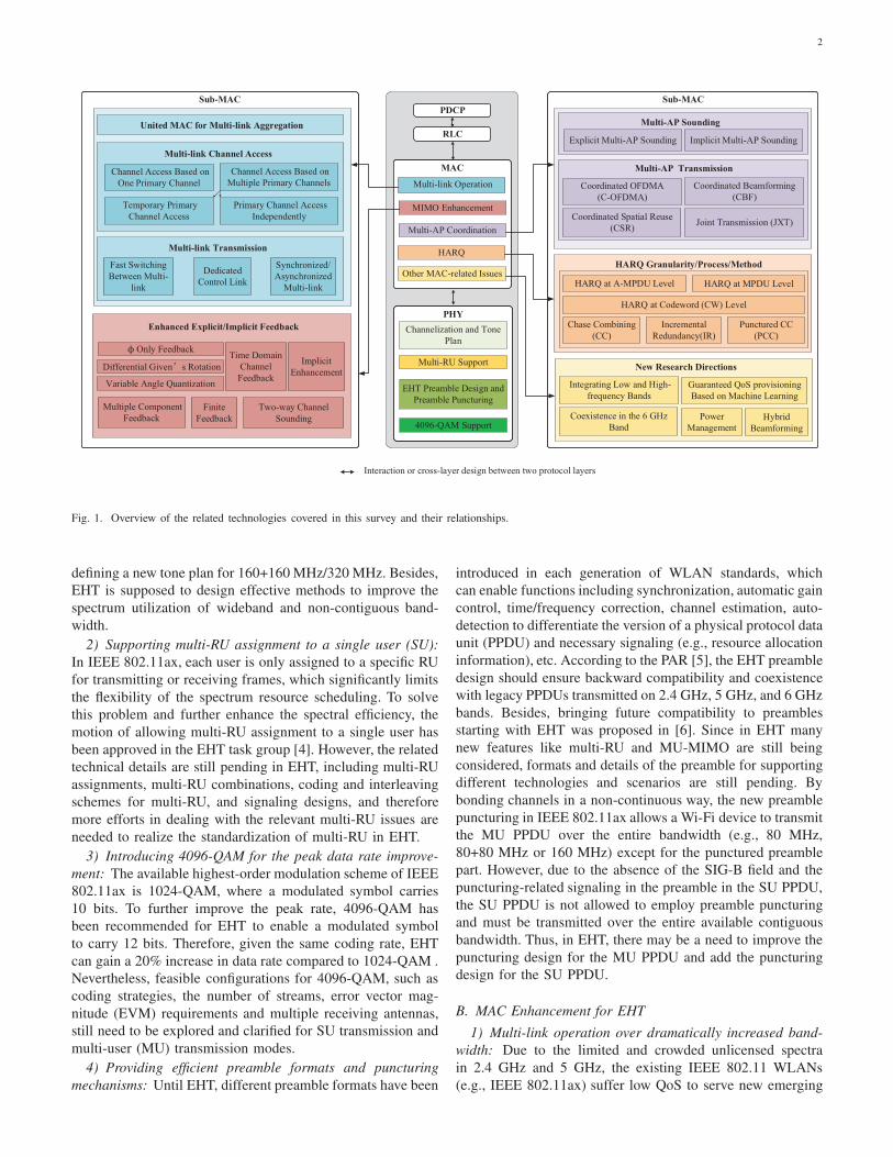
Fig. 2. Key PHY enhancements for EHT.
5GHz New additional 6GHz (5.925GHz-7.125GHz(US))
20/40/80/160MHz Frequency band80/160/320MHz
2.4GHz
20/40MHz
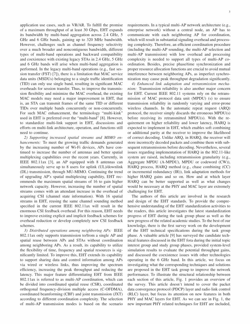
Fig. 3. Available transmission bandwidth over 2.4 GHz, 5 GHz and 6 GHz frequency bands. In the 2.4 GHz band, IEEE 802.11n devices are allowed totransmit in a 40 MHz channel by aggregating two adjacent 20 MHz channels into a single 40 MHz channel. To support high-speed wireless communicationdemands, IEEE 802.11ac/IEEE 802.11ax introduced the capability of extending the number of basic channels, thereby allowing mobile devices to transmitover an 80 MHz/160 MHz channel in the 5 GHz band. In the 6 GHz band, more than 1 GHz of additional unlicensed spectrum is available, allowing mobiledevices to transmit in bandwidths up to 320 MHz.
namely, channelization and tone plan, multi-RU support, 4096-
QAM, preamble design and preamble puncturing. For the
MAC related techniques, we mainly introduce multi-link op-
erations, MIMO enhancement, multi-AP coordination, and
HARQ. Besides, we put forward some new research directions
and viewpoints beyond EHT for promoting the development
of wireless communication networks.
The remainder of this article is organized as follows:
Section II presents the key PHY enhancement techniques.
Section III-VII focus on MAC enhancements and cross-layer
techniques between PHY and MAC layer. Specifically, Section
III presents multi-link aggregation and operations. Section
IV emphasizes on MIMO enhancement. Section V describes
multi-AP coordination technologies. Section VI provides en-
hanced link adaptation and retransmission protocols. Section
VII introduces potential perspectives beyond EHT. Finally,
Section VIII concludes this article.
For presentation clarity, technical terms and acronyms used
repeatedly in this article are listed alphabetically in Appendix
A.
II. PHY ENHANCEMENTS FOR EHT
To support high-throughput and low-latency video appli-
cations such as AR, VR and online gaming, EHT introduces
several PHY enhancement technologies shown in Fig. 2, which
enables the EHT to achieve an ultra-high peak rate of up
to 30 Gbps. And PHY enhancements and related works are
summarised in Table I.
(1) Wider bandwidth modes including 320 MHz, 160+160
MHz, 240 MHz and 160+80 MHz, have been identified as one
of the candidate features in capacity augments for EHT.
(2) Multi-RU assigned to a single user is supported to
enhance the spectral efficiency in EHT.
(3) EHT recommends new higher-order modulation strate-
gies, namely 4096-QAM, to further increase the peak rate
compared to 1024-QAM adopted in IEEE 802.11ax.
(4) Two EHT preamble formats are being considered for
EHT SU PPDU and EHT MU PPDU, respectively. To improve
the spectral efficiency, EHT PHY is also supposed to adopt
a new preamble puncturing mechanism for an EHT PPDU
transmitted to one or more STAs.
5
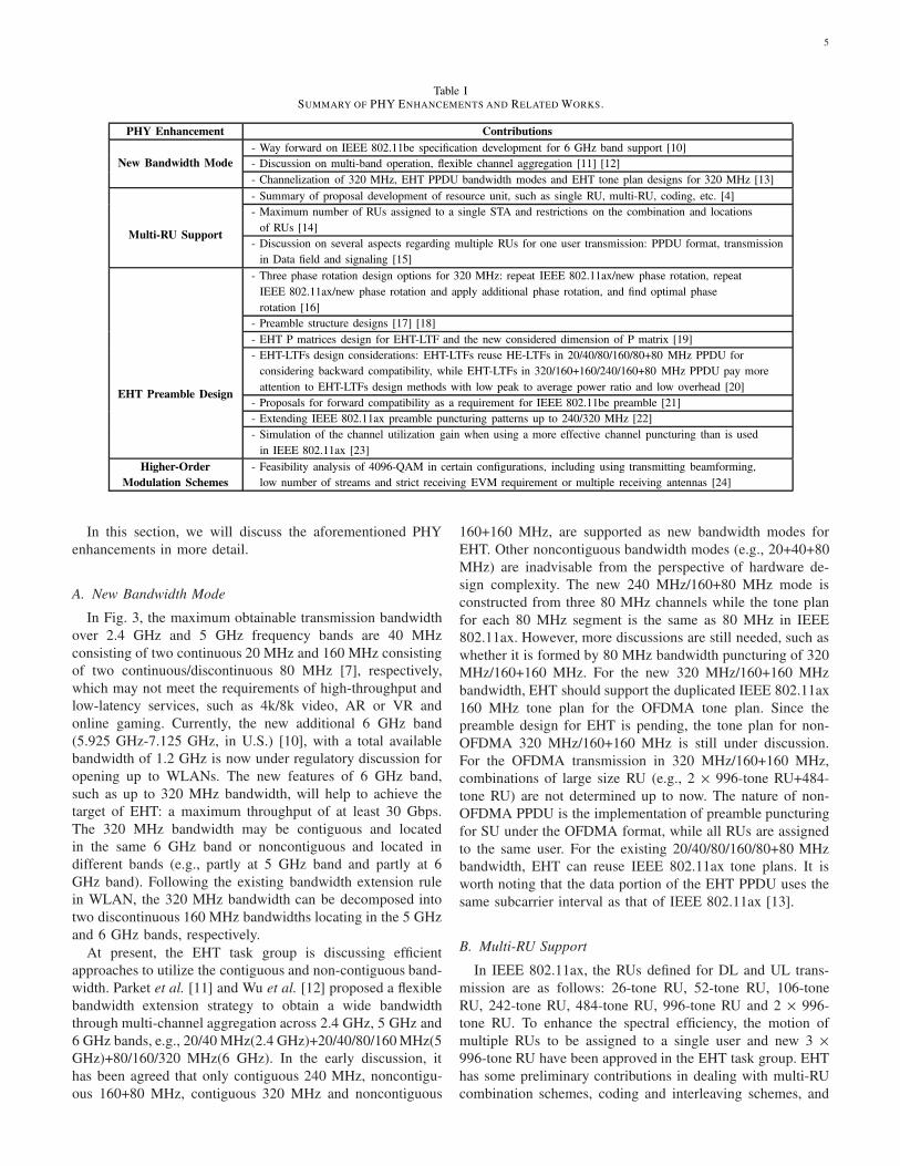
Table ISUMMARY OF PHY ENHANCEMENTS AND RELATED WORKS.
PHY Enhancement Contributions
- Way forward on IEEE 802.11be specification development for 6 GHz band support [10]
- Discussion on multi-band operation, flexible channel aggregation [11] [12]New Bandwidth Mode
- Channelization of 320 MHz, EHT PPDU bandwidth modes and EHT tone plan designs for 320 MHz [13]
- Summary of proposal development of resource unit, such as single RU, multi-RU, coding, etc. [4]
- Maximum number of RUs assigned to a single STA and restrictions on the combination and locations
of RUs [14]Multi-RU Support
- Discussion on several aspects regarding multiple RUs for one user transmission: PPDU format, transmission
in Data field and signaling [15]
- Three phase rotation design options for 320 MHz: repeat IEEE 802.11ax/new phase rotation, repeat
IEEE 802.11ax/new phase rotation and apply additional phase rotation, and find optimal phase
rotation [16]
- Preamble structure designs [17] [18]
- EHT P matrices design for EHT-LTF and the new considered dimension of P matrix [19]
- EHT-LTFs design considerations: EHT-LTFs reuse HE-LTFs in 20/40/80/160/80+80 MHz PPDU for
considering backward compatibility, while EHT-LTFs in 320/160+160/240/160+80 MHz PPDU pay more
attention to EHT-LTFs design methods with low peak to average power ratio and low overhead [20]
- Proposals for forward compatibility as a requirement for IEEE 802.11be preamble [21]
- Extending IEEE 802.11ax preamble puncturing patterns up to 240/320 MHz [22]
EHT Preamble Design
- Simulation of the channel utilization gain when using a more effective channel puncturing than is used
in IEEE 802.11ax [23]
Higher-Order
Modulation Schemes
- Feasibility analysis of 4096-QAM in certain configurations, including using transmitting beamforming,
low number of streams and strict receiving EVM requirement or multiple receiving antennas [24]
In this section, we will discuss the aforementioned PHY
enhancements in more detail.
A. New Bandwidth Mode
In Fig. 3, the maximum obtainable transmission bandwidth
over 2.4 GHz and 5 GHz frequency bands are 40 MHz
consisting of two continuous 20 MHz and 160 MHz consisting
of two continuous/discontinuous 80 MHz [7], respectively,
which may not meet the requirements of high-throughput and
low-latency services, such as 4k/8k video, AR or VR and
online gaming. Currently, the new additional 6 GHz band
(5.925 GHz-7.125 GHz, in U.S.) [10], with a total available
bandwidth of 1.2 GHz is now under regulatory discussion for
opening up to WLANs. The new features of 6 GHz band,
such as up to 320 MHz bandwidth, will help to achieve the
target of EHT: a maximum throughput of at least 30 Gbps.
The 320 MHz bandwidth may be contiguous and located
in the same 6 GHz band or noncontiguous and located in
different bands (e.g., partly at 5 GHz band and partly at 6
GHz band). Following the existing bandwidth extension rule
in WLAN, the 320 MHz bandwidth can be decomposed into
two discontinuous 160 MHz bandwidths locating in the 5 GHz
and 6 GHz bands, respectively.
At present, the EHT task group is discussing efficient
approaches to utilize the contiguous and non-contiguous band-
width. Parket et al. [11] and Wu et al. [12] proposed a flexible
bandwidth extension strategy to obtain a wide bandwidth
through multi-channel aggregation across 2.4 GHz, 5 GHz and
6 GHz bands, e.g., 20/40 MHz(2.4 GHz)+20/40/80/160 MHz(5
GHz)+80/160/320 MHz(6 GHz). In the early discussion, it
has been agreed that only contiguous 240 MHz, noncontigu-
ous 160+80 MHz, contiguous 320 MHz and noncontiguous
160+160 MHz, are supported as new bandwidth modes for
EHT. Other noncontiguous bandwidth modes (e.g., 20+40+80
MHz) are inadvisable from the perspective of hardware de-
sign complexity. The new 240 MHz/160+80 MHz mode is
constructed from three 80 MHz channels while the tone plan
for each 80 MHz segment is the same as 80 MHz in IEEE
802.11ax. However, more discussions are still needed, such as
whether it is formed by 80 MHz bandwidth puncturing of 320
MHz/160+160 MHz. For the new 320 MHz/160+160 MHz
bandwidth, EHT should support the duplicated IEEE 802.11ax
160 MHz tone plan for the OFDMA tone plan. Since the
preamble design for EHT is pending, the tone plan for non-
OFDMA 320 MHz/160+160 MHz is still under discussion.
For the OFDMA transmission in 320 MHz/160+160 MHz,
combinations of large size RU (e.g., 2 × 996-tone RU+484-
tone RU) are not determined up to now. The nature of non-
OFDMA PPDU is the implementation of preamble puncturing
for SU under the OFDMA format, while all RUs are assigned
to the same user. For the existing 20/40/80/160/80+80 MHz
bandwidth, EHT can reuse IEEE 802.11ax tone plans. It is
worth noting that the data portion of the EHT PPDU uses the
same subcarrier interval as that of IEEE 802.11ax [13].
B. Multi-RU Support
In IEEE 802.11ax, the RUs defined for DL and UL trans-
mission are as follows: 26-tone RU, 52-tone RU, 106-tone
RU, 242-tone RU, 484-tone RU, 996-tone RU and 2 × 996-
tone RU. To enhance the spectral efficiency, the motion of
multiple RUs to be assigned to a single user and new 3 ×
996-tone RU have been approved in the EHT task group. EHT
has some preliminary contributions in dealing with multi-RU
combination schemes, coding and interleaving schemes, and
6
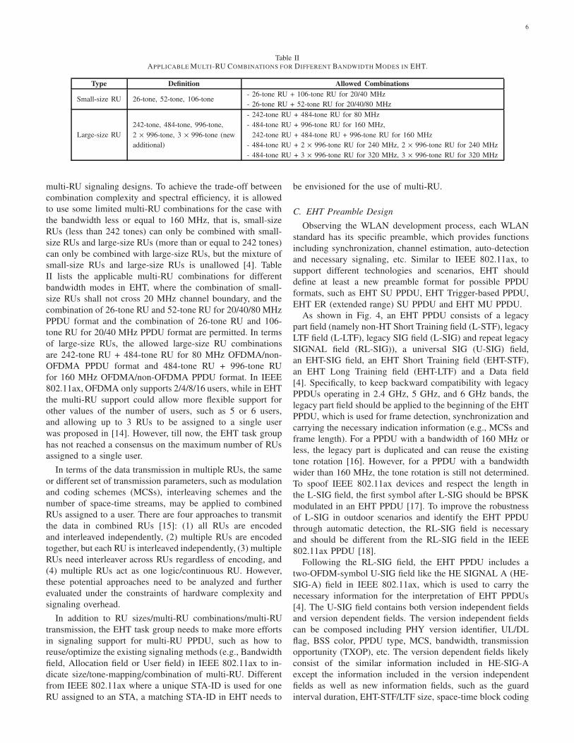
Table IIAPPLICABLE MULTI-RU COMBINATIONS FOR DIFFERENT BANDWIDTH MODES IN EHT.
Type Definition Allowed Combinations
Small-size RU 26-tone, 52-tone, 106-tone- 26-tone RU + 106-tone RU for 20/40 MHz
- 26-tone RU + 52-tone RU for 20/40/80 MHz
Large-size RU
242-tone, 484-tone, 996-tone,
2 × 996-tone, 3 × 996-tone (new
additional)
- 242-tone RU + 484-tone RU for 80 MHz
- 484-tone RU + 996-tone RU for 160 MHz,
242-tone RU + 484-tone RU + 996-tone RU for 160 MHz
- 484-tone RU + 2 × 996-tone RU for 240 MHz, 2 × 996-tone RU for 240 MHz
- 484-tone RU + 3 × 996-tone RU for 320 MHz, 3 × 996-tone RU for 320 MHz
multi-RU signaling designs. To achieve the trade-off between
combination complexity and spectral efficiency, it is allowed
to use some limited multi-RU combinations for the case with
the bandwidth less or equal to 160 MHz, that is, small-size
RUs (less than 242 tones) can only be combined with small-
size RUs and large-size RUs (more than or equal to 242 tones)
can only be combined with large-size RUs, but the mixture of
small-size RUs and large-size RUs is unallowed [4]. Table
II lists the applicable multi-RU combinations for different
bandwidth modes in EHT, where the combination of small-
size RUs shall not cross 20 MHz channel boundary, and the
combination of 26-tone RU and 52-tone RU for 20/40/80 MHz
PPDU format and the combination of 26-tone RU and 106-
tone RU for 20/40 MHz PPDU format are permitted. In terms
of large-size RUs, the allowed large-size RU combinations
are 242-tone RU + 484-tone RU for 80 MHz OFDMA/non-
OFDMA PPDU format and 484-tone RU + 996-tone RU
for 160 MHz OFDMA/non-OFDMA PPDU format. In IEEE
802.11ax, OFDMA only supports 2/4/8/16 users, while in EHT
the multi-RU support could allow more flexible support for
other values of the number of users, such as 5 or 6 users,
and allowing up to 3 RUs to be assigned to a single user
was proposed in [14]. However, till now, the EHT task group
has not reached a consensus on the maximum number of RUs
assigned to a single user.
In terms of the data transmission in multiple RUs, the same
or different set of transmission parameters, such as modulation
and coding schemes (MCSs), interleaving schemes and the
number of space-time streams, may be applied to combined
RUs assigned to a user. There are four approaches to transmit
the data in combined RUs [15]: (1) all RUs are encoded
and interleaved independently, (2) multiple RUs are encoded
together, but each RU is interleaved independently, (3) multiple
RUs need interleaver across RUs regardless of encoding, and
(4) multiple RUs act as one logic/continuous RU. However,
these potential approaches need to be analyzed and further
evaluated under the constraints of hardware complexity and
signaling overhead.
In addition to RU sizes/multi-RU combinations/multi-RU
transmission, the EHT task group needs to make more efforts
in signaling support for multi-RU PPDU, such as how to
reuse/optimize the existing signaling methods (e.g., Bandwidth
field, Allocation field or User field) in IEEE 802.11ax to in-
dicate size/tone-mapping/combination of multi-RU. Different
from IEEE 802.11ax where a unique STA-ID is used for one
RU assigned to an STA, a matching STA-ID in EHT needs to
be envisioned for the use of multi-RU.
C. EHT Preamble Design
Observing the WLAN development process, each WLAN
standard has its specific preamble, which provides functions
including synchronization, channel estimation, auto-detection
and necessary signaling, etc. Similar to IEEE 802.11ax, to
support different technologies and scenarios, EHT should
define at least a new preamble format for possible PPDU
formats, such as EHT SU PPDU, EHT Trigger-based PPDU,
EHT ER (extended range) SU PPDU and EHT MU PPDU.
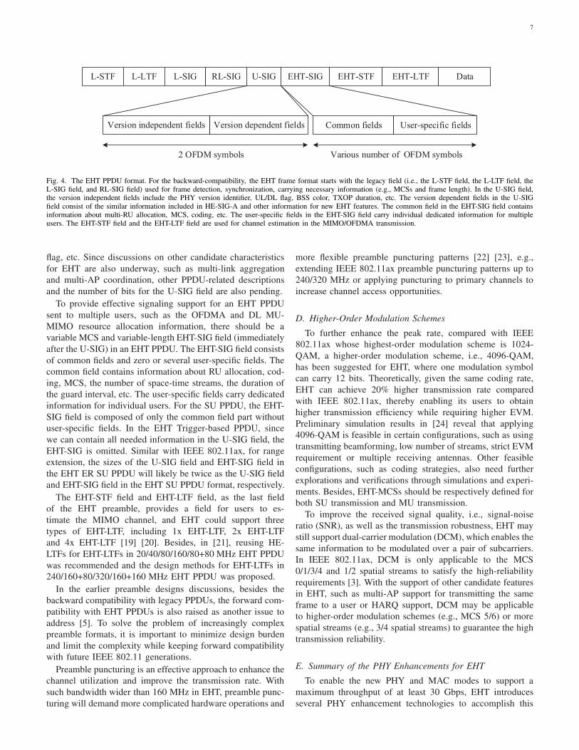
As shown in Fig. 4, an EHT PPDU consists of a legacy
part field (namely non-HT Short Training field (L-STF), legacy
LTF field (L-LTF), legacy SIG field (L-SIG) and repeat legacy
SIGNAL field (RL-SIG)), a universal SIG (U-SIG) field,
an EHT-SIG field, an EHT Short Training field (EHT-STF),
an EHT Long Training field (EHT-LTF) and a Data field
[4]. Specifically, to keep backward compatibility with legacy
PPDUs operating in 2.4 GHz, 5 GHz, and 6 GHz bands, the
legacy part field should be applied to the beginning of the EHT
PPDU, which is used for frame detection, synchronization and
carrying the necessary indication information (e.g., MCSs and
frame length). For a PPDU with a bandwidth of 160 MHz or
less, the legacy part is duplicated and can reuse the existing
tone rotation [16]. However, for a PPDU with a bandwidth
wider than 160 MHz, the tone rotation is still not determined.
To spoof IEEE 802.11ax devices and respect the length in
the L-SIG field, the first symbol after L-SIG should be BPSK
modulated in an EHT PPDU [17]. To improve the robustness
of L-SIG in outdoor scenarios and identify the EHT PPDU
through automatic detection, the RL-SIG field is necessary
and should be different from the RL-SIG field in the IEEE
802.11ax PPDU [18].
Following the RL-SIG field, the EHT PPDU includes a
two-OFDM-symbol U-SIG field like the HE SIGNAL A (HE-
SIG-A) field in IEEE 802.11ax, which is used to carry the
necessary information for the interpretation of EHT PPDUs
[4]. The U-SIG field contains both version independent fields
and version dependent fields. The version independent fields
can be composed including PHY version identifier, UL/DL
flag, BSS color, PPDU type, MCS, bandwidth, transmission
opportunity (TXOP), etc. The version dependent fields likely
consist of the similar information included in HE-SIG-A
except the information included in the version independent
fields as well as new information fields, such as the guard
interval duration, EHT-STF/LTF size, space-time block coding
7
L-STF L-LTF L-SIG RL-SIG U-SIG EHT-LTF DataEHT-SIG EHT-STF
Version independent fields Version dependent fields Common fields User-specific fields
2 OFDM symbols Various number of OFDM symbols
Fig. 4. The EHT PPDU format. For the backward-compatibility, the EHT frame format starts with the legacy field (i.e., the L-STF field, the L-LTF field, theL-SIG field, and RL-SIG field) used for frame detection, synchronization, carrying necessary information (e.g., MCSs and frame length). In the U-SIG field,the version independent fields include the PHY version identifier, UL/DL flag, BSS color, TXOP duration, etc. The version dependent fields in the U-SIGfield consist of the similar information included in HE-SIG-A and other information for new EHT features. The common field in the EHT-SIG field containsinformation about multi-RU allocation, MCS, coding, etc. The user-specific fields in the EHT-SIG field carry individual dedicated information for multipleusers. The EHT-STF field and the EHT-LTF field are used for channel estimation in the MIMO/OFDMA transmission.
flag, etc. Since discussions on other candidate characteristics
for EHT are also underway, such as multi-link aggregation
and multi-AP coordination, other PPDU-related descriptions
and the number of bits for the U-SIG field are also pending.
To provide effective signaling support for an EHT PPDU
sent to multiple users, such as the OFDMA and DL MU-
MIMO resource allocation information, there should be a
variable MCS and variable-length EHT-SIG field (immediately
after the U-SIG) in an EHT PPDU. The EHT-SIG field consists
of common fields and zero or several user-specific fields. The
common field contains information about RU allocation, cod-
ing, MCS, the number of space-time streams, the duration of
the guard interval, etc. The user-specific fields carry dedicated
information for individual users. For the SU PPDU, the EHT-
SIG field is composed of only the common field part without
user-specific fields. In the EHT Trigger-based PPDU, since
we can contain all needed information in the U-SIG field, the
EHT-SIG is omitted. Similar with IEEE 802.11ax, for range
extension, the sizes of the U-SIG field and EHT-SIG field in
the EHT ER SU PPDU will likely be twice as the U-SIG field
and EHT-SIG field in the EHT SU PPDU format, respectively.
The EHT-STF field and EHT-LTF field, as the last field
of the EHT preamble, provides a field for users to es-
timate the MIMO channel, and EHT could support three
types of EHT-LTF, including 1x EHT-LTF, 2x EHT-LTF
and 4x EHT-LTF [19] [20]. Besides, in [21], reusing HE-
LTFs for EHT-LTFs in 20/40/80/160/80+80 MHz EHT PPDU
was recommended and the design methods for EHT-LTFs in
240/160+80/320/160+160 MHz EHT PPDU was proposed.
In the earlier preamble designs discussions, besides the
backward compatibility with legacy PPDUs, the forward com-
patibility with EHT PPDUs is also raised as another issue to
address [5]. To solve the problem of increasingly complex
preamble formats, it is important to minimize design burden
and limit the complexity while keeping forward compatibility
with future IEEE 802.11 generations.
Preamble puncturing is an effective approach to enhance the
channel utilization and improve the transmission rate. With
such bandwidth wider than 160 MHz in EHT, preamble punc-
turing will demand more complicated hardware operations and
more flexible preamble puncturing patterns [22] [23], e.g.,
extending IEEE 802.11ax preamble puncturing patterns up to
240/320 MHz or applying puncturing to primary channels to
increase channel access opportunities.
D. Higher-Order Modulation Schemes
To further enhance the peak rate, compared with IEEE
802.11ax whose highest-order modulation scheme is 1024-
QAM, a higher-order modulation scheme, i.e., 4096-QAM,
has been suggested for EHT, where one modulation symbol
can carry 12 bits. Theoretically, given the same coding rate,
EHT can achieve 20% higher transmission rate compared
with IEEE 802.11ax, thereby enabling its users to obtain
higher transmission efficiency while requiring higher EVM.
Preliminary simulation results in [24] reveal that applying
4096-QAM is feasible in certain configurations, such as using
transmitting beamforming, low number of streams, strict EVM
requirement or multiple receiving antennas. Other feasible
configurations, such as coding strategies, also need further
explorations and verifications through simulations and experi-
ments. Besides, EHT-MCSs should be respectively defined for
both SU transmission and MU transmission.
To improve the received signal quality, i.e., signal-noise
ratio (SNR), as well as the transmission robustness, EHT may
still support dual-carrier modulation (DCM), which enables the
same information to be modulated over a pair of subcarriers.
In IEEE 802.11ax, DCM is only applicable to the MCS
0/1/3/4 and 1/2 spatial streams to satisfy the high-reliability
requirements [3]. With the support of other candidate features
in EHT, such as multi-AP support for transmitting the same
frame to a user or HARQ support, DCM may be applicable
to higher-order modulation schemes (e.g., MCS 5/6) or more
spatial streams (e.g., 3/4 spatial streams) to guarantee the high
transmission reliability.
E. Summary of the PHY Enhancements for EHT
To enable the new PHY and MAC modes to support a
maximum throughput of at least 30 Gbps, EHT introduces
several PHY enhancement technologies to accomplish this
8
MLMES
M
E
Multilink Management
802.1X
PHY
Lower MAC
S
M
EPHY PLME
Lower MAC
Upper MAC
(b) Distributed MAC. (c) Unified MAC.(a) Independent MAC.
PHY SAPPHY SAP
MAC SAPMAC SAP
MLME
PLME
MLMES
M
E
Multiband Management
802.1X
PHY
MAC S
M
EPHY PLME
MACMLME
PLME
MLMES
M
E
Multiband Management
802.1X
PHY
MAC S
M
EPHY PLME
MACMLME
PLME
802.1X
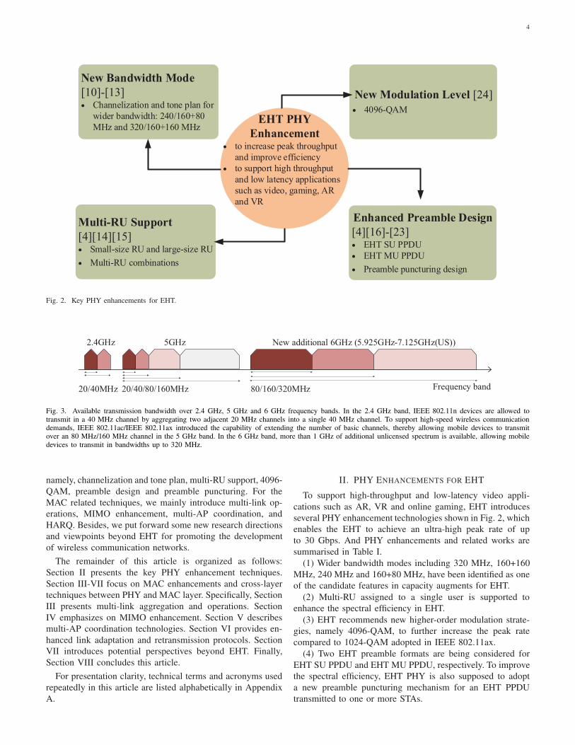
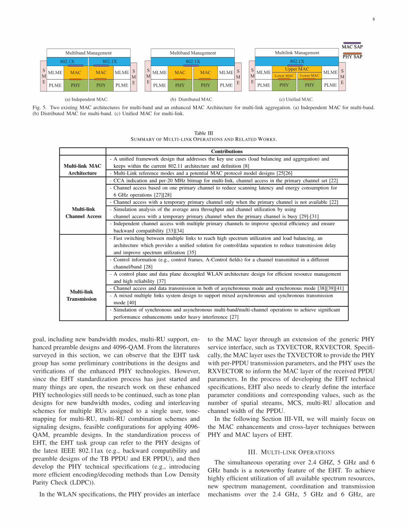
Fig. 5. Two existing MAC architectures for multi-band and an enhanced MAC Architecture for multi-link aggregation. (a) Independent MAC for multi-band.(b) Distributed MAC for multi-band. (c) Unified MAC for multi-link.
Table IIISUMMARY OF MULTI-LINK OPERATIONS AND RELATED WORKS.
Contributions
- A unified framework design that addresses the key use cases (load balancing and aggregation) and
keeps within the current 802.11 architecture and definition [8]Multi-link MAC
Architecture - Multi-Link reference modes and a potential MAC protocol model designs [25[26]
- CCA indication and per-20 MHz bitmap for multi-link, channel access in the primary channel set [22]
- Channel access based on one primary channel to reduce scanning latency and energy consumption for
6 GHz operations [27][28]
- Channel access with a temporary primary channel only when the primary channel is not available [22]
- Simulation analysis of the average area throughput and channel utilization by using
channel access with a temporary primary channel when the primary channel is busy [29]-[31]
Multi-link
Channel Access
- Independent channel access with multiple primary channels to improve spectral efficiency and ensure
backward compatibility [33][34]
- Fast switching between multiple links to reach high spectrum utilization and load balancing, an
architecture which provides a unified solution for control/data separation to reduce transmission delay
and improve spectrum utilization [35]
- Control information (e.g., control frames, A-Control fields) for a channel transmitted in a different
channel/band [28]
- A control plane and data plane decoupled WLAN architecture design for efficient resource management
and high reliability [37]
- Channel access and data transmission in both of asynchronous mode and synchronous mode [38][39][41]
- A mixed multiple links system design to support mixed asynchronous and synchronous transmission
mode [40]
Multi-link
Transmission
- Simulation of synchronous and asynchronous multi-band/multi-channel operations to achieve significant
performance enhancements under heavy interference [27]
goal, including new bandwidth modes, multi-RU support, en-
hanced preamble designs and 4096-QAM. From the literatures
surveyed in this section, we can observe that the EHT task
group has some preliminary contributions in the designs and
verifications of the enhanced PHY technologies. However,
since the EHT standardization process has just started and
many things are open, the research work on these enhanced
PHY technologies still needs to be continued, such as tone plan
designs for new bandwidth modes, coding and interleaving
schemes for multiple RUs assigned to a single user, tone-
mapping for multi-RU, multi-RU combination schemes and
signaling designs, feasible configurations for applying 4096-
QAM, preamble designs. In the standardization process of
EHT, the EHT task group can refer to the PHY designs of
the latest IEEE 802.11ax (e.g., backward compatibility and
preamble designs of the TB PPDU and ER PPDU), and then
develop the PHY technical specifications (e.g., introducing
more efficient encoding/decoding methods than Low Density
Parity Check (LDPC)).
In the WLAN specifications, the PHY provides an interface
to the MAC layer through an extension of the generic PHY
service interface, such as TXVECTOR, RXVECTOR. Specifi-
cally, the MAC layer uses the TXVECTOR to provide the PHY
with per-PPDU transmission parameters, and the PHY uses the
RXVECTOR to inform the MAC layer of the received PPDU
parameters. In the process of developing the EHT technical
specifications, EHT also needs to clearly define the interface
parameter conditions and corresponding values, such as the
number of spatial streams, MCS, multi-RU allocation and
channel width of the PPDU.
In the following Section III-VII, we will mainly focus on
the MAC enhancements and cross-layer techniques between
PHY and MAC layers of EHT.
III. MULTI-LINK OPERATIONS
The simultaneous operating over 2.4 GHZ, 5 GHz and 6
GHz bands is a noteworthy feature of the EHT. To achieve
highly efficient utilization of all available spectrum resources,
new spectrum management, coordination and transmission
mechanisms over the 2.4 GHz, 5 GHz and 6 GHz, are
9
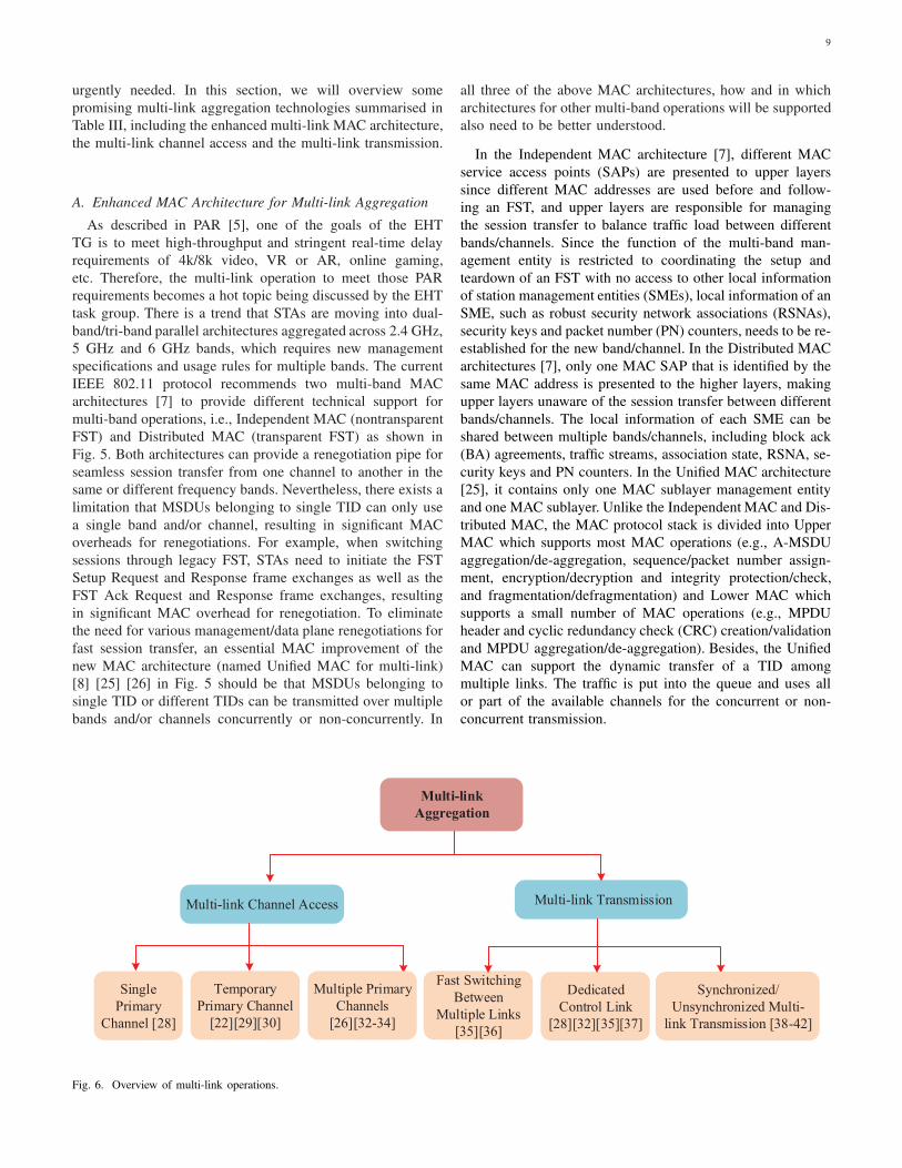
urgently needed. In this section, we will overview some
promising multi-link aggregation technologies summarised in
Table III, including the enhanced multi-link MAC architecture,
the multi-link channel access and the multi-link transmission.
A. Enhanced MAC Architecture for Multi-link Aggregation
As described in PAR [5], one of the goals of the EHT
TG is to meet high-throughput and stringent real-time delay
requirements of 4k/8k video, VR or AR, online gaming,
etc. Therefore, the multi-link operation to meet those PAR
requirements becomes a hot topic being discussed by the EHT
task group. There is a trend that STAs are moving into dual-
band/tri-band parallel architectures aggregated across 2.4 GHz,
5 GHz and 6 GHz bands, which requires new management
specifications and usage rules for multiple bands. The current
IEEE 802.11 protocol recommends two multi-band MAC
architectures [7] to provide different technical support for
multi-band operations, i.e., Independent MAC (nontransparent
FST) and Distributed MAC (transparent FST) as shown in
Fig. 5. Both architectures can provide a renegotiation pipe for
seamless session transfer from one channel to another in the
same or different frequency bands. Nevertheless, there exists a
limitation that MSDUs belonging to single TID can only use
a single band and/or channel, resulting in significant MAC
overheads for renegotiations. For example, when switching
sessions through legacy FST, STAs need to initiate the FST
Setup Request and Response frame exchanges as well as the
FST Ack Request and Response frame exchanges, resulting
in significant MAC overhead for renegotiation. To eliminate
the need for various management/data plane renegotiations for
fast session transfer, an essential MAC improvement of the
new MAC architecture (named Unified MAC for multi-link)
[8] [25] [26] in Fig. 5 should be that MSDUs belonging to
single TID or different TIDs can be transmitted over multiple
bands and/or channels concurrently or non-concurrently. In
all three of the above MAC architectures, how and in which
architectures for other multi-band operations will be supported
also need to be better understood.
In the Independent MAC architecture [7], different MAC
service access points (SAPs) are presented to upper layers
since different MAC addresses are used before and follow-
ing an FST, and upper layers are responsible for managing
the session transfer to balance traffic load between different
bands/channels. Since the function of the multi-band man-
agement entity is restricted to coordinating the setup and
teardown of an FST with no access to other local information
of station management entities (SMEs), local information of an
SME, such as robust security network associations (RSNAs),
security keys and packet number (PN) counters, needs to be re-
established for the new band/channel. In the Distributed MAC
architectures [7], only one MAC SAP that is identified by the
same MAC address is presented to the higher layers, making
upper layers unaware of the session transfer between different
bands/channels. The local information of each SME can be
shared between multiple bands/channels, including block ack
(BA) agreements, traffic streams, association state, RSNA, se-
curity keys and PN counters. In the Unified MAC architecture
[25], it contains only one MAC sublayer management entity
and one MAC sublayer. Unlike the Independent MAC and Dis-
tributed MAC, the MAC protocol stack is divided into Upper
MAC which supports most MAC operations (e.g., A-MSDU
aggregation/de-aggregation, sequence/packet number assign-
ment, encryption/decryption and integrity protection/check,
and fragmentation/defragmentation) and Lower MAC which
supports a small number of MAC operations (e.g., MPDU
header and cyclic redundancy check (CRC) creation/validation
and MPDU aggregation/de-aggregation). Besides, the Unified
MAC can support the dynamic transfer of a TID among
multiple links. The traffic is put into the queue and uses all
or part of the available channels for the concurrent or non-
concurrent transmission.
Multi-link
Aggregation
Multi-link Channel Access Multi-link Transmission
Single
Primary
Channel [28]
Fast Switching
Between
Multiple Links
[35][36]
Dedicated
Control Link
[28][32][35][37]
Multiple Primary
Channels
[26][32-34]
Temporary
Primary Channel
[22][29][30]
Synchronized/
Unsynchronized Multi-
link Transmission [38-42]
Fig. 6. Overview of multi-link operations.
10
B. Multi-link Operation over Wideband and Noncontiguous
Spectra
By utilizing multi-link aggregation across 2.4 GHz, 5 GHz
and 6 GHz bands, a multi-link capable device can parallelly
transmit frames through multiple links, thereby achieving
higher throughput and improving the network flexibility com-
pared with IEEE 802.11ax. However, considering the existing
legacy devices in 2.4 GHz, 5 GHz and 6 GHz, available links
may be restricted. Thus, how to access in multi-link and to
transmit frames over multiple links which may be beneficial
to wideband and noncontiguous spectrum availability need fur-
ther studies. As shown in Fig. 6, several promising multi-link
channel access methods and multi-link transmission modes
have been proposed in the EHT task group, including the chan-
nel access based on one primary channel, the channel access
based on multiple primary channels, the dedicated control link,
the fast link switching and the synchronized/unsynchronized
multi-link transmission.
1) Multi-link Channel Access: In current WLANs, channel
access mechanisms (e.g., clear channel assessment (CCA) in-
dication and per-20MHz bitmap) are only defined for a single
link at 20/40/80/160 MHz channel. However, future Wi-Fi
devices are expected to be multi-link capable and have wider
channel width at most 320 (160+160) MHz across 2.4 GHz,
5 GHz and 6 GHz bands. At present, these channel access
mechanisms for multi-link have not yet been defined in EHT.
Following the existing channel access logic, CCA indication
and per-20 MHz bitmap will evolve from one link to multiple
links [22]. For example, in terms of 320 MHz bandwidth,
CCA demands to add secondary 160 indications. and per-
20 MHz bitmap demands more preamble puncturing patterns
which may even be applied to the primary channel. In this
article, we classify channel access methods for multi-link into
two categories: channel access based on one primary channel
and channel access based on multiple primary channels.
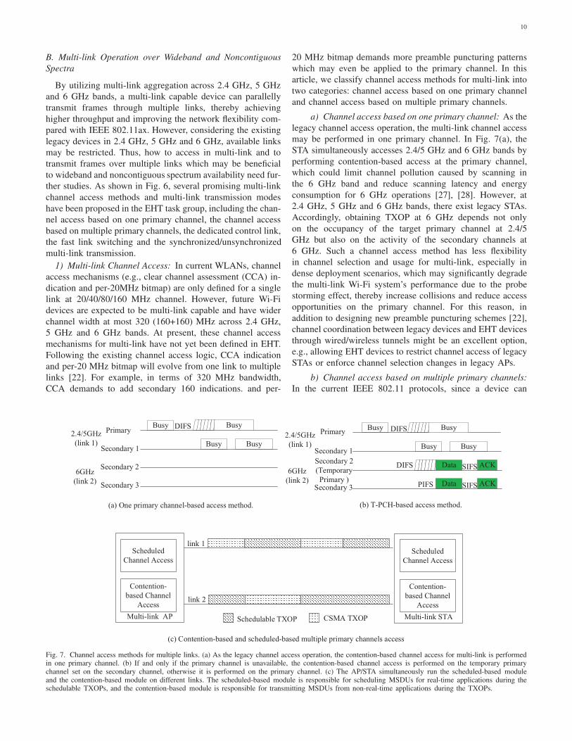
a) Channel access based on one primary channel: As the
legacy channel access operation, the multi-link channel access
may be performed in one primary channel. In Fig. 7(a), the
STA simultaneously accesses 2.4/5 GHz and 6 GHz bands by
performing contention-based access at the primary channel,
which could limit channel pollution caused by scanning in
the 6 GHz band and reduce scanning latency and energy
consumption for 6 GHz operations [27], [28]. However, at
2.4 GHz, 5 GHz and 6 GHz bands, there exist legacy STAs.
Accordingly, obtaining TXOP at 6 GHz depends not only
on the occupancy of the target primary channel at 2.4/5
GHz but also on the activity of the secondary channels at
6 GHz. Such a channel access method has less flexibility
in channel selection and usage for multi-link, especially in
dense deployment scenarios, which may significantly degrade
the multi-link Wi-Fi system’s performance due to the probe
storming effect, thereby increase collisions and reduce access
opportunities on the primary channel. For this reason, in
addition to designing new preamble puncturing schemes [22],
channel coordination between legacy devices and EHT devices
through wired/wireless tunnels might be an excellent option,
e.g., allowing EHT devices to restrict channel access of legacy
STAs or enforce channel selection changes in legacy APs.
b) Channel access based on multiple primary channels:
In the current IEEE 802.11 protocols, since a device can
Data
ACKSIFS
BusyBusy
BusyPrimary
Secondary 1
Secondary 2
(Temporary
Primary ) Secondary 3 PIFS
DIFS
ACKSIFS
DIFS Data
Busy
(b) T-PCH-based access method.
Busy Busy
BusyPrimary
Secondary 1
Secondary 2
Secondary 3
DIFS2.4/5GHz
(link 1)
6GHz
(link 2)
Busy
(a) One primary channel-based access method.
Multi-link AP
Scheduled
Channel Access
Contention-
based Channel
Access
link 1
link 2
Schedulable TXOP CSMA TXOP Multi-link STA
Scheduled
Channel Access
Contention-
based Channel
Access
(c) Contention-based and scheduled-based multiple primary channels access
2.4/5GHz
(link 1)
6GHz
(link 2)
Fig. 7. Channel access methods for multiple links. (a) As the legacy channel access operation, the contention-based channel access for multi-link is performedin one primary channel. (b) If and only if the primary channel is unavailable, the contention-based channel access is performed on the temporary primarychannel set on the secondary channel, otherwise it is performed on the primary channel. (c) The AP/STA simultaneously run the scheduled-based moduleand the contention-based module on different links. The scheduled-based module is responsible for scheduling MSDUs for real-time applications during theschedulable TXOPs, and the contention-based module is responsible for transmitting MSDUs from non-real-time applications during the TXOPs.
11
obtain its TXOP on its primary channel, spectral resources
are hardly utilized if congestion occurs in the primary channel.
To overcome this problem, a temporary primary channel (T-
PCH) [22] [29] [30] can be set on the secondary channels
to increase the channel use opportunities when the primary
channel is unavailable. In Fig. 7(b), the STA can carry out
carrier sensing on the T-PCH as well as on the primary
channel, and it obtains TXOP on the T-PCH if the T-PCH is
idle for a required duration when the primary channel is busy.
After the T-PCH becomes busy while the primary channel
becomes idle again, the STA can be allowed to return from
the T-PCH to the primary channel immediately. By doing this,
the STA may obtain more TXOP on the more idle channels.
Through computer simulation [31], it is confirmed that the
proposed T-PCH can improve the average area throughput
and channel utilization. In a real environment, such a T-PCH
operation could ensure that it does not affect the systems’
performance of those legacy STAs already operated in these
channels and not damage the fairness between new types of
APs and other legacy APs severely.
Since the presence of T-PCH depends on the status of
the primary channel, such channel access dramatically limits
the use of the idle channels. An intuitive idea should be
that the STA may perform channel access on multiple links
independently. Each link performs specific functionality inde-
pendently, e.g., Enhanced Distributed Channel Access (EDCA)
and CCA. This method has higher backward compatibility
compared to the legacy single-link reference architecture,
which is difficult for the coordination of multi-link operations
by the upper layers [26]. Via simulations, the probability of
successfully obtaining channels concurrently on two links is
not high [32]. Because the back-off of multi-link is finished
at different times, it has different operation rules for different
kinds of the multi-link transmission [33]. For the independent
multi-link transmission, the back-off in each link reuses the
existing back-off rules. For the simultaneous multi-link trans-
mission, the back-off procedure in multiple links may be as
follows: (i) When the back-off counter in one link is reduced
to 0 first, and aggregate other links, it will cause fairness issue
in other links. (ii) When the back-off counter in all links are
reduced to 0, and then transmit packets simultaneously on
multi-link, the STA will have less channel access chance than
the legacy STA. In this regard, dynamic bandwidth negotiation
could be supported in multi-link.
However, different kinds of channel access methods (e.g.,
EDCA and triggered uplink channel access [3]) and the diverse
requirements of the current and future applications are not
considered in the aforementioned channel access approaches.
To satisfy different transmission requirements for different
services, which are real-time and non-real-time applications,
the optimized multiple primary channels access method was
also proposed in [34] as shown in Fig. 7(c), where an AP
can simultaneously run two channel access function modules
on different links, namely, the scheduled-based module and
the contention-based module. The scheduled-based module
is responsible for scheduling MSDUs from real-time appli-
cations during the schedulable TXOPs of multi-link, and
the contention-based module is responsible for transmitting
MSDUs from non-real-time applications mainly during the
Carrier Sense Multiple Access (CSMA) TXOPs of multi-link.
In this way, the backward compatibility and coexistence with
legacy channel access methods would guarantee the multi-link
capable STAs operating with different access methods operate
in the same link or different links.2) Multi-link Transmission:
a) Fast switching between multiple links: In general, the
wider the transmission bandwidth, the higher the occurrence
probability of co-channel and adjacent channel interference on
neighboring nodes will be, degrading the spectrum efficiency.
Thus, dynamic link switching based on wireless link states
is a critical technology to reduce the strong interference
from neighboring nodes. When the QoS of the current in-
service link cannot meet the requirements, a multi-link capa-
ble AP/STA can switch the control/management frames and
data to other idle and high-quality links. For the type of
existing switching with negotiation in current IEEE 802.11
specifications [7], there is still significant MAC overhead
related to multi-link operations. For example, when switching
sessions between links, STAs usually require necessary frame
exchanges as data from a single TID and corresponding
BA/Ack can only be allocated to the same link. For the
type of flexible and new switching without negotiation, data
from single TID and corresponding BA/Ack frames should
be transmitted in all links, and operating actions in one link
should also be conducted to all other links, such as key
negotiation, BA negotiation, and power-saving negotiation.
Fast switching between multiple links requires devices to
efficiently select channels in different links to reach high
spectrum utilization. Seamless switching between different
Link 1
Link 2
DL frame
BusyUL frame
Busy
DL frame
Faild Retransmission
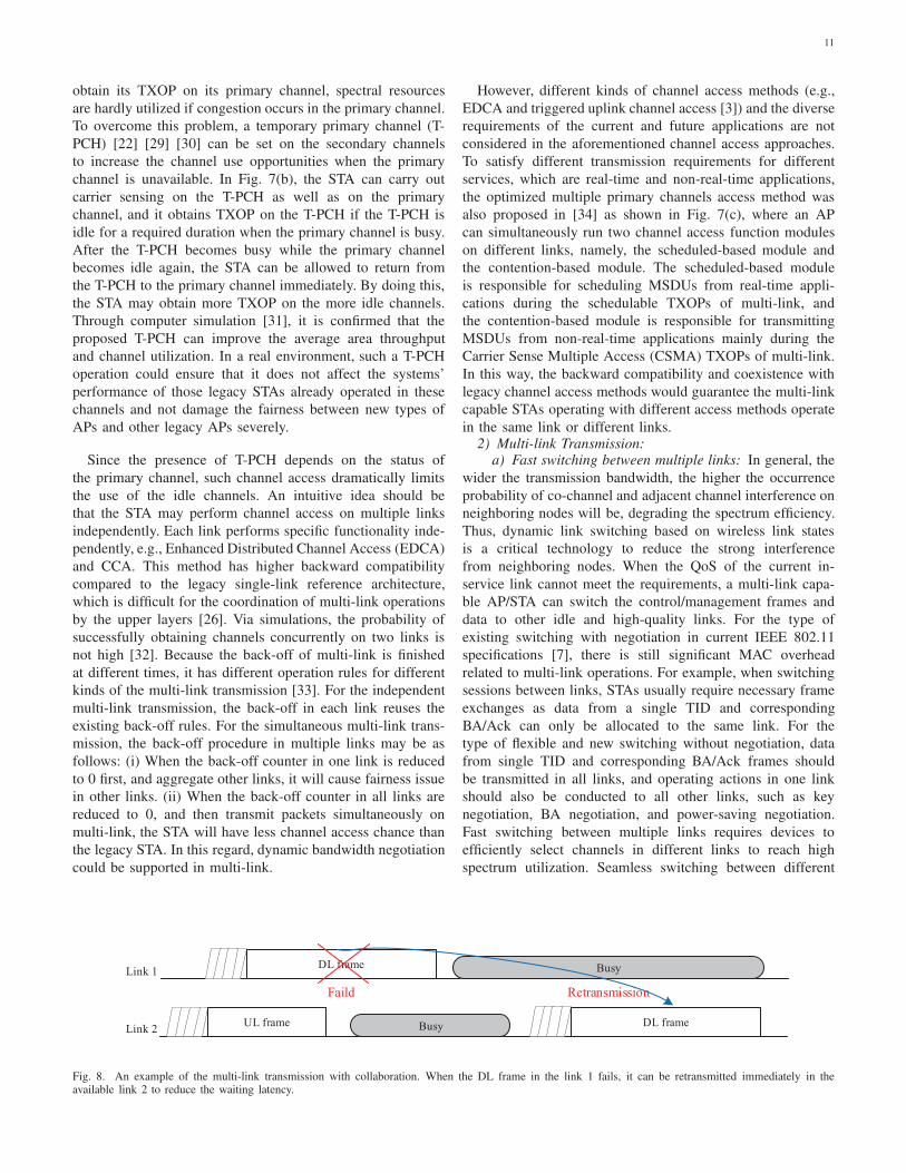
Fig. 8. An example of the multi-link transmission with collaboration. When the DL frame in the link 1 fails, it can be retransmitted immediately in theavailable link 2 to reduce the waiting latency.
12
links helps address the use-case for efficient retransmission,
load balancing and coexistence constraints [35]. In Fig. 8, the
DL frame failed in link 1 can be retransmitted in the available
link 2 for reducing the waiting latency, and the channel
diversity can smoothen out link fluctuations. Based on various
load balancing methods presented in [36] including admission
control, association management, transmission range control,
and association control, STAs can decide to switch all traffic or
partial traffic from one overloaded link to another underloaded
link to improve QoS. For example, based on types of traffic,
the STA can transmit high-throughput and low-latency services
on one link (e.g., 5/6 GHz) and transmit delay-insensitive
services on another link (e.g., 2.4 GHz).
b) Dedicated control link: The legacy STA exchanges
packets by utilizing numerous sequential control/management
operations on the same channels only in one link (e.g., 2.4
GHz or 5 GHz). The data and control/management operated
in separate time will lead to large transmission delay and
low spectrum utilization. These issues could be mitigated
by decoupling the data and control planes over different
links [35]. Decoupling the data and control planes allows
updating regular control/management frames on one of the
links, leaving the other links primarily for data exchange.
In Fig. 9, the control link can arrange every communication
over different data channels, which requires a method that
the receiver knowing exactly which channels to receive the
data through negotiation or intelligent algorithms. Also, other
control information (e.g., control frames, MAC/PHY header)
can be transmitted in a dedicated control link and allowing the
out-of-link exchange of control information can reach more
efficient resource allocation [28]. The complete decoupling of
the data and control planes should also split data packets into
two parts: the data part and the control part transmitted over
multiple links. However, since the data are transmitted over
different links, the non-sequential order of data reception may
happen due to the difference in transmission timing. Therefore,
more researches are still needed to build a more robust and
efficient multi-link system with decoupling the data and con-
trol planes. To solve the problems of inefficient management
and poor reliability of the existing distributed WLAN, a new
control plane and data plane decoupled WLAN architecture
is proposed in [37], which is a centralized control network
Control link
Data link
RTS 1
Data 1
CTS 1
Ack 1
RTS 2 CTS 2
Data 2 Ack 2 Data Ack
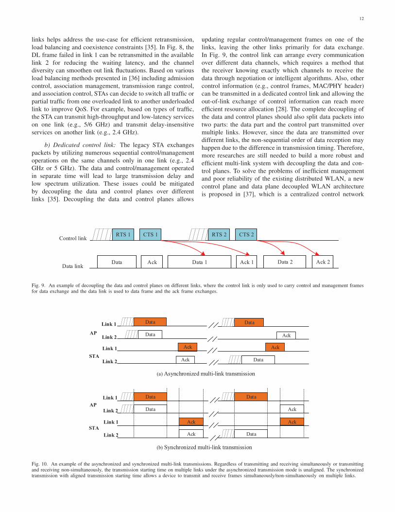
Fig. 9. An example of decoupling the data and control planes on different links, where the control link is only used to carry control and management framesfor data exchange and the data link is used to data frame and the ack frame exchanges.
Data
Ack
Ack
Data
Data
Ack
Ack
Data
Data
Ack
Ack
Data
Data
Ack
Ack
Link 1
Link 2AP
STA
Link 1
Link 2
AP
STA
Link 1
Link 2
Link 1
Link 2 Data
(b) Synchronized multi-link transmission
(a) Asynchronized multi-link transmission
Fig. 10. An example of the asynchronized and synchronized multi-link transmissions. Regardless of transmitting and receiving simultaneously or transmittingand receiving non-simultaneously, the transmission starting time on multiple links under the asynchronized transmission mode is unaligned. The synchronizedtransmission with aligned transmission starting time allows a device to transmit and receive frames simultaneously/non-simultaneously on multiple links.
13
Table IVSUMMARY OF SYNCHRONIZED/UNSYNCHRONIZED MULTI-LINK.
Unsynchronized Multi-link Synchronized Multi-link
Transmission Capability With simultaneous TX & RX capability Without simultaneous TX & RX capability
Power LeakageSufficient frequency isolation or interference
cancellation for concurrent DL and UL.
Sufficient frequency isolation or interference
cancellation for concurrent DL and UL.
Channel AccessIndependent channel access in each link,
minor or no change for standards
Dependent channel access for multi-links,
complex channel access rules
Start Time of Transmission Unaligned Aligned
End Time of Transmission Unaligned Aligned
PPDU Parameters in Each Link Independent PPDU length, bandwidth, MCS, et al. Dependent PPDU length, bandwidth, MCS, et al.
Spectrum Utilization High Low
QoS Issues
Non-sequential packet receptions due to difference of
transmission timing and frame length between links,
failed reception due to leakage to adjacent channel,
unnecessary retransmission due to difference of
channel quality between links [41]
Unnecessary retransmission due to difference of
channel quality between links [41]
architecture with control plane and data plane decoupling,
in which AC (Access Controller) controls and manages all
the APs and STAs through the control plane in the low-
frequency band, and the AP provides data transmissions for
STAs through the data plane in the high-frequency band.
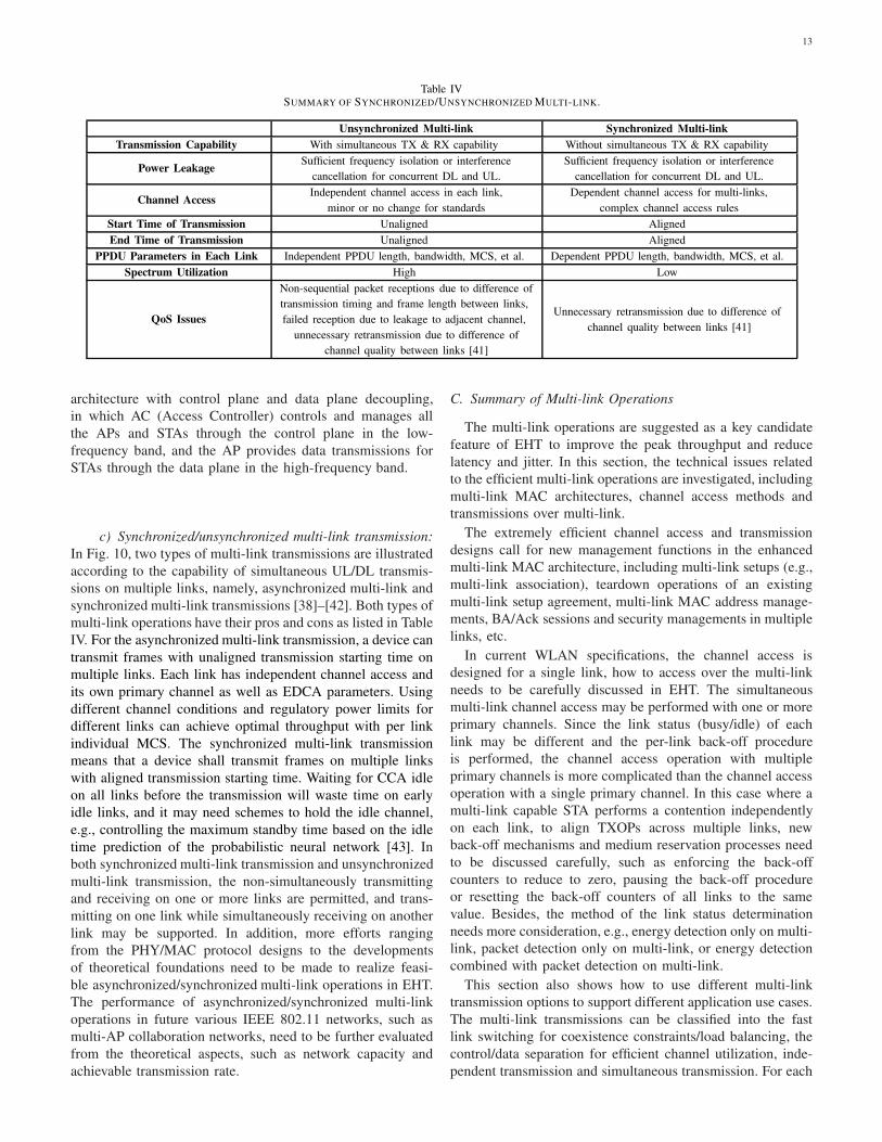
c) Synchronized/unsynchronized multi-link transmission:
In Fig. 10, two types of multi-link transmissions are illustrated
according to the capability of simultaneous UL/DL transmis-
sions on multiple links, namely, asynchronized multi-link and
synchronized multi-link transmissions [38]–[42]. Both types of
multi-link operations have their pros and cons as listed in Table
IV. For the asynchronized multi-link transmission, a device can
transmit frames with unaligned transmission starting time on
multiple links. Each link has independent channel access and
its own primary channel as well as EDCA parameters. Using
different channel conditions and regulatory power limits for
different links can achieve optimal throughput with per link
individual MCS. The synchronized multi-link transmission
means that a device shall transmit frames on multiple links
with aligned transmission starting time. Waiting for CCA idle
on all links before the transmission will waste time on early
idle links, and it may need schemes to hold the idle channel,
e.g., controlling the maximum standby time based on the idle
time prediction of the probabilistic neural network [43]. In
both synchronized multi-link transmission and unsynchronized
multi-link transmission, the non-simultaneously transmitting
and receiving on one or more links are permitted, and trans-
mitting on one link while simultaneously receiving on another
link may be supported. In addition, more efforts ranging
from the PHY/MAC protocol designs to the developments
of theoretical foundations need to be made to realize feasi-
ble asynchronized/synchronized multi-link operations in EHT.
The performance of asynchronized/synchronized multi-link
operations in future various IEEE 802.11 networks, such as
multi-AP collaboration networks, need to be further evaluated
from the theoretical aspects, such as network capacity and
achievable transmission rate.
C. Summary of Multi-link Operations
The multi-link operations are suggested as a key candidate
feature of EHT to improve the peak throughput and reduce
latency and jitter. In this section, the technical issues related
to the efficient multi-link operations are investigated, including
multi-link MAC architectures, channel access methods and
transmissions over multi-link.
The extremely efficient channel access and transmission
designs call for new management functions in the enhanced
multi-link MAC architecture, including multi-link setups (e.g.,
multi-link association), teardown operations of an existing
multi-link setup agreement, multi-link MAC address manage-
ments, BA/Ack sessions and security managements in multiple
links, etc.
In current WLAN specifications, the channel access is
designed for a single link, how to access over the multi-link
needs to be carefully discussed in EHT. The simultaneous
multi-link channel access may be performed with one or more
primary channels. Since the link status (busy/idle) of each
link may be different and the per-link back-off procedure
is performed, the channel access operation with multiple
primary channels is more complicated than the channel access
operation with a single primary channel. In this case where a
multi-link capable STA performs a contention independently
on each link, to align TXOPs across multiple links, new
back-off mechanisms and medium reservation processes need
to be discussed carefully, such as enforcing the back-off
counters to reduce to zero, pausing the back-off procedure
or resetting the back-off counters of all links to the same
value. Besides, the method of the link status determination
needs more consideration, e.g., energy detection only on multi-
link, packet detection only on multi-link, or energy detection
combined with packet detection on multi-link.
This section also shows how to use different multi-link
transmission options to support different application use cases.
The multi-link transmissions can be classified into the fast
link switching for coexistence constraints/load balancing, the
control/data separation for efficient channel utilization, inde-
pendent transmission and simultaneous transmission. For each
14
Table VENHANCED FEEDBACK REDUCTION SCHEMES.
Scheme Method Pros Cons
En
han
ced
Sch
emes
φ Only Feedback [48][49]Existing in IEEE 802.11ah and with minordesign efforts.
Only single data stream is supported.
Time Domain Channel Feedback [47]Existing in IEEE 802.11ad/ay and withminor design efforts.
May need additional signaling to identifytappositions and the extra matrix.
Differential Given’s Rotation [47][50]Improving from IEEE 802.11ax, IEEE802.11ay and with minor design efforts.
May need additional processing and haveerror propagation.
Variable Angle Quantization [48][49]Improving from IEEE 802.11ax and withminor design efforts.
May need additional processing andsignaling to indicate quantization levels.
New
Sch
emes Multiple Component Feedback [48][49][51] Feedback overhead can be reduced.
May need additional design (e.g., feedbacksizes or intervals indications).
Finite Feedback [52]-[55] Feedback overhead can be reduced.May need additional design (e.g.,well-designedcodebook).
Two-way Channel Sounding [56] Feedback overhead can be reduced.May need additional design (e.g., especialsounding signal design).
Enhanced Implicit Feedback [49][63]Improving from IEEE 802.11n and withlow network overhead and latency.
Need calibration.
multi-link transmission option, this section does not cover the
detailed discussions of the BA/ack agreements. Theoretically,
compared to the existing single-link transmission mode, the
multi-link transmissions can double link capacity at the same
time resource. However, in the real world, performance gains
of the multi-link transmissions may be hindered by legacy
single-link devices. Therefore, designing the effective multi-
link transmission schemes need to take into account the
spectrum utilization, the design complexity, and the activities
of legacy devices operating at the same link(s). Moreover,
the simultaneous transmitting and receiving operation over
the multi-link can cause inter-link interference due to power
leakage unless their links are set a minimum separation or
sufficiently far. Since the large guard separation between
adjacent links can reduce the spectrum utilization, we need
to explore some advanced analog/digital interference cancel-
lation/suppression schemes for multi-link transmissions.
IV. MULTIPLE INPUT MULTIPLE OUTPUT(MIMO)
ENHANCEMENT
The use of 16 spatial streams has been discussed as an
attractive MIMO feature of EHT. The increasing number
of spatial streams from the current eight in IEEE 802.11ax
to sixteen could theoretically double the transmission data
rate. However, this comes with an attendant increase in the
amount of sounding and feedback needed. Straightway reusing
the existing sounding and feedback mechanisms defined in
IEEE 802.11ax is not adequate to support 16 spatial streams.
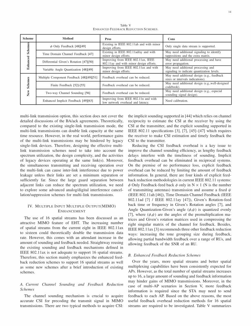
Therefore, this section mainly emphasizes the enhanced feed-
back reduction schemes to support 16 spatial streams as well
as some new schemes after a brief introduction of existing
schemes.
A. Current Channel Sounding and Feedback Reduction
Schemes
The channel sounding mechanism is crucial to acquire
accurate CSI for precoding the transmit signal in MIMO
transmissions. There are two typical methods to acquire CSI:
the implicit sounding supported in [44] which relies on channel
reciprocity to estimate the CSI at the receiver by using the
CSI at the transmitter, and the explicit sounding supported in
IEEE 802.11 specifications [3], [7], [45]–[47] which requires
the receiver to make CSI estimation and timely feedback the
CSI to the transmitter.
Reducing the CSI feedback overhead is a key issue to
improve the channel sounding efficiency, as lengthy feedback
delays interfere with the timeliness of sounding. Implicit
feedback overhead can be eliminated in reciprocal systems.
On the premise of no performance loss, explicit feedback
overhead can be reduced by limiting the amount of feedback
information. In general, there are four kinds of explicit feed-
back reduction methodologies in current IEEE 802.11 systems:
φ Only Feedback-feed back φ only in N × 1 (N is the number
of transmitting antennas) transmission and assume a fixed ψ
(IEEE 802.11ah [46]), Time Domain Channel Feedback (IEEE
802.11ad [7] / IEEE 802.11ay [47]), Given’s Rotation-feed
back time or frequency in Given’s Rotation angles [7], and
Angle Quantization-Given’s angle (φ,ψ) is quantized evenly
[7], where (φ,ψ) are the angles of the premultiplication ma-
trices and Given’s rotation matrices used in compressing the
right singular matrix of the channel for feedback. Besides,
IEEE 802.11ax [3] recommends three other feedback reduction
ways: increasing the tone grouping size during feedback,
allowing partial bandwidth feedback over a range of RUs, and
allowing feedback of the SNR of an RU.
B. Enhanced Feedback Reduction Schemes
Over the years, more spatial streams and better spatial
multiplexing capabilities have been consistently expected for
APs. However, as the total number of spatial streams increases
up to 16, a large amount of sounding and feedback information
may hinder gains of MIMO transmissions. Moreover, in the
case of multi-AP scenarios in Section V, more feedback
information is required since the STA may need to send
feedback to each AP. Based on the above reasons, the most
useful feedback overhead reduction methods for 16 spatial
streams are required to be investigated. Table V summarizes
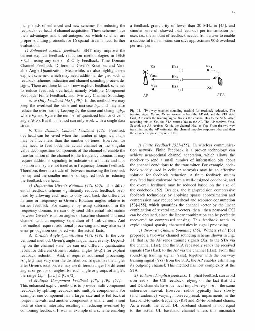
15
many kinds of enhanced and new schemes for reducing the
feedback overhead of channel acquisition. These schemes have
their advantages and disadvantages, but which schemes are
proper sounding protocols for 16 spatial streams need further
evaluations.
1) Enhanced explicit feedback: EHT may improve the
current explicit feedback reduction methodologies in IEEE
802.11 using any one of φ Only Feedback, Time Domain
Channel Feedback, Differential Given’s Rotation, and Vari-
able Angle Quantization. Meanwhile, we also highlight new
explicit schemes, which may need additional designs, such as
feedback schemes indication and channel sounding process de-
signs. There are three kinds of new explicit feedback schemes
to reduce feedback overhead, namely Multiple Component
Feedback, Finite Feedback, and Two-way Channel Sounding.
a) φ Only Feedback [48], [49]: In this method, we may
keep the overhead the same and increase bφ, and may also
reduce the overhead by keeping bφ the same and changingbψ,
where bφ and bψ are the number of quantized bits for Given’s
angle (φ,ψ). But this method can only work with a single data
stream.
b) Time Domain Channel Feedback [47]: Feedback
overhead can be saved when the number of significant taps
may be much less than the number of tones. However, we
may need to feed back the actual channel or the singular
value decomposition components of the channel to enable the
transformation of the channel to the frequency domain. It may
require additional signaling to indicate extra matrix and taps
position as they are not fixed as in frequency domain feedback.
Therefore, there is a trade-off between increasing the feedback
per tap and the smaller number of taps fed back in reducing
the feedback overhead.
c) Differential Given’s Rotation [47], [50]: This differ-
ential feedback scheme significantly reduces feedback over-
head by allowing each user to only feed back the difference
in time or frequency in Given’s Rotation angles relative to
earlier feedback. For example, by using subtraction in the
frequency domain, we can only send differential information
between Given’s rotation angles of baseline channel and next
channel with a frequency separation of 4 sub-carriers. And
this method requires additional processing and may also exist
error propagation compared with the actual facts.
d) Variable Angle Quantization [48], [49]: In the con-
ventional method, Given’s angle is quantized evenly. Depend-
ing on the channel state, we can use different quantization
levels for different Given’s rotation angles (φi ,ψi) for explicit
feedback reduction. And, it requires additional processing.
Angle ψ may vary over the distribution. To quantize the angles
after Given’s rotation, we may use different ranges for different
angles or groups of angles: for each angle or groups of angles,
the range Ωψ = [a, b] ⊂ [0, π/2].
e) Multiple Component Feedback [48], [49], [51]:
This enhanced explicit method is to provide multi-component
feedback by splitting feedback into multiple components. For
example, one component has a larger size and is fed back at
longer intervals, and another component is smaller and is sent
back at shorter intervals, resulting in reducing overhead by
combining feedback. It was an example of a scheme enabling
a feedback granularity of fewer than 20 MHz in [45], and
simulation result showed total feedback per transmission per
user, i.e., the amount of feedback needed from a user to enable
a successful transmission: can save approximate 90% overhead
per user per.
(1)
(2)
(3)
Xa
AP STA
Yas
Yasa
Xs Ysa
Has
Hsa
Hsa
Fig. 11. Two-way channel sounding method for feedback reduction. Thetraining signal Xa and Xs are known on both the AP side and the STA side.First, AP sends the training signal Xa via the channel Has to the STA. Afterreceiving this as Yas, the STA returns Yas to the AP. The AP receives Yasa.Second, the AP receives Xs via the channel Hsa, as Ysa. From the two-waytransmission, the AP estimates the channel impulse response Hsa and thenthe channel impulse response Has.
f) Finite Feedback [52]–[55]: In wireless communica-
tion network, Finite Feedback is a proven technology can
achieve near-optimal channel adaptation, which allows the
receiver to send a small number of information bits about
the channel conditions to the transmitter. For example, code-
book widely used in cellular networks may be an effective
solution for feedback reduction. A finite feedback system
may feed back codeword from a well-designed codebook, and
the overall feedback may be reduced based on the size of
the codebook [52]. Besides, the high-precision compressive
feedback technology by applying sparse approximation and
compression may reduce overhead and resource consumption
[53]–[55], which quantifies the channel vector by the linear
combination of several unit vectors, then , then near-real CSI
can be obtained, since the linear combination can be perfectly
recovered by compressed sensing. This feedback needs to
exploit signal sparsity characteristics in signal processing.
g) Two-way Channel Sounding [56]: Withers et al. [56]
proposed a two-way channel sounding scheme shown in Fig.
11, that is, the AP sends training signals (Xa) to the STA via
the channel (Has), and the STA repeatedly sends the received
signals (Yas) back to the AP via the channel (Has). From this
round-trip training signal (Yasa), together with the one-way
training signal (Ysa) from the STA, the AP enables estimating
its outgoing channel. This method has low complexity at the
STA.
2) Enhanced implicit feedback: Implicit feedback can avoid
overhead of the CSI feedback relying on the fact that UL
and DL channels have identical impulse response in the same
coherence interval. However, radios typically have slowly
(and randomly) varying, non-reciprocal, impairments in the
baseband-to-radio-frequency (RF) and RF-to-baseband chains.
As a result, the actual DL baseband channel is not equal
to the actual UL baseband channel unless this mismatch
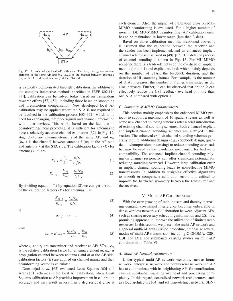
16
AP !"# !"$
STAj
hij hji hjm hmj
Fig. 12. A model of the local AP calibration. The Anti , Antm are antennaelements of the same AP, and hi j (hmj ) is the channel between antenna i
(m) at the AP side and antenna j at the STA side.
is explicitly compensated through calibration. In addition to
the complex interactive methods specified in IEEE 802.11n
[44], calibration can be solved today based on tremendous
research efforts [57]–[59], including those based on smoothing
and predistortion compensation. New developed local AP
calibration may be applied where the STA is not required to
be involved in the calibration process [60]–[62], which is no
need for exchanging reference signals and channel information
with other devices. This works based on the fact that in
beamforming/linear precoding, it is sufficient for antennas to
have a relatively accurate channel estimation [62]. In Fig. 12,
Anti, Antm are antenna elements of the same AP, and hij(hmj ) is the channel between antenna i (m) at the AP side
and antenna j at the STA side. The calibration factors (K) for
antennas i, m are
Ki−j =hij
hji
=
ti/ri
tj/
rj(1)
Km−j =hmj
hjm
=
tm/rm
tj/
rj(2)
By dividing equation (1) by equation (2),we can get the ratio
of the calibration factors (K) for antennas i, m
Km−j
Ki−j=
tm/rm
ti/ri(3)
if
Ki−j = c1 = 1 (4)
then
cm = Km−j =tm/rm
ti/ri=
hmi
him(5)
where ti and ri are transmitter and receiver at AP/ STAj , cmis the relative calibration factor for antenna element m, him is
propagation channel between antenna i and m at the AP side,
calibration factors (K) are applied on channel matrix and then
beamforming vector is calculated.
Doostnejad et al. [62] evaluated Least Squares [60] and
Argos [61] schemes in the local AP calibration, where Least
Squares calibration at AP provides improvement in calibration
accuracy and may result in less than 3 deg residual error at
each element. Also, the impact of calibration error on MU-
MIMO beamforming is evaluated. For a higher number of
users in DL MU-MIMO beamforming, AP calibration error
has to be maintained in lower range (less than 3 deg).
Based on those calibration methods mentioned above, it
is assumed that the calibration between the receiver and
the sender has been implemented, and an enhanced implicit
channel scheme is discussed in [49], [63]. The detailed process
of channel sounding is shown in Fig. 13. For MU-MIMO
scenario, there is a trade-off between the overhead of implicit
method (option 1) and explicit method, which mainly depends
on the number of STAs, the feedback duration, and the
duration of UL sounding frames. For example, as the number
of STAs increases, the number of frames transmitted in UL
also increases. Further, it can be observed that option 2 can
effectively reduce the CSI feedback overhead of more than
one STA compared with option 1.
C. Summary of MIMO Enhancements
This section mainly emphasizes the enhanced MIMO pro-
tocol to support a maximum of 16 spatial streams as well as
some new channel sounding schemes after a brief introduction
of existing channel sounding schemes. Both enhanced explicit
and implicit channel sounding schemes are surveyed in this
section. The enhanced explicit channel sounding schemes gen-
erally require additional designs (e.g., codebook design, quan-
tization/compression processing) to reduce sounding overhead,
but may be used as the mandatory mechanism for backward
compatibility. The enhanced implicit channel sounding rely-
ing on channel reciprocity can offer significant potential for
reducing sounding overhead. However, large calibration error
in implicit channel sounding leads to non-effective MIMO
transmissions. In addition to designing effective algorithms
to smooth or compensate calibration error, it is critical to
improve the hardware symmetry between the transmitter and
the receiver.
V. MULTI-AP COORDINATION
With the ever-growing of mobile users and thereby increas-
ing demand, co-channel interference becomes unbearable in
dense wireless networks. Collaboration between adjacent APs,
such as sharing necessary scheduling information and CSI, is a
promising approach to improve the utilization of limited radio
resources. In this section, we present the multi-AP network and
a general multi-AP transmission procedure, emphasize several
modes of multi-AP transmission including C-OFDMA, CSR,
CBF and JXT, and summarize existing studies on multi-AP
coordination in Table VI.
A. Multi-AP Network Architecture
Under typical multi-AP network scenarios, such as home
network, enterprise network and commercial network, an AP
has to communicate with its neighboring APs for coordination,
causing substantial signaling overhead and processing com-
plexity. In this regard, centralized network architectures, such
as cloud architecture [64] and software-defined network (SDN)
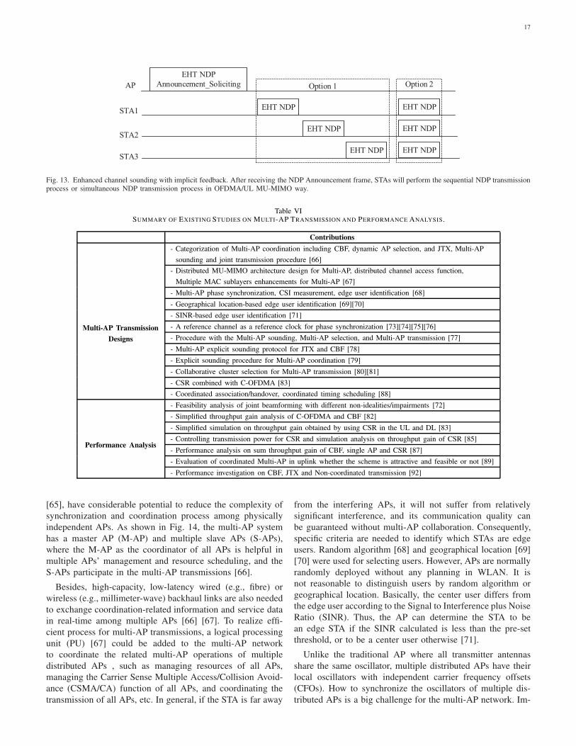
17
EHT NDP
Announcement_SolicitingAP
STA1
Option 2
STA2
STA3
EHT NDP
EHT NDP
EHT NDP
EHT NDP
EHT NDP
EHT NDP
Option 1
Fig. 13. Enhanced channel sounding with implicit feedback. After receiving the NDP Announcement frame, STAs will perform the sequential NDP transmissionprocess or simultaneous NDP transmission process in OFDMA/UL MU-MIMO way.
Table VISUMMARY OF EXISTING STUDIES ON MULTI-AP TRANSMISSION AND PERFORMANCE ANALYSIS.
Contributions
- Categorization of Multi-AP coordination including CBF, dynamic AP selection, and JTX, Multi-AP
sounding and joint transmission procedure [66]
- Distributed MU-MIMO architecture design for Multi-AP, distributed channel access function,
Multiple MAC sublayers enhancements for Multi-AP [67]
- Multi-AP phase synchronization, CSI measurement, edge user identification [68]
- Geographical location-based edge user identification [69][70]
- SINR-based edge user identification [71]
- A reference channel as a reference clock for phase synchronization [73][74][75][76]
- Procedure with the Multi-AP sounding, Multi-AP selection, and Multi-AP transmission [77]
- Multi-AP explicit sounding protocol for JTX and CBF [78]
- Explicit sounding procedure for Multi-AP coordination [79]
- Collaborative cluster selection for Multi-AP transmission [80][81]
- CSR combined with C-OFDMA [83]
Multi-AP Transmission
Designs
- Coordinated association/handover, coordinated timing scheduling [88]
- Feasibility analysis of joint beamforming with different non-idealities/impairments [72]
- Simplified throughput gain analysis of C-OFDMA and CBF [82]
- Simplified simulation on throughput gain obtained by using CSR in the UL and DL [83]
- Controlling transmission power for CSR and simulation analysis on throughput gain of CSR [85]
- Performance analysis on sum throughput gain of CBF, single AP and CSR [87]
- Evaluation of coordinated Multi-AP in uplink whether the scheme is attractive and feasible or not [89]
Performance Analysis
- Performance investigation on CBF, JTX and Non-coordinated transmission [92]
[65], have considerable potential to reduce the complexity of
synchronization and coordination process among physically
independent APs. As shown in Fig. 14, the multi-AP system
has a master AP (M-AP) and multiple slave APs (S-APs),
where the M-AP as the coordinator of all APs is helpful in
multiple APs’ management and resource scheduling, and the
S-APs participate in the multi-AP transmissions [66].
Besides, high-capacity, low-latency wired (e.g., fibre) or
wireless (e.g., millimeter-wave) backhaul links are also needed
to exchange coordination-related information and service data
in real-time among multiple APs [66] [67]. To realize effi-
cient process for multi-AP transmissions, a logical processing
unit (PU) [67] could be added to the multi-AP network
to coordinate the related multi-AP operations of multiple
distributed APs , such as managing resources of all APs,
managing the Carrier Sense Multiple Access/Collision Avoid-
ance (CSMA/CA) function of all APs, and coordinating the
transmission of all APs, etc. In general, if the STA is far away
from the interfering APs, it will not suffer from relatively
significant interference, and its communication quality can
be guaranteed without multi-AP collaboration. Consequently,
specific criteria are needed to identify which STAs are edge
users. Random algorithm [68] and geographical location [69]
[70] were used for selecting users. However, APs are normally
randomly deployed without any planning in WLAN. It is
not reasonable to distinguish users by random algorithm or
geographical location. Basically, the center user differs from
the edge user according to the Signal to Interference plus Noise
Ratio (SINR). Thus, the AP can determine the STA to be
an edge STA if the SINR calculated is less than the pre-set
threshold, or to be a center user otherwise [71].
Unlike the traditional AP where all transmitter antennas
share the same oscillator, multiple distributed APs have their
local oscillators with independent carrier frequency offsets
(CFOs). How to synchronize the oscillators of multiple dis-
tributed APs is a big challenge for the multi-AP network. Im-
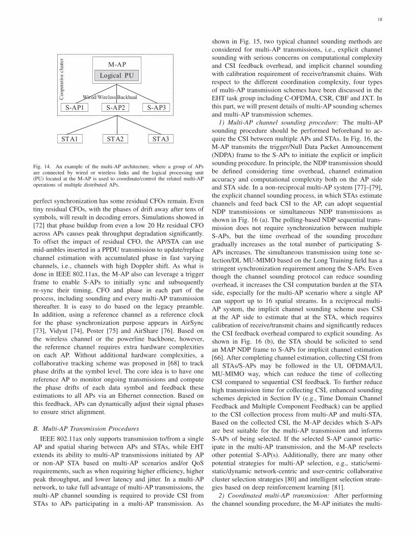
18
M-AP
Wired/Wireless Backhual
Logical PU
S-AP1 S-AP2 S-AP3
STA1 STA3STA2
Co
op
erativ
e c
lust
er
Fig. 14. An example of the multi-AP architecture, where a group of APsare connected by wired or wireless links and the logical processing unit(PU) located at the M-AP is used to coordinate/control the related multi-APoperations of multiple distributed APs.
perfect synchronization has some residual CFOs remain. Even
tiny residual CFOs, with the phases of drift away after tens of
symbols, will result in decoding errors. Simulations showed in
[72] that phase buildup from even a low 20 Hz residual CFO
across APs causes peak throughput degradation significantly.
To offset the impact of residual CFO, the AP/STA can use
mid-ambles inserted in a PPDU transmission to update/replace
channel estimation with accumulated phase in fast varying
channels, i.e., channels with high Doppler shift. As what is
done in IEEE 802.11ax, the M-AP also can leverage a trigger
frame to enable S-APs to initially sync and subsequently
re-sync their timing, CFO and phase in each part of the
process, including sounding and every multi-AP transmission
thereafter. It is easy to do based on the legacy preamble.
In addition, using a reference channel as a reference clock
for the phase synchronization purpose appears in AirSync
[73], Vidyut [74], Poster [75] and AirShare [76]. Based on
the wireless channel or the powerline backbone, however,
the reference channel requires extra hardware complexities
on each AP. Without additional hardware complexities, a
collaborative tracking scheme was proposed in [68] to track
phase drifts at the symbol level. The core idea is to have one
reference AP to monitor ongoing transmissions and compute
the phase drifts of each data symbol and feedback these
estimations to all APs via an Ethernet connection. Based on
this feedback, APs can dynamically adjust their signal phases
to ensure strict alignment.
B. Multi-AP Transmission Procedures
IEEE 802.11ax only supports transmission to/from a single
AP and spatial sharing between APs and STAs, while EHT
extends its ability to multi-AP transmissions initiated by AP
or non-AP STA based on multi-AP scenarios and/or QoS
requirements, such as when requiring higher efficiency, higher
peak throughput, and lower latency and jitter. In a multi-AP
network, to take full advantage of multi-AP transmissions, the
multi-AP channel sounding is required to provide CSI from
STAs to APs participating in a multi-AP transmission. As
shown in Fig. 15, two typical channel sounding methods are
considered for multi-AP transmissions, i.e., explicit channel
sounding with serious concerns on computational complexity
and CSI feedback overhead, and implicit channel sounding
with calibration requirement of receive/transmit chains. With
respect to the different coordination complexity, four types
of multi-AP transmission schemes have been discussed in the
EHT task group including C-OFDMA, CSR, CBF and JXT. In
this part, we will present details of multi-AP sounding schemes
and multi-AP transmission schemes.
1) Multi-AP channel sounding procedure: The multi-AP
sounding procedure should be performed beforehand to ac-
quire the CSI between multiple APs and STAs. In Fig. 16, the
M-AP transmits the trigger/Null Data Packet Announcement
(NDPA) frame to the S-APs to initiate the explicit or implicit
sounding procedure. In principle, the NDP transmission should
be defined considering time overhead, channel estimation
accuracy and computational complexity both on the AP side
and STA side. In a non-reciprocal multi-AP system [77]–[79],
the explicit channel sounding process, in which STAs estimate
channels and feed back CSI to the AP, can adopt sequential
NDP transmissions or simultaneous NDP transmissions as
shown in Fig. 16 (a). The polling-based NDP sequential trans-
mission does not require synchronization between multiple
S-APs, but the time overhead of the sounding procedure
gradually increases as the total number of participating S-
APs increases. The simultaneous transmission using tone se-
lection/DL MU-MIMO based on the Long Training field has a
stringent synchronization requirement among the S-APs. Even
though the channel sounding protocol can reduce sounding
overhead, it increases the CSI computation burden at the STA
side, especially for the multi-AP scenario where a single AP
can support up to 16 spatial streams. In a reciprocal multi-
AP system, the implicit channel sounding scheme uses CSI
at the AP side to estimate that at the STA, which requires
calibration of receive/transmit chains and significantly reduces
the CSI feedback overhead compared to explicit sounding. As
shown in Fig. 16 (b), the STA should be solicited to send
an MAP NDP frame to S-APs for implicit channel estimation
[66]. After completing channel estimation, collecting CSI from
all STAs/S-APs may be followed in the UL OFDMA/UL
MU-MIMO way, which can reduce the time of collecting
CSI compared to sequential CSI feedback. To further reduce
high transmission time for collecting CSI, enhanced sounding
schemes depicted in Section IV (e.g., Time Domain Channel
Feedback and Multiple Component Feedback) can be applied
to the CSI collection process from multi-AP and multi-STA.
Based on the collected CSI, the M-AP decides which S-APs
are best suitable for the multi-AP transmission and informs
S-APs of being selected. If the selected S-AP cannot partic-
ipate in the multi-AP transmission, and the M-AP reselects
other potential S-AP(s). Additionally, there are many other
potential strategies for multi-AP selection, e.g., static/semi-
static/dynamic network-centric and user-centric collaborative
cluster selection strategies [80] and intelligent selection strate-
gies based on deep reinforcement learning [81].
2) Coordinated multi-AP transmission: After performing
the channel sounding procedure, the M-AP initiates the multi-
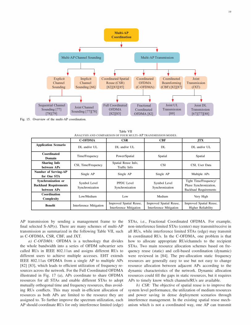
19
Multi-AP
Coordination
Multi-AP Channel Sounding Multi-AP Transmission
Explicit
Channel
Sounding
Coordinated
OFDMA
(C-OFDMA)
Coordinated Spatial
Reuse (CSR)
[82][83][85]
Coordinated
Beamforming
(CBF) [82][87]
Joint
Transmission
(JXT)
Implicit
Channel
Sounding [66]
Sequential Channel
Sounding [77]
[78][79]
Joint Channel
Sounding [77][78]
Joint UL
Transmission
[89]
Joint DL
Transmission
[67][77][88]
Full Coordinated
OFDMA
[82][83]
Fractional
Coordinated
OFDMA [82]
Fig. 15. Overview of the multi-AP coordination.
Table VIIANALYSIS AND COMPARISON OF FOUR MULTI-AP TRANSMISSION MODES.
C-OFDMA CSR CBF JTX
Application ScenarioDL and/or UL DL and/or UL DL DL and/or UL
Coordinated
DomainTime/Frequency Power/Spatial Spatial Spatial
Sharing Info
between APsCSI, Time/Frequency
Spatial Reuse Info,
Traffic InfoCSI CSI, User Data
Number of Serving-AP
for One STASingle AP Single AP Single AP Multiple APs
Synchronization or
Backhaul Requirements
between APs
Symbol Level
Synchronization
PPDU Level
Synchronization
Symbol Level
Synchronization
Tight Time/Frequency/
Phase Synchronization,
Backhaul Requirements
Coordination
ComplexityLow/Medium Low Medium Very High
Benefit Interference MitigationImproved Spatial Reuse,
Interference Mitigation
Improved Spatial Reuse,
Interference Mitigation
Improved Spatial Reuse,
Higher Reliability
AP transmission by sending a management frame to the
final selected S-AP(s). There are many schemes of multi-AP
transmission as summarized in the following Table VII, such
as C-OFDMA, CSR, CBF, and JXT.
a) C-OFDMA: OFDMA is a technology that divides
the whole bandwidth into a series of OFDM subcarrier sets
called RUs in IEEE 802.11ax and assigns different RUs to
different users to achieve multiple accesses. EHT extends
IEEE 802.11ax OFDMA from a single AP to multiple APs
[82] [83], which leads to efficient utilization of frequency re-
sources across the network. For the Full Coordinated OFDMA
illustrated in Fig. 17 (a), APs coordinate to share OFDMA
resources for all STAs and enable different STAs to adopt
mutually orthogonal time and frequency resources, thus avoid-
ing RUs conflicts. This may result in-efficient allocation of
resources as both APs are limited to the resource they are
assigned to. To further improve the spectrum utilization, each
AP should coordinate RUs for only interference limited (edge)
STAs, i.e., Fractional Coordinated OFDMA. For example,
non-interference limited STAs (center) may transmit/receive in
all RUs, while interference limited STAs (edge) may transmit
in coordinated RUs. In the C-OFDMA, one problem is that
how to allocate appropriate RUs/channels to the recipient
STAs. Two main resource allocation schemes based on fre-
quency reuse (static) and cell-based coordination (dynamic)
were reviewed in [84]. The pre-allocation static frequency
resources are generally easy to use but not easy to change
resource allocation between adjacent APs according to the
dynamic characteristics of the network. Dynamic allocation
resources could fill the gaps in static resources, but it requires
APs to timely know which channels/RUs are available.
b) CSR: The objective of spatial reuse is to improve the
system level performance, the utilization of medium resources
and power saving in dense deployment scenarios through
interference management. In the existing spatial reuse mech-
anism which is not a coordinated way, one AP can transmit
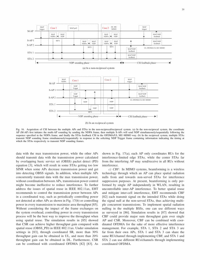
20
(a) In a non-reciprocal system
(b) In an reciprocal system
MAP NDP
feedback
MAP NDP
feedback
MAP
trigger
NDP
Trigger
NDP
Trigger
NDP
NDP
MAP
NDPA
M-AP
S-AP 1
S-AP 2
STA 1
STA 2SIFS
UL OFDMA/UL MU MIMO
CSI feedback phase
MAP NDP
feedback
MAP
trigger
MAP
NDPA
MAP
NDPA
MAP
NDP
MAP
NDP
MAP
NDPA
MAP pollMAP
trigger
M-AP
S-AP 1
S-AP 2
STA 1
STA 2
SIFS
SIFS
MAP
NDP
MAP
NDP
MAP
NDPA
SIFS
Case 1 Case 2
MAP NDP
feedback
MAP NDP
feedback
MAP NDP
feedback
UL OFDMA/UL MU MIMO
NDP sounding phase CSI feedback phase
DL MU
MIMO
NDP
NDP
Case 1 Case 2
Fig. 16. Acquisition of CSI between the multiple APs and STAs in the non-reciprocal/reciprocal system. (a) In the non-reciprocal system, the coordinateAP (M-AP) first initiates the multi-AP sounding by sending the NDPA frame, then multiple S-APs will send NDP simultaneously/sequentially following thesequence specified in the NDPA frame, and finally the STAs feedback CSI in the OFDMA/UL MU-MIMO way. (b) In the reciprocal system, multiple STAstransmit NDP sounding frame simultaneously/sequentially in response to the soliciting NDP Trigger frame containing information indicating the timing atwhich the STAs respectively to transmit NDP sounding frames.
data with the max transmission power, while the other APs
should transmit data with the transmission power calculated
by overlapping basic service set (OBSS) packet detect (PD)
equation [3], which will result in some STAs getting too low
SINR when some APs decrease transmission power and get
into detecting OBSS signals. In addition, when multiple APs
concurrently transmit data with the max transmission power,
without coordination between APs, transmission power control
might become ineffective to reduce interference. To further
address the issues of spatial reuse in IEEE 802.11ax, EHT
recommends to control the transmission power between APs
in a coordinated way, such as periodically controlling power
not detected at other APs as shown in Fig. 17(b) or controlling
power in every transmission to maximize area throughput [85].
Without considering the impact of the frame exchanges on
the system overhead, controlling power in every transmission
process will be the best way to improve the throughput when
using spatial reuse. The simulation results in [85] showed
that CSR can achieve higher throughput gain compared with
spatial reuse (OBSS_PD) in IEEE 802.11ax. Under simulation
settings in [83], through coordinated SR, more than 30%
throughput gain can be obtained in UL, and more than 20%
throughput gain can be obtained in DL. Furthermore, CSR
can be combined with coordinated OFDMA [82] [83]. As
shown in Fig. 17(a), each AP only coordinates RUs for the
interference-limited edge STAs, while the center STAs far
from the interfering AP may send/receive in all RUs without
interference.
c) CBF: In MIMO systems, beamforming is a wireless
technology through which an AP can place spatial radiation
nulls from and towards non-served STAs for interference
suppression purposes. At present, beamforming is only per-
formed by single AP independently in WLAN, resulting in
uncontrollable inter-AP interference. To better spatial reuse
and mitigate inter-cell interference, EHT recommends CBF
[82] each transmit signal on the intended STAs while doing
the signal null at the non-served STAs, thus achieving multi-
ple concurrent transmissions. To implement spatial radiation
nulling in the multiple BSSs, one can use different ways
as surveyed in [86]. Simulation results in [87] showed that
CBF could provide major sum throughput gain over single
AP and CSR. Moreover, CBF can be combined with coor-
dinated OFDMA for the sake of more effective interference
management. For example, STA 1, STA 2 and STA 3 are
far from their own APs, STA 1 and STA 3 can share the
same RU/channel through implementing CBF, and STA 1 and
STA 2 can use different RUs/channels through implementing
coordinated OFDMA.
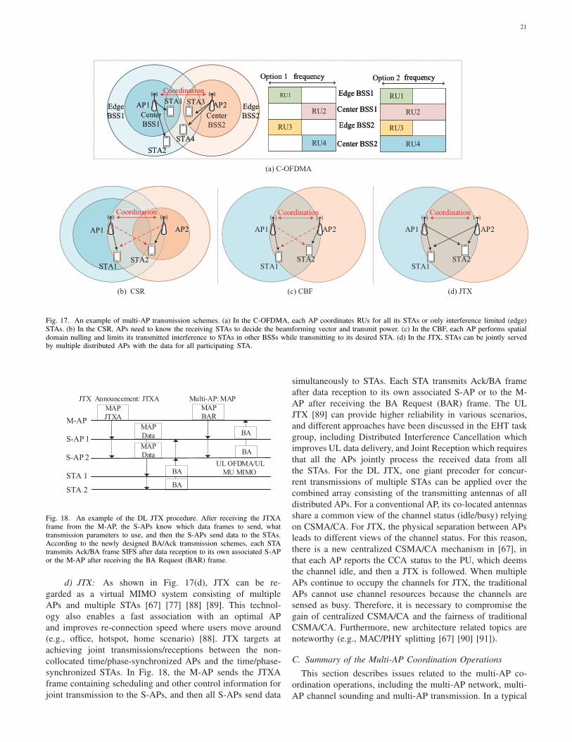
21
AP2
Coordination
AP1
STA2STA1STA1
AP1
STA1
Coordination
STA2
Coordination
STA2
AP2
CoordinationCoordinationCoordination
AP2
Coordination
AP1
STA2STA1
Edge
BSS1
Edge
BSS2
AP1 AP2
Center
BSS1Center
Coordination
STA1 STA3
STA4
STA2
Edge
BSS1
STA2
Edge
BSS2
STA4
CoordinationCoordinationCoordination
STA1STA1
STA4
Edge
BSS1
Edge
BSS2
AP1
Center Center
BSS1
Coordination
STA1
CoordinationCoordination
STA1STA1AP2
Center
Coordination
STA3
CoordinationCoordination
STA3AP1 AP2
Center
BSS1Center
BSS2
Coordination
STA1 STA3
STA4
STA2
RU3
RU1
RU4
RU2
frequency
RU3
RU1
RU4
RU2
frequency
Edge BSS1
Edge BSS2
Center BSS1
Center BSS2
Edge BSS1
Edge BSS2
Center BSS1
Center BSS2
Option 1
RU3
RU1
RU4
RU2
frequency
Edge BSS1
Edge BSS2
Center BSS1
Center BSS2
Option 1
RU3
RU1
RU4
RU2
frequency
RU3
RU1
RU4
RU2
frequencyOption 2
RU3
RU1
RU4
RU2
frequencyOption 2
(a) C-OFDMA
STA1
AP1
STA2
AP2
(c) CBF
Coordination
STA1
AP1
STA2
AP2
(b) CSR
Coordination
(d) JTX
Fig. 17. An example of multi-AP transmission schemes. (a) In the C-OFDMA, each AP coordinates RUs for all its STAs or only interference limited (edge)STAs. (b) In the CSR, APs need to know the receiving STAs to decide the beamforming vector and transmit power. (c) In the CBF, each AP performs spatialdomain nulling and limits its transmitted interference to STAs in other BSSs while transmitting to its desired STA. (d) In the JTX, STAs can be jointly servedby multiple distributed APs with the data for all participating STA.
BA
BA
BA
MAP
BAR
MAP
Data
MAP
Data
BA
MAP
JTXAM-AP
S-AP 1
S-AP 2
STA 1
STA 2
UL OFDMA/UL
MU MIMO
Multi-AP: MAPJTX Announcement: JTXA
Fig. 18. An example of the DL JTX procedure. After receiving the JTXAframe from the M-AP, the S-APs know which data frames to send, whattransmission parameters to use, and then the S-APs send data to the STAs.According to the newly designed BA/Ack transmission schemes, each STAtransmits Ack/BA frame SIFS after data reception to its own associated S-APor the M-AP after receiving the BA Request (BAR) frame.
d) JTX: As shown in Fig. 17(d), JTX can be re-
garded as a virtual MIMO system consisting of multiple
APs and multiple STAs [67] [77] [88] [89]. This technol-
ogy also enables a fast association with an optimal AP
and improves re-connection speed where users move around
(e.g., office, hotspot, home scenario) [88]. JTX targets at
achieving joint transmissions/receptions between the non-
collocated time/phase-synchronized APs and the time/phase-
synchronized STAs. In Fig. 18, the M-AP sends the JTXA
frame containing scheduling and other control information for
joint transmission to the S-APs, and then all S-APs send data
simultaneously to STAs. Each STA transmits Ack/BA frame
after data reception to its own associated S-AP or to the M-
AP after receiving the BA Request (BAR) frame. The UL
JTX [89] can provide higher reliability in various scenarios,
and different approaches have been discussed in the EHT task
group, including Distributed Interference Cancellation which
improves UL data delivery, and Joint Reception which requires
that all the APs jointly process the received data from all
the STAs. For the DL JTX, one giant precoder for concur-
rent transmissions of multiple STAs can be applied over the
combined array consisting of the transmitting antennas of all
distributed APs. For a conventional AP, its co-located antennas
share a common view of the channel status (idle/busy) relying
on CSMA/CA. For JTX, the physical separation between APs
leads to different views of the channel status. For this reason,
there is a new centralized CSMA/CA mechanism in [67], in
that each AP reports the CCA status to the PU, which deems
the channel idle, and then a JTX is followed. When multiple
APs continue to occupy the channels for JTX, the traditional
APs cannot use channel resources because the channels are
sensed as busy. Therefore, it is necessary to compromise the
gain of centralized CSMA/CA and the fairness of traditional
CSMA/CA. Furthermore, new architecture related topics are
noteworthy (e.g., MAC/PHY splitting [67] [90] [91]).
C. Summary of the Multi-AP Coordination Operations
This section describes issues related to the multi-AP co-
ordination operations, including the multi-AP network, multi-
AP channel sounding and multi-AP transmission. In a typical
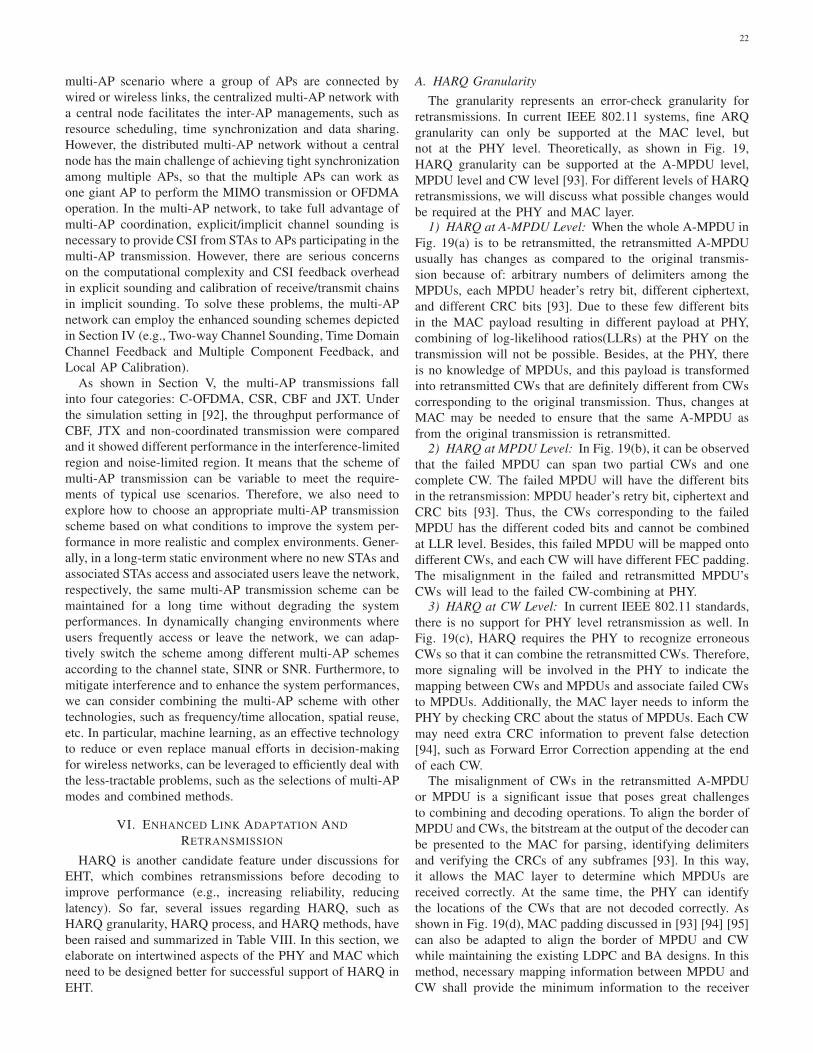
22
multi-AP scenario where a group of APs are connected by
wired or wireless links, the centralized multi-AP network with
a central node facilitates the inter-AP managements, such as
resource scheduling, time synchronization and data sharing.
However, the distributed multi-AP network without a central
node has the main challenge of achieving tight synchronization
among multiple APs, so that the multiple APs can work as
one giant AP to perform the MIMO transmission or OFDMA
operation. In the multi-AP network, to take full advantage of
multi-AP coordination, explicit/implicit channel sounding is
necessary to provide CSI from STAs to APs participating in the
multi-AP transmission. However, there are serious concerns
on the computational complexity and CSI feedback overhead
in explicit sounding and calibration of receive/transmit chains
in implicit sounding. To solve these problems, the multi-AP
network can employ the enhanced sounding schemes depicted
in Section IV (e.g., Two-way Channel Sounding, Time Domain
Channel Feedback and Multiple Component Feedback, and
Local AP Calibration).
As shown in Section V, the multi-AP transmissions fall
into four categories: C-OFDMA, CSR, CBF and JXT. Under
the simulation setting in [92], the throughput performance of
CBF, JTX and non-coordinated transmission were compared
and it showed different performance in the interference-limited
region and noise-limited region. It means that the scheme of
multi-AP transmission can be variable to meet the require-
ments of typical use scenarios. Therefore, we also need to
explore how to choose an appropriate multi-AP transmission
scheme based on what conditions to improve the system per-
formance in more realistic and complex environments. Gener-
ally, in a long-term static environment where no new STAs and
associated STAs access and associated users leave the network,
respectively, the same multi-AP transmission scheme can be
maintained for a long time without degrading the system
performances. In dynamically changing environments where
users frequently access or leave the network, we can adap-
tively switch the scheme among different multi-AP schemes
according to the channel state, SINR or SNR. Furthermore, to
mitigate interference and to enhance the system performances,
we can consider combining the multi-AP scheme with other
technologies, such as frequency/time allocation, spatial reuse,
etc. In particular, machine learning, as an effective technology
to reduce or even replace manual efforts in decision-making
for wireless networks, can be leveraged to efficiently deal with
the less-tractable problems, such as the selections of multi-AP
modes and combined methods.
VI. ENHANCED LINK ADAPTATION AND
RETRANSMISSION
HARQ is another candidate feature under discussions for
EHT, which combines retransmissions before decoding to
improve performance (e.g., increasing reliability, reducing
latency). So far, several issues regarding HARQ, such as
HARQ granularity, HARQ process, and HARQ methods, have
been raised and summarized in Table VIII. In this section, we
elaborate on intertwined aspects of the PHY and MAC which
need to be designed better for successful support of HARQ in
EHT.
A. HARQ Granularity
The granularity represents an error-check granularity for
retransmissions. In current IEEE 802.11 systems, fine ARQ
granularity can only be supported at the MAC level, but
not at the PHY level. Theoretically, as shown in Fig. 19,
HARQ granularity can be supported at the A-MPDU level,
MPDU level and CW level [93]. For different levels of HARQ
retransmissions, we will discuss what possible changes would
be required at the PHY and MAC layer.1) HARQ at A-MPDU Level: When the whole A-MPDU in
Fig. 19(a) is to be retransmitted, the retransmitted A-MPDU
usually has changes as compared to the original transmis-
sion because of: arbitrary numbers of delimiters among the
MPDUs, each MPDU header’s retry bit, different ciphertext,
and different CRC bits [93]. Due to these few different bits
in the MAC payload resulting in different payload at PHY,
combining of log-likelihood ratios(LLRs) at the PHY on the
transmission will not be possible. Besides, at the PHY, there
is no knowledge of MPDUs, and this payload is transformed
into retransmitted CWs that are definitely different from CWs
corresponding to the original transmission. Thus, changes at
MAC may be needed to ensure that the same A-MPDU as
from the original transmission is retransmitted.2) HARQ at MPDU Level: In Fig. 19(b), it can be observed
that the failed MPDU can span two partial CWs and one
complete CW. The failed MPDU will have the different bits
in the retransmission: MPDU header’s retry bit, ciphertext and
CRC bits [93]. Thus, the CWs corresponding to the failed
MPDU has the different coded bits and cannot be combined
at LLR level. Besides, this failed MPDU will be mapped onto
different CWs, and each CW will have different FEC padding.
The misalignment in the failed and retransmitted MPDU’s
CWs will lead to the failed CW-combining at PHY.3) HARQ at CW Level: In current IEEE 802.11 standards,
there is no support for PHY level retransmission as well. In
Fig. 19(c), HARQ requires the PHY to recognize erroneous
CWs so that it can combine the retransmitted CWs. Therefore,
more signaling will be involved in the PHY to indicate the
mapping between CWs and MPDUs and associate failed CWs
to MPDUs. Additionally, the MAC layer needs to inform the
PHY by checking CRC about the status of MPDUs. Each CW
may need extra CRC information to prevent false detection
[94], such as Forward Error Correction appending at the end
of each CW.
The misalignment of CWs in the retransmitted A-MPDU
or MPDU is a significant issue that poses great challenges
to combining and decoding operations. To align the border of
MPDU and CWs, the bitstream at the output of the decoder can
be presented to the MAC for parsing, identifying delimiters
and verifying the CRCs of any subframes [93]. In this way,
it allows the MAC layer to determine which MPDUs are
received correctly. At the same time, the PHY can identify
the locations of the CWs that are not decoded correctly. As
shown in Fig. 19(d), MAC padding discussed in [93] [94] [95]
can also be adapted to align the border of MPDU and CW
while maintaining the existing LDPC and BA designs. In this
method, necessary mapping information between MPDU and
CW shall provide the minimum information to the receiver
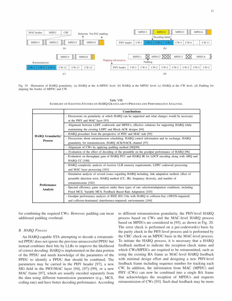
23
.........MPDU1 MPDU2 MPDU3 MPDU4
MAC header MSDU CRC
(a)
.........MPDU1 MPDU2 MPDU3 MPDU4
CW-1 CW-2 CW-3 CW-4 CW-5 CW-6 ... CW-11PHY header
Delimiter
Decoding failed
CW-2 CW-3 CW-4
(b)
(c)
Retransmission
Pre-FEC padding
CW-2PHY header
PaddingMapping information
MPDU1 MPDU2 MPDU3 MPDU4
CW-2 CW-2 CW-2 CW-2 CW-2 CW-2 CW-2
(d)
CW-12 CW-13 CW-14
...MPDU5 MPDU6
Fig. 19. Illustration of HARQ granularity. (a) HARQ at the A-MPDU level. (b) HARQ at the MPDU level. (c) HARQ at the CW level. (d) Padding foraligning the border of MPDU and CW.
Table VIIISUMMARY OF EXISTING STUDIES ON HARQ GRANULARITY/PROCESS AND PERFORMANCE ANALYSIS.
Contributions
- Discussions on granularity at which HARQ can be supported and what changes would be necessary
at the PHY and MAC layer [93]
- Alignment between LDPC codewords and MPDUs, effective solutions for supporting HARQ while
maintaining the existing LDPC and Block-ACK designs [94]
- HARQ procedure from the perspective of PHY and MAC side [95]
- Discussions about retransmission scheduling, HARQ control information and its exchange, HARQ
granularity for retransmission, HARQ ACK/NACK channel [97]
HARQ Granularity/
Process
- Alignment of CWs by applying padding method [98][99]
– Evaluation of the effect of decoding of the preamble on the goodput performance of HARQ [96]
- Evaluation on throughput gain of HARQ PCC and HARQ IR for LDCP encoding along with ARQ and
HARQ CC [100]
- HARQ complexity analysis of receiver LLR memory requirements, LDPC codeword processing
and MAC layer processing [101]
- Simulation analysis of several issues regarding HARQ including, link adaptation method, effect of
preamble detection error, HARQ method (CC, IR), frequency diversity, and number of
retransmissions [102]
- Spectral efficiency gains analysis under three types of rate selection/adaptation conditions, including
Fixed MCS, Variable MCS, Feedback Based Rate Adaptation [103]
Performance
Analysis
- Goodput performance analysis of IEEE 802.11be with HARQ in collision-free (AWGN-impaired)
and collision-dominated (interference-impaired) environments [104]
for combining the required CWs. However, padding can incur
additional padding overhead.
B. HARQ Process
An HARQ-capable STA attempting to decode a retransmit-
ted PPDU does not ignore the previous unsuccessful PPDU but
instead combines their bits by LLRs to improve the likelihood
of correct decoding. HARQ is implemented on the data portion
of the PPDU and needs knowledge of the parameters of the
PPDU to identify a PPDU that should be combined. The
parameters may be carried in the PHY header [97], a new
SIG field in the PHY/MAC layer [94], [97]–[99], or a new
MAC frame [97], which are usually encoded separately from
the data using different transmission parameters (e.g., MCS,
coding rate) and have better decoding performance. According
to different retransmission granularity, the PHY-level HARQ
process based on CWs and the MAC-level HARQ process
based on MPDUs are considered in [95], as shown in Fig. 20.
The error check is performed on a per-codeword(s) basis by
the parity check in the PHY-level process and is performed by
the CRC check on an MPDU basis in the MAC-level process.
To initiate the HARQ process, it is necessary that a HARQ
feedback method to indicate the reception check status and
which CWs/MPDUs are required to be retransmitted, such as
using the existing BA frame as MAC-level HARQ feedback
with minimal design effort and designing a new PHY-level
feedback frame including sequence number for tracking each
CW. In addition, the information from MAC (MPDU) and
PHY (CWs) can now be combined into a single BA frame
that acknowledges the reception of MPDUs and requests
retransmission of CWs [93]. Such dual feedback may be more
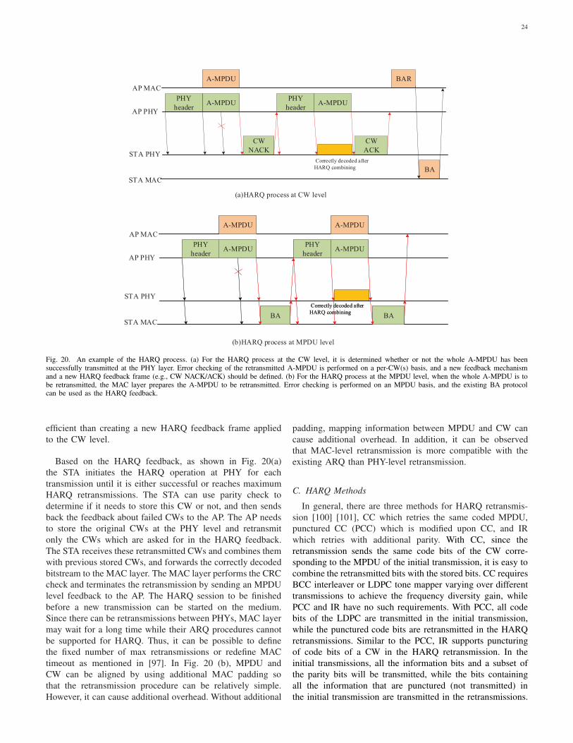
24
CW
NACK
A-MPDUPHY
header
A-MPDU
PHY
headerA-MPDU
CW
ACK
BA
BAR
AP MAC
AP PHY
STA PHY
STA MAC
(a)HARQ process at CW level
Correctly decoded after
HARQ combining
STA PHY
STA MAC
(b)HARQ process at MPDU level
AP MAC
AP PHY
BABA
A-MPDUPHY
header
A-MPDU
PHY
headerA-MPDU
Correctly decoded after
HARQ combining
A-MPDU
BABA
A-MPDUPHY
header
A-MPDU
PHY
headerA-MPDU
Correctly decoded after
HARQ combining
A-MPDU
Fig. 20. An example of the HARQ process. (a) For the HARQ process at the CW level, it is determined whether or not the whole A-MPDU has beensuccessfully transmitted at the PHY layer. Error checking of the retransmitted A-MPDU is performed on a per-CW(s) basis, and a new feedback mechanismand a new HARQ feedback frame (e.g., CW NACK/ACK) should be defined. (b) For the HARQ process at the MPDU level, when the whole A-MPDU is tobe retransmitted, the MAC layer prepares the A-MPDU to be retransmitted. Error checking is performed on an MPDU basis, and the existing BA protocolcan be used as the HARQ feedback.
efficient than creating a new HARQ feedback frame applied
to the CW level.
Based on the HARQ feedback, as shown in Fig. 20(a)
the STA initiates the HARQ operation at PHY for each
transmission until it is either successful or reaches maximum
HARQ retransmissions. The STA can use parity check to
determine if it needs to store this CW or not, and then sends
back the feedback about failed CWs to the AP. The AP needs
to store the original CWs at the PHY level and retransmit
only the CWs which are asked for in the HARQ feedback.
The STA receives these retransmitted CWs and combines them
with previous stored CWs, and forwards the correctly decoded
bitstream to the MAC layer. The MAC layer performs the CRC
check and terminates the retransmission by sending an MPDU
level feedback to the AP. The HARQ session to be finished
before a new transmission can be started on the medium.
Since there can be retransmissions between PHYs, MAC layer
may wait for a long time while their ARQ procedures cannot
be supported for HARQ. Thus, it can be possible to define
the fixed number of max retransmissions or redefine MAC
timeout as mentioned in [97]. In Fig. 20 (b), MPDU and
CW can be aligned by using additional MAC padding so
that the retransmission procedure can be relatively simple.
However, it can cause additional overhead. Without additional
padding, mapping information between MPDU and CW can
cause additional overhead. In addition, it can be observed
that MAC-level retransmission is more compatible with the
existing ARQ than PHY-level retransmission.
C. HARQ Methods
In general, there are three methods for HARQ retransmis-
sion [100] [101], CC which retries the same coded MPDU,
punctured CC (PCC) which is modified upon CC, and IR
which retries with additional parity. With CC, since the
retransmission sends the same code bits of the CW corre-
sponding to the MPDU of the initial transmission, it is easy to
combine the retransmitted bits with the stored bits. CC requires
BCC interleaver or LDPC tone mapper varying over different
transmissions to achieve the frequency diversity gain, while
PCC and IR have no such requirements. With PCC, all code
bits of the LDPC are transmitted in the initial transmission,
while the punctured code bits are retransmitted in the HARQ
retransmissions. Similar to the PCC, IR supports puncturing
of code bits of a CW in the HARQ retransmission. In the
initial transmissions, all the information bits and a subset of
the parity bits will be transmitted, while the bits containing
all the information that are punctured (not transmitted) in
the initial transmission are transmitted in the retransmissions.
25
Unlink CC, IR has some other issues due to the coding method.
For BCC, using different puncturing patterns in each retrans-
mission can be considered to make new parity bits, which is
only applied to RU size less than or equal to 242 tones. Hence
the gain cannot be realized for larger RU sizes. For LDPC en-
coding scheme, IR can support current LDPC code rates (1/2,
2/3, 3/4, 5/6) and CW length (1944 bits) employed in current
IEEE 802.11 standards [100] [101]. Different HARQ methods
have different implementation complexities and gains. How
to choose the exact HARQ methods in different environ-
ments is challenging. The gain from HARQ is dependent
on the link adaptation method [102] which tries to change
the transmission rate based on the real-time channel status
to improve the transmission performance before the initial
transmission. There are three types of rate selection/adaptation
techniques: fixed MCS in the initial transmission and re-
transmission, variable MCS based on long-term SNR, and
optimal rate adaptation based on HARQ feedback, which can
include information like the short-term SNR. HARQ (PCC
and IR) spectral efficiency gains under three types of rate
selection/adaptation conditions were investigated in [103], and
the simulation results showed that the largest gains are for the
case of feedback-based rate adaption and below around 25
dB SNR and losses due to overhead become significant for
shorter HARQ PPDU durations. Thus, it will be essential to
limit overhead loss to realize HARQ gains in real systems.
In [103], the goodput performance of EHT with HARQ in
collision-free (additive white Gaussian noise-impaired) and
collision-dominated (interference-impaired) environments was
evaluated. Simulation results also demonstrated performance
gains but showed that there is a need for different strategies
in collision-dominated environments. Consider more various
conditions (e.g., hardware complexity), further study on im-
plementing HARQ in typical HARQ scenarios is still needed,
e.g., multiple links, multiple users or multiple APs scenarios.
D. Summary of the HARQ
This section presents several issues and challenges regarding
HARQ granularity, HARQ process and methods. Theoreti-
cally, the granularity and process of HARQ can be supported
at the MAC layer level and the PHY level. The basic HARQ
granularity in EHT is not determined yet. As aforementioned,
for the A-MPDU-level/MPDU-level retransmissions, HARQ
combining is ineffective when the retransmitted bitstream
differs from the initial transmitted bitstream. Concerning the
CW-level retransmission, the HARQ combining that only
requires minor changes and designs based on the existing spec-
ifications, which is therefore relatively simple. By contrast,
using the CW-level retransmission is considered more feasible
since the drawback of using the A-MPDU-level/MPDU-level
retransmission without one-to-one mapping between the A-
MPDU/MPDU and CWs can be relatively hard to overcome.
However, EHT requires a more detailed and in-depth inves-
tigation and analysis for the standardization of HARQ, such
as CWs processing and memory requirements for erroneous
CWs. As in Section VI, the PHY-level retransmission process
and the MAC-level retransmission process are investigated. By
contrast, in terms of signaling and potential padding overhead,
the PHY-level retransmission is preferred while we need to
design new feedback and consider how to cooperate with the
existing ARQ protocol. In the case of the MAC-level retrans-
mission, signaling overhead to map MPDUs with CWs and
additional MAC padding overhead will be significant. Thus,
we think that using PHY-level retransmission is appropriate
since the drawback of using PHY-level retransmission with
lower PHY-MAC interaction overhead can be relatively easily
resolved.
VII. FUTURE DEVELOPMENT AND RESEARCH
OPPORTUNITIES
In this section, some open technical issues that need to be
investigated and several promising research directions are dis-
cussed. These topics are expected to promote the development
of wireless communication networks by addressing several
technical challenges including 6GHz co-existence problems,
integrating low-frequency and high-frequency bands, guar-
anteed QoS provisioning based on machine learning, power
management and hybrid beamforming.
A. Coexistence in the 6 GHz band
One of the main objectives of EHT is to make full use of up
to 1.2 GHz spectrum resources in the 6 GHz band. However,
to effectively utilize these frequency resources, EHT has to co-
exist with other different technologies operating in the same
band, such as IEEE 802.11ax and 5G on the unlicensed band.
Coexistence among wireless networks is challenging, espe-
cially when these networks are heterogeneous. The spectrum
access rules differ across networks, which may hinder the fair
sharing of the spectrum resources. We should distinguish at
least two coexistence scenarios [105]: one is that networks
implement coexistence mechanisms on its own without any
consultation from its neighbours, and the other is that networks
directly or indirectly coordinate to ease their coexistence. In
a coordinated coexistence setting, coordination may require
a common management/control plane between heterogeneous
technologies, e.g., control of cloud [63], SDN [106], or a
direct communication tunnel. In an uncoordinated coexistence
setting, uncoordinated schemes might require more sophisti-
cated techniques to implement neighbour-aware coexistence
schemes, and networks try to ensure coexistence with other
networks mostly based on their local observations. Machine
learning has been envisaged to be critical for reaching co-
existence goals by providing the necessary intelligence and
adaptation mechanisms, e.g., using machine learning for co-
existence by discovering network dynamics [106] or predicting
spectrum usage of adjacent networks [107]. New machine
learning algorithms will fast learning speed while leveraging
distributed computing resources over edge and cloud could be
extremely useful in achieving situation-aware coexistence.
B. Integrating low-frequency and high-frequency bands
Densely deployed sub-6GHz WLANs alone may not pro-
vide the seamless connectivity required by mobile services
26
and the rapid increase in mobile data traffic in future wire-
less networks. As a result, one of the main advancements
in the network design for WLAN relies on the integration
of multiple different bands (e.g., microwave and mmWave).
An integrated system that can leverage multiple frequencies
across the microwave/mmWave/THz spectrum is needed to
provide seamless and intelligent connectivity at both wide
and local area levels. The existing IEEE 802.11 standards can
already provide a negotiation pipe among different frequency
bands through FST and On-channel tunneling for multi-band
operations (e.g., fast session transfer) [7]. Besides, there are
already many potential solutions for mobility management
and network data migration management to integrate the
microwave/mmWave spectrum [109]–[113]. However, exploit-
ing integrated low and higher frequency bands will bring
forth several new open problems from hardware to system
design. For example, supporting high mobility at these multi-
ple spectra [114] [115], developing new multiple access and
networking paradigms, and new transceiver architectures are
needed along with new microwave/mmWave/THz frequencies
propagation models. Another important research direction is
to study collaborative operation across these multiple spectra.
C. Guaranteed QoS provisioning based on machine learning
How to intelligently and appropriately recognize the diverse
QoS requirements and efficiently allocate wireless resources
for users with different QoS requirements is a hot topic in
the standardization process. In the existing QoS-supported
WLAN, EDCA adjusts back-off parameters to implement
priority-based channel access at the MAC layer [7], which can
provide a certain degree of QoS guarantee for different types
of traffics with different QoS requirements. The appearance of
emerging and diverse network services (e.g., gaming, VR/AR,
and 4k/8k video) has created new challenges in the diverse
QoS requirements of different users, such as throughput, delay,
jitter, and loss rate. This often requires the network to have to
react quickly to user’s experience, allocate wireless resources
for users with different QoS requirements, and offer a better
QoS. However, current EDCA is good in the view of statistics,
but may be unable to help improve the worst-case latency
and jitter due to such limitations, e.g., discriminating different
types of traffics only according to QoS fields and not directly
reflecting latency requirements of latency-sensitive applica-
tions. In addition to using the shortened Trigger frames for
soliciting Trigger-based PPDU transmission carrying the real-
time traffic [116], a new design of queue [117] may improve
the worst-case latency by (i) linking access delay directly to
the latency required by the latency-critical traffic, (ii) cate-
gorizing traffic by taking into consideration more parameters,
and (iii) being grant with higher priority in channel access, etc.
Besides, machine-learning methods with situation-awareness
[118] may be efficient ways to satisfy users’ QoS requirements
by a set of observations reflecting the network state and the
user’s perception. For example, a multi-link capable device
can apply machine-learning algorithms to predict the future
link status (busy/idle) according to a set of historical link
information (e.g., link status, link traffic or link utilization),
and then adaptively and quickly switch the link subjected
to strong interference to another appropriate link so as to
guarantee the communication quality. In addition, machine-
learning algorithms are currently considered as promising tools
for various purposes in many fields ranging from PHY/MAC
protocols design to the development of theoretical foundations,
such as parameters optimization (e.g., adjusting contention
window or priority for EDCA), protocol version selection,
multi-channel/multi-link aggregation, channel modeling, fast
time-varying channel estimation, modulation recognition, RU
allocation, multi-antenna selection with 16 spatial streams
for SU-MIMO/MU-MIMO transmission, multi-AP selection
and multi-AP network deployment for multi-AP coordina-
tion, etc. For example, a multi-AP network can predict the
future users’ QoS requirements and environment conditions
in terms of properties such as the multi-AP transmission
parameters/settings (e.g., MSC/bandwidth), and then optimize
the network resource management and improve the overall
multi-AP network performance.
D. Power management
Mobile devices are battery-powered and have limited battery
life. In addition to improving the design of the battery itself,
it is critical to enhance energy-saving mechanisms. With the
new requirements and characteristics of EHT, such as multi-
link operation, multi-AP collaboration, and HARQ, the power
consumption level of EHT devices could be significantly
increased. For example, in light traffic load conditions, a
multilink-capable mobile device may be in listening mode for
quite long time, which may constitute a significant ratio of a
multi-link device’s power consumption. As a result, new and
more effective energy-saving mechanisms should be carefully
designed to cope with the increased power consumption. For
example, flexibly enabling/disabling links based on the actual
network conditions or effective prediction methods may be an
ideal approach to save a lot of power compared to the modes
where all links are involved in. Also, the combination of artifi-
cial intelligence algorithms and power management to achieve
intelligent high efficiency and energy saving [119] [120] is also
a direction worthy of research. For example, in a multi-AP
network, the APs participating in the multi-AP transmissions
can intelligently increase or decrease the transmit power based
on the accurately predicted movement trajectory of users,
user’s QoS requirements and channel conditions. Nevertheless,
the timeliness and accuracy of prediction algorithms for power
saving still need to be deeply investigated.
E. Hybrid beamforming
Unlike digital beamforming currently used in sub-6GHz
WLANs, where every spatial stream necessitates an expensive
RF chain [7], hybrid beamforming often requires that the
number of RF chains may be much smaller than the actual
number of antennas. Hybrid beamforming can help balance
flexibility and cost trade-offs while still fielding a system
that meets the required performance parameters. To achieve
hybrid beamforming in future wireless communications sys-
tems, the main issue to be considered are the system models
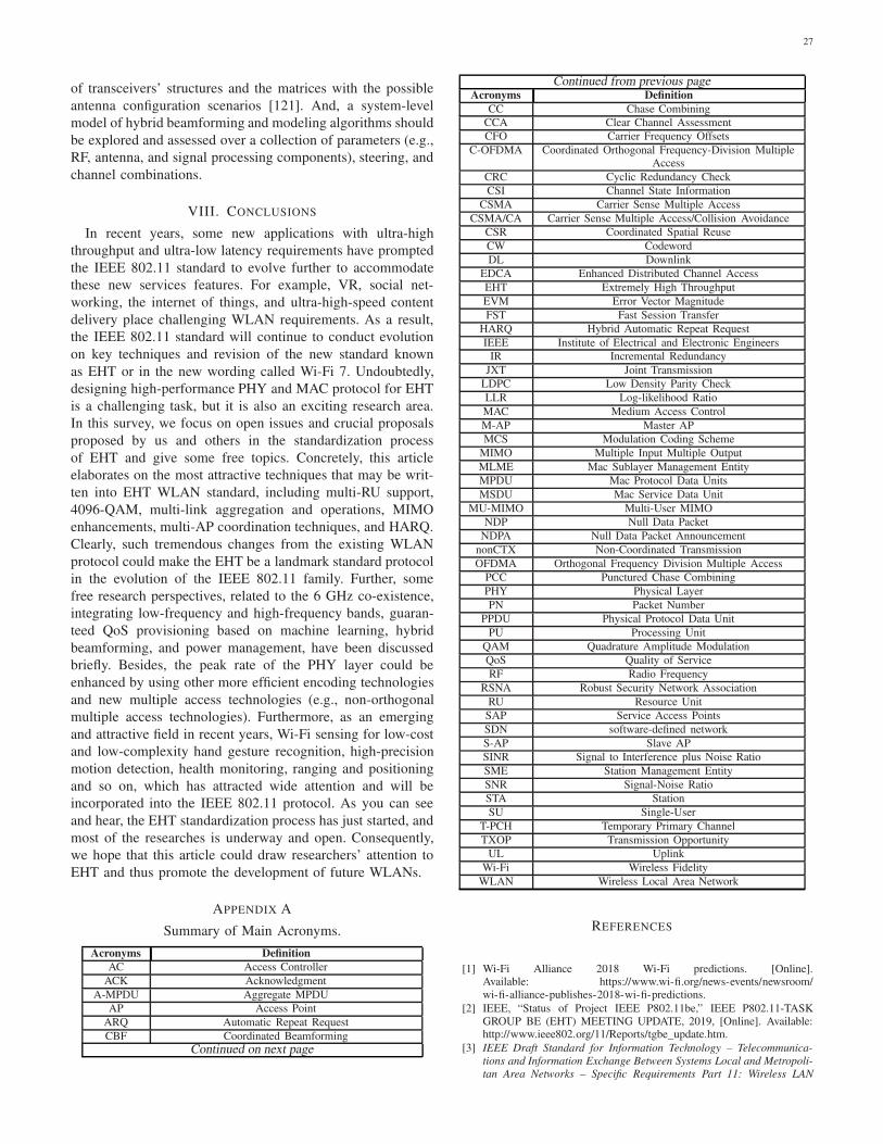
27
of transceivers’ structures and the matrices with the possible
antenna configuration scenarios [121]. And, a system-level
model of hybrid beamforming and modeling algorithms should
be explored and assessed over a collection of parameters (e.g.,
RF, antenna, and signal processing components), steering, and
channel combinations.
VIII. CONCLUSIONS
In recent years, some new applications with ultra-high
throughput and ultra-low latency requirements have prompted
the IEEE 802.11 standard to evolve further to accommodate
these new services features. For example, VR, social net-
working, the internet of things, and ultra-high-speed content
delivery place challenging WLAN requirements. As a result,
the IEEE 802.11 standard will continue to conduct evolution
on key techniques and revision of the new standard known
as EHT or in the new wording called Wi-Fi 7. Undoubtedly,
designing high-performance PHY and MAC protocol for EHT
is a challenging task, but it is also an exciting research area.
In this survey, we focus on open issues and crucial proposals
proposed by us and others in the standardization process
of EHT and give some free topics. Concretely, this article
elaborates on the most attractive techniques that may be writ-
ten into EHT WLAN standard, including multi-RU support,
4096-QAM, multi-link aggregation and operations, MIMO
enhancements, multi-AP coordination techniques, and HARQ.
Clearly, such tremendous changes from the existing WLAN
protocol could make the EHT be a landmark standard protocol
in the evolution of the IEEE 802.11 family. Further, some
free research perspectives, related to the 6 GHz co-existence,
integrating low-frequency and high-frequency bands, guaran-
teed QoS provisioning based on machine learning, hybrid
beamforming, and power management, have been discussed
briefly. Besides, the peak rate of the PHY layer could be
enhanced by using other more efficient encoding technologies
and new multiple access technologies (e.g., non-orthogonal
multiple access technologies). Furthermore, as an emerging
and attractive field in recent years, Wi-Fi sensing for low-cost
and low-complexity hand gesture recognition, high-precision
motion detection, health monitoring, ranging and positioning
and so on, which has attracted wide attention and will be
incorporated into the IEEE 802.11 protocol. As you can see
and hear, the EHT standardization process has just started, and
most of the researches is underway and open. Consequently,
we hope that this article could draw researchers’ attention to
EHT and thus promote the development of future WLANs.
APPENDIX A
Summary of Main Acronyms.
Acronyms Definition
AC Access Controller
ACK Acknowledgment
A-MPDU Aggregate MPDU
AP Access Point
ARQ Automatic Repeat Request
CBF Coordinated Beamforming
Continued on next page
Continued from previous pageAcronyms Definition
CC Chase Combining
CCA Clear Channel Assessment
CFO Carrier Frequency Offsets
C-OFDMA Coordinated Orthogonal Frequency-Division MultipleAccess
CRC Cyclic Redundancy Check
CSI Channel State Information
CSMA Carrier Sense Multiple Access
CSMA/CA Carrier Sense Multiple Access/Collision Avoidance
CSR Coordinated Spatial Reuse
CW Codeword
DL Downlink
EDCA Enhanced Distributed Channel Access
EHT Extremely High Throughput
EVM Error Vector Magnitude
FST Fast Session Transfer
HARQ Hybrid Automatic Repeat Request
IEEE Institute of Electrical and Electronic Engineers
IR Incremental Redundancy
JXT Joint Transmission
LDPC Low Density Parity Check
LLR Log-likelihood Ratio
MAC Medium Access Control
M-AP Master AP
MCS Modulation Coding Scheme
MIMO Multiple Input Multiple Output
MLME Mac Sublayer Management Entity
MPDU Mac Protocol Data Units
MSDU Mac Service Data Unit
MU-MIMO Multi-User MIMO
NDP Null Data Packet
NDPA Null Data Packet Announcement
nonCTX Non-Coordinated Transmission
OFDMA Orthogonal Frequency Division Multiple Access
PCC Punctured Chase Combining
PHY Physical Layer
PN Packet Number
PPDU Physical Protocol Data Unit
PU Processing Unit
QAM Quadrature Amplitude Modulation
QoS Quality of Service
RF Radio Frequency
RSNA Robust Security Network Association
RU Resource Unit
SAP Service Access Points
SDN software-defined network
S-AP Slave AP
SINR Signal to Interference plus Noise Ratio
SME Station Management Entity
SNR Signal-Noise Ratio
STA Station
SU Single-User
T-PCH Temporary Primary Channel
TXOP Transmission Opportunity
UL Uplink
Wi-Fi Wireless Fidelity
WLAN Wireless Local Area Network
REFERENCES
[1] Wi-Fi Alliance 2018 Wi-Fi predictions. [Online].Available: https://www.wi-fi.org/news-events/newsroom/wi-fi-alliance-publishes-2018-wi-fi-predictions.
[2] IEEE, “Status of Project IEEE P802.11be,” IEEE P802.11-TASKGROUP BE (EHT) MEETING UPDATE, 2019, [Online]. Available:http://www.ieee802.org/11/Reports/tgbe_update.htm.
[3] IEEE Draft Standard for Information Technology – Telecommunica-
tions and Information Exchange Between Systems Local and Metropoli-
tan Area Networks – Specific Requirements Part 11: Wireless LAN
28
Medium Access Control (MAC) and Physical Layer (PHY) Specifica-
tions Amendment Enhancements for High Efficiency WLAN, in IEEEP802.11ax/D6.0, November 2019 , vol., no., pp.1-780, 14 Dec. 2019.
[4] E. Au et al., “Specification Framework for TGbe,” IEEE 802.11Documents, Feb. 2020. [Online]. Available: https://mentor.ieee.org/802.11/documents?is_dcn=1262&is_group=00be.
[5] L. Cariou et al., “EHT draft proposed PAR,” IEEE 802.11 Docu-ments, Mar. 2019. [Online]. Available: https://mentor.ieee.org/802.11/documents?is_dcn=1231&is_group=0eht.
[6] S. Vermani et al., “Forward Compatibility for WiFi Preamble Design,”IEEE 802.11 Documents, Nov. 2019. [Online]. Available: https://mentor.ieee.org/802.11/documents?is_dcn=1519&is_group=00be.
[7] IEEE Standard for Information Technology - Telecommunications and
information exchange between systems Local and metropolitan areanetworks-Specific requirements - Part 11: Wireless LAN Medium Ac-
cess Control (MAC) and Physical Layer (PHY) Specifications, IEEEStd 802.11-2016 (Revision of IEEE Std 802.11-2012), pp. 1-3534,Dec.2016.
[8] P. Huang et al., “Multi-link Operation Framework,” IEEE 802.11Documents, Jul. 2019. [Online]. Available: https://mentor.ieee.org/802.11/documents?is_dcn=0773&is_group=00be.
[9] D. López-Pérez, A. Garcia-Rodriguez, L. Galati-Giordano, M. Kasslinand K. Doppler, “IEEE 802.11be Extremely High Throughput: TheNext Generation of Wi-Fi Technology Beyond 802.11ax,” in IEEE
Communications Magazine, vol. 57, no. 9, pp. 113-119, September2019.
[10] Y. Tanaka et al., “Discussion on 6GHz band support,” IEEE 802.11Documents, Jul. 2019. [Online]. Available: https://mentor.ieee.org/802.11/documents?is_dcn=11be&is_group=00be.
[11] M. Parket et al., “Beyond 802.11ax-Throughput Enhancement UtilizingMulti-bands across 2.4/5/6GHz Bands,” IEEE 802.11 Documents, May2018. [Online]. Available: https://mentor.ieee.org/802.11/documents?is_dcn=857.
[12] T. Wu et al., “EHT discussions on throughput enhancement,” IEEE802.11 Documents, Jul.2018. [Online]. Available: https://mentor.ieee.org/802.11/documents?is_dcn=1184.
[13] B. Tian et al., “11be 320MHz channelization and tone plan,” IEEE802.11 Documents, Jul. 2019. [Online]. Available: https://mentor.ieee.org/802.11/documents?is_dcn=0797&is_group=00be.
[14] S. Schelstraete et al., “Multi-RU support for OFDMA,” IEEE 802.11Documents, Jan. 2020. [Online]. Available: https://mentor.ieee.org/802.11/documents?is_dcn=0108&is_group=00be.
[15] R.J. Yu et al., “Multiple RU discussion,” IEEE 802.11 Documents, Jan.2020. [Online]. Available: https://mentor.ieee.org/802.11/documents?is_dcn=1914&is_group=00be.
[16] E. Park et al., “Phase Rotation for 320MHz,” IEEE 802.11 Docu-ments, Nov. 2019. [Online]. Available: https://mentor.ieee.org/802.11/documents?is_dcn=1493&is_group=00be.
[17] R.J. Yu et al., “preamble structure in 11be,” IEEE 802.11 Docu-ments, Sep. 2019. [Online]. Available: https://mentor.ieee.org/802.11/documents?is_dcn=1099&is_group=00be.
[18] X. Chen et al., “11be Preamble Structure,” IEEE 802.11 Docu-ments, Nov. 2019. [Online]. Available: https://mentor.ieee.org/802.11/documents?is_dcn=1516&is_group=00be.
[19] D. Liang et al., “EHT P matrices Discussion,” IEEE 802.11 Docu-ments, Jan. 2020. [Online]. Available: https://mentor.ieee.org/802.11/documents?is_dcn=1980&is_group=00be.
[20] D. Liang et al., “EHT-LTFs Design for Wideband,” IEEE 802.11Documents, Jan. 2020. [Online]. Available: https://mentor.ieee.org/802.11/documents?is_dcn=0117&is_group=00be.
[21] S. Schelstraete et al., “11be preamble and forward compatibility,” IEEE802.11 Documents, Jan. 2020. [Online]. Available: https://mentor.ieee.org/802.11/documents?is_dcn=110&is_group=00be.
[22] W. Ahn et al., “Wider Bandwidth Channel Access in EHT,” IEEE802.11 Documents, Jul.2019. [Online]. Available: https://mentor.ieee.org/802.11/documents?is_dcn=1242&is_group=00be.
[23] O. Redlich et al., “Improved Preamble Puncturing in 802.11be,” IEEE802.11 Documents, Jul.2019. [Online]. Available: https://mentor.ieee.org/802.11/documents?is_dcn=1190&is_group=00be.
[24] S. Schelstraete et al., “Feasibility of 4096QAM,” IEEE 802.11 Docu-ments, Apr. 2019. [Online]. Available: https://mentor.ieee.org/802.11/documents?is_dcn=0637&is_group=00be.
[25] Y. Fang et al., “Multi-Link Architecture and Requirement Discussion,”IEEE 802.11 Documents, Jul.2019. [Online]. Available: https://mentor.ieee.org/802.11/documents?is_dcn=1095&is_group=00be.
[26] S. Nandagopalan et al., “Multiband and Multichannel Operationin IEEE 802.11be,” IEEE 802.11 Documents, Jul. 2019. [Online].Available: https://mentor.ieee.org/802.11/documents?is_dcn=1231&is_group=00be.
[27] Y. Seok et al., “Enhanced Multi-band/Multi-channel Operation,” IEEE802.11 Documents, May 2019. [Online]. Available:https://mentor.ieee.org/802.11/documents?is_dcn=0766&is_group=00be.
[28] L. Cariou et al., “CR for 6 GHz - Discovery,” IEEE 802.11 Docu-ments, Jan. 2019. [Online]. Available: https://mentor.ieee.org/802.11/documents?is_dcn=1227&is_group=00ax.
[29] J. Ahn et al., “OFDMA Non-contiguous Channel Utilization,” IEEE802.11 Documents, Mar. 2015. [Online]. Available: https://mentor.ieee.org/802.11/documents?is_dcn=353&is_group=00ax.
[30] J. Ahn et al., “Efficient Wider Bandwidth Operation in IEEE 802.11ax,”IEEE 802.11 Documents, Nov. 2014. [Online]. Available: https://mentor.ieee.org/802.11/documents?is_dcn=1437&is_group=00ax.
[31] K. Yano, N. Egashira, S. Tsukamoto, J. Webber and T. Kumagai,“Channel Access Balancing for Multiband Wireless LAN by UsingAlternative Primary Channel,” 2017 IEEE Wireless Communicationsand Networking Conference (WCNC), San Francisco, CA, 2017, pp.1-6.
[32] Dmitry Akhmetov, “Performance aspects of Multi-link operations,”IEEE 802.11 Documents, Jul. 2019. [Online]. Available: https://mentor.ieee.org/802.11/documents?is_dcn=1291&is_group=00be.
[33] Y. Li et al., “Channel Access in Multi-band operation,” IEEE 802.11Documents, Jul. 2019. [Online]. Available: https://mentor.ieee.org/802.11/documents?is_dcn=1116&is_group=00be.
[34] L. Lu et al., “Discussion on Multi-band/Multi-channel Access Method,”IEEE 802.11 Documents, May 2019. [Online]. Available: https://mentor.ieee.org/802.11/documents?is_dcn=951&is_group=00be.
[35] A. Patil et al., “Multi-Link Operation: Design Discussion,” IEEE802.11 Documents, May 2019. [Online]. Available: https://mentor.ieee.org/802.11/documents?is_dcn=0823&is_group=00be.
[36] W.K.Soo, et al., “Survey on load-balancing methods in 802.11 infras-tructure mode wireless networks for improving quality of service,”ACM Computing Surveys (CSUR) 51.2 (2018): 34.
[37] P. Zhou, X. Fang, X. Wang and L. Yan, “Multi-Beam Transmission andDual-Band Cooperation for Control/Data Plane Decoupled WLANs,”in IEEE Transactions on Vehicular Technology, 2019, 68(10): 9806-9819.
[38] I. Jiang et al., “Channel Access for Multi-link Operation,” IEEE 802.11Documents, Jul. 2019. [Online]. Available: https://mentor.ieee.org/802.11/documents?is_dcn=1144&is_group=00be.
[39] S. Hwang et al., “Channel Access for Multi-link Operation,” IEEE802.11 Documents, Jul. 2019. [Online]. Available: https://mentor.ieee.org/802.11/documents?is_dcn=1181&is_group=00be.
[40] A. Jauh et al., “Multiple Link Asynchronous and SynchronousTransmission,” IEEE 802.11 Documents, Sep. 2019. [Online].Available: https://mentor.ieee.org/802.11/documents?is_dcn=1678&is_group=00be.
[41] R. Hirata et al., “Discussion on Multi-band operation,” IEEE 802.11Documents, Aug. 2019. [Online]. Available: https://mentor.ieee.org/802.11/documents?is_dcn=0818&is_group=00be.
[42] Y. Seok et al., “EHT Multi-Link Operation Follow-up,” IEEE 802.11Documents, Jul. 2019. [Online]. Available: https://mentor.ieee.org/802.11/documents?is_dcn=0979&is_group=00be.
[43] K. Yano, N. Egashira, J. Webber, M. Usui and Y. Suzuki, “AchievableThroughput of Multiband Wireless LAN using Simultaneous Trans-mission over Multiple Primary Channels Assisted by Idle LengthPrediction Based on PNN,” 2019 International Conference on Artificial
Intelligence in Information and Communication (ICAIIC), Okinawa,Japan, 2019, pp. 022-027.
[44] IEEE Standard for Information technology– Local and metropolitan
area networks– Specific requirements– Part 11: Wireless LAN Medium
Access Control (MAC)and Physical Layer (PHY) Specifications Amend-
ment 5: Enhancements for Higher Throughput, in IEEE Std 802.11n-2009 (Amendment to IEEE Std 802.11-2007 as amended by IEEE Std802.11k-2008, IEEE Std 802.11r-2008, IEEE Std 802.11y-2008, andIEEE Std 802.11w-2009) , vol., no., pp.1-565, 29 Oct. 2009.
[45] IEEE Standard for Information technology–Telecommunications and
information exchange between systemsałLocal and metropolitan area
networks–Specific requirements–Part 11: Wireless LAN Medium Access
Control (MAC) and Physical Layer (PHY) Specifications–Amendment4: Enhancements for Very High Throughput for Operation in Bands
below 6 GHz, in IEEE Std 802.11ac(TM)-2013 (Amendment to IEEEStd 802.11-2012, as amended by IEEE Std 802.11ae-2012, IEEE Std
29
802.11aa-2012, and IEEE Std 802.11ad-2012) , vol., no., pp.1-425, 18Dec. 2013.
[46] IEEE Standard for Information technology–Telecommunications and
information exchange between systems - Local and metropolitan area
networks–Specific requirements - Part 11: Wireless LAN Medium Ac-
cess Control (MAC) and Physical Layer (PHY) Specifications Amend-ment 2: Sub 1 GHz License Exempt Operation, IEEE Std 802.11ah-2016 (Amendment to IEEE Std 802.11-2016, as amended by IEEE Std802.11ai-2016), pp. 1-594,May 2017.
[47] IEEE Draft Standard for Information Technology–Telecommunications
and Information Exchange Between Systems Local and Metropolitan
Area Networks–Specific Requirements Part 11: Wireless LAN Medium
Access Control (MAC) and Physical Layer (PHY) Specifications–Amendment: Enhanced Throughput for Operation in License-Exempt
Bands Above 45 GHz, in IEEE P802.11ay/D4.0, June 2019 , vol., no.,pp.1-791, 17 July 2019.
[48] K. Oteri et al., “Reducing Explicit MIMO Compressed BeamformingFeedback Overhead for 802.11ax,” IEEE 802.11 Documents, Nov.2015. [Online]. Available: https://mentor.ieee.org/802.11/documents?is_dcn=1231&is_group=00ax.
[49] K. Oteri et al., “Feedback Overhead Reduction in 802.11be,” IEEE802.11 Documents, Mar. 2019. [Online]. Available: https://mentor.ieee.org/802.11/documents?is_dcn=0391&is_group=00be.
[50] R. Porat, E. Ojard, N. Jindal, M. Fischer and V. Erceg, “ImprovedMU-MIMO performance for future 802.11 systems using differentialfeedback,” 2013 Information Theory and Applications Workshop (ITA),San Diego, CA, 2013, pp. 1-5.
[51] C. Lim, T. Yoo, B. Clerckx, B. Lee and B. Shim, “Recent trendof multiuser MIMO in LTE-advanced,” in IEEE Communications
Magazine, vol. 51, no. 3, pp. 127-135, March 2013.[52] D. J. Love, R. W. Heath, V. K. N. Lau, D. Gesbert, B. D. Rao and M.
Andrews, “An overview of limited feedback in wireless communicationsystems,” in IEEE Journal on Selected Areas in Communications, vol.26, no. 8, pp. 1341-1365, October 2008.
[53] W. Lu, Y. Liu, D. Wang, “Efficient feedback scheme based on com-pressed sensing in MIMO wireless networks,” Comput. Elect. Eng.,vol. 39, no. 6, pp. 1587-1600, Aug. 2013.
[54] X. Rao and V. K. N. Lau, “Distributed Compressive CSIT Estimationand Feedback for FDD Multi-User Massive MIMO Systems,” in IEEE
Transactions on Signal Processing, vol. 62, no. 12, pp. 3261-3271,June15, 2014.
[55] M. E. Eltayeb, T. Y. Al-Naffouri and H. R. Bahrami, “CompressiveSensing for Feedback Reduction in MIMO Broadcast Channels,” inIEEE Transactions on Communications, vol. 62, no. 9, pp. 3209-3222,Sept. 2014.
[56] L. P. Withers, R. M. Taylor and D. M. Warme, “Echo-MIMO: a two-way channel training method for matched cooperative beamforming,”IEEE Trans. Signal Process., vol. 56, no. 9, pp. 4419-4432, Sep. 2008.
[57] J. Vieira, F. Rusek, O. Edfors, S. Malkowsky, L. Liu and F. Tufvesson,“Reciprocity Calibration for Massive MIMO: Proposal, Modeling, andValidation,” in IEEE Transactions on Wireless Communications, vol.16, no. 5, pp. 3042-3056, May 2017.
[58] E. Hamed, H. Rahul, M. A. Abdelghany, D. Katabi, “Real-timedistributed MIMO systems,” Proc. ACM SIGCOMM Conf., pp. 412-425, 2016.
[59] J. Flordelis, F. Rusek, F. Tufvesson, E. G. Larsson and O. Edfors,“Massive MIMO PerformanceałTDD Versus FDD: What Do Measure-ments Say?,” in IEEE Transactions on Wireless Communications, vol.17, no. 4, pp. 2247-2261, April 2018.
[60] R. Rogalin, O.Y. Bursalioglu, H.C. Papadopoulos, G. Caire and A.F.Molisch, “Hardware-impairment compensation for enabling distributedlarge-scale MIMO,” 2013 Information Theory and Applications Work-
shop (ITA), San Diego, CA, 2013, pp. 1-10.[61] C. Shepard, H. Yu, N. Anand, L.E. Li, T.L. Marzetta, R. Yang, and
L. Zhong, “Argos: Practical many-antenna base stations,” in ACM Int.
Conf. Mobile Computing and Networking (MobiCom), Istanbul, Turkey,Aug. 2012.
[62] R. Doostnejad et al., “Implicit Channel Sounding in IEEE 802.11(Feasibility Study),” IEEE 802.11 Documents, May 2019. [Online].Available: https://mentor.ieee.org/802.11/documents?is_dcn=0767&is_group=00be.
[63] S. Schelstraeteet et al., “MU sounding improvements,” IEEE 802.11Documents, Jul. 2018. [Online]. Available: https://mentor.ieee.org/802.11/documents?is_dcn=1191&is_group=0eht.
[64] A. Checko et al., “Cloud RAN for Mobile NetworksałA TechnologyOverview,” in IEEE Communications Surveys & Tutorials, vol. 17, no.1, pp. 405-426, Firstquarter 2015.
[65] B.A.A. Nunes, M. Mendonca, X. Nguyen, K. Obraczka and T. Turletti,“A Survey of Software-Defined Networking: Past, Present, and Futureof Programmable Networks,” in IEEE Communications Surveys &
Tutorials, vol. 16, no. 3, pp. 1617-1634, Third Quarter 2014.
[66] K. Ryu et al., “Consideration on multi-AP coordination for EHT,” IEEE802.11 Documents, Jan. 2019. [Online]. Available: https://mentor.ieee.org/802.11/documents?is_dcn=1982&is_group=0eht.
[67] D.L. Perez et al., “Distributed MU-MIMO Architecture Design Con-siderations,” IEEE 802.11 Documents, Jan. 2019. [Online]. Available:https://mentor.ieee.org/802.11/documents?is_dcn=89&is_group=0eht.
[68] T. Wang, Q. Yang, K. Tan, J. Zhang, S.C. Liew and S. Zhang, “DCAP:Improving the Capacity of WiFi Networks with Distributed CooperativeAccess Points,” in IEEE Transactions on Mobile Computing, vol. 17,no. 2, pp. 320-333, 1 Feb. 2018.
[69] T. Novlan, J.G. Andrews, I. Sohn, R.K. Ganti and A. Ghosh, “Compar-ison of Fractional Frequency Reuse Approaches in the OFDMA Cel-lular Downlink,” 2010 IEEE Global Telecommunications Conference
GLOBECOM 2010, Miami, FL, 2010, pp. 1-5.
[70] N. Saquib, E. Hossain and D. I. Kim, “Fractional frequency reuse forinterference management in LTE-advanced hetnets,” in IEEE WirelessCommunications, vol. 20, no. 2, pp. 113-122, April 2013.
[71] P. Sun, R. Hou, X. Ma and H. Li, “FFR Based Interference Coor-dination Scheme in the Next Generation WLAN,” 2018 IEEE 87th
Vehicular Technology Conference (VTC Spring), Porto, 2018, pp. 1-5.
[72] S. Srinivasa et al., “Joint Beamforming Simulations,” IEEE 802.11Documents, Jul. 2019. [Online]. Available: https://mentor.ieee.org/802.11/documents?is_dcn=1094&is_group=00be.
[73] H.V. Balan, R. Rogalin, A. Michaloliakos, K. Psounis, G. Caire,“AirSync: Enabling distributed multiuser MIMO with full spatialmultiplexing,” IEEE/ACM Trans. Netw., vol. 21, no. 6, pp. 1681-1695,Dec. 2013.
[74] V. Yenamandra, K. Srinivasan, “Vidyut: Exploiting power line in-frastructure for enterprise wireless networks,” Proc. ACM Conf. SIG-COMM, no. 4, pp. 595-606.
[75] F. Adib, S. Kumar, O. Aryan, S. Gollakota, and D. Katabi, “Poster:clock synchronization for distributed wireless protocols at the physicallayer,” in Proc. of ACM MOBICOM, 2014.
[76] O. Abari, H. Rahul, D. Katabi and M. Pant, “AirShare: Distributedcoherent transmission made seamless,” 2015 IEEE Conference onComputer Communications (INFOCOM), Kowloon, 2015, pp. 1742-1750.
[77] S. Park et al., “Multi-AP Transmission Procedure,” IEEE 802.11Documents, Mar. 2019. [Online]. Available: https://mentor.ieee.org/802.11/documents?is_dcn=0448&is_group=00be.
[78] K. Aio et al., “Consideration on Multi-AP Sounding,” IEEE 802.11Documents, Aug. 2019. [Online]. Available: https://mentor.ieee.org/802.11/documents?is_dcn=1134&is_group=00be.
[79] R.J. Yu et al., “Sounding procedure in AP collaboration,” IEEE 802.11Documents, Jul. 2019. [Online]. Available: https://mentor.ieee.org/802.11/documents?is_dcn=1097&is_group=00be.
[80] S. Bassoy, H. Farooq, M. A. Imran and A. Imran, “CoordinatedMulti-Point Clustering Schemes: A Survey,” in IEEE CommunicationsSurveys & Tutorials, vol. 19, no. 2, pp. 743-764, Secondquarter 2017.
[81] N.N. Krishnan et al. "Optimizing Distributed MIMO Wi-Fi Networkswith Deep Reinforcement Learning,” arXiv preprint arXiv:1812.06885(2018).
[82] K. Oteri et al., “Coordinated Multi-AP Transmission for EHT,” IEEE802.11 Documents, Jan. 2019. [Online]. Available: https://mentor.ieee.org/802.11/documents?is_dcn=0071&is_group=0eht.
[83] J. Y. Guo et al., “AP Coordination in EHT,” IEEE 802.11 Docu-ments, Jan. 2019. [Online]. Available: https://mentor.ieee.org/802.11/documents?is_dcn=0103&is_group=0eht.
[84] A. S. Hamza, S. S. Khalifa, H. S. Hamza and K. Elsayed, “A Surveyon Inter-Cell Interference Coordination Techniques in OFDMA-BasedCellular Networks,” in IEEE Communications Surveys & Tutorials, vol.15, no. 4, pp. 1642-1670, Fourth Quarter 2013.
[85] K. Aio et al., “Coordinated Spatial Reuse Performance Analysis,” IEEE802.11 Documents, Sep. 2019. [Online]. Available: https://mentor.ieee.org/802.11/documents?is_dcn=1534&is_group=0eht.
[86] J. Yao et al., “Comprehensive Study on MIMO-related InterferenceManagement in WLANs,” IEEE Communications Surveys & Tuto-rials (2019). [Online]. Available: https://ieeexplore.ieee.org/abstract/document/8668975.
[87] R. Doostnejad et al., “Multi-AP Collaborative BF in IEEE 802.11,”IEEE 802.11 Documents, May 2019. [Online]. Available: https://mentor.ieee.org/802.11/documents?is_dcn=0772&is_group=0eht.
30
[88] Y. Tanaka et al., “Discussion on Multi-AP Coordination Type,” IEEE802.11 Documents, Jan. 2019. [Online]. Available: https://mentor.ieee.org/802.11/documents?is_dcn=0104&is_group=00be.
[89] R. Doostnejad et al., “Uplink Coordinated Multi-AP,” IEEE 802.11Documents, Nov. 2019. [Online]. Available: https://mentor.ieee.org/802.11/documents?is_dcn=1903&is_group=00be.
[90] J. Bartelt, P. Rost, D. Wubben, J. Lessmann, B. Melis and G. Fettweis,“Fronthaul and backhaul requirements of flexibly centralized radioaccess networks,” in IEEE Wireless Communications, vol. 22, no. 5,pp. 105-111, October 2015.
[91] G. Mountaser, M. L. Rosas, T. Mahmoodi and M. Dohler, “On theFeasibility of MAC and PHY Split in Cloud RAN,” 2017 IEEE WirelessCommunications and Networking Conference (WCNC), San Francisco,CA, 2017, pp. 1-6.
[92] E. Park et al., “Performance Investigation on Multi-AP Transmission,”IEEE 802.11 Documents, Jul. 2019. [Online]. Available: https://mentor.ieee.org/802.11/documents?is_dcn=0779&is_group=00be.
[93] I. Latif et al., “HARQ Framing,” IEEE 802.11 Documents, Jul.2019. [Online]. Available: https://mentor.ieee.org/802.11/documents?is_dcn=0873&is_group=00be.
[94] S. Shilo et al., “HARQ with A-MPDU in 11be,” IEEE 802.11 Doc-uments, Jul. 2019. [Online]. Available: https://mentor.ieee.org/802.11/documents?is_dcn=1038&is_group=00be.
[95] T. Song et al., “Consideration on HARQ Unit,” IEEE 802.11 Doc-uments, Jul. 2019. [Online]. Available: https://mentor.ieee.org/802.11/documents?is_dcn=1131&is_group=00be.
[96] K. Oteri et al., “Effect of Preamble Decoding on HARQ in 802.11be,”IEEE 802.11 Documents, Mar. 2019. [Online]. Available: https://mentor.ieee.org/802.11/documents?is_dcn=0791&is_group=00be.
[97] R. Duan et al., “Discussion on HARQ,” IEEE 802.11 Documents, Jul.2019. [Online]. Available: https://mentor.ieee.org/802.11/documents?is/_dcn=1172&is_group=00be.
[98] S. Abraham et al., “Adding hybrid ARQ to WLAN protocols withMAC based feedback,” U.S. Patent 8 004 992 B2, Aug. 2011.
[99] J. Kim et al., “System and method for performing hybrid auto-matic repeat request (HARQ) in a WLAN system,” U.S. Patent20150071276Al, Mar. 2015.
[100] Y. Zhang et al., “Comparisons of HARQ transmission schemes for11be,”IEEE 802.11 Documents,Jun. 2019.[Online].Available:https://mentor.ieee.org/802.11/documents?is_dcn=0792&is_group=00be.
[101] S. Shellhammer et al., “HARQ Complexity,” IEEE 802.11 Docu-ments, Jul. 2019. [Online]. Available: https://mentor.ieee.org/802.11/documents?is_dcn=1080&is_group=00be.
[102] J. Kim et al., “Consideration on HARQ,” IEEE 802.11 Docu-ments, May 2019. [Online]. Available: https://mentor.ieee.org/802.11/documents?is_dcn=0780&is_group=00be.
[103] S. Shellhammer et al., “HARQ Gains with Overhead Considered,”IEEE 802.11 Documents, Jul. 2019. [Online]. Available: https://mentor.ieee.org/802.11/documents?is_dcn=1079&is_group=00be.
[104] K. Oteri et al., “Hybrid ARQ in Collision-Free and Collision-Dominated Environments,” IEEE 802.11 Documents, Jan. 2019.[Online]. Available: https://mentor.ieee.org/802.11/documents?is_dcn=0070&is_group=00be.
[105] S. Bayhan, G. Gur, A. Zubow, “The future is unlicensed: Coexistencein the unlicensed spectrum for 5g,” 2018,[online] Available: https://arxiv.org/abs/1801.04964.
[106] B.A.A. Nunes, M. Mendonca, X. Nguyen, K. Obraczka and T. Turletti,“A Survey of Software-Defined Networking: Past, Present, and Futureof Programmable Networks,” in IEEE Communications Surveys &
Tutorials, vol. 16, no. 3, pp. 1617-1634, Third Quarter 2014.
[107] Q. Mao, F. Hu and Q. Hao, “Deep Learning for Intelligent WirelessNetworks: A Comprehensive Survey,” in IEEE Communications Sur-veys & Tutorials, vol. 20, no. 4, pp. 2595-2621, Fourthquarter 2018.
[108] R. Mennes, M. Claeys, F. A. P. De Figueiredo, I. Jabandžic, I. Moermanand S. Latré, “Deep Learning-Based Spectrum Prediction CollisionAvoidance for Hybrid Wireless Environments,” in IEEE Access, vol. 7,pp. 45818-45830, 2019.
[109] A. S. Mubarak, H. Esmaiel and E. M. Mohamed, “LTE/Wi-Fi/mmWaveRAN-Level Interworking Using 2C/U Plane Splitting for Future 5GNetworks,” in IEEE Access, vol. 6, pp. 53473-53488, 2018.
[110] O. Semiari, W. Saad, M. Bennis and M. Debbah, “Integrated MillimeterWave and Sub-6 GHz Wireless Networks: A Roadmap for Joint MobileBroadband and Ultra-Reliable Low-Latency Communications,” in IEEE
Wireless Communications, Feb. 2019.
[111] O. Khattab and O. Alani, “Survey on Media Independent Handover(MIH) Approaches in Heterogeneous Wireless Networks,” European
Wireless 2013; 19th European Wireless Conference, Guildford, UK,2013, pp. 1-5.
[112] D. Xenakis, N. Passas, L. Merakos, C. Verikoukis, “ANDSF-assistedvertical handover decisions in the IEEE 802.11/LTE-advanced net-work,” Elsevier Comput. Netw. J., 106 (2016), pp. 91-108.
[113] N. Kato, Z. M. Fadlullah, B. Mao, F. Tang, O. Akashi, T. Inoue, and K.Mizutani, “The deep learning vision for heterogeneous network trafficcontrol: Proposal, challenges, and future perspective,” IEEE Wireless
Communications, vol. 24, no. 3, pp. 146lC153, Dec. 2017.[114] Y. Zhao, G. Yu, H. Xu, “6G Mobile Communication Network: Vision,
Challenges and Key Technologies,” 2019,[online] Available: https://arxiv.org/abs/1905.04983.
[115] W. Saad, M. Bennis, M. Chen, “A vision of 6G wireless systems:Applications trends technologies and open research problems,” 2019,[online] Available: https://arxiv.org/abs/1902.10265.
[116] X. Zuo et al., “Use of Uplink Persistent Allocation for RTA,” IEEE802.11 Documents, Sep. 2019. [Online]. Available: https://mentor.ieee.org/802.11/documents?is_dcn=1538&is_group=00be.
[117] X. Zuo et al., “Considerations of New Queue Mechanism for Real-TimeApplication,” IEEE 802.11 Documents, Jul. 2019. [Online]. Available:https://mentor.ieee.org/802.11/documents?is_dcn=1175.
[118] O. Simeone, “A Very Brief Introduction to Machine Learning WithApplications to Communication Systems,” in IEEE Transactions on
Cognitive Communications and Networking, vol. 4, no. 4, pp. 648-664,Dec. 2018.
[119] I. Ahmed et al., “A Survey on Hybrid Beamforming Techniques in 5G:Architecture and System Model Perspectives,” in IEEE Communica-tions Surveys & Tutorials, vol. 20, no. 4, pp. 3060-3097, Fourthquarter2018.
[120] J. A. Sue, P. Brand, J. Brendel, R. Hasholzner, J. Falk and J. Teich,“A predictive dynamic power management for LTE-Advanced mobiledevices,” 2018 IEEE Wireless Communications and Networking Con-
ference (WCNC), Barcelona, 2018, pp. 1-6.[121] A. Saeed and M. Kolberg, “Towards Optimizing WLANs Power
Saving: Novel Context-Aware Network Traffic Classification Based ona Machine Learning Approach,” in IEEE Access, vol. 7, pp. 3122-3135,2019.


![[Dossier] Boostez votre Wi-FiBoostez votre Wi-Fi ! - Free](https://img.dokumen.tips/doc/110x75/631f5c875ff22fc745071e87/dossier-boostez-votre-wi-fiboostez-votre-wi-fi-free.jpg)


