Embed Size (px)
Citation preview
IEC 60076-2 Edition 3.0 2011-02
INTERNATIONAL STANDARD NORME INTERNATIONALE
Power transformers – Part 2: Temperature rise for liquid-immersed transformers Transformateurs de puissance – Partie 2: Echauffement des transformateurs immergés dans le liquide
IEC
600
76-2
:201
1
®
colourinside
iTeh STANDARD PREVIEW(standards.iteh.ai)
IEC 60076-2:2011https://standards.iteh.ai/catalog/standards/sist/5ab3c281-dbfc-48cd-81b1-
b0ed2892b13d/iec-60076-2-2011
THIS PUBLICATION IS COPYRIGHT PROTECTED Copyright © 2011 IEC, Geneva, Switzerland All rights reserved. Unless otherwise specified, no part of this publication may be reproduced or utilized in any form or by any means, electronic or mechanical, including photocopying and microfilm, without permission in writing from either IEC or IEC's member National Committee in the country of the requester. If you have any questions about IEC copyright or have an enquiry about obtaining additional rights to this publication, please contact the address below or your local IEC member National Committee for further information. Droits de reproduction réservés. Sauf indication contraire, aucune partie de cette publication ne peut être reproduite ni utilisée sous quelque forme que ce soit et par aucun procédé, électronique ou mécanique, y compris la photocopie et les microfilms, sans l'accord écrit de la CEI ou du Comité national de la CEI du pays du demandeur. Si vous avez des questions sur le copyright de la CEI ou si vous désirez obtenir des droits supplémentaires sur cette publication, utilisez les coordonnées ci-après ou contactez le Comité national de la CEI de votre pays de résidence.
IEC Central Office 3, rue de Varembé CH-1211 Geneva 20 Switzerland Email: [email protected] Web: www.iec.ch
About the IEC The International Electrotechnical Commission (IEC) is the leading global organization that prepares and publishes International Standards for all electrical, electronic and related technologies.
About IEC publications The technical content of IEC publications is kept under constant review by the IEC. Please make sure that you have the latest edition, a corrigenda or an amendment might have been published. Catalogue of IEC publications: www.iec.ch/searchpub The IEC on-line Catalogue enables you to search by a variety of criteria (reference number, text, technical committee,…). It also gives information on projects, withdrawn and replaced publications. IEC Just Published: www.iec.ch/online_news/justpub Stay up to date on all new IEC publications. Just Published details twice a month all new publications released. Available on-line and also by email. Electropedia: www.electropedia.org The world's leading online dictionary of electronic and electrical terms containing more than 20 000 terms and definitions in English and French, with equivalent terms in additional languages. Also known as the International Electrotechnical Vocabulary online. Customer Service Centre: www.iec.ch/webstore/custserv If you wish to give us your feedback on this publication or need further assistance, please visit the Customer Service Centre FAQ or contact us: Email: [email protected] Tel.: +41 22 919 02 11 Fax: +41 22 919 03 00
A propos de la CEI La Commission Electrotechnique Internationale (CEI) est la première organisation mondiale qui élabore et publie des normes internationales pour tout ce qui a trait à l'électricité, à l'électronique et aux technologies apparentées.
A propos des publications CEI Le contenu technique des publications de la CEI est constamment revu. Veuillez vous assurer que vous possédez l’édition la plus récente, un corrigendum ou amendement peut avoir été publié. Catalogue des publications de la CEI: www.iec.ch/searchpub/cur_fut-f.htm Le Catalogue en-ligne de la CEI vous permet d’effectuer des recherches en utilisant différents critères (numéro de référence, texte, comité d’études,…). Il donne aussi des informations sur les projets et les publications retirées ou remplacées. Just Published CEI: www.iec.ch/online_news/justpub Restez informé sur les nouvelles publications de la CEI. Just Published détaille deux fois par mois les nouvelles publications parues. Disponible en-ligne et aussi par email. Electropedia: www.electropedia.org Le premier dictionnaire en ligne au monde de termes électroniques et électriques. Il contient plus de 20 000 termes et définitions en anglais et en français, ainsi que les termes équivalents dans les langues additionnelles. Egalement appelé Vocabulaire Electrotechnique International en ligne. Service Clients: www.iec.ch/webstore/custserv/custserv_entry-f.htm Si vous désirez nous donner des commentaires sur cette publication ou si vous avez des questions, visitez le FAQ du Service clients ou contactez-nous: Email: [email protected] Tél.: +41 22 919 02 11 Fax: +41 22 919 03 00
iTeh STANDARD PREVIEW(standards.iteh.ai)
IEC 60076-2:2011https://standards.iteh.ai/catalog/standards/sist/5ab3c281-dbfc-48cd-81b1-
b0ed2892b13d/iec-60076-2-2011
IEC 60076-2 Edition 3.0 2011-02
INTERNATIONAL STANDARD NORME INTERNATIONALE
Power transformers – Part 2: Temperature rise for liquid-immersed transformers Transformateurs de puissance – Partie 2: Echauffement des transformateurs immergés dans le liquide
INTERNATIONAL ELECTROTECHNICAL COMMISSION
COMMISSION ELECTROTECHNIQUE INTERNATIONALE X ICS 29.180
PRICE CODE CODE PRIX
ISBN 978-2-88912-346-9
® Registered trademark of the International Electrotechnical Commission Marque déposée de la Commission Electrotechnique Internationale
®
colourinside
iTeh STANDARD PREVIEW(standards.iteh.ai)
IEC 60076-2:2011https://standards.iteh.ai/catalog/standards/sist/5ab3c281-dbfc-48cd-81b1-
b0ed2892b13d/iec-60076-2-2011
– 2 – 60076-2 IEC:2011
CONTENTS
FOREWORD ........................................................................................................................... 4 1 Scope ............................................................................................................................... 6 2 Normative references ....................................................................................................... 6 3 Terms and definitions ....................................................................................................... 6 4 Cooling methods .............................................................................................................. 8
4.1 Identification symbols .............................................................................................. 8 4.2 Transformers with alternative cooling methods ........................................................ 9
5 Normal cooling conditions................................................................................................. 9 5.1 Air-cooled transformers ........................................................................................... 9 5.2 Water-cooled transformers .................................................................................... 10
6 Temperature rise limits ................................................................................................... 10 6.1 General ................................................................................................................. 10 6.2 Temperature rise limits at rated power .................................................................. 10 6.3 Modified requirements for special cooling conditions ............................................. 12
6.3.1 General ..................................................................................................... 12 6.3.2 Air-cooled transformers ............................................................................. 12 6.3.3 Water-cooled transformers ........................................................................ 13
6.4 Temperature rise during a specified load cycle ...................................................... 13 7 Temperature rise tests .................................................................................................... 13
7.1 General ................................................................................................................. 13 7.2 Temperature of the cooling media ......................................................................... 13
7.2.1 Ambient temperature ................................................................................. 13 7.2.2 Water temperature ..................................................................................... 14
7.3 Test methods for temperature rise determination ................................................... 14 7.3.1 General ..................................................................................................... 14 7.3.2 Test by short-circuit method for two winding transformers.......................... 14 7.3.3 Test modification for particular transformers .............................................. 15
7.4 Determination of liquid temperatures ..................................................................... 16 7.4.1 Top-liquid temperature .............................................................................. 16 7.4.2 Bottom and average liquid temperatures .................................................... 17
7.5 Determination of top, average and bottom liquid temperature rises ........................ 18 7.6 Determination of average winding temperature ...................................................... 18 7.7 Determination of winding resistance at the instant of shutdown ............................. 19 7.8 Determination of average winding temperature rise at the instant of
shutdown ............................................................................................................... 19 7.9 Determination of the average winding to liquid temperature gradient ..................... 19 7.10 Determination of the hot-spot winding temperature rise ......................................... 20
7.10.1 General ..................................................................................................... 20 7.10.2 Determination by calculation ...................................................................... 20 7.10.3 Direct measurement during the temperature rise test ................................. 20
7.11 Uncertainties affecting the results of the temperature rise test............................... 21 7.12 Dissolved gas-in-oil analysis ................................................................................. 21 7.13 Corrections............................................................................................................ 21
Annex A (informative) Hot-spot winding temperature rise determination for OFAF and OFWF cooled transformers based on the top-liquid temperature in tank ................................ 23 Annex B (informative) Methods to estimate the hot-spot winding temperature rises.............. 25
iTeh STANDARD PREVIEW(standards.iteh.ai)
IEC 60076-2:2011https://standards.iteh.ai/catalog/standards/sist/5ab3c281-dbfc-48cd-81b1-
b0ed2892b13d/iec-60076-2-2011
60076-2 IEC:2011 – 3 –
Annex C (informative) Techniques used in temperature rise testing of liquid-immersed transformers ......................................................................................................................... 30 Annex D (informative) Dissolved gases analysis for the detection of local overheating ......... 39 Annex E (informative) Application of optical fibre sensors for winding hot-spot measurements ...................................................................................................................... 43 Bibliography .......................................................................................................................... 47 Figure B.1 – Temperature rise distribution model for ON cooling methods ............................ 26 Figure B.2 – Value of factor Q as a function of rated power and strand height (W) ............... 27 Figure B.3 – Typical liquid flow paths in a disk winding with diverting washers ...................... 28 Figure C.1 – Recommended circuit for transformers with a low resistance winding using two separate direct current sources, one for each winding ........................................... 32 Figure C.2 – Alternative recommended circuit using only one direct current source for both windings........................................................................................................................ 32 Figure C.3 – Average winding temperature variation after shutdown ..................................... 33 Figure C.4 – Extrapolation of the cooling down curve, using the fitting curve
( ) w0w
t/TBektAt
−+−=θ .......................................................................................................... 38
Figure E.1 – Optical fibre sensor application for a disk winding of core type transformer ....... 45 Figure E.2 – Optical fibre sensor application for a transposed cable of core type transformer ........................................................................................................................... 45 Figure E.3 – Modality of optical fibre sensor application in the winding spacer of core type transformer ................................................................................................................... 46 Figure E.4 – Optical fibre sensor application for high voltage winding of shell type transformer ........................................................................................................................... 46 Table 1 – Temperature rise limits .......................................................................................... 11 Table 2 – Recommended values of temperature rise corrections in case of special service conditions ................................................................................................................. 12 Table 3 – Exponents for the corrections of temperature rise test results ............................... 22 Table A.1 – Hot-spot winding temperature rises for some specific transformers determined from conventional heat run test data combined with calculated hot-spot winding temperature rise, and from direct fibre-optic measurements ..................................... 24 Table C.1 – Example of cooling down curve calculation spreadsheet .................................... 37 Table D.1 – Minimum detectable value SD of gases in oil ...................................................... 40 Table D.2 – Admissible limits for gas rate increases ............................................................. 41 Table E.1 – Minimum recommended number of sensors for three-phase transformers .......... 43 Table E.2 – Minimum recommended number of sensors for single-phase transformers ......... 43
iTeh STANDARD PREVIEW(standards.iteh.ai)
IEC 60076-2:2011https://standards.iteh.ai/catalog/standards/sist/5ab3c281-dbfc-48cd-81b1-
b0ed2892b13d/iec-60076-2-2011
– 4 – 60076-2 IEC:2011
INTERNATIONAL ELECTROTECHNICAL COMMISSION ____________
POWER TRANSFORMERS –
Part 2: Temperature rise for liquid-immersed transformers
FOREWORD 1) The International Electrotechnical Commission (IEC) is a worldwide organization for standardization comprising
all national electrotechnical committees (IEC National Committees). The object of IEC is to promote international co-operation on all questions concerning standardization in the electrical and electronic fields. To this end and in addition to other activities, IEC publishes International Standards, Technical Specifications, Technical Reports, Publicly Available Specifications (PAS) and Guides (hereafter referred to as “IEC Publication(s)”). Their preparation is entrusted to technical committees; any IEC National Committee interested in the subject dealt with may participate in this preparatory work. International, governmental and non-governmental organizations liaising with the IEC also participate in this preparation. IEC collaborates closely with the International Organization for Standardization (ISO) in accordance with conditions determined by agreement between the two organizations.
2) The formal decisions or agreements of IEC on technical matters express, as nearly as possible, an international consensus of opinion on the relevant subjects since each technical committee has representation from all interested IEC National Committees.
3) IEC Publications have the form of recommendations for international use and are accepted by IEC National Committees in that sense. While all reasonable efforts are made to ensure that the technical content of IEC Publications is accurate, IEC cannot be held responsible for the way in which they are used or for any misinterpretation by any end user.
4) In order to promote international uniformity, IEC National Committees undertake to apply IEC Publications transparently to the maximum extent possible in their national and regional publications. Any divergence between any IEC Publication and the corresponding national or regional publication shall be clearly indicated in the latter.
5) IEC itself does not provide any attestation of conformity. Independent certification bodies provide conformity assessment services and, in some areas, access to IEC marks of conformity. IEC is not responsible for any services carried out by independent certification bodies.
6) All users should ensure that they have the latest edition of this publication.
7) No liability shall attach to IEC or its directors, employees, servants or agents including individual experts and members of its technical committees and IEC National Committees for any personal injury, property damage or other damage of any nature whatsoever, whether direct or indirect, or for costs (including legal fees) and expenses arising out of the publication, use of, or reliance upon, this IEC Publication or any other IEC Publications.
8) Attention is drawn to the Normative references cited in this publication. Use of the referenced publications is indispensable for the correct application of this publication.
9) Attention is drawn to the possibility that some of the elements of this IEC Publication may be the subject of patent rights. IEC shall not be held responsible for identifying any or all such patent rights.
International Standard IEC 60076-2 has been prepared by IEC technical committee 14: Power transformers.
This third edition cancels and replaces the second edition published in 1993. It is a technical revision.
This edition includes the following significant technical changes with respect to the previous edition:
a) the standard is applicable only to liquid immersed transformers; b) the winding hot-spot temperature rise limit was introduced among the prescriptions; c) the modalities for the temperature rise test were improved in relation to the new thermal
requirements; d) five informative annexes were added in order to facilitate the standard application.
iTeh STANDARD PREVIEW(standards.iteh.ai)
IEC 60076-2:2011https://standards.iteh.ai/catalog/standards/sist/5ab3c281-dbfc-48cd-81b1-
b0ed2892b13d/iec-60076-2-2011
60076-2 IEC:2011 – 5 –
The text of this standard is based on the following documents:
FDIS Report on voting
14/669/FDIS 14/676/RVD
Full information on the voting for the approval of this standard can be found in the report on voting indicated in the above table.
This publication has been drafted in accordance with the ISO/IEC Directives, Part 2.
A list of all parts of the IEC 60076 series can be found, under the general title Power transformers, on the IEC website.
The committee has decided that the contents of this publication will remain unchanged until the stability date indicated on the IEC web site under "http://webstore.iec.ch" in the data related to the specific publication. At this date, the publication will be
• reconfirmed, • withdrawn, • replaced by a revised edition, or • amended.
IMPORTANT – The 'colour inside' logo on the cover page of this publication indicates that it contains colours which are considered to be useful for the correct understanding of its contents. Users should therefore print this document using a colour printer.
iTeh STANDARD PREVIEW(standards.iteh.ai)
IEC 60076-2:2011https://standards.iteh.ai/catalog/standards/sist/5ab3c281-dbfc-48cd-81b1-
b0ed2892b13d/iec-60076-2-2011
– 6 – 60076-2 IEC:2011
POWER TRANSFORMERS –
Part 2: Temperature rise for liquid-immersed transformers
1 Scope
This part of IEC 60076 applies to liquid-immersed transformers, identifies power transformers according to their cooling methods, defines temperature rise limits and gives the methods for temperature rise tests.
2 Normative references
The following referenced documents are indispensable for the application of this document. For dated references, only the edition cited applies. For undated references, the latest edition of the referenced document (including any amendments) applies.
IEC 60076-1, Power transformers – Part 1: General
IEC 60076-8:1997, Power transformers – Part 8: Application guide
IEC 60085:2007, Electrical insulation – Thermal evaluation and designation
IEC 61181:2007, Mineral oil-filled electrical equipment – Application of dissolved gas analysis (DGA) to factory tests on electrical equipment
IEC Guide 115:2007, Application of uncertainty of measurement to conformity assessment activities in the electrotechnical sector
3 Terms and definitions
For the purposes of this document, the terms and definitions given in IEC 60076-1 and the following apply.
3.1 external cooling medium the medium external to the transformer cooling system (air or water) into which the heat produced by the transformer losses is transferred
3.2 internal cooling medium the liquid in contact with the windings and other transformer parts by means of which the heat produced by the losses is transferred to the external cooling medium
NOTE The liquid can be mineral oil or other natural and synthetic liquid.
3.3 temperature rise the difference between the temperature of the part under consideration (for example, the average winding temperature) and the temperature of the external cooling medium
iTeh STANDARD PREVIEW(standards.iteh.ai)
IEC 60076-2:2011https://standards.iteh.ai/catalog/standards/sist/5ab3c281-dbfc-48cd-81b1-
b0ed2892b13d/iec-60076-2-2011
60076-2 IEC:2011 – 7 –
3.4 top-liquid temperature
oθ the temperature of the insulating liquid at the top of the tank, representative of top-liquid in the cooling flow stream
3.5 top-liquid temperature rise
oθ∆ the temperature difference between the top-liquid temperature and the external cooling medium temperature
3.6 bottom-liquid temperature
bθ the temperature of the insulating liquid as measured at the height of the bottom of the windings or to the liquid flowing from the liquid cooling equipment
3.7 bottom-liquid temperature rise
bθ∆ the difference between the bottom-liquid temperature and the external cooling medium temperature
3.8 average liquid temperature
omθ the average temperature of the top-liquid and bottom liquid temperatures
3.9 average liquid temperature rise
omθ∆ the difference between the average liquid temperature and the external cooling medium temperature
3.10 average winding temperature
wθ the winding temperature determined at the end of temperature rise test from the measurement of winding d.c. resistance
3.11 average winding temperature rise
wθ∆ the difference between the average winding temperature and the external cooling medium temperature
3.12 average winding gradient g the difference between the average winding temperature and the average insulating liquid temperature
iTeh STANDARD PREVIEW(standards.iteh.ai)
IEC 60076-2:2011https://standards.iteh.ai/catalog/standards/sist/5ab3c281-dbfc-48cd-81b1-
b0ed2892b13d/iec-60076-2-2011
– 8 – 60076-2 IEC:2011
3.13 hot-spot winding temperature
hθ the hottest temperature of winding conductors in contact with solid insulation or insulating liquid
3.14 hot-spot winding temperature rise
hθ∆ the difference between hot-spot winding temperature and the external cooling medium temperature
3.15 hot-spot factor H a dimensionless factor to estimate the local increase of the winding gradient due to the increase of additional loss and variation in the liquid flow stream
NOTE H factor is obtained by the product of the Q and S factors (see 3.16 and 3.17).
3.16 Q factor a dimensionless factor to estimate the increase of the average winding gradient due to the local increase of the additional loss
3.17 S factor a dimensionless factor to estimate the local increase of the average winding gradient due to the variation in the liquid flow stream
3.18 thermally upgraded paper cellulose-based paper which has been chemically modified to reduce the rate at which the paper decomposes
A paper is considered as thermally upgraded if it meets the life criteria of the 50 % retention in tensile strength after 65 000 h in a sealed tube at 110 °C or any other time/temperature combination given by the equation:
+
−+= 273110
00015 273θ00015
he00065(h) Time (1)
NOTE 1 Ageing effects are reduced either by partial elimination of water forming agents or by inhibiting the formation of water through the use of stabilizing agents.
NOTE 2 See IEC 60076-7, for an alternative test method based on the nitrogen content.
4 Cooling methods
4.1 Identification symbols
Transformers shall be identified according to the cooling method employed. For liquid-immersed transformers, this identification is expressed by a four-letter code as described below.
First letter: Internal cooling medium:
• O: mineral oil or synthetic insulating liquid with fire point ≤ 300 °C;
iTeh STANDARD PREVIEW(standards.iteh.ai)
IEC 60076-2:2011https://standards.iteh.ai/catalog/standards/sist/5ab3c281-dbfc-48cd-81b1-
b0ed2892b13d/iec-60076-2-2011
60076-2 IEC:2011 – 9 –
• K: insulating liquid with fire point > 300 °C;
• L: insulating liquid with no measurable fire point.
Second letter: Circulation mechanism for internal cooling medium:
• N: natural thermosiphon flow through cooling equipment and in windings;
• F: forced circulation through cooling equipment, thermosiphon flow in windings;
• D: forced circulation through cooling equipment, directed from the cooling equipment into at least the main windings.
Third letter: External cooling medium:
• A: air;
• W: water.
Fourth letter: Circulation mechanism for external cooling medium:
• N: natural convection;
• F: forced circulation (fans, pumps).
NOTE 1 In this standard, the use of insulating liquids K and L is considered only for safety and environmental reasons.
NOTE 2 In a transformer designated as having forced directed insulating liquid circulation (second code letter D), the rate of liquid flow through the main windings is determined by the pumps and is not, in principle, determined by the loading. A minor fraction of the flow of liquid through the cooling equipment may be directed as a controlled bypass to provide cooling for core and other parts outside the main windings. Regulating windings and/or other windings having relatively low power may also have non-directed circulation of bypass liquid.
In a transformer with forced, non-directed cooling (second code letter F), the rates of flow of liquid through all the windings are variable with the loading, and not directly related to the pumped flow through the cooling equipment.
4.2 Transformers with alternative cooling methods
A transformer may be specified with alternative cooling methods. In this case, the specification and the rating plate shall then carry information about the power values at which the transformer fulfils the temperature rise limits when these alternatives apply, see IEC 60076-1.
The power value for the alternative cooling methods with the highest cooling capacity is the rated power of the transformer (or of an individual winding of a multi-winding transformer, see IEC 60076-1). The alternatives cooling methods are conventionally listed in rising order of cooling capacity.
Examples:
• ONAN/ONAF. The transformer has a set of fans which may be put into service as desired at high loading. The insulating liquid circulation is by thermosiphon effect only, in both cases.
• ONAN/OFAF. The transformer has cooling equipment with pumps and fans but is also specified with a reduced rated power under natural cooling (for example, in case of failure or reduction of auxiliary power).
5 Normal cooling conditions
5.1 Air-cooled transformers
Normal ambient temperature limits for power transformers are given in IEC 60076-1.
iTeh STANDARD PREVIEW(standards.iteh.ai)
IEC 60076-2:2011https://standards.iteh.ai/catalog/standards/sist/5ab3c281-dbfc-48cd-81b1-
b0ed2892b13d/iec-60076-2-2011
– 10 – 60076-2 IEC:2011
With regard to normal temperature rise requirements, the temperatures at the intended installation site should not exceed:
+ 40 °C at any time; + 30 °C monthly average, of the hottest month; + 20 °C yearly average.
NOTE The average temperatures are to be derived from meteorological data as follows (see IEC 60076-1).
Monthly average temperature:
– half the sum of the average of the daily maxima and the average of the daily minima during a particular month, over many years;
Yearly average temperature:
– one-twelfth of the sum of the monthly average temperatures.
5.2 Water-cooled transformers
Normal cooling condition for water cooled transformers is a temperature of cooling water at the inlet not exceeding 25 °C at any time or a 20 °C yearly average.
If the operating water temperature is higher than this, then a lower temperature rise should be specified (see IEC 60076-1).
6 Temperature rise limits
6.1 General
Temperature rise requirements are specified according to different options:
• a set of requirements which refer to continuous rated power (see 6.2).
• an additional set of explicitly specified requirements, that relate to a prescribed loading cycle (see 6.4).
NOTE The additional set of requirements is applicable mainly to large system transformers for which emergency loading conditions deserve particular attention, and should not be regularly used for small and medium-size standardized transformers.
It is assumed throughout this part that the service temperatures of different parts of a transformer can each be described as the sum of the external cooling medium temperature (ambient air or cooling water) and the temperature rise of the transformer part.
Normal temperature rise limits apply unless other service conditions are specified. In such cases, the limits of temperature rise shall be modified as indicated in 6.3.
No plus tolerance is permitted on temperature rise limits.
6.2 Temperature rise limits at rated power
For transformers up to 2 500 kVA (833 kVA single-phase) with a tapping range not exceeding ± 5 %, the temperature rise limits shall apply to the principal tapping corresponding to the rated voltage (see IEC 60076-1).
For transformer rated power larger than 2 500 kVA or if the tapping range exceeds ± 5 %, the temperature rise limits shall apply to every tapping at the appropriate tapping power, tapping voltage and tapping current.
NOTE 1 The load losses are different for different tappings and sometimes also the no-load loss when variable flux voltage variation is specified.
iTeh STANDARD PREVIEW(standards.iteh.ai)
IEC 60076-2:2011https://standards.iteh.ai/catalog/standards/sist/5ab3c281-dbfc-48cd-81b1-
b0ed2892b13d/iec-60076-2-2011
60076-2 IEC:2011 – 11 –
NOTE 2 In a separate winding transformer, the tapping with the highest load loss is normally the tapping with the maximum current.
NOTE 3 In an auto-transformer with tapping, the tapping with the highest load loss depends on how the tappings are arranged.
For a multi-winding transformer, when the rated power of one winding is equal to the sum of the rated powers of the other windings, the temperature rise requirements refer to rated power in all windings simultaneously. If this is not the case, one or more particular loading combinations have to be selected and specified for the temperature rise limits.
In the case of a transformer with two or more separate winding sections one above the other, the winding temperature limit shall apply to the average of the measurements of the stacked sections, if they are of equal size and rating.
The temperature rise limits given in Table 1 are valid for transformers with solid insulation designated as class 105 °C according to IEC 60085, and immersed in mineral oil or synthetic liquid with a fire point not above 300 °C (first code letter: O).
The limits refer to steady state conditions under continuous rated power, and 20 °C average yearly temperature of the external cooling medium.
If not otherwise agreed between manufacturer and purchaser, the temperature rise limits given in Table 1 are valid for both Kraft and upgraded paper (see also IEC 60076-7).
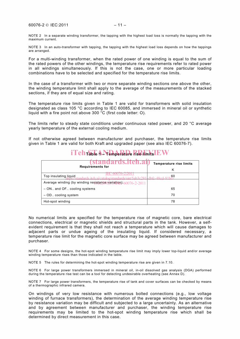
Table 1 – Temperature rise limits
Requirements for Temperature rise limits
K
Top insulating liquid 60
Average winding (by winding resistance variation):
65
70
– ON.. and OF.. cooling systems
– OD.. cooling system
Hot-spot winding 78
No numerical limits are specified for the temperature rise of magnetic core, bare electrical connections, electrical or magnetic shields and structural parts in the tank. However, a self-evident requirement is that they shall not reach a temperature which will cause damages to adjacent parts or undue ageing of the insulating liquid. If considered necessary, a temperature rise limit for the magnetic core surface may be agreed between manufacturer and purchaser.
NOTE 4 For some designs, the hot-spot winding temperature rise limit may imply lower top-liquid and/or average winding temperature rises than those indicated in the table.
NOTE 5 The rules for determining the hot-spot winding temperature rise are given in 7.10.
NOTE 6 For large power transformers immersed in mineral oil, in-oil dissolved gas analysis (DGA) performed during the temperature rise test can be a tool for detecting undesirable overheating (see Annex D).
NOTE 7 For large power transformers, the temperature rise of tank and cover surfaces can be checked by means of a thermographic infrared camera.
On windings of very low resistance with numerous bolted connections (e.g., low voltage winding of furnace transformers), the determination of the average winding temperature rise by resistance variation may be difficult and subjected to a large uncertainty. As an alternative and by agreement between manufacturer and purchaser, the winding temperature rise requirements may be limited to the hot-spot winding temperature rise which shall be determined by direct measurement in this case.
iTeh STANDARD PREVIEW(standards.iteh.ai)
IEC 60076-2:2011https://standards.iteh.ai/catalog/standards/sist/5ab3c281-dbfc-48cd-81b1-
b0ed2892b13d/iec-60076-2-2011
– 12 – 60076-2 IEC:2011
Temperature rise limits for transformers having higher temperature resistant insulation systems and immersed in a less flammable liquid (code letter K or L) are subject to agreement.
6.3 Modified requirements for special cooling conditions
6.3.1 General
If the service conditions at the intended installation site do not fall within the limits of normal cooling conditions given in Clause 5, then the limits of temperature rise for the transformer shall be modified in accordance with the rules indicated below.
6.3.2 Air-cooled transformers
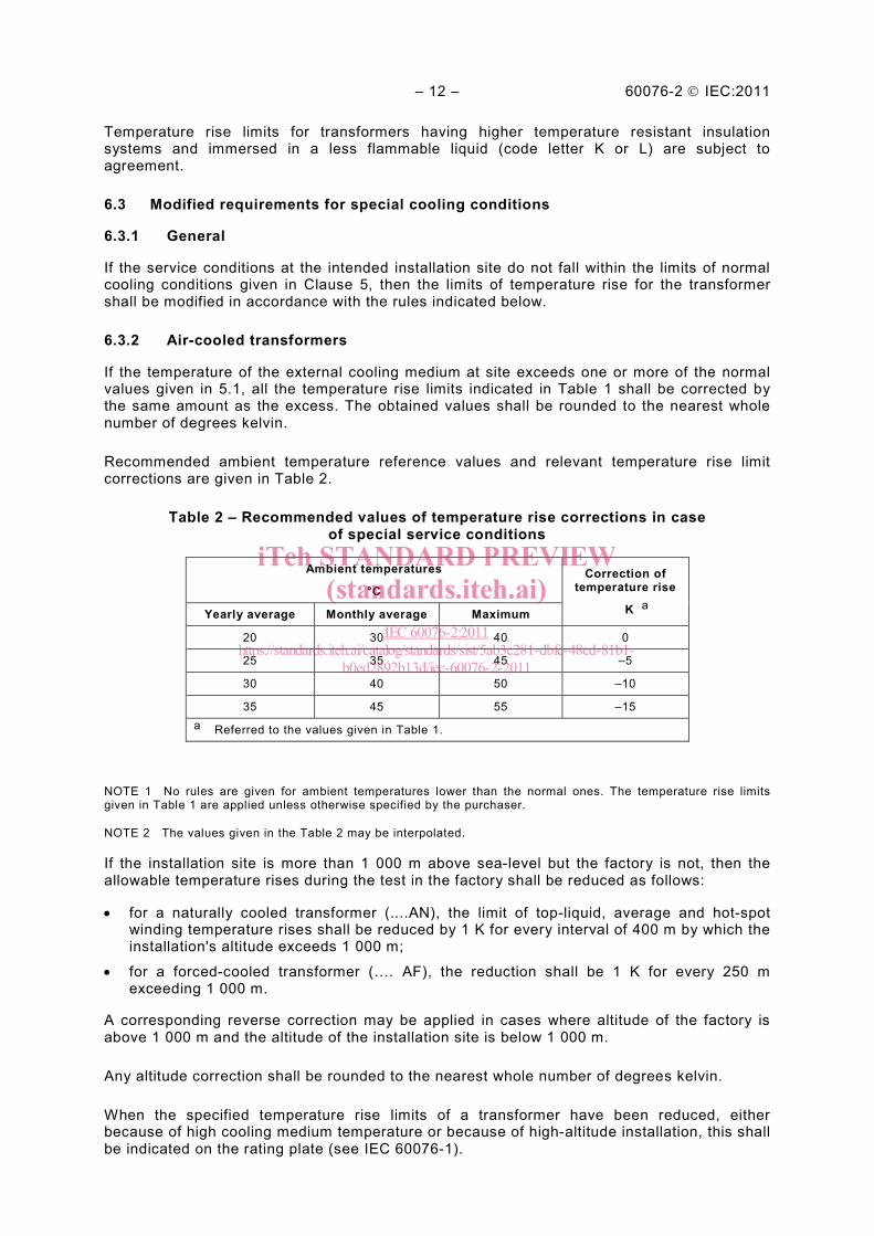
If the temperature of the external cooling medium at site exceeds one or more of the normal values given in 5.1, all the temperature rise limits indicated in Table 1 shall be corrected by the same amount as the excess. The obtained values shall be rounded to the nearest whole number of degrees kelvin.
Recommended ambient temperature reference values and relevant temperature rise limit corrections are given in Table 2.
Table 2 – Recommended values of temperature rise corrections in case of special service conditions
Ambient temperatures
°C Correction of
temperature rise
K a Yearly average Monthly average Maximum
20 30 40 0
25 35 45 –5
30 40 50 –10
35 45 55 –15 a Referred to the values given in Table 1.
NOTE 1 No rules are given for ambient temperatures lower than the normal ones. The temperature rise limits given in Table 1 are applied unless otherwise specified by the purchaser.
NOTE 2 The values given in the Table 2 may be interpolated.
If the installation site is more than 1 000 m above sea-level but the factory is not, then the allowable temperature rises during the test in the factory shall be reduced as follows:
• for a naturally cooled transformer (....AN), the limit of top-liquid, average and hot-spot winding temperature rises shall be reduced by 1 K for every interval of 400 m by which the installation's altitude exceeds 1 000 m;
• for a forced-cooled transformer (…. AF), the reduction shall be 1 K for every 250 m exceeding 1 000 m.
A corresponding reverse correction may be applied in cases where altitude of the factory is above 1 000 m and the altitude of the installation site is below 1 000 m.
Any altitude correction shall be rounded to the nearest whole number of degrees kelvin.
When the specified temperature rise limits of a transformer have been reduced, either because of high cooling medium temperature or because of high-altitude installation, this shall be indicated on the rating plate (see IEC 60076-1).
iTeh STANDARD PREVIEW(standards.iteh.ai)
IEC 60076-2:2011https://standards.iteh.ai/catalog/standards/sist/5ab3c281-dbfc-48cd-81b1-
b0ed2892b13d/iec-60076-2-2011
60076-2 IEC:2011 – 13 –
NOTE 3 When standardized transformers are to be used at high altitudes, a reduced value of power may be calculated, which from the point of view of cooling and temperature rise corresponds to service with rated power under normal ambient conditions.
6.3.3 Water-cooled transformers
If the maximum and/or the yearly cooling water temperature at site exceeds the values indicated in 5.2, all the prescribed temperature rise limits shall be reduced by the same amount as the excess. The values shall be rounded to the nearest whole number of degrees.
NOTE The rule given above does not apply for water temperatures lower than the normal one. In that case, an agreement between manufacturer and purchaser is necessary.
The influence of differing ambient temperature or altitude on the air cooling of the tank shall be disregarded.
6.4 Temperature rise during a specified load cycle
By agreement between manufacturer and purchaser, temperature rise limits can be guaranteed and/or a special test regarding load cycle operation specified (see IEC 60076-7).
7 Temperature rise tests
7.1 General
The following subclauses describe the procedures for the determination of temperature and temperature rise values during factory testing and also the methods for substituting service loading conditions by equivalent test procedures.
During the temperature rise test, the transformer shall be equipped with its protective devices (for example, Buchholz relay). Any indication from these devices during the test shall be noted and the case investigated.
In the case of a transformer with more than one value of rated power (for example, when two or more cooling methods are provided), a temperature rise test shall be in principle performed for each rated power, but by agreement between manufacturer and purchaser the number of tests can be reduced.
7.2 Temperature of the cooling media
7.2.1 Ambient temperature
For the temperature rise test, the cooling air temperature should be in the range between 10 °C and the maximum ambient temperature for which the transformer is designed.
The interpretation of the test results shall be subject to agreement if the external cooling medium temperature during the test is outside the limits indicated.
At least four sensors shall be provided and the average of their readings shall be used to determine the ambient temperature for the evaluation of the test results.
NOTE For tests on large power transformers, the number of sensors should be increased up to six in order to reduce the uncertainty that can affect the average of the readings.
Readings should be taken at regular intervals (e.g., every ten minutes), or automatic continuous recording may be used.
Around an ONAN transformer, the ambient sensors shall be placed at a level about halfway up the cooling surfaces.
iTeh STANDARD PREVIEW(standards.iteh.ai)
IEC 60076-2:2011https://standards.iteh.ai/catalog/standards/sist/5ab3c281-dbfc-48cd-81b1-
b0ed2892b13d/iec-60076-2-2011


