Embed Size (px)
Citation preview

I.C.E.: AN ULTRA-COLD ATOM SOURCE FOR LONG-BASELINEINTERFEROMETRIC INERTIAL SENSORS IN REDUCED GRAVITY
G. VAROQUAUX†, N. ZAHZAM‡, W. CHAIBI?, J-F. CLEMENT†, O. CARRAZ‡, J-P. BRANTUT†,R. A. NYMAN†, F. PEREIRA DOS SANTOS?, L. MONDIN§, M. ROUZE§, Y. BIDEL‡,
A. BRESSON‡, A. LANDRAGIN?, and P. BOUYER†a
† Laboratoire Charles Fabry de l’Institut d’Optique, Campus Polytechnique, RD 128, 91127 Palaiseau,France
‡ Office National d’Etude et de Recherches Aerospatiales, Chemin de la Huniere, 91761 Palaiseau,France
? LNE-SYRTE, UMR8630, Observatoire de Paris, 61 avenue de l’Observatoire, 75014 Paris, France
§ CNES DCT/SI/OP, 18, Avenue Edouard Belin 31401 Toulouse CEDEX 9, France
The accuracy and precision of current atom-interferometric inertial sensors rival state-of-the-art conventional devices using artifact-based test masses1. Atomic sensors are well suited forfundamental measurements of gravito-inertial fields. The sensitivity required to test gravita-tional theories can be achieved by extending the baseline of the interferometer2. The I.C.E.(Interferometrie Coherente pour l’Espace) interferometer aims to achieve long interrogationtimes in compact apparatus via reduced gravity. We have tested a cold-atom source duringairplane parabolic flights. We show that this environment is compatible with free-fall interfero-metric measurements using up to 4 second interrogation time. We present the next-generationapparatus using degenerate gases for low release-velocity atomic sources in space-borne ex-periments.
Inertial sensors are useful devices in both science and industry. Higher precision sensorscould find scientific applications in the areas of general relativity3, navigation, surveying andanalysis of Earth structures. Matter-wave interferometry was first envisaged to probe inertialforces4. Neutron interferometers were used to measure the acceleration due to gravity5 and therotation of the Earth6 at the end of the 1970s. In 1991, atom interference techniques wereused in proof-of-principle work to measure rotations7 and accelerations8. Many theoretical andexperimental works have been performed to investigate this new kind of inertial sensors9. Someof the recent works have since shown very promising results leading to a sensitivity comparableto other kinds of sensors, for both rotation10,11,12 as for acceleration1,13.
[email protected] — http://www.ice-space.fr

1 Atoms in microgravity as probes of the gravito-inertial field
1.1 Using atoms as test masses.
Following pioneering work on atomic clocks 14, ultra-high precision inertial sensors are expectedto be used in micro-gravity for tests of gravitation theories or to provide accurate and exactdrag-free motion that is required for deep-space mapping of gravity15. Closer to Earth, theycan lead to possible experiments that could test the Einstein equivalence principle16: Lorentzinvariances, the universalities of a free fall and gravitational redshift, as well as the constancyof gravitational and fine-structure constants or higher order gravitational effects such as theLense-Thirring effect17,18.
Conventional gravity and acceleration probes17 rely on artifact-based macroscopic test massesto probe the gravito-inertial field. Using atoms as proof masses directly relates measurements tofundamental quantities, without the need for geometrical factors. The test masses are not subjectto manufacturing errors and their displacement is referenced to the well-controlled wavelengthof a pair of laser beams, providing long term accuracy and precision.
1.2 Atom interferometry and precision gravimetry
An atom interferometer measures the phase-shift acquired by atoms through different coherence-preserving paths. Since the phase acquired by an atom during its free propagation is stronglydependent on the gravito-inertial field it experiences19, the interferometric read-out of this phase-shift can give access to direct measurements of the metric tensor20.
In most atom-interferometry experiments, an ensemble of particles is split into two differentpaths by a coherent beam-splitting process9. After a phase accumulation time T , the two pathsare recombined by a second beam-splitting process. The probabilities of detecting particlesin the two output channels of the beam-splitter are given by quantum interference of the twocoherent propagation paths and are sinusoidal functions of the accumulated phase difference.The ultimate precision in the read-out of the phase is limited by the number of detected particlesand scales as ∆φmin = 2π/
√N (quantum projection noise limit21). Typically ∆φmin ∼ 2 mrad
for 107 particles.To detect inertial forces, an atom-interferometer must have physically separated paths.
Therefore, unlike in atomic clocks, the beam-splitting processes must communicate momentumto the atoms. A common scheme uses two-photons Raman transitions to coherently transfermomentum from lasers beams to atoms 22. Two hyperfine levels of an atom can be coupled viatwo counter-propagating laser beams. Raman transitions contribute two photon momenta andcan be used as mirrors and beam-splitters (see figure 1).
The phase shift at the output of such a light-pulse interferometers arises from three contributions19:1. the difference in the action integral along each path,2. the difference in the phases imprinted on the atom waves by the beam splitters and mirrors,3. the term due to the splitting of the wave-packets at the output of the interferometer.
π2 π π
2T T
|g〉|g〉
|e〉
|e〉
|g〉
|g〉
|e〉
Raman transitions between hyperfine levels |e〉 and |g〉 with momentumtransfer create a Mach-Zehnder type interferometer:
1. Beam splitter: a π2
pulse splits the wave packet in a superpositionof different momentum states
2. Mirror: a π pulse inverts the two states3. Output beam splitter: a second π
2pulse recombines the wave
packet
Figure 1: Light-pulse interferometer

Gravito-inertial effects are found in the first term, but can also be hidden in the second termdepending on the chosen reference frame, through movement of the Raman beams. Whenperforming the calculation in an inertial frame, terms 1 and 3 nearly cancel out and leave onlythe term 2, the laser phase difference between mid-points of classical (non-quantum) trajectories.This shows that interferometric process can be pictured1 as measuring the position of freely fallingatoms on an optical ruler made by the two Raman lasers beating together with a wavevector givenby the difference of their wavevectors keff = k2−k1. This simple picture allows to understand thestringent requirement on the lasers for a high-precision measurement, as their spectral qualitydetermines the quality of the optical ruler.
For a light-pulse interferometer with equal times T between the three pulses, in the case ofan accelerated frame with no rotation or gravity gradient, the final phase shift is given by
∆φ =−→k eff · −→a T 2, (1)
where −→a is the local acceleration: the atom interferometer acts as a gravimeter. Current state-of-the-art atom-gravimeters1 have a shot-to-shot accuracy of 10−7 m · s−2 due to technical noise.
1.3 Micro-gravity, the route to enhanced atom-interferometric sensors
Equation 1 shows that the sensitivity of an atom-interferometer increases with interrogationtime. The longer the time the atoms spend between the beam splitters, the greater the scalingfactor between the accumulated phase shifts and the effect they probe. In order to avoid uncon-trolled residual phase-shifts, it is best not to apply fields other than that which is probed duringthe phase accumulation period. In the case of inertial sensing this implies that atoms must be infree fall between the beam-splitting processes. In Earth-based interferometers, with cold-atomsources, the expansion of the atomic cloud is small, and the interrogation time is limited to afraction of second by the available fall height, limiting their precision. Atom interferometry inmicro-gravity allows for longer free fall and thus increased precision.
2 Atom-interferometric sensors in the Zero-G Airbus
We are conducting atom interferometry experiments for inertial sensing on board an airplaneduring ballistic flights. Microgravity is obtained via 20 second-long parabolas by steering theplane to cancel drag and follow gravity. Residual acceleration is on the order of 10−3 g. Eventhough this tropospheric microgravity facility does not provide the environmental quality of aspace-borne mission, either on the ISS or on a dedicated platform, it offers the possibility toperform test and qualification campaigns for future space atomic inertial sensor missions. It alsoprovides the required environment for the first comparison of sensors performances and possiblythe first fundamental physics test with atomic sensors in microgravity.
2.1 Airborne test of the equivalence principle: an Airbus as an Einstein elevator.
The Einstein equivalence principle states that physics in a freely falling reference frame, in agravitational field, is locally equivalent to physics without any gravito-inertial fields. An atominterrogated during its free fall in an interferometer on Earth behaves like an atom interrogatedin deep-space. But inertial-sensing interferometers have a non-zero physical size and can besubject to tidal effects23 (e.g. Lense-Thirring). An experiment carried out nearby a massiveobject is therefore not equivalent to a deep space experiment. On the other hand, there isno difference between an experiment carried in a freely falling airplane and one on a satelliteorbiting around the Earth or the Sun.
In the airplane, atoms falling in the interferometer’s vacuum chamber experience true free fallas long as they do not hit the chamber walls. The interferometer itself is attached to the airplane
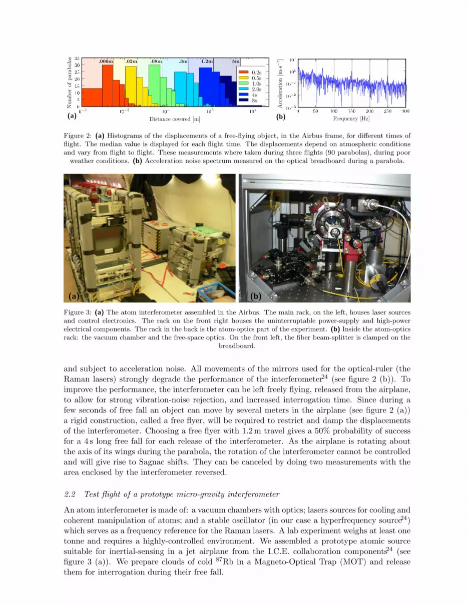
Figure 2: (a) Histograms of the displacements of a free-flying object, in the Airbus frame, for different times offlight. The median value is displayed for each flight time. The displacements depend on atmospheric conditionsand vary from flight to flight. These measurements where taken during three flights (90 parabolas), during poor
weather conditions. (b) Acceleration noise spectrum measured on the optical breadboard during a parabola.
(a) (b)
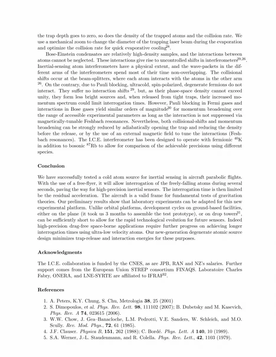
Figure 3: (a) The atom interferometer assembled in the Airbus. The main rack, on the left, houses laser sourcesand control electronics. The rack on the front right houses the uninterruptable power-supply and high-powerelectrical components. The rack in the back is the atom-optics part of the experiment. (b) Inside the atom-opticsrack: the vacuum chamber and the free-space optics. On the front left, the fiber beam-splitter is clamped on the
breadboard.
and subject to acceleration noise. All movements of the mirrors used for the optical-ruler (theRaman lasers) strongly degrade the performance of the interferometer24 (see figure 2 (b)). Toimprove the performance, the interferometer can be left freely flying, released from the airplane,to allow for strong vibration-noise rejection, and increased interrogation time. Since during afew seconds of free fall an object can move by several meters in the airplane (see figure 2 (a))a rigid construction, called a free flyer, will be required to restrict and damp the displacementsof the interferometer. Choosing a free flyer with 1.2 m travel gives a 50% probability of successfor a 4 s long free fall for each release of the interferometer. As the airplane is rotating aboutthe axis of its wings during the parabola, the rotation of the interferometer cannot be controlledand will give rise to Sagnac shifts. They can be canceled by doing two measurements with thearea enclosed by the interferometer reversed.
2.2 Test flight of a prototype micro-gravity interferometer
An atom interferometer is made of: a vacuum chambers with optics; lasers sources for cooling andcoherent manipulation of atoms; and a stable oscillator (in our case a hyperfrequency source24)which serves as a frequency reference for the Raman lasers. A lab experiment weighs at least onetonne and requires a highly-controlled environment. We assembled a prototype atomic sourcesuitable for inertial-sensing in a jet airplane from the I.C.E. collaboration components24 (seefigure 3 (a)). We prepare clouds of cold 87Rb in a Magneto-Optical Trap (MOT) and releasethem for interrogation during their free fall.

OI Optical IsolatorFL Fiber Laser
EDFA Erbium-Doped Fiber Am-plifier
c fiber couplerLDsat saturation Laser Diode
MZ Mach-Zehnder modulatorPPLN Periodically Poled
Lithium NiobatePPLN WG PPLN Wave Guide
DFB Distributed-FeedBacklaser diode
Figure 4: Diagram of our laser system. The master laser is pictured on top, the slave below.
Novel integrated fibered source for rubidium laser-cooling. Laser cooling and manip-ulation of atoms requires frequency-stable, narrow-linewidth laser sources. The laser systemsgenerally used in ultracold atom experiments are neither transportable nor reliable and ro-bust enough for our application. Indeed, free-space optical benches with macroscopic cavitiesoften need regular re-alignment. Moving away from the standard semiconductor-laser baseddesign14, we have created laser sources at 780 nm, suitable for atom interferometry with 87Rb,using frequency-doubled fiber lasers and other telecom components at 1560 nm. These novellaser sources have been described in length elsewhere25, we will limit ourselves to outlining thesuccessful design choices in light of the test flight.
To achieve a frequency-agile configuration, we use a master laser locked on a rubidium tran-sition and slave lasers which are frequency-locked to the master laser with an arbitrary frequencydifference (see figure 4). The master laser (linewidth of 10 kHz) is a monolithic semiconductorelement: a 1560 nm Distributed Feed-Back (DFB) fiber laser, amplified in a 500 mW Erbium-doped fiber amplifier and frequency doubled in a PPLN waveguide. The resulting 780 nm lightis then sent into a saturated-absorption spectroscopy setup for frequency locking to a rubidiumtransition. An error signal is obtained by modulating the frequency of the master laser for phase-sensitive detection. Control of the frequency is achieved via a piezoelectric transducer (actingon the DFB laser) but we also change the temperature of the DFB fiber when the piezoelectricvoltage approaches its maximum range.
The slave lasers are 80mW 1560 nm DFB laser diodes (linewidth of 1.1 MHz). After ampli-fication through an Erbium-doped fiber amplifier they are frequency doubled in free space withtwo 2 cm bulk PPLN crystals in cascade (similar to27). With a 5W fiber amplifier, we obtain∼ 0.3 W at 780 nm. The slave lasers are frequency-locked to the master laser by measuring thefrequency of a beat-note between the two 1560nm lasers recorded on a fibered fast photodiode.Control of the frequency of the slave lasers is achieved via feedback to their supply current.
The power of the cooling laser can be adjusted by switching off the 1560 nm input laser ofthe fibered amplifier with an optical switch after saturating it with a laser source at 1556 nm.The 1556 nm light is not frequency doubled by the PPLN crystals and is filtered by the single-mode 780 nm fibers. A very good extinction is obtained, limited by the amplified spontaneousemission of the fibered amplifier that is frequency-doubled. Mechanical shutters are used tocompletely extinguish the lasers over long timescales (they have a 7 ms dead time), but the useof the saturation diode allows for quicker switching times (∼ 50 µs).
In order to laser cool 87Rb, an additional frequency (called the repumping laser), located

7 GHz away from the cooling laser, is required. Instead of using another laser, we use a 1560 nmfiber Mach-Zehnder modulator to generate two sidebands 7 GHz apart. One sideband is forrepumping and the other is off-resonnace, so causes no ill effects.
Laser light is transported to the vacuum chamber using polarization-maintaining opticalfibers. A fiber beam-splitter (Schafter and Kirchhoff) based on miniature polarizing opticsdivides the laser-cooling fiber in three to provide separate beams for the operation of the MOT.
The laser sources have proved remarkably robust during the test flight, surviving pressurechanges of 200mPa, temperature changes of 15◦C, and remaining frequency-locked in spite of thenoisy environment. It is worth noting that an amplifier was damaged during flight operations, itsoutput power dropping by a factor of 10. This failure did not prevent the MOT from functioning.The cause is currently being investigated.
A robust transportable interferometer setup. Keeping with the philosophy of a flexibleprototype, the atomic-physics part of the interferometer was built using standard lab equipmentmounted on a 600×600 mm optics breadboard (see figure 3 (b)). A rigid frame is bolted throughthe breadboard, holding the vacuum chamber to protect it and meet flight security requirements.
The core of the apparatus is a stainless-steel ultra-high vacuum chamber in which the laserbeams intersect for trapping and manipulating the atoms. The chamber has two 63 mm diam-eters windows and eight lateral 40 mm ports. The large number of available ports allows usto dedicate separate windows for different beams and for observation. MOT and compensationcoils are directly wound onto the chamber. The rubidium atoms are released from commercially-available alkali-metal dispensers directly into the MOT chamber. While operating the interfer-ometer, the dispensers are run continuously and a dilute (< 10−8 mBar) rubidium vapor fillsthe chamber. There are two pumps: an ion pump and a getter pump, maintaining the requiredvacuum even during night power cut. No special care has been taken to ensure that all partsof the system are non-magnetic and the ion pump was not shielded. We relied solely on thecompensation coils to cancel out the magnetic fields in the surroundings of the atoms.
The six counter-propagating lasers beams of the MOT are made of three retro-reflectedbeams each expanded out of a fiber by an out-coupler producing a 25 mm diameter beam. Thecouplers are positioned on kinematic mounts (New Focus 9071) held by 38mm posts boltedon the breadboard. The setup was optimized in our lab in Palaiseau, then carried on a truck500 km away to Bordeaux and loaded into the airplane with no particular precautions. Everyday temperature cycled from 6◦C to 20◦C. We did not notice any misalignment.
The laser source driving the Raman transition is similar to the cooling laser. The secondRaman frequency is achieved as with the repumping frequency by intensity-modulating the laserlight. The presence of the second sideband adds new paths to the interferometer, but they neednot be taken in account as these secondary interferometers are not closed. For the Raman pulsemanipulation, MOT coils are switched from quadrupole configuration to dipole configuration toprovide a polarizing field raising the degeneracy between Zeeman sub-levels. The intensity of thelasers can be up to 20 times the saturation intensity of rubidium, which allows for short Ramanpulses with weak velocity selection to address broad momentum distributions. The pulse iscontrolled via an acousto-optical modulator after the frequency-doubling stage. Raman transferwas not tested during this first flight.
We load 109 atoms of 87Rb in the MOT in one second. A photodiode monitors the fluores-cence, which is proportional to the number of atoms. We release the atoms from the MOT andfurther cool them through a brief phase of optical molasses during which we can prepare theatoms in the lower hyperfine state by turning off the repumping light. The light pulses for theinterferometer (see figure 1) can then be applied. The cooling laser is turned back on to detectthe atoms still in the MOT volume in a state selective way. The flight of the atoms in the opticalmolasses was recorded during the test flight. Our preliminary setup had no magnetic shield and

Figure 5: Images of molasses at different airplane angles. The tilt in the Earth’s magnetic field produces animbalance in the radiation pressure during the molasses phase, and alters the direction in which the atoms escape.The arrows connect the positions of the initial trapped cloud to the escaping atoms. The escape direction doesnot directly relate to the pitch angle of the airplane, as its bearing also changes the direction of the magnetic-field.
the rotation of the Earth’s magnetic field created uncompensated Zeeman shifts. These shiftsimbalance the radiation pressure during molasses, limiting the atomic escape velocity (see figure5).
3 I.C.E.: the next-generation apparatus
Temperatures achieved through laser-cooling techniques reach a limit of around 1 µK (vrms ∼1 cm · s−1). Ballistic expansion of laser-cooled atoms thus limits interrogation times to a fewseconds26. To make full use of micro-gravity (e.g. with a space-borne experiment) further coolingis needed. The limiting factor for atom-interferometric metrology is the size of the atomic cloudafter expansion, given by both its initial size and velocity spread. This size is closely relatedto the phase-space density of the source, which can be seen as an atom-optic equivalent of theluminance of a photonic source. The source of maximum luminance in optics is the laser, andwhich is widely used in photon-interferometry. In atom-optics such a source is a Bose-Einsteincondensate. The intrinsic linewidth of a Bose-Einstein condensate is very narrow, however themomentum-width of a freely falling condensate depends on the trap release process.
Within the I.C.E. project24, we are building a next-generation atom interferometer makinguse of quantum degenerate atomic gases for increased interrogation times during ballistic flights.Degenerate atom sources can be achieved by evaporative cooling, where the depth of a non-dissipative trap is lowered to eject higher energy atoms while relying on two-body collisions tothermalize the cloud, thus lowering its temperature. Magnetic traps, where atoms are trappednear a minimum of magnetic field, are most often used to perform this evaporation. However,releasing atoms from a magnetic trap is an ill-controlled process that will affect the sensorperformances. On the contrary, optical-dipole traps, where atoms are trapped near a maximumof laser light intensity, can be controlled with much more precision. Ramping down to zero thepower of the trapping laser yields a jerk-free release process. In the I.C.E. interferometer, wetransfer the atoms from the MOT to an optical-dipole trap made of two intersecting laser beamsat 1565 nm. Efficient capture of the atoms is achieved for a trap depth of a few times theirkinetic energy. The phase-space volume of a dipole trap is limited by the available laser power.As a MOT is a rather large cloud, it is best to capture it with the spatially largest possible trapwhile still deep enough to load the atoms. Using a 50 W fiber laser, we can load the atoms usingtrap diameters up to 350 µm.
To permit a short duty cycle that allows for high precision measurement and high accuracy,the production of the degenerate atomic source must be fast. For the evaporation process to beefficient, the collision rate needs to increase as the number of trapped atoms decreases. However,lowering the power of the trapping laser reduces the depth of the trap, but not its size, and, as
the trap depth goes to zero, so does the density of the trapped atoms and the collision rate. Weuse a mechanical zoom to change the diameter of the trapping laser beam during the evaporationand optimize the collision rate for quick evaporative cooling28.
Bose-Einstein condensates are relatively high-density samples, and the interactions betweenatoms cannot be neglected. These interactions give rise to uncontrolled shifts in interferometers29,26.Inertial-sensing atom interferometers have a physical extent, and the wave-packets in the dif-ferent arms of the interferometers spend most of their time non-overlapping. The collisionalshifts occur at the beam-splitters, where each atom interacts with the atoms in the other arm26. On the contrary, due to Pauli blocking, ultracold, spin-polarized, degenerate fermions do notinteract. They suffer no interaction shifts 29, but, as their phase-space density cannot exceedunity, they form less bright sources and, when released from tight traps, their increased mo-mentum spectrum could limit interrogation times. However, Pauli blocking in Fermi gases andinteractions in Bose gases yield similar orders of magnitude30 for momentum broadening overthe range of accessible experimental parameters as long as the interaction is not suppressed viamagnetically-tunable Feshbach resonances. Nevertheless, both collisional-shifts and momentumbroadening can be strongly reduced by adiabatically opening the trap and reducing the densitybefore the release, or by the use of an external magnetic field to tune the interactions (Fesh-bach resonances). The I.C.E. interferometer has been designed to operate with fermionic 40Kin addition to bosonic 87Rb to allow for comparison of the achievable precisions using differentspecies.
Conclusion
We have successfully tested a cold atom source for inertial sensing in aircraft parabolic flights.With the use of a free-flyer, it will allow interrogation of the freely-falling atoms during severalseconds, paving the way for high-precision inertial sensors. The interrogation time is then limitedbe the residual acceleration. The aircraft is a valid frame for fundamental tests of gravitationtheories. Our preliminary results show that laboratory experiments can be adapted for this newexperimental platform. Unlike orbital platforms, development cycles on ground-based facilities,either on the plane (it took us 3 months to assemble the test prototype), or on drop towers31,can be sufficiently short to allow for the rapid technological evolution for future sensors. Indeedhigh-precision drag-free space-borne applications require further progress on achieving longerinterrogation times using ultra-low velocity atoms. Our new-generation degenerate atomic sourcedesign minimizes trap-release and interaction energies for these purposes.
Acknowledgments
The I.C.E. collaboration is funded by the CNES, as are JPB, RAN and NZ’s salaries. Furthersupport comes from the European Union STREP consortium FINAQS. Laboratoire CharlesFabry, ONERA, and LNE-SYRTE are affiliated to IFRAF32.
References
1. A. Peters, K.Y. Chung, S. Chu, Metrologia 38, 25 (2001)2. S. Dimopoulos, et al. Phys. Rev. Lett. 98, 111102 (2007); B. Dubetsky and M. Kasevich,
Phys. Rev. A 74, 023615 (2006).3. W.W. Chow, J. Gea–Banacloche, L.M. Pedrotti, V.E. Sanders, W. Schleich, and M.O.
Scully. Rev. Mod. Phys., 72, 61 (1985).4. J.F. Clauser. Physica B, 151, 262 (1988); C. Borde. Phys. Lett. A 140, 10 (1989).5. S.A. Werner, J.-L. Staudenmann, and R. Colella. Phys. Rev. Lett., 42, 1103 (1979).

6. R. Colella, A.W. Overhauser, and S.A. Werner. Phys. Rev. Lett. 34, 1472 (1975).7. F. Riehle, Th. Kisters, A. Witte, J. Helmcke and Ch.J. Borde. Phys. Rev. Lett. 67, 177
(1991).8. M. Kasevich and S. Chu, Appl. Phys., B 54, 321 (1992).9. P.R. Bermann (eds.), Atom Interferometry (Academic, Boston MA, 1997)
10. T.L. Gustavson, P. Bouyer, M.A. Kasevich. Phys. Rev. Lett. 78, 2046 (1997).11. T.L. Gustavson, et al. Class. Quantum Grav. 17, 1 (2000).12. B. Canuel, et al., Phys. Rev. Lett. 97, 010402 (2006)13. A. Peters, K.Y. Chung, B. Young, J. Hensley and S. Chu. Phil. Trans. R. Soc. Lond. A
355, 2223 (1997).14. Ph. Laurent, et al. App. Phys. B 84, 683 (2006)15. Study of the Pioneer anomaly: Anderson et al. Phys. Rev. D 65, 082004 (2002)16. C. Lammerzahl, Appl. Phys. B 84, 551 (2006)17. Gravity Probe B: S. Buchman et al. Advances in Space Research 25, 1177 (2000)18. HYPER Assessment Study Report ESA-SCI(2000)10, European Space Agency (2000)19. Ch. J. Borde, C. R. Acad. Sci. Paris, t. 2 Serie IV, 509 (2001).20. Ch. J. Borde sl et al., in C. Lammerzahl, C.W.F. Everitt, F.W. HehlGyros (Eds.), Clocks
and Interferometers: Testing Relativistic Gravity in Space, Springer-Verlag (2000)21. D.J. Wineland, et al. Phys. Rev. Lett. 66, 6797 (1992)22. M. Kasevich, S. Chu Phys. Rev. Lett. 67, 181 (1991)23. M.-C. Angonin, P. Tourrenc, P. Delva, Appl. Phys. B 84, 579 (2006)24. R.A. Nyman, et al. App. Phys. B 84, 673 (2006)25. F. Lienhart, et al. App. Phys. B , (2007)26. Y. Lecoq, et al. App. Phys. B 84, 627 (2006)27. R. J. Thompson, et al. Optics Express 11, 1709 (2003)28. T. Kinoshita, T.R. Wenger, D.S. Weiss, Phys. Rev. A 71, 01 162(R) (2005)29. S. Gupta, et al. Science 13, 1723 (2003)30. When suddenly releasing interacting Bose gases from a trap, the release momentum is
given by the energy of the bosons in the trap. For trapping frequencies of ω, the harmonic
oscillator length related to the trap is aho =√
hm ω , and the release wave-vector is krelease ∼
1aho
(15 N aaho
)1/5 , with a the scattering length of the atoms. For Fermi gases, the spread in
wave-vector is given by kF ∼ 1aho
(48 N)1/6 .
31. A. Vogel et al. App. Phys. B 84, 663 (2006)32. http://213.251.135.217/ifraf/


