Embed Size (px)
Citation preview
This document is downloaded from DR-NTU, Nanyang Technological
University Library, Singapore.
Title Hybrid supercapacitor with nano-TiP2O7 as intercalationelectrode.
Author(s) Aravindan, V.; Reddy, M. V.; Madhavi, S.; Mhaisalkar, S.G.; Rao, G. V. S.; Chowdari, B. V. R.
Citation
V. Aravindan, M.V. Reddy, S. Madhavi, S.G. Mhaisalkar,G.V.S. Rao, B.V.R. Chowdari, Hybrid supercapacitor withnano-TiP2O7 as intercalation electrode, Journal of PowerSources
Date 2011
URL http://hdl.handle.net/10220/6912
Rights
© 2011 Elsevier. This is the author created version of awork that has been peer reviewed and accepted forpublication by Journal of Power Sources, Elsevier. Itincorporates referee’s comments but changes resultingfrom the publishing process, such as copyediting,structural formatting, may not be reflected in thisdocument. The published version is available at:http://dx.doi.org/10.1016/j.jpowsour.2011.05.074.
Accepted Manuscript
Title: Hybrid supercapacitor with nano-TiP2O7 asintercalation electrode
Authors: V. Aravindan, M.V. Reddy, S. Madhavi, S.G.Mhaisalkar, G.V. Subba Rao, B.V.R. Chowdari
PII: S0378-7753(11)01100-1DOI: doi:10.1016/j.jpowsour.2011.05.074Reference: POWER 14497
To appear in: Journal of Power Sources
Received date: 1-4-2011Revised date: 15-5-2011Accepted date: 27-5-2011
Please cite this article as: V. Aravindan, M.V. Reddy, S. Madhavi, S.G. Mhaisalkar,G.V.S. Rao, B.V.R. Chowdari, Hybrid supercapacitor with nano-TiP2O7 as intercalationelectrode, Journal of Power Sources (2010), doi:10.1016/j.jpowsour.2011.05.074
This is a PDF file of an unedited manuscript that has been accepted for publication.As a service to our customers we are providing this early version of the manuscript.The manuscript will undergo copyediting, typesetting, and review of the resulting proofbefore it is published in its final form. Please note that during the production processerrors may be discovered which could affect the content, and all legal disclaimers thatapply to the journal pertain.
Page 1 of 22
Accep
ted
Man
uscr
ipt
Graphical Absrtact
Page 2 of 22
Accep
ted
Man
uscr
ipt
1
Research Highlights
TiP2O7 is synthesized by urea assisted combustion method for first time
Synthesized material showed phase pure structure and nano-phase in nature
Li/TiP2O7 cell showed, 0.5 mole Li can be reversibly inserted and extracted
AC/TiP2O7 hybrid super-capacitor exhibited the maximum energy density of 13 Wh kg–1
*Highlights
Page 3 of 22
Accep
ted
Man
uscr
ipt
1
Hybrid supercapacitor with nano-TiP2O7 as intercalation electrode
V. Aravindana,b
, M.V. Reddyb, S. Madhavi
a,c, S.G. Mhaisalkar
a,c, G.V. Subba Rao
b and
B.V.R. Chowdarib*
a Energy Research Institute, Nanyang Technological University, Research Techno Plaza,
50 Nanyang Drive, Singapore 637553, Singapore
b Department of Physics, National University of Singapore, 117542, Singapore
c School of Materials Science and Engineering, Nanyang Technological University, Singapore
639798, Singapore
Abstract
Nano-size (≤ 100 nm) TiP2O7 is prepared by the urea assisted combustion synthesis, at
450 oC and 900
oC. The compound is characterized by powder X-ray diffraction, Rietveld
refinement, high resolution transmission electron microscopy and surface area methods. Lithium
cycling properties by way of galvanostaic cycling and cyclic voltammetry (CV) showed a
reversible and stable capacity of 60 (± 3) mAh g–1
(0.5 mole of Li) up to 100 cycles, when cycled
at 15 mA g–1
between 2-3.5 V vs. Li. Non-aqueous hybrid supercapacitor, TiP2O7 (as anode) and
activated carbon (AC) (as cathode) has been studied by galvanostatic cycling and CV in the
range, 0-3 V at 31 mA g–1
and exhibited a specific discharge capacitance of 29 (± 1) F g–1
stable
in the range, 100-500 cycles. The Ragone plot shows a deliverable maximum of 13 Wh kg–1
and
371 W kg–1
energy and power density, respectively.
Keywords: Hybrid supercapacitor; Lithium ion battery; TiP2O7; activated carbon
* Corresponding Author
E-Mail: [email protected] ;
Tel.: +65 6516 2531; fax: +65 6777 6126
*Manuscript text (double-spaced)
Page 4 of 22
Accep
ted
Man
uscr
ipt
2
1 Introduction
Of late, an increasing interest has been devoted to develop supercapacitors due to their
high power application demands in many fields such as electric vehicles (EV), hybrid electric
vehicles (HEV), off-peak energy back-up systems, etc[1]. Based on their energy storage
mechanism supercapacitors are classified into (i) electric double-layer capacitors (EDLCs) and
(ii) pseudo-capacitors [2-4]. EDLC utilize an electrochemical double layer capacitance at the
electrode/electrolyte interface (non-Faradaic process) where electric charges are accumulated on
the electrode surface and ions of opposite charge are arranged in the electrolyte side. Carbon
based materials are preferred as EDLC electrodes owing to their high surface area, relatively low
cost, chemical stability in solutions of different pH and its amphoteric nature that allows rich
electrochemical properties from donor to acceptor state, and wide range of operating
temperatures [5, 6]. Various forms of carbon have been studied as EDLC electrodes including
allotropes (graphite, fullerenes/nanotubes), varied morphology (fibres, foams, fabrics) and
microtextures [5, 6]. In addition, transition metal oxides, like MnO2 and RuO2 or conducting
polymers also have been employed as electrodes, which utilize the charge-transfer pseudo-
capacitance. The EDLCs offer high power density, good reversibility and long cycle life in the
aqueous medium. In contrast to EDLC, pseudocapacitors store charge Faradaically through
transfer of charge between electrode (metal oxides/conducting polymers) and electrolyte
accomplished through electrosorption, reduction-oxidation reactions, and intercalation processes.
These Faradaic processes may allow pseudocapacitors to achieve greater capacitances, energy
densities and good cycle life in comparison to EDLC. However, both EDLC and
pseudocapacitors offer poor energy density (~10 Wh kg-1
) as compared to rechargeable batteries,
like lithium ion batteries (100 Wh kg-1
).
Page 5 of 22
Accep
ted
Man
uscr
ipt
3
Energy density of a supercapacitor is given by E = CV2/2, where C is the capacitance
(F/g) and V is the applied voltage. Based on this, there are two approaches to improve energy
density of supercapacitors: (i) Use of non-aqueous electrolytes that offer higher operating
voltages (~2–4 V) as compared to aqueous electrolytes (~1 V), and (ii) increase the capacitance
(C) by incorporation of asymmetric electrode configuration, with battery-like electrode material
(Faradaic process) along with EDLC electrode (non-Faradaic). This configuration is termed,
“hybrid or asymmetric supercapacitor or hybrid electrochemical capacitor (HEC)” [1, 3, 6-9].
While the HEC employing aqueous electrolytes have been widely studied, there are also recent
reports using non-aqueous solvents and Li-intercalating electrodes, like Li[Ni0.5Mn1.5]O4 [10, 11],
LiMn2O4 [12], LiFePO4 [13], LiCoPO4 [14], Li2MnSiO4 [15], Li2FeSiO4 [16], MnO2 [17], -
FeOOH [18], Li4Ti5O12 [7, 8, 19, 20], TiO2–B [21] and LiCrTiO4 [22]. Among them, Li4Ti5O12
used as negative electrode (anode) is found to show very good HEC characteristics [8].
Titanium pyrophosphate, TiP2O7 has been studied as a Li-insertion host for the past few
years which showed the reversible insertion and extraction of ~0.8 mole of Li per formula unit at
a voltage of 2.6 V vs. Li [23-27]. To the best of our knowledge, TiP2O7 has not been studied in
HEC configuration. In this paper, we have adopted a urea assisted combustion route to prepare
TiP2O7 nanoparticles and have evaluated its Li-insertion properties vs. Li-metal and HEC
configuration as anode with activated carbon (AC) as the counter electrode in non-aqueous
electrolyte.
2 Experimental
For the synthesis of nano-TiP2O7, Ti metal powder (1.41 g, STREM, USA) was dissolved
in H2O2 (30%, Merck, Germany) and ammonia solution (25% Merck, Germany) in a 2:1 volume
ratio. After the complete dissolution of the Ti metal, (NH4)2HPO4 (7.86 g, 99 % Fisher) was
Page 6 of 22
Accep
ted
Man
uscr
ipt
4
added along with 6 moles of urea (99 %, Aldrich) and the solution was slowly evaporated (~80
oC) on a hot plate to yield the precursor powder. The precursor was placed in the pre-heated box
furnace (Carbolite, UK) at 450 oC for 30 min. A portion of it was subsequently calcined at 900
oC for 6 h in air. X-ray diffractometer (Philips X’Pert) equipped with Cu K radiation was used
for structural characterization. The X-ray diffraction (XRD) data were refined by Rietveld
refinement TOPAS-R (version 2.1) software. Morphological features were analyzed by
transmission electron microscope (JEOL, JEM 3010). The Brunauer-Emmett-Teller (BET)
surface area was measured using Micromeritics Tristar 3000, USA.
The composite electrode was prepared by mixing 70 wt.% of active material (TiP2O7), 15
wt.% of conducting additive (super P carbon) and 15 wt.% of binder (Kynar 2801) using N-
methyl pyrrolidinone as solvent for the binder and the resulting slurry was coated on to Al foil
(20 m thickness) using doctor blade technique. The activated carbon (AC, BET surface area
880 (± 20) m2
g–1
, Norit, Netherlands) electrode was prepared by a similar process with 80 wt.%
AC, 10 wt.% super P carbon, and 10 wt.% binder on the Al foil substrate. The electrodes were
dried, pressed between stainless steel twin rollers, and punched in to circular discs of 16 mm dia.
The electrode discs were dried in a vacuum oven at 80 oC for 12 h to remove any residual solvent.
The cells were assembled using 2016 coin cell configuration. Li-cycleability of TiP2O7 was
tested against Li-metal (0.59 mm thick; Kyokuto Metal Co., Japan) which was separated by
microporous glass fiber separator (Whatman, Cat. No. 1825 047, UK). Cyclic voltammetry (CV)
was performed using metallic Li as reference and counter electrode at the slow scan rate of 58
V s–1
between 2-3.4 V using MacPile II (Biologic. France) system. The HEC was constructed
using AC as positive electrode and TiP2O7 as negative electrode. The CVs were recorded for
HEC between 0-3 V at various scan rates, 2 to 50 mV s–1
using Solartron battery tester (Model
Page 7 of 22
Accep
ted
Man
uscr
ipt
5
no. 1470, UK). A solution of 1 M LiPF6 in ethylene carbonate (EC) and dimethyl carbonate
(DMC) (1:1 volume, Merck, Selectipur LP40) was used as the electrolyte. Galvanostatic profiles
were recorded using Bitrode battery tester (SCN 12-4-5/18, USA).
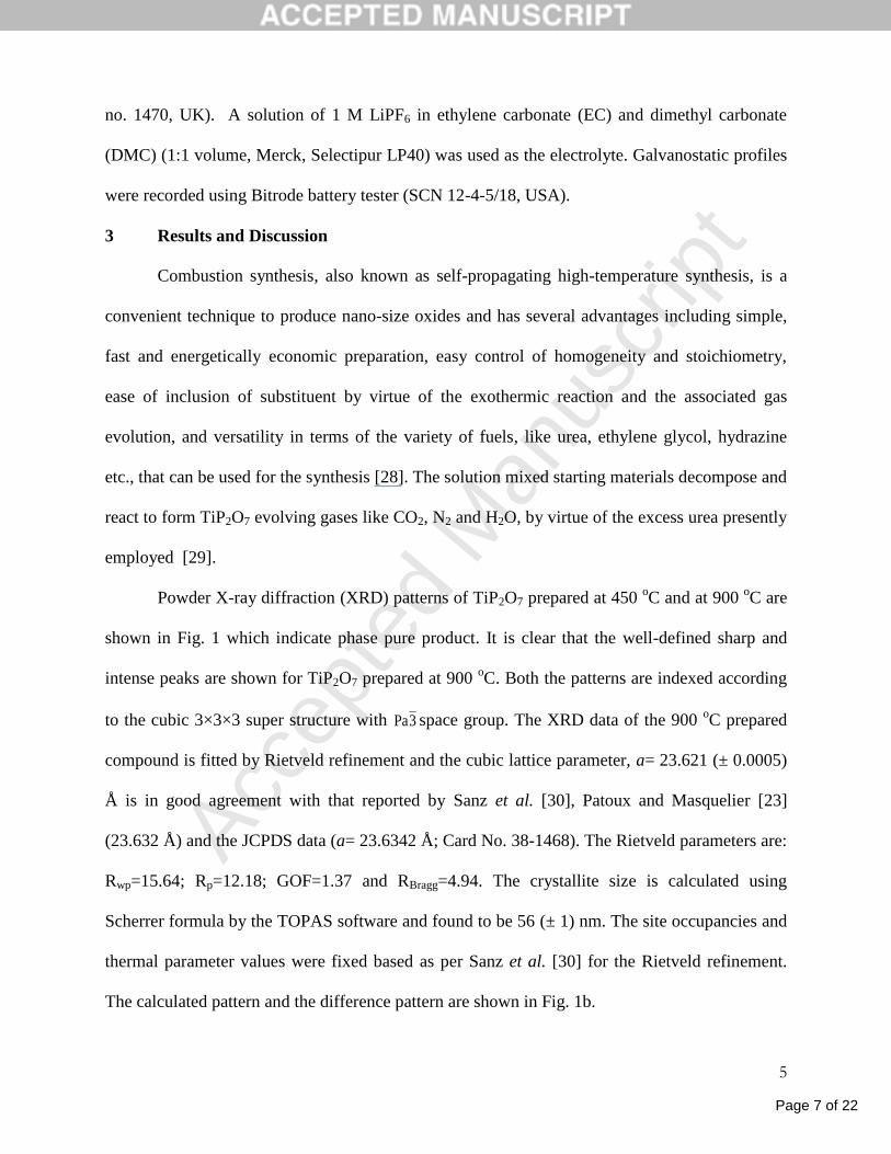
3 Results and Discussion
Combustion synthesis, also known as self-propagating high-temperature synthesis, is a
convenient technique to produce nano-size oxides and has several advantages including simple,
fast and energetically economic preparation, easy control of homogeneity and stoichiometry,
ease of inclusion of substituent by virtue of the exothermic reaction and the associated gas
evolution, and versatility in terms of the variety of fuels, like urea, ethylene glycol, hydrazine
etc., that can be used for the synthesis [28]. The solution mixed starting materials decompose and
react to form TiP2O7 evolving gases like CO2, N2 and H2O, by virtue of the excess urea presently
employed [29].
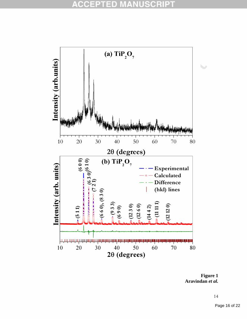
Powder X-ray diffraction (XRD) patterns of TiP2O7 prepared at 450 oC and at 900
oC are
shown in Fig. 1 which indicate phase pure product. It is clear that the well-defined sharp and
intense peaks are shown for TiP2O7 prepared at 900 oC. Both the patterns are indexed according
to the cubic 3×3×3 super structure with 3Pa space group. The XRD data of the 900 oC prepared
compound is fitted by Rietveld refinement and the cubic lattice parameter, a= 23.621 (± 0.0005)
Å is in good agreement with that reported by Sanz et al. [30], Patoux and Masquelier [23]
(23.632 Å) and the JCPDS data (a= 23.6342 Å; Card No. 38-1468). The Rietveld parameters are:
Rwp=15.64; Rp=12.18; GOF=1.37 and RBragg=4.94. The crystallite size is calculated using
Scherrer formula by the TOPAS software and found to be 56 (± 1) nm. The site occupancies and
thermal parameter values were fixed based as per Sanz et al. [30] for the Rietveld refinement.
The calculated pattern and the difference pattern are shown in Fig. 1b.
Page 8 of 22
Accep
ted
Man
uscr
ipt
6
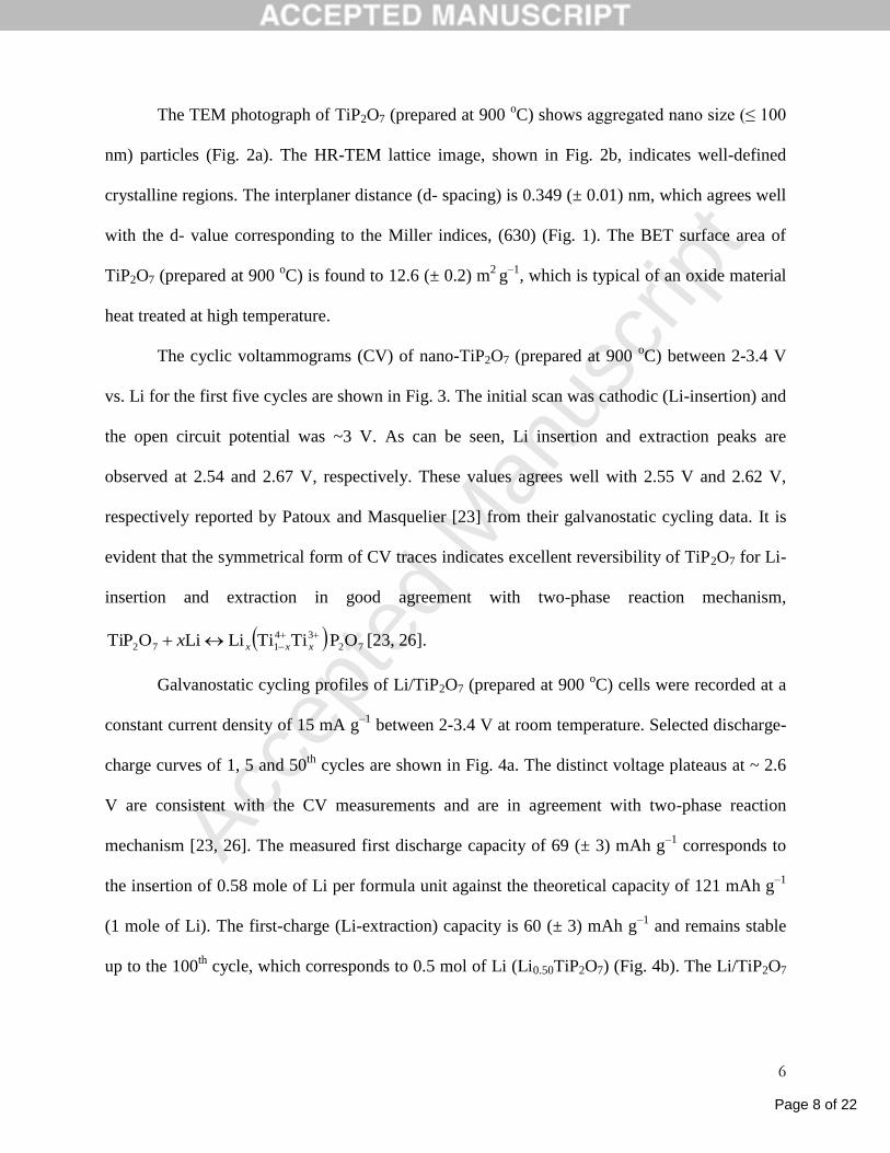
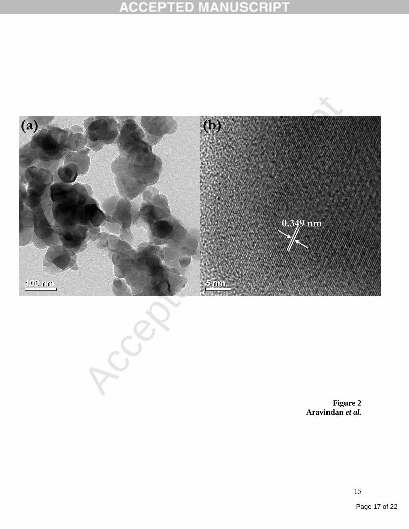
The TEM photograph of TiP2O7 (prepared at 900 oC) shows aggregated nano size (≤ 100
nm) particles (Fig. 2a). The HR-TEM lattice image, shown in Fig. 2b, indicates well-defined
crystalline regions. The interplaner distance (d- spacing) is 0.349 (± 0.01) nm, which agrees well
with the d- value corresponding to the Miller indices, (630) (Fig. 1). The BET surface area of
TiP2O7 (prepared at 900 oC) is found to 12.6 (± 0.2) m
2 g
–1, which is typical of an oxide material
heat treated at high temperature.
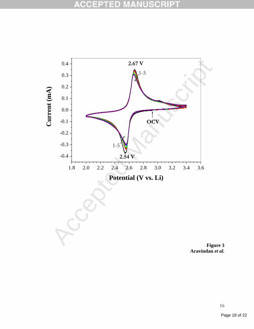
The cyclic voltammograms (CV) of nano-TiP2O7 (prepared at 900 oC) between 2-3.4 V
vs. Li for the first five cycles are shown in Fig. 3. The initial scan was cathodic (Li-insertion) and
the open circuit potential was ~3 V. As can be seen, Li insertion and extraction peaks are
observed at 2.54 and 2.67 V, respectively. These values agrees well with 2.55 V and 2.62 V,
respectively reported by Patoux and Masquelier [23] from their galvanostatic cycling data. It is
evident that the symmetrical form of CV traces indicates excellent reversibility of TiP2O7 for Li-
insertion and extraction in good agreement with two-phase reaction mechanism,
72
34
172 OP TiTiLiLiOTiP
xxxx [23, 26].
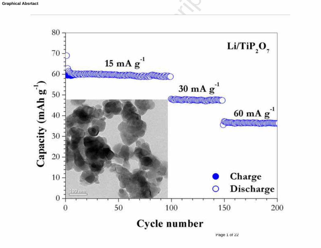
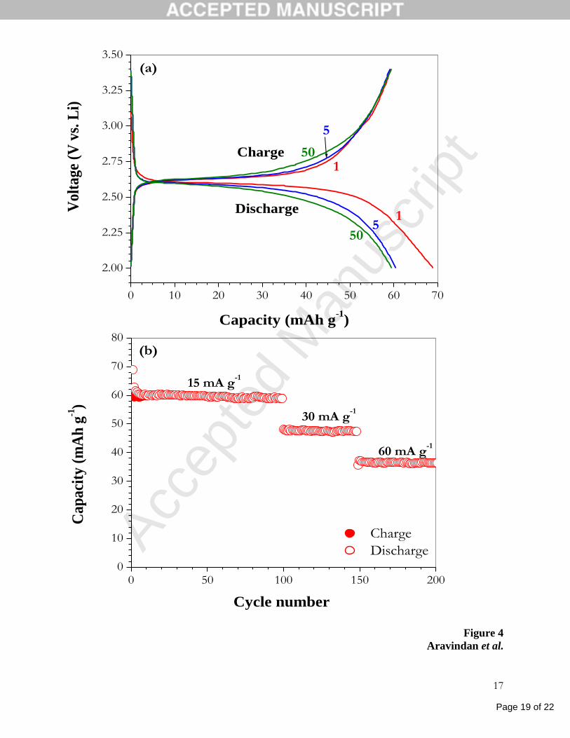
Galvanostatic cycling profiles of Li/TiP2O7 (prepared at 900 oC) cells were recorded at a
constant current density of 15 mA g–1
between 2-3.4 V at room temperature. Selected discharge-
charge curves of 1, 5 and 50th
cycles are shown in Fig. 4a. The distinct voltage plateaus at ~ 2.6
V are consistent with the CV measurements and are in agreement with two-phase reaction
mechanism [23, 26]. The measured first discharge capacity of 69 (± 3) mAh g–1
corresponds to
the insertion of 0.58 mole of Li per formula unit against the theoretical capacity of 121 mAh g–1
(1 mole of Li). The first-charge (Li-extraction) capacity is 60 (± 3) mAh g–1
and remains stable
up to the 100th
cycle, which corresponds to 0.5 mol of Li (Li0.50TiP2O7) (Fig. 4b). The Li/TiP2O7
Page 9 of 22
Accep
ted
Man
uscr
ipt
7
cell shows good current (C) rate capability: At 30 and 60 mA g–1
, a stable capacity of 48 (± 3)
and 37 (± 3) mAh g–1
, respectively was observed (Fig. 4b).
The present results differ slightly from those reported in the literature. Uebou et al. [26]
reported that TiP2O7 prepared at 700 oC by solid state reaction showed first discharge and charge
capacities of ~95 and ~60 mAh g–1
, respectively. However, no cycling data were reported.
Patoux and Masquelier [23] found that the TiP2O7 prepared by sol-gel technique showed a
reversible capacity of ~ 100 mAh g–1
(0.8 mole of Li) and stable up to 38 cycles when cycled
between 2-3.4 V at C/10 rate. Shi et al. [24] reported that the mesoporous TiP2O7 obtained by
sol-gel template route at temperatures 600, 700 and 800 oC exhibited initial reversible capacities
ranging from 90 to 100 mAh g–1
at 0.1 C current rate between 1.5-4 V, but capacity fading was
observed in all cases, up to 10 cycles. A similar trend was observed at 1 C rate, from 10 to 20
cycles. Kishore et al. [25] prepared TiP2O7 by heating the precursor, Ti(HPO4)2·H2O at 800 oC in
air and reported that the compound showed a first-discharge capacity of 90 mAh g–1
and a
reversibly capacity of 63 mAh g–1
which was stable between 5-25 cycles, when cycled at C/10
rate in the range, 1.5-3.5 V vs. Li. It may be mentioned that the galvanostatic performance of the
450 oC-synthesized TiP2O7 was not at all satisfactory and hence no further studies were carried
out.
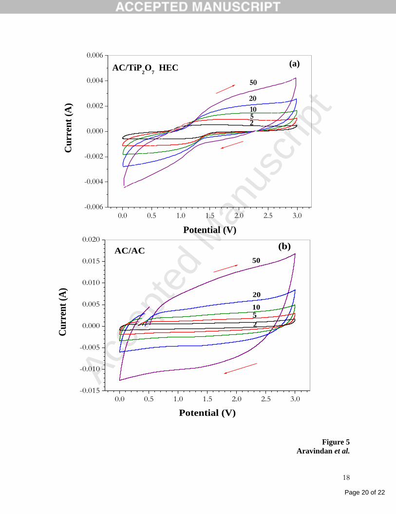
Figure 5a shows the CVs of AC/TiP2O7 (prepared at 900 oC) HEC at various sweep rates
from 2 to 50 mV s–1
between 0-3 V, respectively. In order to compare the CV traces of
AC/TiP2O7 HEC, AC/AC symmetric supercapacitor is constructed using the same electrolyte
solution and studied in the same 0-3 V potential window, and their CV profiles are presented in
figure 5b. The specific capacitance of the HEC (CHEC) is calculated using the relation,
mVqtiCHEC ./)( , where, t is the time (sec.) for the potential V (Volt) change, m is the
Page 10 of 22
Accep
ted
Man
uscr
ipt
8
mass of the active materials used in both electrodes (13.04 mg for AC/TiP2O7), q is the total
charge (coulomb) obtained by integration of positive and negative sweep in the CV [31]. From
the CV traces, the CHEC of 21, 15, 10, 7 and 4 F g–1
were obtained for the sweep rates 2, 5, 10, 20
and 50 mV s–1
, respectively. Whereas, AC/AC system delivered the specific capacitance values
of 31, 27, 24, 21 and 17 F g–1
for 2, 5, 10, 20 and 50 mV s–1
sweep rates, respectively (total mass
of the electrode 18.4 mg). It was observed that the net charge (q) decreased with an increasing
scan rate. Increasing the scan rate leads to Li-ion charge-discharge kinetics faster than the Li-ion
diffusion in to the bulk resulting in decreased specific capacitance. It is pertinent to discuss the
observed shapes of the CVs of the symmetric AC/AC and the HEC, AC/TiP2O7. The shape of the
CVs of the AC/AC maintained almost the expected rectangular shapes at various sweep rates
(Fig. 5b) [32]. However, the CV of AC/TiP2O7 exhibit a large deviation from the rectangular
shape, especially at sweep rates larger than 5 mV s–1
(Fig.5a). This has been reproduced in
duplicate measurements. This can be attributed to the fact that TiP2O7 as the anode in HEC,
utilizes the Faradaic reaction of reversible Li-intercalation-de-intercalation and electron transfer,
and more significantly, in a two-phase reaction, as is clear from Figs. 3 and 4. A similar
deviation from the rectangular shapes of the CVs was observed by Wang et al. [21] in their study
of the non-aqueous HEC, namely CNT (carbon nanotubes)/ TNW (TiO2 nano-wires), and it is
known that TNW shows Li-storage and cyclability in a more or less single-phase reaction [33-
35], which may also involve a pseudo-capacitive Li-storage [36]. Thus, we believe that the
observed shapes of the CVs is mainly due to the Li-cyclability involving a two-phase Faradaic
process in nano-TiP2O7.
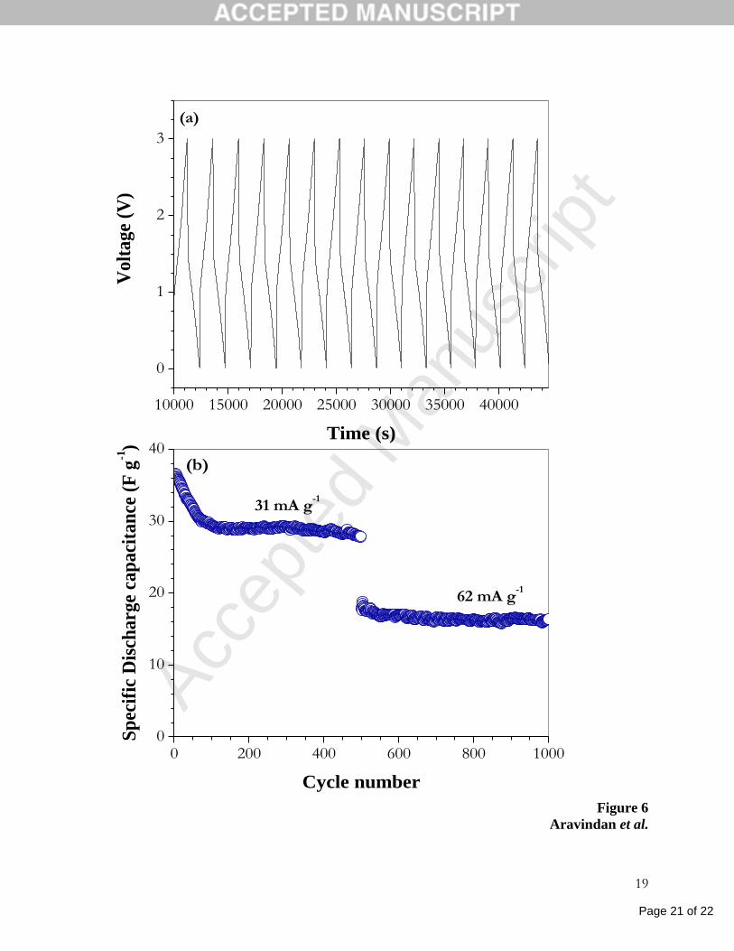
The galvanostatic cycling performance of the AC/TiP2O7 (prepared at 900 oC) HEC
between 0.0-3.0 V at a current of 31 mA g–1
at room temperature is shown in Fig. 6a. The
Page 11 of 22
Accep
ted
Man
uscr
ipt
9
energy storage mechanism at the positive electrode (AC) utilizes non-Faradaic process (electrical
double layer with the anion, 6PF present in the electrolyte) and, as discussed above, a Faradaic
reaction at the TiP2O7. Figure 6b is the plot of specific discharge capacitance (CSP.HEC) vs. cycle
number of AC/TiP2O7 at currents of 31 and 62 mA g–1
between 0-3.0 V. The discharge
capacitance (Ccell) was calculated using the relations, )/.( VtiCcell and )/4(. mCC cellHECSP ,
where i is the applied current (A), t is discharge time (sec.) and V is the potential difference (V)
[14, 37, 38]. It can be seen that, the AC/TiP2O7 HEC delivers an initial discharge capacitance of
37 F g–1
at 31 mA g–1
. This value decreases during the initial 100 cycles and thereafter, a stable
CSP.HEC of 29 (± 1) F g–1
up to 500 cycles is seen. In the range, 500 to 1000 cycles, a CSP.HEC of
17 (± 1) F g–1
at 62 mA g–1
is observed with no noticeable capacity fade.
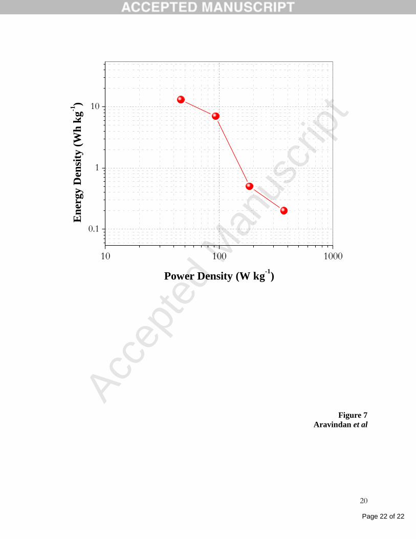
The specific energy density (E) and specific power density (P) of the AC/TiP2O7 HEC are
calculated using the relations, )m/i ΔE(P and ) tP(E , where
2/)EE(E minmax and Emax
and Emin are, respectively, the potential at the beginning of discharge and at the end of discharge
[38]. The Ragone plot (E vs. P) of the HEC is shown in Figure 7 calculated from the data of
Figure 6. As can be seen, at an energy density of 13 Wh kg–1
the corresponding power density is
46 W kg–1
. The Ragone plot also reveals an almost linear relationship. The observed values
compare well with the electrochemical performance of the Li4Ti5O12–based hybrid HEC in the
non-aqueous electrolytes [7, 9].
4 Conclusions
Urea assisted combustion synthesis route was employed for the preparation of nanosize
(≤ 100 nm) TiP2O7. It is characterized by powder X-ray diffraction and Rietveld analysis, HR-
TEM and surface area. Electrochemical Li-cycling showed that 0.5 mole of Li can be reversibly
cycled with good current rate capability and stability up to 200 cycles. Cyclic voltammetry
Page 12 of 22
Accep
ted
Man
uscr
ipt
10
showed that the two-phase reaction occurs in TiP2O7 at 2.56 V (Li-insertion) and 2.67 V (Li-
extraction) vs. Li. The hybrid supercapacitor, activated carbon (AC)/TiP2O7 in the non-aqueous
electrolyte showed good cycling profiles and delivered maximum energy and power densities of
13 Wh kg–1
and 371 W kg–1
, respectively at room temperature.
Acknowledgements
This work is supported by the grants from Competitive Research Programme (CRP) of the
National Research foundation (NRF, Singapore), number NRF-CRP4-2008-03 and the Ministry
of Education (MOE), Singapore, grant No. R-284-000-076-112.
References
[1] C. Liu, F. Li, L.-P. Ma, H.-M. Cheng, Adv. Mater., 22 (2010) E28-E62.
[2] B.E. Conway, 'Electrochemical Supercapacitors: Scientific Fundamentals and Technological
Applications', Springer, 1999.
[3] P. Simon, Y. Gogotsi, Nat. Mater., 7 (2008) 845-854.
[4] Y. Zhang, H. Feng, X. Wu, L. Wang, A. Zhang, T. Xia, H. Dong, X. Li, L. Zhang, Int. J.
Hydrogen Energy, 34 (2009) 4889-4899.
[5] M. Inagaki, H. Konno, O. Tanaike, J. Power Sources, 195 (2010) 7880-7903.
[6] D.S. Su, R. Schlögl, ChemSusChem., 3 (2010) 136-168.
[7] G.G. Amatucci, F. Badway, A. Du Pasquier, T. Zheng, J. Electrochem. Soc., 148 (2001)
A930-A939.
[8] I. Plitz, A. Dupasquier, F. Badway, J. Gural, N. Pereira, A. Gmitter, G.G. Amatucci, Appl.
Phys. A, 82 (2006) 615-626.
Page 13 of 22
Accep
ted
Man
uscr
ipt
11
[9] K. Naoi, P. Simon, Electrochem. Soc. Interface, 17 (2008) 34-37.
[10] H. Li, L. Cheng, Y. Xia, Electrochem. Solid-State Lett., 8 (2005) A433-A436.
[11] H. Wu, C.V. Rao, B. Rambabu, Mater. Chem. Phys., 116 (2009) 532-535.
[12] S.B. Ma, K.W. Nam, W.S. Yoon, X.Q. Yang, K.Y. Ahn, K.H. Oh, K.B. Kim, Electrochem.
Commun., 9 (2007) 2807-2811.
[13] X.L. Wu, L.Y. Jiang, F.F. Cao, Y.G. Guo, L.J. Wan, Adv. Mater., 21 (2009) 2710-2714.
[14] R. Vasanthi, D. Kalpana, N.G. Renganathan, J. Solid State Electrochem., 12 (2008) 961-
969.
[15] K. Karthikeyan, V. Aravindan, S.B. Lee, I.C. Jang, H.H. Lim, G.J. Park, M. Yoshio, Y.S.
Lee, J. Power Sources, 195 (2010) 3761-3764.
[16] K. Karthikeyan, V. Aravindan, S.B. Lee, I.C. Jang, H.H. Lim, G.J. Park, M. Yoshio, Y.S.
Lee, J. Alloys Compd., 504 (2010) 224-227.
[17] H.Q. Wang, Z.S. Li, Y.G. Huang, Q.Y. Li, X.Y. Wang, J. Mater. Chem., 20 (2010) 3883-
3889.
[18] L. Cheng, H.Q. Li, Y.Y. Xia, J. Solid State Electrochem., 10 (2006) 405-410.
[19] K. Naoi, S. Ishimoto, Y. Isobe, S. Aoyagi, J. Power Sources, 195 (2010) 6250-6254.
[20] L. Cheng, H.J. Liu, J.J. Zhang, H.M. Xiong, Y.Y. Xia, J. Electrochem. Soc., 153 (2006)
A1472-A1477.
[21] Q. Wang, Z. Wen, J. Li, Adv. Funct. Mater., 16 (2006) 2141-2146.
[22] C.V. Rao, B. Rambabu, Solid State Ionics, 181 (2010) 839-843.
[23] S. Patoux, C. Masquelier, Chem. Mater., 14 (2002) 5057-5068.
[24] Z. Shi, Q. Wang, W. Ye, Y. Li, Y. Yang, Microporous Mesoporous Mater., 88 (2006) 232-
237.
Page 14 of 22
Accep
ted
Man
uscr
ipt
12
[25] M.S. Kishore, V. Pralong, V. Caignaert, U.V. Varadaraju, B. Raveau, J. Power Sources, 169
(2007) 355-360.
[26] Y. Uebou, S. Okada, M. Egashira, J.I. Yamaki, Solid State Ionics, 148 (2002) 323-328.
[27] H. Wang, K. Huang, Y. Zeng, S. Yang, L. Chen, Electrochim. Acta, 52 (2007) 3280-3285.
[28] K.C. Patil, M.S. Hegde, T. Rattan, S.T. Aruna, 'Chemistry of nanocrystalline oxide
materials:combustion synthesis, properties and applications', World Scientific, Singapore, 2008.
[29] Y. Sharma, N. Sharma, G.V. Subba Rao, B.V.R. Chowdari, Electrochim. Acta, 53 (2008)
2380-2385.
[30] J. Sanz, J.E. Iglesias, J. Soria, E.R. Losilla, M.A.G. Aranda, S. Bruque, Chem. Mater., 9
(1997) 996-1003.
[31] D. Xuan, W. Chengyang, C. Mingming, J. Yang, W. Jin, J. Phys. Chem. C, 113 (2009)
2643-2646.
[32] P.C. Gao, A.-H. Lu, W.-C. Li, J. Power Sources, 196 (2011) 4095-4101.
[33] A.R. Armstrong, G. Armstrong, J. Canales, P.G. Bruce, Angew. Chem. Int. Ed., 43 (2004)
2286-2288.
[34] A.R. Armstrong, G. Armstrong, J. Canales, P.G. Bruce, J. Power Sources, 146 (2005) 501-
506.
[35] T. Beuvier, M.R. Plouet, M.M.L. Granvalet, T. Brousse, O. Crosnier, L. Brohan, Inorg.
Chem., 49 (2010) 8457-8464.
[36] M. Zukalová, M. Kalbác, L. Kavan, I. Exnar, M. Graetzel, Chem. Mater., 17 (2005) 1248-
1255.
[37] J.H. Park, O.O. Park, J. Power Sources, 111 (2002) 185-190.
[38] J.Y. Luo, Y.Y. Xia, J. Power Sources, 186 (2009) 224-227.
Page 15 of 22
Accep
ted
Man
uscr
ipt
13
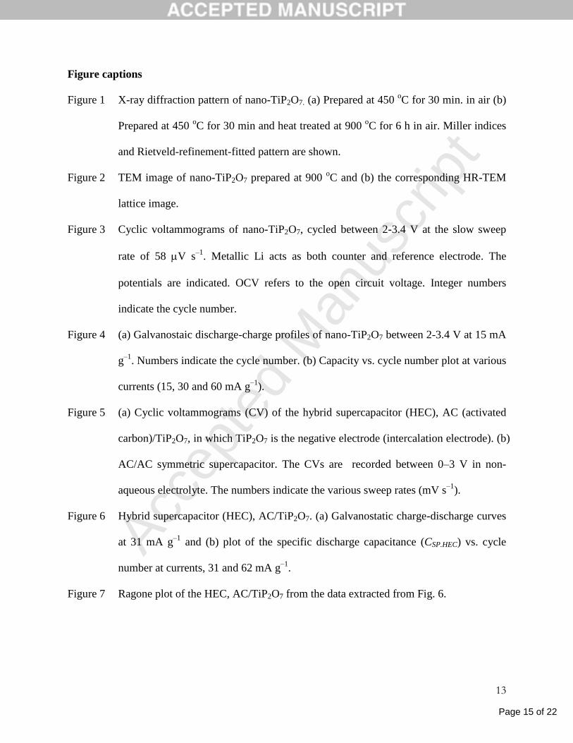
Figure captions
Figure 1 X-ray diffraction pattern of nano-TiP2O7. (a) Prepared at 450 oC for 30 min. in air (b)
Prepared at 450 oC for 30 min and heat treated at 900
oC for 6 h in air. Miller indices
and Rietveld-refinement-fitted pattern are shown.
Figure 2 TEM image of nano-TiP2O7 prepared at 900 oC and (b) the corresponding HR-TEM
lattice image.
Figure 3 Cyclic voltammograms of nano-TiP2O7, cycled between 2-3.4 V at the slow sweep
rate of 58 V s–1
. Metallic Li acts as both counter and reference electrode. The
potentials are indicated. OCV refers to the open circuit voltage. Integer numbers
indicate the cycle number.
Figure 4 (a) Galvanostaic discharge-charge profiles of nano-TiP2O7 between 2-3.4 V at 15 mA
g–1
. Numbers indicate the cycle number. (b) Capacity vs. cycle number plot at various
currents (15, 30 and 60 mA g–1
).
Figure 5 (a) Cyclic voltammograms (CV) of the hybrid supercapacitor (HEC), AC (activated
carbon)/TiP2O7, in which TiP2O7 is the negative electrode (intercalation electrode). (b)
AC/AC symmetric supercapacitor. The CVs are recorded between 0–3 V in non-
aqueous electrolyte. The numbers indicate the various sweep rates (mV s–1
).
Figure 6 Hybrid supercapacitor (HEC), AC/TiP2O7. (a) Galvanostatic charge-discharge curves
at 31 mA g–1
and (b) plot of the specific discharge capacitance (CSP.HEC) vs. cycle
number at currents, 31 and 62 mA g–1
.
Figure 7 Ragone plot of the HEC, AC/TiP2O7 from the data extracted from Fig. 6.
Page 16 of 22
Accep
ted
Man
uscr
ipt
14
Figure 1
Aravindan et al.
Page 17 of 22
Accep
ted
Man
uscr
ipt
15
Figure 2
Aravindan et al.
0.349 nm
(a) (b)
Page 18 of 22
Accep
ted
Man
uscr
ipt
16
Figure 3
Aravindan et al.
1.8 2.0 2.2 2.4 2.6 2.8 3.0 3.2 3.4 3.6
-0.4
-0.3
-0.2
-0.1
0.0
0.1
0.2
0.3
0.4
OCV
1-5
1-5
2.54 V
2.67 V
Cu
rren
t (m
A)
Potential (V vs. Li)
Page 19 of 22
Accep
ted
Man
uscr
ipt
17
Figure 4
Aravindan et al.
0 10 20 30 40 50 60 70
2.00
2.25
2.50
2.75
3.00
3.25
3.50
Charge
Discharge
50
5
1
(a)
505
1
Volt
age
(V v
s. L
i)
Capacity (mAh g-1
)
0 50 100 150 2000
10
20
30
40
50
60
70
80(b)
60 mA g-1
30 mA g-1
15 mA g-1
Charge
Discharge
Cap
aci
ty (
mA
h g
-1)
Cycle number
Page 20 of 22
Accep
ted
Man
uscr
ipt
18
Figure 5
Aravindan et al.
0.0 0.5 1.0 1.5 2.0 2.5 3.0-0.006
-0.004
-0.002
0.000
0.002
0.004
0.006(a)
AC/TiP2O
7 HEC
2 5 10
20
50
Cu
rren
t (A
)
Potential (V)
0.0 0.5 1.0 1.5 2.0 2.5 3.0-0.015
-0.010
-0.005
0.000
0.005
0.010
0.015
0.020(b)
AC/AC50
20
10 5
2
Cu
rren
t (A
)
Potential (V)
Page 21 of 22
Accep
ted
Man
uscr
ipt
19
Figure 6
Aravindan et al.
0 200 400 600 800 10000
10
20
30
40(b)
62 mA g-1
31 mA g-1
Sp
ecif
ic D
isch
arg
e ca
pa
cita
nce
(F
g-1)
Cycle number
10000 15000 20000 25000 30000 35000 40000
0
1
2
3
(a)V
olt
age
(V)
Time (s)
Page 22 of 22
Accep
ted
Man
uscr
ipt
20
Figure 7
Aravindan et al
10 100 1000
0.1
1
10
En
ergy
Den
sity
(W
h k
g-1)
Power Density (W kg-1
)


