Embed Size (px)
Citation preview
310 IEEE/ASME TRANSACTIONS ON MECHATRONICS, VOL. 16, NO. 2, APRIL 2011
Human-Like Walking: Optimal Motion of a BipedalRobot With Toe-Rotation Motion
David Tlalolini, Christine Chevallereau, and Yannick Aoustin
Abstract—Fast human walking includes a phase where the stanceheel rises from the ground and the stance foot rotates about thestance toe. This phase where the biped becomes underactuated isnot present during the walk of current humanoid robots. The ob-jective of this study is to determine whether the introduction ofthis phase for a 3-D bipedal robot is useful to reduce the energyconsumed in the walking. In order to study the efficiency of thisnew gait, two cyclic gaits are presented. The first cyclic motionis composed of successive single-support phases with a flat stancefoot on the ground, and the stance foot does not rotate. The secondcyclic motion is composed of single-support phases that includea subphase of rotation of the supporting foot about the toe. Thesingle-support phases are separated by a double-support phase.For simplicity, this double-support phase is considered as instan-taneous (passive impact). For these two gaits, optimal motions aredesigned by minimizing the torques cost. The given performancesof actuators are taken into account. It is shown that, for a fast mo-tion, a foot-rotation subphase is useful to reduce the cost criterion.These gaits are illustrated with simulation results.
Index Terms—Biped robot, cyclic walking gait, parametric op-timization, robot dynamics.
I. INTRODUCTION
THE knowledge coming from the physiological, biome-chanical, engineering, and robotic fields about human
locomotion leads to the design and development of roboticsstructures as human-like as possible. These anthropomorphicstructures are a useful way to understand the dynamic princi-ples of human walking. Several anthropomorphic mechanicalstructures have been proposed, such as WABOT-1 introducedin 1973 [1], HONDA humanoid robot in 1996 [2], [3], ASIMOin 2000 [4], the anthropomorphic autonomous biped JOHN-NIE [5], and the HRP series, 1, 1S, 2L, 2P, 2, and 3P [6]–[8].However, most of these humanoid robots have been developedwith 6-DoF per leg without toe joints. This limited number ofdegrees of freedom (DoF) cannot capture all the features of
Manuscript received May 29, 2009; revised September 18, 2009 andDecember 27, 2009; accepted December 31, 2009. Date of publication March8, 2010; date of current version January 19, 2011. Recommended by TechnicalEditor V. N. Krovi. This paper was presented in part at the International Confer-ence on Intelligent RObots and Systems (IROS 2008), Nice, France, September22–26, 2008.
D. Tlalolini is with the Laboratory of Physiology of Perception andAction, College de France, 75005 Paris, France (e-mail: [email protected]).
C. Chevallereau and Y. Aoustin are with the Institute of Research in Com-munication and Cybernetics of Nantes, University of Nantes, 44321 Nantes,France (e-mail: [email protected]; [email protected]).
Color versions of one or more of the figures in this paper are available onlineat http://ieeexplore.ieee.org.
Digital Object Identifier 10.1109/TMECH.2010.2042458
the human gait in a humanoid robot. In physiology, biome-chanical, and from studies of human walking gait, authors areconvinced that the role of the foot is essential to the equilib-rium of the whole body. In fact, it serves as shock absorber andhas a propulsive role [9], [10]. Thus, it becomes necessary tounderstand and reproduce the role of the foot on the humanoidrobot to achieve nearly human-like gaits. In the robotic field,only a few papers have been devoted to the behavior of the footin double-support phases and single-support phases. Most re-search works that include foot rotation have been focused oncontroller aspects [11]–[15] and energy efficiency [16], [17].McGeer [18] and Kuo [19] are devoted to a very simple pla-nar biped. They show the relevance of an impulse in the stancefoot before the impact. Recently, Collins et al. [20] have builtminimally actuated bipeds based on passive walking principals,including a toe-like propulsion. An optimized walking gait isproposed in [21] and [22] for a seven-link biped: in single-support phases, the stance foot is flat on the ground and therotation about the feet appears in double-support phases only.The recent works of Nishiwaki et al. [23], Takao et al. [24], andYoon et al. [25] show that the presence of toe joints allow toperform longer strides, climb higher steps, and walk at a higherspeed. Hobbelen and Wisse [26] show that, however, to reducethe energy consumption, a passive spring can be implementedin the ankle with a stiffness that creates premature rise of thestance foot heel. Motivated by energy efficiency and versatilityof locomotion, six optimal cyclic gaits have been analyzed fora planar biped robot in [27]. It is shown that, for fast motions,a rotation of the stance foot during the single-support phase isuseful to reduce the energy consumed in the walking.
In this paper, we extend our analysis of generation of optimalwalking motions from the planar bipedal robots to the generationof optimal walking motions for an anthropomorphic 3-D bipedrobot with passive toe joints. The efforts are focused on thedesign of reference walking trajectories for a 3-D bipedal robot,including foot rotation during the single-support phase. Thecyclic gaits under study consist of successive single-supportphases separated by instantaneous double-support phases. Pointout that it is not possible to obtain a finite-time double-supportphase with a biped composed of rigid links after a passive impactwith a rigid ground [28]. To obtain a finite-time double-supportphase, it is necessary to impose an impactless gait. In practice,due to the elasticity of the sole, a double-support phase is likelyto happen. It is shown in [27] that the benefit of the finite-time double-support phase on the energy cost is not so clear.The real benefit is to improve the stability of the gait [28].The single-support phase may or may not be decomposed intotwo subphases: a flat-foot (fully actuated) subphase and a foot-rotation (underactuated) subphase. This study is different from
1083-4435/$26.00 © 2010 IEEE
TLALOLINI et al.: HUMAN-LIKE WALKING: OPTIMAL MOTION OF A BIPEDAL ROBOT WITH TOE-ROTATION MOTION 311
previous studies in two aspects: first, the kinematic structureconsists of 14 motorized joints on the level of the hip–knee–ankle–foot kinematics chain. In contrast to previous bipedalstructures, this structure has one additional joint to take intoaccount the foot twist rotation. Second, in order to solve theunderactuation problem and ensure the feasibility of the biped’smotion during the foot rotation subphase, we choose the jointpath of the robot [29]–[32]. Therefore, a motion compatible withthe dynamic model is deduced. For the compatible motions, thecenter of pressure (CoP ) remains strictly on the front limitof the stance foot to allow the foot to rotate. The synthesis ofthe reference walking trajectories is stated under the form of aconstrained parameter optimization problem. The resolution ofthis problem is obtained by sequential quadratic programming(SQP) methods. The performance criterion, based on the squareof the torques, is optimized in order to increase the autonomy ofenergy of the biped robot. Furthermore, some constraints, suchas actuator performances and limits on the ground reaction forcein single-support phases and at impacts, are taken into account.
The outline of the paper is as follows. Section II presents thedescription of the two gaits studied, along with the geometricdescription and inverse dynamic model of the bipedal robot.The formulation of the optimization problems for optimal cyclicgait with and without foot rotation are defined in Section III. InSection IV, the various constraints and the cost function takeninto account during the optimization processes are defined. Thesimulation results are presented in Section V. The conclusionsand perspectives are given in Section VI.
II. ANALYSIS OF CYCLIC MOTION AND MODELING
OF BIPEDAL ROBOT
A. Analysis of Cyclic Motion
For a normal human being, the description of walking can beconfined to a cycle pattern of movement that is repeated overand over, step after step. With the assumptions that two steps(left plus right) make one cycle and that, in a normal gait, thereis a natural symmetry between the left and right sides, we studythe movement of a step only (the left step).
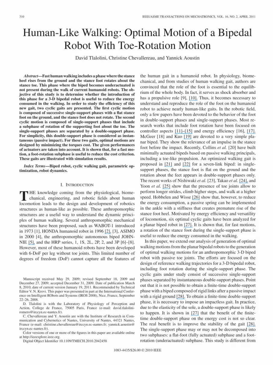
1) Gait A (Single Supports Separated by Impact): In thisgait, the rear (left) foot and the front (right) foot are flat on theground in the initial double support. Then the rear foot leavesthe ground (beginning of the single-support phase), swingingthrough in preparation for the foot strike, while the contralateralfoot, with flat contact on the ground, assures the equilibrium. Atthe end of the single-support phase, the swing foot touches theground with flat foot, producing the final double-support phase,as shown in Fig. 1(a).
In this gait, the double supports are instantaneous. During thesingle-support phase, the whole foot–ground contact assures anarea of contact, which is maximum at all instants. Stability ismaximized. This gait is appropriate to achieve,walking withslow speed.
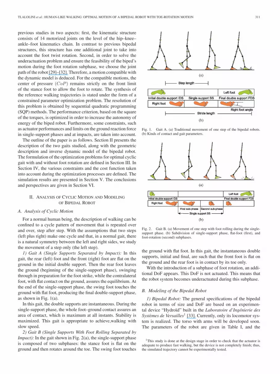
2) Gait B (Single Supports With Foot Rolling Separated byImpact): In the gait shown in Fig. 2(a), the single-support phaseis composed of two subphases: the stance foot is flat on theground and then rotates around the toe. The swing foot touches
Fig. 1. Gait A. (a) Traditional movement of one step of the bipedal robots.(b) Kinds of contact and gait parameters.
Fig. 2. Gait B. (a) Movement of one step with foot rolling during the single-support phase. (b) Subdivision of single-support phase, flat-foot (first), andfoot-rotation (second) subphases.
the ground with flat foot. In this gait, the instantaneous doublesupports, initial and final, are such that the front foot is flat onthe ground and the rear foot is in contact by its toe only.
With the introduction of a subphase of foot rotation, an addi-tional DoF appears. This DoF is not actuated. This means thatthe robot system becomes underactuated during this subphase.
B. Modeling of the Bipedal Robot
1) Bipedal Robot: The general specifications of the bipedalrobot in terms of size and DoF are based on an experimen-tal device “Hydroıd” built in the Laboratoire d’Ingenierie desSystemes de Versailles1 [33]. Currently, only its locomotor sys-tem is realized. The torso with arms will be developed soon.The parameters of the robot are given in Table I, and the
1This study is done at the design stage in order to check that the actuator isadequate to produce fast walking, but the device is not completely finish; thus,the simulated trajectory cannot be experimentally tested.

312 IEEE/ASME TRANSACTIONS ON MECHATRONICS, VOL. 16, NO. 2, APRIL 2011
TABLE IPARAMETERS OF THE BIPED USED IN THE OPTIMAL PROCESS.
characteristics of the robot have been chosen in order to be closeto human being. The bipedal robot consists of seven rigid linksconnected by 14 motorized joints2 and two passive toe joints.This kinematic structure is designed to retain only basic hu-man locomotion mobilities at the level of the hip–knee–ankle–foot kinematics chain. Each ankle of the bipedal robot consistsof the pitch and the yaw axes (flexion/extension and abduc-tion/adduction), and one additional roll axis to take into accountthe foot twist rotation. This twist rotation about the z-axis, un-usual in humanoid robot structures, increases very significantlythe degree of motion anthropomorphism [34]. The knees consistof the pitch axis (flexion/extension) and the hips consist of theroll, pitch, and yaw axes (rotation, flexion/extension, and ab-duction/adduction) to constitute a biped walking system of two3-DoF ankles, two 1-DoF knees, and two 3-DoF hips.
2) Geometric Description of the Kinematic Chain: To definethe geometric structure of the biped walking system, we used theparameterization proposed for manipulator robots. The bipedalrobot is composed of N = 15 links connected by N − 1 revolutejoints into an open serial kinematic chain. The stance foot is thebase and the swing foot is the final link in the kinematic chain.
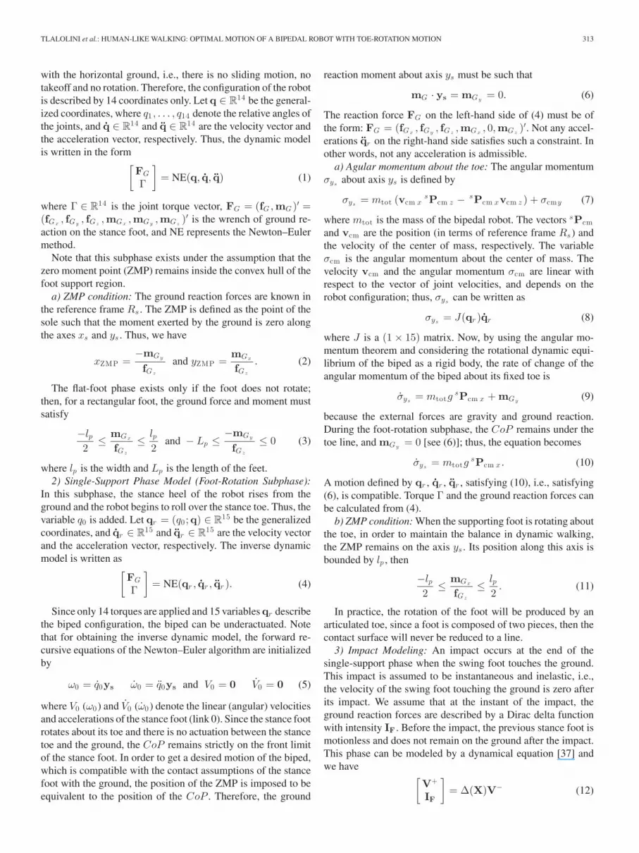
The joint variables are denoted by q0 , . . . , q14 . These variablesdescribe the shape and the orientation of the bipedal robot, asshown Fig. 3. The variable q0 denotes a relative rotation of thestance foot about its toe (z0-axis). q0 is defined as the anglebetween the axes xs and x0 , measured along z0 . An inertialframe Rs(Os, xs, ys , zs) is fixed at the stance toe. The origin Os
of the inertial frame is fixed to the ground at the center of the foottip, as Fig. 3 indicates. The frames have been assigned to 15 linksaccording to the modified Denavit–Hartenberg procedure [35](see Fig. 3).
C. Dynamic Modeling
In order to determine the impact model and the dynamics forthe single-support phase with or without rolling of the foot, theefficient Newton–Euler formulation is chosen. When a simpleplanar robot is modeled as in [27], the dynamic model can be
2Let us assume that the actuator dynamics is neglected in the optimizationprocess. The feet mechanism of Hydroıd considers one passive joint modeledon human toes with metatarsophalangeal joints. In this study, we consider thetoe joint like the tip of the foot.
Fig. 3. Bipedal robot: multilink model, link frames, and coordinate conven-tion. In foot-rotation subphase, q0 denotes a relative angle of the rotation of R0with respect to Rs about z0 , and in flat-foot subphase, q0 = 0.
calculated via the Lagrange formalism. For humanoid robotswith many joints, the Newton–Euler formalism is more efficientfor the calculation cost point of view. Associated to our choiceof parameterization and by performing a so-called forward–backward recursion [36], [37], the joint torques and groundreaction forces can be calculated. For each link, a forward re-cursion returns linear and angular velocities, accelerations, totalforces, and moments, then a backward recursion gives the solu-tion of the inverse dynamic problem by evaluating for each linkjoint torques and the ground reaction forces.
1) Single-Support Phase Model (Flat-Foot Subphase): Duringthis subphase, the stance foot is assumed to remain in flat contact
TLALOLINI et al.: HUMAN-LIKE WALKING: OPTIMAL MOTION OF A BIPEDAL ROBOT WITH TOE-ROTATION MOTION 313
with the horizontal ground, i.e., there is no sliding motion, notakeoff and no rotation. Therefore, the configuration of the robotis described by 14 coordinates only. Let q ∈ R
14 be the general-ized coordinates, where q1 , . . . , q14 denote the relative angles ofthe joints, and q ∈ R
14 and q ∈ R14 are the velocity vector and
the acceleration vector, respectively. Thus, the dynamic modelis written in the form[
FG
Γ
]= NE(q, q, q) (1)
where Γ ∈ R14 is the joint torque vector, FG = (fG,mG )′ =
(fGx, fGy
, fGz,mGx
,mGy,mGz
)′ is the wrench of ground re-action on the stance foot, and NE represents the Newton–Eulermethod.
Note that this subphase exists under the assumption that thezero moment point (ZMP) remains inside the convex hull of thefoot support region.
a) ZMP condition: The ground reaction forces are known inthe reference frame Rs . The ZMP is defined as the point of thesole such that the moment exerted by the ground is zero alongthe axes xs and ys . Thus, we have
xZMP =−mGy
fGz
and yZMP =mGx
fGz
. (2)
The flat-foot phase exists only if the foot does not rotate;then, for a rectangular foot, the ground force and moment mustsatisfy
−lp2
≤ mGx
fGz
≤ lp2
and − Lp ≤−mGy
fGz
≤ 0 (3)
where lp is the width and Lp is the length of the feet.2) Single-Support Phase Model (Foot-Rotation Subphase):
In this subphase, the stance heel of the robot rises from theground and the robot begins to roll over the stance toe. Thus, thevariable q0 is added. Let qr = (q0 ;q) ∈ R
15 be the generalizedcoordinates, and qr ∈ R
15 and qr ∈ R15 are the velocity vector
and the acceleration vector, respectively. The inverse dynamicmodel is written as[
FG
Γ
]= NE(qr , qr , qr ). (4)
Since only 14 torques are applied and 15 variables qr describethe biped configuration, the biped can be underactuated. Notethat for obtaining the inverse dynamic model, the forward re-cursive equations of the Newton–Euler algorithm are initializedby
ω0 = q0ys ω0 = q0ys and V0 = 0 V0 = 0 (5)
where V0 (ω0) and V0 (ω0) denote the linear (angular) velocitiesand accelerations of the stance foot (link 0). Since the stance footrotates about its toe and there is no actuation between the stancetoe and the ground, the CoP remains strictly on the front limitof the stance foot. In order to get a desired motion of the biped,which is compatible with the contact assumptions of the stancefoot with the ground, the position of the ZMP is imposed to beequivalent to the position of the CoP . Therefore, the ground
reaction moment about axis ys must be such that
mG · ys = mGy= 0. (6)
The reaction force FG on the left-hand side of (4) must be ofthe form: FG = (fGx
, fGy, fGz
,mGx, 0,mGz
)′. Not any accel-erations qr on the right-hand side satisfies such a constraint. Inother words, not any acceleration is admissible.
a) Agular momentum about the toe: The angular momentumσys
about axis ys is defined by
σys= mtot (vcm x
sPcm z − sPcm xvcm z ) + σcmy (7)
where mtot is the mass of the bipedal robot. The vectors sPcmand vcm are the position (in terms of reference frame Rs) andthe velocity of the center of mass, respectively. The variableσcm is the angular momentum about the center of mass. Thevelocity vcm and the angular momentum σcm are linear withrespect to the vector of joint velocities, and depends on therobot configuration; thus, σys
can be written as
σys= J(qr )qr (8)
where J is a (1 × 15) matrix. Now, by using the angular mo-mentum theorem and considering the rotational dynamic equi-librium of the biped as a rigid body, the rate of change of theangular momentum of the biped about its fixed toe is
σys= mtotg
sPcm x + mGy(9)
because the external forces are gravity and ground reaction.During the foot-rotation subphase, the CoP remains under thetoe line, and mGy
= 0 [see (6)]; thus, the equation becomes
σys= mtotg
sPcm x . (10)
A motion defined by qr , qr , qr , satisfying (10), i.e., satisfying(6), is compatible. Torque Γ and the ground reaction forces canbe calculated from (4).
b) ZMP condition: When the supporting foot is rotating aboutthe toe, in order to maintain the balance in dynamic walking,the ZMP remains on the axis ys . Its position along this axis isbounded by lp , then
−lp2
≤ mGx
fGz
≤ lp2
. (11)
In practice, the rotation of the foot will be produced by anarticulated toe, since a foot is composed of two pieces, then thecontact surface will never be reduced to a line.
3) Impact Modeling: An impact occurs at the end of thesingle-support phase when the swing foot touches the ground.This impact is assumed to be instantaneous and inelastic, i.e.,the velocity of the swing foot touching the ground is zero afterits impact. We assume that at the instant of the impact, theground reaction forces are described by a Dirac delta functionwith intensity IF . Before the impact, the previous stance foot ismotionless and does not remain on the ground after the impact.This phase can be modeled by a dynamical equation [37] andwe have [
V+
IF
]= Δ(X)V− (12)
314 IEEE/ASME TRANSACTIONS ON MECHATRONICS, VOL. 16, NO. 2, APRIL 2011
where X = (X0 , α0 ,q)′ ∈ R20 is the generalized coordinates
vector. V− and V+ denote the velocities before and after theimpact.
III. GAIT OPTIMIZATION FOR THE CYCLIC MOTION
A. Gait Without Foot Rotation
1) Constructing the Joint Trajectories: The biped is driven by14 torques and its configuration is given in single-support phaseby 14 coordinates q. To define the joint evolution, cubic splinefunctions [38] are used for constructing the joint trajectories.For each joint j(j = 1, . . . , 14), a cubic spline function has theform
qj (t) =
⎧⎪⎪⎨⎪⎪⎩
ϕj,1(t), if t1 ≤ t < t2ϕj,2(t), if t2 ≤ t < t3
......
ϕj,n−1(t), if tn−1 ≤ t ≤ tn
(13)
where n is the number of selected knots. ϕj,1(t), . . . , ϕj,n−1(t)are polynomials of third order3 such that
ϕj,k (t) =3∑
i=0
aij,k (t − tk )i , for t ∈ [tk , tk+1],
k = 1, . . . , n − 1 (14)
with aij,k calculated so that the position, velocity, and accelera-
tion are always continuous in t1 , . . . , tn . The cubic spline func-tions are uniquely defined by specifying an initial configurationqi , an initial velocity qi (both at t = 0), a final configuration qf ,and a final velocity qf (both at t = T f ) in double support, withn − 2 intermediate configurations in single support and T f theduration of the single support. We use n = 3 and define only anintermediate configuration qint at t = T f /2. Consequently, theconfigurations will be defined by a small number of optimizationparameters.
2) Optimization Parameters: In order to define the initial andfinal configurations of the biped legs, only eight independentvariables are necessary because the two feet are flat on theground. We use the twist motion of the swing foot denoted byψf and its position (xf , yf ) in the horizontal plane, as well asthe position of the trunk (xt, yt , zt) and θt , φt the inclinationin the sagittal plane, and rotation about zt-axis of the trunk. Theinclination in the frontal plane is assumed to be null.
The desired trajectory has the particularity of being periodic:two following steps (left plus right) must be identical and, moreprecisely, the legs will swap their roles from one step to the next.The condition of periodicity is used to define the trajectory onlyon one step to reduce the number of optimization parameters.In this way, we avoid to use two single-support models. Theposition of the robot is constant during the passive impact (touchdown configuration), and since the legs swap their roles from onestep to the next, the generalized coordinates must be relabeled
3In an optimization process, the adjustment of polynomial function parame-ters of high order can produce oscillatory movements unintended and disruptive.To avoid this, the cubic spline functions are used.
according to the following equation:
qi = Eqf (15)
where E14×14 is
E =
⎡⎢⎢⎢⎣
0 0 0 0 J2
0 0 0 −J3 00 0 J4 0 00 −J3 0 0 0J2 0 0 0 0
⎤⎥⎥⎥⎦ (16)
with Jm being an antidiagonal (m × m) identity matrix. Thefinal configuration qf is determined from the inverse kinematicssolution of each leg.
To obtain the initial velocity qi , from (12), the 14 last rowsof V+ are used
qi = EV+(7 :2 0 )
. (17)
Using (15) and (17), the cubic spline functions q(t) can bedefined as function of T f ,qint, qf , xf , yf , ψf , xt , yt , zt , θt , φt .The optimal trajectory is defined by 37 parameters only.
3) Torques and Ground Reaction Forces: When function q(t)is chosen, joint velocities and accelerations can be deducedby the differentiation of the polynomial function. The inversedynamic model (1) gives the torques and the ground reactionforces required to produce the motion.
B. Gait With Foot Rotation
1) Flat-Foot Subphase: When a subphase with foot rotation isadded, the optimization process is modified. The two subphasesare separately described and the conditions of continuity inconfiguration and velocity between the subphases are taken intoaccount. For each subphase, the final state of the biped is chosento be defined from the optimization variables and the initial stateis deduced from the continuity conditions.
The flat-foot subphase is described as previously. The dif-ference is just that the final configuration for this phase is nota double-support configuration, but a single support with flatstance foot configuration4; thus, 14 variables are used to describethis configuration qf , and 29 optimization variables define thissubphase, T f , qf , and qf .
2) Foot-Rotation Subphase: During the foot-rotation sub-phase, the biped is driven by 14 torques, and its configuration isgiven in single-support phase by 15 coordinates qr . Therefore,the biped is underactuated and its motion cannot be freely cho-sen. Studies of control of such an underactuated robot [30], [32]have shown that a geometric evolution of the robot qr (s) can bechosen. For a given function qr (s) within some limits, functions(t) corresponding to a motion compatible with the dynamicmodel can be deduced using (10). In the optimization process,the joint evolution is described by function qr (s). This methodsolves the underactuation problem and avoids the use of equalityconstraints as in [39]. This point is detailed in Section III-B3.
4Since the final configuration of this subphase is a single support, an inter-mediate configuration qint is not necessary. Therefore, only third-order polyno-mial functions, defined by qi , qf , qi , and qf , are needed to describe the jointmotion.

TLALOLINI et al.: HUMAN-LIKE WALKING: OPTIMAL MOTION OF A BIPEDAL ROBOT WITH TOE-ROTATION MOTION 315
We choose to define the evolution of the joint variables as athird-order polynomial of s, where s is a monotonic functionfrom 0 to 1. qr (0) and qr (1) are the initial and final configura-tions of the foot-rotation support phase, respectively. Then
qrj (s) =3∑
i=0
aij (s)i , j = 0, . . . , 14 ∀s ∈ [0, 1] (18)
where j is the joint number. The polynomial func-tions qrj (s), j = 0, . . . , 14, are uniquely defined by
qir ,q
fr , dq i
r
ds , and dqfr
ds . The indexes i and f correspond to theinitial (at s = 0) and final (at s = 1) states of the robot for thissubphase, respectively. The velocity of the robot is such that
qr (s) =dqr
dss(s). (19)
Since s is not given, then only the direction of the joint ve-locity is provided, but not its amplitude.
In fact, the initial state for this subphase is the final state forthe flat-foot subphase qi
r = ((qf0 = 0);qf ); thus, it is known by
the 29 optimization parameters for the flat-foot subphase. Theinitial velocity of the robot is known, qi
r = ((qf0 = 0); qf ). The
initial vector dq ir
ds can be deduced if s(0) is known, and this terms(0) will be an optimization variable.
The final configuration is a double support one with onlyone foot flat on the ground; thus, nine coordinates are used todefine this configuration: xf , yf , ψf , xt , yt , zt , θt , φt , qf
0 .The joint path qr (s) during the foot-rotation subphase can be
calculated with 25 optimization variables: 9 for qfr , 15 for dqf
r
ds ,and s(0).
3) From Joint Trajectories to Joint Motions: The joint evo-lution is given as qr (s), but since the robot is underactuated,function s must be such that the robot motion satisfies (10). Theangular momentum is defined by (8). Since qr is a function ofs and qr (s) is proportional to s, this angular momentum can berewritten as
σys= I(s)s(s)
σys= mtotg
sPcm x(qr (s)) (20)
where I(s) = J(qr ) dqr
ds .These two equations can be combined to have, for 0 ≤ s ≤ 1
[30],
12I(0)2 s(0)2 =
12I(s)2 s(s)2 + V (s)
V (s) = −mg
∫ s
0I(ξ)(xg (ξ))dξ. (21)
Since function I(s) and V (s) can be calculated for any givenfunction qr (s), it follows that the initial value s(0) allows todefine the function s completely by
s(s) =
√I(0)2 s(0)2 − 2V (s)
I(s)2 . (22)
The polynomial functions qr (s) are defined with the assumptionthat s is a well-defined increasing function; thus, the following
conditions must be satisfied:
s(0) >
√2maxs(V (s))
I(0)2
I(s) �= 0, for 0 ≤ s ≤ 1 (23)
in order that
s > 0, for 0 ≤ s ≤ 1. (24)
These constraints are taken into account in the optimizationprocess.
At the end of the foot-rotation subphase, the value of s canbe deduced from (22) and the velocity of the robot at the end ofthe foot-rotation subphase is
qfr =
√I(0)2 s(0)2 − 2V (1)
I(1)2
dqfr
ds. (25)
Since the impact occurs in configuration qfr with velocity
qfr , the initial state of the robot for the flat-foot subphase can
be deduced from equations (15) and (17). The duration of thefoot-rotation phase is not a direct optimization variable, it is theresult of integration of the function s(s) that defines at whichtime s = 1, i.e.,
T r =∫ 1
0
1sds. (26)
4) Torques and the Ground Reaction Forces: For the foot-rotation subphase, when function qr (s) is chosen, s(s) can becalculated by (22). Therefore, the joint velocity is calculated by(19) and the joint acceleration can be written as
qr (s) =d2qr
ds2 s2 +dqr
dss(s). (27)
In order to deduce s, we use the linearity of the torque Γ withrespect to acceleration s5 and the fact that the reaction momentabout the toe mGy is zero. Therefore,
Γ = us + v (28)
where, from (4), we have
Γ =[FGΓ
]= NE(qr (s), qr (s), qr (s)). (29)
Using the Newton–Euler algorithm, Γ is calculated for s = 0and s = 1; these vectors are denoted by Γ0 and Γ1 , respectively.For any s, we have
Γ = (Γ1 − Γ0)s + Γ0 = us + v (30)
where v = Γ0 and u = (Γ1 − Γ0).Since the ground reaction moment about the axis ys is such
that mGy is zero, s is easily obtained from the fifth row of (30)as
s = − v5
u5
. (31)
5When the dynamic model is written under the Lagrange formalism, thelinearity between the vector of acceleration and the vector of torque for givenvalues q and q is clear.
316 IEEE/ASME TRANSACTIONS ON MECHATRONICS, VOL. 16, NO. 2, APRIL 2011
Index 5 denotes the fifth component of a vector. Then the torquesrequired to produce the motion are computed as
Γ = u(7:20)
(− v5
u5
)+ v(7:20) (32)
and the ground reaction forces as
FG =[
fGmG
]= u(1:6)
(− v5
u5
)+ v(1:6) . (33)
The index (7 : 20) denotes the 14 last components and the index(1 : 6) denotes the first six components.
IV. OPTIMAL WALK
A. Constraints and Limitations
The objective of this study is to define a feasible optimaltrajectory for a given robot with given actuators. In order toinsure that such trajectory is possible, the constraints on themaximum torques Γmax and velocities qmax of the actuators areconsidered. Some others limitations have to be considered asfollows.
1) Constraints on ground reaction forces: Vertical compo-nents of the ground reaction must be positive; the groundreaction must be inside the friction cone.
2) Constraints on impact model: Vertical components of theimpulsive ground reaction must be positive; the impulsiveground reaction must be inside the friction cone.
3) The swing foot must not touch the ground before the pre-scribed end of the single-support phase.
4) Constraints on the ZMP for the flat-foot and foot-rotationsubphases defined by (3) and (11).
5) Constraints on the monotony of function s defined by (23).All these constraints can be easily written as inequality con-
ditions as they can be expressed as functions of qr (s), qr (s),and qr (s).
B. Cost Function
In electrical motors and for a cycle of walk, most part of theenergy consumption is due to the loss by Joule effect, neglectingthe friction. Thus, the optimized criterion is proportional to thisloss of energy. It is defined as the integral of the norm of thetorque for a displacement of one meter:
JΓ =1d
(∫ T f
0Γ(t)′Γ(t)dt +
∫ 1
0Γ(s)′Γ(s)
1sds
)(34)
where T f is the duration of the flat-foot subphase of one halfstep and d = xf is the step length. The total duration of one stepis defined by T = T f + T r , with T r obtained from (26).
C. Optimization Problem
The objective of this optimization procedure will be to selecta feasible solution by minimizing the criterion (34) for a givenmotion speed of the robot by satisfying the constraints associatedto a walking gait. Let P be the optimization parameters, JΓ (P )
the criterion, and g(P ) the inequality constraints to satisfy. Theoptimization problem can be formally stated as
Minimize JΓ(P )subject to g(P ) ≤ 0
}. (35)
This nonlinear constrained optimization problem is solvednumerically using the fmincon function of the MATLAB opti-mization package. The main parameters for this humanoid robot,used in the presented study, are given in Table I.
V. SIMULATION RESULTS
In all this section, the gait described as A is without rotationof the stance foot. Moreover, there is a rotation of the foot forthe gait named B.
A. Walk Without Foot Rotation
The chosen motion rate for the 3-D bipedal robot is 1 m/s(3.6 km/h). For this motion, the optimal walk has the followingcharacteristics: for one step, the duration T f is 0.39 s and thestep length is 0.39 m. The value of the torque cost criterion JΓ
is 7090 N2 ·m·s. The flat foot presents a twist rotation of 6.5◦.The walk without foot rotation is denoted as gait A in Fig. 4(a).
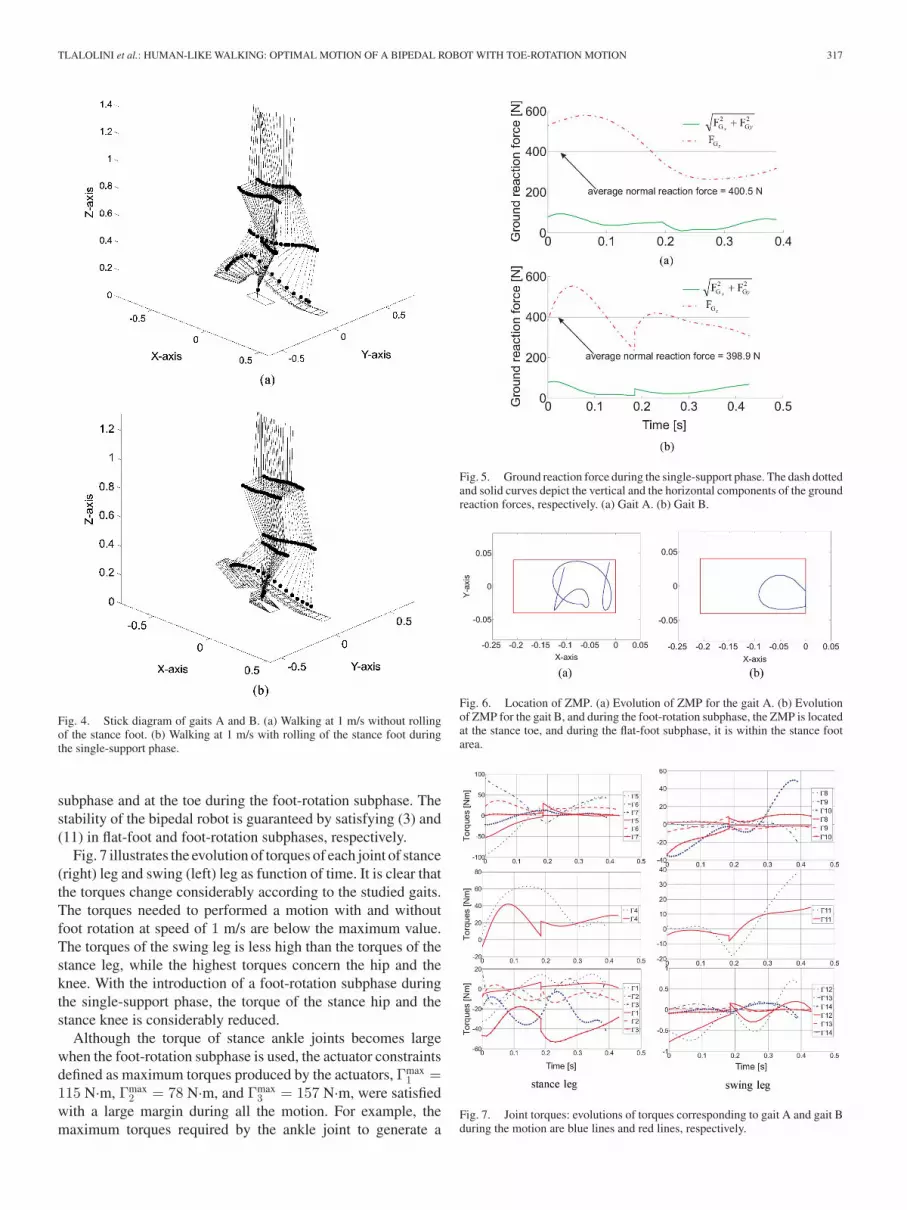
Fig. 5 shows that the constraint on nonsliding and no takeoffare satisfied. In the optimization process, the Coulomb frictioncoefficient μ is chosen as 0.75. The results in Fig. 5 show thatthe motion will be realized without sliding for friction coeffi-cient values between 0.033 and 0.23 for both gaits. The averagevertical reaction force is 400.5 N, which is coherent with theweight of the biped whose mass equals 40.75 kg.
For this gait, the evolution of ZMP is illustrated in Fig. 6(a).This trajectory is the result of the optimization process. TheZMP remains within the foot area, as prescribed by (3).
B. Walk With Foot Rotation
During the optimization process, the angle of rotation of thefoot at the end of the rotation subphase is constrained between5◦ and 45◦. The chosen motion velocity for this simulation is 1m/s (3.6 km/h). The optimal walk has the following characteris-tics: for one step, the duration of the flat-foot and foot-rotationsubphases are T f = 0.18 s and T r = 0.24 s, respectively. Thestep length is 0.42 m. The value of the torque cost criterionJΓ is 3356.6 N2 ·m·s, which is much lower than the cost ofthe previous motion without foot-rotation subphase. During theevolution of this motion, the foot in rotation finishes with anangle equal to 36.9◦ and a twist rotation equal to 6.9◦.
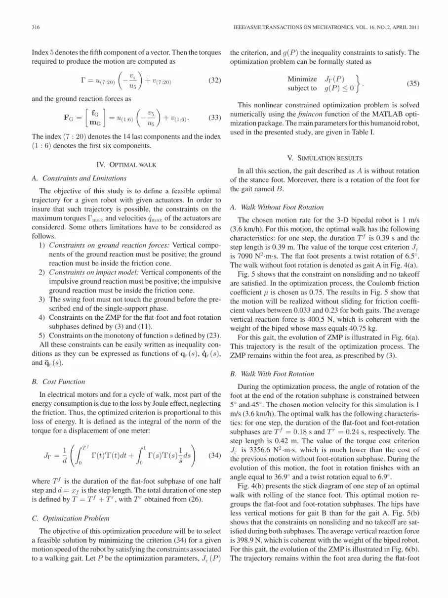
Fig. 4(b) presents the stick diagram of one step of an optimalwalk with rolling of the stance foot. This optimal motion re-groups the flat-foot and foot-rotation subphases. The hips haveless vertical motions for gait B than for the gait A. Fig. 5(b)shows that the constraints on nonsliding and no takeoff are sat-isfied during both subphases. The average vertical reaction forceis 398.9 N, which is coherent with the weight of the biped robot.For this gait, the evolution of the ZMP is illustrated in Fig. 6(b).The trajectory remains within the foot area during the flat-foot
TLALOLINI et al.: HUMAN-LIKE WALKING: OPTIMAL MOTION OF A BIPEDAL ROBOT WITH TOE-ROTATION MOTION 317
Fig. 4. Stick diagram of gaits A and B. (a) Walking at 1 m/s without rollingof the stance foot. (b) Walking at 1 m/s with rolling of the stance foot duringthe single-support phase.
subphase and at the toe during the foot-rotation subphase. Thestability of the bipedal robot is guaranteed by satisfying (3) and(11) in flat-foot and foot-rotation subphases, respectively.
Fig. 7 illustrates the evolution of torques of each joint of stance(right) leg and swing (left) leg as function of time. It is clear thatthe torques change considerably according to the studied gaits.The torques needed to performed a motion with and withoutfoot rotation at speed of 1 m/s are below the maximum value.The torques of the swing leg is less high than the torques of thestance leg, while the highest torques concern the hip and theknee. With the introduction of a foot-rotation subphase duringthe single-support phase, the torque of the stance hip and thestance knee is considerably reduced.
Although the torque of stance ankle joints becomes largewhen the foot-rotation subphase is used, the actuator constraintsdefined as maximum torques produced by the actuators, Γmax
1 =115 N·m, Γmax
2 = 78 N·m, and Γmax3 = 157 N·m, were satisfied
with a large margin during all the motion. For example, themaximum torques required by the ankle joint to generate a
Fig. 5. Ground reaction force during the single-support phase. The dash dottedand solid curves depict the vertical and the horizontal components of the groundreaction forces, respectively. (a) Gait A. (b) Gait B.
Fig. 6. Location of ZMP. (a) Evolution of ZMP for the gait A. (b) Evolutionof ZMP for the gait B, and during the foot-rotation subphase, the ZMP is locatedat the stance toe, and during the flat-foot subphase, it is within the stance footarea.
Fig. 7. Joint torques: evolutions of torques corresponding to gait A and gait Bduring the motion are blue lines and red lines, respectively.
318 IEEE/ASME TRANSACTIONS ON MECHATRONICS, VOL. 16, NO. 2, APRIL 2011
Fig. 8. Joint angles: evolutions of joint angles corresponding to gait A andgait B during the motion are blue lines and red lines, respectively.
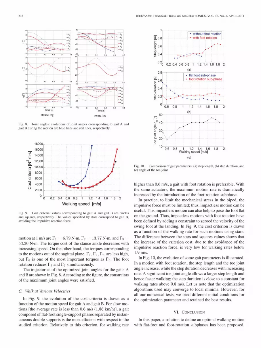
Fig. 9. Cost criteria: values corresponding to gait A and gait B are circlesand squares, respectively. The values specified by stars correspond to gait B,avoiding the impulsive reaction force.
motion at 1 m/s are Γ1 = 6.79 N·m, Γ2 = 13.77 N·m, and Γ3 =53.30 N·m. The torque cost of the stance ankle decreases withincreasing speed. On the other hand, the torques correspondingto the motions out of the sagittal plane, Γ1 ,Γ2 ,Γ7 , are less high,but Γ6 is one of the most important torques as Γ5 . The footrotation reduces Γ5 and Γ6 simultaneously.
The trajectories of the optimized joint angles for the gaits Aand B are shown in Fig. 8. According to the figure, the constraintsof the maximum joint angles were satisfied.
C. Walk at Various Velocities
In Fig. 9, the evolution of the cost criteria is drawn as afunction of the motion speed for gait A and gait B. For slow mo-tions [the average rate is less than 0.6 m/s (1.86 km/h)], a gaitcomposed of flat-foot single-support phases separated by instan-taneous double supports is the most efficient with respect to thestudied criterion. Relatively to this criterion, for walking rate
Fig. 10. Comparison of gait parameters: (a) step length, (b) step duration, and(c) angle of the toe joint.
higher than 0.6 m/s, a gait with foot rotation is preferable. Withthe same actuators, the maximum motion rate is dramaticallyincreased by the introduction of the foot-rotation subphase.
In practice, to limit the mechanical stress in the biped, theimpulsive force must be limited; thus, impactless motion can beuseful. This impactless motion can also help to pose the foot flaton the ground. Thus, impactless motions with foot rotation havebeen defined by adding a constraint to zeroed the velocity of theswing foot at the landing. In Fig. 9, the cost criterion is drawnas a function of the walking rate for such motions using stars.The difference between the stars and squares values shows thatthe increase of the criterion cost, due to the avoidance of theimpulsive reaction force, is very low for walking rates below1.9 m/s.
In Fig. 10, the evolution of some gait parameters is illustrated.In a motion with foot rotation, the step length and the toe jointangle increase, while the step duration decreases with increasingrate. A significant toe joint angle allows a larger step length andhence faster walking; the step duration is close to a constant forwalking rates above 0.8 m/s. Let us note that the optimizationalgorithms used may converge to local minima. However, forall our numerical tests, we tried different initial conditions forthe optimization parameter and retained the best results.
VI. CONCLUSION
In this paper, a solution to define an optimal walking motionwith flat-foot and foot-rotation subphases has been proposed.
TLALOLINI et al.: HUMAN-LIKE WALKING: OPTIMAL MOTION OF A BIPEDAL ROBOT WITH TOE-ROTATION MOTION 319
Since the desired motion is based on the solution of an optimalproblem, and in order to use classical algebraic optimizationtechniques, the optimal trajectory is defined by a reasonablenumber of parameters. Some inequality constraints such as thelimits on torques and velocities, the condition of no takeoffand no sliding during motion and impact, and some limits onthe motion of the free leg are taken into account. The desiredwalking gait was assumed to consist of single supports andinstantaneous double supports defined by passive impacts. Thesingle-support phase can include a foot-rotation subphase or not.It is shown that this subphase allows to reduce the cost criterionfor fast motions. The torques were computed using the inversedynamic model. This model was obtained with the recursiveNewton–Euler algorithm. The main contribution of the paperis to extend the optimal trajectories generation of the planarbiped robots [17] to a 3-D biped robot with rotation of the feeton the ground to achieve an optimal fast motion. To evaluatethe proposed optimal motion, we used the physical parametersof Hydroıd. The experimental implementation on Hydroıd willbe performed in future works. Moreover, a future study willfocus on the introduction of a finite-time double support phaseto achieve a walking motion, where the back foot rotates aroundits toe and the front foot rotates around its heel until the foot isflat on the ground. This phase is probably very important for thestability of the gait.
REFERENCES
[1] I. Kato, S. Ohteru, H. Kobayashi, K. Shirai, and A. Uchiyama,“Information-power machine with senses and limbs,” in Proc. 1st CISM-IFToMM Symp. Theory Pract. Robots Manipulation, 1974, pp. 11–24.
[2] K. Hirai, “Current and future perspective of HONDA humanoid robot,”in Proc. IEEE/RSJ Int. Conf. Intell. Robots Syst., 1997, pp. 500–508.
[3] K. Hirai, M. Hirose, T. Takenaka, Y. Haikawa, and T. Takenaka, “Thedevelopment of honda humanoid robot,” in Proc. IEEE ICRA, 1998,pp. 1321–1326.
[4] M. Hirose, Y. Haikawa, Y. Haikawa, and T. Takenaka, “Development ofhumanoid robot ASIMO,” presented at the Int. Conf. Intell. Robots Syst.,Workshop 2, Maui, HI, 2001.
[5] M. Gienger, K. Loffler, and F. Pfeiffer, “Towards the design of bipedjogging robot,” in Proc. IEEE ICRA, 2001, pp. 4140–4145.
[6] K. Yokoyama, J. Maeda, T. Isozumi, and K. Kaneko, “Application ofhumanoid robots for cooperative tasks in the outdoors,” presented at theInt. Conf. Intell. Robots Syst., Workshop 2, Maui, HI, 2001.
[7] H. Inoue, S. Tachi, Y. Nakmura, K. Hirai, N. Ohyu, S. Hirai, K. Tanie,K. Yokoi, and H. Hiru, “Overview of humanoid robotics project of METI,”in Proc. 32nd Int. Symp. Robot., 2001, pp. 1478–1482.
[8] K. Akachi, K. Kaneko, N. Kanehira, S. Ota, G. Miyamori, M. Hirata,S. Kajita, and F. Kanehiro, “Development of humanoid robot HRP-3,” inProc. IEEE-RAS Int. Conf. Humanoid Robots, 2005, pp. 50–55.
[9] S. Wearing, S. Urry, and P. Perlman, “Sagittal plane motion of the humanarch during gait,” Foot Ankle, vol. 19, no. 11, pp. 738–742, 1998.
[10] Y. Blanc, C. Balmer, T. Landis, and F. Vingerhoerts, “Temporal parametersand patterns of the foot roll over during walking: Normative data forhealthy adults,” Gait Posture, vol. 10, no. 2, pp. 97–108, 1999.
[11] C.-L. Shih, “Ascending and descending stairs for a biped robot,” IEEETrans. Syst., Man, Cybern., vol. 29, no. 3, pp. 255–268, May 1992.
[12] K. Yi, “Walking of a biped robot with compliant ankle joints: Implemen-tation with kubca,” in Proc. 39th IEEE Conf. Decis. Control, Sydney,Australia, Dec. 2000, pp. 4809–4814.
[13] T. Takahashi and A. Kawamura, “Posture control for biped robot walkwith foot toe and sole,” in Proc. 27th Annu. Conf. IEEE Ind. Electron.Soc., 2001, pp. 329–334.
[14] F. Silva and J. T. Machado, “Gait analysis of a human walker wearing robotfeet as shoes,” in Proc. IEEE Int. Conf. Robot. Autom., Seoul, Korea, 2001,pp. 4122–4127.
[15] M. Morisawa, Y. Fujimoto, T. Murakami, and K. Ohnishi, “A walking pat-tern generation for a biped robot with parallel mechanism by consideringcontact force,” in Proc. 27th Annu. Conf. IEEE Ind. Electron. Soc., 2001,pp. 2184–2189.
[16] A. D. Kuo, “Choosing your steps carefully: Trade offs between economyand versatility in dynamic walking bipedal robots,” IEEE Robot. Autom.Mag., vol. 14, no. 2, pp. 18–29, Jun. 2007.
[17] D. Tlalolini, C. Chevallereau, and Y. Aoustin, “Optimal reference motionswith rotation of the feet for a biped,” presented at the Int. Des. Eng. Tech.Conf., New York, 2008.
[18] D. McGeer, “Dynamic and control of bipedal locomotion,” J. Theor. Biol.,vol. 163, no. 3, pp. 277–314, 1993.
[19] A. D. Kuo, “Energetics of actively powered locomotion using the simplestwalking model,” J. Biomech. Eng., vol. 124, pp. 113–120, 2002.
[20] S. H. Collins, A. L. Ruina, R. Tedrake, and M. Wisse, “Efficient bipedalrobots based on passive-dynamic walkers,” Science, vol. 307, no. 5712,pp. 1082–1085, 2005.
[21] Q. Huang, K. Yokoi, S. Kajita, K. Kaneko, H. Arai, N. Koyachi, andK. Tanie, “Planning walking patterns for a biped robot,” IEEE Trans.Robot. Autom., vol. 17, no. 3, pp. 280–289, Jun. 2001.
[22] G. Bessonnet, P. Seguin, and P. Sardin, “A parametric optimization ap-proach to walking pattern synthesis,” Int. J. Robot. Res., vol. 24, no. 7,pp. 523–537, 2005.
[23] K. Nishiwaki, S. Kagami, Y. Kuniyoshi, M. Inaba, and H. Inoue, “Toejoints that enhance bipedal and full-body motion of humanoid robots,” inProc. IEEE Int. Conf. Robot. Autom., Washington, DC, 2002, pp. 3105–3110.
[24] S. Takao, H. Ohta, Y. Yokokohji, and T. Yoshikawa, “Functional analysisof human-like mechanical foot, using mechanically constrained shoes,”in Proc. IEEE/RSJ Int. Conf. Intell. Robots Syst., Sendai, Japan, 2004,pp. 3847–3852.
[25] J.-W. Yoon, N. Handharu, and G. Kim, “A biorobotic toe, foot and heelmodels of a biped robot for more natural walking,,” presented at theIASTED Int. Conf. Modeling, Identification Control, Innsbruck, Austria,2007.
[26] D. G. E. Hobbelen and M. Wisse, “Ankle actuation for limit cycle walk-ers,” Int. J. Robot. Res., vol. 27, no. 6, pp. 709–735, 2008.
[27] D. Tlalolini, C. Chevallereau, and Y. Aoustin, “Comparison of differentgaits with rotation of the feet for a planar biped,” Robot. Auton. Syst.,vol. 57, no. 4, pp. 371–383, 2008.
[28] S. Miossec and Y. Aoustin, “A simplified stability for a biped walk withunder and over actuated phases,” Int. J. Robot. Res., vol. 24, no. 7,pp. 537–551, 2005.
[29] Y. Aoustin and A. Formal’skii, “Control design for a biped: Referencetrajectory based on driven angles as functions of the undriven angle,” Int.J. Comput. Syst. Sci., vol. 42, no. 4, pp. 159–176, 2003.
[30] C. Chevallereau, A. Formal’skii, and D. Djoudi, “Tracking of a joint pathfor the walking of an under actuated biped,” Robotica, vol. 22, no. 1,pp. 15–28, 2004.
[31] E. R. Westervelt, J. W. Grizzle, C. Chevallereau, J.-h. Choi, and B. Mor-ris, Feedback Control of Dynamic Bipedal Robot Locomotion. NewYork/Boca Raton, FL: Taylor & Francis/CRC Press, 2007.
[32] C. Chevallereau, D. Djoudi, and J. Grizzle, “Stable bipedal walking withfoot rotation through direct regulation of the zero moment point,” IEEETrans. Robot., vol. 24, no. 2, pp. 390–401, Apr. 2008.
[33] S. Alfayad, F. B. Ouezdou, and G. Cheng, “Lightweight high performanceintegrated actuator for humanoid robotic applications: Modeling, designand realization,” in Proc. IEEE Int. Conf. Robot. Autom. ICRA, 2009,pp. 562–567.
[34] M. Vukobratovic, B. Borovac, and K. Babkovic, “Contribution to the studyof humanoid robots anthropomorphism,” presented at the 2nd Serbian-Hungarian Joint Symp. Intell. Syst., Subotica, Serbia, Oct. 2004.
[35] W. Khalil and J. Kleinfinger, “A new geometric notation for open andclosed loop robots,” in Proc. IEEE Conf. Robot. Autom., 1985, pp. 1174–1180.
[36] J. Luh, M. Walker, and R. Paul, “Resolved-acceleration control of me-chanical manipulators,” IEEE Trans. Autom. Control, vol. AC-25, no. 3,pp. 468–474, Jun. 1980.
[37] D. Tlalolini, Y. Aoustin, and C. Chevallereau, “Design of a walking cyclicgait with single support phases and impacts for the locomotor system ofa thirteen-link 3D biped using the parametric optimization,” MultibodySyst. Dyn., vol. 23, no. 1, pp. 33–56, 2009.
[38] J. H. Ahlberg, E. N. Nilson, and J. L. Walsh, The Theory of Splines andTheir Applications. New York: Academic, 1967.
[39] C. Chevallereau and Y. Aoustin, “Optimal reference trajectories for walk-ing and running of a biped,” Robotica, vol. 19, no. 5, pp. 557–569, 2001.

320 IEEE/ASME TRANSACTIONS ON MECHATRONICS, VOL. 16, NO. 2, APRIL 2011
David Tlalolini received the M.S. degree in auto-matic control from the Center for Research and Ad-vanced Studies, National Polytechnic Institute, Mex-ico City, Mexico, in 2003, and the Ph.D. degree incontrol and robotics from the Institute of Researchin Communication and Cybernetics of Nantes (IRC-CyN), University of Nantes, Nantes, France, in 2008.
Currently, he is with the Laboratory of Physiologyof Perception and Action, College de France, Paris,France. His research interests include modeling andcontrol of multibody mechanical systems, particu-
larly walking robots.
Christine Chevallereau graduated and received thePh.D. degree in control and robotics from the EcoleNationale Superieure de Mecanique, Nantes, France,in 1985 and 1988, respectively.
Since 1989, she has been with the Centre Nationalde la Recherche Scientifique, Institute of Research inCommunication and Cybernetics of Nantes, Univer-sity of Nantes, Nantes. Her research interests includemodeling and control of robots, especially control ofrobot manipulators and legged robots.
Yannick Aoustin received the Ph.D. degree and theHabilitation to supervise research from the Univer-sity of Nantes, Nantes, France, in 1989 and 2006,respectively.
Currently, he is an Associate Professor at the Uni-versity of Nantes, where he is a member of the In-stitute of Research in Communication and Cybernet-ics of Nantes. His research interests include flexiblerobots, underactuated systems, and walking robots.


