Embed Size (px)
Citation preview
HTC/Flex Coupling Assembly HC-6077 Installation and Maintenance Instructions
Riverhawk Document Number IM-317
Document No. IM-317 Created: 4/2/13 DML
2 of 22
Contents:
Section Description 1.0 General Description 1.1 Warnings and Cautions 1.2 Tools and Hardware Required 1.3 Reference Documents 1.4 General Installation Procedure 2.0 Hydraulic Torque Clamp (HTC) and Hub Assembly Installation 2.1 Hub Shaft Inspection 2.2 Cleaning 2.3 Mounting HTC on Hub 2.4 Mounting The HTC/Hub Assembly on The Shaft 3.0 Flexible Coupling Installation 3.1 Diaphragm Pack Installation 3.2 Spacer Tube Installation 4.0 Ameriflex Coupling Removal 4.1 Removal of the Spacer Tube 4.2 Diaphragm Pack Removal 5.0 Removal of the HTC/Hub Assembly Appendices (Reference only - Check for Current Revision) A HC-6077 HTC/Flex Coupling Assembly Drawing Riverhawk Company B DB-414093 Ameriflex Coupling Drawing Ameridrives International C GT-6078 Installation and Removal Kit Riverhawk Company D MP-2349 Hydraulic Pump and Hose Kit Riverhawk Company E Form. No. 367-SH High Performance Couplings
Installation and Maintenance Manual Ameridrives International
Document No. IM-317 Created: 4/2/13 DML
3 of 22
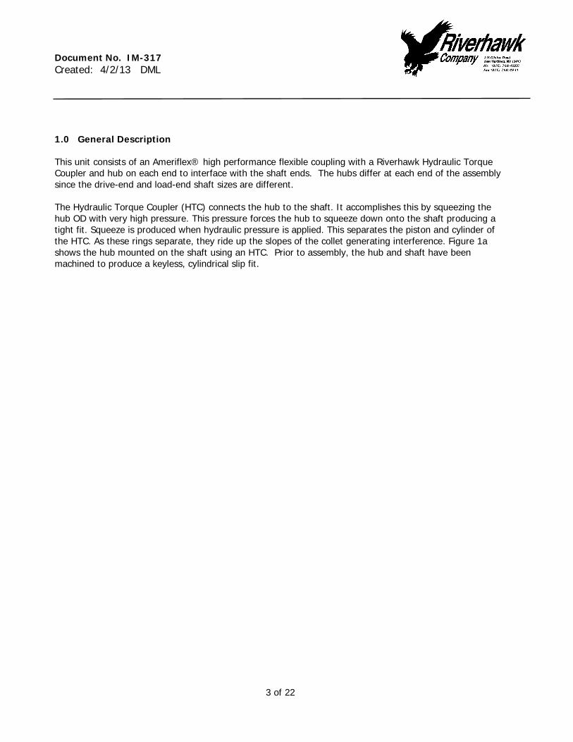
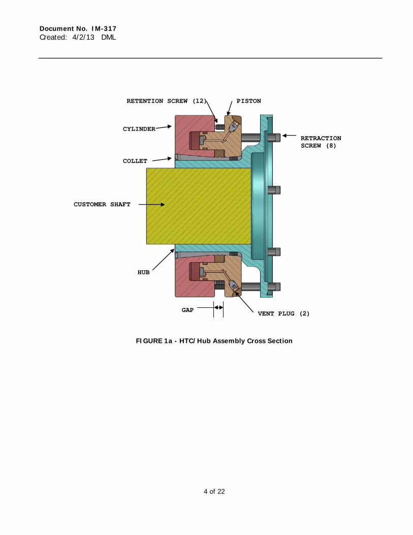
1.0 General Description This unit consists of an Ameriflex® high performance flexible coupling with a Riverhawk Hydraulic Torque Coupler and hub on each end to interface with the shaft ends. The hubs differ at each end of the assembly since the drive-end and load-end shaft sizes are different. The Hydraulic Torque Coupler (HTC) connects the hub to the shaft. It accomplishes this by squeezing the hub OD with very high pressure. This pressure forces the hub to squeeze down onto the shaft producing a tight fit. Squeeze is produced when hydraulic pressure is applied. This separates the piston and cylinder of the HTC. As these rings separate, they ride up the slopes of the collet generating interference. Figure 1a shows the hub mounted on the shaft using an HTC. Prior to assembly, the hub and shaft have been machined to produce a keyless, cylindrical slip fit.
Document No. IM-317 Created: 4/2/13 DML
4 of 22
FIGURE 1a - HTC/Hub Assembly Cross Section
CUSTOMER SHAFT
COLLET
CYLINDER
PISTON RETENTION SCREW (12)
HUB
RETRACTION SCREW (8)
GAP VENT PLUG (2)
Document No. IM-317 Created: 4/2/13 DML
5 of 22
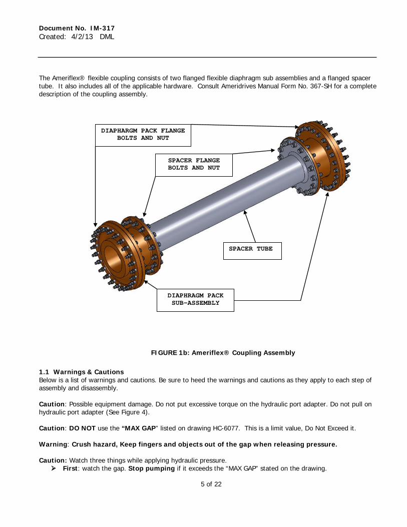
The Ameriflex® flexible coupling consists of two flanged flexible diaphragm sub assemblies and a flanged spacer tube. It also includes all of the applicable hardware. Consult Ameridrives Manual Form No. 367-SH for a complete description of the coupling assembly.
FIGURE 1b: Ameriflex® Coupling Assembly
1.1 Warnings & Cautions Below is a list of warnings and cautions. Be sure to heed the warnings and cautions as they apply to each step of assembly and disassembly. Caution: Possible equipment damage. Do not put excessive torque on the hydraulic port adapter. Do not pull on hydraulic port adapter (See Figure 4). Caution: DO NOT use the “MAX GAP” listed on drawing HC-6077. This is a limit value, Do Not Exceed it. Warning: Crush hazard, Keep fingers and objects out of the gap when releasing pressure. Caution: Watch three things while applying hydraulic pressure.
First: watch the gap. Stop pumping if it exceeds the “MAX GAP” stated on the drawing.
SPACER TUBE
DIAPHRAGM PACK SUB-ASSEMBLY
SPACER FLANGE BOLTS AND NUT
DIAPHARGM PACK FLANGE BOLTS AND NUT
Document No. IM-317 Created: 4/2/13 DML
6 of 22
Second: Do Not apply more than 10,000 psi. Third: retract all screws completely. Make sure that all set screws are fully retracted before releasing the
pressure. 1.2 Tools and Hardware Required The following are tools required to install, operate, and remove HC-6077.
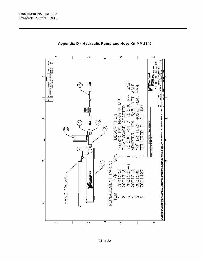
Part Number Description Installation Removal MP-2349
Hydraulic pump and hose kit capable of 10,000 psi. (Riverhawk supplies pumps designed to simplify HTC operation)
x x
Set of inch hex keys x x Dial caliper (or Gap Tool Below) x Oil Drain Pan x x Set of Inch Combination Wrenches x x (2) Dial Indicators x x GT-6078* Installation and Removal Kit includes: 7500886 Gap Tool, Drive-End x 7500845 Gap Tool, Load-End x 2001177 3/8-24 Hydraulic Port Adapter Fitting x x 2001299 3/8-24 Hydraulic Plug x x
* GT-6078 may be supplied by itself, or individual items may be included with coupling HC-6077 1.3 Reference Documents Please obtain and read carefully the latest revision of the following documents before proceeding with installation. Document Number Title Source IM - 317 HTC/Flex Coupling Assembly HC-6077 Installation
and Maintenance Instructions Riverhawk Company
HC-6077 HTC/Flex Coupling Assembly Drawing Riverhawk Company DB-414093 Ameriflex Coupling Drawing Ameridrives International Form. No. 367-SH High Performance Couplings Installation and
Maintenance Manual Ameridrives International
Document No. IM-317 Created: 4/2/13 DML
7 of 22
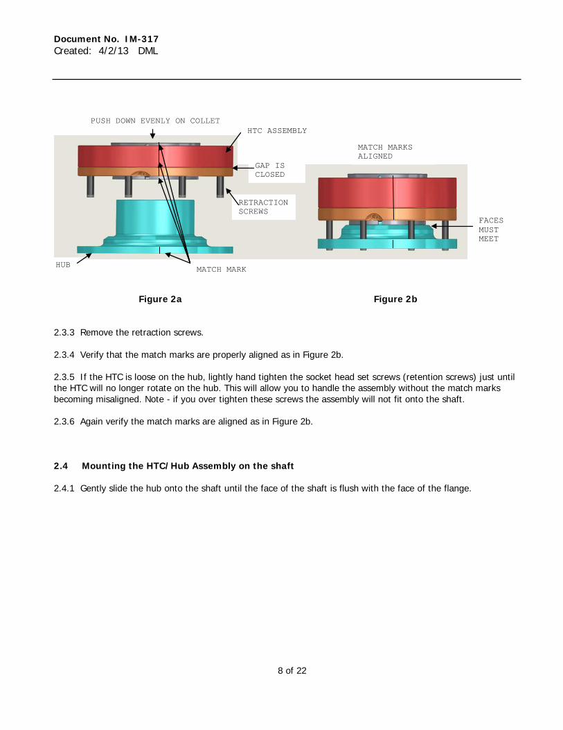
1.4 General Installation Procedure Below is a very abbreviated summary on the installation of the HC-6077. Also noted is the section of this manual in which you will find more detailed descriptions and diagrams. Be sure to read these instructions completely before proceeding with installation. 1.4.1 Align the machinery shafts and set the Distance Between Shaft Ends to be 26.00 +/- .0625 inches. 1.4.2 Install both Hydraulic Torque Couplers (HTC) on to Hubs - See section 2.0 of this manual 1.4.3 Install both HTC/Hub Assemblies onto the Shafts - See section 2.4 of this manual 1.4.4 Install the Diaphragm packs onto the hubs- See section 3.1 of this manual 1.4.5 Install the coupling spacer tube- See section 3.2 of this manual 2.0 HTC/Hub Assembly Installation This section of the manual covers how to install the HTC onto the hub and then the HTC/hub assembly onto the shaft. 2.1 Hub and Shaft Inspection Inspect the hub and shaft to assure that they have been machined to the proper tolerances. The HTC should slide onto the hub with a sliding or light press fit. The hub should fit the shaft in the same manner. Remove any burrs or proud metal that could interfere using a white India Stone. 2.2 Cleaning The hub OD, ID and the shaft OD must be smooth and free of debris. Clean using a solvent that leaves no residue such as acetone. Cleaning of these surfaces is especially important because contamination can make the surfaces slippery and cause the surfaces to slip prematurely during operation. Take special care to remove any thick oils or waxes using a solvent. 2.3 Mount HTC on Hub. Usually you will receive the HTC and Hub already assembled together. If the HTC and hub are already assembled go to Section 2.3.3. If they are not together, assemble them as follows. Note the HTC and Hub have been factory balanced as an assembly. Each is marked with a part number similar to 7500566-X where X is the serial number. The serial number on the hub must match the serial number on the HTC in order to ensure proper balance. 2.3.1 Remove the vent plugs (see Figure 1a). Tighten the retraction screws to 2-5 ft-lbs. Be sure the gap is closed (see Figure 2a). 2.3.2 Put the hub face down on a table. Align the match marks on the collet, Hub, and HTC to as shown in Figure 2a to ensure proper balance. Slide the HTC onto it until stop as shown in Figure 2b. Be sure to slide the HTC onto the hub evenly as there may be a slight interference fit. Always push on the collet , not on the upper part of the HTC when sliding the HTC on hub.
Document No. IM-317 Created: 4/2/13 DML
8 of 22
Figure 2a Figure 2b 2.3.3 Remove the retraction screws. 2.3.4 Verify that the match marks are properly aligned as in Figure 2b. 2.3.5 If the HTC is loose on the hub, lightly hand tighten the socket head set screws (retention screws) just until the HTC will no longer rotate on the hub. This will allow you to handle the assembly without the match marks becoming misaligned. Note - if you over tighten these screws the assembly will not fit onto the shaft. 2.3.6 Again verify the match marks are aligned as in Figure 2b. 2.4 Mounting the HTC/Hub Assembly on the shaft 2.4.1 Gently slide the hub onto the shaft until the face of the shaft is flush with the face of the flange.
PUSH DOWN EVENLY ON COLLET HTC ASSEMBLY
GAP IS CLOSED
HUB
RETRACTION SCREWS
FACES MUST MEET
MATCH MARK
MATCH MARKS ALIGNED
Document No. IM-317 Created: 4/2/13 DML
9 of 22
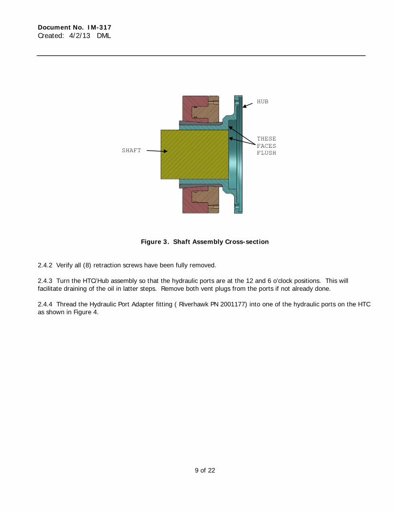
Figure 3. Shaft Assembly Cross-section
2.4.2 Verify all (8) retraction screws have been fully removed. 2.4.3 Turn the HTC/Hub assembly so that the hydraulic ports are at the 12 and 6 o'clock positions. This will facilitate draining of the oil in latter steps. Remove both vent plugs from the ports if not already done. 2.4.4 Thread the Hydraulic Port Adapter fitting ( Riverhawk PN 2001177) into one of the hydraulic ports on the HTC as shown in Figure 4.
SHAFT
HUB
THESE FACES FLUSH
Document No. IM-317 Created: 4/2/13 DML
10 of 22
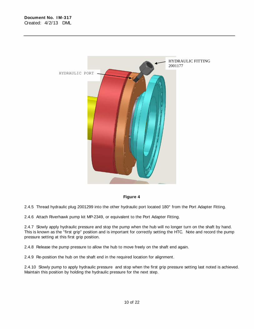
Figure 4 2.4.5 Thread hydraulic plug 2001299 into the other hydraulic port located 180° from the Port Adapter Fitting. 2.4.6 Attach Riverhawk pump kit MP-2349, or equivalent to the Port Adapter Fitting. 2.4.7 Slowly apply hydraulic pressure and stop the pump when the hub will no longer turn on the shaft by hand. This is known as the "first grip" position and is important for correctly setting the HTC. Note and record the pump pressure setting at this first grip position. 2.4.8 Release the pump pressure to allow the hub to move freely on the shaft end again. 2.4.9 Re-position the hub on the shaft end in the required location for alignment. 2.4.10 Slowly pump to apply hydraulic pressure and stop when the first grip pressure setting last noted is achieved. Maintain this position by holding the hydraulic pressure for the next step.
HYDRAULIC PORT
HYDRAULIC FITTING 2001177
Document No. IM-317 Created: 4/2/13 DML
11 of 22
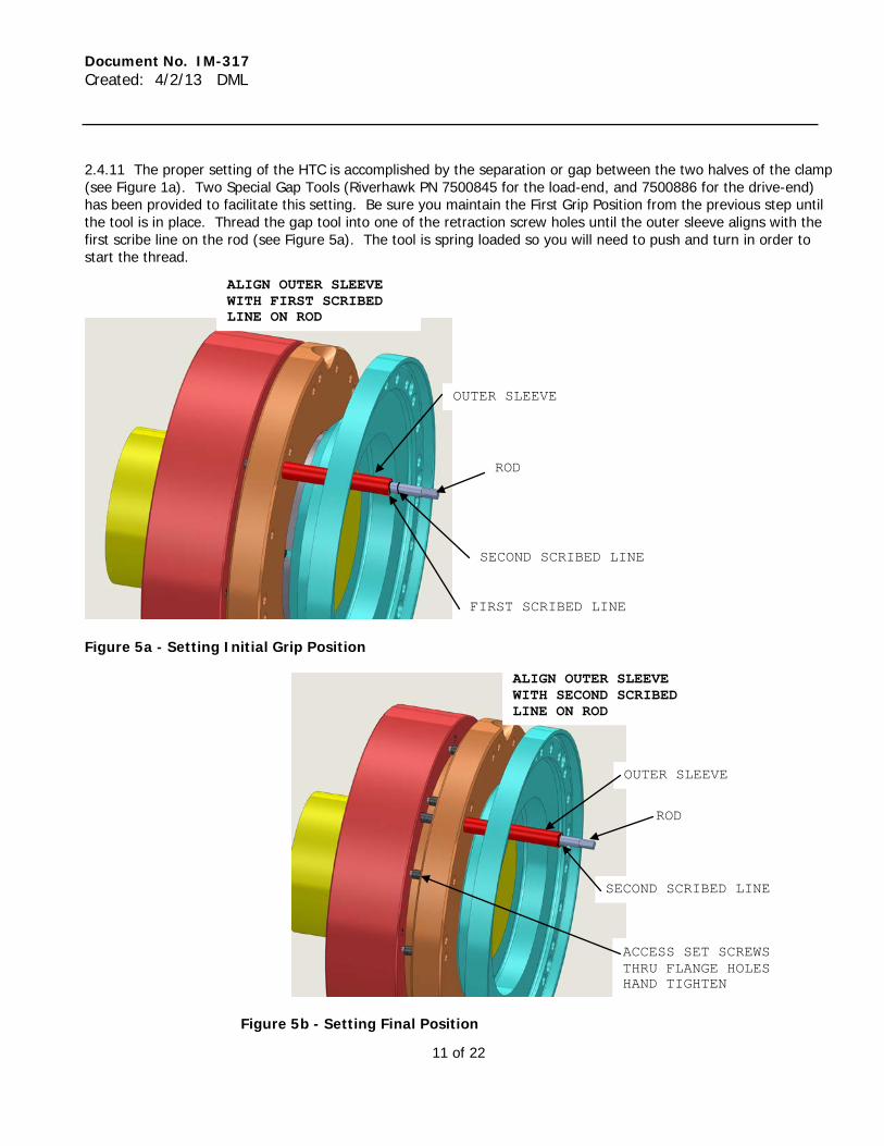
2.4.11 The proper setting of the HTC is accomplished by the separation or gap between the two halves of the clamp (see Figure 1a). Two Special Gap Tools (Riverhawk PN 7500845 for the load-end, and 7500886 for the drive-end) has been provided to facilitate this setting. Be sure you maintain the First Grip Position from the previous step until the tool is in place. Thread the gap tool into one of the retraction screw holes until the outer sleeve aligns with the first scribe line on the rod (see Figure 5a). The tool is spring loaded so you will need to push and turn in order to start the thread.
Figure 5a - Setting Initial Grip Position
Figure 5b - Setting Final Position
ALIGN OUTER SLEEVE WITH FIRST SCRIBED LINE ON ROD
OUTER SLEEVE
ROD
FIRST SCRIBED LINE
SECOND SCRIBED LINE
ALIGN OUTER SLEEVE WITH SECOND SCRIBED LINE ON ROD
ROD
OUTER SLEEVE
SECOND SCRIBED LINE
ACCESS SET SCREWS THRU FLANGE HOLES HAND TIGHTEN
Document No. IM-317 Created: 4/2/13 DML
12 of 22
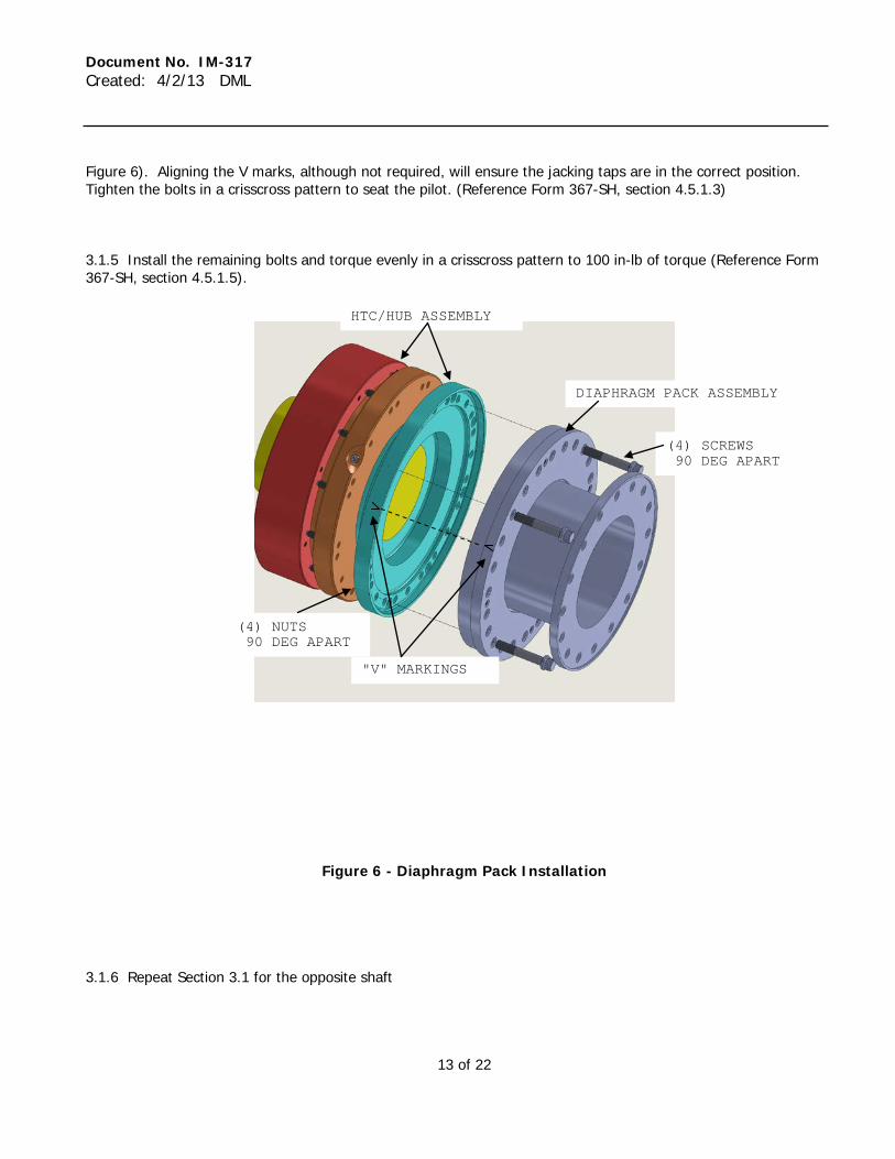
2.4.12 Apply more hydraulic pressure. The HTC halves will separate causing the outer sleeve of the tool to move towards the second scribe line on the rod. When the outer sleeve is aligned with the second scribe line as shown in figure 5b, stop the hydraulic pump while holding pressure. This is the final position of the clamp. Hold hydraulic pressure here for the next step. Note: The Gap Tool is supplied so that proper gap on the HTC can be set through the hub flange. In the event that the gap tool is unavailable, the actual gap can be measured with gage pins or a caliper. Measure the Gap for the "First Grip Position" in step 2.4.7 above. Add 0.172 inches to that measurement to calculate the Total Required Gap for the load-end, or 0.138 inches to that measurement to calculate the Total Required Gap for the drive-end. Apply hydraulic pressure while monitoring the gap until the measurement is equal to the Total Required Gap. 2.4.13 Tighten the twelve retention screws (socket head set screws) hand tight with a hex wrench. The screws are accessed through the flange face as shown in Figure 5b. 2.4.14 Release the hydraulic pressure from the pump. 2.4.15 Remove the gap setting tool 2.4.16 Place a drain pan under the HTC and remove the hydraulic plug and then the adapter fitting. Allow hydraulic oil to drain from the HTC. Blow compressed air (100 psi max) into the top port to fully drain the oil. Failure use compressed air to blow out oil will leave residual oil in the clamp and may cause problems with the balance of the unit. 2.4.17 The retraction screws, hydraulic plugs, adapter fitting, and gap tool will be required for future removal and installation of the clamp. Store them where they will not be lost. 2.4.18 Place vent plugs 2002429 into both hydraulic ports after all oil is drained (see Figure 1a). 3.0 Flexible Coupling and Spacer Tube Installation The instructions given in this section for installation of the Flexible Coupling and spacer tube are summarized from Ameridrives manual Form No 367-SH (see Appendix E). It is imperative that the user consult the Ameridrives manual before attempting installation or removal of HC-6077 as it contains important notes and information that will not be repeated here. In the event of conflicting information, Form No 367-SH supersedes this document. 3.1 Diaphragm Pack Installation 3.1.1 Disassemble the coupling by removing all bolts from the flange interfaces. Use the jacking holes in the spacer tube flange to separate the spacer tube from the diaphragm pack flange (Reference Form 367-SH, section 4.5.1.1) 3.1.2 Clean exposed surfaces with a clean rag dampened with cleaning solvent to remove the protective coating from the diaphragm surfaces. (Reference Form 367-SH, section 4.5.1.2). Inspect all pilots and remove any debris, nicks, dents, or other damage. 3.1.3 Verify the Distance Between Shaft ends to be 26.00 inches. 3.1.4 Install one of the diaphragm packs onto the hub as shown in Figure 6 using Qty(4) supplied bolts and nuts spaced 90 degrees apart. Be sure the 1/4"-28 jacking tap holes located in the diaphragm pack do not line-up with any holes in the HTC hub flange. "V" marks may be located on the hub and diaphragm pack rims as an aid (see
Document No. IM-317 Created: 4/2/13 DML
13 of 22
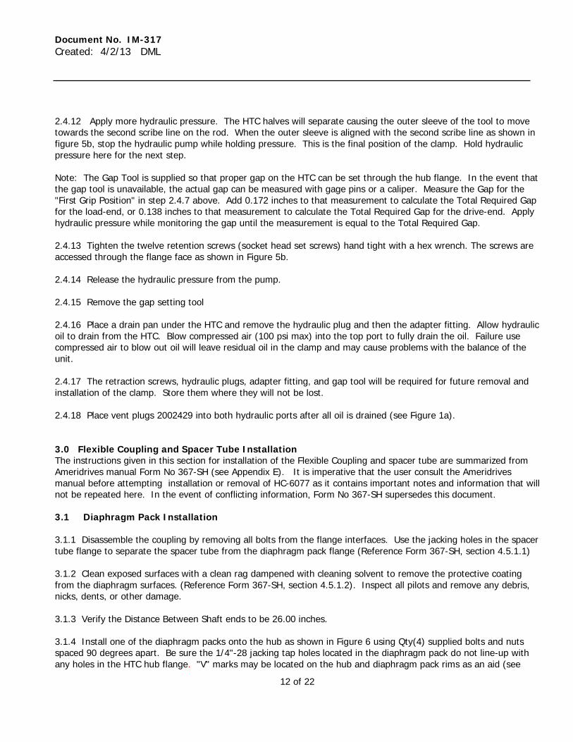
Figure 6). Aligning the V marks, although not required, will ensure the jacking taps are in the correct position. Tighten the bolts in a crisscross pattern to seat the pilot. (Reference Form 367-SH, section 4.5.1.3) 3.1.5 Install the remaining bolts and torque evenly in a crisscross pattern to 100 in-lb of torque (Reference Form 367-SH, section 4.5.1.5).
Figure 6 - Diaphragm Pack Installation
3.1.6 Repeat Section 3.1 for the opposite shaft
HTC/HUB ASSEMBLY
DIAPHRAGM PACK ASSEMBLY
(4) SCREWS 90 DEG APART
(4) NUTS 90 DEG APART
"V" MARKINGS
Document No. IM-317 Created: 4/2/13 DML
14 of 22
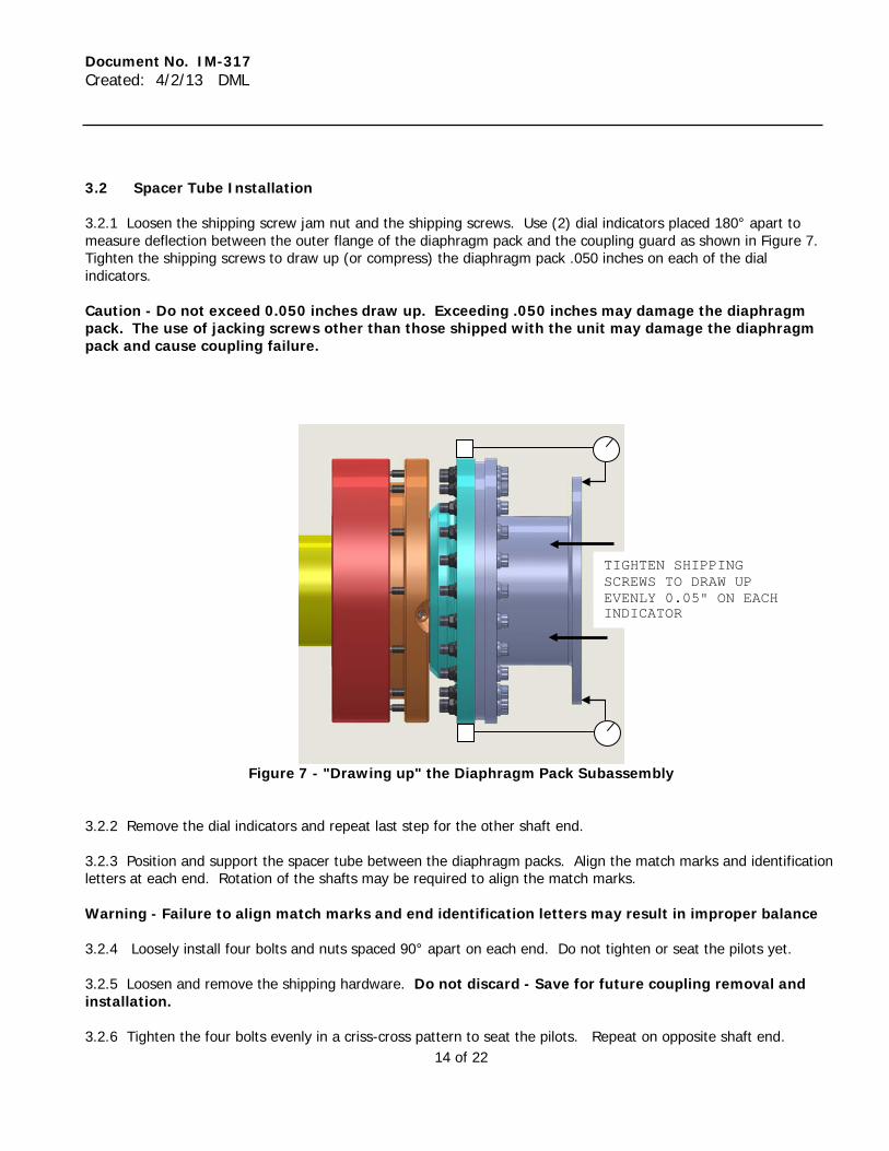
3.2 Spacer Tube Installation 3.2.1 Loosen the shipping screw jam nut and the shipping screws. Use (2) dial indicators placed 180° apart to measure deflection between the outer flange of the diaphragm pack and the coupling guard as shown in Figure 7. Tighten the shipping screws to draw up (or compress) the diaphragm pack .050 inches on each of the dial indicators. Caution - Do not exceed 0.050 inches draw up. Exceeding .050 inches may damage the diaphragm pack. The use of jacking screws other than those shipped with the unit may damage the diaphragm pack and cause coupling failure.
Figure 7 - "Drawing up" the Diaphragm Pack Subassembly
3.2.2 Remove the dial indicators and repeat last step for the other shaft end. 3.2.3 Position and support the spacer tube between the diaphragm packs. Align the match marks and identification letters at each end. Rotation of the shafts may be required to align the match marks. Warning - Failure to align match marks and end identification letters may result in improper balance 3.2.4 Loosely install four bolts and nuts spaced 90° apart on each end. Do not tighten or seat the pilots yet. 3.2.5 Loosen and remove the shipping hardware. Do not discard - Save for future coupling removal and installation. 3.2.6 Tighten the four bolts evenly in a criss-cross pattern to seat the pilots. Repeat on opposite shaft end.
TIGHTEN SHIPPING SCREWS TO DRAW UP EVENLY 0.05" ON EACH INDICATOR
Document No. IM-317 Created: 4/2/13 DML
15 of 22
3.2.7 Install all remaining spacer bolts and nuts and torque evenly in a criss-cross pattern to 200 in-lb. 4.0 Ameriflex® Coupling Removal This section covers the basic steps for removal of the Ameriflex® Spacer Tube and diaphragm pack assemblies. Before attempting to remove the coupling the user should obtain the latest revision of Ameridrives Manual Form No. 376-SH section 4.7. 4.1 Removal of the Spacer Tube 4.1.1 Loosely install the shipping hardware. Note - the shipping screws and mating tapped holes are color coded at the factory to identify the proper screw length. Caution - Only use the original shipping screws supplied with the coupling or exact replacements. Use of an incorrect screw may damage the diaphragm and cause equipment failure. 4.1.2 Remove the spacer tube flange bolts and nuts on one side of the spacer tube (see Figure 1b). 4.1.3 Support the spacer tube and use the tapped jacking holes in the spacer tube flange to compress the diaphragm pack and separate the pilot to obtain a clearance of .005 to .010 inches. 4.1.4 Tighten the shipping hardware to retain the compression of the coupling. 4.1.5 Repeat section 4.1.1 through 4.1.4 for the other end of the spacer tube. Remove the jacking screws. 4.1.6 Remove the spacer tube. 4.2 Diaphragm Pack Removal The diaphragm pack is removed using jacking holes in the diaphragm pack. 4.2.1 Jacking Holes: 4.2.2 Remove all of the diaphragm subassembly flange bolts and screws. 4.2.3 Loosen the shipping screws completely and retighten them hand tight. Tighten the jam nut on the shipping screws so that the diaphragm is unable to flex. 4.2.4 Four jacking holes, 1/4"-28 thread, are located in the flange of the diaphragm assembly. Insert 1/4"-28 jacking screws supplied with the coupling (or any other 1/4"-28 screws available) in each jacking hole, and tighten by hand until the end contacts the hub face. 4.2.5 Using the proper wrench/tool, tighten each bolt, against the hub face. Turn only a small amount, and then move to the opposite hole for turning. 4.2.6 Move in a criss-cross pattern turning the bolt a small amount each time to avoid cocking of the diaphragm pack. 4.2.7 Continue until the diaphragm pack is free from the hub. Remove jacking bolts from the diaphragm pack.
Document No. IM-317 Created: 4/2/13 DML
16 of 22
5.0 Removal of HTC/Hub Assembly This section explains how to remove the HTC/Hub assemblies from the shafts. 5.1 Remove vent plugs from both hydraulic ports. 5.2 Install the hydraulic adapter in one port as in Figure 4. 5.3 Install one hydraulic plug in the opposite port on the HTC. 5.4 Connect the hydraulic pump and slowly apply pressure while attempting to loosen one of the retention set screws. The retention set screws are accessed thru the face of the flange as shown in Figure 5b. As soon as the screw is free to rotate stop the pump. Caution - Over stroking the HTC will cause damage to it. Stop increasing pressure the moment the retention screws are free to turn. Do not, under any circumstances, exceed 10,000 psi hydraulic pressure. Normal pressure required ranges from 3,000 - 8,000 psi. 5.5 Remove all of the retaining screws (12). Save retaining screws for future use. Do not mix with retaining screws from other units. Screws are weight matched in sets of (12) for proper balance. 5.6 Release the hydraulic pressure. Allow 20 seconds or more for the clamp to close and oil to drain back into the pump. The HTC/Hub assembly should now be loose on the shaft. Warning: Crush hazard, Keep fingers and objects out of the gap when releasing pressure. Caution: Watch while pumping.
Do Not apply more than 10,000 psi. Make sure that all set screws are fully retracted before releasing the pressure.
5.7 If the hub does not slide easily on the shaft, the HTC may not be fully closed. Make sure the retention screws are completely loosened. Install the (8) retraction screws (see Figure 1a). Tighten the retraction screws to 5 ft-lbs. The retraction screws will draw the clamp closed and loosen the hub on the shaft. 5.8 You may partially activate the clamp for the purpose of lifting the hub/HTC assembly without the hub sliding off. Remove the retraction screws. Re-install and tighten the retention screws evenly using only hand torque. This will partially open the gap and cause the HTC to grip only the hub, not the shaft, so it won't slide off the hub during lifting and handling. 5.9 Remove hydraulic connections, plug, and adapter fitting. Catch residual hydraulic fluid with a drain pan or rag. Add vent plugs back into both hydraulic ports. 5.10 Carefully slide the hub assembly off the shaft. 5.11 Repeat the procedure above for the other shaft end.
Document No. IM-317 Created: 4/2/13 DML
17 of 22
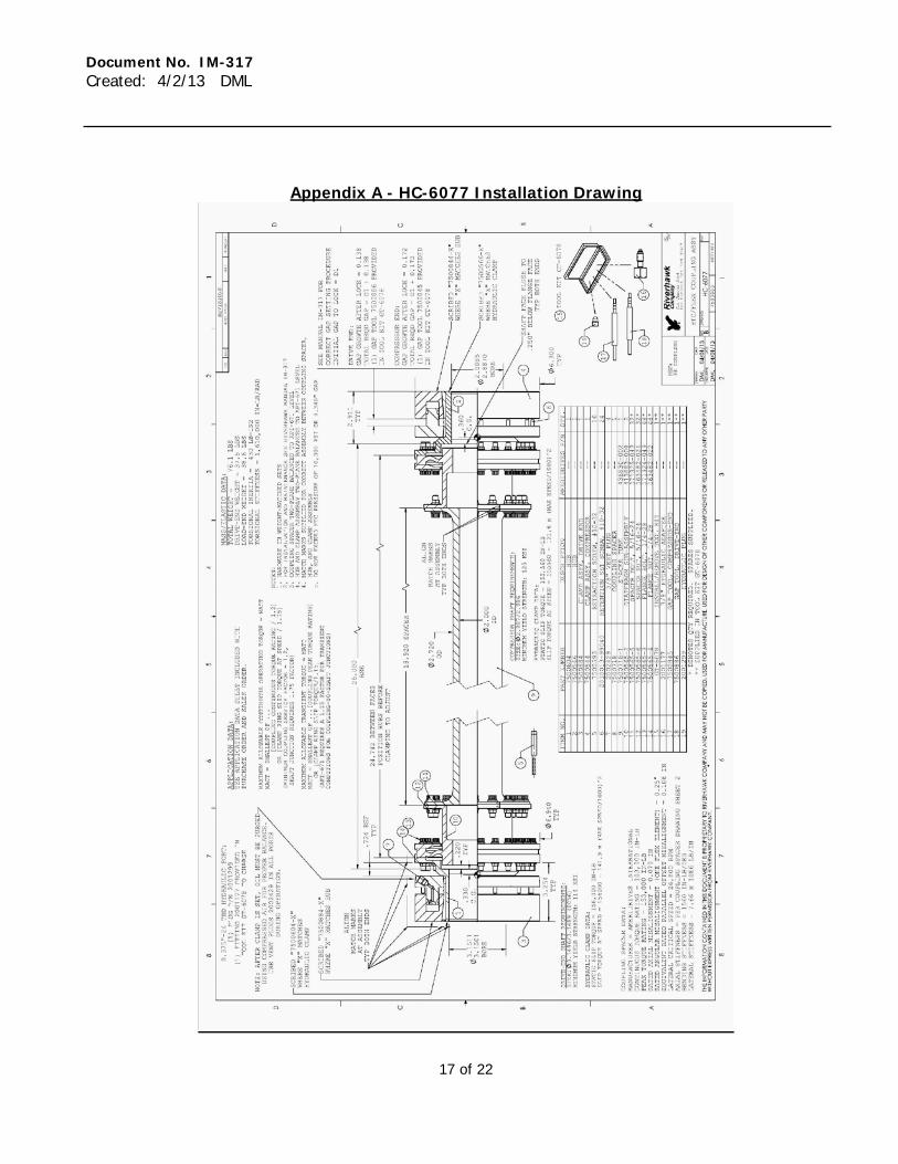
Appendix A - HC-6077 Installation Drawing
Document No. IM-317 Created: 4/2/13 DML
18 of 22
Document No. IM-317 Created: 4/2/13 DML
19 of 22
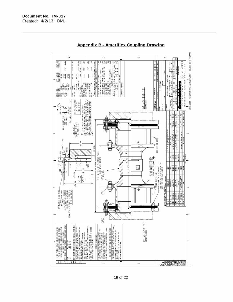
Appendix B - Ameriflex Coupling Drawing
Document No. IM-317 Created: 4/2/13 DML
20 of 22
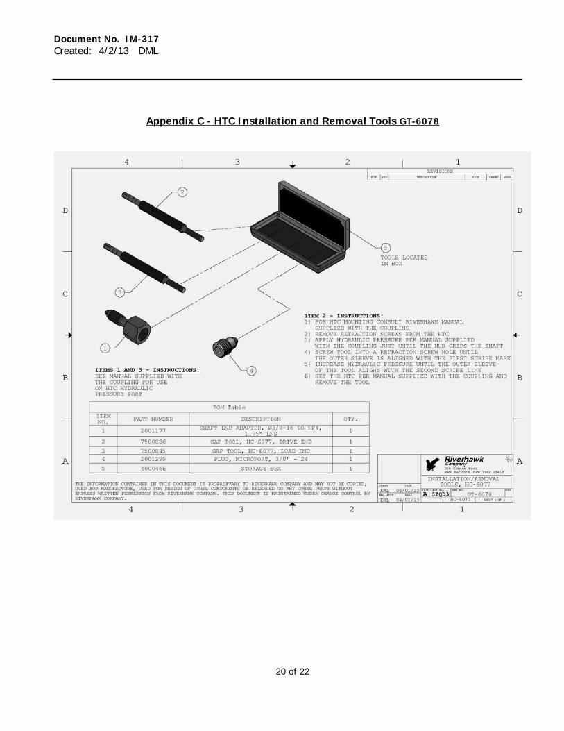
Appendix C - HTC Installation and Removal Tools GT-6078
Document No. IM-317 Created: 4/2/13 DML
21 of 22
Appendix D - Hydraulic Pump and Hose Kit MP-2349

Document No. IM-317 Created: 4/2/13 DML
22 of 22
Appendix E - Ameriflex® High Performance Couplings Installation And Maintenance Manual
Installation Instructions367SH
AmeriflexHigh Performance Couplings
Form. No. 367-SH, 8/10
ISO9001
REGISTERED FIRM10002804 QM08 ACCREDITED BY RvA
Ameridrives International Coupling Products
2
2010 Ameridrives International Reg. TM U.S. Pat. and T.M. Off.
2
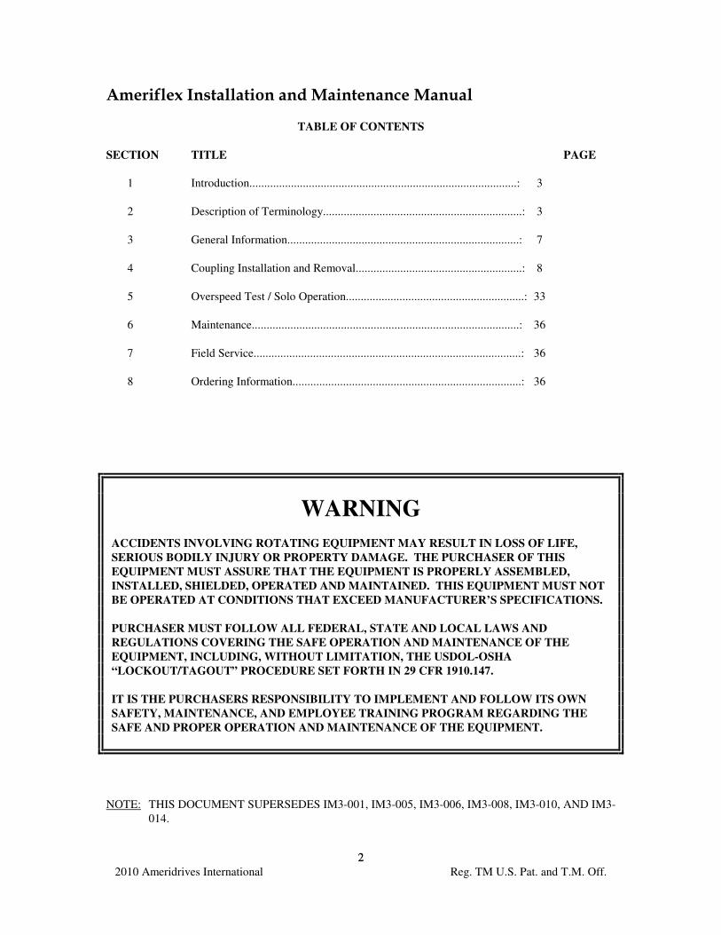
Ameriflex Installation and Maintenance Manual
TABLE OF CONTENTS
SECTION TITLE PAGE
1 Introduction..........................................................................................: 3
2 Description of Terminology...................................................................: 3
3 General Information..............................................................................: 7
4 Coupling Installation and Removal........................................................: 8
5 Overspeed Test / Solo Operation............................................................: 33
6 Maintenance..........................................................................................: 36
7 Field Service..........................................................................................: 36
8 Ordering Information.............................................................................: 36
WARNING
ACCIDENTS INVOLVING ROTATING EQUIPMENT MAY RESULT IN LOSS OF LIFE,
SERIOUS BODILY INJURY OR PROPERTY DAMAGE. THE PURCHASER OF THIS
EQUIPMENT MUST ASSURE THAT THE EQUIPMENT IS PROPERLY ASSEMBLED,
INSTALLED, SHIELDED, OPERATED AND MAINTAINED. THIS EQUIPMENT MUST NOT
BE OPERATED AT CONDITIONS THAT EXCEED MANUFACTURER’S SPECIFICATIONS.
PURCHASER MUST FOLLOW ALL FEDERAL, STATE AND LOCAL LAWS AND
REGULATIONS COVERING THE SAFE OPERATION AND MAINTENANCE OF THE
EQUIPMENT, INCLUDING, WITHOUT LIMITATION, THE USDOL-OSHA
“LOCKOUT/TAGOUT” PROCEDURE SET FORTH IN 29 CFR 1910.147.
IT IS THE PURCHASERS RESPONSIBILITY TO IMPLEMENT AND FOLLOW ITS OWN
SAFETY, MAINTENANCE, AND EMPLOYEE TRAINING PROGRAM REGARDING THE
SAFE AND PROPER OPERATION AND MAINTENANCE OF THE EQUIPMENT.
NOTE: THIS DOCUMENT SUPERSEDES IM3-001, IM3-005, IM3-006, IM3-008, IM3-010, AND IM3-
014.
3
3
1. INTRODUCTION
This Installation Manual is intended to be used as a guide for the installation and maintenance of
Ameriflex diaphragm couplings. For specific operating capacities and coupling data, refer to the
Ameridrives Sales Drawing. The Sales Drawing Number along with other important information has
been electro-etched on the coupling spacer at the factory.
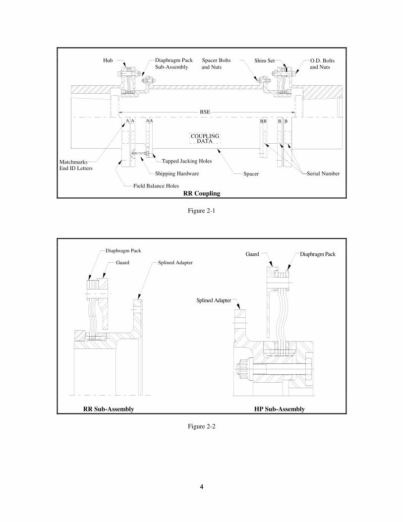
2. DESCRIPTION OF TERMINOLOGY
This section is intended to assist anyone not familiar with the terms used to describe the components
of an Ameriflex coupling. Refer to the following Figures for the coupling type specified on the
Ameridrives Sales Drawing. These Figures identify components and terms referred to in this manual.
Figure 2-1 Components and terms described are common to both the Reduced Ratio (RR) and the
High Performance (HP) series couplings.
Figure 2-2 RR and HP Diaphragm Pack Sub-Assemblies.
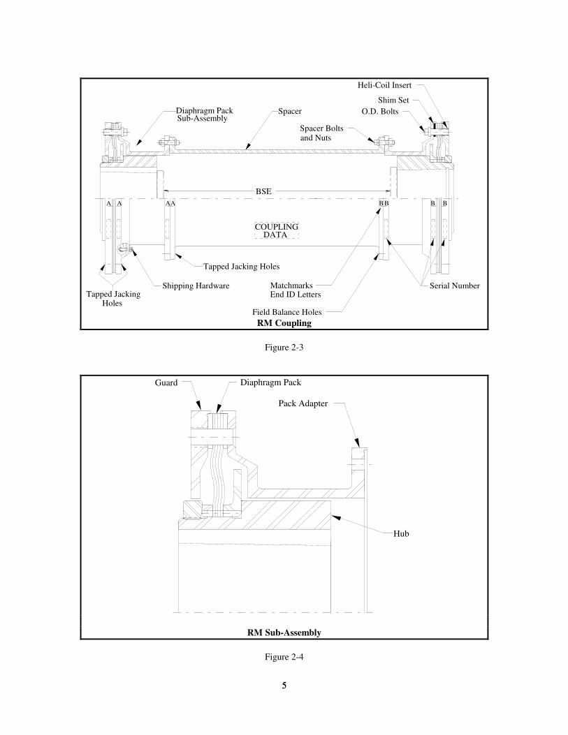
Figure 2-3 Reduced Moment (RM) series coupling.
Figure 2-4 RM Diaphragm Pack Sub-Assembly.
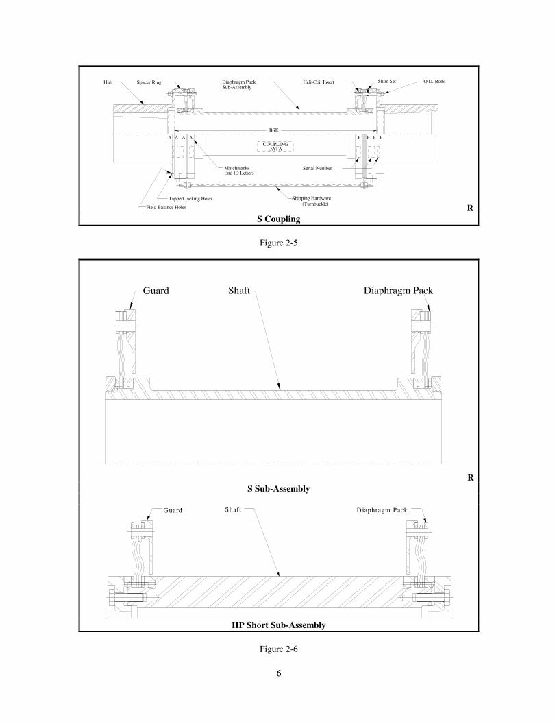
Figure 2-5 Components and terms described are common to both the Reduced Ratio Short (RS) and
the High Performance Short (HP Short) design couplings.
Figure 2-6 RS and High Performance Short Diaphragm Pack Sub-Assemblies.
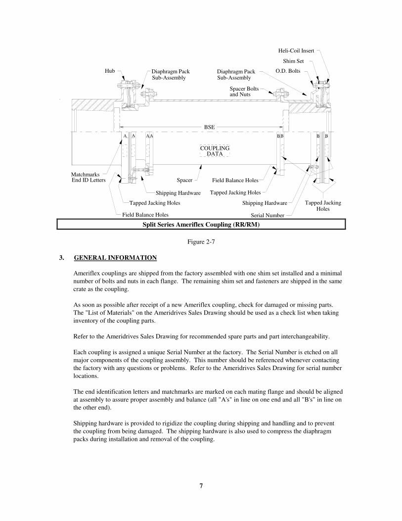
Figure 2-7 Split series Ameriflex coupling (i.e., RR/RM).
Split series couplings are used when application requirements can not be met with a single series
coupling (i.e., envelope limitations, over-hung moment requirements, etc.). When this style of
coupling is used, the appropriate sections of this manual should be used for the different ends of the
coupling.
4
4
MatchmarksEnd ID Letters
Shipping Hardware Spacer Serial Number
O.D. BoltsShim SetSpacer Bolts Diaphragm Pack
Sub-Assembly
Hub
A A AA BB B B
BSE
COUPLINGDATA
Field Balance Holes
Tapped Jacking Holes
and Nuts and Nuts
RR Coupling
Figure 2-1
Diaphragm Pack
Splined AdapterGuard
Splined Adapter
Diaphragm PackGuard
RR Sub-Assembly HP Sub-Assembly
Figure 2-2
5
5
Shipping Hardware MatchmarksEnd ID Letters
Serial Number
Diaphragm PackSub-Assembly
Spacer
Spacer Bolts
O.D. Bolts
Shim Set
Heli-Coil Insert
A A AA
COUPLINGDATA
BB B B
BSE
Field Balance Holes
Tapped JackingHoles
and Nuts
Tapped Jacking Holes
RM Coupling
Figure 2-3
Diaphragm PackGuard
Pack Adapter
Hub
RM Sub-Assembly
Figure 2-4
6
6
Hub Spacer Ring Diaphragm PackSub-Assembly
Heli-Coil Insert Shim Set O.D. Bolts
Serial Number
Shipping Hardware
MatchmarksEnd ID Letters
A A A A
COUPLINGDATA
B B B B
BSE
Tapped Jacking Holes
Field Balance Holes(Turnbuckle)
R
S Coupling
Figure 2-5
Diaphragm Pack Guard Shaft
R
S Sub-Assembly
G uard Shaft D iaphragm Pack
HP Short Sub-Assembly
Figure 2-6
7
7
Tapped Jacking Holes
MatchmarksEnd ID Letters
Field Balance Holes
Shipping Hardware
Shipping Hardware
Spacer
Serial Number
Hub Diaphragm PackSub-Assembly
Diaphragm PackSub-Assembly
Spacer Bolts
Shim Set
Heli-Coil Insert
O.D. Bolts
COUPLINGDATA
Field Balance Holes
Tapped JackingHoles
A A AA BB B B
BSE
and Nuts
Tapped Jacking Holes
Split Series Ameriflex Coupling (RR/RM)
Figure 2-7
3. GENERAL INFORMATION
Ameriflex couplings are shipped from the factory assembled with one shim set installed and a minimal
number of bolts and nuts in each flange. The remaining shim set and fasteners are shipped in the same
crate as the coupling.
As soon as possible after receipt of a new Ameriflex coupling, check for damaged or missing parts.
The "List of Materials" on the Ameridrives Sales Drawing should be used as a check list when taking
inventory of the coupling parts.
Refer to the Ameridrives Sales Drawing for recommended spare parts and part interchangeability.
Each coupling is assigned a unique Serial Number at the factory. The Serial Number is etched on all
major components of the coupling assembly. This number should be referenced whenever contacting
the factory with any questions or problems. Refer to the Ameridrives Sales Drawing for serial number
locations.
The end identification letters and matchmarks are marked on each mating flange and should be aligned
at assembly to assure proper assembly and balance (all "A's" in line on one end and all "B's" in line on
the other end).
Shipping hardware is provided to rigidize the coupling during shipping and handling and to prevent
the coupling from being damaged. The shipping hardware is also used to compress the diaphragm
packs during installation and removal of the coupling.
8
8
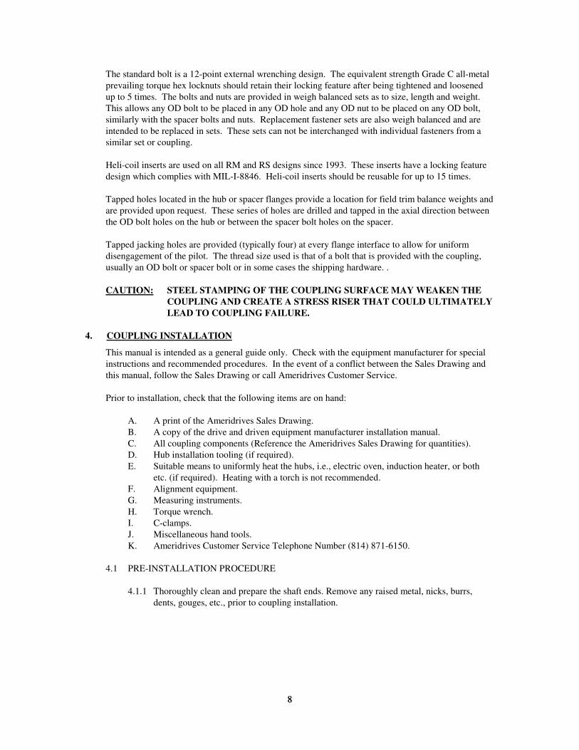
The standard bolt is a 12-point external wrenching design. The equivalent strength Grade C all-metal
prevailing torque hex locknuts should retain their locking feature after being tightened and loosened
up to 5 times. The bolts and nuts are provided in weigh balanced sets as to size, length and weight.
This allows any OD bolt to be placed in any OD hole and any OD nut to be placed on any OD bolt,
similarly with the spacer bolts and nuts. Replacement fastener sets are also weigh balanced and are
intended to be replaced in sets. These sets can not be interchanged with individual fasteners from a
similar set or coupling.
Heli-coil inserts are used on all RM and RS designs since 1993. These inserts have a locking feature
design which complies with MIL-I-8846. Heli-coil inserts should be reusable for up to 15 times.
Tapped holes located in the hub or spacer flanges provide a location for field trim balance weights and
are provided upon request. These series of holes are drilled and tapped in the axial direction between
the OD bolt holes on the hub or between the spacer bolt holes on the spacer.
Tapped jacking holes are provided (typically four) at every flange interface to allow for uniform
disengagement of the pilot. The thread size used is that of a bolt that is provided with the coupling,
usually an OD bolt or spacer bolt or in some cases the shipping hardware. .
CAUTION: STEEL STAMPING OF THE COUPLING SURFACE MAY WEAKEN THE
COUPLING AND CREATE A STRESS RISER THAT COULD ULTIMATELY
LEAD TO COUPLING FAILURE.
4. COUPLING INSTALLATION
This manual is intended as a general guide only. Check with the equipment manufacturer for special
instructions and recommended procedures. In the event of a conflict between the Sales Drawing and
this manual, follow the Sales Drawing or call Ameridrives Customer Service.
Prior to installation, check that the following items are on hand:
A. A print of the Ameridrives Sales Drawing.
B. A copy of the drive and driven equipment manufacturer installation manual.
C. All coupling components (Reference the Ameridrives Sales Drawing for quantities).
D. Hub installation tooling (if required).
E. Suitable means to uniformly heat the hubs, i.e., electric oven, induction heater, or both
etc. (if required). Heating with a torch is not recommended.
F. Alignment equipment.
G. Measuring instruments.
H. Torque wrench.
I. C-clamps.
J. Miscellaneous hand tools.
K. Ameridrives Customer Service Telephone Number (814) 871-6150.
4.1 PRE-INSTALLATION PROCEDURE
4.1.1 Thoroughly clean and prepare the shaft ends. Remove any raised metal, nicks, burrs,
dents, gouges, etc., prior to coupling installation.
9
9
4.1.2 Disassemble the coupling by removing all bolts and nuts from the OD and spacer flanges
(do not remove any heli-coils). Using the tapped jacking holes provided in the hubs,
spacer rings, or flange adapters, remove the hubs, spacer rings, or flange adapters from
the OD of the RR/HP/RS/HP Short diaphragm pack sub-assemblies. Remove the RM
diaphragm pack sub-assemblies from the pack adapters using the tapped jacking holes
provided in the pack adapter. Remove the RR/HP sub-assemblies, or RM pack adapters
from each end of the spacer using the tapped jacking holes provided.
CAUTION: ANY SCRATCH, DENT, OR ANY OTHER MARK ON THE
DIAPHRAGM SURFACE MAY CAUSE COUPLING FAILURE.
4.1.3 Thoroughly clean the exposed surfaces of all components, hubs, flange adapters, spacer
rings, sub-assemblies, and spacer to remove the protective coating applied at the factory.
Do not immerse the diaphragm pack sub-assemblies in cleaning solvent. Use a damp
cloth to wipe clean the protective coating from the exposed surfaces.
CAUTION: DO NOT IMMERSE THE DIAPHRAGM PACK SUB-ASSEMBLIES
IN CLEANING SOLVENT OR ANY OTHER ABRASIVE
CLEANER. THIS MAY CAUSE DETERIORATION OF THE
DIAPHRAGM SURFACE AND MAY LEAD TO COUPLING
FAILURE.
ONLY USE A CLEAN CLOTH DAMPENED WITH A CLEANING
SOLVENT TO WIPE THE PROTECTIVE COATING FROM THE
EXPOSED DIAPHRAGM SURFACES.
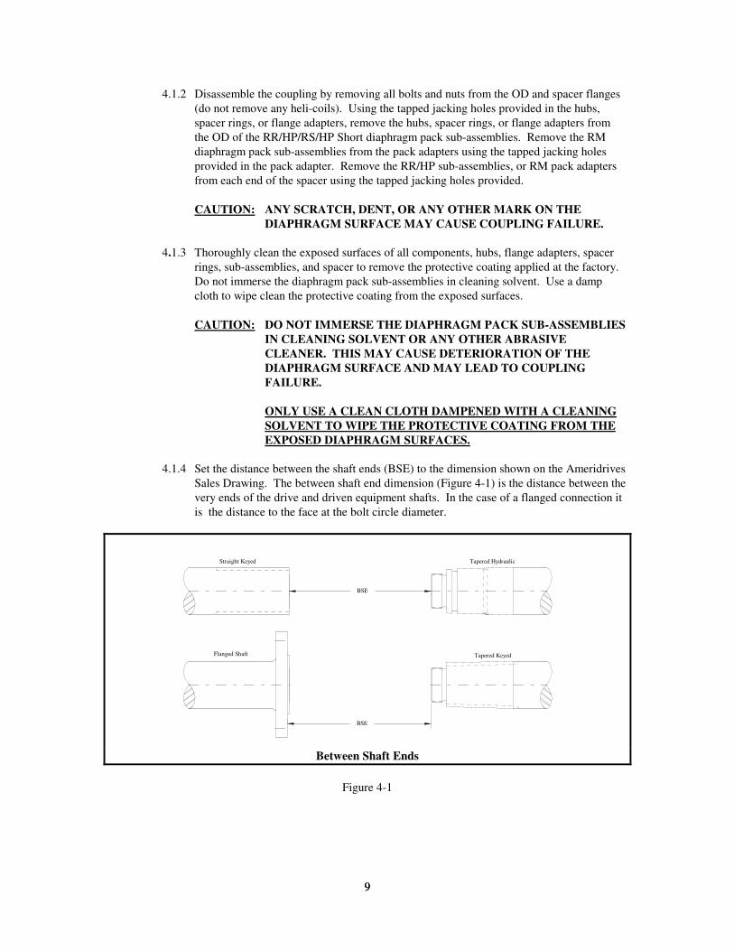
4.1.4 Set the distance between the shaft ends (BSE) to the dimension shown on the Ameridrives
Sales Drawing. The between shaft end dimension (Figure 4-1) is the distance between the
very ends of the drive and driven equipment shafts. In the case of a flanged connection it
is the distance to the face at the bolt circle diameter.
BSE
BSE
Flanged Shaft Tapered Keyed
Tapered HydraulicStraight Keyed
Between Shaft Ends
Figure 4-1
10
10
4.2 HUB MOUNTING PROCEDURE
4.2.1 Straight Bore with Keyway(s)
CAUTION: AMERIDRIVES MANUFACTURED THE COUPLING
INTERFACE BASED ON THE SHAFT DATA SUPPLIED BY THE
PURCHASER. AMERIDRIVES IS NOT RESPONSIBLE FOR
INACCURATE OR INCOMPLETE INFORMATION SUPPLIED BY
THE PURCHASER.
IT IS THE PURCHASERS RESPONSIBILITY TO ASSURE THAT
THE INTERFACE CONNECTIONS (FLANGES, BOLTS, KEYS,
HYDRAULIC FITS, ETC.) BETWEEN THE COUPLING AND THE
CONNECTED EQUIPMENT ARE CAPABLE OF HANDLING THE
ANTICIPATED LOADS.
4.2.1.1 Measure the shaft diameter and the bore diameter to determine the interference fit.
If the measured interference differs from the value on the Ameridrives Sales
Drawing, contact Ameridrives Customer Service or the equipment manufacturer.
4.2.1.2 Verify that the engagement length between the bore and shaft is correct.
4.2.1.3 Check the key(s) and keyway(s) for proper fit. Key(s) should be fitted to the
keyway(s) to minimize their effect on balance. Refer to AGMA-9002-A86 or other
industry standard for recommended key fits.
4.2.1.4 Install the key(s) into the shaft and measure the shaft to key or key to key
dimension. Compare this measurement with the measurement of the bore to
keyway or keyway to keyway dimension of the hub to assure proper fit. If an
interference exists between key(s), and hub, correct the situation or contact the
equipment manufacturer or Ameridrives Customer Service.
4.2.1.5 Expand the bore with a uniform heat source (oven, induction heater, etc.) taking
care not to exceed 550° F (288° C). The following equations will help determine
the temperature required to expand the bore to install the hub onto the shaft.
BORE EXPANSION:
E = BORE EXPANSION (IN.)
e = BORE EXPANSION (MM)
B = BORE DIAMETER (IN.)
b = BORE DIAMETER (MM)
T = TEMPERATURE RISE
ABOVE AMBIENT (° F)
t = TEMPERATURE RISE
ABOVE AMBIENT (° C)
TE
B=
×.0000064
te
b=
×.0000115
CAUTION: DO NOT EXCEED 550° F (288° C) DURING THE
HEATING OR INSTALLATION OF THE HUB.
EXCESSIVE HEAT MAY SOFTEN THE HUB AND
REDUCE THE STRENGTH OF THE STEEL. EXCESSIVE
HEAT MAY ALSO AFFECT THE PERFORMANCE
CHARACTERISTICS OF THE HUB.
11
11
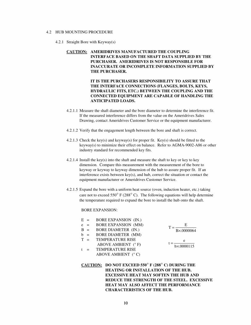
4.2.1.6 Position the hub and key as shown on the Ameridrives Sales Drawing, typically
flush with the shaft end (see Figure 4-2).
Key Flush
Key
Incorrect
Key
Incorrect
Key
Correct
Key RecessedKey Extended Hub and Key Position on Shaft
Figure 4-2
4.2.2 Tapered Bore With Keyway(s)
CAUTION: AMERIDRIVES MANUFACTURED THE COUPLING
INTERFACE BASED ON THE SHAFT DATA SUPPLIED BY THE
PURCHASER. AMERIDRIVES IS NOT RESPONSIBLE FOR
INACCURATE OR INCOMPLETE INFORMATION SUPPLIED BY
THE PURCHASER.
IT IS THE PURCHASERS RESPONSIBILITY TO ASSURE THAT
THE INTERFACE CONNECTIONS (FLANGES, BOLTS, KEYS,
HYDRAULIC FITS, ETC.) BETWEEN THE COUPLING AND THE
CONNECTED EQUIPMENT ARE CAPABLE OF HANDLING THE
ANTICIPATED LOADS.
4.2.2.1 Verify that the engagement length between the bore and tapered shaft end is
correct.
4.2.2.2 Check the key(s) and keyway(s) for proper fit. Key(s) should be fitted to the
keyway(s) to minimize their affect on balance. Refer to AGMA-9002-A86 or
other industry standard for recommended key fits.
4.2.2.3 Install the key(s) into the shaft and measure the shaft to key or key to key
dimension. Compare this measurement with the measurement of the bore to
keyway or keyway to keyway dimension of the hub to assure proper fit. If an
interference exists between key(s), and hub, correct the situation or contact the
equipment manufacturer or Ameridrives Customer Service.
4.2.2.4 With the key(s) installed in the shaft, perform a blue contact check between the
bore and tapered shaft end. Refer to the Ameridrives Sales Drawing for the
recommended contact area per API-671.
4.2.2.5 Remove the bluing from the shaft and bore.
12
12
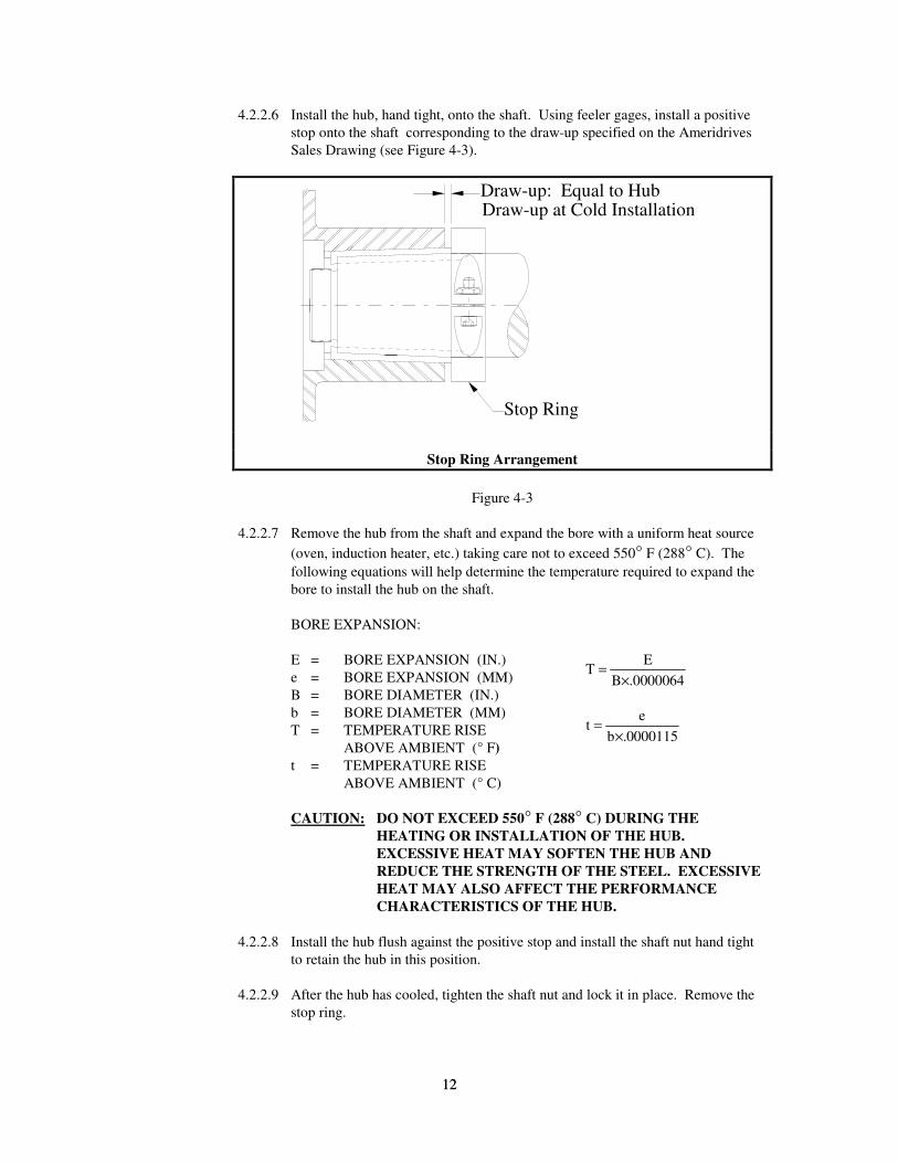
4.2.2.6 Install the hub, hand tight, onto the shaft. Using feeler gages, install a positive
stop onto the shaft corresponding to the draw-up specified on the Ameridrives
Sales Drawing (see Figure 4-3).
Stop Ring
Draw-up: Equal to HubDraw-up at Cold Installation
Stop Ring Arrangement
Figure 4-3
4.2.2.7 Remove the hub from the shaft and expand the bore with a uniform heat source
(oven, induction heater, etc.) taking care not to exceed 550° F (288° C). The
following equations will help determine the temperature required to expand the
bore to install the hub on the shaft.
BORE EXPANSION:
E = BORE EXPANSION (IN.)
e = BORE EXPANSION (MM)
B = BORE DIAMETER (IN.)
b = BORE DIAMETER (MM)
T = TEMPERATURE RISE
ABOVE AMBIENT (° F)
t = TEMPERATURE RISE
ABOVE AMBIENT (° C)
TE
B .0000064=
×
te
b=
×.0000115
CAUTION: DO NOT EXCEED 550° F (288° C) DURING THE
HEATING OR INSTALLATION OF THE HUB.
EXCESSIVE HEAT MAY SOFTEN THE HUB AND
REDUCE THE STRENGTH OF THE STEEL. EXCESSIVE
HEAT MAY ALSO AFFECT THE PERFORMANCE
CHARACTERISTICS OF THE HUB.
4.2.2.8 Install the hub flush against the positive stop and install the shaft nut hand tight
to retain the hub in this position.
4.2.2.9 After the hub has cooled, tighten the shaft nut and lock it in place. Remove the
stop ring.
13
13
4.2.3 Hydraulic Bore
CAUTION: AMERIDRIVES MANUFACTURED THE COUPLING
INTERFACE BASED ON THE SHAFT DATA SUPPLIED BY THE
PURCHASER. AMERIDRIVES IS NOT RESPONSIBLE FOR
INACCURATE OR INCOMPLETE INFORMATION SUPPLIED BY
THE PURCHASER.
IT IS THE PURCHASERS RESPONSIBILITY TO ASSURE THAT
THE INTERFACE CONNECTIONS (FLANGES, BOLTS, KEYS,
HYDRAULIC FITS, ETC.) BETWEEN THE COUPLING AND THE
CONNECTED EQUIPMENT ARE CAPABLE OF HANDLING THE
ANTICIPATED LOADS.
4.2.3.1 Verify that the engagement length between the bore and tapered shaft end is
correct.
4.2.3.2 Without o-rings or back-up rings, perform a blue contact check between the bore
and the tapered shaft end. Refer to the Ameridrives Sales Drawing for the
recommended contact area.
4.2.3.3 Clean the bluing from the shaft and bore.
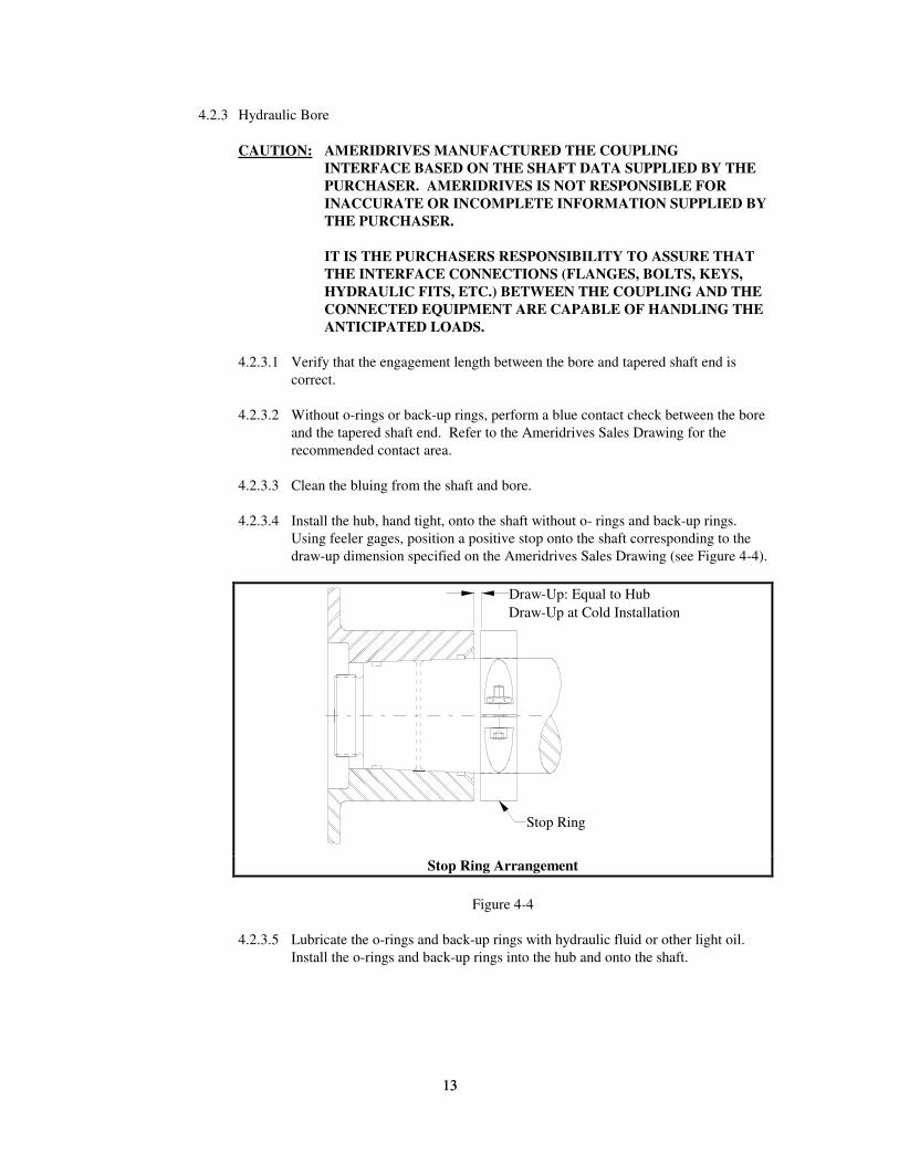
4.2.3.4 Install the hub, hand tight, onto the shaft without o- rings and back-up rings.
Using feeler gages, position a positive stop onto the shaft corresponding to the
draw-up dimension specified on the Ameridrives Sales Drawing (see Figure 4-4).
Stop Ring
Draw-Up: Equal to Hub
Draw-Up at Cold Installation
Stop Ring Arrangement
Figure 4-4
4.2.3.5 Lubricate the o-rings and back-up rings with hydraulic fluid or other light oil.
Install the o-rings and back-up rings into the hub and onto the shaft.
14
14
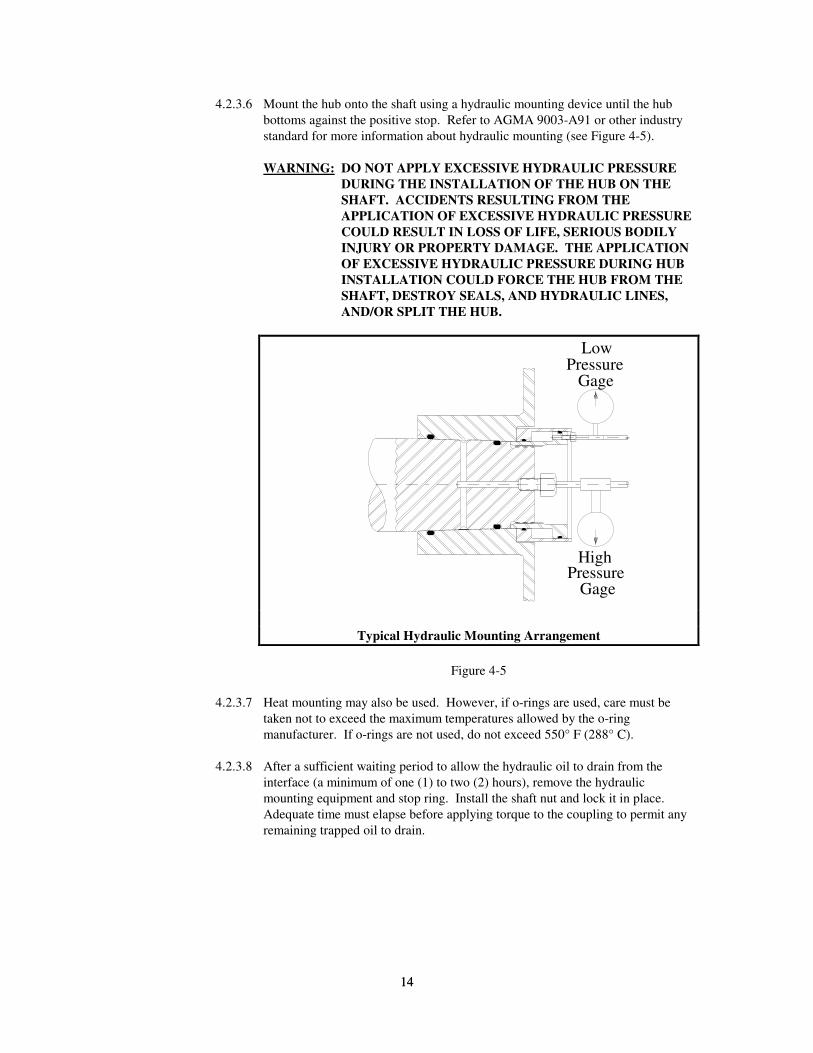
4.2.3.6 Mount the hub onto the shaft using a hydraulic mounting device until the hub
bottoms against the positive stop. Refer to AGMA 9003-A91 or other industry
standard for more information about hydraulic mounting (see Figure 4-5).
WARNING: DO NOT APPLY EXCESSIVE HYDRAULIC PRESSURE
DURING THE INSTALLATION OF THE HUB ON THE
SHAFT. ACCIDENTS RESULTING FROM THE
APPLICATION OF EXCESSIVE HYDRAULIC PRESSURE
COULD RESULT IN LOSS OF LIFE, SERIOUS BODILY
INJURY OR PROPERTY DAMAGE. THE APPLICATION
OF EXCESSIVE HYDRAULIC PRESSURE DURING HUB
INSTALLATION COULD FORCE THE HUB FROM THE
SHAFT, DESTROY SEALS, AND HYDRAULIC LINES,
AND/OR SPLIT THE HUB.
LowPressure
Gage
HighPressure
Gage
Typical Hydraulic Mounting Arrangement
Figure 4-5
4.2.3.7 Heat mounting may also be used. However, if o-rings are used, care must be
taken not to exceed the maximum temperatures allowed by the o-ring
manufacturer. If o-rings are not used, do not exceed 550° F (288° C).
4.2.3.8 After a sufficient waiting period to allow the hydraulic oil to drain from the
interface (a minimum of one (1) to two (2) hours), remove the hydraulic
mounting equipment and stop ring. Install the shaft nut and lock it in place.
Adequate time must elapse before applying torque to the coupling to permit any
remaining trapped oil to drain.
15
15
4.2.4 FLANGE ADAPTERS
CAUTION: AMERIDRIVES MANUFACTURED THE COUPLING
INTERFACE BASED ON THE SHAFT DATA SUPPLIED BY THE
PURCHASER. AMERIDRIVES IS NOT RESPONSIBLE FOR
INACCURATE OR INCOMPLETE INFORMATION SUPPLIED BY
THE PURCHASER. IT IS THE PURCHASERS RESPONSIBILITY TO ASSURE THAT
THE INTERFACE CONNECTIONS (FLANGES, BOLTS, KEYS,
HYDRAULIC FITS, ETC.) BETWEEN THE COUPLING AND THE
CONNECTED EQUIPMENT ARE CAPABLE OF HANDLING THE
ANTICIPATED LOADS.
4.2.4.1 Measure the mating pilots to verify the proper interference fit according to the
original equipment manufacturers recommendation.
4.2.4.2 Check both the equipment flange and the mating adapter flange. Remove any
dirt, dents, raised metal or any other condition that might prevent the mating
faces and pilot from seating properly.
4.2.4.3 Install a minimum of four (4) bolts approximately 90° apart through both flanges
and tighten the bolts evenly in a criss-cross pattern to seat the pilot. Refer to the
Ameridrives Sales Drawing for proper bolt and nut orientation and also to check
if the bolts are supplied by Ameridrives.
4.2.4.4 Install the remaining fasteners and torque all fasteners in a criss-cross pattern to
the value specified on the Ameridrives Sales Drawing. If the flange interface
fasteners are not supplied by Ameridrives, consult the fastener supplier for the
proper tightening torque.
4.3 ALIGNMENT 4.3.1 All Ameriflex couplings are designed to transmit 100% of the ratings stated on the
Ameridrives Sales Drawing for normal torque, axial and angular misalignment
simultaneously. However, if the exact amount of axial and angular movement from
"cold" to "hot" running condition is not known, we recommend not exceeding 25% of the
combined axial and angular capacities at installation.
4.3.2 All measurements taken during alignment should be made with the equipment shafts in
their normal running position (i.e., thrust bearings against their active faces, motor rotors
on their magnetic centers, etc.).
CAUTION: FAILURE TO TAKE MEASUREMENTS DURING ALIGNMENT
WITH THE EQUIPMENT SHAFTS IN THEIR NORMAL
RUNNING POSITION MAY RESULT IN COUPLING DAMAGE
OR FAILURE DUE TO OVER EXTENSION OR COMPRESSION
OF THE DIAPHRAGMS (SEE PARAGRAPH 4.3.2).
4.3.3 Equipment alignment should be accomplished in the manner specified by the equipment
manufacturer.
4.3.4 The Ameriflex coupling is capable of operating at 100% of the axial and angular capacity
stated on the Ameridrives Sales Drawing. If installed such that during normal "hot"
operation the axial and angular misalignments are at or near zero, the loads induced by
the coupling are further reduced, thereby increasing equipment bearing life.
16
16
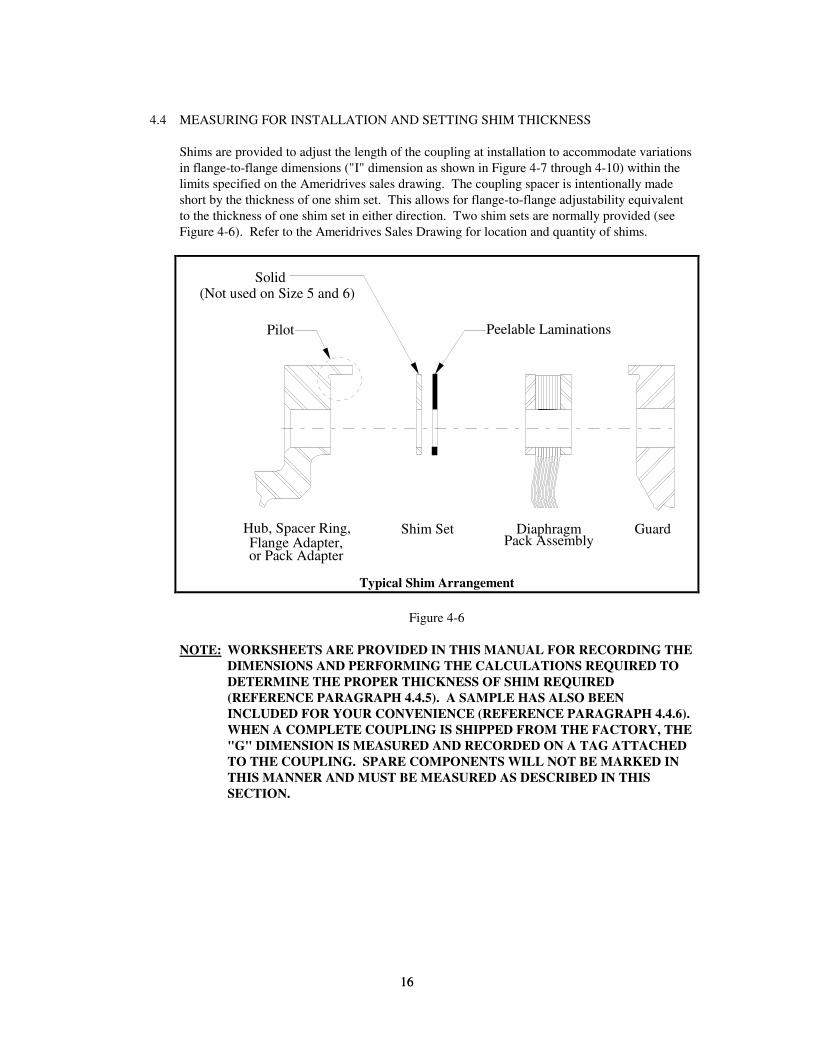
4.4 MEASURING FOR INSTALLATION AND SETTING SHIM THICKNESS
Shims are provided to adjust the length of the coupling at installation to accommodate variations
in flange-to-flange dimensions ("I" dimension as shown in Figure 4-7 through 4-10) within the
limits specified on the Ameridrives sales drawing. The coupling spacer is intentionally made
short by the thickness of one shim set. This allows for flange-to-flange adjustability equivalent
to the thickness of one shim set in either direction. Two shim sets are normally provided (see
Figure 4-6). Refer to the Ameridrives Sales Drawing for location and quantity of shims.
Pilot Peelable Laminations
Hub, Spacer Ring,Flange Adapter,or Pack Adapter
Shim Set DiaphragmPack Assembly
Guard
Solid(Not used on Size 5 and 6)
Typical Shim Arrangement
Figure 4-6
NOTE: WORKSHEETS ARE PROVIDED IN THIS MANUAL FOR RECORDING THE
DIMENSIONS AND PERFORMING THE CALCULATIONS REQUIRED TO
DETERMINE THE PROPER THICKNESS OF SHIM REQUIRED
(REFERENCE PARAGRAPH 4.4.5). A SAMPLE HAS ALSO BEEN
INCLUDED FOR YOUR CONVENIENCE (REFERENCE PARAGRAPH 4.4.6).
WHEN A COMPLETE COUPLING IS SHIPPED FROM THE FACTORY, THE
"G" DIMENSION IS MEASURED AND RECORDED ON A TAG ATTACHED
TO THE COUPLING. SPARE COMPONENTS WILL NOT BE MARKED IN
THIS MANNER AND MUST BE MEASURED AS DESCRIBED IN THIS
SECTION.
17
17
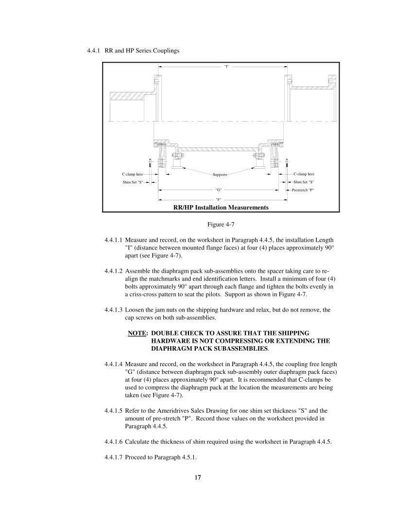
4.4.1 RR and HP Series Couplings
"I"
"G"
"F"
Supports
Shim Set "S" Shim Set "S"
Prestretch "P"
C-clamp here C-clamp here
RR/HP Installation Measurements
Figure 4-7
4.4.1.1 Measure and record, on the worksheet in Paragraph 4.4.5, the installation Length
"I" (distance between mounted flange faces) at four (4) places approximately 90°
apart (see Figure 4-7).
4.4.1.2 Assemble the diaphragm pack sub-assemblies onto the spacer taking care to re-
align the matchmarks and end identification letters. Install a minimum of four (4)
bolts approximately 90° apart through each flange and tighten the bolts evenly in
a criss-cross pattern to seat the pilots. Support as shown in Figure 4-7.
4.4.1.3 Loosen the jam nuts on the shipping hardware and relax, but do not remove, the
cap screws on both sub-assemblies.
NOTE: DOUBLE CHECK TO ASSURE THAT THE SHIPPING
HARDWARE IS NOT COMPRESSING OR EXTENDING THE
DIAPHRAGM PACK SUBASSEMBLIES.
4.4.1.4 Measure and record, on the worksheet in Paragraph 4.4.5, the coupling free length
"G" (distance between diaphragm pack sub-assembly outer diaphragm pack faces)
at four (4) places approximately 90° apart. It is recommended that C-clamps be
used to compress the diaphragm pack at the location the measurements are being
taken (see Figure 4-7).
4.4.1.5 Refer to the Ameridrives Sales Drawing for one shim set thickness "S" and the
amount of pre-stretch "P". Record those values on the worksheet provided in
Paragraph 4.4.5.
4.4.1.6 Calculate the thickness of shim required using the worksheet in Paragraph 4.4.5.
4.4.1.7 Proceed to Paragraph 4.5.1.
18
18
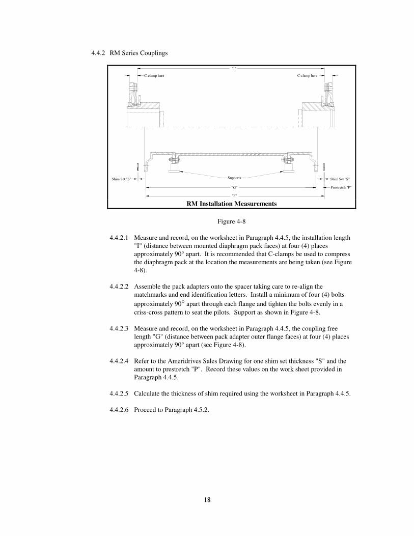
4.4.2 RM Series Couplings
"I"
Supports
"G"
"F"
Shim Set "S" Shim Set "S"
Prestretch "P"
C-clamp here C-clamp here
RM Installation Measurements
Figure 4-8
4.4.2.1 Measure and record, on the worksheet in Paragraph 4.4.5, the installation length
"I" (distance between mounted diaphragm pack faces) at four (4) places
approximately 90° apart. It is recommended that C-clamps be used to compress
the diaphragm pack at the location the measurements are being taken (see Figure
4-8).
4.4.2.2 Assemble the pack adapters onto the spacer taking care to re-align the
matchmarks and end identification letters. Install a minimum of four (4) bolts
approximately 90° apart through each flange and tighten the bolts evenly in a
criss-cross pattern to seat the pilots. Support as shown in Figure 4-8.
4.4.2.3 Measure and record, on the worksheet in Paragraph 4.4.5, the coupling free
length "G" (distance between pack adapter outer flange faces) at four (4) places
approximately 90° apart (see Figure 4-8).
4.4.2.4 Refer to the Ameridrives Sales Drawing for one shim set thickness "S" and the
amount to prestretch "P". Record these values on the work sheet provided in
Paragraph 4.4.5.
4.4.2.5 Calculate the thickness of shim required using the worksheet in Paragraph 4.4.5.
4.4.2.6 Proceed to Paragraph 4.5.2.
19
19
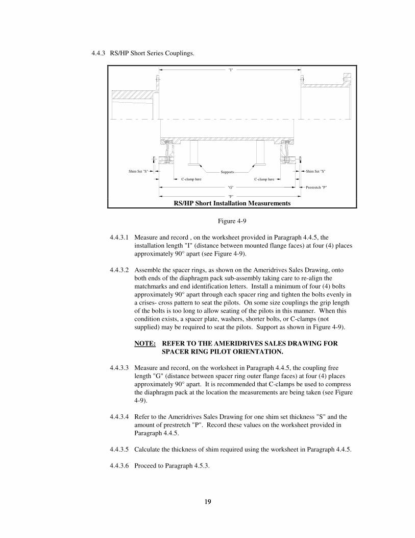
4.4.3 RS/HP Short Series Couplings.
"I"
"G"
"F"
SupportsShim Set "S" Shim Set "S"
Prestretch "P"
C-clamp hereC-clamp here
RS/HP Short Installation Measurements
Figure 4-9
4.4.3.1 Measure and record , on the worksheet provided in Paragraph 4.4.5, the
installation length "I" (distance between mounted flange faces) at four (4) places
approximately 90° apart (see Figure 4-9).
4.4.3.2 Assemble the spacer rings, as shown on the Ameridrives Sales Drawing, onto
both ends of the diaphragm pack sub-assembly taking care to re-align the
matchmarks and end identification letters. Install a minimum of four (4) bolts
approximately 90° apart through each spacer ring and tighten the bolts evenly in
a crises- cross pattern to seat the pilots. On some size couplings the grip length
of the bolts is too long to allow seating of the pilots in this manner. When this
condition exists, a spacer plate, washers, shorter bolts, or C-clamps (not
supplied) may be required to seat the pilots. Support as shown in Figure 4-9).
NOTE: REFER TO THE AMERIDRIVES SALES DRAWING FOR
SPACER RING PILOT ORIENTATION.
4.4.3.3 Measure and record, on the worksheet in Paragraph 4.4.5, the coupling free
length "G" (distance between spacer ring outer flange faces) at four (4) places
approximately 90° apart. It is recommended that C-clamps be used to compress
the diaphragm pack at the location the measurements are being taken (see Figure
4-9).
4.4.3.4 Refer to the Ameridrives Sales Drawing for one shim set thickness "S" and the
amount of prestretch "P". Record these values on the worksheet provided in
Paragraph 4.4.5.
4.4.3.5 Calculate the thickness of shim required using the worksheet in Paragraph 4.4.5.
4.4.3.6 Proceed to Paragraph 4.5.3.
20
20
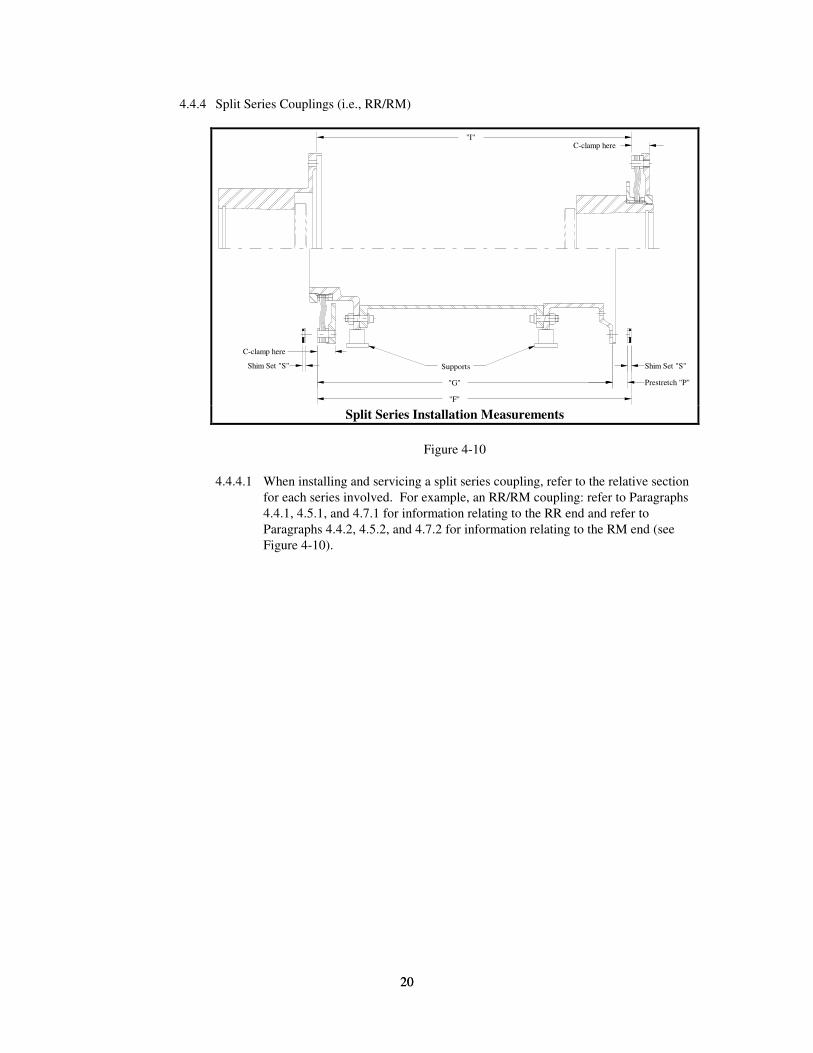
4.4.4 Split Series Couplings (i.e., RR/RM)
"I"
Supports
"G"
"F"
Shim Set "S" Shim Set "S"
Prestretch "P"
C-clamp here
C-clamp here
Split Series Installation Measurements
Figure 4-10
4.4.4.1 When installing and servicing a split series coupling, refer to the relative section
for each series involved. For example, an RR/RM coupling: refer to Paragraphs
4.4.1, 4.5.1, and 4.7.1 for information relating to the RR end and refer to
Paragraphs 4.4.2, 4.5.2, and 4.7.2 for information relating to the RM end (see
Figure 4-10).
21
21
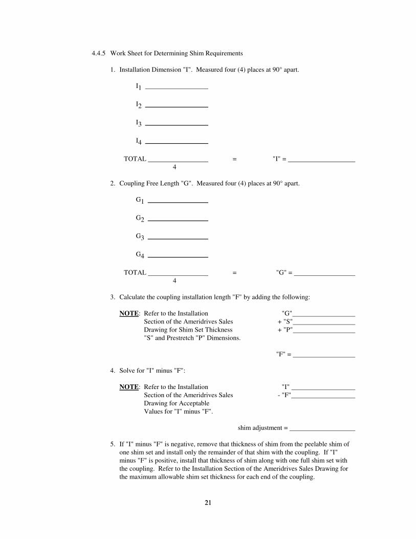
4.4.5 Work Sheet for Determining Shim Requirements
1. Installation Dimension "I". Measured four (4) places at 90° apart.
I1
I2
I3
I4
TOTAL = "I" =
4
2. Coupling Free Length "G". Measured four (4) places at 90° apart.
G1
G2
G3
G4
TOTAL = "G" =
4
3. Calculate the coupling installation length "F" by adding the following:
NOTE: Refer to the Installation "G"
Section of the Ameridrives Sales + "S"
Drawing for Shim Set Thickness + "P"
"S" and Prestretch "P" Dimensions.
"F" =
4. Solve for "I" minus "F":
NOTE: Refer to the Installation "I"
Section of the Ameridrives Sales - "F"
Drawing for Acceptable
Values for "I" minus "F".
shim adjustment =
5. If "I" minus "F" is negative, remove that thickness of shim from the peelable shim of
one shim set and install only the remainder of that shim with the coupling. If "I"
minus "F" is positive, install that thickness of shim along with one full shim set with
the coupling. Refer to the Installation Section of the Ameridrives Sales Drawing for
the maximum allowable shim set thickness for each end of the coupling.
22
22
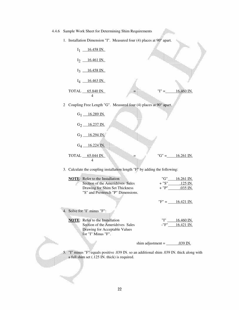
4.4.6 Sample Work Sheet for Determining Shim Requirements
1. Installation Dimension "I". Measured four (4) places at 90° apart.
I1 16.458 IN.
I2 16.461 IN.
I3 16.458 IN.
I4 16.463 IN.
TOTAL 65.840 IN. = "I" = 16.460 IN.
4
2 Coupling Free Length "G". Measured four (4) places at 90° apart.
G1 16.289 IN.
G2 16.237 IN.
G3 16.294 IN.
G4 16.224 IN.
TOTAL 65.044 IN. = "G" = 16.261 IN.
4
3. Calculate the coupling installation length "F" by adding the following:
NOTE: Refer to the Installation "G" 16.261 IN.
Section of the Ameridrives Sales + "S" .125 IN.
Drawing for Shim Set Thickness + "P" .035 IN.
"S" and Prestretch "P" Dimensions.
"F" = 16.421 IN.
4. Solve for "I" minus "F":
NOTE: Refer to the Installation "I" 16.460 IN.
Section of the Ameridrives Sales -"F" 16.421 IN.
Drawing for Acceptable Values
for "I" Minus "F".
shim adjustment = .039 IN.
5. "I" minus "F" equals positive .039 IN. so an additional shim .039 IN. thick along with
a full shim set (.125 IN. thick) is required.
23
23
4.5. SUB-ASSEMBLY AND SPACER MOUNTING
4.5.1 RR and HP Series Coupling
4.5.1.1 Separate the diaphragm pack sub-assemblies from the spacer using the tapped
jacking holes provided.
4.5.1.2 Inspect the mating flange faces and pilots. Remove any dirt, dents, raised metal
or any other condition that might prevent the mating faces and pilot from seating
properly.
4.5.1.3 Install the diaphragm pack sub-assembly by aligning the end identification letters
and matchmarks. Install a minimum of four (4) bolts approximately 90° apart
through the flange, shim(s) (if required) and diaphragm pack. Refer to the
Ameridrives Sales Drawing for proper bolt and nut orientation. Pilots are an
interference fit. Tighten the bolts evenly in a criss-cross pattern to seat the pilots
properly.
4.5.1.4 Repeat Paragraph 4.5.1.3 at the opposite end making sure the end identification
letters and matchmarks are aligned.
4.5.1.5 Install all remaining OD fasteners and torque evenly in a criss-cross patterns to
the value specified on the Ameridrives Sales Drawing. Repeat the bolt
tightening procedure to verify that all fasteners are torqued to the proper value.
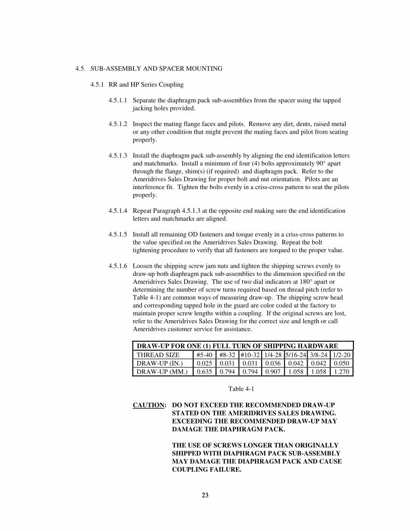
4.5.1.6 Loosen the shipping screw jam nuts and tighten the shipping screws evenly to
draw-up both diaphragm pack sub-assemblies to the dimension specified on the
Ameridrives Sales Drawing. The use of two dial indicators at 180° apart or
determining the number of screw turns required based on thread pitch (refer to
Table 4-1) are common ways of measuring draw-up. The shipping screw head
and corresponding tapped hole in the guard are color coded at the factory to
maintain proper screw lengths within a coupling. If the original screws are lost,
refer to the Ameridrives Sales Drawing for the correct size and length or call
Ameridrives customer service for assistance.
DRAW-UP FOR ONE (1) FULL TURN OF SHIPPING HARDWARE
THREAD SIZE #5-40 #8-32 #10-32 1/4-28 5/16-24 3/8-24 1/2-20
DRAW-UP (IN.) 0.025 0.031 0.031 0.036 0.042 0.042 0.050
DRAW-UP (MM.) 0.635 0.794 0.794 0.907 1.058 1.058 1.270
Table 4-1
CAUTION: DO NOT EXCEED THE RECOMMENDED DRAW-UP
STATED ON THE AMERIDRIVES SALES DRAWING.
EXCEEDING THE RECOMMENDED DRAW-UP MAY
DAMAGE THE DIAPHRAGM PACK.
THE USE OF SCREWS LONGER THAN ORIGINALLY
SHIPPED WITH DIAPHRAGM PACK SUB-ASSEMBLY
MAY DAMAGE THE DIAPHRAGM PACK AND CAUSE
COUPLING FAILURE.
24
24
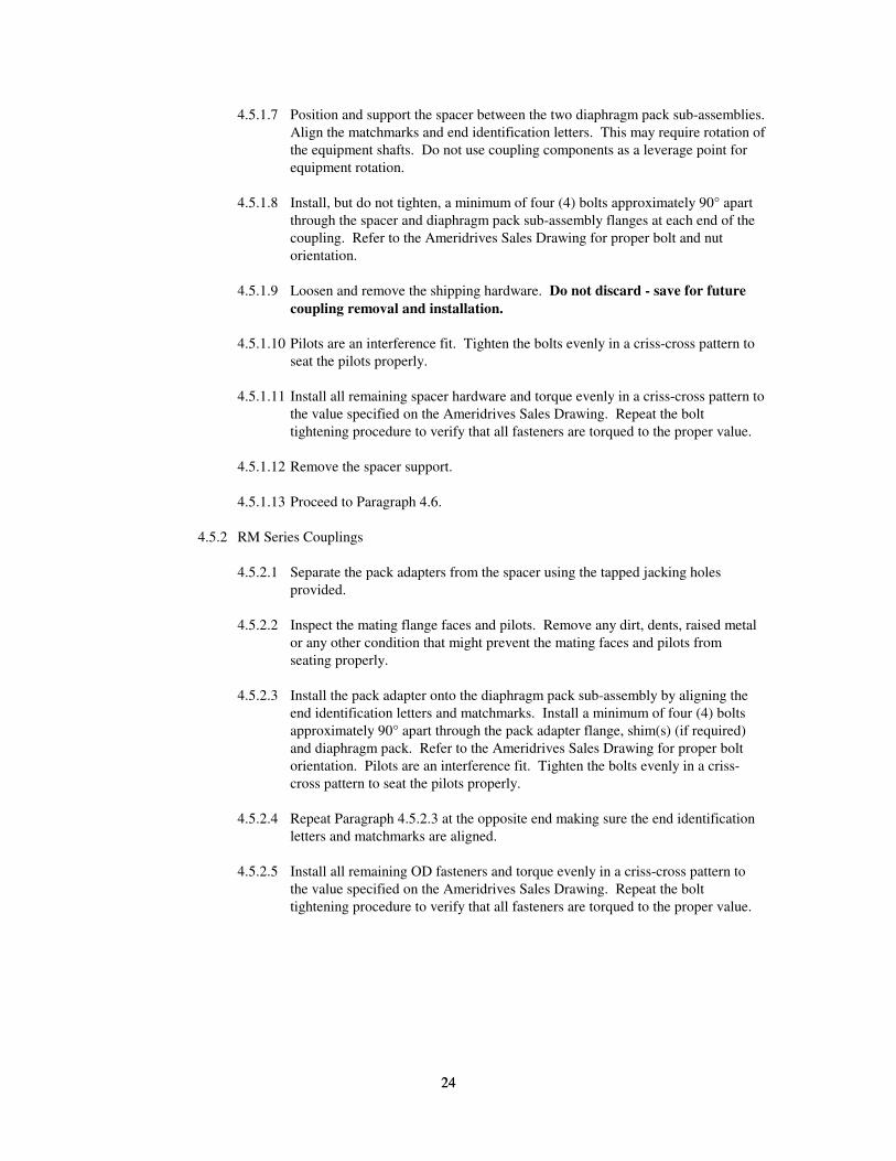
4.5.1.7 Position and support the spacer between the two diaphragm pack sub-assemblies.
Align the matchmarks and end identification letters. This may require rotation of
the equipment shafts. Do not use coupling components as a leverage point for
equipment rotation.
4.5.1.8 Install, but do not tighten, a minimum of four (4) bolts approximately 90° apart
through the spacer and diaphragm pack sub-assembly flanges at each end of the
coupling. Refer to the Ameridrives Sales Drawing for proper bolt and nut
orientation.
4.5.1.9 Loosen and remove the shipping hardware. Do not discard - save for future
coupling removal and installation.
4.5.1.10 Pilots are an interference fit. Tighten the bolts evenly in a criss-cross pattern to
seat the pilots properly.
4.5.1.11 Install all remaining spacer hardware and torque evenly in a criss-cross pattern to
the value specified on the Ameridrives Sales Drawing. Repeat the bolt
tightening procedure to verify that all fasteners are torqued to the proper value.
4.5.1.12 Remove the spacer support.
4.5.1.13 Proceed to Paragraph 4.6.
4.5.2 RM Series Couplings
4.5.2.1 Separate the pack adapters from the spacer using the tapped jacking holes
provided.
4.5.2.2 Inspect the mating flange faces and pilots. Remove any dirt, dents, raised metal
or any other condition that might prevent the mating faces and pilots from
seating properly.
4.5.2.3 Install the pack adapter onto the diaphragm pack sub-assembly by aligning the
end identification letters and matchmarks. Install a minimum of four (4) bolts
approximately 90° apart through the pack adapter flange, shim(s) (if required)
and diaphragm pack. Refer to the Ameridrives Sales Drawing for proper bolt
orientation. Pilots are an interference fit. Tighten the bolts evenly in a criss-
cross pattern to seat the pilots properly.
4.5.2.4 Repeat Paragraph 4.5.2.3 at the opposite end making sure the end identification
letters and matchmarks are aligned.
4.5.2.5 Install all remaining OD fasteners and torque evenly in a criss-cross pattern to
the value specified on the Ameridrives Sales Drawing. Repeat the bolt
tightening procedure to verify that all fasteners are torqued to the proper value.
25
25
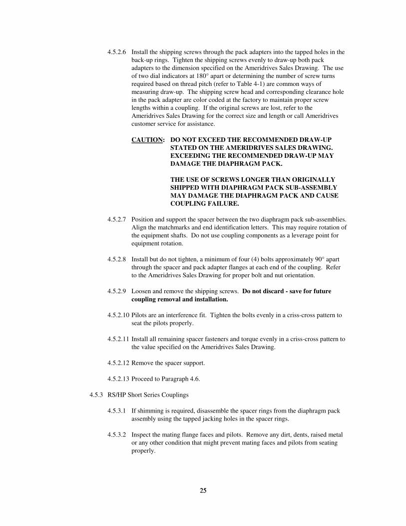
4.5.2.6 Install the shipping screws through the pack adapters into the tapped holes in the
back-up rings. Tighten the shipping screws evenly to draw-up both pack
adapters to the dimension specified on the Ameridrives Sales Drawing. The use
of two dial indicators at 180° apart or determining the number of screw turns
required based on thread pitch (refer to Table 4-1) are common ways of
measuring draw-up. The shipping screw head and corresponding clearance hole
in the pack adapter are color coded at the factory to maintain proper screw
lengths within a coupling. If the original screws are lost, refer to the
Ameridrives Sales Drawing for the correct size and length or call Ameridrives
customer service for assistance.
CAUTION: DO NOT EXCEED THE RECOMMENDED DRAW-UP
STATED ON THE AMERIDRIVES SALES DRAWING.
EXCEEDING THE RECOMMENDED DRAW-UP MAY
DAMAGE THE DIAPHRAGM PACK.
THE USE OF SCREWS LONGER THAN ORIGINALLY
SHIPPED WITH DIAPHRAGM PACK SUB-ASSEMBLY
MAY DAMAGE THE DIAPHRAGM PACK AND CAUSE
COUPLING FAILURE.
4.5.2.7 Position and support the spacer between the two diaphragm pack sub-assemblies.
Align the matchmarks and end identification letters. This may require rotation of
the equipment shafts. Do not use coupling components as a leverage point for
equipment rotation.
4.5.2.8 Install but do not tighten, a minimum of four (4) bolts approximately 90° apart
through the spacer and pack adapter flanges at each end of the coupling. Refer
to the Ameridrives Sales Drawing for proper bolt and nut orientation.
4.5.2.9 Loosen and remove the shipping screws. Do not discard - save for future
coupling removal and installation.
4.5.2.10 Pilots are an interference fit. Tighten the bolts evenly in a criss-cross pattern to
seat the pilots properly.
4.5.2.11 Install all remaining spacer fasteners and torque evenly in a criss-cross pattern to
the value specified on the Ameridrives Sales Drawing.
4.5.2.12 Remove the spacer support.
4.5.2.13 Proceed to Paragraph 4.6.
4.5.3 RS/HP Short Series Couplings
4.5.3.1 If shimming is required, disassemble the spacer rings from the diaphragm pack
assembly using the tapped jacking holes in the spacer rings.
4.5.3.2 Inspect the mating flange faces and pilots. Remove any dirt, dents, raised metal
or any other condition that might prevent mating faces and pilots from seating
properly.
26
26
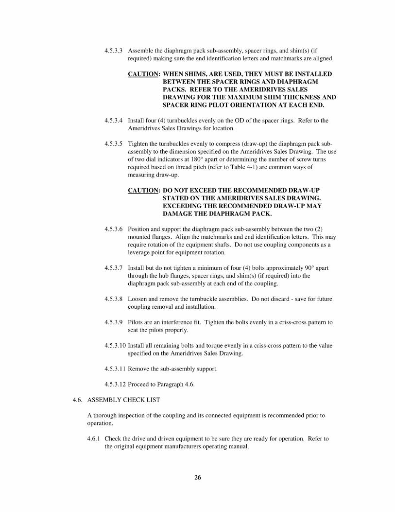
4.5.3.3 Assemble the diaphragm pack sub-assembly, spacer rings, and shim(s) (if
required) making sure the end identification letters and matchmarks are aligned.
CAUTION: WHEN SHIMS, ARE USED, THEY MUST BE INSTALLED
BETWEEN THE SPACER RINGS AND DIAPHRAGM
PACKS. REFER TO THE AMERIDRIVES SALES
DRAWING FOR THE MAXIMUM SHIM THICKNESS AND
SPACER RING PILOT ORIENTATION AT EACH END.
4.5.3.4 Install four (4) turnbuckles evenly on the OD of the spacer rings. Refer to the
Ameridrives Sales Drawings for location.
4.5.3.5 Tighten the turnbuckles evenly to compress (draw-up) the diaphragm pack sub-
assembly to the dimension specified on the Ameridrives Sales Drawing. The use
of two dial indicators at 180° apart or determining the number of screw turns
required based on thread pitch (refer to Table 4-1) are common ways of
measuring draw-up.
CAUTION: DO NOT EXCEED THE RECOMMENDED DRAW-UP
STATED ON THE AMERIDRIVES SALES DRAWING.
EXCEEDING THE RECOMMENDED DRAW-UP MAY
DAMAGE THE DIAPHRAGM PACK.
4.5.3.6 Position and support the diaphragm pack sub-assembly between the two (2)
mounted flanges. Align the matchmarks and end identification letters. This may
require rotation of the equipment shafts. Do not use coupling components as a
leverage point for equipment rotation.
4.5.3.7 Install but do not tighten a minimum of four (4) bolts approximately 90° apart
through the hub flanges, spacer rings, and shim(s) (if required) into the
diaphragm pack sub-assembly at each end of the coupling.
4.5.3.8 Loosen and remove the turnbuckle assemblies. Do not discard - save for future
coupling removal and installation.
4.5.3.9 Pilots are an interference fit. Tighten the bolts evenly in a criss-cross pattern to
seat the pilots properly.
4.5.3.10 Install all remaining bolts and torque evenly in a criss-cross pattern to the value
specified on the Ameridrives Sales Drawing.
4.5.3.11 Remove the sub-assembly support.
4.5.3.12 Proceed to Paragraph 4.6.
4.6. ASSEMBLY CHECK LIST
A thorough inspection of the coupling and its connected equipment is recommended prior to
operation.
4.6.1 Check the drive and driven equipment to be sure they are ready for operation. Refer to
the original equipment manufacturers operating manual.
27
27
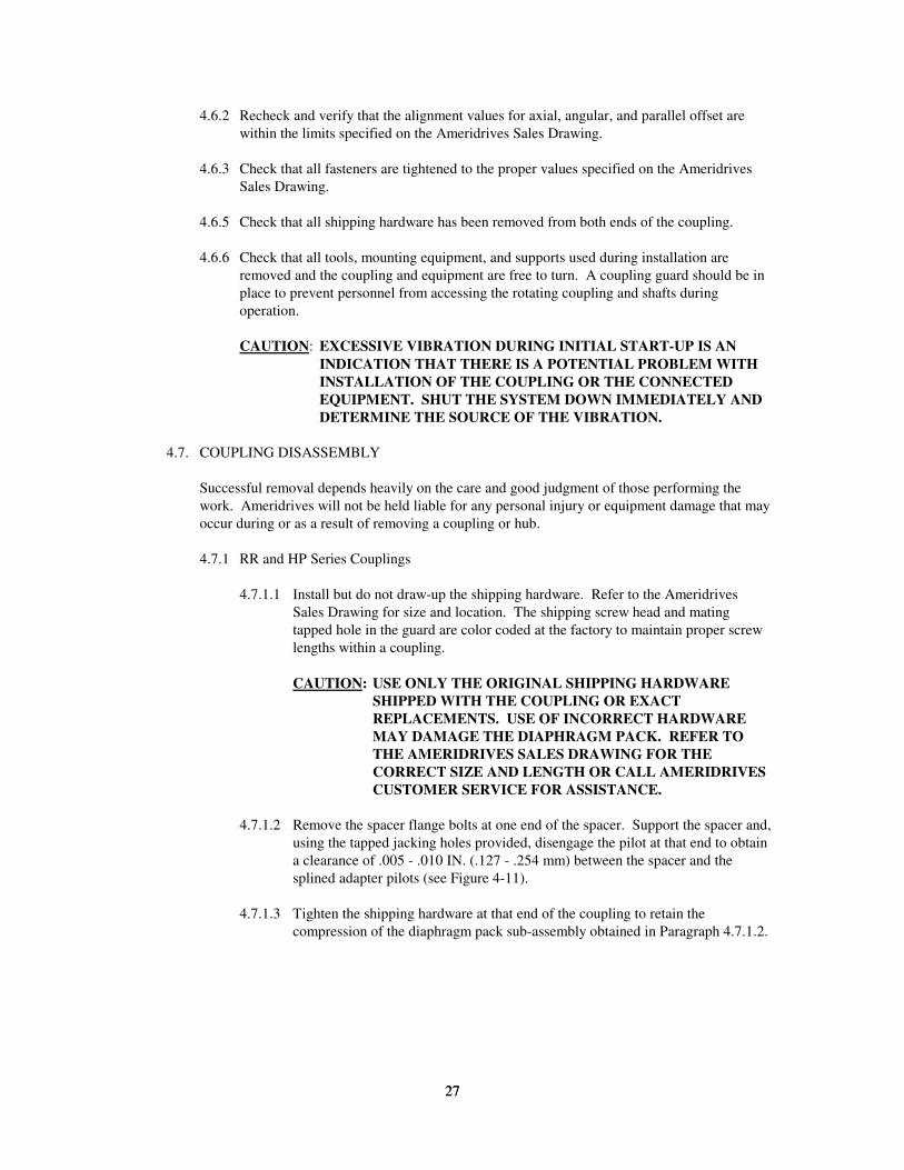
4.6.2 Recheck and verify that the alignment values for axial, angular, and parallel offset are
within the limits specified on the Ameridrives Sales Drawing.
4.6.3 Check that all fasteners are tightened to the proper values specified on the Ameridrives
Sales Drawing.
4.6.5 Check that all shipping hardware has been removed from both ends of the coupling.
4.6.6 Check that all tools, mounting equipment, and supports used during installation are
removed and the coupling and equipment are free to turn. A coupling guard should be in
place to prevent personnel from accessing the rotating coupling and shafts during
operation.
CAUTION: EXCESSIVE VIBRATION DURING INITIAL START-UP IS AN
INDICATION THAT THERE IS A POTENTIAL PROBLEM WITH
INSTALLATION OF THE COUPLING OR THE CONNECTED
EQUIPMENT. SHUT THE SYSTEM DOWN IMMEDIATELY AND
DETERMINE THE SOURCE OF THE VIBRATION.
4.7. COUPLING DISASSEMBLY
Successful removal depends heavily on the care and good judgment of those performing the
work. Ameridrives will not be held liable for any personal injury or equipment damage that may
occur during or as a result of removing a coupling or hub.
4.7.1 RR and HP Series Couplings
4.7.1.1 Install but do not draw-up the shipping hardware. Refer to the Ameridrives
Sales Drawing for size and location. The shipping screw head and mating
tapped hole in the guard are color coded at the factory to maintain proper screw
lengths within a coupling.
CAUTION: USE ONLY THE ORIGINAL SHIPPING HARDWARE
SHIPPED WITH THE COUPLING OR EXACT
REPLACEMENTS. USE OF INCORRECT HARDWARE
MAY DAMAGE THE DIAPHRAGM PACK. REFER TO
THE AMERIDRIVES SALES DRAWING FOR THE
CORRECT SIZE AND LENGTH OR CALL AMERIDRIVES
CUSTOMER SERVICE FOR ASSISTANCE.
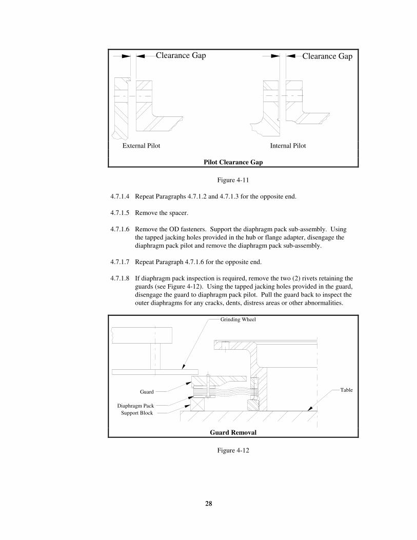
4.7.1.2 Remove the spacer flange bolts at one end of the spacer. Support the spacer and,
using the tapped jacking holes provided, disengage the pilot at that end to obtain
a clearance of .005 - .010 IN. (.127 - .254 mm) between the spacer and the
splined adapter pilots (see Figure 4-11).
4.7.1.3 Tighten the shipping hardware at that end of the coupling to retain the
compression of the diaphragm pack sub-assembly obtained in Paragraph 4.7.1.2.
28
28
Clearance Gap Clearance Gap
External Pilot Internal Pilot
Pilot Clearance Gap
Figure 4-11
4.7.1.4 Repeat Paragraphs 4.7.1.2 and 4.7.1.3 for the opposite end.
4.7.1.5 Remove the spacer.
4.7.1.6 Remove the OD fasteners. Support the diaphragm pack sub-assembly. Using
the tapped jacking holes provided in the hub or flange adapter, disengage the
diaphragm pack pilot and remove the diaphragm pack sub-assembly.
4.7.1.7 Repeat Paragraph 4.7.1.6 for the opposite end.
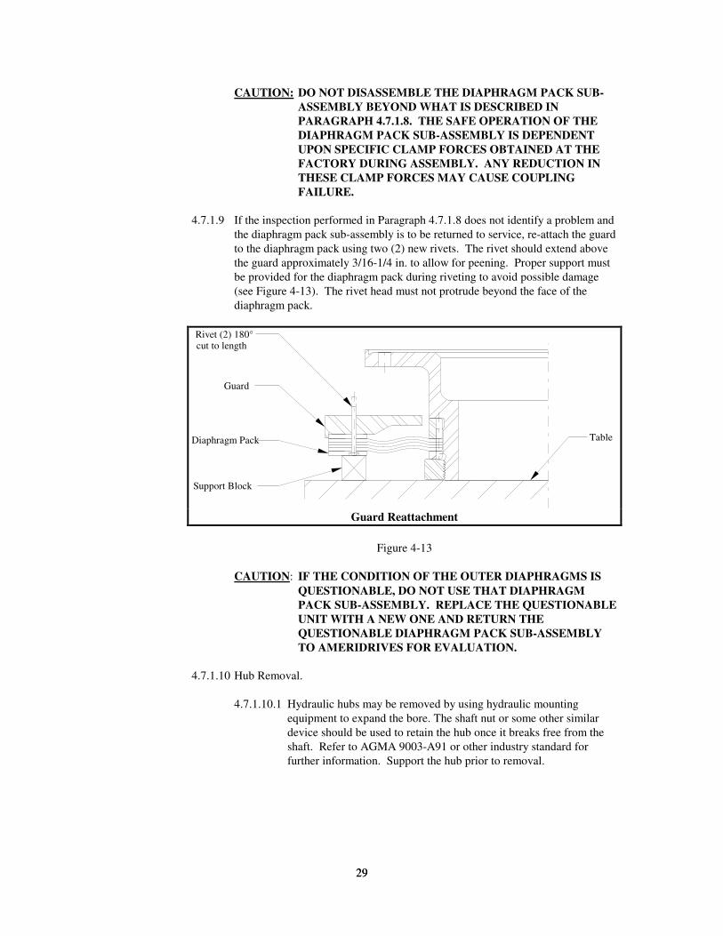
4.7.1.8 If diaphragm pack inspection is required, remove the two (2) rivets retaining the
guards (see Figure 4-12). Using the tapped jacking holes provided in the guard,
disengage the guard to diaphragm pack pilot. Pull the guard back to inspect the
outer diaphragms for any cracks, dents, distress areas or other abnormalities.
Diaphragm Pack
Support Block
Guard Table
Grinding Wheel
Guard Removal
Figure 4-12
29
29
CAUTION: DO NOT DISASSEMBLE THE DIAPHRAGM PACK SUB-
ASSEMBLY BEYOND WHAT IS DESCRIBED IN
PARAGRAPH 4.7.1.8. THE SAFE OPERATION OF THE
DIAPHRAGM PACK SUB-ASSEMBLY IS DEPENDENT
UPON SPECIFIC CLAMP FORCES OBTAINED AT THE
FACTORY DURING ASSEMBLY. ANY REDUCTION IN
THESE CLAMP FORCES MAY CAUSE COUPLING
FAILURE.
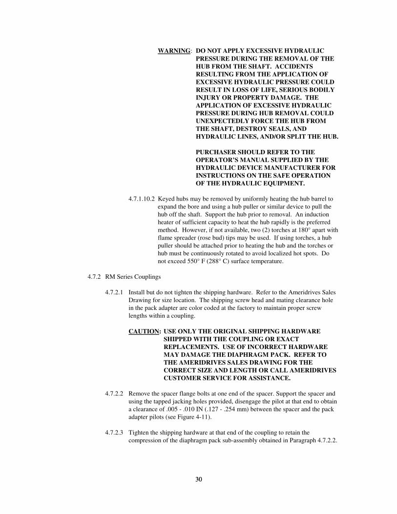
4.7.1.9 If the inspection performed in Paragraph 4.7.1.8 does not identify a problem and
the diaphragm pack sub-assembly is to be returned to service, re-attach the guard
to the diaphragm pack using two (2) new rivets. The rivet should extend above
the guard approximately 3/16-1/4 in. to allow for peening. Proper support must
be provided for the diaphragm pack during riveting to avoid possible damage
(see Figure 4-13). The rivet head must not protrude beyond the face of the
diaphragm pack.
Table
Support Block
Diaphragm Pack
Guard
Rivet (2) 180°cut to length
Guard Reattachment
Figure 4-13
CAUTION: IF THE CONDITION OF THE OUTER DIAPHRAGMS IS
QUESTIONABLE, DO NOT USE THAT DIAPHRAGM
PACK SUB-ASSEMBLY. REPLACE THE QUESTIONABLE
UNIT WITH A NEW ONE AND RETURN THE
QUESTIONABLE DIAPHRAGM PACK SUB-ASSEMBLY
TO AMERIDRIVES FOR EVALUATION.
4.7.1.10 Hub Removal.
4.7.1.10.1 Hydraulic hubs may be removed by using hydraulic mounting
equipment to expand the bore. The shaft nut or some other similar
device should be used to retain the hub once it breaks free from the
shaft. Refer to AGMA 9003-A91 or other industry standard for
further information. Support the hub prior to removal.
30
30
WARNING: DO NOT APPLY EXCESSIVE HYDRAULIC
PRESSURE DURING THE REMOVAL OF THE
HUB FROM THE SHAFT. ACCIDENTS
RESULTING FROM THE APPLICATION OF
EXCESSIVE HYDRAULIC PRESSURE COULD
RESULT IN LOSS OF LIFE, SERIOUS BODILY
INJURY OR PROPERTY DAMAGE. THE
APPLICATION OF EXCESSIVE HYDRAULIC
PRESSURE DURING HUB REMOVAL COULD
UNEXPECTEDLY FORCE THE HUB FROM
THE SHAFT, DESTROY SEALS, AND
HYDRAULIC LINES, AND/OR SPLIT THE HUB.
PURCHASER SHOULD REFER TO THE
OPERATOR’S MANUAL SUPPLIED BY THE
HYDRAULIC DEVICE MANUFACTURER FOR
INSTRUCTIONS ON THE SAFE OPERATION
OF THE HYDRAULIC EQUIPMENT.
4.7.1.10.2 Keyed hubs may be removed by uniformly heating the hub barrel to
expand the bore and using a hub puller or similar device to pull the
hub off the shaft. Support the hub prior to removal. An induction
heater of sufficient capacity to heat the hub rapidly is the preferred
method. However, if not available, two (2) torches at 180° apart with
flame spreader (rose bud) tips may be used. If using torches, a hub
puller should be attached prior to heating the hub and the torches or
hub must be continuously rotated to avoid localized hot spots. Do
not exceed 550° F (288° C) surface temperature.
4.7.2 RM Series Couplings
4.7.2.1 Install but do not tighten the shipping hardware. Refer to the Ameridrives Sales
Drawing for size location. The shipping screw head and mating clearance hole
in the pack adapter are color coded at the factory to maintain proper screw
lengths within a coupling.
CAUTION: USE ONLY THE ORIGINAL SHIPPING HARDWARE
SHIPPED WITH THE COUPLING OR EXACT
REPLACEMENTS. USE OF INCORRECT HARDWARE
MAY DAMAGE THE DIAPHRAGM PACK. REFER TO
THE AMERIDRIVES SALES DRAWING FOR THE
CORRECT SIZE AND LENGTH OR CALL AMERIDRIVES
CUSTOMER SERVICE FOR ASSISTANCE.
4.7.2.2 Remove the spacer flange bolts at one end of the spacer. Support the spacer and
using the tapped jacking holes provided, disengage the pilot at that end to obtain
a clearance of .005 - .010 IN (.127 - .254 mm) between the spacer and the pack
adapter pilots (see Figure 4-11).
4.7.2.3 Tighten the shipping hardware at that end of the coupling to retain the
compression of the diaphragm pack sub-assembly obtained in Paragraph 4.7.2.2.
31
31
4.7.2.4 Repeat Paragraphs 4.7.2.2 and 4.7.2.3 for the other end.
4.7.2.5 Remove the spacer.
4.7.2.6 Remove the OD fasteners and the shipping hardware.
4.7.2.7 Support the pack adapter prior to removal. Using the tapped jacking hole
provided, disengage the pilot and remove the pack adapter from the diaphragm
pack.
4.7.2.8 Repeat Paragraph 4.7.2.7 for the other end.
4.7.2.9 Hub Removal
4.7.2.9.1 Hydraulic hubs may be removed by using hydraulic mounting
equipment to expand the bore. The shaft nut or some other similar
device should be used to retain the hub once it breaks free from the
shaft. Refer to AGMA 9003-A91 or other industry standard for
further information. Support the hub prior to removal.
WARNING: DO NOT APPLY EXCESSIVE HYDRAULIC
PRESSURE DURING THE REMOVAL OF THE
HUB FROM THE SHAFT. ACCIDENTS
RESULTING FROM THE APPLICATION OF
EXCESSIVE HYDRAULIC PRESSURE COULD
RESULT IN LOSS OF LIFE, SERIOUS BODILY
INJURY OR PROPERTY DAMAGE. THE
APPLICATION OF EXCESSIVE HYDRAULIC
PRESSURE DURING HUB REMOVAL COULD
UNEXPECTEDLY FORCE THE HUB FROM
THE SHAFT, DESTROY SEALS, AND
HYDRAULIC LINES, AND/OR SPLIT THE HUB.
PURCHASER SHOULD REFER TO THE
OPERATOR’S MANUAL SUPPLIED BY THE
HYDRAULIC DEVICE MANUFACTURER FOR
INSTRUCTIONS ON THE SAFE OPERATION
OF THE HYDRAULIC EQUIPMENT.
4.7.2.9.2 Keyed hubs may be removed by uniformly heating the hub barrel to
expand the bore and using a hub puller or similar device to pull the
hub off the shaft. Support the hub prior to removal. An induction
heater of sufficient capacity to heat the hub rapidly is the preferred
method. However, if not available, two (2) torches at 180° apart with
flame spreader (rose bud) tips may be used. If using torches, a hub
puller should be attached prior to heating the hub and the torches or
hub must be continuously rotated to avoid localized hot spots. Do
not exceed 550° F (288° C) surface temperature. Support the hub
prior to removal.
32
32
CAUTION: DO NOT USE A TORCH FOR HUB REMOVAL
UNLESS THE ENTIRE DIAPHRAGM PACK HAS
BEEN COVERED WITH A HEAT RESISTANT
COVER (WELDERS BLANKET, KOA-WOOL OR
EQUIVALENT). DIAPHRAGMS WILL HEAT UP
RAPIDLY WHEN EXPOSED TO AN OPEN
FLAME AND THIS MAY CAUSE DAMAGE
AND/OR PREVENT PROPER HUB EXPANSION.
4.7.2.9.3 After the diaphragm pack sub-assembly has been removed from the
shaft end, inspect the diaphragms for cracks, dents, distress areas,
heat discoloration (localized blue or purple spots) or any other
abnormalities.
CAUTION: IF THE CONDITION OF THE OUTER
DIAPHRAGMS IS QUESTIONABLE, DO NOT
USE THAT DIAPHRAGM PACK SUB-
ASSEMBLY. REPLACE THE QUESTIONABLE
UNIT WITH A NEW ONE AND RETURN THE
QUESTIONABLE DIAPHRAGM PACK SUB-
ASSEMBLY TO AMERIDRIVES FOR
EVALUATION.
4.7.3 RS/HP Short Series Couplings
4.7.3.1 Remove the OD fasteners.
4.7.3.2 Install but do not tighten the shipping hardware (turnbuckles). Refer to the
Ameridrives Sales Drawing for location.
4.7.3.3 Support the diaphragm pack sub-assembly.
4.7.3.4 Using the tapped jacking holes provided in the flanges, disengage the spacer ring
to flange pilots at both ends of the coupling to obtain a clearance of .005 - .010
IN. (.127 - .254 mm) between the spacer ring pilot and the flange at both ends of
the coupling (see Figure 4-11).
4.7.3.5 Tighten the turnbuckles to retain the compression of the diaphragm pack sub-
assembly obtained in Paragraph 4.7.3.4.
4.7.3.6 Remove the diaphragm pack sub-assembly.
4.7.3.7 If inspection of the diaphragm pack is required, disengage the guard to
diaphragm pack pilots using the tapped jacking holes provided in the guards.
Pull the guards back to inspect the outer diaphragms for any cracks, dents,
distress areas or other abnormalities.
CAUTION: IF THE CONDITION OF THE OUTER DIAPHRAGMS IS
QUESTIONABLE - DO NOT USE THAT DIAPHRAGM
PACK SUB-ASSEMBLY. REPLACE THE QUESTIONABLE
UNIT WITH A NEW ONE AND RETURN THE
QUESTIONABLE DIAPHRAGM PACK SUB-ASSEMBLY
TO AMERIDRIVES FOR EVALUATION.
33
33
4.7.3.8 Hub Removal
4.7.3.8.1 Hydraulic hubs may be removed by using hydraulic mounting
equipment to expand the bore. The shaft nut or some other similar
device should be used the retain the hub once it breaks free from the
shaft. Refer to AGMA 9003-A91 or other industry standard for
further information. Support the hub prior to removal.
WARNING: DO NOT APPLY EXCESSIVE HYDRAULIC
PRESSURE DURING THE REMOVAL OF THE
HUB FROM THE SHAFT. ACCIDENTS
RESULTING FROM THE APPLICATION OF
EXCESSIVE HYDRAULIC PRESSURE COULD
RESULT IN LOSS OF LIFE, SERIOUS BODILY
INJURY OR PROPERTY DAMAGE. THE
APPLICATION OF EXCESSIVE HYDRAULIC
PRESSURE DURING HUB REMOVAL COULD
UNEXPECTEDLY FORCE THE HUB FROM
THE SHAFT, DESTROY SEALS, AND
HYDRAULIC LINES, AND/OR SPLIT THE HUB.
PURCHASER SHOULD REFER TO THE
OPERATOR’S MANUAL SUPPLIED BY THE
HYDRAULIC DEVICE MANUFACTURER FOR
INSTRUCTIONS ON THE SAFE OPERATION
OF THE HYDRAULIC EQUIPMENT.
4.7.3.8.2 Keyed hubs may be removed by uniformly heating the hub barrel to
expand the bore and using a hub puller or similar device to pull the
hub off the shaft. Support the hub prior to removal. An induction
heater of sufficient capacity to heat the hub rapidly is the preferred
method. However, if not available, two (2) torches at 180° apart with
flame spreader (rose bud) tips may be used. If using torches, a hub
puller should be attached prior to heating the hub and the torches or
hub must be continuously rotated to avoid localized hot spots. Do
not exceed 550° F (288° C) surface temperature.
5. OVERSPEED TEST / SOLO OPERATION 5.1 RR/HP Series Coupling
5.1.1 Remove the spacer and diaphragm pack sub-assemblies as described in Section 4
Paragraph 4.7.1.1 through 4.7.1.7.
5.1.2 Check the hub, key(s), shaft nut, etc. to assure they are secure. If any loose parts are
found, they must be secured before solo operation.
5.1.3 Equipment is now ready for solo operation.
5.2 RM Series Couplings
5.2.1 Remove the spacer as described in Section 4 Paragraph 4.7.2.1 through 4.7.2.5.
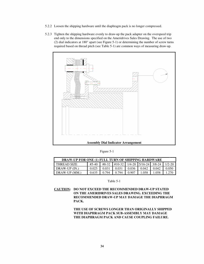
34
34
5.2.2 Loosen the shipping hardware until the diaphragm pack is no longer compressed.
5.2.3 Tighten the shipping hardware evenly to draw-up the pack adapter on the overspeed trip
end only to the dimensions specified on the Ameridrives Sales Drawing. The use of two
(2) dial indicators at 180° apart (see Figure 5-1) or determining the number of screw turns
required based on thread pitch (see Table 5-1) are common ways of measuring draw-up.
Assembly Dial Indicator Arrangement
Figure 5-1
DRAW-UP FOR ONE (1) FULL TURN OF SHIPPING HARDWARE
THREAD SIZE #5-40 #8-32 #10-32 1/4-28 5/16-24 3/8-24 1/2-20
DRAW-UP (IN.) 0.025 0.031 0.031 0.036 0.042 0.042 0.050
DRAW-UP (MM.) 0.635 0.794 0.794 0.907 1.058 1.058 1.270
Table 5-1
CAUTION: DO NOT EXCEED THE RECOMMENDED DRAW-UP STATED
ON THE AMERIDRIVES SALES DRAWING. EXCEEDING THE
RECOMMENDED DRAW-UP MAY DAMAGE THE DIAPHRAGM
PACK.
THE USE OF SCREWS LONGER THAN ORIGINALLY SHIPPED
WITH DIAPHRAGM PACK SUB-ASSEMBLY MAY DAMAGE
THE DIAPHRAGM PACK AND CAUSE COUPLING FAILURE.
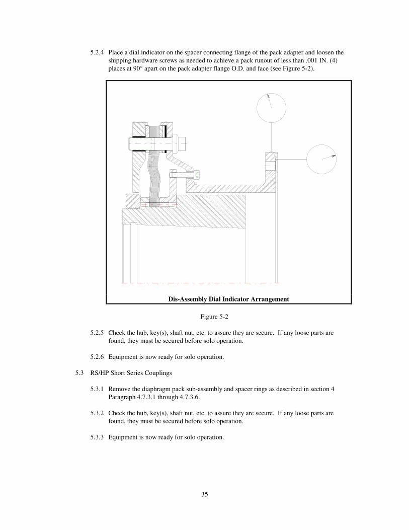
35
35
5.2.4 Place a dial indicator on the spacer connecting flange of the pack adapter and loosen the
shipping hardware screws as needed to achieve a pack runout of less than .001 IN. (4)
places at 90° apart on the pack adapter flange O.D. and face (see Figure 5-2).
Dis-Assembly Dial Indicator Arrangement
Figure 5-2
5.2.5 Check the hub, key(s), shaft nut, etc. to assure they are secure. If any loose parts are
found, they must be secured before solo operation.
5.2.6 Equipment is now ready for solo operation.
5.3 RS/HP Short Series Couplings
5.3.1 Remove the diaphragm pack sub-assembly and spacer rings as described in section 4
Paragraph 4.7.3.1 through 4.7.3.6.
5.3.2 Check the hub, key(s), shaft nut, etc. to assure they are secure. If any loose parts are
found, they must be secured before solo operation.
5.3.3 Equipment is now ready for solo operation.
36
36
6. MAINTENANCE
The Ameriflex coupling has been designed to be maintenance free. However, inspection of the
following items during normal equipment maintenance is recommended.
6.1 Inspect for loose fasteners, keys, hubs, flange adapters and pilot joints.
6.2 Inspect the tightening torque of the fasteners. Refer to the Ameridrives Sales Drawing for the
proper fastener tightening torque.
6.3 An alignment check is recommended to determine any shift in equipment foundations or if
bearing wear is excessive.
6.4 Slowly rotate the equipment and listen for any abnormal noises. Cracked diaphragms have an
audible clicking sound.
CAUTION: IF ANY OF THE CHECKS LISTED ABOVE IDENTIFY A PROBLEM,
THEN DO NOT OPERATE THE EQUIPMENT UNTIL THE CONDITION
HAS BEEN CORRECTED. 6.5 Fastener sets should be replaced after repeated use (5 times for bolts and nuts, 15 times for bolts
and heli-coils).
6.6 Component balanced and assembly check balanced couplings permit field replacement of
components without adversely affecting the final coupling unbalance. Assembly balanced
couplings do not. Refer to the Ameridrives Sales Drawing or contact Ameridrives Customer
Service for part interchangeability.
7. FIELD SERVICE TECHNICIAN
Should you desire assistance during installation of our couplings, Field Service Technicians are
available for on-site technical support. For further information contact Ameridrives Customer Service
at 814/480-5000.
8. ORDERING INFORMATION
8.1 When ordering replacement or spare parts for your Ameriflex coupling, please include the
following:
8.1.1 Coupling size and series.
8.1.2 Serial Number (etched on all major components).
8.1.3 Part Number and name of part (Refer to Ameridrives Sales Drawing).
8.1.4 Sales Drawing Number (etched on the spacer).
8.2 Mail all correspondence to:
Ameridrives International
Coupling Products
1802 Pittsburgh Avenue
Erie, PA 16502-1943
Phone: 814/480-5000
Fax: 814/453-5891

Ameridrives Couplings 1802 Pittsburgh Avenue • Erie, PA 16502814-480-5000 • 814-453-5891www.ameridrives.com
367SH 7/12 Printed in USA


![VEHICLE COMPONENT APPLICATIONS - [HC]](https://img.dokumen.tips/doc/110x75/631732b39076d1dcf80bb452/vehicle-component-applications-hc.jpg)


