Embed Size (px)
Citation preview

HPE FlexNetwork 5130 HI Switch Series Installation Guide Part number: 5998-8420d Document version: 6W102-20161101

© Copyright 2016 Hewlett Packard Enterprise Development LP
The information contained herein is subject to change without notice. The only warranties for Hewlett Packard Enterprise products and services are set forth in the express warranty statements accompanying such products and services. Nothing herein should be construed as constituting an additional warranty. Hewlett Packard Enterprise shall not be liable for technical or editorial errors or omissions contained herein.
Confidential computer software. Valid license from Hewlett Packard Enterprise required for possession, use, or copying. Consistent with FAR 12.211 and 12.212, Commercial Computer Software, Computer Software Documentation, and Technical Data for Commercial Items are licensed to the U.S. Government under vendor’s standard commercial license.
Links to third-party websites take you outside the Hewlett Packard Enterprise website. Hewlett Packard Enterprise has no control over and is not responsible for information outside the Hewlett Packard Enterprise website.
Acknowledgments
Intel®, Itanium®, Pentium®, Intel Inside®, and the Intel Inside logo are trademarks of Intel Corporation in the United States and other countries.
Microsoft® and Windows® are trademarks of the Microsoft group of companies.
Adobe® and Acrobat® are trademarks of Adobe Systems Incorporated.
Java and Oracle are registered trademarks of Oracle and/or its affiliates.
UNIX® is a registered trademark of The Open Group.

i
Contents
Preparing for installation ················································································· 1
Safety recommendations ··································································································································· 1 Examining the installation site ···························································································································· 2
Temperature/humidity ································································································································ 2 Cleanliness ················································································································································· 2 EMI ····························································································································································· 3 Laser safety ················································································································································ 3
Installation tools ················································································································································· 3 Installation accessories ······································································································································ 4
Installing the switch ························································································· 6
Installing the switch in a 19-inch rack ················································································································ 7 Installation methods ··································································································································· 7 Mounting bracket kits ································································································································· 8 Rack-mounting by using front mounting brackets ······················································································ 8 Rack-mounting by using front and rear mounting brackets (HPE 5130 24G PoE+ 4SFP+ 1-slot HI and HPE 5130 48G PoE+ 4SFP+ 1-slot HI) ············································································································ 12
Mounting the switch on a workbench ··············································································································· 15 Grounding the switch ······································································································································· 15
Grounding the switch with a grounding strip ···························································································· 15 Grounding the switch with a grounding conductor buried in the earth ground ········································· 17 Grounding the switch by using the AC power cord ·················································································· 18
Installing/removing a power supply ·················································································································· 18 Installing a PSR150(JD362A, JD362B, JD366A, or JD366B) power supply ············································ 19 Removing a PSR150(JD362A, JD362B, JD366A, or JD366B) power supply ·········································· 20 Installing a PSR720-56A/PSR1110-56A (JG544A/JG545A) power supply ············································· 20 Removing a PSR720-56A/PSR1110-56A (JG544A/JG545A) power supply ··········································· 22
Connecting the power cord ······························································································································ 22 Connecting a PSR150-D/PSR150-D1 (JD366A/JD366B) power supply ················································· 23 Connecting a PSR720-56A (JG544A)/PSR1110-56A (JG545A)/PSR150-A (JD362A)/PSR150-A1 (JD362B) power supply ···························································································································· 24
Installing/removing an interface card ··············································································································· 24 Installing an interface card ······················································································································· 25 Removing an interface card ····················································································································· 26
Verifying the installation ··································································································································· 26 Accessing the switch for the first time ··························································· 28
Setting up the configuration environment ········································································································ 28 Connecting the console cable ·························································································································· 28 Connecting the Mini USB console cable ·········································································································· 29 Setting terminal parameters ····························································································································· 31 Powering on the switch ···································································································································· 31
Setting up an IRF fabric ················································································ 33
IRF fabric setup flowchart ································································································································ 33 Planning IRF fabric setup ································································································································· 34
Planning IRF fabric size and the installation site ······················································································ 34 Identifying the master switch and planning IRF member IDs ··································································· 34 Planning IRF topology and connections ··································································································· 34 Identifying physical IRF ports on the member switches ··········································································· 35 Planning the cabling scheme ··················································································································· 36
Configuring basic IRF settings ························································································································· 38 Connecting the physical IRF ports ··················································································································· 38 Verifying the IRF fabric setup ··························································································································· 39
Maintenance and troubleshooting ································································· 40
Power supply failure ········································································································································· 40
ii
Symptom ·················································································································································· 40 Solution ···················································································································································· 40
Fan tray failure ················································································································································· 40 Removing a fan tray ································································································································· 41 Installing a fan tray ··································································································································· 41
Configuration terminal display problems ·········································································································· 42 No display ················································································································································ 42 Garbled display ········································································································································ 43
Appendix A Chassis views and technical specifications ······························· 44
Chassis views ·················································································································································· 44 HPE 5130 24G 4SFP+ 1-slot HI ·············································································································· 44 HPE 5130 24G PoE+ 4SFP+ 1-slot HI ····································································································· 45 HPE 5130 48G 4SFP+ 1-slot HI ·············································································································· 46 HPE 5130 48G PoE+ 4SFP+ 1-slot HI ····································································································· 47
Technical specifications ··································································································································· 48 Appendix B FRUs and compatibility matrixes ··············································· 51
FRUs and compatibility matrixes ····················································································································· 51 Hot swappable power supplies ························································································································ 51 Hot swappable interface cards ························································································································· 52
Appendix C Ports and LEDs ········································································· 54
Ports ································································································································································· 54 Console port ············································································································································· 54 Management Ethernet port ······················································································································ 54 USB port ··················································································································································· 54 10/100/1000Base-T autosensing Ethernet port ······················································································· 55 SFP+ port ················································································································································· 55
LEDs ································································································································································ 58 System status LED ··································································································································· 58 Power supply status LED ························································································································· 58 LED for the port LED mode (MODE) ········································································································ 59 10/100/1000Base-T autosensing Ethernet port LED ··············································································· 59 SFP+ port LED ········································································································································· 60 Management Ethernet port LEDs ············································································································· 60 Interface card status LED ························································································································· 60 Fan tray status LED on the fan tray ········································································································· 61 Port status LED on the interface card ······································································································ 61 Input status LED and output status LED on the power supply ································································· 61
Appendix D Cooling system ·········································································· 62
Document conventions and icons ································································· 63
Conventions ····················································································································································· 63 Network topology icons ···································································································································· 64
Support and other resources ········································································ 65
Accessing Hewlett Packard Enterprise Support ······························································································ 65 Accessing updates ··········································································································································· 65
Websites ·················································································································································· 66 Customer self repair ································································································································· 66 Remote support ········································································································································ 66 Documentation feedback ························································································································· 66
Index ············································································································· 68

1
Preparing for installation Table 1 HPE 5130 HI switches, power supplies, and interface cards
Product code HPE description Alias
HPE 5130 HI switches
JH323A HPE 5130 24G 4SFP+ 1-slot HI Switch HPE 5130 24G 4SFP+ 1-slot HI
JH324A HPE 5130 48G 4SFP+ 1-slot HI Switch HPE 5130 48G 4SFP+ 1-slot HI
JH325A HPE 5130 24G PoE+ 4SFP+ 1-slot HI Switch HPE 5130 24G PoE+ 4SFP+ 1-slot HI
JH326A HPE 5130 48G PoE+ 4SFP+ 1-slot HI Switch HPE 5130 48G PoE+ 4SFP+ 1-slot HI
Power supplies
JD362A HPE A5800/A5500 150W AC Power Supply PSR150-A
JD362B HPE X361 150W AC Power Supply PSR150-A1
JD366A HPE A5800/A5500 150W DC Power Supply PSR150-D
JD366B HPE X361 150W DC Power Supply PSR150-D1
JG544A HPE X362 720W AC PoE Power Supply PSR720-56A
JG545A HPE X362 1110W AC PoE Power Supply PSR1110-56A
Interface cards
JH156A HPE 5130/5510 10GBASE-T 2-port Module LSWM2XGT2PM
JH157A HPE 5130/5510 10GbE SFP+ 2-port Module LSWM2SP2PM
For regulatory identification purposes, the HPE 5130 HI switches are assigned regulatory model numbers (RMNs), which are listed in the following table. These regulatory numbers should not be confused with the marketing name HPE 5130 HI, or the product codes.
Product code RMN HPE description
JH323A BJNGA-AD0054 HPE 5130 24G 4SFP+ 1-slot HI Switch
JH324A BJNGA-AD0055 HPE 5130 48G 4SFP+ 1-slot HI Switch
JH325A BJNGA-AD0056 HPE 5130 24G PoE+ 4SFP+ 1-slot HI Switch
JH326A BJNGA-AD0057 HPE 5130 48G PoE+ 4SFP+ 1-slot HI Switch
Safety recommendations To avoid any equipment damage or bodily injury caused by improper use, read the following safety recommendations before installation. Note that the recommendations do not cover every possible hazardous condition. • Before cleaning the switch, remove all power cords from the switch. Do not clean the switch
with a wet cloth or liquid.
2
• Do not place the switch near water or in a damp environment. Prevent water or moisture from entering the switch chassis.
• Do not place the switch on an unstable case or desk. The switch might be severely damaged in case of a fall.
• Ensure good ventilation of the equipment room and keep the air inlet and outlet vents of the switch free of obstruction.
• Connect the yellow-green protection grounding cable before power-on. • Make sure the operating voltage is in the required range. • To avoid electrical shocks, do not open the chassis while the switch is operating or when the
switch is just powered off. • When replacing field replacable units (FRUs), including interface cards and power supplies,
wear an ESD wrist strap to avoid damaging the units.
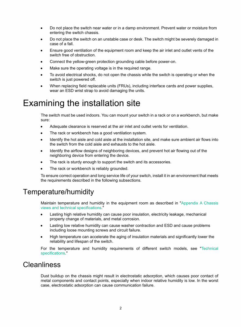
Examining the installation site The switch must be used indoors. You can mount your switch in a rack or on a workbench, but make sure: • Adequate clearance is reserved at the air inlet and outlet vents for ventilation. • The rack or workbench has a good ventilation system. • Identify the hot aisle and cold aisle at the installation site, and make sure ambient air flows into
the switch from the cold aisle and exhausts to the hot aisle. • Identify the airflow designs of neighboring devices, and prevent hot air flowing out of the
neighboring device from entering the device. • The rack is sturdy enough to support the switch and its accessories. • The rack or workbench is reliably grounded.
To ensure correct operation and long service life of your switch, install it in an environment that meets the requirements described in the following subsections.
Temperature/humidity Maintain temperature and humidity in the equipment room as described in "Appendix A Chassis views and technical specifications." • Lasting high relative humidity can cause poor insulation, electricity leakage, mechanical
property change of materials, and metal corrosion. • Lasting low relative humidity can cause washer contraction and ESD and cause problems
including loose mounting screws and circuit failure. • High temperature can accelerate the aging of insulation materials and significantly lower the
reliability and lifespan of the switch.
For the temperature and humidity requirements of different switch models, see "Technical specifications."
Cleanliness Dust buildup on the chassis might result in electrostatic adsorption, which causes poor contact of metal components and contact points, especially when indoor relative humidity is low. In the worst case, electrostatic adsorption can cause communication failure.

3
Table 2 Dust concentration limit in the equipment room
Substance Concentration limit (particles/m³)
Dust ≤ 3 x 10⁴ (no visible dust on the tabletop over three days)
NOTE: Dust diameter ≥ 5 μm
The equipment room must also meet limits on salts, acids, and sulfides to eliminate corrosion and premature aging of components, as shown in Table 3.
Table 3 Harmful gas limits in the equipment room
Gas Maximum concentration (mg/m3)
SO2 0.2
H2S 0.006
NH3 0.05
Cl2 0.01
EMI All electromagnetic interference (EMI) sources, from outside or inside of the switch and application system, adversely affect the switch in the following ways: • A conduction pattern of capacitance coupling. • Inductance coupling. • Electromagnetic wave radiation. • Common impedance (including the grounding system) coupling. To prevent EMI, use the following guidelines: • If AC power is used, use a single-phase three-wire power receptacle with protection earth (PE)
to filter interference from the power grid. • Keep the switch far away from radio transmitting stations, radar stations, and high-frequency
devices. • Use electromagnetic shielding, for example, shielded interface cables, when necessary. • To prevent signal ports from getting damaged by overvoltage or overcurrent caused by lightning
strikes, route interface cables only indoors.
Laser safety
WARNING! The switch is class 1 laser device. Do not stare into any fiber port when the switch has power. The laser light emitted from the optical fiber might hurt your eyes.
Installation tools • Flat-blade screwdriver • Phillips screwdriver

4
• ESD wrist strap
All these installation tools are user supplied.
Installation accessories All the installation accessories except M6 screws and floating nuts, the HPE X721 power to port fan tray, PSR150-A/PSR150-A1 (JD362A/JD362B), and the PSR150-D/PSR150-D1 (JD366A/JD366B) DC power supplies are provided with the switch.
Table 4 Installation accessories
Product code Description Quantity Applicable models
5066-0850
1 U four-hole mounting bracket kit (including one pair of mounting brackets and eight M4 countersunk screws)
1 kit All HPE 5130 HI switches
5190-0297
Rear mounting bracket kit (including one pair of mounting brackets and two load-bearing screws)
1 kit
• HPE 5130 24G PoE+ 4SFP+ 1-slot HI
• HPE 5130 48G PoE+ 4SFP+ 1-slot HI
N/A
M6 screw and floating nut (user supplied)
As required All HPE 5130 HI switches
5185-9292
Grounding cable (tin-plated at one end and with a ring terminal at the other end)
1 • HPE 5130 24G 4SFP+ 1-slot HI • HPE 5130 48G 4SFP+ 1-slot HI
5185-9408
Grounding cable (with ring terminals at both ends)
1
• HPE 5130 24G PoE+ 4SFP+ 1-slot HI
• HPE 5130 48G PoE+ 4SFP+ 1-slot HI
5185-8503
Power supply filler panel
1 • HPE 5130 24G 4SFP+ 1-slot HI • HPE 5130 48G 4SFP+ 1-slot HI
5190-1774 Power supply filler panel 1 • HPE 5130 24G PoE+ 4SFP+ 1-slot
HI • HPE 5130 48G PoE+ 4SFP+ 1-slot

5
Product code Description Quantity Applicable models
HI
5190-0296
Interface card filler panel
1 All HPE 5130 HI switches
5060-0174
HPE X722 port to power fan tray (already installed on the switch)
2 All HPE 5130 HI switches
5060-0175
HPE X721 power to port fan tray (order as required)
2 All HPE 5130 HI switches
5185-9443 5080-0120
DC power cord (supplied with the PSR150-D/PSR150-D1 (JD366A/JD366B)DC power supply)
The power cord color code scheme is for illustration only. The cable delivered for your country or region might use a different color scheme.
1 PSR150-D/PSR150-D1PSR150-D/PSR150-D1(JD366A/JD366B) DC power supply
5184-6719
Console cable
1 All HPE 5130 HI switches
5184-7298
Rubber feet
4 All HPE 5130 HI switches
6
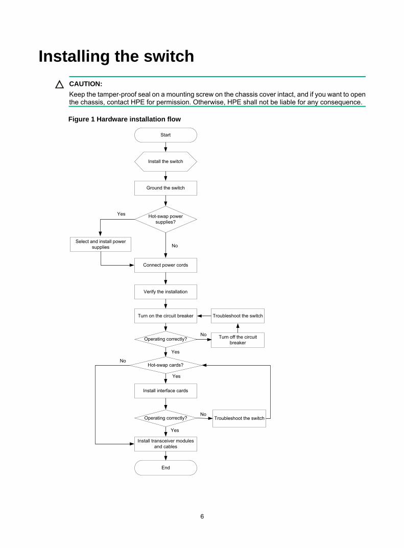
Installing the switch CAUTION:
Keep the tamper-proof seal on a mounting screw on the chassis cover intact, and if you want to open the chassis, contact HPE for permission. Otherwise, HPE shall not be liable for any consequence.
Figure 1 Hardware installation flow
Ground the switch
Install the switch
Start
Connect power cords
Verify the installation
Turn on the circuit breaker
Select and install power supplies
Hot-swap power supplies?
Yes
No
Operating correctly? Turn off the circuit breaker
Troubleshoot the switch
No
Yes
Hot-swap cards?
Install interface cards
Yes
Troubleshoot the switch
Yes
No
End
No
Operating correctly?
Install transceiver modules and cables
7
Installing the switch in a 19-inch rack Installation methods
Table 5 Installation methods for the HPE 5130 HI switches
Chassis Installation methods Installation requirements Installation
procedure
• HPE 5130 24G 4SFP+ 1-slot HI
• HPE 5130 48G 4SFP+ 1-slot HI
Using front mounting brackets
The mounting bracket kit can be installed on the port side, power supply side, or the mid-mounting position.
See "Rack-mounting by using front mounting brackets."
• HPE 5130 24G PoE+ 4SFP+ 1-slot HI
• HPE 5130 48G PoE+ 4SFP+ 1-slot HI
Using front mounting brackets
The front mounting bracket kit must be installed on the mid-mounting position.
See "Rack-mounting by using front mounting brackets."
Using front and rear mounting brackets
• The mounting bracket kit can be installed on the port side or power supply side.
• Install the rear mounting brackets according to the rack depth.
If the rack depth is in the range of 429 to 595 mm (16.89 to 23.43 in), orient the bracket with the wide flange inside the rack.
If the rack depth is in the range of 274 to 440 mm (10.79 to 17.32 in) and the distance from the rear rack posts to the inner surface of the cabinet door is longer than 153 mm (6.02 in), orient the bracket with the wide flange outside the rack.
See "Rack-mounting by using front and rear mounting brackets (HPE 5130 24G PoE+ 4SFP+ 1-slot HI and HPE 5130 48G PoE+ 4SFP+ 1-slot HI)."
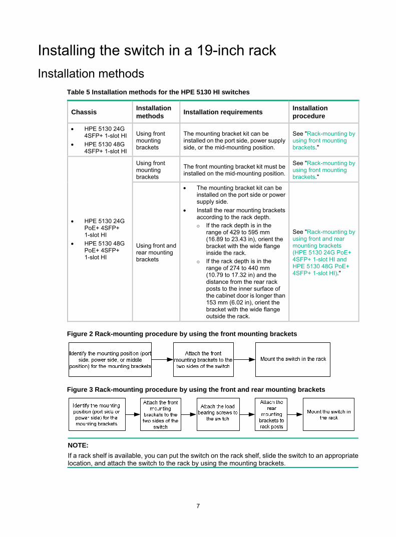
Figure 2 Rack-mounting procedure by using the front mounting brackets
Figure 3 Rack-mounting procedure by using the front and rear mounting brackets
NOTE: If a rack shelf is available, you can put the switch on the rack shelf, slide the switch to an appropriate location, and attach the switch to the rack by using the mounting brackets.

8
Mounting bracket kits Table 6 Mounting bracket kits for the HPE 5130 HI switches
Mounting bracket kits
HPE 5130 24G 4SFP+ 1-slot HI HPE 5130 48G 4SFP+ 1-slot HI
HPE 5130 24G PoE+ 4SFP+ 1-slot HI HPE 5130 48G PoE+ 4SFP+ 1-slot HI
Front mounting bracket kit Provided Provided
Rear mounting bracket kit Not required Provided
Grounding cable Provided Provided
Figure 4 Front mounting bracket kit
(1) Hole for attaching the bracket to the switch chassis
(2) Hole for attaching the bracket to a rack
Figure 5 Rear mounting bracket kit
(1) Hole for attaching the bracket to a rack (2) Load-bearing screw
Rack-mounting by using front mounting brackets This task requires two people.
9
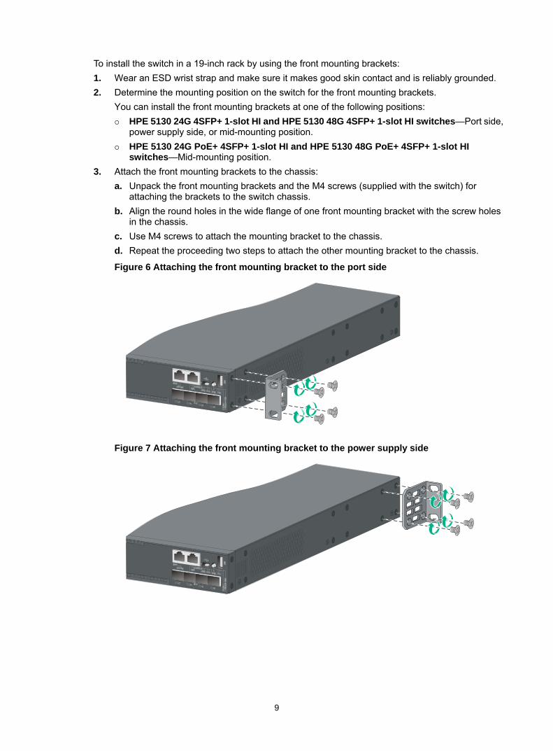
To install the switch in a 19-inch rack by using the front mounting brackets: 1. Wear an ESD wrist strap and make sure it makes good skin contact and is reliably grounded. 2. Determine the mounting position on the switch for the front mounting brackets.
You can install the front mounting brackets at one of the following positions: HPE 5130 24G 4SFP+ 1-slot HI and HPE 5130 48G 4SFP+ 1-slot HI switches—Port side,
power supply side, or mid-mounting position. HPE 5130 24G PoE+ 4SFP+ 1-slot HI and HPE 5130 48G PoE+ 4SFP+ 1-slot HI
switches—Mid-mounting position. 3. Attach the front mounting brackets to the chassis:
a. Unpack the front mounting brackets and the M4 screws (supplied with the switch) for attaching the brackets to the switch chassis.
b. Align the round holes in the wide flange of one front mounting bracket with the screw holes in the chassis.
c. Use M4 screws to attach the mounting bracket to the chassis. d. Repeat the proceeding two steps to attach the other mounting bracket to the chassis.
Figure 6 Attaching the front mounting bracket to the port side
Figure 7 Attaching the front mounting bracket to the power supply side

10
Figure 8 Attaching the front mounting bracket to the mid-mounting position
4. Mount the chassis in the rack: a. One person supports the chassis bottom with one hand, holds the front part of the chassis
with the other hand, and pushes the chassis into the rack gently b. The other person uses M6 screws and cage nuts (user supplied) to attach the switch to the
rack.
Figure 9 Mounting the switch in the rack (front mounting brackets at the port side)

11
Figure 10 Mounting the switch in the rack (front mounting brackets at the power supply side)
Figure 11 Mounting the switch in the rack (front mounting brackets at the mid-mounting position)

12
Rack-mounting by using front and rear mounting brackets (HPE 5130 24G PoE+ 4SFP+ 1-slot HI and HPE 5130 48G PoE+ 4SFP+ 1-slot HI)
This mounting method is applicable only to the HPE 5130 24G PoE+ 4SFP+ 1-slot HI and HPE 5130 48G PoE+ 4SFP+ 1-slot HI switches. You can install the front mounting brackets at the port-side or power-side mounting position as needed. The following takes port-side mounting as an example. The power-side mounting is similar.
This task requires two people.
To install the switch in a 19-inch rack by using the front and rear mounting brackets: 1. Wear an ESD wrist strap and make sure it makes good skin contact and is reliably grounded. 2. Attach the front mounting brackets and load-bearing screws to the chassis:
a. Unpack the front mounting brackets and the M4 screws for attaching the brackets to the switch chassis.
b. Align the round holes in the wide flange of one front mounting bracket with the screw holes in the port-side mounting position on one side of the chassis (see Figure 12).
c. Use M4 screws (supplied with the switch) to attach the mounting bracket to the chassis. d. Repeat the proceeding two steps to attach the other mounting bracket to the chassis. e. Unpack the load-bearing screws. f. Install the load-bearing screws in one of the load-bearing screw mounting positions on both
sides of the chassis (see Figure 12).
Figure 12 Attaching the front mounting brackets and load-bearing screws to the chassis
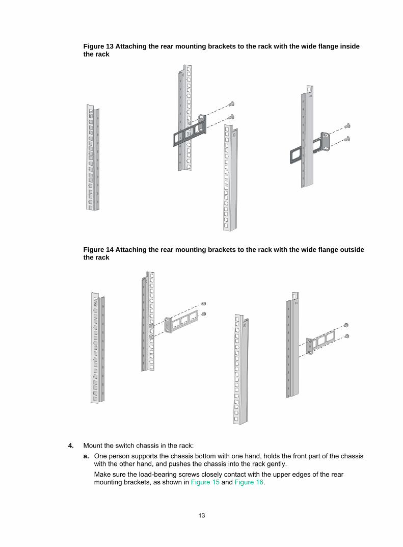
3. Attach the rear mounting brackets to the rack: a. Unpack the rear mounting brackets. b. Install cage nuts (user-supplied) in the mounting holes in the rear rack posts. c. Attach the rear mounting brackets to the rear posts with M6 screws (user supplied), as
shown in Figure 13 and Figure 14. Do not fully tighten the M6 screws before mounting the switch in the rack.
13
Figure 13 Attaching the rear mounting brackets to the rack with the wide flange inside the rack
Figure 14 Attaching the rear mounting brackets to the rack with the wide flange outside the rack
4. Mount the switch chassis in the rack: a. One person supports the chassis bottom with one hand, holds the front part of the chassis
with the other hand, and pushes the chassis into the rack gently. Make sure the load-bearing screws closely contact with the upper edges of the rear mounting brackets, as shown in Figure 15 and Figure 16.

14
b. The other person aligns the oval holes in the front brackets with the mounting holes in the front rack posts, and attaches the front mounting brackets with M6 screws (user supplied) to the front rack posts. Tighten the screws and make sure the front and rear mounting brackets have securely attached the switch to the rack.
Figure 15 Mounting the switch in the rack (with the wide flange of the mounting brackets inside the rack)
Figure 16 Mounting the switch in the rack (with the wide flange of the mounting brackets outside the rack)

15
Mounting the switch on a workbench IMPORTANT: • Ensure good ventilation and 10 cm (3.9 in) of clearance around the chassis for heat dissipation.• Avoid placing heavy objects on the switch.
To mount the switch on a workbench: 1. Verify that the workbench is sturdy and reliably grounded. 2. Place the switch with bottom up, and clean the round holes in the chassis bottom with dry cloth. 3. Attach the rubber feet to the four round holes in the chassis bottom. 4. Place the switch with upside up on the workbench.
Grounding the switch WARNING!
Correctly connecting the switch grounding cable is crucial to lightning protection and EMI protection.
The power input end of the switch has a noise filter, whose central ground is directly connected to the chassis to form the chassis ground (commonly known as PGND). You must securely connect this chassis ground to the earth so the faradism and leakage electricity can be safely released to the earth to minimize EMI susceptibility of the switch.
You can ground the switch in one of the following ways, depending on the grounding conditions available at the installation site: • Grounding the switch with a grounding strip • Grounding the switch with a grounding conductor buried in the earth ground • Grounding the switch by using the AC power cord
NOTE: The power and grounding terminals in this section are for illustration only.
Grounding the switch with a grounding strip
WARNING! Connect the grounding cable to the grounding system in the equipment room. Do not connect it to a fire main or lightning rod.
If a grounding strip is available at the installation site, connect the grounding cable from the chassis to the grounding strip.
Connecting the grounding cable to the chassis 1. Remove the grounding screw from the rear panel of the switch chassis. 2. Use the grounding screw to attach the ring terminal of the grounding cable to the grounding
screw hole. 3. Verify that the grounding cable has been securely connected to the rear grounding point.

16
Figure 17 Connecting the grounding cable to the chassis
(1) Grounding screw (2) Ring terminal (3) Grounding sign (4) Grounding hole (5) Grounding cable
Connecting the grounding cable to a grounding strip (for the HPE 5130 24G PoE+ 4SFP+ 1-slot HI and HPE 5130 48G PoE+ 4SFP+ 1-slot HI switches)
1. Remove the hex nut of a grounding post on the grounding strip. 2. Cut the grounding cable to a length required for connecting to the grounding strip. 3. Attach a ring terminal to the grounding cable:
a. Use a wire stripper to strip 5 mm (0.20 in) of insulation off the end of the grounding cable. b. Slide the heat-shrink tubing onto the cable and insert the bare metal part into the end of the
ring terminal. c. Use a crimper to secure the metal part of the cable to the ring terminal. d. Slide the heat-shrink tubing down the cable until the tube covers the joint. e. Use a heat gun to shrink the tubing around the cable.
Figure 18 Attaching a ring terminal to the grounding cable
4. Connect the ring terminal to the grounding post of the grounding strip, and fasten it with the removed hex nut.

17
Figure 19 Connecting the grounding cable to a grounding strip
(1) Grounding post (2) Grounding strip (3) Grounding cable (4) Hex nut
Connecting the grounding cable to a grounding strip (for the HPE 5130 24G 4SFP+ 1-slot HI and HPE 5130 48G 4SFP+ 1-slot HI switches)
1. Remove the hex nut of a grounding post on the grounding strip. 2. Cut the grounding cable to a length required for connecting to the grounding strip. 3. Use a wire stripper to peel 20 mm (0.79 in) of insulation sheath off the grounding cable end. 4. Use the needle-nose pliers to bend the bare wire. 5. Hook the grounding cable to the post on the grounding strip, and use the hex nut to secure the
cable to the post.
Figure 20 Connecting the grounding cable to a grounding strip
(1) Grounding post (2) Grounding strip (3) Grounding cable (4) Hex nut
Grounding the switch with a grounding conductor buried in the earth ground
If the installation site has no grounding strips, but earth ground is available, hammer a 0.5 m (1.64 ft) or longer angle iron or steel tube into the earth ground to serve as a grounding conductor.
The dimensions of the angle iron must be a minimum of 50 × 50 × 5 mm (1.97 × 1.97 × 0.20 in). The steel tube must be zinc-coated and its wall thickness must be a minimum of 3.5 mm (0.14 in).
Weld the yellow-green grounding cable to the angel iron or steel tube and treat the joint for corrosion protection.
1
4 3
2
1 2
34
18
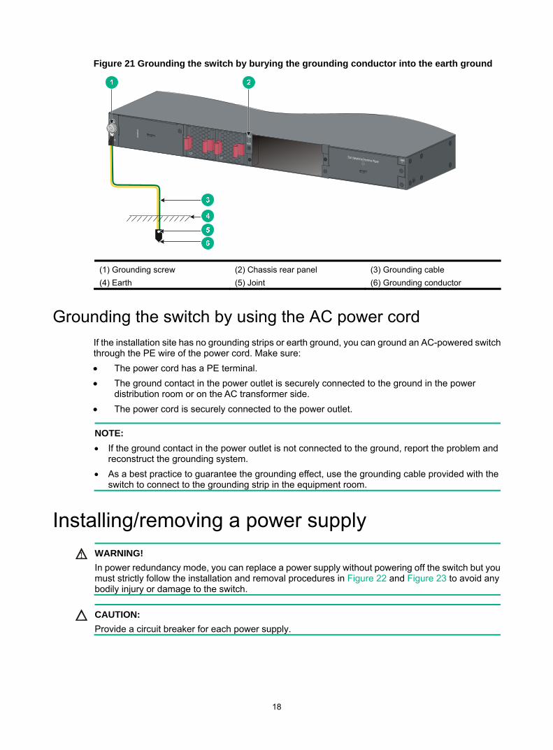
Figure 21 Grounding the switch by burying the grounding conductor into the earth ground
(1) Grounding screw (2) Chassis rear panel (3) Grounding cable (4) Earth (5) Joint (6) Grounding conductor
Grounding the switch by using the AC power cord If the installation site has no grounding strips or earth ground, you can ground an AC-powered switch through the PE wire of the power cord. Make sure: • The power cord has a PE terminal. • The ground contact in the power outlet is securely connected to the ground in the power
distribution room or on the AC transformer side. • The power cord is securely connected to the power outlet.
NOTE: • If the ground contact in the power outlet is not connected to the ground, report the problem and
reconstruct the grounding system. • As a best practice to guarantee the grounding effect, use the grounding cable provided with the
switch to connect to the grounding strip in the equipment room.
Installing/removing a power supply WARNING!
In power redundancy mode, you can replace a power supply without powering off the switch but you must strictly follow the installation and removal procedures in Figure 22 and Figure 23 to avoid any bodily injury or damage to the switch.
CAUTION: Provide a circuit breaker for each power supply.

19
Figure 22 Installation procedure
Figure 23 Removal procedure
Installing a PSR150(JD362A, JD362B, JD366A, or JD366B) power supply
CAUTION: To prevent damage to the power supply or the connectors on the backplane, insert the power supplygently. If you encounter a hard resistance when inserting the power supply, pull out the power supplyand insert it again.
For the PSR150-A/PSR150-A1 (JD362A/JD362B) and PSR150-D/PSR150-D1 (JD366A/JD366B) power supplies, the installation and removal procedures are the same. The following takes the PSR150-A1 (JD362B) power supply as an example.
To install a power supply: 1. Wear an ESD wrist strap and make sure it makes good skin contact and is reliably grounded. 2. Remove the filler panel from the target power supply slot as follows:
a. Remove the screws on the filler panel. b. Use a flathead screwdriver to remove the filler panel.
Figure 24 Removing the filler panel
3. Unpack the power supply and verify that the power supply model is correct. 4. Correctly orient the power supply with the power supply slot (use the letters on the power supply
faceplate for orientation), grasp the handle of the power supply with one hand and support its
Turn off the circuit breaker
Disconnect the power cord
Remove the power supply

20
bottom with the other, and slide the power supply slowly along the guide rails into the slot (see callout 1 in Figure 25).
5. Fasten the captive screws on the power supply with a Phillips screwdriver to secure the power supply in the chassis (see callout 2 in Figure 25). If the captive screw cannot be tightly fastened, verify the installation of the power supply.
6. Install the filler panel over the empty power supply slot to prevent dust and ensure good ventilation if you install only one power supply.
Figure 25 Installing a PSR150-A1 (JD362B) power supply
Removing a PSR150(JD362A, JD362B, JD366A, or JD366B) power supply
1. Wear an ESD wrist strap and make sure it makes good skin contact and is reliably grounded. 2. Disconnect the power cord. 3. Loosen the captive screws of the power supply with a Phillips screwdriver until they are
completely disengaged. 4. Grasp the handle of the power supply with one hand and pull it out a little, support the bottom
with the other hand, and pull the power supply slowly along the guide rails out of the slot. Put away the removed power supply in an antistatic bag or the power supply package bag for future use.
5. Install the filler panel to prevent dust and ensure good ventilation if no power supply is installed in the slot.
Installing a PSR720-56A/PSR1110-56A (JG544A/JG545A) power supply
CAUTION: To prevent damage to the power supply or the connectors on the backplane, insert the power supplygently. If you encounter a hard resistance when inserting the power supply, pull out the power supplyand insert it again.
For the PSR720-56A (JG544A) and PSR1110-56A (JG545A) power supplies, the installation and removal procedures are the same. The following takes the PSR720-56A (JG544A) power supply as an example.
To install a power supply: 1. Wear an ESD wrist strap and make sure it makes good skin contact and is reliably grounded.

21
2. Remove the filler panel from the target power supply slot, as shown in Figure 26.
Figure 26 Removing the filler panel
3. Unpack the power supply and verify that the power supply model is correct.
Put away the packaging box and packaging bag of the power supply for future use. 4. Correctly orient the power supply with the power supply slot (use the letters on the power supply
faceplate for orientation), grasp the handle of the power supply with one hand and support its bottom with the other, and slide the power supply slowly along the guide rails into the slot until you hear that the latch of the power supply clicks into the slot. When you insert the power supply into the slot, you can do that through slight inertia so that the terminals of the power supply can have good contact with the backplane. The PSR1110-56A (JG544A) power supply adds 64 mm (2.52 in) to the depth of the switch, as shown in Figure 27.
5. Install the filler panel over the empty power supply slot to prevent dust and ensure good ventilation if you install only one power supply.
Figure 27 PSR1110-56A (JG545A) in the chassis
22
Removing a PSR720-56A/PSR1110-56A (JG544A/JG545A) power supply
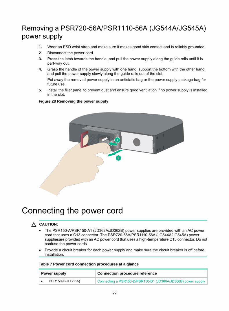
1. Wear an ESD wrist strap and make sure it makes good skin contact and is reliably grounded. 2. Disconnect the power cord. 3. Press the latch towards the handle, and pull the power supply along the guide rails until it is
part-way out. 4. Grasp the handle of the power supply with one hand, support the bottom with the other hand,
and pull the power supply slowly along the guide rails out of the slot. Put away the removed power supply in an antistatic bag or the power supply package bag for future use.
5. Install the filler panel to prevent dust and ensure good ventilation if no power supply is installed in the slot.
Figure 28 Removing the power supply
Connecting the power cord CAUTION: • The PSR150-A/PSR150-A1 (JD362A/JD362B) power supplies are provided with an AC power
cord that uses a C13 connector. The PSR720-56A/PSR1110-56A (JG544A/JG545A) power suppliesare provided with an AC power cord that uses a high-temperature C15 connector. Do not confuse the power cords.
• Provide a circuit breaker for each power supply and make sure the circuit breaker is off before installation.
Table 7 Power cord connection procedures at a glance
Power supply Connection procedure reference
• PSR150-D(JD366A) Connecting a PSR150-D/PSR150-D1 (JD366A/JD366B) power supply
2
1

23
Power supply Connection procedure reference • PSR150-D1(JD366B) (External RPS power supply: RPS800-A or RPS1600-A)
• PSR720-56A (JG544A) • PSR1110-56A (JG545A) • PSR150-A (JD362A) • PSR150-A1 (JD362B)
Connecting a PSR720-56A (JG544A)/PSR1110-56A (JG545A)/PSR150-A (JD362A)/PSR150-A1 (JD362B) power supply
Connecting a PSR150-D/PSR150-D1 (JD366A/JD366B) power supply
WARNING! • HPE DC power cords are required if the –48 VDC power source is used. RPS power cords are
required if the RPS power source is used. • The power cord color code scheme in Figure 29 is for illustration only. The cable delivered for
your country or region might use a different color scheme. When you connect a power cord, always identify the polarity symbol on its wires.
To connect a PSR150-D/PSR150-D1 (JD366A/JD366B) power supply: 1. Wear an ESD wrist strap and make sure it makes good skin contact and is reliably grounded. 2. Insert the DC connector into the DC power receptacle (see callout 1 in Figure 29).
The connector of the DC power cord and the DC power receptacle are foolproof. Make sure the connector is correctly oriented.
3. Use a flat-blade screwdriver to fasten the two screws on the DC plug to secure the plug to the DC receptacle (see callout 2 in Figure 29).
4. Connect the other ends of the wires to the –48 VDC power source wiring terminals, with the negative wire (– or L–) to the negative terminal (–) and the positive wire (+ or M/N) to the positive terminal (+).
Figure 29 Connecting a PSR150-D1 (JD366B) power supply
12

24
Connecting a PSR720-56A (JG544A)/PSR1110-56A (JG545A)/PSR150-A (JD362A)/PSR150-A1 (JD362B) power supply
The procedure is similar for connecting a PSR720-56A (JG544A), PSR1110-56A (JG545A), or PSR150-A/PSR150-A1 (JD362A/JD362B) power supply. The following uses the PSR720-56A (JG544A) power supply as an example.
To connect a PSR720-56A (JG544A) power supply: 1. Wear an ESD wrist strap and make sure it makes good skin contact and is reliably grounded. 2. Plug the female connector end of the AC power cord into the AC input socket of the power
supply (see callout 1 in Figure 30). 3. Use a cable tie to secure the power cord to the handle of the power supply (see callout 2 and
callout 3 in Figure 30). 4. Connect the other end of the AC power cord to an AC power outlet.
Figure 30 Connecting a PSR720-56A (JG544A) power supply
Installing/removing an interface card CAUTION: • Do not touch the surface-mounted components on an interface card directly with your hands. • Do not use excessive force during the installation or removal procedure. • Install a filler panel over an empty interface card slot.
The switch has an interface card slot and supports hot swapping of an interface card. For the interface cards available for the switches, see "Appendix B FRUs and compatibility matrixes."

25
This section uses the LSWM2SP2PM interface card as an example to describe the procedures for installing and removing an interface card.
Installing an interface card 1. Wear an ESD wrist strap and make sure it makes good skin contact and is reliably grounded. 2. Remove the filler panel from the target interface card slot as follows:
a. Remove the screw on the filler panel. b. Use a flathead screwdriver to remove the filler panel. Keep the removed filler panel for future use.
Figure 31 Removing the filler panel over an interface card slot
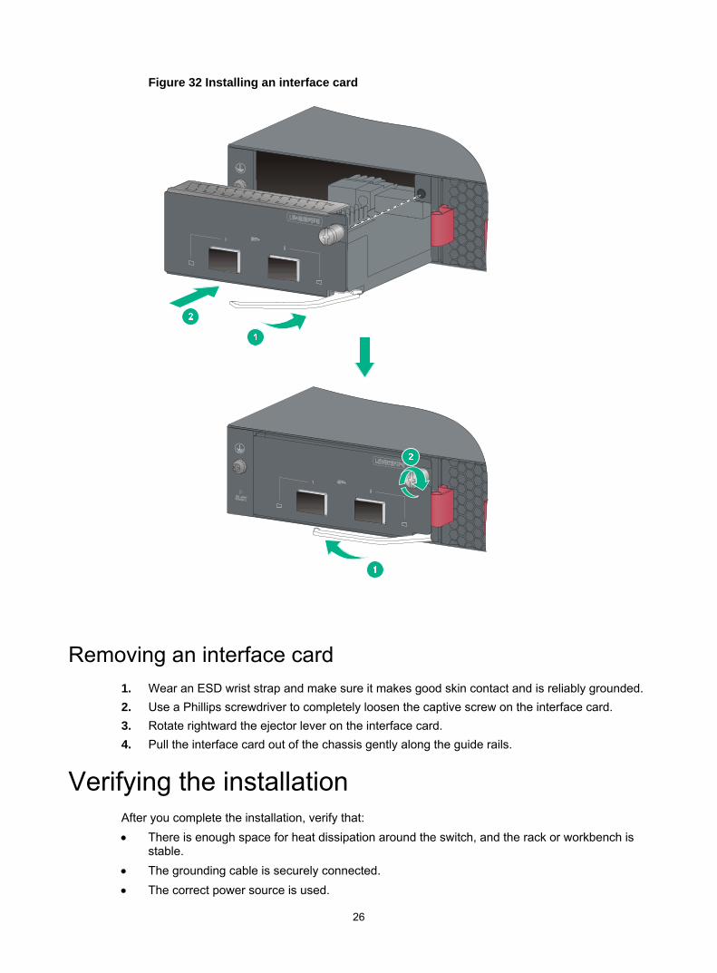
3. Unpack the interface card. 4. Perform the following steps to install the interface card:
a. Rotate rightward the ejector lever on the interface card. b. Gently push the interface card into the slot along the guide rails until the interface card has
good contact with the chassis. c. Rotate leftward the ejector lever. d. Use a Phillips screwdriver to tighten the captive screw on the front panel to secure the
interface card in the slot.
26
Figure 32 Installing an interface card
Removing an interface card 1. Wear an ESD wrist strap and make sure it makes good skin contact and is reliably grounded. 2. Use a Phillips screwdriver to completely loosen the captive screw on the interface card. 3. Rotate rightward the ejector lever on the interface card. 4. Pull the interface card out of the chassis gently along the guide rails.
Verifying the installation After you complete the installation, verify that: • There is enough space for heat dissipation around the switch, and the rack or workbench is
stable. • The grounding cable is securely connected. • The correct power source is used.

27
• The power cords are correctly connected. • All the interface cables are cabled indoors. If any cable is routed outdoors, verify that the socket
strip with lightning protection and lightning arresters for network ports have been correctly connected.
28
Accessing the switch for the first time
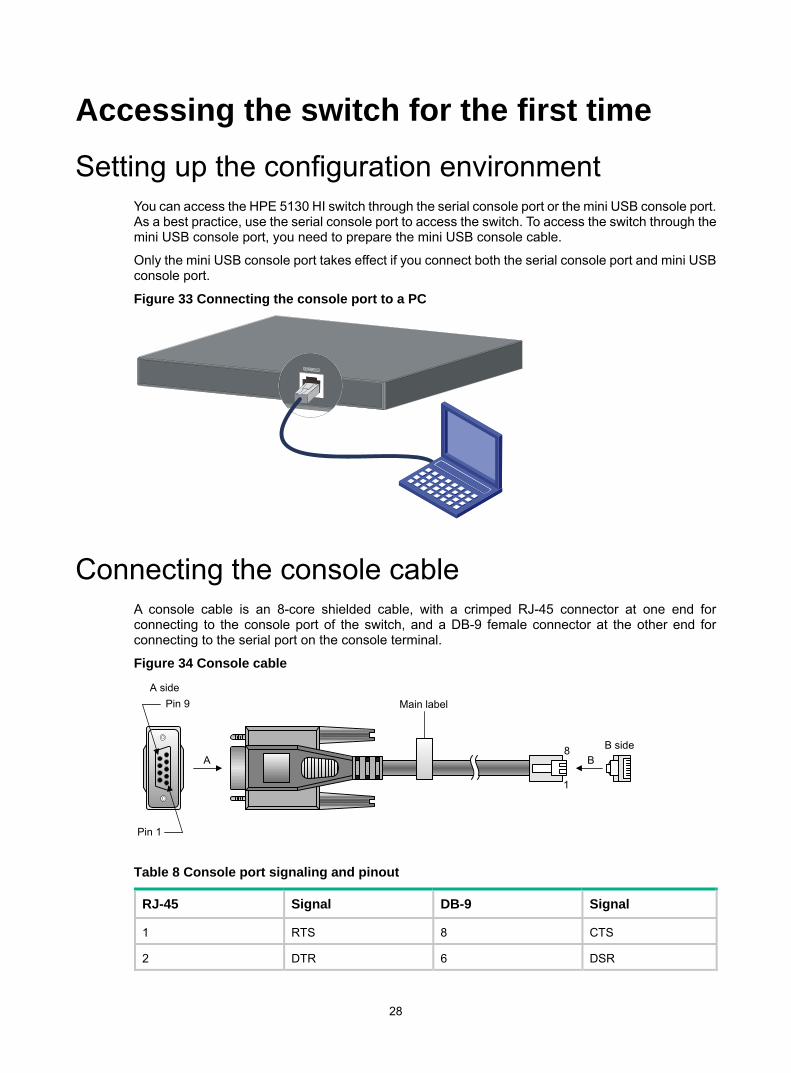
Setting up the configuration environment You can access the HPE 5130 HI switch through the serial console port or the mini USB console port. As a best practice, use the serial console port to access the switch. To access the switch through the mini USB console port, you need to prepare the mini USB console cable.
Only the mini USB console port takes effect if you connect both the serial console port and mini USB console port.
Figure 33 Connecting the console port to a PC
Connecting the console cable A console cable is an 8-core shielded cable, with a crimped RJ-45 connector at one end for connecting to the console port of the switch, and a DB-9 female connector at the other end for connecting to the serial port on the console terminal.
Figure 34 Console cable
Table 8 Console port signaling and pinout
RJ-45 Signal DB-9 Signal
1 RTS 8 CTS
2 DTR 6 DSR
Main label
1
8 B sideB
Pin 9
Pin 1
A side
A

29
RJ-45 Signal DB-9 Signal
3 TXD 2 RXD
4 SG 5 SG
5 SG 5 SG
6 RXD 3 TXD
7 DSR 4 DTR
8 CTS 7 RTS
To connect a configuration terminal (for example, a PC) to the switch: 1. Plug the DB-9 female connector of the console cable to the serial port of the PC. 2. Connect the RJ-45 connector to the console port of the switch.
NOTE: • Identify the mark on the console port and make sure you are connecting to the correct port. • The serial ports on PCs do not support hot swapping. To connect a PC to an operating switch, first
connect the PC end. To disconnect a PC from an operating switch, first disconnect the switch end.
Connecting the Mini USB console cable A Mini USB console cable has a USB mini-Type B connector at one end to connect to the Mini USB console port of the switch, and a standard USB Type A connector at the other end to connect to the USB port on the PC.
To connect to the PC through the Mini USB console cable: 1. Connect the standard USB Type A connector to the USB port of the PC. 2. Connect the Mini USB Type B connector to the Mini USB console port of the switch. 3. Click the following link, or copy it to the address bar on the browser to log in to download page
of the USB console driver, and download the driver. http://www.exar.com/connectivity/uart-and-bridging-solutions/usb-uarts/xr21v1410
4. Select a driver program according to the operating system you use: XR21V1410_XR21B1411_Windows_Ver1840_x86_Installer.EXE—32-bit operating
system. XR21V1410_XR21B1411_Windows_Ver1840_x64_Installer.EXE—64-bit operating
system. 5. Click Next on the installation wizard.
30
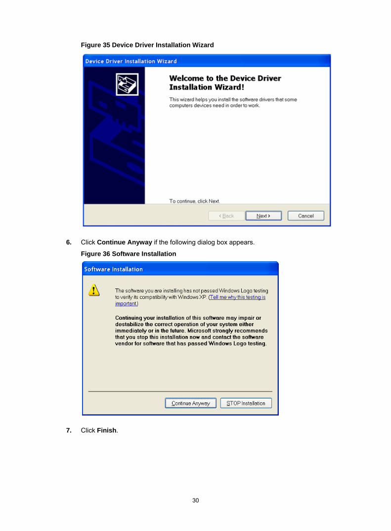
Figure 35 Device Driver Installation Wizard
6. Click Continue Anyway if the following dialog box appears.
Figure 36 Software Installation
7. Click Finish.

31
Figure 37 Completing the device driver installation wizard
Setting terminal parameters To configure and manage the switch through the console port, you must run a terminal emulator program, TeraTermPro or PuTTY, on your PC. You can use the emulator program to connect a network device, a Telnet site, or an SSH site. For more information about the terminal emulator programs, see the user guides for these programs.
The following are the required terminal settings: • Bits per second—9,600. • Data bits—8. • Parity—None. • Stop bits—1. • Flow control—None.
Powering on the switch Before powering on the switch, verify that the following conditions are met: • The power cord is correctly connected. • The input power voltage meets the requirement of the switch. • The console cable is correctly connected. • The PC has started, and its serial port settings are consistent with the console port settings on
the switch.
Power on the switch. During the startup process, you can access Boot ROM menus to perform tasks such as software upgrade and file management. The Boot ROM interface and menu options differ

32
with software versions. For more information about Boot ROM menu options, see the software-matching release notes for the device.
After the startup completes, you can access the CLI to configure the switch.
For more information about the configuration commands and CLI, see HPE 5130 HI Switch Series Configuration Guides and HPE 5130 HI Switch Series Command References.

33
Setting up an IRF fabric You can use HPE IRF technology to connect and virtualize HPE 5130 HI switches into a large virtual switch called an "IRF fabric" for flattened network topology, and high availability, scalability, and manageability.
IRF fabric setup flowchart Figure 38 IRF fabric setup flowchart
To set up an IRF fabric:
Step Description
1. Plan IRF fabric setup
Plan the installation site and IRF fabric setup parameters: • Planning IRF fabric size and the installation site • Identifying the master switch and planning IRF member IDs • Planning IRF topology and connections • Identifying physical IRF ports on the member switches • Planning the cabling scheme
2. Install IRF member switches
See "Installing the switch in a 19-inch rack" or "Mounting the switch on a workbench."

34
Step Description
3. Connect ground wires and power cords See "Grounding the switch" and "Connecting the power cord."
4. Power on the switches N/A
5. Configure basic IRF settings See HPE 5130 HI Switch Series IRF Configuration Guide.
6. Connect the physical IRF ports
Use SFP+ transceiver modules and fibers to connect SFP+ ports over a long distance. Use SFP+ DAC cables to connect SFP+ ports over a short distance.All switches except the master switch automatically reboot, and the IRF fabric is established.
Planning IRF fabric setup This section describes issues that an IRF fabric setup plan must cover.
Planning IRF fabric size and the installation site Choose switch models and identify the number of required IRF member switches, depending on the user density and upstream bandwidth requirements. The switching capacity of an IRF fabric equals the total switching capacities of all member switches.
Plan the installation site depending on your network solution, as follows: • Place all IRF member switches in one rack for centralized high-density access. • Distribute the IRF member switches in different racks to implement the ToR access solution for
a data center.
NOTE: For the maximum number of IRF member devices in an HPE 5130 HI IRF fabric, see the release notes.
Identifying the master switch and planning IRF member IDs Determine which switch you want to use as the master for managing all member switches in the IRF fabric.
An IRF fabric has only one master switch. You configure and manage all member switches in the IRF fabric at the CLI of the master switch. IRF member switches automatically elect a master.
You can affect the election result by assigning a high member priority to the intended master switch. For more information about master election, see HPE 5130 HI Switch Series IRF Configuration Guide.
Prepare an IRF member ID assignment scheme. An IRF fabric uses member IDs to uniquely identify and manage its members, and you must assign each IRF member switch a unique member ID.
Planning IRF topology and connections You can create an IRF fabric in daisy chain topology or more reliable ring topology. In ring topology, the failure of one IRF link does not cause the IRF fabric to split as in daisy chain topology. Instead, the IRF fabric changes to a daisy chain topology without interrupting network services.

35
You connect the IRF member switches through IRF ports, the logical interfaces for the connections between IRF member switches. Each IRF member switch has two IRF ports: IRF-port 1 and IRF-port 2. To use an IRF port, you must bind a minimum of one physical port to it.
When connecting two neighboring IRF member switches, you must connect the physical ports of IRF-port 1 on one switch to the physical ports of IRF-port 2 on the other switch.
As a best practice to avoid loop topology, first complete IRF configuration and then connect the IRF member switches.
The HPE 5130 HI switches can provide 10-GE IRF connections through SFP+ ports, and you can bind several SFP+ ports to an IRF port for increased bandwidth and availability.
Figure 39 and Figure 40 show the topologies of an IRF fabric made up of three HPE 5130 24G 4SFP+ 1-slot HI switches. The IRF port connections in the two figures are for illustration only, and more connection methods are available.
Figure 39 IRF fabric in daisy chain topology
Figure 40 IRF fabric in ring topology
Identifying physical IRF ports on the member switches Identify the physical IRF ports on the member switches according to your topology and connection scheme.
Table 9 shows the physical ports that can be used for IRF connection and the port use restrictions.
IRF-port1IRF-port2
IRF-port1IRF-port2
1
2
3
1 2 3
36
Table 9 Physical IRF port requirements
Candidate physical IRF ports Requirements
• Four fixed SFP+ ports on the front panel • Ports on the interface card on the rear panel
All physical ports to be bound to an IRF port must have the same data rate.
Planning the cabling scheme Use SFP+ DAC cables or SFP+ transceiver modules and fibers to connect the IRF member switches. If the IRF member switches are far away from one another, choose the SFP+ transceiver modules with optical fibers. If the IRF member switches are all in one equipment room, choose SFP+ DAC cables. For more information about SFP+ DAC cables and SFP+ transceiver modules, see "Appendix C Ports and LEDs."
The following subsections describe several HPE recommended IRF connection schemes, and all these schemes use a ring topology.
IMPORTANT: In these schemes, all physical IRF ports are located on the same side. If physical IRF ports are on different sides, you must measure the distance between them to select an appropriate cable.
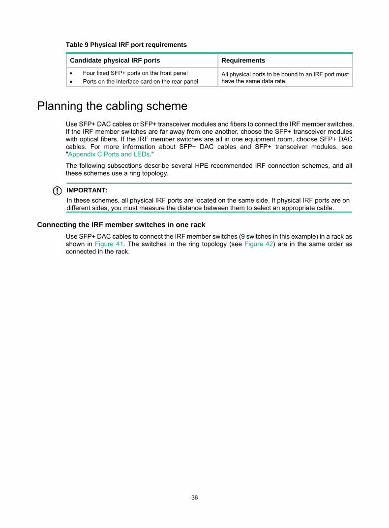
Connecting the IRF member switches in one rack Use SFP+ DAC cables to connect the IRF member switches (9 switches in this example) in a rack as shown in Figure 41. The switches in the ring topology (see Figure 42) are in the same order as connected in the rack.

37
Figure 41 Connecting the switches in one rack
38
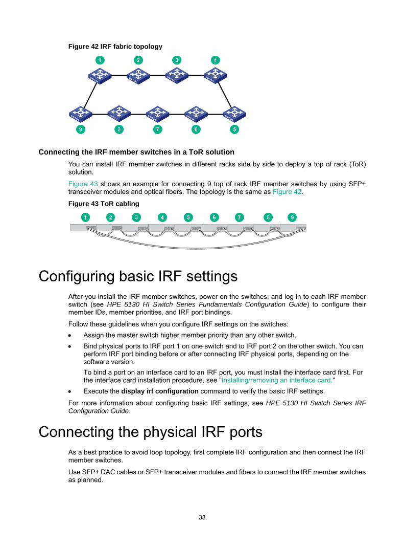
Figure 42 IRF fabric topology
Connecting the IRF member switches in a ToR solution You can install IRF member switches in different racks side by side to deploy a top of rack (ToR) solution.
Figure 43 shows an example for connecting 9 top of rack IRF member switches by using SFP+ transceiver modules and optical fibers. The topology is the same as Figure 42.
Figure 43 ToR cabling
Configuring basic IRF settings After you install the IRF member switches, power on the switches, and log in to each IRF member switch (see HPE 5130 HI Switch Series Fundamentals Configuration Guide) to configure their member IDs, member priorities, and IRF port bindings.
Follow these guidelines when you configure IRF settings on the switches: • Assign the master switch higher member priority than any other switch. • Bind physical ports to IRF port 1 on one switch and to IRF port 2 on the other switch. You can
perform IRF port binding before or after connecting IRF physical ports, depending on the software version. To bind a port on an interface card to an IRF port, you must install the interface card first. For the interface card installation procedure, see "Installing/removing an interface card."
• Execute the display irf configuration command to verify the basic IRF settings.
For more information about configuring basic IRF settings, see HPE 5130 HI Switch Series IRF Configuration Guide.
Connecting the physical IRF ports As a best practice to avoid loop topology, first complete IRF configuration and then connect the IRF member switches.
Use SFP+ DAC cables or SFP+ transceiver modules and fibers to connect the IRF member switches as planned.

39
Wear an ESD wrist strap when you connect SFP+ DAC cables or SFP+ transceiver modules and fibers. For how to connect them, see Pluggable SFP[SFP+][XFP][SFP28] Transceiver Modules Installation Guide.
Verifying the IRF fabric setup To verify the basic functionality of the IRF fabric after you finish configuring basic IRF settings and connecting IRF ports: 1. Log in to the IRF fabric through the console port of any member switch. 2. Create a Layer 3 interface, assign it an IP address, and make sure the IRF fabric and the
remote network management station can reach each other. 3. Use Telnet, web, or SNMP to access the IRF fabric from the network management station. (See
HPE 5130 HI Switch Series Fundamentals Configuration Guide.) 4. Verify that you can manage all member switches as if they were one node. 5. Display the running status of the IRF fabric by using the commands in Table 10.
Table 10 Displaying and maintaining IRF configuration and running status
Task Command
Display information about the IRF fabric. display irf
Display all members’ IRF configurations that take effect at a reboot. display irf configuration
Display IRF fabric topology information. display irf topology
NOTE: To avoid IP address collision and network problems, configure a minimum of one multi-active detection (MAD) mechanism to detect the presence of multiple identical IRF fabrics and handle collisions. For more information about MAD detection, see HPE 5130 HI Switch Series IRF Configuration Guide.

40
Maintenance and troubleshooting
Power supply failure Symptom
The power supply status LEDs are not steady green.
For the HPE 5130 24G 4SFP+ 1-slot HI and HPE 5130 48G 4SFP+ 1-slot HI switches, examine the PWR1 or PWR2 LED of the switch to identify power supply failure.
For the HPE 5130 24G PoE+ 4SFP+ 1-slot HI and HPE 5130 48G PoE+ 4SFP+ 1-slot HI switches, examine the PWR1 or PWR2 LED of the switch and the LEDs on the power supply to identify power supply failure. • For more information about the PWR1 and PWR2 LEDs on the front panel of the switch,
see Table 20. • For more information about the LEDs on a power supply, see HPE PSR720-56A Power Supply
User Guide and HPE PSR1110-56A Power Supply User Guide.
Solution To resolve the problem: 1. Verify that the switch power cord is correctly connected. 2. Verify that the power source meets the requirement. 3. Verify that the operating temperature of the switch is in an acceptable range and the power
supply has good ventilation. 4. If the problem persists, contact HPE Support. 5. To replace a hot swappable power supply, see "Installing/removing a power supply."
Fan tray failure CAUTION: • Do not power on the switch when the switch does not have a fan tray or has only one fan tray
installed. • If both fan trays fail, replace them within 2 minutes. • If one fan tray fails, perform either of the following tasks:
If the ambient temperature is not higher than 27°C (80.6°F), replace the fan tray within 24 hours and make sure the failed fan tray remains in position before the replacement.
If the ambient temperature is higher than 27°C (80.6°F), replace the fan tray immediately.
The switch supports hot swapping of fan trays. When a fan tray fails, see "Removing a fan tray" and "Installing a fan tray" to replace the fan tray. If the problem persists, contact HPE Support.

41
Removing a fan tray
WARNING! • Do not touch any bare conductors or terminals on the fan tray. • Do not place the fan tray in a moist place. Prevent liquid from entering the fan tray. • Do not disassemble faulty fan trays yourself. When the internal wiring or components of a fan tray
are faulty, ask maintenance engineers for maintenance. • Take out the fan tray after the fans completely stop rotating. Do not touch the fans even if the fans
stop rotating to avoid affecting fan balance, which might cause loud fan operating noise.
To remove a fan tray: 1. Wear an ESD wrist strap and make sure it makes good skin contact and is reliably grounded. 2. Grasp the two handles of the fan tray, as shown by callout 1 in Figure 44, and pull out the fan
tray slowly along the guide rails. 3. Put the removed fan tray in an antistatic bag.
Figure 44 Removing a fan tray
Installing a fan tray
CAUTION: • To prevent damage to the fan tray or the connectors on the backplane, insert the fan tray gently.
If you encounter a hard resistance when inserting the fan tray, pull out the fan tray and insert it again.
• Install two fan trays of the same model on the switch. • Make sure all slots have modules or filler panels installed when the switch is operating.
To install a fan tray: 1. Wear an ESD wrist strap and make sure it makes good skin contact and is reliably grounded. 2. Unpack the fan tray and verify that the fan tray model is correct.
1
2
1

42
3. Grasp the two handles of the fan tray with the side marked TOP facing up, and slide the fan tray along the guide rails into the slot until the fan tray seats in the slot and has a firm contact with the backplane.
Figure 45 Installing a fan tray
IMPORTANT: • By default, the switch uses the same air flow direction as the HPE X722 port to power fan tray.• After you install the HPE X721 power to port fan tray, use the fan prefer-direction command to
set the switch to use the same air flow direction as the fan tray. If the switch uses a different air flow direction, the system outputs traps and logs to notify you to replace the fan tray.
Configuration terminal display problems If the configuration environment setup is correct, the configuration terminal displays booting information when the switch is powered on. If the setup is incorrect, the configuration terminal displays nothing or garbled text.
No display Symptom
The PC displays nothing when the switch is powered on.
Solution To resolve the problem: 1. Verify that the power supply is supplying power to the switch. 2. Verify that the console cable is correctly connected. 3. Verify that the console cable does not have any problems and the PC settings are correct. 4. If the problem persists, contact HPE Support.

43
Garbled display Symptom
The display on the PC is garbled.
Solution To resolve the problem: 1. Verify that the following settings are configured for the terminal:
Baud rate—9,600. Data bits—8. Parity—None. Stop bits—1. Flow control—None.
2. If the problem persists, contact HPE Support.

44
Appendix A Chassis views and technical specifications
Chassis views HPE 5130 24G 4SFP+ 1-slot HI
Figure 46 HPE 5130 24G 4SFP+ 1-slot HI front panel
(1) 10/100/1000Base-T autosensing Ethernet port (2) 10/100/1000Base-T autosensing Ethernet port LED(3) Management Ethernet port (4) Console port (CONSOLE) (5) Mini USB console port (6) Port LED mode switching button (7) USB port (8) System status LED (SYS) (9) SFP+ port (10) LED for the port LED mode (MODE) (11) Interface card status LED (SLOT) (12) Power supply 2 status LED (PWR2) (13) Power supply 1 status LED (PWR1) (14) SFP+ port LED (15) Management Ethernet port LED
Figure 47 HPE 5130 24G 4SFP+ 1-slot HI rear panel
(1) Grounding screw (2) Interface card (optional) (3) Fan tray 1 (4) Fan tray 2 (5) Power supply 1 (6) Power supply 2 (optional)
The HPE 5130 24G 4SFP+ 1-slot HI switch comes with power supply slot 1 empty and power supply slot 2 installed with a filler panel. You can install one or two power supplies for the switch as required. In this figure, two PSR150-A1 (JD362B) AC power supplies are installed in the power supply slots. For more information about installing and removing a power supply, see "Installing/removing a power supply."
The HPE 5130 24G 4SFP+ 1-slot HI switch comes with a filler panel in the interface card slot. You can select an interface card for the switch as required. In this figure, an LSWM2SP2PM interface
1 2 3 4 5 6

45
card is installed in the interface card slot. For more information about installing and removing an interface card, see "Installing/removing an interface card."
HPE 5130 24G PoE+ 4SFP+ 1-slot HI Figure 48 HPE 5130 24G PoE+ 4SFP+ 1-slot HI front panel
(1) 10/100/1000Base-T autosensing Ethernet port (2) 10/100/1000Base-T autosensing Ethernet port LED
(3) Management Ethernet port (4) Console port (CONSOLE) (5) Mini USB console port (6) Port LED mode switching button (7) USB port (8) System status LED (SYS) (9) SFP+ port (10) LED for the port LED mode (MODE) (11) Interface card status LED (SLOT) (12) Power supply 2 status LED (PWR2) (13) Power supply 1 status LED (PWR1) (14) SFP+ port LED (15) Management Ethernet port LED
Figure 49 HPE 5130 24G PoE+ 4SFP+ 1-slot HI rear panel
(1) Grounding screw (2) Interface card (optional) (3) Fan tray 1 (4) Fan tray 2 (5) Power supply 1 (6) Power supply 2 (optional)
The HPE 5130 24G PoE+ 4SFP+ 1-slot HI switch comes with power supply slot 1 empty and power supply slot 2 installed with a filler panel. You can install one or two power supplies for the switch as required. In this figure, two PSR720-56A (JG544A) AC power supplies are installed in the power supply slots. For more information about installing and removing a power supply, see "Installing/removing a power supply."
The HPE 5130 24G PoE+ 4SFP+ 1-slot HI switch comes with a filler panel in the interface card slot. You can select an interface card for the switch as required. In this figure, an LSWM2SP2PM interface card is installed in the interface card slot. For more information about installing and removing an interface card, see "Installing/removing an interface card."
1 2 3 4 5 6
46
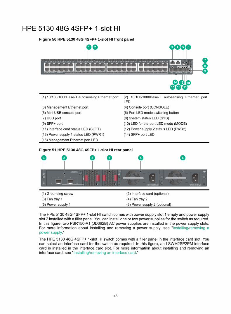
HPE 5130 48G 4SFP+ 1-slot HI Figure 50 HPE 5130 48G 4SFP+ 1-slot HI front panel
(1) 10/100/1000Base-T autosensing Ethernet port (2) 10/100/1000Base-T autosensing Ethernet port LED
(3) Management Ethernet port (4) Console port (CONSOLE) (5) Mini USB console port (6) Port LED mode switching button (7) USB port (8) System status LED (SYS) (9) SFP+ port (10) LED for the port LED mode (MODE) (11) Interface card status LED (SLOT) (12) Power supply 2 status LED (PWR2) (13) Power supply 1 status LED (PWR1) (14) SFP+ port LED (15) Management Ethernet port LED
Figure 51 HPE 5130 48G 4SFP+ 1-slot HI rear panel
(1) Grounding screw (2) Interface card (optional) (3) Fan tray 1 (4) Fan tray 2 (5) Power supply 1 (6) Power supply 2 (optional)
The HPE 5130 48G 4SFP+ 1-slot HI switch comes with power supply slot 1 empty and power supply slot 2 installed with a filler panel. You can install one or two power supplies for the switch as required. In this figure, two PSR150-A1 (JD362B) AC power supplies are installed in the power supply slots. For more information about installing and removing a power supply, see "Installing/removing a power supply."
The HPE 5130 48G 4SFP+ 1-slot HI switch comes with a filler panel in the interface card slot. You can select an interface card for the switch as required. In this figure, an LSWM2SP2PM interface card is installed in the interface card slot. For more information about installing and removing an interface card, see "Installing/removing an interface card."
1 2 3 4 5 6

47
HPE 5130 48G PoE+ 4SFP+ 1-slot HI Figure 52 HPE 5130 48G PoE+ 4SFP+ 1-slot HI front panel
(1) 10/100/1000Base-T autosensing Ethernet port (2) 10/100/1000Base-T autosensing Ethernet port LED
(3) Management Ethernet port (4) Console port (CONSOLE) (5) Mini USB console port (6) Port LED mode switching button (7) USB port (8) System status LED (SYS) (9) SFP+ port (10) LED for the port LED mode (MODE) (11) Interface card status LED (SLOT) (12) Power supply 2 status LED (PWR2) (13) Power supply 1 status LED (PWR1) (14) SFP+ port LED (15) Management Ethernet port LED
Figure 53 HPE 5130 48G PoE+ 4SFP+ 1-slot HI rear panel
(1) Grounding screw (2) Interface card (optional) (3) Fan tray 1 (4) Fan tray 2 (5) Power supply 1 (6) Power supply 2 (optional)
The HPE 5130 48G PoE+ 4SFP+ 1-slot HI switch comes with power supply slot 1 empty and power supply slot 2 installed with a filler panel. You can install one or two power supplies for the switch as required. In this figure, two PSR720-56A (JG544A) AC power supplies are installed in the power supply slots. For more information about installing and removing a power supply, see "Installing/removing a power supply."
The HPE 5130 48G PoE+ 4SFP+ 1-slot HI switch comes with a filler panel in the interface card slot. You can select an interface card for the switch as required. In this figure, an LSWM2SP2PM interface card is installed in the interface card slot. For more information about installing and removing an interface card, see "Installing/removing an interface card."
1 2 3 4 5 6

48
Technical specifications Table 11 Technical specifications for non-PoE switch models
Item HPE 5130 24G 4SFP+ 1-slot HI HPE 5130 48G 4SFP+ 1-slot HI
Dimensions (H × W × D)
43.6 × 440 × 360 mm (1.72 × 17.32 × 14.17 in)
43.6 × 440 × 360 mm (1.72 × 17.32 × 14.17 in)
Weight ≤ 7.5 kg (16.53 lb) ≤ 7.5 kg (16.53 lb)
Console ports • 1 × Mini USB console port • 1 × serial console port Only the Mini USB console port takes effect when you connect both ports.
USB ports 1 1
Management Ethernet ports 1 1
SFP+ ports 4 4
10/100/1000Base-T autosensing Ethernet ports
24 48
Expansion interface card slots 1, on the rear panel 1, on the rear panel
Power supply slots 2, on the rear panel 2, on the rear panel
Fan tray 2, on the rear panel 2, on the rear panel
Input voltage
• AC-input Rated voltage range: 100 VAC to 240 VAC @ 50 Hz or 60 Hz Max voltage range: 90 VAC to 264 VAC @ 47 Hz to 63 Hz
• DC-input Rated voltage range: –48 VDC to –60 VDC Max voltage range: –36 VDC to –72 VDC
NOTE: You can use the site –48 VDC power source or an RPS800-A or RPS1600-A RPS as the DC power source.
Minimum power consumption
• Single AC input: 37 W • Dual AC inputs: 42 W • Single DC input: 43 W • Dual DC inputs: 49 W
• Single AC input: 45 W • Dual AC inputs: 48 W • Single DC input: 50 W • Dual DC inputs: 54 W
Maximum power consumption
• Single AC input: 72 W • Dual AC inputs: 75 W • Single DC input: 77 W • Dual DC inputs: 80 W
• Single AC input: 83 W • Dual AC inputs: 84 W • Single DC input: 88 W • Dual DC inputs: 93 W
Chassis leakage current compliance UL60950-1, EN60950-1, IEC60950-1, GB4943
Melting current of power supply fuse
• AC-input: 5 A, 250V • DC-input: 8 A, 250V
• AC-input: 5 A, 250V • DC-input: 8 A, 250V
Operating temperature 0°C to 45°C (32°F to 113°F)
Relative humidity 5% to 95%, noncondensing

49
Item HPE 5130 24G 4SFP+ 1-slot HI HPE 5130 48G 4SFP+ 1-slot HI
Fire resistance compliance UL60950-1, EN60950-1, IEC60950-1, GB4943
Table 12 Technical specifications for PoE switch models
Item HPE 5130 24G PoE+ 4SFP+ 1-slot HI
HPE 5130 48G PoE+ 4SFP+ 1-slot HI
Dimensions (H × W × D)
43.6 × 440 × 460 mm (1.72 × 17.32 × 18.11 in)
43.6 × 440 × 460 mm (1.72 × 17.32 × 18.11 in)
Weight ≤ 10 kg (22.05 lb) ≤ 10 kg (22.05 lb)
Console ports • 1 × Mini USB console port • 1 × serial console port Only the Mini USB console port is available when you connect both ports.
USB ports 1 1
Management Ethernet ports 1 1
SFP+ ports 4 4
10/100/1000Base-T autosensing Ethernet ports
24 48
Expansion interface card slots 1, on the rear panel 1, on the rear panel
Power supply slots 2, on the rear panel 2, on the rear panel
Fan tray 2, on the rear panel 2, on the rear panel
Input voltage
• PSR720-56A (JG544A) AC-input Rated voltage range: 100 VAC to 240 VAC @ 50 Hz or 60 Hz Max voltage range: 90 VAC to 264 VAC @ 47 Hz to 63 Hz
• PSR1110-56A AC-input Rated voltage range: 115 VAC to 240 VAC @ 50 Hz or 60 Hz Max voltage range: 102.5 VAC to 264 VAC @ 47 Hz to 63 Hz
PoE power capacity Depends on the power supply configurations. For more information, see the following table.
Minimum power consumption 44 W 67 W
Maximum power consumption (including PoE power consumption)
991 W 1950 W
Chassis leakage current compliance UL60950-1, EN60950-1, IEC60950-1, GB4943
Melting current of power supply fuse 15 A, 250V
Operating temperature 0°C to 45°C (32°F to 113°F)

50
Item HPE 5130 24G PoE+ 4SFP+ 1-slot HI
HPE 5130 48G PoE+ 4SFP+ 1-slot HI
Relative humidity 5% to 95%, noncondensing
Fire resistance compliance UL60950-1, EN60950-1, IEC60950-1, GB4943
The following table describes PoE power capacity for the HPE 5130 24G PoE+ 4SFP+ 1-slot HI and HPE 5130 48G PoE+ 4SFP+ 1-slot HI switches:
Power supply configuration
HPE 5130 24G PoE+ 4SFP+ 1-slot HI HPE 5130 48G PoE+ 4SFP+ 1-slot HI
Total PoE power capacity
Max PoE power capacity per port
Total PoE power capacity
Max PoE power capacity per port
Two PSR1110-56As (JG545A)
810 W 30 W 1680 W 30 W
One PSR1110-56A (JG545A) and one PSR720-56A (JG544A)
810 W 30 W 1560 W 30 W
Two PSR720-56As (JG544A) 810 W 30 W 1200 W 30 W
One PSR1110-56A (JG545A) 810 W 30 W 810 W 30 W
One PSR720-56A (JG544A) 450 W 30 W 450 W 30 W

51
Appendix B FRUs and compatibility matrixes
FRUs and compatibility matrixes
FRUs HPE 5130 24G 4SFP+ 1-slot HI HPE 5130 48G 4SFP+ 1-slot HI
HPE 5130 24G PoE+ 4SFP+ 1-slot HI HPE 5130 48G PoE+ 4SFP+ 1-slot HI
Hot swappable power supplies
PSR150-A/PSR150-A1 (JD362A/JD362B) Supported N/A
PSR150-D/PSR150-D1(JD366A/JD366B) Supported N/A
PSR720-56A (JG544A) N/A Supported
PSR1110-56A (JG545A) N/A Supported
Interface cards
LSWM2SP2PM Supported Supported
LSWM2XGT2PM Supported Supported
The PSR720-56A (JG544A), PSR1110-56A (JG545A), PSR150-A/PSR150-A1 (JD362A/JD362B), and PSR150-D/PSR150-D1 (JD366A/JD366B) power supplies support asset management. You can use the display device manuinfo command to view the name, sequence number, and vendor of the power supplies you have installed on the device.
You can install one power supply, or two power supplies for redundancy on the HPE 5130 24G 4SFP+ 1-slot HI and HPE 5130 48G 4SFP+ 1-slot HI switches. These switches support mix of an AC power supply and a DC power supply.
You can install one power supply, or two power supplies for redundancy on the HPE 5130 24G PoE+ 4SFP+ 1-slot HI and HPE 5130 48G PoE+ 4SFP+ 1-slot HI switches. The PoE capabilities of these switches vary by power supply configuration. For more information, see Table 12.
Hot swappable power supplies The switch supports hot swapping of power supplies. The following table describes power supplies available for the switch.
Power supply Specifications Reference
PSR150-A/PSR150-A1 (JD362A/JD362B)
• Rated input voltage range: 100 VAC to 240 VAC @ 50 Hz or 60 Hz
• Max input voltage range: 90 VAC to 264 VAC @ 47 Hz to 63 Hz
• Max output power: 150 W
HPE PSR150-A & PSR150-D Power Supplies User Guide

52
Power supply Specifications Reference
PSR150-D/PSR150-D1 (JD366A/JD366B)
• Rated input voltage range: –48 VDC to –60 VDC
• Max input voltage range: –36 VDC to –72 VDC
• Max output power: 150 W
HPE PSR150-A & PSR150-D Power Supplies User Guide
PSR720-56A (JG544A)
• Rated input voltage range: 100 VAC to 240 VAC @ 50 Hz or 60 Hz
• Max input voltage range: 90 VAC to 264 VAC @ 47 Hz to 63 Hz
• Max output power: 720 W
HPE PSR720-56A Power Supply User Guide
PSR1110-56A (JG545A)
• Rated input voltage range: 115 VAC to 240 VAC @ 50 Hz or 60 Hz
• Max input voltage range: 102.5 VAC to 264 VAC @ 47 Hz to 63 Hz
• Max output power: 1110 W
HPE PSR1110-56A Power Supply User Guide
NOTE: The PSR1110-56A (JG545A) power supply adds 64 mm (2.52 in) to the depth of the switch, including the depth of the power supply handle.
Hot swappable interface cards The switch provides an interface card slot at the rear. The following table describes the interface cards available for the switch.
Card model Port type and quantity Available transceiver modules and cables
LSWM2SP2PM 2 × 1/10 Gbps SFP+ fiber ports See Table 16, Table 17, and Table 18.
LSWM2XGT2PM 2 × 1/10GBase-T Ethernet ports N/A
NOTE: After you install the LSWM2SP2PM and LSWM2XGT2PM interface cards on the switch, the ports on the interface cards can operate only in 10 Gbps.
For more information about these interface cards, see user manuals for the interface cards.
The LSWM2XGT2PM interface card provides copper ports. To connect cables to the copper ports on the LSWM2XGT2PM interface card, follow these guidelines: • Use Category-6A or above cables and connectors. The max transmission distance varies by
cable type: Category-6 UTP—55 m (180.45 ft). Category-6 STP—100 m (328.084 ft), no interference. Category-6 SFTP—100 m (328.084 ft). Category-6A and above twisted pair—100 m (328.084 ft).
• Do not bundle cables in their first 20 m (65.62 ft). • Separate power cords and twisted pair cables at and around the distribution frame. • For ports adjacent to one another on the device, the peer ports on the distribution frame is
preferably not adjacent, for example:

53
If the device connects to one distribution frame, connect port 1 on the device to port 1 on the distribution frame and port 2 on the device to port 3 on the distribution frame.
If the device connects to two distribution frames, connect port 1 on the device to port 1 on distribution frame 1 and port 2 on the device to port 1 on distribution frame 2.
• Keep the device and twisted pair cables away from the interference source, such as a two-way radio and a high-power variable-frequency drive.
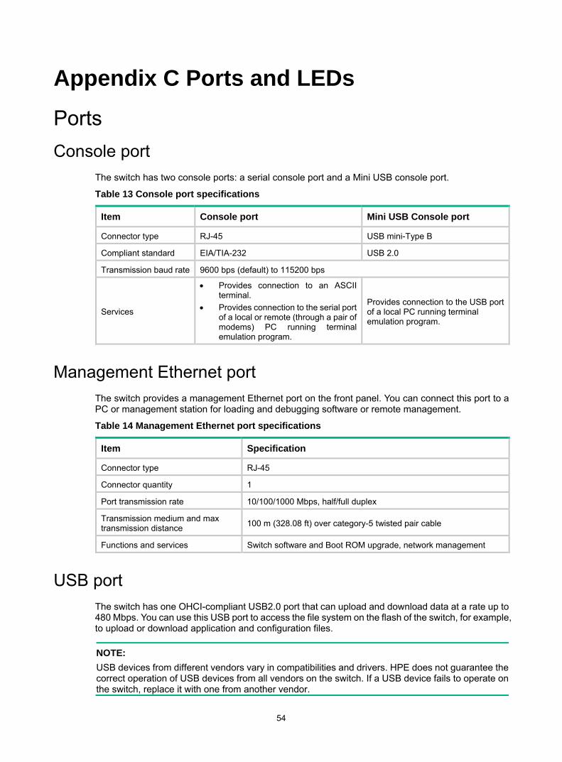
54
Appendix C Ports and LEDs
Ports Console port
The switch has two console ports: a serial console port and a Mini USB console port.
Table 13 Console port specifications
Item Console port Mini USB Console port
Connector type RJ-45 USB mini-Type B
Compliant standard EIA/TIA-232 USB 2.0
Transmission baud rate 9600 bps (default) to 115200 bps
Services
• Provides connection to an ASCII terminal.
• Provides connection to the serial port of a local or remote (through a pair of modems) PC running terminal emulation program.
Provides connection to the USB port of a local PC running terminal emulation program.
Management Ethernet port The switch provides a management Ethernet port on the front panel. You can connect this port to a PC or management station for loading and debugging software or remote management.
Table 14 Management Ethernet port specifications
Item Specification
Connector type RJ-45
Connector quantity 1
Port transmission rate 10/100/1000 Mbps, half/full duplex
Transmission medium and max transmission distance 100 m (328.08 ft) over category-5 twisted pair cable
Functions and services Switch software and Boot ROM upgrade, network management
USB port The switch has one OHCI-compliant USB2.0 port that can upload and download data at a rate up to 480 Mbps. You can use this USB port to access the file system on the flash of the switch, for example, to upload or download application and configuration files.
NOTE: USB devices from different vendors vary in compatibilities and drivers. HPE does not guarantee the correct operation of USB devices from all vendors on the switch. If a USB device fails to operate on the switch, replace it with one from another vendor.
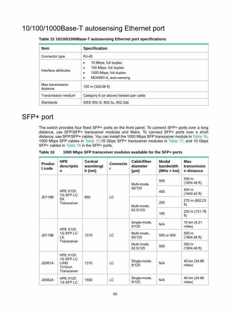
55
10/100/1000Base-T autosensing Ethernet port Table 15 10/100/1000Base-T autosensing Ethernet port specifications
Item Specification
Connector type RJ-45
Interface attributes
• 10 Mbps, full duplex • 100 Mbps, full duplex • 1000 Mbps, full duplex • MDI/MDI-X, auto-sensing
Max transmission distance 100 m (328.08 ft)
Transmission medium Category-5 (or above) twisted pair cable
Standards IEEE 802.3i, 802.3u, 802.3ab
SFP+ port The switch provides four fixed SFP+ ports on the front panel. To connect SFP+ ports over a long distance, use SFP/SFP+ transceiver modules and fibers. To connect SFP+ ports over a short distance, use SFP/SFP+ cables. You can install the 1000 Mbps SFP transceiver module in Table 16, 1000 Mbps SFP cables in Table 17,10 Gbps SFP+ transceiver modules in Table 17, and 10 Gbps SFP+ cables in Table 18 in the SFP+ ports.
Table 16 1000 Mbps SFP transceiver modules available for the SFP+ ports
Product code
HPE description
Central wavelength (nm)
Connector
Cable/fiber diameter (µm)
Modal bandwidth (MHz × km)
Max transmission distance
JD118B
HPE X120 1G SFP LC SX Transceiver
850 LC
Multi-mode, 50/125
500 550 m (1804.46 ft)
400 500 m (1640.42 ft)
Multi-mode, 62.5/125
200 275 m (902.23 ft)
160 220 m (721.78 ft)
JD119B
HPE X120 1G SFP LC LX Transceiver
1310 LC
Single-mode, 9/125 N/A 10 km (6.21
miles)
Multi-mode, 50/125 500 or 400 550 m
(1804.46 ft)
Multi-mode, 62.5/125 500 550 m
(1804.46 ft)
JD061A
HPE X125 1G SFP LC LH40 1310nm Transceiver
1310 LC Single-mode, 9/125 N/A 40 km (24.86
miles)
JD062A HPE X120 1G SFP LC
1550 LC Single-mode, 9/125 N/A 40 km (24.86
miles)

56
Product code
HPE description
Central wavelength (nm)
Connector
Cable/fiber diameter (µm)
Modal bandwidth (MHz × km)
Max transmission distance
LH40 1550nm Transceiver
JD063B
HPE X125 1G SFP LC LH70 Transceiver
1550 LC Single-mode, 9/125 N/A 70 km (43.50
miles)
JD103A
HPE X120 1G SFP LC LH100 Transceiver
1550 LC Single-mode, 9/125 N/A 100 km (62.14
miles)
JD098B
HPE X120 1G SFP LC BX 10-U Transceiver
TX: 1310 RX: 1490
LC Single-mode, 9/125 N/A 10 km (6.21
miles)
JD099B
HPE X120 1G SFP LC BX 10-D Transceiver
TX: 1490 RX: 1310
JD089B
HPE X120 1G SFP RJ45 T Transceiver
N/A RJ-45 Category-5 twisted pair N/A 100 m (328.08
ft)
Note: JD098B and JD099B must be used in pairs.
Table 17 10 Gbps SFP+ transceiver modules available for the SFP+ ports
Product code
HPE description
Central wavelength (nm)
Connector
Fiber diameter (µm)
Modal bandwidth (MHz × km)
Max transmission distance
JD092B
HPE X130 10G SFP+ LC SR Transceiver
850 LC
Multi-mode, 50/125
2000 300 m (984.25 ft)
500 82 m (269.03 ft)
400 66 m (216.54 ft)
Multi-mode, 62.5/125
200 33 m (108.27 ft)
160 26 m (85.30 ft)
JD093B
HPE X130 10G SFP+ LC LRM Transceiver
1310 LC
Multi-mode, 50/125
1500 220 m (721.78 ft)
500
400 100 m (328.08 ft)
Multi-mode, 62.5/125
200 220 m (721.78 ft)
160
JD094B
HPE X130 10G SFP+ LC LR Transceiver
1310 LC Single-mode, 9/125 N/A 10 km (6.21
miles)
JG915A HPE X130 1550 LC Single-mod N/A 80 km (49.71
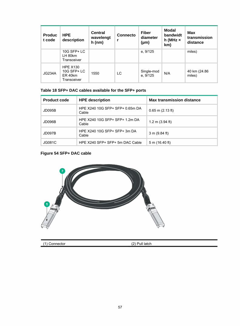
57
Product code
HPE description
Central wavelength (nm)
Connector
Fiber diameter (µm)
Modal bandwidth (MHz × km)
Max transmission distance
10G SFP+ LC LH 80km Transceiver
e, 9/125 miles)
JG234A
HPE X130 10G SFP+ LC ER 40km Transceiver
1550 LC Single-mode, 9/125 N/A 40 km (24.86
miles)
Table 18 SFP+ DAC cables available for the SFP+ ports
Product code HPE description Max transmission distance
JD095B HPE X240 10G SFP+ SFP+ 0.65m DA Cable 0.65 m (2.13 ft)
JD096B HPE X240 10G SFP+ SFP+ 1.2m DA Cable 1.2 m (3.94 ft)
JD097B HPE X240 10G SFP+ SFP+ 3m DA Cable 3 m (9.84 ft)
JG081C HPE X240 SFP+ SFP+ 5m DAC Cable 5 m (16.40 ft)
Figure 54 SFP+ DAC cable
(1) Connector (2) Pull latch

58
NOTE: • The fixed SFP+ ports on the switch do not support the HPE X130 10G SFP+ LC LRM
Transceiver, HPE X130 10G SFP+ LC LH 80km Transceiver, and HPE X130 10G SFP+ LC ER 40km Transceiver.
• To guarantee the functionality of the SFP+ ports, use only HPE SFP/SFP+ transceiver modulesand SFP+ DAC cables.
• The SFP/SFP+ transceiver modules and SFP+ DAC cables available for the switch are subject to change over time. For the most up-to-date list of SFP/SFP+ transceiver modules and SFP+ DAC cables, consult your HPE sales representative or technical support engineer.
• For the specifications for the HPE SFP/SFP+ transceiver modules and SFP+ DAC cables, see HPE Comware-Based Devices Transceiver Modules User Guide.
LEDs System status LED
The system status LED shows the operating state of the switch.
Table 19 System status LED description
LED mark Status Description
SYS
Steady green The switch is operating correctly.
Flashing green (1 Hz) The switch is performing power-on self test (POST).
Steady red The switch has failed the POST or is faulty.
Flashing yellow (1 Hz) Some ports have failed to pass POST or are faulty.
Off The switch is powered off.
Power supply status LED The switch provides two power supply slots at the rear. For each power supply, these switches provide a power supply status LED on the front panel.
Table 20 Power supply status LED description
LED mark Status Description
PWR1
Steady green A power supply is installed in power supply slot 1, and the power supply is outputting power correctly.
Steady yellow A power supply is installed in power supply slot 1, but the power supply has failed or no power is input to the power supply.
Off No power supply is installed in power supply slot 1.
PWR2
Steady green A power supply is installed in power supply slot 2, and the power supply is outputting power correctly.
Steady yellow A power supply is installed in power supply slot 2, but the power supply has failed or no power is input to the power supply.
Off No power supply is installed in power supply slot 2.

59
LED for the port LED mode (MODE) To show more information about the switch through the port LEDs, the switch provides a MODE LED to indicate the type of information that the port LEDs are showing.
You can use the LED mode switching button to change the indication of the MODE LED.
Table 21 Description for the MODE LED
LED mark Status Description
MODE
Steady green The port status LEDs are showing port rates.
Flashing green (1 Hz) (available only for HPE 5130 24G PoE+ 4SFP+ 1-slot HI and HPE 5130 48G PoE+ 4SFP+ 1-slot HI switches)
The port status LEDs are showing the status of PoE power supply on the ports.
Flashing yellow
The port status LEDs indicates the IRF member ID of the switch. For example, if the ports 1 to 5 are steady green, the IRF member ID of the switch is 5.
10/100/1000Base-T autosensing Ethernet port LED The switch provides a status LED for each 10/100/1000Base-T autosensing Ethernet port. The port status LED and the MODE LED indicate the operating state of the 10/100/1000Base-T autosensing Ethernet port in conjunction.
Table 22 10/100/1000Base-T autosensing Ethernet port LED description
Port mode LED (Mode) status Port LED status Description
Steady green (rate mode)
Steady green
The port is operating at 1000 Mbps. The port LED fast flashes when the port is sending or receiving data.
Steady yellow
The port is operating at 10/100 Mbps. The port LED fast flashes when the port is sending or receiving data.
Flashing yellow (3 Hz) POST has failed on the port.
Off No link is present on the port.
Flashing green (1 Hz) (PoE mode, available only for HPE 5130 24G PoE+ 4SFP+ 1-slot HI and HPE 5130 48G PoE+ 4SFP+ 1-slot HI switches)
Steady green PoE power supply is normal.
Flashing green (3 Hz)
The device attached to the port requires power higher than the maximum or currently available PoE output power on the port.
Steady yellow The port is experiencing a PoE failure.
Flashing yellow (3 Hz) POST has failed on the port.
Off The port is not supplying PoE power.
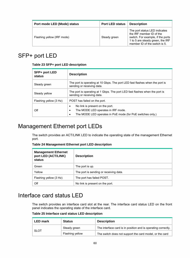
60
Port mode LED (Mode) status Port LED status Description
Flashing yellow (IRF mode) Steady green
The port status LED indicates the IRF member ID of the switch. For example, if the ports 1 to 5 are steady green, the IRF member ID of the switch is 5.
SFP+ port LED Table 23 SFP+ port LED description
SFP+ port LED status Description
Steady green The port is operating at 10 Gbps. The port LED fast flashes when the port is sending or receiving data.
Steady yellow The port is operating at 1 Gbps. The port LED fast flashes when the port is sending or receiving data.
Flashing yellow (3 Hz) POST has failed on the port.
Off • No link is present on the port. • The MODE LED operates in IRF mode. • The MODE LED operates in PoE mode (for PoE switches only.)
Management Ethernet port LEDs The switch provides an ACT/LINK LED to indicate the operating state of the management Ethernet port.
Table 24 Management Ethernet port LED description
Management Ethernet port LED (ACT/LINK) status
Description
Green The port is up.
Yellow The port is sending or receiving data.
Flashing yellow (3 Hz) The port has failed POST.
Off No link is present on the port.
Interface card status LED The switch provides an interface card slot at the rear. The interface card status LED on the front panel indicates the operating state of the interface card.
Table 25 Interface card status LED description
LED mark Status Description
SLOT Steady green The interface card is in position and is operating correctly.
Flashing yellow The switch does not support the card model, or the card
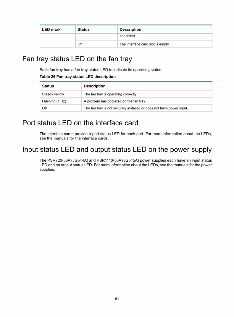
61
LED mark Status Description has failed.
Off The interface card slot is empty.
Fan tray status LED on the fan tray Each fan tray has a fan tray status LED to indicate its operating status.
Table 26 Fan tray status LED description
Status Description
Steady yellow The fan tray is operating correctly.
Flashing (1 Hz) A problem has occurred on the fan tray.
Off The fan tray is not securely installed or does not have power input.
Port status LED on the interface card The interface cards provide a port status LED for each port. For more information about the LEDs, see the manuals for the interface cards.
Input status LED and output status LED on the power supply The PSR720-56A (JG544A) and PSR1110-56A (JG545A) power supplies each have an input status LED and an output status LED. For more information about the LEDs, see the manuals for the power supplies.

62
Appendix D Cooling system The cooling system of the switch includes the air vents in the chassis, fan trays, and built-in fans of hot swappable power supplies. For correct operation of this cooling system, you must consider the site ventilation design when you plan the installation site for the switch.
When the fan trays are operating, ambient air flows in through the air vents in the port-side panel and in the switch sides, circulates through the chassis and the power supplies, and exhausts through the air vents in the fan tray and power supply panels, as shown in Figure 55.
Figure 55 Airflow through the HPE 5130 48G 4SFP+ 1-slot HI switch
IMPORTANT: The chassis and the power supplies use separate air aisles. Make sure both aisles are not blocked.

63
Document conventions and icons
Conventions This section describes the conventions used in the documentation.
Port numbering in examples The port numbers in this document are for illustration only and might be unavailable on your device.
Command conventions
Convention Description
Boldface Bold text represents commands and keywords that you enter literally as shown.
Italic Italic text represents arguments that you replace with actual values.
[ ] Square brackets enclose syntax choices (keywords or arguments) that are optional.
{ x | y | ... } Braces enclose a set of required syntax choices separated by vertical bars, from which you select one.
[ x | y | ... ] Square brackets enclose a set of optional syntax choices separated by vertical bars, from which you select one or none.
{ x | y | ... } * Asterisk marked braces enclose a set of required syntax choices separated by vertical bars, from which you select at least one.
[ x | y | ... ] * Asterisk marked square brackets enclose optional syntax choices separated by vertical bars, from which you select one choice, multiple choices, or none.
&<1-n> The argument or keyword and argument combination before the ampersand (&) sign can be entered 1 to n times.
# A line that starts with a pound (#) sign is comments.
GUI conventions
Convention Description
Boldface Window names, button names, field names, and menu items are in Boldface. For example, the New User window appears; click OK.
> Multi-level menus are separated by angle brackets. For example, File > Create > Folder.
Symbols
Convention Description
WARNING! An alert that calls attention to important information that if not understood or followed can result in personal injury.
CAUTION: An alert that calls attention to important information that if not understood or followed can result in data loss, data corruption, or damage to hardware or software.
IMPORTANT: An alert that calls attention to essential information.
NOTE: An alert that contains additional or supplementary information.
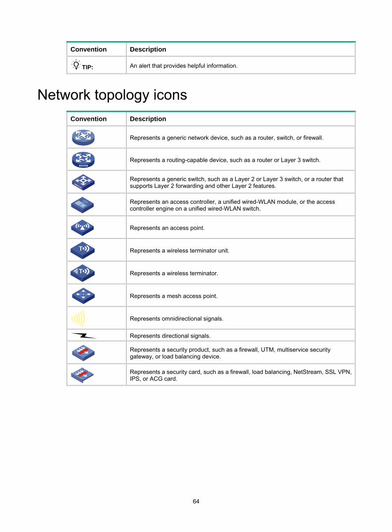
64
Convention Description
TIP: An alert that provides helpful information.
Network topology icons Convention Description
Represents a generic network device, such as a router, switch, or firewall.
Represents a routing-capable device, such as a router or Layer 3 switch.
Represents a generic switch, such as a Layer 2 or Layer 3 switch, or a router that supports Layer 2 forwarding and other Layer 2 features.
Represents an access controller, a unified wired-WLAN module, or the access controller engine on a unified wired-WLAN switch.
Represents an access point.
Represents a wireless terminator unit.
Represents a wireless terminator.
Represents a mesh access point.
Represents omnidirectional signals.
Represents directional signals.
Represents a security product, such as a firewall, UTM, multiservice security gateway, or load balancing device.
Represents a security card, such as a firewall, load balancing, NetStream, SSL VPN, IPS, or ACG card.
TT
TT

65
Support and other resources
Accessing Hewlett Packard Enterprise Support • For live assistance, go to the Contact Hewlett Packard Enterprise Worldwide website:
www.hpe.com/assistance • To access documentation and support services, go to the Hewlett Packard Enterprise Support
Center website: www.hpe.com/support/hpesc
Information to collect • Technical support registration number (if applicable) • Product name, model or version, and serial number • Operating system name and version • Firmware version • Error messages • Product-specific reports and logs • Add-on products or components • Third-party products or components
Accessing updates • Some software products provide a mechanism for accessing software updates through the
product interface. Review your product documentation to identify the recommended software update method.
• To download product updates, go to either of the following: Hewlett Packard Enterprise Support Center Get connected with updates page:
www.hpe.com/support/e-updates Software Depot website:
www.hpe.com/support/softwaredepot • To view and update your entitlements, and to link your contracts, Care Packs, and warranties
with your profile, go to the Hewlett Packard Enterprise Support Center More Information on Access to Support Materials page: www.hpe.com/support/AccessToSupportMaterials
IMPORTANT: Access to some updates might require product entitlement when accessed through the Hewlett Packard Enterprise Support Center. You must have an HP Passport set up with relevant entitlements.
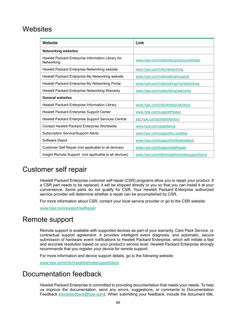
66
Websites
Website Link
Networking websites
Hewlett Packard Enterprise Information Library for Networking www.hpe.com/networking/resourcefinder
Hewlett Packard Enterprise Networking website www.hpe.com/info/networking
Hewlett Packard Enterprise My Networking website www.hpe.com/networking/support
Hewlett Packard Enterprise My Networking Portal www.hpe.com/networking/mynetworking
Hewlett Packard Enterprise Networking Warranty www.hpe.com/networking/warranty
General websites
Hewlett Packard Enterprise Information Library www.hpe.com/info/enterprise/docs
Hewlett Packard Enterprise Support Center www.hpe.com/support/hpesc
Hewlett Packard Enterprise Support Services Central ssc.hpe.com/portal/site/ssc/
Contact Hewlett Packard Enterprise Worldwide www.hpe.com/assistance
Subscription Service/Support Alerts www.hpe.com/support/e-updates
Software Depot www.hpe.com/support/softwaredepot
Customer Self Repair (not applicable to all devices) www.hpe.com/support/selfrepair
Insight Remote Support (not applicable to all devices) www.hpe.com/info/insightremotesupport/docs
Customer self repair Hewlett Packard Enterprise customer self repair (CSR) programs allow you to repair your product. If a CSR part needs to be replaced, it will be shipped directly to you so that you can install it at your convenience. Some parts do not qualify for CSR. Your Hewlett Packard Enterprise authorized service provider will determine whether a repair can be accomplished by CSR.
For more information about CSR, contact your local service provider or go to the CSR website:
www.hpe.com/support/selfrepair
Remote support Remote support is available with supported devices as part of your warranty, Care Pack Service, or contractual support agreement. It provides intelligent event diagnosis, and automatic, secure submission of hardware event notifications to Hewlett Packard Enterprise, which will initiate a fast and accurate resolution based on your product’s service level. Hewlett Packard Enterprise strongly recommends that you register your device for remote support.
For more information and device support details, go to the following website:
www.hpe.com/info/insightremotesupport/docs
Documentation feedback Hewlett Packard Enterprise is committed to providing documentation that meets your needs. To help us improve the documentation, send any errors, suggestions, or comments to Documentation Feedback ([email protected]). When submitting your feedback, include the document title,

67
part number, edition, and publication date located on the front cover of the document. For online help content, include the product name, product version, help edition, and publication date located on the legal notices page.

68
Index Numerics
10/100/1000 Base-T autosensing Ethernet port, 55 port LED, 59
19-inch rack mounting bracket kit, 8 switch installation, 7
A
AC power supply grounding switch through AC power cord, 18
access first time switch access, 28
accessories needed for installation, 4 Appendix
A, chassis views and technical specifications, 44, 48 B, FRUs and compatibility matrixes, 51, 51
B
bits per second (parameter), 31
C
cable connecting console, 28 connecting USB mini console, 29 fiber cable laser safety recommendations, 3 grounding the switch with a grounding conductor buried in the earth ground, 17 grounding the switch with grounding strip, 15 planning IRF cabling scheme, 36
chassis views, 44
cleanliness installation site, 2
compatibility matrixes, 51, 51 configuring
IRF basic settings, 38 switch, 28 troubleshooting configuration terminal problems, 42 verify the IRF fabric setup, 39, 40
connecting console cable, 28 first time switch access, 28 IRF member switches in a ToR solution, 38 IRF member switches in one rack, 36 IRF physical ports, 38
planning IRF connections, 34 power cord, 22 PSR150-D1(JD366B), 23 PSR720-56A(JG544A)/PSR1110-56A(JG545A)/PSR150-A1(JD362B), 24 USB mini console cable, 29
console connecting cable, 28 connecting USB mini cable, 29 port technical specifications, 54
D
data bits (parameter), 31 device
troubleshooting fan failure, 40 troubleshooting power supply module, 40
displaying troubleshooting garbled display, 43 troubleshooting no display, 42
dust installation site, 2
E
electrical connecting console cable, 28 connecting power cord, 22 connecting PSR150-D1 (JD366B), 23 connecting PSR720-56A(JG544A)/PSR1110-56A(JG545A)/PSR150-A1(JD362B), 24 connecting USB mini console cable, 29 EMI prevention, 3 grounding switch through AC power cord, 18 grounding switch with a grounding conductor buried in the earth ground, 17 grounding switch with grounding strip, 15 grounding the switch, 15 power supply, 18 power supply removal, 18 powering on switch, 31 PSR150 (JD362A, JD362B, JD366A, or JD366B) power supply installation, 19 PSR150 (JD362A, JD362B, JD366A, or JD366B) power supply removal, 20 PSR720-56A/PSR1110-56A (JG544A/JG545A) power supply installation, 20 PSR720-56A/PSR1110-56A (JG544A/JG545A) power supply removal, 22 troubleshooting power supply failure, 40
69
electromagnetic interference. See EMI prevention EMI prevention, 3 emulation (parameter), 31 environment
examining installation site, 2 site cleanliness, 2 site dust concentration, 2 site gas saturation, 2 site humidity, 2 site temperature, 2
examining installation site, 2
F
fan failure (troubleshooting), 40
fan tray installation, 41 status LED, 61
fiber laser safety recommendations, 3
field replacement unit. See FRU flow control (parameter), 31 flowchart of IRF fabric setup, 33 FRU
compatibility matrixes, 51, 51
G
garbled display (troubleshooting), 43 gas (installation site), 2 grounding
EMI prevention, 3 grounding conductor buried in the earth ground, 17 grounding strip, 15 switch, 15 switch through AC power cord, 18 switch with a grounding conductor buried in the earth ground, 17 switch with grounding strip, 15
H
hardware 10/100/1000 Base-T autosensing Ethernet port LED, 59 10/100/1000 Base-T autosensing Ethernet port technical specifications, 55 connecting PSR150-D1(JD366B), 23 connecting PSR720-56A(JG544A)/PSR1110-56A(JG545A)/PSR150-A1(JD362B), 24 console port technical specifications, 54 fan tray status LED, 61
grounding switch, 15 grounding switch through AC power cord, 18 grounding switch with a grounding conductor buried in the earth ground, 17 grounding switch with grounding strip, 15 interface card installation, 24, 25 interface card port status LED, 61 interface card removal, 26 interface card status LED, 60 management Ethernet port LED, 60 management Ethernet port technical specifications, 54 mounting bracket kit, 8 port mode LED, 59 port technical specifications, 54 power supply, 18 power supply input status, 61 power supply output status, 61 power supply removal, 18 power supply status LED, 58 PSR150(JD362A, JD362B, JD366A, or JD366B) power supply installation, 19 PSR150(JD362A, JD362B, JD366A, or JD366B) power supply removal, 20 PSR720-56A/PSR1110-56A (JG544A/JG545A) power supply installation, 20 PSR720-56A/PSR1110-56A (JG544A/JG545A) power supply removal, 22 SFP+ port LED, 60 SFP+ port technical specifications, 55 switch installation, 1, 6 switch installation in 19-inch rack, 7 system status LED, 58 USB port technical specifications, 54 verifying switch installation, 26 workbench switch mounting, 15
humidity (installation site), 2
I
ID (IRF member), 34 identifying
IRF master switch, 34 IRF member switch physical ports, 35
installing accessories, 4 EMI prevention, 3 examining installation site, 2 fan tray, 41 front and rear mounting bracket kit, 12 front mounting bracket kit, 8 interface card, 24, 25 IRF fabric installation site planning, 34

70
power supply, 18 PSR150 (JD362A, JD362B, JD366A, or JD366B) power supply, 19 PSR720-56A/PSR1110-56A (JG544A/JG545A) power supply, 20 site cleanliness, 2 site humidity, 2 site temperature, 2 switch, 1, 6 switch in 19-inch rack, 7 tools, 3
interface card installation, 24, 25 port status LED, 61 removal, 26 technical specifications, 52
Interface card status LED, 60
interface card status LED, 60 IRF fabric
configuring basic settings, 38 connecting member switches in a ToR solution, 38 connecting member switches in one rack, 36 connecting physical ports, 38 identifying master switch, 34 identifying member switch physical ports, 35 planning, 34 planning cabling scheme, 36, 36 planning connections, 34 planning installation site, 34 planning member IDs, 34 planning size, 34 planning topology, 34 setting up, 33 setup flowchart, 33 verify the IRF fabric setup, 39, 40
L
LED 10/100/1000 Base-T autosensing Ethernet port, 59 fan tray status LED, 61 interface card port status, 61 interface card status, 60 management Ethernet port, 60 port mode, 59 power supply input status, 61 power supply output status, 61 power supply status, 58 SFP+ port, 60
system status, 58 technical specifications, 58
M
management Ethernet port, 54 port LED, 60
master switch configuring IRF basic settings, 38 IRF fabric, 34
member configuring IRF member switch basic settings, 38 connecting IRF physical ports, 38 identifying IRF member switch physical ports, 35 IRF member ID, 34
mounting workbench mounting switch, 15
N
network management setting up IRF fabric, 33 troubleshooting configuration terminal problems, 42
networking planning IRF cabling scheme, 36
no display (troubleshooting), 42
P
parity (parameter), 31 PC
troubleshooting garbled terminal display, 43 troubleshooting no display, 42
physical port connecting, 38 identifying IRF member switch physical ports, 35
planning IRF cabling scheme, 36, 36 IRF connections, 34 IRF member IDs, 34 IRF topology, 34
port connecting IRF physical ports, 38 identifying IRF member switch physical ports, 35 LED (SFP+), 60 setting up IRF fabric, 33 SFP+, 55 technical specifications, 54
power supply cable, 22 connecting PSR150-D1 (JD362B), 23

71
connecting PSR720-56A(JG544A)/PSR1110-56A(JG545A)/PSR150-A1(JD362B), 24 failure (troubleshooting), 40 grounding switch through AC power cord, 18 input status LED, 61 installation, 18 output status LED, 61 removal, 18 technical specifications, 51
power supply status LED, 58 powering on switch, 31 preparing for installation, 1 preventing
EMI prevention, 3 procedure
configuring IRF basic settings, 38 connecting grounding cable to chassis, 15 connecting grounding cable to grounding strip, 16, 17 connecting IRF physical ports, 38 connecting power cord, 22 connecting PSR150-D1 (JD366B), 23 connecting PSR720-56A(JG544A)/PSR1110-56A(JG545A)/PSR150-A1(JD362B), 24 grounding switch through AC power cord, 18 grounding switch with a grounding conductor buried in the earth ground, 17 grounding switch with grounding strip, 15 grounding the switch, 15 identifying IRF master switch, 34 identifying IRF member switch physical ports, 35 installing PSR150 (JD362A, JD362B, JD366A, or JD366B) power supply, 19 installing PSR720-56A/PSR1110-56A (JG544A/JG545A) power supply, 20 installing switch, 1, 6 installing switch in 19-inch rack, 7 mounting switch on workbench, 15 planning IRF connections, 34 planning IRF fabric installation site, 34 planning IRF member IDs, 34 planning IRF topology, 34 rack-mounting by using front and rear mounting brackets on 19-inch rack, 12 rack-mounting by using front mounting brackets on 19-inch rack, 8 removing PSR150 (JD362A, JD362B, JD366A, or JD366B) power supply, 20
removing PSR720-56A/PSR1110-56A (JG544A/JG545A) power supply, 22 setting up IRF fabric, 33 troubleshooting fan failure, 40 troubleshooting garbled display, 43 troubleshooting no display, 42 troubleshooting power supply failure, 40
PSR150 (JD362A, JD362B, JD366A, or JD366B) power supply
installation, 19 removal, 20
PSR150-D1 (JD366B) connecting, 23
PSR720-56A/PSR1110-56A (JG544A/JG545A) power supply
installation, 20 removal, 22
PSR720-56A(JG544A)/PSR1110-56A(JG545A)/PSR150-A1(JD362B)
connecting, 24
R
rack mounting switch to workbench, 15 switch installation in 19-inch rack, 7 switch installation methods, 7 verifying switch installation, 26
removing interface card, 26 power supply, 18 PSR150 (JD362A, JD362B, JD366A, or JD366B) power supply, 20 PSR720-56A/PSR1110-56A (JG544A/JG545A) power supply, 22
RPS status LED, 59
S
safety EMI prevention, 3 grounding switch through AC power cord, 18 grounding the switch, 15 grounding the switch with a grounding conductor buried in the earth ground, 17 grounding the switch with grounding strip, 15 installation site cleanliness, 2 installation site dust concentration, 2 installation site gas saturation, 2 installation site humidity, 2 installation site temperature, 2 laser safety recommendations, 3
setting IRF fabric, 33

72
switch configuration environment, 28 terminal parameters, 31
SFP+ port, 55 port LED, 60
site cleanliness, 2 dust concentration, 2 examining installation site, 2 gas saturation, 2 humidity, 2 IRF fabric installation site planning, 34 temperature, 2
stop bits (parameter), 31 switch
chassis views, 44 connecting console cable, 28 connecting IRF physical ports, 38 connecting USB mini console cable, 29 cooling system, 62 first time access, 28 grounding, 15 grounding through AC power cord, 18 grounding with a grounding conductor buried in the earth ground, 17 grounding with grounding strip, 15 identifying IRF master switch, 34 identifying IRF member switch physical ports, 35 installation, 1, 6 LEDs, 54 planning IRF cabling scheme, 36, 36 planning IRF member IDs, 34 ports, 54 powering on, 31 setting configuration environment, 28 setting terminal parameters, 31 setting up IRF fabric, 33 technical specifications, 44 verifying installation, 26 workbench mounting switch, 15
system administration troubleshooting configuration terminal problems, 42 troubleshooting fan failure, 40 troubleshooting power supply failure, 40
system status LED, 58
T
technical specifications, 48
10/100/1000 Base-T autosensing Ethernet port, 55 10/100/1000 Base-T autosensing Ethernet port LED, 59 console port, 54 fan tray status LED, 61 interface card, 52 interface card port status LED, 61 interface card status LED, 60 LED, 58 management Ethernet port, 54 management Ethernet port LED, 60 port, 54 port mode LED, 59 power supply, 51 power supply input status, 61 power supply output status, 61 power supply status LED, 58 SFP+ port, 55 SFP+ port LED, 60 system status LED, 58 USB port, 54
temperature installation site requirements, 2
tools needed for installation, 3 topology
planning IRF cabling scheme, 36, 36 topology (IRF fabric), 34 troubleshooting
configuration terminal problems, 42 fan failure, 40 garbled display, 43 no display, 42 power supply failure, 40
U
USB port, 54
V
verify the IRF fabric setup, 39, 40 verifying
IRF fabric setup, 39, 40 switch installation, 26
VT100, 31
W
workbench mounting switch, 15


