Embed Size (px)
Citation preview
MK-91DF8306-13
Hitachi Unified Storage Command Control Interface Installation and Configuration Guide
FASTFIND LINKS
Document Organization
Product Version
Getting Help
Contents
ii
Hitachi Unified Storage Command Control Interface Installation and Configuration Guide
© 2007-2015 Hitachi, Ltd. All rights reserved.
No part of this publication may be reproduced or transmitted in any form or by any means, electronic or mechanical, including photocopying and recording, or stored in a database or retrieval system for any purpose without the express written permission of Hitachi, Ltd. (hereinafter referred to as “Hitachi”), and Hitachi Data Systems Corporation (hereinafter referred to as “Hitachi Data Systems”).
Hitachi and Hitachi Data Systems reserve the right to make changes to this document at any time without notice and assume no responsibility for its use. This document contains the most current information available at the time of publication. When new or revised information becomes available, this entire document will be updated and distributed to all registered users.
All of the features described in this document may not be currently available. Refer to the most recent product announcement or contact your local Hitachi Data Systems sales office for information about feature and product availability.
Notice: Hitachi Data Systems products and services can be ordered only under the terms and conditions of Hitachi Data Systems’ applicable agreements. The use of Hitachi Data Systems products is governed by the terms of your agreements with Hitachi Data Systems.
Hitachi is a registered trademark of Hitachi, Ltd., in the United States and other countries. Hitachi Data Systems is a registered trademark and service mark of Hitachi in the United States and other countries.
ShadowImage and TrueCopy are registered trademarks or trademarks of Hitachi Data Systems.
AIX and IBM are registered trademarks or trademarks of International Business Machines Corporation.
All other trademarks, service marks, and company names are properties of their respective owners.
Microsoft product screen shots reprinted with permission from Microsoft Corporation.
Contents iii
Hitachi Unified Storage Command Control Interface Installation and Configuration Guide
Contents
Preface .................................................................................................... xi Intended audience ............................................................................................... xii Product version .................................................................................................... xii Document revision level .......................................... Error! Bookmark not defined. Changes in this revision ........................................................................................ xii Document organization ......................................................................................... xii Related documentation ........................................................................................ xiii Document conventions ......................................................................................... xv Convention for storage capacity values ................................................................. xvi Accessing product documentation ....................................................................... xvii Getting help ....................................................................................................... xvii Comments ......................................................................................................... xvii
Installing CCI software ........................................................................... 1-1
CCI system requirements .................................................................................... 1-2 About CCI hardware installation .......................................................................... 1-6 About CCI software installation ........................................................................... 1-7
Installing software on a UNIX system ............................................................ 1-7 Installing software on a Windows Server system ........................................... 1-9
Changing the user on UNIX systems .................................................................. 1-10 Creating/editing the configuration file ................................................................ 1-11 Starting CCI ..................................................................................................... 1-13
Starting UNIX systems ............................................................................... 1-13 Starting Windows systems .......................................................................... 1-15 Starting CCI as a service ............................................................................ 1-17
Uninstalling and upgrading CCI software ................................................. 2-1
Uninstalling CCI software on UNIX systems .......................................................... 2-2 Upgrading CCI software on UNIX systems ............................................................ 2-2 Upgrading CCI software on Windows Server ........................................................ 2-3
iv Contents
Hitachi Unified Storage Command Control Interface Installation and Configuration Guide
About copy solutions .............................................................................. 3-1
About CCI .......................................................................................................... 3-2 ShadowImage .................................................................................................... 3-3 SnapShot ........................................................................................................... 3-3 TrueCopy Synchronous/Asynchronous Remote Copy ............................................. 3-4 Contacting Technical Support .............................................................................. 3-5
Overview of CCI .................................................................................... 4-1
About paired volumes ......................................................................................... 4-2 ShadowImage duplicated mirroring ............................................................... 4-3 SnapShot duplicated mirroring ...................................................................... 4-4
About CCI commands ......................................................................................... 4-5 ShadowImage commands ............................................................................. 4-5 SnapShot commands .................................................................................... 4-6 TrueCopy commands.................................................................................... 4-7 TrueCopy/TCE remote commands ................................................................. 4-8 Volume pairs ............................................................................................. 4-10 ShadowImage volume status ...................................................................... 4-11 SnapShot volume status ............................................................................. 4-13 TrueCopy/TCE volume status ...................................................................... 4-15 TrueCopy/TCE fence levels ......................................................................... 4-19
Using CCI commands ........................................................................................ 4-21 Backing up secondary volumes in paired status ............................................ 4-21 Restoring secondary volumes to primary volumes ........................................ 4-23 Backing up secondary volumes ................................................................... 4-25 Swapping paired volumes for duplex operation ............................................ 4-26 Restoring S-VOLs for duplex operation ........................................................ 4-27
About CCI software structure ............................................................................ 4-28 HORCM ..................................................................................................... 4-28 CCI instances ............................................................................................. 4-29 Configuration definition files ....................................................................... 4-30 Command devices ...................................................................................... 4-43 Alternate command devices ........................................................................ 4-44 Protection functions ................................................................................... 4-46 CCI software files ....................................................................................... 4-54 Log and trace files ..................................................................................... 4-56 User-created files ....................................................................................... 4-57 Group version control ................................................................................. 4-58 Virtual command devices ............................................................................ 4-59
Configuration file examples ............................................................................... 4-66 Configuring two hosts and two instances ..................................................... 4-66 Configuring one host and two instances ...................................................... 4-75 Setting two command devices .................................................................... 4-86 Configuring TrueCopy/ShadowImage with cascade pairs .............................. 4-98
Contents v
Hitachi Unified Storage Command Control Interface Installation and Configuration Guide
Configuring TCE/SnapShot with cascade pairs ........................................... 4-104 Confirming configurations ............................................................................... 4-109
Monitoring paired volume errors ............................................................... 4-109 Confirming pair status .............................................................................. 4-110
About VMware ............................................................................................... 4-111 Restrictions ............................................................................................. 4-112 Mounting VHD Disk on Windows 2008 R2/Windows 2012 Hyper-V .............. 4-113 Creating and resynchronzing pairs ............................................................ 4-116
About Hyper-V ............................................................................................... 4-117 Restrictions ............................................................................................. 4-117
Recovery procedures for HA ............................................................................ 4-118 IPv6 support in CCI ........................................................................................ 4-120 Windows Power Shell ..................................................................................... 4-122
Fibre-to-SCSI address conversion ............................................................ 5-1
SCSI TIDs .......................................................................................................... 5-2 Examples of Fibre address conversion.................................................................. 5-3 Fibre address conversion tables ........................................................................... 5-4
CCI operations on Windows systems ....................................................... 6-1
About LDM volume search .................................................................................. 6-2 Searching LDM volumes ............................................................................... 6-3 Using the mountvol command on Windows ................................................... 6-6
About dynamic disk and copy .............................................................................. 6-7 Mounting P-VOL and S-VOL on the same host ...................................................... 6-8
RM Shadow Copy provider for VSS .......................................................... 7-1
About VSS ......................................................................................................... 7-2 Configuring VSS ................................................................................................. 7-3
Configuring single hosts ............................................................................... 7-4 Exporting and importing host configurations .................................................. 7-5 Coordinating Shadow Copy creation .............................................................. 7-5 Using transportable configurations ................................................................ 7-7
Restrictions on VSS configurations ....................................................................... 7-8 About backup software and configurations ........................................................... 7-8 Installing backup software .................................................................................. 7-9
Installing new backup software .................................................................... 7-9 Upgrading backup software ........................................................................ 7-11 Confirming backup software versions .......................................................... 7-12 Checking backup software service registration ............................................. 7-12
Uninstalling backup software ............................................................................. 7-13 Starting VSS ..................................................................................................... 7-14
Setting CCI system environment variables ................................................... 7-14

vi Contents
Hitachi Unified Storage Command Control Interface Installation and Configuration Guide
Setting the CCI environment ....................................................................... 7-14 Performing a backup .................................................................................. 7-17
Notes on VSS ................................................................................................... 7-19 Known VSS problems and concerns ................................................................... 7-20 About event log error messages ........................................................................ 7-22
VMware vCenter Site Recovery Manager ................................................. 8-1
Overview of VMware vCenter Site Recovery Manager ............................................ 8-2 Integration between SRM and Copy Functions ...................................................... 8-3 Configurations Integrating SRM with Copy Functions ............................................ 8-4 SRM Operations ................................................................................................ 8-10 Details of Each Operation .................................................................................. 8-12
Test (test failover) ..................................................................................... 8-12 Cleanup ..................................................................................................... 8-14 Recovery ................................................................................................... 8-16 Reprotect .................................................................................................. 8-18 Cancel ....................................................................................................... 8-18
Requirements ................................................................................................... 8-19 Configuring environment ................................................................................... 8-20
Setting array .............................................................................................. 8-20 Building ESX(i) server ................................................................................. 8-20 Building v server ........................................................................................ 8-21 Building vCenter server .............................................................................. 8-22 Building SRM Server ................................................................................... 8-22 Installing SRA ............................................................................................ 8-22 Building CCI Server .................................................................................... 8-24
Setting SRM ..................................................................................................... 8-36 Configuring protected and recovery site array managers .............................. 8-36
Considerations .................................................................................................. 8-44 Troubleshooting ............................................................................................... 8-45
Differences between groups ................................................................... 9-1
About groups ..................................................................................................... 9-2 Consistency groups ............................................................................................. 9-3
Performing CCI operations ................................................................... 10-1
Important CCI notice ........................................................................................ 10-2 About CCI environment variables ....................................................................... 10-3
Specifying CCI options ................................................................................ 10-4 Verifying instance numbers ......................................................................... 10-6
Creating pairs ................................................................................................... 10-7 Splitting pairs ................................................................................................. 10-14
Using the pairsplit command ..................................................................... 10-20
Contents vii
Hitachi Unified Storage Command Control Interface Installation and Configuration Guide
Resynchronizing pairs ..................................................................................... 10-22 Confirming pairs ............................................................................................. 10-27 Monitoring pairs ............................................................................................. 10-30 Checking pair attribute and status ................................................................... 10-33 Displaying pair status ..................................................................................... 10-38 Checking TrueCopy/TCE pair currency ............................................................. 10-44 Performing TrueCopy/TCE takeover ................................................................. 10-47
Using the horctakeover command ............................................................. 10-50 Horctakeover command ........................................................................... 10-54
Displaying configuration information ................................................................ 10-56 Using the raidscan command .................................................................... 10-56 Using the raidar command ....................................................................... 10-62 Using the raidqry command...................................................................... 10-64
Protecting volume data ................................................................................... 10-66 Using the raidvchkset command ............................................................... 10-67 Using the raidvchkdsp command .............................................................. 10-69 Using the raidvchkscan command ............................................................. 10-72
Controlling CCI activity ................................................................................... 10-75 Using the horcmstart command ................................................................ 10-75 Using the horcmshutdown command ........................................................ 10-76 Using the horcctl command ...................................................................... 10-77
About Windows Server subcommands ............................................................. 10-79 Using the findcmddev subcommand .......................................................... 10-79 Using the drivescan subcommand ............................................................. 10-80 Using the portscan subcommand .............................................................. 10-81 Using the sync and syncd subcommands ................................................... 10-82 Using the mount subcommand ................................................................. 10-84 Using the umount subcommand ............................................................... 10-87 Using environment variable subcommands ................................................ 10-90
CCI command tools ........................................................................................ 10-91 Usng the inqraid command....................................................................... 10-91 Using the mkconf command ..................................................................... 10-98
Controlling host groups .................................................................................. 10-101 Specifying a host group ........................................................................... 10-101 Using host group commands ................................................................... 10-102
Migrating volumes ......................................................................................... 10-103 About volume migration .......................................................................... 10-103 Specifications for volume migration .......................................................... 10-103 Using volume migration commands ......................................................... 10-105 About cc command issues and status ....................................................... 10-106
About the synchronous waiting command for TCE ........................................... 10-107 Using the raidcom command .......................................................................... 10-111
About the raidcom command ................................................................... 10-111 Differences between raidcom and paircreate commands ........................... 10-113 Using raidcom command options ............................................................. 10-114

viii Contents
Hitachi Unified Storage Command Control Interface Installation and Configuration Guide
Troubleshooting................................................................................... 11-1
Troubleshooting ShadowImage ......................................................................... 11-2 Troubleshooting SnapShot ................................................................................ 11-4 Troubleshooting TrueCopy ................................................................................ 11-6 Troubleshooting TCE ....................................................................................... 11-11 Troubleshooting CCI ....................................................................................... 11-16 About error reporting ...................................................................................... 11-19 Recovering PSUE status using ShadowImage ................................................... 11-28
Recovering the pair .................................................................................. 11-28 About internal volumes in an array ............................................................ 11-29 Notes on pair splitting .............................................................................. 11-30
Recovering PSUE status using SnapShot .......................................................... 11-31 Recovering the pair .................................................................................. 11-31
Recovering PSUE status using TrueCopy/TCE ................................................... 11-32 Recovering the pair .................................................................................. 11-32
Calling the Hitachi Data Systems Support Center .............................................. 11-32
Maintenance logs and tracing functions ................................................. 12-1
About log files .................................................................................................. 12-2 About trace files ............................................................................................... 12-5 Using the trace control command ...................................................................... 12-5 Reading error log codes .................................................................................... 12-6
Solaris logs ................................................................................................ 12-7 Linux logs .................................................................................................. 12-8 Windows logs ............................................................................................ 12-9 Sense codes and detail codes ................................................................... 12-10
Using logging commands ................................................................................ 12-63
Copy command options ........................................................................ 13-1
Paircreate options ............................................................................................. 13-2 Pairsplit options ................................................................................................ 13-3 Pairsync options ............................................................................................... 13-4 Pairevtwait options ........................................................................................... 13-5 Pairsyncwait options ......................................................................................... 13-6 Pairmon options ............................................................................................... 13-7 Pairvolchk options ............................................................................................. 13-8 Pairdisplay options ............................................................................................ 13-9 Paircurchk options .......................................................................................... 13-10 Horctakeover options ...................................................................................... 13-11 Horctakeoff options ........................................................................................ 13-12 Raidscan options ............................................................................................ 13-13 Raidar options ................................................................................................ 13-14 Raidqry options .............................................................................................. 13-14
Contents ix
Hitachi Unified Storage Command Control Interface Installation and Configuration Guide
Horcctl options ............................................................................................... 13-15 Raidvchkset options ........................................................................................ 13-16 Raidvchkdsp options ....................................................................................... 13-17 Raidvchkscan options ..................................................................................... 13-18 Inqraid options ............................................................................................... 13-19 Mkconf options ............................................................................................... 13-20 Rmawk options .............................................................................................. 13-20
Acronyms and Abbreviations ....................................................... Acronyms-1
Index .............................................................................................. Index-1

Preface xi
Hitachi Unified Storage Command Control Interface Installation and Configuration Guide
Preface
Welcome to the Hitachi Unified Storage Command Control Interface and Configuration Guide.
This document describes how to set up, use, and maintain Hitachi Unified Storage systems. This document includes a full table of contents, index, chapter task lists, and numerous cross-references to help you find specific information.
Read this document carefully to understand how to use this product, and maintain a copy for reference purposes.
This preface includes the following information: Intended audience Product version Changes in this revision Document organization Related documentation Document conventions Convention for storage capacity values Accessing product documentation Getting help Comments

xii Preface
Hitachi Unified Storage Command Control Interface Installation and Configuration Guide
Intended audience
This document is intended for system administrators, Hitachi representatives, and authorized service providers who install, configure, and operate Hitachi Unified Storage systems.
This document assumes the user has a background in data processing and understands storage systems and their basic functions, Microsoft Windows and its basic functions, and Web browsers and their basic functions.
Product version
This document applies to CCI software version 01-32-03/01 or later and to Hitachi Unified Storage firmware version 0977/M or later.
Changes in this revision • Under Changing the user on UNIX systems on page 1-10, changed the
following directory to “/HORCM/.uds/.lcmcl* directory.”
• Updated displays for Figure 10-30 and Figure 10-31, and Figure 10-31, and added the following to the legend following the figures: “R/W:Shows "-".
• Under Using the sync and syncd subcommands on page 10-82, revised the first sentence preceding the table to indicate that synchronizing the pairs before the CCI command is executed is no longer required.
Document organization
Thumbnail descriptions of the chapters are provided in the following table. Click the chapter title in the first column to go to that chapter. The first page of every chapter or appendix contains links to the contents.
Chapter Description
Chapter 1, Installing CCI software Describes the way you can prepare to operate CCI.
Chapter 2, Uninstalling and upgrading CCI software
Describes the way you install CCI.
Chapter 3, About copy solutions Provides an overview of copy solutions.
Chapter 4, Overview of CCI Provides an overview of CCI operations.
Chapter 5, Fibre-to-SCSI address conversion Describes how to convert Fibre addresses to SCSI addresses.
Chapter 6, CCI operations on Windows systems Provides an overview of how CCI operates on Windows systems.
Chapter 7, RM Shadow Copy provider for VSS Describes the RM Shadow Copy Provider.
Preface xiii
Hitachi Unified Storage Command Control Interface Installation and Configuration Guide
Chapter Description
Chapter 8, VMware vCenter Site Recovery Manager
Describes the VMware vCenter Site Recovery , disaster recovery software for ESX(i) servers provided by VMware, Inc.
Chapter 9, Differences between groups Provides an overview of groups in CCI.
Chapter 10, Performing CCI operations Provides an overview of CCI operations.
Chapter 11, Troubleshooting Provides troubleshooting information.
Chapter 12, Maintenance logs and tracing functions
Describes how to interpret logs.
Chapter 13, Contents Describes how to execute command options.
Related documentation
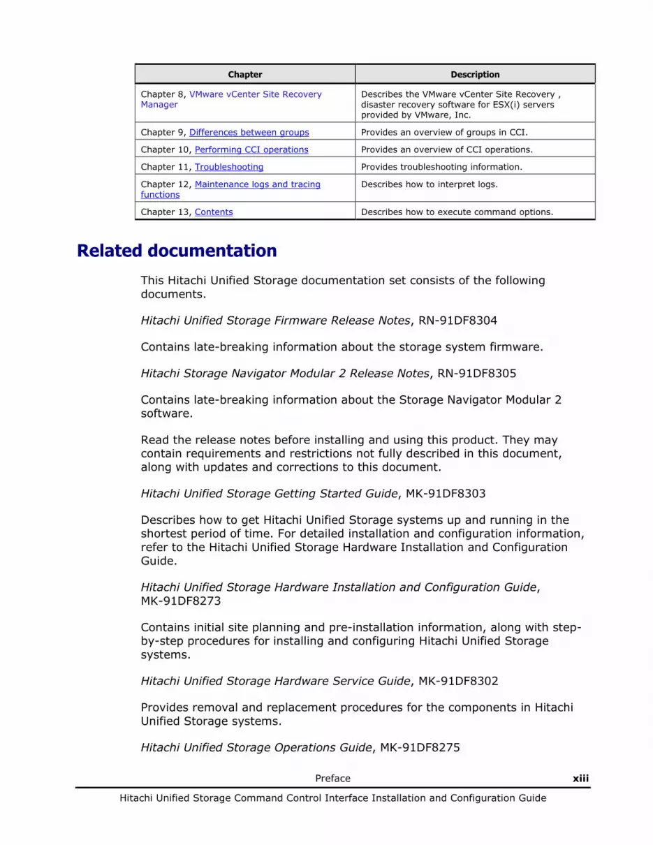
This Hitachi Unified Storage documentation set consists of the following documents.
Hitachi Unified Storage Firmware Release Notes, RN-91DF8304
Contains late-breaking information about the storage system firmware.
Hitachi Storage Navigator Modular 2 Release Notes, RN-91DF8305
Contains late-breaking information about the Storage Navigator Modular 2 software.
Read the release notes before installing and using this product. They may contain requirements and restrictions not fully described in this document, along with updates and corrections to this document.
Hitachi Unified Storage Getting Started Guide, MK-91DF8303
Describes how to get Hitachi Unified Storage systems up and running in the shortest period of time. For detailed installation and configuration information, refer to the Hitachi Unified Storage Hardware Installation and Configuration Guide.
Hitachi Unified Storage Hardware Installation and Configuration Guide, MK-91DF8273
Contains initial site planning and pre-installation information, along with step-by-step procedures for installing and configuring Hitachi Unified Storage systems.
Hitachi Unified Storage Hardware Service Guide, MK-91DF8302
Provides removal and replacement procedures for the components in Hitachi Unified Storage systems.
Hitachi Unified Storage Operations Guide, MK-91DF8275
xiv Preface
Hitachi Unified Storage Command Control Interface Installation and Configuration Guide
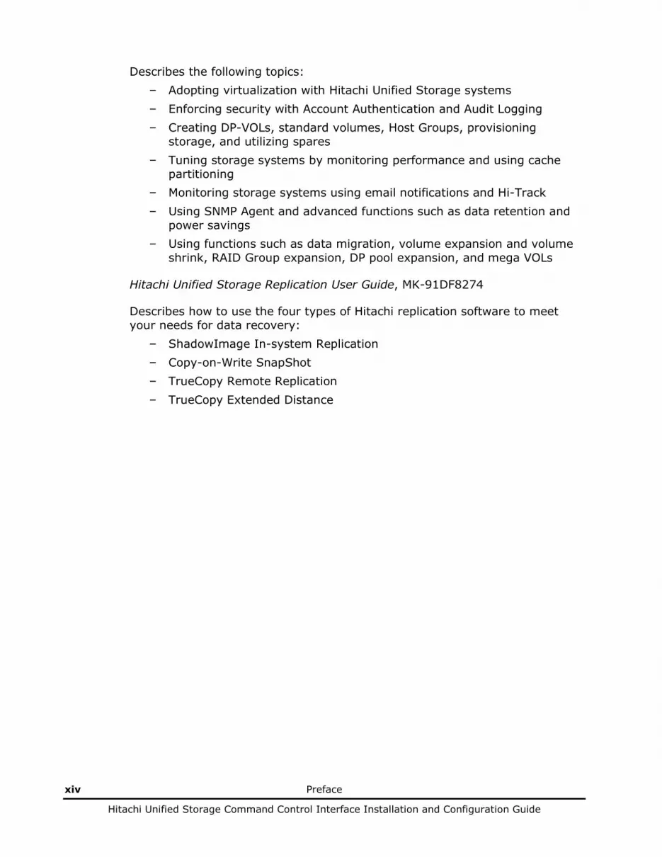
Describes the following topics: – Adopting virtualization with Hitachi Unified Storage systems – Enforcing security with Account Authentication and Audit Logging – Creating DP-VOLs, standard volumes, Host Groups, provisioning
storage, and utilizing spares – Tuning storage systems by monitoring performance and using cache
partitioning – Monitoring storage systems using email notifications and Hi-Track – Using SNMP Agent and advanced functions such as data retention and
power savings – Using functions such as data migration, volume expansion and volume
shrink, RAID Group expansion, DP pool expansion, and mega VOLs
Hitachi Unified Storage Replication User Guide, MK-91DF8274
Describes how to use the four types of Hitachi replication software to meet your needs for data recovery:
– ShadowImage In-system Replication – Copy-on-Write SnapShot – TrueCopy Remote Replication – TrueCopy Extended Distance
Preface xv
Hitachi Unified Storage Command Control Interface Installation and Configuration Guide
Hitachi Unified Storage Command Control Interface Installation and Configuration Guide, MK-91DF8306—this document
Describes Command Control Interface installation, operation, and troubleshooting.
Hitachi Unified Storage Dynamic Provisioning Configuration Guide, MK-91DF8277
Describes how to use virtual storage capabilities to simplify storage additions and administration.
Hitachi Unified Storage Command Line Interface Reference Guide, MK-91DF8276
Describes how to perform management and replication activities from a command line.
Document conventions
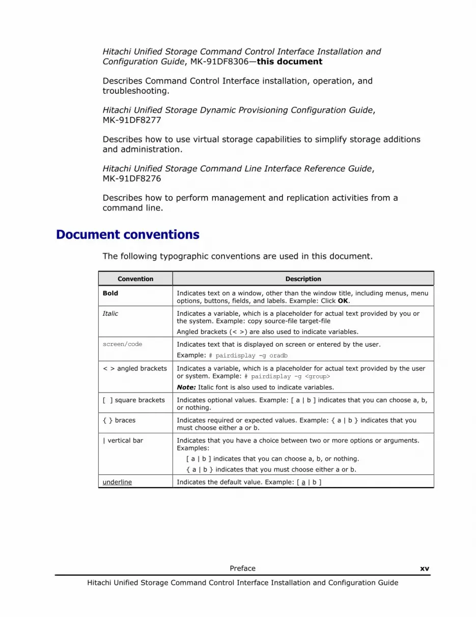
The following typographic conventions are used in this document.
Convention Description
Bold Indicates text on a window, other than the window title, including menus, menu options, buttons, fields, and labels. Example: Click OK.
Italic Indicates a variable, which is a placeholder for actual text provided by you or the system. Example: copy source-file target-file
Angled brackets (< >) are also used to indicate variables.
screen/code Indicates text that is displayed on screen or entered by the user.
Example: # pairdisplay -g oradb
< > angled brackets Indicates a variable, which is a placeholder for actual text provided by the user or system. Example: # pairdisplay -g <group>
Note: Italic font is also used to indicate variables.
[ ] square brackets Indicates optional values. Example: [ a | b ] indicates that you can choose a, b, or nothing.
{ } braces Indicates required or expected values. Example: { a | b } indicates that you must choose either a or b.
| vertical bar Indicates that you have a choice between two or more options or arguments. Examples:
[ a | b ] indicates that you can choose a, b, or nothing.
{ a | b } indicates that you must choose either a or b.
underline Indicates the default value. Example: [ a | b ]
xvi Preface
Hitachi Unified Storage Command Control Interface Installation and Configuration Guide
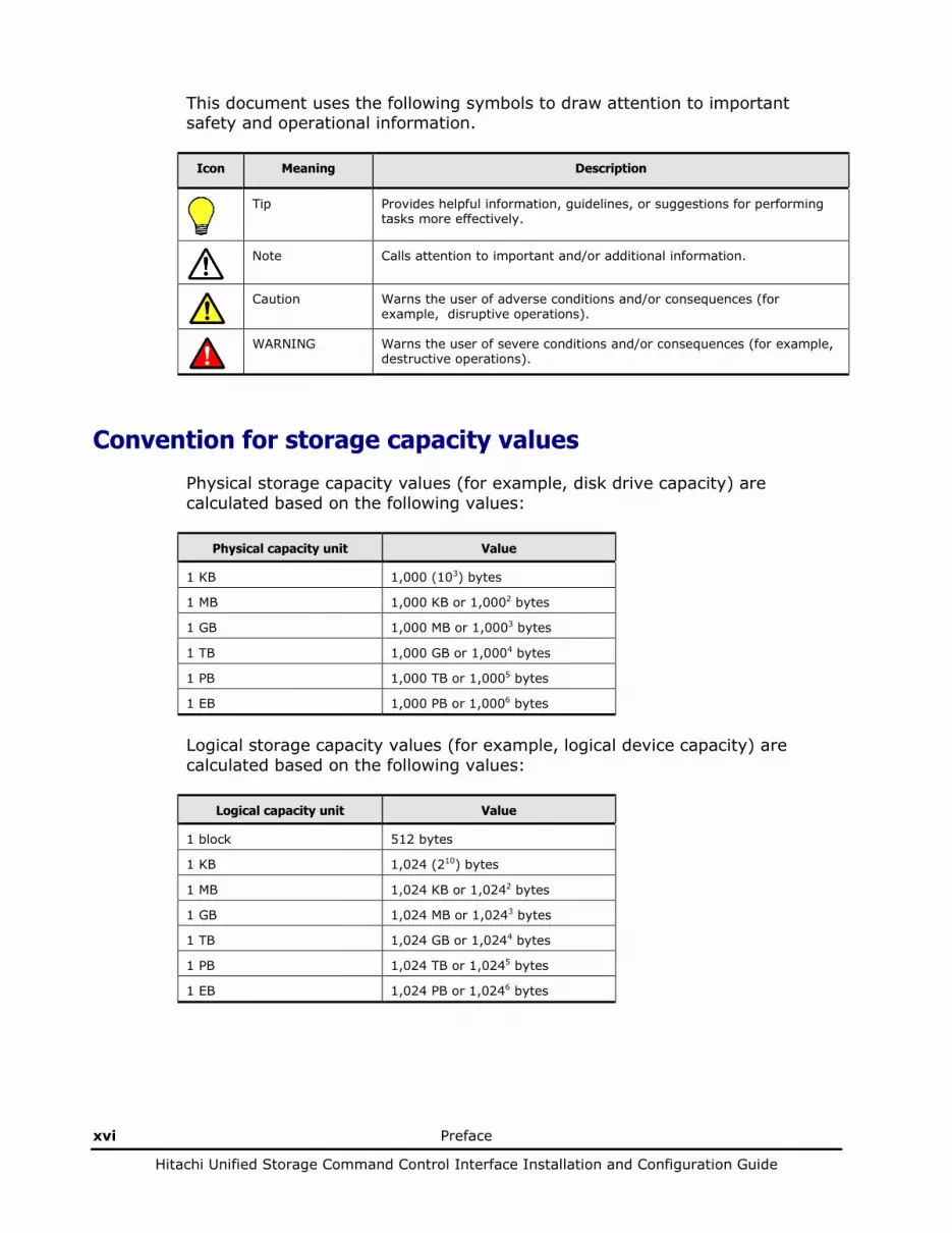
This document uses the following symbols to draw attention to important safety and operational information.
Icon Meaning Description
Tip Provides helpful information, guidelines, or suggestions for performing tasks more effectively.
Note Calls attention to important and/or additional information.
Caution Warns the user of adverse conditions and/or consequences (for example, disruptive operations).
WARNING Warns the user of severe conditions and/or consequences (for example, destructive operations).
Convention for storage capacity values
Physical storage capacity values (for example, disk drive capacity) are calculated based on the following values:
Physical capacity unit Value
1 KB 1,000 (103) bytes
1 MB 1,000 KB or 1,0002 bytes
1 GB 1,000 MB or 1,0003 bytes
1 TB 1,000 GB or 1,0004 bytes
1 PB 1,000 TB or 1,0005 bytes
1 EB 1,000 PB or 1,0006 bytes
Logical storage capacity values (for example, logical device capacity) are calculated based on the following values:
Logical capacity unit Value
1 block 512 bytes
1 KB 1,024 (210) bytes
1 MB 1,024 KB or 1,0242 bytes
1 GB 1,024 MB or 1,0243 bytes
1 TB 1,024 GB or 1,0244 bytes
1 PB 1,024 TB or 1,0245 bytes
1 EB 1,024 PB or 1,0246 bytes

Preface xvii
Hitachi Unified Storage Command Control Interface Installation and Configuration Guide
Accessing product documentation
The Hitachi Unified Storage user documentation is available on the HDS Support Portal: https://portal.hds.com. Please check this site for the most current documentation, including important updates that may have been made after the release of the product.
Getting help
The Hitachi Data Systems customer support staff is available 24 hours a day, seven days a week. If you need technical support, log on to the HDS Support Portal for contact information: https://portal.hds.com
Comments
Please send us your comments on this document: [email protected]. Include the document title and number, including the revision level (for example, -07), and refer to specific sections and paragraphs whenever possible. All comments become the property of Hitachi Data Systems.
Thank you!

xviii Preface
Hitachi Unified Storage Command Control Interface Installation and Configuration Guide
1
Installing CCI software 1-1
Hitachi Unified Storage Command Control Interface Installation and Configuration Guide
Installing CCI software
This chapter includes the following: CCI system requirements About CCI hardware installation About CCI software installation Changing the user on UNIX systems Creating/editing the configuration file Starting CCI
1-2 Installing CCI software
Hitachi Unified Storage Command Control Interface Installation and Configuration Guide
CCI system requirements
CCI operation involves the CCI software on a UNIX or PC host, and Hitachi Storage Navigator Modular 2, ShadowImage, SnapShot, TrueCopy, and/or TCE primary and secondary volumes command sets on the array. From Storage Navigator Modular 2, specify a local and a remote path for the disk array.
Following are the system requirements for CCI:
• CCI software-CCI software is supplied on a CD-ROM. CCI software files require up to 5.5 MBs of space. Log files require up to 3 MBs of space.
• Host platform-CCI is supported on several UNIX®-based and PC host platforms, including Solaris, HP-UX, AIX, Linux, Tru64 UNIX, IRIX, and Windows Server™ (indicates Windows Server 2003, Windows Server 2008, and Windows Server 2012). See the Hitachi Data Systems Interoperability matrix for details on supported versions: http://www.hds.com/products/interoperability
• Access-Root/administrator access to the host is required to perform CCI operations.
• Memory-Static memory capacity should range from a minimum of 600 kB and a maximum of 1,200 kB. Dynamic memory capacity should range from a minimum of 200 kB times the number of unit IDs plus 360 bytes times the number of volumes plus 180 bytes times the number of entries, depending on what HORCM_CONF is set at.
• Operating system usage-Sometimes the local and remote hosts cannot recognize paired logical volumes. Use hosts with the same operating systems. However, a combination of HP-UX, Solaris, AIX, Windows, and Linux hosts can be used for pair operation only.
• Disk array-Disk arrays support CCI. The command device must be defined and accessed as a raw device. File systems and mounted operations are not supported.
• Hitachi Storage Navigator Modular 2-Software program used to define the volumes, perform remote path using TrueCopy/TCE, and to access the CCI command line.
Table 1-1 Applicable platforms
Vendor Operating system
HP HP-UX 11i V1.0 (PA-RISC)
HP-UX 11i V2.0 (PA-RISC)
HP-UX 11i V3.0 (PA-RISC)
HP-UX 11i V2.0 (IPF)
HP-UX 11i V3.0 (IPF)
Tru64 UNIX 5.1

Installing CCI software 1-3
Hitachi Unified Storage Command Control Interface Installation and Configuration Guide
Vendor Operating system
Oracle Solaris 8 (SPARC)
Solaris 9 (SPARC)
Solaris 10 (SPARC)
Solaris 10 (x86)
Solaris 10 (x64)
Solaris 11 (SPARC)
Solaris 11 (x64)
IBM AIX 5.1
AIX 5.2
AIX 5.3
AIX 6.1
Microsoft Windows Server 2003 (IA32)
Windows Server 2008 (IA32)
Windows Server 2003 (x64)
Windows Server 2008 (x64)
Windows Server 2003 (IA64)
Windows Server 2008 (IA64)
Windows Server 2012 (x64)
Red Hat Red Hat Linux AS 2.1 (IA32)
Red Hat Linux AS/ES 3.0 (IA32)
Red Hat Linux AS/ES 4.0 (IA32)
Red Hat Linux AS/ES 5.0 (IA32)
Red Hat Linux AS/ES 3.0 (AMD64/EM64T)
Red Hat Linux AS/ES 4.0 (AMD64/EM64T)
Red Hat Linux AS/ES 6.0 (x64)
Red Hat Linux AS/ES 5.0 (AMD64/EM64T) Note 1
Red Hat Linux AS/ES 6.0 (AMD64/EM64T) Note 1
Red Hat Linux AS/ES 3.0 (IA64)
Red Hat Linux AS/ES 4.0 (IA64) Note 2
SGI IRIX 6.5.x
Note 1: The 32-bit library is required to execute the 32-bit version of CCI commands in the AMD64/EM64T environment. If the 32-bit library is not installed in the AMD64/EM64T by default, install the 32-bit library.
Note 2: To execute the CCI command when Red Hat Linux® AS4.0 is used in the IPF environment (IA64), it is required to install the IA-32EL (Execution Layer). When you install the IA-32EL, install all the 32-bit compatible packages (except CCI for Linux/IA64).

1-4 Installing CCI software
Hitachi Unified Storage Command Control Interface Installation and Configuration Guide
Table 1-2 Applicable virtual OS
Vendor Host Operating System Guest Operating System
VMware (IA32) VMware ESX Server 3.0 Windows Server 2003
Red Hat Linux AS3.0
Red Hat Linux AS4.0
VMware ESX Server 4.0 Windows Server 2003
Windows Server 2008
VMware ESXi Server 5.0 Windows Server 2003
Windows Server 2008
Windows Server 2012
Red Hat Linux AS5.0
Red Hat Linux 6.2
VMware ESXi Server 5.1 Red Hat Linux 6.2
Windows Server 2012
Microsoft Windows Server 2008 Hyper-V Windows Server 2003 SP2
Windows Server 2008
Windows Server 2008 R2 Hyper-V2.0 Windows Server 2003 SP2
Windows Server 2008 R2
Windows Server 2012 Hyper-V Windows Server 2012
Red Hat Linux 6.2
Hitachi Virtage (58-12) Windows Server 2008 R2
Red Hat Enterprise Linux 5.4
Table 1-3 IPv6 supported platforms
Vendor Operating System IPv6 (Note) IPv4 Mapped IPv6
HP HP-UX 11i V2.0 (PA-RISC)
HP-UX 11i V3.0 (PA-RISC)
HP-UX 11i V2.0 (IPF)
HP-UX 11i V3.0 (IPF)
Oracle Solaris 8 (SPARC)
Solaris 9 (SPARC)
Solaris 10 (SPARC)
Solaris 10 (x86)
Solaris 10 (x64)
IBM AIX 5.1
AIX 5.2
AIX 5.3
AIX 6.1

Installing CCI software 1-5
Hitachi Unified Storage Command Control Interface Installation and Configuration Guide
Vendor Operating System IPv6 (Note) IPv4 Mapped IPv6
Microsoft Windows Server 2003 + IPv6 install (IA32) N/A
Windows Server 2008 (IA32) N/A
Windows Server 2003 + IPv6 install (x64) N/A
Windows Server 2008 (x64) N/A
Windows Server 2003 + IPv6 install (IA64) N/A
Windows Server 2008 (IA64) N/A
Windows Server 2012 (x64) N/A
Red Hat Red Hat Linux AS/ES 2.1 (IA32)
Red Hat Linux AS/ES 3.0 (IA32)
Red Hat Linux AS/ES 4.0 (IA32)
Red Hat Linux AS/ES 5.0 (IA32)
Red Hat Linux AS/ES 3.0 (AMD64/EM64T)
Red Hat Linux AS/ES 4.0 (AMD64/EM64T)
Red Hat Linux AS/ES 5.0 (AMD64/EM64T)
Red Hat Linux AS/ES 6.0 (AMD64/EM64T)
Red Hat Linux AS/ES 3.0 (IA64)
Red Hat Linux AS/ES 4.0 (IA64)
Note: For more details about the IPv6 supporting, see IPv6 support in CCI on page 4-120.

1-6 Installing CCI software
Hitachi Unified Storage Command Control Interface Installation and Configuration Guide
About CCI hardware installation
The hardware required for CCI is installed by the user and an Hitachi representative.
Following are the responsibilities of the user:
• Identify the ShadowImage, SnapShot, and/or TrueCopy/TCE primary and secondary volumes, so that CCI hardware and software components can be installed and configured properly.
• Verify that the UNIX/PC host hardware and software are properly installed and configured. Refer to CCI system requirements for system requirements.
• Connect the disk arrays to the UNIX/PC hosts.
• Install and enable ShadowImage, SnapShot, and/or TrueCopy/TCE on the disk arrays.

Installing CCI software 1-7
Hitachi Unified Storage Command Control Interface Installation and Configuration Guide
About CCI software installation
The user, with assistance as needed from an Hitachi representative, installs CCI software.
Installing software on a UNIX system
An offer medium is placed in a preservation format cpio. When you install CCI
When you install from a CD, use RMinstsh under ./program/RM/version name/OS name on the CD (for Linux/IA64, move the directory to LINUX/X64). At this time, you need to move the current directory to the directory containing the RMinstsh you are going to use before executing it. If you are using Linux/IA64, move the directory to LINUX/IA64 and execute ../../RMinstsh. It is recommended that you install the software on a disk that is not the root disk. Installation of other applications or the storage of data may impact the root disk.
When the other media is provided as an installation media, follow the next procedure.
Installing in a non-root directory 1. Insert the installation medium in the appropriate drive. 2. Move to the desired directory for CCI.
The specified directory must be mounted by a partition of except root disk or an external disk. # cd /<specified-directory>
3. Extract all files from the RMHORC file using the cpio command. # cpio -idmu < ./program/RM/01-23-03_08/HP-UX/RMHORC 01-23-03_08 = CCI version ./ = is mounted point
4. Make a symbolic link to the /HORCM directory. # ln -s /<specified-directory>/HORCM /HORCM
5. Execute the HORCM installation command. # /HORCM/horcminstall.sh
6. Verify the installation using the raidqry command. # raidqry –h Model : RAID-Manager/HP-UX Ver&Rev: XX-XX-XX/XX XX = product version number Usage : raidqry [options] for HORC -h Help/Usage :
1-8 Installing CCI software
Hitachi Unified Storage Command Control Interface Installation and Configuration Guide
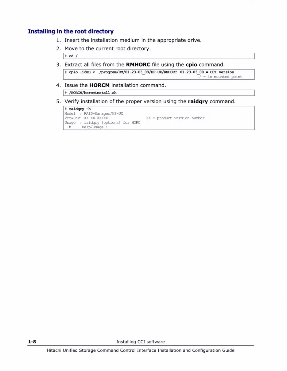
Installing in the root directory 1. Insert the installation medium in the appropriate drive. 2. Move to the current root directory.
# cd /
3. Extract all files from the RMHORC file using the cpio command. # cpio -idmu < ./program/RM/01-23-03_08/HP-UX/RMHORC 01-23-03_08 = CCI version ./ = is mounted point
4. Issue the HORCM installation command. # /HORCM/horcminstall.sh
5. Verify installation of the proper version using the raidqry command. # raidqry –h Model : RAID-Manager/HP-UX Ver&Rev: XX-XX-XX/XX XX = product version number Usage : raidqry [options] for HORC -h Help/Usage :

Installing CCI software 1-9
Hitachi Unified Storage Command Control Interface Installation and Configuration Guide
Installing software on a Windows Server system
Install CCI on all hosts using CCI. If a TCP/IP network is not established, install a Windows Server network, and add TCP/IP protocol.
To install the CCI software on Windows Server system:
1. If a previous version of CCI is already installed, remove it as follows: a. Confirm that HORCM is not running. If it is running, shut it down:
One CCI instance: D:\HORCM\etc> horcmshutdown
Two CCI instances: D:\HORCM\etc> horcmshutdown 0 1
b. If Hitachi replication software commands are running in the interactive mode, terminate the interactive mode and exit these commands using the -q option.
c. Remove the previous version of CCI using the Add/Remove Programs control panel.
2. Insert the installation medium into the proper I/O device. 3. Run Setup.exe and follow the instructions on screen to complete the
installation.
4. Verify installation of the proper version using the raidqry command: D:\HORCM\etc> raidqry –h Model : RAID-Manager/WindowsNT Ver&Rev: XX-XX-XX/XX XX = product version number Usage : raidqry [options] for HORC -h Help/Usage :
1-10 Installing CCI software
Hitachi Unified Storage Command Control Interface Installation and Configuration Guide
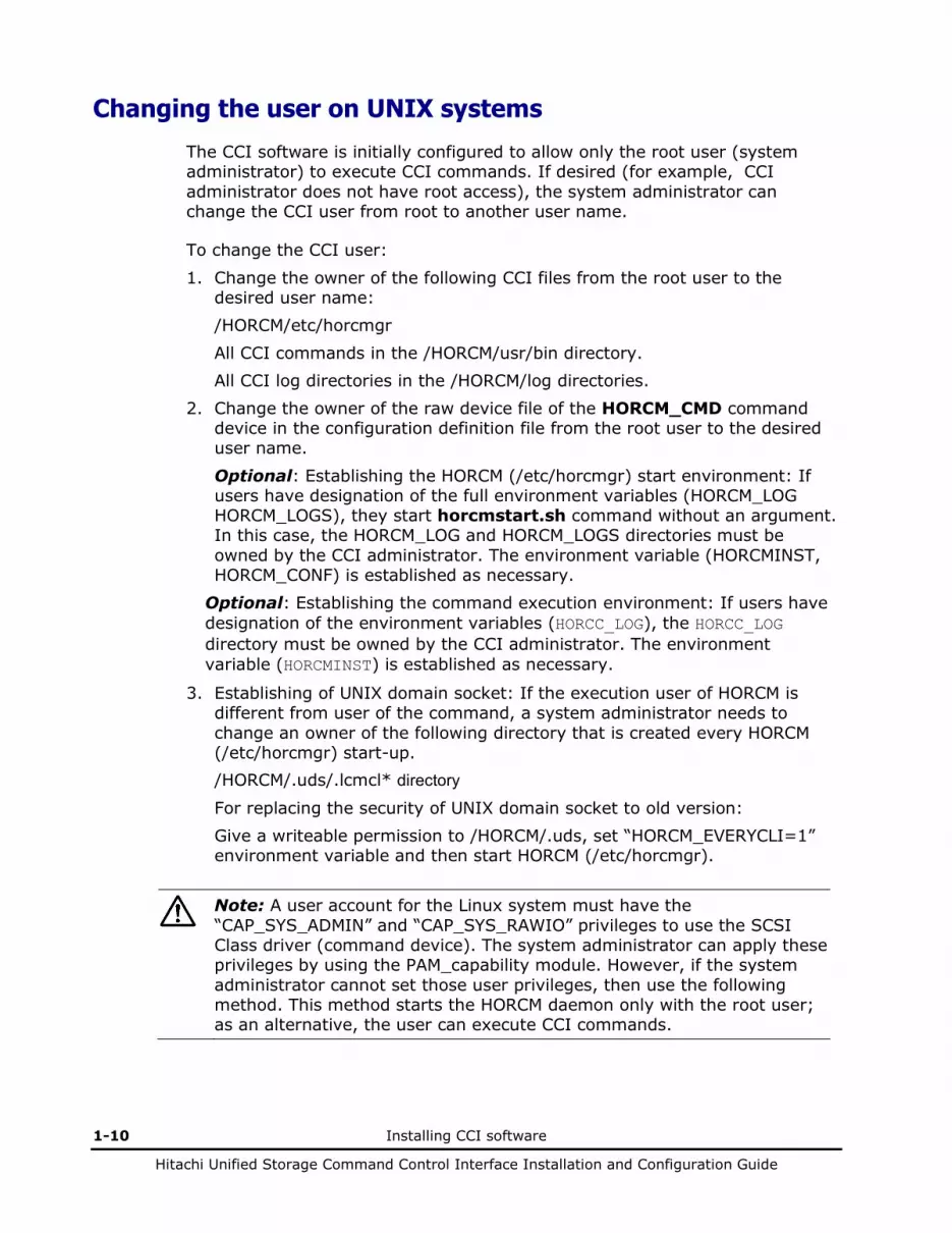
Changing the user on UNIX systems
The CCI software is initially configured to allow only the root user (system administrator) to execute CCI commands. If desired (for example, CCI administrator does not have root access), the system administrator can change the CCI user from root to another user name.
To change the CCI user:
1. Change the owner of the following CCI files from the root user to the desired user name: /HORCM/etc/horcmgr All CCI commands in the /HORCM/usr/bin directory. All CCI log directories in the /HORCM/log directories.
2. Change the owner of the raw device file of the HORCM_CMD command device in the configuration definition file from the root user to the desired user name.
Optional: Establishing the HORCM (/etc/horcmgr) start environment: If users have designation of the full environment variables (HORCM_LOG HORCM_LOGS), they start horcmstart.sh command without an argument. In this case, the HORCM_LOG and HORCM_LOGS directories must be owned by the CCI administrator. The environment variable (HORCMINST, HORCM_CONF) is established as necessary.
Optional: Establishing the command execution environment: If users have designation of the environment variables (HORCC_LOG), the HORCC_LOG directory must be owned by the CCI administrator. The environment variable (HORCMINST) is established as necessary.
3. Establishing of UNIX domain socket: If the execution user of HORCM is different from user of the command, a system administrator needs to change an owner of the following directory that is created every HORCM (/etc/horcmgr) start-up. /HORCM/.uds/.lcmcl* directory
For replacing the security of UNIX domain socket to old version: Give a writeable permission to /HORCM/.uds, set “HORCM_EVERYCLI=1” environment variable and then start HORCM (/etc/horcmgr).
Note: A user account for the Linux system must have the “CAP_SYS_ADMIN” and “CAP_SYS_RAWIO” privileges to use the SCSI Class driver (command device). The system administrator can apply these privileges by using the PAM_capability module. However, if the system administrator cannot set those user privileges, then use the following method. This method starts the HORCM daemon only with the root user; as an alternative, the user can execute CCI commands.
Installing CCI software 1-11
Hitachi Unified Storage Command Control Interface Installation and Configuration Guide
• System administrator: Place the script that starts up horcmstart.sh in the following directory so that the system can start HORCM from /etc/rc.d/rc: /etc/init.d
• Users: When the log directory is only accessible by the system administrator, you cannot use the inqraid or raidscan -find commands. Therefore, set the command log directory by setting the environment variables (HORCC_LOG), and executing the CCI command.
Note: In Windows CCI, it is required to specify the installation destination folder to the HORCM folder directly under the drive.
Creating/editing the configuration file
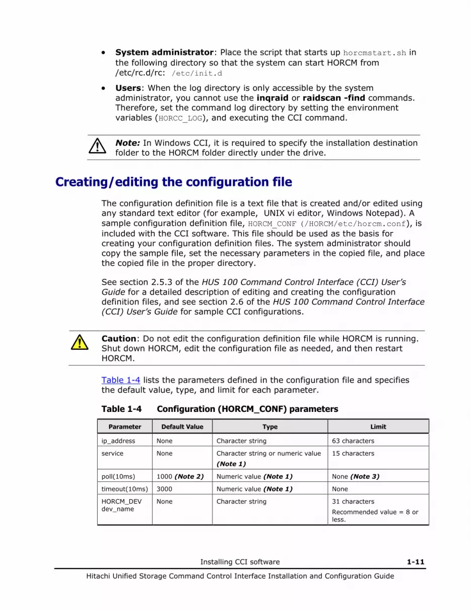
The configuration definition file is a text file that is created and/or edited using any standard text editor (for example, UNIX vi editor, Windows Notepad). A sample configuration definition file, HORCM_CONF (/HORCM/etc/horcm.conf), is included with the CCI software. This file should be used as the basis for creating your configuration definition files. The system administrator should copy the sample file, set the necessary parameters in the copied file, and place the copied file in the proper directory.
See section 2.5.3 of the HUS 100 Command Control Interface (CCI) User’s Guide for a detailed description of editing and creating the configuration definition files, and see section 2.6 of the HUS 100 Command Control Interface (CCI) User’s Guide for sample CCI configurations.
Caution: Do not edit the configuration definition file while HORCM is running. Shut down HORCM, edit the configuration file as needed, and then restart HORCM.
Table 1-4 lists the parameters defined in the configuration file and specifies the default value, type, and limit for each parameter.
Table 1-4 Configuration (HORCM_CONF) parameters
Parameter Default Value Type Limit
ip_address None Character string 63 characters
service None Character string or numeric value
(Note 1) 15 characters
poll(10ms) 1000 (Note 2) Numeric value (Note 1) None (Note 3)
timeout(10ms) 3000 Numeric value (Note 1) None
HORCM_DEV dev_name
None Character string 31 characters
Recommended value = 8 or less.
1-12 Installing CCI software
Hitachi Unified Storage Command Control Interface Installation and Configuration Guide
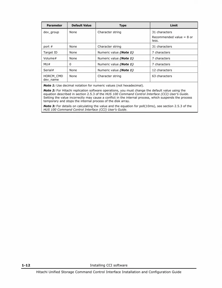
Parameter Default Value Type Limit
dev_group None Character string 31 characters
Recommended value = 8 or less.
port # None Character string 31 characters
Target ID None Numeric value (Note 1) 7 characters
Volume# None Numeric value (Note 1) 7 characters
MU# 0 Numeric value (Note 1) 7 characters
Serial# None Numeric value (Note 1) 12 characters
HORCM_CMD dev_name
None Character string 63 characters
Note 1: Use decimal notation for numeric values (not hexadecimal).
Note 2: For Hitachi replication software operations, you must change the default value using the equation described in section 2.5.3 of the HUS 100 Command Control Interface (CCI) User’s Guide. Setting the value incorrectly may cause a conflict in the internal process, which suspends the process temporary and stops the internal process of the disk array.
Note 3: For details on calculating the value and the equation for poll(10ms), see section 2.5.3 of the HUS 100 Command Control Interface (CCI) User’s Guide.
Installing CCI software 1-13
Hitachi Unified Storage Command Control Interface Installation and Configuration Guide
Starting CCI
After you have installed the CCI software (refer to About CCI software installation ) and set the configuration definition files (refer to Creating/editing the configuration file), you can begin using the CCI software (HORCM) to perform ShadowImage, SnapShot, and/or TrueCopy/TCE operations on the attached disk arrays.
In the environment where multiple host groups are defined, when the high-load host I/O is executed, the start time of HORCM may be long. Be careful of the host I/O load and start HORCM.
Starting UNIX systems
You can start up to two CCI instances on a UNIX system.
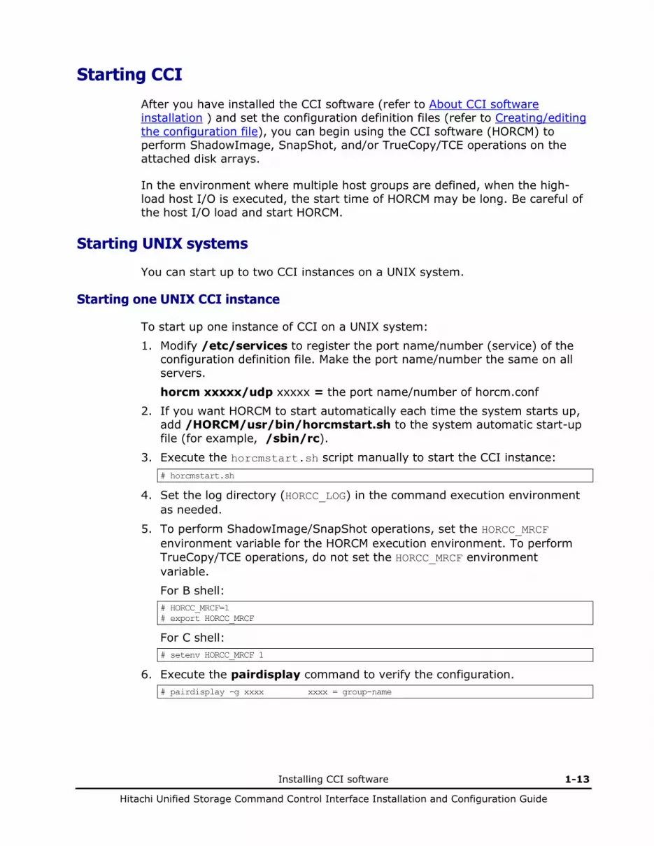
Starting one UNIX CCI instance
To start up one instance of CCI on a UNIX system: 1. Modify /etc/services to register the port name/number (service) of the
configuration definition file. Make the port name/number the same on all servers. horcm xxxxx/udp xxxxx = the port name/number of horcm.conf
2. If you want HORCM to start automatically each time the system starts up, add /HORCM/usr/bin/horcmstart.sh to the system automatic start-up file (for example, /sbin/rc).
3. Execute the horcmstart.sh script manually to start the CCI instance: # horcmstart.sh
4. Set the log directory (HORCC_LOG) in the command execution environment as needed.
5. To perform ShadowImage/SnapShot operations, set the HORCC_MRCF environment variable for the HORCM execution environment. To perform TrueCopy/TCE operations, do not set the HORCC_MRCF environment variable. For B shell: # HORCC_MRCF=1 # export HORCC_MRCF
For C shell: # setenv HORCC_MRCF 1
6. Execute the pairdisplay command to verify the configuration. # pairdisplay -g xxxx xxxx = group-name

1-14 Installing CCI software
Hitachi Unified Storage Command Control Interface Installation and Configuration Guide
Starting two UNIX CCI instances
To start up two instances of CCI on a UNIX system: 1. Make two copies of the sample configuration definition file.
# cp /etc/horcm.conf /etc/horcm0.conf # cp /etc/horcm.conf /etc/horcm1.conf
2. Modify /etc/services to register the port name/number (service) of each configuration definition file. The port name/number must be different for each CCI instance. horcm0 xxxxx/udp xxxxx = the port name/number for horcm0.conf
horcm1 yyyyy/udp yyyyy = the port name/number for horcm1.conf
3. If you want HORCM to start automatically each time the system starts up, add /etc/horcmstart.sh 0 1 to the system automatic start-up file (for example, /sbin/rc).
4. Execute the horcmstart.sh script manually to start the CCI instances: # horcmstart.sh 0 1
5. Set an instance number to the environment which executes a command: For B shell: # HORCMINST=X X = instance number = 0 or 1 # export HORCMINST
For C shell: # setenv HORCMINST X
6. Set the log directory (HORCC_LOG) in the command execution environment as needed.
7. To perform ShadowImage/SnapShot operations, set the HORCC_MRCF environment variable for the HORCM execution environment. To perform TrueCopy/TCE operations, do not set the HORCC_MRCF environment variable. For B shell: # HORCC_MRCF=1 # export HORCC_MRCF
For C shell: # setenv HORCC_MRCF 1
8. Execute the pairdisplay command to verify the configuration.
Installing CCI software 1-15
Hitachi Unified Storage Command Control Interface Installation and Configuration Guide
Starting Windows systems
You can start up to two CCI instances on a Windows system.
Starting One Windows CCI instance
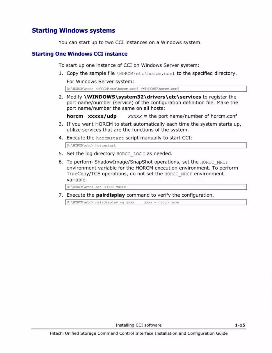
To start up one instance of CCI on Windows Server system:
1. Copy the sample file \HORCM\etc\horcm.conf to the specified directory.
For Windows Server system: D:\HORCM\etc> \HORCM\etc\horcm.conf \WINDOWS\horcm.conf
2. Modify \WINDOWS\system32\drivers\etc\services to register the port name/number (service) of the configuration definition file. Make the port name/number the same on all hosts: horcm xxxxx/udp xxxxx = the port name/number of horcm.conf
3. If you want HORCM to start automatically each time the system starts up, utilize services that are the functions of the system.
4. Execute the horcmstart script manually to start CCI: D:\HORCM\etc> horcmstart
5. Set the log directory HORCC_LOG t as needed.
6. To perform ShadowImage/SnapShot operations, set the HORCC_MRCF environment variable for the HORCM execution environment. To perform TrueCopy/TCE operations, do not set the HORCC_MRCF environment variable. D:\HORCM\etc> set HORCC_MRCF=1
7. Execute the pairdisplay command to verify the configuration. D:\HORCM\etc> pairdisplay -g xxxx xxxx = group name

1-16 Installing CCI software
Hitachi Unified Storage Command Control Interface Installation and Configuration Guide
Starting Two Windows CCI instances
To start up two instances of CCI on a Windows Server system: 1. Make two copies of the sample configuration definition file.
For Windows Server system: D:\HORCM\etc> copy \HORCM\etc\horcm.conf \WINDOWS\horcm0.conf D:\HORCM\etc> copy \HORCM\etc\horcm.conf \WINDOWS\horcm1.conf
2. Modify \WINDOWS\system32\drivers\etc\services to register the port name/number (service) of the configuration definition files. Make sure that the port name/number is different for each instance: horcm0 xxxxx/udp xxxxx = the port name/number of horcm0.conf
horcm1 yyyyy/udp yyyyy = the port name/number of horcm1.conf
3. If you want HORCM to start automatically each time the system starts up, utilize services that are the functions of the system.
4. Execute the horcmstart script manually to start CCI: D:\HORCM\etc> horcmstart 0 1
5. Set an instance number to the environment which executes a command: D:\HORCM\etc> set HORCMINST=X X = instance number = 0 or 1
6. Set the log directory HORCC_LOG in the command execution environment as needed.
7. To perform ShadowImage/SnapShot operations, set the HORCC_MRCF environment variable for the HORCM execution environment. To perform TrueCopy/TCE operations, do not set the HORCC_MRCF environment variable. D:\HORCM\etc> set HORCC_MRCF=1
8. Issue the pairdisplay command to verify the configuration. D:\HORCM\etc> pairdisplay -g xxxx xxxx = group name
Installing CCI software 1-17
Hitachi Unified Storage Command Control Interface Installation and Configuration Guide
Starting CCI as a service
Usually, CCI (HORCM) is started by executing the start-up script from the Windows services. However, in the VSS environment, there is no interface to automatically start CCI. As a result, CCI provides the following svcexe.exe command and a sample script (HORCM0_run.txt) file so that CCI can be started automatically from the services:
C:\HORCM\tool\>svcexe
• Usage for adding [HORCM_START_SVC]: svcexe /A=command_path – For deleting [HORCM_START_SVC]: svcexe /D – For specifying a service: svcexe /S=service_name – For dependent services: svcexe /C=service_name,service_name
This command example uses HORCM0 for the registration of the service name for HORCM instance#0:
• Example for adding [HORCM0]: svcexe /S=HORCM0 “/A=C:\HORCM\Tool\svcexe.exe” – For deleting [HORCM0]: svcexe /S=HORCM0 /D – For starting [HORCM0] : – [1] make a C:\HORCM\Tool\HORCM0_run.txt file.
:[2] set a user account to this service. :[3] confirm to start by horcmstart 0. :[4] confirm to stop by horcmshutdown 0. :[5] start from a service by net start HORCM0.
Performing additional configuration tasks
1. Registering the HORCM instance as a service. The system administrator must add the HORCM instance by using the following command: C:\HORCM\Tool\>svcexe /S=HORCM0 “/A=C:\HORCM\Tool\svcexe.exe”
2. Customizing a sample script file. The system administrator must customize the sample script file HORCM0_run.txt according to the HORCM instance. For details, refer to the descriptions in the HORCM0_run.txt file.
3. Setting the user account. The system administrator must set the user account for the CCI administrator by using the GUI.

1-18 Installing CCI software
Hitachi Unified Storage Command Control Interface Installation and Configuration Guide
4. Starting the HORCM instance from the service. After you have confirmed starting and stopping using “horcmstart 0” and “horcmshutdown 0”, you must verify that HORCM0 starts from the service and that HORCM0 started automatically from REBOOT, using the following command: C:\HORCM\Tool\>net start HORCM0
5. Stopping HORCM instance as a service. Instead of using the horcmshutdown 0 command, you must use the following command to stop HORCM0:
C:\HORCM\Tool\>net stop HORCM0 (By using the horcmshutdown 0 command, the script written into HORCM0_run.txt will automatically restart HORCM0). Note: The sample script (HORCM0_run.txt) is overwritten when RAID Manager is upgraded. Be sure to use a different service name than HORCM0. If HORCM0 is being used as a service name, have a backup of the HORCM0_run.txt before upgrading RAID Manager and replace it with the backup after the upgrade.

2
Uninstalling and upgrading CCI software 2-1
Hitachi Unified Storage Command Control Interface Installation and Configuration Guide
Uninstalling and upgrading CCI software
This chapter includes the following:
Uninstalling CCI software on UNIX systems Upgrading CCI software on UNIX systems Upgrading CCI software on Windows Server

2-2 Uninstalling and upgrading CCI software
Hitachi Unified Storage Command Control Interface Installation and Configuration Guide
Uninstalling CCI software on UNIX systems
To uninstall the CCI software, perform the following procedure: 1. Before uninstalling the CCI software, delete all
ShadowImage/SnapShot/TrueCopy/TCE pairs. However, in case of a plan to continue the copy operation using Navigator 2, do not delete all volume pairs. If the CCI software is still running when you want to uninstall, shut down the CCI software using the horcmshutdown.sh command to ensure a normal end to all Hitachi replication software functions. When the CCI command is started in the interactive mode, use the -q option, and terminate the interactive mode. After verifying that the CCI software is not running, you can uninstall the CCI software.
2. When the installation media is provided by a CD, use the RMuninst script under the./program/RM/version name directory on the CD. If there is no CD, CCI can be uninstalled manually in the following method shown below. To uninstall the CCI software from a root directory (see Figure 2-1), issue the uninstall command. Go to the root directory, and delete the HORCM directory. To uninstall the CCI software from a non-root directory (see Figure 2-2), issue the uninstall command. Go to the root directory, delete the HORCM link and delete the HORCM directory.
#/HORCM/horcmuninstall.sh Issue the uninstall command. #cd / Change directories. #rm -rf /HORCM Delete the CCI directory.
Figure 2-1 Uninstalling CCI software from a root directory
#/HORCM/horcmuninstall.sh Issue the uninstall command. #cd / Change directories. #rm /HORCM Delete the CCI link. #rm -rf /non-root_directory_name/HORCM Delete the CCI directory.
Figure 2-2 Uninstalling CCI software from a non-root directory
Upgrading CCI software on UNIX systems
After verifying that CCI is not running, you can upgrade the CCI software. If CCI is still running when you want to upgrade software versions, shut down the CCI software using the horcmshutdown.sh command to ensure a normal end to all Hitachi replication software functions. Uninstalling CCI software on Windows Server
To uninstall the CCI software, execute the following procedure.
Uninstalling and upgrading CCI software 2-3
Hitachi Unified Storage Command Control Interface Installation and Configuration Guide
1. Before uninstalling the CCI software, delete all ShadowImage/SnapShot/TrueCopy/TCE pairs. However, in case of a plan to continue the copy operation using Navigator 2, do not delete all volume pairs. If the CCI software is still running when you want to uninstall, shut down the CCI software using the horcmshutdown command to ensure a normal end to all Hitachi replication software functions. When the CCI command is started in the interactive mode, use the -q option, and terminate the interactive mode. After verifying that the CCI software is not running, you can uninstall the CCI software.
2. On the Control panel, select the Add or Remove Programs option. 3. When the Add or Remove Programs Properties panel opens, choose the
Change or Remove Programs and select CCI from the program products list.
4. Select the Remove button to remove the CCI software.
Upgrading CCI software on Windows Server
After verifying that the CCI software is not running, you can upgrade the CCI software. If the CCI software is still running when you want to upgrade software versions, shut down the CCI software using the horcmshutdown command to ensure a normal end to all Hitachi replication software functions. To upgrade the CCI software: 1. On the Control panel, select the Add or Remove Programs option. 2. When the Add or Remove Programs Properties panel opens, choose the
Change or Remove Programs and select CCI from the program products list.
3. Select the Remove button to remove the CCI software. 4. Insert the installation medium in the proper I/O device. 5. From the Start menu, select Run. 6. When the Run window opens, enter x:\Setup.exe (where x: is a CD drive)
in the Open pull-down list box.
7. An InstallShield will open. Follow the on screen instructions to install the CCI software.
8. Verify that the correct version of the CCI software is running on your system by executing the raidqry -h command.

2-4 Uninstalling and upgrading CCI software
Hitachi Unified Storage Command Control Interface Installation and Configuration Guide
3
About copy solutions 3-1
Hitachi Unified Storage Command Control Interface Installation and Configuration Guide
About copy solutions
This chapter includes the following: About CCI ShadowImage SnapShot TrueCopy Synchronous/Asynchronous Remote Copy Contacting Technical Support

3-2 About copy solutions
Hitachi Unified Storage Command Control Interface Installation and Configuration Guide
About CCI
The Command Control Interface (CCI) software product provides command line control for ShadowImage, SnapShot, and Synchronous Remote Copy (TrueCopy), Asynchronous Remote Copy (TCE) operations on the array by issuing commands from the system hosts to the disk array. The CCI software interfaces with the system software and high-availability (HA) software on the system hosts as well as with the TrueCopy/TCE/ShadowImage/SnapShot software on the array. For additional information on ShadowImage, SnapShot, and TrueCopy, TCE, please refer to:
• Hitachi ShadowImage in-system replication User’s Guide.
• Hitachi Copy-on-write SnapShot User’s Guide.
• Hitachi TrueCopy remote replication User’s Guide.
• Hitachi TrueCopy Extended Distance User’s Guide.
CCI provides failover and operation commands that support mutual hot standby with industry-standard failover products. CCI also supports a scripting function for defining multiple ShadowImage/SnapShot/TrueCopy/TCE operations in a script (or text) file. Using CCI scripting, you can set up and issue a large number of ShadowImage/SnapShot/TrueCopy/TCE commands in a short period of time.
ShadowImage operations involve primary and secondary volumes within one array. The ShadowImage primary volumes (P-VOLs) contain the original data, and the S-VOLs are the internal duplicate volumes. ShadowImage allows up to eight S-VOLs to be created for each P-VOL. Each S-VOL is paired with the P-VOL independently, allowing each S-VOL to be maintained as an independent copy set. See ShadowImage for more information.
SnapShot operations involve primary (P-VOL) and SnapShot volumes (V-VOLs) within one array. The SnapShot P-VOLs contain the original data, and the V-VOLs are the logical duplicate volumes. SnapShot allows one to 1,024 V-VOLs to be created for each P-VOL. Each V-VOL is paired with the P-VOL independently, allowing each V-VOL to be maintained as an independent copy set. See SnapShot for more information.
TrueCopy/TCE operations involve the primary (main) arrays and the secondary (remote) arrays. The primary arrays contain the TrueCopy/TCE primary volumes (P-VOLs), which are the original data volumes. The secondary arrays contain the TrueCopy/TCE secondary volumes (S-VOLs). When TrueCopy/TCE is performed using CCI, you need to reserve and configure one volume on each array as the CCI command device. See TrueCopy Synchronous/Asynchronous Remote Copy for more information.

About copy solutions 3-3
Hitachi Unified Storage Command Control Interface Installation and Configuration Guide
ShadowImage
The ShadowImage feature enables you to set up and maintain multiple copies of logical volumes within the same disk array. ShadowImage operations for UNIX/PC host-based data can be performed using ShadowImage software on the host where CCI software is installed.
The CCI software on the UNIX/PC host displays ShadowImage information and allows you to perform ShadowImage operations by issuing commands from the UNIX/PC command line or by executing a script file. The CCI software interfaces with the disk array through a dedicated volume called a command device.
SnapShot
The SnapShot feature enables you to set up and maintain multiple copies of logical volumes within the same disk array. SnapShot operations for UNIX/PC host-based data can be performed using SnapShot software on the host where the CCI software is installed.
The CCI software on the UNIX/PC host displays SnapShot information and allows you to perform SnapShot operations by issuing commands from the UNIX/PC command line or by executing a script file. The CCI software interfaces with the disk array through a dedicated volume called a command device.
3-4 About copy solutions
Hitachi Unified Storage Command Control Interface Installation and Configuration Guide
TrueCopy Synchronous/Asynchronous Remote Copy
TrueCopy/TCE is an optional function and can be installed on the array. TrueCopy enables you to create and maintain remote copies of the data stored on the array for data backup and disaster recovery purposes.
TrueCopy/TCE operations can be performed using the Command Control Interface (CCI) software on a UNIX/PC server host. The CCI software on the UNIX/PC server displays TrueCopy/TCE information and allows you to perform TrueCopy/TCE operations from the UNIX command line or via a script file. The CCI software interfaces with the array through a dedicated volume called a command device.
Read the following guidelines and follow them; otherwise, a remote path failure will occur.
• When turning on the array where a path has already been set, turn on the remote array, and turn on the local array after the array becomes READY. When turning off the array where a remote path has already been set, turn off the local array and turn off the remote array.
• A path blockage that occurred while using the TrueCopy/TCE function, even if the remote array was off, also occurs. The remote array is turned on, and automatically recovered when the remote array is READY (about 4 minutes).
• If a remote path blockage is not recovered, regardless of being READY, call the Hitachi maintenance personnel.
About copy solutions 3-5
Hitachi Unified Storage Command Control Interface Installation and Configuration Guide
Contacting Technical Support
If a ShadowImage/TrueCopy suspended-error occurs, the cause is usually due to a failure in the hardware (or when the user forcibly suspends the pair). To recover from a suspended status (PSUE), the hardware error and data must be recovered. To accomplish this task, cooperation between the user and Hitachi maintenance personnel is necessary.
There is two cases of suspend failure (PSUE failure) of SnapShot/TCE: The first is a result of a hardware failure. The second occurs when the free capacity of the DP pool has run short. Recovery from the suspend failure caused by a hardware failure requires not only recovery from the hardware failure but also restoration of a pair. Therefore, it requires co-operation between the user and service personnel of Hitachi.
In order to prevent the suspend failure caused by a shortage of a free capacity of the DP pool, check the free capacity of the DP pool periodically and increase the DP pool capacity when necessary.
For PSUE error, check the CCI system log first. If the error is not caused by user operation, please contact Hitachi maintenance personnel.

3-6 About copy solutions
Hitachi Unified Storage Command Control Interface Installation and Configuration Guide

4
Overview of CCI 4-1
Hitachi Unified Storage Command Control Interface Installation and Configuration Guide
Overview of CCI
CCI allows you to perform ShadowImage, SnapShot, and TrueCopy, TCE operations by issuing ShadowImage/SnapShot/TrueCopy/TCE commands from the UNIX/PC host to the disk array. ShadowImage operations are non-disruptive and allow the primary volume of each volume pair to remain online to all hosts for both read and write operations (except when a hardware error occurs or error occurs during reverse -resync in ShadowImage).
This chapter includes the following: About paired volumes About CCI commands Using CCI commands About CCI software structure Configuration file examples Confirming configurations About VMware About Hyper-V Recovery procedures for HA IPv6 support in CCI Windows Power Shell

4-2 Overview of CCI
Hitachi Unified Storage Command Control Interface Installation and Configuration Guide
About paired volumes
The logical volumes, which have been handled independently by host machines, can be combined or separated in volume pairs that are being handled uniformly by the ShadowImage, SnapShot, TrueCopy, and TCE pairing function. ShadowImage, SnapShot, TrueCopy, and TCE regard those two volumes in a pair to be combined or separated as a unique paired logical volume used by the hosts. It is possible to handle paired volumes as groups by selecting them in units of host software or in units of the database and its attributes.
Oradb Special files
A and B
Host A
Special files C and D
Host B
Oradb
Group name: oradb
Paired logical volume
Volume A Volume C Oradb1
Paired logical volume
Volume B Volume D Oradb2
Special files C and D
Host C
Oradb
Local volume space of host A
Figure 4-1 Paired volumes
Addressing paired logical volumes: The I/O between paired logical volumes and physical volumes is defined by describing the intended paired logical volume names and group names in the configuration definition file of each host. Each paired logical volume must belong to a group in the configuration definition file. One group can contain logical volumes for one host, application, etc.
Specification of volumes by commands: CCI commands that specify a volume name must be given using the paired logical volume names or group names.
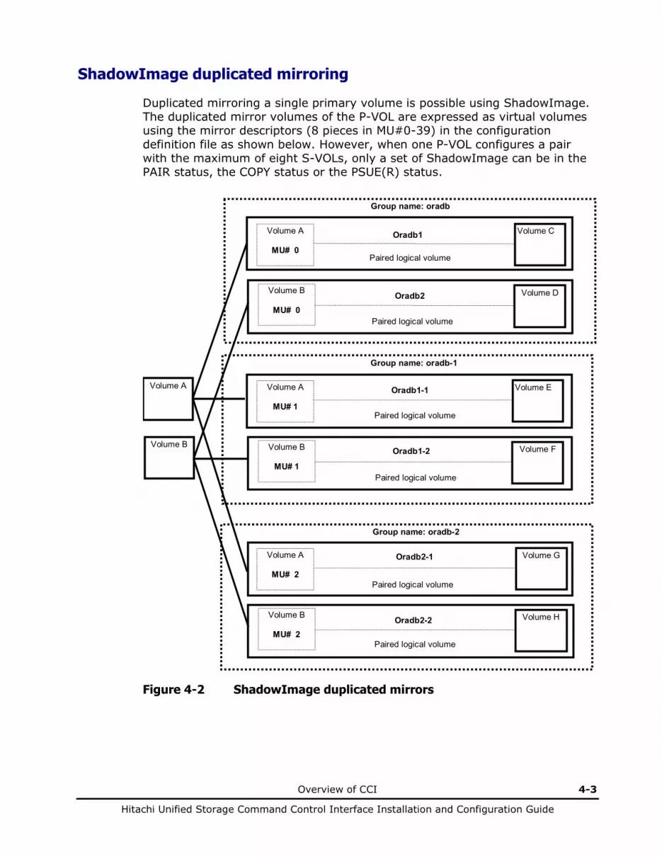
Overview of CCI 4-3
Hitachi Unified Storage Command Control Interface Installation and Configuration Guide
ShadowImage duplicated mirroring
Duplicated mirroring a single primary volume is possible using ShadowImage. The duplicated mirror volumes of the P-VOL are expressed as virtual volumes using the mirror descriptors (8 pieces in MU#0-39) in the configuration definition file as shown below. However, when one P-VOL configures a pair with the maximum of eight S-VOLs, only a set of ShadowImage can be in the PAIR status, the COPY status or the PSUE(R) status.
Group name: oradb
Paired logical volume
Volume COradb1
Paired logical volume
Volume DOradb2
Volume A
Volume B
Group name: oradb-1
Paired logical volume
Volume EOradb1-1
Paired logical volume
Volume FOradb1-2
Group name: oradb-2
Paired logical volume
Volume GOradb2-1
Paired logical volume
Volume HOradb2-2
Volume A
MU# 1
Volume B
MU# 1
Volume A
MU# 0
Volume B
MU# 0
Volume A
MU# 2
Volume B
MU# 2
Figure 4-2 ShadowImage duplicated mirrors
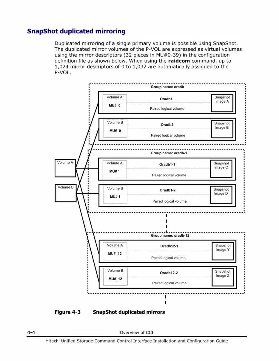
4-4 Overview of CCI
Hitachi Unified Storage Command Control Interface Installation and Configuration Guide
SnapShot duplicated mirroring
Duplicated mirroring of a single primary volume is possible using SnapShot. The duplicated mirror volumes of the P-VOL are expressed as virtual volumes using the mirror descriptors (32 pieces in MU#0-39) in the configuration definition file as shown below. When using the raidcom command, up to 1,024 mirror descriptors of 0 to 1,032 are automatically assigned to the P-VOL.
Group name: oradb
Paired logical volume
Snapshot Image A
Oradb1
Paired logical volume
Snapshot Image B
Oradb2
Volume A
Volume B
Group name: oradb-1
Paired logical volume
Snapshot Image C
Oradb1-1
Paired logical volume
Snapshot Image D
Oradb1-2
Group name: oradb-12
Paired logical volume
Snapshot Image Y
Oradb12-1
Paired logical volume
Snapshot Image Z
Oradb12-2
Volume A
MU# 1
Volume B
MU# 1
Volume A
MU# 0
Volume B
MU# 0
Volume A
MU# 12
Volume B
MU# 12
Figure 4-3 SnapShot duplicated mirrors

Overview of CCI 4-5
Hitachi Unified Storage Command Control Interface Installation and Configuration Guide
About CCI commands
ShadowImage commands
Figure 4-4 shows the ShadowImage configuration. The ShadowImage commands support a function, which links the system operation with the host system operation management to create a volume backup among UNIX/PC hosts.
• Pair creation command: Creates a new volume pair. Volume pairs can be created in units of volume or in a group.
• Pair splitting command: Splits a volume pair and allows read and write access to the secondary volume.
• Pair resynchronization command: Resynchronizes a split volume pair based on the primary volume. The primary volume remains accessible during resynchronization. – Restore option: Resynchronizes a split pair based on the secondary
volume (reverse resync). The primary volume is not accessible during resync with restore option.
• Event waiting command: Used to wait for completion of volume pair creation or resynchronization and to check the pair status.
• Pair status display and configuration confirmation command: Displays the pair status and configuration of the volume pairs, used for checking the completion of pair creation or pair resynchronization.
Commands Commands
HORCM (CCI)
HORCM (CCI)
Host A Host B
Host software
Host software
Operation Management
Operation Management
Primary/ secondary
volume
Secondary/ primary volume
Disk Array
Pair creation and re-synchronization
Pair splitting
Command device
Figure 4-4 ShadowImage system configuration
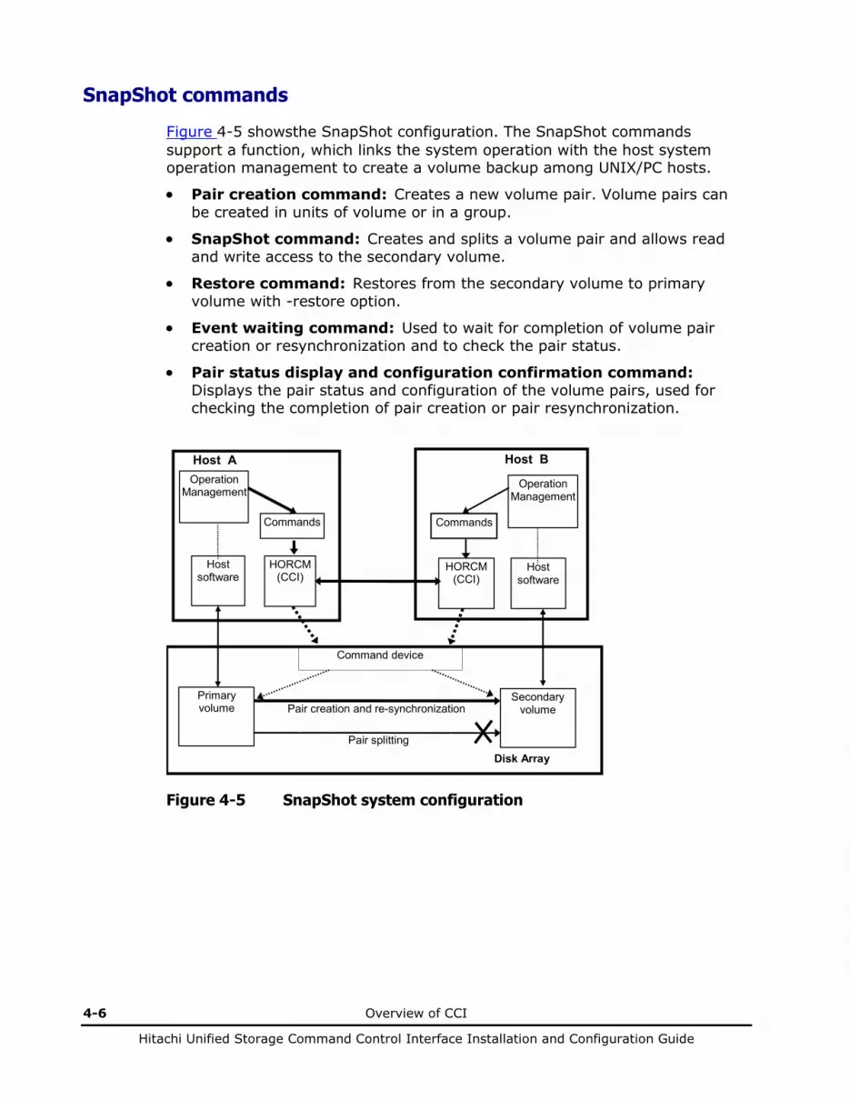
4-6 Overview of CCI
Hitachi Unified Storage Command Control Interface Installation and Configuration Guide
SnapShot commands
Figure 4-5 showsthe SnapShot configuration. The SnapShot commands support a function, which links the system operation with the host system operation management to create a volume backup among UNIX/PC hosts.
• Pair creation command: Creates a new volume pair. Volume pairs can be created in units of volume or in a group.
• SnapShot command: Creates and splits a volume pair and allows read and write access to the secondary volume.
• Restore command: Restores from the secondary volume to primary volume with -restore option.
• Event waiting command: Used to wait for completion of volume pair creation or resynchronization and to check the pair status.
• Pair status display and configuration confirmation command: Displays the pair status and configuration of the volume pairs, used for checking the completion of pair creation or pair resynchronization.
Commands Commands
HORCM (CCI)
HORCM (CCI)
Host A Host B
Host software
Host software
Operation Management
Operation Management
Primary volume
Secondary volume
Disk Array
Pair creation and re-synchronization
Pair splitting
Command device
Figure 4-5 SnapShot system configuration
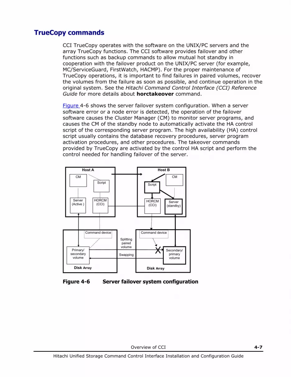
Overview of CCI 4-7
Hitachi Unified Storage Command Control Interface Installation and Configuration Guide
TrueCopy commands
CCI TrueCopy operates with the software on the UNIX/PC servers and the array TrueCopy functions. The CCI software provides failover and other functions such as backup commands to allow mutual hot standby in cooperation with the failover product on the UNIX/PC server (for example, MC/ServiceGuard, FirstWatch, HACMP). For the proper maintenance of TrueCopy operations, it is important to find failures in paired volumes, recover the volumes from the failure as soon as possible, and continue operation in the original system. See the Hitachi Command Control Interface (CCI) Reference Guide for more details about horctakeover command.
Figure 4-6 shows the server failover system configuration. When a server software error or a node error is detected, the operation of the failover software causes the Cluster Manager (CM) to monitor server programs, and causes the CM of the standby node to automatically activate the HA control script of the corresponding server program. The high availability (HA) control script usually contains the database recovery procedures, server program activation procedures, and other procedures. The takeover commands provided by TrueCopy are activated by the control HA script and perform the control needed for handling failover of the server.
Script Script
HORCM (CCI)
HORCM (CCI)
Primary/ secondary
volume
Secondary/ primary volume
Host A Host B
Splitting paired volume
Server (Active ) Server
(standby)
CM CM
Command device Command device
Disk Array
Swapping
Disk Array
Figure 4-6 Server failover system configuration
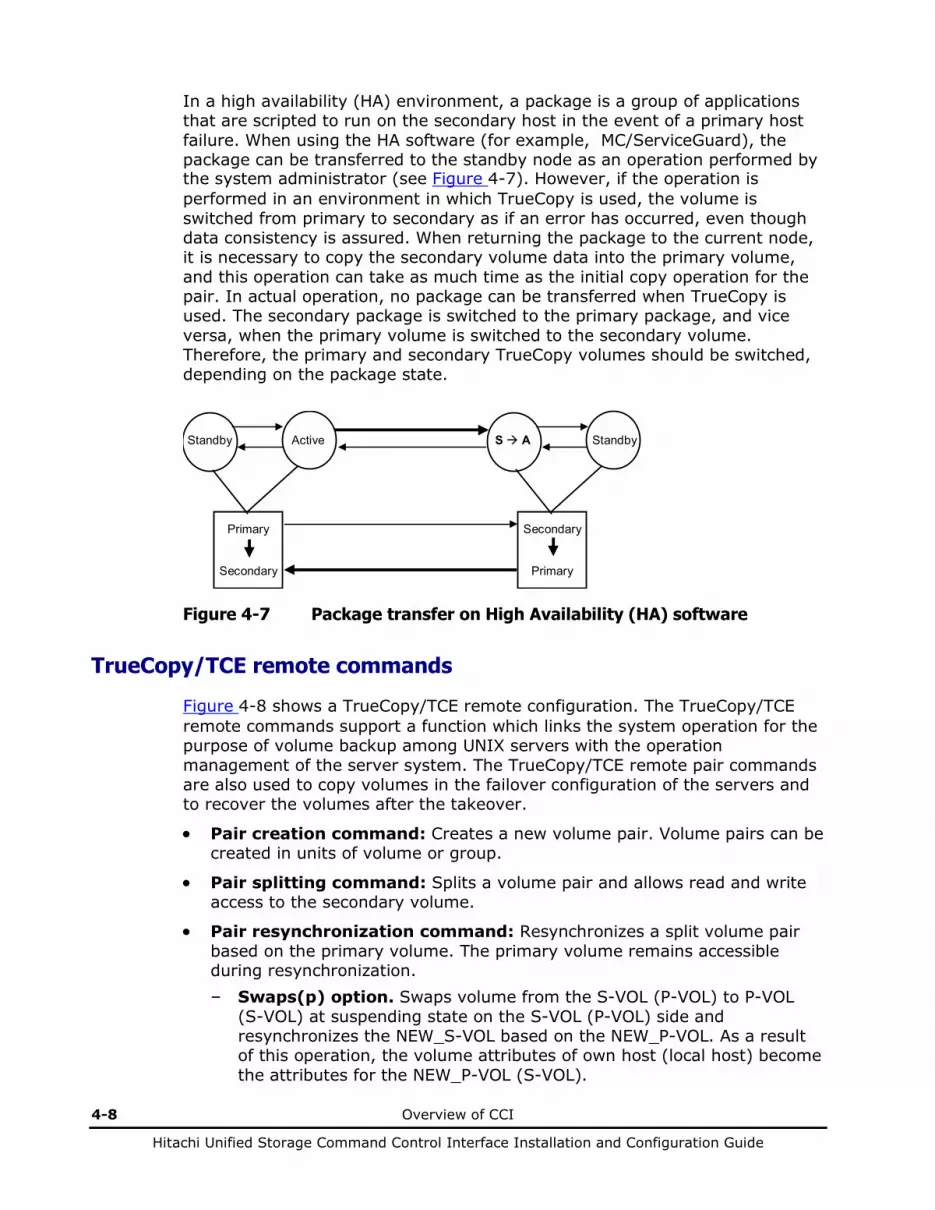
4-8 Overview of CCI
Hitachi Unified Storage Command Control Interface Installation and Configuration Guide
In a high availability (HA) environment, a package is a group of applications that are scripted to run on the secondary host in the event of a primary host failure. When using the HA software (for example, MC/ServiceGuard), the package can be transferred to the standby node as an operation performed by the system administrator (see Figure 4-7). However, if the operation is performed in an environment in which TrueCopy is used, the volume is switched from primary to secondary as if an error has occurred, even though data consistency is assured. When returning the package to the current node, it is necessary to copy the secondary volume data into the primary volume, and this operation can take as much time as the initial copy operation for the pair. In actual operation, no package can be transferred when TrueCopy is used. The secondary package is switched to the primary package, and vice versa, when the primary volume is switched to the secondary volume. Therefore, the primary and secondary TrueCopy volumes should be switched, depending on the package state.
Primary
Secondary
Secondary
Primary
ActiveStandby S A Standby
Figure 4-7 Package transfer on High Availability (HA) software
TrueCopy/TCE remote commands
Figure 4-8 shows a TrueCopy/TCE remote configuration. The TrueCopy/TCE remote commands support a function which links the system operation for the purpose of volume backup among UNIX servers with the operation management of the server system. The TrueCopy/TCE remote pair commands are also used to copy volumes in the failover configuration of the servers and to recover the volumes after the takeover.
• Pair creation command: Creates a new volume pair. Volume pairs can be created in units of volume or group.
• Pair splitting command: Splits a volume pair and allows read and write access to the secondary volume.
• Pair resynchronization command: Resynchronizes a split volume pair based on the primary volume. The primary volume remains accessible during resynchronization. – Swaps(p) option. Swaps volume from the S-VOL (P-VOL) to P-VOL
(S-VOL) at suspending state on the S-VOL (P-VOL) side and resynchronizes the NEW_S-VOL based on the NEW_P-VOL. As a result of this operation, the volume attributes of own host (local host) become the attributes for the NEW_P-VOL (S-VOL).

Overview of CCI 4-9
Hitachi Unified Storage Command Control Interface Installation and Configuration Guide
• Event waiting command: Used to wait for completion of volume pair creation or resynchronization and to check the pair status.
• Pair status display and configuration confirmation command: Displays the pair status and configuration of the volume pairs, used for checking the completion of pair creation or pair resynchronization.
Commands Commands
HORCM (CCI)
HORCM (CCI)
Host A Host B
Server software
Server software
Operation Management
Operation Management
Primary/ secondary
volume
Secondary/ primary volume
Disk Array
Pair creation
and re-sync
Pair splitting
Command device Command device
Disk Array
Figure 4-8 TrueCopy/TCE remote system configuration
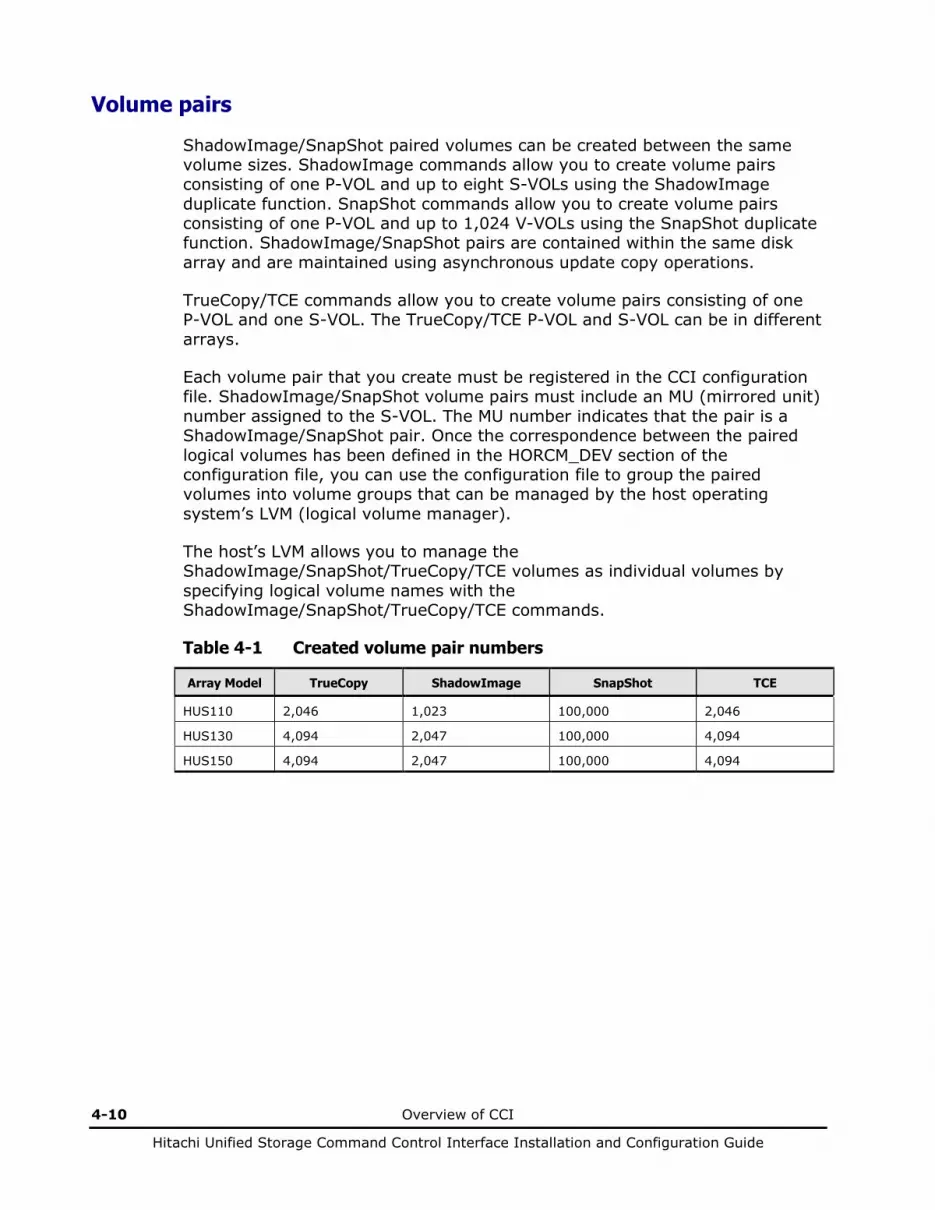
4-10 Overview of CCI
Hitachi Unified Storage Command Control Interface Installation and Configuration Guide
Volume pairs
ShadowImage/SnapShot paired volumes can be created between the same volume sizes. ShadowImage commands allow you to create volume pairs consisting of one P-VOL and up to eight S-VOLs using the ShadowImage duplicate function. SnapShot commands allow you to create volume pairs consisting of one P-VOL and up to 1,024 V-VOLs using the SnapShot duplicate function. ShadowImage/SnapShot pairs are contained within the same disk array and are maintained using asynchronous update copy operations.
TrueCopy/TCE commands allow you to create volume pairs consisting of one P-VOL and one S-VOL. The TrueCopy/TCE P-VOL and S-VOL can be in different arrays.
Each volume pair that you create must be registered in the CCI configuration file. ShadowImage/SnapShot volume pairs must include an MU (mirrored unit) number assigned to the S-VOL. The MU number indicates that the pair is a ShadowImage/SnapShot pair. Once the correspondence between the paired logical volumes has been defined in the HORCM_DEV section of the configuration file, you can use the configuration file to group the paired volumes into volume groups that can be managed by the host operating system’s LVM (logical volume manager).
The host’s LVM allows you to manage the ShadowImage/SnapShot/TrueCopy/TCE volumes as individual volumes by specifying logical volume names with the ShadowImage/SnapShot/TrueCopy/TCE commands.
Table 4-1 Created volume pair numbers
Array Model TrueCopy ShadowImage SnapShot TCE
HUS110 2,046 1,023 100,000 2,046
HUS130 4,094 2,047 100,000 4,094
HUS150 4,094 2,047 100,000 4,094
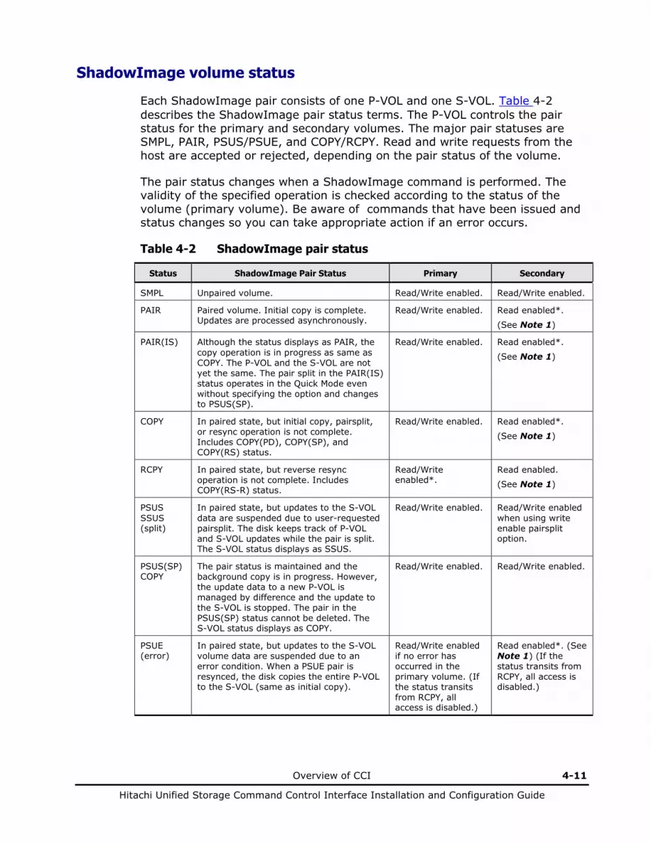
Overview of CCI 4-11
Hitachi Unified Storage Command Control Interface Installation and Configuration Guide
ShadowImage volume status
Each ShadowImage pair consists of one P-VOL and one S-VOL. Table 4-2 describes the ShadowImage pair status terms. The P-VOL controls the pair status for the primary and secondary volumes. The major pair statuses are SMPL, PAIR, PSUS/PSUE, and COPY/RCPY. Read and write requests from the host are accepted or rejected, depending on the pair status of the volume.
The pair status changes when a ShadowImage command is performed. The validity of the specified operation is checked according to the status of the volume (primary volume). Be aware of commands that have been issued and status changes so you can take appropriate action if an error occurs.
Table 4-2 ShadowImage pair status
Status ShadowImage Pair Status Primary Secondary
SMPL Unpaired volume. Read/Write enabled. Read/Write enabled.
PAIR Paired volume. Initial copy is complete. Updates are processed asynchronously.
Read/Write enabled. Read enabled*.
(See Note 1)
PAIR(IS) Although the status displays as PAIR, the copy operation is in progress as same as COPY. The P-VOL and the S-VOL are not yet the same. The pair split in the PAIR(IS) status operates in the Quick Mode even without specifying the option and changes to PSUS(SP).
Read/Write enabled. Read enabled*.
(See Note 1)
COPY In paired state, but initial copy, pairsplit, or resync operation is not complete. Includes COPY(PD), COPY(SP), and COPY(RS) status.
Read/Write enabled. Read enabled*.
(See Note 1)
RCPY In paired state, but reverse resync operation is not complete. Includes COPY(RS-R) status.
Read/Write enabled*.
Read enabled.
(See Note 1)
PSUS SSUS (split)
In paired state, but updates to the S-VOL data are suspended due to user-requested pairsplit. The disk keeps track of P-VOL and S-VOL updates while the pair is split. The S-VOL status displays as SSUS.
Read/Write enabled. Read/Write enabled when using write enable pairsplit option.
PSUS(SP) COPY
The pair status is maintained and the background copy is in progress. However, the update data to a new P-VOL is managed by difference and the update to the S-VOL is stopped. The pair in the PSUS(SP) status cannot be deleted. The S-VOL status displays as COPY.
Read/Write enabled. Read/Write enabled.
PSUE (error)
In paired state, but updates to the S-VOL volume data are suspended due to an error condition. When a PSUE pair is resynced, the disk copies the entire P-VOL to the S-VOL (same as initial copy).
Read/Write enabled if no error has occurred in the primary volume. (If the status transits from RCPY, all access is disabled.)
Read enabled*. (See Note 1) (If the status transits from RCPY, all access is disabled.)
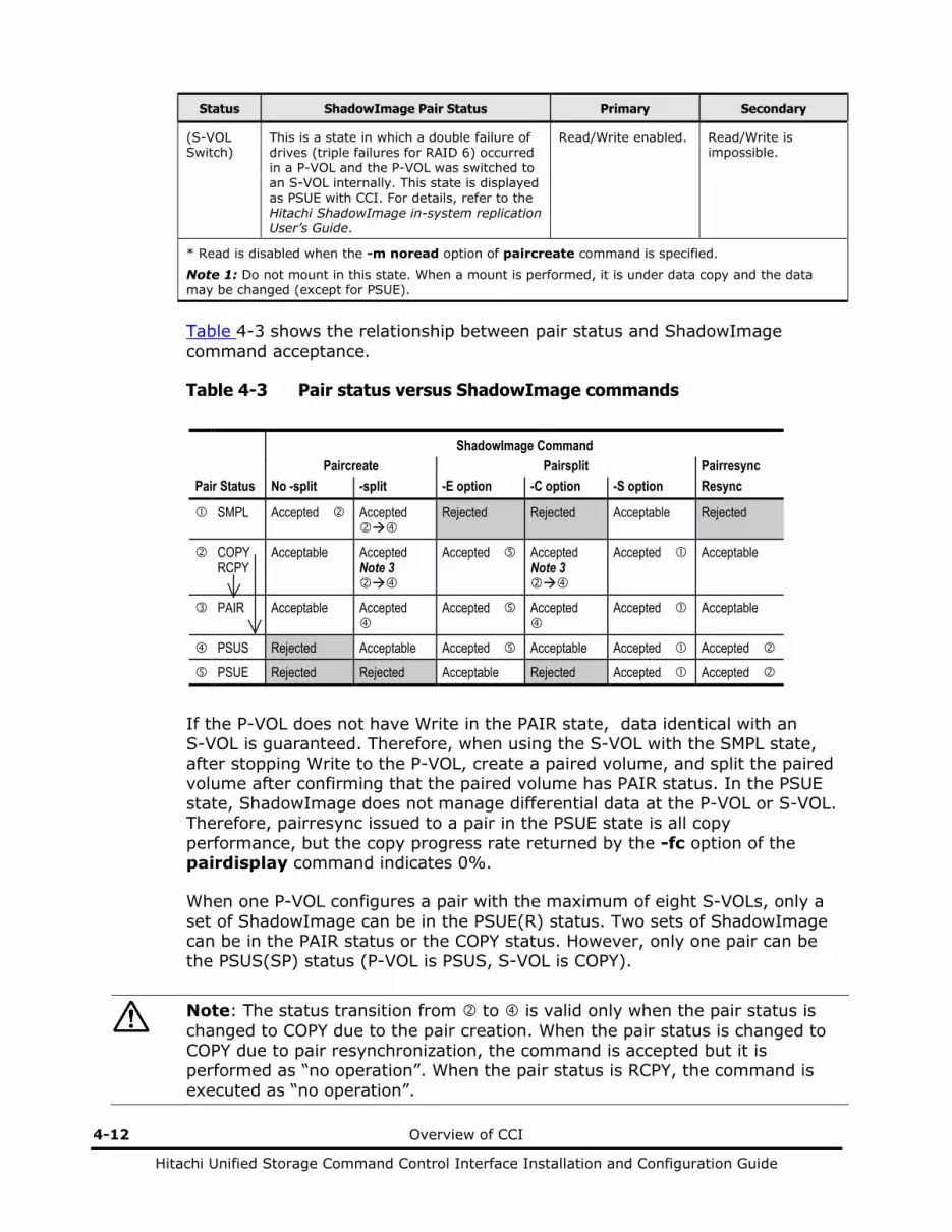
4-12 Overview of CCI
Hitachi Unified Storage Command Control Interface Installation and Configuration Guide
Status ShadowImage Pair Status Primary Secondary
(S-VOL Switch)
This is a state in which a double failure of drives (triple failures for RAID 6) occurred in a P-VOL and the P-VOL was switched to an S-VOL internally. This state is displayed as PSUE with CCI. For details, refer to the Hitachi ShadowImage in-system replication User’s Guide.
Read/Write enabled. Read/Write is impossible.
* Read is disabled when the -m noread option of paircreate command is specified.
Note 1: Do not mount in this state. When a mount is performed, it is under data copy and the data may be changed (except for PSUE).
Table 4-3 shows the relationship between pair status and ShadowImage command acceptance.
Table 4-3 Pair status versus ShadowImage commands
ShadowImage Command Paircreate Pairsplit Pairresync Pair Status No -split -split -E option -C option -S option Resync
SMPL Accepted Accepted
Rejected Rejected Acceptable Rejected
COPY RCPY
Acceptable Accepted Note 3
Accepted Accepted Note 3
Accepted Acceptable
PAIR Acceptable Accepted
Accepted Accepted
Accepted Acceptable
PSUS Rejected Acceptable Accepted Acceptable Accepted Accepted
PSUE Rejected Rejected Acceptable Rejected Accepted Accepted
If the P-VOL does not have Write in the PAIR state, data identical with an S-VOL is guaranteed. Therefore, when using the S-VOL with the SMPL state, after stopping Write to the P-VOL, create a paired volume, and split the paired volume after confirming that the paired volume has PAIR status. In the PSUE state, ShadowImage does not manage differential data at the P-VOL or S-VOL. Therefore, pairresync issued to a pair in the PSUE state is all copy performance, but the copy progress rate returned by the -fc option of the pairdisplay command indicates 0%.
When one P-VOL configures a pair with the maximum of eight S-VOLs, only a set of ShadowImage can be in the PSUE(R) status. Two sets of ShadowImage can be in the PAIR status or the COPY status. However, only one pair can be the PSUS(SP) status (P-VOL is PSUS, S-VOL is COPY).
Note: The status transition from to is valid only when the pair status is changed to COPY due to the pair creation. When the pair status is changed to COPY due to pair resynchronization, the command is accepted but it is performed as “no operation”. When the pair status is RCPY, the command is executed as “no operation”.
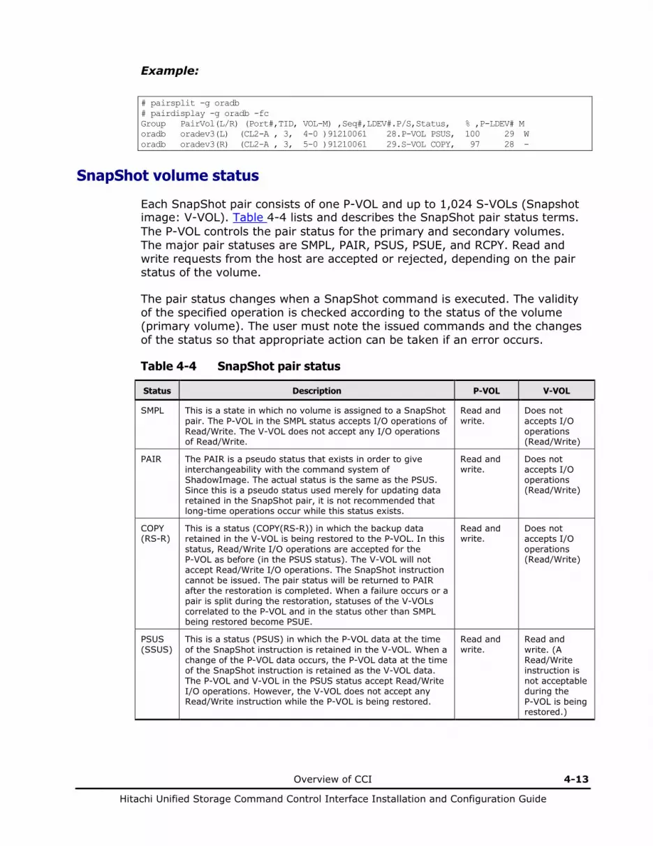
Overview of CCI 4-13
Hitachi Unified Storage Command Control Interface Installation and Configuration Guide
Example:
# pairsplit -g oradb # pairdisplay -g oradb -fc Group PairVol(L/R) (Port#,TID, VOL-M) ,Seq#,LDEV#.P/S,Status, % ,P-LDEV# M oradb oradev3(L) (CL2-A , 3, 4-0 )91210061 28.P-VOL PSUS, 100 29 W oradb oradev3(R) (CL2-A , 3, 5-0 )91210061 29.S-VOL COPY, 97 28 -
SnapShot volume status
Each SnapShot pair consists of one P-VOL and up to 1,024 S-VOLs (Snapshot image: V-VOL). Table 4-4 lists and describes the SnapShot pair status terms. The P-VOL controls the pair status for the primary and secondary volumes. The major pair statuses are SMPL, PAIR, PSUS, PSUE, and RCPY. Read and write requests from the host are accepted or rejected, depending on the pair status of the volume.
The pair status changes when a SnapShot command is executed. The validity of the specified operation is checked according to the status of the volume (primary volume). The user must note the issued commands and the changes of the status so that appropriate action can be taken if an error occurs.
Table 4-4 SnapShot pair status
Status Description P-VOL V-VOL
SMPL This is a state in which no volume is assigned to a SnapShot pair. The P-VOL in the SMPL status accepts I/O operations of Read/Write. The V-VOL does not accept any I/O operations of Read/Write.
Read and write.
Does not accepts I/O operations (Read/Write)
PAIR The PAIR is a pseudo status that exists in order to give interchangeability with the command system of ShadowImage. The actual status is the same as the PSUS. Since this is a pseudo status used merely for updating data retained in the SnapShot pair, it is not recommended that long-time operations occur while this status exists.
Read and write.
Does not accepts I/O operations (Read/Write)
COPY (RS-R)
This is a status (COPY(RS-R)) in which the backup data retained in the V-VOL is being restored to the P-VOL. In this status, Read/Write I/O operations are accepted for the P-VOL as before (in the PSUS status). The V-VOL will not accept Read/Write I/O operations. The SnapShot instruction cannot be issued. The pair status will be returned to PAIR after the restoration is completed. When a failure occurs or a pair is split during the restoration, statuses of the V-VOLs correlated to the P-VOL and in the status other than SMPL being restored become PSUE.
Read and write.
Does not accepts I/O operations (Read/Write)
PSUS (SSUS)
This is a status (PSUS) in which the P-VOL data at the time of the SnapShot instruction is retained in the V-VOL. When a change of the P-VOL data occurs, the P-VOL data at the time of the SnapShot instruction is retained as the V-VOL data. The P-VOL and V-VOL in the PSUS status accept Read/Write I/O operations. However, the V-VOL does not accept any Read/Write instruction while the P-VOL is being restored.
Read and write.
Read and write. (A Read/Write instruction is not acceptable during the P-VOL is being restored.)

4-14 Overview of CCI
Hitachi Unified Storage Command Control Interface Installation and Configuration Guide
Status Description P-VOL V-VOL
PFUS This is a status (PFUS) when the used rate of DP pool reaches the threshold of DP pool. However, PFUS usually operates as PSUS. Only when -fc option is added in the pairdisplay command and -ss option is added in the pairvolchk command, you can recognize as PFUS. (pairvolchk is recognized as returned values.)
Read and write.
Read and write. (R/W are not accepted while the P-VOL is being restored.)
PSUE (Error)
This is a status (PSUE) in which the P-VOL data at the time of the SnapShot instruction cannot be retained in the V-VOL because some failure has occurred in the disk array. In this status, I/O operations of Read/Write concerning the P-VOL is accepted as before (in the PSUS status). However, when a failure occurs during restoration, the P-VOL does not accept any Read/Write instruction. The V-VOL data has been invalidated at this point of time.
To resume the split pair, issue the SnapShot instruction (paircreate -split) again after splitting the pair (using the pairsplit -S) once. However, data of the V-VOL created is not same data that was invalidated but rather is the P-VOL data at the time of the new SnapShot instruction.
Read and write. (The P-VOL does not accept R/W when the pair status is PSUE due to a failure that has occurred while being restored.)
Does not accepts I/O operations (Read/Write)
Table 4-5 shows the relationship between pair status and SnapShot command acceptance.
Table 4-5 Pair status versus SnapShot commands
SnapShot Command Paircreate Snapshot Restore Pair Status No -split -split -C option -S option Resync -restore
SMPL Accepted Accepted
Rejected Acceptable Rejected
RCPY
Rejected Rejected Rejected Accepted Rejected
PAIR Acceptable Accepted
Accepted
Accepted Acceptable
PSUS Rejected Rejected Rejected Accepted Accepted
PSUE Rejected Rejected Rejected Accepted Rejected
Note: In the PSUE state, SnapShot does not manage differential data at the P-VOL or V-VOL.
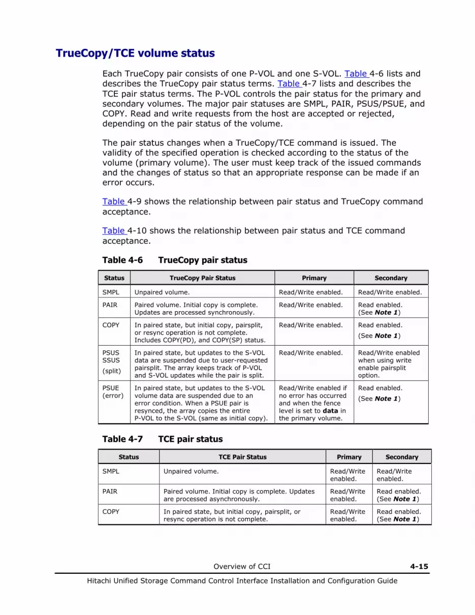
Overview of CCI 4-15
Hitachi Unified Storage Command Control Interface Installation and Configuration Guide
TrueCopy/TCE volume status
Each TrueCopy pair consists of one P-VOL and one S-VOL. Table 4-6 lists and describes the TrueCopy pair status terms. Table 4-7 lists and describes the TCE pair status terms. The P-VOL controls the pair status for the primary and secondary volumes. The major pair statuses are SMPL, PAIR, PSUS/PSUE, and COPY. Read and write requests from the host are accepted or rejected, depending on the pair status of the volume.
The pair status changes when a TrueCopy/TCE command is issued. The validity of the specified operation is checked according to the status of the volume (primary volume). The user must keep track of the issued commands and the changes of status so that an appropriate response can be made if an error occurs.
Table 4-9 shows the relationship between pair status and TrueCopy command acceptance.
Table 4-10 shows the relationship between pair status and TCE command acceptance.
Table 4-6 TrueCopy pair status
Status TrueCopy Pair Status Primary Secondary
SMPL Unpaired volume. Read/Write enabled. Read/Write enabled.
PAIR Paired volume. Initial copy is complete. Updates are processed synchronously.
Read/Write enabled. Read enabled. (See Note 1)
COPY In paired state, but initial copy, pairsplit, or resync operation is not complete. Includes COPY(PD), and COPY(SP) status.
Read/Write enabled. Read enabled.
(See Note 1)
PSUS SSUS
(split)
In paired state, but updates to the S-VOL data are suspended due to user-requested pairsplit. The array keeps track of P-VOL and S-VOL updates while the pair is split.
Read/Write enabled. Read/Write enabled when using write enable pairsplit option.
PSUE (error)
In paired state, but updates to the S-VOL volume data are suspended due to an error condition. When a PSUE pair is resynced, the array copies the entire P-VOL to the S-VOL (same as initial copy).
Read/Write enabled if no error has occurred and when the fence level is set to data in the primary volume.
Read enabled.
(See Note 1)
Table 4-7 TCE pair status
Status TCE Pair Status Primary Secondary
SMPL Unpaired volume. Read/Write enabled.
Read/Write enabled.
PAIR Paired volume. Initial copy is complete. Updates are processed asynchronously.
Read/Write enabled.
Read enabled. (See Note 1)
COPY In paired state, but initial copy, pairsplit, or resync operation is not complete.
Read/Write enabled.
Read enabled. (See Note 1)

4-16 Overview of CCI
Hitachi Unified Storage Command Control Interface Installation and Configuration Guide
Status TCE Pair Status Primary Secondary
PSUS SSUS
PSUS In paired state, but updates to the S-VOL data are suspended due to user-requested pairsplit. The array keeps track of P-VOL updates while the pair is split.
Read/Write enabled.
Read/Write enabled when using write enable pairsplit option.
PSUS(N) This is a status resulted from a failure of the SSWS process or an S-VOL hardware failure occurred during a copy operation. All the data are managed on the P-VOL basis through the utilization of the differential data.
Read/Write is impossible.
Read/Write is impossible.
SSWS This is the status after the SVOL_Takeover operation was performed by the takeover command. The updated data is managed using the differential data of the S-VOL.
— Read/Write enabled.
PFUS (See Note 2)
This is a state in which the available data pool capacity is insufficient (pool-over). The updated data is managed using the differential data of the P-VOL.
Read/Write enabled.
Read enabled. (See Note 1)
PSUE (error) In paired state, but updates to the S-VOL volume data are suspended due to an error condition. When a PSUE pair is resynced, the array copies the entire P-VOL to the S-VOL (same as initial copy).
Read/Write enabled.
Read/Write enabled. (See Note 1)
Note 1: In this state, though it is able to mount, it cannot write in. Moreover, since it is under data copy even if it is able to mount and read, the data may be changed (except for PSUE). Therefore, do not mount in this state.
Note 2: The state of the pool-over concerning TCE differs, depending on the condition. Examples of failures and states are shown in Table 4-8.
Note 3: There may be a case where the status of the S-VOL might become PSUS which does not allow Read/Write operation because of a failure that occurs in the S-VOL of the pair in the PAIR or SSWS status. In this status, it is impossible to perform the SVOL_Takeover operation by means of the horctakeover command. The P-VOL status is changed to PSUE and the pair resynchronization is required for the restoration.
Table 4-8 TCE pool-over status
Event that causes PFUS/PSUE Status
P-VOL S-VOL
Pool-over of the primary array PFUS Keeps as before the occurrence of the pool-over.
Pool-over of the secondary array PSUE PFUS
Pool failure for the secondary array error PSUE PSUS R/W enabled. (See Note 3)
Hardware error PSUE PSUE
Restore the pair status through the pair resynchronization operation after it is changed to the status described above.

Overview of CCI 4-17
Hitachi Unified Storage Command Control Interface Installation and Configuration Guide
Table 4-9 Pair Status versus TrueCopy commands
TrueCopy Command Paircreate Pairsplit Pairresync Pair Status Copy Nocopy Suspend -r, -rw Suspend -P Simplex Resync
SMPL Accepted Accepted Rejected Rejected Acceptable Rejected COPY
Acceptable Acceptable Accepted Rejected Accepted Acceptable
PAIR Acceptable Acceptable Accepted Accepted Accepted Acceptable PSUS Rejected Rejected Acceptable Acceptable Accepted Accepted
(see note 1) PSUE Rejected Rejected Rejected Rejected Accepted Accepted
(see note 1)
For the SSWS state after SVOL-SSUS-takeover, the pairresync command (from P-VOL to S-VOL) is rejected because the delta data for S-VOL becomes dominant, and its state expects to use -swaps(p) option of pairresync. If the pairresync command (from P-VOL to S-VOL) is rejected, verify this special state using the -fc option of the pairdisplay command.
Table 4-10 Pair status versus TCE commands
TCE Command Paircreate Pairsplit Pairresync Pairsplit
(See note 3) Pair Status Copy Nocopy Suspend -r, -rw Simplex -R Suspend -S Resync -mscas
SMPL Accepted Accepted Rejected Acceptable Acceptable Rejected Rejected COPY
Acceptable Acceptable Accepted Accepted Accepted Acceptable
PAIR Acceptable Acceptable Accepted Accepted Accepted Acceptable Accepted
PSUS Rejected Rejected Acceptable Accepted Accepted Accepted Rejected
PSUS(N) Rejected Rejected Acceptable Accepted Accepted Accepted Rejected SSWS Rejected Rejected Acceptable Accepted Accepted (See note 1) Rejected
PSUE Rejected Rejected Rejected Accepted Accepted Accepted Rejected

4-18 Overview of CCI
Hitachi Unified Storage Command Control Interface Installation and Configuration Guide
For the SSWS state after SVOL-SSUS-takeover, the pairresync command (from P-VOL to S-VOL) is rejected because the delta data for S-VOL becomes dominant. Perform the pair splitting and the pair creation in this status. If the pairresync command (from P-VOL to S-VOL) is rejected, verify this special state using the -fc option of the pairdisplay command.
When the fence level is async, the Suspend or Simplex operation waits in the state in which the command is being issued the command until the synchronization of the S-VOL data is completed. The pairsplit -R command (Simplex operation) is responded immediately because no synchronization process is needed.
Note: Because the pairsplit -mscas is a command to split a SnapShot pair cascaded with a TCE S-VOL, the status of the TCE pair is not changed when the command is accepted. It is a command to be issued when the SnapShot pair is in the PSUS or PAIR status, apart from the status of the TCE pair.
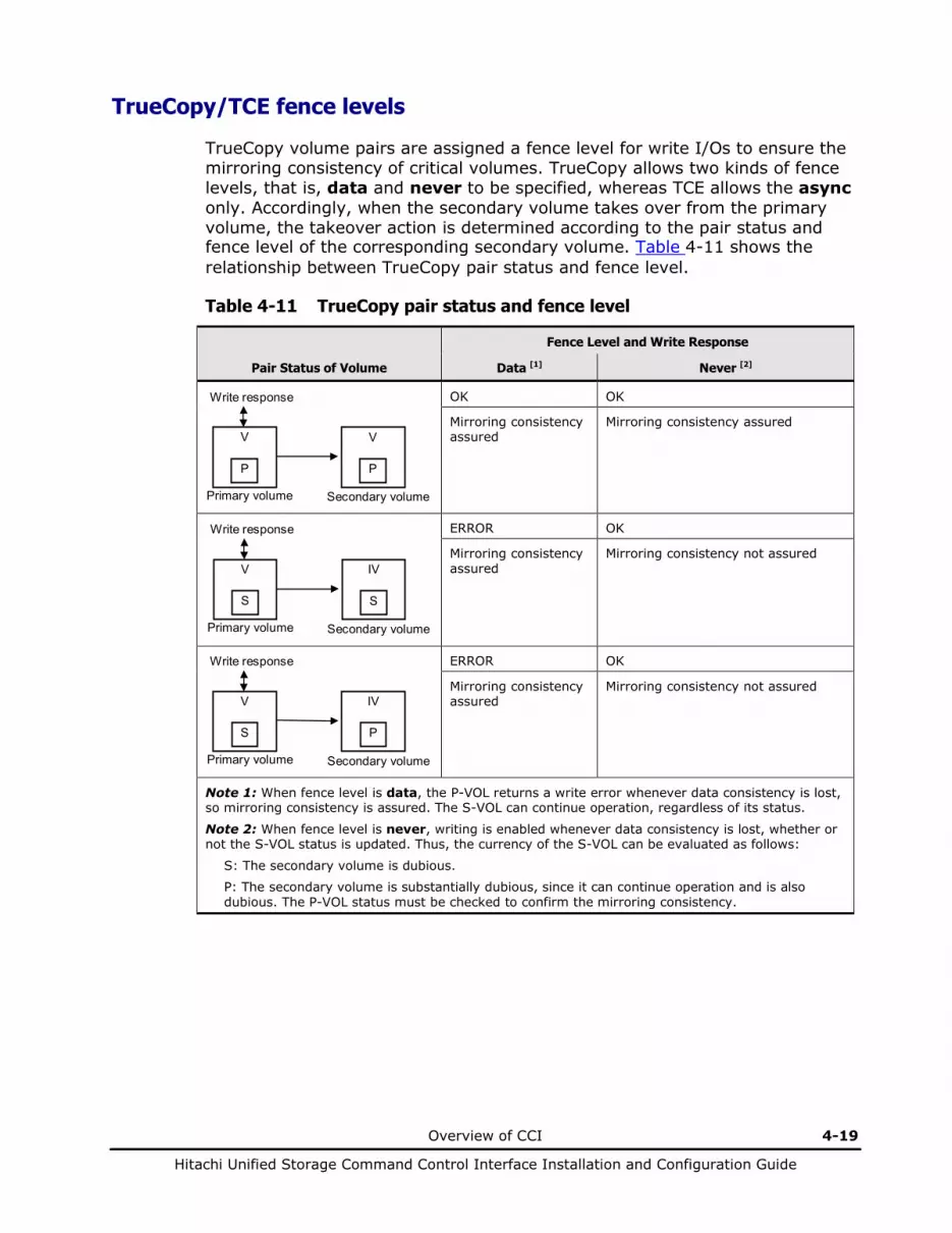
Overview of CCI 4-19
Hitachi Unified Storage Command Control Interface Installation and Configuration Guide
TrueCopy/TCE fence levels
TrueCopy volume pairs are assigned a fence level for write I/Os to ensure the mirroring consistency of critical volumes. TrueCopy allows two kinds of fence levels, that is, data and never to be specified, whereas TCE allows the async only. Accordingly, when the secondary volume takes over from the primary volume, the takeover action is determined according to the pair status and fence level of the corresponding secondary volume. Table 4-11 shows the relationship between TrueCopy pair status and fence level.
Table 4-11 TrueCopy pair status and fence level
Fence Level and Write Response
Pair Status of Volume Data [1] Never [2]
V
P
Secondary volume
V
P
Primary volume
Write response
OK OK
Mirroring consistency assured
Mirroring consistency assured
IV
S
Secondary volume
V
S
Primary volume
Write response
ERROR OK
Mirroring consistency assured
Mirroring consistency not assured
IV
P
Secondary volume
V
S
Primary volume
Write response
ERROR OK
Mirroring consistency assured
Mirroring consistency not assured
Note 1: When fence level is data, the P-VOL returns a write error whenever data consistency is lost, so mirroring consistency is assured. The S-VOL can continue operation, regardless of its status.
Note 2: When fence level is never, writing is enabled whenever data consistency is lost, whether or not the S-VOL status is updated. Thus, the currency of the S-VOL can be evaluated as follows:
S: The secondary volume is dubious.
P: The secondary volume is substantially dubious, since it can continue operation and is also dubious. The P-VOL status must be checked to confirm the mirroring consistency.

4-20 Overview of CCI
Hitachi Unified Storage Command Control Interface Installation and Configuration Guide
Figure 4-9 shows the relationship between redo log files (journal) and data files. If the S-VOL takes over from the P-VOL in the status shown in Figure 4-9 (where two errors have occurred), the secondary host leaves data (V) unprocessed in the roll-back processing and cannot be recovered completely. Therefore, the fence level of a redo log file must be defined as data. Once the fence level is set to data, the P-VOL returns an error if data is inconsistent when a write request is issued by the host. Since the writing into the data file has not been issued due to a write error of the redo log file, the log file stays consistent with the data file. However, when the fence level is set to data, a write I/O error occurs even when operation is suspended due to an error in the S-VOL. Accordingly, the duplication becomes meaningless when the S-VOL takes over. Thus, applications using paired volumes with the data fence level should be able to handle write I/O errors properly. For example, Oracle creates multiple redo log files by itself (three by default). The fence level can be set to data when disk errors are permissible by creating multiple files.
Since most UNIX-based file systems (excluding JFS and VxFS) have no journal files, the fence level should be defined as Never. When a takeover by the S-VOL occurs, fsck is issued on the volume and the file system is cleaned up, even if the S-VOL is undefined at the secondary host. The data that will be lost depends on how much differential data is contained in the P-VOL when the S-VOL is suspended. During operation, error recovery should be performed when the suspended status (PSUE) is detected (when one error occurs).
Data (V) Data (V)
Log (V) Log (IV)
Primary Volume Secondary Volume
Figure 4-9 Relation between logs and data in paired status

Overview of CCI 4-21
Hitachi Unified Storage Command Control Interface Installation and Configuration Guide
Using CCI commands
This section provides examples of tasks that can be performed using CCI commands.
TCE provides the command (pairsplit -mscas) that performs the remote backup leaving the pair status as PAIR by cascading the SnapShot pair with the S-VOL.
Backing up secondary volumes in paired status
Primary PAIR
Secondary PAIR
Read/Write
Secondary PAIR
Primary PAIR
Write (Database flushing)
Pair splitting (Read)
Event waiting (PAIR)
Event waiting (PSUS)
Backup request Database freezing
OLTP (DB) host Backup host
Database unfreezing
Secondary COPY
Secondary PSUS
Primary COPY
Pair re-synchronization
Primary PSUS
Read Read/Write Backup executing
Backup completion Read/Write
Database mount -r
Database un-mount
Figure 4-10 Backing up S-VOL in paired status using ShadowImage

4-22 Overview of CCI
Hitachi Unified Storage Command Control Interface Installation and Configuration Guide
Secondary COPY
Secondary PSUS
Secondary PSUS
Primary PAIR
Secondary PAIR
Read/Write
Primary PSUS
Write (Database flushing)
Pair splitting (Read)
Event waiting (PAIR)
Primary COPY
Pair resynchronization
Primary PSUS
Read Read/Write
Event waiting (PSUS)
Backup request Database freezing
Backup executing
Database unfreezing
Backup completion
Read/Write
OLTP (DB) server Backup server
Database mount -r
Database un-mount
Figure 4-11 Backing up S-VOL in paired status using TrueCopy/TCE

Overview of CCI 4-23
Hitachi Unified Storage Command Control Interface Installation and Configuration Guide
Restoring secondary volumes to primary volumes
OLTP (DB) host DSS host
Primary PSUS
Secondary PSUS
Read/Write Read/Write
SMPL
SMPL
Read/Write
Pair splitting (Simplex)
Pair creation (Remote)
Secondary COPY
Primary COPY
Read/Write
Read/Write
un-mount
Secondary COPY
Primary COPY
Write (Database flushing) Event waiting (PSUS)
Restoration request Database freezing
Pair splitting
Database unfreezing
mount -r
Secondary PAIR
Primary PAIR
Read/Write Event waiting (PAIR)
Secondary PSUS
Primary PSUS
Read/Write
Read
Read/Write differential data
Swapping paired volume
Figure 4-12 Restoring S-VOL to P-VOL in split status using ShadowImage
Note: The secondary status is SSUS.
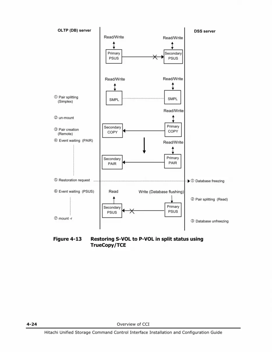
4-24 Overview of CCI
Hitachi Unified Storage Command Control Interface Installation and Configuration Guide
OLTP (DB) server DSS server
Primary PSUS
Secondary PSUS
Read/Write Read/Write
SMPL
SMPL
Read/Write
Pair splitting (Simplex)
Pair creation (Remote)
Secondary COPY
Primary COPY
Read/Write
Read/Write
un-mount
Secondary PSUS
Primary PSUS
Write (Database flushing) Read Event waiting (PSUS)
Restoration request Database freezing
Pair splitting (Read)
Database unfreezing mount -r
Secondary PAIR
Primary PAIR
Read/Write Event waiting (PAIR)
Figure 4-13 Restoring S-VOL to P-VOL in split status using TrueCopy/TCE

Overview of CCI 4-25
Hitachi Unified Storage Command Control Interface Installation and Configuration Guide
Backing up secondary volumes
Primary SMPL
Secondary SMPL
Read/Write
Secondary PSUS
Primary PSUS
Write (Database flushing)
SnapShot
Event waiting
Event waiting (PSUS)
Backup request Database freezing
OLTP (DB) host Backup host
Database unfreezing
Secondary PSUS
Secondary PSUS
Primary PSUS
Primary PSUS
Read Read/Write Backup executing
Backup completion Read/Write
Database mount -r
Database un-mount
Figure 4-14 Backing up secondary volume (V-VOL)
Note: The secondary status is SSUS.
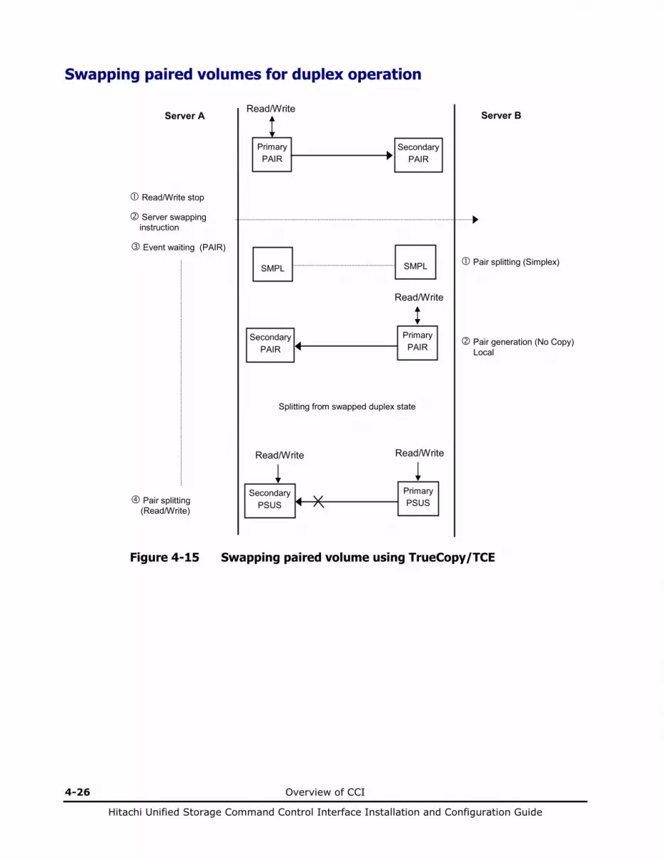
4-26 Overview of CCI
Hitachi Unified Storage Command Control Interface Installation and Configuration Guide
Swapping paired volumes for duplex operation
Secondary PSUS
Primary PSUS
SMPL
SMPL
Secondary PAIR
Primary PAIR
Primary PAIR
Secondary PAIR
Read/Write
Pair splitting (Simplex)
Read/Write
Pair generation (No Copy) Local
Read/Write stop
Read/Write
Pair splitting (Read/Write)
Read/Write
Server A Server B
Server swapping instruction
Splitting from swapped duplex state
Event waiting (PAIR)
Figure 4-15 Swapping paired volume using TrueCopy/TCE

Overview of CCI 4-27
Hitachi Unified Storage Command Control Interface Installation and Configuration Guide
Restoring S-VOLs for duplex operation
SMPL
SMPL
Primary PAIR
Secondary PAIR
Secondary COPY
Primary COPY
SMPL
SMPL
Primary PSUS
Secondary PSUS
Pair splitting (Simplex)
Pair creation (No Copy)
Read/Write
Read/Write Server A Server B
Pair splitting (Simplex)
Event waiting (PAIR)
DB shutdown
Pair creation (Remote)
DB completion notification
Figure 4-16 Restoring S-VOL using TrueCopy/TCE

4-28 Overview of CCI
Hitachi Unified Storage Command Control Interface Installation and Configuration Guide
About CCI software structure
Figure 4-17 showsthe CCI software structure: the CCI components on the disk array, and the CCI instance on the UNIX/PC host. The CCI components on the disk array include the command devices and the ShadowImage/SnapShot/TrueCopy/TCE volumes. Each CCI instance on a UNIX/PC host includes:
• HORC Manager (HORCM): – Log and trace files – A command host – Error monitoring and event reporting files – A configuration management feature
• Configuration definition file (defined by the user)
• The ShadowImage/SnapShot/TrueCopy/TCE user execution environments, which contain the ShadowImage/SnapShot/TrueCopy/TCE commands, a command log, and a monitoring function.
HORCM
The HORCM operates as a daemon process on the host and is activated automatically when the host machine starts up or manually by the start-up script. HORCM refers to the definitions in the configuration file when it is activated. The environmental variable HORCM_CONF is used to define the configuration file to which it is referred.
Command devices
Read/Write command
Command
HORCM
HORCM_CONF
Host machine
Remote communication Communicates with the HORCM (CCI) in the remote host.
Command
Command
Figure 4-17 HORCM operational environment
Overview of CCI 4-29
Hitachi Unified Storage Command Control Interface Installation and Configuration Guide
CCI instances
The basic unit of the CCI software structure is the CCI instance. Each copy of CCI on a host is a CCI instance. Each instance uses a defined configuration file to manage volume relationships while maintaining awareness of the other CCI instances. Each CCI instance normally resides on one host (one node). If two or more nodes are run on a single host (for test operations), it is possible to activate two or more instances using instance numbers.
The default command execution environment for CCI is TrueCopy/TCE (without specification of HORCC_MRCF). Therefore, in order to use CCI command for ShadowImage/SnapShot, the user must specify the environment variable HORCC_MRCF in the configuration definition file (HORCM_CONF). Besides, when returning the execution environment of ShadowImage/SnapShot to that of TrueCopy/TCE, the setting must be changed (without specification of HORCC_MRCF).
The CCI instance shown in Figure 4-18 has a remote execution link and a connection to the array. The remote execution link is a network connection to another PC to allow you to perform CCI functions remotely. The connection between the CCI instance and the disk array showsthe connection between the CCI software on the host and the command device. The command device accepts both ShadowImage, SnapShot, TrueCopy, and TCE CCI commands and communicates read and write I/Os between the host and the volumes on the disk array. The host does not communicate ShadowImage, SnapShot, TrueCopy, or TCE commands directly to the volumes on the disk array. The CCI commands are always sent through the disk array command device.
The disk array command device must be defined using Hitachi Storage Navigator Modular 2. For details on setting the command device, refer to the Hitachi ShadowImage in-system replication User’s Guide, the Hitachi Copy-on-write SnapShot User’s Guide, the Hitachi TrueCopy remote replication User’s Guide, and/or the TrueCopy Extended Distance User’s Guide.
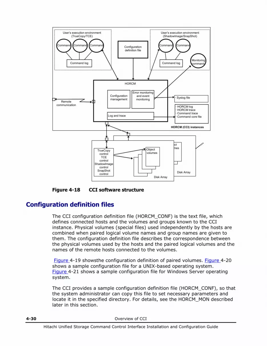
4-30 Overview of CCI
Hitachi Unified Storage Command Control Interface Installation and Configuration Guide
Disk Array
HORC control HOMRCF control
Object volumes
Monitoring command
Remote communication
Configuration management
Log and trace
Error monitoring and event monitoring
HORCM
HORCM log HORCM trace Command trace Command core file
Command
Command
Command
Command log
User’s execution environment (TrueCopy/TCE)
Command log
Command
User’s execution environment (ShadowImage/SnapShot)
Syslog file
HORCM (CCI) instances
Command
Disk Array
TrueCopy control TCE
control ShadowImage
control SnapShot
control
Object volumes
Configuration definition file
Figure 4-18 CCI software structure
Configuration definition files
The CCI configuration definition file (HORCM_CONF) is the text file, which defines connected hosts and the volumes and groups known to the CCI instance. Physical volumes (special files) used independently by the hosts are combined when paired logical volume names and group names are given to them. The configuration definition file describes the correspondence between the physical volumes used by the hosts and the paired logical volumes and the names of the remote hosts connected to the volumes.
Figure 4-19 showsthe configuration definition of paired volumes. Figure 4-20 shows a sample configuration file for a UNIX-based operating system. Figure 4-21 shows a sample configuration file for Windows Server operating system.
The CCI provides a sample configuration definition file (HORCM_CONF), so that the system administrator can copy this file to set necessary parameters and locate it in the specified directory. For details, see the HORCM_MON described later in this section.

Overview of CCI 4-31
Hitachi Unified Storage Command Control Interface Installation and Configuration Guide
The configuration definition file can be created automatically using the mkconf command tool (the user must customize the contents , depending on the management). The value for the poll (10ms) must be specified manually.
G1,Oradb1... P0,T1,L1 G1...HOSTB
L1 L2 Paired logical volume
G1,Oradb1
Special file
P0,T1,L1 P1,T1,L2
HOSTA
G1,Oradb1...P1,T1,L2 G1...HOSTA Special file
HOSTB Configuration definition file Configuration definition file
Explanation of symbols: Px: Port name Tx: Target ID Lx: LU number
Disk Array
Figure 4-19 Configuration definition of paired volumes
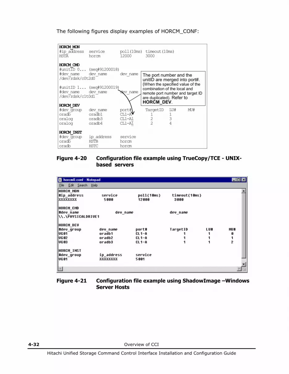
4-32 Overview of CCI
Hitachi Unified Storage Command Control Interface Installation and Configuration Guide
The following figures display examples of HORCM_CONF:
HORCM_MON #ip_address service poll(10ms) timeout(10ms) HSTA horcm 12000 3000 HORCM_CMD #unitID 0... (seq#91200018) #dev_name dev_name dev_name /dev/rdsk/c0t2d0 #unitID 1... (seq#91200019) #dev_name dev_name dev_name /dev/rdsk/c1t0d1 HORCM_DEV #dev_group dev_name port# TargetID LU# MU# oradb oradb1 CL1-A 1 1 oralog oradb3 CL1-A1 2 3 oralog oradb4 CL1-A1 2 4 HORCM_INST #dev_group ip_address service oradb HSTB horcm oradb HSTC horcm
The port number and the unitID are merged into port#. (When the specified value of the combination of the local and remote port number and target ID are duplicated). Refer to HORCM_DEV.
Figure 4-20 Configuration file example using TrueCopy/TCE - UNIX-based servers
Figure 4-21 Configuration file example using ShadowImage –Windows Server Hosts

Overview of CCI 4-33
Hitachi Unified Storage Command Control Interface Installation and Configuration Guide
The procedure for creating and editing the configuration definition file manually is as follows:
1. Shut down the HORCM using horcmshutdown.
2. Open the configuration definition file (HORCM_CONF) using the text editor. Set the parameters for HORCM_MON and HORCM_CMD. Save the file.
3. Start the HORCM (horcmstart).
Issue the raidscan command and write down the target IDs displayed in the execution result.
4. Shut down the HORCM using horcmshutdown.
5. Open the configuration definition file (HORCM_CONF). Using the text editor, set the target ID based on the memo you took in step 4 above for the HORCM_DEV parameter.
6. Set the HORCM_INST parameter, and then save the configuration definition file.
The following items are in the configuration definition file:
• HORCM_MON. The monitor parameter (HORCM_MON) defines the following values: – Ip_address: The IP address (IPv4 or IPv6) of the local host. When
HORCM has two or more network addresses on different subnets for communication, this item must be NONE for the IPv4 or NONE6 for IPv6.
– Service: The port name assigned to the CCI service (registered in the /etc/services file). The service parameter defines the CCI instance that runs on the local host. If a port number is specified instead of a port name, the port number will be used.
– Poll(10ms): The interval for monitoring paired volumes. To reduce the HORCM daemon load, make this interval longer. You must always set a value more than or equal to 6000 for ShadowImage/SnapShot/TrueCopy/TCE operations. To calculate the poll(10ms) value, see the following equation and the example. Setting the value incorrectly may cause an internal conflict between the CCI and the disk array; the internal processing of the disk array suspends temporarily. Processing may not proceed. If the interval is set to -1, the paired volumes are not monitored. The value of -1 is specified when two or more CCI instances run on a single machine. Calculating the value for poll(10ms): 6000 × the number of all CCI instances that controls the array, which its host is connected to the array.
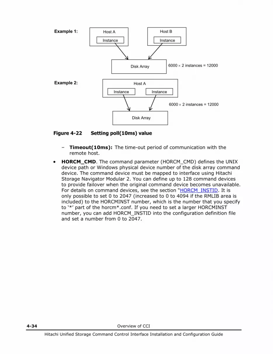
4-34 Overview of CCI
Hitachi Unified Storage Command Control Interface Installation and Configuration Guide
Host A
Instance
Host B
Instance
Disk Array
Example 1:
Host A
Instance Instance
Disk Array
6000 × 2 instances = 12000
Example 2:
6000 × 2 instances = 12000
Figure 4-22 Setting poll(10ms) value
– Timeout(10ms): The time-out period of communication with the remote host.
• HORCM_CMD. The command parameter (HORCM_CMD) defines the UNIX device path or Windows physical device number of the disk array command device. The command device must be mapped to interface using Hitachi Storage Navigator Modular 2. You can define up to 128 command devices to provide failover when the original command device becomes unavailable. For details on command devices, see the section “HORCM_INSTID. It is only possible to set 0 to 2047 (increased to 0 to 4094 if the RMLIB area is included) to the HORCMINST number, which is the number that you specify to ‘*’ part of the horcm*.conf. If you need to set a larger HORCMINST number, you can add HORCM_INSTID into the configuration definition file and set a number from 0 to 2047.
Overview of CCI 4-35
Hitachi Unified Storage Command Control Interface Installation and Configuration Guide
• Command devices.” For details on the alternate command device function,
see the section “Alternate command devices.”
When a host is connected to two or more disk arrays, the HORCM identifies each disk array using the unit ID (see Figure 4-23). The unit ID is assigned sequentially in the order described in this section of the configuration definition file. If more than one command device (up to 128 command devices) is specified in a disk array, the second or more command device has to be described side by side with the already described command device in a line. The host must be able to verify that the unit ID is the same Serial# among hosts when the disk array is shared by two or more hosts. This can be verified using the raidqry command.
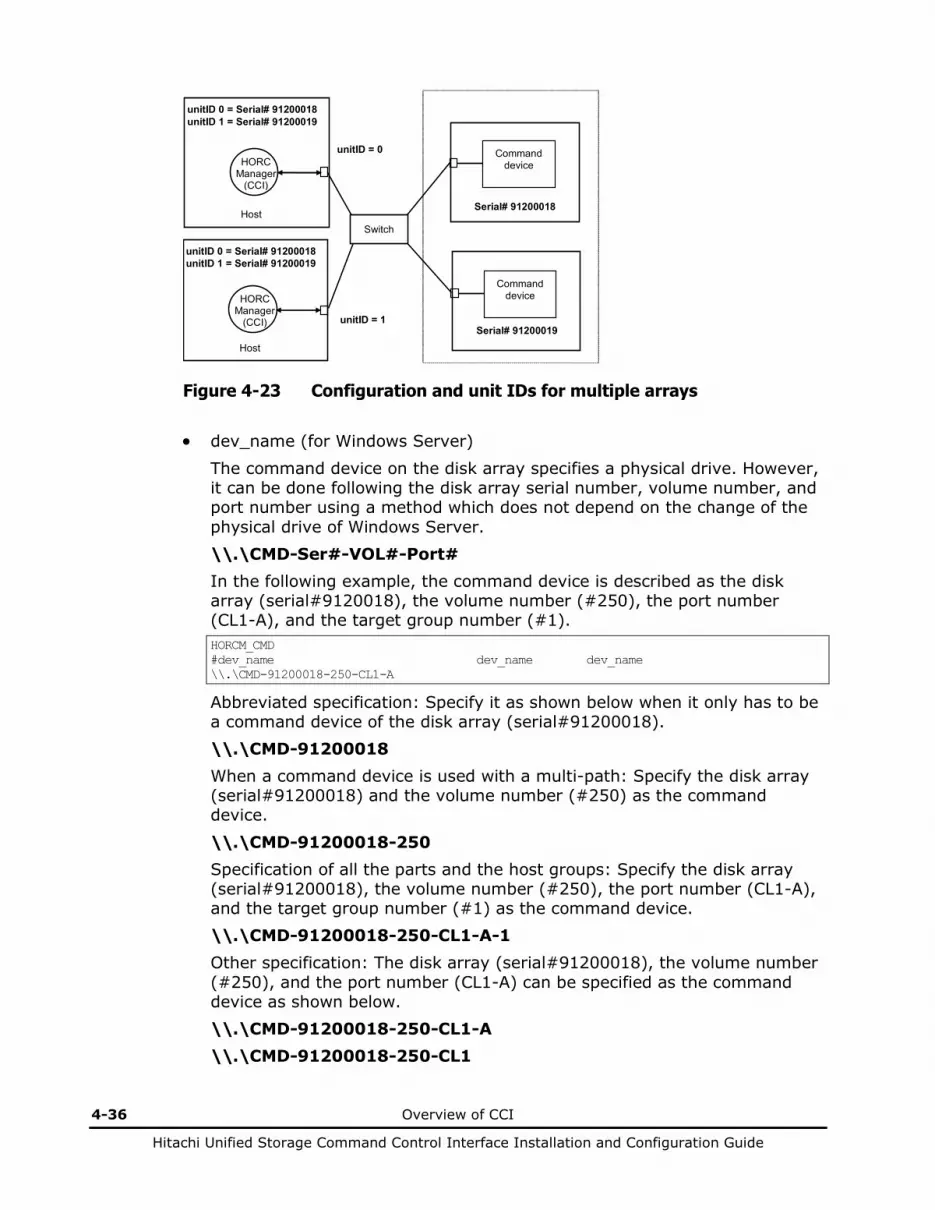
4-36 Overview of CCI
Hitachi Unified Storage Command Control Interface Installation and Configuration Guide
Command device
Command device
Serial# 91200018
HORC Manager
(CCI)
Host
HORC Manager
(CCI)
Host
unitID 0 = Serial# 91200018 unitID 1 = Serial# 91200019
unitID = 0
unitID = 1
unitID 0 = Serial# 91200018 unitID 1 = Serial# 91200019
Serial# 91200019
Switch
Figure 4-23 Configuration and unit IDs for multiple arrays
• dev_name (for Windows Server)
The command device on the disk array specifies a physical drive. However, it can be done following the disk array serial number, volume number, and port number using a method which does not depend on the change of the physical drive of Windows Server. \\.\CMD-Ser#-VOL#-Port# In the following example, the command device is described as the disk array (serial#9120018), the volume number (#250), the port number (CL1-A), and the target group number (#1). HORCM_CMD #dev_name dev_name dev_name \\.\CMD-91200018-250-CL1-A
Abbreviated specification: Specify it as shown below when it only has to be a command device of the disk array (serial#91200018). \\.\CMD-91200018 When a command device is used with a multi-path: Specify the disk array (serial#91200018) and the volume number (#250) as the command device.
\\.\CMD-91200018-250 Specification of all the parts and the host groups: Specify the disk array (serial#91200018), the volume number (#250), the port number (CL1-A), and the target group number (#1) as the command device. \\.\CMD-91200018-250-CL1-A-1 Other specification: The disk array (serial#91200018), the volume number (#250), and the port number (CL1-A) can be specified as the command device as shown below. \\.\CMD-91200018-250-CL1-A \\.\CMD-91200018-250-CL1
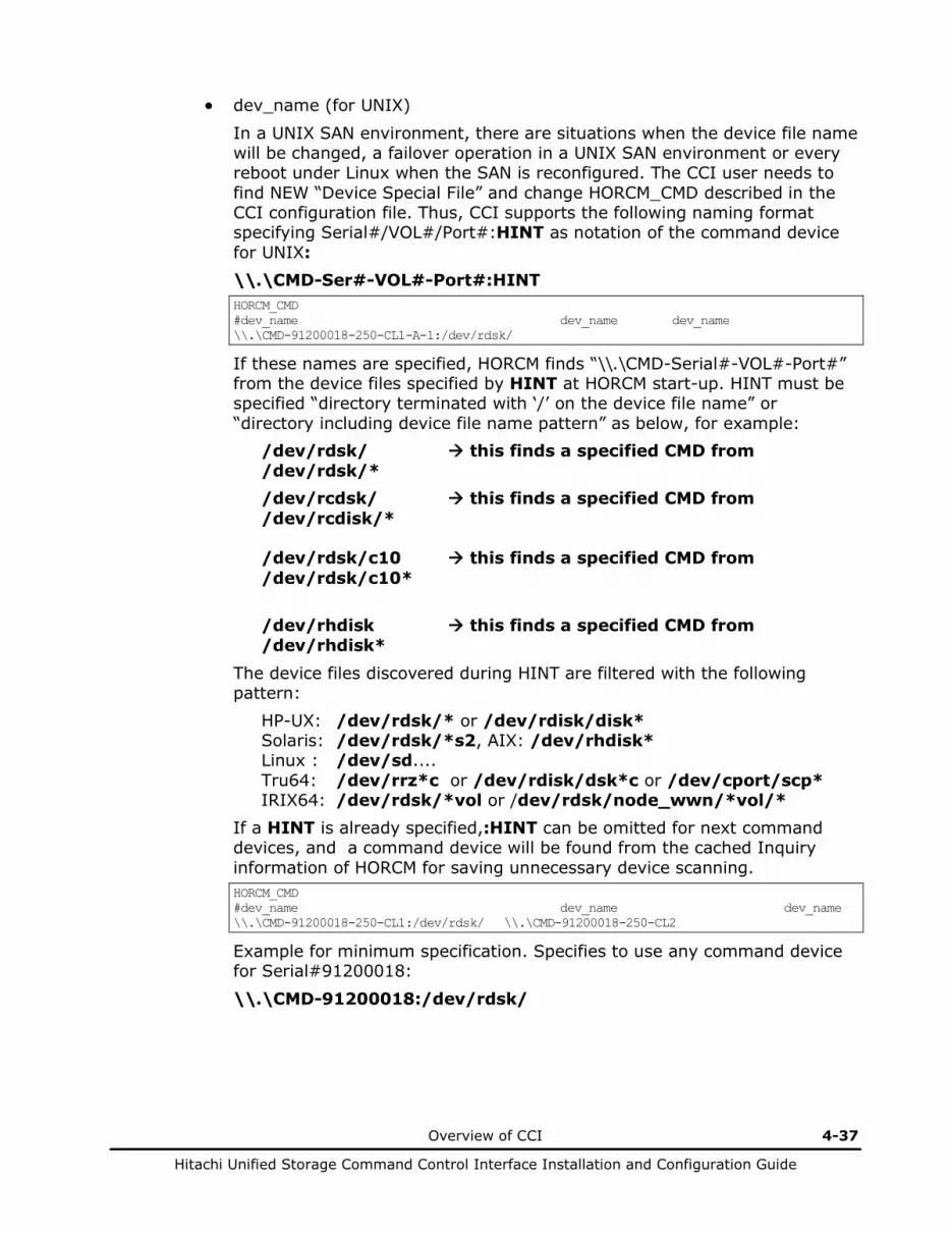
Overview of CCI 4-37
Hitachi Unified Storage Command Control Interface Installation and Configuration Guide
• dev_name (for UNIX)
In a UNIX SAN environment, there are situations when the device file name will be changed, a failover operation in a UNIX SAN environment or every reboot under Linux when the SAN is reconfigured. The CCI user needs to find NEW “Device Special File” and change HORCM_CMD described in the CCI configuration file. Thus, CCI supports the following naming format specifying Serial#/VOL#/Port#:HINT as notation of the command device for UNIX: \\.\CMD-Ser#-VOL#-Port#:HINT HORCM_CMD #dev_name dev_name dev_name \\.\CMD-91200018-250-CL1-A-1:/dev/rdsk/
If these names are specified, HORCM finds “\\.\CMD-Serial#-VOL#-Port#” from the device files specified by HINT at HORCM start-up. HINT must be specified “directory terminated with ‘/’ on the device file name” or “directory including device file name pattern” as below, for example:
/dev/rdsk/ this finds a specified CMD from /dev/rdsk/* /dev/rcdsk/ this finds a specified CMD from /dev/rcdisk/* /dev/rdsk/c10 this finds a specified CMD from /dev/rdsk/c10* /dev/rhdisk this finds a specified CMD from /dev/rhdisk*
The device files discovered during HINT are filtered with the following pattern:
HP-UX: /dev/rdsk/* or /dev/rdisk/disk* Solaris: /dev/rdsk/*s2, AIX: /dev/rhdisk* Linux : /dev/sd.... Tru64: /dev/rrz*c or /dev/rdisk/dsk*c or /dev/cport/scp* IRIX64: /dev/rdsk/*vol or /dev/rdsk/node_wwn/*vol/*
If a HINT is already specified,:HINT can be omitted for next command devices, and a command device will be found from the cached Inquiry information of HORCM for saving unnecessary device scanning. HORCM_CMD #dev_name dev_name dev_name \\.\CMD-91200018-250-CL1:/dev/rdsk/ \\.\CMD-91200018-250-CL2
Example for minimum specification. Specifies to use any command device for Serial#91200018:
\\.\CMD-91200018:/dev/rdsk/
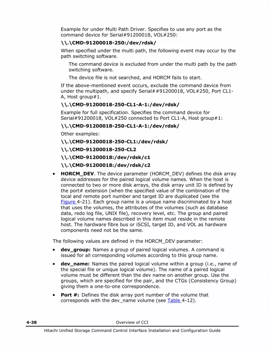
4-38 Overview of CCI
Hitachi Unified Storage Command Control Interface Installation and Configuration Guide
Example for under Multi Path Driver. Specifies to use any port as the command device for Serial#91200018, VOL#250:
\\.\CMD-91200018-250:/dev/rdsk/ When specified under the multi path, the following event may occur by the path switching software.
The command device is excluded from under the multi path by the path switching software. The device file is not searched, and HORCM fails to start.
If the above-mentioned event occurs, exclude the command device from under the multipath, and specify Serial##91200018, VOL#250, Port CL1-A, Host group#1. \\.\CMD-91200018-250-CL1-A-1:/dev/rdsk/ Example for full specification. Specifies the command device for Serial#91200018, VOL#250 connected to Port CL1-A, Host group#1: \\.\CMD-91200018-250-CL1-A-1:/dev/rdsk/ Other examples: \\.\CMD-91200018-250-CL1:/dev/rdsk/ \\.\CMD-91200018-250-CL2 \\.\CMD-91200018:/dev/rdsk/c1 \\.\CMD-91200018:/dev/rdsk/c2
• HORCM_DEV. The device parameter (HORCM_DEV) defines the disk array device addresses for the paired logical volume names. When the host is connected to two or more disk arrays, the disk array unit ID is defined by the port# extension (when the specified value of the combination of the local and remote port number and target ID are duplicated (see the Figure 4-21). Each group name is a unique name discriminated by a host that uses the volumes, the attributes of the volumes (such as database data, redo log file, UNIX file), recovery level, etc. The group and paired logical volume names described in this item must reside in the remote host. The hardware fibre bus or iSCSI, target ID, and VOL as hardware components need not be the same.
The following values are defined in the HORCM_DEV parameter:
• dev_group: Names a group of paired logical volumes. A command is issued for all corresponding volumes according to this group name.
• dev_name: Names the paired logical volume within a group (i.e., name of the special file or unique logical volume). The name of a paired logical volume must be different than the dev name on another group. Use the groups, which are specified for the pair, and the CTGs (Consistency Group) giving them a one-to-one correspondence.
• Port #: Defines the disk array port number of the volume that corresponds with the dev_name volume (see Table 4-12).
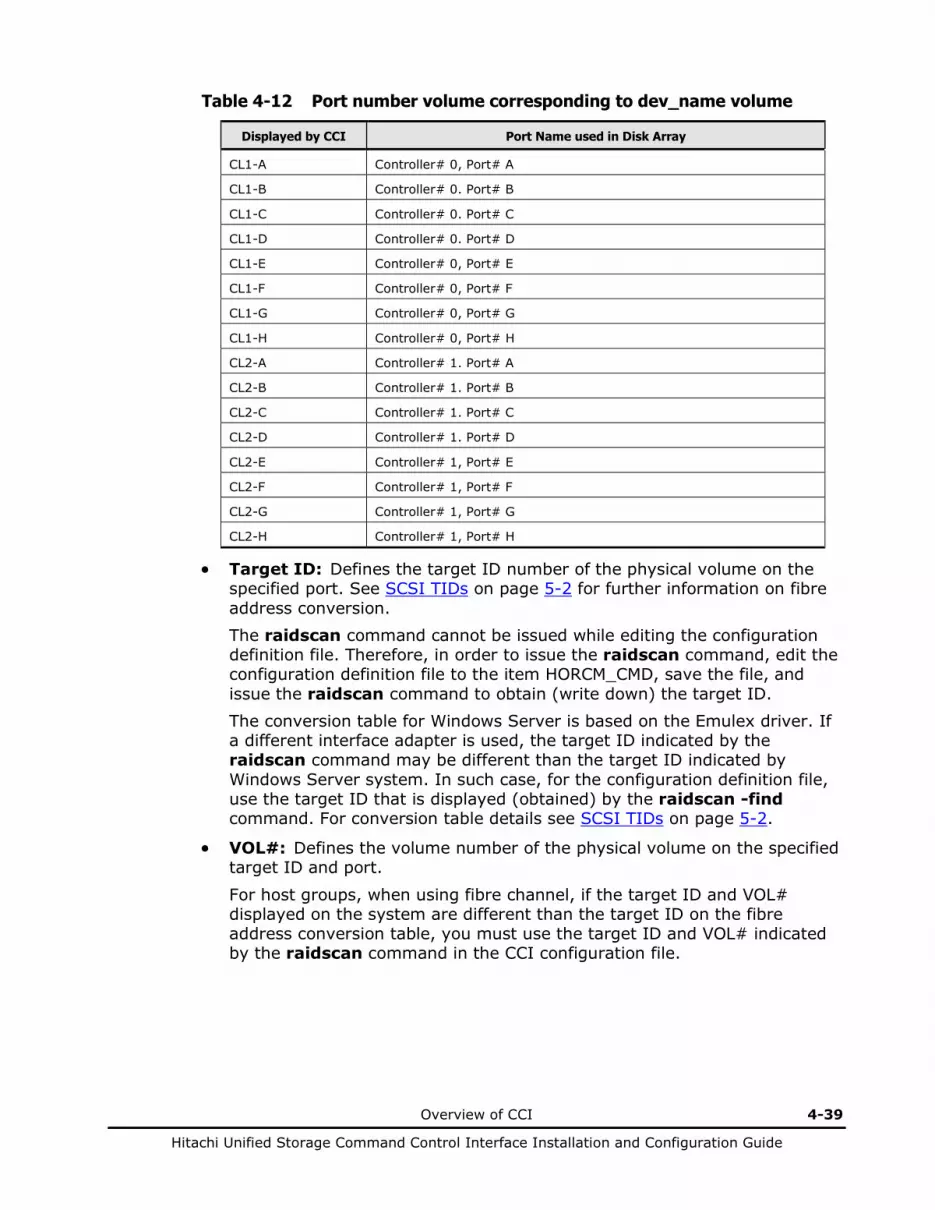
Overview of CCI 4-39
Hitachi Unified Storage Command Control Interface Installation and Configuration Guide
Table 4-12 Port number volume corresponding to dev_name volume
Displayed by CCI Port Name used in Disk Array
CL1-A Controller# 0, Port# A
CL1-B Controller# 0. Port# B
CL1-C Controller# 0. Port# C
CL1-D Controller# 0. Port# D
CL1-E Controller# 0, Port# E
CL1-F Controller# 0, Port# F
CL1-G Controller# 0, Port# G
CL1-H Controller# 0, Port# H
CL2-A Controller# 1. Port# A
CL2-B Controller# 1. Port# B
CL2-C Controller# 1. Port# C
CL2-D Controller# 1. Port# D
CL2-E Controller# 1, Port# E
CL2-F Controller# 1, Port# F
CL2-G Controller# 1, Port# G
CL2-H Controller# 1, Port# H
• Target ID: Defines the target ID number of the physical volume on the specified port. See SCSI TIDs on page 5-2 for further information on fibre address conversion. The raidscan command cannot be issued while editing the configuration definition file. Therefore, in order to issue the raidscan command, edit the configuration definition file to the item HORCM_CMD, save the file, and issue the raidscan command to obtain (write down) the target ID. The conversion table for Windows Server is based on the Emulex driver. If a different interface adapter is used, the target ID indicated by the raidscan command may be different than the target ID indicated by Windows Server system. In such case, for the configuration definition file, use the target ID that is displayed (obtained) by the raidscan -find command. For conversion table details see SCSI TIDs on page 5-2.
• VOL#: Defines the volume number of the physical volume on the specified target ID and port.
For host groups, when using fibre channel, if the target ID and VOL# displayed on the system are different than the target ID on the fibre address conversion table, you must use the target ID and VOL# indicated by the raidscan command in the CCI configuration file.
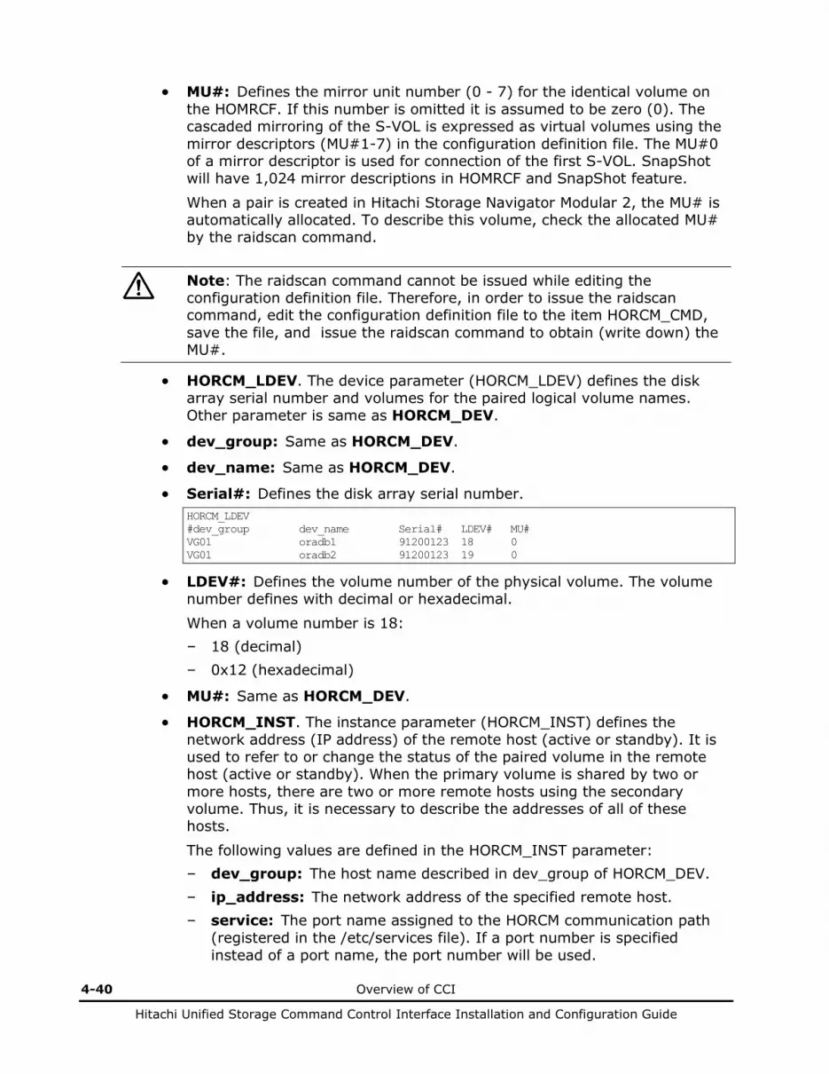
4-40 Overview of CCI
Hitachi Unified Storage Command Control Interface Installation and Configuration Guide
• MU#: Defines the mirror unit number (0 - 7) for the identical volume on the HOMRCF. If this number is omitted it is assumed to be zero (0). The cascaded mirroring of the S-VOL is expressed as virtual volumes using the mirror descriptors (MU#1-7) in the configuration definition file. The MU#0 of a mirror descriptor is used for connection of the first S-VOL. SnapShot will have 1,024 mirror descriptions in HOMRCF and SnapShot feature.
When a pair is created in Hitachi Storage Navigator Modular 2, the MU# is automatically allocated. To describe this volume, check the allocated MU# by the raidscan command.
Note: The raidscan command cannot be issued while editing the configuration definition file. Therefore, in order to issue the raidscan command, edit the configuration definition file to the item HORCM_CMD, save the file, and issue the raidscan command to obtain (write down) the MU#.
• HORCM_LDEV. The device parameter (HORCM_LDEV) defines the disk array serial number and volumes for the paired logical volume names. Other parameter is same as HORCM_DEV.
• dev_group: Same as HORCM_DEV.
• dev_name: Same as HORCM_DEV.
• Serial#: Defines the disk array serial number. HORCM_LDEV #dev_group dev_name Serial# LDEV# MU# VG01 oradb1 91200123 18 0 VG01 oradb2 91200123 19 0
• LDEV#: Defines the volume number of the physical volume. The volume number defines with decimal or hexadecimal.
When a volume number is 18: – 18 (decimal) – 0x12 (hexadecimal)
• MU#: Same as HORCM_DEV.
• HORCM_INST. The instance parameter (HORCM_INST) defines the network address (IP address) of the remote host (active or standby). It is used to refer to or change the status of the paired volume in the remote host (active or standby). When the primary volume is shared by two or more hosts, there are two or more remote hosts using the secondary volume. Thus, it is necessary to describe the addresses of all of these hosts.
The following values are defined in the HORCM_INST parameter: – dev_group: The host name described in dev_group of HORCM_DEV. – ip_address: The network address of the specified remote host. – service: The port name assigned to the HORCM communication path
(registered in the /etc/services file). If a port number is specified instead of a port name, the port number will be used.
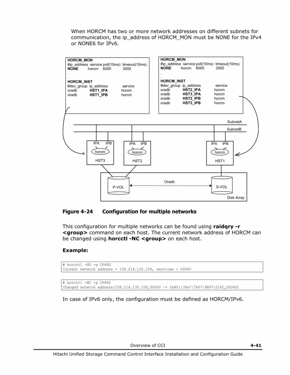
Overview of CCI 4-41
Hitachi Unified Storage Command Control Interface Installation and Configuration Guide
When HORCM has two or more network addresses on different subnets for communication, the ip_address of HORCM_MON must be NONE for the IPv4 or NONE6 for IPv6.
Disk Array
HORCM_MON #ip_address service poll(10ms) timeout(10ms) NONE horcm 6000 3000 . . HORCM_INST #dev_group ip_address service oradb HST2_IPA horcm oradb HST3_IPA horcm oradb HST2_IPB horcm oradb HST3_IPB horcm
IPA IPB
horcm
HST3
IPA IPB
horcm
HST2
IPA IPB
horcm
HST1
SubnetA
SubnetB
P-VOL
S-VOL
Oradb
HORCM_MON #ip_address service poll(10ms) timeout(10ms) NONE horcm 6000 3000 . . HORCM_INST #dev_group ip_address service oradb HST1_IPA horcm oradb HST1_IPB horcm
Figure 4-24 Configuration for multiple networks
This configuration for multiple networks can be found using raidqry -r <group> command on each host. The current network address of HORCM can be changed using horcctl -NC <group> on each host.
Example:
# horcctl -ND -g IP46G Current network address = 158.214.135.106, services = 50060
# horcctl -NC -g IP46G Changed network address(158.214.135.106,50060 -> fe80::39e7:7667:9897:2142,50060)
In case of IPv6 only, the configuration must be defined as HORCM/IPv6.
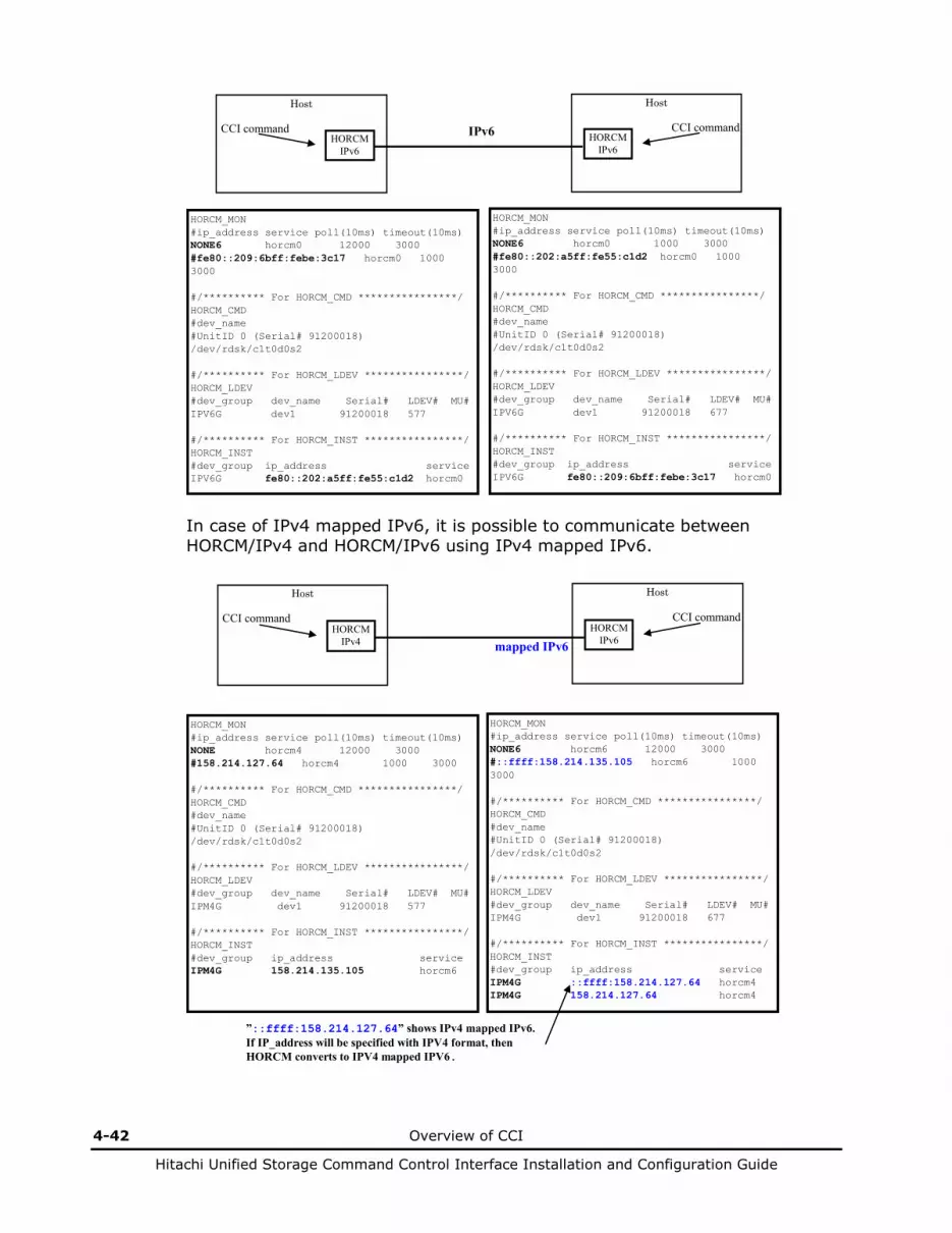
4-42 Overview of CCI
Hitachi Unified Storage Command Control Interface Installation and Configuration Guide
Host CCI command
HORCM IPv6
Host
CCI command HORCM
IPv6
IPv6
HORCM_MON #ip_address service poll(10ms) timeout(10ms) NONE6 horcm0 12000 3000 #fe80::209:6bff:febe:3c17 horcm0 1000 3000 #/********** For HORCM_CMD ****************/ HORCM_CMD #dev_name #UnitID 0 (Serial# 91200018) /dev/rdsk/c1t0d0s2 #/********** For HORCM_LDEV ****************/ HORCM_LDEV #dev_group dev_name Serial# LDEV# MU# IPV6G dev1 91200018 577 #/********** For HORCM_INST ****************/ HORCM_INST #dev_group ip_address service IPV6G fe80::202:a5ff:fe55:c1d2 horcm0
HORCM_MON #ip_address service poll(10ms) timeout(10ms) NONE6 horcm0 1000 3000 #fe80::202:a5ff:fe55:c1d2 horcm0 1000 3000 #/********** For HORCM_CMD ****************/ HORCM_CMD #dev_name #UnitID 0 (Serial# 91200018) /dev/rdsk/c1t0d0s2 #/********** For HORCM_LDEV ****************/ HORCM_LDEV #dev_group dev_name Serial# LDEV# MU# IPV6G dev1 91200018 677 #/********** For HORCM_INST ****************/ HORCM_INST #dev_group ip_address service IPV6G fe80::209:6bff:febe:3c17 horcm0
In case of IPv4 mapped IPv6, it is possible to communicate between HORCM/IPv4 and HORCM/IPv6 using IPv4 mapped IPv6.
Host CCI command
HORCM IPv4
Host
CCI command HORCM
IPv6 mapped IPv6
HORCM_MON #ip_address service poll(10ms) timeout(10ms) NONE horcm4 12000 3000 #158.214.127.64 horcm4 1000 3000 #/********** For HORCM_CMD ****************/ HORCM_CMD #dev_name #UnitID 0 (Serial# 91200018) /dev/rdsk/c1t0d0s2 #/********** For HORCM_LDEV ****************/ HORCM_LDEV #dev_group dev_name Serial# LDEV# MU# IPM4G dev1 91200018 577 #/********** For HORCM_INST ****************/ HORCM_INST #dev_group ip_address service IPM4G 158.214.135.105 horcm6
HORCM_MON #ip_address service poll(10ms) timeout(10ms) NONE6 horcm6 12000 3000 #::ffff:158.214.135.105 horcm6 1000 3000 #/********** For HORCM_CMD ****************/ HORCM_CMD #dev_name #UnitID 0 (Serial# 91200018) /dev/rdsk/c1t0d0s2 #/********** For HORCM_LDEV ****************/ HORCM_LDEV #dev_group dev_name Serial# LDEV# MU# IPM4G dev1 91200018 677 #/********** For HORCM_INST ****************/ HORCM_INST #dev_group ip_address service IPM4G ::ffff:158.214.127.64 horcm4 IPM4G 158.214.127.64 horcm4
”::ffff:158.214.127.64” shows IPv4 mapped IPv6. If IP_address will be specified with IPV4 format, then HORCM converts to IPV4 mapped IPV6.
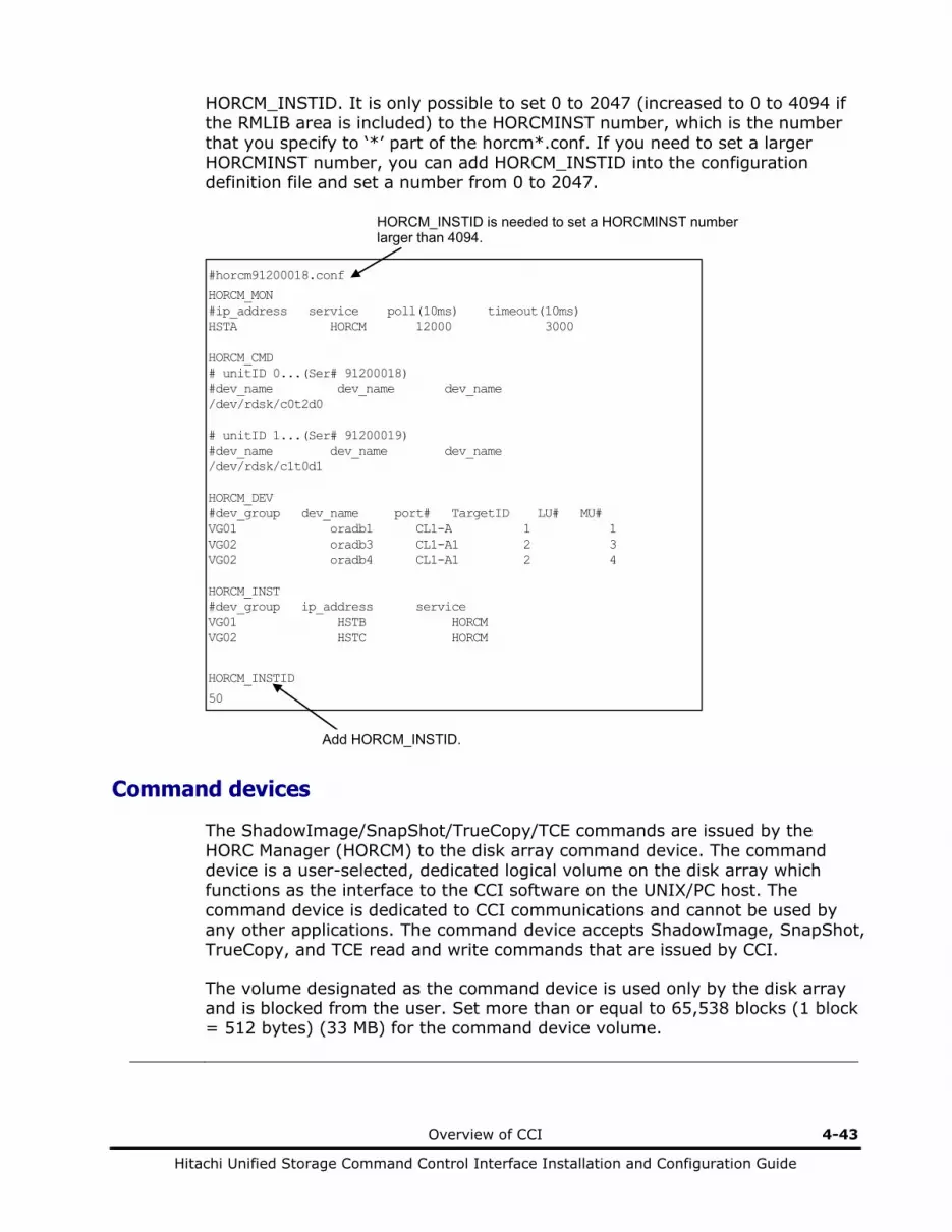
Overview of CCI 4-43
Hitachi Unified Storage Command Control Interface Installation and Configuration Guide
HORCM_INSTID. It is only possible to set 0 to 2047 (increased to 0 to 4094 if the RMLIB area is included) to the HORCMINST number, which is the number that you specify to ‘*’ part of the horcm*.conf. If you need to set a larger HORCMINST number, you can add HORCM_INSTID into the configuration definition file and set a number from 0 to 2047.
Command devices
The ShadowImage/SnapShot/TrueCopy/TCE commands are issued by the HORC Manager (HORCM) to the disk array command device. The command device is a user-selected, dedicated logical volume on the disk array which functions as the interface to the CCI software on the UNIX/PC host. The command device is dedicated to CCI communications and cannot be used by any other applications. The command device accepts ShadowImage, SnapShot, TrueCopy, and TCE read and write commands that are issued by CCI.
The volume designated as the command device is used only by the disk array and is blocked from the user. Set more than or equal to 65,538 blocks (1 block = 512 bytes) (33 MB) for the command device volume.
#horcm91200018.conf
HORCM_MON #ip_address service poll(10ms) timeout(10ms) HSTA HORCM 12000 3000 HORCM_CMD # unitID 0...(Ser# 91200018) #dev_name dev_name dev_name /dev/rdsk/c0t2d0 # unitID 1...(Ser# 91200019) #dev_name dev_name dev_name /dev/rdsk/c1t0d1 HORCM_DEV #dev_group dev_name port# TargetID LU# MU# VG01 oradb1 CL1-A 1 1 VG02 oradb3 CL1-A1 2 3 VG02 oradb4 CL1-A1 2 4 HORCM_INST #dev_group ip_address service VG01 HSTB HORCM VG02 HSTC HORCM
HORCM_INSTID
50
HORCM_INSTID is needed to set a HORCMINST number larger than 4094.
Add HORCM_INSTID.
4-44 Overview of CCI
Hitachi Unified Storage Command Control Interface Installation and Configuration Guide
Warning: Do not mount a volume that will be specified as a command device. Do not write any user data on the volume that is to be selected as the command device. The command device must be accessed as a raw device, without a file system.
The CCI software on the host issues reads and writes commands to the disk array command device. When CCI receives an error notification in reply to a read or write request to the disk array, the CCI software will activate an alternate command device, if one is defined. If a command device is blocked, you can activate an alternate command device manually. If no alternate command device is defined or available, all ShadowImage, SnapShot, TrueCopy, and TCE commands will terminate abnormally, and the host will not be able to issue commands to the disk array. The user must set two or more command devices and use the alternate command device facility if a path error occurs or if the command device is blocked (the maximum is 128 command devices).
When you use the TrueCopy/TCE function, the command devices must be set on both the local and remote arrays.
Each command device must be set using Hitachi Storage Navigator Modular 2. Each command device must also be defined in the HORCM_CMD section of the configuration file for the CCI instance on the attached host. If an alternate command device is not defined in the configuration file, the CCI software may not be able to use the device.
Alternate command devices
The CCI software issues commands to the disk array command device via the UNIX/PC raw I/O interface. If the command device fails in any way, all ShadowImage and SnapShot commands are terminated abnormally, and the user cannot use any commands. Because the use of alternate I/O pathing depends on the platform, restrictions are placed upon it. For example, on HP-UX systems only devices subject to the LVM can use the alternate path PV-LINK. To avoid command device failure, CCI supports an alternate command device function (see Figure 4-25).
• Definition of alternate command devices. To use an alternate command device, you must define two command devices for the HORCM_CMD item in the configuration definition file. When two command devices are defined, they are recognized as alternate command devices.
• Timing of alternate command devices. When the HORCM receives an error notification in reply from the operating system via the raw I/O interface, the command device is alternated. It is possible to alternate the command device forcibly by issuing an alternating command, such as horcctl -C.

Overview of CCI 4-45
Hitachi Unified Storage Command Control Interface Installation and Configuration Guide
• Operation of alternating command. If the command device will be blocked due to online maintenance, the alternating command should be issued in advance. When the alternating command is issued again after completion of the online maintenance, the previous command device is activated again.
• Multiple command devices on HORCM startup. If at least one command device is available when one or more command devices were described in the configuration definition file, HORCM will be able to start with a warning message to the startup log by using an available command device. The user needs to confirm that all command devices can be changed by using the horcctl -C command or HORCM has been started without a warning message to the HORCM start-up log.
HORCM Command
Device
ShadowImage/ SnapShot/ TrueCopy/
TCE Command Command
HORC Manager
(CCI)
Alternating Command
Disk Array
Command
HORCM Command
Device
Figure 4-25 Alternate command device function
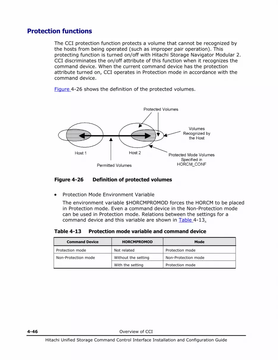
4-46 Overview of CCI
Hitachi Unified Storage Command Control Interface Installation and Configuration Guide
Protection functions
The CCI protection function protects a volume that cannot be recognized by the hosts from being operated (such as improper pair operation). This protecting function is turned on/off with Hitachi Storage Navigator Modular 2. CCI discriminates the on/off attribute of this function when it recognizes the command device. When the current command device has the protection attribute turned on, CCI operates in Protection mode in accordance with the command device.
Figure 4-26 shows the definition of the protected volumes.
Figure 4-26 Definition of protected volumes
• Protection Mode Environment Variable
The environment variable $HORCMPROMOD forces the HORCM to be placed in Protection mode. Even a command device in the Non-Protection mode can be used in Protection mode. Relations between the settings for a command device and this variable are shown in Table 4-13.
Table 4-13 Protection mode variable and command device
Command Device HORCMPROMOD Mode
Protection mode Not related Protection mode
Non-Protection mode Without the setting Non-Protection mode
With the setting Protection mode

Overview of CCI 4-47
Hitachi Unified Storage Command Control Interface Installation and Configuration Guide
When the host cannot recognize a volume due to an error caused while the protection function is ON, operation to the pair of the unrecognized volume cannot be performed. In this case, set the volume so that it can be recognized by the host, or disable the protection function (OFF) once, remove the error cause, and set the volume again to be recognized by the host so that the pair operation can be performed.
• Confirming the Protection Mode Command Devices Used by HORCM
To display the protection mode command device used by HORCM, use the horcctl -D command. The device file name is displayed with * added. # horcctl –D Current control device = /dev/rdsl/c0t0d0*
• Protection Mode and Mirror Descriptor. Volumes described in the configuration definition file (HORCM_CONF) are targets for the protection function and are managed by each mirror descriptor (MU#0). The protection mode enables CCI to check whether the volumes described in the configuration definition file match all volumes recognized from the host at the time when CCI is activated. Permitted volumes are registered in HORCM. Permitted volumes are volumes that are recognized from the host AND the mirror descriptors that are registered in the configuration definition file.
Table 4-14 Permitted volumes and mirror descriptor
Volumes on Horcm.conf
Mirror Descriptor on Horcm.conf TrueCopy ShadowImage
MU#0 MU#1 MU#2 E none E none E none E none
Unknown
/dev/rdsk/c0t0d0
Unknown
E = Mirror descriptor volume to be registered in horcm.conf.
Unknown: Volumes that own host cannot recognize, even though volumes were registered in horcm.conf.
• For the Fibre Switch environment, volumes that are recognized from the host must be set using the VOL Manager feature.
• Volume matching test is performed when operating pairs. Inhibited volumes are rejected as EX_ENPERM.
Permitted Volumes

4-48 Overview of CCI
Hitachi Unified Storage Command Control Interface Installation and Configuration Guide
• Examples of a Protected Volume Configuration.
Example of one host: Group Ora1 and Ora2, in protection mode, cannot differentiate between volume Grp2 and Grp4, from Host 1. The pair operation is inhibited. If the protection mode is OFF, the pair operation is permitted.
Grp4 Grp3
Grp2 Grp1
Horcm0.conf: Volume Grp1 Volume Grp3
Horcm1.conf: Volume Grp2 Volume Grp4
Command Device
Recognizes Grp1, Grp3
Ora1
Ora2
Host 1
Protection mode ON/OFF
/
/
Protection mode ON/OFF
Figure 4-27 Protected volume configuration (one CCI host) (1)
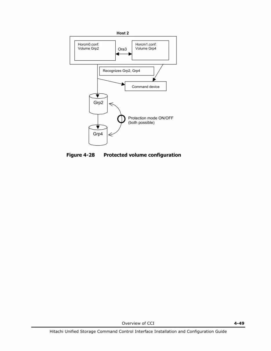
Overview of CCI 4-49
Hitachi Unified Storage Command Control Interface Installation and Configuration Guide
Grp4
Grp2
Command device
Recognizes Grp2, Grp4
Horcm0.conf: Volume Grp2
Horcm1.conf: Volume Grp4 Ora3
Host 2
Protection mode ON/OFF (both possible)
Figure 4-28 Protected volume configuration
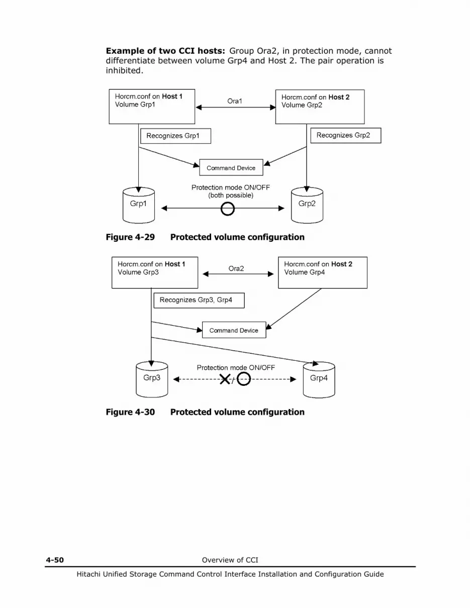
4-50 Overview of CCI
Hitachi Unified Storage Command Control Interface Installation and Configuration Guide
Example of two CCI hosts: Group Ora2, in protection mode, cannot differentiate between volume Grp4 and Host 2. The pair operation is inhibited.
Figure 4-29 Protected volume configuration
Figure 4-30 Protected volume configuration
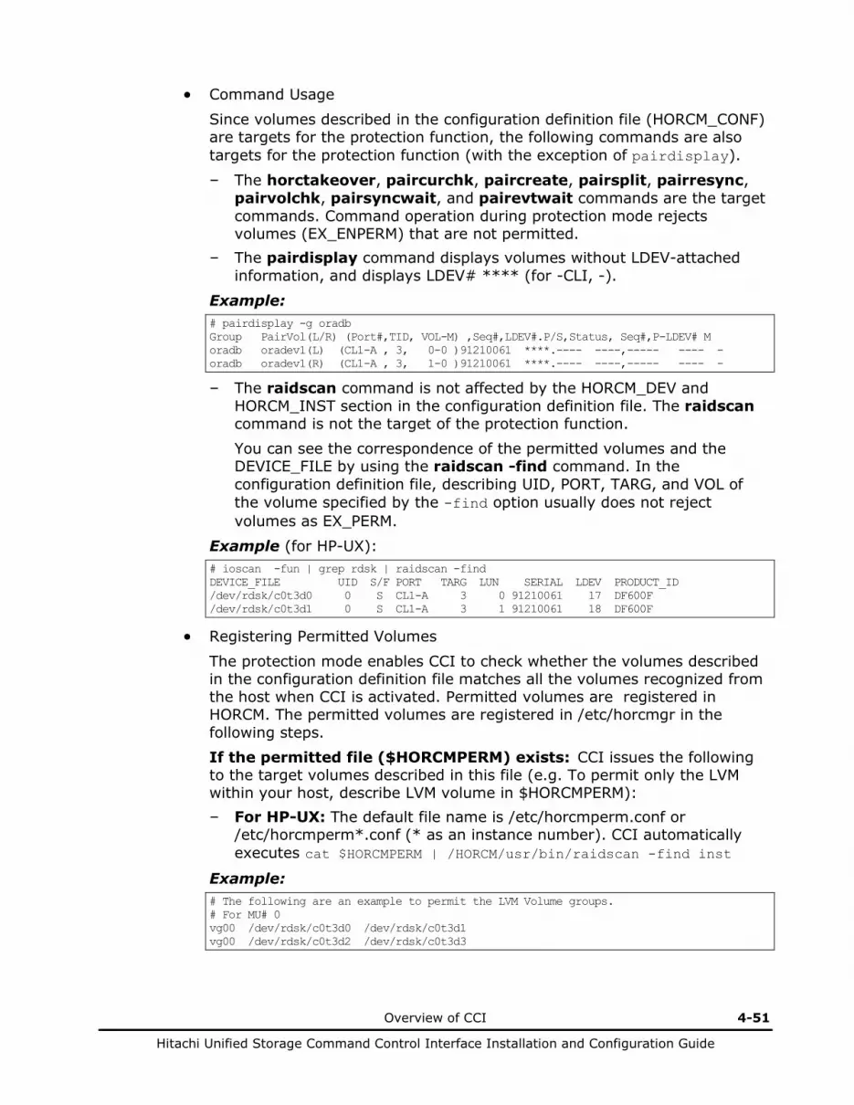
Overview of CCI 4-51
Hitachi Unified Storage Command Control Interface Installation and Configuration Guide
• Command Usage
Since volumes described in the configuration definition file (HORCM_CONF) are targets for the protection function, the following commands are also targets for the protection function (with the exception of pairdisplay).
– The horctakeover, paircurchk, paircreate, pairsplit, pairresync, pairvolchk, pairsyncwait, and pairevtwait commands are the target commands. Command operation during protection mode rejects volumes (EX_ENPERM) that are not permitted.
– The pairdisplay command displays volumes without LDEV-attached information, and displays LDEV# **** (for -CLI, -).
Example: # pairdisplay -g oradb Group PairVol(L/R) (Port#,TID, VOL-M) ,Seq#,LDEV#.P/S,Status, Seq#,P-LDEV# M oradb oradev1(L) (CL1-A , 3, 0-0 )91210061 ****.---- ----,----- ---- - oradb oradev1(R) (CL1-A , 3, 1-0 )91210061 ****.---- ----,----- ---- -
– The raidscan command is not affected by the HORCM_DEV and HORCM_INST section in the configuration definition file. The raidscan command is not the target of the protection function. You can see the correspondence of the permitted volumes and the DEVICE_FILE by using the raidscan -find command. In the configuration definition file, describing UID, PORT, TARG, and VOL of the volume specified by the -find option usually does not reject volumes as EX_PERM.
Example (for HP-UX): # ioscan -fun | grep rdsk | raidscan -find DEVICE_FILE UID S/F PORT TARG LUN SERIAL LDEV PRODUCT_ID /dev/rdsk/c0t3d0 0 S CL1-A 3 0 91210061 17 DF600F /dev/rdsk/c0t3d1 0 S CL1-A 3 1 91210061 18 DF600F
• Registering Permitted Volumes
The protection mode enables CCI to check whether the volumes described in the configuration definition file matches all the volumes recognized from the host when CCI is activated. Permitted volumes are registered in HORCM. The permitted volumes are registered in /etc/horcmgr in the following steps. If the permitted file ($HORCMPERM) exists: CCI issues the following to the target volumes described in this file (e.g. To permit only the LVM within your host, describe LVM volume in $HORCMPERM): – For HP-UX: The default file name is /etc/horcmperm.conf or
/etc/horcmperm*.conf (* as an instance number). CCI automatically executes cat $HORCMPERM | /HORCM/usr/bin/raidscan -find inst
Example: # The following are an example to permit the LVM Volume groups. # For MU# 0 vg00 /dev/rdsk/c0t3d0 /dev/rdsk/c0t3d1 vg00 /dev/rdsk/c0t3d2 /dev/rdsk/c0t3d3

4-52 Overview of CCI
Hitachi Unified Storage Command Control Interface Installation and Configuration Guide
Confirming vg01 groups: The following is an example for confirming whether the LVM volume group vg01 is correctly mapped to the group described in the configuration definition file. Example: # export HORCC_MRCF=1 # cat /etc/horcmperm.conf | grep vg01 | raidscan -find verify 1 -fd
OR # vgdisplay -v /dev/vg01|grep dsk|sed ‘s/\/*\/dsk\//\/rdsk\//g’|raidscan -find verify 1 –fd DEVICE_FILE Group PairVol Device_File M SERIAL LDEV /dev/rdsk/c0t3d0 oradb1 oradev1 c0t3d0 1 91210061 17 /dev/rdsk/c0t3d1 oradb1 oradev2 c0t3d1 1 91210061 18 /dev/rdsk/c0t3d2 oradb oradev3 c0t3d2 1 91210061 19 /dev/rdsk/c0t3d3 - - - 1 91210061 20
As shown in the example, the device file /dev/rdsk/c0t3d2 is mapped to the other group, and the /dev/rdsk/c0t3d3 is not described in the configuration definition file. – For Windows Server: The default file name is
\WINDOWS\horcmperm.conf or \WINDOWS\horcmperm*.conf (* as an instance number). CCI automatically issues: type $HORCMPERM | x:\HORCM\etc\raidscan.exe -find inst
Example: # The following are an example to permit the DB Volumes. # Note: a numerical value is interpreted as Harddisk#. # DB0 For MU# 0 Hd0-10 harddisk12 harddisk13 harddisk17
Example (Confirming DB1 groups): set HORCC_MRCF=1 echo hd20-23 | raidscan -find verify 1 -fd DEVICE_FILE Group PairVol Device_File M SERIAL LDEV Harddisk20 oradb1 oradev1 Harddisk20 1 91210061 17 Harddisk21 oradb1 oradev2 Harddisk21 1 91210061 18 Harddisk22 oradb oradev3 Harddisk22 1 91210061 19 Harddisk23 - - - 1 91210061 20
As shown in the example, Harddisk22 is mapped to the other group, and Harddisk23 is not described in the configuration definition file. If the permitted file ($HORCMPERM) does not exist: CCI targets the volumes of your own host, and performs the following:
For HP-UX: ‘ioscan -fun | grep -e rdisk -e rdsk | /HORCM/usr/bin/raidscan -find inst’
For Solaris: ‘echo /dev/rdsk/* | /HORCM/usr/bin/raidscan -find inst’
For AIX: ‘lsdev -C -c disk | grep hdisk | /HORCM/usr/bin/raidscan -find inst’
For Linux: ‘echo /dev/sd* | /HORCM/usr/bin/raidscan -find inst’
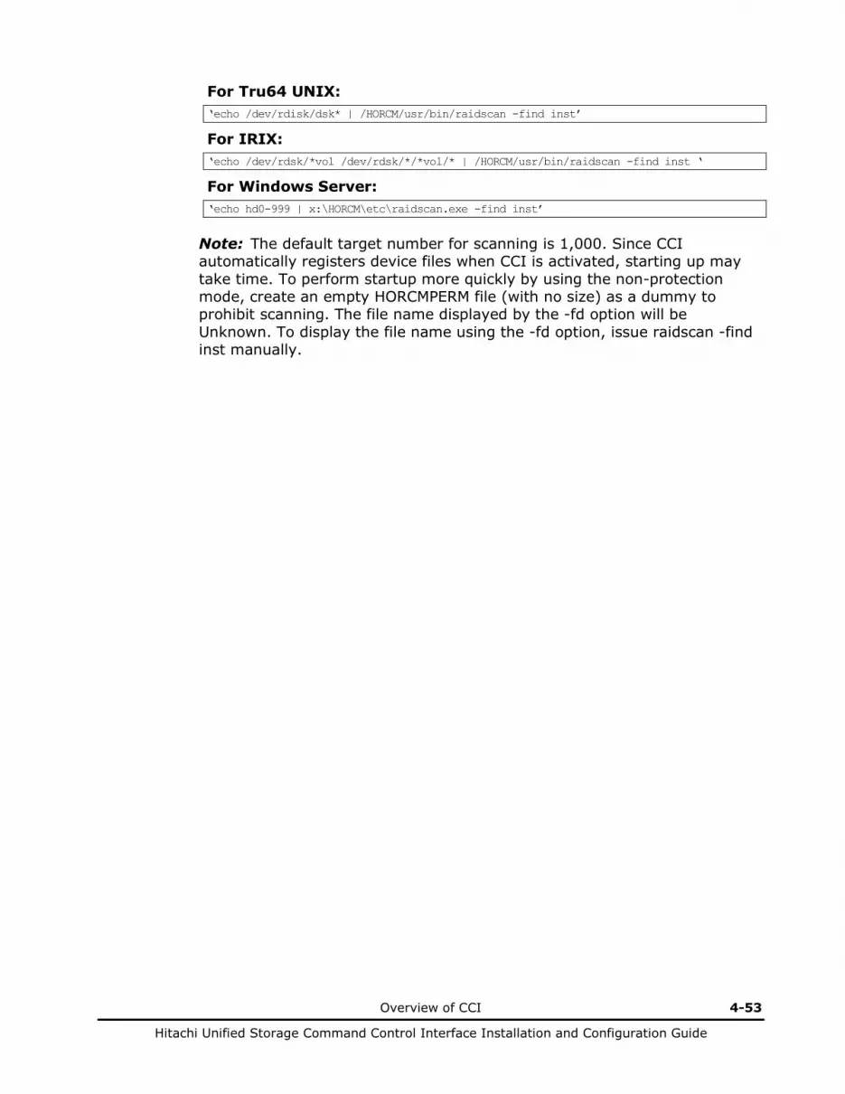
Overview of CCI 4-53
Hitachi Unified Storage Command Control Interface Installation and Configuration Guide
For Tru64 UNIX: ‘echo /dev/rdisk/dsk* | /HORCM/usr/bin/raidscan -find inst’
For IRIX: ‘echo /dev/rdsk/*vol /dev/rdsk/*/*vol/* | /HORCM/usr/bin/raidscan -find inst ‘
For Windows Server: ‘echo hd0-999 | x:\HORCM\etc\raidscan.exe -find inst’
Note: The default target number for scanning is 1,000. Since CCI automatically registers device files when CCI is activated, starting up may take time. To perform startup more quickly by using the non-protection mode, create an empty HORCMPERM file (with no size) as a dummy to prohibit scanning. The file name displayed by the -fd option will be Unknown. To display the file name using the -fd option, issue raidscan -find inst manually.
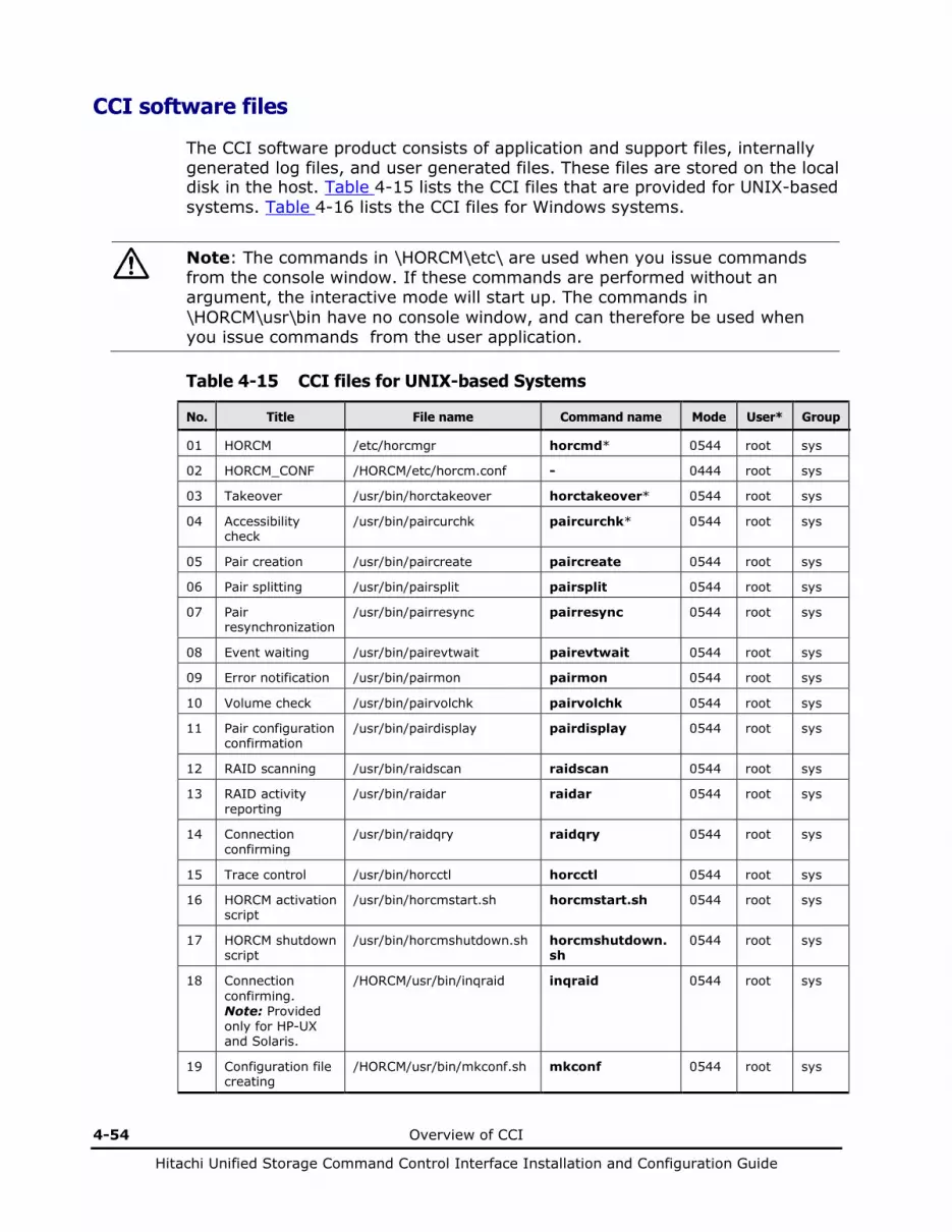
4-54 Overview of CCI
Hitachi Unified Storage Command Control Interface Installation and Configuration Guide
CCI software files
The CCI software product consists of application and support files, internally generated log files, and user generated files. These files are stored on the local disk in the host. Table 4-15 lists the CCI files that are provided for UNIX-based systems. Table 4-16 lists the CCI files for Windows systems.
Note: The commands in \HORCM\etc\ are used when you issue commands from the console window. If these commands are performed without an argument, the interactive mode will start up. The commands in \HORCM\usr\bin have no console window, and can therefore be used when you issue commands from the user application.
Table 4-15 CCI files for UNIX-based Systems
No. Title File name Command name Mode User* Group
01 HORCM /etc/horcmgr horcmd* 0544 root sys
02 HORCM_CONF /HORCM/etc/horcm.conf - 0444 root sys
03 Takeover /usr/bin/horctakeover horctakeover* 0544 root sys
04 Accessibility check
/usr/bin/paircurchk paircurchk* 0544 root sys
05 Pair creation /usr/bin/paircreate paircreate 0544 root sys
06 Pair splitting /usr/bin/pairsplit pairsplit 0544 root sys
07 Pair resynchronization
/usr/bin/pairresync pairresync 0544 root sys
08 Event waiting /usr/bin/pairevtwait pairevtwait 0544 root sys
09 Error notification /usr/bin/pairmon pairmon 0544 root sys
10 Volume check /usr/bin/pairvolchk pairvolchk 0544 root sys
11 Pair configuration confirmation
/usr/bin/pairdisplay pairdisplay 0544 root sys
12 RAID scanning /usr/bin/raidscan raidscan 0544 root sys
13 RAID activity reporting
/usr/bin/raidar raidar 0544 root sys
14 Connection confirming
/usr/bin/raidqry raidqry 0544 root sys
15 Trace control /usr/bin/horcctl horcctl 0544 root sys
16 HORCM activation script
/usr/bin/horcmstart.sh horcmstart.sh 0544 root sys
17 HORCM shutdown script
/usr/bin/horcmshutdown.sh horcmshutdown.sh
0544 root sys
18 Connection confirming. Note: Provided only for HP-UX and Solaris.
/HORCM/usr/bin/inqraid inqraid 0544 root sys
19 Configuration file creating
/HORCM/usr/bin/mkconf.sh mkconf 0544 root sys
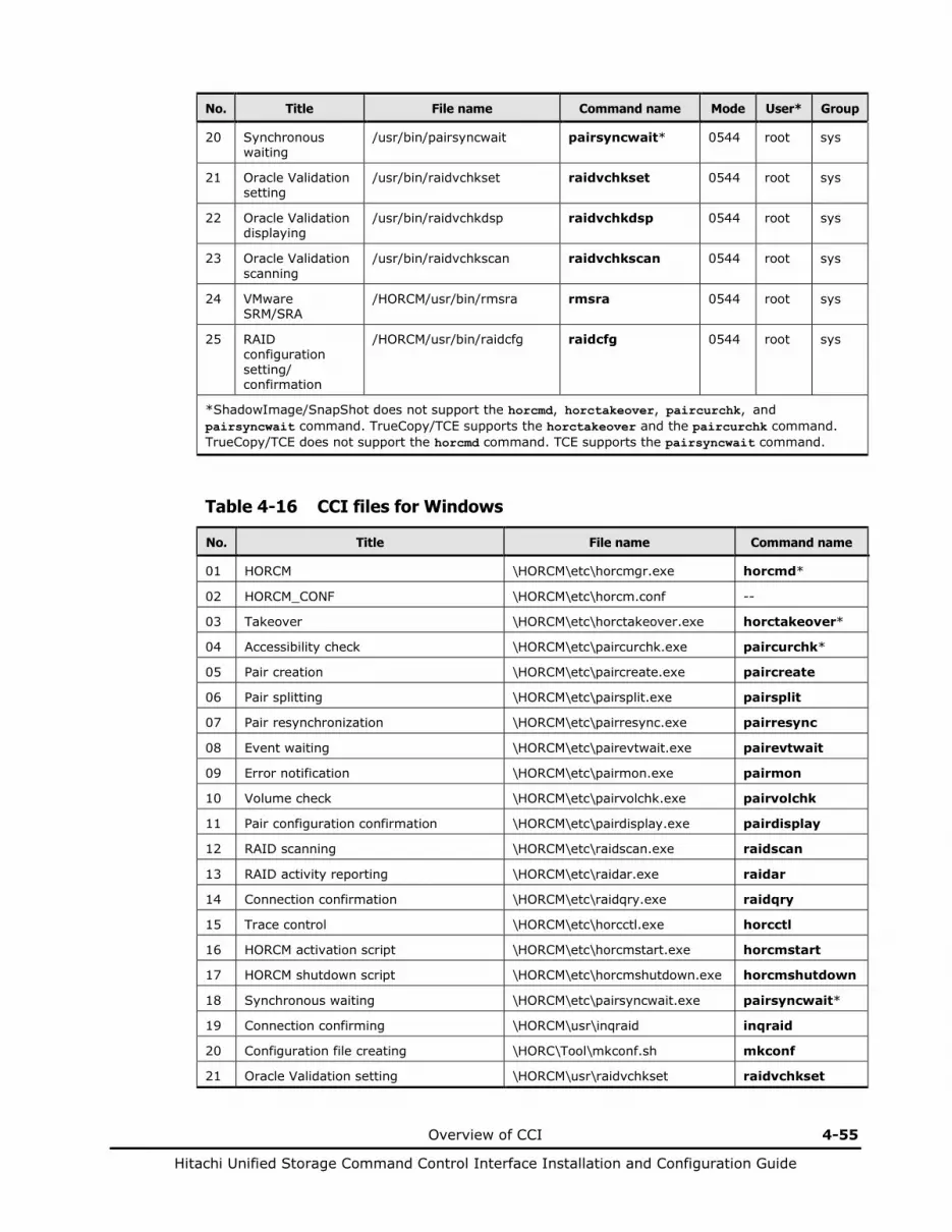
Overview of CCI 4-55
Hitachi Unified Storage Command Control Interface Installation and Configuration Guide
No. Title File name Command name Mode User* Group
20 Synchronous waiting
/usr/bin/pairsyncwait pairsyncwait* 0544 root sys
21 Oracle Validation setting
/usr/bin/raidvchkset raidvchkset 0544 root sys
22 Oracle Validation displaying
/usr/bin/raidvchkdsp raidvchkdsp 0544 root sys
23 Oracle Validation scanning
/usr/bin/raidvchkscan raidvchkscan 0544 root sys
24 VMware SRM/SRA
/HORCM/usr/bin/rmsra rmsra 0544 root sys
25 RAID configuration setting/ confirmation
/HORCM/usr/bin/raidcfg raidcfg 0544 root sys
*ShadowImage/SnapShot does not support the horcmd, horctakeover, paircurchk, and pairsyncwait command. TrueCopy/TCE supports the horctakeover and the paircurchk command. TrueCopy/TCE does not support the horcmd command. TCE supports the pairsyncwait command.
Table 4-16 CCI files for Windows
No. Title File name Command name
01 HORCM \HORCM\etc\horcmgr.exe horcmd*
02 HORCM_CONF \HORCM\etc\horcm.conf --
03 Takeover \HORCM\etc\horctakeover.exe horctakeover*
04 Accessibility check \HORCM\etc\paircurchk.exe paircurchk*
05 Pair creation \HORCM\etc\paircreate.exe paircreate
06 Pair splitting \HORCM\etc\pairsplit.exe pairsplit
07 Pair resynchronization \HORCM\etc\pairresync.exe pairresync
08 Event waiting \HORCM\etc\pairevtwait.exe pairevtwait
09 Error notification \HORCM\etc\pairmon.exe pairmon
10 Volume check \HORCM\etc\pairvolchk.exe pairvolchk
11 Pair configuration confirmation \HORCM\etc\pairdisplay.exe pairdisplay
12 RAID scanning \HORCM\etc\raidscan.exe raidscan
13 RAID activity reporting \HORCM\etc\raidar.exe raidar
14 Connection confirmation \HORCM\etc\raidqry.exe raidqry
15 Trace control \HORCM\etc\horcctl.exe horcctl
16 HORCM activation script \HORCM\etc\horcmstart.exe horcmstart
17 HORCM shutdown script \HORCM\etc\horcmshutdown.exe horcmshutdown
18 Synchronous waiting \HORCM\etc\pairsyncwait.exe pairsyncwait*
19 Connection confirming \HORCM\usr\inqraid inqraid
20 Configuration file creating \HORC\Tool\mkconf.sh mkconf
21 Oracle Validation setting \HORCM\usr\raidvchkset raidvchkset

4-56 Overview of CCI
Hitachi Unified Storage Command Control Interface Installation and Configuration Guide
No. Title File name Command name
22 Oracle Validation displaying \HORCM\usr\raidvchkdsp raidvchkdsp
23 Oracle Validation scanning \HORCM\usr\raidvchkscan raidvchkscan
24 Tool \HORCM\Tool\svcexe.exe svcexe
25 Sample script for svcexe HORCM\Tool\HORCM0_run.txt --
26 VMware SRM/SRA \HORCM\etc\rmsra.exe rmsra
27 RAID configuration setting/confirmation \HORCM\etc\raidcfg.exe raidcfg
28 Takeover \HORCM\usr\bin\horctakeover.exe
horctakeover*
29 Accessibility check \HORCM\usr\bin\paircurchk.exe paircurchk*
30 Pair creation \HORCM\usr\bin\paircreate.exe paircreate
31 Pair splitting \HORCM\usr\bin\pairsplit.exe pairsplit
32 Pair resynchronization \HORCM\usr\bin\pairresync.exe pairresync
33 Event waiting \HORCM\usr\bin\pairevtwait.exe pairevtwait
34 Volume check \HORCM\usr\bin\pairvolchk.exe pairvolchk
35 Pair configuration confirmation \HORCM\usr\bin\pairdisplay.exe pairdisplay
36 RAID scanning \HORCM\usr\bin\raidscan.exe raidscan
37 RAID connection confirmation \HORCM\usr\bin\raidqry.exe raidqry
38 Synchronous waiting \HORCM\usr\bin\pairsyncwait.exe pairsyncwait*
39 Oracle Validation setting \HORCM\usr\bin\raidvchkset raidvchkset
40 Oracle Validation displaying \HORCM\usr\bin\raidvchkdsp raidvchkdsp
41 Oracle Validation scanning \HORCM\usr\bin\raidvchkscan raidvchkscan
42 RAID configuration setting/confirmation \HORCM\usr\bin\raidcfg.exe raidcfg
*ShadowImage/SnapShot does not support the horcmd, horctakeover, paircurchk, and pairsyncwait command. TrueCopy/TCE supports the horctakeover and the paircurchk command. TrueCopy/TCE does not support the horcmd command. TCE supports the pairsyncwait command.
Log and trace files
The CCI software (HORCM) and ShadowImage/SnapShot/TrueCopy/TCE commands maintain start-up log files, execution log files, and trace files which can be used to identify the cause of errors and maintain status transition history records of the paired volumes.
Overview of CCI 4-57
Hitachi Unified Storage Command Control Interface Installation and Configuration Guide
User-created files
Script Files. CCI supports scripting to provide automated and unattended copy operations. A CCI script contains a list of CCI commands, which describes a series of ShadowImage, SnapShot, TrueCopy, and/or TCE operations. The scripted commands for UNIX-based platforms are defined in a shell script file. The scripted commands for Windows-based platforms are defined in a text file. The host reads the script file and sends the commands to the disk array command device to perform the ShadowImage/SnapShot/TrueCopy/TCE operations automatically. The CCI scripts are:
• HORCM startup script (horcmstart.sh, horcmstart.exe): A script that starts HORCM (/etc/horcmgr), sets environmental variables as needed (for example, HORCM_CONF, HORCM_LOG, HORCM_LOGS), and starts HORCM.
• HORCM shutdown script (horcmshutdown.sh, horcmshutdown.exe): A script for stopping the HORCM (/etc/horcmgr).
• HA control script: A script for executing takeover processing automatically when the cluster manager (CM) detects a host error.
When constructing the HORCM environment, the system administrator should make a copy of the HORCM_CONF file. The copied file should be set according to the system environment and registered as the following file (* is the instance number):
• UNIX-based systems: /etc/horcm.conf or /etc/horcm*.conf
• Windows Server systems: \WINDOWS\horcm.conf or \WINDOWS\horcm*.conf

4-58 Overview of CCI
Hitachi Unified Storage Command Control Interface Installation and Configuration Guide
Group version control
Before executing each option of a command, CCI checks the facility version of the Hitachi array internally to verify that the same version is installed on mixed array configuration. If the configuration includes older array systems, this method may not meet the requirements for the mixed array system environment, because the older array system limits the availability enhancements in later facility versions. If the facility versions of the array systems are different, the user will not be able to use disk array-specific facility, because CCI applies the minimum version to all array systems. To expand the capability for mixed array system configurations and avoid problems such as this, CCI supports the following “group version control” to manage a version for each group.
• CCI (HORCM daemon) makes a facility version for each group based on a configuration file at the start-up of HORCM.
• In a mixed array system configuration, if the facility version of the array systems is different on a group, CCI will apply the minimum version for each group.
Array facility version = N
Array facility version = N+1
Mixed array configuration
Facility version = N for group A on Conf.file
Facility version = N for group B on Conf.file
Facility version = N+1 for group C on Conf.file
Figure 4-31 Definition of the group version
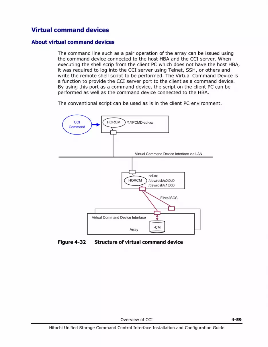
Overview of CCI 4-59
Hitachi Unified Storage Command Control Interface Installation and Configuration Guide
Virtual command devices
About virtual command devices
The command line such as a pair operation of the array can be issued using the command device connected to the host HBA and the CCI server. When executing the shell scrip from the client PC which does not have the host HBA, it was required to log into the CCI server using Telnet, SSH, or others and write the remote shell script to be performed. The Virtual Command Device is a function to provide the CCI server port to the client as a command device. By using this port as a command device, the script on the client PC can be performed as well as the command device connected to the HBA.
The conventional script can be used as is in the client PC environment.
CCI
Command HORCM
HORCM
\\.\IPCMD-cci-xx
cci-xx /dev/rdsk/c0t0d0 /dev/rdsk/c1t0d0
Fibre/iSCSI
Virtual Command Device Interface via LAN
-CM
Array
Virtual Command Device Interface
Figure 4-32 Structure of virtual command device

4-60 Overview of CCI
Hitachi Unified Storage Command Control Interface Installation and Configuration Guide
Specifying virtual command devices
(1) Format for specifying Virtual Command Device CCI supports the following naming format specifying IP address a port number (services) as notation of the command device for all CCI supported platforms.
\\.\IPCMD-IPaddr-Port[-unitid] or IPCMD-IPaddr-Port[-unitid] IPaddr: IP address of HORCM host Port: Port number of HORCM unitid: Unit number of the array in the multiple-unit connection configuration
(a) Configuration file example for IPv4: HORCM_CMD #dev_name dev_name dev_name \\.\IPCMD-158.214.135.113-31001
(b) Configuration file example for IPv6: HORCM_CMD #dev_name dev_name dev_name \\.\IPCMD-fe80::209:6bff:febe:3c17-31001
(c) Configuration file example for mixing with a device file: HORCM_CMD #dev_name dev_name dev_name \\.\IPCMD-91200026:/dev/rdsk/* \\.\IPCMD-158.214.135.113-31001
(d) Configuration file example for alternating with a device file and IP command device: HORCM_CMD #dev_name dev_name \\.\IPCMD-91200026:/dev/rdsk/* \\.\IPCMD-158.214.135.113-31001
HORCM_CMD #dev_name dev_name \\.\IPCMD-158.214.135.113-31001 \\.\IPCMD-91200026:/dev/rdsk/*
(e) Configuration file example for multiple array configuration: HORCM_CMD #dev_name dev_name dev_name \\.\IPCMD-158.214.135.113-31001 \\.\IPCMD-158.214.135.114-31001 \\.\IPCMD-158.214.135.115-31001
Note: The IP address and the port number can be specified the host name and service name which is registered on its host.
Overview of CCI 4-61
Hitachi Unified Storage Command Control Interface Installation and Configuration Guide
(2) Requirement for supporting CCI uses SCSI Path-through driver for implementing Virtual Command Device, and it is accomplished by converting from IP SCSI interface to Fibre SCSI interface. Whether CCI can perform completely or not will be depended on OS, and it has some restriction in case of IP SCSI (Virtual CMDDEV) Command device target. Therefore CCI using Virtual Command Device should be used within the following restrictions. – Virtual Command Device server
The environment where it is CCI supported platform other than Tru64 UNIX and the SCSI Path-through driver is usable is required. In the inappropriate environment, CCI start is rejected and fails. Set “ip_address” of “HORCM_MON” of the configuration definition file to be other than “localhost”.
(3) UDP/IP port for the initiator
CCI uses the following port number as default. For nine specified instance: “34000+0” For instance X: “34000+X+1” If the default will be needed to change, this value can be changed by setting “HORCM_IPSCPORT=<services>” environment variable. <services> can be specified port number or service name.
Note: When an initiator port number and a port number to be assigned to a communication path of HORCM are the same, the operation by CCI may not operate normally. Set different values for the initiator port number and the port number to be assigned to the communication path of HORCM.
(4) Controlling IO traffic for relaying port CCI handles IOs for the Virtual Command Device using synchronized IO as performing of default. In Virtual Command Device router node, if HORCM will receive a many IO request from another HORCM client (command device initiator), it may be caused a performance decrement. Hence CCI supports asynchronous IO for relaying IOs to next node by setting the following environment variable. $ HORCM_IPSCPAIO=1

4-62 Overview of CCI
Hitachi Unified Storage Command Control Interface Installation and Configuration Guide
(5) Format for specifying IP and port security A user will be able to start CCI client (command device initiator) by specifying remote HORCM instance connected to HBA port as \\.\IPCMD-IPaddr-Port[-unitid]. The Virtual Command Device facility will be to use it from many users, however this may have a problem on the security.
Attach HORCM
HORCM
¥¥.¥IPCMD-cci-xx
cci-xx /dev/rdsk/c0t0d0
UNIX
Virtual Command Device Interface
-CM
Array
Figure 4-33 IP Security of virtual command device
Therefore CCI has a mechanism using the following format for allowing the specified IP address and port list only when CCI client (command device initiator) attaches to this instance.
(a) Configuration file example for IPv4: HORCM_ALLOW_INST #ip_address service 158.214.135.113 34000 158.214.135.114 34000
(b) Configuration file example for IPv6: HORCM_ALLOW_INST #ip_address service fe80::209:6bff:febe:3c17 34000
If CCI client will not be allowed, it will be rejected with check condition SKEY=0x05, ASC=0xfe created by HORCM instance.
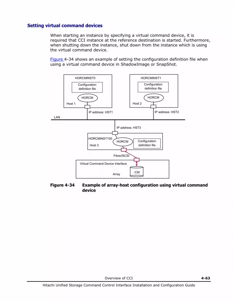
Overview of CCI 4-63
Hitachi Unified Storage Command Control Interface Installation and Configuration Guide
Setting virtual command devices
When starting an instance by specifying a virtual command device, it is required that CCI instance at the reference destination is started. Furthermore, when shutting down the instance, shut down from the instance which is using the virtual command device.
Figure 4-34 shows an example of setting the configuration definition file when using a virtual command device in ShadowImage or SnapShot.
HORCM
HORCM
Configuration definition file
Configuration definition file
Fibre/iSCSI
LAN
-CM
Array
Virtual Command Device Interface
Host 3
HORCMINST100
Host 1
HORCMINST0
IP address: HST1
HORCM
Host 2
HORCMINST1
IP address: HST2
IP address: HST3
Configuration definition file
Figure 4-34 Example of array-host configuration using virtual command device

4-64 Overview of CCI
Hitachi Unified Storage Command Control Interface Installation and Configuration Guide
Configuration definition file for HORCMINST0 (horcm0.conf)
HORCM_MON #ip_address service poll(10ms) timeout(10ms) HST1 30010 18000 3000 HORCM_CMD #dev_name \\.\IPCMD-HST3-20010 HORCM_DEV #dev_group dev_name port# TargetID LU# MU# Oradb oradev1 CL1-A 1 1 Oradb oradev2 CL1-A 1 2 HORCM_INST #dev_group ip_address service Oradb HST2 30011
Configuration definition file for HORCMINST1 (horcm1.conf)
HORCM_MON #ip_address service poll(10ms) timeout(10ms) HST2 30011 18000 3000 HORCM_CMD #dev_name \\.\IPCMD-HST3-20010 HORCM_DEV #dev_group dev_name port# TargetID LU# MU# Oradb oradev1 CL1-B 1 3 Oradb oradev2 CL1-B 1 4 HORCM_INST #dev_group ip_address service Oradb HST1 30010
Configuration definition file for HORCMINST100 (horcm100.conf)
HORCM_MON #ip_address service poll(10ms) timeout(10ms) HST3 20010 18000 3000 HORCM_CMD #dev_name /dev/xxx HORCM_DEV #dev_group dev_name port# TargetID LU# MU# HORCM_INST #dev_group ip_address service

Overview of CCI 4-65
Hitachi Unified Storage Command Control Interface Installation and Configuration Guide
When using TrueCopy or TCE in combination with the configuration of two hosts and two instances, two hosts are required to recognize the command device.
HORCM
HORCM
Configuration definition file
Configuration definition file
Fibre/iSCSI
LAN
-CM
Array 1
Host 3
Host 1
HORCM
Host 2
Configuration definition file
HORCM Configuration definition file
Fibre/iSCSI
-CM
Host 4
Array 2
TrueCopy
Figure 4-35 Example of array-host configuration using virtual command device
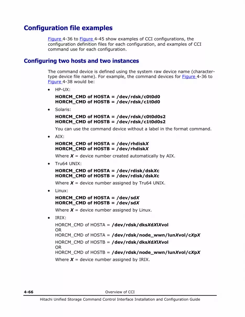
4-66 Overview of CCI
Hitachi Unified Storage Command Control Interface Installation and Configuration Guide
Configuration file examples
Figure 4-36 to Figure 4-45 show examples of CCI configurations, the configuration definition files for each configuration, and examples of CCI command use for each configuration.
Configuring two hosts and two instances
The command device is defined using the system raw device name (character-type device file name). For example, the command devices for Figure 4-36 to Figure 4-38 would be:
• HP-UX:
HORCM_CMD of HOSTA = /dev/rdsk/c0t0d0 HORCM_CMD of HOSTB = /dev/rdsk/c1t0d0
• Solaris:
HORCM_CMD of HOSTA = /dev/rdsk/c0t0d0s2 HORCM_CMD of HOSTB = /dev/rdsk/c1t0d0s2 You can use the command device without a label in the format command.
• AIX: HORCM_CMD of HOSTA = /dev/rhdiskX HORCM_CMD of HOSTB = /dev/rhdiskX Where X = device number created automatically by AIX.
• Tru64 UNIX: HORCM_CMD of HOSTA = /dev/rdisk/dskXc HORCM_CMD of HOSTB = /dev/rdisk/dskXc Where X = device number assigned by Tru64 UNIX.
• Linux: HORCM_CMD of HOSTA = /dev/sdX HORCM_CMD of HOSTB = /dev/sdX Where X = device number assigned by Linux.
• IRIX: HORCM_CMD of HOSTA = /dev/rdsk/dksXdXlXvol OR HORCM_CMD of HOSTA = /dev/rdsk/node_wwn/lunXvol/cXpX HORCM_CMD of HOSTB = /dev/rdsk/dksXdXlXvol OR HORCM_CMD of HOSTB = /dev/rdsk/node_wwn/lunXvol/cXpX
Where X = device number assigned by IRIX.
Overview of CCI 4-67
Hitachi Unified Storage Command Control Interface Installation and Configuration Guide
• Windows Server:
HORCM_CMD of HOSTA = \\.\PhysicalDriveX OR HORCM_CMD of HOSTA = \\.\Volume{guid} OR HORCM_CMD of HOSTA = \\.\CMD-Ser#-ldev#-Port# HORCM_CMD of HOSTB = \\.\PhysicalDriveX OR HORCM_CMD of HOSTB = \\.\Volume{guid} OR HORCM_CMD of HOSTB = \\.\CMD-Ser#-ldev#-Port#
Where X = device number assigned by Windows Server. The PhysicalDrive number may change at every reboot. If the number changes, use \\.\CMD-Ser#-ldev#-Port# or Volume{guid} for which the same name is kept. If \\.\CMD-Ser#-ldev#-Port# or \\.\Volume{guid} is specified, CCI changes it to \\.\PhysicalDrive? to be corresponded. For MSCS, it is recommended to use \\.\CMD-Ser#-ldev#-Port# instead of \\.\Volume{GUID} because \\.\Volume{GUID} may not be maintained. Using \\.\CMD-Ser#-ldev#-Port# does not require creating any partition on a volume. Volume{guid} is created when you make a partition by using the Windows’ Disk Management. You can find Volume{guid} by using the inqraid $Volume -CLI -fv or raidscan -x findcmddev0.? commands.
• Regarding a command device for CCI, do not set two or more paths for a single host. (Windows Server may change the guid when a volume with an identical guid is found.
• For Windows Server, when a path detachment, which is caused by a controller detachment or interface failure, continues for longer than one minute, the command device may be unable to be recognized at the time when recovery from the path detachment is made. To make the recovery, perform the re-scanning of the disks of Windows. When Windows cannot access the command device although CCI becomes able to recognize the command device, restart CCI.
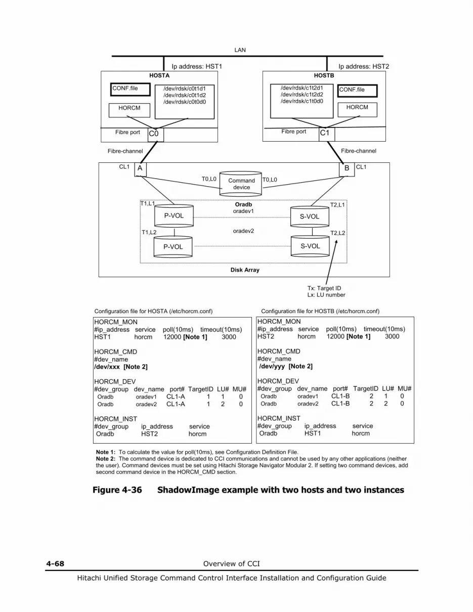
4-68 Overview of CCI
Hitachi Unified Storage Command Control Interface Installation and Configuration Guide
HORCM_MON #ip_address service poll(10ms) timeout(10ms) HST1 horcm 12000 [Note 1] 3000 HORCM_CMD #dev_name /dev/xxx [Note 2] HORCM_DEV #dev_group dev_name port# TargetID LU# MU# Oradb oradev1 CL1-A 1 1 0 Oradb oradev2 CL1-A 1 2 0 HORCM_INST #dev_group ip_address service Oradb HST2 horcm
Configuration file for HOSTA (/etc/horcm.conf)
HORCM_MON #ip_address service poll(10ms) timeout(10ms) HST2 horcm 12000 [Note 1] 3000 HORCM_CMD #dev_name /dev/yyy [Note 2] HORCM_DEV #dev_group dev_name port# TargetID LU# MU# Oradb oradev1 CL1-B 2 1 0 Oradb oradev2 CL1-B 2 2 0 HORCM_INST #dev_group ip_address service Oradb HST1 horcm
Configuration file for HOSTB (/etc/horcm.conf)
LAN
Tx: Target ID Lx: LU number
Note 1: To calculate the value for poll(10ms), see Configuration Definition File. Note 2: The command device is dedicated to CCI communications and cannot be used by any other applications (neither the user). Command devices must be set using Hitachi Storage Navigator Modular 2. If setting two command devices, add second command device in the HORCM_CMD section.
Ip address: HST2
A CL1
Oradb oradev1
oradev2
P-VOL
P-VOL
T1,L1
T1,L2
Command device
T0,L0
B CL1
S-VOL
S-VOL
T2,L2
T2,L1
T0,L0
Disk Array
HOSTA
HORCM
CONF.file
Ip address: HST1
C0
HOSTB
HORCM
CONF.file
C1
/dev/rdsk/c0t1d1 /dev/rdsk/c0t1d2 /dev/rdsk/c0t0d0
/dev/rdsk/c1t2d1 /dev/rdsk/c1t2d2 /dev/rdsk/c1t0d0
Fibre-channel Fibre-channel
Fibre port Fibre port
Figure 4-36 ShadowImage example with two hosts and two instances
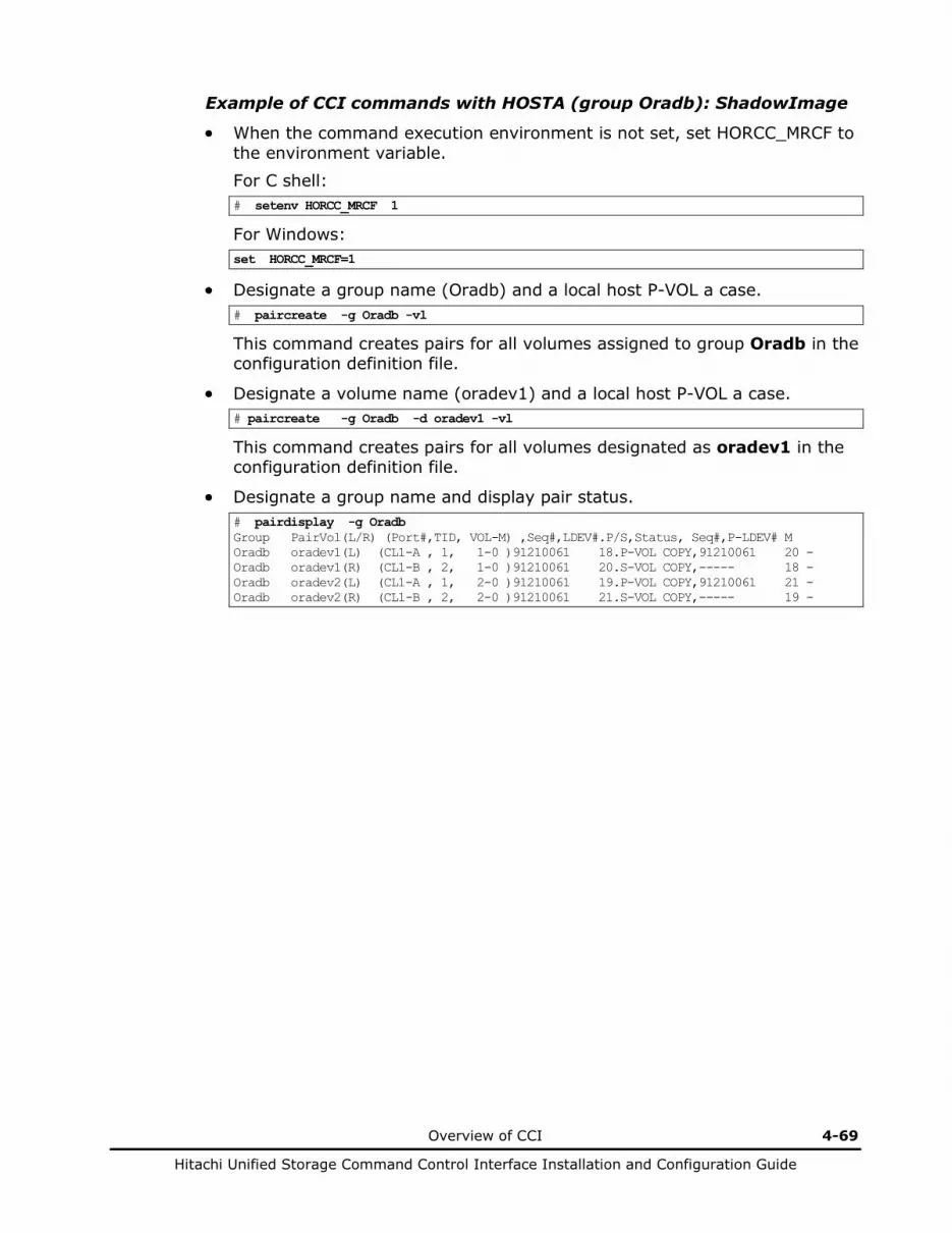
Overview of CCI 4-69
Hitachi Unified Storage Command Control Interface Installation and Configuration Guide
Example of CCI commands with HOSTA (group Oradb): ShadowImage
• When the command execution environment is not set, set HORCC_MRCF to the environment variable. For C shell: # setenv HORCC_MRCF 1
For Windows: set HORCC_MRCF=1
• Designate a group name (Oradb) and a local host P-VOL a case. # paircreate -g Oradb -vl
This command creates pairs for all volumes assigned to group Oradb in the configuration definition file.
• Designate a volume name (oradev1) and a local host P-VOL a case. # paircreate -g Oradb -d oradev1 -vl
This command creates pairs for all volumes designated as oradev1 in the configuration definition file.
• Designate a group name and display pair status. # pairdisplay -g Oradb Group PairVol(L/R) (Port#,TID, VOL-M) ,Seq#,LDEV#.P/S,Status, Seq#,P-LDEV# M Oradb oradev1(L) (CL1-A , 1, 1-0 )91210061 18.P-VOL COPY,91210061 20 - Oradb oradev1(R) (CL1-B , 2, 1-0 )91210061 20.S-VOL COPY,----- 18 - Oradb oradev2(L) (CL1-A , 1, 2-0 )91210061 19.P-VOL COPY,91210061 21 - Oradb oradev2(R) (CL1-B , 2, 2-0 )91210061 21.S-VOL COPY,----- 19 -
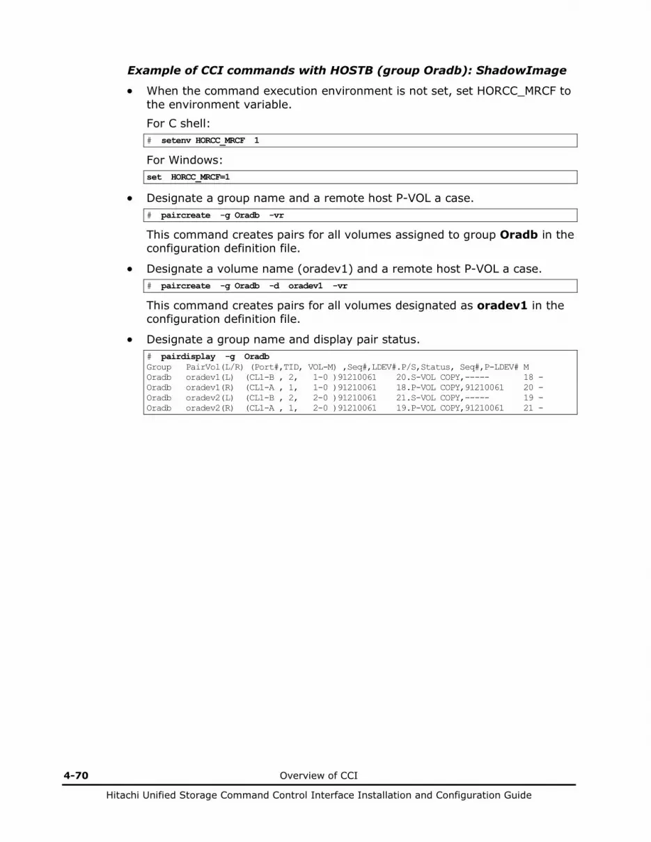
4-70 Overview of CCI
Hitachi Unified Storage Command Control Interface Installation and Configuration Guide
Example of CCI commands with HOSTB (group Oradb): ShadowImage
• When the command execution environment is not set, set HORCC_MRCF to the environment variable. For C shell: # setenv HORCC_MRCF 1
For Windows: set HORCC_MRCF=1
• Designate a group name and a remote host P-VOL a case. # paircreate -g Oradb -vr
This command creates pairs for all volumes assigned to group Oradb in the configuration definition file.
• Designate a volume name (oradev1) and a remote host P-VOL a case. # paircreate -g Oradb -d oradev1 -vr
This command creates pairs for all volumes designated as oradev1 in the configuration definition file.
• Designate a group name and display pair status. # pairdisplay -g Oradb Group PairVol(L/R) (Port#,TID, VOL-M) ,Seq#,LDEV#.P/S,Status, Seq#,P-LDEV# M Oradb oradev1(L) (CL1-B , 2, 1-0 )91210061 20.S-VOL COPY,----- 18 - Oradb oradev1(R) (CL1-A , 1, 1-0 )91210061 18.P-VOL COPY,91210061 20 - Oradb oradev2(L) (CL1-B , 2, 2-0 )91210061 21.S-VOL COPY,----- 19 - Oradb oradev2(R) (CL1-A , 1, 2-0 )91210061 19.P-VOL COPY,91210061 21 -

Overview of CCI 4-71
Hitachi Unified Storage Command Control Interface Installation and Configuration Guide
HORCM_MON #ip_address service poll(10ms) timeout(10ms) HST1 horcm 12000 [Note 1] 3000 HORCM_CMD #dev_name /dev/xxx [Note 2] HORCM_DEV #dev_group dev_name port# TargetID LU# MU# Oradb oradev1 CL1-A 1 1 0 Oradb oradev2 CL1-A 1 2 0 HORCM_INST #dev_group ip_address service Oradb HST2 horcm
Configuration file for HOSTA (/etc/horcm.conf)
HORCM_MON #ip_address service poll(10ms) timeout(10ms) HST2 horcm 12000 [Note 1] 3000 HORCM_CMD #dev_name /dev/yyy [Note 2] HORCM_DEV #dev_group dev_name port# TargetID LU# MU# Oradb oradev1 CL1-B 2 1 0 Oradb oradev2 CL1-B 2 2 0 HORCM_INST #dev_group ip_address service Oradb HST1 horcm
Configuration file for HOSTB (/etc/horcm.conf)
LAN
Tx: Target ID Lx: LU number
Note 1: To calculate the value for poll(10ms), see section 2.5.3. Note 2: The command device is dedicated to CCI communications and cannot be used by any other applications (neither the user). Command devices must be set using Hitachi Storage Navigator Modular 2. If setting two command devices, add second command device in the HORCM_CMD section.
Ip address: HST2
A CL1
Oradb oradev1
oradev2
P-VOL
P-VOL
T1,L1
T1,L2
Command device
T0,L0
B CL1
V-VOL
V-VOL
T2,L2
T2,L1
T0,L0
Disk Array
HOSTA
HORCM
CONF.file
Ip address: HST1
C0
HOSTB
HORCM
CONF.file
C1
/dev/rdsk/c0t1d1 /dev/rdsk/c0t1d2 /dev/rdsk/c0t0d0
/dev/rdsk/c1t2d1 /dev/rdsk/c1t2d2 /dev/rdsk/c1t0d0
Fibre-channel Fibre-channel
Fibre port Fibre port
Figure 4-37 SnapShot example with two hosts and two instances

4-72 Overview of CCI
Hitachi Unified Storage Command Control Interface Installation and Configuration Guide
Example of CCI commands with HOSTA (group Oradb): SnapShot
• When the command execution environment is not set, set HORCC_MRCF to the environment variable. For C shell: # setenv HORCC_MRCF 1
For Windows: set HORCC_MRCF=1
• Designate a group name (Oradb) and a local host P-VOL a case. # paircreate -g Oradb -vl -split
This command creates pairs for all volumes assigned to group Oradb in the configuration definition file.
• Designate a volume name (oradev1) and a local host P-VOL a case. # paircreate -g Oradb -d oradev1 -vl -split
This command creates pairs for all volumes designated as oradev1 in the configuration definition file.
• Designate a group name and display pair status. # pairdisplay -g Oradb Group PairVol(L/R) (Port#,TID, VOL-M) ,Seq#,LDEV#.P/S,Status, Seq#,P-LDEV# M oradb oradev1(L) (CL1-A , 1, 1-0 )91210061 18.P-VOL PSUS,91210061 20 - oradb oradev1(R) (CL1-B , 2, 1-0 )91210061 20.S-VOL SSUS,----- 18 - oradb oradev2(L) (CL1-A , 1, 2-0 )91210061 19.P-VOL PSUS,91210061 21 - oradb oradev2(R) (CL1-B , 2, 2-0 )91210061 21.S-VOL SSUS,----- 19 -

Overview of CCI 4-73
Hitachi Unified Storage Command Control Interface Installation and Configuration Guide
HORCM_MON #ip_address service poll(10ms) timeout(10ms) HST1 horcm 12000 [Note 1] 3000 HORCM_CMD #dev_name /dev/xxx [Note 2] HORCM_DEV #dev_group dev_name port# TargetID LU# MU# Oradb oradev1 CL1-A 1 1 Oradb oradev2 CL1-A 1 2 HORCM_INST #dev_group ip_address service Oradb HST2 horcm
Configuration file for HOSTA (/etc/horcm.conf)
HORCM_MON #ip_address service poll(10ms) timeout(10ms) HST2 horcm 12000 [Note 1] 3000 HORCM_CMD #dev_name /dev/yyy [Note 2] HORCM_DEV #dev_group dev_name port# TargetID LU# MU# Oradb oradev1 CL1-B 2 1 Oradb oradev2 CL1-B 2 2 HORCM_INST #dev_group ip_address service Oradb HST1 horcm
Configuration file for HOSTB (/etc/horcm.conf)
LAN
Tx: Target ID Lx: LU number
Note 1: To calculate the value for poll(10ms), see section 2.5.3. Note 2: The command device is dedicated to CCI communications and cannot be used by any other applications (neither the user). Command devices must be set using Hitachi Storage Navigator Modular 2. If setting two command devices, add second command device in the HORCM_CMD section.
Ip address: HST2
A CL1
Oradb oradev1
oradev2
P-VOL
P-VOL
T1,L1
T1,L2
Command device
T0,L0
B CL1
S-VOL
S-VOL
T2,L2
T2,L1
T0,L0
Disk Array
HOSTA
HORCM
CONF.file
Ip address: HST1
C0
HOSTB
HORCM
CONF.file
C1
/dev/rdsk/c0t1d1 /dev/rdsk/c0t1d2 /dev/rdsk/c0t0d0
/dev/rdsk/c1t2d1 /dev/rdsk/c1t2d2 /dev/rdsk/c1t0d0
Fibre-channel Fibre-channel
Fibre port Fibre port
Command device Disk Array
Figure 4-38 Two hosts and two instances example TrueCopy/TCE
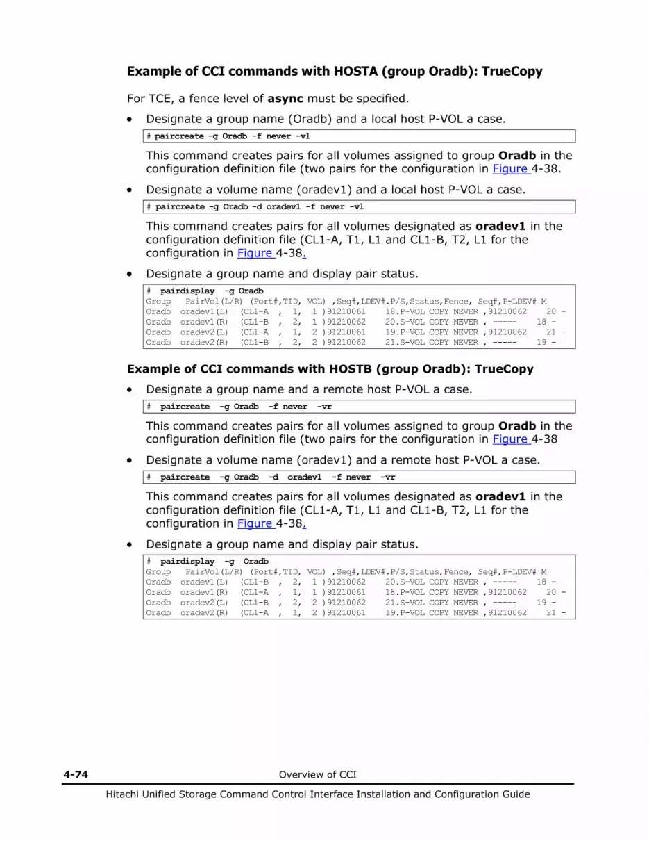
4-74 Overview of CCI
Hitachi Unified Storage Command Control Interface Installation and Configuration Guide
Example of CCI commands with HOSTA (group Oradb): TrueCopy
For TCE, a fence level of async must be specified.
• Designate a group name (Oradb) and a local host P-VOL a case. # paircreate -g Oradb -f never -vl
This command creates pairs for all volumes assigned to group Oradb in the configuration definition file (two pairs for the configuration in Figure 4-38.
• Designate a volume name (oradev1) and a local host P-VOL a case. # paircreate -g Oradb -d oradev1 -f never -vl
This command creates pairs for all volumes designated as oradev1 in the configuration definition file (CL1-A, T1, L1 and CL1-B, T2, L1 for the configuration in Figure 4-38.
• Designate a group name and display pair status. # pairdisplay -g Oradb Group PairVol(L/R) (Port#,TID, VOL) ,Seq#,LDEV#.P/S,Status,Fence, Seq#,P-LDEV# M Oradb oradev1(L) (CL1-A , 1, 1 )91210061 18.P-VOL COPY NEVER ,91210062 20 - Oradb oradev1(R) (CL1-B , 2, 1 )91210062 20.S-VOL COPY NEVER , ----- 18 - Oradb oradev2(L) (CL1-A , 1, 2 )91210061 19.P-VOL COPY NEVER ,91210062 21 - Oradb oradev2(R) (CL1-B , 2, 2 )91210062 21.S-VOL COPY NEVER , ----- 19 -
Example of CCI commands with HOSTB (group Oradb): TrueCopy
• Designate a group name and a remote host P-VOL a case. # paircreate -g Oradb -f never -vr
This command creates pairs for all volumes assigned to group Oradb in the configuration definition file (two pairs for the configuration in Figure 4-38
• Designate a volume name (oradev1) and a remote host P-VOL a case. # paircreate -g Oradb -d oradev1 -f never -vr
This command creates pairs for all volumes designated as oradev1 in the configuration definition file (CL1-A, T1, L1 and CL1-B, T2, L1 for the configuration in Figure 4-38.
• Designate a group name and display pair status. # pairdisplay -g Oradb Group PairVol(L/R) (Port#,TID, VOL) ,Seq#,LDEV#.P/S,Status,Fence, Seq#,P-LDEV# M Oradb oradev1(L) (CL1-B , 2, 1 )91210062 20.S-VOL COPY NEVER , ----- 18 - Oradb oradev1(R) (CL1-A , 1, 1 )91210061 18.P-VOL COPY NEVER ,91210062 20 - Oradb oradev2(L) (CL1-B , 2, 2 )91210062 21.S-VOL COPY NEVER , ----- 19 - Oradb oradev2(R) (CL1-A , 1, 2 )91210061 19.P-VOL COPY NEVER ,91210062 21 -

Overview of CCI 4-75
Hitachi Unified Storage Command Control Interface Installation and Configuration Guide
Configuring one host and two instances
The command device is defined using the system raw device name (character-type device file name). The command device defined in the configuration definition file must be established in a way to be following either every instance. If one command device is used between different instances on the same port, the number of instances is up to 16 per command device. If this restriction is exceeded, use a different path for each instance. For example, the command devices for Figure 4-39 to Figure 4-41 would be:
• HP-UX: HORCM_CMD of HOSTA = /dev/rdsk/c0t0d0 HORCM_CMD of HOSTB = /dev/rdsk/c1t0d0
• Solaris: HORCM_CMD of HOSTA = /dev/rdsk/c0t0d0s2 HORCM_CMD of HOSTB = /dev/rdsk/c1t0d0s2
You can use the command device without a label in the format command.
• AIX: HORCM_CMD of HOSTA = /dev/rhdiskX HORCM_CMD of HOSTB = /dev/rhdiskX Where X = device number created automatically by AIX.
• Tru64 UNIX:
HORCM_CMD of HOSTA = /dev/rdisk/dskXc HORCM_CMD of HOSTB = /dev/rdisk/dskXc Where X = device number assigned by Tru64 UNIX.
• Linux:
HORCM_CMD of HOSTA = /dev/sdX HORCM_CMD of HOSTB = /dev/sdX Where X = device number assigned by Linux.
• IRIX:
HORCM_CMD of HOSTA = /dev/rdsk/dksXdXlXvol OR HORCM_CMD of HOSTA = /dev/rdsk/node_wwn/lunXvol/cXpX
HORCM_CMD of HOSTB = /dev/rdsk/dksXdXlXvol OR HORCM_CMD of HOSTB = /dev/rdsk/node_wwn/lunXvol/cXpX Where X = device number assigned by IRIX.
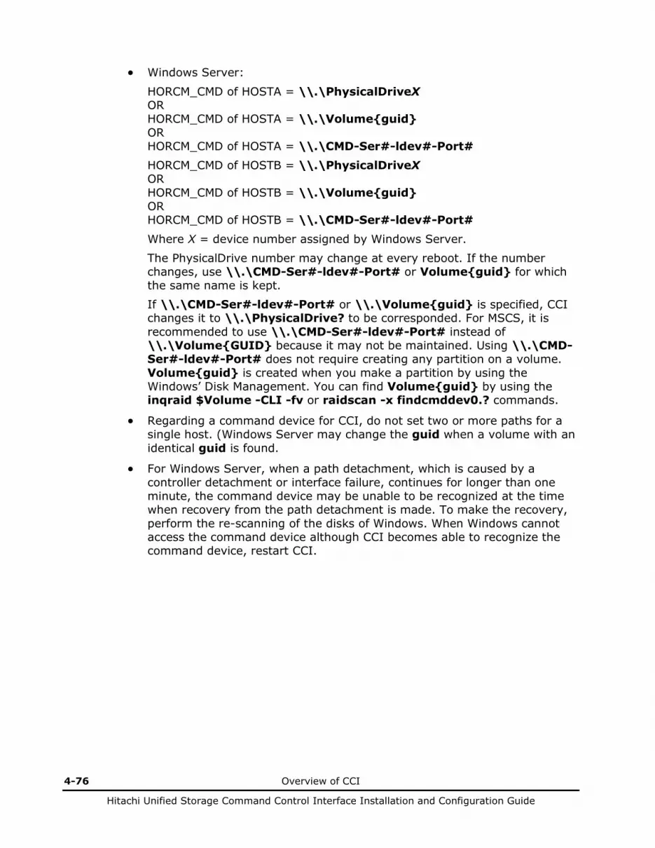
4-76 Overview of CCI
Hitachi Unified Storage Command Control Interface Installation and Configuration Guide
• Windows Server:
HORCM_CMD of HOSTA = \\.\PhysicalDriveX OR HORCM_CMD of HOSTA = \\.\Volume{guid} OR HORCM_CMD of HOSTA = \\.\CMD-Ser#-ldev#-Port# HORCM_CMD of HOSTB = \\.\PhysicalDriveX OR HORCM_CMD of HOSTB = \\.\Volume{guid} OR HORCM_CMD of HOSTB = \\.\CMD-Ser#-ldev#-Port#
Where X = device number assigned by Windows Server. The PhysicalDrive number may change at every reboot. If the number changes, use \\.\CMD-Ser#-ldev#-Port# or Volume{guid} for which the same name is kept. If \\.\CMD-Ser#-ldev#-Port# or \\.\Volume{guid} is specified, CCI changes it to \\.\PhysicalDrive? to be corresponded. For MSCS, it is recommended to use \\.\CMD-Ser#-ldev#-Port# instead of \\.\Volume{GUID} because it may not be maintained. Using \\.\CMD-Ser#-ldev#-Port# does not require creating any partition on a volume. Volume{guid} is created when you make a partition by using the Windows’ Disk Management. You can find Volume{guid} by using the inqraid $Volume -CLI -fv or raidscan -x findcmddev0.? commands.
• Regarding a command device for CCI, do not set two or more paths for a single host. (Windows Server may change the guid when a volume with an identical guid is found.
• For Windows Server, when a path detachment, which is caused by a controller detachment or interface failure, continues for longer than one minute, the command device may be unable to be recognized at the time when recovery from the path detachment is made. To make the recovery, perform the re-scanning of the disks of Windows. When Windows cannot access the command device although CCI becomes able to recognize the command device, restart CCI.

Overview of CCI 4-77
Hitachi Unified Storage Command Control Interface Installation and Configuration Guide
HORCM_MON #ip_address service poll(10ms) timeout(10ms) HST1 horcm0 12000 [Note 1] 3000 HORCM_CMD #dev_name /dev/xxx [Note 2] HORCM_DEV #dev_group dev_name port# TargetID LU# MU# Oradb oradev1 CL1-A 1 1 0 Oradb oradev2 CL1-A 1 2 0 HORCM_INST #dev_group ip_address service Oradb HST1 horcm1
Configuration file for HORCMINST0 (horcm0.conf)
HORCM_MON #ip_address service poll(10ms) timeout(10ms) HST1 horcm1 12000 [Note 1] 3000 HORCM_CMD #dev_name /dev/xxx [Note 2] HORCM_DEV #dev_group dev_name port# TargetID LU# MU# Oradb oradev1 CL1-B 2 1 0 Oradb oradev2 CL1-B 2 2 0 HORCM_INST #dev_group ip_address service Oradb HST1 horcm0
Configuration file for HORCMINST1 (horcm1.conf)
LAN
Tx: Target ID Lx: LU number
A CL1
Oradb oradev1
oradev2
P-VOL
P-VOL
T1,L1
T1,L2
Command device
T0,L0
B CL1
S-VOL
S-VOL
T2,L2
T2,L1
T0,L0
Disk Array
HORCMINST0
HORCM
CONF.file
Ip address: HST1
C0
HORCMINST1
HORCM
CONF.file
C1
/dev/rdsk/c0t1d1 /dev/rdsk/c0t1d2 /dev/rdsk/c0t0d0
/dev/rdsk/c1t2d1 /dev/rdsk/c1t2d2 /dev/rdsk/c1t0d0
Fibre-channel Fibre-channel
Fibre port Fibre port
HOSTA
Note 1: To calculate the value for poll(10ms), see section 2.5.3. Note 2: The command device is dedicated to CCI communications and cannot be used by any other application (neither the user). Command devices must be set using Hitachi Storage Navigator Modular 2. When setting two command devices, add second command device in the HORCM_CMD section. In the same line, you can also add a command device specified by a different path so that the host can use the same command device when one of the paths cannot be used.
Figure 4-39 ShadowImage example with one host and two instances

4-78 Overview of CCI
Hitachi Unified Storage Command Control Interface Installation and Configuration Guide
Example of CCI commands with instance-0 on HOSTA: ShadowImage
• When the command execution environment is not set, set an instance number. For C shell: # setenv HORCMINST 0
For Windows: set HORCMINST=0
• When the command execution environment is not set, set HORCC_MRCF to the environment variable. For C shell: # setenv HORCC_MRCF 1
For Windows: set HORCC_MRCF=1
• Designate a group name (Oradb) and a local instance P-VOL a case. # paircreate -g Oradb -vl
This command creates pairs for all volumes assigned to group Oradb in the configuration definition file.
• Designate a volume name (oradev1) and a local instance P-VOL a case. # paircreate -g Oradb -d oradev1 -vl
This command creates pairs for all volumes designated as oradev1 in the configuration definition file.
• Designate a group name and display pair status. # pairdisplay -g Oradb Group PairVol(L/R) (Port#,TID, VOL-M) ,Seq#,LDEV#.P/S,Status, Seq#,P-LDEV# M Oradb oradev1(L) (CL1-A , 1, 1-0 )91210061 18.P-VOL COPY,91210061 19 - Oradb oradev1(R) (CL1-B , 2, 1-0 )91210061 19.S-VOL COPY,----- 18 - Oradb oradev2(L) (CL1-A , 1, 2-0 )91210061 20.P-VOL COPY,91210061 21 - Oradb oradev2(R) (CL1-B , 2, 2-0 )91210061 21.S-VOL COPY,----- 20 -

Overview of CCI 4-79
Hitachi Unified Storage Command Control Interface Installation and Configuration Guide
Example of CCI commands with instance-1 on HOSTA: ShadowImage
• When the command execution environment is not set, set an instance number. For C shell: # setenv HORCMINST 1
For Windows: set HORCMINST=1
• When the command execution environment is not set, set HORCC_MRCF to the environment variable. For C shell: # setenv HORCC_MRCF 1
For Windows: set HORCC_MRCF=1
• Designate a group name and a remote instance P-VOL a case. # paircreate -g Oradb -vr
This command creates pairs for all volumes designated as Oradb in the configuration definition file.
• Designate a volume name (oradev1) and a remote instance P-VOL a case. # paircreate -g Oradb -d oradev1 -vr
This command creates pairs for all volumes designated as oradev1 in the configuration definition file.
• Designate a group name and display pair status. # pairdisplay -g Oradb Group PairVol(L/R) (Port#,TID, VOL-M) ,Seq#,LDEV#.P/S,Status, Seq#,P-LDEV# M Oradb oradev1(L) (CL1-B , 2, 1-0 )91210061 19.S-VOL COPY,----- 18 - Oradb oradev1(R) (CL1-A , 1, 1-0 )91210061 18.P-VOL COPY,91210061 19 - Oradb oradev2(L) (CL1-B , 2, 2-0 )91210061 21.S-VOL COPY,----- 20 - Oradb oradev2(R) (CL1-A , 1, 2-0 )91210061 20.P-VOL COPY,91210061 21 -

4-80 Overview of CCI
Hitachi Unified Storage Command Control Interface Installation and Configuration Guide
HORCM_MON #ip_address service poll(10ms) timeout(10ms) HST1 horcm0 12000 [Note 1] 3000 HORCM_CMD #dev_name /dev/xxx [Note 2] HORCM_DEV #dev_group dev_name port# TargetID LU# MU# Oradb oradev1 CL1-A 1 1 0 Oradb oradev2 CL1-A 1 2 0 HORCM_INST #dev_group ip_address service Oradb HST1 horcm1
Configuration file for HORCMINST0 (horcm0.conf)
HORCM_MON #ip_address service poll(10ms) timeout(10ms) HST1 horcm1 12000 [Note 1] 3000 HORCM_CMD #dev_name /dev/xxx [Note 2] HORCM_DEV #dev_group dev_name port# TargetID LU# MU# Oradb oradev1 CL1-B 2 1 0 Oradb oradev2 CL1-B 2 2 0 HORCM_INST #dev_group ip_address service Oradb HST1 horcm0
Configuration file for HORCMINST1 (horcm1.conf)
LAN
Tx: Target ID Lx: LU number
A CL1
Oradb oradev1
oradev2
P-VOL
P-VOL
T1,L1
T1,L2
Command device
T0,L0
B CL1
V-VOL
V-VOL
T2,L2
T2,L1
T0,L0
Disk Array
HORCMINST0
HORCM
CONF.file
Ip address: HST1
C0
HORCMINST1
HORCM
CONF.file
C1
/dev/rdsk/c0t1d1 /dev/rdsk/c0t1d2 /dev/rdsk/c0t0d0
/dev/rdsk/c1t2d1 /dev/rdsk/c1t2d2 /dev/rdsk/c1t0d0
Fibre-channel Fibre-channel
Fibre port Fibre port
HOSTA
Note 1: To calculate the value for poll(10ms), see section 2.5.3. Note 2: The command device is dedicated to CCI communications and cannot be used by any other application (neither the user). Command devices must be set using Hitachi Storage Navigator Modular 2. When setting two command devices, add second command device in the HORCM_CMD section. In the same line, you can also add a command device specified by a different path so that the host can use the same command device when one of the paths cannot be used.
Figure 4-40 SnapShot example with one host and two instances
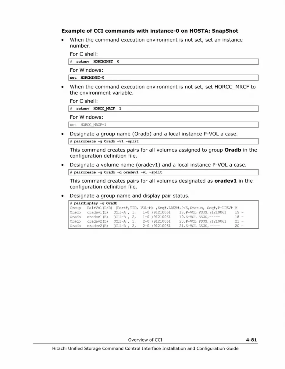
Overview of CCI 4-81
Hitachi Unified Storage Command Control Interface Installation and Configuration Guide
Example of CCI commands with instance-0 on HOSTA: SnapShot
• When the command execution environment is not set, set an instance number. For C shell: # setenv HORCMINST 0
For Windows: set HORCMINST=0
• When the command execution environment is not set, set HORCC_MRCF to the environment variable. For C shell: # setenv HORCC_MRCF 1
For Windows: set HORCC_MRCF=1
• Designate a group name (Oradb) and a local instance P-VOL a case. # paircreate -g Oradb -vl -split
This command creates pairs for all volumes assigned to group Oradb in the configuration definition file.
• Designate a volume name (oradev1) and a local instance P-VOL a case. # paircreate -g Oradb -d oradev1 -vl -split
This command creates pairs for all volumes designated as oradev1 in the configuration definition file.
• Designate a group name and display pair status. # pairdisplay -g Oradb Group PairVol(L/R) (Port#,TID, VOL-M) ,Seq#,LDEV#.P/S,Status, Seq#,P-LDEV# M Oradb oradev1(L) (CL1-A , 1, 1-0 )91210061 18.P-VOL PSUS,91210061 19 - Oradb oradev1(R) (CL1-B , 2, 1-0 )91210061 19.S-VOL SSUS,----- 18 - Oradb oradev2(L) (CL1-A , 1, 2-0 )91210061 20.P-VOL PSUS,91210061 21 - Oradb oradev2(R) (CL1-B , 2, 2-0 )91210061 21.S-VOL SSUS,----- 20 -

4-82 Overview of CCI
Hitachi Unified Storage Command Control Interface Installation and Configuration Guide
Example of CCI commands with instance-1 on HOSTA: SnapShot
• When the command execution environment is not set, set an instance number. For C shell: # setenv HORCMINST 1
For Windows: set HORCMINST=1
• When the command execution environment is not set, set HORCC_MRCF to the environment variable. For C shell: # setenv HORCC_MRCF 1
For Windows: set HORCC_MRCF=1
• Designate a group name and a remote instance P-VOL a case. # paircreate -g Oradb -vr -split
This command creates pairs for all volumes designated as Oradb in the configuration definition file.
• Designate a volume name (oradev1) and a remote instance P-VOL a case. # paircreate -g Oradb -d oradev1 -vr -split
This command creates pairs for all volumes designated as oradev1 in the configuration definition file.
• Designate a group name and display pair status. # pairdisplay -g Oradb Group PairVol(L/R) (Port#,TID, VOL-M) ,Seq#,LDEV#.P/S,Status, Seq#,P-LDEV# M Oradb oradev1(L) (CL1-B , 2, 1-0 )91210061 19.S-VOL SSUS,----- 18 - Oradb oradev1(R) (CL1-A , 1, 1-0 )91210061 18.P-VOL PSUS,91210061 19 - Oradb oradev2(L) (CL1-B , 2, 2-0 )91210061 21.S-VOL SSUS,----- 20 - Oradb oradev2(R) (CL1-A , 1, 2-0 )91210061 20.P-VOL PSUS,91210061 21 -

Overview of CCI 4-83
Hitachi Unified Storage Command Control Interface Installation and Configuration Guide
HORCM_MON #ip_address service poll(10ms) timeout(10ms) HST1 horcm0 12000 [Note 1] 3000 HORCM_CMD #dev_name /dev/xxx [Note 2] HORCM_DEV #dev_group dev_name port# TargetID LU# MU# Oradb oradev1 CL1-A 1 1 Oradb oradev2 CL1-A 1 2 HORCM_INST #dev_group ip_address service Oradb HST1 horcm1
Configuration file for HORCMINST0 (horcm0.conf)
HORCM_MON #ip_address service poll(10ms) timeout(10ms) HST1 horcm1 12000 [Note 1] 3000 HORCM_CMD #dev_name /dev/yyy [Note 2] HORCM_DEV #dev_group dev_name port# TargetID LU# MU# Oradb oradev1 CL1-B 2 1 Oradb oradev2 CL1-B 2 2 HORCM_INST #dev_group ip_address service Oradb HST1 horcm0
Configuration file for HORCMINST1 (horcm1.conf)
LAN
Tx: Target ID Lx: LU number
A CL1
Oradb oradev1
oradev2
P-VOL
P-VOL
T1,L1
T1,L2
Command device
T0,L0
B CL1
S-VOL
S-VOL
T2,L2
T2,L1
T0,L0
Disk Array
HORCMINST0
HORCM
CONF.file
Ip address: HST1
C0
HORCMINST1
HORCM
CONF.file
C1
/dev/rdsk/c0t1d1 /dev/rdsk/c0t1d2 /dev/rdsk/c0t0d0
/dev/rdsk/c1t2d1 /dev/rdsk/c1t2d2 /dev/rdsk/c1t0d0
Fibre-channel Fibre-channel
Fibre port Fibre port
HOSTA
Note 1: To calculate the value for poll(10ms), see section 2.5.3. Note 2: The command device is dedicated to CCI communications and cannot be used by any other applications (neither the user). Command devices must be set using Hitachi Storage Navigator Modular 2. If setting two command devices, add second command device in the HORCM_CMD section. In the same line, you can also add a command device specified by different path, so that the host can use the same command device incase when one of the path cannot be used.
Disk Array
Command device
Figure 4-41 One host and two instances example using TrueCopy/TCE
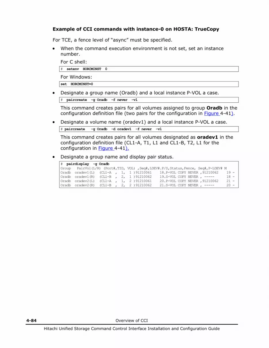
4-84 Overview of CCI
Hitachi Unified Storage Command Control Interface Installation and Configuration Guide
Example of CCI commands with instance-0 on HOSTA: TrueCopy
For TCE, a fence level of “async” must be specified.
• When the command execution environment is not set, set an instance number.
For C shell: # setenv HORCMINST 0
For Windows: set HORCMINST=0
• Designate a group name (Oradb) and a local instance P-VOL a case. # paircreate -g Oradb -f never -vl
This command creates pairs for all volumes assigned to group Oradb in the configuration definition file (two pairs for the configuration in Figure 4-41).
• Designate a volume name (oradev1) and a local instance P-VOL a case. # paircreate -g Oradb -d oradev1 -f never -vl
This command creates pairs for all volumes designated as oradev1 in the configuration definition file (CL1-A, T1, L1 and CL1-B, T2, L1 for the configuration in Figure 4-41).
• Designate a group name and display pair status. # pairdisplay -g Oradb Group PairVol(L/R) (Port#,TID, VOL) ,Seq#,LDEV#.P/S,Status,Fence, Seq#,P-LDEV# M Oradb oradev1(L) (CL1-A , 1, 1 )91210061 18.P-VOL COPY NEVER ,91210062 19 - Oradb oradev1(R) (CL1-B , 2, 1 )91210062 19.S-VOL COPY NEVER , ----- 18 - Oradb oradev2(L) (CL1-A , 1, 2 )91210061 20.P-VOL COPY NEVER ,91210062 21 - Oradb oradev2(R) (CL1-B , 2, 2 )91210062 21.S-VOL COPY NEVER , ----- 20 -
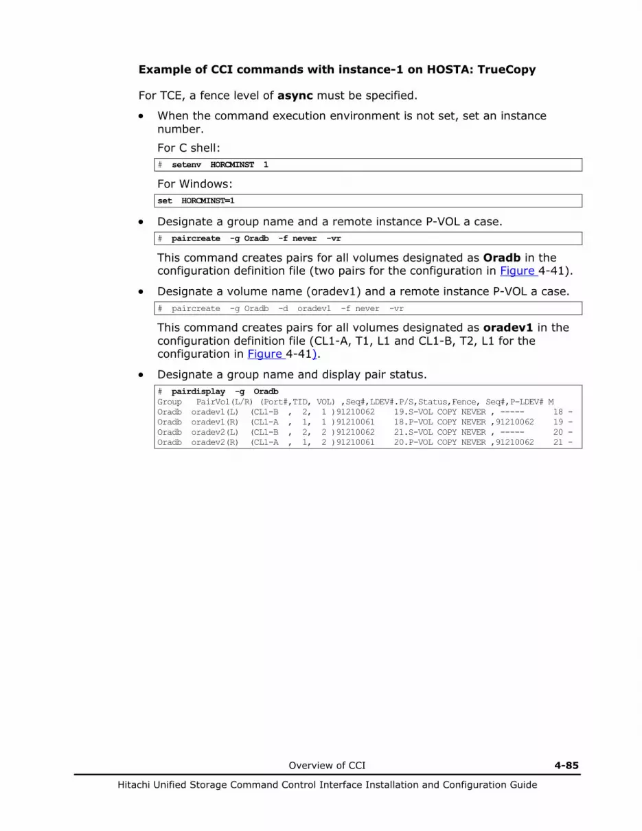
Overview of CCI 4-85
Hitachi Unified Storage Command Control Interface Installation and Configuration Guide
Example of CCI commands with instance-1 on HOSTA: TrueCopy
For TCE, a fence level of async must be specified.
• When the command execution environment is not set, set an instance number.
For C shell: # setenv HORCMINST 1
For Windows: set HORCMINST=1
• Designate a group name and a remote instance P-VOL a case. # paircreate -g Oradb -f never -vr
This command creates pairs for all volumes designated as Oradb in the configuration definition file (two pairs for the configuration in Figure 4-41).
• Designate a volume name (oradev1) and a remote instance P-VOL a case. # paircreate -g Oradb -d oradev1 -f never -vr
This command creates pairs for all volumes designated as oradev1 in the configuration definition file (CL1-A, T1, L1 and CL1-B, T2, L1 for the configuration in Figure 4-41).
• Designate a group name and display pair status. # pairdisplay -g Oradb Group PairVol(L/R) (Port#,TID, VOL) ,Seq#,LDEV#.P/S,Status,Fence, Seq#,P-LDEV# M Oradb oradev1(L) (CL1-B , 2, 1 )91210062 19.S-VOL COPY NEVER , ----- 18 - Oradb oradev1(R) (CL1-A , 1, 1 )91210061 18.P-VOL COPY NEVER ,91210062 19 - Oradb oradev2(L) (CL1-B , 2, 2 )91210062 21.S-VOL COPY NEVER , ----- 20 - Oradb oradev2(R) (CL1-A , 1, 2 )91210061 20.P-VOL COPY NEVER ,91210062 21 -
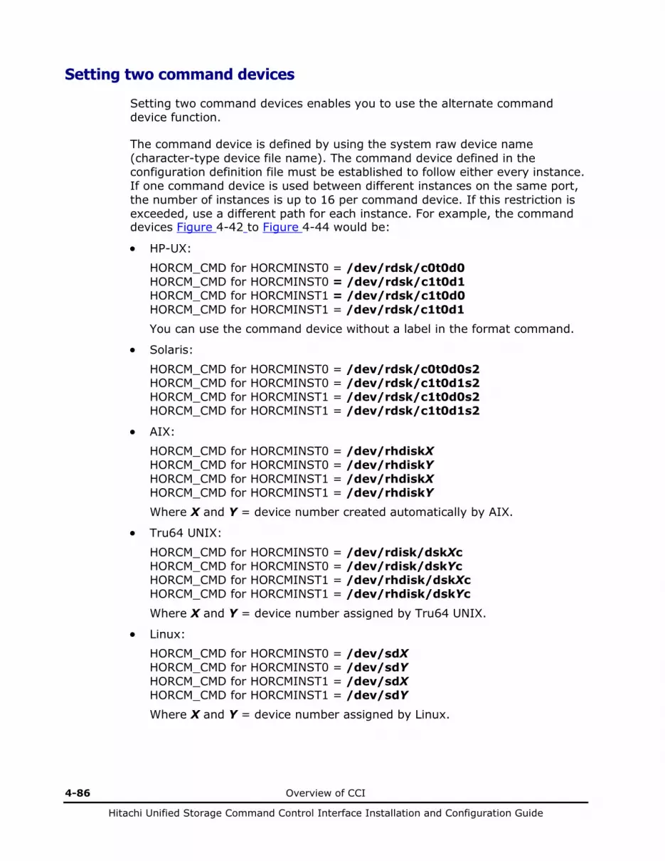
4-86 Overview of CCI
Hitachi Unified Storage Command Control Interface Installation and Configuration Guide
Setting two command devices
Setting two command devices enables you to use the alternate command device function.
The command device is defined by using the system raw device name (character-type device file name). The command device defined in the configuration definition file must be established to follow either every instance. If one command device is used between different instances on the same port, the number of instances is up to 16 per command device. If this restriction is exceeded, use a different path for each instance. For example, the command devices Figure 4-42 to Figure 4-44 would be:
• HP-UX:
HORCM_CMD for HORCMINST0 = /dev/rdsk/c0t0d0 HORCM_CMD for HORCMINST0 = /dev/rdsk/c1t0d1 HORCM_CMD for HORCMINST1 = /dev/rdsk/c1t0d0 HORCM_CMD for HORCMINST1 = /dev/rdsk/c1t0d1 You can use the command device without a label in the format command.
• Solaris:
HORCM_CMD for HORCMINST0 = /dev/rdsk/c0t0d0s2 HORCM_CMD for HORCMINST0 = /dev/rdsk/c1t0d1s2 HORCM_CMD for HORCMINST1 = /dev/rdsk/c1t0d0s2 HORCM_CMD for HORCMINST1 = /dev/rdsk/c1t0d1s2
• AIX: HORCM_CMD for HORCMINST0 = /dev/rhdiskX HORCM_CMD for HORCMINST0 = /dev/rhdiskY HORCM_CMD for HORCMINST1 = /dev/rhdiskX HORCM_CMD for HORCMINST1 = /dev/rhdiskY Where X and Y = device number created automatically by AIX.
• Tru64 UNIX:
HORCM_CMD for HORCMINST0 = /dev/rdisk/dskXc HORCM_CMD for HORCMINST0 = /dev/rdisk/dskYc HORCM_CMD for HORCMINST1 = /dev/rhdisk/dskXc HORCM_CMD for HORCMINST1 = /dev/rhdisk/dskYc
Where X and Y = device number assigned by Tru64 UNIX.
• Linux: HORCM_CMD for HORCMINST0 = /dev/sdX HORCM_CMD for HORCMINST0 = /dev/sdY HORCM_CMD for HORCMINST1 = /dev/sdX HORCM_CMD for HORCMINST1 = /dev/sdY Where X and Y = device number assigned by Linux.

Overview of CCI 4-87
Hitachi Unified Storage Command Control Interface Installation and Configuration Guide
• IRIX:
HORCM_CMD for HORCMINST0 = /dev/rdsk/dksXdXlXvol OR HORCM_CMD for HORCMINST0 = /dev/rdsk/node_wwn/lunXvol/cXpX
HORCM_CMD for HORCMINST0 = /dev/rdsk/dksYdYlYXvol OR HORCM_CMD for HORCMINST0 = /dev/rdsk/node_wwn/lunYvol/cYpY HORCM_CMD for HORCMINST1 = /dev/rdsk/dksXdXlXvol OR HORCM_CMD for HORCMINST1 = /dev/rdsk/node_wwn/lunXvol/cXpX HORCM_CMD for HORCMINST1 = /dev/rdsk/dksYdYlYvol OR HORCM_CMD for HORCMINST1 = /dev/rdsk/node_wwn/lunYvol/cYpY
Where X and Y = device number assigned by IRIX.
• Windows Server: HORCM_CMD of HORCMINST0 = \\.\PhysicalDriveX OR HORCM_CMD of HORCMINST0 = \\.\Volume{guid} OR HORCM_CMD of HORCMINST0 = \\.\CMD-Ser#-ldev#-Port#
HORCM_CMD of HORCMINST0 = \\.\PhysicalDriveY OR HORCM_CMD of HORCMINST0 = \\.\Volume{guid} OR HORCM_CMD of HORCMINST0 = \\.\CMD-Ser#-ldev#-Port# HORCM_CMD of HORCMINST1 = \\.\PhysicalDriveX OR HORCM_CMD of HORCMINST1 = \\.\Volume{guid} OR HORCM_CMD of HORCMINST1 = \\.\CMD-Ser#-ldev#-Port# HORCM_CMD of HORCMINST1 = \\.\PhysicalDriveY OR HORCM_CMD of HORCMINST1 = \\.\Volume{guid} OR HORCM_CMD of HORCMINST1 = \\.\CMD-Ser#-ldev#-Port#
Where X and Y = device number assigned by Windows Server. The PhysicalDrive number may change at every reboot. If the number changes, use \\.\CMD-Ser#-ldev#-Port# or Volume{guid} for which the same name is kept.
4-88 Overview of CCI
Hitachi Unified Storage Command Control Interface Installation and Configuration Guide
If \\.\CMD-Ser#-ldev#-Port# or \\.\Volume{guid} is specified, CCI changes it to \\.\PhysicalDrive? to be corresponded. For MSCS, it is recommended to use \\.\CMD-Ser#-ldev#-Port# instead of \\.\Volume{GUID} because it may not be maintained. Using \\.\CMD-Ser#-ldev#-Port# does not require creating any partition on a volume. Volume{guid} is created when you make a partition by using the Windows’ Disk Management. You can find Volume{guid} by using the inqraid $Volume -CLI -fv or raidscan -x findcmddev0.? commands.
Regarding a command device for CCI, do not set two or more paths for a single host. (Windows Server may change the guid when a volume with an identical guid is found.
For Windows Server, when a path detachment, which is caused by a controller detachment or interface failure, continues for longer than one minute, the command device may be unable to be recognized at the time when recovery from the path detachment is made. To make the recovery, perform the re-scanning of the disks of Windows. When Windows cannot access the command device although CCI becomes able to recognize the command device, restart CCI.
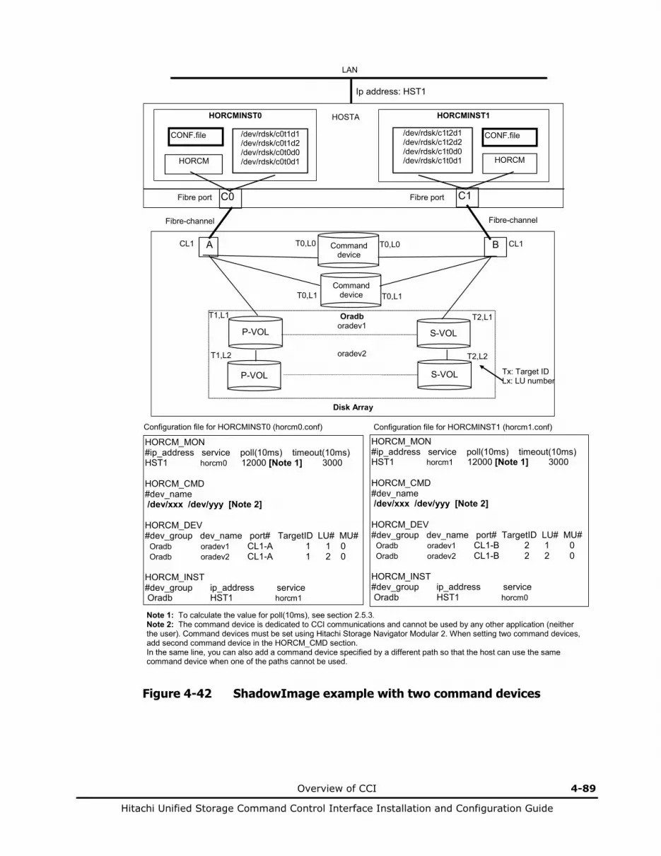
Overview of CCI 4-89
Hitachi Unified Storage Command Control Interface Installation and Configuration Guide
HORCM_MON #ip_address service poll(10ms) timeout(10ms) HST1 horcm0 12000 [Note 1] 3000 HORCM_CMD #dev_name /dev/xxx /dev/yyy [Note 2] HORCM_DEV #dev_group dev_name port# TargetID LU# MU# Oradb oradev1 CL1-A 1 1 0 Oradb oradev2 CL1-A 1 2 0 HORCM_INST #dev_group ip_address service Oradb HST1 horcm1
Configuration file for HORCMINST0 (horcm0.conf)
HORCM_MON #ip_address service poll(10ms) timeout(10ms) HST1 horcm1 12000 [Note 1] 3000 HORCM_CMD #dev_name /dev/xxx /dev/yyy [Note 2] HORCM_DEV #dev_group dev_name port# TargetID LU# MU# Oradb oradev1 CL1-B 2 1 0 Oradb oradev2 CL1-B 2 2 0 HORCM_INST #dev_group ip_address service Oradb HST1 horcm0
Configuration file for HORCMINST1 (horcm1.conf)
LAN
Tx: Target ID Lx: LU number
A CL1
Oradb oradev1
oradev2
P-VOL
P-VOL
T1,L1
T1,L2
Command device
T0,L0 B CL1
S-VOL
S-VOL
T2,L2
T2,L1
T0,L0
Disk Array
HORCMINST0
HORCM
CONF.file
Ip address: HST1
C0
HORCMINST1
HORCM
CONF.file
C1
/dev/rdsk/c0t1d1 /dev/rdsk/c0t1d2 /dev/rdsk/c0t0d0 /dev/rdsk/c0t0d1
/dev/rdsk/c1t2d1 /dev/rdsk/c1t2d2 /dev/rdsk/c1t0d0 /dev/rdsk/c1t0d1
Fibre-channel Fibre-channel
Fibre port Fibre port
HOSTA
Note 1: To calculate the value for poll(10ms), see section 2.5.3. Note 2: The command device is dedicated to CCI communications and cannot be used by any other application (neither the user). Command devices must be set using Hitachi Storage Navigator Modular 2. When setting two command devices, add second command device in the HORCM_CMD section. In the same line, you can also add a command device specified by a different path so that the host can use the same command device when one of the paths cannot be used.
Command device T0,L1 T0,L1
Figure 4-42 ShadowImage example with two command devices

4-90 Overview of CCI
Hitachi Unified Storage Command Control Interface Installation and Configuration Guide
Example of CCI commands with Instance-0 on HOSTA: ShadowImage
• When the command execution environment is not set, set an instance number. For C shell: # setenv HORCMINST 0
For Windows: set HORCMINST=0
• When the command execution environment is not set, set HORCC_MRCF to the environment variable. For C shell: # setenv HORCC_MRCF 1
For Windows: set HORCC_MRCF=1
• Designate a group name (Oradb) and a local instance P-VOL a case. # paircreate -g Oradb -vl
This command creates pairs for all volumes assigned to group Oradb in the configuration definition file.
• Designate a volume name (oradev1) and a local instance P-VOL a case. # paircreate -g Oradb -d oradev1 -vl
This command creates pairs for all volumes designated as oradev1 in the configuration definition file.
• Designate a group name and display pair status. # pairdisplay -g Oradb Group PairVol(L/R) (Port#,TID, VOL-M) ,Seq#,LDEV#.P/S,Status, Seq#,P-LDEV# M Oradb oradev1(L) (CL1-A , 1, 1-0 )91210061 18.P-VOL COPY,91210061 19 - Oradb oradev1(R) (CL1-B , 2, 1-0 )91210061 19.S-VOL COPY,----- 18 - Oradb oradev2(L) (CL1-A , 1, 2-0 )91210061 20.P-VOL COPY,91210061 21 - Oradb oradev2(R) (CL1-B , 2, 2-0 )91210061 21.S-VOL COPY,----- 20 -

Overview of CCI 4-91
Hitachi Unified Storage Command Control Interface Installation and Configuration Guide
Example of CCI commands with Instance-1 on HOSTA: ShadowImage
• When the command execution environment is not set, set an instance number. For C shell: # setenv HORCMINST 1
For Windows: set HORCMINST=1
• When the command execution environment is not set, set HORCC_MRCF to the environment variable. For C shell: # setenv HORCC_MRCF 1
For Windows: set HORCC_MRCF=1
• Designate a group name and a remote instance P-VOL a case. # paircreate -g Oradb -vr
This command creates pairs for all volumes designated as Oradb in the configuration definition file.
• Designate a volume name (oradev1) and a remote instance P-VOL a case. # paircreate -g Oradb -d oradev1 -vr
This command creates pairs for all volumes designated as oradev1 in the configuration definition file.
• Designate a group name and display pair status. # pairdisplay -g Oradb Group PairVol(L/R) (Port#,TID, VOL-M) ,Seq#,LDEV#.P/S,Status, Seq#,P-LDEV# M Oradb oradev1(L) (CL1-B , 2, 1-0 )91210061 19.S-VOL COPY,----- 18 - Oradb oradev1(R) (CL1-A , 1, 1-0 )91210061 18.P-VOL COPY,91210061 19 - Oradb oradev2(L) (CL1-B , 2, 2-0 )91210061 21.S-VOL COPY,----- 20 - Oradb oradev2(R) (CL1-A , 1, 2-0 )91210061 20.P-VOL COPY,91210061 21 -

4-92 Overview of CCI
Hitachi Unified Storage Command Control Interface Installation and Configuration Guide
HORCM_MON #ip_address service poll(10ms) timeout(10ms) HST1 horcm0 12000 [Note 1] 3000 HORCM_CMD #dev_name /dev/xxx /dev/yyy [Note 2] HORCM_DEV #dev_group dev_name port# TargetID LU# MU# Oradb oradev1 CL1-A 1 1 0 Oradb oradev2 CL1-A 1 2 0 Oradb1 oradev1-1 CL1-A 1 1 1 Oradb1 oradev1-2 CL1-A 1 2 1 Oradb2 oradev2-1 CL1-A 1 1 2 Oradb2 oradev2-2 CL1-A 1 2 2 HORCM_INST #dev_group ip_address service Oradb HST1 horcm1
Configuration file for HORCMINST0 (horcm0.conf) HORCM_MON #ip_address service poll(10ms) timeout(10ms) HST1 horcm1 12000 [Note 1] 3000 HORCM_CMD #dev_name /dev/xxx /dev/yyy [Note 2] HORCM_DEV #dev_group dev_name port# TargetID LU# MU# Oradb oradev1 CL1-B 2 1 0 Oradb oradev2 CL1-B 2 2 0 Oradb1 oradev1-1 CL1-B 2 3 0 Oradb1 oradev1-2 CL1-B 2 4 0 Oradb2 oradev2-1 CL1-B 2 5 0 Oradb2 oradev2-2 CL1-B 2 6 0 HORCM_INST #dev_group ip_address service Oradb HST1 horcm0
Configuration file for HORCMINST1 (horcm1.conf)
LAN
Tx: Target ID Lx: LU number
A CL1
Oradb oradev1
oradev2
P-VOL
P-VOL
T1,L1
T1,L2
Command device
T0,L0 B CL1
V-VOL
V-VOL
T2,L2
T2,L1
T0,L0
Disk Array
HORCMINST0
HORCM
CONF.file
Ip address: HST1
C0
HORCMINST1
HORCM
CONF.file
C1
/dev/rdsk/c0t1d1 /dev/rdsk/c0t1d2 /dev/rdsk/c0t0d0 /dev/rdsk/c0t0d1
/dev/rdsk/c1t2d1 /dev/rdsk/c1t2d2 /dev/rdsk/c1t0d0 /dev/rdsk/c1t0d1
Fibre-channel Fibre-channel
Fibre port Fibre port
HOSTA
Note 1: To calculate the value for poll(10ms), see section 2.5.3. Note 2: The command device is dedicated to CCI communications and cannot be used by any other application (neither the user). Command devices must be set using Hitachi Storage Navigator Modular 2. When setting two command devices, add second command device in the HORCM_CMD section. In the same line, you can also add a command device specified by a different path so that the host can use the same command device when one of the paths cannot be used.
Command device T0,L1 T0,L1
Oradb1 oradev1-1
oradev1-2
V-VOL
V-VOL
T2,L4
T2,L3
Oradb2 oradev2-1
oradev2-2
V-VOL
V-VOL
T2,L6
T2,L5
MU#0
MU#1
MU#2
Figure 4-43 SnapShot example with two command devices
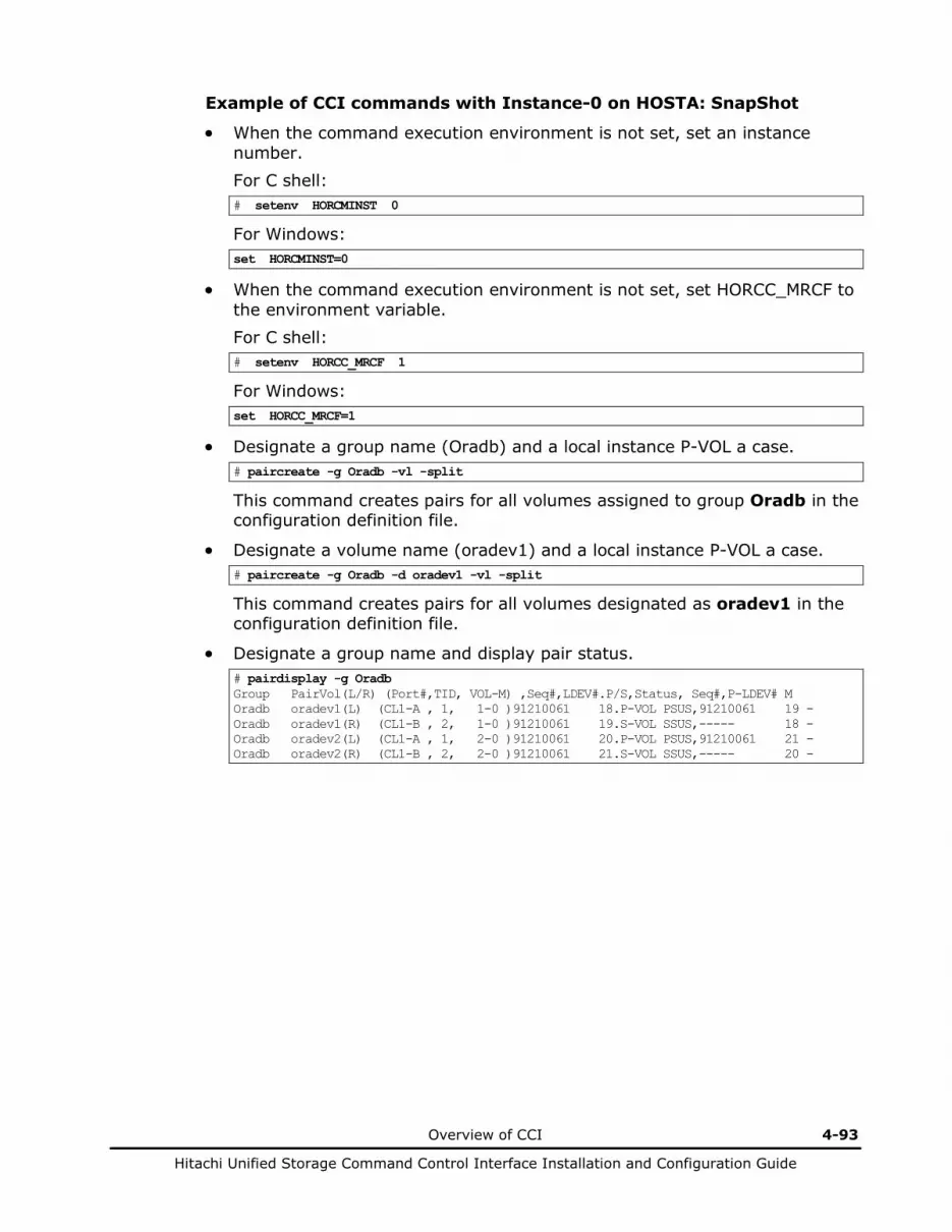
Overview of CCI 4-93
Hitachi Unified Storage Command Control Interface Installation and Configuration Guide
Example of CCI commands with Instance-0 on HOSTA: SnapShot
• When the command execution environment is not set, set an instance number. For C shell: # setenv HORCMINST 0
For Windows: set HORCMINST=0
• When the command execution environment is not set, set HORCC_MRCF to the environment variable. For C shell: # setenv HORCC_MRCF 1
For Windows: set HORCC_MRCF=1
• Designate a group name (Oradb) and a local instance P-VOL a case. # paircreate -g Oradb -vl -split
This command creates pairs for all volumes assigned to group Oradb in the configuration definition file.
• Designate a volume name (oradev1) and a local instance P-VOL a case. # paircreate -g Oradb -d oradev1 -vl -split
This command creates pairs for all volumes designated as oradev1 in the configuration definition file.
• Designate a group name and display pair status. # pairdisplay -g Oradb Group PairVol(L/R) (Port#,TID, VOL-M) ,Seq#,LDEV#.P/S,Status, Seq#,P-LDEV# M Oradb oradev1(L) (CL1-A , 1, 1-0 )91210061 18.P-VOL PSUS,91210061 19 - Oradb oradev1(R) (CL1-B , 2, 1-0 )91210061 19.S-VOL SSUS,----- 18 - Oradb oradev2(L) (CL1-A , 1, 2-0 )91210061 20.P-VOL PSUS,91210061 21 - Oradb oradev2(R) (CL1-B , 2, 2-0 )91210061 21.S-VOL SSUS,----- 20 -
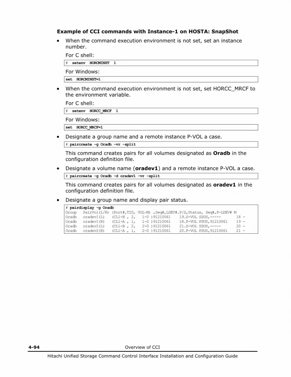
4-94 Overview of CCI
Hitachi Unified Storage Command Control Interface Installation and Configuration Guide
Example of CCI commands with Instance-1 on HOSTA: SnapShot
• When the command execution environment is not set, set an instance number. For C shell: # setenv HORCMINST 1
For Windows: set HORCMINST=1
• When the command execution environment is not set, set HORCC_MRCF to the environment variable. For C shell: # setenv HORCC_MRCF 1
For Windows: set HORCC_MRCF=1
• Designate a group name and a remote instance P-VOL a case. # paircreate -g Oradb -vr -split
This command creates pairs for all volumes designated as Oradb in the configuration definition file.
• Designate a volume name (oradev1) and a remote instance P-VOL a case. # paircreate -g Oradb -d oradev1 -vr -split
This command creates pairs for all volumes designated as oradev1 in the configuration definition file.
• Designate a group name and display pair status. # pairdisplay -g Oradb Group PairVol(L/R) (Port#,TID, VOL-M) ,Seq#,LDEV#.P/S,Status, Seq#,P-LDEV# M Oradb oradev1(L) (CL1-B , 2, 1-0 )91210061 19.S-VOL SSUS,----- 18 - Oradb oradev1(R) (CL1-A , 1, 1-0 )91210061 18.P-VOL PSUS,91210061 19 - Oradb oradev2(L) (CL1-B , 2, 2-0 )91210061 21.S-VOL SSUS,----- 20 - Oradb oradev2(R) (CL1-A , 1, 2-0 )91210061 20.P-VOL PSUS,91210061 21 -
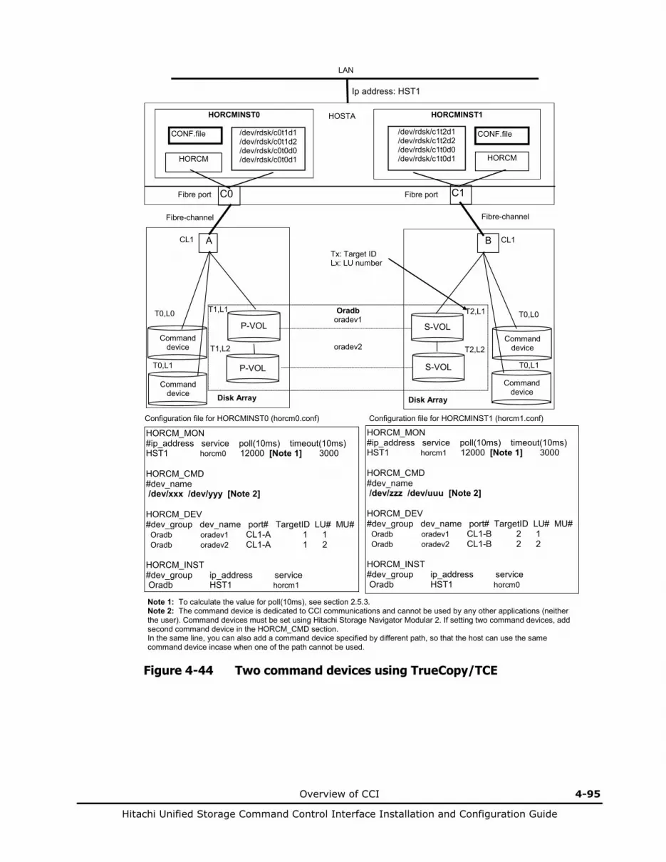
Overview of CCI 4-95
Hitachi Unified Storage Command Control Interface Installation and Configuration Guide
HORCM_MON #ip_address service poll(10ms) timeout(10ms) HST1 horcm0 12000 [Note 1] 3000 HORCM_CMD #dev_name /dev/xxx /dev/yyy [Note 2] HORCM_DEV #dev_group dev_name port# TargetID LU# MU# Oradb oradev1 CL1-A 1 1 Oradb oradev2 CL1-A 1 2 HORCM_INST #dev_group ip_address service Oradb HST1 horcm1
Configuration file for HORCMINST0 (horcm0.conf)
HORCM_MON #ip_address service poll(10ms) timeout(10ms) HST1 horcm1 12000 [Note 1] 3000 HORCM_CMD #dev_name /dev/zzz /dev/uuu [Note 2] HORCM_DEV #dev_group dev_name port# TargetID LU# MU# Oradb oradev1 CL1-B 2 1 Oradb oradev2 CL1-B 2 2 HORCM_INST #dev_group ip_address service Oradb HST1 horcm0
Configuration file for HORCMINST1 (horcm1.conf)
LAN
Tx: Target ID Lx: LU number
A CL1
Oradb oradev1
oradev2
P-VOL
P-VOL
T1,L1
T1,L2
Command device
T0,L0
B CL1
S-VOL
S-VOL
T2,L2
T2,L1 T0,L0
Disk Array
HORCMINST0
HORCM
CONF.file
Ip address: HST1
C0
HORCMINST1
HORCM
CONF.file
C1
/dev/rdsk/c0t1d1 /dev/rdsk/c0t1d2 /dev/rdsk/c0t0d0 /dev/rdsk/c0t0d1
/dev/rdsk/c1t2d1 /dev/rdsk/c1t2d2 /dev/rdsk/c1t0d0 /dev/rdsk/c1t0d1
Fibre-channel Fibre-channel
Fibre port Fibre port
HOSTA
Note 1: To calculate the value for poll(10ms), see section 2.5.3. Note 2: The command device is dedicated to CCI communications and cannot be used by any other applications (neither the user). Command devices must be set using Hitachi Storage Navigator Modular 2. If setting two command devices, add second command device in the HORCM_CMD section. In the same line, you can also add a command device specified by different path, so that the host can use the same command device incase when one of the path cannot be used.
Command device
T0,L1 T0,L1
Command device
Command device
Disk Array
Figure 4-44 Two command devices using TrueCopy/TCE

4-96 Overview of CCI
Hitachi Unified Storage Command Control Interface Installation and Configuration Guide
Example of CCI commands with Instance-0 on HOSTA: TrueCopy
For TCE, a fence level of async must be specified.
• When the command execution environment is not set, set an instance number.
For C shell: # setenv HORCMINST 0
For Windows: set HORCMINST=0
• Designate a group name (Oradb) and a local instance P-VOL a case. # paircreate -g Oradb -f never -vl
This command creates pairs for all volumes assigned to group Oradb in the configuration definition file (two pairs for the configuration in Figure 4-44).
• Designate a volume name (oradev1) and a local instance P-VOL a case. # paircreate -g Oradb -d oradev1 -f never -vl
This command creates pairs for all volumes designated as oradev1 in the configuration definition file (CL1-A, T1, L1 and CL1-B, T2, L1 for the configuration in Figure 4-44).
• Designate a group name and display pair status. # pairdisplay -g Oradb Group PairVol(L/R) (Port#,TID, VOL) ,Seq#,LDEV#.P/S,Status,Fence, Seq#,P-LDEV# M Oradb oradev1(L) (CL1-A , 1, 1 )91210061 18.P-VOL COPY NEVER ,91210062 19 - Oradb oradev1(R) (CL1-B , 2, 1 )91210062 19.S-VOL COPY NEVER , ----- 18 - Oradb oradev2(L) (CL1-A , 1, 2 )91210061 20.P-VOL COPY NEVER ,91210062 21 - Oradb oradev2(R) (CL1-B , 2, 2 )91210062 21.S-VOL COPY NEVER , ----- 20 -
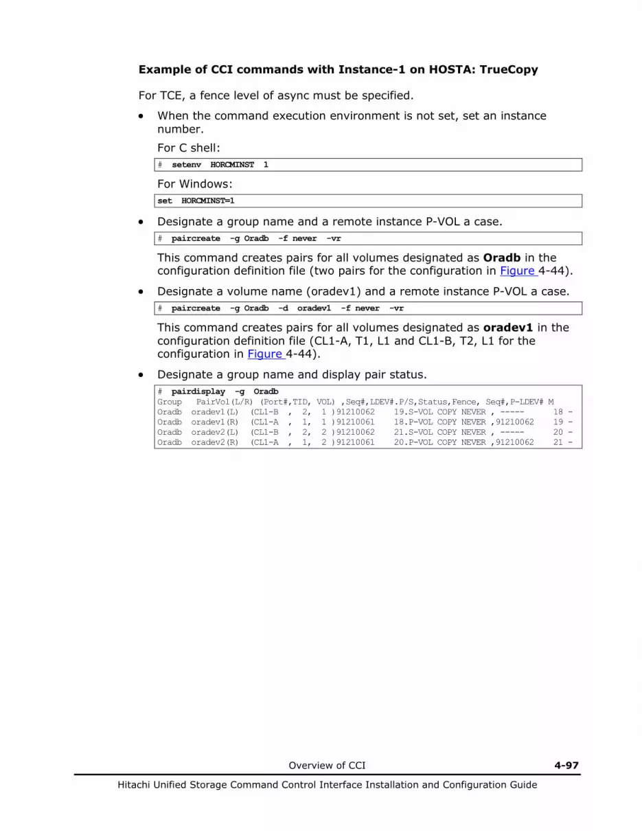
Overview of CCI 4-97
Hitachi Unified Storage Command Control Interface Installation and Configuration Guide
Example of CCI commands with Instance-1 on HOSTA: TrueCopy
For TCE, a fence level of async must be specified.
• When the command execution environment is not set, set an instance number.
For C shell: # setenv HORCMINST 1
For Windows: set HORCMINST=1
• Designate a group name and a remote instance P-VOL a case. # paircreate -g Oradb -f never -vr
This command creates pairs for all volumes designated as Oradb in the configuration definition file (two pairs for the configuration in Figure 4-44).
• Designate a volume name (oradev1) and a remote instance P-VOL a case. # paircreate -g Oradb -d oradev1 -f never -vr
This command creates pairs for all volumes designated as oradev1 in the configuration definition file (CL1-A, T1, L1 and CL1-B, T2, L1 for the configuration in Figure 4-44).
• Designate a group name and display pair status. # pairdisplay -g Oradb Group PairVol(L/R) (Port#,TID, VOL) ,Seq#,LDEV#.P/S,Status,Fence, Seq#,P-LDEV# M Oradb oradev1(L) (CL1-B , 2, 1 )91210062 19.S-VOL COPY NEVER , ----- 18 - Oradb oradev1(R) (CL1-A , 1, 1 )91210061 18.P-VOL COPY NEVER ,91210062 19 - Oradb oradev2(L) (CL1-B , 2, 2 )91210062 21.S-VOL COPY NEVER , ----- 20 - Oradb oradev2(R) (CL1-A , 1, 2 )91210061 20.P-VOL COPY NEVER ,91210062 21 -
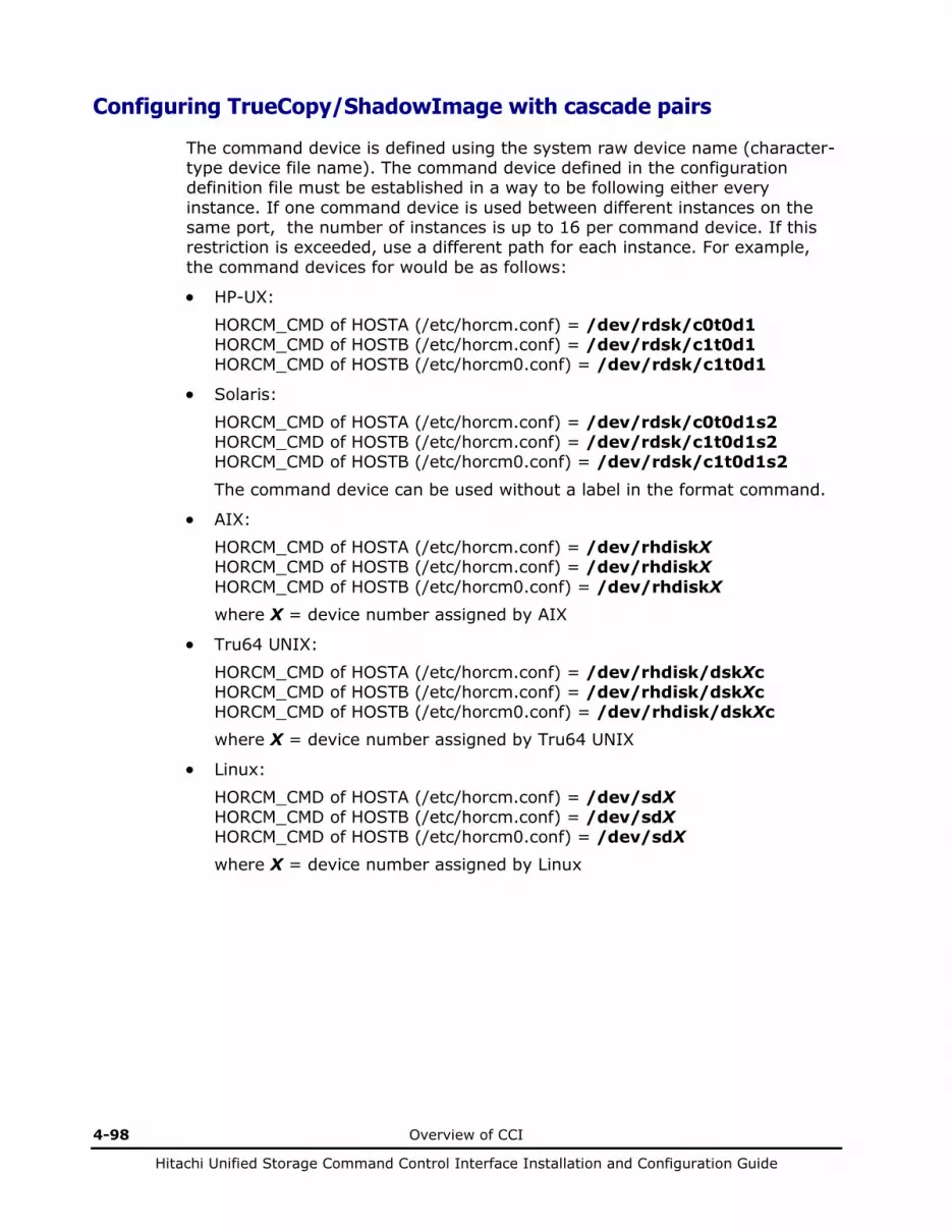
4-98 Overview of CCI
Hitachi Unified Storage Command Control Interface Installation and Configuration Guide
Configuring TrueCopy/ShadowImage with cascade pairs
The command device is defined using the system raw device name (character-type device file name). The command device defined in the configuration definition file must be established in a way to be following either every instance. If one command device is used between different instances on the same port, the number of instances is up to 16 per command device. If this restriction is exceeded, use a different path for each instance. For example, the command devices for would be as follows:
• HP-UX:
HORCM_CMD of HOSTA (/etc/horcm.conf) = /dev/rdsk/c0t0d1 HORCM_CMD of HOSTB (/etc/horcm.conf) = /dev/rdsk/c1t0d1 HORCM_CMD of HOSTB (/etc/horcm0.conf) = /dev/rdsk/c1t0d1
• Solaris:
HORCM_CMD of HOSTA (/etc/horcm.conf) = /dev/rdsk/c0t0d1s2 HORCM_CMD of HOSTB (/etc/horcm.conf) = /dev/rdsk/c1t0d1s2 HORCM_CMD of HOSTB (/etc/horcm0.conf) = /dev/rdsk/c1t0d1s2
The command device can be used without a label in the format command.
• AIX: HORCM_CMD of HOSTA (/etc/horcm.conf) = /dev/rhdiskX HORCM_CMD of HOSTB (/etc/horcm.conf) = /dev/rhdiskX HORCM_CMD of HOSTB (/etc/horcm0.conf) = /dev/rhdiskX where X = device number assigned by AIX
• Tru64 UNIX:
HORCM_CMD of HOSTA (/etc/horcm.conf) = /dev/rhdisk/dskXc HORCM_CMD of HOSTB (/etc/horcm.conf) = /dev/rhdisk/dskXc HORCM_CMD of HOSTB (/etc/horcm0.conf) = /dev/rhdisk/dskXc where X = device number assigned by Tru64 UNIX
• Linux:
HORCM_CMD of HOSTA (/etc/horcm.conf) = /dev/sdX HORCM_CMD of HOSTB (/etc/horcm.conf) = /dev/sdX HORCM_CMD of HOSTB (/etc/horcm0.conf) = /dev/sdX where X = device number assigned by Linux
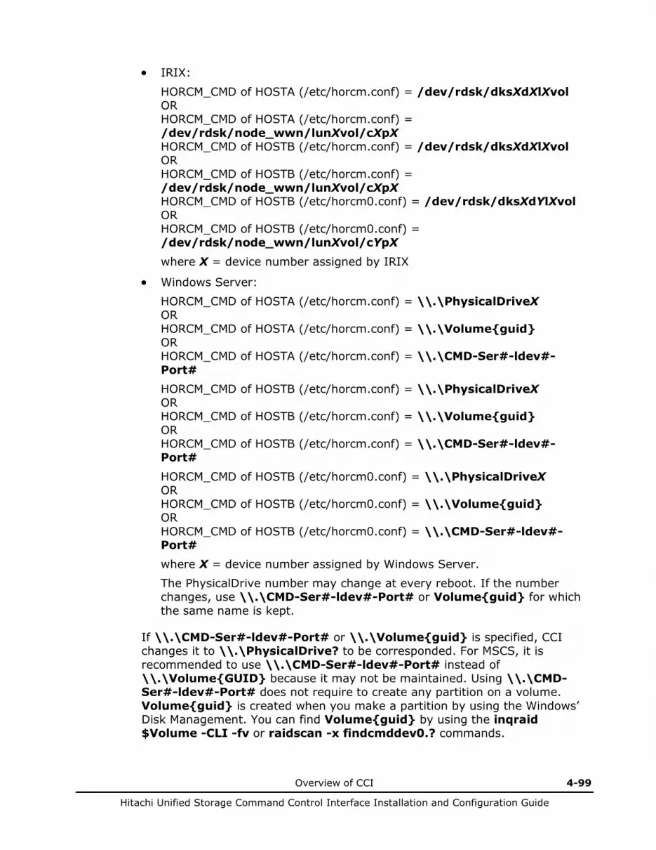
Overview of CCI 4-99
Hitachi Unified Storage Command Control Interface Installation and Configuration Guide
• IRIX:
HORCM_CMD of HOSTA (/etc/horcm.conf) = /dev/rdsk/dksXdXlXvol OR HORCM_CMD of HOSTA (/etc/horcm.conf) = /dev/rdsk/node_wwn/lunXvol/cXpX HORCM_CMD of HOSTB (/etc/horcm.conf) = /dev/rdsk/dksXdXlXvol OR HORCM_CMD of HOSTB (/etc/horcm.conf) = /dev/rdsk/node_wwn/lunXvol/cXpX HORCM_CMD of HOSTB (/etc/horcm0.conf) = /dev/rdsk/dksXdYlXvol OR HORCM_CMD of HOSTB (/etc/horcm0.conf) = /dev/rdsk/node_wwn/lunXvol/cYpX
where X = device number assigned by IRIX
• Windows Server: HORCM_CMD of HOSTA (/etc/horcm.conf) = \\.\PhysicalDriveX OR HORCM_CMD of HOSTA (/etc/horcm.conf) = \\.\Volume{guid} OR HORCM_CMD of HOSTA (/etc/horcm.conf) = \\.\CMD-Ser#-ldev#-Port# HORCM_CMD of HOSTB (/etc/horcm.conf) = \\.\PhysicalDriveX OR HORCM_CMD of HOSTB (/etc/horcm.conf) = \\.\Volume{guid} OR HORCM_CMD of HOSTB (/etc/horcm.conf) = \\.\CMD-Ser#-ldev#-Port#
HORCM_CMD of HOSTB (/etc/horcm0.conf) = \\.\PhysicalDriveX OR HORCM_CMD of HOSTB (/etc/horcm0.conf) = \\.\Volume{guid} OR HORCM_CMD of HOSTB (/etc/horcm0.conf) = \\.\CMD-Ser#-ldev#-Port# where X = device number assigned by Windows Server. The PhysicalDrive number may change at every reboot. If the number changes, use \\.\CMD-Ser#-ldev#-Port# or Volume{guid} for which the same name is kept.
If \\.\CMD-Ser#-ldev#-Port# or \\.\Volume{guid} is specified, CCI changes it to \\.\PhysicalDrive? to be corresponded. For MSCS, it is recommended to use \\.\CMD-Ser#-ldev#-Port# instead of \\.\Volume{GUID} because it may not be maintained. Using \\.\CMD-Ser#-ldev#-Port# does not require to create any partition on a volume. Volume{guid} is created when you make a partition by using the Windows’ Disk Management. You can find Volume{guid} by using the inqraid $Volume -CLI -fv or raidscan -x findcmddev0.? commands.
4-100 Overview of CCI
Hitachi Unified Storage Command Control Interface Installation and Configuration Guide
Regarding a command device for CCI, do not set two or more paths for a single host. (Windows Server may change the guid when a volume with an identical guid is found.
For Windows Server, when a path detachment, which is caused by a controller detachment or interface failure, continues for longer than one minute, the command device may be unable to be recognized at the time when recovery from the path detachment is made. To make the recovery, perform the re-scanning of the disks of Windows. When Windows cannot access the command device although CCI becomes able to recognize the command device, restart CCI.

Overview of CCI 4-101
Hitachi Unified Storage Command Control Interface Installation and Configuration Guide
LAN
HORCM_MON #ip_address service poll(10ms) timeout(10ms) HST1 horcm 12000 [Note 1] 3000 HORCM_CMD #dev_name /dev/xxx [Note 2] HORCM_DEV #dev_groupdev_name port# TID LU# MU# Oradb oradev1 CL1-A 1 1 Oradb oradev2 CL1-A 1 2 HORCM_INST #dev_group ip_address service Oradb HST2 horcm Oradb HST2 horcm0
Config file-HOSTA (/etc/horcm.conf ) Config file-HOSTB (/etc/horcm.conf)
A B CL1
Oradb oradev1
oradev2
S/P-VOL
P-VOL T1,L1
T1,L2
Command device
T0,L1
A B CL1
S/P-VOL
S/P-VOL T2,L2
T2,L1
T0,L1
Disk Array
Ip address: HST2
C0
HORCMINST
HORCM
CONF.file /dev/rdsk/c0t1d1 /dev/rdsk/c0t1d2
/dev/rdsk/c0t0d1
Fibre-channel Fibre-channel
Fibre port
S-VOL
S-VOL
Oradb1 MU# 0 oradev11 MU# 0 oradev12
T3,L1
T3,L2
HORCM_MON #ip_address service poll(10ms) timeout(10ms) HST2 horcm 12000 [Note 1] 3000 HORCM_CMD #dev_name /dev/xxx [Note 2] HORCM_DEV #dev_groupdev_name port# TID LU# MU# Oradb oradev1 CL1-B 2 1 Oradb oradev2 CL1-B 2 2 Oradb1 oradev11 CL1-B 2 1 0 Oradb1 oradev12 CL1-B 2 2 0 HORCM_INST #dev_group ip_address service Oradb HST1 horcm Oradb1 HST2 horcm0
HORCM_MON #ip_address service poll(10ms) timeout(10ms) HST2 horcm0 12000 [Note 1] 3000 HORCM_CMD #dev_name /dev/xxx [Note 2] HORCM_DEV #dev_groupdev_name port# TID LU# MU# Oradb oradev1 CL1-B 2 1 Oradb oradev2 CL1-B 2 2 Oradb1 oradev11 CL1-B 3 1 0 Oradb1 oradev12 CL1-B 3 2 0 HORCM_INST #dev_group ip_address service Oradb HST1 horcm Oradb1 HST2 horcm
Config file-HOSTB (/etc/horcm0.conf)
Command device
Disk Array
HORCMINST0
HORCM
CONF.file
C1
/dev/rdsk/c1t3d1 /dev/rdsk/c1t3d2
. /dev/rdsk/c1t0d1
Fibre port
HOSTA
HORCMINST
HORCM
CONF.file /dev/rdsk/c1t2d1 /dev/rdsk/c1t2d2
/dev/rdsk/c1t0d1
HOSTB Ip address: HST1
Shaded portions: If HORCMINST0 needs to operate TrueCopy’s paired volume, then describe oradb. Note 1: To calculate the value for poll(10ms), see section 2.5.3. Note 2: The command device is dedicated to CCI communications and cannot be used by any other applications (neither the user). Command devices must be set using Hitachi Storage Navigator Modular 2. If you are setting two command devices, add second command device in the HORCM_CMD section. In the same line, you can also add a command device specified by different path, so that the host can use the same command device when one of the paths cannot be used.
Figure 4-45 TrueCopy/ShadowImage configuration example with cascade pairs
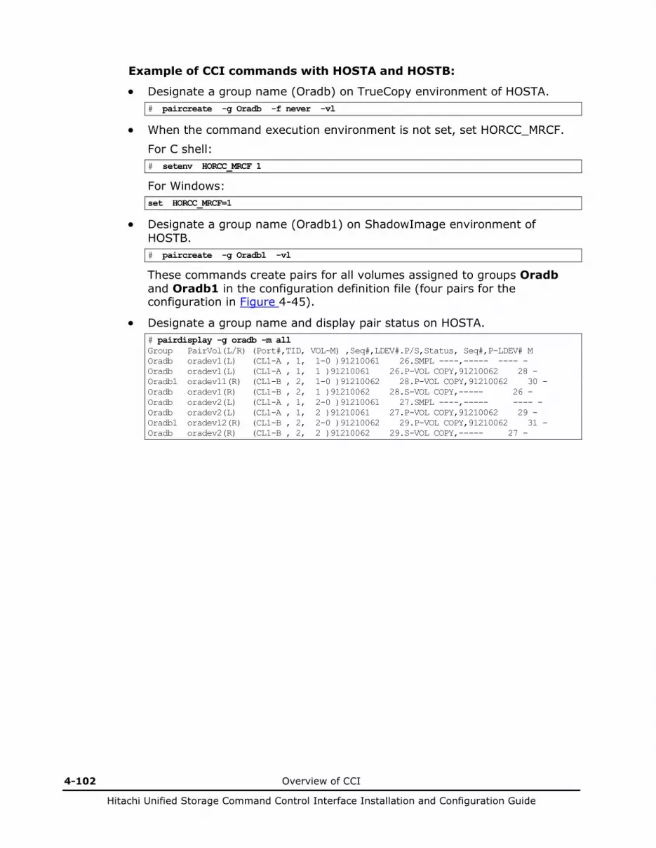
4-102 Overview of CCI
Hitachi Unified Storage Command Control Interface Installation and Configuration Guide
Example of CCI commands with HOSTA and HOSTB:
• Designate a group name (Oradb) on TrueCopy environment of HOSTA. # paircreate -g Oradb -f never -vl
• When the command execution environment is not set, set HORCC_MRCF.
For C shell: # setenv HORCC_MRCF 1
For Windows: set HORCC_MRCF=1
• Designate a group name (Oradb1) on ShadowImage environment of HOSTB. # paircreate -g Oradb1 -vl
These commands create pairs for all volumes assigned to groups Oradb and Oradb1 in the configuration definition file (four pairs for the configuration in Figure 4-45).
• Designate a group name and display pair status on HOSTA. # pairdisplay -g oradb -m all Group PairVol(L/R) (Port#,TID, VOL-M) ,Seq#,LDEV#.P/S,Status, Seq#,P-LDEV# M Oradb oradev1(L) (CL1-A , 1, 1-0 )91210061 26.SMPL ----,----- ---- - Oradb oradev1(L) (CL1-A , 1, 1 )91210061 26.P-VOL COPY,91210062 28 - Oradb1 oradev11(R) (CL1-B , 2, 1-0 )91210062 28.P-VOL COPY,91210062 30 - Oradb oradev1(R) (CL1-B , 2, 1 )91210062 28.S-VOL COPY,----- 26 - Oradb oradev2(L) (CL1-A , 1, 2-0 )91210061 27.SMPL ----,----- ---- - Oradb oradev2(L) (CL1-A , 1, 2 )91210061 27.P-VOL COPY,91210062 29 - Oradb1 oradev12(R) (CL1-B , 2, 2-0 )91210062 29.P-VOL COPY,91210062 31 - Oradb oradev2(R) (CL1-B , 2, 2 )91210062 29.S-VOL COPY,----- 27 -

Overview of CCI 4-103
Hitachi Unified Storage Command Control Interface Installation and Configuration Guide
Example of CCI commands with HOSTB:
• Designate a group name (oradb) on TrueCopy environment of HOSTB. # paircreate -g Oradb -f never -vr
• When the command execution environment is not set, set HORCC_MRCF.
For C shell: # setenv HORCC_MRCF 1
For Windows: set HORCC_MRCF=1
• Designate a group name (Oradb1) on ShadowImage environment of HOSTB. # paircreate -g Oradb1 -vl
This command creates pairs for all volumes assigned to group Oradb1 in the configuration definition file (four pairs for the configuration in Figure 4-45).
• Designate a group name and display pair status on TrueCopy environment of HOSTB. # pairdisplay -g oradb -m all Group PairVol(L/R) (Port#,TID, VOL-M) ,Seq#,LDEV#.P/S,Status, Seq#,P-LDEV# M Oradb1 oradev11(L) (CL1-B , 2, 1-0 )91210062 28.P-VOL PAIR,91210062 30 - Oradb oradev1(L) (CL1-B , 2, 1 )91210062 28.S-VOL PAIR,----- 26 - Oradb oradev1(R) (CL1-A , 1, 1-0 )91210061 26.SMPL ----,----- ---- - Oradb oradev1(R) (CL1-A , 1, 1 )91210061 26.P-VOL PAIR,91210062 28 - Oradb1 oradev12(L) (CL1-B , 2, 2-0 )91210062 29.P-VOL PAIR,91210062 31 - Oradb oradev2(L) (CL1-B , 2, 2 )91210062 29.S-VOL PAIR,----- 27 - Oradb oradev2(R) (CL1-A , 1, 2-0 )91210061 27.SMPL ----,----- ---- - Oradb oradev2(R) (CL1-A , 1, 2 )91210061 27.P-VOL PAIR,91210062 29 -
• Designate a group name and display pair status on ShadowImage environment of HOSTB. # pairdisplay -g oradb1 -m all Group PairVol(L/R) (Port#,TID, VOL-M) ,Seq#,LDEV#.P/S,Status, Seq#,P-LDEV# M Oradb1 oradev11(L) (CL1-B , 2, 1-0 )91210062 28.P-VOL PAIR,91210062 30 - Oradb oradev1(L) (CL1-B , 2, 1 )91210062 28.S-VOL PAIR,----- 26 - Oradb1 oradev11(R) (CL1-B , 3, 1-0 )91210062 30.S-VOL PAIR,----- 28 - Oradb1 oradev12(L) (CL1-B , 2, 2-0 )91210062 29.P-VOL PAIR,91210062 31 - Oradb oradev2(L) (CL1-B , 2, 2 )91210062 29.S-VOL PAIR,----- 27 - Oradb1 oradev12(R) (CL1-B , 3, 2-0 )91210062 31.S-VOL PAIR,----- 29 -
• Designate a group name and display pair status on ShadowImage environment of HOSTB (HORCMINST0). # pairdisplay -g oradb1 -m all Group PairVol(L/R) (Port#,TID, VOL-M) ,Seq#,LDEV#.P/S,Status, Seq#,P-LDEV# M Oradb1 oradev11(L) (CL1-B , 3, 1-0 )91210062 30.S-VOL PAIR,----- 28 - Oradb1 oradev11(R) (CL1-B , 2, 1-0 )91210062 28.P-VOL PAIR,91210062 30 - Oradb oradev1(R) (CL1-B , 2, 1 )91210062 28.S-VOL PAIR,----- 26 - Oradb1 oradev12(L) (CL1-B , 3, 2-0 )91210062 31.S-VOL PAIR,----- 29 - Oradb1 oradev12(R) (CL1-B , 2, 2-0 )91210062 29.P-VOL PAIR,91210062 31 - Oradb oradev2(R) (CL1-B , 2, 2 )91210062 29.S-VOL PAIR,----- 27 -

4-104 Overview of CCI
Hitachi Unified Storage Command Control Interface Installation and Configuration Guide
Configuring TCE/SnapShot with cascade pairs
The command device is defined using the system raw device name (character-type device file name). The command device defined in the configuration definition file must be established in a way to be following either every instance. If one command device is used between different instances on the same port, the number of instances is up to 16 per command device. If this restriction is exceeded, use a different path for each instance. For example, the command devices for would be as follows:
• HP-UX:
HORCM_CMD of HOSTA (/etc/horcm.conf) = /dev/rdsk/c0t0d1 HORCM_CMD of HOSTB (/etc/horcm.conf) = /dev/rdsk/c1t0d1 HORCM_CMD of HOSTB (/etc/horcm0.conf) = /dev/rdsk/c1t0d1
• Solaris:
HORCM_CMD of HOSTA (/etc/horcm.conf) = /dev/rdsk/c0t0d1s2 HORCM_CMD of HOSTB (/etc/horcm.conf) = /dev/rdsk/c1t0d1s2 HORCM_CMD of HOSTB (/etc/horcm0.conf) = /dev/rdsk/c1t0d1s2
The command device can be used without a label in the format command.
• AIX: HORCM_CMD of HOSTA (/etc/horcm.conf) = /dev/rhdiskX HORCM_CMD of HOSTB (/etc/horcm.conf) = /dev/rhdiskX HORCM_CMD of HOSTB (/etc/horcm0.conf) = /dev/rhdiskX where X = device number assigned by AIX
• Tru64 UNIX:
HORCM_CMD of HOSTA (/etc/horcm.conf) = /dev/rhdisk/dskXc HORCM_CMD of HOSTB (/etc/horcm.conf) = /dev/rhdisk/dskXc HORCM_CMD of HOSTB (/etc/horcm0.conf) = /dev/rhdisk/dskXc where X = device number assigned by Tru64 UNIX
• Linux:
HORCM_CMD of HOSTA (/etc/horcm.conf) = /dev/sdX HORCM_CMD of HOSTB (/etc/horcm.conf) = /dev/sdX HORCM_CMD of HOSTB (/etc/horcm0.conf) = /dev/sdX where X = device number assigned by Linux
Overview of CCI 4-105
Hitachi Unified Storage Command Control Interface Installation and Configuration Guide
• IRIX:
HORCM_CMD of HOSTA (/etc/horcm.conf) = /dev/rdsk/dksXdXlXvol OR HORCM_CMD of HOSTA (/etc/horcm.conf) = /dev/rdsk/node_wwn/lunXvol/cXpX HORCM_CMD of HOSTB (/etc/horcm.conf) = /dev/rdsk/dksXdXlXvol OR HORCM_CMD of HOSTB (/etc/horcm.conf) = /dev/rdsk/node_wwn/lunXvol/cXpX HORCM_CMD of HOSTB (/etc/horcm0.conf) = /dev/rdsk/dksXdYlXvol OR HORCM_CMD of HOSTB (/etc/horcm0.conf) = /dev/rdsk/node_wwn/lunXvol/cYpX
where X = device number assigned by IRIX
• Windows Server: HORCM_CMD of HOSTA (/etc/horcm.conf) = \\.\PhysicalDriveX OR HORCM_CMD of HOSTA (/etc/horcm.conf) = \\.\Volume{guid} OR HORCM_CMD of HOSTA (/etc/horcm.conf) = \\.\CMD-Ser#-ldev#-Port# HORCM_CMD of HOSTB (/etc/horcm.conf) = \\.\PhysicalDriveX OR HORCM_CMD of HOSTB (/etc/horcm.conf) = \\.\Volume{guid} OR HORCM_CMD of HOSTB (/etc/horcm.conf) = \\.\CMD-Ser#-ldev#-Port#
HORCM_CMD of HOSTB (/etc/horcm0.conf) = \\.\PhysicalDriveX OR HORCM_CMD of HOSTB (/etc/horcm0.conf) = \\.\Volume{guid} OR HORCM_CMD of HOSTB (/etc/horcm0.conf) = \\.\CMD-Ser#-ldev#-Port# where X = device number assigned by Windows Server. The PhysicalDrive number may change at every reboot. If the number changes, use \\.\CMD-Ser#-ldev#-Port# or Volume{guid} for which the same name is kept. If \\.\CMD-Ser#-ldev#-Port# or \\.\Volume{guid} is specified, CCI changes it to \\.\PhysicalDrive? to be corresponded. For MSCS, it is recommended to use \\.\CMD-Ser#-ldev#-Port# instead of \\.\Volume{GUID} because it may not be maintained. Using \\.\CMD-Ser#-ldev#-Port# does not require to create any partition on a volume. Volume{guid} is created when you make a partition by using the Windows’ Disk Management. You can find Volume{guid} by using the inqraid $Volume -CLI -fv or raidscan -x findcmddev0.? commands.

4-106 Overview of CCI
Hitachi Unified Storage Command Control Interface Installation and Configuration Guide
Regarding a command device for CCI, do not set two or more paths for a single host. (Windows Server may change the guid when a volume with an identical guid is found.
For Windows Server, when a path detachment, which is caused by a controller detachment or interface failure, continues for longer than one minute, the command device may be unable to be recognized at the time when recovery from the path detachment is made. To make the recovery, perform the re-scanning of the disks of Windows. When Windows cannot access the command device although CCI becomes able to recognize the command device, restart CCI.
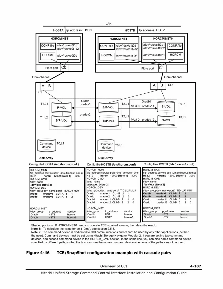
Overview of CCI 4-107
Hitachi Unified Storage Command Control Interface Installation and Configuration Guide
LAN
HORCM_MON #ip_address service poll(10ms) timeout(10ms) HST1 horcm 12000 [Note 1] 3000 HORCM_CMD #dev_name /dev/xxx [Note 2] HORCM_DEV #dev_groupdev_name port# TID LU# MU# Oradb oradev1 CL1-A 1 1 Oradb oradev2 CL1-A 1 2 HORCM_INST #dev_group ip_address service Oradb HST2 horcm Oradb HST2 horcm0
Config file-HOSTA (/etc/horcm.conf ) Config file-HOSTB (/etc/horcm.conf)
A B CL1
Oradb oradev1
oradev2
S/P-VOL
P-VOL T1,L1
T1,L2
Command device
T0,L1
A B CL1
S/P-VOL
S/P-VOL T2,L2
T2,L1
T0,L1
Disk Array
Ip address: HST2
C0
HORCMINST
HORCM
CONF.file /dev/rdsk/c0t1d1 /dev/rdsk/c0t1d2
/dev/rdsk/c0t0d1
Fibre-channel Fibre-channel
Fibre port
S-VOL
S-VOL
Oradb1 MU# 0 oradev11 MU# 0 oradev12
T3,L1
T3,L2
HORCM_MON #ip_address service poll(10ms) timeout(10ms) HST2 horcm 12000 [Note 1] 3000 HORCM_CMD #dev_name /dev/xxx [Note 2] HORCM_DEV #dev_groupdev_name port# TID LU# MU# Oradb oradev1 CL1-B 2 1 Oradb oradev2 CL1-B 2 2 Oradb1 oradev11 CL1-B 2 1 0 Oradb1 oradev12 CL1-B 2 2 0 HORCM_INST #dev_group ip_address service Oradb HST1 horcm Oradb1 HST2 horcm0
HORCM_MON #ip_address service poll(10ms) timeout(10ms) HST2 horcm0 12000 [Note 1] 3000 HORCM_CMD #dev_name /dev/xxx [Note 2] HORCM_DEV #dev_groupdev_name port# TID LU# MU# Oradb oradev1 CL1-B 2 1 Oradb oradev2 CL1-B 2 2 Oradb1 oradev11 CL1-B 3 1 0 Oradb1 oradev12 CL1-B 3 2 0 HORCM_INST #dev_group ip_address service Oradb HST1 horcm Oradb1 HST2 horcm
Config file-HOSTB (/etc/horcm0.conf)
Command device
Disk Array
HORCMINST0
HORCM
CONF.file
C1
/dev/rdsk/c1t3d1 /dev/rdsk/c1t3d2
. /dev/rdsk/c1t0d1
Fibre port
HOSTA
HORCMINST
HORCM
CONF.file /dev/rdsk/c1t2d1 /dev/rdsk/c1t2d2
/dev/rdsk/c1t0d1
HOSTB Ip address: HST1
Shaded portions: If HORCMINST0 needs to operate TCE’s paired volume, then describe oradb. Note 1: To calculate the value for poll(10ms), see section 2.5.3. Note 2: The command device is dedicated to CCI communications and cannot be used by any other applications (neither the user). Command devices must be set using Hitachi Storage Navigator Modular 2. If you are setting two command devices, add second command device in the HORCM_CMD section. In the same line, you can also add a command device specified by different path, so that the host can use the same command device when one of the paths cannot be used.
Figure 4-46 TCE/SnapShot configuration example with cascade pairs

4-108 Overview of CCI
Hitachi Unified Storage Command Control Interface Installation and Configuration Guide
Example of CCI commands with HOSTA and HOSTB:
• Designate a group name (Oradb) on TCE environment of HOSTA. # paircreate -g Oradb -f async -vl
• When the command execution environment is not set, set HORCC_MRCF of HOSTB. For C shell: # setenv HORCC_MRCF 1
For Windows: set HORCC_MRCF=1
• Cascade the P-VOL of SnapShot with the S-VOL of TCE specifying a group in the SnapShot environment of HOSTB. # paircreate -g Oradb1 -vl
These commands create pairs for all volumes assigned to groups Oradb and Oradb1 in the configuration definition file (four pairs for the configuration in Figure 4-46).
• Designate a group name and display pair status on HOSTA. # pairdisplay -g oradb -m all Group PairVol(L/R) (Port#,TID, VOL-M) ,Seq#,LDEV#.P/S,Status, Seq#,P-LDEV# M Oradb oradev1(L) (CL1-A , 1, 1-0 )91203052 26.SMPL ----,----- ---- - Oradb oradev1(L) (CL1-A , 1, 1 )91203052 26.P-VOL COPY,91203053 28 - Oradb1 oradev11(R) (CL1-B , 2, 1-0 )91203053 28.P-VOL COPY,91203053 30 - Oradb oradev1(R) (CL1-B , 2, 1 )91203053 28.S-VOL COPY,----- 26 - Oradb oradev2(L) (CL1-A , 1, 2-0 )91203052 27.SMPL ----,----- ---- - Oradb oradev2(L) (CL1-A , 1, 2 )91203052 27.P-VOL COPY,91203053 29 - Oradb1 oradev12(R) (CL1-B , 2, 2-0 )91203053 29.P-VOL COPY,91203053 31 - Oradb oradev2(R) (CL1-B , 2, 2 )91203053 29.S-VOL COPY,----- 27 -
• Make the Host A specify the cascaded SnapShot pair and split the pair. The command is issued to the group of TCE, however, what is actually split is the cascaded SnapShot pair. # pairsplit -g Oradb -mscas 123456 0
The V-VOL (Mu#:0) of the SnapShot pair, Oradev11, which was specified as Oradb in the configuration definition file and cascaded with a pair in the group of TCE, is split.
• When the status of the volume, which was produced by the splitting of a cascaded SnapShot pair, is displayed specifying a group in the SnapShot environment of the Host B, the following is displayed. # pairdisplay -g Oradb1 -d Oradev11 -v smk Group PairVol(L/R) Serial# LDEV# P/S Status UTC-TIME -----Split-Marker------ Oradb1 oradev11(L) 91203053 30.S-VOL SSUS,- - Oradb1 oradev11(R) 91203053 28.P-VOL PSUS,123456ef 123456

Overview of CCI 4-109
Hitachi Unified Storage Command Control Interface Installation and Configuration Guide
Confirming configurations
HORCM supports error monitoring and configuration confirmation commands for linkage with the system operation management of the UNIX/PC host.
Monitoring paired volume errors
The HORC Manager (HORCM) monitors all volumes defined in the configuration definition file at a certain interval regardless of the ShadowImage/SnapShot/TrueCopy/TCE commands.
• Objects and scope of monitoring: The HORCM operates as a daemon process on the host and monitors all the paired volumes defined in the configuration definition file, not the volume groups. The HORC Manager’s monitoring applies to the primary volumes only (since the primary volumes control the status). The HORC Manager monitors the changes in the pair status of these volumes. Only when the PAIR status changes to the PSUS status and that change is caused by an error (such as P-VOL error or S-VOL’s SUS), does the HORC Manager regard the change as an error.
• Monitoring time and interval: This command always issues I/O instructions to the array in order to obtain information for monitoring. It is possible to specify the monitoring interval in the configuration definition file to adjust the daemon load.
• Error notification by HORCM: Since the operation management of the UNIX host checks Syslog to find system errors in many cases, ShadowImage/SnapShot/TrueCopy/TCE error messages are output to Syslog for linkage with the system operation management.
• Error notification command: The CCI supports the error notification function using commands in order to allow the UNIX host/client to monitor errors. This command is connected to the HORCM (daemon) to obtain the transition of the pairing status and report it. When an error is detected, this command outputs an error message. This command waits until an error occurs or reports that no error occurs if it finds no errors in pairing status transition queue of the HORCM’s pairing monitor. Operations can be specified using certain options. If the command finds the status transition data in the status transition queue, it displays the data of all volumes. Specifying the option of this command can erase data in the HORCM’s status transition queue.

4-110 Overview of CCI
Hitachi Unified Storage Command Control Interface Installation and Configuration Guide
Confirming pair status
The configuration definition file combines physical volumes in the disk array used independently by the hosts. Therefore, be certain that the host volumes are combined as intended by the host system administrator.
The pairdisplay command displays the pairing status to enable you to verify the completion of pair creation or pair resynchronization (see Figure 4-47). This command is also used to confirm the configuration of the paired volume connection path (physical link of paired volumes among the hosts).
G1,Oradb1... P1,T1,L1 G1...HOSTB
Primary LDEV
#1
Secondary LDEV
#2 Paired logical volumes
G1,Oradb1
P1, T1, L1 (Port, Target, LUN) P2, T2, L2
HOSTA
G1,Oradb1... P2,T2,L2 G1...HOSTA
Special file
HOSTB
Special file
Configuration definition file Configuration definition file
Seq#
Fibre-channel
Seq#
Disk Array
--Link information of -- ----Link information of --- Group PairVol(L/R) (Port#,TID, VOL-M) ,Seq#,LDEV#.P/S,Status, Seq#,P-LDEV# M G1 Oradb1(L) (P1 , T1, L1 ),Seq#, 1.P-VOL Pair , Seq#, 2 - G1 Oradb1(R) (P2 , T2, L2 ),Seq#, 2.S-VOL Pair , Seq#, 1 -
Figure 4-47 Pair configuration confirmation (Pairdisplay)
The raidscan command displays the fibre or iSCSI port, target ID, LDEVs mapped to VOLs, and status of those LDEVs, regardless of the configuration definition file. When a port number is specified, this command displays information about all target IDs and VOLs of that port.

Overview of CCI 4-111
Hitachi Unified Storage Command Control Interface Installation and Configuration Guide
About VMware
Operation procedures and restrictions when using CCI installed in a guest OS of VMware are explained below.
Disk Array
Host
Guest OS
CCI#3
Guest OS
CCI#1 CCI#2
HBA
-CM
-CM
Command device for CCI#1 and CCI#2
Command device for CCI#3
VMware ESX Server
Figure 4-48 CCI configuration on VMware
4-112 Overview of CCI
Hitachi Unified Storage Command Control Interface Installation and Configuration Guide
Restrictions • Guest OS
To make CCI operate on the guest OS, it is required that both CCI and VMware support the OS to be used as a guest OS. For the details, refer to “Applicable Platforms” described at the beginning of this manual.
• Command device CCI uses the SCSI through interface in order to access a command device. Therefore, map the command device using the method of Raw Device Mapping with Physical Compatibility Mode.
When starting the CCI instance on two or more guest OS, you can assign the same command device to each guest OS. However, when you use the common command device, you cannot use the same instance number even if between the different guest OS.
• Assigned volume
The volume of guest OS assigned to the pair must be mapped as Raw Device Mapping using Physical Compatibility Mode. However, it is possible to acquire the backup of the system disk or data disk in the VMFS format by shutting down the guest OS.
• Cautions about volumes assigned to guest OS It is required that the volumes assigned to guest OS must be visible at the time of VMware (host OS) will be started. If the S-VOLs used by VSS are in invisible status at the time of VMware (host OS) will be started, VMware (host OS) may not be able to start.
• Restrictions about volume share between guest OS and VMware (host OS)
Sharing of volumes, such as a command device, is not permitted between guest OS and VMware (host OS).
• Restrictions related to the linkage with VSS
When acquiring the backup of the data disk on the guest OS using VSS, use the physical server for the backup host. When using the guest OS for the backup host, the backup cannot be acquired by utilizing VSS.
• Restrictions related to the discovery of the volume in which Raw Device Mapping was performed
The inqraid command uses the SCSI Inquiry command and displays the physical information (P/S/s, RAID groups, and etc) of the volume in which Raw Device Mapping was performed in the guest OS. However, since it is cached in VMware ESX 4.x, the current information is not displayed. Rebooting is required to display the updated information. Or for referring to the pair information, use the CCI commands (raidscan, pairdisplay, and others).
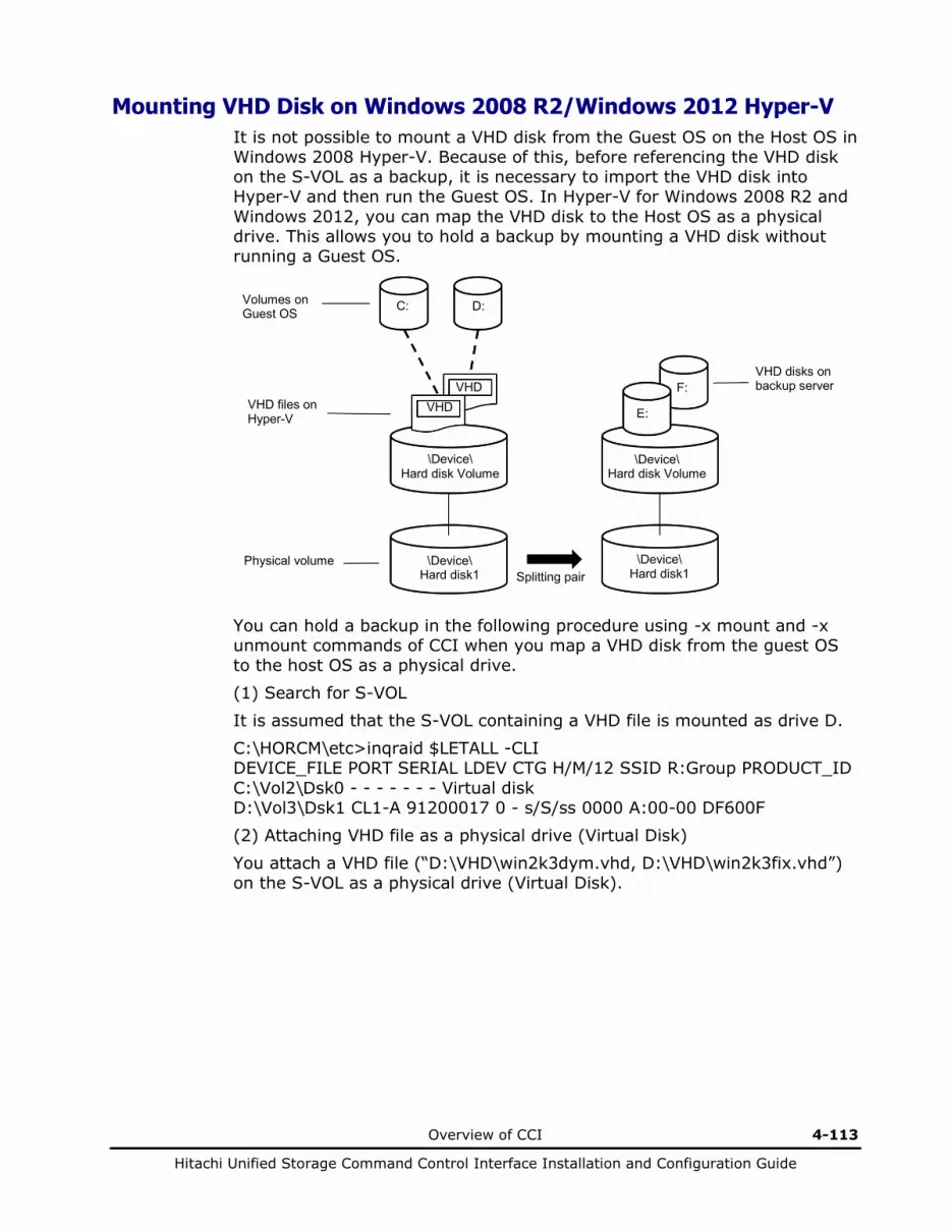
Overview of CCI 4-113
Hitachi Unified Storage Command Control Interface Installation and Configuration Guide
Mounting VHD Disk on Windows 2008 R2/Windows 2012 Hyper-V It is not possible to mount a VHD disk from the Guest OS on the Host OS in Windows 2008 Hyper-V. Because of this, before referencing the VHD disk on the S-VOL as a backup, it is necessary to import the VHD disk into Hyper-V and then run the Guest OS. In Hyper-V for Windows 2008 R2 and Windows 2012, you can map the VHD disk to the Host OS as a physical drive. This allows you to hold a backup by mounting a VHD disk without running a Guest OS.
You can hold a backup in the following procedure using -x mount and -x unmount commands of CCI when you map a VHD disk from the guest OS to the host OS as a physical drive. (1) Search for S-VOL It is assumed that the S-VOL containing a VHD file is mounted as drive D. C:\HORCM\etc>inqraid $LETALL -CLI DEVICE_FILE PORT SERIAL LDEV CTG H/M/12 SSID R:Group PRODUCT_ID C:\Vol2\Dsk0 - - - - - - - Virtual disk D:\Vol3\Dsk1 CL1-A 91200017 0 - s/S/ss 0000 A:00-00 DF600F (2) Attaching VHD file as a physical drive (Virtual Disk) You attach a VHD file (“D:\VHD\win2k3dym.vhd, D:\VHD\win2k3fix.vhd”) on the S-VOL as a physical drive (Virtual Disk).
Volumes on Guest OS
VHD files on Hyper-V
Physical volume
VHD disks on backup server
\Device\ Hard disk Volume
\Device\ Hard disk1
\Device\ Hard disk Volume
\Device\ Hard disk1
D: C:
F:
E: VHD VHD
Splitting pair

4-114 Overview of CCI
Hitachi Unified Storage Command Control Interface Installation and Configuration Guide
DISKPART> select vdisk file="D:\VHD\win2k3dym.vhd" DiskPart successfully selected the virtual disk file. DISKPART> attach vdisk 100 percent completed DiskPart successfully attached the virtual disk file. DISKPART> select vdisk file="D:\VHD\win2k3fix.vhd" DiskPart successfully selected the virtual disk file. DISKPART> attach vdisk 100 percent completed DiskPart successfully attached the virtual disk file. DISKPART>
(3) Search for virtual disk on S-VOL
The VHD disk appears as a “Virtual Disk”. In the example below, the “Virtual Disks” appear as Physical Drive 2 and 3.
C:\HORCM\etc>inqraid $Phys -CLI DEVICE_FILE PORT SERIAL LDEV CTG H/M/12 SSID R:Group PRODUCT_ID Harddisk0 - - - - - - - Virtual disk Harddisk1 CL1-A 91200017 0 - s/S/ss 0000 A:00-00 DF600F Harddisk2 - - - - - - - Virtual Disk Harddisk3 - - - - - - - Virtual Disk
C:\HORCM\etc>inqraid $Vol -CLI DEVICE_FILE PORT SERIAL LDEV CTG H/M/12 SSID R:Group PRODUCT_ID \Vol1\Dsk0 - - - - - - - Virtual disk \Vol2\Dsk0 - - - - - - - Virtual disk
\Vol3\Dsk1 CL1-A 91200017 0 - s/S/ss 0000 A:00-00 DF600F \Vol14\Dsk2 - - - - - - - Virtual Disk \Vol15\Dsk3 - - - - - - - Virtual Disk
(4) Mounting VHD disk
You mount the “Virtual disks” as drive E and F.
C:\HORCM\etc>raidscan -x mount E:\ \Vol14 E:\ <+> HarddiskVolume14
C:\HORCM\etc>raidscan -x mount F:\ \Vol15 F:\ <+> HarddiskVolume15

Overview of CCI 4-115
Hitachi Unified Storage Command Control Interface Installation and Configuration Guide
C:\HORCM\etc>inqraid $LETALL -CLI DEVICE_FILE PORT SERIAL LDEV CTG H/M/12 SSID R:Group PRODUCT_ID C:\Vol2\Dsk0 - - - - - - - Virtual disk D:\Vol3\Dsk1 CL1-A 91200017 0 - s/S/ss 0000 A:00-00 DF600F E:\Vol14\Dsk2 - - - - - - - Virtual Disk F:\Vol15\Dsk3 - - - - - - - Virtual Disk
(5) Unmounting and detaching VHD disk
C:\HORCM\etc>raidscan -x umount E:\ E:\ <-> HarddiskVolume14
C:\HORCM\etc>raidscan -x umount F:\ F:\ <-> HarddiskVolume15
DISKPART> select vdisk file="D:\VHD\win2k3dym.vhd" DiskPart successfully selected the virtual disk file. DISKPART> detach vdisk DiskPart successfully detached the virtual disk file. DISKPART> select vdisk file="D:\VHD\win2k3fix.vhd" DiskPart successfully selected the virtual disk file. DISKPART> detach vdisk DiskPart successfully detached the virtual disk file.
C:\HORCM\etc>inqraid $Phys -CLI DEVICE_FILE PORT SERIAL LDEV CTG H/M/12 SSID R:Group PRODUCT_ID Harddisk0 - - - - - - - Virtual disk Harddisk1 CL1-A 91200017 0 - s/S/ss 0000 A:00-00 DF600F
C:\HORCM\etc>inqraid $Vol -CLI DEVICE_FILE PORT SERIAL LDEV CTG H/M/12 SSID R:Group PRODUCT_ID \Vol1\Dsk0 - - - - - - - Virtual disk \Vol2\Dsk0 - - - - - - - Virtual disk \Vol3\Dsk1 CL1-A 91200017 0 - s/S/ss 0000 A:00-00 DF600F

4-116 Overview of CCI
Hitachi Unified Storage Command Control Interface Installation and Configuration Guide
Creating and resynchronzing pairs
Procedures are explained below for the cases of the pair creation and the pair resynchronization referring to an operation example in which a pair is usually placed in the PSUS status and the P-VOL is resynchronized with the S-VOL when the backup is necessary.
To create a pair: 1. Issue a paircreate command. 2. Wait for the volumes to be paired. 3. Un-mount the P-VOL. 4. Issue a pairsplit command. 5. Mount the P-VOL. 6. Rescan the HBA by clicking the Rescan button on the Configure tab in the
VMware operation window. 7. Reboot the guest OS.
Note: After the paircreate command or rescanning of the disks on the host OS is perfomed, it is required to reboot the guest OS in order to enable it to recognize the S-VOL.
8. Mount the S-VOL.
To resynchronize a pair: 1. Un-mount the S-VOL. 2. Issue a pairresync command. 3. Wait for the volumes to be paired. 4. Un-mount the P-VOL. 5. Issue a pairsplit command. 6. Mount the P-VOL. 7. Rescan the HBA by clicking the Rescan button on the Configure tab in the
VMware operation window. 8. Check if the guest OS has recognized the S-VOL. If it has not recognized
the S-VOL, reboot the guest OS.
9. Mount the S-VOL.
Overview of CCI 4-117
Hitachi Unified Storage Command Control Interface Installation and Configuration Guide
About Hyper-V
Operation restrictions when using CCI installed in a guest OS of Hyper-V are explained below.
Restrictions • Notes on the guest OS
To make CCI operate on the guest OS, it is required that both CCI and Hyper-V support the OS to be used as a guest OS. For the details, refer to “Applicable Platforms” described at the beginning of this manual.
• Notes on the command device
Map the command device using the method of path through disk. CCI uses the SCSI through interface in order to access a command device. When starting CCI Instance on two or more guest OS, assign the command device for each guest OS.
One hundred and twenty-eight command devices can be created per array. Therefore, the maximum number of acceptable guest OS is 128 for each array.
• Restrictions on the volume assigned to the pair
The volume assigned to the pair must be mapped as path through disk. The disk which mapped VHD does not become a pair target.
• Cautions about volumes assigned to guest OS
It is required that the volumes assigned to guest OS must be visible at the time of Hyper-V (management OS) will be started.
• Restrictions about volume share between guest OS and Hyper-V (management OS) Sharing of volumes, such as a command device, is not permitted between guest OS and Hyper-V (management OS).
• Restrictions about the cluster shared volume
The command device cannot be used as a cluster shared volume (CSV) is unsupported in CCI. A P-VOL can be used as a CSV. The S-VOL can connect to a backup server for a backup of the P-VOL.

4-118 Overview of CCI
Hitachi Unified Storage Command Control Interface Installation and Configuration Guide
Recovery procedures for HA
After configuring and starting CCI operations, the system administrator should conduct operational tests for possible failures in the system. In normal operation, service personnel obtain information for identifying the failure cause on the HITRACK and SNMP Agent or Web. However, a motive for the action above should be given by the CCI operation command.
Figure 4-49 shows the system failover and recovery procedure. Figure 4-50 shows the regression and TrueCopy recovery procedure.
P-VOL recovers.
Pairresync -swaps Takeover
Takeover
Host A Host B
P- VOL
S- VOL
Host A Host B
S- VOL
P- VOL
Host A goes down.
Host A Host B
P- VOL
S- VOL
Host A Host B
P- VOL
S-VOL SSUS
(SSWS)
Host A Host B
S- VOL
P- VOL
Difference
P-VOL goes down.
Mirror state Takeover state Recovery state
Host A Host B
P- VOL
S- VOL
A failure occurs in the host A server (1-top) or in the P-VOL (1-bottom).
Host B detects the failure of host A or the P-VOL and issues a takeover command to make the S-VOL usable. Host B takes over processing from host A. In the case of host A failure (1-top), the Swap-takeover command will be issued. In the case of P-VOL failure (1-bottom), the SVOL-SSUS-takeover command will be issued.
While host B continues processing, P-VOL and S-VOL are swapped (pairresync -swaps), and the delta data (BITMAP) updated by host B is fed back to host A. After host A or the P-VOL has recovered, host A can take over processing from host B by executing the Swap-takeover (horctakeover) command.
Figure 4-49 System failover and recovery

Overview of CCI 4-119
Hitachi Unified Storage Command Control Interface Installation and Configuration Guide
Disconnected
Continue (regression)
Host A Host B
P- VOL
S- VOL
Host A Host B
P- VOL
S- VOL
Host A Host B
P- VOL
S- VOL
Continue (regression) Pairsplit -S Paircreate
Entire copy
S-VOL goes down. S-VOL recovers.
Host A Host B
P- VOL
S- VOL
Host A Host B
P- VOL
S- VOL
Host A Host B
P- VOL
S VOL
Pairresync
Difference
Recovery
Mirroring state Regression state Recovery state
The P-VOL detects a failure in the S-VOL and causes suspension of the duplicated writing. (The fence level determines whether host A continues processing or host B takes over the processing from host A.)
The P-VOL changes the paired volume status to PSUE and keeps track of the difference data. The HORCM detects the status change and outputs a message to syslog. If the client of host A has initiated the monitoring command, the message concerned is displayed on the screen of the client. The S-VOL recovers from the failure. The host A issues the pairsplit -S, paircreate -vl, or pairresync command to update the P-VOL data by copying entire data or copying differential data only. The updated data is fed back to the S-VOL.
Figure 4-50 Degeneracy and recovery in case of system error

4-120 Overview of CCI
Hitachi Unified Storage Command Control Interface Installation and Configuration Guide
IPv6 support in CCI Supported level of IPv6 feature depends on the platform and OS version. In such OS platform, CCI will not be able to performed IPv6 communication completely. So CCI logs the results of whether OS is supporting IPv6 feature or not.
/HORCM/log*/curlog/horcm_hostname.log
***************************************************************************** - HORCM STARTUP LOG - Thu Jun 05 15:47:19 2008 ***************************************************************************** 15:47:19-0f230-01720- horcmgr started on Thu Jun 05 15:47:19 2008 :: 15:47:19-1e848-01172- ******** starts Loading library for IPv6 ******* [ AF_INET6 = 26, AI_PASSIVE = 1 ] 15:47:19ca1-02188- dlsym() : Symbl = 'getaddrinfo' : dlsym: symbol "getaddrinfo" not found in "/etc/horcmgr" getaddrinfo() : Unlinked on itself inet_pton() : Linked on itself inet_ntop() : Linked on itself 15:47:19-5ab3e-02188- ******** finished Loading library ************** : HORCM set to IPv6 ( INET6 value = 26) :
If platform does not support IPv6 library, CCI uses own internal function correspond to “inet_pton(), inet_ntop()”, in that case, IPv6 address will not be allowed to describe hostname.
The following table shows the supported IPv6 platforms.
Table 4-17 Supported IPv6 platforms
Vendor Operating System IPv6 (Note) IPv4 Mapped IPv6
HP HP-UX 11i V2.0 (PA-RISC)
HP-UX 11i V3.0 (PA-RISC)
HP-UX 11i V2.0 (IPF)
HP-UX 11i V3.0 (IPF)
SUN Solaris 8 (SPARC)
Solaris 9 (SPARC)
Solaris 10 (SPARC)
Solaris 10 (x86)
Solaris 10 (x64)
IBM AIX 5.1
AIX 5.2
AIX 5.3
AIX 6.1

Overview of CCI 4-121
Hitachi Unified Storage Command Control Interface Installation and Configuration Guide
Vendor Operating System IPv6 (Note) IPv4 Mapped IPv6
Microsoft Windows Server 2003 + IPv6 install (IA32) N/A
Windows Server 2008 (IA32) N/A
Windows Server 2003 + IPv6 install (x64) N/A
Windows Server 2008 (x64) N/A
Windows Server 2003 + IPv6 install (IA64) N/A
Windows Server 2008 (IA64) N/A
Red Hat Red Hat Linux AS/ES 2.1 (IA32)
Red Hat Linux AS/ES 3.0 (IA32)
Red Hat Linux AS/ES 4.0 (IA32)
Red Hat Linux AS/ES 5.0 (IA32)
Red Hat Linux AS/ES 3.0 (AMD64/EM64T)
Red Hat Linux AS/ES 4.0 (AMD64/EM64T)
Red Hat Linux AS/ES 5.0 (AMD64/EM64T)
Red Hat Linux AS/ES 6.0 (AMD64/EM64T)
Red Hat Linux AS/ES 3.0 (IA64)
Red Hat Linux AS/ES 4.0 (IA64)
Note: For more details about IPv6 support, see section 2.11 of the Hitachi DF850 Command Control Interface (CCI) User’s Guide manual.
4-122 Overview of CCI
Hitachi Unified Storage Command Control Interface Installation and Configuration Guide
Windows Power Shell
Like UNIX’s shell, Windows Power Shell translates “$” as a character or a variable, you can not use an object with “$” like $Physical, $LETALL or $Volume. The following command will hang up.
PS C:¥horcm¥etc> ./inqraid -CLI $Phys
In order to avoid this issue, set the environment variable CHG_DVOBJ_CH as CHG_DVOBJ_CH=1, which translates “$” to “%”.
PS C:¥horcm¥etc> $env:CHG_DVOBJ_CH = 1 PS C:¥horcm¥etc> ./inqraid -CLI %Phys DEVICE_FILE PORT SERIAL LDEV CTG H/M/12 SSID R:Group PRODUCT_ID Harddisk0 - - - - - - - LOGICAL VOLUME PS C:¥horcm¥etc> PS C:¥horcm¥etc> $env:CHG_DVOBJ_CH 1

5
Fibre-to-SCSI address conversion 5-1
Hitachi Unified Storage Command Control Interface Installation and Configuration Guide
Fibre-to-SCSI address conversion
SCSI TIDs Examples of Fibre address conversion Fibre address conversion tables

5-2 Fibre-to-SCSI address conversion
Hitachi Unified Storage Command Control Interface Installation and Configuration Guide
SCSI TIDs
Fibre channel physical addresses are converted to SCSI target Ids (TIDs) using a conversion table. Table 5-1 displays the current limits for SCSI TIDs on various operating systems.
Table 5-1 Limits for target IDs
HP-UX and other Systems Solaris Systems Windows Systems Port TID VOL TID VOL TID VOL
Fibre 0 to 15 0 to 511 0 to 125 0 to 511 0 to 31 0 to 511
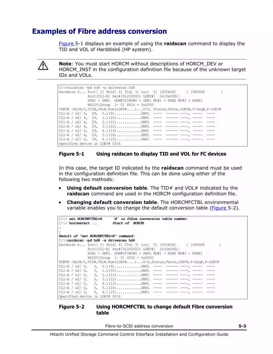
Fibre-to-SCSI address conversion 5-3
Hitachi Unified Storage Command Control Interface Installation and Configuration Guide
Examples of Fibre address conversion
Figure 5-1 displays an example of using the raidscan command to display the TID and VOL of Harddisk6 (HP system).
Note: You must start HORCM without descriptions of HORCM_DEV or HORCM_INST in the configuration definition file because of the unknown target IDs and VOLs.
C:\>raidscan -pd hd6 -x drivescan hd6 Harddisk 6... Port[ 2] PhId[ 4] TId[ 3] Lun[ 5] [HITACHI ] [DF600F ] Port[CL1-A] Ser#[91203005] LDEV#[ 14(0x00E)] HORC = SMPL HOMRCF[MU#0 = SMPL MU#1 = NONE MU#2 = NONE] RAID5[Group 1- 0] SSID = 0x0000 PORT# /ALPA/C,TID#,VOL#.Num(LDEV#....)...P/S, Status,Fence,LDEV#,P-Seq#,P-LDEV# CL1-A / e2/ 4, 29, 0.1(9).............SMPL ---- ------ ----, ----- ---- CL1-A / e2/ 4, 29, 1.1(10)............SMPL ---- ------ ----, ----- ---- CL1-A / e2/ 4, 29, 2.1(11)............SMPL ---- ------ ----, ----- ---- CL1-A / e2/ 4, 29, 3.1(12)............SMPL ---- ------ ----, ----- ---- CL1-A / e2/ 4, 29, 4.1(13)............SMPL ---- ------ ----, ----- ---- CL1-A / e2/ 4, 29, 5.1(14)............SMPL ---- ------ ----, ----- ---- CL1-A / e2/ 4, 29, 6.1(15)............SMPL ---- ------ ----, ----- ---- Specified device is LDEV# 0014
Figure 5-1 Using raidscan to display TID and VOL for FC devices
In this case, the target ID indicated by the raidscan command must be used in the configuration definition file. This can be done using either of the following two methods:
• Using default conversion table. The TID# and VOL# indicated by the raidscan command are used in the HORCM configuration definition file.
• Changing default conversion table. The HORCMFCTBL environmental variable enables you to change the default conversion table (Figure 5-2).
C:\> set HORCMFCTBL=X 'X' is fibre conversion table number. C:\> horcmstart ... Start of HORCM. : : Result of "set HORCMFCTBL=X" command: C:\>raidscan -pd hd6 -x drivescan hd6 Harddisk 6... Port[ 2] PhId[ 4] TId[ 3] Lun[ 5] [HITACHI ] [DF600F ] Port[CL1-A] Ser#[91203005] LDEV#[ 14(0x00E)] HORC = SMPL HOMRCF[MU#0 = SMPL MU#1 = NONE MU#2 = NONE] RAID5[Group 1- 0] SSID = 0x0000 PORT# /ALPA/C,TID#,VOL#.Num(LDEV#....)...P/S,Status,Fence,LDEV#,P-Seq#,P-LDEV# CL1-A / e2/ 0, 3, 0.1(9).............SMPL ---- ------ ----, ----- ---- CL1-A / e2/ 0, 3, 1.1(10)............SMPL ---- ------ ----, ----- ---- CL1-A / e2/ 0, 3, 2.1(11)............SMPL ---- ------ ----, ----- ---- CL1-A / e2/ 0, 3, 3.1(12)............SMPL ---- ------ ----, ----- ---- CL1-A / e2/ 0, 3, 4.1(13)............SMPL ---- ------ ----, ----- ---- CL1-A / e2/ 0, 3, 5.1(14)............SMPL ---- ------ ----, ----- ---- CL1-A / e2/ 0, 3, 6.1(15)............SMPL ---- ------ ----, ----- ---- Specified device is LDEV# 0014
Figure 5-2 Using HORCMFCTBL to change default Fibre conversion table

5-4 Fibre-to-SCSI address conversion
Hitachi Unified Storage Command Control Interface Installation and Configuration Guide
Fibre address conversion tables
Table 5-2, Table 5-3, and Table 5-4 show the fibre address conversion tables.
• AL-PA is an abbreviation for arbitrated loop physical address, and indicates the physical address for Fibre. TID indicates the target ID.
• If the TID displayed on the system is different than the TID indicated in the fibre address conversion table, you must use the TID and VOL# returned by the raidscan command to specify the devices.
• The conversion table for Windows Server is based on the Emulex driver. If a different adapter is used, the target ID indicated by the raidscan command may be different than the target ID indicated by Windows Server system. In such case, for the configuration definition file, use the target ID that is displayed (obtained) by the raidscan -find command.
• The conversion table for Native Fibre is used when the FC_AL conversion for the host is unknown, or when the FC_AL conversion is the device file displayed in VOL as Fabric mode. Only VOL is displayed and the target ID (displayed as zero) will not be used. Therefore, there is no table for Native Fibre since there is no conversion to target ID.
Fibre address conversion tables
Table 5-2 Fibre address conversion table for HP-UX systems
C0 C1 C2 C3 C4 C5 C6 C7 AL-PA TID AL-PA TID AL-PA TID AL-PA TID AL-PA TID AL-PA TID AL-PA TID AL-PA TID
EF 0 CD 0 B2 0 98 0 72 0 55 0 3A 0 25 0
E8 E8 1 CC 1 B1 1 97 1 71 1 54 1 39 1 23
E4 E4 2 CB 2 AE 2 90 2 6E 2 53 2 36 2 1F
E2 E2 3 CA 3 AD 3 8F 3 6D 3 52 3 35 3 1E
E1 E1 4 C9 4 AC 4 88 4 6C 4 51 4 34 4 1D
E0 E0 5 C7 5 AB 5 84 5 6B 5 4E 5 33 5 1B
DC DC 6 C6 6 AA 6 82 6 6A 6 4D 6 32 6 18
DA DA 7 C5 7 A9 7 81 7 69 7 4C 7 31 7 17
D9 D9 8 C3 8 A7 8 80 8 67 8 4B 8 2E 8 10
D6 D6 9 BC 9 A6 9 7C 9 66 9 4A 9 2D 9 0F
D5 D5 10 BA 10 A5 10 7A 10 65 10 49 10 2C 10 08
D4 D4 11 B9 11 A3 11 79 11 63 11 47 11 2B 11 04
D3 D3 12 B6 12 9F 12 76 12 5C 12 46 12 2A 12 02
D2 D2 13 B5 13 9E 13 75 13 5A 13 45 13 29 13 01
D1 D1 14 B4 14 9D 14 74 14 59 14 43 14 27 14
CE CE 15 B3 15 9B 15 73 15 56 15 3C 15 26 15

Fibre-to-SCSI address conversion 5-5
Hitachi Unified Storage Command Control Interface Installation and Configuration Guide
Table 5-3 Fibre address conversion table for Solaris and IRIX systems
C0 C1 C2 C3 C4 C5 C6 C7 AL-PA TID AL-PA TID AL-PA TID AL-PA TID AL-PA TID AL-PA TID AL-PA TID AL-PA TID
EF 0 CD 16 B2 32 98 48 72 64 55 80 3A 96 25 112
E8 1 CC 17 B1 33 97 49 71 65 54 81 39 97 23 113
E4 2 CB 18 AE 34 90 50 6E 66 53 82 36 98 1F 114
E2 3 CA 19 AD 35 8F 51 6D 67 52 83 35 99 1E 115
E1 4 C9 20 AC 36 88 52 6C 68 51 84 34 100 1D 116
E0 5 C7 21 AB 37 84 53 6B 69 4E 85 33 101 1B 117
DC 6 C6 22 AA 38 82 54 6A 70 4D 86 32 101 18 118
DA 7 C5 23 A9 39 81 55 69 71 4C 87 31 103 17 119
D9 8 C3 24 A7 40 80 56 67 72 4B 88 2E 104 10 120
D6 9 BC 25 A6 41 7C 57 66 73 4A 89 2D 105 0F 121
D5 10 BA 26 A5 42 7A 58 65 74 49 90 2C 106 08 122
D4 11 B9 27 A3 43 79 59 63 75 47 91 2B 107 04 123
D3 12 B6 28 9F 44 76 60 5C 76 46 92 2A 108 02 124
D2 13 B5 29 9E 45 75 61 5A 77 45 93 29 109 01 125
D1 14 B4 30 9D 46 74 62 59 78 43 94 27 110
CE 15 B3 31 9B 47 73 63 56 79 3C 95 26 111
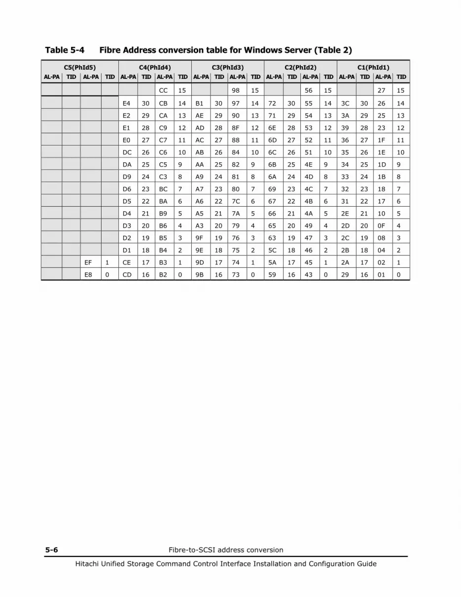
5-6 Fibre-to-SCSI address conversion
Hitachi Unified Storage Command Control Interface Installation and Configuration Guide
Table 5-4 Fibre Address conversion table for Windows Server (Table 2)
C5(PhId5) C4(PhId4) C3(PhId3) C2(PhId2) C1(PhId1)
AL-PA TID AL-PA TID AL-PA TID AL-PA TID AL-PA TID AL-PA TID AL-PA TID AL-PA TID AL-PA TID AL-PA TID
CC 15 98 15 56 15 27 15
E4 30 CB 14 B1 30 97 14 72 30 55 14 3C 30 26 14
E2 29 CA 13 AE 29 90 13 71 29 54 13 3A 29 25 13
E1 28 C9 12 AD 28 8F 12 6E 28 53 12 39 28 23 12
E0 27 C7 11 AC 27 88 11 6D 27 52 11 36 27 1F 11
DC 26 C6 10 AB 26 84 10 6C 26 51 10 35 26 1E 10
DA 25 C5 9 AA 25 82 9 6B 25 4E 9 34 25 1D 9
D9 24 C3 8 A9 24 81 8 6A 24 4D 8 33 24 1B 8
D6 23 BC 7 A7 23 80 7 69 23 4C 7 32 23 18 7
D5 22 BA 6 A6 22 7C 6 67 22 4B 6 31 22 17 6
D4 21 B9 5 A5 21 7A 5 66 21 4A 5 2E 21 10 5
D3 20 B6 4 A3 20 79 4 65 20 49 4 2D 20 0F 4
D2 19 B5 3 9F 19 76 3 63 19 47 3 2C 19 08 3
D1 18 B4 2 9E 18 75 2 5C 18 46 2 2B 18 04 2
EF 1 CE 17 B3 1 9D 17 74 1 5A 17 45 1 2A 17 02 1
E8 0 CD 16 B2 0 9B 16 73 0 59 16 43 0 29 16 01 0
6
CCI operations on Windows systems 6-1
Hitachi Unified Storage Command Control Interface Installation and Configuration Guide
CCI operations on Windows systems
This chapter covers the following topics: About LDM volume search About dynamic disk and copy
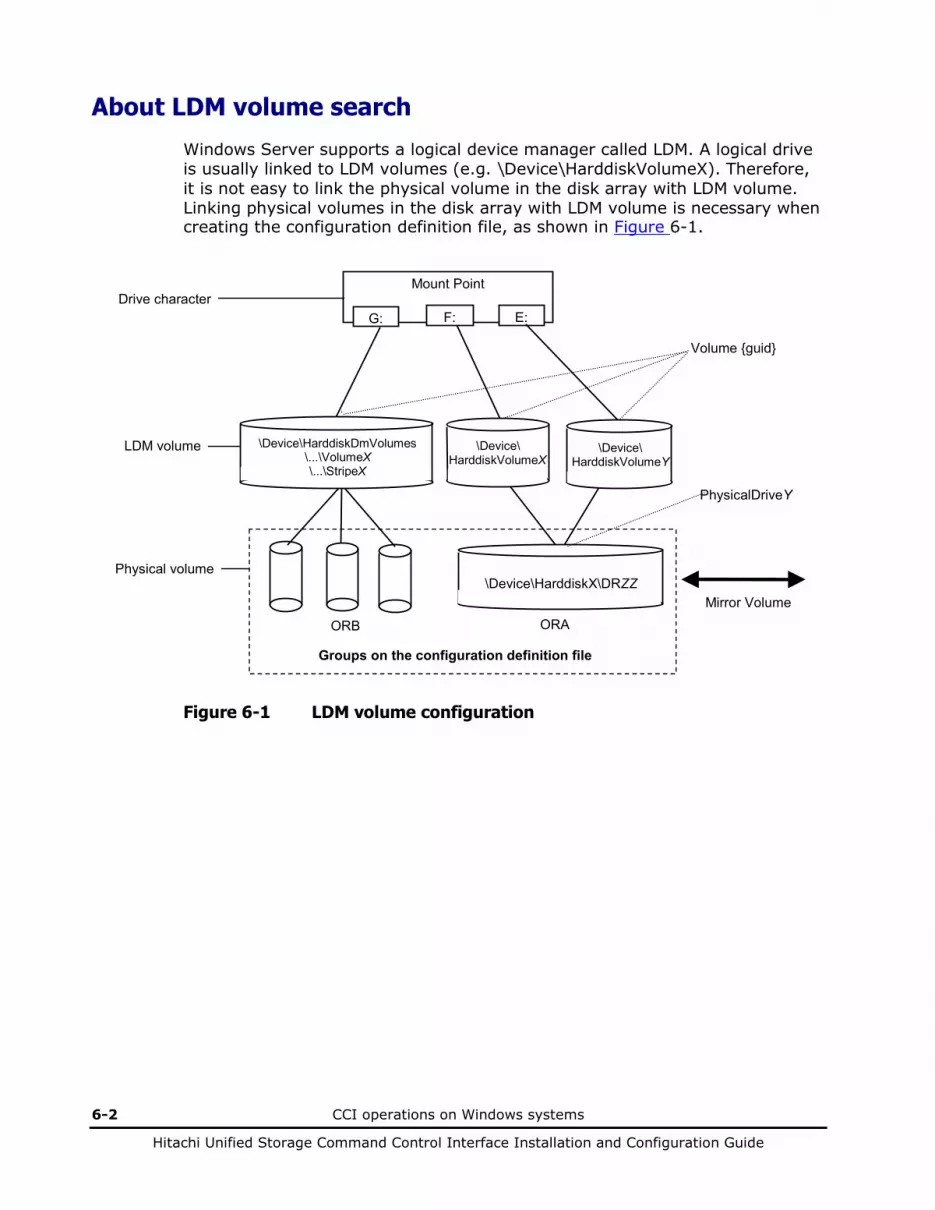
6-2 CCI operations on Windows systems
Hitachi Unified Storage Command Control Interface Installation and Configuration Guide
About LDM volume search
Windows Server supports a logical device manager called LDM. A logical drive is usually linked to LDM volumes (e.g. \Device\HarddiskVolumeX). Therefore, it is not easy to link the physical volume in the disk array with LDM volume. Linking physical volumes in the disk array with LDM volume is necessary when creating the configuration definition file, as shown in Figure 6-1.
Mount Point
G: E:
Mirror Volume
Drive character
LDM volume
Physical volume
F:
\Device\ HarddiskVolumeX
\Device\HarddiskDmVolumes \...\VolumeX \...\StripeX
\Device\ HarddiskVolumeY
\Device\HarddiskX\DRZZ
ORB ORA
Groups on the configuration definition file
Volume {guid}
PhysicalDriveY
Figure 6-1 LDM volume configuration
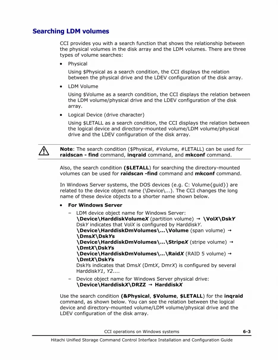
CCI operations on Windows systems 6-3
Hitachi Unified Storage Command Control Interface Installation and Configuration Guide
Searching LDM volumes
CCI provides you with a search function that shows the relationship between the physical volumes in the disk array and the LDM volumes. There are three types of volume searches:
• Physical Using $Physical as a search condition, the CCI displays the relation between the physical drive and the LDEV configuration of the disk array.
• LDM Volume Using $Volume as a search condition, the CCI displays the relation between the LDM volume/physical drive and the LDEV configuration of the disk array.
• Logical Device (drive character)
Using $LETALL as a search condition, the CCI displays the relation between the logical device and directory-mounted volume/LDM volume/physical drive and the LDEV configuration of the disk array.
Note: The search condition ($Physical, #Volume, #LETALL) can be used for raidscan - find command, inqraid command, and mkconf command.
Also, the search condition ($LETALL) for searching the directory-mounted volumes can be used for raidscan -find command and mkconf command.
In Windows Server systems, the DOS devices (e.g. C: Volume{guid}) are related to the device object name (\Device\...). The CCI changes the long name of these device objects to a shorter name shown below.
• For Windows Server – LDM device object name for Windows Server:
\Device\HarddiskVolumeX (partition volume) \VolX\DskY DskY indicates that VolX is configured by HarddiskY. \Device\HarddiskDmVolumes\...\Volume (span volume) \DmsX\DskYs \Device\HarddiskDmVolumes\...\StripeX (stripe volume) \DmtX\DskYs \Device\HarddiskDmVolumes\…\RaidX (RAID 5 volume) \DmtX\DskYs DskYs indicates that DmsX (DmtX, DmrX) is configured by several HarddiskY1, Y2....
– Device object name for Windows Server physical drive: \Device\HarddiskX\DRZZ HarddiskX
Use the search condition (&Physical, $Volume, $LETALL) for the inqraid command, as shown below. You can see the relation between the logical device and directory-mounted volume/LDM volume/physical drive and the LDEV configuration of the disk array.
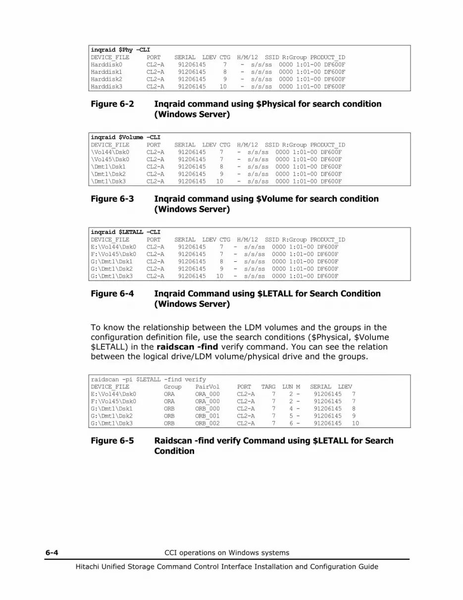
6-4 CCI operations on Windows systems
Hitachi Unified Storage Command Control Interface Installation and Configuration Guide
inqraid $Phy –CLI DEVICE_FILE PORT SERIAL LDEV CTG H/M/12 SSID R:Group PRODUCT_ID Harddisk0 CL2-A 91206145 7 - s/s/ss 0000 1:01-00 DF600F Harddisk1 CL2-A 91206145 8 - s/s/ss 0000 1:01-00 DF600F Harddisk2 CL2-A 91206145 9 - s/s/ss 0000 1:01-00 DF600F Harddisk3 CL2-A 91206145 10 - s/s/ss 0000 1:01-00 DF600F
Figure 6-2 Inqraid command using $Physical for search condition (Windows Server)
inqraid $Volume –CLI DEVICE_FILE PORT SERIAL LDEV CTG H/M/12 SSID R:Group PRODUCT_ID \Vol44\Dsk0 CL2-A 91206145 7 - s/s/ss 0000 1:01-00 DF600F \Vol45\Dsk0 CL2-A 91206145 7 - s/s/ss 0000 1:01-00 DF600F \Dmt1\Dsk1 CL2-A 91206145 8 - s/s/ss 0000 1:01-00 DF600F \Dmt1\Dsk2 CL2-A 91206145 9 - s/s/ss 0000 1:01-00 DF600F \Dmt1\Dsk3 CL2-A 91206145 10 - s/s/ss 0000 1:01-00 DF600F
Figure 6-3 Inqraid command using $Volume for search condition (Windows Server)
inqraid $LETALL –CLI DEVICE_FILE PORT SERIAL LDEV CTG H/M/12 SSID R:Group PRODUCT_ID E:\Vol44\Dsk0 CL2-A 91206145 7 - s/s/ss 0000 1:01-00 DF600F F:\Vol45\Dsk0 CL2-A 91206145 7 - s/s/ss 0000 1:01-00 DF600F G:\Dmt1\Dsk1 CL2-A 91206145 8 - s/s/ss 0000 1:01-00 DF600F G:\Dmt1\Dsk2 CL2-A 91206145 9 - s/s/ss 0000 1:01-00 DF600F G:\Dmt1\Dsk3 CL2-A 91206145 10 - s/s/ss 0000 1:01-00 DF600F
Figure 6-4 Inqraid Command using $LETALL for Search Condition (Windows Server)
To know the relationship between the LDM volumes and the groups in the configuration definition file, use the search conditions ($Physical, $Volume $LETALL) in the raidscan -find verify command. You can see the relation between the logical drive/LDM volume/physical drive and the groups.
raidscan -pi $LETALL -find verify DEVICE_FILE Group PairVol PORT TARG LUN M SERIAL LDEV E:\Vol44\Dsk0 ORA ORA_000 CL2-A 7 2 - 91206145 7 F:\Vol45\Dsk0 ORA ORA_000 CL2-A 7 2 - 91206145 7 G:\Dmt1\Dsk1 ORB ORB_000 CL2-A 7 4 - 91206145 8 G:\Dmt1\Dsk2 ORB ORB_001 CL2-A 7 5 - 91206145 9 G:\Dmt1\Dsk3 ORB ORB_002 CL2-A 7 6 - 91206145 10
Figure 6-5 Raidscan -find verify Command using $LETALL for Search Condition
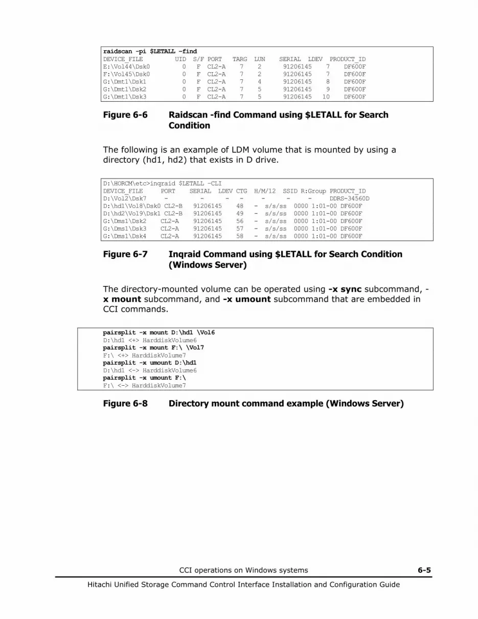
CCI operations on Windows systems 6-5
Hitachi Unified Storage Command Control Interface Installation and Configuration Guide
raidscan -pi $LETALL –find DEVICE_FILE UID S/F PORT TARG LUN SERIAL LDEV PRODUCT_ID E:\Vol44\Dsk0 0 F CL2-A 7 2 91206145 7 DF600F F:\Vol45\Dsk0 0 F CL2-A 7 2 91206145 7 DF600F G:\Dmt1\Dsk1 0 F CL2-A 7 4 91206145 8 DF600F G:\Dmt1\Dsk2 0 F CL2-A 7 5 91206145 9 DF600F G:\Dmt1\Dsk3 0 F CL2-A 7 5 91206145 10 DF600F
Figure 6-6 Raidscan -find Command using $LETALL for Search Condition
The following is an example of LDM volume that is mounted by using a directory (hd1, hd2) that exists in D drive.
D:\HORCM\etc>inqraid $LETALL –CLI DEVICE_FILE PORT SERIAL LDEV CTG H/M/12 SSID R:Group PRODUCT_ID D:\Vol2\Dsk7 - - - - - - - DDRS-34560D D:\hd1\Vol8\Dsk0 CL2-B 91206145 48 - s/s/ss 0000 1:01-00 DF600F D:\hd2\Vol9\Dsk1 CL2-B 91206145 49 - s/s/ss 0000 1:01-00 DF600F G:\Dms1\Dsk2 CL2-A 91206145 56 - s/s/ss 0000 1:01-00 DF600F G:\Dms1\Dsk3 CL2-A 91206145 57 - s/s/ss 0000 1:01-00 DF600F G:\Dms1\Dsk4 CL2-A 91206145 58 - s/s/ss 0000 1:01-00 DF600F
Figure 6-7 Inqraid Command using $LETALL for Search Condition (Windows Server)
The directory-mounted volume can be operated using -x sync subcommand, -x mount subcommand, and -x umount subcommand that are embedded in CCI commands.
pairsplit -x mount D:\hd1 \Vol6 D:\hd1 <+> HarddiskVolume6 pairsplit -x mount F:\ \Vol7 F:\ <+> HarddiskVolume7 pairsplit -x umount D:\hd1 D:\hd1 <-> HarddiskVolume6 pairsplit -x umount F:\ F:\ <-> HarddiskVolume7
Figure 6-8 Directory mount command example (Windows Server)

6-6 CCI operations on Windows systems
Hitachi Unified Storage Command Control Interface Installation and Configuration Guide
Using the mountvol command on Windows
The mountvol /D command attached on Windows Server does not flush the NT file system buffer to the corresponding specified drive. Therefore, you cannot flush an unwritten data to P-VOL nor browse S-VOL by using this command. Do not mount the volume by the mountvol command if the volume was un-mounted by the -x umount command. Do not use the mountvol command to un-mount the volume if the volume was mounted using the –x mount command.
The mountvol command displays the mounted volume in \\?\Volume{XXXX}\ format.
mountvol Creates, deletes, or lists a volume mount point. . . MOUNTVOL [drive:]path VolumeName MOUNTVOL [drive:]path /D MOUNTVOL [drive:]path /L \\?\Volume{56e4954a-28d5-4824-a408-3ff9a6521e5d}\ G:\ \\?\Volume{bf48a395-0ef6-11d5-8d69-00c00d003b1e}\ F:\
Figure 6-9 Mountvol command displaying mounted volumes
You can use the inqraid command or the raidscan command to see the relationship between the device object name and the physical drive of the \\?\Volume{XXXX}\.
inqraid $Volume{bf48a395-0ef6-11d5-8d69-00c00d003b1e} –CLI DEVICE_FILE PORT SERIAL LDEV CTG H/M/12 SSID R:Group PRODUCT_ID \Vol46\Dsk1 CL2-A 91206145 6 - S/s/ss 0000 1:01-00 DF600F
Figure 6-10 Inqraid command displaying mounted volumes
raidscan -pi $Volume{bf48a395-0ef6-11d5-8d69-00c00d003b1e} –find DEVICE_FILE UID S/F PORT TARG LUN SERIAL LDEV PRODUCT_ID \Vol46\Dsk1 0 F CL2-A 7 1 91206145 6 DF600F
Figure 6-11 Raidscan command displaying mounted volumes

CCI operations on Windows systems 6-7
Hitachi Unified Storage Command Control Interface Installation and Configuration Guide
About dynamic disk and copy
In an environment of Windows Server, you cannot use pair volumes as dynamic disk. The reason for this restriction is because in this case if you restart Windows or use the Rescan Disks command after creating or re-synchronizing a pair, there are cases where the S-VOL (V-VOL) is displayed as Foreign in Disk Management and becomes inaccessable.

6-8 CCI operations on Windows systems
Hitachi Unified Storage Command Control Interface Installation and Configuration Guide
Mounting P-VOL and S-VOL on the same host
When you recognize the P-VOL and S-VOLs on Windows Server 2008/Windows Server 2012 at the same time, an alert (Event ID: 58) may be notified in the event log. This issue comes from the same disk signature that the P-VOL and S-VOLs retain when pair creation, pair resynchronization or restore is performed. When this issue happens, the target volume may go offline and become inaccessible.
Windows reconfirms the disk signature during Rescan Disks or reboot. When you mount the P-VOL and S-VOLs to the same host at the same time, rewrite the disk signature according to the following procedure, so that they have different disk signatures
7
RM Shadow Copy provider for VSS 7-1
Hitachi Unified Storage Command Control Interface Installation and Configuration Guide
RM Shadow Copy provider for VSS
This chapter covers the following topics: About VSS Configuring VSS Restrictions on VSS configurations About backup software and configurations Installing backup software Uninstalling backup software Starting VSS Notes on VSS Known VSS problems and concerns About event log error messages

7-2 RM Shadow Copy provider for VSS
Hitachi Unified Storage Command Control Interface Installation and Configuration Guide
About VSS
Windows Server supported the VSS that provides an infrastructure for creating point-in-time images known as shadow copies. VSS is able to produce high fidelity shadow copies through its coordination with business applications, backup applications, and RAID.
VSS is a service that coordinates backup software (requestors), the writers (for example, Database application), and hardware providers that provides vendor-unique shadow copy functions.
A shadow copy volume is a copy of a volume that is used by an application at a specific time. An RM shadow copy provider is a component that creates a shadow copy volume with controlling RAID via VSS.
Install Windows Enterprise Server™ and use it under the following conditions.
Table 7-1 Relationship between RM Shadow Copy provider and Windows Enterprise Server versions
RM Shadow Copy Provider
Version
Windows Enterprise
Server 2003 (Build#3790)
Windows Enterprise Server 2003
(Build#3790) +HotFix#833167
+(831112)
Windows Enterprise Server
2003 SP1 +HotFix#891957
+(903081)
Windows Enterprise
Server 2008
Windows Enterprise
Server 2012
01-04-03/00 or later
Available Available Available Available Available
Enable the following services for the Volume Shadow Copy Service (VSS) hardware provider installation on Windows Enterprise Server 2003.
Table 7-2 Conditions for RM Shadow Copy provider installation
Service Name Display Name Startup Type
RpcSs Remote Procedure Call (RPC) Automatic
EventLog Event Log Automatic
DcomLaunch DCOM Server Process Launcher Automatic
SamSs Security Accounts Manager Automatic
winmgmt Windows Management Instrumentation Automatic
EventSystem COM+ Event System Manual
MSIServer Windows Installer Manual
VSS Volume Shadow Copy Manual
COMSysApp COM+ System Application Manual
MSDTC Distributed Transaction Coordinator Manual
RM Shadow Copy provider for VSS 7-3
Hitachi Unified Storage Command Control Interface Installation and Configuration Guide
Relation of RM Shadow Copy Provider and the disk array firmware
Table 7-3 shows relationship of the RM Shadow Copy Provider attached to CCI delivered with firmware of the disk array.
Table 7-3 Related version of RM Shadow Copy Provider attached to CCI versus firmware
RM Shadow Copy Provider Version
CCI Version HUS110 HUS130 HUS150
01-04-03/00 01-21-03/06 or later 0910/B or later 0910/B or later 0910/B or later
It is highly recommended to install RM Shadow Copy Provider before configuring Windows Server 2003 MSCS or Windows Server 2008/2012 MSFC. When a cluster has already been configured, follow the procedure below to install RM Shadow Copy Provider.
• For Windows Server 2003 MSCS, create and register MSDTC resources.
• Install RM Shadow Copy Provider.
Configuring VSS
CCI provides the RM shadow copy provider as a Hardware Provider for VSS. The RM shadow copy provider supports any disks that are defined in CCI configuration files. If any disks for a backup application are not defined in CCI configuration files, VSS will select the provider using the following default hierarchy:
Hardware provider (RM shadow copy provider) Software provider System software provider, and will create a snapshot volume by using the default System software provider.
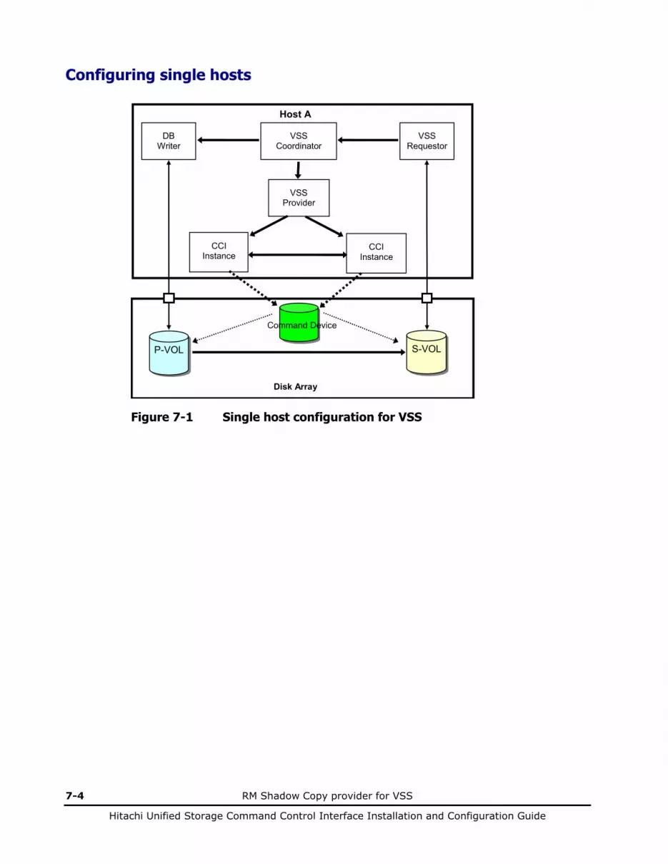
7-4 RM Shadow Copy provider for VSS
Hitachi Unified Storage Command Control Interface Installation and Configuration Guide
Configuring single hosts
Host A
CCI Instance
CCI Instance
DB Writer
VSS Requestor
Disk Array
VSS Coordinator
VSS Provider
S-VOL P-VOL
Command Device
Figure 7-1 Single host configuration for VSS
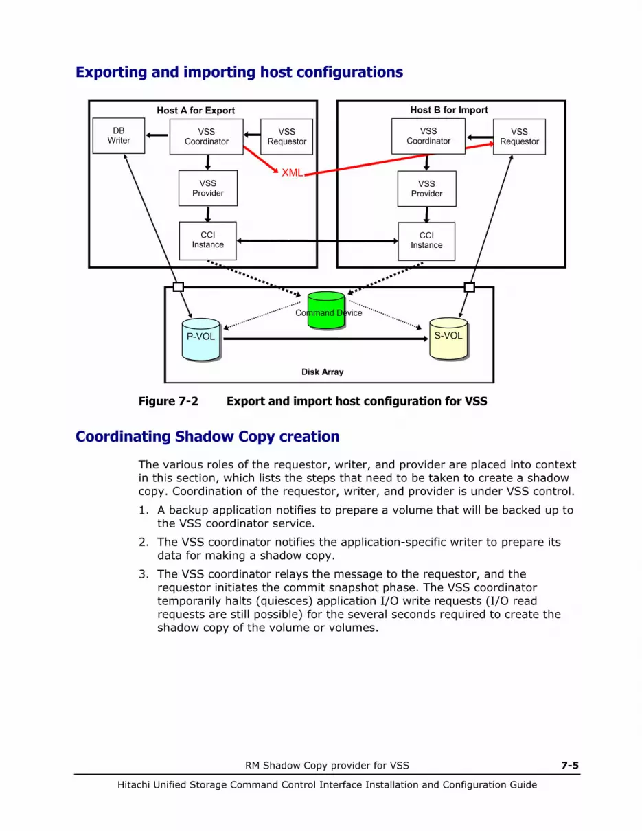
RM Shadow Copy provider for VSS 7-5
Hitachi Unified Storage Command Control Interface Installation and Configuration Guide
Exporting and importing host configurations
Host A for Export
DB Writer
Disk Array
S-VOL P-VOL
Command Device
VSS Requestor
VSS Provider
CCI Instance
VSS Requestor
VSS Provider
CCI Instance
Host B for Import
XML
VSS Coordinator
VSS Coordinator
Figure 7-2 Export and import host configuration for VSS
Coordinating Shadow Copy creation
The various roles of the requestor, writer, and provider are placed into context in this section, which lists the steps that need to be taken to create a shadow copy. Coordination of the requestor, writer, and provider is under VSS control.
1. A backup application notifies to prepare a volume that will be backed up to the VSS coordinator service.
2. The VSS coordinator notifies the application-specific writer to prepare its data for making a shadow copy.
3. The VSS coordinator relays the message to the requestor, and the requestor initiates the commit snapshot phase. The VSS coordinator temporarily halts (quiesces) application I/O write requests (I/O read requests are still possible) for the several seconds required to create the shadow copy of the volume or volumes.
7-6 RM Shadow Copy provider for VSS
Hitachi Unified Storage Command Control Interface Installation and Configuration Guide
4. The VSS coordinator chooses a provider that matches to the volume. If any
disks for a backup application are not defined in CCI configuration files, VSS selects the provider using the default hierarchy (Software provider System software provider).
5. The writer prepares the data appropriately for that application (ex: completing all open transactions, rolling transaction logs, and flushing caches). When the data is prepared for shadow copy creation, the writer notifies to the VSS coordinator.
6. RM Shadow Copy Provider splits a pair of a designated disk and a snapshot disk in order to creates the shadow copy (a maximum of 10 seconds).
7. After the shadow copy is created, the VSS coordinator releases the writer from its temporary quiescent phase. VSS queries the writers to confirm that write I/Os were successfully held during shadow copy creation. If the writes were not successfully held (the shadow copy data is potentially inconsistent), the shadow copy is deleted and the requestor is notified. The requestor can retry the process (loop back to 1) or notify the administrator to retry at a later time.
8. RM Shadow Copy Provider notifies the snapshot disks that match a designated disk to the VSS coordinator.
9. The VSS coordinator creates the XML document file describing the snapshot set in order to export the transportable snapshot volume.
10. The RM Shadow Copy Provider performs to map (Unmask) the designated disk by the VSS coordinator to the VOL.
11. The VSS coordinator discovers the new VOL, and notifies the snapshot volume mapped to an VOL to a backup application.
Note: In Export and Import configuration, Step 10 through 11 above will be performed on Import host, but a backup requestor should support this configuration.
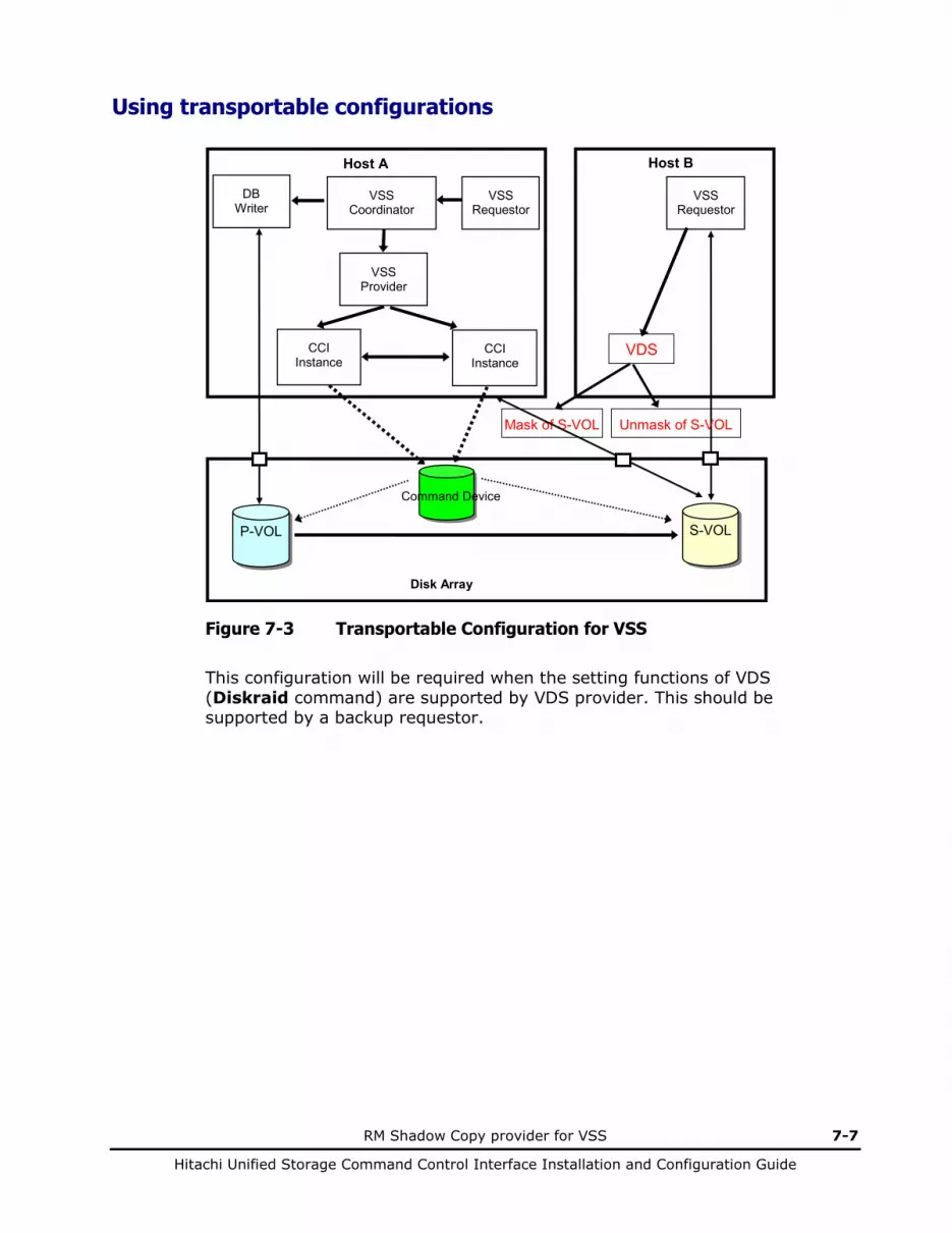
RM Shadow Copy provider for VSS 7-7
Hitachi Unified Storage Command Control Interface Installation and Configuration Guide
Using transportable configurations
Host A
DB Writer
Disk Array
S-VOL P-VOL
Command Device
VSS Requestor
VSS Provider
CCI Instance
VSS Requestor
CCI Instance
Host B
VDS
VSS Coordinator
Unmask of S-VOL Mask of S-VOL
Figure 7-3 Transportable Configuration for VSS
This configuration will be required when the setting functions of VDS (Diskraid command) are supported by VDS provider. This should be supported by a backup requestor.
7-8 RM Shadow Copy provider for VSS
Hitachi Unified Storage Command Control Interface Installation and Configuration Guide
Restrictions on VSS configurations
The VSS and RM shadow copy provider must be used under the following conditions:
• Property of the Shadow Copy Volume The Shadow Copy volume (S-VOL) must be created as property of the hidden and read-only when detected by Windows Server. The drive letters and/or mount points are not automatically assigned.
• Snapshots Containing Dynamic Disks The native support for dynamic disks cannot accommodate VOLs with duplicate signatures and configuration database contents. The snapshot VOLs must be transported to a different host; VSS enforces this. When transporting dynamic disk VOLs to a new host, at least one dynamic disk should exist on the receiving host. This ensures that the disk group identifiers will be unique to both machines.
• Hardware Snapshots not Supported on MSCS MSCS cannot accommodate VOLs with duplicate signatures and partition layout. The snapshot VOLs must be transported to a host outside the cluster.
• Using VSS under the I/O Path Manager
The I/O Path Manager must support the Shadow Copy volume as the PnP device, and must support all of DeviceIocontrol functions used on the Shadow Copy volume.
• Note that HDLM (JP1/HiCommand Dynamic Link Manager) supported the DeviceIocontrol functions that will be using by VSS. Therefore VSS can be used on the I/O Path Manager.
About backup software and configurations
Table 7-4 displays the related support between the backup software and applicable configurations.
The RM Shadow Copy Provider must be used within scope of the following supported backup software.
Table 7-4 Backup software with RM Shadow Copy provider
Software Vendor Software Name Applicable Configurations Single Host Export/Import Host Transportable
Microsoft NTBackup Supported Not supported Not supported
Veritas Backup Exec (BEWS) Supported BEWS10.0
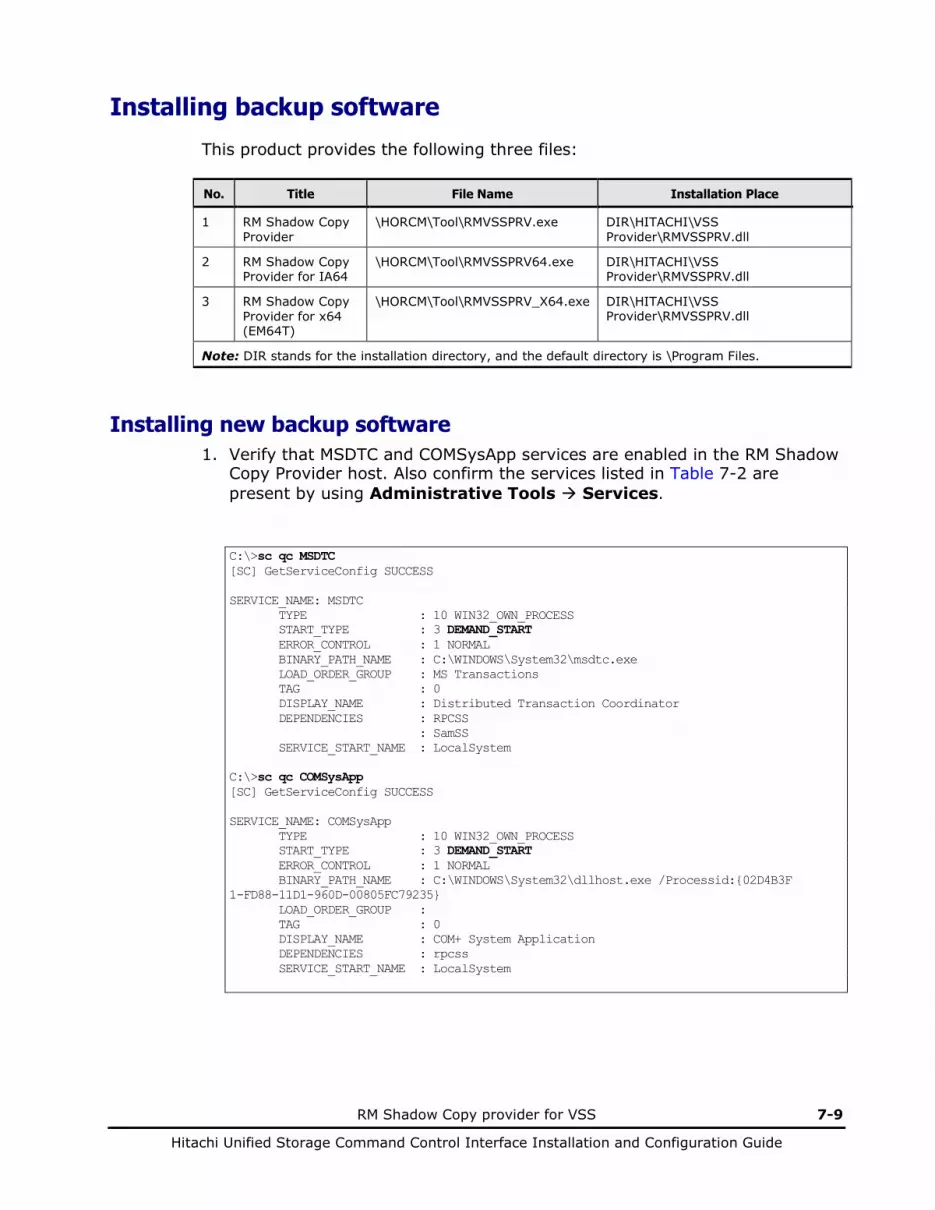
RM Shadow Copy provider for VSS 7-9
Hitachi Unified Storage Command Control Interface Installation and Configuration Guide
Installing backup software
This product provides the following three files: No. Title File Name Installation Place
1 RM Shadow Copy Provider
\HORCM\Tool\RMVSSPRV.exe DIR\HITACHI\VSS Provider\RMVSSPRV.dll
2 RM Shadow Copy Provider for IA64
\HORCM\Tool\RMVSSPRV64.exe DIR\HITACHI\VSS Provider\RMVSSPRV.dll
3 RM Shadow Copy Provider for x64 (EM64T)
\HORCM\Tool\RMVSSPRV_X64.exe DIR\HITACHI\VSS Provider\RMVSSPRV.dll
Note: DIR stands for the installation directory, and the default directory is \Program Files.
Installing new backup software 1. Verify that MSDTC and COMSysApp services are enabled in the RM Shadow
Copy Provider host. Also confirm the services listed in Table 7-2 are present by using Administrative Tools Services.
C:\>sc qc MSDTC [SC] GetServiceConfig SUCCESS SERVICE_NAME: MSDTC TYPE : 10 WIN32_OWN_PROCESS START_TYPE : 3 DEMAND_START ERROR_CONTROL : 1 NORMAL BINARY_PATH_NAME : C:\WINDOWS\System32\msdtc.exe LOAD_ORDER_GROUP : MS Transactions TAG : 0 DISPLAY_NAME : Distributed Transaction Coordinator DEPENDENCIES : RPCSS : SamSS SERVICE_START_NAME : LocalSystem C:\>sc qc COMSysApp [SC] GetServiceConfig SUCCESS SERVICE_NAME: COMSysApp TYPE : 10 WIN32_OWN_PROCESS START_TYPE : 3 DEMAND_START ERROR_CONTROL : 1 NORMAL BINARY_PATH_NAME : C:\WINDOWS\System32\dllhost.exe /Processid:{02D4B3F 1-FD88-11D1-960D-00805FC79235} LOAD_ORDER_GROUP : TAG : 0 DISPLAY_NAME : COM+ System Application DEPENDENCIES : rpcss SERVICE_START_NAME : LocalSystem

7-10 RM Shadow Copy provider for VSS
Hitachi Unified Storage Command Control Interface Installation and Configuration Guide
2. If the MSDTC and COMSysApp services have not started, set them to the automatic start or manual start using the Computer Management option, and install RM Shadow Copy Provider using the following procedure, after the services are started. C:\>sc config MSDTC start= demand [SC] ChangeServiceConfig SUCCESS C:\>sc config COMSysApp start= demand [SC] ChangeServiceConfig SUCCESS
3. Stop Microsoft Volume Shadow Copy Service by using the following command. For Windows Server 2003: C:\net STOP Volume Shadow Copy
For Windows Server 2008/Windows Server 2012 C:\net STOP VSS
If starting: The Volume Shadow Copy service is stopping. The Volume Shadow Copy service was stopped successfully.
If stopping: The Volume Shadow Copy service is not started.
4. Change the current directory to \HORCM\Tool\ where CCI has been installed.
5. Perform the appropriate RMVSSPRV.exe setup program: – For a 32-bit system, run the RMVSSPRV.exe. – For an IA64 system, run the RMVSSPRV64.exe.
6. Restarts Microsoft Volume Shadow Copy Service by using the following command if VSS will not be started. For Windows Server 2003: C:\net START Volume Shadow Copy The Volume Shadow Copy service is starting. The Volume Shadow Copy service was started successfully.
For Windows Server 2008/Windows Server 2012 C:\net START VSS The Volume Shadow Copy service is starting. The Volume Shadow Copy service was started successfully.

RM Shadow Copy provider for VSS 7-11
Hitachi Unified Storage Command Control Interface Installation and Configuration Guide
Upgrading backup software 1. Stop Microsoft Volume Shadow Copy Service by using the following
command. For Windows Server 2003: C:\net STOP Volume Shadow Copy
For Windows Server 2008/ Windows Server 2012 C:\net STOP VSS
If starting: The Volume Shadow Copy service is stopping. The Volume Shadow Copy service was stopped successfully.
If stopping: The Volume Shadow Copy service is not started.
2. Delete the installed RM Shadow Copy Provider using Addition and deletion of application on the control panel.
3. Change the current directory to \HORCM\Tool\ where CCI has been installed.
4. Perform the appropriate RMVSSPRV.exe setup program: – For a 32-bit system, run the RMVSSPRV.exe. – For an IA64 system, run the RMVSSPRV64.exe.
5. Restarts Microsoft Volume Shadow Copy Service by using the following command if VSS will not be started.
For Windows Server 2003: C:\net START Volume Shadow Copy The Volume Shadow Copy service is starting. The Volume Shadow Copy service was started successfully.
For Windows Server 2008/ Windows Server 2012 C:\net START VSS The Volume Shadow Copy service is starting. The Volume Shadow Copy service was started successfully.
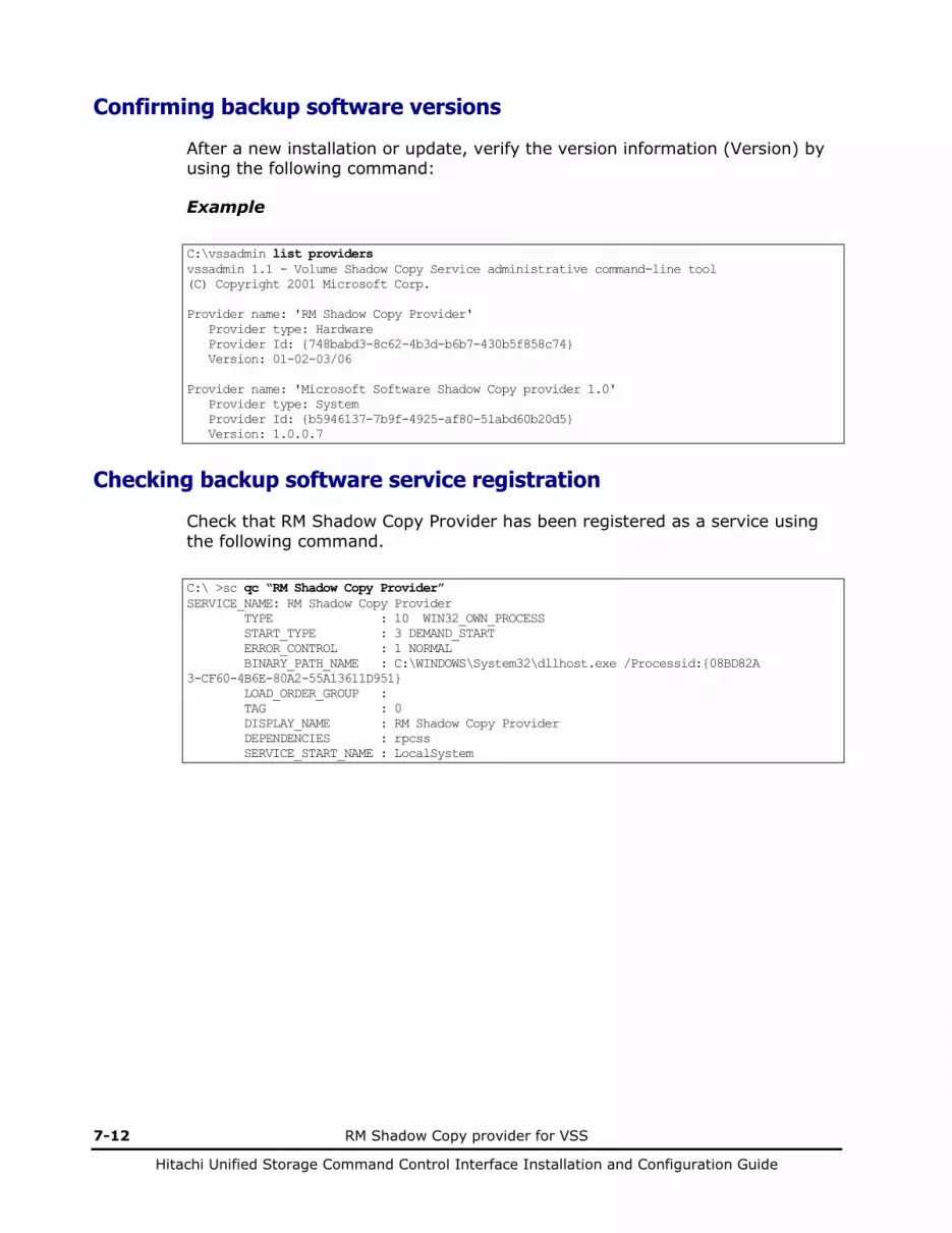
7-12 RM Shadow Copy provider for VSS
Hitachi Unified Storage Command Control Interface Installation and Configuration Guide
Confirming backup software versions
After a new installation or update, verify the version information (Version) by using the following command:
Example
C:\vssadmin list providers vssadmin 1.1 - Volume Shadow Copy Service administrative command-line tool (C) Copyright 2001 Microsoft Corp. Provider name: 'RM Shadow Copy Provider' Provider type: Hardware Provider Id: {748babd3-8c62-4b3d-b6b7-430b5f858c74} Version: 01-02-03/06 Provider name: 'Microsoft Software Shadow Copy provider 1.0' Provider type: System Provider Id: {b5946137-7b9f-4925-af80-51abd60b20d5} Version: 1.0.0.7
Checking backup software service registration
Check that RM Shadow Copy Provider has been registered as a service using the following command.
C:\ >sc qc “RM Shadow Copy Provider” SERVICE_NAME: RM Shadow Copy Provider TYPE : 10 WIN32_OWN_PROCESS START_TYPE : 3 DEMAND_START ERROR_CONTROL : 1 NORMAL BINARY_PATH_NAME : C:\WINDOWS\System32\dllhost.exe /Processid:{08BD82A 3-CF60-4B6E-80A2-55A13611D951} LOAD_ORDER_GROUP : TAG : 0 DISPLAY_NAME : RM Shadow Copy Provider DEPENDENCIES : rpcss SERVICE_START_NAME : LocalSystem

RM Shadow Copy provider for VSS 7-13
Hitachi Unified Storage Command Control Interface Installation and Configuration Guide
Uninstalling backup software 1. Stop Microsoft Volume Shadow Copy Service by using the following
command. For Windows Server 2003: C:\net STOP Volume Shadow Copy
For Windows Server 2008/ Windows Server 2012: C:\net STOP VSS
If starting: The Volume Shadow Copy service is stopping. The Volume Shadow Copy service was stopped successfully.
If stopping: The Volume Shadow Copy service is not started.
2. Delete the installed RM Shadow Copy Provider using Addition and deletion of application on the control panel.
3. Restart Microsoft Volume Shadow Copy Service with the following command if VSS will not be started.
For Windows Server 2003: C:\net START Volume Shadow Copy The Volume Shadow Copy service is starting. The Volume Shadow Copy service was started successfully.
For Windows Server 2008/ Windows Server 2012: C:\net START VSS The Volume Shadow Copy service is starting. The Volume Shadow Copy service was started successfully.
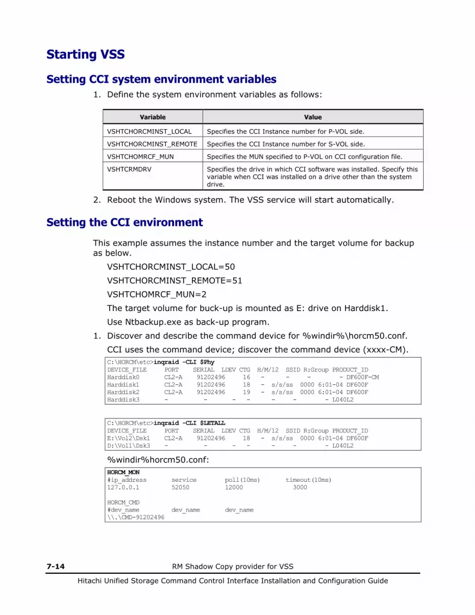
7-14 RM Shadow Copy provider for VSS
Hitachi Unified Storage Command Control Interface Installation and Configuration Guide
Starting VSS
Setting CCI system environment variables 1. Define the system environment variables as follows:
Variable Value
VSHTCHORCMINST_LOCAL Specifies the CCI Instance number for P-VOL side.
VSHTCHORCMINST_REMOTE Specifies the CCI Instance number for S-VOL side.
VSHTCHOMRCF_MUN Specifies the MUN specified to P-VOL on CCI configuration file.
VSHTCRMDRV Specifies the drive in which CCI software was installed. Specify this variable when CCI was installed on a drive other than the system drive.
2. Reboot the Windows system. The VSS service will start automatically.
Setting the CCI environment
This example assumes the instance number and the target volume for backup as below.
VSHTCHORCMINST_LOCAL=50 VSHTCHORCMINST_REMOTE=51 VSHTCHOMRCF_MUN=2 The target volume for buck-up is mounted as E: drive on Harddisk1. Use Ntbackup.exe as back-up program.
1. Discover and describe the command device for %windir%\horcm50.conf. CCI uses the command device; discover the command device (xxxx-CM). C:\HORCM\etc>inqraid -CLI $Phy DEVICE_FILE PORT SERIAL LDEV CTG H/M/12 SSID R:Group PRODUCT_ID Harddisk0 CL2-A 91202496 16 - - - - DF600F-CM Harddisk1 CL2-A 91202496 18 - s/s/ss 0000 6:01-04 DF600F Harddisk2 CL2-A 91202496 19 - s/s/ss 0000 6:01-04 DF600F Harddisk3 - - - - - - - L040L2
C:\HORCM\etc>inqraid -CLI $LETALL DEVICE_FILE PORT SERIAL LDEV CTG H/M/12 SSID R:Group PRODUCT_ID E:\Vol2\Dsk1 CL2-A 91202496 18 - s/s/ss 0000 6:01-04 DF600F D:\Vol1\Dsk3 - - - - - - - L040L2
%windir%horcm50.conf: HORCM_MON #ip_address service poll(10ms) timeout(10ms) 127.0.0.1 52050 12000 3000 HORCM_CMD #dev_name dev_name dev_name \\.\CMD-91202496
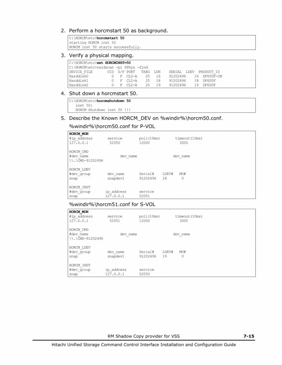
RM Shadow Copy provider for VSS 7-15
Hitachi Unified Storage Command Control Interface Installation and Configuration Guide
2. Perform a horcmstart 50 as background. C:\HORCM\etc>horcmstart 50 starting HORCM inst 50 HORCM inst 50 starts successfully.
3. Verify a physical mapping. C:\HORCM\etc>set HORCMINST=50 C:\HORCM\etc>raidscan -pi $Phys -find DEVICE_FILE UID S/F PORT TARG LUN SERIAL LDEV PRODUCT_ID Harddisk0 0 F CL2-A 25 16 91202496 16 DF600F-CM Harddisk1 0 F CL2-A 25 18 91202496 18 DF600F Harddisk2 0 F CL2-A 25 19 91202496 19 DF600F
4. Shut down a horcmstart 50. C:\HORCM\etc>horcmshutdown 50 inst 50: HORCM Shutdown inst 50 !!!
5. Describe the Known HORCM_DEV on %windir%\horcm50.conf. %windir%\horcm50.conf for P-VOL HORCM_MON #ip_address service poll(10ms) timeout(10ms) 127.0.0.1 52050 12000 3000 HORCM_CMD #dev_name dev_name dev_name \\.\CMD-91202496 HORCM_LDEV #dev_group dev_name Serial# LDEV# MU# snap snapdev1 91202496 18 0 HORCM_INST #dev_group ip_address service snap 127.0.0.1 52051
%windir%\horcm51.conf for S-VOL HORCM_MON #ip_address service poll(10ms) timeout(10ms) 127.0.0.1 52051 12000 3000 HORCM_CMD #dev_name dev_name dev_name \\.\CMD-91202496 HORCM_LDEV #dev_group dev_name Serial# LDEV# MU# snap snapdev1 91202496 19 0 HORCM_INST #dev_group ip_address service snap 127.0.0.1 52050
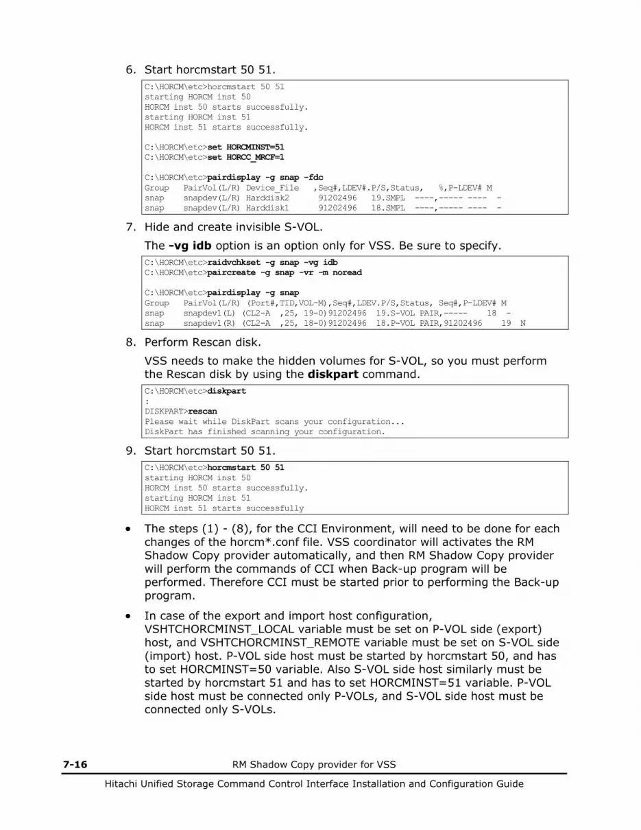
7-16 RM Shadow Copy provider for VSS
Hitachi Unified Storage Command Control Interface Installation and Configuration Guide
6. Start horcmstart 50 51. C:\HORCM\etc>horcmstart 50 51 starting HORCM inst 50 HORCM inst 50 starts successfully. starting HORCM inst 51 HORCM inst 51 starts successfully. C:\HORCM\etc>set HORCMINST=51 C:\HORCM\etc>set HORCC_MRCF=1 C:\HORCM\etc>pairdisplay -g snap -fdc Group PairVol(L/R) Device_File ,Seq#,LDEV#.P/S,Status, %,P-LDEV# M snap snapdev(L/R) Harddisk2 91202496 19.SMPL ----,----- ---- - snap snapdev(L/R) Harddisk1 91202496 18.SMPL ----,----- ---- -
7. Hide and create invisible S-VOL. The -vg idb option is an option only for VSS. Be sure to specify. C:\HORCM\etc>raidvchkset -g snap -vg idb C:\HORCM\etc>paircreate -g snap -vr -m noread C:\HORCM\etc>pairdisplay -g snap Group PairVol(L/R) (Port#,TID,VOL-M),Seq#,LDEV.P/S,Status, Seq#,P-LDEV# M snap snapdev1(L) (CL2-A ,25, 19-0)91202496 19.S-VOL PAIR,----- 18 - snap snapdev1(R) (CL2-A ,25, 18-0)91202496 18.P-VOL PAIR,91202496 19 N
8. Perform Rescan disk. VSS needs to make the hidden volumes for S-VOL, so you must perform the Rescan disk by using the diskpart command. C:\HORCM\etc>diskpart : DISKPART>rescan Please wait while DiskPart scans your configuration... DiskPart has finished scanning your configuration.
9. Start horcmstart 50 51. C:\HORCM\etc>horcmstart 50 51 starting HORCM inst 50 HORCM inst 50 starts successfully. starting HORCM inst 51 HORCM inst 51 starts successfully
• The steps (1) - (8), for the CCI Environment, will need to be done for each changes of the horcm*.conf file. VSS coordinator will activates the RM Shadow Copy provider automatically, and then RM Shadow Copy provider will perform the commands of CCI when Back-up program will be performed. Therefore CCI must be started prior to performing the Back-up program.
• In case of the export and import host configuration, VSHTCHORCMINST_LOCAL variable must be set on P-VOL side (export) host, and VSHTCHORCMINST_REMOTE variable must be set on S-VOL side (import) host. P-VOL side host must be started by horcmstart 50, and has to set HORCMINST=50 variable. Also S-VOL side host similarly must be started by horcmstart 51 and has to set HORCMINST=51 variable. P-VOL side host must be connected only P-VOLs, and S-VOL side host must be connected only S-VOLs.
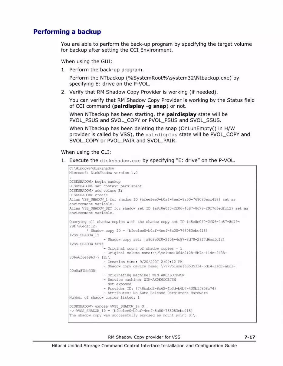
RM Shadow Copy provider for VSS 7-17
Hitachi Unified Storage Command Control Interface Installation and Configuration Guide
Performing a backup
You are able to perform the back-up program by specifying the target volume for backup after setting the CCI Environment.
When using the GUI: 1. Perform the back-up program.
Perform the NTbackup (%SystemRoot%\system32\Ntbackup.exe) by specifying E: drive on the P-VOL.
2. Verify that RM Shadow Copy Provider is working (if needed). You can verify that RM Shadow Copy Provider is working by the Status field of CCI command (pairdisplay -g snap) or not.
When NTbackup has been starting, the pairdisplay state will be PVOL_PSUS and SVOL_COPY or PVOL_PSUS and SVOL_SSUS. When NTbackup has been deleting the snap (OnLunEmpty() in H/W provider is called by VSS), the pairdisplay state will be PVOL_COPY and SVOL_COPY or PVOL_PAIR and SVOL_PAIR.
When using the CLI:
1. Execute the diskshadow.exe by specifying “E: drive” on the P-VOL. C:\Windows>diskshadow Microsoft DiskShadow version 1.0 : DISKSHADOW> begin backup DISKSHADOW> set context persistent DISKSHADOW> add volume E: DISKSHADOW> create Alias VSS_SHADOW_1 for shadow ID {bfeelee0-b0af-4eef-8a00-768083ebc418} set as environment variable. Alias VSS_SHADOW_SET for shadow set ID {a8c8e0f0-2f06-4c87-8d79-29f7d6edfc12} set as environment variable. Querying all shadow copies with the shadow copy set ID {a8c8e0f0-2f06-4c87-8d79-29f7d6edfc12} * Shadow copy ID = {bfeelee0-b0af-4eef-8a00-768083ebc418} %VSS_SHADOW_1% - Shadow copy set: {a8c8e0f0-2f06-4c87-8d79-29f7d6edfc12} %VSS_SHADOW_SET% - Original count of shadow copies = 1 - Original volume name:\\?\Volume{064c2128-5b7a-11dc-9438-806e6f6e6963}\ [E:\] - Creation time: 9/20/2007 2:09:12 PM - Shadow copy device name: \\?\Volume{63535314-5d14-11dc-abd1-00c0a87bb335} - Originating machine: WIN-AK0K6OCBJSW - Service machine: WIN-AK0K6OCBJSW - Not exposed - Provider ID: {748babd3-8c62-4b3d-b6b7-430b5f858c74} - Attributes: No_Auto_Release Persistent Hardware Number of shadow copies listed: 1 DISKSHADOW> expose %VSS_SHADOW_1% S: -> %VSS_SHADOW_1% = {bfeelee0-b0af-4eef-8a00-768083ebc418} The shadow copy was successfully exposed as mount point S:\.

7-18 RM Shadow Copy provider for VSS
Hitachi Unified Storage Command Control Interface Installation and Configuration Guide
2. Perform back-up operation on S: drive. DISKSHADOW> unexposed S: Shadow copy ID {bfeelee0-b0af-4eef-8a00-768083ebc418} is no longer exposed. DISKSHADOW> delete shadows ID %VSS_SHADOW_1% -> %VSS_SHADOW_1% = {bfeelee0-b0af-4eef-8a00-768083ebc418} Deleing shadow copy {bfeelee0-b0af-4eef-8a00-768083ebc418}... 1 shadow copy deleted. DISKSHADOW> end backup:
3. Verify that RM Shadow Copy Provider is working (if needed). You can verify that RM Shadow Copy Provider is working by the Status field of CCI command (pairdisplay -g snap) or not.
When NTbackup has been starting, the pairdisplay state will be PVOL_PSUS and SVOL_COPY or PVOL_PSUS and SVOL_SSUS. When NTbackup has been deleting the snap (OnLunEmpty() in H/W provider is called by VSS), the pairdisplay state will be PVOL_COPY and SVOL_COPY or PVOL_PAIR and SVOL_PAIR.

RM Shadow Copy provider for VSS 7-19
Hitachi Unified Storage Command Control Interface Installation and Configuration Guide
Notes on VSS • S-VOL (V-VOL) that is no longer used as a VSS
For a volume that is hidden by the raidvchkset -vg idb, deleting and formatting, etc. are restricted. For a volume that is no longer used as a dynamic disk, eliminate hiding by using the raidvchkset -vg command.
• Starting CCI
The CCI must be started with the privilege for administrator, when the user will start the CCI as a service. If the CCI is started with the System privilege, CCI commands via command prompt will be unable to attach to the CCI.
• Independent VDS
Note that RM Shadow Copy Provider and CCI does not use VDS interface. RM Shadow Copy Provider and CCI can support two host configurations for the OFF HOST Backup (one is export host, another is import host), but these configurations must be supported via the back-up requestor by transporting the XML file between export and import host.
• Do not use RM Shadow Copy Provider to perform a backup operation with disks from other vendors. Otherwise, RM Shadow Copy Provider checks the disks from the other vendor and leaves the warning [EV_ENOUSUP] in the log to indicate the disks are not supported.
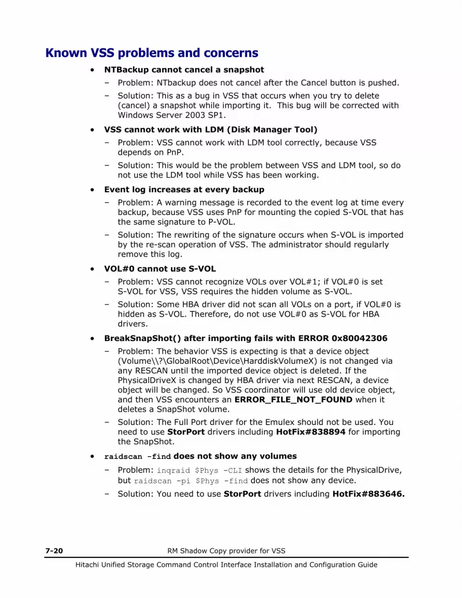
7-20 RM Shadow Copy provider for VSS
Hitachi Unified Storage Command Control Interface Installation and Configuration Guide
Known VSS problems and concerns • NTBackup cannot cancel a snapshot
– Problem: NTbackup does not cancel after the Cancel button is pushed. – Solution: This as a bug in VSS that occurs when you try to delete
(cancel) a snapshot while importing it. This bug will be corrected with Windows Server 2003 SP1.
• VSS cannot work with LDM (Disk Manager Tool) – Problem: VSS cannot work with LDM tool correctly, because VSS
depends on PnP. – Solution: This would be the problem between VSS and LDM tool, so do
not use the LDM tool while VSS has been working.
• Event log increases at every backup – Problem: A warning message is recorded to the event log at time every
backup, because VSS uses PnP for mounting the copied S-VOL that has the same signature to P-VOL.
– Solution: The rewriting of the signature occurs when S-VOL is imported by the re-scan operation of VSS. The administrator should regularly remove this log.
• VOL#0 cannot use S-VOL – Problem: VSS cannot recognize VOLs over VOL#1; if VOL#0 is set
S-VOL for VSS, VSS requires the hidden volume as S-VOL. – Solution: Some HBA driver did not scan all VOLs on a port, if VOL#0 is
hidden as S-VOL. Therefore, do not use VOL#0 as S-VOL for HBA drivers.
• BreakSnapShot() after importing fails with ERROR 0x80042306 – Problem: The behavior VSS is expecting is that a device object
(Volume\\?\GlobalRoot\Device\HarddiskVolumeX) is not changed via any RESCAN until the imported device object is deleted. If the PhysicalDriveX is changed by HBA driver via next RESCAN, a device object will be changed. So VSS coordinator will use old device object, and then VSS encounters an ERROR_FILE_NOT_FOUND when it deletes a SnapShot volume.
– Solution: The Full Port driver for the Emulex should not be used. You need to use StorPort drivers including HotFix#838894 for importing the SnapShot.
• raidscan -find does not show any volumes
– Problem: inqraid $Phys -CLI shows the details for the PhysicalDrive, but raidscan -pi $Phys -find does not show any device.
– Solution: You need to use StorPort drivers including HotFix#883646.
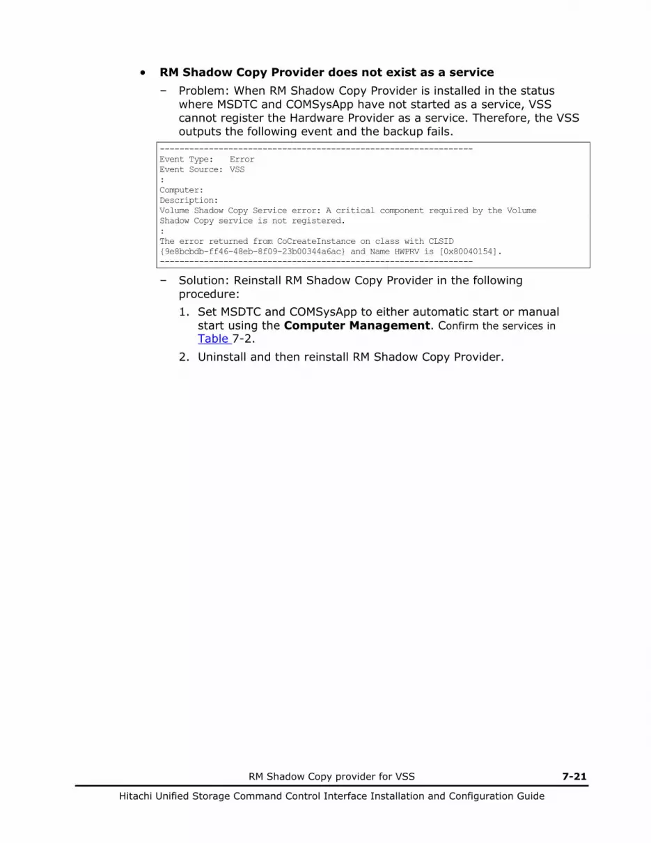
RM Shadow Copy provider for VSS 7-21
Hitachi Unified Storage Command Control Interface Installation and Configuration Guide
• RM Shadow Copy Provider does not exist as a service – Problem: When RM Shadow Copy Provider is installed in the status
where MSDTC and COMSysApp have not started as a service, VSS cannot register the Hardware Provider as a service. Therefore, the VSS outputs the following event and the backup fails.
---------------------------------------------------------------- Event Type: Error Event Source: VSS : Computer: Description: Volume Shadow Copy Service error: A critical component required by the Volume Shadow Copy service is not registered. : The error returned from CoCreateInstance on class with CLSID {9e8bcbdb-ff46-48eb-8f09-23b00344a6ac} and Name HWPRV is [0x80040154]. ----------------------------------------------------------------
– Solution: Reinstall RM Shadow Copy Provider in the following procedure: 1. Set MSDTC and COMSysApp to either automatic start or manual
start using the Computer Management. Confirm the services in Table 7-2.
2. Uninstall and then reinstall RM Shadow Copy Provider.
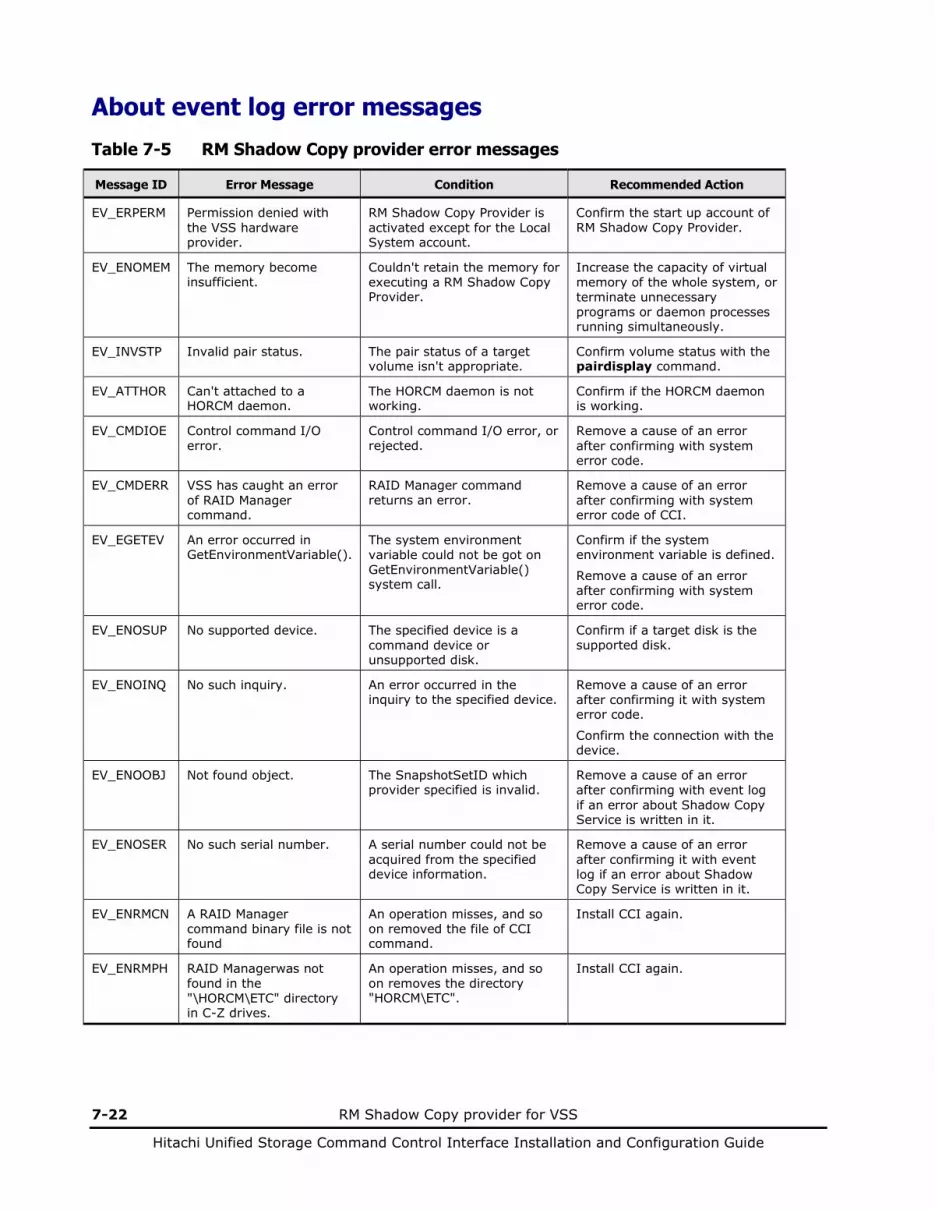
7-22 RM Shadow Copy provider for VSS
Hitachi Unified Storage Command Control Interface Installation and Configuration Guide
About event log error messages
Table 7-5 RM Shadow Copy provider error messages
Message ID Error Message Condition Recommended Action
EV_ERPERM Permission denied with the VSS hardware provider.
RM Shadow Copy Provider is activated except for the Local System account.
Confirm the start up account of RM Shadow Copy Provider.
EV_ENOMEM The memory become insufficient.
Couldn't retain the memory for executing a RM Shadow Copy Provider.
Increase the capacity of virtual memory of the whole system, or terminate unnecessary programs or daemon processes running simultaneously.
EV_INVSTP Invalid pair status. The pair status of a target volume isn't appropriate.
Confirm volume status with the pairdisplay command.
EV_ATTHOR Can't attached to a HORCM daemon.
The HORCM daemon is not working.
Confirm if the HORCM daemon is working.
EV_CMDIOE Control command I/O error.
Control command I/O error, or rejected.
Remove a cause of an error after confirming with system error code.
EV_CMDERR VSS has caught an error of RAID Manager command.
RAID Manager command returns an error.
Remove a cause of an error after confirming with system error code of CCI.
EV_EGETEV An error occurred in GetEnvironmentVariable().
The system environment variable could not be got on GetEnvironmentVariable() system call.
Confirm if the system environment variable is defined.
Remove a cause of an error after confirming with system error code.
EV_ENOSUP No supported device. The specified device is a command device or unsupported disk.
Confirm if a target disk is the supported disk.
EV_ENOINQ No such inquiry. An error occurred in the inquiry to the specified device.
Remove a cause of an error after confirming it with system error code.
Confirm the connection with the device.
EV_ENOOBJ Not found object. The SnapshotSetID which provider specified is invalid.
Remove a cause of an error after confirming with event log if an error about Shadow Copy Service is written in it.
EV_ENOSER No such serial number. A serial number could not be acquired from the specified device information.
Remove a cause of an error after confirming it with event log if an error about Shadow Copy Service is written in it.
EV_ENRMCN A RAID Manager command binary file is not found
An operation misses, and so on removed the file of CCI command.
Install CCI again.
EV_ENRMPH RAID Managerwas not found in the "\HORCM\ETC" directory in C-Z drives.
An operation misses, and so on removes the directory "HORCM\ETC".
Install CCI again.
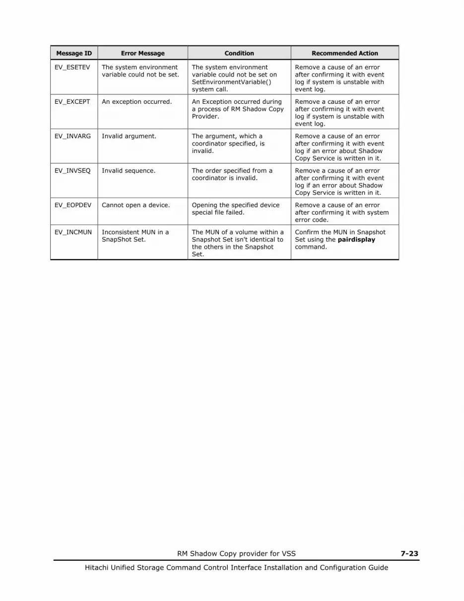
RM Shadow Copy provider for VSS 7-23
Hitachi Unified Storage Command Control Interface Installation and Configuration Guide
Message ID Error Message Condition Recommended Action
EV_ESETEV The system environment variable could not be set.
The system environment variable could not be set on SetEnvironmentVariable() system call.
Remove a cause of an error after confirming it with event log if system is unstable with event log.
EV_EXCEPT An exception occurred. An Exception occurred during a process of RM Shadow Copy Provider.
Remove a cause of an error after confirming it with event log if system is unstable with event log.
EV_INVARG Invalid argument. The argument, which a coordinator specified, is invalid.
Remove a cause of an error after confirming it with event log if an error about Shadow Copy Service is written in it.
EV_INVSEQ Invalid sequence. The order specified from a coordinator is invalid.
Remove a cause of an error after confirming it with event log if an error about Shadow Copy Service is written in it.
EV_EOPDEV Cannot open a device. Opening the specified device special file failed.
Remove a cause of an error after confirming it with system error code.
EV_INCMUN Inconsistent MUN in a SnapShot Set.
The MUN of a volume within a Snapshot Set isn't identical to the others in the Snapshot Set.
Confirm the MUN in Snapshot Set using the pairdisplay command.

7-24 RM Shadow Copy provider for VSS
Hitachi Unified Storage Command Control Interface Installation and Configuration Guide

8
RM Shadow Copy provider for VSS 8-1
Hitachi Unified Storage Command Control Interface Installation and Configuration Guide
VMware vCenter Site Recovery Manager
Overview of VMware vCenter Site Recovery Manager
Integration between SRM and Copy Functions Configurations Integrating SRM with Copy Functions SRM Operations Requirements Configuring environment Setting SRM Considerations Troubleshooting
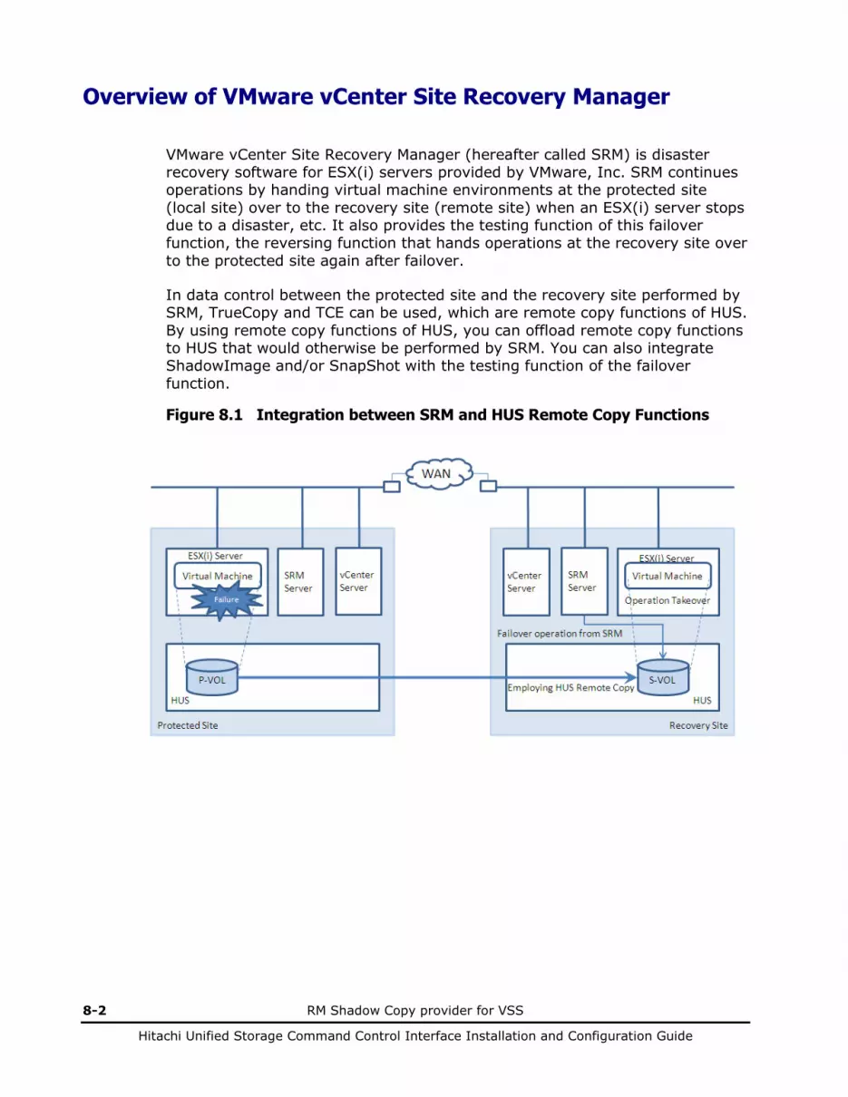
8-2 RM Shadow Copy provider for VSS
Hitachi Unified Storage Command Control Interface Installation and Configuration Guide
Overview of VMware vCenter Site Recovery Manager
VMware vCenter Site Recovery Manager (hereafter called SRM) is disaster recovery software for ESX(i) servers provided by VMware, Inc. SRM continues operations by handing virtual machine environments at the protected site (local site) over to the recovery site (remote site) when an ESX(i) server stops due to a disaster, etc. It also provides the testing function of this failover function, the reversing function that hands operations at the recovery site over to the protected site again after failover.
In data control between the protected site and the recovery site performed by SRM, TrueCopy and TCE can be used, which are remote copy functions of HUS. By using remote copy functions of HUS, you can offload remote copy functions to HUS that would otherwise be performed by SRM. You can also integrate ShadowImage and/or SnapShot with the testing function of the failover function.
Figure 8.1 Integration between SRM and HUS Remote Copy Functions
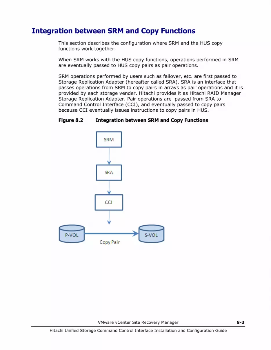
VMware vCenter Site Recovery Manager 8-3
Hitachi Unified Storage Command Control Interface Installation and Configuration Guide
Integration between SRM and Copy Functions
This section describes the configuration where SRM and the HUS copy functions work together.
When SRM works with the HUS copy functions, operations performed in SRM are eventually passed to HUS copy pairs as pair operations.
SRM operations performed by users such as failover, etc. are first passed to Storage Replication Adapter (hereafter called SRA). SRA is an interface that passes operations from SRM to copy pairs in arrays as pair operations and it is provided by each storage vender. Hitachi provides it as Hitachi RAID Manager Storage Replication Adapter. Pair operations are passed from SRA to Command Control Interface (CCI), and eventually passed to copy pairs because CCI eventually issues instructions to copy pairs in HUS.
Figure 8.2 Integration between SRM and Copy Functions

8-4 RM Shadow Copy provider for VSS
Hitachi Unified Storage Command Control Interface Installation and Configuration Guide
Configurations Integrating SRM with Copy Functions
This section describes examples of the configurations where SRM and the HUS copy functions work together.
To integrate SRM with the copy functions, the following servers are required for both the protected site and the recovery site in addition to HUS.
Table 8.1 Servers Required for SRM
No. Server In This Server, Required OS
1 ESX(i) server SRM-managed virtual machines run. VMware ESX(i)
2 vCenter server vCenter is installed. SRM operations are performed after logging in a vCenter server via a vCenter server or a vSphere Client.
Windows Server
3 SRM server (Note)
SRM and SRA are installed. Windows Server
4 CCl server (Note)
CCI is installed. Linux, HP-UX, AIX, Solaris, etc.
Note: If you install SRM and CCI together in a vCenter server, you do not necessarily need to prepare CCI and CCI server separately.
Here are five examples of the configurations where SRM, SRA, and CCI are installed in different servers.
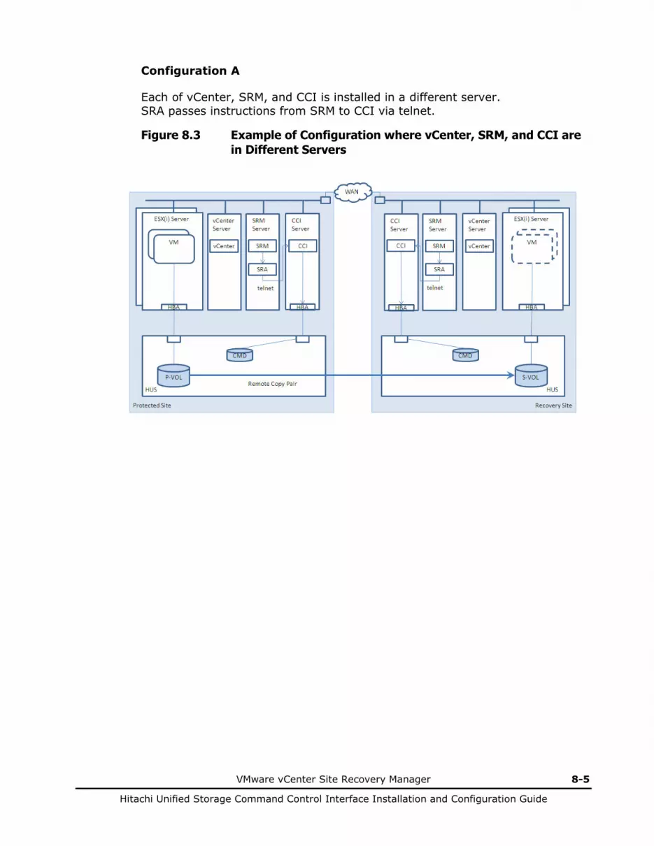
VMware vCenter Site Recovery Manager 8-5
Hitachi Unified Storage Command Control Interface Installation and Configuration Guide
Configuration A
Each of vCenter, SRM, and CCI is installed in a different server. SRA passes instructions from SRM to CCI via telnet.
Figure 8.3 Example of Configuration where vCenter, SRM, and CCI are in Different Servers
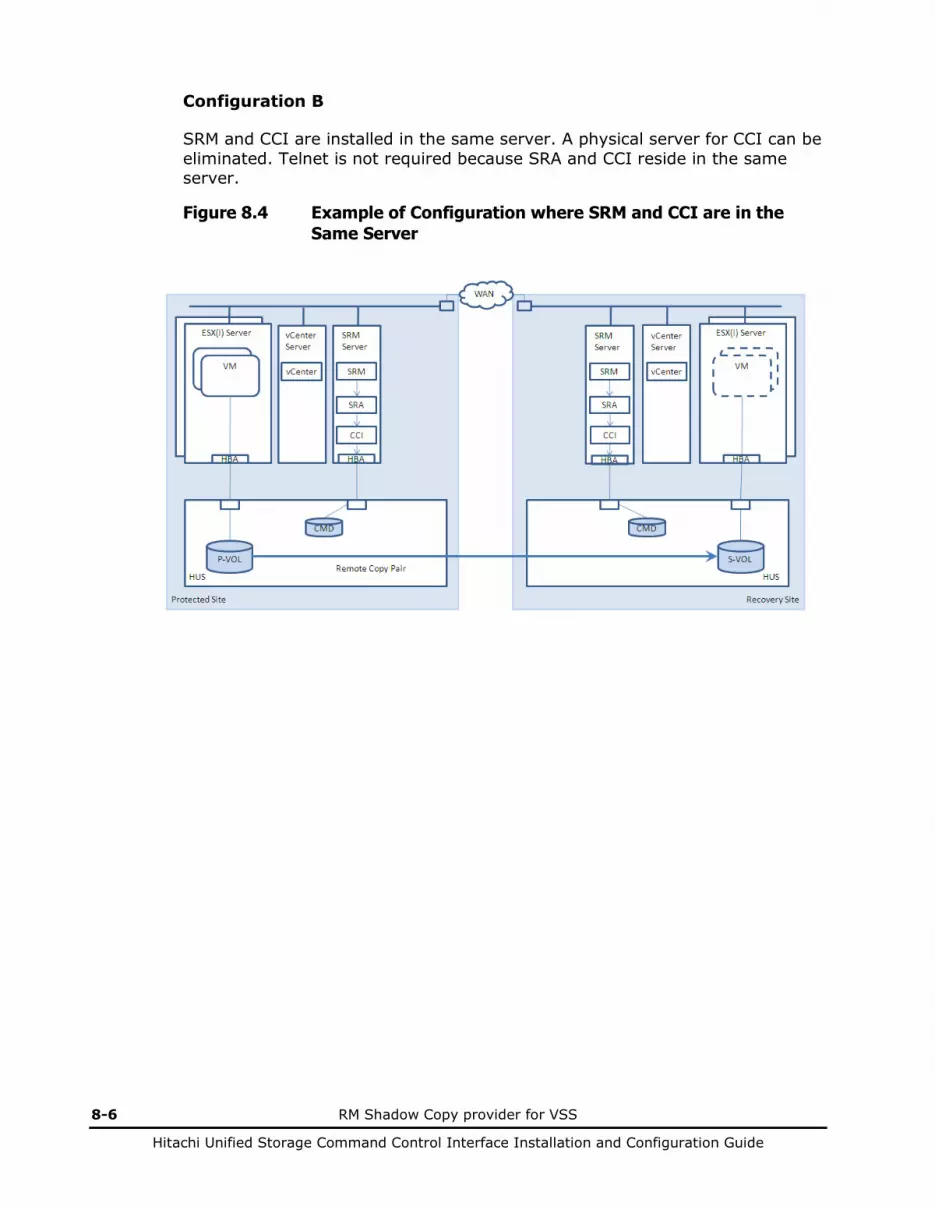
8-6 RM Shadow Copy provider for VSS
Hitachi Unified Storage Command Control Interface Installation and Configuration Guide
Configuration B
SRM and CCI are installed in the same server. A physical server for CCI can be eliminated. Telnet is not required because SRA and CCI reside in the same server.
Figure 8.4 Example of Configuration where SRM and CCI are in the Same Server
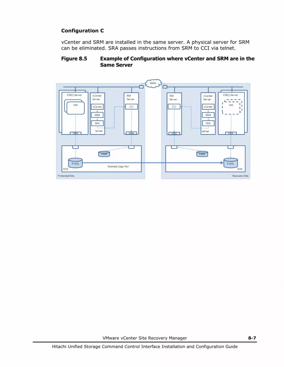
VMware vCenter Site Recovery Manager 8-7
Hitachi Unified Storage Command Control Interface Installation and Configuration Guide
Configuration C
vCenter and SRM are installed in the same server. A physical server for SRM can be eliminated. SRA passes instructions from SRM to CCI via telnet.
Figure 8.5 Example of Configuration where vCenter and SRM are in the Same Server
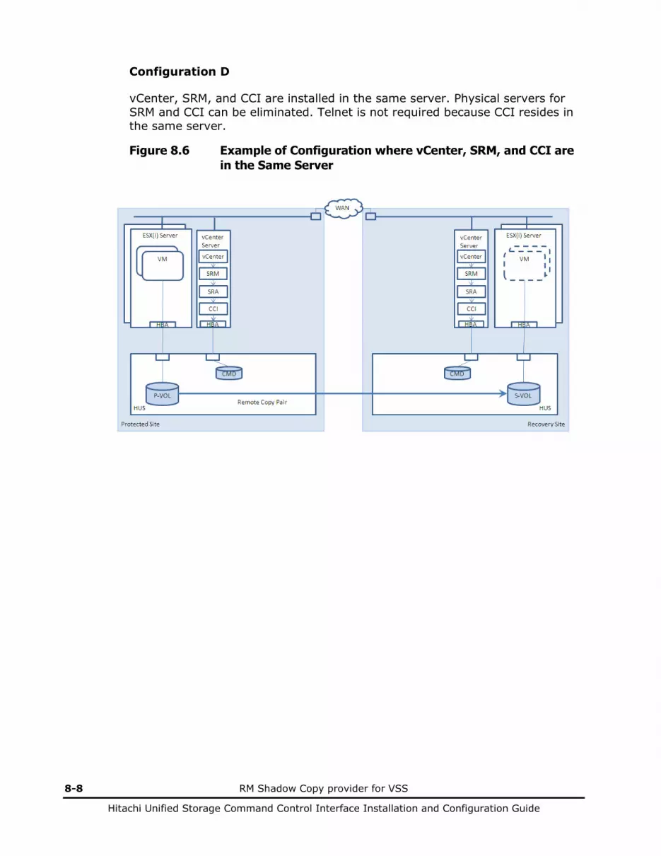
8-8 RM Shadow Copy provider for VSS
Hitachi Unified Storage Command Control Interface Installation and Configuration Guide
Configuration D
vCenter, SRM, and CCI are installed in the same server. Physical servers for SRM and CCI can be eliminated. Telnet is not required because CCI resides in the same server.
Figure 8.6 Example of Configuration where vCenter, SRM, and CCI are in the Same Server
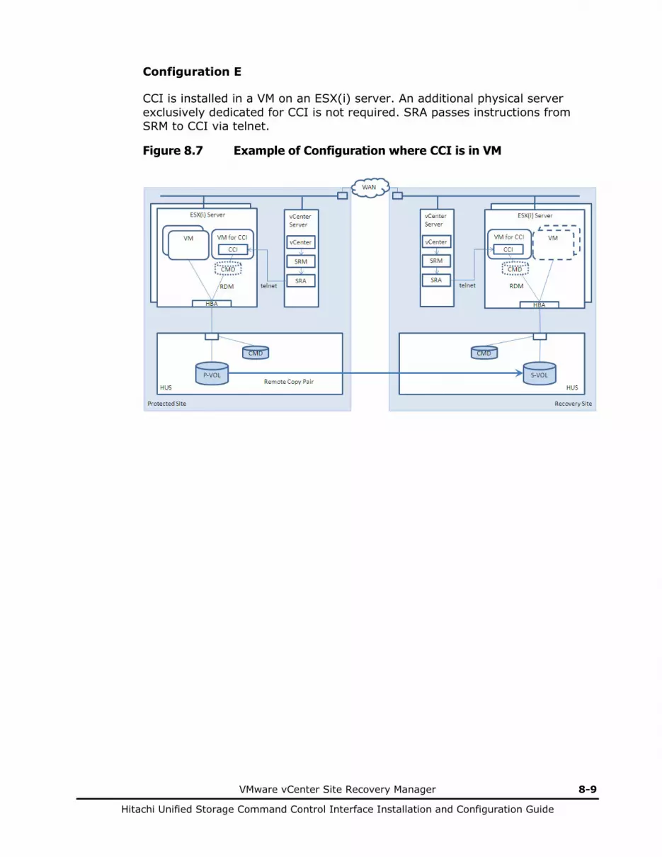
VMware vCenter Site Recovery Manager 8-9
Hitachi Unified Storage Command Control Interface Installation and Configuration Guide
Configuration E
CCI is installed in a VM on an ESX(i) server. An additional physical server exclusively dedicated for CCI is not required. SRA passes instructions from SRM to CCI via telnet.
Figure 8.7 Example of Configuration where CCI is in VM

8-10 RM Shadow Copy provider for VSS
Hitachi Unified Storage Command Control Interface Installation and Configuration Guide
SRM Operations
This section describes an overview of operations that can be performed in SRM such as failover, etc. and how HUS copy functions work according to the operations. In SRM, you can perform the following five operations.
Table 8.2 SRM Operations
No. Operation Description
1 Test ("test failover" in this guide)
Checks if failover function operates normally in an environment. Target can be remote copy or local copy.
2 Cleanup Recovers the environment before test failover after performing it.
3 Recovery Performs failover from protected site to recovery site. Planned Migration and Disaster Recovery are available.
4 Reprotect Protects the operating recovery site after recovery. After reprotecting, recovery can be performed at the recovery site.
5 Cancel Cancels an operation being performed.
The following table shows copy functions and available SRM operations for each copy function.
Test failover to a local copy can be performed only if S-VOL of a remote copy and P-VOL of a local copy are in the cascade configuration. SRM operations other than test failover can be performed in any configuration.

VMware vCenter Site Recovery Manager 8-11
Hitachi Unified Storage Command Control Interface Installation and Configuration Guide
Table 8.3 SRM Operations Supported by Copy Functions
SRM Operation Supported Copy Function
TrueCopy only
TrueCopy(S) + ShadowImage(P)
TrueCopy(S) + SnapShot(P)
TCE only TCE(S) + SnapShot(P)
Test failover and cleanup to remote copy
Available Available Available Available Available
Test failover and cleanup to local copy
Not available Available Available Not available Available
Recovery Available Available Available Available Available
Reprotect Available Available Available Available Available
Cancel Available Available Available Available Available
TrueCopy(S)+ShadowImage(P): TrueCopy S-VOL and ShadowImage P-VOL share a volume in the cascade configuration TrueCopy(S)+SnapShot(P): TrueCopy S-VOL and SnapShot P-VOL share a volume in the cascade configuration TCE(S)+SnapShot(P): TCE S-VOL and SnapShot P-VOL share a volume in the cascade configuration

8-12 RM Shadow Copy provider for VSS
Hitachi Unified Storage Command Control Interface Installation and Configuration Guide
Details of Each Operation
Test (test failover)
This operation checks if the failover function operates normally in an environment.
Test failover starts up virtual machines at the recovery site without shutting down virtual machines at the protected site. This action enables confirmation of failover function feasibility in an environment that you build without affecting virtual machines in a production environment. At this time, pair split is performed to the copy pair in the array and the statuses of P-VOL and S-VOL become PSUS and SSUS respectively.
Test failover can be performed to both remote copy pairs and local copy pairs. However, if a local copy pair becomes the target, a remote copy pair and a local copy pair at the recovery site need to be configured in cascade. In this case, you can switch the target of test failover between remote copy pair and local copy pair by changing the SplitReplication environment variable. For details, see Setting environment variables on page 8-32.
When the target is a remote copy pair
Pair split is performed to a remote copy pair and a virtual machine starts up in S-VOL of the remote copy pair.
Figure 8.8 Test Failover Operation (with Remote Copy)

VMware vCenter Site Recovery Manager 8-13
Hitachi Unified Storage Command Control Interface Installation and Configuration Guide
1. Perform test (test failover) from SRM to a remote copy pair. 2. SRM instructs SRA to start test failover. 3. SRA instructs CCI to start test failover. 4. CCI instructs a remote copy pair to be split. 5. A virtual machine (VM) starts up in S-VOL of the remote copy pair.
When the target is a local copy pair Pair split is performed to a local copy pair and a virtual machine starts up in S-VOL of the local copy pair.
Figure 8.9 Test Failover Operation (with Local Copy)
1. Perform test (test failover) from SRM to a local copy pair. 2. SRM instructs SRA to start test failover. 3. SRA instructs CCI to start test failover. 4. CCI instructs a local copy pair to be split. 5. A virtual machine starts up in S-VOL of the local copy pair.

8-14 RM Shadow Copy provider for VSS
Hitachi Unified Storage Command Control Interface Installation and Configuration Guide
Cleanup This operation recovers the environment before test failover after it is performed. It shuts down the virtual machine for testing that started up at the recovery site after test failover. After that, pair resync is performed to a remote copy pair or a local copy pair that was performed test failover to synchronize data again in P-VOL and S-VOL of the copy pair. The pair status becomes PAIR.
When remote copy is used
This operation shuts down the virtual machine that started up at the recovery site after test failover and performs pair resync to a remote copy pair.
Figure 8.10 Cleanup Operation (with Remote Copy)
1. SRM performs cleanup to a remote copy pair.
2. The virtual machine for testing that is running at the recovery site is shut down.
3. SRM instructs SRA to terminate test failover.
4. SRA instructs CCI to terminate test failover.
5. CCI instructs a remote copy pair to be to be resynced.

VMware vCenter Site Recovery Manager 8-15
Hitachi Unified Storage Command Control Interface Installation and Configuration Guide
When a local copy is used
A virtual machine that started up after test failover is shut down and pair resync is performed to a local copy pair.
Figure 8.11 Cleanup Operation (with Local Copy)
1. SRM performs cleanup to a local copy pair.
2. A virtual machine for testing that is running at the recovery site is shut down.
3. SRM instructs SRA to terminate test failover.
4. SRA instructs CCI to terminate test failover.
5. CCI instructs a local copy pair to be resynced.
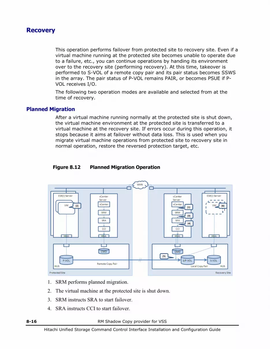
8-16 RM Shadow Copy provider for VSS
Hitachi Unified Storage Command Control Interface Installation and Configuration Guide
Recovery
This operation performs failover from protected site to recovery site. Even if a virtual machine running at the protected site becomes unable to operate due to a failure, etc., you can continue operations by handing its environment over to the recovery site (performing recovery). At this time, takeover is performed to S-VOL of a remote copy pair and its pair status becomes SSWS in the array. The pair status of P-VOL remains PAIR, or becomes PSUE if P-VOL receives I/O.
The following two operation modes are available and selected from at the time of recovery.
Planned Migration After a virtual machine running normally at the protected site is shut down, the virtual machine environment at the protected site is transferred to a virtual machine at the recovery site. If errors occur during this operation, it stops because it aims at failover without data loss. This is used when you migrate virtual machine operations from protected site to recovery site in normal operation, restore the reversed protection target, etc.
Figure 8.12 Planned Migration Operation
1. SRM performs planned migration.
2. The virtual machine at the protected site is shut down.
3. SRM instructs SRA to start failover.
4. SRA instructs CCI to start failover.
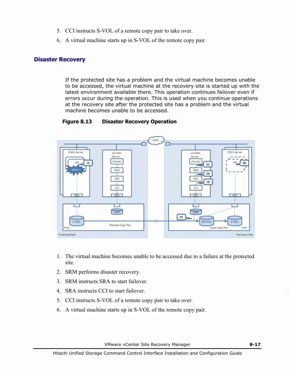
VMware vCenter Site Recovery Manager 8-17
Hitachi Unified Storage Command Control Interface Installation and Configuration Guide
5. CCI instructs S-VOL of a remote copy pair to take over.
6. A virtual machine starts up in S-VOL of the remote copy pair.
Disaster Recovery
If the protected site has a problem and the virtual machine becomes unable to be accessed, the virtual machine at the recovery site is started up with the latest environment available there. This operation continues failover even if errors occur during the operation. This is used when you continue operations at the recovery site after the protected site has a problem and the virtual machine becomes unable to be accessed.
Figure 8.13 Disaster Recovery Operation
1. The virtual machine becomes unable to be accessed due to a failure at the protected site.
2. SRM performs disaster recovery.
3. SRM instructs SRA to start failover.
4. SRA instructs CCI to start failover.
5. CCI instructs S-VOL of a remote copy pair to take over.
6. A virtual machine starts up in S-VOL of the remote copy pair.
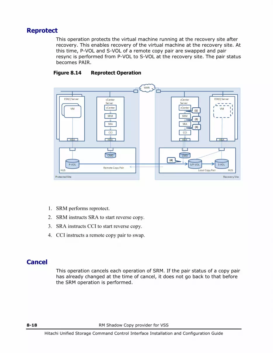
8-18 RM Shadow Copy provider for VSS
Hitachi Unified Storage Command Control Interface Installation and Configuration Guide
Reprotect This operation protects the virtual machine running at the recovery site after recovery. This enables recovery of the virtual machine at the recovery site. At this time, P-VOL and S-VOL of a remote copy pair are swapped and pair resync is performed from P-VOL to S-VOL at the recovery site. The pair status becomes PAIR.
Figure 8.14 Reprotect Operation
1. SRM performs reprotect.
2. SRM instructs SRA to start reverse copy.
3. SRA instructs CCI to start reverse copy.
4. CCI instructs a remote copy pair to swap.
Cancel This operation cancels each operation of SRM. If the pair status of a copy pair has already changed at the time of cancel, it does not go back to that before the SRM operation is performed.
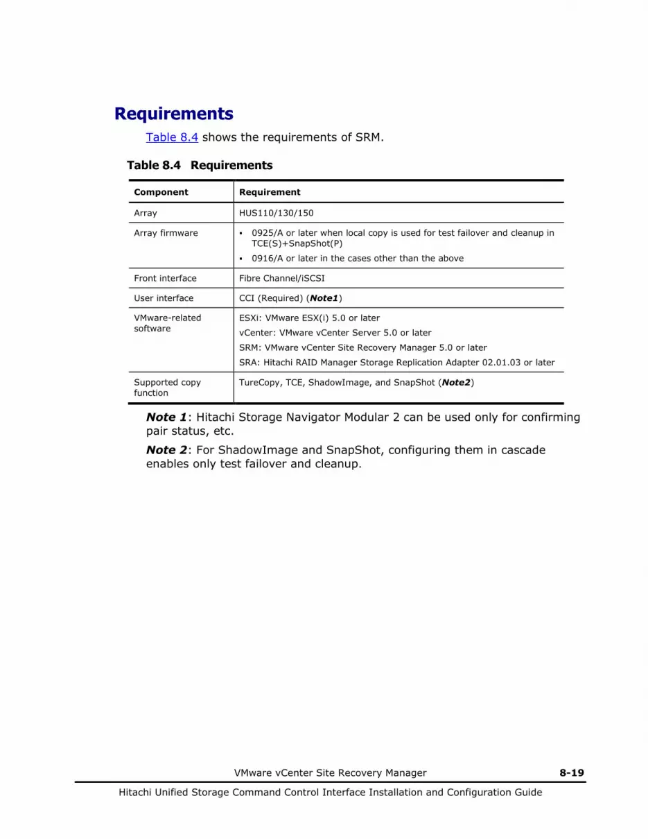
VMware vCenter Site Recovery Manager 8-19
Hitachi Unified Storage Command Control Interface Installation and Configuration Guide
Requirements Table 8.4 shows the requirements of SRM.
Table 8.4 Requirements
Component Requirement
Array HUS110/130/150
Array firmware 0925/A or later when local copy is used for test failover and cleanup in TCE(S)+SnapShot(P)
0916/A or later in the cases other than the above
Front interface Fibre Channel/iSCSI
User interface CCI (Required) (Note1)
VMware-related software
ESXi: VMware ESX(i) 5.0 or later
vCenter: VMware vCenter Server 5.0 or later
SRM: VMware vCenter Site Recovery Manager 5.0 or later
SRA: Hitachi RAID Manager Storage Replication Adapter 02.01.03 or later
Supported copy function
TureCopy, TCE, ShadowImage, and SnapShot (Note2)
Note 1: Hitachi Storage Navigator Modular 2 can be used only for confirming pair status, etc.
Note 2: For ShadowImage and SnapShot, configuring them in cascade enables only test failover and cleanup.

8-20 RM Shadow Copy provider for VSS
Hitachi Unified Storage Command Control Interface Installation and Configuration Guide
Configuring environment
This section describes how to configure an environment where SRM can be used. The following tasks are needed to configure an SRM environment.
Table 8.5 Requirements Tasks
No. Task Description
1 Set array Create a volume to be copy pair and map it to ESX(i) server
2 Build ESX(i) server Install ESX(i) in Windows Server
3 Build vCenter server Install vCenter in Windows Server
4 Build SRM server (Note)
Install SRM and SRA in Windows Server
5 Build CCI server (Note)
Install SRM in Linux server. Set configuration definition file and environment variables.
Note: If you install SRM and CCI together in a vCenter server, you do not necessarily need to prepare CCI and CCI server separately.
Setting array
Perform the following in the array.
Create a volume for copy pair and map it to the ESX(i) server
Create a volume for copy pair and map it to the ESX(i) server
Create a volume for a placeholder datastore and map it to the ESX(i) server
Create a command device and map it to the vCenter server (or CCI server
Building ESX(i) server
SRM-managed virtual machines run on an ESX(i) server.
Install ESX(i) in a physical server. For installing ESX(i), see the documents provided by VMware, Inc.
VMware vCenter Site Recovery Manager 8-21
Hitachi Unified Storage Command Control Interface Installation and Configuration Guide
Building v server
SRM-managed virtual machines run on an ESX(i) server.
Install ESX(i) in a physical server. For installing ESX(i), see the documents provided by VMware, Inc.

8-22 RM Shadow Copy provider for VSS
Hitachi Unified Storage Command Control Interface Installation and Configuration Guide
Building vCenter server
In a vCenter server, you manage ESX(i) servers and virtual machines, and perform SRM operations. Install vCenter in Windows Server. For installing vCenter, see the documents provided by VMware, Inc.
• Create a virtual machine to be managed by SRM.
• Create a datastore on a volume in the array mapped to an ESX(i) server.
• Create a virtual machine on the datastore created.
• Create a datastore also on a volume created for a placeholder datastore.
For details, see the documents provided by VMware, Inc
Building SRM Server
An SRM server passes SRM operations from vCenter server to SRA. Install SRM and SRA in Windows Server. For installing SRM, see the documents provided by VMware, Inc. If you do not prepare an SRM server separately, install SRM and SRA in the vCenter server.
Installing SRA
To install SRA, perform the following steps.
Install it at both the protected site and the recovery site. Download an installer of SRA at a Web page of VMware.
Verify that the following SRM-related services are running. If not, start them.
Table 8.6 SRM-related Services
No. Service Display Name Startup Type
1 vpxd VMware VirtualCenter Server Automatic
2 vmware-dr VMware vCenter Site Recovery Manager Server
Automatic
3 EventLog Windows Event Log Automatic

VMware vCenter Site Recovery Manager 8-23
Hitachi Unified Storage Command Control Interface Installation and Configuration Guide
1. Click RMHTCSRA-xx.xx.x.exe.
2. Read License Agreement, and click I accept the terms of the license agreement.
3. Either accept or change the default installation path. The default location is C:\Program Files\VMware\VMware vCenter Site Recover Manger. Click Next.
4. Click Install and proceed through the wizard.
5. Click Finish.
SRA installation is now complete.
8-24 RM Shadow Copy provider for VSS
Hitachi Unified Storage Command Control Interface Installation and Configuration Guide
Updating SRA
To update SRA, perform the following steps. It needs to be performed at both the protected site and the recovery site.
1. Delete Hitachi Storage Replication Adapter by using Add or Remove Programs in Control Panel.
2. Install SRA according Installing SRA on page 8-22.
3. Start the SRM-related services according to Table 8.6.
Unistalling SRA
To uninstall SRA, perform the following steps.
1. Delete Hitachi Storage Replication Adapter by using Add or Remove Programs in Control Panel.
2. Start the SRM-related services according to Table 6.6.
Building CCI Server
A CCI server instructs pair operations to copy pairs in an array according to the instructions issued by SRA in an SRM server.
Install CCI in Linux, HP-UX, AIX, or Solaris. Transfer the rmsra20 command to a CCI server. The rmsra20 command passes instructions from SRA in SRM server to CCI server via telnet.
If you do not prepare a CCI server separately, install CCI in a vCenter server or an SRM server.
Installing CCI
Install CCI according to CCI system requirements on page 1-2.
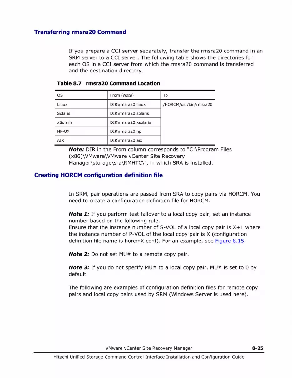
VMware vCenter Site Recovery Manager 8-25
Hitachi Unified Storage Command Control Interface Installation and Configuration Guide
Transferring rmsra20 Command
If you prepare a CCI server separately, transfer the rmsra20 command in an SRM server to a CCI server. The following table shows the directories for each OS in a CCI server from which the rmsra20 command is transferred and the destination directory.
Table 8.7 rmsra20 Command Location
OS From (Note) To
Linux DIR\rmsra20.linux /HORCM/usr/bin/rmsra20
Solaris DIR\rmsra20.solaris
xSolaris DIR\rmsra20.xsolaris
HP-UX DIR\rmsra20.hp
AIX DIR\rmsra20.aix
Note: DIR in the From column corresponds to "C:\Program Files (x86)\VMware\VMware vCenter Site Recovery Manager\storage\sra\RMHTC\", in which SRA is installed.
Creating HORCM configuration definition file
In SRM, pair operations are passed from SRA to copy pairs via HORCM. You need to create a configuration definition file for HORCM. Note 1: If you perform test failover to a local copy pair, set an instance number based on the following rule. Ensure that the instance number of S-VOL of a local copy pair is X+1 where the instance number of P-VOL of the local copy pair is X (configuration definition file name is horcmX.conf). For an example, see Figure 8.15. Note 2: Do not set MU# to a remote copy pair. Note 3: If you do not specify MU# to a local copy pair, MU# is set to 0 by default. The following are examples of configuration definition files for remote copy pairs and local copy pairs used by SRM (Windows Server is used here).
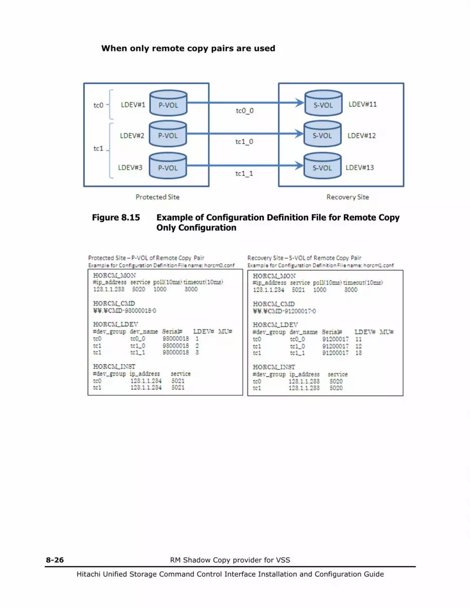
8-26 RM Shadow Copy provider for VSS
Hitachi Unified Storage Command Control Interface Installation and Configuration Guide
When only remote copy pairs are used
Figure 8.15 Example of Configuration Definition File for Remote Copy Only Configuration

VMware vCenter Site Recovery Manager 8-27
Hitachi Unified Storage Command Control Interface Installation and Configuration Guide
When remote copy pairs and local copy pairs are in the cascade configuration at the recovery site

8-28 RM Shadow Copy provider for VSS
Hitachi Unified Storage Command Control Interface Installation and Configuration Guide
Figure 8.16 Example of Configuration Definition File for Remote Copy Pair and Local Copy Pair Cascade Configuration

VMware vCenter Site Recovery Manager 8-29
Hitachi Unified Storage Command Control Interface Installation and Configuration Guide
When copy pairs for other purposes than the SRM are used with a single instance
You can put copy pairs for both SRM operations and other types of operations in a single configuration definition file. For example, if you have a local copy pair with multiple S-VOLs and use some of them for other purposes than test failover such as for local backup purposes, you can put all the S-VOLs in a single configuration definition file. For this, you have to set the MU# of the S-VOL used for test failover to the environment variable “RMSRATMU”.
P-VOL
tc0_0 LDEV#1 tc0
Protected Site Recovery Site
LDEV#21 si0_0 si0
tc1_0 LDEV#2 LDEV#12 tc1
LDEV#22 si1_0 si1
P-VOL
S/P-VOL
S/P-VOL
S-VOL
S-VOL
LDEV#11
tc0_0: Remote copy pair for SRM
tc1_0: Remote copy pair for other purposes than SRM
si0_0: Local copy pair for SRM (test failover)
si1_0: Local copy pair for other purposes than SRM
Figure 8.17 Example of Configuration Definition File Including Copy Pairs used for Other Purposes than SRM
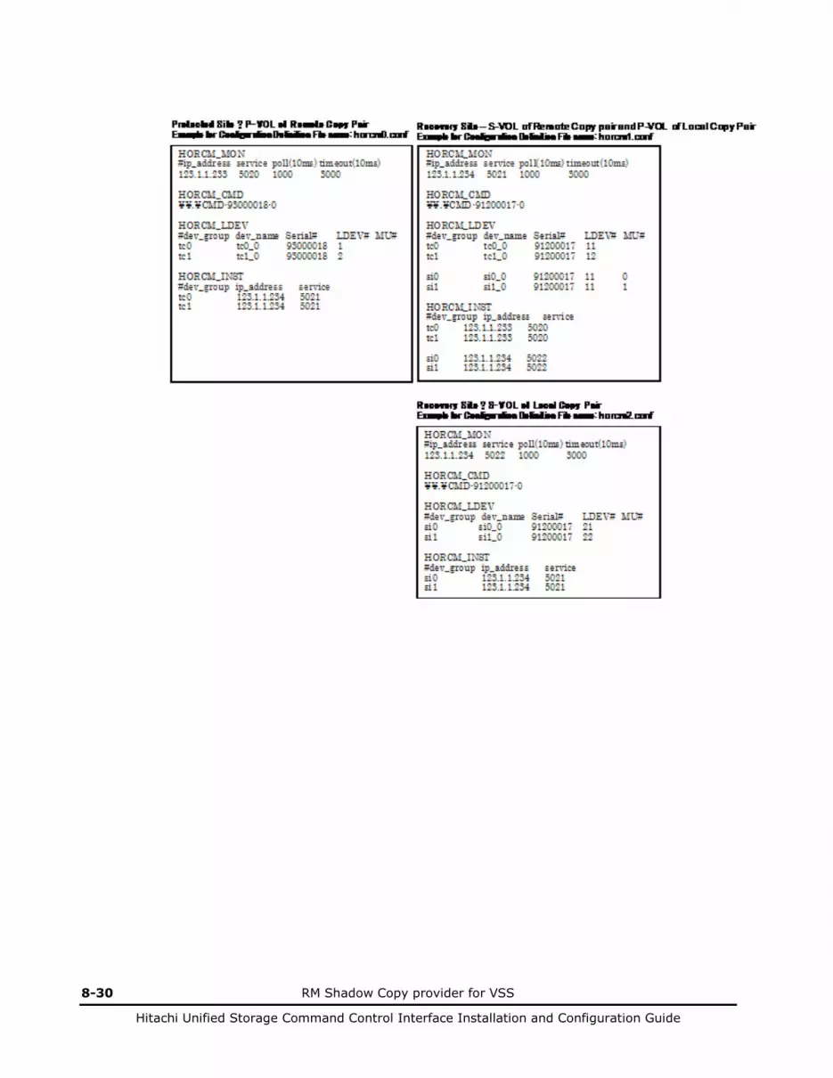
8-30 RM Shadow Copy provider for VSS
Hitachi Unified Storage Command Control Interface Installation and Configuration Guide
VMware vCenter Site Recovery Manager 8-31
Hitachi Unified Storage Command Control Interface Installation and Configuration Guide
Starting HORCM
Start HORCM used in SRM. If CCI is installed in Windows Server, HORCM can be automatically started as a service at Windows Server startup.

8-32 RM Shadow Copy provider for VSS
Hitachi Unified Storage Command Control Interface Installation and Configuration Guide
Creating copy pair
You need to crate a copy pair where a virtual machine is stored before performing SRM operations. Use CCI to create a remote copy pair and verify that the pair status is PAIR. If you use a local copy pair for test failover, create a local copy pair and make the cascade configuration with a remote copy pair. Verify that the status of the local copy pair is PAIR.
Setting environment variables
You can select remote copy or local copy as the target of test failover by changing environment variables in Windows on the server where CCI is installed. Available environment variables are as follows.
Table 8.8 Environment Variables
No. Environment Variable Description
1 SplitReplication "true" specifies that remote copy pair is test failover target. "false" specifies that local copy pair is test failover target.
2 RMSRATMU Specifies MU# of S-VOL of local copy pair. S-VOL of local copy pair that has the specified MU# becomes test failover target. If you specify remote copy as test failover target, specify MU# that is not used in local copy pairs.
3 HORCMROOT Specifies the directory where CCI is installed. This environment variable needs to be set both at protected site and recovery site.
4 RMSRATOV Specifies timeout period of failover. Default value is 60 seconds.
The following are examples of settings of SplitReplication and RMSRATMU when the target of test failover is a remote copy and a local copy.
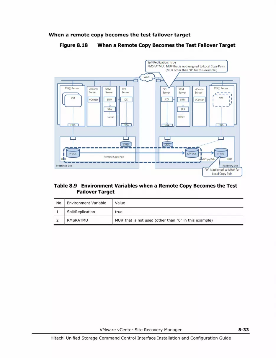
VMware vCenter Site Recovery Manager 8-33
Hitachi Unified Storage Command Control Interface Installation and Configuration Guide
When a remote copy becomes the test failover target
Figure 8.18 When a Remote Copy Becomes the Test Failover Target
Table 8.9 Environment Variables when a Remote Copy Becomes the Test Failover Target
No. Environment Variable Value
1 SplitReplication true
2 RMSRATMU MU# that is not used (other than "0" in this example)

8-34 RM Shadow Copy provider for VSS
Hitachi Unified Storage Command Control Interface Installation and Configuration Guide
When a local copy becomes the test failover target
Figure 8.19 When a Local Copy Becomes the Test Failover Target
Table 8 .10 Environment Variables when Local Copy Becomes Test Failover Target
No. Environment Variable Value
1 SplitReplication false
2 RMSRATMU MU# of S-VOL of the test failover target ("0" in this example)
To set environment variables when CCI is installed in Windows
Set them at the site where a local copy pair is in the cascade configuration with a remote copy pair.
1. Change the values in the Environment Variables dialog box in Control Panel.
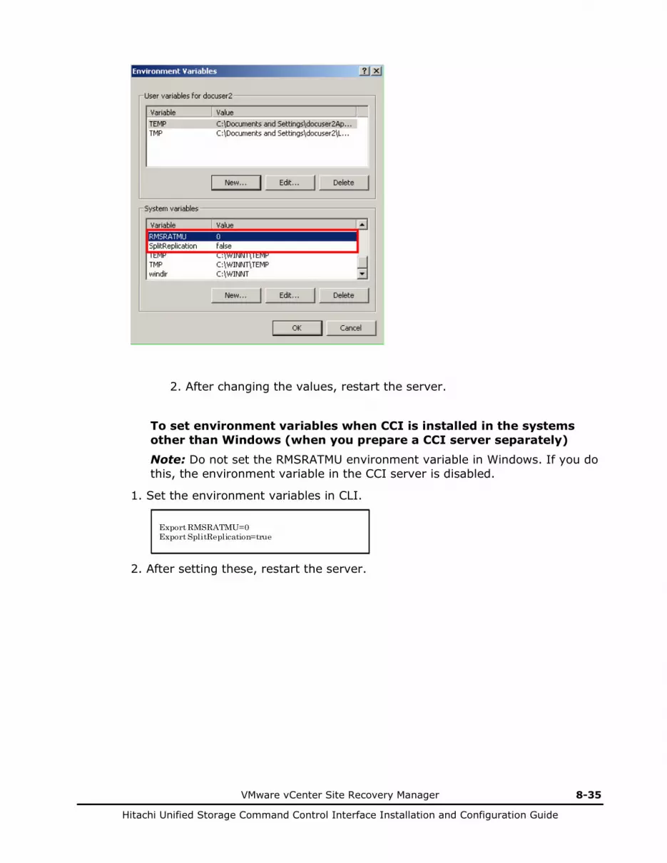
VMware vCenter Site Recovery Manager 8-35
Hitachi Unified Storage Command Control Interface Installation and Configuration Guide
2. After changing the values, restart the server.
To set environment variables when CCI is installed in the systems other than Windows (when you prepare a CCI server separately) Note: Do not set the RMSRATMU environment variable in Windows. If you do this, the environment variable in the CCI server is disabled.
1. Set the environment variables in CLI.
Export RMSRATMU=0Export SplitReplication=true
2. After setting these, restart the server.
8-36 RM Shadow Copy provider for VSS
Hitachi Unified Storage Command Control Interface Installation and Configuration Guide
Setting SRM
To set SRM, perform the following steps.
Table 8.11 SRM Setting Tasks
No. Task Description
1 Connect protected site and recovery site
Authenticate and connect SRM-managed protected site and recovery site each other. See the documents provided by VMware, Inc.
2 Set array manager Use the array manager to associate SRM with SRA.
3 Set inventory mapping Set the mapping of resources between protected site and recovery site, virtual machine folders, and network. See the documents provided by VMware, Inc.
4 Set place holder datastore Specify datastore where configuration information of protection target virtual machine is stored. See the documents provided by VMware, Inc.
5 Create protection group Create virtual machine group where SRM operations are performed simultaneously. See the documents provided by VMware, Inc.
6 Create recovery plan Specify which recovery step is performed when SRM operations are instructed. See the documents provided by VMware, Inc.
Configuring protected and recovery site array managers
Configure an array manager to associate SRM with SRA. By doing this, copy pairs operated by SRM are recognized. To configure an array manager, perform the following steps. You can do it at the protected site or the recovery site, and the settings are automatically transferred to its counterpart.
1. Log in to SRM.
Use a vSphere Client to log in to vCenter server at the protected site or the recovery site. On the Home page, click Site Recovery, and enter the user name and password to log in to SRM.
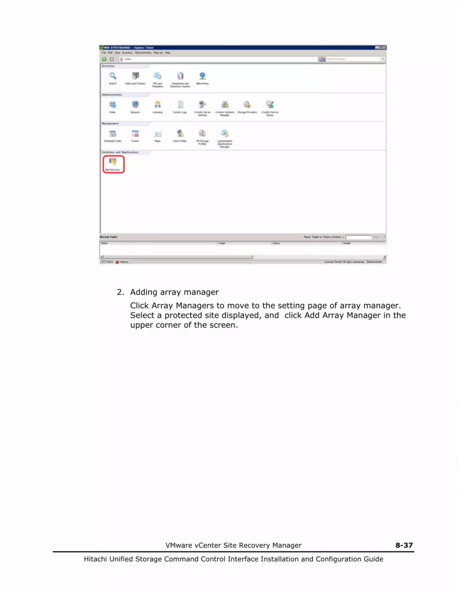
VMware vCenter Site Recovery Manager 8-37
Hitachi Unified Storage Command Control Interface Installation and Configuration Guide
2. Adding array manager
Click Array Managers to move to the setting page of array manager. Select a protected site displayed, and click Add Array Manager in the upper corner of the screen.
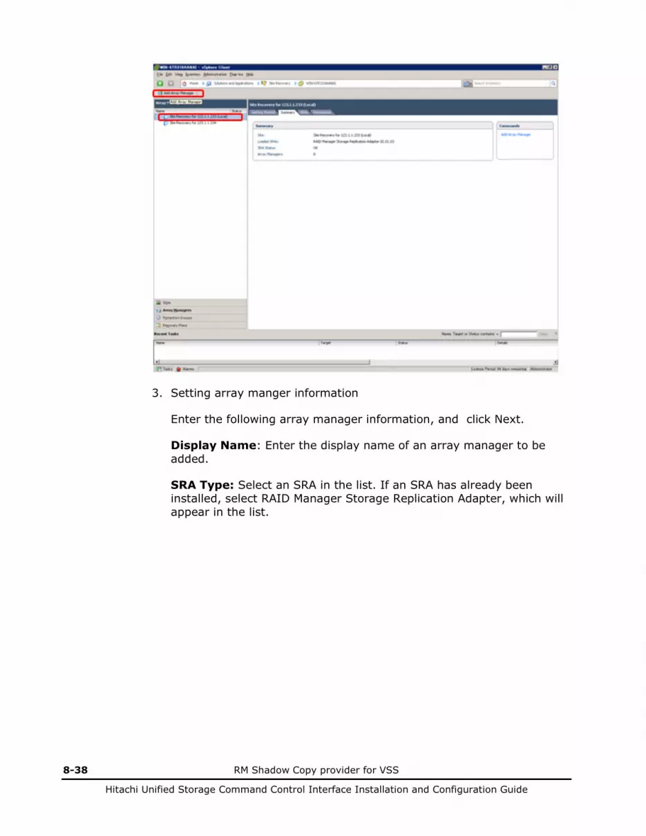
8-38 RM Shadow Copy provider for VSS
Hitachi Unified Storage Command Control Interface Installation and Configuration Guide
3. Setting array manger information
Enter the following array manager information, and click Next.
Display Name: Enter the display name of an array manager to be added.
SRA Type: Select an SRA in the list. If an SRA has already been installed, select RAID Manager Storage Replication Adapter, which will appear in the list.

VMware vCenter Site Recovery Manager 8-39
Hitachi Unified Storage Command Control Interface Installation and Configuration Guide
4. Setting SRA connection information
Set the following information on HORCM, which is connected by SRA.
HORCMINST and AP Address of HORCM (CCI) Server: Enter the instance number of HORCM, which is connected by SRA. You may need to enter additional information as follows, depending on the conditions where CCI is installed in the vCenter server or the CCI server is connected to the vCenter server via Telnet.
When CCI is installed in the vCenter server:
HORCMINST=<instance number>
When the CCI server is connected to the vCenter server via Telnet:
HORCMINST=<instance number>@<IP Address of the HORCM (CCI) Server>
Username: Enter the username for logging in to the server where CCI is installed.
Password: Enter the password for logging in to the server where CCI is installed.
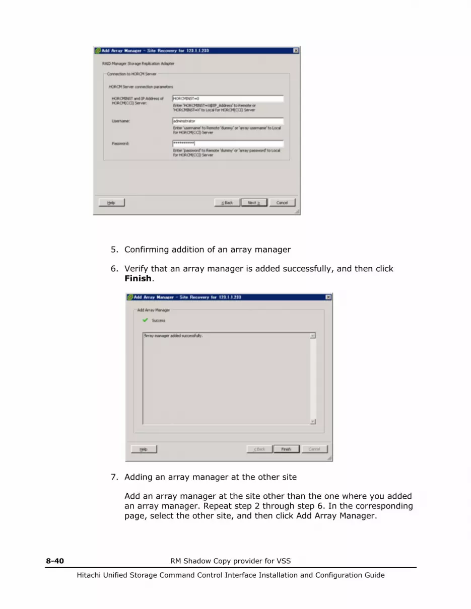
8-40 RM Shadow Copy provider for VSS
Hitachi Unified Storage Command Control Interface Installation and Configuration Guide
5. Confirming addition of an array manager
6. Verify that an array manager is added successfully, and then click Finish.
7. Adding an array manager at the other site
Add an array manager at the site other than the one where you added an array manager. Repeat step 2 through step 6. In the corresponding page, select the other site, and then click Add Array Manager.

VMware vCenter Site Recovery Manager 8-41
Hitachi Unified Storage Command Control Interface Installation and Configuration Guide
8. Enabling a copy pair
After adding array managers in both sites, SRM detects copy pairs and displays them. The detected copy pairs are displayed in the Array Pairs tab. Click Enable.

8-42 RM Shadow Copy provider for VSS
Hitachi Unified Storage Command Control Interface Installation and Configuration Guide
9. Confirming copy pair status
Verify that the status of a detected copy pair is “Enabled”.

VMware vCenter Site Recovery Manager 8-43
Hitachi Unified Storage Command Control Interface Installation and Configuration Guide
10. Confirming devices of a copy pair
After a copy pair is enabled, devices of the copy pair are displayed in the Devices tab. Verify that:
• Local device and remote device have dev_name that is specified in a configuration definition file.
• Correct copy direction is set to each copy pair.
• Each datastore is at the local site.
The setting of array managers is now complete.
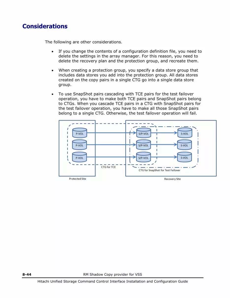
8-44 RM Shadow Copy provider for VSS
Hitachi Unified Storage Command Control Interface Installation and Configuration Guide
Considerations
The following are other considerations.
• If you change the contents of a configuration definition file, you need to delete the settings in the array manager. For this reason, you need to delete the recovery plan and the protection group, and recreate them.
• When creating a protection group, you specify a data store group that includes data stores you add into the protection group. All data stores created on the copy pairs in a single CTG go into a single data store group.
• To use SnapShot pairs cascading with TCE pairs for the test failover operation, you have to make both TCE pairs and SnapShot pairs belong to CTGs. When you cascade TCE pairs in a CTG with SnapShot pairs for the test failover operation, you have to make all those SnapShot pairs belong to a single CTG. Otherwise, the test failover operation will fail.
VMware vCenter Site Recovery Manager 8-45
Hitachi Unified Storage Command Control Interface Installation and Configuration Guide
Troubleshooting
See the Troubleshooting section in Hitachi Storage Replication Adapter 2.0 for VMware vCenter Site Recovery Manager 5.0/5.1 Deployment Guide, MK-09RM6745, for how to handle issues you may face with using SRM with the array.

9
Differences between groups 9-1
Hitachi Unified Storage Command Control Interface Installation and Configuration Guide
Differences between groups
About groups Consistency groups

9-2 Differences between groups
Hitachi Unified Storage Command Control Interface Installation and Configuration Guide
About groups
Multiple pairs are managed as a group. A configuration file of CCI defines a group as a set of pairs. Disk array also manages and operates a set of pairs as a consistency group. The differences between two types of groups are explained by using Figure 9-1.
A group described in a configuration file (a group in short) can have one or more pairs. A group specified by -g option of CCI commands indicates a group defined in a configuration file. By using a group, an operation to multiple pairs is done at a time.
A CTG is a group managed by disk array and a CTG can have one or more pairs. If data consistency across multiple pairs is required, such pairs must be operated as a consistency group by disk array. A group cannot belong to multiple CTGs. Pairs in a group cannot belong to multiple CTGs.
While two or more groups can belong to one CTG, it is strongly recommended to give each group a different CTG.
CTG number cannot be specified in CCI commands except for paircreate command. Only a group can be specified in the CCI commands. Operations like pairsplit require operating pairs in a CTG at a time so CCI and disk array interpret an operation request for a group as a request for a CTG to which the specified group belongs.

Differences between groups 9-3
Hitachi Unified Storage Command Control Interface Installation and Configuration Guide
Consistency groups
Consistency Group 1
Group 1
LU 0 LU 1
Group 2
LU 2 LU 3
Defined at pair create
Defined in configuration file
Specified in -g option of CCI commands
Which Disk array processes, a group or a consistency group, depends on types of CCI commands
Figure 9-1 Group and consistency groups
Table 9-1 shows which disk array processes, a group or a consistency group, when -g option is specified in each major CCI command.
For example, a pairdisplay command displays pair statuses of a specified group. In a case of Figure 9-1, specifying the group 1 in a pairdisplay command shows only information about the group 1.
On the other hand, a pairsplit command splits all pairs in all groups belonging to a CTG to which a specified group belongs. In a case of Figure 9-1, specifying the group 1 in a pairsplit command splits not only the group 1 but also the group 2.
If multiple groups belong to a CTG, operating only the specific group within the CTG is impossible. In a case of Figure 9-1 example, splitting only the group 1 but keeping the group 2 be PAIR is impossible. When splitting the specific group, it is required to split all pairs in the group one by one.
Note: Splitting each pair does not guarantee data consistency across the split pairs. Only one pair per a CTG is processed at a time.
Table 9-1 The CCI -g option and target
Command Name or Status ShadowImage Snapshot TrueCopy TCE
pairvolchk Group Group Group Group
paircurchk - - Group Group
pairdisplay Group Group Group Group
pairevtwait Group Group Group Group
pairsyncwait - - - CTG
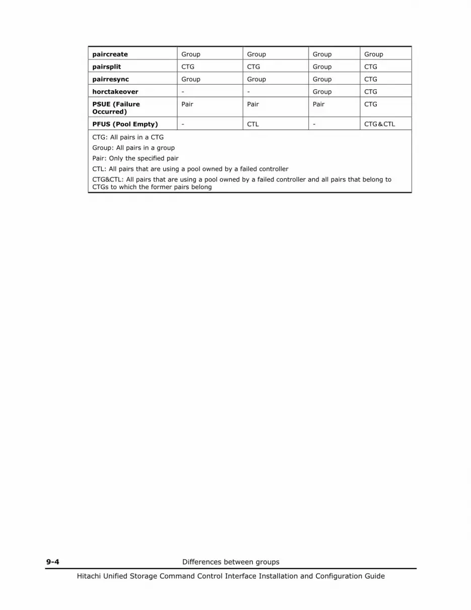
9-4 Differences between groups
Hitachi Unified Storage Command Control Interface Installation and Configuration Guide
paircreate Group Group Group Group
pairsplit CTG CTG Group CTG
pairresync Group Group Group CTG
horctakeover - - Group CTG
PSUE (Failure Occurred)
Pair Pair Pair CTG
PFUS (Pool Empty) - CTL - CTG&CTL
CTG: All pairs in a CTG
Group: All pairs in a group
Pair: Only the specified pair
CTL: All pairs that are using a pool owned by a failed controller
CTG&CTL: All pairs that are using a pool owned by a failed controller and all pairs that belong to CTGs to which the former pairs belong
10
Performing CCI operations 10-1
Hitachi Unified Storage Command Control Interface Installation and Configuration Guide
Performing CCI operations
This chapter includes the following: Important CCI notice About CCI environment variables Splitting pairs Resynchronizing pairs Confirming pairs Monitoring pairs Checking pair attribute and status Displaying pair status Checking TrueCopy/TCE pair currency Performing TrueCopy/TCE takeover Displaying configuration information Protecting volume data Controlling CCI activity About Windows Server subcommands CCI command tools Controlling host groups Migrating volumes About the synchronous waiting command for TCE Using the raidcom command

10-2 Performing CCI operations
Hitachi Unified Storage Command Control Interface Installation and Configuration Guide
Important CCI notice
Note the following when performing CCI operations:
• Remember to change the default value for the poll(10ms) parameter in the configuration definition file.
• When an internal process conflict occurs between the CCI and the disk array, the processing of the disk array is temporarily suspended. If the conflict continues, internal processing may not proceed. Therefore, when monitoring (polling) the status of the disk array (by creating a script using the CCI commands) set the display-information-based commands (e.g. pairdisplay, raidscan, raidar, and raidqry) to be issued more than or equal to a minute.
• Commands that change the status of pairs (paircreate, pairsplit, pairresync) cannot be performed while changing the firmware online.
• Do not change the firmware online while executing commands that change the status of pairs (paircreate, pairsplit, pairresync). The execution time for the copying process varies; changing the firmware online suspends the copying operation temporarily. The processing time for changing the firmware online is 4 min./CTL (the copying process will be suspended for 4 minutes per CTL). The waiting process in the batch file may end abnormally when executing a copy (using a batch file) by designating a specific time.
• Commands that change the status of pairs (paircreate, pairsplit, pairresync) of TrueCopy/TCE cannot be performed while the host re-starting in TrueCopy/TCE environment. The command may end abnormally when executing a command while the host re-starting.
• It is essential that both P-VOL and V-VOL should be defined in advance from Hitachi Storage Navigator Modular 2. Also, the secondary volume (S-VOL) used and assigned by the CCI is the same as the SnapShot image created by Hitachi Storage Navigator Modular 2.
• In the case of Windows, do not use the diskpart command for a mounting and unmounting of a volume.
• When use host I/O and CCI simultaneously, the completion of CCI commands may be late by the performance and load of the host.
• All command options displayed in help do not perform.
The options that can perform are limited to the options described in this manual.
• The host machines must run on the operating system (OS) of the same architecture and the same CCI version because the host machine may be incapable of recognizing the paired volume of another host. However, it is possible to prepare only one server at a secondary site by supporting CCI communications (32-bit, 64-bit (Tru64)) among different OSs (HP-UX, Solaris, AIX, Linux, and Windows).
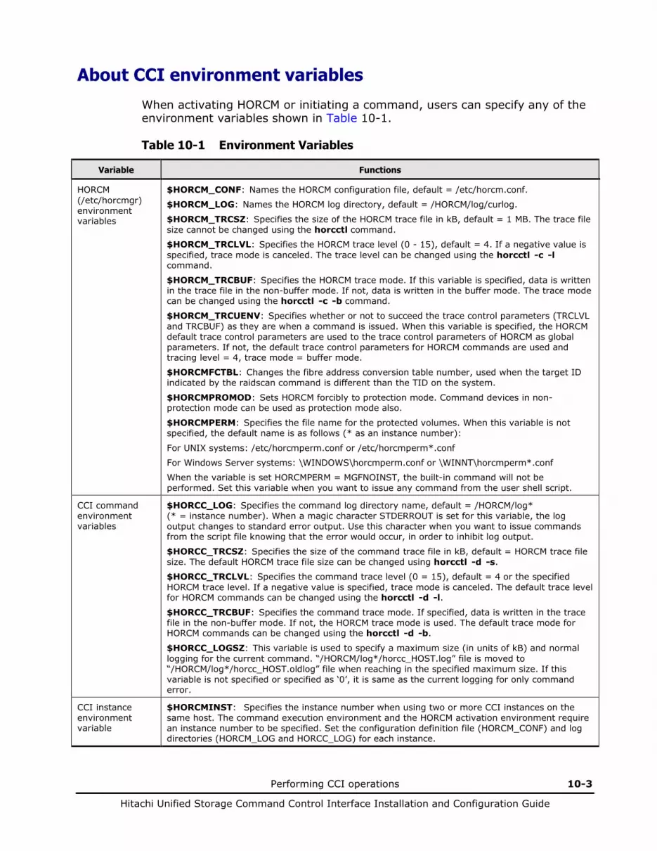
Performing CCI operations 10-3
Hitachi Unified Storage Command Control Interface Installation and Configuration Guide
About CCI environment variables
When activating HORCM or initiating a command, users can specify any of the environment variables shown in Table 10-1.
Table 10-1 Environment Variables
Variable Functions
HORCM (/etc/horcmgr) environment variables
$HORCM_CONF: Names the HORCM configuration file, default = /etc/horcm.conf.
$HORCM_LOG: Names the HORCM log directory, default = /HORCM/log/curlog.
$HORCM_TRCSZ: Specifies the size of the HORCM trace file in kB, default = 1 MB. The trace file size cannot be changed using the horcctl command.
$HORCM_TRCLVL: Specifies the HORCM trace level (0 - 15), default = 4. If a negative value is specified, trace mode is canceled. The trace level can be changed using the horcctl -c -l command.
$HORCM_TRCBUF: Specifies the HORCM trace mode. If this variable is specified, data is written in the trace file in the non-buffer mode. If not, data is written in the buffer mode. The trace mode can be changed using the horcctl -c -b command.
$HORCM_TRCUENV: Specifies whether or not to succeed the trace control parameters (TRCLVL and TRCBUF) as they are when a command is issued. When this variable is specified, the HORCM default trace control parameters are used to the trace control parameters of HORCM as global parameters. If not, the default trace control parameters for HORCM commands are used and tracing level = 4, trace mode = buffer mode.
$HORCMFCTBL: Changes the fibre address conversion table number, used when the target ID indicated by the raidscan command is different than the TID on the system.
$HORCMPROMOD: Sets HORCM forcibly to protection mode. Command devices in non-protection mode can be used as protection mode also.
$HORCMPERM: Specifies the file name for the protected volumes. When this variable is not specified, the default name is as follows (* as an instance number):
For UNIX systems: /etc/horcmperm.conf or /etc/horcmperm*.conf
For Windows Server systems: \WINDOWS\horcmperm.conf or \WINNT\horcmperm*.conf
When the variable is set HORCMPERM = MGFNOINST, the built-in command will not be performed. Set this variable when you want to issue any command from the user shell script.
CCI command environment variables
$HORCC_LOG: Specifies the command log directory name, default = /HORCM/log* (* = instance number). When a magic character STDERROUT is set for this variable, the log output changes to standard error output. Use this character when you want to issue commands from the script file knowing that the error would occur, in order to inhibit log output.
$HORCC_TRCSZ: Specifies the size of the command trace file in kB, default = HORCM trace file size. The default HORCM trace file size can be changed using horcctl -d -s.
$HORCC_TRCLVL: Specifies the command trace level (0 = 15), default = 4 or the specified HORCM trace level. If a negative value is specified, trace mode is canceled. The default trace level for HORCM commands can be changed using the horcctl -d -l. $HORCC_TRCBUF: Specifies the command trace mode. If specified, data is written in the trace file in the non-buffer mode. If not, the HORCM trace mode is used. The default trace mode for HORCM commands can be changed using the horcctl -d -b.
$HORCC_LOGSZ: This variable is used to specify a maximum size (in units of kB) and normal logging for the current command. “/HORCM/log*/horcc_HOST.log” file is moved to “/HORCM/log*/horcc_HOST.oldlog” file when reaching in the specified maximum size. If this variable is not specified or specified as ‘0’, it is same as the current logging for only command error.
CCI instance environment variable
$HORCMINST: Specifies the instance number when using two or more CCI instances on the same host. The command execution environment and the HORCM activation environment require an instance number to be specified. Set the configuration definition file (HORCM_CONF) and log directories (HORCM_LOG and HORCC_LOG) for each instance.

10-4 Performing CCI operations
Hitachi Unified Storage Command Control Interface Installation and Configuration Guide
Variable Functions
ShadowImage/ SnapShot command environment variables
$HORCC_MRCF: Sets the command execution environment of the ShadowImage/SnapShot commands. The selection whether the command functions as that of the TrueCopy/TCE or the ShadowImage/SnapShot is made according to this variable. The HORCM is not affected by this variable. When issuing a TrueCopy/TCE command, do not set the HORCC_MRCF variable for the execution environment of the command. When issuing a ShadowImage/SnapShot command, set the environmental variable HORCC_MRCF=1 for the execution environment of the command.
Besides, when returning the command execution environment of ShadowImage/SnapShot to that of TrueCopy/TCE, set HORCC_MRCF=.
The following environment variables can be set of ShadowImage pair operation.
$HORCC_SPLT:
NORMAL: The pairsplit and paircreate -split will be performed as Non quick mode.
QUICK: The pairsplit and paircreate -split will be performed as Quick Split.
$ HORCC_RSYN:
NORMAL: The pairresync will be performed as Non quick mode.
QUICK: The pairresync will be performed as Quick Resync.
Specifying CCI options
Normally, the CCI command performs it using a number set for the environmental variable of $HORCMINST as an instance number. The command operates in the TrueCopy/TCE execution environment when the environmental variable of $HORCC_MRCF is not set or in the ShadowImage/SnapShot/Data Retention execution environment when the valuable is set as 1. When the option for specifying the instance number is used, the instance number can be specified irrespective of the environmental variable of $HORCMINST only in the command execution in which the option is used. Besides, when the option for specifying the execution environment is used, the execution environment can be changed irrespective of the environmental variable of $HORCC_MRCF only in the command execution in which the option is used.
• A way to specify options -I[instance#]
This option specifies the instance number. Example: Issue the pairdisplay command setting the instance number as 5. # pairdisplay -g<group> -I5 ...
Issue the pairdisplay command setting the instance number as no instance number. # pairdisplay -g<group> -I ...
-IH[instance#] or -ITC[instance#] This option selects the TrueCopy/TCE execution environment and specifies the instance number.
Example: Issue the pairdisplay command in the TrueCopy/TCE execution environment setting the instance number as no instance number.
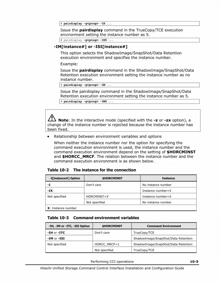
Performing CCI operations 10-5
Hitachi Unified Storage Command Control Interface Installation and Configuration Guide
# pairdisplay -g<group> -IH ...
Issue the pairdisplay command in the TrueCopy/TCE execution environment setting the instance number as 5. # pairdisplay -g<group> -IH5 ...
-IM[instance#] or -ISI[instance#] This option selects the ShadowImage/SnapShot/Data Retention execution environment and specifies the instance number. Example: Issue the pairdisplay command in the ShadowImage/SnapShot/Data Retention execution environment setting the instance number as no instance number. # pairdisplay -g<group> -IM ...
Issue the pairdisplay command in the ShadowImage/SnapShot/Data Retention execution environment setting the instance number as 5. # pairdisplay -g<group> -IM5 ...
Note: In the interactive mode (specified with the -z or -zx option), a change of the instance number is rejected because the instance number has been fixed.
• Relationship between environment variables and options
When neither the instance number nor the option for specifying the command execution environment is used, the instance number and the command execution environment depend on the setting of $HORCMINST and $HORCC_MRCF. The relation between the instance number and the command execution environment is as shown below.
Table 10-2 The instance for the connection
-I[instance#] Option $HORCMINST Instance
-I Don’t care No instance number
-IX Instance number=X
Not specified HORCMINST=X Instance number=X
Not specified No instance number
X: Instance number
Table 10-3 Command environment variables
-IH, -IM or -ITC, -ISI Option $HORCMINST Command Environment
-IH or -ITC Don’t care TrueCopy/TCE
-IM or -ISI ShadowImage/SnapShot/Data Retention
Not specified HORCC_MRCF=1 ShadowImage/SnapShot/Data Retention
Not specified TrueCopy/TCE

10-6 Performing CCI operations
Hitachi Unified Storage Command Control Interface Installation and Configuration Guide
Verifying instance numbers • A way to verify instance number and command environment
The instance number and the command execution environment at the time of the command execution are displayed as shown below.
Example: C:\HORCM\etc>pairdisplay –h Model : RAID-Manager/WindowsNT Ver&Rev: 01-25-03/05 Usage : pairdisplay [options] for HORC[5] -h Help/Usage -I[#] Set to HORCMINST# -IH[#] or -ITC[#] Set to HORC mode [and HORCMINST#] -IM[#] or -ISI[#] Set to MRCF mode [and HORCMINST#] :
Instance number Command environment (TrueCopy/TCE)
Example with interactive mode: C:\HORCM\etc>pairdisplay -z pairdisplay[HOMRCF[5]]: -IM pairdisplay[HOMRCF[5]]: -q :
Instance number Command environment (ShadowImage/SnapShot/Data Retention)
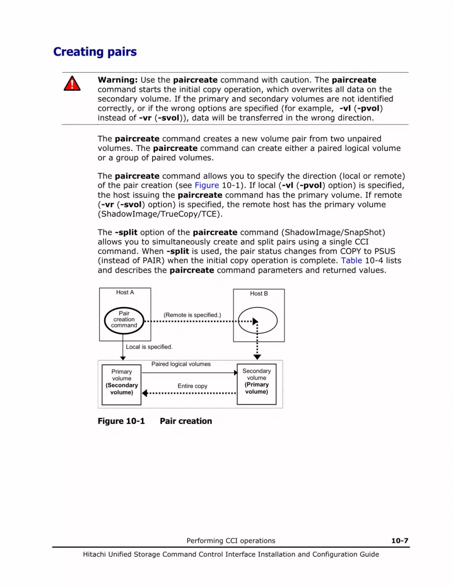
Performing CCI operations 10-7
Hitachi Unified Storage Command Control Interface Installation and Configuration Guide
Creating pairs
Warning: Use the paircreate command with caution. The paircreate command starts the initial copy operation, which overwrites all data on the secondary volume. If the primary and secondary volumes are not identified correctly, or if the wrong options are specified (for example, -vl (-pvol) instead of -vr (-svol)), data will be transferred in the wrong direction.
The paircreate command creates a new volume pair from two unpaired volumes. The paircreate command can create either a paired logical volume or a group of paired volumes.
The paircreate command allows you to specify the direction (local or remote) of the pair creation (see Figure 10-1). If local (-vl (-pvol) option) is specified, the host issuing the paircreate command has the primary volume. If remote (-vr (-svol) option) is specified, the remote host has the primary volume (ShadowImage/TrueCopy/TCE).
The -split option of the paircreate command (ShadowImage/SnapShot) allows you to simultaneously create and split pairs using a single CCI command. When -split is used, the pair status changes from COPY to PSUS (instead of PAIR) when the initial copy operation is complete. Table 10-4 lists and describes the paircreate command parameters and returned values.
Pair creation
command
Host A Host B
Local is specified.
(Remote is specified.)
Primary volume
(Secondary volume)
Secondary volume
(Primary volume)
Paired logical volumes
Entire copy
Figure 10-1 Pair creation

10-8 Performing CCI operations
Hitachi Unified Storage Command Control Interface Installation and Configuration Guide
Before issuing the paircreate command, verify that the secondary volume is not mounted on any system. If the secondary volume is mounted after paircreate, delete the pair (pairsplit -S), unmount the secondary volume, and reissue the paircreate command.
Note: The paircreate command terminates before the initial copy operation is complete (except when the -nocopy option is specified). Use the pair event waiting or pairdisplay to verify that the initial copy operation completed successfully (status changes from COPY to PAIR, or from COPY to PSUS if the -split option was specified). The execution log file also shows completion of the initial copy operation.
Figure 10-2 shows how pairs are created.
Start
Issue a paircreate command.
Could the pair be created?
End
Issue a pairdisplay command, and verify which S-VOL is not SMPL.
Issue pairsplit -R commands for S-VOLs that are not SMPL.
NO
Yes
Figure 10-2 Pair creation
Table 10-4 Paircreate command parameters
Parameter Value
Command Name
paircreate
Format paircreate { -h | -q | -z | -x | -xh | -I [H | M] [instance#] | -g <group> | -d <pair Vol> | -d [g] <raw_device> [MU#] | -d [g] <seq#> <LDEV#> [MU#] -f <fence> [CTGID] | -fg <fence> [CTGID] | -v | -c <size> | -nocopy | -nomsg | -split [[Split-Marker]] | [-m <mode>] | -jp <PID> -js <PID> | -pid <PID> | -fq <mode> | -p [s] vol}
Options -h: Displays Help/Usage and version information.
-q: Terminates the interactive mode and exits the command.
-z or -zx: Makes the paircreate command enter the interactive mode. The -zx option guards performing of the HORCM in the interactive mode. When this option detects a HORCM shut down, interactive mode terminates.
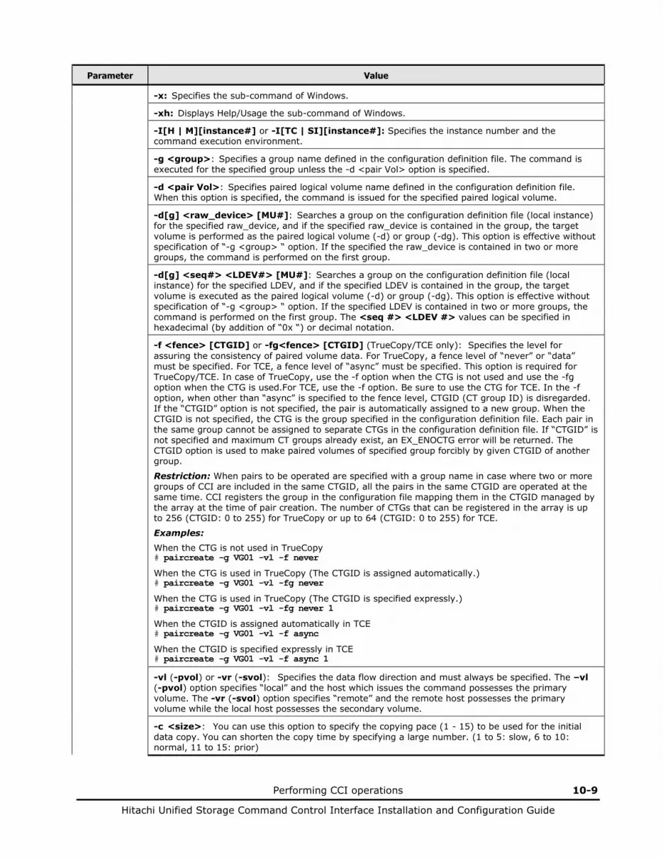
Performing CCI operations 10-9
Hitachi Unified Storage Command Control Interface Installation and Configuration Guide
Parameter Value
-x: Specifies the sub-command of Windows.
-xh: Displays Help/Usage the sub-command of Windows.
-I[H | M][instance#] or -I[TC | SI][instance#]: Specifies the instance number and the command execution environment.
-g <group>: Specifies a group name defined in the configuration definition file. The command is executed for the specified group unless the -d <pair Vol> option is specified.
-d <pair Vol>: Specifies paired logical volume name defined in the configuration definition file. When this option is specified, the command is issued for the specified paired logical volume.
-d[g] <raw_device> [MU#]: Searches a group on the configuration definition file (local instance) for the specified raw_device, and if the specified raw_device is contained in the group, the target volume is performed as the paired logical volume (-d) or group (-dg). This option is effective without specification of “-g <group> “ option. If the specified the raw_device is contained in two or more groups, the command is performed on the first group.
-d[g] <seq#> <LDEV#> [MU#]: Searches a group on the configuration definition file (local instance) for the specified LDEV, and if the specified LDEV is contained in the group, the target volume is executed as the paired logical volume (-d) or group (-dg). This option is effective without specification of “-g <group> “ option. If the specified LDEV is contained in two or more groups, the command is performed on the first group. The <seq #> <LDEV #> values can be specified in hexadecimal (by addition of “0x “) or decimal notation.
-f <fence> [CTGID] or -fg<fence> [CTGID] (TrueCopy/TCE only): Specifies the level for assuring the consistency of paired volume data. For TrueCopy, a fence level of “never” or “data” must be specified. For TCE, a fence level of “async” must be specified. This option is required for TrueCopy/TCE. In case of TrueCopy, use the -f option when the CTG is not used and use the -fg option when the CTG is used.For TCE, use the -f option. Be sure to use the CTG for TCE. In the -f option, when other than “async” is specified to the fence level, CTGID (CT group ID) is disregarded. If the “CTGID” option is not specified, the pair is automatically assigned to a new group. When the CTGID is not specified, the CTG is the group specified in the configuration definition file. Each pair in the same group cannot be assigned to separate CTGs in the configuration definition file. If “CTGID” is not specified and maximum CT groups already exist, an EX_ENOCTG error will be returned. The CTGID option is used to make paired volumes of specified group forcibly by given CTGID of another group.
Restriction: When pairs to be operated are specified with a group name in case where two or more groups of CCI are included in the same CTGID, all the pairs in the same CTGID are operated at the same time. CCI registers the group in the configuration file mapping them in the CTGID managed by the array at the time of pair creation. The number of CTGs that can be registered in the array is up to 256 (CTGID: 0 to 255) for TrueCopy or up to 64 (CTGID: 0 to 255) for TCE.
Examples: When the CTG is not used in TrueCopy # paircreate -g VG01 -vl -f never
When the CTG is used in TrueCopy (The CTGID is assigned automatically.) # paircreate -g VG01 -vl -fg never
When the CTG is used in TrueCopy (The CTGID is specified expressly.) # paircreate -g VG01 -vl -fg never 1
When the CTGID is assigned automatically in TCE # paircreate -g VG01 -vl -f async
When the CTGID is specified expressly in TCE # paircreate -g VG01 -vl -f async 1
-vl (-pvol) or -vr (-svol): Specifies the data flow direction and must always be specified. The –vl (-pvol) option specifies “local” and the host which issues the command possesses the primary volume. The -vr (-svol) option specifies “remote” and the remote host possesses the primary volume while the local host possesses the secondary volume.
-c <size>: You can use this option to specify the copying pace (1 - 15) to be used for the initial data copy. You can shorten the copy time by specifying a large number. (1 to 5: slow, 6 to 10: normal, 11 to 15: prior)

10-10 Performing CCI operations
Hitachi Unified Storage Command Control Interface Installation and Configuration Guide
Parameter Value
-nocopy (TrueCopy/TCE): Creates paired volumes without copying data in the case in which the data consistency of simplex volumes is assured by the user.
-nomsg: Suppresses messages to be displayed when this command is performed. It is used to perform this command from a user program. This option must be specified at the beginning of a command argument. The command execution log is not affected by this option.
-split [Split-Marker] (ShadowImage/SnapShot only): Splits the paired volume after the initial copy operation is complete. Besides, an optional character string (with ASCII 31 characters), which is specified by a user, can be added to the V-VOL as a <Split-Marker>.
-m <mode> (ShadowImage only): For mode, you can specify the following option:
noread: Specifies the noread mode for hiding the secondary volume. The secondary volume becomes read-disabled when this mode option is specified. The secondary volume is read-enabled when this mode option is omitted. Note: The primary volume becomes read-disabled only during a reverse resync operation (restore option of pairresync command).
mode=grp [CTGID] (SnapShot/ShadowImage only) Makes a group for splitting all SnapShot/ShadowImage pairs specified in a group. SnapShot/ShadowImage guarantees data consistency among multiple VOLs in a group at a single point in time when doing a split using the pairsplit -g <group> command (except -S or -E option).
A CTGID is assigned automatically if you do not specify the CTGID option in this command. If CTGID is not specified and maximum CT groups already exists, an EX_ENOCTG error will be returned. Therefore, the CTGID option can forcibly assign a volume group to an existing CTGID.
Note: This option cannot be specified with -split option in the same command. A plurality of pairs can be created to one P-VOL. But, the number of pair that can be set in one group is one pair per one P-VOL.
mode=cc (Volume Migration only): This option instructs the copying of the volume migration to be made.
The -vl (-pvol) specifies the local instruction, that is, an instruction to copy a local instance volume (P-VOL) to a remote instance volume (S-VOL) and to maps a copying destination volume (a volume of the remote instance) to the local instance volume (P-VOL).
The -vr (-svol) specifies the remote instruction, and copies data from a remote instance volume (P-VOL) to a local instance volume (S-VOL) and maps a copy destination volume (a volume of the local instance) to the remote instance volume (P-VOL).
Note: This option cannot be specified with -split option in the same command.
-jp <PID> -js <PID>: This can be specified by TCE only. The number (DP pool ID) of a DP pool used by a P-VOL is specified with the -jp option and that used by an S-VOL is specified with the -js option. The same DP pool is used for the local replication data DP pool and the local management area DP pool. The different DP pools cannot be specified respectively. Remote side is same as above.
Note: The -jp and -js options are enabled when the fence level is specified as async. When the -jp and -js options are omitted, 0 is used as a DP pool ID.
-pid <PID> (SnapShot only): This option specifies the DP pool number (DP pool ID) which the pair to create uses. When one P-VOL configures a pair with two or more V-VOLs, the pair configured by the same P-VOL needs to use a common DP pool. If this option is omitted, 0 is used as a DP pool ID. The same DP pool is used for the replication data DP pool and the management area DP pool. The different DP pools cannot be specified respectively.
-fq <mode> (ShadowImage only): This option is used to specify the mode whether -split is performed or not as “QUICK”.
mode = normal The paircreate -split will be performed as non-quick mode regardless of setting of $HORCC_SPLT environment variable.
mode = quick The paircreate -split will be performed as Quick Split regardless of setting of $HORCC_SPLT environment variable.
Returned values
Normal termination: 0. When creating groups, 0 = normal termination for all pairs.
Abnormal termination: Returns a common error code and a unique error code for this command. For details on error codes, see Chapter 10.
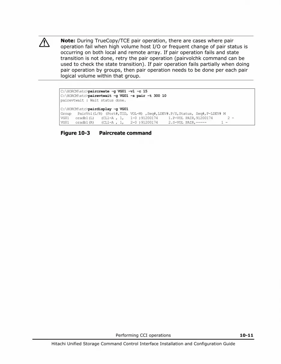
Performing CCI operations 10-11
Hitachi Unified Storage Command Control Interface Installation and Configuration Guide
Note: During TrueCopy/TCE pair operation, there are cases where pair operation fail when high volume host I/O or frequent change of pair status is occurring on both local and remote array. If pair operation fails and state transition is not done, retry the pair operation (pairvolchk command can be used to check the state transition). If pair operation fails partially when doing pair operation by groups, then pair operation needs to be done per each pair logical volume within that group.
C:\HORCM\etc>paircreate -g VG01 -vl -c 15 C:\HORCM\etc>pairevtwait -g VG01 -s pair -t 300 10 pairevtwait : Wait status done. C:\HORCM\etc>pairdisplay -g VG01 Group PairVol(L/R) (Port#,TID, VOL-M) ,Seq#,LDEV#.P/S,Status, Seq#,P-LDEV# M VG01 oradb1(L) (CL1-A , 1, 1-0 )91200174 1.P-VOL PAIR,91200174 2 - VG01 oradb1(R) (CL1-A , 1, 2-0 )91200174 2.S-VOL PAIR,----- 1 -
Figure 10-3 Paircreate command
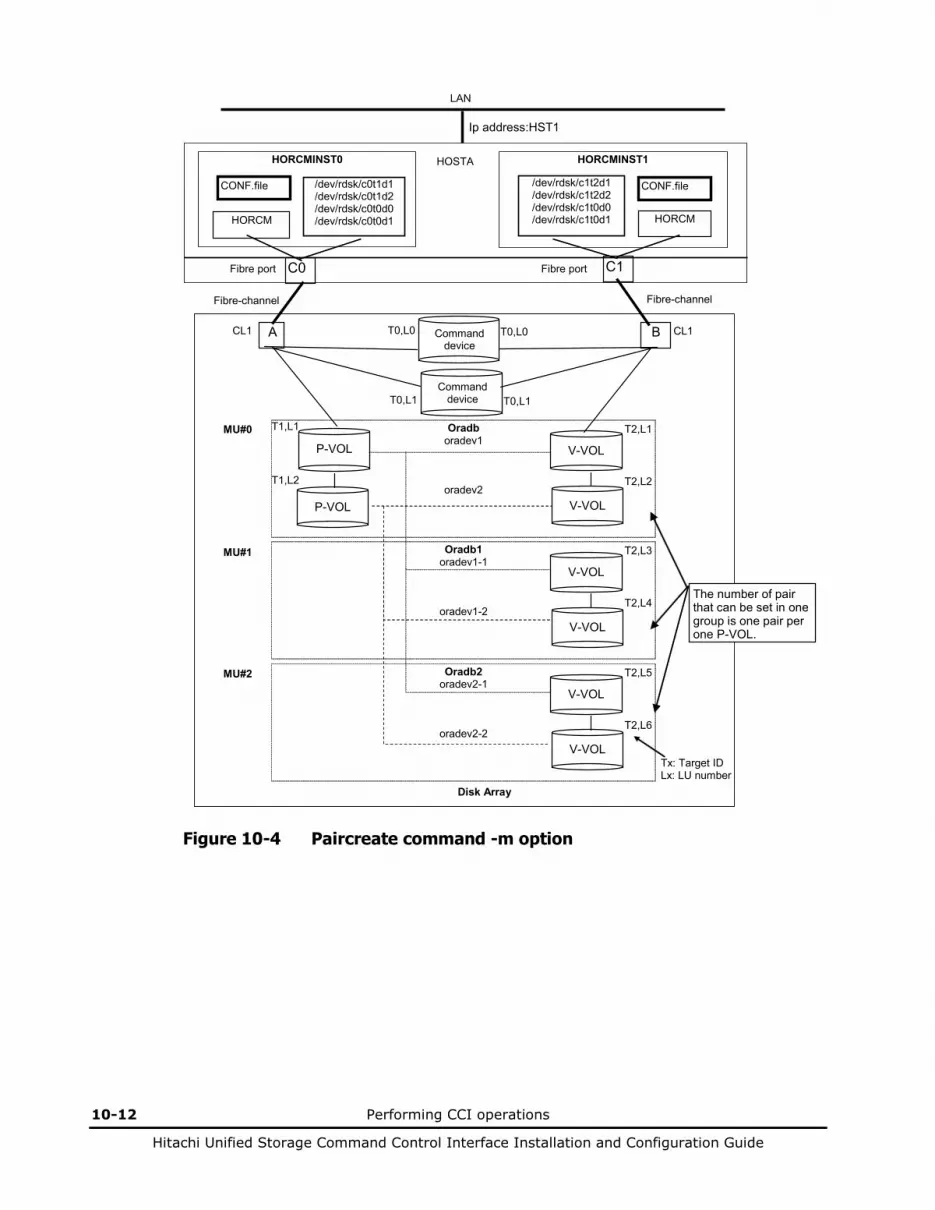
10-12 Performing CCI operations
Hitachi Unified Storage Command Control Interface Installation and Configuration Guide
LAN
Tx: Target ID Lx: LU number
A CL1
Oradb oradev1
oradev2
P-VOL
P-VOL
T1,L1
T1,L2
Command device
T0,L0 B CL1
V-VOL
V-VOL
T2,L2
T2,L1
T0,L0
Disk Array
HORCMINST0
HORCM
CONF.file
Ip address:HST1
C0
HORCMINST1
HORCM
CONF.file
C1
/dev/rdsk/c0t1d1 /dev/rdsk/c0t1d2 /dev/rdsk/c0t0d0 /dev/rdsk/c0t0d1
/dev/rdsk/c1t2d1 /dev/rdsk/c1t2d2 /dev/rdsk/c1t0d0 /dev/rdsk/c1t0d1
Fibre-channel Fibre-channel
Fibre port Fibre port
HOSTA
Command device T0,L1 T0,L1
Oradb1 oradev1-1
oradev1-2
V-VOL
V-VOL
T2,L4
T2,L3
Oradb2 oradev2-1
oradev2-2
V-VOL
V-VOL
T2,L6
T2,L5
MU#0
MU#1
MU#2
The number of pair that can be set in one group is one pair per one P-VOL.
Figure 10-4 Paircreate command -m option

Performing CCI operations 10-13
Hitachi Unified Storage Command Control Interface Installation and Configuration Guide
LAN
Tx: Target ID Lx: LU number
A CL1
Oradb oradev1
oradev2
oradev3
oradev4
P-VOL
P-VOL
T1,L1
T1,L2
Command device
T0,L0 B CL1
V-VOL
V-VOL
T2,L2
T2,L1
T0,L0
Disk Array
HORCMINST0
HORCM
CONF.file
Ip address:HST1
C0
HORCMINST1
HORCM
CONF.file
C1
/dev/rdsk/c0t1d1 /dev/rdsk/c0t1d2 /dev/rdsk/c0t0d0 /dev/rdsk/c0t0d1
/dev/rdsk/c1t2d1 /dev/rdsk/c1t2d2 /dev/rdsk/c1t0d0 /dev/rdsk/c1t0d1
Fibre-channel Fibre-channel
Fibre port Fibre port
HOSTA
Command device T0,L1 T0,L1
Oradb2 oradev2-1
oradev2-2
V-VOL
V-VOL
T2,L6
T2,L5
MU#0
MU#1
MU#2
A plurality of pairs belong to the same group to one P-VOL.
V-VOL
V-VOL
T2,L4
T2,L3
Figure 10-5 Paircreate command -m option (inappropriate example)
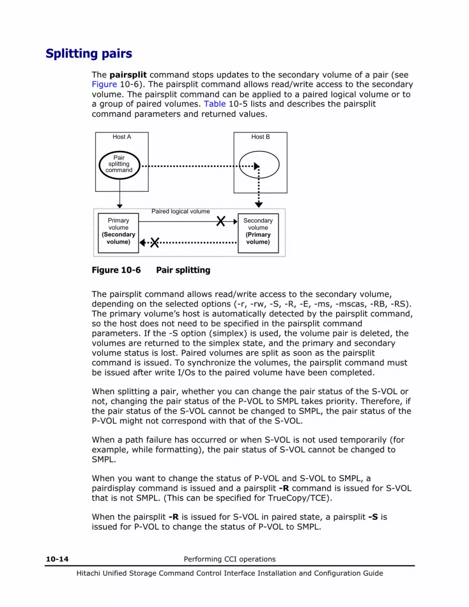
10-14 Performing CCI operations
Hitachi Unified Storage Command Control Interface Installation and Configuration Guide
Splitting pairs
The pairsplit command stops updates to the secondary volume of a pair (see Figure 10-6). The pairsplit command allows read/write access to the secondary volume. The pairsplit command can be applied to a paired logical volume or to a group of paired volumes. Table 10-5 lists and describes the pairsplit command parameters and returned values.
Pair splitting
command
Host A Host B
Primary volume
(Secondary volume)
Secondary volume
(Primary volume)
Paired logical volume
Figure 10-6 Pair splitting
The pairsplit command allows read/write access to the secondary volume, depending on the selected options (-r, -rw, -S, -R, -E, -ms, -mscas, -RB, -RS). The primary volume’s host is automatically detected by the pairsplit command, so the host does not need to be specified in the pairsplit command parameters. If the -S option (simplex) is used, the volume pair is deleted, the volumes are returned to the simplex state, and the primary and secondary volume status is lost. Paired volumes are split as soon as the pairsplit command is issued. To synchronize the volumes, the pairsplit command must be issued after write I/Os to the paired volume have been completed.
When splitting a pair, whether you can change the pair status of the S-VOL or not, changing the pair status of the P-VOL to SMPL takes priority. Therefore, if the pair status of the S-VOL cannot be changed to SMPL, the pair status of the P-VOL might not correspond with that of the S-VOL.
When a path failure has occurred or when S-VOL is not used temporarily (for example, while formatting), the pair status of S-VOL cannot be changed to SMPL.
When you want to change the status of P-VOL and S-VOL to SMPL, a pairdisplay command is issued and a pairsplit -R command is issued for S-VOL that is not SMPL. (This can be specified for TrueCopy/TCE).
When the pairsplit -R is issued for S-VOL in paired state, a pairsplit -S is issued for P-VOL to change the status of P-VOL to SMPL.

Performing CCI operations 10-15
Hitachi Unified Storage Command Control Interface Installation and Configuration Guide
When the S-VOL of the TCE pair is placed in the SMPL status through an issue of a command for the pair splitting (pairsplit -R) to the TCE pair, the S-VOL data may become unsettled data that is being copied. Therefore, to use the data as the settled one on which the P-VOL data has been reflected, change the volume status to SSWS by issuing the command for the takeover (horctakeover) beforehand, and issue the command for the pair splitting (pairsplit -R).
Note: During the period until the response of the command is returned after the pair status change command such as pairsplit is performed, the pairdisplay command cannot be performed in the same screen. Therefore, start another screen and issue pairdisplay to check the pair status.
Table 10-5 Pairsplit command parameters
Parameter Value
Command Name
pairsplit
Format pairsplit {-h | -q | -z | -x | -xh | -I[H | M][instance#] | -g <group> | -d <pair Vol> | -d[g] <raw_device> [MU#] | -FHORC | -FMRCF [MU#] |-d[g] <seq#> <LDEV#> [MU#] | -r | -rw | -S | -R[B][S] | -P | -l | -nomsg | -C <size> | -E | -ms<Split-Marker> | -mscas<Split-Marker> [MU#] | -fq <mode> | -t <time>}
Options -h: Displays Help/Usage and version information.
-q: Terminates the interactive mode and exits this command.
-z or -zx: Makes the pairsplit command enter the interactive mode. The -zx option guards performing of the HORCM in the interactive mode. When this option detects a HORCM shut down, interactive mode terminates.
-x: Specifies the sub-command of Windows.
-xh: Displays Help/Usage the sub-command of Windows.
-I[H | M][instance#] or -I[TC | SI][instance#]: Specifies the instance number and the command execution environment.
-g <group>: Specifies a group name defined in the configuration definition file. This option must always be specified. The command is executed for the specified group unless the -d <pair Vol> option is specified.
-d <pair Vol>: Specifies the paired logical volume name defined in the configuration definition file. When this option is specified, the command is issued for the specified paired logical volumes.
-d[g] <raw_device> [MU#]: Searches a group on the configuration definition file (local instance) for the specified raw_device, and if the specified raw_device is contained in the group, the target volume is issued as the paired logical volume (-d) or group (-dg). This option is effective without specification of “-g <group>“ option. If the specified the raw_device is contained in two or more groups, the command is performed on the first group.
-FHORC or -FCA: Forcibly specifies a cascading TrueCopy/TCE volume for specified pair logical volumes on a ShadowImage/SnapShot environment (see example in Figure 10-7). If the -l option is specified, this option splits a cascading TrueCopy/TCE volume on a local host (near site). If no -l option is specified, this option splits a cascading TrueCopy/TCE volume on a remote host (far site). The target TrueCopy/TCE volume must be a P-VOL and the -R option cannot be specified. Only the P-VOL of SnapShot can be cascaded with the TCE. In the case where the P-VOL of SnapShot is cascaded with the S-VOL of TCE, an instruction to split the SnapShot pair cannot be issued directly when the both pairs are in the PAIR status.

10-16 Performing CCI operations
Hitachi Unified Storage Command Control Interface Installation and Configuration Guide
Parameter Value
-FMRCF [MU#] or -FBC [MU#]: Forcibly specifies a cascading ShadowImage/SnapShot volume for specified pair logical volumes on a TrueCopy/TCE environment (see example in Figure 10-8). If the -l option is specified, this option splits a cascading ShadowImage/SnapShot volume on a local host (near site). If no -l option is specified, this option splits a cascading ShadowImage/SnapShot volume on a remote host (far site). The target ShadowImage/SnapShot volume must be a P-VOL and the -E option cannot be specified.
-d[g] <seq#> <LDEV#> [MU#]: Searches a group on the configuration definition file (local instance) for the specified LDEV, and if the specified LDEV is in the group, the target volume is performed as the paired logical volume (-d) or group (-dg). This option is effective without specification of “-g <group>“ option. If the specified LDEV is contained in two or more groups, the command is performed on the first group. The <seq #> <LDEV #> values can be specified in hexadecimal (by addition of “0x”) or decimal notation.
-r or -rw (for TrueCopy/TCE): Specifies a mode of access to the S-VOL after paired volumes are split. The -r option (default) allows read-only from the S-VOL. The -rw option enables read and write access for the S-VOL.
-S: Selects simplex mode (releases the pair). When the pairing direction is reversed among the hosts (for example, disaster recovery), this mode is established once, and the paircreate command is issued. To re-establish a pair which has been released, you must use the paircreate command (not pairresync).
-R (for TrueCopy/TCE): Brings the secondary volume into the simplex mode forcibly. It is issued by the secondary host, if the host possessing the primary volume is down or has failed.
-RS (for TrueCopy/TCE): Brings the secondary volume forcibly into SSWS mode.
-RB (for TrueCopy/TCE): Backs the secondary volume forcibly from SSWS into PSUS (PSUE) (SSUS) mode. This makes to be able to back to the primary volume if the user wants to back from the secondary host in SSWS state on Link failure to the primary host.
-P (for TrueCopy): This option is used to bring the primary volume forcibly into write disabled mode like PSUE with "fence=data". It is issued by the secondary host to disable P-VOL data changes by the host possessing the primary volume.
-l: When this command cannot utilize the remote host for host down, this option enables a pairsplit operation by local host only. The target volume of local host can be P-VOL or S-VOL.
-nomsg: Suppresses messages to be displayed when this command is executed. It is used to issue a command from a user program. This option must be specified at the beginning of a command argument. The command execution log is not affected by this option.
-C <size>: This option does not affect on operation even if it specified or omitted.
-E (ShadowImage only): Suspends a paired volume forcibly when a failure occurs. Not normally used.
-ms <Split-Marker> (for ShadowImage/SnapShot only): This option adds the optional character strings (ASCII code of 31 characters) specified by the user to the S-VOL or the V-VOL as <Split-Marker>.
-mscas <Split-Marker> [MU#] (TCE only): This option splits the V-VOL of the SnapShot pair cascaded with the S-VOL of the TCE pair by issuing an instruction (only the group can be specified) to TCE. As to the TCE pair targeted, its S-VOL must be cascaded with a SnapShot pair with the same “MU#.” All the TCE pairs concerned must be in the PAIR status. All the SnapShot pairs must be in the PSUS or PAIR status. All the TCE pairs (in the PAIR status) in the CTG that includes the specified group are to be processed. The pairs (in the CTG) to be processed must be in the PAIR status only. Besides, an optional character string (with ASCII 31 characters), which is specified by a user, can be added to the V-VOL as a <Split-Marker>. Incidentally, this option cannot be used together with the option of -d.
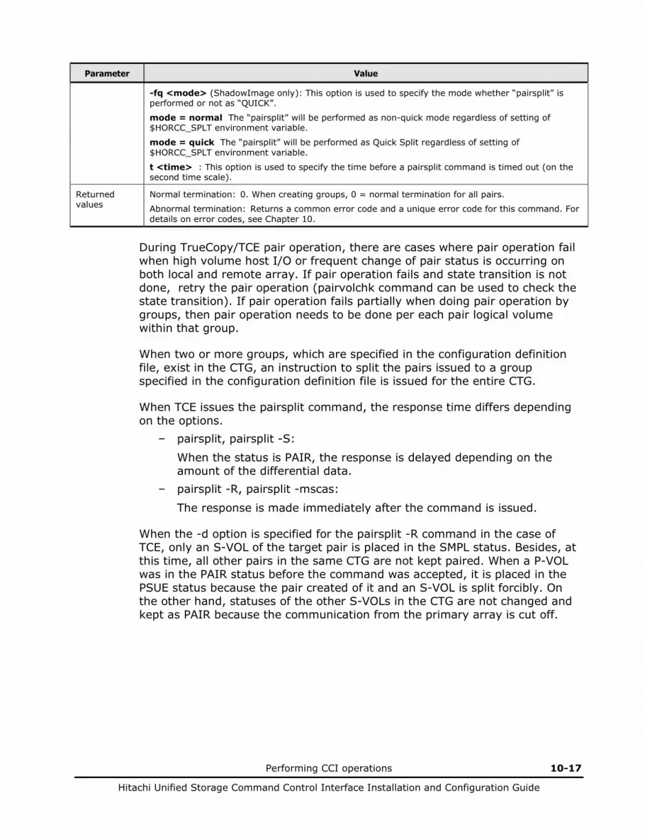
Performing CCI operations 10-17
Hitachi Unified Storage Command Control Interface Installation and Configuration Guide
Parameter Value
-fq <mode> (ShadowImage only): This option is used to specify the mode whether “pairsplit” is performed or not as “QUICK”.
mode = normal The “pairsplit” will be performed as non-quick mode regardless of setting of $HORCC_SPLT environment variable.
mode = quick The “pairsplit” will be performed as Quick Split regardless of setting of $HORCC_SPLT environment variable.
t <time> : This option is used to specify the time before a pairsplit command is timed out (on the second time scale).
Returned values
Normal termination: 0. When creating groups, 0 = normal termination for all pairs.
Abnormal termination: Returns a common error code and a unique error code for this command. For details on error codes, see Chapter 10.
During TrueCopy/TCE pair operation, there are cases where pair operation fail when high volume host I/O or frequent change of pair status is occurring on both local and remote array. If pair operation fails and state transition is not done, retry the pair operation (pairvolchk command can be used to check the state transition). If pair operation fails partially when doing pair operation by groups, then pair operation needs to be done per each pair logical volume within that group.
When two or more groups, which are specified in the configuration definition file, exist in the CTG, an instruction to split the pairs issued to a group specified in the configuration definition file is issued for the entire CTG.
When TCE issues the pairsplit command, the response time differs depending on the options.
– pairsplit, pairsplit -S:
When the status is PAIR, the response is delayed depending on the amount of the differential data.
– pairsplit -R, pairsplit -mscas:
The response is made immediately after the command is issued.
When the -d option is specified for the pairsplit -R command in the case of TCE, only an S-VOL of the target pair is placed in the SMPL status. Besides, at this time, all other pairs in the same CTG are not kept paired. When a P-VOL was in the PAIR status before the command was accepted, it is placed in the PSUE status because the pair created of it and an S-VOL is split forcibly. On the other hand, statuses of the other S-VOLs in the CTG are not changed and kept as PAIR because the communication from the primary array is cut off.
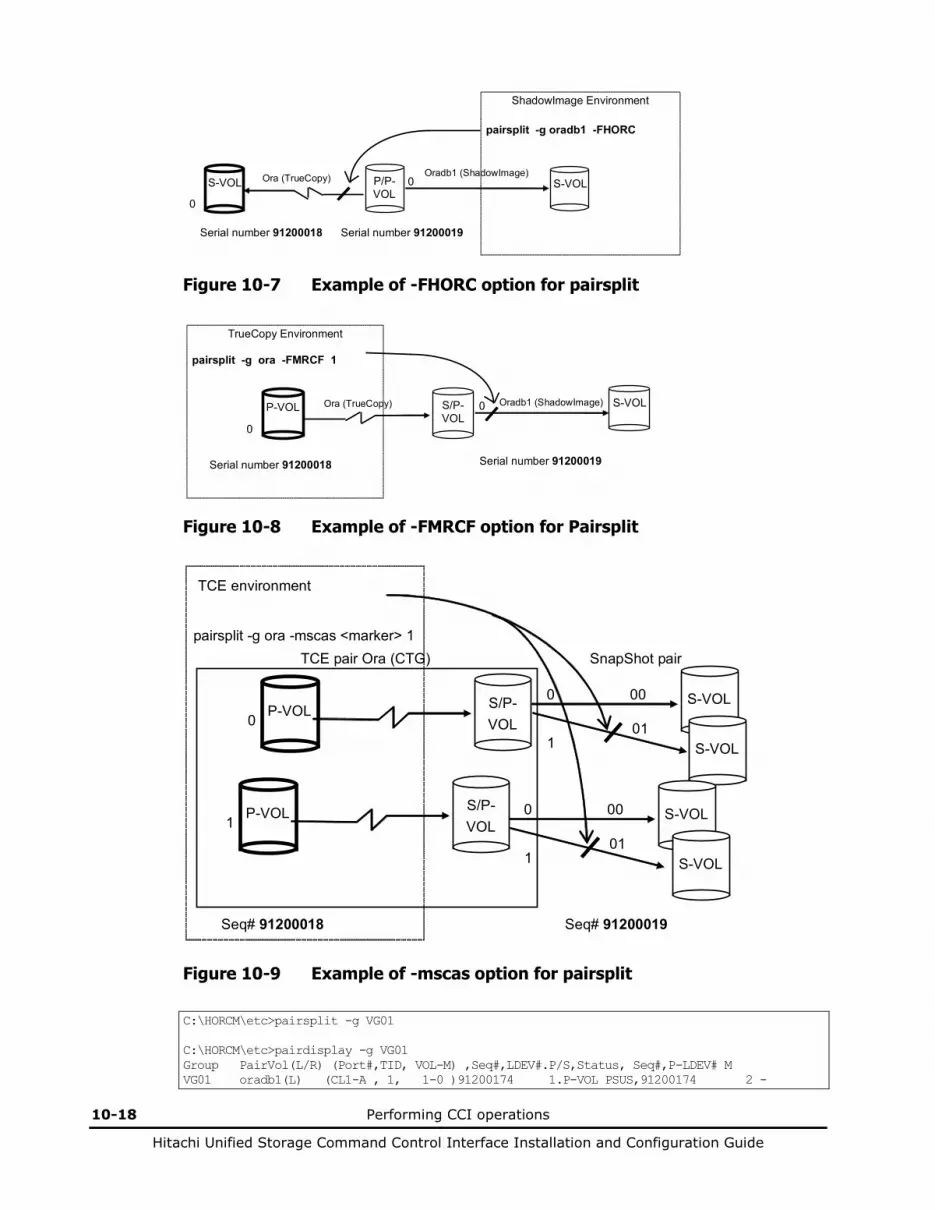
10-18 Performing CCI operations
Hitachi Unified Storage Command Control Interface Installation and Configuration Guide
ShadowImage Environment pairsplit -g oradb1 -FHORC
S-VOL
P/P- VOL
S-VOL
Ora (TrueCopy) Oradb1 (ShadowImage) 0
0
Serial number 91200018 Serial number 91200019
Figure 10-7 Example of -FHORC option for pairsplit
TrueCopy Environment pairsplit -g ora -FMRCF 1
P-VOL
S/P- VOL
S-VOL
Ora (TrueCopy) Oradb1 (ShadowImage) 0
0
Serial number 91200018 Serial number 91200019
Figure 10-8 Example of -FMRCF option for Pairsplit
TCE environment
pairsplit -g ora -mscas <marker> 1
P-VOL
S/P- VOL
S-VOL
TCE pair Ora (CTG)
00 0
0
Seq# 91200018 Seq# 91200019
S-VOL
1 01
SnapShot pair
P-VOL
S/P- VOL
S-VOL
00 0 1
S-VOL
1 01
Figure 10-9 Example of -mscas option for pairsplit
C:\HORCM\etc>pairsplit -g VG01 C:\HORCM\etc>pairdisplay -g VG01 Group PairVol(L/R) (Port#,TID, VOL-M) ,Seq#,LDEV#.P/S,Status, Seq#,P-LDEV# M VG01 oradb1(L) (CL1-A , 1, 1-0 )91200174 1.P-VOL PSUS,91200174 2 -
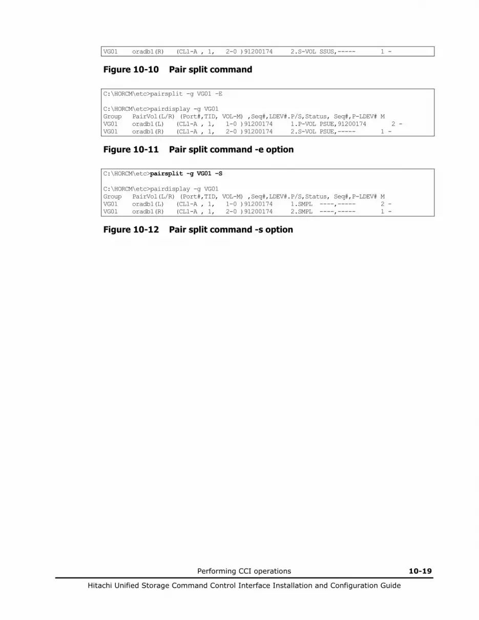
Performing CCI operations 10-19
Hitachi Unified Storage Command Control Interface Installation and Configuration Guide
VG01 oradb1(R) (CL1-A , 1, 2-0 )91200174 2.S-VOL SSUS,----- 1 -
Figure 10-10 Pair split command
C:\HORCM\etc>pairsplit -g VG01 –E C:\HORCM\etc>pairdisplay -g VG01 Group PairVol(L/R) (Port#,TID, VOL-M) ,Seq#,LDEV#.P/S,Status, Seq#,P-LDEV# M VG01 oradb1(L) (CL1-A , 1, 1-0 )91200174 1.P-VOL PSUE,91200174 2 - VG01 oradb1(R) (CL1-A , 1, 2-0 )91200174 2.S-VOL PSUE,----- 1 -
Figure 10-11 Pair split command -e option
C:\HORCM\etc>pairsplit -g VG01 –S C:\HORCM\etc>pairdisplay -g VG01 Group PairVol(L/R) (Port#,TID, VOL-M) ,Seq#,LDEV#.P/S,Status, Seq#,P-LDEV# M VG01 oradb1(L) (CL1-A , 1, 1-0 )91200174 1.SMPL ----,----- 2 - VG01 oradb1(R) (CL1-A , 1, 2-0 )91200174 2.SMPL ----,----- 1 -
Figure 10-12 Pair split command -s option
10-20 Performing CCI operations
Hitachi Unified Storage Command Control Interface Installation and Configuration Guide
Using the pairsplit command
Since a pair is split at the time when the pairsplit command is issued, verify that writing onto pair volumes is fixed before issuing the command.
• Instantaneous offline backup of the UNIX file system: – Unmount the primary volume, and split the volume pair. – Mount the primary volume (mount). – Verify that the pairsplit is complete, and mount the secondary volume
(mount -r). – Perform the backup. – Restore the volumes to their previous state, and resynchronize the
volume pair (ShadowImage/TrueCopy).
• Online backup of the UNIX file system: – Issue the sync command to a mounted primary volume to flush the file
system buffer, and split the volume pair in Read/Write mode. – Verify that the pairsplit is complete, and use the fsck command to
check the consistency of the secondary volume file system. – Mount (mount) the secondary volume. – Perform the backup. – Restore the volumes to their previous state and resynchronize the
volume pair (ShadowImage/TrueCopy).
• Instantaneous offline backup of Windows Server file system: – Issue -x umount of the primary volume, split the volume pair. – Issue -x mount of the primary volume. – Verify that the pairsplit is complete, then issue -x mount of the
secondary volume. – Perform the backup. – Restore the volumes to their previous state, and resynchronize the
volume pair (ShadowImage/TrueCopy).
• Online backup of Windows Server file system: – Issue the -x sync command to a mounted primary volume to flush the
file system buffer, then split the volume pair in Read/Write mode. – Verify that the pairsplit is complete, and use -x mount of the
secondary volume. – Perform the backup. – Restore the volumes to their previous state and resynchronize the
volume pair (ShadowImage/TrueCopy).
If the primary volume is divided by LVM or partition, the control information of LVM or partition on the primary volume is also copied to the secondary volume. When executing the backup from the secondary volume, import this control information and issue pairsplit when activating the secondary volume.

Performing CCI operations 10-21
Hitachi Unified Storage Command Control Interface Installation and Configuration Guide
TCE takes some time for the pair splitting in order to reflect the P-VOL data on the S-VOL.
TCE can split V-VOL of the SnapShot pair cascaded with the secondary volume through the instruction issued from the primary host leaving the pair status as PAIR. From the above, backup data can be collected online more smoothly.

10-22 Performing CCI operations
Hitachi Unified Storage Command Control Interface Installation and Configuration Guide
Resynchronizing pairs
The pairresync command re-establishes a split pair, and restarts the update copy operations to the secondary volume (see Figure 10-13). The pairresync command can resynchronize either a paired logical volume or a group of paired volumes. The normal direction of resynchronization is from the primary volume to the secondary volume. If the -restore option is specified (ShadowImage only), the pair is resynchronized in the reverse direction (i.e., secondary volume to primary volume). Figure 10-14 shows the normal and restore resync operations. The primary volume is read and write accessible during pairresync. The secondary volume becomes write-disabled when the pairresync command is issued.
Table 10-6 lists and describes the pairresync command parameters and returned values. The primary volume’s host is automatically detected by the pairresync command, so the host does not need to be specified in the pairresync command parameters.
The pairresync command terminates before resynchronization of the secondary (or primary) volume is complete. Use the pair event waiting or pair display command to verify that the resync operation completed successfully (status changes from COPY to PAIR). The execution log file also shows completion of the resync operation. The status transition of the paired volume is judged by the status of the primary volume.
If no data was written to the secondary volume while the pair was split, the differential data on the primary volume is copied. If data was written to the secondary volume, the differential data on the primary volume and secondary volume is copied to the secondary volume. This process is reversed when the ShadowImage -restore option is specified.
Before issuing the pairresync command (normal or reverse direction), make sure that the secondary volume is not mounted on any UNIX system. Before issuing a reverse pairresync command, make sure that the primary volume is not mounted on any UNIX system.
Note: Commands that change the status of pairs (paircreate, pairsplit, pairresync) cannot be issued while the host is being restarted in a TrueCopy/TCE environment. Processing may end abruptly when a command is issued while the host is being restarted.
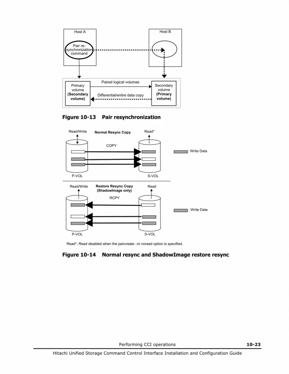
Performing CCI operations 10-23
Hitachi Unified Storage Command Control Interface Installation and Configuration Guide
Pair re- synchronization
command
Host A Host B
Primary volume
(Secondary volume)
Secondary volume
(Primary volume)
Paired logical volumes
Differential/entire data copy
Figure 10-13 Pair resynchronization
P-VOL S-VOL
: Write Data COPY
Read/Write Read*
P-VOL S-VOL
: Write Data
RCPY
Read Read/Write
Normal Resync Copy
Restore Resync Copy (ShadowImage only)
Read*: Read disabled when the paircreate –m noread option is specified.
Figure 10-14 Normal resync and ShadowImage restore resync
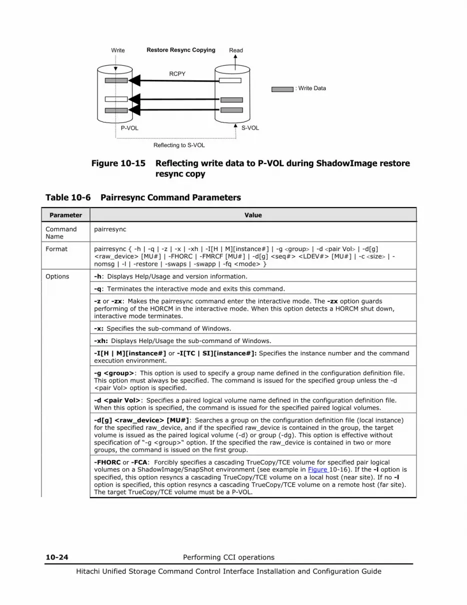
10-24 Performing CCI operations
Hitachi Unified Storage Command Control Interface Installation and Configuration Guide
P-VOL S-VOL
: Write Data
RCPY
Read Write Restore Resync Copying
Reflecting to S-VOL
Figure 10-15 Reflecting write data to P-VOL during ShadowImage restore resync copy
Table 10-6 Pairresync Command Parameters
Parameter Value
Command Name
pairresync
Format pairresync { -h | -q | -z | -x | -xh | -I[H | M][instance#] | -g <group> | -d <pair Vol> | -d[g] <raw_device> [MU#] | -FHORC | -FMRCF [MU#] | -d[g] <seq#> <LDEV#> [MU#] | -c <size> | -nomsg | -l | -restore | -swaps | -swapp | -fq <mode> }
Options -h: Displays Help/Usage and version information.
-q: Terminates the interactive mode and exits this command.
-z or -zx: Makes the pairresync command enter the interactive mode. The -zx option guards performing of the HORCM in the interactive mode. When this option detects a HORCM shut down, interactive mode terminates.
-x: Specifies the sub-command of Windows.
-xh: Displays Help/Usage the sub-command of Windows.
-I[H | M][instance#] or -I[TC | SI][instance#]: Specifies the instance number and the command execution environment.
-g <group>: This option is used to specify a group name defined in the configuration definition file. This option must always be specified. The command is issued for the specified group unless the -d <pair Vol> option is specified.
-d <pair Vol>: Specifies a paired logical volume name defined in the configuration definition file. When this option is specified, the command is issued for the specified paired logical volumes.
-d[g] <raw_device> [MU#]: Searches a group on the configuration definition file (local instance) for the specified raw_device, and if the specified raw_device is contained in the group, the target volume is issued as the paired logical volume (-d) or group (-dg). This option is effective without specification of “-g <group>“ option. If the specified the raw_device is contained in two or more groups, the command is issued on the first group.
-FHORC or -FCA: Forcibly specifies a cascading TrueCopy/TCE volume for specified pair logical volumes on a ShadowImage/SnapShot environment (see example in Figure 10-16). If the -l option is specified, this option resyncs a cascading TrueCopy/TCE volume on a local host (near site). If no -l option is specified, this option resyncs a cascading TrueCopy/TCE volume on a remote host (far site). The target TrueCopy/TCE volume must be a P-VOL.

Performing CCI operations 10-25
Hitachi Unified Storage Command Control Interface Installation and Configuration Guide
Parameter Value
-FMRCF [MU#] or -FBC [MU#]: Forcibly specifies a cascading ShadowImage/SnapShot volume for specified pair logical volumes on a TrueCopy/TCE environment (see example in Figure 10-17). If the -l option is specified, this option resyncs a cascading ShadowImage/SnapShot volume on a local host (near site). If no -l option is specified, this option resyncs a cascading ShadowImage/SnapShot volume on a remote host (far site). The target ShadowImage/SnapShot volume must be a P-VOL.
-d[g] <seq#> <LDEV#> [MU#]: Searches a group on the configuration definition file (local instance) for the specified LDEV, and if the specified LDEV is contained in the group, the target volume is issued as the paired logical volume (-d) or group (-dg). This option is effective without specification of the “-g <group>“ option. If the specified LDEV is contained in two or more groups, the command is issued on the first group. The <seq #> <LDEV #> values can be specified in hexadecimal (by addition of “0x”) or decimal notation.
<seq #> <LDEV #> values can be specified in hexadecimal (by addition of “0x “) or decimal notation.
-c <size>: You can use this option to specify the copying pace for the resync operation (range = 1 to 15). If omitted, the value used for paircreate or at previous pairresync will be used. (1 to 5: slow, 6 to 10: normal, 11 to 15: prior)
-nomsg: Suppresses messages to be displayed when this command is issued. It is used to issue this command from a user program. This option must be specified at the beginning of a command argument. The command execution log is not affected by this option.
-l: When this command cannot utilize the remote host for host down, this option enables a pairresync operation by the local host only. The target volume of the local host can be P-VOL or S-VOL.
-restore: Performs reverse resync (from secondary volume to primary volume).
-swaps (TrueCopy/TCE only): Issued from the S-VOL side when there is no host on the P-VOL side to help. Typically issued in PSUS state to facilitate “fast failback” without requiring a full copy. In Figure 10-18, the left side shows T0 for both the P-VOL and S-VOL (before command execution), and the right side shows T1, after the command has issued. For both -swaps and -swapp, the delta data from the original S-VOL becomes dominant and is copied to the original P-VOL, then the S/P-VOL designations are swapped.
-swapp (TrueCopy/TCE only): Issues the equivalent of a -swaps from the original P-VOL side. Unlike -swaps, -swapp does require the cooperation of hosts at both sides.
-fq <mode> (ShadowImage only): This option is used to specify the mode whether “pairresync” is performed or not as “QUICK”.
mode = normal The “pairresync” will be performed as non-quick mode regardless of setting of $HORCC_RSYN environment variable.
mode = quick The “pairresync” will be performed as Quick Resync regardless of setting of $HORCC_RSYN environment variable.
Returned Values
Normal termination: 0. When resynchronizing groups, 0 = normal termination for all pairs.
Abnormal termination: Returns a common error code and a unique error code for this command. For details on error codes, see Chapter 10.
During TrueCopy/TCE pair operation, there are cases where pair operation fail when high volume host I/O or frequent change of pair status is occuring on both local and remote array. If pair operation fails and state transition is not done, retry the pair operation (pairvolchk command can be used to check the state transition). If pair operation fails partially when doing pair operation by groups, then pair operation needs to be done per each pair logical volume within that group.
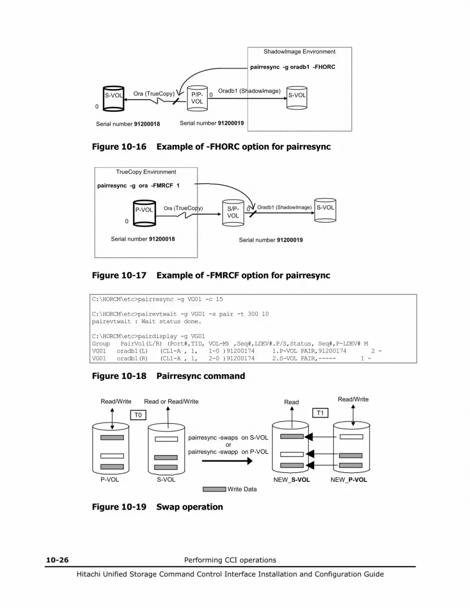
10-26 Performing CCI operations
Hitachi Unified Storage Command Control Interface Installation and Configuration Guide
ShadowImage Environment pairresync -g oradb1 -FHORC
S-VOL
P/P- VOL
S-VOL
Ora (TrueCopy) Oradb1 (ShadowImage) 0
0
Serial number 91200018 Serial number 91200019
Figure 10-16 Example of -FHORC option for pairresync
TrueCopy Environment pairresync -g ora -FMRCF 1
P-VOL
S/P- VOL
S-VOL
Ora (TrueCopy) Oradb1 (ShadowImage) 0
0
Serial number 91200018 Serial number 91200019
Figure 10-17 Example of -FMRCF option for pairresync
C:\HORCM\etc>pairresync -g VG01 -c 15 C:\HORCM\etc>pairevtwait -g VG01 -s pair -t 300 10 pairevtwait : Wait status done. C:\HORCM\etc>pairdisplay -g VG01 Group PairVol(L/R) (Port#,TID, VOL-M) ,Seq#,LDEV#.P/S,Status, Seq#,P-LDEV# M VG01 oradb1(L) (CL1-A , 1, 1-0 )91200174 1.P-VOL PAIR,91200174 2 - VG01 oradb1(R) (CL1-A , 1, 2-0 )91200174 2.S-VOL PAIR,----- 1 -
Figure 10-18 Pairresync command
P-VOL S-VOL Write Data
Read or Read/Write Read/Write
NEW_S-VOL NEW_P-VOL
Read/Write Read
pairresync -swaps on S-VOL or
pairresync -swapp on P-VOL
T0 T1
Figure 10-19 Swap operation
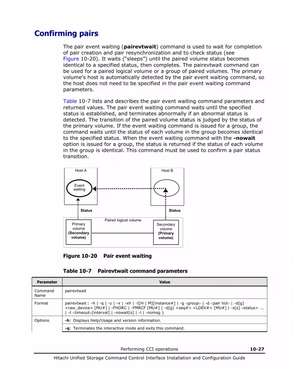
Performing CCI operations 10-27
Hitachi Unified Storage Command Control Interface Installation and Configuration Guide
Confirming pairs
The pair event waiting (pairevtwait) command is used to wait for completion of pair creation and pair resynchronization and to check status (see Figure 10-20). It waits (“sleeps”) until the paired volume status becomes identical to a specified status, then completes. The pairevtwait command can be used for a paired logical volume or a group of paired volumes. The primary volume’s host is automatically detected by the pair event waiting command, so the host does not need to be specified in the pair event waiting command parameters.
Table 10-7 lists and describes the pair event waiting command parameters and returned values. The pair event waiting command waits until the specified status is established, and terminates abnormally if an abnormal status is detected. The transition of the paired volume status is judged by the status of the primary volume. If the event waiting command is issued for a group, the command waits until the status of each volume in the group becomes identical to the specified status. When the event waiting command with the -nowait option is issued for a group, the status is returned if the status of each volume in the group is identical. This command must be used to confirm a pair status transition.
Host A Host B
Primary volume
(Secondary volume)
Secondary volume
(Primary volume)
Paired logical volume
Status Status
Event waiting
Figure 10-20 Pair event waiting
Table 10-7 Pairevtwait command parameters
Parameter Value
Command Name
pairevtwait
Format pairevtwait { -h | -q | -z | -x | -xh | -I[H | M][instance#] | -g <group> | -d <pair Vol> | -d[g] <raw_device> [MU#] | -FHORC | -FMRCF [MU#] | -d[g] <seq#> <LDEV#> [MU#] | -s[s] <status> ... | -t <timeout>[interval] | -nowait[s] | -l | -nomsg }
Options -h: Displays Help/Usage and version information.
-q: Terminates the interactive mode and exits this command.

10-28 Performing CCI operations
Hitachi Unified Storage Command Control Interface Installation and Configuration Guide
Parameter Value
-z or -zx: Makes the pairevtwait command enter the interactive mode. The -zx option guards performing of the HORCM in the interactive mode. When this option detects a HORCM shut down, interactive mode terminates.
-x: Specifies the sub-command of Windows.
-xh: Displays Help/Usage the sub-command of Windows.
-I[H | M][instance#] or -I[TC | SI][instance#]: Specifies the instance number and the command execution environment.
-g <group>: Specifies a group name defined in the configuration definition file. This option must always be specified. The command is issued for the specified group unless the -d <pair Vol> option is specified.
-d <pair Vol>: Specifies a paired logical volume name defined in the configuration definition file. When this option is specified, the command is issued for the specified paired logical volumes.
-d[g] <raw_device> [MU#]: Searches a group on the configuration definition file (local instance) for the specified raw_device, and if the specified raw_device is contained in the group, the target volume is issued as the paired logical volume (-d) or group (-dg). This option is effective without specifying the “-g <group>“ option. If the specified the raw_device is contained in two or more groups, the command is issued on the first group.
-FHORC or -FCA: Forcibly specifies a cascading TrueCopy/TCE volume for specified pair logical volumes on a ShadowImage/SnapShot environment (see example in Figure 10-21). If the -l option is specified, this option tests status of a cascading TrueCopy/TCE volume on a local host (near site). If no -l option is specified, this option tests status of a cascading TrueCopy/TCE volume on a remote host (far site). The target TrueCopy/TCE volume must be P-VOL or SMPL.
-FMRCF [MU#] or -FBC [MU#]: Forcibly specifies a cascading ShadowImage/SnapShot volume for specified pair logical volumes on a TrueCopy/TCE environment (see example in Figure 10-22). If the -l option is specified, this option tests status of a cascading ShadowImage/SnapShot volume on a local host (near site). If no -l option is specified, this option tests status of a cascading ShadowImage/SnapShot volume on a remote host (far site). The target ShadowImage/SnapShot volume must be P-VOL or SMPL.
-d[g] <seq#> <LDEV#> [MU#]: Searches a group on the configuration definition file (local instance) for the specified LDEV, and if the specified LDEV is contained in the group, the target volume is issued as the paired logical volume (-d) or group (-dg). This option is effective without specifying the “-g <group>“ option. If the specified LDEV is contained in two or more groups, the command is issued on the first group. The <seq #> <LDEV #> values can be specified in hexadecimal (by addition of “0x”) or decimal notation.
-s <status> ...: Specifies the waiting status, which is “smpl”, “copy/rcpy”, “pair”, “psus”, or “psue”. If two or more statuses are specified following -s, waiting is done according to the logical OR of the specified statuses. This option is valid when the -nowait option is not specified.
-ss <status> ...: Specifies the waiting status, which is “smpl”, “copy/rcpy”, “pair”, “ssus”, or “psue” on S-VOL. If two or more statuses are specified following -ss, waiting is done according to the logical OR of the specified statuses. This option is valid when the -nowaits option is not specified.
-t <timeout> [interval]: Specifies the interval of monitoring a status specified using the -s option and the time-out period in units of 1 sec. Unless [interval] is specified, the default value is used. This option is valid when the -nowait option is not specified. When a value, 2,000,000 or more is specified for the <timeout>, a warning message is displayed.
-nowait: When this option is specified, the pair status at that time is reported without waiting. The pair status is set as a returned value for this command. When this option is specified, the -t and -s options are not needed.
-nowaits: When this option is specified, the pair status on S-VOL at that time is reported without waiting. The pair status is set as a returned value for this command. When this option is specified, the -t and -ss options are not needed.
-l: When this command cannot utilize a remote host for host down, this option issues this command by a local host only. The target volume of the local host can be P-VOL or S-VOL.
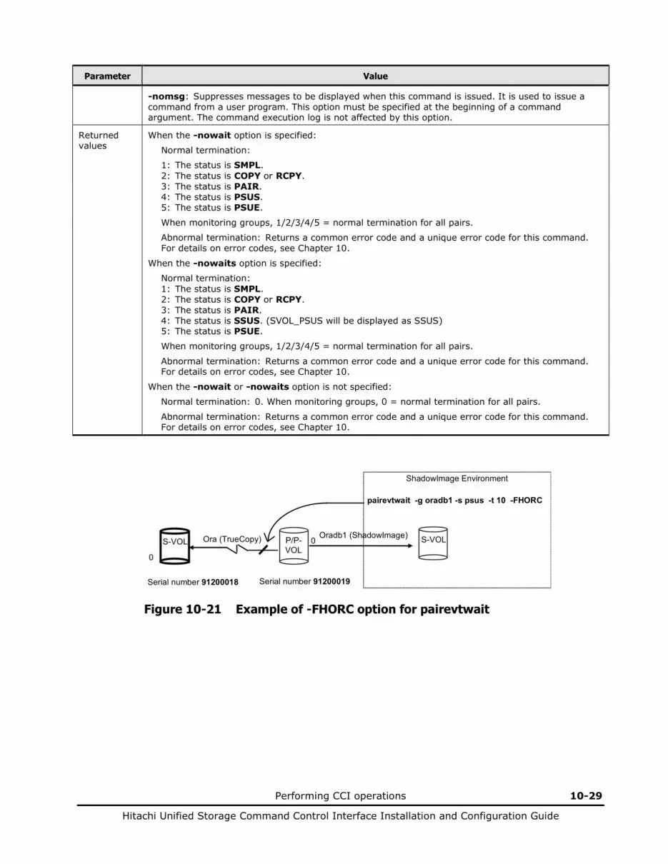
Performing CCI operations 10-29
Hitachi Unified Storage Command Control Interface Installation and Configuration Guide
Parameter Value
-nomsg: Suppresses messages to be displayed when this command is issued. It is used to issue a command from a user program. This option must be specified at the beginning of a command argument. The command execution log is not affected by this option.
Returned values
When the -nowait option is specified:
Normal termination:
1: The status is SMPL. 2: The status is COPY or RCPY. 3: The status is PAIR. 4: The status is PSUS. 5: The status is PSUE.
When monitoring groups, 1/2/3/4/5 = normal termination for all pairs.
Abnormal termination: Returns a common error code and a unique error code for this command. For details on error codes, see Chapter 10.
When the -nowaits option is specified:
Normal termination: 1: The status is SMPL. 2: The status is COPY or RCPY. 3: The status is PAIR. 4: The status is SSUS. (SVOL_PSUS will be displayed as SSUS) 5: The status is PSUE.
When monitoring groups, 1/2/3/4/5 = normal termination for all pairs.
Abnormal termination: Returns a common error code and a unique error code for this command. For details on error codes, see Chapter 10.
When the -nowait or -nowaits option is not specified:
Normal termination: 0. When monitoring groups, 0 = normal termination for all pairs.
Abnormal termination: Returns a common error code and a unique error code for this command. For details on error codes, see Chapter 10.
ShadowImage Environment pairevtwait -g oradb1 -s psus -t 10 -FHORC
S-VOL
P/P- VOL
S-VOL
Ora (TrueCopy) Oradb1 (ShadowImage) 0
0
Serial number 91200018 Serial number 91200019
Figure 10-21 Example of -FHORC option for pairevtwait
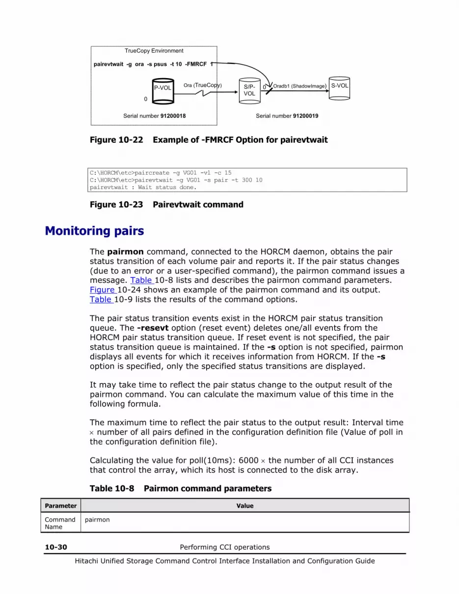
10-30 Performing CCI operations
Hitachi Unified Storage Command Control Interface Installation and Configuration Guide
TrueCopy Environment pairevtwait -g ora -s psus -t 10 -FMRCF 1
P-VOL
S/P- VOL
S-VOL
Ora (TrueCopy) Oradb1 (ShadowImage) 0
0
Serial number 91200018 Serial number 91200019
Figure 10-22 Example of -FMRCF Option for pairevtwait
C:\HORCM\etc>paircreate -g VG01 -vl -c 15 C:\HORCM\etc>pairevtwait -g VG01 -s pair -t 300 10 pairevtwait : Wait status done.
Figure 10-23 Pairevtwait command
Monitoring pairs
The pairmon command, connected to the HORCM daemon, obtains the pair status transition of each volume pair and reports it. If the pair status changes (due to an error or a user-specified command), the pairmon command issues a message. Table 10-8 lists and describes the pairmon command parameters. Figure 10-24 shows an example of the pairmon command and its output. Table 10-9 lists the results of the command options.
The pair status transition events exist in the HORCM pair status transition queue. The -resevt option (reset event) deletes one/all events from the HORCM pair status transition queue. If reset event is not specified, the pair status transition queue is maintained. If the -s option is not specified, pairmon displays all events for which it receives information from HORCM. If the -s option is specified, only the specified status transitions are displayed.
It may take time to reflect the pair status change to the output result of the pairmon command. You can calculate the maximum value of this time in the following formula.
The maximum time to reflect the pair status to the output result: Interval time × number of all pairs defined in the configuration definition file (Value of poll in the configuration definition file).
Calculating the value for poll(10ms): 6000 × the number of all CCI instances that control the array, which its host is connected to the disk array.
Table 10-8 Pairmon command parameters
Parameter Value
Command Name
pairmon
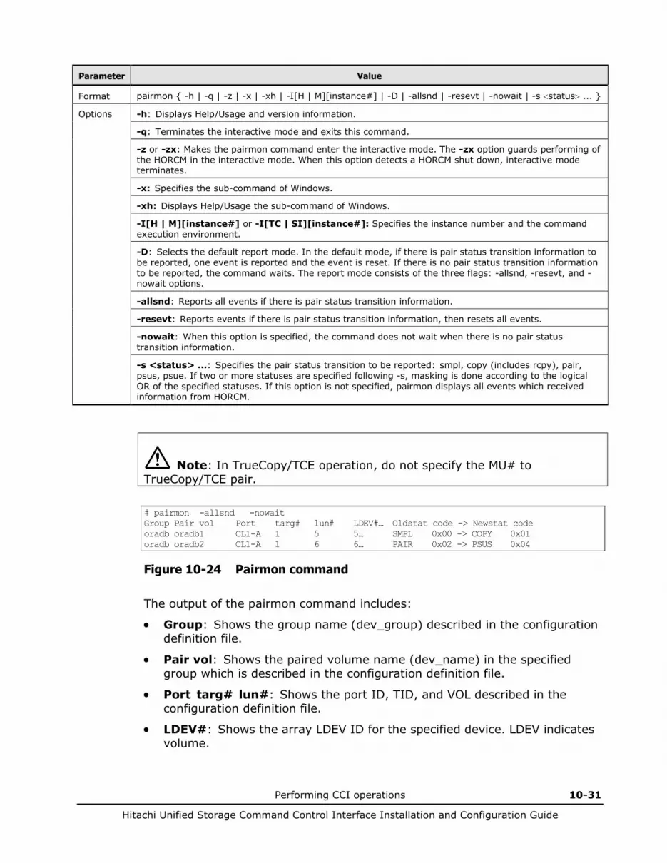
Performing CCI operations 10-31
Hitachi Unified Storage Command Control Interface Installation and Configuration Guide
Parameter Value
Format pairmon { -h | -q | -z | -x | -xh | -I[H | M][instance#] | -D | -allsnd | -resevt | -nowait | -s <status> ... }
Options -h: Displays Help/Usage and version information.
-q: Terminates the interactive mode and exits this command.
-z or -zx: Makes the pairmon command enter the interactive mode. The -zx option guards performing of the HORCM in the interactive mode. When this option detects a HORCM shut down, interactive mode terminates.
-x: Specifies the sub-command of Windows.
-xh: Displays Help/Usage the sub-command of Windows.
-I[H | M][instance#] or -I[TC | SI][instance#]: Specifies the instance number and the command execution environment.
-D: Selects the default report mode. In the default mode, if there is pair status transition information to be reported, one event is reported and the event is reset. If there is no pair status transition information to be reported, the command waits. The report mode consists of the three flags: -allsnd, -resevt, and -nowait options.
-allsnd: Reports all events if there is pair status transition information.
-resevt: Reports events if there is pair status transition information, then resets all events.
-nowait: When this option is specified, the command does not wait when there is no pair status transition information.
-s <status> ...: Specifies the pair status transition to be reported: smpl, copy (includes rcpy), pair, psus, psue. If two or more statuses are specified following -s, masking is done according to the logical OR of the specified statuses. If this option is not specified, pairmon displays all events which received information from HORCM.
Note: In TrueCopy/TCE operation, do not specify the MU# to TrueCopy/TCE pair.
# pairmon -allsnd -nowait Group Pair vol Port targ# lun# LDEV#… Oldstat code -> Newstat code oradb oradb1 CL1-A 1 5 5… SMPL 0x00 -> COPY 0x01 oradb oradb2 CL1-A 1 6 6… PAIR 0x02 -> PSUS 0x04
Figure 10-24 Pairmon command
The output of the pairmon command includes:
• Group: Shows the group name (dev_group) described in the configuration definition file.
• Pair vol: Shows the paired volume name (dev_name) in the specified group which is described in the configuration definition file.
• Port targ# lun#: Shows the port ID, TID, and VOL described in the configuration definition file.
• LDEV#: Shows the array LDEV ID for the specified device. LDEV indicates volume.

10-32 Performing CCI operations
Hitachi Unified Storage Command Control Interface Installation and Configuration Guide
• Oldstat: Shows the old pair status when the status of the volume is changed.
• Newstat: Shows the new pair status when the status of the volume is changed.
• Code: Shows the array-internal code for the specified status.
Table 10-9 Results of pairmon command options
-D -nowait -resevt -allsnd Actions
-D When HORCM does not have an event, this option waits until an event occurs. If one or more events exist, it reports one event and resets the event which it reported.
Invalid -allsnd When HORCM does not have an event, this option waits until an event occurs. If one or more events exist, it reports all events.
Invalid -resevt When HORCM does not have an event, this option waits until an event occurs. If one or more events exist, it reports one event and resets all events.
Invalid -resevt -allsnd When HORCM does not have an event, this option waits until an event occurs. If one or more events exist, it reports all events and resets all events.
Invalid -nowait When HORCM does not have an event, this option reports event nothing. If one or more events exist, it reports one event and resets the event which it reported.
Invalid -nowait -allsnd When HORCM does not have an event, this option reports event nothing. If one or more events exist, it reports all events.
Invalid -nowait -resevt When HORCM does not have an event, this option reports event nothing. If one or more events exist, it reports one event and resets all events.
Invalid -nowait -resevt -allsnd When HORCM does not have an event, this option reports event nothing. If one or more events exist, it reports all events and resets all events.

Performing CCI operations 10-33
Hitachi Unified Storage Command Control Interface Installation and Configuration Guide
Checking pair attribute and status
The pairvolchk command acquires and reports the attribute of a volume or group connected to the local host (issuing the command) or remote host. The volume attribute is SMPL (simplex), P-VOL (primary volume), or S-VOL (secondary volume). The -s[s] option reports the pair status in addition to the attribute. Table 10-10 lists and describes the pairvolchk command parameters and returned values. Figure 10-27 shows an example of the pairvolchk command and its output. Table 10-11 shows the truth table for pairvolchk group status display.
Table 10-10 Pairvolchk command parameters
Parameter Value
Command Name
pairvolchk
Format pairvolchk { -h | -q | -z | -x | -xh | -I[H | M][instance#] | -g <group> | -d <pair Vol> | -d[g] <raw_device> [MU#] | -FHORC | -FMRCF [MU#] | -d[g] <seq#> <LDEV#> [MU#] | -c | -ss | -nomsg }
Options -h: Displays Help/Usage and version information.
-q: Terminates the interactive mode and exits the pair volume check command.
-z or -zx: Makes the pairvolchk command enter the interactive mode. The -zx option guards performing of the HORCM in the interactive mode. When this option detects a HORCM shut down, interactive mode terminates.
-x: Specifies the sub-command of Windows.
-xh: Displays Help/Usage the sub-command of Windows.
-I[H | M][instance#] or -I[TC | SI][instance#]: Specifies the instance number and the command execution environment.
-g <group>: Specifies the group name defined in the configuration definition file. This option must always be specified. The command is issued for the specified group unless the -d <pair Vol> option is specified.
-d <pair Vol>: This option is used to specify the paired logical volume name defined in the configuration definition file. When this option is specified, the command is issued for the specified paired logical volumes.
-d[g] <raw_device> [MU#]: Searches a group on the configuration definition file (local instance) for the specified raw_device, and if the specified raw_device is contained in the group, the target volume is issued as the paired logical volume (-d) or group (-dg). This option is effective without specifying the “-g <group>“ option. If the specified the raw_device is contained in two or more groups, the command is issued on the first group.
-FHORC or -FCA: Forcibly specifies a cascading TrueCopy/TCE volume for specified pair logical volumes on a ShadowImage/SnapShot environment (see example in Figure 10-25). If no -c option is specified, this option acquires the attributes of a cascading TrueCopy/TCE volume on a local host (near site). If the -c option is specified, this option acquires the attributes of a cascading TrueCopy/TCE volume on a remote host (far site).
-FMRCF [MU#] or -FBC [MU#]: Forcibly specifies a cascading ShadowImage/SnapShot volume for specified pair logical volumes on a TrueCopy/TCE environment (see example in Figure 10-26). If no -c option is specified, this option acquires the attributes of a cascading ShadowImage/SnapShot volume on a local host (near site). If the -c option is specified, this option acquires the attributes of a cascading ShadowImage/SnapShot volume on a remote host (far site).
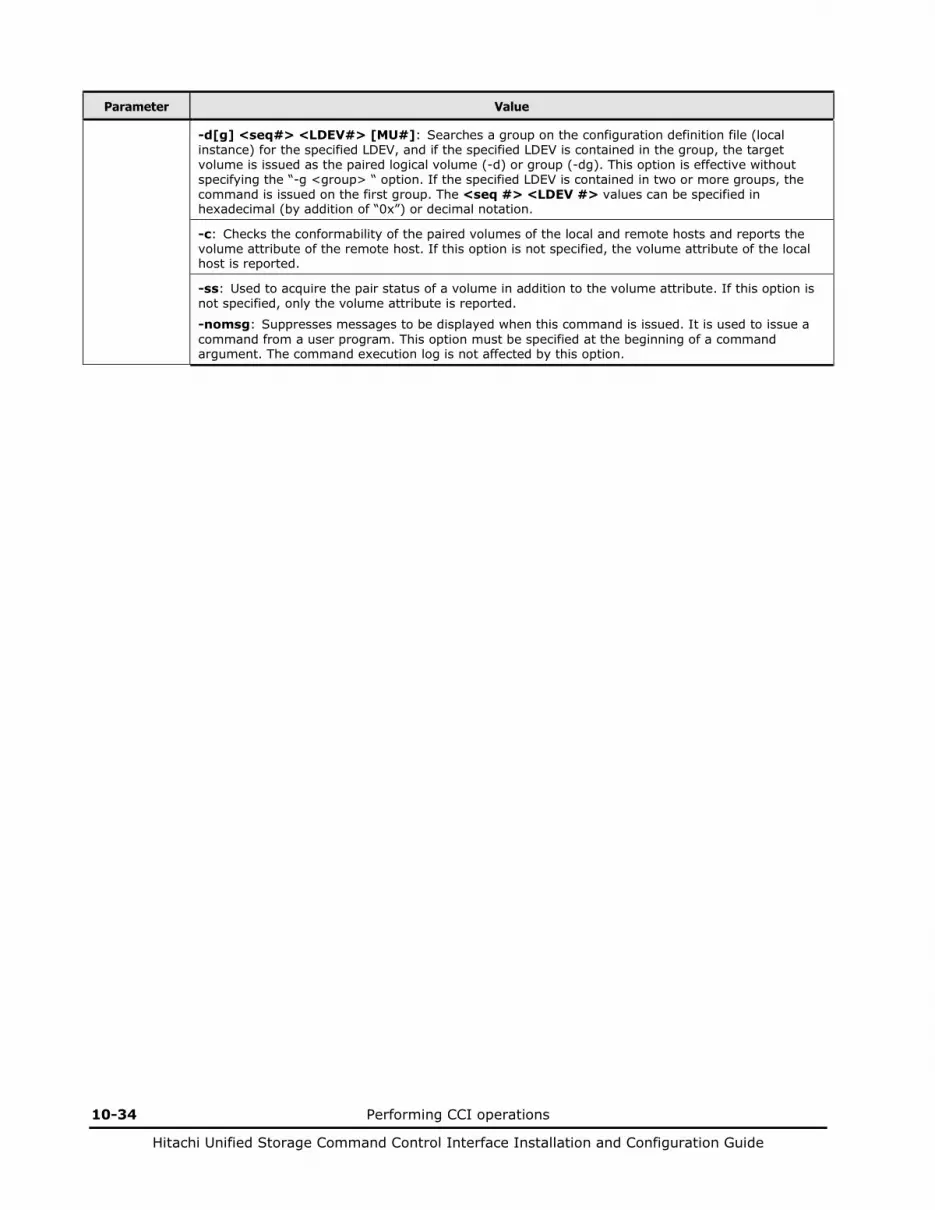
10-34 Performing CCI operations
Hitachi Unified Storage Command Control Interface Installation and Configuration Guide
Parameter Value
-d[g] <seq#> <LDEV#> [MU#]: Searches a group on the configuration definition file (local instance) for the specified LDEV, and if the specified LDEV is contained in the group, the target volume is issued as the paired logical volume (-d) or group (-dg). This option is effective without specifying the “-g <group> “ option. If the specified LDEV is contained in two or more groups, the command is issued on the first group. The <seq #> <LDEV #> values can be specified in hexadecimal (by addition of “0x”) or decimal notation.
-c: Checks the conformability of the paired volumes of the local and remote hosts and reports the volume attribute of the remote host. If this option is not specified, the volume attribute of the local host is reported.
-ss: Used to acquire the pair status of a volume in addition to the volume attribute. If this option is not specified, only the volume attribute is reported.
-nomsg: Suppresses messages to be displayed when this command is issued. It is used to issue a command from a user program. This option must be specified at the beginning of a command argument. The command execution log is not affected by this option.

Performing CCI operations 10-35
Hitachi Unified Storage Command Control Interface Installation and Configuration Guide
Parameter Value
Returned values
When the -ss option is not specified:
Normal termination:
1: The volume attribute is SMPL. 2: The volume attribute is P-VOL. 3: The volume attribute is S-VOL. Abnormal termination: Returns a common error code and a unique error code for this command. For details on error codes, see Chapter 10.
When the -ss option is specified:
Normal termination:
11: The status is SMPL.
For SnapShot: 22: The status is PVOL_COPY or PVOL_RCPY. 23: The status is PVOL_PAIR. 24: The status is PVOL_PSUS. 25: The status is PVOL_PSUE. 28: The status is PVOL_PFUS. 32: The status is SVOL_COPY or SVOL_RCPY. 33: The status is SVOL_PAIR. 34: The status is SVOL_PSUS. 35: The status is SVOL_PSUE. 38: The status is SVOL_PFUS.
39: The status is SVOL_PFUS or SVOL_PSUS.
For TrueCopy and ShadowImage: 22: The status is PVOL_COPY or PVOL_RCPY. 23: The status is PVOL_PAIR. 24: The status is PVOL_PSUS. 25: The status is PVOL_PSUE. 32: The status is SVOL_COPY or SVOL_RCPY. 33: The status is SVOL_PAIR. 34: The status is SVOL_PSUS. 35: The status is SVOL_PSUE.
For TCE: 42: The status is PVOL_COPY. 43: The status is PVOL_PAIR. 44: The status is PVOL_PSUS. 45: The status is PVOL_PSUE. 48: The status is PVOL_PFUS. 52: The status is SVOL_COPY. 53: The status is SVOL_PAIR. 54: The status is SVOL_PSUS. 55: The status is SVOL_PSUE. 58: The status is SVOL_PFUS.
Abnormal termination: Returns a common error code and a unique error code for this command. For details on error codes, see Chapter 10.
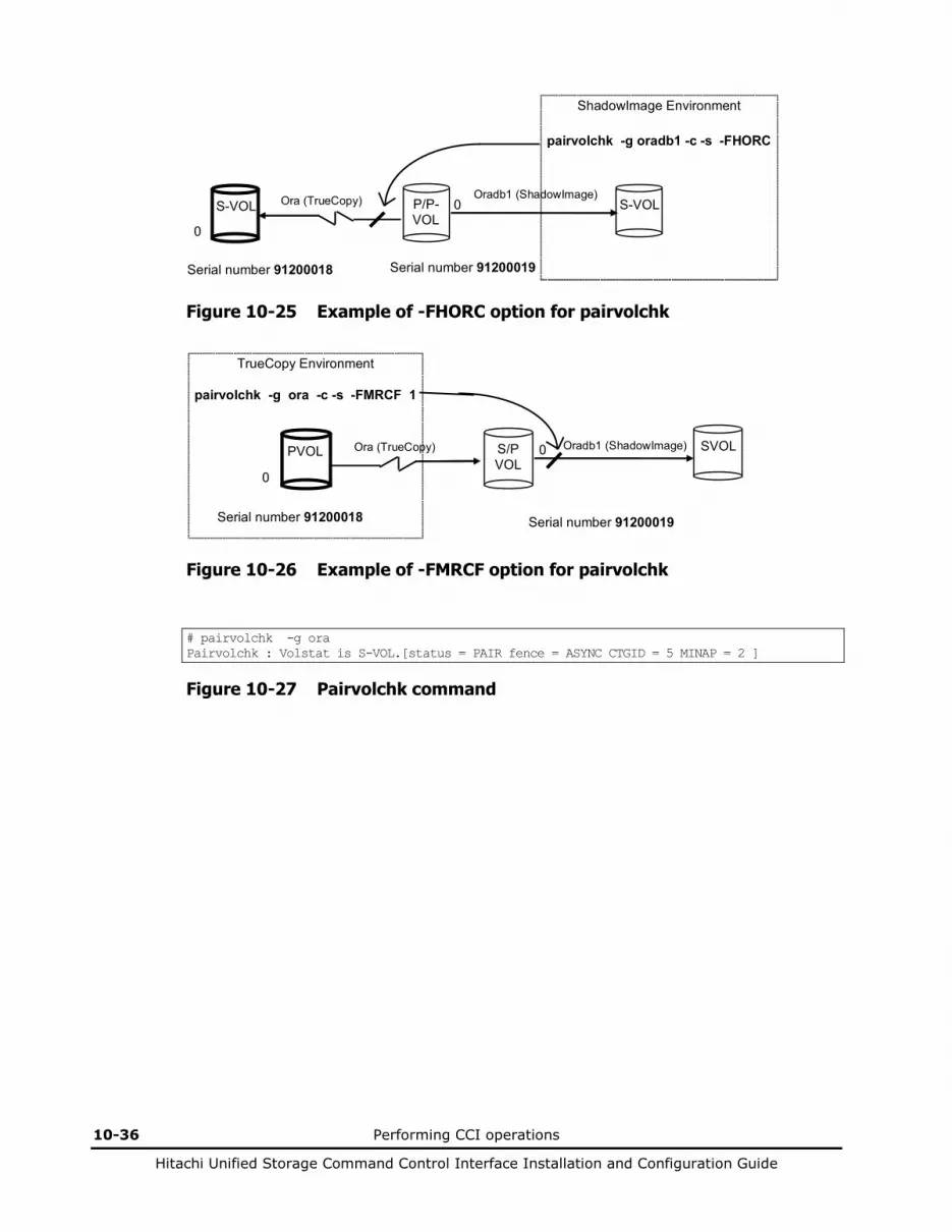
10-36 Performing CCI operations
Hitachi Unified Storage Command Control Interface Installation and Configuration Guide
ShadowImage Environment pairvolchk -g oradb1 -c -s -FHORC
S-VOL
P/P- VOL
S-VOL
Ora (TrueCopy) Oradb1 (ShadowImage) 0
0
Serial number 91200018 Serial number 91200019
Figure 10-25 Example of -FHORC option for pairvolchk
TrueCopy Environment pairvolchk -g ora -c -s -FMRCF 1
PVOL
S/P VOL
SVOL
Ora (TrueCopy) Oradb1 (ShadowImage) 0
0
Serial number 91200018 Serial number 91200019
Figure 10-26 Example of -FMRCF option for pairvolchk
# pairvolchk -g ora Pairvolchk : Volstat is S-VOL.[status = PAIR fence = ASYNC CTGID = 5 MINAP = 2 ]
Figure 10-27 Pairvolchk command
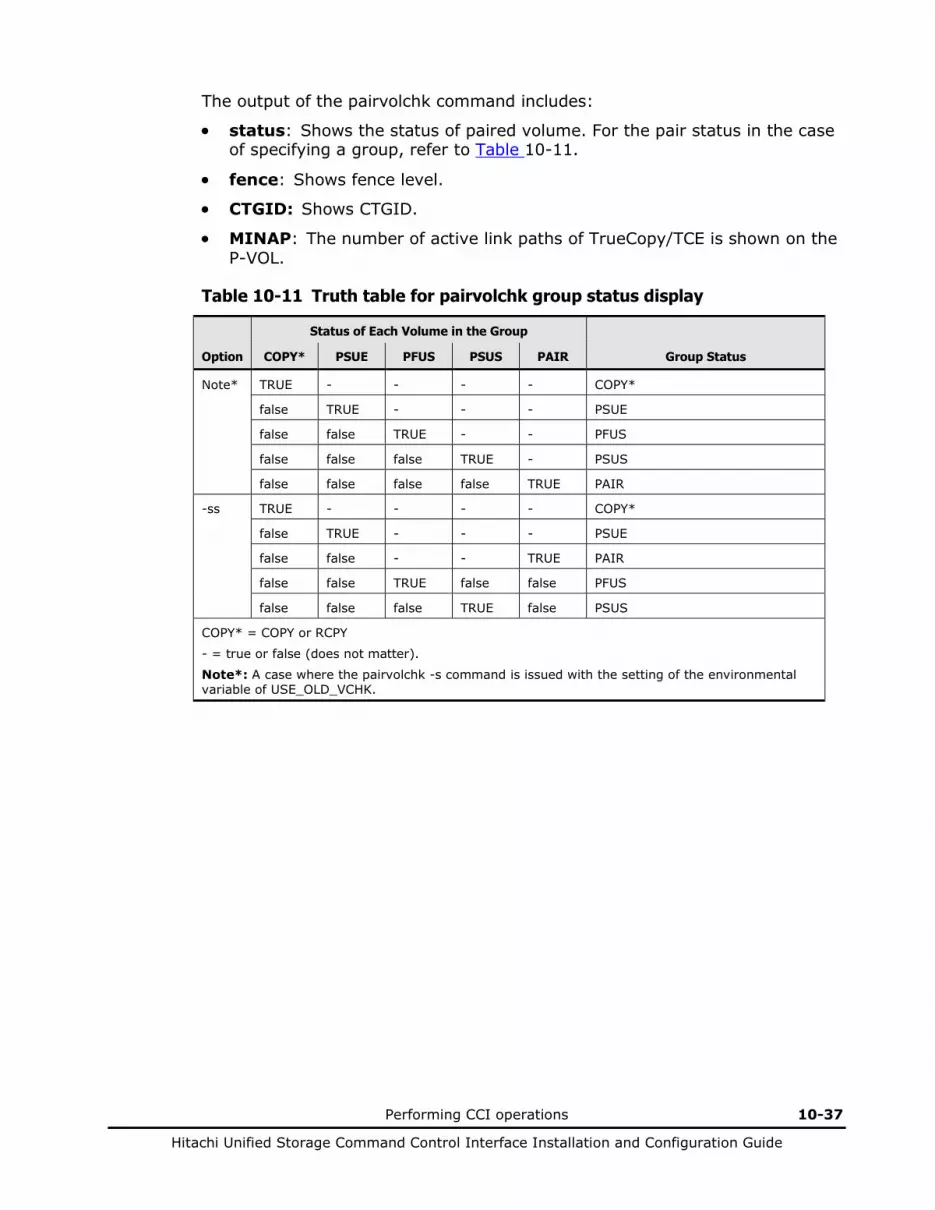
Performing CCI operations 10-37
Hitachi Unified Storage Command Control Interface Installation and Configuration Guide
The output of the pairvolchk command includes:
• status: Shows the status of paired volume. For the pair status in the case of specifying a group, refer to Table 10-11.
• fence: Shows fence level.
• CTGID: Shows CTGID.
• MINAP: The number of active link paths of TrueCopy/TCE is shown on the P-VOL.
Table 10-11 Truth table for pairvolchk group status display
Status of Each Volume in the Group
Option COPY* PSUE PFUS PSUS PAIR Group Status
Note* TRUE - - - - COPY*
false TRUE - - - PSUE
false false TRUE - - PFUS
false false false TRUE - PSUS
false false false false TRUE PAIR
-ss TRUE - - - - COPY*
false TRUE - - - PSUE
false false - - TRUE PAIR
false false TRUE false false PFUS
false false false TRUE false PSUS
COPY* = COPY or RCPY
- = true or false (does not matter).
Note*: A case where the pairvolchk -s command is issued with the setting of the environmental variable of USE_OLD_VCHK.
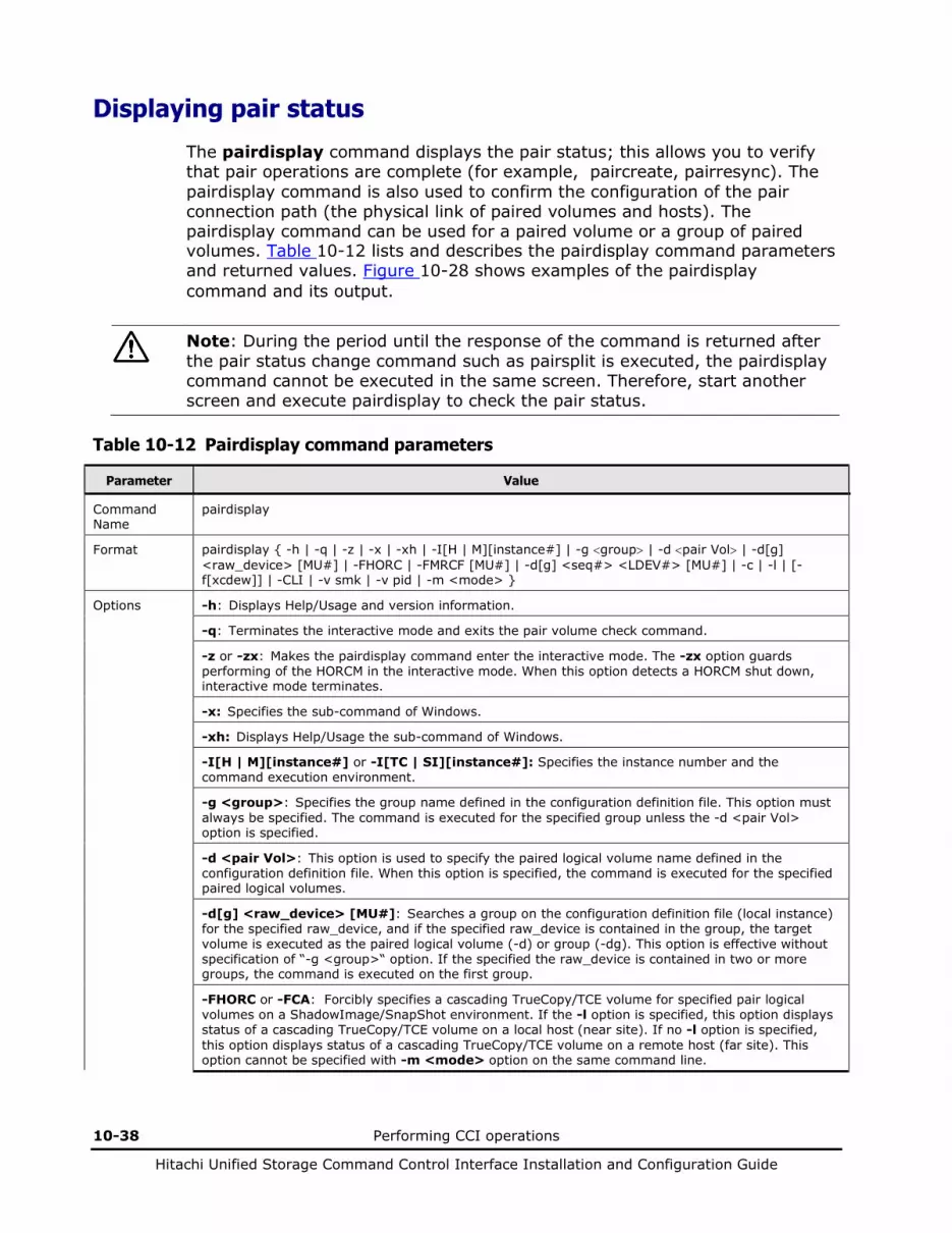
10-38 Performing CCI operations
Hitachi Unified Storage Command Control Interface Installation and Configuration Guide
Displaying pair status
The pairdisplay command displays the pair status; this allows you to verify that pair operations are complete (for example, paircreate, pairresync). The pairdisplay command is also used to confirm the configuration of the pair connection path (the physical link of paired volumes and hosts). The pairdisplay command can be used for a paired volume or a group of paired volumes. Table 10-12 lists and describes the pairdisplay command parameters and returned values. Figure 10-28 shows examples of the pairdisplay command and its output.
Note: During the period until the response of the command is returned after the pair status change command such as pairsplit is executed, the pairdisplay command cannot be executed in the same screen. Therefore, start another screen and execute pairdisplay to check the pair status.
Table 10-12 Pairdisplay command parameters
Parameter Value
Command Name
pairdisplay
Format pairdisplay { -h | -q | -z | -x | -xh | -I[H | M][instance#] | -g <group> | -d <pair Vol> | -d[g] <raw_device> [MU#] | -FHORC | -FMRCF [MU#] | -d[g] <seq#> <LDEV#> [MU#] | -c | -l | [-f[xcdew]] | -CLI | -v smk | -v pid | -m <mode> }
Options -h: Displays Help/Usage and version information.
-q: Terminates the interactive mode and exits the pair volume check command.
-z or -zx: Makes the pairdisplay command enter the interactive mode. The -zx option guards performing of the HORCM in the interactive mode. When this option detects a HORCM shut down, interactive mode terminates.
-x: Specifies the sub-command of Windows.
-xh: Displays Help/Usage the sub-command of Windows.
-I[H | M][instance#] or -I[TC | SI][instance#]: Specifies the instance number and the command execution environment.
-g <group>: Specifies the group name defined in the configuration definition file. This option must always be specified. The command is executed for the specified group unless the -d <pair Vol> option is specified.
-d <pair Vol>: This option is used to specify the paired logical volume name defined in the configuration definition file. When this option is specified, the command is executed for the specified paired logical volumes.
-d[g] <raw_device> [MU#]: Searches a group on the configuration definition file (local instance) for the specified raw_device, and if the specified raw_device is contained in the group, the target volume is executed as the paired logical volume (-d) or group (-dg). This option is effective without specification of “-g <group>“ option. If the specified the raw_device is contained in two or more groups, the command is executed on the first group.
-FHORC or -FCA: Forcibly specifies a cascading TrueCopy/TCE volume for specified pair logical volumes on a ShadowImage/SnapShot environment. If the -l option is specified, this option displays status of a cascading TrueCopy/TCE volume on a local host (near site). If no -l option is specified, this option displays status of a cascading TrueCopy/TCE volume on a remote host (far site). This option cannot be specified with -m <mode> option on the same command line.
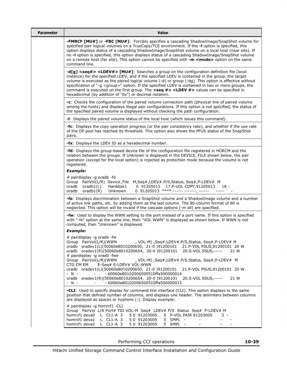
Performing CCI operations 10-39
Hitachi Unified Storage Command Control Interface Installation and Configuration Guide
Parameter Value
-FMRCF [MU#] or -FBC [MU#]: Forcibly specifies a cascading ShadowImage/SnapShot volume for specified pair logical volumes on a TrueCopy/TCE environment. If the -l option is specified, this option displays status of a cascading ShadowImage/SnapShot volume on a local host (near site). If no -l option is specified, this option displays status of a cascading ShadowImage/SnapShot volume on a remote host (far site). This option cannot be specified with -m <mode> option on the same command line.
-d[g] <seq#> <LDEV#> [MU#]: Searches a group on the configuration definition file (local instance) for the specified LDEV, and if the specified LDEV is contained in the group, the target volume is executed as the paired logical volume (-d) or group (-dg). This option is effective without specification of “-g <group>“ option. If the specified LDEV is contained in two or more groups, the command is executed on the first group. The <seq #> <LDEV #> values can be specified in hexadecimal (by addition of “0x”) or decimal notation.
-c: Checks the configuration of the paired volume connection path (physical link of paired volume among the hosts) and displays illegal pair configurations. If this option is not specified, the status of the specified paired volume is displayed without checking the path configuration.
-l: Displays the paired volume status of the local host (which issues this command).
-fc: Displays the copy operation progress (or the pair consistency rate), and whether if the use rate of the DP pool has reached its threshold. This option also shows the PFUS status of the SnapShot pairs.
-fx: Displays the LDEV ID as a hexadecimal number.
-fd: Displays the group-based device file of the configuration file registered in HORCM and the relation between the groups. If Unknown is displayed in the DEVICE_FILE shown below, the pair operation (except for the local option) is rejected as protection mode because the volume is not registered.
Example: # pairdisplay -g oradb -fd Group PairVol(L/R) Device_File M,Seq#,LDEV#.P/S,Status, Seq#,P-LDEV# M oradb oradb1(L) Harddisk1 0 91205013 17.P-VOL COPY,91205013 18 - oradb oradb1(R) Unknown 0 91205013 ****.------ -------, ------ ----- -
-fe: Displays discrimination between a SnapShot volume and a ShadowImage volume and a number of active link paths, etc. by adding them as the last column. The 80-column format of 80 is neglected. This option will be invalid if the cascade options (-m all) are specified.
-fw: Used to display the WWN setting to the port instead of a port name. If this option is specified with “-fe” option at the same line, then “VOL WWN” is displayed as shown below. If WWN is not computed, then “Unknown” is displayed.
Example: # pairdisplay -g oradb -fw Group PairVol(L/R)(WWN , VOL-M) ,Seq#,LDEV#.P/S,Status, Seq#,P-LDEV# M oradb oradev1(L)(50060e8010200650, 21-0 )91200101 21.P-VOL PSUS,91200101 20 W oradb oradev1(R)(50060e8010200654, 20-0 )91200101 20.S-VOL SSUS,----- 21 W # pairdisplay -g oradb -fwe Group PairVol(L/R)(WWN , VOL-M) ,Seq#,LDEV#.P/S,Status, Seq#,P-LDEV# M CTG CM EM E-Seq# E-LDEV# VOL-WWN oradb oradev1(L)(50060e8010200650, 21-0 )91200101 21.P-VOL PSUS,91200101 20 W - N - - - 60060e80102006500510ffa500000014 oradb oradev1(R)(50060e8010200654, 20-0 )91200101 20.S-VOL SSUS,----- 21 W - N - - - 60060e80102006500510ffa500000015
-CLI: Used to specify display for command line interface (CLI). This option displays to the same position that defined number of columns, and displays one header. The delimiters between columns are displayed as spaces or hyphens (-). Display example:
# pairdisplay -g homrcf1 -CLI Group PairVol L/R Port# TID VOL-M Seq# LDEV# P/S Status Seq# P-LDEV# M homrcf1 deva0 L CL1-A 3 5 0 91203005 5 P-VOL PAIR 91203005 3 - homrcf1 deva1 L CL1-A 3 5 0 91203005 5 SMPL - - - - homrcf1 deva2 L CL1-A 3 5 0 91203005 5 SMPL - - - -

10-40 Performing CCI operations
Hitachi Unified Storage Command Control Interface Installation and Configuration Guide
Parameter Value
-v smk (for ShadowImage/SnapShot): This option displays Split-Marker (character string within 31 characters) added to the S-VOL (in case of ShadowImage) or the V-VOL (in case of SnapShot) and the time (UTC) which added Split-Marker. Split-Marker is added when pair split is executed by pairsplit -ms.
-v pid (for SnapShot only): This option displays the pair volume name or the information on the pool which the pair specified by <raw_device> uses. The information on the pool of the local side is displayed on the 1st line, and the information on the pool of the remote side is displayed on the 2nd line. If executing it to the SnapShot pair, the displays of the 1st line and the 2nd line become equal. Note: This option displays nothing if the target volume is NOT SnapShot volume.
-m <mode>: Used to display a paired status of each mirror descriptors for the specified pair logical volume, and used for paired status indication of the cascading volume. <mode> option can be designated “all “ (see Figure 10-29):
“all” option is used to display a paired status of all mirror descriptors (MU#).
Returned values
Normal termination: 0. Abnormal termination: Returns a common error code for this command. For details on error codes, see Chapter 2.
# pairdisplay -g oradb Group PairVol(L/R) (Port#,TID, VOL-M) ,Seq#,LDEV#.P/S,Status, Seq#,P-LDEV# M oradb oradb1(L) (CL1-A , 1, 1-0 )91203005 1.P-VOL COPY,91203005 19 - oradb oradb1(R) (CL1-A , 2, 1-0 )91203005 1.S-VOL COPY,----- 18 -
Figure 10-28 Pairdisplay command
The output of the pairdisplay command includes:
• Group: Shows the group name (dev_group) described in the configuration definition file.
• Pair Vol(L/R): Shows the paired volume name (dev_name) described in the configuration definition file. (L) indicates the local host; (R) indicates the remote host.
• (Port#,TID,VOL) (TrueCopy/TCE): Shows the port number, target ID and volume number as described in the configuration definition file.
• (Port#,TID,VOL-M) (ShadowImage/SnapShot): Shows the port number, target ID, volume number, and MU number as described in the configuration definition file.
• Seq#: Shows the serial number of the disk array.
• LDEV#: Shows the logical device number. LDEV indicates volume.
• P/S: Shows the volume attribute.
• Status: Shows the status of the paired volume.
• Fence (for TrueCopy/TCE): Shows fence level.

Performing CCI operations 10-41
Hitachi Unified Storage Command Control Interface Installation and Configuration Guide
• %: Shows copy operation completion or percent pair synchronization.
State TrueCopy TCE ShadowImage/SnapShot VOL. COPY PAIR OTHER COPY PAIR OTHER COPY PAIR PVOL_PSUS
SVOL_COPY OTHER
P-VOL CR BMP BMP CR UnBMP BMP CR CR BMP CR
S-VOL - BMP BMP - UnBMP BMP CR CR CR CR
CR: Shows the copy operation rate (identical rate of a pair).
BMP: Shows the identical percentage of BITMAP both P-VOL and S-VOL.
UnBMP: Shows the inconsistent percentage of BITMAP both P-VOL and S-VOL.
When the paircreate or pairresync command is executed, the pair undergoes the full copy or differential copy in the COPY status, undergoes the cyclic copy once, and then placed in the PAIR status. When a new pair is added to a CTG, which is already placed in the PAIR status, by the paircreate or pairresync command, the copy operation halts until the time of the existing cyclic copy after the full copy or differential copy is completed. Further, it is not placed in the PAIR status until the first cyclic copy is completed after it begins to act in time to the cycle. Therefore, the pair synchronization rate displayed by Hitachi Storage Navigator Modular 2 or CCI may be 100% or not changed when the pair status is COPY.
• P-LDEV#: Shows the LDEV number of the partner volume of the pair.
• M
M = W (PSUS only): For P-VOLs, shows suspension with the S-VOL read/write enabled. For S-VOLs, shows that write I/Os were accepted at the S-VOL. M = N (COPY, PAIR, PSUE, PSUS only): Shows that read access is disabled. At this time, make sure of the pair, which is displayed by Hitachi Storage Navigator Modular 2, status of which is PSUS (PSUS(N)), and no reading/writing from/to which is allowed.
Figure 10-29 shows examples of the -m option of the pairdisplay command.
Display examples for -m all:
# pairdisplay -g oradb -m all Group PairVol(L/R) (Port#,TID, VOL-M) ,Seq#,LDEV#.P/S,Status, Seq#,P-LDEV# M oradb oradev1(L) (CL1-A , 3, 0-0 )91203005 0.SMPL ----, ---- ---- - oradb oradev1(L) (CL1-A , 3, 0-0 )91203005 0.P-VOL PAIR,91203005 26 - oradb1 oradev11(R) (CL1-A , 3, 2-0 )91203005 2.P-VOL COPY,91203005 27 - oradb oradev1(R) (CL1-A , 3, 2-0 )91203005 2.S-VOL COPY, ----- 25 - # pairdisplay -d Harddisk1 -l -m all Group PairVol(L/R) (Port#,TID, VOL-M) ,Seq#,LDEV#.P/S,Status, Seq#,P-LDEV# M oradb oradev1(L) (CL1-A , 3, 0-0 )91203005 0.SMPL ----, ---- ---- - oradb oradev1(L) (CL1-A , 3, 0-0 )91203005 0.P-VOL PAIR,91203005 26 -
Figure 10-29 Pairdisplay command -m option
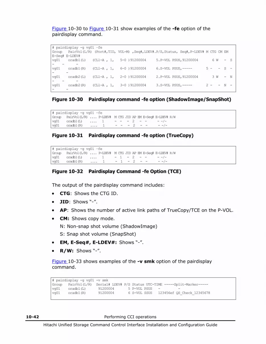
10-42 Performing CCI operations
Hitachi Unified Storage Command Control Interface Installation and Configuration Guide
Figure 10-30 to Figure 10-31 show examples of the -fe option of the pairdisplay command.
# pairdisplay -g vg01 –fe Group PairVol(L/R) (Port#,TID, VOL-M) ,Seq#,LDEV#.P/S,Status, Seq#,P-LDEV# M CTG CM EM E-Seq# E-LDEV# vg01 oradb1(L) (CL1-A , 1, 5-0 )91200004 5.P-VOL PSUS,91200004 6 W - S - - - vg01 oradb1(R) (CL1-A , 1, 6-0 )91200004 6.S-VOL PSUS,----- 5 - - S - - - vg01 oradb2(L) (CL1-A , 1, 2-0 )91200004 2.P-VOL PSUS,91200004 3 W - N - - - vg01 oradb2(R) (CL1-A , 1, 3-0 )91200004 3.S-VOL PSUS,----- 2 - - N - - -
Figure 10-30 Pairdisplay command -fe option (ShadowImage/SnapShot)
# pairdisplay -g vg01 –fe Group PairVol(L/R) .... P-LDEV# M CTG JID AP EM E-Seq# E-LDEV# R/W vg01 oradb1(L) .... 1 - - - 2 - - - -/- vg01 oradb1(R) .... 1 - - - 2 - - - -/-
Figure 10-31 Pairdisplay command -fe option (TrueCopy)
# pairdisplay -g vg01 –fe Group PairVol(L/R) .... P-LDEV# M CTG JID AP EM E-Seq# E-LDEV# R/W vg01 oradb1(L) .... 1 - 1 - 2 - - - -/- vg01 oradb1(R) .... 1 - 1 - 2 - - - -/-
Figure 10-32 Pairdisplay Command -fe Option (TCE)
The output of the pairdisplay command includes:
• CTG: Shows the CTG ID.
• JID: Shows “-”.
• AP: Shows the number of active link paths of TrueCopy/TCE on the P-VOL.
• CM: Shows copy mode.
N: Non-snap shot volume (ShadowImage) S: Snap shot volume (SnapShot)
• EM, E-Seq#, E-LDEV#: Shows “-”.
• R/W: Shows “-”.
Figure 10-33 shows examples of the -v smk option of the pairdisplay command.
# pairdisplay -g vg01 -v smk Group PairVol(L/R) Serial# LDEV# P/S Status UTC-TIME -----Split-Marker----- vg01 oradb1(L) 91200004 5 P-VOL PSUS - - vg01 oradb1(R) 91200004 6 S-VOL SSUS 123456ef QS_Check_12345678
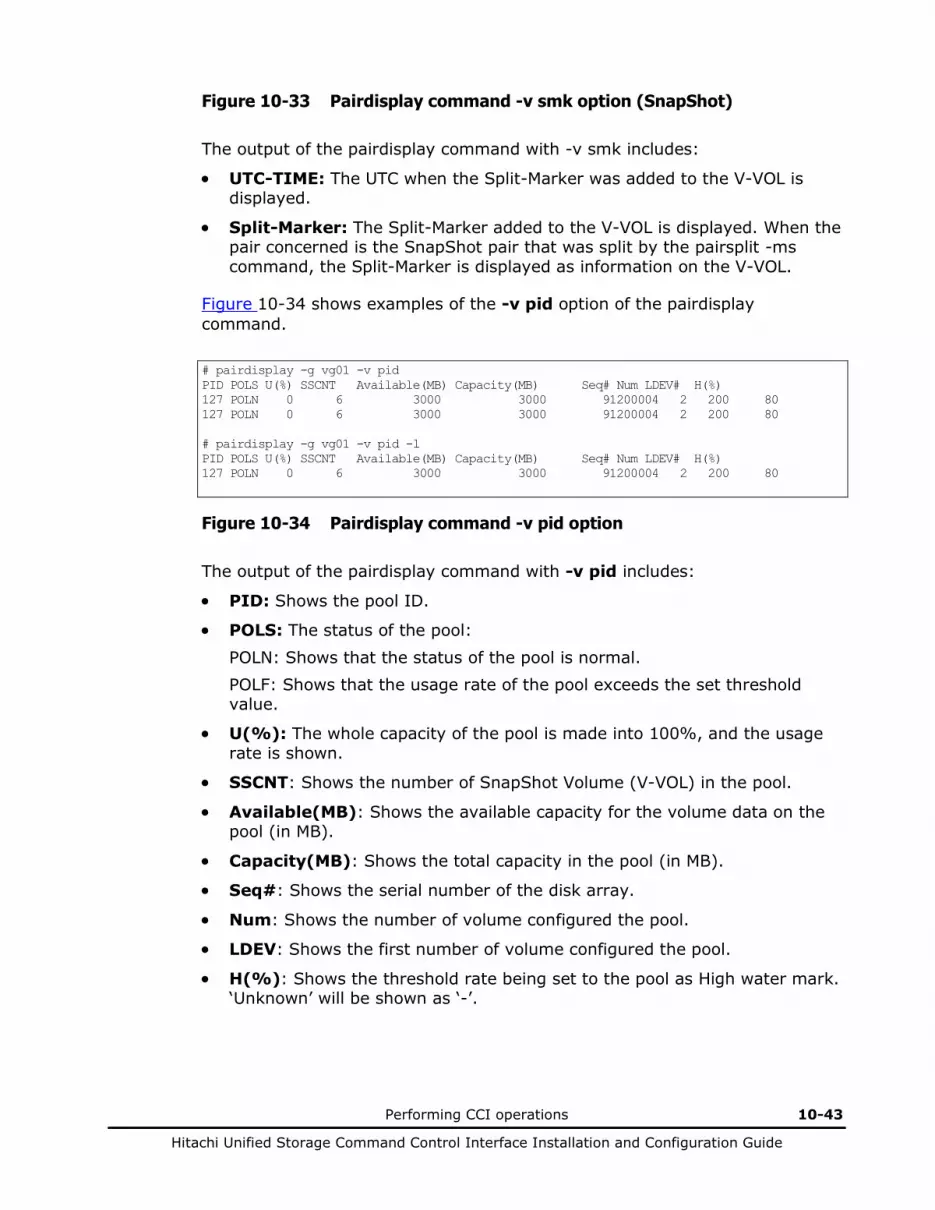
Performing CCI operations 10-43
Hitachi Unified Storage Command Control Interface Installation and Configuration Guide
Figure 10-33 Pairdisplay command -v smk option (SnapShot)
The output of the pairdisplay command with -v smk includes:
• UTC-TIME: The UTC when the Split-Marker was added to the V-VOL is displayed.
• Split-Marker: The Split-Marker added to the V-VOL is displayed. When the pair concerned is the SnapShot pair that was split by the pairsplit -ms command, the Split-Marker is displayed as information on the V-VOL.
Figure 10-34 shows examples of the -v pid option of the pairdisplay command.
# pairdisplay -g vg01 -v pid PID POLS U(%) SSCNT Available(MB) Capacity(MB) Seq# Num LDEV# H(%) 127 POLN 0 6 3000 3000 91200004 2 200 80 127 POLN 0 6 3000 3000 91200004 2 200 80 # pairdisplay -g vg01 -v pid -l PID POLS U(%) SSCNT Available(MB) Capacity(MB) Seq# Num LDEV# H(%) 127 POLN 0 6 3000 3000 91200004 2 200 80
Figure 10-34 Pairdisplay command -v pid option
The output of the pairdisplay command with -v pid includes:
• PID: Shows the pool ID.
• POLS: The status of the pool:
POLN: Shows that the status of the pool is normal. POLF: Shows that the usage rate of the pool exceeds the set threshold value.
• U(%): The whole capacity of the pool is made into 100%, and the usage rate is shown.
• SSCNT: Shows the number of SnapShot Volume (V-VOL) in the pool.
• Available(MB): Shows the available capacity for the volume data on the pool (in MB).
• Capacity(MB): Shows the total capacity in the pool (in MB).
• Seq#: Shows the serial number of the disk array.
• Num: Shows the number of volume configured the pool.
• LDEV: Shows the first number of volume configured the pool.
• H(%): Shows the threshold rate being set to the pool as High water mark. ‘Unknown’ will be shown as ‘-’.

10-44 Performing CCI operations
Hitachi Unified Storage Command Control Interface Installation and Configuration Guide
Checking TrueCopy/TCE pair currency
The TrueCopy/TCE paircurchk command checks the currency of the TrueCopy/TCE secondary volumes by evaluating the data consistency based on pair status and fence level. Table 10-13 specifies the data consistency for each possible state of a TrueCopy/TCE volume. A paired volume or group can be specified as the target of the paircurchk command. The paircurchk command assumes that the target is an S-VOL. If the paircurchk command is specified for a group, the data consistency of each volume in the group is checked, and all inconsistent volumes are found in the execution log file and displayed. Paircurchk is also executed as part of the TrueCopy/TCE horctakeover command (see the next section).
TrueCopy/TCE supports the paircurchk command. The paircurchk command may be executed in the cases where it is performed by the user specification and the SVOL_Takeover processing by the horctakeover command.
Table 10-13 Data consistency displayed by the paircurchk command
Object Volume Paircurchk Attribute Status Fence User Specification SVOL_Takeover Processing
SMPL − − To be confirmed (Not executed)
P-VOL − − To be confirmed (Not executed)
S-VOL
COPY Data Inconsistent Inconsistent
Never
Async
PAIR Data OK OK
Never To be analyzed To be analyzed
Async To be analyzed OK
PSUS Data Suspected Suspected
Never
Async
PSUS(N) Async Suspected Inconsistent
PFUS Async Suspected OK
PSUE Data OK OK
Never Suspected Suspected
Async OK
SSWS Async Suspected (Not executed)
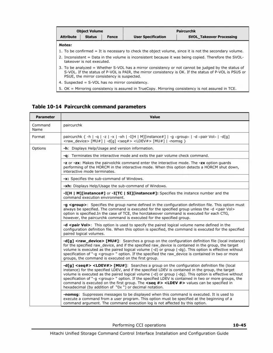
Performing CCI operations 10-45
Hitachi Unified Storage Command Control Interface Installation and Configuration Guide
Object Volume Paircurchk Attribute Status Fence User Specification SVOL_Takeover Processing
Notes: 1. To be confirmed = It is necessary to check the object volume, since it is not the secondary volume.
2. Inconsistent = Data in the volume is inconsistent because it was being copied. Therefore the SVOL-takeover is not executed.
3. To be analyzed = Whether S-VOL has a mirror consistency or not cannot be judged by the status of S-VOL. If the status of P-VOL is PAIR, the mirror consistency is OK. If the status of P-VOL is PSUS or PSUE, the mirror consistency is suspected.
4. Suspected = S-VOL has no mirror consistency.
5. OK = Mirroring consistency is assured in TrueCopy. Mirroring consistency is not assured in TCE.
Table 10-14 Paircurchk command parameters
Parameter Value
Command Name
paircurchk
Format paircurchk { -h | -q | -z | -x | -xh | -I[H | M][instance#] | -g <group> | -d <pair Vol> | -d[g] <raw_device> [MU#] | -d[g] <seq#> <LDEV#> [MU#] | -nomsg }
Options -h: Displays Help/Usage and version information.
-q: Terminates the interactive mode and exits the pair volume check command.
-z or -zx: Makes the pairvolchk command enter the interactive mode. The -zx option guards performing of the HORCM in the interactive mode. When this option detects a HORCM shut down, interactive mode terminates.
-x: Specifies the sub-command of Windows.
-xh: Displays Help/Usage the sub-command of Windows.
-I[H | M][instance#] or -I[TC | SI][instance#]: Specifies the instance number and the command execution environment.
-g <group>: Specifies the group name defined in the configuration definition file. This option must always be specified. The command is executed for the specified group unless the -d <pair Vol> option is specified.In the case of TCE, the horctakeover command is executed for each CTG, however, the paircurchk command is executed for the specified group.
-d <pair Vol>: This option is used to specify the paired logical volume name defined in the configuration definition file. When this option is specified, the command is executed for the specified paired logical volumes.
-d[g] <raw_device> [MU#]: Searches a group on the configuration definition file (local instance) for the specified raw_device, and if the specified raw_device is contained in the group, the target volume is executed as the paired logical volume (-d) or group (-dg). This option is effective without specification of “-g <group> “ option. If the specified the raw_device is contained in two or more groups, the command is executed on the first group.
-d[g] <seq#> <LDEV#> [MU#]: Searches a group on the configuration definition file (local instance) for the specified LDEV, and if the specified LDEV is contained in the group, the target volume is executed as the paired logical volume (-d) or group (-dg). This option is effective without specification of “-g <group> “ option. If the specified LDEV is contained in two or more groups, the command is executed on the first group. The <seq #> <LDEV #> values can be specified in hexadecimal (by addition of “0x “) or decimal notation.
-nomsg: Suppresses messages to be displayed when this command is executed. It is used to execute a command from a user program. This option must be specified at the beginning of a command argument. The command execution log is not affected by this option.
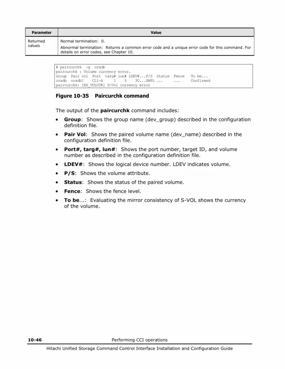
10-46 Performing CCI operations
Hitachi Unified Storage Command Control Interface Installation and Configuration Guide
Parameter Value
Returned values
Normal termination: 0.
Abnormal termination: Returns a common error code and a unique error code for this command. For details on error codes, see Chapter 10.
# paircurchk -g oradb paircurchk : Volume currency error. Group Pair vol Port targ# lun# LDEV#...P/S Status Fence To be... oradb oradb1 CL1-A 1 5 30...SMPL ... ... Confirmed paircurchk: [EX_VOLCUR] S-Vol currency error
Figure 10-35 Paircurchk command
The output of the paircurchk command includes:
• Group: Shows the group name (dev_group) described in the configuration definition file.
• Pair Vol: Shows the paired volume name (dev_name) described in the configuration definition file.
• Port#, targ#, lun#: Shows the port number, target ID, and volume number as described in the configuration definition file.
• LDEV#: Shows the logical device number. LDEV indicates volume.
• P/S: Shows the volume attribute.
• Status: Shows the status of the paired volume.
• Fence: Shows the fence level.
• To be...: Evaluating the mirror consistency of S-VOL shows the currency of the volume.
Performing CCI operations 10-47
Hitachi Unified Storage Command Control Interface Installation and Configuration Guide
Performing TrueCopy/TCE takeover
When the array to be used is changed to the remote one by the horctakeover command, the local array is placed in the PSUE status, depending on the time when the change is made because of a collision with an I/O instruction issued by a host to the local array. This status transition occurs because the change is untimely. However, even if this occurs, reading/writing from/to an S-VOL of the remote array can be done because the horctakeover command keeps the S-VOL in the PSUS status (SSWS).
In the case of TrueCopy, when the horctakeover command is issued to the remote array, there may be a rare case where the SWAP-Takeover fails and terminates in the SVOL-Takeover status because of a load of the other CCI command on the local array added to a load of the horctakeover command. However, even if this occurs, the S-VOL is kept in the PSUS status (SSWS) and reading/writing from/to it can be done. Besides, a swap between a primary and secondary volume can be done when it is possible after statuses of the local and remote arrays are checked and the pairresync -swaps command is executed for the remote array.
When the -d option is specified in the case of TCE, only an S-VOL of the target pair is placed in the SSWS status. Besides, at this time, all the other pairs in the same CTG are not kept paired. When a P-VOL was in the PAIR status before the command was accepted, it is placed in the PSUE status because the pair created of it and an S-VOL is split forcibly. On the other hand, statuses of the other S-VOLs in the CTG are not changed and kept as PAIR because the communication from the primary array is cut off.
The horctakeover command is a scripted command for executing several HORC operations. The horctakeover command checks the specified volume’s or group’s attributes (paircurchk), decides the takeover function based on the attributes, executes the chosen takeover function, and returns the result. The four TrueCopy takeover functions designed for HA software operation are: takeover-switch, swap-takeover, PVOL-takeover, and SVOL-takeover. TCE takeover function designed for HA software operation is SVOL-takeover only. A paired volume or a group can be specified as the target of the TrueCopy/TCE horctakeover command. If TrueCopy/TCE SVOL-takeover is specified for a group, the data consistency check is executed for all volumes in the group, and all inconsistent volumes are found in the execution log file and displayed (same as paircurchk command).
The horctakeover command allows swapping of the primary and secondary volumes, so that if the primary or secondary volume is switched due to a server error or package transfer, duplex operations can be continued using the reversed volumes. When control is handed over to the current node, swapping the volumes again deletes the need to copy them. The horctakeover command also allows the secondary volume to be separated for disaster recovery operations.

10-48 Performing CCI operations
Hitachi Unified Storage Command Control Interface Installation and Configuration Guide
Table 10-15 lists and describes the TrueCopy/TCE horctakeover command parameters and returned values.
Table 10-15 Horctakeover command parameters
Parameter Value
Command Name
horctakeover
Format horctakeover { -h | -q | -z | -x | -xh | -I[H | M][instance#] | -g <group> | -d <pair Vol> | -d[g] <raw_device> [MU#] | -d[g] <seq#> <LDEV#> [MU#] |-S | -l | -t<timeout> | -nomsg }
Options -h: Displays Help/Usage and version information.
-q: Terminates the interactive mode and exits the pair volume check command.
-z or -zx: Makes the pairvolchk command enter the interactive mode. The -zx option guards performing of the HORCM in the interactive mode. When this option detects a HORCM shut down, interactive mode terminates.
-x: Specifies the sub-command of Windows.
-xh: Displays Help/Usage the sub-command of Windows.
-I[H | M][instance#] or -I[TC | SI][instance#]: Specifies the instance number and the command execution environment.
-g <group>: Specifies the group name defined in the configuration definition file. This option must always be specified. The command is executed for the specified group unless the -d <pair Vol> option is specified.
-d <pair Vol>: This option is used to specify the paired logical volume name defined in the configuration definition file. When this option is specified, the command is executed for the specified paired logical volumes.
-d[g] <raw_device> [MU#]: Searches a group on the configuration definition file (local instance) for the specified raw_device, and if the specified raw_device is contained in the group, the target volume is executed as the paired logical volume (-d) or group (-dg). This option is effective without specification of “-g <group> “ option. If the specified the raw_device is contained in two or more groups, the command is executed on the first group.
-d[g] <seq#> <LDEV#> [MU#]: Searches a group on the configuration definition file (local instance) for the specified LDEV, and if the specified LDEV is contained in the group, the target volume is executed as the paired logical volume (-d) or group (-dg). This option is effective without specification of “-g <group> “ option. If the specified LDEV is contained in two or more groups, the command is executed on the first group. The <seq #> <LDEV #> values can be specified in hexadecimal (by addition of “0x “) or decimal notation.
-S: Selects and executes SVOL-takeover. The target volume of the local host must be an S-VOL. If this option is specified, then the following “-l” option is invalid.
-l: Enables read and write to the primary volumes by a local host only without a remote host, and executes PVOL-takeover when the primary volume cannot be used because it is fenced (fence = DATA, state = PSUE, or PSUE volume is contained in the group). If the primary volume can be accessed, nop- takeover is executed. The target volume of the local host must be a P-VOL.
-t<timeout>: Must be specified for async volumes only (TCE), ignored for sync. Specifies the maximum time to wait (in seconds) for swap-takeover and SVOL-takeover operation to synchronize the P-VOL and S-VOL. If this timeout occurs, the horctakeover command fails with EX_EWSTOT. To avoid timeout, set this value less than or equal to the start-up timeout value of the HA Control Script.
-nomsg: Suppresses messages to be displayed when this command is executed. It is used to execute a command from a user program. This option must be specified at the beginning of a command argument. The command execution log is not affected by this option.

Performing CCI operations 10-49
Hitachi Unified Storage Command Control Interface Installation and Configuration Guide
Parameter Value
Returned values
Normal termination:
0: Nop-takeover (no operation). 1: Swap-takeover was successfully executed. 2: SVOL-takeover was successfully executed. 3: PVOL-SMPL-takeover was successfully executed. 4: PVOL-PSUE-takeover was successfully executed. 5: SVOL-SSUS-takeover was successfully executed.
Abnormal termination: other than 0-5, Returns a common error code and a unique error code for this command. For details on error codes, see Chapter 10.
During TrueCopy/TCE pair operation, there are cases where pair operation fail when high volume host I/O or frequent change of pair status is occurring on both local and remote array. If pair operation fails and state transition is not done, then retry the pair operation (pairvolchk command can be used to check the state transition). When some of the pair operators fail, it is required to perform the pair operation for each logical volume pair in the group.
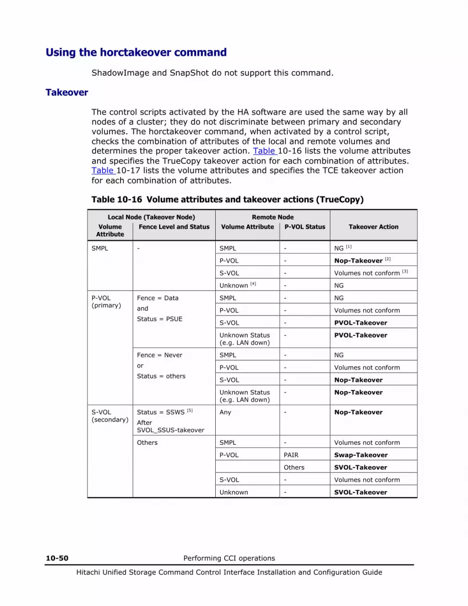
10-50 Performing CCI operations
Hitachi Unified Storage Command Control Interface Installation and Configuration Guide
Using the horctakeover command
ShadowImage and SnapShot do not support this command.
Takeover
The control scripts activated by the HA software are used the same way by all nodes of a cluster; they do not discriminate between primary and secondary volumes. The horctakeover command, when activated by a control script, checks the combination of attributes of the local and remote volumes and determines the proper takeover action. Table 10-16 lists the volume attributes and specifies the TrueCopy takeover action for each combination of attributes. Table 10-17 lists the volume attributes and specifies the TCE takeover action for each combination of attributes.
Table 10-16 Volume attributes and takeover actions (TrueCopy)
Local Node (Takeover Node) Remote Node Volume
Attribute Fence Level and Status Volume Attribute P-VOL Status Takeover Action
SMPL - SMPL - NG [1]
P-VOL - Nop-Takeover [2]
S-VOL - Volumes not conform [3]
Unknown [4] - NG
P-VOL (primary)
Fence = Data
and
Status = PSUE
SMPL - NG
P-VOL - Volumes not conform
S-VOL - PVOL-Takeover
Unknown Status (e.g. LAN down)
- PVOL-Takeover
Fence = Never
or
Status = others
SMPL - NG
P-VOL - Volumes not conform
S-VOL - Nop-Takeover
Unknown Status (e.g. LAN down)
- Nop-Takeover
S-VOL (secondary)
Status = SSWS [5]
After SVOL_SSUS-takeover
Any - Nop-Takeover
Others SMPL - Volumes not conform
P-VOL PAIR Swap-Takeover
Others SVOL-Takeover
S-VOL - Volumes not conform
Unknown - SVOL-Takeover

Performing CCI operations 10-51
Hitachi Unified Storage Command Control Interface Installation and Configuration Guide
Table 10-17 Volume attributes and takeover actions (TCE)
Local Node (Takeover Node) Remote Node
Volume Attribute Fence Level and Status Volume Attribute
P-VOL Status Takeover Action
SMPL - SMPL - NG [1]
P-VOL - Nop-Takeover [2]
S-VOL - Volumes not conform [3]
Unknown [4] - NG
P-VOL (primary) Fence = Async SMPL - NG
P-VOL - Volumes not conform
S-VOL - Nop-Takeover
Unknown - Nop-Takeover
S-VOL (secondary) Fence = Async
and
Status = SSWS
- - Nop-Takeover
Fence = Async
and
Status = PSUS(N)
- - NG
Fence = Async
and
Status = COPY
- - NG
Others SMPL - Volumes not conform
P-VOL PAIR SVOL-Takeover
Others SVOL-Takeover Note 2
S-VOL - Volumes not conform
Unknown - SVOL-Takeover Note 2
Note 1: 1. NG = The horctakeover command is rejected, and the operation terminates abnormally.
2. Nop-Takeover = The horctakeover command is accepted, but no operation is performed.
3. Volumes not conform = The volumes are not in sync, and the horctakeover command terminates abnormally.
4. Unknown = The remote node attribute is unknown and cannot be identified. The remote node system is down or cannot communicate.
5. SSWS = Suspend for Swapping with S-VOL side only. The SSWS state is displayed as SSUS (SVOL_PSUS) by ALL commands except the -fc option of the pairdisplay command.
Note 2: When the attribute of the self-node volume is SSUS, the target displays the NG message but the status changes to SSWS.
10-52 Performing CCI operations
Hitachi Unified Storage Command Control Interface Installation and Configuration Guide
Swap-takeover
When the P-VOL status of the remote node is PAIR and the S-VOL data is consistent, it is possible to swap the primary and secondary volumes. Therefore, when the P-VOL status of the remote node is PAIR, the swap-takeover function can be executed. The swap-takeover function is used by the HA control script when a package is manually moved to an alternate data center while all hardware is operational. Swap-takeover can be specified for a paired volume or a group.
The swap-takeover function internally executes the following commands to swap the primary and secondary volumes:
1. Execute Suspend for Swapping for the local volume (S-VOL). If this step fails, swap-takeover is disabled and an error is returned.
2. Execute Resync for Swapping to switch to the primary volume for which the local volume (S-VOL) is swapped as the NEW_P-VOL. Re-synchronizes the NEW_S-VOL based on the NEW_P-VOL. As for copy pace, if the remote host is known, the command will use the value of P-VOL specified at paircreate time. If the remote host is unknown, the command will use the default number of pace (three). If this step fails, swap-takeover returns at SVOL-SSUS-takeover, and the local volume (S-VOL) is maintained in SSUS(PSUS) state which allows and keeps track of write I/Os using a bitmap for the S-VOL This special state is displayed as SSWS using the -fc option of the pairdisplay command.
Note: The swap-takeover function does not use SMPL or No Copy mode for swapping to guarantee mirror consistence. This is included as a function of SVOL-takeover.
SVOL-takeover
The SVOL-takeover function allows the takeover node to use the secondary volume (except in COPY state) in SSUS (PSUS) state (i.e., reading and writing are enabled), on the assumption that the remote node (possessing the primary volume) cannot be used. The data consistency of the TrueCopy S-VOL is evaluated by its pair status and fence level (same as paircurchk). If the primary and secondary volumes are not consistent, the SVOL-takeover function fails. If primary and secondary volumes are consistent, the SVOL-takeover function attempts to switch to the primary volume using Resync for Swapping. If successful, the SVOL-takeover function returns Swap-takeover as the return value of the horctakeover command. If not successful, the SVOL-takeover function returns SVOL-SSUS-takeover as the return value of the horctakeover command. In case of a host failure, Swap-takeover is returned. In case of P-VOL site failure, SVOL-SSUS-takeover is returned.
SVOL-takeover can be specified for a paired volume or a group. If the SVOL-takeover is specified for a group, a data consistency check is executed for all volumes in the group, and all inconsistent volumes are displayed (see Table 10-13).
Performing CCI operations 10-53
Hitachi Unified Storage Command Control Interface Installation and Configuration Guide
PVOL-takeover
The PVOL-takeover function releases the pair state as a group, since that maintains the consistency of the secondary volume at having accepted horctakeover command when the primary volume is fenced (“data” and “PSUE” state, “PSUE” volume are contained in the group). This function allows the takeover node to use the primary volume (i.e., reading and writing are enabled), on the assumption that the remote node (possessing the secondary volume) cannot be used. PVOL-takeover can be specified for a paired volume or a group.
The PVOL-takeover function executes the following two commands:
• PVOL-PSUE-takeover: Changes the primary volume to the suspend (PSUE, PSUS) state which enables write I/Os to all primary volumes of the group. The action of the PVOL-PSUE-Takeover causes PSUE and/or PSUS to be intermingled in the group. This intermingled pair status is PSUE as the group status; therefore, pairvolchk command returned gives priority to PSUE rather than PSUS as the group status. This special state turns back to the original state when the pairresync command is issued.
• PVOL-SMPL-takeover: Changes the primary volume to the simplex (SMPL) state. First, PVOL-takeover executes PVOL-PSUE-takeover further than PVOL-SMPL-takeover. If the PVOL-PSUE-takeover function fails, the PVOL-SMPL-takeover function is executed.

10-54 Performing CCI operations
Hitachi Unified Storage Command Control Interface Installation and Configuration Guide
Horctakeover command
The basic TrueCopy/TCE commands (takeover, pair creation, pair splitting, pair resynchronization, event waiting) can be combined to enable recovery from a disaster, backup of paired volumes, and many other operations (for example, restoration of paired volumes based on the secondary volume, swapping of the paired volumes). Figure 10-36 showsthe flow of starting operations on a UNIX server at the secondary site using the TrueCopy/TCE horctakeover command. Figure 10-37 showsthe flow of starting operations on Windows Server at the secondary site using the TrueCopy/TCE horctakeover command.
1. horctakeover Communication with the primary site is disabled. Accordingly, SVOL-takeover is executed SVOL-SSUS-takeover. The secondary volume is Read/Write-enabled.
2. vgchange -a e The LVM is activated in exclusive mode, and the S-VOL server gets the right to use. The S-VOL accepts Read/Write.
3. fsck Conformability of the file system is checked.
4. mount The file system is mounted for Read/Write.
5. Server software activation The server DB software is activated, and the database is rolled back and rolled forward.
6. Application activation The user program is activated.
Takeover Command
1. horctakeover 2. vgchange -a e 3. fsck 4. mount 5. Server software activation 6. Application activation
User’s Shell Script
User’s Environment
Activation from HA software
Manual activation
Activation from Server/Workstation
Execution Log
S-VOL
SMPL or SVOL_SSUS
End of pairing. Read/Write is enabled.
HORC Manager
Figure 10-36 Application/Example of TrueCopy/TCE Takeover (UNIX -based System)
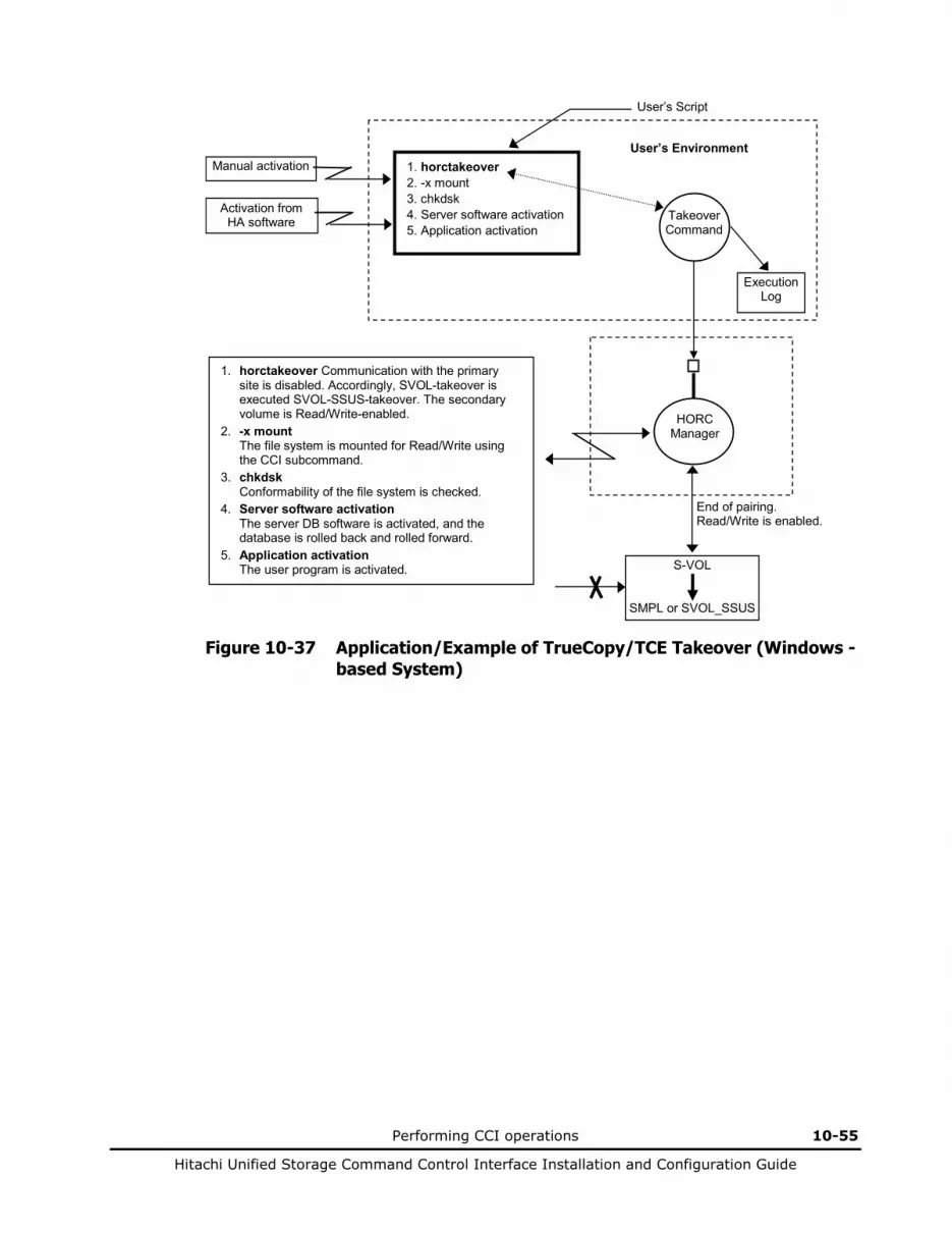
Performing CCI operations 10-55
Hitachi Unified Storage Command Control Interface Installation and Configuration Guide
1. horctakeover Communication with the primary site is disabled. Accordingly, SVOL-takeover is executed SVOL-SSUS-takeover. The secondary volume is Read/Write-enabled.
2. -x mount The file system is mounted for Read/Write using the CCI subcommand.
3. chkdsk Conformability of the file system is checked.
4. Server software activation The server DB software is activated, and the database is rolled back and rolled forward.
5. Application activation The user program is activated.
Takeover Command
1. horctakeover 2. -x mount 3. chkdsk 4. Server software activation 5. Application activation
User’s Script
User’s Environment
Activation from HA software
Manual activation
Execution Log
S-VOL
SMPL or SVOL_SSUS
End of pairing. Read/Write is enabled.
HORC Manager
Figure 10-37 Application/Example of TrueCopy/TCE Takeover (Windows -based System)

10-56 Performing CCI operations
Hitachi Unified Storage Command Control Interface Installation and Configuration Guide
Displaying configuration information
Using the raidscan command
The raidscan command displays configuration and status information for the specified disk array port/TIDs/devices. The information is acquired directly from the disk array (not the configuration definition file). Table 10-18 lists and describes the raidscan command parameters. Figure 10-38 to Figure 10-44 list examples of the raidscan command and its output. Note that LDEV indicates volume.
Table 10-18 Raidscan Command Parameters
Parameter Value
Command Name
raidscan
Format raidscan { -h | -q | -z | -x | -xh | -I[H | M][instance#] | -p <port> [hgrp] | -pd[g] <raw_device> | -s <Seq#> | -t <targ> | -l <lun> | [ -f[xfgde] ] | -CLI | -find[g] [op] [MU#] [-g group] | -pi <strings> -m<mun> }
Options -h: Displays Help/Usage and version information.
-q: Terminates the interactive mode and exits the command.
-z or -zx: Makes the raidscan command enter the interactive mode. The -zx option guards performing of the HORCM in the interactive mode. When this option detects a HORCM shut down, interactive mode terminates.
-x: Specifies the sub-command of Windows.
-xh: Displays Help/Usage the sub-command of Windows.
-I[H | M][instance#] or -I[TC | SI][instance#]: Specifies the instance number and the command execution environment.
-p <port> [hgrp]: Specifies the port ID of the array port to be scanned. Valid ports are CL1-A to CL1-H and CL2-A to CL2-H. This option must always be specified. [hgrp] is specified to display only the LDEVs mapped to a host group on a port for disk array.
-pd[g] <raw_device>: Specifies the raw device name. This option finds Seq# and port_name of the array that the specified device can be connected, and scans the port of the disk array which corresponds with the unit ID that searches the unit ID from Seq#. This option must always be specified.
-pdg option is specified to find host group and to display VOL.
-s <Seq#>: Used to specify the Seq# of the disk array when this option can’t specify the unit ID which is contained for “-p <port>” option. This option scans the port specified by “-p <port>” option of the disk array which corresponds with the unit ID that searches the unit ID from Seq#. If this option is specified, then the unit ID which is contained in “-p <port>” option is invalid.
-t <targ>: Specifies a target ID (0 to 15) of the specified port. If this option is not specified, the command applies to all target IDs.
-l <lun>: Specifies a VOL (0 to 7) of the specified target ID. If this option is not specified, the command applies to all VOLs. If this option is specified, the TID must also be specified.
-fx: Displays the LDEV number in hexadecimal notation.
-f or -ff: Specifies display of volume-type for a display column. If this option is specified, then the following -fg and -fd option is invalid.
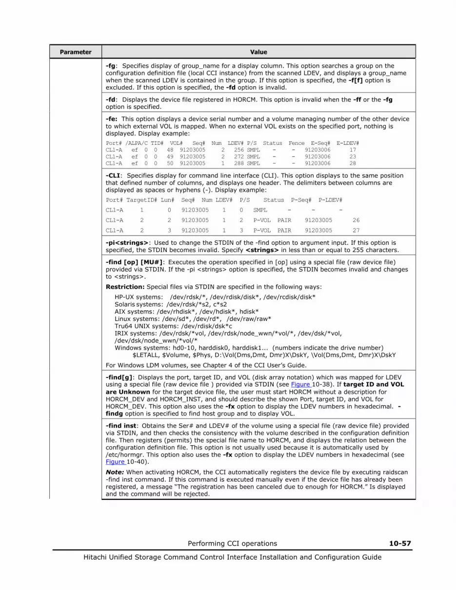
Performing CCI operations 10-57
Hitachi Unified Storage Command Control Interface Installation and Configuration Guide
Parameter Value
-fg: Specifies display of group_name for a display column. This option searches a group on the configuration definition file (local CCI instance) from the scanned LDEV, and displays a group_name when the scanned LDEV is contained in the group. If this option is specified, the -f[f] option is excluded. If this option is specified, the -fd option is invalid.
-fd: Displays the device file registered in HORCM. This option is invalid when the -ff or the -fg option is specified.
-fe: This option displays a device serial number and a volume managing number of the other device to which external VOL is mapped. When no external VOL exists on the specified port, nothing is displayed. Display example: Port# /ALPA/C TID# VOL# Seq# Num LDEV# P/S Status Fence E-Seq# E-LDEV# CL1-A ef 0 0 48 91203005 2 256 SMPL - - 91203006 17 CL1-A ef 0 0 49 91203005 2 272 SMPL - - 91203006 23 CL1-A ef 0 0 50 91203005 1 288 SMPL - - 91203006 28
-CLI: Specifies display for command line interface (CLI). This option displays to the same position that defined number of columns, and displays one header. The delimiters between columns are displayed as spaces or hyphens (-). Display example: Port# TargetID# Lun# Seq# Num LDEV# P/S Status P-Seq# P-LDEV#
CL1-A 1 0 91203005 1 0 SMPL - - -
CL1-A 2 2 91203005 1 2 P-VOL PAIR 91203005 26
CL1-A 2 3 91203005 1 3 P-VOL PAIR 91203005 27
-pi<strings>: Used to change the STDIN of the -find option to argument input. If this option is specified, the STDIN becomes invalid. Specify <strings> in less than or equal to 255 characters.
-find [op] [MU#]: Executes the operation specified in [op] using a special file (raw device file) provided via STDIN. If the -pi <strings> option is specified, the STDIN becomes invalid and changes to <strings>.
Restriction: Special files via STDIN are specified in the following ways:
HP-UX systems: /dev/rdsk/*, /dev/rdisk/disk*, /dev/rcdisk/disk* Solaris systems: /dev/rdsk/*s2, c*s2 AIX systems: /dev/rhdisk*, /dev/hdisk*, hdisk* Linux systems: /dev/sd*, /dev/rd*, /dev/raw/raw* Tru64 UNIX systems: /dev/rdisk/dsk*c IRIX systems: /dev/rdsk/*vol, /dev/rdsk/node_wwn/*vol/*, /dev/dsk/*vol, /dev/dsk/node_wwn/*vol/* Windows systems: hd0-10, harddisk0, harddisk1... (numbers indicate the drive number) $LETALL, $Volume, $Phys, D:\Vol(Dms,Dmt, Dmr)X\DskY, \Vol(Dms,Dmt, Dmr)X\DskY
For Windows LDM volumes, see Chapter 4 of the CCI User’s Guide.
-find[g]: Displays the port, target ID, and VOL (disk array notation) which was mapped for LDEV using a special file (raw device file ) provided via STDIN (see Figure 10-38). If target ID and VOL are Unknown for the target device file, the user must start HORCM without a description for HORCM_DEV and HORCM_INST, and should describe the shown Port, target ID, and VOL for HORCM_DEV. This option also uses the -fx option to display the LDEV numbers in hexadecimal. -findg option is specified to find host group and to display VOL.
-find inst: Obtains the Ser# and LDEV# of the volume using a special file (raw device file) provided via STDIN, and then checks the consistency with the volume described in the configuration definition file. Then registers (permits) the special file name to HORCM, and displays the relation between the configuration definition file. This option is not usually used because it is automatically used by /etc/hormgr. This option also uses the -fx option to display the LDEV numbers in hexadecimal (see Figure 10-40).
Note: When activating HORCM, the CCI automatically registers the device file by executing raidscan -find inst command. If this command is executed manually even if the device file has already been registered, a message “The registration has been canceled due to enough for HORCM.” Is displayed and the command will be rejected.
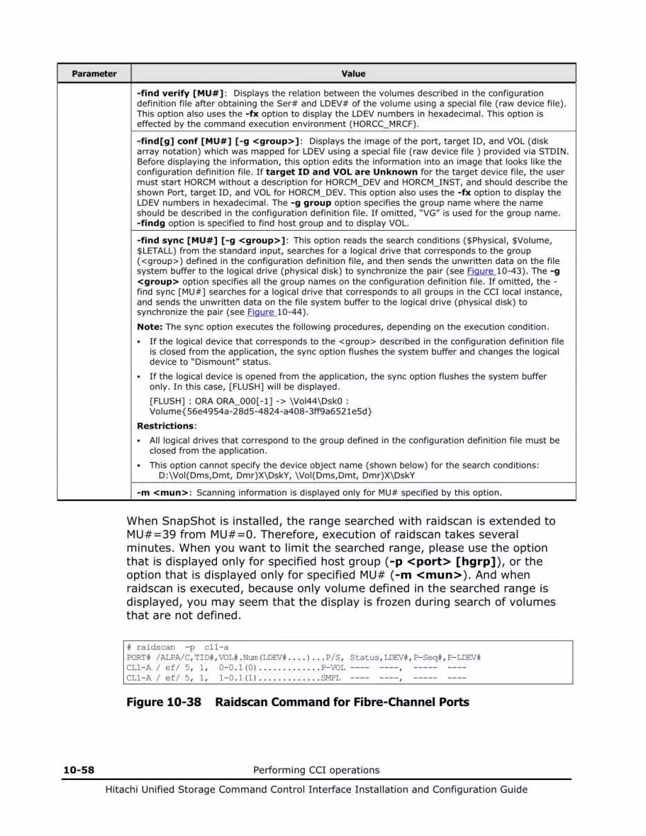
10-58 Performing CCI operations
Hitachi Unified Storage Command Control Interface Installation and Configuration Guide
Parameter Value
-find verify [MU#]: Displays the relation between the volumes described in the configuration definition file after obtaining the Ser# and LDEV# of the volume using a special file (raw device file). This option also uses the -fx option to display the LDEV numbers in hexadecimal. This option is effected by the command execution environment (HORCC_MRCF).
-find[g] conf [MU#] [-g <group>]: Displays the image of the port, target ID, and VOL (disk array notation) which was mapped for LDEV using a special file (raw device file ) provided via STDIN. Before displaying the information, this option edits the information into an image that looks like the configuration definition file. If target ID and VOL are Unknown for the target device file, the user must start HORCM without a description for HORCM_DEV and HORCM_INST, and should describe the shown Port, target ID, and VOL for HORCM_DEV. This option also uses the -fx option to display the LDEV numbers in hexadecimal. The -g group option specifies the group name where the name should be described in the configuration definition file. If omitted, “VG” is used for the group name. -findg option is specified to find host group and to display VOL.
-find sync [MU#] [-g <group>]: This option reads the search conditions ($Physical, $Volume, $LETALL) from the standard input, searches for a logical drive that corresponds to the group (<group>) defined in the configuration definition file, and then sends the unwritten data on the file system buffer to the logical drive (physical disk) to synchronize the pair (see Figure 10-43). The -g <group> option specifies all the group names on the configuration definition file. If omitted, the -find sync [MU#] searches for a logical drive that corresponds to all groups in the CCI local instance, and sends the unwritten data on the file system buffer to the logical drive (physical disk) to synchronize the pair (see Figure 10-44).
Note: The sync option executes the following procedures, depending on the execution condition. If the logical device that corresponds to the <group> described in the configuration definition file
is closed from the application, the sync option flushes the system buffer and changes the logical device to “Dismount” status.
If the logical device is opened from the application, the sync option flushes the system buffer only. In this case, [FLUSH] will be displayed.
[FLUSH] : ORA ORA_000[-1] -> \Vol44\Dsk0 : Volume{56e4954a-28d5-4824-a408-3ff9a6521e5d}
Restrictions:
All logical drives that correspond to the group defined in the configuration definition file must be closed from the application.
This option cannot specify the device object name (shown below) for the search conditions: D:\Vol(Dms,Dmt, Dmr)X\DskY, \Vol(Dms,Dmt, Dmr)X\DskY
-m <mun>: Scanning information is displayed only for MU# specified by this option.
When SnapShot is installed, the range searched with raidscan is extended to MU#=39 from MU#=0. Therefore, execution of raidscan takes several minutes. When you want to limit the searched range, please use the option that is displayed only for specified host group (-p <port> [hgrp]), or the option that is displayed only for specified MU# (-m <mun>). And when raidscan is executed, because only volume defined in the searched range is displayed, you may seem that the display is frozen during search of volumes that are not defined.
# raidscan -p cl1-a PORT# /ALPA/C,TID#,VOL#.Num(LDEV#....)...P/S, Status,LDEV#,P-Seq#,P-LDEV# CL1-A / ef/ 5, 1, 0-0.1(0).............P-VOL ---- ----, ----- ---- CL1-A / ef/ 5, 1, 1-0.1(1).............SMPL ---- ----, ----- ----
Figure 10-38 Raidscan Command for Fibre-Channel Ports
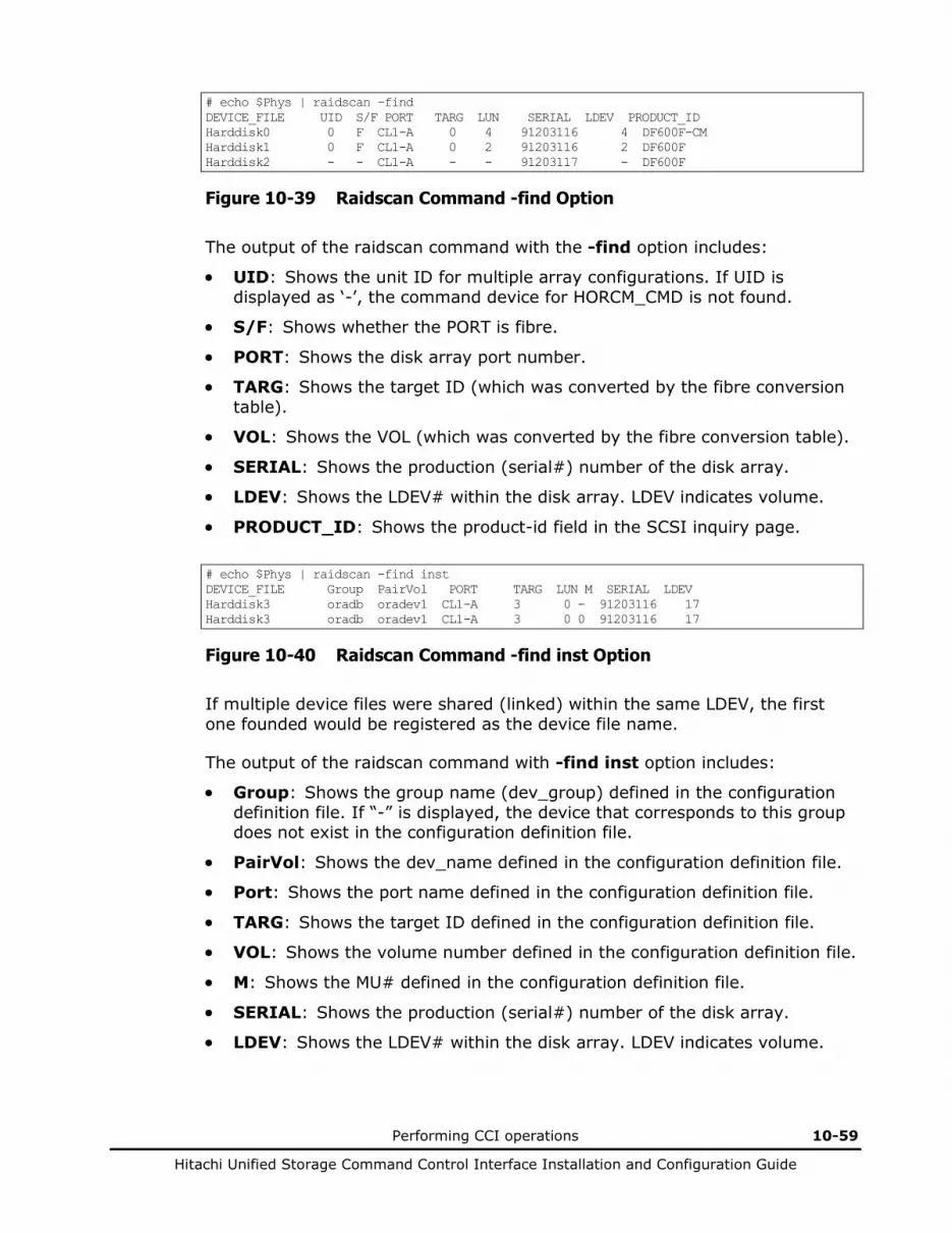
Performing CCI operations 10-59
Hitachi Unified Storage Command Control Interface Installation and Configuration Guide
# echo $Phys | raidscan –find DEVICE_FILE UID S/F PORT TARG LUN SERIAL LDEV PRODUCT_ID Harddisk0 0 F CL1-A 0 4 91203116 4 DF600F-CM Harddisk1 0 F CL1-A 0 2 91203116 2 DF600F Harddisk2 - - CL1-A - - 91203117 - DF600F
Figure 10-39 Raidscan Command -find Option
The output of the raidscan command with the -find option includes:
• UID: Shows the unit ID for multiple array configurations. If UID is displayed as ‘-’, the command device for HORCM_CMD is not found.
• S/F: Shows whether the PORT is fibre.
• PORT: Shows the disk array port number.
• TARG: Shows the target ID (which was converted by the fibre conversion table).
• VOL: Shows the VOL (which was converted by the fibre conversion table).
• SERIAL: Shows the production (serial#) number of the disk array.
• LDEV: Shows the LDEV# within the disk array. LDEV indicates volume.
• PRODUCT_ID: Shows the product-id field in the SCSI inquiry page.
# echo $Phys | raidscan -find inst DEVICE_FILE Group PairVol PORT TARG LUN M SERIAL LDEV Harddisk3 oradb oradev1 CL1-A 3 0 - 91203116 17 Harddisk3 oradb oradev1 CL1-A 3 0 0 91203116 17
Figure 10-40 Raidscan Command -find inst Option
If multiple device files were shared (linked) within the same LDEV, the first one founded would be registered as the device file name.
The output of the raidscan command with -find inst option includes:
• Group: Shows the group name (dev_group) defined in the configuration definition file. If “-” is displayed, the device that corresponds to this group does not exist in the configuration definition file.
• PairVol: Shows the dev_name defined in the configuration definition file.
• Port: Shows the port name defined in the configuration definition file.
• TARG: Shows the target ID defined in the configuration definition file.
• VOL: Shows the volume number defined in the configuration definition file.
• M: Shows the MU# defined in the configuration definition file.
• SERIAL: Shows the production (serial#) number of the disk array.
• LDEV: Shows the LDEV# within the disk array. LDEV indicates volume.

10-60 Performing CCI operations
Hitachi Unified Storage Command Control Interface Installation and Configuration Guide
# echo $Phys | raidscan -find verify DEVICE_FILE Group PairVol PORT TARG LUN M SERIAL LDEV Harddisk0 oradb oradev1 CL1-A 3 0 0 91203501 17 Harddisk1 oradb oradev2 CL1-A 3 1 0 91203501 18 Harddisk3 - - - - - 0 91203501 19 # iocsan -fun | grep rdsk | raidscan -find verify 1 -fd DEVICE_FILE Group PairVol Device_File M SERIAL LDEV Harddisk0 oradb oradev1 C0t3d0 1 91203501 17 Harddisk1 oradb oradev2 Unknown 1 91203501 18 Harddisk2 - - - 1 91203501 19
Figure 10-41 Raidscan Command -find verify Option
If the contents displayed in DEVICE_FILE and Device_File is different, it indicates that the volumes are shared (linked) within the same LDEV. If “Unknown” is displayed in Device_File, this volume is not registered, so the pair operation (except for local options) is rejected in the protection mode.
The output of the raidscan command with -find verify option includes:
• Group: Shows the group name (dev_group) described in the configuration definition file. If “-” is displayed, the device that corresponds to this group does not exist in the configuration definition file.
• PairVol: Shows the dev_name described in the configuration definition file.
• Device_File: Shows the device file registered in HORCM.
• Port: Shows the port name described in the configuration definition file.
• TARG: Shows the target ID described in the configuration definition file.
• VOL: Shows the volume number described in the configuration definition file.
• M: Shows the MU# described in the configuration definition file.
• SERIAL: Shows the production (serial#) number of the array.
• LDEV: Shows the LDEV# within the disk array. LDEV indicates volume.

Performing CCI operations 10-61
Hitachi Unified Storage Command Control Interface Installation and Configuration Guide
# type hormperm.conf | raidscan -find conf 0 -g ORA HORCM_DEV #dev_group dev_name port# TargetID VOL# MU# Harddisk14 SER =91206145 LDEV = 2 [FIBRE FCTBL = 4] ORA ORA_000 CL2-A 0 0 0 Harddisk15 SER =91206145 LDEV = 3 [FIBRE FCTBL = 4] ORA ORA_001 CL2-A 0 1 0 Harddisk16 SER =91206145 LDEV = 4 [FIBRE FCTBL = 4] ORA ORA_002 CL2-A 0 2 0 Harddisk17 SER =91206145 LDEV = 5 [FIBRE FCTBL = 4] ORA ORA_003 CL2-A 0 3 0 #ERROR [CMDDEV] Harddisk0 SER =91206145 LDEV = 9 [DF600F-CM]
Figure 10-42 Raidscan Command -find conf Option
If a command device is included in the STDIN device, a comment is displayed as follows and the target device will not be included.
#ERROR [CMDDEV] Harddisk0 SER =91206145 LDEV = 9 [DF600F-CM]
• If an STDIN device is shared by multiple device files and is displayed as target device, a comment is displayed as follows and the target device will not be included. #ERROR [LDEV LINK] Harddisk17 SER =91206145 LDEV = 5 [FIBRE FCTBL = 4]
• If the STDIN device does not have a proper MU#, a comment is displayed as follows and the target device will not be included. #ERROR [INVALID MUN(2<1)] Harddisk17 SER =91206145 LDEV = 5 [DF600F ]
• If the STDIN device is mixed between the arrays that have different mirroring control, a comment is displayed as follows and the target device will be not be included. #ERROR [MIXING RAID TYPE] Harddisk17 SER =91206145 LDEV = 5 [DF600F ]
The following is an example of synchronizing (flushing) the system buffer that corresponds to group ORB in the configuration definition file.
raidscan -pi $Volume -find sync -g ORB [SYNC] : ORB ORB_000[-] -> \Dmt1\Dsk1 : Volume{bf48a395-0ef6-11d5-8d69-00c00d003b1e} [SYNC] : ORB ORB_001[-] -> \Dmt1\Dsk2 : Volume{bf48a395-0ef6-11d5-8d69-00c00d003b1e} [SYNC] : ORB ORB_002[-] -> \Dmt1\Dsk3 : Volume{bf48a395-0ef6-11d5-8d69-00c00d003b1e}
Figure 10-43 Raidscan Command -find sync Option Example (1)
The following is an example of synchronizing (flushing) the system buffer that corresponds to all groups in the CCI local instance.
[SYNC] : ORA ORA_000[-] -> \Vol44\Dsk0: Volume{56e4954a-28d5-4824-a408-3ff9a6521e5d} [SYNC] : ORA ORA_000[-] -> \Vol45\Dsk0: Volume{56e4954a-28d5-4824-a408-3ff9a6521e5e} [SYNC] : ORB ORB_000[-] -> \Dmt1\Dsk1 : Volume{bf48a395-0ef6-11d5-8d69-00c00d003b1e} [SYNC] : ORB ORB_001[-] -> \Dmt1\Dsk2 : Volume{bf48a395-0ef6-11d5-8d69-00c00d003b1e} [SYNC] : ORB ORB_002[-] -> \Dmt1\Dsk3 : Volume{bf48a395-0ef6-11d5-8d69-00c00d003b1e}
Figure 10-44 Raidscan Command -find sync Option Example (2)
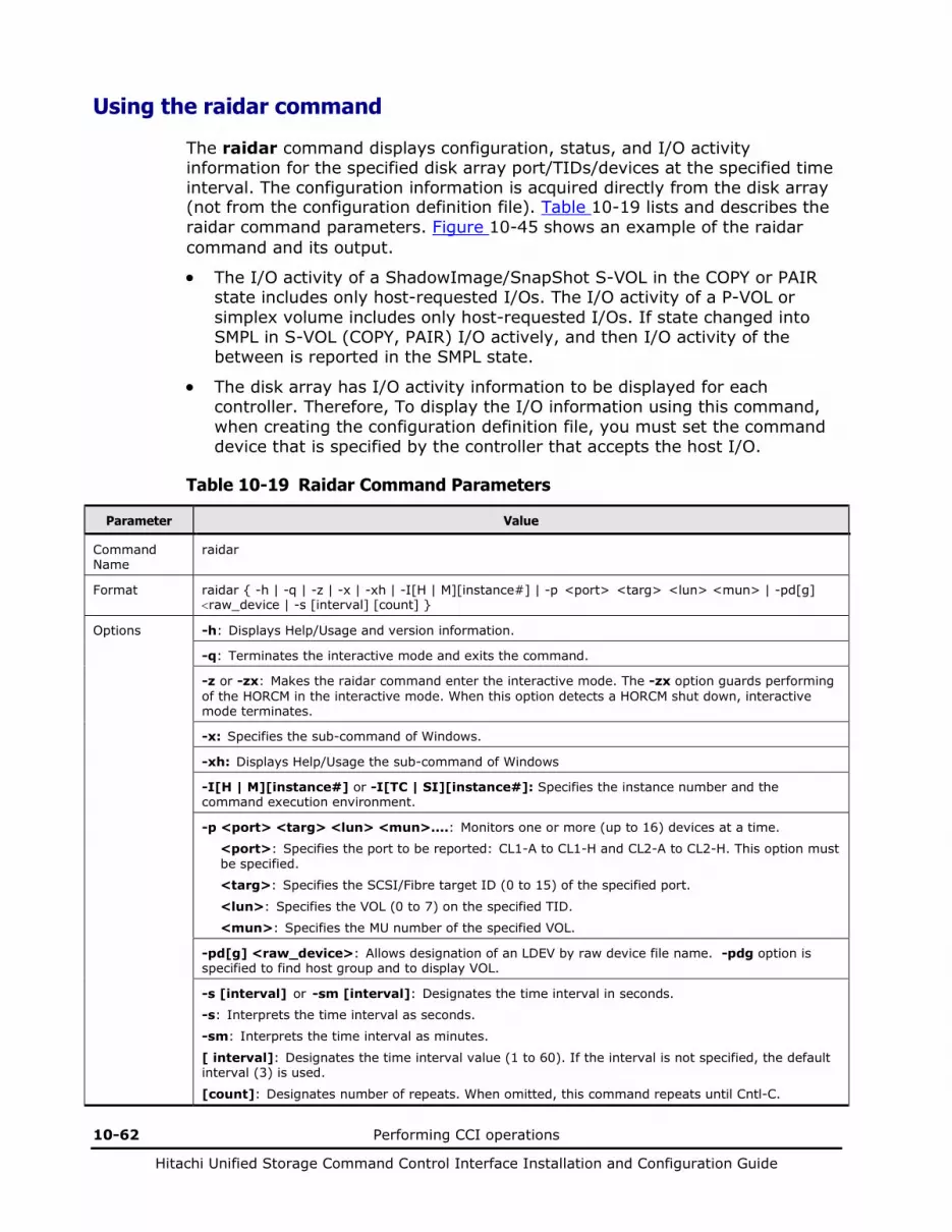
10-62 Performing CCI operations
Hitachi Unified Storage Command Control Interface Installation and Configuration Guide
Using the raidar command
The raidar command displays configuration, status, and I/O activity information for the specified disk array port/TIDs/devices at the specified time interval. The configuration information is acquired directly from the disk array (not from the configuration definition file). Table 10-19 lists and describes the raidar command parameters. Figure 10-45 shows an example of the raidar command and its output.
• The I/O activity of a ShadowImage/SnapShot S-VOL in the COPY or PAIR state includes only host-requested I/Os. The I/O activity of a P-VOL or simplex volume includes only host-requested I/Os. If state changed into SMPL in S-VOL (COPY, PAIR) I/O actively, and then I/O activity of the between is reported in the SMPL state.
• The disk array has I/O activity information to be displayed for each controller. Therefore, To display the I/O information using this command, when creating the configuration definition file, you must set the command device that is specified by the controller that accepts the host I/O.
Table 10-19 Raidar Command Parameters
Parameter Value
Command Name
raidar
Format raidar { -h | -q | -z | -x | -xh | -I[H | M][instance#] | -p <port> <targ> <lun> <mun> | -pd[g] <raw_device | -s [interval] [count] }
Options -h: Displays Help/Usage and version information.
-q: Terminates the interactive mode and exits the command.
-z or -zx: Makes the raidar command enter the interactive mode. The -zx option guards performing of the HORCM in the interactive mode. When this option detects a HORCM shut down, interactive mode terminates.
-x: Specifies the sub-command of Windows.
-xh: Displays Help/Usage the sub-command of Windows
-I[H | M][instance#] or -I[TC | SI][instance#]: Specifies the instance number and the command execution environment.
-p <port> <targ> <lun> <mun>....: Monitors one or more (up to 16) devices at a time.
<port>: Specifies the port to be reported: CL1-A to CL1-H and CL2-A to CL2-H. This option must be specified.
<targ>: Specifies the SCSI/Fibre target ID (0 to 15) of the specified port.
<lun>: Specifies the VOL (0 to 7) on the specified TID.
<mun>: Specifies the MU number of the specified VOL.
-pd[g] <raw_device>: Allows designation of an LDEV by raw device file name. -pdg option is specified to find host group and to display VOL.
-s [interval] or -sm [interval]: Designates the time interval in seconds.
-s: Interprets the time interval as seconds. -sm: Interprets the time interval as minutes.
[ interval]: Designates the time interval value (1 to 60). If the interval is not specified, the default interval (3) is used.
[count]: Designates number of repeats. When omitted, this command repeats until Cntl-C.
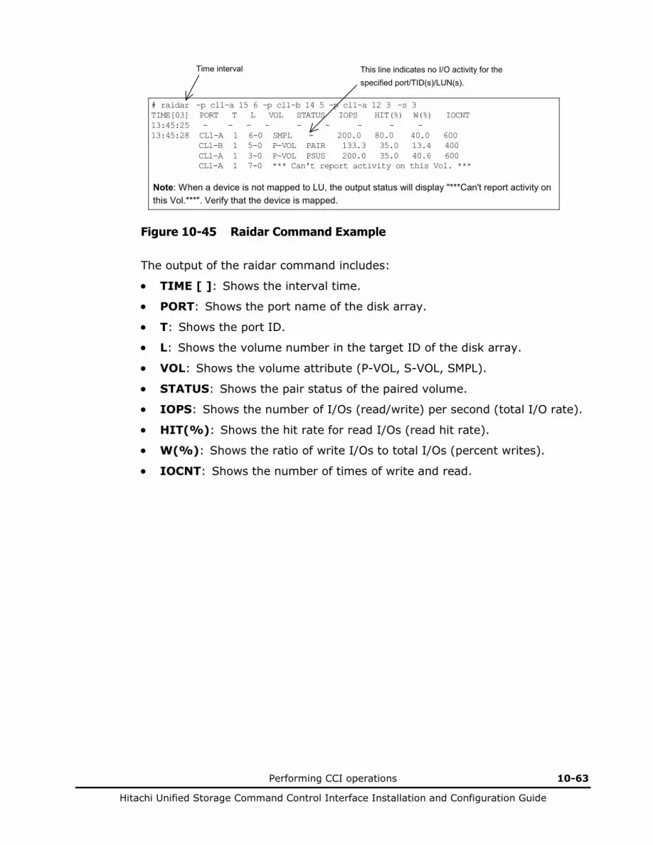
Performing CCI operations 10-63
Hitachi Unified Storage Command Control Interface Installation and Configuration Guide
# raidar -p cl1-a 15 6 -p cl1-b 14 5 -p cl1-a 12 3 -s 3 TIME[03] PORT T L VOL STATUS IOPS HIT(%) W(%) IOCNT 13:45:25 - - - - - - - - - 13:45:28 CL1-A 1 6-0 SMPL - 200.0 80.0 40.0 600 CL1-B 1 5-0 P-VOL PAIR 133.3 35.0 13.4 400 CL1-A 1 3-0 P-VOL PSUS 200.0 35.0 40.6 600 CL1-A 1 7-0 *** Can't report activity on this Vol. ***
Time interval This line indicates no I/O activity for the specified port/TID(s)/LUN(s).
Note: When a device is not mapped to LU, the output status will display "***Can't report activity on this Vol.***". Verify that the device is mapped.
Figure 10-45 Raidar Command Example
The output of the raidar command includes:
• TIME [ ]: Shows the interval time.
• PORT: Shows the port name of the disk array.
• T: Shows the port ID.
• L: Shows the volume number in the target ID of the disk array.
• VOL: Shows the volume attribute (P-VOL, S-VOL, SMPL).
• STATUS: Shows the pair status of the paired volume.
• IOPS: Shows the number of I/Os (read/write) per second (total I/O rate).
• HIT(%): Shows the hit rate for read I/Os (read hit rate).
• W(%): Shows the ratio of write I/Os to total I/Os (percent writes).
• IOCNT: Shows the number of times of write and read.
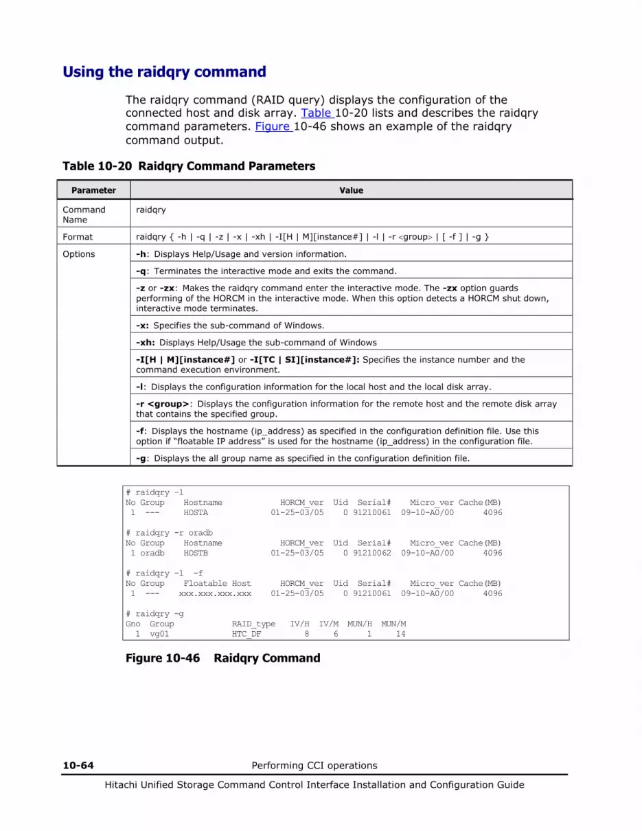
10-64 Performing CCI operations
Hitachi Unified Storage Command Control Interface Installation and Configuration Guide
Using the raidqry command
The raidqry command (RAID query) displays the configuration of the connected host and disk array. Table 10-20 lists and describes the raidqry command parameters. Figure 10-46 shows an example of the raidqry command output.
Table 10-20 Raidqry Command Parameters
Parameter Value
Command Name
raidqry
Format raidqry { -h | -q | -z | -x | -xh | -I[H | M][instance#] | -l | -r <group> | [ -f ] | -g }
Options -h: Displays Help/Usage and version information.
-q: Terminates the interactive mode and exits the command.
-z or -zx: Makes the raidqry command enter the interactive mode. The -zx option guards performing of the HORCM in the interactive mode. When this option detects a HORCM shut down, interactive mode terminates.
-x: Specifies the sub-command of Windows.
-xh: Displays Help/Usage the sub-command of Windows
-I[H | M][instance#] or -I[TC | SI][instance#]: Specifies the instance number and the command execution environment.
-l: Displays the configuration information for the local host and the local disk array.
-r <group>: Displays the configuration information for the remote host and the remote disk array that contains the specified group.
-f: Displays the hostname (ip_address) as specified in the configuration definition file. Use this option if “floatable IP address” is used for the hostname (ip_address) in the configuration file.
-g: Displays the all group name as specified in the configuration definition file.
# raidqry –l No Group Hostname HORCM_ver Uid Serial# Micro_ver Cache(MB) 1 --- HOSTA 01-25-03/05 0 91210061 09-10-A0/00 4096 # raidqry -r oradb No Group Hostname HORCM_ver Uid Serial# Micro_ver Cache(MB) 1 oradb HOSTB 01-25-03/05 0 91210062 09-10-A0/00 4096 # raidqry -l -f No Group Floatable Host HORCM_ver Uid Serial# Micro_ver Cache(MB) 1 --- xxx.xxx.xxx.xxx 01-25-03/05 0 91210061 09-10-A0/00 4096 # raidqry -g Gno Group RAID_type IV/H IV/M MUN/H MUN/M 1 vg01 HTC_DF 8 6 1 14
Figure 10-46 Raidqry Command
Performing CCI operations 10-65
Hitachi Unified Storage Command Control Interface Installation and Configuration Guide
The output of the raidqry command includes:
• No: Shows the order when the group name (dev_group) described in the configuration definition file has multiple remote hosts.
• Group: When the -r or -g option is used, this column shows the group name (dev_group) described in the configuration definition file.
• Hostname: When the -l option is used, this column shows the host name of the local host. When the -r option is used, this column shows the remote host name for the group (dev_group) which is described in the configuration definition file. The host name with more than or equal to 30 characters cannot be displayed.
• Floatable Host: When the -f option is used, this column shows the host name (ip_address) described in the configuration definition file. Up to 30 host names can be displayed. The -f option interprets the host name as utilizing floatable IP for a host.
• HORCM_ver: Shows the version of the HORC Manager on the local or remote host. The -l option specifies local host. The -r option specifies remote host.
• Uid Serial# Micro_ver: Shows the unitID, serial number, and firmware version of the disk array connected to the local or remote host. The -l option specifies local host. The -r option specifies remote host.
• Cache(MB): Shows the logical cache capacity (in MB) of the disk array connected to the local or remote host. The -l option specifies local host. The -r option specifies remote host.
• Gno: When the -g option is used, this column shows as order when the group name (dev_group) described in the configuration definition file.
• RAID_type: When the -g option is used, this column shows the type of RAID configured a group.
• IV/H: When the -g option is used, this column shows the interface version for TrueCopy/TCE that made the consistence in a group, this is used for the maintenance.
• IV/M: When the -g option is used, this column shows the interface version for ShadowImage/SnapShot that made the consistence in a group, this is used for the maintenance.
• MUN/H: When the -g option is used, this column shows the number of maximum MUs for TrueCopy/TCE that made the consistence in a group.
• MUN/M: When the -g option is used, this column shows the number of maximum MUs for ShadowImage/SnapShot that made the consistence in a group.
10-66 Performing CCI operations
Hitachi Unified Storage Command Control Interface Installation and Configuration Guide
Protecting volume data
The disk array supports parameters for data protection of each volume, and these parameters are set through the command device using CCI. CCI supports the following three commands in order to set and verify these parameters for data protection of each volume.
• raidvchkset: Sets the data protection parameter to the specified volumes.
• raidvchkdsp: Shows the data protection parameter on the specified volumes based on CCI configuration definition file.
• raidvchkscan: Shows the parameter for data protection on the specified ports based on the raidscan command.
CCI will report the following message to the syslog file as validation error when each statistical information counted an error will be updated:
[HORCM_103] Detected a validation check error on this volume(0000 unit#0,ldev#0) : CfEC=n, MNEC=n, SCEC=n, BNEC=n
When the volume concerned has been set as a protected volume using the raidvchkset command, the following restrictions are placed.
• The setting with the raidvchkset -vg svd or raidvchkset -vg idb can be performed without using the license key for Data Retention, but the setting cannot be released by Hitachi Storage Navigator Modular 2. In regard to a volume for which the setting has been made using the raidvchkset -vg svd or raidvchkset -vg idb, operations such as deleting and formatting of it are restricted. To release the setting, issue the raidvchkset -vg command.
• When setting the data protection for a UNIX file system volume, unmount the volume, and then mount it as a read-only volume to use it.
For a Windows Server file system, you have to use “ -x mount” and “-x umount” option of CCI commands with above procedures.
• When changing a configuration of the LVM including a protected volume, the volume concerned must be temporarily placed in the status in which the check on it is inhibited by the raidvchkset -vg command. Place the volume again in the status in which it is checked when the LVM configuration change is completed.
• There may be a case where a volume to which the data protection is applied cannot be used as a resource of the HA cluster software (such as the MSCS). This is because the HA cluster software (such as the MSCS) writes management information in the management area periodically in order to check propriety of the resource.
• When setting a volume being used by Windows Server as a protected volume, protection can be applied to a basic disk only. When the protection is applied to a dynamic disk, the volume is not recognized correctly.
• Some OS cannot be recognized VOLs over VOL#1, if VOL#0 will being set to the “inv” as the attribute of the data protection, the reason is that some HBA driver does not scan all VOLs on a port, if VOL#0 will be invisible.

Performing CCI operations 10-67
Hitachi Unified Storage Command Control Interface Installation and Configuration Guide
Using the raidvchkset command
The raidvchkset command sets the parameters for data protection of the specified volumes, and can also be used to turn off all data protection without specifying [type]. Unit of protection for data is based on the group of CCI configuration definition file.
Table 10-21 lists and describes the raidvchkset command parameters.
Table 10-21 Raidvchkset command parameters
Parameter Value
Command Name
raidvchkset
Format raidvchkset { -h | -q | -z | -x | -xh | -I[H | M][instance#] | -g <group> | -d <pair Vol> -d[g] <raw_device> [MU#] | -d[g] <seq#> <LDEV#> [MU#] | -nomsg | -vg [type][rtime] }
Options -h: Displays Help/Usage and version information.
-q: Terminates the interactive mode and exits the command.
-z or -zx: Makes the raidvchkset command enter the interactive mode. The -zx option guards performing of the HORCM in the interactive mode. When this option detects a HORCM shut down, interactive mode terminates.
-x: Specifies the sub-command of Windows.
-xh: Displays Help/Usage the sub-command of Windows.
-I[H | M][instance#] or -I[TC | SI][instance#]: Specifies the instance number and the command execution environment.
-g <group>: Specifies a group name written in the configuration definition file.
-d <pair Vol>: Specifies paired logical volume name defined in the configuration definition file. When this option is specified, the command is executed for the specified paired logical volume.
-d[g] <raw_device> [MU#]: Searches a group on the configuration definition file (local instance) for the specified raw_device, and if the specified raw_device is contained in the group, the target volume is executed as the paired logical volume (-d) or group (-dg). This option is effective without specification of “-g <group>“ option. If the specified the raw_device is contained in two or more groups, the command is executed on the first group.
-d[g] <seq#> <LDEV#> [MU#]: Searches a group on the configuration definition file (local instance) for the specified LDEV, and if the specified LDEV is in the group, the target volume is executed as the paired logical volume (-d) or group (-dg). This option is effective without specification of “-g <group>“ option. If the specified LDEV is contained in two or more groups, the command is executed on the first group. The <seq #> <LDEV #> values can be specified in hexadecimal (by addition of “0x “) or decimal notation.
-nomsg: Suppresses messages to be displayed when this command is executed. It is used to execute this command from a user program. This option must be specified at the beginning of a command argument. The command execution log is not affected by this option.
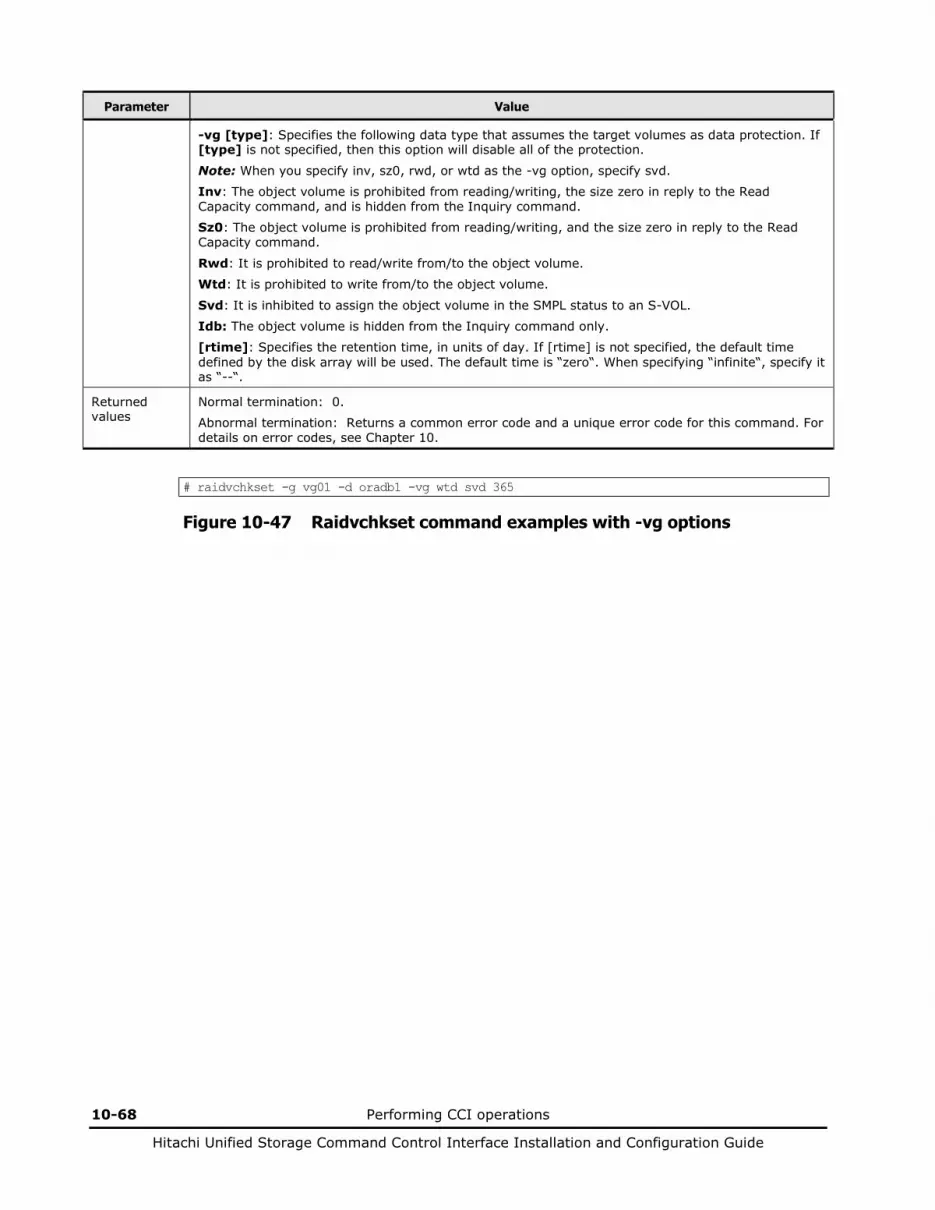
10-68 Performing CCI operations
Hitachi Unified Storage Command Control Interface Installation and Configuration Guide
Parameter Value
-vg [type]: Specifies the following data type that assumes the target volumes as data protection. If [type] is not specified, then this option will disable all of the protection.
Note: When you specify inv, sz0, rwd, or wtd as the -vg option, specify svd.
Inv: The object volume is prohibited from reading/writing, the size zero in reply to the Read Capacity command, and is hidden from the Inquiry command.
Sz0: The object volume is prohibited from reading/writing, and the size zero in reply to the Read Capacity command.
Rwd: It is prohibited to read/write from/to the object volume.
Wtd: It is prohibited to write from/to the object volume.
Svd: It is inhibited to assign the object volume in the SMPL status to an S-VOL.
Idb: The object volume is hidden from the Inquiry command only.
[rtime]: Specifies the retention time, in units of day. If [rtime] is not specified, the default time defined by the disk array will be used. The default time is “zero“. When specifying “infinite“, specify it as “--“.
Returned values
Normal termination: 0.
Abnormal termination: Returns a common error code and a unique error code for this command. For details on error codes, see Chapter 10.
# raidvchkset -g vg01 -d oradb1 -vg wtd svd 365
Figure 10-47 Raidvchkset command examples with -vg options
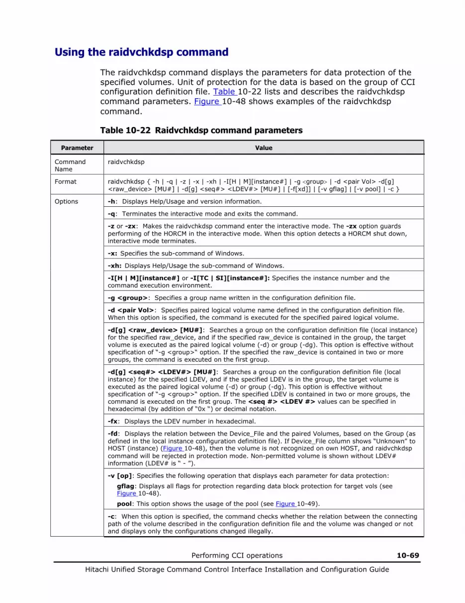
Performing CCI operations 10-69
Hitachi Unified Storage Command Control Interface Installation and Configuration Guide
Using the raidvchkdsp command
The raidvchkdsp command displays the parameters for data protection of the specified volumes. Unit of protection for the data is based on the group of CCI configuration definition file. Table 10-22 lists and describes the raidvchkdsp command parameters. Figure 10-48 shows examples of the raidvchkdsp command.
Table 10-22 Raidvchkdsp command parameters
Parameter Value
Command Name
raidvchkdsp
Format raidvchkdsp { -h | -q | -z | -x | -xh | -I[H | M][instance#] | -g <group> | -d <pair Vol> -d[g] <raw_device> [MU#] | -d[g] <seq#> <LDEV#> [MU#] | [-f[xd]] | [-v gflag] | [-v pool] | -c }
Options -h: Displays Help/Usage and version information.
-q: Terminates the interactive mode and exits the command.
-z or -zx: Makes the raidvchkdsp command enter the interactive mode. The -zx option guards performing of the HORCM in the interactive mode. When this option detects a HORCM shut down, interactive mode terminates.
-x: Specifies the sub-command of Windows.
-xh: Displays Help/Usage the sub-command of Windows.
-I[H | M][instance#] or -I[TC | SI][instance#]: Specifies the instance number and the command execution environment.
-g <group>: Specifies a group name written in the configuration definition file.
-d <pair Vol>: Specifies paired logical volume name defined in the configuration definition file. When this option is specified, the command is executed for the specified paired logical volume.
-d[g] <raw_device> [MU#]: Searches a group on the configuration definition file (local instance) for the specified raw_device, and if the specified raw_device is contained in the group, the target volume is executed as the paired logical volume (-d) or group (-dg). This option is effective without specification of “-g <group>“ option. If the specified the raw_device is contained in two or more groups, the command is executed on the first group.
-d[g] <seq#> <LDEV#> [MU#]: Searches a group on the configuration definition file (local instance) for the specified LDEV, and if the specified LDEV is in the group, the target volume is executed as the paired logical volume (-d) or group (-dg). This option is effective without specification of “-g <group>“ option. If the specified LDEV is contained in two or more groups, the command is executed on the first group. The <seq #> <LDEV #> values can be specified in hexadecimal (by addition of “0x “) or decimal notation.
-fx: Displays the LDEV number in hexadecimal.
-fd: Displays the relation between the Device_File and the paired Volumes, based on the Group (as defined in the local instance configuration definition file). If Device_File column shows “Unknown” to HOST (instance) (Figure 10-48), then the volume is not recognized on own HOST, and raidvchkdsp command will be rejected in protection mode. Non-permitted volume is shown without LDEV# information (LDEV# is “ - ”).
-v [op]: Specifies the following operation that displays each parameter for data protection:
gflag: Displays all flags for protection regarding data block protection for target vols (see Figure 10-48).
pool: This option shows the usage of the pool (see Figure 10-49).
-c: When this option is specified, the command checks whether the relation between the connecting path of the volume described in the configuration definition file and the volume was changed or not and displays only the configurations changed illegally.
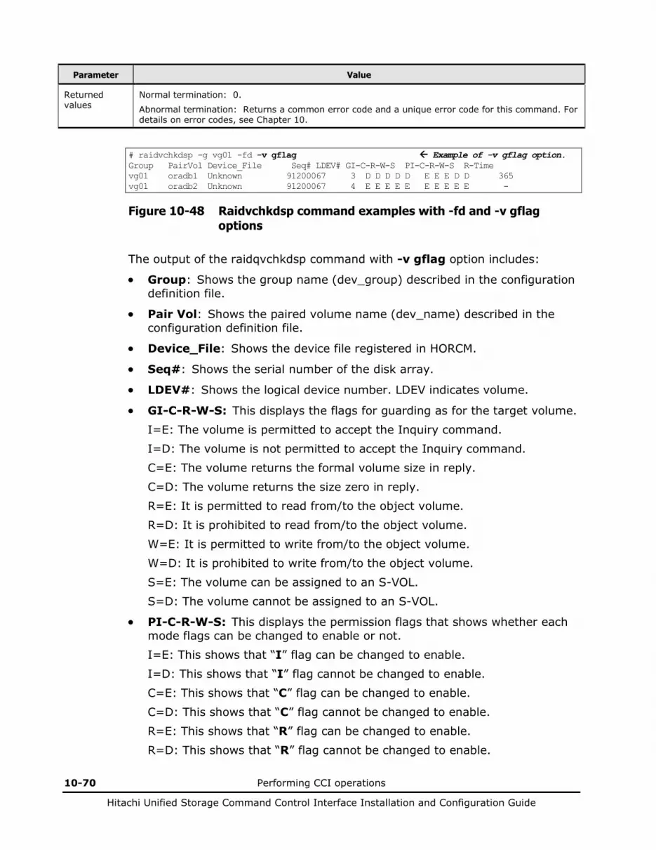
10-70 Performing CCI operations
Hitachi Unified Storage Command Control Interface Installation and Configuration Guide
Parameter Value
Returned values
Normal termination: 0.
Abnormal termination: Returns a common error code and a unique error code for this command. For details on error codes, see Chapter 10.
# raidvchkdsp -g vg01 -fd -v gflag Example of -v gflag option. Group PairVol Device_File Seq# LDEV# GI-C-R-W-S PI-C-R-W-S R-Time vg01 oradb1 Unknown 91200067 3 D D D D D E E E D D 365 vg01 oradb2 Unknown 91200067 4 E E E E E E E E E E -
Figure 10-48 Raidvchkdsp command examples with -fd and -v gflag options
The output of the raidqvchkdsp command with -v gflag option includes:
• Group: Shows the group name (dev_group) described in the configuration definition file.
• Pair Vol: Shows the paired volume name (dev_name) described in the configuration definition file.
• Device_File: Shows the device file registered in HORCM.
• Seq#: Shows the serial number of the disk array.
• LDEV#: Shows the logical device number. LDEV indicates volume.
• GI-C-R-W-S: This displays the flags for guarding as for the target volume. I=E: The volume is permitted to accept the Inquiry command. I=D: The volume is not permitted to accept the Inquiry command. C=E: The volume returns the formal volume size in reply. C=D: The volume returns the size zero in reply. R=E: It is permitted to read from/to the object volume. R=D: It is prohibited to read from/to the object volume. W=E: It is permitted to write from/to the object volume. W=D: It is prohibited to write from/to the object volume. S=E: The volume can be assigned to an S-VOL. S=D: The volume cannot be assigned to an S-VOL.
• PI-C-R-W-S: This displays the permission flags that shows whether each mode flags can be changed to enable or not. I=E: This shows that “I” flag can be changed to enable. I=D: This shows that “I” flag cannot be changed to enable. C=E: This shows that “C” flag can be changed to enable. C=D: This shows that “C” flag cannot be changed to enable. R=E: This shows that “R” flag can be changed to enable. R=D: This shows that “R” flag cannot be changed to enable.

Performing CCI operations 10-71
Hitachi Unified Storage Command Control Interface Installation and Configuration Guide
W=E: This shows that “W” flag can be changed to enable. W=D: This shows that “W” flag cannot be changed to enable. S=E: This shows that “S” flag can be changed to enable. S=D: This shows that “S” flag cannot be changed to enable.
• R-Time: The term of protection set for the volume is displayed with a number of days. When “-” is displayed, it means that the term is indefinite. Expiration Lock status is shown as the retention time plus 1000000. “R-Time + 1000000” shows the retention time with Expiration Lock status.
# raidvchkdsp -g vg01 -d oradb1 -v pool Example of -v pool option. Group PairVol Port# TID VOL Seq# LDEV# Bsize Available Capacity vg01 oradb1 CL1-A 1 2 91200015 2 2048 1024 3072
Figure 10-49 Raidvchkdsp Command Examples with -v pool Options
The output of the raidvchkdsp command with -v pool option includes:
• Group: Shows the group name (dev_group) described in the configuration definition file.
• Pair Vol: Shows the paired volume name (dev_name) described in the configuration definition file.
• Port#: Shows the device file registered in HORCM.
• TID: Shows the target ID.
• VOL: Shows the volume number in the target ID of the disk array.
• Seq#: Shows the serial number of the disk array.
• LDEV#: Shows the logical device number. LDEV indicates volume.
• Bsize: The unit of Available and Capacity is shown by block (1 block = 512 bytes). The unit of Available and Capacity becomes 1 MB (= 2048 blocks) in the example of a display in Figure 10-49.
• Available: Shows the available capacity for the volume data on the pool.
• Capacity: Shows the total capacity in the pool.
# raidvchkdsp -g vg01 –c Group PairVol Port# TID VOL Seq# LDEV# LDEV#(conf) -change-> LDEV# vg01 oradb1 CL1-A 1 2 91200015 - 2(conf) -change-> NO LDEV
Figure 10-50 Raidvchkdsp Command Examples with -c Options
The output of the raidvchkdsp command with -c option includes:
• Group: Shows the group name (dev_group) described in the configuration definition file.
• Pair Vol: Shows the paired volume name (dev_name) described in the configuration definition file.
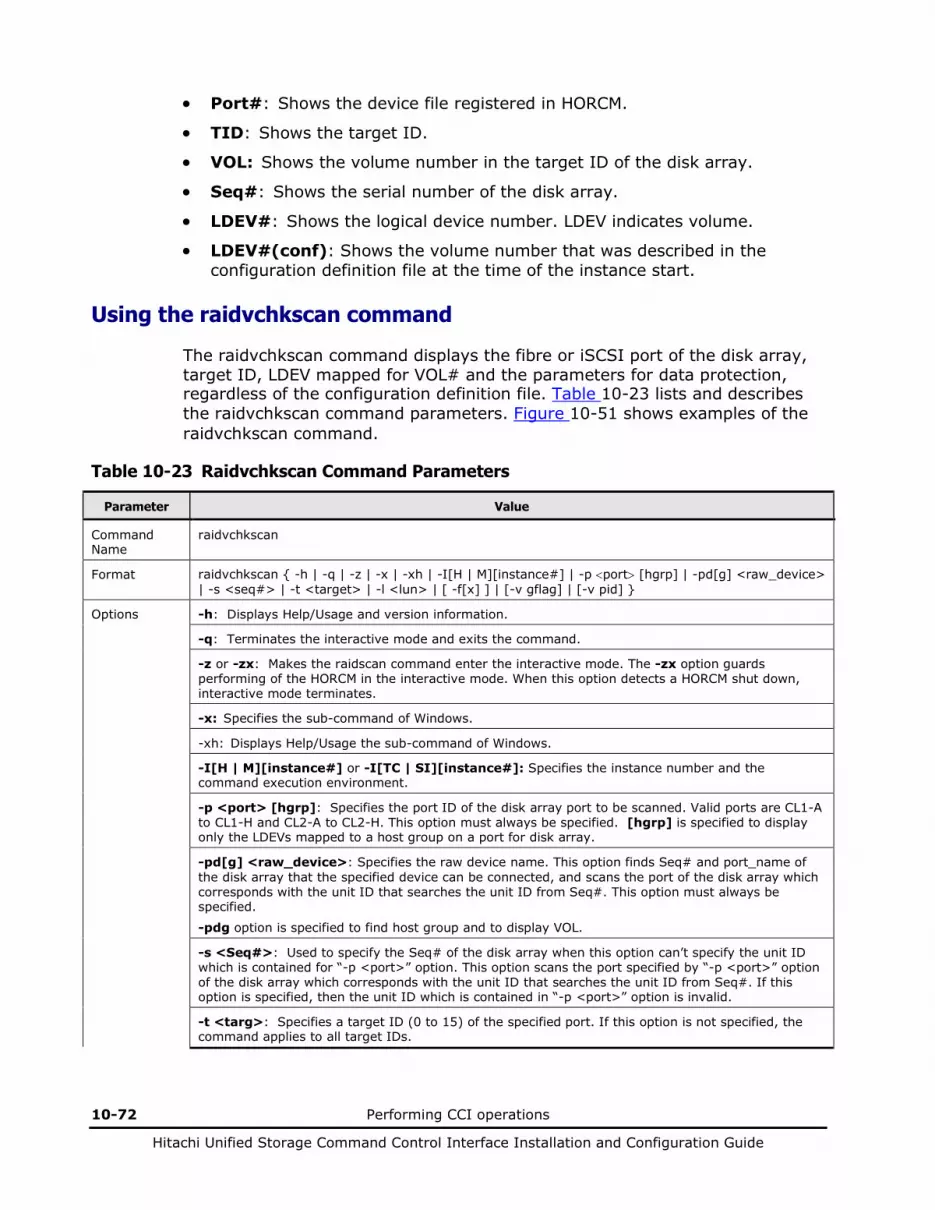
10-72 Performing CCI operations
Hitachi Unified Storage Command Control Interface Installation and Configuration Guide
• Port#: Shows the device file registered in HORCM.
• TID: Shows the target ID.
• VOL: Shows the volume number in the target ID of the disk array.
• Seq#: Shows the serial number of the disk array.
• LDEV#: Shows the logical device number. LDEV indicates volume.
• LDEV#(conf): Shows the volume number that was described in the configuration definition file at the time of the instance start.
Using the raidvchkscan command
The raidvchkscan command displays the fibre or iSCSI port of the disk array, target ID, LDEV mapped for VOL# and the parameters for data protection, regardless of the configuration definition file. Table 10-23 lists and describes the raidvchkscan command parameters. Figure 10-51 shows examples of the raidvchkscan command.
Table 10-23 Raidvchkscan Command Parameters
Parameter Value
Command Name
raidvchkscan
Format raidvchkscan { -h | -q | -z | -x | -xh | -I[H | M][instance#] | -p <port> [hgrp] | -pd[g] <raw_device> | -s <seq#> | -t <target> | -l <lun> | [ -f[x] ] | [-v gflag] | [-v pid] }
Options -h: Displays Help/Usage and version information.
-q: Terminates the interactive mode and exits the command.
-z or -zx: Makes the raidscan command enter the interactive mode. The -zx option guards performing of the HORCM in the interactive mode. When this option detects a HORCM shut down, interactive mode terminates.
-x: Specifies the sub-command of Windows.
-xh: Displays Help/Usage the sub-command of Windows.
-I[H | M][instance#] or -I[TC | SI][instance#]: Specifies the instance number and the command execution environment.
-p <port> [hgrp]: Specifies the port ID of the disk array port to be scanned. Valid ports are CL1-A to CL1-H and CL2-A to CL2-H. This option must always be specified. [hgrp] is specified to display only the LDEVs mapped to a host group on a port for disk array.
-pd[g] <raw_device>: Specifies the raw device name. This option finds Seq# and port_name of the disk array that the specified device can be connected, and scans the port of the disk array which corresponds with the unit ID that searches the unit ID from Seq#. This option must always be specified.
-pdg option is specified to find host group and to display VOL.
-s <Seq#>: Used to specify the Seq# of the disk array when this option can’t specify the unit ID which is contained for “-p <port>” option. This option scans the port specified by “-p <port>” option of the disk array which corresponds with the unit ID that searches the unit ID from Seq#. If this option is specified, then the unit ID which is contained in “-p <port>” option is invalid.
-t <targ>: Specifies a target ID (0 to 15) of the specified port. If this option is not specified, the command applies to all target IDs.

Performing CCI operations 10-73
Hitachi Unified Storage Command Control Interface Installation and Configuration Guide
Parameter Value
-l <lun>: Specifies a VOL (0 to 7) of the specified target ID. If this option is not specified, the command applies to all VOLs. If this option is specified, the TID must also be specified.
-fx: Displays the LDEV number in hexadecimal notation.
-v [op]: Specifies the following operation that displays each parameter for data protection:
gflag: Displays all flags for data regarding data block protection for target vols (see Figure 10-51).
pid: This option shows the usage of the pool. The displayed contents are same as the pairdisplay -v pid.
Returned values
Normal termination: 0.
Abnormal termination: Returns a common error code and a unique error code for this command. For details on error codes, see Chapter 10.
# raidvchkscan -p CL1-A -v gflag PORT# /ALPA/C TID# VOL# Seq# Num LDEV# GI-C-R-W-S PI-C-R-W-S R-Time CL1-A /ef/ 0 0 2 91202332 1 2 D D D D D E E E D D 365 CL1-A /ef/ 0 0 3 91202332 1 3 E E E E E E E E E E -
Figure 10-51 Raidvchkscan command example with -v gflag option
The output of the raidqvchkscan command with -v gflag option includes:
• Port#: Shows the port name of the disk array.
• ALPA/C: For the fibre channel, shows the physical address of the Fibre channel in a port. For iSCSI, displayed “ef” always.
• TID#: Shows the target ID of the disk array.
• VOL#: Shows the volume number.
• Seq#: Shows the production (serial#) number of the disk array.
• Num: Shows the number of volumes that constitute volume# (one fixed).
• LDEV#: Shows the LDEV# within the disk array. LDEV indicates volume.
• GI-C-R-W-S: This displays the flags for guarding as for the target volume.
I=E: The volume is permitted to accept the Inquiry command. I=D: The volume is not permitted to accept the Inquiry command. C=E: The volume returns the formal volume size in reply. C=D: The volume returns the size zero in reply. R=E: It is permitted to read from/to the object volume. R=D: It is prohibited to read from/to the object volume. W=E: It is permitted to write from/to the object volume. W=D: It is prohibited to write from/to the object volume. S=E: The volume can be assigned to an S-VOL. S=D: The volume cannot be assigned to an S-VOL.
10-74 Performing CCI operations
Hitachi Unified Storage Command Control Interface Installation and Configuration Guide
• PI-C-R-W-S: This displays the permission flags that shows whether each mode flags can be changed to enable or not. I=E: This shows that “I” flag can be changed to enable. I=D: This shows that “I” flag cannot be changed to enable. C=E: This shows that “C” flag can be changed to enable. C=D: This shows that “C” flag cannot be changed to enable. R=E: This shows that “R” flag can be changed to enable. R=D: This shows that “R” flag cannot be changed to enable. W=E: This shows that “W” flag can be changed to enable. W=D: This shows that “W” flag cannot be changed to enable. S=E: This shows that “S” flag can be changed to enable. S=D: This shows that “S” flag cannot be changed to enable.
• R-Time: The term of protection set for the volume is displayed with a number of days. When “-” is displayed, it means that the term is indefinite. Expiration Lock status is shown as the retention time plus 1000000. “R-Time + 1000000” shows the retention time with Expiration Lock status.
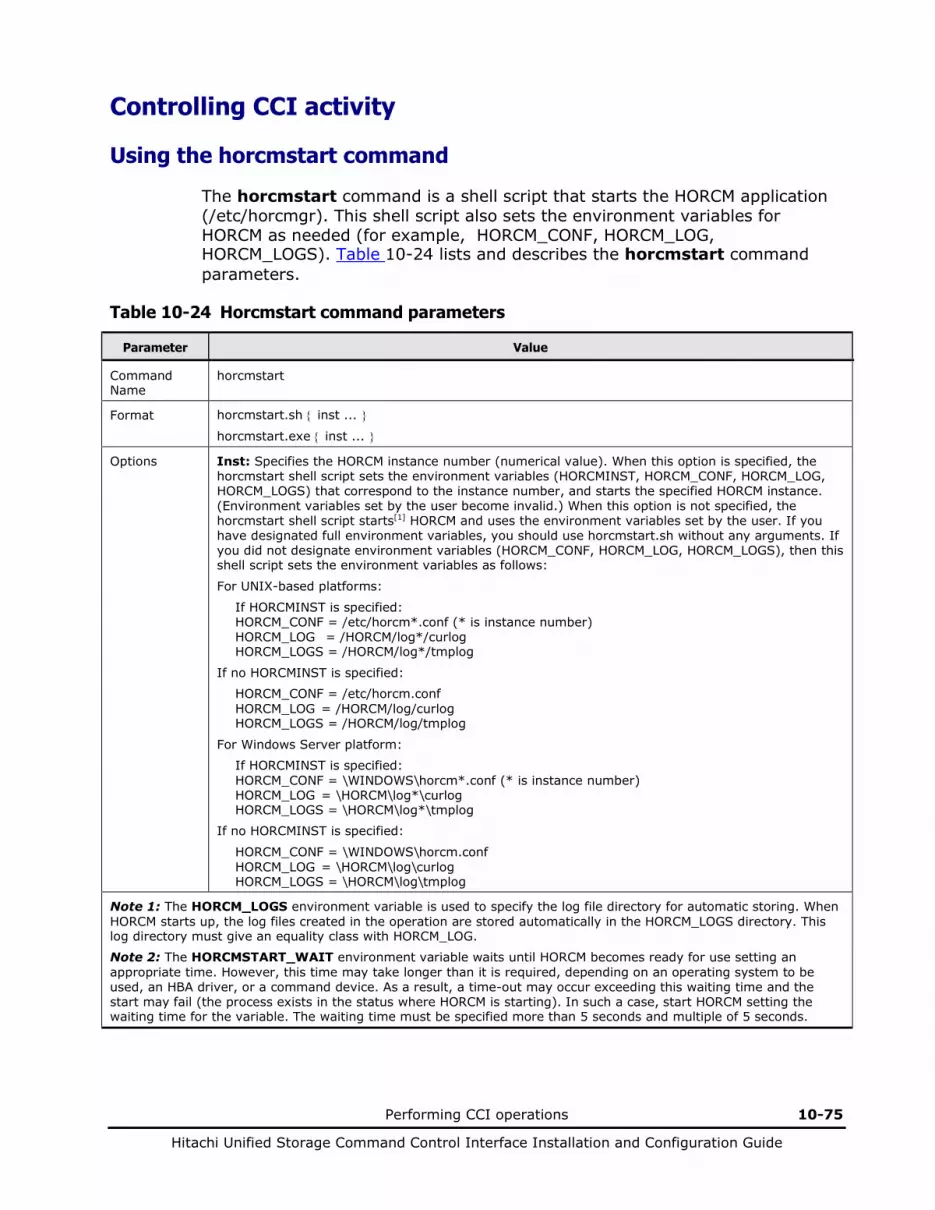
Performing CCI operations 10-75
Hitachi Unified Storage Command Control Interface Installation and Configuration Guide
Controlling CCI activity
Using the horcmstart command
The horcmstart command is a shell script that starts the HORCM application (/etc/horcmgr). This shell script also sets the environment variables for HORCM as needed (for example, HORCM_CONF, HORCM_LOG, HORCM_LOGS). Table 10-24 lists and describes the horcmstart command parameters.
Table 10-24 Horcmstart command parameters
Parameter Value
Command Name
horcmstart
Format horcmstart.sh { inst ... }
horcmstart.exe { inst ... }
Options Inst: Specifies the HORCM instance number (numerical value). When this option is specified, the horcmstart shell script sets the environment variables (HORCMINST, HORCM_CONF, HORCM_LOG, HORCM_LOGS) that correspond to the instance number, and starts the specified HORCM instance. (Environment variables set by the user become invalid.) When this option is not specified, the horcmstart shell script starts[1] HORCM and uses the environment variables set by the user. If you have designated full environment variables, you should use horcmstart.sh without any arguments. If you did not designate environment variables (HORCM_CONF, HORCM_LOG, HORCM_LOGS), then this shell script sets the environment variables as follows:
For UNIX-based platforms:
If HORCMINST is specified: HORCM_CONF = /etc/horcm*.conf (* is instance number) HORCM_LOG = /HORCM/log*/curlog HORCM_LOGS = /HORCM/log*/tmplog
If no HORCMINST is specified:
HORCM_CONF = /etc/horcm.conf HORCM_LOG = /HORCM/log/curlog HORCM_LOGS = /HORCM/log/tmplog
For Windows Server platform:
If HORCMINST is specified: HORCM_CONF = \WINDOWS\horcm*.conf (* is instance number) HORCM_LOG = \HORCM\log*\curlog HORCM_LOGS = \HORCM\log*\tmplog
If no HORCMINST is specified:
HORCM_CONF = \WINDOWS\horcm.conf HORCM_LOG = \HORCM\log\curlog HORCM_LOGS = \HORCM\log\tmplog
Note 1: The HORCM_LOGS environment variable is used to specify the log file directory for automatic storing. When HORCM starts up, the log files created in the operation are stored automatically in the HORCM_LOGS directory. This log directory must give an equality class with HORCM_LOG.
Note 2: The HORCMSTART_WAIT environment variable waits until HORCM becomes ready for use setting an appropriate time. However, this time may take longer than it is required, depending on an operating system to be used, an HBA driver, or a command device. As a result, a time-out may occur exceeding this waiting time and the start may fail (the process exists in the status where HORCM is starting). In such a case, start HORCM setting the waiting time for the variable. The waiting time must be specified more than 5 seconds and multiple of 5 seconds.
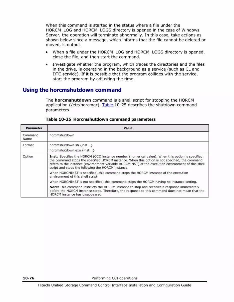
10-76 Performing CCI operations
Hitachi Unified Storage Command Control Interface Installation and Configuration Guide
When this command is started in the status where a file under the HORCM_LOG and HORCM_LOGS directory is opened in the case of Windows Server, the operation will terminate abnormally. In this case, take actions as shown below since a message, which informs that the file cannot be deleted or moved, is output.
• When a file under the HORCM_LOG and HORCM_LOGS directory is opened, close the file, and then start the command.
• Investigate whether the program, which traces the directories and the files in the drive, is operating in the background as a service (such as CL and DTC service). If it is possible that the program collides with the service, start the program by adjusting the time.
Using the horcmshutdown command
The horcmshutdown command is a shell script for stopping the HORCM application (/etc/horcmgr). Table 10-25 describes the shutdown command parameters.
Table 10-25 Horcmshutdown command parameters
Parameter Value
Command Name
horcmshutdown
Format horcmshutdown.sh {inst...}
horcmshutdown.exe {inst...}
Option Inst: Specifies the HORCM (CCI) instance number (numerical value). When this option is specified, the command stops the specified HORCM instance. When this option is not specified, the command refers to the instance (environment variable HORCMINST) of the execution environment of this shell script and stops the following the HORCM instance.
When HORCMINST is specified, this command stops the HORCM instance of the execution environment of this shell script.
When HORCMINST is not specified, this command stops the HORCM having no instance setting.
Note: This command instructs the HORCM instance to stop and receives a response immediately before the HORCM instance stops. Therefore, the response to this command does not mean that the HORCM instance has disappeared.

Performing CCI operations 10-77
Hitachi Unified Storage Command Control Interface Installation and Configuration Guide
Using the horcctl command
The HORCM software has logs that identify the cause of software and/or hardware errors as well as a tracing function for investigating such errors. The location of the log files depends on the user’s command execution environment and the HORC Manager’s execution environment. The command trace file and core file reside together under the directory specified in the HORC Manager’s execution environment.
The horcctl command can be used for both maintenance and troubleshooting. The horcctl command allows you to change and display the internal trace control parameters (for example, level, type, buffer size) of the HORC Manager commands. If a new value for a parameter is not specified, the current trace control parameter is displayed. Table 10-26 lists and describes the horcctl command parameters.
Caution: Do not change the trace level unless directed to do so by a Hitachi representative. Level 4 is the normal trace level setting. Levels 0-3 are for troubleshooting. Setting a trace level other than 4 may impact problem resolution. If you request a change of the trace level using the horcctl -l <level> command, a warning message is displayed, and this command enters interactive mode.
Table 10-26 Horcctl command parameters
Parameter Value
Command Name
horcctl
Format horcctl { -h | -q | -z | -x | -xh | -I[H | M][instance#] | -d | -c | -l <level> | -d <y/n> | -s <size(KB)> | -t <type> | -S | -D | -C | [-u <-unitid> | -ND | -NC | -g <group>}
Options -h: Displays Help/Usage and version information.
-q: Terminates the interactive mode and exits the command.
-z or -zx: Makes the horcctl command enter the interactive mode. The -zx option guards performing of HORCM in interactive mode. When this option detects a HORCM shutdown, interactive mode terminates.
-x: Specifies the sub-command of Windows.
-xh: Displays Help/Usage the sub-command of Windows.
-I[H | M][instance#] or -I[TC | SI][instance#]: Specifies the instance number and the command execution environment.
-d: Interprets the control options following this option (-l <level>, -b <y/n>, -s <size(kB)>, and -t <type>) as the parameters of the CCI commands.
-c: Interprets the control options following this option (-l <level>, -b <y/n> and -t <type>) as the parameters of the HORC Manager (HORCM).
-l <level>: Sets the trace level (range = 0 to 15). If a negative value is specified, the trace mode is canceled. A negative value “n” must be specified as “-n”.
Caution: Do not change the trace level unless directed to do so by a Hitachi representative. Level 4 is the normal trace level setting. Levels 0-3 are for troubleshooting. Setting a trace level other than 4 may impact problem resolution. If you request a change of the trace level using the horcctl -l <level> command, a warning message is displayed, and this command enters interactive mode.
-b <y/n>: Sets the trace writing mode: Y = buffer mode, N = synchronous mode.
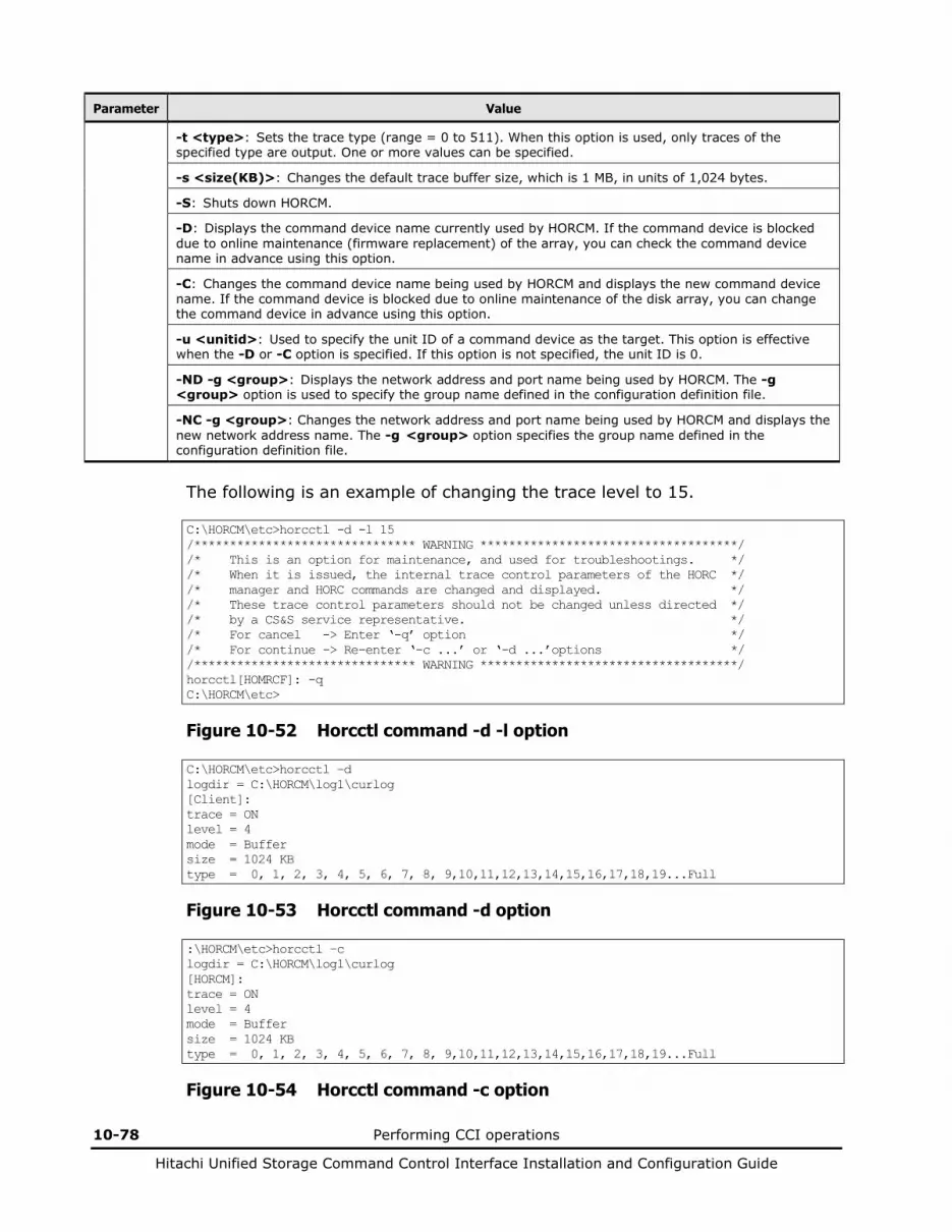
10-78 Performing CCI operations
Hitachi Unified Storage Command Control Interface Installation and Configuration Guide
Parameter Value
-t <type>: Sets the trace type (range = 0 to 511). When this option is used, only traces of the specified type are output. One or more values can be specified.
-s <size(KB)>: Changes the default trace buffer size, which is 1 MB, in units of 1,024 bytes.
-S: Shuts down HORCM.
-D: Displays the command device name currently used by HORCM. If the command device is blocked due to online maintenance (firmware replacement) of the array, you can check the command device name in advance using this option.
-C: Changes the command device name being used by HORCM and displays the new command device name. If the command device is blocked due to online maintenance of the disk array, you can change the command device in advance using this option.
-u <unitid>: Used to specify the unit ID of a command device as the target. This option is effective when the -D or -C option is specified. If this option is not specified, the unit ID is 0.
-ND -g <group>: Displays the network address and port name being used by HORCM. The -g <group> option is used to specify the group name defined in the configuration definition file.
-NC -g <group>: Changes the network address and port name being used by HORCM and displays the new network address name. The -g <group> option specifies the group name defined in the configuration definition file.
The following is an example of changing the trace level to 15.
C:\HORCM\etc>horcctl -d -l 15 /******************************* WARNING ************************************/ /* This is an option for maintenance, and used for troubleshootings. */ /* When it is issued, the internal trace control parameters of the HORC */ /* manager and HORC commands are changed and displayed. */ /* These trace control parameters should not be changed unless directed */ /* by a CS&S service representative. */ /* For cancel -> Enter ‘-q’ option */ /* For continue -> Re-enter ‘-c ...’ or ‘-d ...’options */ /******************************* WARNING ************************************/ horcctl[HOMRCF]: -q C:\HORCM\etc>
Figure 10-52 Horcctl command -d -l option
C:\HORCM\etc>horcctl –d logdir = C:\HORCM\log1\curlog [Client]: trace = ON level = 4 mode = Buffer size = 1024 KB type = 0, 1, 2, 3, 4, 5, 6, 7, 8, 9,10,11,12,13,14,15,16,17,18,19...Full
Figure 10-53 Horcctl command -d option
:\HORCM\etc>horcctl –c logdir = C:\HORCM\log1\curlog [HORCM]: trace = ON level = 4 mode = Buffer size = 1024 KB type = 0, 1, 2, 3, 4, 5, 6, 7, 8, 9,10,11,12,13,14,15,16,17,18,19...Full
Figure 10-54 Horcctl command -c option

Performing CCI operations 10-79
Hitachi Unified Storage Command Control Interface Installation and Configuration Guide
About Windows Server subcommands
The CCI software provides subcommands for Windows Server platforms which are executed as options (-x <command> <arg>) of another command. When you specify a subcommand as the only option of a command, you do not need to start HORCM. If another option of the command and the subcommand is specified on the same command line, place the other option after the subcommand.
Using the findcmddev subcommand
The findcmddev subcommand (find command device) searches for command devices within the specified range of disk drive numbers. If it is found, the command device is displayed in the same format as in the configuration definition file. This subcommand is used when the command device name is not known. Table 10-27 lists and describes the findcmddev subcommand parameters. Figure 10-55 shows an example of the findcmddev subcommand used as an option of the raidscan command output.
Caution: The findcmddev subcommand must be used when HORCM is not running.
The findcmddev subcommand searches for the physical and logical devices associated with the command device. If the command device is indicated as a logical device, you must delete the drive letter assigned to the command device to prevent utilization by general users. The physical drive number may change at every reboot. If the number changes, use \\.\CMD-Ser#-ldev#-Port# or Volume{guid} for which the same name is kept. Volume{guid} is created when you make a partition by using the Windows’ Disk Management. Do not format.
Table 10-27 Findcmddev subcommand parameters
Parameter Value
Command Name
findcmddev
Format -x findcmddev drive#(0-N)
Argument drive#(0-N): Specifies the range of disk drive numbers on the Windows system.
C:\HORCM\etc>raidscan -x findcmddev hdisk0,20 cmddev of Ser#91203001 = \\.\PhysicalDrive0 cmddev of Ser#91203001 = \\.\E: cmddev of Ser#91203001 = \\.\Volume{b9b31c79-240a-11d5-a37f-00c00d003b1e}
Figure 10-55 Findcmddev subcommand
This example searches for command devices in the range of disk drive numbers 0 to 20.

10-80 Performing CCI operations
Hitachi Unified Storage Command Control Interface Installation and Configuration Guide
Using the drivescan subcommand
The drivescan subcommand displays the relationship between the disk numbers assigned by Windows Server system and the LDEVs on the disk array, and also displays attribute and status information for each LDEV. Table 10-28 lists and describes the drivescan subcommand parameters. Figure 10-56 shows an example of the drivescan subcommand used as an option of the raidscan command and its output.
Table 10-28 Drivescan subcommand parameters
Parameter Value
Command Name drivescan
Format -x drivescan drive#(0-N)
Argument drive#(0-N): Specifies the range of disk drive numbers on the Windows system.
C:\HORCM\etc>raidscan -x drivescan harddisk0,20 Harddisk 0... Port[ 1] PhId[ 0] TId[ 0] Lun[ 0] [HITACHI] [DK328H-43WS ] Harddisk 1... Port[ 2] PhId[ 4] TId[ 29] Lun[ 0] [HITACHI] [DF600F ] Port[CL1-A] Ser#[91203005] LDEV#[ 9(0x009)] HORC = SMPL HOMRCF[MU#0 = SMPL MU#1 = NONE MU#2 = NONE] RAID5[Group 2- 1] SSID = 0x0000 Harddisk 2... Port[ 2] PhId[ 4] TId[ 29] Lun[ 1] [HITACHI] [DF600F ] Port[CL1-A] Ser#[91203005] LDEV#[ 10(0x00A)] HORC = SMPL HOMRCF[MU#0 = SMPL MU#1 = NONE MU#2 = NONE] RAID5[Group 2- 1] SSID = 0x0000 Harddisk 3... Port[ 2] PhId[ 4] TId[ 29] Lun[ 6] [HITACHI] [DF600F-CM ] Port[CL1-A] Ser#[91203005] LDEV#[ 15(0x00F)]
Figure 10-56 Drivescan subcommand example
This example displays the devices for the range of disk drive numbers from 0 to 20.
The output of the drivescan subcommand includes:
• Harddisk #: Shows the hard disk recognized by Windows Server system.
• Port: Shows the port number on the device adapter recognized by Windows Server system.
• PhId: Shows the bus number on the device adapter port recognized by Windows Server 2003 system.
• Tid: Shows the target ID of the hard disks on the specified port and bus.
• VOL: Shows the volume number of the hard disk on the specified port, bus, and TID.
• Port[CLX-Y]: Shows the port number on the disk array.
• Ser#: Shows the production number of the disk array.
• LDEV#: Shows the LDEV ID (hexadecimal) of the specified volume on the disk array. LDEV indicates volume.
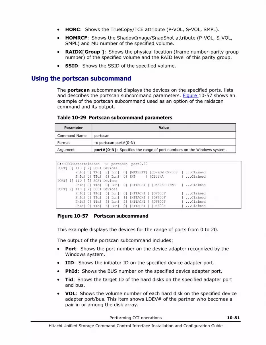
Performing CCI operations 10-81
Hitachi Unified Storage Command Control Interface Installation and Configuration Guide
• HORC: Shows the TrueCopy/TCE attribute (P-VOL, S-VOL, SMPL).
• HOMRCF: Shows the ShadowImage/SnapShot attribute (P-VOL, S-VOL, SMPL) and MU number of the specified volume.
• RAIDX[Group ]: Shows the physical location (frame number-parity group number) of the specified volume and the RAID level of this parity group.
• SSID: Shows the SSID of the specified volume.
Using the portscan subcommand
The portscan subcommand displays the devices on the specified ports. lists and describes the portscan subcommand parameters. Figure 10-57 shows an example of the portscan subcommand used as an option of the raidscan command and its output.
Table 10-29 Portscan subcommand parameters
Parameter Value
Command Name portscan
Format -x portscan port#(0-N)
Argument port#(0-N): Specifies the range of port numbers on the Windows system.
C:\HORCM\etc>raidscan -x portscan port0,20 PORT[ 0] IID [ 7] SCSI Devices PhId[ 0] TId[ 3] Lun[ 0] [MATSHIT] [CD-ROM CR-508 ] ...Claimed PhId[ 0] TId[ 4] Lun[ 0] [HP ] [C1537A ] ...Claimed PORT[ 1] IID [ 7] SCSI Devices PhId[ 0] TId[ 0] Lun[ 0] [HITACHI ] [DK328H-43WS ] ...Claimed PORT[ 2] IID [ 7] SCSI Devices PhId[ 0] TId[ 5] Lun[ 0] [HITACHI ] [DF600F ] ...Claimed PhId[ 0] TId[ 5] Lun[ 1] [HITACHI ] [DF600F ] ...Claimed PhId[ 0] TId[ 5] Lun[ 2] [HITACHI ] [DF600F ] ...Claimed PhId[ 0] TId[ 6] Lun[ 0] [HITACHI ] [DF600F ] ...Claimed
Figure 10-57 Portscan subcommand
This example displays the devices for the range of ports from 0 to 20.
The output of the portscan subcommand includes:
• Port: Shows the port number on the device adapter recognized by the Windows system.
• IID: Shows the initiator ID on the specified device adapter port.
• PhId: Shows the BUS number on the specified device adapter port.
• Tid: Shows the target ID of the hard disks on the specified adapter port and bus.
• VOL: Shows the volume number of each hard disk on the specified device adapter port/bus. This item shows LDEV# of the partner who becomes a pair in or among the disk array.

10-82 Performing CCI operations
Hitachi Unified Storage Command Control Interface Installation and Configuration Guide
Using the sync and syncd subcommands
The sync (synchronization) subcommand sends unwritten data remaining on Windows Server to the specified devices. The syncd (synchronization delay) subcommand waits the delayed I/O for dismount after issued “sync”. Table 10-30 lists and describes the sync and syncd subcommand parameters.
Table 10-30 Sync and syncd subcommand parameters
Parameter Value
Command Name
sync
syncd
Format -x sync[d] A: B: C: ...
-x sync[d] all
-x sync[d] drive#(0-N) ...
-x sync[d] Volume#(0-N) ...
-x sync[d] D:\directory or \directory pattern ... (Windows Server systems only)
Argument A: B: C:[\directory or \directory pattern] … : Specifies the logical devices that you want to synchronize. The data is flushed to the specified logical device and to the physical device that corresponds to the specified logical device.
If a directory-mounted volume exists in the specified logical device, the data will be flushed including the directory-mounted volume as follows: pairsplit -x sync D: [SYNC] D: HarddiskVolume2 [SYNC] D: \hd1 HarddiskVolume8 [SYNC] D: \hd2 HarddiskVolume9
[\directory or \directory pattern] (Windows Server systems only) Specifies the directory or the directory pattern for searching the directory mount point in the logical device.
If directory is specified: The applicable directory-mounted volume will be flushed. pairsplit -x sync D:\hd1 [SYNC] D:\hd1 HarddiskVolume8
If directory patter is specified: The directory-mounted volume that matches the specified pattern will be flushed. pairsplit -x sync D:\h [SYNC] D:\hd1 HarddiskVolume8 [SYNC] D:\hd2 HarddiskVolume9
all: Synchronizes all logical devices. The logical device on which the CCI software is installed and the logical device containing Windows Server directory are excluded. If a directory-mounted volume exists in the specified logical device, the data will be flushed including the directory-mounted volume as follows: pairsplit -x sync all [SYNC] C: HarddiskVolume1 [SYNC] D: \hd1 HarddiskVolume8 [SYNC] D: \hd2 HarddiskVolume9 [SYNC] G: HarddiskVolume10
drive#(0-N) ...: Specifies the range of devices on Windows Server system.
Volume#(0-N) ...: Synchronizes the data to the specified LDM (logical device manager) volume. The LDM volume specifies the following device objects: \Vol#, \Dms#, \Dmt#, \Dmr#, or Volume{GUID}.

Performing CCI operations 10-83
Hitachi Unified Storage Command Control Interface Installation and Configuration Guide
Parameter Value
Note The sync command executes the following procedures, depending on the execution condition.
If the logical device is closed from the application, the system buffer is flushed and changes the logical device to “Dismount” status.
If the logical device is opened from the application, the sync option flushes the system buffer only. In this case, [WARNING] will be displayed. pairsplit -x sync -C: WARNING: Only flushed to [\\.\C] drive due to be opening. [SYNC] C: HarddiskVolume3
The syncd command executes the following procedures, depending on the execution condition.
If the logical drives designated as the objects of the sync command will not be opened to any applications, then syncd flushes the system buffer to a drive and waits (30 sec) the delayed (paging) I/O for dismount after made the dismount state about the drive.
This avoids a problem that NTFS on P-VOL will be split on inconsistent state because Windows Server delays the I/O for dismounting.
The following examples show the sync subcommand used as an option of the pairsplit command. For the example in Figure 10-58, the data remaining on logical devices C: and D: is written to disk, all pairs in the specified group are split (status = PSUS), and read/write access is enabled for all S-VOLs in the specified group.
pairsplit -x sync C: D: -g oradb
Figure 10-58 Sync subcommand example 1
For the example in Figure 10-59, the data remaining on physical devices harddisk2 and harddisk3 is written to disk, all pairs in the specified group are deleted (status = SMPL), which enables read/write access for all secondary volumes.
pairsplit -x sync hdisk2 hdisk3 -g oradb -S
Figure 10-59 Sync subcommand example 2

10-84 Performing CCI operations
Hitachi Unified Storage Command Control Interface Installation and Configuration Guide
Using the mount subcommand
The mount subcommand mounts the specified drive to the specified partition on the specified hard disk drive. If the mount subcommand is executed without specifying an argument, all drives that are currently mounted are displayed. Table 10-31 lists and describes the mount subcommand parameters. Figure 10-60 shows example of the mount subcommand used as an option of the pairsplit command output.
For the directory mount, specify the mount point in the form of F:\ or D:\hdl (with \).
Caution: The partition on the specified disk drive (Harddisk) must be recognized on Windows Server system. Note that when you want to not use directory mount, it will be unmounted forcedly by logging off of Windows Server system. You can avoid the Windows Server mount problems by setting USE_MOUNTVOL_P of the environment variable. You can avoid mount problems that is event ID1 occurrence by setting this environment variable.
Table 10-31 Mount subcommand parameters
Parameter Value
Command Name mount
Format -x mount
-x mount drive: Volume#(0-N) ...
-x mount drive: [\[directory]] Volume#(0-N) ... (Windows Server systems only)
Arguments Drive: [\[directory]] Volume#: For Windows Server. The drive specifies the logical device to be mounted. The hdisk# specifies the following device object names of the LDM volume to be mounted: hdisk#, \Vol#, \Dms#, \Dmt#, \Dmr#, or Volume{GUID}
[\directory] Specifies the directory for specifying the directory mount point in the logical device. The character string of the directory cannot include space letters. pairsplit -x mount D:\hd1 \Vol8 D:\hd1 <+> HarddiskVolume8 pairsplit -x mount D:\hd2 \Vol9 D:\hd2 <+> HarddiskVolume9 If this command is executed without any argument, the device that is already mounted will be displayed.
When mounting it by using the mountvol command supplied with Windows Server, the character string of the specified directory can include space letters (however, do not use the mountvol command when mounting the volumes created in disk array). When the character string includes a space (example: aaa bbb), it is indicated by adding “…” to the first character string in the mount command as shown in the following example.
pairsplit -x mount
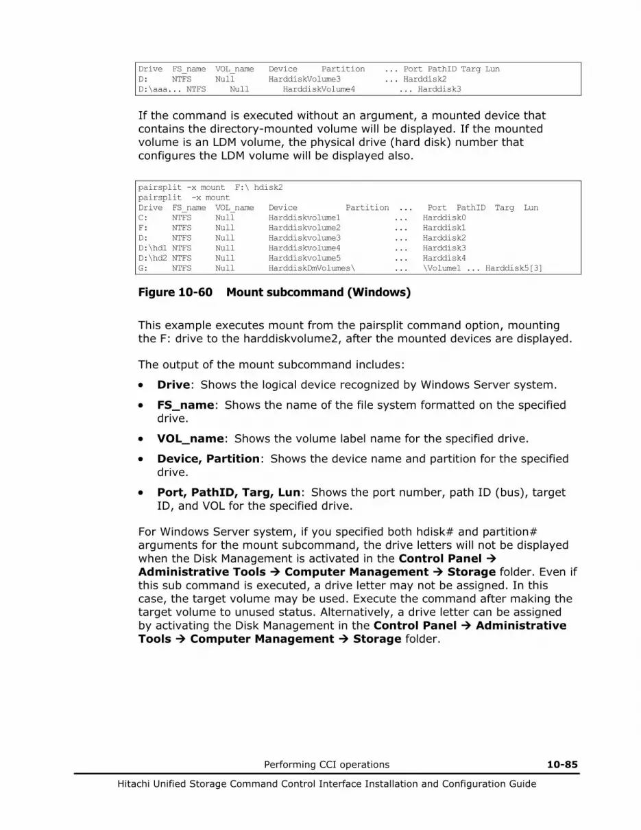
Performing CCI operations 10-85
Hitachi Unified Storage Command Control Interface Installation and Configuration Guide
Drive FS_name VOL_name Device Partition ... Port PathID Targ Lun D: NTFS Null HarddiskVolume3 ... Harddisk2 D:\aaa... NTFS Null HarddiskVolume4 ... Harddisk3
If the command is executed without an argument, a mounted device that contains the directory-mounted volume will be displayed. If the mounted volume is an LDM volume, the physical drive (hard disk) number that configures the LDM volume will be displayed also.
pairsplit -x mount F:\ hdisk2 pairsplit -x mount Drive FS_name VOL_name Device Partition ... Port PathID Targ Lun C: NTFS Null Harddiskvolume1 ... Harddisk0 F: NTFS Null Harddiskvolume2 ... Harddisk1 D: NTFS Null Harddiskvolume3 ... Harddisk2 D:\hd1 NTFS Null Harddiskvolume4 ... Harddisk3 D:\hd2 NTFS Null Harddiskvolume5 ... Harddisk4 G: NTFS Null HarddiskDmVolumes\ ... \Volume1 ... Harddisk5[3]
Figure 10-60 Mount subcommand (Windows)
This example executes mount from the pairsplit command option, mounting the F: drive to the harddiskvolume2, after the mounted devices are displayed.
The output of the mount subcommand includes:
• Drive: Shows the logical device recognized by Windows Server system.
• FS_name: Shows the name of the file system formatted on the specified drive.
• VOL_name: Shows the volume label name for the specified drive.
• Device, Partition: Shows the device name and partition for the specified drive.
• Port, PathID, Targ, Lun: Shows the port number, path ID (bus), target ID, and VOL for the specified drive.
For Windows Server system, if you specified both hdisk# and partition# arguments for the mount subcommand, the drive letters will not be displayed when the Disk Management is activated in the Control Panel Administrative Tools Computer Management Storage folder. Even if this sub command is executed, a drive letter may not be assigned. In this case, the target volume may be used. Execute the command after making the target volume to unused status. Alternatively, a drive letter can be assigned by activating the Disk Management in the Control Panel Administrative Tools Computer Management Storage folder.
10-86 Performing CCI operations
Hitachi Unified Storage Command Control Interface Installation and Configuration Guide
When using Volume{guid} as argument for mount sub-command on Windows Server, the Volume{guid} of secondary volumes (S-VOL/V-VOL) of ShadowImage/SnapShot/TrueCopy/TCE is set by recognizing from OS by the Control Panel Administrative Tools Computer Management Storage folder Rescan Disks, while status is PSUS after pair create. Afterwards, the set Volume{guid} can be confirmed by “inqraid.exe -CLI $Vol -fv”. However, if Volume{guid} is already set when partition is already created at SMPL status before pair create, then Volume{guid} after pair create may not be recognized even if “re-scan disk” is done at PSUS status after pair create. In case of using Volume{guid} with secondary volumes (S-VOL/V-VOL), be sure to create pair when partition is not created to the secondary volume (S-VOL/V-VOL) before pair creation.
When making a secondary volume (S-VOL or V-VOL) of ShadowImage, SnapShot, TrueCopy, or TCE recognized by a host on Windows Server, make it in a state in which the pair is placed in the PSUS status after the pair has been created. If the pair status is changed to PSUS after the pair has been recognized by a host while it has been in the PSUS status, the pair may not operate correctly thereafter because the pair status is changed to that of the primary volume (P-VOL). To recognizing from host by the Control Panel Administrative Tools Computer Management Storage folder Rescan Disks, or reboot a host.

Performing CCI operations 10-87
Hitachi Unified Storage Command Control Interface Installation and Configuration Guide
Using the umount subcommand
The umount subcommand unmounts the specified logical drive and deletes the drive letter. Before deleting the drive letter, this subcommand executes sync internally for the specified logical drive and flushes unwritten data. Table 10-32 lists and describes the umount subcommand parameters. Figure 10-61 shows an example of the umount subcommand used as an option of the pairsplit command.
For the directory mount, specify the mount point in the form of F:\ or D:\hdl (with \).
Caution: The logical drive to be unmounted and the corresponding physical drive must be closed to all applications. You can avoid the Windows Server mount problems by setting USE_MOUNTVOL_P of the environment variable. You can avoid mount problems that is event ID1 occurrence by setting this environment variable.
When Disk Management is started or the Rescan Disks is executed on Windows Server 2003, the Write command may be issued by Windows Server 2003. Besides, the Write command by Disk Management start or the Rescan Disks is also issued to a logical drive unmounted by the unmount sub-command. Therefore, when Disk Management is started or the Rescan Disk is executed in the status where a logical drive is not writable in the disk array, an error indicating a failure of writing to the logical drive may remain in the event log of Windows Server 2003 even though the logical drive in the write disabled status is unmounted. For example, because an S-VOL placed in the COPY or PAIR status by the pairresync is in the write disabled status, an error may remain in the event log of Windows Server 2003 when Disk Management is started or the Rescan Disks is executed even though the S-VOL is unmounted. The data has no problem even though an error remains in the event log of Windows Server 2003. If you do not want the error remained, execute the Rescan Disks before the logical drive is placed in the write disabled status by the pairresync command, etc. after unmounting the logical drive.
Procedure for the resync operation after unmounting the S-VOL: 1. Unmount the S-VOL by the unmount sub-command. 2. Execute the Rescan (that is equivalent to the Rescan Disks of Disk
Management) of the diskpart command. 3. Wait for about 30 seconds. 4. Execute the pairresync command. (The S-VOL is changed to the write
disabled status)

10-88 Performing CCI operations
Hitachi Unified Storage Command Control Interface Installation and Configuration Guide
Windows Server may write for the un-mounted volume. If a pair is resynchronized while remaining the data to the S-VOL on the memory of the server, the compatible backup cannot be collected. Therefore, execute the sync command of CCI immediately before re-synchronizing the pair for the un-mounted S-VOL.
Table 10-32 Umount subcommand parameters
Parameter Value
Command Name
umount
Format -x umount drive:
-x umount drive:[\[directory]] ... (Windows Server systems only)
Argument drive: Specifies the mounted logical device.
Drive:[\[directory]]: Specify the mounted logical device for drive.
[\directory]: Specifies the directory for specifying the directory mount point in the logical device. pairsplit -x umount D:\hd1 D:\hd1 <-> HarddiskVolume8 pairsplit -x umount D:\hd2 D:\hd2 <-> HarddiskVolume9
Note When the logical drive opened to applications, specified as following. pairsplit -x umount D:\hd1 ERROR: Couldn't unmount [\\.\D:\hd1] due to be opening.
pairsplit -x umount F:\ -x umount G:\ -g oradb pairsplit -x mount Drive FS_name VOL_name Device Partition ... Port PathID Targ Lun C: FAT Null Harddisk0 Partition1 ... 1 0 0 0 Z: Unknown Unknown CdRom0 ... Unknown
Figure 10-61 Umount subcommand
This example unmounts the F: and G: drives, splits all pairs in the specified group (status = PSUS), enables read/write access to all secondary volumes in the specified group, and then displays all mounted drives.
The output of the umount subcommand includes:
• Drive: Shows the logical drive recognized by Windows Server system.
• FS_name: Shows the name of the file system formatted on the specified drive.
• VOL_name: Shows the volume label name for the specified drive.
• Device, Partition: Shows the device name and partition for the specified drive.
• Port, PathID, Targ, Lun: Shows the port number, path ID (bus), target ID, and VOL for the specified drive.

Performing CCI operations 10-89
Hitachi Unified Storage Command Control Interface Installation and Configuration Guide
For Windows Server system, even if this sub command is executed, a drive letter may not be deleted. In this case, the target volume may be used. Execute the command after making the target volume to unused status. Alternatively, a drive letter can be deleted by activating the Disk Management in the Control Panel Administrative Tools Computer Management Storage folder.
If you use the mount command with directory mount option on Windows Server, the umount command must be used with directory mount option.
Example: correct pairsplit -x mount F:\ hdisk2 pairsplit -x umount F:\
Example: correct pairsplit -x mount F: hdisk2 pairsplit -x umount F:
Example: incorrect pairsplit -x mount F:\ hdisk2 pairsplit -x umount F:
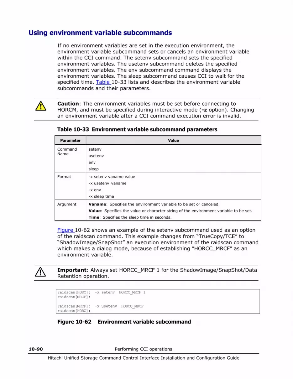
10-90 Performing CCI operations
Hitachi Unified Storage Command Control Interface Installation and Configuration Guide
Using environment variable subcommands
If no environment variables are set in the execution environment, the environment variable subcommand sets or cancels an environment variable within the CCI command. The setenv subcommand sets the specified environment variables. The usetenv subcommand deletes the specified environment variables. The env subcommand command displays the environment variables. The sleep subcommand causes CCI to wait for the specified time. Table 10-33 lists and describes the environment variable subcommands and their parameters.
Caution: The environment variables must be set before connecting to HORCM, and must be specified during interactive mode (-z option). Changing an environment variable after a CCI command execution error is invalid.
Table 10-33 Environment variable subcommand parameters
Parameter Value
Command Name
setenv
usetenv
env
sleep
Format -x setenv vaname value
-x usetenv vaname
-x env
-x sleep time
Argument Vaname: Specifies the environment variable to be set or canceled.
Value: Specifies the value or character string of the environment variable to be set.
Time: Specifies the sleep time in seconds.
Figure 10-62 shows an example of the setenv subcommand used as an option of the raidscan command. This example changes from “TrueCopy/TCE” to “ShadowImage/SnapShot” an execution environment of the raidscan command which makes a dialog mode, because of establishing “HORCC_MRCF” as an environment variable.
Important: Always set HORCC_MRCF 1 for the ShadowImage/SnapShot/Data Retention operation.
raidscan[HORC]: -x setenv HORCC_MRCF 1 raidscan[MRCF]: raidscan[MRCF]: -x usetenv HORCC_MRCF raidscan[HORC]:
Figure 10-62 Environment variable subcommand

Performing CCI operations 10-91
Hitachi Unified Storage Command Control Interface Installation and Configuration Guide
CCI command tools
Usng the inqraid command
The inqraid command tool confirms the drive connection between the disk array and the host system. The inqraid command displays the relation between special files on the HP-UX system and actual physical drive of the disk array. Table 10-34 lists and describes the inqraid command and parameters. Figure 10-63 to Figure 10-78 show examples of using inqraid and system commands to display the connection between the STDIN special file and the actual physical drive of disk array.
Table 10-34 Inqraid Command Parameters
Parameter Value
Command Name
inqraid
Format /HORCM/usr/bin/inqraid [-h | quit | -inqdump | -fx[l][g][w] | -find[c] | <special file> | -CLI | -CLIWP | -CLIWN | sort | -CM ]
\HORCM\etc\inqraid [-h | quit | -inqdump | -fx[l][g][w] | -find[c] | <special file> | -CLI | -CLIWP | -CLIWN | sort | -CM | -gvinf | -svinf ]
Options -h: This option displays Help/Usage.
quit: This option terminates from waiting STDIN and exits this command.
-inqdump: This option displays information for standard inquiry with Dump Image of hexadecimal.
-fx: This option displays the LDEV number with hexadecimal.
-fl: Shows a data protection volume with “-CLI ” option by appending an asterisk (*) to the device file name.
-fg: This option is specified to find host group and to display VOL.
-fw: This option extends the contents of display, and indicates the V-VOL information to the maximum of MU#. This option is used by combining with the option of -CLI (see Figure 10-78 also).
-find [c]: This option searches a group on the configuration definition file ( local instance) from <special file> of STDIN by using pairdisplay command, and uses the following options of the pairdisplay command to display its state. The -find option executes the following command (see Figure 10-71 also).
pairdisplay -d <Seq#><LDEV> 0 1 2 -l [-fx] [-CLI] 2>/dev/null
The -find[c] option executes the following command and then displays the result edited to CLI format (see Figure 10-71 also).
pairdisplay -d <Seq#><LDEV><MU#> -fd -CLI 2>/dev/null
<special file>: This option is used to specify the special file name as argument of command.
If no argument, this command makes mode that wait for STDIN without argument.
-CLI: Displays the CLI. This option displays the CLI using one header and divides the column with space or with “-” (see Figure 10-73 also).
-CLIWP and -CLIWN: For fibre channel, these options display the WWN of the host adaptor in CLI format. PWWN or NWWN will be displayed for WWN (see Figure 10-74 also). For iSCSI, “0000000000000000” will be always displayed for WWN.
-sort [-CM]: Sorts and displays the order of the disk array product number and the volume management number. The [-CM] option searches for command device from the specified special file (raw device file) provided via STDIN or argument input, and then displays only the command device in the image of the configuration definition file (see Figure 10-75 also).
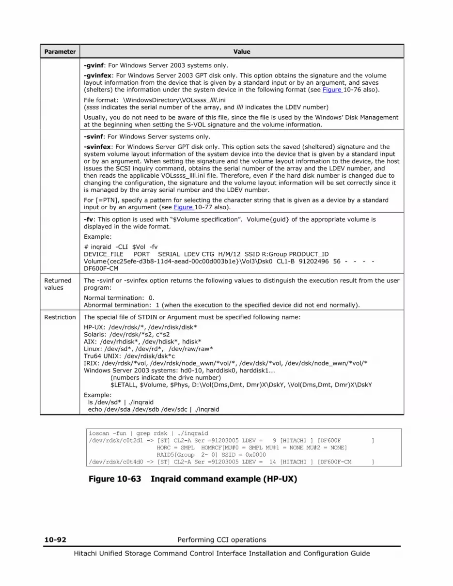
10-92 Performing CCI operations
Hitachi Unified Storage Command Control Interface Installation and Configuration Guide
Parameter Value
-gvinf: For Windows Server 2003 systems only.
-gvinfex: For Windows Server 2003 GPT disk only. This option obtains the signature and the volume layout information from the device that is given by a standard input or by an argument, and saves (shelters) the information under the system device in the following format (see Figure 10-76 also).
File format: \WindowsDirectory\VOLssss_llll.ini (ssss indicates the serial number of the array, and llll indicates the LDEV number)
Usually, you do not need to be aware of this file, since the file is used by the Windows’ Disk Management at the beginning when setting the S-VOL signature and the volume information.
-svinf: For Windows Server systems only.
-svinfex: For Windows Server GPT disk only. This option sets the saved (sheltered) signature and the system volume layout information of the system device into the device that is given by a standard input or by an argument. When setting the signature and the volume layout information to the device, the host issues the SCSI inquiry command, obtains the serial number of the array and the LDEV number, and then reads the applicable VOLssss_llll.ini file. Therefore, even if the hard disk number is changed due to changing the configuration, the signature and the volume layout information will be set correctly since it is managed by the array serial number and the LDEV number.
For [=PTN], specify a pattern for selecting the character string that is given as a device by a standard input or by an argument (see Figure 10-77 also).
-fv: This option is used with “$Volume specification”. Volume{guid} of the appropriate volume is displayed in the wide format.
Example:
# inqraid -CLI $Vol -fv DEVICE_FILE PORT SERIAL LDEV CTG H/M/12 SSID R:Group PRODUCT_ID Volume{cec25efe-d3b8-11d4-aead-00c00d003b1e}\Vol3\Dsk0 CL1-B 91202496 56 - - - - DF600F-CM
Returned values
The -svinf or -svinfex option returns the following values to distinguish the execution result from the user program:
Normal termination: 0. Abnormal termination: 1 (when the execution to the specified device did not end normally).
Restriction The special file of STDIN or Argument must be specified following name:
HP-UX: /dev/rdsk/*, /dev/rdisk/disk* Solaris: /dev/rdsk/*s2, c*s2 AIX: /dev/rhdisk*, /dev/hdisk*, hdisk* Linux: /dev/sd*, /dev/rd*, /dev/raw/raw* Tru64 UNIX: /dev/rdisk/dsk*c IRIX: /dev/rdsk/*vol, /dev/rdsk/node_wwn/*vol/*, /dev/dsk/*vol, /dev/dsk/node_wwn/*vol/* Windows Server 2003 systems: hd0-10, harddisk0, harddisk1... (numbers indicate the drive number) $LETALL, $Volume, $Phys, D:\Vol(Dms,Dmt, Dmr)X\DskY, \Vol(Dms,Dmt, Dmr)X\DskY
Example: ls /dev/sd* | ./inqraid echo /dev/sda /dev/sdb /dev/sdc | ./inqraid
ioscan -fun | grep rdsk | ./inqraid /dev/rdsk/c0t2d1 -> [ST] CL2-A Ser =91203005 LDEV = 9 [HITACHI ] [DF600F ] HORC = SMPL HOMRCF[MU#0 = SMPL MU#1 = NONE MU#2 = NONE] RAID5[Group 2- 0] SSID = 0x0000 /dev/rdsk/c0t4d0 -> [ST] CL2-A Ser =91203005 LDEV = 14 [HITACHI ] [DF600F-CM ]
Figure 10-63 Inqraid command example (HP-UX)

Performing CCI operations 10-93
Hitachi Unified Storage Command Control Interface Installation and Configuration Guide
ls /dev/rdsk/* | ./inqraid /dev/rdsk/c0t2d1s2 -> [ST] CL2-A Ser =91203005 LDEV = 9 [HITACHI ] [DF600F ] HORC = SMPL HOMRCF[MU#0 = SMPL MU#1 = NONE MU#2 = NONE] RAID5[Group 2- 0] SSID = 0x0000 /dev/rdsk/c0t4d0s2 -> [ST] CL2-A Ser =91203005 LDEV = 14 [HITACHI ] [DF600F-CM ]
Figure 10-64 Inqraid command (Solaris)
lsdev -C -c disk | ./inqraid hdisk10 -> [ST] CL2-A Ser =91203005 LDEV = 9 [HITACHI ] [DF600F ] HORC = SMPL HOMRCF[MU#0 = SMPL MU#1 = NONE MU#2 = NONE] RAID5[Group 2- 0] SSID = 0x0000 hdisk11 -> [ST] CL2-A Ser =91203005 LDEV = 14 [HITACHI ] [DF600F-CM ]
Figure 10-65 Inqraid command (AIX)
ls /dev/sd* | inqraid /dev/sdh -> CHNO = 0 TID = 1 LUN = 7 [ST] CL2-A Ser =91203005 LDEV = 9 [HITACHI ] [DF600F ] HORC = SMPL HOMRCF[MU#0 = SMPL MU#1 = NONE MU#2 = NONE] RAID5[Group 2- 0] SSID = 0x0000 /dev/sdi -> CHNO = 0 TID = 4 LUN = 0 [ST] CL2-A Ser =91203005 LDEV = 14 [HITACHI ] [DF600F-CM ]
Figure 10-66 Inqraid command (Linux)
ls /dev/rdisk/dsk* | ./inqraid /dev/rdisk/dsk10c -> [ST] CL2-A Ser =91203005 LDEV = 9 [HITACHI ] [DF600F ] HORC = SMPL HOMRCF[MU#0 = SMPL MU#1 = NONE MU#2 = NONE] RAID5[Group 2- 0] SSID = 0x0000 /dev/rdisk/dsk11c -> [ST] CL2-A Ser =91203005 LDEV = 14 [HITACHI ] [DF600F-CM ]
Figure 10-67 Inqraid command (Tru64 UNIX)
echo hd10-11 | .\inqraid Harddisk10 -> [ST] CL2-A Ser =91203005 LDEV = 9 [HITACHI ] [DF600F ] HORC = SMPL HOMRCF[MU#0 = SMPL MU#1 = NONE MU#2 = NONE] RAID5[Group 2- 0] SSID = 0x0000 Harddisk11 -> [ST] CL2-A Ser =91203005 LDEV = 14 [HITACHI ] [DF600F-CM ]
Figure 10-68 Inqraid command (Windows)
ls /dev/rdsk/*vol | ./inqraid /dev/rdsk/dks1d6vol -> [ST] CL2-A Ser =91203005 LDEV = 9 [HITACHI ] [DF600F ] HORC = SMPL HOMRCF[MU#0 = SMPL MU#1 = NONE MU#2 = NONE] RAID5[Group 2- 0] SSID = 0x0000 /dev/rdsk/dks1d7vol -> [ST] CL2-A Ser =91203005 LDEV = 14 [HITACHI ] [DF600F-CM ]
Figure 10-69 Inqraid command (IRIX FC_AL)
ls /dev/rdsk/*/*vol/* | ./inqraid /dev/rdsk/50060e8000100262/lun3vol/c8p0 -> [ST] CL2-A Ser =91203005 LDEV = 9 [HITACHI ] [DF600F ] HORC = SMPL HOMRCF[MU#0 = SMPL MU#1 = NONE MU#2 = NONE] RAID5[Group 2- 0] SSID = 0x0000 /dev/rdsk/50060e8000100262/lun4vol/c8p0 -> [ST] CL2-A Ser =91203005 LDEV = 14 [HITACHI ] [DF600F-CM ]
Figure 10-70 Inqraid command (IRIX Fabric Fibre)
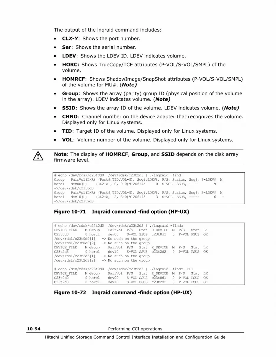
10-94 Performing CCI operations
Hitachi Unified Storage Command Control Interface Installation and Configuration Guide
The output of the inqraid command includes:
• CLX-Y: Shows the port number.
• Ser: Shows the serial number.
• LDEV: Shows the LDEV ID. LDEV indicates volume.
• HORC: Shows TrueCopy/TCE attributes (P-VOL/S-VOL/SMPL) of the volume.
• HOMRCF: Shows ShadowImage/SnapShot attributes (P-VOL/S-VOL/SMPL) of the volume for MU#. (Note)
• Group: Shows the array (parity) group ID (physical position of the volume in the array). LDEV indicates volume. (Note)
• SSID: Shows the array ID of the volume. LDEV indicates volume. (Note)
• CHNO: Channel number on the device adapter that recognizes the volume. Displayed only for Linux systems.
• TID: Target ID of the volume. Displayed only for Linux systems.
• VOL: Volume number of the volume. Displayed only for Linux systems.
Note: The display of HOMRCF, Group, and SSID depends on the disk array firmware level.
# echo /dev/rdsk/c23t0d0 /dev/rdsk/c23t2d3 | ./inqraid –find Group PairVol(L/R) (Port#,TID,VOL-M), Seq#,LDEV#, P/S, Status, Seq#, P-LDEV# M horcl dev00(L) (CL2-A , 0, 0-0)91206145 0 S-VOL SSUS, ----- 9 - ->/dev/rdsk/c23t0d0 Group PairVol(L/R) (Port#,TID,VOL-M), Seq#,LDEV#, P/S, Status, Seq#, P-LDEV# M horcl dev10(L) (CL2-A, 2, 3-0)91206145 3 S-VOL SSUS, ----- 6 - ->/dev/rdsk/c23t2d3
Figure 10-71 Inqraid command -find option (HP-UX)
# echo /dev/rdsk/c23t0d0 /dev/rdsk/c23t2d3 | ./inqraid –findc DEVICE_FILE M Group PairVol P/S Stat R_DEVICE M P/S Stat LK C23t0d0 0 horcl dev00 S-VOL SSUS c23t0d1 0 P-VOL PSUS OK /dev/rdsl/c23t0d0[1] -> No such on the group /dev/rdsl/c23t0d0[2] -> No such on the group DEVICE_FILE M Group PairVol P/S Stat R_DEVICE M P/S Stat LK C23t2d3 0 horcl dev10 S-VOL SSUS c23t2d2 0 P-VOL PSUS OK /dev/rdsl/c23t2d3[1] -> No such on the group /dev/rdsl/c23t2d3[2] -> No such on the group # echo /dev/rdsk/c23t0d0 /dev/rdsk/c23t2d3 | ./inqraid -findc -CLI DEVICE_FILE M Group PairVol P/S Stat R_DEVICE M P/S Stat LK C23t0d0 0 horcl dev00 S-VOL SSUS c23t0d1 0 P-VOL PSUS OK C23t2d3 0 horcl dev10 S-VOL SSUS c23t2d2 0 P-VOL PSUS OK
Figure 10-72 Inqraid command -findc option (HP-UX)

Performing CCI operations 10-95
Hitachi Unified Storage Command Control Interface Installation and Configuration Guide
The output of the inqraid command with -find (and -findc) includes:
• DEVICE_FILE: Shows only the device file name.
• M: Shows the MU#.
• Group: Shows the group name (dev_group) described in the configuration definition file.
• PairVol: Shows the paired volume name (dev_name) of the group described in the configuration definition file.
• P/S: Shows the volume attribute (P-VOL, S-VOL, SMPL).
• Stat: Shows the status of the paired volume.
• R_DEVICE: Shows the device file name of the remote site.
• LK: Shows the configuration check result for the paired volume connection path (physical link of the paired volumes between the hosts).
# ls /dev/sd* | ./inqraid –CLI DEVICE_FILE PORT SERIAL LDEV H/M/12 SSID R:Group PRODUCT_ID sdh CL2-B 91203005 23 -/P/-- 0004 5:02-00 DF600F sdi CL2-B 91203005 14 - - - DF600F-CM sdj - - - - - - -
Figure 10-73 Inqraid command -cli option (Linux)
The output of the inqraid command with -CLI includes:
• DEVICE_FILE: Shows only the device file name.
• PORT: Shows the port name of the disk array.
• SERIAL: Shows the product number of the disk array.
• LDEV: Shows the volume management number in the disk array. LDEV indicates volume.
• H/M/12: Shows the volume attribute of ShadowImage/TrueCopy/TCE (P-VOL is indicated as P, S-VOL is indicated as S, and SMPL is indicated as s).
• SSID: Shows the array ID where LDEV is allocated. LDEV indicates volume.
• R:Group: Shows the position of the physical CCI group mapped in LDEV. LDEV indicates volume.
• PRODUCT_ID: Shows the product ID in the standard inquiry page.
# echo /dev/rdsk/c23t0d0 /dev/rdsk/c23t0d1 | ./inqraid –CLIWP DEVICE_FILE PWWN AL PORT LUN SERIAL LDEV PRODUCT_ID c23t0d0 500060e802f01018 - CL2-A - 91206145 12 DF600F c23t0d1 500060e802f01018 - CL2-A - 91206145 12 DF600F
Figure 10-74 Inqraid command -CLIWP option example (HP-UX)

10-96 Performing CCI operations
Hitachi Unified Storage Command Control Interface Installation and Configuration Guide
The output of the inqraid command with -CLIWP includes:
• DEVICE_FILE: Shows only the device file name.
• WWN (PWWN or NWWN): For fibre channel, if -CLIWP option is specified, this option shows the Port_WWN of the host adaptor for the specified device. If -CLIWN option is specified, this option shows the Node_WWN of the host adaptor. For iSCSI, “0000000000000000” will be always displayed.
• AL and VOL: Shows a hyphen (-) all the time.
• PORT: Shows the port name of the disk array.
• SERIAL: Shows the product number of the disk array.
• LDEV: Shows the volume management number in the disk array. LDEV indicates volume.
• PRODUCT_ID: Shows the product ID in the standard inquiry page.
# ioscan -fun | grep rdsk | ./inqraid -sort -CM -CLI HORCM_CMD # dev_name dev_name dev_name #UnitID 0 (Serial# 91203001) /dev/rdsk/c0t3d0 /dev/rdsk/c1t2d1 #UnitID 1 (Serial# 91203002) /dev/rdsk/c2t3d0
Figure 10-75 Inqraid command -sort[-CM] option (HP-UX)
The unit ID is added in the order of the disk array’s product number. If multiple command devices exist within the array, the device file that is used to share between the disk array port would be chosen in prior, and is used as alternate command device.
The following is an example of using the -gvinf option of the inqraid command. The information in all physical drives will be saved (sheltered) by giving $Phy.
D:\HORCM\etc>inqraid $Phys -gvinf –CLI \\.\PhysicalDrive0: \ Harddisk0 -> [VOL91206145_448_DA7C0D91] [DF600F ] \\.\PhysicalDrive1: \ Harddisk1 -> [VOL91206145_449_DA7C0D92] [DF600F ] \\.\PhysicalDrive2: \ Harddisk2 -> [VOL12006145_450_DA7C0D93] [DF600F ]
Signature
LDEV number
Array serial number
Figure 10-76 Inqraid command -gvinf option example
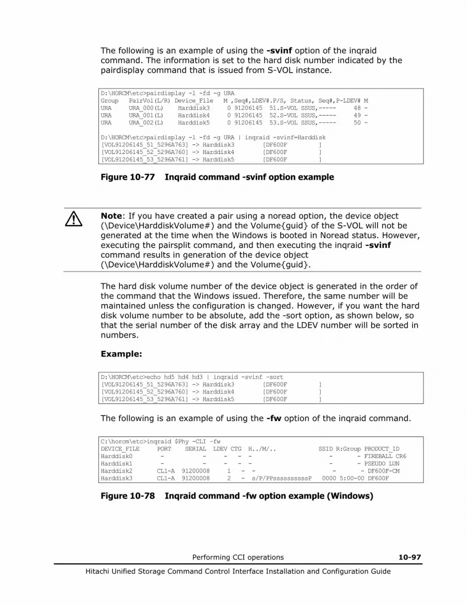
Performing CCI operations 10-97
Hitachi Unified Storage Command Control Interface Installation and Configuration Guide
The following is an example of using the -svinf option of the inqraid command. The information is set to the hard disk number indicated by the pairdisplay command that is issued from S-VOL instance.
D:\HORCM\etc>pairdisplay -l -fd -g URA Group PairVol(L/R) Device_File M ,Seq#,LDEV#.P/S, Status, Seq#,P-LDEV# M URA URA_000(L) Harddisk3 0 91206145 51.S-VOL SSUS,----- 48 - URA URA_001(L) Harddisk4 0 91206145 52.S-VOL SSUS,----- 49 - URA URA_002(L) Harddisk5 0 91206145 53.S-VOL SSUS,----- 50 - D:\HORCM\etc>pairdisplay -l -fd -g URA | inqraid -svinf=Harddisk [VOL91206145_51_5296A763] -> Harddisk3 [DF600F ] [VOL91206145_52_5296A760] -> Harddisk4 [DF600F ] [VOL91206145_53_5296A761] -> Harddisk5 [DF600F ]
Figure 10-77 Inqraid command -svinf option example
Note: If you have created a pair using a noread option, the device object (\Device\HarddiskVolume#) and the Volume{guid} of the S-VOL will not be generated at the time when the Windows is booted in Noread status. However, executing the pairsplit command, and then executing the inqraid -svinf command results in generation of the device object (\Device\HarddiskVolume#) and the Volume{guid}.
The hard disk volume number of the device object is generated in the order of the command that the Windows issued. Therefore, the same number will be maintained unless the configuration is changed. However, if you want the hard disk volume number to be absolute, add the -sort option, as shown below, so that the serial number of the disk array and the LDEV number will be sorted in numbers.
Example:
D:\HORCM\etc>echo hd5 hd4 hd3 | inqraid -svinf –sort [VOL91206145_51_5296A763] -> Harddisk3 [DF600F ] [VOL91206145_52_5296A760] -> Harddisk4 [DF600F ] [VOL91206145_53_5296A761] -> Harddisk5 [DF600F ]
The following is an example of using the -fw option of the inqraid command.
C:\horcm\etc>inqraid $Phy -CLI –fw DEVICE_FILE PORT SERIAL LDEV CTG H../M/.. SSID R:Group PRODUCT_ID Harddisk0 - - - - - - - FIREBALL CR6 Harddisk1 - - - - - - - PSEUDO LUN Harddisk2 CL1-A 91200008 1 - - - - DF600F-CM Harddisk3 CL1-A 91200008 2 - s/P/PPssssssssssP 0000 5:00-00 DF600F
Figure 10-78 Inqraid command -fw option example (Windows)

10-98 Performing CCI operations
Hitachi Unified Storage Command Control Interface Installation and Configuration Guide
Using the mkconf command
The mkconf command executes the following operation and creates a configuration definition file automatically from the special file via STDIN. The user must edit the created configuration definition file as needed.
1. The mkconf command executes inqraid -sort -CM -CLI and then creates a configuration definition file only for HORCM_CMD.
2. The mkconf command starts the HORCM instance using the created definition file.
3. The mkconf command executes raidscan -find conf by using the special file via STDIN, and then creates the definition file that contains HORCM_DEV and HORCM_INST.
4. The mkconf command starts the HORCM instance again to verify the created definition file.
5. The mkconf command executes raidscan -find verify and displays the correspondence between the special files via STDIN with the definition file.
Table 10-35 Mkconf Command Parameters
Parameter Value
Command Name
mkconf
Format /HORCM/usr/bin/mkconf.sh [-g[g] <group> [-m <mu#>] [-i <inst#>] [-s <service>] [-a] ] \HORCM\Tool\ mkconf.exe [-g[g] <group> [-m <mu#>] [-i <inst#>] [-s <service>] [-a] [-c <drive>]]
Options If no argument, this command creates a mode that waits for STDIN without argument.
-g[g] <group>: This option specifies the group described in the configuration definition file. If omitted, “VG” is used for the group name. -gg option is specified to find host group and to display VOL.
-m <MU#>: This option specifies the mirror descriptor MU#.
-i <inst>: This option shows the instance number.
-s <service>: This option specifies the service name (port number) described in the configuration definition file. If omitted, “52323” is used for the port number.
-a: This option adds a group to an already created configuration definition file.
-c <drive>: This option specifies the range of the command device to be searched. If omitted, “$PhysicalDrive” is used for <drive>.
Note The configuration definition file and the log file are created in the current directory as horcm*.conf or log* (* as an instance number). The user must edit the created configuration definition file as necessary (such as ip_addresses, and services).
WARNING: If you have created the configuration definition file using the mkconf command tool, remember to change the value of the poll(10ms) manually. Setting the value incorrectly may cause a conflict between the CCI and the disk array, which causes the internal process of the disk array to suspend temporary. The process may not proceed.

Performing CCI operations 10-99
Hitachi Unified Storage Command Control Interface Installation and Configuration Guide
C:\HORCM>type C:\HORCM\usr\bin\horcm.conf | C:\HORCM\Tool\mkconf.exe -g ORA -i 9 -m 0 starting HORCM inst 9 HORCM inst 9 starts successfully. HORCM Shutdown inst 9 !!! A CONFIG file was successfully completed. starting HORCM inst 9 HORCM inst 9 starts successfully. DEVICE_FILE Group PairVol PORT TARG LUN M SERIAL LDEV Harddisk1 ORA ORA_000 CL2-A 0 0 0 91206145 0 Harddisk2 ORA ORA_001 CL2-A 0 1 0 91206145 1 Harddisk3 ORA ORA_002 CL2-A 0 2 0 91206145 2 Harddisk4 ORA ORA_003 CL2-A 0 3 0 91206145 3 Harddisk5 ORA ORA_004 CL2-A 0 4 0 91206145 4 Harddisk6 ORA ORA_005 CL2-A 0 5 0 91206145 5 Harddisk6 - - - - - 0 91206145 - HORCM Shutdown inst 9 !!! Please check ‘C:\HORCM\horcm9.conf','C:\HORCM\log9\curlog\horcm_*_log.txt’, and modify ip_address & service’. C:\HORCM>dir /b horcm9.conf log9 Tool usr C:\HORCM>type horcm9.conf # Created by mkconf on Tue Sep 11 17:11:41 HORCM_MON #ip_address service poll(10ms) timeout(10ms) localhost 52323 1000 [Note] 3000 HORCM_CMD #dev_name dev_name dev_name #UnitID 0 (Serial# 91206145) \\.\PhysicalDrive6 HORCM_DEV #dev_group dev_name port# TargetID VOL# MU# # Harddisk1 SER = 91206145 LDEV = 0 [ FIBRE FCTBL = 4 ] ORA ORA_000 CL2-A 0 0 0 # Harddisk2 SER = 91206145 LDEV = 1 [ FIBRE FCTBL = 4 ] ORA ORA_001 CL2-A 0 1 0 # Harddisk3 SER = 91206145 LDEV = 2 [ FIBRE FCTBL = 4 ] ORA ORA_002 CL2-A 0 2 0 # Harddisk4 SER = 91206145 LDEV = 3 [ FIBRE FCTBL = 4 ] ORA ORA_006 CL2-A 0 6 0 # ERROR [CMDDEV] Harddisk5 SER = 91206145 LDEV = 7 [ DF600F-CM ] HORCM_INST #dev_group ip_address service ORA localhost 52323
Figure 10-79 Mkconf command example (Windows)
Note: Make sure to change the value of the poll (10ms) parameter using the equation.
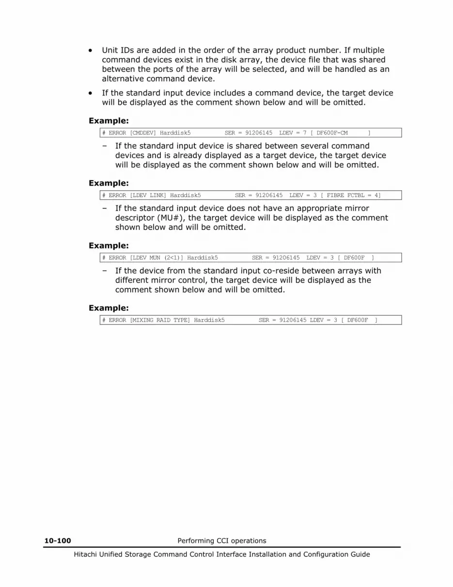
10-100 Performing CCI operations
Hitachi Unified Storage Command Control Interface Installation and Configuration Guide
• Unit IDs are added in the order of the array product number. If multiple command devices exist in the disk array, the device file that was shared between the ports of the array will be selected, and will be handled as an alternative command device.
• If the standard input device includes a command device, the target device will be displayed as the comment shown below and will be omitted.
Example: # ERROR [CMDDEV] Harddisk5 SER = 91206145 LDEV = 7 [ DF600F-CM ]
– If the standard input device is shared between several command devices and is already displayed as a target device, the target device will be displayed as the comment shown below and will be omitted.
Example: # ERROR [LDEV LINK] Harddisk5 SER = 91206145 LDEV = 3 [ FIBRE FCTBL = 4]
– If the standard input device does not have an appropriate mirror descriptor (MU#), the target device will be displayed as the comment shown below and will be omitted.
Example: # ERROR [LDEV MUN (2<1)] Harddisk5 SER = 91206145 LDEV = 3 [ DF600F ]
– If the device from the standard input co-reside between arrays with different mirror control, the target device will be displayed as the comment shown below and will be omitted.
Example: # ERROR [MIXING RAID TYPE] Harddisk5 SER = 91206145 LDEV = 3 [ DF600F ]

Performing CCI operations 10-101
Hitachi Unified Storage Command Control Interface Installation and Configuration Guide
Controlling host groups
The disk array has the defined host group in the port and are able to allocate host volume every this host group. CCI does not use this host volume, and specifies by using absolute VOL in the port. Therefore, a user can become confused because VOL of the CCI notation does not correspond to VOL on the host view. Thus, CCI supports a way of specifying a host group and VOL on the host view.
Specifying a host group
(1) Defining the formats
The way what CCI has addition of argument for the host group to the raidscan command and the configuration file will not be able to maintain the compatibility with conventional CLI. Therefore, CCI adopts a way that supports in the form which specifies a host group in the port strings as follows.
• CL1-A-GRP# (GRP# are up to 127) – Specifying the host group for the raidscan command as follows: raidscan -p CL1-A-5
– Specifying the host group for the configuration file #dev_group dev_name port# TargetID VOL# MU# ORA ORA_000 CL1-A-1 4 1 0 ORA ORA_001 CL1-A-1 4 2 0
If the port including a host group is specified to the port name, then maximum of specifiable VOLs are up to 255.
(2) Specifiable port strings
As the result, CCI supports four kinds of forms in the port name.
• Specifying the Port name without a host group
CL1-A CL1-An where n: unit ID for multiple RAID
• Specifying the Port name with a host group CL1-A-g where g: host group CL1-An-g where n-g: host group=g on CL1-A in unit ID=n
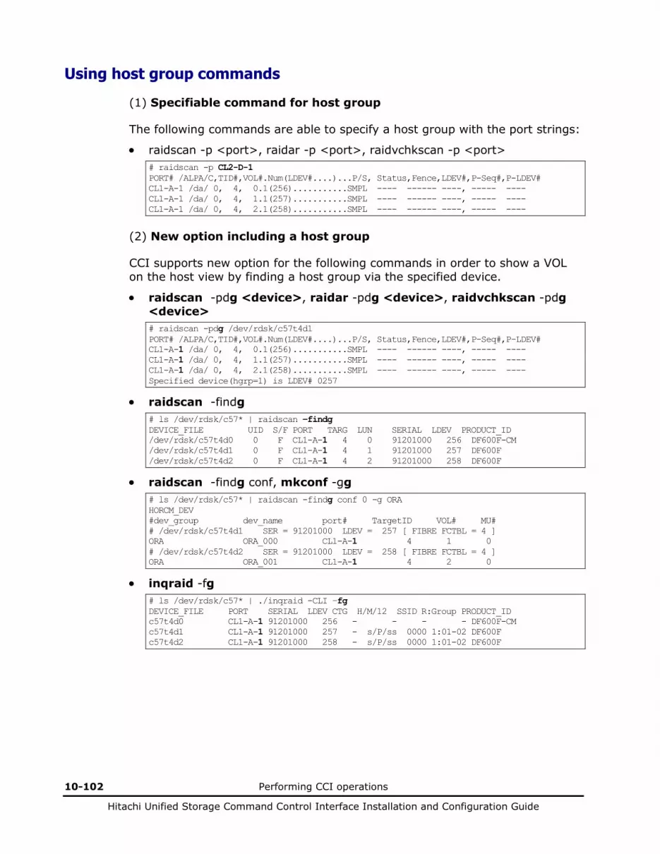
10-102 Performing CCI operations
Hitachi Unified Storage Command Control Interface Installation and Configuration Guide
Using host group commands
(1) Specifiable command for host group
The following commands are able to specify a host group with the port strings:
• raidscan -p <port>, raidar -p <port>, raidvchkscan -p <port> # raidscan -p CL2-D-1 PORT# /ALPA/C,TID#,VOL#.Num(LDEV#....)...P/S, Status,Fence,LDEV#,P-Seq#,P-LDEV# CL1-A-1 /da/ 0, 4, 0.1(256)...........SMPL ---- ------ ----, ----- ---- CL1-A-1 /da/ 0, 4, 1.1(257)...........SMPL ---- ------ ----, ----- ---- CL1-A-1 /da/ 0, 4, 2.1(258)...........SMPL ---- ------ ----, ----- ----
(2) New option including a host group
CCI supports new option for the following commands in order to show a VOL on the host view by finding a host group via the specified device.
• raidscan -pdg <device>, raidar -pdg <device>, raidvchkscan -pdg <device> # raidscan -pdg /dev/rdsk/c57t4d1 PORT# /ALPA/C,TID#,VOL#.Num(LDEV#....)...P/S, Status,Fence,LDEV#,P-Seq#,P-LDEV# CL1-A-1 /da/ 0, 4, 0.1(256)...........SMPL ---- ------ ----, ----- ---- CL1-A-1 /da/ 0, 4, 1.1(257)...........SMPL ---- ------ ----, ----- ---- CL1-A-1 /da/ 0, 4, 2.1(258)...........SMPL ---- ------ ----, ----- ---- Specified device(hgrp=1) is LDEV# 0257
• raidscan -findg # ls /dev/rdsk/c57* | raidscan –findg DEVICE_FILE UID S/F PORT TARG LUN SERIAL LDEV PRODUCT_ID /dev/rdsk/c57t4d0 0 F CL1-A-1 4 0 91201000 256 DF600F-CM /dev/rdsk/c57t4d1 0 F CL1-A-1 4 1 91201000 257 DF600F /dev/rdsk/c57t4d2 0 F CL1-A-1 4 2 91201000 258 DF600F
• raidscan -findg conf, mkconf -gg # ls /dev/rdsk/c57* | raidscan -findg conf 0 -g ORA HORCM_DEV #dev_group dev_name port# TargetID VOL# MU# # /dev/rdsk/c57t4d1 SER = 91201000 LDEV = 257 [ FIBRE FCTBL = 4 ] ORA ORA_000 CL1-A-1 4 1 0 # /dev/rdsk/c57t4d2 SER = 91201000 LDEV = 258 [ FIBRE FCTBL = 4 ] ORA ORA_001 CL1-A-1 4 2 0
• inqraid -fg # ls /dev/rdsk/c57* | ./inqraid -CLI –fg DEVICE_FILE PORT SERIAL LDEV CTG H/M/12 SSID R:Group PRODUCT_ID c57t4d0 CL1-A-1 91201000 256 - - - - DF600F-CM c57t4d1 CL1-A-1 91201000 257 - s/P/ss 0000 1:01-02 DF600F c57t4d2 CL1-A-1 91201000 258 - s/P/ss 0000 1:01-02 DF600F
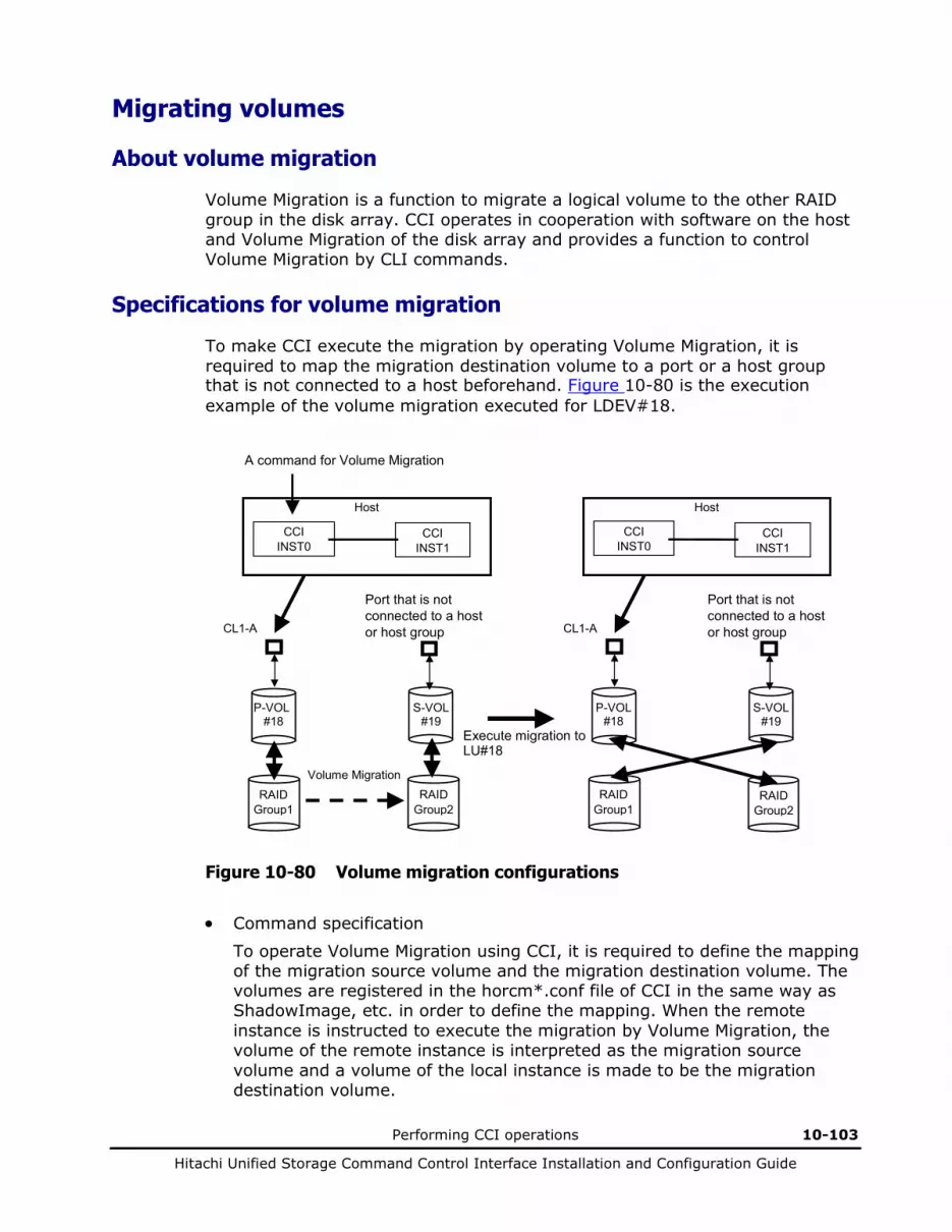
Performing CCI operations 10-103
Hitachi Unified Storage Command Control Interface Installation and Configuration Guide
Migrating volumes
About volume migration
Volume Migration is a function to migrate a logical volume to the other RAID group in the disk array. CCI operates in cooperation with software on the host and Volume Migration of the disk array and provides a function to control Volume Migration by CLI commands.
Specifications for volume migration
To make CCI execute the migration by operating Volume Migration, it is required to map the migration destination volume to a port or a host group that is not connected to a host beforehand. Figure 10-80 is the execution example of the volume migration executed for LDEV#18.
Host
P-VOL #18
S-VOL #19
CL1-A
CCI INST0
CCI INST1
RAID Group1
Port that is not connected to a host or host group
Execute migration to LU#18
Volume Migration
A command for Volume Migration
RAID Group2
Host
P-VOL #18
S-VOL #19
CL1-A
CCI INST0
CCI INST1
RAID Group1
RAID Group2
Port that is not connected to a host or host group
Figure 10-80 Volume migration configurations
• Command specification
To operate Volume Migration using CCI, it is required to define the mapping of the migration source volume and the migration destination volume. The volumes are registered in the horcm*.conf file of CCI in the same way as ShadowImage, etc. in order to define the mapping. When the remote instance is instructed to execute the migration by Volume Migration, the volume of the remote instance is interpreted as the migration source volume and a volume of the local instance is made to be the migration destination volume.
10-104 Performing CCI operations
Hitachi Unified Storage Command Control Interface Installation and Configuration Guide
• Group operation
It is possible to perform an operation of Volume Migration for a group through a description in the horcm*.conf file of CCI, but the data consistency of a group for which the command has been executed is not maintained. When a host crashes while the command is executed for the group, the command execution is interrupted halfway and volumes in statuses different from each other may exist.
• HORCM instance It is possible to describe a volume to be operated by Volume Migration in the horcm*.conf file, in which a volume to be operated by the other function such as ShadowImage is described, as the other group in duplicate. It is also possible to define a volume to be operated by Volume Migration in the other horcm*.conf file than that for a volume to be operated by the other function such as ShadowImage and to operate it from the independent HORCM instance.

Performing CCI operations 10-105
Hitachi Unified Storage Command Control Interface Installation and Configuration Guide
Using volume migration commands
Table 10-36 lists and describes the Volume Migration command parameters.
• Command for volume migration CCI supports the volume migration by adding an option (-m cc) to the paircreate command.
Table 10-36 Command for volume migration
Parameter Value
Command Name
paircreate
Format paircreate -g <group> -d <pair Vol> -m cc -vl[r] | -p[s]vol -c <size>
Options -m cc: This option instructs the copying of the volume migration to be made.
Note: This option cannot be specified with “-split” option in the same command.
-vl (-pvol) or -vr (-svol): Specifies the data flow direction and must always be specified. The -vl (-pvol) specifies the local instruction, that is, an instruction to copy a local instance volume (P-VOL) to a remote instance volume (S-VOL) and to maps a copying destination volume (a volume of the remote instance) to the local instance volume (P-VOL). The -vr (-svol) specifies the remote instruction, and copies data from a remote instance volume (P-VOL) to a local instance volume (S-VOL) and maps a copy destination volume (a volume of the local instance) to the remote instance volume (P-VOL).
-c <size>: You can use this option to specify the copying pace (1 - 15) to be used for the initial data copy. You can shorten the copy time by specifying a large number. Do not use the default value of 3. (1 to 5: slow, 6 to 10: normal, 11 to 15: priority).
If a copying is made at the “normal” pace when the host I/O load is heavy, the host I/O performance may be deteriorated remarkably. When you want to prevent the host I/O performance being deteriorated, select the “slow” pace. Select the “prior” pace only when you want to give much priority to the time for the completion of the copy than the host I/O performance in a period of time when the P-VOL is rarely accessed.
• Confirming the migration pair status
You can check that the RAID group to which the volume that executed the migration belongs has been changed by referring to the RAID group to which the volume concerned belongs using the inqraid command.
C:\HORCM\etc>echo hd0 | inqraid Harddisk0 -> [ST] CL1-A Ser =91200067 LDEV = 1 [HITACHI ] [DF600F ] HORC = SMPL HOMRCF[MU#0 = S-VOL MU#1 = SMPL MU#2 = SMPL] RAID5[Group 1- 0] SSID = 0x0000 C:\HORCM\etc>paircreate –g vg01 –m cc –vl C:\HORCM\etc>echo hd0 | inqraid Harddisk0 -> [ST] CL1-A Ser =91200067 LDEV = 1 [HITACHI ] [DF600F ] HORC = SMPL HOMRCF[MU#0 = S-VOL MU#1 = SMPL MU#2 = SMPL] RAID5[Group 2- 0] SSID = 0x0000
The volume has been migrated to the other RAID group.
Figure 10-81 Inqraid command example
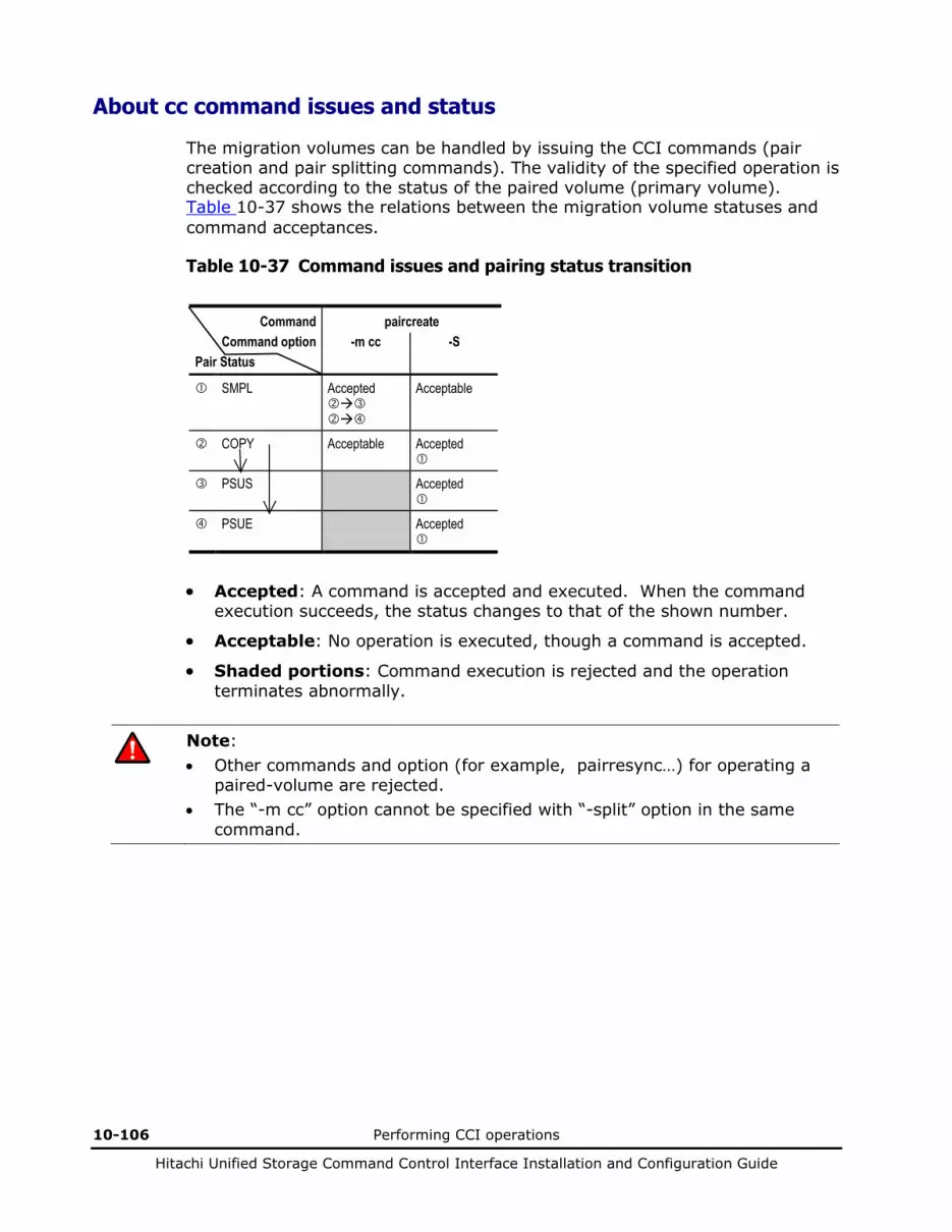
10-106 Performing CCI operations
Hitachi Unified Storage Command Control Interface Installation and Configuration Guide
About cc command issues and status
The migration volumes can be handled by issuing the CCI commands (pair creation and pair splitting commands). The validity of the specified operation is checked according to the status of the paired volume (primary volume). Table 10-37 shows the relations between the migration volume statuses and command acceptances.
Table 10-37 Command issues and pairing status transition
Command paircreate Command option -m cc -S
Pair Status
SMPL Accepted
Acceptable
COPY
Acceptable Accepted
PSUS Accepted
PSUE Accepted
• Accepted: A command is accepted and executed. When the command
execution succeeds, the status changes to that of the shown number.
• Acceptable: No operation is executed, though a command is accepted.
• Shaded portions: Command execution is rejected and the operation terminates abnormally.
Note: • Other commands and option (for example, pairresync…) for operating a
paired-volume are rejected. • The “-m cc” option cannot be specified with “-split” option in the same
command.

Performing CCI operations 10-107
Hitachi Unified Storage Command Control Interface Installation and Configuration Guide
About the synchronous waiting command for TCE
Table 10-38 lists and describes the pair synchronization waiting command parameters and returned values. The pairsyncwait is a command exclusive for TCE. It is a command to check whether or not the data written immediately after the issue of the command is reflected on the S-VOL of the remote site. This command gets the latest sequence # of local array (P-VOL latest sequence # within the CT group) and the sequence # of remote array within the CT group which correspond to the <group> or <raw_device> that is specified by pairsyncwait, and compares local array with remote array sequence # at that time and at regular interval. Because the sequence number is updated for each group, you can check whether the S-VOL data has been updated or not by executing the command specifying a group when all the pairs in the target group are in the PAIR status.
If remote array sequence # is over the value of local array sequence # within the term that was specified by pairsysncwait, this command reports the return code 0 with the meaning of completion of synchronization. The -nowait option shows the latest sequence # (Q-marker) of local array P-VOL and CTGID. The marker is shown in hexadecimal of ten characters.
Table 10-38 Pairsyncwait command parameters
Parameter Value
Command Name
pairsyncwait
Format pairsyncwait { -h | -q | -z | -x | -xh | -I[H | M][instance#] | -g <group> | -d <pair Vol> | -d[g] <raw_device> [MU#] | -d[g] <seq#> <LDEV#> [MU#] | -t <timeout> | -nowait | [-m <marker> | -nomsg] }
Options -h: Displays Help/Usage and version information.
-q: Terminates the interactive mode and exits this command.
-z or -zx: Makes the pairsyncwait command enter the interactive mode. The -zx option guards performing of the HORCM in the interactive mode. When this option detects a HORCM shut down, interactive mode terminates.
-x: Specifies the sub-command of Windows.
-xh: Displays Help/Usage the sub-command of Windows.
-I[H | M][instance#] or -I[TC | SI][instance#]: Specifies the instance number and the command execution environment.
-g <group>: Specifies a group name defined in the configuration definition file. The command is executed for each CTG unless the -d <pair Vol> option is specified. The execution result of the pairsyncwait command for each option, see Table 10-39 and Table 10-40.
-d <pair Vol>: Specifies a paired logical volume name defined in the configuration definition file. When this option is specified, the command is executed for the specified paired logical volumes.
-d[g] <raw_device> [MU#]: Searches a group on the configuration definition file (local instance) for the specified raw_device, and if the specified raw_device is contained in the group, the target volume is executed as the paired logical volume (-d) or group (-dg). This option is effective without specifying the “-g <group>“ option. If the specified the raw_device is contained in two or more groups, the command is executed on the first group.

10-108 Performing CCI operations
Hitachi Unified Storage Command Control Interface Installation and Configuration Guide
Parameter Value
-d[g] <seq#> <LDEV#> [MU#]: Searches a group on the configuration definition file (local instance) for the specified LDEV, and if the specified LDEV is contained in the group, the target volume is executed as the paired logical volume (-d) or group (-dg). This option is effective without specifying the “-g <group>“ option. If the specified LDEV is contained in two or more groups, the command is executed on the first group. The <seq #> <LDEV #> values can be specified in hexadecimal (by addition of “0x”) or decimal notation.
-t <timeout>: Specifies the timeout value to wait for the completion. The unit is 100 ms. Local array gets the latest sequence # from remote array at regular interval.
-nowait: Gets the latest sequence # of local array P-VOL and CTGID without waiting. When this option is specified, the latest sequence # of local array P-VOL is reported immediately, and -t <timeout>option is ignored.
-nomsg: Suppresses messages to be displayed when this command is executed. It is used to execute a command from a user program. This option must be specified at the beginning of a command argument. The command execution log is not affected by this option.
-m <marker>: Specifies the sequence # of local array P-VOL, called the Q-marker. If the application gets Q-marker as the result of execution of pairsyncwait because of timeout or “-nowait”, the application can reconfirm the completion of asynchronous transfer by using pairsyncwait with Q-marker. If the application does not specify Q-marker, CCI uses the latest sequence # when CCI receives pairsyncwait. It is also possible to wait for the completion from S-VOL side with this option.
Q-Marker format: = iissssssss, where ii = incarnation # of pair volume, and ssssssss = P-VOL serial #.
Returned values
When the -nowait option is specified:
Normal termination: 0: The status is NOWAIT.
Abnormal termination: other than 0 to 127, refer to the execution logs for error details.
When the -nowait option is not specified:
Normal termination: 0: The status is DONE (completion of synchronization). 1: The status is TIMEOUT (timeout). 2: The status is BROKEN (Q-marker synchronized process is rejected). 3: The status is CHANGED (Q-marker is invalid due to resynchronize).
Abnormal termination: other than 0 to 127, refer to the execution logs for error details.
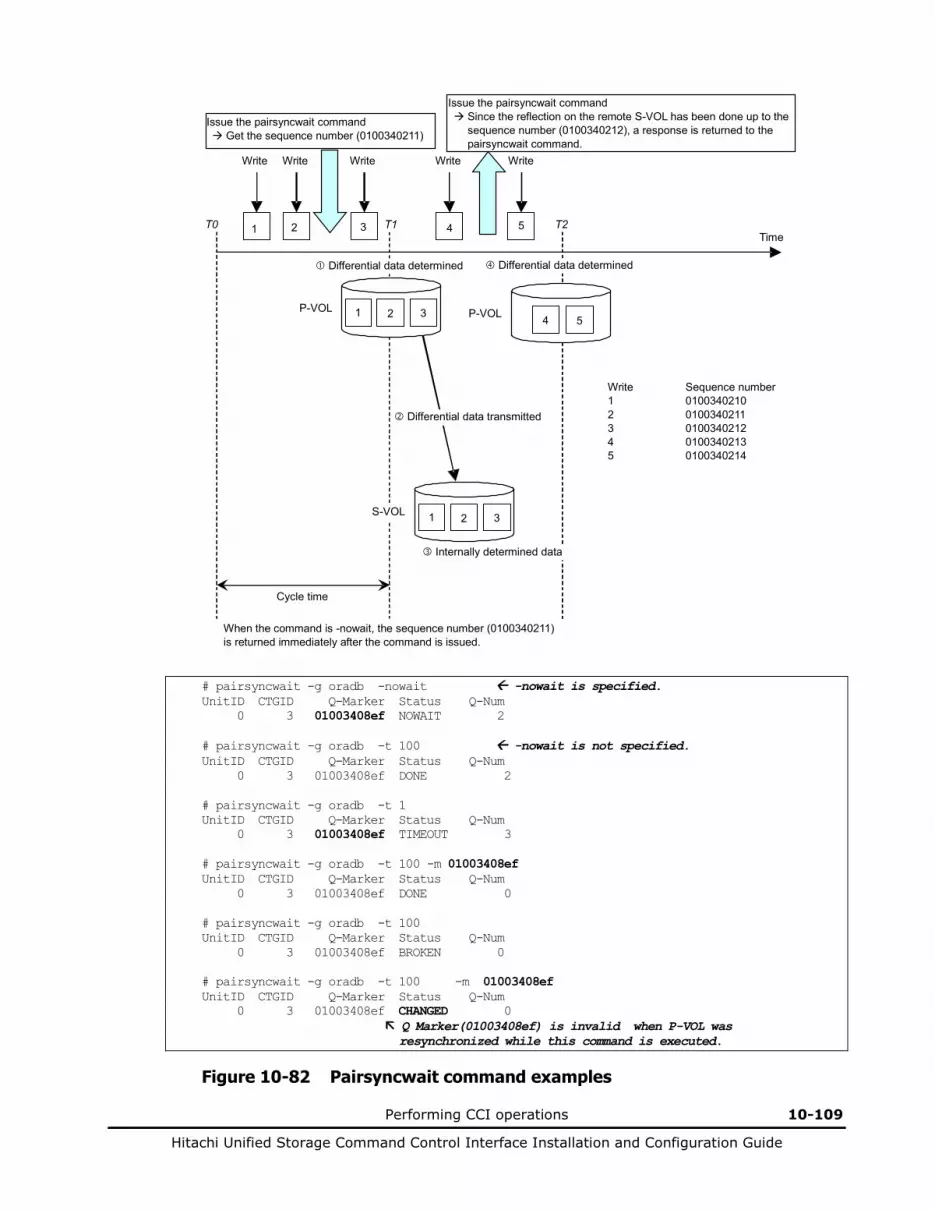
Performing CCI operations 10-109
Hitachi Unified Storage Command Control Interface Installation and Configuration Guide
Time 1 2 3 4 5
Write
Differential data determined
P-VOL
S-VOL
Differential data transmitted
Cycle time
Issue the pairsyncwait command Get the sequence number (0100340211)
Internally determined data
Issue the pairsyncwait command Since the reflection on the remote S-VOL has been done up to the
sequence number (0100340212), a response is returned to the pairsyncwait command.
T0 T1 T2
When the command is -nowait, the sequence number (0100340211) is returned immediately after the command is issued.
Write Sequence number 1 0100340210 2 0100340211 3 0100340212 4 0100340213 5 0100340214
Write
Differential data determined
Write Write Write
P-VOL 4 5
1 2 3
1 2 3
# pairsyncwait -g oradb -nowait -nowait is specified. UnitID CTGID Q-Marker Status Q-Num 0 3 01003408ef NOWAIT 2 # pairsyncwait -g oradb -t 100 -nowait is not specified. UnitID CTGID Q-Marker Status Q-Num 0 3 01003408ef DONE 2 # pairsyncwait -g oradb -t 1 UnitID CTGID Q-Marker Status Q-Num 0 3 01003408ef TIMEOUT 3 # pairsyncwait -g oradb -t 100 -m 01003408ef UnitID CTGID Q-Marker Status Q-Num 0 3 01003408ef DONE 0 # pairsyncwait -g oradb -t 100 UnitID CTGID Q-Marker Status Q-Num 0 3 01003408ef BROKEN 0 # pairsyncwait -g oradb -t 100 -m 01003408ef UnitID CTGID Q-Marker Status Q-Num 0 3 01003408ef CHANGED 0 Q Marker(01003408ef) is invalid when P-VOL was resynchronized while this command is executed.
Figure 10-82 Pairsyncwait command examples
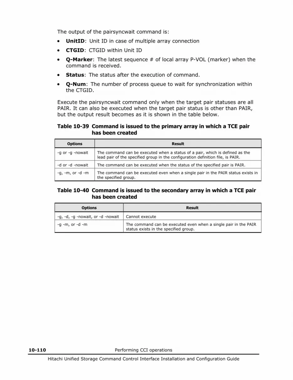
10-110 Performing CCI operations
Hitachi Unified Storage Command Control Interface Installation and Configuration Guide
The output of the pairsyncwait command is:
• UnitID: Unit ID in case of multiple array connection
• CTGID: CTGID within Unit ID
• Q-Marker: The latest sequence # of local array P-VOL (marker) when the command is received.
• Status: The status after the execution of command.
• Q-Num: The number of process queue to wait for synchronization within the CTGID.
Execute the pairsyncwait command only when the target pair statuses are all PAIR. It can also be executed when the target pair status is other than PAIR, but the output result becomes as it is shown in the table below.
Table 10-39 Command is issued to the primary array in which a TCE pair has been created
Options Result
-g or -g -nowait The command can be executed when a status of a pair, which is defined as the lead pair of the specified group in the configuration definition file, is PAIR.
-d or -d -nowait The command can be executed when the status of the specified pair is PAIR.
-g, -m, or -d -m The command can be executed even when a single pair in the PAIR status exists in the specified group.
Table 10-40 Command is issued to the secondary array in which a TCE pair has been created
Options Result
-g, -d, -g -nowait, or -d -nowait Cannot execute
-g -m, or -d -m The command can be executed even when a single pair in the PAIR status exists in the specified group.

Performing CCI operations 10-111
Hitachi Unified Storage Command Control Interface Installation and Configuration Guide
Using the raidcom command
All command options displayed in help do not perform. The options that can perform are limited to the options described in this manual.
About the raidcom command
The raidcom command can be mainly used for the SnapShot operation.
While one P-VOL can have up to 32 pairs with the paircreate command, using the raidcom command allows a P-VOL to have up to 1,024 pairs. Therefore, use the raidcom command when over 32 pairs per P-VOL are needed.
The concept of the SnapShot operation using the raidcom command is shown in the figure below.
P-VOL 1 P-VOL 2 P-VOL 3
DP pool
Host
Array
Command device
Snapshotset: snap2
Snapshot data VOL#10
mum1 mum0
mum1 mum0
mum1 mum0
Snapshotset: snap1
Figure 10-83 Concept of SnapShot operation using raidcom command
10-112 Performing CCI operations
Hitachi Unified Storage Command Control Interface Installation and Configuration Guide
In the SnapShot operation using the raidcom command, the volume of the duplication target is called a P-VOL and its duplication is called snapshot data (Note 1). In the raidcom command, it is necessary to register the P-VOL to create the snapshot data and the DP pool to be used in the snapshotset (Note 2) before creating the snapshot data. After registering the P-VOL in the snapshotset, the snapshot data is created. The duplication of the P-VOL can be acquired for the first time by creating the snapshot data. Since multiple P-VOLs can be registered in the snapshotset and those snapshot data can be created, the snapshotset is called the aggregate of the snapshot data. By setting the snapshotset to the operation target of the raidcom command, all the snapshot data belonging to the relevant snapshotset can be operated at once. The operation per snapshot data is also possible by specifying the P-VOL at the same time.
Furthermore, specifying the P-VOL and mum# (MU#) can uniquely identify the snapshot data to be operated without specifying the snapshotset name (when multiple snapshot data exist in the same P-VOL in the snapshotset, mum# is enabled to uniquely identify the snapshot data to be operated). The mum# is assigned to the P-VOL automatically when creating the snapshot data.
Since the volume number is not assigned to the created snapshot data, when using it by making the host recognize it, use the raidcom map snapshot command and map the volume number to the snapshot data. The mapped volume number can be unmapped or change the assignment of the different snapshot data of the same P-VOL.
Furthermore, the snapshotset supports the CTG mode. When creating the snapshot data, the consistency of the data of the snapshot data belonging to the snapshotset whose CTG mode is enabled is guaranteed. The consistency of the data of the snapshot data belonging to the snapshotset whose CTG mode is disabled is not guaranteed.
Note: • The snapshot data is equivalent to the V-VOL. • The snapshotset is equivalent to the CTG of the SnapShot pair created by
the paircreate command. The paircreate command can create a SnapShot pair not belonging to CTG, but the snapshot data created by the raidcom command must belong to the snapshotset.

Performing CCI operations 10-113
Hitachi Unified Storage Command Control Interface Installation and Configuration Guide
Differences between raidcom and paircreate commands
The paircreate command can also operate SnapShot. However, unless otherwise a special purpose such as maintenance, do not mix the pairs created by the raidcom command and the paircreate command.
Table 10-41 shows the difference of the snapshot data or the V-VOL pair created by the raidcom command and the paircreate command.
Table 10-41 Difference between raidcom and paircreate command
Items Raidcom Paircreate
Configuration definition file
Only HORCM_CMD is described HORCM_MON, HORCM_CMD, HORCM_DEV, HORCM_INST must be described
The number of pairs to be created per P-VOL
1024 32
CTG# This is assigned automatically. However, it is not used in the operation of the raidcom command.
When using CTG, this is assigned manually or automatically.
CTG mode Enabled/Disabled is specified manually. When using CTG, this is always enabled.
mum# A number from 1 to 1032 is assigned automatically. Furthermore, the number from 0 to 1032 can be displayed.
Up to 32 numbers from 0 to 39 are assigned manually in the configuration definition file. Furthermore, the number from 0 to 39 can be displayed.
Snapshot data or V-VOL without volume number
The snapshot data without the volume number can be created.
The V-VOL pair without the volume number cannot be created. It is necessary to prepare the V-VOL in Hitachi Storage Navigator Modular 2 in advance.
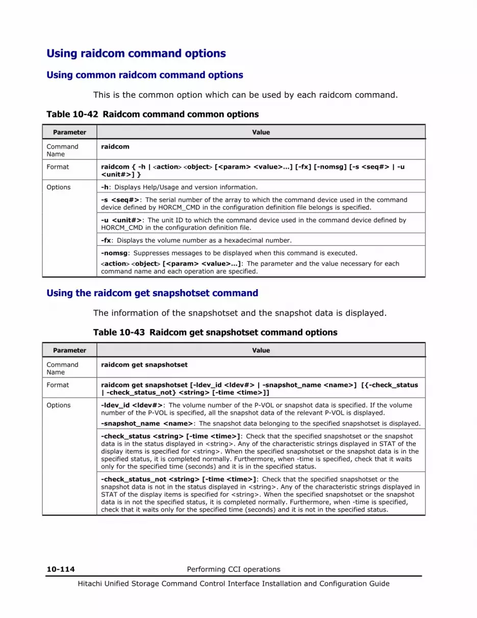
10-114 Performing CCI operations
Hitachi Unified Storage Command Control Interface Installation and Configuration Guide
Using raidcom command options
Using common raidcom command options
This is the common option which can be used by each raidcom command.
Table 10-42 Raidcom command common options
Parameter Value
Command Name
raidcom
Format raidcom { -h | <action> <object> [<param> <value>…] [-fx] [-nomsg] [-s <seq#> | -u <unit#>] }
Options -h: Displays Help/Usage and version information.
-s <seq#>: The serial number of the array to which the command device used in the command device defined by HORCM_CMD in the configuration definition file belongs is specified.
-u <unit#>: The unit ID to which the command device used in the command device defined by HORCM_CMD in the configuration definition file.
-fx: Displays the volume number as a hexadecimal number.
-nomsg: Suppresses messages to be displayed when this command is executed. <action> <object> [<param> <value>…]: The parameter and the value necessary for each command name and each operation are specified.
Using the raidcom get snapshotset command
The information of the snapshotset and the snapshot data is displayed.
Table 10-43 Raidcom get snapshotset command options
Parameter Value
Command Name
raidcom get snapshotset
Format raidcom get snapshotset [-ldev_id <ldev#> | -snapshot_name <name>] [{-check_status | -check_status_not} <string> [-time <time>]]
Options -ldev_id <ldev#>: The volume number of the P-VOL or snapshot data is specified. If the volume number of the P-VOL is specified, all the snapshot data of the relevant P-VOL is displayed.
-snapshot_name <name>: The snapshot data belonging to the specified snapshotset is displayed.
-check_status <string> [-time <time>]: Check that the specified snapshotset or the snapshot data is in the status displayed in <string>. Any of the characteristic strings displayed in STAT of the display items is specified for <string>. When the specified snapshotset or the snapshot data is in the specified status, it is completed normally. Furthermore, when -time is specified, check that it waits only for the specified time (seconds) and it is in the specified status.
-check_status_not <string> [-time <time>]: Check that the specified snapshotset or the snapshot data is not in the status displayed in <string>. Any of the characteristic strings displayed in STAT of the display items is specified for <string>. When the specified snapshotset or the snapshot data is in not the specified status, it is completed normally. Furthermore, when -time is specified, check that it waits only for the specified time (seconds) and it is not in the specified status.
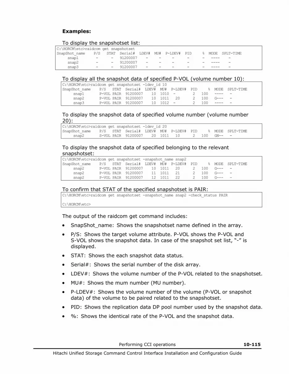
Performing CCI operations 10-115
Hitachi Unified Storage Command Control Interface Installation and Configuration Guide
Examples:
To display the snapshotset list: C:\HORCM\etc>raidcom get snapshotset SnapShot_name P/S STAT Serial# LDEV# MU# P-LDEV# PID % MODE SPLT-TIME snap1 - - 91200007 - - - - - ---- - snap2 - - 91200007 - - - - - ---- - snap3 - - 91200007 - - - - - ---- -
To display all the snapshot data of specified P-VOL (volume number 10): C:\HORCM\etc>raidcom get snapshotset -ldev_id 10 SnapShot_name P/S STAT Serial# LDEV# MU# P-LDEV# PID % MODE SPLT-TIME snap1 P-VOL PAIR 91200007 10 1010 - 2 100 ---- - snap2 P-VOL PAIR 91200007 10 1011 20 2 100 G--- - snap3 P-VOL PAIR 91200007 10 1012 - 2 100 ---- -
To display the snapshot data of specified volume number (volume number 20): C:\HORCM\etc>raidcom get snapshotset -ldev_id 20 SnapShot_name P/S STAT Serial# LDEV# MU# P-LDEV# PID % MODE SPLT-TIME snap2 S-VOL PAIR 91200007 20 1011 10 2 100 GN-- -
To display the snapshot data of specified belonging to the relevant snapshotset: C:\HORCM\etc>raidcom get snapshotset -snapshot_name snap2 SnapShot_name P/S STAT Serial# LDEV# MU# P-LDEV# PID % MODE SPLT-TIME snap2 P-VOL PAIR 91200007 10 1011 20 2 100 G--- - snap2 P-VOL PAIR 91200007 11 1011 21 2 100 G--- - snap2 P-VOL PAIR 91200007 12 1011 22 2 100 G--- -
To confirm that STAT of the specified snapshotset is PAIR: C:\HORCM\etc>raidcom get snapshotset -snapshot_name snap2 -check_status PAIR C:\HORCM\etc>
The output of the raidcom get command includes:
• SnapShot_name: Shows the snapshotset name defined in the array.
• P/S: Shows the target volume attribute. P-VOL shows the P-VOL and S-VOL shows the snapshot data. In case of the snapshot set list, “-” is displayed.
• STAT: Shows the each snapshot data status.
• Serial#: Shows the serial number of the disk array.
• LDEV#: Shows the volume number of the P-VOL related to the snapshotset.
• MU#: Shows the mum number (MU number).
• P-LDEV#: Shows the volume number of the volume (P-VOL or snapshot data) of the volume to be paired related to the snapshotset.
• PID: Shows the replication data DP pool number used by the snapshot data.
• %: Shows the identical rate of the P-VOL and the snapshot data.
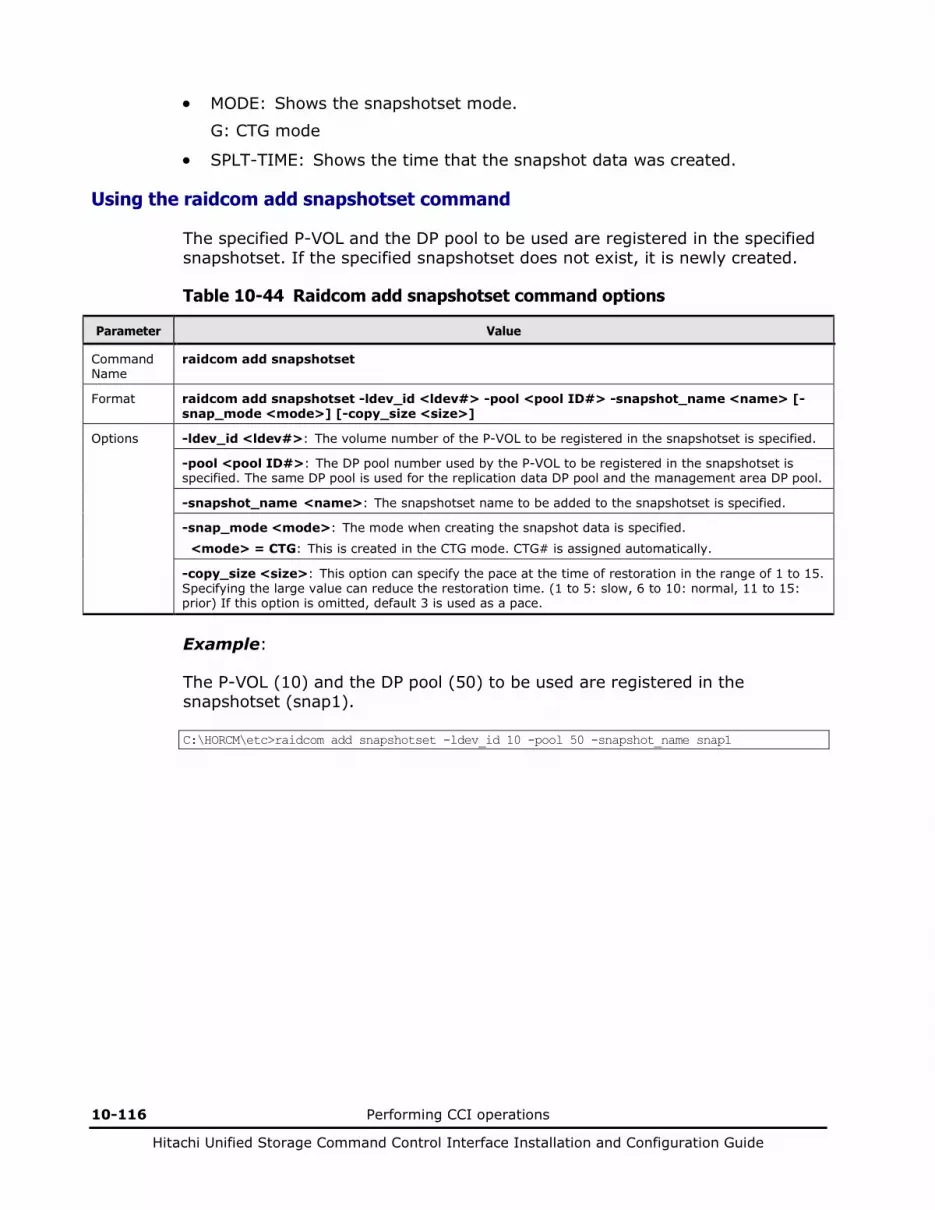
10-116 Performing CCI operations
Hitachi Unified Storage Command Control Interface Installation and Configuration Guide
• MODE: Shows the snapshotset mode.
G: CTG mode
• SPLT-TIME: Shows the time that the snapshot data was created.
Using the raidcom add snapshotset command
The specified P-VOL and the DP pool to be used are registered in the specified snapshotset. If the specified snapshotset does not exist, it is newly created.
Table 10-44 Raidcom add snapshotset command options
Parameter Value
Command Name
raidcom add snapshotset
Format raidcom add snapshotset -ldev_id <ldev#> -pool <pool ID#> -snapshot_name <name> [-snap_mode <mode>] [-copy_size <size>]
Options -ldev_id <ldev#>: The volume number of the P-VOL to be registered in the snapshotset is specified.
-pool <pool ID#>: The DP pool number used by the P-VOL to be registered in the snapshotset is specified. The same DP pool is used for the replication data DP pool and the management area DP pool.
-snapshot_name <name>: The snapshotset name to be added to the snapshotset is specified.
-snap_mode <mode>: The mode when creating the snapshot data is specified.
<mode> = CTG: This is created in the CTG mode. CTG# is assigned automatically.
-copy_size <size>: This option can specify the pace at the time of restoration in the range of 1 to 15. Specifying the large value can reduce the restoration time. (1 to 5: slow, 6 to 10: normal, 11 to 15: prior) If this option is omitted, default 3 is used as a pace.
Example:
The P-VOL (10) and the DP pool (50) to be used are registered in the snapshotset (snap1). C:\HORCM\etc>raidcom add snapshotset -ldev_id 10 -pool 50 -snapshot_name snap1

Performing CCI operations 10-117
Hitachi Unified Storage Command Control Interface Installation and Configuration Guide
Using the raidcom delete snapshotset command
The snapshotset is deleted. Once the P-VOL is specified, the snapshot data of the relevant P-VOL is deleted from the snapshotset.
The snapshot data in which the volume number is mapped and the snapshotset including such snapshot data cannot be deleted. Un-map the volume number from the snapshot data, and then delete them.
Table 10-45 Raidcom delete snapshotset command options
Parameter Value
Command Name
raidcom delete snapshotset
Format raidcom delete snapshotset {-snapshot_name <name> | -ldev_id <ldev#> {-mirror_id <mun#> | -snapshot_name <name>}}
Options -snapshot_name <name>: The snapshotset name of the snapshotset to be deleted is specified. Once the snapshot set is deleted, all the snapshot data belonging to the relevant snapshotset is also deleted.
-ldev_id <ldev#>: The volume number of the P-VOL of the snapshot data to be deleted is specified. Furthermore, the snapshot data to be deleted is identified by specifying the snapshotset name or mun#.
-mirror_id <mun#>: mun# of the snapshot data to be deleted is specified.
Example:
The snapshot data of the P-VOL (10) belonging to the snapshotset (snap1) is deleted. C:\HORCM\etc>raidcom delete snapshotset -snapshot_name snap1 -ldev_id 10
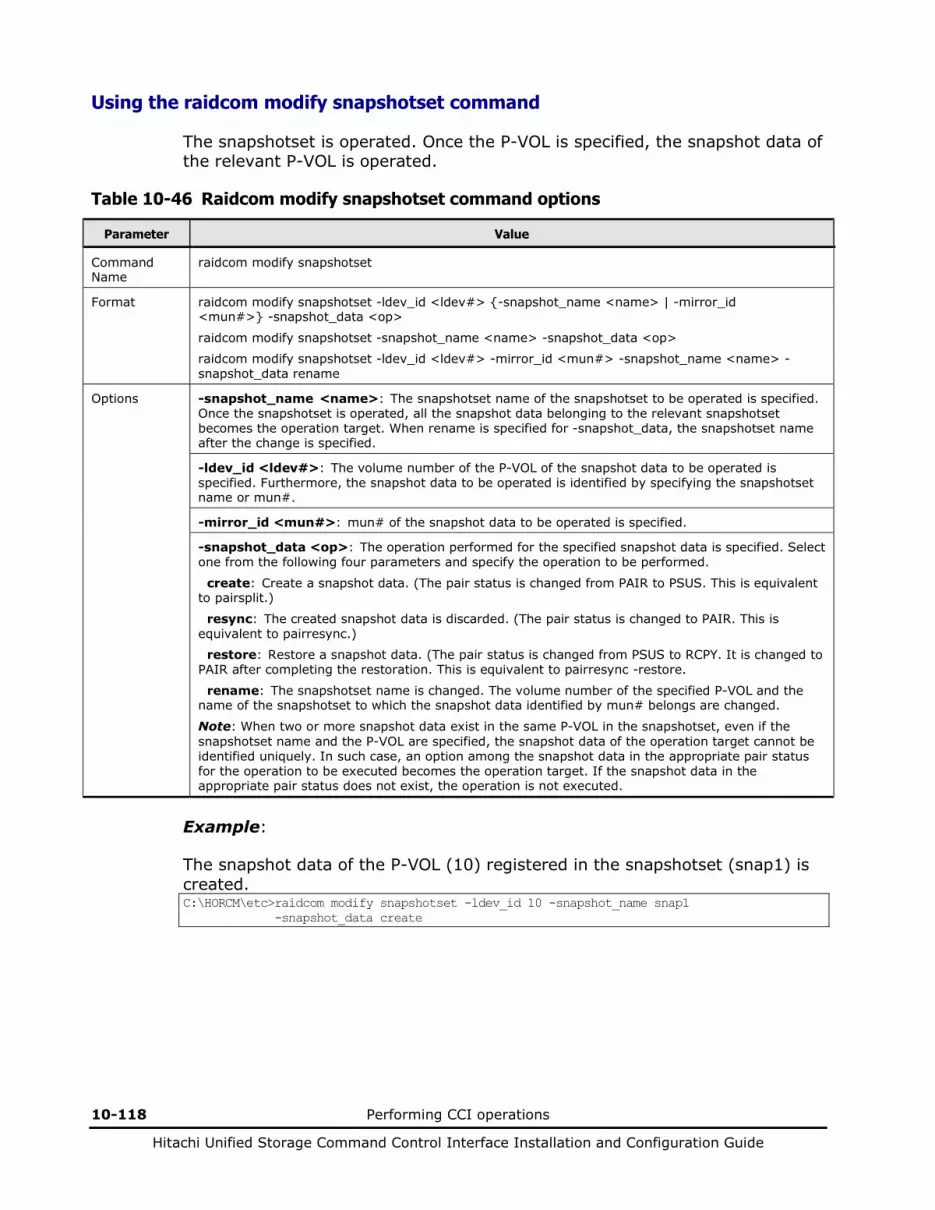
10-118 Performing CCI operations
Hitachi Unified Storage Command Control Interface Installation and Configuration Guide
Using the raidcom modify snapshotset command
The snapshotset is operated. Once the P-VOL is specified, the snapshot data of the relevant P-VOL is operated.
Table 10-46 Raidcom modify snapshotset command options
Parameter Value
Command Name
raidcom modify snapshotset
Format raidcom modify snapshotset -ldev_id <ldev#> {-snapshot_name <name> | -mirror_id <mun#>} -snapshot_data <op>
raidcom modify snapshotset -snapshot_name <name> -snapshot_data <op>
raidcom modify snapshotset -ldev_id <ldev#> -mirror_id <mun#> -snapshot_name <name> -snapshot_data rename
Options -snapshot_name <name>: The snapshotset name of the snapshotset to be operated is specified. Once the snapshotset is operated, all the snapshot data belonging to the relevant snapshotset becomes the operation target. When rename is specified for -snapshot_data, the snapshotset name after the change is specified.
-ldev_id <ldev#>: The volume number of the P-VOL of the snapshot data to be operated is specified. Furthermore, the snapshot data to be operated is identified by specifying the snapshotset name or mun#.
-mirror_id <mun#>: mun# of the snapshot data to be operated is specified.
-snapshot_data <op>: The operation performed for the specified snapshot data is specified. Select one from the following four parameters and specify the operation to be performed.
create: Create a snapshot data. (The pair status is changed from PAIR to PSUS. This is equivalent to pairsplit.)
resync: The created snapshot data is discarded. (The pair status is changed to PAIR. This is equivalent to pairresync.)
restore: Restore a snapshot data. (The pair status is changed from PSUS to RCPY. It is changed to PAIR after completing the restoration. This is equivalent to pairresync -restore.
rename: The snapshotset name is changed. The volume number of the specified P-VOL and the name of the snapshotset to which the snapshot data identified by mun# belongs are changed.
Note: When two or more snapshot data exist in the same P-VOL in the snapshotset, even if the snapshotset name and the P-VOL are specified, the snapshot data of the operation target cannot be identified uniquely. In such case, an option among the snapshot data in the appropriate pair status for the operation to be executed becomes the operation target. If the snapshot data in the appropriate pair status does not exist, the operation is not executed.
Example:
The snapshot data of the P-VOL (10) registered in the snapshotset (snap1) is created. C:\HORCM\etc>raidcom modify snapshotset -ldev_id 10 -snapshot_name snap1 -snapshot_data create
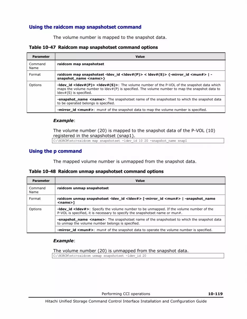
Performing CCI operations 10-119
Hitachi Unified Storage Command Control Interface Installation and Configuration Guide
Using the raidcom map snapshotset command
The volume number is mapped to the snapshot data.
Table 10-47 Raidcom map snapshotset command options
Parameter Value
Command Name
raidcom map snapshotset
Format raidcom map snapshotset -ldev_id <ldev#(P)> < ldev#(S)> {-mirror_id <mun#> | -snapshot_name <name>}
Options -ldev_id <ldev#(P)> <ldev#(S)>: The volume number of the P-VOL of the snapshot data which maps the volume number to ldev#(P) is specified. The volume number to map the snapshot data to ldev#(S) is specified.
-snapshot_name <name>: The snapshotset name of the snapshotset to which the snapshot data to be operated belongs is specified.
-mirror_id <mun#>: mun# of the snapshot data to map the volume number is specified.
Example:
The volume number (20) is mapped to the snapshot data of the P-VOL (10) registered in the snapshotset (snap1). C:\HORCM\etc>raidcom map snapshotset -ldev_id 10 20 -snapshot_name snap1
Using the p command
The mapped volume number is unmapped from the snapshot data.
Table 10-48 Raidcom unmap snapshotset command options
Parameter Value
Command Name
raidcom unmap snapshotset
Format raidcom unmap snapshotset -ldev_id <ldev#> [-mirror_id <mun#> | -snapshot_name <name>]
Options -ldev_id <ldev#>: Specify the volume number to be unmapped. If the volume number of the P-VOL is specified, it is necessary to specify the snapshotset name or mun#.
-snapshot_name <name>: The snapshotset name of the snapshotset to which the snapshot data to unmap the volume number belongs is specified.
-mirror_id <mun#>: mun# of the snapshot data to operate the volume number is specified.
Example:
The volume number (20) is unmapped from the snapshot data. C:\HORCM\etc>raidcom unmap snapshotset -ldev_id 20
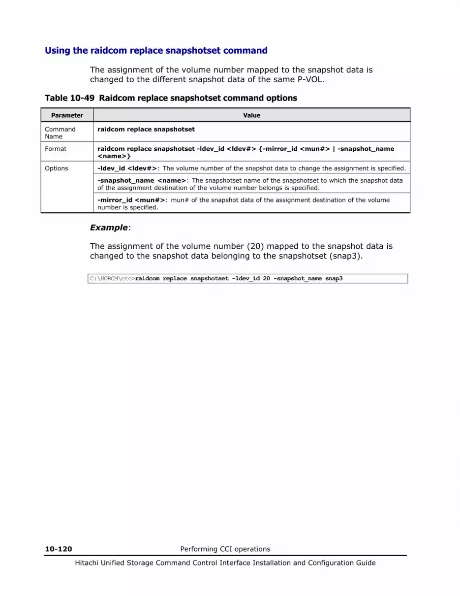
10-120 Performing CCI operations
Hitachi Unified Storage Command Control Interface Installation and Configuration Guide
Using the raidcom replace snapshotset command
The assignment of the volume number mapped to the snapshot data is changed to the different snapshot data of the same P-VOL.
Table 10-49 Raidcom replace snapshotset command options
Parameter Value
Command Name
raidcom replace snapshotset
Format raidcom replace snapshotset -ldev_id <ldev#> {-mirror_id <mun#> | -snapshot_name <name>}
Options -ldev_id <ldev#>: The volume number of the snapshot data to change the assignment is specified.
-snapshot_name <name>: The snapshotset name of the snapshotset to which the snapshot data of the assignment destination of the volume number belongs is specified.
-mirror_id <mun#>: mun# of the snapshot data of the assignment destination of the volume number is specified.
Example:
The assignment of the volume number (20) mapped to the snapshot data is changed to the snapshot data belonging to the snapshotset (snap3).
C:\HORCM\etc>raidcom replace snapshotset -ldev_id 20 -snapshot_name snap3
11
Troubleshooting 11-1
Hitachi Unified Storage Command Control Interface Installation and Configuration Guide
Troubleshooting
This chapter covers the following topics: Troubleshooting ShadowImage Troubleshooting SnapShot Troubleshooting TrueCopy Troubleshooting TCE Troubleshooting CCI About error reporting Recovering PSUE status using ShadowImage Recovering PSUE status using SnapShot Recovering PSUE status using TrueCopy/TCE Calling the Hitachi Data Systems Support Center

11-2 Troubleshooting
Hitachi Unified Storage Command Control Interface Installation and Configuration Guide
Troubleshooting ShadowImage
In the case of the ShadowImage pair, a pair failure may be caused by occurrence of a hardware failure, so that the work for restoring the pair status is required. When the operation of pair release is performed forcibly by a user, the pair status is changed to PSUE in the same way that a pair failure occurs, so that the work for restoring the pair status is required. Furthermore, when the DP-VOLs are used for the volumes configuring a pair, a pair failure may occur, depending on the consumed capacity of the DP pool and the pair status may become PSUE.
When the DP-VOL created in the DP pool is used for a ShadowImage pair, since the required area cannot be allocated, a pair failure may occur. If a failure occurs during the DP pool formatting, wait until the formatting of the DP pool for total capacity of the DP-VOLs created in the DP pool is completed. If a failure occurs due to the DP pool capacity depletion, for making the DP pool status normal, perform the DP pool capacity growing and DP pool optimization, and increase the DP pool free capacity.
If a hardware error occurs while you are operating ShadowImage, both of the following are necessary:
• A CCI user intervention
• Assistance from a Hitachi Customer Service representative
For example, when formatting is needed to resolve a volume error and that volume is used for ShadowImage, the pair must be released by the user (CCI operation by the user) before the volume can be formatted. Therefore, please contact Hitachi personnel because maintenance requires the user to issue CCI commands. Note that the Hitachi personnel can only remove errors which result from hardware. An operation such as recovering a ShadowImage pair status (e.g. resynchronizing) must be done by the user. Figure 11-1 shows the flow of action when the PSUE error occurs. Table 11-1 shows the share of action to be taken by the user.

Troubleshooting 11-3
Hitachi Unified Storage Command Control Interface Installation and Configuration Guide
NO
YES
Start
PSUE occurred in the system (event) log.
Did PSUE occur due to the CCI command?
Resynchronize the pair.
Collect error log and traces.
Call the maintenance personnel.
End
Remove the error by cooperating with the maintenance personnel.
Message ID: HORCM_102
NO
Is a DP-VOL used for the operation target pair?
Review the DP pool status, and secure the capacity of the DP pool
required for the pair operation.
YES
NO
Figure 11-1 Pair status information example using ShadowImage
Table 11-1 Operational notes for ShadowImage
Action Action taken by whom
Confirm the message (syslog). User
Verify that PSUE is caused by the user operation. User
Verify the status of the array. User
Call maintenance personnel when the array malfunctions. User
For other reasons, call the Hitachi Data Systems Support Center.
User (only for users who are registered to receive support)
Hardware maintenance. Hitachi Customer Service
Reconfigure and recover the pair. User
11-4 Troubleshooting
Hitachi Unified Storage Command Control Interface Installation and Configuration Guide
Troubleshooting SnapShot
If a hardware error occurs while you are operating SnapShot, both of the following are necessary:
• A CCI user intervention
• Assistance from a Hitachi Customer Service representative
There are three causes of PSUE status induced during an operation of SnapShot: an insufficient DP pool capacity (full of the DP pool), DP pool capacity is depleted, and an occurrence of a logically abnormal status caused by a hardware failure. When the DP pool capacity is insufficient, split all pairs that have been placed in the PSUE status. After that, check if the configuration including the DP pool capacity and number of V-VOLs is appropriate because it is judged that the system configuration has a problem. After the check is finished, carry out an operation of SnapShot for recovering a pair status (such as paircreate). All those operations are to be done by a user.
When the DP-VOL created in the DP pool is used for a SnapShot pair, since the required area cannot be allocated, a pair failure may occur. If a failure occurs during the DP pool formatting, wait until the formatting of the DP pool for total capacity of the DP-VOLs created in the DP pool is completed. If a failure occurs due to the DP pool capacity depletion, for making the DP pool status normal, perform the DP pool capacity growing and DP pool optimization, and increase the DP pool free capacity.
For example, when formatting is needed to resolve a volume error and that volume is used for SnapShot, the pair must be released by the user (CCI operation by the user) before the volume can be formatted. Therefore, please contact Hitachi personnel because maintenance requires the user to issue CCI commands. Note that the Hitachi personnel can only remove errors which result from hardware. An operation such as recovering a SnapShot pair status (e.g. paircreate) must be done by the user. Figure 11-2 shows the flow of action when the PSUE error occurs. Table 11-2 shows the share of action to be taken by the user.
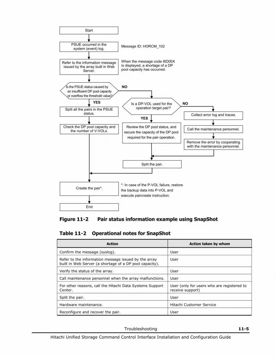
Troubleshooting 11-5
Hitachi Unified Storage Command Control Interface Installation and Configuration Guide
Start
PSUE occurred in the system (event) log.
Create the pair*.
Collect error log and traces.
Call the maintenance personnel.
End
Remove the error by cooperating with the maintenance personnel.
Message ID: HORCM_102
Split the pair.
*: In case of the P-VOL failure, restore the backup data into P-VOL and execute paircreate instruction.
NO
YES
Is the PSUE status caused by an insufficient DP pool capacity or overflow the threshold value?
Refer to the information message issued by the array built in Web
Server.
Split all the pairs in the PSUE status.
Check the DP pool capacity and the number of V-VOLs.
When the message code I6D00X is displayed, a shortage of a DP pool capacity has occurred.
Is a DP-VOL used for the operation target pair?
Review the DP pool status, and secure the capacity of the DP pool
required for the pair operation.
YES
NO
Figure 11-2 Pair status information example using SnapShot
Table 11-2 Operational notes for SnapShot
Action Action taken by whom
Confirm the message (syslog). User
Refer to the information message issued by the array built in Web Server (a shortage of a DP pool capacity).
User
Verify the status of the array. User
Call maintenance personnel when the array malfunctions. User
For other reasons, call the Hitachi Data Systems Support Center.
User (only for users who are registered to receive support)
Split the pair. User
Hardware maintenance. Hitachi Customer Service
Reconfigure and recover the pair. User
11-6 Troubleshooting
Hitachi Unified Storage Command Control Interface Installation and Configuration Guide
Troubleshooting TrueCopy
When the following problem occurs, the pair status is changed to PSUE: – The path detached occurs – A logical abnormal state occurs by the trouble of the array – An abnormal state occurs by the causes other than the array
If a hardware or Fibre path error occurs while you are operating the TrueCopy, both of the following are necessary:
• A CCI user intervention
• Assistance from a Hitachi Customer Service representative
For example, when formatting is needed to resolve a volume error and that volume is used for TrueCopy, the pair must be released by the user (CCI operation by the user) before the volume can be formatted. Therefore, please contact Hitachi personnel because maintenance requires the user to issue CCI commands. Note that the Hitachi personnel can only remove errors which result from hardware. An operation such as recovering the TrueCopy pair status (e.g. resynchronizing) must be done by the user. Figure 11-3 shows the flow of action when the PSUE error occurs. Table 11-3 shows the share of action to be taken by the user.

Troubleshooting 11-7
Hitachi Unified Storage Command Control Interface Installation and Configuration Guide
NO
YES Is the ShadowImage S-VOL suspended (PSUE)?
After the maintenance works by the maintenance personal resynchronize the PSUE pairs.
Resynchronize the PSUE pairs.
End
NO
YES Confirm the path status. Is the path status blocked?
After having recovered the ShadowImage volume from suspended status (PSUE), resynchronize it in the direction of P-VOL to S-VOL.
Collect the error log and traces and maintain together with the maintenance personal. After recovering the error, resynchronize the PSUE pairs.
NO
YES Confirm the local array and remote array status.
Is the error displayed?
Start
It is necessary to specify the detailed error factor. NO
YES Confirm the pair operation
procedure. Does the problem occur when
resynchronizing the pairs?
1
Figure 11-3 Pair status information example using TrueCopy

11-8 Troubleshooting
Hitachi Unified Storage Command Control Interface Installation and Configuration Guide
NO
YES Is the target volume of the remote side reserved?
Is the target volume of the remote side unformatted?
Is the target volume of the remote side undefined?
Release the pair and create the pair after formatting defined target volume is completed.
NO
NO
Is the target volume of the remote side in formatting?
YES
YES
YES
YES Is the SyncCache command executed for the remote
array?
NO
NO
2 3 4
1
NO
YES
NO
NO
YES
YES
YES
NO
Is the path specified value on the remote array different?
Is the pair status of the remote array SSWS? Note 1
Is the TrueCopy option in the remote array locked?
Is the command from CCI in progress
in the remote array? Note 1
Release the pair and then create the pair again after unlocking the TrueCopy option of the remote side.
Figure 11-3 Pair status information example using TrueCopy (cont.)
Note: When swap is in progress from S-VOL to P-VOL, the pairs cannot be resynchronized from P-VOL to S-VOL.

Troubleshooting 11-9
Hitachi Unified Storage Command Control Interface Installation and Configuration Guide
YES Is the suspend command issued from the host server?
NO
2 4 3
YES Is the queue full occurred in the remote array, or is the
system very busy?
NO
YES Is the target volume of the remote side in ACA Active
status?
NO (Only while using AIX server.)
Confirm and retry the system.
Was the pairsplit -R issued to S-VOL?
NO
YES
Since S-VOL will be SMPL when releasing S-VOL in PAIR status forcibly, issue pairsplit -S to P-VOL to change the PAIR status of P-VOL to SMPL.
Resynchronize the PSUE pairs.
End
Release the pair and create the pair again.
Review the DP pool status, and secure the capacity of the DP pool
required for the pair operation.
Is the DP pool to which the DP-VOL belongs being
formatted?
Is the capacity of the DP pool to which the DP-VOL
belongs depleted?
NO
NO
YES
YES
Figure 11-3 Pair status information example using TrueCopy (cont.)

11-10 Troubleshooting
Hitachi Unified Storage Command Control Interface Installation and Configuration Guide
Table 11-3 Operational notes for TrueCopy
Action Action taken by whom
Confirm the message (syslog). User
Confirm whether PSUE is caused by the user operation. User
Confirm the status of the array. User
Call the maintenance personnel when the array malfunctions. User
For other reasons, call the Hitachi Data Systems Support Center. User (only for users who are registered to receive support)
Hardware maintenance (including path blockage). Hitachi maintenance personnel
Reconfigure and recover the pair. User
Troubleshooting 11-11
Hitachi Unified Storage Command Control Interface Installation and Configuration Guide
Troubleshooting TCE
When the following problem occurs, the pair status is changed to PSUE: – The amount of the data in the DP pool exceeds the capacity allowed to
be used – The path detached occurs – A logical abnormal state occurs by the trouble of the array – An abnormal state occurs by the causes other than the array
If a hardware or Fibre path error occurs while you are operating the TCE, both of the following are necessary:
• A CCI user intervention
• Assistance from a Hitachi Customer Service representative
When the amount of the data in the DP pool exceeds the capacity allowed to be used, can be recover by resynchronizing all the pairs whose DP pools are placed in the PSUE or PFUS status. After that, check if the configuration including the DP pool capacity and number of V-VOLs (when concurrent use of SnapShot) is appropriate because it is judged that the system configuration has a problem. After the check is finished, carry out an operation of TCE for recovering a pair status (such as paircreate). All those operations are to be done by a user.
For example, when formatting is needed to resolve a volume error and that volume is used for TCE, the pair must be released by the user (CCI operation by the user) before the volume can be formatted. Therefore, please contact Hitachi personnel because maintenance requires the user to issue CCI commands. Note that the Hitachi personnel can only remove errors which result from hardware. An operation such as recovering the TCE pair status (e.g. resynchronizing) must be done by the user. Figure 11-4 shows the flow of action when the PSUE error occurs. Table 11-4 shows the share of action to be taken by the user.
Note: • In the case of TCE, even when one of the pairs belonging to the same CTG
is placed in the PSUE status, all the pairs in the CTG are placed in the PSUE status because the change to the PSUE status is made in units of CTG. However, concerning the pair in the PSUS status, the status is not changed to PSUE but left as it is.
• In the case where the DP pool-over occurs in the secondary DP pool, it is reported to the P-VOL after the S-VOL status is changed to PFUS and the P-VOL status is changed to PSUE. On the other hand, when the DP pool-over occurs in the primary DP pool, only the P-VOL status is changed to PFUS and the change of the S-VOL status does not occur.
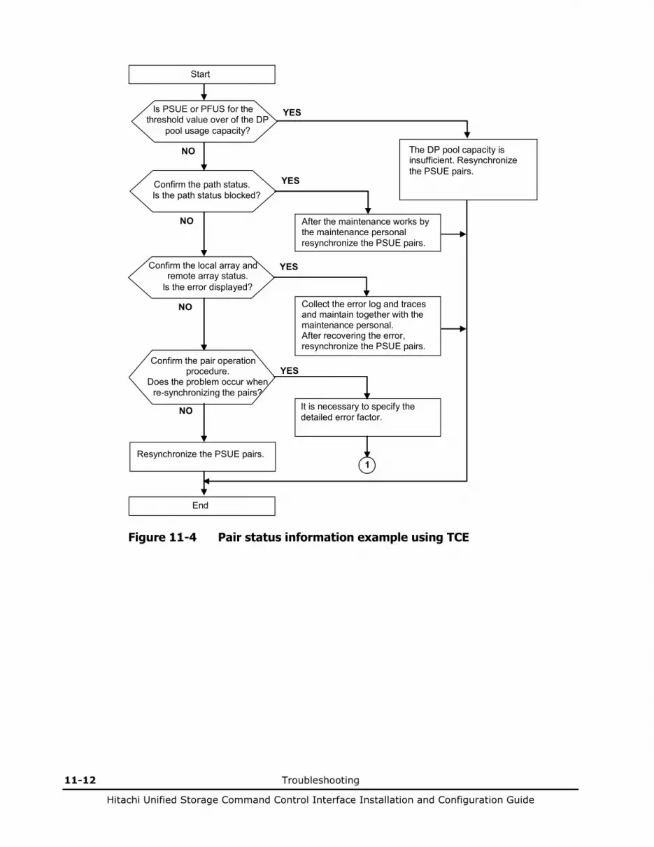
11-12 Troubleshooting
Hitachi Unified Storage Command Control Interface Installation and Configuration Guide
NO
YES Is PSUE or PFUS for the threshold value over of the DP
pool usage capacity?
After the maintenance works by the maintenance personal resynchronize the PSUE pairs.
Resynchronize the PSUE pairs.
End
NO
YES Confirm the path status. Is the path status blocked?
The DP pool capacity is insufficient. Resynchronize the PSUE pairs.
Collect the error log and traces and maintain together with the maintenance personal. After recovering the error, resynchronize the PSUE pairs.
NO
YES Confirm the local array and remote array status.
Is the error displayed?
Start
It is necessary to specify the detailed error factor.
NO
YES Confirm the pair operation
procedure. Does the problem occur when
re-synchronizing the pairs?
1
Figure 11-4 Pair status information example using TCE

Troubleshooting 11-13
Hitachi Unified Storage Command Control Interface Installation and Configuration Guide
NO
YES Is the target volume of the remote side reserved?
Is the target volume of the remote side unformatted?
Is the target volume of the remote side undefined?
Release the pair and create the pair after formatting defined target volume is completed.
NO
NO
Is the target volume of the remote side in formatting?
YES
YES
YES
YES Is the SyncCache command executed for the remote
array?
NO
NO
2 3 4
1
NO
YES
NO
NO
YES
YES
YES
NO
Is the path specified value on the remote array different?
Is the pair status of the remote array SSWS? Note 1
Is the TrueCopy option in the remote array locked?
Is the command from CCI in progress
in the remote array? Note 1
Release the pair and then create the pair again after unlocking the TrueCopy option of the remote side.
Figure 11-4 Pair status information example using TCE (continued)
Note: When swap is in progress from S-VOL to P-VOL, the pairs can not be resynchronized from P-VOL to S-VOL.
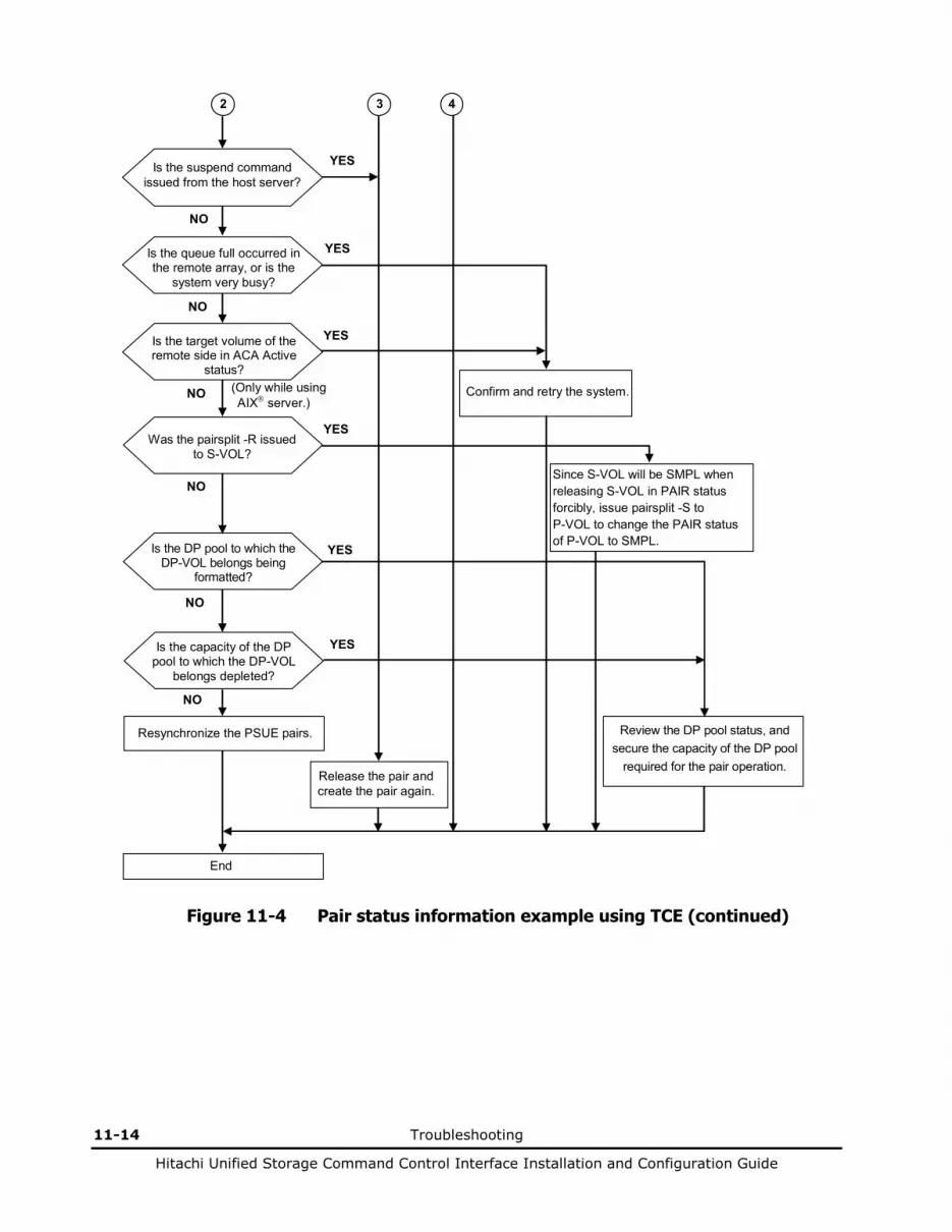
11-14 Troubleshooting
Hitachi Unified Storage Command Control Interface Installation and Configuration Guide
YES Is the suspend command issued from the host server?
NO
2 4 3
YES Is the queue full occurred in the remote array, or is the
system very busy?
NO
YES Is the target volume of the remote side in ACA Active
status?
NO (Only while using AIX server.)
Confirm and retry the system.
Was the pairsplit -R issued to S-VOL?
NO
YES
Since S-VOL will be SMPL when releasing S-VOL in PAIR status forcibly, issue pairsplit -S to P-VOL to change the PAIR status of P-VOL to SMPL.
Resynchronize the PSUE pairs.
End
Release the pair and create the pair again.
Review the DP pool status, and secure the capacity of the DP pool
required for the pair operation.
Is the DP pool to which the DP-VOL belongs being
formatted?
Is the capacity of the DP pool to which the DP-VOL
belongs depleted?
NO
NO
YES
YES
Figure 11-4 Pair status information example using TCE (continued)

Troubleshooting 11-15
Hitachi Unified Storage Command Control Interface Installation and Configuration Guide
Table 11-4 Operational notes for TCE
Action Action taken by whom
Confirm the message (syslog). User
Checking the Information message sent from the Web built-in array (making sure of insufficiency of the DP pool capacity)
User
Confirm whether PSUE is caused by the user operation. User
Confirm the status of the array. User
Call the maintenance personnel when the array malfunctions. User
For other reasons, call the Hitachi Data Systems Support Center.
User (only for users who are registered to receive support)
Hardware maintenance (including path blockage). Hitachi maintenance personnel
Reconfigure and recover the pair. User
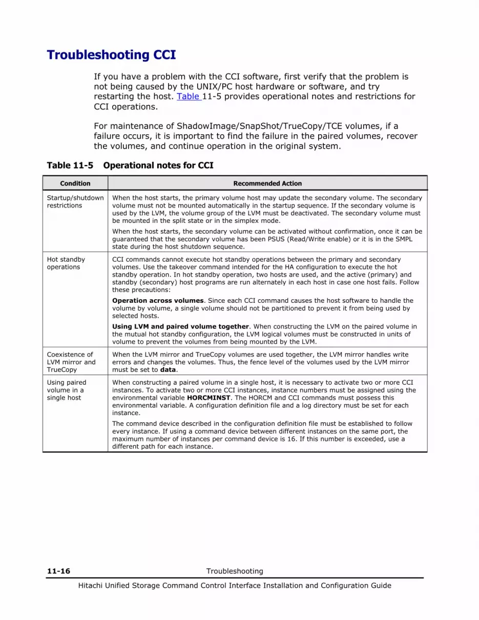
11-16 Troubleshooting
Hitachi Unified Storage Command Control Interface Installation and Configuration Guide
Troubleshooting CCI
If you have a problem with the CCI software, first verify that the problem is not being caused by the UNIX/PC host hardware or software, and try restarting the host. Table 11-5 provides operational notes and restrictions for CCI operations.
For maintenance of ShadowImage/SnapShot/TrueCopy/TCE volumes, if a failure occurs, it is important to find the failure in the paired volumes, recover the volumes, and continue operation in the original system.
Table 11-5 Operational notes for CCI
Condition Recommended Action
Startup/shutdown restrictions
When the host starts, the primary volume host may update the secondary volume. The secondary volume must not be mounted automatically in the startup sequence. If the secondary volume is used by the LVM, the volume group of the LVM must be deactivated. The secondary volume must be mounted in the split state or in the simplex mode.
When the host starts, the secondary volume can be activated without confirmation, once it can be guaranteed that the secondary volume has been PSUS (Read/Write enable) or it is in the SMPL state during the host shutdown sequence.
Hot standby operations
CCI commands cannot execute hot standby operations between the primary and secondary volumes. Use the takeover command intended for the HA configuration to execute the hot standby operation. In hot standby operation, two hosts are used, and the active (primary) and standby (secondary) host programs are run alternately in each host in case one host fails. Follow these precautions:
Operation across volumes. Since each CCI command causes the host software to handle the volume by volume, a single volume should not be partitioned to prevent it from being used by selected hosts.
Using LVM and paired volume together. When constructing the LVM on the paired volume in the mutual hot standby configuration, the LVM logical volumes must be constructed in units of volume to prevent the volumes from being mounted by the LVM.
Coexistence of LVM mirror and TrueCopy
When the LVM mirror and TrueCopy volumes are used together, the LVM mirror handles write errors and changes the volumes. Thus, the fence level of the volumes used by the LVM mirror must be set to data.
Using paired volume in a single host
When constructing a paired volume in a single host, it is necessary to activate two or more CCI instances. To activate two or more CCI instances, instance numbers must be assigned using the environmental variable HORCMINST. The HORCM and CCI commands must possess this environmental variable. A configuration definition file and a log directory must be set for each instance.
The command device described in the configuration definition file must be established to follow every instance. If using a command device between different instances on the same port, the maximum number of instances per command device is 16. If this number is exceeded, use a different path for each instance.
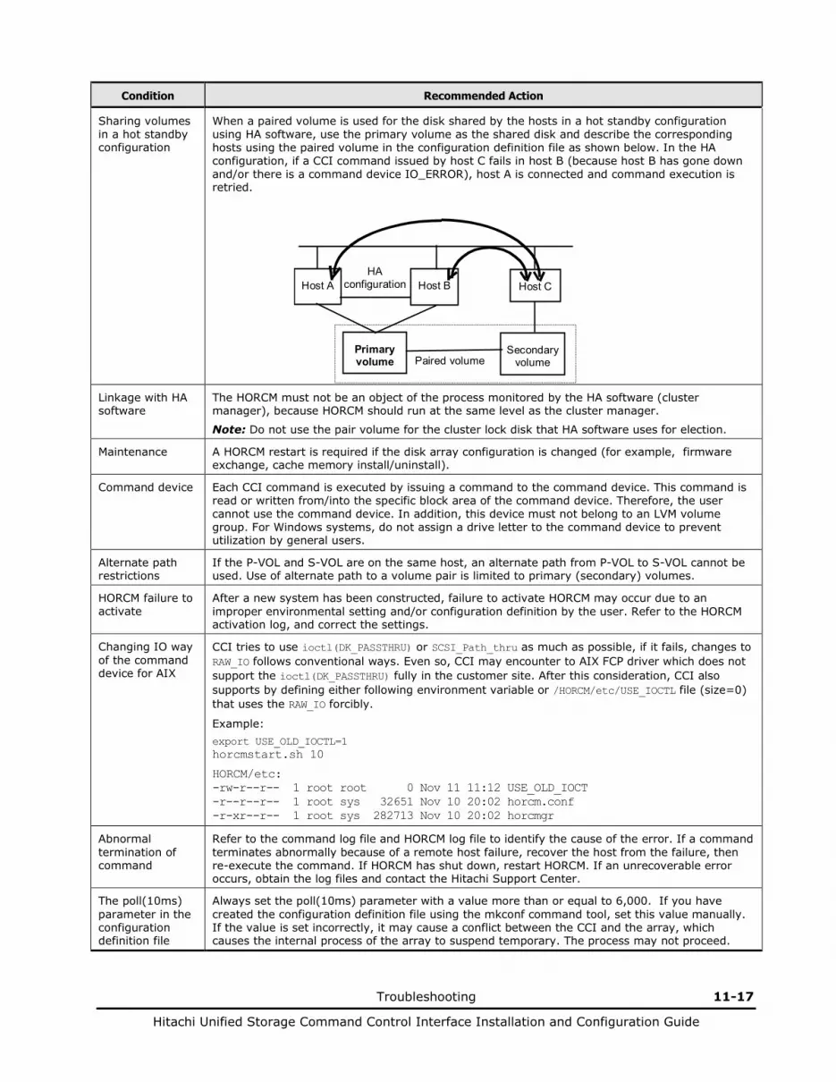
Troubleshooting 11-17
Hitachi Unified Storage Command Control Interface Installation and Configuration Guide
Condition Recommended Action
Sharing volumes in a hot standby configuration
When a paired volume is used for the disk shared by the hosts in a hot standby configuration using HA software, use the primary volume as the shared disk and describe the corresponding hosts using the paired volume in the configuration definition file as shown below. In the HA configuration, if a CCI command issued by host C fails in host B (because host B has gone down and/or there is a command device IO_ERROR), host A is connected and command execution is retried.
Primaryvolume
Secondaryvolume
Host A Host B
Paired volume
HAconfiguration Host C
Linkage with HA software
The HORCM must not be an object of the process monitored by the HA software (cluster manager), because HORCM should run at the same level as the cluster manager.
Note: Do not use the pair volume for the cluster lock disk that HA software uses for election.
Maintenance A HORCM restart is required if the disk array configuration is changed (for example, firmware exchange, cache memory install/uninstall).
Command device Each CCI command is executed by issuing a command to the command device. This command is read or written from/into the specific block area of the command device. Therefore, the user cannot use the command device. In addition, this device must not belong to an LVM volume group. For Windows systems, do not assign a drive letter to the command device to prevent utilization by general users.
Alternate path restrictions
If the P-VOL and S-VOL are on the same host, an alternate path from P-VOL to S-VOL cannot be used. Use of alternate path to a volume pair is limited to primary (secondary) volumes.
HORCM failure to activate
After a new system has been constructed, failure to activate HORCM may occur due to an improper environmental setting and/or configuration definition by the user. Refer to the HORCM activation log, and correct the settings.
Changing IO way of the command device for AIX
CCI tries to use ioctl(DK_PASSTHRU) or SCSI_Path_thru as much as possible, if it fails, changes to RAW_IO follows conventional ways. Even so, CCI may encounter to AIX FCP driver which does not support the ioctl(DK_PASSTHRU) fully in the customer site. After this consideration, CCI also supports by defining either following environment variable or /HORCM/etc/USE_IOCTL file (size=0) that uses the RAW_IO forcibly.
Example: export USE_OLD_IOCTL=1 horcmstart.sh 10
HORCM/etc: -rw-r--r-- 1 root root 0 Nov 11 11:12 USE_OLD_IOCT -r--r--r-- 1 root sys 32651 Nov 10 20:02 horcm.conf -r-xr--r-- 1 root sys 282713 Nov 10 20:02 horcmgr
Abnormal termination of command
Refer to the command log file and HORCM log file to identify the cause of the error. If a command terminates abnormally because of a remote host failure, recover the host from the failure, then re-execute the command. If HORCM has shut down, restart HORCM. If an unrecoverable error occurs, obtain the log files and contact the Hitachi Support Center.
The poll(10ms) parameter in the configuration definition file
Always set the poll(10ms) parameter with a value more than or equal to 6,000. If you have created the configuration definition file using the mkconf command tool, set this value manually. If the value is set incorrectly, it may cause a conflict between the CCI and the array, which causes the internal process of the array to suspend temporary. The process may not proceed.
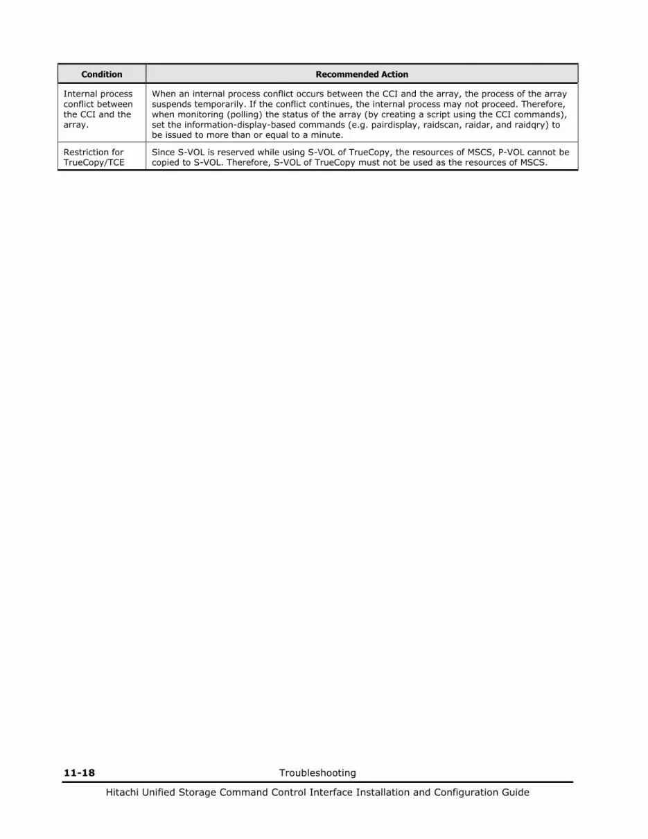
11-18 Troubleshooting
Hitachi Unified Storage Command Control Interface Installation and Configuration Guide
Condition Recommended Action
Internal process conflict between the CCI and the array.
When an internal process conflict occurs between the CCI and the array, the process of the array suspends temporarily. If the conflict continues, the internal process may not proceed. Therefore, when monitoring (polling) the status of the array (by creating a script using the CCI commands), set the information-display-based commands (e.g. pairdisplay, raidscan, raidar, and raidqry) to be issued to more than or equal to a minute.
Restriction for TrueCopy/TCE
Since S-VOL is reserved while using S-VOL of TrueCopy, the resources of MSCS, P-VOL cannot be copied to S-VOL. Therefore, S-VOL of TrueCopy must not be used as the resources of MSCS.
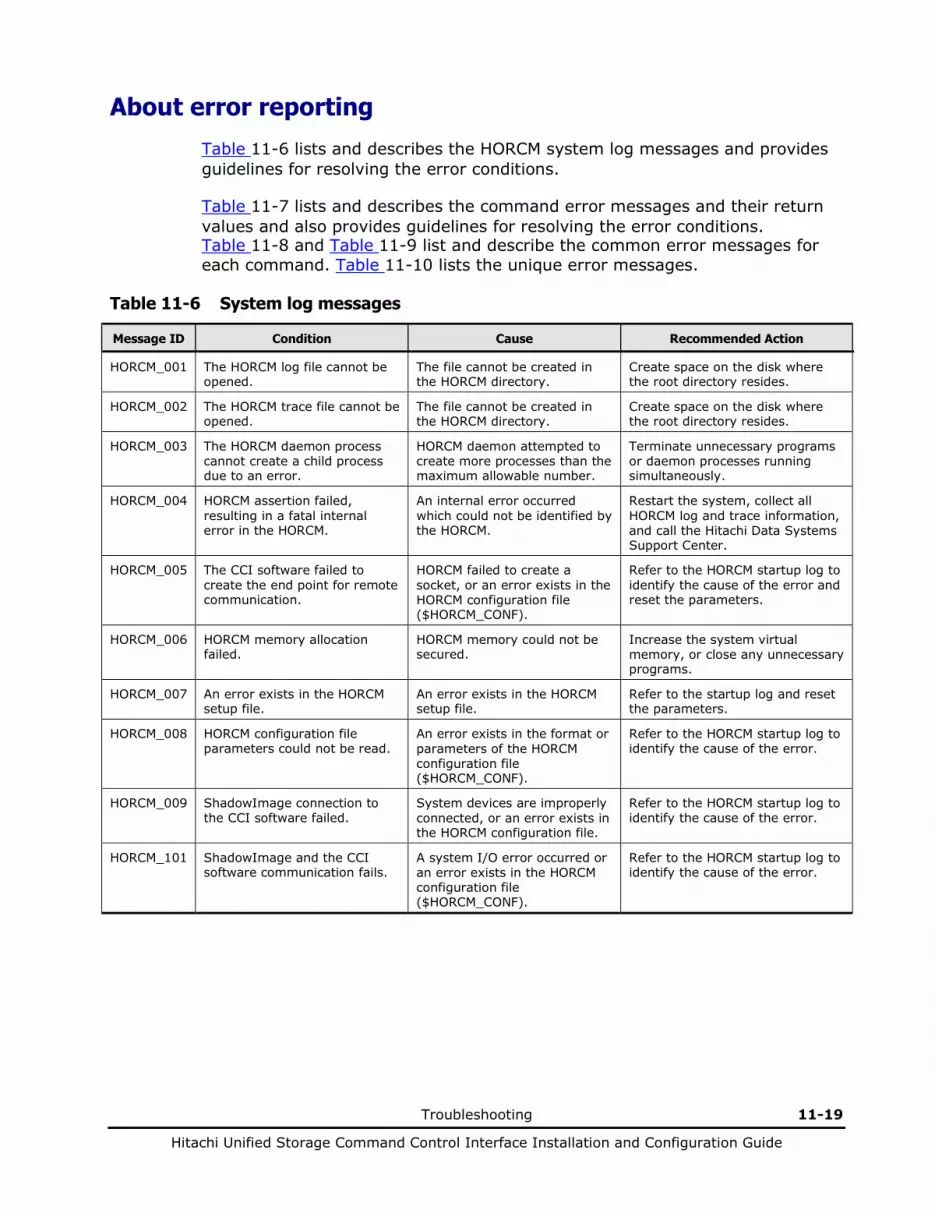
Troubleshooting 11-19
Hitachi Unified Storage Command Control Interface Installation and Configuration Guide
About error reporting
Table 11-6 lists and describes the HORCM system log messages and provides guidelines for resolving the error conditions.
Table 11-7 lists and describes the command error messages and their return values and also provides guidelines for resolving the error conditions. Table 11-8 and Table 11-9 list and describe the common error messages for each command. Table 11-10 lists the unique error messages.
Table 11-6 System log messages
Message ID Condition Cause Recommended Action
HORCM_001 The HORCM log file cannot be opened.
The file cannot be created in the HORCM directory.
Create space on the disk where the root directory resides.
HORCM_002 The HORCM trace file cannot be opened.
The file cannot be created in the HORCM directory.
Create space on the disk where the root directory resides.
HORCM_003 The HORCM daemon process cannot create a child process due to an error.
HORCM daemon attempted to create more processes than the maximum allowable number.
Terminate unnecessary programs or daemon processes running simultaneously.
HORCM_004 HORCM assertion failed, resulting in a fatal internal error in the HORCM.
An internal error occurred which could not be identified by the HORCM.
Restart the system, collect all HORCM log and trace information, and call the Hitachi Data Systems Support Center.
HORCM_005 The CCI software failed to create the end point for remote communication.
HORCM failed to create a socket, or an error exists in the HORCM configuration file ($HORCM_CONF).
Refer to the HORCM startup log to identify the cause of the error and reset the parameters.
HORCM_006 HORCM memory allocation failed.
HORCM memory could not be secured.
Increase the system virtual memory, or close any unnecessary programs.
HORCM_007 An error exists in the HORCM setup file.
An error exists in the HORCM setup file.
Refer to the startup log and reset the parameters.
HORCM_008 HORCM configuration file parameters could not be read.
An error exists in the format or parameters of the HORCM configuration file ($HORCM_CONF).
Refer to the HORCM startup log to identify the cause of the error.
HORCM_009 ShadowImage connection to the CCI software failed.
System devices are improperly connected, or an error exists in the HORCM configuration file.
Refer to the HORCM startup log to identify the cause of the error.
HORCM_101 ShadowImage and the CCI software communication fails.
A system I/O error occurred or an error exists in the HORCM configuration file ($HORCM_CONF).
Refer to the HORCM startup log to identify the cause of the error.
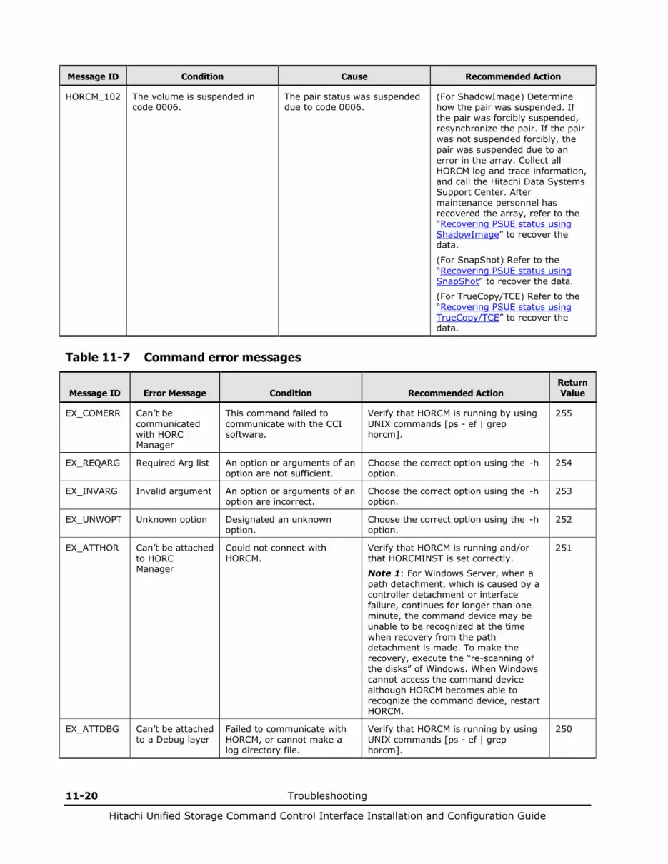
11-20 Troubleshooting
Hitachi Unified Storage Command Control Interface Installation and Configuration Guide
Message ID Condition Cause Recommended Action
HORCM_102 The volume is suspended in code 0006.
The pair status was suspended due to code 0006.
(For ShadowImage) Determine how the pair was suspended. If the pair was forcibly suspended, resynchronize the pair. If the pair was not suspended forcibly, the pair was suspended due to an error in the array. Collect all HORCM log and trace information, and call the Hitachi Data Systems Support Center. After maintenance personnel has recovered the array, refer to the “Recovering PSUE status using ShadowImage” to recover the data.
(For SnapShot) Refer to the “Recovering PSUE status using SnapShot” to recover the data.
(For TrueCopy/TCE) Refer to the “Recovering PSUE status using TrueCopy/TCE” to recover the data.
Table 11-7 Command error messages
Message ID Error Message Condition Recommended Action Return Value
EX_COMERR Can’t be communicated with HORC Manager
This command failed to communicate with the CCI software.
Verify that HORCM is running by using UNIX commands [ps - ef | grep horcm].
255
EX_REQARG Required Arg list An option or arguments of an option are not sufficient.
Choose the correct option using the -h option.
254
EX_INVARG Invalid argument An option or arguments of an option are incorrect.
Choose the correct option using the -h option.
253
EX_UNWOPT Unknown option Designated an unknown option.
Choose the correct option using the -h option.
252
EX_ATTHOR Can’t be attached to HORC Manager
Could not connect with HORCM.
Verify that HORCM is running and/or that HORCMINST is set correctly.
Note 1: For Windows Server, when a path detachment, which is caused by a controller detachment or interface failure, continues for longer than one minute, the command device may be unable to be recognized at the time when recovery from the path detachment is made. To make the recovery, execute the “re-scanning of the disks” of Windows. When Windows cannot access the command device although HORCM becomes able to recognize the command device, restart HORCM.
251
EX_ATTDBG Can’t be attached to a Debug layer
Failed to communicate with HORCM, or cannot make a log directory file.
Verify that HORCM is running by using UNIX commands [ps - ef | grep horcm].
250
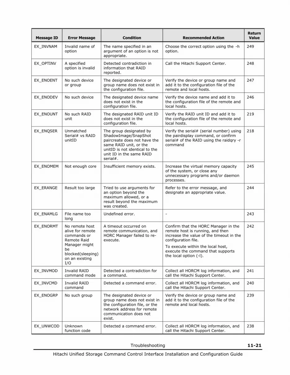
Troubleshooting 11-21
Hitachi Unified Storage Command Control Interface Installation and Configuration Guide
Message ID Error Message Condition Recommended Action Return Value
EX_INVNAM Invalid name of option
The name specified in an argument of an option is not appropriate.
Choose the correct option using the -h option.
249
EX_OPTINV A specified option is invalid
Detected contradiction in information that RAID reported.
Call the Hitachi Support Center. 248
EX_ENOENT No such device or group
The designated device or group name does not exist in the configuration file.
Verify the device or group name and add it to the configuration file of the remote and local hosts.
247
EX_ENODEV No such device The designated device name does not exist in the configuration file.
Verify the device name and add it to the configuration file of the remote and local hosts.
246
EX_ENOUNT No such RAID unit
The designated RAID unit ID does not exist in the configuration file.
Verify the RAID unit ID and add it to the configuration file of the remote and local hosts.
219
EX_ENQSER Unmatched Serial# vs RAID unitID
The group designated by ShadowImage/SnapShot paircreate does not have the same RAID unit, or the unitID is not identical to the unit ID in the same RAID serial#.
Verify the serial# (serial number) using the pairdisplay command, or confirm serial# of the RAID using the raidqry -r command
218
EX_ENOMEM Not enough core Insufficient memory exists. Increase the virtual memory capacity of the system, or close any unnecessary programs and/or daemon processes.
245
EX_ERANGE Result too large Tried to use arguments for an option beyond the maximum allowed, or a result beyond the maximum was created.
Refer to the error message, and designate an appropriate value.
244
EX_ENAMLG File name too long
Undefined error. - 243
EX_ENORMT No remote host alive for remote commands or Remote Raid Manager might be blocked(sleeping) on an existing I/O
A timeout occurred on remote communication, and HORC Manager failed to re-execute.
Confirm that the HORC Manager in the remote host is running, and then increase the value of the timeout in the configuration file.
To execute within the local host, execute the command that supports the local option (-l).
242
EX_INVMOD Invalid RAID command mode
Detected a contradiction for a command.
Collect all HORCM log information, and call the Hitachi Support Center.
241
EX_INVCMD Invalid RAID command
Detected a command error. Collect all HORCM log information, and call the Hitachi Support Center.
240
EX_ENOGRP No such group The designated device or group name does not exist in the configuration file, or the network address for remote communication does not exist.
Verify the device or group name and add it to the configuration file of the remote and local hosts.
239
EX_UNWCOD Unknown function code
Detected a command error. Collect all HORCM log information, and call the Hitachi Support Center.
238

11-22 Troubleshooting
Hitachi Unified Storage Command Control Interface Installation and Configuration Guide
Message ID Error Message Condition Recommended Action Return Value
EX_CMDIOE Control command I/O error
A read/write to the command device failed with an I/O error.
Refer to the host syslog file, and investigate the cause of the error. If the problem persists, collect all HORCM log information, and call the Hitachi Support Center.
237
EX_CMDRJE An order to the control/command device was rejected
The request to the command device failed or was rejected.
Note: This error code is sometimes caused by the operating system and reported as EX_CMDIOE instead of EX_CMDRJE (see next row).
Investigate the detailed factor of the error referring to the information on the syslog of the host or the HORCM log. Confirm the following items, and if the problem persists, collect all HORCM log information, and call the Hitachi Support Center.
Verify ShadowImage/SnapShot/TrueCopy/TCE functions are installed.
Verify that the target volume is available.
221
EX_CMDIOE Control command I/O error, or rejected
A read/write to the command device failed with an I/O error or was rejected.
Investigate the detailed factor of the error referring to the information on the syslog of the host or the HORCM log. If the cause is “Illegal Request (0x05)” Sense Key, please confirm the following items. If the problem persists, collect all HORCM log information, and call the Hitachi Support Center.
Verify ShadowImage/SnapShot functions are installed.
Verify that the target volume is available.
237
EX_ENQVOL Unmatched volume status within the group
The volume attribute or the fence level within a group is not identical.
Verify status using the pairdisplay command. Make sure all volumes in the group have the same fence level and volume attributes.
236
EX_EVOLCE Pair Volume combination error
Combination of a volume is unsuitable between the remote and local host.
Verify volume status using the pairdisplay command, and change the combination of volumes properly.
235
EX_EWSUSE Pair suspended at WAIT state
Detected a suspended status (PSUE) for the paired volume, before it achieves the designated status.
Determine how the pair was suspended.
If the pair was forcibly suspended, resynchronize the pair. If the pair was not suspended forcibly, the pair was suspended due to an error in the array. Collect all HORCM log and trace information, and call the Hitachi Data Systems Support Center.
234
EX_EWSTOT Timeout waiting for specified status
Detected a timeout before it achieved the designated status.
Increase the value of the timeout using the -t option.
233
EX_EWSLTO Timeout waiting for specified status on the local host
Timeout error because the remote did not note expected status.
Verify that HORC Manager on the remote host is running.
232
EX_ESTMON HORCM Monitor stopped
HORC Manager monitoring was refused.
Verify the value of “poll” in the configuration file.
231
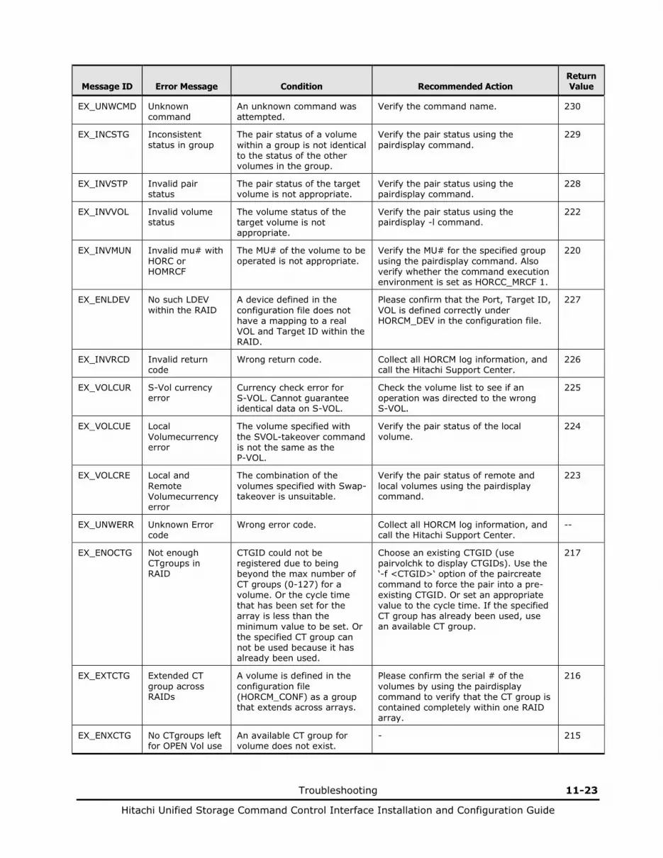
Troubleshooting 11-23
Hitachi Unified Storage Command Control Interface Installation and Configuration Guide
Message ID Error Message Condition Recommended Action Return Value
EX_UNWCMD Unknown command
An unknown command was attempted.
Verify the command name. 230
EX_INCSTG Inconsistent status in group
The pair status of a volume within a group is not identical to the status of the other volumes in the group.
Verify the pair status using the pairdisplay command.
229
EX_INVSTP Invalid pair status
The pair status of the target volume is not appropriate.
Verify the pair status using the pairdisplay command.
228
EX_INVVOL Invalid volume status
The volume status of the target volume is not appropriate.
Verify the pair status using the pairdisplay -l command.
222
EX_INVMUN Invalid mu# with HORC or HOMRCF
The MU# of the volume to be operated is not appropriate.
Verify the MU# for the specified group using the pairdisplay command. Also verify whether the command execution environment is set as HORCC_MRCF 1.
220
EX_ENLDEV No such LDEV within the RAID
A device defined in the configuration file does not have a mapping to a real VOL and Target ID within the RAID.
Please confirm that the Port, Target ID, VOL is defined correctly under HORCM_DEV in the configuration file.
227
EX_INVRCD Invalid return code
Wrong return code. Collect all HORCM log information, and call the Hitachi Support Center.
226
EX_VOLCUR S-Vol currency error
Currency check error for S-VOL. Cannot guarantee identical data on S-VOL.
Check the volume list to see if an operation was directed to the wrong S-VOL.
225
EX_VOLCUE Local Volumecurrency error
The volume specified with the SVOL-takeover command is not the same as the P-VOL.
Verify the pair status of the local volume.
224
EX_VOLCRE Local and Remote Volumecurrency error
The combination of the volumes specified with Swap-takeover is unsuitable.
Verify the pair status of remote and local volumes using the pairdisplay command.
223
EX_UNWERR Unknown Error code
Wrong error code. Collect all HORCM log information, and call the Hitachi Support Center.
--
EX_ENOCTG Not enough CTgroups in RAID
CTGID could not be registered due to being beyond the max number of CT groups (0-127) for a volume. Or the cycle time that has been set for the array is less than the minimum value to be set. Or the specified CT group can not be used because it has already been used.
Choose an existing CTGID (use pairvolchk to display CTGIDs). Use the ‘-f <CTGID>‘ option of the paircreate command to force the pair into a pre-existing CTGID. Or set an appropriate value to the cycle time. If the specified CT group has already been used, use an available CT group.
217
EX_EXTCTG Extended CT group across RAIDs
A volume is defined in the configuration file (HORCM_CONF) as a group that extends across arrays.
Please confirm the serial # of the volumes by using the pairdisplay command to verify that the CT group is contained completely within one RAID array.
216
EX_ENXCTG No CTgroups left for OPEN Vol use
An available CT group for volume does not exist.
- 215

11-24 Troubleshooting
Hitachi Unified Storage Command Control Interface Installation and Configuration Guide
Message ID Error Message Condition Recommended Action Return Value
EX_ENQCTG Unmatched CTGID within the group
The CT group references within a group do not have an identical CTGID.
Please confirm the CTGID using the pairvolchk command and/or confirm that group references within the configuration file (HORCM_CONF) refer to the same CT group.
214
EX_ENPERM Permission denied with the LDEV
The device described in the configuration definition file is not permitted for pair operation.
Execute the pairdisplay command or the raidscan - use the verify command to verify that the device is permitted for the pair operation.
213
EX_ENQSIZ Unmatched volume size for pairing
1. The number or the size of the volume between the local and remote volume is not appropriate.
2. The product ID on the local array does not correspond with the product ID on the remote array.
1. Check the volume size of the target pair using raidscan -f option, and then set the same size for local and remote volumes for the target pair.
2. Set the identical product ID in the local and remote array.
212
EX_ERPERM Permission denied with the RAID
The volume on the configuration file is a volume that is not permitted to operate a pair in the array.
Set HITACHI for the vendor ID. 211
EX_ESVOLD SVOL denied due to be disabling
It is inhibited to assign the specified volume to be paired to an S-VOL.
Check whether the volume to be paired is not inhibited to be assigned to an S-VOL using the inquired -fl or raidvchkdsp -v gflag command.
209
EX_ENOSUP Micro code not supported
The specified command option is not supported by the firmware of the array.
Make sure of a version of the firmware of the array using the raidgry -l command.
210
EX_EPRORT Mode changes denied due to retention time
It is inhibited to change a mode of the specified volume during the term of protection.
Make sure of the term of protection for the object volume using the raidvchkdsp -v gflag command.
208
The following list includes common error messages for the horctakeover, paircurchk, paircreate, pairsplit, pairresync, pairevtwait, pairvolchk, pairsyncwait, and pairdisplay commands.
Table 11-8 Common error messages (1)
Type Message ID Error Message Return Value
Syntax for Argument Unrecoverable
EX_REQARG Required Arg list 254
EX_INVARG Invalid argument 253
EX_INVNAM Invalid name of option 249
EX_UNWOPT Unknown option 252
EX_UNWCOD Unknown function code 238
EX_UNWCMD Unknown command 230
EX_ERANGE Result too large 244
EX_ENAMLG File name too long 243
EX_INVRCD Invalid return code 226
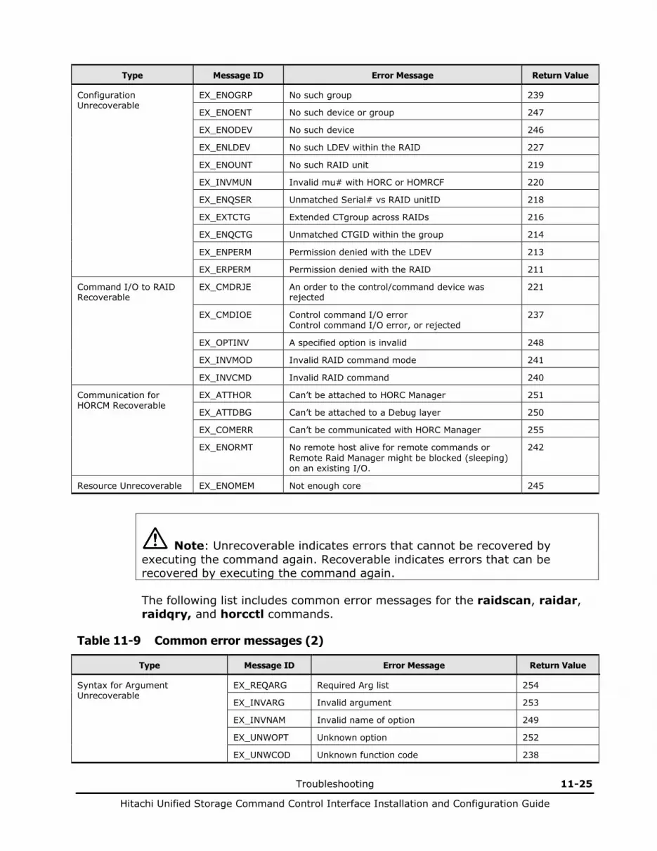
Troubleshooting 11-25
Hitachi Unified Storage Command Control Interface Installation and Configuration Guide
Type Message ID Error Message Return Value
Configuration Unrecoverable
EX_ENOGRP No such group 239
EX_ENOENT No such device or group 247
EX_ENODEV No such device 246
EX_ENLDEV No such LDEV within the RAID 227
EX_ENOUNT No such RAID unit 219
EX_INVMUN Invalid mu# with HORC or HOMRCF 220
EX_ENQSER Unmatched Serial# vs RAID unitID 218
EX_EXTCTG Extended CTgroup across RAIDs 216
EX_ENQCTG Unmatched CTGID within the group 214
EX_ENPERM Permission denied with the LDEV 213
EX_ERPERM Permission denied with the RAID 211
Command I/O to RAID Recoverable
EX_CMDRJE An order to the control/command device was rejected
221
EX_CMDIOE Control command I/O error Control command I/O error, or rejected
237
EX_OPTINV A specified option is invalid 248
EX_INVMOD Invalid RAID command mode 241
EX_INVCMD Invalid RAID command 240
Communication for HORCM Recoverable
EX_ATTHOR Can’t be attached to HORC Manager 251
EX_ATTDBG Can’t be attached to a Debug layer 250
EX_COMERR Can’t be communicated with HORC Manager 255
EX_ENORMT No remote host alive for remote commands or Remote Raid Manager might be blocked (sleeping) on an existing I/O.
242
Resource Unrecoverable EX_ENOMEM Not enough core 245
Note: Unrecoverable indicates errors that cannot be recovered by executing the command again. Recoverable indicates errors that can be recovered by executing the command again.
The following list includes common error messages for the raidscan, raidar, raidqry, and horcctl commands.
Table 11-9 Common error messages (2)
Type Message ID Error Message Return Value
Syntax for Argument Unrecoverable
EX_REQARG Required Arg list 254
EX_INVARG Invalid argument 253
EX_INVNAM Invalid name of option 249
EX_UNWOPT Unknown option 252
EX_UNWCOD Unknown function code 238

11-26 Troubleshooting
Hitachi Unified Storage Command Control Interface Installation and Configuration Guide
Type Message ID Error Message Return Value
EX_UNWCMD Unknown command 230
EX_ERANGE Result too large 244
EX_ENAMLG File name too long 243
EX_INVRCD Invalid return code 226
Configuration Unrecoverable EX_ENLDEV No such LDEV within the RAID 227
EX_ENOUNT No such RAID unit 219
EX_INVMUN Invalid mu# with HORC or HOMRCF 220
EX_ERPERM Permission denied with the RAID 211
EX_ENOSUP Micro code not supported 210
Command I/O to RAID Recoverable
EX_CMDIOE Control command I/O error Control command I/O error, or rejected
237
EX_OPTINV A specified option is invalid 248
EX_INVMOD Invalid RAID command mode 241
EX_INVCMD Invalid RAID command 240
Communication for HORCM Recoverable
EX_ATTHOR Can’t be attached to HORC Manager 251
EX_ATTDBG Can’t be attached to a Debug layer 250
EX_COMERR Can’t be communicated with HORC Manager 255
Resource Unrecoverable EX_ENOMEM Not enough core 245
Note: Unrecoverable indicates errors that cannot be recovered by executing the command again. Recoverable indicates errors that can be recovered by executing the command again.
The following list includes unique error messages for the horctakeover, paircurchk, paircreate, pairsplit, pairresync, pairevtwait, pairvolchk, pairsyncwait, and raidvchkset commands.
Table 11-10 Unique error messages
Command Type Message ID Error Message Return Value
paircreate, pairsplit, pairresync, pairevtwait, pairvolchk, horctakeover
Volume status Unrecoverable
EX_ENQVOL Unmatched volume status within the group
236
paircreate, pairsplit, pairresync, pairevtwait, horctakeover
EX_INCSTG Inconsistent status in group 229
paircreate, pairsplit, pairresync, pairevtwait, pairsyncwait
EX_INVVOL Invalid volume status 222
pairsplit, pairevtwait, pairvolchk, horctakeover
EX_EVOLCE Pair Volume combination error 235
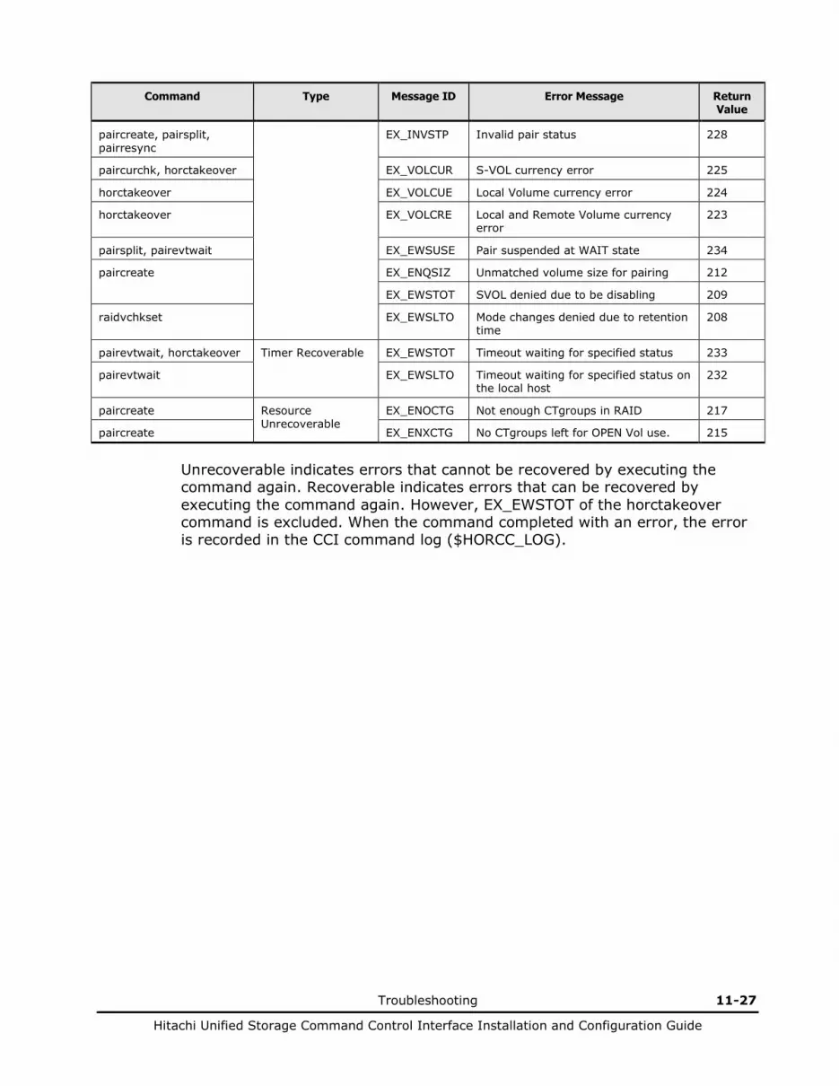
Troubleshooting 11-27
Hitachi Unified Storage Command Control Interface Installation and Configuration Guide
Command Type Message ID Error Message Return Value
paircreate, pairsplit, pairresync
EX_INVSTP Invalid pair status 228
paircurchk, horctakeover EX_VOLCUR S-VOL currency error 225
horctakeover EX_VOLCUE Local Volume currency error 224
horctakeover EX_VOLCRE Local and Remote Volume currency error
223
pairsplit, pairevtwait EX_EWSUSE Pair suspended at WAIT state 234
paircreate EX_ENQSIZ Unmatched volume size for pairing 212
EX_EWSTOT SVOL denied due to be disabling 209
raidvchkset EX_EWSLTO Mode changes denied due to retention time
208
pairevtwait, horctakeover Timer Recoverable EX_EWSTOT Timeout waiting for specified status 233
pairevtwait EX_EWSLTO Timeout waiting for specified status on the local host
232
paircreate Resource Unrecoverable
EX_ENOCTG Not enough CTgroups in RAID 217
paircreate EX_ENXCTG No CTgroups left for OPEN Vol use. 215
Unrecoverable indicates errors that cannot be recovered by executing the command again. Recoverable indicates errors that can be recovered by executing the command again. However, EX_EWSTOT of the horctakeover command is excluded. When the command completed with an error, the error is recorded in the CCI command log ($HORCC_LOG).

11-28 Troubleshooting
Hitachi Unified Storage Command Control Interface Installation and Configuration Guide
Recovering PSUE status using ShadowImage
When a pair was suspended (PSUE) due to a failure in the array, collect the CCI system log files and call the Hitachi maintenance personnel.
Maintenance personnel will remove the source of error in the array. After the source of the error has been removed, the system administrator must recover the pair using the CCI commands.
Recovering the pair
Make sure that the system administrator has verified that the PSUE occurred while resynchronizing from S-VOL to P-VOL (pairresync -restore). Table 11-11 shows data assurance and the method for recovering the pair.
Table 11-11 Data assurance and the method for recovering the pair
State before PSUE
Data Assurance Action to be taken after PSUE
Other than RCPY
P-VOL: Assured
S-VOL: Not assured
Resynchronize (pairresync) in the direction of P-VOL to S-VOL. Note that the pair may have been split due to a drive’s double-malfunction in one or both volumes. In this case, confirm that the data exists in the P-VOL, and then create a pair (paircreate).
RCPY P-VOL: Not assured
S-VOL: Not assured
Split the pair (pairsplit -S), restore the backup data to P-VOL, and then create a pair (paircreate). Note that the pair may have been split due to a drive’s double-malfunction in one or both volumes. In this case, confirm that the backup data restoration is complete to the P-VOL, and then create a pair.
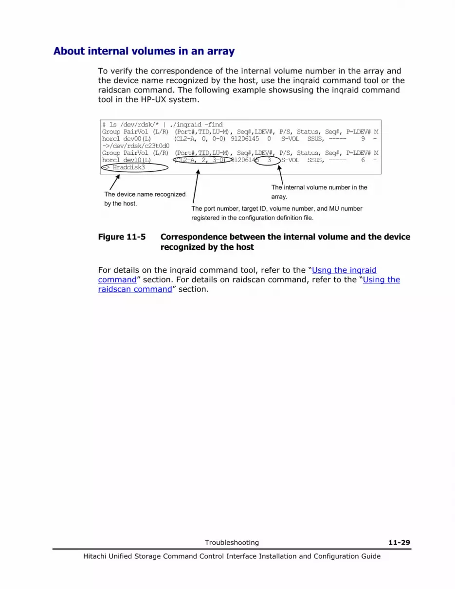
Troubleshooting 11-29
Hitachi Unified Storage Command Control Interface Installation and Configuration Guide
About internal volumes in an array
To verify the correspondence of the internal volume number in the array and the device name recognized by the host, use the inqraid command tool or the raidscan command. The following example showsusing the inqraid command tool in the HP-UX system.
# ls /dev/rdsk/* | ./inqraid –find Group PairVol (L/R) (Port#,TID,LU-M), Seq#,LDEV#, P/S, Status, Seq#, P-LDEV# M horcl dev00(L) (CL2-A, 0, 0-0) 91206145 0 S-VOL SSUS, ----- 9 - ->/dev/rdsk/c23t0d0 Group PairVol (L/R) (Port#,TID,LU-M), Seq#,LDEV#, P/S, Status, Seq#, P-LDEV# M horcl dev10(L) (CL2-A, 2, 3-0) 91206145 3 S-VOL SSUS, ----- 6 - -> Hraddisk3
The device name recognized by the host.
The port number, target ID, volume number, and MU number registered in the configuration definition file.
The internal volume number in the array.
Figure 11-5 Correspondence between the internal volume and the device recognized by the host
For details on the inqraid command tool, refer to the “Usng the inqraid command” section. For details on raidscan command, refer to the “Using the raidscan command” section.
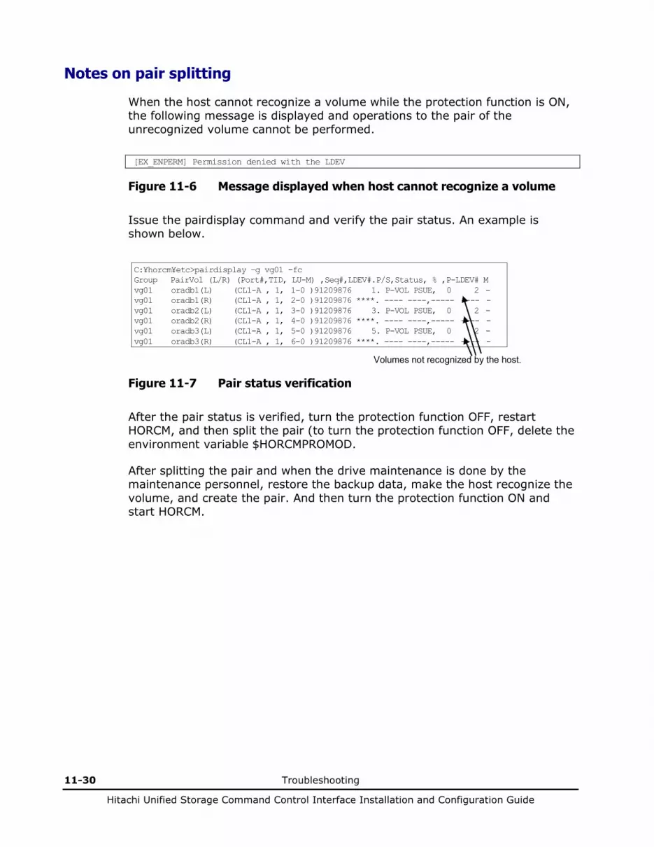
11-30 Troubleshooting
Hitachi Unified Storage Command Control Interface Installation and Configuration Guide
Notes on pair splitting
When the host cannot recognize a volume while the protection function is ON, the following message is displayed and operations to the pair of the unrecognized volume cannot be performed.
[EX_ENPERM] Permission denied with the LDEV
Figure 11-6 Message displayed when host cannot recognize a volume
Issue the pairdisplay command and verify the pair status. An example is shown below.
C:¥horcm¥etc>pairdisplay –g vg01 -fc Group PairVol (L/R) (Port#,TID, LU-M) ,Seq#,LDEV#.P/S,Status, % ,P-LDEV# M vg01 oradb1(L) (CL1-A , 1, 1-0 )91209876 1. P-VOL PSUE, 0 2 - vg01 oradb1(R) (CL1-A , 1, 2-0 )91209876 ****. ---- ----,----- ---- - vg01 oradb2(L) (CL1-A , 1, 3-0 )91209876 3. P-VOL PSUE, 0 2 - vg01 oradb2(R) (CL1-A , 1, 4-0 )91209876 ****. ---- ----,----- ---- - vg01 oradb3(L) (CL1-A , 1, 5-0 )91209876 5. P-VOL PSUE, 0 2 - vg01 oradb3(R) (CL1-A , 1, 6-0 )91209876 ****. ---- ----,----- ---- -
Volumes not recognized by the host.
Figure 11-7 Pair status verification
After the pair status is verified, turn the protection function OFF, restart HORCM, and then split the pair (to turn the protection function OFF, delete the environment variable $HORCMPROMOD.
After splitting the pair and when the drive maintenance is done by the maintenance personnel, restore the backup data, make the host recognize the volume, and create the pair. And then turn the protection function ON and start HORCM.

Troubleshooting 11-31
Hitachi Unified Storage Command Control Interface Installation and Configuration Guide
Recovering PSUE status using SnapShot
When a pair was suspended (PSUE) due to a failure in the array, collect the CCI system log files and then call the Hitachi maintenance personnel The maintenance personnel will remove the error cause of the array. After the error cause has been removed, the system administrator must recover the pair using the CCI commands.
Recovering the pair
The concrete pair recovery using SnapShot is that pair is split (with pairsplit -S) once and then create again (with paircreate). Recover the pair following the detailed recovery procedure shown in Figure 11-2.
Make sure that the system administrator has verified that the PSUE occurred while restoring from V-VOL to P-VOL (pairresync -restore). Table 11-12 shows data assurance and the method for recovering the pair.
Table 11-12 Data assurance and the method for recovering the pair
State before PSUE
Data Assurance Action to be taken after PSUE
Other than COPY(RS-R)
P-VOL: Assured V-VOL: Not assured
Split the pair (pairsplit -S), and then create a pair (paircreate) again. Note that the pair may have been split due to the drive’s double-malfunction in either or both volumes. In such case, confirm that the data exists in the P-VOL, and then create a pair (paircreate). Incidentally, the V-VOL data generated is not the one invalidated previously but the P-VOL data at the time when the pair was newly formed.
COPY(RS-R) P-VOL: Not assured V-VOL: Not assured
Split the pair (pairsplit -S), restore the backup data to P-VOL, and then create a pair (paircreate). Note that the pair may have been split due to the drive’s double-malfunction in either or both volumes. In such case, confirm that the backup data restoration has been completed to the P-VOL, and then create a pair. Incidentally, the V-VOL data generated is not the one invalidated previously but the P-VOL data at the time when the pair was newly formed.

11-32 Troubleshooting
Hitachi Unified Storage Command Control Interface Installation and Configuration Guide
Recovering PSUE status using TrueCopy/TCE
When a pair was suspended (PSUE) due to a failure in the array, collect the CCI system log files and then call the Hitachi maintenance personnel The maintenance personnel will remove the error cause of the array. After the error cause has been removed, the system administrator must recover the pair using the CCI commands.
Recovering the pair
Resynchronization in the direction of P-VOL to S-VOL enables to recover a TrueCopy/TCE pair. (The resynchronization cannot be performed in the direction of S-VOL to P-VOL.) However, when a pair was suspended (status = PSUE) without a failure in the system, once release the pair and create the pair again. Please recover the pair following the procedure for the recovery in the flow of Figure 11-3 or Figure 11-4.
In the case of TCE, the resynchronization of the S-VOL with the P-VOL is required when the P-VOL status is changed to PFUS because the amount of the data in the primary DP pool exceeds the capacity allowed to be used or the S-VOL status is changed to PSUS(N) as well as the P-VOL status is changed to PSUE. The PSUS(N) means the PSUS status that the Read/Write operation cannot be performed; and it is a status in which the S-VOL data is not restored even when the SVOL-Takeover operation is performed.
Calling the Hitachi Data Systems Support Center
If you need to call the Hitachi Data Systems Support Center, make sure to provide as much information about the problem as possible, including:
• The circumstances surrounding the error or failure
• The exact content of any error messages displayed on the host systems
• The error codes displayed on Storage Navigator Modular 2
The Hitachi Data Systems customer support staff is available 24 hours a day, seven days a week. If you need technical support, please log on to the Hitachi Data Systems Portal for contact information: https://portal.hds.com

12
Maintenance logs and tracing funtions 12-1
Hitachi Unified Storage Command Control Interface Installation and Configuration Guide
Maintenance logs and tracing functions
This chapter covers the following topics: About log files About trace files Using the trace control command Reading error log codes Using logging commands
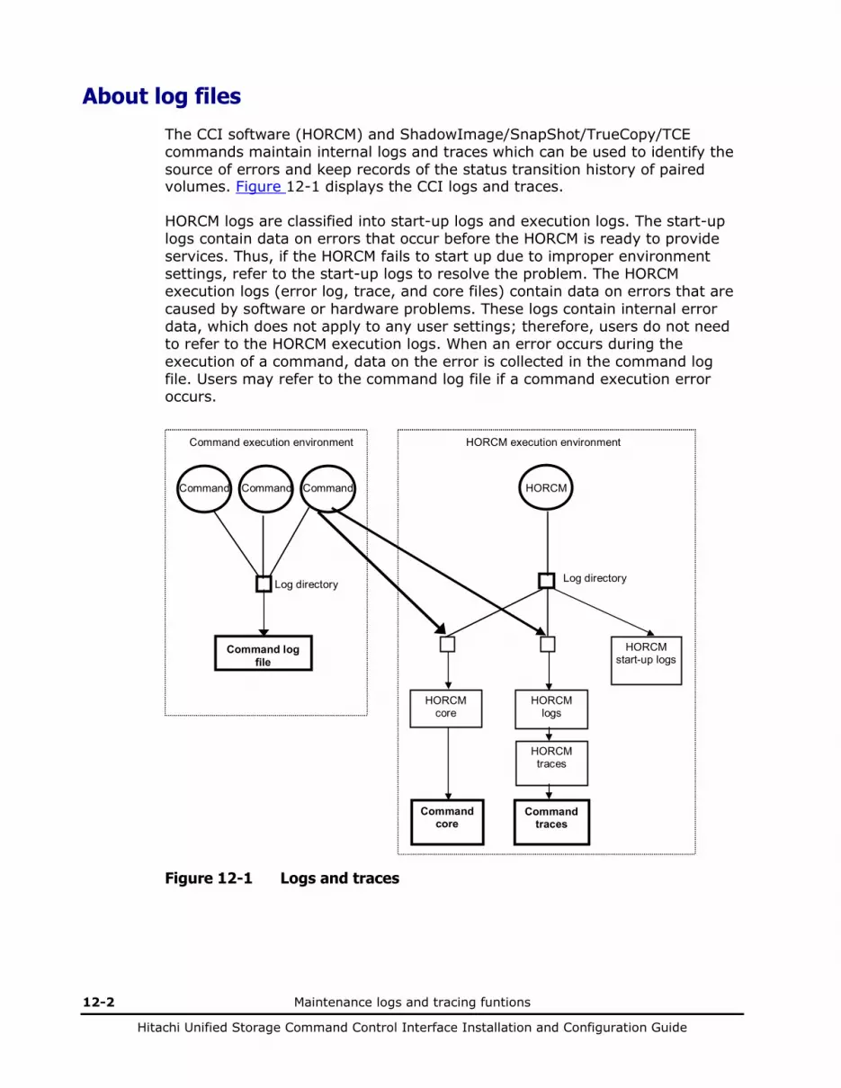
12-2 Maintenance logs and tracing funtions
Hitachi Unified Storage Command Control Interface Installation and Configuration Guide
About log files
The CCI software (HORCM) and ShadowImage/SnapShot/TrueCopy/TCE commands maintain internal logs and traces which can be used to identify the source of errors and keep records of the status transition history of paired volumes. Figure 12-1 displays the CCI logs and traces.
HORCM logs are classified into start-up logs and execution logs. The start-up logs contain data on errors that occur before the HORCM is ready to provide services. Thus, if the HORCM fails to start up due to improper environment settings, refer to the start-up logs to resolve the problem. The HORCM execution logs (error log, trace, and core files) contain data on errors that are caused by software or hardware problems. These logs contain internal error data, which does not apply to any user settings; therefore, users do not need to refer to the HORCM execution logs. When an error occurs during the execution of a command, data on the error is collected in the command log file. Users may refer to the command log file if a command execution error occurs.
Command
Command logfile
Command execution environment
HORCM
HORCMstart-up logs
HORCMlogs
HORCMtraces
Commandtraces
HORCMcore
Commandcore
HORCM execution environment
Log directoryLog directory
Command Command
Figure 12-1 Logs and traces

Maintenance logs and tracing funtions 12-3
Hitachi Unified Storage Command Control Interface Installation and Configuration Guide
The start-up log, error log, trace, and core files are stored as shown in Table 12-1. Specify the directories for the HORCM and command log files using the HORCM_LOG and HORCC_LOG environmental variables as shown in Table 12-2. If it is not possible to create the log files, or if an error occurs before the log files are created, the error logs are output in the system log file. If the HORCM activation fails, the system administrator should check the system log file, identify the error cause, and take the proper action. For details on message output to the system log file and the recommended actions for resolving the error conditions, see Chapter 11. The system log file for UNIX-based systems is the syslog file. The system log file for Windows-based systems is the event log file.
Table 12-1 Log files
File UNIX-based Systems Windows-based Systems
Start-up log
HORCM start-up log: $HORCM_LOG/horcm_HOST.log
Command log: $HORCC_LOG/horcc_HOST.log
HORCM start-up log: $HORCM_LOG\horcm_HOST_log.txt
Command log: $HORCC_LOG\horcc_HOST_log.txt
Error log
HORCM error log: $HORCM_LOG/horcmlog_HOST/horcm.log
HORCM error log: $HORCM_LOG\horcmlog_HOST\horcm_log.txt
Trace HORCM trace: $HORCM_LOG/horcmlog_HOST/horcm_PID.trc
Command trace: $HORCM_LOG/horcmlog_HOST/horcc_PID.trc
HORCM trace: $HORCM_LOG\horcmlog_HOST\horcm_PID_ trc.txt
Command trace: $HORCM_LOG\horcmlog_HOST\horcc_PID_ trc.txt
Core HORCM core: $HORCM_LOG/core_HOST_PID/core
Command core: $HORCM_LOG/core_HOST_PID/core
HORCM core: $HORCM_LOG\core_HOST_PID\core
Command core: $HORCM_LOG\core_HOST_PID\core
Note: Host denotes the host name of the corresponding machine. PID denotes the process ID of that machine.
The location of the directory that contains the log file depends on the user’s command execution environment and the HORCM execution environment. The command trace file and core file reside together under the directory specified in the HORCM execution environment. A directory specified using the environmental variable HORCM_LOG is used as the log directory in the HORCM execution environment. If no directory is specified, directory /tmp is used. A directory specified using the environmental variable HORCC_LOG is used as the log directory in the command execution environment. If no directory is specified, the directory /HORCM/log* is used (* = instance number). A nonexistent directory may be specified as a log directory using the environmental variable.

12-4 Maintenance logs and tracing funtions
Hitachi Unified Storage Command Control Interface Installation and Configuration Guide
Table 12-2 Log directories
Directory Name Definition
$HORCM LOG A directory specified using the environmental variable HORCM_LOG. The HORCM log file, trace file, and core file as well as the command trace file and core file are stored in this directory. If no environmental variable is specified, /HORCM/log/curlog is used.
$HORCC LOG A directory specified using the environmental variable HORCC_LOG. The command log file is stored in this directory. If no environmental variable is specified, the directory /HORCM/log* is used (* is the instance number). While the HORCM is running, the log files are stored in the $HORCM_LOG directory shown in (a). When the HORCM starts up, the log files created in the operation are stored automatically in the $HORCM_LOGS directory shown in (b).
6. HORCM log file directory in operation $HORCM_LOG = /HORCM/log*/curlog (* is instance number)
7. HORCM log file directory for automatic storing $HORCM_LOGS = /HORCM/log*/tmplog (* is instance number)

Maintenance logs and tracing funtions 12-5
Hitachi Unified Storage Command Control Interface Installation and Configuration Guide
About trace files
The command trace file is used for maintenance troubleshooting maintenance. It is not created normally. If the source of an error cannot be identified by means of the log file, the environmental variables or trace control commands with trace control parameters are issued to start tracing and the trace file is created. The trace control parameters consist of the trace level, file size, mode, etc. Increasing the trace level enables more detailed tracing. Tracing is made in wraparound within the range of the file size. The HORCM creates the trace file according to the trace level specified in the HORCM start-up shell script set to activate the HORCM.
Using the trace control command
The trace control command (one of the HORCM control commands) sets or changes the trace control parameters. This command is used for troubleshooting and maintenance. If no trace control parameters can be specified using the environmental variables in the user’s command execution environment, it is possible to change the trace control parameters into the global parameters using this command. Table 12-3 lists and describes the parameters of the trace control command.
Table 12-3 Trace command parameters
Parameter Function
Trace level parameter Specifies the trace level, range = 0 to 15.
Trace size parameter Specifies the trace file size in kB.
Trace mode parameter Specifies the buffer mode or non-buffer mode for writing data in the trace file.
Trace type parameter Specifies the trace type defined internally.
Trace change instruction Specifies either the command or the HORCM (CCI instance) for which the trace control parameters are changed.
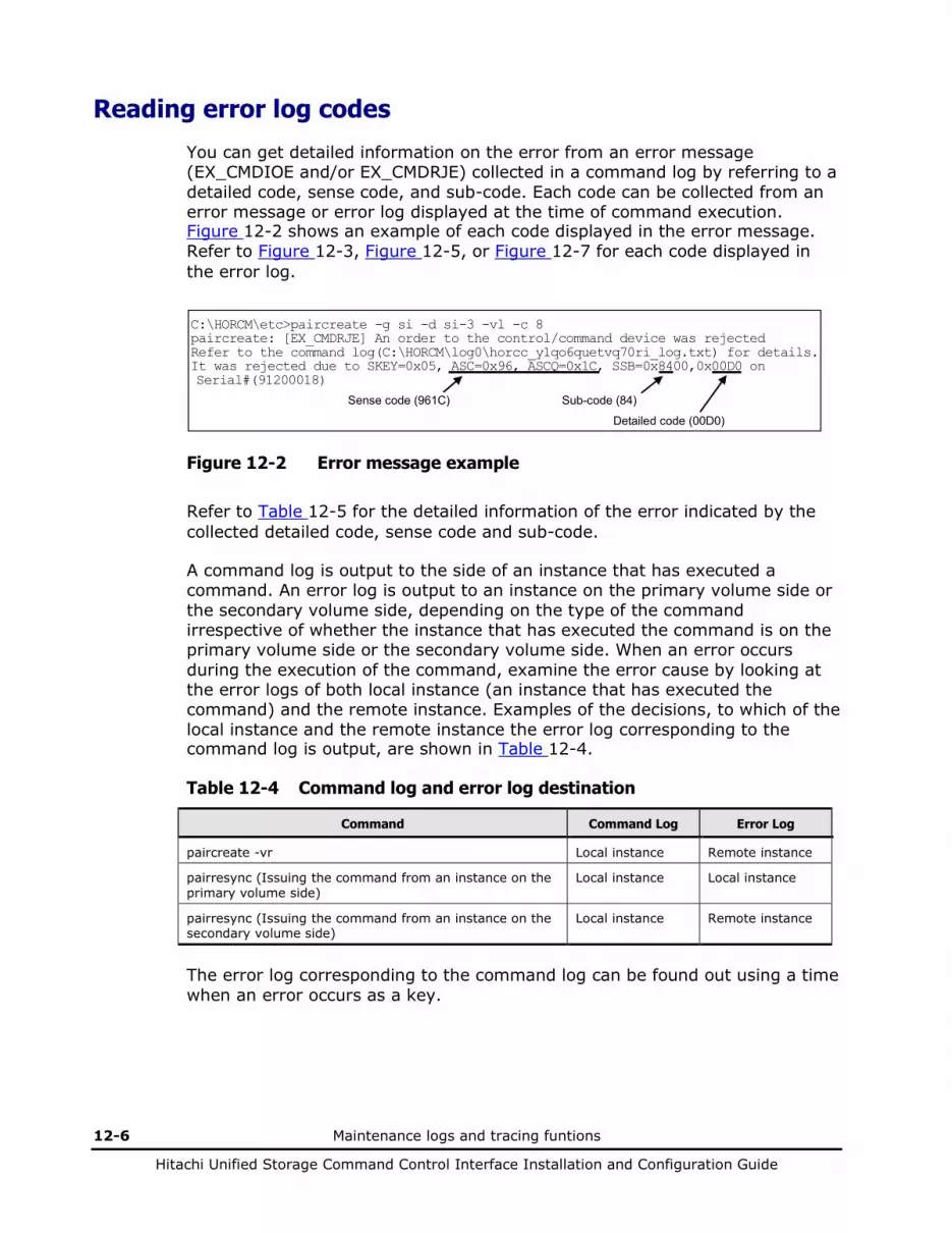
12-6 Maintenance logs and tracing funtions
Hitachi Unified Storage Command Control Interface Installation and Configuration Guide
Reading error log codes
You can get detailed information on the error from an error message (EX_CMDIOE and/or EX_CMDRJE) collected in a command log by referring to a detailed code, sense code, and sub-code. Each code can be collected from an error message or error log displayed at the time of command execution. Figure 12-2 shows an example of each code displayed in the error message. Refer to Figure 12-3, Figure 12-5, or Figure 12-7 for each code displayed in the error log.
C:\HORCM\etc>paircreate -g si -d si-3 -vl -c 8 paircreate: [EX_CMDRJE] An order to the control/command device was rejected Refer to the command log(C:\HORCM\log0\horcc_y1qo6quetvq70ri_log.txt) for details. It was rejected due to SKEY=0x05, ASC=0x96, ASCQ=0x1C, SSB=0x8400,0x00D0 on Serial#(91200018)
Sense code (961C) Sub-code (84)
Detailed code (00D0)
Figure 12-2 Error message example
Refer to Table 12-5 for the detailed information of the error indicated by the collected detailed code, sense code and sub-code.
A command log is output to the side of an instance that has executed a command. An error log is output to an instance on the primary volume side or the secondary volume side, depending on the type of the command irrespective of whether the instance that has executed the command is on the primary volume side or the secondary volume side. When an error occurs during the execution of the command, examine the error cause by looking at the error logs of both local instance (an instance that has executed the command) and the remote instance. Examples of the decisions, to which of the local instance and the remote instance the error log corresponding to the command log is output, are shown in Table 12-4.
Table 12-4 Command log and error log destination
Command Command Log Error Log
paircreate -vr Local instance Remote instance
pairresync (Issuing the command from an instance on the primary volume side)
Local instance Local instance
pairresync (Issuing the command from an instance on the secondary volume side)
Local instance Remote instance
The error log corresponding to the command log can be found out using a time when an error occurs as a key.

Maintenance logs and tracing funtions 12-7
Hitachi Unified Storage Command Control Interface Installation and Configuration Guide
Solaris logs
The command log is stored in the command log file in the start log directory listed in Figure 12-1, “Log File List.” The error log is stored in the HORCM error log file in the error log directory listed in the same Figure 12-1, “Log File List.” The following are locations for storing the command log and error log in the case where the directories are not specified using the environmental variable, HORCC_LOG.
Command log: /HORCM/logINS/horcc_HOST.log Error log: /HORCM/logINS/curlog/horcmlog_HOST/horcm.log
INS is an instance number and HOST is a host name of the computer concerned.
COMMAND ERROR : EUserId for HOMRCF : root (0) Tue Dec 2 18:18:07 2003 CMDLINE : paircreate -g SI -d SI_000 -vl -c 15 18:18:08-95274-03005- ERROR:cm_sndrcv[rc < 0 from HORCM] 18:18:08-9fe17-03005- [paircreate] L_CMD(CREATEPAIR) ERROR :rc = -35 18:18:08-a1eaa-03005- [paircreate][exit(221)] [EX_CMDRJE] An order to the control/command device was rejected [Cause ]: An order to the command(control) device failed,or was rejected. [Action]:Please confirm the following items.If this trouble doesn't resolve,then collect HORCM error logs(HORCM_LOG=/HORCM/log0/curlog) and trace data,and send them to service personnel. (1) Check if the 'HORC or HOMRCF function' is installed in the RAID. (2) Check if the RCP and LCP are installed in the RAID. (3) Check if the path between the RAID CUs is established by using the SVP. (4) Check if the pair target volume is an appropriate status.
Error occurs time
Figure 12-3 Command log output example (Solaris)
18:18:07-d9b1e-02746- SCSI : Check Condition. 18:18:07-dedfd-02746- ***** SCSI SENSE DATA ***** ---ADDR--- -OFF- 0-1-2-3- 4-5-6-7- 8-9-A-B- C-D-E-F- ------CHAR------ [0xffbeef14]0000: 70000500 00000038 84000039 95760000 p......8...9.v.. [0xffbeef24]0010: 00001000 .... 18:18:07-ef183-02746- SKEY = 0x05 18:18:07-f326b-02746- ASC = 0x95 [System Call Error] SysCall: write Errorno: 22 (Invalid argument) ErrInfo: Internal Error ErrTime: Tue Dec 2 18:18:08 2003 SrcFile: horcpprc.c SrcLine: 1178
Error occurs time
Sense code Detail code
Sub code
Figure 12-4 Error log output example (Solaris)
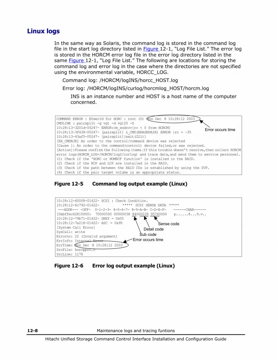
12-8 Maintenance logs and tracing funtions
Hitachi Unified Storage Command Control Interface Installation and Configuration Guide
Linux logs
In the same way as Solaris, the command log is stored in the command log file in the start log directory listed in Figure 12-1, “Log File List.” The error log is stored in the HORCM error log file in the error log directory listed in the same Figure 12-1, “Log File List.” The following are locations for storing the command log and error log in the case where the directories are not specified using the environmental variable, HORCC_LOG.
Command log: /HORCM/logINS/horcc_HOST.log Error log: /HORCM/logINS/curlog/horcmlog_HOST/horcm.log
INS is an instance number and HOST is a host name of the computer concerned.
COMMAND ERROR : EUserId for HORC : root (0) Mon Dec 8 10:28:12 2003 CMDLINE : pairsplit -g vg1 -d vg120 -S 10:28:13-3201d-05247- ERROR:cm_sndrcv[rc < 0 from HORCM] 10:28:13-3f438-05247- [pairsplit] L_CMD(ERASEPAIR) ERROR :rc = -35 10:28:13-43af5-05247- [pairsplit][exit(221)] [EX_CMDRJE] An order to the control/command device was rejected [Cause ]: An order to the command(control) device failed,or was rejected. [Action]:Please confirm the following items.If this trouble doesn't resolve,then collect HORCM error logs(HORCM_LOG=/HORCM/log2/curlog) and trace data,and send them to service personnel. (1) Check if the 'HORC or HOMRCF function' is installed in the RAID. (2) Check if the RCP and LCP are installed in the RAID. (3) Check if the path between the RAID CUs is established by using the SVP. (4) Check if the pair target volume is an appropriate status.
Error occurs time
Figure 12-5 Command log output example (Linux)
10:28:12-600f8-01422- SCSI : Check Condition. 10:28:12-6c792-01422- ***** SCSI SENSE DATA ***** ---ADDR--- -OFF- 0-1-2-3- 4-5-6-7- 8-9-A-B- C-D-E-F- ------CHAR------ [0xbffec628]0000: 70000500 00000038 84000039 95760000 p......8...9.v.. 10:28:12-79b71-01422- SKEY = 0x05 10:28:12-7e218-01422- ASC = 0x95 [System Call Error] SysCall: write Errorno: 22 (Invalid argument) ErrInfo: Internal Error ErrTime: Mon Dec 8 10:28:12 2003 SrcFile: horcpprc.c SrcLine: 1178
Error occurs time
Sense code Detail code
Sub code
Figure 12-6 Error log output example (Linux)
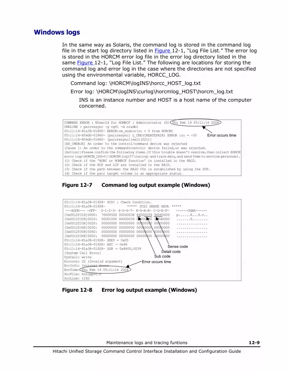
Maintenance logs and tracing funtions 12-9
Hitachi Unified Storage Command Control Interface Installation and Configuration Guide
Windows logs
In the same way as Solaris, the command log is stored in the command log file in the start log directory listed in Figure 12-1, “Log File List.” The error log is stored in the HORCM error log file in the error log directory listed in the same Figure 12-1, “Log File List.” The following are locations for storing the command log and error log in the case where the directories are not specified using the environmental variable, HORCC_LOG.
Command log: \HORCM\logINS\horcc_HOST_log.txt Error log: \HORCM\logINS\curlog\horcmlog_HOST\horcm_log.txt
INS is an instance number and HOST is a host name of the computer concerned.
COMMAND ERROR : EUserId for HOMRCF : Administrator (0) Thu Feb 19 05:11:14 2004 CMDLINE : pairresync -g vg01 -d oradb1 05:11:14-81a38-01860- ERROR:cm_sndrcv[rc < 0 from HORCM] 05:11:14-854d0-01860- [pairresync] L_CMD(CREATEPAIR) ERROR :rc = -35 05:11:14-854d0-01860- [pairresync][exit(221)] [EX_CMDRJE] An order to the control/command device was rejected [Cause ]: An order to the command(control) device failed,or was rejected. [Action]:Please confirm the following items.If this trouble doesn't resolve,then collect HORCM error logs(HORCM_LOG=C:\HORCM\log137\curlog) and trace data,and send them to service personnel. (1) Check if the 'HORC or HOMRCF function' is installed in the RAID. (2) Check if the RCP and LCP are installed in the RAID. (3) Check if the path between the RAID CUs is established by using the SVP. (4) Check if the pair target volume is an appropriate status.
Error occurs time
Figure 12-7 Command log output example (Windows)
05:11:14-81a38-01928- SCSI : Check Condition. 05:11:14-81a38-01928- ***** SCSI SENSE DATA ***** ---ADDR--- -OFF- 0-1-2-3- 4-5-6-7- 8-9-A-B- C-D-E-F- ------CHAR------ [0x0012f318]0000: 70000500 00000038 84000039 96080000 p......8...9.v.. [0x0012f328]0010: 00001000 84000039 00000000 10fd0000 .......9........ [0x0012f338]0020: 00000000 00000000 00000000 00000000 ................ [0x0012f348]0030: 00000000 00000000 00000000 00000000 ................ [0x0012f358]0040: 00000000 00000000 00000000 00000000 ................ [0x0012f368]0050: 00000000 00000000 00000000 00000000 ................ 05:11:14-81a38-01928- SKEY = 0x05 05:11:14-81a38-01928- ASC = 0x96 05:11:14-81a38-01928- SSB = 0x8400,0039 [System Call Error] SysCall: write Errorno: 22 (Invalid argument) ErrInfo: Internal Error ErrTime: Thu Feb 19 05:11:14 2004 SrcFile: horcpprc.c SrcLine: 1182
Error occurs time
Sense code Detail code
Sub code
Figure 12-8 Error log output example (Windows)

12-10 Maintenance logs and tracing funtions
Hitachi Unified Storage Command Control Interface Installation and Configuration Guide
Sense codes and detail codes
Table 12-5 shows sense codes and detailed codes. 0~A will be set in the x of detailed codes.
Table 12-5 Sense codes and detailed codes
Sense code
Detailed code
Sub code
Error contents Recommended Action
2602 The primary sequence number is beyond the limits of supported.
Check the serial number.
2602 The secondary sequence number is beyond the limits of supported.
Check the serial number.
2602 The VOL of the P-VOL is beyond the limits of supported.
Check the specified VOL.
2602 The VOL of the S-VOL is beyond the limits of supported.
Check the specified VOL.
2602 The primary port number is beyond the limits of supported.
Check the specified port number.
2602 The secondary port number is beyond the limits of supported.
Check the specified port number.
2602 The object VOL is beyond the limits of supported.
Check the status of the VOL.
2602 The object VOL is undefined. Check the status of the VOL.
2602 The environment has a problem. Check the environment of CCI.
2602 The retention term is beyond the limits of validity.
Check that the specified value that has been set is 0 to 21900.
3180 The object VOL is unformatted. Check the status of the VOL.
9501 A command was received during execution of the pseudo deliberate shutdown.
Retry after the pseudo deliberate shutdown is completed.
9510 A command was received during a performance of hot replacement of the firmware.
Retry after waiting for a while.
9531 The password protection is being logged in. Retry after waiting for a while.
9536 The optional feature is invalid. Install the optional feature.
9552 The object VOL is defined as a command device.
Check the attribute of the VOL.
9557 VOL capacities of the P-VOL and S-VOL are not the same.
Check the capacity of the VOL.
956B The capacity is beyond the limits of supported.
Split the unnecessary pairs.
9576 0000 84 The pair status of the P-VOL is other than Normal or Regression.
Check the pair status of the VOL.
9576 0001 84 The status of the P-VOL is other than normal or regressive.
Check the status of the VOL.
9576 0002 84 The P-VOL is a Cache Residency VOL. Check the status of the VOL.
9576 0003 84 The P-VOL is reserved as a Cache Residency VOL.
Check the status of the VOL.

Maintenance logs and tracing funtions 12-11
Hitachi Unified Storage Command Control Interface Installation and Configuration Guide
Sense code
Detailed code
Sub code
Error contents Recommended Action
9576 0004 84 The P-VOL is a command device. Check the status of the VOL.
9576 0005 84 The primary sequence number is different from the own Array ID.
Check the Array ID.
9576 0006 84 Both of the two paths are abnormal. Check the status of the path.
9576 0007 84 The P-VOL has been defined as a SubLU of a unified VOL.
Check the status of the VOL.
9576 0009 84 There are maximum number of pairs already.
Delete the unnecessary pairs.
9576 000D 84 The P-VOL is in a status other than PSUS or PSUE.
Check the pair status of the VOL.
9576 000E 84 The status of the P-VOL is other than normal or regressive.
Check the pair attribute of the VOL.
9576 000F 84 The number of the VOL to be paired is different.
Check the specified VOL.
9576 0010 84 The primary sequence number is different from the own Array ID.
Check the Array ID.
9576 0011 84 Both of the two paths are abnormal. Check the status of the path. Also, check the S-VOL status. When it is SSWS, the S-VOL is available for I/O.
9576 0012 84 The specified P-VOL is in a status other than COPY or PAIR.
Check the pair status of the VOL.
9576 0014 84 The current Array ID differs from the number that was set initially.
Check the Array ID.
9576 0016 84 The number of the VOL to be paired is different.
Check the specified VOL.
9576 0017 84 The primary sequence number is different from the own Array ID.
Check the Array ID.
9576 0018 84 The pairsplit -R command to a P-VOL or the pairsplit -S command to an S-VOL was received.
Check the pair status of the VOL.
9576 0020 84 The Asynchronous mode is turned on. The Asynchronous mode is not supported.
9576 0021 84 The fence level is STATUS. Make sure of the specified fence level.
9576 0023 84 The P-VOL is a volume of ShadowImage. It is in the PSUE status and cannot accept Read/Write instructions.
Check the pair status of the VOL.
9576 0024 84 The P-VOL is undergoing the restoration of ShadowImage pair.
Check the pair status of the VOL.
9576 0025 84 The P-VOL received an instruction to swap pair.
Check the pair status of the VOL.
9576 0026 84 The pair status is not SSWS. Check the pair status of the VOL.
9576 0027 84 The S-VOL received an instruction to resynchronize pair.
Check the pair status of the VOL.
9576 0028 84 The volume is a P-VOL of ShadowImage. It is in the PSUE status and cannot accept Read/Write instructions.
Place the P-VOL concerned in the SMPL status and create the pair again.
9576 0029 84 The volume is a P-VOL of ShadowImage and undergoing a reverse copy.
Check the pair status of the VOL.
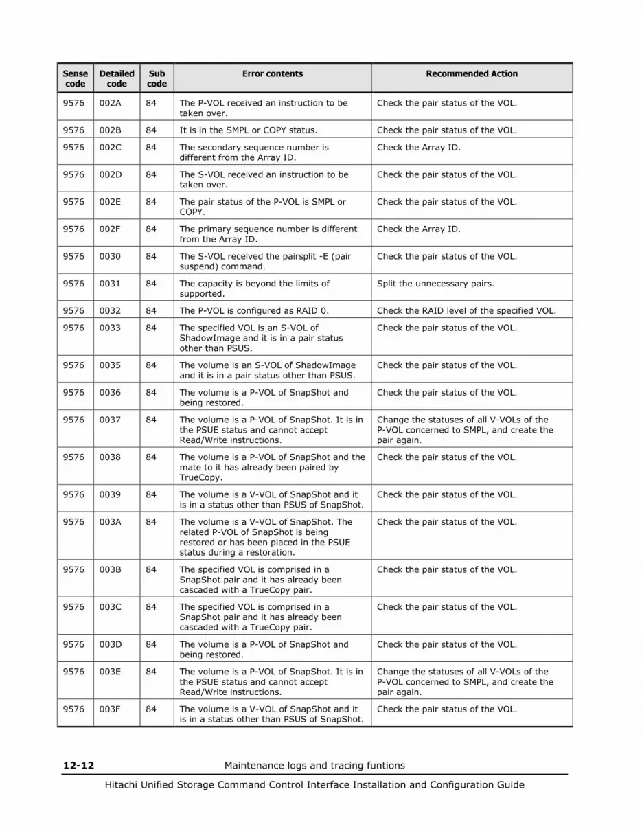
12-12 Maintenance logs and tracing funtions
Hitachi Unified Storage Command Control Interface Installation and Configuration Guide
Sense code
Detailed code
Sub code
Error contents Recommended Action
9576 002A 84 The P-VOL received an instruction to be taken over.
Check the pair status of the VOL.
9576 002B 84 It is in the SMPL or COPY status. Check the pair status of the VOL.
9576 002C 84 The secondary sequence number is different from the Array ID.
Check the Array ID.
9576 002D 84 The S-VOL received an instruction to be taken over.
Check the pair status of the VOL.
9576 002E 84 The pair status of the P-VOL is SMPL or COPY.
Check the pair status of the VOL.
9576 002F 84 The primary sequence number is different from the Array ID.
Check the Array ID.
9576 0030 84 The S-VOL received the pairsplit -E (pair suspend) command.
Check the pair status of the VOL.
9576 0031 84 The capacity is beyond the limits of supported.
Split the unnecessary pairs.
9576 0032 84 The P-VOL is configured as RAID 0. Check the RAID level of the specified VOL.
9576 0033 84 The specified VOL is an S-VOL of ShadowImage and it is in a pair status other than PSUS.
Check the pair status of the VOL.
9576 0035 84 The volume is an S-VOL of ShadowImage and it is in a pair status other than PSUS.
Check the pair status of the VOL.
9576 0036 84 The volume is a P-VOL of SnapShot and being restored.
Check the pair status of the VOL.
9576 0037 84 The volume is a P-VOL of SnapShot. It is in the PSUE status and cannot accept Read/Write instructions.
Change the statuses of all V-VOLs of the P-VOL concerned to SMPL, and create the pair again.
9576 0038 84 The volume is a P-VOL of SnapShot and the mate to it has already been paired by TrueCopy.
Check the pair status of the VOL.
9576 0039 84 The volume is a V-VOL of SnapShot and it is in a status other than PSUS of SnapShot.
Check the pair status of the VOL.
9576 003A 84 The volume is a V-VOL of SnapShot. The related P-VOL of SnapShot is being restored or has been placed in the PSUE status during a restoration.
Check the pair status of the VOL.
9576 003B 84 The specified VOL is comprised in a SnapShot pair and it has already been cascaded with a TrueCopy pair.
Check the pair status of the VOL.
9576 003C 84 The specified VOL is comprised in a SnapShot pair and it has already been cascaded with a TrueCopy pair.
Check the pair status of the VOL.
9576 003D 84 The volume is a P-VOL of SnapShot and being restored.
Check the pair status of the VOL.
9576 003E 84 The volume is a P-VOL of SnapShot. It is in the PSUE status and cannot accept Read/Write instructions.
Change the statuses of all V-VOLs of the P-VOL concerned to SMPL, and create the pair again.
9576 003F 84 The volume is a V-VOL of SnapShot and it is in a status other than PSUS of SnapShot.
Check the pair status of the VOL.
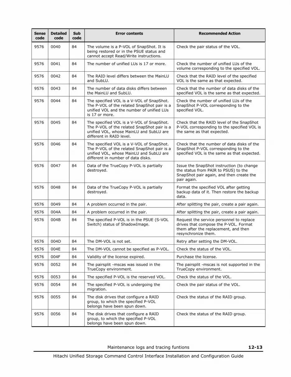
Maintenance logs and tracing funtions 12-13
Hitachi Unified Storage Command Control Interface Installation and Configuration Guide
Sense code
Detailed code
Sub code
Error contents Recommended Action
9576 0040 84 The volume is a P-VOL of SnapShot. It is being restored or in the PSUE status and cannot accept Read/Write instructions.
Check the pair status of the VOL.
9576 0041 84 The number of unified LUs is 17 or more. Check the number of unified LUs of the volume corresponding to the specified VOL.
9576 0042 84 The RAID level differs between the MainLU and SubLU.
Check that the RAID level of the specified VOL is the same as that expected.
9576 0043 84 The number of data disks differs between the MainLU and SubLU.
Check that the number of data disks of the specified VOL is the same as that expected.
9576 0044 84 The specified VOL is a V-VOL of SnapShot. The P-VOL of the related SnapShot pair is a unified VOL and the number of unified LUs is 17 or more.
Check the number of unified LUs of the SnapShot P-VOL corresponding to the specified VOL.
9576 0045 84 The specified VOL is a V-VOL of SnapShot. The P-VOL of the related SnapShot pair is a unified VOL, whose MainLU and SubLU are different in RAID level.
Check that the RAID level of the SnapShot P-VOL corresponding to the specified VOL is the same as that expected.
9576 0046 84 The specified VOL is a V-VOL of SnapShot. The P-VOL of the related SnapShot pair is a unified VOL, whose MainLU and SubLU are different in number of data disks.
Check that the number of data disks of the SnapShot P-VOL corresponding to the specified VOL is the same as that expected.
9576 0047 84 Data of the TrueCopy P-VOL is partially destroyed.
Issue the SnapShot instruction (to change the status from PAIR to PSUS) to the SnapShot pair again, and then create the pair again.
9576 0048 84 Data of the TrueCopy P-VOL is partially destroyed.
Format the specified VOL after getting backup data of it. Then restore the backup data.
9576 0049 84 A problem occurred in the pair. After splitting the pair, create a pair again.
9576 004A 84 A problem occurred in the pair. After splitting the pair, create a pair again.
9576 004B 84 The specified P-VOL is in the PSUE (S-VOL Switch) status of ShadowImage.
Request the service personnel to replace drives that compose the P-VOL. Format them after the replacement, and then resynchronize them.
9576 004D 84 The DM-VOL is not set. Retry after setting the DM-VOL.
9576 004E 84 The DM-VOL cannot be specified as P-VOL. Check the status of the VOL.
9576 004F 84 Validity of the license expired. Purchase the license.
9576 0052 84 The pairsplit -mscas was issued in the TrueCopy environment.
The pairsplit -mscas is not supported in the TrueCopy environment.
9576 0053 84 The specified P-VOL is the reserved VOL. Check the status of the VOL.
9576 0054 84 The specified P-VOL is undergoing the migration.
Check the pair status of the VOL.
9576 0055 84 The disk drives that configure a RAID group, to which the specified P-VOL belongs have been spun down.
Check the status of the RAID group.
9576 0056 84 The disk drives that configure a RAID group, to which the specified P-VOL belongs have been spun down.
Check the status of the RAID group.
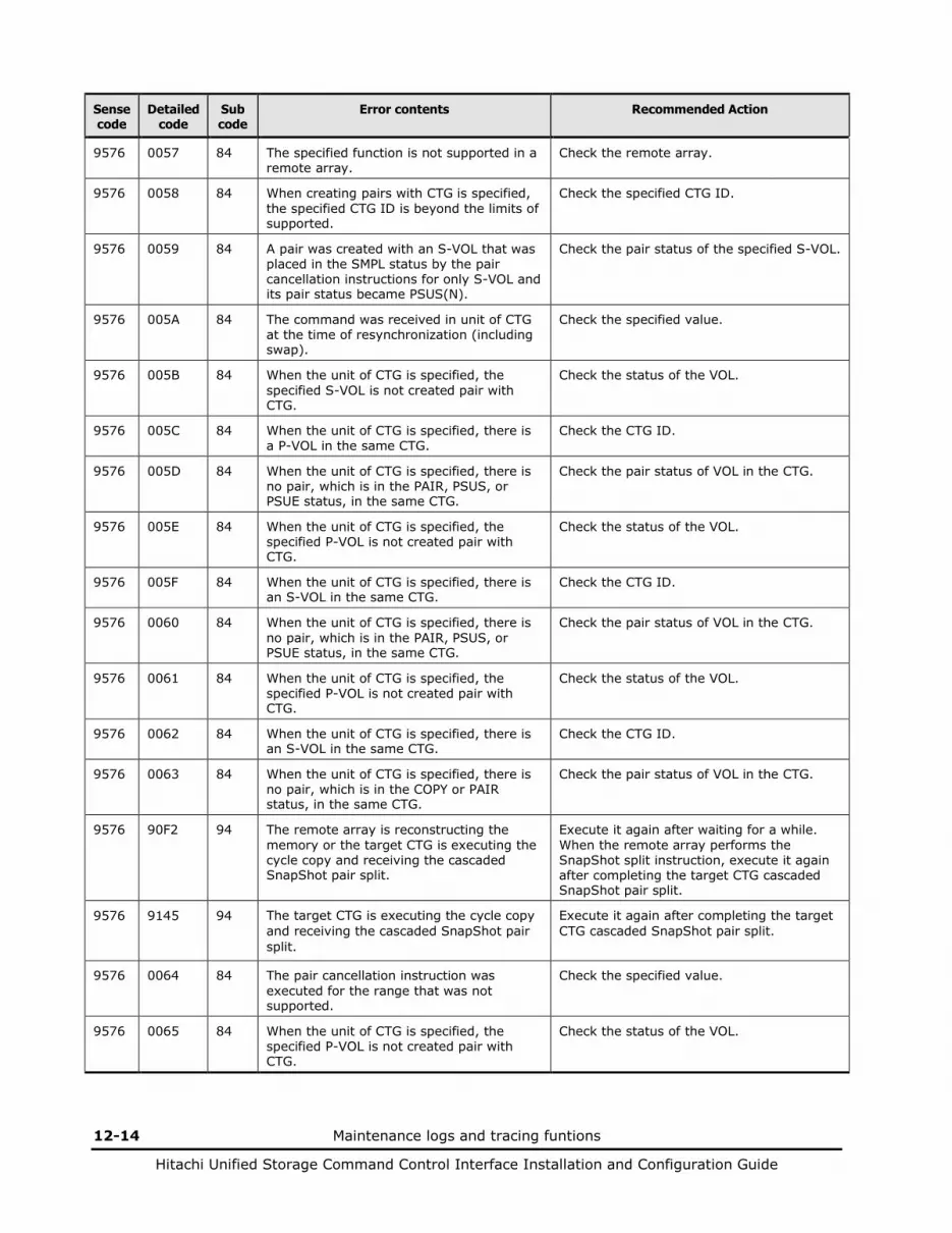
12-14 Maintenance logs and tracing funtions
Hitachi Unified Storage Command Control Interface Installation and Configuration Guide
Sense code
Detailed code
Sub code
Error contents Recommended Action
9576 0057 84 The specified function is not supported in a remote array.
Check the remote array.
9576 0058 84 When creating pairs with CTG is specified, the specified CTG ID is beyond the limits of supported.
Check the specified CTG ID.
9576 0059 84 A pair was created with an S-VOL that was placed in the SMPL status by the pair cancellation instructions for only S-VOL and its pair status became PSUS(N).
Check the pair status of the specified S-VOL.
9576 005A 84 The command was received in unit of CTG at the time of resynchronization (including swap).
Check the specified value.
9576 005B 84 When the unit of CTG is specified, the specified S-VOL is not created pair with CTG.
Check the status of the VOL.
9576 005C 84 When the unit of CTG is specified, there is a P-VOL in the same CTG.
Check the CTG ID.
9576 005D 84 When the unit of CTG is specified, there is no pair, which is in the PAIR, PSUS, or PSUE status, in the same CTG.
Check the pair status of VOL in the CTG.
9576 005E 84 When the unit of CTG is specified, the specified P-VOL is not created pair with CTG.
Check the status of the VOL.
9576 005F 84 When the unit of CTG is specified, there is an S-VOL in the same CTG.
Check the CTG ID.
9576 0060 84 When the unit of CTG is specified, there is no pair, which is in the PAIR, PSUS, or PSUE status, in the same CTG.
Check the pair status of VOL in the CTG.
9576 0061 84 When the unit of CTG is specified, the specified P-VOL is not created pair with CTG.
Check the status of the VOL.
9576 0062 84 When the unit of CTG is specified, there is an S-VOL in the same CTG.
Check the CTG ID.
9576 0063 84 When the unit of CTG is specified, there is no pair, which is in the COPY or PAIR status, in the same CTG.
Check the pair status of VOL in the CTG.
9576 90F2 94 The remote array is reconstructing the memory or the target CTG is executing the cycle copy and receiving the cascaded SnapShot pair split.
Execute it again after waiting for a while. When the remote array performs the SnapShot split instruction, execute it again after completing the target CTG cascaded SnapShot pair split.
9576 9145 94 The target CTG is executing the cycle copy and receiving the cascaded SnapShot pair split.
Execute it again after completing the target CTG cascaded SnapShot pair split.
9576 0064 84 The pair cancellation instruction was executed for the range that was not supported.
Check the specified value.
9576 0065 84 When the unit of CTG is specified, the specified P-VOL is not created pair with CTG.
Check the status of the VOL.

Maintenance logs and tracing funtions 12-15
Hitachi Unified Storage Command Control Interface Installation and Configuration Guide
Sense code
Detailed code
Sub code
Error contents Recommended Action
9576 0066 84 When the unit of CTG is specified, there is an S-VOL in the same CTG.
Check the CTG ID.
9576 0067 84 When the unit of CTG is specified, the specified S-VOL is not created pair with CTG.
Check the status of the VOL.
9576 0068 84 When the unit of CTG is specified, there is a P-VOL in the same CTG.
Check the CTG ID.
9576 0069 84 The specified secondary sequence number does not match with the array serial number.
Check the specified command device number.
9576 006A 84 The command cannot execute because the Auto Migration is undergoing.
Check the Migration status.
9576 006B 84 The command cannot execute because the Auto Migration is undergoing.
Check the Migration status.
9576 006C 84 The command cannot execute because the Auto Migration is undergoing.
Check the Migration status.
9576 006D 84 There are other pairs in the group, whose fence level is not the same as the one specified.
Confirm the fence level of the pair you are creating.
9576 006E 84 There are other pairs in the group, whose P-VOL and S-VOL are swapped.
Confirm the array on which you are executing the command.
9576 006F 84 The specified VOL is the P-VOL or S-VOL of a ShadowImage pair that the status is PSUS(SP) or PAIR(IS).
Check the status of the ShadowImage pair.
9576 0072 84 The RAID group to which the specified VOL belongs indicates a status other than Normal.
Retry after the status becomes Normal.
9576 0073 84 An VOL that belongs to the RAID group that indicates a status other than Normal is included in the data pool that is used by pairs in the specified group.
Retry after the RAID group status becomes Normal.
9576 0074 84 The specified CTG number has been used into other remote replication pair with the remote array.
Retry after specifying the number other than specified CTG number.
9576 0075 84 The specified local Edge array has created a remote replication pair with another array.
Check the pair status of the local array.
9576 0076 84 The local array can not execute create pair with the specified remote array because the maximum number of the connected arrays is beyond the limits.
Retry after deleting the all remote replication pair with the another remote array.
9576 0077 84 The VOL created in DP pool was specified as P-VOL.
Specify an VOL other than the VOL created in DP pool.
9576 0078 84 The VOL that was specified as P-VOL does not exist.
Check the specified VOL.
9576 0079 84 The specified P-VOL is a volume of ShadowImage pair that includes the VOL created in DP pool.
Confirm the ShadowImage pair that the specified P-VOL is part of.
9576 007A 84 The specified P-VOL is a volume of ShadowImage pair that includes the VOL created in DP pool.
Confirm the ShadowImage pair that the specified P-VOL is part of.
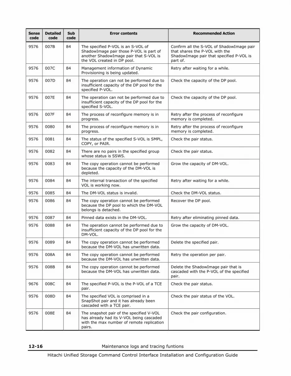
12-16 Maintenance logs and tracing funtions
Hitachi Unified Storage Command Control Interface Installation and Configuration Guide
Sense code
Detailed code
Sub code
Error contents Recommended Action
9576 007B 84 The specified P-VOL is an S-VOL of ShadowImage pair those P-VOL is part of another ShadowImage pair that S-VOL is the VOL created in DP pool.
Confirm all the S-VOL of ShadowImage pair that shares the P-VOL with the ShadowImage pair that specified P-VOL is part of.
9576 007C 84 Management information of Dynamic Provisioning is being updated.
Retry after waiting for a while.
9576 007D 84 The operation can not be performed due to insufficient capacity of the DP pool for the specified P-VOL.
Check the capacity of the DP pool.
9576 007E 84 The operation can not be performed due to insufficient capacity of the DP pool for the specified S-VOL.
Check the capacity of the DP pool.
9576 007F 84 The process of reconfigure memory is in progress.
Retry after the process of reconfigure memory is completed.
9576 0080 84 The process of reconfigure memory is in progress.
Retry after the process of reconfigure memory is completed.
9576 0081 84 The status of the specified S-VOL is SMPL, COPY, or PAIR.
Check the pair status.
9576 0082 84 There are no pairs in the specified group whose status is SSWS.
Check the pair status.
9576 0083 84 The copy operation cannot be performed because the capacity of the DM-VOL is depleted.
Grow the capacity of DM-VOL.
9576 0084 84 The internal transaction of the specified VOL is working now.
Retry after waiting for a while.
9576 0085 84 The DM-VOL status is invalid. Check the DM-VOL status.
9576 0086 84 The copy operation cannot be performed because the DP pool to which the DM-VOL belongs is detached.
Recover the DP pool.
9576 0087 84 Pinned data exists in the DM-VOL. Retry after eliminating pinned data.
9576 0088 84 The operation cannot be performed due to insufficient capacity of the DP pool for the DM-VOL.
Grow the capacity of DM-VOL.
9576 0089 84 The copy operation cannot be performed because the DM-VOL has unwritten data.
Delete the specified pair.
9576 008A 84 The copy operation cannot be performed because the DM-VOL has unwritten data.
Retry the operation per pair.
9576 008B 84 The copy operation cannot be performed because the DM-VOL has unwritten data.
Delete the ShadowImage pair that is cascaded with the P-VOL of the specified pair.
9676 008C 84 The specified P-VOL is the P-VOL of a TCE pair.
Check the pair status.
9576 008D 84 The specified VOL is comprised in a SnapShot pair and it has already been cascaded with a TCE pair.
Check the pair status of the VOL.
9576 008E 84 The snapshot pair of the specified V-VOL has already had its V-VOL being cascaded with the max number of remote replication pairs.
Check the pair configuration.
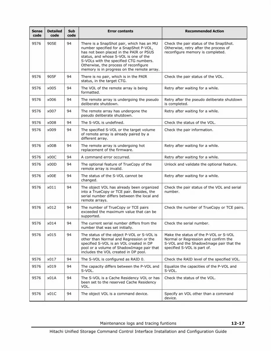
Maintenance logs and tracing funtions 12-17
Hitachi Unified Storage Command Control Interface Installation and Configuration Guide
Sense code
Detailed code
Sub code
Error contents Recommended Action
9576 905E 94 There is a SnapShot pair, which has an MU number specified for a SnapShot P-VOL, has not been placed in the PAIR or PSUS status, and whose S-VOL is one of the S-VOLs with the specified CTG numbers. Otherwise, the process of reconfigure memory is in progress on the remote array.
Check the pair status of the SnapShot. Otherwise, retry after the process of reconfigure memory is completed.
9576 905F 94 There is no pair, which is in the PAIR status, in the target CTG.
Check the pair status of the VOL.
9576 x005 94 The VOL of the remote array is being formatted.
Retry after waiting for a while.
9576 x006 94 The remote array is undergoing the pseudo deliberate shutdown.
Retry after the pseudo deliberate shutdown is completed.
9576 x007 94 The remote array has undergone the pseudo deliberate shutdown.
Retry after waiting for a while.
9576 x008 94 The S-VOL is undefined. Check the status of the VOL.
9576 x009 94 The specified S-VOL or the target volume of remote array is already paired by a different array.
Check the pair information.
9576 x00B 94 The remote array is undergoing hot replacement of the firmware.
Retry after waiting for a while.
9576 x00C 94 A command error occurred. Retry after waiting for a while.
9576 x00D 94 The optional feature of TrueCopy of the remote array is invalid.
Unlock and validate the optional feature.
9576 x00E 94 The status of the S-VOL cannot be changed.
Retry after waiting for a while.
9576 x011 94 The object VOL has already been organized into a TrueCopy or TCE pair. Besides, the serial number differs between the local and remote arrays.
Check the pair status of the VOL and serial number.
9576 x012 94 The number of TrueCopy or TCE pairs exceeded the maximum value that can be supported.
Check the number of TrueCopy or TCE pairs.
9576 x014 94 The current serial number differs from the number that was set initially.
Check the serial number.
9576 x015 94 The status of the object P-VOL or S-VOL is other than Normal and Regression or the specified S-VOL is an VOL created in DP pool or a volume of ShadowImage pair that includes the VOL created in DP pool.
Make the status of the P-VOL or S-VOL Normal or Regression and confirm the S-VOL and the ShadowImage pair that the specified S-VOL is part of.
9576 x017 94 The S-VOL is configured as RAID 0. Check the RAID level of the specified VOL.
9576 x019 94 The capacity differs between the P-VOL and S-VOL.
Equalize the capacities of the P-VOL and S-VOL.
9576 x01A 94 The S-VOL is a Cache Residency VOL or has been set to the reserved Cache Residency VOL.
Check the status of the VOL.
9576 x01C 94 The object VOL is a command device. Specify an VOL other than a command device.
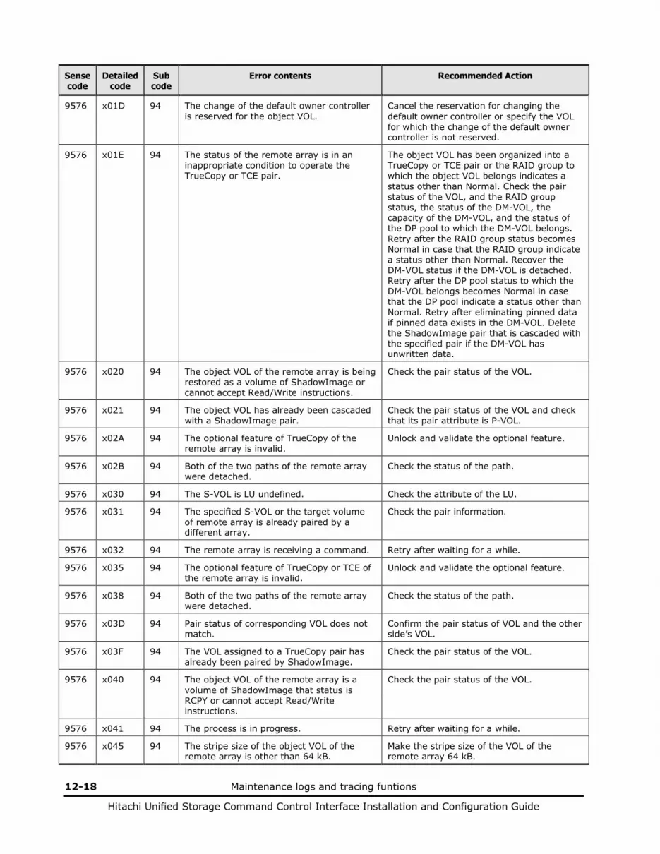
12-18 Maintenance logs and tracing funtions
Hitachi Unified Storage Command Control Interface Installation and Configuration Guide
Sense code
Detailed code
Sub code
Error contents Recommended Action
9576 x01D 94 The change of the default owner controller is reserved for the object VOL.
Cancel the reservation for changing the default owner controller or specify the VOL for which the change of the default owner controller is not reserved.
9576 x01E 94 The status of the remote array is in an inappropriate condition to operate the TrueCopy or TCE pair.
The object VOL has been organized into a TrueCopy or TCE pair or the RAID group to which the object VOL belongs indicates a status other than Normal. Check the pair status of the VOL, and the RAID group status, the status of the DM-VOL, the capacity of the DM-VOL, and the status of the DP pool to which the DM-VOL belongs. Retry after the RAID group status becomes Normal in case that the RAID group indicate a status other than Normal. Recover the DM-VOL status if the DM-VOL is detached. Retry after the DP pool status to which the DM-VOL belongs becomes Normal in case that the DP pool indicate a status other than Normal. Retry after eliminating pinned data if pinned data exists in the DM-VOL. Delete the ShadowImage pair that is cascaded with the specified pair if the DM-VOL has unwritten data.
9576 x020 94 The object VOL of the remote array is being restored as a volume of ShadowImage or cannot accept Read/Write instructions.
Check the pair status of the VOL.
9576 x021 94 The object VOL has already been cascaded with a ShadowImage pair.
Check the pair status of the VOL and check that its pair attribute is P-VOL.
9576 x02A 94 The optional feature of TrueCopy of the remote array is invalid.
Unlock and validate the optional feature.
9576 x02B 94 Both of the two paths of the remote array were detached.
Check the status of the path.
9576 x030 94 The S-VOL is LU undefined. Check the attribute of the LU.
9576 x031 94 The specified S-VOL or the target volume of remote array is already paired by a different array.
Check the pair information.
9576 x032 94 The remote array is receiving a command. Retry after waiting for a while.
9576 x035 94 The optional feature of TrueCopy or TCE of the remote array is invalid.
Unlock and validate the optional feature.
9576 x038 94 Both of the two paths of the remote array were detached.
Check the status of the path.
9576 x03D 94 Pair status of corresponding VOL does not match.
Confirm the pair status of VOL and the other side’s VOL.
9576 x03F 94 The VOL assigned to a TrueCopy pair has already been paired by ShadowImage.
Check the pair status of the VOL.
9576 x040 94 The object VOL of the remote array is a volume of ShadowImage that status is RCPY or cannot accept Read/Write instructions.
Check the pair status of the VOL.
9576 x041 94 The process is in progress. Retry after waiting for a while.
9576 x045 94 The stripe size of the object VOL of the remote array is other than 64 kB.
Make the stripe size of the VOL of the remote array 64 kB.
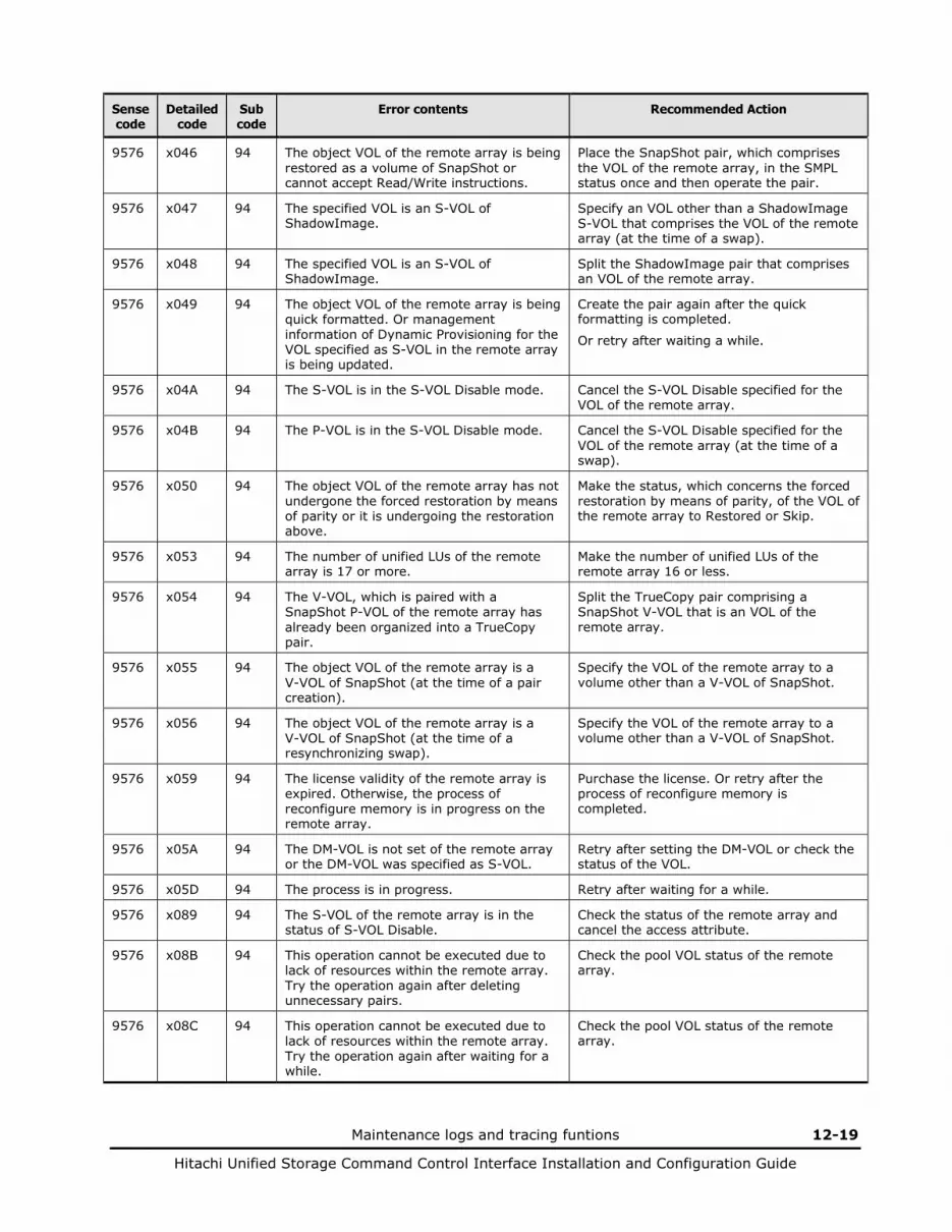
Maintenance logs and tracing funtions 12-19
Hitachi Unified Storage Command Control Interface Installation and Configuration Guide
Sense code
Detailed code
Sub code
Error contents Recommended Action
9576 x046 94 The object VOL of the remote array is being restored as a volume of SnapShot or cannot accept Read/Write instructions.
Place the SnapShot pair, which comprises the VOL of the remote array, in the SMPL status once and then operate the pair.
9576 x047 94 The specified VOL is an S-VOL of ShadowImage.
Specify an VOL other than a ShadowImage S-VOL that comprises the VOL of the remote array (at the time of a swap).
9576 x048 94 The specified VOL is an S-VOL of ShadowImage.
Split the ShadowImage pair that comprises an VOL of the remote array.
9576 x049 94 The object VOL of the remote array is being quick formatted. Or management information of Dynamic Provisioning for the VOL specified as S-VOL in the remote array is being updated.
Create the pair again after the quick formatting is completed.
Or retry after waiting a while.
9576 x04A 94 The S-VOL is in the S-VOL Disable mode. Cancel the S-VOL Disable specified for the VOL of the remote array.
9576 x04B 94 The P-VOL is in the S-VOL Disable mode. Cancel the S-VOL Disable specified for the VOL of the remote array (at the time of a swap).
9576 x050 94 The object VOL of the remote array has not undergone the forced restoration by means of parity or it is undergoing the restoration above.
Make the status, which concerns the forced restoration by means of parity, of the VOL of the remote array to Restored or Skip.
9576 x053 94 The number of unified LUs of the remote array is 17 or more.
Make the number of unified LUs of the remote array 16 or less.
9576 x054 94 The V-VOL, which is paired with a SnapShot P-VOL of the remote array has already been organized into a TrueCopy pair.
Split the TrueCopy pair comprising a SnapShot V-VOL that is an VOL of the remote array.
9576 x055 94 The object VOL of the remote array is a V-VOL of SnapShot (at the time of a pair creation).
Specify the VOL of the remote array to a volume other than a V-VOL of SnapShot.
9576 x056 94 The object VOL of the remote array is a V-VOL of SnapShot (at the time of a resynchronizing swap).
Specify the VOL of the remote array to a volume other than a V-VOL of SnapShot.
9576 x059 94 The license validity of the remote array is expired. Otherwise, the process of reconfigure memory is in progress on the remote array.
Purchase the license. Or retry after the process of reconfigure memory is completed.
9576 x05A 94 The DM-VOL is not set of the remote array or the DM-VOL was specified as S-VOL.
Retry after setting the DM-VOL or check the status of the VOL.
9576 x05D 94 The process is in progress. Retry after waiting for a while.
9576 x089 94 The S-VOL of the remote array is in the status of S-VOL Disable.
Check the status of the remote array and cancel the access attribute.
9576 x08B 94 This operation cannot be executed due to lack of resources within the remote array. Try the operation again after deleting unnecessary pairs.
Check the pool VOL status of the remote array.
9576 x08C 94 This operation cannot be executed due to lack of resources within the remote array. Try the operation again after waiting for a while.
Check the pool VOL status of the remote array.

12-20 Maintenance logs and tracing funtions
Hitachi Unified Storage Command Control Interface Installation and Configuration Guide
Sense code
Detailed code
Sub code
Error contents Recommended Action
9576 x08D 94 The S-VOL of the remote array does not meet the conditions of cascading with a SnapShot pair.
Check the status of the VOL in the remote array.
9576 x090 94 The S-VOL of the remote array does not meet the conditions of cascading with a SnapShot pair.
Check the status of the VOL in the remote array.
9576 x091 94 The indicated Array ID is not same as the actual one for remote array.
Confirm the Array ID for the remote array.
9576 x095 94 The S-VOL in the remote array is undergoing the forced parity correction.
Check the status of the remote array and retry after waiting for a while.
9576 x097 94 The S-VOL in the remote array received an illegal command.
Check the status of the remote array.
9576 x09A 94 The VOL status of the S-VOL in the remote array is normal or other than regressed.
Check the VOL status of the remote array.
9576 x09F 94 The internal transaction which are splitting or deleting for SnapShot is working now.
Retry after waiting for a while.
9576 x0A0 94 The remote array has no DP pool. Create a DP pool for the remote array.
9576 x0A2 94 The VOL status of the S-VOL in the remote array is Normal or other than Regresson.
Check the DP pool status of the remote array.
9576 x0A4 94 The S-VOL in the remote array exceeded the total allowable maximum number of TCE and SnapShot pairs.
Check the status of the remote array. In addition, delete unnecessary pairs of the remote array.
9576 x0A5 94 The TCE pair status of the S-VOL in the remote array is PSUE.
Check the TCE pair status of the remote array.
9576 x0A6 94 The TCE pair status of the S-VOL in the remote array is PFUS.
Check the TCE pair status of the remote array.
9576 x0A7 94 The TCE pair status of the S-VOL in the remote array is PSUS (no reading/writing allowed).
Check the TCE pair status of the remote array.
9576 x0A8 94 The TCE pair status of the S-VOL in the remote array is SSWS (including SSWS(R)).
Check the TCE pair status of the remote array.
9576 x0A9 94 The TCE pair status of the S-VOL in the remote array is SMPL.
Check the TCE pair status of the remote array.
9576 x0AA 94 The TCE pair status of the S-VOL in the remote array is PSUS.
Check the TCE pair status of the remote array.
9576 x0AB 94 The TCE pair status of the S-VOL in the remote array is not SMPL.
Check the TCE pair status of the remote array.
9576 x0B3 94 The specified S-VOL is a unified VOL including a SubLU with a capacity less than 1 GB.
Check whether the VOL with a capacity less than 1 GB is included in each VOL of the specified unified VOL.
9576 x0B4 94 The S-VOL in the remote array does not exist on the default owner controller and, at the same time, the special processing cannot be continued.
Check the status of the remote array and retry after waiting for a while.
9576 x0B5 94 The S-VOL in the remote array does not exist on the default owner controller and, at the same time, an ownership of VOL change for it has been started.
Check the status of the remote array and retry after waiting for a while.

Maintenance logs and tracing funtions 12-21
Hitachi Unified Storage Command Control Interface Installation and Configuration Guide
Sense code
Detailed code
Sub code
Error contents Recommended Action
9576 x0B6 94 The S-VOL in the remote array does not exist on the default owner controller and it has started an ownership of VOL change.
Check the status of the remote array and retry after waiting for a while.
9576 x0B7 94 The S-VOL in the remote array does not exist on the default owner controller and, at the same time, an ownership of VOL to be changed is blocked.
Check the status of the remote array and retry after waiting for a while.
9576 x0B8 94 The S-VOL in the remote array cannot change an ownership of VOL and, at the same time, it is using the sequential buffer.
Check the status of the remote array and retry after waiting for a while.
9576 x0B9 94 The S-VOL in the remote array cannot change an ownership of VOL temporarily.
Retry after waiting for a while.
9576 x0BA 94 The S-VOL in the remote array cannot change an ownership of VOL and, at the same time, it has pinned data.
Contact the service personnel.
9576 x0BB 94 The S-VOL in the remote array cannot change an ownership of VOL temporarily.
Retry after waiting for a while.
9576 x0BC 94 The S-VOL in the remote array cannot change an ownership of VOL temporarily.
Retry after waiting for a while.
9576 x0BD 94 The S-VOL in the remote array cannot change an ownership of VOL and a time-out occurred.
Check the status of the remote array and retry after waiting for a while.
9576 x0BE 94 The S-VOL in the remote array cannot change an ownership of VOL and, at the same time, the group# is illegal.
Check the status of the remote array.
9576 x0C0 94 The S-VOL in the remote array does not exist on the default owner controller and, at the same time, it is making the drive spun up.
Check the status of the remote array and retry after waiting for a while.
9576 x0C1 94 The S-VOL in the remote array does not exist on the default owner controller and, at the same time, it is making the system copy.
Check the status of the remote array and retry after waiting for a while.
9576 x0C2 94 The S-VOL in the remote array does not exist on the default owner controller and, at the same time, it is writing the takeover information.
Check the status of the remote array and retry after waiting for a while.
9576 x0C4 94 When a new pair of a CTG is created, the cycle time that has been set for the local and remote array is less than the minimum interval.
Check the cycle time that has been set for the local and remote array.
9576 x0C6 94 The specified S-VOL is undergoing the migration.
Re-execute the migration after splitting the pair.
9576 x0C7 94 The specified S-VOL is the reserved VOL. Re-execute the migration specifying an VOL other than the reserved VOL for the S-VOL.
9576 x0CA 94 The specified S-VOL is undergoing the migration.
Re-execute the migration after splitting the pair.
9576 x0CB 94 The specified S-VOL is the reserved VOL. Re-execute the migration specifying an VOL other than the reserved VOL for the S-VOL.
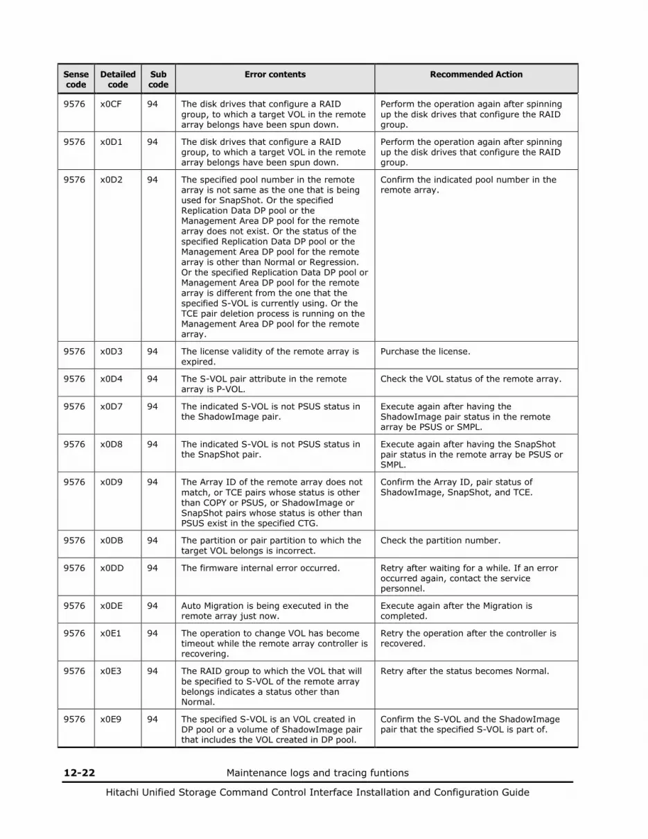
12-22 Maintenance logs and tracing funtions
Hitachi Unified Storage Command Control Interface Installation and Configuration Guide
Sense code
Detailed code
Sub code
Error contents Recommended Action
9576 x0CF 94 The disk drives that configure a RAID group, to which a target VOL in the remote array belongs have been spun down.
Perform the operation again after spinning up the disk drives that configure the RAID group.
9576 x0D1 94 The disk drives that configure a RAID group, to which a target VOL in the remote array belongs have been spun down.
Perform the operation again after spinning up the disk drives that configure the RAID group.
9576 x0D2 94 The specified pool number in the remote array is not same as the one that is being used for SnapShot. Or the specified Replication Data DP pool or the Management Area DP pool for the remote array does not exist. Or the status of the specified Replication Data DP pool or the Management Area DP pool for the remote array is other than Normal or Regression. Or the specified Replication Data DP pool or Management Area DP pool for the remote array is different from the one that the specified S-VOL is currently using. Or the TCE pair deletion process is running on the Management Area DP pool for the remote array.
Confirm the indicated pool number in the remote array.
9576 x0D3 94 The license validity of the remote array is expired.
Purchase the license.
9576 x0D4 94 The S-VOL pair attribute in the remote array is P-VOL.
Check the VOL status of the remote array.
9576 x0D7 94 The indicated S-VOL is not PSUS status in the ShadowImage pair.
Execute again after having the ShadowImage pair status in the remote array be PSUS or SMPL.
9576 x0D8 94 The indicated S-VOL is not PSUS status in the SnapShot pair.
Execute again after having the SnapShot pair status in the remote array be PSUS or SMPL.
9576 x0D9 94 The Array ID of the remote array does not match, or TCE pairs whose status is other than COPY or PSUS, or ShadowImage or SnapShot pairs whose status is other than PSUS exist in the specified CTG.
Confirm the Array ID, pair status of ShadowImage, SnapShot, and TCE.
9576 x0DB 94 The partition or pair partition to which the target VOL belongs is incorrect.
Check the partition number.
9576 x0DD 94 The firmware internal error occurred. Retry after waiting for a while. If an error occurred again, contact the service personnel.
9576 x0DE 94 Auto Migration is being executed in the remote array just now.
Execute again after the Migration is completed.
9576 x0E1 94 The operation to change VOL has become timeout while the remote array controller is recovering.
Retry the operation after the controller is recovered.
9576 x0E3 94 The RAID group to which the VOL that will be specified to S-VOL of the remote array belongs indicates a status other than Normal.
Retry after the status becomes Normal.
9576 x0E9 94 The specified S-VOL is an VOL created in DP pool or a volume of ShadowImage pair that includes the VOL created in DP pool.
Confirm the S-VOL and the ShadowImage pair that the specified S-VOL is part of.

Maintenance logs and tracing funtions 12-23
Hitachi Unified Storage Command Control Interface Installation and Configuration Guide
Sense code
Detailed code
Sub code
Error contents Recommended Action
9576 x0F1 94 Management information of Dynamic Provisioning for the VOL specified as S-VOL in the remote array is being updated.
Retry after waiting a while.
9576 x0F2 94 The process of reconfigure memory is in progress on the remote array.
Retry after the process of reconfigure memory is completed.
9576 x0F5 94 The full capacity mode differs between the P-VOL and S-VOL. Or the full capacity mode is not supported.
Set both P-VOL and S-VOL the same value. Or check the firmware version of array.
9576 x101 94 The copy operation can not be performed because the capacity of the DM-VOL is depleted.
Grow the capacity of DM-VOL.
9576 x104 94 The internal transaction of the specified VOL is working now.
Retry after waiting for a while.
9576 x107 94 The copy operation can not be performed because the DM-VOL is detached.
Recover the DM-VOL status.
9576 x10A 94 The copy operation can not be performed because the DP pool to which the DM-VOL belongs is detached.
Recover the DP pool.
9576 x10D 94 Pinned data exists in the DM-VOL. Retry after eliminating pinned data.
9576 x110 94 The operation can not be performed due to insufficient capacity of the DP Pool for the DM-VOL.
Grow the capacity of DP pool.
9576 x113 94 The copy operation can not be performed because the DM-VOL has unwritten data.
Delete the ShadowImage pair that is cascaded with the specified pair.
9576 x13A 94 There are the maximum number of groups for TCE on the remote array.
Check the number of groups for TCE.
9591 There exist maximum number of pairs already.
Split the unnecessary pairs.
9606 The P-VOL or S-VOL is an invalidated VOL. Check the status of the VOL.
9607 The P-VOL or S-VOL is a P-VOL (other than SMPL, or the SMPL and a V-VOL that has been set) or a V-VOL of SnapShot.
Check the pair status.
9608 0000 84 In the operation to change an ownership of VOL, an VOL having pinned data was specified.
Retry after eliminating pinned data.
9608 0001 84 The controller that controls the VOL cannot be changed temporarily.
Retry after waiting for a while.
9608 0002 84 The operation to change an ownership of VOL is in progress.
Retry after waiting for a while.
9608 0003 84 There is no partition to which the current partition is to be changed.
Retry after waiting for a while.
9608 0004 84 The specified P-VOL or the specified S-VOL is the VOL, for which a change of the cache partitions had been reserved.
Retry after releasing the reserved status.
9608 0004 84 The P-VOL is in a status other than Normal and Regression.
Check the status of the VOL.
9608 0005 84 The operation to change an ownership of VOL is in progress.
Retry after waiting for a while.
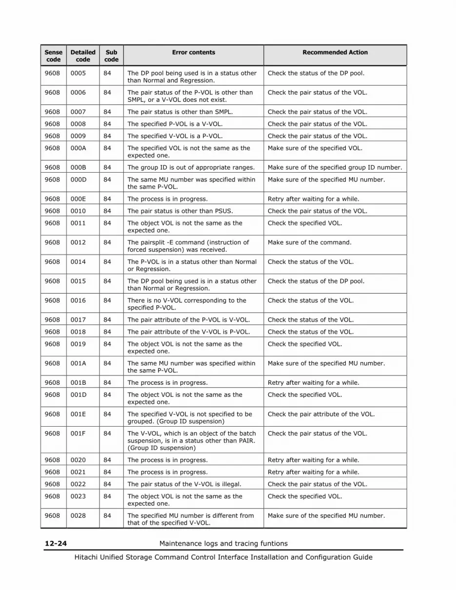
12-24 Maintenance logs and tracing funtions
Hitachi Unified Storage Command Control Interface Installation and Configuration Guide
Sense code
Detailed code
Sub code
Error contents Recommended Action
9608 0005 84 The DP pool being used is in a status other than Normal and Regression.
Check the status of the DP pool.
9608 0006 84 The pair status of the P-VOL is other than SMPL, or a V-VOL does not exist.
Check the pair status of the VOL.
9608 0007 84 The pair status is other than SMPL. Check the pair status of the VOL.
9608 0008 84 The specified P-VOL is a V-VOL. Check the pair status of the VOL.
9608 0009 84 The specified V-VOL is a P-VOL. Check the pair status of the VOL.
9608 000A 84 The specified VOL is not the same as the expected one.
Make sure of the specified VOL.
9608 000B 84 The group ID is out of appropriate ranges. Make sure of the specified group ID number.
9608 000D 84 The same MU number was specified within the same P-VOL.
Make sure of the specified MU number.
9608 000E 84 The process is in progress. Retry after waiting for a while.
9608 0010 84 The pair status is other than PSUS. Check the pair status of the VOL.
9608 0011 84 The object VOL is not the same as the expected one.
Check the specified VOL.
9608 0012 84 The pairsplit -E command (instruction of forced suspension) was received.
Make sure of the command.
9608 0014 84 The P-VOL is in a status other than Normal or Regression.
Check the status of the VOL.
9608 0015 84 The DP pool being used is in a status other than Normal or Regression.
Check the status of the DP pool.
9608 0016 84 There is no V-VOL corresponding to the specified P-VOL.
Check the status of the VOL.
9608 0017 84 The pair attribute of the P-VOL is V-VOL. Check the status of the VOL.
9608 0018 84 The pair attribute of the V-VOL is P-VOL. Check the status of the VOL.
9608 0019 84 The object VOL is not the same as the expected one.
Check the specified VOL.
9608 001A 84 The same MU number was specified within the same P-VOL.
Make sure of the specified MU number.
9608 001B 84 The process is in progress. Retry after waiting for a while.
9608 001D 84 The object VOL is not the same as the expected one.
Check the specified VOL.
9608 001E 84 The specified V-VOL is not specified to be grouped. (Group ID suspension)
Check the pair attribute of the VOL.
9608 001F 84 The V-VOL, which is an object of the batch suspension, is in a status other than PAIR. (Group ID suspension)
Check the pair status of the VOL.
9608 0020 84 The process is in progress. Retry after waiting for a while.
9608 0021 84 The process is in progress. Retry after waiting for a while.
9608 0022 84 The pair status of the V-VOL is illegal. Check the pair status of the VOL.
9608 0023 84 The object VOL is not the same as the expected one.
Check the specified VOL.
9608 0028 84 The specified MU number is different from that of the specified V-VOL.
Make sure of the specified MU number.
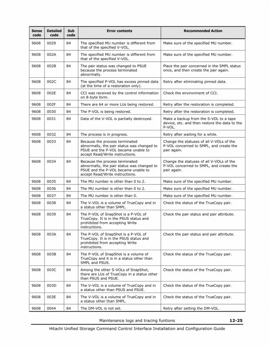
Maintenance logs and tracing funtions 12-25
Hitachi Unified Storage Command Control Interface Installation and Configuration Guide
Sense code
Detailed code
Sub code
Error contents Recommended Action
9608 0029 84 The specified MU number is different from that of the specified V-VOL.
Make sure of the specified MU number.
9608 002A 84 The specified MU number is different from that of the specified V-VOL.
Make sure of the specified MU number.
9608 002B 84 The pair status was changed to PSUE because the process terminated abnormally.
Place the pair concerned in the SMPL status once, and then create the pair again.
9608 002C 84 The specified P-VOL has excess pinned data (at the time of a restoration only).
Retry after eliminating pinned data.
9608 002E 84 CCI was received by the control information on 8-byte form.
Check the environment of CCI.
9608 002F 84 There are 64 or more LUs being restored. Retry after the restoration is completed.
9608 0030 84 The P-VOL is being restored. Retry after the restoration is completed.
9608 0031 84 Data of the V-VOL is partially destroyed. Make a backup from the S-VOL to a tape device, etc. and then restore the data to the P-VOL.
9608 0032 84 The process is in progress. Retry after waiting for a while.
9608 0033 84 Because the process terminated abnormally, the pair status was changed to PSUE and the P-VOL became unable to accept Read/Write instructions.
Change the statuses of all V-VOLs of the P-VOL concerned to SMPL, and create the pair again.
9608 0034 84 Because the process terminated abnormally, the pair status was changed to PSUE and the P-VOL became unable to accept Read/Write instructions.
Change the statuses of all V-VOLs of the P-VOL concerned to SMPL, and create the pair again.
9608 0035 84 The MU number is other than 0 to 2. Make sure of the specified MU number.
9608 0036 84 The MU number is other than 0 to 2. Make sure of the specified MU number.
9608 0037 84 The MU number is other than 0. Make sure of the specified MU number.
9608 0038 84 The V-VOL is a volume of TrueCopy and in a status other than SMPL.
Check the status of the TrueCopy pair.
9608 0039 84 The P-VOL of SnapShot is a P-VOL of TrueCopy. It is in the PSUS status and prohibited from accepting Write instructions.
Check the pair status and pair attribute.
9608 003A 84 The P-VOL of SnapShot is a P-VOL of TrueCopy. It is in the PSUS status and prohibited from accepting Write instructions.
Check the pair status and pair attribute.
9608 003B 84 The P-VOL of SnapShot is a volume of TrueCopy and it is in a status other than SMPL and PSUS.
Check the status of the TrueCopy pair.
9608 003C 84 Among the other S-VOLs of SnapShot, there are LUs of TrueCopy in a status other than PSUS and PSUE.
Check the status of the TrueCopy pair.
9608 003D 84 The V-VOL is a volume of TrueCopy and in a status other than PSUS and PSUE.
Check the status of the TrueCopy pair.
9608 003E 84 The V-VOL is a volume of TrueCopy and in a status other than SMPL.
Check the status of the TrueCopy pair.
9608 0044 84 The DM-VOL is not set. Retry after setting the DM-VOL.

12-26 Maintenance logs and tracing funtions
Hitachi Unified Storage Command Control Interface Installation and Configuration Guide
Sense code
Detailed code
Sub code
Error contents Recommended Action
9608 0045 84 The DM-VOL was specified as P-VOL. Check the status of the VOL.
9608 0046 84 The DM-VOL was specified as V-VOL. Check the status of the VOL.
9608 0047 84 The DM-VOL is not set. Retry after setting the DM-VOL.
9608 0048 84 The DM-VOL was specified as P-VOL. Check the status of the VOL.
9608 0049 84 The DM-VOL was specified as V-VOL. Check the status of the VOL.
9608 004A 84 Validity of the license expired. Purchase the license.
9608 004B 84 Validity of the license expired. Purchase the license.
9608 0052 84 The specified P-VOL is a P-VOL of TCE and the status of the TCE pair is other than PSUS (at the time of restoration).
Check the status of the VOL.
9608 0053 84 The specified P-VOL is an S-VOL of TCE and the status of the TCE pair is PSUS and writing to the S-VOL is prohibited (at the time of restoration).
Check the status of the VOL.
9608 0054 84 The specified P-VOL is an S-VOL of TCE and the determined data at the end of the previous cycle is being restored to the S-VOL.
Retry after waiting for a while.
9608 0056 84 The specified P-VOL is an S-VOL of TCE and the status of the TCE pair is PSUS and reading/writing from/to the S-VOL is prohibited (at the time of restoration).
Check the status of the VOL.
9608 0057 84 The specified P-VOL is an S-VOL of TCE and the status of the TCE pair is other than SMPL or PSUS (at the time of restoration).
Check the status of the VOL.
9608 0058 84 The P-VOL of this SnapShot is the S-VOL of the TCE pair. It cannot be executed because the status of this TCE pair is COPY or PAIR.
Check the status of the VOL.
9608 0059 84 The specified P-VOL is an S-VOL of TCE and the status of the TCE pair is PSUS and reading/writing from/to the S-VOL is prohibited.
Check the status of the VOL.
9608 005A 84 The specified P-VOL is an S-VOL of TCE and the status of the TCE pair is COPY or PAIR.
Check the status of the VOL.
9608 005B 84 The specified P-VOL is an S-VOL of TCE and the status of the TCE pair is PSUS and reading/writing from/to the S-VOL is prohibited.
Check the status of the VOL.
9608 005C 84 The specified P-VOL is an S-VOL of TCE and the status of the TCE pair is PFUS (at the time of restoration).
Check the status of the VOL.
9608 005D 84 The specified P-VOL is the reserved VOL. Check the status of the VOL.
9608 005E 84 The specified P-VOL is the reserved VOL. Check the status of the VOL.
9608 005F 84 Though the specified P-VOL requires a change of an ownership of VOL, it has the pinned data.
Contact the service personnel.
9608 0060 84 The controller that controls the VOL that will be P-VOL cannot be changed.
Check the status of the VOL.

Maintenance logs and tracing funtions 12-27
Hitachi Unified Storage Command Control Interface Installation and Configuration Guide
Sense code
Detailed code
Sub code
Error contents Recommended Action
9608 0061 84 The operation to change VOL is in progress. Retry after waiting for a while.
9608 0062 84 There is no partition to which the current partition to be changed.
Retry after waiting for a while.
9608 0063 84 Though the specified P-VOL requires a change of an ownership of VOL, the directory structure is being changed.
Check the status of the VOL.
9608 0064 84 Though the specified P-VOL requires a change of an ownership of VOL, a time-out occurred in the ownership of VOL changed.
Check the status of the VOL.
9608 0065 84 The disk drives that configure a RAID group, to which the specified P-VOL belongs have been spun down (at the time of restoration).
Check the status of the RAID group.
9608 0066 84 The specified DP pool is beyond the limits of supported.
Check the specified DP pool ID.
9608 0067 84 There is no DP pool at the specified DP pool ID.
Check the specified DP pool ID.
9608 0068 84 The specified P-VOL is already paired with one or more V-VOLs, and the specified DP pool ID is different from the DP pool ID, which is already assigned.
Check the specified DP pool ID.
9608 0069 84 The RAID group, to which the specified P-VOL belongs, is RAID 0.
Check the RAID level of the specified VOL.
9608 006A 84 For the specified P-VOL, the V-VOL has already created the maximum number of pairs.
Check the number of V-VOLs which are paired with the P-VOLs.
9608 006B 84 The specified P-VOL is a SubLU of a unified VOL.
Check the status of the VOL.
9608 006C 84 The specified P-VOL is a Volume Migration pair.
Check the status of the VOL.
9608 006D 84 The specified P-VOL is a ShadowImage pair.
Check the attribute of the VOL.
9608 006E 84 The specified P-VOL has been defined to the command device.
Check the attribute of the VOL.
9608 006F 84 The capacity of SnapShot pair is beyond the limits.
Confirm the capacity of all the SnapShot V-VOLs, all the P-VOLs and S-VOLs of TCE pairs, and DP pools is less than or equal to the supported capacity.
9608 0070 84 The process is in progress. Retry after waiting for a while.
9608 0071 84 It is exceeded the total allowable maximum number of TCE and SnapShot pairs.
Delete the unnecessary pairs.
9608 0072 84 The specified P-VOL is a MainLU of a unified VOL, which includes an VOL with a capacity smaller than 1 GB.
Check the status of the VOL.
9608 0073 84 The specified P-VOL has been set to the current Cache Residency VOL.
Check the status of the VOL.
9608 0074 84 The specified P-VOL has been set to the reserved Cache Residency VOL.
Check the status of the VOL.

12-28 Maintenance logs and tracing funtions
Hitachi Unified Storage Command Control Interface Installation and Configuration Guide
Sense code
Detailed code
Sub code
Error contents Recommended Action
9608 0075 84 The specified P-VOL is the VOL, for which a change of the cache partitions had been reserved to other directory.
Check the status of the VOL.
9608 0076 84 Differential bit map is insufficient. Delete the unnecessary pairs.
9608 0077 84 When the specified P-VOL is a TCE pair, the specified DP pool ID and the used DP pool ID are not the same.
Check the specified DP pool ID.
9608 0078 84 VOL capacities of the P-VOL and V-VOL are different.
Check the capacity of the VOL.
9608 007B 84 An unsupported command option was received.
Check the specified value.
9608 007C 84 The specified DP pool ID is beyond the limits of supported.
Check the specified DP pool ID.
9608 007D 84 There is no DP pool at the specified DP pool ID.
Check the specified DP pool ID.
9608 007E 84 An instruction to create a pair was issued to a P-VOL, which has one or more pairs, specifying a pool ID different from that has been assigned.
Check the specified DP pool ID.
9608 007F 84 The RAID group, to which the specified P-VOL belongs, is RAID 0.
Check the RAID level of the specified VOL.
9608 0080 84 The V-VOL has already created the maximum number of pairs for the specified P-VOL.
Check the number of V-VOLs which have paired with the P-VOL.
9608 0081 84 The specified P-VOL is a SubLU of a unified VOL.
Check the status of the VOL.
9608 0082 84 The specified P-VOL is a Volume Migration pair.
Check the attribute of the VOL.
9608 0083 84 The specified P-VOL is a ShadowImage pair.
Check the attribute of the VOL.
9608 0084 84 The specified P-VOL has been defined to the command device.
Check the attribute of the VOL.
9608 0085 84 The capacity of SnapShot pair is beyond the limits.
Confirm the capacity of all the SnapShot V-VOLs, all the P-VOLs and S-VOLs of TCE pairs, and DP pools is less than or equal to the supported capacity.
9608 0086 84 The process is in progress. Retry after waiting for a while.
9608 0087 84 It is exceeded the total allowable maximum number of TCE and SnapShot pairs.
Delete the unnecessary pairs.
9608 0088 84 The specified P-VOL is a MainLU of a unified VOL, which includes an VOL with a capacity smaller than 1 GB.
Check the status of the VOL.
9608 0089 84 The specified P-VOL has been set to the current Cache Residency VOL.
Check the status of the VOL.
9608 008A 84 The specified P-VOL has been set to the reserved Cache Residency VOL.
Check the status of the VOL.
9608 008B 84 The specified P-VOL is the VOL, for which a change of the cache partitions had been reserved to other directory.
Check the status of the VOL.
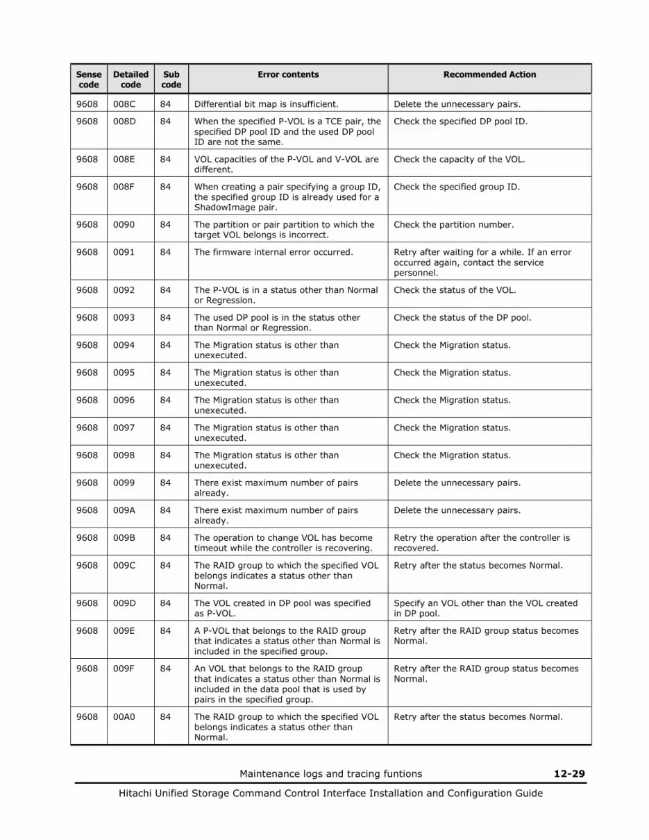
Maintenance logs and tracing funtions 12-29
Hitachi Unified Storage Command Control Interface Installation and Configuration Guide
Sense code
Detailed code
Sub code
Error contents Recommended Action
9608 008C 84 Differential bit map is insufficient. Delete the unnecessary pairs.
9608 008D 84 When the specified P-VOL is a TCE pair, the specified DP pool ID and the used DP pool ID are not the same.
Check the specified DP pool ID.
9608 008E 84 VOL capacities of the P-VOL and V-VOL are different.
Check the capacity of the VOL.
9608 008F 84 When creating a pair specifying a group ID, the specified group ID is already used for a ShadowImage pair.
Check the specified group ID.
9608 0090 84 The partition or pair partition to which the target VOL belongs is incorrect.
Check the partition number.
9608 0091 84 The firmware internal error occurred. Retry after waiting for a while. If an error occurred again, contact the service personnel.
9608 0092 84 The P-VOL is in a status other than Normal or Regression.
Check the status of the VOL.
9608 0093 84 The used DP pool is in the status other than Normal or Regression.
Check the status of the DP pool.
9608 0094 84 The Migration status is other than unexecuted.
Check the Migration status.
9608 0095 84 The Migration status is other than unexecuted.
Check the Migration status.
9608 0096 84 The Migration status is other than unexecuted.
Check the Migration status.
9608 0097 84 The Migration status is other than unexecuted.
Check the Migration status.
9608 0098 84 The Migration status is other than unexecuted.
Check the Migration status.
9608 0099 84 There exist maximum number of pairs already.
Delete the unnecessary pairs.
9608 009A 84 There exist maximum number of pairs already.
Delete the unnecessary pairs.
9608 009B 84 The operation to change VOL has become timeout while the controller is recovering.
Retry the operation after the controller is recovered.
9608 009C 84 The RAID group to which the specified VOL belongs indicates a status other than Normal.
Retry after the status becomes Normal.
9608 009D 84 The VOL created in DP pool was specified as P-VOL.
Specify an VOL other than the VOL created in DP pool.
9608 009E 84 A P-VOL that belongs to the RAID group that indicates a status other than Normal is included in the specified group.
Retry after the RAID group status becomes Normal.
9608 009F 84 An VOL that belongs to the RAID group that indicates a status other than Normal is included in the data pool that is used by pairs in the specified group.
Retry after the RAID group status becomes Normal.
9608 00A0 84 The RAID group to which the specified VOL belongs indicates a status other than Normal.
Retry after the status becomes Normal.
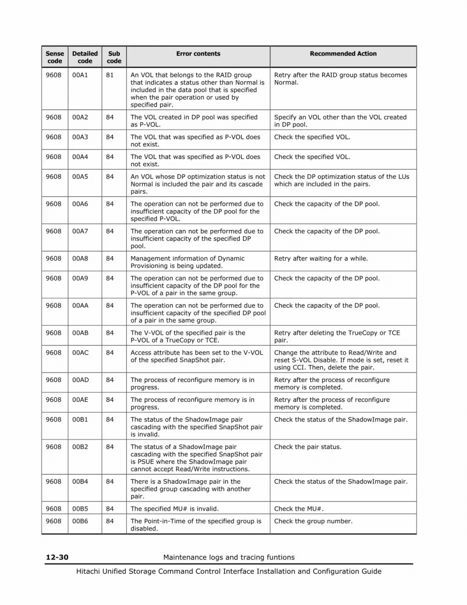
12-30 Maintenance logs and tracing funtions
Hitachi Unified Storage Command Control Interface Installation and Configuration Guide
Sense code
Detailed code
Sub code
Error contents Recommended Action
9608 00A1 81 An VOL that belongs to the RAID group that indicates a status other than Normal is included in the data pool that is specified when the pair operation or used by specified pair.
Retry after the RAID group status becomes Normal.
9608 00A2 84 The VOL created in DP pool was specified as P-VOL.
Specify an VOL other than the VOL created in DP pool.
9608 00A3 84 The VOL that was specified as P-VOL does not exist.
Check the specified VOL.
9608 00A4 84 The VOL that was specified as P-VOL does not exist.
Check the specified VOL.
9608 00A5 84 An VOL whose DP optimization status is not Normal is included the pair and its cascade pairs.
Check the DP optimization status of the LUs which are included in the pairs.
9608 00A6 84 The operation can not be performed due to insufficient capacity of the DP pool for the specified P-VOL.
Check the capacity of the DP pool.
9608 00A7 84 The operation can not be performed due to insufficient capacity of the specified DP pool.
Check the capacity of the DP pool.
9608 00A8 84 Management information of Dynamic Provisioning is being updated.
Retry after waiting for a while.
9608 00A9 84 The operation can not be performed due to insufficient capacity of the DP pool for the P-VOL of a pair in the same group.
Check the capacity of the DP pool.
9608 00AA 84 The operation can not be performed due to insufficient capacity of the specified DP pool of a pair in the same group.
Check the capacity of the DP pool.
9608 00AB 84 The V-VOL of the specified pair is the P-VOL of a TrueCopy or TCE.
Retry after deleting the TrueCopy or TCE pair.
9608 00AC 84 Access attribute has been set to the V-VOL of the specified SnapShot pair.
Change the attribute to Read/Write and reset S-VOL Disable. If mode is set, reset it using CCI. Then, delete the pair.
9608 00AD 84 The process of reconfigure memory is in progress.
Retry after the process of reconfigure memory is completed.
9608 00AE 84 The process of reconfigure memory is in progress.
Retry after the process of reconfigure memory is completed.
9608 00B1 84 The status of the ShadowImage pair cascading with the specified SnapShot pair is invalid.
Check the status of the ShadowImage pair.
9608 00B2 84 The status of a ShadowImage pair cascading with the specified SnapShot pair is PSUE where the ShadowImage pair cannot accept Read/Write instructions.
Check the pair status.
9608 00B4 84 There is a ShadowImage pair in the specified group cascading with another pair.
Check the status of the ShadowImage pair.
9608 00B5 84 The specified MU# is invalid. Check the MU#.
9608 00B6 84 The Point-in-Time of the specified group is disabled.
Check the group number.
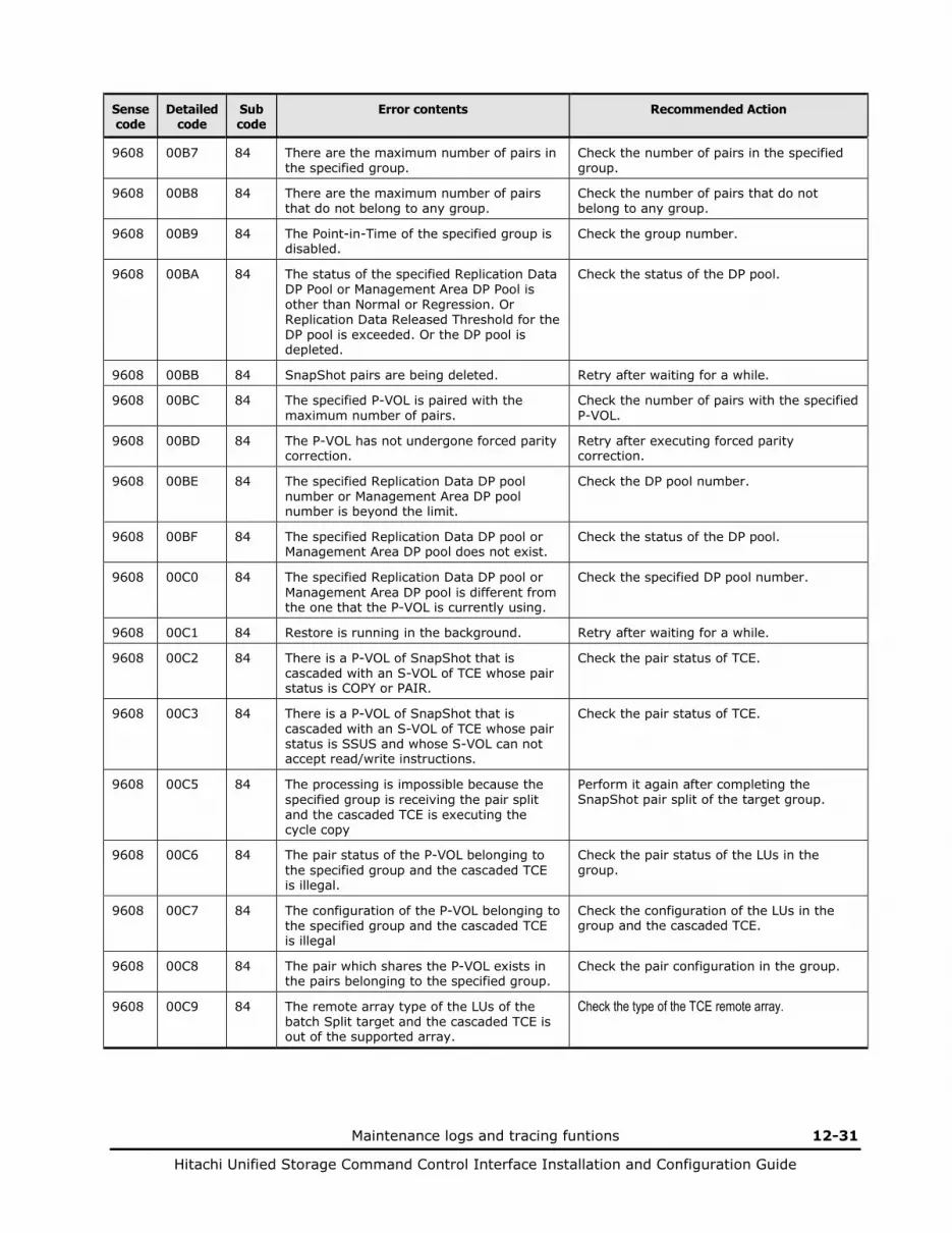
Maintenance logs and tracing funtions 12-31
Hitachi Unified Storage Command Control Interface Installation and Configuration Guide
Sense code
Detailed code
Sub code
Error contents Recommended Action
9608 00B7 84 There are the maximum number of pairs in the specified group.
Check the number of pairs in the specified group.
9608 00B8 84 There are the maximum number of pairs that do not belong to any group.
Check the number of pairs that do not belong to any group.
9608 00B9 84 The Point-in-Time of the specified group is disabled.
Check the group number.
9608 00BA 84 The status of the specified Replication Data DP Pool or Management Area DP Pool is other than Normal or Regression. Or Replication Data Released Threshold for the DP pool is exceeded. Or the DP pool is depleted.
Check the status of the DP pool.
9608 00BB 84 SnapShot pairs are being deleted. Retry after waiting for a while.
9608 00BC 84 The specified P-VOL is paired with the maximum number of pairs.
Check the number of pairs with the specified P-VOL.
9608 00BD 84 The P-VOL has not undergone forced parity correction.
Retry after executing forced parity correction.
9608 00BE 84 The specified Replication Data DP pool number or Management Area DP pool number is beyond the limit.
Check the DP pool number.
9608 00BF 84 The specified Replication Data DP pool or Management Area DP pool does not exist.
Check the status of the DP pool.
9608 00C0 84 The specified Replication Data DP pool or Management Area DP pool is different from the one that the P-VOL is currently using.
Check the specified DP pool number.
9608 00C1 84 Restore is running in the background. Retry after waiting for a while.
9608 00C2 84 There is a P-VOL of SnapShot that is cascaded with an S-VOL of TCE whose pair status is COPY or PAIR.
Check the pair status of TCE.
9608 00C3 84 There is a P-VOL of SnapShot that is cascaded with an S-VOL of TCE whose pair status is SSUS and whose S-VOL can not accept read/write instructions.
Check the pair status of TCE.
9608 00C5 84 The processing is impossible because the specified group is receiving the pair split and the cascaded TCE is executing the cycle copy
Perform it again after completing the SnapShot pair split of the target group.
9608 00C6 84 The pair status of the P-VOL belonging to the specified group and the cascaded TCE is illegal.
Check the pair status of the LUs in the group.
9608 00C7 84 The configuration of the P-VOL belonging to the specified group and the cascaded TCE is illegal
Check the configuration of the LUs in the group and the cascaded TCE.
9608 00C8 84 The pair which shares the P-VOL exists in the pairs belonging to the specified group.
Check the pair configuration in the group.
9608 00C9 84 The remote array type of the LUs of the batch Split target and the cascaded TCE is out of the supported array.
Check the type of the TCE remote array.
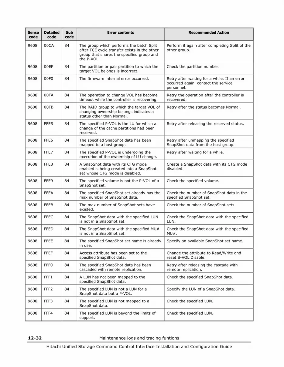
12-32 Maintenance logs and tracing funtions
Hitachi Unified Storage Command Control Interface Installation and Configuration Guide
Sense code
Detailed code
Sub code
Error contents Recommended Action
9608 00CA 84 The group which performs the batch Split after TCE cycle transfer exists in the other group that shares the specified group and the P-VOL.
Perform it again after completing Split of the other group.
9608 00EF 84 The partition or pair partition to which the target VOL belongs is incorrect.
Check the partition number.
9608 00F0 84 The firmware internal error occurred. Retry after waiting for a while. If an error occurred again, contact the service personnel.
9608 00FA 84 The operation to change VOL has become timeout while the controller is recovering.
Retry the operation after the controller is recovered.
9608 00FB 84 The RAID group to which the target VOL of changing ownership belongs indicates a status other than Normal.
Retry after the status becomes Normal.
9608 FFE5 84 The specified P-VOL is the LU for which a change of the cache partitions had been reserved.
Retry after releasing the reserved status.
9608 FFE6 84 The specified SnapShot data has been mapped to a host group.
Retry after unmapping the specified SnapShot data from the host group.
9608 FFE7 84 The specified P-VOL is undergoing the execution of the ownership of LU change.
Retry after waiting for a while.
9608 FFE8 84 A SnapShot data with its CTG mode enabled is being created into a SnapShot set whose CTG mode is disabled.
Create a SnapShot data with its CTG mode disabled.
9608 FFE9 84 The specified volume is not the P-VOL of a SnapShot set.
Check the specified volume.
9608 FFEA 84 The specified SnapShot set already has the max number of SnapShot data.
Check the number of SnapShot data in the specified SnapShot set.
9608 FFEB 84 The max number of SnapShot sets have existed.
Check the number of SnapShot sets.
9608 FFEC 84 The SnapShot data with the specified LUN is not in a SnapShot set.
Check the SnapShot data with the specified LUN.
9608 FFED 84 The SnapShot data with the specified MU# is not in a SnapShot set.
Check the SnapShot data with the specified MU#.
9608 FFEE 84 The specified SnapShot set name is already in use.
Specify an available SnapShot set name.
9608 FFEF 84 Access attribute has been set to the specified SnapShot data.
Change the attribute to Read/Write and reset S-VOL Disable.
9608 FFF0 84 The specified SnapShot data has been cascaded with remote replication.
Retry after releasing the cascade with remote replication.
9608 FFF1 84 A LUN has not been mapped to the specified SnapShot data.
Check the specified SnapShot data.
9608 FFF2 84 The specified LUN is not a LUN for a SnapShot data but a P-VOL.
Specify the LUN of a SnapShot data.
9608 FFF3 84 The specified LUN is not mapped to a SnapShot data.
Check the specified LUN.
9608 FFF4 84 The specified LUN is beyond the limits of support.
Check the specified LUN.

Maintenance logs and tracing funtions 12-33
Hitachi Unified Storage Command Control Interface Installation and Configuration Guide
Sense code
Detailed code
Sub code
Error contents Recommended Action
9608 FFF5 84 A LUN has already been mapped to the specified SnapShot data.
Check the LUN of the SnapShot data.
9608 FFF6 84 The specified P-VOL does not have a SnapShot data with the specified MU#.
Check the specified P-VOL and MU#.
9608 FFF7 84 The specified P-VOL does not have a SnapShot data with the specified SnapShot set name.
Check the specified P-VOL and SnapShot set name.
9608 FFF8 84 The specified LUN is not a LUN for a P-VOL but a SnapShot data.
Specify the LUN of a P-VOL.
9608 FFF9 84 The specified LUN is already in use. Specify an available LUN.
9608 FFFA 84 The SnapShot data can not be identified from the combination of the specified P-VOL and SnapShot set name.
Specify a P-VOL and MU# to indentify the target SnapShot data.
9608 FFFB 84 The specified MU# is beyond the limits of support.
Check the specified MU#.
9608 FFFC 84 The LUN of the specified P-VOL is beyond the limits of support.
Check the LUN for the specified P-VOL.
9608 FFFD 84 Over one P-VOL was specified for the command.
Specify one P-VOL only.
9608 FFFE 84 An internal error occurred regarding CCI. Check the requirements for CCI to work correctly.
9608 FFFF 84 The raidcom command is not supported on this platform.
Confirm the raidcom command you are executing.
9608 x000 84 The controller that controls the VOL cannot be changed because pinned data exits.
Retry after eliminating pinned data.
9608 x001 84 The controller that controls the VOL cannot be changed temporarily.
Retry after waiting for a while.
9608 x002 84 The operation to change VOL is in progress. Retry after waiting for a while.
9608 x003 84 There is no partition to which the current partition is to be changed.
Retry after waiting for a while.
9608 x004 84 The directory configuration is being changed.
Reboot the array.
9608 x005 84 The change of a controller that controls the VOL resulted in a time-out.
Retry after waiting for a while.
9608 x090 84 The partition or pair partition to which the target VOL belongs is incorrect.
Check the partition number.
9608 x091 84 The firmware internal error occurred. Retry after waiting for a while. If an error occurred again, contact the service personnel.
9609 0001 84 The target VOL is undergoing the change of an ownership of VOL.
Retry after waiting for a while.
9609 0002 84 The target VOL is undergoing the change of an ownership of VOL.
Retry after waiting for a while.
9609 0003 84 An instruction to change the controller that controls the VOL was issued.
Retry after waiting for a while.
9609 0004 84 The owner controller LUs to be paired is detached.
Retry.
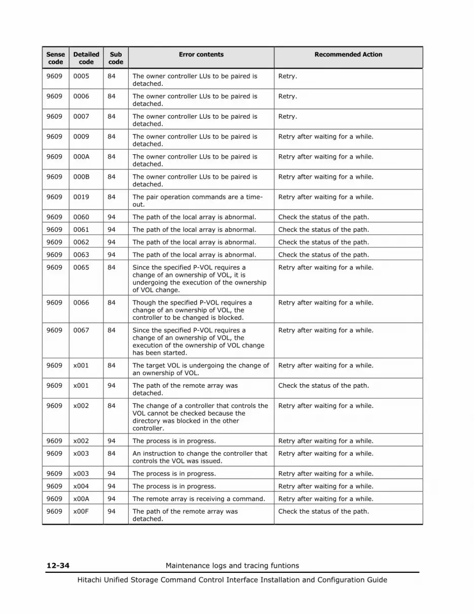
12-34 Maintenance logs and tracing funtions
Hitachi Unified Storage Command Control Interface Installation and Configuration Guide
Sense code
Detailed code
Sub code
Error contents Recommended Action
9609 0005 84 The owner controller LUs to be paired is detached.
Retry.
9609 0006 84 The owner controller LUs to be paired is detached.
Retry.
9609 0007 84 The owner controller LUs to be paired is detached.
Retry.
9609 0009 84 The owner controller LUs to be paired is detached.
Retry after waiting for a while.
9609 000A 84 The owner controller LUs to be paired is detached.
Retry after waiting for a while.
9609 000B 84 The owner controller LUs to be paired is detached.
Retry after waiting for a while.
9609 0019 84 The pair operation commands are a time-out.
Retry after waiting for a while.
9609 0060 94 The path of the local array is abnormal. Check the status of the path.
9609 0061 94 The path of the local array is abnormal. Check the status of the path.
9609 0062 94 The path of the local array is abnormal. Check the status of the path.
9609 0063 94 The path of the local array is abnormal. Check the status of the path.
9609 0065 84 Since the specified P-VOL requires a change of an ownership of VOL, it is undergoing the execution of the ownership of VOL change.
Retry after waiting for a while.
9609 0066 84 Though the specified P-VOL requires a change of an ownership of VOL, the controller to be changed is blocked.
Retry after waiting for a while.
9609 0067 84 Since the specified P-VOL requires a change of an ownership of VOL, the execution of the ownership of VOL change has been started.
Retry after waiting for a while.
9609 x001 84 The target VOL is undergoing the change of an ownership of VOL.
Retry after waiting for a while.
9609 x001 94 The path of the remote array was detached.
Check the status of the path.
9609 x002 84 The change of a controller that controls the VOL cannot be checked because the directory was blocked in the other controller.
Retry after waiting for a while.
9609 x002 94 The process is in progress. Retry after waiting for a while.
9609 x003 84 An instruction to change the controller that controls the VOL was issued.
Retry after waiting for a while.
9609 x003 94 The process is in progress. Retry after waiting for a while.
9609 x004 94 The process is in progress. Retry after waiting for a while.
9609 x00A 94 The remote array is receiving a command. Retry after waiting for a while.
9609 x00F 94 The path of the remote array was detached.
Check the status of the path.
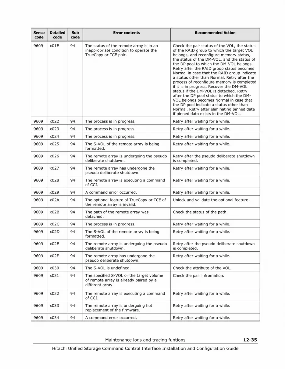
Maintenance logs and tracing funtions 12-35
Hitachi Unified Storage Command Control Interface Installation and Configuration Guide
Sense code
Detailed code
Sub code
Error contents Recommended Action
9609 x01E 94 The status of the remote array is in an inappropriate condition to operate the TrueCopy or TCE pair.
Check the pair status of the VOL, the status of the RAID group to which the target VOL belongs, and reconfigure memory status, the status of the DM-VOL, and the status of the DP pool to which the DM-VOL belongs. Retry after the RAID group status becomes Normal in case that the RAID group indicate a status other than Normal. Retry after the process of reconfigure memory is completed if it is in progress. Recover the DM-VOL status if the DM-VOL is detached. Retry after the DP pool status to which the DM-VOL belongs becomes Normal in case that the DP pool indicate a status other than Normal. Retry after eliminating pinned data if pinned data exists in the DM-VOL.
9609 x022 94 The process is in progress. Retry after waiting for a while.
9609 x023 94 The process is in progress. Retry after waiting for a while.
9609 x024 94 The process is in progress. Retry after waiting for a while.
9609 x025 94 The S-VOL of the remote array is being formatted.
Retry after waiting for a while.
9609 x026 94 The remote array is undergoing the pseudo deliberate shutdown.
Retry after the pseudo deliberate shutdown is completed.
9609 x027 94 The remote array has undergone the pseudo deliberate shutdown.
Retry after waiting for a while.
9609 x028 94 The remote array is executing a command of CCI.
Retry after waiting for a while.
9609 x029 94 A command error occurred. Retry after waiting for a while.
9609 x02A 94 The optional feature of TrueCopy or TCE of the remote array is invalid.
Unlock and validate the optional feature.
9609 x02B 94 The path of the remote array was detached.
Check the status of the path.
9609 x02C 94 The process is in progress. Retry after waiting for a while.
9609 x02D 94 The S-VOL of the remote array is being formatted.
Retry after waiting for a while.
9609 x02E 94 The remote array is undergoing the pseudo deliberate shutdown.
Retry after the pseudo deliberate shutdown is completed.
9609 x02F 94 The remote array has undergone the pseudo deliberate shutdown.
Retry after waiting for a while.
9609 x030 94 The S-VOL is undefined. Check the attribute of the VOL.
9609 x031 94 The specified S-VOL or the target volume of remote array is already paired by a different array.
Check the pair infromation.
9609 x032 94 The remote array is executing a command of CCI.
Retry after waiting for a while.
9609 x033 94 The remote array is undergoing hot replacement of the firmware.
Retry after waiting for a while.
9609 x034 94 A command error occurred. Retry after waiting for a while.

12-36 Maintenance logs and tracing funtions
Hitachi Unified Storage Command Control Interface Installation and Configuration Guide
Sense code
Detailed code
Sub code
Error contents Recommended Action
9609 x035 94 The optional feature of TrueCopy or TCE of the remote array is locked. Otherwise, the process of reconfigure memory is in progress on the remote array.
Unlock and enable the optional feature. Or retry after the process of reconfigure memory is completed.
9609 x036 94 The process is in progress. Retry after waiting for a while. In case that the RAID group to which the VOL that will be S-VOL belongs indicate a status other than Normal, retry after the status becomes Normal.
9609 x037 94 The remote array is busy. Or the copy operation can not be performed because the capacity of the DP pool is depleted or can be depleted by this copy for either the S-VOL or an S-VOL of ShadowImage cascading in the remote array. Or the status of the object VOL is other than normal or regression. Or the full capacity mode is not supported.
Retry after checking the pair status of the VOL, Array ID, number of the connected arrays, and group number. Or resolve the insufficient capacity of the DP pool and retry. Or make the status of the object VOL normal or regression. Or check the firmware version of array.
9609 x038 94 Both of the two paths of the remote array were detached.
Check the status of the path.
9609 x039 94 The process is in progress. Retry after waiting for a while.
9609 x03A 94 The process is in progress. Retry after waiting for a while.
9609 x03E 94 The S-VOL command is receiving a command.
Retry after waiting for a while.
9609 x041 94 The S-VOL of the remote array is doing a duplicate writing.
Retry after waiting for a while.
9609 x042 94 The capacity of TCE pair is beyond the limits within the remote array.
Confirm the capacity of all the SnapShot P-VOLs, all the P-VOLs and S-VOLs of TCE pairs, and DP pools is less than or equal to the supported capacity for the installed cache memory.
9609 x058 94 The ShadowImage P-VOL of the remote array is in the PSUE (S-VOL Switch) status.
Contact the service personnel.
9609 x086 94 The S-VOL of the remote array is specified as a command device.
Specify a volume other than a command device of the remote array as the S-VOL.
9609 x087 94 The S-VOL of the remote array is executing format. Or management information of Dynamic Provisioning for the VOL specified as S-VOL in the remote array is being updated.
Create the pair again after the quick formatting is completed.
Or retry after waiting a while.
9609 x088 94 The S-VOL of the remote array is specified as the DM-VOL.
Specify a volume other than the DM-VOL of the remote array as the S-VOL.
9609 x089 94 The S-VOL of the remote array is in the status of S-VOL Disable.
Check the status of the remote array and cancel the access attribute.
9609 x08A 94 The S-VOL in the remote array cannot be allocated the differential bit of TCE pair because the capacity is beyond the supported limit. Or the copy operation can not be performed because the capacity of the DP pool is depleted or can be depleted by this copy for either the S-VOL or an S-VOL of ShadowImage cascading in the remote array.
Check the status of the remote array. In addition, delete unnecessary pairs of the remote array.
Or resolve the insufficient capacity of the DP pool and retry.
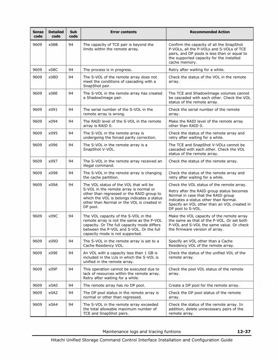
Maintenance logs and tracing funtions 12-37
Hitachi Unified Storage Command Control Interface Installation and Configuration Guide
Sense code
Detailed code
Sub code
Error contents Recommended Action
9609 x08B 94 The capacity of TCE pair is beyond the limits within the remote array.
Confirm the capacity of all the SnapShot P-VOLs, all the P-VOLs and S-VOLs of TCE pairs, and DP pools is less than or equal to the supported capacity for the installed cache memory.
9609 x08C 94 The process is in progress. Retry after waiting for a while.
9609 x08D 94 The S-VOL of the remote array does not meet the conditions of cascading with a SnapShot pair.
Check the status of the VOL in the remote array.
9609 x08E 94 The S-VOL in the remote array has created a ShadowImage pair.
The TCE and ShadowImage volumes cannot be cascaded with each other. Check the VOL status of the remote array.
9609 x091 94 The serial number of the S-VOL in the remote array is wrong.
Check the serial number of the remote array.
9609 x094 94 The RAID level of the S-VOL in the remote array is RAID 0.
Make the RAID level of the remote array other than RAID 0.
9609 x095 94 The S-VOL in the remote array is undergoing the forced parity correction.
Check the status of the remote array and retry after waiting for a while.
9609 x096 94 The S-VOL in the remote array is a SnapShot V-VOL.
The TCE and SnapShot V-VOLs cannot be cascaded with each other. Check the VOL status of the remote array.
9609 x097 94 The S-VOL in the remote array received an illegal command.
Check the status of the remote array.
9609 x098 94 The S-VOL in the remote array is changing the cache partition.
Check the status of the remote array and retry after waiting for a while.
9609 x09A 94 The VOL status of the VOL that will be S-VOL in the remote array is normal or other than regressed or the RAID group to which the VOL is belongs indicates a status other than Normal or the VOL is created in DP pool.
Check the VOL status of the remote array.
Retry after the RAID group status becomes Normal in case that the RAID group indicates a status other than Normal. Specify an VOL other than an VOL created in DP pool to S-VOL.
9609 x09C 94 The VOL capacity of the S-VOL in the remote array is not the same as the P-VOL capacity. Or The full capacity mode differs between the P-VOL and S-VOL. Or the full capacity mode is not supported.
Make the VOL capacity of the remote array the same as that of the P-VOL. Or set both P-VOL and S-VOL the same value. Or check the firmware version of array.
9609 x09D 94 The S-VOL in the remote array is set to a Cache Residency VOL.
Specify an VOL other than a Cache Residency VOL of the remote array.
9609 x09E 94 An VOL with a capacity less than 1 GB is included in the LUs in which the S-VOL is unified in the remote array.
Check the status of the unified VOL of the remote array.
9609 x09F 94 This operation cannot be executed due to lack of resources within the remote array. Retry after waiting for a while.
Check the pool VOL status of the remote array.
9609 x0A0 94 The remote array has no DP pool. Create a DP pool for the remote array.
9609 x0A2 94 The DP pool status in the remote array is normal or other than regressed.
Check the DP pool status of the remote array.
9609 x0A4 94 The S-VOL in the remote array exceeded the total allowable maximum number of TCE and SnapShot pairs.
Check the status of the remote array. In addition, delete unnecessary pairs of the remote array.
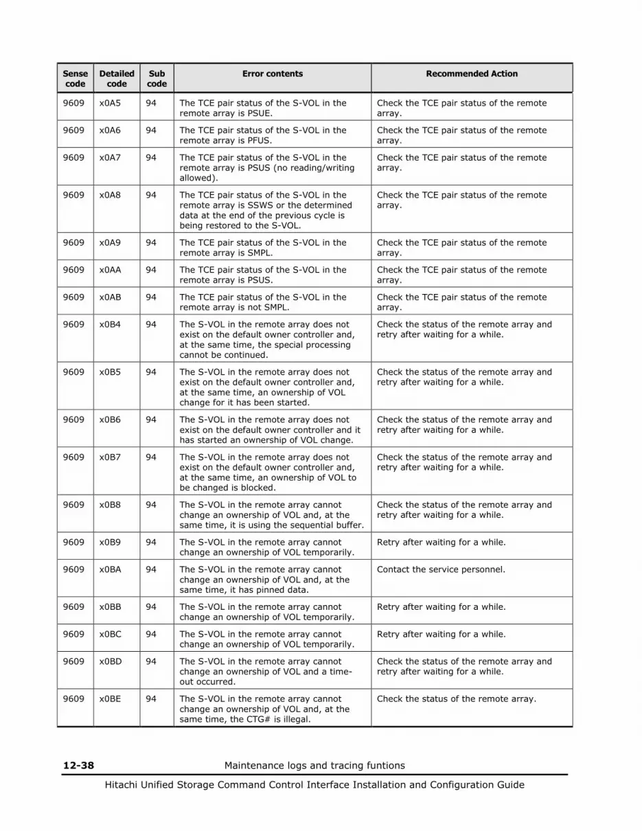
12-38 Maintenance logs and tracing funtions
Hitachi Unified Storage Command Control Interface Installation and Configuration Guide
Sense code
Detailed code
Sub code
Error contents Recommended Action
9609 x0A5 94 The TCE pair status of the S-VOL in the remote array is PSUE.
Check the TCE pair status of the remote array.
9609 x0A6 94 The TCE pair status of the S-VOL in the remote array is PFUS.
Check the TCE pair status of the remote array.
9609 x0A7 94 The TCE pair status of the S-VOL in the remote array is PSUS (no reading/writing allowed).
Check the TCE pair status of the remote array.
9609 x0A8 94 The TCE pair status of the S-VOL in the remote array is SSWS or the determined data at the end of the previous cycle is being restored to the S-VOL.
Check the TCE pair status of the remote array.
9609 x0A9 94 The TCE pair status of the S-VOL in the remote array is SMPL.
Check the TCE pair status of the remote array.
9609 x0AA 94 The TCE pair status of the S-VOL in the remote array is PSUS.
Check the TCE pair status of the remote array.
9609 x0AB 94 The TCE pair status of the S-VOL in the remote array is not SMPL.
Check the TCE pair status of the remote array.
9609 x0B4 94 The S-VOL in the remote array does not exist on the default owner controller and, at the same time, the special processing cannot be continued.
Check the status of the remote array and retry after waiting for a while.
9609 x0B5 94 The S-VOL in the remote array does not exist on the default owner controller and, at the same time, an ownership of VOL change for it has been started.
Check the status of the remote array and retry after waiting for a while.
9609 x0B6 94 The S-VOL in the remote array does not exist on the default owner controller and it has started an ownership of VOL change.
Check the status of the remote array and retry after waiting for a while.
9609 x0B7 94 The S-VOL in the remote array does not exist on the default owner controller and, at the same time, an ownership of VOL to be changed is blocked.
Check the status of the remote array and retry after waiting for a while.
9609 x0B8 94 The S-VOL in the remote array cannot change an ownership of VOL and, at the same time, it is using the sequential buffer.
Check the status of the remote array and retry after waiting for a while.
9609 x0B9 94 The S-VOL in the remote array cannot change an ownership of VOL temporarily.
Retry after waiting for a while.
9609 x0BA 94 The S-VOL in the remote array cannot change an ownership of VOL and, at the same time, it has pinned data.
Contact the service personnel.
9609 x0BB 94 The S-VOL in the remote array cannot change an ownership of VOL temporarily.
Retry after waiting for a while.
9609 x0BC 94 The S-VOL in the remote array cannot change an ownership of VOL temporarily.
Retry after waiting for a while.
9609 x0BD 94 The S-VOL in the remote array cannot change an ownership of VOL and a time-out occurred.
Check the status of the remote array and retry after waiting for a while.
9609 x0BE 94 The S-VOL in the remote array cannot change an ownership of VOL and, at the same time, the CTG# is illegal.
Check the status of the remote array.
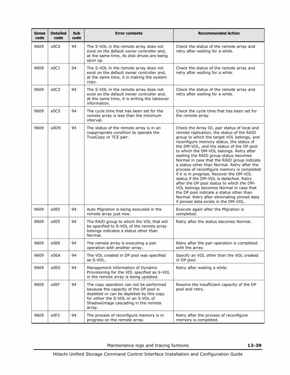
Maintenance logs and tracing funtions 12-39
Hitachi Unified Storage Command Control Interface Installation and Configuration Guide
Sense code
Detailed code
Sub code
Error contents Recommended Action
9609 x0C0 94 The S-VOL in the remote array does not exist on the default owner controller and, at the same time, its disk drives are being spun up.
Check the status of the remote array and retry after waiting for a while.
9609 x0C1 94 The S-VOL in the remote array does not exist on the default owner controller and, at the same time, it is making the system copy.
Check the status of the remote array and retry after waiting for a while.
9609 x0C2 94 The S-VOL in the remote array does not exist on the default owner controller and, at the same time, it is writing the takeover information.
Check the status of the remote array and retry after waiting for a while.
9609 x0C5 94 The cycle time that has been set for the remote array is less than the minimum interval.
Check the cycle time that has been set for the remote array.
9609 x0D9 94 The status of the remote array is in an inappropriate condition to operate the TrueCopy or TCE pair.
Check the Array ID, pair status of local and remote replication, the status of the RAID group to which the target VOL belongs, and reconfigure memory status, the status of the DM-VOL, and the status of the DP pool to which the DM-VOL belongs. Retry after waiting the RAID group status becomes Normal in case that the RAID group indicate a status other than Normal. Retry after the process of reconfigure memory is completed if it is in progress. Recover the DM-VOL status if the DM-VOL is detached. Retry after the DP pool status to which the DM-VOL belongs becomes Normal in case that the DP pool indicate a status other than Normal. Retry after eliminating pinned data if pinned data exists in the DM-VOL.
9609 x0E0 94 Auto Migration is being executed in the remote array just now.
Execute again after the Migration is completed.
9609 x0E5 94 The RAID group to which the VOL that will be specified to S-VOL of the remote array belongs indicates a status other than Normal.
Retry after the status becomes Normal.
9609 x0E8 94 The remote array is executing a pair operation with another array.
Retry after the pair operation is completed with the array.
9609 x0EA 94 The VOL created in DP pool was specified as S-VOL.
Specify an VOL other than the VOL created in DP pool.
9609 x0ED 94 Management information of Dynamic Provisioning for the VOL specified as S-VOL in the remote array is being updated.
Retry after waiting a while.
9609 x0EF 94 The copy operation can not be performed because the capacity of the DP pool is depleted or can be depleted by this copy for either the S-VOL or an S-VOL of ShadowImage cascading in the remote array.
Resolve the insufficient capacity of the DP pool and retry.
9609 x0F2 94 The process of reconfigure memory is in progress on the remote array.
Retry after the process of reconfigure memory is completed.

12-40 Maintenance logs and tracing funtions
Hitachi Unified Storage Command Control Interface Installation and Configuration Guide
Sense code
Detailed code
Sub code
Error contents Recommended Action
9609 x0F3 94 The remote array is reconstructing the memory or the target CTG is executing the cycle copy and receiving the cascaded SnapShot pair split.
Execute it again after waiting for a while. When the SnapShot split instruction is performed in the remote array, execute it again after completing the target CTG cascaded SnapShot pair split.
9609 x0F6 94 The full capacity mode differs between the P-VOL and S-VOL. Or the full capacity mode is not supported.
Set both P-VOL and S-VOL the same value. Or check the firmware version of array.
9609 x103 94 The copy operation can not be performed because the capacity of the DM-VOL is depleted.
Grow the capacity of DM-VOL.
9609 x106 94 The internal transaction of the specified VOL is working now.
Retry after waiting for a while.
9609 x107 94 The copy operation can not be performed because the DM-VOL is detached.
Recover the DM-VOL status.
9609 x109 94 The copy operation can not be performed because the DM-VOL is detached.
Recover the DM-VOL status.
9609 x10A 94 The copy operation can not be performed because the DP pool to which the DM-VOL belongs is detached.
Recover the DP pool.
9609 x10C 94 The copy operation can not be performed because the DP pool to which the DM-VOL belongs is detached.
Recover the DP pool.
9609 x10D 94 Pinned data exists in the DM-VOL. Retry after eliminating pinned data.
9609 x10F 94 Pinned data exists in the DM-VOL. Retry after eliminating pinned data.
9609 x110 94 The operation can not be performed due to insufficient capacity of the DP Pool for the DM-VOL.
Grow the capacity of DP pool.
9609 x112 94 The operation can not be performed due to insufficient capacity of the DP Pool for the DM-VOL.
Grow the capacity of DP pool.
9609 x115 94 The copy operation can not be performed because the DM-VOL has unwritten data.
Delete the ShadowImage pair that is cascaded with the specified pair.
9609 x123 94 The specified Replication Data DP pool for the remote array does not exist.
Check the status of the Replication Data DP pool for the remote array.
9609 x126 94 The specified Management Area DP pool for the remote array does not exist.
Check the status of the Management Area DP pool for the remote array.
9609 x129 94 The status of the specified Replication Data DP pool for the remote array is other than Normal or Regression.
Check the status of the Replication Data DP pool for the remote array.
9609 x12C 94 The specified Management Area DP pool for the remote array is other than Normal or Regression.
Check the status of the Management Area DP pool for the remote array.
9609 x12F 94 The specified Replication Data DP pool for the remote array is different from the one that the specified S-VOL is currently using.
Check the specified Replication Data DP pool number for the remote array.
9609 x133 94 The specified Management Area DP pool for the remote array is different from the one that the specified S-VOL is currently using.
Check the specified Management Area DP pool number for the remote array.
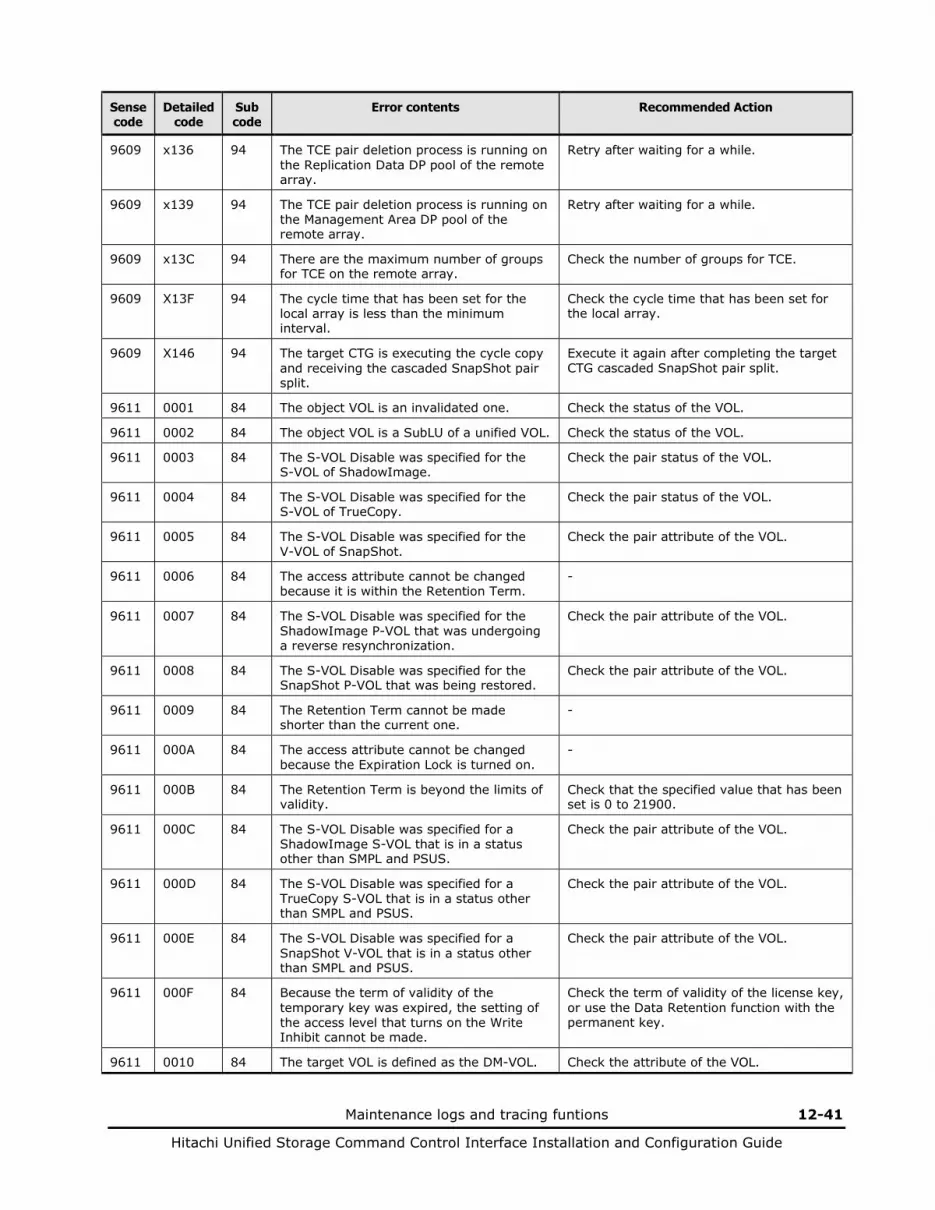
Maintenance logs and tracing funtions 12-41
Hitachi Unified Storage Command Control Interface Installation and Configuration Guide
Sense code
Detailed code
Sub code
Error contents Recommended Action
9609 x136 94 The TCE pair deletion process is running on the Replication Data DP pool of the remote array.
Retry after waiting for a while.
9609 x139 94 The TCE pair deletion process is running on the Management Area DP pool of the remote array.
Retry after waiting for a while.
9609 x13C 94 There are the maximum number of groups for TCE on the remote array.
Check the number of groups for TCE.
9609 X13F 94 The cycle time that has been set for the local array is less than the minimum interval.
Check the cycle time that has been set for the local array.
9609 X146 94 The target CTG is executing the cycle copy and receiving the cascaded SnapShot pair split.
Execute it again after completing the target CTG cascaded SnapShot pair split.
9611 0001 84 The object VOL is an invalidated one. Check the status of the VOL.
9611 0002 84 The object VOL is a SubLU of a unified VOL. Check the status of the VOL.
9611 0003 84 The S-VOL Disable was specified for the S-VOL of ShadowImage.
Check the pair status of the VOL.
9611 0004 84 The S-VOL Disable was specified for the S-VOL of TrueCopy.
Check the pair status of the VOL.
9611 0005 84 The S-VOL Disable was specified for the V-VOL of SnapShot.
Check the pair attribute of the VOL.
9611 0006 84 The access attribute cannot be changed because it is within the Retention Term.
-
9611 0007 84 The S-VOL Disable was specified for the ShadowImage P-VOL that was undergoing a reverse resynchronization.
Check the pair attribute of the VOL.
9611 0008 84 The S-VOL Disable was specified for the SnapShot P-VOL that was being restored.
Check the pair attribute of the VOL.
9611 0009 84 The Retention Term cannot be made shorter than the current one.
-
9611 000A 84 The access attribute cannot be changed because the Expiration Lock is turned on.
-
9611 000B 84 The Retention Term is beyond the limits of validity.
Check that the specified value that has been set is 0 to 21900.
9611 000C 84 The S-VOL Disable was specified for a ShadowImage S-VOL that is in a status other than SMPL and PSUS.
Check the pair attribute of the VOL.
9611 000D 84 The S-VOL Disable was specified for a TrueCopy S-VOL that is in a status other than SMPL and PSUS.
Check the pair attribute of the VOL.
9611 000E 84 The S-VOL Disable was specified for a SnapShot V-VOL that is in a status other than SMPL and PSUS.
Check the pair attribute of the VOL.
9611 000F 84 Because the term of validity of the temporary key was expired, the setting of the access level that turns on the Write Inhibit cannot be made.
Check the term of validity of the license key, or use the Data Retention function with the permanent key.
9611 0010 84 The target VOL is defined as the DM-VOL. Check the attribute of the VOL.
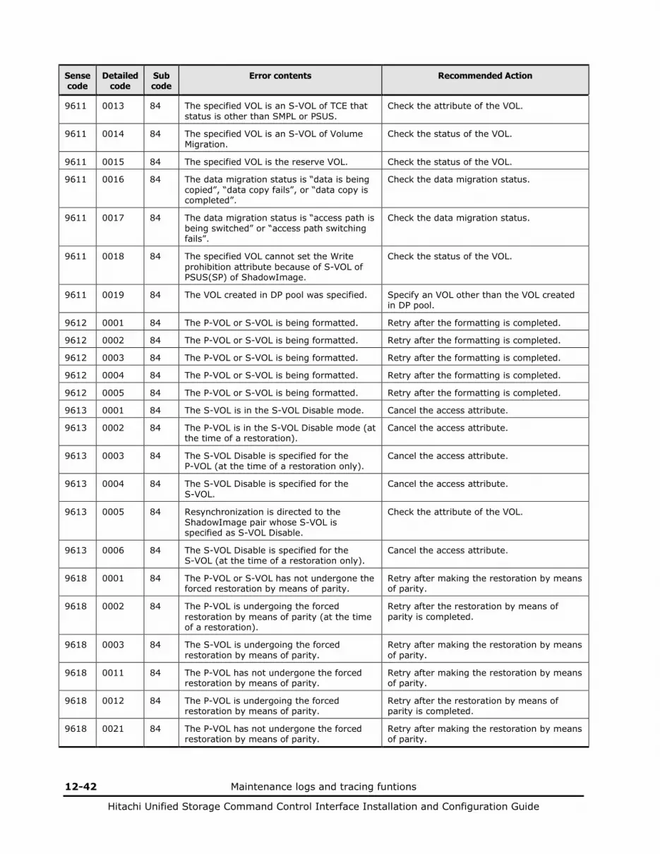
12-42 Maintenance logs and tracing funtions
Hitachi Unified Storage Command Control Interface Installation and Configuration Guide
Sense code
Detailed code
Sub code
Error contents Recommended Action
9611 0013 84 The specified VOL is an S-VOL of TCE that status is other than SMPL or PSUS.
Check the attribute of the VOL.
9611 0014 84 The specified VOL is an S-VOL of Volume Migration.
Check the status of the VOL.
9611 0015 84 The specified VOL is the reserve VOL. Check the status of the VOL.
9611 0016 84 The data migration status is “data is being copied”, “data copy fails”, or “data copy is completed”.
Check the data migration status.
9611 0017 84 The data migration status is “access path is being switched” or “access path switching fails”.
Check the data migration status.
9611 0018 84 The specified VOL cannot set the Write prohibition attribute because of S-VOL of PSUS(SP) of ShadowImage.
Check the status of the VOL.
9611 0019 84 The VOL created in DP pool was specified. Specify an VOL other than the VOL created in DP pool.
9612 0001 84 The P-VOL or S-VOL is being formatted. Retry after the formatting is completed.
9612 0002 84 The P-VOL or S-VOL is being formatted. Retry after the formatting is completed.
9612 0003 84 The P-VOL or S-VOL is being formatted. Retry after the formatting is completed.
9612 0004 84 The P-VOL or S-VOL is being formatted. Retry after the formatting is completed.
9612 0005 84 The P-VOL or S-VOL is being formatted. Retry after the formatting is completed.
9613 0001 84 The S-VOL is in the S-VOL Disable mode. Cancel the access attribute.
9613 0002 84 The P-VOL is in the S-VOL Disable mode (at the time of a restoration).
Cancel the access attribute.
9613 0003 84 The S-VOL Disable is specified for the P-VOL (at the time of a restoration only).
Cancel the access attribute.
9613 0004 84 The S-VOL Disable is specified for the S-VOL.
Cancel the access attribute.
9613 0005 84 Resynchronization is directed to the ShadowImage pair whose S-VOL is specified as S-VOL Disable.
Check the attribute of the VOL.
9613 0006 84 The S-VOL Disable is specified for the S-VOL (at the time of a restoration only).
Cancel the access attribute.
9618 0001 84 The P-VOL or S-VOL has not undergone the forced restoration by means of parity.
Retry after making the restoration by means of parity.
9618 0002 84 The P-VOL is undergoing the forced restoration by means of parity (at the time of a restoration).
Retry after the restoration by means of parity is completed.
9618 0003 84 The S-VOL is undergoing the forced restoration by means of parity.
Retry after making the restoration by means of parity.
9618 0011 84 The P-VOL has not undergone the forced restoration by means of parity.
Retry after making the restoration by means of parity.
9618 0012 84 The P-VOL is undergoing the forced restoration by means of parity.
Retry after the restoration by means of parity is completed.
9618 0021 84 The P-VOL has not undergone the forced restoration by means of parity.
Retry after making the restoration by means of parity.
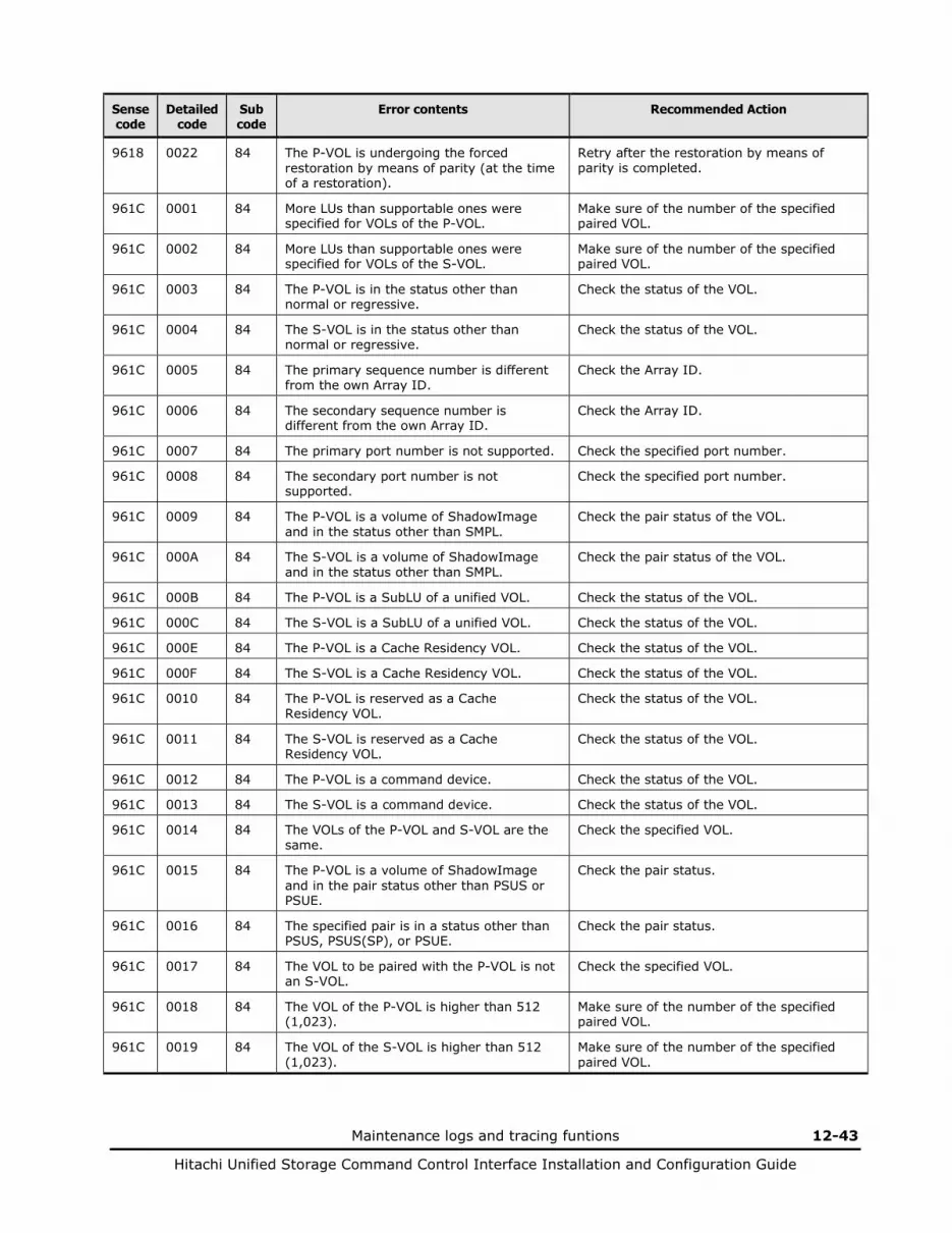
Maintenance logs and tracing funtions 12-43
Hitachi Unified Storage Command Control Interface Installation and Configuration Guide
Sense code
Detailed code
Sub code
Error contents Recommended Action
9618 0022 84 The P-VOL is undergoing the forced restoration by means of parity (at the time of a restoration).
Retry after the restoration by means of parity is completed.
961C 0001 84 More LUs than supportable ones were specified for VOLs of the P-VOL.
Make sure of the number of the specified paired VOL.
961C 0002 84 More LUs than supportable ones were specified for VOLs of the S-VOL.
Make sure of the number of the specified paired VOL.
961C 0003 84 The P-VOL is in the status other than normal or regressive.
Check the status of the VOL.
961C 0004 84 The S-VOL is in the status other than normal or regressive.
Check the status of the VOL.
961C 0005 84 The primary sequence number is different from the own Array ID.
Check the Array ID.
961C 0006 84 The secondary sequence number is different from the own Array ID.
Check the Array ID.
961C 0007 84 The primary port number is not supported. Check the specified port number.
961C 0008 84 The secondary port number is not supported.
Check the specified port number.
961C 0009 84 The P-VOL is a volume of ShadowImage and in the status other than SMPL.
Check the pair status of the VOL.
961C 000A 84 The S-VOL is a volume of ShadowImage and in the status other than SMPL.
Check the pair status of the VOL.
961C 000B 84 The P-VOL is a SubLU of a unified VOL. Check the status of the VOL.
961C 000C 84 The S-VOL is a SubLU of a unified VOL. Check the status of the VOL.
961C 000E 84 The P-VOL is a Cache Residency VOL. Check the status of the VOL.
961C 000F 84 The S-VOL is a Cache Residency VOL. Check the status of the VOL.
961C 0010 84 The P-VOL is reserved as a Cache Residency VOL.
Check the status of the VOL.
961C 0011 84 The S-VOL is reserved as a Cache Residency VOL.
Check the status of the VOL.
961C 0012 84 The P-VOL is a command device. Check the status of the VOL.
961C 0013 84 The S-VOL is a command device. Check the status of the VOL.
961C 0014 84 The VOLs of the P-VOL and S-VOL are the same.
Check the specified VOL.
961C 0015 84 The P-VOL is a volume of ShadowImage and in the pair status other than PSUS or PSUE.
Check the pair status.
961C 0016 84 The specified pair is in a status other than PSUS, PSUS(SP), or PSUE.
Check the pair status.
961C 0017 84 The VOL to be paired with the P-VOL is not an S-VOL.
Check the specified VOL.
961C 0018 84 The VOL of the P-VOL is higher than 512 (1,023).
Make sure of the number of the specified paired VOL.
961C 0019 84 The VOL of the S-VOL is higher than 512 (1,023).
Make sure of the number of the specified paired VOL.
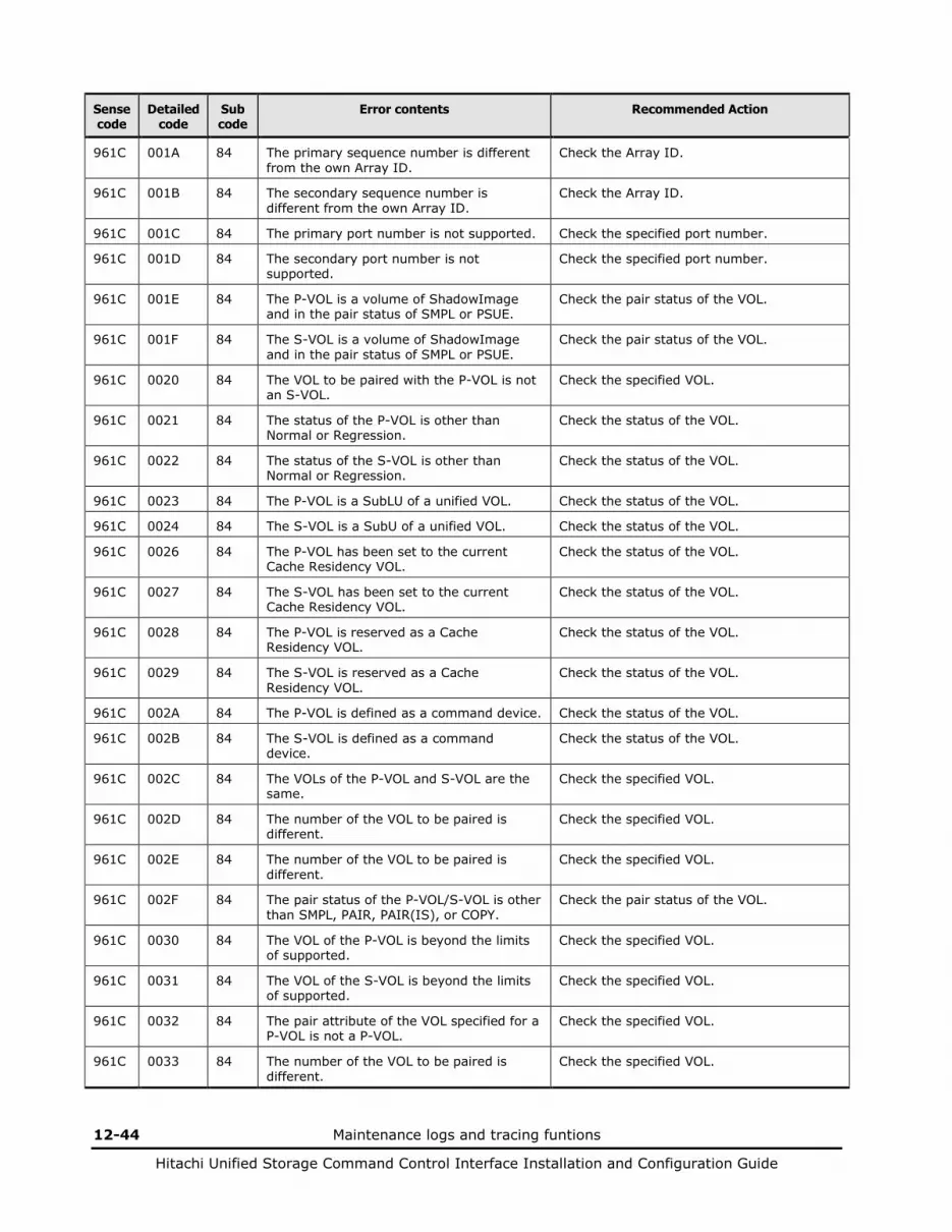
12-44 Maintenance logs and tracing funtions
Hitachi Unified Storage Command Control Interface Installation and Configuration Guide
Sense code
Detailed code
Sub code
Error contents Recommended Action
961C 001A 84 The primary sequence number is different from the own Array ID.
Check the Array ID.
961C 001B 84 The secondary sequence number is different from the own Array ID.
Check the Array ID.
961C 001C 84 The primary port number is not supported. Check the specified port number.
961C 001D 84 The secondary port number is not supported.
Check the specified port number.
961C 001E 84 The P-VOL is a volume of ShadowImage and in the pair status of SMPL or PSUE.
Check the pair status of the VOL.
961C 001F 84 The S-VOL is a volume of ShadowImage and in the pair status of SMPL or PSUE.
Check the pair status of the VOL.
961C 0020 84 The VOL to be paired with the P-VOL is not an S-VOL.
Check the specified VOL.
961C 0021 84 The status of the P-VOL is other than Normal or Regression.
Check the status of the VOL.
961C 0022 84 The status of the S-VOL is other than Normal or Regression.
Check the status of the VOL.
961C 0023 84 The P-VOL is a SubLU of a unified VOL. Check the status of the VOL.
961C 0024 84 The S-VOL is a SubU of a unified VOL. Check the status of the VOL.
961C 0026 84 The P-VOL has been set to the current Cache Residency VOL.
Check the status of the VOL.
961C 0027 84 The S-VOL has been set to the current Cache Residency VOL.
Check the status of the VOL.
961C 0028 84 The P-VOL is reserved as a Cache Residency VOL.
Check the status of the VOL.
961C 0029 84 The S-VOL is reserved as a Cache Residency VOL.
Check the status of the VOL.
961C 002A 84 The P-VOL is defined as a command device. Check the status of the VOL.
961C 002B 84 The S-VOL is defined as a command device.
Check the status of the VOL.
961C 002C 84 The VOLs of the P-VOL and S-VOL are the same.
Check the specified VOL.
961C 002D 84 The number of the VOL to be paired is different.
Check the specified VOL.
961C 002E 84 The number of the VOL to be paired is different.
Check the specified VOL.
961C 002F 84 The pair status of the P-VOL/S-VOL is other than SMPL, PAIR, PAIR(IS), or COPY.
Check the pair status of the VOL.
961C 0030 84 The VOL of the P-VOL is beyond the limits of supported.
Check the specified VOL.
961C 0031 84 The VOL of the S-VOL is beyond the limits of supported.
Check the specified VOL.
961C 0032 84 The pair attribute of the VOL specified for a P-VOL is not a P-VOL.
Check the specified VOL.
961C 0033 84 The number of the VOL to be paired is different.
Check the specified VOL.
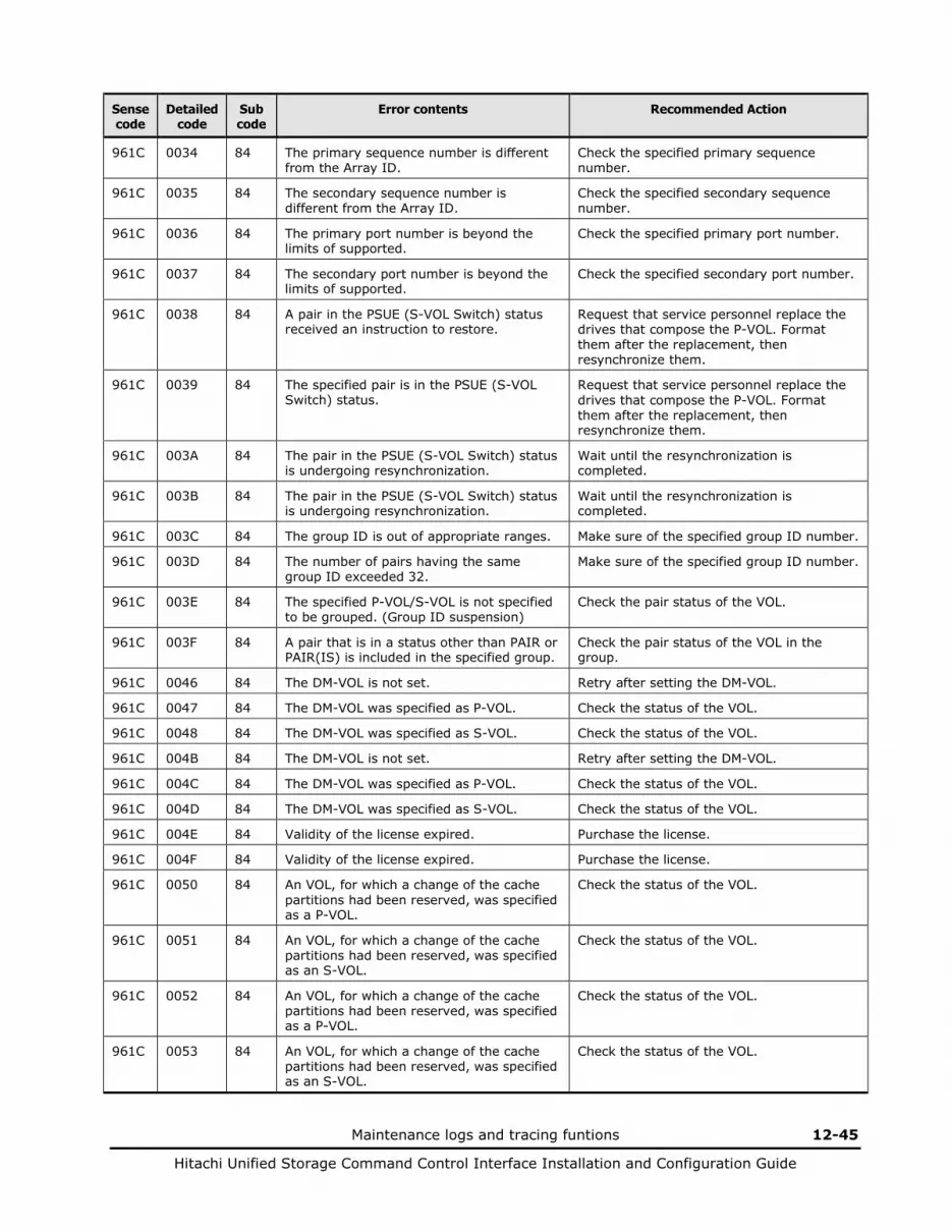
Maintenance logs and tracing funtions 12-45
Hitachi Unified Storage Command Control Interface Installation and Configuration Guide
Sense code
Detailed code
Sub code
Error contents Recommended Action
961C 0034 84 The primary sequence number is different from the Array ID.
Check the specified primary sequence number.
961C 0035 84 The secondary sequence number is different from the Array ID.
Check the specified secondary sequence number.
961C 0036 84 The primary port number is beyond the limits of supported.
Check the specified primary port number.
961C 0037 84 The secondary port number is beyond the limits of supported.
Check the specified secondary port number.
961C 0038 84 A pair in the PSUE (S-VOL Switch) status received an instruction to restore.
Request that service personnel replace the drives that compose the P-VOL. Format them after the replacement, then resynchronize them.
961C 0039 84 The specified pair is in the PSUE (S-VOL Switch) status.
Request that service personnel replace the drives that compose the P-VOL. Format them after the replacement, then resynchronize them.
961C 003A 84 The pair in the PSUE (S-VOL Switch) status is undergoing resynchronization.
Wait until the resynchronization is completed.
961C 003B 84 The pair in the PSUE (S-VOL Switch) status is undergoing resynchronization.
Wait until the resynchronization is completed.
961C 003C 84 The group ID is out of appropriate ranges. Make sure of the specified group ID number.
961C 003D 84 The number of pairs having the same group ID exceeded 32.
Make sure of the specified group ID number.
961C 003E 84 The specified P-VOL/S-VOL is not specified to be grouped. (Group ID suspension)
Check the pair status of the VOL.
961C 003F 84 A pair that is in a status other than PAIR or PAIR(IS) is included in the specified group.
Check the pair status of the VOL in the group.
961C 0046 84 The DM-VOL is not set. Retry after setting the DM-VOL.
961C 0047 84 The DM-VOL was specified as P-VOL. Check the status of the VOL.
961C 0048 84 The DM-VOL was specified as S-VOL. Check the status of the VOL.
961C 004B 84 The DM-VOL is not set. Retry after setting the DM-VOL.
961C 004C 84 The DM-VOL was specified as P-VOL. Check the status of the VOL.
961C 004D 84 The DM-VOL was specified as S-VOL. Check the status of the VOL.
961C 004E 84 Validity of the license expired. Purchase the license.
961C 004F 84 Validity of the license expired. Purchase the license.
961C 0050 84 An VOL, for which a change of the cache partitions had been reserved, was specified as a P-VOL.
Check the status of the VOL.
961C 0051 84 An VOL, for which a change of the cache partitions had been reserved, was specified as an S-VOL.
Check the status of the VOL.
961C 0052 84 An VOL, for which a change of the cache partitions had been reserved, was specified as a P-VOL.
Check the status of the VOL.
961C 0053 84 An VOL, for which a change of the cache partitions had been reserved, was specified as an S-VOL.
Check the status of the VOL.

12-46 Maintenance logs and tracing funtions
Hitachi Unified Storage Command Control Interface Installation and Configuration Guide
Sense code
Detailed code
Sub code
Error contents Recommended Action
961C 005E 84 The specified P-VOL is a TCE pair. Check the status of the VOL.
961C 005F 84 The specified S-VOL is a TCE pair. Check the status of the VOL.
961C 0060 84 The specified P-VOL is a TCE pair. Check the status of the VOL.
961C 0061 84 The specified S-VOL is a TCE pair. Check the status of the VOL.
961C 0064 84 The specified MU# is used within the specified P-VOL.
Check the specified MU number.
961C 0065 84 One or more volumes of PAIR/COPY/RCOPY are under the specified P-VOL.
Check the pair status of the VOL.
961C 0066 84 One or more volumes of special PSUE are under the specified P-VOL.
Check the pair status of the VOL.
961C 0067 84 One or more PSUE pairs that are not readable/writable (PSUE transition due to a failure during the restoration) under the specified P-VOL.
Check the pair status of the VOL.
961C 0068 84 The group ID overlaps within the specified P-VOL at the time of creating the pair of which the group is specified.
Make sure of the specified group ID number.
961C 0069 84 The pair attribute of the specified P-VOL is not a P-VOL or the pair attribute of the specified S-VOL is not an S-VOL.
Check the pair attribute of the VOL.
961C 006A 84 The specified MU# and the MU# of the specified P-VOL are mismatched.
Check the specified MU number.
961C 006B 84 One or more volumes of PAIR/COPY/RCOPY are under the specified P-VOL.
Check the pair status of the VOL.
961C 006C 84 One or more PSUE pairs that are not readable/writable (PSUE transition due to a failure during the restoration) under the specified P-VOL.
Check the pair status of the VOL.
961C 006D 84 The pair attribute of the specified P-VOL is not a P-VOL or the pair attribute of the specified S-VOL is not an S-VOL.
Check the pair attribute of the VOL.
961C 006E 84 The specified MU# and the MU# of the specified S-VOL are mismatched.
Check the specified MU number.
961C 006F 84 The specified MU# and the MU# of the specified S-VOL are mismatched.
Check the specified MU number.
961C 0070 84 The specified MU# is used within the specified P-VOL.
Check the specified MU number.
961C 0071 84 One or more volumes of PAIR/COPY/RCOPY are under the specified P-VOL.
Check the pair status of the VOL.
961C 0072 84 One or more volumes of special PSUE are under the specified P-VOL.
Check the pair status of the VOL.
961C 0073 84 One or more PSUE pairs that are not readable/writable (PSUE transition due to a failure during the restoration) under the specified P-VOL.
Check the pair status of the VOL.
961C 0074 84 The specified MU# and the MU# of the specified S-VOL are mismatched.
Check the specified MU number.
961C 0075 84 The specified MU# and the MU# of the specified S-VOL are mismatched.
Check the specified MU number.

Maintenance logs and tracing funtions 12-47
Hitachi Unified Storage Command Control Interface Installation and Configuration Guide
Sense code
Detailed code
Sub code
Error contents Recommended Action
961C 0077 84 The specified P-VOL is the reserved VOL. Check the status of the VOL.
961C 0078 84 The specified S-VOL is the reserved VOL. Check the status of the VOL.
961C 0079 84 The specified S-VOL is undergoing the migration and its status is PSUS or PSUE.
Check the pair status of the VOL.
961C 0080 84 The specified S-VOL is undergoing the migration and its status is COPY or PSUS.
Check the pair status of the VOL.
961C 0081 84 The specified P-VOL is the reserved VOL. Check the pair status of the VOL.
961C 0082 84 The specified S-VOL is the reserved VOL. Check the pair status of the VOL.
961C 0083 84 The specified S-VOL is undergoing the migration and its status is COPY.
Check the pair status of the VOL.
961C 0084 84 The specified volume is undergoing the migration.
Check the pair status of the VOL.
961C 0085 84 The specified P-VOL is undergoing the migration.
Check the pair status of the VOL.
961C 0086 84 The disk drives that configure a RAID group, to which the specified P-VOL belongs have been spun down.
Check the status of the RAID group.
961C 0087 84 The disk drives that configure a RAID group, to which the specified S-VOL belongs have been spun down.
Check the status of the RAID group.
961C 0088 84 The disk drives that configure a RAID group, to which the specified P-VOL belongs have been spun down.
Check the status of the RAID group.
961C 0089 84 The disk drives that configure a RAID group, to which the specified S-VOL belongs have been spun down.
Check the status of the RAID group.
961C 008A 84 The disk drives that configure a RAID group, to which the specified P-VOL belongs have been spun down.
Check the status of the RAID group.
961C 008B 84 The disk drives that configure a RAID group, to which the specified S-VOL belongs have been spun down.
Check the status of the RAID group.
961C 008C 84 When creating a pair specifying a group ID, the specified group ID is already used for a SnapShot pair.
Check the specified group ID.
961C 008D 84 The S-VOL is a volume of Remote Replication and in a status other than Split and Failure.
Check the status of the Remote Replication pair.
961C 008F 84 An unsupported command option was received.
Check the specified value.
961C 0090 84 The specified P-VOL has been set to a ShadowImage S-VOL.
Check the status of the VOL.
961C 0091 84 The specified P-VOL has been set to a ShadowImage S-VOL.
Check the status of the VOL.
961C 0092 84 The Migration status is other than unexecuted.
Check the Migration status.
961C 0093 84 The Migration status is other than unexecuted.
Check the Migration status.
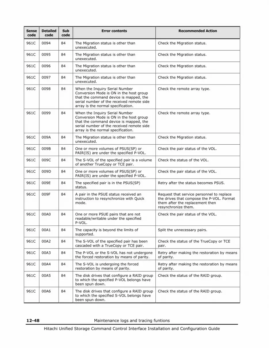
12-48 Maintenance logs and tracing funtions
Hitachi Unified Storage Command Control Interface Installation and Configuration Guide
Sense code
Detailed code
Sub code
Error contents Recommended Action
961C 0094 84 The Migration status is other than unexecuted.
Check the Migration status.
961C 0095 84 The Migration status is other than unexecuted.
Check the Migration status.
961C 0096 84 The Migration status is other than unexecuted.
Check the Migration status.
961C 0097 84 The Migration status is other than unexecuted.
Check the Migration status.
961C 0098 84 When the Inquiry Serial Number Conversion Mode is ON in the host group that the command device is mapped, the serial number of the received remote side array is the normal specification.
Check the remote array type.
961C 0099 84 When the Inquiry Serial Number Conversion Mode is ON in the host group that the command device is mapped, the serial number of the received remote side array is the normal specification.
Check the remote array type.
961C 009A 84 The Migration status is other than unexecuted.
Check the Migration status.
961C 009B 84 One or more volumes of PSUS(SP) or PAIR(IS) are under the specified P-VOL.
Check the pair status of the VOL.
961C 009C 84 The S-VOL of the specified pair is a volume of another TrueCopy or TCE pair.
Check the status of the VOL.
961C 009D 84 One or more volumes of PSUS(SP) or PAIR(IS) are under the specified P-VOL.
Check the pair status of the VOL.
961C 009E 84 The specified pair is in the PSUS(SP) status.
Retry after the status becomes PSUS.
961C 009F 84 A pair in the PSUE status received an instruction to resynchronize with Quick mode.
Request that service personnel to replace the drives that compose the P-VOL. Format them after the replacement then resynchronize them.
961C 00A0 84 One or more PSUE pairs that are not readable/writable under the specified P-VOL.
Check the pair status of the VOL.
961C 00A1 84 The capacity is beyond the limits of supported.
Split the unnecessary pairs.
961C 00A2 84 The S-VOL of the specified pair has been cascaded with a TrueCopy or TCE pair.
Check the status of the TrueCopy or TCE pair.
961C 00A3 84 The P-VOL or the S-VOL has not undergone the forced restoration by means of parity.
Retry after making the restoration by means of parity.
961C 00A4 84 The S-VOL is undergoing the forced restoration by means of parity.
Retry after making the restoration by means of parity.
961C 00A5 84 The disk drives that configure a RAID group to which the specified P-VOL belongs have been spun down.
Check the status of the RAID group.
961C 00A6 84 The disk drives that configure a RAID group to which the specified S-VOL belongs have been spun down.
Check the status of the RAID group.

Maintenance logs and tracing funtions 12-49
Hitachi Unified Storage Command Control Interface Installation and Configuration Guide
Sense code
Detailed code
Sub code
Error contents Recommended Action
961C 00A7 84 A pair that is in a status other than PAIR, PAIR(IS), or COPY is included in the specified group.
Check the pair status of VOL in the group.
961C 00A8 84 A pair that shares the P-VOL with another pair that is in PSUE status that is not readable/writable is included in the specified group.
Check the pair status of VOL in the group.
961C 00A9 84 The capacity is beyond the limits of supported.
Split the unnecessary pairs.
961C 00AA 84 A pair that the S-VOL has been cascaded with a TrueCopy or TCE pair is included in the specified group.
Check the status of the TrueCopy or TCE pair.
961C 00AB 84 A pair that the P-VOL or the S-VOL has not undergone the forced restoration by means of parity is included in the specified group.
Retry after making the restoration by means of parity.
961C 00AC 84 A pair that the S-VOL is undergoing the forced restoration by means of parity is included in the specified group.
Retry after making the restoration by means of parity.
961C 00AD 84 A pair that the P-VOL belongs to a RAID group configured by the disk drives that have been spun down is in the specified group.
Check the status of the RAID group.
961C 00AE 84 A pair that the S-VOL belongs to a RAID group configured by the disk drives that have been spun down is in the specified group.
Check the status of the RAID group.
961C 00AF 84 One or more volumes of PSUS(SP) or PAIR(IS) are under the specified P-VOL.
Check the pair status of the VOL.
961C 00B0 84 The P-VOL or the S-VOL of the specified pair is a volume of another TrueCopy or TCE pair.
Check the status of the TrueCopy or TCE pair.
961C 00B1 84 The specified pair is in the PSUS(SP) status.
Check the pair status of the VOL.
961C 00B2 84 The RAID group to which the specified VOL belongs indicates a status other than Normal.
Retry after the status becomes Normal.
961C 00B3 84 An VOL that belongs to the RAID group that indicates a status other than Normal is included in the specified group.
Retry after the RAID group status becomes Normal.
961C 00B4 84 The specified pair is in a status other than PSUS or PSUE.
Check the pair status.
961C 00B5 84 The VOL that was specified as P-VOL does not exist.
Check the specified VOL.
961C 00B6 84 The VOL that was specified as P-VOL does not exist.
Check the specified VOL.
961C 00B7 84 The VOL that was specified as S-VOL does not exist.
Check the specified VOL.
961C 00B8 84 The VOL that was specified as S-VOL does not exist.
Check the specified VOL.
961C 00B9 84 DP pool is insufficient. Confirm the capacity of DP pool.
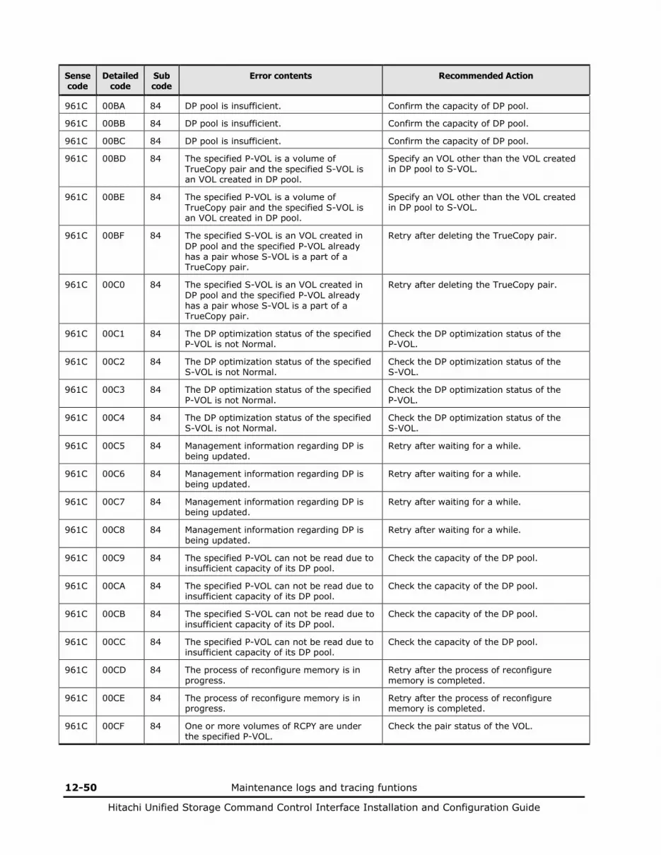
12-50 Maintenance logs and tracing funtions
Hitachi Unified Storage Command Control Interface Installation and Configuration Guide
Sense code
Detailed code
Sub code
Error contents Recommended Action
961C 00BA 84 DP pool is insufficient. Confirm the capacity of DP pool.
961C 00BB 84 DP pool is insufficient. Confirm the capacity of DP pool.
961C 00BC 84 DP pool is insufficient. Confirm the capacity of DP pool.
961C 00BD 84 The specified P-VOL is a volume of TrueCopy pair and the specified S-VOL is an VOL created in DP pool.
Specify an VOL other than the VOL created in DP pool to S-VOL.
961C 00BE 84 The specified P-VOL is a volume of TrueCopy pair and the specified S-VOL is an VOL created in DP pool.
Specify an VOL other than the VOL created in DP pool to S-VOL.
961C 00BF 84 The specified S-VOL is an VOL created in DP pool and the specified P-VOL already has a pair whose S-VOL is a part of a TrueCopy pair.
Retry after deleting the TrueCopy pair.
961C 00C0 84 The specified S-VOL is an VOL created in DP pool and the specified P-VOL already has a pair whose S-VOL is a part of a TrueCopy pair.
Retry after deleting the TrueCopy pair.
961C 00C1 84 The DP optimization status of the specified P-VOL is not Normal.
Check the DP optimization status of the P-VOL.
961C 00C2 84 The DP optimization status of the specified S-VOL is not Normal.
Check the DP optimization status of the S-VOL.
961C 00C3 84 The DP optimization status of the specified P-VOL is not Normal.
Check the DP optimization status of the P-VOL.
961C 00C4 84 The DP optimization status of the specified S-VOL is not Normal.
Check the DP optimization status of the S-VOL.
961C 00C5 84 Management information regarding DP is being updated.
Retry after waiting for a while.
961C 00C6 84 Management information regarding DP is being updated.
Retry after waiting for a while.
961C 00C7 84 Management information regarding DP is being updated.
Retry after waiting for a while.
961C 00C8 84 Management information regarding DP is being updated.
Retry after waiting for a while.
961C 00C9 84 The specified P-VOL can not be read due to insufficient capacity of its DP pool.
Check the capacity of the DP pool.
961C 00CA 84 The specified P-VOL can not be read due to insufficient capacity of its DP pool.
Check the capacity of the DP pool.
961C 00CB 84 The specified S-VOL can not be read due to insufficient capacity of its DP pool.
Check the capacity of the DP pool.
961C 00CC 84 The specified P-VOL can not be read due to insufficient capacity of its DP pool.
Check the capacity of the DP pool.
961C 00CD 84 The process of reconfigure memory is in progress.
Retry after the process of reconfigure memory is completed.
961C 00CE 84 The process of reconfigure memory is in progress.
Retry after the process of reconfigure memory is completed.
961C 00CF 84 One or more volumes of RCPY are under the specified P-VOL.
Check the pair status of the VOL.

Maintenance logs and tracing funtions 12-51
Hitachi Unified Storage Command Control Interface Installation and Configuration Guide
Sense code
Detailed code
Sub code
Error contents Recommended Action
961C 00D0 84 Three or more volumes of PAIR/COPY/PAIR(IS)/PSUS(SP) can not exist under the specified P-VOL.
Check the pair status of the VOL.
961C 00D1 84 One or more volumes of RCPY are under the specified P-VOL.
Check the pair status of the VOL.
961C 00D2 84 Three or more volumes of PAIR/COPY/PAIR(IS)/PSUS(SP) can not exist under the specified P-VOL.
Check the pair status of the VOL.
961C 00D3 84 Two or more volumes of PSUS(SP) can not exist under the specified P-VOL.
Check the pair status of the VOL.
961C 00D4 84 Two or more volumes of PSUS(SP) can not exist under the specified P-VOL.
Check the pair status of the VOL.
961C 00D5 84 Two or more volumes of PSUS(SP) can not exist under the specified P-VOL.
Check the pair status of the VOL.
961C 00D6 84 Two or more volumes of PSUS(SP) can not exist under the specified P-VOL.
Check the pair status of the VOL.
961C 00D7 84 The full capacity mode differs between the P-VOL and S-VOL.
Set both P-VOL and S-VOL the same value.
961C 00D8 84 The full capacity mode differs between the P-VOL and S-VOL.
Set both P-VOL and S-VOL the same value.
961C 00D9 84 The status of the SnapShot pair cascading with the specified ShadowImage pair is invalid.
Check the status of the SnapShot pair.
961C 00DA 84 The status of a SnapShot pair cascading with the specified ShadowImage pair is PSUE where the SnapShot pair cannot accept Read/Write instructions.
Check the pair status.
961C 00DB 84 The specified VOL is a V-VOL. Check the VOL.
961C 00DC 84 The specified S-VOL is the P-VOL of a SnapShot pair.
Check the pair status.
961C 00DD 84 The specified P-VOL already has the maximum number of S-VOLs.
Check the number of S-VOL paired with the P-VOL.
961C 00DE 84 Any pair operations cannot be performed due to the status of the TrueCopy pair cascading with the S-VOL of the SnapShot pair that shared P-VOL of the specified ShadowImage pair.
Check the TrueCopy pair status.
961C 00DF 84 The copy operation can not be performed because the capacity of the DM-VOL is depleted.
Grow the capacity of DM-VOL.
961C 00E0 84 The internal transaction of the specified VOL is working now.
Retry after waiting for a while.
961C 00E1 84 The DM-VOL status is invalid. Check the DM-VOL status.
961C 00E2 84 The copy operation can not be performed because the DP pool to which the DM-VOL belongs is detached.
Recover the DP pool.
961C 00E3 84 Pinned data exists in the DM-VOL. Retry after eliminating pinned data.

12-52 Maintenance logs and tracing funtions
Hitachi Unified Storage Command Control Interface Installation and Configuration Guide
Sense code
Detailed code
Sub code
Error contents Recommended Action
961C 00E4 84 The operation can not be performed due to insufficient capacity of the DP pool for the DM-VOL.
Grow the capacity of DP pool.
961C 00E5 84 The copy operation can not be performed because the DM-VOL has unwritten data.
Delete the specified pair.
961C 00E6 84 The copy operation can not be performed because the DM-VOL has unwritten data.
Retry the operation per pair.
961C 00E7 84 The copy operation can not be performed because the DM-VOL has unwritten data.
Delete the TrueCopy pair that is cascaded with the S-VOL of the specified pair.
9622 0001 84 The specified P-VOL is Normal or other than Regression.
Check the status of the VOL.
9622 0002 84 The specified P-VOL has been set to the current Cache Residency VOL.
Check the attribute of the VOL.
9622 0003 84 The specified P-VOL has been set to the reserved Cache Residency VOL.
Check the attribute of the VOL.
9622 0004 84 The specified P-VOL has been defined to the command device.
Check the attribute of the VOL.
9622 0005 84 The accepted sequence number is different from the Array ID.
Check the Array ID.
9622 0006 84 Both of the two paths are abnormal. Check the status of the path.
9622 0007 84 The specified P-VOL is a SubLU of a unified VOL.
Check the attribute of the VOL.
9622 0009 84 The status of the TCE pair of the specified P-VOL is other than SMPL.
Check the pair status of the VOL.
9622 000A 84 The specified P-VOL is a ShadowImage pair.
Check the attribute of the VOL.
9622 000B 84 The specified P-VOL is a SnapShot V-VOL. Check the attribute of the VOL.
9622 000C 84 The CTG ID is beyond the limits (more than 16) of supported.
Check the CTG ID.
9622 000D 84 The pair status of the specified P-VOL is other than SSUS or PSUE.
Check the pair status of the VOL.
9622 000E 84 The specified P-VOL status is Normal or other than Regression.
Check the status of the VOL.
9622 000F 84 The specified S-VOL is not a pair target VOL.
Check the VOL of the S-VOL.
9622 0010 84 The accepted sequence number is different from the Array ID.
Check the Array ID.
9622 0011 84 Both of the two paths are abnormal. Check the status of the path.
9622 0012 84 When the unit of pair is specified, the pair status of the specified P-VOL is other than COPY and PAIR.
Check the pair status of the VOL.
9622 0013 84 The capacity of TCE pair is beyond the limits.
Confirm the capacity of all the SnapShot P-VOLs, all the P-VOLs and S-VOLs of TCE pairs, and DP pools is less than or equal to the supported capacity for the installed cache memory.
9622 0014 84 The accepted sequence number is different from the Array ID.
Check the Array ID.

Maintenance logs and tracing funtions 12-53
Hitachi Unified Storage Command Control Interface Installation and Configuration Guide
Sense code
Detailed code
Sub code
Error contents Recommended Action
9622 0015 84 The process is in progress. Retry after waiting for a while.
9622 0016 84 When the unit of pair is specified, the specified S-VOL is not a pair target VOL.
Check the VOL of the specified S-VOL.
9622 0017 84 The accepted sequence number is different from the Array ID.
Check the Array ID.
9622 0018 84 The command with the -R option was issued to the P-VOL and that with the -S option was issued to the S-VOL.
Check the pair attribute of the VOL.
9622 0019 84 This operation cannot be executed due to lack of resources.
Retry after waiting for a while.
9622 0020 84 The DP pool is not defined. Define the DP pool and retry.
9622 0021 84 The specified fence level is STATUS. Make sure of the specified fence level.
9622 0022 84 The capacity of TCE pair is beyond the limits.
Confirm the capacity of all the SnapShot P-VOLs, all the P-VOLs and S-VOLs of TCE pairs, and DP pools is less than or equal to the supported capacity for the installed cache memory.
9622 0023 84 The internal pair status of the specified P-VOL is “under pair deletion”.
Check the pair status of the VOL.
9622 0025 84 The pairsplit -P (forced blockade of a P-VOL) command was accepted.
The pairsplit -P (forced blockade of a P-VOL) command is not supported.
9622 0026 84 The type of the pairsplit command is other than Drain (ordinary splitting).
Check the command line.
9622 0027 84 The S-VOL received an instruction. Check the pair attribute of the VOL.
9622 0029 84 The S-VOL received an instruction. Check the pair attribute of the VOL.
9622 002A 84 The P-VOL received an instruction. Check the pair attribute of the VOL.
9622 002B 84 When the unit of pair is specified, the pair status of the specified S-VOL is SMPL or COPY.
Check the pair status of the VOL.
9622 002C 84 The accepted sequence number is different from the Array ID.
Check the Array ID.
9622 002D 84 The specified MU number is beyond the limits (0 to13) of supported.
Check the specified MU number.
9622 0030 84 The S-VOL received an instruction. Check the pair attribute of the VOL.
9622 0032 84 The RAID group, to which the specified P-VOL belongs, is RAID 0.
Check the RAID level of the specified VOL.
9622 0036 84 The specified P-VOL is a SnapShot P-VOL and it is being restored.
Check the pair status of the SnapShot.
9622 0037 84 The specified P-VOL is a SnapShot P-VOL and its status was changed to PSUE during restoration.
Check the pair status of the SnapShot.
9622 0038 84 There is no vacancy in the generation bits. Retry after waiting for a while.
9622 0039 84 There is one or more pairs in the status of “under execution of pairsplit -mscas command” in the target CTG.
Check the pair status of each VOL in the target CTG. It is required to wait until the process is completed.
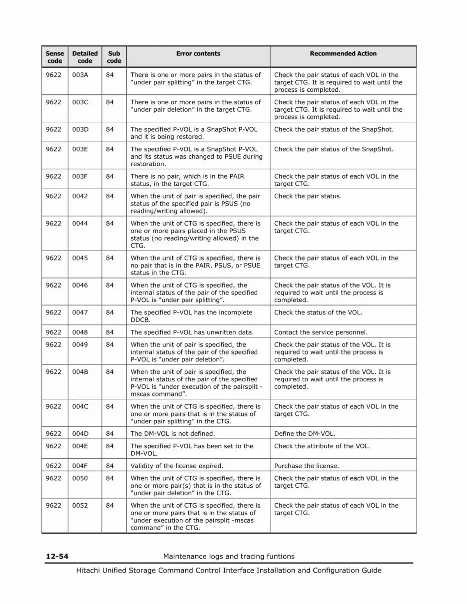
12-54 Maintenance logs and tracing funtions
Hitachi Unified Storage Command Control Interface Installation and Configuration Guide
Sense code
Detailed code
Sub code
Error contents Recommended Action
9622 003A 84 There is one or more pairs in the status of “under pair splitting” in the target CTG.
Check the pair status of each VOL in the target CTG. It is required to wait until the process is completed.
9622 003C 84 There is one or more pairs in the status of “under pair deletion” in the target CTG.
Check the pair status of each VOL in the target CTG. It is required to wait until the process is completed.
9622 003D 84 The specified P-VOL is a SnapShot P-VOL and it is being restored.
Check the pair status of the SnapShot.
9622 003E 84 The specified P-VOL is a SnapShot P-VOL and its status was changed to PSUE during restoration.
Check the pair status of the SnapShot.
9622 003F 84 There is no pair, which is in the PAIR status, in the target CTG.
Check the pair status of each VOL in the target CTG.
9622 0042 84 When the unit of pair is specified, the pair status of the specified pair is PSUS (no reading/writing allowed).
Check the pair status.
9622 0044 84 When the unit of CTG is specified, there is one or more pairs placed in the PSUS status (no reading/writing allowed) in the CTG.
Check the pair status of each VOL in the target CTG.
9622 0045 84 When the unit of CTG is specified, there is no pair that is in the PAIR, PSUS, or PSUE status in the CTG.
Check the pair status of each VOL in the target CTG.
9622 0046 84 When the unit of CTG is specified, the internal status of the pair of the specified P-VOL is “under pair splitting”.
Check the pair status of the VOL. It is required to wait until the process is completed.
9622 0047 84 The specified P-VOL has the incomplete DDCB.
Check the status of the VOL.
9622 0048 84 The specified P-VOL has unwritten data. Contact the service personnel.
9622 0049 84 When the unit of pair is specified, the internal status of the pair of the specified P-VOL is “under pair deletion”.
Check the pair status of the VOL. It is required to wait until the process is completed.
9622 004B 84 When the unit of pair is specified, the internal status of the pair of the specified P-VOL is “under execution of the pairsplit -mscas command”.
Check the pair status of the VOL. It is required to wait until the process is completed.
9622 004C 84 When the unit of CTG is specified, there is one or more pairs that is in the status of “under pair splitting” in the CTG.
Check the pair status of each VOL in the target CTG.
9622 004D 84 The DM-VOL is not defined. Define the DM-VOL.
9622 004E 84 The specified P-VOL has been set to the DM-VOL.
Check the attribute of the VOL.
9622 004F 84 Validity of the license expired. Purchase the license.
9622 0050 84 When the unit of CTG is specified, there is one or more pair(s) that is in the status of “under pair deletion” in the CTG.
Check the pair status of each VOL in the target CTG.
9622 0052 84 When the unit of CTG is specified, there is one or more pairs that is in the status of “under execution of the pairsplit -mscas command” in the CTG.
Check the pair status of each VOL in the target CTG.
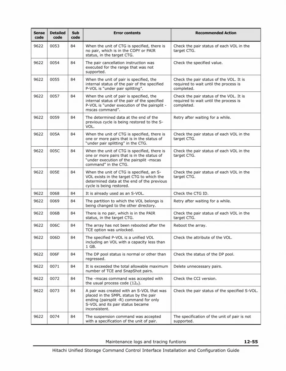
Maintenance logs and tracing funtions 12-55
Hitachi Unified Storage Command Control Interface Installation and Configuration Guide
Sense code
Detailed code
Sub code
Error contents Recommended Action
9622 0053 84 When the unit of CTG is specified, there is no pair, which is in the COPY or PAIR status, in the target CTG.
Check the pair status of each VOL in the target CTG.
9622 0054 84 The pair cancellation instruction was executed for the range that was not supported.
Check the specified value.
9622 0055 84 When the unit of pair is specified, the internal status of the pair of the specified P-VOL is “under pair splitting”.
Check the pair status of the VOL. It is required to wait until the process is completed.
9622 0057 84 When the unit of pair is specified, the internal status of the pair of the specified P-VOL is “under execution of the pairsplit -mscas command”.
Check the pair status of the VOL. It is required to wait until the process is completed.
9622 0059 84 The determined data at the end of the previous cycle is being restored to the S-VOL.
Retry after waiting for a while.
9622 005A 84 When the unit of CTG is specified, there is one or more pairs that is in the status of “under pair splitting” in the CTG.
Check the pair status of each VOL in the target CTG.
9622 005C 84 When the unit of CTG is specified, there is one or more pairs that is in the status of “under execution of the pairsplit -mscas command” in the CTG.
Check the pair status of each VOL in the target CTG.
9622 005E 84 When the unit of CTG is specified, an S-VOL exists in the target CTG to which the determined data at the end of the previous cycle is being restored.
Check the pair status of each VOL in the target CTG.
9622 0068 84 It is already used as an S-VOL. Check the CTG ID.
9622 0069 84 The partition to which the VOL belongs is being changed to the other directory.
Retry after waiting for a while.
9622 006B 84 There is no pair, which is in the PAIR status, in the target CTG.
Check the pair status of each VOL in the target CTG.
9622 006C 84 The array has not been rebooted after the TCE option was unlocked.
Reboot the array.
9622 006D 84 The specified P-VOL is a unified VOL including an VOL with a capacity less than 1 GB.
Check the attribute of the VOL.
9622 006F 84 The DP pool status is normal or other than regressed.
Check the status of the DP pool.
9622 0071 84 It is exceeded the total allowable maximum number of TCE and SnapShot pairs.
Delete unnecessary pairs.
9622 0072 84 The -mscas command was accepted with the usual process code (12H).
Check the CCI version.
9622 0073 84 A pair was created with an S-VOL that was placed in the SMPL status by the pair ending (pairsplit -R) command for only S-VOL and its pair status became inconsistent.
Check the pair status of the specified S-VOL.
9622 0074 84 The suspension command was accepted with a specification of the unit of pair.
The specification of the unit of pair is not supported.
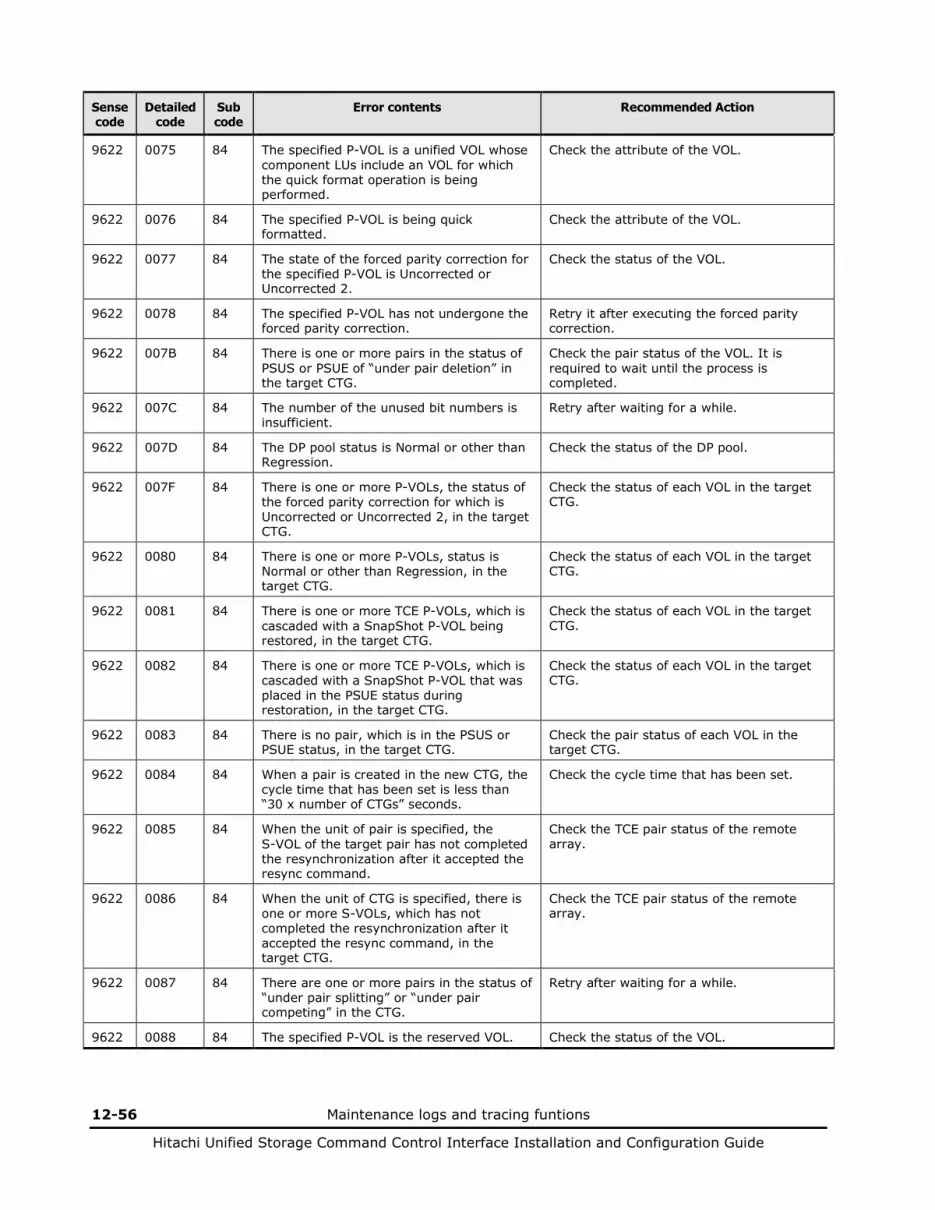
12-56 Maintenance logs and tracing funtions
Hitachi Unified Storage Command Control Interface Installation and Configuration Guide
Sense code
Detailed code
Sub code
Error contents Recommended Action
9622 0075 84 The specified P-VOL is a unified VOL whose component LUs include an VOL for which the quick format operation is being performed.
Check the attribute of the VOL.
9622 0076 84 The specified P-VOL is being quick formatted.
Check the attribute of the VOL.
9622 0077 84 The state of the forced parity correction for the specified P-VOL is Uncorrected or Uncorrected 2.
Check the status of the VOL.
9622 0078 84 The specified P-VOL has not undergone the forced parity correction.
Retry it after executing the forced parity correction.
9622 007B 84 There is one or more pairs in the status of PSUS or PSUE of “under pair deletion” in the target CTG.
Check the pair status of the VOL. It is required to wait until the process is completed.
9622 007C 84 The number of the unused bit numbers is insufficient.
Retry after waiting for a while.
9622 007D 84 The DP pool status is Normal or other than Regression.
Check the status of the DP pool.
9622 007F 84 There is one or more P-VOLs, the status of the forced parity correction for which is Uncorrected or Uncorrected 2, in the target CTG.
Check the status of each VOL in the target CTG.
9622 0080 84 There is one or more P-VOLs, status is Normal or other than Regression, in the target CTG.
Check the status of each VOL in the target CTG.
9622 0081 84 There is one or more TCE P-VOLs, which is cascaded with a SnapShot P-VOL being restored, in the target CTG.
Check the status of each VOL in the target CTG.
9622 0082 84 There is one or more TCE P-VOLs, which is cascaded with a SnapShot P-VOL that was placed in the PSUE status during restoration, in the target CTG.
Check the status of each VOL in the target CTG.
9622 0083 84 There is no pair, which is in the PSUS or PSUE status, in the target CTG.
Check the pair status of each VOL in the target CTG.
9622 0084 84 When a pair is created in the new CTG, the cycle time that has been set is less than “30 x number of CTGs” seconds.
Check the cycle time that has been set.
9622 0085 84 When the unit of pair is specified, the S-VOL of the target pair has not completed the resynchronization after it accepted the resync command.
Check the TCE pair status of the remote array.
9622 0086 84 When the unit of CTG is specified, there is one or more S-VOLs, which has not completed the resynchronization after it accepted the resync command, in the target CTG.
Check the TCE pair status of the remote array.
9622 0087 84 There are one or more pairs in the status of “under pair splitting” or “under pair competing” in the CTG.
Retry after waiting for a while.
9622 0088 84 The specified P-VOL is the reserved VOL. Check the status of the VOL.

Maintenance logs and tracing funtions 12-57
Hitachi Unified Storage Command Control Interface Installation and Configuration Guide
Sense code
Detailed code
Sub code
Error contents Recommended Action
9622 0089 84 The specified P-VOL is undergoing the migration.
Check the pair status of the VOL.
9622 008A 84 The disk drives that configure a RAID group, to which the specified P-VOL belongs have been spun down.
Check the status of the RAID group.
9622 008B 84 The disk drives that configure a RAID group, to which the specified P-VOL belongs have been spun down.
Check the status of the RAID group.
9622 008C 84 There are one or more TCE P-VOLs corresponding to a RAID group that belongs to the CTG concerned and the disk drives that configure the RAID group have been spun down.
Check the status of the RAID group.
9622 008D 84 The primary DP pool ID is beyond the limits of supported.
Check the DP pool ID.
9622 008E 84 The secondary DP pool ID is beyond the limits of supported.
Check the DP pool ID.
9622 008F 84 The specified DP pool ID differs from the DP pool ID in use.
Check the DP pool ID.
9622 0090 84 The Swap pair has been issued to TCE pair with AMS500 or AMS1000.
The Swap command is not supported in this configuration.
9622 0091 84 The Swap operation was received in the P-VOL.
Check the pair attribute of the VOL.
9622 0092 84 The Swap operation was received by specifying the pair unit.
Confirm the operation and try again.
9622 0093 84 The VOL whose pair status is not SSWS exists in the target CTG.
Check the pair status of each VOL in the target CTG.
9622 0094 84 An S-VOL exists in the target CTG to which the determined data at the end of the previous cycle is being restored.
Check the pair status of each VOL in the target CTG.
9622 0095 84 There is a pair that is a status of SSWS and also deleted just in the local array in the CTG.
Delete the pair that is a status of SSWS in the CTG, not only in the local array but also in the remote array. Then execute again.
9622 0096 84 The internal transaction, which are splitting or deleting for SnapShot is working now.
Retry after waiting for a while.
9622 0097 84 The DP pool status is Normal or other than Regression.
Check the status of the DP pool.
9622 0099 84 There is one or more S-VOLs, the status of the forced parity correction for which is Uncorrected or Uncorrected 2, in the target CTG.
Check the status of each VOL in the target CTG.
9622 009A 84 There is one or more S-VOLs, status is Normal or other than Regression, in the target CTG.
Check the status of each VOL in the target CTG.
9622 009B 84 There is one or more TCE S-VOLs, which is cascaded with a SnapShot P-VOL being restored, in the target CTG.
Check the status of each VOL in the target CTG.
9622 009C 84 There is one or more TCE S-VOLs, which is cascaded with a SnapShot P-VOL that was placed in the PSUE status during restoration, in the target CTG.
Check the status of each VOL in the target CTG.
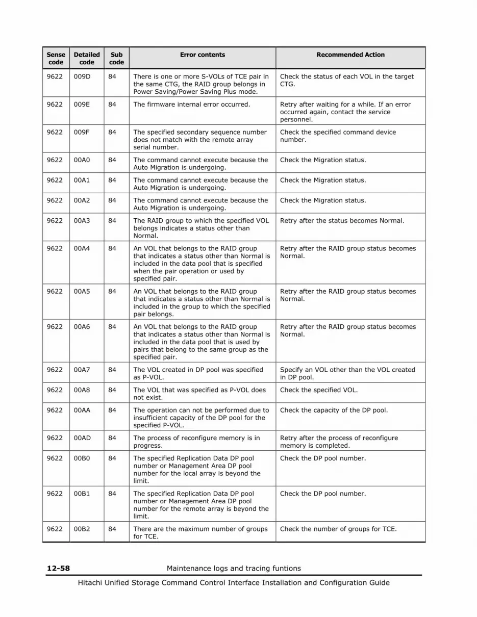
12-58 Maintenance logs and tracing funtions
Hitachi Unified Storage Command Control Interface Installation and Configuration Guide
Sense code
Detailed code
Sub code
Error contents Recommended Action
9622 009D 84 There is one or more S-VOLs of TCE pair in the same CTG, the RAID group belongs in Power Saving/Power Saving Plus mode.
Check the status of each VOL in the target CTG.
9622 009E 84 The firmware internal error occurred. Retry after waiting for a while. If an error occurred again, contact the service personnel.
9622 009F 84 The specified secondary sequence number does not match with the remote array serial number.
Check the specified command device number.
9622 00A0 84 The command cannot execute because the Auto Migration is undergoing.
Check the Migration status.
9622 00A1 84 The command cannot execute because the Auto Migration is undergoing.
Check the Migration status.
9622 00A2 84 The command cannot execute because the Auto Migration is undergoing.
Check the Migration status.
9622 00A3 84 The RAID group to which the specified VOL belongs indicates a status other than Normal.
Retry after the status becomes Normal.
9622 00A4 84 An VOL that belongs to the RAID group that indicates a status other than Normal is included in the data pool that is specified when the pair operation or used by specified pair.
Retry after the RAID group status becomes Normal.
9622 00A5 84 An VOL that belongs to the RAID group that indicates a status other than Normal is included in the group to which the specified pair belongs.
Retry after the RAID group status becomes Normal.
9622 00A6 84 An VOL that belongs to the RAID group that indicates a status other than Normal is included in the data pool that is used by pairs that belong to the same group as the specified pair.
Retry after the RAID group status becomes Normal.
9622 00A7 84 The VOL created in DP pool was specified as P-VOL.
Specify an VOL other than the VOL created in DP pool.
9622 00A8 84 The VOL that was specified as P-VOL does not exist.
Check the specified VOL.
9622 00AA 84 The operation can not be performed due to insufficient capacity of the DP pool for the specified P-VOL.
Check the capacity of the DP pool.
9622 00AD 84 The process of reconfigure memory is in progress.
Retry after the process of reconfigure memory is completed.
9622 00B0 84 The specified Replication Data DP pool number or Management Area DP pool number for the local array is beyond the limit.
Check the DP pool number.
9622 00B1 84 The specified Replication Data DP pool number or Management Area DP pool number for the remote array is beyond the limit.
Check the DP pool number.
9622 00B2 84 There are the maximum number of groups for TCE.
Check the number of groups for TCE.
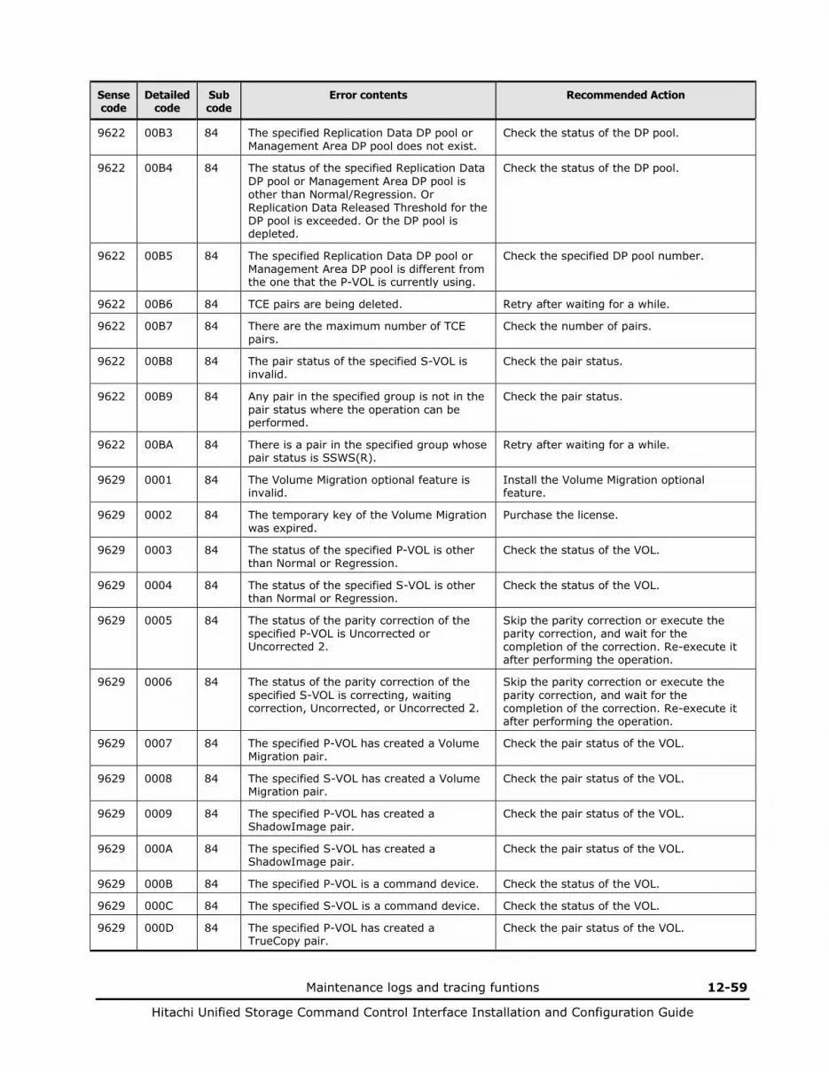
Maintenance logs and tracing funtions 12-59
Hitachi Unified Storage Command Control Interface Installation and Configuration Guide
Sense code
Detailed code
Sub code
Error contents Recommended Action
9622 00B3 84 The specified Replication Data DP pool or Management Area DP pool does not exist.
Check the status of the DP pool.
9622 00B4 84 The status of the specified Replication Data DP pool or Management Area DP pool is other than Normal/Regression. Or Replication Data Released Threshold for the DP pool is exceeded. Or the DP pool is depleted.
Check the status of the DP pool.
9622 00B5 84 The specified Replication Data DP pool or Management Area DP pool is different from the one that the P-VOL is currently using.
Check the specified DP pool number.
9622 00B6 84 TCE pairs are being deleted. Retry after waiting for a while.
9622 00B7 84 There are the maximum number of TCE pairs.
Check the number of pairs.
9622 00B8 84 The pair status of the specified S-VOL is invalid.
Check the pair status.
9622 00B9 84 Any pair in the specified group is not in the pair status where the operation can be performed.
Check the pair status.
9622 00BA 84 There is a pair in the specified group whose pair status is SSWS(R).
Retry after waiting for a while.
9629 0001 84 The Volume Migration optional feature is invalid.
Install the Volume Migration optional feature.
9629 0002 84 The temporary key of the Volume Migration was expired.
Purchase the license.
9629 0003 84 The status of the specified P-VOL is other than Normal or Regression.
Check the status of the VOL.
9629 0004 84 The status of the specified S-VOL is other than Normal or Regression.
Check the status of the VOL.
9629 0005 84 The status of the parity correction of the specified P-VOL is Uncorrected or Uncorrected 2.
Skip the parity correction or execute the parity correction, and wait for the completion of the correction. Re-execute it after performing the operation.
9629 0006 84 The status of the parity correction of the specified S-VOL is correcting, waiting correction, Uncorrected, or Uncorrected 2.
Skip the parity correction or execute the parity correction, and wait for the completion of the correction. Re-execute it after performing the operation.
9629 0007 84 The specified P-VOL has created a Volume Migration pair.
Check the pair status of the VOL.
9629 0008 84 The specified S-VOL has created a Volume Migration pair.
Check the pair status of the VOL.
9629 0009 84 The specified P-VOL has created a ShadowImage pair.
Check the pair status of the VOL.
9629 000A 84 The specified S-VOL has created a ShadowImage pair.
Check the pair status of the VOL.
9629 000B 84 The specified P-VOL is a command device. Check the status of the VOL.
9629 000C 84 The specified S-VOL is a command device. Check the status of the VOL.
9629 000D 84 The specified P-VOL has created a TrueCopy pair.
Check the pair status of the VOL.

12-60 Maintenance logs and tracing funtions
Hitachi Unified Storage Command Control Interface Installation and Configuration Guide
Sense code
Detailed code
Sub code
Error contents Recommended Action
9629 000E 84 The specified S-VOL has created a TrueCopy pair.
Check the pair status of the VOL.
9629 000F 84 The specified P-VOL has created a TCE pair. Check the pair status of the VOL.
9629 0010 84 The specified S-VOL has created a TCE pair.
Check the pair status of the VOL.
9629 0011 84 The P-VOL is a Cache Residency VOL or has been set to the reserved Cache Residency VOL.
Check the status of the VOL.
9629 0012 84 The S-VOL is a Cache Residency VOL or has been set to the reserved Cache Residency VOL.
Check the status of the VOL.
9629 0013 84 The specified P-VOL has created a SnapShot pair.
Check the pair status of the VOL.
9629 0014 84 The specified S-VOL has created a SnapShot pair.
Check the pair status of the VOL.
9629 0015 84 The specified P-VOL is the pool VOL. Check the status of the VOL.
9629 0016 84 The specified S-VOL is the pool VOL. Check the status of the VOL.
9629 0017 84 The specified P-VOL is being quick formatted.
Retry after the quick formatting is completed.
9629 0018 84 The specified S-VOL is being quick formatted.
Retry after the quick formatting is completed.
9629 0019 84 The specified P-VOL is the DM-VOL. Check the status of the VOL.
9629 001A 84 The specified S-VOL is the DM-VOL. Check the status of the VOL.
9629 001B 84 The DM-VOL is not set. Retry after setting the DM-VOL.
9629 001C 84 The specified P-VOL has unwritten data. Check the status of the VOL.
9629 001D 84 The pair cannot be allocated the differential bit map.
Split the unnecessary pairs.
9629 001E 84 The specified P-VOL is a SubLU of a unified VOL.
Check the status of the VOL.
9629 001F 84 The specified S-VOL is a SubLU of a unified VOL.
Check the status of the VOL.
9629 0020 84 The size of the specified P-VOL and the S-VOL are not the same.
Specify an VOL that the same size.
9629 0021 84 The DIRs in charge of the specified P-VOL and the S-VOL are not the same.
Specify an VOL that belongs to the same DIR.
9629 0022 84 The VOLs of the specified P-VOL and S-VOL are the same.
Check the specified VOL.
9629 0023 84 There exist maximum number of pairs already (included ShadowImage pairs).
Split the unnecessary pairs.
9629 0024 84 The specified P-VOL is the VOL, for which a change of the cache partitions had been reserved.
Retry after releasing the reserved status.
9629 0025 84 The specified S-VOL is the VOL, for which a change of the cache partitions had been reserved.
Retry after releasing the reserved status.
9629 0026 84 The RAID group of the specified P-VOL and S-VOL are the same.
Specify a different RAID group.
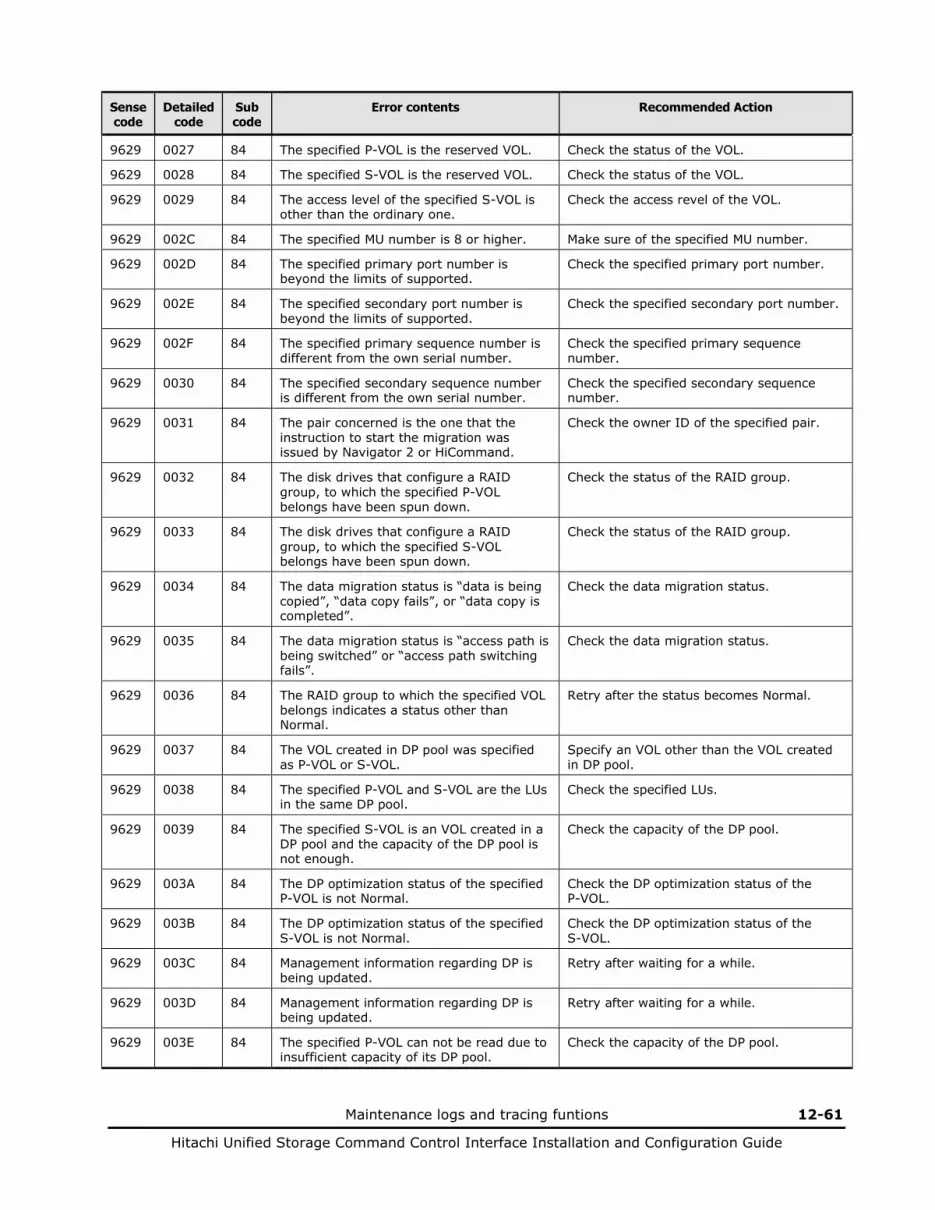
Maintenance logs and tracing funtions 12-61
Hitachi Unified Storage Command Control Interface Installation and Configuration Guide
Sense code
Detailed code
Sub code
Error contents Recommended Action
9629 0027 84 The specified P-VOL is the reserved VOL. Check the status of the VOL.
9629 0028 84 The specified S-VOL is the reserved VOL. Check the status of the VOL.
9629 0029 84 The access level of the specified S-VOL is other than the ordinary one.
Check the access revel of the VOL.
9629 002C 84 The specified MU number is 8 or higher. Make sure of the specified MU number.
9629 002D 84 The specified primary port number is beyond the limits of supported.
Check the specified primary port number.
9629 002E 84 The specified secondary port number is beyond the limits of supported.
Check the specified secondary port number.
9629 002F 84 The specified primary sequence number is different from the own serial number.
Check the specified primary sequence number.
9629 0030 84 The specified secondary sequence number is different from the own serial number.
Check the specified secondary sequence number.
9629 0031 84 The pair concerned is the one that the instruction to start the migration was issued by Navigator 2 or HiCommand.
Check the owner ID of the specified pair.
9629 0032 84 The disk drives that configure a RAID group, to which the specified P-VOL belongs have been spun down.
Check the status of the RAID group.
9629 0033 84 The disk drives that configure a RAID group, to which the specified S-VOL belongs have been spun down.
Check the status of the RAID group.
9629 0034 84 The data migration status is “data is being copied”, “data copy fails”, or “data copy is completed”.
Check the data migration status.
9629 0035 84 The data migration status is “access path is being switched” or “access path switching fails”.
Check the data migration status.
9629 0036 84 The RAID group to which the specified VOL belongs indicates a status other than Normal.
Retry after the status becomes Normal.
9629 0037 84 The VOL created in DP pool was specified as P-VOL or S-VOL.
Specify an VOL other than the VOL created in DP pool.
9629 0038 84 The specified P-VOL and S-VOL are the LUs in the same DP pool.
Check the specified LUs.
9629 0039 84 The specified S-VOL is an VOL created in a DP pool and the capacity of the DP pool is not enough.
Check the capacity of the DP pool.
9629 003A 84 The DP optimization status of the specified P-VOL is not Normal.
Check the DP optimization status of the P-VOL.
9629 003B 84 The DP optimization status of the specified S-VOL is not Normal.
Check the DP optimization status of the S-VOL.
9629 003C 84 Management information regarding DP is being updated.
Retry after waiting for a while.
9629 003D 84 Management information regarding DP is being updated.
Retry after waiting for a while.
9629 003E 84 The specified P-VOL can not be read due to insufficient capacity of its DP pool.
Check the capacity of the DP pool.

12-62 Maintenance logs and tracing funtions
Hitachi Unified Storage Command Control Interface Installation and Configuration Guide
Sense code
Detailed code
Sub code
Error contents Recommended Action
9629 0040 84 The full capacity mode differs between the P-VOL and S-VOL.
Set both P-VOL and S-VOL the same value.
9629 0041 84 The copy operation can not be performed because the capacity of the DM-VOL is depleted.
Grow the capacity of DM-VOL.
9629 0042 84 The internal transaction of the specified VOL is working now.
Retry after waiting for a while.
9629 0043 84 The DM-VOL status is invalid. Check the DM-VOL status.
9629 0044 84 Pinned data exists in the DM-VOL. Retry after eliminating pinned data.
9629 0045 84 The copy operation can not be performed because the DP pool to which the DM-VOL belongs is detached.
Recover the DP pool.
9629 0046 84 The operation can not be performed due to insufficient capacity of the DP Pool for the DM-VOL.
Grow the capacity of DP pool.
9629 0047 84 The copy operation can not be performed because the DM-VOL has unwritten data.
Recover the DM-VOL status.
Maintenance logs and tracing funtions 12-63
Hitachi Unified Storage Command Control Interface Installation and Configuration Guide
Using logging commands
Normally, logging of a command collects the error information when an error occurs in the command execution. In addition, it provides a function of logging all commands for the purpose of the examination and the verification of the command issued by the user script. The logging of all the commands can be done through the setting of the following control valuables.
• HORCC_LOGSZ=file size: valuable This valuable specifies the maximum size of the command log file. The $HORCC_LOG/horcc_HOST.log file is moved to the $HORCC_LOG/horcc_HOST.oldlog file when its size (in kB) exceeds the specified size. This variable can be defined as an environmental variable or the following $HORCC_LOG/horcc_HOST.conf file. When this variable is not specified or the size is specified as zero, the logging is done as a default operation only when an error occurs. Setting example:
HORCC_LOGSZ=2048 Export HORCC_LOGSZ

12-64 Maintenance logs and tracing funtions
Hitachi Unified Storage Command Control Interface Installation and Configuration Guide
• $HORCC_LOG/horcc_HOST.conf file
This file describes the HORCC_LOGSZ variable and the variable for masking the logging. Specify the maximum size. When the variable is not specified as the environmental variable, the HORCC_LOGSZ variable described in this file is used. When neither of them is specified, the logging is done as a default operation only when an error occurs. – HORCC_LOGSZ variable
Describes as following. # For example HORCC_LOGSZ=2048
– Masking variable
This masking variable specifies a command name and a return value. However, the inqraid command and error codes are excluded. For example, when the user script tests the return value of the pairvolchk command at regular intervals, the log data may overflow. In this case, the logging can be masked through the specification of the HORCC_LOGSZ environmental variable as zero, but the script must be changed as shown below. # For example masking pairvolchk on the script export HORCC_LOGSZ=0 Pairvolchk -g xxx -s Unset HORCC_LOGSZ
This function validates logging of a command without changing the user script. # For example, # if you want to mask pairvolchk (returns 22) and raidqry, # you can specify as below. pairvolchk=22 raidqry=0
The user decides whether or not to mask the user script after tracking the $HORCC_LOG/horcc_HOST.conf file without masking the user script.

Maintenance logs and tracing funtions 12-65
Hitachi Unified Storage Command Control Interface Installation and Configuration Guide
• Relation between the environmental variable and the $HORCC_LOG/horcc_HOST.conf file When the HORCC_LOGSZ environmental variable is not specified, the HORCC_LOGSZ variable described in the $HORCC_LOG/horcc_HOST.conf file is used. When neither of them is specified, the logging is done as a default operation only when an error occurs.
Table 12-6 Relation between the environmental variable and the $HORCC_LOG/horcc_HOST.conf file
$HORCC_LOGSZ HORCC_HOST.conf Operation
$HORCC_LOGSZ=size It is not influenced specification. The logging is valid in the specified script.
$HORCC_LOGSZ=0 The logging is invalid in the specified script.
It is not specified HORCC_LOGSZ=size The logging is valid in the instance.
HORCC_LOGSZ=0 The logging is invalid in the instance.
It is not specified or no file exists.
Default logging (logging is done only when an error occurs)
Example:
\HORCM\log* directory [root@raidmanager log9]# ls –l total 16 drwxr-xr-x 3 root root 4096 Oct 27 17:33 curlog -rw-r--r-- 1 root root 3936 Oct 27 17:36 horcc_raidmanager.log -rw-r--r-- 1 root root 2097452 Oct 27 17:29 horcc_raidmanager.oldlog -rw-r--r-- 1 root root 46 Oct 27 17:19 horcc_raidmanager.conf drwxr-xr-x 3 root root 4096 Oct 27 17:19 tmplog
\HORCM\log*\horcc_HOST.log file COMMAND NORMAL : EUserId for HORC : root (0) Tue Nov 1 12:21:53 2005 CMDLINE : pairvolchk -ss -g URA 12:21:54-2d27f-10090- [pairvolchk][exit(32)] COMMAND NORMAL : EUserId for HORC : root (0) Thu Oct 27 17:36:32 2005 CMDLINE : raidqry -l 17:36:32-3d83c-17539- [raidqry][exit(0)] COMMAND ERROR : EUserId for HORC : root (0) Thu Oct 27 17:31:28 2005 CMDLINE : pairdisplay -g UR 17:31:28-9a206-17514- ERROR:cm_sndrcv[rc < 0 from HORCM] 17:31:28-9b0a3-17514- [pairdisplay][exit(239)] [EX_ENOGRP] No such group [Cause ]:The group name which was designated or the device name doesn't exist in the configuration file,or the network address for remote communication doesn't exist. [Action]:Please confirm if the group name exists in the configuration file of the local and remote host.

12-66 Maintenance logs and tracing funtions
Hitachi Unified Storage Command Control Interface Installation and Configuration Guide
\HORCM\log*\horcc_HOST.conf file
# For Example HORCC_LOGSZ=2048 # The masking variable # This variable is used to disable the logging by the command and exit code. # For masking below log pairvolchk returned ‘32’(status is "SVOL_COPY") # COMMAND NORMAL : EUserId for HORC : root (0) Tue Nov 1 12:21:53 2005 # CMDLINE : pairvolchk -ss -g URA # 12:21:54-2d27f-10090- [pairvolchk][exit(32)] pairvolchk=32 pairvolchk=22
13
Copy command options 13-1
Hitachi Unified Storage Command Control Interface Installation and Configuration Guide
Copy command options
Paircreate options Pairsplit options Pairsync options Pairevtwait options Pairsyncwait options Pairmon options Pairvolchk options Pairdisplay options Paircurchk options Horctakeover options Horctakeoff options Raidscan options Raidar options Raidqry options Horcctl options Raidvchkset options Raidvchkdsp options Raidvchkscan options
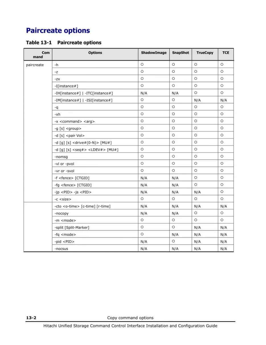
13-2 Copy command options
Hitachi Unified Storage Command Control Interface Installation and Configuration Guide
Paircreate options
Table 13-1 Paircreate options
Command
Options ShadowImage SnapShot TrueCopy TCE
paircreate -h
-z
-zx
-I[instance#]
-IH[instance#] | -ITC[instance#] N/A N/A
-IM[instance#] | -ISI[instance#] N/A N/A
-q
-xh
-x <command> <arg>
-g [s] <group>
-d [s] <pair Vol>
-d [g] [s] <drive#(0-N)> [MU#]
-d [g] [s] <seq#> <LDEV#> [MU#]
-nomsg
-vl or -pvol
-vr or -svol
-f <fence> [CTGID] N/A N/A
-fg <fence> [CTGID] N/A N/A
-jp <PID> -js <PID> N/A N/A N/A
-c <size>
-cto <o-time> [c-time] [r-time] N/A N/A N/A N/A
-nocopy N/A N/A
-m <mode>
-split [Split-Marker] N/A N/A
-fq <mode> N/A N/A N/A
-pid <PID> N/A N/A N/A
-nocsus N/A N/A N/A N/A
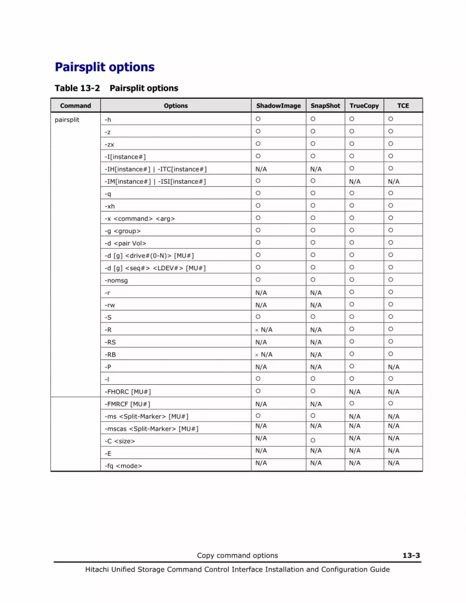
Copy command options 13-3
Hitachi Unified Storage Command Control Interface Installation and Configuration Guide
Pairsplit options
Table 13-2 Pairsplit options
Command Options ShadowImage SnapShot TrueCopy TCE
pairsplit -h
-z
-zx
-I[instance#]
-IH[instance#] | -ITC[instance#] N/A N/A
-IM[instance#] | -ISI[instance#] N/A N/A
-q
-xh
-x <command> <arg>
-g <group>
-d <pair Vol>
-d [g] <drive#(0-N)> [MU#]
-d [g] <seq#> <LDEV#> [MU#]
-nomsg
-r N/A N/A
-rw N/A N/A
-S
-R × N/A N/A
-RS N/A N/A
-RB × N/A N/A
-P N/A N/A N/A
-l
-FHORC [MU#] N/A N/A
-FMRCF [MU#] N/A N/A
-ms <Split-Marker> [MU#] N/A N/A
-mscas <Split-Marker> [MU#] N/A N/A N/A N/A
-C <size> N/A N/A N/A
-E N/A N/A N/A N/A
-fq <mode> N/A N/A N/A N/A

13-4 Copy command options
Hitachi Unified Storage Command Control Interface Installation and Configuration Guide
Pairsync options
Table 13-3 Pairsync options
Command Options ShadowImage SnapShot TrueCopy TCE
pairresync -h
-z
-zx
-I[instance#]
-IH[instance#] | -ITC[instance#] N/A N/A
-IM[instance#] | -ISI[instance#] N/A N/A
-q
-xh
-x <command> <arg>
-g <group>
-d <pair Vol>
-d [g] <drive#(0-N)> [MU#]
-d [g] <seq#> <LDEV#> [MU#]
-nomsg
-c <size>
-cto <o-time> [c-time] [r-time] N/A N/A N/A N/A
-l
-FHORC [MU#] N/A N/A
-FMRCF [MU#] N/A N/A
-swapp N/A N/A
-swaps N/A N/A
-restore N/A N/A
-fq <mode> N/A N/A N/A
-f [g] <fence> [CTGID] N/A N/A N/A N/A
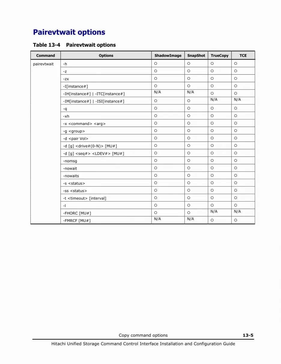
Copy command options 13-5
Hitachi Unified Storage Command Control Interface Installation and Configuration Guide
Pairevtwait options
Table 13-4 Pairevtwait options
Command Options ShadowImage SnapShot TrueCopy TCE
pairevtwait -h
-z
-zx
-I[instance#]
-IH[instance#] | -ITC[instance#] N/A N/A
-IM[instance#] | -ISI[instance#] N/A N/A
-q
-xh
-x <command> <arg>
-g <group>
-d <pair Vol>
-d [g] <drive#(0-N)> [MU#]
-d [g] <seq#> <LDEV#> [MU#]
-nomsg
-nowait
-nowaits
-s <status>
-ss <status>
-t <timeout> [interval]
-l
-FHORC [MU#] N/A N/A
-FMRCF [MU#] N/A N/A
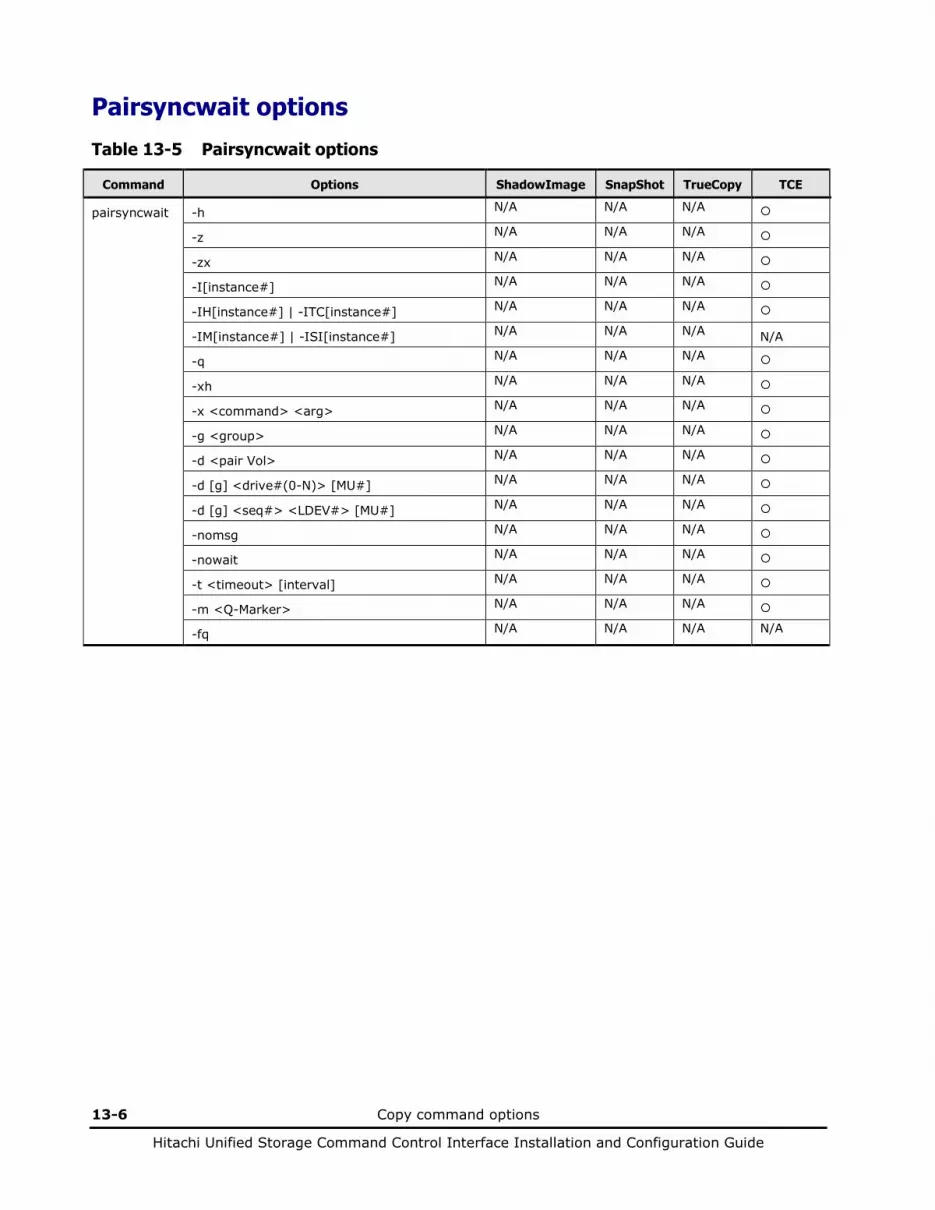
13-6 Copy command options
Hitachi Unified Storage Command Control Interface Installation and Configuration Guide
Pairsyncwait options
Table 13-5 Pairsyncwait options
Command Options ShadowImage SnapShot TrueCopy TCE
pairsyncwait -h N/A N/A N/A
-z N/A N/A N/A
-zx N/A N/A N/A
-I[instance#] N/A N/A N/A
-IH[instance#] | -ITC[instance#] N/A N/A N/A
-IM[instance#] | -ISI[instance#] N/A N/A N/A N/A
-q N/A N/A N/A
-xh N/A N/A N/A
-x <command> <arg> N/A N/A N/A
-g <group> N/A N/A N/A
-d <pair Vol> N/A N/A N/A
-d [g] <drive#(0-N)> [MU#] N/A N/A N/A
-d [g] <seq#> <LDEV#> [MU#] N/A N/A N/A
-nomsg N/A N/A N/A
-nowait N/A N/A N/A
-t <timeout> [interval] N/A N/A N/A
-m <Q-Marker> N/A N/A N/A
-fq N/A N/A N/A N/A

Copy command options 13-7
Hitachi Unified Storage Command Control Interface Installation and Configuration Guide
Pairmon options
Table 13-6 Pairmon options
Command Options ShadowImage SnapShot TrueCopy TCE
pairmon -h
-z
-zx
-I[instance#]
-IH[instance#] | -ITC[instance#] N/A N/A
-IM[instance#] | -ISI[instance#] N/A N/A
-q
-xh
-x <command> <arg>
-D
-allsnd
-resevt
-nowait
-s <status>
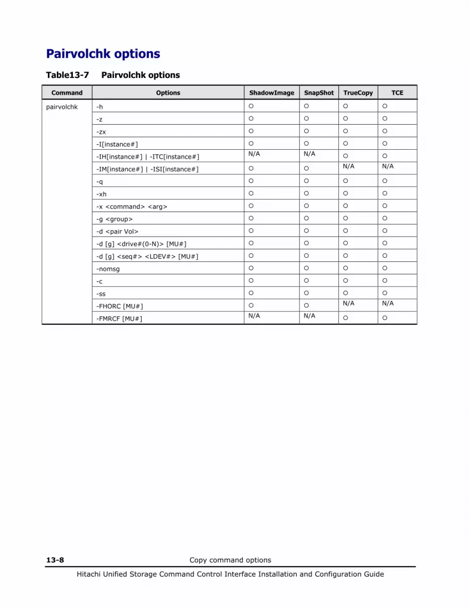
13-8 Copy command options
Hitachi Unified Storage Command Control Interface Installation and Configuration Guide
Pairvolchk options
Table 13-7 Pairvolchk options
Command Options ShadowImage SnapShot TrueCopy TCE
pairvolchk -h
-z
-zx
-I[instance#]
-IH[instance#] | -ITC[instance#] N/A N/A
-IM[instance#] | -ISI[instance#] N/A N/A
-q
-xh
-x <command> <arg>
-g <group>
-d <pair Vol>
-d [g] <drive#(0-N)> [MU#]
-d [g] <seq#> <LDEV#> [MU#]
-nomsg
-c
-ss
-FHORC [MU#] N/A N/A
-FMRCF [MU#] N/A N/A

Copy command options 13-9
Hitachi Unified Storage Command Control Interface Installation and Configuration Guide
Pairdisplay options
Table 13-8 Pairdisplay options
Command Options ShadowImage SnapShot TrueCopy TCE
pairdisplay -h
-z
-zx
-I[instance#]
-IH[instance#] | -ITC[instance#] N/A N/A
-IM[instance#] | -ISI[instance#] N/A N/A
-q
-xh
-x <command> <arg>
-g <group>
-d <pair Vol>
-d [g] <drive#(0-N)> [MU#]
-d [g] <seq#> <LDEV#> [MU#]
-c
-l
-m <mode>
-f [x]
-f [c]
-f [d]
-f [m] N/A N/A N/A N/A
-f [e]
-f [w]
-f [r] N/A N/A N/A N/A
-CLI
-FHORC [MU#] N/A N/A
-FMRCF [MU#] N/A N/A
-v jnl [t] N/A N/A N/A N/A
-v ctg N/A N/A N/A N/A
-v smk N/A N/A
-v pid × N/A N/A N/A

13-10 Copy command options
Hitachi Unified Storage Command Control Interface Installation and Configuration Guide
Paircurchk options
Table 13-9 Paircurchk options
Command Options ShadowImage SnapShot TrueCopy TCE
paircurchk -h N/A N/A
-z N/A N/A
-zx N/A N/A
-I[instance#] N/A N/A
-IH[instance#] | -ITC[instance#] N/A N/A
-IM[instance#] | -ISI[instance#] N/A N/A N/A N/A
-q N/A N/A
-xh N/A N/A
-x <command> <arg> N/A N/A
-g <group> N/A N/A
-d <pair Vol> N/A N/A
-d [g] <drive#(0-N)> [MU#] N/A N/A
-d [g] <seq#> <LDEV#> [MU#] N/A N/A
-nomsg N/A N/A

Copy command options 13-11
Hitachi Unified Storage Command Control Interface Installation and Configuration Guide
Horctakeover options
Table 13-10 Horctakeover options
Command Options ShadowImage SnapShot TrueCopy TCE
horctakeover -h N/A N/A
-z N/A N/A
-zx N/A N/A
-I[instance#] N/A N/A
-IH[instance#] | -ITC[instance#] N/A N/A
-IM[instance#] | -ISI[instance#] N/A N/A N/A N/A
-q N/A N/A
-xh N/A N/A
-x <command> <arg> N/A N/A
-g <group> N/A N/A
-d <pair Vol> N/A N/A
-d [g] <drive#(0-N)> [MU#] N/A N/A
-d [g] <seq#> <LDEV#> [MU#] N/A N/A
-nomsg N/A N/A
-S N/A N/A
-l N/A N/A N/A
-t <timeout> N/A N/A
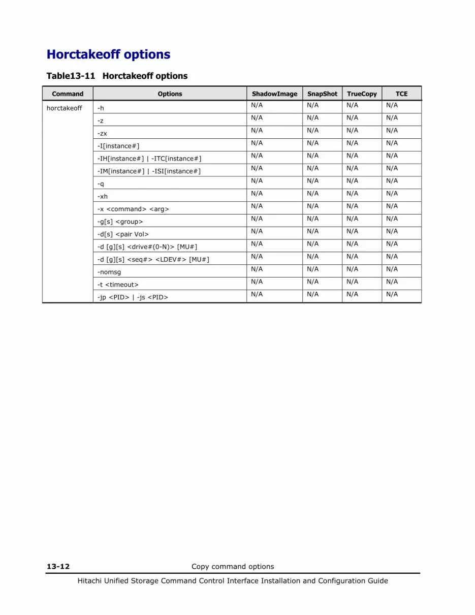
13-12 Copy command options
Hitachi Unified Storage Command Control Interface Installation and Configuration Guide
Horctakeoff options
Table 13-11 Horctakeoff options
Command Options ShadowImage SnapShot TrueCopy TCE
horctakeoff -h N/A N/A N/A N/A
-z N/A N/A N/A N/A
-zx N/A N/A N/A N/A
-I[instance#] N/A N/A N/A N/A
-IH[instance#] | -ITC[instance#] N/A N/A N/A N/A
-IM[instance#] | -ISI[instance#] N/A N/A N/A N/A
-q N/A N/A N/A N/A
-xh N/A N/A N/A N/A
-x <command> <arg> N/A N/A N/A N/A
-g[s] <group> N/A N/A N/A N/A
-d[s] <pair Vol> N/A N/A N/A N/A
-d [g][s] <drive#(0-N)> [MU#] N/A N/A N/A N/A
-d [g][s] <seq#> <LDEV#> [MU#] N/A N/A N/A N/A
-nomsg N/A N/A N/A N/A
-t <timeout> N/A N/A N/A N/A
-jp <PID> | -js <PID> N/A N/A N/A N/A

Copy command options 13-13
Hitachi Unified Storage Command Control Interface Installation and Configuration Guide
Raidscan options
Table 13-12 Raidscan options
Command Options ShadowImage SnapShot TrueCopy TCE
raidscan -h
-z
-zx
-I[instance#]
-IH[instance#] | -ITC[instance#] N/A N/A
-IM[instance#] | -ISI[instance#] N/A N/A
-q
-xh
-x <command> <arg>
-p <port> [hgrp]
-pd [g] <drive#(0-N)>
-pi <strings>
-t <targ>
-l <lun>
-m <mun>
-s <seq#>
-f [f]
-f [x]
-f [g]
-f [d]
-f [e]
-f [r] N/A N/A N/A N/A
-CLI
-find [g]
-find inst
-find verify
-find [g] conf
-find sync
-find syncd N/A N/A N/A N/A

13-14 Copy command options
Hitachi Unified Storage Command Control Interface Installation and Configuration Guide
Raidar options
Table 13-13 Raidar options
Command Options ShadowImage SnapShot TrueCopy TCE
raidar -h
-z
-zx
-I[instance#]
-IH[instance#] | -ITC[instance#] N/A N/A
-IM[instance#] | -ISI[instance#] N/A N/A
-q
-xh
-x <command> <arg>
-s <interval> [count]
-sm <interval> [count]
-p <port> <targ> <lun>
-pd [g] <drive#(0-N)>
Raidqry options
Table 13-14 Raidqry options
Command Options ShadowImage SnapShot TrueCopy TCE
raidqry -h
-z
-zx
-I[instance#]
-IH[instance#] | -ITC[instance#] N/A N/A
-IM[instance#] | -ISI[instance#] N/A N/A
-q
-xh
-x <command> <arg>
-g
-l
-r <group>
-f
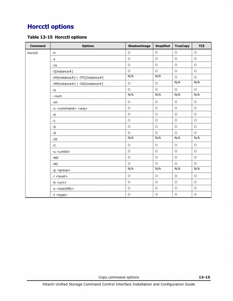
Copy command options 13-15
Hitachi Unified Storage Command Control Interface Installation and Configuration Guide
Horcctl options
Table 13-15 Horcctl options
Command Options ShadowImage SnapShot TrueCopy TCE
horcctl -h
-z
-zx
-I[instance#]
-IH[instance#] | -ITC[instance#] N/A N/A
-IM[instance#] | -ISI[instance#] N/A N/A
-q
--num N/A N/A N/A N/A
-xh
-x <command> <arg>
-d
-c
-S
-D
-DI N/A N/A N/A N/A
-C
-u <unitid>
-ND
-NC
-g <group> N/A N/A N/A N/A
-l <level>
-b <y/n>
-s <size(KB)>
-t <type>
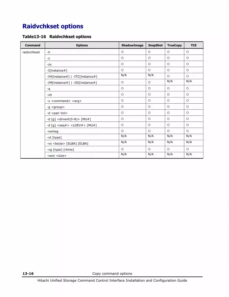
13-16 Copy command options
Hitachi Unified Storage Command Control Interface Installation and Configuration Guide
Raidvchkset options
Table 13-16 Raidvchkset options
Command Options ShadowImage SnapShot TrueCopy TCE
raidvchkset -h
-z
-zx
-I[instance#]
-IH[instance#] | -ITC[instance#] N/A N/A
-IM[instance#] | -ISI[instance#] N/A N/A
-q
-xh
-x <command> <arg>
-g <group>
-d <pair Vol>
-d [g] <drive#(0-N)> [MU#]
-d [g] <seq#> <LDEV#> [MU#]
-nomsg
-vt [type] N/A N/A N/A N/A
-vs <bsize> [SLBA] [ELBA] N/A N/A N/A N/A
-vg [type] [rtime]
-vext <size> N/A N/A N/A N/A
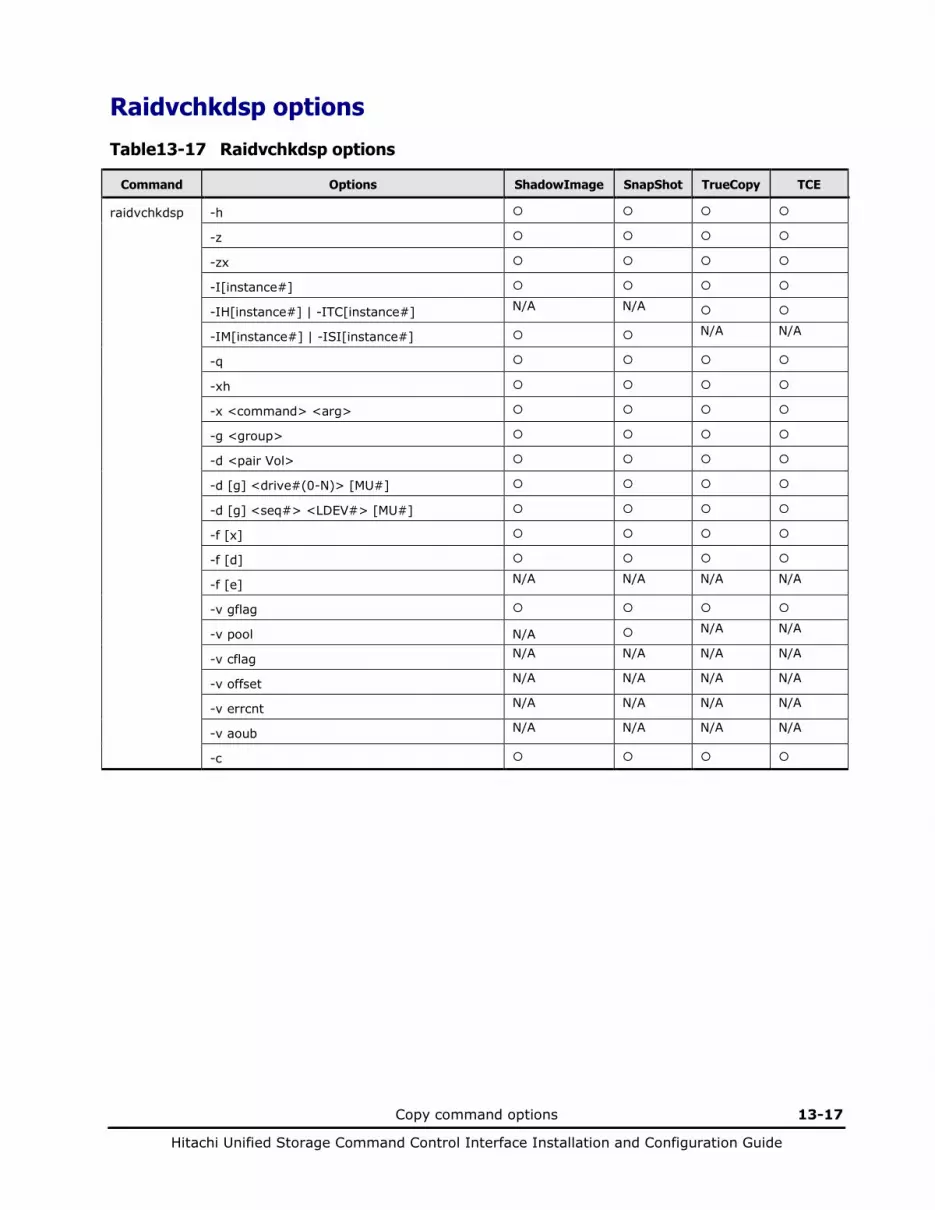
Copy command options 13-17
Hitachi Unified Storage Command Control Interface Installation and Configuration Guide
Raidvchkdsp options
Table 13-17 Raidvchkdsp options
Command Options ShadowImage SnapShot TrueCopy TCE
raidvchkdsp -h
-z
-zx
-I[instance#]
-IH[instance#] | -ITC[instance#] N/A N/A
-IM[instance#] | -ISI[instance#] N/A N/A
-q
-xh
-x <command> <arg>
-g <group>
-d <pair Vol>
-d [g] <drive#(0-N)> [MU#]
-d [g] <seq#> <LDEV#> [MU#]
-f [x]
-f [d]
-f [e] N/A N/A N/A N/A
-v gflag
-v pool N/A N/A N/A
-v cflag N/A N/A N/A N/A
-v offset N/A N/A N/A N/A
-v errcnt N/A N/A N/A N/A
-v aoub N/A N/A N/A N/A
-c
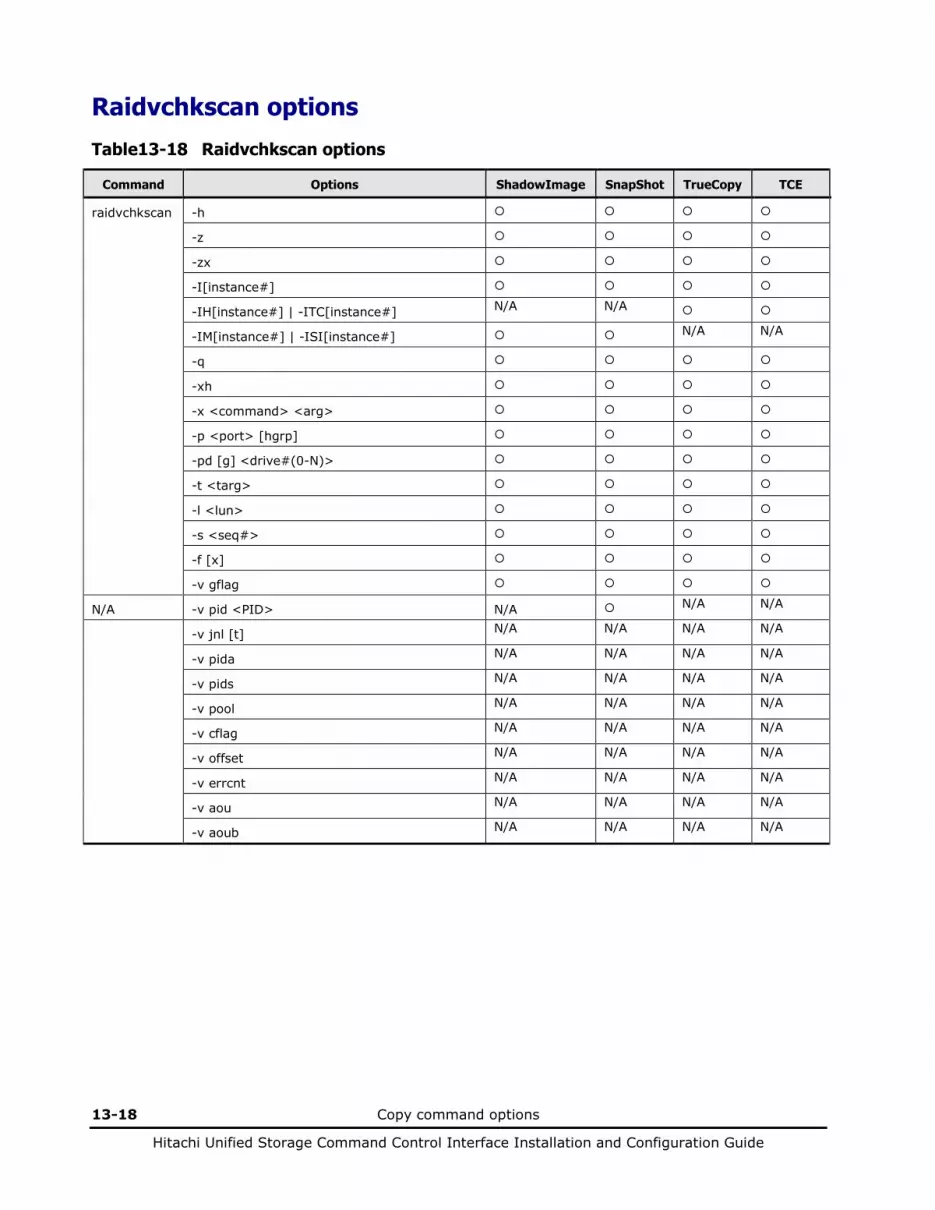
13-18 Copy command options
Hitachi Unified Storage Command Control Interface Installation and Configuration Guide
Raidvchkscan options
Table 13-18 Raidvchkscan options
Command Options ShadowImage SnapShot TrueCopy TCE
raidvchkscan -h
-z
-zx
-I[instance#]
-IH[instance#] | -ITC[instance#] N/A N/A
-IM[instance#] | -ISI[instance#] N/A N/A
-q
-xh
-x <command> <arg>
-p <port> [hgrp]
-pd [g] <drive#(0-N)>
-t <targ>
-l <lun>
-s <seq#>
-f [x]
-v gflag
N/A -v pid <PID> N/A N/A N/A
-v jnl [t] N/A N/A N/A N/A
-v pida N/A N/A N/A N/A
-v pids N/A N/A N/A N/A
-v pool N/A N/A N/A N/A
-v cflag N/A N/A N/A N/A
-v offset N/A N/A N/A N/A
-v errcnt N/A N/A N/A N/A
-v aou N/A N/A N/A N/A
-v aoub N/A N/A N/A N/A
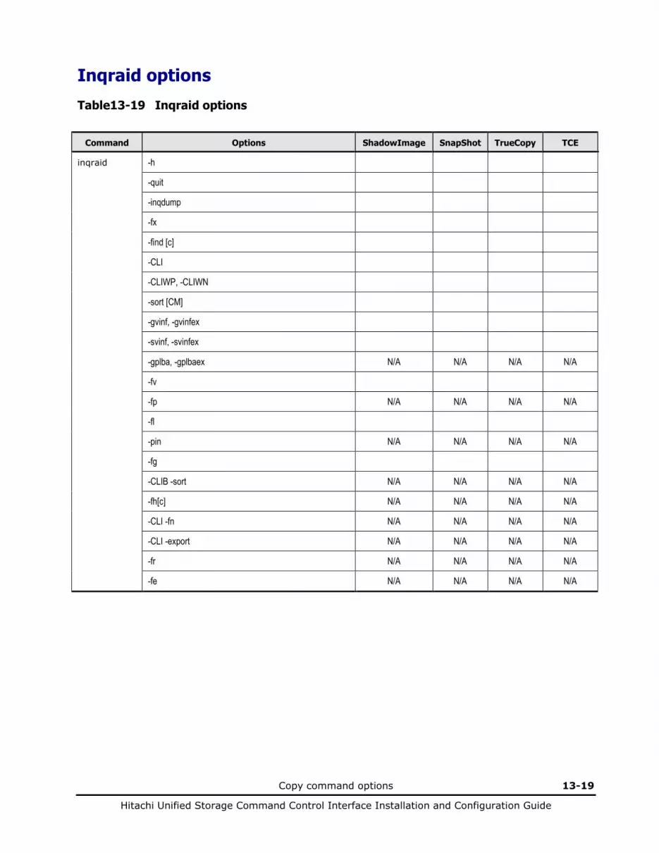
Copy command options 13-19
Hitachi Unified Storage Command Control Interface Installation and Configuration Guide
Inqraid options
Table 13-19 Inqraid options
Command Options ShadowImage SnapShot TrueCopy TCE
inqraid -h
-quit
-inqdump
-fx
-find [c]
-CLI
-CLIWP, -CLIWN
-sort [CM]
-gvinf, -gvinfex
-svinf, -svinfex
-gplba, -gplbaex N/A N/A N/A N/A
-fv
-fp N/A N/A N/A N/A
-fl
-pin N/A N/A N/A N/A
-fg
-CLIB -sort N/A N/A N/A N/A
-fh[c] N/A N/A N/A N/A
-CLI -fn N/A N/A N/A N/A
-CLI -export N/A N/A N/A N/A
-fr N/A N/A N/A N/A
-fe N/A N/A N/A N/A

13-20 Copy command options
Hitachi Unified Storage Command Control Interface Installation and Configuration Guide
Mkconf options
Table 13-20 Mkconf options
Command Options ShadowImage SnapShot TrueCopy TCE
mkconf -g <group>
-gg
-m <mu#>
-i <inst#>
-s <service>
-a
-c <drive#>
Rmawk options
Table 13-21 Rmawk options
Command Options ShadowImage SnapShot TrueCopy TCE
rmawk -h N/A N/A N/A N/A
exe="command_line" N/A N/A N/A N/A
exe="print ..." N/A N/A N/A N/A
exe="printn ..." or exe="prints ..."
N/A N/A N/A N/A
exe=exit N/A N/A N/A N/A
sys="command_line" N/A N/A N/A N/A
timeout=value N/A N/A N/A N/A
interval=value N/A N/A N/A N/A
-BL N/A N/A N/A N/A
-AT N/A N/A N/A N/A
-EC[VAL] N/A N/A N/A N/A
@variable N/A N/A N/A N/A
operators (-operator:) N/A N/A N/A N/A
operators (=operator:) N/A N/A N/A N/A
operators (-operator) N/A N/A N/A N/A
raidcom * copy_grp N/A N/A N/A N/A
raidcom * device_grp N/A N/A N/A N/A
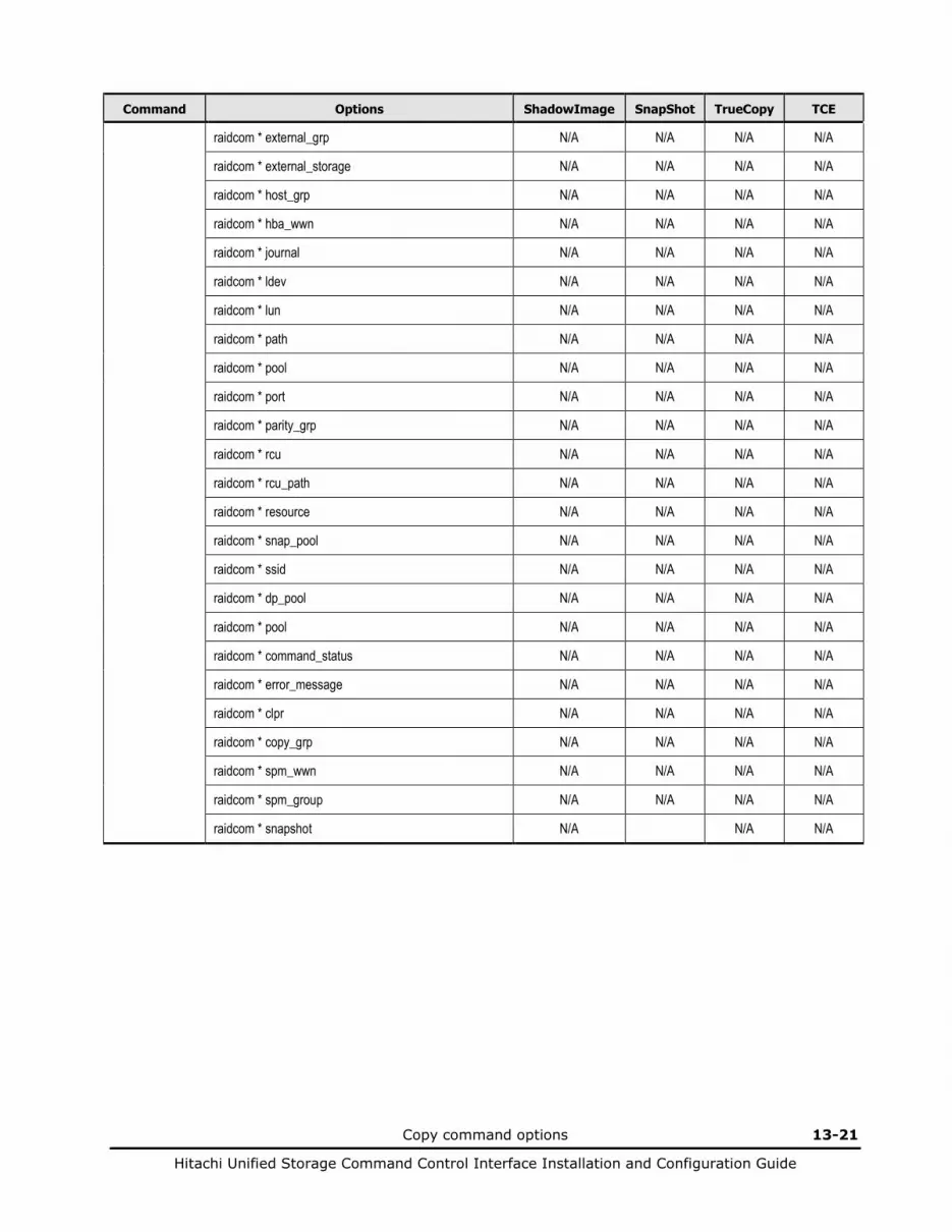
Copy command options 13-21
Hitachi Unified Storage Command Control Interface Installation and Configuration Guide
Command Options ShadowImage SnapShot TrueCopy TCE
raidcom * external_grp N/A N/A N/A N/A
raidcom * external_storage N/A N/A N/A N/A
raidcom * host_grp N/A N/A N/A N/A
raidcom * hba_wwn N/A N/A N/A N/A
raidcom * journal N/A N/A N/A N/A
raidcom * ldev N/A N/A N/A N/A
raidcom * lun N/A N/A N/A N/A
raidcom * path N/A N/A N/A N/A
raidcom * pool N/A N/A N/A N/A
raidcom * port N/A N/A N/A N/A
raidcom * parity_grp N/A N/A N/A N/A
raidcom * rcu N/A N/A N/A N/A
raidcom * rcu_path N/A N/A N/A N/A
raidcom * resource N/A N/A N/A N/A
raidcom * snap_pool N/A N/A N/A N/A
raidcom * ssid N/A N/A N/A N/A
raidcom * dp_pool N/A N/A N/A N/A
raidcom * pool N/A N/A N/A N/A
raidcom * command_status N/A N/A N/A N/A
raidcom * error_message N/A N/A N/A N/A
raidcom * clpr N/A N/A N/A N/A
raidcom * copy_grp N/A N/A N/A N/A
raidcom * spm_wwn N/A N/A N/A N/A
raidcom * spm_group N/A N/A N/A N/A
raidcom * snapshot N/A N/A N/A

13-22 Copy command options
Hitachi Unified Storage Command Control Interface Installation and Configuration Guide

Acronyms and Abbreviations Acronyms-1
Hitachi Unified Storage Command Control Interface Installation and Configuration Guide
Acronyms and Abbreviations
AL-PA arbitrated loop-physical address AOU allocation on use (another name for Dynamic Provisioning) BMP bitmap CCI Command Control Interface CLI command line interface CM cluster manager CMDDEV command device CTG consistency group ELBA ending logical block address FC fibre-channel GB gigabyte GUI graphical user interface HA high availability HACMP High Availability Cluster Multiprocessing HDLM Hitachi Dynamic Link Manager HOMRCF Hitachi Open Multi-RAID Coupling Feature (another name for
ShadowImage) HORC Hitachi Open Remote Copy (another name for TrueCopy) HORCM HORC Manager (another name for the CCI software) HUS Hitachi Unified Storage I/O input/output INST instance number IOPS I/Os per second IP internet protocol KB kilobyte LDEV logical device LDM Logical Disk Manager LV logical volume
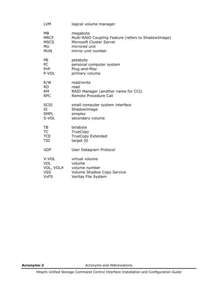
Acronyms-2 Acronyms and Abbreviations
Hitachi Unified Storage Command Control Interface Installation and Configuration Guide
LVM logical volume manager MB megabyte MRCF Multi-RAID Coupling Feature (refers to ShadowImage) MSCS Microsoft Cluster Server MU mirrored unit MUN mirror unit number PB petabyte PC personal computer system PnP Plug-and-Play P-VOL primary volume R/W read/write RD read RM RAID Manager (another name for CCI) RPC Remote Procedure Call SCSI small computer system interface SI ShadowImage SMPL simplex S-VOL secondary volume TB terabyte TC TrueCopy TCE TrueCopy Extended TID target ID UDP User Datagram Protocol V-VOL virtual volume VOL volume VOL, VOL# volume number VSS Volume Shadow Copy Service VxFS Veritas File System
Acronyms and Abbreviations Index-1
Hitachi Unified Storage Command Control Interface Installation and Configuration Guide
Index
A addressing paired volumes, 4-2
B backing up
secondary volume, 4-25 secondary volume in paired status, 4-21
C calculating poll(10ms), 4-33 CCI
command applications, 4-21 controlling CCI activities, 10-75 files for UNIX based system, 4-54 files for Windows, 4-55 instance configuration, 4-29 performing operations, 10-3 preparing for operations, 1-2 software files, 4-54 software structure, 4-28 startup, 1-13 startup for UNIX systems, 1-13 startup for Windows systems, 1-15 system requirements, 1-2
CCI server, 8-20 changing the CCI user for UNIX systems, 1-10 cluster manager, 11-17 Command Control Interface (CCI), 3-2 command device, 4-43
alternate command device function, 4-44 command execution environment, 10-4 commands
drivescan, 10-80 findcmdev, 10-79 horcctl, 10-77 horcmshutdown, 10-76 horcmstart, 10-75 horctakeover, 10-47 inqraid, 10-91 mkconf, 10-98 mount, 10-84
mountvol, 6-6 paircreate, 10-7 paircurchk, 10-44 pairdisplay, 10-38 pairevtwait, 10-27 pairmon, 10-30 pairresync, 10-22 pairsplit, 10-14 pairsplit -E, 10-16 pairsplit -S, 10-16 pairsyncwait, 10-107 pairvolchk, 10-33 portscan, 10-81 raidar, 10-62 raidqry, 10-64 raidscan, 10-56 raidvchkdsp, 10-69 raidvchkscan, 10-72 raidvchkset, 10-67 sync, 10-82 syncd, 10-82 umount, 10-87
configuration confirming, 4-109 configuration definition file, 4-30
creating, 1-11 editing, 1-11 examples, 4-66 parameter setting, 4-30 parameters, 1-11
D daemon process, 4-109 data assurance, 11-28, 11-31 data recovery procedure for PSUE status, 11-32 data recovey procedure for PSUE status, 11-28,
11-31 displaying configuration information, 10-56 drivescan, 10-80
E environment variable, 8-12 environment variable subcommands, 10-90

Index-2
Hitachi Unified Storage Command Control Interface Installation and Configuration Guide
environment variables, 10-3 CCI command, 10-3, 10-92 CCI instance, 10-3 HORCM (/etc/horcmgr), 10-3 HORCMROOT, 8-32 RMSRATMU, 8-32 RMSRATOV, 8-32 setting, 1-10, 1-13, 1-14, 1-15, 1-16 ShadowImage command, 10-4 SplitReplication, 8-32
error command error messages, 7-22, 11-20 common error messages, 11-24, 11-25 unique error messages, 11-26
error monitoring, 4-109 error reporting, 11-19 ESX(i) server, xiii, 8-2, 8-4, 8-20 examples
configuration definition files, 4-66 protected volume configuration, 4-48
F failover, 3-2, 8-2, 8-10 fence level, 11-16 Fibre address conversion table
for HP-UX® systems, 5-4 for Solaris and IRIX® systems, 5-5 for Windows Server 2003/Windows Server
2008 systems, 5-6 files
configuration definition files, 4-30, 4-66 created by users, 4-57 log files, 4-56 of CCI software, 4-54 trace files, 4-56, 12-5
findcmdev, 10-79 flushing, 6-2, 10-61, 10-87 fsck, 10-20
G group version control for mixed array
configurations, 4-58
H HA, 3-2, 11-16, 11-17 Hitachi Data Systems Support Center, 11-32 HORCC LOG, 12-4 HORCC_LOG, 10-3 HORCC_MRCF, 4-29, 10-4 HORCC_TRCBUF, 10-3 HORCC_TRCLVL, 10-3 HORCC_TRCSZ, 10-3 horcctl, 10-77 HORCM
operational environment, 4-28 HORCM LOG, 12-4 HORCM_CMD, 4-34 HORCM_CONF, 4-29, 4-30, 4-32, 10-3
parameters, 1-11 HORCM_DEV, 4-38 HORCM_INST, 4-40 HORCM_INSTID, 4-34, 4-43 HORCM_LOG, 10-3 HORCM_MON, 4-33 HORCM_TRCBUF, 10-3 HORCM_TRCLVL, 10-3 HORCM_TRCSZ, 10-3 HORCM_TRCUENV, 10-3 HORCMFCTBL, 10-3 HORCMINST, 10-3 HORCMPERM, 10-3 HORCMPORMOD, 10-3 HORCMROOT, 8-32 horcmshutdown, 4-57, 10-76 horcmstart, 4-57, 10-75 horctakeover, 10-47
I inqraid, 10-91 installing
hardware, 1-6 software on UNIX systems, 1-7 software on Windows Server systems, 1-9
interval time (poll), 4-30
L LDM, 6-2
volume search, 6-3 LDM search conditions
$LETALL, 6-3 $Physical, 6-3 $Volume, 6-3
lock disk for HA software, 11-17 log files, 4-56
core, 12-3 error log, 12-3 start-up log, 12-3 trace, 12-3
logical device manager, 6-2 LVM, 4-51, 10-20, 11-16, 11-17
M maintenance notes, 3-6, 11-2, 11-4, 11-6, 11-
11 messages
command error, 7-22, 11-20 common error, 11-24, 11-25 system log, 11-19 unique error, 11-26
mkconf, 10-98 mount, 10-84 mountvol, 6-6
O obtaining pair status, 10-30 offline backup, 10-20
Index-3
Hitachi Unified Storage Command Control Interface Installation and Configuration Guide
online backup, 10-20 overview
CCI, 3-2 CCI operations, 4-1 copy solutions, 3-2 ShadowImage, 3-3 SnapShot, 3-3 TrueCopy/TCE, 3-4
P pair
configuration confirming, 4-5, 4-6, 4-9 creating, 4-5, 4-6, 4-8 event waiting, 4-5, 4-6, 4-9 restoration, 4-6 resynchronizing, 4-5, 4-8 splitting, 4-5, 4-6, 4-8 splitting (before volume format), 11-30 splitting (during reverse pairresync), 11-30 status, 4-12, 4-14 status display, 4-5, 4-6, 4-9
pair recovering, 11-28, 11-31, 11-32 pair status
PSUE, 4-14 PSUS, 4-13 SMPL, 4-13
pair status display, 4-110 pair status versus ShadowImage commands, 4-
12 pair status versus SnapShot commands, 4-14 pair status versus TCE commands, 4-17 pair status versus TrueCopy commands, 4-17 paircreate, 10-7 paircurchk, 10-44 pairdisplay, 10-38 paired volume
confirming configuration, 4-110 error monitoring, 4-109 features, 4-2
pairevtwait, 10-27 pairmon, 10-30 pairresync, 10-22 pairsplit, 10-14
timing, 10-20 pairsplit -E, 10-16 pairsplit -S, 10-16 pairsyncwait, 10-107 pairvolchk, 10-33 permitted volumes, 4-47
registering, 4-51 poll, 1-11, 4-30, 4-33
equation, 4-33 port name, 1-13, 1-14, 1-15, 1-16, 4-33, 4-39,
4-40 port number, 1-13, 1-14, 1-15, 1-16, 4-39, 10-
98 portscan, 10-81 preparing for CCI operations, 1-2
procedure for recovering data, 11-28, 11-31, 11-32
protected volumes, 4-46, 10-3 protection function, 4-46, 11-30 protection mode
and mirror descriptor, 4-47 command usage, 4-51
PSUE, 4-14 PSUS, 4-13
R raidar, 10-62 raidqry, 10-64 raidscan, 10-56 raidvchkdsp, 10-69 raidvchkscan, 10-72 raidvchkset, 10-67 raw device, 4-44, 4-66, 4-75, 4-86 recovering data, 11-28, 11-31, 11-32 recovering the pair, 11-28, 11-31, 11-32 recovery procedures for HA configurations, 4-
118 releasing pairs, 10-16 reporting pair status, 10-30 restoring
secondary volume to primary volume, 4-23 S-VOL for duplex operation, 4-27
RMSRATMU, 8-32, 8-33, 8-34 RMSRATOV, 8-32
S setting
environment variables, 1-10, 1-13, 1-14, 1-15, 1-16, 10-3, 11-16, 12-3
ShadowImage, 3-3 duplicated mirroring, 4-3 operations, 4-5 pair status, 4-11 volume status, 4-11
SMPL, 4-13 SnapShot, 3-3
duplicated mirroring, 4-4 operations, 4-6 pair status, 4-13 volume status, 4-13
special files, 4-30, 10-91, 10-98 specification of volumes by commands, 4-2 SplitReplication, 8-12, 8-32, 8-33, 8-34 SRA, 8-3 SRM
configuration integrating with copy functions, 8-4
integration with copy functions, 8-3 operations, 8-10 overview, 8-2
SRM operations, 8-10 cancel, 8-10 cleanup, 8-10, 8-19 recovery, 8-10
Index-4
Hitachi Unified Storage Command Control Interface Installation and Configuration Guide
reprotect, 8-10 test, 8-10, 8-12 test failover, 8-10, 8-12, 8-19
SRM server, 8-20 status transition, 4-56, 10-30, 12-2 status transition queue, 4-109, 10-30 subcommands, 10-79, 10-90
for environment variable, 10-90 for Windows Server 2003/Windows Server
2008, 10-79 suspended pairs
recovering, 11-28, 11-31, 11-32 suspending pairs, 10-16 swapping
paired volume for duplex operation, 4-26 sync, 10-82 syncd, 10-82 system requirements, 1-2
T target ID limits, 5-2 TCE
pair status, 4-15 technical support, 11-32 timing of pairsplit operations, 10-20 trace control command, 12-5 trace files, 4-56, 12-5 troubleshooting, 11-16 TrueCopy
pair status, 4-15 takeover commands, 4-7
TrueCopy/TCE, 3-4 fence-level settings, 4-19 remote commands, 4-8 volume status, 4-15
U umount, 10-87 uninstalling
software from UNIX systems, 2-2 software from Windows Server 2003/Windows
Server 2008 systems, 2-2 upgrading
for UNIX systems, 2-2 for Windows Server 2003/Windows Server
2008 systems, 2-3 user created files, 4-57
V vCenter server, 8-4, 8-20 Volume Migration, 10-103 volume number and device number, 11-29 volume pairs, 4-10 volume search, 6-2

Hitachi Unified Storage Command Control Interface Installation and Configuration Guide
MK-91DF8306-13
Hitachi Data Systems
Corporate Headquarters 2845 Lafayette Street Santa Clara, California 95050-2639 U.S.A. www.hds.com
Regional Contact Information
Americas +1 408 970 1000 [email protected]
Europe, Middle East, and Africa +44 (0) 1753 618000 [email protected]
Asia Pacific +852 3189 7900 [email protected]


![1 CCI Titlul în limba engleză [255]1 Health Operational](https://img.dokumen.tips/doc/110x75/63340796ef4f30e7d30bbf96/1-cci-titlul-in-limba-engleza-2551-health-operational-.jpg)

