Embed Size (px)
Citation preview
AmphenolAmphenol PCD Shenzhen
www.amphenolpcd.com.cn
HVCOHigh Voltage Coupler Outlet

2
CONTENTS
IEC STANDARD - TERMS AND DEFINITIONS…………………………................ 3
TECHNICAl CHARACTERISTICS....………………...….…….…....................…. 4
INSERT ARRANGEMENTS.................................................................................. 5
CIRCUIT DIAGRAMS..........................………………...….…….…....................…. 6
CHARGING SYSTEM COMPONENTS.……………………….............….............. 7
lOCKING ACTUATOR..………………………………….............…........................ 8
SOCKET-OUTlET DIMENSIONS........................................................................ 9
PlUG DIMENSIONS............................................................................................ 11
VEHIClE CONNECTOR + PlUG DIMENSIONS.……….........…......................... 12
HOw TO ORDER.................................................................................................. 13
IEC COMBO SOCKET-OUTlET DIMENSIONS................................................... 15
IEC COMBO PlUG DIMENSIONS....................................................................... 16
IEC COMBO ElECTRICAl SPECIFICATIONS.................................................... 17
HOw TO ORDER.................................................................................................. 18
3
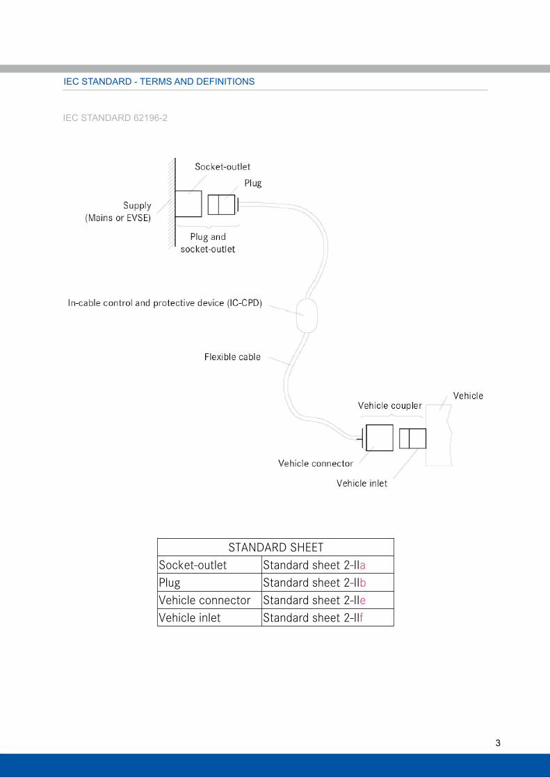
IEC STANDARD - TERMS AND DEFINITIONS
STANDARD SHEET Socket-outlet Standard sheet 2-IIa Plug Standard sheet 2-IIb Vehicle connector Standard sheet 2-IIe Vehicle inlet Standard sheet 2-IIf
IEC STANDARD 62196-2
4
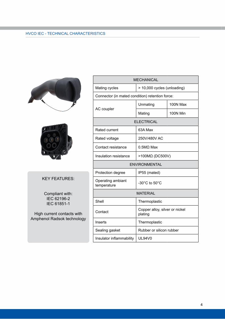
KEY FEATURES:
Compliant with:IEC 62196-2IEC 61851-1
High current contacts with Amphenol Radsok technology
MECHANICAl
Mating cycles > 10,000 cycles (unloading)
Connector (in mated condition) retention force:
AC coupler Unmating 100N Max
Mating 100N Min
ElECTRICAl
Rated current 63A Max
Rated voltage 250V/480V AC
Contact resistance 0.5MΩ Max
Insulation resistance >100MΩ (DC500V)
ENVIRONMENTAl
Protection degree IP55 (mated)
Operating ambiant temperature -30°C to 50°C
MATERIAl
Shell Thermoplastic
Contact Copper alloy, silver or nickel plating
lnserts Thermoplastic
Sealing gasket Rubber or silicon rubber
Insulator inflammability Ul94V0
HVCO IEC - TECHNICAl CHARACTERISTICS
5
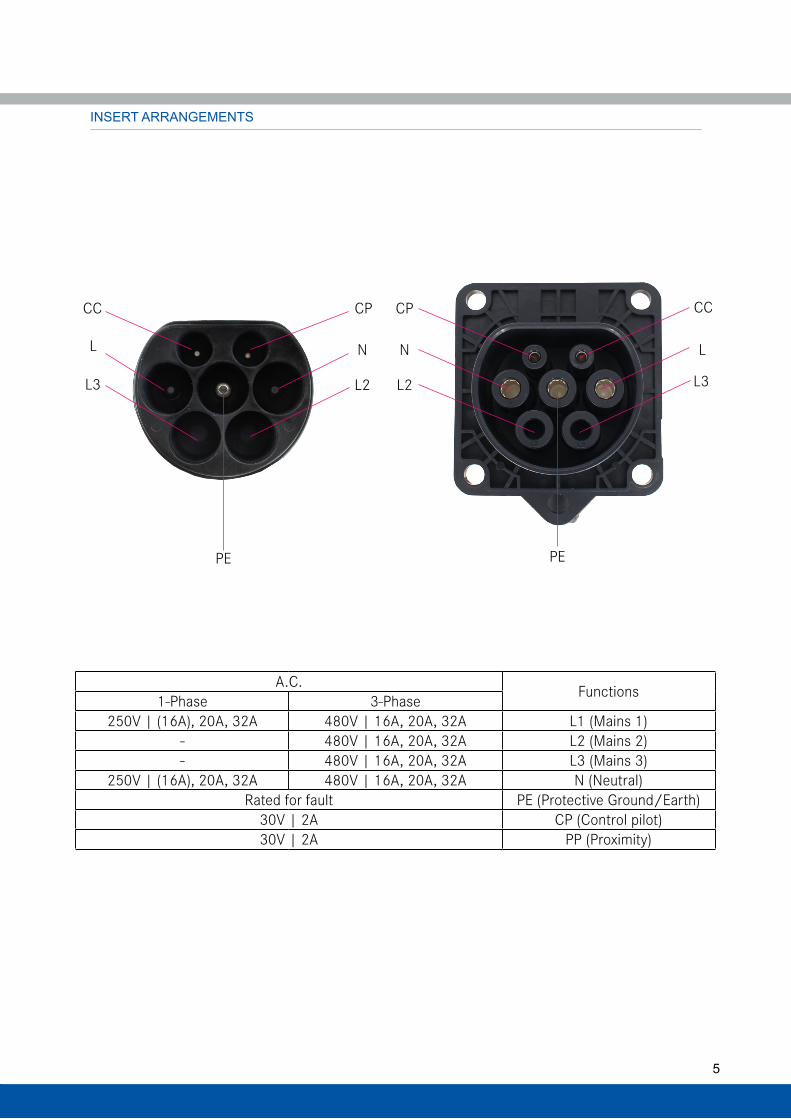
INSERT ARRANGEMENTS
A.C. Functions1-Phase 3-Phase250V | (16A), 20A, 32A 480V | 16A, 20A, 32A L1 (Mains 1)
- 480V | 16A, 20A, 32A L2 (Mains 2)- 480V | 16A, 20A, 32A L3 (Mains 3)
250V | (16A), 20A, 32A 480V | 16A, 20A, 32A N (Neutral)Rated for fault PE (Protective Ground/Earth)
30V | 2A CP (Control pilot)30V | 2A PP (Proximity)
CPCC
NL
L2L3
CCCP
LN
L3L2
PEPE
6
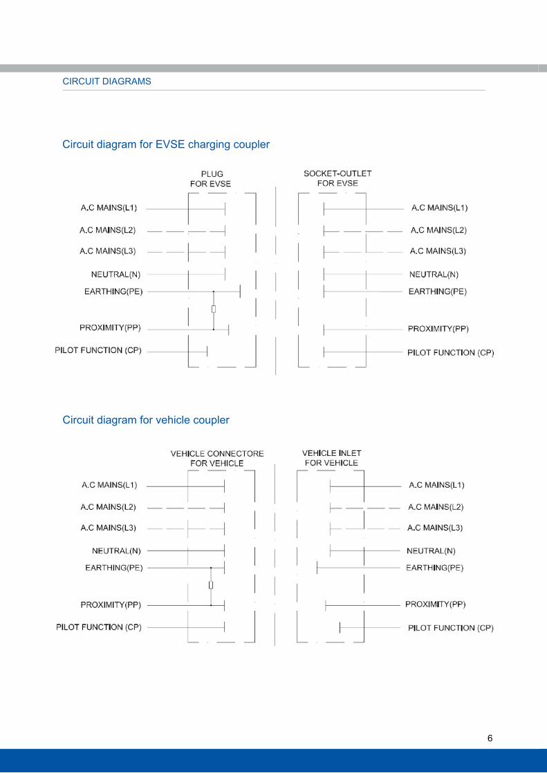
CIRCUIT DIAGRAMS
Circuit diagram for EVSE charging coupler
Circuit diagram for vehicle coupler

7
CHARGING SYSTEM COMPONENTS
Part Number (without cable)16/20A 1-Phase HVCOIFSR6SS502l000016/20A 3-Phase HVCOIFSR6SS702l0000
32A 1-Phase HVCOIFSR6SF510l000032A 3-Phase HVCOIFSR6SF710l000063A 1-Phase HVCOIFSR6SF516l000063A 3-Phase HVCOIFSR6SF716l0000
Part Number (without cable)16/20A 1-Phase HVCOIMASR6PS502l000016/20A 3-Phase HVCOIMASR6PS702l0000
32A 1-Phase HVCOIMASR6PF506l000032A 3-Phase HVCOIMASR6PF706l0000
Part Number (without cable)16/20A 1-Phase HVCOIMAR6PS502l000016/20A 3-Phase HVCOIMAR6PS702l0000
32A 1-Phase HVCOIMAR6PF506l000032A 3-Phase HVCOIMAR6PF706l0000
AC TYPE 2 COUPlER FOR EVSE SIDE
Vehicle connector
Socket-outlet
Plug
Compliant with IEC 62196-2 standard 2-II a. Configuration:250V | (16A), 20A, 32A or 63A | 1-phase480V | (16A), 20A, 32A or 63A | 3-phase
AC TYPE 2 COUPlER FOR EV SIDE
Electronic lock and Solenoid lock both available3 positions (120° rotatable):4 o'clock, 8 o'clock, 12 o'clock
Compliant with IEC 62196-2 standard sheet 2-II b. Configuration:250V | 16A/20A, or 32A | 1-phase480V | 16A/20A or 32A | 3-phase
Compliant with IEC 62196-2 standard sheet 2-II e.Configuration:250V | 16A/20A or 32A | 1-phase480V | 16A/20A or 32A | 3- phase
More features: Protection cap, water drainage design, rear mount
8
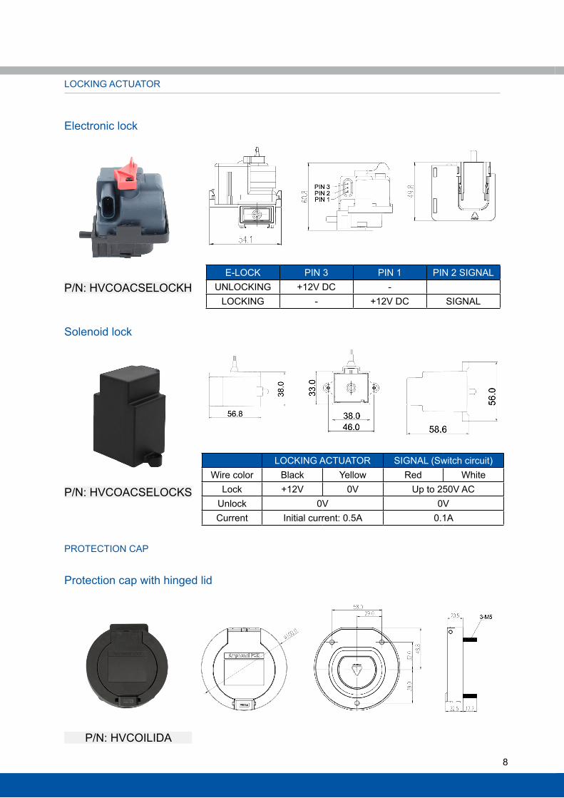
lOCKING ACTUATOR
PROTECTION CAP
Electronic lock
Solenoid lock
P/N: HVCOACSElOCKH
P/N: HVCOACSElOCKS
P/N: HVCOIlIDA
Protection cap with hinged lid
E-lOCK PIN 3 PIN 1 PIN 2 SIGNAlUNlOCKING +12V DC -
lOCKING - +12V DC SIGNAl
lOCKING ACTUATOR SIGNAl (Switch circuit)wire color Black Yellow Red white
lock +12V 0V Up to 250V ACUnlock 0V 0VCurrent Initial current: 0.5A 0.1A
9
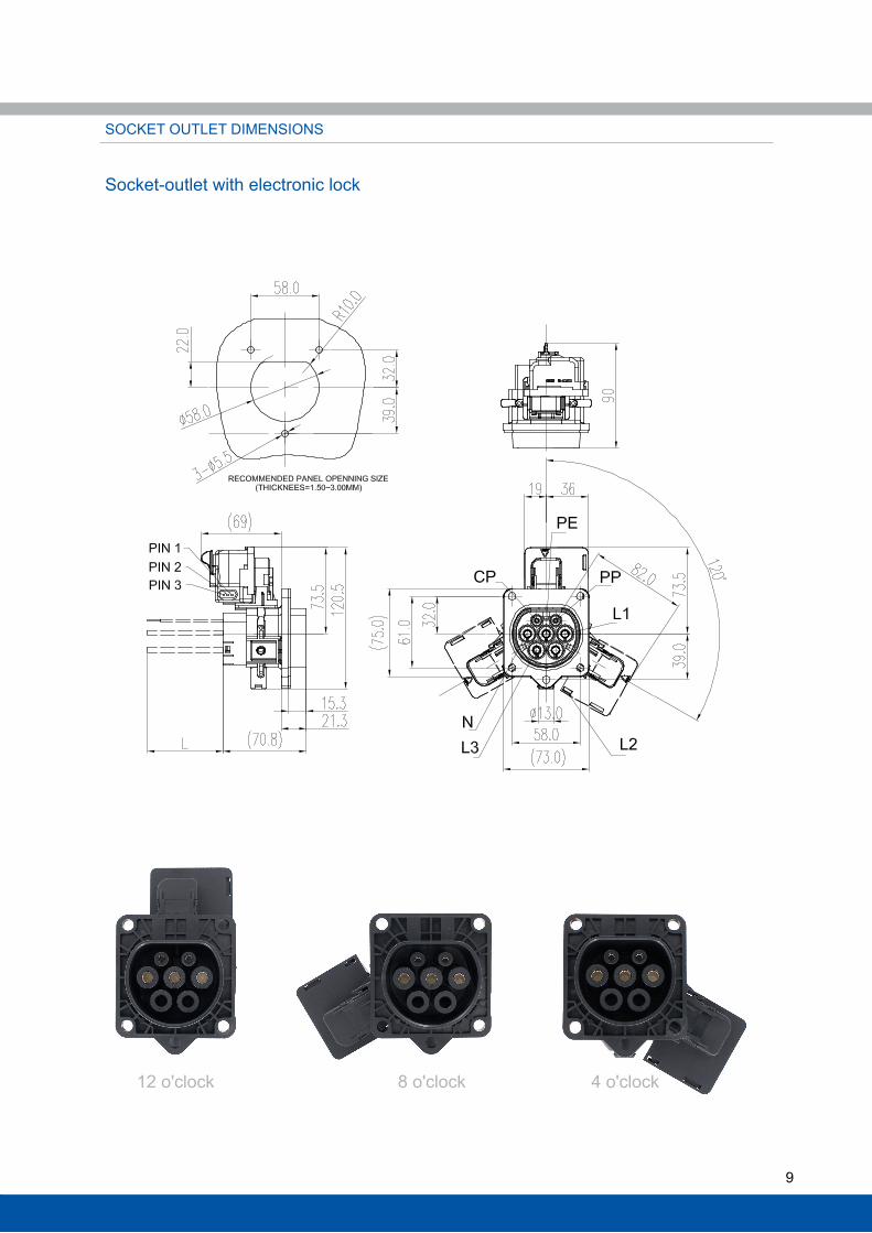
SOCKET OUTlET DIMENSIONS
Socket-outlet with electronic lock
12 o'clock 8 o'clock 4 o'clock
10
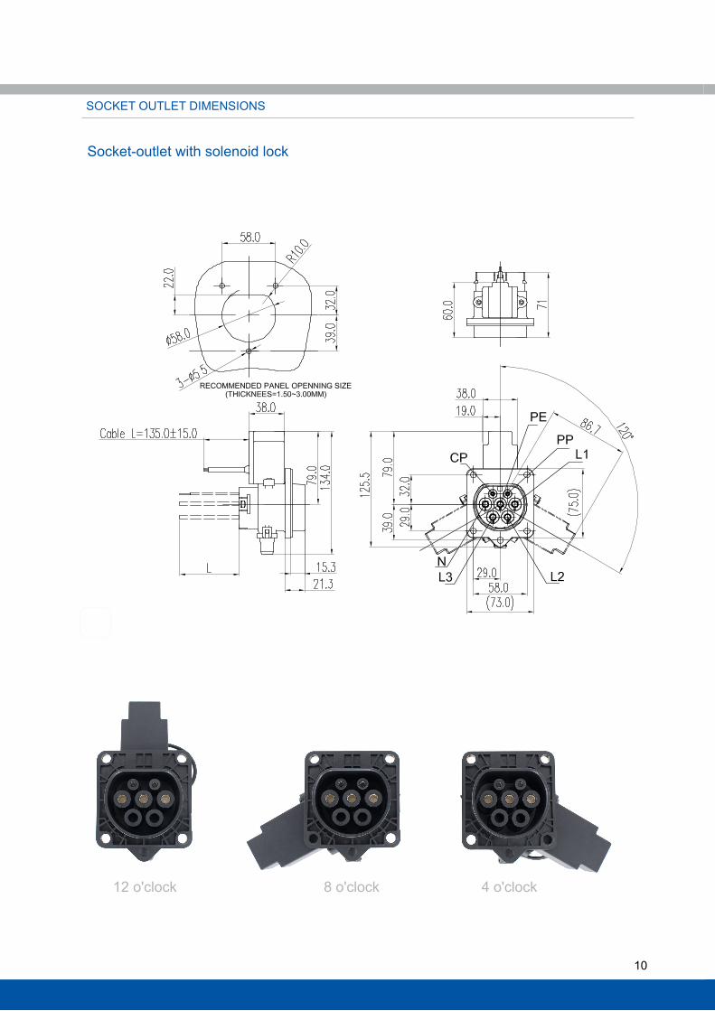
SOCKET OUTlET DIMENSIONS
Socket-outlet with solenoid lock
12 o'clock 8 o'clock 4 o'clock

11
PlUG DIMENSIONS (EVSE)
VEHIClE CONNECTOR DIMENSIONS
12
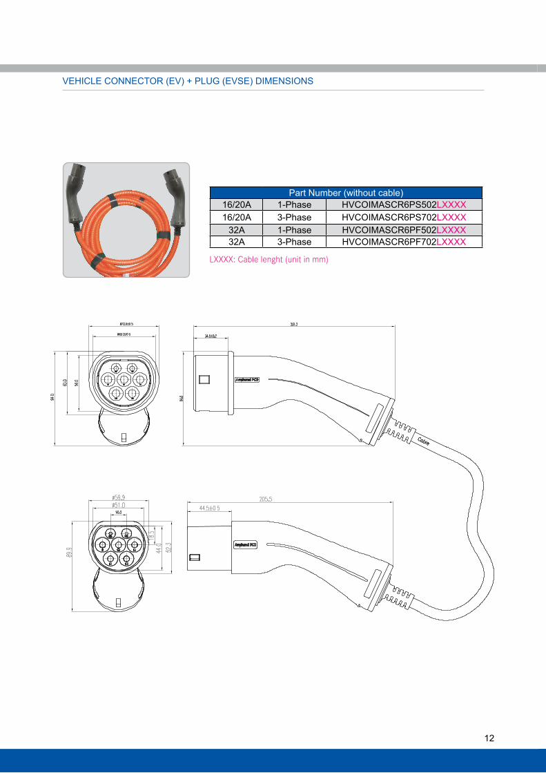
VEHIClE CONNECTOR (EV) + PlUG (EVSE) DIMENSIONS
Part Number (without cable)16/20A 1-Phase HVCOIMASCR6PS502lXXXX16/20A 3-Phase HVCOIMASCR6PS702lXXXX
32A 1-Phase HVCOIMASCR6PF502lXXXX32A 3-Phase HVCOIMASCR6PF702lXXXX
LXXXX: Cable lenght (unit in mm)

13
HOw TO ORDER
HVCO I M SC R6 PSXXX T R w lXXXX XXXX
I: IEC Type 2 Charge outlet
Connector type: M: Plug / Plug + Vehicle connector (see p.12) / Vehicle connector F: Socket-outlet / Vehicle inlet
S: EVSE coupler (Plug or socket-outlet) SC: Plug + Vehicle connector (see p.12) Omit SC: Vehicle coupler (Vehicle connector or vehicle inlet)
Contact size: R6: 6mm Radsok, pin contact
Type of connector and insert arrangements: PSXXX: 20A cable side (Plug Slow / Vehicle connector Slow) PFXXX: 32A cable side (Plug Fast / Vehicle connector Fast) SSXXX: 20A panel side (Socket-outlet Slow / Vehicle inlet Slow) SFXXX: 32A cable side (Socket-outlet Fast / Vehicle inlet Fast)
Temperature sensor: T: Temperature sensor Omit: No temperature sensor needed
R: Resistor inside the plug / vehicle connector Omit: No resistor needed
W: Protection tube Omit: No protection tube needed
Cable length: LXXXX: Cable lenght (Unit in mm) Omit: No cable needed
Cable accessories: XXXX: Cable accessories or customer code
14
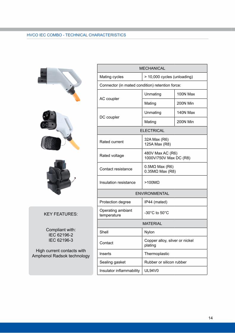
KEY FEATURES:
Compliant with:IEC 62196-2IEC 62196-3
High current contacts with Amphenol Radsok technology
MECHANICAl
Mating cycles > 10,000 cycles (unloading)
Connector (in mated condition) retention force:
AC coupler Unmating 100N Max
Mating 200N Min
DC couplerUnmating 140N Max
Mating 200N Min
ElECTRICAl
Rated current 32A Max (R6)125A Max (R8)
Rated voltage 480V Max AC (R6)1000V/750V Max DC (R8)
Contact resistance 0.5MΩ Max (R6)0.35MΩ Max (R8)
Insulation resistance >100MΩ
ENVIRONMENTAl
Protection degree IP44 (mated)
Operating ambiant temperature -30°C to 50°C
MATERIAl
Shell Nylon
Contact Copper alloy, silver or nickel plating
lnserts Thermoplastic
Sealing gasket Rubber or silicon rubber
Insulator inflammability Ul94V0
HVCO IEC COMBO - TECHNICAl CHARACTERISTICS

15
IEC COMBO VEHIClE INlET DIMENSIONS
Rear mount without protection cap
Rear mount with protection cap
6.0MAX
16
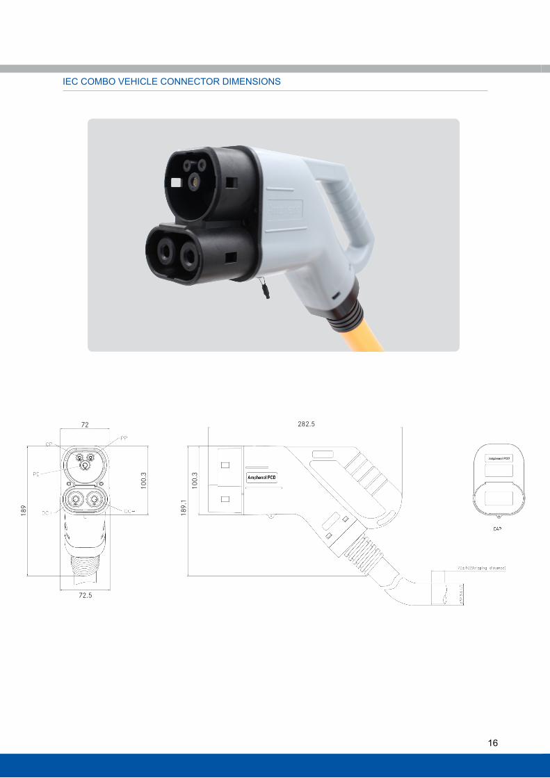
IEC COMBO VEHIClE CONNECTOR DIMENSIONS
282.5
100.
318
9.1
189
72
72.5
100.
3
17
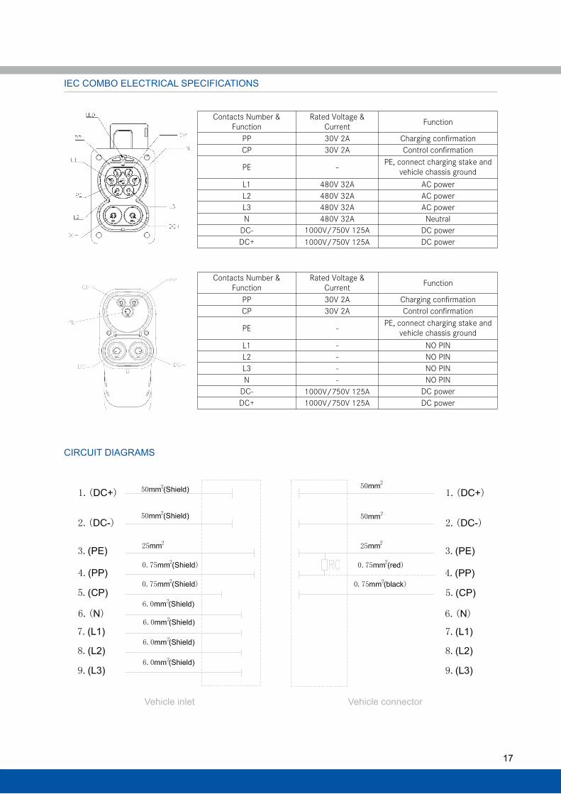
IEC COMBO ElECTRICAl SPECIFICATIONS
Contacts Number & Function
Rated Voltage & Current Function
PP 30V 2A Charging confirmation CP 30V 2A Control confirmation
PE - PE, connect charging stake and vehicle chassis ground
L1 480V 32A AC power L2 480V 32A AC power L3 480V 32A AC power N 480V 32A Neutral
DC- 1000V 200A DC power DC+ 1000V 200A DC power
Contacts Number & Function
Rated Voltage & Current Function
PP 30V 2A Charging confirmation CP 30V 2A Control confirmation
PE - PE, connect charging stake and vehicle chassis ground
L1 - NO PIN L2 - NO PIN L3 - NO PIN N - NO PIN
DC- 1000V 200A DC power DC+ 1000V 200A DC power
CIRCUIT DIAGRAMS
Vehicle inlet Vehicle connector
1000V/750V 125A1000V/750V 125A
1000V/750V 125A1000V/750V 125A
18
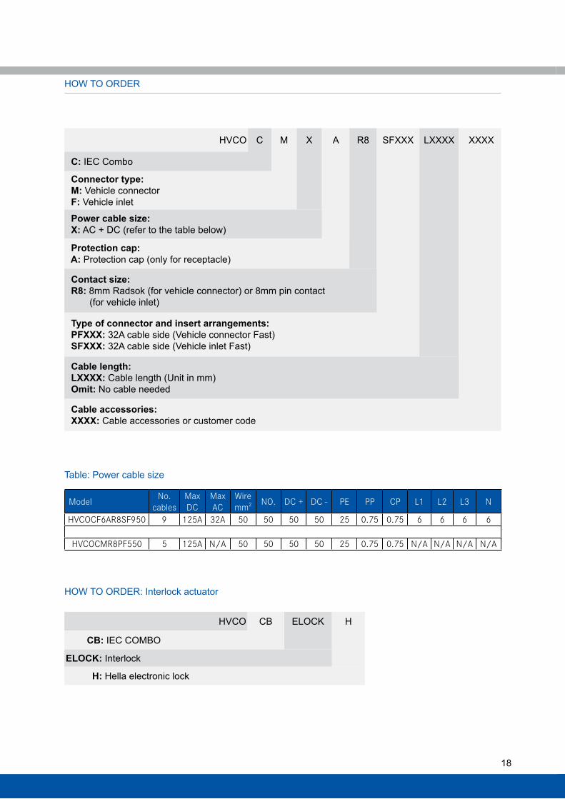
HOw TO ORDER
HVCO C M X A R8 SFXXX lXXXX XXXX
C: IEC Combo
Connector type: M: Vehicle connector F: Vehicle inlet
Power cable size: X: AC + DC (refer to the table below)
Protection cap: A: Protection cap (only for receptacle)
Contact size: R8: 8mm Radsok (for vehicle connector) or 8mm pin contact (for vehicle inlet)
Type of connector and insert arrangements: PFXXX: 32A cable side (Vehicle connector Fast) SFXXX: 32A cable side (Vehicle inlet Fast)
Cable length: LXXXX: Cable length (Unit in mm) Omit: No cable needed
Cable accessories: XXXX: Cable accessories or customer code
HVCO CB ElOCK H
CB: IEC COMBO
ELOCK: Interlock
H: Hella electronic lock
HOw TO ORDER: Interlock actuator
Model No. cables
MaxDC
MaxAC
Wiremm2 NO. DC + DC - PE PP CP L1 L2 L3 N
HVCOCF6AR8SF950 9 125A 32A 50 50 50 50 25 0.75 0.75 6 6 6 6
HVCOCMR8PF550 5 125A N/A 50 50 50 50 25 0.75 0.75 N/A N/A N/A N/A
Table: Power cable size
19
Notes:
Amphenol PCD Shenzhen has made every effort to ensure that the information contained in this catalog is accurate at the time of publication. Specifications or information stated in this publication are subject to change without notice.
Amphenol PCD Shenzhen reserves the right to clarify this catalog.
Amphenol PCD Shenzhen Building 211st liao Keng Industrial ZoneShi Yan Street, Bao An District Shenzhen 518108China
Tel.: +86 755-8173-8000Fax: +86 755-8173-8180Email: [email protected]
www.amphenolpcd.com.cn


