Embed Size (px)
Citation preview
High-Quality Reflections, Refractions, and Caustics in Augmented Realityand their Contribution to Visual Coherence
P. Kan∗ H. Kaufmann†
Institute of Software Technology and Interactive Systems,Vienna University of Technology, Vienna, Austria
ABSTRACT
In this paper we present a novel high-quality rendering system forAugmented Reality (AR). We study ray-tracing based renderingtechniques in AR with the goal of achieving real-time performanceand improving visual quality as well as visual coherence betweenreal and virtual objects in a final composited image. A number ofrealistic and physically correct rendering effects are demonstrated,that have not been presented in real-time AR environments before.Examples are high-quality specular effects such as caustics, re-fraction, reflection, together with a depth of field effect and anti-aliasing.
We present a new GPU implementation of photon mapping andits application for the calculation of caustics in environments wherereal and virtual objects are combined. The composited image isproduced on-the-fly without the need of any preprocessing step. Amain contribution of our work is the achievement of interactive ren-dering speed for high-quality ray-tracing algorithms in AR setups.
Finally we performed an evaluation to study how users perceivevisual quality and visual coherence with different realistic renderingeffects. The results of our user study show that in 40.1% cases usersmistakenly judged virtual objects as real ones. Moreover we showthat high-quality rendering positively affects the perceived visualcoherence.
Index Terms: H.5.1 [Information Interfaces and Presentation]:Multimedia Information Systems —Artificial, augmented, andvirtual realities; I.3.7 [Computer Graphics]: Three-DimensionalGraphics and Realism —Raytracing
1 INTRODUCTION
By definition Augmented Reality (AR) is the combination of realand virtual to augment the real world in order to improve people’ssenses and skills. A requirement in most AR applications is visualcoherence between real and virtual objects. Visual coherence mayprovide precise information about spatial location, radiometric andgeometric properties of inserted virtual objects. Furthermore real-istic appearance of virtual objects and their proper interaction withthe real world is of high interest in many applications areas e.g. en-tertainment (movie production, previsualisation), design, medicine(therapy, rehabilitation, surgery), education and others.
The majority of AR applications use simple rendering and shad-ing algorithms, thus achieving only a low level of visual coherence.A simplified illumination model and the lack of lighting interchangebetween virtual objects and the real world together with the pin-hole camera model are insufficient for achieving effects created by aphysical lens. They cause a low degree of visual coherence betweenvirtual and real objects. A complete light interaction simulationbetween real and virtual objects involves global illumination (GI)
∗e-mail: [email protected]†e-mail: [email protected]
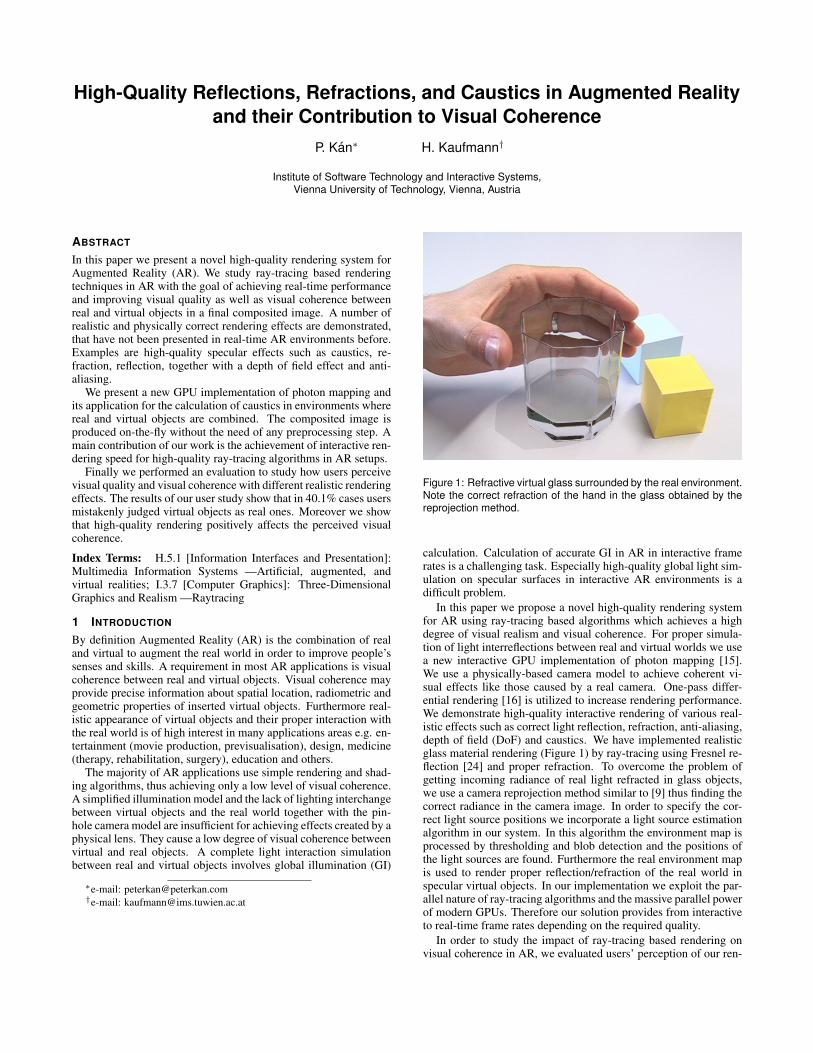
Figure 1: Refractive virtual glass surrounded by the real environment.Note the correct refraction of the hand in the glass obtained by thereprojection method.
calculation. Calculation of accurate GI in AR in interactive framerates is a challenging task. Especially high-quality global light sim-ulation on specular surfaces in interactive AR environments is adifficult problem.
In this paper we propose a novel high-quality rendering systemfor AR using ray-tracing based algorithms which achieves a highdegree of visual realism and visual coherence. For proper simula-tion of light interreflections between real and virtual worlds we usea new interactive GPU implementation of photon mapping [15].We use a physically-based camera model to achieve coherent vi-sual effects like those caused by a real camera. One-pass differ-ential rendering [16] is utilized to increase rendering performance.We demonstrate high-quality interactive rendering of various real-istic effects such as correct light reflection, refraction, anti-aliasing,depth of field (DoF) and caustics. We have implemented realisticglass material rendering (Figure 1) by ray-tracing using Fresnel re-flection [24] and proper refraction. To overcome the problem ofgetting incoming radiance of real light refracted in glass objects,we use a camera reprojection method similar to [9] thus finding thecorrect radiance in the camera image. In order to specify the cor-rect light source positions we incorporate a light source estimationalgorithm in our system. In this algorithm the environment map isprocessed by thresholding and blob detection and the positions ofthe light sources are found. Furthermore the real environment mapis used to render proper reflection/refraction of the real world inspecular virtual objects. In our implementation we exploit the par-allel nature of ray-tracing algorithms and the massive parallel powerof modern GPUs. Therefore our solution provides from interactiveto real-time frame rates depending on the required quality.
In order to study the impact of ray-tracing based rendering onvisual coherence in AR, we evaluated users’ perception of our ren-

dering solution using quantitative methods. Visual coherence wasevaluated in two different scenarios. Furthermore we asked partic-ipants to state which objects in the shown video are real and whichare virtual, in order to see if the visual quality and coherence is goodenough to make people believe that AR content is real. The resultsof the user study show that our system is able to achieve a very highdegree of visual coherence between real and virtual objects.
The main contributions of our work are:
• New high-quality ray-tracing based rendering and composit-ing system for interactive AR providing realistic rendering ef-fects.
• Interactive photon mapping on the GPU for caustics render-ing in augmented reality introducing global light transport be-tween virtual and real objects.
• Real-time physically based rendering of specular reflectionand refraction in AR.
• User studies confirming the positive impact of ray-tracingbased rendering in AR to visual coherence.
The advantage of our method over previous work is that we canvery naturally render specular surfaces like glass or mirrors in highquality. Moreover we propose a method for calculating caustics inAR in interactive frame rates. Caustics can be created by reflectingor refracting light on both real and virtual specular objects. Ourrendering and compositing method runs on-the-fly and no prepro-cessing is needed while high rendering quality is achieved.
The rest of the paper is organized as follows. In section 2 previ-ous research is discussed. Section 3 describes the main algorithmsthat we developed in detail: simulation of ray-tracing based refrac-tion and reflection, rendering of caustics by photon mapping and thelight source estimation technique. Moreover the used image repro-jection technique and details about density estimation are discussedthere. Section 4 details the implementation of all proposed algo-rithms. In section 5 the evaluation of the system is presented. Userstudy examining the influence of ray-tracing based rendering on thehuman perception is described and results are discussed. Further-more performance measurements are summarized.
2 RELATED WORK
In this section we give an overview of previous research that fo-cused on high-quality rendering in AR, comparing it to our ap-proach.
High-quality rendering in AR The majority of techniques thataim to achieve high rendering quality in AR use rasterization-basedrendering. Usually they focus on special effects like material simu-lation, self-shadowing simulation by ambient occlusion, or diffuseglobal illumination and color bleeding. These approaches usuallydo not simulate the light paths reflected from specular surfaces andthey use a high amount of approximation in order to achieve highrendering speed.
Believable material simulation can increase the amount of real-ism in AR. Pessoa et al. [23] created an approach for photorealisticrendering in AR using rasterization. They proposed an extendedversion of Lafortune Spatial BRDF model to properly simulate ma-terial properties. Additionally they used the Irradiance Environ-ment Mapping [29] in order to simulate global illumination comingfrom the real world to virtual objects. Hover their solution can-not simulate global illumination coming from virtual objects to realones. Furthermore a static environment image was used in their so-lution and therefore no dynamic movement of reflected real objectsor lighting change could be simulated.
Diffuse global illumination in real-time augmented reality wasproposed by Knecht at al. [18] in their Differential Instant Radios-ity approach. They extended Imperfect Shadow Maps [30] to work
in AR and used single-pass differential rendering to create the fi-nal composite image. Their system is capable of simulating diffuseglobal illumination including color bleeding between real and vir-tual objects at interactive frame rates. However they do not sim-ulate the specular light paths that create caustics and light reflec-tion or refraction. Another approach simulating high-quality dif-fuse global illumination in AR was proposed by Grosch et al. [10].Authors used Spherical Harmonics arranged in a grid to simulatediffuse light transport. Moreover a correct near-field illuminationwas calculated using the predefined model of surrounding geom-etry (Room) in combination with a fish-eye lens camera. Theyachieved real-time frame rates, however their solution does not sim-ulate specular effects like caustics, refraction or reflection. An ap-proximation of self-shadowing in AR calculated by Ambient Oc-clusion was used by Franke and Jung [7]. They proposed a materialreconstruction technique using genetic algorithms. Multipass ren-dering for AR was proposed by Agusanto et al. [1]. They usedirradiance environment maps to simulate global illumination com-ing from real light to virtual objects. However their system did notsimulate light reflected from virtual objects affecting the real scene.
An advantage of our system in comparison to a rasterization-based AR rendering systems is that we can calculate specular ef-fects like reflection, refraction and caustics in high-quality, whilespecular effects are very difficult to calculate in rasterization-basedrendering. We can also simulate the lighting change on real objectscaused by inserting virtual ones. Moreover ray-tracing renderingsystems can usually provide higher quality of the final result.
AR systems usually use the simulation of real lighting in ren-dering. In some systems an image-based lighting approach isused [18, 3] by sampling the environment map according to theprobability density function (pdf) similar to the intensities of thepixels. Other approaches use light reconstruction to precisely spec-ify the light positions and intensities. Frahm et al. [6] used an im-age processing approach to obtain information about light sources.They search for regions with high saturation in all channels and thenapply a segmentation. They approximate the real light by point lightsources and calculate their positions by processing two images fromtwo fish-eye lens cameras. High-quality light reconstruction froma single-camera image is proposed in [17]. Authors used a userguided algorithm, which processes the light sources marked by theuser to find the optimal positions, shapes and sizes of them.
A composited image of real and virtual objects in augmented re-ality is usually created using differential rendering which was orig-inally proposed by Fournier et al. [5] and later extended by De-bevec [3]. This algorithm requires two solutions of lighting simu-lation, doubling the rendering time. To overcome this problem weuse our one-pass differential rendering algorithm proposed in [16].
A good overview of reflection and refraction simulation in ARcan be found in [26]. The author describes rasterization-based tech-niques. However ray-tracing can provide physically-based simula-tion of refractive and reflective material while rasterization basedtechniques provide solutions at lower quality.
Ray-tracing in AR Physically-based algorithms developed incomputer graphics often use ray-tracing to achieve accurate lighttransport calculation. However the problem of high-quality ray-tracing based rendering systems is performance. A good image cantake time to render. Offline rendering systems for mixing virtual ob-jects to simulate full global illumination were proposed in [17, 3].Important research for specular effects simulation in AR was doneby Grosch [9]. He proposed Differential Photon Mapping in or-der to simulate caustics and shadows more efficiently. Moreoverhe proposed an image reprojection technique to obtain real radi-ance coming through refractive surfaces. His system achieves highrendering quality, however it runs offline and not in real-time. Ad-vantage of our method over differential photon mapping is that weachieve interactive to real-time frame rates and our system is capa-
ble to simulate more visual features, for example physically-baseddepth of field.
The use of the ray-tracing in AR applications was examined byScheer et al. [31] who used it for realistic rendering and Pomi etal. [27] who studied the insertion of the real video of characters intoa virtual environment in TV Studio applications. The disadvantageof Pomi’s implementation was the requirement of a PC cluster toachieve interactive frame rates.
Photon mapping Photon mapping proposed by Jensen [15] isan effective two pass algorithm for the calculation of global illu-mination. It traces photons from the light source into the scene.When a photon hits a surface it is either reflected, refracted, or ab-sorbed. The photons are stored at their hit positions and later sortedinto a Kd-tree data structure called photon map. In the second stepthe radiance information is reconstructed from the photon map inthe points visible from the camera. The Kd-tree is traversed in or-der to find the photons contributing to a specified location. Photonmapping can simulate full global illumination and it is especiallyefficient in specular global illumination effects like caustics, whichare difficult for other GI algorithms.
Since photon mapping was invented many improvements havebeen published. Several solutions for fast photon mapping wereproposed. An interactive solution was created by Fabianowskiand Dingliana [4], who generated the footprints of all photon hitsand stored them in the improved BVH optimized for fast search.A very efficient photon mapping implementation combining GPUrasterization and CPU ray-tracing was proposed by McGuire andLuebke [20]. They used photon volumes rasterization in orderto avoid costly KNN queries. An efficient GPU-based approachfor full global illumination calculation was proposed by Wang etal. [39]. The authors used the GPU Kd-tree construction proposedby Zhou [40] and they implemented the whole global illuminationcalculation only on the GPU, achieving interactive frame rates. Pur-cell et al. [28] proposed another GPU implementation of photonmapping using shader programs. A grid-based photon map wasused in their approach. Gupte [12] proposed an interactive photonmapping implementation using the OptiX ray-tracing engine thatwe use as well. The main difference compared to our method isthat they used a Spatial Hashing Method instead of the Kd-tree forstoring and searching photons. An interactive photon mapping im-plementation running on multiple computers is shown in [11].
A special case of the photon mapping algorithm reformulation isshown in splatting approaches. Usually the energy carried by pho-tons is splat to the specified buffer and the photon’s contributionand weight are added to already stored values in the area of contri-bution. A scalable photon splatting algorithm was proposed in [19]and photon ray splatting was proposed in [13].
Another kind of algorithmic improvement can be achieved by in-creasing the quality of the produced result. A high-quality photonmapping improvement was proposed by Spencer and Jones [35].The authors focused mainly on the density estimation part of caus-tics rendering. They proposed the novel method of relaxing theinitial distribution into one with a blue noise spectral signature.This improvement enables the use of low bandwidth kernels andincreases efficiency of the rendering. The same authors also pro-posed Hierarchical Photon Mapping [34] to increase the quality ofthe final gathering.
3 HIGH QUALITY RENDERING SYSTEM FOR ARIn order to solve the problem of visual coherence between virtualand real objects, a high-quality composition of the final image isrequired. As shown in previous research, some realistic renderingeffects can be achieved using the rasterization pipeline on the GPU.However it is still difficult to render high-quality specular effectslike realistic refraction, or caustics. The natural way of render-ing more complex lighting effects is by using ray-tracing, which
is also used in an extended form for physically based rendering.With the recent development of graphics hardware, ray-tracing be-comes available for use in real-time applications. We propose theadaptation and application of ray-tracing based algorithms into ARin order to achieve visually appealing rendering results.
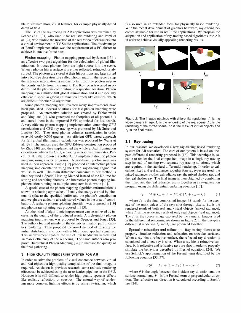
Figure 2: The images obtained with differential rendering. Ic is thevideo camera image, Ir is the rendering of the real scene, Im is therendering of the mixed scene, M is the mask of virtual objects andIf is the final result.
3.1 Ray-tracingIn our research we developed a new ray-tracing based renderingsystem for AR scenarios. The core of our system is based on one-pass differential rendering proposed in [16]. This technique is ca-pable to render the final composited image in a single ray-tracingstep instead of running two separate ray-tracing solutions, whichare required in the standard differential rendering. In order to cal-culate mixed and real radiances together four ray types are used: themixed radiance ray, the real radiance ray, the mixed shadow ray, andthe real shadow ray. The final image is then obtained by combiningthe mixed and the real radiance results together in a ray-generationprogram using the differential rendering equation [17]:
If =M � Im + (1−M)� (Ic + Im − Ir) (1)
where If is the final composited image, M stands for the aver-age of the mask values of the rays shot through pixels. Im is therendered result of both real and virtual objects (mixed radiance),while Ir is the rendering result of only real objects (real radiance).The Ic is the source image captured by the camera. Images usedin the differential rendering are shown in figure 2. In the one-passdifferential rendering Ir and Im are produced together.
Specular refraction and reflection Ray-tracing allows us toproperly simulate reflection and refraction on specular surfaces.When a ray hits a reflective surface, the reflected ray direction iscalculated and a new ray is shot. When a ray hits a refractive sur-face, both reflective and refractive rays are shot in order to properlysimulate the behaviour described by Fresnel equations [24]. Weuse Schlick’s approximation of the Fresnel term described by thefollowing equation [32, 37]:
F (θ) = F⊥ + (1− F⊥)(1− cos θ)5 (2)
where θ is the angle between the incident ray direction and thesurface normal, and F⊥ is the Fresnel term at perpendicular direc-tion. The refractive ray direction is calculated according to Snell’slaw [24].
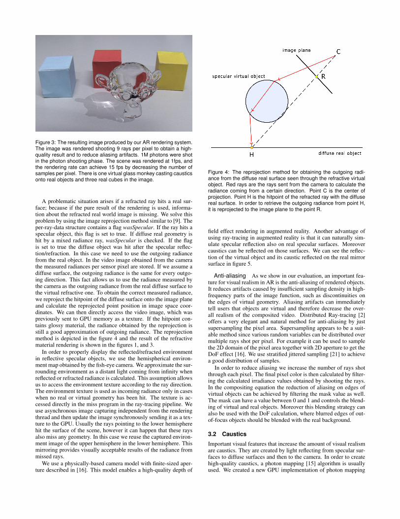
Figure 3: The resulting image produced by our AR rendering system.The image was rendered shooting 9 rays per pixel to obtain a high-quality result and to reduce aliasing artifacts. 1M photons were shotin the photon shooting phase. The scene was rendered at 1fps, andthe rendering rate can achieve 15 fps by decreasing the number ofsamples per pixel. There is one virtual glass monkey casting causticsonto real objects and three real cubes in the image.
A problematic situation arises if a refracted ray hits a real sur-face; because if the pure result of the rendering is used, informa-tion about the refracted real world image is missing. We solve thisproblem by using the image reprojection method similar to [9]. Theper-ray-data structure contains a flag wasSpecular. If the ray hits aspecular object, this flag is set to true. If diffuse real geometry ishit by a mixed radiance ray, wasSpecular is checked. If the flagis set to true the diffuse object was hit after the specular reflec-tion/refraction. In this case we need to use the outgoing radiancefrom the real object. In the video image obtained from the camerathe measured radiances per sensor pixel are stored. If we assume adiffuse surface, the outgoing radiance is the same for every outgo-ing direction. This fact allows us to use the radiance measured bythe camera as the outgoing radiance from the real diffuse surface tothe virtual refractive one. To obtain the correct measured radiance,we reproject the hitpoint of the diffuse surface onto the image planeand calculate the reprojected point position in image space coor-dinates. We can then directly access the video image, which waspreviously sent to GPU memory as a texture. If the hitpoint con-tains glossy material, the radiance obtained by the reprojection isstill a good approximation of outgoing radiance. The reprojectionmethod is depicted in the figure 4 and the result of the refractivematerial rendering is shown in the figures 1, and 3.
In order to properly display the reflected/refracted environmentin reflective specular objects, we use the hemispherical environ-ment map obtained by the fish-eye camera. We approximate the sur-rounding environment as a distant light coming from infinity whenreflected or refracted radiance is calculated. This assumption allowsus to access the environment texture according to the ray direction.The environment texture is used as incoming radiance only in caseswhen no real or virtual geometry has been hit. The texture is ac-cessed directly in the miss program in the ray-tracing pipeline. Weuse asynchronous image capturing independent from the renderingthread and then update the image synchronously sending it as a tex-ture to the GPU. Usually the rays pointing to the lower hemispherehit the surface of the scene, however it can happen that these raysalso miss any geometry. In this case we reuse the captured environ-ment image of the upper hemisphere in the lower hemisphere. Thismirroring provides visually acceptable results of the radiance frommissed rays.
We use a physically-based camera model with finite-sized aper-ture described in [16]. This model enables a high-quality depth of
Figure 4: The reprojection method for obtaining the outgoing radi-ance from the diffuse real surface seen through the refractive virtualobject. Red rays are the rays sent from the camera to calculate theradiance coming from a certain direction. Point C is the center ofprojection. Point H is the hitpoint of the refracted ray with the diffusereal surface. In order to retrieve the outgoing radiance from point H,it is reprojected to the image plane to the point R.
field effect rendering in augmented reality. Another advantage ofusing ray-tracing in augmented reality is that it can naturally sim-ulate specular reflection also on real specular surfaces. Moreovercaustics can be reflected on those surfaces. We can see the reflec-tion of the virtual object and its caustic reflected on the real mirrorsurface in figure 5.
Anti-aliasing As we show in our evaluation, an important fea-ture for visual realism in AR is the anti-aliasing of rendered objects.It reduces artifacts caused by insufficient sampling density in high-frequency parts of the image function, such as discontinuities onthe edges of virtual geometry. Aliasing artifacts can immediatelytell users that objects are virtual and therefore decrease the over-all realism of the composited video. Distributed Ray-tracing [2]offers a very elegant and natural method for anti-aliasing by justsupersampling the pixel area. Supersampling appears to be a suit-able method since various random variables can be distributed overmultiple rays shot per pixel. For example it can be used to samplethe 2D domain of the pixel area together with 2D aperture to get theDoF effect [16]. We use stratified jittered sampling [21] to achievea good distribution of samples.
In order to reduce aliasing we increase the number of rays shotthrough each pixel. The final pixel color is then calculated by filter-ing the calculated irradiance values obtained by shooting the rays.In the compositing equation the reduction of aliasing on edges ofvirtual objects can be achieved by filtering the mask value as well.The mask can have a value between 0 and 1 and controls the blend-ing of virtual and real objects. Moreover this blending strategy canalso be used with the DoF calculation, where blurred edges of out-of-focus objects should be blended with the real background.
3.2 Caustics
Important visual features that increase the amount of visual realismare caustics. They are created by light reflecting from specular sur-faces to diffuse surfaces and then to the camera. In order to createhigh-quality caustics, a photon mapping [15] algorithm is usuallyused. We created a new GPU implementation of photon mapping

Figure 5: Caustics can be created by both virtual and real specularobjects. The green caustic was created by the virtual torus. Partof it was created by the reflection of light from the real mirror. Thediffuse cube on which the caustic is drawn is also virtual. Note thecorrect reflection of the generated caustic in the real mirror and alsothe correct refraction in the torus.
using the OptiX ray-tracing engine [22] in order to achieve interac-tive frame rates while keeping quality of the created caustics high(Figure 6).
In our implementation we use a two-pass caustic generation al-gorithm. In the first pass photons are emitted from the light sourceinto the scene. When photons hit a specular virtual surface theyare reflected or refracted in the direction of specular reflection orrefraction. If a photon hits a diffuse surface after reflection from aspecular object, it is recorded in an array of photons. This array islater processed on the CPU, and a Kd-tree is created to allow fastersearch for near-by photons. In the next step rays are traced from thecamera through the image plane to obtain the radiance incomingfrom the scene. If a ray hits a surface in the scene, direct illumina-tion is calculated and indirect caustic illumination is reconstructedfrom the photon map (Figure 3).
In order to reconstruct indirect illumination at a certain point ofthe scene from point samples that are stored in the photon map,density estimation techniques are applied. There are three main ap-proaches for density estimation: using a histogram, nearest neigh-bour search or kernel density estimation [33, 36].
The K-nearest neighbour (KNN) search is the method that is of-ten used in combination with photon maps. This technique reducesthe variance while keeping the bias low, however a high number ofK has to be used in order to obtain accurate results. Because ofmany samples required, the KNN search is often a bottleneck ofradiance estimation from photon maps.
We use a kernel method to estimate illumination based on thephoton map, which allows us to perform a fast calculation of visu-ally correct results. With kernel methods there is always a tradeoffbetween bias and noise. A standard kernel method estimates theprobability density function (pdf) p(x) given N samples xi by theequation [33, 36]:
p(t) =1
Nhd
N∑i=1
K( t− xih
) (3)
K is a kernel function, h is the kernel bandwidth, d is the di-mension of the domain of p, and t is the position of estimation.The accuracy of the kernel density estimation technique depends
on shape and bandwidth of a kernel. A kernel bandwidth selectionis an important step. If the kernel is too wide, more bias is pro-duced and if it is too narrow, more variance can be observed. Ker-nel estimation techniques with adaptive bandwidth were proposedin previous work [36, 13]. They use a different bandwidth for everysample according to its correctness, previously estimated density,or the number of surrounding samples. Those techniques are ofteniterative and require additional computational time to find a goodbandwidth.
We decided to use density estimation with a fixed kernel size.This approach can potentionally produce bias and blur the discon-tinuities in caustics. However, we solved this problem by selectinga narrow kernel width. The variance is then reduced by increasingthe number of shot photons. Using a fixed kernel size with a nar-row kernel enables very fast photon search in a Kd-tree as well asfast density estimation. We use the Epanechnikov kernel, which isa standard in density estimation [36]. A comparison of renderingwith and without caustics can be seen in figure 8.
Figure 6: Interactive caustic rendering. There is a virtual glasssphere inserted into the real scene. The image was rendered at 10fps.
A problem when emitting photons for caustics creation is the se-lection of good directions in which a specular surface will be hit.Jensen proposed a solution to rasterize specular objects to hemi-sphere to obtain only directions where they are seen from the lightposition [15]. Another approach is to approximate the geometry ofspecular surfaces in a form of bounding volumes and to shoot raysinto the resulting primitives. In our system specular objects are ap-proximated by bounding spheres for the purpose of photon shoot-ing. In the scene loading phase all geometry is traversed with thegoal of finding caustic generators. If a caustic generator is found, abounding sphere, including all geometry of this object, is created.In the photon shooting program the center and the radius of eachbounding sphere is used in the following way. First, one of thecaustic generators is randomly selected according to the projectedarea of the bounding sphere. Then a disk perpendicular to the di-rection from the center of the object to the light source is sampledusing stratified jittered sampling. A direction of photon is then cal-culated as the direction from light source position to the sampledpoint. By this sampling process some photons may miss a causticgenerator, however a high numbers of hitpoints are achieved.
3.3 Light Source EstimationWe are using a fish-eye camera to capture the light situation in thereal environment which allows us to estimate the positions and in-

tensities of the light source(s). Generally two different approacheshave been reported in literature. The first approach builds a cumula-tive distribution function from the environment image, allowing forrandom sampling from the probability distribution, which equalsthe intensity of the incoming light from different directions on thehemisphere [24].
The second approach is to apply image processing techniques tothe environment image and extract the positions of light sources.This approach was used for example in [6].
We use image processing in our system, because random envi-ronment light sampling requires a lot of samples and creates anadditional overhead. In our implementation first thresholding is ap-plied to the captured environment image. In the next step we useblob detection on the binary image to detect the biggest sources ofhigh incoming radiance. Connected component analysis providedby OpenCV is utilized here and a contour tracing approach [8] isused to find the contours of radiance blobs. The area of every blobis calculated and the biggest blobs are selected as light sources.The direction of incoming light is estimated according to the blobcenter position in the environment image by reprojecting it to thehemisphere. The exact position is then estimated with the user sup-plied average room size constant and the light is positioned in thatdistance in the reconstructed direction.
An arbitrary number of light sources can be extracted and biggerarea light sources can be sampled by more point light sources. Weusually use single point light source extraction in our experiments.Point light sources produce sharper caustics than area light sourcesdo.
We run environment image capturing and light source estima-tion asynchronously in a separate thread. Rendering speed is thenalmost independent of the light source estimation and the last cal-culated values are always read.
4 IMPLEMENTATION
We implemented our AR rendering system by using the OptiX ray-tracing engine [22]. It is a powerful tool for running ray-tracingbased algorithms on modern parallel GPUs. To composite the finalimage with the real video captured by the camera we use one-passdifferential rendering directly in the ray-generation program. Thephoton shooting pass is also implemented using OptiX.
The main steps of our rendering and compositing method are de-picted in figure 7. For every frame the images from video cameraand fish-eye camera are captured and sent to the GPU. The envi-ronment image is processed and light source positions are found. Avisual marker is detected in the video image and position and ori-entation of the camera are estimated. The first GPU step is photonmapping. Photons are then processed on the CPU and a Kd-treeis created. The final rendering step is GPU ray-tracing from thecamera position. All calculated results together with geometry andmaterials of real and virtual scenes are used here. Density estima-tion is performed on every diffuse surface hit in the ray-tracing stepto estimate the indirect illumination from the photon map. The re-sult of the rendering is composited with the real video image anddirectly displayed on the output device.
A computer with hexa-core CPU and a GeForce GTX 590 graph-ics card was used for high-speed rendering. The upper hemisphereof the scene’s illumination was captured with an environment cam-era with a fish-eye lens. The captured image is used as a distantsource of real illumination for reflected/refracted light and as apoint light source for direct light calculation. This allows us toreuse the environment map in every point of the scene. Using alight source as a distant light in reflection and refraction completelyomits the spatial variation, however it is a very good approximationfor the directional variation in the scene. Therefore the environmentimage is accessed with the ray direction in the miss program.
Our main camera to capture images and augment them with vir-tual objects in real time is the Sony HVR-Z1E. This camera has alens that allows big aperture size and is therefore suitable for thecreation of a good depth of field effect by the optics of the real lens.The camera parameters can then be used in the rendering system tosimulate physically correct depth of field for the rendering of virtualobjects.
Figure 7: Overview of our rendering and compositing method. Ar-rows indicate the data flow between different components.
To track the camera’s position and orientation, the ARToolkit-Plus [38] marker-based tracking system was used. The actual cam-era image is utilized both for the camera pose calculation and forrendering. By reconstructing the camera position and orientationdirectly out of the camera image that is also used for rendering, nosynchronization problems between tracking and rendering appear.The orientation of the marker determines the rotation of the worldcoordinate space and therefore determines where virtual objects arepositioned. The environment image retrieved by the fish-eye cam-era is orientation-dependent, therefore the fish-eye camera has tobe aligned with the marker. Proper alignment ensures correct re-flections and refractions on specular virtual surfaces.
Reconstructed geometry and materials of the real scene are re-quired in order to properly create the composited image by differ-ential rendering. We use a predefined model of the real scene forthis purpose.
5 EVALUATION AND RESULTS
In order to evaluate the impact of interactive ray-tracing on visualcoherence in AR we designed and performed a user study. Quanti-tative methods were used to evaluate our hypotheses. Our hypothe-ses were:
• Realistic features of ray-tracing based rendering have a pos-itive impact on the user’s perception of visual coherence inaugmented reality.
• Every realistic rendering effect used in our system positivelyinfluences the realistic appearance of the composited video.
5.1 Study DesignAt the beginning of the user study we showed a single video of atable containing diffuse real cubes, diffuse virtual cubes, a refrac-tive virtual glass sphere and a reflective virtual ring. All effects thatwe describe in this paper (simulation of refraction/reflection, anti-aliasing, caustics, and DoF) were enabled in this video. We askedusers to rate how realistic the video was on a linear visual analoguescale from -3 to 3. The value of -3 means that the video is not re-alistic at all and the value of 3 means that the video is completelyrealistic. Moreover we asked people to indicate which objects werereal and which were virtual.
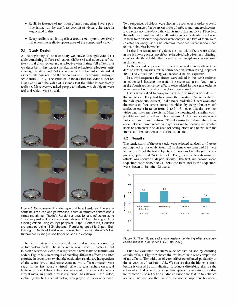
Figure 8: Comparison of rendering with different features. The scenecontains a real red and yellow cube, a virtual refractive sphere and avirtual metal ring. (Top left) Rendering refraction and reflection using1 ray per pixel and no caustic simulation at 27 fps. (Top right) Anti-aliasing added using 25 rays per pixel - 7 fps. (Bottom left) Causticsare enabled using 150K photons. Rendering speed is 3 fps. (Bot-tom right) Depth of Field effect is enabled. Frame rate is 2.5 fps.Differences in images can better be seen in closeup.
In the next stage of the user study we used sequences consistingof five videos each. The same scene was shown in each clip butin each successive video in a sequence a new realistic feature wasadded. Figure 8 is an example of enabling different effects one afteranother. In order to show that the evaluation results are independentof the scene layout and scene content, two different scenes wereused. In the first scene a virtual refractive glass sphere on a realtable with real diffuse cubes was rendered. In a second scene avirtual metal ring with diffuse real cubes was shown. Each video,including the first general video, was played to users only once.
Two sequences of videos were shown to every user in order to avoidthe dependence of answers on order of effects and rendered scenes.Each sequence introduced the effects in a different order. Thereforethe order was randomized for all participants in a standardized way.In total four different sequences were created and two of them wereselected for every user. This selection made sequences randomizedto avoid the bias in results.
In the first sequence of videos the realistic effects were addedin the following order: no effect, refraction/reflection, anti-aliasing,caustics, depth of field. The virtual refractive sphere was renderedin this sequence.
In the second sequence the effects were added in a different or-der: no effect, caustics, refraction/reflection, anti-aliasing, depth offield. The virtual metal ring was rendered in this sequence.
In a third sequence the effects were added in the same order asin sequence 1, however the metal ring scene was used. And finallyin the fourth sequence the effects were added in the same order asin sequence 2 with a refractive glass sphere used.
Users were asked to compare each pair of successive videos inthe sequence. They had to answer the question: Which video inthe pair (previous, current) looks more realistic? Users evaluatedthe increase of realism in successive videos by using a linear visualanalogue scale in range from -3 to 3. -3 means that the previousvideo was much more realistic. 0 has the meaning of a similar, com-parable amount of realism in both videos. And 3 means the currentvideo is much more realistic. The decision to evaluate the differ-ence between two successive clips was made because we wantedusers to concentrate on desired rendering effect and to evaluate theincrease of realism when this effect is enabled.
5.2 ResultsThe participants of the user study were selected randomly. 43 usersparticipated in our evaluation. 12 of them were men and 31 werewomen. 26% of the test subjects had previous knowledge in com-puter graphics and 74% did not. The general video showing alleffects was shown to all participants. The first and second videosequences were shown to 21 users; the third and fourth sequenceswere shown to the other 22 users.
Figure 9: The influence of single realistic rendering effects on per-ceived realism in AR videos. (σ = std. dev.).
First we evaluated the increase of realism caused by enablingcertain effects. Figure 9 shows the results of pair-wise comparisonof all effects. The addition of each effect contributed positively tothe perception of realism in AR. We can see that the highest contri-bution is caused by anti-aliasing. It reduces disturbing alias on theedges of virtual objects, making them appear more natural. Realis-tic refraction and reflection is also an important feature to enhancerealism. We can see that caustics are not so important for users,

Figure 10: Difference in perceived realism with single realistic effectsusing different virtual content.
but also contribute to increase the amount of realism in AR. How-ever, the result on caustics could be influenced by the fact that inthe second sequence caustics were added to an object before reflec-tion/refraction. This made caustics look unnatural because the re-spective objects were rendered just semitransparently. In summaryour second hypothesis was confirmed because the results indicatethat all added rendering features increased the amount of realismin AR. Influence of virtual content to realism perceived by users invideo sequences 1 and 3 can be seen in figure 10.
We were interested to see how users perceived realism of theoverall video. The results can be seen in figure 11. The averageof 0.8 indicates that the scene was perceived as realistic and theresult confirms our first hypothesis. However, there is room for im-provement in future work. In addition we analyzed the perceptionof realism separately for selected groups within our participants.We analyzed the results depending on gender and computer graph-ics experience. The results are shown in figure 11. Men with CGknowledge report higher values of realism.
Figure 11: Average results of perceived realism of the overall ARvideo. (σ = std. dev.).
Another result was more surprising. We asked users to judgewhich objects in the overall video are real and which are virtual.The intention of this question was to see if the visual quality andcoherence is good enough to make people believe that AR contentis real. One goal is to make virtual objects indistinguishable fromreal ones. In average 40.1% of the virtual objects were mistakenlymarked as real ones. The most realistic appearance according to this
evaluation had the virtual metal ring reflecting the real environmentand casting caustics. 53.5% of users marked this virtual object asa real one. It is important to say that in 36% of all cases usersmistakenly thought that real objects were virtual ones.
In summary the evaluation demonstrates that each developedrendering effect has a positive impact to visual coherence in AR.The results of enabling different effects can be seen in figure 8. Inthe top left image of the figure, the rendering of specular refractionand reflection is enabled. However in this image only 1 ray per pixelwas shot and we can observe aliasing artifacts. The top right imageshows how aliasing artifacts disappear when supersampling is en-abled. In the bottom images caustics rendering was added. Note thesmall caustic created under the glass sphere. In the lower left imagethe real yellow cube is blurred by DoF of the real lens. Thereforethe virtual sphere is visually incoherent because it is sharp. TheDoF effect is enabled in the bottom right image.
The second part of our evaluation concerned rendering perfor-mance. We measured the rendering speed of different effects and atdifferent sampling rates. As we can see in table 1 our system is ca-pable to produce a high-quality result in interactive frame rates. Thetable also shows the computation times for different steps of render-ing: photon emitting, Kd-tree build, and ray-tracing with densityestimation. Texture copying to the GPU memory usually took 20ms in our experiments. Our system is capable to preserve interactiv-ity even with complex scenes like the glass happy Budha consistingof 855K triangles. Increasing the sampling rate improves the qual-ity of the produced result, however as we see in table 1 it decreasesrendering speed, thus offering a tradeoff between quality and speed.
6 CONCLUSION AND FUTURE WORK
In this paper we present a novel high-quality rendering and com-positing system for augmented reality. Our system is able to rendervarious realistic effects by using ray-tracing at interactive or real-time frame rates. A novelty of our work was achieved by usinginteractive ray-tracing in AR on a single PC while simulating spec-ular effects like refraction, reflection and caustics. Our method iscapable to produce believable interactive augmentations. Moreoverwe designed and performed a user study confirming the positive im-pact of realistic rendering on user’s perception of visual coherence.
There are several possible extensions of the proposed systemwhich can increase the amount of realism in AR. We plan to in-corporate full global illumination into rendering in future work toallow effects like color bleeding and diffuse indirect lighting to beproduced. Possible performance improvements can be achieved byusing a GPU implementation of Kd-tree construction [40] for pho-ton mapping. Accurate camera tracking is an important part of anAR system, because even little jitter in tracking data can be im-mediately observed by users as unnatural and unstable behavior ofvirtual objects. We plan to extend our system using a more stabletracking solution like the ioTracker [25]. Automatic 3D reconstruc-tion of the real scene would be of high benefit in our system. Apossible solution to this problem can be KinectFusion [14] whichcan provide both 3D reconstruction of the real scene and a stabletracking solution.
In our work we demonstrate the possibility of using high-qualityray-tracing based rendering techniques in interactive AR and weexpect GPU ray-tracing to be the future of rendering in AR.
ACKNOWLEDGEMENTS
We thank the anonymous reviewers for their valuable commentsand suggestions. We would like to thank to Iana Podkosova whohelped us with reformulation of some parts of the paper. This workwas supported in part by the PhD school of informatics at TU Vi-enna.
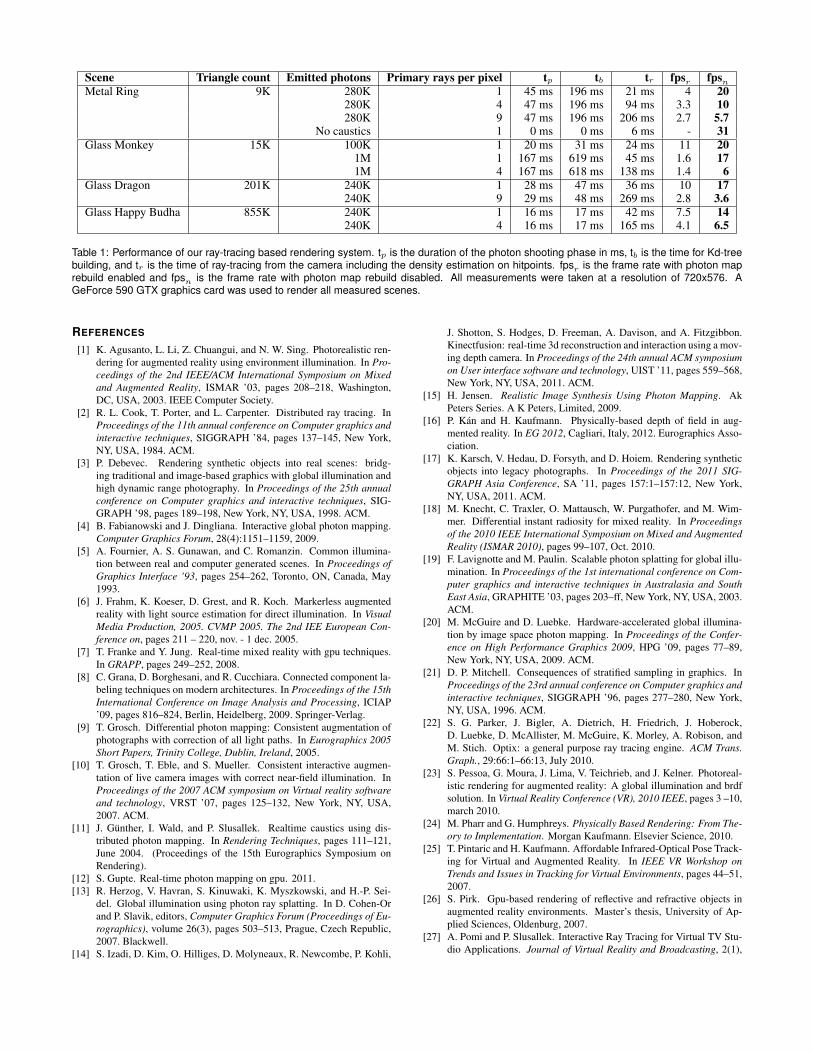
Scene Triangle count Emitted photons Primary rays per pixel tp tb tr fpsr fpsnMetal Ring 9K 280K 1 45 ms 196 ms 21 ms 4 20
280K 4 47 ms 196 ms 94 ms 3.3 10280K 9 47 ms 196 ms 206 ms 2.7 5.7
No caustics 1 0 ms 0 ms 6 ms - 31Glass Monkey 15K 100K 1 20 ms 31 ms 24 ms 11 20
1M 1 167 ms 619 ms 45 ms 1.6 171M 4 167 ms 618 ms 138 ms 1.4 6
Glass Dragon 201K 240K 1 28 ms 47 ms 36 ms 10 17240K 9 29 ms 48 ms 269 ms 2.8 3.6
Glass Happy Budha 855K 240K 1 16 ms 17 ms 42 ms 7.5 14240K 4 16 ms 17 ms 165 ms 4.1 6.5
Table 1: Performance of our ray-tracing based rendering system. tp is the duration of the photon shooting phase in ms, tb is the time for Kd-treebuilding, and tr is the time of ray-tracing from the camera including the density estimation on hitpoints. fpsr is the frame rate with photon maprebuild enabled and fpsn is the frame rate with photon map rebuild disabled. All measurements were taken at a resolution of 720x576. AGeForce 590 GTX graphics card was used to render all measured scenes.
REFERENCES
[1] K. Agusanto, L. Li, Z. Chuangui, and N. W. Sing. Photorealistic ren-dering for augmented reality using environment illumination. In Pro-ceedings of the 2nd IEEE/ACM International Symposium on Mixedand Augmented Reality, ISMAR ’03, pages 208–218, Washington,DC, USA, 2003. IEEE Computer Society.
[2] R. L. Cook, T. Porter, and L. Carpenter. Distributed ray tracing. InProceedings of the 11th annual conference on Computer graphics andinteractive techniques, SIGGRAPH ’84, pages 137–145, New York,NY, USA, 1984. ACM.
[3] P. Debevec. Rendering synthetic objects into real scenes: bridg-ing traditional and image-based graphics with global illumination andhigh dynamic range photography. In Proceedings of the 25th annualconference on Computer graphics and interactive techniques, SIG-GRAPH ’98, pages 189–198, New York, NY, USA, 1998. ACM.
[4] B. Fabianowski and J. Dingliana. Interactive global photon mapping.Computer Graphics Forum, 28(4):1151–1159, 2009.
[5] A. Fournier, A. S. Gunawan, and C. Romanzin. Common illumina-tion between real and computer generated scenes. In Proceedings ofGraphics Interface ’93, pages 254–262, Toronto, ON, Canada, May1993.
[6] J. Frahm, K. Koeser, D. Grest, and R. Koch. Markerless augmentedreality with light source estimation for direct illumination. In VisualMedia Production, 2005. CVMP 2005. The 2nd IEE European Con-ference on, pages 211 – 220, nov. - 1 dec. 2005.
[7] T. Franke and Y. Jung. Real-time mixed reality with gpu techniques.In GRAPP, pages 249–252, 2008.
[8] C. Grana, D. Borghesani, and R. Cucchiara. Connected component la-beling techniques on modern architectures. In Proceedings of the 15thInternational Conference on Image Analysis and Processing, ICIAP’09, pages 816–824, Berlin, Heidelberg, 2009. Springer-Verlag.
[9] T. Grosch. Differential photon mapping: Consistent augmentation ofphotographs with correction of all light paths. In Eurographics 2005Short Papers, Trinity College, Dublin, Ireland, 2005.
[10] T. Grosch, T. Eble, and S. Mueller. Consistent interactive augmen-tation of live camera images with correct near-field illumination. InProceedings of the 2007 ACM symposium on Virtual reality softwareand technology, VRST ’07, pages 125–132, New York, NY, USA,2007. ACM.
[11] J. Gunther, I. Wald, and P. Slusallek. Realtime caustics using dis-tributed photon mapping. In Rendering Techniques, pages 111–121,June 2004. (Proceedings of the 15th Eurographics Symposium onRendering).
[12] S. Gupte. Real-time photon mapping on gpu. 2011.[13] R. Herzog, V. Havran, S. Kinuwaki, K. Myszkowski, and H.-P. Sei-
del. Global illumination using photon ray splatting. In D. Cohen-Orand P. Slavik, editors, Computer Graphics Forum (Proceedings of Eu-rographics), volume 26(3), pages 503–513, Prague, Czech Republic,2007. Blackwell.
[14] S. Izadi, D. Kim, O. Hilliges, D. Molyneaux, R. Newcombe, P. Kohli,
J. Shotton, S. Hodges, D. Freeman, A. Davison, and A. Fitzgibbon.Kinectfusion: real-time 3d reconstruction and interaction using a mov-ing depth camera. In Proceedings of the 24th annual ACM symposiumon User interface software and technology, UIST ’11, pages 559–568,New York, NY, USA, 2011. ACM.
[15] H. Jensen. Realistic Image Synthesis Using Photon Mapping. AkPeters Series. A K Peters, Limited, 2009.
[16] P. Kan and H. Kaufmann. Physically-based depth of field in aug-mented reality. In EG 2012, Cagliari, Italy, 2012. Eurographics Asso-ciation.
[17] K. Karsch, V. Hedau, D. Forsyth, and D. Hoiem. Rendering syntheticobjects into legacy photographs. In Proceedings of the 2011 SIG-GRAPH Asia Conference, SA ’11, pages 157:1–157:12, New York,NY, USA, 2011. ACM.
[18] M. Knecht, C. Traxler, O. Mattausch, W. Purgathofer, and M. Wim-mer. Differential instant radiosity for mixed reality. In Proceedingsof the 2010 IEEE International Symposium on Mixed and AugmentedReality (ISMAR 2010), pages 99–107, Oct. 2010.
[19] F. Lavignotte and M. Paulin. Scalable photon splatting for global illu-mination. In Proceedings of the 1st international conference on Com-puter graphics and interactive techniques in Australasia and SouthEast Asia, GRAPHITE ’03, pages 203–ff, New York, NY, USA, 2003.ACM.
[20] M. McGuire and D. Luebke. Hardware-accelerated global illumina-tion by image space photon mapping. In Proceedings of the Confer-ence on High Performance Graphics 2009, HPG ’09, pages 77–89,New York, NY, USA, 2009. ACM.
[21] D. P. Mitchell. Consequences of stratified sampling in graphics. InProceedings of the 23rd annual conference on Computer graphics andinteractive techniques, SIGGRAPH ’96, pages 277–280, New York,NY, USA, 1996. ACM.
[22] S. G. Parker, J. Bigler, A. Dietrich, H. Friedrich, J. Hoberock,D. Luebke, D. McAllister, M. McGuire, K. Morley, A. Robison, andM. Stich. Optix: a general purpose ray tracing engine. ACM Trans.Graph., 29:66:1–66:13, July 2010.
[23] S. Pessoa, G. Moura, J. Lima, V. Teichrieb, and J. Kelner. Photoreal-istic rendering for augmented reality: A global illumination and brdfsolution. In Virtual Reality Conference (VR), 2010 IEEE, pages 3 –10,march 2010.
[24] M. Pharr and G. Humphreys. Physically Based Rendering: From The-ory to Implementation. Morgan Kaufmann. Elsevier Science, 2010.
[25] T. Pintaric and H. Kaufmann. Affordable Infrared-Optical Pose Track-ing for Virtual and Augmented Reality. In IEEE VR Workshop onTrends and Issues in Tracking for Virtual Environments, pages 44–51,2007.
[26] S. Pirk. Gpu-based rendering of reflective and refractive objects inaugmented reality environments. Master’s thesis, University of Ap-plied Sciences, Oldenburg, 2007.
[27] A. Pomi and P. Slusallek. Interactive Ray Tracing for Virtual TV Stu-dio Applications. Journal of Virtual Reality and Broadcasting, 2(1),
Dec. 2005.[28] T. J. Purcell, C. Donner, M. Cammarano, H. W. Jensen, and P. Han-
rahan. Photon mapping on programmable graphics hardware. In Pro-ceedings of the ACM SIGGRAPH/EUROGRAPHICS conference onGraphics hardware, HWWS ’03, pages 41–50, Aire-la-Ville, Switzer-land, Switzerland, 2003. Eurographics Association.
[29] R. Ramamoorthi and P. Hanrahan. An efficient representation for irra-diance environment maps. In Proceedings of the 28th annual confer-ence on Computer graphics and interactive techniques, SIGGRAPH’01, pages 497–500, New York, NY, USA, 2001. ACM.
[30] T. Ritschel, T. Grosch, M. H. Kim, H.-P. Seidel, C. Dachsbacher, andJ. Kautz. Imperfect shadow maps for efficient computation of indirectillumination. In ACM SIGGRAPH Asia 2008 papers, SIGGRAPHAsia ’08, pages 129:1–129:8, New York, NY, USA, 2008. ACM.
[31] F. Scheer, O. Abert, and S. Muller. Towards using realistic ray tracingin augmented reality applications with natural lighting. GI WorkshopARVR 07, 2007.
[32] C. Schlick. An inexpensive brdf model for physically-based rendering.Computer Graphics Forum, 13:233–246, 1994.
[33] B. W. Silverman. Density estimation for statistics and data analysis.Chapmann and Hall, New York, 1986.
[34] B. Spencer and M. W. Jones. Hierarchical photon mapping. IEEETransactions on Visualization and Computer Graphics, 15(1):49–61,Jan-Feb 2009.
[35] B. Spencer and M. W. Jones. Into the blue: Better caustics throughphoton relaxation. Comput. Graph. Forum, 28(2):319–328, 2009.
[36] F. Suykens and Y. D. Willems. Adaptive Filtering for ProgressiveMonte Carlo Image Rendering. In WSCG, 2000.
[37] L. Szirmay-Kalos, L. Szecsi, and M. Sbert. GPU-Based Techniquesfor Global Illumination Effects. Synthesis Lectures on ComputerGraphics and Animation. Morgan & Claypool Publishers, 2008.
[38] D. Wagner and D. Schmalstieg. ARToolKitPlus for Pose Tracking onMobile Devices. Technical report, Institute for Computer Graphicsand Vision, Graz University of Technology, Feb. 2007.
[39] R. Wang, R. Wang, K. Zhou, M. Pan, and H. Bao. An efficientgpu-based approach for interactive global illumination. In ACM SIG-GRAPH 2009 papers, SIGGRAPH ’09, pages 91:1–91:8, New York,NY, USA, 2009. ACM.
[40] K. Zhou, Q. Hou, R. Wang, and B. Guo. Real-time kd-tree construc-tion on graphics hardware. In ACM SIGGRAPH Asia 2008 papers,SIGGRAPH Asia ’08, pages 126:1–126:11, New York, NY, USA,2008. ACM.


