Embed Size (px)
Citation preview
CATALO
G N
o.EXm400
-5
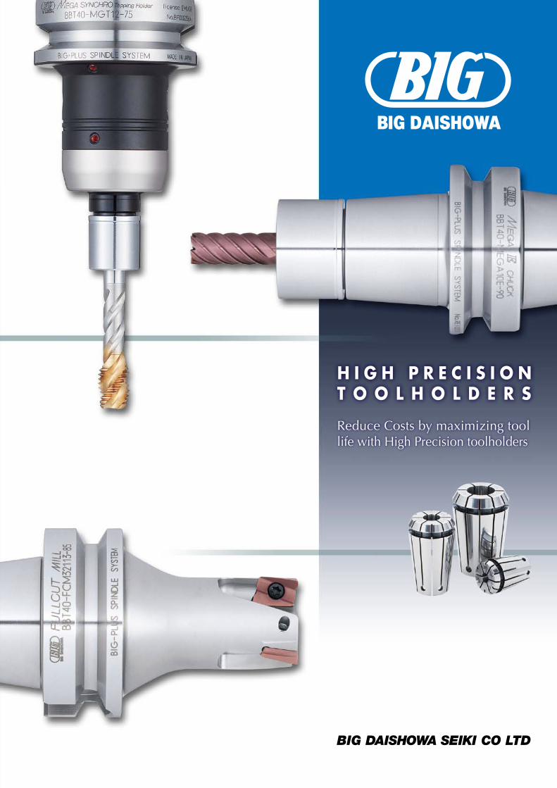
H I G H P R E C I S I O NT O O L H O L D E R S
Reduce Costs by maximizing tool life with High Precision toolholders
CATALOG No.EXm400-5-0414-1 H
Takaramachi 5-2, Higashiosakashi Osaka 579-8025 JAPANPhone : (+81)-72-982-8277 Fax : (+81)-72-982-8370http://www.big-daishowa.com E-mail: [email protected]
JQA-QM3913FA Dept.
JQA-QMA11602AWAJI No.1 Factory
CERTIFIED
MA
NAGEMENT SYSTEM
ISO 9001
Subject to technical changes by further developments.

Awaji Factory No,2
Osaka Factory
MEGA TECHNICAL CENTER
Awaji Factory No,1 Awaji Factory No,3
Awaji Factory No,4 Awaji Factory No,5
Tooling system of highest qualityBased on superior technologies and state-of-the-art production facilities, we guarantee to offer "high precision" and "high quality" tooling to your satisfaction.
Through our activities as a specialized manufacturer of tooling since 1967, BIG Daishowa has the distinction of having the highest market share in Japan and we continue to increase the number of our customers in the world-wide market and gain their trust. We devote ourselves to the development of new products and continuously improve quality "to comply with the latest trends". We are confident that BIG Daishowa's quality and tooling variety will lead you to the best result.
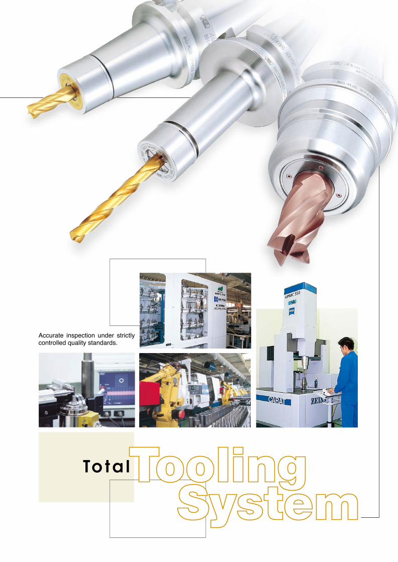
Accurate inspection under strictly controlled quality standards.
MEGA ER GRIP
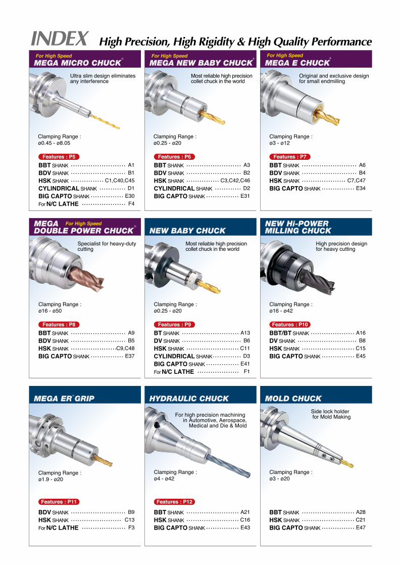
Clamping Range : ø0.45 - ø8.05
Ultra slim design eliminates any interference
A1B1
C1,C40,C45D1
E30F4
.........................
.........................
............... ............
............... ....................
Clamping Range : ø0.25 - ø20
High precision design for heavy cutting
Most reliable high precision collet chuck in the world
Clamping Range : ø1.9 - ø20
Specialist for heavy-duty cutting
A3B2
C3,C42,C46D2
E31
BBT SHANKBDV SHANKHSK SHANKCYLINDRICAL SHANKBIG CAPTO SHANK
BBT SHANKBDV SHANKHSK SHANKCYLINDRICAL SHANKBIG CAPTO SHANKFor N/C LATHE
.........................
.........................
............... ............
...............
Most reliable high precision collet chuck in the world
A6B4
C7,C47E34
BBT SHANKBDV SHANKHSK SHANKBIG CAPTO SHANK
.........................
.........................
.................... ...............
Original and exclusive design for small endmilling
Clamping Range : ø3 - ø12
A16B8
C15E45
BBT/BT SHANKDV SHANKHSK SHANKBIG CAPTO SHANK
.................... ...........................
........................ ...............
Clamping Range : ø16 - ø42
Clamping Range : ø16 - ø50
A13B6
C11D3
E41F1
..........................
...................................................
............................
...................
Clamping Range : ø0.25 - ø20
A9B5
C9,C48E37
BBT SHANKBDV SHANKHSK SHANKBIG CAPTO SHANK
.........................
.........................
..................... ...............
B9C13
F3
BDV SHANKHSK SHANKFor N/C LATHE
.........................
....................... ....................
Features : P5
Features : P8
Features : P11
Features : P9 Features : P10
Features : P6 Features : P7
For High Speed For High Speed For High Speed
For High Speed
Side lock holder for Mold Making
A28C21E47
BBT SHANKHSK SHANKBIG CAPTO SHANK
........................
........................ ...............
Clamping Range : ø3 - ø20
BT SHANKDV SHANKHSK SHANKCYLINDRICAL SHANKBIG CAPTO SHANKFor N/C LATHE
A21C16E43
BBT SHANKHSK SHANKBIG CAPTO SHANK
........................
........................ ...............
Clamping Range : ø4 - ø42
HYDRAULIC CHUCK
For high precision machining in Automotive, Aerospace,
Medical and Die & Mold
Features : P12
COOLANTPIPE
PULL STUDBOLT
OTHERSCLEANER
G23....
C51....
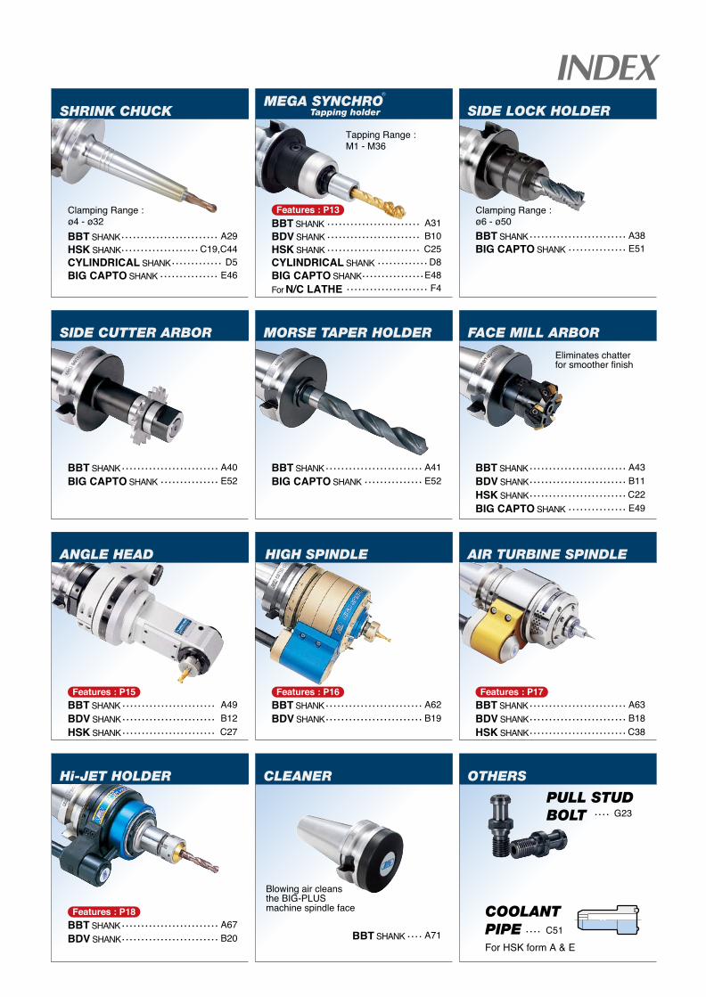
Eliminates chatterfor smoother finish
A38E51
BBT SHANKBIG CAPTO SHANK
........................................
Clamping Range : ø6 - ø50
A41E52
BBT SHANKBIG CAPTO SHANK
........................................
A40E52
BBT SHANKBIG CAPTO SHANK
........................................
A43B11C22E49
BBT SHANKBDV SHANKHSK SHANKBIG CAPTO SHANK
.........................
.........................
........................................
A29C19,C44
D5E46
BBT SHANKHSK SHANKCYLINDRICAL SHANKBIG CAPTO SHANK
.........................
.................... .............
...............
Clamping Range : ø4 - ø32
A63B18C38
BBT SHANKBDV SHANKHSK SHANK
.........................
.........................
.........................
A71BBT SHANK ....
Blowing air cleans the BIG-PLUS machine spindle face
AIR TURBINE SPINDLE
A62B19
BBT SHANKBDV SHANK
.........................
.........................
HIGH SPINDLE
A67B20
BBT SHANKBDV SHANK
.........................
.........................
Hi-JET HOLDER
A49B12C27
BBT SHANKBDV SHANKHSK SHANK
........................
........................
........................
ANGLE HEAD
A31B10C25D8
E48F4
BBT SHANKBDV SHANKHSK SHANKCYLINDRICAL SHANKBIG CAPTO SHANKFor N/C LATHE
........................
........................
........................ .............
................ .....................
Tapping Range : M1 - M36
MEGA SYNCHROTapping holder
SIDE CUTTER ARBOR MORSE TAPER HOLDER FACE MILL ARBOR
SIDE LOCK HOLDER
For HSK form A & E
Features : P15
Features : P18
Features : P16
Features : P13
Features : P17
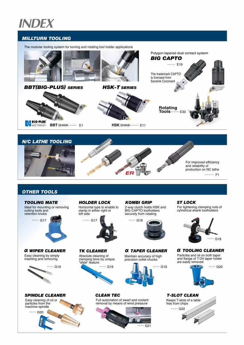
MILLTURN TOOLING
OTHER TOOLS
E1BBT SHANK ...... E11HSK SHANK
RotatingTools
......
E30......
E19......BIG CAPTO
N/C LATHE TOOLING
For improved efficiency and reliability of production on NC lathe
The trademark CAPTO is licensed from Sandvik Coromant
F1.......
G17.....
G19.....
G20.....
G21.....
G22.....
G19..... G19..... G20.....
G17..... G18.....
G18.....
Polygon-tapered dual contact system
HSK-T SERIESBBT(BIG-PLUS) SERIES
Keeps T-slots of a table free from chips
Maintain accuracy of high precision collet chucks
Ideal for mounting or removing cutting tools and retention knobs
For tightening clamping nuts of cylindrical shank toolholders
Horizontal type to enable to clamp in either right or left side
2-way clutch holds HSK and BIG CAPTO toolholders securely from rotating
Particles and oil on both taperand flange of 7/24 taper holder are easily removed
Easy cleaning of oil or particles from the machine spindle
Full automation of swarf and coolant removal by means of wind pressure
Easy cleaning by simply inserting and removing
Absolute cleaning of clamping bore by unique "slide" feature
The modular tooling system for turning and rotating tool holder applications
ER
R
S P I N D L E S Y S T E M
D U A L C O N T A C T
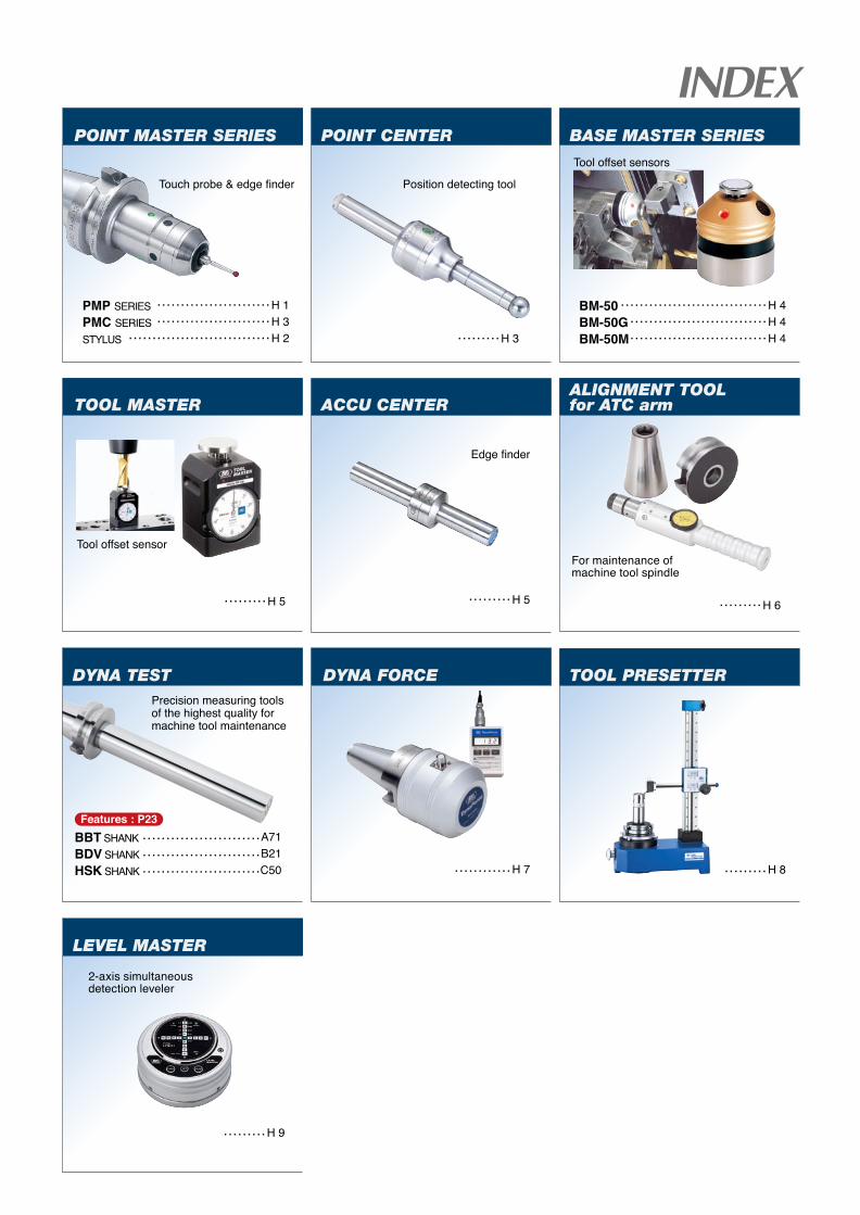
DYNA TEST
ACCU CENTER
POINT MASTER SERIES
Touch probe & edge finder
H 1H 3H 2
PMP SERIESPMC SERIESSTYLUS
........................
......................................................
DYNA FORCE
H 7............
BASE MASTER SERIES
H 4H 4H 4
BM-50BM-50GBM-50M
.........................................................................................
Tool offset sensors
Tool offset sensor
TOOL PRESETTER
LEVEL MASTER
A71B21C50
BBT SHANKBDV SHANKHSK SHANK
.........................
.........................
.........................
Features : P23
Precision measuring tools of the highest quality for machine tool maintenance
H 5.........
2-axis simultaneous detection leveler
H 8.........
H 9.........
H 5.........
POINT CENTER
Position detecting tool
Edge finder
H 3.........
ALIGNMENT TOOL for ATC arm
For maintenance of machine tool spindle
H 6.........
TOOL MASTER
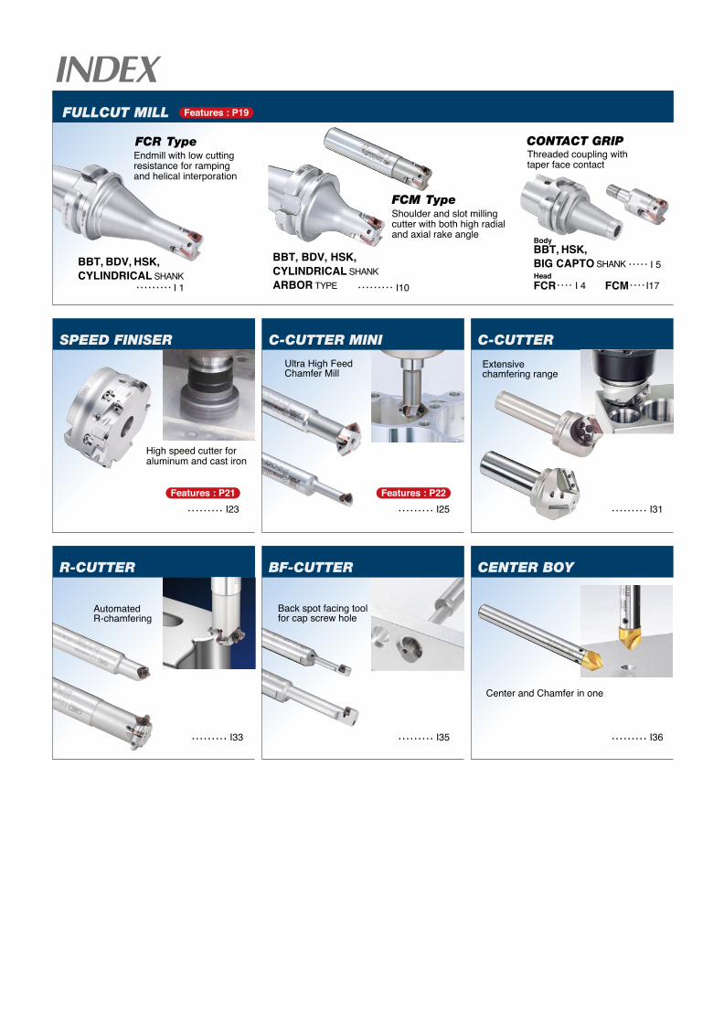
SPEED FINISER C-CUTTER MINI C-CUTTER
R-CUTTER BF-CUTTER CENTER BOY
FULLCUT MILL
Endmill with low cutting resistance for ramping and helical interporation
Ultra High FeedChamfer Mill
I10
BBT, BDV, HSK,CYLINDRICAL SHANKARBOR TYPE .........I 1.........
I 5BBT, HSK, BIG CAPTO SHANK .....
I 4FCR.... I17FCM....BBT, BDV, HSK,CYLINDRICAL SHANK
Center and Chamfer in one
Extensive chamfering range
Shoulder and slot milling cutter with both high radial and axial rake angle
Threaded coupling with taper face contact
CONTACT GRIP
High speed cutter for aluminum and cast iron
Automated R-chamfering
Back spot facing tool for cap screw hole
I33......... I35......... I36.........
I31.........Features : P22
I25.........Features : P21
I23.........
Body
Head
Features : P19
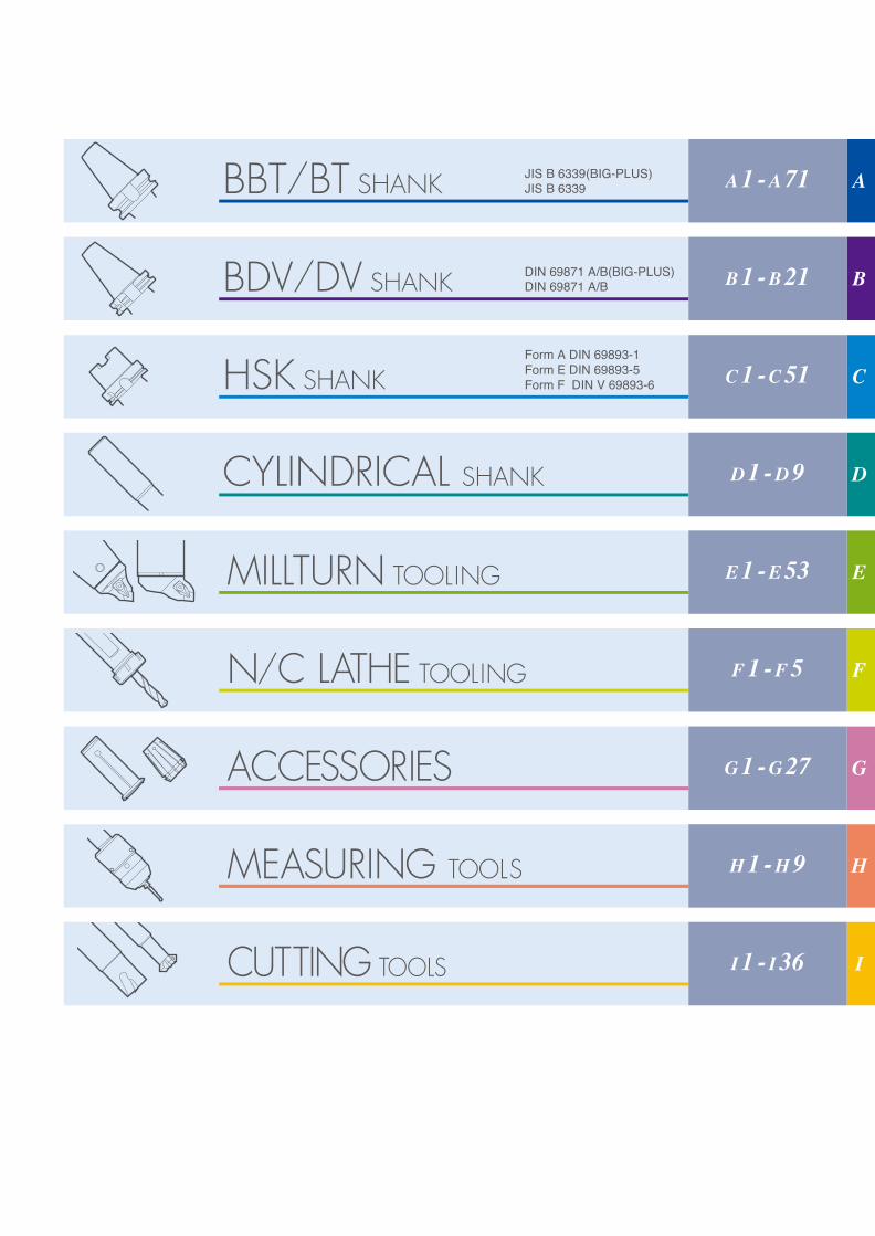
DIN 69871 A/B(BIG-PLUS)DIN 69871 A/B
Form A DIN 69893-1Form E DIN 69893-5Form F DIN V 69893-6
MEASURING TOOLS
N/C LATHE TOOLING
MILLTURN TOOLING
JIS B 6339(BIG-PLUS) JIS B 6339 A 1 - A 71
B 1 - B 21
C 1 - C 51
D 1 - D 9
E 1 - E 53
F 1 - F 5
G 1 - G 27
H 1 - H 9
I 1 - I 36
A
B
C
D
E
F
G
H
I
BBT Shank A1BDV Shank B1
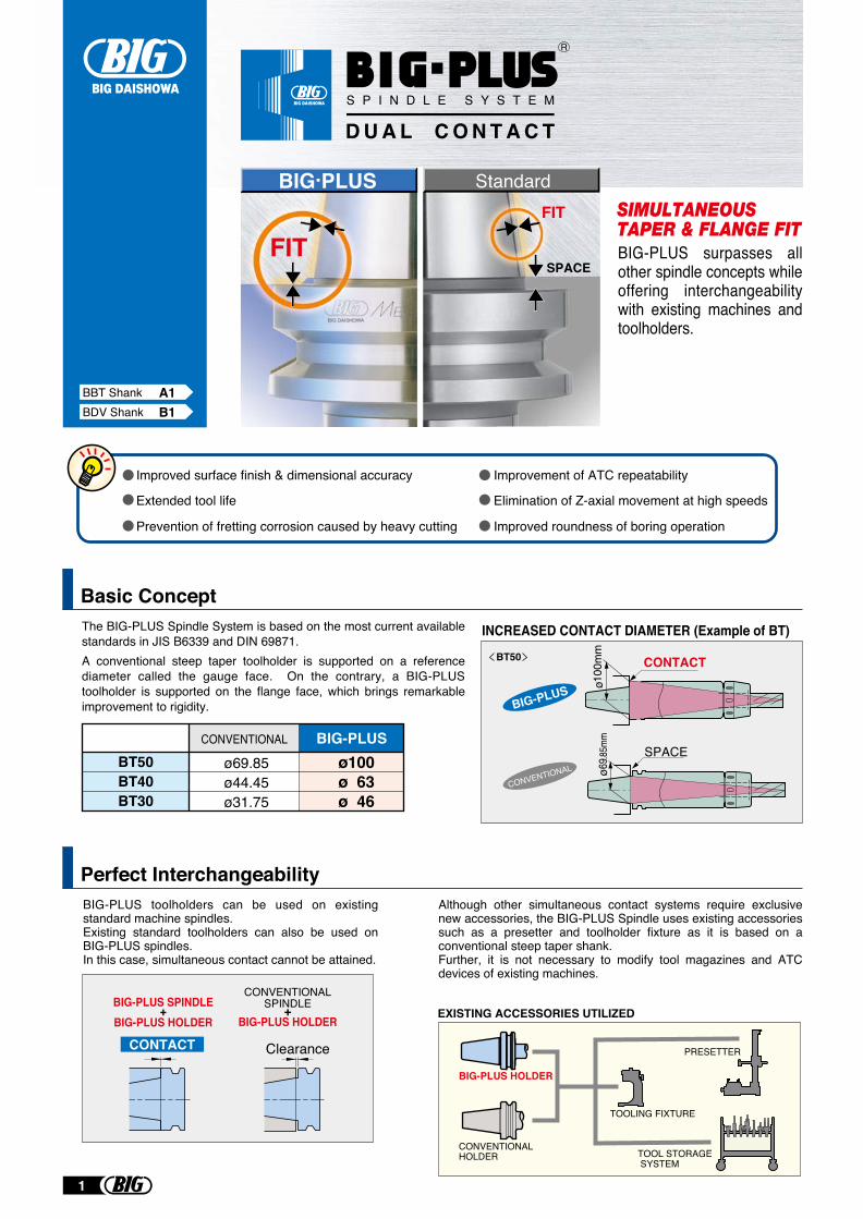
BIG-PLUS surpasses all other spindle concepts while offering interchangeability with existing machines and toolholders.
BT50
BIG-PLUS
CONTACT
SPACE
CONVENTIONAL øø
INCREASED CONTACT DIAMETER (Example of BT)
Basic Concept
FITFIT
SPACE
BIG.PLUS Standard
BIG-PLUSCONVENTIONAL
ø100ø 63ø 46
ø69.85ø44.45ø31.75
BT50BT40BT30
The BIG-PLUS Spindle System is based on the most current available standards in JIS B6339 and DIN 69871.A conventional steep taper toolholder is supported on a reference diameter called the gauge face. On the contrary, a BIG-PLUS toolholder is supported on the flange face, which brings remarkable improvement to rigidity.
Perfect InterchangeabilityBIG-PLUS toolholders can be used on existing standard machine spindles.Existing standard toolholders can also be used on BIG-PLUS spindles.In this case, simultaneous contact cannot be attained.
Although other simultaneous contact systems require exclusive new accessories, the BIG-PLUS Spindle uses existing accessories such as a presetter and toolholder fixture as it is based on a conventional steep taper shank.Further, it is not necessary to modify tool magazines and ATC devices of existing machines.
BIG-PLUS HOLDER
CONVENTIONAL HOLDER
TOOLING FIXTURE
TOOL STORAGE SYSTEM
PRESETTER
EXISTING ACCESSORIES UTILIZED
CONVENTIONALSPINDLE+
BIG-PLUS HOLDER
Clearance
BIG-PLUS SPINDLE+
BIG-PLUS HOLDER
CONTACT
Improved surface finish & dimensional accuracy Improvement of ATC repeatability
Elimination of Z-axial movement at high speeds
Improved roundness of boring operation
Extended tool life
Prevention of fretting corrosion caused by heavy cutting
R
S P I N D L E S Y S T E M
D U A L C O N T A C T
1
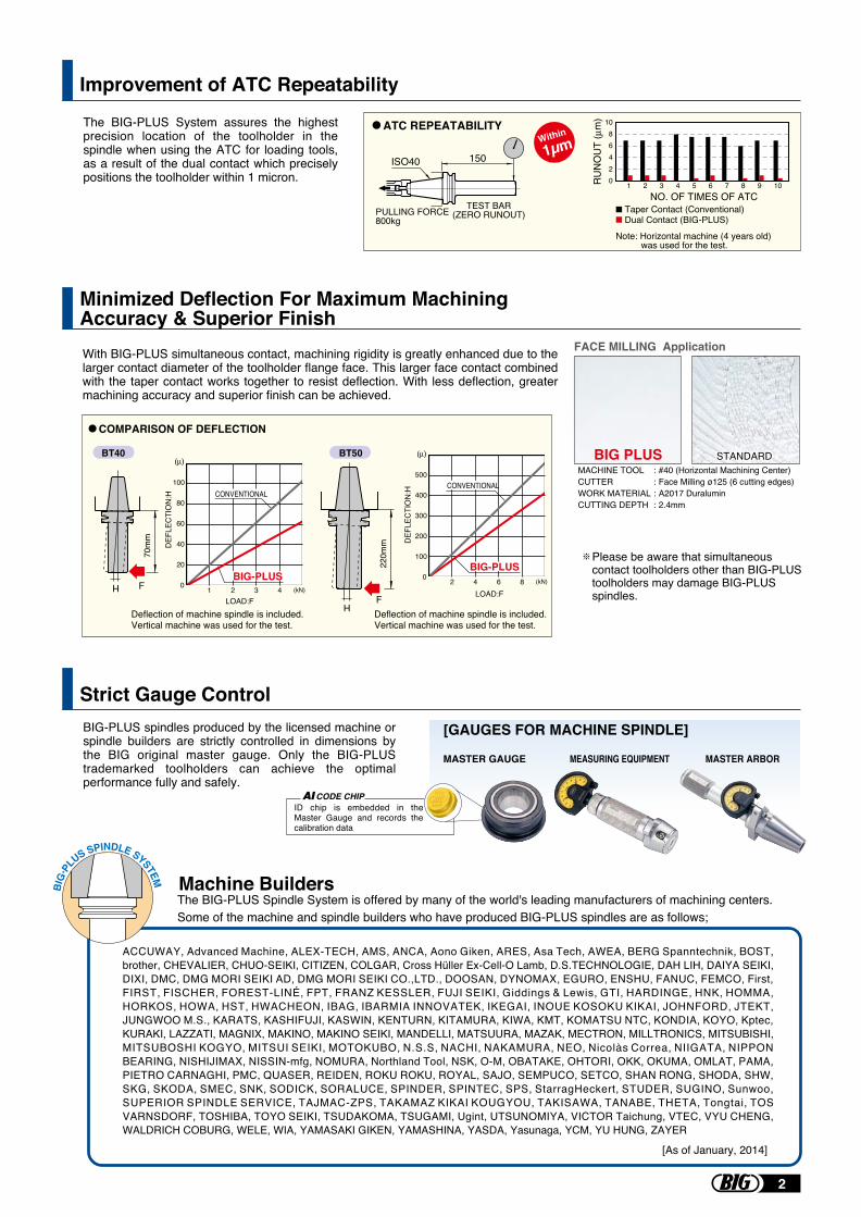
Improvement of ATC Repeatability
Minimized Deflection For Maximum Machining Accuracy & Superior Finish
Strict Gauge Control
FACE MILLING Application
STANDARDSTANDARDMACHINE TOOLCUTTERWORK MATERIALCUTTING DEPTH
::::
#40 (Horizontal Machining Center)Face Milling ø125 (6 cutting edges)A2017 Duralumin2.4mm
BIG PLUS
The BIG-PLUS System assures the highest precision location of the toolholder in the spindle when using the ATC for loading tools, as a result of the dual contact which precisely positions the toolholder within 1 micron.
150
TEST BAR(ZERO RUNOUT)
ISO40
PULLING FORCE800kg
Taper Contact (Conventional)Dual Contact (BIG-PLUS)
1086420
NO. OF TIMES OF ATC1 2 3 4 5 6 7 8 9 10
ATC REPEATABILITY
Note: Horizontal machine (4 years old) was used for the test.
Within
1µm
Machine BuildersThe BIG-PLUS Spindle System is offered by many of the world's leading manufacturers of machining centers. Some of the machine and spindle builders who have produced BIG-PLUS spindles are as follows;
ACCUWAY, Advanced Machine, ALEX-TECH, AMS, ANCA, Aono Giken, ARES, Asa Tech, AWEA, BERG Spanntechnik, BOST, brother, CHEVALIER, CHUO-SEIKI, CITIZEN, COLGAR, Cross Hüller Ex-Cell-O Lamb, D.S.TECHNOLOGIE, DAH LIH, DAIYA SEIKI, DIXI, DMC, DMG MORI SEIKI AD, DMG MORI SEIKI CO.,LTD., DOOSAN, DYNOMAX, EGURO, ENSHU, FANUC, FEMCO, First, FIRST, FISCHER, FOREST-LINÉ, FPT, FRANZ KESSLER, FUJI SEIKI, Giddings & Lewis, GTI, HARDINGE, HNK, HOMMA, HORKOS, HOWA, HST, HWACHEON, IBAG, IBARMIA INNOVATEK, IKEGAI, INOUE KOSOKU KIKAI, JOHNFORD, JTEKT, JUNGWOO M.S., KARATS, KASHIFUJI, KASWIN, KENTURN, KITAMURA, KIWA, KMT, KOMATSU NTC, KONDIA, KOYO, Kptec, KURAKI, LAZZATI, MAGNIX, MAKINO, MAKINO SEIKI, MANDELLI, MATSUURA, MAZAK, MECTRON, MILLTRONICS, MITSUBISHI, MITSUBOSHI KOGYO, MITSUI SEIKI, MOTOKUBO, N.S.S, NACHI, NAKAMURA, NEO, Nicolàs Correa, NIIGATA, NIPPON BEARING, NISHIJIMAX, NISSIN-mfg, NOMURA, Northland Tool, NSK, O-M, OBATAKE, OHTORI, OKK, OKUMA, OMLAT, PAMA, PIETRO CARNAGHI, PMC, QUASER, REIDEN, ROKU ROKU, ROYAL, SAJO, SEMPUCO, SETCO, SHAN RONG, SHODA, SHW, SKG, SKODA, SMEC, SNK, SODICK, SORALUCE, SPINDER, SPINTEC, SPS, StarragHeckert, STUDER, SUGINO, Sunwoo, SUPERIOR SPINDLE SERVICE, TAJMAC-ZPS, TAKAMAZ KIKAI KOUGYOU, TAKISAWA, TANABE, THETA, Tongtai, TOS VARNSDORF, TOSHIBA, TOYO SEIKI, TSUDAKOMA, TSUGAMI, Ugint, UTSUNOMIYA, VICTOR Taichung, VTEC, VYU CHENG, WALDRICH COBURG, WELE, WIA, YAMASAKI GIKEN, YAMASHINA, YASDA, Yasunaga, YCM, YU HUNG, ZAYER
BIG
PL
US SPINDLE SYSTEM
[As of January, 2014]
70m
m
FH
220m
m
FH
BT40 BT50
COMPARISON OF DEFLECTION
100
80
60
40
20
0 1 2 3 4 (kN)
DEF
LEC
TIO
N:H CONVENTIONAL
LOAD:F
BIG-PLUS 0 2 4 6 8 (kN)
500
400
300
200
100
DEF
LEC
TIO
N:H
LOAD:F
CONVENTIONAL
BIG-PLUS
Deflection of machine spindle is included.Vertical machine was used for the test.
Deflection of machine spindle is included.Vertical machine was used for the test.
With BIG-PLUS simultaneous contact, machining rigidity is greatly enhanced due to the larger contact diameter of the toolholder flange face. This larger face contact combined with the taper contact works together to resist deflection. With less deflection, greater machining accuracy and superior finish can be achieved.
BIG-PLUS spindles produced by the licensed machine or spindle builders are strictly controlled in dimensions by the BIG original master gauge. Only the BIG-PLUS trademarked toolholders can achieve the optimal performance fully and safely.
[GAUGES FOR MACHINE SPINDLE]
MASTER GAUGE MEASURING EQUIPMENT MASTER ARBOR
AICODE CHIPID chip is embedded in the Master Gauge and records the calibration data
Please be aware that simultaneous contact toolholders other than BIG-PLUS toolholders may damage BIG-PLUS spindles.
2
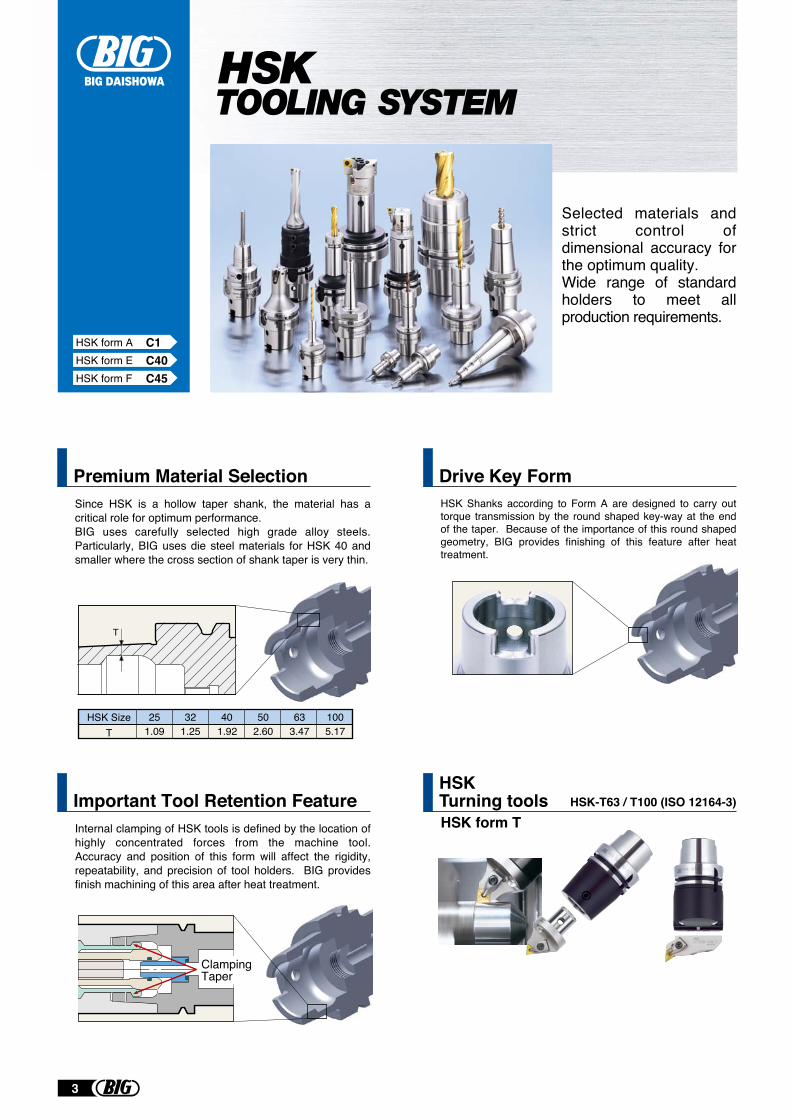
Premium Material SelectionSince HSK is a hollow taper shank, the material has a critical role for optimum performance. BIG uses carefully selected high grade alloy steels. Particularly, BIG uses die steel materials for HSK 40 and smaller where the cross section of shank taper is very thin.
Drive Key FormHSK Shanks according to Form A are designed to carry out torque transmission by the round shaped key-way at the end of the taper. Because of the importance of this round shaped geometry, BIG provides finishing of this feature after heat treatment.
Selected materials and strict control of dimensional accuracy for the optimum quality.Wide range of standard holders to meet all production requirements.
HSK SizeT 1.09 1.25 1.92 2.60 3.47 5.17
25 32 40 50 63 100
T
Important Tool Retention Feature
ClampingTaper
HSK form A C1HSK form E C40HSK form F C45
HSKTurning tools HSK-T63 / T100 (ISO 12164-3)HSK form TInternal clamping of HSK tools is defined by the location of
highly concentrated forces from the machine tool. Accuracy and position of this form will affect the rigidity, repeatability, and precision of tool holders. BIG provides finish machining of this area after heat treatment.
3
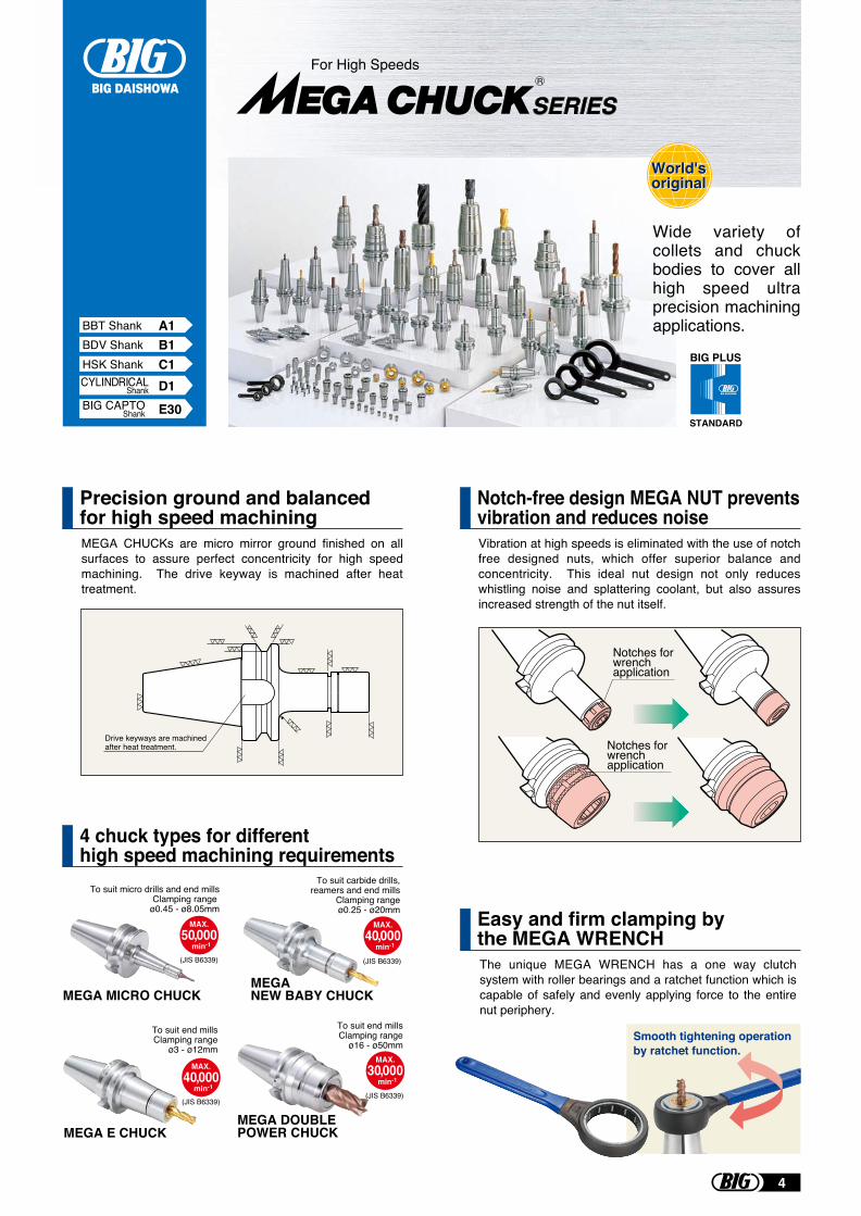
MEGA CHUCKs are micro mirror ground finished on all surfaces to assure perfect concentricity for high speed machining. The drive keyway is machined after heat treatment.
The unique MEGA WRENCH has a one way clutch system with roller bearings and a ratchet function which is capable of safely and evenly applying force to the entire nut periphery.
Precision ground and balanced for high speed machining
Vibration at high speeds is eliminated with the use of notch free designed nuts, which offer superior balance and concentricity. This ideal nut design not only reduces whistling noise and splattering coolant, but also assures increased strength of the nut itself.
Notch-free design MEGA NUT prevents vibration and reduces noise
4 chuck types for different high speed machining requirements
Easy and firm clamping by the MEGA WRENCH
MAX.30,000
min-1
MAX.40,000
min-1
Wide variety of collets and chuck bodies to cover all high speed ultra precision machining applications.
World'soriginalWorld'soriginal
MAX.40,000
min-1
MAX.50,000
min-1
For High Speeds
(JIS B6339) (JIS B6339)
(JIS B6339)(JIS B6339)
BIG PLUS
STANDARD
Drive keyways are machined after heat treatment. Notches for
wrenchapplication
Notches for wrenchapplication
Smooth tightening operation by ratchet function.
MEGA E CHUCK
MEGA MICRO CHUCKMEGANEW BABY CHUCK
MEGA DOUBLEPOWER CHUCK
To suit carbide drills, reamers and end mills Clamping range
ø0.25 - ø20mm
To suit end mills Clamping range ø3 - ø12mm
To suit micro drills and end millsClamping range
ø0.45 - ø8.05mm
To suit end millsClamping range
ø16 - ø50mm
R
BDV Shank B1HSK Shank C1
D1CYLINDRICALShank
BBT Shank A1
E30BIG CAPTOShank
4
ø10mmFull scale
3Stype
3Stype
4Stype 6Stype 8Stype
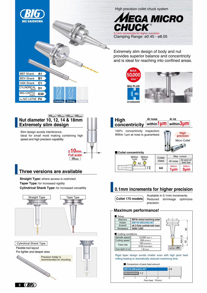
Nut diameter 10, 12, 14 & 18mmExtremely slim designSlim design avoids interference.Ideal for small mold making combining high speed and high precision capability.
100% concentricity inspection. Within 1μm at nose is guaranteed.
Available in 0.1mm increments.Reduced shrinkage optimizes precision.
Extremely slim design of body and nut provides superior balance and concentricity and is ideal for reaching into confined areas.
4d
ød
Colletclass
Max. runout
At nose At end oftest bar
Within1μm
Within3μmAA
Micro Collet
Highconcentricity
Straight Type Taper Type
Flexible tool layoutFor tighter and deeper area
Cylindrical Shank Type
Precision holder isrecommended for chucking.
Collet 175 models
9030
Pf
0 1 2 3 4 5
3.81.2
Peck feed Pf(mm)
Comparison of peck feed amount
BBT40-MEGA6S-90TOther manufacturer
Maximum performance!
Spindle speed
Feed rate
12,000 (min–1)
720 (mm/min.)
1.8 (mm)0.03 (mm/cutter)
Cutting speed
Axial depth of cut
226 (m/min.)
BBT40 vertical machining centerBBT40-MEGA6S-90Tø6 2-flute carbide ball noseS50C (JIS)
MachineHolderEndmill
Workpiece
Rigid taper design avoids chatter even with high peck feed milling leading to dramatically reduced machining time.
BIG PLUS
STANDARD
Ad=1
.8
within1μmAt nose
within3μmAt 4d
Setup
Cutting conditions
Within1μm
Within3μm
Highprecision
Collet concentricity
0.1mm increments for higher precision
Straight Type: where access is restricted Taper Type: for increased rigidity Cylindrical Shank Type: for increased versatility
Three versions are available
MAX.50,000
min-1
High precision collet chuck system
Clamping Range: ø0.45 - ø8.050.1mm increments for higher precision
R
Endmilling Drilling Reamer
BDV Shank B1HSK Shank C1
D1CYLINDRICALShank
BBT Shank A1
For N/C LATHE F4E30BIG CAPTO
Shank
5
BDV Shank B2HSK Shank C3
D2CYLINDRICALShank
BBT Shank A3
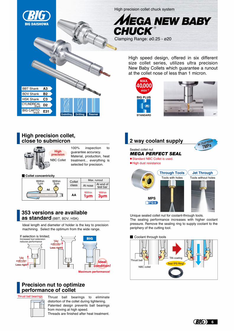
NBC Collet
100% inspection to guarantee accuracy.Material, production, heat treatment... everything is selected for precision.
Unique sealed collet nut for coolant-through tools. The sealing performance increases with higher coolant pressure. Remove the sealing ring to supply coolant to the periphery of the cutting tool.
Within 1m
Ideal length and diameter of holder is the key to precision machining. Select the optimum from the wide range.
Thrust ball bearings
TiN coating
NBC collet
Thrust ball
If selection is limited;Increased tool extension reduces performance
Maximum performance!
Tools without holesTools with holesThrough Tools Jet Through
G 9
Toolextension
Standard NBC Collet is used.High dust resistance
Coolant through tools
MPS
Sealed collet nut
ToolextensionLess rigid
Less rigid
Idealcondition!
Highprecision
2 way coolant supply
BIG PLUS
STANDARD
High precision collet, close to submicron
Thrust ball bearings to eliminate distortion of the collet during tightening.Patented design prevents ball bearings from moving at high speed.Threads are finished after heat treatment.
Precision nut to optimize performance of collet
353 versions are available as standard (BBT, BDV, HSK)
High speed design, offered in six different size collet series, utilizes ultra precision New Baby Collets which guarantee a runout at the collet nose of less than 1 micron.
MAX. COOLANT PRESSUREMAX. COOLANT PRESSURE
7MPa7MPa
Seal (PS Ring)
MAX.40,000
min-1
Colletclass
Max. runout
At nose At end oftest bar
Within1μm
Within3μmAA
Collet concentricity
4d
Within1μm
Within3μm
ød
Clamping Range: ø0.25 - ø20
High precision collet chuck system
R
Endmilling ReamerDrillingE31BIG CAPTO
Shank
6
BDV Shank B4HSK Shank C7
BBT Shank A6
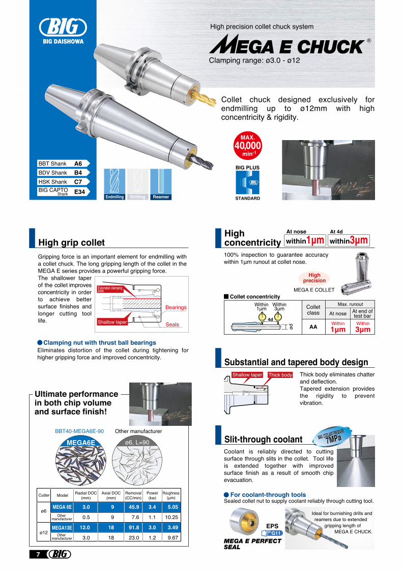
High grip collet100% inspection to guarantee accuracy within 1μm runout at collet nose.
Thick body eliminates chatter and deflection.Tapered extension provides the rigidity to prevent vibration.
Coolant is reliably directed to cutting surface through slits in the collet. Tool life is extended together with improved surface finish as a result of smooth chip evacuation.
Colletclass
Max. runout
At nose At end oftest bar
Within1μm
Within3μmAA
Highconcentricity
BIG PLUS
STANDARD
within1μmAt nose
within3μmAt 4d
Collet concentricity
Substantial and tapered body design
Slit-through coolant
Collet chuck designed exclusively for endmilling up to ø12mm with high concentricity & rigidity.
MAX.40,000
min-1
Gripping force is an important element for endmilling with a collet chuck. The long gripping length of the collet in the MEGA E series provides a powerful gripping force.The shallower taper of the collet improves concentricity in order to achieve better surface finishes and longer cutting tool life.
MEGA E COLLET
Bearings
Ultimate performance in both chip volume and surface finish!
For coolant-through tools
Extended clampingarea
Shallow taper Seals
Shallow taper Thick body
45.9
7.6
91.8
23.0
Cutter Model Radial DOC(mm)
Axial DOC(mm)
Removal(CC/min)
Power(kw)
Roughness(μm)
ø6MEGA 6E
Other manufacturer
Other manufacturer
MEGA13Eø12
3.0
0.5
12.0
3.0
9
9
18
18
3.4
1.1
3.0
1.2
5.05
10.25
3.49
9.67
MEGA6E ø6, L=90
BBT40-MEGA6E-90 Other manufacturer
Sealed collet nut to supply coolant reliably through cutting tool.
Eliminates distortion of the collet during tightening for higher gripping force and improved concentricity.
Clamping nut with thrust ball bearings
Ideal for burnishing drills and reamers due to extended
gripping length of MEGA E CHUCK.
MAX. COOLANT PRESSUREMAX. COOLANT PRESSURE
7MPa7MPa
Highprecision
4d
ød
Within3μm
Within1μm
Clamping range: ø3.0 - ø12
High precision collet chuck system
G11EPS
R
Endmilling Drilling ReamerE34BIG CAPTO
Shank
7
BDV Shank B5HSK Shank C9
BBT Shank A9
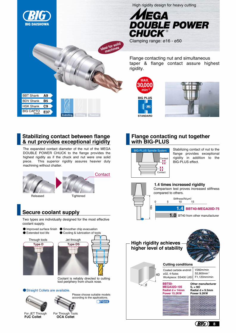
The expanded contact diameter of the nut of the MEGA DOUBLE POWER CHUCK to the flange provides the highest rigidity as if the chuck and nut were one solid piece. This superior rigidity assures heavier duty machining without chatter.
Flange contacting nut together with BIG-PLUS
BIG PLUS
STANDARD
Stabilizing contact between flange & nut provides exceptional rigidity
Flange contacting nut and simultaneous taper & flange contact assure highest rigidity.
MAX.30,000
min-1
High rigidity achieves higher level of stability
Coated carbide endmillø32, 4-flutesWorkpiece: SS400 (JIS)
Cutting conditionsV282m/minS2,800min-1
F1,120mm/min
BBT50-MEGA32D-105Radial d = 14mmPower 15.2KW
Other manufacturer (L = 90)Radial d = 9.5mmPower 9.2KW
Released Tightened
Contact
Stabilizing contact of nut to the flange provides exceptional rigidity in addition to the BIG-PLUS effect.
1.4 times increased rigidityComparison test proves increased stiffness compared to others.
BBT40-MEGA20D-75
151050
BT40 from other manufacturer
Stiffness(N/μm)
1.41.0
Contact
Contact
BIG-PLUS Spindle System
160
40
d
Ideal for solid
machines
Clamping range: ø16 - ø50
High rigidity design for heavy cutting
R
Endmilling ReamerDrilling
Two types are individually designed for the most effective coolant supply.
Secure coolant supply
Improved surface finishExtended tool life
Smoother chip evacuationCooling & lubrication of tools
Through tools Jet throughType D Type DS
Coolant is reliably directed to cutting tool periphery from chuck nose.
For Through ToolsOCA Collet
Straight Collets are available.
G15
Please choose suitable models according to the applications.
For JET ThroughPJC Collet
E37BIG CAPTOShank
8
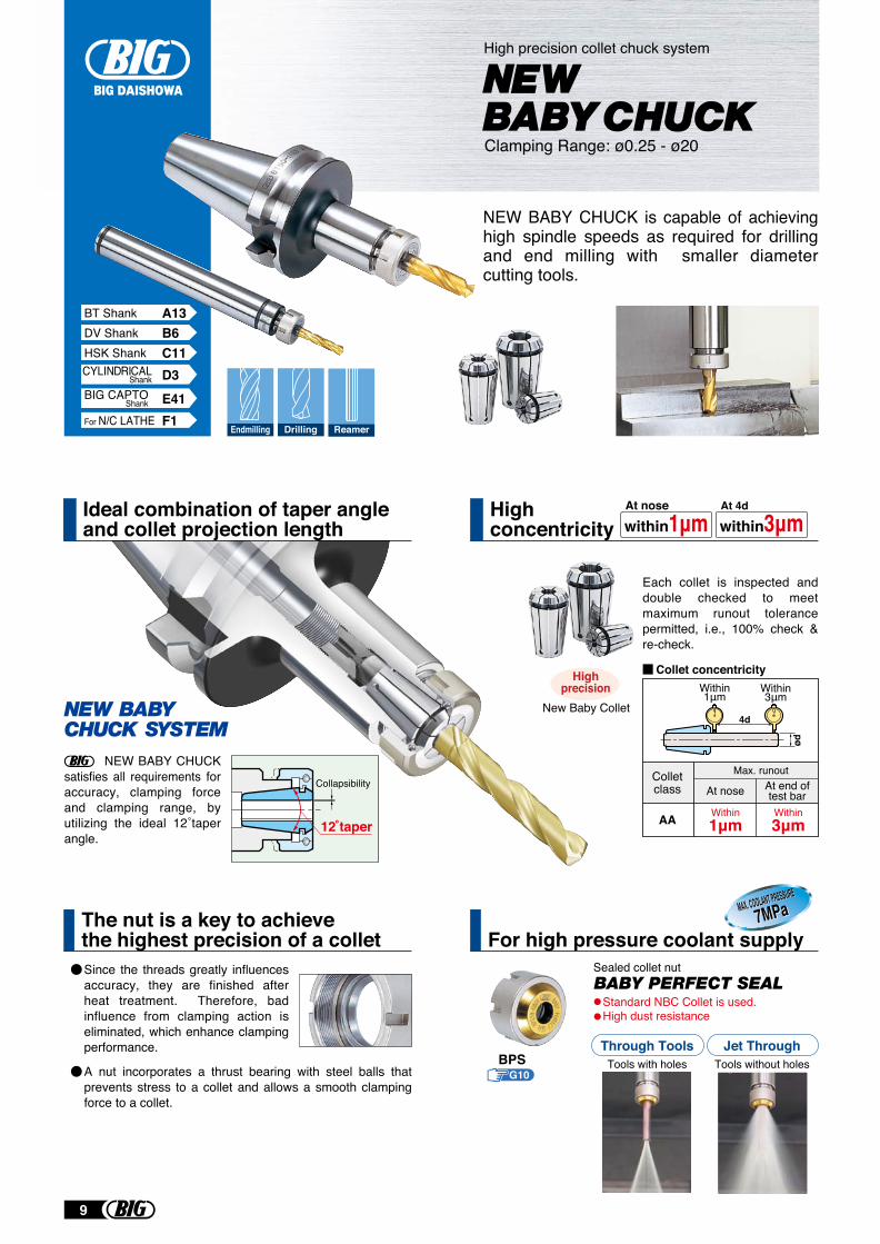
NEW BABY CHUCK is capable of achieving high spindle speeds as required for drilling and end milling with smaller diameter cutting tools.
Tools without holesTools with holesThrough Tools Jet Through
G10
Standard NBC Collet is used.High dust resistance
BPS
Sealed collet nut
For high pressure coolant supplyThe nut is a key to achieve the highest precision of a collet
MAX. COOLANT PRESSUREMAX. COOLANT PRESSURE
7MPa7MPa
High precision collet chuck system
Clamping Range: ø0.25 - ø20
NEW BABY CHUCK satisfies all requirements for accuracy, clamping force and clamping range, by utilizing the ideal 12˚taper angle.
Collapsibility
12 taper
Since the threads greatly influences accuracy, they are finished after heat treatment. Therefore, bad influence from clamping action is eliminated, which enhance clamping performance.
A nut incorporates a thrust bearing with steel balls that prevents stress to a collet and allows a smooth clamping force to a collet.
Colletclass
Max. runout
At nose At end oftest bar
Within1μm
Within3μmAA
Highconcentricity within1μm
At nose
within3μmAt 4d
Collet concentricity
Ideal combination of taper angle and collet projection length
4d
Within1μm
Within3μm
ød
Each collet is inspected and double checked to meet maximum runout tolerance permitted, i.e., 100% check & re-check.
Endmilling Drilling Reamer
New Baby Collet
Highprecision
DV Shank B6BT Shank A13
HSK Shank C11
For N/C LATHE F1
D3CYLINDRICALShank
E41BIG CAPTOShank
9
BDV/DV Shank B8HSK Shank C15
BBT/BT Shank A16BIG PLUS
STANDARD
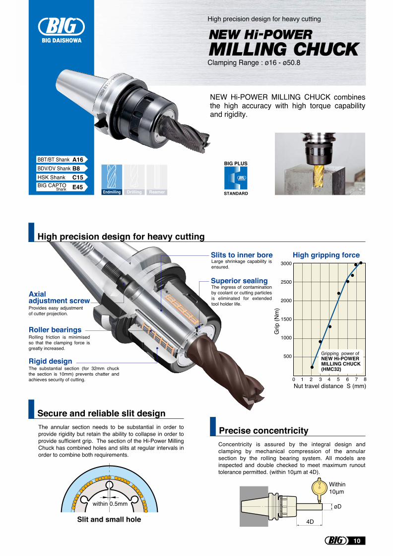
NEW Hi-POWER MILLING CHUCK combines the high accuracy with high torque capability and rigidity.
Concentricity is assured by the integral design and clamping by mechanical compression of the annular section by the rolling bearing system. All models are inspected and double checked to meet maximum runout tolerance permitted. (within 10μm at 4D).
øD
4D
Within10μm
High gripping force3000
2500
2000
1500
1000
500
0 1 2 3 4 5 6 7 8
Grip
(Nm
)
Nut travel distance S (mm)
Axial adjustment screw
Roller bearings
Slits to inner bore
Rigid design
Superior sealing
Rolling friction is minimised so that the clamping force is greatly increased.
The substantial section (for 32mm chuck the section is 10mm) prevents chatter and achieves security of cutting.
The ingress of contamination by coolant or cutting particles is eliminated for extended tool holder life.
Large shrinkage capability is ensured.
Provides easy adjustment of cutter projection.
High precision design for heavy cutting
Precise concentricityThe annular section needs to be substantial in order to provide rigidity but retain the ability to collapse in order to provide sufficient grip. The section of the Hi-Power Milling Chuck has combined holes and slits at regular intervals in order to combine both requirements.
Secure and reliable slit design
Gripping power ofNEW Hi-POWER MILLING CHUCK(HMC32)
Clamping Range : ø16 - ø50.8
High precision design for heavy cutting
Slit and small hole
within 0.5mm
Endmilling ReamerDrillingE45BIG CAPTO
Shank
10
High rigidity body that increases the contact area of the collet
BIG PLUS
STANDARD
Tools without holesTools with holesThrough Tools Jet Through
2 way coolant supply
The ERC collet with the bestrunout accuracy in the world
Sealed collet nut
MAX.35,000
min-1
High precision collet chuck system
Clamping Range: ø1.9 - ø20
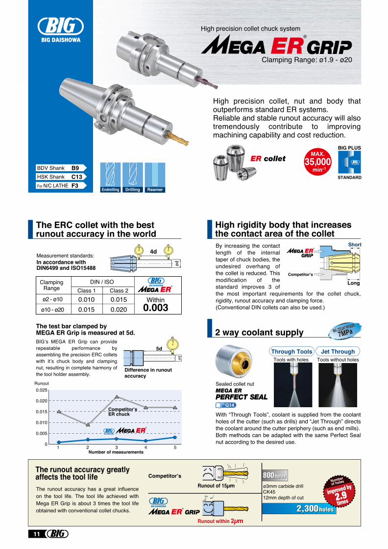
High precision collet, nut and body that outperforms standard ER systems.Reliable and stable runout accuracy will also tremendously contribute to improving machining capability and cost reduction.
Measurement standards:In accordance withDIN6499 and ISO15488
ClampingRange
ø2 - ø10ø10 - ø20
Class 1 Class 2DIN / ISO
0.0100.015
0.0150.0030.020
The test bar clamped byMEGA ER Grip is measured at 5d.BIG’s MEGA ER Grip can provide repeatable performance by assembling the precision ERC collets with it’s chuck body and clamping nut, resulting in complete harmony of the tool holder assembly.
4d
ød
5d
ød
1
0.025
0.020
0.015
0.010
0.005
0 2 3 4 5Number of measurements
Runout
Difference in runout accuracy
Competitor’s ER chuck
Within
Competitor’s
By increasing the contact length of the internal taper of chuck bodies, the undesired overhang of the collet is reduced. This modification of the standard improves 3 of the most important requirements for the collet chuck, rigidity, runout accuracy and clamping force.(Conventional DIN collets can also be used.)
Short
Long
With “Through Tools”, coolant is supplied from the coolant holes of the cutter (such as drills) and “Jet Through” directs the coolant around the cutter periphery (such as end mills).Both methods can be adapted with the same Perfect Seal nut according to the desired use.
MAX. COOLANT PRESSUREMAX. COOLANT PRESSURE
7MPa7MPa
Runout of 15µm
Runout within 2µm
ø3mm carbide drillCK4512mm depth of cut
The runout accuracy greatly affects the tool life Competitor’s
The runout accuracy has a great influence on the tool life. The tool life achieved with Mega ER Grip is about 3 times the tool life obtained with conventional collet chucks.
Numberof holes
Endmilling Drilling ReamerFor N/C LATHE F3HSK Shank C13BDV Shank B9
G14
11
Runout accuracy less than 3μm Easy clamping with 1 wrench
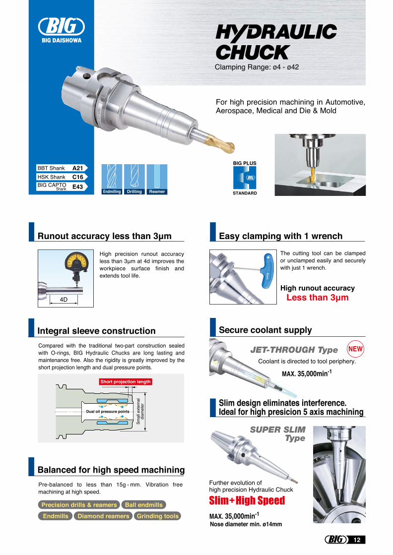
Compared with the traditional two-part construction sealed with O-rings, BIG Hydraulic Chucks are long lasting and maintenance free. Also the rigidity is greatly improved by the short projection length and dual pressure points.
Integral sleeve construction
Pre-balanced to less than 15g mm. Vibration free machining at high speed.
Balanced for high speed machining
Clamping Range: ø4 - ø42
High precision runout accuracy less than 3μm at 4d improves the workpiece surface finish and extends tool life.
4D
The cutting tool can be clamped or unclamped easily and securely with just 1 wrench.
High runout accuracyLess than 3μm
Precision drills & reamers
Diamond reamers
Ball endmills
Endmills Grinding tools
Dual oil pressure points
Short projection length
Smal
l ext
erna
ldi
amet
er
For high precision machining in Automotive, Aerospace, Medical and Die & Mold
Endmilling Drilling Reamer
BIG PLUS
STANDARD
BBT Shank A21HSK Shank C16
E43BIG CAPTOShank
Secure coolant supply
Slim design eliminates interference. Ideal for high presicion 5 axis machining
Further evolution of high precision Hydraulic Chuck
Nose diameter min. ø14mmMAX. 35,000min-1
NEW
SUPER SLIMType
JET-THROUGH TypeCoolant is directed to tool periphery.
MAX. 35,000min-1
12
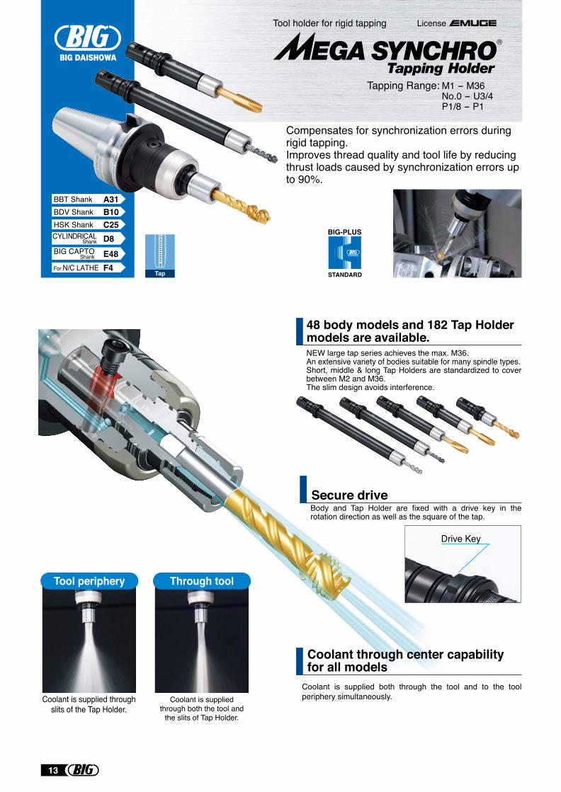
Body and Tap Holder are fixed with a drive key in the rotation direction as well as the square of the tap.
Tool holder for rigid tapping
Drive Key
License
Tapping Range: M1 - M36 No.0 - U3/4 P1/8 - P1
Coolant is supplied both through the tool and to the tool periphery simultaneously.
Coolant through center capabilityfor all models
Secure drive
NEW large tap series achieves the max. M36.An extensive variety of bodies suitable for many spindle types.Short, middle & long Tap Holders are standardized to cover between M2 and M36.The slim design avoids interference.
48 body models and 182 Tap Holder models are available.
Tap
BIG-PLUS
STANDARD
BDV Shank B10HSK Shank C25
For N/C LATHE F4
D8CYLINDRICALShank
BBT Shank A31
Compensates for synchronization errors during rigid tapping.Improves thread quality and tool life by reducing thrust loads caused by synchronization errors up to 90%.
Tool periphery Through tool
Coolant is supplied throughslits of the Tap Holder.
Coolant is suppliedthrough both the tool and
the slits of Tap Holder.
®
E48BIG CAPTOShank
13
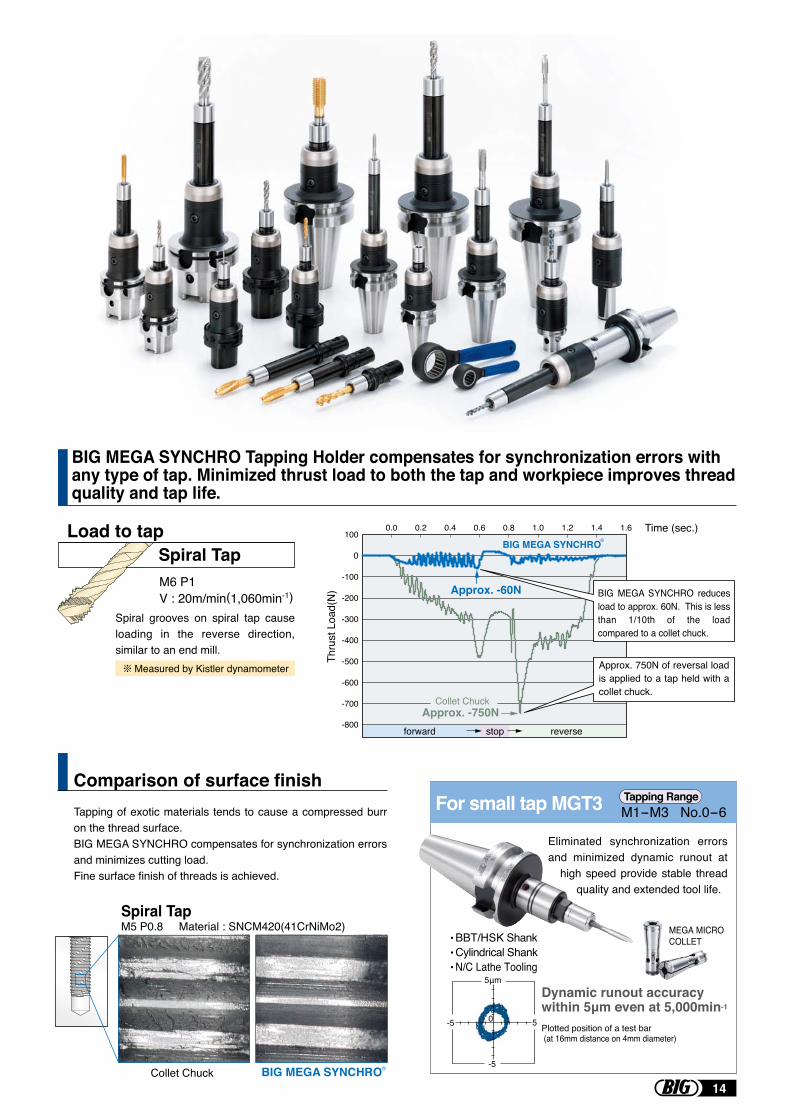
BIG MEGA SYNCHRO Tapping Holder compensates for synchronization errors with any type of tap. Minimized thrust load to both the tap and workpiece improves thread quality and tap life.
M6 P1V : 20m/min(1,060min-1)
Spiral Tap
Collet Chuck
Tapping of exotic materials tends to cause a compressed burr on the thread surface.BIG MEGA SYNCHRO compensates for synchronization errors and minimizes cutting load.Fine surface finish of threads is achieved.
BIG MEGA SYNCHRO
Spiral TapM5 P0.8 Material : SNCM420(41CrNiMo2)
Load to tap
Comparison of surface finish
Measured by Kistler dynamometer
Spiral grooves on spiral tap cause loading in the reverse direction, similar to an end mill.
-800
-700
-600
-500
-400
-300
-200
-100
0
100 Time (sec.)
Thru
st L
oad(
N)
0.0 0.2 0.4 0.6 0.8 1.0 1.2 1.4 1.6
forward stop reverse
BIG MEGA SYNCHRO
Approx. -60N
Approx. -750NCollet Chuck
R
Approx. 750N of reversal load is applied to a tap held with a collet chuck.
BIG MEGA SYNCHRO reduces load to approx. 60N. This is less than 1/10th of the load compared to a collet chuck.
. BBT/HSK Shank
. Cylindrical Shank
. N/C Lathe Tooling
For small tap MGT3
Plotted position of a test bar (at 16mm distance on 4mm diameter)
Dynamic runout accuracy within 5μm even at 5,000min-1
0
5μm
-5
5-5
MEGA MICRO COLLET
Eliminated synchronization errors and minimized dynamic runout at
high speed provide stable thread quality and extended tool life.
M1-M3 No.0-6Tapping Range
R
14
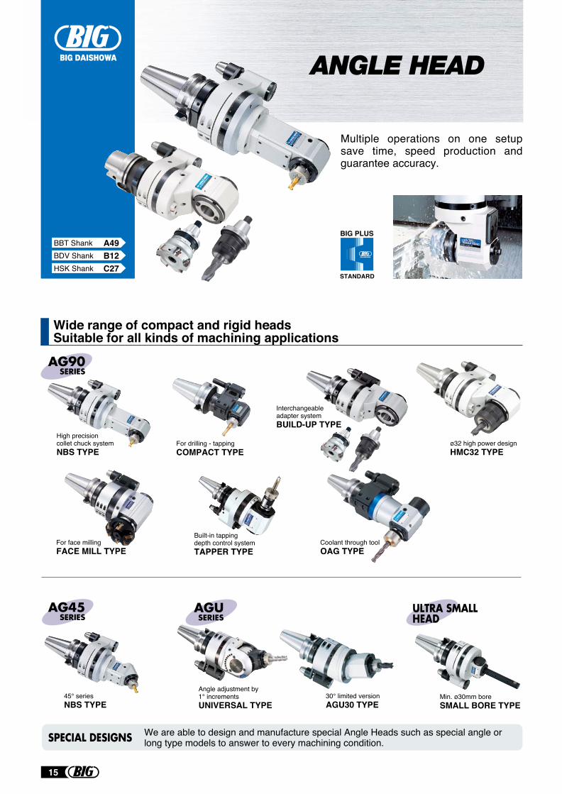
Wide range of compact and rigid headsSuitable for all kinds of machining applications
BIG PLUS
STANDARD
Multiple operations on one setup save time, speed production and guarantee accuracy.
Coolant through toolOAG TYPE
For face millingFACE MILL TYPE
Built-in tapping depth control systemTAPPER TYPE
45° seriesNBS TYPE
30° limited versionAGU30 TYPE
Angle adjustment by 1° incrementsUNIVERSAL TYPE
Min. ø30mm boreSMALL BORE TYPE
SPECIAL DESIGNS We are able to design and manufacture special Angle Heads such as special angle or long type models to answer to every machining condition.
Interchangeable adapter systemBUILD-UP TYPE
High precision collet chuck systemNBS TYPE
For drilling - tappingCOMPACT TYPE
ø32 high power designHMC32 TYPE
ANGLE HEAD
BDV Shank B12HSK Shank C27
BBT Shank A49
15
BBT Shank A62
BIG PLUS
STANDARD
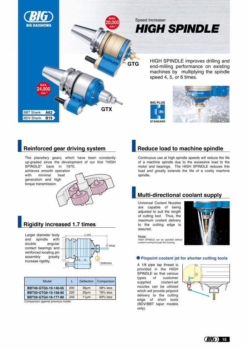
Reinforced gear driving system
Rigidity increased 1.7 times
HIGH SPINDLE improves drilling and end-milling performance on existing machines by multiplying the spindle speed 4, 5, or 6 times.
MAX.20,000
min-1
MAX.24,000
min-1
Speed Increaser
HIGH SPINDLE
Continuous use at high spindle speeds will reduce the life of a machine spindle due to the excessive load to the motor and bearings. The HIGH SPINDLE reduces this load and greatly extends the life of a costly machine spindle.
Reduce load to machine spindle
Universal Coolant Nozzles are capable of being adjusted to suit the length of cutting tool. Thus, the maximum coolant delivery to the cutting edge is assured.
Multi-directional coolant supply
Pinpoint coolant jet for shorter cutting tools
L mm
Deflection
20kgf
BBT40-GTG5-10-140-65BBT50-GTG6-10-158-80BBT50-GTG4-16-177-80
36µm25µm11µm
58% less78% less93% less
Model L ComparisonDeflection
The planetary gears, which have been constantly up-graded since the development of our first "HIGH SPINDLE" back in 1970, achieves smooth operation with minimal heat generation and high torque transmission.
Larger diameter body and spindle with double angular contact bearings and reinforced locating pin assembly greatly increase rigidity.
A 1/8 pipe tap thread is provided in the HIGH SPINDLE so that various types of customer supplied coolant-jet nozzles can be utilized which will provide pinpoint delivery to the cutting edge of short tools (BDV/BBT taper models only).
200220240
Note: HIGH SPINDLE can be operated without coolant running through the housing.
Comparison against previous model.
GTG
GTXBDV Shank B19
16
BDV Shank B18HSK Shank C38
BBT Shank A63BIG-PLUS
STANDARD
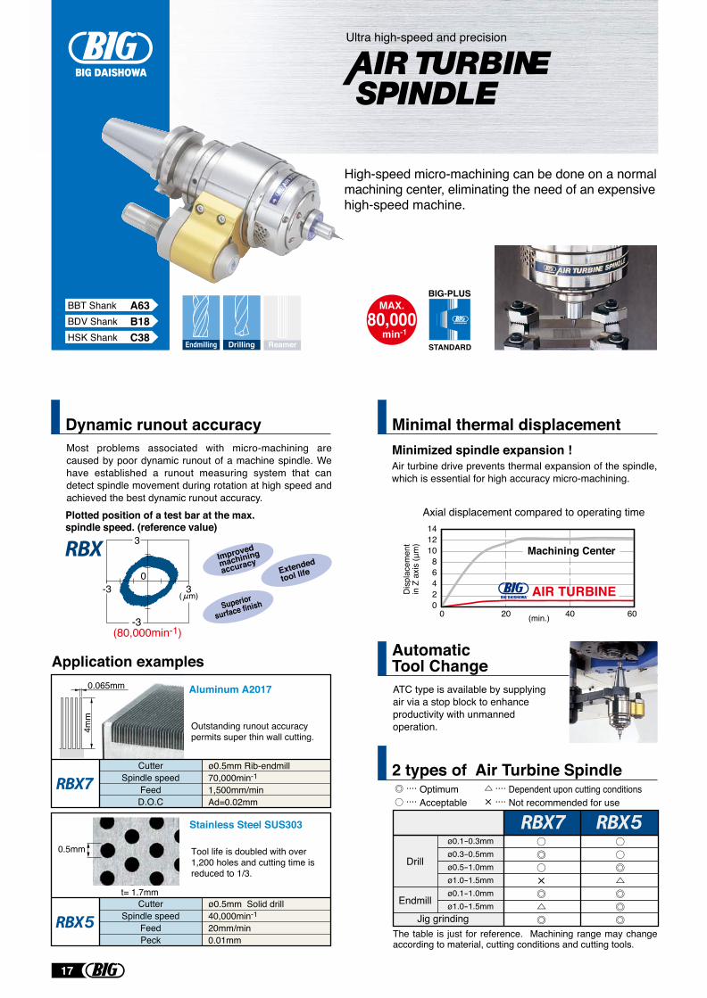
Dynamic runout accuracy
ATC type is available by supplying air via a stop block to enhance productivity with unmanned operation.
Automatic Tool Change
The table is just for reference. Machining range may change according to material, cutting conditions and cutting tools.
2 types of Air Turbine Spindle
Air turbine drive prevents thermal expansion of the spindle, which is essential for high accuracy micro-machining.
Minimal thermal displacement
High-speed micro-machining can be done on a normal machining center, eliminating the need of an expensive high-speed machine.
MAX.80,000
min-1
Ultra high-speed and precision
Endmilling Drilling Reamer
Minimized spindle expansion !
Axial displacement compared to operating time
(min.)
14121086420
0 20 40 60
Dis
plac
emen
tin
Z a
xis
(μm
)
Machining Center
AIR TURBINE
ø0.5mm Rib-endmill70,000min-1
1,500mm/minAd=0.02mm
0.065mm
4mm
ø0.5mm Solid drill40,000min-1
20mm/min0.01mm
Stainless Steel SUS303
0.5mm
t= 1.7mm
Tool life is doubled with over 1,200 holes and cutting time is reduced to 1/3.
CutterSpindle speed
FeedD.O.C
CutterSpindle speed
FeedPeck
Application examples
Drill
Endmill
ø0.1-0.3mmø0.3-0.5mmø0.5-1.0mmø1.0-1.5mmø0.1-1.0mmø1.0-1.5mm
.... Optimum
.... Acceptable.... Dependent upon cutting conditions.... Not recommended for use
Jig grinding
Aluminum A2017
Outstanding runout accuracy permits super thin wall cutting.
Improved
machining
accuracyExtended
tool life
Superior
surface finish
Most problems associated with micro-machining are caused by poor dynamic runout of a machine spindle. We have established a runout measuring system that can detect spindle movement during rotation at high speed and achieved the best dynamic runout accuracy.
30
-3
3
-3( m)
(80,000min-1)
Plotted position of a test bar at the max. spindle speed. (reference value)
17
BBT Shank A67
BIG PLUS
STANDARD
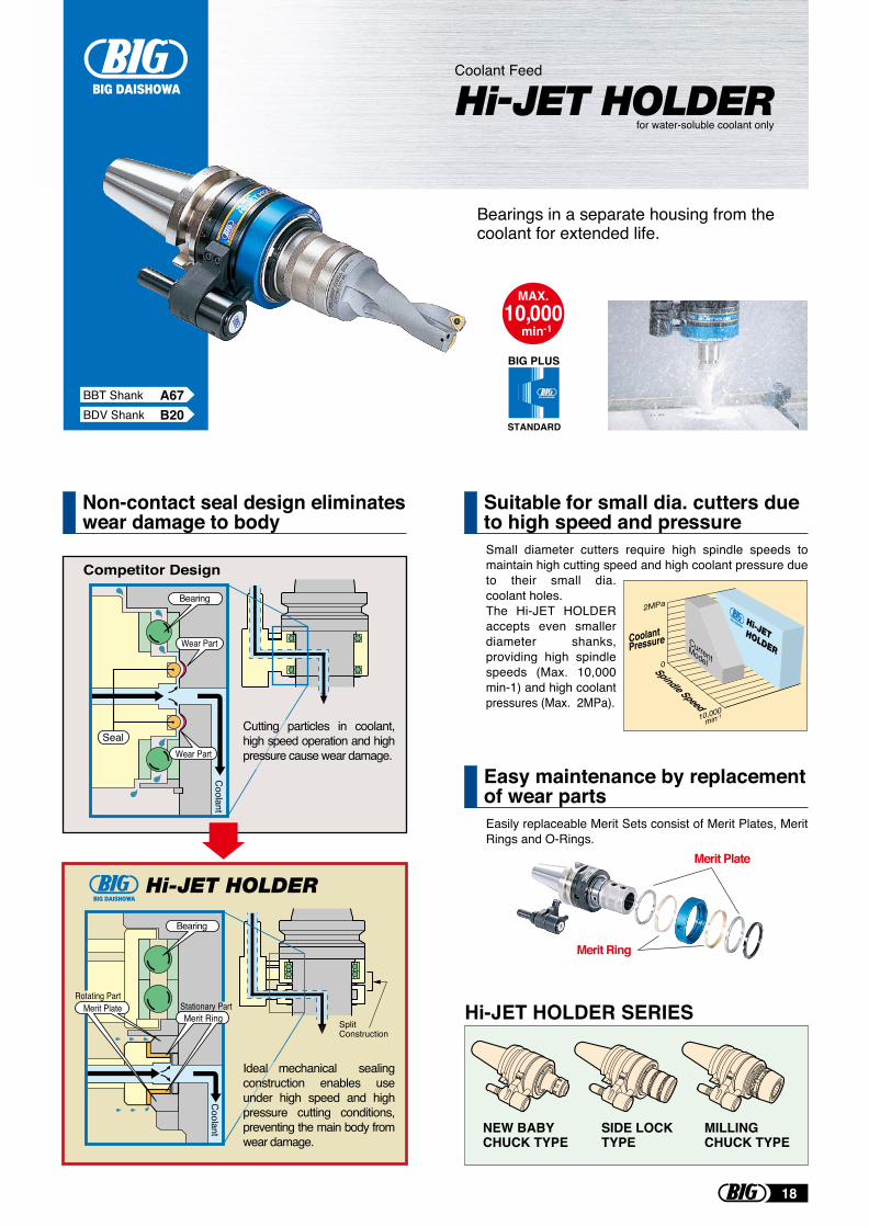
Non-contact seal design eliminates wear damage to body
Bearings in a separate housing from the coolant for extended life.
MAX.10,000
min-1
Coolant Feed
Hi-JET HOLDERfor water-soluble coolant only
Competitor Design
Coolant
Seal
Bearing
Wear Part
Wear Part
Small diameter cutters require high spindle speeds to maintain high cutting speed and high coolant pressure due to their small dia. coolant holes.The Hi-JET HOLDER accepts even smaller diameter shanks, providing high spindle speeds (Max. 10,000 min-1) and high coolant pressures (Max. 2MPa).
Coolant
Bearing
Stationary PartRotating Part
Merit Ring SplitConstruction
Merit Plate
CurrentModel
2MPa
0
10,000min-1
CoolantPressure
Spindle Speed
Cutting particles in coolant, high speed operation and high pressure cause wear damage.
Ideal mechanical sealing construction enables use under high speed and high pressure cutting conditions, preventing the main body from wear damage.
Merit Plate
Merit Ring
Suitable for small dia. cutters due to high speed and pressure
Easily replaceable Merit Sets consist of Merit Plates, Merit Rings and O-Rings.
Easy maintenance by replacement of wear parts
Hi-JET HOLDER SERIES
NEW BABY CHUCK TYPE
MILLING CHUCK TYPE
SIDE LOCK TYPE
BDV Shank B20
18
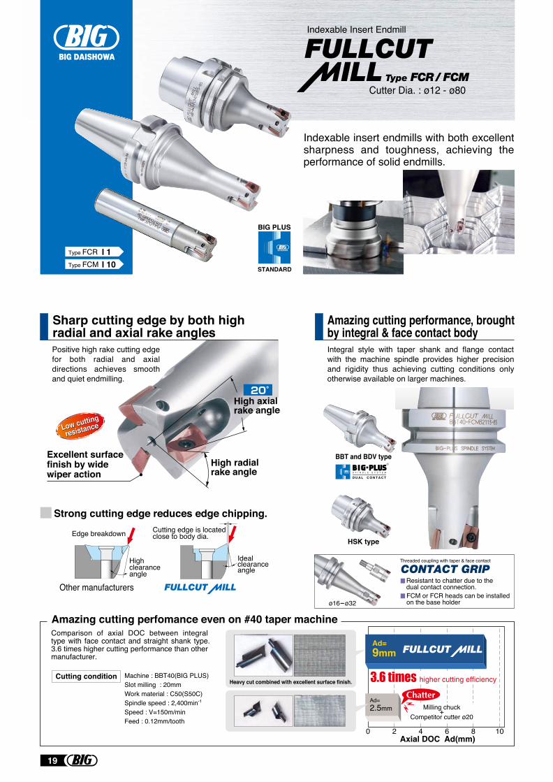
High axial rake angle
High radialrake angle
Low cutting
resistanceLow cutting
resistance
Excellent surface finish by wide wiper action
Sharp cutting edge by both high radial and axial rake angles
Amazing cutting performance, brought by integral & face contact body
Indexable insert endmills with both excellent sharpness and toughness, achieving the performance of solid endmills.
Positive high rake cutting edge for both radial and axial directions achieves smooth and quiet endmilling.
Integral style with taper shank and flange contact with the machine spindle provides higher precision and rigidity thus achieving cutting conditions only otherwise available on larger machines.
Strong cutting edge reduces edge chipping.Cutting edge is located close to body dia.
Ideal clearance angle
Edge breakdown
High clearance angle
Other manufacturers
20 4 6 8 10
Milling chuck+Competitor cutter ø20
Axial DOC Ad(mm)
Machine : BBT40(BIG PLUS)Slot milling : 20mmWork material : C50(S50C)Spindle speed : 2,400min-1
Speed : V=150m/minFeed : 0.12mm/tooth
Ad=9mm
Ad=2.5mm
Heavy cut combined with excellent surface finish.Cutting condition
Amazing cutting perfomance even on #40 taper machineComparison of axial DOC between integral type with face contact and straight shank type. 3.6 times higher cutting performance than other manufacturer.
BBT and BDV type
HSK type
Indexable Insert Endmill
Cutter Dia. : ø12 - ø80
BIG PLUS
STANDARD
Type FCR I 1Type FCM I 10
Threaded coupling with taper & face contact
FCM or FCR heads can be installedon the base holderø16-ø32
Resistant to chatter due to thedual contact connection.
CONTACT GRIP
R
S P I N D L E S Y S T E M
D U A L C O N T A C T
19
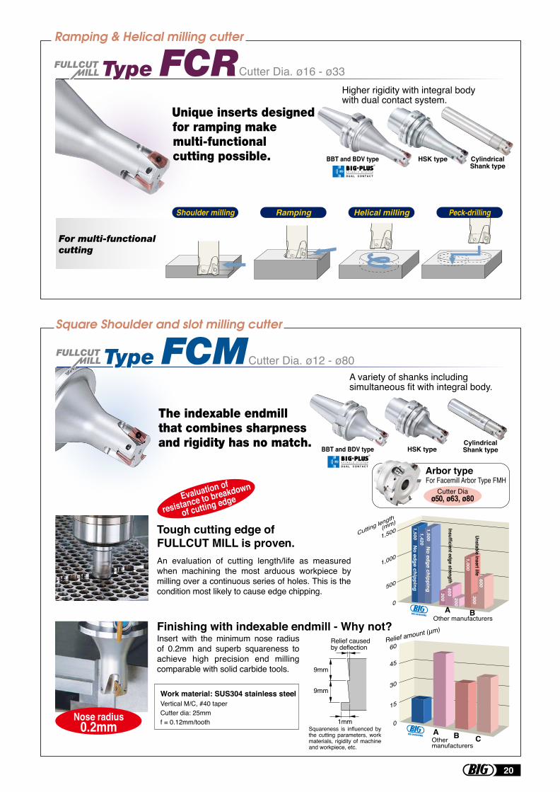
An evaluation of cutting length/life as measured when machining the most arduous workpiece by milling over a continuous series of holes. This is the condition most likely to cause edge chipping.
Insert with the minimum nose radius of 0.2mm and superb squareness to achieve high precision end milling comparable with solid carbide tools.
Higher rigidity with integral body with dual contact system.
A variety of shanks including simultaneous fit with integral body.
BBT and BDV type HSK typeCylindricalShank type
Cutter Dia. ø16 - ø33
Cutter Dia. ø12 - ø80
BBT and BDV type HSK type CylindricalShank type
Evaluation of
resistance to breakdown
of cutting edge
Tough cutting edge of FULLCUT MILL is proven.
Finishing with indexable endmill - Why not? Relief amount (μm)
45
60
30
15
0
Other manufacturers
BAC
Work material: SUS304 stainless steel
Relief caused by deflection
9mm
9mm
1mm
Vertical M/C, #40 taperCutter dia: 25mmf = 0.12mm/tooth
Squareness is influenced by the cutting parameters, work materials, rigidity of machine and workpiece, etc.
Shoulder milling Ramping Helical milling Peck-drilling
Nose radius0.2mm
Arbor typeFor Facemill Arbor Type FMH
Cutter Diaø50, ø63, ø80
1,500Cutting length
(mm)
1,000
500
0
1,500
1,000
300 300600
400200
1,5001,420
Insufficient edge strength
Unstable insert life
No edge chipping
No edge chipping
BAOther manufacturers
R
S P I N D L E S Y S T E M
D U A L C O N T A C T
R
S P I N D L E S Y S T E M
D U A L C O N T A C T
20
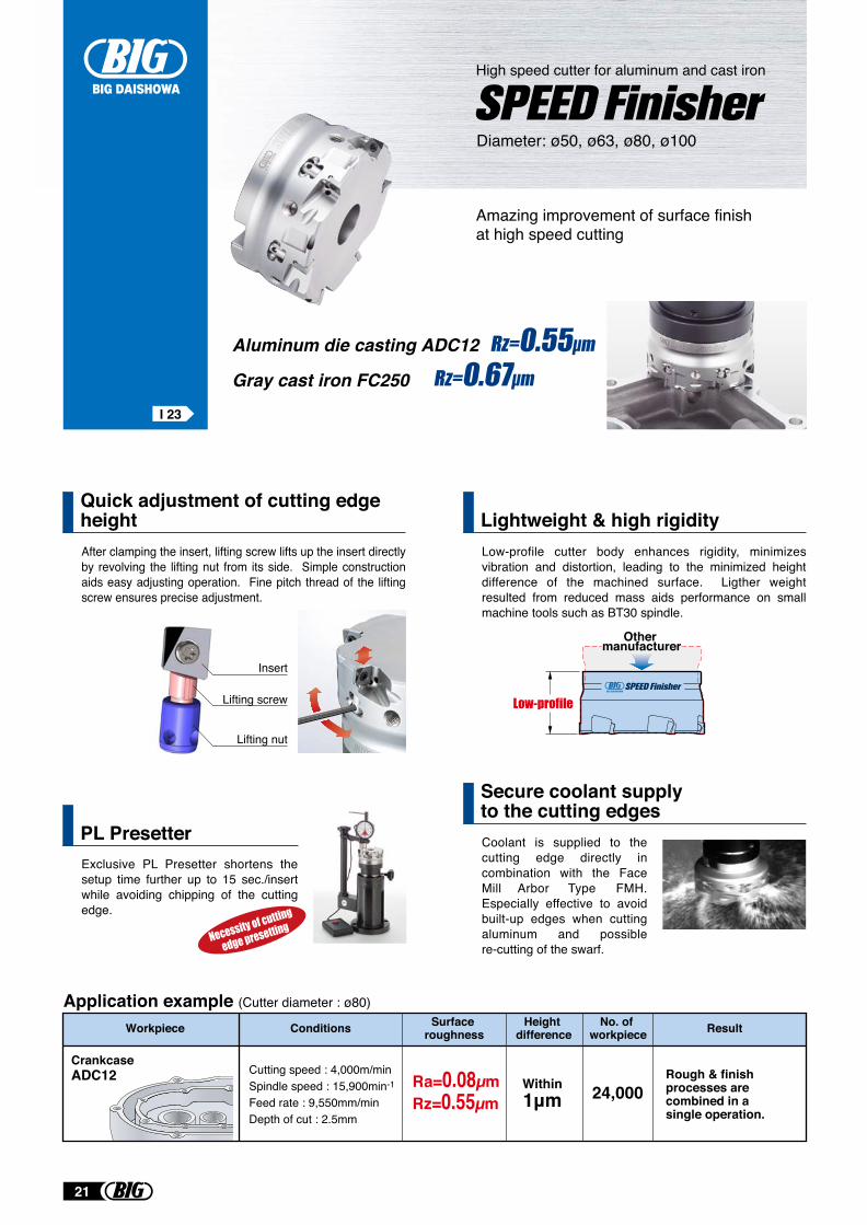
Quick adjustment of cutting edge heightAfter clamping the insert, lifting screw lifts up the insert directly by revolving the lifting nut from its side. Simple construction aids easy adjusting operation. Fine pitch thread of the lifting screw ensures precise adjustment.
Amazing improvement of surface finish at high speed cutting
Diameter: ø50, ø63, ø80, ø100
Lightweight & high rigidityLow-profile cutter body enhances rigidity, minimizes vibration and distortion, leading to the minimized height difference of the machined surface. Ligther weight resulted from reduced mass aids performance on small machine tools such as BT30 spindle.
PL PresetterExclusive PL Presetter shortens the setup time further up to 15 sec./insert while avoiding chipping of the cutting edge.
Secure coolant supply to the cutting edgesCoolant is supplied to the cutting edge directly in combination with the Face Mill Arbor Type FMH. Especially effective to avoid built-up edges when cutting aluminum and possible re-cutting of the swarf.
Lifting screw
Lifting nut
Insert
High speed cutter for aluminum and cast iron
Other manufacturer
Rough & finish processes are combined in a single operation.
Workpiece Result
CrankcaseADC12 Cutting speed : 4,000m/min
Spindle speed : 15,900min-1
Feed rate : 9,550mm/minDepth of cut : 2.5mm
Ra=0.08µmRz=0.55µm
Within1μm 24,000
Conditions Surface roughness
Height difference
No. of workpiece
Application example (Cutter diameter : ø80)
Aluminum die casting ADC12
Gray cast iron FC250
I 23
21
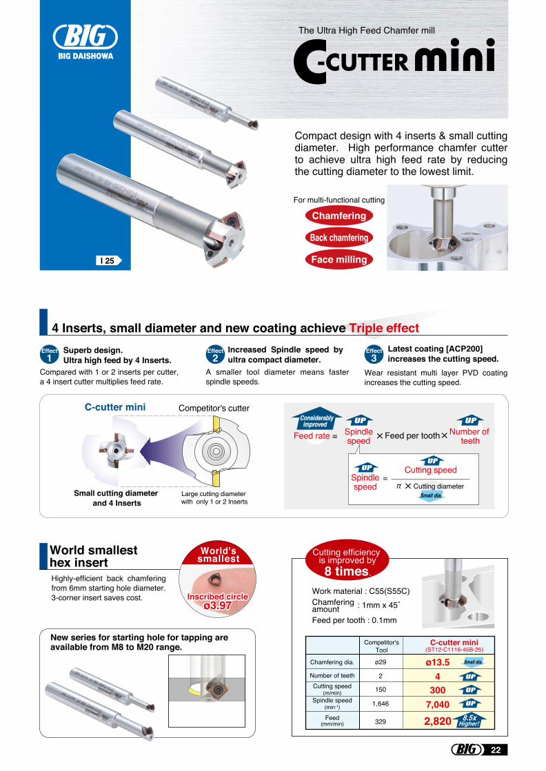
I 25
4 Inserts, small diameter and new coating achieve Triple effect
Compact design with 4 inserts & small cutting diameter. High performance chamfer cutter to achieve ultra high feed rate by reducing the cutting diameter to the lowest limit.
Highly-efficient back chamfering from 6mm starting hole diameter.3-corner insert saves cost.
Chamfering
Back chamfering
Face milling
For multi-functional cutting
Competitor's cutterC-cutter mini
Large cutting diameter with only 1 or 2 Inserts
Small cutting diameter and 4 Inserts
Feed rate = Number of teethFeed per toothSpindle
speed
Cutting speed
Cutting diameterSpindlespeed
Small dia.
Compared with 1 or 2 inserts per cutter, a 4 insert cutter multiplies feed rate.
Superb design. Ultra high feed by 4 Inserts.
Increased Spindle speed by ultra compact diameter.
A smaller tool diameter means faster spindle speeds.
Latest coating [ACP200] increases the cutting speed.
Wear resistant multi layer PVD coating increases the cutting speed.
Effect1
Effect2
Effect3
ø29
329Feed(mm/min)
Chamfering dia.
Number of teethCutting speed
(m/min)Spindle speed
(min-1)
Competitor'sTool
C-cutter mini(ST12-C1116-45B-25)
ø13.5
1,646 7,040150 300
2 4
2,820
Small dia.
Work material : C55(S55C)Chamfering amount : 1mm x 45˚
Feed per tooth : 0.1mm
World smallest hex insert
New series for starting hole for tapping are available from M8 to M20 range.
World'ssmallest Cutting efficiency
is improved by 8 times.
Inscribed circleø3.97
Inscribed circleø3.97
The Ultra High Feed Chamfer mill
22
BDV Shank B21HSK Shank C50
BBT Shank A71
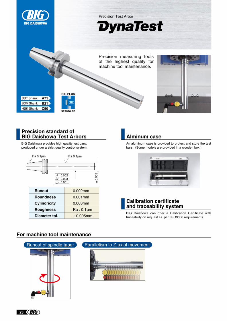
Precision standard ofBIG Daishowa Test Arbors
BIG Daishowa can offer a Calibration Certificate with traceability on request as per ISO9000 requirements.
Calibration certificateand traceability system
Precision measuring tools of the highest quality for machine tool maintenance.
BIG Daishowa provides high quality test bars,produced under a strict quality control system.
Alminum caseAn aluminum case is provided to protect and store the test bars. (Some models are provided in a wooden box.)
RunoutRoundness 0.001mmCylindricity 0.003mmRoughness Ra : 0.1μm Diameter tol. ± 0.005mm
0.002mm
± 0.
005
Ra 0.1μmRa 0.1μm
0.0020.0030.001
For machine tool maintenance
Precision Test Arbor
Parallelism to Z-axial movementRunout of spindle taper
BIG PLUS
STANDARD
23
MEGA MICRO CHUCK
MEGA NEW BABY CHUCK
MEGA E CHUCK
MEGA DOUBLE POWER CHUCK
NEW BABY CHUCK
NEW Hi-POWER MILLING CHUCK
HYDRAULIC CHUCK
MOLD CHUCK
SHRINK CHUCK
MEGA SYNCHRO Tapping Holder
SIDE LOCK HOLDER
SIDE CUTTER ARBOR
MORSE TAPER HOLDER
FACE MILL ARBOR
ANGLE HEAD
HIGH SPINDLE
AIR TURBINE SPINDLE
Hi-JET HOLDER
DYNA TEST
CLEANER
A1
A3
A6
A9
A13
A16
A21
A28
A29
A31
A38 · A42
A40
A41
A43
A49
A62
A63
A67
A71
A71
A
A
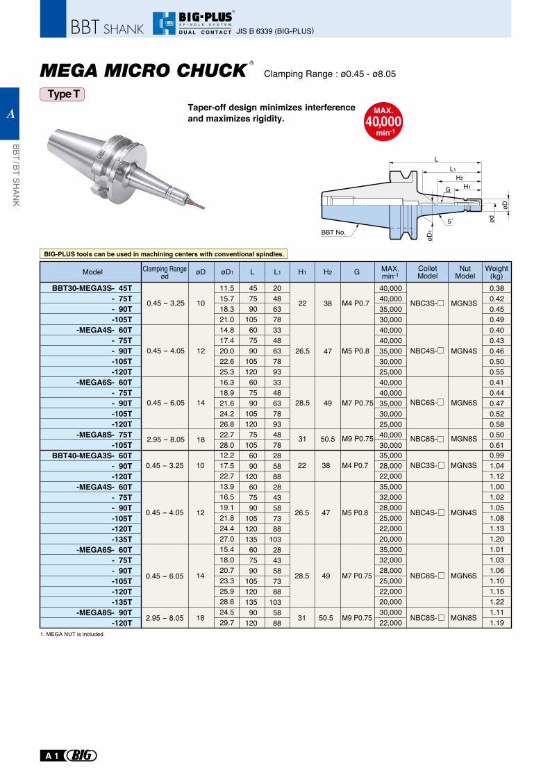
Clamping Range : ø0.45 - ø8.05
MAX.40,000
min-1
1. MEGA NUT is included.
Taper-off design minimizes interference and maximizes rigidity.
Type T
BBT30-MEGA3S- 45T- 75T- 90T-105T
-MEGA4S- 60T- 75T- 90T-105T-120T
-MEGA6S- 60T- 75T- 90T-105T-120T
-MEGA8S- 75T-105T
BBT40-MEGA3S- 60T- 90T-120T
-MEGA4S- 60T- 75T- 90T-105T-120T-135T
-MEGA6S- 60T- 75T- 90T-105T-120T-135T
-MEGA8S- 90T-120T
0.45 - 4.05
0.45 - 3.25
0.45 - 6.05
2.95 - 8.05
10
12
14
18
457590
105607590
105120607590
10512075
1056090
120607590
105120135607590
10512013590
120
11.515.718.321.014.817.420.022.625.316.318.921.624.226.822.728.012.217.522.713.916.519.121.824.427.015.418.020.723.325.928.624.529.7
204863783348637893334863789348782858882843587388
1032843587388
1035888
38
47
49
50.5
NBC3S-
NBC4S-
NBC6S-
NBC8S-
0.380.420.450.490.400.430.460.500.550.410.440.470.520.580.500.610.991.041.121.001.021.051.081.131.201.011.031.061.101.151.221.111.19
40,00040,00035,00030,00040,00040,00035,00030,00025,00040,00040,00035,00030,00025,00040,00030,00035,00028,00022,00035,00032,00028,00025,00022,00020,00035,00032,00028,00025,00022,00020,00030,00022,000
MGN3S
MGN4S
MGN6S
MGN8S
MAX.min-1
ColletModel
NutModel
Weight(kg)Model L L1 H2
22
26.5
28.5
31
H1 GøD øD1
M4 P0.7
M5 P0.8
M7 P0.75
M9 P0.75
0.45 - 3.25
0.45 - 4.05
0.45 - 6.05
2.95 - 8.05
10
12
14
18
38
47
49
50.5
NBC3S-
NBC4S-
NBC6S-
NBC8S-
MGN3S
MGN4S
MGN6S
MGN8S
22
26.5
28.5
31
M4 P0.7
M5 P0.8
M7 P0.75
M9 P0.75
Clamping Rangeød
R
BBT No.
H2
H1
øD
øD
1
ød
L
5˚
L1
G
BIG-PLUS tools can be used in machining centers with conventional spindles.
JIS B 6339 (BIG-PLUS)
BBT / BT SHAN
K
A
A 1
R
S P I N D L E S Y S T E M
D U A L C O N T A C T
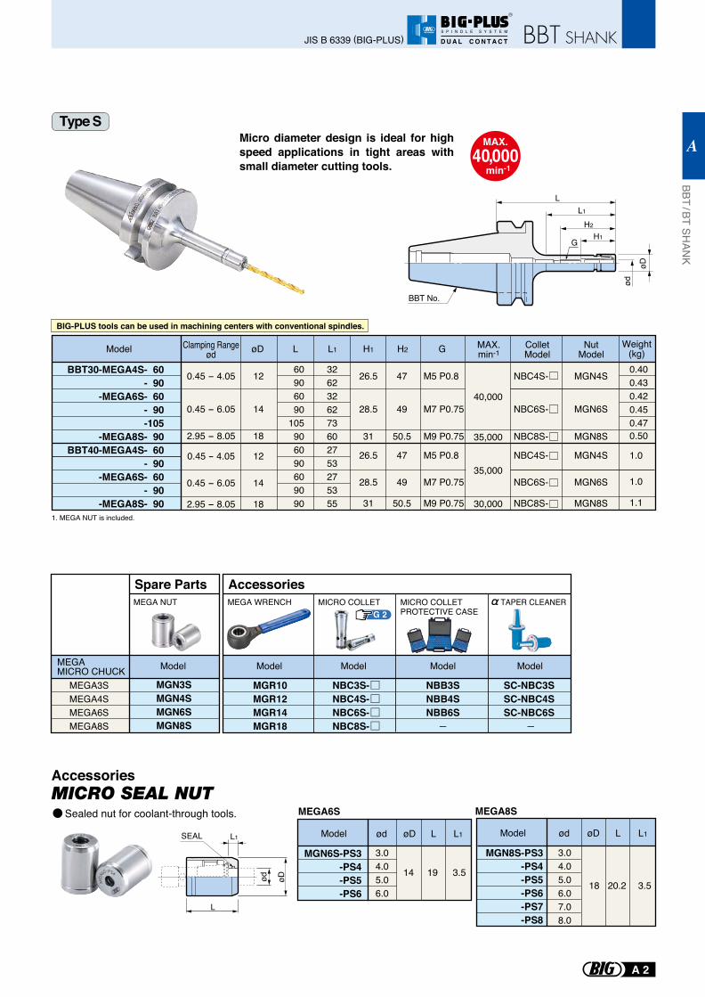
1. MEGA NUT is included.
Micro diameter design is ideal for high speed applications in tight areas with small diameter cutting tools.
Type S
BBT30-MEGA4S- 60- 90
-MEGA6S- 60- 90-105
-MEGA8S- 90BBT40-MEGA4S- 60
- 90-MEGA6S- 60
- 90-MEGA8S- 90
0.45 - 4.05
0.45 - 6.05
2.95 - 8.05
0.45 - 4.05
0.45 - 6.05
2.95 - 8.05
12
14
18
12
14
18
60906090
105906090609090
3262326273602753275355
47
49
50.5
47
49
50.5
40,000
35,000
35,000
30,000
NBC4S-
NBC6S-
NBC8S-
NBC4S-
NBC6S-
NBC8S-
MGN4S
MGN6S
MGN8S
MGN4S
MGN6S
MGN8S
0.400.430.420.450.470.50
1.0
1.0
1.1
Model L L1 H2
26.5
28.5
31
26.5
28.5
31
H1 G MAX.min-1
ColletModel
NutModel
Weight(kg)øD
M5 P0.8
M7 P0.75
M9 P0.75
M5 P0.8
M7 P0.75
M9 P0.75
BBT No.
H2
H1
øD
ød
LL1
G
MAX.40,000
min-1
Clamping Rangeød
MEGA3SMEGA4SMEGA6SMEGA8S
MGN3SMGN4SMGN6SMGN8S
Spare PartsMEGA NUT
MEGA MICRO CHUCK Model
MGR10MGR12MGR14MGR18
MICRO COLLETPROTECTIVE CASE
MICRO COLLET
Accessories
Accessories
MEGA WRENCH
NBB3SNBB4SNBB6S
Model Model Model
NBC3S-NBC4S-NBC6S-NBC8S-
Model
SC-NBC3SSC-NBC4SSC-NBC6S
TAPER CLEANER
BIG-PLUS tools can be used in machining centers with conventional spindles.
G 2
MEGA8S
L
L1SEAL
øD
ød
ødModelød øD L L1 øD L L1
3.04.05.06.0
14 19 3.518 20.2 3.5
MGN6S-PS3-PS4-PS5-PS6
MGN8S-PS3-PS4-PS5-PS6-PS7-PS8
Model
3.04.05.06.07.08.0
MEGA6SMICRO SEAL NUT
Sealed nut for coolant-through tools.
JIS B 6339 (BIG-PLUS)
BBT / BT SHAN
K
A
A 2
R
S P I N D L E S Y S T E M
D U A L C O N T A C T
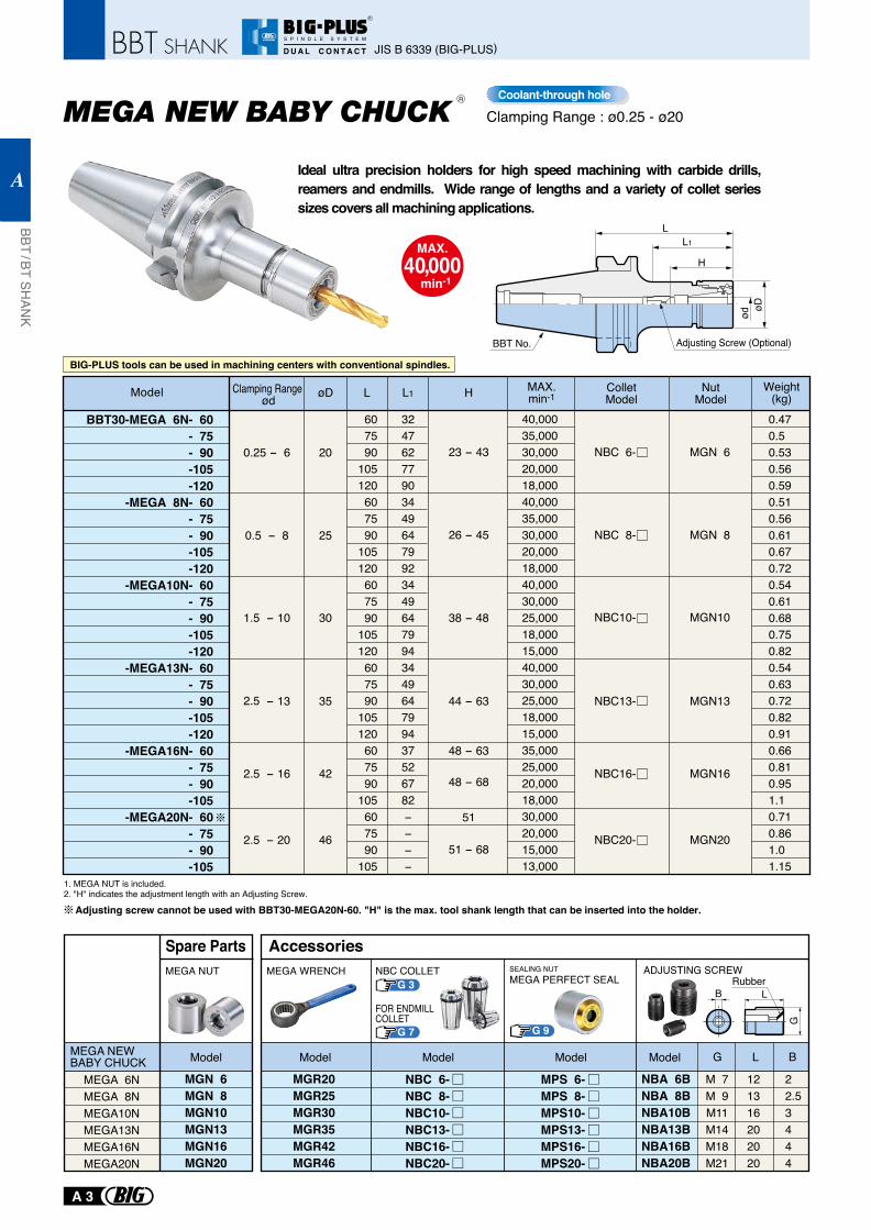
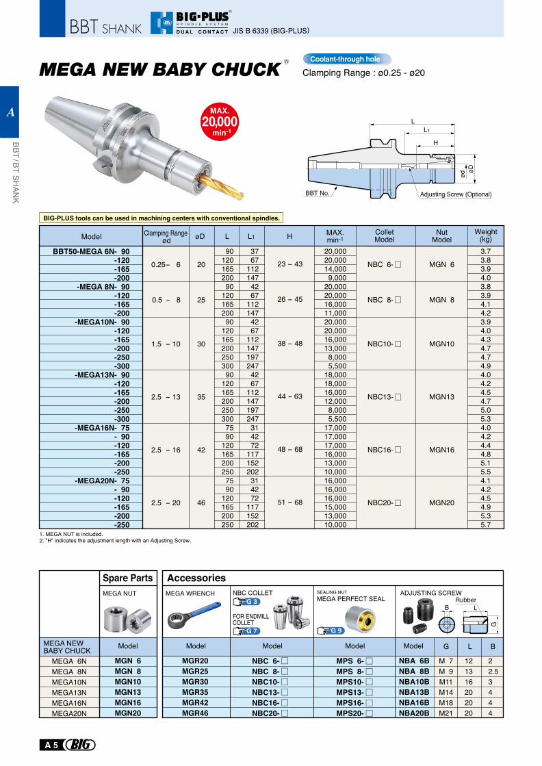
Clamping Range : ø0.25 - ø20
MAX.40,000
min-1
BBT30-MEGA 6N- 60- 75- 90-105-120
-MEGA 8N- 60- 75- 90-105-120
-MEGA10N- 60- 75- 90-105-120
-MEGA13N- 60- 75- 90-105-120
-MEGA16N- 60- 75- 90-105
-MEGA20N- 60- 75- 90-105
0.25 - 6
0.5 - 8
1.5 - 10
øD
20
25
30
L
607590
105120607590
105120607590
105120607590
105120607590
105607590
105
L1 H
324762779034496479923449647994344964799437526782−−−−
40,00035,00030,00020,00018,00040,00035,00030,00020,00018,00040,00030,00025,00018,00015,00040,00030,00025,00018,00015,00035,00025,00020,00018,00030,00020,00015,00013,000
ColletModel
NBC 6-
NBC 8-
NBC10-
NutModel
MGN 6
MGN 8
MGN10
2.5 - 13 35 NBC13- MGN13
2.5 - 16 42 NBC16- MGN16
2.5 - 20 46 NBC20- MGN20
0.470.5 0.530.560.590.510.560.610.670.720.540.610.680.750.820.540.630.720.820.910.660.810.951.1 0.710.861.0 1.15
Model Clamping Range ød
Weight(kg)
51
23 - 43
26 - 45
38 - 48
44 - 63
48 - 68
48 - 63
51 - 68
MPS 6-MPS 8-MPS10-MPS13-MPS16-MPS20-
G 9
G 3 Rubber
MEGA 6NMEGA 8NMEGA10NMEGA13NMEGA16NMEGA20N
MEGA NEW BABY CHUCK
MGN 6MGN 8MGN10MGN13MGN16MGN20
MEGA NUT
Model
Spare Parts
MGR20MGR25MGR30MGR35MGR42MGR46
NBA 6BNBA 8BNBA10BNBA13BNBA16BNBA20B
M 7M 9M11M14M18M21
121316202020
22.53444
MEGA WRENCH NBC COLLET
G 7
FOR ENDMILLCOLLET
SEALING NUTMEGA PERFECT SEAL
ADJUSTING SCREW
G L B
B L
G
ModelModelModelModel
Accessories
NBC 6-NBC 8-NBC10-NBC13-NBC16-NBC20-
Coolant-through hole
H
øD
ød
L1
L
BBT No. Adjusting Screw (Optional)
Adjusting screw cannot be used with BBT30-MEGA20N-60. "H" is the max. tool shank length that can be inserted into the holder.
Ideal ultra precision holders for high speed machining with carbide drills, reamers and endmills. Wide range of lengths and a variety of collet series sizes covers all machining applications.
1. MEGA NUT is included.2. "H" indicates the adjustment length with an Adjusting Screw.
R
BIG-PLUS tools can be used in machining centers with conventional spindles.
MAX.min-1
JIS B 6339 (BIG-PLUS)
BBT / BT SHAN
K
A
A 3
R
S P I N D L E S Y S T E M
D U A L C O N T A C T
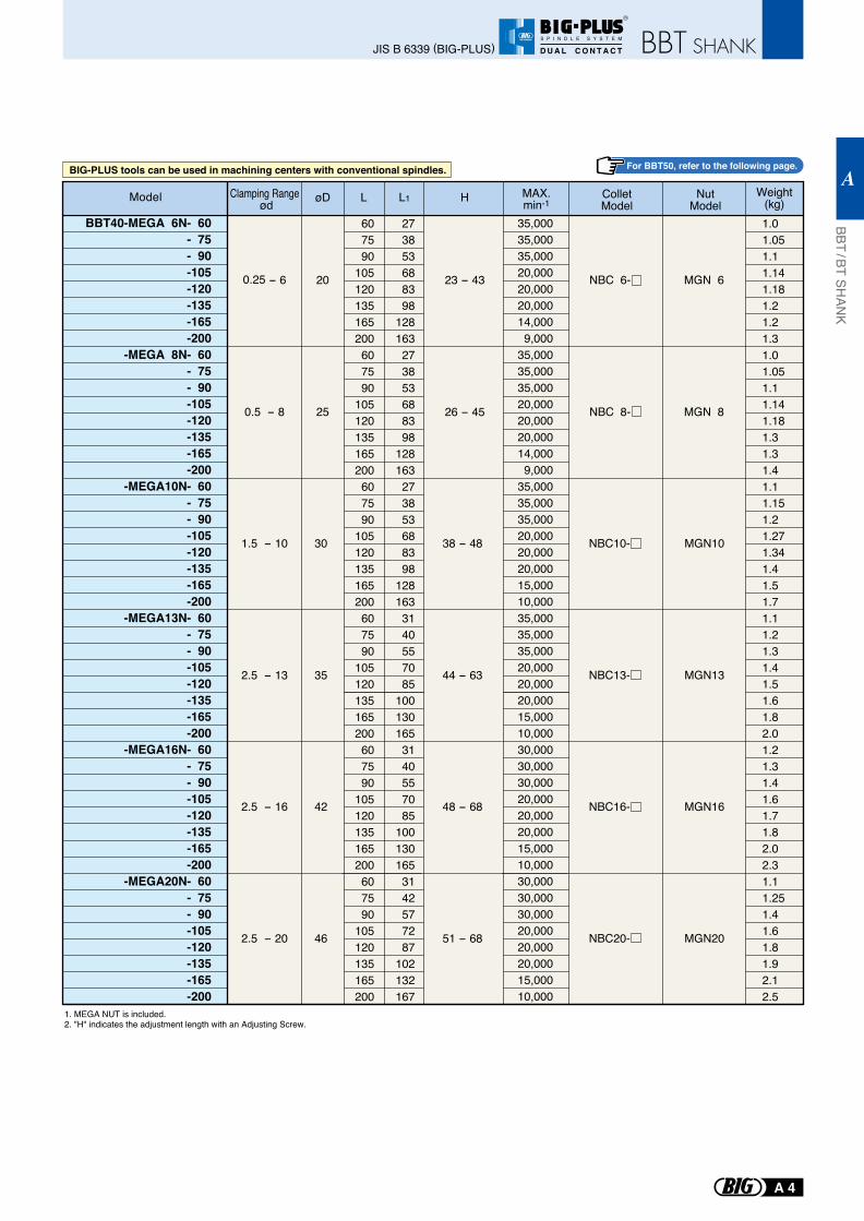
1. MEGA NUT is included.2. "H" indicates the adjustment length with an Adjusting Screw.
2.5 - 13
2.5 - 16
2.5 - 20
35
42
46
NBC13- MGN13
1.5 - 10 30 NBC10- MGN10
NBC16- MGN16
NBC20- MGN20
BBT40-MEGA 6N- 60- 75- 90-105-120-135-165-200
-MEGA 8N- 60- 75- 90-105-120-135-165-200
-MEGA10N- 60- 75- 90-105-120-135-165-200
-MEGA13N- 60- 75- 90-105-120-135-165-200
-MEGA16N- 60- 75- 90-105-120-135-165-200
-MEGA20N- 60- 75- 90-105-120-135-165-200
øD L
607590
105120135165200607590
105120135165200607590
105120135165200607590
105120135165200607590
105120135165200607590
105120135165200
L1 H
273853688398
128163273853688398
128163273853688398
1281633140557085
1001301653140557085
1001301653142577287
102132167
35,00035,00035,00020,00020,00020,00014,0009,000
35,00035,00035,00020,00020,00020,00014,0009,000
35,00035,00035,00020,00020,00020,00015,00010,00035,00035,00035,00020,00020,00020,00015,00010,00030,00030,00030,00020,00020,00020,00015,00010,00030,00030,00030,00020,00020,00020,00015,00010,000
0.25 - 6
0.5 - 8
20
25
NBC 6-
NBC 8-
MGN 6
MGN 8
1.01.051.11.141.181.21.21.31.01.051.11.141.181.31.31.41.11.151.21.271.341.41.51.71.11.21.31.41.51.61.82.01.21.31.41.61.71.82.02.31.11.251.41.61.81.92.12.5
Model Clamping Range ød
Weight(kg)
44 - 63
48 - 68
51 - 68
38 - 48
ColletModel
NutModel
23 - 43
26 - 45
For BBT50, refer to the following page.BIG-PLUS tools can be used in machining centers with conventional spindles.
MAX.min-1
JIS B 6339 (BIG-PLUS)
BBT / BT SHAN
K
A
A 4
R
S P I N D L E S Y S T E M
D U A L C O N T A C T
Clamping Range : ø0.25 - ø20
MAX.20,000
min-1
H
øD
ød
L1
L
BBT No. Adjusting Screw (Optional)
1. MEGA NUT is included.2. "H" indicates the adjustment length with an Adjusting Screw.
BBT50-MEGA 6N- 90-120-165-200
-MEGA 8N- 90-120-165-200
-MEGA10N- 90-120-165-200-250-300
-MEGA13N- 90-120-165-200-250-300
-MEGA16N- 75- 90-120-165-200-250
-MEGA20N- 75- 90-120-165-200-250
0.25- 6
0.5 - 8
1.5 - 10
2.5 - 13
2.5 - 16
2.5 - 20
20
25
30
35
42
46
9012016520090
12016520090
12016520025030090
1201652002503007590
1201652002507590
120165200250
3767
1121474267
1121474267
1121471972474267
112147197247314272
117152202314272
117152202
20,00020,00014,0009,000
20,00020,00016,00011,00020,00020,00016,00013,0008,0005,500
18,00018,00016,00012,0008,0005,500
17,00017,00017,00016,00013,00010,00016,00016,00016,00015,00013,00010,000
NBC 6-
NBC 8-
NBC10-
NBC13-
NBC16-
NBC20-
MGN 6
MGN 8
MGN10
MGN13
MGN16
MGN20
3.73.83.94.03.83.94.14.23.94.04.34.74.74.94.04.24.54.75.05.34.04.24.44.85.15.54.14.24.54.95.35.7
Clamping Range ød øD L HL1Model Weight
(kg)
23 - 43
26 - 45
38 - 48
44 - 63
48 - 68
51 - 68
ColletModel
NutModel
R
MPS 6-MPS 8-MPS10-MPS13-MPS16-MPS20-
G 9
Rubber
MEGA 6NMEGA 8NMEGA10NMEGA13NMEGA16NMEGA20N
MEGA NEW BABY CHUCK
MGN 6MGN 8MGN10MGN13MGN16MGN20
MEGA NUT
Model
Spare Parts
MGR20MGR25MGR30MGR35MGR42MGR46
NBA 6BNBA 8BNBA10BNBA13BNBA16BNBA20B
M 7M 9M11M14M18M21
121316202020
22.53444
MEGA WRENCH SEALING NUTMEGA PERFECT SEAL
ADJUSTING SCREW
G L B
B L
G
ModelModelModelModel
Accessories
NBC 6-NBC 8-NBC10-NBC13-NBC16-NBC20-
Coolant-through hole
G 3NBC COLLET
G 7
FOR ENDMILLCOLLET
BIG-PLUS tools can be used in machining centers with conventional spindles.
MAX.min-1
JIS B 6339 (BIG-PLUS)
BBT / BT SHAN
K
A
A 5
R
S P I N D L E S Y S T E M
D U A L C O N T A C T
37 - 45
42 - 51
48 - 58
50 - 60
50 - 58
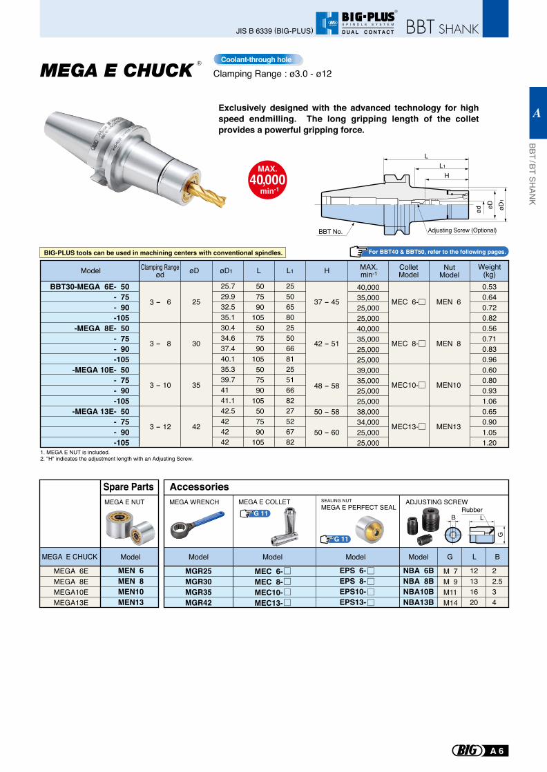
BBT30-MEGA 6E- 50- 75- 90-105
-MEGA 8E- 50- 75- 90-105
-MEGA 10E- 50- 75- 90-105
-MEGA 13E- 50- 75- 90-105
25.729.932.535.130.434.637.440.135.339.74141.142.5424242
507590
105507590
105507590
105507590
105
25 50 65 80 25 50 66 81 25 51 66 82 27 52 67 82
0.530.640.720.820.560.710.830.960.600.800.931.060.650.901.051.20
40,00035,00025,00025,00040,00035,00025,00025,00039,00035,00025,00025,00038,00034,00025,00025,000
3 - 6
3 - 8
3 - 10
3 - 12
øD øD1 L L1
25
30
35
42
MEN 6
MEN 8
MEN10
MEN13
H
MEC 6-
MEC 8-
MEC10-
MEC13-
Model Clamping Rangeød
ColletModel
NutModel
Weight(kg)
L
BBT No.
L1
øD1
øDød
H
Adjusting Screw (Optional)
1. MEGA E NUT is included.2. "H" indicates the adjustment length with an Adjusting Screw.
Clamping Range : ø3.0 - ø12
MAX.40,000
min-1
For BBT40 & BBT50, refer to the following pages.
R Coolant-through hole
G 11
G 11
SEALING NUTMEGA E PERFECT SEAL Rubber
B L
GMEGA E COLLET
MEGA 6EMEGA 8EMEGA10EMEGA13E
MEGA E CHUCK Model
Spare Parts
MEN 6MEN 8MEN10MEN13
MEGA E NUT
MGR25MGR30MGR35MGR42
NBA 6BNBA 8BNBA10BNBA13B
EPS 6-EPS 8-EPS10-EPS13-
M 7M 9M11M14
12131620
22.534
G L B
MEGA WRENCH ADJUSTING SCREW
ModelModel Model Model
Accessories
MEC 6-MEC 8-MEC10-MEC13-
Exclusively designed with the advanced technology for high speed endmilling. The long gripping length of the collet provides a powerful gripping force.
BIG-PLUS tools can be used in machining centers with conventional spindles.
MAX.min-1
JIS B 6339 (BIG-PLUS)
BBT / BT SHAN
K
A
A 6
R
S P I N D L E S Y S T E M
D U A L C O N T A C T
37 - 45
42 - 51
42 - 48
48 - 58
50 - 60
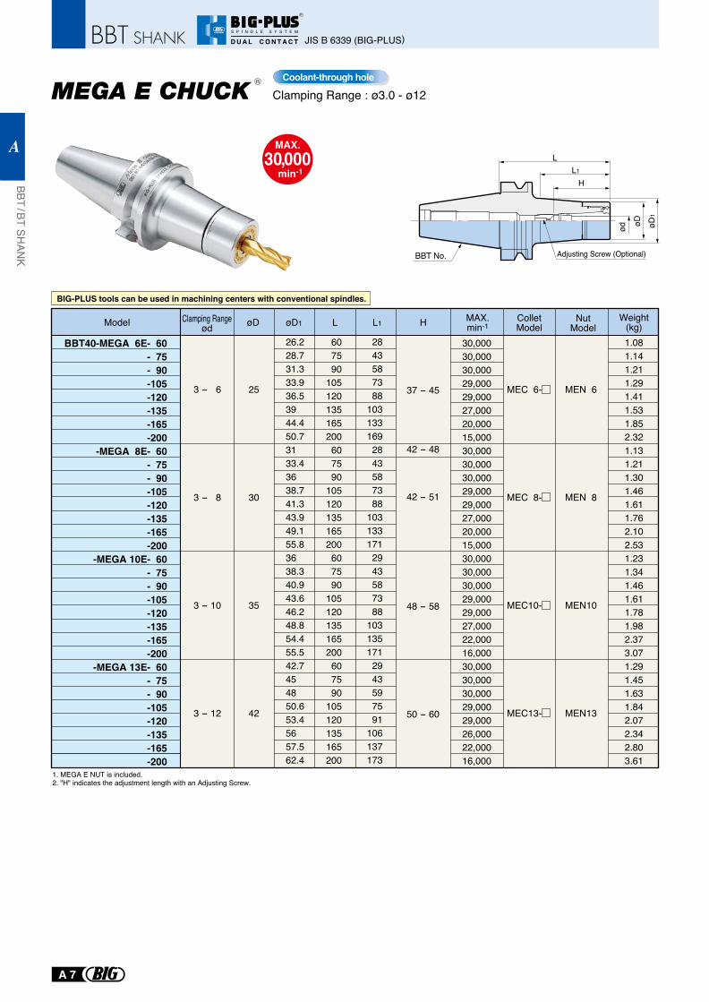
BBT40-MEGA 6E- 60- 75- 90-105-120-135-165-200
-MEGA 8E- 60- 75- 90-105-120-135-165-200
-MEGA 10E- 60- 75- 90-105-120-135-165-200
-MEGA 13E- 60- 75- 90-105-120-135-165-200
26.228.731.333.936.53944.450.73133.43638.741.343.949.155.83638.340.943.646.248.854.455.542.7454850.653.45657.562.4
607590
105120135165200607590
105120135165200607590
105120135165200607590
105120135165200
28 43 58 73 88103133169 28 43 58 73 88103133171 29 43 58 73 88103135171 29 43 59 75 91106137173
1.081.141.211.291.411.531.852.321.131.211.301.461.611.762.102.531.231.341.461.611.781.982.373.071.291.451.631.842.072.342.803.61
30,00030,00030,00029,00029,00027,00020,00015,00030,00030,00030,00029,00029,00027,00020,00015,00030,00030,00030,00029,00029,00027,00022,00016,00030,00030,00030,00029,00029,00026,00022,00016,000
3 - 6
3 - 8
3 - 10
3 - 12
øD øD1 L L1
25
30
35
42
MEN 6
MEN 8
MEN10
MEN13
H
MEC 6-
MEC 8-
MEC10-
MEC13-
Model Clamping Rangeød
ColletModel
NutModel
Weight(kg)
MAX.30,000
min-1
Clamping Range : ø3.0 - ø12
L
BBT No.
L1
øD1
øDød
H
Adjusting Screw (Optional)
Coolant-through hole
1. MEGA E NUT is included.2. "H" indicates the adjustment length with an Adjusting Screw.
R
BIG-PLUS tools can be used in machining centers with conventional spindles.
MAX.min-1
JIS B 6339 (BIG-PLUS)
BBT / BT SHAN
K
A
A 7
R
S P I N D L E S Y S T E M
D U A L C O N T A C T
3 - 6
3 - 8
3 - 10
3 - 12
25
30
35
42
MEC 6-
MEC 8-
MEC10-
MEC13-
MEN 6
MEN 8
MEN10
MEN13
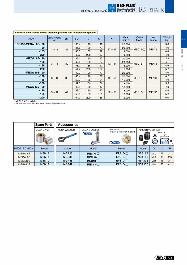
BBT50-MEGA 6E- 90-120-165-200
-MEGA 8E- 90-120-165-200
-MEGA 10E- 90-120-165-200
-MEGA 13E- 90-120-165-200
30.435.643.549.635.140.448.254.440.045.453.059.346.552.059.064.7
9012016520090
12016520090
12016520090
120165200
47 77 122 157 47 77 122 157 47 77 121 156 47 77 121 156
3.84.04.44.93.94.14.65.24.04.24.95.54.04.45.26.0
20,00020,00014,0009,000
20,00020,00016,00011,00020,00020,00016,00013,00018,00018,00016,00012,000
øD øD1 L L1 HModel Clamping Rangeød
ColletModel
Nut Model
Weight(kg)
37 - 45
42 - 51
48 - 58
50 - 60
G 11
G 11
SEALING NUTMEGA E PERFECT SEAL Rubber
B L
G
MEGA E COLLET
MEGA 6EMEGA 8EMEGA10EMEGA13E
MEGA E CHUCK Model
Spare Parts
MEN 6MEN 8MEN10MEN13
MEGA E NUT
MGR25MGR30MGR35MGR42
NBA 6BNBA 8BNBA10BNBA13B
EPS 6-EPS 8-EPS10-EPS13-
M 7M 9M11M14
12131620
22.534
G L B
MEGA WRENCH ADJUSTING SCREW
ModelModel Model Model
Accessories
MEC 6-MEC 8-MEC10-MEC13-
1. MEGA E NUT is included.2. "H" indicates the adjustment length with an Adjusting Screw.
BIG-PLUS tools can be used in machining centers with conventional spindles.
MAX.min-1
JIS B 6339 (BIG-PLUS)
BBT / BT SHAN
K
A
A 8
R
S P I N D L E S Y S T E M
D U A L C O N T A C T
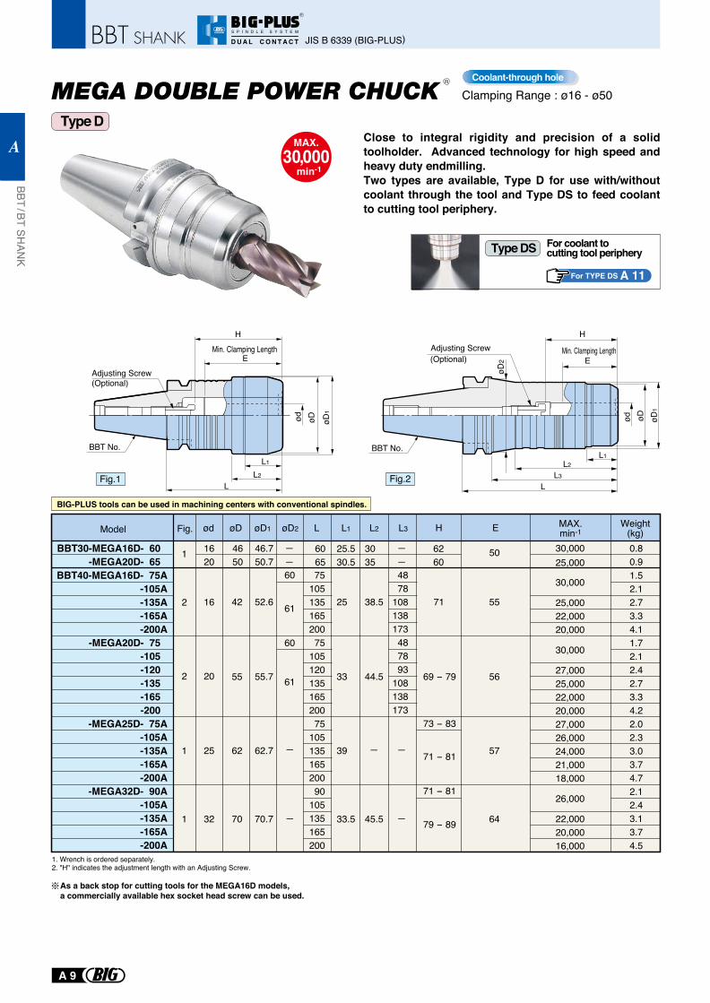
Clamping Range : ø16 - ø50
MAX.30,000
min-1
Close to integral rigidity and precision of a solid toolholder. Advanced technology for high speed and heavy duty endmilling. Two types are available, Type D for use with/without coolant through the tool and Type DS to feed coolant to cutting tool periphery.
L1
ød
H
E
L2
øD øD1
øD2
LL3
øDød
Adjusting Screw(Optional)
L1
H
L2
øD1
BBT30-MEGA16D- 60 -MEGA20D- 65
BBT40-MEGA16D- 75A-105A-135A-165A-200A
-MEGA20D- 75 -105 -120 -135 -165 -200
-MEGA25D- 75A-105A-135A-165A-200A
-MEGA32D- 90A-105A-135A-165A-200A
7510513516520075
10512013516520075
10513516520090
105135165200
4878
108138173487893
108138173
0.80.91.52.12.73.34.11.72.12.42.73.34.22.02.33.03.74.72.12.43.13.74.5
16
1620
4650
46.750.7
3035
25.530.5
6065
6260
50
20
25
32
2
1
2
1
1
52.6
55.7
62.7
70.7
71
LøD1
61
61
60
60
øD2
42
55
62
70
55
56
57
øDød L1
38.5
44.5
L2
25
33
39
33.5
L3Model
30,000
25,00022,00020,000
30,000
27,00025,00022,00020,00027,00026,00024,00021,00018,000
26,000
22,00020,00016,000
30,00025,000
Fig. Weight(kg)H E
Min. Clamping Length
69 - 79
71 - 81
71 - 81
73 - 83
79 - 89
For TYPE DS A 11
For coolant to cutting tool peripheryType DS
Coolant-through hole
L
Adjusting Screw(Optional)E
Min. Clamping Length
BBT No. BBT No.
Fig.1 Fig.2
R
BIG-PLUS tools can be used in machining centers with conventional spindles.
Type D
MAX.min-1
1. Wrench is ordered separately.2. "H" indicates the adjustment length with an Adjusting Screw.
As a back stop for cutting tools for the MEGA16D models, a commercially available hex socket head screw can be used.
6445.5
JIS B 6339 (BIG-PLUS)
BBT / BT SHAN
K
A
A 9
R
S P I N D L E S Y S T E M
D U A L C O N T A C T
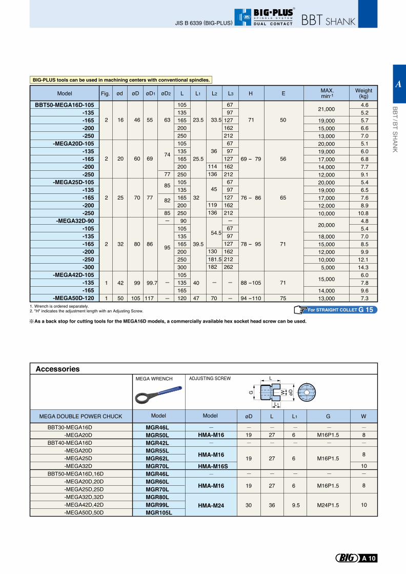
1. Wrench is ordered separately.2. "H" indicates the adjustment length with an Adjusting Screw.
BBT50-MEGA16D-105-135-165-200-250
-MEGA20D-105-135-165-200-250
-MEGA25D-105-135-165-200-250
-MEGA32D-90-105-135-165-200-250-300
-MEGA42D-105-135-165
-MEGA50D-120
10513516520025010513516520025010513516520025090
105135165200250300105135165120
67 97127162212 67 97127162212 67 97127162212 67 97127162212262
4.65.25.76.67.05.16.06.87.79.15.46.57.68.9
10.84.85.47.08.59.9
12.114.36.07.89.67.3
16
20
25
2
2
2
55
69
77
7163
74
77
85
85
82
46
60
70
50
56
65
33.5
36
45
23.5
25.5
32
114136
119136
130181.5182
Model
32
42
50
2
1
1
86
99.7
117
9580
99
105
71
71
75
54.5
70
39.5
40
47
21,000
19,00015,00013,00020,00019,00017,00014,00012,00020,00019,00017,00012,00010,000
20,000
18,00015,00012,00010,0005,000
15,000
14,00013,000
Fig. LøD1 øD2øDød L1 L2 L3 Weight(kg)H E
69 - 79
76 - 86
78 - 95
88 -105
94 -110
L
L1
øDWG
MGR46L MGR50L MGR42L MGR55L MGR62L MGR70L MGR46L MGR60L
MGR70L MGR80L MGR99L MGR105L
AccessoriesMEGA WRENCH
Model
HMA-M16
HMA-M16
HMA-M16S
HMA-M16
HMA-M24
ModelMEGA DOUBLE POWER CHUCK
BBT30-MEGA16D -MEGA20DBBT40-MEGA16D -MEGA20D -MEGA25D -MEGA32DBBT50-MEGA16D,16D -MEGA20D,20D -MEGA25D,25D -MEGA32D,32D -MEGA42D,42D -MEGA50D,50D
19
19
19
30
27
27
27
36
6
6
6
9.5
M16P1.5
M16P1.5
M16P1.5
M24P1.5
8
8
10
8
10
øD L L1 G W
ADJUSTING SCREW
As a back stop for cutting tools for the MEGA16D models, a commercially available hex socket head screw can be used.
BIG-PLUS tools can be used in machining centers with conventional spindles.
For STRAIGHT COLLET G 15
MAX.min-1
JIS B 6339 (BIG-PLUS)
BBT / BT SHAN
K
A
A 10
R
S P I N D L E S Y S T E M
D U A L C O N T A C T
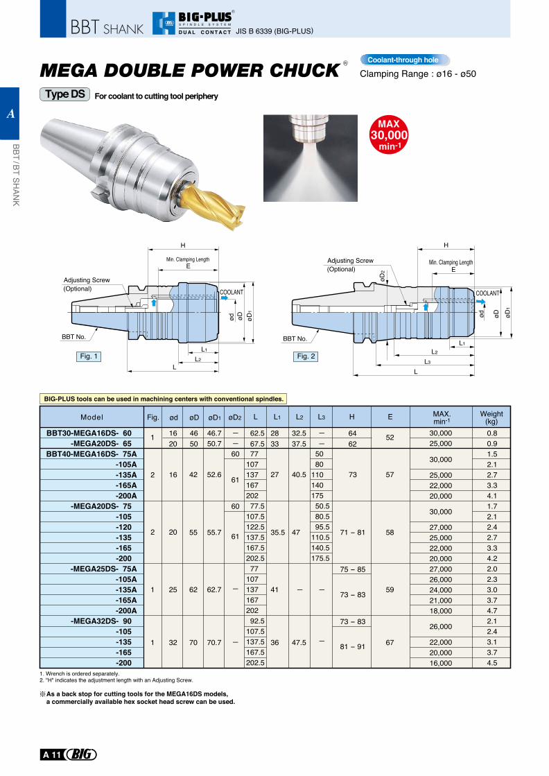
Clamping Range : ø16 - ø50
For coolant to cutting tool periphery
L1
L2
L1
L2
LL
L3
BBT30-MEGA16DS- 60 -MEGA20DS- 65
BBT40-MEGA16DS- 75A-105A-135A-165A-200A
-MEGA20DS- 75 -105 -120 -135 -165 -200
-MEGA25DS- 75A-105A-135A-165A-200A
-MEGA32DS- 90 -105 -135 -165 -200
77 107 137 167 202 77.5
107.5122.5137.5167.5202.5
77 107 137 167 202 92.5
107.5137.5167.5202.5
50 80
110 140 175 50.580.595.5
110.5140.5175.5
0.80.91.52.12.73.34.11.72.12.42.73.34.22.02.33.03.74.72.12.43.13.74.5
H
16
1620
4650
46.750.7
32.537.5
2833
62.567.5
6462
52
20
25
32
2
1
2
1
1
52.6
55.7
62.7
70.7
73
71 - 81
73 - 83
81 - 91
61
61
60
60
42
55
62
70
57
58
59
67
40.5
47
47.5
27
35.5
41
36
75 - 85
73 - 83
30,000
25,00022,00020,000
30,000
27,00025,00022,00020,00027,00026,00024,00021,00018,000
26,000
22,00020,00016,000
30,00025,000
øDød øD1
øD2
øD1
øDød
E
H
E
H
Adjusting Screw(Optional)
Adjusting Screw(Optional)
COOLANTCOOLANT
Fig. LøD1 øD2 øD ød L1 L2 L3Model E
Min. Clamping Length Min. Clamping Length
MAX.min-1
Weight(kg)
Fig. 1 Fig. 2
Coolant-through hole
BBT No. BBT No.
R
BIG-PLUS tools can be used in machining centers with conventional spindles.
Type DS
1. Wrench is ordered separately.2. "H" indicates the adjustment length with an Adjusting Screw.
As a back stop for cutting tools for the MEGA16DS models, a commercially available hex socket head screw can be used.
JIS B 6339 (BIG-PLUS)
BBT / BT SHAN
K
A
A 11
R
S P I N D L E S Y S T E M
D U A L C O N T A C T
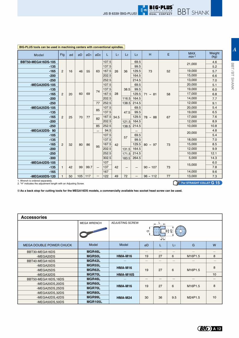
-MEGA25DS-105-135-165-200-250
-MEGA32DS- 90-105-135-165-200-250-300
-MEGA42DS-105-135-165
-MEGA50DS-120
107.5137.5167.5202.5252.594.5
107.5137.5167.5202.5252.5302.5107 137 167 122
69.599.5
129.5164.5214.5
69.599.5
129.5164.5214.5264.5
5.46.57.68.9
10.84.85.47.08.59.9
12.114.36.07.89.67.3
25
32
42
50
2
2
1
1
70
80
99
105
67
73
73
77
78 - 88
80 - 97
90 - 107
96 - 112
85
85
82
95 42
42
49
47.5
57
72
77
86
99.7
117
BBT50-MEGA16DS-105-135-165-200-250
-MEGA20DS-105-135-165-200-250
107.5137.5167.5202.5252.5107.5137.5167.5202.5252.5
69.599.5
129.5164.5214.569.599.5
129.5164.5214.5
20,00019,00017,00012,00010,000
20,000
18,00015,00012,00010,0005,000
15,000
14,00013,000
21,000
19,00015,00013,00020,00019,00017,00014,00012,000
4.65.25.76.67.05.16.06.87.79.1
16
20
2
2
46
60
52
58
73
71 - 81
63
74
77
26
28
34.5
36
38.5
116.5138.5
121.5138.5
131.5171.5183.5
55
69
Fig LøD1 øD2 øD ød L1 L2 L3 Weight(kg)Model H E
L
L1
øDWG
MGR46L MGR50L MGR42L MGR55L MGR62L MGR70L MGR46L MGR60L MGR70L MGR80L MGR99L MGR105L
AccessoriesMEGA WRENCH
Model
HMA-M16
HMA-M16
HMA-M16S
HMA-M16
HMA-M24
ModelMEGA DOUBLE POWER CHUCK
BBT30-MEGA16DS -MEGA20DSBBT40-MEGA16DS -MEGA20DS -MEGA25DS -MEGA32DSBBT50-MEGA16DS,16DS -MEGA20DS,20DS -MEGA25DS,25DS -MEGA32DS,32DS -MEGA42DS,42DS -MEGA50DS,50DS
6
6
6
9.5
M16P1.5
M16P1.5
M16P1.5
M24P1.5
8
8
10
8
10
L1 G W
ADJUSTING SCREW
1. Wrench is ordered separately.2. "H" indicates the adjustment length with an Adjusting Screw.
As a back stop for cutting tools for the MEGA16DS models, a commercially available hex socket head screw can be used.
BIG-PLUS tools can be used in machining centers with conventional spindles.
For STRAIGHT COLLET G 15
MAX.min-1
19
19
19
30
øD
27
27
27
36
L
JIS B 6339 (BIG-PLUS)
BBT / BT SHAN
K
A
A 12
R
S P I N D L E S Y S T E M
D U A L C O N T A C T
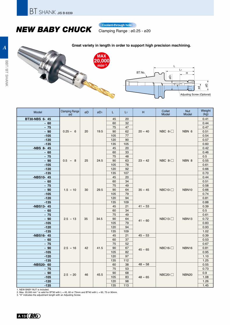
Clamping Range : ø0.25 - ø20
øD1
ød
øD
Adjusting Screw (Optional)
BT No.
LL1
H
1. NEW BABY NUT is included.2. Max. 20,000 min-1 is valid for BT30 with L = 45, 60 or 75mm and BT40 with L = 60, 75 or 90mm.3. "H" indicates the adjustment length with an Adjusting Screw.
BT30-NBS 6- 45 - 60- 75- 90-105-120-135
-NBS 8- 45- 60- 75- 90-105-120-135
-NBS10- 45- 60- 75- 90-105-120-135
-NBS13- 45- 60- 75- 90-105-120-135
-NBS16- 45- 60- 75- 90-105-120-135
-NBS20- 60- 75- 90-105-120-135
2.5 - 13
1.5 - 10
0.5 - 8
0.25 - 6
2.5 - 16
2.5 - 20
35 - 45
23 - 42
20 - 40
41 - 60
48 - 65
48 - 58
45 - 65
45 - 53
0.41 0.44 0.47 0.51 0.54 0.57 0.60 0.42 0.46 0.5 0.55 0.61 0.66 0.70 0.44 0.51 0.58 0.66 0.74 0.81 0.88 0.39 0.5 0.61 0.72 0.83 0.93 1.02 0.39 0.53 0.67 0.81 0.95 1.10 1.25 0.55 0.73 0.9 1.08 1.26 1.45
41 - 53
45607590
10512013545607590
10512013545607590
10512013545607590
10512013545607590
105120135607590
105120135
30
25
20
42
46
19.5
29.5
24.5
41.5
45.5
35 34.5
203247627790
105203348637892
107203449647994
109213449647994
109213752678297
1123853688398
113
Model øD øD1 L H Weight(kg)L1
Great variety in length in order to support high precision machining.
Coolant-through hole
ColletModel
NutModel
NBN 6
NBN 8
NBN10
NBN13
NBN16
NBN20
Clamping Range ød
NBC 6-
NBC 8-
NBC10-
NBC13-
NBC16-
NBC20-
BBT / BT SHAN
K
A
A 13
JIS B 6339
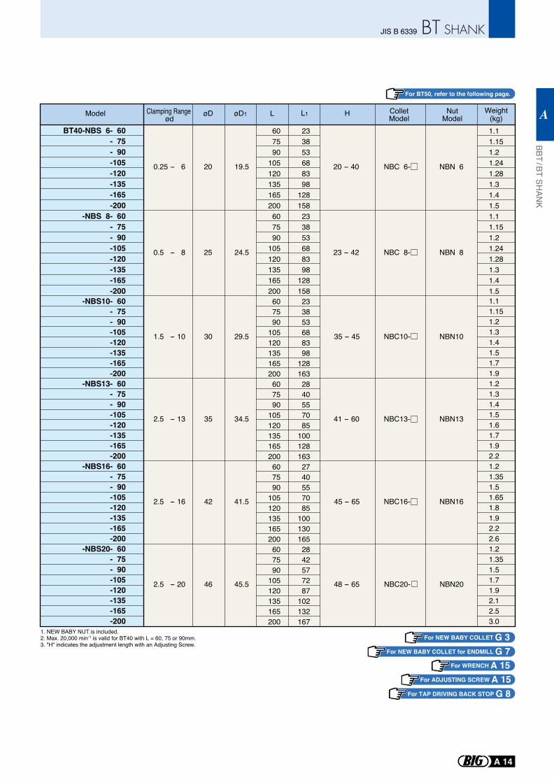
1. NEW BABY NUT is included.2. Max. 20,000 min-1 is valid for BT40 with L = 60, 75 or 90mm.3. "H" indicates the adjustment length with an Adjusting Screw.
BT40-NBS 6- 60- 75- 90-105-120-135-165-200
-NBS 8- 60- 75- 90-105-120-135-165-200
-NBS10- 60- 75- 90-105-120-135-165-200
-NBS13- 60- 75- 90-105-120-135-165-200
-NBS16- 60- 75- 90-105-120-135-165-200
-NBS20- 60- 75- 90-105-120-135-165-200
1.1 1.151.21.241.281.31.41.51.11.151.21.241.281.31.41.51.11.151.21.31.41.51.71.91.21.31.41.51.61.71.92.21.21.351.51.651.81.92.22.61.21.351.51.71.92.12.53.0
0.5 - 8 25 24.5
0.25 - 6 20 19.5
23 - 42
20 - 40
607590
105120135165200607590
105120135165200607590
105120135165200607590
105120135165200607590
105120135165200607590
105120135165200
233853688398
128158233853688398
128158233853688398
1281632840557085
1001281632740557085
1001301652842577287
102132167
2.5 - 20 46 45.5 48 - 65
2.5 - 16 42 41.5 45 - 65
2.5 - 13 35 34.5 41 - 60
1.5 - 10 30 29.5 35 - 45
Model
For ADJUSTING SCREW A 15For WRENCH A 15
For NEW BABY COLLET G 3For NEW BABY COLLET for ENDMILL G 7
For BT50, refer to the following page.
ColletModel
NutModeløD øD1 L H Weight
(kg)L1Clamping Range
ød
NBN 6
NBN 8
NBN10
NBN13
NBN16
NBN20
NBC 6-
NBC 8-
NBC10-
NBC13-
NBC16-
NBC20-
For TAP DRIVING BACK STOP G 8
BBT / BT SHAN
K
A
A 14
JIS B 6339
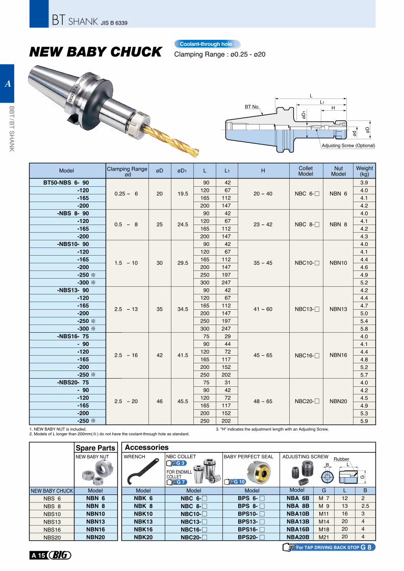
Clamping Range : ø0.25 - ø20
1. NEW BABY NUT is included.2. Models of L longer than 200mm( ) do not have the coolant-through hole as standard.
BT50-NBS 6- 90-120-165-200
-NBS 8- 90-120-165-200
-NBS10- 90-120-165-200-250-300
-NBS13- 90-120-165-200-250-300
-NBS16- 75- 90-120-165-200-250
-NBS20- 75- 90-120-165-200-250
0.25 - 6
0.5 - 8
20
25
19.5
24.5
20 - 40
23 - 42
2.5 - 20 46 45.5 48 - 65
2.5 - 16 42 41.5 45 - 65
1.5 - 10 30 29.5 35 - 45
2.5 - 13 35 34.5 41 - 60
3.94.04.14.24.04.14.24.34.04.14.44.64.95.24.24.44.75.05.45.84.04.14.44.85.25.74.04.24.54.95.35.9
9012016520090
12016520090
12016520025030090
1201652002503007590
1201652002507590
120165200250
4267
1121474267
1121474267
1121471972474267
112147197247294472
117152202314272
117152202
NBS 6NBS 8NBS10NBS13NBS16NBS20
NBN 6NBN 8NBN10NBN13NBN16NBN20
NEW BABY CHUCK
NEW BABY NUT
Model
Spare Parts
NBK 6NBK 8NBK10NBK13NBK16NBK20
BPS 6-BPS 8-BPS10-BPS13-BPS16-BPS20-
NBC 6-NBC 8-NBC10-NBC13-NBC16-NBC20-
WRENCH
Model Model Model
Accessories
NBA 6BNBA 8BNBA10BNBA13BNBA16BNBA20B
M 7M 9M11M14M18M21
121316202020
22.53444
ADJUSTING SCREW
G L B
BRubber
L
G
Model
BABY PERFECT SEAL
3. "H" indicates the adjustment length with an Adjusting Screw.
For TAP DRIVING BACK STOP G 8
Coolant-through hole
G 3NBC COLLET
G 7
FOR ENDMILLCOLLET
ColletModel
NutModel
øD1
ød øD
Adjusting Screw (Optional)
BT No.
LL1
H
Model øD øD1 L H Weight(kg)L1
NBN 6
NBN 8
NBN10
NBN13
NBN16
NBN20
Clamping Range ød
NBC 6-
NBC 8-
NBC10-
NBC13-
NBC16-
NBC20-
G 10
BBT / BT SHAN
K
A
A 15
JIS B 6339
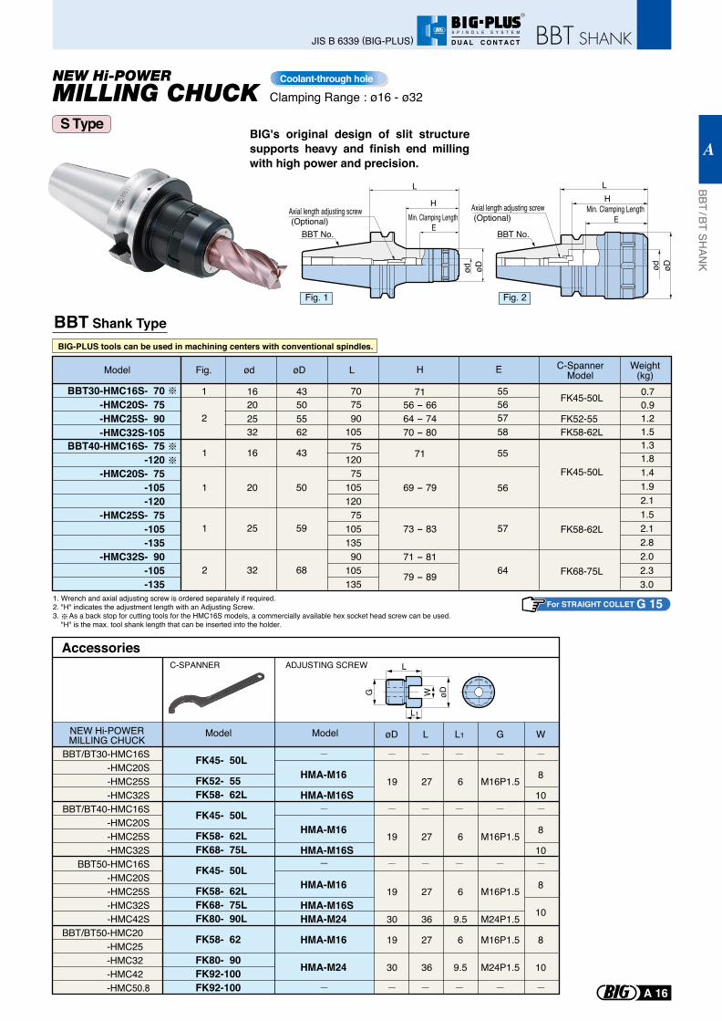
BIG's original design of slit structure supports heavy and finish end milling with high power and precision.
Clamping Range : ø16 - ø32
BBT Shank Type
1. Wrench and axial adjusting screw is ordered separately if required.2. "H" indicates the adjustment length with an Adjusting Screw.3. As a back stop for cutting tools for the HMC16S models, a commercially available hex socket head screw can be used. "H" is the max. tool shank length that can be inserted into the holder.
Coolant-through hole
Model Fig. ød L H C-SpannerModel
Weight(kg)EøD
707590
10575
12075
10512075
10513590
105135
FK45-50L
FK52-55FK58-62L
FK45-50L
FK58-62L
FK68-75L
0.70.91.21.51.31.81.41.92.11.52.12.82.02.33.0
43505562
16202532
1
2
55565758
55
56
57
64
43
50
59
68
16
20
25
32
1
1
1
2
BBT30-HMC16S- 70-HMC20S- 75-HMC25S- 90-HMC32S-105
BBT40-HMC16S- 75-120
-HMC20S- 75-105-120
-HMC25S- 75-105-135
-HMC32S- 90-105-135
7156 - 6664 - 7470 - 80
71
69 - 79
73 - 83
71 - 81
79 - 89
BIG-PLUS tools can be used in machining centers with conventional spindles.
S Type
ød øD
HMin. Clamping Length
E
L
Axial length adjusting screw (Optional)
BBT No.
Axial length adjusting screw (Optional)
øDød
HMin. Clamping Length
E
L
BBT No.
Fig. 1 Fig. 2
For STRAIGHT COLLET G 15
L
L1
øDWG
ADJUSTING SCREW
FK45- 50L
FK52- 55FK58- 62L
FK45- 50L
FK58- 62LFK68- 75L
FK45- 50L
FK58- 62LFK68- 75LFK80- 90L
FK58- 62
FK80- 90FK92-100FK92-100
AccessoriesC-SPANNER
Model
HMA-M16
HMA-M16S
HMA-M16
HMA-M16S
HMA-M16
HMA-M16SHMA-M24
HMA-M16
HMA-M24
19
19
19
30
19
30
27
27
27
36
27
36
M16P1.5
M16P1.5
M16P1.5
M24P1.5
M16P1.5
M24P1.5
6
6
6
9.5
6
9.5
8
10
8
10
8
10
8
10
Model øD L L1 G W
BBT/BT30-HMC16S-HMC20S-HMC25S-HMC32S
BBT/BT40-HMC16S-HMC20S-HMC25S-HMC32S
BBT50-HMC16S-HMC20S-HMC25S-HMC32S-HMC42S
BBT/BT50-HMC20 -HMC25 -HMC32 -HMC42 -HMC50.8
NEW Hi-POWERMILLING CHUCK
BBT / BT SHAN
K
A
A 16
JIS B 6339 (BIG-PLUS)
R
S P I N D L E S Y S T E M
D U A L C O N T A C T
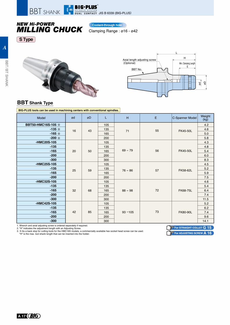
Clamping Range : ø16 - ø42Coolant-through hole
BBT Shank Type
ød øD
H
Min. Clamping Length E
L
Axial length adjusting screw (Optional)
BBT No.
S Type
Model ød L H C-Spanner Model Weight(kg)EøD
105135165200105135165200300105135165200105135165200300105135165200300
FK45-50L
FK45-50L
FK58-62L
FK68-75L
FK80-90L
4.24.65.05.84.34.85.46.08.34.55.25.97.54.65.46.47.4
11.55.26.27.49.6
14.1
43
50
59
68
85
16
20
25
32
42
55
56
57
72
73
BBT50-HMC16S-105-135-165-200
-HMC20S-105-135-165-200-300
-HMC25S-105-135-165-200
-HMC32S-105-135-165-200-300
-HMC42S-105-135-165-200-300
71
69 - 79
76 - 86
88 - 98
93 -105
BIG-PLUS tools can be used in machining centers with conventional spindles.
1. Wrench and axial adjusting screw is ordered separately if required.2. "H" indicates the adjustment length with an Adjusting Screw.3. As a back stop for cutting tools for the HMC16S models, a commercially available hex socket head screw can be used. "H" is the max. tool shank length that can be inserted into the holder.
For STRAIGHT COLLET G 15For ADJUSTING SCREW A 16
JIS B 6339 (BIG-PLUS)
BBT / BT SHAN
K
A
A 17
R
S P I N D L E S Y S T E M
D U A L C O N T A C T
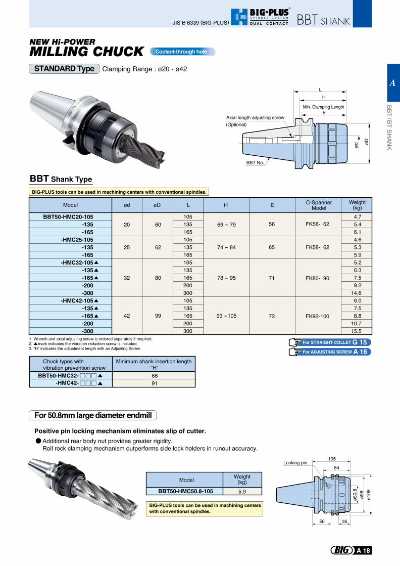
Clamping Range : ø20 - ø42
(Optional)Axial length adjusting screw
H
ød øD
L
BBT Shank Type
1. Wrench and axial adjusting screw is ordered separately if required.2. mark indicates the vibration reduction screw is included.3. "H" indicates the adjustment length with an Adjusting Screw.
62
80
99
74 - 84
78 - 95
93 -105
60 69 - 7920
25
32
42
105135165105135165105135165200300105135165200300
FK58- 62
FK58- 62
FK80- 90
FK92-100
4.7 5.4 6.1 4.6 5.3 5.9 5.2 6.3 7.5 9.2
14.6 6.0 7.5 8.8
10.7 15.5
BBT50-HMC20-105-135-165
-HMC25-105-135-165
-HMC32-105-135-165-200-300
-HMC42-105-135-165-200-300
Weight(kg)Model ød LøD H
Coolant-through hole
BBT50-HMC32--HMC42-
8891
Chuck types with vibration prevention screw
Minimum shank insertion length “H”
C-SpannerModelE
Min. Clamping Length E
56
65
71
73
BBT No.
STANDARD Type
For 50.8mm large diameter endmill
BIG-PLUS tools can be used in machining centers with conventional spindles.
For STRAIGHT COLLET G 15For ADJUSTING SCREW A 16
Positive pin locking mechanism eliminates slip of cutter.
ø50.
8ø9
8ø1
08
50 35
105
84Locking pin
BIG-PLUS tools can be used in machining centers with conventional spindles.
BBT50-HMC50.8-105
Model Weight(kg)5.9
Additional rear body nut provides greater rigidity.Roll rock clamping mechanism outperforms side lock holders in runout accuracy.
BBT / BT SHAN
K
A
A 18
JIS B 6339 (BIG-PLUS)
R
S P I N D L E S Y S T E M
D U A L C O N T A C T
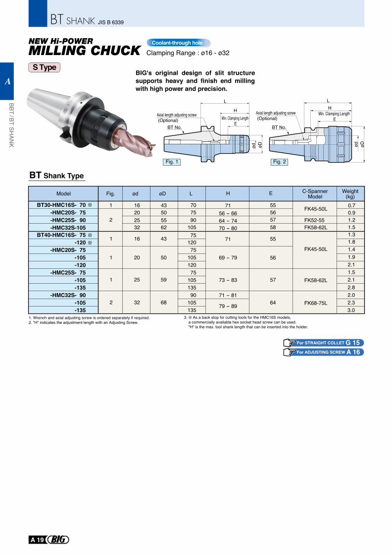
BIG's original design of slit structure supports heavy and finish end milling with high power and precision.
Clamping Range : ø16 - ø32
BT Shank Type
1. Wrench and axial adjusting screw is ordered separately if required.2. "H" indicates the adjustment length with an Adjusting Screw.
Coolant-through hole
3. As a back stop for cutting tools for the HMC16S models, a commercially available hex socket head screw can be used. "H" is the max. tool shank length that can be inserted into the holder.
Model Fig. ød L H C-SpannerModel
Weight(kg)EøD
707590
10575
12075
10512075
10513590
105135
FK45-50L
FK52-55FK58-62L
FK45-50L
FK58-62L
FK68-75L
0.70.91.21.51.31.81.41.92.11.52.12.82.02.33.0
43505562
16202532
1
2
55565758
55
56
57
64
43
50
59
68
16
20
25
32
1
1
1
2
BT30-HMC16S- 70-HMC20S- 75-HMC25S- 90-HMC32S-105
BT40-HMC16S- 75-120
-HMC20S- 75-105-120
-HMC25S- 75-105-135
-HMC32S- 90-105-135
7156 - 6664 - 7470 - 80
71
69 - 79
73 - 83
71 - 81
79 - 89
S Type
ød øD
HMin. Clamping Length
E
L
Axial length adjusting screw (Optional)
BT No.
Axial length adjusting screw (Optional)
øDød
HMin. Clamping Length
E
L
BT No.
Fig. 1 Fig. 2
For STRAIGHT COLLET G 15For ADJUSTING SCREW A 16
BBT / BT SHAN
K
A
A 19
JIS B 6339
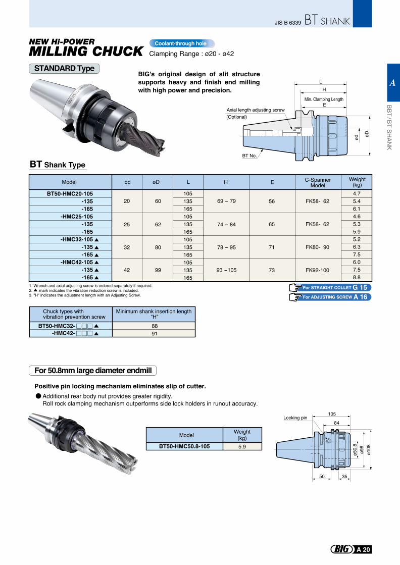
For STRAIGHT COLLET G 15For ADJUSTING SCREW A 16
BT No.
BIG's original design of slit structure supports heavy and finish end milling with high power and precision.
Clamping Range : ø20 - ø42
(Optional)Axial length adjusting screw
H
ød øD
L
BT Shank Type
62
80
99
74 - 84
78 - 95
93 -105
60 69 - 7920
25
32
42
105135165105135165105135165105135165
FK58- 62
FK58- 62
FK80- 90
FK92-100
4.75.46.14.65.35.95.26.37.56.07.58.8
BT50-HMC20-105-135-165
-HMC25-105-135-165
-HMC32-105-135-165
-HMC42-105-135-165
Weight(kg)Model ød LøD H
Coolant-through hole
BT50-HMC32--HMC42-
8891
Chuck types with vibration prevention screw
Minimum shank insertion length “H”
E
Min. Clamping Length E
56
65
71
73
C-SpannerModel
1. Wrench and axial adjusting screw is ordered separately if required.2. mark indicates the vibration reduction screw is included.3. "H" indicates the adjustment length with an Adjusting Screw.
ø50.
8ø9
8ø1
08
50 35
105
84Locking pin
BT50-HMC50.8-105
Model Weight(kg)5.9
STANDARD Type
For 50.8mm large diameter endmill
Positive pin locking mechanism eliminates slip of cutter.Additional rear body nut provides greater rigidity.Roll rock clamping mechanism outperforms side lock holders in runout accuracy.
BBT / BT SHAN
K
A
A 20
JIS B 6339
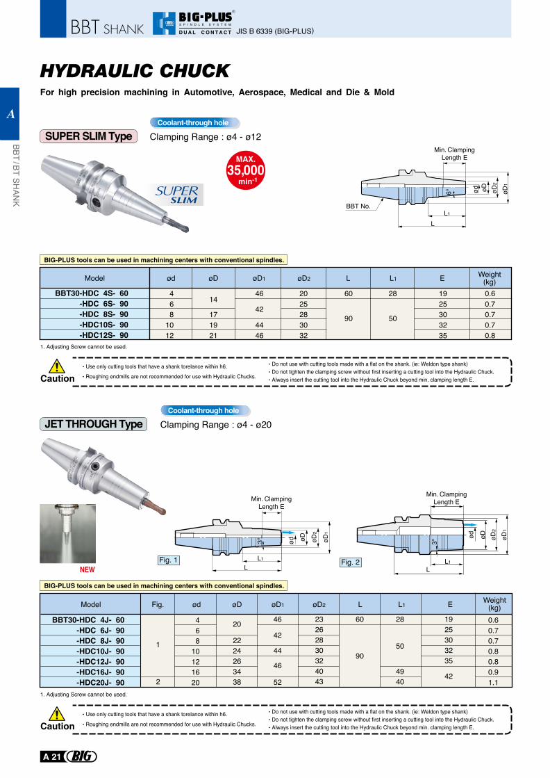
SUPER SLIM Type
HYDRAULIC CHUCKFor high precision machining in Automotive, Aerospace, Medical and Die & Mold
BIG-PLUS tools can be used in machining centers with conventional spindles.
BIG-PLUS tools can be used in machining centers with conventional spindles.
JET THROUGH Type Clamping Range : ø4 - ø20Coolant-through hole
Clamping Range : ø4 - ø12Coolant-through hole
CautionUse only cutting tools that have a shank torelance within h6.
Roughing endmills are not recommended for use with Hydraulic Chucks.
Do not use with cutting tools made with a flat on the shank. (ie: Weldon type shank)Do not tighten the clamping screw without first inserting a cutting tool into the Hydraulic Chuck.Always insert the cutting tool into the Hydraulic Chuck beyond min. clamping length E.
LL1
ød øD øD2
Min. ClampingLength E
6° øD1
BBT No.
BBT30-HDC 4S- 60-HDC 6S- 90-HDC 8S- 90
-HDC10S- 90-HDC12S- 90
2025283032
46
4446
0.60.70.70.70.8
9042
50
60 28468
1012
14
171921
1925303235
Model ød øD øD2øD1 L L1 Weight(kg)E
1. Adjusting Screw cannot be used.
CautionUse only cutting tools that have a shank torelance within h6.
Roughing endmills are not recommended for use with Hydraulic Chucks.
Do not use with cutting tools made with a flat on the shank. (ie: Weldon type shank)Do not tighten the clamping screw without first inserting a cutting tool into the Hydraulic Chuck.Always insert the cutting tool into the Hydraulic Chuck beyond min. clamping length E.
1. Adjusting Screw cannot be used.
SLIMSUPER
MAX.35,000
min-1
JIS B 6339 (BIG-PLUS)
BBT / BT SHAN
K
A
A 21
R
S P I N D L E S Y S T E M
D U A L C O N T A C T
Model ød øDFig. øD1 øD2 L L1Weight
(kg)E
468
10121620
20 46 60
901
2
28
50
4940
23262830324043
1925303235
42
0.60.70.70.80.80.91.1
42
46
52
442224263438
BBT30-HDC 4J- 60-HDC 6J- 90
-HDC 8J- 90-HDC10J- 90-HDC12J- 90-HDC16J- 90-HDC20J- 90
Fig. 1L
L1
ød øD øD2
øD1
3°
Min. ClampingLength E
NEWFig. 2
øD2
øDød
L1L
Min. ClampingLength E
øD1
3°
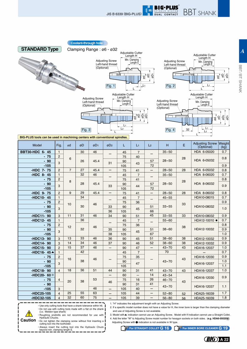
STANDARD Type Clamping Range : ø6 - ø32Coolant-through hole
BIG-PLUS tools can be used in machining centers with conventional spindles.
Fig. 1L
ød øD øD1
L1
Adjustable CutterLength HMin. Clamping
Length EAdjusting ScrewLeft-hand thread(Optional)
Fig. 2L
ød øD øD1
L1
Adjustable CutterLength HMin. Clamping
Length EAdjusting ScrewLeft-hand thread(Optional)
Fig. 4
Adjustable CutterLength HMin. Clamping
Length E
øD øD1
L32
øD2
L2L1
Adjusting ScrewLeft-hand thread(Optional)
ød
Fig. 3ød øD øD
1
L
øD2
L2L1
Adjustable CutterLength HMin. Clamping
Length E
Adjusting ScrewLeft-hand thread(Optional)
Use only cutting tools that have a shank tolerance within h6.Do not use with cutting tools made with a flat on the shank (i.e.: Weldon type shank)Roughing endmills are not recommended for use with Hydraulic Chucks.Do not tighten the clamping screw without first inserting a cutting tool into the toolholder.Always insert the cutting tool into the Hydraulic Chuck beyond min. clamping length E.
Caution
1. "H" indicates the adjustment length with an Adjusting Screw.2. If a specific model number does not have a value for H, the inner bore is larger than the clamping diameter and use of Adjusting Screw is not available.3. Model with indication cannot use an Adjusting Screw. Model with indication cannot use a Straight Collet. 4. Add the letter "W" to Adjusting Screw model number for hexagon sockets on both sides. (e.g. HDA6-05020W) Adjusting Screw with indication is not available in W type.
For STRAIGHT COLLET G 16 For INNER BORE CLEANER G 19
BBT / BT SHAN
K
A
A 22
JIS B 6339 (BIG-PLUS)
R
S P I N D L E S Y S T E M
D U A L C O N T A C T
7
8
9
10
11
12
131415
16
18
20
2532
28-50
28-50
28-50
35-50
33-55
33-55
45-55
38-60
38-6038-6043-70
55-60
43-7043-5446-70
43-70
52-8056-80
43-70
70
28
28
28
33
33
38
383843
43
43
5256
43
HDA 6-05032HDA 8-06020
HDA 8-06032
HDA 8-06032HDA10-08015
HDA10-08032
HDA10-08032HDA12-10010
HDA12-10032
HDA16-12030
HDA16-12037
HDA25-16039HDA25-16039
HDA12-10032HDA12-10032HDA16-12037
-HDA16-12030
HDA16-12037
HDA16-12037
417
41
44
417
36
45
517
36
45
4546477
35
47
31-1631404439
2732
28
2934
30
3136
32
33343742
38
36
38
5560
45.446
45.4
45.4
46
46
46
464646
46
51
53
466375
3
212
3
212
3
312
344
33212
3
4
4
-
-
-
-
45
-
5152-
-
41142641---
-
33
-
-
-
-
46
333634
---
35383637-
-
44-
5772
5166
5167
BBT30-HDC 6- 45- 75- 90-105
-HDC 7- 75-HDC 8- 45
- 75- 90-105
-HDC 9- 75-HDC10- 45
- 75- 90-105
-HDC11- 90-HDC12- 45
- 75- 90-105
-HDC13- 90-HDC14- 90-HDC15- 90-HDC16- 45
- 75- 90-105
-HDC18- 90-HDC20- 60
- 75- 90-105
-HDC25-105-HDC32-105
6 28-50
35-50
28 HDA 6-05032
HDA 6-05020457590
10575457590
10575457590
10590457590
105909090457590
10590607590
105105105
740
430.8
0.90.80.70.8
0.9
0.80.70.9
1.0
0.90.70.80.91.00.90.91.00.70.91.01.11.0
0.9
1.1
1.71.8
30
26
46
45.4
12
3
-
Model ødFig. øD øD1 øD2 L L1 L2Adjusting Screw
(Optional)H E
-
31
Weight(kg)0.7
5772
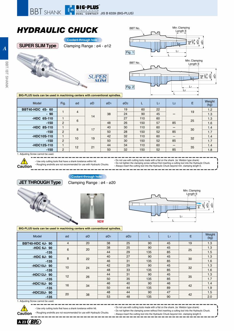
SLIMSUPER
SUPER SLIM Type
HYDRAULIC CHUCK
BIG-PLUS tools can be used in machining centers with conventional spindles.
BIG-PLUS tools can be used in machining centers with conventional spindles.
Fig. 1 L1
L
øD2
ød øD øD1
Min. ClampingLength E
6°
BBT No.
Fig. 2
L
Min. ClampingLength E
L2
6°
L1
øD2
ød øD øD1
BBT No.
1. Adjusting Screw cannot be used.
CautionUse only cutting tools that have a shank torelance within h6.Roughing endmills are not recommended for use with Hydraulic Chucks.
Do not use with cutting tools made with a flat on the shank. (ie: Weldon type shank)Do not tighten the clamping screw without first inserting a cutting tool into the Hydraulic Chuck.Always insert the cutting tool into the Hydraulic Chuck beyond min. clamping length E.
1. Adjusting Screw cannot be used.
CautionUse only cutting tools that have a shank torelance within h6.
Roughing endmills are not recommended for use with Hydraulic Chucks.
Do not use with cutting tools made with a flat on the shank. (ie: Weldon type shank)Do not tighten the clamping screw without first inserting a cutting tool into the Hydraulic Chuck.Always insert the cutting tool into the Hydraulic Chuck beyond min. clamping length E.
BBT40-HDC 4S- 60- 90
-HDC 6S-110-150
-HDC 8S-110-150
-HDC10S-110-150
-HDC12S-110-150
Weight(kg)E
19242726302832303432
38
48405042504450
1.21.31.31.61.41.71.41.71.41.8
1
12121212
4
6
8
10
12
14
17
19
21
19
25
30
32
35
6090
110150110150110150110150
22456057605260526052
-
85-85-85-85
Model ødFig. øD øD2øD1 L L1 L2
Clamping Range : ø4 - ø12Coolant-through hole
JET THROUGH Type Clamping Range : ø4 - ø20Coolant-through hole
JIS B 6339 (BIG-PLUS)
BBT / BT SHAN
K
A
A 23
R
S P I N D L E S Y S T E M
D U A L C O N T A C T
NEW LL1
øD2
ød øD
Min. ClampingLength E
øD1
3°
Model ød øD øD1 øD2 L L1Weight
(kg)E
4
6
8
10
12
16
20
9090
13590
13590
13590
13590
13590
135
45458545854585458546894790
19 1.31.31.51.31.61.31.61.31.71.41.91.52.0
38384440464248445046504853
25252927312933313540444448
20
20
22
24
26
34
38
BBT40-HDC 4J- 90-HDC 6J- 90
-135-HDC 8J- 90
-135-HDC10J- 90
-135-HDC12J- 90
-135-HDC16J- 90
-135-HDC20J- 90
-135
25
30
32
35
42
42
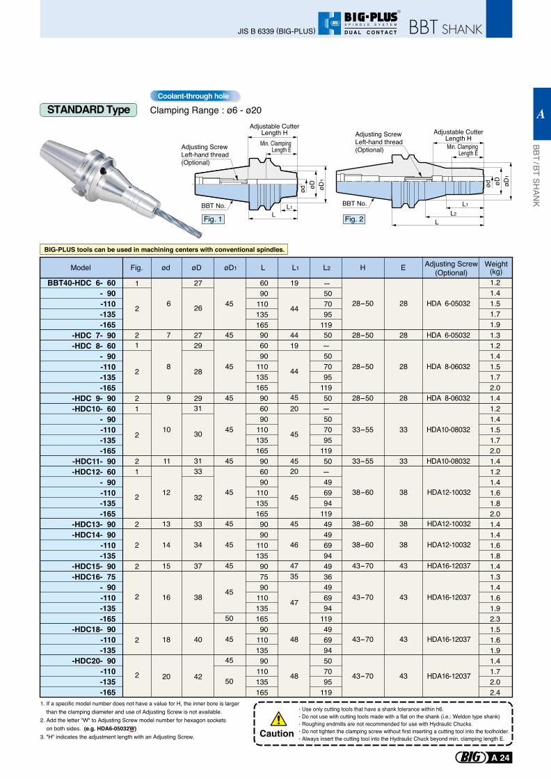
BBT40-HDC 6- 60- 90-110-135-165
-HDC 7- 90-HDC 8- 60
- 90-110-135-165
-HDC 9- 90-HDC10- 60
- 90-110-135-165
-HDC11- 90-HDC12- 60
- 90-110-135-165
-HDC13- 90-HDC14- 90
-110-135
-HDC15- 90-HDC16- 75
- 90-110-135-165
-HDC18- 90-110-135
-HDC20- 90-110-135-165
6 28-50 28 HDA 6-0503245
6090
110135165
19
44
1.21.41.51.71.9
1
2
-
26
27
Model ødFig. øD øD1 L L1 L2 Weight(kg)
Adjusting Screw(Optional)H E
507095
119
38-60
38-60
38-60
43-70
43-70
43-70
43-70
38
38
38
43
43
43
43
HDA12-10032
HDA12-10032
HDA12-10032
HDA16-12037
HDA16-12037
HDA16-12037
HDA16-12037
45
45
45
45
45
50
45
45
50
20
45
45
46
4735
47
48
48
1
2 12
13
14
15
2
2
2
34
33
32
33
37
7
8
9
10
11
28-50
28-50
28-50
33-55
33-55
28
28
28
33
33
HDA 6-05032
HDA 8-06032
HDA 8-06032
HDA10-08032
HDA10-08032
45
45
45
45
45 906090
110135165906090
110135165906090
1101351659090
110135907590
11013516590
11013590
110135165
4419
44
4520
45
45
1.31.21.41.51.72.01.41.21.41.51.72.01.41.21.41.61.82.01.41.41.61.81.41.31.41.61.92.31.51.61.91.41.72.02.4
2
2
1
1
2
2
2
27
29
31
29
28
31
30
50- 507095
11950- 507095
11950- 496994
119494969944936496994
119496994507095
119
16
18
20
2
2
2 38
40
42
STANDARD Type Clamping Range : ø6 - ø20Coolant-through hole
BIG-PLUS tools can be used in machining centers with conventional spindles.
Adjustable CutterLength HMin. Clamping
Length EAdjusting ScrewLeft-hand thread(Optional)
L
ød øD øD1
L1
Fig. 1
BBT No.L2
L1
L
Adjustable CutterLength HMin. Clamping
Length E
Adjusting ScrewLeft-hand thread(Optional)
ød øD øD1
Fig. 2
BBT No.
1. If a specific model number does not have a value for H, the inner bore is larger than the clamping diameter and use of Adjusting Screw is not available.2. Add the letter "W" to Adjusting Screw model number for hexagon sockets on both sides. (e.g. HDA6-05032W)3. "H" indicates the adjustment length with an Adjusting Screw.
Use only cutting tools that have a shank tolerance within h6.Do not use with cutting tools made with a flat on the shank (i.e.: Weldon type shank)Roughing endmills are not recommended for use with Hydraulic Chucks.Do not tighten the clamping screw without first inserting a cutting tool into the toolholder.Always insert the cutting tool into the Hydraulic Chuck beyond min. clamping length E.
Caution
BBT / BT SHAN
K
A
A 24
JIS B 6339 (BIG-PLUS)
R
S P I N D L E S Y S T E M
D U A L C O N T A C T
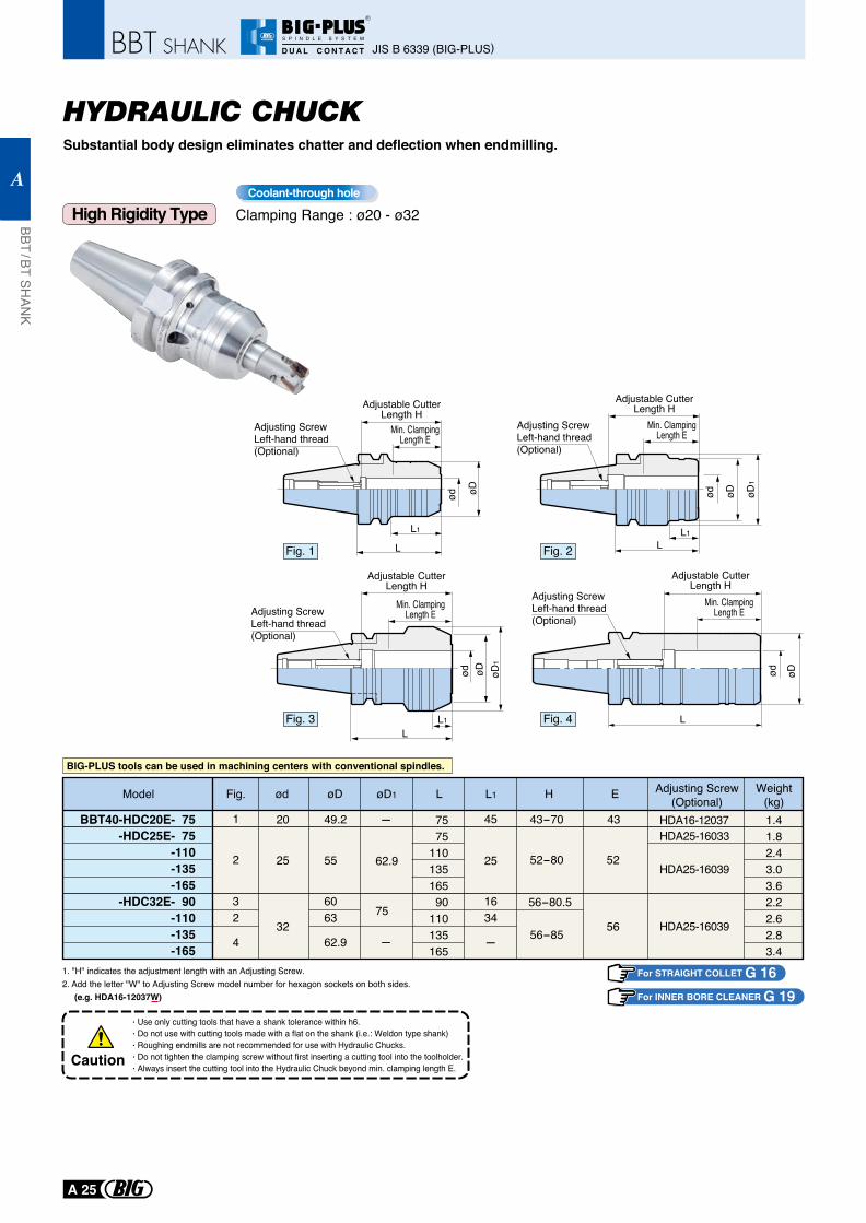
High Rigidity Type
BIG-PLUS tools can be used in machining centers with conventional spindles.
For STRAIGHT COLLET G 16For INNER BORE CLEANER G 19
1. "H" indicates the adjustment length with an Adjusting Screw.2. Add the letter "W" to Adjusting Screw model number for hexagon sockets on both sides. (e.g. HDA16-12037W)
Use only cutting tools that have a shank tolerance within h6.Do not use with cutting tools made with a flat on the shank (i.e.: Weldon type shank)Roughing endmills are not recommended for use with Hydraulic Chucks.Do not tighten the clamping screw without first inserting a cutting tool into the toolholder.Always insert the cutting tool into the Hydraulic Chuck beyond min. clamping length E.
Caution
HYDRAULIC CHUCKSubstantial body design eliminates chatter and deflection when endmilling.
Clamping Range : ø20 - ø32Coolant-through hole
JIS B 6339 (BIG-PLUS)
BBT / BT SHAN
K
A
A 25
R
S P I N D L E S Y S T E M
D U A L C O N T A C T
25
32
201
2
32
4
7575
11013516590
110135165
1.41.82.43.03.62.22.62.83.4
49.2 -
62.9
75
-
45
25
1634
-
43-70
52-80
56-85
56-80.5
43
52
56
55
6063
62.9
HDA16-12037HDA25-16033
HDA25-16039
HDA25-16039
ødFig. øD1øD L L1 Adjusting Screw(Optional)H Weight
(kg)EModel
BBT40-HDC20E- 75-HDC25E- 75
-110-135-165
-HDC32E- 90-110-135-165
Adjusting ScrewLeft-hand thread(Optional)
L
øDød
Adjustable CutterLength H
Min. ClampingLength E
L
L1
ød øD
Adjustable CutterLength H
Min. ClampingLength E
Adjusting ScrewLeft-hand thread(Optional)
LL1
øDød øD1
Adjustable CutterLength H
Min. ClampingLength E
Adjusting ScrewLeft-hand thread(Optional)
LL1
ød øD øD1
Adjustable CutterLength H
Adjusting ScrewLeft-hand thread(Optional)
Min. ClampingLength E
Fig. 1 Fig. 2
Fig. 3 Fig. 4
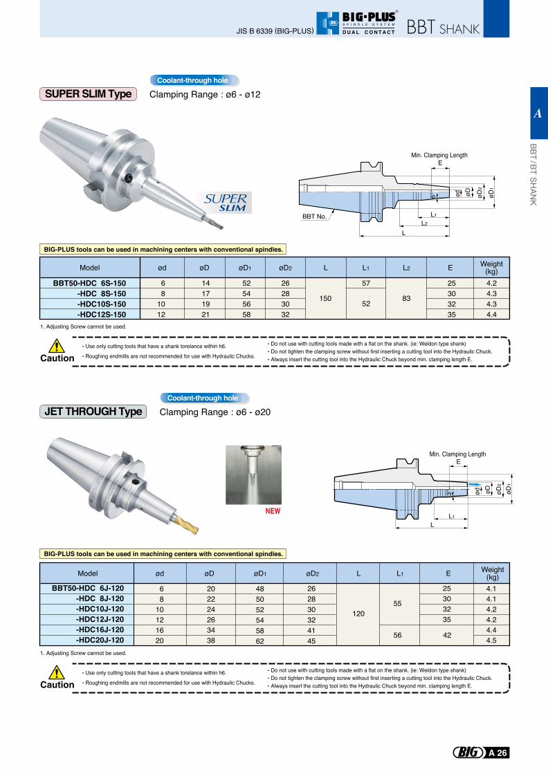
SUPER SLIM Type
BBT50-HDC 6S-150-HDC 8S-150-HDC10S-150-HDC12S-150
26283032
52545658
4.24.34.34.4
15052
83
68
1012
14171921
25303235
57
SLIMSUPER
BIG-PLUS tools can be used in machining centers with conventional spindles.
BIG-PLUS tools can be used in machining centers with conventional spindles.
L
øD2
L1
ød øD
Min. Clamping Length E
L2
øD1
6°
BBT No.
Model ød øD øD2øD1 L L1 L2 Weight(kg)E
CautionUse only cutting tools that have a shank torelance within h6.
Roughing endmills are not recommended for use with Hydraulic Chucks.
Do not use with cutting tools made with a flat on the shank. (ie: Weldon type shank)Do not tighten the clamping screw without first inserting a cutting tool into the Hydraulic Chuck.Always insert the cutting tool into the Hydraulic Chuck beyond min. clamping length E.
1. Adjusting Screw cannot be used.
CautionUse only cutting tools that have a shank torelance within h6.
Roughing endmills are not recommended for use with Hydraulic Chucks.
Do not use with cutting tools made with a flat on the shank. (ie: Weldon type shank)Do not tighten the clamping screw without first inserting a cutting tool into the Hydraulic Chuck.Always insert the cutting tool into the Hydraulic Chuck beyond min. clamping length E.
1. Adjusting Screw cannot be used.
JET THROUGH Type Clamping Range : ø6 - ø20Coolant-through hole
Clamping Range : ø6 - ø12Coolant-through hole
BBT / BT SHAN
K
A
A 26
JIS B 6339 (BIG-PLUS)
R
S P I N D L E S Y S T E M
D U A L C O N T A C T
NEW
Model ød øD øD1 øD2 L L1 Weight(kg)E
68
10121620
12055
56 42
4.14.14.24.24.44.5
25303235
485052545862
262830324145
202224263438
BBT50-HDC 6J-120-HDC 8J-120-HDC10J-120-HDC12J-120-HDC16J-120-HDC20J-120
LL1
Min. Clamping Length E
øD2
ød øD øD1
3°
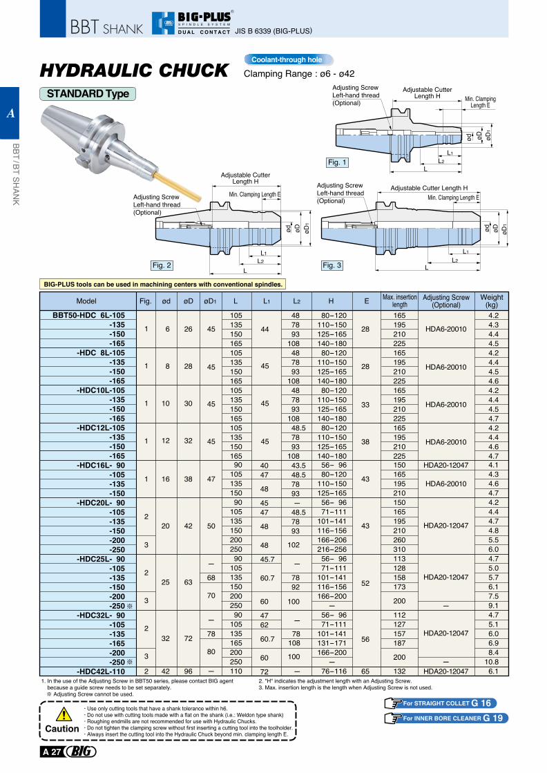
Clamping Range : ø6 - ø42
STANDARD Type
Coolant-through hole
HYDRAULIC CHUCK
Fig. 1
Fig. 3Fig. 2
BIG-PLUS tools can be used in machining centers with conventional spindles.
1. In the use of the Adjusting Screw in BBT50 series, please contact BIG agent because a guide screw needs to be set separately. Adjusting Screw cannot be used.
2. "H" indicates the adjustment length with an Adjusting Screw.3. Max. insertion length is the length when Adjusting Screw is not used.
Use only cutting tools that have a shank tolerance within h6.Do not use with cutting tools made with a flat on the shank (i.e.: Weldon type shank)Roughing endmills are not recommended for use with Hydraulic Chucks.Do not tighten the clamping screw without first inserting a cutting tool into the toolholder.Always insert the cutting tool into the Hydraulic Chuck beyond min. clamping length E.
Caution
For STRAIGHT COLLET G 16For INNER BORE CLEANER G 19
JIS B 6339 (BIG-PLUS)
BBT / BT SHAN
K
A
A 27
R
S P I N D L E S Y S T E M
D U A L C O N T A C T
Min. ClampingLength E
Min. Clamping Length E
øD1
ød øD
Adjusting ScrewLeft-hand thread(Optional)
Adjustable CutterLength H
Adjustable CutterLength H
L2L1
L
øD1
ød øD
Adjusting ScrewLeft-hand thread(Optional)
L2L1
L
-HDC16L- 90-105-135-150
-HDC20L- 90-105-135-150-200-250
-HDC25L- 90-105-135-150-200-250
-HDC32L- 90-105-135-165-200-250
-HDC42L-110
90105135150 90105135150200250 90105135150200250 90105135165200250110
4.14.34.64.74.24.44.74.85.56.04.75.05.76.17.59.14.75.16.06.98.4
10.86.1
56- 96 80-120110-150125-165 56- 96 71-111101-141116-156166-206216-256 56- 96 71-111101-141116-156166-200-
56- 96 71-111101-141131-171166-200-
76-116
150165195210150165195210260310113128158173
200
112127157187
200
132
4047
48
4547
48
48
45.7
60.7
60
4762
60.7
60
72
43.5 48.5 78 93 - 48.5 78 93
102
-
100
-
1 43
43
52HDA20-12047
HDA20-12047
HDA20-12047
-
-
HDA20-12047
HDA6-20010
HDA20-12047
56
65
47
50
-
-
68
70
78
80
-
78 92
78108
100
-
16
20
25
32
42
38
42
63
72
96
2
3
2
2
3
3
2
BBT50-HDC 6L-105-135-150-165
-HDC 8L-105-135-150-165
-HDC10L-105-135-150-165
-HDC12L-105-135-150-165
105135150165105135150165105135150165105135150165
4.24.34.44.54.24.44.54.64.24.44.54.74.24.44.64.7
80-120110-150125-165140-180 80-120110-150125-165140-180 80-120110-150125-165140-180 80-120110-150125-165140-180
165195210225165195210225165195210225165195210225
48 78 93108 48 78 93108 48 78 93108 48.5 78 93108
Model ød
1
1
1
1
45
45
45
45
44 28
28
33
38 HDA6-20010
HDA6-20010
HDA6-20010
HDA6-20010
45
45
45
6
8
10
12
26
28
30
32
Fig. øD LøD1 L1 L2 Adjusting Screw(Optional)H E Max. insertion
lengthWeight
(kg)
Adjusting ScrewLeft-hand thread(Optional)
ød øD øD1
L1
L2L
Min. Clamping Length EAdjustable Cutter Length H
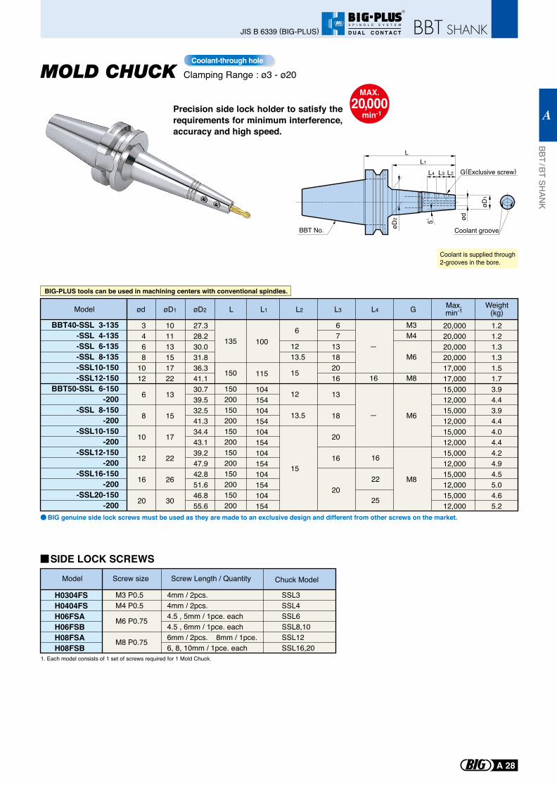
1. Each model consists of 1 set of screws required for 1 Mold Chuck.
Model Screw size Screw Length / Quantity
H0304FSH0404FSH06FSAH06FSBH08FSAH08FSB
Chuck Model
M3 P0.5M4 P0.5
M6 P0.75 M8 P0.75
4mm / 2pcs.4mm / 2pcs.4.5 , 5mm / 1pce. each4.5 , 6mm / 1pce. each6mm / 2pcs. 8mm / 1pce.6, 8, 10mm / 1pce. each
SSL3SSL4SSL6 SSL8,10 SSL12 SSL16,20
SIDE LOCK SCREWS
BBT No.
BIG genuine side lock screws must be used as they are made to an exclusive design and different from other screws on the market.
Coolant is supplied through2-grooves in the bore.
Precision side lock holder to satisfy the requirements for minimum interference, accuracy and high speed.
MAX.20,000
min-1
5˚
G(Exclusive screw)
LL1
L3L4 L2
ød
øD2
øD1
Coolant groove
ød øD1 øD2
G Max.min-1L4L L1 L2
16
L3
BBT40-SSL 3-135-SSL 4-135-SSL 6-135-SSL 8-135-SSL10-150-SSL12-150
BBT50-SSL 6-150-200
-SSL 8-150-200
-SSL10-150-200
-SSL12-150-200
-SSL16-150-200
-SSL20-150-200
3468
1012
6
8
10
12
16
20
6
1213.5
15 12
13.5
15
101113151722
13
15
17
22
26
30
27.328.230.031.836.341.130.739.532.541.334.443.139.247.942.851.646.855.6
16
22
25
135
150
150200150200150200150200150200150200
M3M4
M6
M8
M6
M8
1.21.21.31.31.51.73.94.43.94.44.04.44.24.94.55.04.65.2
20,00020,00020,00020,00017,00017,00015,00012,00015,00012,00015,00012,00015,00012,00015,00012,00015,00012,000
100
115
104154104154104154104154104154104154
67
13182016
13
18
20
16
20
Weight(kg)Model
BIG-PLUS tools can be used in machining centers with conventional spindles.
Clamping Range : ø3 - ø20Coolant-through hole
BBT / BT SHAN
K
A
A 28
JIS B 6339 (BIG-PLUS)
R
S P I N D L E S Y S T E M
D U A L C O N T A C T
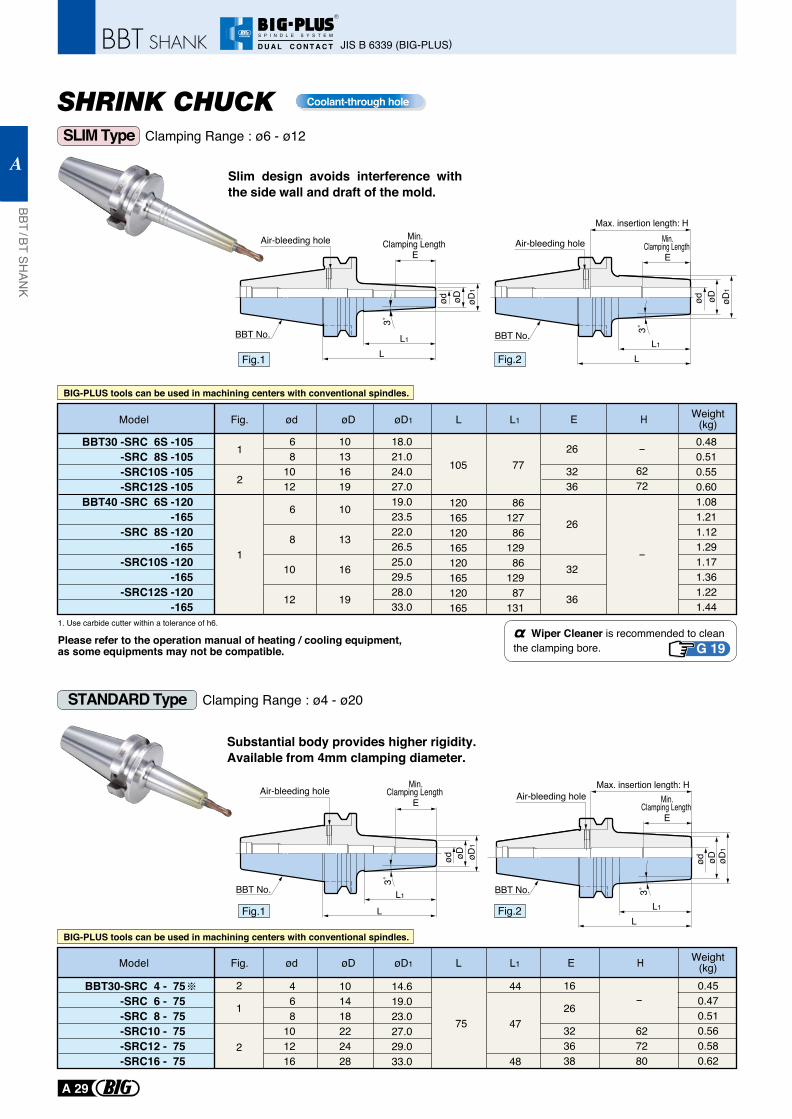
Clamping Range : ø6 - ø12
STANDARD Type
Coolant-through hole
Slim design avoids interference with the side wall and draft of the mold.
SLIM Type
Clamping Range : ø4 - ø20
1. Use carbide cutter within a tolerance of h6.
Please refer to the operation manual of heating / cooling equipment, as some equipments may not be compatible.
Wiper Cleaner is recommended to clean the clamping bore.
Model ødFig. øD1øD L1L
BBT30 -SRC 6S -105 -SRC 8S -105 -SRC10S -105 -SRC12S -105
BBT40 -SRC 6S -120 -165
-SRC 8S -120 -165
-SRC10S -120 -165
-SRC12S -120 -165
68
1012
6
8
10
12
10131619
10
13
16
19
18.021.024.027.019.023.522.026.525.029.528.033.0
105
120165120165120165120165
0.480.510.550.601.081.211.121.291.171.361.221.44
6272
1
2
1
77
8612786
12986
12987
131
26
3236
26
32
36
-
-
H Weight(kg)E
L1
L
BBT No.
Air-bleeding hole
øD1
øDød
3˚
Min.Clamping Length
E
Fig.1
Air-bleeding hole
BBT No.L1
L
øD1
øDød
3˚
Max. insertion length: HMin.
Clamping Length E
Fig.2
G 19
Substantial body provides higher rigidity. Available from 4mm clamping diameter.
Air-bleeding hole
BBT No. L1
L
øD1
øDød
3˚
Min.Clamping Length
E
Fig.1 L1
L
BBT No.
Air-bleeding hole
øD1
øDød
3˚
Max. insertion length: HMin.
Clamping Length E
Fig.2
BBT30-SRC 4 - 75-SRC 6 - 75
-SRC 8 - 75 -SRC10 - 75 -SRC12 - 75 -SRC16 - 75
468
101216
101418222428
14.619.023.027.029.033.0
75 627280
0.450.470.510.560.580.62
2
1
2
44
47
48
16
26
323638
Model ødFig. øD1øD L1L
-
HE Weight(kg)
BIG-PLUS tools can be used in machining centers with conventional spindles.
BIG-PLUS tools can be used in machining centers with conventional spindles.
JIS B 6339 (BIG-PLUS)
BBT / BT SHAN
K
A
A 29
R
S P I N D L E S Y S T E M
D U A L C O N T A C T
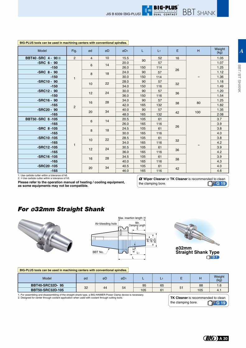
BIG-PLUS tools can be used in machining centers with conventional spindles.
BBT40 -SRC 4 - 90 -SRC 6 - 90
-150 -SRC 8 - 90
-150 -SRC10 - 90
-150 -SRC12 - 90
-150 -SRC16 - 90
-165 -SRC20 - 90
-165BBT50 -SRC 6 -105
-165 -SRC 8 -105
-165 -SRC10 -105
-165 -SRC12 -105
-165 -SRC16 -105
-165 -SRC20 -105
-165
4
6
8
10
12
16
20
6
8
10
12
16
20
10
14
18
22
24
28
34
14
18
22
24
28
34
15.520.026.024.030.028.034.030.036.034.042.040.048.020.526.024.530.028.534.030.536.034.540.040.546.0
1.051.071.251.121.361.181.491.201.541.251.821.352.083.73.93.84.03.84.23.94.23.94.34.04.6
5257
114
16
26
32
36
38
42
26
32
36
38
42
-
80
100
-
2
2
1
1
90
15090
15090
15090
15090
16590
165105165105165105165105165105165105165
5711657
11657
13257
13261
11661
11661
11661
11661
11661
116
57114
Model Fig. ød øD øD1 L L1 Weight(kg)HE
Wiper Cleaner or TK Cleaner is recommended to clean the clamping bore. G 19
TK Cleaner is recommended to clean the clamping bore. G 19
1. Use carbide cutter within a tolerance of h6.2. Use carbide cutter within a tolerance of h5.
1. For assembling and disassembling of the straight shank type, a BIG-HAIMER Power Clamp device is necessary. 2. Designed for center through coolant application when used with coolant through cutting tools.
Please refer to the operation manual of heating / cooling equipment, as some equipments may not be compatible.
BIG-PLUS tools can be used in machining centers with conventional spindles.
95105
6561
88105
1.64.1
5132 44 54BBT40-SRC32D- 95BBT50-SRC32D-105
Model ød øD øD1 L L1 Weight(kg)HE
L1
L
Min.Clamping Length
E
øD1
øDød
Max. insertion length: H
4.5˚
Air-bleeding hole
BBT No.ø32mmStraight Shank Type
D 7
For ø32mm Straight Shank
BBT / BT SHAN
K
A
A 30
JIS B 6339 (BIG-PLUS)
R
S P I N D L E S Y S T E M
D U A L C O N T A C T
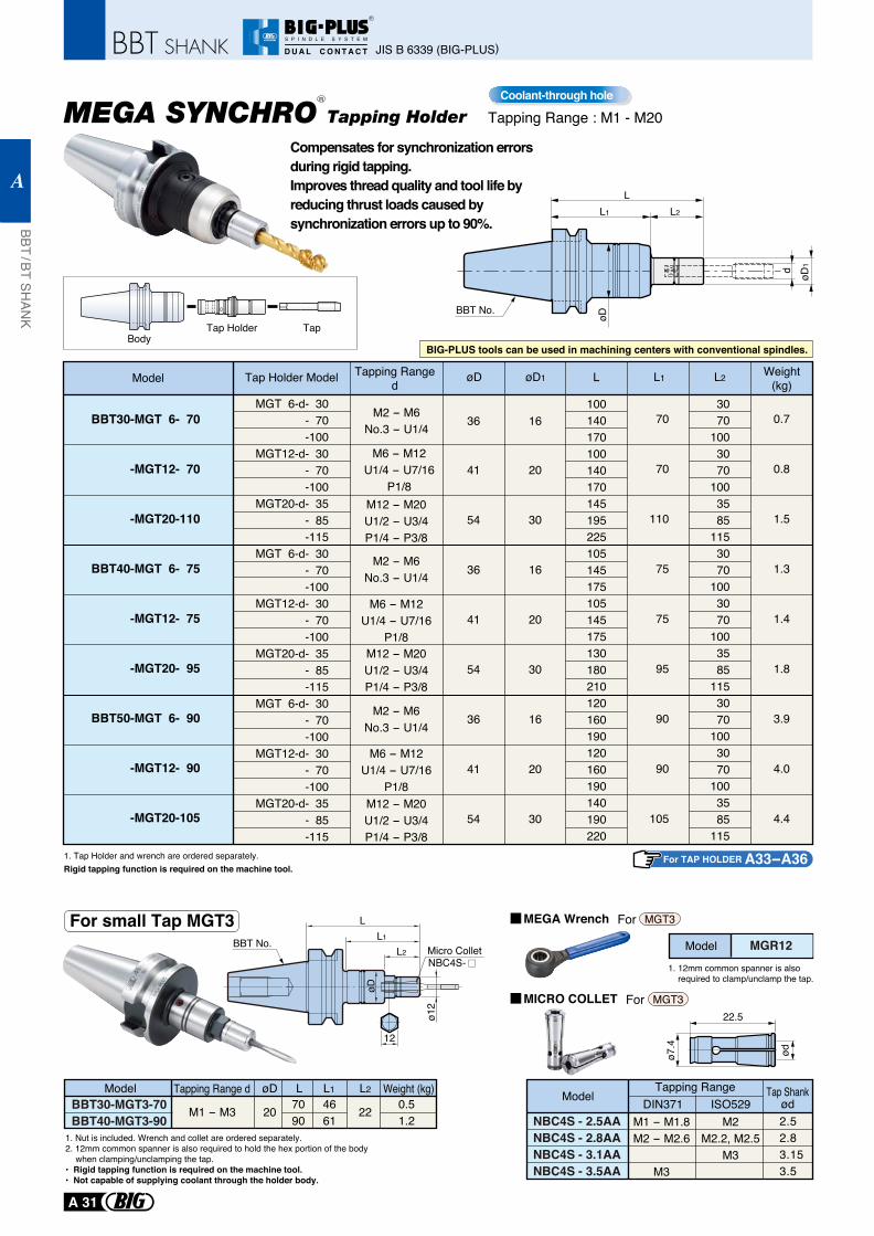
Tapping Range : M1 - M20Coolant-through hole
Model Tapping Ranged
Weight(kg)Tap Holder Model øD1øD L2
BBT30-MGT 6- 70
-MGT12- 70
-MGT20-110
BBT40-MGT 6- 75
-MGT12- 75
-MGT20- 95
BBT50-MGT 6- 90
-MGT12- 90
-MGT20-105
36
41
54
36
41
54
36
41
54
16
20
30
16
20
30
16
20
30
3070
1003070
1003585
1153070
1003070
1003585
1153070
1003070
1003585
115
L
100140170100140170145195225105145175105145175130180210120160190120160190140190220
M2 - M6No.3 - U1/4
M6 - M12U1/4 - U7/16
P1/8M12 - M20U1/2 - U3/4P1/4 - P3/8
M2 - M6No.3 - U1/4
M6 - M12U1/4 - U7/16
P1/8M12 - M20U1/2 - U3/4P1/4 - P3/8
M2 - M6No.3 - U1/4
M6 - M12U1/4 - U7/16
P1/8M12 - M20U1/2 - U3/4P1/4 - P3/8
L1
70
70
110
75
75
95
90
90
105
0.7
0.8
1.5
1.3
1.4
1.8
3.9
4.0
4.4
1. Tap Holder and wrench are ordered separately.Rigid tapping function is required on the machine tool.
BodyTap Holder Tap
MGT 6-d- 30 - 70 -100
MGT12-d- 30 - 70 -100
MGT20-d- 35 - 85 -115
MGT 6-d- 30 - 70 -100
MGT12-d- 30 - 70 -100
MGT20-d- 35 - 85 -115
MGT 6-d- 30 - 70 -100
MGT12-d- 30 - 70 -100
MGT20-d- 35 - 85 -115
MEGA SYNCHRO Tapping Holder
BIG-PLUS tools can be used in machining centers with conventional spindles.
For TAP HOLDER A33- A36
Compensates for synchronization errors during rigid tapping. Improves thread quality and tool life by reducing thrust loads caused by synchronization errors up to 90%.
L2
L
døD
1
øD
L1
BBT No.
Model MGR12
ø7.4
ød
22.5MICRO COLLET
MEGA Wrench
NBC4S - 2.5AANBC4S - 2.8AANBC4S - 3.1AANBC4S - 3.5AA
ModelTapping Range
DIN371 ISO529Tap Shank
ød2.52.83.153.5
M1 - M1.8M2 - M2.6
M3
M2M2.2, M2.5
M3
1. 12mm common spanner is also required to clamp/unclamp the tap.
For MGT3
For MGT3
R
ModelBBT30-MGT3-70BBT40-MGT3-90
7090
4661
0.51.2
Tapping Range d Weight (kg)øD L2L L1
For small Tap MGT3
ø12
Micro ColletNBC4S-
L2
øD
LL1
12
BBT No.
1. Nut is included. Wrench and collet are ordered separately.2. 12mm common spanner is also required to hold the hex portion of the body
when clamping/unclamping the tap.• Rigid tapping function is required on the machine tool.• Not capable of supplying coolant through the holder body.
M1 - M3 20 22
JIS B 6339 (BIG-PLUS)
BBT / BT SHAN
K
A
A 31
R
S P I N D L E S Y S T E M
D U A L C O N T A C T
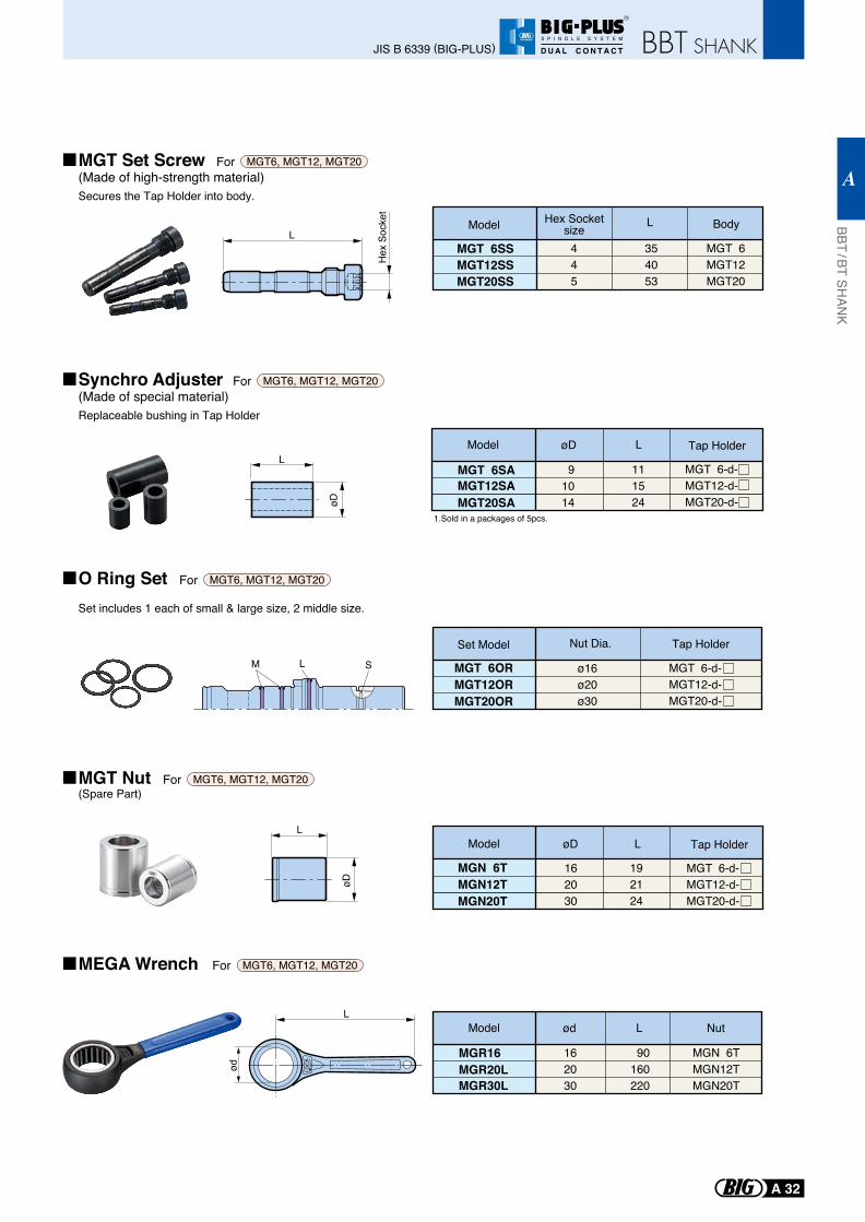
L
øD
Model øD L
MGN 6TMGN12TMGN20T
Tap Holder
162030
192124
MGT 6-d- MGT12-d-MGT20-d-
Model øD L
MGT 6SAMGT12SAMGT20SA
91014
111524
L
MGT 6SSMGT12SSMGT20SS
445
35 4053
MGT 6 MGT12MGT20
L
øD
ød LOC
K
L
1.Sold in a packages of 5pcs.
L
Hex
Soc
ket
Hex SocketsizeModel Body
Set Model Tap Holder
Tap Holder
SLM MGT 6ORMGT12ORMGT20OR
Nut Dia.
ø16ø20ø30
MGR16MGR20LMGR30L
162030
90160220
MGN 6TMGN12TMGN20T
Model ød L Nut
MGT 6-d- MGT12-d-MGT20-d-
MGT 6-d- MGT12-d-MGT20-d-
MGT Set Screw(Made of high-strength material)Secures the Tap Holder into body.
For MGT6, MGT12, MGT20
Synchro Adjuster(Made of special material)Replaceable bushing in Tap Holder
For MGT6, MGT12, MGT20
O Ring Set Set includes 1 each of small & large size, 2 middle size.
For MGT6, MGT12, MGT20
MGT Nut(Spare Part)
For MGT6, MGT12, MGT20
MEGA Wrench For MGT6, MGT12, MGT20
BBT / BT SHAN
K
A
A 32
JIS B 6339 (BIG-PLUS)
R
S P I N D L E S Y S T E M
D U A L C O N T A C T
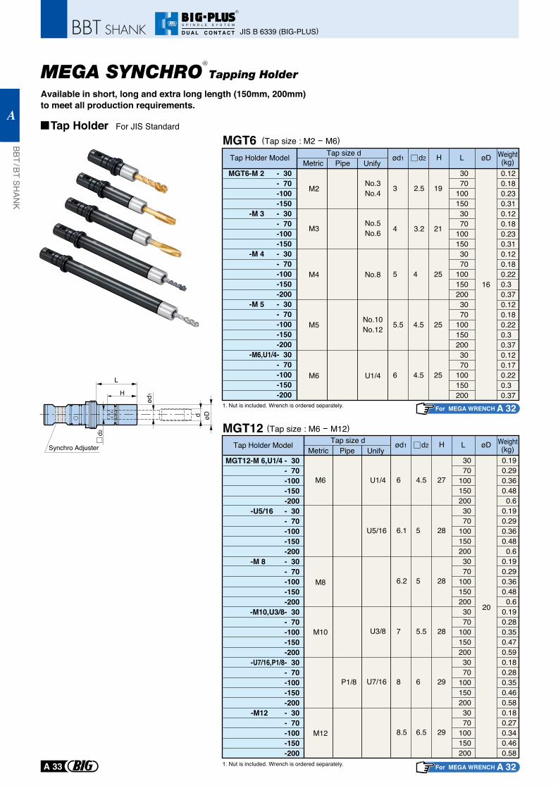
MEGA SYNCHRO Tapping Holder
Available in short, long and extra long length (150mm, 200mm) to meet all production requirements.
L
d2
d øD
H
ød1
Synchro Adjuster
MGT12 (Tap size : M6 - M12)
MGT12-M 6,U1/4 - 30- 70-100-150-200
-U5/16 - 30- 70-100-150-200
-M 8 - 30- 70-100-150-200
-M10,U3/8- 30- 70-100-150-200
-U7/16,P1/8- 30- 70-100-150-200
-M12 - 30- 70-100-150-200
6
6.1
6.2
7
8
8.5
4.5
5
5
5.5
6
6.5
27
28
28
28
29
29
3070
1001502003070
1001502003070
1001502003070
1001502003070
1001502003070
100150200
0.190.290.360.480.6
0.190.290.360.480.6
0.190.290.360.480.6
0.190.280.350.470.590.180.280.350.460.580.180.270.340.460.58
20
M6
M8
M10
M12
U1/4
U5/16
U3/8
U7/16P1/8
Tap Holder Model Tap size dMetric UnifyPipe
Hød1 d2 L øD
1. Nut is included. Wrench is ordered separately. For MEGA WRENCH A 32
Weight(kg)
Tap Holder For JIS Standard
MGT6 (Tap size : M2 - M6)
Tap Holder Model
MGT6-M 2 - 30- 70-100-150
-M 3 - 30- 70-100-150
-M 4 - 30- 70-100-150-200
-M 5 - 30- 70-100-150-200
-M6,U1/4- 30- 70-100-150-200
3
4
2.5
3.2
19
21
5
5.5
6
4
4.5
4.5
25
25
25
3070
1001503070
1001503070
1001502003070
1001502003070
100150200
0.120.180.230.310.120.180.230.310.120.180.220.30.370.120.180.220.30.370.120.170.220.30.37
16
Tap size dMetric UnifyPipe
Hød1 d2 L øD
M2 No.3No.4
M3 No.5No.6
M4 No.8
M5 No.10No.12
M6 U1/4
1. Nut is included. Wrench is ordered separately. For MEGA WRENCH A 32
Weight(kg)
R
JIS B 6339 (BIG-PLUS)
BBT / BT SHAN
K
A
A 33
R
S P I N D L E S Y S T E M
D U A L C O N T A C T
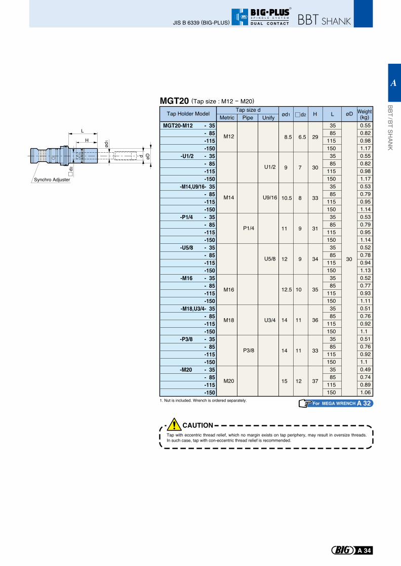
MGT20 (Tap size : M12 - M20)
MGT20-M12 - 35- 85-115-150
-U1/2 - 35- 85-115-150
-M14,U9/16- 35- 85-115-150
-P1/4 - 35- 85
-115-150
-U5/8 - 35- 85-115-150
-M16 - 35- 85-115-150
-M18,U3/4- 35- 85-115-150
-P3/8 - 35- 85-115-150
-M20 - 35- 85-115-150
8.5
9
10.5
11
12
12.5
14
14
15
6.5
7
8
9
9
10
11
11
12
29
30
33
31
34
35
36
33
37
3585
1151503585
1151503585
1151503585
1151503585
1151503585
1151503585
1151503585
1151503585
115150
0.550.820.981.170.550.820.981.170.530.790.951.140.530.790.951.140.520.780.941.130.520.770.931.110.510.760.921.10.510.760.921.10.490.740.891.06
M14
M12
M18
M16
P1/4
U9/16
U1/2
U3/4
U5/8
P3/8
M20
30
Tap Holder Model Tap size dMetric UnifyPipe ød1
L
d2
d øDH
ød1
Synchro Adjuster
Hd2 L øD
1. Nut is included. Wrench is ordered separately.For MEGA WRENCH A 32
Tap with eccentric thread relief, which no margin exists on tap periphery, may result in oversize threads. In such case, tap with con-eccentric thread relief is recommended.
CAUTION
Weight(kg)
BBT / BT SHAN
K
A
A 34
JIS B 6339 (BIG-PLUS)
R
S P I N D L E S Y S T E M
D U A L C O N T A C T
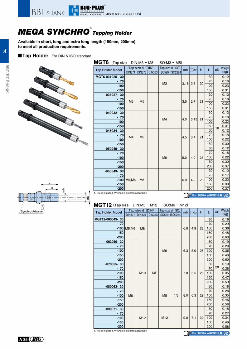
MEGA SYNCHRO Tapping Holder
Available in short, long and extra long length (150mm, 200mm) to meet all production requirements.
Tap Holder For DIN & ISO standard
L
d2
d øD
H
ød1
Synchro Adjuster
MGT12
1. Nut is included. Wrench is ordered separately.
1. Nut is included. Wrench is ordered separately.
(Tap size DIN:M5 - M12 ISO:M6 - M12)
For MEGA WRENCH A 32
For MEGA WRENCH A 32
MGT6Tap Holder Model
MGT6-031025- 30- 70-100-150
-035027- 30- 70-100-150
-040032- 30- 70-100-150
-045034- 30- 70-100-150
-050040- 30- 70-100-150-200
-060049- 30- 70-100-150-200
3070
1001503070
1001503070
1001503070
1001503070
1001502003070
100150200
0.120.180.230.310.120.180.230.310.120.180.230.310.120.180.220.300.120.180.220.300.370.120.170.220.300.37
3.15
3.5
4.0
4.5
5.0
6.0
2.5
2.7
3.15
3.4
4.0
4.9
20
21
21
21
25
26
Tap size d (DIN) Tap size d (ISO)DIN371 DIN376 DIN353 ISO529 ISO2284
H øDød1 d2 L
M3
M4
M5,M6
M5
M6
M8
M3
M4
16
M5
(Tap size DIN:M3 - M8 ISO:M3 - M5)Weight(kg)
Tap Holder Model
3070
1001502003070
1001502003070
1001502003070
1001502003070
100150200
0.190.290.360.480.600.190.290.360.480.600.190.280.350.470.590.180.280.350.460.580.180.270.340.460.58
6.0
6.3
7.0
8.0
9.0
4.9
5.0
5.5
6.3
7.1
28
28
28
29
30
DIN371 DIN376 DIN353 ISO529 ISO2284Hød1 d2 L
M8
M5,M6 M8
M10 1/8
M12
M6
M8 1/8
M12
Tap size d (DIN) Tap size d (ISO)
MGT12-060049- 30- 70-100-150-200
-063050- 30- 70-100-150-200
-070055- 30- 70-100-150-200
-080063- 30- 70-100-150-200
-090071- 30- 70-100-150-200
20
øD Weight(kg)
R
JIS B 6339 (BIG-PLUS)
BBT / BT SHAN
K
A
A 35
R
S P I N D L E S Y S T E M
D U A L C O N T A C T
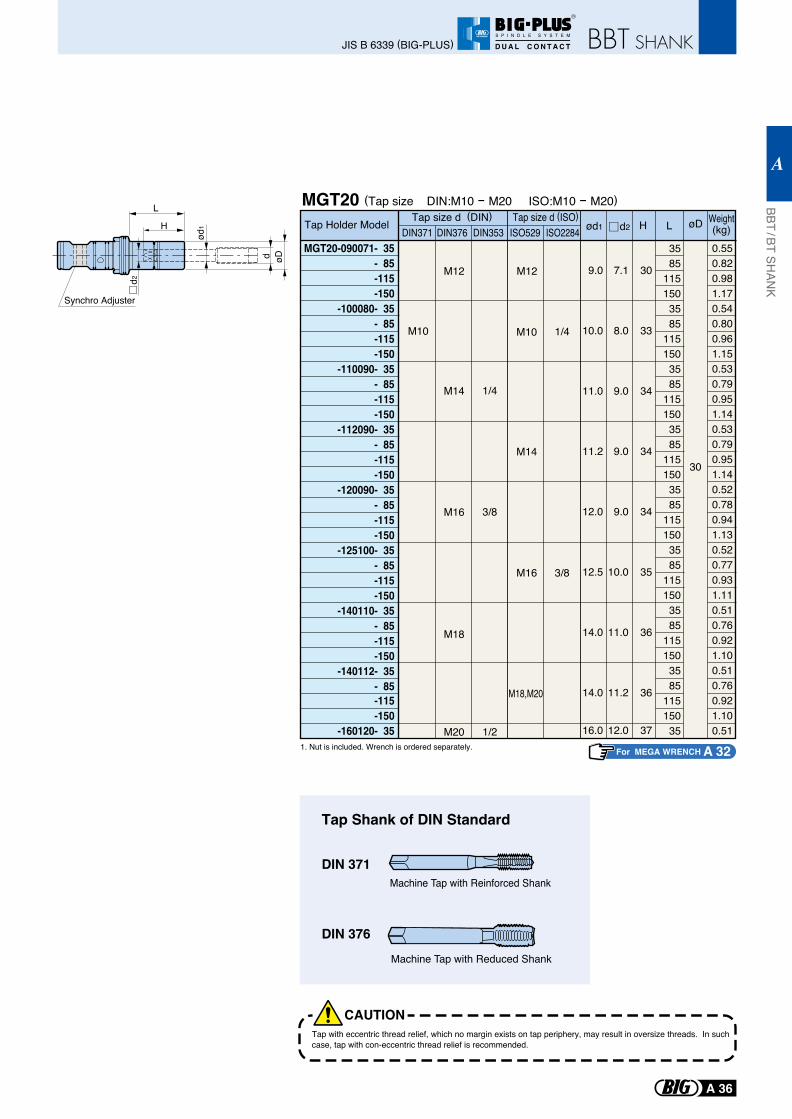
L
d2
d øD
H
ød1
Synchro Adjuster
MGT20
MGT20-090071- 35- 85-115-150
-100080- 35- 85-115-150
-110090- 35- 85-115-150
-112090- 35- 85
-115-150
-120090- 35- 85-115-150
-125100- 35- 85-115-150
-140110- 35- 85-115-150
-140112- 35- 85-115-150
-160120- 35
3585
1151503585
1151503585
1151503585
1151503585
1151503585
1151503585
1151503585
11515035
0.550.820.981.170.540.800.961.150.530.790.951.140.530.790.951.140.520.780.941.130.520.770.931.110.510.760.921.100.510.760.921.100.51
9.0
10.0
11.0
11.2
12.0
12.5
14.0
14.0
16.0
7.1
8.0
9.0
9.0
9.0
10.0
11.0
11.2
12.0
30
33
34
34
34
35
36
36
37
Tap Holder Model ød1 Hd2 LDIN371 DIN376 DIN353 ISO529 ISO2284
M10
1/4
3/8
1/2
M12 M12
M14
30
M16
M18
M20
M10
M14
M16
1/4
3/8
M18,M20
Tap size d (DIN) Tap size d (ISO)
1. Nut is included. Wrench is ordered separately.
(Tap size DIN:M10 - M20 ISO:M10 - M20)
Tap Shank of DIN Standard
DIN 371
DIN 376
Machine Tap with Reinforced Shank
Machine Tap with Reduced Shank
For MEGA WRENCH A 32
Tap with eccentric thread relief, which no margin exists on tap periphery, may result in oversize threads. In such case, tap with con-eccentric thread relief is recommended.
CAUTION
øD Weight(kg)
BBT / BT SHAN
K
A
A 36
JIS B 6339 (BIG-PLUS)
R
S P I N D L E S Y S T E M
D U A L C O N T A C T
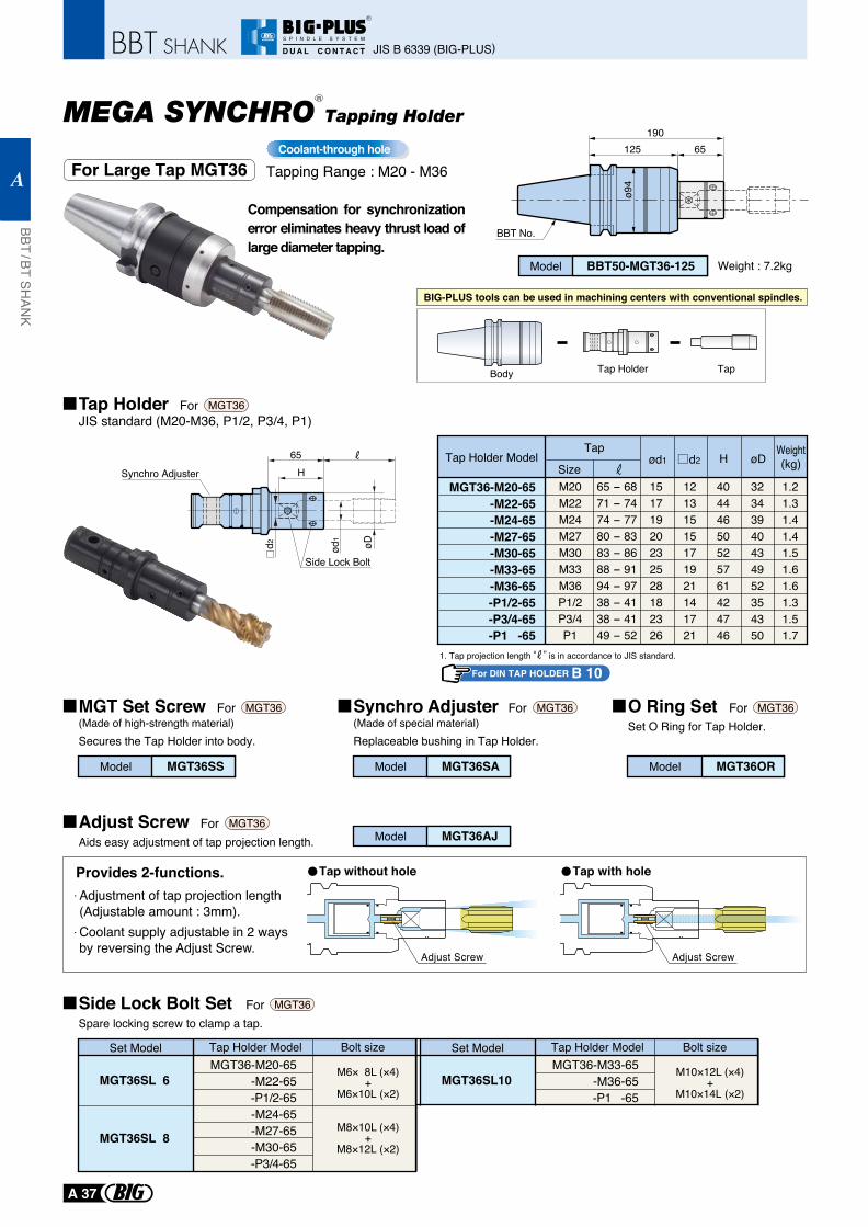
Tapping Range : M20 - M36Coolant-through hole
MEGA SYNCHRO Tapping Holder
For Large Tap MGT36
Compensation for synchronization error eliminates heavy thrust load of large diameter tapping.
Tap HolderJIS standard (M20-M36, P1/2, P3/4, P1)
For MGT36
MGT Set Screw(Made of high-strength material)Secures the Tap Holder into body.
For MGT36
Body Tap Holder Tap
BIG-PLUS tools can be used in machining centers with conventional spindles.
Model BBT50-MGT36-125 Weight : 7.2kg
19065125
ø94
BBT No.
65
d2 ød1
øD
HSynchro Adjuster
Side Lock Bolt
Tap Holder ModelTap
SizeM20M22M24M27M30M33M36P1/2P3/4P1
65 - 6871 - 7474 - 7780 - 8383 - 8688 - 9194 - 9738 - 4138 - 4149 - 52
15171920232528182326
12131515171921141721
40444650525761424746
32343940434952354350
1.21.31.41.41.51.61.61.31.51.7
MGT36-M20-65-M22-65-M24-65-M27-65-M30-65-M33-65-M36-65-P1/2-65-P3/4-65-P1 -65
Hød1 d2 øDWeight(kg)
1. Tap projection length “ ” is in accordance to JIS standard.
Model MGT36SS
Synchro Adjuster(Made of special material)Replaceable bushing in Tap Holder.
For MGT36
Model MGT36SA
O Ring SetSet O Ring for Tap Holder.
For MGT36
Adjust ScrewAids easy adjustment of tap projection length.
For MGT36
Side Lock Bolt SetSpare locking screw to clamp a tap.
For MGT36
Model MGT36OR
Model MGT36AJ
Adjustment of tap projection length (Adjustable amount : 3mm).Coolant supply adjustable in 2 waysby reversing the Adjust Screw.
Provides 2-functions. Tap without hole
Adjust Screw Adjust Screw
Set Model Tap Holder Model Bolt sizeMGT36-M20-65
-M22-65-P1/2-65-M24-65-M27-65-M30-65-P3/4-65
MGT36SL 6
MGT36SL 8
Set Model Tap Holder Model Bolt sizeMGT36-M33-65
-M36-65-P1 -65
MGT36SL10
Tap with hole
R
For DIN TAP HOLDER B 10
JIS B 6339 (BIG-PLUS)
BBT / BT SHAN
K
A
A 37
R
S P I N D L E S Y S T E M
D U A L C O N T A C T
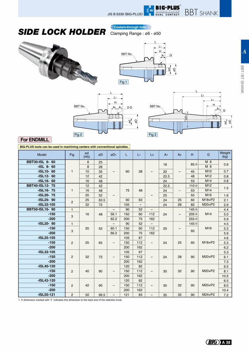
For ENDMILL
Clamping Range : ø6 - ø50
BIG-PLUS tools can be used in machining centers with conventional spindles.
L1
H
L
A2 A1 2-G
øDød
LL1
H
øDød
GA1
øDød
HA1
L
L1
L2
øD1
G
BBT30-ISL 6- 60-ISL 8- 60-ISL10- 60-ISL12- 60-ISL16- 60
BBT40-ISL12- 75-ISL16- 75-ISL20- 75-ISL25- 90-ISL32-105
BBT50-ISL16- 90-150-200
-ISL20- 90-150-200
-ISL25-105-150-200
-ISL32-105-150-200
-ISL40-120-150-200
-ISL42-120-150-200
-ISL50-121
Fig.
1
1
1
3
1
2
2
2
2
2
3
2
ød(H5) 6 81012 16 1216202532
16
20
25
32
40
42
50
øD øD1
252835424842485263.572
48
52
65
72
90
90
99.5
L L1 L2
60
75
9010590
15020090
150200105150200105150200120150200120150200121
38
48
63
52607552607567
11216267
11216282
11216282
11216283
A1 A2
-
-
2528
-
-
25
28
32
32
35
-
-
-56.162.2-
60.166.2
-
-
-
-
-
-
-
-112162-
112162
-
-
-
-
-
18
2022.52422.524252424
24
25
24
24
30
30
35
GH Weight(kg)
0.6
0.70.80.8
1.5
1.62.12.94.45.05.94.55.35.94.65.36.25.36.17.36.58.1
10.56.58.0
10.47.2
-
85
454853
11053556082
145205255145
60
60
90
90
90
90
M 6M 8M10M12M14M12M14M16
M18×P2 M20×P2
M14
M16
M18×P2
M20×P2
M20×P2
M20×P2
M24×P2
Model
Fig.1
Fig.2 Fig.3
BBT No.
BBT No. BBT No.
1. H dimension marked with indicates this dimension to the back end of the retention knob.
Coolant-through hole
BBT / BT SHAN
K
A
A 38
JIS B 6339 (BIG-PLUS)
R
S P I N D L E S Y S T E M
D U A L C O N T A C T
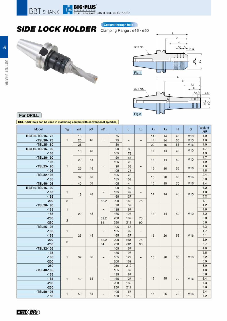
For DRILL
Clamping Range : ø16 - ø50
Fig.1
Fig.2
øDød
HA1A2
L
L2
L1
øD1
2-GBBT No.
A2 A1
L
2-G
øDød
L1
HBBT No.
BIG-PLUS tools can be used in machining centers with conventional spindles.
Coolant-through hole
BBT30-TSL16- 75-TSL20- 75-TSL25- 80
BBT40-TSL16- 90-105
-TSL20- 90- 105
-TSL25- 90-105
-TSL32-105-135
-TSL40-105BBT50-TSL16- 90
-135-165-200
-TSL20- 90-135-165-200-250
-TSL25-105-135-165-200-250
-TSL32-105-135-165-200-250
-TSL40-105-135-165-200-250
-TSL50-105-150
ød øDFig. øD1 L L1 L2 A1 A2 H G Weight(kg)
162025
16
20
25
32
40
16
20
25
32
40
50
1
1
1
2
1
2
1
2
1
1
1
48 - --
-
-
-
-
62.2 75
62.264
-
-
-
-
62.264
7590
7590
75758090
10590
105
63786378637878
108
90
9013516520090
135165200250105135165200250105135165200250105135165200250105150
5297
1271625297
1271622126797
127162212
6797
1271622126797
12716221267
112
105105135105
48
48
48
63
68
48
48
48
63
68
84
-
-
-
-
-
-
-
141420
14 14
20
20
25
1414
15
15
15
141415
15
14
14
15
15
15
20
14
14
20
25
25
485056
48
50
56
60
70
48
50
56
60
70
70
M10M10M16
M10
M10
M10
M10
M16
M16
M16
M16
M16
M16
M16
1.01.01.01.71.91.71.91.61.82.43.02.44.24.85.26.14.24.85.26.06.84.34.75.15.96.74.85.56.26.98.04.85.66.47.38.65.47.2
Model
JIS B 6339 (BIG-PLUS)
BBT / BT SHAN
K
A
A 39
R
S P I N D L E S Y S T E M
D U A L C O N T A C T
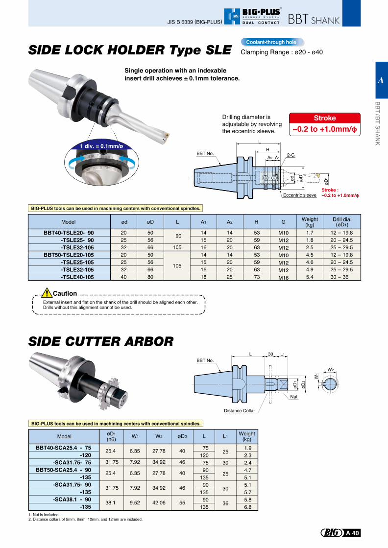
Clamping Range : ø20 - ø40Coolant-through hole
SIDE LOCK HOLDER Type SLE
SIDE CUTTER ARBOR
1 div. = 0.1mm/ø
Single operation with an indexable insert drill achieves ± 0.1mm tolerance.
External insert and flat on the shank of the drill should be aligned each other.Drills without this alignment cannot be used.
Caution
Drilling diameter is adjustable by revolving the eccentric sleeve.
Stroke−0.2 to +1.0mm/φ
BBT40-TSLE20- 90-TSLE25- 90-TSLE32-105
BBT50-TSLE20-105-TSLE25-105-TSLE32-105-TSLE40-105
20253220253240
øD
50566650566680
L
90
105
105
A1 A2
14151614151618
14202014202025
H
53596353596373
M10M12M12M10M12M12M16
Drill dia.(øD1)
12 - 19.820 - 24.525 - 29.512 - 19.820 - 24.525 - 29.530 - 36
Weight(kg)1.71.82.54.54.64.95.4
ød GModel
BIG-PLUS tools can be used in machining centers with conventional spindles.
BIG-PLUS tools can be used in machining centers with conventional spindles.
Eccentric sleeve
2-G
ød øD
HL
A2 A1
øD1
Stroke :−0.2 to +1.0mm/φ
BBT No.
25.4
31.75
25.4
31.75
38.1
W1
6.35
7.92
6.35
7.92
9.52
W2
27.78
34.92
27.78
34.92
42.06
øD2
40
46
40
46
55
L
75120 75 90135 90135 90135
L1
25
30
25
30
36
1.92.32.44.75.15.15.75.86.8
BBT40-SCA25.4 - 75-120
-SCA31.75- 75BBT50-SCA25.4 - 90
-135-SCA31.75- 90
-135-SCA38.1 - 90
-135
Weight(kg)
øD1(h6)Model
1. Nut is included.2. Distance collars of 5mm, 8mm, 10mm, and 12mm are included.
W2
W1
L
øD2
øD1
L130
Distance Collar
Nut
BBT No.
BBT / BT SHAN
K
A
A 40
JIS B 6339 (BIG-PLUS)
R
S P I N D L E S Y S T E M
D U A L C O N T A C T
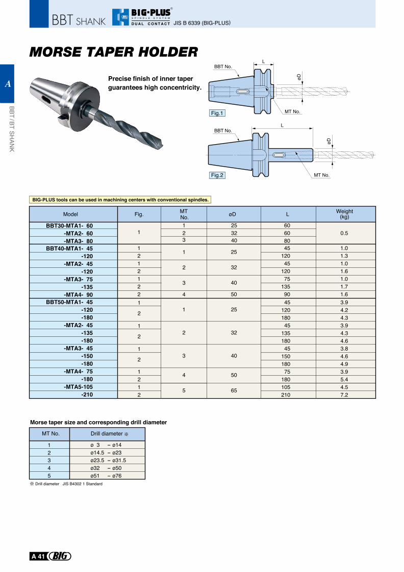
Precise finish of inner taper guarantees high concentricity.
MT No.
L
øD
L
MT No.
øD
BBT30-MTA1- 60-MTA2- 60-MTA3- 80
BBT40-MTA1- 45-120
-MTA2- 45-120
-MTA3- 75-135
-MTA4- 90BBT50-MTA1- 45
-120-180
-MTA2- 45-135-180
-MTA3- 45-150-180
-MTA4- 75-180
-MTA5-105-210
1
2
3
4
1212122
25
32
40
50
4512045
12075
13590
1.01.31.01.61.01.71.6
123
253240
606080
0.51
MT No.
12345
Drill diameter
ø 3 - ø14ø14.5 - ø23 ø23.5 - ø31.5ø32 - ø50ø51 - ø76
Drill diameter JIS B4302 1 Standard
1
2
3
4
5
1
2
1
2
1
2
1212
25
32
40
50
65
4512018045
13518045
15018075
180105210
3.94.24.33.94.34.63.84.64.93.95.44.57.2
Model MTNo.Fig. øD L Weight
(kg)
BBT No.
BBT No.
Morse taper size and corresponding drill diameter
Fig.1
Fig.2
BIG-PLUS tools can be used in machining centers with conventional spindles.
JIS B 6339 (BIG-PLUS)
BBT / BT SHAN
K
A
A 41
R
S P I N D L E S Y S T E M
D U A L C O N T A C T
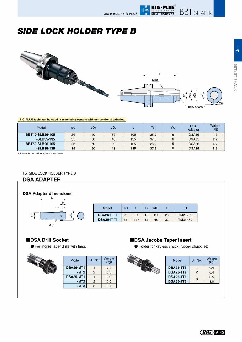
L1
G
LH
øD øD1
DSA Adapter dimensions
Model
DSA26-DSA35-
øD
2635
92117
L L1
1212
øD1
3948
H
2632
G
TM26×P2TM35×P2
Model
DSA26-MT1-MT2
DSA35-MT1-MT2-MT3
MT No. Weight(kg)
12123
0.40.30.90.80.7
DSA ADAPTERFor SIDE LOCK HOLDER TYPE B
Model
DSA26-JT1DSA26-JT2DSA26-JT6DSA35-JT6
JT No.
6
12
Weight(kg)0.40.40.51.0
W1
W2
øD2
ød
L
M10
øD1
DSA Adapter
BBT40-SLB26-105-SLB35-135
BBT50-SLB26-105-SLB35-135
26352635
øD1
50605060
øD2
39483948
L
105135105135
W1
28.237.628.237.6
W2
5656
DSA AdapterDSA26DSA35DSA26DSA35
Weight(kg)1.62.24.75.6
ød
1. Use with the DSA Adapter shown below.
Model
For morse taper drills with tang.
BIG-PLUS tools can be used in machining centers with conventional spindles.
SIDE LOCK HOLDER TYPE B
DSA Drill SocketHolder for keyless chuck, rubber chuck, etc.
DSA Jacobs Taper Insert
BBT / BT SHAN
K
A
A 42
JIS B 6339 (BIG-PLUS)
R
S P I N D L E S Y S T E M
D U A L C O N T A C T
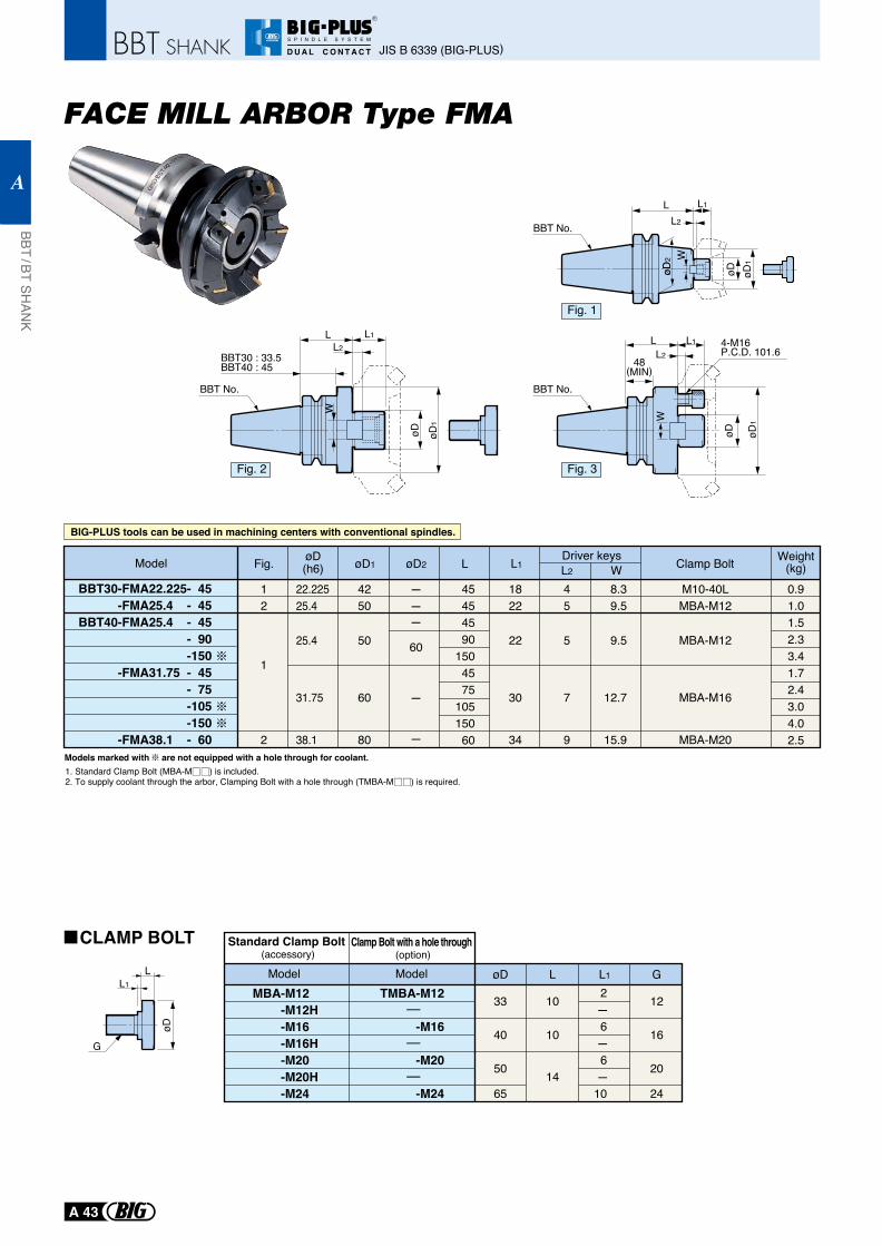
1. Standard Clamp Bolt (MBA-M ) is included.2. To supply coolant through the arbor, Clamping Bolt with a hole through (TMBA-M ) is required.
Models marked with are not equipped with a hole through for coolant.
L
48(MIN)
L1
øD
W
øD1
L24-M16P.C.D. 101.6
W
L L1
L2
øD øD1
øDøD2
BBT30 : 33.5BBT40 : 45
øD
LL1
L L1L2
øD øD1
WW
Fig.
1
2
øD(h6)
25.4
25.4
31.75
38.1
øD1
50
50
60
80
øD2
--
60
-
L
45454590
1504575
10515060
L1
22
22
30
34
L2
5
5
7
9
W
9.5
9.5
12.7
15.9
Clamp Bolt
MBA-M1212
22.225 42 - 18 4 8.3 M10-40L
MBA-M12
MBA-M16
MBA-M20
Weight(kg)0.91.01.52.33.41.72.43.04.02.5
BBT30-FMA22.225- 45-FMA25.4 - 45
BBT40-FMA25.4 - 45- 90-150
-FMA31.75 - 45- 75-105-150
-FMA38.1 - 60
G
Driver keys
øD L L1 GMBA-M12
-M12H -M16-M16H-M20-M20H-M24
Standard Clamp Bolt (accessory)
ModelTMBA-M12
-M16
-M20
-M24
-
-
-
Model
Clamp Bolt with a hole through (option)
33
40
50
65
10
10
14
12
16
20
24
2- 6- 6-10
-
Model
BIG-PLUS tools can be used in machining centers with conventional spindles.
FACE MILL ARBOR Type FMA
Fig. 1
Fig. 3Fig. 2
BBT No. BBT No.
BBT No.
CLAMP BOLT
JIS B 6339 (BIG-PLUS)
BBT / BT SHAN
K
A
A 43
R
S P I N D L E S Y S T E M
D U A L C O N T A C T
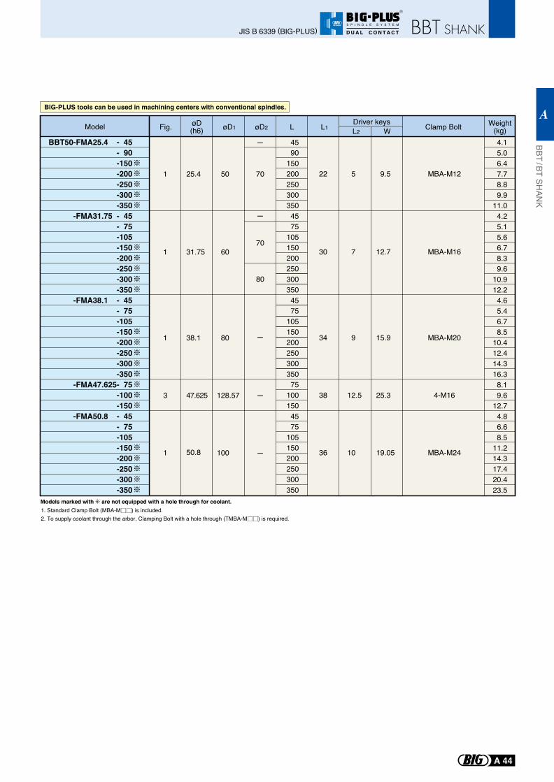
BBT50-FMA25.4 - 45- 90
-150-200-250-300-350
-FMA31.75 - 45- 75-105-150-200-250-300-350
-FMA38.1 - 45- 75-105-150-200-250-300-350
-FMA47.625- 75-100-150
-FMA50.8 - 45- 75-105-150-200-250-300-350
Fig. øD(h6) øD1 øD2 L L1 L2 W Clamp Bolt Weight
(kg)Driver keysModel
1
1
1
1
3
25.4
31.75
38.1
47.625
50
60
80
128.57
100
-
-
-
-
-
70
70
80
4590
1502002503003504575
1051502002503003504575
10515020025030035075
1001504575
105150200250300350
22
30
34
38
36
5
7
9
12.5
10
9.5
12.7
15.9
25.3
19.05
MBA-M12
MBA-M16
MBA-M20
4-M16
MBA-M24
4.15.06.47.78.89.9
11.04.25.15.66.78.39.6
10.912.24.65.46.78.5
10.412.414.316.38.19.6
12.74.86.68.5
11.214.317.420.423.5
BBT50-FMA25.4 - 45- 90
-150-200-250-300-350
-FMA31.75 - 45- 75-105-150-200-250-300-350
-FMA38.1 - 45- 75-105-150-200-250-300-350
-FMA47.625- 75-100-150
-FMA50.8 - 45- 75-105-150-200-250-300-350
50.8
BIG-PLUS tools can be used in machining centers with conventional spindles.
1. Standard Clamp Bolt (MBA-M ) is included.2. To supply coolant through the arbor, Clamping Bolt with a hole through (TMBA-M ) is required.
Models marked with are not equipped with a hole through for coolant.
BBT / BT SHAN
K
A
A 44
JIS B 6339 (BIG-PLUS)
R
S P I N D L E S Y S T E M
D U A L C O N T A C T
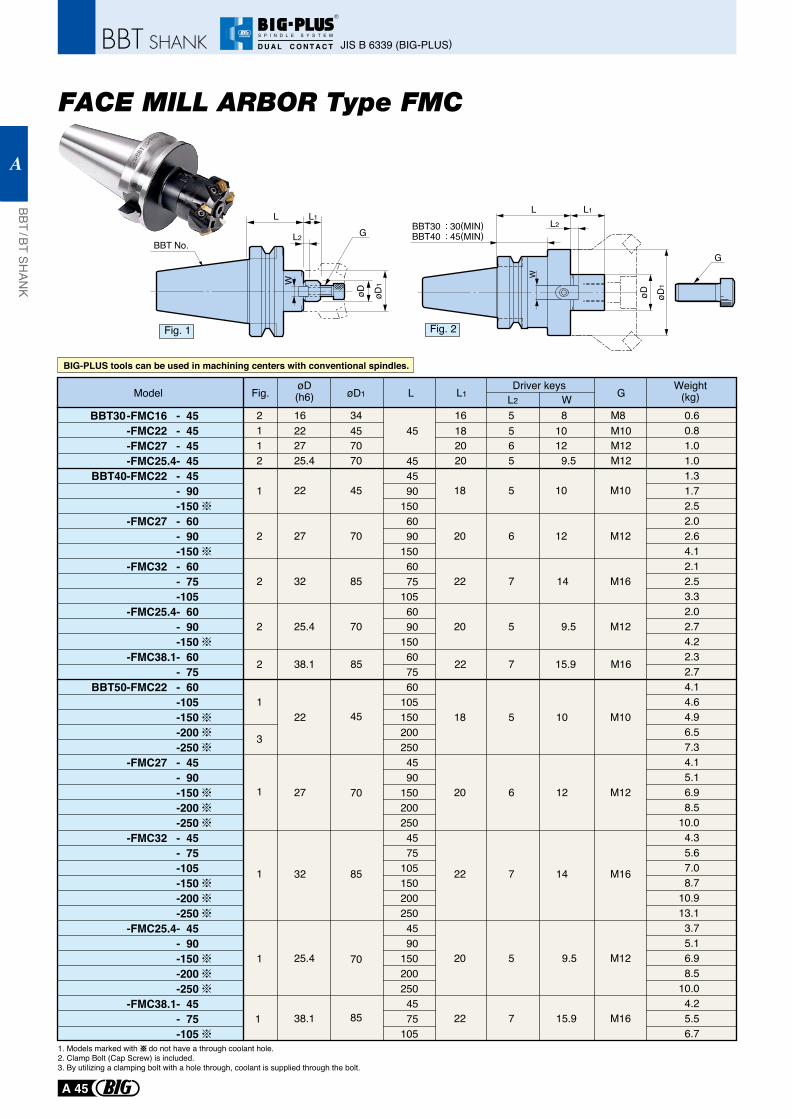
L L1
L2
øD
G
øD1W
BBT No.
1. Models marked with do not have a through coolant hole.2. Clamp Bolt (Cap Screw) is included. 3. By utilizing a clamping bolt with a hole through, coolant is supplied through the bolt.
BIG-PLUS tools can be used in machining centers with conventional spindles.
Model
BBT30-FMC16 - 45 -FMC22 - 45
-FMC27 - 45-FMC25.4- 45
BBT40-FMC22 - 45- 90-150
-FMC27 - 60- 90-150
-FMC32 - 60- 75-105
-FMC25.4- 60- 90-150
-FMC38.1- 60- 75
BBT50-FMC22 - 60-105-150-200-250
-FMC27 - 45- 90-150-200-250
-FMC32 - 45- 75-105-150-200-250
-FMC25.4- 45- 90-150-200-250
-FMC38.1- 45- 75-105
22 45
70
4570
20
1816
20M12
M10M1227
22
25.4 5655
18 5 M10
25.4 70 20 5 M129.5
9.5
34 M816 8
10
10
27 70 20 6 M1212
12
32 85 22 7 M1614
15.938.1 85 22 7 M16
25.4 70 20 5 M129.5
38.1 85 22 7 M1615.9
22 45 18 5 M1010
27 70 20 6 M1212
32 85 22 7 M1614
øD1 L
45
454590
1506090
1506075
1056090
150607560
1051502002504590
1502002504575
1051502002504590
1502002504575
105
L1Fig. L2GW
0.60.81.01.01.31.72.52.02.64.12.12.53.32.02.74.22.32.74.14.64.96.57.34.15.16.98.5
10.04.35.67.08.7
10.913.13.75.16.98.5
10.04.25.56.7
øD(h6)
Weight(kg)
2112
1
2
2
2
2
1
3
1
1
1
1
Driver keys
Fig. 1 Fig. 2
øD øD1
W
G
L L1
L2BBT30 : 30(MIN)BBT40 : 45(MIN)
JIS B 6339 (BIG-PLUS)
BBT / BT SHAN
K
A
A 45
R
S P I N D L E S Y S T E M
D U A L C O N T A C T
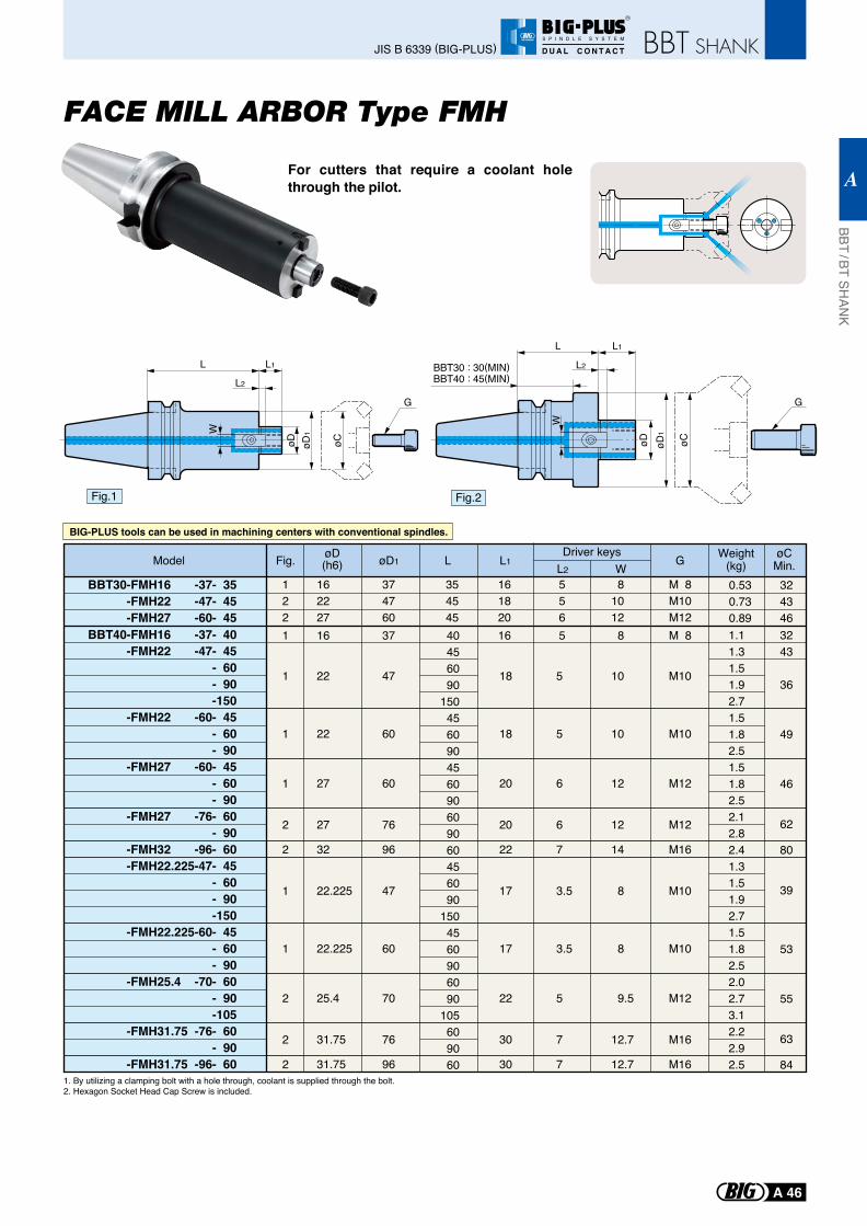
For cutters that require a coolant hole through the pilot.
Fig.1 Fig.2
GDriver keys
WL L1Fig. øD1
øD(h6)
BBT40-FMH16 -37- 40-FMH22 -47- 45
- 60 - 90 -150
-FMH22 -60- 45 - 60 - 90
-FMH27 -60- 45- 60- 90
-FMH27 -76- 60- 90
-FMH32 -96- 60-FMH22.225-47- 45
- 60 - 90
-150-FMH22.225-60- 45
- 60 - 90
-FMH25.4 -70- 60- 90-105
-FMH31.75 -76- 60- 90
-FMH31.75 -96- 60
BBT30-FMH16 -37- 35-FMH22 -47- 45-FMH27 -60- 45
Weight(kg)
1.11.31.51.92.71.51.82.51.51.82.52.12.82.41.31.51.92.71.51.82.52.02.73.12.22.92.5
40456090
150456090456090609060456090
1504560906090
105609060
L2
22
22
27
27
32
22.225
22.225
25.4
31.75
31.75
47
60
60
76
96
47
60
70
76
96
18
18
20
20
22
17
17
22
30
30
5
5
6
6
7
3.5
3.5
5
7
7
M10
M10
M12
M12
M16
M10
M10
M12
M16
M16
10
10
12
12
14
8
8
9.5
12.7
12.7
1
1
1
2
2
1
1
2
2
2
354545
122
162227
374760
161820
556
81012
M 8M10M12
0.530.730.89
øCMin.
3243
36
49
46
62
80
39
53
55
63
84
324346
Model
1. By utilizing a clamping bolt with a hole through, coolant is supplied through the bolt.2. Hexagon Socket Head Cap Screw is included.
BIG-PLUS tools can be used in machining centers with conventional spindles.
1 16 37 16 5 8 M 8
BBT / BT SHAN
K
A
A 46
JIS B 6339 (BIG-PLUS)
R
S P I N D L E S Y S T E M
D U A L C O N T A C T
G
W
øD1
øCøD
L2
L1L
øD øD1
øC
W
G
L L1
L2BBT30 : 30(MIN)BBT40 : 45(MIN)
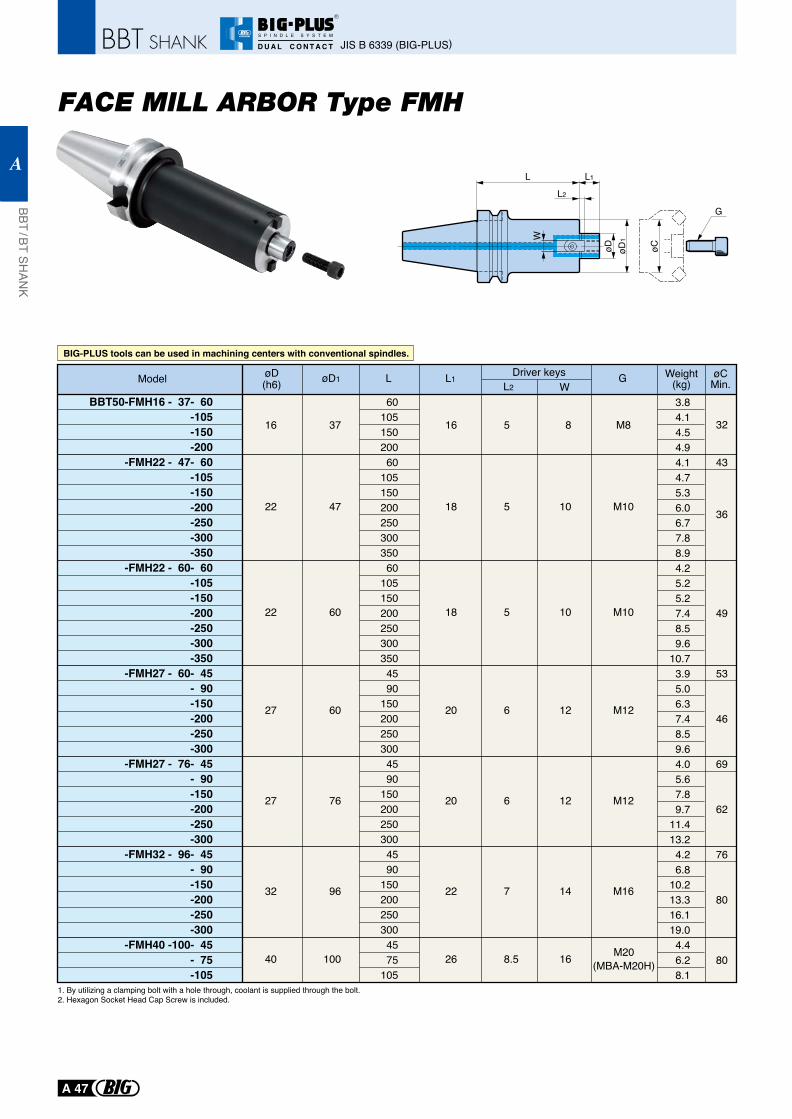
BBT50-FMH16 - 37- 60-105-150-200
-FMH22 - 47- 60 -105
-150 -200
-250-300-350
-FMH22 - 60- 60 -105 -150 -200 -250
-300-350
-FMH27 - 60- 45 - 90 -150
-200-250-300
-FMH27 - 76- 45 - 90
-150-200-250-300
-FMH32 - 96- 45 - 90
-150-200-250-300
-FMH40 -100- 45 - 75
-105
G øCMin.W
L L1L2
øD1 Weight(kg)
øD(h6)
3.84.14.54.94.14.75.36.06.77.88.94.25.25.27.48.59.6
10.7 3.9
5.0 6.3 7.4 8.5 9.6 4.0 5.6 7.8 9.711.413.2 4.2 6.810.213.316.119.0 4.4 6.2 8.1
32
43
36
49
53
46
69
62
76
80
80
6010515020060
10515020025030035060
1051502002503003504590
1502002503004590
1502002503004590
1502002503004575
105
8
10
10
12
12
14
16
M8
M10
M10
M12
M12
M16
5
5
5
6
6
7
8.5
16
18
18
20
20
22
26
37
47
60
60
76
96
100
16
22
22
27
27
32
40 M20(MBA-M20H)
Driver keysModel
BIG-PLUS tools can be used in machining centers with conventional spindles.
1. By utilizing a clamping bolt with a hole through, coolant is supplied through the bolt.2. Hexagon Socket Head Cap Screw is included.
JIS B 6339 (BIG-PLUS)
BBT / BT SHAN
K
A
A 47
R
S P I N D L E S Y S T E M
D U A L C O N T A C T
G
W
øD1
øCøD
L2
L1L
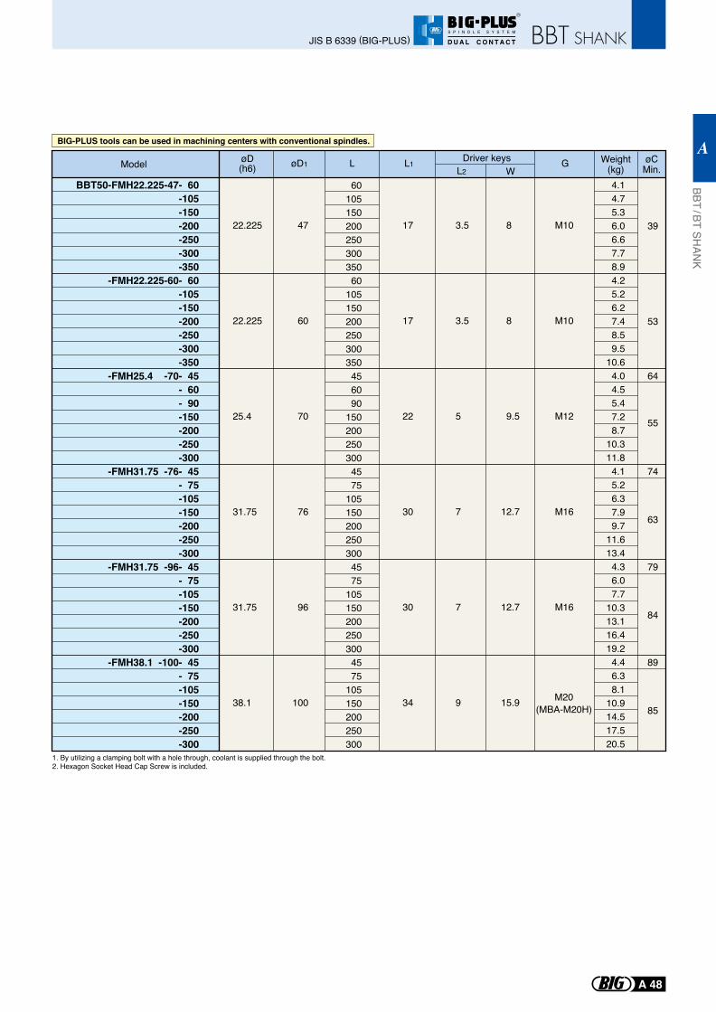
BIG-PLUS tools can be used in machining centers with conventional spindles.
BBT50-FMH22.225-47- 60 -105 -150 -200 -250
-300-350
-FMH22.225-60- 60 -105 -150 -200 -250
-300-350
-FMH25.4 -70- 45 - 60 - 90
-150 -200
-250-300
-FMH31.75 -76- 45 - 75
-105 -150 -200
-250-300
-FMH31.75 -96- 45 - 75
-105 -150
-200-250-300
-FMH38.1 -100- 45 - 75
-105 -150 -200
-250-300
GW
L L1L2
øD1 Weight(kg)
øD(h6)
4.1 4.7 5.3 6.0 6.6 7.7 8.9 4.2 5.2 6.2 7.4 8.5 9.510.64.0
4.5 5.4 7.2 8.710.311.8 4.1 5.2 6.3 7.9 9.711.613.4 4.3 6.0 7.710.313.116.419.2 4.4 6.3 8.110.914.517.520.5
6010515020025030035060
105150200250300350456090
1502002503004575
1051502002503004575
1051502002503004575
105150200250300
8
8
9.5
12.7
12.7
15.9
M10
M10
M12
M16
M16
3.5
3.5
5
7
7
9
17
17
22
30
30
34
47
60
70
76
96
100
22.225
22.225
25.4
31.75
31.75
38.1
Driver keys
M20(MBA-M20H)
Model
1. By utilizing a clamping bolt with a hole through, coolant is supplied through the bolt.2. Hexagon Socket Head Cap Screw is included.
øCMin.
39
53
64
55
74
63
79
84
89
85
BBT / BT SHAN
K
A
A 48
JIS B 6339 (BIG-PLUS)
R
S P I N D L E S Y S T E M
D U A L C O N T A C T
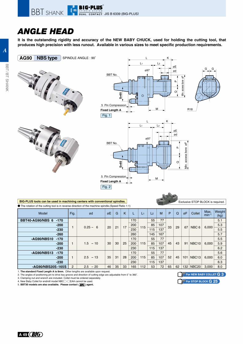
ANGLE HEADIt is the outstanding rigidity and accuracy of the NEW BABY CHUCK, used for holding the cutting tool, that produces high precision with less runout. Available in various sizes to meet specific production requirements.
1. The standard Fixed Length A is 8mm. Other lengths are available upon request.2. The angles of positioning pin to drive key groove and direction of cutting edge are adjustable from 0˚ to 360˚.3. Clamping nut and wrench are included. Collet must be ordered separately.4. New Baby Collet for endmill model NBC - EAA cannot be used.5. BBT30 models are also available. Please contact agent.
R18
G G
The rotation of the cutting tool is in reverse direction of the machine spindle.(Speed Ratio 1:1)
For NEW BABY COLLET G 3For STOP BLOCK G 25
Weight(kg)
Max.min-1Colletød øEFig. G K L L1 L2 M P Q øF
1
1
Model
BBT40-AG90/NBS 6 -170-200-230-260
-AG90/NBS10 -170-200-230
-AG90/NBS13 -170-200-230
-AG90/NBS20S -165S
5.15.35.55.75.55.96.25.66.06.38.0
NBC13
NBC10
NBC 6
NBC20
6,000
6,000
6,0001
3,000
0.25 - 6 20 21 17
170
115
55 77
33 29 67200 85 107230260
115 137145 167
1.5 - 10 30 30 25170
115 55 77
45 43 91200 85 107230 115 137
2.5 - 13 35 31 28170
115 55 77
52 45 101200 85 107230 115 137
2.5 - 20 46 35 33 165 112 53 72 65 62 1322
Exclusive STOP BLOCK is required.
AG90 NBS type
BIG-PLUS tools can be used in machining centers with conventional spindles.
Fig. 1
Fig. 2
L1 L2
ø97
Fixed Length A
PQ
Min.
acce
ss bo
re øF
S=65
L K
øE
5 Pin Compression
ød
M
BBT No.
Fixed Length A5 Pin Compression
L1 L2
ø97
PQ
Min
. acc
ess
bore
øF
S=65
L K
øEød
M
BBT No.
SPINDLE ANGLE : 90˚
JIS B 6339 (BIG-PLUS)
BBT / BT SHAN
K
A
A 49
R
S P I N D L E S Y S T E M
D U A L C O N T A C T
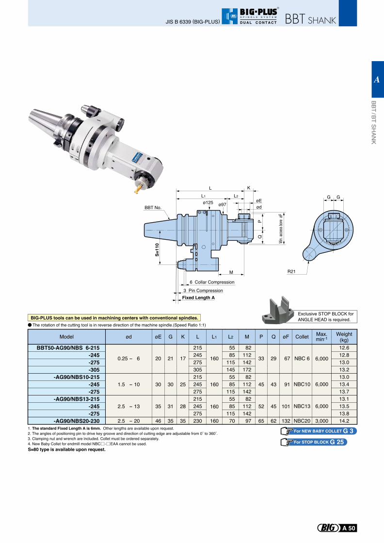
1. The standard Fixed Length A is 6mm. Other lengths are available upon request.2. The angles of positioning pin to drive key groove and direction of cutting edge are adjustable from 0˚ to 360˚.3. Clamping nut and wrench are included. Collet must be ordered separately.4. New Baby Collet for endmill model NBC - EAA cannot be used.
The rotation of the cutting tool is in reverse direction of the machine spindle.(Speed Ratio 1:1)
S=80 type is available upon request.
G G
R21
L1 L2
ø97ø125
Fixed Length A
PQ
S=11
0
L K
øE
3 Pin Compression
6 Collar Compression
ød
MMi
n. ac
cess
bore
øF
For NEW BABY COLLET G 3For STOP BLOCK G 25
Max.min-1Colletød øE G K L L1 L2 M P Q øFModel Weight
(kg)BBT50-AG90/NBS 6-215
-245-275
-AG90/NBS10-215-245-275
-AG90/NBS13-215-245-275
12.612.813.0
13.013.413.713.113.513.8
NBC 6
NBC10
NBC13
0.25 - 6 20 21 17
215
160
55 82
33 29 67245 85 112275 115 142
-305 13.2305 145 172
1.5 - 10 30 30 25215
160 55 82
45 43 91245 85 112275 115 142
2.5 - 13 35 31 28215
160 55 82
52 45 101245 85 112275 115 142
6,000
6,000
6,000
230-AG90/NBS20-230 14.2NBC202.5 - 20 46 35 35 160 70 97 65 62 132 3,000
Exclusive STOP BLOCK forANGLE HEAD is required.BIG-PLUS tools can be used in machining centers with conventional spindles.
BBT No.
BBT / BT SHAN
K
A
A 50
JIS B 6339 (BIG-PLUS)
R
S P I N D L E S Y S T E M
D U A L C O N T A C T
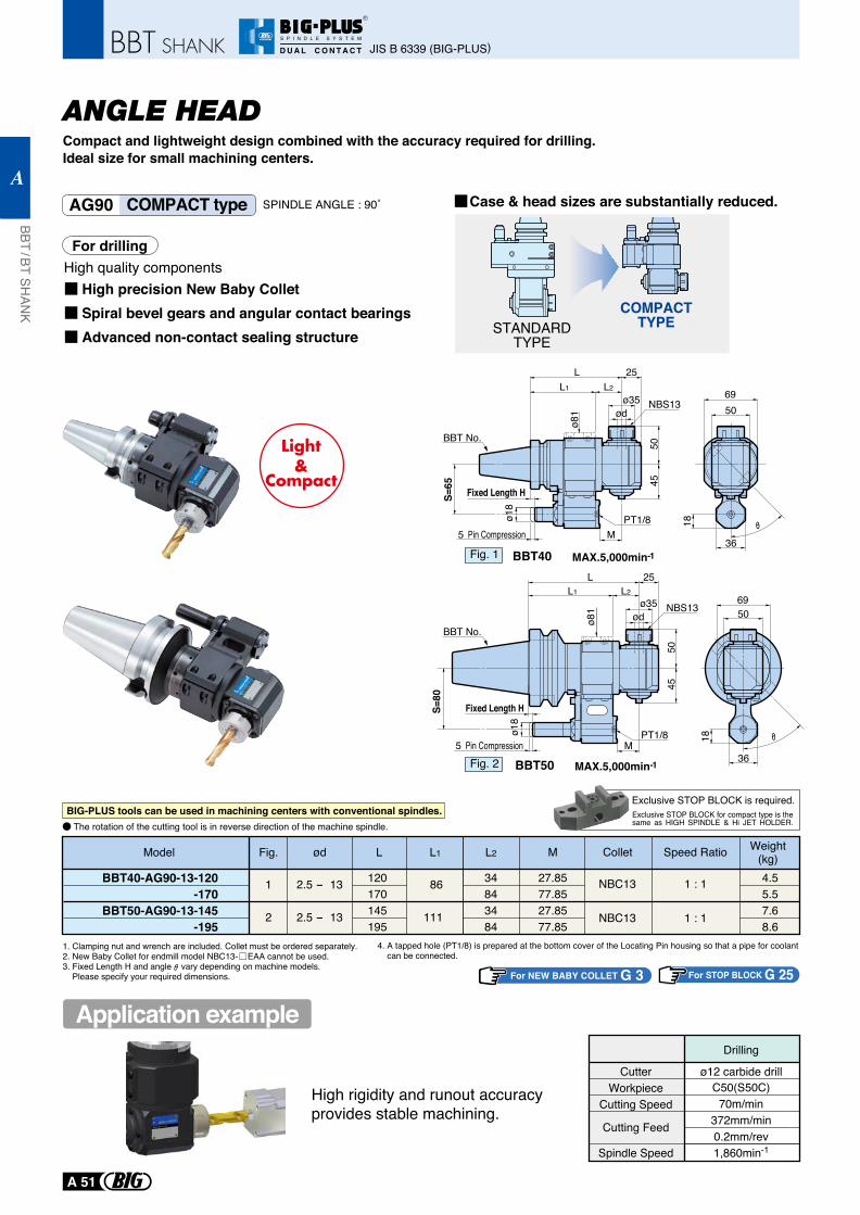
For STOP BLOCK G 25
MAX.5,000min-1BBT50
MAX.5,000min-1BBT40
50
36
18
69
L 25L2
M
ø35
Fixed Length H
Fixed Length H
5 Pin Compression
5045
ø81
ø18
ød
L1
PT1/8
NBS13
L 25L2
M
ø35 NBS13
5 Pin Compression
5045
ø81
ø18
ød
L1
PT1/8
50
36
18
69
1. Clamping nut and wrench are included. Collet must be ordered separately.2. New Baby Collet for endmill model NBC13- EAA cannot be used.3. Fixed Length H and angle vary depending on machine models. Please specify your required dimensions.
Model L L1Weight
(kg)Collet Speed Ratio
1 : 1
1 : 1
4.55.57.68.6
NBC13
NBC13
120170145195
34843484
86
111
ød
2.5 - 13
2.5 - 13
1
2
L2
27.8577.8527.8577.85
M
BBT40-AG90-13-120-170
BBT50-AG90-13-145-195
Fig.
CutterWorkpiece
Cutting Speed
Cutting Feed
Spindle Speed
ø12 carbide drillC50(S50C)
70m/min372mm/min0.2mm/rev1,860min-1
Drilling
High rigidity and runout accuracy provides stable machining.
For drilling
High precision New Baby ColletSpiral bevel gears and angular contact bearingsAdvanced non-contact sealing structure
High quality components
Case & head sizes are substantially reduced.
For NEW BABY COLLET G 3
COMPACTTYPESTANDARD
TYPE
S=65
S=80
4. A tapped hole (PT1/8) is prepared at the bottom cover of the Locating Pin housing so that a pipe for coolant can be connected.
Exclusive STOP BLOCK is required.BIG-PLUS tools can be used in machining centers with conventional spindles.
The rotation of the cutting tool is in reverse direction of the machine spindle.Exclusive STOP BLOCK for compact type is the same as HIGH SPINDLE & Hi JET HOLDER.
ANGLE HEADCompact and lightweight design combined with the accuracy required for drilling.Ideal size for small machining centers.
AG90 COMPACT type
BBT No.
BBT No.
Fig. 1
Fig. 2
Application example
SPINDLE ANGLE : 90˚
JIS B 6339 (BIG-PLUS)
BBT / BT SHAN
K
A
A 51
R
S P I N D L E S Y S T E M
D U A L C O N T A C T
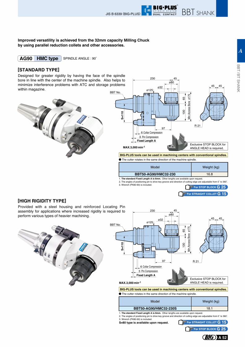
45 45
R 21
45 45
R 21
1. The standard Fixed Length A is 6mm. Other lengths are available upon request.2. The angles of positioning pin to drive key groove and direction of cutting edge are adjustable from 0˚ to 360˚.3. Wrench (FK80-90) is included.
MAX.3,000 min-1
1. The standard Fixed Length A is 6mm. Other lengths are available upon request.2. The angles of positioning pin to drive key groove and direction of cutting edge are adjustable from 0˚ to 360˚.3. Wrench (FK80-90) is included.
For STOP BLOCK G 25
S=80 type is available upon request.
Exclusive STOP BLOCK forANGLE HEAD is required.
Exclusive STOP BLOCK forANGLE HEAD is required.
BBT50-AG90/HMC32-230
Weight (kg)
16.8
Model
BBT50-AG90/HMC32-230S
Weight (kg)
18.1
Model
For STRAIGHT COLLET G 15
For STOP BLOCK G 25For STRAIGHT COLLET G 15
The cutter rotates in the same direction of the machine spindle.
The cutter rotates in the same direction of the machine spindle.
Improved versatility is achieved from the 32mm capacity Milling Chuck by using parallel reduction collets and other accessories.
AG90 HMC type
[STANDARD TYPE]Designed for greater rigidity by having the face of the spindle bore in line with the center of the machine spindle. Also helps to minimize interference problems with ATC and storage problems within magazine.
[HIGH RIGIDITY TYPE]Provided with a steel housing and reinforced Locating Pin assembly for applications where increased rigidity is required to perform various types of heavier machining.
BIG-PLUS tools can be used in machining centers with conventional spindles.
BIG-PLUS tools can be used in machining centers with conventional spindles.
ø80ø32
ø125
97
65
Min.A
cces
s Bor
e ø1
75
100
S=11
0
230 45
MAX.3,000 min-1
Fixed Length A3 Pin Compression
6 Collar Compression
BBT No.
ø80
ø32ø125
97
Fixed Length A
65
Min.A
cces
s Bor
e ø1
75
100
S=11
0
230 45
3 Pin Compression6 Collar Compression
BBT No.
SPINDLE ANGLE : 90˚
BBT / BT SHAN
K
A
A 52
JIS B 6339 (BIG-PLUS)
R
S P I N D L E S Y S T E M
D U A L C O N T A C T
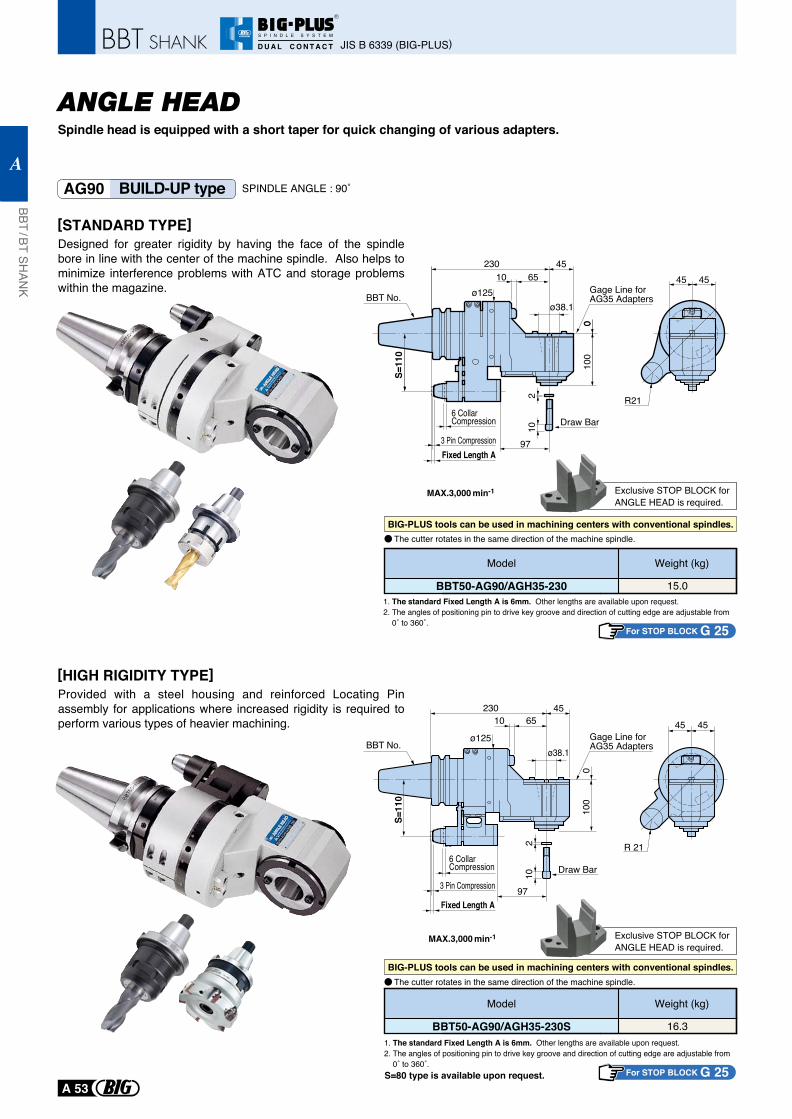
Spindle head is equipped with a short taper for quick changing of various adapters.
AG90 BUILD-UP type
MAX.3,000 min-1
MAX.3,000 min-1
1. The standard Fixed Length A is 6mm. Other lengths are available upon request.2. The angles of positioning pin to drive key groove and direction of cutting edge are adjustable from 0˚ to 360˚.
1. The standard Fixed Length A is 6mm. Other lengths are available upon request.2. The angles of positioning pin to drive key groove and direction of cutting edge are adjustable from 0˚ to 360˚.
6510ø125
97
010
0
230 45
Gage Line for AG35 Adapters
ø38.1
3 Pin Compression
6 CollarCompression Draw Bar
102
Fixed Length A
0
S=11
0
45 45
R21
S=80 type is available upon request.
Exclusive STOP BLOCK forANGLE HEAD is required.
Exclusive STOP BLOCK forANGLE HEAD is required.
The cutter rotates in the same direction of the machine spindle.
The cutter rotates in the same direction of the machine spindle.
[STANDARD TYPE]Designed for greater rigidity by having the face of the spindle bore in line with the center of the machine spindle. Also helps to minimize interference problems with ATC and storage problems within the magazine.
[HIGH RIGIDITY TYPE]Provided with a steel housing and reinforced Locating Pin assembly for applications where increased rigidity is required to perform various types of heavier machining.
BBT No.
102
65
97
10
ø125
Fixed Length A
010
0
S=11
0
230 45
ø38.1
3 Pin Compression
6 CollarCompression
Gage Line for AG35 Adapters
Draw Bar
45 45
R 21
BBT No.
BBT50-AG90/AGH35-230
Weight (kg)
15.0
Model
BBT50-AG90/AGH35-230S
Weight (kg)
16.3
Model
BIG-PLUS tools can be used in machining centers with conventional spindles.
BIG-PLUS tools can be used in machining centers with conventional spindles.
For STOP BLOCK G 25
For STOP BLOCK G 25
SPINDLE ANGLE : 90˚
ANGLE HEAD
JIS B 6339 (BIG-PLUS)
BBT / BT SHAN
K
A
A 53
R
S P I N D L E S Y S T E M
D U A L C O N T A C T
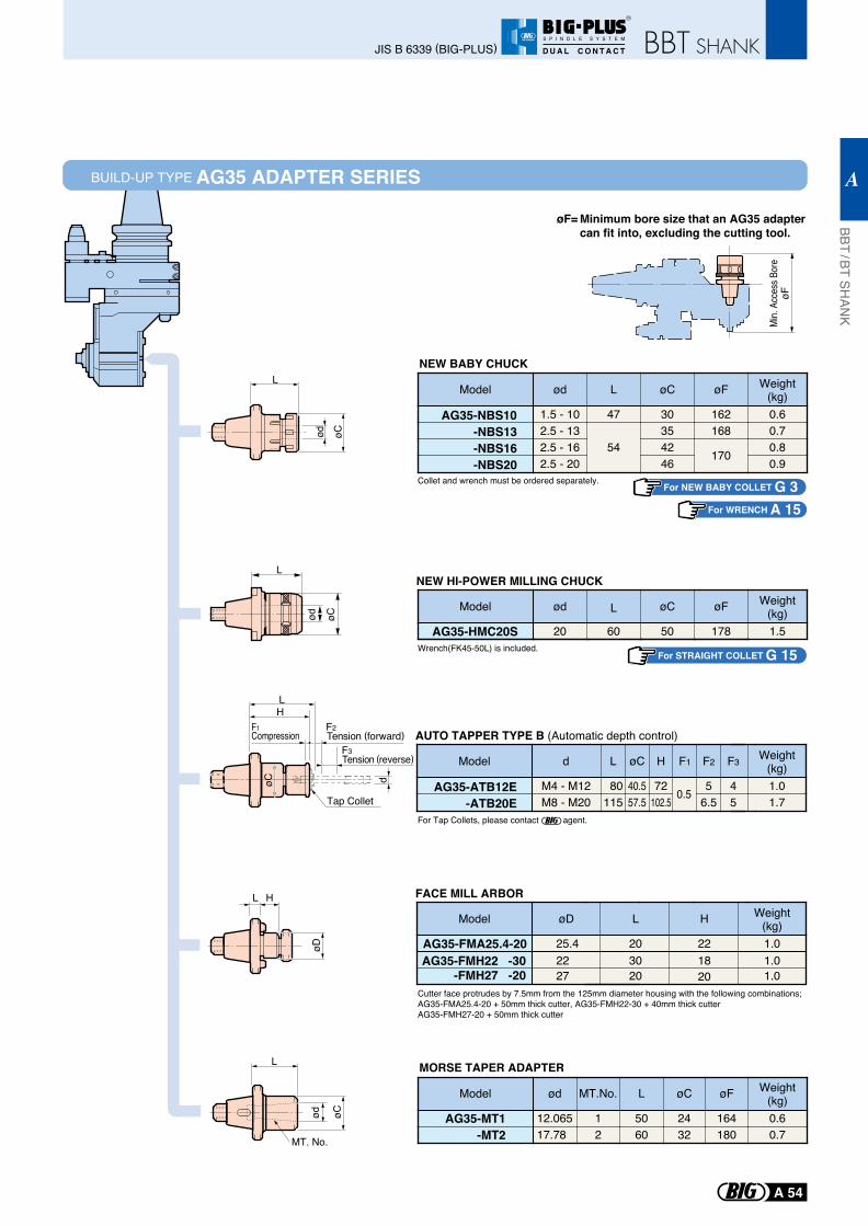
BUILD-UP TYPE AG35 ADAPTER SERIES
Min.
Acce
ss B
ore
øF
Minimum bore size that an AG35 adapter can fit into, excluding the cutting tool.
øF=
For NEW BABY COLLET G 3For WRENCH A 15
L
øCød
L H
øD
HF1 F2
F3
L
døC
Compression Tension (forward)
Tension (reverse)
Tap ColletAG35-ATB12E
-ATB20E
øC H F1 F2 F3
40.5 72 0.5 5 457.5 102.5 6.5 5
Ld
80115
M4 - M12M8 - M20
Weight(kg)1.01.7
Model
AG35-NBS10-NBS13-NBS16-NBS20
ød
1.5 - 102.5 - 132.5 - 162.5 - 20
L
47
54
øC
30354246
øF
162168
170
Weight(kg)0.60.70.80.9
Model
AG35-HMC20S
ød
20
L
60
øC
50
øF
178
Weight(kg)1.5
Model
AG35-FMA25.4-20
øD
25.4
L
20
H
22
Weight(kg)1.0
AG35-FMH22 -30-FMH27 -20
22 30 1820
1.027 20 1.0
Model
Wrench(FK45-50L) is included.
For Tap Collets, please contact agent.
Cutter face protrudes by 7.5mm from the 125mm diameter housing with the following combinations;AG35-FMA25.4-20 + 50mm thick cutter, AG35-FMH22-30 + 40mm thick cutterAG35-FMH27-20 + 50mm thick cutter
Collet and wrench must be ordered separately.
NEW BABY CHUCK
AG35-MT1-MT2
ød
12.06517.78
MT.No.
1
L
50602
øC
2432
øF
164180
Weight(kg)0.60.7
Model
MORSE TAPER ADAPTER
NEW HI-POWER MILLING CHUCK
AUTO TAPPER TYPE B (Automatic depth control)
FACE MILL ARBOR
L
MT. No.
øCød
For STRAIGHT COLLET G 15
BBT / BT SHAN
K
A
A 54
JIS B 6339 (BIG-PLUS)
R
S P I N D L E S Y S T E M
D U A L C O N T A C T
L
ød øC
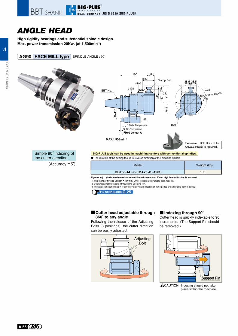
AG90 FACE MILL type
1. The standard Fixed Length A is 6mm. Other lengths are available upon request.2. Coolant cannot be supplied through the Locating Pin.3. The angles of positioning pin to drive key groove and direction of cutting edge are adjustable from 0˚ to 360˚.
For STOP BLOCK G 25
Exclusive STOP BLOCK forANGLE HEAD is required.
BBT50-AG90-FMA25.4S-190S
Weight (kg)
19.2
Model
Figures in ( ) indicate dimensions when 80mm diameter and 50mm high face mill cutter is mounted.
38.5
5
38.5
9.35
Min. bore for access
ø206
R21
Following the release of the Adjusting Bolts (8 positions), the cutter direction can be easily adjusted.
Cutter head is quickly indexable to 90˚ increments. (The Support Pin should be removed.)
CAUTION :
Cutter head adjustable through360˚ to any angle
AdjustingBolt
Indexing through 90˚
Support PinIndexing should not take place within the machine.
(Accuracy 5 )
Simple 90 indexing of the cutter direction. The rotation of the cutting tool is in reverse direction of the machine spindle.
SPINDLE ANGLE : 90˚
High rigidity bearings and substantial spindle design.Max. power transmission 20Kw. (at 1,500min-1)
ANGLE HEAD
MAX.1,500 min-1
ø25.4
76.5
(117
)67
(50)
22
ø140Clamp Bolt
ø125
(ø80)38.5190
57
Fixed Length A3 Pin Compression
6 Collar Compression
S=11
0
BBT No.
BIG-PLUS tools can be used in machining centers with conventional spindles.
JIS B 6339 (BIG-PLUS)
BBT / BT SHAN
K
A
A 55
R
S P I N D L E S Y S T E M
D U A L C O N T A C T
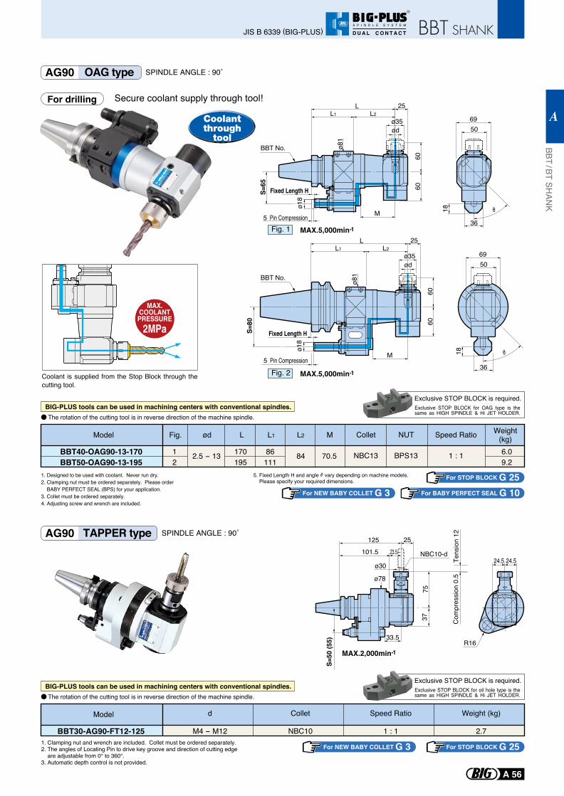
AG90 OAG type SPINDLE ANGLE : 90˚
Secure coolant supply through tool!
1. Designed to be used with coolant. Never run dry.2. Clamping nut must be ordered separately. Please order BABY PERFECT SEAL (BPS) for your application.3. Collet must be ordered separately.4. Adjusting screw and wrench are included.
5. Fixed Length H and angle vary depending on machine models. Please specify your required dimensions.
MAX.COOLANT
PRESSURE2MPa
The rotation of the cutting tool is in reverse direction of the machine spindle.
For drilling
MAX.5,000min-1
5069
L 25L2
M
ø35
Fixed Length H
5 Pin Compression
60
S=65 60
ø81
ø18
ød
L1
36
18
MAX.5,000min-1
5069
M5 Pin Compression
S=80
6060
ø81
L 25L2
ø35L1
ød
Fixed Length H
ø18
36
18
Model L L1Weight
(kg)Collet Speed Ratio
1 : 1 6.09.2
NBC13
NUT
BPS13170195
86111
12
ød
2.5 - 13 84 70.5
L2 M
BBT40-OAG90-13-170BBT50-OAG90-13-195
Fig.
Exclusive STOP BLOCK is required.Exclusive STOP BLOCK for OAG type is the same as HIGH SPINDLE & Hi JET HOLDER.
For STOP BLOCK G 25For NEW BABY COLLET G 3
For STOP BLOCK G 25For NEW BABY COLLET G 3
For BABY PERFECT SEAL G 10
Coolant is supplied from the Stop Block through the cutting tool.
Coolantthrough
tool
BIG-PLUS tools can be used in machining centers with conventional spindles.
The rotation of the cutting tool is in reverse direction of the machine spindle.
Exclusive STOP BLOCK is required.Exclusive STOP BLOCK for oil hole type is the same as HIGH SPINDLE & Hi JET HOLDER.
BIG-PLUS tools can be used in machining centers with conventional spindles.
AG90 TAPPER type SPINDLE ANGLE : 90˚
Model Weight (kg)
2.7
Speed Ratio
1 : 1
Collet
NBC10
d
M4 - M12BBT30-AG90-FT12-1251. Clamping nut and wrench are included. Collet must be ordered separately. 2. The angles of Locating Pin to drive key groove and direction of cutting edge are adjustable from 0° to 360°. 3. Automatic depth control is not provided.
MAX.2,000min-1
ø78
ø30
S=50
(55) 33.5
3775
Tens
ion
12
125
101.5 23.5
25
Com
pres
sion
0.5
NBC10-d24.5 24.5
R16
Fig. 1
Fig. 2
BBT No.
BBT No.
BBT / BT SHAN
K
A
A 56
JIS B 6339 (BIG-PLUS)
R
S P I N D L E S Y S T E M
D U A L C O N T A C T
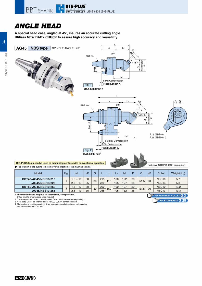
High rigidity bearings and substantial spindle design.Max. power transmission 20Kw. (at 1,500min-1)
ANGLE HEAD
1. The standard fixed length A: 40 taper=8mm , 50 taper=6mm. Other lengths are available upon request.2. Clamping nut and wrench are included. Collet must be ordered separately.3. New Baby Collet for endmill model NBC - EAA cannot be used.4. The angles of positioning pin to drive key groove and direction of cutting edge are adjustable from 0˚ to 360˚.
A special head case, angled at 45°, insures an accurate cutting angle. Utilizes NEW BABY CHUCK to assure high accuracy and versatility.
R18 (BBT40)R21 (BBT50)
G G
BBT50-AG45/NBS10-260-AG45/NBS13-265
Collet Weight (kg)
NBC10NBC13
ød øE L L1 L2 P Q øF
1.5 - 10 30 260 160
G
30 100 20 51.5 902.5 - 13 35 265 105
M
127132 25
13.213.3
BBT40-AG45/NBS10-215-AG45/NBS13-220
NBC10NBC13
1.5 - 10 30 215 11530 100 20 51.5 902.5 - 13 35 220 105122127 25
5.75.8
Model
ø97
PQ
Min. A
ccess
Bore
øF
L
øEød
45˚
M
L2L1
S=65
Fig.
1
2
AG45 NBS type SPINDLE ANGLE : 45˚
BBT No.
The rotation of the cutting tool is in reverse direction of the machine spindle.BIG-PLUS tools can be used in machining centers with conventional spindles.
M
L1 L2
ø97
S=11
0
L
PQ
Min. A
ccess
Bore
øF
øEød
45˚
MAX.6,000 min-1Fig. 2
BBT No.
6 Collar Compression3 Pin CompressionFixed Length A
5 Pin CompressionFixed Length A
MAX.6,000min-1Fig. 1
For STOP BLOCK G 25For NEW BABY COLLET G 3
Exclusive STOP BLOCK is required.
JIS B 6339 (BIG-PLUS)
BBT / BT SHAN
K
A
A 57
R
S P I N D L E S Y S T E M
D U A L C O N T A C T
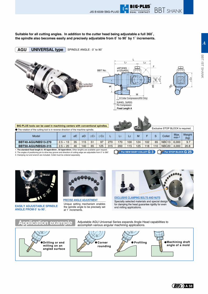
AGU UNIVERSAL type SPINDLE ANGLE : 0˚ to 90˚
Suitable for all cutting angles. In addition to the cutter head being adjustable a full 360˚, the spindle also becomes easily and precisely adjustable from 0˚ to 90˚ by 1˚ increments.
Drilling or end milling on an angled surface
Corner rounding
Profiling Machining draftangle of a mold
Adjustable AGU Universal Series expands Angle Head capabilities toaccomplish various angular machining applications.
EXCLUSIVE CLAMPING BOLTS AND NUTSSpecially selected materials and special designfor clamping the head guarantee rigidity for even end milling applications.
Unique setting mechanism enables the spindle angle to be precisely set at 1˚ increments.
PRECISE ANGLE ADJUSTMENT
EASILY ADJUSTABLE SPINDLE ANGLE FROM 0˚ to 90˚.
1. The standard fixed length A: 40 taper=8mm , 50 taper=6mm. Other lengths are available upon request.2. The angles of positioning pin to drive key groove and direction of cutting edge are adjustable from 0˚ to 360˚.3. Clamping nut and wrench are included. Collet must be ordered separately.
For NEW BABY COLLET G 3 For STOP BLOCK G 25
BBT40-AGU/NBS13-270BBT50-AGU/NBS20-315
Weight(kg)
Max.min-1Colletød øD C1 C2 L1 L2 M F SModel øE L
17027035 115 51 97 100 124 102 65 6,000NBC13 9.72.5 - 1320031546 140 65 125 115 125 118 110 4,000NBC20 20.82.5 - 20
Exclusive STOP BLOCK is required.The rotation of the cutting tool is in reverse direction of the machine spindle.BIG-PLUS tools can be used in machining centers with conventional spindles.
Application example
C2
øD
C1
Fixed Length A
5(#40), 3(#50)6 Collar Compression(#50 Only)
LL2
M
øE
S ød
FL1
Pin Compression
ø97(#40)ø125(#50)BBT No.
BBT / BT SHAN
K
A
A 58
JIS B 6339 (BIG-PLUS)
R
S P I N D L E S Y S T E M
D U A L C O N T A C T
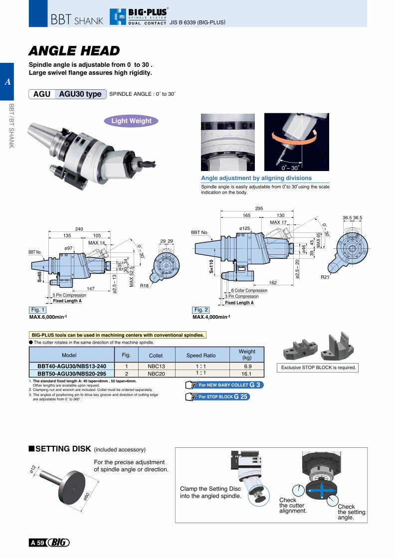
ANGLE HEADSpindle angle is adjustable from 0 to 30 .Large swivel flange assures high rigidity.
AGU AGU30 type SPINDLE ANGLE : 0˚ to 30˚
For NEW BABY COLLET G 3For STOP BLOCK G 25
Exclusive STOP BLOCK is required.
Spindle angle is easily adjustable from 0 to 30 using the scale indication on the body.
Angle adjustment by aligning divisions
1. The standard fixed length A: 40 taper=8mm , 50 taper=6mm. Other lengths are available upon request.2. Clamping nut and wrench are included. Collet must be ordered separately.3. The angles of positioning pin to drive key groove and direction of cutting edge are adjustable from 0˚ to 360˚.
Clamp the Setting Discinto the angled spindle.
For the precise adjustment of spindle angle or direction.ø1
2
ø60
0 - 30
Model ColletWeight
(kg)Fig.
NBC13NBC20
1 1 6.916.1
BBT40-AGU30/NBS13-240BBT50-AGU30/NBS20-295
12 1 1
Speed Ratio
Check the cutter alignment. Check
the setting angle.
The cutter rotates in the same direction of the machine spindle.
Light Weight
MAX.6,000min-1Fig. 1
MAX.4,000min-1Fig. 2
BIG-PLUS tools can be used in machining centers with conventional spindles.
SETTING DISK (included accessory)
MAX 14
MAX
52.
5
0˚-30˚
ø2.5-
13
105240
13529 29
ø35 34
30
147
S=65
5 Pin CompressionFixed Length A
R18
ø97BBT No.
S=11
0295
165 130MAX 17
ø46 M
AX 6
5
0˚-30˚
4539
ø2.5-
20
36.5 36.5
6 Collar Compression3 Pin CompressionFixed Length A
162R21
ø125BBT No.
JIS B 6339 (BIG-PLUS)
BBT / BT SHAN
K
A
A 59
R
S P I N D L E S Y S T E M
D U A L C O N T A C T
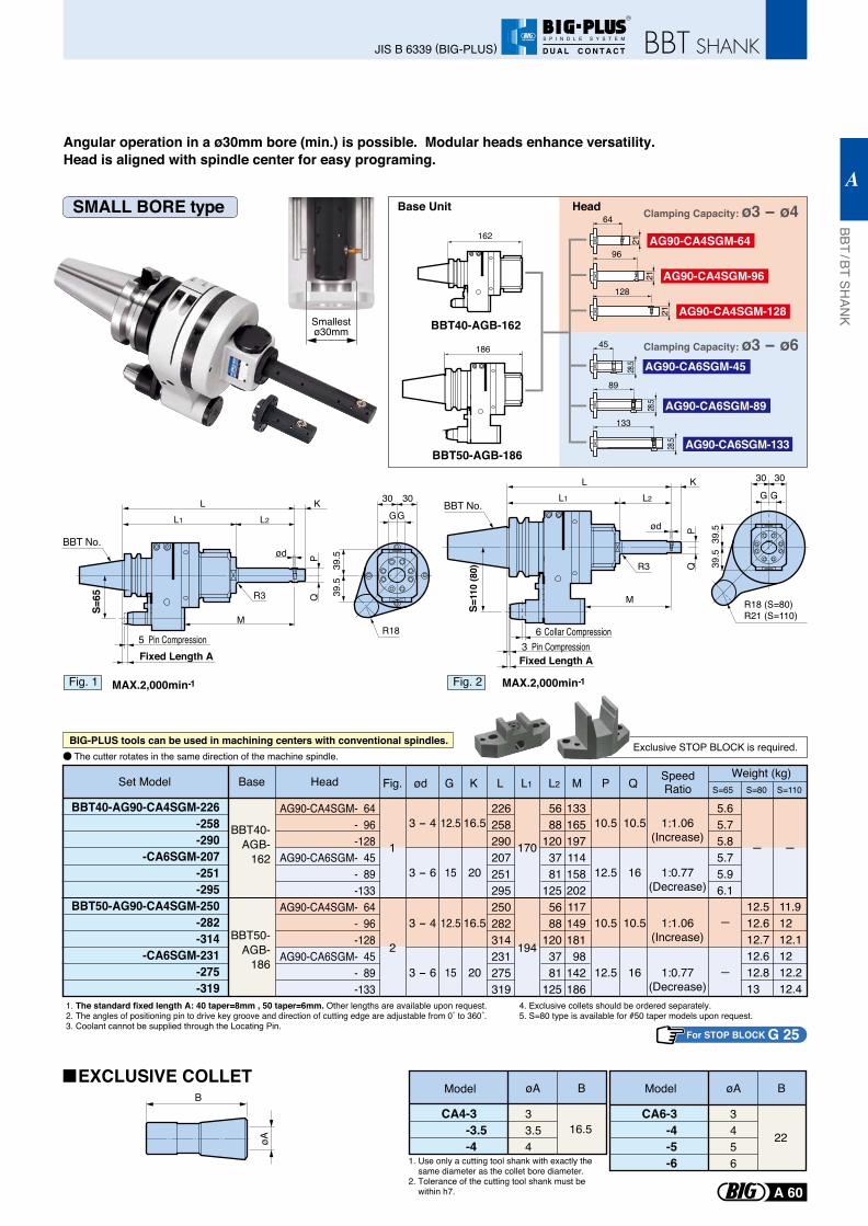
Angular operation in a ø30mm bore (min.) is possible. Modular heads enhance versatility.Head is aligned with spindle center for easy programing.
For STOP BLOCK G 25
BBT40-AG90-CA4SGM-226-258-290
-CA6SGM-207-251-295
BBT50-AG90-CA4SGM-250-282-314
-CA6SGM-231-275-319
AG90-CA4SGM- 64- 96-128
AG90-CA6SGM- 45- 89-133
AG90-CA4SGM- 64- 96-128
AG90-CA6SGM- 45- 89-133
226258290207251295250282314231275319
5688
1203781
1255688
1203781
125
13316519711415820211714918198
142186
5.65.75.85.75.96.1
12.512.612.712.612.813
11.91212.11212.212.4
BBT40-AGB-
162
BBT50-AGB-
186
Fig. ød G K L M P QL1 L2 Weight (kg)
1
3 - 4
3 - 6
3 - 4
3 - 6
12.5
15
12.5
15
16.5
20
16.5
20
10.5
12.5
10.5
12.5
10.5
16
10.5
16
1:1.06(Increase)
1:0.77(Decrease)
1:1.06(Increase)
1:0.77(Decrease)
2
170
194
S=65 S=80 S=110
1. The standard fixed length A: 40 taper=8mm , 50 taper=6mm. Other lengths are available upon request.2. The angles of positioning pin to drive key groove and direction of cutting edge are adjustable from 0˚ to 360˚.3. Coolant cannot be supplied through the Locating Pin.
4. Exclusive collets should be ordered separately.5. S=80 type is available for #50 taper models upon request.
1. Use only a cutting tool shank with exactly the same diameter as the collet bore diameter.2. Tolerance of the cutting tool shank must be within h7.
CA4-3 -3.5-4
33.54
Model øA B
16.5CA6-3
-4-5-6
3456
øA B
22
Smallestø30mm
ModelB
øA
BBT40-AGB-162
162
Base Unit
128
21
96
21
64
21
133
89
45
28.5
28.5
28.5
Head
AG90-CA4SGM-128
AG90-CA4SGM-96
AG90-CA4SGM-64
AG90-CA6SGM-133
AG90-CA6SGM-89
AG90-CA6SGM-45186
BBT50-AGB-186
Set Model Base Head
Clamping Capacity: ø3 - ø4
Clamping Capacity: ø3 - ø6
SpeedRatio
Exclusive STOP BLOCK is required.The cutter rotates in the same direction of the machine spindle.
SMALL BORE type
BIG-PLUS tools can be used in machining centers with conventional spindles.
EXCLUSIVE COLLET
Fixed Length A5 Pin Compression
R18
30 30
GG
39.5
39.5
MAX.2,000min-1
L K
ød
M
QP
L1 L2
R3
S=65
Fig. 1
BBT No.
Fixed Length A3 Pin Compression
R18 (S=80)R21 (S=110)
30 30
G G
39.5
39.5
MAX.2,000min-1
L K
R3
M
S=11
0 (8
0)
L1 L2
ød
QP
6 Collar Compression
Fig. 2
BBT No.
BBT / BT SHAN
K
A
A 60
JIS B 6339 (BIG-PLUS)
R
S P I N D L E S Y S T E M
D U A L C O N T A C T
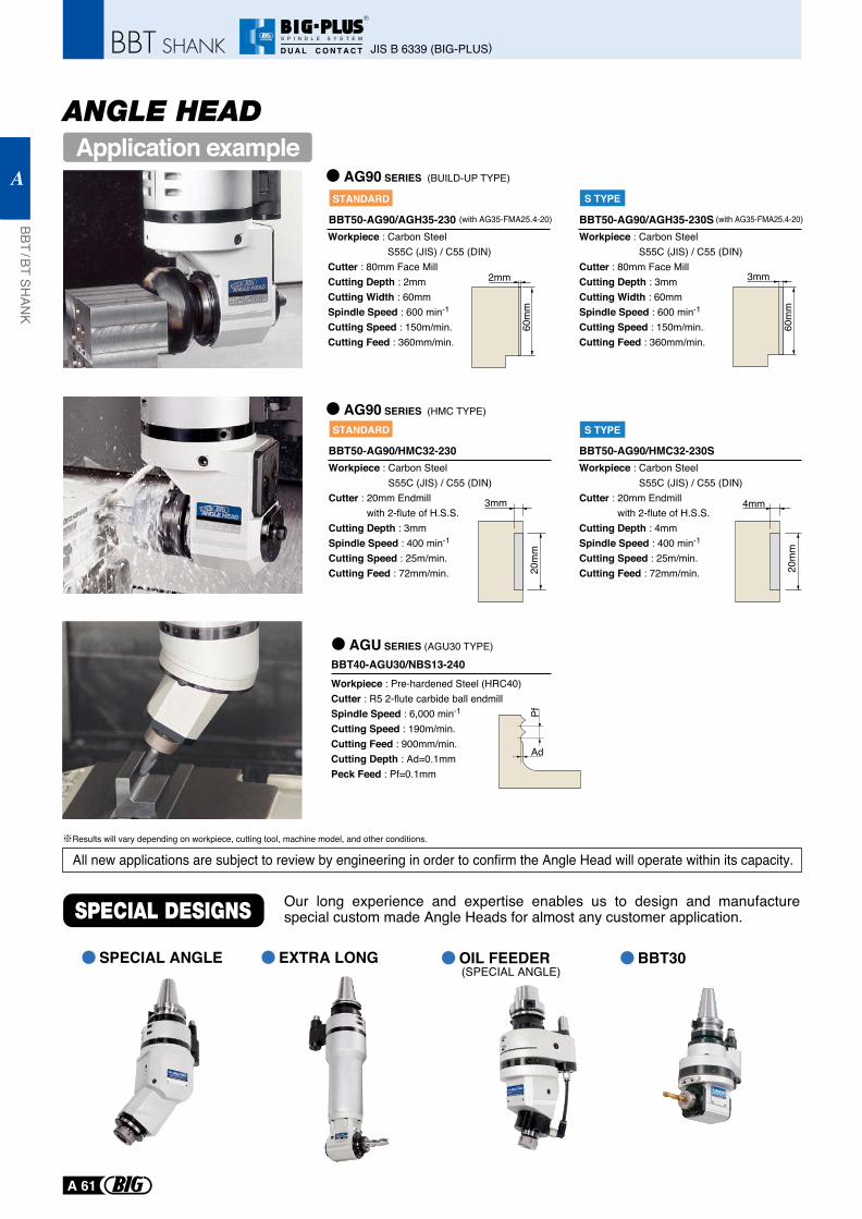
AG90 SERIES (HMC TYPE)
AGU SERIES (AGU30 TYPE)
AG90 SERIES (BUILD-UP TYPE)
All new applications are subject to review by engineering in order to confirm the Angle Head will operate within its capacity.
Workpiece : Carbon Steel S55C (JIS) / C55 (DIN)
Cutter : 80mm Face MillCutting Depth : 2mmCutting Width : 60mm Spindle Speed : 600 min-1
Cutting Speed : 150m/min.Cutting Feed : 360mm/min.
BBT50-AG90/AGH35-230
2mm
60m
m
Workpiece : Carbon Steel S55C (JIS) / C55 (DIN)
Cutter : 80mm Face MillCutting Depth : 3mmCutting Width : 60mm Spindle Speed : 600 min-1
Cutting Speed : 150m/min.Cutting Feed : 360mm/min.
BBT50-AG90/AGH35-230S
3mm
60m
m
3mm
20m
m
4mm
20m
m
STANDARD
STANDARD
S TYPE
S TYPE
Workpiece : Carbon Steel S55C (JIS) / C55 (DIN)
Cutter : 20mm Endmill with 2-flute of H.S.S.
Cutting Depth : 4mmSpindle Speed : 400 min-1
Cutting Speed : 25m/min.Cutting Feed : 72mm/min.
BBT50-AG90/HMC32-230SWorkpiece : Carbon Steel
S55C (JIS) / C55 (DIN)Cutter : 20mm Endmill
with 2-flute of H.S.S.Cutting Depth : 3mmSpindle Speed : 400 min-1
Cutting Speed : 25m/min.Cutting Feed : 72mm/min.
BBT50-AG90/HMC32-230
(with AG35-FMA25.4-20) (with AG35-FMA25.4-20)
Our long experience and expertise enables us to design and manufacture special custom made Angle Heads for almost any customer application.
SPECIAL ANGLE OIL FEEDER BBT30EXTRA LONG
Workpiece : Pre-hardened Steel (HRC40)Cutter : R5 2-flute carbide ball endmillSpindle Speed : 6,000 min-1
Cutting Speed : 190m/min.Cutting Feed : 900mm/min.Cutting Depth : Ad=0.1mmPeck Feed : Pf=0.1mm
BBT40-AGU30/NBS13-240
Ad
Pf
Results will vary depending on workpiece, cutting tool, machine model, and other conditions.
(SPECIAL ANGLE)
Application exampleANGLE HEAD
JIS B 6339 (BIG-PLUS)
BBT / BT SHAN
K
A
A 61
R
S P I N D L E S Y S T E M
D U A L C O N T A C T
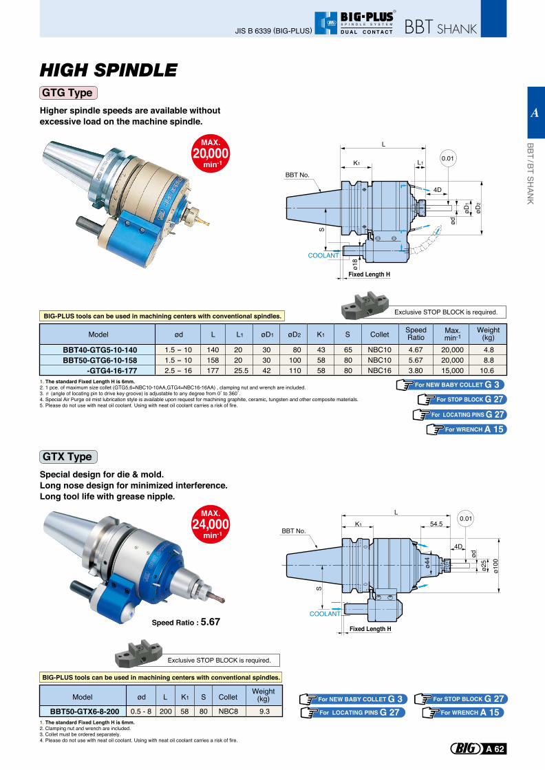
HIGH SPINDLE
Higher spindle speeds are available without excessive load on the machine spindle.
Special design for die & mold.Long nose design for minimized interference.Long tool life with grease nipple.
1. The standard Fixed Length H is 6mm. 2. 1 pce. of maximum size collet (GTG5,6=NBC10-10AA,GTG4=NBC16-16AA) , clamping nut and wrench are included.3. (angle of locating pin to drive key groove) is adjustable to any degree from 0˚ to 360˚.4. Special Air Purge oil mist lubrication style is available upon request for machining graphite, ceramic, tungsten and other composite materials.5. Please do not use with neat oil coolant. Using with neat oil coolant carries a risk of fire.
For NEW BABY COLLET G 3For STOP BLOCK G 27
For LOCATING PINS G 27
Exclusive STOP BLOCK is required.
For WRENCH A 15
Model L1L øD1 øD2 K1 S Collet SpeedRatioød Max.
min-1Weight
(kg)4.88.8
10.6
4.675.673.80
20,00020,00015,000
140158177
202025.5
1.5 - 101.5 - 102.5 - 16
303042
80100110
435858
658080
NBC10NBC10NBC16
BBT40-GTG5-10-140BBT50-GTG6-10-158
-GTG4-16-177
BIG-PLUS tools can be used in machining centers with conventional spindles.
0.01
Fixed Length H
L
ø18
S
øD1
øD2
COOLANT
4D
K1 L1
ød
BBT No.
1. The standard Fixed Length H is 6mm. 2. Clamping nut and wrench are included.3. Collet must be ordered separately.4. Please do not use with neat oil coolant. Using with neat oil coolant carries a risk of fire.
For LOCATING PINS G 27For NEW BABY COLLET G 3 For STOP BLOCK G 27Model L K1 S Colletød
Weight(kg)
200 9.30.5 - 8 58 80 NBC8BBT50-GTX6-8-200
Speed Ratio : 5.67
Exclusive STOP BLOCK is required.
BIG-PLUS tools can be used in machining centers with conventional spindles.
For WRENCH A 15
COOLANT
ø44
ø100
ødø2
5
54.5
L
K1
S
4D
0.01
Fixed Length H
BBT No.
GTG Type
GTX Type
MAX.20,000
min-1
MAX.24,000
min-1
BBT / BT SHAN
K
A
A 62
JIS B 6339 (BIG-PLUS)
R
S P I N D L E S Y S T E M
D U A L C O N T A C T
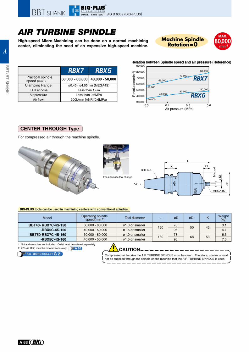
AIR TURBINE SPINDLEHigh-speed Micro-Machining can be done on a normal machining center, eliminating the need of an expensive high-speed machine.
CENTER THROUGH Type For compressed air through the machine spindle.
1. Nut and wrenches are included. Collet must be ordered separately.2. XF1(Air Unit) must be ordered separately.
Model
150
160
78967896
50
68
43
53
3.14.16.37.3
Weight(kg)KøD øD1LTool diameterOperating spindle
speed(min-1)60,000 - 80,00040,000 - 50,00060,000 - 80,00040,000 - 50,000
ø1.0 or smallerø1.5 or smallerø1.0 or smallerø1.5 or smaller
BBT40- RBX7C-4S-150-RBX5C-4S-150
BBT50-RBX7C-4S-160-RBX5C-4S-160
CAUTIONCompressed air to drive the AIR TURBINE SPINDLE must be clean. Therefore, coolant should not be supplied through the spindle on the machine that the AIR TURBINE SPINDLE is used.
For MICRO COLLET G 2
BIG-PLUS tools can be used in machining centers with conventional spindles.
A 65
For automatic tool change
MAX.80,000
min-1
Machine SpindleRotation=0
Relation between Spindle speed and air pressure (Reference)
58,000
66,000
73,000
80,000
90,000
80,000
70,000
60,000
50,000
40,000
30,0000.3 0.4 0.5 0.6
Rev
olut
ion(
min
-1)
38,000
43,00047,000
50,000
Air pressure (MPa)
Practical spindle speed (min-1) 60,000 - 80,000 40,000 - 50,000
Clamping RangeT.I.R at noseAir pressure
Air flow
ø0.45 - ø4.05mm (MEGA4S)Less than 1 m
Less than 0.6MPa300L/min [ANR](0.6MPa)
Air
L
K 22
MEGA4S
Max
.ø4
øD
ø12
øD1
BBT No.
JIS B 6339 (BIG-PLUS)
BBT / BT SHAN
K
A
A 63
R
S P I N D L E S Y S T E M
D U A L C O N T A C T
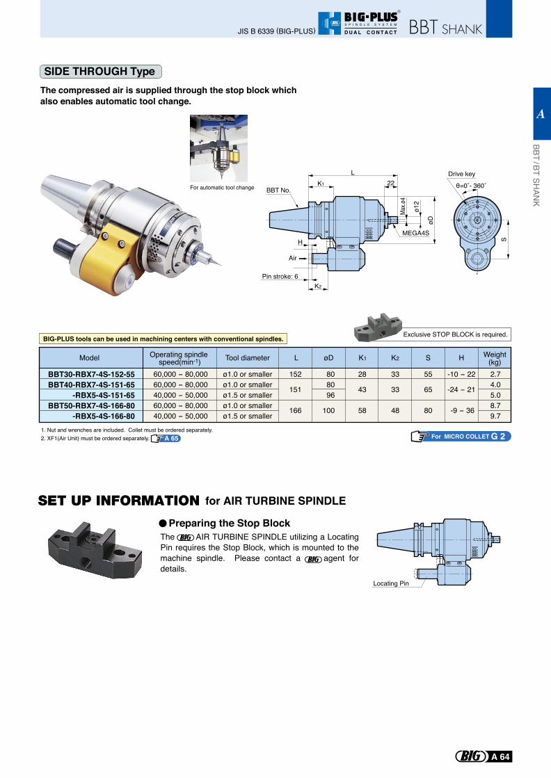
SIDE THROUGH Type
S
Drive key
θ=0˚- 360˚
The compressed air is supplied through the stop block which also enables automatic tool change.
Exclusive STOP BLOCK is required.
For MICRO COLLET G 2
Model Weight(kg)HSK2K1øDLTool diameterOperating spindle
speed(min-1)152
151
166
808096
100
33
33
48
55
65
80
-10 - 22
-24 - 21
-9 - 36
2.74.05.08.79.7
BBT30-RBX7-4S-152-55BBT40-RBX7-4S-151-65
-RBX5-4S-151-65BBT50-RBX7-4S-166-80
-RBX5-4S-166-80
60,000 - 80,00060,000 - 80,00040,000 - 50,00060,000 - 80,00040,000 - 50,000
ø1.0 or smallerø1.0 or smallerø1.5 or smallerø1.0 or smallerø1.5 or smaller
28
43
58
1. Nut and wrenches are included. Collet must be ordered separately.2. XF1(Air Unit) must be ordered separately.
BIG-PLUS tools can be used in machining centers with conventional spindles.
For automatic tool change
A 65
Air
MEGA4S
Pin stroke: 6K2
H
L
Max.ø
4
øD
ø12
K1 22BBT No.
The AIR TURBINE SPINDLE utilizing a Locating Pin requires the Stop Block, which is mounted to the machine spindle. Please contact a agent for details.
Locating Pin
Preparing the Stop Block
for AIR TURBINE SPINDLE
BBT / BT SHAN
K
A
A 64
JIS B 6339 (BIG-PLUS)
R
S P I N D L E S Y S T E M
D U A L C O N T A C T
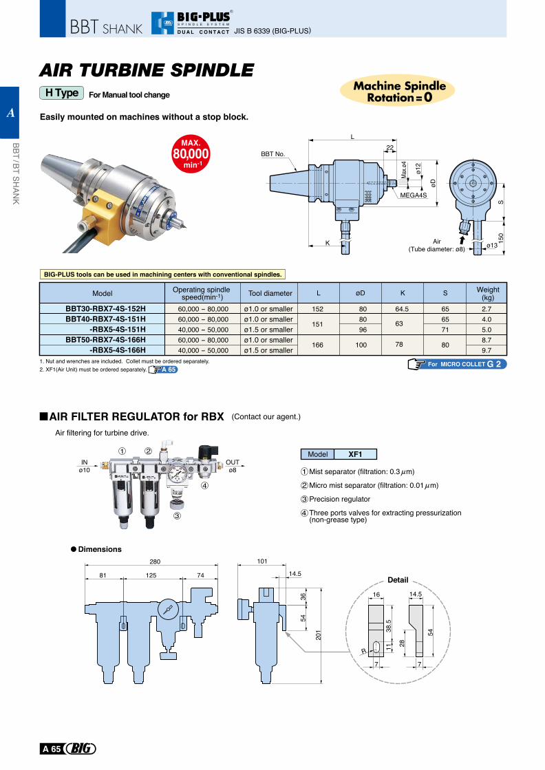
AIR TURBINE SPINDLE
Easily mounted on machines without a stop block.
For Manual tool changeH Type
S15
0
ø13Air(Tube diameter: ø8)
BBT30-RBX7-4S-152HBBT40-RBX7-4S-151H
-RBX5-4S-151HBBT50-RBX7-4S-166H
-RBX5-4S-166H
2.74.05.08.79.7
808096
100
152
151
166
64.5
63
78
656571
80
L φD K S
BBT30-RBX7-4S-152HBBT40-RBX7-4S-151H
-RBX5-4S-151HBBT50-RBX7-4S-166H
-RBX5-4S-166H
60,000 - 80,00060,000 - 80,00040,000 - 50,00060,000 - 80,00040,000 - 50,000
ø1.0 or smallerø1.0 or smallerø1.5 or smallerø1.0 or smallerø1.5 or smaller
2.74.05.08.79.7
808096
100
152
151
166
64.5
63
78
656571
80
L øD K S Weight(kg)
Operating spindle speed(min-1) Tool diameterModel
For MICRO COLLET G 21. Nut and wrenches are included. Collet must be ordered separately.2. XF1(Air Unit) must be ordered separately. A 65
BIG-PLUS tools can be used in machining centers with conventional spindles.
MAX.80,000
min-1
Machine SpindleRotation=0
Model XF11
1
2
2
3
3
4
4
Mist separator (filtration: 0.3 m)
Micro mist separator (filtration: 0.01 m)
Precision regulator
Three ports valves for extracting pressurization (non-grease type)
Air filtering for turbine drive.
INø10
OUTø8
R
28
54
14.516
7
1138
.5
201
5436
14.5
101280
7412581
7
Dimensions
Detail
(Contact our agent.)AIR FILTER REGULATOR for RBX
MEGA4S
L
Max.ø
4
øD
ø12
K
22BBT No.
JIS B 6339 (BIG-PLUS)
BBT / BT SHAN
K
A
A 65
R
S P I N D L E S Y S T E M
D U A L C O N T A C T
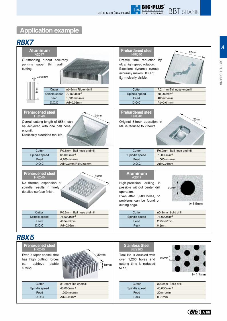
AluminumA2017
Prehardened steelHRC40
Prehardened steelHRC40
0.065mm
4mm ø0.5mm Rib-endmill
70,000min-1
1,500mm/minAd=0.02mm
CutterSpindle speed
FeedD.O.C
ø1.5mm Rib-endmill40,000min-1
1,000mm/minAd=0.05mm
CutterSpindle speed
FeedD.O.C
R0.1mm Ball nose endmill80,000min-1
400mm/minAd=0.01mm
CutterSpindle speed
FeedD.O.C
ø0.3mm Solid drill75,000min-1
200mm/min0.3mm
CutterSpindle speed
FeedPeck
AluminumA2017
ø0.5mm Solid drill40,000min-1
20mm/min0.01mm
CutterSpindle speed
FeedPeck
R0.2mm Ball nose endmill70,000min-1
1,000mm/minAd=0.01mm
CutterSpindle speed
FeedD.O.C
R0.5mm Ball nose endmill65,000min-1
4,200mm/minAd=0.2mm Rd=0.05mm
CutterSpindle speed
FeedD.O.C
R0.5mm Ball nose endmill75,000min-1
400mm/minAd=0.02mm
CutterSpindle speed
FeedD.O.C
0.3mm
0.5mm
30mm
20mm
20mm
Prehardened steelHRC40
Prehardened steelHRC40
Stainless SteelSUS303
Prehardened steelHRC40
40mm
30mm
10mm
t= 1.5mm
t= 1.7mm
Outstanding runout accuracy permits super thin wall cutting.
Overall cutting length of 656m can be achieved with one ball nose endmill.Drastically extended tool life.
No thermal expansion of spindle results in finely detailed surface finish.
Even a taper endmill that has high cutting forces can achieve stable cutting.
Tool life is doubled with over 1,200 holes and cutting time is reduced to 1/3.
High-precision drilling is possible without center drill operation.Even after 3,500 holes, no problems can be found on cutting edge.
Drastic time reduction by ultra high speed rotation.Excellent dynamic runout accuracy makes DOC of 5 m clearly visible.
Original 5 hour operation in MC is reduced to 2 hours.
Application example
BBT / BT SHAN
K
A
A 66
JIS B 6339 (BIG-PLUS)
R
S P I N D L E S Y S T E M
D U A L C O N T A C T
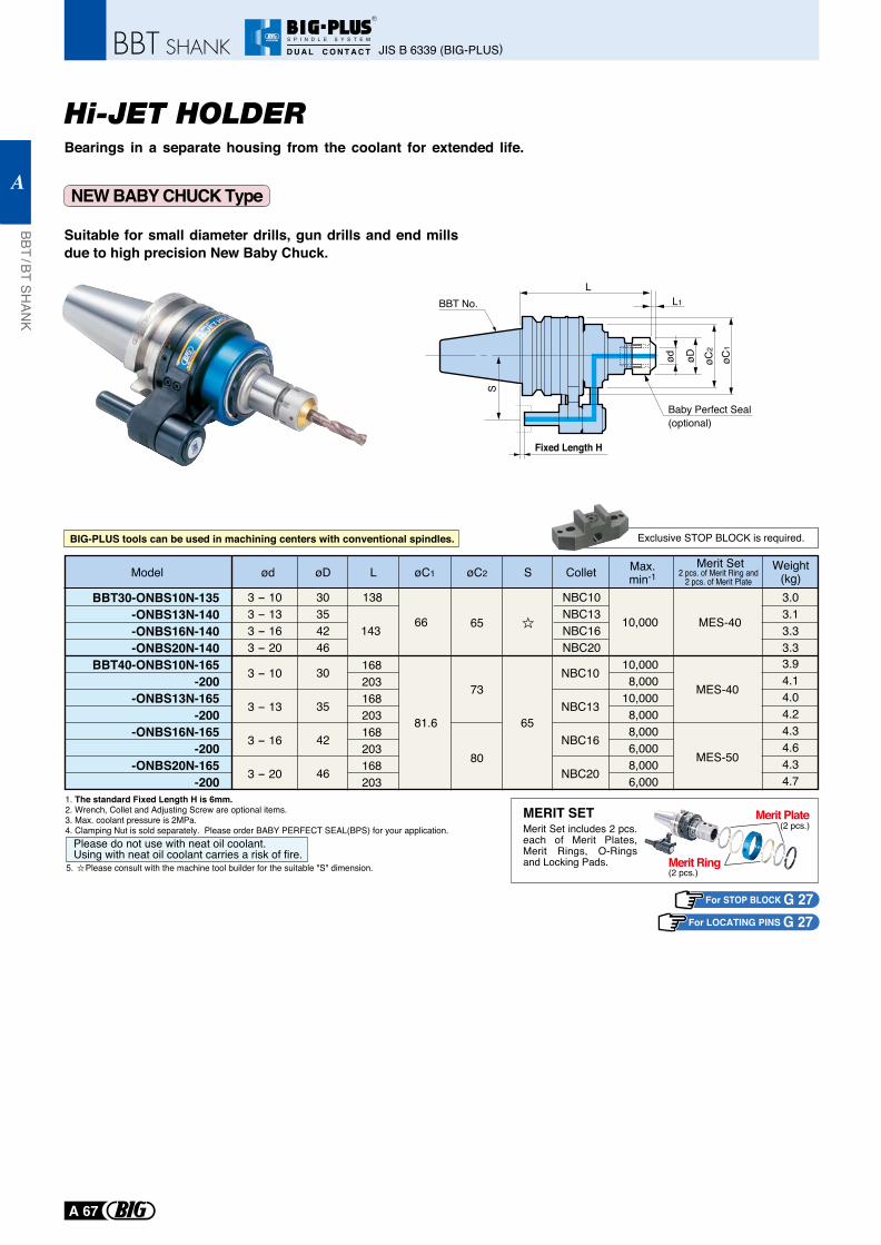
Hi-JET HOLDER
NEW BABY CHUCK Type
Suitable for small diameter drills, gun drills and end mills due to high precision New Baby Chuck.
1. The standard Fixed Length H is 6mm. 2. Wrench, Collet and Adjusting Screw are optional items.3. Max. coolant pressure is 2MPa.4. Clamping Nut is sold separately. Please order BABY PERFECT SEAL(BPS) for your application.
For STOP BLOCK G 27For LOCATING PINS G 27
Please do not use with neat oil coolant.Using with neat oil coolant carries a risk of fire.
Model Colletød L SøC2øC1øD Max.min-1
Merit Set Weight(kg)2 pcs. of Merit Ring and
2 pcs. of Merit Plate
Exclusive STOP BLOCK is required.
BBT30-ONBS10N-135 -ONBS13N-140
-ONBS16N-140 -ONBS20N-140
BBT40-ONBS10N-165 -200 -ONBS13N-165 -200 -ONBS16N-165 -200 -ONBS20N-165 -200
30
35
42
46
3 - 10
3 - 13
3 - 16
3 - 20
NBC10
NBC13
NBC16
NBC20
168203168203168203168203
81.6
66 10,000 MES-40
65
73
80
MES-40
MES-50
10,0008,000
10,0008,0008,0006,0008,0006,000
3.94.14.04.24.34.64.34.7
3 - 103 - 133 - 163 - 20
30354246
NBC10NBC13NBC16NBC20
3.03.13.33.3
138
143 65
5. Please consult with the machine tool builder for the suitable "S" dimension.
BIG-PLUS tools can be used in machining centers with conventional spindles.
ød
S
øC1
øD
LL1
Baby Perfect Seal(optional)
øC2
Fixed Length H
BBT No.
Bearings in a separate housing from the coolant for extended life.
(2 pcs.)
(2 pcs.)MERIT SETMerit Set includes 2 pcs. each of Merit Plates, Merit Rings, O-Rings and Locking Pads.
Merit Plate
Merit Ring
JIS B 6339 (BIG-PLUS)
BBT / BT SHAN
K
A
A 67
R
S P I N D L E S Y S T E M
D U A L C O N T A C T
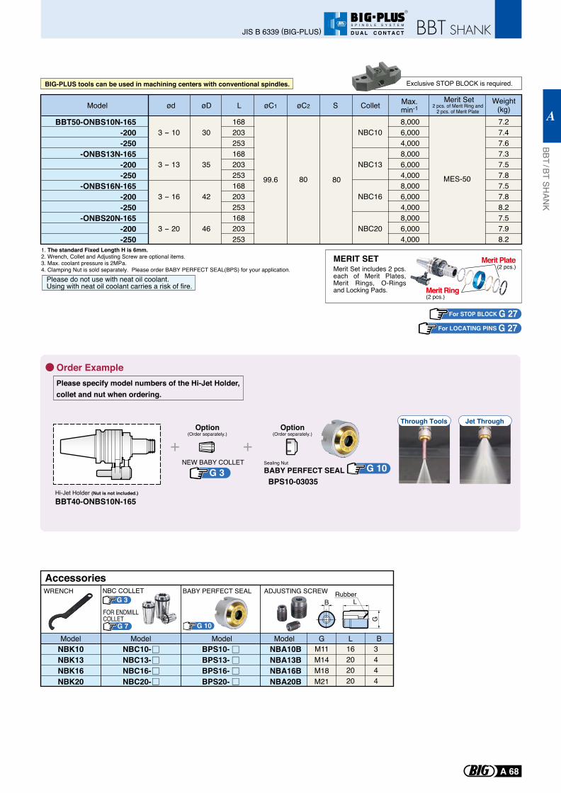
Order Example
Sealing Nut
BABY PERFECT SEAL BPS10-03035
NEW BABY COLLET
Hi-Jet Holder (Nut is not included.)
BBT40-ONBS10N-165
Please specify model numbers of the Hi-Jet Holder, collet and nut when ordering.
Option(Order separately.)
Option(Order separately.)
Through Tools Jet Through
1. The standard Fixed Length H is 6mm. 2. Wrench, Collet and Adjusting Screw are optional items.3. Max. coolant pressure is 2MPa.4. Clamping Nut is sold separately. Please order BABY PERFECT SEAL(BPS) for your application.
For STOP BLOCK G 27For LOCATING PINS G 27
Please do not use with neat oil coolant.Using with neat oil coolant carries a risk of fire.
Model Colletød L SøC2øC1øD Max.min-1
Merit Set Weight(kg)2 pcs. of Merit Ring and
2 pcs. of Merit Plate
Exclusive STOP BLOCK is required.
99.6 8080 MES-50
8,0006,0004,0008,0006,0004,0008,0006,0004,0008,0006,0004,000
BIG-PLUS tools can be used in machining centers with conventional spindles.
BBT50-ONBS10N-165 -200 -250 -ONBS13N-165 -200 -250 -ONBS16N-165 -200 -250 -ONBS20N-165 -200 -250
3 - 10
3 - 13
3 - 16
3 - 20
30
35
42
46
168203253168203253168203253168203253
NBC10
NBC13
NBC16
NBC20
7.27.47.67.37.57.87.57.88.27.57.98.2
NBK10NBK13NBK16NBK20
G 10
BPS10-BPS13-BPS16-BPS20-
NBC10-NBC13-NBC16-NBC20-
WRENCH
Model Model Model
Accessories
NBA10BNBA13BNBA16BNBA20B
M11M14M18M21
16202020
3444
ADJUSTING SCREW
G L B
BRubber
L
G
Model
BABY PERFECT SEALG 3
NBC COLLET
G 7
FOR ENDMILLCOLLET
G 3 G 10
(2 pcs.)
(2 pcs.)MERIT SETMerit Set includes 2 pcs. each of Merit Plates, Merit Rings, O-Rings and Locking Pads.
Merit Plate
Merit Ring
BBT / BT SHAN
K
A
A 68
JIS B 6339 (BIG-PLUS)
R
S P I N D L E S Y S T E M
D U A L C O N T A C T
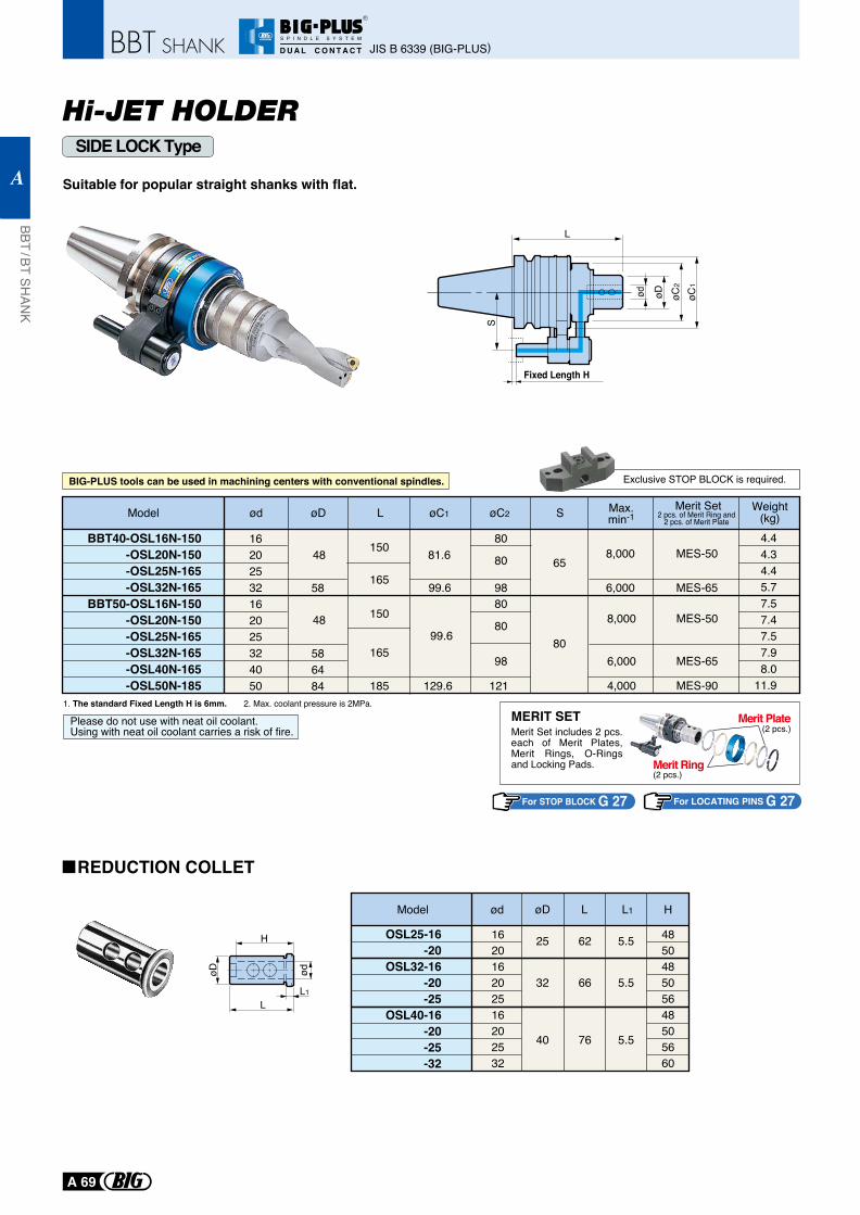
Hi-JET HOLDERSIDE LOCK Type
Suitable for popular straight shanks with flat.
L
ød øC1
øD øC2
S
1. The standard Fixed Length H is 6mm. 2. Max. coolant pressure is 2MPa.
For STOP BLOCK G 27
Model
OSL25-16-20
OSL32-16-20-25
OSL40-16-20-25-32
ød
162016202516202532
485048505648505660
øD
25
32
40
62
66
76
5.5
5.5
5.5
L L1 H
H
LL1
øD ød
Please do not use with neat oil coolant.Using with neat oil coolant carries a risk of fire.
Exclusive STOP BLOCK is required.
Fixed Length H
For LOCATING PINS G 27
80
80
121
98
150
150
165
185
165
48
48
58
586484
80
80
98
BBT40-OSL16N-150-OSL20N-150-OSL25N-165-OSL32N-165
BBT50-OSL16N-150-OSL20N-150-OSL25N-165-OSL32N-165-OSL40N-165-OSL50N-185
16202532162025324050
81.6 65
80
99.6
8,000
6,000
MES-50
MES-65
4.44.34.45.77.57.47.57.98.0
11.9
99.6
129.6
8,000
6,000
4,000
MES-50
MES-65
MES-90
Model ød L SøC2øC1øD Max.min-1
Merit Set Weight(kg)2 pcs. of Merit Ring and
2 pcs. of Merit Plate
REDUCTION COLLET
BIG-PLUS tools can be used in machining centers with conventional spindles.
(2 pcs.)
(2 pcs.)MERIT SETMerit Set includes 2 pcs. each of Merit Plates, Merit Rings, O-Rings and Locking Pads.
Merit Plate
Merit Ring
JIS B 6339 (BIG-PLUS)
BBT / BT SHAN
K
A
A 69
R
S P I N D L E S Y S T E M
D U A L C O N T A C T
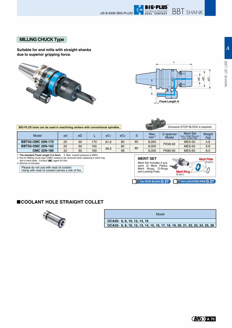
1. The standard Fixed Length H is 6mm. 2. Max. coolant pressure is 2MPa.3. Nut for Milling chuck type (OMC) needs to be removed when replacing a merit ring and a merit plate. Contact agent for this.4. Wrench is included.
For STOP BLOCK G 27
Please do not use with neat oil coolant.Using with neat oil coolant carries a risk of fire.
Exclusive STOP BLOCK is required.
For LOCATING PINS G 27
Model
OCA20- 6, 8, 10, 12, 14, 16OCA32- 6, 8, 10, 12, 13, 14, 15, 16, 17, 18, 19, 20, 21, 22, 23, 24, 25, 28
MILLING CHUCK Type
Suitable for end mills with straight shanksdue to superior gripping force.
COOLANT HOLE STRAIGHT COLLET
Model ød L SøC2øC1øD Max.min-1
Merit Set Weight(kg)
BBT40-OMC 20N-170BBT50-OMC 20N-165
OMC 32N-180
202032
606080
170165180
808098
4.86.88.5
C-spannerModel
FK58-62
FK80-90
8,0008,0006,000
MES-50MES-50MES-65
81.6
99.6
65
80
2 pcs. of Merit Ring and2 pcs. of Merit Plate
ød øD
L
øC1
S
Fixed Length H
øC2
BIG-PLUS tools can be used in machining centers with conventional spindles.
(2 pcs.)
(2 pcs.)MERIT SETMerit Set includes 2 pcs. each of Merit Plates, Merit Rings, O-Rings and Locking Pads.
Merit Plate
Merit Ring
BBT / BT SHAN
K
A
A 70
JIS B 6339 (BIG-PLUS)
R
S P I N D L E S Y S T E M
D U A L C O N T A C T
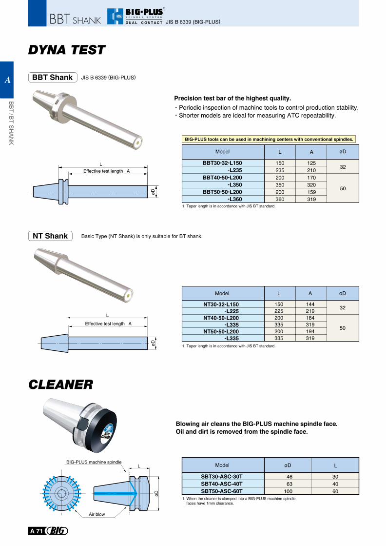
LEffective test length A
øD
Model øD L
SBT30-ASC-30TSBT40-ASC-40TSBT50-ASC-60T
4663
100
304060
øD
L
BBT Shank JIS B 6339 (BIG-PLUS)
Basic Type (NT Shank) is only suitable for BT shank.NT Shank
BBT40-50-L200 200 170-L350
BBT30-32-L150-L235
350 320
150 125235 210
BBT50-50-L200 200 159-L360 360 319
50
32
Model L A øD
Precision test bar of the highest quality.Periodic inspection of machine tools to control production stability.Shorter models are ideal for measuring ATC repeatability.
Blowing air cleans the BIG-PLUS machine spindle face.Oil and dirt is removed from the spindle face.
BIG-PLUS machine spindle
Air blow
1. When the cleaner is clamped into a BIG-PLUS machine spindle, faces have 1mm clearance.
L
Effective test length A
øD
50
32NT30-32-L150 150 144-L225 225 219
NT40-50-L200 200 184-L335 335 319
NT50-50-L200 200 194-L335 335 319
Model L A øD
1. Taper length is in accordance with JIS BT standard.
1. Taper length is in accordance with JIS BT standard.
BIG-PLUS tools can be used in machining centers with conventional spindles.
JIS B 6339 (BIG-PLUS)
BBT / BT SHAN
K
A
A 71
R
S P I N D L E S Y S T E M
D U A L C O N T A C T
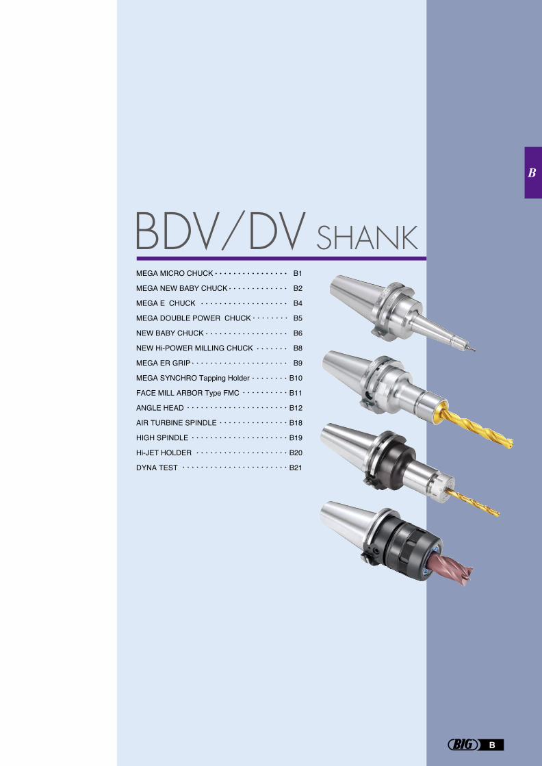
MEGA MICRO CHUCK
MEGA NEW BABY CHUCK
MEGA E CHUCK
MEGA DOUBLE POWER CHUCK
NEW BABY CHUCK
NEW Hi-POWER MILLING CHUCK
MEGA ER GRIP
MEGA SYNCHRO Tapping Holder
FACE MILL ARBOR Type FMC
ANGLE HEAD
AIR TURBINE SPINDLE
HIGH SPINDLE
Hi-JET HOLDER
DYNA TEST
B1
B2
B4
B5
B6
B8
B9
B10
B11
B12
B18
B19
B20
B21
B
B
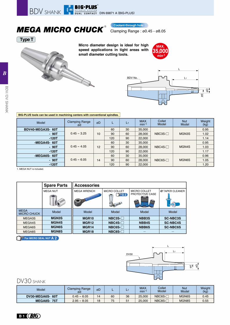
BIG-PLUS tools can be used in machining centers with conventional spindles.
Clamping Range : ø0.45 - ø8.05
MAX.35,000
min-1
Micro diameter design is ideal for high speed applications in tight areas with small diameter cutting tools.
Type T
BDV40-MEGA3S- 60T- 90T-120T
-MEGA4S- 60T- 90T-120T
-MEGA6S- 60T- 90T-120T
0.45 - 4.05
0.45 - 3.25
0.45 - 6.05
10
12
14
6090
1206090
1206090
120
306090306090306090
35,00028,00022,00035,00028,00022,00035,00028,00022,000
0.951.021.140.951.031.170.961.051.20
MGN3S
MGN4S
MGN6S
MAX.min-1
ColletModel
Nut Model
Weight(kg)Model L L1øD
NBC3S-
NBC4S-
NBC6S-
1. MEGA NUT is included.
BDV No.
ød
øD
L
L1
G 2
MEGA3SMEGA4SMEGA6SMEGA8S
MGN3SMGN4SMGN6SMGN8S
Spare PartsMEGA NUT
MEGA MICRO CHUCK Model
MGR10MGR12MGR14MGR18
MICRO COLLET
AccessoriesMEGA WRENCH
NBB3SNBB4SNBB6S
Model Model Model
NBC3S-NBC4S-NBC6S-NBC8S-
Model
SC-NBC3SSC-NBC4SSC-NBC6S
TAPER CLEANER
Coolant-through hole
Clamping Range ød
DV30-MEGA6S- 60TMEGA8S- 75T
1418
6075
3651
25,00025,000
0.45 - 6.052.95 - 8.05
0.450.55
MGN6SMGN8S
MAX.min-1
ColletModel
Nut Model
Weight(kg)Model L L1øD
NBC6S-NBC8S-
Clamping Range ød
MICRO COLLETPROTECTIVE CASE
R
DV30
ød øD
L
L1
For MICRO SEAL NUT A 2
B 1
DIN 69871 A (BIG-PLUS)
BDV / D
V SHAN
K
B
R
S P I N D L E S Y S T E M
D U A L C O N T A C T
DV30 SHANK
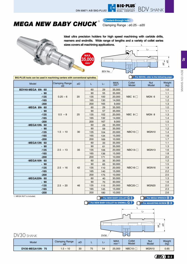
1. MEGA NUT is included.
BDV40-MEGA 6N- 60- 90-135-165-200
-MEGA 8N- 60- 90-135-165-200
-MEGA10N- 60- 90-135-165-200
-MEGA13N- 60- 90-135-165-200
-MEGA16N- 60- 90-135-165-200
-MEGA20N- 60- 90-135-165-200
øD L
6090
1351652006090
1351652006090
1351652006090
1351652006090
1351652006090
135165200
L1
2955
1001301652957
1021321672959
1041341693361
1061361713565
1101401754070
115145180
MAX.min-1
35,00035,00020,00014,0009,000
35,00035,00020,00014,0009,000
35,00035,00020,00015,00010,00035,00035,00020,00015,00010,00030,00030,00020,00015,00010,00030,00030,00020,00015,00010,000
0.25 - 6
0.5 - 8
20
25
NBC 6-
NBC 8-
MGN 6
MGN 8
1.01.11.21.21.31.01.11.31.41.51.11.21.41.61.71.11.31.61.82.01.21.51.92.22.51.31.62.02.32.6
Model Weight(kg)
2.5 - 13
2.5 - 16
2.5 - 20
35
42
46
NBC13- MGN13
1.5 - 10 30 NBC10- MGN10
NBC16- MGN16
MGN20NBC20-
Collet Model
Nut Model
øD
ød
L1
L
BDV No.
Clamping Range : ø0.25 - ø20
MAX.35,000
min-1
Coolant-through hole
Ideal ultra precision holders for high speed machining with carbide drills, reamers and endmills. Wide range of lengths and a variety of collet series sizes covers all machining applications.
For NEW BABY COLLET G 3For NEW BABY COLLET for ENDMILL G 7 For ADJUSTING SCREW B 3
For MEGA WRENCH B 3
Clamping Range ød
For BDV50, refer to the following page.
R
BIG-PLUS tools can be used in machining centers with conventional spindles.
DV30-MEGA10N- 75 30 75 54 25,0001.5 - 10 0.65MGN10
MAX.min-1
ColletModel
Nut Model
Weight(kg)Model L L1øD
NBC10-
Clamping Range ød
LL1
DV30
øD
ød
B 2
BDV / D
V SHAN
K
B
DIN 69871 A/B (BIG-PLUS)
R
S P I N D L E S Y S T E M
D U A L C O N T A C T
DV30 SHANK
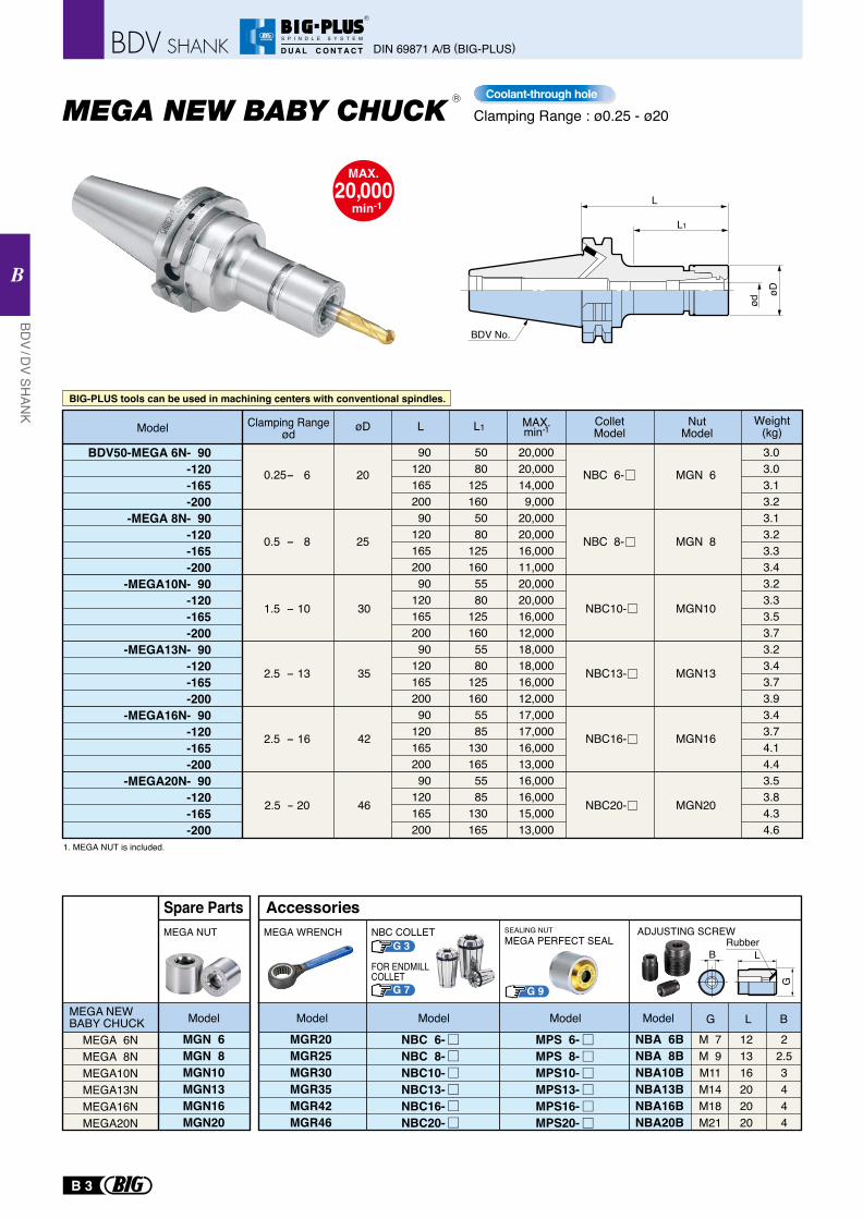
øD
ød
L1
L
BDV No.
Clamping Range : ø0.25 - ø20
MAX.20,000
min-1
1. MEGA NUT is included.
BDV50-MEGA 6N- 90-120-165-200
-MEGA 8N- 90-120-165-200
-MEGA10N- 90-120-165-200
-MEGA13N- 90-120-165-200
-MEGA16N- 90-120-165-200
-MEGA20N- 90-120-165-200
øD L
9012016520090
12016520090
12016520090
12016520090
12016520090
120165200
L1
5080
1251605080
1251605580
1251605580
1251605585
1301655585
130165
MAX.min-1
20,00020,00014,0009,000
20,00020,00016,00011,00020,00020,00016,00012,00018,00018,00016,00012,00017,00017,00016,00013,00016,00016,00015,00013,000
0.25- 6
0.5 - 8
20
25
NBC 6-
NBC 8-
MGN 6
MGN 8
3.03.03.13.23.13.23.33.43.23.33.53.73.23.43.73.93.43.74.14.43.53.84.34.6
Model Weight(kg)
2.5 - 13
2.5 - 16
35
42
NBC13- MGN13
1.5 - 10 30 NBC10- MGN10
NBC16- MGN16
2.5 - 20 46 NBC20- MGN20
ColletModel
NutModel
MPS 6-MPS 8-MPS10-MPS13-MPS16-MPS20-
Rubber
MEGA 6NMEGA 8NMEGA10NMEGA13NMEGA16NMEGA20N
MEGA NEW BABY CHUCK
MGN 6MGN 8MGN10MGN13MGN16MGN20
MEGA NUT
Model
Spare Parts
MGR20MGR25MGR30MGR35MGR42MGR46
NBA 6BNBA 8BNBA10BNBA13BNBA16BNBA20B
M 7M 9M11M14M18M21
121316202020
22.53444
MEGA WRENCH SEALING NUTMEGA PERFECT SEAL
ADJUSTING SCREW
G L B
B L
G
ModelModelModelModel
Accessories
NBC 6-NBC 8-NBC10-NBC13-NBC16-NBC20-
Coolant-through hole
BIG-PLUS tools can be used in machining centers with conventional spindles.
NBC COLLET
FOR ENDMILLCOLLET
Clamping Range ød
R
G 3
G 7 G 9
B 3
DIN 69871 A/B (BIG-PLUS)
BDV / D
V SHAN
K
B
R
S P I N D L E S Y S T E M
D U A L C O N T A C T
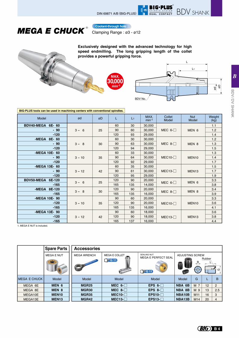
Clamping Range : ø3 - ø12
1. MEGA E NUT is included.
Exclusively designed with the advanced technology for high speed endmilling. The long gripping length of the collet provides a powerful gripping force.
BDV40-MEGA 6E- 60- 90-120
-MEGA 8E- 60- 90-120
-MEGA 10E- 60- 90-120
-MEGA 13E- 60- 90-120
BDV50-MEGA 6E-120-165
-MEGA 8E-120-165
-MEGA 10E- 90-120-165
-MEGA 13E- 90-120-165
6090
1206090
1206090
1206090
12012016512016590
12016590
120165
30 60 93 30 63 94 33 64 92 35 61 95 90135 90135 60 90135 60 90137
1.11.21.41.21.31.51.31.41.71.51.71.93.33.83.43.93.33.64.13.63.84.4
30,00030,00029,00030,00030,00029,00030,00030,00029,00030,00030,00029,00020,00014,00020,00016,00020,00020,00016,00018,00018,00016,000
3 - 6
3 - 8
3 - 10
3 - 12
3 - 6
3 - 8
3 - 10
3 - 12
25
30
35
42
25
30
35
42
MEC 6-
MEC 8-
MEC10-
MEC13-
MEC 6-
MEC 8-
MEC10-
MEC13-
MAX.min-1
ColletModel
MEN 6
MEN 8
MEN10
MEN13
MEN 6
MEN 8
MEN10
MEN13
Nut Model
Weight(kg)Model L L1øD
BDV No.
L1
øDød
L
MAX.30,000
min-1
SEALING NUTMEGA E PERFECT SEAL Rubber
B L
G
MEGA E COLLET
MEGA 6EMEGA 8EMEGA10EMEGA13E
MEGA E CHUCK Model
Spare Parts
MEN 6MEN 8MEN10MEN13
MEGA E NUT
MGR25MGR30MGR35MGR42
NBA 6BNBA 8BNBA10BNBA13B
M 7M 9M11M14
22.534
12131620
G L B
MEGA WRENCH ADJUSTING SCREW
EPS 6-EPS 8-EPS10-EPS13-
ModelModel Model Model
Accessories
MEC 6-MEC 8-MEC10-MEC13-
ød
Coolant-through holeR
G 11
G 11
BIG-PLUS tools can be used in machining centers with conventional spindles.
B 4
BDV / D
V SHAN
K
B
DIN 69871 A/B (BIG-PLUS)
R
S P I N D L E S Y S T E M
D U A L C O N T A C T
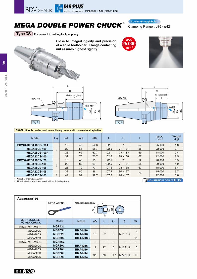
MAX.25,000
min-1
Clamping Range : ø16 - ø42
Type DS
R
For coolant to cutting tool periphery
BDV40-MEGA16DS- 90A-MEGA20DS-100 -MEGA25DS-100A-MEGA32DS-100
BDV50-MEGA16DS- 70 -MEGA20DS-100 -MEGA25DS-105 -MEGA32DS-105 -MEGA42DS-105
Fig. øD1 øD MAX.min-1
Weight(kg)ødModel
1. Wrench is ordered separately.2. "H" indicates the adjustment length with an Adjusting Screw.
H
1
1
2
162025321620253242
425562704660708099
52.655.762.770.75569778699.7
7371 - 8173 - 8378 - 88
7371 - 8178 - 8880 - 9790 -107
25,00022,00018,00012,00020,00020,00018,00015,00012,000
1.82.12.42.53.54.95.45.76.6
Close to integral rigidity and precision of a solid toolholder. Flange contacting nut assures highest rigidity.
L
H
EøD øD
1
ød
COOLANT
H
E
L
øD1
øDød
COOLANT
L
92 102.5102 102.572.5
102.5 107.5107.5107.5
57585967525867
73
E
L
L1
øDWG
MGR42L MGR55L MGR62L MGR70L MGR46L MGR60L
MGR70L MGR80L MGR99L
AccessoriesMEGA WRENCH
Model
HMA-M16HMA-M16HMA-M16S HMA-M16HMA-M16HMA-M24HMA-M24
ModelMEGA DOUBLE POWER CHUCK
BDV40-MEGA16DS -MEGA20DS -MEGA25DS -MEGA32DSBDV50-MEGA16DS -MEGA20DS -MEGA25DS -MEGA32DS -MEGA42DS
øD L L1 G W
ADJUSTING SCREW
Coolant-through hole
BDV No. BDV No.
19 27 6
19 27 6
30 36 9.5
M16P1.5
M16P1.5
M24P1.5
8
10
8
10
Fig.1 Fig.2
For STRAIGHT COLLET G 15
BIG-PLUS tools can be used in machining centers with conventional spindles.
Min Clamping LengthMin Clamping Length
B 5
DIN 69871 A/B (BIG-PLUS)
BDV / D
V SHAN
K
B
R
S P I N D L E S Y S T E M
D U A L C O N T A C T
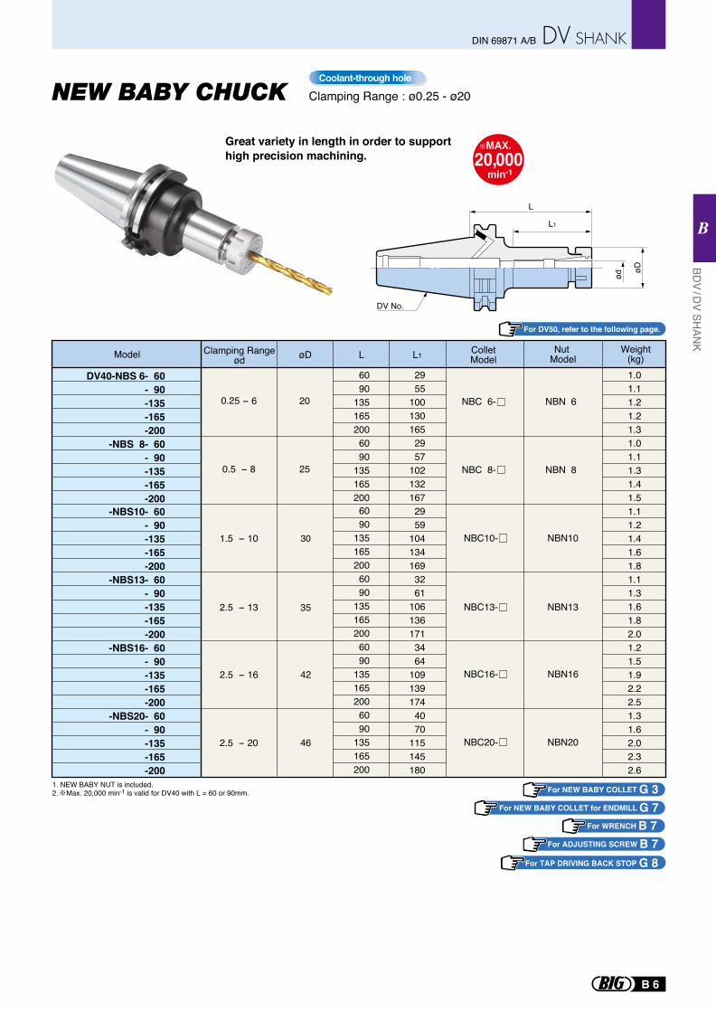
1. NEW BABY NUT is included.2. Max. 20,000 min-1 is valid for DV40 with L = 60 or 90mm.
øD
ød
L1
L
DV No.
DV40-NBS 6- 60- 90-135-165-200
-NBS 8- 60- 90-135-165-200
-NBS10- 60- 90-135-165-200
-NBS13- 60- 90-135-165-200
-NBS16- 60- 90-135-165-200
-NBS20- 60- 90-135-165-200
6090
1351652006090
1351652006090
1351652006090
1351652006090
1351652006090
135165200
2955
1001301652957
1021321672959
1041341693261
1061361713464
1091391744070
115145180
0.25 - 6
0.5 - 8
20
25
1.01.11.21.21.31.01.11.31.41.51.11.21.41.61.81.11.31.61.82.01.21.51.92.22.51.31.62.02.32.6
2.5 - 13
2.5 - 16
2.5 - 20
35
42
46
1.5 - 10 30
øD L L1Model Weight(kg)
Clamping Rangeød
ColletModel
Nut Model
NBC 6-
NBC 8-
NBN 6
NBN 8
NBC13- NBN13
NBC10- NBN10
NBC16- NBN16
NBN20NBC20-
Clamping Range : ø0.25 - ø20
Great variety in length in order to supporthigh precision machining.
For DV50, refer to the following page.
MAX.20,000
min-1
Coolant-through hole
For ADJUSTING SCREW B 7For WRENCH B 7
For NEW BABY COLLET G 3For NEW BABY COLLET for ENDMILL G 7
For TAP DRIVING BACK STOP G 8
B 6
BDV / D
V SHAN
K
B
DIN 69871 A/B
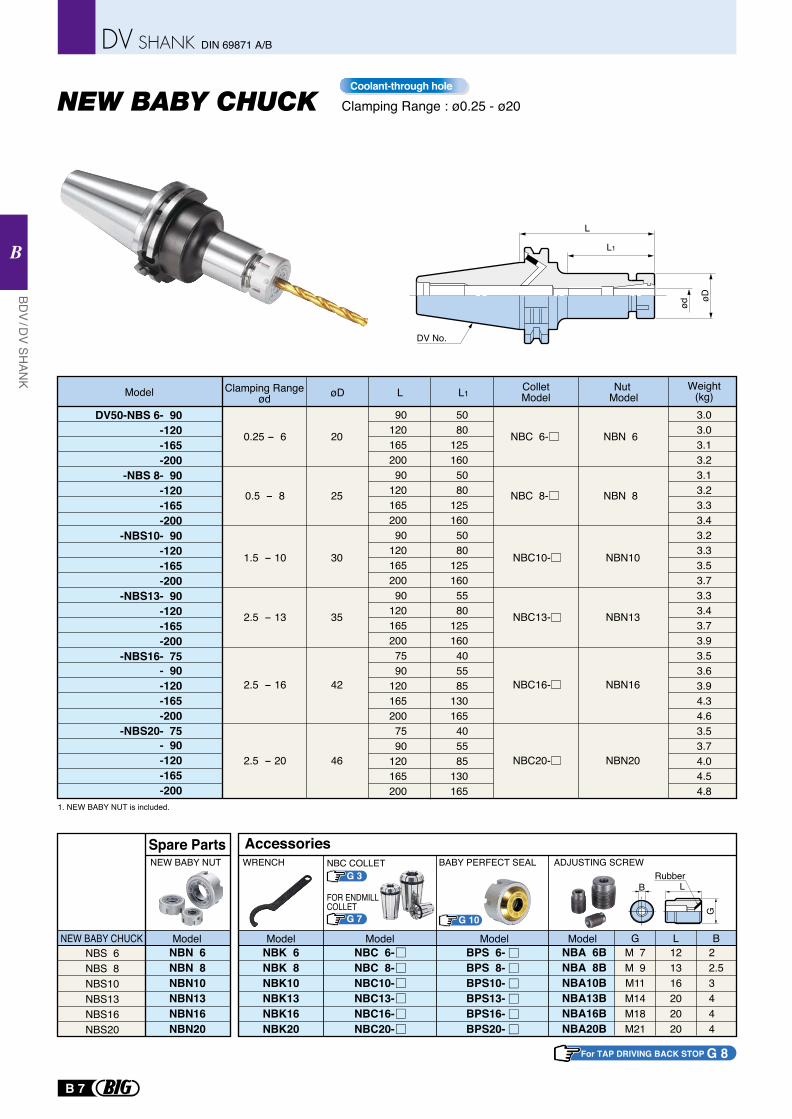
øD
ød
L1
L
DV No.
Clamping Range : ø0.25 - ø20
NBS 6NBS 8NBS10NBS13NBS16NBS20
NBN 6NBN 8NBN10NBN13NBN16NBN20
NEW BABY CHUCK
NEW BABY NUT
Model
Spare Parts
NBK 6NBK 8NBK10NBK13NBK16NBK20
BPS 6-BPS 8-BPS10-BPS13-BPS16-BPS20-
NBC 6-NBC 8-NBC10-NBC13-NBC16-NBC20-
WRENCH
Model Model Model
Accessories
NBA 6BNBA 8BNBA10BNBA13BNBA16BNBA20B
M 7M 9M11M14M18M21
121316202020
22.53444
ADJUSTING SCREW
G L B
BRubber
L
G
Model
BABY PERFECT SEAL
1. NEW BABY NUT is included.
DV50-NBS 6- 90-120-165-200
-NBS 8- 90-120-165-200
-NBS10- 90-120-165-200
-NBS13- 90-120-165-200
-NBS16- 75- 90-120-165-200
-NBS20- 75- 90-120-165-200
9012016520090
12016520090
12016520090
1201652007590
1201652007590
120165200
5080
1251605080
1251605080
1251605580
125160405585
130165405585
130165
0.25 - 6
0.5 - 8
20
25
3.03.03.13.23.13.23.33.43.23.33.53.73.33.43.73.93.53.63.94.34.63.53.74.04.54.8
2.5 - 13
2.5 - 16
35
42
1.5 - 10 30
2.5 - 20 46
øD L L1Model Weight(kg)
Clamping Rangeød
ColletModel
Nut Model
NBC 6-
NBC 8-
NBN 6
NBN 8
NBC13- NBN13
NBC10- NBN10
NBC16- NBN16
NBN20NBC20-
Coolant-through hole
NBC COLLET
FOR ENDMILLCOLLET
For TAP DRIVING BACK STOP G 8
G 3
G 7 G 10
B 7
BDV / D
V SHAN
K
B
DIN 69871 A/B
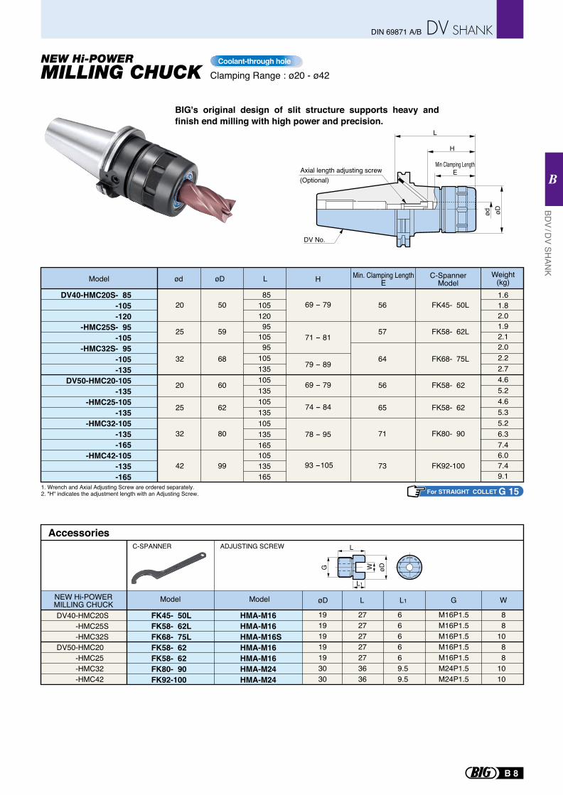
DV No.
H
EMin Clamping Length
L
øDød
(Optional)Axial length adjusting screw
BIG's original design of slit structure supports heavy and finish end milling with high power and precision.
Clamping Range : ø20 - ø42
L
L1
øDWG
ADJUSTING SCREW
FK45- 50LFK58- 62LFK68- 75LFK58- 62 FK58- 62 FK80- 90FK92-100
AccessoriesC-SPANNER
Model
HMA-M16HMA-M16HMA-M16SHMA-M16HMA-M16HMA-M24HMA-M24
Model
19191919193030
27272727273636
666669.59.5
M16P1.5M16P1.5M16P1.5M16P1.5M16P1.5M24P1.5M24P1.5
88
1088
1010
øD L L1 G W
DV40-HMC20S -HMC25S -HMC32SDV50-HMC20 -HMC25 -HMC32 -HMC42
NEW Hi-POWERMILLING CHUCK
1. Wrench and Axial Adjusting Screw are ordered separately.2. "H" indicates the adjustment length with an Adjusting Screw.
Coolant-through hole
For STRAIGHT COLLET G 15
93 -105
8510512095
10595
105135105135105135105135165105135165
1.61.82.01.92.12.02.22.74.65.24.65.35.26.37.46.07.49.1
DV40-HMC20S- 85-105-120
-HMC25S- 95-105
-HMC32S- 95-105-135
DV50-HMC20-105-135
-HMC25-105-135
-HMC32-105-135-165
-HMC42-105-135-165
69 - 79
79 - 89
71 - 81
69 - 79
78 - 95
74 - 84
Weight(kg)Model ød LøD H
20
25
32
20
25
32
42
50
59
68
60
62
80
99
FK45- 50L
FK58- 62L
FK68- 75L
FK58- 62
FK58- 62
FK80- 90
FK92-100
56
57
64
56
65
71
73
C-SpannerModel
Min. Clamping LengthE
B 8
BDV / D
V SHAN
K
B
DIN 69871 A/B
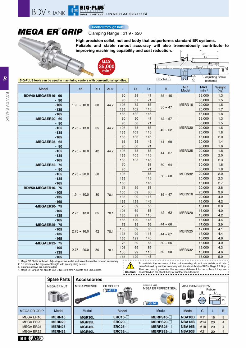
BDV40-MEGAER16- 60 - 90 -105 -135 -165 -MEGAER20- 60 - 90 -105 -135 -165 -MEGAER25- 65 - 90 -105 -135 -165 -MEGAER32- 70 - 90 -105 -135 -165BDV50-MEGAER16- 75 -105 -135 -165 -MEGAER20- 75 -105 -135 -165 -MEGAER25- 75 -105 -135 -165 -MEGAER32- 75 -105 -135 -165
60 90105135165 60 90105135165 65 90105135165 70 90105135165 75105135165 75105135165 75105135165 75105135165
29 57 72102132 30 58 73103133 35 60 75105135
-
39 69 99129 39 69 99129 39 69 99129 39 69 99129
-
70.1
70.1
70.1
70.1
41 71 86116146 41 71 86116146 46 71 86116146 51 71 86116146 56 86116146 56 86116146 56 86116146 56 86116146
35,00035,00020,00020,00015,00035,00035,00020,00020,00015,00030,00030,00020,00020,00015,00030,00030,00020,00020,00015,00020,00020,00020,00016,00018,00018,00018,00016,00017,00017,00017,00016,00016,00016,00016,00015,000
1.31.51.51.71.81.31.51.61.82.01.41.61.82.02.31.61.82.02.32.73.83.94.04.23.84.04.24.43.94.14.44.64.04.34.65.0
øD L L1øD1 L2
30
35
42
50
30
35
42
50
HModel ød MAX.min-1
Weight(kg)
NutModel
1. Mega ER Nut is included. Adjusting screw, collet and wrench must be ordered separately.2. "H" indicates the adjustment length with an adjusting screw.3. Balance screws are not included. 4. Mega ER Grip is not able to use DIN6499 Form-A collets and ESX collets.
1.9 - 10.0
2.75 - 13.0
2.75 - 16.0
2.75 - 20.0
1.9 - 10.0
2.75 - 13.0
2.75 - 16.0
2.75 - 20.0
44.7
44.7
44.7
35 - 47
35 - 45
42 - 62
42 - 57
44 - 60
44 - 67
50 - 64
50 - 68
MAX.35,000
min-1
To maintain the accuracy of the tool assembly, do not use collets and nuts manufactured by another company with the chuck body of BIG’s Mega ER Grip. Also, we cannot guarantee the accuracy statement for our collets if they are assembled on the chuck body of another manufacturer.Caution
Adjusting Screw (optional)øD
1
LL2
L1
ød øD
BDV No.BIG-PLUS tools can be used in machining centers with conventional spindles.
High precision collet, nut and body that outperforms standard ER systems.Reliable and stable runout accuracy will also tremendously contribute to improving machining capability and cost reduction.
35 - 47
42 - 62
44 - 66
44 - 67
50 - 66
50 - 68
MEGA ER GRIPR
Clamping Range : ø1.9 - ø20Coolant-through hole
MEGA ER16MEGA ER20MEGA ER25MEGA ER32
MERN16MERN20MERN25MERN32
MEGA ER NUT
Model
Spare Parts
MEGA ER GRIP
RubberB L
G
MEGA WRENCH
G L BModelModelModelModel
AccessoriesER COLLET
G 14
M11M14M18M21
16202020
3444
SEALING NUTMEGA ER PERFECT SEAL
ADJUSTING SCREW
MGR30LMGR35LMGR42LMGR50L
ERC16-ERC20-ERC25-ERC32-
NBA10BNBA13BNBA16BNBA20B
MERPS16-MERPS20-MERPS25-MERPS32-
G 13
MERN16
MERN20
MERN25
MERN32
MERN16
MERN20
MERN25
MERN32
B 9
BDV / D
V SHAN
K
B
DIN 69871 A/B (BIG-PLUS)
R
S P I N D L E S Y S T E M
D U A L C O N T A C T

1. Tap Holder and wrench are ordered separately.2. Coolant through flange is standard on all BDV40 & 50 Bodies.Rigid tapping function is required on the machine tool.
For MEGA WRENCH A 32For TAP HOLDER A 33- A 36
Tapping Range for DIN & ISO Standard
Model Tapping RangedTap Holder Model øD1øD L2
BDV40-MGT 6- 80
-MGT12- 80
-MGT20-105
BDV50-MGT 6- 85
-MGT12- 85
-MGT20-105
36
41
54
36
41
54
16
20
30
16
20
30
3070
1003070
1003585
1153070
1003070
1003585
115
L
110150180110150180140190220115155185115155185140190220
M2 - M6No.3 - U1/4
M6 - M12U1/4 - U7/16
P1/8M12 - M20U1/2 - U3/4P1/4 - P3/8
M2 - M6No.3 - U1/4
M6 - M12U1/4 - U7/16
P1/8M12 - M20U1/2 - U3/4P1/4 - P3/8
L1
80
80
105
85
85
105
1.4
1.5
1.9
3.6
3.7
4.2
MGT Size DIN StandardDIN371 DIN376 DIN353 ISO529 ISO2284
ISO Standard
MGT 6MGT12MGT20
M3-M6M5-M8
M10
M5-M8 M8-M12 M12-M20
1/81/4-1/2
M3-M5M6,M8,M12M10-M20
1/81/4-3/8
BDV No.
L2
L
d øD1
øD
L1
BodyTap Holder Tap
For detail of TAP HOLDER A 35-A 36
MGT 6-d- 30 - 70 -100
MGT12-d- 30 - 70 -100
MGT20-d- 35 - 85 -115
MGT 6-d- 30 - 70 -100
MGT12-d- 30 - 70 -100
MGT20-d- 35 - 85 -115
BIG-PLUS tools can be used in machining centers with conventional spindles.
BIG-PLUS tools can be used in machining centers with conventional spindles.
Weight(kg)
Tapping Range : M2 - M20Coolant-through hole
MEGA SYNCHRO Tapping HolderR
22565160
φ94
Tap HolderDIN standard
65
d2 ød1
øD
H
Synchro AdjusterSide Lock Bolt
Tapping Range : M22 - M36Coolant-through hole
For Large Tap MGT36
Model BDV50-MGT36-160
Tap Holder ModelTap size
DIN376 DIN353M22,24
M27M30M33M36
P5/8P3/4P7/8P1
1820222528
14.516182022
4551535862
3840424952
1.41.41.51.61.6
MGT36-180145-65-200160-65-220180-65-250200-65-280220-65
Hød1 d2 øDWeight(kg)
For JIS TAP HOLDER A 37
BDV / D
V SHAN
K
B
DIN 69871 A/B (BIG-PLUS)
B 10
R
S P I N D L E S Y S T E M
D U A L C O N T A C T
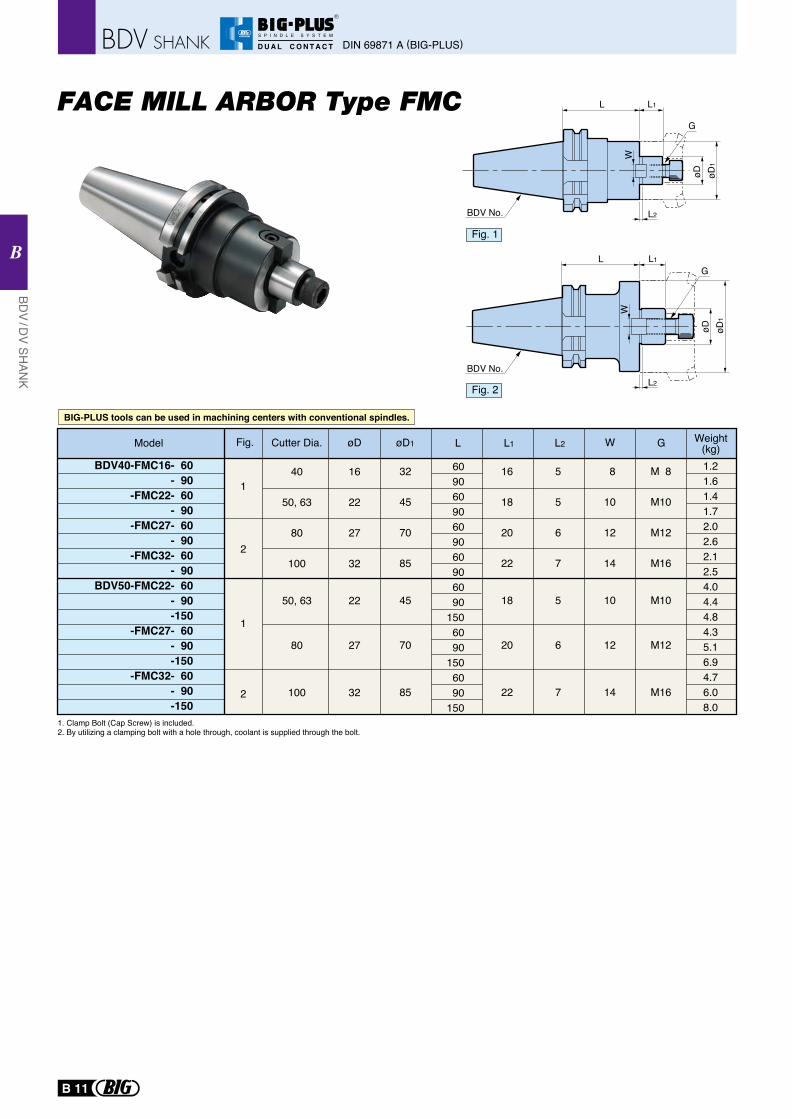
L1
L2
L
W
øD
L2
W
L1L
øD1
øD øD1
BDV No.
BDV No.
G
G
1
2
1
2
60906090609060906090
1506090
1506090
150
40
50, 63
80
100
50, 63
80
100
16
22
27
32
22
27
32
32
45
70
85
45
70
85
16
18
20
22
18
20
22
5
5
6
7
5
6
7
8
10
12
14
10
12
14
M 8
M10
M12
M16
M10
M12
M16
BDV40-FMC16- 60- 90
-FMC22- 60- 90
-FMC27- 60- 90
-FMC32- 60- 90
BDV50-FMC22- 60- 90-150
-FMC27- 60- 90-150
-FMC32- 60- 90-150
1.21.61.41.72.02.62.12.54.04.44.84.35.16.94.76.08.0
Model Cutter Dia. L GWL1øD øD1 L2 Weight(kg)
1. Clamp Bolt (Cap Screw) is included. 2. By utilizing a clamping bolt with a hole through, coolant is supplied through the bolt.
Fig.
Fig. 1
Fig. 2
BIG-PLUS tools can be used in machining centers with conventional spindles.
DIN 69871 A (BIG-PLUS)
BDV / D
V SHAN
K
B
B 11
R
S P I N D L E S Y S T E M
D U A L C O N T A C T
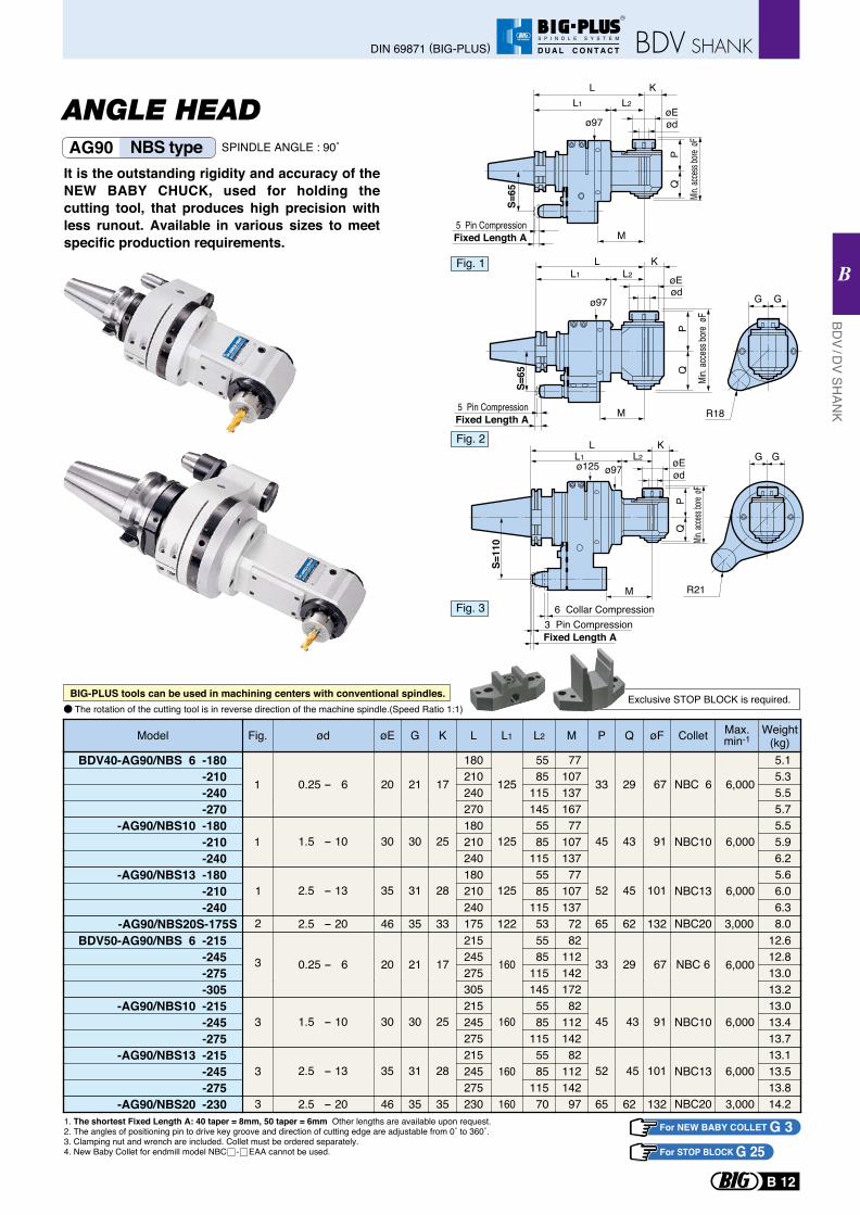
ANGLE HEAD
It is the outstanding rigidity and accuracy of the NEW BABY CHUCK, used for holding the cutting tool, that produces high precision with less runout. Available in various sizes to meet specific production requirements.
1. The shortest Fixed Length A: 40 taper = 8mm, 50 taper = 6mm Other lengths are available upon request.2. The angles of positioning pin to drive key groove and direction of cutting edge are adjustable from 0˚ to 360˚.3. Clamping nut and wrench are included. Collet must be ordered separately.4. New Baby Collet for endmill model NBC - EAA cannot be used.
For NEW BABY COLLET G 3For STOP BLOCK G 25
BIG-PLUS tools can be used in machining centers with conventional spindles.
AG90 NBS type SPINDLE ANGLE : 90˚
The rotation of the cutting tool is in reverse direction of the machine spindle.(Speed Ratio 1:1)
BDV40-AG90/NBS 6 -180-210-240
-AG90/NBS10 -180-210-240
-AG90/NBS13 -180-210-240
-AG90/NBS20S-175S
Weight(kg) 5.1 5.3 5.5
5.5 5.9 6.2 5.6 6.0 6.3 8.0
Max.min-1
NBC13
NBC10
NBC 6
NBC20 3,000
Colletød øEFig. G K L L1 L2 M P Q øF
0.25 - 6 20 21 17
180
125
55 77
33 29 67210 85 107240 115 137
-270 5.7270 167145
1.5 - 10 30 30 25
1
1180
125 55 77
45 43 91210 85 107240 115 137
2.5 - 13 35 31 28180
125 55 77
52 45 101210 85 107240 115 137
2.5 - 20 46 35 33 175 122 53 72 65 62 132
Model
6,000
6,000
6,000
1
2
3
3
3
3
BDV50-AG90/NBS 6 -215-245
-305-AG90/NBS10 -215
-245-275
-AG90/NBS13 -215-245-275
-AG90/NBS20 -230
12.612.8
13.213.013.413.713.113.513.814.2
NBC10
NBC13
NBC20
215 55 82245 85 112
305 145 172-275 13.0275 115 142
1.5 - 10 30 30 25215
160 55 82
45 43 91245 85 112275 115 142
2.5 - 13 35 31 28215
160 55 82
52 45 101245 85 112275 115 142
2.5 - 20 46 35 35 230 160 70 97 65 62 132
33
6,000
6,000
3,000
NBC 60.25 - 6 20 21 17 160 29 67 6,000
L1 L2
ø97
Fixed Length A
PQ
Min. a
ccess
bore
øF
S=65
L K
øE
5 Pin Compression
ød
M
R18
G G
Fixed Length A5 Pin Compression
L1 L2
ø97
PQ
Min.
acce
ss bo
re øF
S=65
L K
øEød
M
G G
R21
L1 L2
ø97ø125
Fixed Length A
PQ
S=11
0
L KøE
3 Pin Compression6 Collar Compression
ød
M
Min. ac
cess b
ore øF
Fig. 1
Fig. 2
Fig. 3
Exclusive STOP BLOCK is required.
BDV / D
V SHAN
K
B
DIN 69871 (BIG-PLUS)
B 12
R
S P I N D L E S Y S T E M
D U A L C O N T A C T
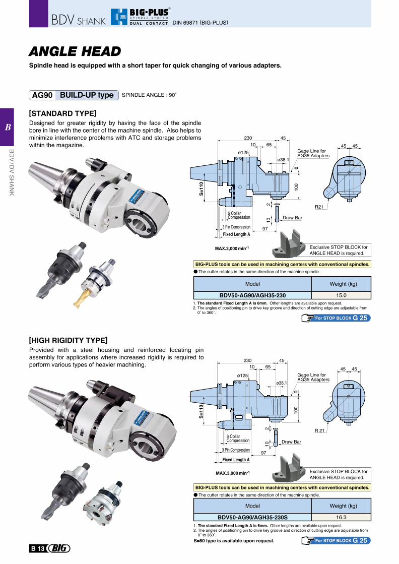
Spindle head is equipped with a short taper for quick changing of various adapters.
AG90 BUILD-UP type
MAX.3,000 min-1
MAX.3,000 min-1
1. The standard Fixed Length A is 6mm. Other lengths are available upon request.2. The angles of positioning pin to drive key groove and direction of cutting edge are adjustable from 0˚ to 360˚.
1. The standard Fixed Length A is 6mm. Other lengths are available upon request.2. The angles of positioning pin to drive key groove and direction of cutting edge are adjustable from 0˚ to 360˚.S=80 type is available upon request.
Exclusive STOP BLOCK forANGLE HEAD is required.
Exclusive STOP BLOCK forANGLE HEAD is required.
The cutter rotates in the same direction of the machine spindle.
The cutter rotates in the same direction of the machine spindle.
[STANDARD TYPE]Designed for greater rigidity by having the face of the spindle bore in line with the center of the machine spindle. Also helps to minimize interference problems with ATC and storage problems within the magazine.
[HIGH RIGIDITY TYPE]Provided with a steel housing and reinforced locating pin assembly for applications where increased rigidity is required to perform various types of heavier machining.
BIG-PLUS tools can be used in machining centers with conventional spindles.
BIG-PLUS tools can be used in machining centers with conventional spindles.
For STOP BLOCK G 25
For STOP BLOCK G 25
SPINDLE ANGLE : 90˚
ANGLE HEAD
102
65
97
10
ø125
Fixed Length A
010
0
S=11
0
230 45
ø38.1
3 Pin Compression
6 CollarCompression
Gage Line for AG35 Adapters
Draw Bar
45 45
R 21
6510ø125
97
010
0
230 45
Gage Line for AG35 Adapters
ø38.1
3 Pin Compression
6 CollarCompression Draw Bar
102
Fixed Length A
0
S=11
0
45 45
R21
BDV50-AG90/AGH35-230
Weight (kg)
15.0
Model
BDV50-AG90/AGH35-230S
Weight (kg)
16.3
Model
DIN 69871 (BIG-PLUS)
BDV / D
V SHAN
K
B
B 13
R
S P I N D L E S Y S T E M
D U A L C O N T A C T
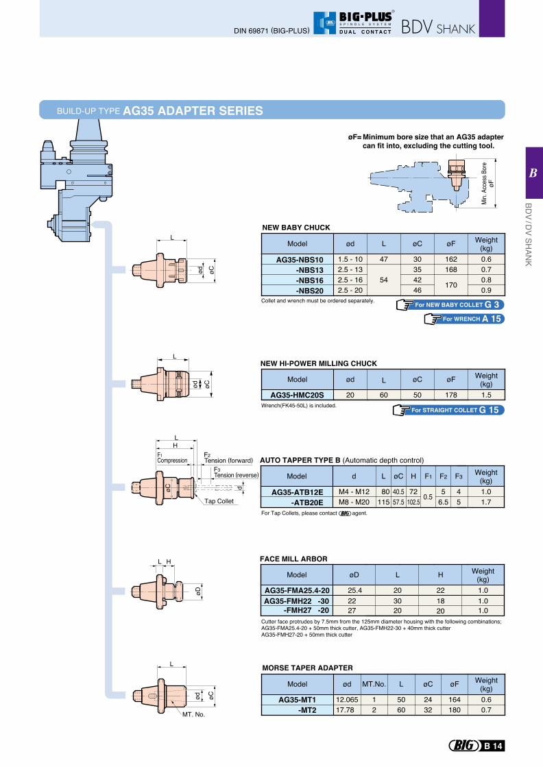
BUILD-UP TYPE AG35 ADAPTER SERIES
Min.
Acce
ss B
ore
øF
Minimum bore size that an AG35 adapter can fit into, excluding the cutting tool.
øF=
For NEW BABY COLLET G 3For WRENCH A 15
L
øCød
L H
øD
HF1 F2
F3
L
døC
Compression Tension (forward)
Tension (reverse)
Tap ColletAG35-ATB12E
-ATB20E
øC H F1 F2 F3
40.5 72 0.5 5 457.5 102.5 6.5 5
Ld
80115
M4 - M12M8 - M20
Weight(kg)1.01.7
Model
AG35-NBS10-NBS13-NBS16-NBS20
ød
1.5 - 102.5 - 132.5 - 162.5 - 20
L
47
54
øC
30354246
øF
162168
170
Weight(kg)0.60.70.80.9
Model
AG35-HMC20S
ød
20
L
60
øC
50
øF
178
Weight(kg)1.5
Model
AG35-FMA25.4-20
øD
25.4
L
20
H
22
Weight(kg)1.0
AG35-FMH22 -30-FMH27 -20
22 30 1820
1.027 20 1.0
Model
Wrench(FK45-50L) is included.
For Tap Collets, please contact agent.
Cutter face protrudes by 7.5mm from the 125mm diameter housing with the following combinations;AG35-FMA25.4-20 + 50mm thick cutter, AG35-FMH22-30 + 40mm thick cutterAG35-FMH27-20 + 50mm thick cutter
Collet and wrench must be ordered separately.
NEW BABY CHUCK
AG35-MT1-MT2
ød
12.06517.78
MT.No.
1
L
50602
øC
2432
øF
164180
Weight(kg)0.60.7
Model
MORSE TAPER ADAPTER
NEW HI-POWER MILLING CHUCK
AUTO TAPPER TYPE B (Automatic depth control)
FACE MILL ARBOR
L
MT. No.
øCød
For STRAIGHT COLLET G 15
L
ød øC
BDV / D
V SHAN
K
B
DIN 69871 (BIG-PLUS)
B 14
R
S P I N D L E S Y S T E M
D U A L C O N T A C T
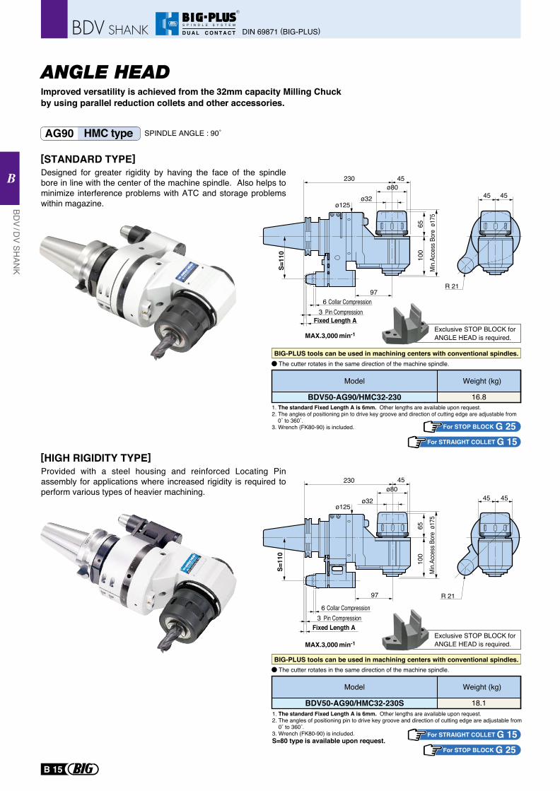
1. The standard Fixed Length A is 6mm. Other lengths are available upon request.2. The angles of positioning pin to drive key groove and direction of cutting edge are adjustable from 0˚ to 360˚.3. Wrench (FK80-90) is included.
MAX.3,000 min-1
MAX.3,000 min-1
1. The standard Fixed Length A is 6mm. Other lengths are available upon request.2. The angles of positioning pin to drive key groove and direction of cutting edge are adjustable from 0˚ to 360˚.3. Wrench (FK80-90) is included.
For STOP BLOCK G 25
S=80 type is available upon request.
Exclusive STOP BLOCK forANGLE HEAD is required.
Exclusive STOP BLOCK forANGLE HEAD is required.
BDV50-AG90/HMC32-230
Weight (kg)
16.8
Model
BDV50-AG90/HMC32-230S
Weight (kg)
18.1
Model
For STRAIGHT COLLET G 15
For STOP BLOCK G 25For STRAIGHT COLLET G 15
The cutter rotates in the same direction of the machine spindle.
The cutter rotates in the same direction of the machine spindle.
Improved versatility is achieved from the 32mm capacity Milling Chuck by using parallel reduction collets and other accessories.
AG90 HMC type
[STANDARD TYPE]Designed for greater rigidity by having the face of the spindle bore in line with the center of the machine spindle. Also helps to minimize interference problems with ATC and storage problems within magazine.
[HIGH RIGIDITY TYPE]Provided with a steel housing and reinforced Locating Pin assembly for applications where increased rigidity is required to perform various types of heavier machining.
BIG-PLUS tools can be used in machining centers with conventional spindles.
BIG-PLUS tools can be used in machining centers with conventional spindles.
SPINDLE ANGLE : 90˚
ø80
ø32ø125
97
Fixed Length A
65
Min.A
cces
s Bor
e ø1
75
100
S=11
0
230 45
3 Pin Compression6 Collar Compression
45 45
R 21
45 45
R 21
ø80ø32
ø125
97
65
Min.A
cces
s Bor
e ø1
75
100
S=11
0
230 45
Fixed Length A3 Pin Compression
6 Collar Compression
ANGLE HEAD
DIN 69871 (BIG-PLUS)
BDV / D
V SHAN
K
B
B 15
R
S P I N D L E S Y S T E M
D U A L C O N T A C T
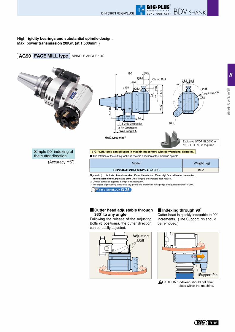
AG90 FACE MILL type
1. The standard Fixed Length A is 6mm. Other lengths are available upon request.2. Coolant cannot be supplied through the Locating Pin.3. The angles of positioning pin to drive key groove and direction of cutting edge are adjustable from 0˚ to 360˚.
For STOP BLOCK G 25
Exclusive STOP BLOCK forANGLE HEAD is required.
BDV50-AG90-FMA25.4S-190S
Weight (kg)
19.2
Model
Figures in ( ) indicate dimensions when 80mm diameter and 50mm high face mill cutter is mounted.
Following the release of the Adjusting Bolts (8 positions), the cutter direction can be easily adjusted.
Cutter head is quickly indexable to 90˚ increments. (The Support Pin should be removed.)
CAUTION :
Cutter head adjustable through360˚ to any angle
AdjustingBolt
Indexing through 90˚
Support PinIndexing should not take place within the machine.
(Accuracy 5 )
Simple 90 indexing of the cutter direction. The rotation of the cutting tool is in reverse direction of the machine spindle.
SPINDLE ANGLE : 90˚
High rigidity bearings and substantial spindle design.Max. power transmission 20Kw. (at 1,500min-1)
MAX.1,500 min-1
BIG-PLUS tools can be used in machining centers with conventional spindles.
ø25.4
76.5
(117
)67
(50)
22
ø140Clamp Bolt
ø125
(ø80)38.5190
57
Fixed Length A3 Pin Compression
6 Collar Compression
S=11
0
38.5
5
38.5
9.35
Min. bore for access
ø206
R21
BDV / D
V SHAN
K
B
DIN 69871 (BIG-PLUS)
B 16
R
S P I N D L E S Y S T E M
D U A L C O N T A C T
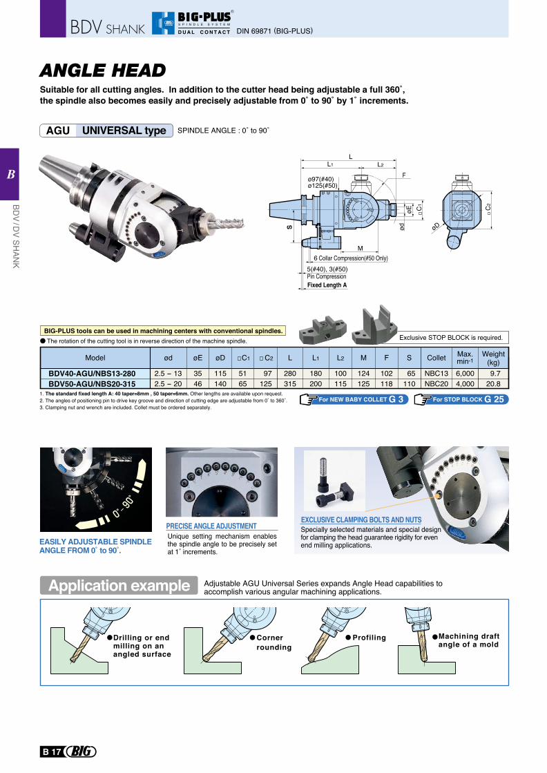
AGU UNIVERSAL type SPINDLE ANGLE : 0˚ to 90˚
Suitable for all cutting angles. In addition to the cutter head being adjustable a full 360˚, the spindle also becomes easily and precisely adjustable from 0˚ to 90˚ by 1˚ increments.
Drilling or end milling on an angled surface
Corner rounding
Profiling Machining draftangle of a mold
Adjustable AGU Universal Series expands Angle Head capabilities toaccomplish various angular machining applications.
EXCLUSIVE CLAMPING BOLTS AND NUTSSpecially selected materials and special designfor clamping the head guarantee rigidity for even end milling applications.
Unique setting mechanism enables the spindle angle to be precisely set at 1˚ increments.
PRECISE ANGLE ADJUSTMENT
EASILY ADJUSTABLE SPINDLE ANGLE FROM 0˚ to 90˚.
1. The standard fixed length A: 40 taper=8mm , 50 taper=6mm. Other lengths are available upon request.2. The angles of positioning pin to drive key groove and direction of cutting edge are adjustable from 0˚ to 360˚.3. Clamping nut and wrench are included. Collet must be ordered separately.
For NEW BABY COLLET G 3 For STOP BLOCK G 25
BDV40-AGU/NBS13-280BDV50-AGU/NBS20-315
Weight(kg)
Max.min-1Colletød øD C1 C2 L1 L2 M F SModel øE L
18028035 115 51 97 100 124 102 65 6,000NBC13 9.72.5 - 1320031546 140 65 125 115 125 118 110 4,000NBC20 20.82.5 - 20
Exclusive STOP BLOCK is required.The rotation of the cutting tool is in reverse direction of the machine spindle.BIG-PLUS tools can be used in machining centers with conventional spindles.
Application example
C1
C2
øD
Fixed Length A
5(#40), 3(#50)6 Collar Compression(#50 Only)
LL2
M
øE
S ød
FL1
Pin Compression
ø97(#40)ø125(#50)
ANGLE HEAD
DIN 69871 (BIG-PLUS)
BDV / D
V SHAN
K
B
B 17
R
S P I N D L E S Y S T E M
D U A L C O N T A C T
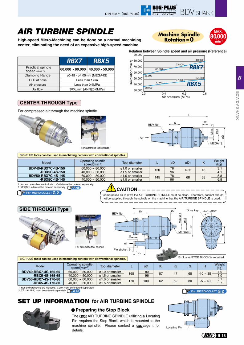
BIG-PLUS tools can be used in machining centers with conventional spindles.
SIDE THROUGH Type
Exclusive STOP BLOCK is required.
For MICRO COLLET G 21. Nut and wrenches are included. Collet must be ordered separately.2. XF1(Air Unit) must be ordered separately.
BIG-PLUS tools can be used in machining centers with conventional spindles.
For automatic tool change
A 65
The AIR TURBINE SPINDLE utilizing a Locating Pin requires the Stop Block, which is mounted to the machine spindle. Please contact a agent for details.
Locating Pin
Preparing the Stop Block
for AIR TURBINE SPINDLE
Model Weight(kg)HSK2K1øDLTool diameterOperating spindle
speed(min-1)165
170
8096
100
47
52
65
80
-10 - 35
-5 - 40
4.05.08.79.7
BDV40-RBX7-4S-165-65-RBX5-4S-165-65
BDV50-RBX7-4S-170-80-RBX5-4S-170-80
60,000 - 80,00040,000 - 50,00060,000 - 80,00040,000 - 50,000
ø1.0 or smallerø1.5 or smallerø1.0 or smallerø1.5 or smaller
57
62
AIR TURBINE SPINDLEHigh-speed Micro-Machining can be done on a normal machining center, eliminating the need of an expensive high-speed machine.
CENTER THROUGH Type For compressed air through the machine spindle.
1. Nut and wrenches are included. Collet must be ordered separately.2. XF1(Air Unit) must be ordered separately.
Model
150
145
78967896
49.6
68
43
38
3.14.15.86.8
Weight(kg)KøD øD1LTool diameterOperating spindle
speed(min-1)60,000 - 80,00040,000 - 50,00060,000 - 80,00040,000 - 50,000
ø1.0 or smallerø1.5 or smallerø1.0 or smallerø1.5 or smaller
BDV40-RBX7C-4S-150-RBX5C-4S-150
BDV50-RBX7C-4S-145-RBX5C-4S-145
CAUTIONCompressed air to drive the AIR TURBINE SPINDLE must be clean. Therefore, coolant should not be supplied through the spindle on the machine that the AIR TURBINE SPINDLE is used.
For MICRO COLLET G 2A 65
For automatic tool change
MAX.80,000
min-1
Machine SpindleRotation=0
Relation between Spindle speed and air pressure (Reference)
58,000
66,000
73,000
80,000
90,000
80,000
70,000
60,000
50,000
40,000
30,0000.3 0.4 0.5 0.6
Rev
olut
ion(
min
-1)
38,000
43,00047,000
50,000
Air pressure (MPa)
Practical spindle speed (min-1) 60,000 - 80,000 40,000 - 50,000
Clamping RangeT.I.R at noseAir pressure
Air flow
ø0.45 - ø4.05mm (MEGA4S)Less than 1 m
Less than 0.6MPa300L/min [ANR](0.6MPa)
S
=0˚-360˚Drive key
K2
Air
MEGA4S
Pin stroke : 6
H
L
Max
.ø 4
ø12
K1 22
øD
BDV No.
Air
L
K 22
MEGA4S
Max
.ø 4
øD
ø12
øD
1
BDV No.
BDV / D
V SHAN
K
B
DIN 69871 (BIG-PLUS)
B 18
R
S P I N D L E S Y S T E M
D U A L C O N T A C T
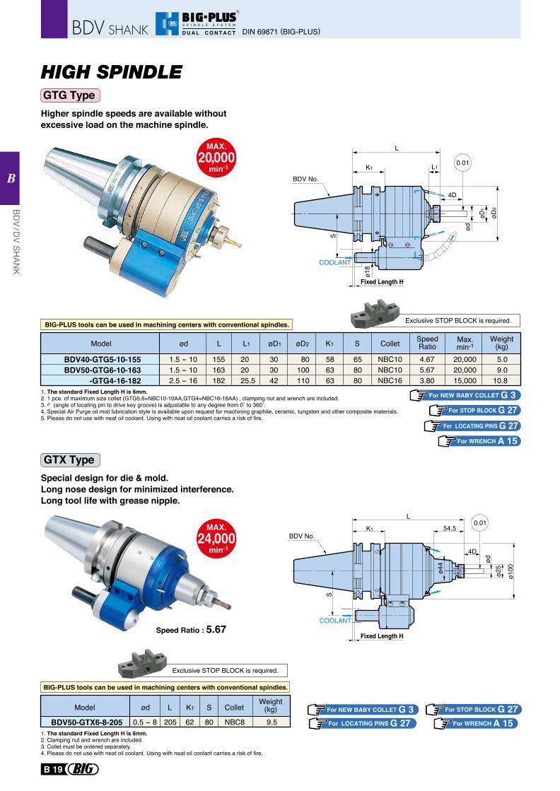
HIGH SPINDLE
Higher spindle speeds are available without excessive load on the machine spindle.
Special design for die & mold.Long nose design for minimized interference.Long tool life with grease nipple.
1. The standard Fixed Length H is 6mm. 2. 1 pce. of maximum size collet (GTG5,6=NBC10-10AA,GTG4=NBC16-16AA) , clamping nut and wrench are included.3. (angle of locating pin to drive key groove) is adjustable to any degree from 0˚ to 360˚.4. Special Air Purge oil mist lubrication style is available upon request for machining graphite, ceramic, tungsten and other composite materials.5. Please do not use with neat oil coolant. Using with neat oil coolant carries a risk of fire.
For STOP BLOCK G 27For LOCATING PINS G 27
Exclusive STOP BLOCK is required.
For WRENCH A 15
Model L1L øD1 øD2 K1 S Collet SpeedRatioød Max.
min-1Weight
(kg)5.09.0
10.8
4.675.673.80
20,00020,00015,000
155163182
202025.5
1.5 - 101.5 - 102.5 - 16
303042
80100110
586363
658080
NBC10NBC10NBC16
BDV40-GTG5-10-155BDV50-GTG6-10-163
-GTG4-16-182
BIG-PLUS tools can be used in machining centers with conventional spindles.
BDV No.
1. The standard Fixed Length H is 6mm. 2. Clamping nut and wrench are included.3. Collet must be ordered separately.4. Please do not use with neat oil coolant. Using with neat oil coolant carries a risk of fire.
For LOCATING PINS G 27For NEW BABY COLLET G 3 For STOP BLOCK G 27Model L K1 S Colletød
Weight(kg)
205 9.50.5 - 8 62 80 NBC8BDV50-GTX6-8-205
Speed Ratio : 5.67
Exclusive STOP BLOCK is required.
BIG-PLUS tools can be used in machining centers with conventional spindles.
For WRENCH A 15
BDV No.
GTG Type
GTX Type
For NEW BABY COLLET G 3
COOLANT
ø44
ø100
ødø2
5
54.5
L
K1
S
4D
0.01
Fixed Length H
L
ø18
S
øD1
øD2
COOLANT
4D
K1 L1
ød
0.01
Fixed Length H
MAX.20,000
min-1
MAX.24,000
min-1
DIN 69871 (BIG-PLUS)
BDV / D
V SHAN
K
B
B 19
R
S P I N D L E S Y S T E M
D U A L C O N T A C T
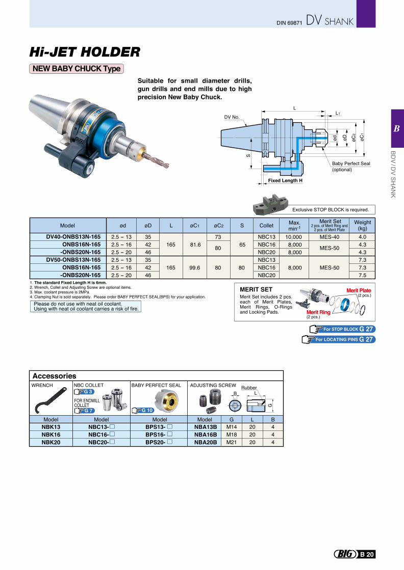
Hi-JET HOLDERNEW BABY CHUCK Type
Suitable for small diameter drills, gun drills and end mills due to high precision New Baby Chuck.
1. The standard Fixed Length H is 6mm. 2. Wrench, Collet and Adjusting Screw are optional items.3. Max. coolant pressure is 2MPa.4. Clamping Nut is sold separately. Please order BABY PERFECT SEAL(BPS) for your application.
For STOP BLOCK G 27For LOCATING PINS G 27
Model Colletød L SøC2øC1øD Max.min-1
Merit Set Weight(kg)2 pcs. of Merit Ring and
2 pcs. of Merit Plate
Exclusive STOP BLOCK is required.
DV40-ONBS13N-165ONBS16N-165
-ONBS20N-165DV50-ONBS13N-165
ONBS16N-165-ONBS20N-165
81.6
99.6
65
80
73
80
80
MES-40
MES-50
MES-50
10,0008,0008,000
8,000
2.5 - 132.5 - 162.5 - 202.5 - 132.5 - 162.5 - 20
354246354246
NBC13NBC16NBC20NBC13NBC16NBC20
4.04.34.37.37.37.5
165
165
Please do not use with neat oil coolant.Using with neat oil coolant carries a risk of fire.
NBK13NBK16NBK20
G 10
BPS13-BPS16-BPS20-
NBC13-NBC16-NBC20-
WRENCH
Model Model Model
Accessories
NBA13BNBA16BNBA20B
M14M18M21
202020
444
ADJUSTING SCREW
G L B
BRubber
L
G
Model
BABY PERFECT SEALG 3
NBC COLLET
G 7
FOR ENDMILLCOLLET
DV No.
ød
S
øC1
øD
LL1
Baby Perfect Seal(optional)
øC2
Fixed Length H
(2 pcs.)
(2 pcs.)MERIT SETMerit Set includes 2 pcs. each of Merit Plates, Merit Rings, O-Rings and Locking Pads.
Merit Plate
Merit Ring
BDV / D
V SHAN
K
B
B 20
DIN 69871
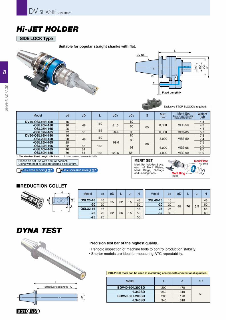
Hi-JET HOLDER
LEffective test length A
øD
BDV40-50-L200SD 200 170-L340SD 340 310
BDV50-50-L200SD 200 178-L340SD 340 318
50
Model L A øD
Precision test bar of the highest quality.Periodic inspection of machine tools to control production stability.Shorter models are ideal for measuring ATC repeatability.
BIG-PLUS tools can be used in machining centers with conventional spindles.
SIDE LOCK TypeSuitable for popular straight shanks with flat.
1. The standard Fixed Length H is 6mm. 2. Max. coolant pressure is 2MPa.
For STOP BLOCK G 27
H
LL1
øD ød
Please do not use with neat oil coolant.Using with neat oil coolant carries a risk of fire.
Exclusive STOP BLOCK is required.
For LOCATING PINS G 27
80
80
12198
150
150
165
185
165
48
48
58
586484
80
80
98
DV40-OSL16N-150-OSL20N-150-OSL25N-165-OSL32N-165
DV50-OSL16N-150-OSL20N-150-OSL25N-165-OSL32N-165-OSL40N-165-OSL50N-185
16202532162025324050
81.6 65
80
99.6
8,000
6,000
MES-50
MES-65
4.44.34.45.77.57.47.57.98.0
11.9
99.6
129.6
8,000
6,0004,000
MES-50
MES-65MES-90
Model ød L SøC2øC1øD Max.min-1
Merit Set Weight(kg)2 pcs. of Merit Ring and
2 pcs. of Merit Plate
REDUCTION COLLET
L
ød øC1
øD øC2
S
Fixed Length H
DV No.
(2 pcs.)
(2 pcs.)MERIT SETMerit Set includes 2 pcs. each of Merit Plates, Merit Rings, O-Rings and Locking Pads.
Merit Plate
Merit Ring
Model
OSL25-16-20
OSL32-16-20-25
ød
1620162025
4850485056
øD
25
32
62
66
5.5
5.5
L L1 H Model
OSL40-16-20-25-32
ød
16202532
48505660
øD
40 76 5.5
L L1 H
BDV / D
V SHAN
K
B
B 21
DIN 69871
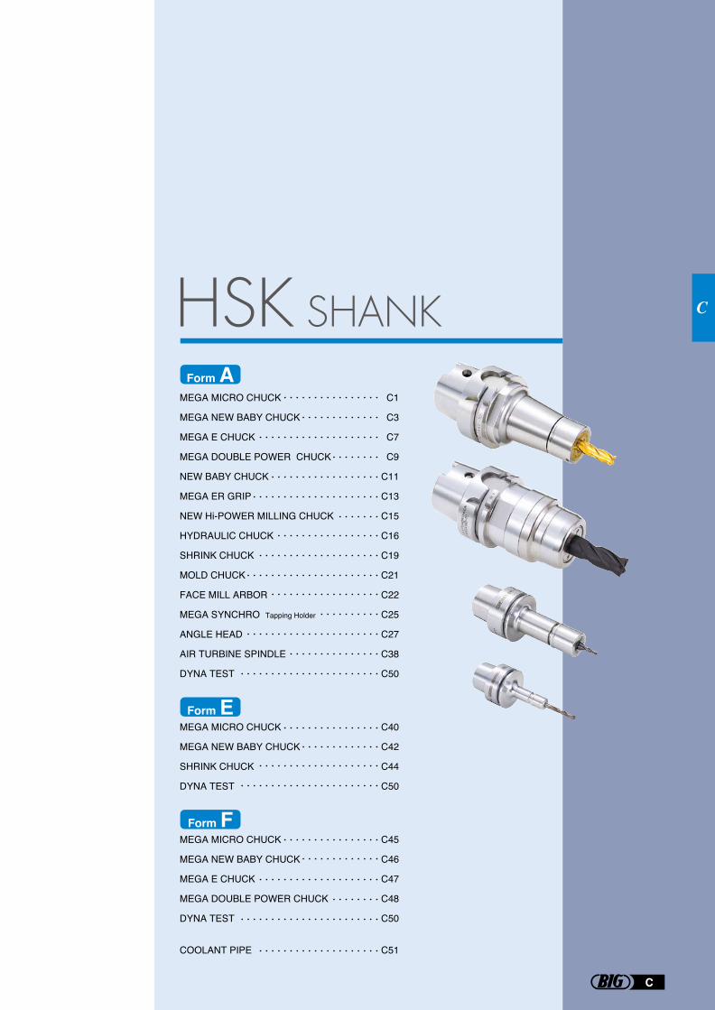
MEGA MICRO CHUCK
MEGA NEW BABY CHUCK
MEGA E CHUCK
MEGA DOUBLE POWER CHUCK
NEW BABY CHUCK
MEGA ER GRIP
NEW Hi-POWER MILLING CHUCK
HYDRAULIC CHUCK
SHRINK CHUCK
MOLD CHUCK
FACE MILL ARBOR
MEGA SYNCHRO Tapping Holder
ANGLE HEAD
AIR TURBINE SPINDLE
DYNA TEST
MEGA MICRO CHUCK
MEGA NEW BABY CHUCK
SHRINK CHUCK
DYNA TEST
MEGA MICRO CHUCK
MEGA NEW BABY CHUCK
MEGA E CHUCK
MEGA DOUBLE POWER CHUCK
DYNA TEST
COOLANT PIPE
C1
C3
C7
C9
C11
C13
C15
C16
C19
C21
C22
C25
C27
C38
C50
C40
C42
C44
C50
C45
C46
C47
C48
C50
C51
Form E
Form F
Form A
C
C
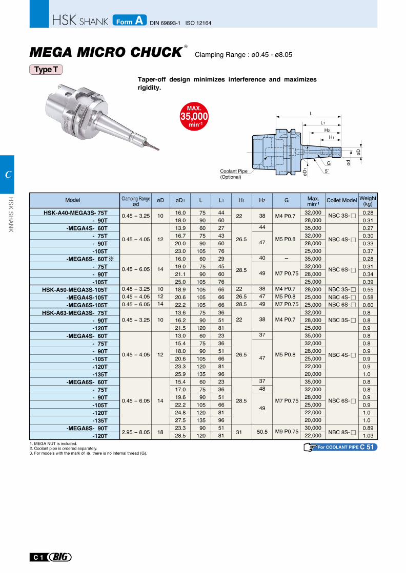
Taper-off design minimizes interference and maximizes rigidity.
Clamping Range : ø0.45 - ø8.05
MAX.35,000
min-1
1. MEGA NUT is included. 2. Coolant pipe is ordered separately.3. For models with the mark of , there is no internal thread (G).
0.45 - 6.05 14
2.95 - 8.05 18
0.45 - 4.05 12
0.45 - 6.05 14
0.45 - 4.05 12
0.45 - 3.25
0.45 - 3.250.45 - 4.050.45 - 6.05
10
101214
0.45 - 3.25 10
7590607590
105607590
1051051051057590
120607590
105120135607590
10512013590
120
16.018.013.916.720.023.016.019.021.125.018.920.622.213.616.221.513.015.418.020.623.325.915.417.019.622.224.827.523.328.5
446027436076294560766666663651812336516681962336516681965181
32,00028,00035,00032,00028,00025,00035,00032,00028,00025,00028,00025,00025,00032,00028,00025,00035,00032,00028,00025,00022,00020,00035,00032,00028,00025,00022,00020,00030,00022,000
38
44
47
40
49
384749
38
37
47
3748
49
50.5
Model
HSK-A40-MEGA3S- 75T- 90T
-MEGA4S- 60T- 75T- 90T-105T
-MEGA6S- 60T- 75T- 90T-105T
HSK-A50-MEGA3S-105T-MEGA4S-105T-MEGA6S-105T
HSK-A63-MEGA3S- 75T- 90T-120T
-MEGA4S- 60T- 75T- 90T-105T-120T-135T
-MEGA6S- 60T- 75T- 90T-105T-120T-135T
-MEGA8S- 90T-120T
Clamping Rangeød LøD1 L1 H2
22
26.5
28.5
2226.528.5
22
26.5
28.5
31
H1
M4 P0.7
M5 P0.8
-
M7 P0.75
M4 P0.7M5 P0.8M7 P0.75
M4 P0.7
M5 P0.8
M7 P0.75
M9 P0.75
GøD Max.min-1
0.280.310.270.300.330.370.280.310.340.390.550.580.600.80.80.90.80.80.90.90.91.00.80.80.90.91.01.00.891.03
NBC 6S-
NBC 4S-
NBC 3S-
NBC 6S-
NBC 4S-
NBC 3S-
NBC 3S-NBC 4S-NBC 6S-
Collet Model Weight(kg)
NBC 8S-
Coolant Pipe (Optional)
øD
H2
H1
5
L1
L
ød
øD1
G
R
Type T
For COOLANT PIPE C 51
C 1
HSK SH
ANK
C
DIN 69893-1 ISO 12164Form A
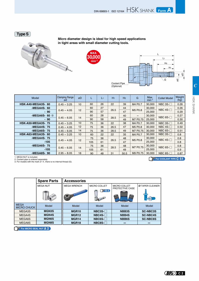
Micro diameter design is ideal for high speed applications in tight areas with small diameter cutting tools.
MAX.30,000
min-1
1. MEGA NUT is included. 2. Coolant pipe is ordered separately.3. For models with the mark of , there is no internal thread (G).
G 2
MEGA3SMEGA4SMEGA6SMEGA8S
MGN3SMGN4SMGN6SMGN8S
Spare PartsMEGA NUT
MEGA MICRO CHUCK Model
MGR10MGR12MGR14MGR18
MICRO COLLETPROTECTIVE CASE
MICRO COLLET
AccessoriesMEGA WRENCH
NBB3SNBB4SNBB6S-
Model Model Model
NBC3S-NBC4S-NBC6S-NBC8S-
Model
SC-NBC3SSC-NBC4SSC-NBC6S
-
TAPER CLEANER
14
12
6075
10575
10590
223661366148
HSK-A63-MEGA3S- 60-MEGA4S- 75
-105 -MEGA6S- 75
-105 -MEGA8S- 90
0.45 - 6.05
0.45 - 6.05
14
0.45 - 4.05
0.45 - 4.05
0.45 - 3.25
0.45 - 3.25
0.45 - 6.05
182.95 - 8.05
0.45 - 4.05
12
10
10
2627572858
30,00030,00025,00030,00025,00030,000
30,00030,00025,00030,00025,00030,00030,00030,000
3548474849
50.5
3944474049
0.260.260.290.270.300.490.500.510.80.80.80.80.90.87
Model
HSK-A40-MEGA3S- 60-MEGA4S- 60
- 90 -MEGA6S- 60
- 90HSK-A50-MEGA3S- 75
-MEGA4S- 75 -MEGA6S- 75
L L1 H2øD
NBC 4S-
NBC 4S-
NBC 3S-
NBC 3S-
NBC 6S-
Collet Model Weight(kg)
Max.min-1
6060906090
0.45 - 3.25 101214
363636
384749
M4 P0.7
M5 P0.8
M7 P0.75M4 P0.7M5 P0.8M7 P0.75M4 P0.7
M5 P0.8
M7 P0.75
M9 P0.75
G
22
26.5
28.5
2226.528.522
26.5
28.5
31
H1
NBC 3S-NBC 4S-NBC 6S-
7575
75
NBC 6S-
-
NBC 8S-
Coolant Pipe (Optional)
øD
H2
H1
L1
L
ødG
Clamping Rangeød
Type S
For COOLANT PIPE C 51
For MICRO SEAL NUT A 2
C 2
DIN 69893-1 ISO 12164 Form AH
SK SHAN
K
C
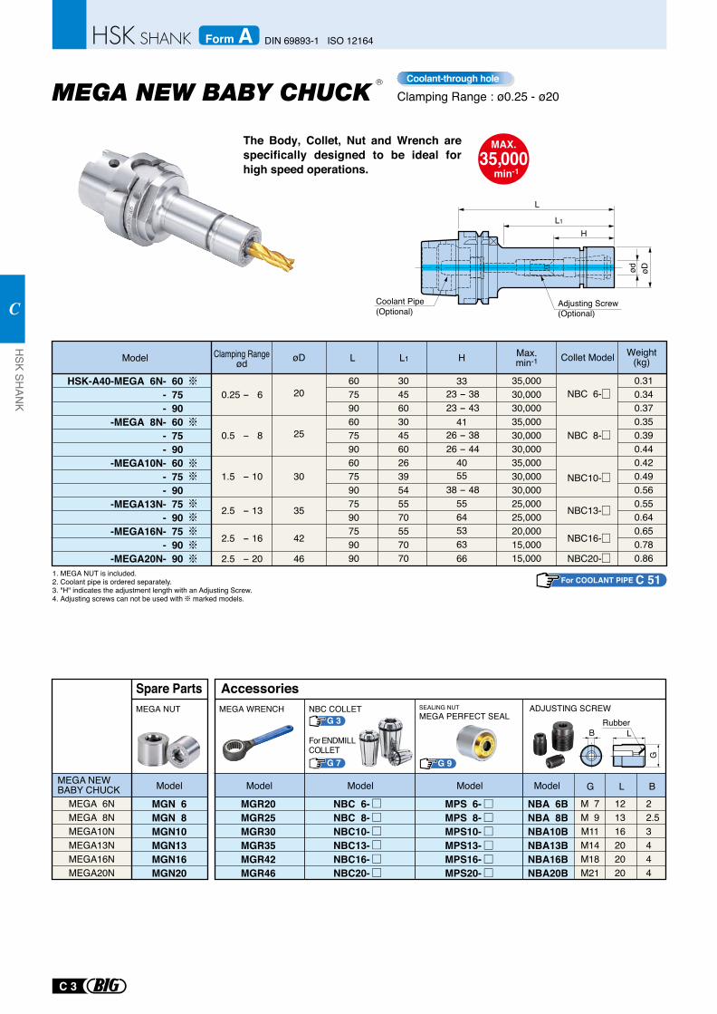
The Body, Collet, Nut and Wrench are specifically designed to be ideal for high speed operations.
Clamping Range : ø0.25 - ø20
MAX.35,000
min-1
NBC 8-
NBC10-
NBC13-
NBC16-
NBC20-
NBC 6-
0.5 - 8
1.5 - 10
2.5 - 13
2.5 - 20
2.5 - 16
25
30
35
42
46
0.25 - 6 23 - 3823 - 43
26 - 3826 - 44
38 - 48
206075906075906075907590759090
3045603045602639545570557070
35,00030,00030,00035,00030,00030,00035,00030,00030,00025,00025,00020,00015,00015,000
0.310.340.370.350.390.440.420.490.560.550.640.650.780.86
HSK-A40-MEGA 6N- 60- 75- 90
-MEGA 8N- 60- 75- 90
-MEGA10N- 60- 75- 90
-MEGA13N- 75- 90
-MEGA16N- 75- 90
-MEGA20N- 90
Model L Collet ModelL1øD H Max.min-1
33
41
4055
5564536366
Weight(kg)
H
L
L1
ød
øD
1. MEGA NUT is included. 2. Coolant pipe is ordered separately.3. "H" indicates the adjustment length with an Adjusting Screw.4. Adjusting screws can not be used with marked models.
Coolant-through hole
Adjusting Screw (Optional)
Coolant Pipe (Optional)
MPS 6-MPS 8-MPS10-MPS13-MPS16-MPS20-
G 9
G 3 Rubber
MEGA 6NMEGA 8NMEGA10NMEGA13NMEGA16NMEGA20N
MEGA NEW BABY CHUCK
MGN 6MGN 8MGN10MGN13MGN16MGN20
MEGA NUT
Model
Spare Parts
MGR20MGR25MGR30MGR35MGR42MGR46
NBA 6BNBA 8BNBA10BNBA13BNBA16BNBA20B
M 7M 9M11M14M18M21
121316202020
22.53444
MEGA WRENCH NBC COLLET
G 7
For ENDMILLCOLLET
SEALING NUTMEGA PERFECT SEAL
ADJUSTING SCREW
G L B
B L
G
ModelModelModelModel
Accessories
NBC 6-NBC 8-NBC10-NBC13-NBC16-NBC20-
R
Clamping Rangeød
For COOLANT PIPE C 51
C 3
HSK SH
ANK
C
DIN 69893-1 ISO 12164Form A
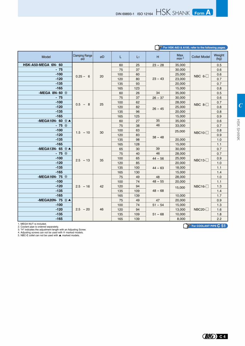
NBC 6-
NBC 8-
NBC10-
NBC13-
NBC16-
NBC20-
HSK-A50-MEGA 6N- 60- 75-100-120-135-165
-MEGA 8N- 60- 75-100-120-135-165
-MEGA10N- 60- 75-100-120-135-165
-MEGA13N- 65- 75-100-120-135-165
-MEGA16N- 75-100-120-135-165
-MEGA20N- 75-100-120-135-165
0.25 - 6
0.5 - 8
1.5 - 10
20
25
30
35
42
46
2.5 - 13
2.5 - 20
2.5 - 16
0.50.60.60.70.70.80.50.60.70.80.80.90.60.70.80.91.01.10.70.70.91.01.11.41.01.11.31.41.70.91.31.61.82.2
6075
1001201351656075
1001201351656075
1001201351656575
10012013516575
10012013516575
100120135165
2537608093
1232637628296
1252738638398
12830406585
100130497494
109139497494
109139
35,00030,00025,00023,00020,00015,00035,00030,00028,00025,00020,00015,00035,00033,000
20,00015,00030,00028,00025,00020,00018,00015,00028,00020,000
10,00020,00015,00013,00010,0008,000
25,000
15,000
4635
34
4639
48
47
23 - 43
23 - 28
26 - 37
26 - 45
38 - 48
44 - 56
44 - 63
48 - 55
48 - 68
51 - 68
51 - 54
Model L Collet ModelL1øD H Max.min-1
Weight(kg)
1. MEGA NUT is included. 2. Coolant pipe is ordered separately.3. "H" indicates the adjustment length with an Adjusting Screw.4. Adjusting screws can not be used with marked models. 5. NBC-E collet can not be used with marked models.
Clamping Rangeød
For HSK-A63 & A100, refer to the following pages.
For COOLANT PIPE C 51
C 4
DIN 69893-1 ISO 12164 Form AH
SK SHAN
K
C
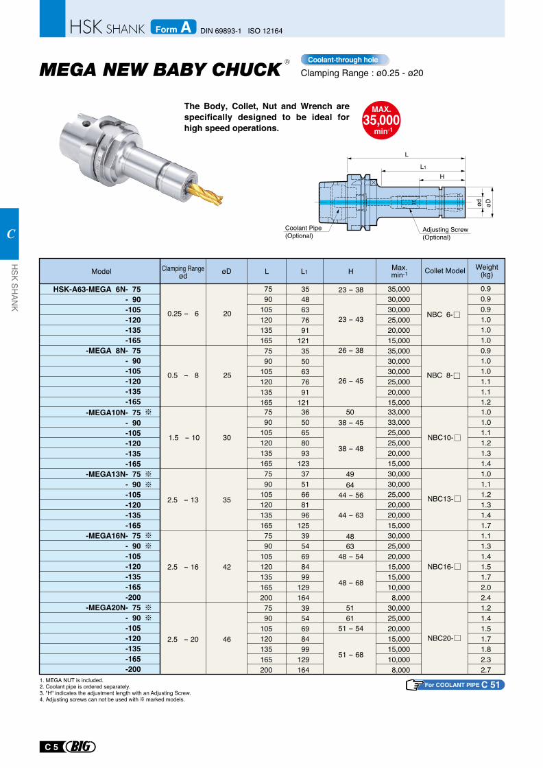
The Body, Collet, Nut and Wrench are specifically designed to be ideal for high speed operations.
Clamping Range : ø0.25 - ø20
MAX.35,000
min-1
H
L
L1
ød
øD
Coolant-through hole
Adjusting Screw (Optional)
Coolant Pipe (Optional)
R
1. MEGA NUT is included. 2. Coolant pipe is ordered separately.3. "H" indicates the adjustment length with an Adjusting Screw.4. Adjusting screws can not be used with marked models.
NBC 6-
NBC 8-
HSK-A63-MEGA 6N- 75- 90-105-120-135-165
-MEGA 8N- 75- 90-105-120-135-165
0.25 - 6
23 - 38
23 - 43
26 - 38
26 - 45
38 - 45
38 - 48
44 - 56
44 - 63
48 - 54
48 - 68
51 - 54
51 - 68
0.5 - 8
20
25
0.90.90.91.01.01.00.91.01.01.11.11.2
7590
1051201351657590
105120135165
3650658093
1233751668196
1253954698499
1291643954698499
129164
3548637691
1213550637691
121
35,00030,00030,00025,00020,00015,00035,00030,00030,00025,00020,00015,000
-MEGA10N- 75- 90-105-120-135-165
-MEGA13N- 75- 90-105-120-135-165
-MEGA16N- 75- 90-105-120-135-165-200
-MEGA20N- 75- 90-105-120-135-165-200
33,00033,00025,00025,00020,00015,00030,00030,00025,00020,00020,00015,00030,00025,00020,00015,00015,00010,0008,000
30,00025,00020,00015,00015,00010,0008,000
1.5 - 10 NBC10-30
1.01.01.11.21.31.41.01.11.21.31.41.71.11.31.41.51.72.02.41.21.41.51.71.82.32.7
NBC13-
NBC16-
NBC20-
2.5 - 13
2.5 - 16
2.5 - 20
35
42
46
49
50
64
4863
5161
Model L L1øD H Max.min-1
Weight(kg)
7590
1051201351657590
1051201351657590
1051201351652007590
105120135165200
Collet ModelClamping Rangeød
For COOLANT PIPE C 51
C 5
HSK SH
ANK
C
DIN 69893-1 ISO 12164Form A
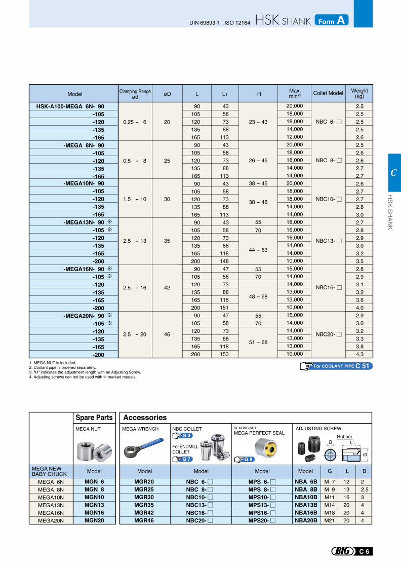
1. MEGA NUT is included.2. Coolant pipe is ordered separately.3. "H" indicates the adjustment length with an Adjusting Screw.4. Adjusting screws can not be used with marked models.
-MEGA10N- 90-105-120-135-165
-MEGA13N- 90-105-120-135-165-200
-MEGA16N- 90-105-120-135-165-200
-MEGA20N- 90-105-120-135-165-200
2.5 - 13
2.5 - 16
2.5 - 20
NBC13-
NBC16-
NBC20-
35
42
46
1.5 - 10 NBC10-30
5570
5570
5570
HSK-A100-MEGA 6N- 90-105-120-135-165
-MEGA 8N- 90-105-120-135-165
9010512013516590
10512013516590
10512013516590
10512013516520090
10512013516520090
105120135165200
43587388
11343587388
11343587388
11343587388
11814847587388
11815147587388
118153
20,000 18,00018,00014,00012,00020,00018,00018,00014,00014,00020,00018,00018,00014,00014,00018,00016,00016,00014,00014,00010,00015,00014,00014,00013,00013,00010,00015,00014,00014,00013,000 13,00010,000
2.52.52.52.52.62.52.62.62.72.72.62.72.72.83.02.72.82.93.03.23.52.82.93.13.23.64.02.93.03.23.33.84.3
0.25 - 6
0.5 - 8
20
25
NBC 6-
NBC 8-
Model L L1øD H Max.min-1
Weight(kg)
23 - 43
26 - 45
38 - 45
38 - 48
48 - 68
51 - 68
44 - 63
Collet Model
MPS 6-MPS 8-MPS10-MPS13-MPS16-MPS20-
G 9
G 3 Rubber
MEGA 6NMEGA 8NMEGA10NMEGA13NMEGA16NMEGA20N
MEGA NEW BABY CHUCK
MGN 6MGN 8MGN10MGN13MGN16MGN20
MEGA NUT
Model
Spare Parts
MGR20MGR25MGR30MGR35MGR42MGR46
NBA 6BNBA 8BNBA10BNBA13BNBA16BNBA20B
M 7M 9M11M14M18M21
121316202020
22.53444
MEGA WRENCH NBC COLLET
G 7
For ENDMILLCOLLET
SEALING NUTMEGA PERFECT SEAL
ADJUSTING SCREW
G L B
B L
G
ModelModelModelModel
Accessories
NBC 6-NBC 8-NBC10-NBC13-NBC16-NBC20-
Clamping Rangeød
For COOLANT PIPE C 51
C 6
DIN 69893-1 ISO 12164 Form AH
SK SHAN
K
C
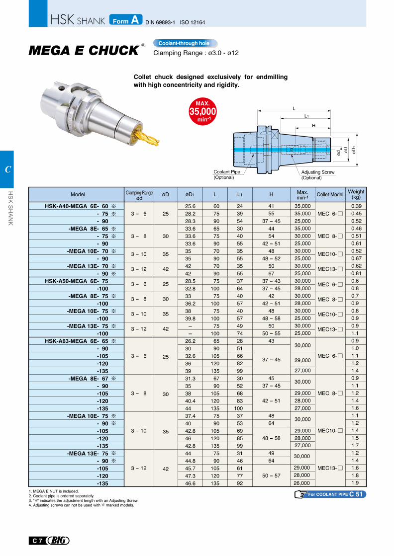
Collet chuck designed exclusively for endmilling with high concentricity and rigidity.
Clamping Range : ø3.0 - ø12
MAX.35,000
min-1
Coolant-through hole
25.628.228.333.633.633.63535424228.532.83336.23839.8 - -26.23032.6363931.3353840.44437.44042.84642.84444.845.747.346.6
6075906575907090709075
10075
10075
10075
1006590
1051201356790
1051201357590
1051201357590
105120135
243954304055355535553764405740574974285166829930526883
10037536985993146617792
0.390.450.520.460.510.610.520.670.620.810.60.80.70.90.80.90.91.10.91.01.11.21.40.91.11.21.41.61.11.21.41.51.71.21.41.61.81.9
30,000
29,000
27,000
30,000
29,00028,000
30,000
29,00028,000
27,000
30,000
29,00028,00027,000
26,000
35,00035,00025,00035,00030,00025,00030,00025,00030,00025,00030,00028,00030,00028,00030,00025,00030,00025,000
4155
37 - 454454
42 - 5148
48 - 525067
37 - 4337 - 45
4242 - 51
4848 - 58
5050 - 55
43
37 - 45
45
42 - 51
4864
48 - 58
4964
50 - 57
3 - 6
3 - 8
3 - 10
3 - 12
Model øD øD1 L L1 H
25
30
35
42
3 - 10
3 - 12
3 - 6
3 - 8
3 - 10
3 - 12
25
30
35
42
25
30
35
42
MEC 6-
MEC 8-
MEC10-
MEC13-
MEC 6-
MEC 8-
MEC 6-
MEC 8-
MEC10-
MEC13-
MEC10-
MEC13-
HSK-A40-MEGA 6E- 60- 75- 90
-MEGA 8E- 65- 75- 90
-MEGA 10E- 70- 90
-MEGA 13E- 70- 90
HSK-A50-MEGA 6E- 75-100
-MEGA 8E- 75-100
-MEGA 10E- 75-100
-MEGA 13E- 75-100
HSK-A63-MEGA 6E- 65- 90-105-120-135
-MEGA 8E- 67- 90-105-120-135
-MEGA 10E- 75- 90-105-120-135
-MEGA 13E- 75- 90-105-120-135
Max.min-1
Weight(kg)
Coolant Pipe (Optional)
LL1
øD1
øDød
H
Adjusting Screw (Optional)
3 - 6
3 - 8
1. MEGA E NUT is included. 2. Coolant pipe is ordered separately.3. "H" indicates the adjustment length with an Adjusting Screw.4. Adjusting screws can not be used with marked models.
37 - 45
Collet ModelClamping Rangeød
R
For COOLANT PIPE C 51
C 7
HSK SH
ANK
C
DIN 69893-1 ISO 12164Form A
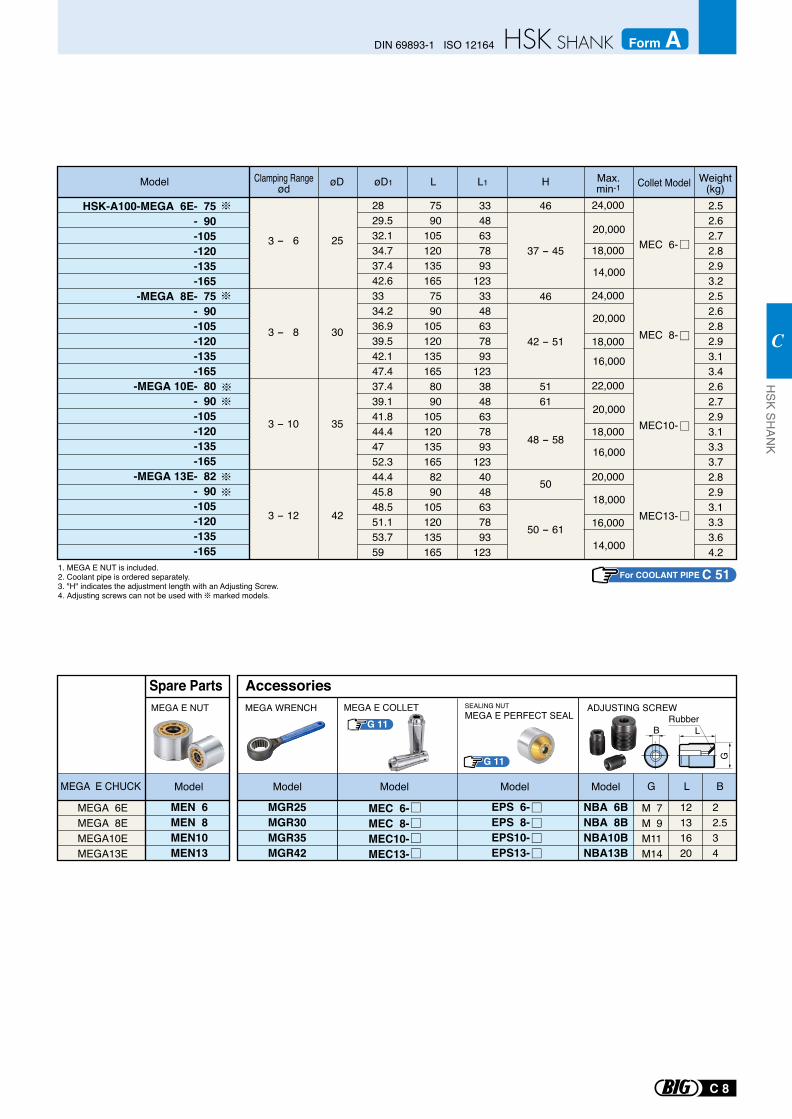
G 11
G 11
SEALING NUTMEGA E PERFECT SEAL Rubber
B LG
MEGA E COLLET
MEGA 6EMEGA 8EMEGA10EMEGA13E
MEGA E CHUCK Model
Spare Parts
MEN 6MEN 8MEN10MEN13
MEGA E NUT
MGR25MGR30MGR35MGR42
NBA 6BNBA 8BNBA10BNBA13B
EPS 6-EPS 8-EPS10-EPS13-
M 7M 9M11M14
12131620
22.534
G L B
MEGA WRENCH ADJUSTING SCREW
ModelModel Model Model
Accessories
MEC 6-MEC 8-MEC10-MEC13-
2829.532.134.737.442.63334.236.939.542.147.437.439.141.844.44752.344.445.848.551.153.759
7590
1051201351657590
1051201351658090
1051201351658290
105120135165
3348637893
1233348637893
1233848637893
1234048637893
123
2.52.62.72.82.93.22.52.62.82.93.13.42.62.72.93.13.33.72.82.93.13.33.64.2
3 - 6
3 - 8
3 - 10
3 - 12
25
30
35
42
MEC 6-
MEC 8-
MEC10-
MEC13-
20,000
16,000
18,000
14,000
HSK-A100-MEGA 6E- 75- 90-105-120-135-165
-MEGA 8E- 75- 90-105-120-135-165
-MEGA 10E- 80- 90-105-120-135-165
-MEGA 13E- 82- 90-105-120-135-165
20,000
14,000
46
37 - 45
46
42 - 51
5161
48 - 58
50
50 - 61
20,000
16,000
Model øD øD1 L L1 Weight(kg)
24,000
18,000
24,000
18,000
22,000
18,000
20,000
16,000
H Max.min-1
1. MEGA E NUT is included.2. Coolant pipe is ordered separately.3. "H" indicates the adjustment length with an Adjusting Screw.4. Adjusting screws can not be used with marked models.
Collet ModelClamping Rangeød
For COOLANT PIPE C 51
C 8
DIN 69893-1 ISO 12164 Form AH
SK SHAN
K
C
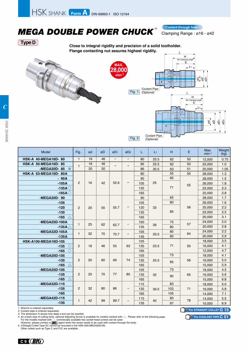
Close to integral rigidity and precision of a solid toolholder. Flange contacting nut assures highest rigidity.
Clamping Range : ø16 - ø42
MAX.28,000
min-1
Coolant-through holeR
1. Wrench is ordered separately.2. Coolant pipe is ordered separately.3. The dimension H shows how deep a tool can be inserted.4. As a back stop of cutting tools, optional Adjusting Screw is available for models marked with . Please refer to the following page. For the models marked with , commecially available hex socket head screws can be used. However, please contact a agent when the screw needs to be used with coolant through the body.5. Straight Collet Type AC cannot be mounted in the HSK-A50-MEGA20D-85. Other collets such as Type C and PJC are available.
62
70
62.7
70.7
8085868090
10513516590
105120135165100135105135
46
60
70
80
99
55
69
77
86
99.7
39
33.5
5565
75
90
8080
71
71
73
85
73
90
831031058397
-
-
-
-
-
-
-
-
25
33
50
505051
55
6580
8556
57
64
78
56
65
71
5023.5
25.5
32
39.5
40
63
74
85
-
-
105135165105135165105135165115135165115135
18,00016,00012,00018,00016,00015,00018,00016,00015,00018,00016,00014,00014,00010,000
25
32
16
20
25
32
42
55 55.720
42 52.616
12,00025,00020,00028,00028,00026,00022,00022,00028,00026,00025,00022,00020,00024,00020,00024,00020,000
0.751.01.051.31.51.82.32.81.71.62.22.53.12.02.82.22.93.54.14.74.15.05.94.55.66.85.05.87.15.56.9
HSK-A 40-MEGA16D- 80HSK-A 50-MEGA16D- 85
-MEGA20D- 85HSK-A 63-MEGA16D- 80
- 90-105-135-165
-MEGA20D- 90-105-120-135-165
-MEGA25D-100-135
-MEGA32D-105-135
AAAAA
AAAA
HSK-A100-MEGA16D-105-135-165
-MEGA20D-105-135-165
-MEGA25D-105-135-165
-MEGA32D-115-135-165
-MEGA42D-115-135
Model øD1 øD2øD L L1Max.min-1HødFig . Weight
(kg)161620
1
1
2
2
2
2
1
2
2
1
1
464650
25.525.530.5
626263
E
For STRAIGHT COLLET G 15
Type D
For COOLANT PIPE C 51
C 9
HSK SH
ANK
C
DIN 69893-1 ISO 12164Form A
Min. Clamping Length
Fig. 2
L
ød
H
EL1
øD1
øD øD2
Coolant Pipe (Optional)
Min. Clamping Length
Fig. 1
ød
L
L1
E
H
øD
Coolant Pipe (Optional)
øD1
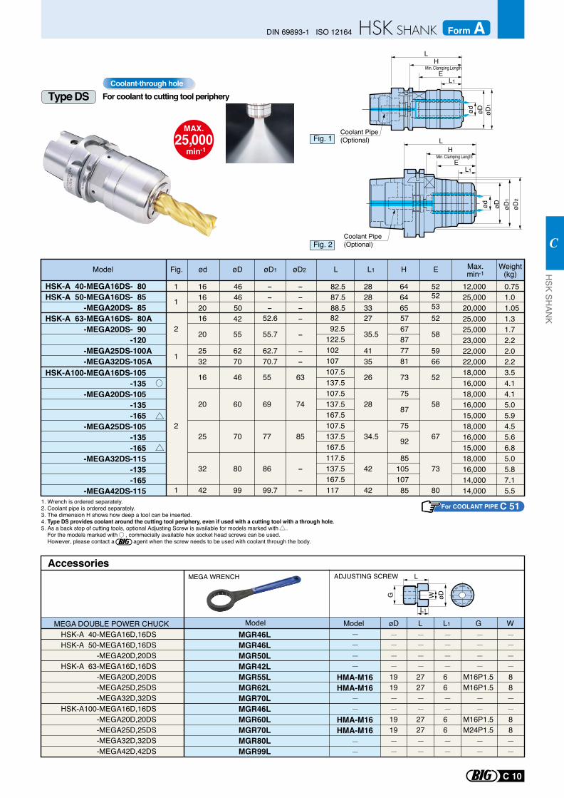
MAX.25,000
min-1
Coolant-through hole
1. Wrench is ordered separately.2. Coolant pipe is ordered separately.3. The dimension H shows how deep a tool can be inserted.4. Type DS provides coolant around the cutting tool periphery, even if used with a cutting tool with a through hole.5. As a back stop of cutting tools, optional Adjusting Screw is available for models marked with . For the models marked with , commecially available hex socket head screws can be used. However, please contact a agent when the screw needs to be used with coolant through the body.
20
2532
161620
464650
82.587.588.5
282833
646465
---
---
16
20
25
32
42
4135
35.5
26
28
34.5
42
42
55
42
6270
62.770.7
55.7
46
60
70
80
99
55
69
77
86
99.7
-
-
--
63
74
85
-
-
12,00025,00020,00025,00025,00023,00022,00022,00018,00016,00018,00016,00015,00018,00016,00015,00018,00016,00014,00014,000
58
16 2752.6 52
5253
52
5966
5767877781
82 92.5
122.5102107
HSK-A 40-MEGA16DS- 80HSK-A 50-MEGA16DS- 85
-MEGA20DS- 85HSK-A 63-MEGA16DS- 80
-MEGA20DS- 90-120
-MEGA25DS-100-MEGA32DS-105
A
AA
HSK-A100-MEGA16DS-105-135
-MEGA20DS-105-135-165
-MEGA25DS-105-135-165
-MEGA32DS-115-135-165
-MEGA42DS-115
85
92
75
52
58
67
73
80
105 107 85
107.5137.5107.5137.5167.5107.5137.5167.5117.5137.5167.5
117
73
75
87
0.751.01.051.31.72.22.02.23.54.14.15.05.94.55.66.85.05.87.15.5
Max.min-1
Weight(kg)Model øD1 øD2øD L L1 HødFig.
Type DS
Min. Clamping Length
L
L1
øDWG
MGR46L MGR46L MGR50L MGR42L MGR55L MGR62L MGR70L MGR46L
MGR60L MGR70L MGR80L MGR99L
AccessoriesMEGA WRENCH
Model
HMA-M16HMA-M16
HMA-M16HMA-M16
ModelMEGA DOUBLE POWER CHUCKHSK-A 40-MEGA16D,16DSHSK-A 50-MEGA16D,16DS -MEGA20D,20DSHSK-A 63-MEGA16D,16DS -MEGA20D,20DS -MEGA25D,25DS -MEGA32D,32DSHSK-A100-MEGA16D,16DS -MEGA20D,20DS -MEGA25D,25DS -MEGA32D,32DS -MEGA42D,42DS
1919
1919
2727
2727
66
66
M16P1.5M16P1.5
M16P1.5M24P1.5
88
88
øD L L1 G W
ADJUSTING SCREW
For coolant to cutting tool periphery
E
For COOLANT PIPE C 51
Min. Clamping Length
1
1
1
1
2
2
C 10
DIN 69893-1 ISO 12164 Form AH
SK SHAN
K
C
ød
L
L1E
H
øD øD1
Coolant Pipe (Optional)
E
L
L1
ød
H
øD1
øD øD2
Coolant Pipe (Optional)
Fig. 1
Fig. 2
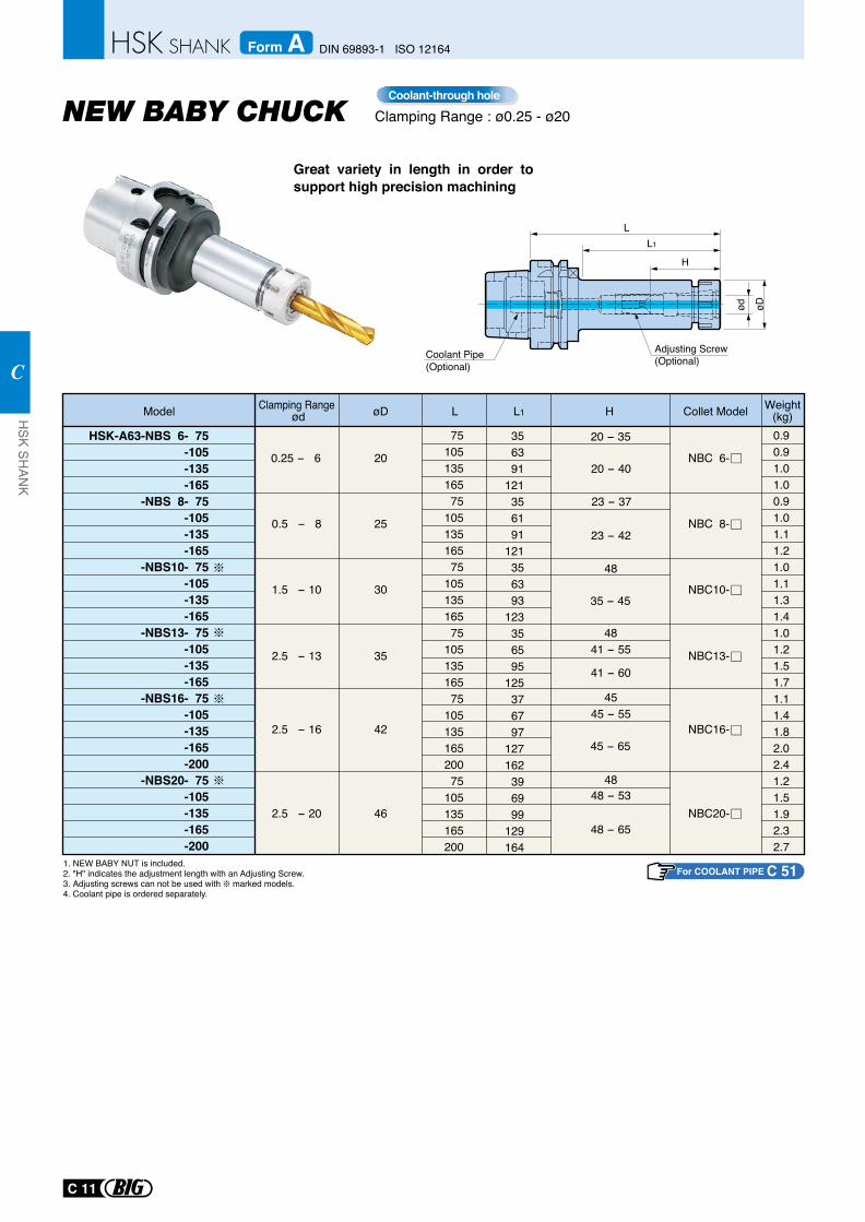
Great variety in length in order to support high precision machining
Clamping Range : ø0.25 - ø20Coolant-through hole
Coolant Pipe (Optional)
1. NEW BABY NUT is included.2. "H" indicates the adjustment length with an Adjusting Screw.3. Adjusting screws can not be used with marked models. 4. Coolant pipe is ordered separately.
HSK-A63-NBS 6- 75-105-135-165
-NBS 8- 75-105-135-165
-NBS10- 75-105-135-165
-NBS13- 75-105-135-165
-NBS16- 75-105-135-165-200
-NBS20- 75-105-135-165-200
0.25 - 6
0.5 - 8
1.5 - 10
2.5 - 13
2.5 - 16
2.5 - 20
20
25
30
35
42
46
7510513516575
10513516575
10513516575
10513516575
10513516520075
105135165200
0.90.91.01.00.91.01.11.21.01.11.31.41.01.21.51.71.11.41.82.02.41.21.51.92.32.7
Model øD L L1
NBC 6-
NBC 8-
NBC10-
NBC13-
NBC16-
NBC20-
23 - 42
48
20 - 40
20 - 35
35 - 45
41 - 60
45 - 65
48 - 65
48
45
48
41 - 55
45 - 55
48 - 53
H
23 - 37
H
LL1
ød øD
Adjusting Screw (Optional)
Weight(kg)Collet ModelClamping Range
ød356391
121356191
121356393
123356595
125376797
127162396999
129164
For COOLANT PIPE C 51
C 11
HSK SH
ANK
C
DIN 69893-1 ISO 12164Form A
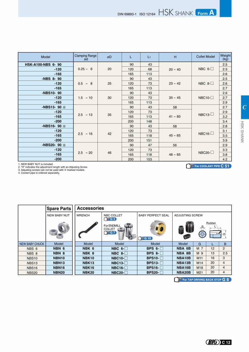
NBS 6NBS 8NBS10NBS13NBS16NBS20
NBN 6NBN 8NBN10NBN13NBN16NBN20
NEW BABY CHUCK
NEW BABY NUT
Model
Spare Parts
NBK 6NBK 8NBK10NBK13NBK16NBK20
G 10
BPS 6-BPS 8-BPS10-BPS13-BPS16-BPS20-
NBC 6-NBC 8-NBC10-NBC13-NBC16-NBC20-
WRENCH
Model Model Model
Accessories
NBA 6BNBA 8BNBA10BNBA13BNBA16BNBA20B
M 7M 9M11M14M18M21
121316202020
22.53444
ADJUSTING SCREW
G L B
BRubber
LG
Model
BABY PERFECT SEAL
For TAP DRIVING BACK STOP G 8
1. NEW BABY NUT is included.2. "H" indicates the adjustment length with an Adjusting Screw.3. Adjusting screws can not be used with marked models. 4. Coolant pipe is ordered separately.
HSK-A100-NBS 6- 90-120-165
-NBS 8- 90-120-165
-NBS10- 90-120-165
-NBS13- 90-120-165-200
-NBS16- 90-120-165-200
-NBS20- 90-120-165-200
0.25 - 6
0.5 - 8
1.5 - 10
2.5 - 13
2.5 - 16
2.5 - 20
20
25
30
35
42
46
NBC 6-
NBC 8-
NBC10-
NBC13-
NBC16-
NBC20-
9012016590
12016590
12016590
12016520090
12016520090
120165200
4368
1134373
1134373
1134373
1131484373
1181514773
118153
2.52.52.62.52.62.72.62.72.92.72.93.23.42.83.13.53.92.93.33.84.2
20 - 40
58
56
23 - 42
41 - 60
35 - 45
58
45 - 65
48 - 65
Model øD L L1 H Weight(kg)
Clamping Range ød
Collet Model
G 3NBC COLLET
G 7
For ENDMILLCOLLET
For COOLANT PIPE C 51
C 12
DIN 69893-1 ISO 12164 Form AH
SK SHAN
K
C
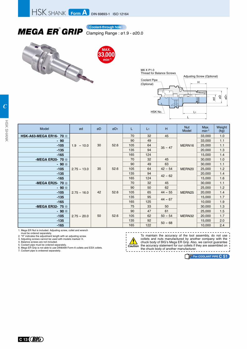
For COOLANT PIPE C 51
To maintain the accuracy of the tool assembly, do not use collets and nuts manufactured by another company with the chuck body of BIG’s Mega ER Grip. Also, we cannot guarantee the accuracy statement for our collets if they are assembled on the chuck body of another manufacturer.
Caution
1. Mega ER Nut is included. Adjusting screw, collet and wrench must be ordered separately.2. "H" indicates the adjustment length with an adjusting screw.3. Adjusting screws cannot be used with models marked . 4. Balance screws are not included.5. Coolant pipe must be ordered separately.6. Mega ER Grip is not able to use DIN6499 Form-A collets and ESX collets.7. Coolant pipe is ordeered separately.
HSK-A63-MEGA ER16- 70 - 90 -105 -135 -165
-MEGA ER20- 70 - 90 -105 -135 -165
-MEGA ER25- 70 - 90 -105 -135 -165
-MEGA ER32- 75 - 90 -105 -135 -165
7090
1051351657090
1051351657090
1051351657590
105135165
32496494
12432496494
12432506595
12533476292
122
33,00033,00025,00020,00015,00030,00030,00025,00020,00015,00030,00025,00020,00015,00010,00030,00025,00020,00015,00010,000
1.01.11.11.31.41.01.11.21.41.61.11.21.41.71.91.31.51.72.02.4
45
35 - 47
4563
42 - 54
42 - 62
4562
44 - 55
44 - 67
5061
50 - 54
50 - 68
øD øD1 L L1
30
35
42
50
52.6
52.6
52.6
52.6
HModel ød NutModel
Max.min-1
Weight(kg)
1.9 - 10.0
2.75 - 13.0
2.75 - 16.0
2.75 - 20.0
MERN16
MERN20
MERN25
MERN32ød øD
1
H
øD
L1
L
HSK No.
(Optional)Coolant Pipe
M6 X P1.0Thread for Balance Screws
Adjusting Screw (Optional)
Clamping Range : ø1.9 - ø20.0
MAX.33,000
min-1
R
MEGA ER GRIPCoolant-through hole
C 13
HSK SH
ANK
C
DIN 69893-1 ISO 12164Form A
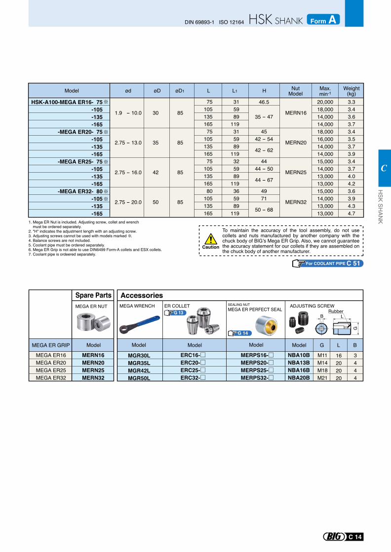
For COOLANT PIPE C 51
To maintain the accuracy of the tool assembly, do not use collets and nuts manufactured by another company with the chuck body of BIG’s Mega ER Grip. Also, we cannot guarantee the accuracy statement for our collets if they are assembled on the chuck body of another manufacturer.
Caution
HSK-A100-MEGA ER16- 75 -105 -135 -165
-MEGA ER20- 75 -105 -135 -165
-MEGA ER25- 75 -105 -135 -165
-MEGA ER32- 80 -105 -135 -165
7510513516575
10513516575
10513516580
105135165
315989
119315989
119325989
119365989
119
3.33.43.63.73.43.53.73.93.43.74.04.23.63.94.34.7
20,000 18,000 14,000 14,000 18,000 16,000 14,000 14,000 15,000 14,000 13,000 13,000 15,000 14,000 13,000 13,000
46.5
35 - 47
4542 - 54
42 - 62
4444 - 50
44 - 67
4971
50 - 68
øDød øD1 L L1
30
35
42
50
85
85
85
85
HModel NutModel
Max.min-1
Weight(kg)
1.9 - 10.0
2.75 - 13.0
2.75 - 16.0
2.75 - 20.0
MERN16
MERN20
MERN25
MERN32
1. Mega ER Nut is included. Adjusting screw, collet and wrench must be ordered separately.2. "H" indicates the adjustment length with an adjusting screw.3. Adjusting screws cannot be used with models marked . 4. Balance screws are not included.5. Coolant pipe must be ordered separately.6. Mega ER Grip is not able to use DIN6499 Form-A collets and ESX collets.7. Coolant pipe is ordeered separately.
MEGA ER16MEGA ER20MEGA ER25MEGA ER32
MERN16MERN20MERN25MERN32
MEGA ER NUT
Model
Spare Parts
MEGA ER GRIP
RubberB L
G
MEGA WRENCH
G L BModelModelModelModel
AccessoriesER COLLET
G 14
M11M14M18M21
16202020
3444
SEALING NUTMEGA ER PERFECT SEAL
ADJUSTING SCREW
MGR30LMGR35LMGR42LMGR50L
ERC16-ERC20-ERC25-ERC32-
NBA10BNBA13BNBA16BNBA20B
MERPS16-MERPS20-MERPS25-MERPS32-
G 13
C 14
DIN 69893-1 ISO 12164 Form AH
SK SHAN
K
C
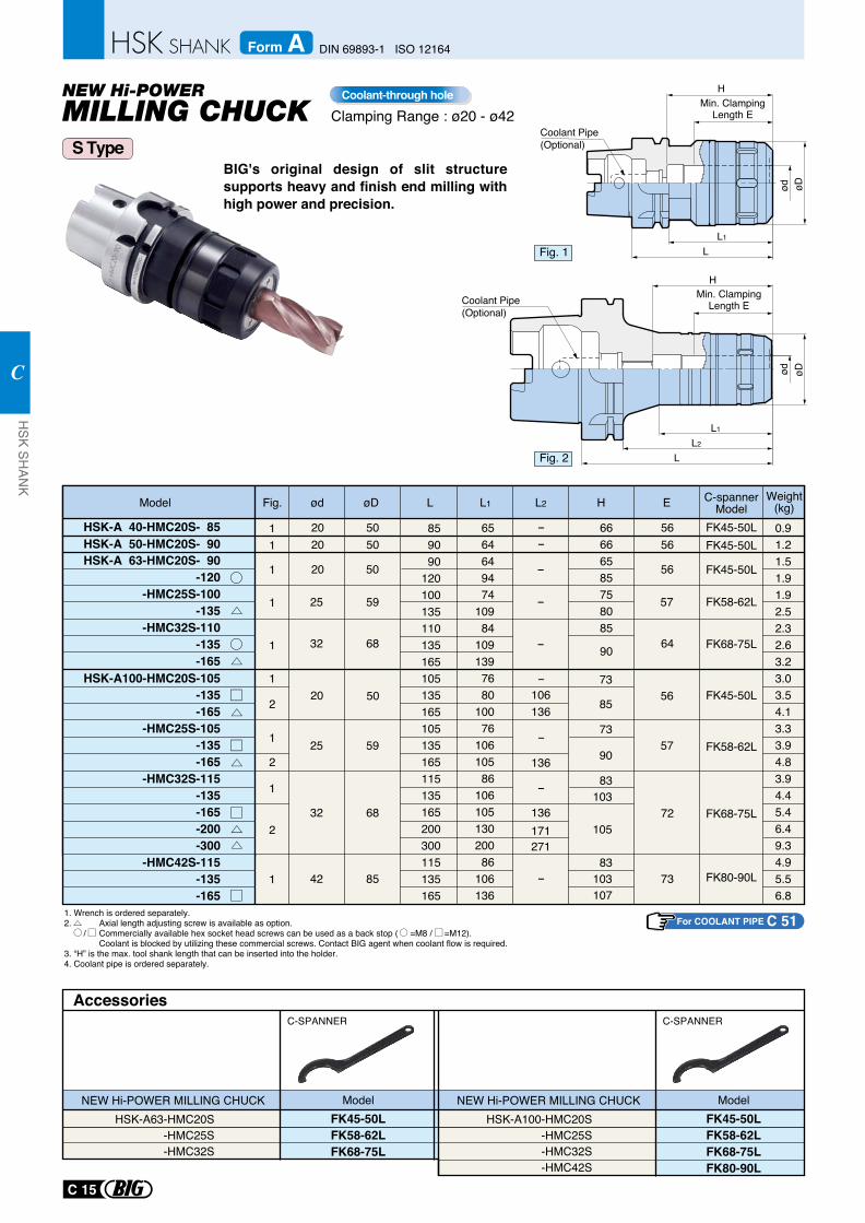
1. Wrench is ordered separately.2. Axial length adjusting screw is available as option. / Commercially available hex socket head screws can be used as a back stop ( =M8 / =M12). Coolant is blocked by utilizing these commercial screws. Contact BIG agent when coolant flow is required.3. “H” is the max. tool shank length that can be inserted into the holder.4. Coolant pipe is ordered separately.
BIG's original design of slit structure supports heavy and finish end milling with high power and precision.
Clamping Range : ø20 - ø42Coolant-through hole
FK45-50L FK58-62LFK68-75L
AccessoriesC-SPANNER C-SPANNER
ModelNEW Hi-POWER MILLING CHUCKHSK-A63-HMC20S -HMC25S -HMC32S
FK45-50L FK58-62LFK68-75LFK80-90L
ModelNEW Hi-POWER MILLING CHUCKHSK-A100-HMC20S -HMC25S -HMC32S -HMC42S
S Type
Fig. 1
Fig. 2
øDød
L1
L
Coolant Pipe (Optional)
HMin. Clamping
Length E
25
25
32
42
32
øDModel
HSK-A 63-HMC20S- 90-120
-HMC25S-100-135
-HMC32S-110-135-165
L L1 L2 H EFig.
HSK-A100-HMC20S-105-135-165
-HMC25S-105-135 -165
-HMC32S-115-135-165-200-300
-HMC42S-115-135-165
859090
120100135110135165105135165105135165115135165200300115135165
0.91.21.51.91.92.52.32.63.23.03.54.13.33.94.83.94.45.46.49.34.95.56.8
6564649474
10984
1091397680
10076
10610586
10610513020086
106136
66666585758085
90
ød Weight(kg)
--
-
-
-
-
-
-
-
106136
136
136105171
27183
83
73
85
73
90
107103
103
11
1
1
1
1
2
2
2
1
1
1
20
20
2020
59
59
68
85
68
50
57
64
56
50
57
72
73
56
5050
5656
HSK-A 40-HMC20S- 85HSK-A 50-HMC20S- 90
○
○
□
△
△
△
□
□
□
△
△△
FK45-50LFK45-50L
FK45-50L
FK45-50L
FK58-62L
FK58-62L
FK68-75L
FK68-75L
FK80-90L
C-spanner Model
Coolant Pipe (Optional)
ød øD
L1
L2
L
HMin. Clamping
Length E
For COOLANT PIPE C 51
C 15
HSK SH
ANK
C
DIN 69893-1 ISO 12164Form A
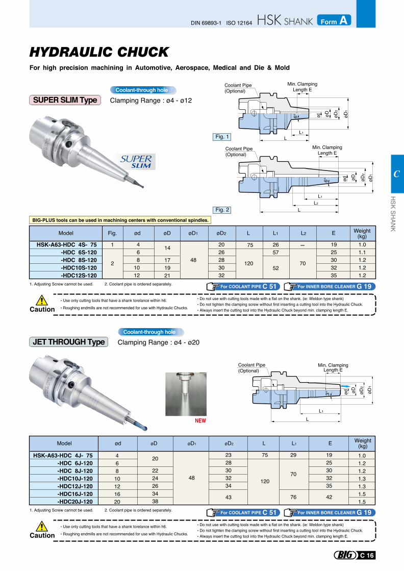
JET THROUGH Type Clamping Range : ø4 - ø20Coolant-through hole
CautionUse only cutting tools that have a shank torelance within h6.
Roughing endmills are not recommended for use with Hydraulic Chucks.
Do not use with cutting tools made with a flat on the shank. (ie: Weldon type shank)Do not tighten the clamping screw without first inserting a cutting tool into the Hydraulic Chuck.Always insert the cutting tool into the Hydraulic Chuck beyond min. clamping length E.
1. Adjusting Screw cannot be used. 2. Coolant pipe is ordered separately.
1. Adjusting Screw cannot be used. 2. Coolant pipe is ordered separately.
For INNER BORE CLEANER G 19For COOLANT PIPE C 51
SUPER SLIM Type
HYDRAULIC CHUCKFor high precision machining in Automotive, Aerospace, Medical and Die & Mold
BIG-PLUS tools can be used in machining centers with conventional spindles.
Clamping Range : ø4 - ø12Coolant-through hole
CautionUse only cutting tools that have a shank torelance within h6.
Roughing endmills are not recommended for use with Hydraulic Chucks.
Do not use with cutting tools made with a flat on the shank. (ie: Weldon type shank)Do not tighten the clamping screw without first inserting a cutting tool into the Hydraulic Chuck.Always insert the cutting tool into the Hydraulic Chuck beyond min. clamping length E.
For INNER BORE CLEANER G 19For COOLANT PIPE C 51
C 16
DIN 69893-1 ISO 12164 Form AH
SK SHAN
K
C
Fig. 1
Model ød øD øD1 øD2 L L1 Weight(kg)E
20 75
120
29
70
2328303234
43
1.01.21.21.31.31.51.5
482224263438
HSK-A63-HDC 4J- 75-HDC 6J-120
-HDC 8J-120-HDC10J-120-HDC12J-120-HDC16J-120-HDC20J-120
46810121620
1925303235
76 42
LL1
Min. ClampingLength E
øD2
ød øD øD1
3°
Coolant Pipe (Optional)
NEW
SLIMSUPER
Model øD øD2øD1 L L1 L2 Weight(kg)E
52
2657
12048
1
2 70
75 -468
1012
14
171921
1925303235
HSK-A63-HDC 4S- 75-HDC 6S-120-HDC 8S-120
-HDC10S-120-HDC12S-120
2026283032
1.01.11.21.21.2
ødFig.
Fig. 2 LL2
L1
Min. ClampingLength E
øD2
ød øD øD1
Coolant Pipe (Optional)
6°
øD1
Min. ClampingLength E
L1
øD2
ød øD
L
6°
Coolant Pipe (Optional)
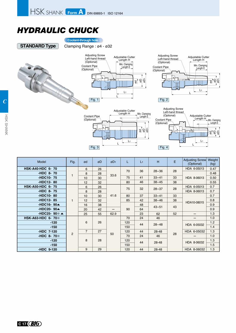
HYDRAULIC CHUCK
Clamping Range : ø4 - ø32Coolant-through hole
STANDARD Type
ød øD øD1
L1
L
LL1
øD øD1
ød øD1
ød øD
L1L
øD1
ød øDL1
L
Adjustable CutterLength H
Adjustable CutterLength H
Adjustable CutterLength H
Adjustable CutterLength H
Min. ClampingLength E
Min. ClampingLength E
Min. ClampingLength E
Min. ClampingLength E
Adjusting ScrewLeft-hand thread(Optional)
Adjusting ScrewLeft-hand thread(Optional)
Coolant Pipe (Optional)
Coolant Pipe (Optional)
Adjusting ScrewLeft-hand thread(Optional)
Coolant Pipe (Optional)
Coolant Pipe (Optional)
Fig. 1
Fig. 3
Fig. 2
Fig. 4
C 17
HSK SH
ANK
C
DIN 69893-1 ISO 12164Form A
Model
HSK-A63-HDC 6- 70-120-150
-HDC 7-120-HDC 8- 70
-120-150
-HDC 9-120
ød øD1 L L1 EH Adjusting Screw(Optional)
Weight(kg)
6
7
8
9
1.01.21.41.31.01.31.51.3
2
1
1
50
øDFig.
26
27
28
29
7012015012070
120150120
24
44
4424
44
44
28
46
28-48
28-4846
28-48
28-48
-
HDA 6-05032
HDA 6-05032-
HDA 8-06032
HDA 8-06032
HSK-A40-HDC 6- 70-HDC 8- 70-HDC10- 75-HDC12- 80
HSK-A50-HDC 6- 75-HDC 8- 75-HDC10- 80-HDC12- 85-HDC16- 90-HDC20- 90-HDC25- 90
HDA 6-05013
HDA 6-05013HDA 8-06013
HDA10-08015
HDA 8-06013
68
101268
1012162025
0.470.480.500.550.70.70.70.80.90.91.3
33.6
41.6
-62.9
2628303226283032384255
70
7580
75
8085
90
36
4146
3742486423
32
28
3338
28
43
52
3338
28-36
33-4138-45
28-37
33-4138-46
43-51
62 -
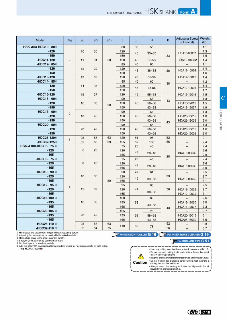
1. H indicates the adjustment length with an Adjusting Screw. 2. Adjusting Screws cannot be used with marked models. 3. H length is equal to the max. insertion length. 4. Straight Collet cannot be used with mark.5. Coolant pipe is ordered separately. 6. Add the letter "W" to Adjusting Screw model number for hexagon sockets on both sides. (e.g. HDA12-10025W) Use only cutting tools that have a shank tolerance within h6.
Do not use with cutting tools made with a flat on the shank (i.e.: Weldon type shank)Roughing endmills are not recommended for use with Hydraulic Chucks.Do not tighten the clamping screw without first inserting a cutting tool into the toolholder.Always insert the cutting tool into the Hydraulic Chuck beyond min. clamping length E.
Caution
For STRAIGHT COLLET G 16 For INNER BORE CLEANER G 19For COOLANT PIPE C 51
C 18
DIN 69893-1 ISO 12164 Form AH
SK SHAN
K
C
Model ød øD1 L L1 EH Adjusting Screw(Optional)
Weight(kg)
2 50
øDFig.
33
38
HSK-A63-HDC10- 80-120-150
-HDC11-120-HDC12- 85
-120-150
-
HDA10-08032
HDA10-08032-
HDA12-10025
10
11
12
1.11.31.61.41.11.41.6
30
31
32
8012015012085
120150
35
45
4540
45
55
33-53
33-5360
38-58
-HDC13-120-HDC14- 85
-120-150
-HDC15-120-HDC16- 90
-120-150
-HDC18- 90-120-150
-HDC20- 90-120-150
-HDC25-120-HDC32-125
13
14
15
16
18
20
2532
1.41.21.41.71.51.31.51.91.31.62.01.31.62.02.12.4
50
6369
3
4
2
33
34
37
38
40
42
5560
12085
12015012090
12015090
12015090
120150120125
4540
45
45
46
46
48
5159
38
43
43
5256
38-5860
38-58
58-6865
58-6843-68
6558-6843-68
6558-6843-68
95100
HDA12-10025-
HDA12-10025
HDA16-12015-
HDA16-12015HDA16-12037
-HDA20-16015HDA25-16039
-HDA20-16015HDA25-16039
--
HSK-A100-HDC 6- 75-120-165
-HDC 8- 75-120-165
-HDC10- 90-120-165
-HDC12- 95-120-165
-HDC16-100-135-165
-HDC20-105-135-165
-HDC25-110-HDC32-110
6
8
10
12
16
20
2532
2.42.62.92.42.63.02.52.73.12.52.73.12.63.03.32.73.13.63.33.7
6375
50
26
28
30
32
38
42
5564
7512016575
12016590
12016595
120165100135165105135165
110
26
44
26
44
42
45
47
53
59
62
28
33
38
43
5256
46
28-48
46
28-48
61
33-53
63
38-58
68
43-68
7358-6843-68
78
-
HDA 6-05032
-
HDA 8-06032
-
HDA10-08032
-HDA12-10025HDA12-10032
-HDA16-12030HDA16-12037
-HDA20-16015HDA25-16039
--
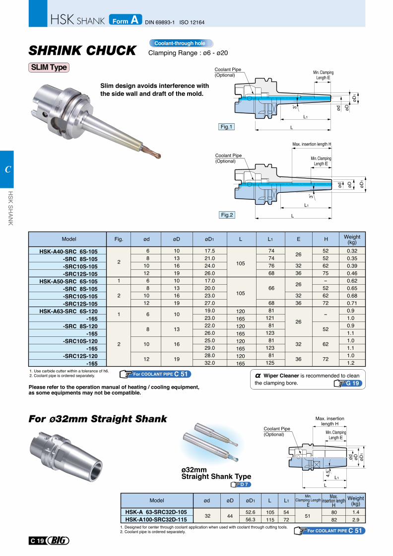
Slim design avoids interference with the side wall and draft of the mold.
Clamping Range : ø6 - ø20Coolant-through hole
Model ødFig. øD1øD L1L
HSK-A40-SRC 6S-105 -SRC 8S-105 -SRC10S-105 -SRC12S-105
HSK-A50-SRC 6S-105 -SRC 8S-105 -SRC10S-105 -SRC12S-105
HSK-A63-SRC 6S-120 -165
-SRC 8S-120 -165
-SRC10S-120 -165
-SRC12S-120 -165
68
101268
1012
6
8
10
12
1013161910131619
10
13
16
19
17.521.024.026.017.020.023.027.019.023.022.026.025.029.028.032.0
105
105
120165120165120165120165
0.320.350.390.460.620.650.680.710.91.00.91.11.01.11.01.2
2
1
2
1
2
74 74 76 68
66
68 81
121 81
123 81
123 81
125
26
3236
26
3236
26
32
36
52526275-526272
-
52
62
72
1. Use carbide cutter within a tolerance of h6.2. Coolant pipe is ordered separately.
Fig.1
Fig.2
L1
L
L1
L
øD1
3˚
3˚
Min. ClampingLength E
E
Min. ClampingLength E
Please refer to the operation manual of heating / cooling equipment, as some equipments may not be compatible.
Wiper Cleaner is recommended to clean the clamping bore. G 19
Coolant Pipe (Optional)
Coolant Pipe (Optional)
ødød
øDøD
1øD
Weight(kg)H
Max. insertion length H
SLIM Type
øD1
øDød
105115
5472
8082
1.42.9
5132 4452.656.3
1. Designed for center through coolant application when used with coolant through cutting tools.2. Coolant pipe is ordered separately.
HSK-A 63-SRC32D-105HSK-A100-SRC32D-115
Min. ClampingLength E
Max. insertionlength H
LL14.
5˚
For ø32mm Straight ShankCoolant Pipe (Optional)
Model ød øD1øD L1LMin.
Clamping LengthE
Weight(kg)
Max.insertion length
H
For COOLANT PIPE C 51
For COOLANT PIPE C 51
ø32mmStraight Shank Type
D 7
C 19
HSK SH
ANK
C
DIN 69893-1 ISO 12164Form A
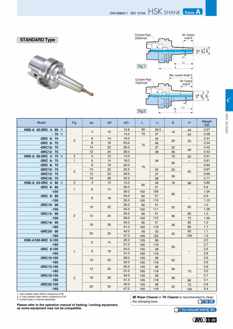
Please refer to the operation manual of heating / cooling equipment, as some equipment may not be compatible.
Fig.1
Fig.2
Min. ClampingLength E
Min. ClampingLength E
3˚3˚
Coolant Pipe (Optional)
Coolant Pipe (Optional)
ød øDød øD øD
1øD
1
L1
L
L1
L
Model ødFig. Weight(kg)øD1øD L1L E
HSK-A 40-SRC 4- 60- 70
-SRC 6- 75 -SRC 8- 75 -SRC10- 75 -SRC12- 75
HSK-A 50-SRC 4- 75-SRC 6- 75
-SRC 8- 75 -SRC10- 75 -SRC12- 75 -SRC16- 75
HSK-A 63-SRC 4- 90 -SRC 6- 90
-150 -SRC 8- 90
-150 -SRC10- 90
-150 -SRC12- 90
-150 -SRC16- 90
-165 -SRC20- 90
-165HSK-A100-SRC 6-105
-165 -SRC 8-105
-165 -SRC10-105
-165 -SRC12-105
-165 -SRC16-105
-165 -SRC20-105
-165
68
1012468
1012164
6
8
10
12
16
20
6
8
10
12
16
20
1418222410141822242810
14
18
22
24
28
34
14
18
22
24
28
34
4 10 12.814.019.023.026.028.014.018.022.025.528.032.015.020.026.024.030.028.034.030.036.034.041.040.047.020.027.024.031.028.035.030.037.034.041.040.047.0
75
75
6070
0.270.280.310.340.420.430.510.610.640.670.690.710.850.91.040.91.151.01.291.01.331.01.71.11.92.52.72.52.82.62.92.63.02.73.12.83.4
21
2
2
1
2
1
2
45 46 37 38
36
35 37 38 46
119 53
122 58
118 58
118 58
118 58
118 58
118 58
118
26.537
26
323616
26
32
36
16
26
32
36
38
42
26
32
36
38
42
16
52
56
55-
68
-
-
62
6572658065100
-
8072100
4454
1. Use carbide cutter within a tolerance of h6.2. Use carbide cutter within a tolerance of h5.3. Coolant pipe is ordered separately.
2
52
5110851
11051
11151
11251
90
15090
15090
15090
15090
72
Wiper Cleaner or TK Cleaner is reccomended to clean the clamping bore. G 19
H
Max. insertion length H
STANDARD Type
16590
165105165105165105165105165105165105165
For COOLANT PIPE C 51
C 20
DIN 69893-1 ISO 12164 Form AH
SK SHAN
K
C
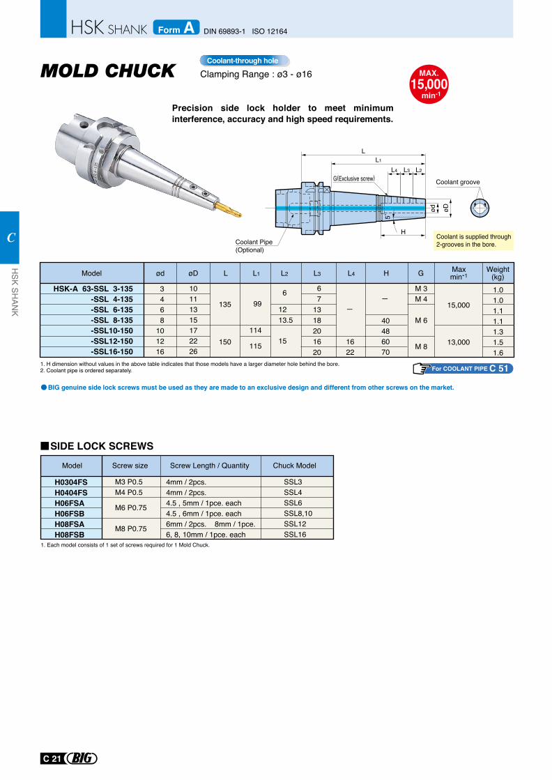
Precision side lock holder to meet minimum interference, accuracy and high speed requirements.
Clamping Range : ø3 - ø16Coolant-through hole
1. H dimension without values in the above table indicates that those models have a larger diameter hole behind the bore. 2. Coolant pipe is ordered separately.
Coolant is supplied through2-grooves in the bore.
Model L2 L3 L4øD
HSK-A 63-SSL 3-135-SSL 4-135-SSL 6-135-SSL 8-135-SSL10-150-SSL12-150-SSL16-150
L1
10111315172226
6
1213.5
15 1622
15,000
13,000
67
1318201620
3468
101216
L
135
150
99
114
115
Maxmin-1
L4 L3 L2
øDød
H
L1
G(Exclusive screw)
L
5˚
H
40486070
G Weight(kg)
M 3M 4
M 6
M 8
1.01.01.11.11.31.51.6
ød
1. Each model consists of 1 set of screws required for 1 Mold Chuck.
Model Screw size Screw Length / Quantity
H0304FSH0404FSH06FSAH06FSBH08FSAH08FSB
Chuck Model
M3 P0.5M4 P0.5
M6 P0.75 M8 P0.75
4mm / 2pcs.4mm / 2pcs.4.5 , 5mm / 1pce. each4.5 , 6mm / 1pce. each6mm / 2pcs. 8mm / 1pce.6, 8, 10mm / 1pce. each
SSL3SSL4SSL6 SSL8,10 SSL12 SSL16
MAX.15,000
min-1
Coolant groove
BIG genuine side lock screws must be used as they are made to an exclusive design and different from other screws on the market.
Coolant Pipe (Optional)
SIDE LOCK SCREWS
For COOLANT PIPE C 51
C 21
HSK SH
ANK
C
DIN 69893-1 ISO 12164Form A
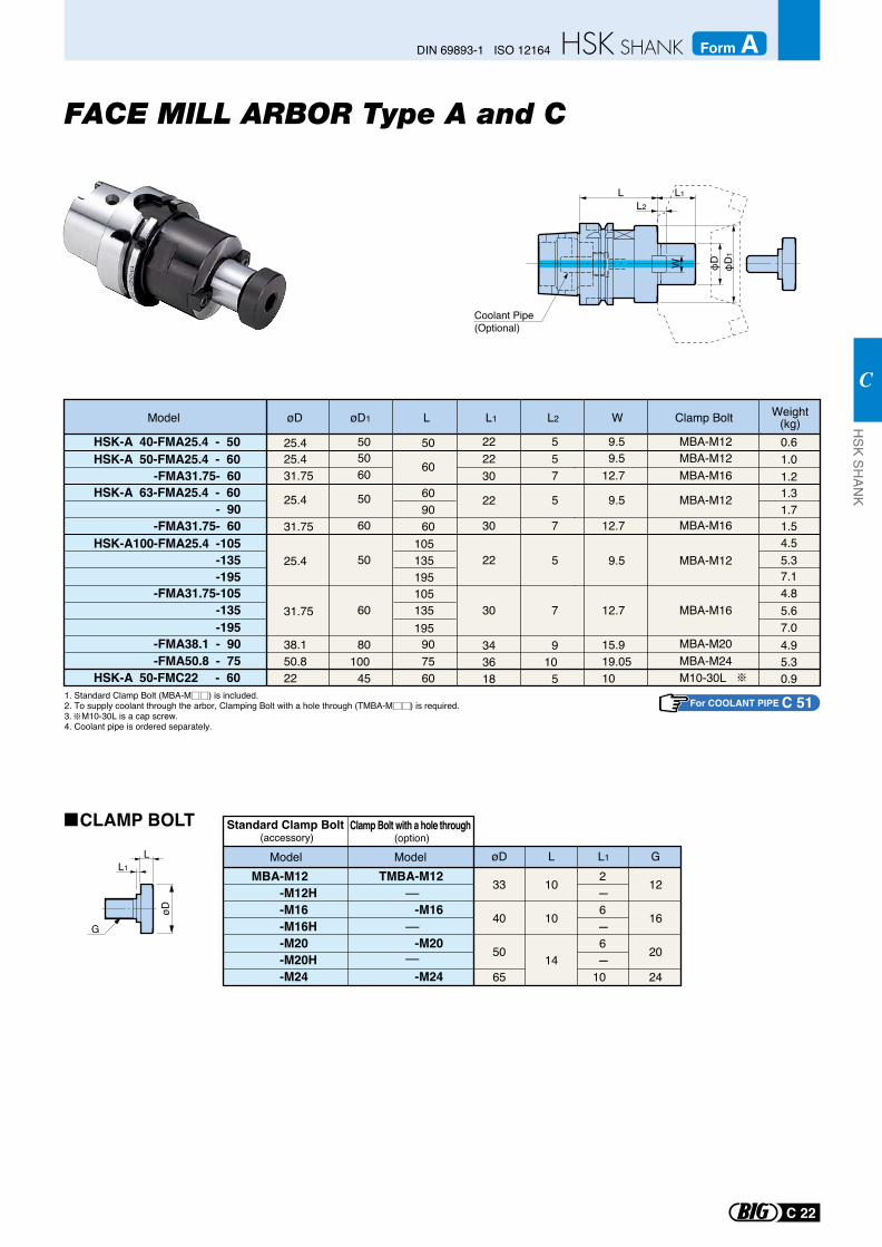
L L1L2
φD
1
φDW
Coolant Pipe (Optional)
Model øD øD1
HSK-A 40-FMA25.4 - 50
HSK-A 63-FMA25.4 - 60- 90
-FMA31.75- 60HSK-A100-FMA25.4 -105
-135-195
-FMA31.75-105-135-195
-FMA38.1 - 90-FMA50.8 - 75
L1 L2
25.4
25.4
31.75
22
22
30
25.4
31.75
38.150.8
50
50
60
50
60
80
45100
22
30
3436
5
5
7
5
7
9
510
9.5
9.5
12.7
9.5
12.7
15.919.05
MBA-M12
MBA-M12
MBA-M16
MBA-M12
MBA-M16
MBA-M20MBA-M24
W Clamp BoltL
609060
HSK-A 50-FMA25.4 - 60-FMA31.75- 60
5025.431.75
2230
5060
57
9.512.7
MBA-M12MBA-M16
60
0.61.01.21.31.71.54.55.37.14.85.67.04.95.3
105135195105135195
9075
HSK-A 50-FMC22 - 60 22 18 10 M10-30L 0.960
Weight(kg)
øD
L
G
L1øD L L1 G
MBA-M12-M12H -M16-M16H-M20-M20H-M24
Standard Clamp Bolt (accessory)
ModelTMBA-M12
-M16
-M20
-M24-
-
-
Model
Clamp Bolt with a hole through (option)
33
40
50
65
10
10
14
12
16
20
24
2 - 6 - 6 -10
FACE MILL ARBOR Type A and C
CLAMP BOLT
1. Standard Clamp Bolt (MBA-M ) is included.2. To supply coolant through the arbor, Clamping Bolt with a hole through (TMBA-M ) is required.3. M10-30L is a cap screw. 4. Coolant pipe is ordered separately.
For COOLANT PIPE C 51
C 22
DIN 69893-1 ISO 12164 Form AH
SK SHAN
K
C
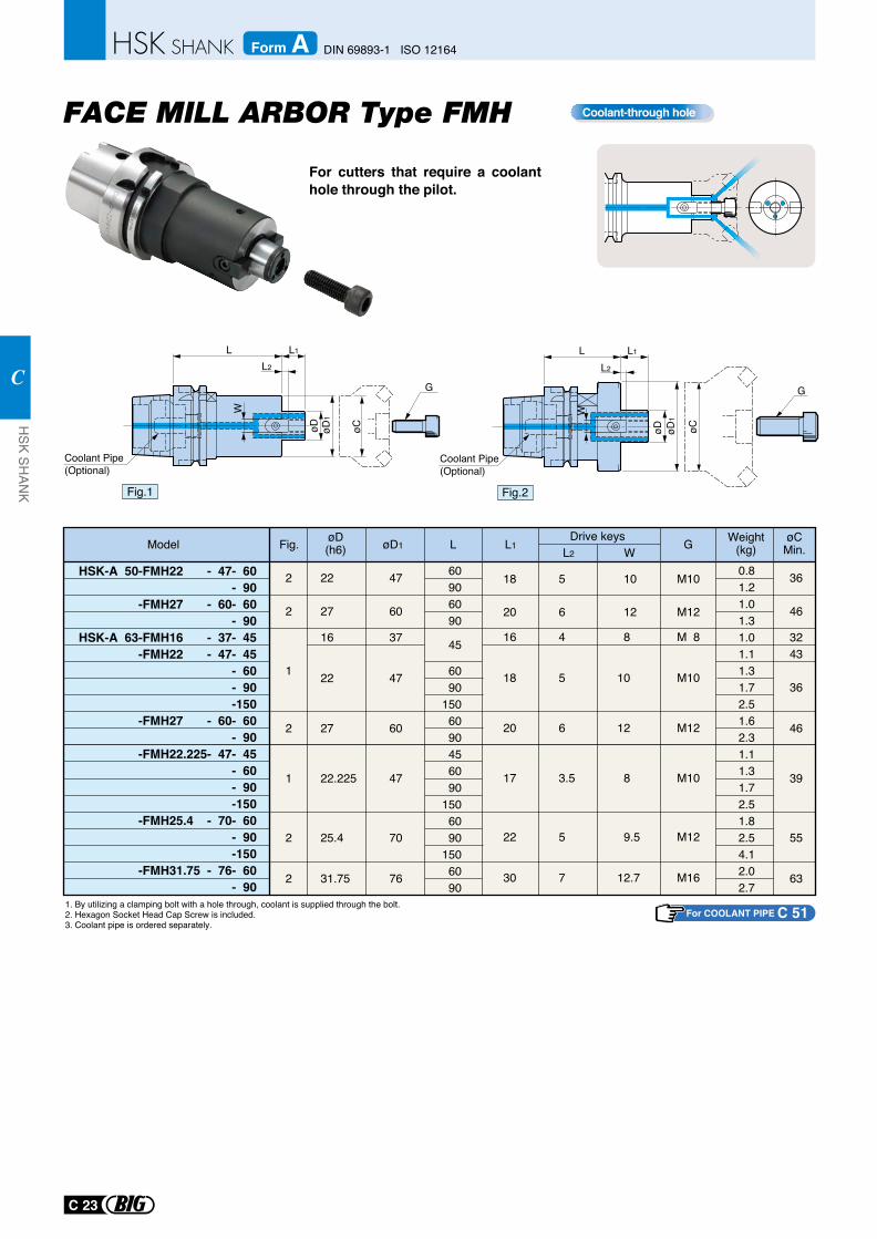
For cutters that require a coolant hole through the pilot.
Coolant-through hole
Model G øCMin.
Drive keysW
L L1Fig. øD1øD(h6)
HSK-A 50-FMH22 - 47- 60- 90
-FMH27 - 60- 60- 90
HSK-A 63-FMH16 - 37- 45-FMH22 - 47- 45
- 60- 90-150
-FMH27 - 60- 60- 90
-FMH22.225- 47- 45- 60- 90-150
-FMH25.4 - 70- 60- 90-150
-FMH31.75 - 76- 60- 90
Weight(kg)
60906090
45
6090
1506090456090
1506090
1506090
0.81.21.01.31.01.11.31.72.51.62.31.11.31.72.51.82.54.12.02.7
36
46
3243
36
46
39
55
63
2
2
1
2
1
2
2
22
27
16
22
27
22.225
25.4
31.75
M10
M12
M10
M12
M16
47
60
37
47
60
47
70
76
18
20
17
22
30
5
6
3.5
5
7
10
12
8
9.5
12.7
L2
1. By utilizing a clamping bolt with a hole through, coolant is supplied through the bolt.2. Hexagon Socket Head Cap Screw is included.3. Coolant pipe is ordered separately.
16 4 8 M 8
18 5 10 M10
20 6 12 M12
For COOLANT PIPE C 51
C 23
HSK SH
ANK
C
DIN 69893-1 ISO 12164Form A
Fig.2
W
øD1
øD
L2
L1L
Coolant Pipe (Optional)
øC
G
Fig.1
W
øD1
øD
L2
L1L
Coolant Pipe (Optional)
G
øC
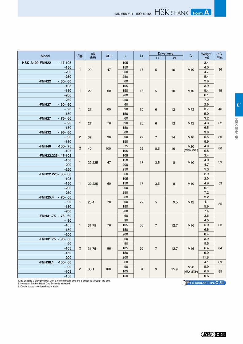
1. By utilizing a clamping bolt with a hole through, coolant is supplied through the bolt.2. Hexagon Socket Head Cap Screw is included.3. Coolant pipe is ordered separately.
Model GDrive keysWL L1Fig. øD1
øD(h6)
Weight(kg)
10515020025060
1051502002506090
1506090
1506090
15075
10510515020025060
1051502002506090
1502006090
1051502006090
1051502006090
105150
3.44.04.75.42.93.95.46.17.22.93.75.03.24.36.53.85.58.94.96.83.44.04.75.32.93.94.96.17.23.24.15.97.43.64.55.06.68.43.95.56.49.0
11.84.15.96.89.6
1
1
1
1
2
2
1
1
1
1
2
2
47
60
60
76
96
100
47
60
70
76
96
100
18
18
20
20
22
26
17
17
22
30
30
34
M10
M10
M12
M12
M16
M20(MBA-M20)
M10
M10
M12
M16
M16
M20(MBA-M20H)
5
5
6
6
7
8.5
3.5
3.5
5
7
7
9
10
10
12
12
14
16
8
8
9.5
12.7
12.7
15.9
22
22
27
27
32
40
22.225
22.225
25.4
31.75
31.75
38.1
L2
HSK-A100-FMH22 - 47-105-150-200-250
-FMH22 - 60- 60-105-150-200-250
-FMH27 - 60- 60- 90-150
-FMH27 - 76- 60- 90-150
-FMH32 - 96- 60- 90-150
-FMH40 -100- 75-105
-FMH22.225- 47-105-150-200-250
-FMH22.225- 60- 60-105-150-200-250
-FMH25.4 - 70- 60- 90-150-200
-FMH31.75 - 76- 60- 90-105-150-200
-FMH31.75 - 96- 60- 90-105-150-200
-FMH38.1 -100- 60- 90-105-150
For COOLANT PIPE C 51
øCMin.
36
49
46
62
80
80
39
53
55
63
84
89
85
C 24
DIN 69893-1 ISO 12164 Form AH
SK SHAN
K
C
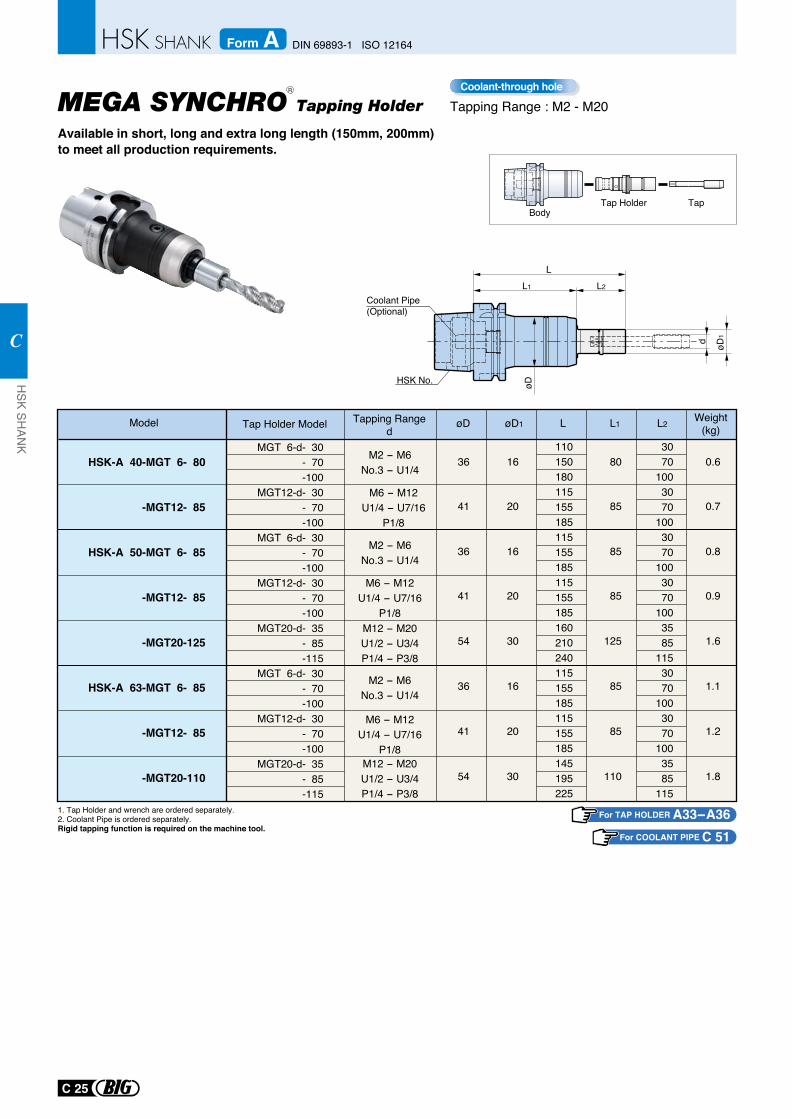
Tapping RangedTap Holder ModelModel øD1øD L1L L2
HSK-A 40-MGT 6- 80
-MGT12- 85
HSK-A 50-MGT 6- 85
-MGT12- 85
-MGT20-125
HSK-A 63-MGT 6- 85
-MGT12- 85
-MGT20-110
36
41
36
41
54
36
41
54
16
20
16
20
30
16
20
30
80
85
85
85
125
85
85
110
0.6
0.7
0.8
0.9
1.6
1.1
1.2
1.8
3070
1003070
1003070
1003070
1003585
1153070
1003070
1003585
115
110150180115155185115155185115155185160210240115155185115155185145195225
M2 - M6No.3 - U1/4
M6 - M12U1/4 - U7/16
P1/8
M2 - M6No.3 - U1/4
M6 - M12U1/4 - U7/16
P1/8M12 - M20U1/2 - U3/4P1/4 - P3/8
M2 - M6No.3 - U1/4
M6 - M12U1/4 - U7/16
P1/8M12 - M20U1/2 - U3/4P1/4 - P3/8
1. Tap Holder and wrench are ordered separately.2. Coolant Pipe is ordered separately.Rigid tapping function is required on the machine tool.
BodyTap Holder Tap
For TAP HOLDER A33-A36
MGT 6-d- 30 - 70 -100
MGT12-d- 30 - 70 -100
MGT 6-d- 30 - 70 -100
MGT12-d- 30 - 70 -100
MGT20-d- 35 - 85 -115
MGT 6-d- 30 - 70 -100
MGT12-d- 30 - 70 -100
MGT20-d- 35 - 85 -115
Weight(kg)
MEGA SYNCHRO Tapping Holder
Available in short, long and extra long length (150mm, 200mm) to meet all production requirements.
øD
øD1d
LL2L1
HSK No.
Coolant Pipe(Optional)
Tapping Range : M2 - M20Coolant-through hole
For COOLANT PIPE C 51
R
C 25
HSK SH
ANK
C
DIN 69893-1 ISO 12164Form A
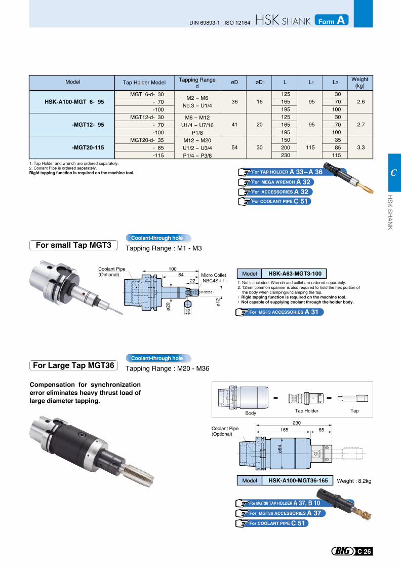
Tapping RangedTap Holder ModelModel øD1øD L1L L2
HSK-A100-MGT 6- 95
-MGT12- 95
-MGT20-115
36
41
54
16
20
30
95
95
115
2.6
2.7
3.3
3070
1003070
1003585
115
125165195125165195150200230
M2 - M6No.3 - U1/4
M6 - M12U1/4 - U7/16
P1/8M12 - M20U1/2 - U3/4P1/4 - P3/8
1. Tap Holder and wrench are ordered separately.2. Coolant Pipe is ordered separately.Rigid tapping function is required on the machine tool.
MGT 6-d- 30 - 70 -100
MGT12-d- 30 - 70 -100
MGT20-d- 35 - 85 -115
Weight(kg)
Body Tap Holder Tap
Model HSK-A100-MGT36-165
ø94
23065165
Compensation for synchronization error eliminates heavy thrust load of large diameter tapping.
Coolant Pipe(Optional)
Weight : 8.2kg
For Large Tap MGT36 Tapping Range : M20 - M36Coolant-through hole
For MGT36 TAP HOLDER A 37, B 10For MGT36 ACCESSORIES A 37
For MGT3 ACCESSORIES A 31
For COOLANT PIPE C 51
For COOLANT PIPE C 51
For TAP HOLDER A 33- A 36For MEGA WRENCH A 32For ACCESSORIES A 32
For small Tap MGT3 Tapping Range : M1 - M3Coolant-through hole
1. Nut is included. Wrench and collet are ordered separately.2. 12mm common spanner is also required to hold the hex portion of
the body when clamping/unclamping the tap.• Rigid tapping function is required on the machine tool.• Not capable of supplying coolant through the holder body.
C 26
DIN 69893-1 ISO 12164 Form AH
SK SHAN
K
C
Micro Collet NBC4S-22
64100
ø20 ø1
2
12
Coolant Pipe(Optional) Model HSK-A63-MGT3-100
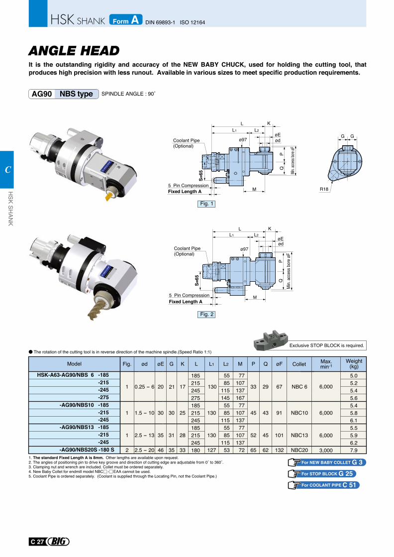
R18
G G
ANGLE HEADIt is the outstanding rigidity and accuracy of the NEW BABY CHUCK, used for holding the cutting tool, that produces high precision with less runout. Available in various sizes to meet specific production requirements.
AG90 NBS type SPINDLE ANGLE : 90˚
HSK-A63-AG90/NBS 6 -185 -215-245-275
-AG90/NBS10 -185-215-245
-AG90/NBS13 -185-215-245
-AG90/NBS20S -180 S
NBC13
NBC10
NBC 6
NBC20
ød øE K L L1 L2 P Q øF Collet
0.25 - 6 20 17 130
55
33 29 6785115145
1.5 - 10 30 25 13055
45 43 9185115
2.5 - 13 35 28 13055
52 45 10185115
2.5 - 20 127 53 65 62 132
1
1
1
2 46 35 33
Fig.Model M
107137
107137
107137167
77
77
77
72
G
30
31
6,000
6,000
6,000
3,000
21
185215245275185215245185215245180
5.05.25.45.65.45.86.15.55.96.27.9
Fig. 1
Fig. 2
L1 L2
ø97
PQ
Min. a
ccess
bore
øF
S=65
L K
øEød
M
Coolant Pipe(Optional)
Fixed Length A5 Pin Compression
L1 L2
ø97
PQ
Min.
acce
ss bo
re ø
F
S=65
L K
øEød
M
Coolant Pipe(Optional)
Fixed Length A5 Pin Compression
Weight(kg)
Max.min-1
1. The standard Fixed Length A is 8mm. Other lengths are available upon request.2. The angles of positioning pin to drive key groove and direction of cutting edge are adjustable from 0˚ to 360˚.3. Clamping nut and wrench are included. Collet must be ordered separately.4. New Baby Collet for endmill model NBC - EAA cannot be used.5. Coolant Pipe is ordered separately. (Coolant is supplied through the Locating Pin, not the Coolant Pipe.)
For NEW BABY COLLET G 3For STOP BLOCK G 25
The rotation of the cutting tool is in reverse direction of the machine spindle.(Speed Ratio 1:1)Exclusive STOP BLOCK is required.
For COOLANT PIPE C 51
C 27
HSK SH
ANK
C
DIN 69893-1 ISO 12164Form A
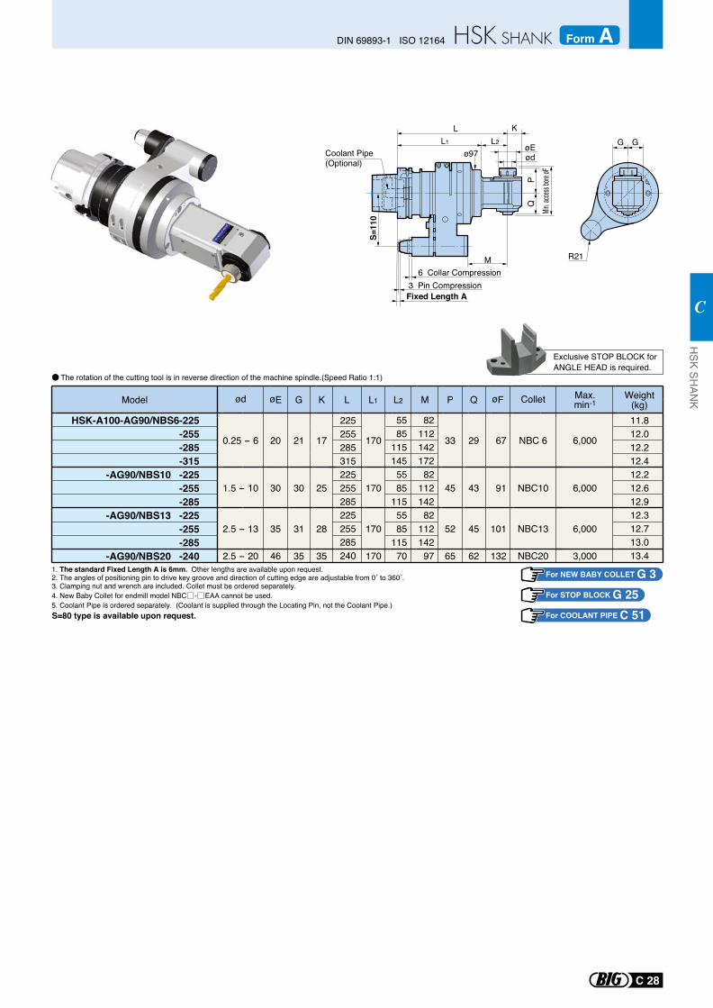
G G
R21
L1 L2
ø97
PQ
S=11
0
L K
øEød
M
Min. ac
cess b
ore øF
Coolant Pipe(Optional)
0.25 - 6
HSK-A100-AG90/NBS6-225-255-285-315
-AG90/NBS10 -225-255-285
-AG90/NBS13 -225-255-285
-AG90/NBS20 -240
NBC 6
NBC10
NBC13
NBC20
Colletød øE K L L1 L2 P Q øF
20 17 170
55
33 29 6785115145
1.5 - 10 30 25 17055
45 43 9185115
2.5 - 13 35 28 17055
52 45 10185115
2.5 - 20 46 35 170 70 65 62 132
G
21
30
31
35
112142172
112142
112142
M
82
82
82
97
Model Max.min-1
225255285315225255285225255285240
11.812.012.212.412.212.612.912.312.713.013.4
6,000
6,000
6,000
3,000
Weight(kg)
1. The standard Fixed Length A is 6mm. Other lengths are available upon request.2. The angles of positioning pin to drive key groove and direction of cutting edge are adjustable from 0˚ to 360˚.3. Clamping nut and wrench are included. Collet must be ordered separately.4. New Baby Collet for endmill model NBC - EAA cannot be used.5. Coolant Pipe is ordered separately. (Coolant is supplied through the Locating Pin, not the Coolant Pipe.) S=80 type is available upon request.
For NEW BABY COLLET G 3For STOP BLOCK G 25
The rotation of the cutting tool is in reverse direction of the machine spindle.(Speed Ratio 1:1)
Exclusive STOP BLOCK forANGLE HEAD is required.
Fixed Length A3 Pin Compression
6 Collar Compression
For COOLANT PIPE C 51
C 28
DIN 69893-1 ISO 12164 Form AH
SK SHAN
K
C
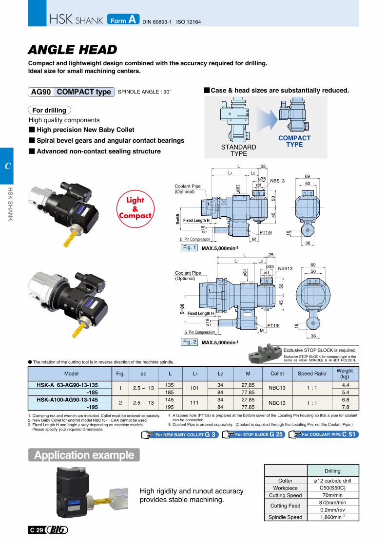
Exclusive STOP BLOCK is required.Exclusive STOP BLOCK for compact type is the same as HIGH SPINDLE & Hi JET HOLDER.
For STOP BLOCK G 25
1. Clamping nut and wrench are included. Collet must be ordered separately.2. New Baby Collet for endmill model NBC13- EAA cannot be used.3. Fixed Length H and angle vary depending on machine models. Please specify your required dimensions.
Model L L1Weight
(kg)Collet Speed Ratio
1 : 1
1 : 1
4.45.46.87.8
NBC13
NBC13
135185145195
34843484
101
111
ød
2.5 - 13
2.5 - 13
1
2
L2
27.8577.8527.8577.85
M
HSK-A 63-AG90-13-135-185
HSK-A100-AG90-13-145-195
Fig.
CutterWorkpiece
Cutting Speed
Cutting Feed
Spindle Speed
ø12 carbide drillC50(S50C)
70m/min372mm/min0.2mm/rev1,860min-1
Drilling
High rigidity and runout accuracy provides stable machining.
For drilling
High precision New Baby ColletSpiral bevel gears and angular contact bearingsAdvanced non-contact sealing structure
High quality components
Case & head sizes are substantially reduced.
For NEW BABY COLLET G 3
COMPACTTYPESTANDARD
TYPE
4. A tapped hole (PT1/8) is prepared at the bottom cover of the Locating Pin housing so that a pipe for coolant can be connected.5. Coolant Pipe is ordered separately. (Coolant is supplied through the Locating Pin, not the Coolant Pipe.)
The rotation of the cutting tool is in reverse direction of the machine spindle.
ANGLE HEADCompact and lightweight design combined with the accuracy required for drilling.Ideal size for small machining centers.
AG90 COMPACT type
Fig. 1
Application example
SPINDLE ANGLE : 90˚
MAX.5,000min-1
Fig. 2 MAX.5,000min-1
50
36
18
69
L 25L2
M
ø35
50
S=65 45
ø81 ød
L1
PT1/8
NBS13
L 25L2
M
ø35 NBS13
50
S=80
45
ø81 ød
L1
PT1/8
50
36
18
69
Coolant Pipe(Optional)
Coolant Pipe(Optional)
5 Pin Compression
Fixed Length H
ø18
5 Pin Compression
Fixed Length H
ø18
For COOLANT PIPE C 51
C 29
HSK SH
ANK
C
DIN 69893-1 ISO 12164Form A
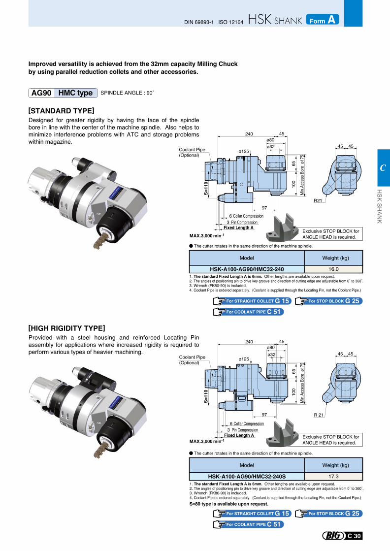
1. The standard Fixed Length A is 6mm. Other lengths are available upon request.2. The angles of positioning pin to drive key groove and direction of cutting edge are adjustable from 0˚ to 360˚.3. Wrench (FK80-90) is included.4. Coolant Pipe is ordered separately. (Coolant is supplied through the Locating Pin, not the Coolant Pipe.)
MAX.3,000 min-1
MAX.3,000 min-1
1. The standard Fixed Length A is 6mm. Other lengths are available upon request.2. The angles of positioning pin to drive key groove and direction of cutting edge are adjustable from 0˚ to 360˚.3. Wrench (FK80-90) is included.4. Coolant Pipe is ordered separately. (Coolant is supplied through the Locating Pin, not the Coolant Pipe.)
For STOP BLOCK G 25
S=80 type is available upon request.
Exclusive STOP BLOCK forANGLE HEAD is required.
Exclusive STOP BLOCK forANGLE HEAD is required.
HSK-A100-AG90/HMC32-240
Weight (kg)
16.0
Model
HSK-A100-AG90/HMC32-240S
Weight (kg)
17.3
Model
For STRAIGHT COLLET G 15
The cutter rotates in the same direction of the machine spindle.
The cutter rotates in the same direction of the machine spindle.
Improved versatility is achieved from the 32mm capacity Milling Chuck by using parallel reduction collets and other accessories.
AG90 HMC type
[STANDARD TYPE]Designed for greater rigidity by having the face of the spindle bore in line with the center of the machine spindle. Also helps to minimize interference problems with ATC and storage problems within magazine.
[HIGH RIGIDITY TYPE]Provided with a steel housing and reinforced Locating Pin assembly for applications where increased rigidity is required to perform various types of heavier machining.
SPINDLE ANGLE : 90˚
ø80ø32
ø125
97
65
Min.A
cces
s Bor
e ø1
75
100
S=11
0
240 45
ø80ø32
ø125
97
65
Min.A
cces
s Bor
e ø1
75
100
S=11
0
240 45
45 45
R21
R 21
45 45
Fixed Length A3 Pin Compression
6 Collar Compression
Coolant Pipe(Optional)
Coolant Pipe(Optional)
Fixed Length A3 Pin Compression
6 Collar Compression
For COOLANT PIPE C 51
For STOP BLOCK G 25For STRAIGHT COLLET G 15For COOLANT PIPE C 51
C 30
DIN 69893-1 ISO 12164 Form AH
SK SHAN
K
C
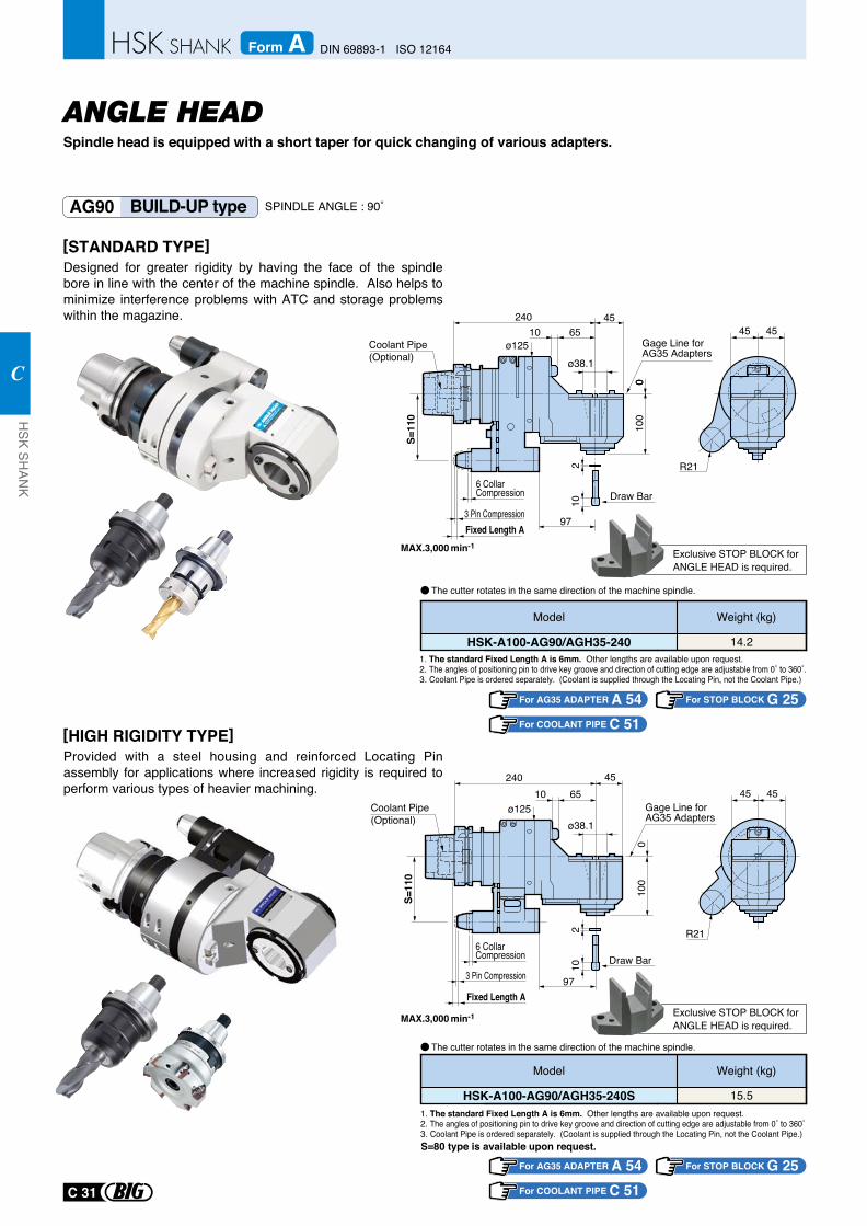
6510ø125
97
010
0
240 45
Gage Line for AG35 Adapters
ø38.1
Draw Bar
102
0
S=11
0
45 45
R21
45 45
R21
Coolant Pipe (Optional)
Spindle head is equipped with a short taper for quick changing of various adapters.
AG90 BUILD-UP type
MAX.3,000 min-1
MAX.3,000 min-1
1. The standard Fixed Length A is 6mm. Other lengths are available upon request.2. The angles of positioning pin to drive key groove and direction of cutting edge are adjustable from 0˚ to 360˚.3. Coolant Pipe is ordered separately. (Coolant is supplied through the Locating Pin, not the Coolant Pipe.)
1. The standard Fixed Length A is 6mm. Other lengths are available upon request.2. The angles of positioning pin to drive key groove and direction of cutting edge are adjustable from 0˚ to 360˚3. Coolant Pipe is ordered separately. (Coolant is supplied through the Locating Pin, not the Coolant Pipe.) S=80 type is available upon request.
Exclusive STOP BLOCK forANGLE HEAD is required.
Exclusive STOP BLOCK forANGLE HEAD is required.
The cutter rotates in the same direction of the machine spindle.
The cutter rotates in the same direction of the machine spindle.
[STANDARD TYPE]Designed for greater rigidity by having the face of the spindle bore in line with the center of the machine spindle. Also helps to minimize interference problems with ATC and storage problems within the magazine.
[HIGH RIGIDITY TYPE]Provided with a steel housing and reinforced Locating Pin assembly for applications where increased rigidity is required to perform various types of heavier machining.
HSK-A100-AG90/AGH35-240
Weight (kg)
14.2
Model
HSK-A100-AG90/AGH35-240S
Weight (kg)
15.5
Model
For AG35 ADAPTER A 54
For AG35 ADAPTER A 54
SPINDLE ANGLE : 90˚
ANGLE HEAD
3 Pin Compression
6 CollarCompression
Fixed Length A
102
65
97
10
010
0
S=11
0
240 45
ø38.1Gage Line for AG35 Adapters
Draw Bar
ø125Coolant Pipe (Optional)
Fixed Length A
3 Pin Compression
6 CollarCompression
For COOLANT PIPE C 51
For COOLANT PIPE C 51
For STOP BLOCK G 25
For STOP BLOCK G 25
C 31
HSK SH
ANK
C
DIN 69893-1 ISO 12164Form A
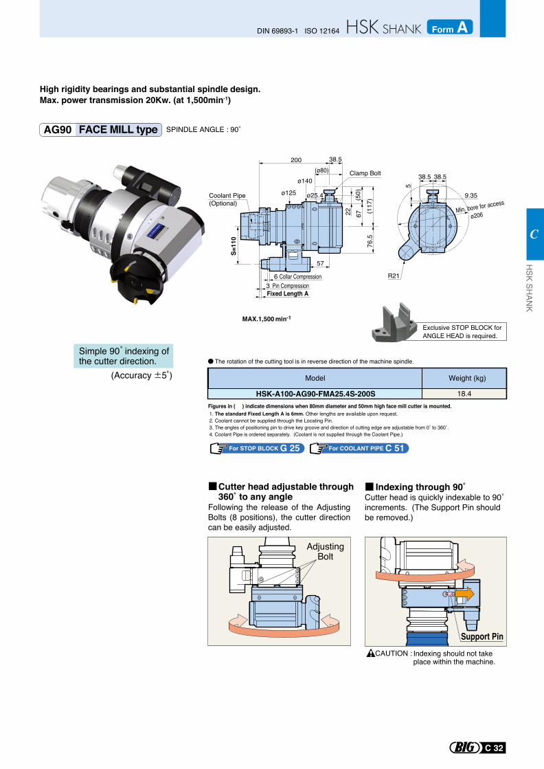
AG90 FACE MILL type
1. The standard Fixed Length A is 6mm. Other lengths are available upon request.2. Coolant cannot be supplied through the Locating Pin.3. The angles of positioning pin to drive key groove and direction of cutting edge are adjustable from 0˚ to 360˚.4. Coolant Pipe is ordered separately. (Coolant is not supplied through the Coolant Pipe.)
For STOP BLOCK G 25
Exclusive STOP BLOCK forANGLE HEAD is required.
HSK-A100-AG90-FMA25.4S-200S
Weight (kg)
18.4
Model
Figures in ( ) indicate dimensions when 80mm diameter and 50mm high face mill cutter is mounted.
Following the release of the Adjusting Bolts (8 positions), the cutter direction can be easily adjusted.
Cutter head is quickly indexable to 90˚ increments. (The Support Pin should be removed.)
CAUTION :
Cutter head adjustable through360˚ to any angle
AdjustingBolt
Indexing through 90˚
Support PinIndexing should not take place within the machine.
(Accuracy 5 )
Simple 90 indexing of the cutter direction. The rotation of the cutting tool is in reverse direction of the machine spindle.
SPINDLE ANGLE : 90˚
High rigidity bearings and substantial spindle design.Max. power transmission 20Kw. (at 1,500min-1)
ø25.4
S=11
0
76.5
(117
)67
(50)
22
ø140Clamp Bolt
ø125
(ø80)38.5200
57
38.5
5
38.5
9.35
Min. bore for access
ø206
R21
Coolant Pipe (Optional)
MAX.1,500 min-1
Fixed Length A3 Pin Compression
6 Collar Compression
For COOLANT PIPE C 51
C 32
DIN 69893-1 ISO 12164 Form AH
SK SHAN
K
C
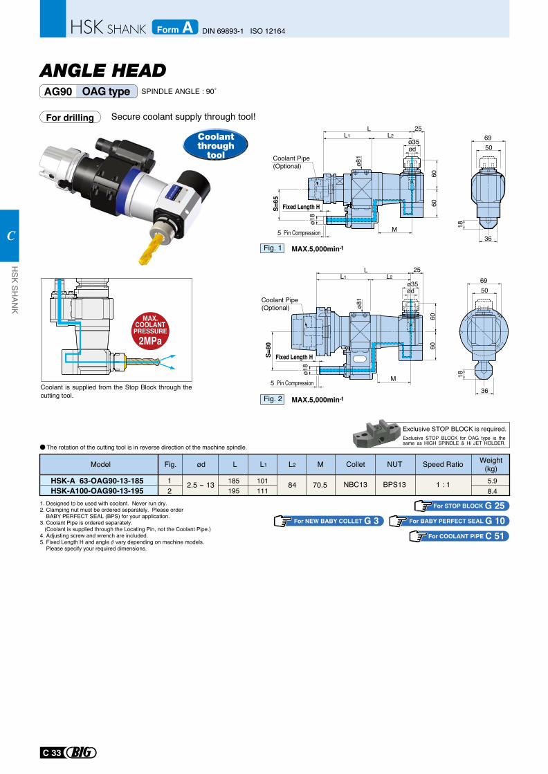
AG90 OAG type SPINDLE ANGLE : 90˚
Secure coolant supply through tool!
1. Designed to be used with coolant. Never run dry.2. Clamping nut must be ordered separately. Please order BABY PERFECT SEAL (BPS) for your application.3. Coolant Pipe is ordered separately. (Coolant is supplied through the Locating Pin, not the Coolant Pipe.) 4. Adjusting screw and wrench are included. 5. Fixed Length H and angle vary depending on machine models. Please specify your required dimensions.
MAX.COOLANT
PRESSURE2MPa
The rotation of the cutting tool is in reverse direction of the machine spindle.
For drilling
Model L L1Weight
(kg)Collet Speed Ratio
1 : 1 5.98.4
NBC13
NUT
BPS13185195
101111
12
ød
2.5 - 13 84 70.5
L2 M
HSK-A 63-OAG90-13-185HSK-A100-OAG90-13-195
Fig.
Exclusive STOP BLOCK is required.Exclusive STOP BLOCK for OAG type is the same as HIGH SPINDLE & Hi JET HOLDER.
For STOP BLOCK G 25For NEW BABY COLLET G 3 For BABY PERFECT SEAL G 10
Coolant is supplied from the Stop Block through the cutting tool.
Coolantthrough
tool5069
L 25L2
M
ø35
60
S=65 60
ø81
ød
L1
36
18
Coolant Pipe (Optional)
5069
M
S=80
6060
ø81
L 25L2
ø35L1
ød
36
18
Coolant Pipe (Optional)
MAX.5,000min-1Fig. 1
MAX.5,000min-1Fig. 2
ANGLE HEAD
Fixed Length H
5 Pin Compression
ø18
Fixed Length H
5 Pin Compression
ø18
For COOLANT PIPE C 51
C 33
HSK SH
ANK
C
DIN 69893-1 ISO 12164Form A
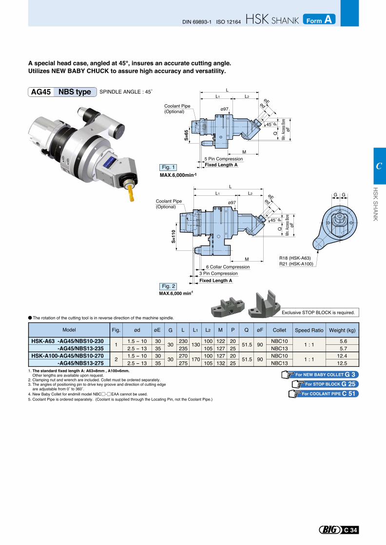
1. The standard fixed length A: A63=8mm , A100=6mm. Other lengths are available upon request.2. Clamping nut and wrench are included. Collet must be ordered separately.3. The angles of positioning pin to drive key groove and direction of cutting edge are adjustable from 0˚ to 360˚.4. New Baby Collet for endmill model NBC - EAA cannot be used.5. Coolant Pipe is ordered separately. (Coolant is supplied through the Locating Pin, not the Coolant Pipe.)
R18 (HSK-A63)R21 (HSK-A100)
G G
AG45 NBS type SPINDLE ANGLE : 45˚
The rotation of the cutting tool is in reverse direction of the machine spindle.
For STOP BLOCK G 25For NEW BABY COLLET G 3
ø97
PQ
Min. A
ccess
Bore
øF
L
øEød
45˚
M
L2L1
S=65
Coolant Pipe (Optional)
L1 L2
ø97
L
M
PQ
Min. A
ccess
Bore
øF
øEød
45˚
S=11
0
Coolant Pipe (Optional)
MAX.6,000min-1Fig. 1
MAX.6,000 min-1Fig. 2
5 Pin CompressionFixed Length A
6 Collar Compression3 Pin CompressionFixed Length A
HSK-A63 -AG45/NBS10-230-AG45/NBS13-235
HSK-A100-AG45/NBS10-270-AG45/NBS13-275
Speed Ratio
1 : 1
1 : 1
NBC10NBC13NBC10NBC13
ød øE G L L1 L2 M P Q øF
1.5 - 10 30 30 230 130 100 122 20 51.5 902.5 - 13 35 235 105 127 251.5 - 10 30 30 270 170 100 127 20 51.5 902.5 - 13 35 275 105 132 25
Fig.
1
2
5.6 5.712.412.5
Model Collet Weight (kg)
A special head case, angled at 45°, insures an accurate cutting angle. Utilizes NEW BABY CHUCK to assure high accuracy and versatility.
Exclusive STOP BLOCK is required.
For COOLANT PIPE C 51
C 34
DIN 69893-1 ISO 12164 Form AH
SK SHAN
K
C
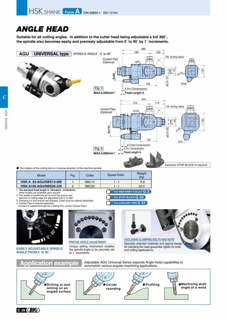
AGU UNIVERSAL type SPINDLE ANGLE : 0˚ to 90˚
Suitable for all cutting angles. In addition to the cutter head being adjustable a full 360˚, the spindle also becomes easily and precisely adjustable from 0˚ to 90˚ by 1˚ increments.
Drilling or end milling on an angled surface
Corner rounding
Profiling Machining draftangle of a mold
Adjustable AGU Universal Series expands Angle Head capabilities toaccomplish various angular machining applications.
EXCLUSIVE CLAMPING BOLTS AND NUTSSpecially selected materials and special designfor clamping the head guarantee rigidity for even end milling applications.
Unique setting mechanism enables the spindle angle to be precisely set at 1˚ increments.
PRECISE ANGLE ADJUSTMENT
EASILY ADJUSTABLE SPINDLE ANGLE FROM 0˚ to 90˚.
1. The standard fixed length A: A63=8mm , A100=6mm. Other lengths are available upon request.2. The angles of positioning pin to drive key groove and direction of cutting edge are adjustable from 0˚ to 360˚.3. Clamping nut and wrench are included. Collet must be ordered separately.4. Coolant Pipe is ordered separately. (Coolant is supplied through the Locating Pin, not the Coolant Pipe.)
For STOP BLOCK G 25
Exclusive STOP BLOCK is required.The rotation of the cutting tool is in reverse direction of the machine spindle.
Application example
51ø3
5ø2
.5-1
3
ø115
ø97
285
S=65
185
124
102 turning radius100
97
R18
Coolant Pipe (Optional)
MAX.6,000min-1Fig. 1
S=11
0ø125
325210
125
115
65ø4
6ø2
.5-2
0
118 turning radius
125
ø140
R21
Coolant Pipe (Optional)
MAX.4,000min-1Fig. 2
Weight(kg)
NBC13NBC20
1 : 11 : 1
HSK-A 63-AGU/NBS13-285HSK-A100-AGU/NBS20-325
12
9.620.0
Model Collet Speed RatioFig.
ANGLE HEAD
5 Pin CompressionFixed Length A
6 Collar Compression3 Pin CompressionFixed Length A
For COOLANT PIPE C 51
For NEW BABY COLLET G 3
C 35
HSK SH
ANK
C
DIN 69893-1 ISO 12164Form A
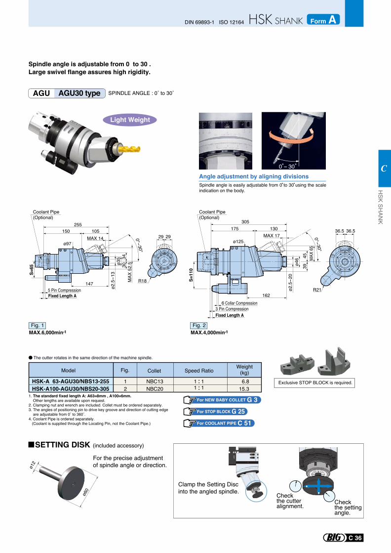
MAX
65
0°-30°
305175 130
MAX 17
ø46 45
39
ø2.5-2
0
S=11
0
162
ø125
36.5 36.5
R21
MAX 14
MAX
52.
5
0°-30°
ø2.5-1
3
255150 105
ø35 34
30
147
S=65
ø9729 29
R18
Spindle angle is adjustable from 0 to 30 .Large swivel flange assures high rigidity.
AGU AGU30 type SPINDLE ANGLE : 0˚ to 30˚
For NEW BABY COLLET G 3For STOP BLOCK G 25
Exclusive STOP BLOCK is required.
Spindle angle is easily adjustable from 0 to 30 using the scale indication on the body.
Angle adjustment by aligning divisions
1. The standard fixed length A: A63=8mm , A100=6mm. Other lengths are available upon request.2. Clamping nut and wrench are included. Collet must be ordered separately.3. The angles of positioning pin to drive key groove and direction of cutting edge are adjustable from 0˚ to 360˚.4. Coolant Pipe is ordered separately. (Coolant is supplied through the Locating Pin, not the Coolant Pipe.)
Clamp the Setting Discinto the angled spindle.
For the precise adjustment of spindle angle or direction.ø1
2
ø60
0 - 30
Model ColletWeight
(kg)Fig.
NBC13NBC20
1 1 6.815.3
HSK-A 63-AGU30/NBS13-255HSK-A100-AGU30/NBS20-305
12 1 1
Speed Ratio
Check the cutter alignment. Check
the setting angle.
The cutter rotates in the same direction of the machine spindle.
Light Weight
MAX.6,000min-1Fig. 1
MAX.4,000min-1Fig. 2
SETTING DISK (included accessory)
5 Pin CompressionFixed Length A
6 Collar Compression3 Pin CompressionFixed Length A
Coolant Pipe (Optional)
Coolant Pipe (Optional)
For COOLANT PIPE C 51
C 36
DIN 69893-1 ISO 12164 Form AH
SK SHAN
K
C
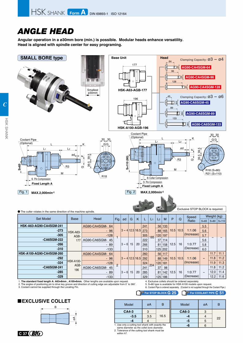
Angular operation in a ø30mm bore (min.) is possible. Modular heads enhance versatility.Head is aligned with spindle center for easy programing.
For STOP BLOCK G 25
1. The standard fixed length A: A63=8mm , A100=6mm. Other lengths are available upon request.2. The angles of positioning pin to drive key groove and direction of cutting edge are adjustable from 0˚ to 360˚.3. Coolant cannot be supplied through the Locating Pin.
4. Exclusive collets should be ordered separately.5. S=80 type is available for HSK-A100 models upon request.6. Coolant Pipe is ordered separately. (Coolant is not supplied through the Coolant Pipe.)
1. Use only a cutting tool shank with exactly the same diameter as the collet bore diameter.2. Tolerance of the cutting tool shank must be within h7.
CA4-3 -3.5-4
33.54
Model øA B
16.5CA6-3
-4-5-6
3456
øA B
22
Smallestø30mm
ModelB
øA
Base Unit
128
21
96
21
64
21
133
89
45
28.5
28.5
28.5
Head
AG90-CA4SGM-128
AG90-CA4SGM-96
AG90-CA4SGM-64
AG90-CA6SGM-133
AG90-CA6SGM-89
AG90-CA6SGM-45
Clamping Capacity: ø3 - ø4
Clamping Capacity: ø3 - ø6
Exclusive STOP BLOCK is required.The cutter rotates in the same direction of the machine spindle.
SMALL BORE type
EXCLUSIVE COLLET
MAX.2,000min-1Fig. 1 MAX.2,000min-1Fig. 2
L K
ød
R3
MS=11
0 (8
0)
QP
L1 L2L K
ød
M
S=65 Q
P
L1 L2
R3
R18
30 30G G
39.5
39.5
R18 (S=80)R21 (S=110)
30 30G G
39.5
39.5
Coolant Pipe (Optional)
Coolant Pipe (Optional)
Fixed Length A5 Pin Compression
Fixed Length A3 Pin Compression
6 Collar Compression
HSK-A63-AG90-CA4SGM-241 -273 -305
-CA6SGM-222 -266 -310
HSK-A100-AG90-CA4SGM-260 -292 -324
-CA6SGM-241 -285 -329
AG90-CA4SGM- 64- 96-128
AG90-CA6SGM- 45- 89-133
AG90-CA4SGM- 64- 96-128
AG90-CA6SGM- 45- 89-133
241273305222266310260292324241285329
5688
1203781
1255688
1203781
125
133165197114158202117149181
98142186
5.55.65.75.65.86.0
-
11.711.811.911.812.012.2
-
11.111.211.311.211.411.6
HSK-A63-AGB-
177
HSK-A100-AGB-196
1
3 - 4
3 - 6
3 - 4
3 - 6
12.5
15
12.5
15
16.5
20
16.5
20
10.5
12.5
10.5
12.5
10.5
16
10.5
16
1:1.06(Increase)
1:0.77(Decrease)
1:1.06(Increase)
1:0.77(Decrease)
2
185
204
-
-
Fig. ød G K L M P QL1 L2Set Model Base Head SpeedRatio
Weight (kg)S=65 S=80 S=110
ANGLE HEAD
For COOLANT PIPE C 51
HSK-A63-AGB-177
HSK-A100-AGB-196
196
177
C 37
HSK SH
ANK
C
DIN 69893-1 ISO 12164Form A
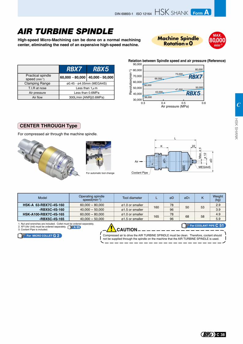
AIR TURBINE SPINDLEHIgh-speed Micro-Machining can be done on a normal machining center, eliminating the need of an expensive high-speed machine.
CENTER THROUGH Type For compressed air through the machine spindle.
For automatic tool change
MAX.80,000
min-1
Machine SpindleRotation=0
Relation between Spindle speed and air pressure (Reference)
58,000
66,000
73,000
80,000
90,000
80,000
70,000
60,000
50,000
40,000
30,0000.3 0.4 0.5 0.6
Rev
olut
ion(
min
-1)
38,000
43,00047,000
50,000
Air pressure (MPa)
Practical spindle speed (min-1) 60,000 - 80,000 40,000 - 50,000
Clamping RangeT.I.R at noseAir pressure
Air flow
ø0.45 - ø4.05mm (MEGA4S)Less than 1 m
Less than 0.6MPa300L/min [ANR](0.6MPa)
Model
2.93.94.95.9
Weight(kg)øD1 KøDLOperating spindle
speed(min-1)60,000 - 80,00040,000 - 50,000
HSK-A 63-RBX7C-4S-160-RBX5C-4S-160
60,000 - 80,00040,000 - 50,000
HSK-A100-RBX7C-4S-165-RBX5C-4S-165
160
165
78967896
Tool diameter
ø1.0 or smallerø1.5 or smallerø1.0 or smallerø1.5 or smaller
50
68
53
58
1. Nut and wrenches are included. Collet must be ordered separately.2. XF1(Air Unit) must be ordered separately. 3. Coolant Pipe is included. CAUTION
Compressed air to drive the AIR TURBINE SPINDLE must be clean. Therefore, coolant should not be supplied through the spindle on the machine that the AIR TURBINE SPINDLE is used.
For MICRO COLLET G 2
A 65
Air
L
K 22
MEGA4S
Max
. ø 4
øD
ø 12
øD
1
Coolant Pipe
For COOLANT PIPE C 51
C 38
DIN 69893-1 ISO 12164 Form AH
SK SHAN
K
C
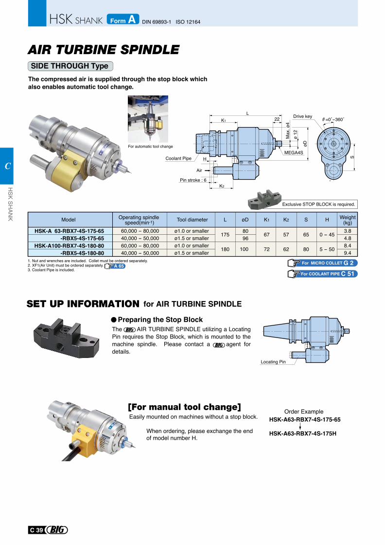
SIDE THROUGH Type The compressed air is supplied through the stop block which also enables automatic tool change.
For automatic tool change
The AIR TURBINE SPINDLE utilizing a Locating Pin requires the Stop Block, which is mounted to the machine spindle. Please contact a agent for details.
Locating Pin
Preparing the Stop Block
for AIR TURBINE SPINDLE
Exclusive STOP BLOCK is required.
S
Drive key =0˚-360˚
Air
MEGA4S
Pin stroke : 6K2
H
L
Max
. ø4
øD
ø 12
K1 22
Coolant Pipe
Easily mounted on machines without a stop block.
When ordering, please exchange the end of model number H.
HSK-A63-RBX7-4S-175-65
HSK-A63-RBX7-4S-175H
Order Example
1. Nut and wrenches are included. Collet must be ordered separately.2. XF1(Air Unit) must be ordered separately.3. Coolant Pipe is included.
Model
3.84.88.49.4
Weight(kg)HSK2K1øDLTool diameterOperating spindle
speed(min-1)60,000 - 80,00040,000 - 50,000
ø1.0 or smallerø1.5 or smallerø1.0 or smallerø1.5 or smaller
HSK-A 63-RBX7-4S-175-65-RBX5-4S-175-65
60,000 - 80,00040,000 - 50,000
HSK-A100-RBX7-4S-180-80-RBX5-4S-180-80
175
180
8096
100
57
62
67
72
65
80
0 - 45
5 - 50
For MICRO COLLET G 2A 65
AIR TURBINE SPINDLE
For COOLANT PIPE C 51
C 39
HSK SH
ANK
C
DIN 69893-1 ISO 12164Form A
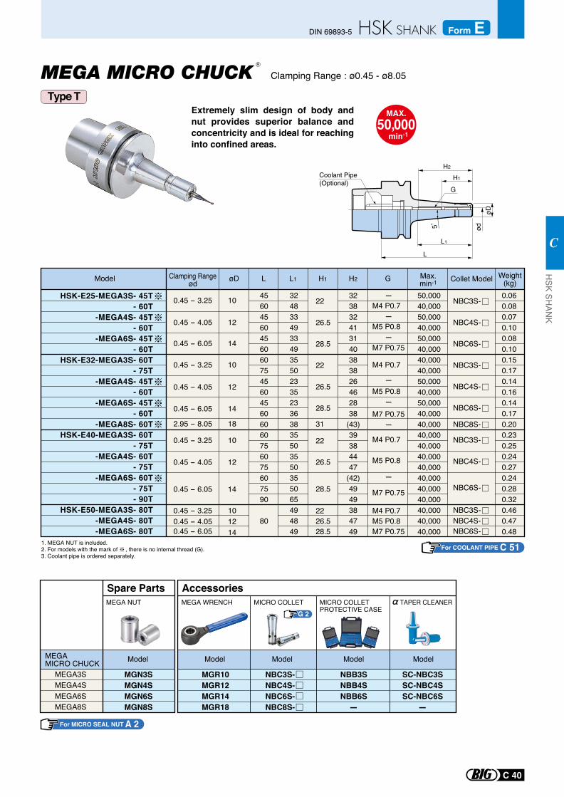
Extremely slim design of body and nut provides superior balance and concentricity and is ideal for reaching into confined areas.
Clamping Range : ø0.45 - ø8.05
MAX.50,000
min-1
Coolant Pipe (Optional)
HSK-E25-MEGA3S- 45T- 60T
-MEGA4S- 45T- 60T
-MEGA6S- 45T- 60T
HSK-E32-MEGA3S- 60T- 75T
-MEGA4S- 45T- 60T
-MEGA6S- 45T- 60T
-MEGA8S- 60THSK-E40-MEGA3S- 60T
- 75T-MEGA4S- 60T
- 75T-MEGA6S- 60T
- 75T- 90T
HSK-E50-MEGA3S- 80T-MEGA4S- 80T-MEGA6S- 80T
0.45 - 3.25
0.45 - 4.05
0.45 - 3.25
0.45 - 6.05
0.45 - 6.05
0.45 - 3.25
10
12
10
0.45 - 6.05 14
14
2.95 - 8.05 18
0.45 - 4.05 12
14
0.45 - 4.05 12
0.45 - 3.25 10
100.45 - 4.05 120.45 - 6.05 14
NBC3S-
NBC4S-
NBC6S-
NBC3S-
NBC4S-
NBC6S-
NBC4S-
NBC3S-
NBC6S-
NBC3S-NBC4S-NBC6S-
NBC8S-
4560456045606075456045606060756075607590
80
3248334933493550233523363835503550355065494849
Max.min-1
323832413140383826462838
(43)39384447
(42)4949384749
-M4 P0.7 -M5 P0.8 -M7 P0.75
M4 P0.7
-M5 P0.8 -M7 P0.75 -
M4 P0.7
M5 P0.8
-
M7 P0.75
M4 P0.7M5 P0.8M7 P0.75
22
26.5
28.5
22
26.5
28.5
31
22
26.5
28.5
2226.528.5
50,00040,00050,00040,00050,00040,00040,00040,00050,00040,00050,00040,00040,00040,00040,00040,00040,00040,00040,00040,00040,00040,00040,000
0.060.080.070.100.080.100.150.170.140.160.140.170.200.230.250.240.270.240.280.320.460.470.48
Model L L1øD H1 H2 G Weight(kg)
1. MEGA NUT is included.2. For models with the mark of , there is no internal thread (G).3. Coolant pipe is ordered separately.
5˚ ødøD
H2
L1
L
H1
G
R
Collet ModelClamping Rangeød
Type T
G 2
MEGA3SMEGA4SMEGA6SMEGA8S
MGN3SMGN4SMGN6SMGN8S
Spare PartsMEGA NUT
MEGA MICRO CHUCK Model
MGR10MGR12MGR14MGR18
MICRO COLLETPROTECTIVE CASE
MICRO COLLET
AccessoriesMEGA WRENCH
NBB3SNBB4SNBB6S-
Model Model Model
NBC3S-NBC4S-NBC6S-NBC8S-
Model
SC-NBC3SSC-NBC4SSC-NBC6S
-
TAPER CLEANER
For COOLANT PIPE C 51
For MICRO SEAL NUT A 2
C 40
HSK SH
ANK
C
DIN 69893-5 Form E
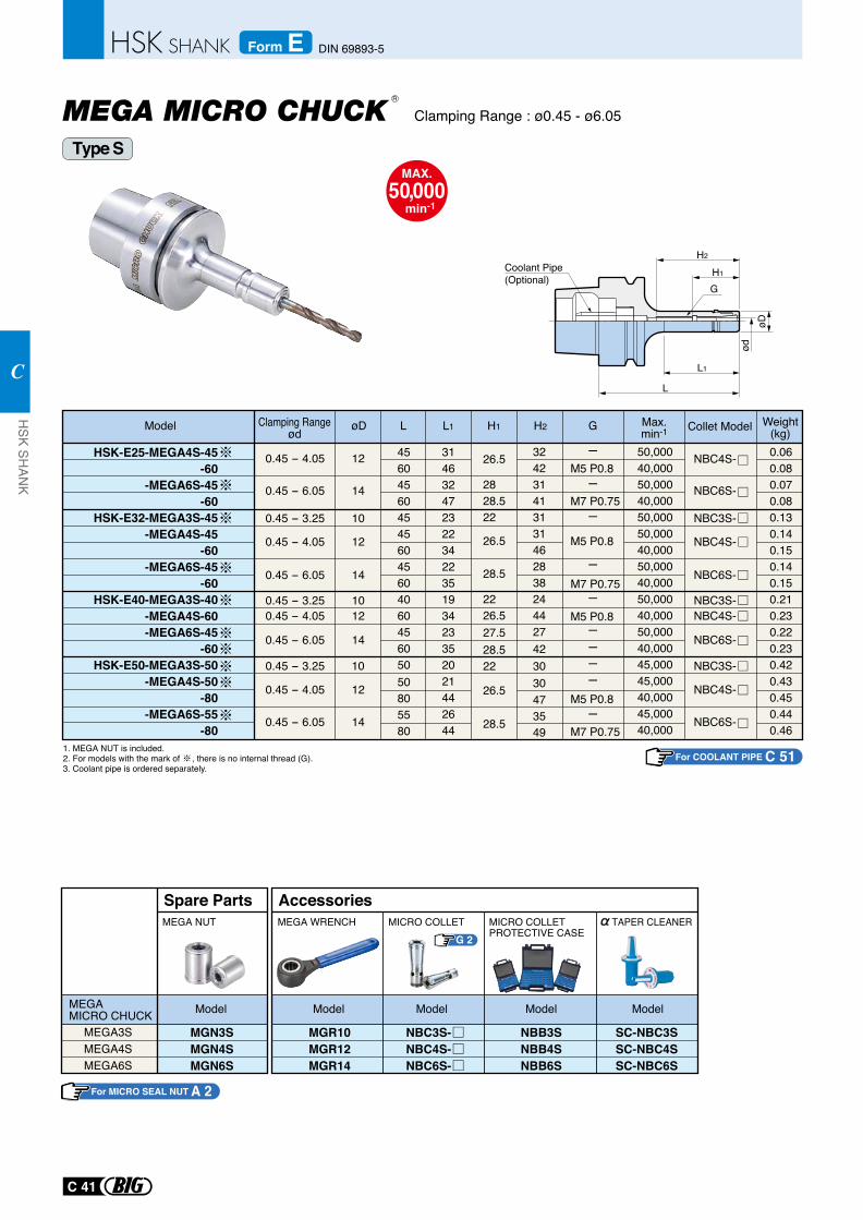
MAX.50,000
min-1
0.45 - 6.05
0.45 - 6.05
0.45 - 4.05
0.45 - 3.25
0.45 - 4.05
0.45 - 6.05
0.45 - 3.250.45 - 4.05
0.45 - 6.05
0.45 - 3.25
0.45 - 4.05
14
14
12
10
12
14
1012
14
10
12
HSK-E25-MEGA4S-45-60
-MEGA6S-45-60
HSK-E32-MEGA3S-45-MEGA4S-45
-60-MEGA6S-45
-60HSK-E40-MEGA3S-40
-MEGA4S-60-MEGA6S-45
-60HSK-E50-MEGA3S-50
-MEGA4S-50-80
-MEGA6S-55-80
NBC6S-
NBC6S-
NBC4S-
NBC3S-
NBC4S-
NBC6S-
NBC3S-NBC4S-
NBC6S-
NBC3S-
NBC4S-
45604560454560456040 6045605050805580
M5 P0.8
M7 P0.75
M5 P0.8
M5 P0.8
M5 P0.8
M7 P0.75
314632472322342235193423352021442644
0.060.080.070.080.130.140.150.140.150.210.230.220.230.420.430.450.440.46
324231413131462838244427423030473549
26.5
2828.522
26.5
28.5
2226.527.528.522
26.5
28.5
50,00040,00050,00040,00050,00050,00040,00050,00040,00050,00040,00050,00040,00045,00045,00040,00045,00040,000
-
-
-
-
-
-
--
-
-
M7 P0.75
Max.min-1Model L L1øD H1 H2 G Weight
(kg)
1. MEGA NUT is included.2. For models with the mark of , there is no internal thread (G).3. Coolant pipe is ordered separately.
ødøD
H2
L1
L
H1
G
G 2
MEGA3SMEGA4SMEGA6S
MGN3SMGN4SMGN6S
Spare PartsMEGA NUT
MEGA MICRO CHUCK Model
MGR10MGR12MGR14
MICRO COLLETPROTECTIVE CASE
MICRO COLLET
AccessoriesMEGA WRENCH
NBB3SNBB4SNBB6S
Model Model Model
NBC3S-NBC4S-NBC6S-
Model
SC-NBC3SSC-NBC4SSC-NBC6S
TAPER CLEANER
Coolant Pipe (Optional)
Clamping Rangeød Collet Model
Type S
Clamping Range : ø0.45 - ø6.05R
For COOLANT PIPE C 51
For MICRO SEAL NUT A 2
C 41
HSK SH
ANK
C
DIN 69893-5Form E
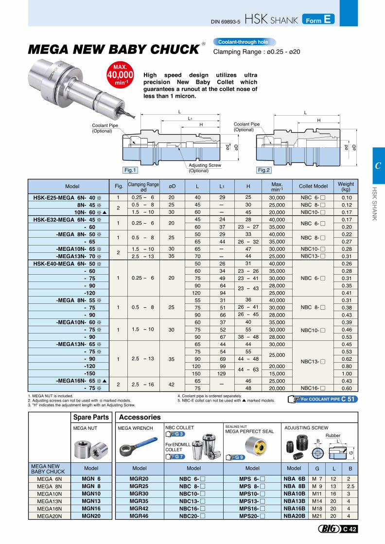
Clamping Range : ø0.25 - ø20
MAX.40,000
min-1
Coolant-through hole
25
30
35
42 -
--
--
90120557590607590657590
1201506575
649431516637526744546999
129
HSK-E40-MEGA 6N- 50- 60- 75- 90-120
-MEGA 8N- 55- 75- 90
-MEGA10N- 60- 75- 90
-MEGA13N- 65- 75- 90-120-150
-MEGA16N- 65- 75
3035
2025
1
2
1
1
1
1
1
1
2
2
30
20
20
25
6050656570506075
372944
263449
28,00025,00040,00030,00028,00035,00030,00028,00030,000
25,000
20,00015,00025,00020,000
35,00040,00035,00030,00025,00040,00035,00030,000
40456045
29
24
30,00025,00020,00040,000
0.25 - 60.5 - 81.5 - 10
0.25 - 6
0.5 - 8
1.5 - 10
2.5 - 13
1.5 - 102.5 - 13
2.5 - 16
0.25 - 6
0.5 - 8
HSK-E32-MEGA 6N- 45- 60
-MEGA 8N- 50- 65
-MEGA10N- 65-MEGA13N- 70
HSK-E25-MEGA 6N- 408N- 45
10N- 60
0.100.120.170.170.200.220.270.280.310.260.280.310.350.410.310.380.430.390.460.530.450.530.620.801.000.430.60
NBC 6-
NBC 8-
NBC13-NBC10-
NBC 6-NBC 8-NBC10-
NBC 6-
NBC 8-
NBC10-
NBC13-
NBC16-
25304528
23 - 2733
26 - 32474431
23 - 2623 - 41
23 - 43
3626 - 4126 - 45
4055
38 - 484455
44 - 48
44 - 63
4648
Model L L1øD H Max.min-1
Weight(kg)
1. MEGA NUT is included.2. Adjusting screws can not be used with marked models.3. "H" indicates the adjustment length with an Adjusting Screw.
Fig.
Coolant Pipe (Optional)
øDød
HL1
L
Adjusting Screw (Optional) Fig.1
Coolant Pipe (Optional)
L
ød øD
H
Fig.2
R
Collet ModelClamping Rangeød
High speed design utilizes ultra precision New Baby Collet which guarantees a runout at the collet nose of less than 1 micron.
MPS 6-MPS 8-MPS10-MPS13-MPS16-MPS20-
G 9
Rubber
MEGA 6NMEGA 8NMEGA10NMEGA13NMEGA16NMEGA20N
MEGA NEW BABY CHUCK
MGN 6MGN 8MGN10MGN13MGN16MGN20
MEGA NUT
Model
Spare Parts
MGR20MGR25MGR30MGR35MGR42MGR46
NBA 6BNBA 8BNBA10BNBA13BNBA16BNBA20B
M 7M 9M11M14M18M21
121316202020
22.53444
MEGA WRENCH SEALING NUTMEGA PERFECT SEAL
ADJUSTING SCREW
G L B
B L
G
ModelModelModelModel
Accessories
NBC 6-NBC 8-NBC10-NBC13-NBC16-NBC20-
G 3NBC COLLET
G 7
For ENDMILLCOLLET
4. Coolant pipe is ordered separately.5. NBC-E collet can not be used with marked models. For COOLANT PIPE C 51
C 42
HSK SH
ANK
C
DIN 69893-5 Form E
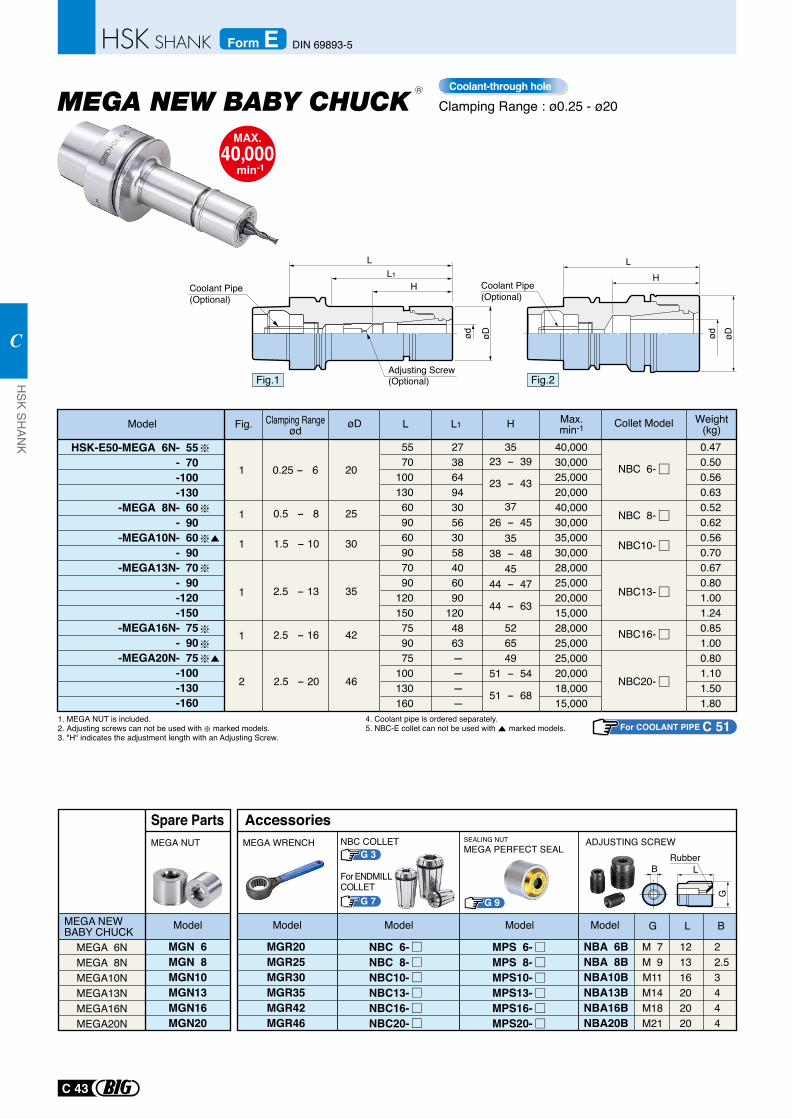
MPS 6-MPS 8-MPS10-MPS13-MPS16-MPS20-
G 9
Rubber
MEGA 6NMEGA 8NMEGA10NMEGA13NMEGA16NMEGA20N
MEGA NEW BABY CHUCK
MGN 6MGN 8MGN10MGN13MGN16MGN20
MEGA NUT
Model
Spare Parts
MGR20MGR25MGR30MGR35MGR42MGR46
NBA 6BNBA 8BNBA10BNBA13BNBA16BNBA20B
M 7M 9M11M14M18M21
121316202020
22.53444
MEGA WRENCH SEALING NUTMEGA PERFECT SEAL
ADJUSTING SCREW
G L B
B L
G
ModelModelModelModel
Accessories
NBC 6-NBC 8-NBC10-NBC13-NBC16-NBC20-
HSK-E50-MEGA 6N- 55- 70-100-130
-MEGA 8N- 60- 90
-MEGA10N- 60- 90
-MEGA13N- 70- 90-120-150
-MEGA16N- 75- 90
-MEGA20N- 75-100-130-160
0.25 - 6
0.5 - 8
1.5 - 10
2.5 - 13
2.5 - 16
2.5 - 20
201
1
1
1
1
2
25
30
35
42
46
NBC 6-
NBC 8-
NBC10-
NBC13-
NBC16-
NBC20-
5570
100130609060907090
120150759075
100130160
2738649430563058406090
1204863- - - -
0.470.500.560.630.520.620.560.700.670.801.001.240.851.000.801.101.501.80
40,00030,00025,00020,00040,00030,00035,00030,00028,00025,00020,00015,00028,00025,00025,00020,00018,00015,000
3523 - 39
23 - 43
3726 - 45
3538 - 48
4544 - 47
44 - 63
526549
51 - 54
51 - 68
Model L L1øD H Max.min-1
Weight(kg)
1. MEGA NUT is included.2. Adjusting screws can not be used with marked models. 3. "H" indicates the adjustment length with an Adjusting Screw.
Fig.
4. Coolant pipe is ordered separately.5. NBC-E collet can not be used with marked models.
G 3NBC COLLET
G 7
For ENDMILLCOLLET
Collet ModelClamping Rangeød
Clamping Range : ø0.25 - ø20
MAX.40,000
min-1
Coolant-through hole
Coolant Pipe (Optional)
øDød
HL1
L
Adjusting Screw (Optional) Fig.1
Coolant Pipe (Optional)
L
ød øD
H
Fig.2
R
For COOLANT PIPE C 51
C 43
HSK SH
ANK
C
DIN 69893-5Form E
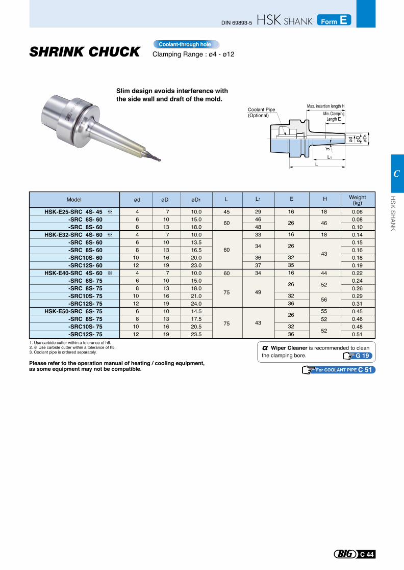
Slim design avoids interference with the side wall and draft of the mold.
Clamping Range : ø4 - ø12Coolant-through hole
L1
L
3˚
Min. ClampingLength E
Model ød Weight(kg)øD1øD L1L
HSK-E25-SRC 4S- 45-SRC 6S- 60
-SRC 8S- 60HSK-E32-SRC 4S- 60
-SRC 6S- 60 -SRC 8S- 60 -SRC10S- 60 -SRC12S- 60
HSK-E40-SRC 4S- 60-SRC 6S- 75
-SRC 8S- 75 -SRC10S- 75 -SRC12S- 75
HSK-E50-SRC 6S- 75 -SRC 8S- 75 -SRC10S- 75 -SRC12S- 75
468468
1012468
101268
1012
710137
101316197
1013161910131619
10.015.018.010.013.516.520.023.010.015.018.021.024.014.517.520.523.5
60
60
60
75
75
45 0.060.080.100.140.150.160.180.190.220.240.260.290.310.450.460.480.51
29464833
34
363734
49
43
26
16
26
323516
26
3236
26
3236
16
46
18
44
52
56
5552
52
18
43
Please refer to the operation manual of heating / cooling equipment, as some equipment may not be compatible.
Wiper Cleaner is recommended to clean the clamping bore. G 19
E
Coolant Pipe (Optional)
ød øD øD1
H
Max. insertion length H
1. Use carbide cutter within a tolerance of h6.2. Use carbide cutter within a tolerance of h5.3. Coolant pipe is ordered separately.
For COOLANT PIPE C 51
C 44
HSK SH
ANK
C
DIN 69893-5 Form E
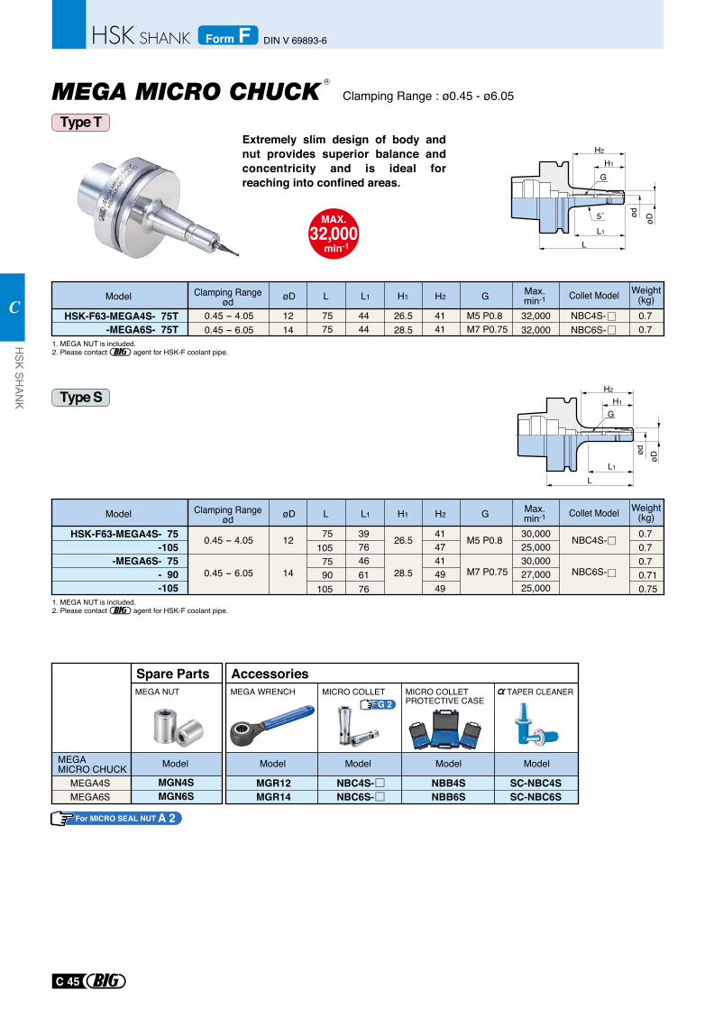
Extremely slim design of body and nut provides superior balance and concentricity and is ideal for reaching into confined areas.
Clamping Range : ø0.45 - ø6.05
MAX.32,000
min-1
1. MEGA NUT is included.2. Please contact agent for HSK-F coolant pipe.
GH1
L1
L
ødøD
H2
0.45 - 4.050.45 - 6.05
1214
26.528.5
HSK-F63-MEGA4S- 75T-MEGA6S- 75T
32,00032,000
7575
4444
4141
M5 P0.8M7 P0.75
0.70.7
5˚
G
L1
ød
øD
L
H1
H2
Max.min-1Model L L1øD H1 H2 G Weight
(kg)NBC4S-NBC6S-
Collet Model
0.45 - 4.05
0.45 - 6.05
12
14
26.5
28.5
NBC4S-
NBC6S-
HSK-F63-MEGA4S- 75 -105
-MEGA6S- 75 - 90
-105
30,00025,00030,00027,00025,000
751057590
105
3976466176
4147414949
M5 P0.8
M7 P0.75
0.70.70.70.710.75
Max.min-1Model L L1øD H1 H2 G Weight
(kg)Collet Model
G 2
MEGA4SMEGA6S
MGN4SMGN6S
Spare PartsMEGA NUT
MEGA MICRO CHUCK Model
MGR12MGR14
MICRO COLLETPROTECTIVE CASE
MICRO COLLET
AccessoriesMEGA WRENCH
NBB4SNBB6S
Model Model Model
NBC4S-NBC6S-
Model
SC-NBC4SSC-NBC6S
TAPER CLEANER
Clamping Rangeød
Clamping Rangeød
R
Type S
Type T
1. MEGA NUT is included.2. Please contact agent for HSK-F coolant pipe.
For MICRO SEAL NUT A 2
C 45
HSK SH
ANK
C
DIN V 69893-6Form F
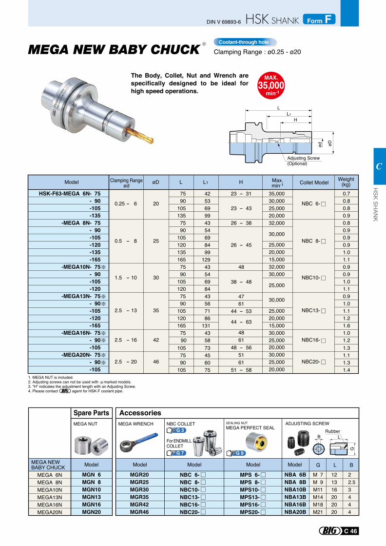
MPS 6-MPS 8-MPS10-MPS13-MPS16-MPS20-
G 9
Rubber
MEGA 6NMEGA 8NMEGA10NMEGA13NMEGA16NMEGA20N
MEGA NEW BABY CHUCK
MGN 6MGN 8MGN10MGN13MGN16MGN20
MEGA NUT
Model
Spare Parts
MGR20MGR25MGR30MGR35MGR42MGR46
NBA 6BNBA 8BNBA10BNBA13BNBA16BNBA20B
M 7M 9M11M14M18M21
121316202020
22.53444
MEGA WRENCH SEALING NUTMEGA PERFECT SEAL
ADJUSTING SCREW
G L B
B L
G
ModelModelModelModel
Accessories
NBC 6-NBC 8-NBC10-NBC13-NBC16-NBC20-
The Body, Collet, Nut and Wrench are specifically designed to be ideal for high speed operations.
Clamping Range : ø0.25 - ø20
MAX.35,000
min-1
Coolant-through hole
23 - 31
23 - 43
26 - 38
26 - 45
48
38 - 48
4761
44 - 53
44 - 63
4861
48 - 565161
51 - 58
H
LL1
ød øD
0.25 - 6
0.5 - 8
1.5 - 10
2.5 - 13
2.5 - 16
2.5 - 20
NBC 6-
NBC 8-
NBC10-
NBC13-
NBC16-
NBC20-
20
25
30
35
42
46
HSK-F63-MEGA 6N- 75- 90-105-135
-MEGA 8N- 75- 90-105-120-135-165
-MEGA10N- 75- 90-105-120
-MEGA13N- 75- 90-105-120-165
-MEGA16N- 75- 90-105
-MEGA20N- 75- 90-105
35,00030,00025,00020,00032,000
30,000
25,00020,00015,00032,00030,000
25,000
30,000
25,00020,00015,00030,00025,00020,00030,00025,00020,000
75 90105135 75 90105120135165 75 90105120 75 90105120165 75 90105 75 90105
42 53 69 99 43 54 69 84 99129 43 54 69 84 43 56 71 86131 43 58 73 45 60 75
0.70.80.80.90.80.90.90.91.01.10.90.91.01.10.91.01.11.21.61.01.21.31.11.31.4
1. MEGA NUT is included.2. Adjusting screws can not be used with marked models. 3. "H" indicates the adjustment length with an Adjusting Screw.4. Please contact agent for HSK-F coolant pipe.
Adjusting Screw (Optional)
Model L L1øD H Max.min-1
Weight(kg)
G 3NBC COLLET
G 7
For ENDMILLCOLLET
Collet ModelClamping Rangeød
R
C 46
HSK SH
ANK
C
DIN V 69893-6 Form F
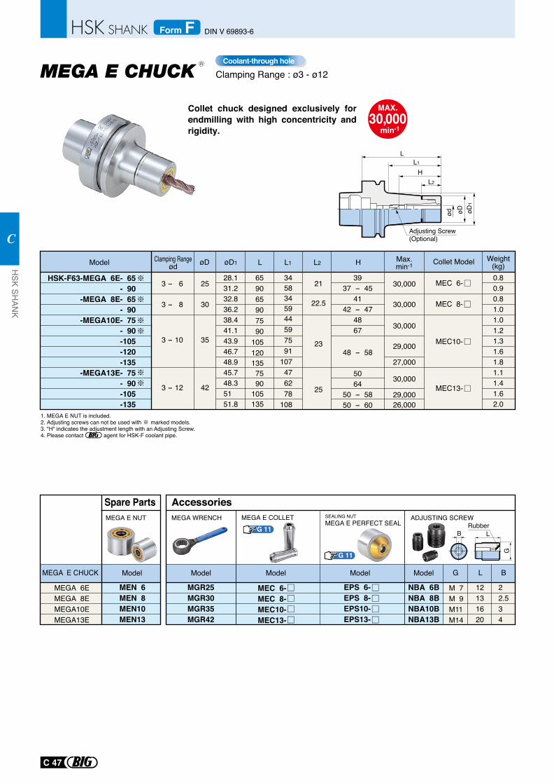
Collet chuck designed exclusively for endmilling with high concentricity and rigidity.
Clamping Range : ø3 - ø12
MAX.30,000
min-1
Coolant-through hole
G 11
G 11
SEALING NUTMEGA E PERFECT SEAL Rubber
B L
GMEGA E COLLET
MEGA 6EMEGA 8EMEGA10EMEGA13E
MEGA E CHUCK Model
Spare Parts
MEN 6MEN 8MEN10MEN13
MEGA E NUT
MGR25MGR30MGR35MGR42
NBA 6BNBA 8BNBA10BNBA13B
EPS 6-EPS 8-EPS10-EPS13-
M 7M 9M11M14
12131620
22.534
G L B
MEGA WRENCH ADJUSTING SCREW
ModelModel Model Model
Accessories
MEC 6-MEC 8-MEC10-MEC13-
1. MEGA E NUT is included.2. Adjusting screws can not be used with marked models.3. "H" indicates the adjustment length with an Adjusting Screw.4. Please contact agent for HSK-F coolant pipe.
3 - 8
3 - 10
3 - 12
30
35
42
3 - 6 25659065907590
1051201357590
105135
3458345944597591
107476278
108
28.131.232.836.238.441.143.946.748.945.748.351 51.8
HSK-F63-MEGA 6E- 65- 90
-MEGA 8E- 65- 90
-MEGA10E- 75- 90-105-120-135
-MEGA13E- 75- 90-105-135
0.80.90.81.01.01.21.31.61.81.11.41.62.0
MEC 6-
MEC 8-
MEC10-
MEC13-
30,000
30,000
30,000
29,000
27,000
30,000
29,00026,000
21
22.5
23
25
3937 - 45
4142 - 47
4867
48 - 58
5064
50 - 5850 - 60
ød øD
L1
L2
L
H
øD1
Adjusting Screw (Optional)
Model L L1 L2øD øD1 Max.min-1
Weight(kg)H Collet ModelClamping Range
ød
R
C 47
HSK SH
ANK
C
DIN V 69893-6Form F
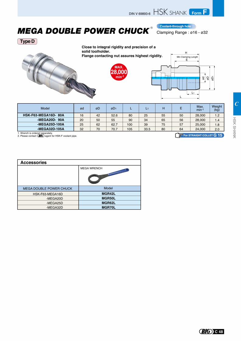
Close to integral rigidity and precision of a solid toolholder. Flange contacting nut assures highest rigidity.
Clamping Range : ø16 - ø32
MAX.28,000
min-1
Coolant-through holeR
1. Wrench is ordered separately.2. Please contact agent for HSK-F coolant pipe.
Model øDød
HSK-F63 -MEGA16D- 80A -MEGA20D- 90A -MEGA25D-100A -MEGA32D-105A
øD1
28,00028,00025,00024,000
Max.min-1L L1 H
16202532
42506270
55657580
50565764
52.65562.770.7
80 90100105
25343933.5
1.21.41.82.0
Weight(kg)
MGR42L MGR50L MGR62L MGR70L
AccessoriesMEGA WRENCH
ModelMEGA DOUBLE POWER CHUCKHSK-F63-MEGA16D -MEGA20D -MEGA25D -MEGA32D
For STRAIGHT COLLET G 15
E
LL1
H
øD1
øDød
EMin Clamping Length
Type D
C 48
HSK SH
ANK
C
DIN V 69893-6 Form F
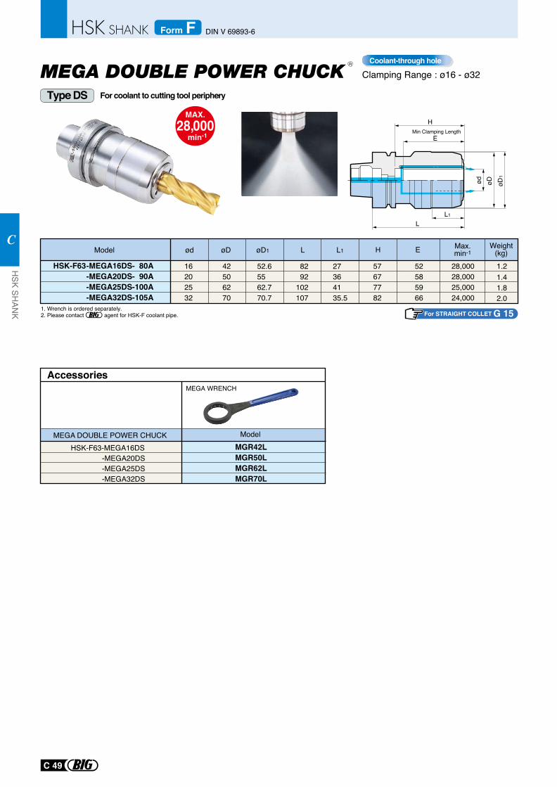
Clamping Range : ø16 - ø32Coolant-through holeR
For STRAIGHT COLLET G 151. Wrench is ordered separately.2. Please contact agent for HSK-F coolant pipe.
Model øDød
HSK-F63 -MEGA16DS- 80A -MEGA20DS- 90A -MEGA25DS-100A -MEGA32DS-105A
øD1
28,00028,00025,00024,000
Max.min-1L L1 H
16202532
42506270
57677782
52585966
52.65562.770.7
82 92102107
27364135.5
1.21.41.82.0
Weight(kg)
LL1
H
øD1
øDød
EMin Clamping Length
E
For coolant to cutting tool peripheryType DS
MGR42L MGR50L MGR62L MGR70L
AccessoriesMEGA WRENCH
ModelMEGA DOUBLE POWER CHUCKHSK-F63-MEGA16DS -MEGA20DS -MEGA25DS -MEGA32DS
MAX.28,000
min-1
C 49
HSK SH
ANK
C
DIN V 69893-6Form F
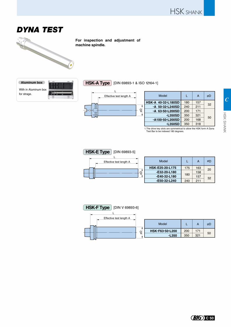
For inspection and adjustment of machine spindle.
With in Aluminum box for strage.
Aluminum box [DIN 69893-1 & ISO 12164-1]
L
Effective test length A
øD
LEffective test length A
øD
LEffective test length A
øD
-A100-50-L200SD-L350SD
-A 63-50-L200SD-A 50-32-L240SD
HSK-A 40-32-L180SD
-L350SD
180 157240 211200 171350 321200 168350 318
32
50
Model L A øD
1.The drive key slots are symmetrical to allow the HSK form A Dyna Test Bar to be indexed 180 degrees.
Model L A øD
175
240
180
163158157211
20
32
HSK-E25-20-L175-E32-20-L180-E40-32-L180-E50-32-L240
50HSK-F63-50-L200-L350
200 171350 321
Model L A øD
HSK-A Type
[DIN 69893-5]HSK-E Type
[DIN V 69893-6]HSK-F Type
C 50
HSK SH
ANK
C
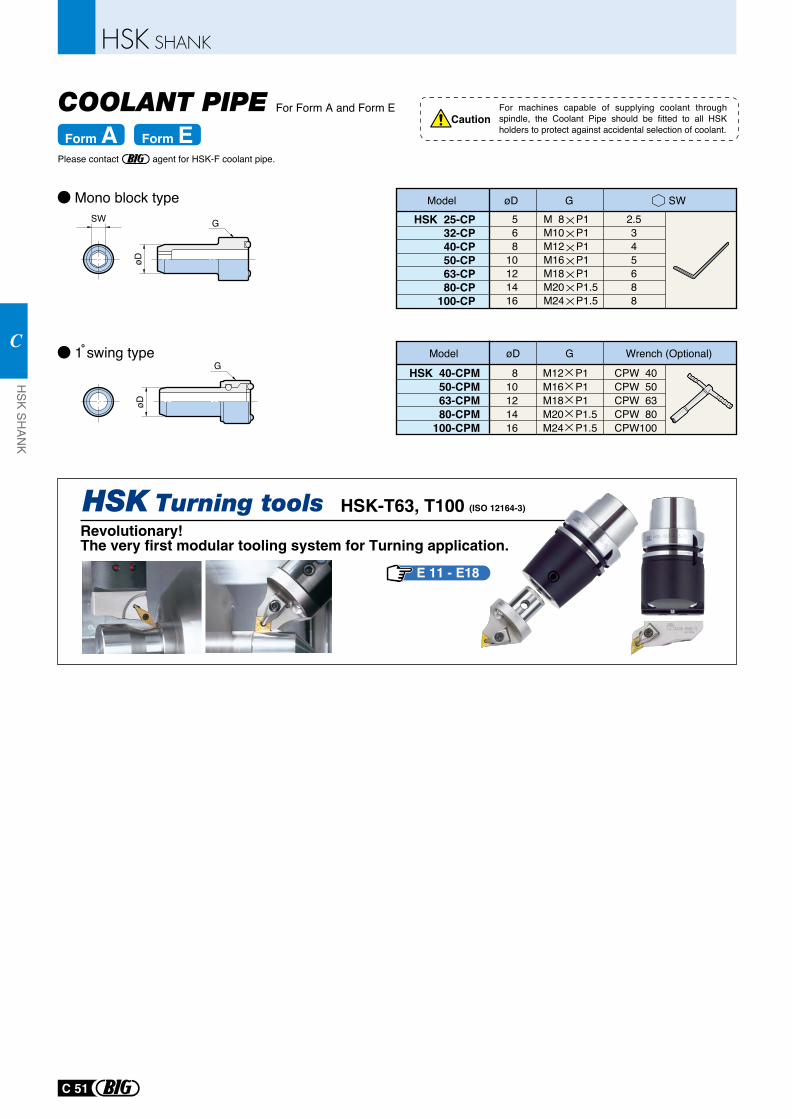
For Form A and Form E
Model øD G SWHSK 25-CP
32-CP40-CP50-CP63-CP80-CP
100-CP
568
10121416
M 8 P1M10 P1M12 P1M16 P1M18 P1M20 P1.5M24 P1.5
2.5345688
Model øD G Wrench (Optional)
HSK 40-CPM50-CPM
63-CPM80-CPM
100-CPM
810121416
M12 P1M16 P1M18 P1M20 P1.5M24 P1.5
CPW 40CPW 50CPW 63CPW 80CPW100
Mono block type
1 swing type
G
øD
SW
G
øD
Caution
Form A Form EFor machines capable of supplying coolant through spindle, the Coolant Pipe should be fitted to all HSK holders to protect against accidental selection of coolant.
COOLANT PIPE
E 11 - E18
HSK-T63, T100 (ISO 12164-3)
Revolutionary!The very first modular tooling system for Turning application.
Please contact agent for HSK-F coolant pipe.
C 51
HSK SH
ANK
C
MEGA MICRO CHUCK
MEGA NEW BABY CHUCK
NEW BABY CHUCK
SHRINK CHUCK
MEGA SYNCHRO Tapping Holder
D1
D2
D3
D5
D8
D
D
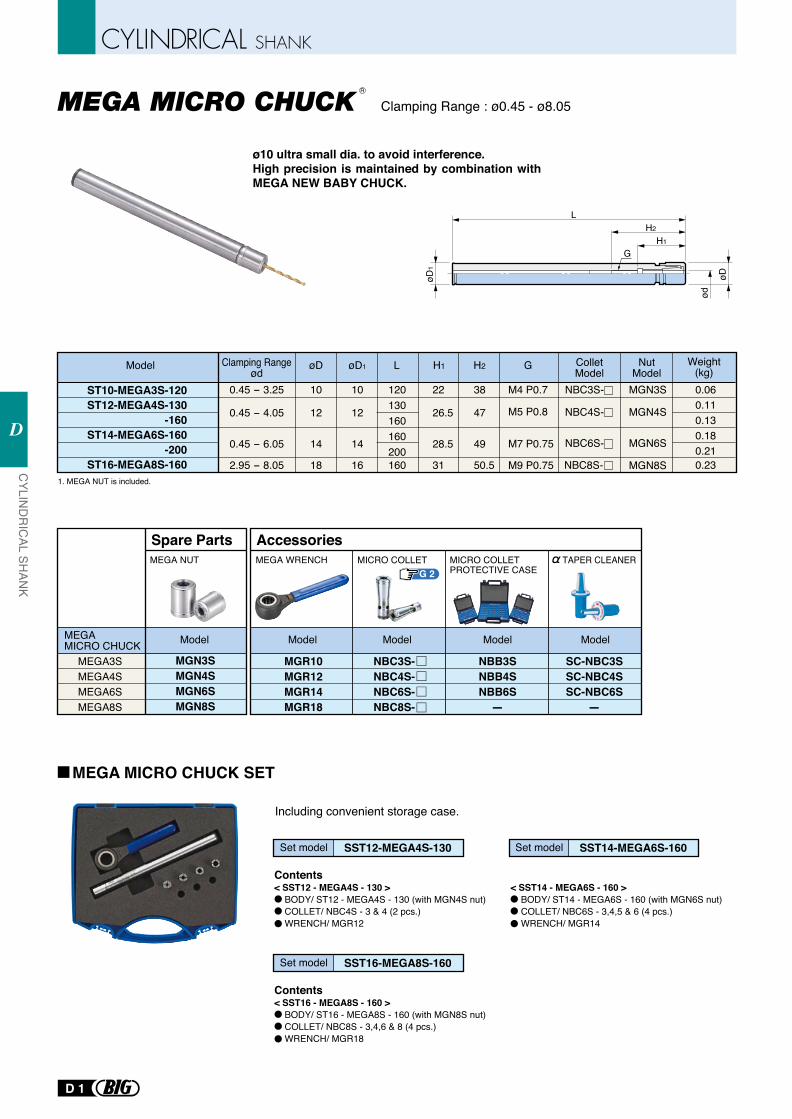
ø10 ultra small dia. to avoid interference.High precision is maintained by combination with MEGA NEW BABY CHUCK.
Clamping Range : ø0.45 - ø8.05
Model
ST10-MEGA3S-120ST12-MEGA4S-130
-160ST14-MEGA6S-160
-200ST16-MEGA8S-160
øD
10
12
14
18
øD1
10
12
14
16
L
120130160160200160
H1
22
26.5
28.5
31
H2
38
47
49
50.5
G
0.060.110.130.180.210.23
1. MEGA NUT is included.
Weight(kg)
NBC3S-
NBC4S-
NBC6S-
NBC8S-
MGN3S
MGN4S
MGN6S
MGN8S
MEGA MICRO CHUCK SET
Including convenient storage case.
ColletModel
NutModel
0.45 - 3.25
0.45 - 4.05
0.45 - 6.05
2.95 - 8.05
M4 P0.7
M5 P0.8
M7 P0.75
M9 P0.75
H2
L
øD
ød
H1
øD1
G
G 2
MEGA3SMEGA4SMEGA6SMEGA8S
MGN3SMGN4SMGN6SMGN8S
Spare PartsMEGA NUT
MEGA MICRO CHUCK Model
MGR10MGR12MGR14MGR18
MICRO COLLETPROTECTIVE CASE
MICRO COLLET
AccessoriesMEGA WRENCH
NBB3SNBB4SNBB6S-
Model Model Model
NBC3S-NBC4S-NBC6S-NBC8S-
Model
SC-NBC3SSC-NBC4SSC-NBC6S
-
TAPER CLEANER
Clamping Rangeød
R
SST12-MEGA4S-130Set model SST14-MEGA6S-160Set model
Contents< SST12 - MEGA4S - 130 > BODY/ ST12 - MEGA4S - 130 (with MGN4S nut) COLLET/ NBC4S - 3 & 4 (2 pcs.) WRENCH/ MGR12
< SST14 - MEGA6S - 160 > BODY/ ST14 - MEGA6S - 160 (with MGN6S nut) COLLET/ NBC6S - 3,4,5 & 6 (4 pcs.) WRENCH/ MGR14
SST16-MEGA8S-160Set model
Contents< SST16 - MEGA8S - 160 > BODY/ ST16 - MEGA8S - 160 (with MGN8S nut) COLLET/ NBC8S - 3,4,6 & 8 (4 pcs.) WRENCH/ MGR18
CYLIN
DR
ICAL SH
ANK
D
D 1
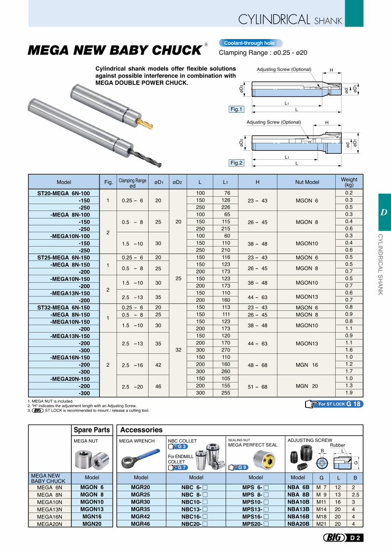
Clamping Range : ø0.25 - ø20Coolant-through hole
Cylindrical shank models offer flexible solutions against possible interference in combination with MEGA DOUBLE POWER CHUCK.
MPS 6-MPS 8-MPS10-MPS13-MPS16-MPS20-
G 9
Rubber
MEGA 6NMEGA 8NMEGA10NMEGA13NMEGA16NMEGA20N
MEGA NEW BABY CHUCK
MGON 6MGON 8MGON10MGON13MGN16MGN20
MEGA NUT
Model
Spare Parts
MGR20MGR25MGR30MGR35MGR42MGR46
NBA 6BNBA 8BNBA10BNBA13BNBA16BNBA20B
M 7M 9M11M14M18M21
121316202020
22.53444
MEGA WRENCH SEALING NUTMEGA PERFECT SEAL
ADJUSTING SCREW
G L B
B L
G
ModelModelModelModel
Accessories
NBC 6-NBC 8-NBC10-NBC13-NBC16-NBC20-
Model Fig. øD1 øD2 L L1 H Nut Model Weight(kg)
ST20-MEGA 6N-100-150-250
-MEGA 8N-100-150-250
-MEGA10N-100-150-250
ST25-MEGA 6N-150-MEGA 8N-150
-200-MEGA10N-150
-200-MEGA13N-150
-200ST32-MEGA 6N-150
-MEGA 8N-150-MEGA10N-150
-200-MEGA13N-150
-200-300
-MEGA16N-150-200-300
-MEGA20N-150-200-300
1
2
1
2
1
2
0.25 - 6
0.5 - 8
1.5 -10
0.5 - 8
1.5 -10
2.5 -13
2.5 -13
2.5 -16
2.5 -20
0.25 - 6
0.25 - 60.5 - 8
1.5 -10
23 - 43
26 - 45
38 - 48
MGON 6
MGON 8
MGON10
MGON 8
MGON10
MGON13
MGON10
MGON13
MGN 16
MGN 20
MGON 6
MGON 6MGON 8
23 - 43
26 - 45
38 - 48
44 - 63
23 - 4326 - 45
38 - 48
44 - 63
48 - 68
51 - 68
20
25
30
20
25
30
35
2025
30
35
42
46
20
25
32
100150250100150250100150250150150200150200150200150150150200150200300150200300150200300
7612622665
11521560
110210116123173123173110160113111123173120170270110160260105155255
0.20.30.50.30.40.60.30.40.60.50.50.70.50.70.60.70.80.90.81.10.91.11.61.01.21.71.01.31.9
LL1
HAdjusting Screw (Optional)
H
LL1
Adjusting Screw (Optional)
1. MEGA NUT is included.2. "H" indicates the adjustment length with an Adjusting Screw.3. ST LOCK is recommended to mount / release a cutting tool.
Fig.1
Fig.2
ødød
øD1
øD2
øD2
øD1
For ST LOCK G 18
G 3NBC COLLET
G 7
For ENDMILLCOLLET
Clamping Rangeød
R
D 2
CYLIN
DR
ICAL SH
ANK
D
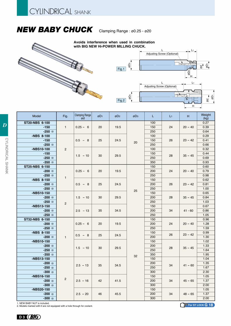
Avoids interference when used in combination with BIG NEW Hi-POWER MILLING CHUCK.
Clamping Range : ø0.25 - ø20
Model
ST20-NBS 6-100-150-250
-NBS 8-100-150-250
-NBS10-100-150-250-350
ST25-NBS 6-150-200-250
-NBS 8-150-200-250
-NBS10-150-200-250
-NBS13-150-200-250
0.25 - 6
0.5 - 8
1
2
1
2
1.5 - 10
0.25 - 6
0.5 - 8
1.5 - 10
2.5 - 13
øD1 øD2
20
25
30
20
25
30
35
19.5
24.5
29.5
19.5
24.5
29.5
34.5
øD3
20
25
L
100150250100150250100150250350150200250150200250150200250150200250
L1
24
26
28
24
26
28
34
H
20 - 40
23 - 42
35 - 45
20 - 40
23 - 42
35 - 45
41 - 60
0.270.390.640.290.410.660.320.440.690.930.600.790.980.620.811.000.650.841.030.670.861.05
Fig. Weight(kg)
1. NEW BABY NUT is included.2. Models marked with are not equipped with a hole through for coolant.
Fig.1
Fig.2
For ST LOCK G 18
Clamping Rangeød
ST32-NBS 6-150-200-250
-NBS 8-150-200
-NBS10-150-200-250-350
-NBS13-150-200-250-300
-NBS16-150-200-300
-NBS20-150-200-300
0.25 - 6
0.5 - 81
1.5 - 10
20
25
30
19.5
24.5
29.5
32
150200250150200150200250350150200250300150200300150200300
24
26
28
20 - 40
23 - 42
35 - 45
0.961.281.590.991.301.021.331.641.951.041.351.672.301.051.372.001.051.372.00
2
2.5 - 13
2.5 - 16
2.5 - 20
35
42
46
34.5
41.5
45.5
34
34
34
41 - 60
45 - 65
48 - 65
øD1
ødøD3
L1LAdjusting Screw (Optional)
H
øD2
H
ødøD
1
øD3
L1L
øD2
Adjusting Screw (Optional)
CYLIN
DR
ICAL SH
ANK
D
D 3
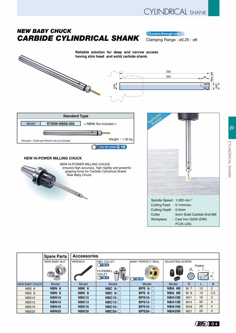
Reliable solution for deep and narrow access having slim head and solid carbide shank.
Clamping Range : ø0.25 - ø6Coolant-through hole
NEW Hi-POWER MILLING CHUCK
Remarks : Collet and Wrench are not included.
NEW Hi-POWER MILLING CHUCK ensures high accuracy, high rigidity and powerful gripping force for Carbide Cylindrical Shank New Baby Chuck.
Spindle Speed : 1,000 min-1
Cutting Feed : 0.1mm/rev.Cutting Depth : 0.5mmCutter : 5mm Solid Carbide End MillWorkpiece : Cast Iron G025 (DIN) FC25 (JIS)
Standard Type
250
224 26
ø20
Max
.ø6
ø20
Application
Example
Weight 1.20 kg
< NBN6 Nut included >Model ST20W-NBS6-250
For ST LOCK G 18
NBS 6NBS 8NBS10NBS13NBS16NBS20
NBN 6NBN 8NBN10NBN13NBN16NBN20
NEW BABY CHUCK
NEW BABY NUT
Model
Spare Parts
NBK 6NBK 8NBK10NBK13NBK16NBK20
G 10
BPS 6-BPS 8-BPS10-BPS13-BPS16-BPS20-
NBC 6-NBC 8-NBC10-NBC13-NBC16-NBC20-
WRENCH
Model Model Model
Accessories
NBA 6BNBA 8BNBA10BNBA13BNBA16BNBA20B
M 7M 9M11M14M18M21
121316202020
22.53444
ADJUSTING SCREW
G L B
BRubber
L
G
Model
BABY PERFECT SEALG 3
NBC COLLET
G 7
For ENDMILLCOLLET
D 4
CYLIN
DR
ICAL SH
ANK
D
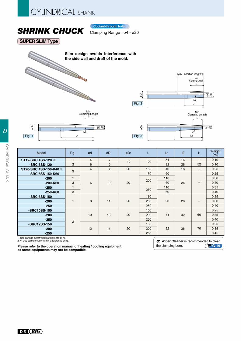
Clamping Range : ø4 - ø20Coolant-through hole
Slim design avoids interference with the side wall and draft of the mold.
SUPER SLIM Type
Model ødFig. øD1øD L1L
464
6
8
10
12
12
3
1313
1
2
797
9
11
13
15
20
20
20
20
20
0.100.100.250.250.300.300.350.400.250.300.400.250.350.400.250.350.45
162616
26
26
32
36
51324060
11060
11060
90
71
52
-52-
-
-
60
70
ST12-SRC 4SS-120-SRC 6SS-120
ST20-SRC 4SS-150-K40-SRC 6SS-150-K60
-200-200-K60-250-250-K60
-SRC 8SS-150-200-250
-SRC10SS-150-200-250
-SRC12SS-150-200-250
12 120
150150
200
250
150200250150200250150200250
L1L
Min.Clamping Length
E
øD1
øDød3°
3˚
L1L
Min.Clamping Length
E
øD1
øDød3°
3˚
L1L
Min.Clamping Length
E
øD1
øDød
Max. insertion length: H
3°
3˚
Fig. 1 Fig. 3
Fig. 2
H Weight(kg)E
Please refer to the operation manual of heating / cooling equipment, as some equipments may not be compatible.
Wiper Cleaner is recommended to clean the clamping bore. G 19
1. Use carbide cutter within a tolerance of h6.2. Use carbide cutter within a tolerance of h5.
CYLIN
DR
ICAL SH
ANK
D
D 5
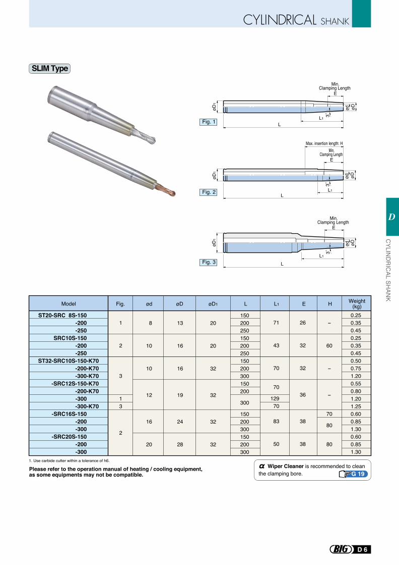
8
10
10
12
16
20
1
2
3
13
2
13
16
16
19
24
28
150200250150200250150200300150200
300
150200300150200300
20
20
32
32
32
32
0.250.350.450.250.350.450.500.751.200.550.801.201.250.600.851.300.600.851.30
26
32
32
36
38
38
71
43
70
70
12970
83
50
-
60
-
-
70
80
80
ST20-SRC 8S-150-200-250
SRC10S-150-200-250
ST32-SRC10S-150-K70-200-K70-300-K70
-SRC12S-150-K70-200-K70-300-300-K70
-SRC16S-150-200-300
-SRC20S-150-200-300
L
L
L
Min.Clamping Length
E
Min.Clamping Length
E
Min.Clamping Length
E
øD1
øD1
øD1
øDødøDød
øDød
L1
L1
L1
3˚3˚
3˚
Max. insertion length: H
SLIM Type
Fig. 1
Fig. 2
Fig. 3
Model ødFig. øD1øD L1L H Weight(kg)E
Please refer to the operation manual of heating / cooling equipment, as some equipments may not be compatible.
Wiper Cleaner is recommended to clean the clamping bore. G 19
1. Use carbide cutter within a tolerance of h6.
D 6
CYLIN
DR
ICAL SH
ANK
D
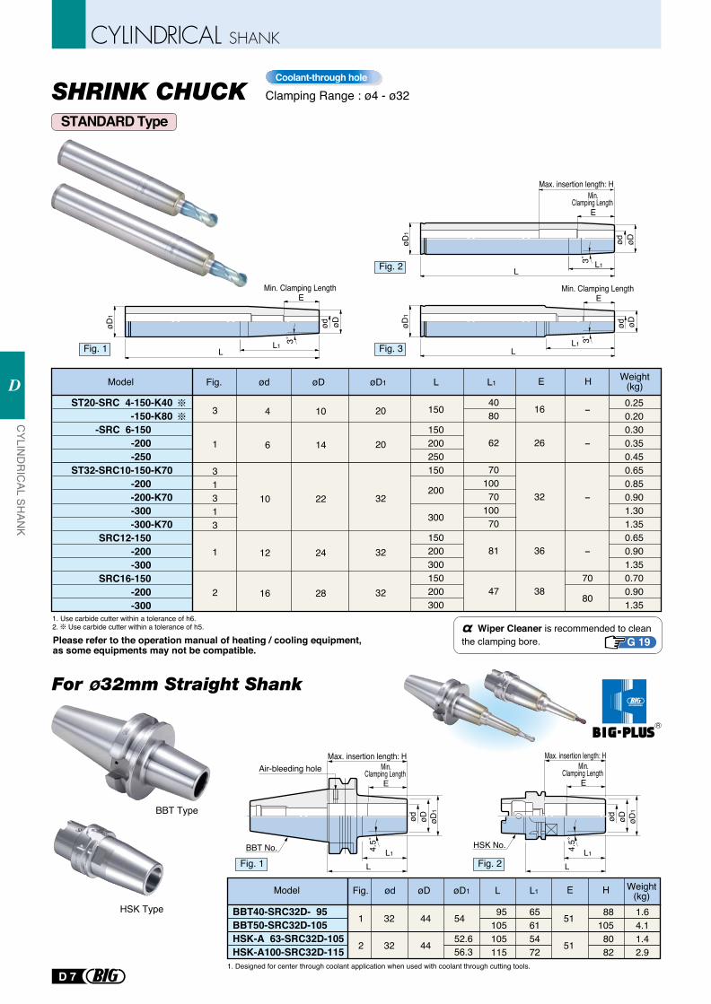
Model ødFig. øD1øD L1L
4
6
10
12
16
3
1
31313
1
2
10
14
22
24
28
20
20
32
32
32
150
150200250150
200
300
150200300150200300
0.250.200.300.350.450.650.850.901.301.350.650.901.350.700.901.35
16
26
32
36
38
4080
62
7010070
10070
81
47
-
-
-
-
70
80
ST20-SRC 4-150-K40-150-K80
-SRC 6-150-200-250
ST32-SRC10-150-K70-200-200-K70-300-300-K70
SRC12-150-200-300
SRC16-150-200-300
BBT Type
HSK Type
BBT No. L1
L
Min.Clamping Length
E
øD1
øDød
Max. insertion length: H
4.5˚
Air-bleeding hole
Model Fig. øD1øDød L1L
95105105115
65615472
881058082
1.64.11.42.9
51
51
32
32
44
44
54
52.656.3
1
2
BBT40-SRC32D- 95BBT50-SRC32D-105HSK-A 63-SRC32D-105HSK-A100-SRC32D-115
øD1
øDød
HSK No.
Min.Clamping Length
E
Max. insertion length: H
LL14.
5˚
øD1
Min. Clamping Length E
L
øDød
L1
3˚
L
Min. Clamping Length E
øD1
øDød
L1 3˚
øD1
LL1
øDød
3˚
Max. insertion length: H
R
Fig. 1 Fig. 3
Fig. 2
H Weight(kg)E
Fig. 1 Fig. 2
H Weight(kg)E
Please refer to the operation manual of heating / cooling equipment, as some equipments may not be compatible.
Wiper Cleaner is recommended to clean the clamping bore. G 19
1. Use carbide cutter within a tolerance of h6.2. Use carbide cutter within a tolerance of h5.
Min.Clamping Length
E
STANDARD Type
SHRINK CHUCK Clamping Range : ø4 - ø32Coolant-through hole
For ø32mm Straight Shank
1. Designed for center through coolant application when used with coolant through cutting tools.
CYLIN
DR
ICAL SH
ANK
D
D 7
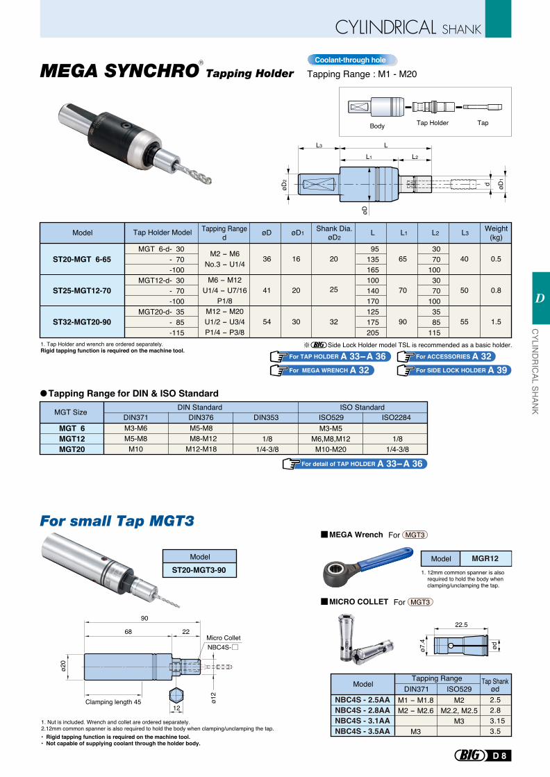
Shank Dia.øD2
øD L1L L2
ST20-MGT 6-65
ST25-MGT12-70
ST32-MGT20-90
36
41
54
16
20
30
øD1
65
70
90
40
50
55
0.5
0.8
1.5
L3
3070
1003070
1003585
115
95135165100140170125175205
M2 - M6No.3 - U1/4
M6 - M12U1/4 - U7/16
P1/8M12 - M20U1/2 - U3/4P1/4 - P3/8
20
25
32
Model
L3
øD2
L1 L2
L
d
øD
øD1
Body Tap Holder Tap
Tapping RangedTap Holder Model
1. Tap Holder and wrench are ordered separately.Rigid tapping function is required on the machine tool.
Side Lock Holder model TSL is recommended as a basic holder.For TAP HOLDER A 33- A 36 For ACCESSORIES A 32
For SIDE LOCK HOLDER A 39For MEGA WRENCH A 32
Tapping Range for DIN & ISO Standard
MGT Size DIN StandardDIN371 DIN376 DIN353 ISO529 ISO2284
ISO Standard
MGT 6MGT12MGT20
M3-M6M5-M8
M10
M5-M8 M8-M12 M12-M18
1/81/4-3/8
M3-M5M6,M8,M12M10-M20
1/81/4-3/8
For detail of TAP HOLDER A 33- A 36
MGT 6-d- 30 - 70 -100
MGT12-d- 30 - 70 -100
MGT20-d- 35 - 85 -115
Weight(kg)
Tapping Range : M1 - M20Coolant-through hole
MEGA SYNCHRO Tapping Holder
Model MGR12
1. Nut is included. Wrench and collet are ordered separately.2.12mm common spanner is also required to hold the body when clamping/unclamping the tap. • Rigid tapping function is required on the machine tool.• Not capable of supplying coolant through the holder body.
ø7.4
ød
22.5
1. 12mm common spanner is also required to hold the body when clamping/unclamping the tap.
ø20
Clamping length 45
68
90
22Micro ColletNBC4S-
ø12
12
MICRO COLLET
MEGA Wrench For MGT3
For MGT3
NBC4S - 2.5AANBC4S - 2.8AANBC4S - 3.1AANBC4S - 3.5AA
ModelTapping Range
DIN371 ISO529Tap Shank
ød2.52.83.153.5
M1 - M1.8M2 - M2.6
M3
M2M2.2, M2.5
M3
Model
ST20-MGT3-90
For small Tap MGT3
R
D 8
CYLIN
DR
ICAL SH
ANK
D
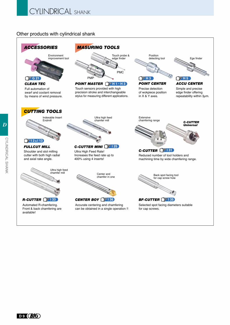
Ultra High Feed Rate!Increases the feed rate up to 400% using 4 inserts!
Shoulder and slot milling cutter with both high radial and axial rake angle.
Full automation of swarf and coolant removal by means of wind pressure.
Touch sensors provided with high precision stroke and interchangeable stylus for measuring different applications.
Precise detection of wokpiece position in X & Y axes.
Simple and precise edge finder offering repeatability within 3µm.
Reduced number of tool holders and machining time by wide chamfering range.
Accurate centering and chamfering can be obtained in a single operation !!
Selected spot facing diameters suitable for cap screws.
Ultra high feed chamfer mill
Indexable InsertEndmill
Position detecting tool
Environment improvement tool
Automated R-chamfering.Front & back chamfering are available!
Center and chamfer in one Back spot facing tool
for cap screw hole
POINT MASTER
PMP
PMC
H 1 - H 3 G 21
Other products with cylindrical shank
CUTTING TOOLS
C-CUTTER
C-CUTTER Universal
R-CUTTER CENTER BOY BF-CUTTER
MASURING TOOLSACCESSORIES
C-CUTTER MINIFULLCUT MILL
CLEAN TEC
Ultra high feed chamfer mill
Extensive chamfering range
POINT CENTER ACCU CENTER
I 33
I 25I 2 I 13&
I 31
I 36 I 35
H 3 H 5
Ege finderTouch probe & edge finder
CYLIN
DR
ICAL SH
ANK
D
D 9
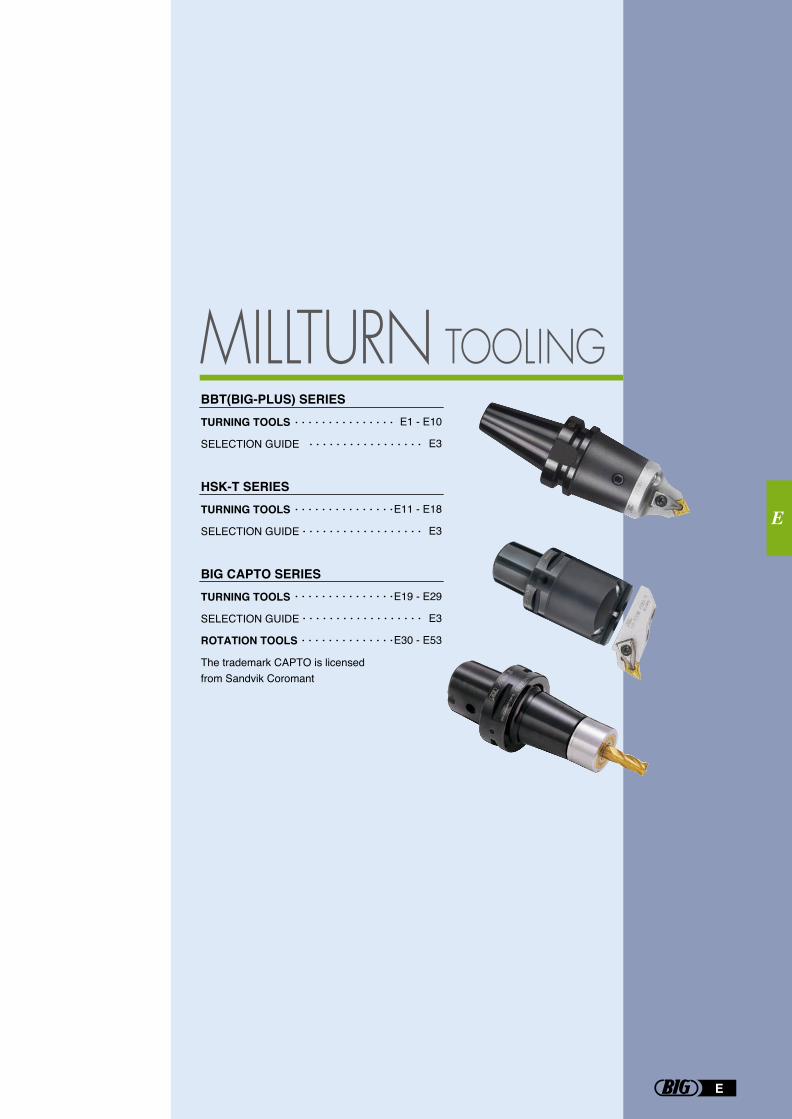
E1 - E10
E3
E11 - E18
E3
E19 - E29
E3
E30 - E53
E
E
MILLTURN TOOLINGTURNING TOOLS
SELECTION GUIDE
TURNING TOOLS
SELECTION GUIDE
TURNING TOOLS
SELECTION GUIDE
ROTATION TOOLS
The trademark CAPTO is licensed from Sandvik Coromant
BBT(BIG-PLUS) SERIES
HSK-T SERIES
BIG CAPTO SERIES
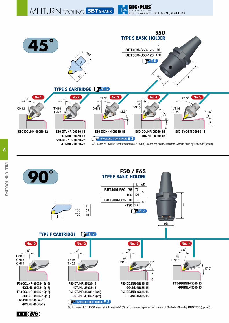
BBT40M-F50- 75-105
BBT50M-F63- 70-130
Lø50
L
L øD
f3545
F50F63
øD
7510570130
50
63
BBT40M-S50- 75BBT50M-S50-120
L75120
50
ø50
f
5˚
CN12
3˚
TN16TN22
17.5˚
DN1512.5˚
DN15
3˚
27˚
6
27.5˚
25˚
5
VB16VC16
S50-DCLNN-00050-12 S50-DDHNN-00050-15 S50-DDJNR-00050-15-DDJNL-00050-15
S50-DTJNR-00050-16-DTJNL-00050-16
S50-DTJNR-00050-22-DTJNL-00050-22
S50-SVQBN-00050-16
No.1 No.2 No.3 No.4 No.5
F50 / F63
F50-DCLNR-35035-12(16)-DCLNL-35035-12(16)
F63-DCLNR-45035-12(16)-DCLNL-45035-12(16)
F63-PCLNR-45045-19-PCLNL-45045-19
F50-DTJNR-35035-16 -DTJNL-35035-16F63-DTJNR-45035-16(22) -DTJNL-45035-16(22)
F50-DDJNR-35035-15-DDJNL-35035-15
F63-DDJNR-45035-15-DDJNL-45035-15
F63-DDHNR-45040-15-DDHNL-45040-15
CN12CN16CN19
5˚
TN16TN22
3˚
DN15
3˚
27˚
6
17.5˚
17.5˚
DN15
No.10 No.12 No.13 No.14
E 5
For SELECTION GUIDE E 3
E 7
E 7
For SELECTION GUIDE E 3
E 6
In case of DN1506 insert (thickness of 6.35mm), please replace the standard Carbide Shim by DNS1506 (option).
In case of DN1506 insert (thickness of 6.35mm), please replace the standard Carbide Shim by DNS1506 (option).
E 1
MILLTU
RN
TOO
LING
E
JIS B 6339 (BIG-PLUS)BBT SHANKMILLTURN TOOLING
R
S P I N D L E S Y S T E M
D U A L C O N T A C T
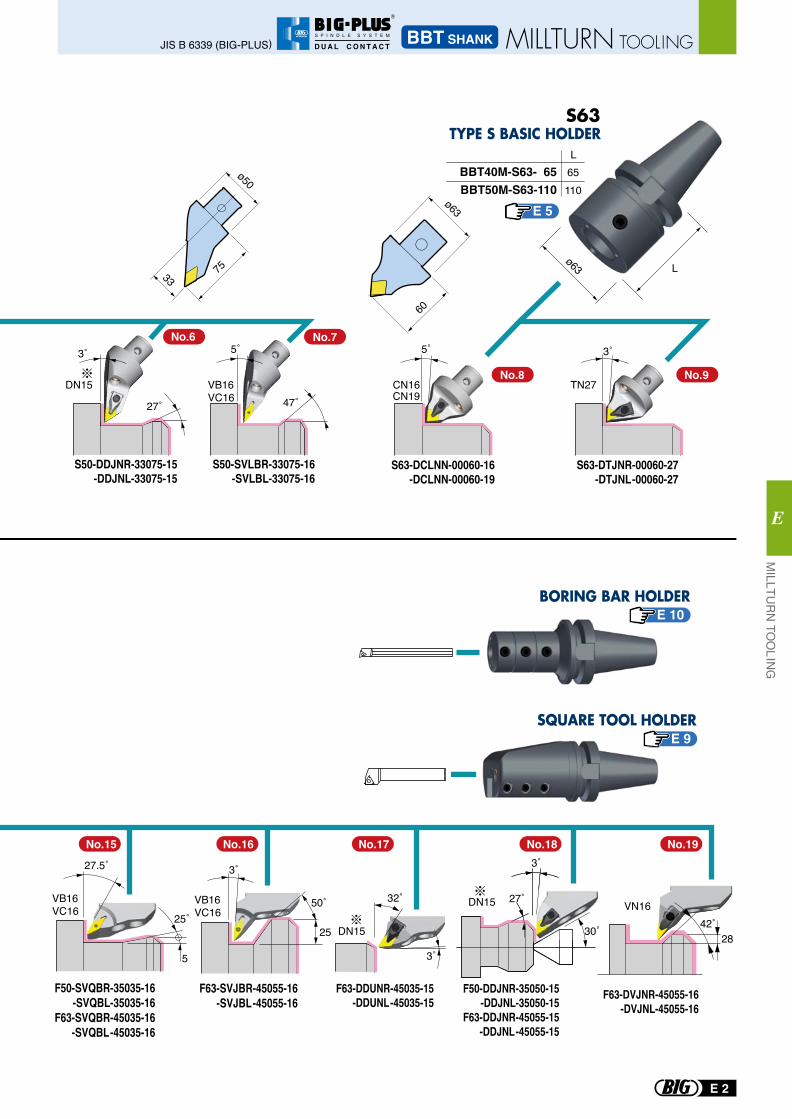
Lø6375
ø50
33
BBT40M-S63- 65BBT50M-S63-110
L65110
60
ø63
F63-DVJNR-45055-16-DVJNL-45055-16
VN1642˚
28
CN16CN19
5˚ 3˚
TN27
S63-DCLNN-00060-16-DCLNN-00060-19
S63-DTJNR-00060-27-DTJNL-00060-27
No.6 No.7
No.8 No.9
S50-DDJNR-33075-15-DDJNL-33075-15
S50-SVLBR-33075-16-SVLBL-33075-16
3˚
27˚
DN15
5˚
47˚VB16VC16
50˚VB16VC16
3˚
25
27.5˚
25˚
5
VB16VC16
DN15
3˚
27˚
30˚
3˚
32˚
DN15
F50-DDJNR-35050-15-DDJNL-35050-15
F63-DDJNR-45055-15-DDJNL-45055-15
F63-SVJBR-45055-16-SVJBL-45055-16
F50-SVQBR-35035-16-SVQBL-35035-16
F63-SVQBR-45035-16-SVQBL-45035-16
F63-DDUNR-45035-15-DDUNL-45035-15
No.16No.15 No.18 No.19No.17
E 5
E 10
E 9
E 2
MILLTU
RN
TOO
LING
E
BBT SHANKJIS B 6339 (BIG-PLUS) MILLTURN TOOLING
R
S P I N D L E S Y S T E M
D U A L C O N T A C T
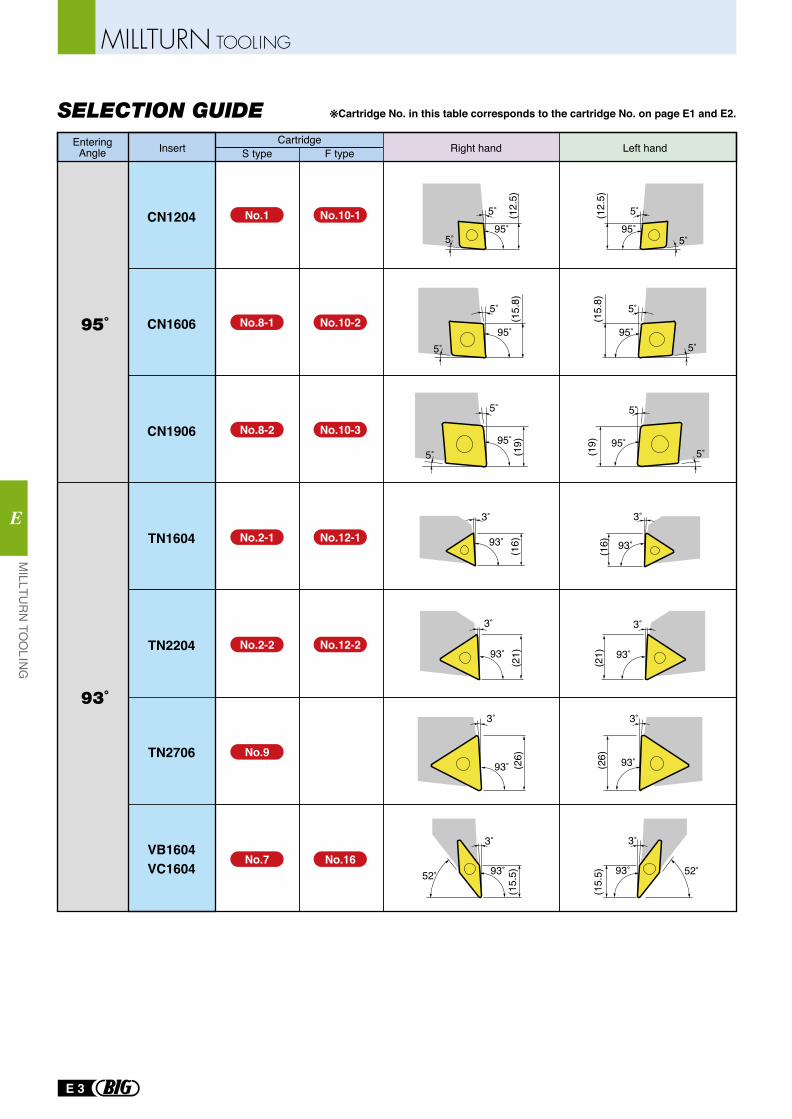
SELECTION GUIDE ※Cartridge No. in this table corresponds to the cartridge No. on page E1 and E2.
95˚
(12.
5)
5˚
5˚95˚
(12.
5)
5˚
5˚
95˚
(15.
8)
5˚
5˚
95˚
(15.
8)
5˚
5˚
95˚
(19)
5˚
5˚
95˚
(19)
5˚
5˚
93˚
(16)
3˚
93˚(16)
3˚
93˚
(21)
3˚
93˚
(21)
3˚
93˚ (26)
3˚
(26) 93˚
3˚
52˚ 93˚
3˚
(15.
5) 52˚93˚
3˚
(15.
5)
EnteringAngle Right hand Left hand
CartridgeS type F typeInsert
95˚
93˚
CN1204
CN1606
CN1906
TN1604
TN2204
TN2706
VB1604VC1604
No.1
No.8-1
No.2-1
No.2-2
No.9
No.7
No.10-1
No.10-2
No.8-2 No.10-3
No.12-1
No.12-2
No.16
E 3
MILLTURN TOOLING
MILLTU
RN
TOO
LING
E
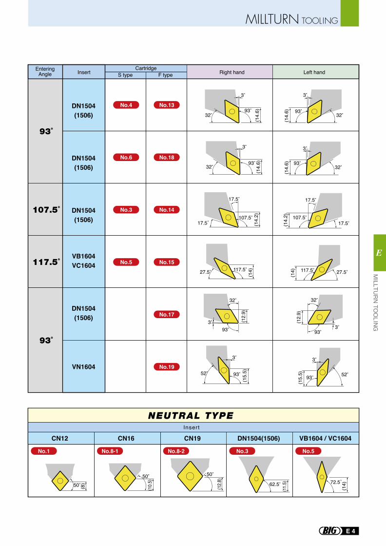
52˚ 93˚
(15.
5)
3˚
32˚93˚
(14.
6)
3˚
(14.
6) 32˚93˚
3˚
32˚
93˚3˚ (1
2.9)
(14.
6)
3˚
32˚93˚
(14.
6)
3˚
32˚93˚
17.5˚107.5˚
(14.
2)
17.5˚
(14.
2)
17.5˚107.5˚
17.5˚
52˚93˚
(15.
5)
3˚
(12.
9)32˚
93˚3˚
27.5˚117.5˚
(14)27.5˚ 117.5˚
(14)
62.5˚
(11.5) 72.5˚
(14)50˚ (8)
(10.5
)50˚
(12.8
)
50˚
NEUTRAL TYPE
EnteringAngle Right hand Left hand
CartridgeS type F typeInsert
93˚
107.5˚
117.5˚
93˚
DN1504(1506)
DN1504(1506)
DN1504(1506)
VB1604VC1604
DN1504(1506)
VN1604
CN12 CN16 CN19 DN1504(1506) VB1604 / VC1604
No.4
No.6
No.3
No.5
No.13
No.18
No.14
No.15
No.17
No.19
No.1 No.8-1 No.8-2 No.3 No.5
Insert
E 4
MILLTURN TOOLINGM
ILLTUR
N TO
OLING
E
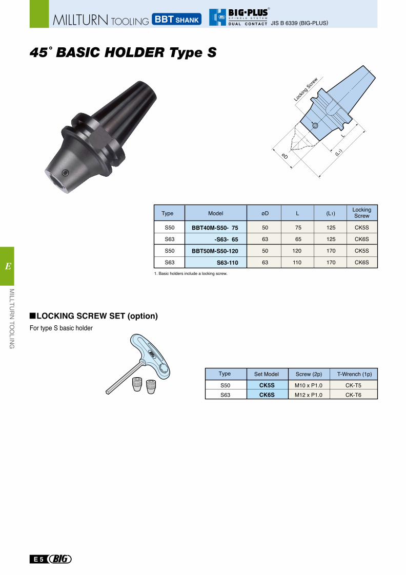
For type S basic holder
Type Set Model Screw (2p) T-Wrench (1p)
S50S63
CK5SCK6S
M10 x P1.0M12 x P1.0
CK-T5CK-T6
LOCKING SCREW SET (option)
BBT40M-S50- 75
-S63- 65
BBT50M-S50-120
S63-110
S50
S63
S50
S63
75
65
120
110
125
125
170
170
50
63
50
63
Type Model øD L (L1) LockingScrew
CK5S
CK6S
CK5S
CK6S
(L1)
Locki
ng Scre
w
L
øD
45˚ BASIC HOLDER Type S
1. Basic holders include a locking screw.
E 5
MILLTU
RN
TOO
LING
E
JIS B 6339 (BIG-PLUS)BBT SHANKMILLTURN TOOLING
R
S P I N D L E S Y S T E M
D U A L C O N T A C T
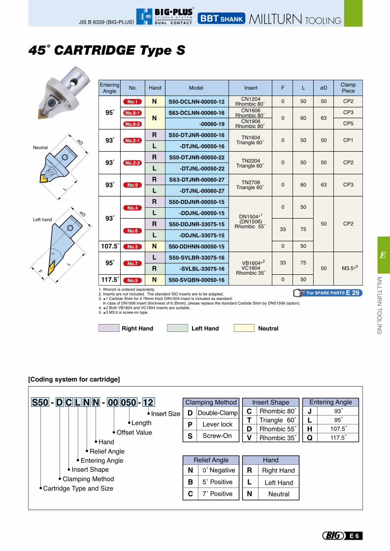
45˚ CARTRIDGE Type S
For SPARE PARTS E 29
S50 - D C L N N - 00 050 - 12
[Coding system for cartridge]
NBC
Right Hand
Left Hand
RLN
Relief Angle Hand
Neutral
Rhombic 80˚Triangle 60˚Rhombic 55˚Rhombic 35˚
CTDV
Double-ClampLever lock
Clamping Method Insert ShapeDP
Screw-OnS
JLH
93˚95˚
107.5˚117.5˚Q
Entering AngleInsert Size
LengthOffset Value
HandRelief Angle
Entering AngleInsert Shape
Clamping MethodCartridge Type and Size
L
LF
Left hand
Neutral
NeutralRight Hand Left Hand
1. Wrench is ordered separately.2. Inserts are not included. The standard ISO inserts are to be adapted. 3. *1 Carbide Shim for 4.76mm thick DIN1504 insert is included as standard. In case of DN1506 insert (thickness of 6.35mm), please replace the standard Carbide Shim by DNS1506 (option). 4. *2 Both VB1604 and VC1604 inserts are suitable.5. *3 M3.5 is screw-on type.
HandNo. Model Insert F L øD ClampPiece
EnteringAngle
N
N
RLRLRLRLRLNLRN
S50-DCLNN-00050-12
S63-DCLNN-00060-16
-00060-19
S50-DTJNR-00050-16
-DTJNL-00050-16
S50-DTJNR-00050-22
-DTJNL-00050-22
S63-DTJNR-00060-27
-DTJNL-00060-27
S50-DDJNR-00050-15
-DDJNL-00050-15
S50-DDJNR-33075-15
-DDJNL-33075-15
S50-DDHNN-00050-15
S50-SVLBR-33075-16
-SVLBL-33075-16
S50-SVQBN-00050-16
95˚
93˚
93˚
93˚
93˚
107.5˚
95˚
117.5˚
0
0
0
0
0
0
33
0
33
0
50
60
50
50
60
50
75
50
75
50
50
63
50
50
63
50
50
CP2
CP3
CP5
CP1
CP2
CP3
CP2
M3.5*3
TN1604Triangle 60˚
TN2204Triangle 60˚
TN2706Triangle 60˚
DN1504*1
(DN1506)Rhombic 55˚
VB1604*2
VC1604Rhombic 35˚
CN1204Rhombic 80˚
CN1606Rhombic 80˚
CN1906Rhombic 80˚
No.1
No.8-1
No.8-2
No.2-1
No.2-2
No.9
No.4
No.6
No.3
No.7
No.5
E 6
MILLTU
RN
TOO
LING
E
BBT SHANKJIS B 6339 (BIG-PLUS) MILLTURN TOOLING
R
S P I N D L E S Y S T E M
D U A L C O N T A C T
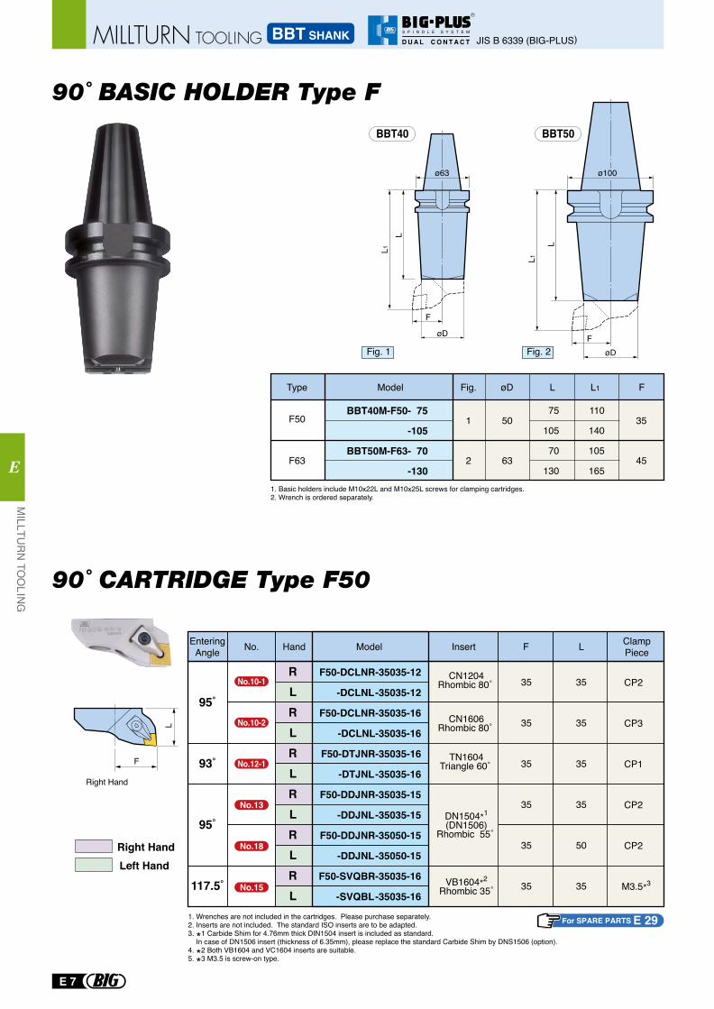
90˚ BASIC HOLDER Type F
90˚ CARTRIDGE Type F50
50
F63
F50 351
63 452
75
105
70
130
110
140
105
165
BBT40M-F50- 75
-105
BBT50M-F63- 70
-130
Type Model øDFig. L L1 F
1. Basic holders include M10x22L and M10x25L screws for clamping cartridges.2. Wrench is ordered separately.
BBT50
L
F
L1
øD
ø100
øD
BBT40
F
L1
ø63
L
Fig. 1 Fig. 2
For SPARE PARTS E 29
L
F
Right Hand
HandNo. Model Insert F L EnteringAngle
RLRLRLRLRLRL
F50-DCLNR-35035-12
-DCLNL-35035-12
F50-DCLNR-35035-16
-DCLNL-35035-16
F50-DTJNR-35035-16
-DTJNL-35035-16
F50-DDJNR-35035-15
-DDJNL-35035-15
F50-DDJNR-35050-15
-DDJNL-35050-15
F50-SVQBR-35035-16
-SVQBL-35035-16
95˚
93˚
95˚
117.5˚
35
35
35
35
35
35
35
35
35
35
50
35
CP2
CP3
CP1
CP2
CP2
M3.5*3
ClampPiece
TN1604Triangle 60˚
DN1504*1
(DN1506)Rhombic 55˚
VB1604*2
Rhombic 35˚
CN1204Rhombic 80˚
CN1606Rhombic 80˚
Right HandLeft Hand
1. Wrenches are not included in the cartridges. Please purchase separately.2. Inserts are not included. The standard ISO inserts are to be adapted. 3. *1 Carbide Shim for 4.76mm thick DIN1504 insert is included as standard. In case of DN1506 insert (thickness of 6.35mm), please replace the standard Carbide Shim by DNS1506 (option). 4. *2 Both VB1604 and VC1604 inserts are suitable.5. *3 M3.5 is screw-on type.
No.10-1
No.10-2
No.12-1
No.13
No.18
No.15
E 7
MILLTU
RN
TOO
LING
E
JIS B 6339 (BIG-PLUS)BBT SHANKMILLTURN TOOLING
R
S P I N D L E S Y S T E M
D U A L C O N T A C T
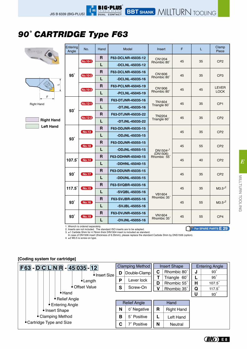
90˚ CARTRIDGE Type F63
For SPARE PARTS E 29
L
F
Right Hand
HandNo. Model Insert F L EnteringAngle
RLRLRLRLRLRLRLRLRLRLRLRL
F63-DCLNR-45035-12
-DCLNL-45035-12
F63-DCLNR-45035-16
-DCLNL-45035-16
F63-PCLNR-45045-19
-PCLNL-45045-19
F63-DTJNR-45035-16
-DTJNL-45035-16
F63-DTJNR-45035-22
-DTJNL-45035-22
F63-DDJNR-45035-15
-DDJNL-45035-15
F63-DDJNR-45055-15
-DDJNL-45055-15
F63-DDHNR-45040-15
-DDHNL-45040-15
F63-DDUNR-45035-15
-DDUNL-45035-15
F63-SVQBR-45035-16
-SVQBL-45035-16
F63-SVJBR-45055-16
-SVJBL-45055-16
F63-DVJNR-45055-16
-DVJNL-45055-16
95˚
93˚
93˚
107.5˚
93˚
117.5˚
93˚
93˚
45
45
45
45
45
45
45
45
45
45
45
45
35
35
45
35
35
35
55
40
35
35
55
55
CP2
CP3
LEVERLOCK
CP1
CP2
CP2
CP2
CP2
CP2
M3.5*2
M3.5*2
CP4
TN1604Triangle 60˚
TN2204Triangle 60˚
DN1504*1
(DN1506)Rhombic 55˚
VN1604Rhombic 35˚
VB1604Rhombic 35˚
F63 - D C L N R - 45 035 - 12[Coding system for cartridge]
NBC
Right Hand
Left Hand
RLN
Relief Angle Hand
Neutral
Rhombic 80˚Triangle 60˚Rhombic 55˚Rhombic 35˚
CTDV
Double-ClampLever lock
Clamping Method Insert ShapeDP
Screw-OnS
JLHQU
Entering Angle
Insert SizeLength
Offset ValueHand
Relief AngleEntering Angle
Insert ShapeClamping Method
Cartridge Type and Size
CN1204Rhombic 80˚
CN1606Rhombic 80˚
CN1906Rhombic 80˚
ClampPiece
1. Wrench is ordered separately.2. Inserts are not included. The standard ISO inserts are to be adapted. 3. *1 Carbide Shim for 4.76mm thick DIN1504 insert is included as standard. In case of DN1506 insert (thickness of 6.35mm), please replace the standard Carbide Shim by DNS1506 (option). 4. *2 M3.5 is screw-on type.
93˚95˚
107.5˚117.5˚
93˚
Right HandLeft Hand
No.10-1
No.10-2
No.10-3
No.12-1
No.12-2
No.13
No.18
No.14
No.17
No.15
No.16
No.19
E 8
MILLTU
RN
TOO
LING
E
BBT SHANKJIS B 6339 (BIG-PLUS) MILLTURN TOOLING
R
S P I N D L E S Y S T E M
D U A L C O N T A C T
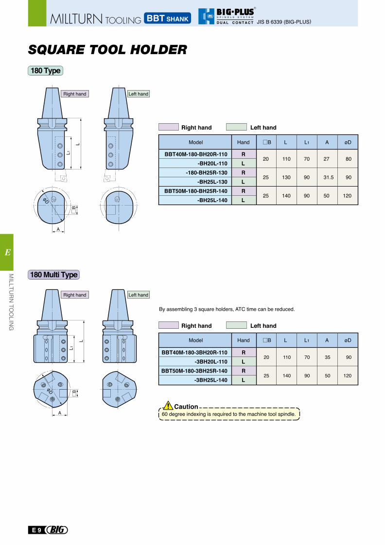
SQUARE TOOL HOLDER
By assembling 3 square holders, ATC time can be reduced.
L
L1B
A
φD
Model Hand A
20
25
25
110
130
140
70
90
90
27
31.5
50
B øD
80
90
120
BBT40M-180-BH20R-110-BH20L-110
-180-BH25R-130-BH25L-130
BBT50M-180-BH25R-140-BH25L-140
RLRLRL
L L1
Right hand Left hand
Right hand Left hand
20
25
110
140
70
90
35
50
90
120
BBT40M-180-3BH20R-110-3BH20L-110
BBT50M-180-3BH25R-140-3BH25L-140
RLRL
B
A
L
L1
φD
180 Type
180 Multi Type
Right hand Left hand
Right hand Left hand
Model Hand AB øDL L1
60 degree indexing is required to the machine tool spindle.Caution
E 9
MILLTU
RN
TOO
LING
E
JIS B 6339 (BIG-PLUS)BBT SHANKMILLTURN TOOLING
R
S P I N D L E S Y S T E M
D U A L C O N T A C T
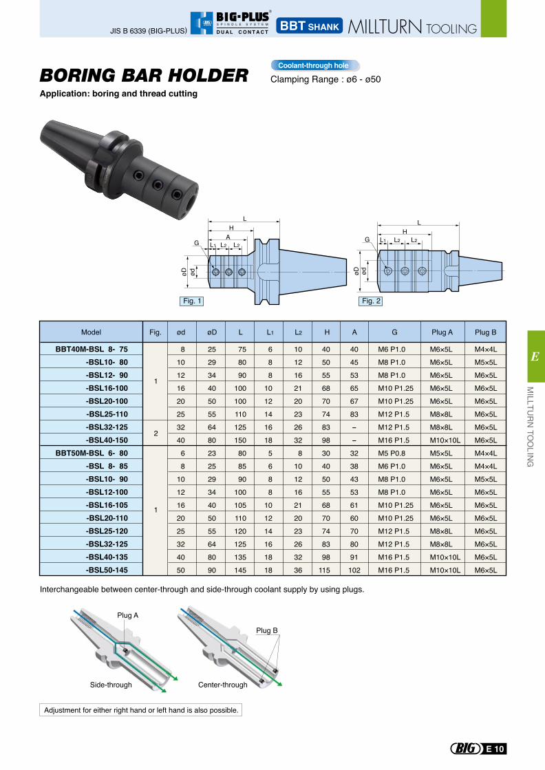
M6 P1.0M8 P1.0M8 P1.0M10 P1.25M10 P1.25M12 P1.5M12 P1.5M16 P1.5M5 P0.8M6 P1.0M8 P1.0M8 P1.0M10 P1.25M10 P1.25M12 P1.5M12 P1.5M16 P1.5M16 P1.5
688
10121416185688
101214161818
81012162025324068
1012162025324050
252934405055648023252934405055648090
758090
100100110125150808590
100105110120125135145
10121621202326328
101216212023263236
4050556870748398304050556870748398
115
M4×4LM5×5LM6×5LM6×5LM6×5LM6×5LM6×5LM6×5LM4×4LM4×4LM5×5LM6×5LM6×5LM6×5LM6×5LM6×5LM6×5LM6×5L
M6×5LM6×5LM6×5LM6×5LM6×5LM8×8LM8×8LM10×10LM5×5LM6×5LM6×5LM6×5LM6×5LM6×5LM8×8LM8×8LM10×10LM10×10L
BBT40M-BSL 8- 75-BSL10- 80-BSL12- 90-BSL16-100-BSL20-100-BSL25-110-BSL32-125-BSL40-150
BBT50M-BSL 6- 80-BSL 8- 85-BSL10- 90-BSL12-100-BSL16-105-BSL20-110-BSL25-120-BSL32-125-BSL40-135-BSL50-145
1
1
2
404553656783--323843536160708091102
Center-throughSide-through
Plug B
Plug A
L2L2L1A
ødøD
HL
G L2L2L1
ødøD
HL
G
Fig. 1 Fig. 2
Model G Plug A Plug BL AHL1 L2Fig. ød øD
Interchangeable between center-through and side-through coolant supply by using plugs.
Adjustment for either right hand or left hand is also possible.
Application: boring and thread cuttingBORING BAR HOLDER Clamping Range : ø6 - ø50
Coolant-through hole
E 10
MILLTU
RN
TOO
LING
E
BBT SHANKJIS B 6339 (BIG-PLUS) MILLTURN TOOLING
R
S P I N D L E S Y S T E M
D U A L C O N T A C T
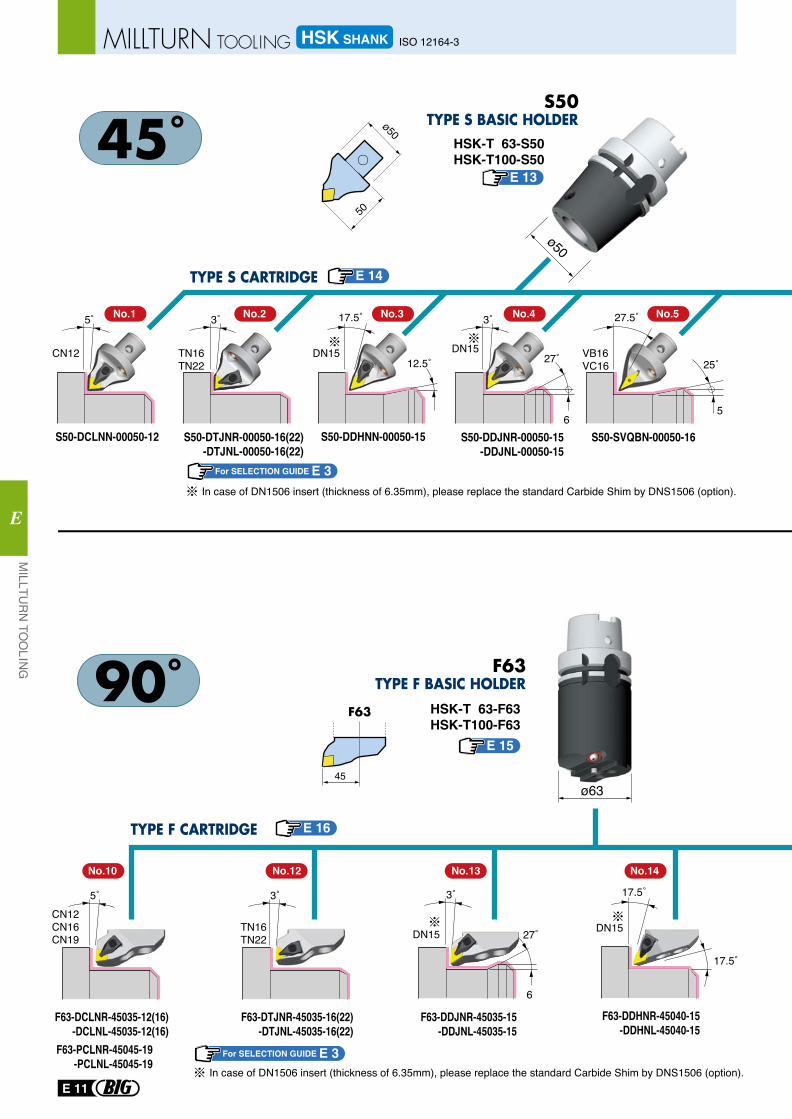
CN12CN16CN19
TN16TN22 DN15
S50-DCLNN-00050-12 S50-DDHNN-00050-15 S50-DDJNR-00050-15-DDJNL-00050-15
S50-DTJNR-00050-16(22)-DTJNL-00050-16(22)
F63-PCLNR-45045-19 -PCLNL-45045-19
F63-DCLNR-45035-12(16)-DCLNL-45035-12(16)
F63-DTJNR-45035-16(22)-DTJNL-45035-16(22)
F63-DDJNR-45035-15-DDJNL-45035-15
5˚
5˚
3˚
3˚
17.5˚
CN12 TN16TN22
DN15 DN15
3˚
27˚
6
3˚
27˚
6
S50-SVQBN-00050-16
27.5˚
25˚
5
VB16VC1612.5˚
ø50
HSK-T 63-F63HSK-T100-F63
HSK-T 63-S50HSK-T100-S50
In case of DN1506 insert (thickness of 6.35mm), please replace the standard Carbide Shim by DNS1506 (option).
In case of DN1506 insert (thickness of 6.35mm), please replace the standard Carbide Shim by DNS1506 (option).
F63-DDHNR-45040-15-DDHNL-45040-15
17.5˚
17.5˚
DN15
ø63
50
ø50
45
F63
No.1 No.2 No.3 No.4 No.5
No.10 No.12 No.13 No.14
F63
For SELECTION GUIDE E 3
For SELECTION GUIDE E 3
E 16
E 13
E 14
E 15
E 11
MILLTU
RN
TOO
LING
E
HSK SHANK ISO 12164-3MILLTURN TOOLING
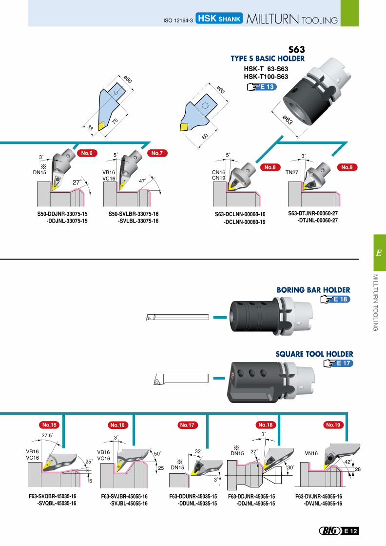
S50-DDJNR-33075-15-DDJNL-33075-15
S50-SVLBR-33075-16-SVLBL-33075-16
S63-DCLNN-00060-16-DCLNN-00060-19
F63-DDJNR-45055-15-DDJNL-45055-15
F63-DVJNR-45055-16-DVJNL-45055-16
3˚
27˚
S63-DTJNR-00060-27-DTJNL-00060-27
3˚
TN27DN15 CN16CN19
5˚
47˚
5˚
VB16VC16
F63-SVQBR-45035-16-SVQBL-45035-16
27.5˚
25˚
5
VB16VC16
ø6375
ø50
33
HSK-T 63-S63HSK-T100-S63
DN15 VN16
3˚
27˚
30˚
No.16 No.17
3˚
32˚
F63-DDUNR-45035-15-DDUNL-45035-15
DN15
50˚VB16VC16
3˚
25
F63-SVJBR-45055-16-SVJBL-45055-16
60
ø63
42˚28
No.6
No.15 No.18 No.19
No.7
No.8 No.9
E 13
E 18
E 17
E 12
MILLTU
RN
TOO
LING
E
HSK SHANKISO 12164-3 MILLTURN TOOLING
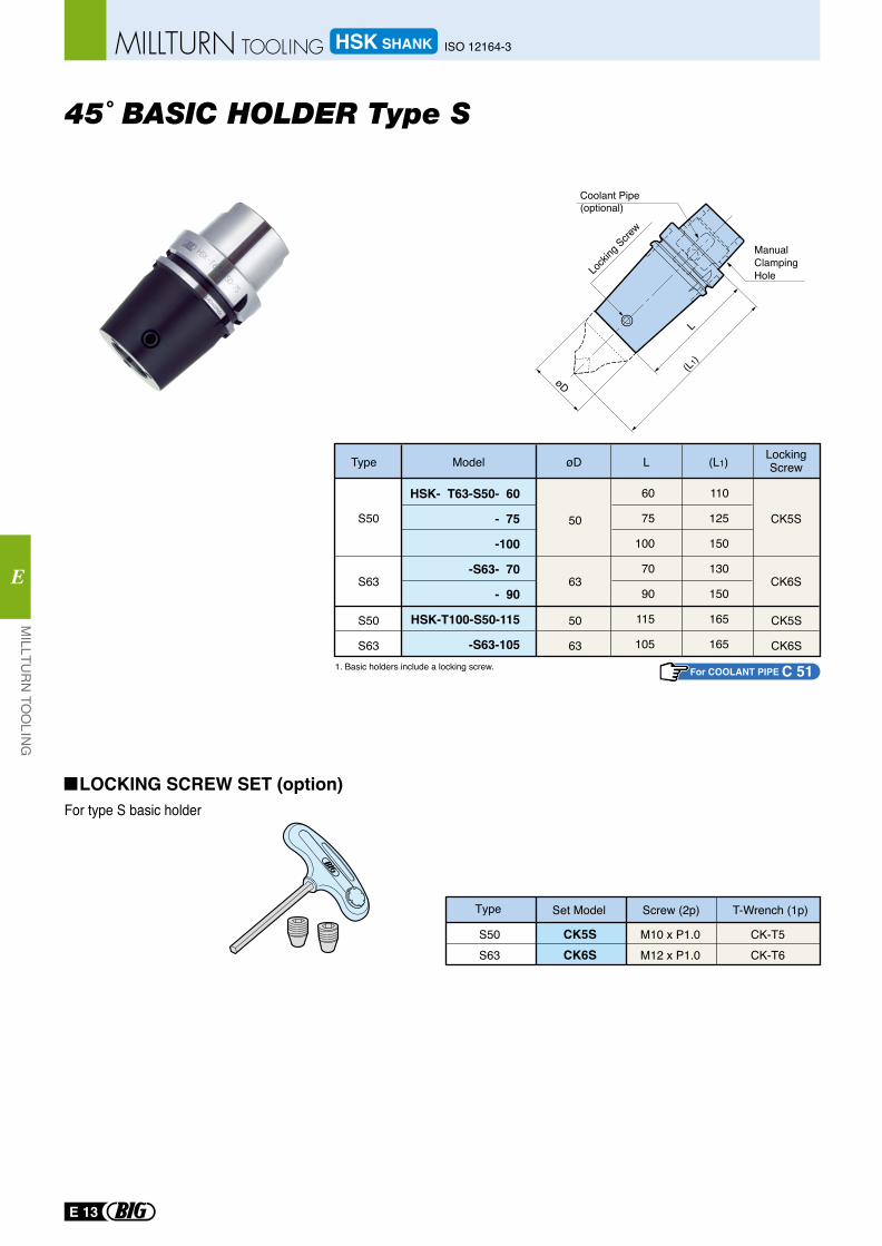
45˚ BASIC HOLDER Type S
S50
S63
S50
S63
60
75
100
70
90
115
105
110
125
150
130
150
165
165
63
50
Type Model øD L (L1) LockingScrew
CK6S
CK5S
L
(L1)
øD
Coolant Pipe(optional)
ManualClampingHole
For type S basic holder
Type Set Model Screw (2p) T-Wrench (1p)
S50S63
CK5SCK6S
M10 x P1.0M12 x P1.0
CK-T5CK-T6
LOCKING SCREW SET (option)
1. Basic holders include a locking screw.
Locki
ng Scre
w
HSK- T63-S50- 60
- 75
-100
-S63- 70
- 90
HSK-T100-S50-115
-S63-105
CK5S
CK6S
50
63
For COOLANT PIPE C 51
E 13
MILLTU
RN
TOO
LING
E
HSK SHANK ISO 12164-3MILLTURN TOOLING
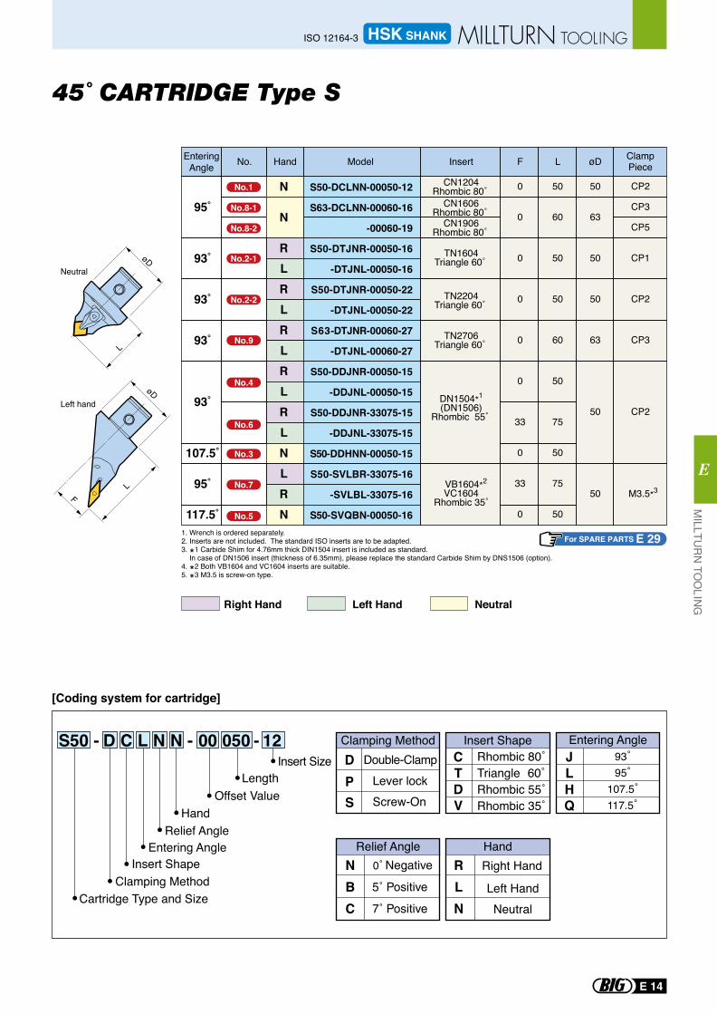
45˚ CARTRIDGE Type S
S50 - D C L N N - 00 050 - 12
[Coding system for cartridge]
NBC
Right Hand
Left Hand
RLN
Relief Angle Hand
Neutral
Rhombic 80˚Triangle 60˚Rhombic 55˚Rhombic 35˚
CTDV
Double-ClampLever lock
Clamping Method Insert ShapeDP
Screw-OnS
JLH
93˚95˚
107.5˚117.5˚Q
Entering AngleInsert Size
LengthOffset Value
HandRelief Angle
Entering AngleInsert Shape
Clamping MethodCartridge Type and Size
L
LF
Left hand
Neutral
NeutralRight Hand Left Hand
For SPARE PARTS E 291. Wrench is ordered separately.2. Inserts are not included. The standard ISO inserts are to be adapted. 3. *1 Carbide Shim for 4.76mm thick DIN1504 insert is included as standard. In case of DN1506 insert (thickness of 6.35mm), please replace the standard Carbide Shim by DNS1506 (option). 4. *2 Both VB1604 and VC1604 inserts are suitable.5. *3 M3.5 is screw-on type.
HandNo. Model Insert F L øD ClampPiece
EnteringAngle
N
N
RLRLRLRLRLNLRN
S50-DCLNN-00050-12
S63-DCLNN-00060-16
-00060-19
S50-DTJNR-00050-16
-DTJNL-00050-16
S50-DTJNR-00050-22
-DTJNL-00050-22
S63-DTJNR-00060-27
-DTJNL-00060-27
S50-DDJNR-00050-15
-DDJNL-00050-15
S50-DDJNR-33075-15
-DDJNL-33075-15
S50-DDHNN-00050-15
S50-SVLBR-33075-16
-SVLBL-33075-16
S50-SVQBN-00050-16
95˚
93˚
93˚
93˚
93˚
107.5˚
95˚
117.5˚
0
0
0
0
0
0
33
0
33
0
50
60
50
50
60
50
75
50
75
50
50
63
50
50
63
50
50
CP2
CP3
CP5
CP1
CP2
CP3
CP2
M3.5*3
TN1604Triangle 60˚
TN2204Triangle 60˚
TN2706Triangle 60˚
DN1504*1
(DN1506)Rhombic 55˚
VB1604*2
VC1604Rhombic 35˚
CN1204Rhombic 80˚
CN1606Rhombic 80˚
CN1906Rhombic 80˚
No.1
No.8-1
No.8-2
No.2-1
No.2-2
No.9
No.4
No.6
No.3
No.7
No.5
E 14
MILLTU
RN
TOO
LING
E
HSK SHANKISO 12164-3 MILLTURN TOOLING
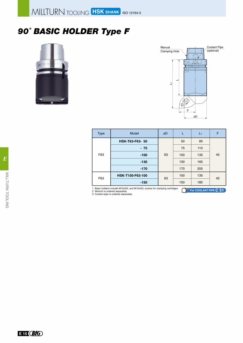
90˚ BASIC HOLDER Type F
63F63 45
50
75
100
130
170
100
150
85
110
135
165
205
135
185
HSK-T63-F63- 50
- 75
-100
-130
-170
HSK-T100-F63-100
-150
Type Model øD L L1 F
1. Basic holders include M10x22L and M10x25L screws for clamping cartridges.2. Wrench is ordered separately.3. Coolant pipe is ordered separately.
L1
L
F
øD
ManualClamping Hole
Coolant Pipe(optional)
63F63 45
For COOLANT PIPE C 51
E 15
MILLTU
RN
TOO
LING
E
HSK SHANK ISO 12164-3MILLTURN TOOLING
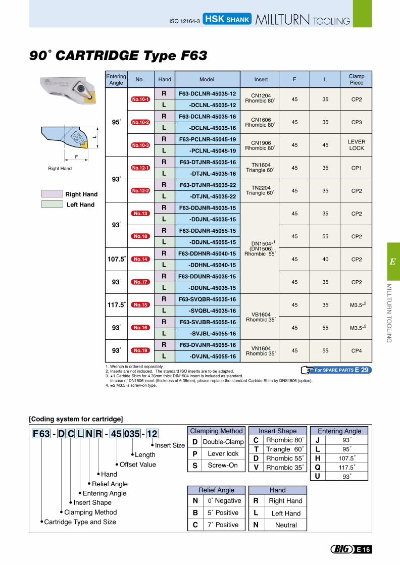
90˚ CARTRIDGE Type F63
L
F
Right Hand
F63 - D C L N R - 45 035 - 12
For SPARE PARTS E 29
HandNo. Model Insert F L EnteringAngle
RLRLRLRLRLRLRLRLRLRLRLRL
F63-DCLNR-45035-12
-DCLNL-45035-12
F63-DCLNR-45035-16
-DCLNL-45035-16
F63-PCLNR-45045-19
-PCLNL-45045-19
F63-DTJNR-45035-16
-DTJNL-45035-16
F63-DTJNR-45035-22
-DTJNL-45035-22
F63-DDJNR-45035-15
-DDJNL-45035-15
F63-DDJNR-45055-15
-DDJNL-45055-15
F63-DDHNR-45040-15
-DDHNL-45040-15
F63-DDUNR-45035-15
-DDUNL-45035-15
F63-SVQBR-45035-16
-SVQBL-45035-16
F63-SVJBR-45055-16
-SVJBL-45055-16
F63-DVJNR-45055-16
-DVJNL-45055-16
95˚
93˚
93˚
107.5˚
93˚
117.5˚
93˚
93˚
45
45
45
45
45
45
45
45
45
45
45
45
35
35
45
35
35
35
55
40
35
35
55
55
CP2
CP3
LEVERLOCK
CP1
CP2
CP2
CP2
CP2
CP2
M3.5*2
M3.5*2
CP4
TN1604Triangle 60˚
TN2204Triangle 60˚
DN1504*1
(DN1506)Rhombic 55˚
VN1604Rhombic 35˚
VB1604Rhombic 35˚
CN1204Rhombic 80˚
CN1606Rhombic 80˚
CN1906Rhombic 80˚
ClampPiece
1. Wrench is ordered separately.2. Inserts are not included. The standard ISO inserts are to be adapted. 3. *1 Carbide Shim for 4.76mm thick DIN1504 insert is included as standard. In case of DN1506 insert (thickness of 6.35mm), please replace the standard Carbide Shim by DNS1506 (option). 4. *2 M3.5 is screw-on type.
No.10-1
No.10-2
No.10-3
No.12-1
No.12-2
No.13
No.18
No.14
No.17
No.15
No.16
No.19
[Coding system for cartridge]
NBC
Right Hand
Left Hand
RLN
Relief Angle Hand
Neutral
Rhombic 80˚Triangle 60˚Rhombic 55˚Rhombic 35˚
CTDV
Double-ClampLever lock
Clamping Method Insert ShapeDP
Screw-OnS
JLHQU
Entering Angle
Insert SizeLength
Offset ValueHand
Relief AngleEntering Angle
Insert ShapeClamping Method
Cartridge Type and Size
93˚95˚
107.5˚117.5˚
93˚
Right HandLeft Hand
E 16
MILLTU
RN
TOO
LING
E
HSK SHANKISO 12164-3 MILLTURN TOOLING
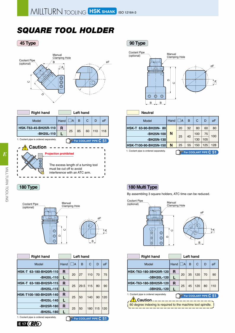
A B D øF
HSK-T 63-180-BH20R-110 -BH20L-110
HSK-T 63-180-BH25R-115 -BH25L-115
HSK-T100-180-BH25R-140-BH25L-140-BH25R-180-BH25L-180
20
25
25
25
27
29.5
50
50
70
80
90
115
C
110
115
140
180
75
90
120
120
RLRLRLRL
Hand A B D øF
HSK-T63-180-3BH20R-120-3BH20L-120
HSK-T63-180-3BH25R-120-3BH25L-120
20
25
35
45
70
80
C
120
120
90
110
RLRL
HandModel Model
ManualClamping Hole
CautionProjection prohibited
B
øF
B
AD
C
C
D
B
A
øF
Coolant Pipe(optional)
B
CD
A
ManualClamping Hole
øF
HSK-T 63-90-BH20N- 80 -BH25N-100 -BH25N-130
HSK-T100-90-BH25N-150
20
25
25 55 128
32
40
6075
105125
80100130150
80
100N
N
HSK-T63-45-BH25R-110 -BH25L-110
25 85 11060 118RL
A
B
C
D
øF
60 degree indexing is required to the machine tool spindle.Caution
By assembling 3 square holders, ATC time can be reduced.
Coolant Pipe(optional)
The excess length of a turning tool must be cut off to avoid interference with an ATC arm.
Right hand Left hand
Right hand Left hand Right hand Left hand
Neutral
ManualClamping Hole
ManualClamping Hole
Coolant Pipe(optional)
Coolant Pipe(optional)
A B D øFCModel Hand A B D øFCModel Hand
SQUARE TOOL HOLDER45 Type 90 Type
180 Type 180 Multi Type
For COOLANT PIPE C 51
For COOLANT PIPE C 51
For COOLANT PIPE C 51
For COOLANT PIPE C 51
1. Coolant pipe is ordered separately.
1. Coolant pipe is ordered separately.
1. Coolant pipe is ordered separately.
1. Coolant pipe is ordered separately.
E 17
MILLTU
RN
TOO
LING
E
HSK SHANK ISO 12164-3MILLTURN TOOLING
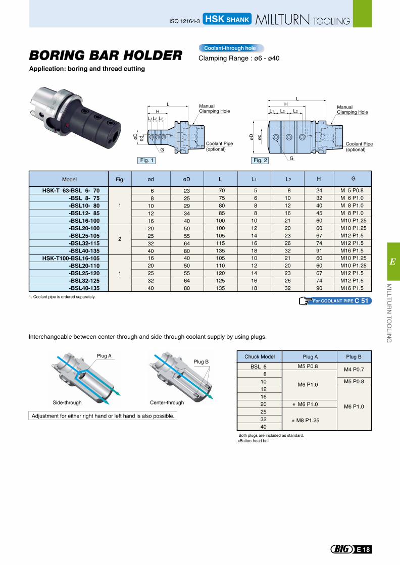
BSL 68
10121620253240
M4 P0.7
M5 P0.8
M6 P1.0
M5 P0.8
M6 P1.0
M6 P1.0
M8 P1.25
Plug A Plug B
HSK-T 63-BSL 6- 70 -BSL 8- 75 -BSL10- 80 -BSL12- 85 -BSL16-100 -BSL20-100 -BSL25-105 -BSL32-115 -BSL40-135
HSK-T100-BSL16-105 -BSL20-110 -BSL25-120 -BSL32-125 -BSL40-135
Chuck Model
1
2
1
68
10121620253240
232529344050556480
70758085
100100105115135
5688
1012141618
81012162120232632
243240456060677491
1620253240
4050556480
105110120125135
1012141618
2120232632
6060677490
M 5 P0.8 M 6 P1.0 M 8 P1.0 M 8 P1.0 M10 P1.25M10 P1.25M12 P1.5 M12 P1.5 M16 P1.5 M10 P1.25M10 P1.25M12 P1.5 M12 P1.5 M16 P1.5
Plug APlug B
Interchangeable between center-through and side-through coolant supply by using plugs.
Both plugs are included as standard.※Button-head bolt.
※
※
Center-throughSide-through
Adjustment for either right hand or left hand is also possible.
ManualClamping Hole
Coolant Pipe(optional)
L2L2L1
ødøD
H
G
L ManualClamping Hole
Coolant Pipe(optional)
L2L2L1
ødøD
H
G
L
ød øD L L1 L2 H GModel Fig.
Fig. 1 Fig. 2
Application: boring and thread cuttingBORING BAR HOLDER Clamping Range : ø6 - ø40
Coolant-through hole
For COOLANT PIPE C 511. Coolant pipe is ordered separately.
E 18
MILLTU
RN
TOO
LING
E
HSK SHANKISO 12164-3 MILLTURN TOOLING
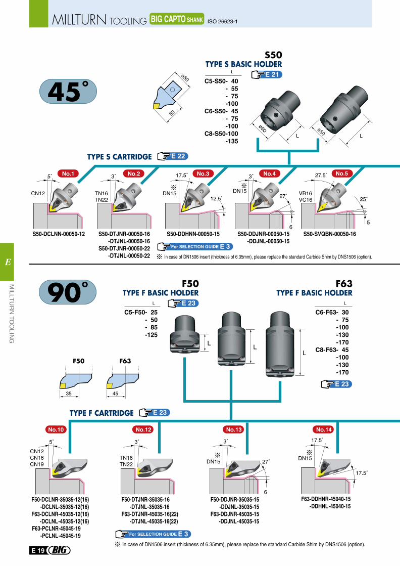
C5-S50- 40- 55- 75-100
C6-S50- 45- 75-100
C8-S50-100-135
C5-F50- 25- 50- 85-125
L
L
50
ø50
4535
F50
C6-F63- 30- 75-100-130-170
C8-F63- 45-100-130-170
L
F63
L L
F50 F63
LL
L
ø50 ø50
F50-DCLNR-35035-12(16)-DCLNL-35035-12(16)
F63-DCLNR-45035-12(16)-DCLNL-45035-12(16)
F63-PCLNR-45045-19-PCLNL-45045-19
F50-DTJNR-35035-16 -DTJNL-35035-16F63-DTJNR-45035-16(22) -DTJNL-45035-16(22)
F50-DDJNR-35035-15-DDJNL-35035-15
F63-DDJNR-45035-15-DDJNL-45035-15
F63-DDHNR-45040-15-DDHNL-45040-15
CN12CN16CN19
5˚
TN16TN22
3˚
DN15
3˚
27˚
6
17.5˚
17.5˚
DN15
5˚
CN12
3˚
TN16TN22
17.5˚
DN1512.5˚
DN15
3˚
27˚
6
27.5˚
25˚
5
VB16VC16
S50-DCLNN-00050-12 S50-DDHNN-00050-15 S50-DDJNR-00050-15-DDJNL-00050-15
S50-DTJNR-00050-16-DTJNL-00050-16
S50-DTJNR-00050-22-DTJNL-00050-22
S50-SVQBN-00050-16
No.10 No.12 No.13 No.14
No.1 No.2 No.3 No.4 No.5
For SELECTION GUIDE E 3
E 21
E 22
E 23
E 23
E 23
In case of DN1506 insert (thickness of 6.35mm), please replace the standard Carbide Shim by DNS1506 (option).
For SELECTION GUIDE E 3In case of DN1506 insert (thickness of 6.35mm), please replace the standard Carbide Shim by DNS1506 (option).
E 19
MILLTU
RN
TOO
LING
E
ISO 26623-1MILLTURN TOOLING BIG CAPTO SHANK
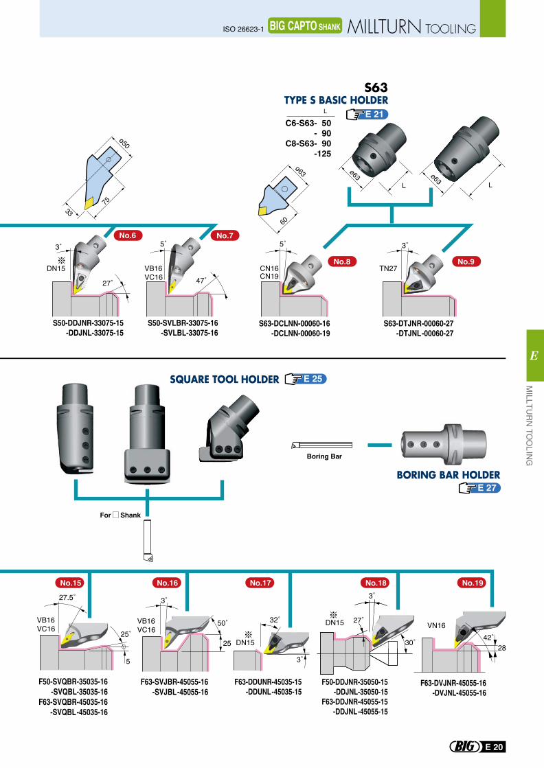
75
ø50
33
60
ø63
Boring Bar
For Shank
L L
C6-S63- 50- 90
C8-S63- 90-125
L
ø63 ø63
50˚VB16VC16
3˚
25
27.5˚
25˚
5
VB16VC16
DN15
3˚
27˚
30˚
3˚
32˚
DN15
CN16CN19
5˚ 3˚
TN27
S63-DCLNN-00060-16-DCLNN-00060-19
S63-DTJNR-00060-27-DTJNL-00060-27
F50-DDJNR-35050-15-DDJNL-35050-15
F63-DDJNR-45055-15-DDJNL-45055-15
F63-DVJNR-45055-16-DVJNL-45055-16
F63-SVJBR-45055-16-SVJBL-45055-16
F50-SVQBR-35035-16-SVQBL-35035-16
F63-SVQBR-45035-16-SVQBL-45035-16
F63-DDUNR-45035-15-DDUNL-45035-15
No.16No.15 No.18 No.19No.17
No.8 No.9
VN1642˚
28
No.6 No.7
S50-DDJNR-33075-15-DDJNL-33075-15
S50-SVLBR-33075-16-SVLBL-33075-16
3˚
27˚
DN15
5˚
47˚VB16VC16
E 21
E 25
E 27
E 20
MILLTU
RN
TOO
LING
E
ISO 26623-1 MILLTURN TOOLINGBIG CAPTO SHANK
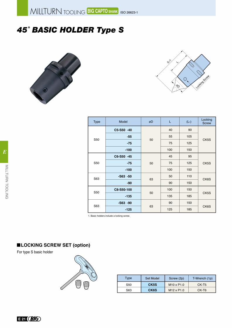
45˚ BASIC HOLDER Type S
(L1) L
Locki
ng Scre
w
C5-S50 -40
-55
-75
-100
C6-S50 -45
-75
-100
-S63 -50
-90
C8-S50-100
-135
-S63 -90
-125
S50
S50
S50
S63
S63
40
55
75
100
45
75
100
50
90
100
135
90
125
90
105
125
150
95
125
150
110
150
150
185
150
185
63
63
50
50
50
Type Model øD L (L1) LockingScrew
CK6S
CK6S
CK5S
CK5S
CK5S
For type S basic holder
Type Set Model Screw (2p) T-Wrench (1p)
S50S63
CK5SCK6S
M10 x P1.0M12 x P1.0
CK-T5CK-T6
LOCKING SCREW SET (option)
1. Basic holders include a locking screw.
E 21
MILLTU
RN
TOO
LING
E
ISO 26623-1MILLTURN TOOLING BIG CAPTO SHANK
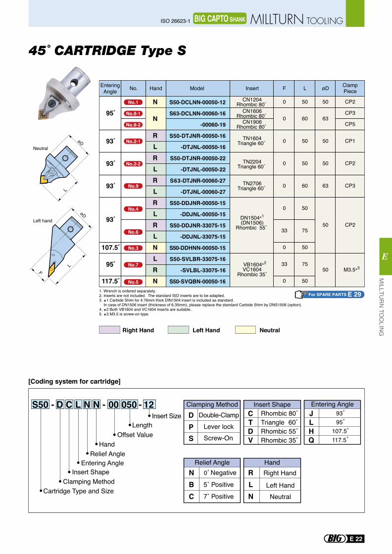
45˚ CARTRIDGE Type S
S50 - D C L N N - 00 050 - 12
[Coding system for cartridge]
NBC
Right Hand
Left Hand
RLN
Relief Angle Hand
Neutral
Rhombic 80˚Triangle 60˚Rhombic 55˚Rhombic 35˚
CTDV
Double-ClampLever lock
Clamping Method Insert ShapeDP
Screw-OnS
JLH
93˚95˚
107.5˚117.5˚Q
Entering AngleInsert Size
LengthOffset Value
HandRelief Angle
Entering AngleInsert Shape
Clamping MethodCartridge Type and Size
L
LF
Left hand
Neutral
NeutralRight Hand Left Hand
For SPARE PARTS E 291. Wrench is ordered separately.2. Inserts are not included. The standard ISO inserts are to be adapted. 3. *1 Carbide Shim for 4.76mm thick DIN1504 insert is included as standard. In case of DN1506 insert (thickness of 6.35mm), please replace the standard Carbide Shim by DNS1506 (option). 4. *2 Both VB1604 and VC1604 inserts are suitable.5. *3 M3.5 is screw-on type.
HandNo. Model Insert F L øD ClampPiece
EnteringAngle
N
N
RLRLRLRLRLNLRN
S50-DCLNN-00050-12
S63-DCLNN-00060-16
-00060-19
S50-DTJNR-00050-16
-DTJNL-00050-16
S50-DTJNR-00050-22
-DTJNL-00050-22
S63-DTJNR-00060-27
-DTJNL-00060-27
S50-DDJNR-00050-15
-DDJNL-00050-15
S50-DDJNR-33075-15
-DDJNL-33075-15
S50-DDHNN-00050-15
S50-SVLBR-33075-16
-SVLBL-33075-16
S50-SVQBN-00050-16
95˚
93˚
93˚
93˚
93˚
107.5˚
95˚
117.5˚
0
0
0
0
0
0
33
0
33
0
50
60
50
50
60
50
75
50
75
50
50
63
50
50
63
50
50
CP2
CP3
CP5
CP1
CP2
CP3
CP2
M3.5*3
TN1604Triangle 60˚
TN2204Triangle 60˚
TN2706Triangle 60˚
DN1504*1
(DN1506)Rhombic 55˚
VB1604*2
VC1604Rhombic 35˚
CN1204Rhombic 80˚
CN1606Rhombic 80˚
CN1906Rhombic 80˚
No.1
No.8-1
No.8-2
No.2-1
No.2-2
No.9
No.4
No.6
No.3
No.7
No.5
E 22
MILLTU
RN
TOO
LING
E
ISO 26623-1 MILLTURN TOOLINGBIG CAPTO SHANK
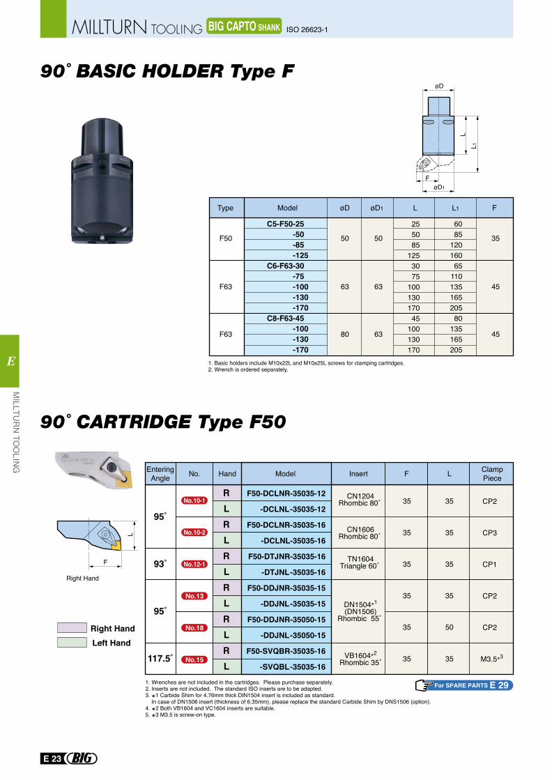
90˚ BASIC HOLDER Type F
L1L
FøD1
øD
50
63
50
63
80
F50
F63
F63 63
35
45
45
255085
1253075
10013017045
100130170
6085
12016065
11013516520580
135165205
C5-F50-25 -50 -85 -125C6-F63-30 -75 -100 -130 -170C8-F63-45 -100 -130 -170
Type Model øD øD1 L L1 F
1. Basic holders include M10x22L and M10x25L screws for clamping cartridges.2. Wrench is ordered separately.
90˚ CARTRIDGE Type F50
L
F
Right Hand
Right HandLeft Hand
For SPARE PARTS E 29
HandNo. Model Insert F L EnteringAngle
RLRLRLRLRLRL
F50-DCLNR-35035-12
-DCLNL-35035-12
F50-DCLNR-35035-16
-DCLNL-35035-16
F50-DTJNR-35035-16
-DTJNL-35035-16
F50-DDJNR-35035-15
-DDJNL-35035-15
F50-DDJNR-35050-15
-DDJNL-35050-15
F50-SVQBR-35035-16
-SVQBL-35035-16
95˚
93˚
95˚
117.5˚
35
35
35
35
35
35
35
35
35
35
50
35
CP2
CP3
CP1
CP2
CP2
M3.5*3
ClampPiece
TN1604Triangle 60˚
DN1504*1
(DN1506)Rhombic 55˚
VB1604*2
Rhombic 35˚
CN1204Rhombic 80˚
CN1606Rhombic 80˚
1. Wrenches are not included in the cartridges. Please purchase separately.2. Inserts are not included. The standard ISO inserts are to be adapted. 3. *1 Carbide Shim for 4.76mm thick DIN1504 insert is included as standard. In case of DN1506 insert (thickness of 6.35mm), please replace the standard Carbide Shim by DNS1506 (option). 4. *2 Both VB1604 and VC1604 inserts are suitable.5. *3 M3.5 is screw-on type.
No.10-1
No.10-2
No.12-1
No.13
No.18
No.15
E 23
MILLTU
RN
TOO
LING
E
ISO 26623-1MILLTURN TOOLING BIG CAPTO SHANK
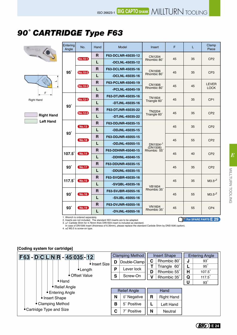
90˚ CARTRIDGE Type F63
L
F
Right Hand
F63 - D C L N R - 45 035 - 12[Coding system for cartridge]
NBC
Right Hand
Left Hand
RLN
Relief Angle Hand
Neutral
Rhombic 80˚Triangle 60˚Rhombic 55˚Rhombic 35˚
CTDV
Double-ClampLever lock
Clamping Method Insert ShapeDP
Screw-OnS
JLHQU
Entering Angle
Insert SizeLength
Offset ValueHand
Relief AngleEntering Angle
Insert ShapeClamping Method
Cartridge Type and Size
93˚95˚
107.5˚117.5˚
93˚
Right HandLeft Hand
For SPARE PARTS E 29
HandNo. Model Insert F L EnteringAngle
RLRLRLRLRLRLRLRLRLRLRLRL
F63-DCLNR-45035-12
-DCLNL-45035-12
F63-DCLNR-45035-16
-DCLNL-45035-16
F63-PCLNR-45045-19
-PCLNL-45045-19
F63-DTJNR-45035-16
-DTJNL-45035-16
F63-DTJNR-45035-22
-DTJNL-45035-22
F63-DDJNR-45035-15
-DDJNL-45035-15
F63-DDJNR-45055-15
-DDJNL-45055-15
F63-DDHNR-45040-15
-DDHNL-45040-15
F63-DDUNR-45035-15
-DDUNL-45035-15
F63-SVQBR-45035-16
-SVQBL-45035-16
F63-SVJBR-45055-16
-SVJBL-45055-16
F63-DVJNR-45055-16
-DVJNL-45055-16
95˚
93˚
93˚
107.5˚
93˚
117.5˚
93˚
93˚
45
45
45
45
45
45
45
45
45
45
45
45
35
35
45
35
35
35
55
40
35
35
55
55
CP2
CP3
LEVERLOCK
CP1
CP2
CP2
CP2
CP2
CP2
M3.5*2
M3.5*2
CP4
TN1604Triangle 60˚
TN2204Triangle 60˚
DN1504*1
(DN1506)Rhombic 55˚
VN1604Rhombic 35˚
VB1604Rhombic 35˚
CN1204Rhombic 80˚
CN1606Rhombic 80˚
CN1906Rhombic 80˚
ClampPiece
1. Wrench is ordered separately.2. Inserts are not included. The standard ISO inserts are to be adapted. 3. *1 Carbide Shim for 4.76mm thick DIN1504 insert is included as standard. In case of DN1506 insert (thickness of 6.35mm), please replace the standard Carbide Shim by DNS1506 (option). 4. *2 M3.5 is screw-on type.
No.10-1
No.10-2
No.10-3
No.12-1
No.12-2
No.13
No.18
No.14
No.17
No.15
No.16
No.19
MILLTU
RN
TOO
LING
E
E 24
ISO 26623-1 MILLTURN TOOLINGBIG CAPTO SHANK
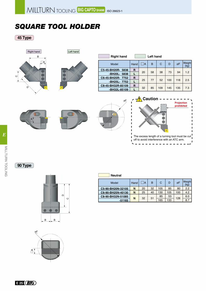
SQUARE TOOL HOLDER
øF
øF
45 Type
90 Type
C5-45-BH20R- 5838-BH20L- 5838
C6-45-BH25R- 7752-BH25L- 7752
C8-45-BH32R-85109-BH32L-85109
RLRLRL
20
25
32
58
77
85
38
52
109
73
100
145
94
118
135
1.2
2.5
7.3
B D Weight(kg)øFCAHandModel
C5-90-BH20N-32105C6-90-BH25N-40130C8-90-BH32N-51085
-51165
NN
N
2025
32
3240
51
10513085
165
8510553
133
2.24.26.08.7
80100
128
B D Weight(kg)øFCAHandModel
CautionProjectionprohibited
The excess length of a turning tool must be cutoff to avoid interference with an ATC arm.
B
C
D
Right hand Left hand
Right hand
Neutral
Left hand
BB
D
C
E 25
MILLTU
RN
TOO
LING
E
ISO 26623-1MILLTURN TOOLING BIG CAPTO SHANK
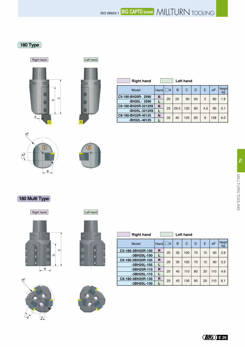
E
D C
B
øF
D
B
C
øF
E
C5-180-BH20R- 2590 -BH20L- 2590C6-180-BH25R-32120S -BH25L-32120SC8-180-BH32R-40125 -BH32L-40125
RLRLRL
20
25
32
25
29.5
40
90
120
125
65
80
85
5
4.5
8
80
90
128
1.6
3.1
6.0
B D E Weight(kg)øFCAHandModel
C5-180-3BH20R-100 -3BH20L-100C6-180-3BH20R-105 -3BH20L-105
-3BH25R-110 -3BH25L-110C8-180-3BH25R-130 -3BH25L-130
RLRLRLRL
20
20
25
25
35
35
45
45
100
105
110
130
70
70
80
90
15
15
20
20
90
90
110
110
2.6
3.2
4.6
6.1
B D E Weight(kg)øFCAHandModel
180 Type
180 Multi Type
Right hand Left hand
Right hand Left hand
Right hand Left hand
Right hand Left hand
MILLTU
RN
TOO
LING
E
E 26
ISO 26623-1 MILLTURN TOOLINGBIG CAPTO SHANK
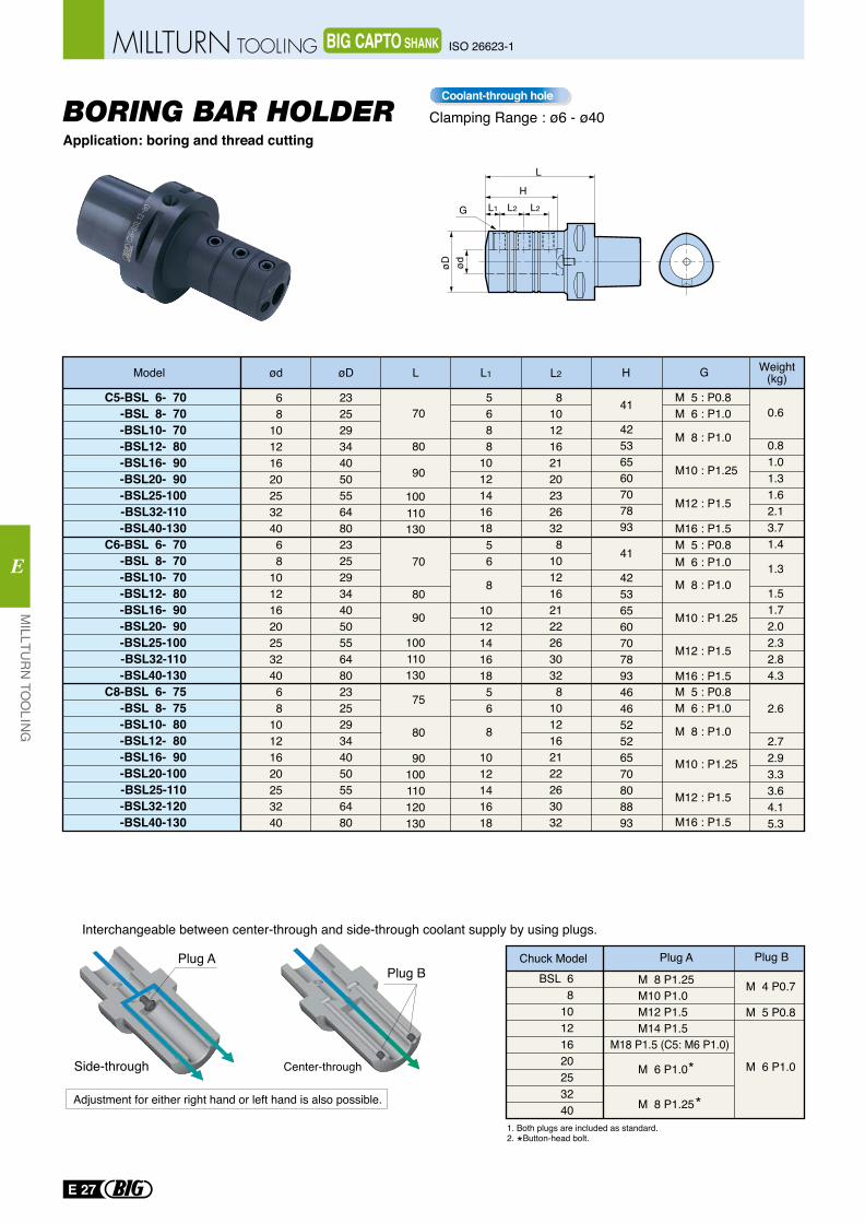
L
HL1G L2 L2
Plug ABSL 6
810121620253240
M 4 P0.7
M 5 P0.8
M 6 P1.0
M 8 P1.25M10 P1.0 M12 P1.5 M14 P1.5
M 6 P1.0
M 8 P1.25
1. Both plugs are included as standard.2. *Button-head bolt.
Chuck Model Plug A Plug BPlug B
Interchangeable between center-through and side-through coolant supply by using plugs.
Adjustment for either right hand or left hand is also possible.
Center-throughSide-throughM18 P1.5 (C5: M6 P1.0)
*
*
Application: boring and thread cuttingBORING BAR HOLDER
C5-BSL 6- 70-BSL 8- 70-BSL10- 70-BSL12- 80-BSL16- 90-BSL20- 90-BSL25-100-BSL32-110-BSL40-130
C6-BSL 6- 70-BSL 8- 70-BSL10- 70-BSL12- 80-BSL16- 90-BSL20- 90-BSL25-100-BSL32-110-BSL40-130
C8-BSL 6- 75-BSL 8- 75-BSL10- 80-BSL12- 80-BSL16- 90-BSL20-100-BSL25-110-BSL32-120-BSL40-130
68
1012162025324068
1012162025324068
10121620253240
232529344050556480232529344050556480232529344050556480
810121621202326328
10121621222630328
1012162122263032
5688
101214161856
101214161856
1012141618
42536560707893
41
42536560707893464652526570808893
41
M 5 : P0.8M 6 : P1.0
M16 : P1.5
M 5 : P0.8M 6 : P1.0
M 8 : P1.0
M10 : P1.25
M12 : P1.5
M16 : P1.5M 5 : P0.8M 6 : P1.0
M 8 : P1.0
M 8 : P1.0
M10 : P1.25
M10 : P1.25
M12 : P1.5
M12 : P1.5
M16 : P1.5
70
80
90
100110130
70
100110130
90100110120130
80
90
75
80 8
8
Model ød øD L H G Weight(kg)L1 L2
0.6
0.81.01.31.62.13.71.4
1.3
1.51.72.02.32.84.3
2.6
2.72.93.33.64.15.3
Clamping Range : ø6 - ø40Coolant-through hole
E 27
MILLTU
RN
TOO
LING
E
ISO 26623-1MILLTURN TOOLING BIG CAPTO SHANK
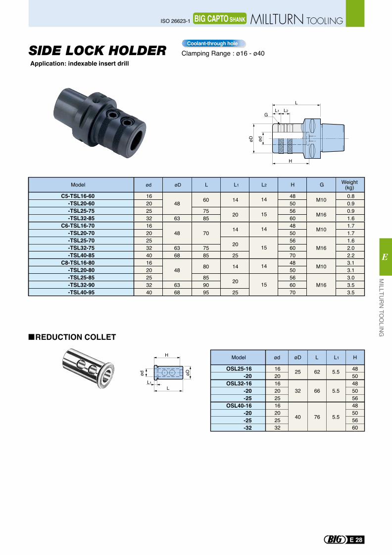
H
LL1
øDød
Application: indexable insert drill
ød øD L L1 L2 H G Weight(kg)Model
C5-TSL16-60-TSL20-60-TSL25-75-TSL32-85
C6-TSL16-70-TSL20-70-TSL25-70-TSL32-75-TSL40-85
C8-TSL16-80-TSL20-80-TSL25-85-TSL32-90-TSL40-95
1620253216202532401620253240
4850566048505660704850566070
0.80.90.91.61.71.71.62.02.23.13.13.03.53.5
48
63
48
6368
48
6368
14
20
14
20
25
14
20
25
14
15
14
15
14
15
M10
M16
M10
M16
M10
M16
60
7585
70
7585
80
859095
SIDE LOCK HOLDER
REDUCTION COLLET
Clamping Range : ø16 - ø40Coolant-through hole
L
øD ød
H
L1G
L2
Model
OSL25-16-20
OSL32-16-20-25
OSL40-16-20-25-32
ød
162016202516202532
485048505648505660
øD
25
32
40
62
66
76
5.5
5.5
5.5
L L1 H
MILLTU
RN
TOO
LING
E
E 28
ISO 26623-1 MILLTURN TOOLINGBIG CAPTO SHANK
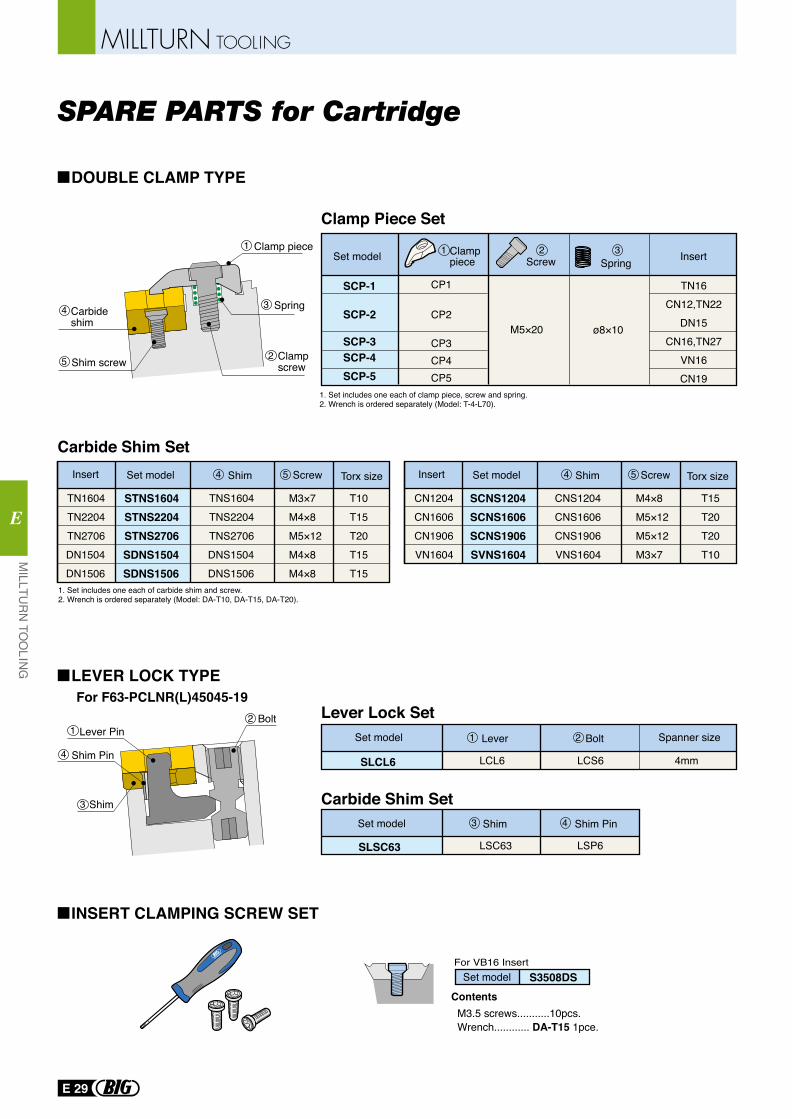
SPARE PARTS for Cartridge
1. Set includes one each of clamp piece, screw and spring.2. Wrench is ordered separately (Model: T-4-L70).
1. Set includes one each of carbide shim and screw.2. Wrench is ordered separately (Model: DA-T10, DA-T15, DA-T20).
Carbideshim
Clamp screwShim screw
Spring
Clamp piece
M3.5 screws...........10pcs.Wrench............ DA-T15 1pce.
Contents
Set model S3508DSFor VB16 Insert
Clamppiece Screw Spring
TN16CN12,TN22
DN15CN16,TN27
VN16CN19
M5×20 ø8×10
Set model Insert
SCP-1
SCP-2
SCP-3SCP-4SCP-5
Lever Lock Set
Carbide Shim Set
LCL6 LCS6 4mm
Set model
SLCL6
Lever Bolt Spanner size
LSC63 LSP6
Set model Shim Shim Pin
SLSC63
Shim
Shim Pin
Lever Pin
Torx sizeShim ScrewInsert Set model Torx sizeShim ScrewInsert Set model
CP1
CP2
CP3CP4CP5
Bolt
STNS1604STNS2204STNS2706SDNS1504SDNS1506
TN1604TN2204TN2706DN1504DN1506
TNS1604TNS2204TNS2706DNS1504DNS1506
M3×7M4×8M5×12M4×8M4×8
T10T15T20T15T15
SCNS1204SCNS1606SCNS1906SVNS1604
CN1204CN1606CN1906VN1604
CNS1204CNS1606CNS1906VNS1604
M4×8M5×12M5×12M3×7
T15T20T20T10
For F63-PCLNR(L)45045-19
Carbide Shim Set
Clamp Piece Set1 1 2 3
4
5
3
2
4 5 4 5
21
1
3 4
24
3
LEVER LOCK TYPE
DOUBLE CLAMP TYPE
INSERT CLAMPING SCREW SET
E 29
MILLTURN TOOLING
MILLTU
RN
TOO
LING
E
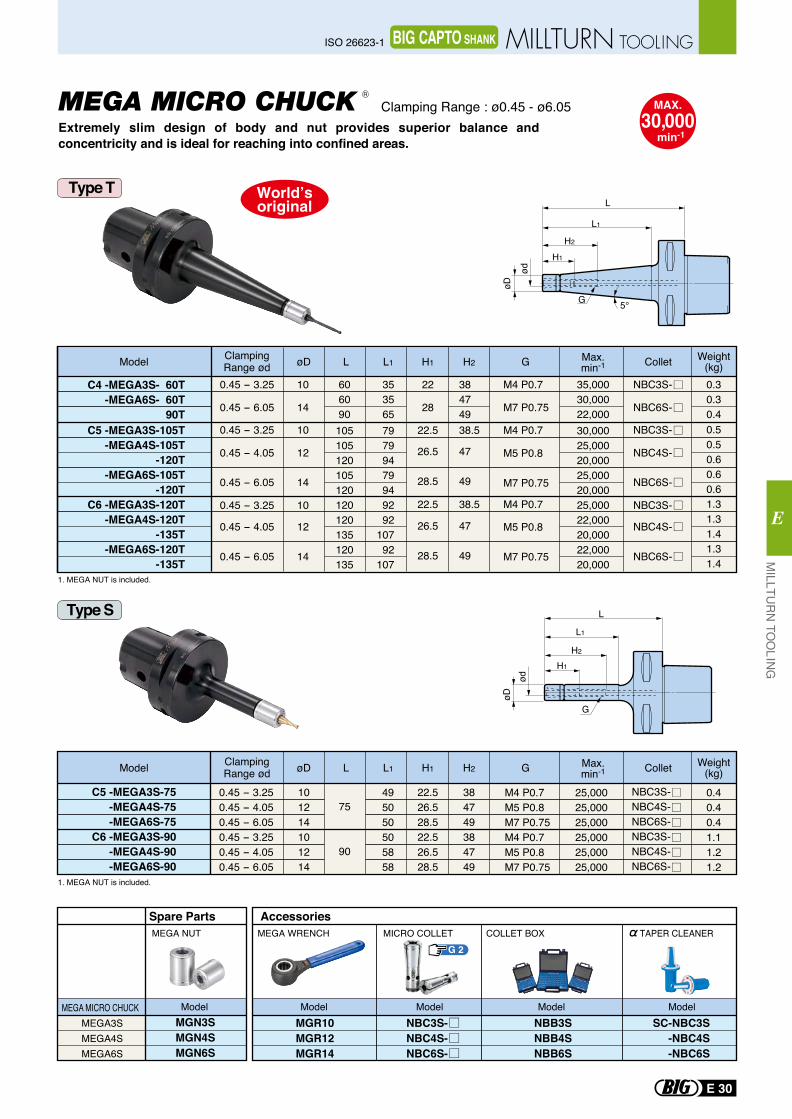
øD
ød
5°G
L1
H1
H2
L
G
L1
øDød
H1
H2
L
MEGA3SMEGA4SMEGA6S
MGN3SMGN4SMGN6S
Spare Parts
MEGA MICRO CHUCK ModelMGR10MGR12MGR14
NBB3SNBB4SNBB6S
ModelNBC3S-NBC4S-NBC6S-
Model Model ModelSC-NBC3S -NBC4S -NBC6S
Accessories
0.45 - 3.250.45 - 4.050.45 - 6.050.45 - 3.250.45 - 4.050.45 - 6.05
101214101214
22.526.528.522.526.528.5
384749384749
75
90
495050505858
M4 P0.7M5 P0.8M7 P0.75M4 P0.7M5 P0.8M7 P0.75
NBC3S-NBC4S-NBC6S-NBC3S-NBC4S-NBC6S-
25,00025,00025,00025,00025,00025,000
0.40.40.41.11.21.2
0.45 - 3.25
0.45 - 4.05
0.45 - 6.05
0.45 - 3.25
0.45 - 4.05
0.45 - 6.05
NBC3S-
NBC4S-
NBC6S-
NBC3S-
NBC4S-
NBC6S-
10
12
14
10
12
14
79799479949292
10792
107
30,00025,00020,00025,00020,00025,00022,00020,00022,00020,000
105105120105120120120135120135
0.50.50.60.60.61.31.31.41.31.4
M4 P0.7
M5 P0.8
M7 P0.75
M4 P0.7
M5 P0.8
M7 P0.75
38.5
47
49
38.5
47
49
22.5
26.5
28.5
22.5
26.5
28.5
1. MEGA NUT is included.
1. MEGA NUT is included.
Model øD L G Collet Weight(kg)L1
ClampingRange ød H1 H2 Max.
min-1
Model øD L G Collet Weight(kg)L1
ClampingRange ød H1 H2 Max.
min-1
MEGA NUT COLLET BOXMICRO COLLETMEGA WRENCH TAPER CLEANER
C5 -MEGA3S-105T-MEGA4S-105T
-120T-MEGA6S-105T
-120TC6 -MEGA3S-120T
-MEGA4S-120T-135T
-MEGA6S-120T-135T
C5 -MEGA3S-75-MEGA4S-75-MEGA6S-75
C6 -MEGA3S-90-MEGA4S-90-MEGA6S-90
Extremely slim design of body and nut provides superior balance and concentricity and is ideal for reaching into confined areas.
MEGA MICRO CHUCK Clamping Range : ø0.45 - ø6.05R
Type S
Type T
G 2
MAX.30,000
min-1
0.45 - 3.25
0.45 - 6.05
NBC3S-
NBC6S-
10
14
353565
35,00030,00022,000
606090
0.30.30.4
M4 P0.7
M7 P0.75
384749
22
28
C4 -MEGA3S- 60T -MEGA6S- 60T
90T
MILLTU
RN
TOO
LING
E
E 30
ISO 26623-1 MILLTURN TOOLINGBIG CAPTO SHANK
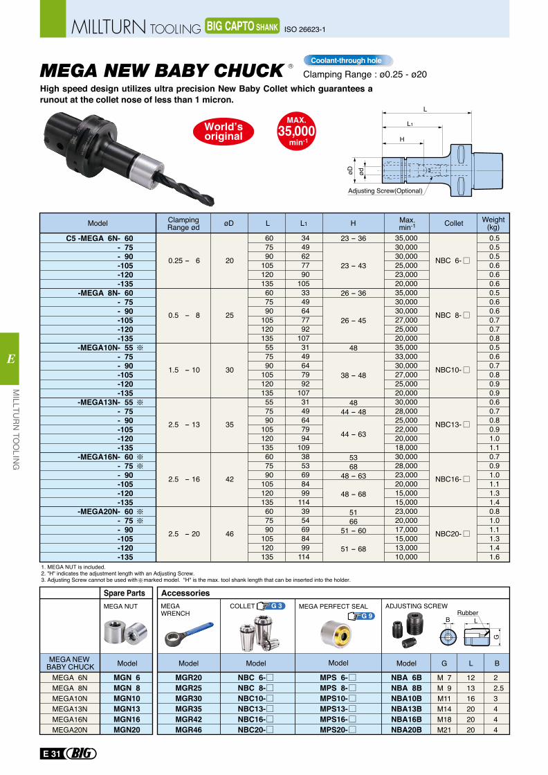
MEGA NEW BABY CHUCK
L1
H
L
øD ød
Adjusting Screw(Optional)
Spare Parts
MEGA NEW BABY CHUCK
MEGA NUT
MEGA 6NMEGA 8NMEGA10NMEGA13NMEGA16NMEGA20N
MGN 6MGN 8MGN10MGN13MGN16MGN20
Model
MEGAWRENCH
ADJUSTING SCREW
G L B
B L
G
Rubber
AccessoriesCOLLET MEGA PERFECT SEALG 3
G 9
MGR20MGR25MGR30MGR35MGR42MGR46
NBA 6BNBA 8BNBA10BNBA13BNBA16BNBA20B
M 7M 9M11M14M18M21
121316202020
22.53444
NBC 6-NBC 8-NBC10-NBC13-NBC16-NBC20-
MPS 6-MPS 8-MPS10-MPS13-MPS16-MPS20-
ModelModelModel Model
C5 -MEGA 6N- 60- 75- 90-105-120-135
-MEGA 8N- 60- 75- 90-105-120-135
-MEGA10N- 55- 75- 90-105-120-135
-MEGA13N- 55- 75- 90-105-120-135
-MEGA16N- 60- 75- 90-105-120-135
-MEGA20N- 60- 75- 90-105-120-135
0.25 - 6
0.5 - 8
1.5 - 10
2.5 - 13
2.5 - 16
2.5 - 20
20
25
30
35
42
46
NBC 6-
NBC 8-
NBC10-
NBC13-
NBC16-
NBC20-
23 - 36
23 - 43
26 - 36
26 - 45
48
38 - 48
4844 - 48
44 - 63
5368
48 - 63
48 - 68
5166
51 - 60
51 - 68
607590
105120135607590
105120135557590
105120135557590
105120135607590
105120135607590
105120135
0.50.50.50.60.60.60.50.60.60.70.70.80.50.60.70.80.90.90.60.70.80.91.01.10.70.91.01.11.31.40.81.01.11.31.41.6
3449627790
1053349647792
1073149647992
1073149647994
1093853698499
1143954698499
114
35,00030,00030,00025,00023,00020,00035,00030,00030,00027,00025,00020,00035,00033,00030,00027,00025,00020,00030,00028,00025,00022,00020,00018,00030,00028,00023,00020,00015,00015,00023,00020,00017,00015,00013,00010,000
1. MEGA NUT is included.2. "H" indicates the adjustment length with an Adjusting Screw.3. Adjusting Screw cannot be used with marked model. "H" is the max. tool shank length that can be inserted into the holder.
Model ClampingRange ød HøD L Collet Weight
(kg)L1 Max.min-1
High speed design utilizes ultra precision New Baby Collet which guarantees a runout at the collet nose of less than 1 micron.
R
Clamping Range : ø0.25 - ø20Coolant-through hole
MAX.35,000
min-1
E 31
MILLTU
RN
TOO
LING
E
ISO 26623-1MILLTURN TOOLING BIG CAPTO SHANK
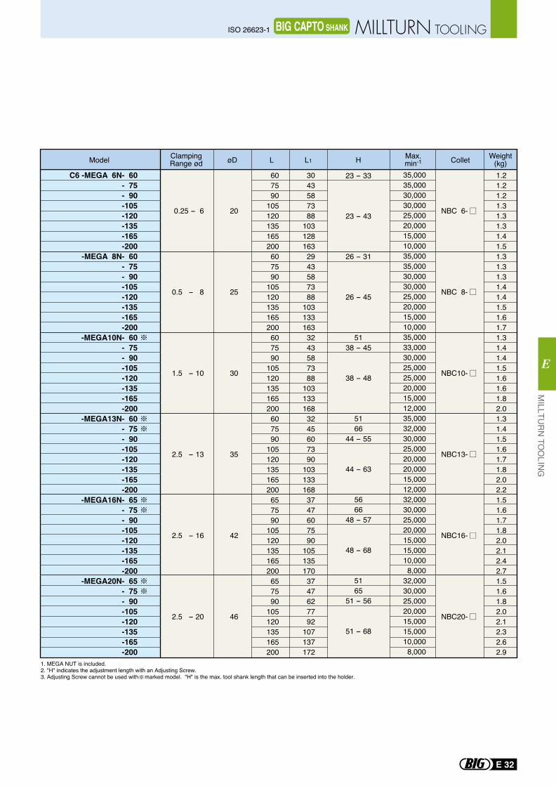
C6 -MEGA 6N- 60- 75- 90-105-120-135-165-200
-MEGA 8N- 60- 75- 90-105-120-135-165-200
-MEGA10N- 60- 75- 90-105-120-135-165-200
-MEGA13N- 60- 75- 90-105-120-135-165-200
-MEGA16N- 65- 75- 90-105-120-135-165-200
-MEGA20N- 65- 75- 90-105-120-135-165-200
0.25 - 6
0.5 - 8
1.5 - 10
2.5 - 13
2.5 - 16
2.5 - 20
NBC 6-
NBC 8-
NBC10-
NBC13-
NBC16-
NBC20-
20
25
30
35
42
46
607590
105120135165200607590
105120135165200607590
105120135165200607590
105120135165200657590
105120135165200657590
105120135165200
3043587388
1031281632943587388
1031331633243587388
1031331683245607390
1031331683747607590
1051351703747627792
107137172
1.21.21.21.31.31.31.41.51.31.31.31.41.41.51.61.71.31.41.41.51.61.61.82.01.31.41.51.61.71.82.02.21.51.61.71.82.02.12.42.71.51.61.82.02.12.32.62.9
26 - 31
26 - 45
5138 - 45
38 - 48
5166
44 - 55
44 - 63
5666
48 - 57
48 - 68
5165
51 - 56
51 - 68
35,00035,00030,00030,00025,00020,00015,00010,00035,00035,00030,00030,00025,00020,00015,00010,00035,00033,00030,00025,00025,00020,00015,00012,00035,00032,00030,00025,00020,00020,00015,00012,00032,00030,00025,00020,00015,00015,00010,000 8,00032,00030,00025,00020,00015,00015,00010,000 8,000
23 - 33
23 - 43
Model ClampingRange ød HøD L Collet Weight
(kg)L1Max.min-1
1. MEGA NUT is included.2. "H" indicates the adjustment length with an Adjusting Screw.3. Adjusting Screw cannot be used with marked model. "H" is the max. tool shank length that can be inserted into the holder.
MILLTU
RN
TOO
LING
E
E 32
ISO 26623-1 MILLTURN TOOLINGBIG CAPTO SHANK
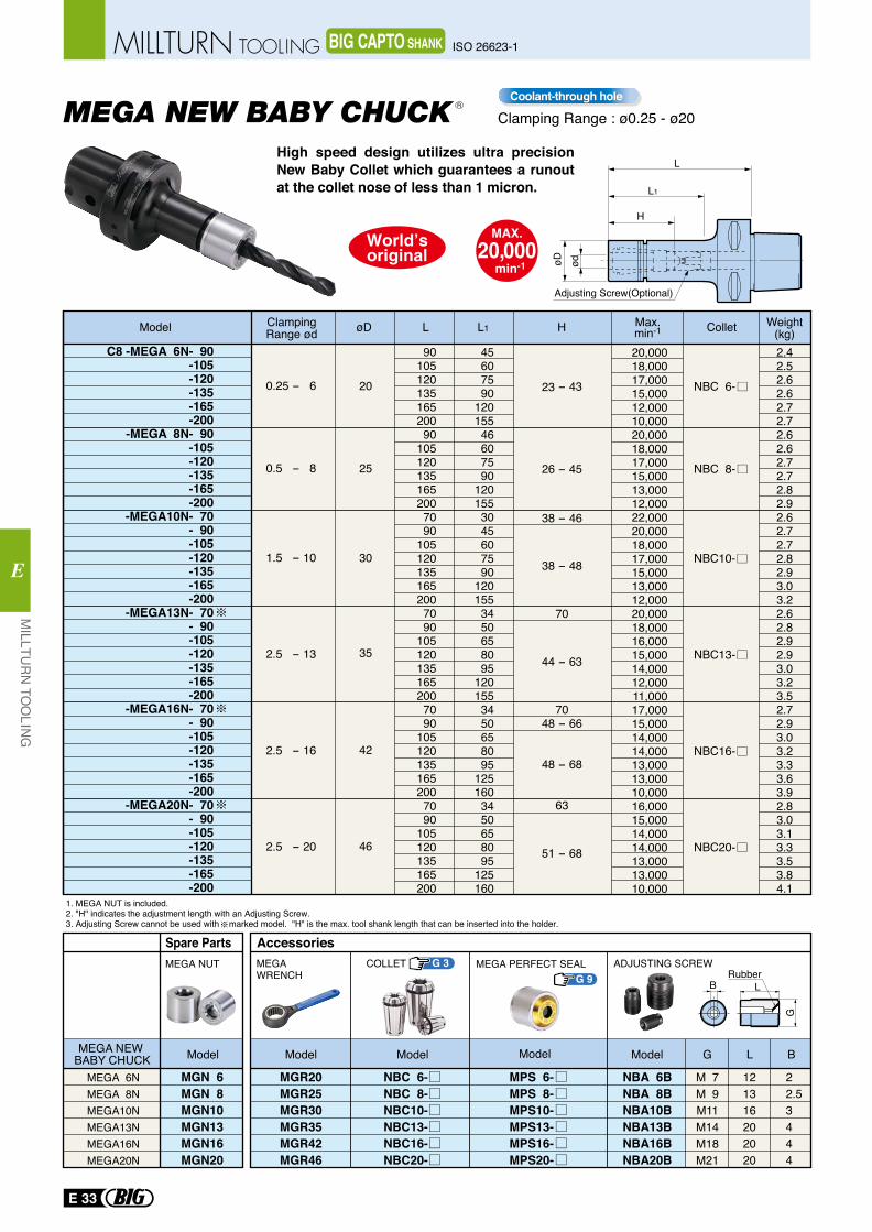
MEGA NEW BABY CHUCK
L1
H
L
øD ød
Adjusting Screw(Optional)
C8 -MEGA 6N- 90-105-120-135-165-200
-MEGA 8N- 90-105-120-135-165-200
-MEGA10N- 70- 90-105-120-135-165-200
-MEGA13N- 70- 90-105-120-135-165-200
-MEGA16N- 70- 90-105-120-135-165-200
-MEGA20N- 70- 90-105-120-135-165-200
0.25 - 6
0.5 - 8
1.5 - 10
2.5 - 13
2.5 - 16
2.5 - 20
NBC 6-
NBC 8-
NBC10-
NBC13-
NBC16-
NBC20-
20
25
30
35
42
46
9010512013516520090
1051201351652007090
1051201351652007090
1051201351652007090
1051201351652007090
105120135165200
45607590
12015546607590
1201553045607590
1201553450658095
1201553450658095
1251603450658095
125160
2.42.52.62.62.72.72.62.62.72.72.82.92.62.72.72.82.93.03.22.62.82.92.93.03.23.52.72.93.03.23.33.63.92.83.03.13.33.53.84.1
20,00018,00017,00015,00012,00010,00020,00018,00017,00015,00013,00012,00022,00020,00018,00017,00015,00013,00012,00020,00018,00016,00015,00014,00012,00011,00017,00015,00014,00014,00013,00013,00010,00016,00015,00014,00014,00013,00013,00010,000
23 - 43
26 - 45
38 - 46
38 - 48
70
44 - 63
7048 - 66
48 - 68
63
51 - 68
Model ClampingRange ød HøD L Collet Weight
(kg)L1 Max.min-1
High speed design utilizes ultra precision New Baby Collet which guarantees a runout at the collet nose of less than 1 micron.
R
1. MEGA NUT is included.2. "H" indicates the adjustment length with an Adjusting Screw.3. Adjusting Screw cannot be used with marked model. "H" is the max. tool shank length that can be inserted into the holder.
Spare Parts
MEGA NEW BABY CHUCK
MEGA NUT
MEGA 6NMEGA 8NMEGA10NMEGA13NMEGA16NMEGA20N
MGN 6MGN 8MGN10MGN13MGN16MGN20
Model
MEGAWRENCH
ADJUSTING SCREW
G L B
B L
G
Rubber
AccessoriesCOLLET MEGA PERFECT SEALG 3
G 9
MGR20MGR25MGR30MGR35MGR42MGR46
NBA 6BNBA 8BNBA10BNBA13BNBA16BNBA20B
M 7M 9M11M14M18M21
121316202020
22.53444
NBC 6-NBC 8-NBC10-NBC13-NBC16-NBC20-
MPS 6-MPS 8-MPS10-MPS13-MPS16-MPS20-
ModelModelModel Model
Clamping Range : ø0.25 - ø20Coolant-through hole
MAX.20,000
min-1
E 33
MILLTU
RN
TOO
LING
E
ISO 26623-1MILLTURN TOOLING BIG CAPTO SHANK
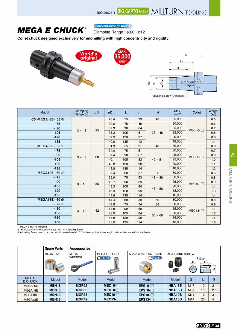
L1
L
øDøD1
ød
H
Adjusting Screw(Optional)
BRubber
L
G
Spare Parts
MEGA 6EMEGA 8EMEGA10EMEGA13E
MEGA E CHUCK
MEN 6MEN 8MEN10MEN13
MEGA E NUT
Model
MGR25MGR30MGR35MGR42
NBA 6BNBA 8BNBA10BNBA13B
M 7M 9M11M14
12131620
22.534
G L B
MEGAWRENCH
MEGA E COLLET ADJUSTING SCREW
EPS 6-EPS 8-EPS10-EPS13-
MEC 6-MEC 8-MEC10-MEC13-
MEGA E PERFECT SEAL
Accessories
G 11 G 11
ModelModel ModelModel
C5 -MEGA 6E- 55- 75- 90-105-120-135
-MEGA 8E- 55- 75- 90-105-120-135
-MEGA10E- 60- 75- 90-105-120-135
-MEGA13E- 60- 75- 90-105-120-135
3 - 6
3 - 8
3 - 10
3 - 12
25
30
35
42
MEC 6-
MEC 8-
MEC10-
MEC13-
26.429.632.335.237.940.931.334.037.440.142.845.837.439.942.745.345.344.644.444.844.846.045.845.0
557590
105120135557590
105120135607590
105120135607590
105120135
2949648197
1133151678298
1143753698499
1143954698499
114
48
37 - 45
48
42 - 51
5348 - 49
48 - 58
5068
50 - 60
0.50.60.70.80.91.10.60.70.81.01.11.30.60.80.91.11.31.40.80.91.11.31.41.6
35,00030,00025,00022,00020,00018,00035,00030,00025,00022,00020,00018,00030,00030,00025,00020,00018,00016,00030,00030,00025,00020,00016,00013,000
Model ClampingRange ød HøD øD1 L Collet Weight
(kg)L1 Max.min-1
Collet chuck designed exclusively for endmilling with high concentricity and rigidity.MEGA E CHUCK R
1. MEGA E NUT is included.2. "H" indicates the adjustment length with an Adjusting Screw.3. Adjusting Screw cannot be used with marked model. "H" is the max. tool shank length that can be inserted into the holder.
Clamping Range : ø3.0 - ø12Coolant-through hole
MAX.35,000
min-1
MILLTU
RN
TOO
LING
E
E 34
ISO 26623-1 MILLTURN TOOLINGBIG CAPTO SHANK
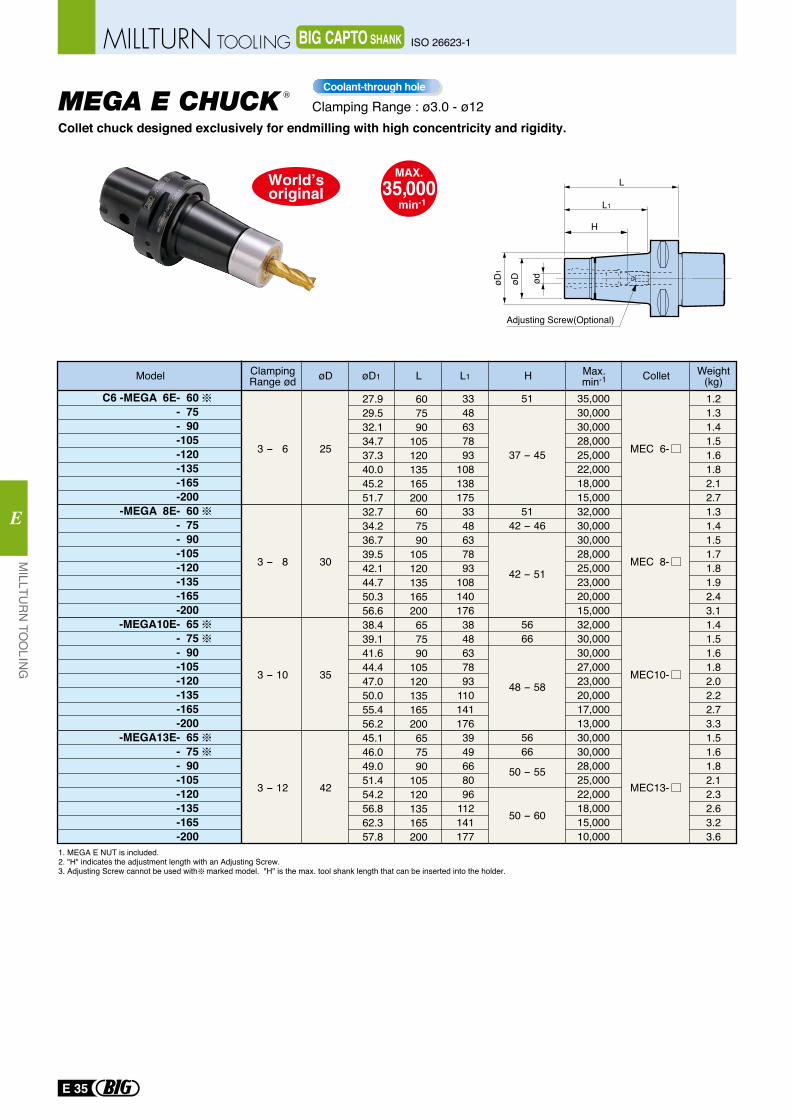
L1
L
øDøD1
ød
H
Adjusting Screw(Optional)
Collet chuck designed exclusively for endmilling with high concentricity and rigidity.MEGA E CHUCK
R
51
37 - 45
5142 - 46
42 - 51
5666
48 - 58
5666
50 - 55
50 - 60
35,00030,00030,00028,00025,00022,00018,00015,00032,00030,00030,00028,00025,00023,00020,00015,00032,00030,00030,00027,00023,00020,00017,00013,00030,00030,00028,00025,00022,00018,00015,00010,000
1.21.31.41.51.61.82.12.71.31.41.51.71.81.92.43.11.41.51.61.82.02.22.73.31.51.61.82.12.32.63.23.6
C6 -MEGA 6E- 60- 75- 90-105-120-135-165-200
-MEGA 8E- 60- 75- 90-105-120-135-165-200
-MEGA10E- 65- 75- 90-105-120-135-165-200
-MEGA13E- 65- 75- 90-105-120-135-165-200
25
30
35
42
3 - 6
3 - 8
3 - 10
3 - 12
MEC 6-
MEC 8-
MEC10-
MEC13-
3348637893
1081381753348637893
1081401763848637893
1101411763949668096
112141177
27.929.532.134.737.340.045.251.732.734.236.739.542.144.750.356.638.439.141.644.447.050.055.456.245.146.049.051.454.256.862.357.8
607590
105120135165200607590
105120135165200657590
105120135165200657590
105120135165200
Model ClampingRange ød HøD øD1 L Collet Weight
(kg)L1 Max.min-1
Clamping Range : ø3.0 - ø12Coolant-through hole
1. MEGA E NUT is included.2. "H" indicates the adjustment length with an Adjusting Screw.3. Adjusting Screw cannot be used with marked model. "H" is the max. tool shank length that can be inserted into the holder.
MAX.35,000
min-1
E 35
MILLTU
RN
TOO
LING
E
ISO 26623-1MILLTURN TOOLING BIG CAPTO SHANK
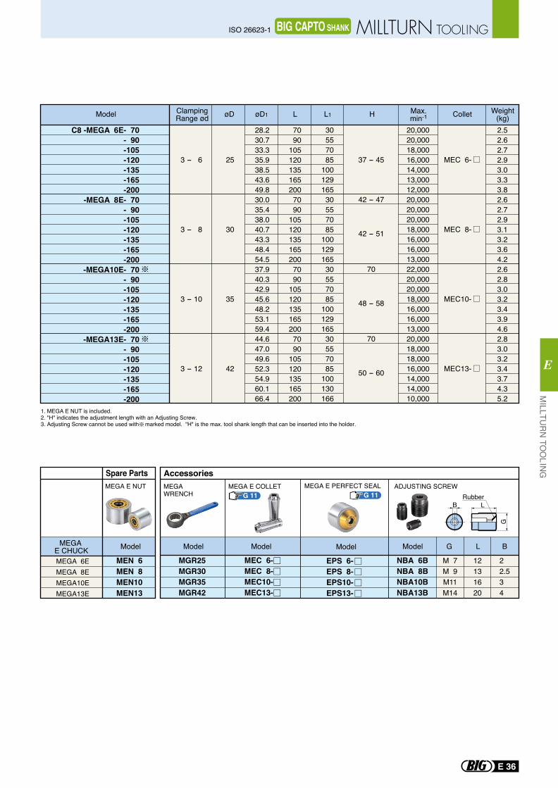
BRubber
LG
Spare Parts
MEGA 6EMEGA 8EMEGA10EMEGA13E
MEGA E CHUCK
MEN 6MEN 8MEN10MEN13
MEGA E NUT
Model
MGR25MGR30MGR35MGR42
NBA 6BNBA 8BNBA10BNBA13B
M 7M 9M11M14
12131620
22.534
G L B
MEGAWRENCH
MEGA E COLLET ADJUSTING SCREW
EPS 6-EPS 8-EPS10-EPS13-
MEC 6-MEC 8-MEC10-MEC13-
MEGA E PERFECT SEAL
Accessories
G 11 G 11
ModelModel ModelModel
37 - 45
42 - 47
42 - 51
70
48 - 58
70
50 - 60
20,00020,00018,00016,00014,00013,00012,00020,00020,00020,00018,00016,00016,00013,00022,00020,00020,00018,00016,00016,00013,00020,00018,00018,00016,00014,00014,00010,000
2.52.62.72.93.03.33.82.62.72.93.13.23.64.22.62.83.03.23.43.94.62.83.03.23.43.74.35.2
C8 -MEGA 6E- 70- 90-105-120-135-165-200
-MEGA 8E- 70- 90-105-120-135-165-200
-MEGA10E- 70- 90-105-120-135-165-200
-MEGA13E- 70- 90-105-120-135-165-200
25
30
35
42
3 - 6
3 - 8
3 - 10
3 - 12
MEC 6-
MEC 8-
MEC10-
MEC13-
30557085
10012916530557085
10012916530557085
10012916530557085
100130166
28.230.733.335.938.543.649.830.035.438.040.743.348.454.537.940.342.945.648.253.159.444.647.049.652.354.960.166.4
7090
1051201351652007090
1051201351652007090
1051201351652007090
105120135165200
Model ClampingRange ød HøD øD1 L Collet Weight
(kg)L1 Max.min-1
1. MEGA E NUT is included.2. "H" indicates the adjustment length with an Adjusting Screw.3. Adjusting Screw cannot be used with marked model. "H" is the max. tool shank length that can be inserted into the holder.
MILLTU
RN
TOO
LING
E
E 36
ISO 26623-1 MILLTURN TOOLINGBIG CAPTO SHANK
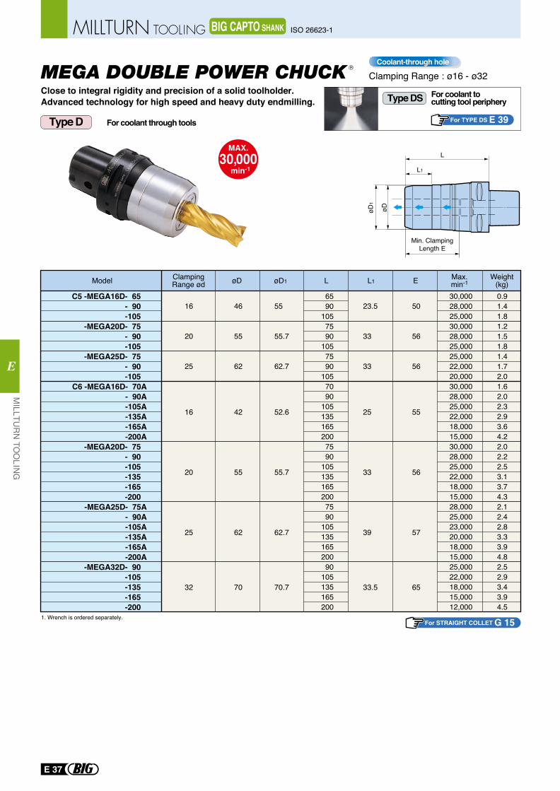
C5 -MEGA16D- 65- 90-105
-MEGA20D- 75- 90-105
-MEGA25D- 75- 90-105
C6 -MEGA16D- 70A- 90A-105A-135A-165A-200A
-MEGA20D- 75- 90-105-135-165-200
-MEGA25D- 75A- 90A-105A-135A-165A-200A
-MEGA32D- 90-105-135-165-200
16
20
25
16
20
25
32
46
55
62
42
55
62
70
23.5
33
33
25
33
39
33.5
50
56
56
55
56
57
65
55
55.7
62.7
52.6
55.7
62.7
70.7
6590
1057590
1057590
1057090
1051351652007590
1051351652007590
10513516520090
105135165200
0.91.41.81.21.51.81.41.72.01.62.02.32.93.64.22.02.22.53.13.74.32.12.42.83.33.94.82.52.93.43.94.5
30,00028,00025,00030,00028,00025,00025,00022,00020,00030,00028,00025,00022,00018,00015,00030,00028,00025,00022,00018,00015,00028,00025,00023,00020,00018,00015,00025,00022,00018,00015,00012,000
Close to integral rigidity and precision of a solid toolholder.Advanced technology for high speed and heavy duty endmilling.
MEGA DOUBLE POWER CHUCK R
1. Wrench is ordered separately.
Type D
Model ClampingRange ød
Weight(kg)E Max.
min-1øD øD1 L L1
For STRAIGHT COLLET G 15
Clamping Range : ø16 - ø32Coolant-through hole
MAX.30,000
min-1
For TYPE DS E 39
For coolant to cutting tool peripheryType DS
For coolant through tools
E 37
MILLTU
RN
TOO
LING
E
ISO 26623-1MILLTURN TOOLING BIG CAPTO SHANK
Min. ClampingLength E
øD1
L
øD
L1
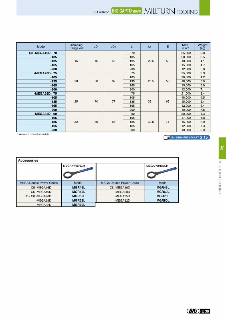
C8 -MEGA16D- 70-105-135-165-200
-MEGA20D- 75-105-135-165-200
-MEGA25D- 75-105-135-165-200
-MEGA32D- 90-105-135-165-200
16
20
25
32
23.5
25.5
32
39.5
50
56
65
71
55
69
77
86
46
60
70
80
7010513516520075
10513516520075
10513516520090
105135165200
2.83.54.14.75.63.34.25.05.97.13.44.55.46.47.84.34.86.07.39.0
25,00020,00018,00015,00012,00025,00020,00018,00015,00012,00021,00018,00015,00012,00010,00020,00017,00015,00012,00010,000
1. Wrench is ordered separately.
Model ClampingRange ød
Weight(kg)E Max.
min-1øD øD1 L L1
For STRAIGHT COLLET G 15
MGR46LMGR42LMGR55LMGR62LMGR70L
MGR46LMGR60LMGR70LMGR80L
C5 -MEGA16DC6 -MEGA16D
C5 / C6 -MEGA20D-MEGA25D-MEGA32D
MEGA WRENCH MEGA WRENCH
Accessories
MEGA Double Power ChuckC8 -MEGA16D
-MEGA20D-MEGA25D-MEGA32D
MEGA Double Power ChuckModel Model
MILLTU
RN
TOO
LING
E
E 38
ISO 26623-1 MILLTURN TOOLINGBIG CAPTO SHANK
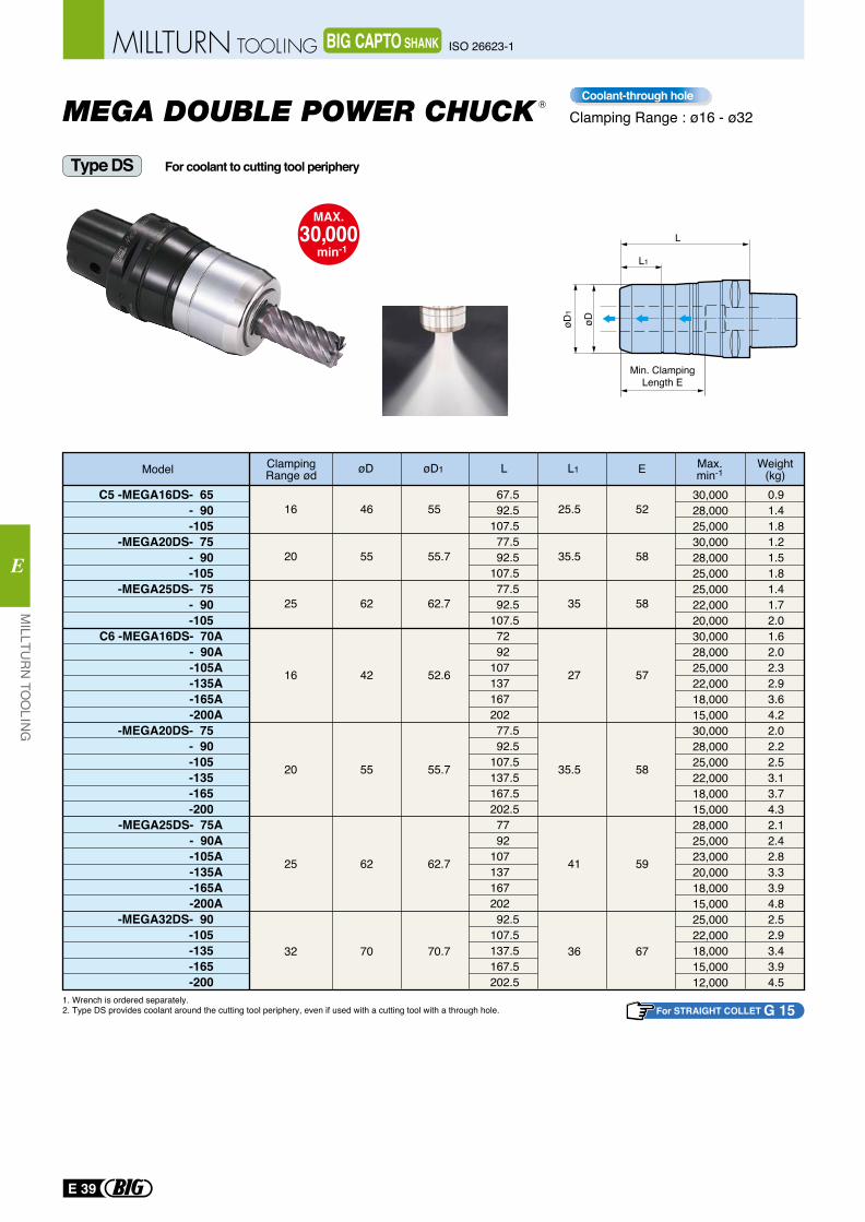
C5 -MEGA16DS- 65- 90-105
-MEGA20DS- 75- 90-105
-MEGA25DS- 75- 90-105
C6 -MEGA16DS- 70A- 90A-105A-135A-165A-200A
-MEGA20DS- 75- 90-105-135-165-200
-MEGA25DS- 75A- 90A-105A-135A-165A-200A
-MEGA32DS- 90-105-135-165-200
16
20
25
16
20
25
32
46
55
62
42
55
62
70
55
55.7
62.7
52.6
55.7
62.7
70.7
25.5
35.5
35
27
35.5
41
36
52
58
58
57
58
59
67
67.592.5
107.577.592.5
107.577.592.5
107.572 92
107 137 167 202 77.592.5
107.5137.5167.5202.5
77 92
107 137 167 202 92.5
107.5137.5167.5202.5
0.91.41.81.21.51.81.41.72.01.62.02.32.93.64.22.02.22.53.13.74.32.12.42.83.33.94.82.52.93.43.94.5
30,00028,00025,00030,00028,00025,00025,00022,00020,00030,00028,00025,00022,00018,00015,00030,00028,00025,00022,00018,00015,00028,00025,00023,00020,00018,00015,00025,00022,00018,00015,00012,000
Model ClampingRange ød
Weight(kg)E Max.
min-1øD øD1 L L1
1. Wrench is ordered separately.2. Type DS provides coolant around the cutting tool periphery, even if used with a cutting tool with a through hole.
MEGA DOUBLE POWER CHUCK R
For STRAIGHT COLLET G 15
Type DS
Clamping Range : ø16 - ø32Coolant-through hole
MAX.30,000
min-1
For coolant to cutting tool periphery
E 39
MILLTU
RN
TOO
LING
E
ISO 26623-1MILLTURN TOOLING BIG CAPTO SHANK
Min. ClampingLength E
øD1
L
øD
L1
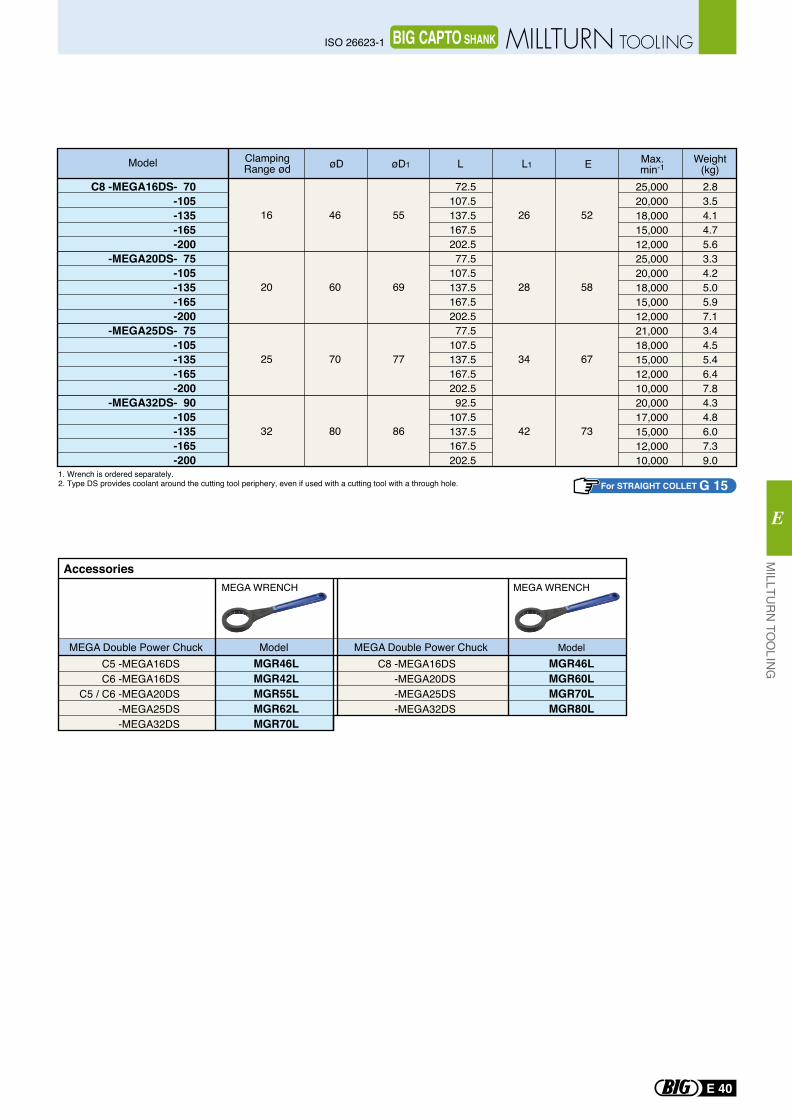
For STRAIGHT COLLET G 15
MGR46LMGR42LMGR55LMGR62LMGR70L
MGR46LMGR60LMGR70LMGR80L
C5 -MEGA16DSC6 -MEGA16DS
C5 / C6 -MEGA20DS-MEGA25DS-MEGA32DS
MEGA WRENCH MEGA WRENCH
Accessories
MEGA Double Power ChuckC8 -MEGA16DS
-MEGA20DS-MEGA25DS-MEGA32DS
MEGA Double Power ChuckModel Model
1. Wrench is ordered separately.2. Type DS provides coolant around the cutting tool periphery, even if used with a cutting tool with a through hole.
C8 -MEGA16DS- 70-105-135-165-200
-MEGA20DS- 75-105-135-165-200
-MEGA25DS- 75-105-135-165-200
-MEGA32DS- 90-105-135-165-200
16
20
25
32
46
60
70
80
55
69
77
86
26
28
34
42
52
58
67
73
72.5107.5137.5167.5202.577.5
107.5137.5167.5202.577.5
107.5137.5167.5202.592.5
107.5137.5167.5202.5
2.83.54.14.75.63.34.25.05.97.13.44.55.46.47.84.34.86.07.39.0
25,00020,00018,00015,00012,00025,00020,00018,00015,00012,00021,00018,00015,00012,00010,00020,00017,00015,00012,00010,000
Model ClampingRange ød E Max.
min-1Weight
(kg)øD øD1 L L1
MILLTU
RN
TOO
LING
E
E 40
ISO 26623-1 MILLTURN TOOLINGBIG CAPTO SHANK
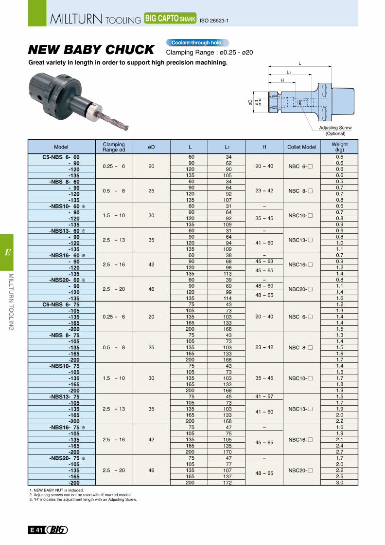
øD ød
L
L1
Adjusting Screw(Optional)
H
C5-NBS 6- 60- 90-120-135
-NBS 8- 60- 90-120-135
-NBS10- 60- 90-120-135
-NBS13- 60- 90-120-135
-NBS16- 60- 90-120-135
-NBS20- 60- 90-120-135
C6-NBS 6- 75-105-135-165-200
-NBS 8- 75-105-135-165-200
-NBS10- 75-105-135-165-200
-NBS13- 75-105-135-165-200
-NBS16- 75-105-135-165-200
-NBS20- 75-105-135-165-200
0.25 - 6
0.5 - 8
1.5 - 10
2.5 - 13
2.5 - 16
2.5 - 20
0.25 - 6
0.5 - 8
1.5 - 10
2.5 - 13
2.5 - 16
2.5 - 20
20
25
30
35
42
46
20
25
30
35
42
46
NBC 6-
NBC 8-
NBC10-
NBC13-
NBC16-
NBC20-
NBC 6-
NBC 8-
NBC10-
NBC13-
NBC16-
NBC20-
6090
1201356090
1201356090
1201356090
1201356090
1201356090
12013575
10513516520075
10513516520075
10513516520075
10513516520075
10513516520075
105135165200
346290
105346492
107316492
109316494
109386898
113396999
1144373
1031331684373
1031331684373
1031331684573
1031331684775
1051351704777
107137172
20 - 40
23 - 42
−
35 - 45
−
41 - 60
−45 - 6345 - 65
−48 - 6048 - 65
20 - 40
23 - 42
35 - 45
41 - 57
41 - 60
−
45 - 65
−
48 - 65
0.50.60.60.60.50.70.70.80.60.70.80.90.60.81.01.10.70.91.21.40.81.11.41.61.21.31.41.41.51.31.41.51.61.71.41.51.71.81.91.51.71.92.02.21.61.92.12.42.71.72.02.22.63.0
Great variety in length in order to support high precision machining.NEW BABY CHUCK
1. NEW BABY NUT is included.2. Adjusting screws can not be used with marked models.3. "H" indicates the adjustment length with an Adjusting Screw.
Model ClampingRange ød øD L Collet Model Weight
(kg)HL1
Clamping Range : ø0.25 - ø20Coolant-through hole
E 41
MILLTU
RN
TOO
LING
E
ISO 26623-1MILLTURN TOOLING BIG CAPTO SHANK
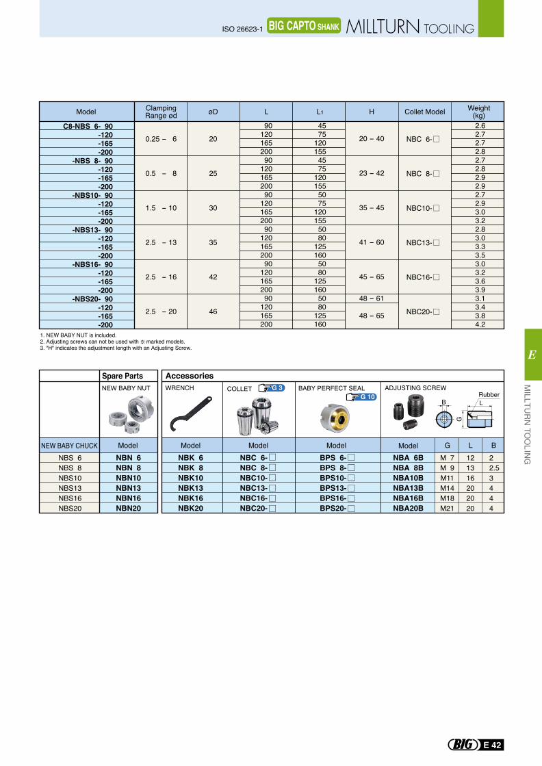
C8-NBS 6- 90-120-165-200
-NBS 8- 90-120-165-200
-NBS10- 90-120-165-200
-NBS13- 90-120-165-200
-NBS16- 90-120-165-200
-NBS20- 90-120-165-200
0.25 - 6
0.5 - 8
1.5 - 10
2.5 - 13
2.5 - 16
2.5 - 20
20
25
30
35
42
46
NBC 6-
NBC 8-
NBC10-
NBC13-
NBC16-
NBC20-
9012016520090
12016520090
12016520090
12016520090
12016520090
120165200
4575
1201554575
1201555075
1201555080
1251605080
1251605080
125160
20 - 40
23 - 42
35 - 45
41 - 60
45 - 65
48 - 61
48 - 65
2.62.72.72.82.72.82.92.92.72.93.03.22.83.03.33.53.03.23.63.93.13.43.84.2
G 3G 10
ModelModelModel ModelModelNBK 6NBK 8NBK10NBK13NBK16NBK20
NBA 6BNBA 8BNBA10BNBA13BNBA16BNBA20B
M 7M 9M11M14M18M21
121316202020
22.53444
WRENCH ADJUSTING SCREW
G L B
B L
G
Rubber
AccessoriesBABY PERFECT SEAL
BPS 6-BPS 8-BPS10-BPS13-BPS16-BPS20-
NBC 6-NBC 8-NBC10-NBC13-NBC16-NBC20-
COLLET
Spare Parts
NBS 6NBS 8NBS10NBS13NBS16NBS20
NEW BABY CHUCKNBN 6NBN 8NBN10NBN13NBN16NBN20
NEW BABY NUT
1. NEW BABY NUT is included.2. Adjusting screws can not be used with marked models.3. "H" indicates the adjustment length with an Adjusting Screw.
Model ClampingRange ød øD L Collet Model Weight
(kg)HL1
MILLTU
RN
TOO
LING
E
E 42
ISO 26623-1 MILLTURN TOOLINGBIG CAPTO SHANK
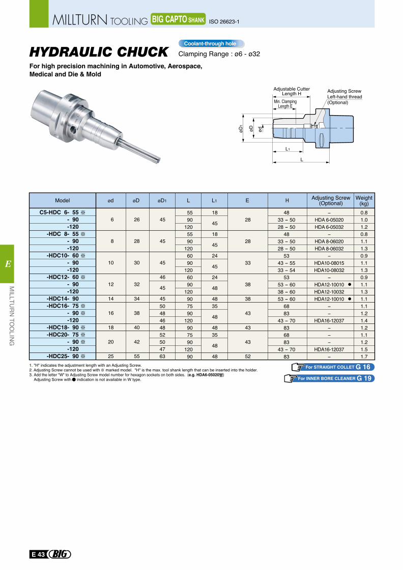
HYDRAULIC CHUCKFor high precision machining in Automotive, Aerospace, Medical and Die & Mold
1. "H" indicates the adjustment length with an Adjusting Screw.2. Adjusting Screw cannot be used with marked model. "H" is the max. tool shank length that can be inserted into the holder.3. Add the letter "W" to Adjusting Screw model number for hexagon sockets on both sides. (e.g. HDA6-05020W) Adjusting Screw with indication is not available in W type.
Clamping Range : ø6 - ø32Coolant-through hole
For STRAIGHT COLLET G 16For INNER BORE CLEANER G 19
øD1
øD ød
L1
L
Adjustable CutterLength H
Min. ClampingLength E
Adjusting ScrewLeft-hand thread(Optional)
E 43
MILLTU
RN
TOO
LING
E
ISO 26623-1MILLTURN TOOLING BIG CAPTO SHANK
C5-HDC 6- 55- 90-120
-HDC 8- 55- 90-120
-HDC10- 60- 90-120
-HDC12- 60- 90-120
-HDC14- 90-HDC16- 75
- 90-120
-HDC18- 90-HDC20- 75
- 90-120
-HDC25- 90
Model ød øD øD1 EL HL1
6
8
10
12
14
16
18
20
25
26
28
30
32
34
38
40
42
55
45
45
45
46
45
45
Adjusting Screw(Optional)
5590
1205590
1206090
1206090
120907590
120907590
12090
0.81.01.20.81.11.30.91.11.30.91.11.31.11.11.21.41.21.11.21.51.7
5048464852504763
18
45
18
45
24
45
24
48
4835
48
4835
48
48
28
28
33
38
38
43
43
43
52
4833 - 5028 - 50
4833 - 5028 - 50
5343 - 5533 - 54
5353 - 6038 - 6053 - 60
6883
43 - 70836883
43 - 7083
−HDA 6-05020HDA 6-05032
−HDA 8-06020HDA 8-06032
−HDA10-08015HDA10-08032
−HDA12-10010HDA12-10032HDA12-10010
−−
HDA16-12037−−−
HDA16-12037−
Weight(kg)
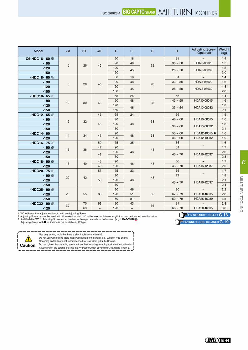
1. "H" indicates the adjustment length with an Adjusting Screw.2. Adjusting Screw cannot be used with marked model. "H" is the max. tool shank length that can be inserted into the holder.3. Add the letter "W" to Adjusting Screw model number for hexagon sockets on both sides. (e.g. HDA6-05020W) Adjusting Screw with indication is not available in W type.
Use only cutting tools that have a shank tolerance within h6.Do not use with cutting tools made with a flat on the shank (i.e.: Weldon type shank)Roughing endmills are not recommended for use with Hydraulic Chucks.Do not tighten the clamping screw without first inserting a cutting tool into the toolholder.Always insert the cutting tool into the Hydraulic Chuck beyond min. clamping length E.
Caution
For STRAIGHT COLLET G 16For INNER BORE CLEANER G 19
MILLTU
RN
TOO
LING
E
E 44
ISO 26623-1 MILLTURN TOOLINGBIG CAPTO SHANK
C6-HDC 6- 60- 90-120-150
-HDC 8- 60- 90-120-150
-HDC10- 65- 90-120-150
-HDC12- 65- 90-120-150
-HDC14- 90-120
-HDC16- 75- 90-120-150
-HDC18- 90-120
-HDC20- 75- 90-120-150
-HDC25- 90-120-150
-HDC32- 90-120
6
8
10
12
14
16
18
20
25
32
28
28
33
38
38
43
43
43
52
56
26
28
30
32
34
38
40
42
55
7563
6090
120150
6090
120150
6590
120150
6590
120150
90120
7590
120150
90120
7590
120150
90120150
90120
1.41.51.82.01.41.61.82.01.41.61.82.11.51.61.82.11.61.91.61.72.02.31.72.01.71.82.12.42.22.83.52.83.0
45
45
45
46
45
45
5047
48
484953
50
63
63−
1848
45
1848
45
2448
45
24
48
48
35
48
48
33
48
46518143−
5133 - 50
28 - 50
5133 - 50
28 - 50
5643 - 55
33 - 54
5648 - 60
38 - 60
53 - 6038 - 60
6681
43 - 70
6643 - 70
6672
43 - 70
8067 - 7952 - 79
8166 - 78
−HDA 6-05020
HDA 6-05032
−HDA 8-06020
HDA 8-06032
−HDA10-08015
HDA10-08032
−HDA10-08015
HDA10-08032
HDA12-10010HDA12-10032
−
HDA16-12037
−HDA16-12037
−
HDA16-12037
−HDA20-16015HDA25-16039
−HDA20-16015
※
※※
※
※※
※
※
Model ød øD øD1 EL HL1 Adjusting Screw(Optional)
Weight(kg)
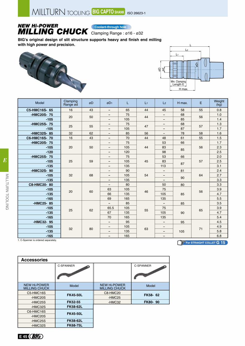
C5-HMC16S- 65-HMC20S- 75
-105-HMC25S- 75
-105-HMC32S- 85
C6-HMC16S- 70-HMC20S- 75
-105-120
-HMC25S- 75 -105
-135-HMC32S- 90
-105 -135
C8-HMC20- 80 -105 -135 -165
-HMC25- 85 -105 -135 -165
-HMC32- 95 -105 -135 -165
16
20
25
3216
20
25
32
20
25
32
0.81.01.41.31.71.61.51.72.32.52.02.53.12.42.73.33.33.94.75.53.53.94.75.44.54.95.86.8
BIG's original design of slit structure supports heavy and finish end milling with high power and precision.
MILLING CHUCKNEW Hi-POWER
1. C-Spanner is ordered separately.
Model ClampingRange ød
43
50
55
6243
50
59
68
60
62
80
øD
-----------------636669-
65.56770----
6575
10575
105857075
10512075
10513590
10513580
10513516585
10513516595
105135165
øD1 L
5868856887786166
85
66
87
81
90
80
85
85
90
95
105
H max.
55
56
57
5855
56
57
64
56
65
71
E
44
44
47
5644
44
45
54
46
55
63
L1
45-----485383985383
113 ---5075
105 135 -75
105 135 ----
L2 Weight(kg)
For STRAIGHT COLLET G 15
Clamping Range : ø16 - ø32Coolant-through hole
H max.
Min. ClampingLength E
ødøD
L1
L2
L
øD1
FK58- 62
FK80- 90
FK45-50L
FK52-55FK58-62L
FK45-50L
FK58-62LFK68-75L
AccessoriesC-SPANNER
Model
C-SPANNER
Model
C5-HMC16S-HMC20S-HMC25S-HMC32S
C6-HMC16S-HMC20S-HMC25S-HMC32S
C8-HMC20 -HMC25 -HMC32
NEW Hi-POWERMILLING CHUCK
NEW Hi-POWERMILLING CHUCK
E 45
MILLTU
RN
TOO
LING
E
ISO 26623-1MILLTURN TOOLING BIG CAPTO SHANK
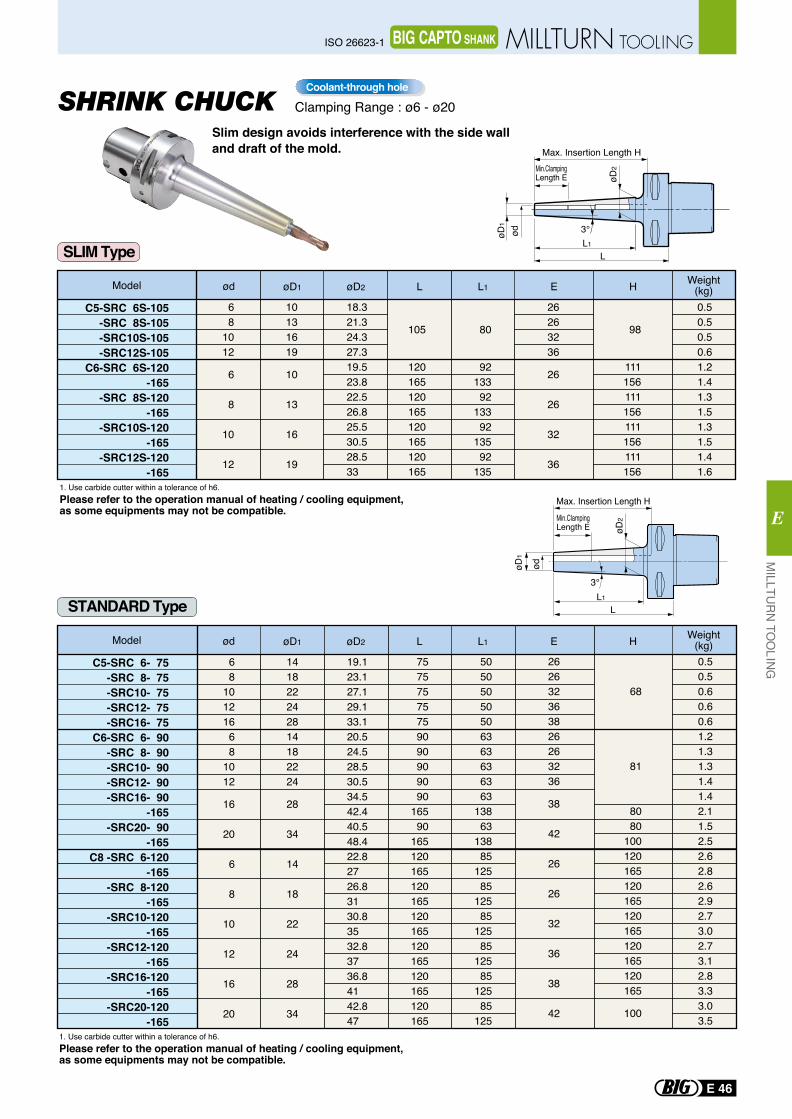
C5-SRC 6- 75-SRC 8- 75-SRC10- 75-SRC12- 75-SRC16- 75
C6-SRC 6- 90-SRC 8- 90-SRC10- 90-SRC12- 90-SRC16- 90
-165-SRC20- 90
-165C8 -SRC 6-120
-165-SRC 8-120
-165-SRC10-120
-165-SRC12-120
-165-SRC16-120
-165-SRC20-120
-165
68
10121668
1012
16
20
6
8
10
12
16
20
141822242814182224
28
34
14
18
22
24
28
34
19.123.127.129.133.120.524.528.530.534.542.440.548.422.82726.83130.83532.83736.84142.847
75757575759090909090
16590
165120165120165120165120165120165120165
50505050506363636363
13863
13885
12585
12585
12585
12585
12585
125
262632363826263236
38
42
26
26
32
36
38
42
0.50.50.60.60.61.21.31.31.41.42.11.52.52.62.82.62.92.73.02.73.12.83.33.03.5
68
81
8080
100120165120165120165120165120165
100
1. Use carbide cutter within a tolerance of h6.Please refer to the operation manual of heating / cooling equipment, as some equipments may not be compatible.
1. Use carbide cutter within a tolerance of h6.Please refer to the operation manual of heating / cooling equipment, as some equipments may not be compatible.
C5-SRC 6S-105-SRC 8S-105-SRC10S-105-SRC12S-105
C6-SRC 6S-120-165
-SRC 8S-120-165
-SRC10S-120-165
-SRC12S-120-165
68
1012
6
8
10
12
10131619
10
13
16
19
18.321.324.327.319.523.822.526.825.530.528.533
105
120165120165120165120165
80
9213392
13392
13592
135
26263236
26
26
32
36
0.50.50.50.61.21.41.31.51.31.51.41.6
98
111156111156111156111156
STANDARD Type
SLIM Type
Model ød øD1 øD2 L L1 E Weight(kg)H
Model ød øD1 øD2 L L1 E Weight(kg)H
Slim design avoids interference with the side walland draft of the mold.
SHRINK CHUCK
Min.ClampingLength E
3°
Max. Insertion Length H
øD1
ød
L1
L
øD2
3°
øD2Min.Clamping
Length E
Max. Insertion Length H
L1
L
øD1
ød
Clamping Range : ø6 - ø20Coolant-through hole
MILLTU
RN
TOO
LING
E
E 46
ISO 26623-1 MILLTURN TOOLINGBIG CAPTO SHANK
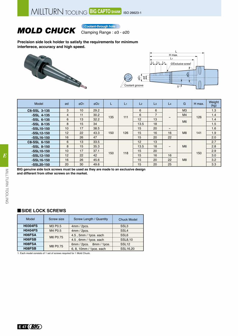
C6-SSL 3-135-SSL 4-135-SSL 6-135-SSL 8-135-SSL10-150-SSL12-150-SSL16-150
C8-SSL 6-150-SSL 8-150-SSL10-150-SSL12-150-SSL16-150-SSL20-150
Model
3468
10121668
10121620
10111315172226131517222630
29.230.232.23438.543.34733.535.337.14245.649.6
135
150
150
111
126
118
6 61213.51515151213.515151515
67
1318201620131820162020
-
-1622
-
162225
M3M4
M6
M8
M6
M8
126
141
150
1.31.41.41.51.61.92.02.72.82.93.03.23.3
ød øD1 øD2 L L1 L2 L3 L4 G H max. Weight(kg)
1. Each model consists of 1 set of screws required for 1 Mold Chuck.
Model Screw size Screw Length / Quantity
H0304FSH0404FSH06FSAH06FSBH08FSAH08FSB
Chuck Model
M3 P0.5M4 P0.5
M6 P0.75 M8 P0.75
4mm / 2pcs.4mm / 2pcs.4.5 , 5mm / 1pce. each4.5 , 6mm / 1pce. each6mm / 2pcs. 8mm / 1pce.6, 8, 10mm / 1pce. each
SSL3SSL4SSL6 SSL8,10 SSL12 SSL16,20
SIDE LOCK SCREWS
Precision side lock holder to satisfy the requirements for minimum interferece, accuracy and high speed.
MOLD CHUCK
BIG genuine side lock screws must be used as they are made to an exclusive designand different from other screws on the market.
Clamping Range : ø3 - ø20Coolant-through hole
Coolant groove
øD2
øD1
ød
L4L3L2
L1H max.
L
5°
G(Exclusive screw)
E 47
MILLTU
RN
TOO
LING
E
ISO 26623-1MILLTURN TOOLING BIG CAPTO SHANK
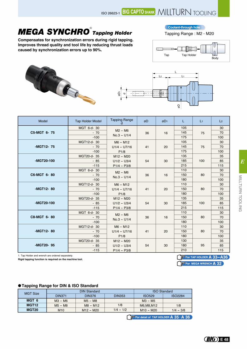
L1L2
L
døD1
øD
øD øD1 L1L L2
MGT 6-d- 30 - 70 -100
MGT12-d- 30 - 70 -100
MGT20-d- 35 - 85 -115
MGT 6-d- 30 - 70 -100
MGT12-d- 30 - 70 -100
MGT20-d- 35 - 85 -115
MGT 6-d- 30 - 70 -100
MGT12-d- 30 - 70 -100
MGT20-d- 35 - 85 -115
C5-MGT 6- 75
-MGT12- 75
-MGT20-100
C6-MGT 6- 80
-MGT12- 80
-MGT20-100
C8-MGT 6- 80
-MGT12- 80
-MGT20- 95
36
41
54
36
41
54
36
41
54
16
20
30
16
20
30
16
20
30
75
75
100
80
80
100
80
80
95
3070
1003070
1003585
1153070
1003070
1003585
1153070
1003070
1003585
115
105145175105145175135185215110150180110150180135185215110150180110150180130180210
M2 - M6No.3 - U1/4
M6 - M12U1/4 - U7/16
P1/8M12 - M20U1/2 - U3/4P1/4 - P3/8
M2 - M6No.3 - U1/4
M6 - M12U1/4 - U7/16
P1/8M12 - M20U1/2 - U3/4P1/4 - P3/8
M2 - M6No.3 - U1/4
M6 - M12U1/4 - U7/16
P1/8M12 - M20U1/2 - U3/4P1/4 - P3/8
Model
BodyTap HolderTap
Tapping RangedTap Holder Model
1. Tap Holder and wrench are ordered separately.Rigid tapping function is required on the machine tool.
Tapping Range for DIN & ISO Standard
MGT Size DIN StandardDIN371 DIN376 DIN353 ISO529 ISO2284
ISO Standard
MGT 6MGT12MGT20
M3 - M6M5 - M8
M10
M5 - M8 M8 - M12 M12 - M20
1/81/4 - 1/2
M3 - M5M6,M8,M12M10 - M20
1/81/4 - 3/8
Compensates for synchronization errors during rigid tapping.Improves thread quality and tool life by reducing thrust loadscaused by synchronization errors up to 90%.
For TAP HOLDER A 33-A36For MEGA WRENCH A 32
For detail of TAP HOLDER A 35 A 36
Tapping Range : M2 - M20Coolant-through hole
MEGA SYNCHRO Tapping HolderR
MILLTU
RN
TOO
LING
E
E 48
ISO 26623-1 MILLTURN TOOLINGBIG CAPTO SHANK
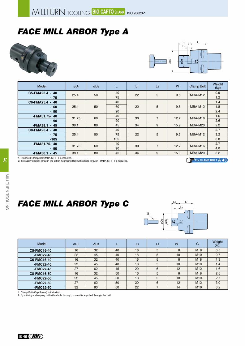
FACE MILL ARBOR Type ALL1
L2
WøD2
øD1
øD2
øD1
L1
L2
L
W
G
1. Clamp Bolt (Cap Screw) is included. 2. By utilizing a clamping bolt with a hole through, coolant is supplied through the bolt.
C5-FMC16-40-FMC22-40
C6-FMC16-40-FMC22-40-FMC27-45
C8-FMC16-50-FMC22-50-FMC27-50-FMC32-50
Model
162216222716222732
324532456232456280
404040404550505050
161816182016182022
555565567
8108
10128
101214
0.50.71.31.41.62.52.73.03.2
M 8M10M 8M10M12M 8M10M12M16
øD1 øD2 L L1 L2 W Weight(kg)G
C5-FMA25.4 - 40- 75
C6-FMA25.4 - 40- 60- 90
-FMA31.75- 40- 90
-FMA38.1 - 45C8-FMA25.4 - 40
- 75-105
-FMA31.75- 40- 90
-FMA38.1 - 45
25.4
25.4
31.75
38.1
25.4
31.75
38.1
50
50
60
80
50
60
80
40754060904090454075
105409045
22
22
30
34
22
30
34
5
5
7
9
5
7
9
9.5
9.5
12.7
15.9
9.5
12.7
15.9
0.91.21.41.82.41.62.62.22.73.23.82.74.03.2
MBA-M12
MBA-M12
MBA-M16
MBA-M20
MBA-M12
MBA-M16
MBA-M20
Weight(kg)
FACE MILL ARBOR Type C
Model øD1 øD2 L L1 L2 W Clamp Bolt
For CLAMP BOLT A 431. Standard Clamp Bolt (MBA-M ) is included.2. To supply coolant through the arbor, Clamping Bolt with a hole through (TMBA-M ) is required.
E 49
MILLTU
RN
TOO
LING
E
ISO 26623-1MILLTURN TOOLING BIG CAPTO SHANK
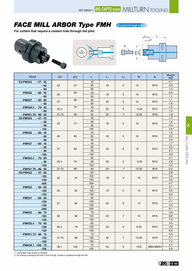
Coolant-through hole
C5-FMH22 - 47- 45- 60- 90
-FMH22 - 60- 45- 60
-FMH27 - 60- 60- 90
-FMH25.4 - 70- 45- 60
-FMH31.75- 96- 50C6-FMH22 - 47- 45
- 60- 90
- 150-FMH22 - 60- 45
- 60- 90
-FMH27 - 60- 45- 60- 90-150
-FMH25.4 - 70- 60- 90-150
-FMH31.75- 96- 60
Model
22
22
27
25.4
31.75
22
22
27
25.4
31.75
47
60
60
70
96
47
60
60
70
96
45609045606090456050456090
150456090456090
1506090
15060
18
18
20
22
30
18
18
20
22
30
5
5
6
5
7
5
5
6
5
7
10
10
12
9.35
12.55
10
10
12
9.35
12.55
0.70.91.40.91.11.11.61.01.21.81.41.62.02.81.62.02.61.72.02.73.92.12.84.22.2
M10
M10
M12
M12
M16
M10
M10
M12
M12
M16
øD1 øD2 L L1 L2 W Weight(kg)G
For cutters that require a coolant hole through the pilot.FACE MILL ARBOR Type FMH
1. Clamp Bolt (Cap Screw) is included. 2. By utilizing a clamping bolt with a hole through, coolant is supplied through the bolt.
WøD2
øD1
L2
L1 L
G
1. Clamp Bolt (Cap Screw) is included. 2. By utilizing a clamping bolt with a hole through, coolant is supplied through the bolt.
C8-FMH22 - 47- 60-105-150-200
-FMH22 - 60- 60-105-150
-FMH27 - 60- 60-105-150-200
-FMH32 - 96- 75-105-150
-FMH25.4 - 70- 60-105-150
-FMH31.75- 96- 75-105-150
-FMH38.1 -100- 75-105
22
22
27
32
25.4
31.75
38.1
47
60
60
96
70
96
100
6010515020060
10515060
10515020075
10515060
10515075
10515075
105
18
18
20
22
22
30
34
5
5
6
7
5
7
9
10
10
12
14
9.35
12.55
15.8
2.83.44.04.73.14.05.03.14.15.06.14.66.87.53.34.66.04.55.17.34.75.8
M10
M10
M12
M16
M12
M16
MBA-M20H
MILLTU
RN
TOO
LING
E
E 50
ISO 26623-1 MILLTURN TOOLINGBIG CAPTO SHANK
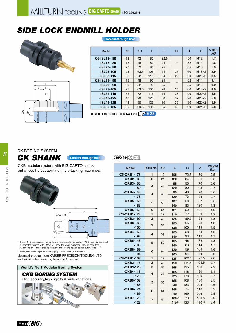
Coolant-through hole
1. L and A dimensions on the table are reference figures when EWN Head is mounted. indicates figures with EWN150 Head for large diameter. Please note that A-dimension is the distance from the face of the flange to the cutting edge.2. Designed to be capable of supplying coolant though the shank.
Licensed product from KAISER PRECISION TOOLING LTD. for limited sales territory, Asia and Oceania.
øDCKB No.Model L L1 A Weight(kg)
80 96 70 95 70 95 87
120 101 83 98 78
113 78
113 79
114 108 143 72.5
105.5130 130 190 130 205 110 206 130 180
72.584.555 80 48 73 50 83 50 77.589.565
100 58 93 48 83 59 94
102.5114.5125 118 178 108 183 74
169 73
123
105 120 95
120 95
120 107 140 121 110 125 105 140 105 140 105 140 130 165 135 150 165 165 225 165 240 145 240 160 210
1924
31
39
50
641924
31
39
50
64
192431
39
50
64
90
12
3
4
5
612
3
4
5
6
123
4
5
6
7
C5-CKB1- 73-CKB2- 85-CKB3- 55
- 80-CKB4- 48
- 73-CKB5- 50
- 83-CKB6- 50
C6-CKB1- 78-CKB2- 90-CKB3- 65
-100-CKB4- 58
- 93-CKB5- 48
- 83-CKB6- 59
- 94C8-CKB1-103
-CKB2-115-CKB3-125-CKB4-118
-178-CKB5-108
-183-CKB6- 74
-169-CKB7- 73
-123
0.50.60.60.70.60.70.61.31.01.21.31.31.51.31.71.31.71.62.32.62.72.93.13.73.54.63.25.85.08.4
World’s No.1 Modular Boring System
High accurary,high rigidity & wide variations.
A
L1
L
CKB No.
øD
CKB modular system with BIG CAPTO shank enhancesthe capability of multi-tasking machines.
CK BORING SYSTEM
SIDE LOCK ENDMILL HOLDER
C6-ISL12- 80-ISL16- 80-ISL20- 80-ISL25-105-ISL32-115
C8-ISL16- 90-ISL20- 90-ISL25-105-ISL32-115-ISL40-125-ISL42-125-ISL50-135
Model ød øD L2L L1 H G
121620253216202532404250
42485263.572485263.572909099.5
808080
1051159090
105115125125135
22.52425242424252424303035
505255609052556090909090
M12M14M16M18×2M20×2M14M16M18×2M20×2M20×2M20×2M24×2
Weight(kg)1.71.81.92.93.53.13.24.04.55.85.96.8
2528
2528323235
øD ød
LH
G
L1 L2
SIDE LOCK HOLDER for Drill※
Coolant-through hole
E 28
E 51
MILLTU
RN
TOO
LING
E
ISO 26623-1MILLTURN TOOLING BIG CAPTO SHANK
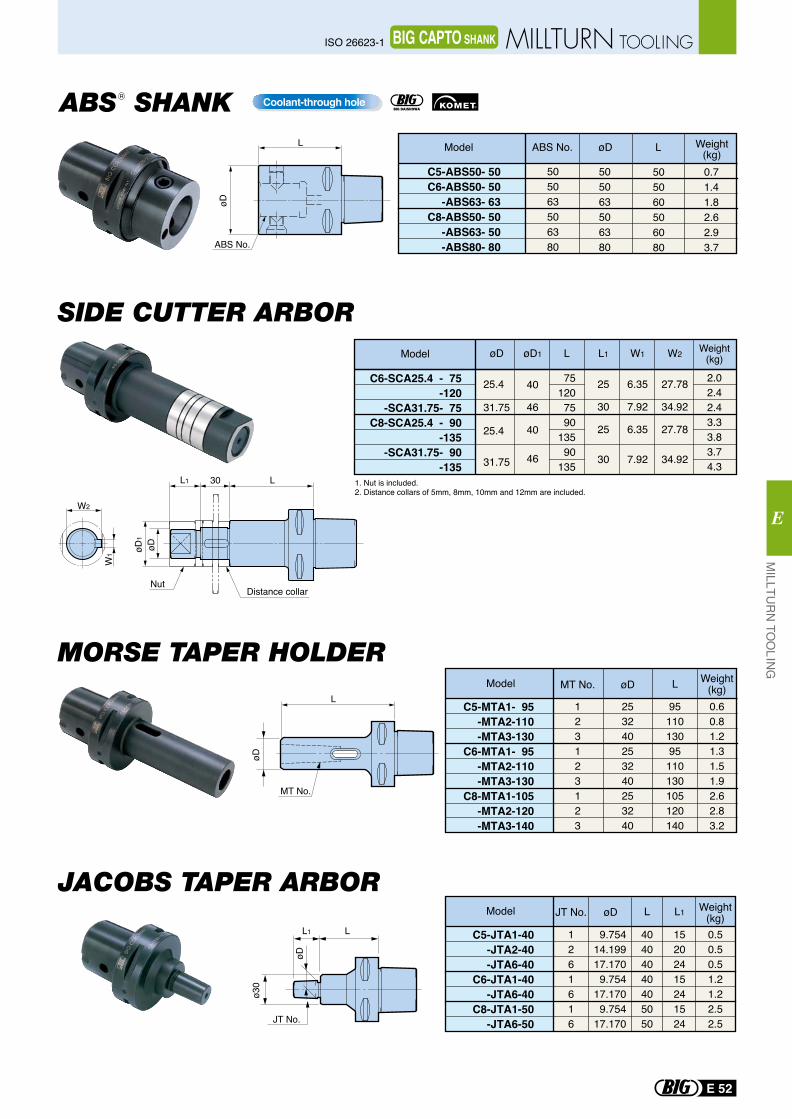
SIDE CUTTER ARBOR
MORSE TAPER HOLDER
JACOBS TAPER ARBOR
L1
JT No.
L
øD
ø30
40404040405050
253240253240253240
9511013095110130105120140
0.60.81.21.31.51.92.62.83.2
C5-MTA1- 95-MTA2-110-MTA3-130
C6-MTA1- 95-MTA2-110-MTA3-130
C8-MTA1-105-MTA2-120-MTA3-140
123123123
9.75414.19917.1709.754
17.1709.754
17.170
15202415241524
0.50.50.51.21.22.52.5
C5-JTA1-40-JTA2-40-JTA6-40
C6-JTA1-40-JTA6-40
C8-JTA1-50-JTA6-50
1261616
Model MT No. LøD
Model JT No. L1 Weight(kg)øD L
L
MT No.
øD
W2
W1
LL1 30
Distance collarNut
øD1
øD
1. Nut is included.2. Distance collars of 5mm, 8mm, 10mm and 12mm are included.
Model øD øD1 W1L L1 W2
C6-SCA25.4 - 75-120
-SCA31.75- 75C8-SCA25.4 - 90
-135-SCA31.75- 90
-135
25.4
31.75
25.4
31.75
40
46
40
46
751207590
13590
135
25
30
25
30
6.35
7.92
6.35
7.92
27.78
34.92
27.78
34.92
Weight(kg)
2.02.42.43.33.83.74.3
Weight(kg)
ABS SHANK R
R
C5-ABS50- 50C6-ABS50- 50
-ABS63- 63C8-ABS50- 50
-ABS63- 50-ABS80- 80
505063506380
505063506380
505060506080
Model L
0.71.41.82.62.93.7
Weight(kg)øDABS No.L
ABS No.
øD
Coolant-through hole
MILLTU
RN
TOO
LING
E
E 52
ISO 26623-1 MILLTURN TOOLINGBIG CAPTO SHANK
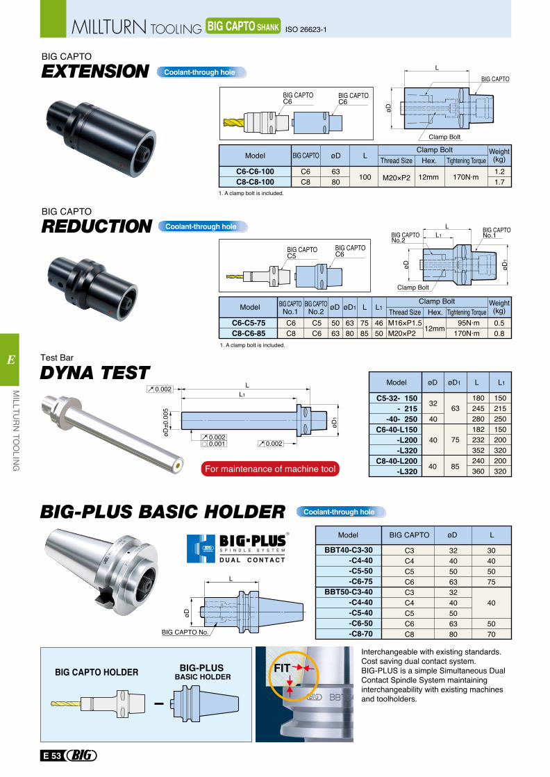
0.002
0.0020.0020.001
LL1
øD±0
.005
øD1
32
40
40
63
75
L1øD1 LøDModel
40 85
C5-32- 150- 215
-40- 250C6-40-L150
-L200-L320
C8-40-L200-L320
150215250150200320200320
180245280182232352240360For maintenance of machine tool
Test Bar
DYNA TEST
BIG-PLUS BASIC HOLDER
BIG-PLUS BASIC HOLDERBIG CAPTO HOLDER
øD L
BBT40-C3-30-C4-40-C5-50-C6-75
BBT50-C3-40-C4-40-C5-40-C6-50-C8-70
FITInterchangeable with existing standards. Cost saving dual contact system. BIG-PLUS is a simple Simultaneous Dual Contact Spindle System maintaining interchangeability with existing machines and toolholders.
C3C4C5C6C3C4C5C6C8
324050633240506380
30405075
40
5070
Model BIG CAPTO
L
BIG CAPTO No.
øD
Coolant-through hole
BIG CAPTOC6BIG CAPTO
C5
BIG CAPTOC6
BIG CAPTOC6
Coolant-through hole
Coolant-through hole
Model
C6-C5-75C8-C6-85
BIG CAPTONo.2
BIG CAPTONo.1C6C8
C5C6
5063
7585
4650
Weight(kg)0.50.8
øD
6380
øD1 L L1Clamp Bolt
Thread Size Hex. Tightening TorqueM16×P1.5M20×P2 12mm
95N·m170N·m
Model
C6-C6-100C8-C8-100
C6C8
øD
6380
Weight(kg)1.21.7
LClamp Bolt
100 M20×P2 12mm 170N·m
BIG CAPTO
EXTENSIONBIG CAPTO
REDUCTIONBIG CAPTO
1. A clamp bolt is included.
1. A clamp bolt is included.
L
øD
BIG CAPTO
L1
L
øD øD1
BIG CAPTONo.1
Clamp Bolt
Clamp Bolt
BIG CAPTONo.2
Thread Size Hex. Tightening Torque
R
S P I N D L E S Y S T E M
D U A L C O N T A C T
E 53
MILLTU
RN
TOO
LING
E
ISO 26623-1MILLTURN TOOLING BIG CAPTO SHANK
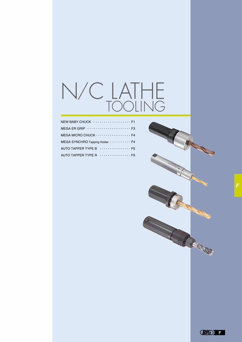
NEW BABY CHUCK
MEGA ER GRIP
MEGA MICRO CHUCK
MEGA SYNCHRO Tapping Holder
AUTO TAPPER TYPE B
AUTO TAPPER TYPE R
F1
F3
F4
F4
F5
F5
N/C LATHETOOLING
F
F
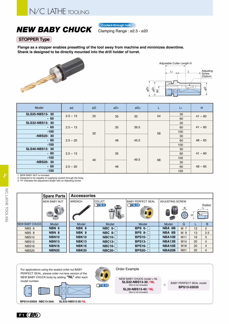
Model ød øD øD2 L
30603060
1003060
1003060
1003060
100
2.5 - 13
2.5 - 13
2.5 - 20
2.5 - 13
2.5 - 20
35
35
46
35
46
41 - 60
41 - 60
48 - 65
41 - 60
48 - 65
32
39.5
45.5
49.5
L1øD1
32
25
40
58
54
68
Flange as a stopper enables presetting of the tool away from machine and minimizes downtime.Shank is designed to be directly mounted into the drill holder of turret.
1. NEW BABY NUT is included.2. Designed to be capable of supplying coolant through the body.3. "H" indicates the adjustment length with an Adjusting Screw.
NEW BABY NUT
Spare PartsWRENCH
AccessoriesADJUSTING SCREWCOLLET BABY PERFECT SEAL
ød
LL1
øDøD2
øD1
Adjustable Cutter Length H
Adjusting Screw (Option)
H
SLS25-NBS13- 30- 60
SLS32-NBS13- 30- 60-100
-NBS20- 30- 60-100
SLS40-NBS13- 30- 60-100
-NBS20- 30- 60-100
NBS 6NBS 8NBS10NBS13NBS16NBS20
NBN 6NBN 8NBN10NBN13NBN16NBN20
NEW BABY CHUCKNBK 6NBK 8NBK10NBK13NBK16NBK20
BPS 6-BPS 8-BPS10-BPS13-BPS16-BPS20-
NBC 6-NBC 8-NBC10-NBC13-NBC16-NBC20-
NBA 6BNBA 8BNBA10BNBA13BNBA16BNBA20B
M 7M 9M11M14M18M21
121316202020
22.53444
G L B
BRubberL
G
ModelModelModelModelModel
For applications using the sealed collet nut BABY PERFECT SEAL, please order nut-less version of the NEW BABY CHUCK body by adding "NL" after each model number.
BABY PERFECT SEAL modelBPS13-03035
NEW BABY CHUCK model + NLSLS32-NBS13-30 / NL
(Nut is not included)
SL20-NBS13-40 / NL(Nut is not included)
Order Example
SLS32-NBS13-30 / NLBPS13-03035 NBC13-3AA
NEW BABY CHUCK Clamping Range : ø2.5 - ø20Coolant-through hole
G 10
G 10G 3
STOPPER Type
N/C LATHE TO
OLING
F
N/C LATHE TOOLING
F 1
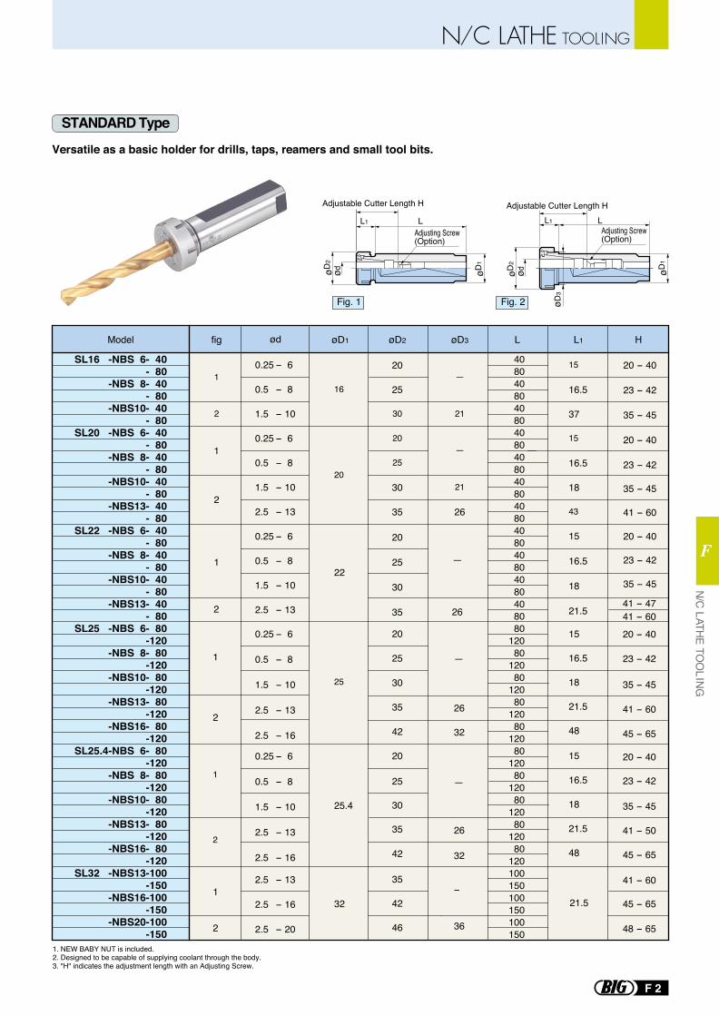
Versatile as a basic holder for drills, taps, reamers and small tool bits.
STANDARD Type
1. NEW BABY NUT is included.2. Designed to be capable of supplying coolant through the body.3. "H" indicates the adjustment length with an Adjusting Screw.
ød
LL1
øD1
øD2
Adjustable Cutter Length H
Adjusting Screw (Option)
LAdjustable Cutter Length H
øD1
ød
øD2
øD3
Adjusting Screw (Option)
L1
Model
20
25
30
20
25
30
35
20
25
30
35
42
20
25
30
35
42
35
42
46
øD2
20
25
30
35
H
1
2
1
2
1
2
fig
—
—
21
21
26
41 - 4741 - 60
øD3
—
26
32
—
26
32
−
36
—
26
20 - 40
23 - 42
35 - 45
41 - 60
45 - 65
20 - 40
23 - 42
35 - 45
41 - 50
45 - 65
41 - 60
45 - 65
48 - 65
20 - 40
23 - 42
35 - 45
20 - 40
23 - 42
35 - 45
41 - 60
20 - 40
23 - 42
35 - 45
1
2
1
2
1
2
4080408040804080408040804080408040804080408080
12080
12080
12080
12080
12080
12080
12080
12080
12080
120100150100150100150
L
15
16.5
37
15
16.5
18
43
15
16.5
18
21.5
15
16.5
18
21.5
48
15
16.5
18
21.5
48
L1
21.5
16
20
22
25
25.4
32
øD1
0.25 - 6
0.5 - 8
1.5 - 10
2.5 - 13
2.5 - 16
2.5 - 13
2.5 - 16
2.5 - 20
0.25 - 6
0.5 - 8
1.5 - 10
0.25 - 6
0.5 - 8
1.5 - 10
2.5 - 13
0.25 - 6
0.5 - 8
1.5 - 10
2.5 - 13
0.25 - 6
0.5 - 8
1.5 - 10
2.5 - 13
2.5 - 16
ød
SL16 -NBS 6- 40- 80
-NBS 8- 40- 80
-NBS10- 40- 80
SL20 -NBS 6- 40- 80
-NBS 8- 40- 80
-NBS10- 40- 80
-NBS13- 40- 80
SL22 -NBS 6- 40- 80
-NBS 8- 40- 80
-NBS10- 40- 80
-NBS13- 40- 80
SL25 -NBS 6- 80-120
-NBS 8- 80-120
-NBS10- 80-120
-NBS13- 80-120
-NBS16- 80-120
SL25.4-NBS 6- 80-120
-NBS 8- 80-120
-NBS10- 80-120
-NBS13- 80-120
-NBS16- 80-120
SL32 -NBS13-100-150
-NBS16-100-150
-NBS20-100-150
Fig. 1 Fig. 2
N/C LATHE TO
OLING
F
N/C LATHE TOOLING
F 2
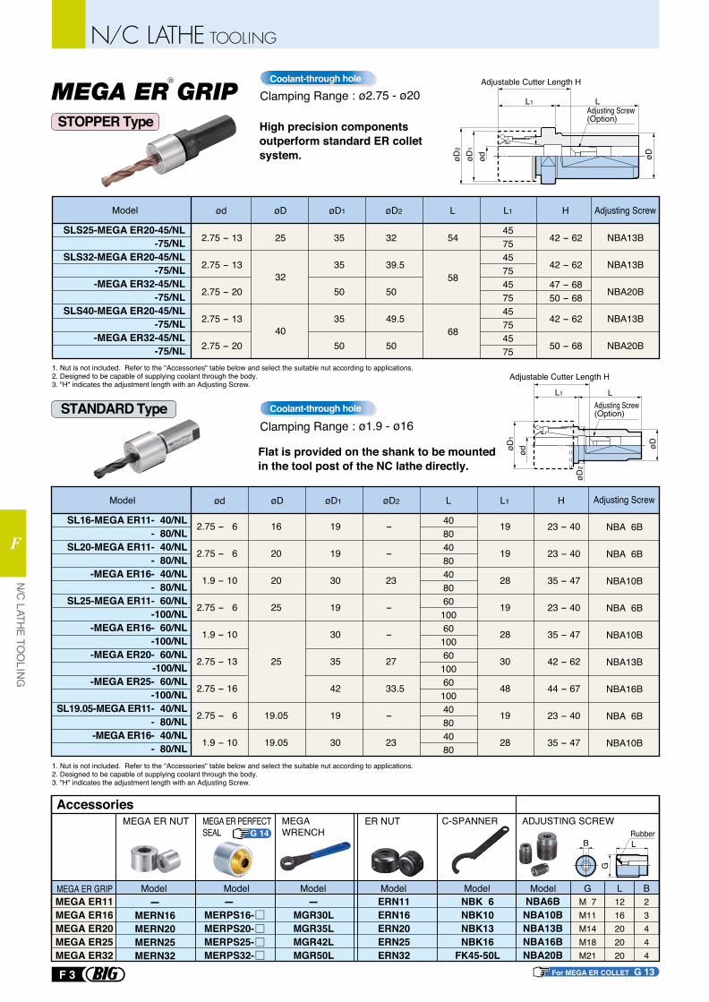
Clamping Range : ø1.9 - ø16Coolant-through hole
High precision components outperform standard ER collet system.
Model ød øD øD2 L
45754575457545754575
2.75 - 13
2.75 - 13
2.75 - 20
2.75 - 13
2.75 - 20
35
35
50
35
50
42 - 62
42 - 62
42 - 62
50 - 68
32
39.5
50
49.5
50
L1øD1
32
25
40
58
54
68
H
SLS25-MEGA ER20-45/NL-75/NL
SLS32-MEGA ER20-45/NL-75/NL
-MEGA ER32-45/NL-75/NL
SLS40-MEGA ER20-45/NL-75/NL
-MEGA ER32-45/NL-75/NL
1. Nut is not included. Refer to the "Accessories" table below and select the suitable nut according to applications.2. Designed to be capable of supplying coolant through the body.3. "H" indicates the adjustment length with an Adjusting Screw.
1. Nut is not included. Refer to the "Accessories" table below and select the suitable nut according to applications.2. Designed to be capable of supplying coolant through the body.3. "H" indicates the adjustment length with an Adjusting Screw.
Adjusting Screw
NBA13B
NBA13B
NBA20B
NBA13B
NBA20B
Flat is provided on the shank to be mounted in the tool post of the NC lathe directly.
MEGA ER GRIP Clamping Range : ø2.75 - ø20Coolant-through hole
Model ød øD øD2 L Adjusting Screw
4080408040806010060100601006010040804080
2.75 - 6
2.75 - 6
1.9 - 10
2.75 - 6
1.9 - 10
2.75 - 13
2.75 - 16
2.75 - 6
1.9 - 10
16
20
20
25
25
19.05
19.05
19
19
30
19
30
35
42
19
30
19
19
28
19
28
30
48
19
28
NBA 6B
NBA 6B
NBA10B
NBA 6B
NBA10B
NBA13B
NBA16B
NBA 6B
NBA10B
23 - 40
23 - 40
35 - 47
23 - 40
35 - 47
42 - 62
44 - 67
23 - 40
35 - 47
-
-
23
-
-
27
33.5
-
23
L1øD1 H
SL16-MEGA ER11- 40/NL- 80/NL
SL20-MEGA ER11- 40/NL- 80/NL
-MEGA ER16- 40/NL- 80/NL
SL25-MEGA ER11- 60/NL-100/NL
-MEGA ER16- 60/NL-100/NL
-MEGA ER20- 60/NL-100/NL
-MEGA ER25- 60/NL-100/NL
SL19.05-MEGA ER11- 40/NL- 80/NL
-MEGA ER16- 40/NL- 80/NL
MEGA WRENCH
C-SPANNER ADJUSTING SCREWAccessories
-MERPS16-MERPS20-MERPS25-MERPS32-
-MERN16MERN20MERN25MERN32
Model Model-
MGR30LMGR35LMGR42LMGR50L
ModelERN11ERN16ERN20ERN25ERN32
ModelNBK 6NBK10NBK13NBK16
FK45-50L
ModelNBA6B
NBA10BNBA13BNBA16BNBA20B
G L BModelMEGA ER GRIP
B
MEGA ER11MEGA ER16MEGA ER20MEGA ER25MEGA ER32
M 7M11M14M18M21
1216202020
23444
Adjusting Screw (Option)
L1 L
Adjustable Cutter Length H
ød
øDøD1
øD2
MEGA ER NUT ER NUTMEGA ER PERFECT SEAL Rubber
L
G
For MEGA ER COLLET G 13
G 14
STOPPER Type
STANDARD Type
øD2
ød
Adjusting Screw (Option)
LL1
Adjustable Cutter Length H
øDøD1
R
47 - 6850 - 68
N/C LATHE TO
OLING
F
N/C LATHE TOOLING
F 3
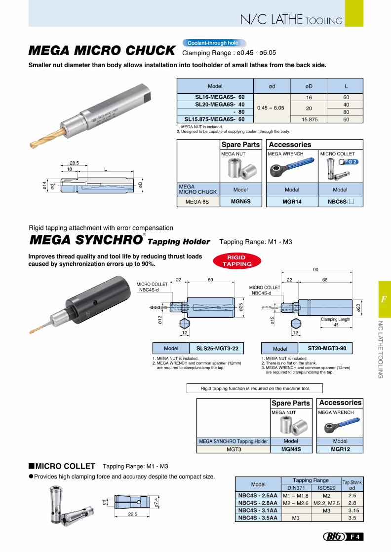
Model SLS25-MGT3-22
MEGA SYNCHRO Tapping Holder
MICRO COLLET NBC4S-d
ø25
6022
ø12
12
Model ST20-MGT3-90
MICRO COLLET NBC4S-d
ø20
68
Clamping Length 45
90
22
ø12
ø7.4ød
22.5
Tapping Range: M1 - M3
MEGA NUT
Spare PartsMEGA WRENCH
Accessories
MGT3 MGN4SMEGA SYNCHRO Tapping Holder Model
MGR12 Model
1. MEGA NUT is included.2. MEGA WRENCH and common spanner (12mm) are required to clamp/unclamp the tap.
1. MEGA NUT is included.2. There is no flat on the shank.3. MEGA WRENCH and common spanner (12mm) are required to clamp/unclamp the tap.
RIGID TAPPING
Rigid tapping function is required on the machine tool.
Rigid tapping attachment with error compensation
12
Provides high clamping force and accuracy despite the compact size.
Tapping Range: M1 - M3
NBC4S - 2.5AANBC4S - 2.8AANBC4S - 3.1AANBC4S - 3.5AA
ModelTapping Range
DIN371 ISO529Tap Shank
ød2.52.83.153.5
M1 - M1.8M2 - M2.6
M3
M2M2.2, M2.5
M3
Model ød øD
60408060
0.45 - 6.05
L
20
16
15.8751. MEGA NUT is included.2. Designed to be capable of supplying coolant through the body.
ød
18
øD
L28.5
ø14
MEGA NUT
Spare PartsMEGA WRENCH MICRO COLLET
Accessories
MEGA 6S MGN6S
MEGA MICRO CHUCK Model
MGR14
Model Model
SL16-MEGA6S- 60SL20-MEGA6S- 40
- 80SL15.875-MEGA6S- 60
G 2
NBC6S-
Smaller nut diameter than body allows installation into toolholder of small lathes from the back side.
Improves thread quality and tool life by reducing thrust loads caused by synchronization errors up to 90%.
MEGA MICRO CHUCK Clamping Range : ø0.45 - ø6.05Coolant-through hole
MICRO COLLET
R
N/C LATHE TO
OLING
F
N/C LATHE TOOLING
F 4
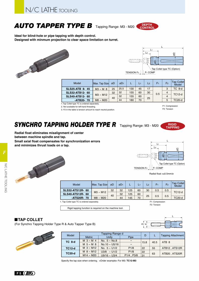
RIGID TAPPING
Tap Collet type TC (Option)
Radial float =±0.5mm/ø
L1
L2
L
øD
øD1
TENSION F2 F1 COMP
Model øDMax. Tap Size L F2F1
125125145
606070
323244
L1
30
25
L2øD1
32
40
0.5
0.5
0.5
0.5
1. Tap Collet type TC is ordered separately.
SLS32-ATS12R- 60SLS40-ATS12R- 60
-ATS20R- 70F1: CompressionF2: Tension
Tap Collet Model
TC12-d
TC20-d
M3 - M12
M8 - M20
D
L
d
Model
TC 8-d
TC12-dTC20-d
Tapping Range dMetric Unify Pipe
No. 5 - No.8No.10 - U5/16No. 5 - U1/2U3/8 - U1/2U9/16 - U3/4
--
P1/8P1/8
P1/4 , P3/8
D
15.8
222231
L
55
63
40.5
Tapping Attachment
ATB 8
ATB12 , ATS12R
ATB20 , ATS20R
M 3 - M 4M 5 - M 8 M 3 - M12M 8 - M12 M14 - M20
Specify the tap size when ordering. <Order example> For M3: TC12-M3
DEPTH CONTROL
TENSION F2
øD
LL1
L2
Tap Collet type TC (Option)F1 COMP
øD1
Model øD L F2F1
45606070
0.5
3445
Tap Collet Model
TC 8-d
TC12-d
TC20-d
25.5323244
L1
1730
25
L2øD1
3225
40
1.Tap Collet type TC is ordered separately.2. Not available for left-hand threading.3. F2 in the table is tension amount to reach neutral position.
F1: CompressionF2: Tension
SLS25-ATB 8- 45SLS32-ATB12- 60SLS40-ATB12- 60
-ATB20- 70
130155155180
Max. Tap Size
M3 - M 8
M3 - M12
M8 - M20
SYNCHRO TAPPING HOLDER TYPE RRadial float eliminates misalignment of center between machine spindle and tap.
Ideal for blind-hole or pipe tapping with depth control.Designed with minmum projection to clear space limitation on turret.
Small axial float compensates for synchronization errors and minimizes thrust loads on a tap.
Tapping Range: M3 - M20
Tapping Range: M3 - M20
Rigid tapping function is required on the machine tool.
AUTO TAPPER TYPE B
(For Synchro Tapping Holder Type R & Auto Tapper Type B)TAP COLLET
N/C LATHE TO
OLING
F
N/C LATHE TOOLING
F 5

G
G
MICRO COLLET
NEW BABY COLLET(NBC / NBC-E / FONBC)
COLLET EJECTOR / REMOVER
PERFECT SEAL(MPS / BPS / EPS)
MEGA E COLLET
TORQUE WRENCH
MEGA ER COLLET
MEGA ER PERFECT SEAL
STRAIGHT COLLET for HMC & HDC
TOOLING MATE
HOLDER LOCK
KOMBI GRIP
ST LOCK
CLEANER SERIES
CLEAN TEC
T-SLOT CLEAN
G2
G3
G8
G9
G11
G12
G13
G14
G15
G17
G17
G18
G18
G19
G21
G22
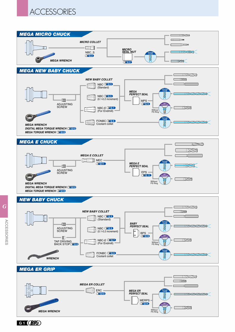
NEW BABY CHUCK
MEGA NEW BABY CHUCK
MPS
Without PS Ring
NBC(0.1-0.2 increment)
NBC(Standard)
NBC-E(For Endmill)
FONBC Coolant collet
NEW BABY COLLET
MEGA PERFECT SEAL
Without PS Ring
NBC(Standard)
NBC(0.1-0.2 increment)
NBC-E(For Endmill)
FONBC Coolant collet
NEW BABY COLLET
MEGA E CHUCK
MEGA ER GRIP
BPS
BABY PERFECT SEAL
Without PS Ring
EPS
MECMEGA E COLLET
MEGA E PERFECT SEAL
ERC
MERPS
Without PS Ring
MEGA ER COLLET
MEGA ERPERFECT SEAL
G 3
G 5
G 7
G 6
G 9
G 3
G 5
G 7
G 6
G13
G14
G10
G11
G 8
G 11
ThroughTools
ThroughTools
JETThrough
JETThrough
ThroughTools
ThroughTools
ThroughTools
JETThrough
ThroughTools
JETThrough
G 1
ACC
ESSOR
IES
G
ADJUSTINGSCREW
ADJUSTINGSCREW
ADJUSTINGSCREW
TAP DRIVING BACK STOP
MEGA WRENCH
WRENCH
G12G12
MEGA WRENCHDIGITAL MEGA TORQUE WRENCHMEGA TORQUE WRENCH
G12G12
MEGA WRENCHDIGITAL MEGA TORQUE WRENCHMEGA TORQUE WRENCH
NBC_S
MICRO COLLET
MEGA MICRO CHUCK
G 2
A 2MEGA WRENCH
MICRO SEAL NUT Through
Tools
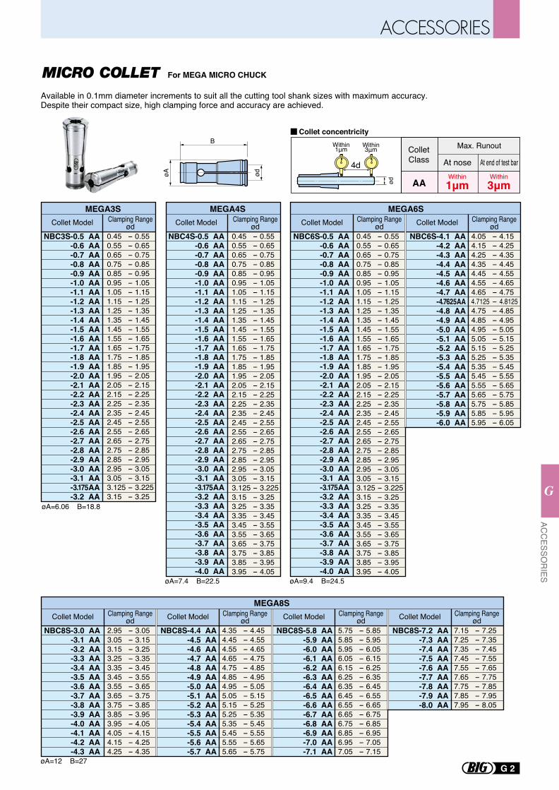
For MEGA MICRO CHUCK
Available in 0.1mm diameter increments to suit all the cutting tool shank sizes with maximum accuracy. Despite their compact size, high clamping force and accuracy are achieved.
øA ød
B
NBC4S-0.5 AA-0.6 AA-0.7 AA-0.8 AA-0.9 AA-1.0 AA-1.1 AA-1.2 AA-1.3 AA-1.4 AA-1.5 AA-1.6 AA-1.7 AA-1.8 AA-1.9 AA-2.0 AA-2.1 AA-2.2 AA-2.3 AA-2.4 AA-2.5 AA-2.6 AA-2.7 AA-2.8 AA-2.9 AA-3.0 AA-3.1 AA-3.175AA-3.2 AA-3.3 AA-3.4 AA-3.5 AA-3.6 AA-3.7 AA-3.8 AA-3.9 AA-4.0 AA
0.45 - 0.550.55 - 0.650.65 - 0.750.75 - 0.850.85 - 0.950.95 - 1.051.05 - 1.151.15 - 1.251.25 - 1.351.35 - 1.451.45 - 1.551.55 - 1.651.65 - 1.751.75 - 1.851.85 - 1.951.95 - 2.052.05 - 2.152.15 - 2.252.25 - 2.352.35 - 2.452.45 - 2.552.55 - 2.652.65 - 2.752.75 - 2.852.85 - 2.952.95 - 3.053.05 - 3.153.125 - 3.2253.15 - 3.253.25 - 3.353.35 - 3.453.45 - 3.553.55 - 3.653.65 - 3.753.75 - 3.853.85 - 3.953.95 - 4.05
NBC6S-0.5 AA-0.6 AA-0.7 AA-0.8 AA-0.9 AA-1.0 AA-1.1 AA-1.2 AA-1.3 AA-1.4 AA-1.5 AA-1.6 AA-1.7 AA-1.8 AA-1.9 AA-2.0 AA-2.1 AA-2.2 AA-2.3 AA-2.4 AA-2.5 AA-2.6 AA-2.7 AA-2.8 AA-2.9 AA-3.0 AA-3.1 AA-3.175AA-3.2 AA-3.3 AA-3.4 AA-3.5 AA-3.6 AA-3.7 AA-3.8 AA-3.9 AA-4.0 AA
øA=7.4 B=22.5 øA=9.4 B=24.5
0.45 - 0.550.55 - 0.650.65 - 0.750.75 - 0.850.85 - 0.950.95 - 1.051.05 - 1.151.15 - 1.251.25 - 1.351.35 - 1.451.45 - 1.551.55 - 1.651.65 - 1.751.75 - 1.851.85 - 1.951.95 - 2.052.05 - 2.152.15 - 2.252.25 - 2.352.35 - 2.452.45 - 2.552.55 - 2.652.65 - 2.752.75 - 2.852.85 - 2.952.95 - 3.053.05 - 3.153.125 - 3.2253.15 - 3.253.25 - 3.353.35 - 3.453.45 - 3.553.55 - 3.653.65 - 3.753.75 - 3.853.85 - 3.953.95 - 4.05
NBC6S-4.1 AA-4.2 AA-4.3 AA-4.4 AA-4.5 AA-4.6 AA-4.7 AA-4.7625AA-4.8 AA-4.9 AA-5.0 AA-5.1 AA-5.2 AA-5.3 AA-5.4 AA-5.5 AA-5.6 AA-5.7 AA-5.8 AA-5.9 AA-6.0 AA
4.05 - 4.154.15 - 4.254.25 - 4.354.35 - 4.454.45 - 4.554.55 - 4.654.65 - 4.75
4.7125 - 4.81254.75 - 4.854.85 - 4.954.95 - 5.055.05 - 5.155.15 - 5.255.25 - 5.355.35 - 5.455.45 - 5.555.55 - 5.655.65 - 5.755.75 - 5.855.85 - 5.955.95 - 6.05
MEGA4S
NBC3S-0.5 AA-0.6 AA-0.7 AA-0.8 AA-0.9 AA-1.0 AA-1.1 AA-1.2 AA-1.3 AA-1.4 AA-1.5 AA-1.6 AA-1.7 AA-1.8 AA-1.9 AA-2.0 AA-2.1 AA-2.2 AA-2.3 AA-2.4 AA-2.5 AA-2.6 AA-2.7 AA-2.8 AA-2.9 AA-3.0 AA-3.1 AA
-3.175AA-3.2 AA
0.45 - 0.550.55 - 0.650.65 - 0.750.75 - 0.850.85 - 0.950.95 - 1.051.05 - 1.151.15 - 1.251.25 - 1.351.35 - 1.451.45 - 1.551.55 - 1.651.65 - 1.751.75 - 1.851.85 - 1.951.95 - 2.052.05 - 2.152.15 - 2.252.25 - 2.352.35 - 2.452.45 - 2.552.55 - 2.652.65 - 2.752.75 - 2.852.85 - 2.952.95 - 3.053.05 - 3.153.125 - 3.2253.15 - 3.25
øA=6.06 B=18.8
MEGA3S MEGA6SClamping Range
ødClamping Range
ødClamping Range
ødClamping Range
ødCollet Model Collet Model Collet Model Collet Model
NBC8S-3.0 AA-3.1 AA-3.2 AA-3.3 AA-3.4 AA-3.5 AA-3.6 AA-3.7 AA-3.8 AA-3.9 AA-4.0 AA-4.1 AA-4.2 AA-4.3 AA
øA=12 B=27
2.95 - 3.053.05 - 3.153.15 - 3.253.25 - 3.353.35 - 3.453.45 - 3.553.55 - 3.653.65 - 3.753.75 - 3.853.85 - 3.953.95 - 4.054.05 - 4.154.15 - 4.254.25 - 4.35
NBC8S-4.4 AA-4.5 AA-4.6 AA-4.7 AA-4.8 AA-4.9 AA-5.0 AA-5.1 AA-5.2 AA-5.3 AA-5.4 AA-5.5 AA-5.6 AA-5.7 AA
4.35 - 4.454.45 - 4.554.55 - 4.654.65 - 4.754.75 - 4.854.85 - 4.954.95 - 5.055.05 - 5.155.15 - 5.255.25 - 5.355.35 - 5.455.45 - 5.555.55 - 5.655.65 - 5.75
MEGA8SClamping Range
ødClamping Range
ødCollet Model Collet Model
NBC8S-5.8 AA-5.9 AA-6.0 AA-6.1 AA-6.2 AA-6.3 AA-6.4 AA-6.5 AA-6.6 AA-6.7 AA-6.8 AA-6.9 AA-7.0 AA-7.1 AA
5.75 - 5.855.85 - 5.955.95 - 6.056.05 - 6.156.15 - 6.256.25 - 6.356.35 - 6.456.45 - 6.556.55 - 6.656.65 - 6.756.75 - 6.856.85 - 6.956.95 - 7.057.05 - 7.15
Clamping RangeødCollet Model
NBC8S-7.2 AA-7.3 AA-7.4 AA-7.5 AA-7.6 AA-7.7 AA-7.8 AA-7.9 AA-8.0 AA
7.15 - 7.257.25 - 7.357.35 - 7.457.45 - 7.557.55 - 7.657.65 - 7.757.75 - 7.857.85 - 7.957.95 - 8.05
Clamping RangeødCollet Model
ColletClass
Max. Runout
At nose At end of test barWithin1μm
Within3μmAA
4d
ød
Within1μm
Within3μm
Collet concentricity
G 2
ACC
ESSOR
IES
G
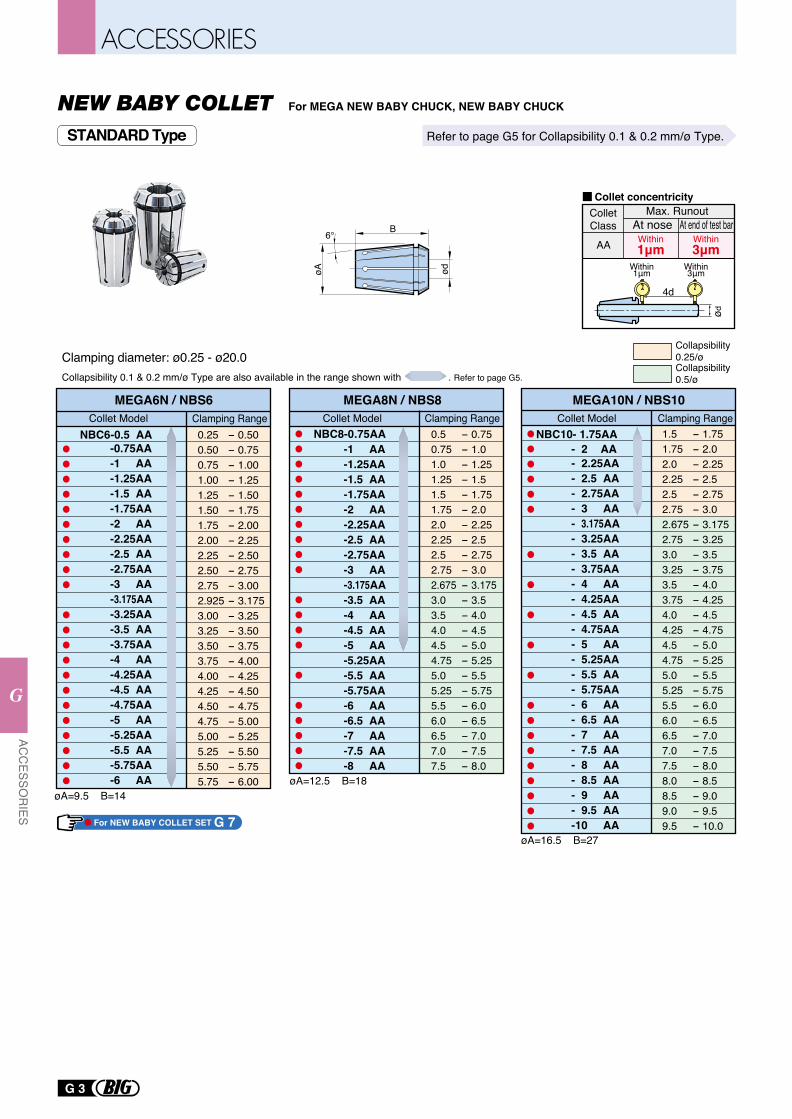
B
ødøA
6°
Collapsibility 0.5/ø
Collapsibility 0.25/ø
0.25 - 0.500.50 - 0.750.75 - 1.001.00 - 1.251.25 - 1.501.50 - 1.751.75 - 2.002.00 - 2.252.25 - 2.502.50 - 2.752.75 - 3.002.925 - 3.1753.00 - 3.253.25 - 3.503.50 - 3.753.75 - 4.004.00 - 4.254.25 - 4.504.50 - 4.754.75 - 5.005.00 - 5.255.25 - 5.505.50 - 5.755.75 - 6.00
NBC6-0.5 AA-0.75AA-1 AA-1.25AA-1.5 AA-1.75AA-2 AA-2.25AA-2.5 AA-2.75AA-3 AA-3.175AA-3.25AA-3.5 AA-3.75AA-4 AA-4.25AA-4.5 AA-4.75AA-5 AA-5.25AA-5.5 AA-5.75AA-6 AA
Collet Model Clamping Range
øA=9.5 B=14
MEGA6N / NBS6
0.5 - 0.750.75 - 1.01.0 - 1.251.25 - 1.51.5 - 1.751.75 - 2.02.0 - 2.252.25 - 2.52.5 - 2.752.75 - 3.02.675 - 3.1753.0 - 3.53.5 - 4.04.0 - 4.54.5 - 5.04.75 - 5.255.0 - 5.55.25 - 5.755.5 - 6.06.0 - 6.56.5 - 7.07.0 - 7.57.5 - 8.0
NBC8-0.75AA-1 AA-1.25AA-1.5 AA-1.75AA-2 AA-2.25AA-2.5 AA-2.75AA-3 AA-3.175AA-3.5 AA-4 AA-4.5 AA-5 AA-5.25AA-5.5 AA-5.75AA-6 AA-6.5 AA-7 AA-7.5 AA-8 AA
Collet Model Clamping Range
øA=12.5 B=18
MEGA8N / NBS8
NBC10- 1.75AA- 2 AA- 2.25AA- 2.5 AA- 2.75AA- 3 AA- 3.175AA- 3.25AA- 3.5 AA- 3.75AA- 4 AA- 4.25AA- 4.5 AA- 4.75AA- 5 AA- 5.25AA- 5.5 AA- 5.75AA- 6 AA- 6.5 AA- 7 AA- 7.5 AA- 8 AA- 8.5 AA- 9 AA- 9.5 AA-10 AA
1.5 - 1.751.75 - 2.02.0 - 2.252.25 - 2.52.5 - 2.752.75 - 3.02.675 - 3.1752.75 - 3.253.0 - 3.53.25 - 3.753.5 - 4.03.75 - 4.254.0 - 4.54.25 - 4.754.5 - 5.04.75 - 5.255.0 - 5.55.25 - 5.755.5 - 6.06.0 - 6.56.5 - 7.07.0 - 7.57.5 - 8.08.0 - 8.58.5 - 9.09.0 - 9.59.5 - 10.0
Collet Model Clamping Range
øA=16.5 B=27
MEGA10N / NBS10
Clamping diameter: ø0.25 - ø20.0
Refer to page G5 for Collapsibility 0.1 & 0.2 mm/ø Type.
For MEGA NEW BABY CHUCK, NEW BABY CHUCK
AA Within1μm
Within3μm
ColletClass
Max. RunoutAt nose At end of test bar
Collet concentricity
4d
ød
Within1μm
Within3μm
STANDARD Type
Collapsibility 0.1 & 0.2 mm/ø Type are also available in the range shown with . Refer to page G5.
For NEW BABY COLLET SET G 7
G 3
ACC
ESSOR
IES
G
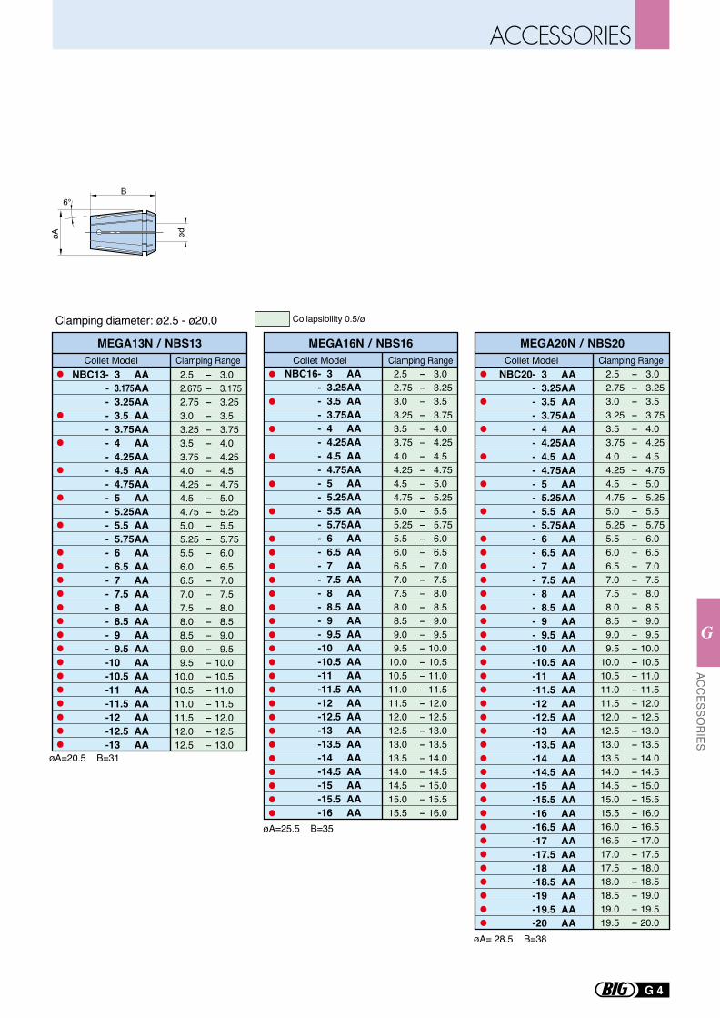
BødøA
6°
Collapsibility 0.5/ø
2.5 - 3.0 2.675 - 3.175 2.75 - 3.25 3.0 - 3.5 3.25 - 3.75 3.5 - 4.0 3.75 - 4.25 4.0 - 4.5 4.25 - 4.75 4.5 - 5.0 4.75 - 5.25 5.0 - 5.5 5.25 - 5.75 5.5 - 6.0 6.0 - 6.5 6.5 - 7.0 7.0 - 7.5 7.5 - 8.0 8.0 - 8.5 8.5 - 9.0 9.0 - 9.5 9.5 - 10.010.0 - 10.510.5 - 11.011.0 - 11.511.5 - 12.012.0 - 12.512.5 - 13.0
NBC13- 3 AA- 3.175AA- 3.25AA- 3.5 AA- 3.75AA- 4 AA- 4.25AA- 4.5 AA- 4.75AA- 5 AA- 5.25AA- 5.5 AA- 5.75AA- 6 AA- 6.5 AA- 7 AA- 7.5 AA- 8 AA- 8.5 AA- 9 AA- 9.5 AA-10 AA-10.5 AA-11 AA-11.5 AA-12 AA-12.5 AA-13 AA
Collet Model Clamping Range
øA=20.5 B=31
MEGA13N / NBS13
NBC16- 3 AA- 3.25AA- 3.5 AA- 3.75AA- 4 AA- 4.25AA- 4.5 AA- 4.75AA- 5 AA- 5.25AA- 5.5 AA- 5.75AA- 6 AA- 6.5 AA- 7 AA- 7.5 AA- 8 AA- 8.5 AA- 9 AA- 9.5 AA-10 AA-10.5 AA-11 AA-11.5 AA-12 AA-12.5 AA-13 AA-13.5 AA-14 AA-14.5 AA-15 AA-15.5 AA-16 AA
2.5 - 3.0 2.75 - 3.25 3.0 - 3.5 3.25 - 3.75 3.5 - 4.0 3.75 - 4.25 4.0 - 4.5 4.25 - 4.75 4.5 - 5.0 4.75 - 5.25 5.0 - 5.5 5.25 - 5.75 5.5 - 6.0 6.0 - 6.5 6.5 - 7.0 7.0 - 7.5 7.5 - 8.0 8.0 - 8.5 8.5 - 9.0 9.0 - 9.5 9.5 - 10.010.0 - 10.510.5 - 11.011.0 - 11.511.5 - 12.012.0 - 12.512.5 - 13.013.0 - 13.513.5 - 14.014.0 - 14.514.5 - 15.015.0 - 15.515.5 - 16.0
Collet Model Clamping RangeMEGA16N / NBS16
øA=25.5 B=35
2.5 - 3.0 2.75 - 3.25 3.0 - 3.5 3.25 - 3.75 3.5 - 4.0 3.75 - 4.25 4.0 - 4.5 4.25 - 4.75 4.5 - 5.0 4.75 - 5.25 5.0 - 5.5 5.25 - 5.75 5.5 - 6.0 6.0 - 6.5 6.5 - 7.0 7.0 - 7.5 7.5 - 8.0 8.0 - 8.5 8.5 - 9.0 9.0 - 9.5 9.5 - 10.010.0 - 10.510.5 - 11.011.0 - 11.511.5 - 12.012.0 - 12.512.5 - 13.013.0 - 13.513.5 - 14.014.0 - 14.514.5 - 15.015.0 - 15.515.5 - 16.016.0 - 16.516.5 - 17.017.0 - 17.517.5 - 18.018.0 - 18.518.5 - 19.019.0 - 19.519.5 - 20.0
NBC20- 3 AA- 3.25AA- 3.5 AA- 3.75AA- 4 AA- 4.25AA- 4.5 AA- 4.75AA- 5 AA- 5.25AA- 5.5 AA- 5.75AA- 6 AA- 6.5 AA- 7 AA- 7.5 AA- 8 AA- 8.5 AA- 9 AA- 9.5 AA-10 AA-10.5 AA-11 AA-11.5 AA-12 AA-12.5 AA-13 AA-13.5 AA-14 AA-14.5 AA-15 AA-15.5 AA-16 AA-16.5 AA-17 AA-17.5 AA-18 AA-18.5 AA-19 AA-19.5 AA-20 AA
Collet Model Clamping RangeMEGA20N / NBS20
øA= 28.5 B=38
Clamping diameter: ø2.5 - ø20.0
G 4
ACC
ESSOR
IES
G
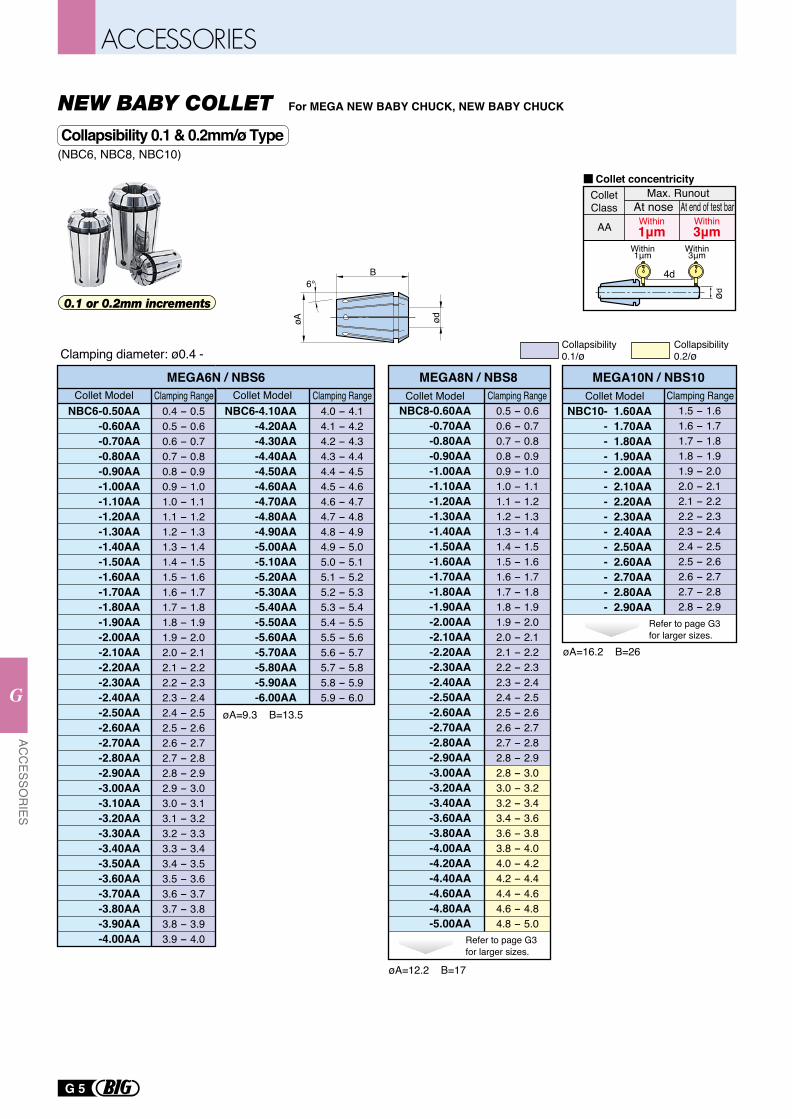
Collapsibility 0.1/ø
Collapsibility 0.2/ø
øA=9.3 B=13.5
NBC6-0.50AA-0.60AA-0.70AA-0.80AA-0.90AA-1.00AA-1.10AA-1.20AA-1.30AA-1.40AA-1.50AA-1.60AA-1.70AA-1.80AA-1.90AA-2.00AA-2.10AA-2.20AA-2.30AA-2.40AA-2.50AA-2.60AA-2.70AA-2.80AA-2.90AA-3.00AA-3.10AA-3.20AA-3.30AA-3.40AA-3.50AA-3.60AA-3.70AA-3.80AA-3.90AA-4.00AA
0.4 - 0.50.5 - 0.60.6 - 0.70.7 - 0.80.8 - 0.90.9 - 1.01.0 - 1.11.1 - 1.21.2 - 1.31.3 - 1.41.4 - 1.51.5 - 1.61.6 - 1.71.7 - 1.81.8 - 1.91.9 - 2.02.0 - 2.12.1 - 2.22.2 - 2.32.3 - 2.42.4 - 2.52.5 - 2.62.6 - 2.72.7 - 2.82.8 - 2.92.9 - 3.03.0 - 3.13.1 - 3.23.2 - 3.33.3 - 3.43.4 - 3.53.5 - 3.63.6 - 3.73.7 - 3.83.8 - 3.93.9 - 4.0
Collet Model Clamping RangeMEGA6N / NBS6
NBC6-4.10AA-4.20AA-4.30AA-4.40AA-4.50AA-4.60AA-4.70AA-4.80AA-4.90AA-5.00AA-5.10AA-5.20AA-5.30AA-5.40AA-5.50AA-5.60AA-5.70AA-5.80AA-5.90AA-6.00AA
Collet Model Clamping Range
øA=16.2 B=26
1.5 - 1.61.6 - 1.71.7 - 1.81.8 - 1.91.9 - 2.02.0 - 2.12.1 - 2.22.2 - 2.32.3 - 2.42.4 - 2.52.5 - 2.62.6 - 2.72.7 - 2.82.8 - 2.9
NBC10- 1.60AA- 1.70AA- 1.80AA- 1.90AA- 2.00AA- 2.10AA- 2.20AA- 2.30AA- 2.40AA- 2.50AA- 2.60AA- 2.70AA- 2.80AA- 2.90AA
Collet Model Clamping RangeMEGA10N / NBS10
øA=12.2 B=17
MEGA8N / NBS8
NBC8-0.60AA-0.70AA-0.80AA-0.90AA-1.00AA-1.10AA-1.20AA-1.30AA-1.40AA-1.50AA-1.60AA-1.70AA-1.80AA-1.90AA-2.00AA-2.10AA-2.20AA-2.30AA-2.40AA-2.50AA-2.60AA-2.70AA-2.80AA-2.90AA-3.00AA-3.20AA-3.40AA-3.60AA-3.80AA-4.00AA-4.20AA-4.40AA-4.60AA-4.80AA-5.00AA
Collet Model Clamping Range
Refer to page G3 for larger sizes.
Refer to page G3 for larger sizes.
(NBC6, NBC8, NBC10)
4.0 - 4.14.1 - 4.24.2 - 4.34.3 - 4.44.4 - 4.54.5 - 4.64.6 - 4.74.7 - 4.84.8 - 4.94.9 - 5.05.0 - 5.15.1 - 5.25.2 - 5.35.3 - 5.45.4 - 5.55.5 - 5.65.6 - 5.75.7 - 5.85.8 - 5.95.9 - 6.0
0.5 - 0.60.6 - 0.70.7 - 0.80.8 - 0.90.9 - 1.01.0 - 1.11.1 - 1.21.2 - 1.31.3 - 1.41.4 - 1.51.5 - 1.61.6 - 1.71.7 - 1.81.8 - 1.91.9 - 2.02.0 - 2.12.1 - 2.22.2 - 2.32.3 - 2.42.4 - 2.52.5 - 2.62.6 - 2.72.7 - 2.82.8 - 2.92.8 - 3.03.0 - 3.23.2 - 3.43.4 - 3.63.6 - 3.83.8 - 4.04.0 - 4.24.2 - 4.44.4 - 4.64.6 - 4.84.8 - 5.0
0.1 or 0.2mm increments
Clamping diameter: ø0.4 -
AA Within1μm
Within3μm
ColletClass
Max. RunoutAt nose At end of test bar
Collet concentricity
4d
ød
Within1μm
Within3μm
For MEGA NEW BABY CHUCK, NEW BABY CHUCK
B
ødøA6°
Collapsibility 0.1 & 0.2mm/ø Type
G 5
ACC
ESSOR
IES
G
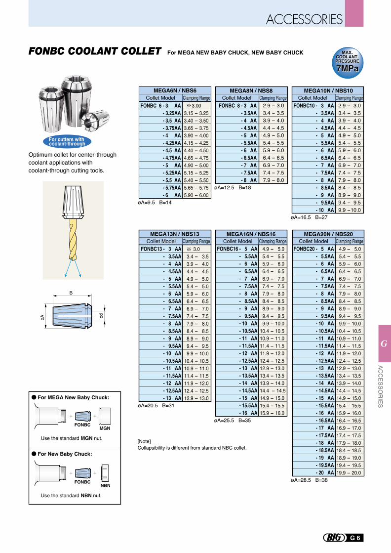
4.9 - 5.0 5.4 - 5.5 5.9 - 6.0 6.4 - 6.5 6.9 - 7.0 7.4 - 7.5 7.9 - 8.0 8.4 - 8.5 8.9 - 9.0 9.4 - 9.5 9.9 - 10.010.4 - 10.510.9 - 11.011.4 - 11.511.9 - 12.012.4 - 12.512.9 - 13.013.4 - 13.513.9 - 14.014.4 - 14.514.9 - 15.015.4 - 15.515.9 - 16.016.4 - 16.516.9 - 17.017.4 - 17.517.9 - 18.018.4 - 18.518.9 - 19.019.4 - 19.519.9 - 20.0
Collet Model Clamping RangeMEGA20N / NBS20
MEGA8N / NBS8
2.9 - 3.03.4 - 3.53.9 - 4.04.4 - 4.54.9 - 5.05.4 - 5.55.9 - 6.06.4 - 6.56.9 - 7.07.4 - 7.57.9 - 8.0
Collet Model Clamping RangeMEGA10N / NBS10
2.9 - 3.03.4 - 3.53.9 - 4.04.4 - 4.54.9 - 5.05.4 - 5.55.9 - 6.06.4 - 6.56.9 - 7.07.4 - 7.57.9 - 8.08.4 - 8.58.9 - 9.09.4 - 9.59.9 -10.0
Collet Model Clamping Range
3.0 3.4 - 3.5 3.9 - 4.0 4.4 - 4.5 4.9 - 5.0 5.4 - 5.0 5.9 - 6.0 6.4 - 6.5 6.9 - 7.0 7.4 - 7.5 7.9 - 8.0 8.4 - 8.5 8.9 - 9.0 9.4 - 9.5 9.9 - 10.010.4 - 10.510.9 - 11.011.4 - 11.511.9 - 12.012.4 - 12.512.9 - 13.0
Collet Model Clamping RangeMEGA13N / NBS13
4.9 - 5.0 5.4 - 5.5 5.9 - 6.0 6.4 - 6.5 6.9 - 7.0 7.4 - 7.5 7.9 - 8.0 8.4 - 8.5 8.9 - 9.0 9.4 - 9.5 9.9 - 10.010.4 - 10.510.9 - 11.011.4 - 11.511.9 - 12.012.4 - 12.512.9 - 13.013.4 - 13.513.9 - 14.014.4 - 14.514.9 - 15.015.4 - 15.515.9 - 16.0
Collet Model Clamping RangeMEGA16N / NBS16
øA=12.5 B=18
øA=9.5 B=14
øA=16.5 B=27
øA=25.5 B=35
øA=28.5 B=38
Collet Model Clamping RangeMEGA6N / NBS6
3.003.15 - 3.253.40 - 3.503.65 - 3.753.90 - 4.004.15 - 4.254.40 - 4.504.65 - 4.754.90 - 5.005.15 - 5.255.40 - 5.505.65 - 5.755.90 - 6.00
Optimum collet for center-through coolant applications with coolant-through cutting tools.
For cutters with coolant-through
[Note]Collapsibility is different from standard NBC collet.
For MEGA New Baby Chuck:
For New Baby Chuck:
Use the standard MGN nut.
FONBCMGN
FONBC
Use the standard NBN nut.
NBN
FONBC 6 - 3 AA- 3.25AA- 3.5 AA- 3.75AA- 4 AA- 4.25AA- 4.5 AA- 4.75AA- 5 AA- 5.25AA- 5.5 AA- 5.75AA- 6 AA
FONBC 8 - 3 AA- 3.5AA- 4 AA- 4.5AA - 5 AA- 5.5AA - 6 AA- 6.5AA - 7 AA- 7.5AA - 8 AA
FONBC10 - 3 AA- 3.5AA- 4 AA- 4.5AA
- 5 AA- 5.5AA- 6 AA- 6.5AA- 7 AA- 7.5AA- 8 AA- 8.5AA- 9 AA- 9.5AA- 10 AA
FONBC13 - 3 AA- 3.5AA- 4 AA- 4.5AA
- 5 AA- 5.5AA- 6 AA- 6.5AA- 7 AA- 7.5AA- 8 AA- 8.5AA- 9 AA- 9.5AA- 10 AA- 10.5AA- 11 AA- 11.5AA- 12 AA- 12.5AA- 13 AA
FONBC16 - 5 AA- 5.5AA- 6 AA- 6.5AA
- 7 AA- 7.5AA- 8 AA- 8.5AA- 9 AA- 9.5AA- 10 AA- 10.5AA- 11 AA- 11.5AA- 12 AA- 12.5AA- 13 AA- 13.5AA- 14 AA- 14.5AA- 15 AA- 15.5AA- 16 AA
FONBC20 - 5 AA- 5.5AA - 6 AA - 6.5AA- 7 AA- 7.5AA- 8 AA- 8.5AA- 9 AA- 9.5AA- 10 AA- 10.5AA
- 11 AA- 11.5AA- 12 AA- 12.5AA- 13 AA- 13.5AA- 14 AA- 14.5AA- 15 AA- 15.5AA- 16 AA- 16.5AA- 17 AA- 17.5AA- 18 AA- 18.5AA- 19 AA- 19.5AA- 20 AA
øA
B
ød
MAX.COOLANT PRESSURE
MAX.COOLANT PRESSURE
7MPa7MPa
For MEGA NEW BABY CHUCK, NEW BABY CHUCKFONBC COOLANT COLLET
øA=20.5 B=31
G 6
ACC
ESSOR
IES
G
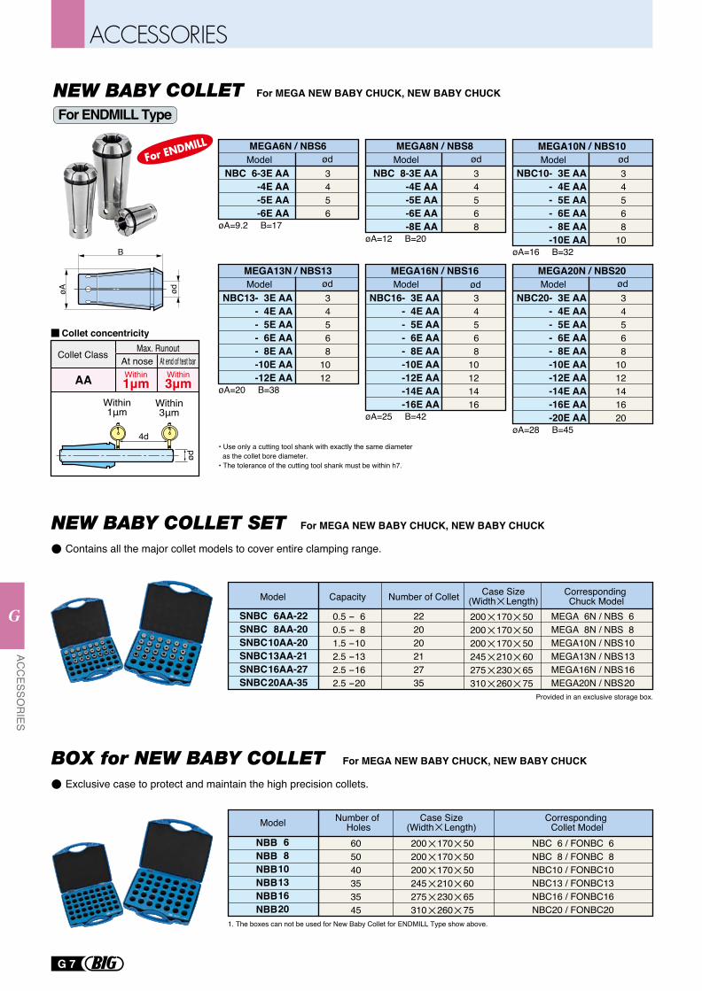
SNBCSNBCSNBCSNBCSNBCSNBC
68
10131620
0.5 - 60.5 - 81.5 -102.5 -132.5 -162.5 -20
222020212735
NBBNBBNBBNBBNBBNBB
68
10131620
605040353545
AA-22AA-20AA-20AA-21AA-27AA-35
NBC 6 / FONBC 6NBC 8 / FONBC 8NBC10 / FONBC10NBC13 / FONBC13NBC16 / FONBC16NBC20 / FONBC20
Provided in an exclusive storage box.
1. The boxes can not be used for New Baby Collet for ENDMILL Type show above.
MEGA 6N / NBS 6MEGA 8N / NBS 8MEGA10N / NBS10MEGA13N / NBS13MEGA16N / NBS16MEGA20N / NBS20
For MEGA NEW BABY CHUCK, NEW BABY CHUCKNEW BABY COLLET SET
Model Capacity Number of Collet Corresponding Chuck Model
Case Size(Width Length)
Model Number of Holes
Corresponding Collet Model
Case Size(Width Length)
200 170 50200 170 50200 170 50245 210 60275 230 65310 260 75
200 170 50200 170 50200 170 50245 210 60275 230 65310 260 75
For MEGA NEW BABY CHUCK, NEW BABY CHUCK
MEGA13N / NBS13
øA=20 B=38
NBC13- 3E AA- 4E AA- 5E AA- 6E AA- 8E AA-10E AA-12E AA
34568
1012
Model ød
MEGA8N / NBS8
øA=12 B=20
NBC 8-3E AA-4E AA-5E AA-6E AA-8E AA
34568
Model ødMEGA6N / NBS6
øA=9.2 B=17
NBC 6-3E AA-4E AA-5E AA-6E AA
3456
Model ød
øA=16 B=32
NBC10- 3E AA- 4E AA- 5E AA- 6E AA- 8E AA-10E AA
34568
10
MEGA16N / NBS16
øA=25 B=42
NBC16- 3E AA- 4E AA- 5E AA- 6E AA- 8E AA-10E AA-12E AA-14E AA-16E AA
34568
10121416
Model ødMEGA20N / NBS20
øA=28 B=45
NBC20- 3E AA- 4E AA- 5E AA- 6E AA- 8E AA-10E AA-12E AA-14E AA-16E AA-20E AA
34568
1012141620
Model ød
øA
B
ød
• Use only a cutting tool shank with exactly the same diameter as the collet bore diameter.• The tolerance of the cutting tool shank must be within h7.
MEGA10N / NBS10Model ød
AA Within1μm
Within3μm
Collet Class Max. RunoutAt nose At end of test bar
Collet concentricity
4d
Within1μm
Within3μm
ød
Contains all the major collet models to cover entire clamping range.
For MEGA NEW BABY CHUCK, NEW BABY CHUCKBOX for NEW BABY COLLETExclusive case to protect and maintain the high precision collets.
For ENDMILL Type
G 7
ACC
ESSOR
IES
G
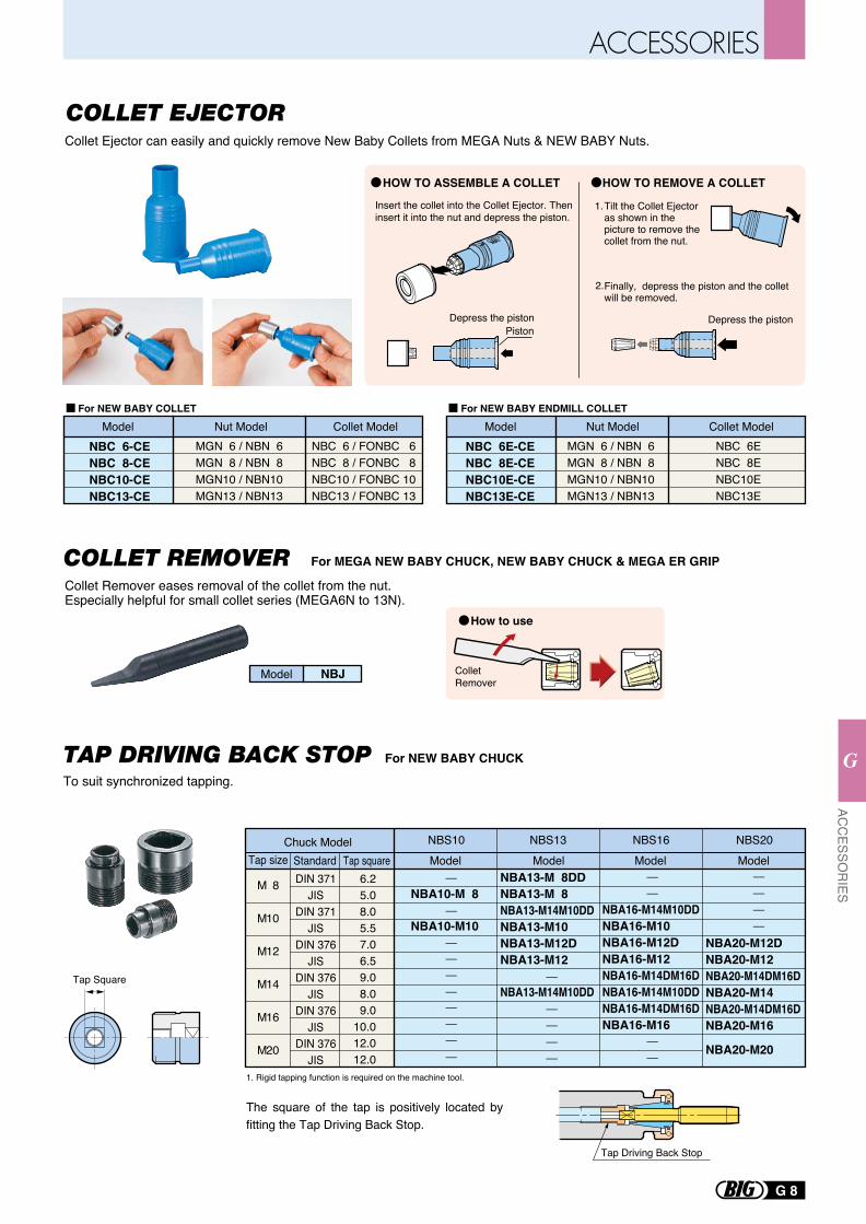
Collet Ejector can easily and quickly remove New Baby Collets from MEGA Nuts & NEW BABY Nuts.
Collet Remover eases removal of the collet from the nut.Especially helpful for small collet series (MEGA6N to 13N).
HOW TO ASSEMBLE A COLLET HOW TO REMOVE A COLLET
Tilt the Collet Ejector as shown in the picture to remove the collet from the nut.
Finally, depress the piston and the collet will be removed.
Depress the piston
NBC 6-CENBC 8-CENBC10-CENBC13-CE
MGN 6 / NBN 6MGN 8 / NBN 8MGN10 / NBN10MGN13 / NBN13
NBC 6 / FONBC 6NBC 8 / FONBC 8NBC10 / FONBC 10NBC13 / FONBC 13
NBC 6E-CENBC 8E-CENBC10E-CENBC13E-CE
MGN 6 / NBN 6MGN 8 / NBN 8MGN10 / NBN10MGN13 / NBN13
NBC 6ENBC 8ENBC10ENBC13E
Insert the collet into the Collet Ejector. Then insert it into the nut and depress the piston.
Depress the pistonPiston
For NEW BABY ENDMILL COLLETFor NEW BABY COLLET
1.
2.
Model Nut Model Collet Model Model Nut Model Collet Model
Collet Remover
NBJModel
For MEGA NEW BABY CHUCK, NEW BABY CHUCK & MEGA ER GRIPCOLLET REMOVER
For NEW BABY CHUCK
1. Rigid tapping function is required on the machine tool.
The square of the tap is positively located by fitting the Tap Driving Back Stop.
To suit synchronized tapping.
Tap Driving Back Stop
Chuck ModelTap size
M
M
M
M
M
M
8
10
12
14
16
20
Tap squareStandardDIN 371
JISDIN 371
JISDIN 376
JISDIN 376
JISDIN 376
JISDIN 376
JIS
NBS13NBS10 NBS16 NBS20ModelModelModel Model
NBA13-M 8DDNBA13-M 8 NBA13-M14M10DDNBA13-M10NBA13-M12DNBA13-M12
NBA13-M14M10DD
NBA10-M 8
NBA10-M10NBA16-M14M10DDNBA16-M10NBA16-M12DNBA16-M12NBA16-M14DM16DNBA16-M14M10DDNBA16-M14DM16DNBA16-M16
NBA20-M12DNBA20-M12NBA20-M14DM16DNBA20-M14NBA20-M14DM16DNBA20-M16
NBA20-M20
6.25.08.05.57.06.59.08.09.0
10.012.012.0
Tap Square
How to use
G 8
ACC
ESSOR
IES
G
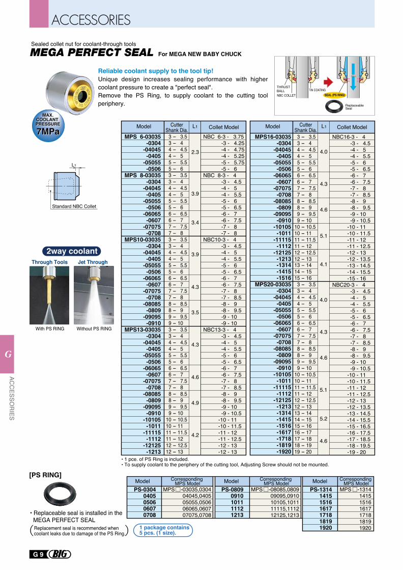
For MEGA NEW BABY CHUCK
Reliable coolant supply to the tool tip!Unique design increases sealing performance with higher coolant pressure to create a "perfect seal". Remove the PS Ring, to supply coolant to the cutting tool periphery.
L1
Standard NBC Collet
Sealed collet nut for coolant-through tools
PS-08090910101111121213
MPS -08085,080909095,091010105,101111115,111212125,1213
PS-03040405050606070708
MPS -03035,030404045,040505055,050606065,060707075,0708
PS-1314141515161617171818191920
MPS -1314141515161617171818191920
Corresponding MPS ModelModel Corresponding
MPS ModelModel Corresponding MPS ModelModel
1 package contains 5 pcs. (1 size).
[PS RING]
• Replaceable seal is installed in the MEGA PERFECT SEAL
Replacement seal is recommended when coolant leaks due to damage of the PS Ring.
• 1 pce. of PS Ring is included.• To supply coolant to the periphery of the cutting tool, Adjusting Screw should not be mounted.
MAX.COOLANT PRESSURE
MAX.COOLANT PRESSURE
7MPa7MPa
NBC COLLET SEAL (PS RING)TiN COATING
Replaceable Seal
THRUST BALL
Through Tools
With PS RING Without PS RING
Jet Through
2way coolant
MPS16-03035-0304
-04045-0405
-05055-0506
-06065-0607
-07075-0708
-08085-0809
-09095-0910
-10105-1011
-11115-1112
-12125-1213 -1314 -1415 -1516
MPS20-03035-0304
-04045-0405
-05055-0506
-06065-0607
-07075-0708
-08085-0809
-09095-0910
-10105-1011
-11115-1112
-12125-1213 -1314 -1415 -1516 -1617 -1718 -1819 -1920
NBC16-3 - 4 -3 - 4.5 -4 - 5 -4 - 5.5 -5 - 6 -5 - 6.5 -6 - 7 -6 - 7.5 -7 - 8 -7 - 8.5 -8 - 9 -8 - 9.5 -9 - 10 -9 - 10.5 -10 - 11 -10 - 11.5 -11 - 12 -11 - 12.5 -12 - 13 -12 - 13.5 -13 - 14.5 -14 - 15.5 -15 - 16NBC20-3 - 4 -3 - 4.5 -4 - 5 -4 - 5.5 -5 - 6 -5 - 6.5 -6 - 7 -6 - 7.5 -7 - 8 -7 - 8.5 -8 - 9 -8 - 9.5 -9 - 10 -9 - 10.5 -10 - 11 -10 - 11.5 -11 - 12 -11 - 12.5 -12 - 13 -12 - 13.5 -13 - 14.5 -14 - 15.5 -15 - 16.5 -16 - 17.5 -17 - 18.5 -18 - 19.5 -19 - 20
4.0
4.3
4.6
5.1
4.1
4.0
4.3
4.6
5.1
4.6
5.2
3 - 3.5 3 - 4 4 - 4.5 4 - 5 5 - 5.5 5 - 6 6 - 6.5 6 - 7 7 - 7.5 7 - 8 8 - 8.5 8 - 9 9 - 9.5 9 - 1010 - 10.510 - 1111 - 11.511 - 1212 - 12.512 - 1313 - 1414 - 1515 - 16 3 - 3.5 3 - 4 4 - 4.5 4 - 5 5 - 5.5 5 - 6 6 - 6.5 6 - 7 7 - 7.5 7 - 8 8 - 8.5 8 - 9 9 - 9.5 9 - 1010 - 10.510 - 1111 - 11.511 - 1212 - 12.512 - 1313 - 1414 - 1515 - 1616 - 1717 - 1818 - 1919 - 20
MPS 6-03035-0304
-04045-0405
-05055-0506
MPS 8-03035-0304
-04045-0405
-05055-0506
-06065-0607
-07075-0708
MPS10-03035-0304
-04045-0405
-05055-0506
-06065-0607
-07075-0708
-08085-0809
-09095-0910
MPS13-03035-0304
-04045-0405
-05055-0506
-06065-0607
-07075-0708
-08085-0809
-09095-0910
-10105-1011
-11115-1112
-12125-1213
NBC 6-3 - 3.75 -3 - 4.25 -4 - 4.75 -4 - 5.25 -5 - 5.75 -5 - 6NBC 8-3 - 4 -3 - 4.5 -4 - 5 -4 - 5.5 -5 - 6 -5 - 6.5 -6 - 7 -6 - 7.5 -7 - 8 -7 - 8NBC10-3 - 4 -3 - 4.5 -4 - 5 -4 - 5.5 -5 - 6 -5 - 6.5 -6 - 7 -6 - 7.5 -7 - 8 -7 - 8.5 -8 - 9 -8 - 9.5 -9 - 10 -9 - 10NBC13-3 - 4 -3 - 4.5 -4 - 5 -4 - 5.5 -5 - 6 -5 - 6.5 -6 - 7 -6 - 7.5 -7 - 8 -7 - 8.5 -8 - 9 -8 - 9.5 -9 - 10 -9 - 10.5 -10 - 11 -10 - 11.5 -11 - 12 -11 - 12.5 -12 - 13 -12 - 13
2.3
3.9
3.4
3.9
4.3
4.6
4.9
4.2
4.3
3.5
3 - 3.5 3 - 4 4 - 4.5 4 - 5 5 - 5.5 5 - 6 3 - 3.5 3 - 4 4 - 4.5 4 - 5 5 - 5.5 5 - 6 6 - 6.5 6 - 7 7 - 7.5 7 - 8 3 - 3.5 3 - 4 4 - 4.5 4 - 5 5 - 5.5 5 - 6 6 - 6.5 6 - 7 7 - 7.5 7 - 8 8 - 8.5 8 - 9 9 - 9.5 9 - 10 3 - 3.5 3 - 4 4 - 4.5 4 - 5 5 - 5.5 5 - 6 6 - 6.5 6 - 7 7 - 7.5 7 - 8 8 - 8.5 8 - 9 9 - 9.5 9 - 1010 - 10.510 - 1111 - 11.511 - 1212 - 12.512 - 13
L1Model Collet ModelCutterShank Dia.
L1Model Collet ModelCutterShank Dia.
G 9
ACC
ESSOR
IES
G
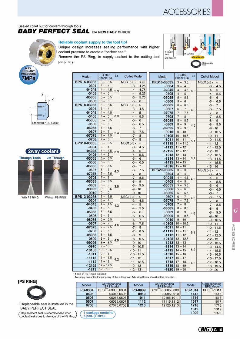
For NEW BABY CHUCK
L1
3
Standard NBC Collet
Reliable coolant supply to the tool tip!Unique design increases sealing performance with higher coolant pressure to create a "perfect seal". Remove the PS Ring, to supply coolant to the cutting tool periphery.
Sealed collet nut for coolant-through tools
MAX.COOLANT PRESSURE
MAX.COOLANT PRESSURE
7MPa7MPa
PS-08090910101111121213
BPS -08085,080909095,091010105,101111115,111212125,1213
PS-03040405050606070708
BPS -03035,030404045,040505055,050606065,060707075,0708
PS-1314141515161617171818191920
BPS -1314141515161617171818191920
Model Model Model
1 package contains 5 pcs. (1 size).
• Replaceable seal is installed in the BABY PERFECT SEAL
Replacement seal is recommended when coolant leaks due to damage of the PS Ring.
• 1 pce. of PS Ring is included.• To supply coolant to the periphery of the cutting tool, Adjusting Screw should not be mounted.
NBC COLLET SEAL (PS RING)TiN COATING
Replaceable Seal
THRUST BALL
Through Tools
With PS RING Without PS RING
Jet Through
2way coolant
BPS16-03035-0304
-04045-0405
-05055-0506
-06065-0607
-07075-0708
-08085-0809
-09095-0910
-10105-1011
-11115-1112
-12125-1213 -1314 -1415 -1516
BPS20-03035-0304
-04045-0405
-05055-0506
-06065-0607
-07075-0708
-08085-0809
-09095-0910
-10105-1011
-11115-1112
-12125-1213 -1314 -1415 -1516 -1617 -1718 -1819 -1920
NBC16-3 - 4 -3 - 4.5 -4 - 5 -4 - 5.5 -5 - 6 -5 - 6.5 -6 - 7 -6 - 7.5 -7 - 8 -7 - 8.5 -8 - 9 -8 - 9.5 -9 - 10 -9 - 10.5 -10 - 11 -10 - 11.5 -11 - 12 -11 - 12.5 -12 - 13 -12 - 13.5 -13 - 14.5 -14 - 15.5 -15 - 16NBC20-3 - 4 -3 - 4.5 -4 - 5 -4 - 5.5 -5 - 6 -5 - 6.5 -6 - 7 -6 - 7.5 -7 - 8 -7 - 8.5 -8 - 9 -8 - 9.5 -9 - 10 -9 - 10.5 -10 - 11 -10 - 11.5 -11 - 12 -11 - 12.5 -12 - 13 -12 - 13.5 -13 - 14.5 -14 - 15.5 -15 - 16.5 -16 - 17.5 -17 - 18.5 -18 - 19.5 -19 - 20
4.0
4.3
4.6
5.1
4.1
4.0
4.3
4.6
5.1
4.6
5.2
3 - 3.5 3 - 4 4 - 4.5 4 - 5 5 - 5.5 5 - 6 6 - 6.5 6 - 7 7 - 7.5 7 - 8 8 - 8.5 8 - 9 9 - 9.5 9 - 1010 - 10.510 - 1111 - 11.511 - 1212 - 12.512 - 1313 - 1414 - 1515 - 16 3 - 3.5 3 - 4 4 - 4.5 4 - 5 5 - 5.5 5 - 6 6 - 6.5 6 - 7 7 - 7.5 7 - 8 8 - 8.5 8 - 9 9 - 9.5 9 - 1010 - 10.510 - 1111 - 11.511 - 1212 - 12.512 - 1313 - 1414 - 1515 - 1616 - 1717 - 1818 - 1919 - 20
BPS 6-03035-0304
-04045-0405
-05055-0506
BPS 8-03035-0304
-04045-0405
-05055-0506
-06065-0607
-07075-0708
BPS10-03035-0304
-04045-0405
-05055-0506
-06065-0607
-07075-0708
-08085-0809
-09095-0910
BPS13-03035-0304
-04045-0405
-05055-0506
-06065-0607
-07075-0708
-08085-0809
-09095-0910
-10105-1011
-11115-1112
-12125-1213
NBC 6-3 - 3.75 -3 - 4.25 -4 - 4.75 -4 - 5.25 -5 - 5.75 -5 - 6NBC 8-3 - 4 -3 - 4.5 -4 - 5 -4 - 5.5 -5 - 6 -5 - 6.5 -6 - 7 -6 - 7.5 -7 - 8 -7 - 8NBC10-3 - 4 -3 - 4.5 -4 - 5 -4 - 5.5 -5 - 6 -5 - 6.5 -6 - 7 -6 - 7.5 -7 - 8 -7 - 8.5 -8 - 9 -8 - 9.5 -9 - 10 -9 - 10NBC13-3 - 4 -3 - 4.5 -4 - 5 -4 - 5.5 -5 - 6 -5 - 6.5 -6 - 7 -6 - 7.5 -7 - 8 -7 - 8.5 -8 - 9 -8 - 9.5 -9 - 10 -9 - 10.5 -10 - 11 -10 - 11.5 -11 - 12 -11 - 12.5 -12 - 13 -12 - 13
2.3
3.9
3.4
3.9
4.3
4.6
4.9
4.2
4.3
3.5
3 - 3.5 3 - 4 4 - 4.5 4 - 5 5 - 5.5 5 - 6 3 - 3.5 3 - 4 4 - 4.5 4 - 5 5 - 5.5 5 - 6 6 - 6.5 6 - 7 7 - 7.5 7 - 8 3 - 3.5 3 - 4 4 - 4.5 4 - 5 5 - 5.5 5 - 6 6 - 6.5 6 - 7 7 - 7.5 7 - 8 8 - 8.5 8 - 9 9 - 9.5 9 - 10 3 - 3.5 3 - 4 4 - 4.5 4 - 5 5 - 5.5 5 - 6 6 - 6.5 6 - 7 7 - 7.5 7 - 8 8 - 8.5 8 - 9 9 - 9.5 9 - 1010 - 10.510 - 1111 - 11.511 - 1212 - 12.512 - 13
L1Model Collet ModelCutterShank Dia. L1Model Collet ModelCutter
Shank Dia.
Corresponding BPS Model
Corresponding BPS Model
Corresponding BPS Model
[PS RING]
G 10
ACC
ESSOR
IES
G
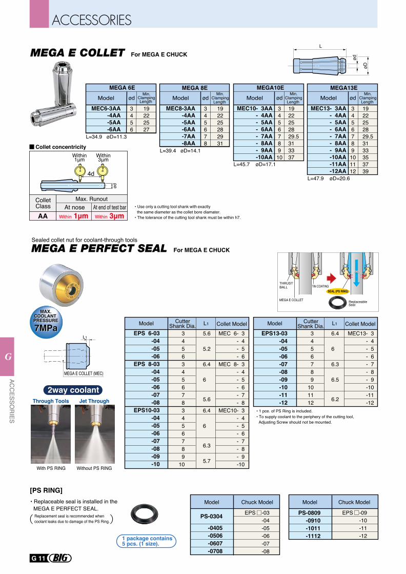
For MEGA E CHUCK
• Use only a cutting tool shank with exactly the same diameter as the collet bore diamater.• The tolerance of the cutting tool shank must be within h7.
L=34.9 øD=11.3
L=39.4 øD=14.1
L=45.7 øD=17.1
L=47.9 øD=20.6
MEC6-3AA-4AA-5AA-6AA
Model
19222527
MEC8-3AA-4AA-5AA-6AA-7AA-8AA
Model
192225282931
MEC10- 3AA- 4AA- 5AA- 6AA- 7AA- 8AA- 9AA-10AA
Model
1922252829.5313337
MEC13- 3AA- 4AA- 5AA- 6AA- 7AA- 8AA
- 9AA-10AA-11AA-12AA
Model
1922252829.53133353739
ødød
3456789101112
345678910
ød
345678
ød
3456
MEGA 6E MEGA 8E MEGA10E MEGA13EMin.
ClampingLength
Min.ClampingLength
Min.ClampingLength
Min.ClampingLength
ød
øD
L
4d
ød
ColletClass
Max. RunoutAt nose At end of test bar
Within 1μm Within 3μmAA
Collet concentricityWithin1μm
Within3μm
For MEGA E CHUCK
Chuck ModelModel
PS-0304
-0405-0506-0607-0708
EPS -03-04-05-06-07-08
PS-0809-0910-1011-1112
EPS -09-10-11-121 package contains
5 pcs. (1 size).
• Replaceable seal is installed in the MEGA E PERFECT SEAL.
Replacement seal is recommended when coolant leaks due to damage of the PS Ring.
Chuck ModelModel
EPS 6-03-04-05-06
EPS 8-03-04-05-06-07-08
EPS10-03-04-05-06-07-08-09-10
MEC 6- 3- 4- 5- 6
MEC 8- 3- 4- 5- 6- 7- 8
MEC10- 3- 4- 5- 6- 7- 8- 9-10
34563456783456789
10
5.6
5.2
6.4
6
5.6
6.4
6
6.3
5.7
L1
MEGA E COLLET (MEC)
EPS13-03-04-05-06-07-08-09-10-11-12
MEC13- 3- 4- 5- 6- 7- 8- 9-10-11-12
3456789
101112
6.4
6
6.3
6.5
6.2
• 1 pce. of PS Ring is included.• To supply coolant to the periphery of the cutting tool, Adjusting Screw should not be mounted.
L1Model Collet ModelCutterShank Dia.L1Model Collet ModelCutter
Shank Dia.
[PS RING]
Sealed collet nut for coolant-through tools
MAX.COOLANT PRESSURE
MAX.COOLANT PRESSURE
7MPa7MPa
MEGA E COLLET
SEAL (PS RING)TiN COATING
Replaceable Seal
THRUST BALL
Through Tools
With PS RING Without PS RING
Jet Through
2way coolant
G 11
ACC
ESSOR
IES
G
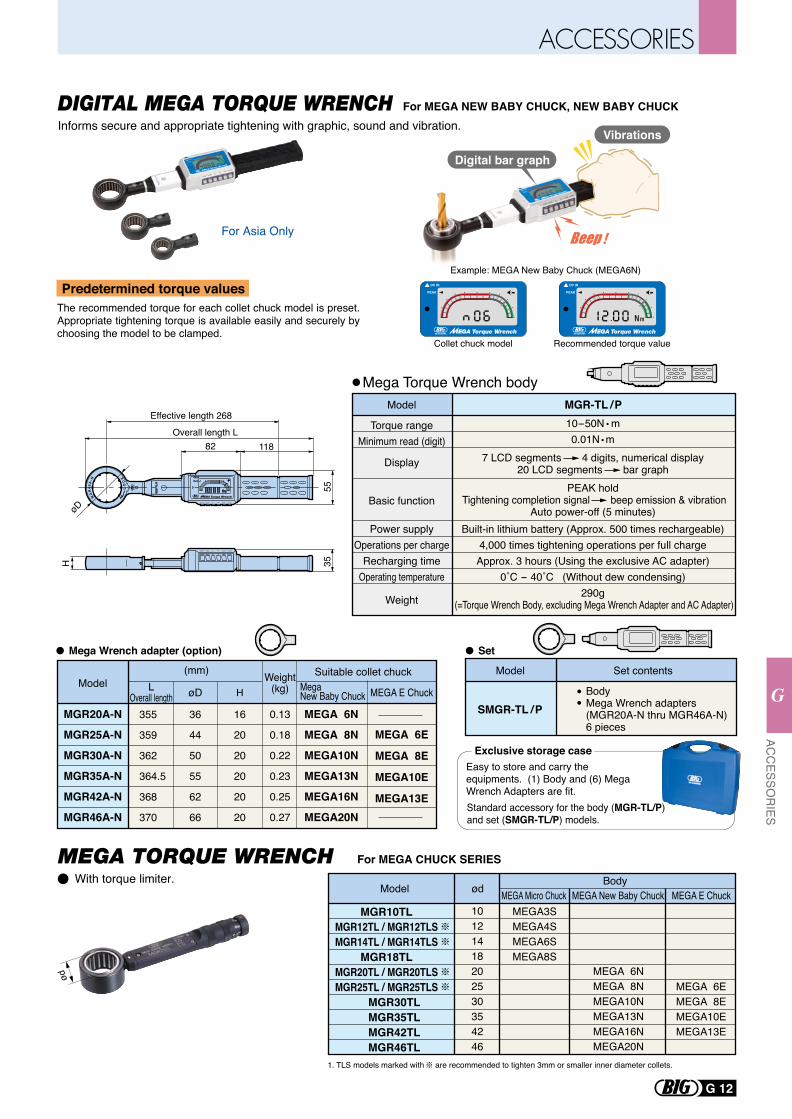
Basic function
Weight
PEAK hold Tightening completion signal beep emission & vibration
Auto power-off (5 minutes)
290g (=Torque Wrench Body, excluding Mega Wrench Adapter and AC Adapter)
Power supplyOperations per charge
Recharging timeOperating temperature
Built-in lithium battery (Approx. 500 times rechargeable)4,000 times tightening operations per full chargeApprox. 3 hours (Using the exclusive AC adapter)
0˚C - 40˚C (Without dew condensing)
Display 7 LCD segments 4 digits, numerical display20 LCD segments bar graph
Torque rangeMinimum read (digit)
10-50N m0.01N m
MGR-TL /P
MEGA 6N
MEGA 8N
MEGA10N
MEGA13N
MEGA16N
MEGA20N
MEGA 6E
MEGA 8E
MEGA10E
MEGA13E
355
359
362
364.5
368
370
36
44
50
55
62
66
16
20
20
20
20
20
0.13
0.18
0.22
0.23
0.25
0.27
Model Weight(kg)L
Overall length øD H
(mm)
Effective length 268
Overall length L82 118
5535H
øD
ON/OFF MODE PEAK CLEAR
ON/OFF MODE PEAK CLEAR
ON/OFF MODE PEAK CLEAR
DC IN
PEAK
MG
R-T
L/P
Suitable collet chuckMega New Baby Chuck MEGA E Chuck
Model
Set contentsModel
SMGR-TL /P
Digital bar graph
Vibrations
For MEGA NEW BABY CHUCK, NEW BABY CHUCKDIGITAL MEGA TORQUE WRENCH
For MEGA CHUCK SERIESMEGA TORQUE WRENCH
Informs secure and appropriate tightening with graphic, sound and vibration.
The recommended torque for each collet chuck model is preset. Appropriate tightening torque is available easily and securely by choosing the model to be clamped.
Predetermined torque values
Collet chuck model Recommended torque value
Example: MEGA New Baby Chuck (MEGA6N)
With torque limiter.
1. TLS models marked with are recommended to tighten 3mm or smaller inner diameter collets.
MEGA Micro ChuckModel ød MEGA New Baby Chuck MEGA E ChuckBody
MGR10TLMGR12TL / MGR12TLSMGR14TL / MGR14TLS
MGR18TLMGR20TL / MGR20TLSMGR25TL / MGR25TLS
MGR30TL MGR35TL MGR42TL MGR46TL
MEGA 6NMEGA 8NMEGA10NMEGA13NMEGA16NMEGA20N
MEGA 6EMEGA 8EMEGA10EMEGA13E
MEGA3SMEGA4SMEGA6SMEGA8S
10121418202530354246
ød
Standard accessory for the body (MGR-TL/P) and set (SMGR-TL/P) models.
Easy to store and carry the equipments. (1) Body and (6) Mega Wrench Adapters are fit.
Exclusive storage case
Mega Torque Wrench body
Mega Wrench adapter (option) Set
MGR20A-N
MGR25A-N
MGR30A-N
MGR35A-N
MGR42A-N
MGR46A-N
BodyMega Wrench adapters(MGR20A-N thru MGR46A-N)6 pieces
For Asia Only
G 12
ACC
ESSOR
IES
G
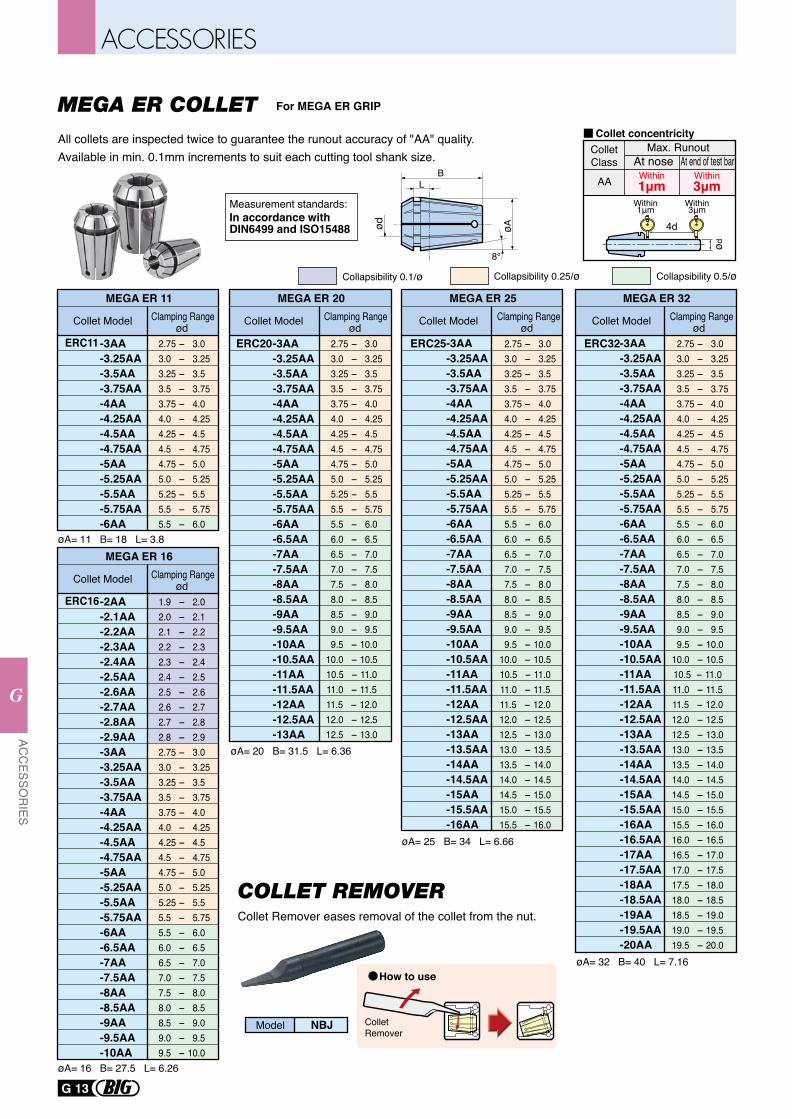
For MEGA ER GRIP
MEGA ER 11
øA= 11 B= 18 L= 3.8
-3AA-3.25AA-3.5AA-3.75AA-4AA-4.25AA-4.5AA-4.75AA-5AA-5.25AA-5.5AA-5.75AA-6AA
ERC11
MEGA ER 20
øA= 20 B= 31.5 L= 6.36
ERC20-3AA-3.25AA-3.5AA-3.75AA-4AA-4.25AA-4.5AA-4.75AA-5AA-5.25AA-5.5AA-5.75AA-6AA-6.5AA-7AA-7.5AA-8AA-8.5AA-9AA-9.5AA-10AA-10.5AA-11AA-11.5AA-12AA-12.5AA-13AA
MEGA ER 25
øA= 25 B= 34 L= 6.66
ERC25-3AA-3.25AA-3.5AA-3.75AA-4AA-4.25AA-4.5AA-4.75AA-5AA-5.25AA-5.5AA-5.75AA-6AA-6.5AA-7AA-7.5AA-8AA-8.5AA-9AA-9.5AA-10AA-10.5AA-11AA-11.5AA-12AA-12.5AA-13AA-13.5AA-14AA-14.5AA-15AA-15.5AA-16AA
MEGA ER 32
øA= 32 B= 40 L= 7.16
ERC32-3AA-3.25AA-3.5AA-3.75AA-4AA-4.25AA-4.5AA-4.75AA-5AA-5.25AA-5.5AA-5.75AA-6AA-6.5AA-7AA-7.5AA-8AA-8.5AA-9AA-9.5AA-10AA-10.5AA-11AA-11.5AA-12AA-12.5AA-13AA-13.5AA-14AA-14.5AA-15AA-15.5AA-16AA-16.5AA-17AA-17.5AA-18AA-18.5AA-19AA-19.5AA-20AA
ød ød ød ød
All collets are inspected twice to guarantee the runout accuracy of "AA" quality.Available in min. 0.1mm increments to suit each cutting tool shank size.
Collet Model Clamping Range Collet Model Clamping Range Collet Model Clamping Range Collet Model Clamping Range
2.75 - 3.0 3.0 - 3.25 3.25 - 3.5 3.5 - 3.75 3.75 - 4.0 4.0 - 4.25 4.25 - 4.5 4.5 - 4.75 4.75 - 5.0 5.0 - 5.25 5.25 - 5.5 5.5 - 5.75 5.5 - 6.0 6.0 - 6.5 6.5 - 7.0 7.0 - 7.5 7.5 - 8.0 8.0 - 8.5 8.5 - 9.0 9.0 - 9.5 9.5 - 10.0 10.0 - 10.5 10.5 - 11.0 11.0 - 11.5 11.5 - 12.0 12.0 - 12.5 12.5 - 13.0 13.0 - 13.5 13.5 - 14.0 14.0 - 14.5 14.5 - 15.0 15.0 - 15.5 15.5 - 16.0 16.0 - 16.5 16.5 - 17.0 17.0 - 17.5 17.5 - 18.0 18.0 - 18.5 18.5 - 19.0 19.0 - 19.5 19.5 - 20.0
2.75 - 3.0 3.0 - 3.25 3.25 - 3.5 3.5 - 3.75 3.75 - 4.0 4.0 - 4.25 4.25 - 4.5 4.5 - 4.75 4.75 - 5.0 5.0 - 5.25 5.25 - 5.5 5.5 - 5.75 5.5 - 6.0 6.0 - 6.5 6.5 - 7.0 7.0 - 7.5 7.5 - 8.0 8.0 - 8.5 8.5 - 9.0 9.0 - 9.5 9.5 - 10.0 10.0 - 10.5 10.5 - 11.0 11.0 - 11.5 11.5 - 12.0 12.0 - 12.5 12.5 - 13.0 13.0 - 13.5 13.5 - 14.0 14.0 - 14.5 14.5 - 15.0 15.0 - 15.5 15.5 - 16.0
2.75 - 3.0 3.0 - 3.25 3.25 - 3.5 3.5 - 3.75 3.75 - 4.0 4.0 - 4.25 4.25 - 4.5 4.5 - 4.75 4.75 - 5.0 5.0 - 5.25 5.25 - 5.5 5.5 - 5.75 5.5 - 6.0 6.0 - 6.5 6.5 - 7.0 7.0 - 7.5 7.5 - 8.0 8.0 - 8.5 8.5 - 9.0 9.0 - 9.5 9.5 - 10.0 10.0 - 10.5 10.5 - 11.0 11.0 - 11.5 11.5 - 12.0 12.0 - 12.5 12.5 - 13.0
2.75 - 3.0 3.0 - 3.25 3.25 - 3.5 3.5 - 3.75 3.75 - 4.0 4.0 - 4.25 4.25 - 4.5 4.5 - 4.75 4.75 - 5.0 5.0 - 5.25 5.25 - 5.5 5.5 - 5.75 5.5 - 6.0
MEGA ER 16
øA= 16 B= 27.5 L= 6.26
-2AA-2.1AA-2.2AA-2.3AA-2.4AA-2.5AA-2.6AA-2.7AA-2.8AA-2.9AA-3AA-3.25AA-3.5AA-3.75AA-4AA-4.25AA-4.5AA-4.75AA-5AA-5.25AA-5.5AA-5.75AA-6AA-6.5AA-7AA-7.5AA-8AA-8.5AA-9AA-9.5AA-10AA
ERC16ødCollet Model Clamping Range
1.9 - 2.0 2.0 - 2.1 2.1 - 2.2 2.2 - 2.3 2.3 - 2.4 2.4 - 2.5 2.5 - 2.6 2.6 - 2.7 2.7 - 2.8 2.8 - 2.9 2.75 - 3.0 3.0 - 3.25 3.25 - 3.5 3.5 - 3.75 3.75 - 4.0 4.0 - 4.25 4.25 - 4.5 4.5 - 4.75 4.75 - 5.0 5.0 - 5.25 5.25 - 5.5 5.5 - 5.75 5.5 - 6.0 6.0 - 6.5 6.5 - 7.0 7.0 - 7.5 7.5 - 8.0 8.0 - 8.5 8.5 - 9.0 9.0 - 9.5 9.5 - 10.0
Measurement standards:In accordance withDIN6499 and ISO15488 ød
BL
øA
8°
Collapsibility 0.1/ø Collapsibility 0.5/øCollapsibility 0.25/ø
AA Within1μm
Within3μm
ColletClass
Max. RunoutAt nose At end of test bar
Collet concentricity
4d
ød
Within1μm
Within3μm
MEGA ER COLLET
Collet Remover eases removal of the collet from the nut.
Collet Remover
NBJModel
COLLET REMOVER
How to use
G 13
ACC
ESSOR
IES
G
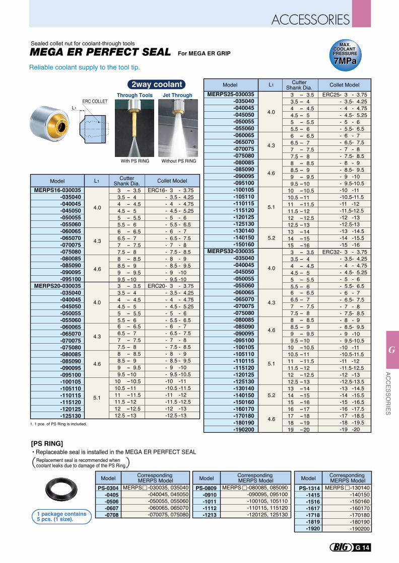
MEGA ER PERFECT SEAL
MERPS16-030035-035040-040045-045050-050055-055060-060065-065070-070075-075080-080085-085090-090095-095100
MERPS20-030035-035040-040045-045050-050055
-055060-060065-065070-070075-075080-080085-085090-090095-095100-100105-105110-110115-115120-120125-125130
L1
4.0
4.3
4.6
4.0
4.3
4.6
5.1
Model Collet Model
L1
ERC COLLET
CutterShank Dia. 3 - 3.5 3.5 - 4 4 - 4.5 4.5 - 5 5 - 5.5 5.5 - 6 6 - 6.5 6.5 - 7 7 - 7.5 7.5 - 8 8 - 8.5 8.5 - 9 9 - 9.5 9.5 -10 3 - 3.5 3.5 - 4 4 - 4.5 4.5 - 5 5 - 5.5 5.5 - 6 6 - 6.5 6.5 - 7 7 - 7.5 7.5 - 8 8 - 8.5 8.5 - 9 9 - 9.5 9.5 -1010 -10.510.5 -1111 -11.511.5 -1212 -12.512.5 -13
MERPS25-030035-035040-040045-045050-050055-055060-060065-065070-070075-075080-080085-085090-090095-095100-100105-105110-110115-115120-120125-125130-130140-140150-150160
MERPS32-030035-035040-040045-045050-050055-055060-060065
-065070-070075-075080-080085-085090-090095-095100-100105-105110-110115-115120-120125-125130-130140-140150-150160-160170-170180-180190-190200
L1
4.0
4.3
4.6
5.1
4.3
5.1
4.6
5.2
4.6
5.2
4.0
Model Collet ModelCutterShank Dia. 3 - 3.5 3.5 - 4 4 - 4.5 4.5 - 5 5 - 5.5 5.5 - 6 6 - 6.5 6.5 - 7 7 - 7.5 7.5 - 8 8 - 8.5 8.5 - 9 9 - 9.5 9.5 - 1010 - 10.510.5 - 1111 - 11.511.5 - 1212 - 12.512.5 - 1313 - 1414 - 1515 - 16 3 - 3.5 3.5 - 4 4 - 4.5 4.5 - 5 5 - 5.5 5.5 - 6 6 - 6.5 6.5 - 7 7 - 7.5 7.5 - 8 8 - 8.5 8.5 - 9 9 - 9.5 9.5 - 1010 - 10.510.5 - 1111 - 11.511.5 - 1212 - 12.512.5 - 1313 - 1414 - 1515 - 1616 - 1717 - 1818 - 1919 - 20
PS-0304-0405-0506-0607-0708
MERPS -030035, 035040-040045, 045050-050055, 055060-060065, 065070-070075, 075080
PS-0809-0910-1011-1112-1213
MERPS -080085, 085090-090095, 095100-100105, 105110-110115, 115120-120125, 125130
PS-1314-1415-1516-1617-1718-1819-1920
MERPS -130140-140150-150160-160170-170180-180190-190200
ERC16- 3 - 3.75- 3.5 - 4.25- 4 - 4.75- 4.5 - 5.25- 5 - 6- 5.5 - 6.5- 6 - 7- 6.5 - 7.5- 7 - 8- 7.5 - 8.5- 8 - 9 - 8.5 - 9.5- 9 -10- 9.5 -10
ERC20- 3 - 3.75- 3.5 - 4.25- 4 - 4.75- 4.5 - 5.25- 5 - 6- 5.5 - 6.5- 6 - 7- 6.5 - 7.5- 7 - 8- 7.5 - 8.5- 8 - 9- 8.5 - 9.5- 9 -10- 9.5 -10.5-10 -11-10.5 -11.5-11 -12-11.5 -12.5-12 -13-12.5 -13
ERC25- 3 - 3.75- 3.5- 4.25- 4 - 4.75- 4.5- 5.25- 5 - 6- 5.5- 6.5- 6 - 7- 6.5- 7.5- 7 - 8- 7.5- 8.5- 8 - 9 - 8.5- 9.5- 9 -10- 9.5-10.5-10 -11-10.5-11.5-11 -12-11.5-12.5-12 -13-12.5-13-13 -14.5-14 -15.5-15 -16
ERC32- 3 - 3.75- 3.5- 4.25- 4 - 4.75- 4.5- 5.25- 5 - 6- 5.5- 6.5- 6 - 7- 6.5- 7.5- 7 - 8- 7.5- 8.5- 8 - 9 - 8.5- 9.5- 9 -10- 9.5-10.5-10 -11-10.5-11.5-11 -12-11.5-12.5-12 -13-12.5-13.5 -13 -14.5-14 -15.5-15 -16.5-16 -17.5-17 -18.5-18 -19.5-19 -20
Corresponding MERPS ModelModel Corresponding
MERPS ModelModel Corresponding MERPS ModelModel
1 package contains 5 pcs. (1 size).
[PS RING]
Reliable coolant supply to the tool tip.
1. 1 pce. of PS Ring is included.
For MEGA ER GRIPSealed collet nut for coolant-through tools MAX.
COOLANT PRESSURE
MAX.COOLANT PRESSURE
7MPa7MPa
Through Tools
With PS RING Without PS RING
Jet Through
2way coolant
• Replaceable seal is installed in the MEGA ER PERFECT SEALReplacement seal is recommended when coolant leaks due to damage of the PS Ring.
G 14
ACC
ESSOR
IES
G
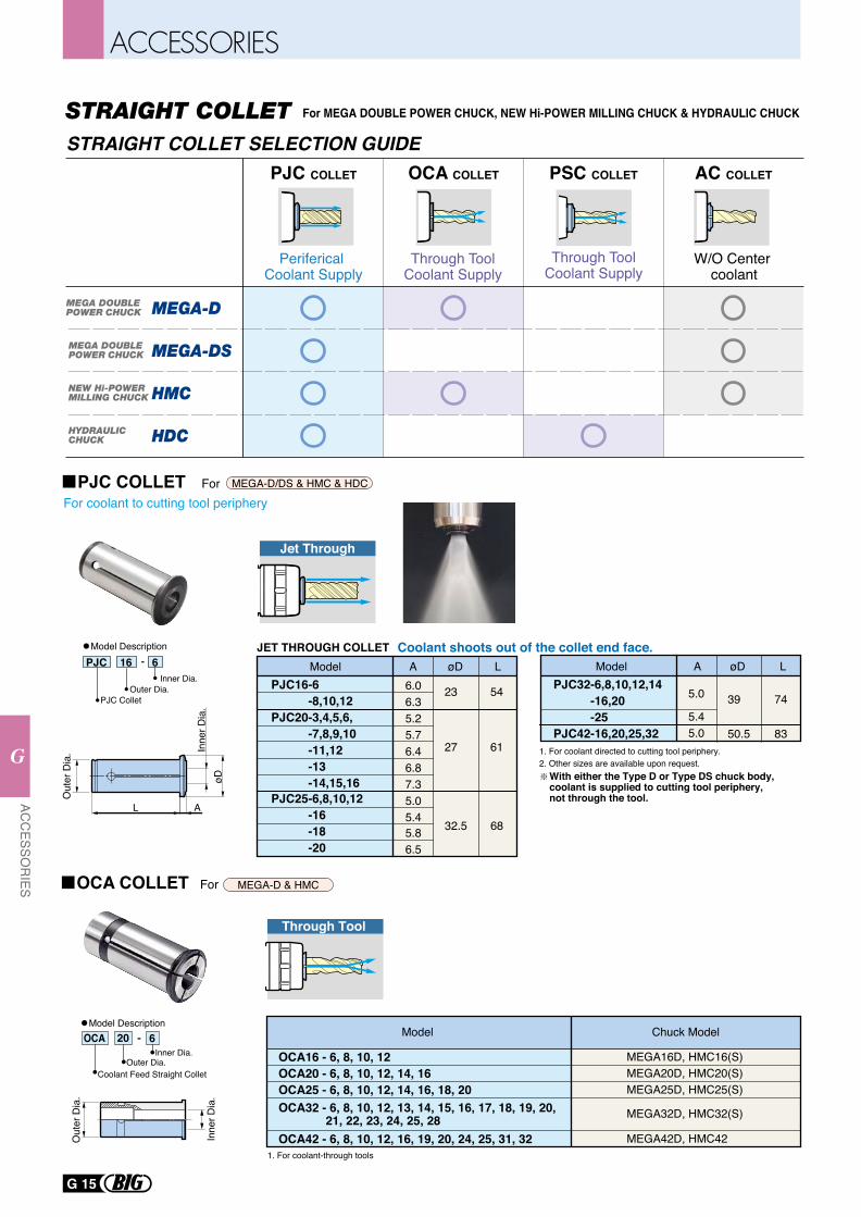
PJC COLLETFor coolant to cutting tool periphery
For MEGA-D/DS & HMC & HDC
1. For coolant directed to cutting tool periphery.2. Other sizes are available upon request.
With either the Type D or Type DS chuck body, coolant is supplied to cutting tool periphery, not through the tool.
Coolant shoots out of the collet end face.JET THROUGH COLLET
For MEGA DOUBLE POWER CHUCK, NEW Hi-POWER MILLING CHUCK & HYDRAULIC CHUCK
PJC16-6 -8,10,12PJC20-3,4,5,6, -7,8,9,10 -11,12 -13 -14,15,16PJC25-6,8,10,12 -16 -18 -20
23
27
54
61
6.06.35.25.76.46.87.35.05.45.86.5
PJC 16 6-
PJC ColletOuter Dia.
Inner Dia.
Model Description
AModel øD L
32.5 68
PJC32-6,8,10,12,14 -16,20 -25PJC42-16,20,25,32
39
50.5
74
835.45.0
AModel øD L
øD
AL
Inne
r Dia
.
Out
er D
ia.
Jet Through
5.0
OCA COLLET For MEGA-D & HMC
Coolant Feed Straight ColletOuter Dia.
Inner Dia.OCA 20 6-
1. For coolant-through tools
Out
er D
ia.
Inne
r Dia
.
OCA20 - 6, 8, 10, 12, 14, 16OCA25 - 6, 8, 10, 12, 14, 16, 18, 20
OCA42 - 6, 8, 10, 12, 16, 19, 20, 24, 25, 31, 32
OCA32 - 6, 8, 10, 12, 13, 14, 15, 16, 17, 18, 19, 20, 21, 22, 23, 24, 25, 28
MEGA20D, HMC20(S)MEGA25D, HMC25(S)
OCA16 - 6, 8, 10, 12 MEGA16D, HMC16(S)
MEGA42D, HMC42
MEGA32D, HMC32(S)
Chuck ModelModelModel Description
Through Tool
MEGA DOUBLE POWER CHUCK
MEGA DOUBLE POWER CHUCK
NEW Hi-POWERMILLING CHUCK
HYDRAULIC CHUCK
PJC COLLET PSC COLLETOCA COLLET AC COLLET
Periferical Coolant Supply
W/O Center coolant
Through ToolCoolant Supply
Through ToolCoolant Supply
MEGA-D
MEGA-DS
HMC
HDC
STRAIGHT COLLET SELECTION GUIDE
G 15
ACC
ESSOR
IES
G
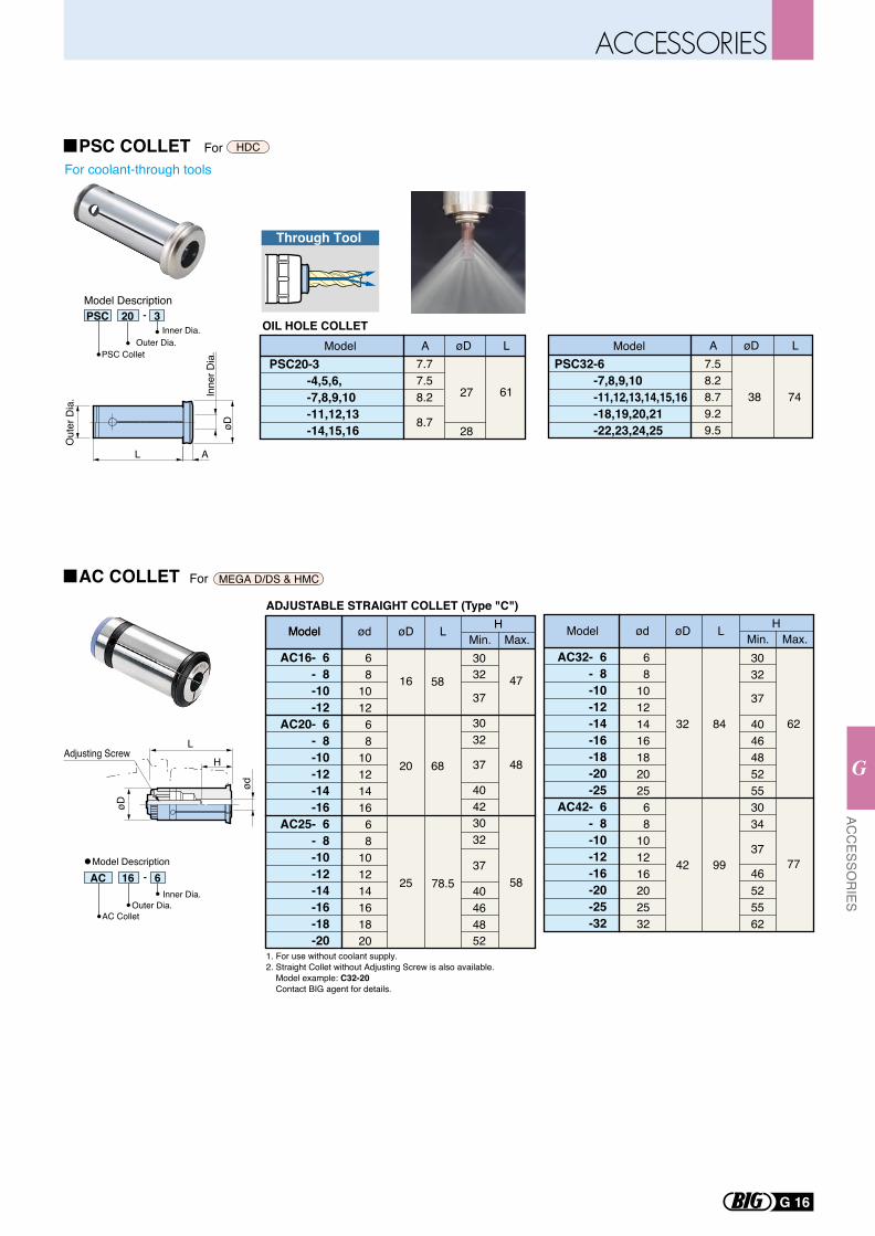
AC COLLET For MEGA D/DS & HMC
ADJUSTABLE STRAIGHT COLLET (Type "C")
1. For use without coolant supply.2. Straight Collet without Adjusting Screw is also available. Model example: C32-20 Contact BIG agent for details.
AC 16 6-
AC ColletOuter Dia.
Inner Dia.
Model Description
Model
AC16- 6- 8-10-12
AC20- 6- 8-10-12-14-16
AC25- 6- 8-10-12-14-16-18-20
ød
68
101268
1012141668
101214161820
øD
20
25
L
68
78.5
HMin.
3032
37
3230
37
4240
3032
37
4648
40
52
Max.
48
16 58 47
58
Model Model
AC32- 6- 8-10-12-14-16-18-20-25
AC42- 6- 8-10-12-16-20-25-32
ød
68
1012141618202568
101216202532
øD
32
42
L
84
99
HMin.3032
37
4640
4852553034
37
46525562
Max.
62
77
L
H
øD
ød
Adjusting Screw
PSC 20 3-
PSC ColletOuter Dia.
Inner Dia.
Model Description
øD
Out
er D
ia. In
ner D
ia.
AL
ModelPSC20-3 -4,5,6, -7,8,9,10 -11,12,13 -14,15,16
27
28
61
A øD L ModelPSC32-6 -7,8,9,10 -11,12,13,14,15,16 -18,19,20,21 -22,23,24,25
38 74
A øD L7.77.58.2
8.7
7.58.28.79.29.5
For coolant-through toolsPSC COLLET For HDC
OIL HOLE COLLET
Through Tool
G 16
ACC
ESSOR
IES
G
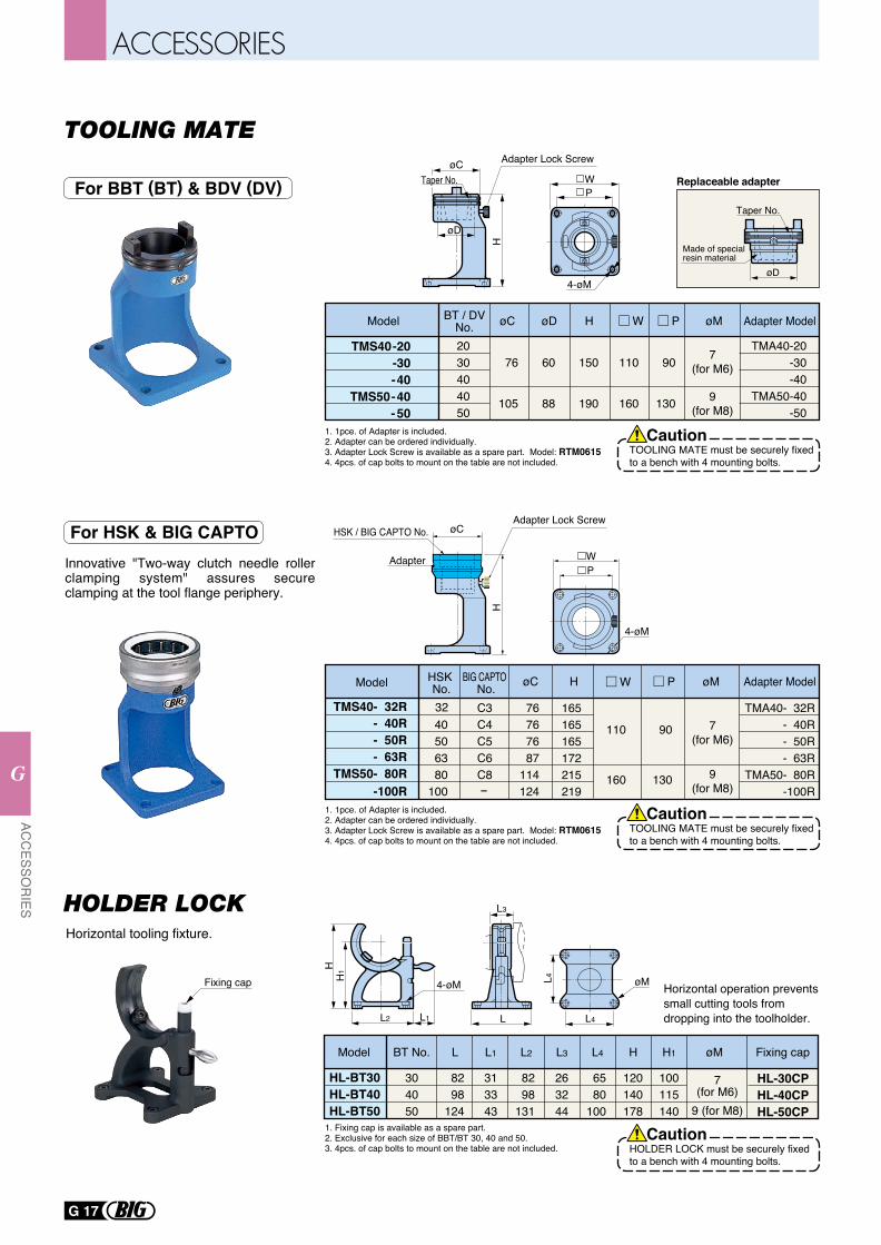
Innovative "Two-way clutch needle roller clamping system" assures secure clamping at the tool flange periphery.
øC
øC
HH
Taper No.
øD
4-øM
4-øM
WP
Replaceable adapter
Taper No.
øD
Made of special resin material
1. 1pce. of Adapter is included.2. Adapter can be ordered individually.3. Adapter Lock Screw is available as a spare part. Model: RTM0615 4. 4pcs. of cap bolts to mount on the table are not included.
1. 1pce. of Adapter is included.2. Adapter can be ordered individually.3. Adapter Lock Screw is available as a spare part. Model: RTM0615 4. 4pcs. of cap bolts to mount on the table are not included.
Model BT / DVNo. øC øD PH W øM Adapter Model
TMS40-20-30-40
TMS50-40- 50
2030404050
76
105
60
88
150
190
110
160
90
130
7(for M6)
9(for M8)
TMA40-20 -30 -40 TMA50-40 -50
Adapter Lock Screw
Adapter Lock Screw
WP
HSK No.
BIG CAPTO No.
- 63R
- 40RTMS40- 32R
- 50R40506380
100
C3C4C5C6C8
76767687
114124
TMA40- 32R- 40R- 50R- 63R
TMA50- 80R-100R
165165165172215219
110
160
90
130TMS50- 80R-100R
32
-
Adapter
HSK / BIG CAPTO No.
TOOLING MATE must be securely fixed to a bench with 4 mounting bolts.
Caution
TOOLING MATE must be securely fixed to a bench with 4 mounting bolts.
Caution
Model øC H PW øM Adapter Model
9(for M8)
7(for M6)
For BBT (BT) & BDV (DV)
1. Fixing cap is available as a spare part.2. Exclusive for each size of BBT/BT 30, 40 and 50.3. 4pcs. of cap bolts to mount on the table are not included.
Model LBT No. L1 L2 L3 L4 H H1 Fixing capøM
HL-BT30HL-BT40HL-BT50
304050
8298
124
313343
8298
131
263244
6580
100
120140178
100115140 9 (for M8)
HL-30CPHL-40CPHL-50CP
7(for M6)
L3
LL1
4-øM
L2
HH
1
øM
L4
L4Fixing cap Horizontal operation prevents small cutting tools from dropping into the toolholder.
Horizontal tooling fixture.
HOLDER LOCK must be securely fixed to a bench with 4 mounting bolts.
Caution
For HSK & BIG CAPTO
G 17
ACC
ESSOR
IES
G
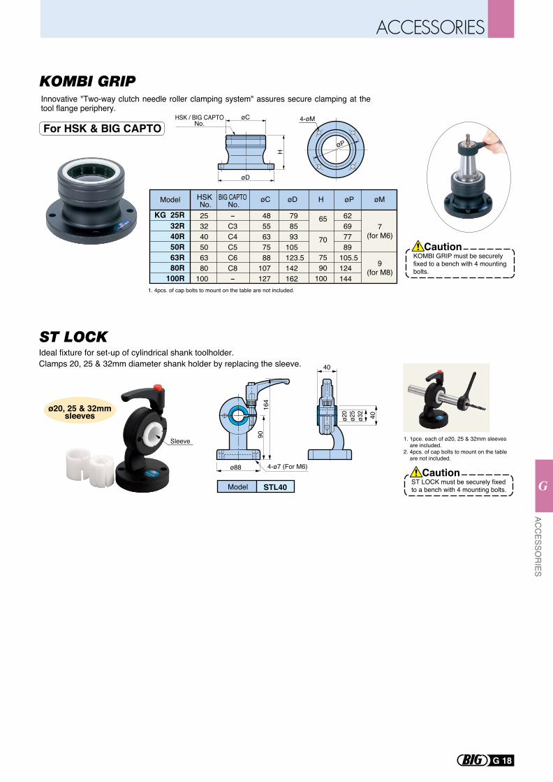
1. 1pce. each of ø20, 25 & 32mm sleeves are included.2. 4pcs. of cap bolts to mount on the table are not included.
Model STL40
ø88
40
4-ø7 (For M6)
ø20
ø25
ø32
40
Ideal fixture for set-up of cylindrical shank toolholder.Clamps 20, 25 & 32mm diameter shank holder by replacing the sleeve.
Sleeve
9016
4
ø20, 25 & 32mmsleeves
ST LOCK must be securely fixed to a bench with 4 mounting bolts.
Caution
4-øM
øP
øD
øC
H
HSK / BIG CAPTONo.
Innovative "Two-way clutch needle roller clamping system" assures secure clamping at the tool flange periphery.
Model HSK No.
BIG CAPTO No. øC øM
50R
32RKG 25R
40R
253240506380
100
-C3C4C5C6C8-
4855637588
107127
7(for M6)
9(for M8)
øD
79 85 93105123.5142162
62 69 77 89105.5124144
H
7590
100
65
70
øP
63R80R
100R1. 4pcs. of cap bolts to mount on the table are not included.
KOMBI GRIP must be securelyfixed to a bench with 4 mountingbolts.
Caution
For HSK & BIG CAPTO
G 18
ACC
ESSOR
IES
G
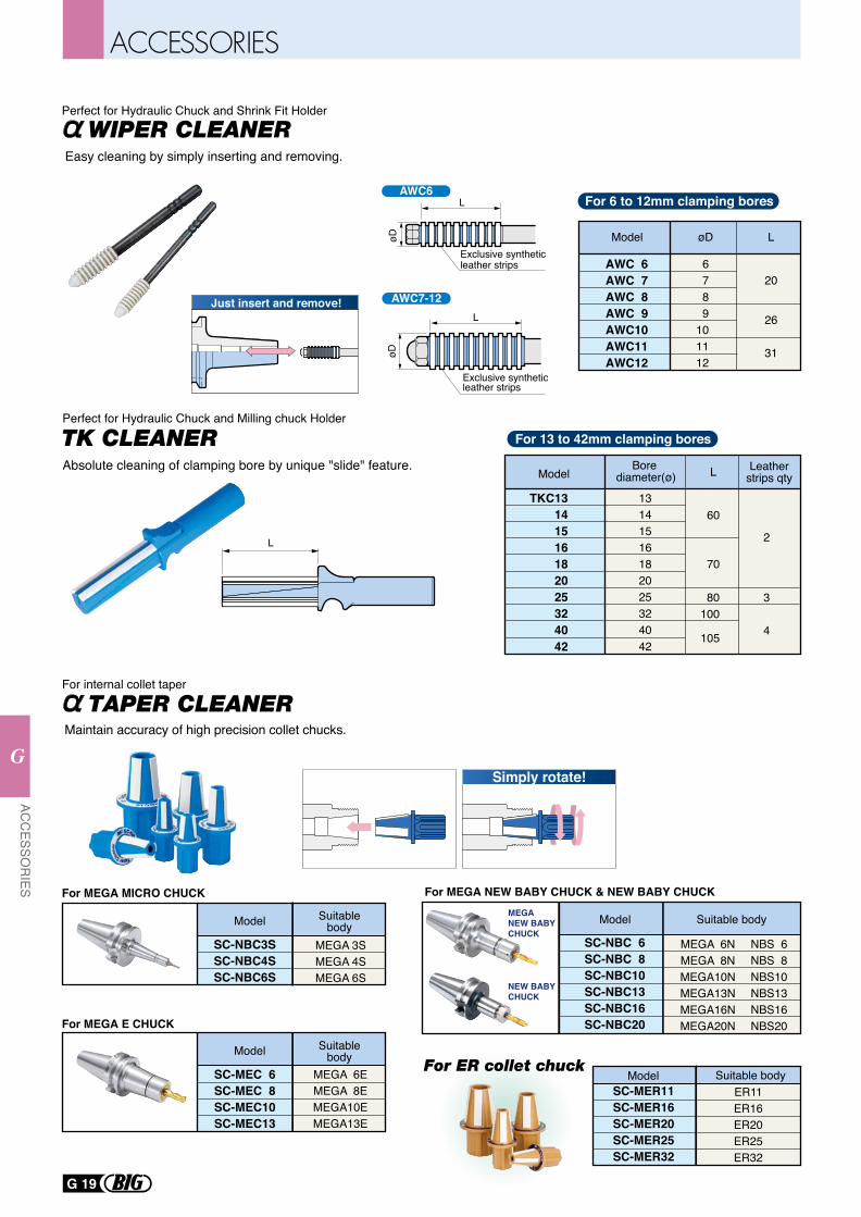
AWC 6AWC 7AWC 8AWC 9AWC10AWC11AWC12
Model
6789
101112
20
26
31
øD L
For 6 to 12mm clamping bores
Easy cleaning by simply inserting and removing.
AWC6
Exclusive synthetic leather strips
øD
L
Exclusive synthetic leather strips
AWC7-12
øD
L
TKC13141516182025324042
70
105
60
Model
13141516182025324042
Bore diameter(ø) L Leather
strips qty
80100
3
4
2
For 13 to 42mm clamping bores
L
Absolute cleaning of clamping bore by unique "slide" feature.
Model
SC-NBC3SSC-NBC4SSC-NBC6S
Suitable body
Model
SC-MEC 6SC-MEC 8SC-MEC10SC-MEC13
Suitable body
MEGA 3SMEGA 4SMEGA 6S
Model Suitable body
For MEGA MICRO CHUCK
MEGA 6EMEGA 8EMEGA10EMEGA13E
For MEGA E CHUCK
SC-MER11SC-MER16SC-MER20SC-MER25SC-MER32
ER11ER16ER20ER25ER32
Model
SC-NBC 6SC-NBC 8SC-NBC10SC-NBC13SC-NBC16SC-NBC20
Suitable body
MEGA 6NMEGA 8NMEGA10NMEGA13NMEGA16NMEGA20N
NBS 6NBS 8NBS10NBS13NBS16NBS20
MEGA NEW BABY CHUCK
NEW BABY CHUCK
Maintain accuracy of high precision collet chucks.
For MEGA NEW BABY CHUCK & NEW BABY CHUCK
Simply rotate!
For internal collet taper
Perfect for Hydraulic Chuck and Shrink Fit Holder
Perfect for Hydraulic Chuck and Milling chuck Holder
Just insert and remove!
G 19
ACC
ESSOR
IES
G
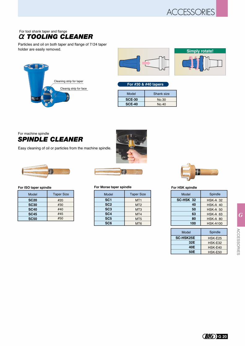
For #30 & #40 tapersCleaning strip for taper
Cleanig strip for face
SCE-30SCE-40
Shank sizeModelNo.30No.40
Simply rotate!
For tool shank taper and flange
Particles and oil on both taper and flange of 7/24 taper holder are easily removed.
SC20SC30SC40SC45SC50
Model Taper Size
For HSK spindle
SC1SC2SC3SC4SC5SC6
ModelMT1MT2MT3MT4MT5MT6
Taper Size
For Morse taper spindle
For machine spindle
Easy cleaning of oil or particles from the machine spindle.
For ISO taper spindle
#20 #30 #40 #45 #50
SC-HSK 3240506380
100
Model
HSK-A 32HSK-A 40HSK-A 50HSK-A 63HSK-A 80HSK-A100
Spindle
SC-HSK25E32E40E50E
Model
HSK-E25HSK-E32HSK-E40HSK-E50
Spindle
G 20
ACC
ESSOR
IES
G
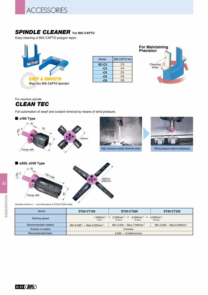
SPINDLE CLEANER For BIG CAPTOEasy cleaning of BIG CAPTO polygon taper.
SC-C3-C4-C5-C6-C8
C3C4C5C6C8
Model BIG CAPTO No.
Cleaningstrips
For MaintainingPrecision
For machine spindle
Full automation of swarf and coolant removal by means of wind pressure.
260mm(330mm)
45
130 (166)
62
ø20
Flange ø66
160mm
45
82
ø20
62
Flange ø66
ø160 Type
ø260, ø330 Type
Numbers shown in ( ) are dimensions of ST20-CT330 model.
ST20-CT260
Min.4,000 - Max.7,000min-1
3,000 - 10,000mm/minClockwise
ST20-CT330Model
Recommended rotationDirection of rotation
Recommended feed
ST20-CT160
Min.6,000-1 - Max.9,000min-1
Starting speed 1,000min-1(1sec)
2,000min-1(0.5sec)
3,000min-1(0.5sec)
4,000min-1(0.5sec)
Min.3,000 - Max.6,000min-1
High pressure coolant removes swarf. Wind pressure cleans workpieces.
G 21
ACC
ESSOR
IES
G
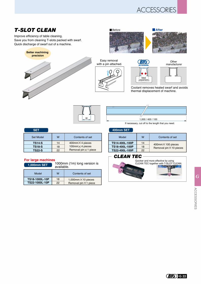
Improve efficiency of table cleaning.Save you from cleaning T-slots packed with swarf.Quick discharge of swarf out of a machine.
W
Other manufacturer
Coolant removes heated swarf and avoids thermal displacement of machine.
Easy removal with a pin attached.
Quicker and more effective by using CLEAN TEC together with T-SLOT CLEAN.
Ideal expansion
1,000 / 400 / 100
W Contents of setSet Model
400mm 4 pieces100mm 4 piecesRemoval pin 1 piece
141822
TS14-STS18-STS22-S
W Contents of setModel
1822
TS18-1000L-10PTS22-1000L-10P
If necessary, cut off to the length that you need.
1,000mm 10 piecesRemoval pin 1 piece
W Contents of setModel
400mm 100 piecesRemoval pin 10 pieces
141822
TS14-400L-100PTS18-400L-100PTS22-400L-100P
Before After
For large machines
400mm SET
1,000mm SET
SET
Better machining precision
1000mm (1m) long version is available.
G 22
ACC
ESSOR
IES
G
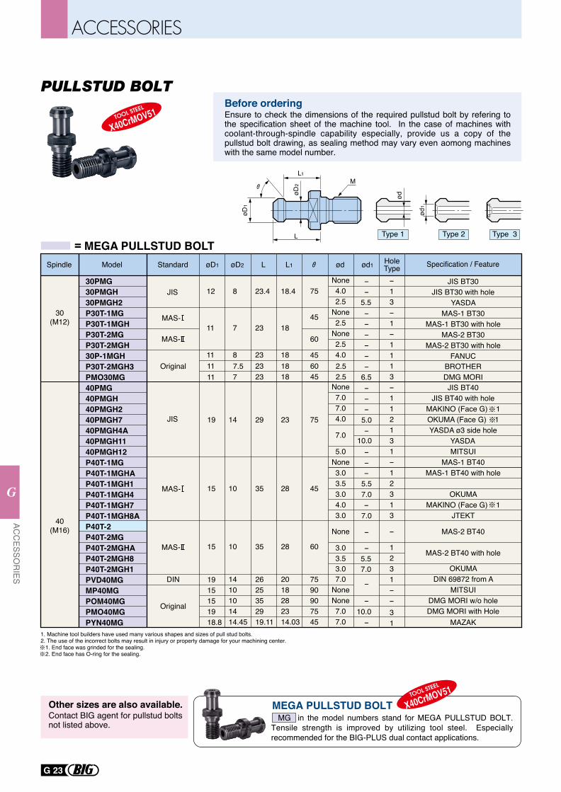
L1M
LøD
1
øD2
ød
ød1
Type 1 Type 2 Type 3
30PMG30PMGH30PMGH2P30T-1MGP30T-1MGHP30T-2MGP30T-2MGH30P-1MGHP30T-2MGH3PMO30MG40PMG40PMGH40PMGH240PMGH740PMGH4A40PMGH1140PMGH12P40T-1MGP40T-1MGHAP40T-1MGH1P40T-1MGH4P40T-1MGH7P40T-1MGH8AP40T-2P40T-2MGP40T-2MGHAP40T-2MGH8P40T-2MGH1PVD40MGMP40MGPOM40MGPMO40MGPYN40MG
12
11
11
8
7
8
23.4
23
23
18.4
18
18
75
45
60
7590907545
23
28
28
2018282314.03
29
35
35
2625352919.11
14
10
10
1410101414.45
19
15
15
1915151918.8
None4.02.5
None2.5
None2.54.0
None7.07.04.0
7.0
5.0None3.03.53.04.03.0
None
3.03.53.07.0
NoneNone7.07.0
-13-1-1113-112131-12313
-
1231--31
Specification / Feature
30(M12)
40(M16)
JIS
MAS-
MAS-
JIS
Spindle Model Standard øD1 ød ød1 HoleTypeøD2 L L1
MAS-
MAS-
75
45
60
45
5.5
5.57.0
-5.57.0
-7.0
10.0
10.0
JIS BT30JIS BT30 with hole
YASDAMAS-1 BT30
MAS-1 BT30 with holeMAS-2 BT30
MAS-2 BT30 with holeFANUC
JIS BT40JIS BT40 with hole
MAKINO (Face G) 1OKUMA (Face G) 1YASDA ø3 side hole
YASDA MITSUI
MAS-1 BT40MAS-1 BT40 with hole
OKUMAMAKINO (Face G) 1
JTEKT
MAS-2 BT40
MAS-2 BT40 with hole
OKUMADIN 69872 from A
MITSUIDMG MORI w/o holeDMG MORI with Hole
MAZAK
Original
Original
DIN
= MEGA PULLSTUD BOLT
1111
7.57
2323
1818
6045
2.52.5
--
------
---
5.0-
--
-
-
-
-
-
6.5BROTHERDMG MORI
Before orderingEnsure to check the dimensions of the required pullstud bolt by refering to the specification sheet of the machine tool. In the case of machines with coolant-through-spindle capability especially, provide us a copy of the pullstud bolt drawing, as sealing method may vary even aomong machines with the same model number.
MEGA PULLSTUD BOLTContact BIG agent for pullstud bolts not listed above.
Other sizes are also available. MG in the model numbers stand for MEGA PULLSTUD BOLT. Tensile strength is improved by utilizing tool steel. Especially recommended for the BIG-PLUS dual contact applications.
1. Machine tool builders have used many various shapes and sizes of pull stud bolts. 2. The use of the incorrect bolts may result in injury or property damage for your machining center. 1. End face was grinded for the sealing. 2. End face has O-ring for the sealing.
G 23
ACC
ESSOR
IES
G
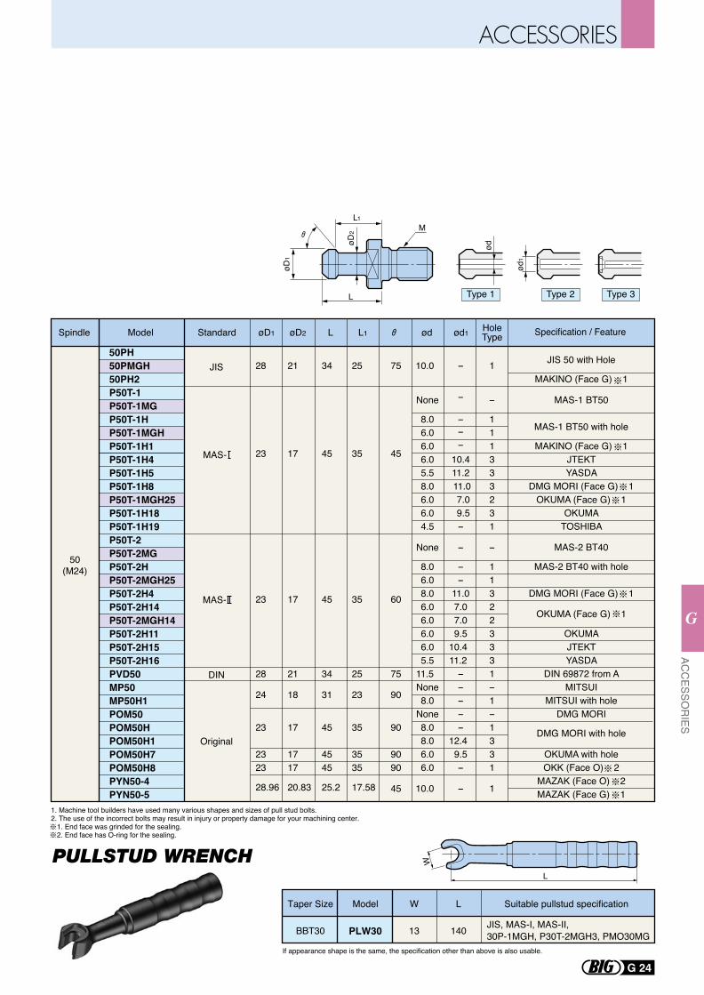
L1M
LøD
1
øD2
ød
ød1
Type 1 Type 2 Type 3
50PH50PMGH50PH2P50T-1P50T-1MGP50T-1HP50T-1MGHP50T-1H1P50T-1H4P50T-1H5P50T-1H8P50T-1MGH25P50T-1H18P50T-1H19P50T-2P50T-2MGP50T-2HP50T-2MGH25P50T-2H4P50T-2H14P50T-2MGH14P50T-2H11P50T-2H15P50T-2H16PVD50MP50MP50H1POM50POM50HPOM50H1POM50H7POM50H8PYN50-4PYN50-5
28
23
23
28
24
23
2323
28.96
21
17
17
21
18
17
1717
20.83
25
35
35
25
23
35
3535
17.58
75
45
60
75
90
90
9090
45
34
45
45
34
31
45
4545
25.2
10.0
None
8.06.06.06.05.58.06.06.04.5
None
8.06.08.06.06.06.06.05.5
11.5 None8.0
None8.08.06.06.0
10.0
1
-
111333231
-
113223331-1-1331
1
JIS 50 with Hole
MAKINO (Face G) 1
MAS-1 BT50
MAS-1 BT50 with hole
MAKINO (Face G) 1JTEKTYASDA
DMG MORI (Face G) 1OKUMA (Face G) 1
OKUMATOSHIBA
MAS-2 BT40
MAS-2 BT40 with hole
DMG MORI (Face G) 1
OKUMA (Face G) 1
OKUMAJTEKTYASDA
DIN 69872 from AMITSUI
MITSUI with holeDMG MORI
DMG MORI with hole
OKUMA with holeOKK (Face O) 2
MAZAK (Face O) 2MAZAK (Face G) 1
-
-
---
10.4 11.2
11.0 7.0 9.5-
-
--
11.07.07.09.5
10.4 11.2 - ----
12.4 9.5-
-
Specification / Feature
50(M24)
JIS
DIN
Spindle Model Standard øD1 ød ød1øD2 L L1
MAS-
MAS-
Original
HoleType
1. Machine tool builders have used many various shapes and sizes of pull stud bolts. 2. The use of the incorrect bolts may result in injury or property damage for your machining center. 1. End face was grinded for the sealing. 2. End face has O-ring for the sealing.
PULLSTUD WRENCH
L Suitable pullstud specificationModel
JIS, MAS-Ⅰ, MAS-Ⅱ,30P-1MGH, P30T-2MGH3, PMO30MG140
WTaper Size
13BBT30 PLW30
If appearance shape is the same, the specification other than above is also usable.
G 24
ACC
ESSOR
IES
G
L
W
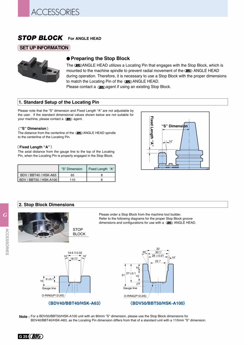
The ANGLE HEAD utilizes a Locating Pin that engages with the Stop Block, which is mounted to the machine spindle to prevent radial movement of the ANGLE HEAD during operation. Therefore, it is necessary to use a Stop Block with the proper dimensions to match the Locating Pin of the ANGLE HEAD.Please contact a agent if using an existing Stop Block.
Preparing the Stop Block
1. Standard Setup of the Locating Pin
Fixed Length “A”
“S” Dimension
BDV / BBT40 / HSK-A63BDV / BBT50 / HSK-A100
65110
”S” Dimension
86
Fixed Length “A”
10˚
2. Stop Block Dimensions
27 0.1
10
15
2
30˚
10˚
3230
28 0.01
22.7
+0.2 0
31
Gauge line
18 +0.03+0.01
19.6 0.02
O-RING(P12/JIS) O-RING(P12/JIS)
10˚
9 0.115
Gauge line
10˚
STOPBLOCK
The distance from the centerline of the ANGLE HEAD spindle to the centerline of the Locating Pin.
Please note that the “S” dimension and Fixed Length “A” are not adjustable by the user. If the standard dimensional values shown below are not suitable for your machine, please contact a agent.
The axial distance from the gauge line to the top of the Locating Pin, when the Locating Pin is properly engaged in the Stop Block.
Please order a Stop Block from the machine tool builder.Refer to the following diagrams for the proper Stop Block groove dimensions and configurations for use with a ANGLE HEAD.
For a BDV50/BBT50/HSK-A100 unit with an 80mm ”S” dimension, please use the Stop Block dimensions for BDV40/BBT40/HSK-A63, as the Locating Pin dimension differs from that of a standard unit with a 110mm ”S” dimension.
Note :
“S” Dimension
Fixed Length “A”
For ANGLE HEAD
BDV50/BBT50/HSK-A100BDV40/BBT40/HSK-A63
SET UP INFORMATION
STOP BLOCK
G 25
ACC
ESSOR
IES
G
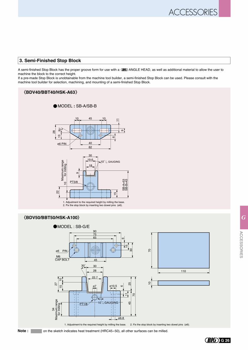
3. Semi-Finished Stop Block
A semi-finished Stop Block has the proper groove form for use with a ANGLE HEAD, as well as additional material to allow the user to machine the block to the correct height.If a pre-made Stop Block is unobtainable from the machine tool builder, a semi-finished Stop Block can be used. Please consult with the machine tool builder for selection, machining, and mounting of a semi-finished Stop Block.
Note : on the sketch indicates heat treatment (HRC45-50), all other surfaces can be milled.
MODEL : SB-G/E
MODEL : SB-A/SB-B
10 45 10
1330
˚
28
116
9
8240ø6 PIN
30
9
18
PT3/8
1. Adjustment to the required height by milling the base.2. Fix the stop block by inserting two dowel pins (ø6).
1. Adjustment to the required height by milling the base. 2. Fix the stop block by inserting two dowel pins (ø6).
SB-A
=53
SB-B
=43
15
10
22M
axim
um ra
nge
for m
illing
19.6 0-15˚10˚ GAUGING
7010
110
30˚
PT1/8
34
70
611
452527
1510
Max
imum
rang
e fo
r milli
ng
ø10.5
22.7
30
ø6.8
ø6 PIN
CAP BOLT 45
30
615
657590
M6
28
ø7
0-15˚ 10˚ GAUGING
BDV40/BBT40/HSK-A63
BDV50/BBT50/HSK-A100
G 26
ACC
ESSOR
IES
G
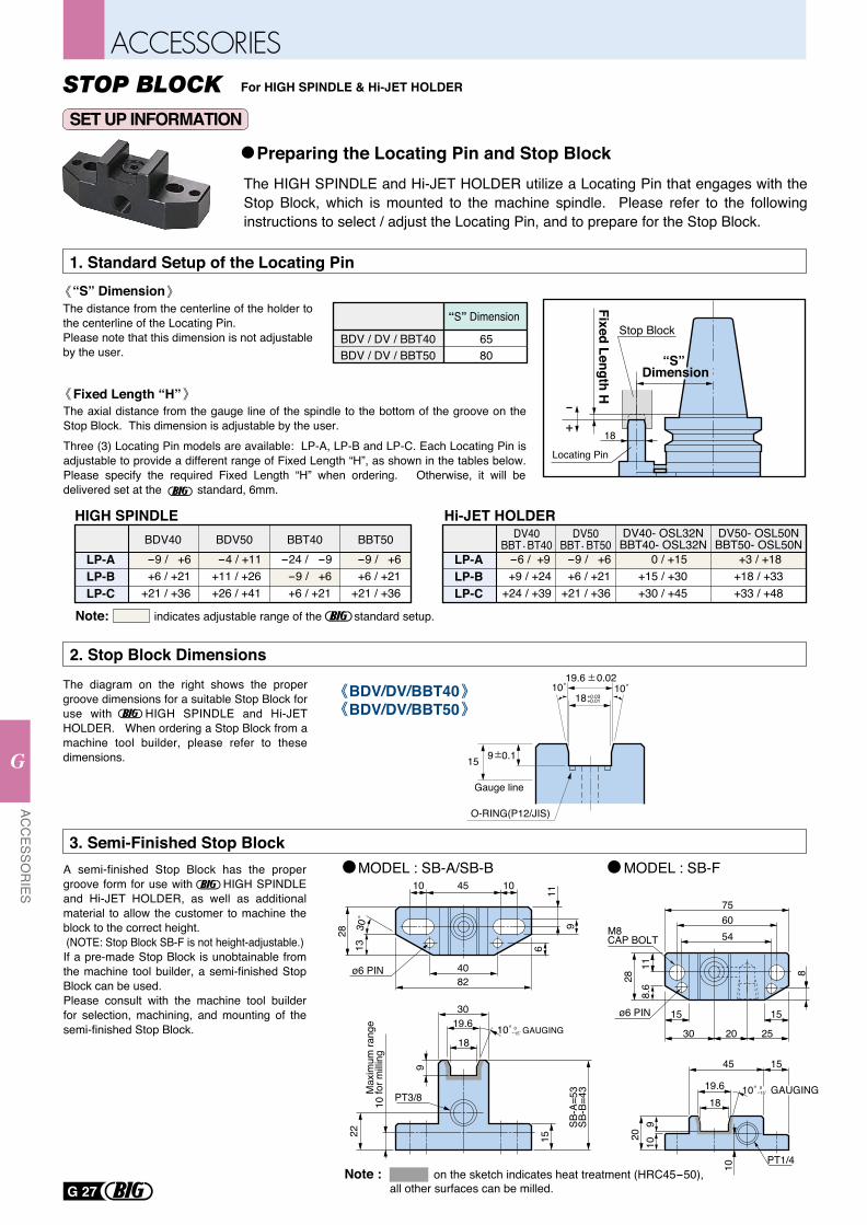
For HIGH SPINDLE & Hi-JET HOLDER
SET UP INFORMATION
STOP BLOCK
The HIGH SPINDLE and Hi-JET HOLDER utilize a Locating Pin that engages with the Stop Block, which is mounted to the machine spindle. Please refer to the following instructions to select / adjust the Locating Pin, and to prepare for the Stop Block.
Preparing the Locating Pin and Stop Block
1. Standard Setup of the Locating Pin
BDV / DV / BBT40BDV / DV / BBT50
6580
HIGH SPINDLE
BDV/DV/BBT40BDV/DV/BBT50
2. Stop Block DimensionsThe diagram on the right shows the proper groove dimensions for a suitable Stop Block for use with HIGH SPINDLE and Hi-JET HOLDER. When ordering a Stop Block from a machine tool builder, please refer to these dimensions.
3. Semi-Finished Stop BlockMODEL : SB-A/SB-B MODEL : SB-F
10 45 10
1330˚
28
116
9
8240ø6 PIN
30
9
18
PT3/8
SB-A
=53
SB-B
=43
15
10
22M
axim
um ra
nge
for m
illing
19.6 0-15˚10˚ GAUGING
18
45 15
PT1/4
2010
9
10
19.6 0-15˚10˚ GAUGING
6075
2811
8.6
15 15
30 20 25
8
M8CAP BOLT 54
ø6 PIN
A semi-finished Stop Block has the proper groove form for use with HIGH SPINDLE and Hi-JET HOLDER, as well as additional material to allow the customer to machine the block to the correct height. (NOTE: Stop Block SB-F is not height-adjustable.)If a pre-made Stop Block is unobtainable from the machine tool builder, a semi-finished Stop Block can be used.Please consult with the machine tool builder for selection, machining, and mounting of the semi-finished Stop Block.
“S” Dimension
Fixed Length H
Locating Pin
LP-ALP-BLP-C
BDV40 -9 / +6 +6 / +21+21 / +36
BDV50 -4 / +11+11 / +26+26 / +41
BBT40-24 / -9 -9 / +6 +6 / +21
BBT50 -9 / +6 +6 / +21+21 / +36
“S” DimensionThe distance from the centerline of the holder to the centerline of the Locating Pin. Please note that this dimension is not adjustable by the user.
Fixed Length “H”The axial distance from the gauge line of the spindle to the bottom of the groove on the Stop Block. This dimension is adjustable by the user.Three (3) Locating Pin models are available: LP-A, LP-B and LP-C. Each Locating Pin is adjustable to provide a different range of Fixed Length “H”, as shown in the tables below. Please specify the required Fixed Length “H” when ordering. Otherwise, it will be delivered set at the standard, 6mm.
18
“S” Dimension
+-
Note: indicates adjustable range of the standard setup.
Stop Block
Note : on the sketch indicates heat treatment (HRC45-50), all other surfaces can be milled.
Hi-JET HOLDER
LP-ALP-BLP-C
DV40BBT BT40 -6 / +9 +9 / +24+24 / +39
-9 / +6 +6 / +21+21 / +36
DV40- OSL32NBBT40- OSL32N
DV50- OSL50NBBT50- OSL50N
+3 / +18+18 / +33+33 / +48
0 / +15+15 / +30+30 / +45
DV50BBT BT50
18+0.03+0.01
19.6 0.02
O-RING(P12/JIS)
10˚
9 0.115
Gauge line
10˚
G 27
ACC
ESSOR
IES
G
H
H
MEASURINGTOOLS
POINT MASTER PRO PMP
POINT MASTER PMC
POINT CENTER
BASE MASTER SERIES
TOOL MASTER
ACCU CENTER
ALIGNMENT TOOL for ATC arm
DYNA FORCE
TOOL PRESETTER type TPS
LEVEL MASTER
H1
H3
H3
H4
H5
H5
H6
H7
H8
H9
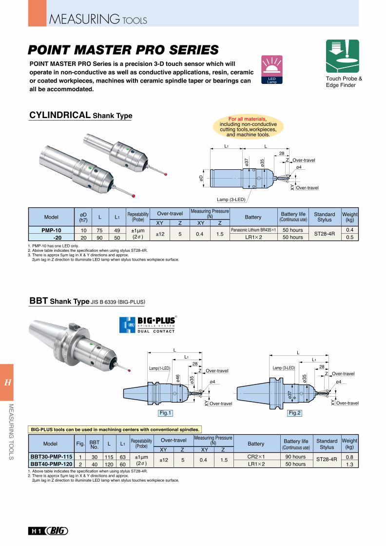
POINT MASTER PRO Series is a precision 3-D touch sensor which will operate in non-conductive as well as conductive applications, resin, ceramic or coated workpieces, machines with ceramic spindle taper or bearings can all be accommodated.
Fig.1 Fig.2
PMP-10 -20
1020
7590
4950
0.40.5
L L1Over-travel
XY Z XY ZPanasonic Lithium BR435 1
±12 0.4 1.5 ST28-4R5 50 hours50 hours
BBT30-PMP-115BBT40-PMP-120
3040
115120
6360
0.81.3
12
BBTNo. L L1
LR1 2
Over-travel
XY Z XY ZCR2 1±12 0.4 1.5 ST28-4R5
50 hours90 hours
Fig.
XY
ø4
L1
L
Z28
ø35
ø37
Over-travel
Over-travelLamp (3-LED)
øD
L1 L
Z28
ø35
ø37
ø4
XY
Over-travel
Over-travel
Lamp (3-LED)
L1
L
Z28
ø35
ø46
ø4
XY
Over-travel
Over-travel
Lamp (1-LED)
Model øD(h7) Battery Battery life
(Continuous use)Standard
StylusWeight
(kg)
Model Battery Battery life(Continuous use)
StandardStylus
Weight(kg)
LR1 2
For all materials, including non-conductivecutting tools,workpieces,
and machine tools.
Repeatability(Probe)
Repeatability(Probe)
Measuring Pressure(N)
Measuring Pressure(N)
Touch Probe & Edge Finder
LEDLamp
1. PMP-10 has one LED only.2. Above table indicates the specification when using stylus ST28-4R.3. There is approx 5μm lag in X & Y directions and approx. 2μm lag in Z direction to illuminate LED lamp when stylus touches workpiece surface.
1. Above table indicates the specification when using stylus ST28-4R.2. There is approx 5μm lag in X & Y directions and approx. 2μm lag in Z direction to illuminate LED lamp when stylus touches workpiece surface.
BIG-PLUS tools can be used in machining centers with conventional spindles.
POINT MASTER PRO SERIES
BBT Shank Type JIS B 6339 (BIG-PLUS)
CYLINDRICAL Shank Type
±1μm(2 )
±1μm(2 )
R
S P I N D L E S Y S T E M
D U A L C O N T A C T
H 1
MEASURING TOOLS
MEASU
RING
TOO
LSH
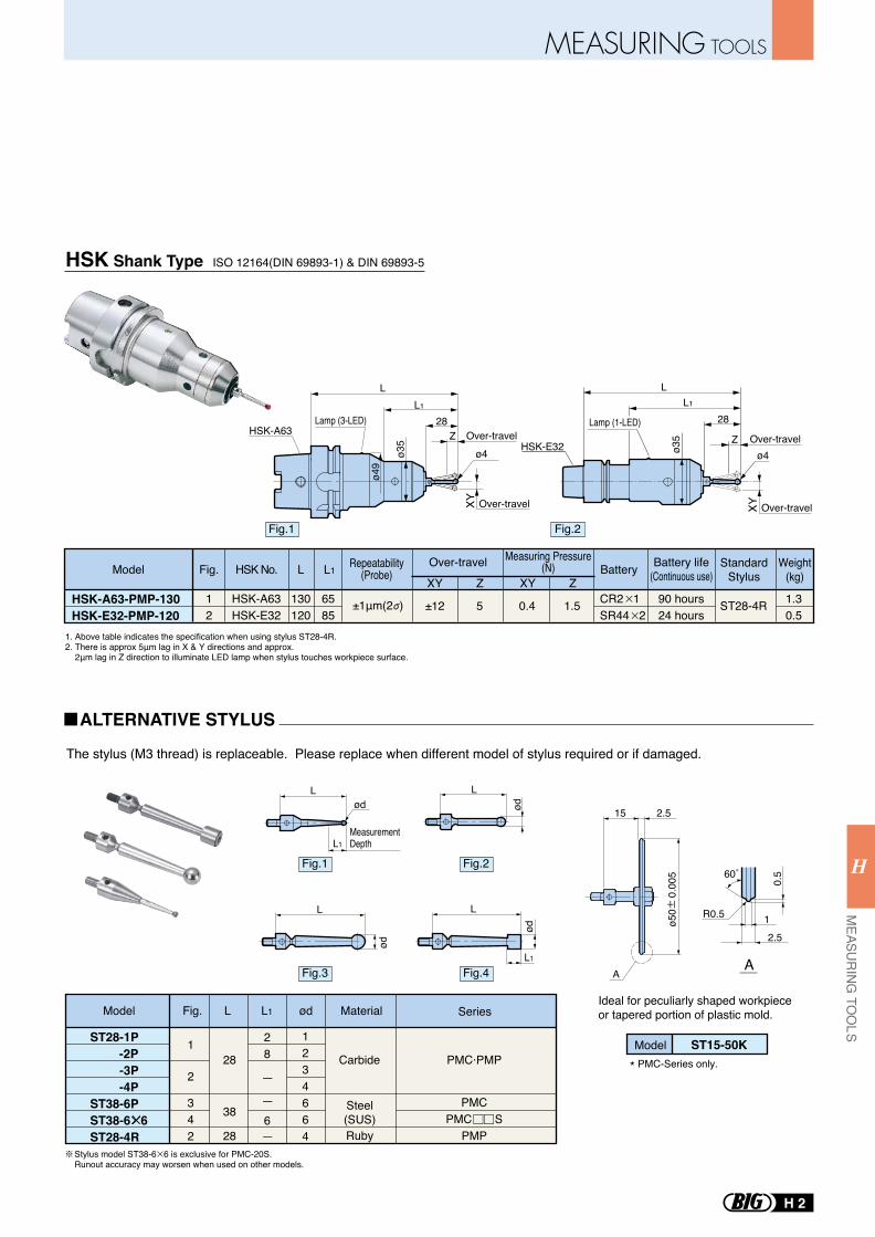
Model
HSK-A63HSK-E32
130120
HSK No. L
12
Fig. L1
CR2 1SR44 2
Over-travel
XY Z XY ZBattery Battery life
(Continuous use)Standard
StylusWeight
(kg)
±126585
1.5 ST28-4R 1.30.5
5HSK-A63-PMP-130HSK-E32-PMP-120
0.4 90 hours24 hours
Repeatability(Probe)
Measuring Pressure(N)
Fig.1 Fig.2
Fig.3 Fig.4
Model
ST28-1P -2P -3P -4PST38-6PST38-6 6ST28-4R
1234664
1
2
342
PMC·PMP
PMCPMC S
PMP
28
38
28
Carbide
Steel(SUS)Ruby
28
6
Fig. L L1 ød Material Series
Model ST15-50K
15 2.5
MeasurementDepthL1
AA
60˚
12.5
R0.5
0.5
Lød
L
ød
L
L1
ød
L
ød
* PMC-Series only.
ø50
0.
005
The stylus (M3 thread) is replaceable. Please replace when different model of stylus required or if damaged.
Ideal for peculiarly shaped workpieceor tapered portion of plastic mold.
Stylus model ST38-6 6 is exclusive for PMC-20S. Runout accuracy may worsen when used on other models.
1. Above table indicates the specification when using stylus ST28-4R.2. There is approx 5μm lag in X & Y directions and approx. 2μm lag in Z direction to illuminate LED lamp when stylus touches workpiece surface.
ALTERNATIVE STYLUS
Fig.1 Fig.2
±1μm(2 )
HSK Shank Type ISO 12164(DIN 69893-1) & DIN 69893-5
ø4
HSK-A63
XY
L1
L
Z28
ø35
ø4
9
Lamp (3-LED)
Over-travel
Over-travel
ø35
28
LL1
Lamp (1-LED)
HSK-E32 Zø4
XY Over-travel
Over-travel
MEASURING TOOLS
H 2
MEASU
RING
TOO
LS
H
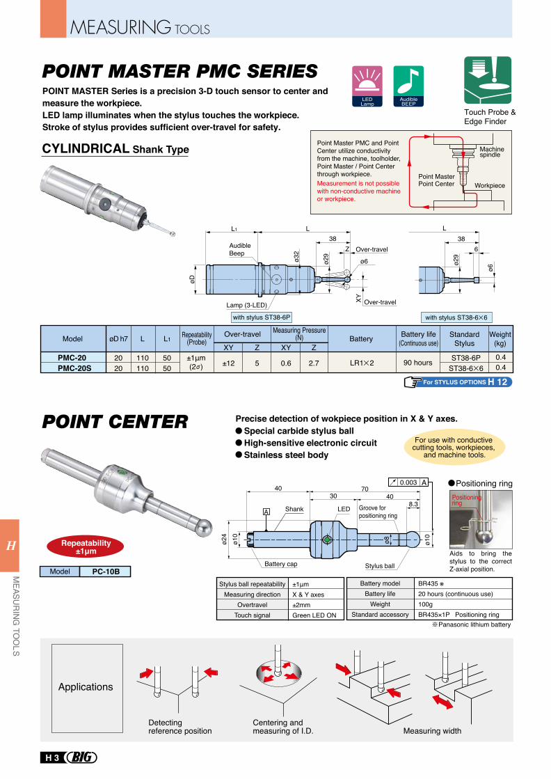
CYLINDRICAL Shank Type
POINT MASTER Series is a precision 3-D touch sensor to center and measure the workpiece.LED lamp illuminates when the stylus touches the workpiece.Stroke of stylus provides sufficient over-travel for safety.
LEDLamp
AudibleBEEP
with stylus ST38-6P
ø29
L38
ø6
6
L1 L38
ø29
ø32
ø6
øD
XY
Over-travel
Over-travel
Z
Model
PMC-20PMC-20S
2020
110110
5050
øD h7 L L1
LR1 2 90 hours
Over-travel
XY Z XY ZBattery Battery life
(Continuous use)Standard
StylusWeight
(kg)
±12 0.6 2.7 ST38-6PST38-6 65
0.40.4
Lamp (3-LED)
AudibleBeep
For use with conductive cutting tools, workpieces,
and machine tools.
Repeatability(Probe)
Measuring Pressure(N)
with stylus ST38-6 6
Touch Probe & Edge Finder
Detecting reference position
Centering and measuring of I.D. Measuring width
Applications
Special carbide stylus ballHigh-sensitive electronic circuitStainless steel body
Precise detection of wokpiece position in X & Y axes.POINT CENTER
POINT MASTER PMC SERIES
±1μm(2 )
For STYLUS OPTIONS H 12
PC-10BModel
Repeatability±1μm
8.3
0.003
ø8ø24
ø10
ø10
4030
7040
Shank Groove for positioning ring
LED
Battery cap Stylus ball
±1μmX & Y axes±2mmGreen LED ON
Stylus ball repeatabilityMeasuring direction
OvertravelTouch signal
Positioning ring
Panasonic lithium battery
BR435 ※20 hours (continuous use)100gBR435×1P Positioning ring
Battery modelBattery life
WeightStandard accessory
Positioning ring
Aids to bring the stylus to the correct Z-axial position.
A
A
Machinespindle
Workpiece
Point Master PMC and Point Center utilize conductivity from the machine, toolholder, Point Master / Point Center through workpiece. Measurement is not possible with non-conductive machine or workpiece.
Point MasterPoint Center
H 3
MEASURING TOOLS
MEASU
RING
TOO
LSH
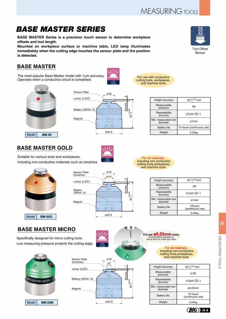
BASE MASTER
BASE MASTER GOLD
BASE MASTER Series is a precision touch sensor to determine workpiece offsets and tool length.Mounted on workpiece surface or machine table, LED lamp illuminates immediately when the cutting edge touches the sensor plate and the position is detected.
Model BM-50
Model BM-50G
+0.005 0Height accuracy
Measureablepressure
Min. measurable tooldiameter
Repeatabilityaccurary
Battery life
Weight
3N
ø1mm
±1μm (2 )
±1μm (2 )
±1μm (2 )
10 hours (continuous use)
0.23kg
For use with conductive cutting tools, workpieces,
and machine tools.
For all materials, including non-conductivecutting tools,workpieces,
and machine tools.
LEDLamp
LEDLamp
Height accuracyMeasureable
pressureRepeatability
accurary
Battery life
Weight
2N
Min. measurable tooldiameter ø1mm
10hours (continuous use)
0.24kg
The most popular Base Master model with 1μm accuracy.Operates when a conductive circuit is completed.
Suitable for various tools and workpieces, including non-conductive materials such as ceramics.
Tool OffsetSensor
BASE MASTER SERIES
BASE MASTER MICRO
Model BM-50MModel BM-50M
For all materials, including non-conductivecutting tools,workpieces,
and machine tools.
LEDLamp
Pre-set tools.Considerable reduction of
set-up time for small dia. tools.
+0.005 0Height accuracy
Measureablepressure
Min. measurable tooldiameter
Repeatabilityaccurary
Battery life
Weight
0.3N
ø0.05mm
10 hours (continuous use)
0.24kg
50 mm
Specifically designed for micro cutting tools.Low measuring pressure protects the cutting edge.
+0.005 0
50 mm
50 mm
ø18
ø42.550
Stro
ke
Sensor Plate
Lamp (LED)
Battery (SR44 2)
Magnet
3+0
.005
0
ø14ø18
ø42.5
3St
roke
(Ceramic)Sensor Plate
Lamp (LED)
Magnet
Battery(SR44 2)
50+0
.005
0
ø7ø18
ø42.5
1St
roke
(Ceramic)Sensor Plate
Lamp (LED)
Battery (SR44 2)
Magnet 50+0
.005
0
MEASURING TOOLS
H 4
MEASU
RING
TOO
LS
H
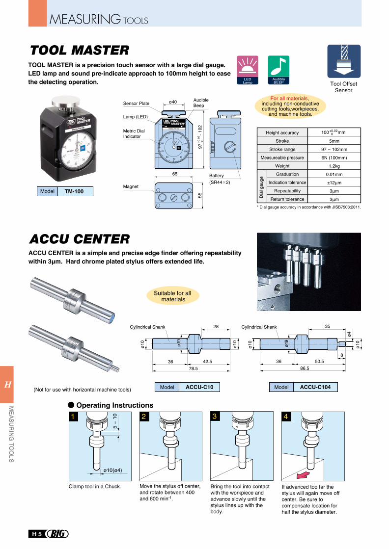
TOOL MASTER
Model TM-100
Graduation
Indication tolerance
Repeatability
Return toleranceDia
l gau
ge
Height accuracy
Stroke
Stroke range
Measureable pressure
Weight
5mm
97 - 102mm
6N (100mm)
1.2kg
0.01mm
±12μm
3μm
3μm
+0.02 0100 mm
For all materials, including non-conductivecutting tools,workpieces,
and machine tools.
LEDLamp
AudibleBEEP
* Dial gauge accuracy in accordance with JISB7503:2011.
MODEL TM-100
010
20
30
4050
60
70
80
90
ø40
65
5597
- 102
+0.0
2 0
Sensor Plate
Battery
Metric DialIndicator
AudibleBeep
Lamp (LED)
Magnet(SR44 2)
TOOL MASTER is a precision touch sensor with a large dial gauge. LED lamp and sound pre-indicate approach to 100mm height to ease the detecting operation. Tool Offset
Sensor
ø10
ø10
36
28
42.578.5
ø19
ø10
ø10
ø19
36 50.586.5
8ø4
35
2 41
5 -
10
ø10(ø4)
3
Clamp tool in a Chuck. Move the stylus off center, and rotate between 400 and 600 min-1.
Bring the tool into contact with the workpiece and advance slowly until the stylus lines up with the body.
If advanced too far the stylus will again move off center. Be sure to compensate location for half the stylus diameter.
Cylindrical Shank Cylindrical Shank
Model ModelACCU-C10 ACCU-C104
Operating Instructions
(Not for use with horizontal machine tools)
Suitable for all materials
ACCU CENTERACCU CENTER is a simple and precise edge finder offering repeatability within 3μm. Hard chrome plated stylus offers extended life.
H 5
MEASURING TOOLS
MEASU
RING
TOO
LSH
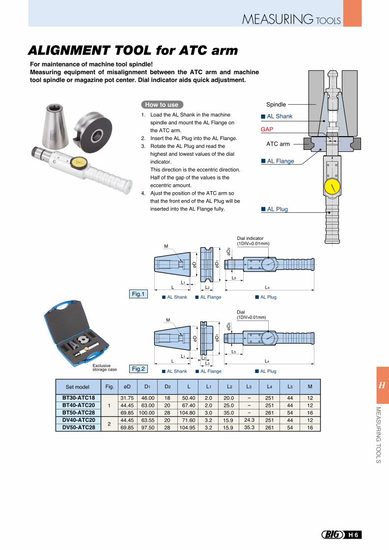
For maintenance of machine tool spindle!Measuring equipment of misalignment between the ATC arm and machine tool spindle or magazine pot center. Dial indicator aids quick adjustment.
ALIGNMENT TOOL for ATC arm
AL Shank
AL Flange
AL Plug
How to use1. Load the AL Shank in the machine
spindle and mount the AL Flange on the ATC arm.
2. Insert the AL Plug into the AL Flange.3. Rotate the AL Plug and read the
highest and lowest values of the dial indicator.This direction is the eccentric direction. Half of the gap of the values is the eccentric amount.
4. Ajust the position of the ATC arm so that the front end of the AL Plug will be inserted into the AL Flange fully.
Spindle
ATC arm
GAP
L
M
øD1
øD2
L1L2
L5
L4
Dial indicator(1DIV=0.01mm)
øD
AL Shank AL PlugAL Flange
BT30-ATC18BT40-ATC20BT50-ATC28DV40-ATC20DV50-ATC28
31.7544.4569.8544.4569.85
1
2
46.0063.00
100.0063.5597.50
L
50.4067.40
104.8071.60
104.95
M
1212161216
L1D1
1820282028
D2
2.02.03.03.23.2
L2
- - -24.335.3
20.025.035.0
L3
251251261251261
L4
4444544454
L5øDFig.Set model
Exclusivestorage case
L
M
øD
øD2
L1
øD1
L2L3
L5
L4
Dial(1DIV=0.01mm)
AL Shank AL PlugAL Flange
15.915.9
Fig.1
Fig.2
MEASURING TOOLS
H 6
MEASU
RING
TOO
LS
H
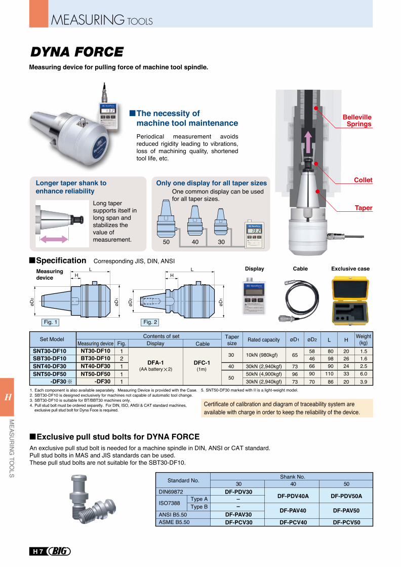
Taper
Collet
BellevilleSprings
DYNA FORCEMeasuring device for pulling force of machine tool spindle.
An exclusive pull stud bolt is needed for a machine spindle in DIN, ANSI or CAT standard.Pull stud bolts in MAS and JIS standards can be used.These pull stud bolts are not suitable for the SBT30-DF10.
øD2
øD1
LH
Measuring device
Display Cable
1. Each component is also available separately. Measuring Device is provided with the Case.2. SBT30-DF10 is designed exclusively for machines not capable of automatic tool change.3. SBT30-DF10 is suitable for BT/BBT30 machines only.4. Pull stud bolt must be ordered separetly. For DIN, ISO, ANSI & CAT standard machines,
exclusive pull stud bolt for Dyna Foce is required.
Corresponding JIS, DIN, ANSIExclusive case
Set ModelMeasuring device Fig. Display
(AA battery 2)
Contents of set Tapersize Rated capacity
CableL H Weight
(kg)øD1 øD2
SNT30-DF10SBT30-DF10
DFC-1DFA-110kN (980kgf) 65
9673
30
30kN (2,940kgf)50kN (4,900kgf)30kN (2,940kgf)
7340
50
5846
8098
2026
1.51.6
9070
11086
3320
6.03.9
66 90 24 2.5
Longer taper shank to enhance reliability
Only one display for all taper sizes
Periodical measurement avoids reduced rigidity leading to vibrations, loss of machining quality, shortened tool life, etc.
Certificate of calibration and diagram of traceability system are available with charge in order to keep the reliability of the device.
304050
Specification
Long taper supports itself in long span and stabilizes the value of measurement.
One common display can be used for all taper sizes.
(1m)
NT30-DF10BT30-DF10
12
NT50-DF50 -DF30
11
SNT40-DF30 NT40-DF30 1
øD2
øD1
LH
30DIN69872
Standard No.
ISO7388
ANSI B5.50ASME B5.50
Type AType B
DF-PDV30
DF-PAV30DF-PCV30
Shank No.40
DF-PDV40A
DF-PAV40
DF-PCV40
50
DF-PDV50A
DF-PAV50
DF-PCV50
SNT50-DF50 -DF30
––
5. SNT50-DF30 marked with is a light-weight model.
The necessity of machine tool maintenance
Fig. 1 Fig. 2
Exclusive pull stud bolts for DYNA FORCE
H 7
MEASURING TOOLS
MEASU
RING
TOO
LSH
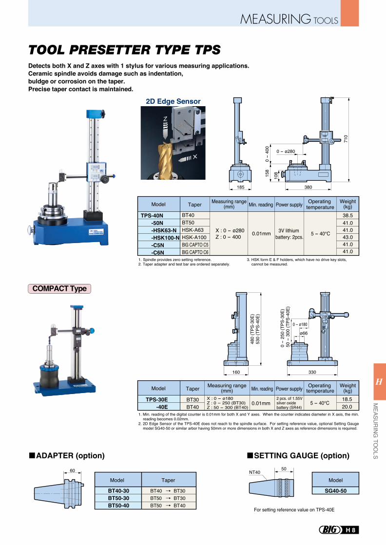
TOOL PRESETTER TYPE TPS
60
Model Taper
BT40-30BT50-30BT50-40
BT40 BT30BT50 BT30BT50 BT40
2D Edge Sensor
185 380
0 - ø280
158
710
108
0 -
400
3V lithium battery: 2pcs.
Model Taper Measuring range(mm) Min. reading Weight
(kg)Power supply Operating temperature
TPS-40N -50N -HSK63-N -HSK100-N -C5N -C6N
BT40BT50HSK-A63HSK-A100BIG CAPTO C5BIG CAPTO C6
X : 0 - ø280Z : 0 - 400 0.01mm 5 - 40℃
38.541.041.043.041.041.0
2 pcs. of 1.55V silver oxide battery (SR44)
BT30BT40
X : 0 - ø180Z : 0 - 250 (BT30)Z : 50 - 300 (BT40)
0.01mm 5 - 40℃18.5 20.0
1. Spindle provides zero setting reference.2. Taper adapter and test bar are ordered separately.
3. HSK form E & F holders, which have no drive key slots, cannot be measured.
TPS-30E -40E
ø66
0 - ø180
0 -
250
(TPS
-30E
)50
- 3
00 (T
PS-4
0E)
330
480
(TPS
-30E
)53
0 (T
PS-4
0E)
160
Detects both X and Z axes with 1 stylus for various measuring applications.Ceramic spindle avoids damage such as indentation, buldge or corrosion on the taper. Precise taper contact is maintained.
For setting reference value on TPS-40E
Model
SG40-50
50NT40
COMPACT Type
Model Taper Measuring range(mm) Min. reading Weight
(kg)Power supply Operating temperature
ADAPTER (option) SETTING GAUGE (option)
1. Min. reading of the digital counter is 0.01mm for both X and Y axes. When the counter indicates diameter in X axis, the min. reading becomes 0.02mm.
2. 2D Edge Sensor of the TPS-40E does not reach to the spindle surface. For setting reference value, optional Setting Gauge model SG40-50 or similar arbor having 50mm or more dimensions in both X and Z axes as reference dimensions is required.
MEASURING TOOLS
H 8
MEASU
RING
TOO
LS
H
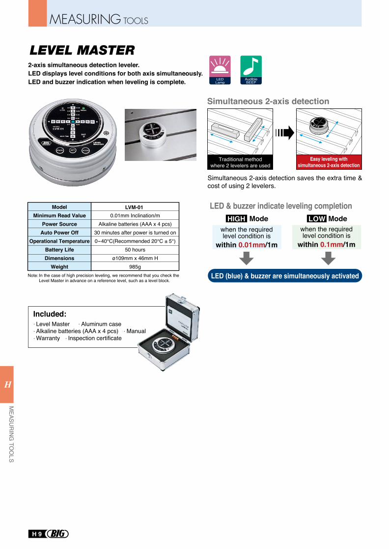
LEVEL MASTER2-axis simultaneous detection leveler.LED displays level conditions for both axis simultaneously. LED and buzzer indication when leveling is complete.
Simultaneous 2-axis detection
Traditional methodwhere 2 levelers are used
Simultaneous 2-axis detection saves the extra time & cost of using 2 levelers.
LED (blue) & buzzer are simultaneously activated
ModelMinimum Read Value
Power SourceAuto Power Off
Operational TemperatureBattery LifeDimensions
Weight
0.01mm Inclination/mAlkaline batteries (AAA x 4 pcs)
30 minutes after power is turned on0-40°C(Recommended 20°C ± 5°)
50 hoursø109mm x 46mm H
985g
LVM-01
Easy leveling withsimultaneous 2-axis detection
Included:Level Master Aluminum caseAlkaline batteries (AAA x 4 pcs) ManualWarranty Inspection certificate
In the case of high precision leveling, we recommend that you check the Level Master in advance on a reference level, such as a level block.
Note:
LED & buzzer indicate leveling completionHIGH LOW
when the requiredlevel condition is
within 0.1mm/1m
Mode Modewhen the requiredlevel condition is
within 0.01mm/1m
LEDLamp
AudibleBEEP
H 9
MEASURING TOOLS
MEASU
RING
TOO
LSH
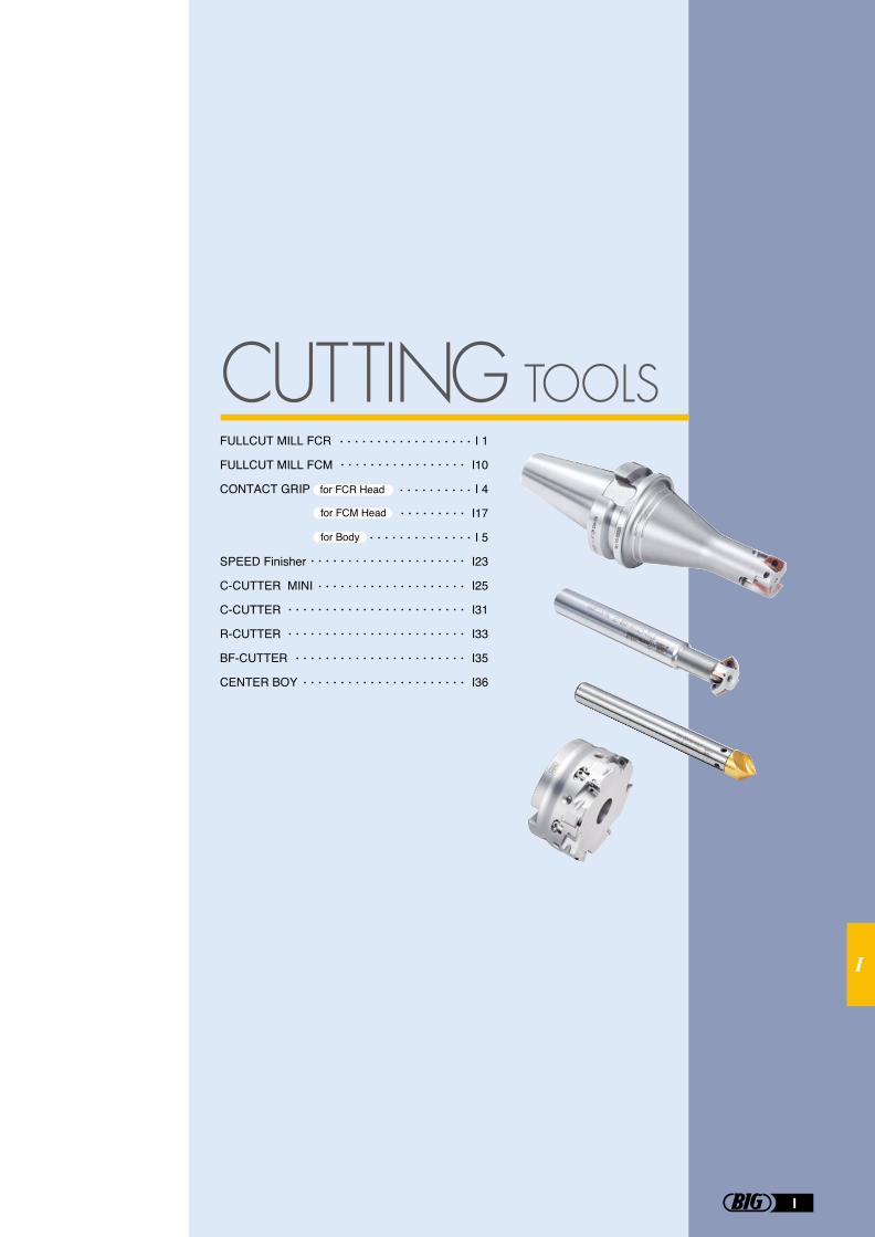
I
I
I 1
I10
I 4
I17
I 5
I23
I25
I31
I33
I35
I36
FULLCUT MILL FCR
FULLCUT MILL FCM
CONTACT GRIP for FCR Head
SPEED Finisher
C-CUTTER MINI
C-CUTTER
R-CUTTER
BF-CUTTER
CENTER BOY
for FCM Head
for Body
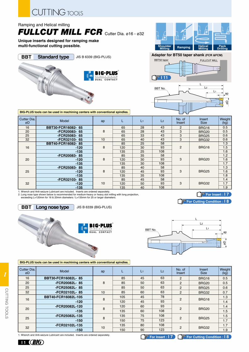
For Insert : I 7For Cutting Condition : I 8
For Insert : I 7 For Cutting Condition : I 8
Cutter Dia. ø16 - ø32
Ramping and Helical milling
Unique inserts designed for ramping make multi-functional cutting possible. Shoulder
MillingHelicalMilling
PeckDrillingRamping
BBT Standard type JIS B 6339 (BIG-PLUS)
BBT30-FCR16082- 65-FCR20083- 65-FCR25083- 65-FCR32103- 65
BBT40-FCR16082- 85-120-135
-FCR20083- 85-120-135
-FCR25083- 85-120-135
-FCR32103- 85-120-135
8
10
2333
6565656585
12013585
12013585
12013585
120135
16202532
16
20
25
32
8
8
8
10
2
3
3
3
28283340253025353030404535455040
Model L L1 L2Cutter Dia.øD
No. ofInsert
InsertSizeap
BRG16BRG20BRG25BRG32
BRG16
BRG20
BRG25
BRG32
Weight(kg)0.50.50.60.61.31.51.61.21.61.71.31.61.81.41.71.9
434343435893
1085893
1085893
1085893
108
BBT No.ap
L1
L
øD
L2
FULLCUT MILL
Adapter for BT50 taper shank (FCR &FCM)BBT50 taper
BBT Long nose type JIS B 6339 (BIG-PLUS)
BBT30-FCR16082L- 85-FCR20082L- 85-FCR25082L- 85-FCR32102L- 85
BBT40-FCR16082L-105-120
-FCR20082L-120-135
-FCR25082L-135-150
-FCR32102L-135-150
8
10
2222
85858585
105120120135135150135150
16202532
16
20
25
32
8
8
8
10
2
2
2
2
455050604545606075758090
Model L L1 L2Cutter Dia.øD
No. ofInsert
InsertSizeap
BRG16BRG20BRG25BRG32
BRG16
BRG20
BRG25
BRG32
Weight(kg)0.50.50.60.71.31.41.41.51.51.71.71.9
63636363789393
108108123108123
apL1
LøD
L2
BBT No.
BIG-PLUS tools can be used in machining centers with conventional spindles.
BIG-PLUS tools can be used in machining centers with conventional spindles.
I 11
1. Wrench and Anti-seizure Lubricant are included. Inserts are ordered separately.2. Long nose type shown below is recommended for medium-heavy or heavy slot milling with long projection, exceeding L=120mm for 16 & 20mm diameters / L=135mm for 25 or larger diameters.
1. Wrench and Anti-seizure Lubricant are included. Inserts are ordered separately.
R
S P I N D L E S Y S T E M
D U A L C O N T A C T
R
S P I N D L E S Y S T E M
D U A L C O N T A C T
I 1
CUTTING TOOLS
CU
TTING
TOO
LS
I
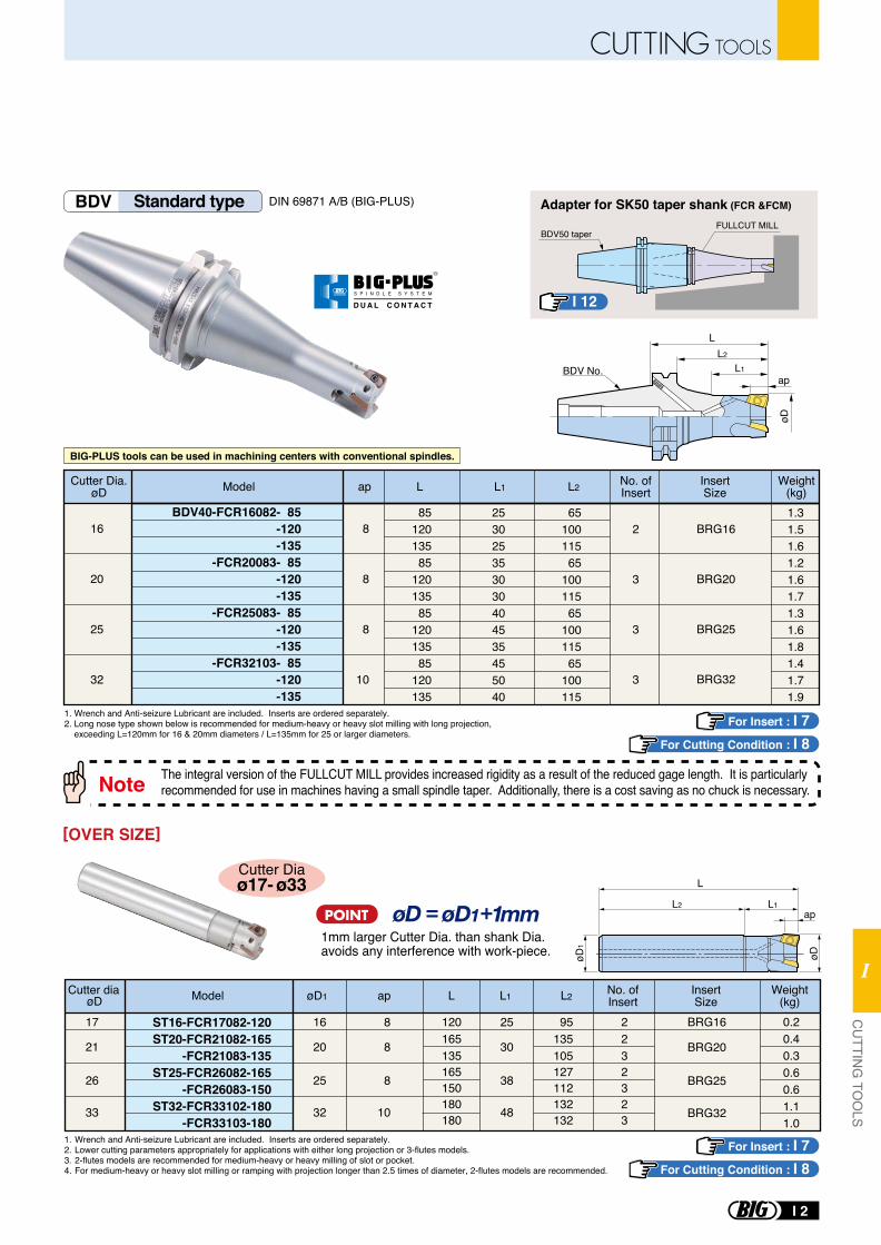
The integral version of the FULLCUT MILL provides increased rigidity as a result of the reduced gage length. It is particularly recommended for use in machines having a small spindle taper. Additionally, there is a cost saving as no chuck is necessary. Note
Adapter for SK50 taper shank (FCR &FCM)
BDV50 taperFULLCUT MILL
BIG-PLUS tools can be used in machining centers with conventional spindles.
BDV Standard type DIN 69871 A/B (BIG-PLUS)
BDV40-FCR16082- 85-120-135
-FCR20083- 85-120-135
-FCR25083- 85-120-135
-FCR32103- 85-120-135
8
8
8
10
8512013585
12013585
12013585
120135
253025353030404535455040
6510011565
10011565
10011565
100115
1.31.51.61.21.61.71.31.61.81.41.71.9
2
3
3
3
BRG16
BRG20
BRG25
BRG32
Model L L1 L2
16
20
25
32
Cutter Dia.øD
No. ofInsert
InsertSize
Weight(kg)ap
L2
øD
L1ap
L
BDV No.
For Insert : I 7For Cutting Condition : I 8
For Insert : I 7For Cutting Condition : I 8
I 12
1. Wrench and Anti-seizure Lubricant are included. Inserts are ordered separately.2. Lower cutting parameters appropriately for applications with either long projection or 3-flutes models.3. 2-flutes models are recommended for medium-heavy or heavy milling of slot or pocket.4. For medium-heavy or heavy slot milling or ramping with projection longer than 2.5 times of diameter, 2-flutes models are recommended.
1mm larger Cutter Dia. than shank Dia. avoids any interference with work-piece.
Cutter Diaø17- ø33
[OVER SIZE]
BRG16
BRG20
BRG25
BRG32
Model
ST16-FCR17082-120ST20-FCR21082-165
-FCR21083-135ST25-FCR26082-165
-FCR26083-150ST32-FCR33102-180
-FCR33103-180
øDCutter dia øD1 Lap
17
21
26
33
16
20
25
32
25
30
38
48
8
8
8
10
L1
95135105127112132132
L2
2232323
120165135165150180180
0.20.40.30.60.61.11.0
No. ofInsert
InsertSize
Weight(kg)
L
L1L2ap
øDøD1
1. Wrench and Anti-seizure Lubricant are included. Inserts are ordered separately.2. Long nose type shown below is recommended for medium-heavy or heavy slot milling with long projection, exceeding L=120mm for 16 & 20mm diameters / L=135mm for 25 or larger diameters.
R
S P I N D L E S Y S T E M
D U A L C O N T A C T
I 2
CUTTING TOOLSC
UTTIN
G TO
OLS
I
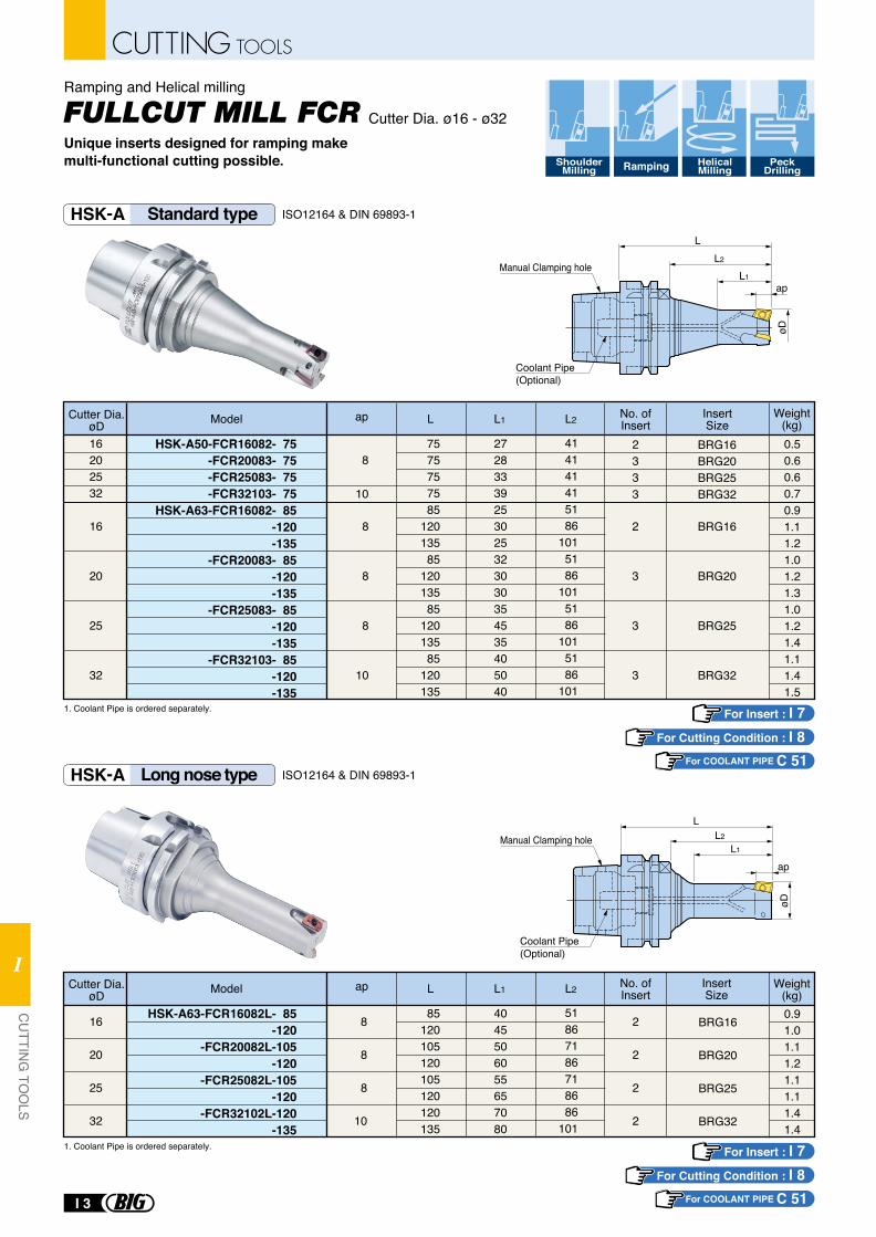
øD
L
L1
L2
ap
Coolant Pipe (Optional)
Manual Clamping hole
øD
L
L1
L2
ap
Coolant Pipe (Optional)
Manual Clamping hole
HSK-A Standard type
HSK-A Long nose type
ISO12164 & DIN 69893-1
ISO12164 & DIN 69893-1
HSK-A50-FCR16082- 75-FCR20083- 75-FCR25083- 75-FCR32103- 75
HSK-A63-FCR16082- 85-120-135
-FCR20083- 85-120-135
-FCR25083- 85-120-135
-FCR32103- 85-120-135
8
10
2333
7575757585
12013585
12013585
12013585
120135
16202532
16
20
25
32
8
8
8
10
2
3
3
3
27283339253025323030354535405040
Model L L1 L2Cutter Dia.øD
No. ofInsert
InsertSize
ap
BRG16BRG20BRG25BRG32
BRG16
BRG20
BRG25
BRG32
Weight(kg)0.50.60.60.70.91.11.21.01.21.31.01.21.41.11.41.5
414141415186
1015186
1015186
1015186
101
HSK-A63-FCR16082L- 85-120
-FCR20082L-105-120
-FCR25082L-105-120
-FCR32102L-120-135
85120105120105120120135
16
20
25
32
8
8
8
10
2
2
2
2
4045506055657080
Model L L1 L2Cutter Dia.øD
No. ofInsert
InsertSize
ap
BRG16
BRG20
BRG25
BRG32
Weight(kg)0.91.01.11.21.11.11.41.4
51867186718686
101
1. Coolant Pipe is ordered separately.
1. Coolant Pipe is ordered separately.
Cutter Dia. ø16 - ø32
Ramping and Helical milling
Unique inserts designed for ramping make multi-functional cutting possible. Shoulder
MillingHelicalMilling
PeckDrillingRamping
For COOLANT PIPE C 51
For Insert : I 7For Cutting Condition : I 8
For COOLANT PIPE C 51
For Insert : I 7For Cutting Condition : I 8
CUTTING TOOLS
I 3
CU
TTING
TOO
LS
I
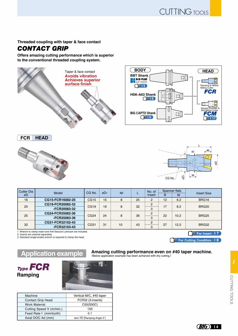
FCR HEAD
Offers amazing cutting performance which is superior to the conventional threaded coupling system.
Threaded coupling with taper & face contact
CONTACT GRIP
CG15-FCR16082-25CG19-FCR20082-32
-FCR20083-32CG24-FCR25082-36
-FCR25083-36CG31-FCR32102-43
-FCR32103-43
2232323
16
20
25
32
15
19
24
31
BRG16
BRG20
BRG25
BRG32
8
8
8
10
25
32
36
43
12
17
22
27
6.2
8.2
10.2
12.2
CG15
CG19
CG24
CG31
CG No. øD1
B ap
W
øD
L
1. Wrench to clamp insert and Anti-Seizure Lubricant are included. 2. Inserts are ordered separately.3. Standard single-ended wrench is required to clamp the head.
Model L BSpanner flatsNo. of
InsertCutter Dia
øD W Insert SizeapøD1CG No.
Ramping
MachineContact Grip HeadWork MaterialCutting Speed V (m/min.)Feed Rate f (mm/tooth)Axial DOC Ad (mm)
Vertical M/C, #40 taperFCR32 (3-inserts)
C50(S50C)1500.1
MAX.10 (Ramping Angle 3˚)
Amazing cutting performance even on #40 taper machine.(Below application example has been achieved with dry cutting.)Application example
Taper & face contactAvoids vibrationAchieves superior surface finish
BBT Shank
HSK-A63 Shank
BIG CAPTO Shank
I 5
I 6
I 6
BODY HEAD
I 17
Ramping & Helical Milling Cutter
Square Shoulder & Slot Milling Cutter
For Insert : I 7For Cutting Condition : I 8
R
S P I N D L E S Y S T E M
D U A L C O N T A C T
I 4
CUTTING TOOLSC
UTTIN
G TO
OLS
I
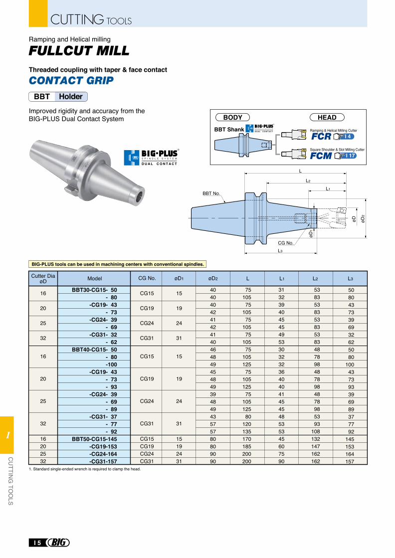
Ramping & Helical Milling Cutter
Square Shoulder & Slot Milling Cutter
BBT ShankI 4
I 17
BODY HEAD
BBT No.
CG No.
øD1
L2
L1
øD2
øD
L
L3
Improved rigidity and accuracy from the BIG-PLUS Dual Contact System
16
20
25
32
16
20
25
32
16202532
CG15
CG19
CG24
CG31
CG15
CG19
CG24
CG31
CG15CG19CG24CG31
15
19
24
31
15
19
24
31
15192431
Model L L2 L3L1øD1 øD2
BBT30-CG15- 50 - 80
-CG19- 43 - 73
-CG24- 39 - 69
-CG31- 32 - 62
BBT40-CG15- 50 - 80 -100
-CG19- 43 - 73 - 93
-CG24- 39 - 69 - 89
-CG31- 37 - 77 - 92
BBT50-CG15-145 -CG19-153 -CG24-164 -CG31-157
50804373396932625080
100437393396989377792
145153164157
Cutter DiaøD CG No.
404040424142414046484945484939484943575780809090
7510575
10575
10575
10575
10512575
10512575
10512580
120135170185200200
313239404545495330323236404041454548535345607590
53835383538353834878984878984878985393
108132147162162
1. Standard single-ended wrench is required to clamp the head.
BBT Holder
BIG-PLUS tools can be used in machining centers with conventional spindles.
Ramping and Helical milling
CONTACT GRIPThreaded coupling with taper & face contact
R
S P I N D L E S Y S T E M
D U A L C O N T A C T
R
S P I N D L E S Y S T E M
D U A L C O N T A C T
I 5
CUTTING TOOLS
CU
TTING
TOO
LS
I
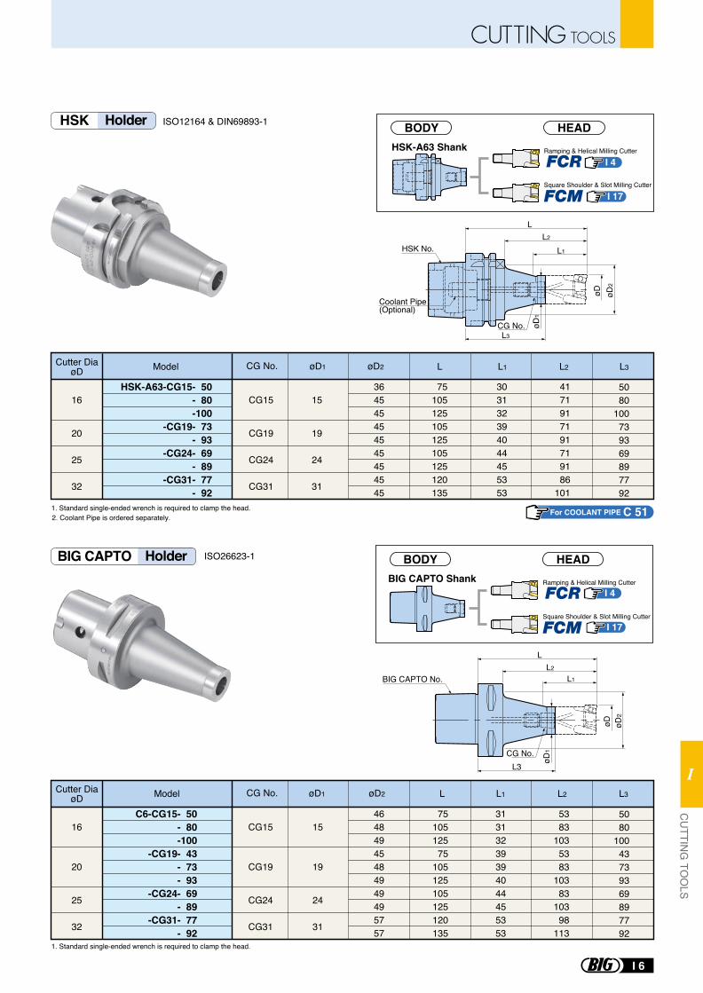
ISO12164 & DIN69893-1
ISO26623-1
16
20
25
32
CG15
CG19
CG24
CG31
15
19
24
31
Model L L3L2øD1 øD2
C6-CG15- 50 - 80 -100
-CG19- 43 - 73 - 93
-CG24- 69 - 89
-CG31- 77 - 92
5080
10043739369897792
Cutter DiaøD CG No.
46484945484949495757
7510512575
105125105125120135
31313239394044455353
L1
5383
1035383
10383
10398
113
16
20
25
32
CG15
CG19
CG24
CG31
15
19
24
31
Model L L1 L2 L3øD1 øD2
HSK-A63-CG15- 50 - 80 -100
-CG19- 73 - 93
-CG24- 69 - 89
-CG31- 77 - 92
5080
100739369897792
Cutter DiaøD CG No.
364545454545454545
75105125105125105125120135
303132394044455353
4171917191719186
101
BIG CAPTO No.
CG No.
øD1
L2
L1
øD2
øD
L
L3
1. Standard single-ended wrench is required to clamp the head.
1. Standard single-ended wrench is required to clamp the head.
HSK No.
CG No. øD1
L2
L1
L3
øD2
øD
L
Coolant Pipe (Optional)
2. Coolant Pipe is ordered separately.
HSK Holder
BIG CAPTO Holder
For COOLANT PIPE C 51
BIG CAPTO ShankI 4
I 17
Ramping & Helical Milling Cutter
Square Shoulder & Slot Milling Cutter
BODY HEAD
HSK-A63 Shank Ramping & Helical Milling Cutter
Square Shoulder & Slot Milling Cutter
BODY HEAD
I 4
I 17
I 6
CUTTING TOOLSC
UTTIN
G TO
OLS
I
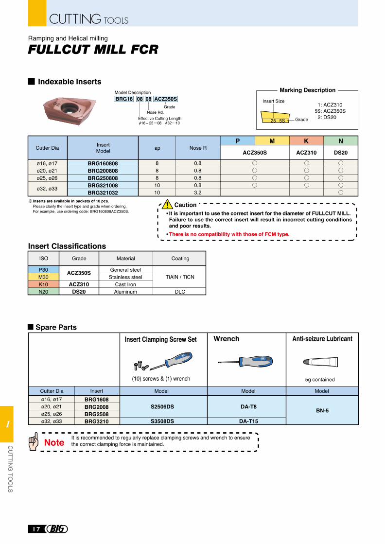
Inserts are available in packets of 10 pcs.Please clarify the insert type and grade when ordering. For example, use ordering code: BRG160808ACZ350S. It is important to use the correct insert for the diameter of FULLCUT MILL.
Failure to use the correct insert will result in incorrect cutting conditions and poor results.There is no compatibility with those of FCM type.
ø16, ø17ø20, ø21ø25, ø26ø32, ø33 S3508DS
S2506DS DA-T8 BN-5
DA-T15
BRG1608BRG2008BRG2508BRG3210
GradeNose Rd.
BRG16 08 08 ACZ350SModel Description
Effective Cutting Length 16- 25 08 32 10
1: ACZ3105S: ACZ350S 2: DS20
Marking Description
It is recommended to regularly replace clamping screws and wrench to ensure the correct clamping force is maintained.Note
Cutter Dia
Wrench Anti-seizure Lubricant
5g contained(10) screws & (1) wrench
Insert Clamping Screw Set
Model Model ModelInsert
Caution
Indexable Inserts
Spare Parts
Ramping and Helical milling
BRG160808BRG200808BRG250808BRG321008BRG321032
ø16, ø17ø20, ø21ø25, ø26
ø32, ø33
0.80.80.80.83.2
8881010
apCutter Dia Nose RInsertModel
P M
P30M30K10N20
ISO
ACZ350S
ACZ310DS20
Grade
General steelStainless steel
Cast IronAluminum
Material
TiAlN / TiCN
DLC
Coating
Insert Classifications
ACZ350S ACZ310
K NDS20
Grade
Insert Size
25 5S
I 7
CUTTING TOOLS
CU
TTING
TOO
LS
I
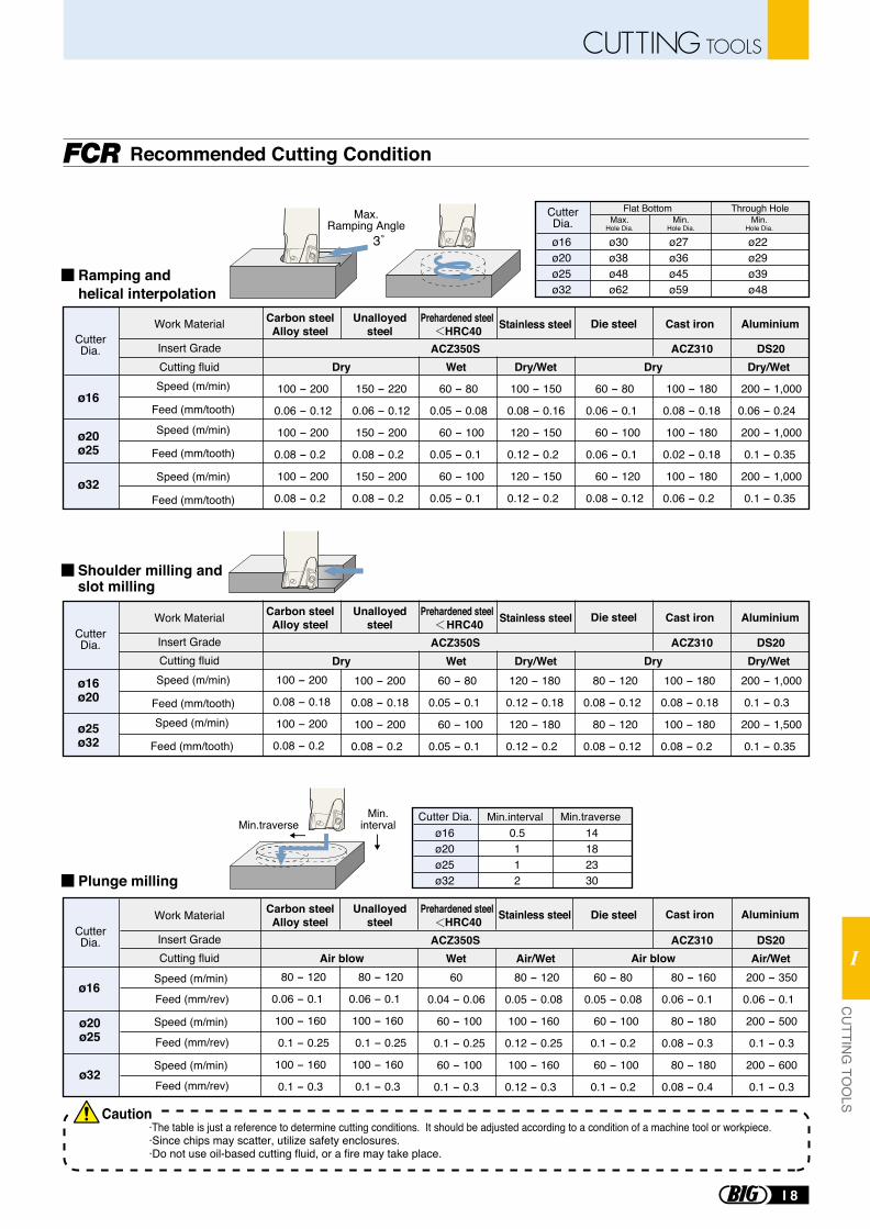
ø16ø20
ø25ø32
100 - 200
0.08 - 0.18
100 - 200
0.08 - 0.2
100 - 200
0.08 - 0.18
100 - 200
0.08 - 0.2
60 - 80
0.05 - 0.1
60 - 100
0.05 - 0.1
120 - 180
0.12 - 0.18
120 - 180
0.12 - 0.2
80 - 120
0.08 - 0.12
80 - 120
0.08 - 0.12
100 - 180
0.08 - 0.18
100 - 180
0.08 - 0.2
200 - 1,000
0.1 - 0.3
200 - 1,500
0.1 - 0.35
Feed (mm/rev)
Feed (mm/rev)
Feed (mm/rev)
ø16
ø20ø25
ø32
80 - 120
0.06 - 0.1
100 - 160
0.1 - 0.25
100 - 160
0.1 - 0.3
80 - 120
0.06 - 0.1
100 - 160
0.1 - 0.25
100 - 160
0.1 - 0.3
60
0.04 - 0.06
60 - 100
0.1 - 0.25
60 - 100
0.1 - 0.3
80 - 120
0.05 - 0.08
100 - 160
0.12 - 0.25
100 - 160
0.12 - 0.3
60 - 80
0.05 - 0.08
60 - 100
0.1 - 0.2
60 - 100
0.1 - 0.2
80 - 160
0.06 - 0.1
80 - 180
0.08 - 0.3
80 - 180
0.08 - 0.4
200 - 350
0.06 - 0.1
200 - 500
0.1 - 0.3
200 - 600
0.1 - 0.3
Speed (m/min)
Feed (mm/tooth)
Speed (m/min)
Feed (mm/tooth)
Speed (m/min)
Feed (mm/tooth)
Speed (m/min)
Feed (mm/tooth)
Speed (m/min)
Feed (mm/tooth)
Work Material
Insert GradeCutting fluid
Cutting fluid
Cutting fluid
ACZ350S ACZ310 DS20
Work Material
Insert Grade ACZ350S ACZ310 DS20
Work Material
Insert Grade ACZ350S ACZ310 DS20Air/Wet Air/Wet
ø16
ø32
ø20ø25
100 - 200
0.06 - 0.12
100 - 200
0.08 - 0.2
100 - 200
0.08 - 0.2
150 - 220
0.06 - 0.12
150 - 200
0.08 - 0.2
150 - 200
0.08 - 0.2
60 - 80
0.05 - 0.08
60 - 100
0.05 - 0.1
60 - 100
0.05 - 0.1
100 - 150
0.08 - 0.16
120 - 150
0.12 - 0.2
120 - 150
0.12 - 0.2
60 - 80
0.06 - 0.1
60 - 100
0.06 - 0.1
60 - 120
0.08 - 0.12
100 - 180
0.08 - 0.18
100 - 180
0.02 - 0.18
100 - 180
0.06 - 0.2
200 - 1,000
0.06 - 0.24
200 - 1,000
0.1 - 0.35
200 - 1,000
0.1 - 0.35
3˚
Min.traverseMin.traverseMin.
intervalMin.interval
ø16ø20ø25ø32
0.5112
14182330
ø16ø20ø25ø32
ø30ø38ø48ø62
ø27ø36ø45ø59
ø22ø29ø39ø48
Max.Hole Dia.
Min.Hole Dia.
Min.Hole Dia.
CutterDia.
CutterDia.
CutterDia.
CutterDia.
Max.Ramping Angle
Recommended Cutting Condition
Ramping andhelical interpolation
Plunge milling
Speed (m/min)
Speed (m/min)
Speed (m/min)
Shoulder milling and slot milling
Dry Wet Dry/Wet Dry/WetDry
Dry Wet Dry/Wet Dry/WetDry
Air blow Air blowWet
Stainless steel Cast ironDie steelCarbon steelAlloy steel
Prehardened steel HRC40
Unalloyedsteel
Die steelCarbon steelAlloy steel
Prehardened steel HRC40
Unalloyedsteel
Die steelCarbon steelAlloy steel
Prehardened steel HRC40
Unalloyedsteel
Aluminium
Stainless steel Cast iron Aluminium
Stainless steel Cast iron Aluminium
Cutter Dia.
·The table is just a reference to determine cutting conditions. It should be adjusted according to a condition of a machine tool or workpiece.·Since chips may scatter, utilize safety enclosures.·Do not use oil-based cutting fluid, or a fire may take place.
Flat Bottom Through Hole
Caution
I 8
CUTTING TOOLSC
UTTIN
G TO
OLS
I
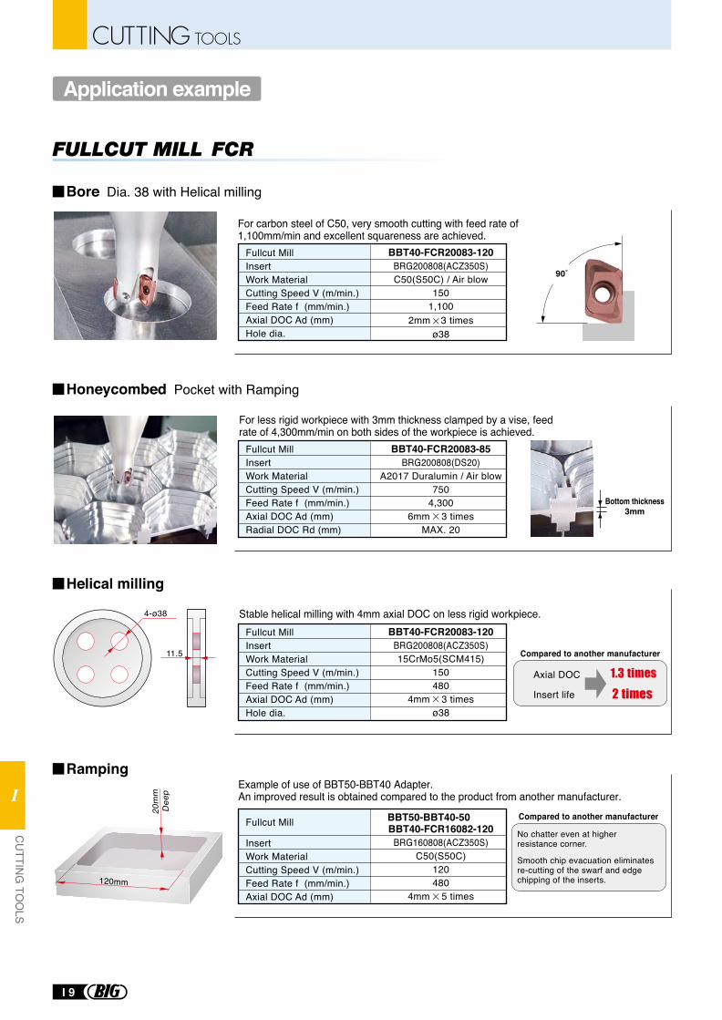
Fullcut MillInsertWork MaterialCutting Speed V (m/min.)Feed Rate f (mm/min.)Axial DOC Ad (mm)Hole dia.
Fullcut MillInsertWork MaterialCutting Speed V (m/min.)Feed Rate f (mm/min.)Axial DOC Ad (mm)Radial DOC Rd (mm)
BBT40-FCR20083-120BRG200808(ACZ350S)C50(S50C) / Air blow
1501,100
2mm 3 timesø38
BBT40-FCR20083-85BRG200808(DS20)
A2017 Duralumin / Air blow750
4,3006mm 3 times
MAX. 20
Bottom thickness3mm
90˚
Fullcut MillInsertWork MaterialCutting Speed V (m/min.)Feed Rate f (mm/min.)Axial DOC Ad (mm)Hole dia.
BBT40-FCR20083-120BRG200808(ACZ350S)15CrMo5(SCM415)
150480
4mm 3 timesø38
Axial DOC
Insert life
4-ø38
11.5
20m
mD
eep
InsertWork MaterialCutting Speed V (m/min.)Feed Rate f (mm/min.)Axial DOC Ad (mm)
BBT40-FCR16082-120BRG160808(ACZ350S)
C50(S50C)120480
4mm 5 times
BBT50-BBT40-50Fullcut Mill
120mm
Stable helical milling with 4mm axial DOC on less rigid workpiece.
Compared to another manufacturer
Compared to another manufacturer
Example of use of BBT50-BBT40 Adapter. An improved result is obtained compared to the product from another manufacturer.
No chatter even at higherresistance corner.
Smooth chip evacuation eliminatesre-cutting of the swarf and edgechipping of the inserts.
For carbon steel of C50, very smooth cutting with feed rate of 1,100mm/min and excellent squareness are achieved.
For less rigid workpiece with 3mm thickness clamped by a vise, feed rate of 4,300mm/min on both sides of the workpiece is achieved.
Bore Dia. 38 with Helical milling
Application example
Honeycombed Pocket with Ramping
Helical milling
Ramping
I 9
CUTTING TOOLS
CU
TTING
TOO
LS
I
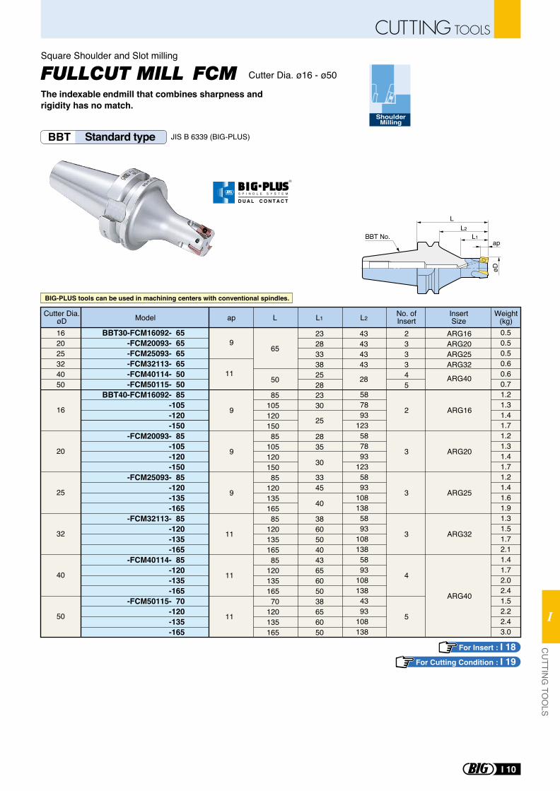
Cutter Dia. ø16 - ø50
The indexable endmill that combines sharpness and rigidity has no match.
BBT Standard type JIS B 6339 (BIG-PLUS)
9
11
65
50
162025324050
16
20
25
32
40
50
232833382528
233345
ARG16ARG20ARG25ARG32
ARG40
Model Lap L1 L2Cutter Dia.
øDNo. ofInsert
Weight(kg)
InsertSize
0.50.50.50.60.60.71.21.31.41.71.21.31.41.71.21.41.61.91.31.51.72.11.41.72.02.41.52.22.43.0
43434343
28
BBT30-FCM16092- 65-FCM20093- 65-FCM25093- 65-FCM32113- 65-FCM40114- 50-FCM50115- 50
BBT40-FCM16092- 85-105-120-150
-FCM20093- 85-105-120-150
-FCM25093- 85-120-135-165
-FCM32113- 85-120-135-165
-FCM40114- 85-120-135-165
-FCM50115- 70-120-135-165
9
9
9
11
11
11
2
3
3
3
4
5
ARG16
ARG20
ARG25
ARG32
ARG40
8510512015085
10512015085
12013516585
12013516585
12013516570
120135165
587893
123587893
1235893
1081385893
1081385893
1081384393
108138
2330
25
2835
30
3345
40
386050404365605038656050
Square Shoulder and Slot milling
ShoulderMilling
BBT No.
LL2
L1
øD
ap
BIG-PLUS tools can be used in machining centers with conventional spindles.
For Insert : I 18For Cutting Condition : I 19
R
S P I N D L E S Y S T E M
D U A L C O N T A C T
I 10
CUTTING TOOLSC
UTTIN
G TO
OLS
I
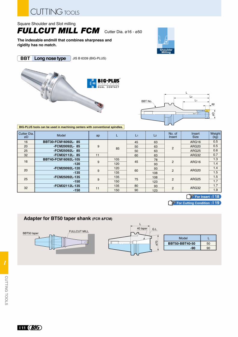
FULLCUT MILL
L40 taper
ø70
BBT50-BBT40-50-90
5090
Model L
Adapter for BT50 taper shank (FCR &FCM)
BBT50 taperG.L
BBT Long nose type JIS B 6339 (BIG-PLUS)
BBT30-FCM16092L- 85-FCM20092L- 85-FCM25092L- 85-FCM32112L- 85
BBT40-FCM16092L-105 -120
-FCM20092L-120-135
-FCM25092L-135-150
-FCM32112L-135-150
9
11
9
9
9
11
85 2
2
2
2
2
Model Lap L2No. ofInsert
Weight(kg)
InsertSize
0.50.50.60.71.31.41.41.51.51.71.71.9
63636363789393
10810812393
123
ARG16ARG20ARG25ARG32
ARG16
ARG20
ARG25
ARG32
L1
45505060
45
60
75
8090
105120120135135150135150
16202532
16
20
25
32
Cutter Dia.øD
BBT No.ap
L1
L
øD
L2
For Insert : I 18For Cutting Condition : I 19
Cutter Dia. ø16 - ø50
ShoulderMilling
The indexable endmill that combines sharpness and rigidity has no match.
Square Shoulder and Slot milling
BIG-PLUS tools can be used in machining centers with conventional spindles.
R
S P I N D L E S Y S T E M
D U A L C O N T A C T
I 11
CUTTING TOOLS
CU
TTING
TOO
LS
I
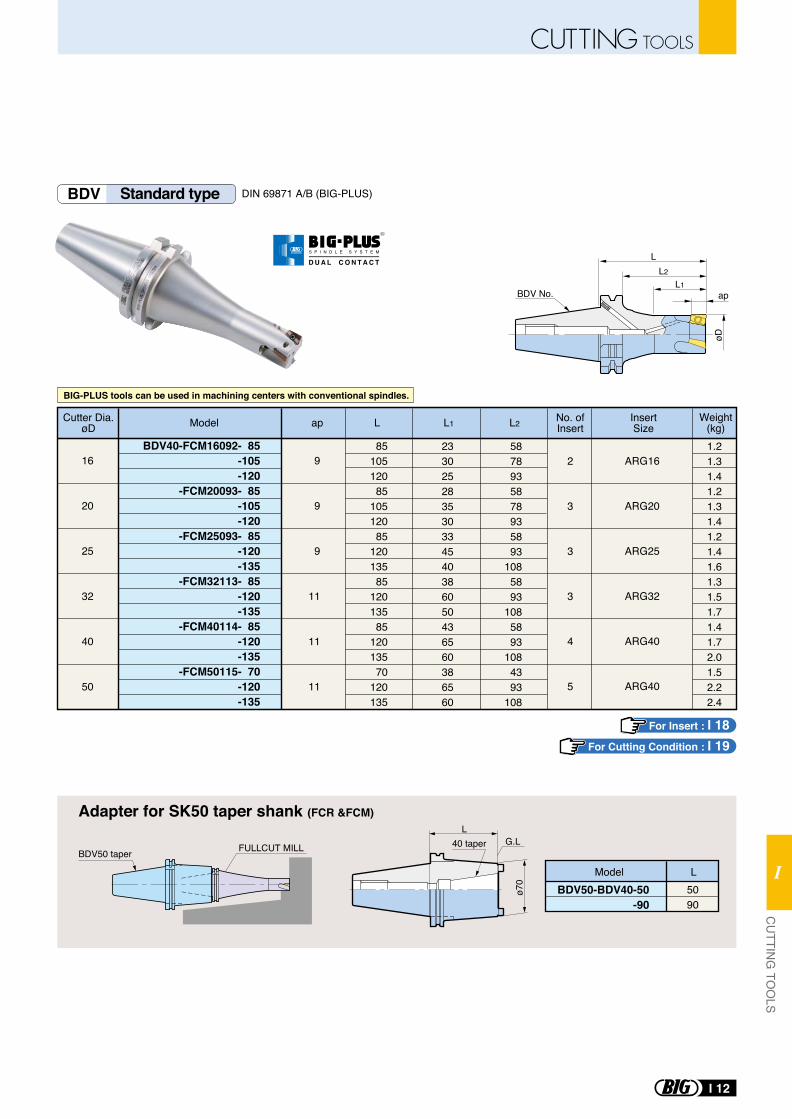
BDV50-BDV40-50-90
5090
Model L
Adapter for SK50 taper shank (FCR &FCM)
BDV50 taper FULLCUT MILL
L40 taper
ø70
G.L
BDV Standard type DIN 69871 A/B (BIG-PLUS)
øD
L1ap
L
BDV No.
L2
BDV40-FCM16092- 85-105-120
-FCM20093- 85-105-120
-FCM25093- 85-120-135
-FCM32113- 85-120-135
-FCM40114- 85-120-135
-FCM50115- 70-120-135
9
9
9
11
11
11
8510512085
10512085
12013585
12013585
12013570
120135
233025283530334540386050436560386560
5878935878935893
1085893
1085893
1084393
108
1.21.31.41.21.31.41.21.41.61.31.51.71.41.72.01.52.22.4
2
3
3
3
4
5
ARG16
ARG20
ARG25
ARG32
ARG40
ARG40
Model Lap L1 L2 No. ofInsert
InsertSize
16
20
25
32
40
50
Cutter Dia.øD
Weight(kg)
For Insert : I 18For Cutting Condition : I 19
BIG-PLUS tools can be used in machining centers with conventional spindles.
R
S P I N D L E S Y S T E M
D U A L C O N T A C T
I 12
CUTTING TOOLSC
UTTIN
G TO
OLS
I
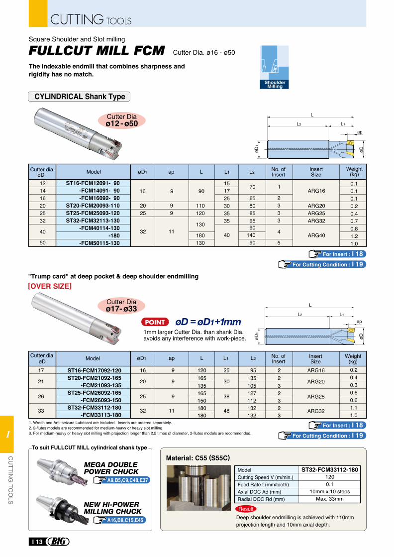
Cutter Dia. ø16 - ø50
ShoulderMilling
The indexable endmill that combines sharpness and rigidity has no match.
Square Shoulder and Slot milling
1. Wrech and Anti-seizure Lubricant are included. Inserts are ordered separately.2. 2-flutes models are recommended for medium-heavy or heavy slot milling.3. For medium-heavy or heavy slot milling with projection longer than 2.5 times of diameter, 2-flutes models are recommended.
"Trump card" at deep pocket & deep shoulder endmilling
Deep shoulder endmilling is achieved with 110mm projection length and 10mm axial depth.
Result
ModelCutting Speed V (m/min.)Feed Rate f (mm/tooth)Axial DOC Ad (mm)Radial DOC Rd (mm)
ST32-FCM33112-1801200.1
10mm x 10 stepsMax. 33mm
1mm larger Cutter Dia. than shank Dia. avoids any interference with work-piece.
Cutter Diaø12 - ø50
Cutter Diaø17- ø33
Material: C55 (S55C)
A9,B5,C9,C48,E37
A16,B8,C15,E45
L
L1L2
ap
øDøD1
L
L1L2
ap
øD1
øD
To suit FULLCUT MILL cylindrical shank type
[OVER SIZE]
CYLINDRICAL Shank Type
ST16-FCM12091- 90-FCM14091- 90-FCM16092- 90
ST20-FCM20093-110ST25-FCM25093-120ST32-FCM32113-130
-FCM40114-130-180
-FCM50115-130
121416202532
40
50
99
11
110120
130
180130
2025
32
151725303535
4090
14090
65808595
2333
4
5
ARG16
ARG20ARG25ARG32
ARG40
916 9070 1
Model LapøD1 L1 L2Cutter diaøD
No. ofInsert
InsertSize
0.10.10.10.20.40.70.81.21.0
Weight(kg)
ARG16
ARG20
ARG25
ARG32
Model
ST16-FCM17092-120ST20-FCM21092-165
-FCM21093-135ST25-FCM26092-165
-FCM26093-150ST32-FCM33112-180
-FCM33113-180
øDCutter dia øD1 Lap
17
21
26
33
16
20
25
32
25
30
38
48
9
9
9
11
L1
95135105127112132132
L2
2232323
120165135165150180180
0.20.40.30.60.61.11.0
No. ofInsert
InsertSize
Weight(kg)
For Insert : I 18For Cutting Condition : I 19
For Insert : I 18For Cutting Condition : I 19
I 13
CUTTING TOOLS
CU
TTING
TOO
LS
I
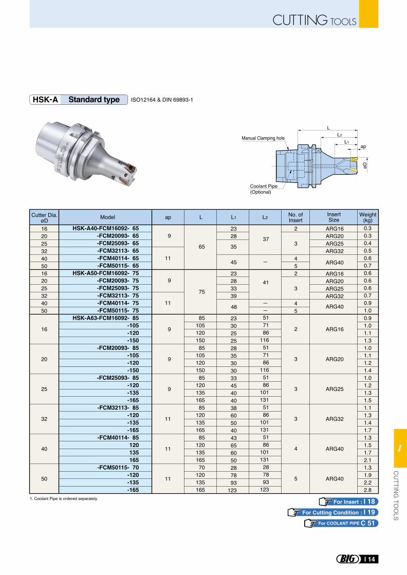
For Insert : I 18For Cutting Condition : I 19
øD
L
L1
L2
Coolant Pipe (Optional)
apManual Clamping hole
HSK-A Standard type ISO12164 & DIN 69893-1
HSK-A40-FCM16092- 65 -FCM20093- 65 -FCM25093- 65 -FCM32113- 65 -FCM40114- 65 -FCM50115- 65
HSK-A50-FCM16092- 75-FCM20093- 75-FCM25093- 75-FCM32113- 75-FCM40114- 75-FCM50115- 75
HSK-A63-FCM16092- 85-105-120-150
-FCM20093- 85-105-120-150
-FCM25093- 85-120-135-165
-FCM32113- 85-120-135-165
-FCM40114- 85120135165
-FCM50115- 70-120-135-165
16
20
25
32
40
50
2
3
3
3
4
5
2328
23283339
2330252528353030334540403860504043656050287893
123
2
3
452
3
45
35
45
48
8510512015085
10512015085
12013516585
12013516585
12013516570
120135165
162025324050162025324050
65
75
9
9
9
11
11
11
9
11
9
11
ARG16
ARG20
ARG25
ARG32
ARG40
ARG40
ARG16ARG20ARG25ARG32
ARG40
ARG16ARG20ARG25ARG32
ARG40
Model ap L1L L2Cutter Dia.øD
No. ofInsert
InsertSize
Weight(kg)
517186
116517186
1165186
1011315186
1011315186
101131287893
123
37
41
0.91.01.11.31.01.11.21.41.01.21.31.51.11.31.41.71.31.51.72.11.31.92.22.8
0.30.30.40.50.60.70.60.60.60.70.91.0
1. Coolant Pipe is ordered separately.
For COOLANT PIPE C 51
I 14
CUTTING TOOLSC
UTTIN
G TO
OLS
I
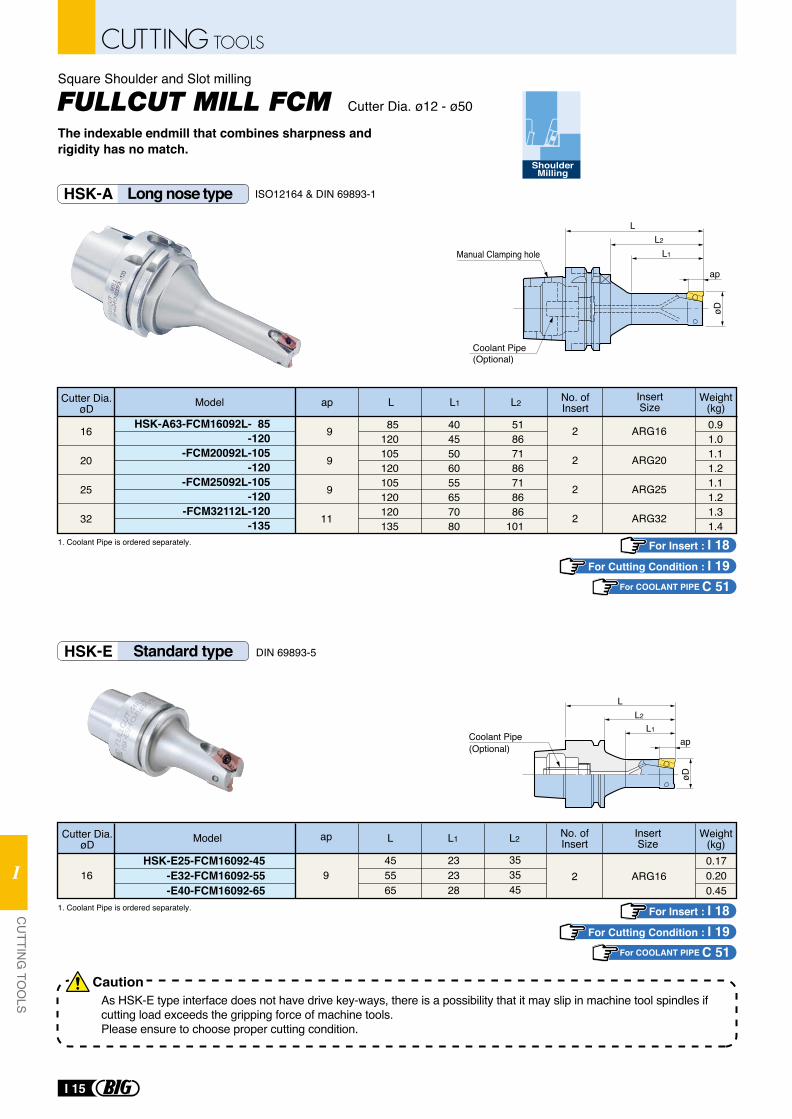
For Insert : I 18For Cutting Condition : I 19
For Insert : I 18
øD
L
L1
L2
Coolant Pipe (Optional)
ap
Manual Clamping hole
Cutter Dia. ø12 - ø50
ShoulderMilling
The indexable endmill that combines sharpness and rigidity has no match.
Square Shoulder and Slot milling
øD
L
L1
L2
apCoolant Pipe (Optional)
As HSK-E type interface does not have drive key-ways, there is a possibility that it may slip in machine tool spindles if cutting load exceeds the gripping force of machine tools.Please ensure to choose proper cutting condition.
HSK-E Standard type
HSK-A Long nose type
DIN 69893-5
ISO12164 & DIN 69893-1
HSK-A63-FCM16092L- 85-120
-FCM20092L-105-120
-FCM25092L-105-120
-FCM32112L-120-135
4045506055657080
51867186718686
101
2
2
2
2
85120105120105120120135
16
20
25
32
9
9
9
11
ARG16
ARG20
ARG25
ARG32
Model ap L1L L2Cutter Dia.øD
No. ofInsert
InsertSize
Weight(kg)0.91.01.11.21.11.21.31.4
HSK-E25-FCM16092-45-E32-FCM16092-55-E40-FCM16092-65
9 2455565
16232328
Model L L1 L2Cutter Dia.øD
No. ofInsert
InsertSizeap
ARG16
Weight(kg)0.170.200.45
353545
1. Coolant Pipe is ordered separately.
1. Coolant Pipe is ordered separately.
Caution
For COOLANT PIPE C 51
For Cutting Condition : I 19For COOLANT PIPE C 51
I 15
CUTTING TOOLS
CU
TTING
TOO
LS
I
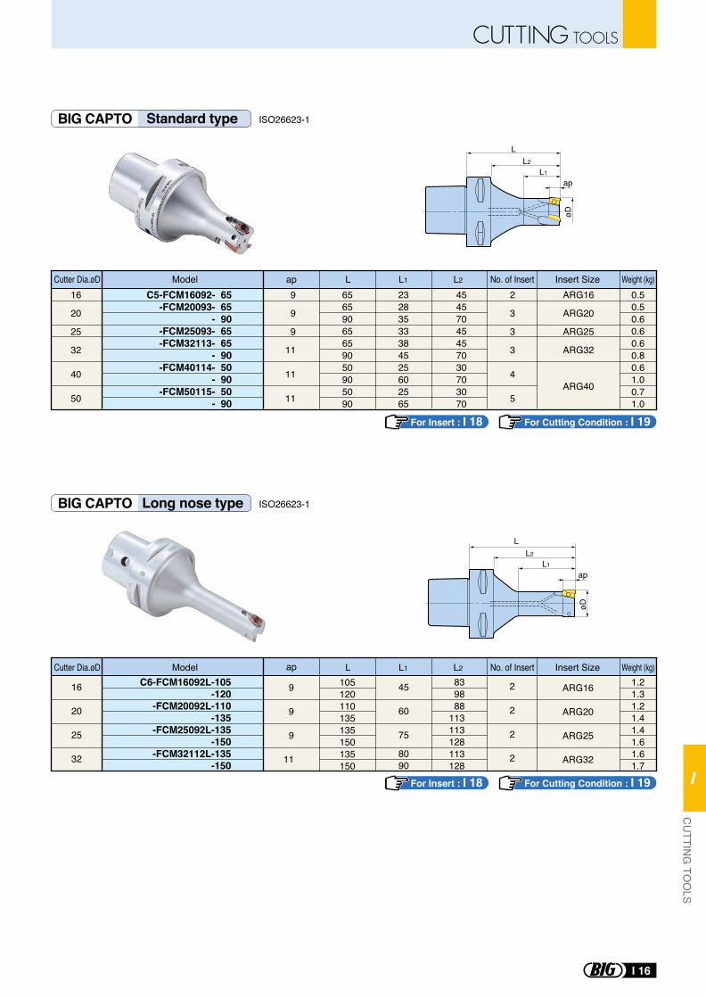
For Insert : I 18 For Cutting Condition : I 19
For Insert : I 18 For Cutting Condition : I 19
C5-FCM16092- 65-FCM20093- 65
- 90-FCM25093- 65-FCM32113- 65
- 90-FCM40114- 50
- 90-FCM50115- 50
- 90
9
9
9
11
11
11
2
3
3
3
4
5
23283533384525602565
65659065659050905090
45457045457030703070
0.50.50.60.60.60.80.61.00.71.0
16
20
25
32
40
50
ARG16
ARG20
ARG25
ARG32
ARG40
C6-FCM16092L-105-120
-FCM20092L-110-135
-FCM25092L-135-150
-FCM32112L-135-150
9
9
9
11
105120110135135150135150
8090
839888
113113128113128
1.21.31.21.41.41.61.61.7
16
20
25
32
2
2
2
2
ARG16
ARG20
ARG25
ARG32
Model L L1 L2Cutter Dia.øD No. of Insert Insert Sizeap Weight (kg)
Model L L1 L2Cutter Dia.øD No. of Insert Insert Sizeap Weight (kg)
45
60
75
øD
L
L1
L2
ap
øD
L
L1
L2
ap
BIG CAPTO Standard type
BIG CAPTO Long nose type
ISO26623-1
ISO26623-1
I 16
CUTTING TOOLSC
UTTIN
G TO
OLS
I
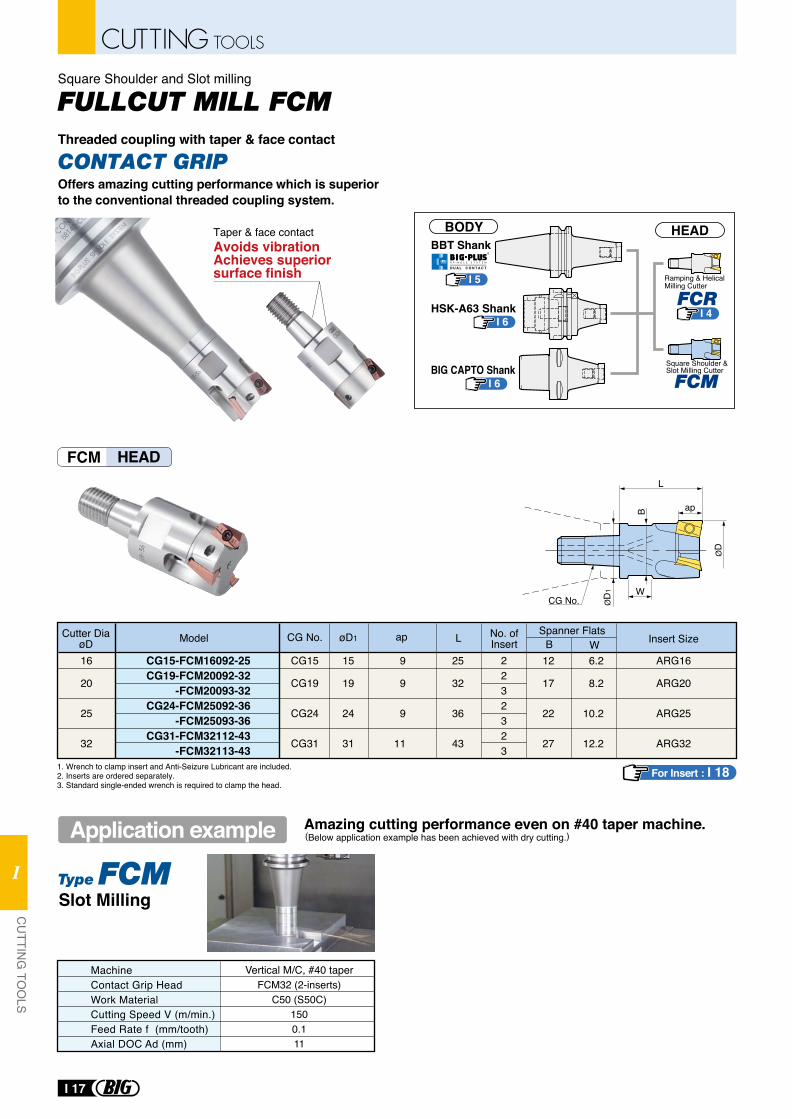
FCM HEAD
Offers amazing cutting performance which is superior to the conventional threaded coupling system.
CONTACT GRIP
Amazing cutting performance even on #40 taper machine.(Below application example has been achieved with dry cutting.)Application example
CG15-FCM16092-25CG19-FCM20092-32
-FCM20093-32CG24-FCM25092-36
-FCM25093-36CG31-FCM32112-43
-FCM32113-43
2232323
16
20
25
32
15
19
24
31
CG15
CG19
CG24
CG31
ARG16
ARG20
ARG25
ARG32
9
9
9
11
25
32
36
43
12
17
22
27
6.2
8.2
10.2
12.2
Model L BSpanner FlatsNo. of
InsertCutter Dia
øD W Insert SizeapøD1CG No.
CG No. ØD
1
B ap
W
ØD
L
1. Wrench to clamp insert and Anti-Seizure Lubricant are included. 2. Inserts are ordered separately.3. Standard single-ended wrench is required to clamp the head.
For Insert : I 18
MachineContact Grip HeadWork MaterialCutting Speed V (m/min.)Feed Rate f (mm/tooth)Axial DOC Ad (mm)
Vertical M/C, #40 taperFCM32 (2-inserts)
C50 (S50C)1500.111
Slot Milling
Square Shoulder and Slot milling
Threaded coupling with taper & face contact
Taper & face contactAvoids vibrationAchieves superior surface finish
BBT Shank
HSK-A63 Shank
BIG CAPTO Shank
I 5
I 6
I 6
BODY HEAD
I 4
Ramping & Helical Milling Cutter
Square Shoulder & Slot Milling Cutter
R
S P I N D L E S Y S T E M
D U A L C O N T A C T
I 17
CUTTING TOOLS
CU
TTING
TOO
LS
I
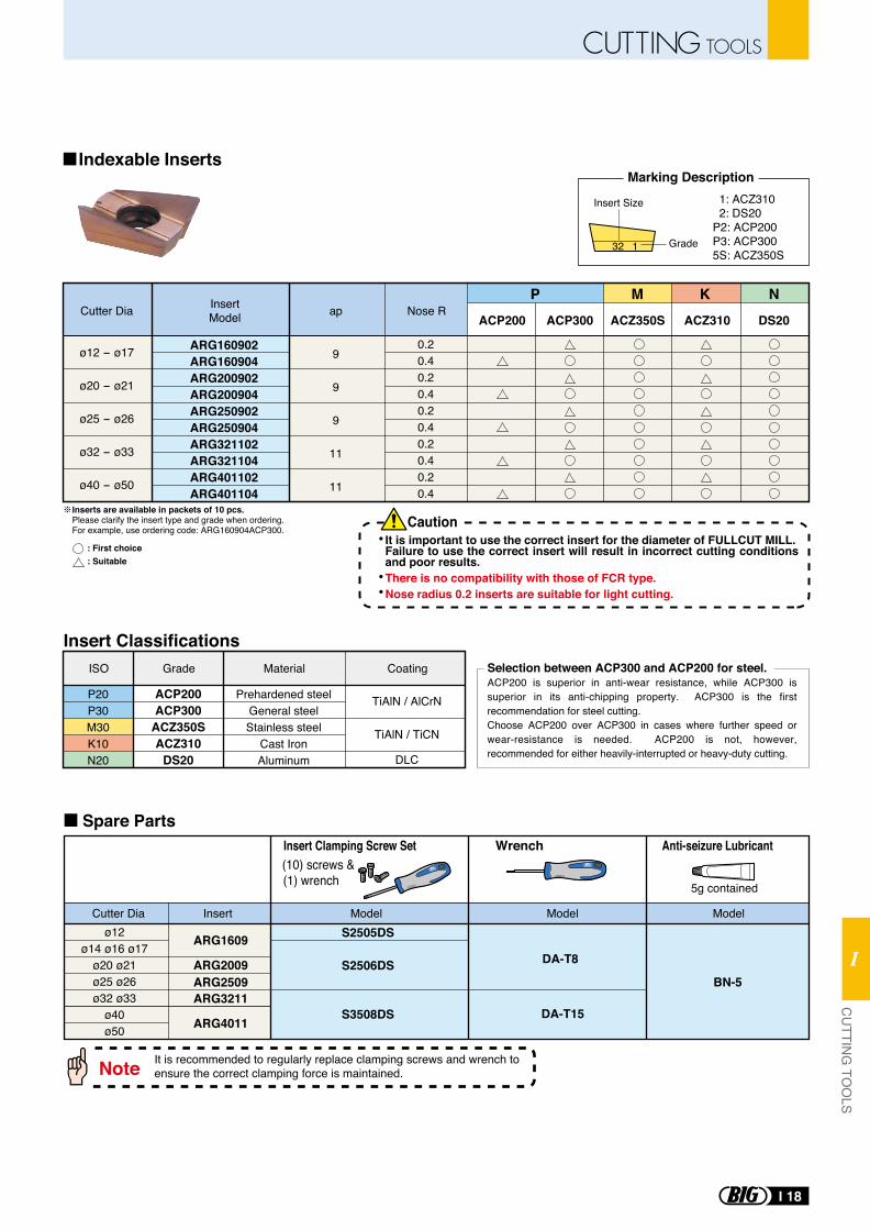
Indexable Inserts
Inserts are available in packets of 10 pcs.Please clarify the insert type and grade when ordering. For example, use ordering code: ARG160904ACP300.
: First choice: Suitable
ø12ø14 ø16 ø17
ø20 ø21ø25 ø26ø32 ø33
ø40ø50
S2506DS
S2505DS
S3508DS
DA-T8
BN-5
DA-T15
ARG1609
ARG2009ARG2509ARG3211
ARG4011
Selection between ACP300 and ACP200 for steel.ACP200 is superior in anti-wear resistance, while ACP300 is superior in its anti-chipping property. ACP300 is the first recommendation for steel cutting.Choose ACP200 over ACP300 in cases where further speed or wear-resistance is needed. ACP200 is not, however, recommended for either heavily-interrupted or heavy-duty cutting.
5g contained
(10) screws & (1) wrench
Wrench Anti-seizure LubricantInsert Clamping Screw Set
Cutter Dia Model Model ModelInsert
It is recommended to regularly replace clamping screws and wrench to ensure the correct clamping force is maintained.Note
Spare Parts
It is important to use the correct insert for the diameter of FULLCUT MILL.Failure to use the correct insert will result in incorrect cutting conditions and poor results.There is no compatibility with those of FCR type.Nose radius 0.2 inserts are suitable for light cutting.
Caution
ARG160902ARG160904ARG200902ARG200904ARG250902ARG250904ARG321102ARG321104ARG401102ARG401104
9
9
9
11
11
ø12 - ø17
ø20 - ø21
ø25 - ø26
ø32 - ø33
ø40 - ø50
0.20.40.20.40.20.40.20.40.20.4
apCutter Dia Nose RInsertModel ACP200 ACP300 ACZ350S DS20ACZ310
P M K N
P20P30M30K10N20
ISO
ACP200ACP300
ACZ350SACZ310
DS20
Grade
Prehardened steelGeneral steelStainless steel
Cast IronAluminum
Material
TiAlN / AlCrN
TiAlN / TiCN
DLC
Coating
Insert Classifications
1: ACZ310 2: DS20P2: ACP200P3: ACP3005S: ACZ350S
Grade
Insert Size
Marking Description
32 1
I 18
CUTTING TOOLSC
UTTIN
G TO
OLS
I
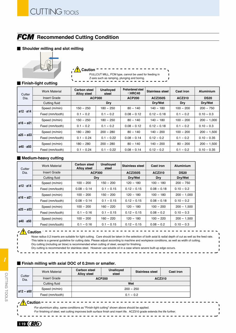
Recommended Cutting Condition
ACP300 ACP200 ACZ350S ACZ310 DS20Cutting fluid
150 - 250
0.1 - 0.2
150 - 250
0.1 - 0.2
180 - 280
0.1 - 0.24
180 - 280
0.1 - 0.24
180 - 250
0.1 - 0.2
180 - 250
0.1 - 0.2
200 - 280
0.1 - 0.22
200 - 280
0.1 - 0.22
80 - 140
0.08 - 0.12
80 - 140
0.08 - 0.12
80 - 140
0.08 - 0.14
80 - 140
0.08 - 0.14
140 - 180
0.12 - 0.18
140 - 180
0.12 - 0.18
140 - 200
0.12 - 0.2
140 - 200
0.12 - 0.2
100 - 200
0.1 - 0.2
100 - 200
0.1 - 0.2
100 - 200
0.1 - 0.2
80 - 200
0.1 - 0.2
200 - 750
0.10 - 0.3
200 - 1,000
0.10 - 0.3
200 - 1,500
0.10 - 0.35
200 - 1,500
0.10 - 0.35
ACP300 ACZ350S ACZ310 DS20Cutting fluid Dry
Dry
Dry/Wet Dry/Wet120 - 180
0.12 - 0.15
120 - 180
0.12 - 0.15
120 - 180
0.12 - 0.15
120 - 180
0.12 - 0.15
Dry
Dry/Wet Dry/WetDry
100 - 180
0.08 - 0.18
100 - 180
0.08 - 0.18
100 - 200
0.08 - 0.2
100 - 220
0.08 - 0.2
200 - 750
0.10 - 0.2
200 - 1,000
0.10 - 0.2
200 - 1,500
0.10 - 0.3
200 - 1,500
0.10 - 0.3
ACP200 ACZ310Cutting fluid Wet
ø12 - ø50200 - 250
0.1 - 0.2
100 - 200
0.08 - 0.14
100 - 200
0.08 - 0.14
100 - 200
0.1 - 0.16
100 - 200
0.1 - 0.16
150 - 200
0.1 - 0.15
150 - 200
0.1 - 0.15
160 - 220
0.1 - 0.15
160 - 220
0.1 - 0.15
CutterDia.
Work Material
Insert Grade
CutterDia.
Work Material
Insert Grade
CutterDia.
Work Material
Insert Grade
Speed (m/min)
Feed (mm/tooth)
Speed (m/min)
Feed (mm/tooth)
Speed (m/min)
Feed (mm/tooth)
Speed (m/min)
Feed (mm/tooth)
Speed (m/min)
Feed (mm/tooth)
Speed (m/min)
Feed (mm/tooth)
Speed (m/min)
Feed (mm/tooth)
Speed (m/min)
Feed (mm/tooth)
Speed (m/min)
Feed (mm/tooth)
Finish-light cutting
Medium-heavy cutting
Stainless steel Cast iron Aluminium
Stainless steel Cast iron
Stainless steel Cast iron
Aluminium
Carbon steelAlloy steel
Unalloyedsteel
Carbon steelAlloy steel
Unalloyedsteel
Carbon steelAlloy steel
Unalloyedsteel
Prehardened steel HRC40
·This table is a general guideline for cutting data. Please adjust according to machine and workpiece conditions, as well as width of cutting.·Dry cutting (including air blow) is recommended when cutting of steel, except for finishing.·Dry cutting is recommended for stainless steel. However use soluble oil in a case where severe built-up edge occurs.
Finish milling with axial DOC of 0.2mm or smaller.
·For aluminium alloy, same conditions as "Finish-light cutting" shown above should be applied.·For finishing of steel, wet cutting improves both surface finish and insert life. ACZ310 grade extends the life further.
FULLCUT MILL, FCM type, cannot be used for feeding inZ-axis such as ramping, plunging and boring.
·Nose radius 0.2 inserts are suitable for light cutting. Care should be taken in the selection of both axial & radial depth of cut as well as the feed rate.
Shoulder milling and slot milling
Caution
Caution
Caution
ø12 ø14
ø16 - ø21
ø25 - ø33
ø40 ø50
ø12 ø14
ø16 - ø21
ø25 - ø33
ø40 ø50
I 19
CUTTING TOOLS
CU
TTING
TOO
LS
I
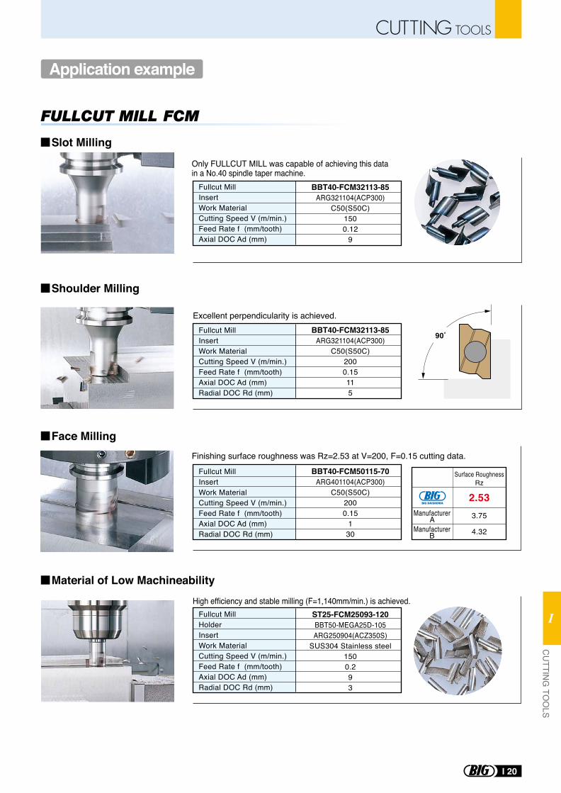
Application example
Excellent perpendicularity is achieved.Fullcut MillInsertWork MaterialCutting Speed V (m/min.)Feed Rate f (mm/tooth)Axial DOC Ad (mm)Radial DOC Rd (mm)
BBT40-FCM32113-85ARG321104(ACP300)
C50(S50C)2000.15115
Fullcut MillInsertWork MaterialCutting Speed V (m/min.)Feed Rate f (mm/tooth)Axial DOC Ad (mm)Radial DOC Rd (mm)
BBT40-FCM50115-70ARG401104(ACP300)
C50(S50C)2000.15
130
ST25-FCM25093-120BBT50-MEGA25D-105ARG250904(ACZ350S)
SUS304 Stainless steel1500.293
90˚
BBT40-FCM32113-85ARG321104(ACP300)
C50(S50C)1500.12
9
Fullcut MillHolderInsertWork MaterialCutting Speed V (m/min.)Feed Rate f (mm/tooth)Axial DOC Ad (mm)Radial DOC Rd (mm)
High efficiency and stable milling (F=1,140mm/min.) is achieved.
Fullcut MillInsertWork MaterialCutting Speed V (m/min.)Feed Rate f (mm/tooth)Axial DOC Ad (mm)
Only FULLCUT MILL was capable of achieving this data in a No.40 spindle taper machine.
Finishing surface roughness was Rz=2.53 at V=200, F=0.15 cutting data.
ManufacturerA
ManufacturerB
3.75
4.32
Surface RoughnessRz
2.53
Slot Milling
Shoulder Milling
Face Milling
Material of Low Machineability
I 20
CUTTING TOOLSC
UTTIN
G TO
OLS
I
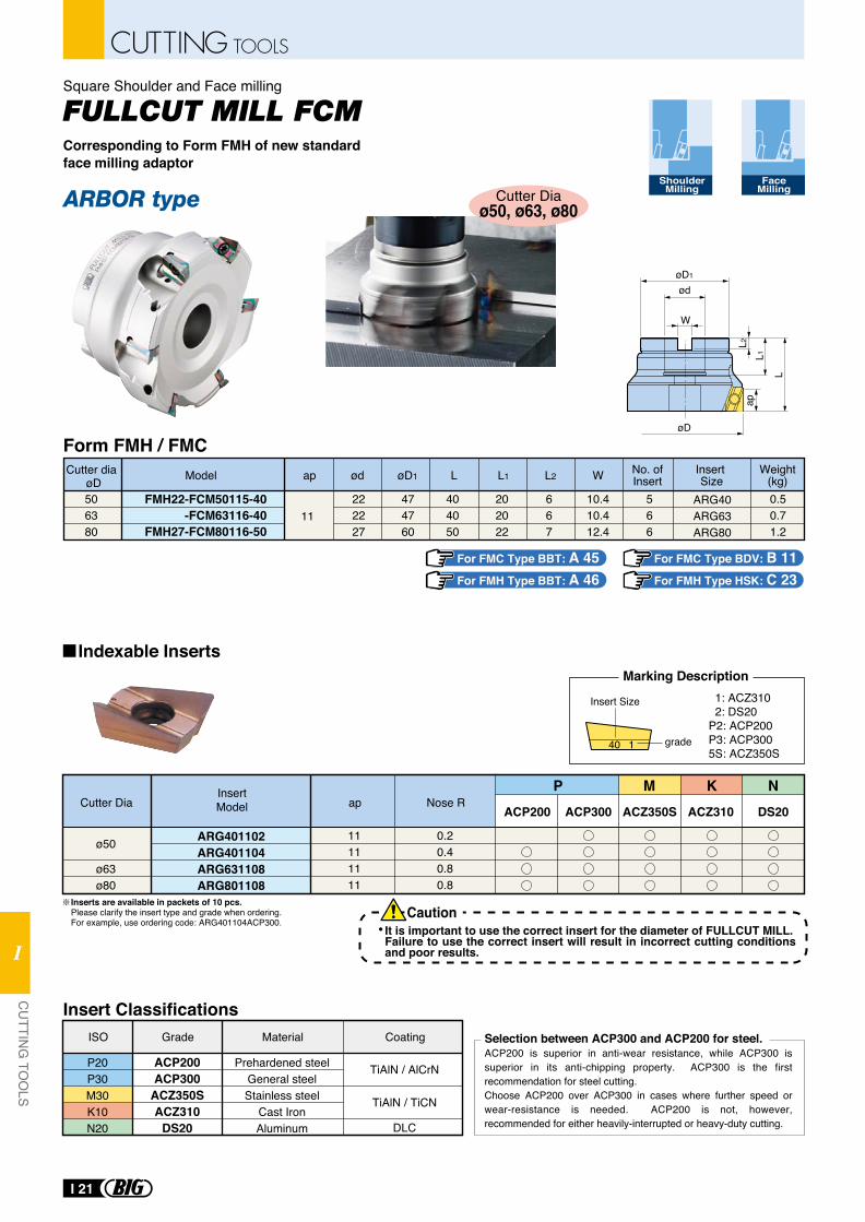
øD1
ød
W
øD
L
L2L1
ap
P20P30M30K10N20
ISO
ACP200ACP300
ACZ350SACZ310
DS20
Grade
Prehardened steelGeneral steelStainless steel
Cast IronAluminum
Material
TiAlN / AlCrN
TiAlN / TiCN
DLC
Coating
ACP200 ACP300
ARG401102ARG401104ARG631108ARG801108
ø50
ø63ø80
0.20.40.80.8
11111111
apCutter Dia Nose RInsertModel ACZ310ACZ350S
P KM NDS20
Insert Classifications
Inserts are available in packets of 10 pcs.Please clarify the insert type and grade when ordering. For example, use ordering code: ARG401104ACP300.
Selection between ACP300 and ACP200 for steel.ACP200 is superior in anti-wear resistance, while ACP300 is superior in its anti-chipping property. ACP300 is the first recommendation for steel cutting.Choose ACP200 over ACP300 in cases where further speed or wear-resistance is needed. ACP200 is not, however, recommended for either heavily-interrupted or heavy-duty cutting.
It is important to use the correct insert for the diameter of FULLCUT MILL.Failure to use the correct insert will result in incorrect cutting conditions and poor results.
Caution
Indexable Inserts
ShoulderMilling
For FMC Type BDV: B 11For FMH Type HSK: C 23
For FMC Type BBT: A 45For FMH Type BBT: A 46
Cutter Diaø50, ø63, ø80
Square Shoulder and Face milling
Corresponding to Form FMH of new standard face milling adaptor
Insert Size
Weight(kg)Model
FMH22-FCM50115-40-FCM63116-40
FMH27-FCM80116-50
Lap
506380
404050
0.50.71.2
566
L1
202022
L2
667
11
No. ofInsert
ARG40ARG63ARG80
øDCutter dia øD1ød
222227
W
10.410.412.4
474760
Form FMH / FMC
1: ACZ310 2: DS20P2: ACP200P3: ACP3005S: ACZ350S
grade
Insert Size
Marking Description
40 1
FaceMilling
I 21
CUTTING TOOLS
CU
TTING
TOO
LS
I
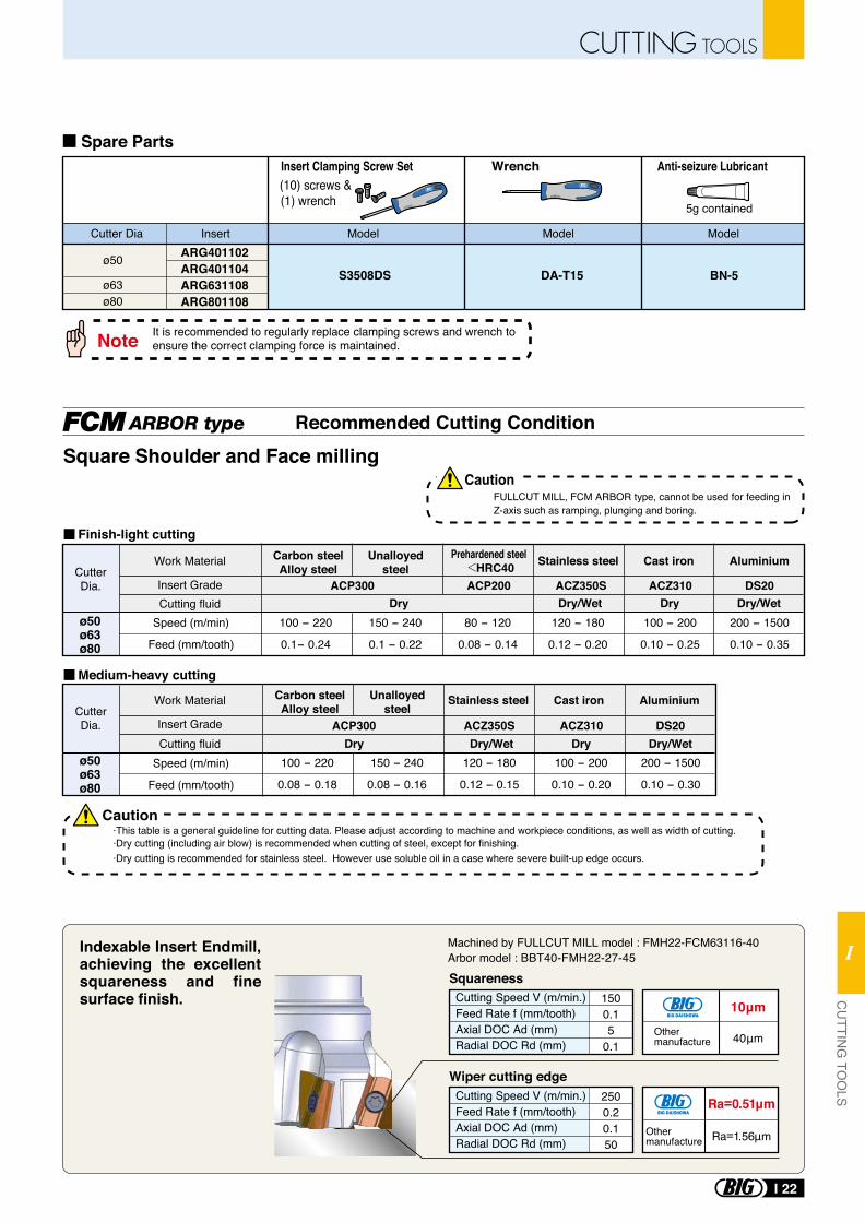
Squareness
Wiper cutting edge
Cutting Speed V (m/min.)Feed Rate f (mm/tooth)Axial DOC Ad (mm)Radial DOC Rd (mm)
1500.15
0.1
Cutting Speed V (m/min.)Feed Rate f (mm/tooth)Axial DOC Ad (mm)Radial DOC Rd (mm)
2500.20.150
10μm
40μmOther manufacture
ø50
ø63ø80
BN-5DA-T15
ARG401102ARG401104ARG631108ARG801108
5g contained
(10) screws & (1) wrench
Wrench Anti-seizure LubricantInsert Clamping Screw Set
Cutter Dia Model Model ModelInsert
It is recommended to regularly replace clamping screws and wrench to ensure the correct clamping force is maintained.Note
Spare Parts
S3508DS
Indexable Insert Endmill, achieving the excellent squareness and fine surface finish.
Recommended Cutting Condition
ACP300 ACP200 ACZ350S ACZ310 DS20Cutting fluid
ø50ø63ø80
100 - 220
0.1- 0.24
150 - 240
0.1 - 0.22
80 - 120
0.08 - 0.14
120 - 180
0.12 - 0.20
100 - 200
0.10 - 0.25
200 - 1500
0.10 - 0.35
ACP300 ACZ350S ACZ310 DS20Cutting fluid Dry
Dry
Dry/Wet Dry/Wet120 - 180
0.12 - 0.15
Dry
Dry/Wet Dry/WetDry
100 - 200
0.10 - 0.20
200 - 1500
0.10 - 0.30
100 - 220
0.08 - 0.18
150 - 240
0.08 - 0.16
CutterDia.
Work Material
Insert Grade
CutterDia.
Work Material
Insert Grade
Speed (m/min)
Feed (mm/tooth)
Speed (m/min)
Feed (mm/tooth)
Finish-light cutting
Medium-heavy cutting
Stainless steel Cast iron Aluminium
Stainless steel Cast iron Aluminium
Carbon steelAlloy steel
Unalloyedsteel
Carbon steelAlloy steel
Unalloyedsteel
Prehardened steel HRC40
·This table is a general guideline for cutting data. Please adjust according to machine and workpiece conditions, as well as width of cutting.·Dry cutting (including air blow) is recommended when cutting of steel, except for finishing.·Dry cutting is recommended for stainless steel. However use soluble oil in a case where severe built-up edge occurs.
FULLCUT MILL, FCM ARBOR type, cannot be used for feeding inZ-axis such as ramping, plunging and boring.
Square Shoulder and Face milling Caution
Caution
ø50ø63ø80
Ra=0.51μm
Ra=1.56μm
Machined by FULLCUT MILL model : FMH22-FCM63116-40Arbor model : BBT40-FMH22-27-45
Other manufacture
I 22
CUTTING TOOLSC
UTTIN
G TO
OLS
I
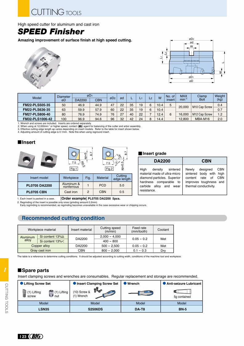
High speed cutter for aluminum and cast iron
FM22-PLS505-35FM22-PLS636-35FM27-PLS806-40FM32-PLS1006-42
Model
506380100
46.959.976.996.9
44.957.974.994.6
47607696
22222732
35354042
0.40.71.22.0
M10 Cap Screw
M12 Cap ScrewMBA-M16
5
6
DiameterøD DA2200 CBN øD2
øD1ød L
19192224
L1
6678
L2
10.410.412.414.4
W No. of insert
Weight(kg)
ClampBolt
20,000
16,00012,800
MAXmin-1
1. Wrench and screws are included. Inserts are ordered separately.2. When using at 12,000min-1 or higher speed, contact agent for balancing of the cutter and arbor assembly. 3. Effective cutting edge length ap varies depending on insert models. Refer to the table for insert shown below.4. Adjusting amount of cutting edge is 0.1mm. Note this when using reground insert.
1. Each insert is packed in a case.2. Regrinding of the insert is possible only once (grinding amount 0.2mm). Early regrinding is recommended, as regrinding becomes unavailable in the case excessive wear or chipping occurs.
(1) Lifting screw
PL0705 DA2200
PL0705 CBN
1
2
PCD
CBN
5.0
0.5Cast iron
The table is a reference to determine cutting conditions. It should be adjusted according to cutting width, conditions of the machine tool and workpiece.
DA2200 CBNHigh density sintered material made of ultra-micro diamond particles. Superior hardness comparable to carbide alloy and wear resistance.
Newly designed CBN sintered body with high content rate of CBN improves toughness and thermal conductivity.
(1) Lifting nut
(10) Screw &(1) Wrench 5g contained
Insert clamping screws and wrenches are consumables. Regular replacement and storage are recommended.
S2506DS BN-5DA-T8LSN35
Lifting Screw Set Insert Clamping Screw Set Wrench Anti-seizure Lubricant
Model Model Model Model
Wet
WetDry
0.05 - 0.2
0.05 - 0.20.1 - 0.3
2,000 - 4,000400 - 800
500 - 2,500800 - 2,000
DA2200
DA2200CBN
Workpiece material
Copper alloyGray cast iron
Si content 13% Si content 13%Aluminum
alloy
Insert material Cutting speed(m/min)
Feed rate(mm/tooth) Coolant
L
øD1
øD
øD2ødW
L1L2
ap
2
ap=0
.58.
7
7.5
Fig.2
8.7
7.5
ap=5
R0.5
Fig.1
Insert model Fig. Cutting edge lengthMaterialWorkpiece
Aluminum &nonferrous
[Order example] PL0705 DA2200 5pcs.
Insert grade
SPEED FinisherAmazing improvement of surface finish at high speed cutting.
Insert
Spare parts
Recommended cutting condition
I 23
CUTTING TOOLS
CU
TTING
TOO
LS
I
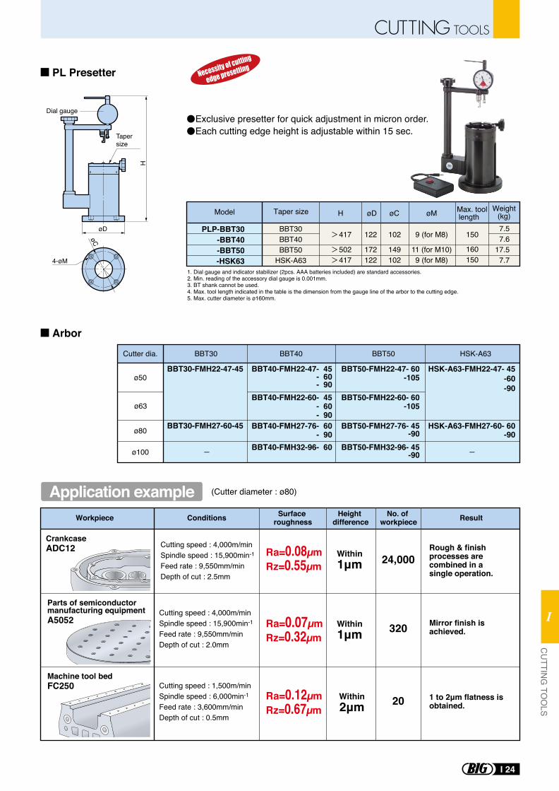
PLP-BBT30-BBT40-BBT50-HSK63
Model Weight(kg)Taper size øDH
BBT30BBT40BBT50
HSK-A63
7.57.6
17.57.7
122
172122
øC
102 150
160150
149102
øM
9 (for M8)
11 (for M10)9 (for M8)
417
502417
Exclusive presetter for quick adjustment in micron order.Each cutting edge height is adjustable within 15 sec.
BBT30-FMH22-47-45
BBT30-FMH27-60-45
BBT40-FMH22-47- 45- 60- 90
BBT50-FMH22-47- 60-105
HSK-A63-FMH22-47- 45-60-90
BBT40-FMH22-60- 45- 60- 90
BBT50-FMH22-60- 60-105
Cutter dia. BBT30 BBT40 BBT50 HSK-A63
ø50
ø63
ø80 BBT40-FMH27-76- 60- 90
BBT50-FMH27-76- 45-90
HSK-A63-FMH27-60- 60-90
ø100 BBT40-FMH32-96- 60 BBT50-FMH32-96- 45-90
Dial gauge
øD
HTapersize
øC
4-øM
Max. toollength
1. Dial gauge and indicator stabilizer (2pcs. AAA batteries included) are standard accessories.2. Min. reading of the accessory dial gauge is 0.001mm.3. BT shank cannot be used.4. Max. tool length indicated in the table is the dimension from the gauge line of the arbor to the cutting edge. 5. Max. cutter diameter is ø160mm.
PL Presetter
Arbor
Rough & finish processes are combined in a single operation.
Mirror finish is achieved.
1 to 2μm flatness is obtained.
Workpiece Result
CrankcaseADC12
Parts of semiconductor manufacturing equipmentA5052
Machine tool bedFC250
Cutting speed : 4,000m/minSpindle speed : 15,900min-1
Feed rate : 9,550mm/minDepth of cut : 2.5mm
Cutting speed : 4,000m/minSpindle speed : 15,900min-1
Feed rate : 9,550mm/minDepth of cut : 2.0mm
Cutting speed : 1,500m/minSpindle speed : 6,000min-1
Feed rate : 3,600mm/minDepth of cut : 0.5mm
Ra=0.08µmRz=0.55µm
Ra=0.07µmRz=0.32µm
Ra=0.12µmRz=0.67µm
Within1μm
Within2μm
Within1μm
24,000
20
320
Conditions Surface roughness
Height difference
No. of workpiece
(Cutter diameter : ø80)Application example
I 24
CUTTING TOOLSC
UTTIN
G TO
OLS
I
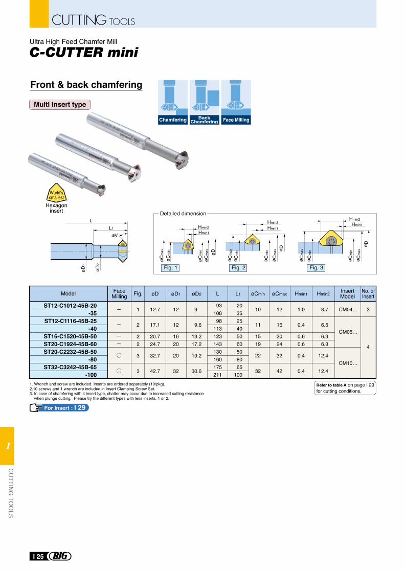
Front & back chamfering
Multi insert type
1. Wrench and screw are included. Inserts are ordered separately (10/pkg).2.10 screws and 1 wrench are included in Insert Clamping Screw Set.3. In case of chamfering with 4 insert type, chatter may occur due to increased cutting resistance when plunge cutting. Please try the different types with less inserts, 1 or 2.
Ultra High Feed Chamfer Mill
Hexagoninsert
World'ssmallest
Chamfering BackChamfering Face Milling
For Insert : I 29
Refer to table A on page I 29 for cutting conditions.
L1
L
øD2
øD1
45˚
ø Cm
ax
ø Cm
in
ø D
ø Cm
ax
ø Cm
in
Hmin2Hmin1
ø Cm
ax
ø Cm
in
ø Cm
ax ø D
ø Cm
in
Hmin2Hmin1
Detailed dimension
ST12-C1012-45B-20-35
ST12-C1116-45B-25-40
ST16-C1520-45B-50ST20-C1924-45B-60ST20-C2232-45B-50
-80ST32-C3242-45B-65
-100
øD1øD InsertModel
FaceMilling
CM04…
CM05…
CM10…
øCmaxøCminøD2 L Hmin1 Hmin2L1
1
2
22
3
3
12.7
17.1
20.724.7
32.7
42.7
12
12
1620
20
32
9
9.6
13.217.2
19.2
30.6
93108
98113123143130160175211
203525405060508065
100
10
11
1519
22
32
12
16
2024
32
42
1.0
0.4
0.60.6
0.4
0.4
3.7
6.5
6.36.3
12.4
12.4
3
4
Model Fig. No. ofInsert
Fig. 1 Fig. 2 Fig. 3
øC
max
øD
øC
min
Hmin2
Hmin1
øC
max
øC
min
I 25
CUTTING TOOLS
CU
TTING
TOO
LS
I
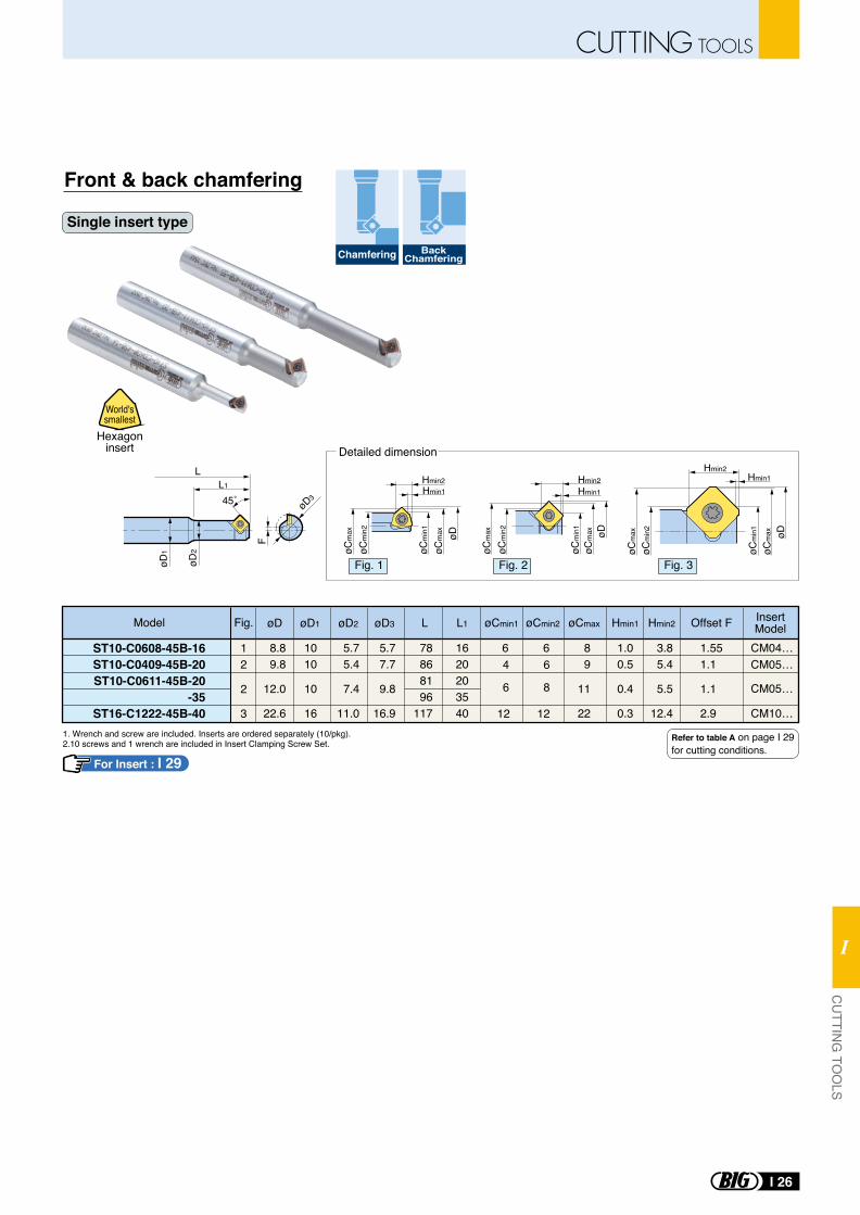
Front & back chamfering
Single insert type
1. Wrench and screw are included. Inserts are ordered separately (10/pkg).2.10 screws and 1 wrench are included in Insert Clamping Screw Set.
Hexagoninsert
World'ssmallest
For Insert : I 29
Chamfering BackChamfering
ST10-C0608-45B-16ST10-C0409-45B-20ST10-C0611-45B-20
-35ST16-C1222-45B-40
Model Fig. øD1øD InsertModelOffset F
CM04…64 6
6 8
12
6
12
CM05…
CM05…
CM10…
øCmin2 øCmaxøCmin1øD2 L Hmin1 Hmin2L1øD3
78868196
117
1620203540
12
2
3
8.8 9.8
12.0
22.6
1010
10
16
5.7 5.4
7.4
11.0
5.77.7
9.8
16.9
89
11
22
1.00.5
0.4
0.3
3.85.4
5.5
12.4
1.551.1
1.1
2.9
øCm
ax
øCm
in1
øCm
ax
øD
øCm
in2
Hmin2Hmin1
øDøC
max
øCm
ax
øCm
in1
øCm
in2
Hmin2Hmin1
L1
L
F
øD2
øD3
øD1
45˚
Detailed dimension
Fig. 1 Fig. 2 Fig. 3
Refer to table A on page I 29 for cutting conditions.
Hmin2Hmin1
øCm
ax
øCm
in2
øCm
ax øD
øCm
in1
I 26
CUTTING TOOLSC
UTTIN
G TO
OLS
I
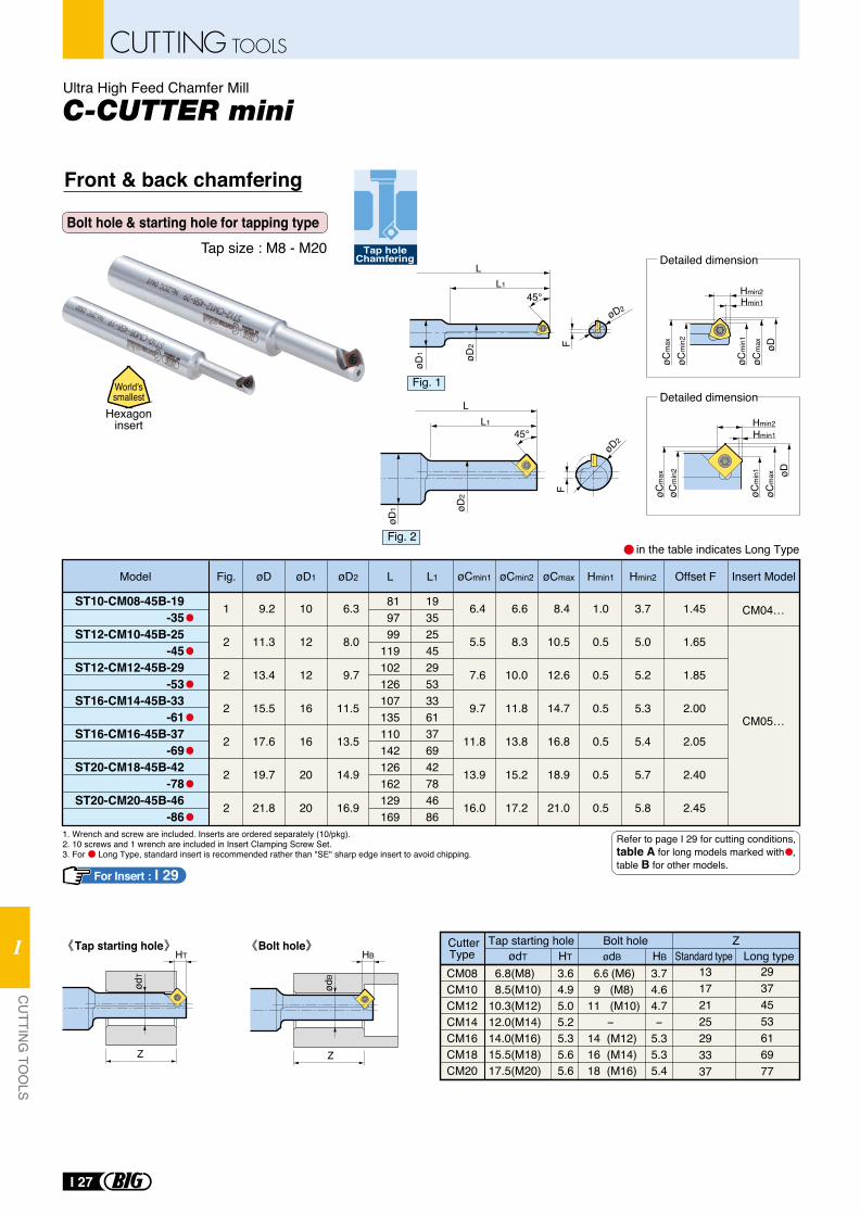
Bolt hole & starting hole for tapping type
Hexagoninsert
World'ssmallest
in the table indicates Long Type
CutterType
Tap starting hole Bolt hole Z
13172125293337
29374553616977
ødT HT ødB Standard type Long typeHB
CM08CM10CM12CM14CM16CM18CM20
6.8(M8) 8.5(M10)10.3(M12)12.0(M14)14.0 (M16)15.5(M18)17.5(M20)
3.64.95.05.25.35.65.6
6.6 (M6) 9 (M8)11 (M10) -14 (M12)16 (M14)18 (M16)
3.74.64.7-
5.35.35.4
HT
Z
ødT
Tap starting hole Bolt holeHB
Z
ødB
1. Wrench and screw are included. Inserts are ordered separately (10/pkg).2. 10 screws and 1 wrench are included in Insert Clamping Screw Set.3. For Long Type, standard insert is recommended rather than "SE" sharp edge insert to avoid chipping.
Tap size : M8 - M20 Tap holeChamfering
Front & back chamfering
Ultra High Feed Chamfer Mill
L1
LøD
1 øD2
F
øD245°
F
45°
LL1
øD2
øD2
øD1
Detailed dimension
Detailed dimension
Model øD1øDFig. Insert Model
CM04…
CM05…
øD2 Hmin1 Hmin2L L1
ST10-CM08-45B-19-35
ST12-CM10-45B-25-45
ST12-CM12-45B-29-53
ST16-CM14-45B-33-61
ST16-CM16-45B-37-69
ST20-CM18-45B-42-78
ST20-CM20-45B-46-86
Offset F
1
2
2
2
2
2
2
9.2
11.3
13.4
15.5
17.6
19.7
21.8
10
12
12
16
16
20
20
6.3
8.0
9.7
11.5
13.5
14.9
16.9
6.4
5.5
7.6
9.7
11.8
13.9
16.0
6.6
8.3
10.0
11.8
13.8
15.2
17.2
8.4
10.5
12.6
14.7
16.8
18.9
21.0
1.0
0.5
0.5
0.5
0.5
0.5
0.5
3.7
5.0
5.2
5.3
5.4
5.7
5.8
1.45
1.65
1.85
2.00
2.05
2.40
2.45
819799
119102126107135110142126162129169
1935254529533361376942784686
øCmin1 øCmin2 øCmax
Refer to page I 29 for cutting conditions, table A for long models marked with , table B for other models.
Fig. 1
Fig. 2
Hmin2Hmin1
øCm
ax
øCm
in2
øCm
ax øD
øCm
in1
Hmin2Hmin1
øCm
ax
øCm
in2
øCm
ax øD
øCm
in1
For Insert : I 29
I 27
CUTTING TOOLS
CU
TTING
TOO
LS
I
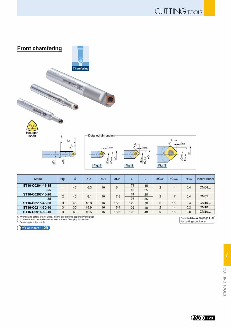
Front chamfering
Chamfering
1. Wrench and screw are included. Inserts are ordered separately (10/pkg).2. 10 screws and 1 wrench are included in Insert Clamping Screw Set.3. Centering is not possible.
Model Fig. øD1øD Insert ModeløCmaxøCminøD2 L HminL1
ST10-C0204-45-15-25
ST10-C0207-45-20-35
ST16-C0515-45-50ST16-C0214-30-40ST16-C0916-60-40
1
2
333
45˚
45˚
45˚30˚60˚
6.3
8.1
15.815.916.5
10
10
161616
6
7.8
15.215.415.6
2
2
529
4
7
151416
0.4
0.4
0.40.20.8
78888196
122105105
15252035504040
CM04…
CM05…
CM10…CM10…CM10…
L1
L
øD2
øD1
Hmin
HminøC
min
øCm
ax øD
øCm
inøC
max øD
Detailed dimension
θ θθ
Hmin
øCm
in
øCm
ax øD
Hexagoninsert
World'ssmallest
Refer to table A on page I 29 for cutting conditions.
Fig. 1 Fig. 2 Fig. 3
For Insert : I 29
I 28
CUTTING TOOLSC
UTTIN
G TO
OLS
I
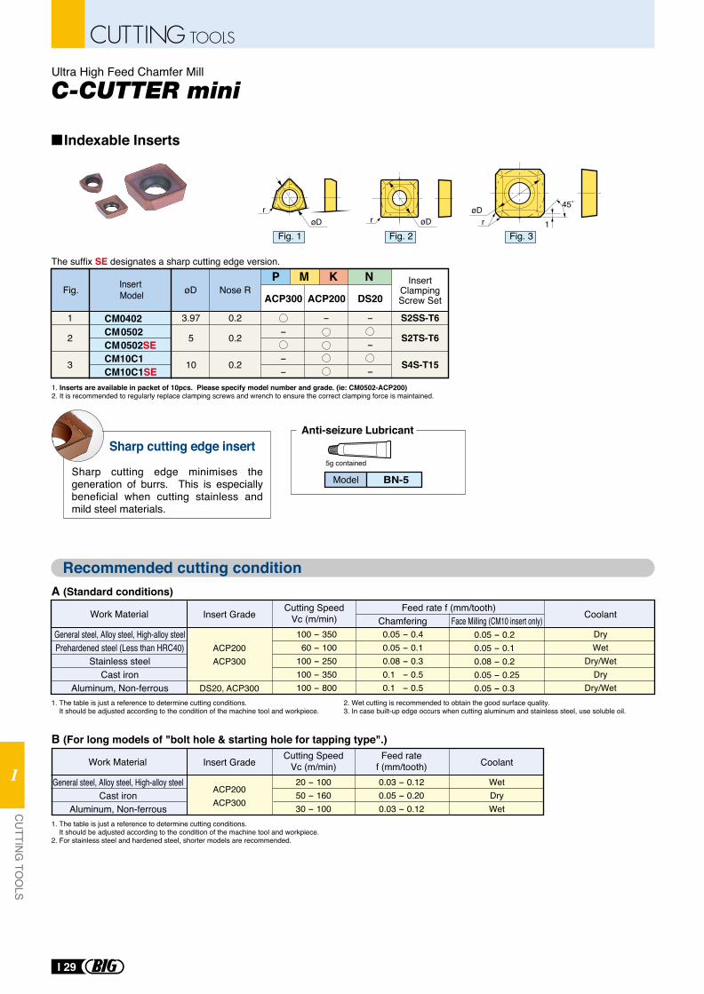
Ultra High Feed Chamfer Mill
Indexable Inserts
CM0402CM0502CM0502SECM10C1CM10C1SE
3.97
5
10
1
2
3
--
--
-
-
-
0.2
0.2
0.2
øDFig. Nose R
S2SS-T6
S2TS-T6
S4S-T15
InsertClampingScrew Set
Insert Model ACP300 ACP200 DS20
1. Inserts are available in packet of 10pcs. Please specify model number and grade. (ie: CM0502-ACP200)2. It is recommended to regularly replace clamping screws and wrench to ensure the correct clamping force is maintained.
The suffix SE designates a sharp cutting edge version.
øDr
r øDøD
r
45˚
1
Sharp cutting edge insert
Sharp cutting edge minimises the generation of burrs. This is especially beneficial when cutting stainless and mild steel materials.
Recommended cutting condition
P M K N
5g contained
Anti-seizure Lubricant
BN-5Model
A (Standard conditions)
1. The table is just a reference to determine cutting conditions. It should be adjusted according to the condition of the machine tool and workpiece.
2. Wet cutting is recommended to obtain the good surface quality.3. In case built-up edge occurs when cutting aluminum and stainless steel, use soluble oil.
Work Material Feed rate f (mm/tooth)Face Milling (CM10 insert only)Chamfering CoolantInsert Grade Cutting Speed
Vc (m/min)0.05 - 0.2 0.05 - 0.1 0.08 - 0.2 0.05 - 0.250.05 - 0.3
0.05 - 0.40.05 - 0.10.08 - 0.30.1 - 0.50.1 - 0.5
100 - 35060 - 100
100 - 250100 - 350100 - 800
DryWet
Dry/WetDry
Dry/Wet
General steel, Alloy steel, High-alloy steelPrehardened steel (Less than HRC40)
Stainless steelCast iron
Aluminum, Non-ferrous
ACP200ACP300
DS20, ACP300
B (For long models of "bolt hole & starting hole for tapping type".)
1. The table is just a reference to determine cutting conditions. It should be adjusted according to the condition of the machine tool and workpiece.2. For stainless steel and hardened steel, shorter models are recommended.
Work Material Feed ratef (mm/tooth) CoolantInsert Grade Cutting Speed
Vc (m/min)0.03 - 0.120.05 - 0.200.03 - 0.12
20 - 10050 - 16030 - 100
WetDryWet
General steel, Alloy steel, High-alloy steelCast iron
Aluminum, Non-ferrous
ACP200ACP300
Fig. 1 Fig. 2 Fig. 3
I 29
CUTTING TOOLS
CU
TTING
TOO
LS
I
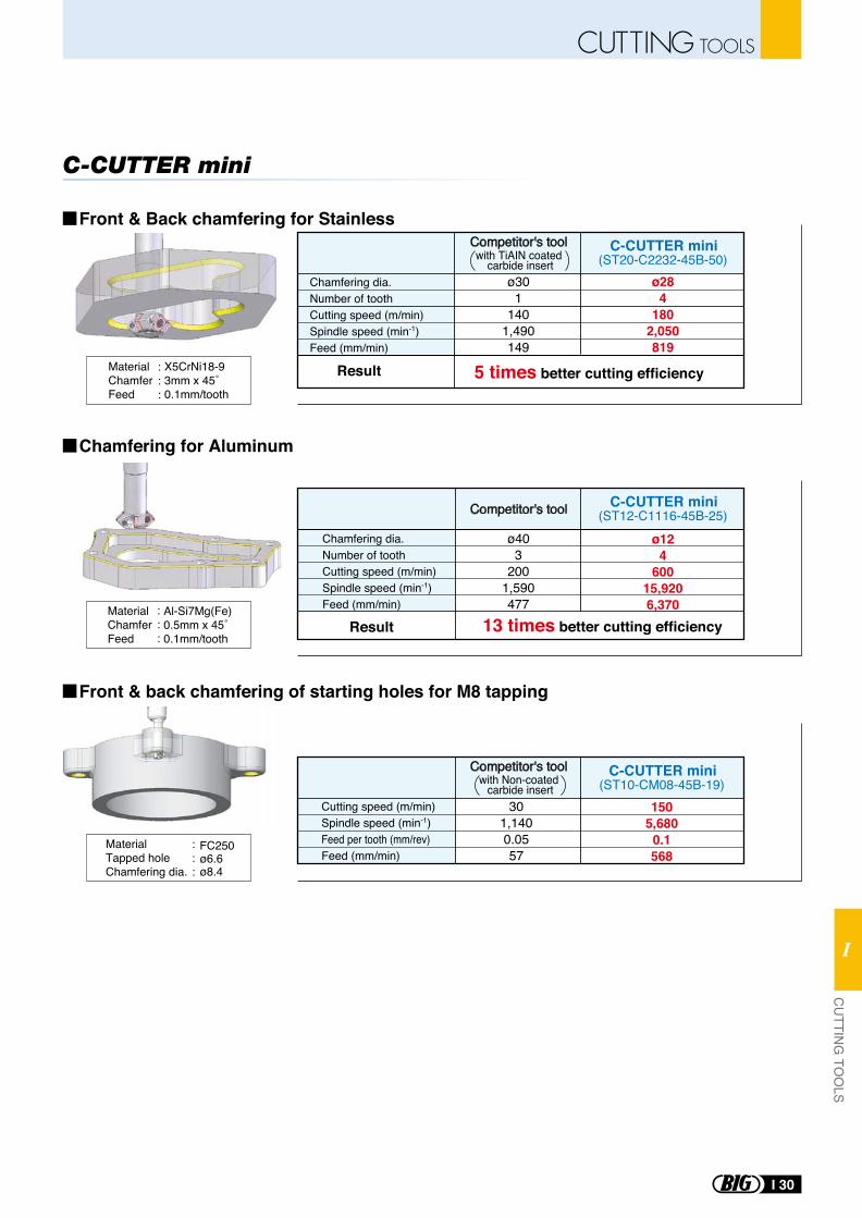
Chamfering dia.Number of toothCutting speed (m/min)Spindle speed (min-1)Feed (mm/min)
(ST20-C2232-45B-50)ø30
1140
1,490149
ø284
1802,050819
C-CUTTER mini
MaterialChamferFeed
MaterialChamferFeed
X5CrNi18-93mm x 45˚0.1mm/tooth
Al-Si7Mg(Fe)0.5mm x 45˚0.1mm/tooth
(ST12-C1116-45B-25)ø40
3200
1,590477
ø124
60015,9206,370
C-CUTTER mini
Result
Result
:::
:::
Chamfering dia.Number of toothCutting speed (m/min)Spindle speed (min-1)Feed (mm/min)
MaterialTapped holeChamfering dia.
FC250ø6.6ø8.4
Cutting speed (m/min)Spindle speed (min-1)Feed per tooth (mm/rev)Feed (mm/min)
(ST10-CM08-45B-19)30
1,1400.0557
1505,680
0.1568
C-CUTTER miniCompetitor's toolwith Non-coated carbide insert
Competitor's tool
Competitor's tool
:::
with TiAIN coated carbide insert
5 times better cutting efficiency
13 times better cutting efficiency
Front & Back chamfering for Stainless
Front & back chamfering of starting holes for M8 tapping
Chamfering for Aluminum
I 30
CUTTING TOOLSC
UTTIN
G TO
OLS
I
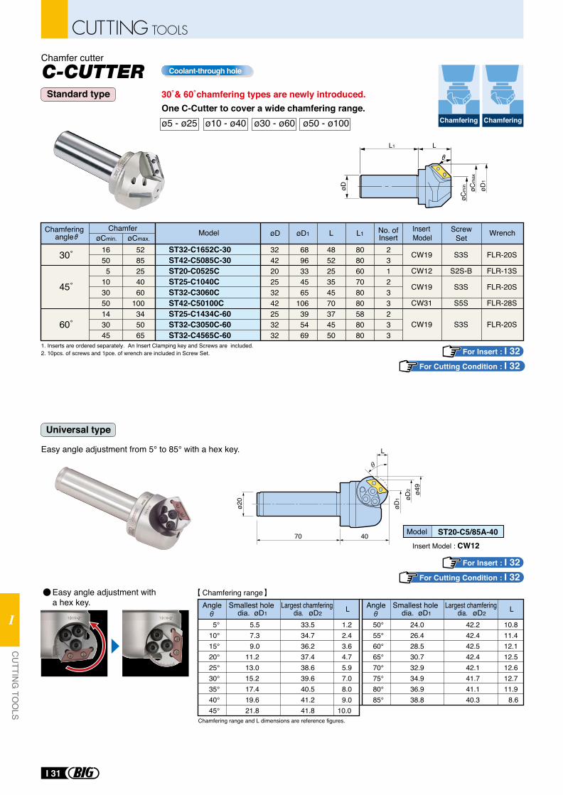
One C-Cutter to cover a wide chamfering range.ø5 - ø25 ø10 - ø40 ø30 - ø60 ø50 - ø100 ChamferingChamfering
Chamfer cutter
Standard type
Universal type
30˚& 60˚chamfering types are newly introduced.
Coolant-through hole
Chamfering range and L dimensions are reference figures.
5°10°15°20°25°30°35°40°45°
5.57.39.0
11.213.015.217.419.621.8
33.534.736.237.438.639.640.541.241.8
1.22.43.64.75.97.08.09.0
10.0
Smallest hole dia. øD1
Angle Largest chamfering dia. øD2 L
50°55°60°65°70°75°80°85°
24.026.428.530.732.934.936.938.8
42.242.442.542.442.141.741.140.3
10.811.412.112.512.612.711.9
8.6
øD1 øD
2 ø49
L
ø20
4070
Easy angle adjustment from 5° to 85° with a hex key.
Model ST20-C5/85A-40Insert Model : CW12
Smallest hole dia. øD1
Angle Largest chamfering dia. øD2 L
Chamfering range
1. Inserts are ordered separately. An Insert Clamping key and Screws are included.2. 10pcs. of screws and 1pce. of wrench are included in Screw Set.
L
øCm
in øCm
ax
øD1
øD
L1
ModelChamferChamferingangle øD
324220253242253232
øCmin.
16505
103050143045
øCmax.øD1
5285254060
100345065
L
485225354570374550
6896334565
106395469
L1
808060708080588080
No. of Insert
231233233
CW19
CW12
CW19
CW31
CW19
Insert Model
S3S
S2S-B
S3S
S5S
S3S
ScrewSet
FLR-20S
FLR-13S
FLR-20S
FLR-28S
FLR-20S
Wrench
ST32-C1652C-30ST42-C5085C-30ST20-C0525CST25-C1040CST32-C3060CST42-C50100CST25-C1434C-60ST32-C3050C-60ST32-C4565C-60
60˚
45˚
30˚
For Insert : I 32For Cutting Condition : I 32
For Insert : I 32For Cutting Condition : I 32
Easy angle adjustment with a hex key.
I 31
CUTTING TOOLS
CU
TTING
TOO
LS
I
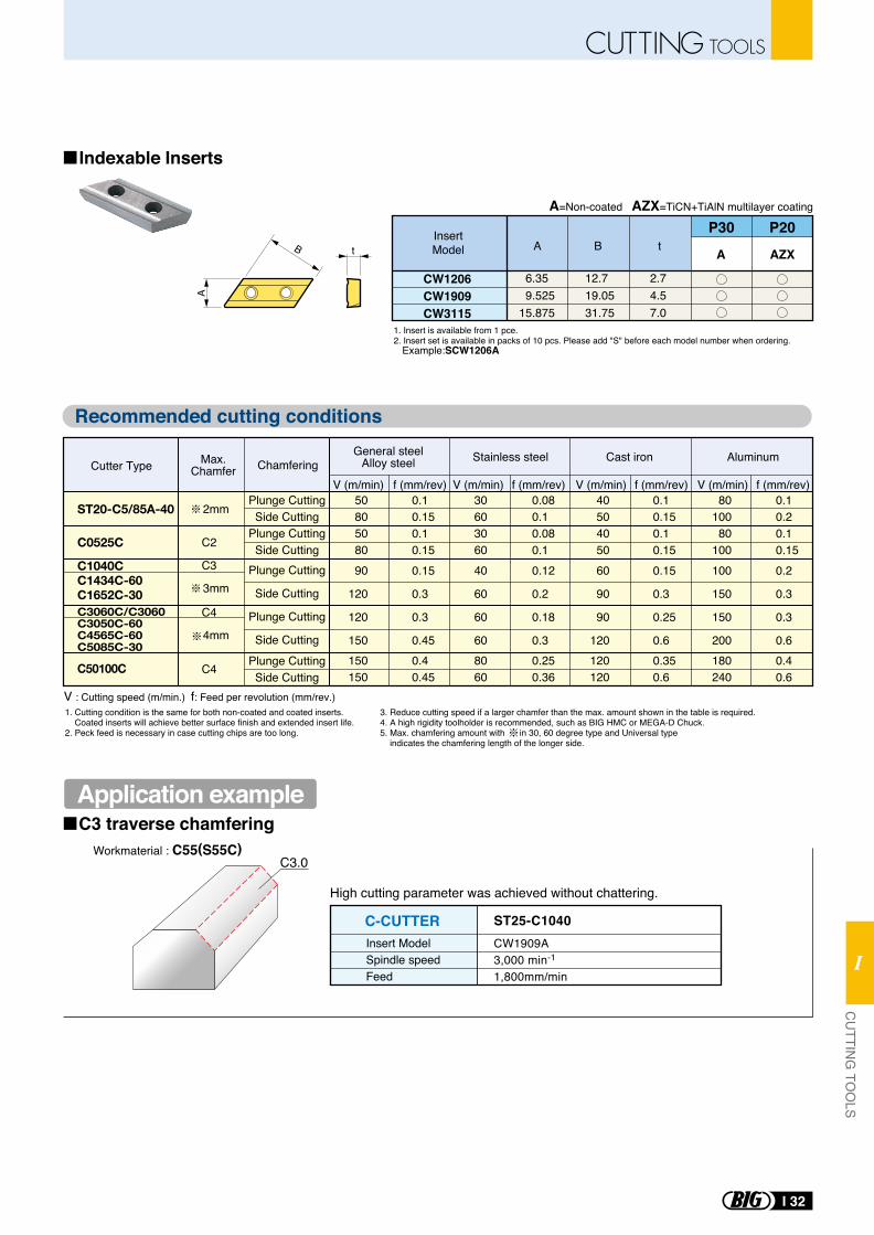
C3.0Workmaterial : C55(S55C)
t
A
B
Indexable Inserts
Recommended cutting conditions
P30 P20
CW1206CW1909CW3115
6.35 9.52515.875
12.719.0531.75
2.74.57.0
InsertModel A A AZXB t
1. Insert is available from 1 pce.2. Insert set is available in packs of 10 pcs. Please add "S" before each model number when ordering. Example:SCW1206A
1. Cutting condition is the same for both non-coated and coated inserts. Coated inserts will achieve better surface finish and extended insert life.2. Peck feed is necessary in case cutting chips are too long.
3. Reduce cutting speed if a larger chamfer than the max. amount shown in the table is required.4. A high rigidity toolholder is recommended, such as BIG HMC or MEGA-D Chuck.5. Max. chamfering amount with in 30, 60 degree type and Universal type indicates the chamfering length of the longer side.
V : Cutting speed (m/min.) f: Feed per revolution (mm/rev.)
A=Non-coated AZX=TiCN+TiAlN multilayer coating
CW1909A3,000 min-1
1,800mm/min
Insert ModelSpindle speedFeed
C-CUTTER ST25-C1040
High cutting parameter was achieved without chattering.
Chamfering
C2
C3
C4
C4
V (m/min) f (mm/rev) V (m/min) f (mm/rev)V (m/min) f (mm/rev)V (m/min) f (mm/rev)
C0525C
C50100C
C1040CC1434C-60C1652C-30C3060C/C3060C3050C-60C4565C-60C5085C-30
3mm
4mm
Cutter Type Max.Chamfer
General steelAlloy steel Stainless steel Cast iron Aluminum
0.10.15
0.40.6
0.2
0.3
0.3
0.6
0.10.15
0.350.6
0.15
0.3
0.25
0.6
0.080.1
0.250.36
0.12
0.2
0.18
0.3
0.10.15
0.40.45
0.15
0.3
0.3
0.45
80100
180240
100
150
150
200
4050
120120
60
90
90
120
3060
8060
40
60
60
60
5080
150150
90
120
120
150
Plunge CuttingSide Cutting
ST20-C5/85A-400.10.2
0.10.15
0.080.1
0.10.15
80100
4050
3060
5080
Plunge CuttingSide Cutting
Plunge CuttingSide Cutting
Plunge Cutting
Side Cutting
Plunge Cutting
Side Cutting
2mm
Application exampleC3 traverse chamfering
I 32
CUTTING TOOLSC
UTTIN
G TO
OLS
I
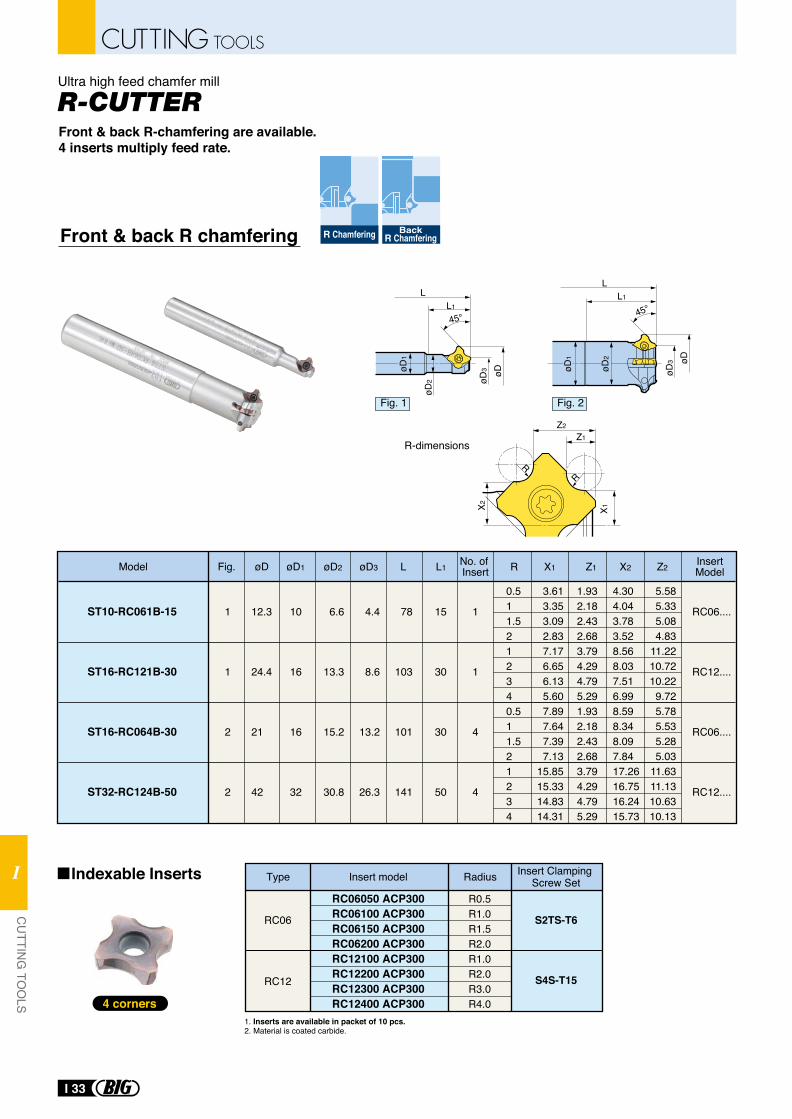
R-CUTTERUltra high feed chamfer mill
Z2
Z1
X2 X1
RR
ST10-RC061B-15
ST16-RC121B-30
ST16-RC064B-30
ST32-RC124B-50
1
1
2
2
12.3
24.4
21
42
10
16
16
32
6.6
13.3
15.2
30.8
4.4
8.6
13.2
26.3
78
103
101
141
15
30
30
50
1
1
4
4
RC06....
RC12....
RC06....
RC12....
0.511.5212340.511.521234
3.613.353.092.837.176.656.135.607.897.647.397.13
15.8515.3314.8314.31
1.932.182.432.683.794.294.795.291.932.182.432.683.794.294.795.29
4.304.043.783.528.568.037.516.998.598.348.097.8417.2616.7516.2415.73
5.585.335.084.83
11.2210.7210.229.725.785.535.285.03
11.6311.1310.6310.13
Model Fig. øD øD1 L RL1 No. of InsertøD2 øD3 X1 Z1 X2 Z2 Insert
Model
R-dimensions
Front & back R chamfering R Chamfering BackR Chamfering
Fig. 1 Fig. 2
45°
L
øDøD
3
øD2
L145°
LL1
øDøD
3
øD1
øD1
øD2
Front & back R-chamfering are available.4 inserts multiply feed rate.
1. Inserts are available in packet of 10 pcs.2. Material is coated carbide.
Type RadiusInsert model
RC06
RC12
RC06050 ACP300RC06100 ACP300RC06150 ACP300RC06200 ACP300RC12100 ACP300RC12200 ACP300RC12300 ACP300RC12400 ACP300
R0.5R1.0R1.5R2.0R1.0R2.0R3.0R4.0
Insert Clamping Screw Set
S2TS-T6
S4S-T15
4 corners
Indexable Inserts
I 33
CUTTING TOOLS
CU
TTING
TOO
LS
I
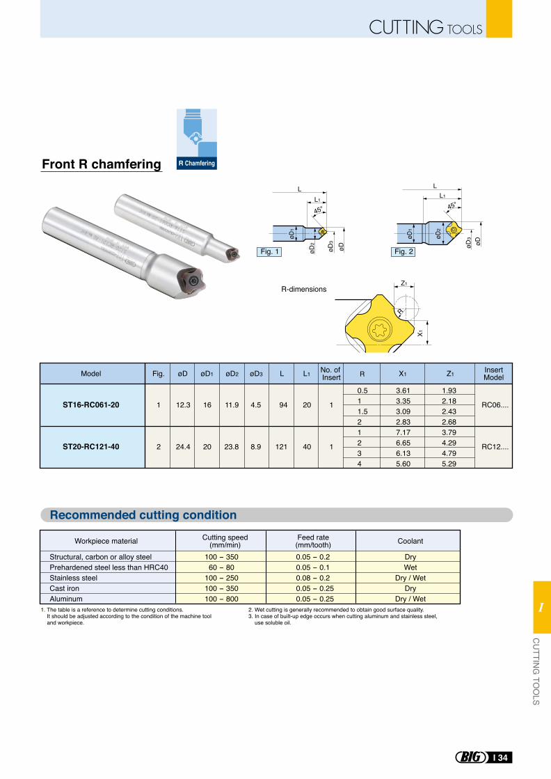
Z1
X1
R
R-dimensions
ST16-RC061-20
ST20-RC121-40
1
2
12.3
24.4
16
20
11.9
23.8
4.5
8.9
94
121
20
40
1
1
RC06....
RC12....
1.932.182.432.683.794.294.795.29
3.613.353.092.837.176.656.135.60
Front R chamfering
Fig. 1 Fig. 2
1. The table is a reference to determine cutting conditions. It should be adjusted according to the condition of the machine tool and workpiece.
2. Wet cutting is generally recommended to obtain good surface quality.3. In case of built-up edge occurs when cutting aluminum and stainless steel, use soluble oil.
Structural, carbon or alloy steelPrehardened steel less than HRC40Stainless steelCast ironAluminum
100 - 350 60 - 80100 - 250100 - 350100 - 800
0.05 - 0.20.05 - 0.10.08 - 0.20.05 - 0.250.05 - 0.25
DryWet
Dry / WetDry
Dry / Wet
Workpiece material Feed rate(mm/tooth) CoolantCutting speed
(mm/min)
Recommended cutting condition
0.511.521234
Model Fig. øD øD1 L RL1 No. of InsertøD2 øD3 X1 Z1 Insert
Model
R Chamfering
LL1
øDøD3
øD2
45° 45°
LL1
øDøD3øD
1
øD1
øD2
I 34
CUTTING TOOLSC
UTTIN
G TO
OLS
I
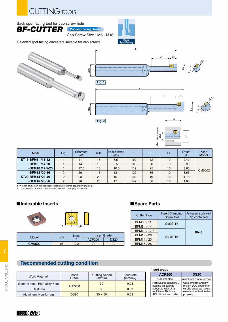
BF-CUTTERBack spot facing tool for cap screw hole
L1
øDøD2
Min.
hole
diam
eter
øDøD1
L
L2
øD2
F
L1
øD
L
øD1
F
øD2
L1 L2
Model Fig.
ST16-BFM6 /11-12-BFM8 /14-20-BFM10 /17.5-25-BFM12 /20-36
ST20-BFM14 /23-49-BFM16 /26-56
111222
ChamferøD111417.5202326
øD1
161616162020
Min. hole diameterøD2
6.58.510.5131517
L
102108112122136142
L1
122025364956
L2
99
10101010
OffsetF
2.402.903.653.654.154.65
InsertModel
CM0502
1. Wrench and screw are included. Inserts are ordered separately (10/pkg).2. 10 screws and 1 wrench are included in Insert Clamping Screw Set.
High wear-resistant PVD coating on carbide substrate with ultra multilayer TiAlN and AlCrN in micron order.
ACP200Insert grade
Ultra smooth and low friction DLC coating on carbide substrate having excellent anti-adhesive property.
DS20General steel Aluminum & non-ferrous
Work Material Feed rate(mm/rev)
InsertGrade
Cutting Speed(m/min)
0.030.030.03
3030
30 - 50
ACP200
DS20
General steel, High-alloy SteelCast iron
Aluminum, Non-ferrous
CM0502 ø5 0.2
Insert Grade NoserøDModel
ACP200 DS20
øDr S2SS-T6
S2TS-T6BN-5
BFM6 / 11BFM8 / 14BFM10 / 17.5BFM12 / 20BFM14 / 23BFM16 / 26
Cutter Type Insert ClampingScrew Set
Anti-seizure Lubricant5g contained
Cap Screw Size : M6 - M16Coolant-through hole
Fig. 1
Fig. 2
Indexable Inserts Spare Parts
Recommended cutting condition
BackSpot FacingSelected spot facing diameters suitable for cap screws.
I 35
CUTTING TOOLS
CU
TTING
TOO
LS
I
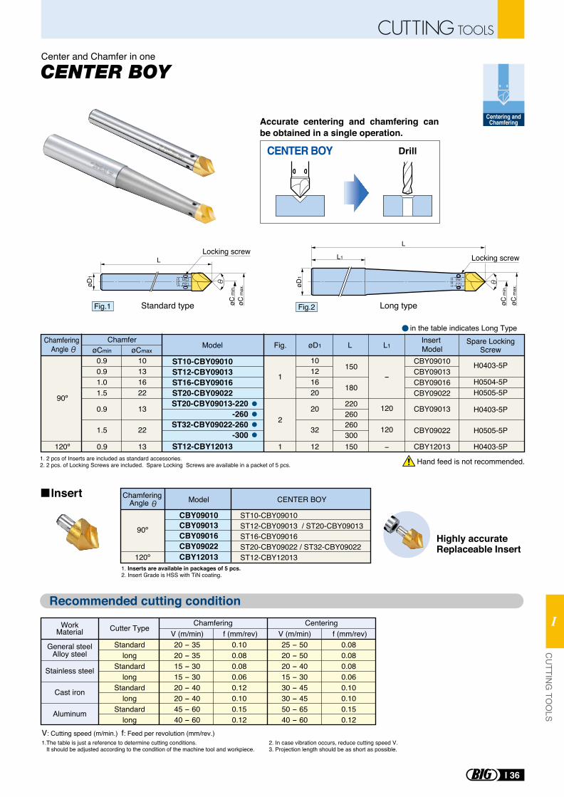
Accurate centering and chamfering can be obtained in a single operation.
Insert
1. Inserts are available in packages of 5 pcs.2. Insert Grade is HSS with TiN coating.
CBY09010
Model CENTER BOYChamferingAngle
CBY09013ST10-CBY09010ST12-CBY09013 / ST20-CBY09013ST16-CBY09016ST20-CBY09022 / ST32-CBY09022ST12-CBY12013
90º
120º
CBY09016CBY09022CBY12013
1.The table is just a reference to determine cutting conditions. It should be adjusted according to the condition of the machine tool and workpiece.
2. In case vibration occurs, reduce cutting speed V.3. Projection length should be as short as possible.
1. 2 pcs of Inserts are included as standard accessories.2. 2 pcs. of Locking Screws are included. Spare Locking Screws are available in a packet of 5 pcs.
V: Cutting speed (m/min.) f: Feed per revolution (mm/rev.)
L
øD1
øC m
in.
øC m
ax.
Locking screw
Fig.1
CENTER BOY Drill
Fig.2øD
1
L
L1
Long typeStandard type
in the table indicates Long Type
Hand feed is not recommended.
Highly accurate Replaceable Insert
Recommended cutting condition
Cutter Type
Standardlong
Standardlong
Standardlong
Standardlong
Chamfering Centering
20 - 3520 - 3515 - 3015 - 3020 - 4020 - 4045 - 6040 - 60
0.100.080.080.060.120.100.150.12
WorkMaterial V (m/min) f (mm/rev)
25 - 5020 - 5020 - 4015 - 3030 - 4530 - 4550 - 6540 - 60
0.080.080.080.060.100.100.150.12
V (m/min) f (mm/rev)General steel
Alloy steel
Stainless steel
Cast iron
Aluminum
CBY09013
Model øD1Chamfer
L L1Insert Model
Chamfering Angle
CBY09022
CBY09010CBY09013CBY09016CBY09022
H0403-5P
H0403-5P
H0505-5P
H0504-5PH0505-5P
ST10-CBY09010 ST12-CBY09013 ST16-CBY09016 ST20-CBY09022 ST20-CBY09013-220
-260ST32-CBY09022-260
-300ST12-CBY12013
150
180
220260260300150
10121620
20
32
10131622
13
22
0.90.91.01.5
0.9
1.5
-
-
120
120
Fig.
90º
120º 0.9 13
2
1
Spare LockingScrewøCmin øCmax
øC m
in.
øC m
ax.
Locking screw
Centering andChamfering
Center and Chamfer in one
CBY12013121 H0403-5P
I 36
CUTTING TOOLSC
UTTIN
G TO
OLS
I
CATALO
G N
o.EXm400
-5
H I G H P R E C I S I O NT O O L H O L D E R S
Reduce Costs by maximizing tool life with High Precision toolholders
CATALOG No.EXm400-5-0414-1 H
Takaramachi 5-2, Higashiosakashi Osaka 579-8025 JAPANPhone : (+81)-72-982-8277 Fax : (+81)-72-982-8370http://www.big-daishowa.com E-mail: [email protected]
JQA-QM3913FA Dept.
JQA-QMA11602AWAJI No.1 Factory
CERTIFIED
MA
NAGEMENT SYSTEM
ISO 9001
Subject to technical changes by further developments.


